US11890034B1 - Collet for a polyaxial screw assembly - Google Patents
Collet for a polyaxial screw assemblyDownload PDFInfo
- Publication number
- US11890034B1 US11890034B1US16/715,763US201916715763AUS11890034B1US 11890034 B1US11890034 B1US 11890034B1US 201916715763 AUS201916715763 AUS 201916715763AUS 11890034 B1US11890034 B1US 11890034B1
- Authority
- US
- United States
- Prior art keywords
- collet
- track
- movable head
- head
- screw
- Prior art date
- Legal status (The legal status is an assumption and is not a legal conclusion. Google has not performed a legal analysis and makes no representation as to the accuracy of the status listed.)
- Active, expires
Links
Images


Classifications
- A—HUMAN NECESSITIES
- A61—MEDICAL OR VETERINARY SCIENCE; HYGIENE
- A61B—DIAGNOSIS; SURGERY; IDENTIFICATION
- A61B17/00—Surgical instruments, devices or methods
- A61B17/56—Surgical instruments or methods for treatment of bones or joints; Devices specially adapted therefor
- A61B17/58—Surgical instruments or methods for treatment of bones or joints; Devices specially adapted therefor for osteosynthesis, e.g. bone plates, screws or setting implements
- A61B17/68—Internal fixation devices, including fasteners and spinal fixators, even if a part thereof projects from the skin
- A61B17/70—Spinal positioners or stabilisers, e.g. stabilisers comprising fluid filler in an implant
- A61B17/7001—Screws or hooks combined with longitudinal elements which do not contact vertebrae
- A61B17/7035—Screws or hooks, wherein a rod-clamping part and a bone-anchoring part can pivot relative to each other
- A61B17/7037—Screws or hooks, wherein a rod-clamping part and a bone-anchoring part can pivot relative to each other wherein pivoting is blocked when the rod is clamped
- A—HUMAN NECESSITIES
- A61—MEDICAL OR VETERINARY SCIENCE; HYGIENE
- A61B—DIAGNOSIS; SURGERY; IDENTIFICATION
- A61B17/00—Surgical instruments, devices or methods
- A61B17/56—Surgical instruments or methods for treatment of bones or joints; Devices specially adapted therefor
- A61B17/58—Surgical instruments or methods for treatment of bones or joints; Devices specially adapted therefor for osteosynthesis, e.g. bone plates, screws or setting implements
- A61B17/68—Internal fixation devices, including fasteners and spinal fixators, even if a part thereof projects from the skin
- A61B17/70—Spinal positioners or stabilisers, e.g. stabilisers comprising fluid filler in an implant
- A61B17/7001—Screws or hooks combined with longitudinal elements which do not contact vertebrae
- A61B17/7035—Screws or hooks, wherein a rod-clamping part and a bone-anchoring part can pivot relative to each other
- A—HUMAN NECESSITIES
- A61—MEDICAL OR VETERINARY SCIENCE; HYGIENE
- A61B—DIAGNOSIS; SURGERY; IDENTIFICATION
- A61B17/00—Surgical instruments, devices or methods
- A61B17/56—Surgical instruments or methods for treatment of bones or joints; Devices specially adapted therefor
- A61B17/58—Surgical instruments or methods for treatment of bones or joints; Devices specially adapted therefor for osteosynthesis, e.g. bone plates, screws or setting implements
- A61B17/68—Internal fixation devices, including fasteners and spinal fixators, even if a part thereof projects from the skin
- A61B17/84—Fasteners therefor or fasteners being internal fixation devices
- A61B17/86—Pins or screws or threaded wires; nuts therefor
- A61B17/8605—Heads, i.e. proximal ends projecting from bone
- A—HUMAN NECESSITIES
- A61—MEDICAL OR VETERINARY SCIENCE; HYGIENE
- A61B—DIAGNOSIS; SURGERY; IDENTIFICATION
- A61B17/00—Surgical instruments, devices or methods
- A61B17/56—Surgical instruments or methods for treatment of bones or joints; Devices specially adapted therefor
- A61B17/58—Surgical instruments or methods for treatment of bones or joints; Devices specially adapted therefor for osteosynthesis, e.g. bone plates, screws or setting implements
- A61B17/68—Internal fixation devices, including fasteners and spinal fixators, even if a part thereof projects from the skin
- A61B17/84—Fasteners therefor or fasteners being internal fixation devices
- A61B17/86—Pins or screws or threaded wires; nuts therefor
- A61B17/8685—Pins or screws or threaded wires; nuts therefor comprising multiple separate parts
- A—HUMAN NECESSITIES
- A61—MEDICAL OR VETERINARY SCIENCE; HYGIENE
- A61B—DIAGNOSIS; SURGERY; IDENTIFICATION
- A61B17/00—Surgical instruments, devices or methods
- A61B17/56—Surgical instruments or methods for treatment of bones or joints; Devices specially adapted therefor
- A61B17/58—Surgical instruments or methods for treatment of bones or joints; Devices specially adapted therefor for osteosynthesis, e.g. bone plates, screws or setting implements
- A61B17/68—Internal fixation devices, including fasteners and spinal fixators, even if a part thereof projects from the skin
- A61B17/70—Spinal positioners or stabilisers, e.g. stabilisers comprising fluid filler in an implant
- A61B17/7001—Screws or hooks combined with longitudinal elements which do not contact vertebrae
- A61B17/7032—Screws or hooks with U-shaped head or back through which longitudinal rods pass
Definitions
- Embodiments of the inventionpertain to spinal surgery.
- this hardwareincludes polyaxial pedicle screws that may allow angulation in various degrees of freedom between the movable screw head and the screw itself.
- Such screwsmay have a spherical head which is attached to a bone screw, and is captured somewhere within the moveable head.
- a bone screw headmay be pushed through a lower opening of a screw head by excess compression force transferred from a locking element.
- This excess compression forcemay result in failure of the screw head/bone screw interface, and may result in a loss of fixation of the bone screw.
- the described inventionaims to limit the compression force from the locking element to prevent this failure and provide a more circumferential lock between the bone screw/screw head interface.
- an apparatusmay include: a screw, including a shaft and a screw head fixedly attached with the shaft, where the screw head further comprises a portion of a sphere; a movable head including a top portion and a bottom portion, a concave interior larger than the screw head, and being movable with respect to the screw head; a connecting rod; a locking element, capable of engaging the movable head and creating an axial compression force thereon the connecting rod; and a collet interposed between the screw head and the concave interior of the movable head, where the collet comprises a top portion capable of contacting said connecting rod and at least one flexible hinge, where the collet limits the axial compression force transferred from the locking element to the screw head by deforming outwards at the at least one flexible hinge until contact is made with the concave interior of the moveable head.
- the flexible hingemay extend from the top end of the collet and for a distance spaced from the bottom end of the collet, and opposite the flexible hinge is an open slot extending vertically from the top end of the collet to the bottom end of the collet. In other embodiments, the flexible hinge may extend from the top end of the collet to the bottom end of the collet, and opposite the flexible hinge is an open slot extending vertically from the top end of the collet to the bottom end of the collet.
- the colletmay further include an internal surface and an external surface, and where the flexible hinge has a larger radius than the external surface of the collet.
- the flexible hingemay include a concave tab extending outward from the external surface of the collet. In other embodiments, the flexible hinge may be perpendicular to the cradle capable of receiving the connecting rod.
- the movable headfurther may include one or more tracks capable of receiving the flexible hinge of the collet.
- the one or more tracksmay be vertical tracks.
- the one or more tracksmay be circumferential tracks located between the plurality of threads.
- a collet for a polyaxial screw assemblymay include: a top end configured to receive a connecting rod; a bottom end configured to interface with a screw head fixedly attached with a shaft of a screw; a flexible hinge extending in a direction; and an open slot extending in a direction from the top end to the bottom end and located opposite the flexible hinge, where the open slot creates a discontinuous circumference.
- the flexible hingemay extend from the top end of the collet and for a distance spaced from the bottom end of the collet. In other embodiments, the flexible hinge may extend from the top end of the collet to the bottom end of the collet. In still other embodiments, the flexible hinge may include a concave tab extending outward from an external surface of the collet. In still other embodiments, the flexible hinge may be at a position that is perpendicular to a longitudinal axis of a cradle of the top end capable of receiving the connecting rod.
- a method of inserting a collet into a movable headincluding: obtaining a collet and a movable head, wherein the collet comprises a flexible hinge and wherein the movable head comprises a first track that traverses from adjacent a top portion of the movable head to a bottom portion of the movable head; inserting the collet into a first track of the movable head in a compressed configuration; moving the collet along at least the first track of the movable head in the compressed configuration; and positioning the collet into an uncompressed configuration within said moveable head.
- the movable headfurther may comprise a second track intersecting the first track, where the second track is substantially circumferential and the first track is traverse to the second track.
- moving the colletmay include rotating the collet from a first orientation to a second orientation within the second track.
- the first trackmay be a channel and the second track may be a channel, and where the step of moving the collet along at least the first track of the movable head in the compressed configuration may include sliding the flexible hinge in the first track then the second track.
- the first trackmay be a channel and the step of moving the collet along at least the first track of the movable head in the compressed configuration may include sliding the flexible hinge within the first channel of the first track.
- the movable headmay further comprise an open slot extending from a top end to a bottom end of the collet, where the open slot creates a discontinuous circumference.
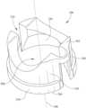
- FIG. 1is a perspective view of an embodiment of an apparatus described herein.
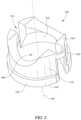
- FIG. 2is a perspective view of an embodiment of a collet for a polyaxial screw assembly described herein.
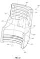
- FIG. 3is a perspective view of another embodiment of a collet for a polyaxial screw assembly described herein.
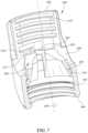
- FIG. 4is a perspective view of a cross-section of an embodiment of a movable head described herein.
- FIG. 5is a perspective view of a cross-section of the movable head of FIG. 4 with a collet contained therein
- FIG. 6is a perspective view of a cross-section of an embodiment of a movable head described herein.
- FIG. 7is a perspective view of a cross-section of the movable head of FIG. 6 with a collet contained therein described herein.
- FIG. 8 A-Dare perspective views of the movable head of FIG. 6 with a collet contained therein in various positions for installation.
- FIG. 8 Aillustrates a collet in an initial installation position
- FIG. 8 Billustrates a collet in an engaged position
- FIG. 8 Cillustrates a collet in a rotated position
- FIG. 8 Dillustrates a collet in an installed position.
- an embodiment of a portion of an apparatus 100that provides a screw 105 that may possess a shaft 110 , and a screw head 130 that may be integral with or attached to the shaft 110 .
- the screw head 130may be a portion of a sphere or have a spheroidal shape.
- the apparatusmay further be provided with a collet 200 that may fit around all or a portion of the screw head 130 .
- the apparatusmay further have a movable head 400 , 600 , which will in turn contain the collet 200 .
- Screw 100may possess threads 120 around shaft 110 .
- Screw 100may have a longitudinal axis 140 .
- the longitudinal axis 140generally extends through the center of the screw 100 along its length.
- the screw shaft 110may be either solid (as illustrated) or alternatively may be hollow, with the empty central region being available for other purposes as may be desired.
- the screw 100including the screw head 130 , may be axisymmetric about longitudinal axis 140 .
- the apparatusmay further be provided with a locking element.
- a locking elementmay be any element capable of applying vertical force to lock the rod to the moveable screw head.
- a locking elementmay be, for example, a set screw 500 that may have an external thread 540 that may engage with an internal thread, or set of internal threads of a movable head (described in detail herein). It is further possible that there could be provided timing features marked on any of the nearby parts for indicating the optimal place to begin engagement of the set screw thread 540 and the internal thread, or set of threads of the movable head.
- collet 200may have a ring shape defining a central opening 208 and a longitudinal axis 240 .
- the collet 200may have a first or top end 202 of the collet 200 and a second or bottom end 204 of the collet 200 .
- the collet 200 longitudinal axis 240may extend through the center of the collet from a top end 202 to a bottom end 204 .
- the collet 200may have a collet interior surface 220 that may be partially spherical and may resemble a portion of the external surface of the screw head 130 thus forming a cradle 235 for receiving a connecting rod.
- the collet interior surface 220does not need to exactly match the external surface of the screw head 130 .
- the collet interior surface 220may be concave with a less tight curvature (that is, a larger radius of curvature) than the spherical portion of the screw head 130 .
- the collet interior surface 220may be an inverted cone that mates on top of the spherical portion of the screw head 130 .
- the collet interior surface 220 and the screw head 130may be related to each other such that when the collet 200 is constrained against outward radial deformation, the screw head 130 is prevented from sliding distally with respect to the collet 200 , such as by a wedging action.
- the collet 200may have a collet external surface 230 , which may resemble an internal surface 420 of the movable head 400 (see FIG. 4 ).
- the collet external surface 230need not exactly match internal surface 420 of movable head 400 or any other internal surface of the movable head 400 .
- the collet 200may further include a flexible hinge 260 .
- the flexible hinge 260may extend vertically from the top end 202 of the collet 200 towards the bottom end 204 of the collet 200 .
- the flexible hinge 260may extend fully from the top end 202 to the bottom end 204 of the collet 200 .
- the flexible hinge 260may extend vertically from the bottom end 204 of the collet 200 towards the top end 204 of the collet 200 .
- the flexible hingemay extend a length between the top end 202 of the collet 200 and the bottom end 204 of the collet 200 , for example in a middle area between the top end 202 and the bottom end 204 .
- the collet 200may further include an open slot 210 .
- the open slot 210may be located opposite of the flexible hinge 260 , and may fully extend vertically from the top end 202 to the bottom end 204 of the collet 200 creating a discontinuous circumference of the collet 200 , but is not so limited.
- the flexible hinge 260may extend beyond the external surface 230 of the collet 200 , such that it protrudes from the remainder of the collet 200 . In other embodiments, the flexible hinge 260 may be described as concave in shape extending outward from the exterior surface 230 of the collet.
- the flexible hinge 260 and the open slot 210are both perpendicular to the cradle 235 for receiving a connecting rod.
- the collet 200may further have an external lip 250 at or near its bottom end. Such an external lip 250 may extend farther outwardly in a radial direction than the rest of the collet 200 .
- the external lip 250may be interrupted by the open slot 210 just as nearby parts of the collet 200 , other than the external lip 250 , are interrupted by the open slot 210 .
- collet 300for a polyaxial screw assembly is illustrated.
- collet 300illustrated in FIG. 3
- collet 300is similar to collet 200 , illustrated in FIG. 2 ; as such, similar structures have been numbered with similar numbers, replacing the 2 with a 3.
- collet 300generally may have a ring shape defining a central opening 308 and a longitudinal axis 340 .
- the collet 300may have a first or top end 302 of the collet 300 and a second or bottom end 304 of the collet 300 .
- the collet 300 longitudinal axis 340may extend through the center of the collet from a top end 302 to a bottom end 304 .
- the collet 300may have a collet interior surface 320 that may be partially spherical and may resemble a portion of the external surface of the screw head 130 thus forming a cradle 335 for receiving a rod.
- the collet interior surface 320does not need to exactly match the connecting external surface of the screw head 130 .
- the collet interior surface 320may be concave with a less tight curvature (that is, a larger radius of curvature) than the spherical portion of the screw head 130 .
- the collet interior surface 320 and the screw head 130may be related to each other such that when the collet 300 is constrained against outward radial deformation, the screw head 130 is prevented from sliding distally with respect to the collet 300 , such as by a wedging action.
- the collet 300may have a collet external surface 330 , which may resemble an internal surface 620 of the movable head 600 (see FIGS. 6 and 7 ).
- the collet external surface 330need not exactly match internal surface 620 of movable head 400 or any other internal surface of the movable head 600 .
- the collet 300may further include a flexible hinge 360 .
- the flexible hingemay extend vertically from the top end 302 of the collet 300 towards the bottom end 304 of the collet 300 .
- the flexible hinge 360may extend from the top end 302 for a distance spaced from the bottom end 304 of the collet 300 .
- the flexible hinge 360may extend a length between the top end 302 of the collet 300 and the bottom end 304 of the collet 300 , for example in a middle area between the top end 302 and the bottom end 304 .
- the flexible hinge 360may comprise only a small portion of the vertical space between the top end 302 and the bottom end 304 of the collet 300 , as illustrated in FIG. 3 . In other embodiments, the flexible hinge 360 may comprise a larger portion of the vertical space between the top end 302 and the bottom end 304 of the collet 300 . Also similar to collet 200 of FIG. 2 , the collet may have an open slot 310 . In some embodiments, the open slot 310 may be opposite of the flexible hinge 360 , but is not so limited In some embodiments the open slot 310 may extend vertically from the top end 302 to the bottom end 304 of the collet 300 , thus creating a discontinuous circumference of the collet 300 . In other embodiments, the open slot may partially open the area extending between the top end 302 and the bottom end 304 of the collet 300 .
- the flexible hinge 360may extend beyond the external surface 330 of the collet 300 , such that it protrudes from the remainder of the collet 300 .
- the flexible hinge 360may be described as concave in shape extending outward from the exterior surface 330 of the collet.
- the flexible hinge 360may be in the form of a concave tab that extends outward from the external surface 330 of the collet 300 .
- the flexible hinge 360 and the open slot 310are both perpendicular to the cradle 335 for receiving a connecting rod.
- the collet 300may further have an external lip 350 at or near its bottom end. Such an external lip 350 may extend farther outwardly in a radial direction than the rest of the collet 300 .
- the external lip 350may be interrupted by the open slot 310 just as nearby parts of the collet 300 , other than the external lip 350 , are interrupted by the open slot 310 .
- the collet 200 , 300may be capable of expanding and deforming radially outwardly so as to receive the bone screw screw head 130 .
- This radial expansion and deformationmay be primarily at the open slot 210 , 310 , which may splay open when axial compression force is transferred to the collet 200 , 300 through the set screw and connecting rod.
- the radial expansion and deformation of the collet 200 , 300may minimize the axial compression force that is transferred to the screw head 130 .
- FIGS. 4 - 8 Dmultiple embodiments of a movable heads consistent with the disclosure herein are described and illustrated.
- FIGS. 4 and 5illustrate an embodiment of a movable head 400 for use with the particular embodiment of collet 200 illustrated in FIG. 2 ; however this is not to be understood as limiting, as the embodiment of movable head 400 illustrated in FIGS. 4 and 5 may be utilized with collet 300 , or other embodiments of a collet.
- movable head 400may have a proximal end 402 and a distal end 404 and a generally longitudinal axis 440 extending from the proximal end 402 to the distal end 404 through the center of the movable head 400 .
- the movable head 400may also have a first or top portion or end and a second or bottom portion or end, whereby the top portion is located at a proximal end 402 of the movable head 400 and the bottom portion is located at a distal end 404 of the movable head 400 .
- the movable head 400may also have, at its proximal end 402 , a U-shaped passageway or U-trough 460 through the movable head 400 , only half of which is visible in FIGS. 4 and 5 .
- the U-trough 460may have an axis generally perpendicular to the longitudinal axis 440 of the movable head.
- the U-trough 460 axismay also be generally transverse through the movable head 400 .
- the movable head 400may have a hole (not illustrated in FIGS. 4 and 5 ) therethrough at its distal end or bottom portion, through which the screw 105 , or portions thereof, may pass.
- the movable head 400may have a first set of internal threads 410 at its proximal end 402 .
- This first set of internal threads 410may be capable of receiving a set screw 500 .
- the first set of internal threads 410may have a roughly semi-circular or concave-shaped cutout, indention, or track 415 .
- this trackmay traverse the internal threads from the top to the bottom. In other embodiments, this track may be described as a channel that traverses the internal surface of the movable head.
- these cutouts, indentions, or track 415may be shaped so as receive the flexible hinge 260 , 360 of the collet 200 , 300 when the collet 200 , 300 is in an unexpanded and undistorted state.
- the movable head 400may also have an internal surface 420 located between the first set of internal threads 410 and the hole (not illustrated) at the distal end 404 .
- the internal surface 420may be generally concave and may be at least partially cylindrical or generally spheroidal in shape. Similar to the first set of threads 415 , the internal surface may also have a roughly semi-circular or concave-shaped cutout, intention, or track 425 . In some embodiments, this cutout, indention, or track 425 in the internal surface 420 may be shaped so as receive the flexible hinge 260 , 360 of the collet 200 , 300 when the collet 200 , 300 is in an unexpanded state.
- the movable head 400may also have an internal lip 450 between the internal surface 420 and a second set of internal threads 455 , which may function to retain a lower lip of a collet after installation.
- FIG. 5illustrates the movable head 400 with collet 200 inserted.
- the collet 200may be inserted into the movable head 400 from an opening at the top (not illustrated) of the movable head 400 or through an opening defined by the U-trough 460 .
- the collet 200may then be positioned such that the flexible hinge 260 is aligned with the cutouts or indentions 415 of the first set of internal threads 410 .
- the colletmay then to move vertically towards the distal end 404 of the movable head.
- the flexible hinge 260 of the collet 200may pass through the cutouts or indentions 415 of the first set of internal threads 410 into the cutout or intention 425 of the internal surface 420 as the collet 200 moves toward the distal end 404 .
- the collet 200may be inserted into the moveable head 400 in a compressed, undistorted state; this may also be described as a “pinched” state.
- the collet 200may continue its vertical movement towards the distal end, and the external lip 250 at or near the bottom end of the collet 200 may engage the internal lip 450 of the movable head 400 , which is positioned between the internal surface 420 and the distal end 404 .
- radial expansion and deformation of the collet 200may occur primarily at the open slot 210 , which may splay open when axial compression force is transferred to the top end 202 of the collet 200 , through the set screw 500 and connecting rod. Furthermore, this radial expansion and deformation of the collet 200 (e.g. by splaying open the open slot 210 ) may absorb at least a portion of the force that would have otherwise been transferred to screw head 130 , thus minimizing the axial compression force that is transferred to the screw head 130 , which may prevent failure of the screw head/bone screw interface. In some embodiments, the minimization the axial compression force transferred to the screw head 130 may prevent the second set of internal threads 455 (if present) of movable head 400 from being stripped or sheared.
- FIGS. 6 and 7another embodiment of a movable head 600 is illustrated.
- movable head 600may be used with the particular embodiment of collet 300 illustrated in FIG. 3 ; however this is not to be understood as limiting, as the embodiment of movable head 600 illustrated in FIGS. 6 , 7 , and 8 A -D may be utilized with other embodiments of a collet.
- the movable head 600may have a proximal end 602 and a distal end 604 and a generally longitudinal axis 640 extending from the proximal end 602 to the distal end 604 through the center of the movable head 600 .
- the movable head 600may also have a first or top portion or end and a second or bottom portion or end, whereby the top portion is located at a proximal end 602 of the movable head 600 and the bottom portion is located at a distal end 604 of the movable head 600 .
- the movable head 600may also have, at its proximal end 602 , a U-shaped passageway or U-trough 660 through the movable head 600 (only half of which is visible in FIGS. 6 and 7 ; see FIGS. 8 A-D ).
- the U-trough 660may have an axis generally perpendicular to the longitudinal axis 640 of the movable head.
- the U-trough 660 axismay also be generally transverse through the movable head 600 .
- the movable head 600may have a hole (not illustrated in FIGS. 6 and 7 ) therethrough at its distal end or bottom portion, through which the screw 105 , or portions thereof, may pass.
- the movable head 600may have a first set of internal threads 610 at its proximal end 602 . This first set of internal threads 610 may be capable of receiving a set screw 500 (see FIG. 1 ).
- the movable head 600may further have an internal surface 620 located between the first set of internal threads 610 and the hole (not illustrated) at the distal end 604 .
- the internal surface 620may be generally concave and may be at least partially spherical or generally spheroidal in shape.
- the movable head 600may also have an internal lip 650 between the internal surface 620 and a second set of internal threads 655 .
- the internal surface 620may further comprise a first track 670 .
- this track 670is located generally parallel to the first set of internal threads 610 and the second set of internal threads 655 (if present).
- the first track 670may be aa channel shaped so as to receive a flexible hinge of a collet, and as such the width and depth of the first track 670 may appropriately correspond, or be slightly larger than, the width and depth of a flexible hinge of a collet, for example flexible hinge 360 .
- the internal surface 620may also comprise a second track 675 , which intersects the first track 670 , such that the first track 670 and second track 675 are roughly perpendicular to each other, such that the first track 670 and the second track 675 form a roughly 90 degree angle.
- the second track 675may also be shaped so as to receive a flexible hinge of a collet, and as such the width and depth of the second track 675 may also appropriately correspond, or be slightly larger than, the width and depth of a flexible hinge of a collet, for example flexible hinge 360 .
- the width of the second track 675may be substantially larger than the width of a flexible hinge, for example flexible hinge 360 .
- FIG. 7illustrates the movable head 600 with collet 300 in an installed position.
- the collet 300may be inserted into the moveable head 600 in a compressed state; this may also be described as a “pinched” state.
- the installation of the collet 300 into the movable head 600is described in detail below with respect to FIGS. 8 A-D .
- the collet 300may engage the internal lip 650 of the movable head 600 , the collet 300 may expand and deform radially outwardly in order to receive the screw head 130 .
- this radial expansion and deformation of the collet 300may occur primarily at the open slot 310 , which may splay open when axial compression force is transferred to the top end 302 of the collet 300 , through the set screw 500 and connecting rod. In other embodiments, this radial expansion and deformation of the collet 300 may occur at both the open slot 310 and the flexible hinge 360 . Furthermore, this radial expansion, deformation of the collet 300 (e.g. by splaying open the open slot 310 and/or the flexible hinge 360 ), and wedging of the components together may absorb at least a portion of the force that would have otherwise been transferred to screw head 130 , thus minimizing the axial compression force that is transferred to the screw head 130 . In embodiments, with a second set of internal threads 655 of movable head 600 , this may prevent or minimize these internal threads 655 from being stripped or sheared.
- FIGS. 8 A-Dillustrate the movable head 600 with a collet 300 contained therein in various positions for installation.
- a collet 300is illustrated in an initial installation position, or in a first orientation. In such a position, the collet 300 is inserted into the movable head 600 . In some embodiments, the collet 300 is inserted through the U-trough 660 .
- the initial installation position, or first orientationmay align the collet 300 so that a first edge of the collet 312 intersects the first track 670 of the movable head 600 .
- the collet 300may then be moved from the installation position to an engaged position (illustrated in FIG. 8 B ). In some embodiments, the movement from the installation position to the engaged position may be through rotation of the collet 300 .
- FIG. 8 Billustrates the collet 300 in the movable head 600 in the engaged position, or in a second orientation.
- the flexible hinge 360may be inserted into the first track 670 of the movable head 600 , in some case by rotation of the collet 300 .
- FIG. 8 Cillustrates the collet 300 in a rotated position, wherein the flexible hinge 360 may be moved along, or through, the first track 670 .
- the collet 300may then be moved from the rotated position to an installed position (illustrated in FIG. 8 D ) through movement along the second track 675 of the movable head 600 .
- FIGS. 8 A-Cthe collet 300 is in a compressed/pinched position, as described previously.
- FIG. 8 Dillustrates the collet 300 in an installed position.
- the collet 300may be moved (e.g. by rotation) along the first track 670 of the movable head 600 until the first track 670 intersects the second track 675 .
- the collet 300may engage the second track 675 .
- this engagement of the second track 675means the collet may move in a direction approximately 90 degrees from the direction the collet 300 moved along the first track 675 .
- this engagement of the second track 675may cause the collet 300 to move in a vertical direction (as opposed to the horizontal direction of the movement along the first track 670 ).
- the engagement of the second trackmay cause the collet to move in a horizontal direction (as opposed to a vertical direction of the movement along the first track) (not illustrated in FIGS. 8 A-D ).
- the collet 300may spring back from a compressed or pinched position to an uncompressed state; the collet 300 may then be deformed outward to accept the bone screw 105 .
- the collet 300may expand or deform around the bone screw 105 , and wedge against the screw head 130 .
- the external lip 350 of the collet 300may also engage the internal lip 650 of the movable head 600 (see FIG. 7 ).
- the collet 300may expand and deform radially outwardly in order to receive the screw head 130 .
- this radial expansion and deformation of the collet 300may occur primarily at the open slot 310 , which may splay open when axial compression force is transferred to the top end 302 of the collet 300 , through the set screw 500 and connecting rod, and may contact the internal surface 650 of the screw head which may absorb at least a portion of the force that would have otherwise been transferred to screw head 130 by wedging the components together, thus minimizing the axial compression force that is transferred to the screw head 130 . Minimizing the axial compression force that is transferred to the screw head 130 may prevent the second set of internal threads 655 of movable head 600 from being stripped or sheared.
- the installation of the collet 300 into a movable head 600is described in terms of the collet 300 moving, this is not to be understood as limiting.
- the movable head 600may move relative to the collet 300 .
- the movable head 400 , 600may further include, on an external surface, any of a variety of interface features. Although referenced and illustrated with respect to movable head 600 , this is not intended to be limiting, as movable head 400 , or any other movable head may also include interface features.
- interface features 690which may have a corresponding interface feature directly opposed from it (not illustrated in FIG. 8 A-D ), may be utilized for interfacing with a tool or instrument.
- the interface features 690may be identical to each other or symmetrical to each other about a common plane or axis, or, alternatively, there may be design differences between the interface features.
- either or both of the interface features 690may have an undercut so as to provide a slip-resistant interface with the instrument or tool.
- an undercutmay have a cross-sectional shape that is trapezoidal.
- a reference to “A and/or B”, when used in conjunction with open-ended language such as “comprising”can refer, in one embodiment, to A only (optionally including elements other than B); in another embodiment, to B only (optionally including elements other than A); in yet another embodiment, to both A and B (optionally including other elements); etc.
- the phrase “at least one,” in reference to a list of one or more elements,should be understood to mean at least one element selected from any one or more of the elements in the list of elements, but not necessarily including at least one of each and every element specifically listed within the list of elements and not excluding any combinations of elements in the list of elements.
- This definitionalso allows that elements may optionally be present other than the elements specifically identified within the list of elements to which the phrase “at least one” refers, whether related or unrelated to those elements specifically identified.
- “at least one of A and B”can refer, in one embodiment, to at least one, optionally including more than one, A, with no B present (and optionally including elements other than B); in another embodiment, to at least one, optionally including more than one, B, with no A present (and optionally including elements other than A); in yet another embodiment, to at least one, optionally including more than one, A, and at least one, optionally including more than one, B (and optionally including other elements); etc.
Landscapes
- Health & Medical Sciences (AREA)
- Orthopedic Medicine & Surgery (AREA)
- Life Sciences & Earth Sciences (AREA)
- Surgery (AREA)
- Neurology (AREA)
- Heart & Thoracic Surgery (AREA)
- Engineering & Computer Science (AREA)
- Biomedical Technology (AREA)
- Nuclear Medicine, Radiotherapy & Molecular Imaging (AREA)
- Medical Informatics (AREA)
- Molecular Biology (AREA)
- Animal Behavior & Ethology (AREA)
- General Health & Medical Sciences (AREA)
- Public Health (AREA)
- Veterinary Medicine (AREA)
- Surgical Instruments (AREA)
Abstract
Description
Embodiments of the invention pertain to spinal surgery.
Surgery, whether of the spine or other areas of the body, is often complex and routinely involves the need for highly experienced medical staff, in addition to well-designed and well-manufactured implants, made to exacting specifications. Often the implants take the form of various types of hardware. At times, this hardware includes polyaxial pedicle screws that may allow angulation in various degrees of freedom between the movable screw head and the screw itself. Such screws may have a spherical head which is attached to a bone screw, and is captured somewhere within the moveable head. Conventionally, a bone screw head may be pushed through a lower opening of a screw head by excess compression force transferred from a locking element. This excess compression force may result in failure of the screw head/bone screw interface, and may result in a loss of fixation of the bone screw. The described invention aims to limit the compression force from the locking element to prevent this failure and provide a more circumferential lock between the bone screw/screw head interface.
An apparatus and method related to a collet for a spinal screw are described herein. In one aspect an apparatus, may include: a screw, including a shaft and a screw head fixedly attached with the shaft, where the screw head further comprises a portion of a sphere; a movable head including a top portion and a bottom portion, a concave interior larger than the screw head, and being movable with respect to the screw head; a connecting rod; a locking element, capable of engaging the movable head and creating an axial compression force thereon the connecting rod; and a collet interposed between the screw head and the concave interior of the movable head, where the collet comprises a top portion capable of contacting said connecting rod and at least one flexible hinge, where the collet limits the axial compression force transferred from the locking element to the screw head by deforming outwards at the at least one flexible hinge until contact is made with the concave interior of the moveable head.
In some embodiments, the flexible hinge may extend from the top end of the collet and for a distance spaced from the bottom end of the collet, and opposite the flexible hinge is an open slot extending vertically from the top end of the collet to the bottom end of the collet. In other embodiments, the flexible hinge may extend from the top end of the collet to the bottom end of the collet, and opposite the flexible hinge is an open slot extending vertically from the top end of the collet to the bottom end of the collet.
In some embodiment, the collet may further include an internal surface and an external surface, and where the flexible hinge has a larger radius than the external surface of the collet. In some embodiments, the flexible hinge may include a concave tab extending outward from the external surface of the collet. In other embodiments, the flexible hinge may be perpendicular to the cradle capable of receiving the connecting rod.
In some embodiments, the movable head further may include one or more tracks capable of receiving the flexible hinge of the collet. In other embodiments, the one or more tracks may be vertical tracks. In still other embodiments, the one or more tracks may be circumferential tracks located between the plurality of threads.
In another aspect a collet for a polyaxial screw assembly is disclosed, and may include: a top end configured to receive a connecting rod; a bottom end configured to interface with a screw head fixedly attached with a shaft of a screw; a flexible hinge extending in a direction; and an open slot extending in a direction from the top end to the bottom end and located opposite the flexible hinge, where the open slot creates a discontinuous circumference.
In some embodiments, the flexible hinge may extend from the top end of the collet and for a distance spaced from the bottom end of the collet. In other embodiments, the flexible hinge may extend from the top end of the collet to the bottom end of the collet. In still other embodiments, the flexible hinge may include a concave tab extending outward from an external surface of the collet. In still other embodiments, the flexible hinge may be at a position that is perpendicular to a longitudinal axis of a cradle of the top end capable of receiving the connecting rod.
In yet another aspect, a method of inserting a collet into a movable head is disclosed. The method including: obtaining a collet and a movable head, wherein the collet comprises a flexible hinge and wherein the movable head comprises a first track that traverses from adjacent a top portion of the movable head to a bottom portion of the movable head; inserting the collet into a first track of the movable head in a compressed configuration; moving the collet along at least the first track of the movable head in the compressed configuration; and positioning the collet into an uncompressed configuration within said moveable head.
In some embodiments, the movable head further may comprise a second track intersecting the first track, where the second track is substantially circumferential and the first track is traverse to the second track. In other embodiments, moving the collet may include rotating the collet from a first orientation to a second orientation within the second track.
In some embodiments, the first track may be a channel and the second track may be a channel, and where the step of moving the collet along at least the first track of the movable head in the compressed configuration may include sliding the flexible hinge in the first track then the second track. In other embodiments, the first track may be a channel and the step of moving the collet along at least the first track of the movable head in the compressed configuration may include sliding the flexible hinge within the first channel of the first track.
In some embodiments, the movable head may further comprise an open slot extending from a top end to a bottom end of the collet, where the open slot creates a discontinuous circumference.
Embodiments are further described in the following illustrations.
Embodiments will be further understood with reference to various Figures. With reference toFIG.1 , an embodiment of a portion of anapparatus 100 that provides ascrew 105 that may possess ashaft 110, and ascrew head 130 that may be integral with or attached to theshaft 110. Thescrew head 130 may be a portion of a sphere or have a spheroidal shape. The apparatus may further be provided with acollet 200 that may fit around all or a portion of thescrew head 130. The apparatus may further have amovable head collet 200.
Screw
Screw100 may possessthreads 120 aroundshaft 110.Screw 100 may have alongitudinal axis 140. Thelongitudinal axis 140 generally extends through the center of thescrew 100 along its length. In the vicinity oflongitudinal axis 140, thescrew shaft 110 may be either solid (as illustrated) or alternatively may be hollow, with the empty central region being available for other purposes as may be desired. Thescrew 100, including thescrew head 130, may be axisymmetric aboutlongitudinal axis 140.
Locking Element
The apparatus may further be provided with a locking element. A locking element may be any element capable of applying vertical force to lock the rod to the moveable screw head. A locking element may be, for example, aset screw 500 that may have an external thread540 that may engage with an internal thread, or set of internal threads of a movable head (described in detail herein). It is further possible that there could be provided timing features marked on any of the nearby parts for indicating the optimal place to begin engagement of the set screw thread540 and the internal thread, or set of threads of the movable head.
Collet
Turning now toFIG.2 , a first embodiment of acollet 200 for a polyaxial screw assembly is illustrated. Generally,collet 200 may have a ring shape defining acentral opening 208 and alongitudinal axis 240. Thecollet 200 may have a first ortop end 202 of thecollet 200 and a second orbottom end 204 of thecollet 200. Thecollet 200longitudinal axis 240 may extend through the center of the collet from atop end 202 to abottom end 204.
It is further possible that thecollet 200 may have a colletinterior surface 220 that may be partially spherical and may resemble a portion of the external surface of thescrew head 130 thus forming acradle 235 for receiving a connecting rod. However, the colletinterior surface 220 does not need to exactly match the external surface of thescrew head 130. More generally, the colletinterior surface 220 may be concave with a less tight curvature (that is, a larger radius of curvature) than the spherical portion of thescrew head 130. Additionally, in some embodiments, the colletinterior surface 220 may be an inverted cone that mates on top of the spherical portion of thescrew head 130. The colletinterior surface 220 and thescrew head 130 may be related to each other such that when thecollet 200 is constrained against outward radial deformation, thescrew head 130 is prevented from sliding distally with respect to thecollet 200, such as by a wedging action.
It is further possible that thecollet 200 may have a colletexternal surface 230, which may resemble aninternal surface 420 of the movable head400 (seeFIG.4 ). However, the colletexternal surface 230 need not exactly matchinternal surface 420 ofmovable head 400 or any other internal surface of themovable head 400.
Thecollet 200 may further include aflexible hinge 260. In some embodiments, theflexible hinge 260 may extend vertically from thetop end 202 of thecollet 200 towards thebottom end 204 of thecollet 200. In some embodiments, such as illustrated inFIG.2 , theflexible hinge 260 may extend fully from thetop end 202 to thebottom end 204 of thecollet 200. In other embodiments, theflexible hinge 260 may extend vertically from thebottom end 204 of thecollet 200 towards thetop end 204 of thecollet 200. In still other embodiments, the flexible hinge may extend a length between thetop end 202 of thecollet 200 and thebottom end 204 of thecollet 200, for example in a middle area between thetop end 202 and thebottom end 204. Thecollet 200 may further include anopen slot 210. In some embodiments, theopen slot 210 may be located opposite of theflexible hinge 260, and may fully extend vertically from thetop end 202 to thebottom end 204 of thecollet 200 creating a discontinuous circumference of thecollet 200, but is not so limited.
In some embodiments, theflexible hinge 260 may extend beyond theexternal surface 230 of thecollet 200, such that it protrudes from the remainder of thecollet 200. In other embodiments, theflexible hinge 260 may be described as concave in shape extending outward from theexterior surface 230 of the collet.
In some embodiments, theflexible hinge 260 and theopen slot 210 are both perpendicular to thecradle 235 for receiving a connecting rod.
Thecollet 200 may further have anexternal lip 250 at or near its bottom end. Such anexternal lip 250 may extend farther outwardly in a radial direction than the rest of thecollet 200. Theexternal lip 250 may be interrupted by theopen slot 210 just as nearby parts of thecollet 200, other than theexternal lip 250, are interrupted by theopen slot 210.
Turning now toFIG.3 , another embodiment of acollet 300 for a polyaxial screw assembly is illustrated. In many structural aspects,collet 300, illustrated inFIG.3 , is similar tocollet 200, illustrated inFIG.2 ; as such, similar structures have been numbered with similar numbers, replacing the 2 with a 3. As withcollet 200,collet 300 generally may have a ring shape defining acentral opening 308 and alongitudinal axis 340. Thecollet 300 may have a first ortop end 302 of thecollet 300 and a second orbottom end 304 of thecollet 300. Thecollet 300longitudinal axis 340 may extend through the center of the collet from atop end 302 to abottom end 304.
It is further possible that thecollet 300 may have a colletinterior surface 320 that may be partially spherical and may resemble a portion of the external surface of thescrew head 130 thus forming a cradle335 for receiving a rod. However, the colletinterior surface 320 does not need to exactly match the connecting external surface of thescrew head 130. More generally, the colletinterior surface 320 may be concave with a less tight curvature (that is, a larger radius of curvature) than the spherical portion of thescrew head 130. The colletinterior surface 320 and thescrew head 130 may be related to each other such that when thecollet 300 is constrained against outward radial deformation, thescrew head 130 is prevented from sliding distally with respect to thecollet 300, such as by a wedging action.
It is further possible that thecollet 300 may have a colletexternal surface 330, which may resemble aninternal surface 620 of the movable head600 (seeFIGS.6 and7 ). However, the colletexternal surface 330 need not exactly matchinternal surface 620 ofmovable head 400 or any other internal surface of themovable head 600.
Thecollet 300 may further include aflexible hinge 360. In some embodiments, the flexible hinge may extend vertically from thetop end 302 of thecollet 300 towards thebottom end 304 of thecollet 300. In other embodiments, such as illustrated inFIG.3 , theflexible hinge 360 may extend from thetop end 302 for a distance spaced from thebottom end 304 of thecollet 300. In still other embodiments, theflexible hinge 360 may extend a length between thetop end 302 of thecollet 300 and thebottom end 304 of thecollet 300, for example in a middle area between thetop end 302 and thebottom end 304. In some embodiments, theflexible hinge 360 may comprise only a small portion of the vertical space between thetop end 302 and thebottom end 304 of thecollet 300, as illustrated inFIG.3 . In other embodiments, theflexible hinge 360 may comprise a larger portion of the vertical space between thetop end 302 and thebottom end 304 of thecollet 300. Also similar tocollet 200 ofFIG.2 , the collet may have anopen slot 310. In some embodiments, theopen slot 310 may be opposite of theflexible hinge 360, but is not so limited In some embodiments theopen slot 310 may extend vertically from thetop end 302 to thebottom end 304 of thecollet 300, thus creating a discontinuous circumference of thecollet 300. In other embodiments, the open slot may partially open the area extending between thetop end 302 and thebottom end 304 of thecollet 300.
In some embodiments, theflexible hinge 360 may extend beyond theexternal surface 330 of thecollet 300, such that it protrudes from the remainder of thecollet 300. In other embodiments, theflexible hinge 360 may be described as concave in shape extending outward from theexterior surface 330 of the collet. In still other embodiments, theflexible hinge 360 may be in the form of a concave tab that extends outward from theexternal surface 330 of thecollet 300.
In some embodiments, theflexible hinge 360 and theopen slot 310 are both perpendicular to the cradle335 for receiving a connecting rod.
Thecollet 300 may further have anexternal lip 350 at or near its bottom end. Such anexternal lip 350 may extend farther outwardly in a radial direction than the rest of thecollet 300. Theexternal lip 350 may be interrupted by theopen slot 310 just as nearby parts of thecollet 300, other than theexternal lip 350, are interrupted by theopen slot 310.
The various embodiments of the collet described herein may function similarly to each other. Generally, thecollet screw screw head 130. This radial expansion and deformation may be primarily at theopen slot collet collet screw head 130.
Movable Head
Turning now toFIGS.4-8D , multiple embodiments of a movable heads consistent with the disclosure herein are described and illustrated. In particular,FIGS.4 and5 illustrate an embodiment of amovable head 400 for use with the particular embodiment ofcollet 200 illustrated inFIG.2 ; however this is not to be understood as limiting, as the embodiment ofmovable head 400 illustrated inFIGS.4 and5 may be utilized withcollet 300, or other embodiments of a collet.
Referring now toFIGS.4 and5 ,movable head 400 may have aproximal end 402 and adistal end 404 and a generallylongitudinal axis 440 extending from theproximal end 402 to thedistal end 404 through the center of themovable head 400. Themovable head 400 may also have a first or top portion or end and a second or bottom portion or end, whereby the top portion is located at aproximal end 402 of themovable head 400 and the bottom portion is located at adistal end 404 of themovable head 400. Themovable head 400 may also have, at itsproximal end 402, a U-shaped passageway or U-trough460 through themovable head 400, only half of which is visible inFIGS.4 and5 . The U-trough460 may have an axis generally perpendicular to thelongitudinal axis 440 of the movable head. The U-trough460 axis may also be generally transverse through themovable head 400. Themovable head 400 may have a hole (not illustrated inFIGS.4 and5 ) therethrough at its distal end or bottom portion, through which thescrew 105, or portions thereof, may pass.
In some embodiments, themovable head 400 may have a first set ofinternal threads 410 at itsproximal end 402. This first set ofinternal threads 410 may be capable of receiving aset screw 500. In some embodiments, the first set ofinternal threads 410 may have a roughly semi-circular or concave-shaped cutout, indention, ortrack 415. In some embodiments, this track may traverse the internal threads from the top to the bottom. In other embodiments, this track may be described as a channel that traverses the internal surface of the movable head. In some embodiments, these cutouts, indentions, or track415 may be shaped so as receive theflexible hinge collet collet
Themovable head 400 may also have aninternal surface 420 located between the first set ofinternal threads 410 and the hole (not illustrated) at thedistal end 404. Theinternal surface 420 may be generally concave and may be at least partially cylindrical or generally spheroidal in shape. Similar to the first set ofthreads 415, the internal surface may also have a roughly semi-circular or concave-shaped cutout, intention, ortrack 425. In some embodiments, this cutout, indention, or track425 in theinternal surface 420 may be shaped so as receive theflexible hinge collet collet
Themovable head 400 may also have aninternal lip 450 between theinternal surface 420 and a second set ofinternal threads 455, which may function to retain a lower lip of a collet after installation.
Generally, thecollet 200 may be inserted into themoveable head 400 in a compressed, undistorted state; this may also be described as a “pinched” state. Thecollet 200 may continue its vertical movement towards the distal end, and theexternal lip 250 at or near the bottom end of thecollet 200 may engage theinternal lip 450 of themovable head 400, which is positioned between theinternal surface 420 and thedistal end 404. In some embodiments, there may be a second set ofinternal threads 455 located proximate thedistal end 404. Once thecollet 200 has engaged theinternal lip 450 of themovable head 400, thecollet 200 may expand radially outwardly in order to interfere withinternal lip 450 and prevent ejection. After installation, in some embodiments, in order to receive thescrew head 130 radial expansion and deformation of thecollet 200 may occur primarily at theopen slot 210, which may splay open when axial compression force is transferred to thetop end 202 of thecollet 200, through theset screw 500 and connecting rod. Furthermore, this radial expansion and deformation of the collet200 (e.g. by splaying open the open slot210) may absorb at least a portion of the force that would have otherwise been transferred to screwhead 130, thus minimizing the axial compression force that is transferred to thescrew head 130, which may prevent failure of the screw head/bone screw interface. In some embodiments, the minimization the axial compression force transferred to thescrew head 130 may prevent the second set of internal threads455 (if present) ofmovable head 400 from being stripped or sheared.
Turning now toFIGS.6 and7 , another embodiment of amovable head 600 is illustrated. In some embodiments,movable head 600 may be used with the particular embodiment ofcollet 300 illustrated inFIG.3 ; however this is not to be understood as limiting, as the embodiment ofmovable head 600 illustrated inFIGS.6,7, and8A -D may be utilized with other embodiments of a collet.
Referring now toFIG.6 , a perspective view of a cross-section of an embodiment of amovable head 600 is illustrated. Themovable head 600 may have aproximal end 602 and adistal end 604 and a generallylongitudinal axis 640 extending from theproximal end 602 to thedistal end 604 through the center of themovable head 600. Themovable head 600 may also have a first or top portion or end and a second or bottom portion or end, whereby the top portion is located at aproximal end 602 of themovable head 600 and the bottom portion is located at adistal end 604 of themovable head 600. Themovable head 600 may also have, at itsproximal end 602, a U-shaped passageway or U-trough660 through the movable head600 (only half of which is visible inFIGS.6 and7 ; seeFIGS.8A-D ). The U-trough660 may have an axis generally perpendicular to thelongitudinal axis 640 of the movable head. The U-trough660 axis may also be generally transverse through themovable head 600. Themovable head 600 may have a hole (not illustrated inFIGS.6 and7 ) therethrough at its distal end or bottom portion, through which thescrew 105, or portions thereof, may pass.
Themovable head 600 may have a first set ofinternal threads 610 at itsproximal end 602. This first set ofinternal threads 610 may be capable of receiving a set screw500 (seeFIG.1 ). Themovable head 600 may further have aninternal surface 620 located between the first set ofinternal threads 610 and the hole (not illustrated) at thedistal end 604. Theinternal surface 620 may be generally concave and may be at least partially spherical or generally spheroidal in shape. Themovable head 600 may also have aninternal lip 650 between theinternal surface 620 and a second set ofinternal threads 655.
Theinternal surface 620 may further comprise afirst track 670. In some embodiments, thistrack 670 is located generally parallel to the first set ofinternal threads 610 and the second set of internal threads655 (if present). In some embodiments, thefirst track 670 may be aa channel shaped so as to receive a flexible hinge of a collet, and as such the width and depth of thefirst track 670 may appropriately correspond, or be slightly larger than, the width and depth of a flexible hinge of a collet, for exampleflexible hinge 360. Theinternal surface 620 may also comprise asecond track 675, which intersects thefirst track 670, such that thefirst track 670 andsecond track 675 are roughly perpendicular to each other, such that thefirst track 670 and thesecond track 675 form a roughly 90 degree angle. In some embodiments, thesecond track 675 may also be shaped so as to receive a flexible hinge of a collet, and as such the width and depth of thesecond track 675 may also appropriately correspond, or be slightly larger than, the width and depth of a flexible hinge of a collet, for exampleflexible hinge 360. In other embodiments, the width of thesecond track 675 may be substantially larger than the width of a flexible hinge, for exampleflexible hinge 360.
Once in an installed position, thecollet 300 may spring back from a compressed or pinched position to an uncompressed state; thecollet 300 may then be deformed outward to accept thebone screw 105. During locking, thecollet 300 may expand or deform around thebone screw 105, and wedge against thescrew head 130. Theexternal lip 350 of thecollet 300 may also engage theinternal lip 650 of the movable head600 (seeFIG.7 ). As discussed with respect toFIG.7 , once thecollet 300 has engaged theinternal lip 650 of themovable head 600, thecollet 300 may expand and deform radially outwardly in order to receive thescrew head 130. In some embodiments, this radial expansion and deformation of thecollet 300 may occur primarily at theopen slot 310, which may splay open when axial compression force is transferred to thetop end 302 of thecollet 300, through theset screw 500 and connecting rod, and may contact theinternal surface 650 of the screw head which may absorb at least a portion of the force that would have otherwise been transferred to screwhead 130 by wedging the components together, thus minimizing the axial compression force that is transferred to thescrew head 130. Minimizing the axial compression force that is transferred to thescrew head 130 may prevent the second set ofinternal threads 655 ofmovable head 600 from being stripped or sheared.
Although the installation of thecollet 300 into amovable head 600 is described in terms of thecollet 300 moving, this is not to be understood as limiting. In some embodiments, themovable head 600 may move relative to thecollet 300.
Themovable head movable head 600, this is not intended to be limiting, asmovable head 400, or any other movable head may also include interface features. For example, interface features690, which may have a corresponding interface feature directly opposed from it (not illustrated inFIG.8A-D ), may be utilized for interfacing with a tool or instrument. The interface features690 may be identical to each other or symmetrical to each other about a common plane or axis, or, alternatively, there may be design differences between the interface features. It is possible that either or both of the interface features690 may have an undercut so as to provide a slip-resistant interface with the instrument or tool. As is illustrated most particularly inFIG.8B , such an undercut may have a cross-sectional shape that is trapezoidal.
While several embodiments have been described and illustrated herein, those of ordinary skill in the art will readily envision a variety of other means and/or structures for performing the function and/or obtaining the results and/or one or more of the advantages described herein, and each of such variations and/or modifications is deemed to be within the scope of the embodiments described herein. More generally, those skilled in the art will readily appreciate that all parameters, dimensions, materials, and configurations described herein are meant to be exemplary and that the actual parameters, dimensions, materials, and/or configurations will depend upon the specific application or applications for which the teachings is/are used. Those skilled in the art will recognize, or be able to ascertain using no more than routine experimentation, many equivalents to the specific embodiments described herein. It is, therefore, to be understood that the foregoing embodiments are presented by way of example only and that, within the scope of the appended claims and equivalents thereto, embodiments may be practiced otherwise than as specifically described and claimed. Embodiments of the present disclosure are directed to each individual feature, system, article, material, and/or method described herein. In addition, any combination of two or more such features, systems, articles, materials, and/or methods, if such features, systems, articles, materials, and/or methods are not mutually inconsistent, is included within the scope of the present disclosure.
All definitions, as defined and used herein, should be understood to control over dictionary definitions, definitions in documents incorporated by reference, and/or ordinary meanings of the defined terms.
The indefinite articles “a” and “an,” as used herein in the specification and in the claims, unless clearly indicated to the contrary, should be understood to mean “at least one.”
The phrase “and/or,” as used herein in the specification and in the claims, should be understood to mean “either or both” of the elements so conjoined, i.e., elements that are conjunctively present in some cases and disjunctively present in other cases. Multiple elements listed with “and/or” should be construed in the same fashion, i.e., “one or more” of the elements so conjoined. Other elements may optionally be present other than the elements specifically identified by the “and/or” clause, whether related or unrelated to those elements specifically identified. Thus, as a non-limiting example, a reference to “A and/or B”, when used in conjunction with open-ended language such as “comprising” can refer, in one embodiment, to A only (optionally including elements other than B); in another embodiment, to B only (optionally including elements other than A); in yet another embodiment, to both A and B (optionally including other elements); etc.
As used herein in the specification and in the claims, “or” should be understood to have the same meaning as “and/or” as defined above. For example, when separating items in a list, “or” or “and/or” shall be interpreted as being inclusive, i.e., the inclusion of at least one, but also including more than one, of a number or list of elements, and, optionally, additional unlisted items. Only terms clearly indicated to the contrary, such as “only one of” or “exactly one of,” or, when used in the claims, “consisting of,” will refer to the inclusion of exactly one element of a number or list of elements. In general, the term “or” as used herein shall only be interpreted as indicating exclusive alternatives (i.e. “one or the other but not both”) when preceded by terms of exclusivity, such as “either,” “one of,” “only one of,” or “exactly one of.” “Consisting essentially of,” when used in the claims, shall have its ordinary meaning as used in the field of patent law.
As used herein in the specification and in the claims, the phrase “at least one,” in reference to a list of one or more elements, should be understood to mean at least one element selected from any one or more of the elements in the list of elements, but not necessarily including at least one of each and every element specifically listed within the list of elements and not excluding any combinations of elements in the list of elements. This definition also allows that elements may optionally be present other than the elements specifically identified within the list of elements to which the phrase “at least one” refers, whether related or unrelated to those elements specifically identified. Thus, as a non-limiting example, “at least one of A and B” (or, equivalently, “at least one of A or B,” or, equivalently “at least one of A and/or B”) can refer, in one embodiment, to at least one, optionally including more than one, A, with no B present (and optionally including elements other than B); in another embodiment, to at least one, optionally including more than one, B, with no A present (and optionally including elements other than A); in yet another embodiment, to at least one, optionally including more than one, A, and at least one, optionally including more than one, B (and optionally including other elements); etc.
It should also be understood that, unless clearly indicated to the contrary, in any methods claimed herein that include more than one step or act, the order of the steps or acts of the method is not necessarily limited to the order in which the steps or acts of the method are recited.
In the claims, as well as in the specification above, all transitional phrases such as “comprising,” “including,” “carrying,” “having,” “containing,” “involving,” “holding,” “composed of,” and the like are to be understood to be open-ended, i.e., to mean including but not limited to. Only the transitional phrases “consisting of” and “consisting essentially of” shall be closed or semi-closed transitional phrases, respectively, as set forth in the United States Patent Office Manual of Patent Examining Procedures, Section 2111.03.
The foregoing description of several embodiments of the invention has been presented for purposes of illustration. It is not intended to be exhaustive or to limit the invention to the precise steps and/or forms disclosed, and obviously many modifications and variations are possible in light of the above teaching.
Claims (16)
1. An apparatus, comprising:
a screw, comprising a shaft and a screw head fixedly attached with the shaft, wherein the screw head further comprises a portion of a sphere;
a movable head comprising a top portion and a bottom portion, a concave interior larger than the screw head, and being movable with respect to the screw head;
a connecting rod;
a locking element, capable of engaging the movable head and creating an axial compression force on the connecting rod; and
a collet having a central opening with a longitudinal axis, wherein the collet is interposed between the screw head and the concave interior of the movable head,
wherein the collet comprises a top portion capable of contacting said connecting rod, and at least one flexible hinge, wherein the at least one flexible hinge extends from the top portion of the collet and for a distance spaced from the bottom portion of the collet and includes a concave interior intersecting the central opening and extending radially outward away from the central opening and the longitudinal axis whereby the concave interior of the at least one flexible hinge faces towards the longitudinal axis, and wherein the collet includes one or more open slots extending in a direction between the top portion of the collet and the bottom portion of the collet.
2. The apparatus ofclaim 1 , wherein the collet further comprises an external surface, and wherein the at least one flexible hinge has a convex exterior opposite to the concave interior at a larger radius from the central axis of the collet than the external surface of the collet.
3. The apparatus ofclaim 2 , wherein the concave interior of the at least one flexible hinge extends radially outward beyond the external surface of the collet.
4. The apparatus ofclaim 1 , wherein the at least one flexible hinge is opposite to the one more open slots.
5. The apparatus ofclaim 1 , wherein the movable head further comprises one or more tracks capable of receiving the at least one flexible hinge of the collet.
6. The apparatus ofclaim 5 , where the one or more tracks are vertical tracks.
7. The apparatus ofclaim 6 , where the one or more tracks are circumferential tracks.
8. A collet for a polyaxial screw assembly, comprising:
a top end configured to receive a connecting rod;
a bottom end configured to interface with a screw head;
a central opening with a longitudinal axis extending between the top end and the bottom end; and
one or more flexible hinges, wherein the one or more flexible hinges extend from the top end of the collet and for a distance spaced from the bottom end of the collet and includes a concave interior intersecting the central opening and extending radially outward away from the central opening and the longitudinal axis whereby the concave interior of the one or more flexible hinges faces towards the longitudinal axis.
9. The collet ofclaim 8 , wherein the one or more flexible hinges comprises a convex exterior opposite the concave interior extending outward from an external surface of the collet.
10. The collet ofclaim 8 , wherein the one or more flexible hinges is at a position that is perpendicular to a longitudinal axis of a cradle of the top end capable of receiving the connecting rod.
11. The collet ofclaim 8 , further comprising one or more open slots extending in a direction between the top end and the bottom end, wherein the one or more open slots creates a discontinuous circumference of the collet.
12. A method of inserting a collet into a movable head, the method comprising:
obtaining a movable head, wherein the movable head includes one or more tracks;
obtaining a collet, wherein the collet includes a central opening with a longitudinal axis and one or more flexible hinges, and wherein the one or more flexible hinges includes a concave interior intersecting the central opening and extending radially outward away from the central opening and the longitudinal axis whereby the concave interior of the one or more flexible hinges faces towards the longitudinal axis;
inserting the one or more flexible hinges of the collet into the one or more tracks of the movable head when the collet is in a compressed configuration;
moving the collet in the compressed configuration along the one or more tracks of the movable head by sliding the one or more flexible hinges in the one or more tracks; and
positioning the collet into an uncompressed configuration within said moveable head.
13. The method ofclaim 12 , wherein the one or more tracks includes a first track intersecting a second track, wherein the second track is substantially circumferential and the first track is traverse to the second track.
14. The method ofclaim 13 , wherein moving the collet includes rotating the collet from a first orientation to a second orientation within the second track.
15. The method ofclaim 13 , wherein the first track is a channel and the second track is a channel, and wherein the step of moving the collet includes circumferentially sliding the one or more flexible hinges in the second track before axially sliding the one or more flexible hinges in the first track.
16. The method ofclaim 12 , wherein the collet further comprises one or more open slots extending in a direction between a top end and a bottom end of the collet, wherein the one or more open slots creates a discontinuous circumference of the collet.
Priority Applications (2)
| Application Number | Priority Date | Filing Date | Title |
|---|---|---|---|
| US16/715,763US11890034B1 (en) | 2017-10-11 | 2019-12-16 | Collet for a polyaxial screw assembly |
| US18/400,372US20240138882A1 (en) | 2017-10-11 | 2023-12-29 | Collet for a Polyaxial Screw Assembly |
Applications Claiming Priority (2)
| Application Number | Priority Date | Filing Date | Title |
|---|---|---|---|
| US15/730,400US10507043B1 (en) | 2017-10-11 | 2017-10-11 | Collet for a polyaxial screw assembly |
| US16/715,763US11890034B1 (en) | 2017-10-11 | 2019-12-16 | Collet for a polyaxial screw assembly |
Related Parent Applications (1)
| Application Number | Title | Priority Date | Filing Date |
|---|---|---|---|
| US15/730,400ContinuationUS10507043B1 (en) | 2017-10-11 | 2017-10-11 | Collet for a polyaxial screw assembly |
Related Child Applications (1)
| Application Number | Title | Priority Date | Filing Date |
|---|---|---|---|
| US18/400,372ContinuationUS20240138882A1 (en) | 2017-10-11 | 2023-12-29 | Collet for a Polyaxial Screw Assembly |
Publications (1)
| Publication Number | Publication Date |
|---|---|
| US11890034B1true US11890034B1 (en) | 2024-02-06 |
Family
ID=68841336
Family Applications (3)
| Application Number | Title | Priority Date | Filing Date |
|---|---|---|---|
| US15/730,400Active2038-02-09US10507043B1 (en) | 2017-10-11 | 2017-10-11 | Collet for a polyaxial screw assembly |
| US16/715,763Active2040-07-04US11890034B1 (en) | 2017-10-11 | 2019-12-16 | Collet for a polyaxial screw assembly |
| US18/400,372PendingUS20240138882A1 (en) | 2017-10-11 | 2023-12-29 | Collet for a Polyaxial Screw Assembly |
Family Applications Before (1)
| Application Number | Title | Priority Date | Filing Date |
|---|---|---|---|
| US15/730,400Active2038-02-09US10507043B1 (en) | 2017-10-11 | 2017-10-11 | Collet for a polyaxial screw assembly |
Family Applications After (1)
| Application Number | Title | Priority Date | Filing Date |
|---|---|---|---|
| US18/400,372PendingUS20240138882A1 (en) | 2017-10-11 | 2023-12-29 | Collet for a Polyaxial Screw Assembly |
Country Status (1)
| Country | Link |
|---|---|
| US (3) | US10507043B1 (en) |
Families Citing this family (18)
| Publication number | Priority date | Publication date | Assignee | Title |
|---|---|---|---|---|
| US8444681B2 (en) | 2009-06-15 | 2013-05-21 | Roger P. Jackson | Polyaxial bone anchor with pop-on shank, friction fit retainer and winged insert |
| US11229457B2 (en) | 2009-06-15 | 2022-01-25 | Roger P. Jackson | Pivotal bone anchor assembly with insert tool deployment |
| AU2011324058A1 (en)* | 2010-11-02 | 2013-06-20 | Roger P. Jackson | Polyaxial bone anchor with pop-on shank and pivotable retainer |
| US9259247B2 (en) | 2013-03-14 | 2016-02-16 | Medos International Sarl | Locking compression members for use with bone anchor assemblies and methods |
| US10064658B2 (en) | 2014-06-04 | 2018-09-04 | Roger P. Jackson | Polyaxial bone anchor with insert guides |
| US10543021B2 (en) | 2014-10-21 | 2020-01-28 | Roger P. Jackson | Pivotal bone anchor assembly having an open ring positioner for a retainer |
| US11219471B2 (en) | 2014-10-21 | 2022-01-11 | Roger P. Jackson | Pivotal bone anchor receiver having an insert with post-placement tool deployment |
| US10507043B1 (en) | 2017-10-11 | 2019-12-17 | Seaspine Orthopedics Corporation | Collet for a polyaxial screw assembly |
| US11596449B2 (en) | 2018-09-13 | 2023-03-07 | Roger P. Jackson | Pivotal bone anchor assembly with modular receiver and universal shank head |
| WO2020102787A1 (en) | 2018-11-16 | 2020-05-22 | Surber, James L. | Pivotal bone anchor assembly having a deployable collet insert with internal pressure ring |
| WO2021127251A1 (en) | 2019-12-17 | 2021-06-24 | Jackson Roger P | Bone anchor assembly with closed ring retainer and internal snap ring |
| USD956233S1 (en)* | 2020-04-24 | 2022-06-28 | Solco Biomedical Co., Ltd. | Cervical screw |
| WO2022184797A1 (en) | 2021-03-05 | 2022-09-09 | Medos International Sarl | Selectively locking polyaxial screw |
| US12364515B2 (en) | 2021-03-05 | 2025-07-22 | Medos International Sàrl | Multi-feature polyaxial screw |
| US11751915B2 (en) | 2021-07-09 | 2023-09-12 | Roger P. Jackson | Modular spinal fixation system with bottom-loaded universal shank heads |
| CN114305638A (en)* | 2022-01-07 | 2022-04-12 | 洪琦 | Zero-notch conjoined screw of adjacent vertebral bodies |
| US12414801B2 (en) | 2022-11-03 | 2025-09-16 | Roger P. Jackson | Spinal fixation system with modular receiver sub-assemblies for connecting with bi-spherical universal shank heads |
| US12245796B1 (en)* | 2024-05-14 | 2025-03-11 | Complex Spinal, LLC | Spinal fixation system having a lockable connector |
Citations (300)
| Publication number | Priority date | Publication date | Assignee | Title |
|---|---|---|---|---|
| US2699774A (en) | 1952-05-12 | 1955-01-18 | Livingston Herman Harrison | Bone pin locking device |
| US4653481A (en) | 1985-07-24 | 1987-03-31 | Howland Robert S | Advanced spine fixation system and method |
| US4719905A (en) | 1985-11-01 | 1988-01-19 | Acromed Corporation | Apparatus and method for maintaining vertebrae in a desired relationship |
| US4805602A (en) | 1986-11-03 | 1989-02-21 | Danninger Medical Technology | Transpedicular screw and rod system |
| US4950269A (en) | 1988-06-13 | 1990-08-21 | Acromed Corporation | Spinal column fixation device |
| US5053036A (en) | 1987-11-03 | 1991-10-01 | Synthes (U.S.A.) | Point contact bone compression plate |
| US5085660A (en) | 1990-11-19 | 1992-02-04 | Lin Kwan C | Innovative locking plate system |
| US5108395A (en) | 1989-09-18 | 1992-04-28 | Societe De Fabrication De Materiel Orthopedique - Sofamor | Implant for anterior dorsolumbar spinal osteosynthesis, intended for the correction of kyphoses |
| US5112332A (en) | 1988-12-21 | 1992-05-12 | Zimmer, Inc. | Method of performing spinal surgery |
| US5116334A (en) | 1988-12-21 | 1992-05-26 | Zimmer, Inc. | Posterior spinal system and method |
| US5152303A (en) | 1991-06-18 | 1992-10-06 | Carl Allen | Anterolateral spinal fixation system and related insertion process |
| US5154719A (en) | 1990-02-19 | 1992-10-13 | Societe De Fabrication De Materiel Orthopedique - Sofamor | Implant for a device for osteosynthesis, in particular of the spine |
| US5181917A (en) | 1990-06-19 | 1993-01-26 | Chaim Rogozinski | System and method for instrumentation of the spine in the treatment of spinal deformities |
| US5196013A (en) | 1989-11-03 | 1993-03-23 | Harms Juergen | Pedicel screw and correcting and supporting apparatus comprising such screw |
| US5207678A (en) | 1989-07-20 | 1993-05-04 | Prufer | Pedicle screw and receiver member therefore |
| US5261911A (en) | 1991-06-18 | 1993-11-16 | Allen Carl | Anterolateral spinal fixation system |
| US5281223A (en) | 1992-09-21 | 1994-01-25 | Ray R Charles | Tool and method for derotating scoliotic spine |
| US5324290A (en) | 1992-09-24 | 1994-06-28 | Danek Medical, Inc. | Anterior thoracolumbar plate |
| US5330473A (en) | 1993-03-04 | 1994-07-19 | Advanced Spine Fixation Systems, Inc. | Branch connector for spinal fixation systems |
| US5380325A (en) | 1992-11-06 | 1995-01-10 | Biomat | Osteosynthesis device for spinal consolidation |
| US5382248A (en) | 1992-09-10 | 1995-01-17 | H. D. Medical, Inc. | System and method for stabilizing bone segments |
| US5403314A (en) | 1993-02-05 | 1995-04-04 | Acromed Corporation | Apparatus for retaining spinal elements in a desired spatial relationship |
| US5443467A (en) | 1993-03-10 | 1995-08-22 | Biedermann Motech Gmbh | Bone screw |
| US5466237A (en) | 1993-11-19 | 1995-11-14 | Cross Medical Products, Inc. | Variable locking stabilizer anchor seat and screw |
| US5474555A (en) | 1990-04-26 | 1995-12-12 | Cross Medical Products | Spinal implant system |
| US5480401A (en) | 1993-02-17 | 1996-01-02 | Psi | Extra-discal inter-vertebral prosthesis for controlling the variations of the inter-vertebral distance by means of a double damper |
| US5486176A (en) | 1991-03-27 | 1996-01-23 | Smith & Nephew Richards, Inc. | Angled bone fixation apparatus |
| US5501684A (en) | 1992-06-25 | 1996-03-26 | Synthes (U.S.A.) | Osteosynthetic fixation device |
| US5549608A (en) | 1995-07-13 | 1996-08-27 | Fastenetix, L.L.C. | Advanced polyaxial locking screw and coupling element device for use with rod fixation apparatus |
| US5554157A (en) | 1995-07-13 | 1996-09-10 | Fastenetix, L.L.C. | Rod securing polyaxial locking screw and coupling element assembly |
| US5584834A (en) | 1995-07-13 | 1996-12-17 | Fastenetix, L.L.C. | Polyaxial locking screw and coupling element assembly for use with side loading rod fixation apparatus |
| US5586984A (en) | 1995-07-13 | 1996-12-24 | Fastenetix, L.L.C. | Polyaxial locking screw and coupling element assembly for use with rod fixation apparatus |
| US5591235A (en) | 1995-03-15 | 1997-01-07 | Kuslich; Stephen D. | Spinal fixation device |
| US5591165A (en) | 1992-11-09 | 1997-01-07 | Sofamor, S.N.C. | Apparatus and method for spinal fixation and correction of spinal deformities |
| US5601552A (en) | 1994-03-18 | 1997-02-11 | Sofamor, S.N.C. | Fixing device for a rigid transverse connection device between rods of a spinal osteosynthesis system |
| US5615965A (en) | 1992-11-10 | 1997-04-01 | Sofamor S.N.C. | Device for interconnecting an elongate element and a support for said element |
| US5620443A (en) | 1995-01-25 | 1997-04-15 | Danek Medical, Inc. | Anterior screw-rod connector |
| US5669911A (en) | 1995-04-13 | 1997-09-23 | Fastenetix, L.L.C. | Polyaxial pedicle screw |
| US5672176A (en) | 1995-03-15 | 1997-09-30 | Biedermann; Lutz | Anchoring member |
| US5681319A (en) | 1995-03-01 | 1997-10-28 | Biedermann; Lutz | Locking tool |
| US5683391A (en) | 1995-06-07 | 1997-11-04 | Danek Medical, Inc. | Anterior spinal instrumentation and method for implantation and revision |
| US5713900A (en) | 1996-05-31 | 1998-02-03 | Acromed Corporation | Apparatus for retaining bone portions in a desired spatial relationship |
| US5716356A (en) | 1994-07-18 | 1998-02-10 | Biedermann; Lutz | Anchoring member and adjustment tool therefor |
| US5725527A (en) | 1992-09-10 | 1998-03-10 | Biedermann Motech Gmbh | Anchoring member |
| US5728098A (en) | 1996-11-07 | 1998-03-17 | Sdgi Holdings, Inc. | Multi-angle bone screw assembly using shape-memory technology |
| US5733285A (en) | 1995-07-13 | 1998-03-31 | Fastenetix, Llc | Polyaxial locking mechanism |
| US5738685A (en) | 1993-05-18 | 1998-04-14 | Schafer Micomed Gmbh | Osteosynthesis device |
| US5752957A (en) | 1997-02-12 | 1998-05-19 | Third Millennium Engineering, Llc | Polyaxial mechanism for use with orthopaedic implant devices |
| US5782833A (en) | 1996-12-20 | 1998-07-21 | Haider; Thomas T. | Pedicle screw system for osteosynthesis |
| US5797911A (en) | 1996-09-24 | 1998-08-25 | Sdgi Holdings, Inc. | Multi-axial bone screw assembly |
| US5800435A (en) | 1996-10-09 | 1998-09-01 | Techsys, Llc | Modular spinal plate for use with modular polyaxial locking pedicle screws |
| US5863293A (en) | 1996-10-18 | 1999-01-26 | Spinal Innovations | Spinal implant fixation assembly |
| US5879350A (en) | 1996-09-24 | 1999-03-09 | Sdgi Holdings, Inc. | Multi-axial bone screw assembly |
| US5882350A (en) | 1995-04-13 | 1999-03-16 | Fastenetix, Llc | Polyaxial pedicle screw having a threaded and tapered compression locking mechanism |
| US5885286A (en) | 1996-09-24 | 1999-03-23 | Sdgi Holdings, Inc. | Multi-axial bone screw assembly |
| US5888221A (en) | 1992-08-11 | 1999-03-30 | Gelbard; Steven D. | Spinal stabilization implant system |
| US5891145A (en) | 1997-07-14 | 1999-04-06 | Sdgi Holdings, Inc. | Multi-axial screw |
| US5910142A (en) | 1998-10-19 | 1999-06-08 | Bones Consulting, Llc | Polyaxial pedicle screw having a rod clamping split ferrule coupling element |
| US5925047A (en) | 1998-10-19 | 1999-07-20 | Third Millennium Engineering, Llc | Coupled rod, anterior vertebral body screw, and staple assembly |
| US5964760A (en) | 1996-10-18 | 1999-10-12 | Spinal Innovations | Spinal implant fixation assembly |
| US5989254A (en) | 1997-05-20 | 1999-11-23 | Katz; Akiva Raphael | Pedicle screw assembly |
| US5997539A (en) | 1997-05-15 | 1999-12-07 | Spinal Concepts, Inc. | Polyaxial pedicle screw having a compression locking rod gripping mechanism |
| US6010503A (en) | 1998-04-03 | 2000-01-04 | Spinal Innovations, Llc | Locking mechanism |
| US6017344A (en) | 1997-05-15 | 2000-01-25 | Spinal Concepts, Inc. | Polyaxial pedicle screw having a through bar clamp locking mechanism |
| US6019759A (en) | 1996-07-29 | 2000-02-01 | Rogozinski; Chaim | Multi-Directional fasteners or attachment devices for spinal implant elements |
| US6022350A (en) | 1996-05-13 | 2000-02-08 | Stryker France S.A. | Bone fixing device, in particular for fixing to the sacrum during osteosynthesis of the backbone |
| US6048343A (en) | 1999-06-02 | 2000-04-11 | Mathis; John M. | Bone screw system |
| WO2000019923A1 (en) | 1998-10-06 | 2000-04-13 | Surgical Dynamics, Inc. | Device for securing spinal rods |
| US6050997A (en) | 1999-01-25 | 2000-04-18 | Mullane; Thomas S. | Spinal fixation system |
| US6063090A (en) | 1996-12-12 | 2000-05-16 | Synthes (U.S.A.) | Device for connecting a longitudinal support to a pedicle screw |
| US6074391A (en) | 1997-06-16 | 2000-06-13 | Howmedica Gmbh | Receiving part for a retaining component of a vertebral column implant |
| US6090111A (en) | 1998-06-17 | 2000-07-18 | Surgical Dynamics, Inc. | Device for securing spinal rods |
| US6113601A (en) | 1998-06-12 | 2000-09-05 | Bones Consulting, Llc | Polyaxial pedicle screw having a loosely coupled locking cap |
| US6132430A (en) | 1996-10-24 | 2000-10-17 | Spinal Concepts, Inc. | Spinal fixation system |
| US6146383A (en) | 1998-02-02 | 2000-11-14 | Sulzer Orthopadie Ag | Pivotal securing system at a bone screw |
| US6183473B1 (en) | 1999-04-21 | 2001-02-06 | Richard B Ashman | Variable angle connection assembly for a spinal implant system |
| US6187005B1 (en) | 1998-09-11 | 2001-02-13 | Synthes (Usa) | Variable angle spinal fixation system |
| US6206879B1 (en) | 1998-10-22 | 2001-03-27 | Aesculap Ag & Co. Kg | Osteosynthetic holding system |
| US6210376B1 (en) | 1999-04-08 | 2001-04-03 | New York University | Cannulated delivery pin |
| US6214006B1 (en) | 1992-03-02 | 2001-04-10 | Howmedica Gmbh | Apparatus for bracing vertebrae |
| US6214012B1 (en) | 1998-11-13 | 2001-04-10 | Harrington Arthritis Research Center | Method and apparatus for delivering material to a desired location |
| US6226548B1 (en) | 1997-09-24 | 2001-05-01 | Surgical Navigation Technologies, Inc. | Percutaneous registration apparatus and method for use in computer-assisted surgical navigation |
| US20010001119A1 (en) | 1999-09-27 | 2001-05-10 | Alan Lombardo | Surgical screw system and related methods |
| US6248105B1 (en) | 1997-05-17 | 2001-06-19 | Synthes (U.S.A.) | Device for connecting a longitudinal support with a pedicle screw |
| US6254602B1 (en) | 1999-05-28 | 2001-07-03 | Sdgi Holdings, Inc. | Advanced coupling device using shape-memory technology |
| WO2001052758A1 (en) | 2000-01-19 | 2001-07-26 | Surgical Dynamics, Inc. | Device for securing spinal rods |
| US6273888B1 (en) | 1999-05-28 | 2001-08-14 | Sdgi Holdings, Inc. | Device and method for selectively preventing the locking of a shape-memory alloy coupling system |
| US6280442B1 (en) | 1999-09-01 | 2001-08-28 | Sdgi Holdings, Inc. | Multi-axial bone screw assembly |
| US6280443B1 (en) | 1999-01-30 | 2001-08-28 | Ja-Kyo Gu | Spinal fixation system |
| US6302888B1 (en) | 1999-03-19 | 2001-10-16 | Interpore Cross International | Locking dovetail and self-limiting set screw assembly for a spinal stabilization member |
| US6309391B1 (en) | 2000-03-15 | 2001-10-30 | Sdgi Holding, Inc. | Multidirectional pivoting bone screw and fixation system |
| US20020010467A1 (en) | 2000-07-22 | 2002-01-24 | Corin Spinal Systems Limited | Pedicle attachment assembly |
| US20020022842A1 (en) | 2000-04-18 | 2002-02-21 | Horvath Andres A. | Medical fastener cap system |
| US20020035366A1 (en) | 2000-09-18 | 2002-03-21 | Reto Walder | Pedicle screw for intervertebral support elements |
| US6361535B2 (en) | 2000-02-16 | 2002-03-26 | Roger P. Jackson | Bone screw threaded plug closure with central set screw |
| US6368321B1 (en) | 2000-12-04 | 2002-04-09 | Roger P. Jackson | Lockable swivel head bone screw |
| US6371957B1 (en) | 1997-01-22 | 2002-04-16 | Synthes (Usa) | Device for connecting a longitudinal bar to a pedicle screw |
| US6375657B1 (en) | 2000-03-14 | 2002-04-23 | Hammill Manufacturing Co. | Bonescrew |
| US20020058942A1 (en) | 2000-11-10 | 2002-05-16 | Biedermann Motech Gmbh | Bone screw |
| US20020082602A1 (en) | 2000-12-22 | 2002-06-27 | Lutz Biedermann | Fixing element |
| US6413257B1 (en) | 1997-05-15 | 2002-07-02 | Surgical Dynamics, Inc. | Clamping connector for spinal fixation systems |
| US20020091386A1 (en) | 2001-01-05 | 2002-07-11 | Greg Martin | Pedicle screw assembly |
| US20020133154A1 (en) | 2001-03-15 | 2002-09-19 | Saint Martin Pierre Henri | Anchoring member with safety ring |
| US6454768B1 (en) | 2000-12-05 | 2002-09-24 | Roger P. Jackson | Removable gripping set screw |
| US20020138076A1 (en) | 2000-12-27 | 2002-09-26 | Biederman Motech Gmbh | Screw |
| US6458132B2 (en) | 2000-03-15 | 2002-10-01 | Gil-Woon Choi | Spine supporting system |
| US20020143341A1 (en) | 2001-03-27 | 2002-10-03 | Lutz Biedermann | Anchoring element |
| US20020151900A1 (en) | 2001-01-12 | 2002-10-17 | Craig Glascott | Polyaxial screw with improved locking |
| US6471705B1 (en) | 1999-08-02 | 2002-10-29 | Lutz Biedermann | Bone screw |
| US6475218B2 (en) | 2000-06-30 | 2002-11-05 | Sofamor, S.N.C. | Spinal implant for an osteosynthesis device |
| US6485491B1 (en) | 2000-09-15 | 2002-11-26 | Sdgi Holdings, Inc. | Posterior fixation system |
| US20030023243A1 (en) | 2001-07-27 | 2003-01-30 | Biedermann Motech Gmbh | Bone screw and fastening tool for same |
| US20030032957A1 (en) | 2001-08-13 | 2003-02-13 | Mckinley Laurence M. | Vertebral alignment and fixation assembly |
| US6547790B2 (en) | 2000-08-08 | 2003-04-15 | Depuy Acromed, Inc. | Orthopaedic rod/plate locking mechanisms and surgical methods |
| US20030073996A1 (en) | 2001-10-17 | 2003-04-17 | Doubler Robert L. | Split ring bone screw for a spinal fixation system |
| US20030073997A1 (en) | 2001-10-17 | 2003-04-17 | Doubler Robert L. | Split ring bone screw for a spinal fixation system |
| US6554834B1 (en) | 1999-10-07 | 2003-04-29 | Stryker Spine | Slotted head pedicle screw assembly |
| US6554832B2 (en) | 2001-04-02 | 2003-04-29 | Endius Incorporated | Polyaxial transverse connector |
| US20030083657A1 (en) | 2001-10-30 | 2003-05-01 | Drewry Troy D. | Flexible spinal stabilization system and method |
| US20030100904A1 (en) | 2001-11-27 | 2003-05-29 | Lutz Biedermann | Locking device for securing a rod-shaped element in a holding element connected to a shank |
| US20030100896A1 (en) | 2001-11-27 | 2003-05-29 | Lutz Biedermann | Element with a shank and a holding element connected to it for connecting to a rod |
| US6582436B2 (en) | 1998-09-29 | 2003-06-24 | Synthes (U.S.A.) | Device for connecting a longitudinal support to a bone anchor |
| US20030125741A1 (en) | 2001-12-28 | 2003-07-03 | Biedermann Motech Gmbh | Locking device for securing a rod-shaped element in a holding element connected to a shank |
| US20030149431A1 (en) | 2002-02-01 | 2003-08-07 | Varieur Michael S. | Closure system for spinal fixation instrumentation |
| US20030158552A1 (en) | 2001-10-31 | 2003-08-21 | Chang-Hun Jeon | Bone fixation apparatus |
| US6613050B1 (en) | 1996-10-24 | 2003-09-02 | Spinal Concepts, Inc. | Method and apparatus for spinal fixation |
| US6626906B1 (en) | 2000-10-23 | 2003-09-30 | Sdgi Holdings, Inc. | Multi-planar adjustable connector |
| US20030187442A1 (en) | 2002-03-12 | 2003-10-02 | Marc Richelsoph | Bone plate and screw retaining mechanism |
| US20030187439A1 (en) | 2002-03-27 | 2003-10-02 | Biedermann Motech Gmbh | Bone anchoring device for stabilizing bone segments and seat part of a bone anchoring device |
| US20030199873A1 (en) | 2002-04-18 | 2003-10-23 | Marc Richelsoph | Screw and rod fixation assembly and device |
| US6652526B1 (en) | 2001-10-05 | 2003-11-25 | Ruben P. Arafiles | Spinal stabilization rod fastener |
| US6660006B2 (en) | 2002-04-17 | 2003-12-09 | Stryker Spine | Rod persuader |
| US6689137B2 (en) | 2001-10-15 | 2004-02-10 | Gary Jack Reed | Orthopedic fastener and method |
| US20040030337A1 (en) | 2002-04-09 | 2004-02-12 | Neville Alleyne | Bone fixation apparatus |
| US6692500B2 (en) | 2001-10-15 | 2004-02-17 | Gary Jack Reed | Orthopedic stabilization device and method |
| US6702817B2 (en) | 2001-01-19 | 2004-03-09 | Aesculap Ag & Co. Kg | Locking mechanism for a bone screw |
| US6716214B1 (en) | 2003-06-18 | 2004-04-06 | Roger P. Jackson | Polyaxial bone screw with spline capture connection |
| US6730092B2 (en) | 2001-12-03 | 2004-05-04 | Pioneer Laboratories, Inc. | System and method for bone fixation |
| US20040097933A1 (en) | 2002-11-19 | 2004-05-20 | Rodolphe Lourdel | Vertebral anchoring device and its blocking device on a polyaxial screw |
| US20040102781A1 (en) | 2002-11-25 | 2004-05-27 | U & I Corporation | Bone fixation apparatus, method and tool for assembling the same |
| US6755835B2 (en) | 1999-08-14 | 2004-06-29 | Aesculap Ag & Co. Kg | Bone screw |
| US6755829B1 (en) | 2000-09-22 | 2004-06-29 | Depuy Acromed, Inc. | Lock cap anchor assembly for orthopaedic fixation |
| US20040138660A1 (en) | 2003-01-10 | 2004-07-15 | Serhan Hassan A. | Locking cap assembly for spinal fixation instrumentation |
| US20040138662A1 (en) | 2002-10-30 | 2004-07-15 | Landry Michael E. | Spinal stabilization systems and methods |
| US6770075B2 (en) | 2001-05-17 | 2004-08-03 | Robert S. Howland | Spinal fixation apparatus with enhanced axial support and methods for use |
| US20040158247A1 (en) | 2003-02-07 | 2004-08-12 | Arthit Sitiso | Polyaxial pedicle screw system |
| US6786907B2 (en) | 2001-04-24 | 2004-09-07 | Co-Ligne Ag | Instrumentation for stabilizing certain vertebrae of the spine |
| US20040181224A1 (en) | 2003-03-11 | 2004-09-16 | Biedermann Motech Gmbh | Anchoring element for use in spine or bone surgery, methods for use and production thereof |
| US20040186473A1 (en) | 2003-03-21 | 2004-09-23 | Cournoyer John R. | Spinal fixation devices of improved strength and rigidity |
| US20040186474A1 (en) | 2002-12-02 | 2004-09-23 | Biedermann Motech Gmbh | Implant having a shaft and a holding element connected therewith for connecting with a rod |
| US6800079B2 (en) | 2002-03-15 | 2004-10-05 | Lock-N-Stitch, Inc. | Orthopedic stabilization device and method |
| US6800078B2 (en) | 2001-11-07 | 2004-10-05 | Lock-N-Stitch, Inc. | Orthopedic stabilization device and method |
| US20040225289A1 (en) | 2003-05-07 | 2004-11-11 | Biedermann Motech Gmbh | Dynamic anchoring device and dynamic stabilization device for bones, in particular for vertebrae, with such an anchoring device |
| US20040230192A1 (en) | 2001-07-20 | 2004-11-18 | Henry Graf | Intervertebral linking device |
| US20040236330A1 (en) | 2003-05-22 | 2004-11-25 | Thomas Purcell | Variable angle spinal screw assembly |
| US20040243126A1 (en) | 2001-09-14 | 2004-12-02 | Stryker Spine | Methods for stabilizing bone using spinal fixation devices |
| US20040249378A1 (en) | 2001-10-04 | 2004-12-09 | Saint Martin Pierre Henri | Spinal osteosynthesis assembly comprising the head of an anchoring member and a tool for fixing said head |
| US20040260284A1 (en) | 2003-06-23 | 2004-12-23 | Matthew Parker | Anti-splay pedicle screw |
| US20040260283A1 (en) | 2003-06-19 | 2004-12-23 | Shing-Cheng Wu | Multi-axis spinal fixation device |
| US20040267264A1 (en) | 2003-06-27 | 2004-12-30 | Konieczynski David D. | Polyaxial bone screw |
| US6837889B2 (en) | 2002-03-01 | 2005-01-04 | Endius Incorporated | Apparatus for connecting a longitudinal member to a bone portion |
| US20050010218A1 (en) | 2003-07-07 | 2005-01-13 | Dalton Brian E. | Bone fixation assembly and method of securement |
| US20050033298A1 (en) | 2001-10-31 | 2005-02-10 | Ortho Development Corporation | Cervical plate for stabilizing the human spine |
| US20050038430A1 (en) | 2003-08-11 | 2005-02-17 | Mckinley Laurence M. | Low profile vertebral alignment and fixation assembly |
| US6858031B2 (en) | 1999-04-16 | 2005-02-22 | Sdgi Holdings, Inc. | Multi-axial bone anchor system |
| US20050049589A1 (en) | 2003-08-28 | 2005-03-03 | Jackson Roger P. | Polyaxial bone screw apparatus |
| US20050049588A1 (en) | 2003-08-28 | 2005-03-03 | Jackson Roger P. | Polyaxial bone screw with split retainer ring |
| US20050055026A1 (en) | 2002-10-02 | 2005-03-10 | Biedermann Motech Gmbh | Bone anchoring element |
| US6869432B2 (en) | 2000-04-19 | 2005-03-22 | Synthes (U.S.A.) | Device for the articulated connection of two bodies |
| US20050070901A1 (en) | 2003-09-26 | 2005-03-31 | Stryker Spine | Bone fixation assembly and method |
| US20050070899A1 (en) | 2003-09-26 | 2005-03-31 | Doubler Robert L. | Polyaxial bone screw with torqueless fastening |
| US20050080415A1 (en) | 2003-10-14 | 2005-04-14 | Keyer Thomas R. | Polyaxial bone anchor and method of spinal fixation |
| US20050080420A1 (en) | 2003-08-20 | 2005-04-14 | Farris Robert A. | Multi-axial orthopedic device and system |
| US20050085812A1 (en) | 2003-10-21 | 2005-04-21 | Sherman Michael C. | Apparatus and method for providing dynamizable translations to orthopedic implants |
| US6896677B1 (en) | 2003-12-11 | 2005-05-24 | A-Spine Holding Group Corp. | Rotary device for retrieving spinal column under treatment |
| US20050119658A1 (en) | 2001-02-15 | 2005-06-02 | K2 Medical Llc | Polyaxial pedicle screw having a rotating locking element |
| US20050137594A1 (en) | 2002-02-04 | 2005-06-23 | Doubler Robert L. | Spinal fixation assembly |
| US20050154391A1 (en) | 2003-12-30 | 2005-07-14 | Thomas Doherty | Bone anchor assemblies |
| US20050154389A1 (en) | 2003-12-16 | 2005-07-14 | Depuy Spine, Inc. | Methods and devices for minimally invasive spinal fixation element placement |
| US20050187548A1 (en) | 2004-01-13 | 2005-08-25 | Butler Michael S. | Pedicle screw constructs for spine fixation systems |
| US20050187555A1 (en) | 2004-02-24 | 2005-08-25 | Biedermann Motech Gmbh | Bone anchoring element |
| US20050192571A1 (en) | 2004-02-27 | 2005-09-01 | Custom Spine, Inc. | Polyaxial pedicle screw assembly |
| US20050192589A1 (en) | 2004-02-06 | 2005-09-01 | Douglas Raymond | Devices and methods for inserting a spinal fixation element |
| US20050192573A1 (en) | 2004-02-27 | 2005-09-01 | Custom Spine, Inc. | Biased angle polyaxial pedicle screw assembly |
| US20050192580A1 (en) | 2004-02-26 | 2005-09-01 | Dalton Brian E. | Polyaxial locking screw plate assembly |
| US20050203516A1 (en) | 2004-03-03 | 2005-09-15 | Biedermann Motech Gmbh | Anchoring element and stabilization device for the dynamic stabilization of vertebrae or bones using such anchoring elements |
| US20050216003A1 (en) | 2004-03-03 | 2005-09-29 | Biedermann Motech Gmbh | Bone anchoring element for anchoring in a bone or vertebra, and stabilization device with such a bone anchoring element |
| US6951561B2 (en) | 2003-05-06 | 2005-10-04 | Triage Medical, Inc. | Spinal stabilization device |
| US20050228382A1 (en) | 2004-04-12 | 2005-10-13 | Marc Richelsoph | Screw and rod fixation assembly and device |
| US20050228379A1 (en) | 2003-06-18 | 2005-10-13 | Jackson Roger P | Upload shank swivel head bone screw spinal implant |
| US20050240180A1 (en) | 2001-09-03 | 2005-10-27 | Cecile Vienney | Spinal osteosynthesis system comprising a support pad |
| US20050251139A1 (en) | 2004-05-07 | 2005-11-10 | Roh Jeffrey S | Systems and methods that facilitate minimally invasive spine surgery |
| US6964664B2 (en) | 2000-01-06 | 2005-11-15 | Spinal Concepts Inc. | System and method for stabilizing the human spine with a bone plate |
| US6964666B2 (en) | 2003-04-09 | 2005-11-15 | Jackson Roger P | Polyaxial bone screw locking mechanism |
| US20050261687A1 (en) | 2004-04-20 | 2005-11-24 | Laszlo Garamszegi | Pedicle screw assembly |
| US20050267472A1 (en) | 2002-03-27 | 2005-12-01 | Biedermann Motech Gmbh | Bone anchoring device for stabilising bone segments and seat part of a bone anchoring device |
| US20050277928A1 (en) | 2004-06-14 | 2005-12-15 | Boschert Paul F | Spinal implant fixation assembly |
| US20050277923A1 (en) | 2004-06-09 | 2005-12-15 | Sweeney Patrick J | Spinal fixation system |
| US20050277931A1 (en) | 2004-06-09 | 2005-12-15 | Spinal Generations, Llc | Spinal fixation system |
| US20050283157A1 (en) | 2004-06-17 | 2005-12-22 | Coates Bradley J | Multi-axial bone attachment assembly |
| US20060036260A1 (en) | 2004-08-06 | 2006-02-16 | Runco Thomas J | Instrument for guiding a rod into an implant in a spinal fixation system |
| US20060036252A1 (en) | 2004-08-12 | 2006-02-16 | Baynham Bret O | Polyaxial screw |
| US20060036242A1 (en) | 2004-08-10 | 2006-02-16 | Nilsson C M | Screw and rod fixation system |
| US20060036244A1 (en) | 2003-10-21 | 2006-02-16 | Innovative Spinal Technologies | Implant assembly and method for use in an internal structure stabilization system |
| US20060052783A1 (en) | 2004-08-17 | 2006-03-09 | Dant Jack A | Polyaxial device for spine stabilization during osteosynthesis |
| US20060052784A1 (en) | 2004-08-17 | 2006-03-09 | Zimmer Spine, Inc. | Polyaxial device for spine stabilization during osteosynthesis |
| US20060058788A1 (en) | 2004-08-27 | 2006-03-16 | Hammer Michael A | Multi-axial connection system |
| US20060074419A1 (en) | 2004-10-05 | 2006-04-06 | Taylor Harold S | Spinal implants with multi-axial anchor assembly and methods |
| US20060084981A1 (en) | 2004-10-20 | 2006-04-20 | Endius Incorporated | Apparatus for connecting a longitudinal member to a bone portion |
| US20060084979A1 (en) | 2003-04-09 | 2006-04-20 | Jackson Roger P | Polyaxial bone screw with uploaded threaded shank and method of assembly and use |
| US20060084980A1 (en) | 2004-10-05 | 2006-04-20 | Melkent Anthony J | Spinal implants and methods with extended multi-axial anchor assemblies |
| US20060129149A1 (en) | 2004-04-08 | 2006-06-15 | Andrew Iott | Polyaxial screw |
| US20060200128A1 (en) | 2003-04-04 | 2006-09-07 | Richard Mueller | Bone anchor |
| US20060235389A1 (en) | 2005-03-03 | 2006-10-19 | Accin Corporation | Spinal stabilization using bone anchor and anchor seat with tangential locking feature |
| US7141051B2 (en) | 2003-02-05 | 2006-11-28 | Pioneer Laboratories, Inc. | Low profile spinal fixation system |
| US20070090238A1 (en) | 2005-10-20 | 2007-04-26 | Sdgi Holdings, Inc. | Bottom loading multi-axial screw assembly |
| US20070118123A1 (en) | 2005-11-21 | 2007-05-24 | Strausbaugh William L | Polyaxial bone anchors with increased angulation |
| US20070270813A1 (en)* | 2006-04-12 | 2007-11-22 | Laszlo Garamszegi | Pedicle screw assembly |
| US7303562B2 (en) | 1999-12-24 | 2007-12-04 | Sdgi Holdings, Inc. | Pedicle screws with inclined channels to hold support rods |
| US7314467B2 (en) | 2002-04-24 | 2008-01-01 | Medical Device Advisory Development Group, Llc. | Multi selective axis spinal fixation system |
| US7316684B1 (en) | 1999-07-22 | 2008-01-08 | Stryker Spine | Multiaxial connection for osteosynthesis |
| US7322979B2 (en) | 2000-03-15 | 2008-01-29 | Warsaw Orthopedic, Inc. | Multidirectional pivoting bone screw and fixation system |
| US20080097441A1 (en) | 2004-10-20 | 2008-04-24 | Stanley Kyle Hayes | Systems and methods for posterior dynamic stabilization of the spine |
| US20080161859A1 (en) | 2006-10-16 | 2008-07-03 | Innovative Delta Technology Llc | Bone Screw and Associated Assembly and Methods of Use Thereof |
| US20080183223A1 (en) | 2005-09-26 | 2008-07-31 | Jeon Dong M | Hybrid jointed bone screw system |
| US20080262556A1 (en) | 2007-02-27 | 2008-10-23 | Jacofsky Marc C | Modular polyaxial pedicle screw system |
| US7445627B2 (en) | 2005-01-31 | 2008-11-04 | Alpinespine, Llc | Polyaxial pedicle screw assembly |
| US20080312655A1 (en) | 2007-06-14 | 2008-12-18 | X-Spine Systems, Inc. | Polyaxial screw system and method having a hinged receiver |
| US7476239B2 (en) | 2005-05-10 | 2009-01-13 | Jackson Roger P | Polyaxial bone screw with compound articulation |
| US20090062914A1 (en) | 2007-08-29 | 2009-03-05 | Marino James F | Devices and methods for intervertebral therapy |
| US20090105770A1 (en) | 2007-10-23 | 2009-04-23 | Gregory Berrevoets | Rod Coupling Assembly and Methods for Bone Fixation |
| US20090105716A1 (en) | 2007-10-23 | 2009-04-23 | Michael Barrus | Mono-axial, taper lock bone screw |
| US20090118772A1 (en) | 2007-06-01 | 2009-05-07 | Jennifer Diederich | Polyaxial bone anchor with increased angulation |
| US7604655B2 (en) | 2004-10-25 | 2009-10-20 | X-Spine Systems, Inc. | Bone fixation system and method for using the same |
| USD603510S1 (en) | 2008-07-03 | 2009-11-03 | Theken Spine, Llc | Cervical plate |
| USD603507S1 (en) | 2008-07-03 | 2009-11-03 | Theken Spine, Llc | Cervical plate |
| USD603505S1 (en) | 2008-07-03 | 2009-11-03 | Theken Spine, Llc | Cervical plate |
| USD603509S1 (en) | 2008-07-03 | 2009-11-03 | Theken Spine, Llc | Cervical plate |
| USD603504S1 (en) | 2008-07-03 | 2009-11-03 | Theken Spine, Llc | Cervical plate |
| USD603508S1 (en) | 2008-07-03 | 2009-11-03 | Theken Spine, Llc | Cervical plate |
| USD603503S1 (en) | 2008-07-03 | 2009-11-03 | Theken Spine, Llc | Cervical plate |
| USD603511S1 (en) | 2008-07-03 | 2009-11-03 | Theken Spine, Llc | Cervical plate |
| USD603506S1 (en) | 2008-07-03 | 2009-11-03 | Theken Spine, Llc | Cervical plate |
| USD603963S1 (en) | 2008-07-03 | 2009-11-10 | Theken Spine, Llc | Cervical plate |
| USD603961S1 (en) | 2008-07-03 | 2009-11-10 | Theken Spine, Llc | Cervical plate |
| USD603962S1 (en) | 2008-07-03 | 2009-11-10 | Theken Spine, Llc | Cervical plate |
| USD603964S1 (en) | 2008-07-03 | 2009-11-10 | Theken Spine, Llc | Cervical plate |
| US7625394B2 (en) | 2005-08-05 | 2009-12-01 | Warsaw Orthopedic, Inc. | Coupling assemblies for spinal implants |
| US7635380B2 (en) | 2007-06-05 | 2009-12-22 | Spartek Medical, Inc. | Bone anchor with a compressor element for receiving a rod for a dynamic stabilization and motion preservation spinal implantation system and method |
| US20100063545A1 (en) | 2008-09-09 | 2010-03-11 | Richelsoph Marc E | Polyaxial screw assembly |
| US7686835B2 (en) | 2005-10-04 | 2010-03-30 | X-Spine Systems, Inc. | Pedicle screw system with provisional locking aspects |
| US7691129B2 (en) | 2004-10-27 | 2010-04-06 | Felix Brent A | Spinal stabilizing system |
| US20100087873A1 (en) | 2008-10-06 | 2010-04-08 | Warsaw Orthopedics, Inc. | Surgical Connectors for Attaching an Elongated Member to a Bone |
| US7717941B2 (en) | 2002-09-11 | 2010-05-18 | Spinevision | Linking element for dynamically stabilizing a spinal fixing system and spinal fixing system comprising same |
| US20100125302A1 (en) | 2008-11-14 | 2010-05-20 | Hammill Sr John E | Locking Polyaxial Ball And Socket Fastener |
| US20100152787A1 (en) | 2007-07-26 | 2010-06-17 | Biotechni America Spine Group, Inc. | Spinal fixation assembly |
| US7766944B2 (en) | 2002-05-21 | 2010-08-03 | Peter Metz-Stavenhagen | Anchoring element for fastening a rod of a device for adjusting a human or animal vertebral column on a vertebra |
| US20100204735A1 (en) | 2009-02-11 | 2010-08-12 | Gephart Matthew P | Wide Angulation Coupling Members For Bone Fixation System |
| US7780706B2 (en) | 2005-04-27 | 2010-08-24 | Trinity Orthopedics, Llc | Mono-planar pedicle screw method, system and kit |
| US20100249837A1 (en) | 2009-03-26 | 2010-09-30 | Kspine, Inc. | Semi-constrained anchoring system |
| US7833252B2 (en) | 2006-01-27 | 2010-11-16 | Warsaw Orthopedic, Inc. | Pivoting joints for spinal implants including designed resistance to motion and methods of use |
| US7875065B2 (en) | 2004-11-23 | 2011-01-25 | Jackson Roger P | Polyaxial bone screw with multi-part shank retainer and pressure insert |
| US7892257B2 (en) | 2004-02-27 | 2011-02-22 | Custom Spine, Inc. | Spring loaded, load sharing polyaxial pedicle screw assembly and method |
| US20110054536A1 (en) | 2008-11-11 | 2011-03-03 | Kspine, Inc. | Growth directed vertebral fixation system with distractible connector(s) and apical control |
| US7931676B2 (en) | 2007-01-18 | 2011-04-26 | Warsaw Orthopedic, Inc. | Vertebral stabilizer |
| US7931678B2 (en) | 2004-12-08 | 2011-04-26 | Depuy Spine, Inc. | Hybrid spinal plates |
| US20110098747A1 (en) | 2009-04-15 | 2011-04-28 | Synthes Usa, Llc | Arcuate fixation member |
| US7951172B2 (en) | 2005-03-04 | 2011-05-31 | Depuy Spine Sarl | Constrained motion bone screw assembly |
| US20110152949A1 (en) | 2009-12-21 | 2011-06-23 | Lutz Biedermann | Bone anchoring device |
| US20110178559A1 (en) | 2010-01-15 | 2011-07-21 | Ebi, Llc | Uniplanar bone anchor system |
| US20110178558A1 (en) | 2010-01-15 | 2011-07-21 | Ebi, Llc | Uniplanar bone anchor system |
| US8012186B2 (en) | 2008-10-10 | 2011-09-06 | Globus Medical, Inc. | Uniplanar screw |
| US8016862B2 (en) | 2006-09-27 | 2011-09-13 | Innovasis, Inc. | Spinal stabilizing system |
| US8038701B2 (en) | 2007-10-22 | 2011-10-18 | K2M, Inc. | Uni-planar, taper lock bone screw |
| US20110257690A1 (en) | 2010-04-20 | 2011-10-20 | Warsaw Orthopedic, Inc. | Transverse and Sagittal Adjusting Screw |
| US8048129B2 (en) | 2007-08-15 | 2011-11-01 | Zimmer Spine, Inc. | MIS crosslink apparatus and methods for spinal implant |
| US8048124B2 (en) | 2005-05-04 | 2011-11-01 | Spinefrontier Inc | Spinal screw assembly and screw insertion tool |
| US8075594B2 (en) | 2006-10-06 | 2011-12-13 | Alphatec Spine, Inc | Multi-axial transverse rod connector |
| US8097020B2 (en) | 2004-02-27 | 2012-01-17 | Custom Spine, Inc. | Pedicle dynamic facet arthroplasty system and method |
| US8137387B2 (en)* | 2006-07-14 | 2012-03-20 | Phygen, LLC. | Pedicle screw assembly with inclined surface seat |
| US8157846B2 (en)* | 2008-07-24 | 2012-04-17 | Ingenium S.A. | Locking mechanism with two-piece washer |
| US8167912B2 (en) | 2007-02-27 | 2012-05-01 | The Center for Orthopedic Research and Education, Inc | Modular pedicle screw system |
| US20120109218A1 (en) | 2010-10-29 | 2012-05-03 | Warsaw Orthopedic, Inc. | Directional Control for a Multi-Axial Screw Assembly |
| US8197517B1 (en) | 2007-05-08 | 2012-06-12 | Theken Spine, Llc | Frictional polyaxial screw assembly |
| US8221472B2 (en) | 2005-04-25 | 2012-07-17 | Synthes Usa, Llc | Bone anchor with locking cap and method of spinal fixation |
| US8337530B2 (en) | 2011-03-09 | 2012-12-25 | Zimmer Spine, Inc. | Polyaxial pedicle screw with increased angulation |
| US8398682B2 (en) | 2003-06-18 | 2013-03-19 | Roger P. Jackson | Polyaxial bone screw assembly |
| US8449577B2 (en) | 2005-02-08 | 2013-05-28 | Henning Kloss | Spine fixator |
| US8556938B2 (en) | 2009-06-15 | 2013-10-15 | Roger P. Jackson | Polyaxial bone anchor with non-pivotable retainer and pop-on shank, some with friction fit |
| US8628558B2 (en) | 2008-11-03 | 2014-01-14 | DePuy Synthes Products, LLC | Uni-planer bone fixation assembly |
| US8632571B2 (en) | 2010-04-30 | 2014-01-21 | Kilian Kraus | Pedicle screw and device and method for stabilizing the spinal column |
| US20140121703A1 (en) | 2012-10-31 | 2014-05-01 | Roger P. Jackson | Polyaxial bone anchor with pop-on multi-thread shank, some with diametric interference fit inserts |
| US8845693B2 (en) | 2011-04-27 | 2014-09-30 | Jeffrey Scott Smith | Tulip head apparatus |
| US8951294B2 (en) | 2009-03-12 | 2015-02-10 | Euros | Spinal implant with a lockable ball joint |
| US8986349B1 (en) | 2009-11-11 | 2015-03-24 | Nuvasive, Inc. | Systems and methods for correcting spinal deformities |
| US9084634B1 (en) | 2010-07-09 | 2015-07-21 | Theken Spine, Llc | Uniplanar screw |
| US20170172630A1 (en)* | 2015-12-21 | 2017-06-22 | Lutz Biedermann | Polyaxial bone anchoring device |
| US10159519B2 (en) | 2014-08-11 | 2018-12-25 | Biedermann Technologies Gmbh & Co. Kg | Polyaxial bone anchoring device |
| US10194950B2 (en) | 2008-09-11 | 2019-02-05 | Innovasis, Inc. | Radiolucent screw with radiopaque marker |
| US10507043B1 (en) | 2017-10-11 | 2019-12-17 | Seaspine Orthopedics Corporation | Collet for a polyaxial screw assembly |
- 2017
- 2017-10-11USUS15/730,400patent/US10507043B1/enactiveActive
- 2019
- 2019-12-16USUS16/715,763patent/US11890034B1/enactiveActive
- 2023
- 2023-12-29USUS18/400,372patent/US20240138882A1/enactivePending
Patent Citations (395)
| Publication number | Priority date | Publication date | Assignee | Title |
|---|---|---|---|---|
| US2699774A (en) | 1952-05-12 | 1955-01-18 | Livingston Herman Harrison | Bone pin locking device |
| US4653481A (en) | 1985-07-24 | 1987-03-31 | Howland Robert S | Advanced spine fixation system and method |
| US4719905B1 (en) | 1985-11-01 | 1995-10-31 | Acromed Corp | Apparatus and method for maintaining vertebrae in a desired relationship |
| US4719905A (en) | 1985-11-01 | 1988-01-19 | Acromed Corporation | Apparatus and method for maintaining vertebrae in a desired relationship |
| US4805602A (en) | 1986-11-03 | 1989-02-21 | Danninger Medical Technology | Transpedicular screw and rod system |
| US5053036A (en) | 1987-11-03 | 1991-10-01 | Synthes (U.S.A.) | Point contact bone compression plate |
| US4950269A (en) | 1988-06-13 | 1990-08-21 | Acromed Corporation | Spinal column fixation device |
| US5112332A (en) | 1988-12-21 | 1992-05-12 | Zimmer, Inc. | Method of performing spinal surgery |
| US5116334A (en) | 1988-12-21 | 1992-05-26 | Zimmer, Inc. | Posterior spinal system and method |
| US5207678A (en) | 1989-07-20 | 1993-05-04 | Prufer | Pedicle screw and receiver member therefore |
| US5108395A (en) | 1989-09-18 | 1992-04-28 | Societe De Fabrication De Materiel Orthopedique - Sofamor | Implant for anterior dorsolumbar spinal osteosynthesis, intended for the correction of kyphoses |
| US5196013A (en) | 1989-11-03 | 1993-03-23 | Harms Juergen | Pedicel screw and correcting and supporting apparatus comprising such screw |
| US5154719A (en) | 1990-02-19 | 1992-10-13 | Societe De Fabrication De Materiel Orthopedique - Sofamor | Implant for a device for osteosynthesis, in particular of the spine |
| US5624442A (en) | 1990-04-26 | 1997-04-29 | Cross Medical Products, Inc. | Transverse link for use with a spinal implant system |
| US5474555A (en) | 1990-04-26 | 1995-12-12 | Cross Medical Products | Spinal implant system |
| US5181917A (en) | 1990-06-19 | 1993-01-26 | Chaim Rogozinski | System and method for instrumentation of the spine in the treatment of spinal deformities |
| US5085660A (en) | 1990-11-19 | 1992-02-04 | Lin Kwan C | Innovative locking plate system |
| US5486176A (en) | 1991-03-27 | 1996-01-23 | Smith & Nephew Richards, Inc. | Angled bone fixation apparatus |
| US5152303A (en) | 1991-06-18 | 1992-10-06 | Carl Allen | Anterolateral spinal fixation system and related insertion process |
| US5261911A (en) | 1991-06-18 | 1993-11-16 | Allen Carl | Anterolateral spinal fixation system |
| US6537276B2 (en) | 1992-03-02 | 2003-03-25 | Stryker Trauma Gmbh | Apparatus for bracing vertebrae |
| US6214006B1 (en) | 1992-03-02 | 2001-04-10 | Howmedica Gmbh | Apparatus for bracing vertebrae |
| US5501684A (en) | 1992-06-25 | 1996-03-26 | Synthes (U.S.A.) | Osteosynthetic fixation device |
| US5888221A (en) | 1992-08-11 | 1999-03-30 | Gelbard; Steven D. | Spinal stabilization implant system |
| US5725527A (en) | 1992-09-10 | 1998-03-10 | Biedermann Motech Gmbh | Anchoring member |
| US5382248A (en) | 1992-09-10 | 1995-01-17 | H. D. Medical, Inc. | System and method for stabilizing bone segments |
| US5281223A (en) | 1992-09-21 | 1994-01-25 | Ray R Charles | Tool and method for derotating scoliotic spine |
| US5324290A (en) | 1992-09-24 | 1994-06-28 | Danek Medical, Inc. | Anterior thoracolumbar plate |
| US5380325A (en) | 1992-11-06 | 1995-01-10 | Biomat | Osteosynthesis device for spinal consolidation |
| US5591165A (en) | 1992-11-09 | 1997-01-07 | Sofamor, S.N.C. | Apparatus and method for spinal fixation and correction of spinal deformities |
| US5615965A (en) | 1992-11-10 | 1997-04-01 | Sofamor S.N.C. | Device for interconnecting an elongate element and a support for said element |
| US5403314A (en) | 1993-02-05 | 1995-04-04 | Acromed Corporation | Apparatus for retaining spinal elements in a desired spatial relationship |
| US5480401A (en) | 1993-02-17 | 1996-01-02 | Psi | Extra-discal inter-vertebral prosthesis for controlling the variations of the inter-vertebral distance by means of a double damper |
| US5330473A (en) | 1993-03-04 | 1994-07-19 | Advanced Spine Fixation Systems, Inc. | Branch connector for spinal fixation systems |
| US5443467A (en) | 1993-03-10 | 1995-08-22 | Biedermann Motech Gmbh | Bone screw |
| US5738685A (en) | 1993-05-18 | 1998-04-14 | Schafer Micomed Gmbh | Osteosynthesis device |
| US5466237A (en) | 1993-11-19 | 1995-11-14 | Cross Medical Products, Inc. | Variable locking stabilizer anchor seat and screw |
| US5601552A (en) | 1994-03-18 | 1997-02-11 | Sofamor, S.N.C. | Fixing device for a rigid transverse connection device between rods of a spinal osteosynthesis system |
| US5716356A (en) | 1994-07-18 | 1998-02-10 | Biedermann; Lutz | Anchoring member and adjustment tool therefor |
| US5620443A (en) | 1995-01-25 | 1997-04-15 | Danek Medical, Inc. | Anterior screw-rod connector |
| US5681319A (en) | 1995-03-01 | 1997-10-28 | Biedermann; Lutz | Locking tool |
| US5591235A (en) | 1995-03-15 | 1997-01-07 | Kuslich; Stephen D. | Spinal fixation device |
| US5672176A (en) | 1995-03-15 | 1997-09-30 | Biedermann; Lutz | Anchoring member |
| USRE39089E1 (en) | 1995-04-13 | 2006-05-02 | Fastenetix, Llc | Polyaxial pedicle screw having a threaded and tapered compression locking mechanism |
| US5690630A (en) | 1995-04-13 | 1997-11-25 | Fastenetix, Llc | Polyaxial pedicle screw |
| US5817094A (en) | 1995-04-13 | 1998-10-06 | Fastenetix, Llc | Polyaxial locking screw and coupling element |
| USRE37665E1 (en) | 1995-04-13 | 2002-04-16 | Fastenetix, Llc | Polyaxial pedicle screw having a threaded and tapered compression locking mechanism |
| US5669911A (en) | 1995-04-13 | 1997-09-23 | Fastenetix, L.L.C. | Polyaxial pedicle screw |
| US5882350A (en) | 1995-04-13 | 1999-03-16 | Fastenetix, Llc | Polyaxial pedicle screw having a threaded and tapered compression locking mechanism |
| USRE37161E1 (en) | 1995-06-07 | 2001-05-01 | Gary Karlin Michelson | Anterior spinal instrumentation and method for implantation and revision |
| US5683391A (en) | 1995-06-07 | 1997-11-04 | Danek Medical, Inc. | Anterior spinal instrumentation and method for implantation and revision |
| US5584834A (en) | 1995-07-13 | 1996-12-17 | Fastenetix, L.L.C. | Polyaxial locking screw and coupling element assembly for use with side loading rod fixation apparatus |
| US5586984A (en) | 1995-07-13 | 1996-12-24 | Fastenetix, L.L.C. | Polyaxial locking screw and coupling element assembly for use with rod fixation apparatus |
| US5549608A (en) | 1995-07-13 | 1996-08-27 | Fastenetix, L.L.C. | Advanced polyaxial locking screw and coupling element device for use with rod fixation apparatus |
| US5554157A (en) | 1995-07-13 | 1996-09-10 | Fastenetix, L.L.C. | Rod securing polyaxial locking screw and coupling element assembly |
| US5733285A (en) | 1995-07-13 | 1998-03-31 | Fastenetix, Llc | Polyaxial locking mechanism |
| US6022350A (en) | 1996-05-13 | 2000-02-08 | Stryker France S.A. | Bone fixing device, in particular for fixing to the sacrum during osteosynthesis of the backbone |
| US5713900A (en) | 1996-05-31 | 1998-02-03 | Acromed Corporation | Apparatus for retaining bone portions in a desired spatial relationship |
| US6019759A (en) | 1996-07-29 | 2000-02-01 | Rogozinski; Chaim | Multi-Directional fasteners or attachment devices for spinal implant elements |
| US5879350A (en) | 1996-09-24 | 1999-03-09 | Sdgi Holdings, Inc. | Multi-axial bone screw assembly |
| US5885286A (en) | 1996-09-24 | 1999-03-23 | Sdgi Holdings, Inc. | Multi-axial bone screw assembly |
| US6053917A (en) | 1996-09-24 | 2000-04-25 | Sdgi Holdings, Inc. | Multi-axial bone screw assembly |
| US5797911A (en) | 1996-09-24 | 1998-08-25 | Sdgi Holdings, Inc. | Multi-axial bone screw assembly |
| US5800435A (en) | 1996-10-09 | 1998-09-01 | Techsys, Llc | Modular spinal plate for use with modular polyaxial locking pedicle screws |
| US5964760A (en) | 1996-10-18 | 1999-10-12 | Spinal Innovations | Spinal implant fixation assembly |
| US5863293A (en) | 1996-10-18 | 1999-01-26 | Spinal Innovations | Spinal implant fixation assembly |
| US6132432A (en) | 1996-10-18 | 2000-10-17 | Spinal Innovations Llc | Spinal implant fixation assembly |
| US6595992B1 (en) | 1996-10-24 | 2003-07-22 | Spinal Concepts, Inc. | Method and apparatus for spinal fixation |
| US6613050B1 (en) | 1996-10-24 | 2003-09-02 | Spinal Concepts, Inc. | Method and apparatus for spinal fixation |
| US6132430A (en) | 1996-10-24 | 2000-10-17 | Spinal Concepts, Inc. | Spinal fixation system |
| US6416515B1 (en) | 1996-10-24 | 2002-07-09 | Spinal Concepts, Inc. | Spinal fixation system |
| US5954725A (en) | 1996-11-07 | 1999-09-21 | Sdgi Holdings, Inc. | Multi-angle bone screw assembly using shape memory technology |
| US6132434A (en) | 1996-11-07 | 2000-10-17 | Sdgi Holdings, Inc. | Multi-angle bone screw assembly using shape-memory technology |
| US6287311B1 (en) | 1996-11-07 | 2001-09-11 | Sdgi Holdings, Inc. | Multi-angle bone screw assembly using shape-memory technology |
| US6454773B1 (en) | 1996-11-07 | 2002-09-24 | Sdgi Holdings, Inc. | Multi-angle bone screw assembly using shape-memory technology |
| US5728098A (en) | 1996-11-07 | 1998-03-17 | Sdgi Holdings, Inc. | Multi-angle bone screw assembly using shape-memory technology |
| US6063090A (en) | 1996-12-12 | 2000-05-16 | Synthes (U.S.A.) | Device for connecting a longitudinal support to a pedicle screw |
| US5782833A (en) | 1996-12-20 | 1998-07-21 | Haider; Thomas T. | Pedicle screw system for osteosynthesis |
| US6485494B1 (en) | 1996-12-20 | 2002-11-26 | Thomas T. Haider | Pedicle screw system for osteosynthesis |
| US6565567B1 (en) | 1996-12-20 | 2003-05-20 | Thomas T. Haider | Pedicle screw for osteosynthesis |
| US6371957B1 (en) | 1997-01-22 | 2002-04-16 | Synthes (Usa) | Device for connecting a longitudinal bar to a pedicle screw |
| US7022122B2 (en) | 1997-01-22 | 2006-04-04 | Synthes (U.S.A.) | Device for connecting a longitudinal bar to a pedicle screw |
| US5752957A (en) | 1997-02-12 | 1998-05-19 | Third Millennium Engineering, Llc | Polyaxial mechanism for use with orthopaedic implant devices |
| US6017344A (en) | 1997-05-15 | 2000-01-25 | Spinal Concepts, Inc. | Polyaxial pedicle screw having a through bar clamp locking mechanism |
| US6413257B1 (en) | 1997-05-15 | 2002-07-02 | Surgical Dynamics, Inc. | Clamping connector for spinal fixation systems |
| US6706045B2 (en) | 1997-05-15 | 2004-03-16 | Howmedica Osteonics Corp. | Clamping connector for spinal fixation systems |
| US5997539A (en) | 1997-05-15 | 1999-12-07 | Spinal Concepts, Inc. | Polyaxial pedicle screw having a compression locking rod gripping mechanism |
| US6248105B1 (en) | 1997-05-17 | 2001-06-19 | Synthes (U.S.A.) | Device for connecting a longitudinal support with a pedicle screw |
| US5989254A (en) | 1997-05-20 | 1999-11-23 | Katz; Akiva Raphael | Pedicle screw assembly |
| US6074391A (en) | 1997-06-16 | 2000-06-13 | Howmedica Gmbh | Receiving part for a retaining component of a vertebral column implant |
| US5891145A (en) | 1997-07-14 | 1999-04-06 | Sdgi Holdings, Inc. | Multi-axial screw |
| US6226548B1 (en) | 1997-09-24 | 2001-05-01 | Surgical Navigation Technologies, Inc. | Percutaneous registration apparatus and method for use in computer-assisted surgical navigation |
| US6146383A (en) | 1998-02-02 | 2000-11-14 | Sulzer Orthopadie Ag | Pivotal securing system at a bone screw |
| US6355040B1 (en) | 1998-04-03 | 2002-03-12 | Spinal Innovations, L.L.C. | Locking mechanism |
| US6010503A (en) | 1998-04-03 | 2000-01-04 | Spinal Innovations, Llc | Locking mechanism |
| US6113601A (en) | 1998-06-12 | 2000-09-05 | Bones Consulting, Llc | Polyaxial pedicle screw having a loosely coupled locking cap |
| US6565565B1 (en) | 1998-06-17 | 2003-05-20 | Howmedica Osteonics Corp. | Device for securing spinal rods |
| US20020120272A1 (en) | 1998-06-17 | 2002-08-29 | Hansen Yuan | Device for securing spinal rods |
| US6090111A (en) | 1998-06-17 | 2000-07-18 | Surgical Dynamics, Inc. | Device for securing spinal rods |
| US20050288671A1 (en) | 1998-06-17 | 2005-12-29 | Hansen Yuan | Methods for securing spinal rods |
| US6187005B1 (en) | 1998-09-11 | 2001-02-13 | Synthes (Usa) | Variable angle spinal fixation system |
| US6582436B2 (en) | 1998-09-29 | 2003-06-24 | Synthes (U.S.A.) | Device for connecting a longitudinal support to a bone anchor |
| WO2000019923A1 (en) | 1998-10-06 | 2000-04-13 | Surgical Dynamics, Inc. | Device for securing spinal rods |
| US5925047A (en) | 1998-10-19 | 1999-07-20 | Third Millennium Engineering, Llc | Coupled rod, anterior vertebral body screw, and staple assembly |
| US5910142A (en) | 1998-10-19 | 1999-06-08 | Bones Consulting, Llc | Polyaxial pedicle screw having a rod clamping split ferrule coupling element |
| US6206879B1 (en) | 1998-10-22 | 2001-03-27 | Aesculap Ag & Co. Kg | Osteosynthetic holding system |
| US6214012B1 (en) | 1998-11-13 | 2001-04-10 | Harrington Arthritis Research Center | Method and apparatus for delivering material to a desired location |
| US6050997A (en) | 1999-01-25 | 2000-04-18 | Mullane; Thomas S. | Spinal fixation system |
| US6280443B1 (en) | 1999-01-30 | 2001-08-28 | Ja-Kyo Gu | Spinal fixation system |
| US6302888B1 (en) | 1999-03-19 | 2001-10-16 | Interpore Cross International | Locking dovetail and self-limiting set screw assembly for a spinal stabilization member |
| US6210376B1 (en) | 1999-04-08 | 2001-04-03 | New York University | Cannulated delivery pin |
| US6858031B2 (en) | 1999-04-16 | 2005-02-22 | Sdgi Holdings, Inc. | Multi-axial bone anchor system |
| US6183473B1 (en) | 1999-04-21 | 2001-02-06 | Richard B Ashman | Variable angle connection assembly for a spinal implant system |
| US6273888B1 (en) | 1999-05-28 | 2001-08-14 | Sdgi Holdings, Inc. | Device and method for selectively preventing the locking of a shape-memory alloy coupling system |
| US6254602B1 (en) | 1999-05-28 | 2001-07-03 | Sdgi Holdings, Inc. | Advanced coupling device using shape-memory technology |
| US6048343A (en) | 1999-06-02 | 2000-04-11 | Mathis; John M. | Bone screw system |
| US7316684B1 (en) | 1999-07-22 | 2008-01-08 | Stryker Spine | Multiaxial connection for osteosynthesis |
| US6471705B1 (en) | 1999-08-02 | 2002-10-29 | Lutz Biedermann | Bone screw |
| US6755835B2 (en) | 1999-08-14 | 2004-06-29 | Aesculap Ag & Co. Kg | Bone screw |
| US20040116929A1 (en) | 1999-09-01 | 2004-06-17 | Barker B. Thomas | Multi-axial bone screw assembly |
| US6660004B2 (en) | 1999-09-01 | 2003-12-09 | Sdgi Holdings, Inc. | Multi-axial bone screw assembly |
| US6280442B1 (en) | 1999-09-01 | 2001-08-28 | Sdgi Holdings, Inc. | Multi-axial bone screw assembly |
| US20020026193A1 (en) | 1999-09-01 | 2002-02-28 | B. Thomas Barker | Multi-axial bone screw assembly |
| US20010001119A1 (en) | 1999-09-27 | 2001-05-10 | Alan Lombardo | Surgical screw system and related methods |
| US6540748B2 (en) | 1999-09-27 | 2003-04-01 | Blackstone Medical, Inc. | Surgical screw system and method of use |
| US6554834B1 (en) | 1999-10-07 | 2003-04-29 | Stryker Spine | Slotted head pedicle screw assembly |
| US7303562B2 (en) | 1999-12-24 | 2007-12-04 | Sdgi Holdings, Inc. | Pedicle screws with inclined channels to hold support rods |
| US6964664B2 (en) | 2000-01-06 | 2005-11-15 | Spinal Concepts Inc. | System and method for stabilizing the human spine with a bone plate |
| WO2001052758A1 (en) | 2000-01-19 | 2001-07-26 | Surgical Dynamics, Inc. | Device for securing spinal rods |
| US6361535B2 (en) | 2000-02-16 | 2002-03-26 | Roger P. Jackson | Bone screw threaded plug closure with central set screw |
| US6375657B1 (en) | 2000-03-14 | 2002-04-23 | Hammill Manufacturing Co. | Bonescrew |
| US7322979B2 (en) | 2000-03-15 | 2008-01-29 | Warsaw Orthopedic, Inc. | Multidirectional pivoting bone screw and fixation system |
| US6309391B1 (en) | 2000-03-15 | 2001-10-30 | Sdgi Holding, Inc. | Multidirectional pivoting bone screw and fixation system |
| US6458132B2 (en) | 2000-03-15 | 2002-10-01 | Gil-Woon Choi | Spine supporting system |
| US6440137B1 (en) | 2000-04-18 | 2002-08-27 | Andres A. Horvath | Medical fastener cap system |
| US20020022842A1 (en) | 2000-04-18 | 2002-02-21 | Horvath Andres A. | Medical fastener cap system |
| US6869432B2 (en) | 2000-04-19 | 2005-03-22 | Synthes (U.S.A.) | Device for the articulated connection of two bodies |
| US6475218B2 (en) | 2000-06-30 | 2002-11-05 | Sofamor, S.N.C. | Spinal implant for an osteosynthesis device |
| US6626908B2 (en) | 2000-07-22 | 2003-09-30 | Corin Spinal Systems Limited | Pedicle attachment assembly |
| US20020010467A1 (en) | 2000-07-22 | 2002-01-24 | Corin Spinal Systems Limited | Pedicle attachment assembly |
| US6547790B2 (en) | 2000-08-08 | 2003-04-15 | Depuy Acromed, Inc. | Orthopaedic rod/plate locking mechanisms and surgical methods |
| US20030004512A1 (en) | 2000-09-15 | 2003-01-02 | Farris Robert A. | Posterior fixation system |
| US6485491B1 (en) | 2000-09-15 | 2002-11-26 | Sdgi Holdings, Inc. | Posterior fixation system |
| US20020035366A1 (en) | 2000-09-18 | 2002-03-21 | Reto Walder | Pedicle screw for intervertebral support elements |
| US6755829B1 (en) | 2000-09-22 | 2004-06-29 | Depuy Acromed, Inc. | Lock cap anchor assembly for orthopaedic fixation |
| US20050177154A1 (en) | 2000-09-22 | 2005-08-11 | Missoum Moumene | Locking cap assembly for spinal fixation instrumentation |
| US20050033296A1 (en) | 2000-09-22 | 2005-02-10 | Bono Frank Scott | Locking cap assembly for spinal fixation instrumentation |
| US6626906B1 (en) | 2000-10-23 | 2003-09-30 | Sdgi Holdings, Inc. | Multi-planar adjustable connector |
| US20020058942A1 (en) | 2000-11-10 | 2002-05-16 | Biedermann Motech Gmbh | Bone screw |
| US20040153077A1 (en) | 2000-11-10 | 2004-08-05 | Lutz Biedermann | Bone screw |
| US6736820B2 (en) | 2000-11-10 | 2004-05-18 | Biedermann Motech Gmbh | Bone screw |
| US6368321B1 (en) | 2000-12-04 | 2002-04-09 | Roger P. Jackson | Lockable swivel head bone screw |
| US6454768B1 (en) | 2000-12-05 | 2002-09-24 | Roger P. Jackson | Removable gripping set screw |
| US6695843B2 (en) | 2000-12-22 | 2004-02-24 | Biedermann Motech Gmbh | Fixing element |
| US20020082602A1 (en) | 2000-12-22 | 2002-06-27 | Lutz Biedermann | Fixing element |
| US20020138076A1 (en) | 2000-12-27 | 2002-09-26 | Biederman Motech Gmbh | Screw |
| US6488681B2 (en) | 2001-01-05 | 2002-12-03 | Stryker Spine S.A. | Pedicle screw assembly |
| US20020183748A1 (en) | 2001-01-05 | 2002-12-05 | Stryker Spine | Pedicle screw assembly and methods therefor |
| US20020091386A1 (en) | 2001-01-05 | 2002-07-11 | Greg Martin | Pedicle screw assembly |
| US6858030B2 (en) | 2001-01-05 | 2005-02-22 | Stryker Spine | Pedicle screw assembly and methods therefor |
| US20020151900A1 (en) | 2001-01-12 | 2002-10-17 | Craig Glascott | Polyaxial screw with improved locking |
| US6869433B2 (en) | 2001-01-12 | 2005-03-22 | Depuy Acromed, Inc. | Polyaxial screw with improved locking |
| US20040249380A1 (en) | 2001-01-12 | 2004-12-09 | Craig Glascott | Polyaxial screw with improved locking |
| US6702817B2 (en) | 2001-01-19 | 2004-03-09 | Aesculap Ag & Co. Kg | Locking mechanism for a bone screw |
| US20050119658A1 (en) | 2001-02-15 | 2005-06-02 | K2 Medical Llc | Polyaxial pedicle screw having a rotating locking element |
| US20020133154A1 (en) | 2001-03-15 | 2002-09-19 | Saint Martin Pierre Henri | Anchoring member with safety ring |
| US20020143341A1 (en) | 2001-03-27 | 2002-10-03 | Lutz Biedermann | Anchoring element |
| US6835196B2 (en) | 2001-03-27 | 2004-12-28 | Biedermann Motech Gmbh | Anchoring element |
| US20050171542A1 (en) | 2001-03-27 | 2005-08-04 | Lutz Biedermann | Anchoring element |
| US6554832B2 (en) | 2001-04-02 | 2003-04-29 | Endius Incorporated | Polyaxial transverse connector |
| US6786907B2 (en) | 2001-04-24 | 2004-09-07 | Co-Ligne Ag | Instrumentation for stabilizing certain vertebrae of the spine |
| US6770075B2 (en) | 2001-05-17 | 2004-08-03 | Robert S. Howland | Spinal fixation apparatus with enhanced axial support and methods for use |
| US20040230192A1 (en) | 2001-07-20 | 2004-11-18 | Henry Graf | Intervertebral linking device |
| US6723100B2 (en) | 2001-07-27 | 2004-04-20 | Biedermann Motech Gmbh | Bone screw and fastening tool for same |
| US20030023243A1 (en) | 2001-07-27 | 2003-01-30 | Biedermann Motech Gmbh | Bone screw and fastening tool for same |
| US20030032957A1 (en) | 2001-08-13 | 2003-02-13 | Mckinley Laurence M. | Vertebral alignment and fixation assembly |
| US20050240180A1 (en) | 2001-09-03 | 2005-10-27 | Cecile Vienney | Spinal osteosynthesis system comprising a support pad |
| US20080132953A1 (en) | 2001-09-14 | 2008-06-05 | Stryker Spine | Methods for stabilizing bone using spinal fixation devices |
| US6974460B2 (en) | 2001-09-14 | 2005-12-13 | Stryker Spine | Biased angulation bone fixation assembly |
| US20040243126A1 (en) | 2001-09-14 | 2004-12-02 | Stryker Spine | Methods for stabilizing bone using spinal fixation devices |
| US20040249378A1 (en) | 2001-10-04 | 2004-12-09 | Saint Martin Pierre Henri | Spinal osteosynthesis assembly comprising the head of an anchoring member and a tool for fixing said head |
| US6652526B1 (en) | 2001-10-05 | 2003-11-25 | Ruben P. Arafiles | Spinal stabilization rod fastener |
| US6692500B2 (en) | 2001-10-15 | 2004-02-17 | Gary Jack Reed | Orthopedic stabilization device and method |
| US6689137B2 (en) | 2001-10-15 | 2004-02-10 | Gary Jack Reed | Orthopedic fastener and method |
| US20030073997A1 (en) | 2001-10-17 | 2003-04-17 | Doubler Robert L. | Split ring bone screw for a spinal fixation system |
| US6887242B2 (en) | 2001-10-17 | 2005-05-03 | Ortho Innovations, Llc | Split ring bone screw for a spinal fixation system |
| US6623485B2 (en) | 2001-10-17 | 2003-09-23 | Hammill Manufacturing Company | Split ring bone screw for a spinal fixation system |
| US20030073996A1 (en) | 2001-10-17 | 2003-04-17 | Doubler Robert L. | Split ring bone screw for a spinal fixation system |
| US6783527B2 (en) | 2001-10-30 | 2004-08-31 | Sdgi Holdings, Inc. | Flexible spinal stabilization system and method |
| US20040172025A1 (en) | 2001-10-30 | 2004-09-02 | Drewry Troy D. | Flexible spinal stabilization system and method |
| US7018379B2 (en) | 2001-10-30 | 2006-03-28 | Sdgi Holdings, Inc. | Flexible spinal stabilization system and method |
| US20030083657A1 (en) | 2001-10-30 | 2003-05-01 | Drewry Troy D. | Flexible spinal stabilization system and method |
| US6905500B2 (en) | 2001-10-31 | 2005-06-14 | U & I Corporation | Bone fixation apparatus |
| US20050033298A1 (en) | 2001-10-31 | 2005-02-10 | Ortho Development Corporation | Cervical plate for stabilizing the human spine |
| US20030158552A1 (en) | 2001-10-31 | 2003-08-21 | Chang-Hun Jeon | Bone fixation apparatus |
| US6800078B2 (en) | 2001-11-07 | 2004-10-05 | Lock-N-Stitch, Inc. | Orthopedic stabilization device and method |
| US20030100896A1 (en) | 2001-11-27 | 2003-05-29 | Lutz Biedermann | Element with a shank and a holding element connected to it for connecting to a rod |
| US7223268B2 (en) | 2001-11-27 | 2007-05-29 | Biedermann Mötech GmbH | Locking device for securing a rod-shaped element in a holding element connected to a shank |
| US20030100904A1 (en) | 2001-11-27 | 2003-05-29 | Lutz Biedermann | Locking device for securing a rod-shaped element in a holding element connected to a shank |
| US6730092B2 (en) | 2001-12-03 | 2004-05-04 | Pioneer Laboratories, Inc. | System and method for bone fixation |
| US7211086B2 (en) | 2001-12-28 | 2007-05-01 | Biedermann Motech Gmbh | Locking device for securing a rod-shaped element in a holding element connected to a shank |
| US20030125741A1 (en) | 2001-12-28 | 2003-07-03 | Biedermann Motech Gmbh | Locking device for securing a rod-shaped element in a holding element connected to a shank |
| US6641586B2 (en) | 2002-02-01 | 2003-11-04 | Depuy Acromed, Inc. | Closure system for spinal fixation instrumentation |
| US20030149431A1 (en) | 2002-02-01 | 2003-08-07 | Varieur Michael S. | Closure system for spinal fixation instrumentation |
| US20050137594A1 (en) | 2002-02-04 | 2005-06-23 | Doubler Robert L. | Spinal fixation assembly |
| US6837889B2 (en) | 2002-03-01 | 2005-01-04 | Endius Incorporated | Apparatus for connecting a longitudinal member to a bone portion |
| US20030187442A1 (en) | 2002-03-12 | 2003-10-02 | Marc Richelsoph | Bone plate and screw retaining mechanism |
| US6800079B2 (en) | 2002-03-15 | 2004-10-05 | Lock-N-Stitch, Inc. | Orthopedic stabilization device and method |
| US20030187439A1 (en) | 2002-03-27 | 2003-10-02 | Biedermann Motech Gmbh | Bone anchoring device for stabilizing bone segments and seat part of a bone anchoring device |
| US6918911B2 (en) | 2002-03-27 | 2005-07-19 | Biedermann Motech Gmbh | Bone anchoring device for stabilizing bone segments and seat part of a bone anchoring device |
| US7530992B2 (en) | 2002-03-27 | 2009-05-12 | Biedermann Motech Gmbh | Bone anchoring device for stabilising bone segments and seat part of a bone anchoring device |
| US20050267472A1 (en) | 2002-03-27 | 2005-12-01 | Biedermann Motech Gmbh | Bone anchoring device for stabilising bone segments and seat part of a bone anchoring device |
| US20040030337A1 (en) | 2002-04-09 | 2004-02-12 | Neville Alleyne | Bone fixation apparatus |
| US7776040B2 (en) | 2002-04-17 | 2010-08-17 | Stryker Spine | System for use in spinal stabilization |
| US6660006B2 (en) | 2002-04-17 | 2003-12-09 | Stryker Spine | Rod persuader |
| US6740086B2 (en) | 2002-04-18 | 2004-05-25 | Spinal Innovations, Llc | Screw and rod fixation assembly and device |
| US20040193160A1 (en) | 2002-04-18 | 2004-09-30 | Marc Richelsoph | Screw and rod fixation asembly and device |
| US20030199873A1 (en) | 2002-04-18 | 2003-10-23 | Marc Richelsoph | Screw and rod fixation assembly and device |
| US7314467B2 (en) | 2002-04-24 | 2008-01-01 | Medical Device Advisory Development Group, Llc. | Multi selective axis spinal fixation system |
| US7766944B2 (en) | 2002-05-21 | 2010-08-03 | Peter Metz-Stavenhagen | Anchoring element for fastening a rod of a device for adjusting a human or animal vertebral column on a vertebra |
| US7717941B2 (en) | 2002-09-11 | 2010-05-18 | Spinevision | Linking element for dynamically stabilizing a spinal fixing system and spinal fixing system comprising same |
| US20050055026A1 (en) | 2002-10-02 | 2005-03-10 | Biedermann Motech Gmbh | Bone anchoring element |
| US20040172022A1 (en) | 2002-10-30 | 2004-09-02 | Landry Michael E. | Bone fastener assembly for a spinal stabilization system |
| US20040138662A1 (en) | 2002-10-30 | 2004-07-15 | Landry Michael E. | Spinal stabilization systems and methods |
| US20060142761A1 (en) | 2002-10-30 | 2006-06-29 | Landry Michael E | Spinal stabilization systems and methods |
| US7250052B2 (en) | 2002-10-30 | 2007-07-31 | Abbott Spine Inc. | Spinal stabilization systems and methods |
| US20040143265A1 (en) | 2002-10-30 | 2004-07-22 | Landry Michael E. | Spinal stabilization systems and methods using minimally invasive surgical procedures |
| US20060084993A1 (en) | 2002-10-30 | 2006-04-20 | Landry Michael E | Spinal stabilization systems and methods |
| US7914558B2 (en) | 2002-10-30 | 2011-03-29 | Zimmer Spine, Inc. | Spinal stabilization systems and methods using minimally invasive surgical procedures |
| US7691132B2 (en) | 2002-10-30 | 2010-04-06 | Zimmer Spine, Inc. | Spinal stabilization systems and methods |
| US20040097933A1 (en) | 2002-11-19 | 2004-05-20 | Rodolphe Lourdel | Vertebral anchoring device and its blocking device on a polyaxial screw |
| US20040102781A1 (en) | 2002-11-25 | 2004-05-27 | U & I Corporation | Bone fixation apparatus, method and tool for assembling the same |
| US7335202B2 (en) | 2002-12-02 | 2008-02-26 | Biedermann Motech Gmbh | Implant having a shaft and a hold element connected therewith for connecting with a rod |
| US20040186474A1 (en) | 2002-12-02 | 2004-09-23 | Biedermann Motech Gmbh | Implant having a shaft and a holding element connected therewith for connecting with a rod |
| US20040138660A1 (en) | 2003-01-10 | 2004-07-15 | Serhan Hassan A. | Locking cap assembly for spinal fixation instrumentation |
| US6843791B2 (en) | 2003-01-10 | 2005-01-18 | Depuy Acromed, Inc. | Locking cap assembly for spinal fixation instrumentation |
| US7141051B2 (en) | 2003-02-05 | 2006-11-28 | Pioneer Laboratories, Inc. | Low profile spinal fixation system |
| US20070055235A1 (en) | 2003-02-05 | 2007-03-08 | Pioneer Laboratories, Inc. | Low profile spinal fixation system |
| US20040158247A1 (en) | 2003-02-07 | 2004-08-12 | Arthit Sitiso | Polyaxial pedicle screw system |
| US20040181224A1 (en) | 2003-03-11 | 2004-09-16 | Biedermann Motech Gmbh | Anchoring element for use in spine or bone surgery, methods for use and production thereof |
| US20040186473A1 (en) | 2003-03-21 | 2004-09-23 | Cournoyer John R. | Spinal fixation devices of improved strength and rigidity |
| US20060200128A1 (en) | 2003-04-04 | 2006-09-07 | Richard Mueller | Bone anchor |
| US20060084979A1 (en) | 2003-04-09 | 2006-04-20 | Jackson Roger P | Polyaxial bone screw with uploaded threaded shank and method of assembly and use |
| US6964666B2 (en) | 2003-04-09 | 2005-11-15 | Jackson Roger P | Polyaxial bone screw locking mechanism |
| US6951561B2 (en) | 2003-05-06 | 2005-10-04 | Triage Medical, Inc. | Spinal stabilization device |
| US20040225289A1 (en) | 2003-05-07 | 2004-11-11 | Biedermann Motech Gmbh | Dynamic anchoring device and dynamic stabilization device for bones, in particular for vertebrae, with such an anchoring device |
| US20080243189A1 (en) | 2003-05-22 | 2008-10-02 | Alphatec Spine, Inc., | Variable angle spinal screw assembly |
| US20040236330A1 (en) | 2003-05-22 | 2004-11-25 | Thomas Purcell | Variable angle spinal screw assembly |
| US7377923B2 (en) | 2003-05-22 | 2008-05-27 | Alphatec Spine, Inc. | Variable angle spinal screw assembly |
| US20050228379A1 (en) | 2003-06-18 | 2005-10-13 | Jackson Roger P | Upload shank swivel head bone screw spinal implant |
| US6716214B1 (en) | 2003-06-18 | 2004-04-06 | Roger P. Jackson | Polyaxial bone screw with spline capture connection |
| US8398682B2 (en) | 2003-06-18 | 2013-03-19 | Roger P. Jackson | Polyaxial bone screw assembly |
| US20040260283A1 (en) | 2003-06-19 | 2004-12-23 | Shing-Cheng Wu | Multi-axis spinal fixation device |
| US20040260284A1 (en) | 2003-06-23 | 2004-12-23 | Matthew Parker | Anti-splay pedicle screw |
| US20040267264A1 (en) | 2003-06-27 | 2004-12-30 | Konieczynski David D. | Polyaxial bone screw |
| US7087057B2 (en) | 2003-06-27 | 2006-08-08 | Depuy Acromed, Inc. | Polyaxial bone screw |
| US20050010219A1 (en) | 2003-07-07 | 2005-01-13 | Dalton Brain E. | Bone fixation assembly and method of securement |
| US20050010218A1 (en) | 2003-07-07 | 2005-01-13 | Dalton Brian E. | Bone fixation assembly and method of securement |
| US6981973B2 (en) | 2003-08-11 | 2006-01-03 | Mckinley Laurence M | Low profile vertebral alignment and fixation assembly |
| US20050038430A1 (en) | 2003-08-11 | 2005-02-17 | Mckinley Laurence M. | Low profile vertebral alignment and fixation assembly |
| US20050080420A1 (en) | 2003-08-20 | 2005-04-14 | Farris Robert A. | Multi-axial orthopedic device and system |
| US8021397B2 (en) | 2003-08-20 | 2011-09-20 | Warsaw Orthopedic, Inc. | Multi-axial orthopedic device and system |
| US20050049588A1 (en) | 2003-08-28 | 2005-03-03 | Jackson Roger P. | Polyaxial bone screw with split retainer ring |
| US20050049589A1 (en) | 2003-08-28 | 2005-03-03 | Jackson Roger P. | Polyaxial bone screw apparatus |
| US20050070901A1 (en) | 2003-09-26 | 2005-03-31 | Stryker Spine | Bone fixation assembly and method |
| US20050070899A1 (en) | 2003-09-26 | 2005-03-31 | Doubler Robert L. | Polyaxial bone screw with torqueless fastening |
| US20050080415A1 (en) | 2003-10-14 | 2005-04-14 | Keyer Thomas R. | Polyaxial bone anchor and method of spinal fixation |
| US20050085812A1 (en) | 2003-10-21 | 2005-04-21 | Sherman Michael C. | Apparatus and method for providing dynamizable translations to orthopedic implants |
| US20060036244A1 (en) | 2003-10-21 | 2006-02-16 | Innovative Spinal Technologies | Implant assembly and method for use in an internal structure stabilization system |
| US6896677B1 (en) | 2003-12-11 | 2005-05-24 | A-Spine Holding Group Corp. | Rotary device for retrieving spinal column under treatment |
| US20050131410A1 (en) | 2003-12-11 | 2005-06-16 | A-Spine Holding Group Corp. | Rotary device for retrieving spinal column under treatment |
| US20050154389A1 (en) | 2003-12-16 | 2005-07-14 | Depuy Spine, Inc. | Methods and devices for minimally invasive spinal fixation element placement |
| US20050203515A1 (en) | 2003-12-30 | 2005-09-15 | Thomas Doherty | Bone anchor assemblies |
| US20050154391A1 (en) | 2003-12-30 | 2005-07-14 | Thomas Doherty | Bone anchor assemblies |
| US8092494B2 (en) | 2004-01-13 | 2012-01-10 | Life Spine, Inc. | Pedicle screw constructs for spine fixation systems |
| US20080021473A1 (en) | 2004-01-13 | 2008-01-24 | Life Spine Llc | Pedicle screw constructs for spine fixation systetms |
| US7678137B2 (en) | 2004-01-13 | 2010-03-16 | Life Spine, Inc. | Pedicle screw constructs for spine fixation systems |
| US20050187548A1 (en) | 2004-01-13 | 2005-08-25 | Butler Michael S. | Pedicle screw constructs for spine fixation systems |
| US20050192589A1 (en) | 2004-02-06 | 2005-09-01 | Douglas Raymond | Devices and methods for inserting a spinal fixation element |
| US20050187555A1 (en) | 2004-02-24 | 2005-08-25 | Biedermann Motech Gmbh | Bone anchoring element |
| US20050192580A1 (en) | 2004-02-26 | 2005-09-01 | Dalton Brian E. | Polyaxial locking screw plate assembly |
| US7892257B2 (en) | 2004-02-27 | 2011-02-22 | Custom Spine, Inc. | Spring loaded, load sharing polyaxial pedicle screw assembly and method |
| US7163539B2 (en) | 2004-02-27 | 2007-01-16 | Custom Spine, Inc. | Biased angle polyaxial pedicle screw assembly |
| US20050192571A1 (en) | 2004-02-27 | 2005-09-01 | Custom Spine, Inc. | Polyaxial pedicle screw assembly |
| US20050192573A1 (en) | 2004-02-27 | 2005-09-01 | Custom Spine, Inc. | Biased angle polyaxial pedicle screw assembly |
| US8097020B2 (en) | 2004-02-27 | 2012-01-17 | Custom Spine, Inc. | Pedicle dynamic facet arthroplasty system and method |
| US20050216003A1 (en) | 2004-03-03 | 2005-09-29 | Biedermann Motech Gmbh | Bone anchoring element for anchoring in a bone or vertebra, and stabilization device with such a bone anchoring element |
| US20050203516A1 (en) | 2004-03-03 | 2005-09-15 | Biedermann Motech Gmbh | Anchoring element and stabilization device for the dynamic stabilization of vertebrae or bones using such anchoring elements |
| US20060129149A1 (en) | 2004-04-08 | 2006-06-15 | Andrew Iott | Polyaxial screw |
| US20050228382A1 (en) | 2004-04-12 | 2005-10-13 | Marc Richelsoph | Screw and rod fixation assembly and device |
| US20050261687A1 (en) | 2004-04-20 | 2005-11-24 | Laszlo Garamszegi | Pedicle screw assembly |
| US20050251139A1 (en) | 2004-05-07 | 2005-11-10 | Roh Jeffrey S | Systems and methods that facilitate minimally invasive spine surgery |
| US7744635B2 (en) | 2004-06-09 | 2010-06-29 | Spinal Generations, Llc | Spinal fixation system |
| US20050277923A1 (en) | 2004-06-09 | 2005-12-15 | Sweeney Patrick J | Spinal fixation system |
| US20060149245A1 (en) | 2004-06-09 | 2006-07-06 | Spinal Generations, Llc | Bone fixation system |
| US20050277931A1 (en) | 2004-06-09 | 2005-12-15 | Spinal Generations, Llc | Spinal fixation system |
| US20050277928A1 (en) | 2004-06-14 | 2005-12-15 | Boschert Paul F | Spinal implant fixation assembly |
| US7264621B2 (en) | 2004-06-17 | 2007-09-04 | Sdgi Holdings, Inc. | Multi-axial bone attachment assembly |
| US20050283157A1 (en) | 2004-06-17 | 2005-12-22 | Coates Bradley J | Multi-axial bone attachment assembly |
| US20060036260A1 (en) | 2004-08-06 | 2006-02-16 | Runco Thomas J | Instrument for guiding a rod into an implant in a spinal fixation system |
| US20060036242A1 (en) | 2004-08-10 | 2006-02-16 | Nilsson C M | Screw and rod fixation system |
| US7186255B2 (en) | 2004-08-12 | 2007-03-06 | Atlas Spine, Inc. | Polyaxial screw |
| US20060036252A1 (en) | 2004-08-12 | 2006-02-16 | Baynham Bret O | Polyaxial screw |
| US20060052783A1 (en) | 2004-08-17 | 2006-03-09 | Dant Jack A | Polyaxial device for spine stabilization during osteosynthesis |
| US20060052784A1 (en) | 2004-08-17 | 2006-03-09 | Zimmer Spine, Inc. | Polyaxial device for spine stabilization during osteosynthesis |
| US20060058788A1 (en) | 2004-08-27 | 2006-03-16 | Hammer Michael A | Multi-axial connection system |
| US20060084980A1 (en) | 2004-10-05 | 2006-04-20 | Melkent Anthony J | Spinal implants and methods with extended multi-axial anchor assemblies |
| US20060074419A1 (en) | 2004-10-05 | 2006-04-06 | Taylor Harold S | Spinal implants with multi-axial anchor assembly and methods |
| US20060084981A1 (en) | 2004-10-20 | 2006-04-20 | Endius Incorporated | Apparatus for connecting a longitudinal member to a bone portion |
| US20080097441A1 (en) | 2004-10-20 | 2008-04-24 | Stanley Kyle Hayes | Systems and methods for posterior dynamic stabilization of the spine |
| US7604655B2 (en) | 2004-10-25 | 2009-10-20 | X-Spine Systems, Inc. | Bone fixation system and method for using the same |
| US7691129B2 (en) | 2004-10-27 | 2010-04-06 | Felix Brent A | Spinal stabilizing system |
| US7875065B2 (en) | 2004-11-23 | 2011-01-25 | Jackson Roger P | Polyaxial bone screw with multi-part shank retainer and pressure insert |
| US7931678B2 (en) | 2004-12-08 | 2011-04-26 | Depuy Spine, Inc. | Hybrid spinal plates |
| US7445627B2 (en) | 2005-01-31 | 2008-11-04 | Alpinespine, Llc | Polyaxial pedicle screw assembly |
| US8449577B2 (en) | 2005-02-08 | 2013-05-28 | Henning Kloss | Spine fixator |
| US8167913B2 (en) | 2005-03-03 | 2012-05-01 | Altus Partners, Llc | Spinal stabilization using bone anchor and anchor seat with tangential locking feature |
| US20060235389A1 (en) | 2005-03-03 | 2006-10-19 | Accin Corporation | Spinal stabilization using bone anchor and anchor seat with tangential locking feature |
| US20110196431A1 (en) | 2005-03-04 | 2011-08-11 | Depuy Spine Sarl | Constrained motion bone screw assembly |
| US7951172B2 (en) | 2005-03-04 | 2011-05-31 | Depuy Spine Sarl | Constrained motion bone screw assembly |
| US8221472B2 (en) | 2005-04-25 | 2012-07-17 | Synthes Usa, Llc | Bone anchor with locking cap and method of spinal fixation |
| US7780706B2 (en) | 2005-04-27 | 2010-08-24 | Trinity Orthopedics, Llc | Mono-planar pedicle screw method, system and kit |
| US8048124B2 (en) | 2005-05-04 | 2011-11-01 | Spinefrontier Inc | Spinal screw assembly and screw insertion tool |
| US7476239B2 (en) | 2005-05-10 | 2009-01-13 | Jackson Roger P | Polyaxial bone screw with compound articulation |
| US7625394B2 (en) | 2005-08-05 | 2009-12-01 | Warsaw Orthopedic, Inc. | Coupling assemblies for spinal implants |
| US20080183223A1 (en) | 2005-09-26 | 2008-07-31 | Jeon Dong M | Hybrid jointed bone screw system |
| US7686835B2 (en) | 2005-10-04 | 2010-03-30 | X-Spine Systems, Inc. | Pedicle screw system with provisional locking aspects |
| US8002806B2 (en) | 2005-10-20 | 2011-08-23 | Warsaw Orthopedic, Inc. | Bottom loading multi-axial screw assembly |
| US20070090238A1 (en) | 2005-10-20 | 2007-04-26 | Sdgi Holdings, Inc. | Bottom loading multi-axial screw assembly |
| US20130090693A1 (en) | 2005-11-21 | 2013-04-11 | William L. Strausbaugh | Polyaxial bone anchors with increased angulation |
| US8100946B2 (en) | 2005-11-21 | 2012-01-24 | Synthes Usa, Llc | Polyaxial bone anchors with increased angulation |
| US20070118123A1 (en) | 2005-11-21 | 2007-05-24 | Strausbaugh William L | Polyaxial bone anchors with increased angulation |
| US7833252B2 (en) | 2006-01-27 | 2010-11-16 | Warsaw Orthopedic, Inc. | Pivoting joints for spinal implants including designed resistance to motion and methods of use |
| US20070270813A1 (en)* | 2006-04-12 | 2007-11-22 | Laszlo Garamszegi | Pedicle screw assembly |
| US8137387B2 (en)* | 2006-07-14 | 2012-03-20 | Phygen, LLC. | Pedicle screw assembly with inclined surface seat |
| US8016862B2 (en) | 2006-09-27 | 2011-09-13 | Innovasis, Inc. | Spinal stabilizing system |
| US8075594B2 (en) | 2006-10-06 | 2011-12-13 | Alphatec Spine, Inc | Multi-axial transverse rod connector |
| US8167910B2 (en) | 2006-10-16 | 2012-05-01 | Innovative Delta Technology Llc | Bone screw and associated assembly and methods of use thereof |
| US20080161859A1 (en) | 2006-10-16 | 2008-07-03 | Innovative Delta Technology Llc | Bone Screw and Associated Assembly and Methods of Use Thereof |
| US7931676B2 (en) | 2007-01-18 | 2011-04-26 | Warsaw Orthopedic, Inc. | Vertebral stabilizer |
| US8167912B2 (en) | 2007-02-27 | 2012-05-01 | The Center for Orthopedic Research and Education, Inc | Modular pedicle screw system |
| US20080262556A1 (en) | 2007-02-27 | 2008-10-23 | Jacofsky Marc C | Modular polyaxial pedicle screw system |
| US8197517B1 (en) | 2007-05-08 | 2012-06-12 | Theken Spine, Llc | Frictional polyaxial screw assembly |
| US20090118772A1 (en) | 2007-06-01 | 2009-05-07 | Jennifer Diederich | Polyaxial bone anchor with increased angulation |
| US7635380B2 (en) | 2007-06-05 | 2009-12-22 | Spartek Medical, Inc. | Bone anchor with a compressor element for receiving a rod for a dynamic stabilization and motion preservation spinal implantation system and method |
| US8118842B2 (en) | 2007-06-05 | 2012-02-21 | Spartek Medical, Inc. | Multi-level dynamic stabilization and motion preservation spinal implantation system and method |
| US20080312655A1 (en) | 2007-06-14 | 2008-12-18 | X-Spine Systems, Inc. | Polyaxial screw system and method having a hinged receiver |
| US20100152787A1 (en) | 2007-07-26 | 2010-06-17 | Biotechni America Spine Group, Inc. | Spinal fixation assembly |
| US8048129B2 (en) | 2007-08-15 | 2011-11-01 | Zimmer Spine, Inc. | MIS crosslink apparatus and methods for spinal implant |
| US20090062914A1 (en) | 2007-08-29 | 2009-03-05 | Marino James F | Devices and methods for intervertebral therapy |
| US8038701B2 (en) | 2007-10-22 | 2011-10-18 | K2M, Inc. | Uni-planar, taper lock bone screw |
| US20090105770A1 (en) | 2007-10-23 | 2009-04-23 | Gregory Berrevoets | Rod Coupling Assembly and Methods for Bone Fixation |
| US20090105716A1 (en) | 2007-10-23 | 2009-04-23 | Michael Barrus | Mono-axial, taper lock bone screw |
| USD603509S1 (en) | 2008-07-03 | 2009-11-03 | Theken Spine, Llc | Cervical plate |
| USD603507S1 (en) | 2008-07-03 | 2009-11-03 | Theken Spine, Llc | Cervical plate |
| USD603961S1 (en) | 2008-07-03 | 2009-11-10 | Theken Spine, Llc | Cervical plate |
| USD603963S1 (en) | 2008-07-03 | 2009-11-10 | Theken Spine, Llc | Cervical plate |
| USD603962S1 (en) | 2008-07-03 | 2009-11-10 | Theken Spine, Llc | Cervical plate |
| USD603506S1 (en) | 2008-07-03 | 2009-11-03 | Theken Spine, Llc | Cervical plate |
| USD603511S1 (en) | 2008-07-03 | 2009-11-03 | Theken Spine, Llc | Cervical plate |
| USD603505S1 (en) | 2008-07-03 | 2009-11-03 | Theken Spine, Llc | Cervical plate |
| USD603964S1 (en) | 2008-07-03 | 2009-11-10 | Theken Spine, Llc | Cervical plate |
| USD603510S1 (en) | 2008-07-03 | 2009-11-03 | Theken Spine, Llc | Cervical plate |
| USD603503S1 (en) | 2008-07-03 | 2009-11-03 | Theken Spine, Llc | Cervical plate |
| USD603508S1 (en) | 2008-07-03 | 2009-11-03 | Theken Spine, Llc | Cervical plate |
| USD603504S1 (en) | 2008-07-03 | 2009-11-03 | Theken Spine, Llc | Cervical plate |
| US8157846B2 (en)* | 2008-07-24 | 2012-04-17 | Ingenium S.A. | Locking mechanism with two-piece washer |
| US20100063545A1 (en) | 2008-09-09 | 2010-03-11 | Richelsoph Marc E | Polyaxial screw assembly |
| US10194950B2 (en) | 2008-09-11 | 2019-02-05 | Innovasis, Inc. | Radiolucent screw with radiopaque marker |
| US20100087873A1 (en) | 2008-10-06 | 2010-04-08 | Warsaw Orthopedics, Inc. | Surgical Connectors for Attaching an Elongated Member to a Bone |
| US8012186B2 (en) | 2008-10-10 | 2011-09-06 | Globus Medical, Inc. | Uniplanar screw |
| US8628558B2 (en) | 2008-11-03 | 2014-01-14 | DePuy Synthes Products, LLC | Uni-planer bone fixation assembly |
| US20110054536A1 (en) | 2008-11-11 | 2011-03-03 | Kspine, Inc. | Growth directed vertebral fixation system with distractible connector(s) and apical control |
| US20100125302A1 (en) | 2008-11-14 | 2010-05-20 | Hammill Sr John E | Locking Polyaxial Ball And Socket Fastener |
| US20100204735A1 (en) | 2009-02-11 | 2010-08-12 | Gephart Matthew P | Wide Angulation Coupling Members For Bone Fixation System |
| US8951294B2 (en) | 2009-03-12 | 2015-02-10 | Euros | Spinal implant with a lockable ball joint |
| US20100249837A1 (en) | 2009-03-26 | 2010-09-30 | Kspine, Inc. | Semi-constrained anchoring system |
| US20110098747A1 (en) | 2009-04-15 | 2011-04-28 | Synthes Usa, Llc | Arcuate fixation member |
| US8556938B2 (en) | 2009-06-15 | 2013-10-15 | Roger P. Jackson | Polyaxial bone anchor with non-pivotable retainer and pop-on shank, some with friction fit |
| US8986349B1 (en) | 2009-11-11 | 2015-03-24 | Nuvasive, Inc. | Systems and methods for correcting spinal deformities |
| US20110152949A1 (en) | 2009-12-21 | 2011-06-23 | Lutz Biedermann | Bone anchoring device |
| US9486246B2 (en) | 2009-12-21 | 2016-11-08 | Biedermann Technologies Gmbh & Co. Kg | Bone anchoring device |
| US20110178558A1 (en) | 2010-01-15 | 2011-07-21 | Ebi, Llc | Uniplanar bone anchor system |
| US20110178559A1 (en) | 2010-01-15 | 2011-07-21 | Ebi, Llc | Uniplanar bone anchor system |
| US20110257690A1 (en) | 2010-04-20 | 2011-10-20 | Warsaw Orthopedic, Inc. | Transverse and Sagittal Adjusting Screw |
| US8632571B2 (en) | 2010-04-30 | 2014-01-21 | Kilian Kraus | Pedicle screw and device and method for stabilizing the spinal column |
| US9707014B1 (en) | 2010-07-09 | 2017-07-18 | Theken Spine, Llc | Apparatus and method for limiting a range of angular positions of a screw |
| US9084634B1 (en) | 2010-07-09 | 2015-07-21 | Theken Spine, Llc | Uniplanar screw |
| US20120109218A1 (en) | 2010-10-29 | 2012-05-03 | Warsaw Orthopedic, Inc. | Directional Control for a Multi-Axial Screw Assembly |
| US8337530B2 (en) | 2011-03-09 | 2012-12-25 | Zimmer Spine, Inc. | Polyaxial pedicle screw with increased angulation |
| US8845693B2 (en) | 2011-04-27 | 2014-09-30 | Jeffrey Scott Smith | Tulip head apparatus |
| US20140121703A1 (en) | 2012-10-31 | 2014-05-01 | Roger P. Jackson | Polyaxial bone anchor with pop-on multi-thread shank, some with diametric interference fit inserts |
| US10159519B2 (en) | 2014-08-11 | 2018-12-25 | Biedermann Technologies Gmbh & Co. Kg | Polyaxial bone anchoring device |
| US20170172630A1 (en)* | 2015-12-21 | 2017-06-22 | Lutz Biedermann | Polyaxial bone anchoring device |
| US10507043B1 (en) | 2017-10-11 | 2019-12-17 | Seaspine Orthopedics Corporation | Collet for a polyaxial screw assembly |
Non-Patent Citations (3)
| Title |
|---|
| PCT/US2004/010319 International Preliminary Report on Patentability and Written Opinion dated Oct. 14, 2005, pp. 1-4. |
| PCT/US2004/010319 International Search Report dated Oct. 14, 2004, p. 1. |
| PCT/US2004/010319 Written Opinion of the International Search Authority dated Oct. 14, 2004, pp. 1-3. |
Also Published As
| Publication number | Publication date |
|---|---|
| US20240138882A1 (en) | 2024-05-02 |
| US10507043B1 (en) | 2019-12-17 |
Similar Documents
| Publication | Publication Date | Title |
|---|---|---|
| US20240138882A1 (en) | Collet for a Polyaxial Screw Assembly | |
| US12096963B2 (en) | Coupling assembly for coupling a rod to a bone anchoring element and bone anchoring device with such a coupling assembly | |
| US12310632B2 (en) | Spring cage spinal fixation systems | |
| US9439680B2 (en) | Coupling assembly for coupling a rod to a bone anchoring element, kit of such a coupling assembly different rod receiving elements and bone anchoring device | |
| EP3473198B1 (en) | Polyaxial bone anchoring device and system of an instrument and a polyaxial bone anchoring device | |
| JP6430225B2 (en) | Extension device and bone anchor system, and spinal stabilization system used for minimally invasive surgery | |
| US9131971B2 (en) | Polyaxial bone anchoring device | |
| US8388666B2 (en) | Locking screw system with relatively hard spiked polyaxial bushing | |
| US9364266B2 (en) | Receiving part for receiving a rod for coupling the rod to a bone anchoring element and a bone anchoring device with such a receiving part | |
| US12042186B1 (en) | Apparatus and method for limiting a range of angular positions of a screw | |
| US20190223917A1 (en) | Bone anchor, instruments, and methods for use | |
| US20220168025A1 (en) | Bone anchor, instruments, and methods for use | |
| US11744626B2 (en) | Bone fixation system with fasteners and a removal tool for decoupling of the fasteners | |
| CN104837425A (en) | Bone anchoring device | |
| US20230355279A1 (en) | Bone Screw for Attaching Rod to Bone | |
| US12127765B2 (en) | Bottom loading polyaxial screw | |
| US20250064487A1 (en) | Polyaxial screw assembly |
Legal Events
| Date | Code | Title | Description |
|---|---|---|---|
| FEPP | Fee payment procedure | Free format text:ENTITY STATUS SET TO UNDISCOUNTED (ORIGINAL EVENT CODE: BIG.); ENTITY STATUS OF PATENT OWNER: LARGE ENTITY | |
| FEPP | Fee payment procedure | Free format text:ENTITY STATUS SET TO SMALL (ORIGINAL EVENT CODE: SMAL); ENTITY STATUS OF PATENT OWNER: LARGE ENTITY | |
| FEPP | Fee payment procedure | Free format text:ENTITY STATUS SET TO UNDISCOUNTED (ORIGINAL EVENT CODE: BIG.); ENTITY STATUS OF PATENT OWNER: LARGE ENTITY | |
| STCF | Information on status: patent grant | Free format text:PATENTED CASE |