US11888199B2 - Operation of molten carbonate fuel cells with high electrolyte fill level - Google Patents
Operation of molten carbonate fuel cells with high electrolyte fill levelDownload PDFInfo
- Publication number
- US11888199B2 US11888199B2US17/677,363US202217677363AUS11888199B2US 11888199 B2US11888199 B2US 11888199B2US 202217677363 AUS202217677363 AUS 202217677363AUS 11888199 B2US11888199 B2US 11888199B2
- Authority
- US
- United States
- Prior art keywords
- fuel cell
- cathode
- vol
- electrolyte
- anode
- Prior art date
- Legal status (The legal status is an assumption and is not a legal conclusion. Google has not performed a legal analysis and makes no representation as to the accuracy of the status listed.)
- Active
Links
Images


Classifications
- H—ELECTRICITY
- H01—ELECTRIC ELEMENTS
- H01M—PROCESSES OR MEANS, e.g. BATTERIES, FOR THE DIRECT CONVERSION OF CHEMICAL ENERGY INTO ELECTRICAL ENERGY
- H01M8/00—Fuel cells; Manufacture thereof
- H01M8/14—Fuel cells with fused electrolytes
- H01M8/141—Fuel cells with fused electrolytes the anode and the cathode being gas-permeable electrodes or electrode layers
- H01M8/142—Fuel cells with fused electrolytes the anode and the cathode being gas-permeable electrodes or electrode layers with matrix-supported or semi-solid matrix-reinforced electrolyte
- H—ELECTRICITY
- H01—ELECTRIC ELEMENTS
- H01M—PROCESSES OR MEANS, e.g. BATTERIES, FOR THE DIRECT CONVERSION OF CHEMICAL ENERGY INTO ELECTRICAL ENERGY
- H01M8/00—Fuel cells; Manufacture thereof
- H01M8/02—Details
- H01M8/0202—Collectors; Separators, e.g. bipolar separators; Interconnectors
- H—ELECTRICITY
- H01—ELECTRIC ELEMENTS
- H01M—PROCESSES OR MEANS, e.g. BATTERIES, FOR THE DIRECT CONVERSION OF CHEMICAL ENERGY INTO ELECTRICAL ENERGY
- H01M8/00—Fuel cells; Manufacture thereof
- H01M8/02—Details
- H01M8/0289—Means for holding the electrolyte
- H—ELECTRICITY
- H01—ELECTRIC ELEMENTS
- H01M—PROCESSES OR MEANS, e.g. BATTERIES, FOR THE DIRECT CONVERSION OF CHEMICAL ENERGY INTO ELECTRICAL ENERGY
- H01M8/00—Fuel cells; Manufacture thereof
- H01M8/04—Auxiliary arrangements, e.g. for control of pressure or for circulation of fluids
- H01M8/04276—Arrangements for managing the electrolyte stream, e.g. heat exchange
- H01M8/04283—Supply means of electrolyte to or in matrix-fuel cells
- H—ELECTRICITY
- H01—ELECTRIC ELEMENTS
- H01M—PROCESSES OR MEANS, e.g. BATTERIES, FOR THE DIRECT CONVERSION OF CHEMICAL ENERGY INTO ELECTRICAL ENERGY
- H01M8/00—Fuel cells; Manufacture thereof
- H01M8/04—Auxiliary arrangements, e.g. for control of pressure or for circulation of fluids
- H01M8/04298—Processes for controlling fuel cells or fuel cell systems
- H01M8/04694—Processes for controlling fuel cells or fuel cell systems characterised by variables to be controlled
- H01M8/04858—Electric variables
- H01M8/04895—Current
- H01M8/04902—Current of the individual fuel cell
- H—ELECTRICITY
- H01—ELECTRIC ELEMENTS
- H01M—PROCESSES OR MEANS, e.g. BATTERIES, FOR THE DIRECT CONVERSION OF CHEMICAL ENERGY INTO ELECTRICAL ENERGY
- H01M8/00—Fuel cells; Manufacture thereof
- H01M8/06—Combination of fuel cells with means for production of reactants or for treatment of residues
- H01M8/0606—Combination of fuel cells with means for production of reactants or for treatment of residues with means for production of gaseous reactants
- H01M8/0612—Combination of fuel cells with means for production of reactants or for treatment of residues with means for production of gaseous reactants from carbon-containing material
- H01M8/0618—Reforming processes, e.g. autothermal, partial oxidation or steam reforming
- H—ELECTRICITY
- H01—ELECTRIC ELEMENTS
- H01M—PROCESSES OR MEANS, e.g. BATTERIES, FOR THE DIRECT CONVERSION OF CHEMICAL ENERGY INTO ELECTRICAL ENERGY
- H01M8/00—Fuel cells; Manufacture thereof
- H01M8/14—Fuel cells with fused electrolytes
- H01M8/144—Fuel cells with fused electrolytes characterised by the electrolyte material
- H01M8/145—Fuel cells with fused electrolytes characterised by the electrolyte material comprising carbonates
- H—ELECTRICITY
- H01—ELECTRIC ELEMENTS
- H01M—PROCESSES OR MEANS, e.g. BATTERIES, FOR THE DIRECT CONVERSION OF CHEMICAL ENERGY INTO ELECTRICAL ENERGY
- H01M8/00—Fuel cells; Manufacture thereof
- H01M8/14—Fuel cells with fused electrolytes
- H01M2008/147—Fuel cells with molten carbonates
- H—ELECTRICITY
- H01—ELECTRIC ELEMENTS
- H01M—PROCESSES OR MEANS, e.g. BATTERIES, FOR THE DIRECT CONVERSION OF CHEMICAL ENERGY INTO ELECTRICAL ENERGY
- H01M2300/00—Electrolytes
- H01M2300/0017—Non-aqueous electrolytes
- H01M2300/0048—Molten electrolytes used at high temperature
- H01M2300/0051—Carbonates
- H—ELECTRICITY
- H01—ELECTRIC ELEMENTS
- H01M—PROCESSES OR MEANS, e.g. BATTERIES, FOR THE DIRECT CONVERSION OF CHEMICAL ENERGY INTO ELECTRICAL ENERGY
- H01M8/00—Fuel cells; Manufacture thereof
- H01M8/02—Details
- H01M8/0289—Means for holding the electrolyte
- H01M8/0295—Matrices for immobilising electrolyte melts
- Y—GENERAL TAGGING OF NEW TECHNOLOGICAL DEVELOPMENTS; GENERAL TAGGING OF CROSS-SECTIONAL TECHNOLOGIES SPANNING OVER SEVERAL SECTIONS OF THE IPC; TECHNICAL SUBJECTS COVERED BY FORMER USPC CROSS-REFERENCE ART COLLECTIONS [XRACs] AND DIGESTS
- Y02—TECHNOLOGIES OR APPLICATIONS FOR MITIGATION OR ADAPTATION AGAINST CLIMATE CHANGE
- Y02E—REDUCTION OF GREENHOUSE GAS [GHG] EMISSIONS, RELATED TO ENERGY GENERATION, TRANSMISSION OR DISTRIBUTION
- Y02E60/00—Enabling technologies; Technologies with a potential or indirect contribution to GHG emissions mitigation
- Y02E60/30—Hydrogen technology
- Y02E60/50—Fuel cells
Definitions
- Systems and methodsare provided for operating molten carbonate fuel cells for enhanced CO 2 utilization while maintaining long operational lifetime.
- the systems and methodsinclude using an increased fill level of electrolyte within the fuel cell and/or associated structures.
- Molten carbonate fuel cellsutilize hydrogen and/or other fuels to generate electricity.
- the hydrogenmay be provided by reforming methane or other reformable fuels in a steam reformer, such as steam reformer located upstream of the fuel cell or integrated within the fuel cell.
- Fuelcan also be reformed in the anode cell in a molten carbonate fuel cell, which can be operated to create conditions that are suitable for reforming fuels in the anode.
- Still another optioncan be to perform some reforming both externally and internally to the fuel cell. Reformable fuels can encompass hydrocarbon materials that can be reacted with steam and/or oxygen at elevated temperature and/or pressure to produce a gaseous product that comprises hydrogen.
- molten carbonate fuel cellsOne of the attractive features of molten carbonate fuel cells is the ability to transport CO 2 from a low concentration stream (such as a cathode input stream) to a higher concentration stream (such as an anode output flow).
- CO 2 and O 2 in an MCFC cathodeare converted to carbonate ion (CO 3 2 ⁇ ), which is then transported across the molten carbonate electrolyte as a charge carrier.
- the carbonate ionreacts with H 2 in the fuel cell anode to form H 2 O and CO 2 .
- one of the net outcomes of operating the MCFCis transport of CO 2 across the electrolyte.
- This transport of CO 2 across the electrolytecan allow an MCFC to generate electrical power while reducing or minimizing the cost and/or challenge of sequestering carbon oxides from various CO x -containing streams.
- a combustion sourcesuch as a natural gas fired power plant
- U.S. Patent Application Publication 2015/0093665describes methods for operating a molten carbonate fuel cell with some combustion in the cathode to provide supplemental heat for performing additional reforming (and/or other endothermic reactions) within the fuel cell anode.
- the publicationnotes that the voltage and/or power generated by a carbonate fuel cell can start to drop rapidly as the CO 2 concentration falls below about 1.0 mole %.
- the publicationfurther state that as the CO 2 concentration drops further, e.g., to below about 0.3 vol %, at some point the voltage across the fuel cell can become low enough that little or no further transport of carbonate may occur and the fuel cell ceases to function.
- U.S. Pat. No. 7,939,219describes in-situ delayed addition of carbonate electrolyte for a molten carbonate fuel cell.
- the delayed addition of carbonate electrolyteis achieved by including additional electrolyte in the fuel cell that remains solid for an extended period of time, such as 2000 hours or more. After the extended period of time, the additional electrolyte melts and replenishes the electrolyte in the fuel cell. This is described as providing for a longer fuel cell lifetime.
- U.S. Pat. No. 8,557,468describes molten carbonate fuel cells with electrolytes that include multiple carbonate components and/or additional lithium precursors.
- the electrolytescorrespond to both eutectic and non-eutectic mixtures of alkali carbonates, optionally with other metal carbonates and/or other lithium precursors.
- a methodfor producing electricity in a molten carbonate fuel cell comprising a lithium-containing electrolyte.
- the methodincludes operating a molten carbonate fuel cell comprising an anode, a matrix, and a cathode with a cathode input stream comprising 10 vol % or less of CO 2 at an average current density of 120 mA/cm 2 or more and a CO 2 utilization of 60% or more.
- the molten carbonate fuel cellincludes a combined target electrolyte fill level of 70 vol % or more of a combined matrix pore volume and cathode pore volume.
- a methodfor producing electricity in a molten carbonate fuel cell comprising a lithium-containing electrolyte.
- the methodincludes operating a molten carbonate fuel cell comprising an anode, a matrix, and a cathode with a cathode input stream comprising CO 2 at an average current density of 120 mA/cm 2 or more and a CO 2 utilization of 90% or more.
- the molten carbonate fuel cellincludes a combined target electrolyte fill level of 70 vol % or more of a combined matrix pore volume and cathode pore volume.
- a molten carbonate fuel cellin still another aspect, includes a cathode collector, a cathode, a matrix, and an anode.
- the fuelfurther includes a lithium-containing electrolyte.
- the fuel cellincludes a combined target electrolyte fill level of the lithium-containing electrolyte corresponding to 85 vol % or more of a combined matrix pore volume and cathode pore volume.
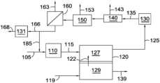
- FIG. 1shows an example of a configuration for molten carbonate fuel cells and associated reforming and separation stages.
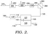
- FIG. 2shows another example of a configuration for molten carbonate fuel cells and associated reforming and separation stages.
- FIG. 3shows an example of a molten carbonate fuel cell.
- FIG. 4shows the relative operating voltage as a function of time for molten carbonate fuel cells operated under carbon capture conditions with varying levels of target electrolyte fill in the cathode.
- FIG. 5shows the cathode lithium content for cathodes from molten carbonate fuel cells operated with varying levels of CO 2 in the cathode input stream.
- FIG. 6shows the relative ohmic resistance for molten carbonate fuel cells operated under various conditions and with various target electrolyte fill levels in the cathode.
- an elevated amount of electrolyteis used to initially fill a molten carbonate fuel cell that is operated under carbon capture conditions.
- the increased initial electrolyte fill levelcan be achieved in part by adding additional electrolyte to the cathode collector prior to start of operation.
- the increased initial electrolyte fill levelcan provide improved fuel cell performance and lifetime when operating a molten carbonate fuel cell at high current density with a low-C 2 content cathode input stream and/or when operating a molten carbonate fuel cell at high CO 2 utilization. This is in contrast to fuel cell operation at conventional conditions, where an elevated initial electrolyte fill level leads to reduced operating voltage.
- the initial electrolyte fill levelcan be characterized in several ways. One option is to characterize a combined target electrolyte fill amount for the combined pore volume of the matrix and the cathode.
- a combined target electrolyte fill level or amountis defined herein as the amount of the combined matrix pore volume and cathode pore volume that would be occupied by the electrolyte if all of the initial electrolyte fill amount were in a molten state and located in the matrix or cathode. It is understood that the target electrolyte fill level is a characterization of the total electrolyte initially added to a molten carbonate fuel cell.
- the combined amount of matrix pore volume and cathode pore volume that will actually be occupied by electrolytewill be lower. This is due, for example, to the fact that not all of the electrolyte melts immediately when starting up a fuel cell, so a portion of the unmelted (solid) electrolyte will likely still be present in the cathode collector. As the fuel cell operates, additional electrolyte will melt, but the consumption of electrolyte by the cathode and/or other electrolyte losses will prevent the actual combined fill level from reaching the “target” combined fill level.
- a second optioncan be to separately characterize the target fill level for the matrix pore volume and the target fill level for the cathode pore volume. It is noted that the cathode pore volume is typically 1.5-2.0 times the matrix pore volume. Thus, when determining a combined target fill level based on the separate target fill levels for the matrix pore volume and the cathode pore volume, the combined target fill level corresponds to a weighted average. For example, if the cathode pore volume is 2.0 times the matrix pore volume, the combined target fill amount can be calculated as ( ⁇ matrix pore volume>+ ⁇ 2.0*cathode pore volume>)/3. Similarly, if the cathode pore volume is 1.5 times the matrix pore volume, the combined target fill amount can be calculated as ( ⁇ matrix pore volume>+ ⁇ 1.5*cathode pore volume>)/2.5.
- the amount of electrolyte used in a conventional molten carbonate fuel cellwas also selected based on a desire to maintain a high operating voltage.
- Conventional electrolyte loadings for molten carbonate fuel cellstypically correspond to a target fill level of greater than 90 vol % for the matrix (relative to a pore volume of the matrix) and roughly 50 vol % to 60 vol % for the cathode (relative to a pore volume of the cathode). For a fuel cell with a cathode pore volume that is 2.0 times the matrix volume, this corresponds to a combined target fill level of roughly 63 vol % to 73 vol % (determined as a weighted average).
- U.S. Pat. No. 7,939,219describes having an additional 10% of the target electrolyte volume present in a fuel cell in the form of an electrolyte that remains solid until later in the operation of the cell. Based on the conventional combined target fill levels described above, an additional 10% of the target electrolyte volume would, at most, correspond to an additional 7.6 vol %, resulting in a combined target fill level of 84 vol % or less.
- the electrolyte in a molten carbonate fuel cellstypically corresponds to a mixture of lithium carbonate with one or more other alkali metal carbonates.
- eutectic mixtures of carbonate saltsare convenient to use, as the composition of the electrolyte in solid form is the same as the composition that will melt into the fuel cell as electrolyte stored in the cathode collector is melted into a liquid.
- the combined target electrolyte fill levelcan be 70 vol % to 128 vol %, or 85 vol % to 128 vol %, or 90 vol % to 128 vol %, or 100 vol % to 128 vol %, or 70 vol % to 115 vol %, or 85 vol % to 115 vol %, or 90 vol % to 115 vol %, or 70 vol % to 100 vol %, or 85 vol % to 100 vol %, or 90 vol % to 100 vol %.
- This unexpected voltage increase when operating with an elevated combined target electrolyte fill levelcan be observed after operating the molten carbonate fuel cell at carbon capture conditions with high current density for a cumulative time of 50 hours or more, or 100 hours or more, or 200 hours or more.
- the unexpected increase in operating voltagecan be achieved by using a) a target matrix electrolyte fill level of 90 vol % to 100 vol % for the matrix pore volume and b) a target cathode electrolyte fill level of 65 vol % to 140 vol % of the cathode pore volume, or 65 vol % to 120 vol %, or 65 vol % to 100 vol %, or 75 vol % to 140 vol %, or 75 vol % to 120 vol %, or 75 vol % to 100 vol %, or 85 vol % to 140 vol %, or 85 vol % to 120 vol %, or 85 vol % to 100 vol %, or 95 vol % to 140 vol %, or 95 vol % to 120 vol %.
- Carbon capture conditionsrefer to conditions where a fuel cell is operated with a CO 2 content in the cathode input stream of 10 vol % or less and/or when operating a fuel cell at a CO 2 utilization of 90 vol % or more.
- the CO 2 utilizationcan be 70 vol % or more, or 75 vol % or more, or 80 vol % or more, such as up to 95 vol % or possibly still higher.
- Operating a fuel cell under carbon capture conditions with high current densityrefers to conditions where the fuel cell is operated to generate a current density of 120 mA/cm 2 or more while operating under carbon capture conditions, or 130 mA/cm 2 or more, or 140 mA/cm 2 or more, or 150 mA/cm 2 or more, such as up to 300 mA/cm 2 or possibly still higher.
- lithium in the fuel cellcauses lithium in the fuel cell to be depleted at an increased rate. Some of the lithium depletion is believed to be due to evaporation or other loss outside of the cell. It is believed that such losses can be accelerated by high space velocities, as may often be used under carbon capture conditions. Other lithium depletion is believed to be due to incorporation of lithium into the fuel cell cathode and/or the matrix. Such incorporation of lithium into structures within the fuel cell can be thermodynamically favored at sufficiently low concentrations of CO 2 .
- This electrolyte depletion under carbon capture conditionscan cause the electrolyte fill level in the fuel cell to be roughly 20 vol % to 30 vol % lower at end of run than would be expected under conventional operation.
- the increased depletion of lithiumresults in a loss of fuel cell operating voltage and lifetime.
- the electrolyte loss phenomenonreduces the ionic conductivity of the melt and the active area of the cathode, which can result in unfilled pores in the matrix network.
- higher ohmic resistance and gas crossoverhave been observed after extended testing of the fuel cell at carbon capture conditions. This leads to reduced fuel cell voltages even at modest current densities ( ⁇ 100 mA/cm 2 ). Additionally, if gas crossover is occurring in appreciable amounts, this can lead to rapid fuel cell voltage decay. Gas crossover leads to the direct combustion of fuel rather than the electrochemical oxidation and risks oxidation of the anode and the reforming catalyst stored in the anode current collector, impacting directly the stack temperature and the thermal profile.
- an electrolyte with an increased amount of lithiumcan also be beneficial when operating a fuel cell under carbon capture conditions.
- eutectic mixtures of carbonate electrolyteshave been convenient to use. Because the increase in electrolyte depletion is selective for lithium depletion, however, using an electrolyte containing a greater amount of lithium than a eutectic mixture can potentially be beneficial.
- the carbon capture conditionscan correspond to conditions where substantial transport of alternative ions occurs as charge carriers across the electrolyte.
- Hydroxide ionsare an example of an alternative ion that can be transported across the electrolyte if the concentration of CO 2 is sufficiently low in a localized region of the fuel cell.
- Conventional operating conditions for molten carbonate fuel cellstypically correspond to conditions where the amount of alternative ion transport is reduced, minimized, or non-existent.
- a portion of the charge transported across the electrolyte in the fuel cellcan be based on transport of ions other than carbonate ions.
- One difficulty in using MCFCs for elevated CO 2 captureis that the operation of the fuel cell can potentially be kinetically limited if one or more of the reactants required for fuel cell operation is present in low quantities.
- a cathode outlet concentration of 1.0 vol % or lessdoes not necessarily mean that the CO 2 is evenly distributed throughout the cathode. Instead, the concentration will typically vary within the cathode due to a variety of factors, such as the flow patterns in the anode and the cathode. The variations in CO 2 concentration can result in portions of the cathode where CO 2 concentrations substantially below 1.0 vol % are present.
- One of the advantages of transport of alternative ions across the electrolyteis that the fuel cell can continue to operate, even though a sufficient number of CO 2 molecules are not kinetically available. This can allow additional CO 2 to be transferred from cathode to anode even though the amount of CO 2 present in the cathode would conventionally be considered insufficient for normal fuel cell operation. This can allow the fuel cell to operate with a measured CO 2 utilization closer to 100%, while the calculated CO 2 utilization (based on current density) can be at least 3% greater than the measured CO 2 utilization, or at least 5% greater, or at least 10% greater, or at least 20% greater. It is noted that alternative ion transport can allow a fuel cell to operate with a current density that would correspond to more than 100% calculated CO 2 utilization.
- the amount of alternative ion transportcan be quantified based on the transference for a fuel cell.
- the transferenceis defined as the fraction of ions transported across the molten carbonate electrolyte that correspond to carbonate ions, as opposed to hydroxide ions and/or other ions.
- a convenient way to determine the transferencecan be based on comparing a) the measured change in CO 2 concentration at the cathode inlet versus the cathode outlet with b) the amount of carbonate ion transport required to achieve the current density being produced by the fuel cell. It is noted that this definition for the transference assumes that back-transport of CO 2 from the anode to the cathode is minimal. It is believed that such back-transport is minimal for the operating conditions described herein.
- the cathode input stream and/or cathode output streamcan be sampled, with the sample diverted to a gas chromatograph for determination of the CO 2 content.
- the average current density for the fuel cellcan be measured in any convenient manner.
- the transferencecan be relatively close to 1.0, such as 0.98 or more and/or such as having substantially no alternative ion transport.
- a transference of 0.98 or moremeans that 98% or more of the ionic charge transported across the electrolyte corresponds to carbonate ions. It is noted that hydroxide ions have a charge of ⁇ 1 while carbonate ions have a charge of ⁇ 2, so two hydroxide ions need to be transported across the electrolyte to result in the same charge transfer as transport of one carbonate ion.
- regionscontain additional CO 2 that would be desirable to transport across an electrolyte, such as for carbon capture.
- the CO 2 in such regionsis typically not transported across the electrolyte when operating under conventional conditions.
- the regions with sufficient CO 2can be used to transport additional CO 2 while the depleted regions can operate based on alternative ion transport. This can increase the practical limit for the amount of CO 2 captured from a cathode input stream.
- the electrolyte loading within a molten carbonate fuel cellcan be controlled based on the amount of electrolyte included in the fuel cell during initial formation of the fuel cell. For practical reasons, attempting to add electrolyte to a fuel cell after forming a fuel cell structure is not economically attractive. Instead, fuel cells are usually constructed used, for a desired lifetime, and then disassembled with recovery of any usable components for use in future fuel cell construction. As a result, the electrolyte fill level within a fuel cell can be characterized based on the amount of electrolyte included in the fuel cell when it is constructed relative to the available pore volume in the matrix and the cathode of the fuel cell.
- This electrolyte fill level at constructioncan be referred to as a target electrolyte fill level. It is noted that the target electrolyte fill level refers to electrolyte that is added to the fuel cell prior to initial operation. Thus, any electrolyte added after the beginning of fuel cell operation is be definition excluded from the target electrolyte fill level.
- the electrolyte included in a molten carbonate fuel cellis a solid at ambient conditions.
- the target fill level of the electrolytecan be included in the fuel cell as a solid.
- This solid electrolytemay be at least partially included in structures other than the matrix and the cathode.
- at least a portion of the solid electrolytecan be incorporated into the cathode collector of the fuel cell.
- the electrolytecan melt, which causes electrolyte to flow toward the matrix and cathode within the fuel cell.
- a cathode fill level of roughly 50 vol % to 60 vol % at the beginning of life with a completely filled matrix (greater than 90 vol % of matrix pore volume)is targeted.
- this conventional loadingcorresponds to a combined target fill level of roughly 76 vol % or less, depending on the relative pore volumes of the cathode and the matrix.
- gas crossoveris minimal and the conductivity of the membrane layer is maximized.
- higher cathode fill levelsare typically not used in order to avoid cathode flooding. This occurs when excess electrolyte exists in the cathode layer, increasing the gas phase mass transfer resistance through the porous electrode. Under conventional conditions, cathode flooding is known to be detrimental to fuel cell performance.
- the electrolyte fill level in a fuel cellcan be characterized based on a comparison of the volume of electrolyte (based on being a liquid at the operating temperature of the fuel cell) relative to the pore volume in the matrix and the cathode in the fuel cell.
- the volume of liquid electrolyte at the operating temperaturecan be calculated based on the corresponding volume (or weight) of solid electrolyte included in the fuel cell during formation of the fuel cell.
- both the matrix and the cathode in a fuel cellcorrespond to porous structures.
- the matrixcan correspond to a porous structure that is suitable for holding the molten carbonate electrolyte.
- a suitable matrix materialis a matrix composed of aluminum oxide and lithium aluminate.
- An example of a suitable cathode materialis nickel oxide.
- the pore volume of these structurescan be characterized using a convenient porosimetry method. In this discussion, the pore volume of a layer (matrix, cathode, anode) can be determined by mercury porosimetry, such as by ASTM D4284.
- the target electrolyte fill level within a fuel cellis selected in order to provide a balance between having sufficient electrolyte in the cathode to provide good electrical conductivity while also having sufficient void space in the cathode so that CO 2 and O 2 gas can enter the porous cathode for conversion into carbonate ions.
- thiscorresponds to having a combined target electrolyte fill level of 76 vol % or less, which corresponds to 50 vol % to 60 vol % of the available pore volume in the cathode, along with filling substantially all of the available pore volume in the electrolyte matrix (greater than 90 vol %).
- These fill levelscan be achieved by including sufficient amounts of solid electrolyte in the matrix, the cathode, and/or the cathode collector prior to starting operation of the fuel cell.
- any convenient type of electrolyte suitable for operation of a molten carbonate fuel cellcan be used.
- Many conventional MCFCsuse a eutectic carbonate mixture as the carbonate electrolyte, such as a eutectic mixture of 62 mol % lithium carbonate and 38 mol % potassium carbonate (62% Li 2 CO 3 /38% K 2 CO 3 ) or a eutectic mixture of 52 mol % lithium carbonate and 48 mol % sodium carbonate (52% Li 2 CO 3 /48% Na 2 CO 3 ).
- eutectic mixturesare also available, such as a eutectic mixture of 40 mol % lithium carbonate and 60 mol % potassium carbonate (40 mol % Li 2 CO 3 /60 mol % K 2 CO 3 ) or ternary eutectic Li/Na/K (44 mol % Li 2 CO 3 /30 mol % Na 2 CO 3 /26 mol % K 2 CO 3 ) or any binary eutectic Li/Na (52 mol % Li 2 CO 3 /48 mol % Na 2 CO 3 ) doped with K 2 CO 3 and/or Cs 2 CO 3 and/or Rb 2 CO 3 .
- a eutectic mixture of 40 mol % lithium carbonate and 60 mol % potassium carbonate40 mol % Li 2 CO 3 /60 mol % K 2 CO 3
- ternary eutectic Li/Na/K44 mol % Li 2 CO 3 /30 mol % Na 2 CO
- Still other eutectic mixturescan be based on combinations of three or more carbonates, including eutectic mixtures containing three or more alkali metal carbonates. Yet other mixtures can be based on combinations of three or more carbonates, so that the mixture differs from a eutectic mixture. Additionally or alternately, still other mixtures can include one or more lithium precursors different from lithium carbonate.
- the electrolytecan include a mixture of three or more of Li 2 CO 3 , Na 2 CO 3 , K 2 CO 3 , Rb 2 CO 3 , Cs 2 CO 3 , BaCO 3 , La 2 O 3 , Bi 2 O 3 , Bi 2 O 5 , Ta 2 O 5 , and mixtures thereof.
- 70 wt % or more, or 80 wt % or more, or 90 wt % or more, such as up to substantially all of the alkali metal carbonates in the electrolytecan correspond to a mixture of two or more of Li 2 CO 3 , Na 2 CO 3 , and K 2 CO 3 .
- the lithium precursor materialcan optionally but preferably be one or more of lithium hydroxide, lithium nitrate, lithium acetate, lithium oxalate and mixtures thereof.
- non-eutectic mixtures of carbonatescan be advantageous.
- the difference between the composition for a mixture of carbonates and a eutectic compositioncan be characterized based on the difference in the weight percentage of lithium carbonate in the mixture versus the weight percentage of lithium carbonate in the corresponding eutectic mixture.
- non-alkali metal carbonatesthat are present in an amount of 2 wt % or less are not considered.
- the mixturecan be characterized as having a lithium carbonate content that differs from the corresponding eutectic mixture by 28 wt %.
- non-eutectic mixturescan include various combinations of any of the carbonates and/or lithium precursor materials described herein.
- the target electrolyte fill levelcan be based on including a plurality of types of carbonate mixtures in the fuel cell.
- non-eutectic mixturesare known to melt more slowly under fuel cell operating conditions than eutectic mixtures. Therefore, one strategy can be to have a first portion of the electrolyte (located in the matrix and/or cathode) that corresponds to a eutectic mixture, while a second portion of the electrolyte (located in the cathode collector) that corresponds to a non-eutectic mixture with an increased amount of lithium relative to the eutectic mixture.
- the slower melting non-eutectic mixturewill have a higher lithium content than the initial electrolyte, and therefore can compensate for the selective loss of lithium during operation under carbon capture conditions.
- two non-eutectic mixturescan be used, with the second mixture being higher in lithium carbonate content than the first mixture.
- the amount of the first electrolyte mixturei.e., the electrolyte mixture lower in lithium carbonate content, such as a eutectic mixture
- the amount of the first electrolyte mixturecan correspond to 20 wt % to 80 wt % of the total amount of electrolyte in the initial electrolyte fill level, or 20 wt % to 50 wt %, or 55 wt % to 80 wt %.
- a fuel cellcan correspond to a single cell, with an anode and a cathode separated by an electrolyte.
- the anode and cathodecan receive input gas flows to facilitate the respective anode and cathode reactions for transporting charge across the electrolyte and generating electricity.
- a fuel cell stackcan represent a plurality of cells in an integrated unit. Although a fuel cell stack can include multiple fuel cells, the fuel cells can typically be connected in parallel and can function (approximately) as if they collectively represented a single fuel cell of a larger size.
- the fuel stackcan include flow channels for dividing the input flow between each of the cells in the stack and flow channels for combining the output flows from the individual cells.
- a fuel cell arraycan be used to refer to a plurality of fuel cells (such as a plurality of fuel cell stacks) that are arranged in series, in parallel, or in any other convenient manner (e.g., in a combination of series and parallel).
- a fuel cell arraycan include one or more stages of fuel cells and/or fuel cell stacks, where the anode/cathode output from a first stage may serve as the anode/cathode input for a second stage.
- the anodes in a fuel cell arraydo not have to be connected in the same way as the cathodes in the array.
- the input to the first anode stage of a fuel cell arraymay be referred to as the anode input for the array, and the input to the first cathode stage of the fuel cell array may be referred to as the cathode input to the array.
- the output from the final anode/cathode stagemay be referred to as the anode/cathode output from the array.
- a fuel cellherein typically denotes a “fuel cell stack” composed of individual fuel cells, and more generally refers to use of one or more fuel cell stacks in fluid communication.
- Individual fuel cell elementsplates
- This fuel cell stackcan typically take a feed stream and distribute reactants among all of the individual fuel cell elements and can then collect the products from each of these elements.
- the fuel cell stack in operationcan be taken as a whole even though composed of many (often tens or hundreds) of individual fuel cell elements.
- These individual fuel cell elementscan typically have similar voltages (as the reactant and product concentrations are similar), and the total power output can result from the summation of all of the electrical currents in all of the cell elements, when the elements are electrically connected in series.
- Stackscan also be arranged in a series arrangement to produce high voltages. A parallel arrangement can boost the current. If a sufficiently large volume fuel cell stack is available to process a given exhaust flow, the systems and methods described herein can be used with a single molten carbonate fuel cell stack. In other aspects of the invention, a plurality of fuel cell stacks may be desirable or needed for a variety of reasons.
- fuel cellshould be understood to also refer to and/or is defined as including a reference to a fuel cell stack composed of set of one or more individual fuel cell elements for which there is a single input and output, as that is the manner in which fuel cells are typically employed in practice.
- fuel cellsplural
- fuel cellsshould be understood to also refer to and/or is defined as including a plurality of separate fuel cell stacks.
- all references within this documentunless specifically noted, can refer interchangeably to the operation of a fuel cell stack as a “fuel cell”.
- the volume of exhaust generated by a commercial scale combustion generatormay be too large for processing by a fuel cell (i.e., a single stack) of conventional size.
- a fuel celli.e., a single stack
- a plurality of fuel cellsi.e., two or more separate fuel cells or fuel cell stacks
- each fuel cellcan process (roughly) an equal portion of the combustion exhaust.
- each fuel cellcan typically be operated in a generally similar manner, given its (roughly) equal portion of the combustion exhaust.
- FIG. 3shows a general example of a molten carbonate fuel cell.
- the fuel cell represented in FIG. 3corresponds to a fuel cell that is part of a fuel cell stack.
- the fuel cellincludes separator plates 310 and 311 .
- the fuel cellincludes an anode 330 and a cathode 350 that are separated by an electrolyte matrix 340 that contains an electrolyte 342 .
- Anode collector 320provides electrical contact between anode 330 and the other anodes in the stack, while cathode collector 360 provides similar electrical contact between cathode 350 and the other cathodes in the fuel cell stack. Additionally, anode collector 320 allows for introduction and exhaust of gases from anode 330 , while cathode collector 360 allows for introduction and exhaust of gases from cathode 350 .
- solid electrolytecan be incorporated, as possible, within the matrix, the cathode, and the cathode collector. Because the electrolyte is solid during initial fill, it can be difficult to achieve a desired loading by only adding the solid electrolyte to the matrix and the cathode. In order to achieve a desired loading, solid electrolyte can also be added to the cathode collector. The electrolyte added to the cathode collector can melt as the fuel cell is operated, which then allows the electrolyte to flow into the cathode. Similarly, as electrolyte in the cathode is melted, a portion of the molten electrolyte can be passed from the cathode to the matrix to fill additional portions of the matrix volume.
- thiscan correspond to a target loading of 66 grams or less of electrolyte per 250 cm 2 of fuel cell area.
- the target loadingcan be 40 grams to 66 grams of electrolyte per 250 cm 2 of fuel cell area, or 45 grams to 66 grams, or 50 grams to 66 grams.
- a portion of the target electrolyte loadingcan be included in the cathode collector.
- the portion of the target electrolyte loading included in the cathode collectorcan correspond to 38 grams of electrolyte or less per 250 cm 2 of fuel cell area.
- the portion of the target electrolyte loading included in the cathode collectorcan correspond to 18 grams to 38 grams of electrolyte per 250 cm 2 of fuel cell area, or 24 grams to 38 grams, or 28 grams to 38 grams.
- CO 2is passed into the cathode collector 360 along with O 2 .
- the CO 2 and O 2diffuse into the porous cathode 350 and travel to a cathode interface region near the boundary of cathode 350 and electrolyte matrix 340 .
- a portion of electrolyte 342can be present in the pores of cathode 350 .
- the CO 2 and O 2can be converted near/in the cathode interface region to carbonate ion (CO 3 2 ⁇ ), which can then be transported across electrolyte 342 (and therefore across electrolyte matrix 340 ) to facilitate generation of electrical current.
- a portion of the O 2can be converted to an alternative ion, such as a hydroxide ion or a peroxide ion, for transport in electrolyte 342 .
- an alternative ionsuch as a hydroxide ion or a peroxide ion
- the carbonate ioncan reach an anode interface region near the boundary of electrolyte matrix 340 and anode 330 .
- the carbonate ioncan be converted back to CO 2 and H 2 O in the presence of H 2 , releasing electrons that are used to form the current generated by the fuel cell.
- the H 2 and/or a hydrocarbon suitable for forming H 2are introduced into anode 330 via anode collector 320 .
- the flow direction within the anode of a molten carbonate fuel cellcan have any convenient orientation relative to the flow direction within a cathode.
- One optioncan be to use a cross-flow configuration, so that the flow direction within the anode is roughly at a 90° angle relative to the flow direction within the cathode.
- This type of flow configurationcan have practical benefits, as using a cross-flow configuration can allow the manifolds and/or piping for the anode inlets/outlets to be located on different sides of a fuel cell stack from the manifolds and/or piping for the cathode inlets/outlets.
- suitable conditions for the anodecan include providing the anode with H 2 , a reformable fuel, or a combination thereof; and operating with any convenient fuel utilization that generates a desired current density, including fuel utilizations ranging from 20% to 80%. In some aspects this can correspond to a traditional fuel utilization amount, such as a fuel utilization of 60% or more, or 70% or more, such as up to 85% or possibly still higher.
- thiscan correspond to a fuel utilization selected to provide an anode output stream with an elevated content of H 2 and/or an elevated combined content of H 2 and CO (i.e., syngas), such as a fuel utilization of 55% or less, or 50% or less, or 40% or less, such as down to 20% or possibly still lower.
- the H 2 content in the anode output stream and/or the combined content of H 2 and CO in the anode output streamcan be sufficient to allow generation of a desired current density.
- the H 2 content in the anode output streamcan be 3.0 vol % or more, or 5.0 vol % or more, or 8.0 vol % or more, such as up to 15 vol % or possibly still higher.
- the combined amount of H 2 and CO in the anode output streamcan be 4.0 vol % or more, or 6.0 vol % or more, or 10 vol % or more, such as up to 20 vol % or possibly still higher.
- the H 2 content in the anode output streamcan be in a higher range, such as an H 2 content of 10 vol % to 25 vol %.
- the syngas content of the anode output streamcan be correspondingly higher, such as a combined H 2 and CO content of 15 vol % to 35 vol %.
- the anodecan be operated to increase the amount of electrical energy generated, to increase the amount of chemical energy generated, (i.e., H 2 generated by reforming that is available in the anode output stream), or operated using any other convenient strategy that is compatible with operating the fuel cell to cause alternative ion transport.
- chemical energy generatedi.e., H 2 generated by reforming that is available in the anode output stream
- the anode input stream for a MCFCcan include hydrogen, a hydrocarbon such as methane, a hydrocarbon or hydrocarbon-like compound that may contain heteroatoms different from C and H, or a combination thereof.
- the source of the hydrogen/hydrocarbon/hydrocarbon-like compoundscan be referred to as a fuel source.
- most of the methane (or other hydrocarbon, hydrocarbon, or hydrocarbon-like compound) fed to the anodecan typically be fresh methane.
- a fresh fuelsuch as fresh methane refers to a fuel that is not recycled from another fuel cell process.
- methane recycled from the anode outlet stream back to the anode inletmay not be considered “fresh” methane, and can instead be described as reclaimed methane.
- the fuel source usedcan be shared with other components, such as a turbine that uses a portion of the fuel source to provide a CO 2 -containing stream for the cathode input.
- the fuel source inputcan include water in a proportion to the fuel appropriate for reforming the hydrocarbon (or hydrocarbon-like) compound in the reforming section that generates hydrogen.
- the molar ratio of water to fuelcan be from about one to one to about ten to one, such as at least about two to one. A ratio of four to one or greater is typical for external reforming, but lower values can be typical for internal reforming.
- the fuel sourcecan also optionally contain components incidental to the fuel source (e.g., a natural gas feed can contain some content of CO 2 as an additional component).
- a natural gas feedcan contain CO 2 , N 2 , and/or other inert (noble) gases as additional components.
- the fuel sourcemay also contain CO, such as CO from a recycled portion of the anode exhaust.
- An additional or alternate potential source for CO in the fuel into a fuel cell assemblycan be CO generated by steam reforming of a hydrocarbon fuel performed on the fuel prior to entering the fuel cell assembly.
- a variety of types of fuel streamsmay be suitable for use as an anode input stream for the anode of a molten carbonate fuel cell.
- Some fuel streamscan correspond to streams containing hydrocarbons and/or hydrocarbon-like compounds that may also include heteroatoms different from C and H.
- a reference to a fuel stream containing hydrocarbons for an MCFC anodeis defined to include fuel streams containing such hydrocarbon-like compounds.
- hydrocarbon (including hydrocarbon-like) fuel streamsinclude natural gas, streams containing C 1 -C 4 carbon compounds (such as methane or ethane), and streams containing heavier C 5+ hydrocarbons (including hydrocarbon-like compounds), as well as combinations thereof.
- Still other additional or alternate examples of potential fuel streams for use in an anode inputcan include biogas-type streams, such as methane produced from natural (biological) decomposition of organic material.
- a molten carbonate fuel cellcan be used to process an input fuel stream, such as a natural gas and/or hydrocarbon stream, with a low energy content due to the presence of diluent compounds.
- some sources of methane and/or natural gasare sources that can include substantial amounts of either CO 2 or other inert molecules, such as nitrogen, argon, or helium. Due to the presence of elevated amounts of CO 2 and/or inert components, the energy content of a fuel stream based on the source can be reduced.
- a low energy content fuel for a combustion reaction(such as for powering a combustion-powered turbine) can pose difficulties.
- a molten carbonate fuel cellcan generate power based on a low energy content fuel source with a reduced or minimal impact on the efficiency of the fuel cell.
- the presence of additional gas volumecan require additional heat for raising the temperature of the fuel to the temperature for reforming and/or the anode reaction.
- the presence of additional CO 2can have an impact on the relative amounts of H 2 and CO present in the anode output.
- the inert compoundsotherwise can have only a minimal direct impact on the reforming and anode reactions.
- the amount of CO 2 and/or inert compounds in a fuel stream for a molten carbonate fuel cell, when present,can be at least about 1 vol %, such as at least about 2 vol %, or at least about 5 vol %, or at least about 10 vol %, or at least about 15 vol %, or at least about 20 vol %, or at least about 25 vol %, or at least about 30 vol %, or at least about 35 vol %, or at least about 40 vol %, or at least about 45 vol %, or at least about 50 vol %, or at least about 75 vol %.
- the amount of CO 2 and/or inert compounds in a fuel stream for a molten carbonate fuel cellcan be about 90 vol % or less, such as about 75 vol % or less, or about 60 vol % or less, or about 50 vol % or less, or about 40 vol % or less, or about 35 vol % or less.
- anode input streamcan correspond to refinery and/or other industrial process output streams.
- cokingis a common process in many refineries for converting heavier compounds to lower boiling ranges. Coking typically produces an off-gas containing a variety of compounds that are gases at room temperature, including CO and various C 1 -C 4 hydrocarbons. This off-gas can be used as at least a portion of an anode input stream.
- Other refinery off-gas streamscan additionally or alternately be suitable for inclusion in an anode input stream, such as light ends (C 1 -C 4 ) generated during cracking or other refinery processes.
- Still other suitable refinery streamscan additionally or alternately include refinery streams containing CO or CO 2 that also contain H 2 and/or reformable fuel compounds.
- an anode inputcan additionally or alternately include streams with increased water content.
- an ethanol output stream from an ethanol plantcan include a substantial portion of H 2 O prior to final distillation.
- H 2 Ocan typically cause only minimal impact on the operation of a fuel cell.
- a fermentation mixture of alcohol (or other fermentation product) and watercan be used as at least a portion of an anode input stream.
- Biogasor digester gas
- Biogasmay primarily comprise methane and CO 2 and is typically produced by the breakdown or digestion of organic matter. Anaerobic bacteria may be used to digest the organic matter and produce the biogas. Impurities, such as sulfur-containing compounds, may be removed from the biogas prior to use as an anode input.
- the output stream from an MCFC anodecan include H 2 O, CO 2 , CO, and H 2 .
- the anode output streamcould also have unreacted fuel (such as H 2 or CH 4 ) or inert compounds in the feed as additional output components.
- this output streamcan be used as a fuel source to provide heat for a reforming reaction or as a combustion fuel for heating the cell.
- one or more separationscan be performed on the anode output stream to separate the CO 2 from the components with potential value as inputs to another process, such as H 2 or CO.
- the H 2 and/or COcan be used as a syngas for chemical synthesis, as a source of hydrogen for chemical reaction, and/or as a fuel with reduced greenhouse gas emissions.
- the anode exhaustcan be subjected to a variety of gas processing options, including water-gas shift and separation of the components from each other. Two general anode processing schemes are shown in FIGS. 1 and 2 .
- FIG. 1schematically shows an example of a reaction system for operating a fuel cell array of molten carbonate fuel cells in conjunction with a chemical synthesis process.
- a fuel stream 105is provided to a reforming stage (or stages) 110 associated with the anode 127 of a fuel cell 120 , such as a fuel cell that is part of a fuel cell stack in a fuel cell array.
- the reforming stage 110 associated with fuel cell 120can be internal to a fuel cell assembly.
- an external reforming stage(not shown) can also be used to reform a portion of the reformable fuel in an input stream prior to passing the input stream into a fuel cell assembly.
- Fuel stream 105can preferably include a reformable fuel, such as methane, other hydrocarbons, and/or other hydrocarbon-like compounds such as organic compounds containing carbon-hydrogen bonds. Fuel stream 105 can also optionally contain H 2 and/or CO, such as H 2 and/or CO provided by optional anode recycle stream 185 . It is noted that anode recycle stream 185 is optional, and that in many aspects no recycle stream is provided from the anode exhaust 125 back to anode 127 , either directly or indirectly via combination with fuel stream 105 or reformed fuel stream 115 . After reforming, the reformed fuel stream 115 can be passed into anode 127 of fuel cell 120 .
- a reformable fuelsuch as methane, other hydrocarbons, and/or other hydrocarbon-like compounds such as organic compounds containing carbon-hydrogen bonds.
- Fuel stream 105can also optionally contain H 2 and/or CO, such as H 2 and/or CO provided by optional anode recycle stream 185 . It is noted that ano
- a CO 2 and O 2 -containing stream 119can also be passed into cathode 129 .
- a flow of carbonate ions 122 , CO 3 2 ⁇ , from the cathode portion 129 of the fuel cellcan provide the remaining reactant needed for the anode fuel cell reactions.
- the resulting anode exhaust 125can include H 2 O, CO 2 , one or more components corresponding to incompletely reacted fuel (H 2 , CO, CH 4 , or other components corresponding to a reformable fuel), and optionally one or more additional nonreactive components, such as N 2 and/or other contaminants that are part of fuel stream 105 .
- the anode exhaust 125can then be passed into one or more separation stages.
- a CO 2 removal stage 140can correspond to a cryogenic CO 2 removal system, an amine wash stage for removal of acid gases such as CO 2 , or another suitable type of CO 2 separation stage for separating a CO 2 output stream 143 from the anode exhaust.
- the anode exhaustcan first be passed through a water gas shift reactor 130 to convert any CO present in the anode exhaust (along with some H 2 O) into CO 2 and H 2 in an optionally water gas shifted anode exhaust 135 .
- a water condensation or removal stage 150may be desirable to remove a water output stream 153 from the anode exhaust. Though shown in FIG.
- Stream 166could additionally or alternately be shifted in a second water-gas shift reactor 131 to adjust the H 2 , CO, and CO 2 content to a different ratio, producing an output stream 168 for further use in a chemical synthesis process.
- FIG. 1After the CO 2 separation stage 140 , it may optionally be located before the CO 2 separation stage 140 instead.
- an optional membrane separation stage 160 for separation of H 2can be used to generate a high purity permeate stream 163 of H 2 .
- the resulting retentate stream 166can then be used as an input to a chemical synthesis process.
- Stream 166could additionally or alternately be shifted in a second water-gas shift reactor 131 to adjust the H 2 , CO, and CO 2 content to a different ratio, producing an output stream 168 for further use in a chemical synthesis process.
- FIG. 1after the CO 2 separation stage 140 , it may optionally be located before the CO 2 separation stage 140 instead.
- an optional membrane separation stage 160 for separation of H 2can be used
- anode recycle stream 185is shown as being withdrawn from the retentate stream 166 , but the anode recycle stream 185 could additionally or alternately be withdrawn from other convenient locations in or between the various separation stages.
- the separation stages and shift reactor(s)could additionally or alternately be configured in different orders, and/or in a parallel configuration.
- a stream with a reduced content of CO 2 139can be generated as an output from cathode 129 .
- various stages of compression and heat addition/removalthat might be useful in the process, as well as steam addition or removal, are not shown.
- FIG. 2shows an example of an alternative order for performing separations on an anode exhaust.
- anode exhaust 125can be initially passed into separation stage 260 for removing a portion 263 of the hydrogen content from the anode exhaust 125 .
- Thiscan allow, for example, reduction of the H 2 content of the anode exhaust to provide a retentate 266 with a ratio of H 2 to CO closer to 2:1.
- the ratio of H 2 to COcan then be further adjusted to achieve a desired value in a water gas shift stage 230 .
- the water gas shifted output 235can then pass through CO 2 separation stage 240 and water removal stage 250 to produce an output stream 275 suitable for use as an input to a desired chemical synthesis process.
- output stream 275could be exposed to an additional water gas shift stage (not shown).
- a portion of output stream 275can optionally be recycled (not shown) to the anode input.
- still other combinations and sequencing of separation stagescan be used to generate a stream based on the anode output that has a desired composition. For the sake of simplicity, various stages of compression and heat addition/removal that might be useful in the process, as well as steam addition or removal, are not shown.
- suitable conditions for the cathodecan include providing the cathode with cathode input flow that includes CO 2 and O 2 .
- the cathode input flowcan further include a sufficient amount of water.
- the CO 2 concentration in the cathode input flowcan be 10 vol % or less, or 8.0 vol % or less, or 6.0 vol % or less, or 4.0 vol % or less, such as down to 1.5 vol % or possibly still lower. Additionally or alternately, the cathode can be operated at a CO 2 utilization of 60% or more, or 70% or more, or 80% or more, such as up to 95% or possibly still higher. It is noted that if the CO 2 utilization is less than 80%, then the CO 2 concentration in the cathode input flow can be 10 vol % or less. In some aspects, the O 2 concentration in the cathode input stream can correspond to an oxygen content of 4.0 vol % to 15 vol %, or 6.0 vol % to 10 vol %.
- the carbon capture conditionscorrespond to conditions where alternative ion transport occurs
- a sufficient amount of watershould also be present for alternative ion transport to occur. This can correspond to having 1.0 vol % or more of water present in the cathode input flow, or 2.0 vol % or more. It is noted that because air is commonly used as an O 2 source, and since H 2 O is one of the products generated during combustion (a common source of CO 2 ), a sufficient amount of water is typically available within the cathode.
- a molten carbonate fuel cellcan be operated based on drawing a desired load while consuming some portion of the fuel in the fuel stream delivered to the anode.
- the voltage of the fuel cellcan then be determined by the load, fuel input to the anode, air and CO 2 provided to the cathode, and the internal resistances of the fuel cell.
- the CO 2 to the cathodecan be conventionally provided in part by using the anode exhaust as at least a part of the cathode input stream.
- the present inventioncan use separate/different sources for the anode input and cathode input.
- combustion sourcesinclude, but are not limited to, sources based on combustion of natural gas, combustion of coal, and/or combustion of other hydrocarbon-type fuels (including biologically derived fuels). Additional or alternate sources can include other types of boilers, fired heaters, furnaces, and/or other types of devices that burn carbon-containing fuels in order to heat another substance (such as water or air).
- Other potential sources for a cathode input streamcan additionally or alternately include sources of bio-produced CO 2 .
- Thiscan include, for example, CO 2 generated during processing of bio-derived compounds, such as CO 2 generated during ethanol production.
- An additional or alternate examplecan include CO 2 generated by combustion of a bio-produced fuel, such as combustion of lignocellulose.
- Still other additional or alternate potential CO 2 sourcescan correspond to output or exhaust streams from various industrial processes, such as CO 2 -containing streams generated by plants for manufacture of steel, cement, and/or paper.
- CO 2 -containing streams from a fuel cellcan correspond to a cathode output stream from a different fuel cell, an anode output stream from a different fuel cell, a recycle stream from the cathode output to the cathode input of a fuel cell, and/or a recycle stream from an anode output to a cathode input of a fuel cell.
- an MCFC operated in standalone mode under conventional conditionscan generate a cathode exhaust with a CO 2 concentration of at least about 5 vol %.
- Such a CO 2 -containing cathode exhaustcould be used as a cathode input for an MCFC operated according to an aspect of the invention. More generally, other types of fuel cells that generate a CO 2 output from the cathode exhaust can additionally or alternately be used, as well as other types of CO 2 -containing streams not generated by a “combustion” reaction and/or by a combustion-powered generator. Optionally but preferably, a CO 2 -containing stream from another fuel cell can be from another molten carbonate fuel cell.
- the output from the cathode for a first molten carbonate fuel cellcan be used as the input to the cathode for a second molten carbonate fuel cell.
- a cathode input streamcan include O 2 to provide the components necessary for the cathode reaction.
- Some cathode input streamscan be based on having air as a component.
- a combustion exhaust streamcan be formed by combusting a hydrocarbon fuel in the presence of air.
- Such a combustion exhaust stream, or another type of cathode input stream having an oxygen content based on inclusion of aircan have an oxygen content of about 20 vol % or less, such as about 15 vol % or less, or about 10 vol % or less.
- the oxygen content of the cathode input streamcan be at least about 4 vol %, such as at least about 6 vol %, or at least about 8 vol %.
- a cathode input streamcan have a suitable content of oxygen for performing the cathode reaction. In some aspects, this can correspond to an oxygen content of about 5 vol % to about 15 vol %, such as from about 7 vol % to about 9 vol %.
- the combined amount of CO 2 and O 2can correspond to less than about 21 vol % of the input stream, such as less than about 15 vol % of the stream or less than about 10 vol % of the stream.
- An air stream containing oxygencan be combined with a CO 2 source that has low oxygen content.
- the exhaust stream generated by burning coalmay include a low oxygen content that can be mixed with air to form a cathode inlet stream.
- a cathode input streamcan also be composed of inert/nonreactive species such as N 2 , H 2 O, and other typical oxidant (air) components.
- inert/nonreactive speciessuch as N 2 , H 2 O, and other typical oxidant (air) components.
- the exhaust gascan include typical components of air such as N 2 , H 2 O, and other compounds in minor amounts that are present in air.
- additional species present after combustion based on the fuel sourcemay include one or more of H 2 O, oxides of nitrogen (NO x ) and/or sulfur (SO x ), and other compounds either present in the fuel and/or that are partial or complete combustion products of compounds present in the fuel, such as CO. These species may be present in amounts that do not poison the cathode catalyst surfaces though they may reduce the overall cathode activity. Such reductions in performance may be acceptable, or species that interact with the cathode catalyst may be reduced to acceptable levels by known pollutant removal technologies.
- the amount of O 2 present in a cathode input streamcan advantageously be sufficient to provide the oxygen needed for the cathode reaction in the fuel cell.
- the volume percentage of O 2can advantageously be at least 0.5 times the amount of CO 2 in the exhaust.
- additional aircan be added to the cathode input to provide sufficient oxidant for the cathode reaction.
- the amount of N 2 in the cathode exhaustcan be at least about 78 vol %, e.g., at least about 88 vol %, and/or about 95 vol % or less.
- the cathode input streamcan additionally or alternately contain compounds that are generally viewed as contaminants, such as H 2 S or NH 3 .
- the cathode input streamcan be cleaned to reduce or minimize the content of such contaminants.
- a suitable temperature for operation of an MCFCcan be between about 450° C. and about 750° C., such as at least about 500° C., e.g., with an inlet temperature of about 550° C. and an outlet temperature of about 625° C.
- heatcan be added to or removed from the cathode input stream, if desired, e.g., to provide heat for other processes, such as reforming the fuel input for the anode.
- the source for the cathode input streamis a combustion exhaust stream
- the combustion exhaust streammay have a temperature greater than a desired temperature for the cathode inlet. In such an aspect, heat can be removed from the combustion exhaust prior to use as the cathode input stream.
- the combustion exhaustcould be at very low temperature, for example after a wet gas scrubber on a coal-fired boiler, in which case the combustion exhaust can be below about 100° C.
- the combustion exhaustcould be from the exhaust of a gas turbine operated in combined cycle mode, in which the gas can be cooled by raising steam to run a steam turbine for additional power generation. In this case, the gas can be below about 50° C. Heat can be added to a combustion exhaust that is cooler than desired.
- the anode of the fuel cellwhen operating a MCFC to cause alternative ion transport, can be operated at a traditional fuel utilization value of roughly 60% to 80%.
- operating the anode of the fuel cell at a relatively high fuel utilizationcan be beneficial for improving electrical efficiency (i.e., electrical energy generated per unit of chemical energy consumed by the fuel cell).
- Thiscan be beneficial, for example, if it is desirable to consume excess heat generated in the fuel cell (or fuel cell stack) by performing additional reforming and/or performing another endothermic reaction.
- a molten carbonate fuel cellcan be operated to provide increased production of syngas and/or hydrogen.
- the heat required for performing the endothermic reforming reactioncan be provided by the exothermic electrochemical reaction in the anode for electricity generation.
- this excess heatcan be used in situ as a heat source for reforming and/or another endothermic reaction. This can result in more efficient use of the heat energy and/or a reduced need for additional external or internal heat exchange. This efficient production and use of heat energy, essentially in-situ, can reduce system complexity and components while maintaining advantageous operating conditions.
- the amount of reforming or other endothermic reactioncan be selected to have an endothermic heat requirement comparable to, or even greater than, the amount of excess heat generated by the exothermic reaction(s) rather than significantly less than the heat requirement typically described in the prior art.
- the fuel cellcan be operated so that the temperature differential between the anode inlet and the anode outlet can be negative rather than positive.
- a sufficient amount of reforming and/or other endothermic reactioncan be performed to cause the output stream from the anode outlet to be cooler than the anode inlet temperature.
- additional fuelcan be supplied to a heater for the fuel cell and/or an internal reforming stage (or other internal endothermic reaction stage) so that the temperature differential between the anode input and the anode output can be smaller than the expected difference based on the relative demand of the endothermic reaction(s) and the combined exothermic heat generation of the cathode combustion reaction and the anode reaction for generating electrical power.
- reformingis used as the endothermic reaction
- operating a fuel cell to reform excess fuelcan allow for production of increased synthesis gas and/or increased hydrogen relative to conventional fuel cell operation while minimizing the system complexity for heat exchange and reforming.
- the additional synthesis gas and/or additional hydrogencan then be used in a variety of applications, including chemical synthesis processes and/or collection/repurposing of hydrogen for use as a “clean” fuel.
- the amount of heat generated per mole of hydrogen oxidized by the exothermic reaction at the anodecan be substantially larger than the amount of heat consumed per mole of hydrogen generated by the reforming reaction.
- the net reaction for hydrogen in a molten carbonate fuel cell(H 2 +1 ⁇ 2O 2 ⁇ H 2 O) can have an enthalpy of reaction of about ⁇ 285 kJ/mol of hydrogen molecules. At least a portion of this energy can be converted to electrical energy within the fuel cell. However, the difference (approximately) between the enthalpy of reaction and the electrical energy produced by the fuel cell can become heat within the fuel cell.
- This quantity of energycan alternatively be expressed as the current density (current per unit area) for the cell multiplied by the difference between the theoretical maximum voltage of the fuel cell and the actual voltage, or ⁇ current density>*(Vmax ⁇ Vact).
- This quantity of energyis defined as the “waste heat” for a fuel cell.
- the enthalpy of reforming for methane(CH 4 +2H 2 O ⁇ 4H 2 +CO 2 ) can be about 250 kJ/mol of methane, or about 62 kJ/mol of hydrogen molecules. From a heat balance standpoint, each hydrogen molecule electrochemically oxidized can generate sufficient heat to generate more than one hydrogen molecule by reforming.
- this excess heatcan result in a substantial temperature difference from anode inlet to anode outlet.
- the excess heatcan be consumed by performing a matching amount of the reforming reaction.
- the excess heat generated in the anodecan be supplemented with the excess heat generated by the combustion reaction in the fuel cell. More generally, the excess heat can be consumed by performing an endothermic reaction in the fuel cell anode and/or in an endothermic reaction stage heat integrated with the fuel cell.
- the amount of reforming and/or other endothermic reactioncan be selected relative to the amount of hydrogen reacted in the anode in order to achieve a desired thermal ratio for the fuel cell.
- the “thermal ratio”is defined as the heat produced by exothermic reactions in a fuel cell assembly (including exothermic reactions in both the anode and cathode) divided by the endothermic heat demand of reforming reactions occurring within the fuel cell assembly.
- the thermal ratio (TH)Q EX /Q EN , where Q EX is the sum of heat produced by exothermic reactions and Q EN is the sum of heat consumed by the endothermic reactions occurring within the fuel cell.
- the heat produced by the exothermic reactionscan correspond to any heat due to reforming reactions, water gas shift reactions, combustion reactions (i.e., oxidation of fuel compounds) in the cathode, and/or the electrochemical reactions in the cell.
- the heat generated by the electrochemical reactionscan be calculated based on the ideal electrochemical potential of the fuel cell reaction across the electrolyte minus the actual output voltage of the fuel cell.
- the ideal electrochemical potential of the reaction in a MCFCis believed to be about 1.04 V based on the net reaction that occurs in the cell.
- the cellcan typically have an output voltage less than 1.04 V due to various losses.
- a common output/operating voltagecan be about 0.7 V.
- the heat generatedcan be equal to the electrochemical potential of the cell (i.e. ⁇ 1.04V) minus the operating voltage.
- the heat produced by the electrochemical reactions in the cellcan be ⁇ 0.34 V when the output voltage of ⁇ 0.7V is attained in the fuel cell.
- the electrochemical reactionswould produce ⁇ 0.7 V of electricity and ⁇ 0.34 V of heat energy.
- the ⁇ 0.7 V of electrical energyis not included as part of Q EX . In other words, heat energy is not electrical energy.
- a thermal ratiocan be determined for any convenient fuel cell structure, such as a fuel cell stack, an individual fuel cell within a fuel cell stack, a fuel cell stack with an integrated reforming stage, a fuel cell stack with an integrated endothermic reaction stage, or a combination thereof.
- the thermal ratiomay also be calculated for different units within a fuel cell stack, such as an assembly of fuel cells or fuel cell stacks.
- the thermal ratiomay be calculated for a fuel cell (or a plurality of fuel cells) within a fuel cell stack along with integrated reforming stages and/or integrated endothermic reaction stage elements in sufficiently close proximity to the fuel cell(s) to be integrated from a heat integration standpoint.
- a characteristic width in a fuel cell stackcan be the height of an individual fuel cell stack element. It is noted that the separate reforming stage and/or a separate endothermic reaction stage could have a different height in the stack than a fuel cell. In such a scenario, the height of a fuel cell element can be used as the characteristic height.
- an integrated endothermic reaction stagecan be defined as a stage heat integrated with one or more fuel cells, so that the integrated endothermic reaction stage can use the heat from the fuel cells as a heat source for reforming. Such an integrated endothermic reaction stage can be defined as being positioned less than 10 times the height of a stack element from fuel cells providing heat to the integrated stage.
- an integrated endothermic reaction stage(such as a reforming stage) can be positioned less than 10 times the height of a stack element from any fuel cells that are heat integrated, or less than 8 times the height of a stack element, or less than 5 times the height of a stack element, or less than 3 times the height of a stack element.
- an integrated reforming stage and/or integrated endothermic reaction stage that represents an adjacent stack element to a fuel cell elementis defined as being about one stack element height or less away from the adjacent fuel cell element.
- a thermal ratio of about 1.3 or less, or about 1.15 or less, or about 1.0 or less, or about 0.95 or less, or about 0.90 or less, or about 0.85 or less, or about 0.80 or less, or about 0.75 of less,can be lower than the thermal ratio typically sought in use of MCFC fuel cells.
- the thermal ratiocan be reduced to increase and/or optimize syngas generation, hydrogen generation, generation of another product via an endothermic reaction, or a combination thereof.
- the operation of the fuel cellscan be characterized based on a thermal ratio.
- a molten carbonate fuel cellcan be operated to have a thermal ratio of about 1.5 or less, for example about 1.3 or less, or about 1.15 or less, or about 1.0 or less, or about 0.95 or less, or about 0.90 or less, or about 0.85 or less, or about 0.80 or less, or about 0.75 or less.
- the thermal ratiocan be at least about 0.25, or at least about 0.35, or at least about 0.45, or at least about 0.50.
- the fuel cellcan be operated to have a temperature rise between anode input and anode output of about 40° C. or less, such as about 20° C. or less, or about 10° C. or less. Still further additionally or alternately, the fuel cell can be operated to have an anode outlet temperature that is from about 10° C. lower to about 10° C. higher than the temperature of the anode inlet. Yet further additionally or alternately, the fuel cell can be operated to have an anode inlet temperature greater than the anode outlet temperature, such as at least about 5° C. greater, or at least about 10° C. greater, or at least about 20° C. greater, or at least about 25° C. greater.
- the fuel cellcan be operated to have an anode inlet temperature greater than the anode outlet temperature by about 100° C. or less, or about 80° C. or less, or about 60° C. or less, or about 50° C. or less, or about 40° C. or less, or about 30° C. or less, or about 20° C. or less.
- a temperature drop across the fuel cellcan cause a temperature drop across the fuel cell.
- the amount of reforming and/or other endothermic reactionmay be limited so that a temperature drop from the anode inlet to the anode outlet can be about 100° C. or less, such as about 80° C. or less, or about 60° C. or less, or about 50° C. or less, or about 40° C. or less, or about 30° C. or less, or about 20° C. or less.
- Limiting the temperature drop from the anode inlet to the anode outletcan be beneficial, for example, for maintaining a sufficient temperature to allow complete or substantially complete conversion of fuels (by reforming) in the anode.
- additional heatcan be supplied to the fuel cell (such as by heat exchange or combustion of additional fuel) so that the anode inlet temperature is greater than the anode outlet temperature by less than about 100° C. or less, such as about 80° C. or less, or about 60° C. or less, or about 50° C. or less, or about 40° C. or less, or about 30° C. or less, or about 20° C. or less, due to a balancing of the heat consumed by the endothermic reaction and the additional external heat supplied to the fuel cell.
- the amount of reformingcan additionally or alternately be dependent on the availability of a reformable fuel. For example, if the fuel only comprised H 2 , no reformation would occur because H 2 is already reformed and is not further reformable.
- the amount of “syngas produced” by a fuel cellcan be defined as a difference in the lower heating value (LHV) value of syngas in the anode input versus an LVH value of syngas in the anode output.
- Syngas (sg) produced LHV (sg net)(LHV (sg out) ⁇ LHV (sg in)), where LHV (sg in) and LHV (sg out) refer to the LHV of the syngas in the anode inlet and syngas in the anode outlet streams or flows, respectively.
- a fuel cell provided with a fuel containing substantial amounts of H 2can be limited in the amount of potential syngas production, since the fuel contains substantial amounts of already reformed H 2 , as opposed to containing additional reformable fuel.
- the lower heating valueis defined as the enthalpy of combustion of a fuel component to vapor phase, fully oxidized products (i.e., vapor phase CO 2 and H 2 O product).
- any CO 2 present in an anode input streamdoes not contribute to the fuel content of the anode input, since CO 2 is already fully oxidized.
- the amount of oxidation occurring in the anode due to the anode fuel cell reactionis defined as oxidation of H 2 in the anode as part of the electrochemical reaction in the anode.
- An example of a method for operating a fuel cell with a reduced thermal ratiocan be a method where excess reforming of fuel is performed in order to balance the generation and consumption of heat in the fuel cell and/or consume more heat than is generated. Reforming a reformable fuel to form H 2 and/or CO can be an endothermic process, while the anode electrochemical oxidation reaction and the cathode combustion reaction(s) can be exothermic. During conventional fuel cell operation, the amount of reforming needed to supply the feed components for fuel cell operation can typically consume less heat than the amount of heat generated by the anode oxidation reaction.
- conventional operation at a fuel utilization of about 70% or about 75%produces a thermal ratio substantially greater than 1, such as a thermal ratio of at least about 1.4 or greater, or 1.5 or greater.
- the output streams for the fuel cellcan be hotter than the input streams.
- the amount of fuel reformed in the reforming stages associated with the anodecan be increased.
- additional fuelcan be reformed so that the heat generated by the exothermic fuel cell reactions can either be (roughly) balanced by the heat consumed in reforming and/or consume more heat than is generated.
- Either hydrogen or syngascan be withdrawn from the anode exhaust as a chemical energy output.
- Hydrogencan be used as a clean fuel without generating greenhouse gases when it is burned or combusted. Instead, for hydrogen generated by reforming of hydrocarbons (or hydrocarbonaceous compounds), the CO 2 will have already been “captured” in the anode loop. Additionally, hydrogen can be a valuable input for a variety of refinery processes and/or other synthesis processes. Syngas can also be a valuable input for a variety of processes. In addition to having fuel value, syngas can be used as a feedstock for producing other higher value products, such as by using syngas as an input for Fischer-Tropsch synthesis and/or methanol synthesis processes.
- the reformable hydrogen content of reformable fuel in the input stream delivered to the anode and/or to a reforming stage associated with the anodecan be at least about 50% greater than the net amount of hydrogen reacted at the anode, such as at least about 75% greater or at least about 100% greater. Additionally or alternately, the reformable hydrogen content of fuel in the input stream delivered to the anode and/or to a reforming stage associated with the anode can be at least about 50% greater than the net amount of hydrogen reacted at the anode, such as at least about 75% greater or at least about 100% greater.
- a ratio of the reformable hydrogen content of the reformable fuel in the fuel stream relative to an amount of hydrogen reacted in the anodecan be at least about 1.5:1, or at least about 2.0:1, or at least about 2.5:1, or at least about 3.0:1. Additionally or alternately, the ratio of reformable hydrogen content of the reformable fuel in the fuel stream relative to the amount of hydrogen reacted in the anode can be about 20:1 or less, such as about 15:1 or less or about 10:1 or less. In one aspect, it is contemplated that less than 100% of the reformable hydrogen content in the anode inlet stream can be converted to hydrogen.
- the amount of reformable fuel delivered to the anodecan be characterized based on the Lower Heating Value (LHV) of the reformable fuel relative to the LHV of the hydrogen oxidized in the anode.
- LHVLower Heating Value
- the reformable fuel surplus ratiocan be at least about 2.0, such as at least about 2.5, or at least about 3.0, or at least about 4.0.
- the reformable fuel surplus ratiocan be about 25.0 or less, such as about 20.0 or less, or about 15.0 or less, or about 10.0 or less.
- using an elevated target electrolyte fill level for a fuel cellcan provide an unexpected increase in operating voltage and an operating lifetime benefit relative to using a standard target fill level.
- Table 1shows voltage values during operation at beginning of life for fuel cells operated under various conditions.
- the fuel cellswere 250 cm 2 in size.
- the target electrolyte fill level for the fuel cellscorresponded to either 56 vol % of the cathode pore volume or 80 vol % of the cathode pore volume. It is noted that a target cathode electrolyte fill level of 80 vol % corresponds to a combined target electrolyte fill level of roughly 87 vol %.
- the operating conditionscorresponded to either conventional conditions (17 vol % CO 2 in cathode input flow, 75% CO 2 utilization) or carbon capture conditions (4 vol % CO 2 in cathode input flow, 90% CO 2 utilization).
- FIG. 4shows the voltage behavior of molten carbonate fuel cells operated under carbon capture conditions over a period of time.
- molten carbonate fuel cellswere operated to generate a current density of either 120 mA/cm 2 or 150 mA/cm 2 with a cathode input flow containing between 4.0 vol % and 5.0 vol % CO 2 and a CO 2 utilization of roughly 90%.
- the fuel cellseither had a standard target electrolyte fill level (50 vol % to 56 vol % of the cathode pore volume; roughly 63 vol % to 70 vol % combined target electrolyte fill level) or an elevated target electrolyte fill level (80 vol % or more of the cathode pore volume; roughly 87 vol % combined target electrolyte fill level).
- a standard target electrolyte fill level50 vol % to 56 vol % of the cathode pore volume; roughly 63 vol % to 70 vol % combined target electrolyte fill level
- an elevated target electrolyte fill level80 vol % or more of the cathode pore volume; roughly 87 vol % combined target electrolyte fill level.
- the operating voltage for the fuel cells with the elevated target electrolyte fill levelwas higher than the operating voltage for the fuel cells with the standard target electrolyte fill level.
- the first few hours of data points for the standard target fill level at 120 mA/cm 2are not shown in FIG. 4 , but it is believed that the beginning of life voltage was briefly higher than the corresponding elevated target fill level.
- the improved operating voltage when using an elevated target electrolyte fill level at carbon capture conditionsis due in part to the increased loss of lithium in the fuel cell.
- the increased loss of lithiumcan be observed in several manners.
- One indication of the increased loss of lithiumis the overall decrease in the amount of electrolyte present in a molten carbonate fuel cell after extended operation at carbon capture conditions.
- Table 2shows the relative fill level of electrolyte in various portions of a molten carbonate fuel cell after operating the fuel cell for 2500 hours at carbon capture conditions ( ⁇ 4.0 vol % CO 2 in cathode input stream, ⁇ 90% CO 2 utilization).
- the target electrolyte fill levelwas a standard fill level of roughly 56 vol % of the cathode pore volume and >90 vol % of the matrix volume. This corresponds to a combined target electrolyte fill level of roughly 70 vol %.
- the results shown in Table 2are relative to a baseline of a fuel cell operated at conventional conditions for 2500 hours. The fill level change is based on the available pore volume in each portion of the fuel cell.
- FIG. 5shows inductively-coupled plasma mass spectrometry analysis (ICP-MS) of cathode structures after exposure in a test environment to lithium under various conditions.
- the cathode structureswere composed of nickel oxide.
- the cathode structureswere tested by exposing the cathode structure, an electrolyte, and a cathode collector in an out-of-cell test apparatus to an environment that simulates an oxidizing environment. Several different oxidizing environments were used.
- a first oxidizing environmentcorresponded to 0.5 vol % CO 2 , 9 vol % O 2 , and 10 vol % H 2 O, with the balance being N 2 .
- a second oxidizing environmentcorresponded to 4.1 vol % CO 2 , 9 vol % O 2 , and 10 vol % H 2 O, with the balance being N 2 .
- a third oxidizing environmentcorresponded to 18.5 vol % CO 2 , 11.3 vol % O 2 , 3.0 vol % H 2 O, with the balance being N 2 . It is noted that the third oxidizing environment corresponds to conventional molten carbonate fuel cell conditions, while the first and second oxidizing environments correspond to carbon capture conditions.
- the composition of the cathodeswas analyzed using ICP-MS to determine the lithium content.
- FIG. 5exposure of a fuel cell to conventional operating conditions resulted in a cathode with a lithium content of less than 3.0 wt %.
- Exposure of a fuel to an oxidizing environment with roughly 0.5 vol % CO 2resulted in a cathode with a lithium content of between 9.0 wt % and 10 wt %.
- FIG. 6shows results from measurement of ohmic resistance over time for fuel cells operated under three types of conditions.
- the fuel cellshad a size of 6.24 in ⁇ 6.24 in (15.85 cm ⁇ 15.85 cm).
- a first conditionwas operation under conventional operating conditions ( ⁇ 18 vol % CO 2 in the cathode input stream, ⁇ 75% CO 2 utilization) with a standard target electrolyte fill level ( ⁇ 56 vol % of the cathode pore volume). This was considered as a baseline condition. All of the data shown in FIG. 6 was normalized to the ohmic resistance at this baseline condition.
- the ohmic resistance for the baseline conditionis shown as “1.0” in normalized units.
- a second conditioncorresponded to carbon capture conditions ( ⁇ 4.0 vol % CO 2 in the cathode input stream, ⁇ 90% CO 2 utilization) with a standard target electrolyte fill level.
- a third conditioncorresponded to carbon capture conditions with an elevated target electrolyte fill level ( ⁇ 80 vol % of the cathode pore volume). As shown in FIG. 6 , at the carbon capture conditions, using the elevated initial electrolyte fill level substantially reduced the ohmic resistance of the fuel cell under carbon capture conditions.
- Embodiment 1A method for producing electricity in a molten carbonate fuel cell comprising a lithium-containing electrolyte, the method comprising: operating a molten carbonate fuel cell comprising an anode, a matrix, and a cathode with a cathode input stream comprising 10 vol % or less of CO 2 at an average current density of 120 mA/cm 2 or more and a CO 2 utilization of 60% or more, the molten carbonate fuel cell further comprising a combined target electrolyte fill level of 70 vol % or more of a combined matrix pore volume and cathode pore volume.
- Embodiment 2The method of Embodiment 1, wherein operating the molten carbonate fuel cell comprises operating at a measured CO 2 utilization of 75% or more.
- Embodiment 3A method for producing electricity in a molten carbonate fuel cell comprising a lithium-containing electrolyte, the method comprising: operating a molten carbonate fuel cell comprising an anode, a matrix, and a cathode with a cathode input stream comprising CO 2 at an average current density of 120 mA/cm 2 or more and a CO 2 utilization of 90% or more, the molten carbonate fuel cell further comprising a combined target electrolyte fill level of 70 vol % or more of a combined matrix pore volume and cathode pore volume.
- Embodiment 4The method of any of the above embodiments, i) wherein the cathode input stream comprises 5.0 vol % or less of CO 2 , ii) wherein the cathode exhaust comprises 2.0 vol % or less of CO 2 , iii) wherein the molten carbonate fuel cell is operated at a transference of 0.95 or less, or iv) a combination of two or more of i), ii), and iii).
- Embodiment 5The method of any of the above embodiments, wherein the electrolyte comprises a non-eutectic mixture, or wherein the lithium carbonate content of the electrolyte is greater than a corresponding eutectic composition by 10 wt % or more.
- Embodiment 6The method of any of the above embodiments, wherein the current density is 150 mA/cm 2 or more.
- Embodiment 7The method of any of the above embodiments, wherein the molten carbonate fuel cell is operated for a cumulative time of 50 hours or more.
- Embodiment 8The method of any of the above embodiments, wherein a target cathode electrolyte fill level comprises 85 vol % to 140 vol % of the cathode pore volume.
- Embodiment 9The method of any of the above embodiments, wherein the combined target electrolyte fill level is 85 vol % to 128 vol %.
- Embodiment 10The method of any of the above embodiments, wherein at least a portion of the combined target electrolyte fill level is stored in the cathode collector.
- a molten carbonate fuel cellcomprising: a cathode collector, a cathode, a matrix, and an anode; and a lithium-containing electrolyte, a combined target electrolyte fill level of the lithium-containing electrolyte corresponding to 85 vol % or more of a combined matrix pore volume and cathode pore volume.
- Embodiment 12The fuel cell of Embodiment 11, wherein the electrolyte comprises a lithium carbonate content that is greater than a corresponding lithium content in a corresponding eutectic mixture by 10 wt % or more.
- Embodiment 13The fuel cell of Embodiment 11 or 12, wherein at least a portion of the combined target electrolyte fill level is stored in the cathode collector.
- Embodiment 14The fuel cell of any of Embodiments 11 to 13, wherein the combined target electrolyte fill level is 90 vol % to 127 vol %.
- Embodiment 15The fuel cell of any of Embodiments 11 to 14, wherein the fuel cell comprises a target cathode electrolyte fill level of 85 vol % to 140 vol %.
- Embodiment AThe method of any of Embodiments 1 to 10 or the fuel cell of any of Embodiments 11 to 15, wherein the cathode pore volume is 1.5 to 2.0 times the matrix pore volume.
Landscapes
- Life Sciences & Earth Sciences (AREA)
- Engineering & Computer Science (AREA)
- Manufacturing & Machinery (AREA)
- Sustainable Development (AREA)
- Sustainable Energy (AREA)
- Chemical & Material Sciences (AREA)
- Chemical Kinetics & Catalysis (AREA)
- Electrochemistry (AREA)
- General Chemical & Material Sciences (AREA)
- Fuel Cell (AREA)
- Inert Electrodes (AREA)
Abstract
Description
| TABLE 1 |
| Voltage versus Target Electrolyte Fill Level |
| Targeted Cathode | Voltage (mV at 17% | Voltage (mV at 4% | ||
| Fill Level | CO2) | CO2) | ||
| 56% (standard) | 792 (5× average) | 763 | ||
| 80% | 783 (3× average) | 761 | ||
| TABLE 2 |
| Relative Electrolyte Fill Level after Operation at Carbon Capture |
| Conditions |
| Component | Relative Fill Level | ||
| Cathode | −23 vol % | ||
| Matrix | −5 vol % | ||
| Anode | −50 vol % | ||
Claims (7)
Priority Applications (1)
| Application Number | Priority Date | Filing Date | Title |
|---|---|---|---|
| US17/677,363US11888199B2 (en) | 2019-11-26 | 2022-02-22 | Operation of molten carbonate fuel cells with high electrolyte fill level |
Applications Claiming Priority (2)
| Application Number | Priority Date | Filing Date | Title |
|---|---|---|---|
| US16/695,356US11335937B2 (en) | 2019-11-26 | 2019-11-26 | Operation of molten carbonate fuel cells with high electrolyte fill level |
| US17/677,363US11888199B2 (en) | 2019-11-26 | 2022-02-22 | Operation of molten carbonate fuel cells with high electrolyte fill level |
Related Parent Applications (1)
| Application Number | Title | Priority Date | Filing Date |
|---|---|---|---|
| US16/695,356DivisionUS11335937B2 (en) | 2019-11-26 | 2019-11-26 | Operation of molten carbonate fuel cells with high electrolyte fill level |
Publications (2)
| Publication Number | Publication Date |
|---|---|
| US20220173421A1 US20220173421A1 (en) | 2022-06-02 |
| US11888199B2true US11888199B2 (en) | 2024-01-30 |
Family
ID=69005858
Family Applications (2)
| Application Number | Title | Priority Date | Filing Date |
|---|---|---|---|
| US16/695,356ActiveUS11335937B2 (en) | 2019-11-26 | 2019-11-26 | Operation of molten carbonate fuel cells with high electrolyte fill level |
| US17/677,363ActiveUS11888199B2 (en) | 2019-11-26 | 2022-02-22 | Operation of molten carbonate fuel cells with high electrolyte fill level |
Family Applications Before (1)
| Application Number | Title | Priority Date | Filing Date |
|---|---|---|---|
| US16/695,356ActiveUS11335937B2 (en) | 2019-11-26 | 2019-11-26 | Operation of molten carbonate fuel cells with high electrolyte fill level |
Country Status (8)
| Country | Link |
|---|---|
| US (2) | US11335937B2 (en) |
| EP (1) | EP4066301A1 (en) |
| JP (1) | JP7515584B2 (en) |
| KR (1) | KR20220107183A (en) |
| CN (1) | CN114930588B (en) |
| AU (1) | AU2019476660B2 (en) |
| CA (1) | CA3162231A1 (en) |
| WO (1) | WO2021107935A1 (en) |
Families Citing this family (6)
| Publication number | Priority date | Publication date | Assignee | Title |
|---|---|---|---|---|
| WO2020112895A1 (en) | 2018-11-30 | 2020-06-04 | Exxonmobil Research And Engineering Company | Reforming catalyst pattern for fuel cell operated with enhanced co2 utilization |
| AU2019388977B2 (en) | 2018-11-30 | 2025-01-30 | ExxonMobil Technology and Engineering Company | Flow field baffle for molten carbonate fuel cell cathode |
| CN114830387A (en) | 2019-11-26 | 2022-07-29 | 埃克森美孚技术与工程公司 | Fuel cell module assembly and system using the same |
| EP4066301A1 (en)* | 2019-11-26 | 2022-10-05 | ExxonMobil Technology and Engineering Company | Operation of molten carbonate fuel cells with high electrolyte fill level |
| AU2019476316B2 (en) | 2019-11-26 | 2023-08-10 | ExxonMobil Technology and Engineering Company | Fuel cell assembly with external manifold for parallel flow |
| US11978931B2 (en) | 2021-02-11 | 2024-05-07 | ExxonMobil Technology and Engineering Company | Flow baffle for molten carbonate fuel cell |
Citations (236)
| Publication number | Priority date | Publication date | Assignee | Title |
|---|---|---|---|---|
| US3615839A (en) | 1968-07-12 | 1971-10-26 | United Aircraft Corp | Fuel cell system with recycle stream |
| US3970474A (en) | 1975-08-11 | 1976-07-20 | Stanford Research Institute | Method and apparatus for electrochemical generation of power from carbonaceous fuels |
| US4041210A (en) | 1976-08-30 | 1977-08-09 | United Technologies Corporation | Pressurized high temperature fuel cell power plant with bottoming cycle |
| US4160663A (en) | 1978-02-21 | 1979-07-10 | Jack Hsieh | Method for the direct reduction of iron ore |
| JPS5669775A (en) | 1979-11-12 | 1981-06-11 | Hitachi Ltd | Generation of molten-carbonate fuel cell |
| JPS5893170A (en) | 1981-11-26 | 1983-06-02 | Toshiba Corp | Molten carbonate fuel cell |
| US4389467A (en) | 1979-12-27 | 1983-06-21 | The United States Of America As Represented By The United States Department Of Energy | Porous electrolyte retainer for molten carbonate fuel cell |
| US4567117A (en) | 1982-07-08 | 1986-01-28 | Energy Research Corporation | Fuel cell employing non-uniform catalyst |
| EP0170277A2 (en) | 1984-07-31 | 1986-02-05 | Hitachi, Ltd. | Fuel cell power plant |
| EP0180941A2 (en) | 1984-11-06 | 1986-05-14 | Energy Research Corporation | Fuel cell system |
| US4702973A (en) | 1986-08-25 | 1987-10-27 | Institute Of Gas Technology | Dual compartment anode structure |
| US4772634A (en) | 1986-07-31 | 1988-09-20 | Energy Research Corporation | Apparatus and method for methanol production using a fuel cell to regulate the gas composition entering the methanol synthesizer |
| US4800052A (en) | 1985-12-23 | 1989-01-24 | International Fuel Cells Corporation | Method of fabricating molten carbonate cathodes |
| US4810595A (en) | 1987-01-09 | 1989-03-07 | New Energy Development Organization | Molten carbonate fuel cell, and its operation control method |
| JPH0275164A (en) | 1988-09-08 | 1990-03-14 | Hitachi Ltd | Molten carbonate fuel cell power generation device and method of operating the power generation device |
| US4917971A (en) | 1989-03-03 | 1990-04-17 | Energy Research Corporation | Internal reforming fuel cell system requiring no recirculated cooling and providing a high fuel process gas utilization |
| US4921765A (en) | 1989-06-26 | 1990-05-01 | The United States Of America As Represented By The United States Department Of Energy | Combined goal gasifier and fuel cell system and method |
| US4925745A (en) | 1985-03-29 | 1990-05-15 | Institute Of Gas Technoloy | Sulfur tolerant molten carbonate fuel cell anode and process |
| US4983472A (en) | 1989-11-24 | 1991-01-08 | International Fuel Cells Corporation | Fuel cell current collector |
| JPH031447A (en) | 1988-09-08 | 1991-01-08 | Internatl Fuel Cells Corp | Fuel cell |
| US4995807A (en) | 1989-03-20 | 1991-02-26 | Bryan Steam Corporation | Flue gas recirculation system |
| US5039579A (en) | 1988-12-24 | 1991-08-13 | Ishikawajima-Harima Heavy Industries Co., Ltd. | Electric power producing system using molten carbonate type fuel cell |
| DE4005468A1 (en) | 1990-02-21 | 1991-08-22 | Linde Ag | Operation of high temp. fuel cells - using ion-conducting electrolytes, removing cathode and anode off-gases produced and recycling anode off-gas |
| JPH03210774A (en) | 1990-01-11 | 1991-09-13 | Kansai Electric Power Co Inc:The | Internal reforming molten carbonate fuel cell |
| US5071719A (en) | 1989-11-20 | 1991-12-10 | Haldor Topsoe A/S | Fuel cell power plant |
| US5079103A (en) | 1989-04-25 | 1992-01-07 | Linde Aktiengesellschaft | Fuel cells with hydrogen recycle |
| US5082752A (en) | 1989-11-25 | 1992-01-21 | Ishikawajima-Harima Heavy Industries Co., Ltd. | Power generation system using molten carbonate fuel cell |
| US5084362A (en) | 1990-08-29 | 1992-01-28 | Energy Research Corporation | Internal reforming molten carbonate fuel cell system with methane feed |
| JPH0439868A (en) | 1990-06-06 | 1992-02-10 | Ishikawajima Harima Heavy Ind Co Ltd | Separator for molten carbonate fuel cells |
| US5134043A (en) | 1990-02-15 | 1992-07-28 | Ishikawajima-Harima Heavy Industries Co., Ltd. | Operation method for power generation system using fuel cell |
| US5169717A (en) | 1988-07-01 | 1992-12-08 | Haldor Topsoe A/S | Method of preparing ammonia |
| JPH0529009A (en) | 1991-07-18 | 1993-02-05 | Matsushita Electric Ind Co Ltd | Gas channel plate for fuel cell |
| US5198311A (en) | 1990-05-30 | 1993-03-30 | Ishikawajima-Harima Heavy Industries Co., Ltd. | Lng cryogenic power generation system using molten carbonate fuel cells |
| US5208113A (en) | 1991-07-10 | 1993-05-04 | Ishikawajima-Harima Heavy Industries Co., Ltd. | Power generation method using molten carbonate fuel cells |
| JPH05163180A (en) | 1991-12-16 | 1993-06-29 | Ishikawajima Harima Heavy Ind Co Ltd | Methanol synthesis using hydrocarbon gas as raw material |
| US5232793A (en) | 1989-09-19 | 1993-08-03 | Ishikawajima-Harima Heavy Industries Co., Ltd. | Method of and apparatus for utilizing and recovering co2 in combustion exhaust gas |
| JPH05325996A (en) | 1992-05-22 | 1993-12-10 | Matsushita Electric Ind Co Ltd | Internal reforming molten carbonate fuel cell |
| JPH06196184A (en) | 1992-10-30 | 1994-07-15 | Sekiyu Sangyo Kasseika Center | Catalyst filling device for fuel cell |
| CA2120858A1 (en) | 1993-04-26 | 1994-10-27 | Ramachandran Krishnamurthy | Enhanced recovery of carbon dioxide from kiln gas by addition of cooled carbon dioxide |
| US5376472A (en) | 1993-10-06 | 1994-12-27 | Ceramatec, Inc. | Semi-internally manifolded interconnect |
| US5380600A (en) | 1989-06-19 | 1995-01-10 | Haldor Topsoe A/S | Fuel cell system |
| US5413878A (en) | 1993-10-28 | 1995-05-09 | The United States Of America As Represented By The Department Of Energy | System and method for networking electrochemical devices |
| US5417051A (en) | 1990-10-15 | 1995-05-23 | Mannesmann Aktiengesellschaft | Process and installation for the combined generation of electrical and mechanical energy |
| US5422195A (en) | 1994-05-04 | 1995-06-06 | Energy Research Corporation | Carbonate fuel cell with direct recycle of anode exhaust to cathode |
| EP0678926A1 (en) | 1994-04-19 | 1995-10-25 | FINMECCANICA S.p.A. AZIENDA ANSALDO | A method of manufacturing cathodes for fuel cells |
| US5468573A (en) | 1994-06-23 | 1995-11-21 | International Fuel Cells Corporation | Electrolyte paste for molten carbonate fuel cells |
| US5470670A (en) | 1993-03-01 | 1995-11-28 | Matsushita Electric Industrial Co., Ltd. | Fuel cell |
| EP0691701A1 (en) | 1994-07-05 | 1996-01-10 | Ishikawajima-Harima Heavy Industries Co., Ltd. | Plate reformer |
| JPH0896824A (en) | 1994-09-29 | 1996-04-12 | Ishikawajima Harima Heavy Ind Co Ltd | Molten carbonate fuel cell power generator |
| US5518827A (en) | 1993-04-28 | 1996-05-21 | Mitsubishi Denki Kabushiki Kaisha | Internal reforming type fuel cell device and fuel cell generating system |
| JPH08138701A (en) | 1994-11-15 | 1996-05-31 | Toshiba Corp | Molten carbonate fuel cell |
| US5541014A (en) | 1995-10-23 | 1996-07-30 | The United States Of America As Represented By The United States Department Of Energy | Indirect-fired gas turbine dual fuel cell power cycle |
| US5554453A (en) | 1995-01-04 | 1996-09-10 | Energy Research Corporation | Carbonate fuel cell system with thermally integrated gasification |
| DE19515669A1 (en) | 1995-04-28 | 1996-10-31 | Ingbuero Dipl Ing Rudolf Loock | Generation of electrical energy from biomass fermentation |
| US5616430A (en) | 1994-08-30 | 1997-04-01 | Toyota Jidosha Kabushiki Kaisha | Reformer and fuel cell system using the same |
| DE19545186A1 (en) | 1995-12-04 | 1997-06-05 | Siemens Ag | Method for operating a high-temperature fuel cell system and high-temperature fuel cell system |
| US5660941A (en) | 1996-06-19 | 1997-08-26 | Energy Research Corporation | Catalyst assembly for internal reforming fuel cell |
| WO1997033828A1 (en) | 1996-03-12 | 1997-09-18 | Technische Universiteit Delft | Method for the manufacture of ammonia |
| DE19609313C1 (en) | 1996-03-09 | 1997-09-25 | Mtu Friedrichshafen Gmbh | Method for producing a cathode for a molten carbonate fuel cell and a cathode produced by the method |
| US5736026A (en) | 1996-02-05 | 1998-04-07 | Energy Research Corporation | Biomass-fuel cell cogeneration apparatus and method |
| JPH10172595A (en) | 1996-12-17 | 1998-06-26 | Ishikawajima Harima Heavy Ind Co Ltd | Method and apparatus for monitoring carbon deposition in molten carbonate fuel cell |
| US5833734A (en) | 1995-10-10 | 1998-11-10 | Voest-Alpine Industrieanlagenbau Gmbh | Process for the direct reduction of particulate iron-containing material and a plant for carrying out the process |
| JPH1191427A (en) | 1997-09-26 | 1999-04-06 | Kanto Auto Works Ltd | Cup holder |
| NL1008883C2 (en) | 1998-04-15 | 1999-10-18 | Univ Delft Tech | Production of hydrogen by high temperature conversion of hydrocarbons in the presence of water or oxygen |
| JPH11312527A (en) | 1998-04-28 | 1999-11-09 | Nippon Steel Corp | Molten carbonate fuel cell power generation-exhaust gas recovery combined system using steelmaking by-product gas |
| US6030718A (en) | 1997-11-20 | 2000-02-29 | Avista Corporation | Proton exchange membrane fuel cell power system |
| WO2000031815A1 (en) | 1998-11-25 | 2000-06-02 | Gas Technology Institute | Sheet metal bipolar plate design for polymer electrolyte membrane fuel cells |
| US6083636A (en) | 1994-08-08 | 2000-07-04 | Ztek Corporation | Fuel cell stacks for ultra-high efficiency power systems |
| US6090312A (en) | 1996-01-31 | 2000-07-18 | Ziaka; Zoe D. | Reactor-membrane permeator process for hydrocarbon reforming and water gas-shift reactions |
| DE19941724A1 (en) | 1998-09-14 | 2000-08-31 | Forschungszentrum Juelich Gmbh | Fuel cell operated with excess fuel |
| US6126718A (en) | 1999-02-03 | 2000-10-03 | Kawasaki Steel Corporation | Method of producing a reduced metal, and traveling hearth furnace for producing same |
| US6162556A (en) | 1995-12-04 | 2000-12-19 | Siemens Aktiengesellschaft | Method for operating a high-temperature fuel cell installation, and a high-temperature fuel cell installation |
| US6267799B1 (en) | 1995-04-07 | 2001-07-31 | Technological Resources Pty. Ltd. | Method of producing metals and metal alloys |
| DE10016847A1 (en) | 2000-04-05 | 2001-10-18 | Zae Bayern Bayerisches Zentrum Fuer Angewandte Energieforschung Ev | Device for energetic use of materials containing carbon has thermochemical conversion reactor, high temperature fuel cell(s) and heat conducting pipe(s) transferring waste heat to reactor |
| US6322916B1 (en) | 1996-08-23 | 2001-11-27 | Technische Universiteit Delft | Method of operating a molten carbonate fuel cell, a fuel cell, a fuel cell stack and an apparatus provided therewith |
| US6365290B1 (en) | 1999-12-02 | 2002-04-02 | Fuelcell Energy, Inc. | High-efficiency fuel cell system |
| CA2325072A1 (en) | 2000-10-30 | 2002-04-30 | Questair Technologies Inc. | Gas separation for molten carbonate fuel cell |
| US6383677B1 (en) | 1999-10-07 | 2002-05-07 | Allen Engineering Company, Inc. | Fuel cell current collector |
| US6383251B1 (en) | 1997-08-22 | 2002-05-07 | William Lyon Sherwood | Direct iron and steelmaking |
| JP2002151111A (en) | 2000-11-10 | 2002-05-24 | Sumitomo Metal Ind Ltd | Polymer electrolyte fuel cell |
| US6420062B1 (en) | 1997-05-23 | 2002-07-16 | Mtu Motoren-Und Turbinen-Union Friedrichshafen Gmbh | Double layer cathode for molten carbonate fuel cells and method for producing the same |
| US20020106549A1 (en) | 2000-10-23 | 2002-08-08 | The Regents Of The University Of California | Fuel cell apparatus and method thereof |
| WO2002069430A2 (en) | 2001-02-23 | 2002-09-06 | Meacham G B Kirby | Internal reforming improvements for fuel cells |
| WO2002070402A2 (en) | 2001-03-05 | 2002-09-12 | Shell Internationale Research Maatschappij B.V. | Apparatus and process for the production of hydrogen |
| JP2002319428A (en) | 2001-04-19 | 2002-10-31 | Ishikawajima Harima Heavy Ind Co Ltd | Molten carbonate fuel cell power generation equipment |
| US20020164522A1 (en) | 2001-05-03 | 2002-11-07 | Chao Huang | Sol-gel coated cathode side hardware for carbonate fuel cells |
| US6492045B1 (en) | 2001-06-26 | 2002-12-10 | Fuelcell Energy, Inc. | Corrugated current collector for direct internal reforming fuel cells |
| WO2002103833A1 (en) | 2001-06-15 | 2002-12-27 | Ztek Corporation | Zero/low emission and co-production energy supply station |
| US20030008183A1 (en) | 2001-06-15 | 2003-01-09 | Ztek Corporation | Zero/low emission and co-production energy supply station |
| US6509113B2 (en) | 2000-12-15 | 2003-01-21 | Delphi Technologies, Inc. | Fluid distribution surface for solid oxide fuel cells |
| US6524356B2 (en) | 1997-09-05 | 2003-02-25 | Midrex Technologies, Inc. | Method and apparatus for producing reformed gases |
| US20030096155A1 (en) | 2001-11-01 | 2003-05-22 | Korea Institute Of Science And Technology | Anode for molten carbonate fuel cell coated with porous ceramic films |
| WO2003063276A2 (en) | 2002-01-25 | 2003-07-31 | Questair Technologies Inc. | High temperature fuel cell power plant |
| US20030143448A1 (en) | 2000-10-30 | 2003-07-31 | Questair Technologies Inc. | High temperature fuel cell power plant |
| US6648942B2 (en) | 2001-01-26 | 2003-11-18 | Midrex International B.V. Rotterdam, Zurich Branch | Method of direct iron-making / steel-making via gas or coal-based direct reduction and apparatus |
| US20030219637A1 (en) | 2002-05-22 | 2003-11-27 | Coors W. Grover | Direct hydrocarbon reforming in protonic ceramic fuel cells by electrolyte steam permeation |
| JP2004014124A (en) | 2002-06-03 | 2004-01-15 | Chubu Electric Power Co Inc | Power generation method and power generation device |
| WO2004013924A2 (en) | 2002-07-27 | 2004-02-12 | Mtu Friedrichshafen Gmbh | Composite fuel cell system |
| US20040038089A1 (en) | 2002-04-16 | 2004-02-26 | Claus Hoffjann | Method for treating and distributing water generated in a self-contained water using unit |
| US20040038115A1 (en) | 2002-08-23 | 2004-02-26 | Richard Johnsen | Dual-porosity ribbed fuel cell cathode |
| US20040043274A1 (en) | 2001-06-01 | 2004-03-04 | Scartozzi John P. | Fuel cell power system |
| JP2004079495A (en) | 2002-08-21 | 2004-03-11 | Fc Tekku:Kk | Fuel cell power generation system using waste gasification gas |
| JP2004186074A (en) | 2002-12-05 | 2004-07-02 | Ishikawajima Harima Heavy Ind Co Ltd | Carbon dioxide recovery method using molten carbonate fuel cell |
| US20040202914A1 (en) | 2003-04-09 | 2004-10-14 | Ion America Corporation | Co-production of hydrogen and electricity in a high temperature electrochemical system |
| WO2005001977A1 (en) | 2003-06-23 | 2005-01-06 | Intellergy Corporation | Process and system for converting carbonaceous feedstocks into energy without greenhouse gas emissions |
| US20050079395A1 (en) | 2003-10-09 | 2005-04-14 | General Electric Company | Integrated fuel cell hybrid power plant with controlled oxidant flow for combustion of spent fuel |
| US20050106429A1 (en) | 2003-11-19 | 2005-05-19 | Questair Technologies Inc. | High efficiency load-following solid oxide fuel cell systems |
| US6896988B2 (en) | 2003-09-11 | 2005-05-24 | Fuelcell Energy, Inc. | Enhanced high efficiency fuel cell/turbine power plant |
| US20050112425A1 (en) | 2003-10-07 | 2005-05-26 | Ztek Corporation | Fuel cell for hydrogen production, electricity generation and co-production |
| US20050123810A1 (en) | 2003-12-09 | 2005-06-09 | Chellappa Balan | System and method for co-production of hydrogen and electrical energy |
| JP2005190981A (en) | 2003-12-05 | 2005-07-14 | Kyocera Corp | Fuel cell |
| US20050164051A1 (en) | 2004-01-22 | 2005-07-28 | Ion America Corporation | High temperature fuel cell system and method of operating same |
| US20050181247A1 (en) | 2002-05-21 | 2005-08-18 | Ceramic Fuel Cells Limited | Fuel cell system |
| JP2006073316A (en) | 2004-09-01 | 2006-03-16 | Tokyo Gas Co Ltd | Fuel cell cogeneration system and control method thereof |
| KR20060057023A (en) | 2006-04-20 | 2006-05-25 | 안살도 퓨얼 셀즈 에스.피.에이. | Electrolyte Transfer Control Method for Large Area Molten Carbonate Fuel Cell Stack |
| EP1670090A1 (en) | 2004-12-13 | 2006-06-14 | Ngk Insulators, Ltd. | Molten carbonate fuel cell, operating method thereof, sintering furnace, and power generator |
| US20060123705A1 (en) | 2004-12-09 | 2006-06-15 | Zhiwen Ma | High performance internal reforming unit for high temperature fuel cells |
| US20060127718A1 (en) | 2004-12-13 | 2006-06-15 | Ngk Insulators, Ltd. | Fuel cell, operating method thereof, sintering furnace, and power generator |
| WO2006072262A1 (en) | 2005-01-04 | 2006-07-13 | Ansaldo Fuel Cells S.P.A. | Method and system of operating molten carbonate fuel cells |
| US20060159967A1 (en) | 2003-01-14 | 2006-07-20 | Shell Oil Company | Process for generating electricity and concentrated carbon dioxide |
| US20060204806A1 (en) | 2005-03-11 | 2006-09-14 | Kabushikikaisha Equos Research | Separator unit and fuel cell stack |
| US20060251940A1 (en) | 2005-05-09 | 2006-11-09 | Bandhauer Todd M | High temperature fuel cell system with integrated heat exchanger network |
| KR100651270B1 (en) | 2006-05-30 | 2006-11-30 | 한국기계연구원 | Molten Carbonate Fuel Cell Device |
| US20060269830A1 (en)* | 2005-05-27 | 2006-11-30 | Richard Johnsen | Carbonate fuel cell and components thereof for in-situ delayed addition of carbonate electrolyte |
| CA2551219A1 (en) | 2005-07-08 | 2007-01-08 | General Electric Company | Systems and methods for power generation with carbon dioxide isolation |
| US20070017367A1 (en) | 2005-07-25 | 2007-01-25 | Ion America Corporation | Partial pressure swing adsorption system for providing hydrogen to a vehicle fuel cell |
| JP2007052937A (en) | 2005-08-15 | 2007-03-01 | Toyota Motor Corp | Fuel cell system and operation method thereof |
| US20070072027A1 (en) | 2005-09-28 | 2007-03-29 | Ion America Corporation | Fuel cell water purification system and method |
| US20070099038A1 (en) | 2002-06-27 | 2007-05-03 | Galloway Terry R | Process and system for converting carbonaceous feedstocks into energy without greenhouse gas emissions |
| JP2007179910A (en) | 2005-12-28 | 2007-07-12 | Toshiba Fuel Cell Power Systems Corp | Fuel cell |
| US20070184310A1 (en) | 2006-02-07 | 2007-08-09 | Doosan Heavy Industries & Construction Co., Ltd. | Molten Carbonate Fuel Cell Provided with Indirect Internal Steam Reformer |
| JP2007214134A (en) | 2006-02-10 | 2007-08-23 | Doosan Heavy Industries & Construction Co Ltd | Separation plate for molten carbonate fuel cell and method for producing the same |
| US20070224467A1 (en) | 2004-05-05 | 2007-09-27 | Ansaldo Fuel Cells S.P.A. | Deferential Presssure Control Method for Molten Carbonates Fuel Cell Power Plants |
| US20070231659A1 (en) | 2006-03-31 | 2007-10-04 | Zhiwen Ma | Fuel cell plate structure having baffles in wet seal area |
| JP2007287580A (en) | 2006-04-19 | 2007-11-01 | Central Res Inst Of Electric Power Ind | Power generation equipment |
| US20070287046A1 (en) | 2004-10-19 | 2007-12-13 | Central Research Institute Of Electric Power Industry | Combined Power Generation Equipment |
| US7311986B2 (en) | 2000-10-30 | 2007-12-25 | Ztek Corporation | Multi-function energy system operable as a fuel cell, reformer, or thermal plant |
| CN101098022A (en) | 2007-07-03 | 2008-01-02 | 山东省科学院能源研究所 | Biomass Hydrogen Power Generation Method |
| DE102006047823A1 (en) | 2006-08-07 | 2008-02-14 | Mtu Cfc Solutions Gmbh | Electrode for a molten carbonate fuel cell and process for its preparation |
| US20080057361A1 (en) | 2006-09-01 | 2008-03-06 | Doosan Heavy Industries & Construction Co., Ltd | Fuel cell power generation system using fuel electrode exhaust gas recycling process |
| WO2008036169A2 (en) | 2006-09-19 | 2008-03-27 | Bloom Energy Corporation | High temperature fuel cell system for operaton with low purity ethanol |
| KR100827954B1 (en) | 2007-06-26 | 2008-05-08 | 한국전력공사 | Molten carbonate fuel cell protection device and method |
| EP1926171A1 (en) | 2006-11-22 | 2008-05-28 | Technip KTI S.p.A. | Method and apparatus for integrating a liquid fuel processor and a fuel cell through dual reforming and a gas turbine |
| US20080124255A1 (en) | 2002-01-04 | 2008-05-29 | Johnston Anthony M | Reformer apparatus and method |
| US7396603B2 (en) | 2004-06-03 | 2008-07-08 | Fuelcell Energy, Inc. | Integrated high efficiency fossil fuel power plant/fuel cell system with CO2 emissions abatement |
| JP2008192425A (en) | 2007-02-02 | 2008-08-21 | Nippon Oil Corp | Fuel cell system and operation method thereof |
| JP2008287940A (en) | 2007-05-15 | 2008-11-27 | Central Res Inst Of Electric Power Ind | Power generation equipment |
| US20090029204A1 (en) | 2007-07-26 | 2009-01-29 | Bloom Energy Corporation | Hybrid fuel heat exchanger - pre- reformer in SOFC systems |
| US20090042070A1 (en) | 2007-08-08 | 2009-02-12 | The University Corporation, Inc. At California State University, Northridge | Barometric thermal trap and collection apparatus and method thereof for combining multiple exhaust streams into one |
| JP2009043487A (en) | 2007-08-07 | 2009-02-26 | Chugoku Electric Power Co Inc:The | Generating system |
| US7503178B2 (en) | 2003-12-23 | 2009-03-17 | Alstom Technology Ltd | Thermal power plant with sequential combustion and reduced-CO2 emission, and a method for operating a plant of this type |
| KR20090067426A (en) | 2007-12-21 | 2009-06-25 | 주식회사 포스코 | Exhaust gas moisture removal device of molten carbonate fuel cell and its method |
| US20090169452A1 (en) | 2007-12-28 | 2009-07-02 | Constantz Brent R | Methods of sequestering co2 |
| US7563527B2 (en) | 2003-06-30 | 2009-07-21 | Kawasaki Jukogyo Kabushiki Kaisha | Fuel cell-atmospheric-pressure turbine hybrid system |
| US20090208784A1 (en) | 2008-02-19 | 2009-08-20 | Bloom Energy Corporation | Fuel cell system containing anode tail gas oxidizer and hybrid heat exchanger/reformer |
| DE102008019981A1 (en) | 2008-04-21 | 2009-10-22 | Futuree Fuel Cell Solutions Gmbh | Cabinet i.e. switch cabinet, for accommodating power supply systems, has power supply systems spaced from side wall of cabinet, and air guiding channels staying in connection with interior of fuel cell stacks of power supply systems |
| KR20090124824A (en) | 2008-05-30 | 2009-12-03 | 한국전력공사 | Externally Modified Molten Carbonate Fuel Cell System |
| US20090317669A1 (en) | 2006-04-24 | 2009-12-24 | Diane Hildebrandt | Carbon Efficiencies in Hydrocarbon Production |
| US20100015486A1 (en) | 2007-02-07 | 2010-01-21 | Central Research Institute Of Electric Power Industry | Power generating plant |
| US20100035109A1 (en) | 2008-08-06 | 2010-02-11 | Bloom Energy Corporation | Fuel cell systems with increased floor density |
| KR20100032974A (en) | 2008-09-19 | 2010-03-29 | 대한민국(농촌진흥청장) | Raising seedings of multistage apparatus |
| WO2010044113A1 (en) | 2008-10-15 | 2010-04-22 | Ansaldo Fuel Cells S.P.A. | Apparatus and method for capturing carbon dioxide from combustion exhaust gas and generating electric energy by means of mcfc systems |
| EP2182572A1 (en) | 2007-08-02 | 2010-05-05 | Sharp Kabushiki Kaisha | Fuel cell stack and fuel cell system |
| US20100148410A1 (en) | 2004-03-31 | 2010-06-17 | Nu-Iron Technology, Llc | Linear hearth furnace system and methods regarding same |
| WO2010067223A1 (en) | 2008-12-11 | 2010-06-17 | Flsmidth A/S | Method and plant for heat treatment of raw materials |
| US20100239924A1 (en) | 2005-07-25 | 2010-09-23 | Ion America Corporation | Fuel cell system with partial recycling of anode exhaust |
| WO2010125443A1 (en) | 2009-04-29 | 2010-11-04 | Ansaldo Fuel Cells S.P.A. | System and process for separation of co2 and recovery of fuel from anodic exhaust gas of molten-carbonate fuel cells |
| WO2010147885A1 (en) | 2009-06-16 | 2010-12-23 | Shell Oil Company | Systems and processes of operating fuel cell systems |
| WO2010147886A1 (en) | 2009-06-16 | 2010-12-23 | Shell Oil Company | Systems and processes for operating fuel cell systems |
| US7862938B2 (en) | 2007-02-05 | 2011-01-04 | Fuelcell Energy, Inc. | Integrated fuel cell and heat engine hybrid system for high efficiency power generation |
| KR20110029963A (en) | 2009-09-17 | 2011-03-23 | 한국전력공사 | Molten Carbonate Fuel Cell System Including Hydrocarbon Generator |
| US7914765B2 (en) | 2007-01-08 | 2011-03-29 | Available Energy Corporation | Reactor and process for the continuous production of hydrogen based on steam oxidation of molten iron |
| KR20110032443A (en) | 2009-09-23 | 2011-03-30 | 한국전력공사 | Molten carbonate fuel cell system for carbon dioxide refrigerant manufacturing and heat pump |
| US20110104577A1 (en) | 2009-06-16 | 2011-05-05 | Jingyu Cui | Systems and processes for operating fuel cell systems |
| US20110111315A1 (en) | 2009-06-16 | 2011-05-12 | Jingyu Cui | Systems and processes of operating fuel cell systems |
| US20110117460A1 (en) | 2009-11-18 | 2011-05-19 | Samsung Sdi Co., Ltd. | Fuel cell system and operation method thereof |
| US20110154951A1 (en) | 2008-09-16 | 2011-06-30 | Istc Co., Ltd. | Process for producing molten iron |
| WO2011077224A1 (en) | 2009-12-21 | 2011-06-30 | Ansaldo Fuel Cells S.P.A. | System and method for separating co2 from combustion exhaust gas by means of mcfc multistacks |
| KR20110077775A (en) | 2009-12-30 | 2011-07-07 | 두산중공업 주식회사 | Fuel cell system |
| US20110167821A1 (en) | 2008-05-12 | 2011-07-14 | Membrane Technology And Research, Inc | Combustion systems, power plants, and flue gas treatment systems incorporating sweep-based membrane separation units to remove carbon dioxide from combustion gases |
| US20110171544A1 (en) | 2008-09-19 | 2011-07-14 | Mtu Onsite Energy Gmbh | Fuel cell assembly with improved gas recirculation |
| CN201902241U (en) | 2010-12-23 | 2011-07-20 | 河北新能电力集团有限公司 | Generating device utilizing discharge smoke waste heat of gas turbine engine |
| US20110223501A1 (en) | 2008-11-18 | 2011-09-15 | Tokyo Gas Co., Ltd. | Hydrogen-recycling mcfc power-generating system |
| US20110223500A1 (en) | 2008-11-18 | 2011-09-15 | Tokyo Gas Co., Ltd. | Mcfc power generation system and method for operating same |
| CA2694153A1 (en) | 2010-03-18 | 2011-09-18 | Gerard Voon | Steam reformation fuel cell with waste heat cogeneration turbine heat to energy pyroelectric crystals and/or thermo-coupling any and all waste heat to energy technologies and/or new macro-micros fuel cell power plant design |
| US8047007B2 (en) | 2009-09-23 | 2011-11-01 | Pioneer Energy Inc. | Methods for generating electricity from carbonaceous material with substantially no carbon dioxide emissions |
| US8080344B2 (en) | 2006-05-16 | 2011-12-20 | Fuelcell Energy, Inc. | Fuel cell hybrid power generation system |
| US20120028145A1 (en) | 2009-03-10 | 2012-02-02 | Powercell Sweden Ab | Arrangement and method for generating hydrogen from hydrocarbon fuel |
| US8142943B2 (en) | 2005-11-16 | 2012-03-27 | Bloom Energy Corporation | Solid oxide fuel cell column temperature equalization by internal reforming and fuel cascading |
| KR20120050319A (en) | 2010-11-10 | 2012-05-18 | 포항공과대학교 산학협력단 | Internal refroming type fuel cell using hydrogen and hydrogen containing gas and operating methods thereof |
| WO2012091096A1 (en) | 2010-12-28 | 2012-07-05 | Jx日鉱日石エネルギー株式会社 | Fuel cell system |
| US20120171588A1 (en) | 2009-09-08 | 2012-07-05 | The Ohio State University Research Foundation | Integration of reforming/water splitting and electrochemical systems for power generation with integrated carbon capture |
| US20120214076A1 (en) | 2009-10-30 | 2012-08-23 | Wartsila Finland Oy | Method and arrangement for controlling anode recirculation |
| WO2012128928A1 (en) | 2011-03-22 | 2012-09-27 | Exxonmobile Upstream Research Company | Systems and methods for carbon dioxide capture in low emission combined turbine systems |
| US20120251898A1 (en) | 2011-03-31 | 2012-10-04 | General Electric Company | Recirculation complex for increasing yield from fuel cell with co2 capture |
| US20120295180A1 (en) | 2010-03-15 | 2012-11-22 | Honda Motor Co., Ltd. | Fuel cell stack |
| WO2012176177A1 (en) | 2011-06-24 | 2012-12-27 | Ansaldo Energia S.P.A. | System and method for separating c02 from combustion flue gas containing sox and nox by means of molten carbonate fuel cells (mcfc) |
| WO2012176176A1 (en) | 2011-06-24 | 2012-12-27 | Ansaldo Energia S.P.A. | Multi-stack mcfc system and method for separating c02 from combustion flue gas containing sox and nox |
| US20120325053A1 (en) | 2010-03-02 | 2012-12-27 | Giulio Grossi | Apparatus and methods for producing direct reduced iron |
| US8349504B1 (en) | 2009-03-24 | 2013-01-08 | Michael John Radovich | Electricity, heat and fuel generation system using fuel cell, bioreactor and twin-fluid bed steam gasifier |
| JP2013045535A (en) | 2011-08-23 | 2013-03-04 | Tokyo Gas Co Ltd | Carbonic acid gas recovery type fuel cell system |
| US20130081516A1 (en) | 2011-10-04 | 2013-04-04 | John J. Simmons | Direct Production of Iron Slabs and Nuggets From Ore Without Pelletizing or Briquetting |
| US20130209904A1 (en) | 2011-09-27 | 2013-08-15 | Georgia Tech Research Corporation | Integrated natural gas powered sofc systems |
| US8557468B2 (en) | 2010-07-21 | 2013-10-15 | Fuelcell Energy, Inc. | High performance electrolyte for molten carbonate fuel cells comprising carbonate electrolyte doped with additive material(s) and lithium precursor(s) |
| US8562903B2 (en) | 2006-03-01 | 2013-10-22 | Technological Resources Pty Limited | Direct smelting plant |
| KR20130128116A (en) | 2012-05-16 | 2013-11-26 | 한국에너지기술연구원 | Membrane electrode assembly including polymer binder and alkaline membrane fuel cell comprising the same |
| US20130337360A1 (en) | 2006-01-09 | 2013-12-19 | F. Michael Mahoney | Fuel cell components having porous electrodes |
| KR20140085839A (en) | 2012-12-27 | 2014-07-08 | 재단법인 포항산업과학연구원 | Cathod for molten carbonate fuel cell and method for manufacturing the same |
| US8802332B2 (en) | 2007-05-10 | 2014-08-12 | Fuelcell Energy, Inc. | Fuel cell current collector with loading material deposited thereon and method of making same |
| US20140242482A1 (en) | 2009-06-16 | 2014-08-28 | Shell Oil Company | Systems and processes for operating fuel cell systems |
| US8822090B2 (en) | 2009-03-09 | 2014-09-02 | Fuelcell Energy, Inc. | Internally reforming fuel cell assembly with staged fuel flow and selective catalyst loading for improved temperature uniformity and efficiency |
| US20140272616A1 (en) | 2013-03-15 | 2014-09-18 | Exxonmobil Research And Engineering Company | Integrated power generation and carbon capture using fuel cells |
| US20140272641A1 (en) | 2013-03-15 | 2014-09-18 | Exxonmobil Research And Engineering Company | Integration of Molten Carbonate Fuel Cells in Fischer-Tropsch Synthesis |
| US20150093665A1 (en) | 2013-09-30 | 2015-04-02 | Exxonmobil Research And Engineering Company | Cathode combustion for enhanced fuel cell syngas production |
| KR20150066314A (en) | 2013-12-06 | 2015-06-16 | 두산중공업 주식회사 | Cell package for fuel cell |
| US9077007B2 (en) | 2013-03-15 | 2015-07-07 | Exxonmobil Research And Engineering Company | Integrated power generation and chemical production using fuel cells |
| US20150280265A1 (en) | 2014-04-01 | 2015-10-01 | Dustin Fogle McLarty | Poly-generating fuel cell with thermally balancing fuel processing |
| EP2991139A1 (en) | 2014-08-29 | 2016-03-02 | Honda Motor Co., Ltd. | Cathode for an air secondary battery having a trap portion configured to confine a metal oxide reaction product |
| KR20160041309A (en) | 2014-10-07 | 2016-04-18 | 주식회사 엘지화학 | Air electorde structure, fuel cell comprising the same, battery module comprising the fuel cell and method of manufacturing the air electorde structure |
| US20160190613A1 (en) | 2014-12-26 | 2016-06-30 | Toyota Jidosha Kabushiki Kaisha | Fuel cell system and method of controlling operation of fuel cell |
| US20160190604A1 (en) | 2014-12-30 | 2016-06-30 | Ess Tech, Inc. | Alternative low cost electrodes for hybrid flow batteries |
| JP2016532243A (en) | 2013-09-30 | 2016-10-13 | エクソンモービル リサーチ アンド エンジニアリング カンパニーExxon Research And Engineering Company | Cathode combustion to improve fuel cell synthesis gas production |
| WO2016196952A1 (en) | 2015-06-05 | 2016-12-08 | Fuelcell Energy, Inc. | High-efficiency fuel cell system with carbon dioxide capture assembly and method |
| US20170040620A1 (en) | 2014-05-13 | 2017-02-09 | Sumitomo Precision Products Co., Ltd. | Fuel cell |
| US20170271701A1 (en) | 2016-03-17 | 2017-09-21 | Exxonmobil Research And Engineering Company | Integrated operation of molten carbonate fuel cells |
| US20170271707A1 (en) | 2016-03-15 | 2017-09-21 | Kabushiki Kaisha Toshiba | Non-aqueous electrolyte battery, non-aqueous electrolyte battery pack, and vehicle |
| WO2017223218A1 (en) | 2016-06-22 | 2017-12-28 | Fuelcell Energy, Inc. | High-performance electrolyte for molten carbonate fuel cell |
| CN207542331U (en) | 2017-10-25 | 2018-06-26 | 中国华能集团清洁能源技术研究院有限公司 | A kind of tandem melting carbonate fuel cell generation system |
| WO2018222265A1 (en) | 2017-05-31 | 2018-12-06 | Fuelcell Energy, Inc. | Fuel cell anode flow field design configurations for achieving increased fuel utilization |
| US20190051919A1 (en) | 2015-03-31 | 2019-02-14 | Ngk Spark Plug Co., Ltd. | Flat plate type fuel cell |
| US20190131636A1 (en) | 2016-04-28 | 2019-05-02 | Audi Ag | Bipolar plate which has reactant gas channels with variable cross-sectional areas, fuel cell stack, and vehicle comprising such a fuel cell stack |
| US20190198904A1 (en) | 2016-09-02 | 2019-06-27 | Showa Denko K.K. | Redox flow secondary battery and electrode thereof |
| US20190386317A1 (en) | 2018-06-14 | 2019-12-19 | Saint-Gobain Ceramics & Plastics, Inc. | Cathode layer and electrochemical device including the same |
| US20200020965A1 (en) | 2018-07-10 | 2020-01-16 | Cummins Enterprise Llc | Fuel cell system and control method thereof |
| US20200176795A1 (en) | 2018-11-30 | 2020-06-04 | Exxonmobil Research And Engineering Company | Anode exhaust processing for molten carbonate fuel cells |
| US11335937B2 (en)* | 2019-11-26 | 2022-05-17 | Exxonmobil Research And Engineering Company | Operation of molten carbonate fuel cells with high electrolyte fill level |
- 2019
- 2019-11-26EPEP19827919.2Apatent/EP4066301A1/enactivePending
- 2019-11-26AUAU2019476660Apatent/AU2019476660B2/enactiveActive
- 2019-11-26KRKR1020227017787Apatent/KR20220107183A/enactivePending
- 2019-11-26CNCN201980102582.5Apatent/CN114930588B/enactiveActive
- 2019-11-26WOPCT/US2019/063345patent/WO2021107935A1/ennot_activeCeased
- 2019-11-26USUS16/695,356patent/US11335937B2/enactiveActive
- 2019-11-26JPJP2022530718Apatent/JP7515584B2/enactiveActive
- 2019-11-26CACA3162231Apatent/CA3162231A1/enactivePending
- 2022
- 2022-02-22USUS17/677,363patent/US11888199B2/enactiveActive
Patent Citations (275)
| Publication number | Priority date | Publication date | Assignee | Title |
|---|---|---|---|---|
| US3615839A (en) | 1968-07-12 | 1971-10-26 | United Aircraft Corp | Fuel cell system with recycle stream |
| US3970474A (en) | 1975-08-11 | 1976-07-20 | Stanford Research Institute | Method and apparatus for electrochemical generation of power from carbonaceous fuels |
| US4041210A (en) | 1976-08-30 | 1977-08-09 | United Technologies Corporation | Pressurized high temperature fuel cell power plant with bottoming cycle |
| US4160663A (en) | 1978-02-21 | 1979-07-10 | Jack Hsieh | Method for the direct reduction of iron ore |
| JPS5669775A (en) | 1979-11-12 | 1981-06-11 | Hitachi Ltd | Generation of molten-carbonate fuel cell |
| US4389467A (en) | 1979-12-27 | 1983-06-21 | The United States Of America As Represented By The United States Department Of Energy | Porous electrolyte retainer for molten carbonate fuel cell |
| JPS5893170A (en) | 1981-11-26 | 1983-06-02 | Toshiba Corp | Molten carbonate fuel cell |
| US4567117A (en) | 1982-07-08 | 1986-01-28 | Energy Research Corporation | Fuel cell employing non-uniform catalyst |
| EP0170277A2 (en) | 1984-07-31 | 1986-02-05 | Hitachi, Ltd. | Fuel cell power plant |
| EP0180941A2 (en) | 1984-11-06 | 1986-05-14 | Energy Research Corporation | Fuel cell system |
| US4925745A (en) | 1985-03-29 | 1990-05-15 | Institute Of Gas Technoloy | Sulfur tolerant molten carbonate fuel cell anode and process |
| US4800052A (en) | 1985-12-23 | 1989-01-24 | International Fuel Cells Corporation | Method of fabricating molten carbonate cathodes |
| US4772634A (en) | 1986-07-31 | 1988-09-20 | Energy Research Corporation | Apparatus and method for methanol production using a fuel cell to regulate the gas composition entering the methanol synthesizer |
| US4702973A (en) | 1986-08-25 | 1987-10-27 | Institute Of Gas Technology | Dual compartment anode structure |
| US4810595A (en) | 1987-01-09 | 1989-03-07 | New Energy Development Organization | Molten carbonate fuel cell, and its operation control method |
| US5169717A (en) | 1988-07-01 | 1992-12-08 | Haldor Topsoe A/S | Method of preparing ammonia |
| JPH0275164A (en) | 1988-09-08 | 1990-03-14 | Hitachi Ltd | Molten carbonate fuel cell power generation device and method of operating the power generation device |
| JPH031447A (en) | 1988-09-08 | 1991-01-08 | Internatl Fuel Cells Corp | Fuel cell |
| US5039579A (en) | 1988-12-24 | 1991-08-13 | Ishikawajima-Harima Heavy Industries Co., Ltd. | Electric power producing system using molten carbonate type fuel cell |
| US4917971A (en) | 1989-03-03 | 1990-04-17 | Energy Research Corporation | Internal reforming fuel cell system requiring no recirculated cooling and providing a high fuel process gas utilization |
| US4995807A (en) | 1989-03-20 | 1991-02-26 | Bryan Steam Corporation | Flue gas recirculation system |
| US5079103A (en) | 1989-04-25 | 1992-01-07 | Linde Aktiengesellschaft | Fuel cells with hydrogen recycle |
| US5380600A (en) | 1989-06-19 | 1995-01-10 | Haldor Topsoe A/S | Fuel cell system |
| US4921765A (en) | 1989-06-26 | 1990-05-01 | The United States Of America As Represented By The United States Department Of Energy | Combined goal gasifier and fuel cell system and method |
| US5232793A (en) | 1989-09-19 | 1993-08-03 | Ishikawajima-Harima Heavy Industries Co., Ltd. | Method of and apparatus for utilizing and recovering co2 in combustion exhaust gas |
| US5071719A (en) | 1989-11-20 | 1991-12-10 | Haldor Topsoe A/S | Fuel cell power plant |
| WO1991008595A1 (en) | 1989-11-24 | 1991-06-13 | International Fuel Cells Corporation | Fuel cell current collector |
| JPH05503606A (en) | 1989-11-24 | 1993-06-10 | 株式会社東芝 | fuel cell current collector plate |
| US4983472A (en) | 1989-11-24 | 1991-01-08 | International Fuel Cells Corporation | Fuel cell current collector |
| EP0502125A1 (en) | 1989-11-24 | 1992-09-09 | Int Fuel Cells Corp | Fuel cell current collector. |
| US5082752A (en) | 1989-11-25 | 1992-01-21 | Ishikawajima-Harima Heavy Industries Co., Ltd. | Power generation system using molten carbonate fuel cell |
| US5100743A (en) | 1990-01-11 | 1992-03-31 | Kansai Electric Power Co., Inc. | Internal reforming type molten carbonate fuel cell |
| JPH03210774A (en) | 1990-01-11 | 1991-09-13 | Kansai Electric Power Co Inc:The | Internal reforming molten carbonate fuel cell |
| US5134043A (en) | 1990-02-15 | 1992-07-28 | Ishikawajima-Harima Heavy Industries Co., Ltd. | Operation method for power generation system using fuel cell |
| DE4005468A1 (en) | 1990-02-21 | 1991-08-22 | Linde Ag | Operation of high temp. fuel cells - using ion-conducting electrolytes, removing cathode and anode off-gases produced and recycling anode off-gas |
| US5198311A (en) | 1990-05-30 | 1993-03-30 | Ishikawajima-Harima Heavy Industries Co., Ltd. | Lng cryogenic power generation system using molten carbonate fuel cells |
| JPH0439868A (en) | 1990-06-06 | 1992-02-10 | Ishikawajima Harima Heavy Ind Co Ltd | Separator for molten carbonate fuel cells |
| EP0473153A2 (en) | 1990-08-29 | 1992-03-04 | Energy Research Corporation | Internal reforming molten carbonate fuel cell with methane feed |
| US5084362A (en) | 1990-08-29 | 1992-01-28 | Energy Research Corporation | Internal reforming molten carbonate fuel cell system with methane feed |
| US5417051A (en) | 1990-10-15 | 1995-05-23 | Mannesmann Aktiengesellschaft | Process and installation for the combined generation of electrical and mechanical energy |
| US5208113A (en) | 1991-07-10 | 1993-05-04 | Ishikawajima-Harima Heavy Industries Co., Ltd. | Power generation method using molten carbonate fuel cells |
| JPH0529009A (en) | 1991-07-18 | 1993-02-05 | Matsushita Electric Ind Co Ltd | Gas channel plate for fuel cell |
| JPH05163180A (en) | 1991-12-16 | 1993-06-29 | Ishikawajima Harima Heavy Ind Co Ltd | Methanol synthesis using hydrocarbon gas as raw material |
| JPH05325996A (en) | 1992-05-22 | 1993-12-10 | Matsushita Electric Ind Co Ltd | Internal reforming molten carbonate fuel cell |
| JPH06196184A (en) | 1992-10-30 | 1994-07-15 | Sekiyu Sangyo Kasseika Center | Catalyst filling device for fuel cell |
| US5470670A (en) | 1993-03-01 | 1995-11-28 | Matsushita Electric Industrial Co., Ltd. | Fuel cell |
| CA2120858A1 (en) | 1993-04-26 | 1994-10-27 | Ramachandran Krishnamurthy | Enhanced recovery of carbon dioxide from kiln gas by addition of cooled carbon dioxide |
| US5518827A (en) | 1993-04-28 | 1996-05-21 | Mitsubishi Denki Kabushiki Kaisha | Internal reforming type fuel cell device and fuel cell generating system |
| US5376472A (en) | 1993-10-06 | 1994-12-27 | Ceramatec, Inc. | Semi-internally manifolded interconnect |
| US5413878A (en) | 1993-10-28 | 1995-05-09 | The United States Of America As Represented By The Department Of Energy | System and method for networking electrochemical devices |
| EP0678926A1 (en) | 1994-04-19 | 1995-10-25 | FINMECCANICA S.p.A. AZIENDA ANSALDO | A method of manufacturing cathodes for fuel cells |
| US5688292A (en) | 1994-04-19 | 1997-11-18 | Finmeccanica S.P.A. Azienda Ansaldo | Method of manufacturing cathodes for fuel cells |
| JPH07302604A (en) | 1994-05-04 | 1995-11-14 | Mitsubishi Electric Corp | Fuel cell system |
| EP0685897A1 (en) | 1994-05-04 | 1995-12-06 | ENERGY RESEARCH CORPORATION (a Corporation of the State of New York) | Carbonate fuel cell with direct recycle of anode exhaust to cathode |
| US5422195A (en) | 1994-05-04 | 1995-06-06 | Energy Research Corporation | Carbonate fuel cell with direct recycle of anode exhaust to cathode |
| US5468573A (en) | 1994-06-23 | 1995-11-21 | International Fuel Cells Corporation | Electrolyte paste for molten carbonate fuel cells |
| EP0691701A1 (en) | 1994-07-05 | 1996-01-10 | Ishikawajima-Harima Heavy Industries Co., Ltd. | Plate reformer |
| US6083636A (en) | 1994-08-08 | 2000-07-04 | Ztek Corporation | Fuel cell stacks for ultra-high efficiency power systems |
| US5616430A (en) | 1994-08-30 | 1997-04-01 | Toyota Jidosha Kabushiki Kaisha | Reformer and fuel cell system using the same |
| JPH0896824A (en) | 1994-09-29 | 1996-04-12 | Ishikawajima Harima Heavy Ind Co Ltd | Molten carbonate fuel cell power generator |
| JPH08138701A (en) | 1994-11-15 | 1996-05-31 | Toshiba Corp | Molten carbonate fuel cell |
| US5554453A (en) | 1995-01-04 | 1996-09-10 | Energy Research Corporation | Carbonate fuel cell system with thermally integrated gasification |
| US6267799B1 (en) | 1995-04-07 | 2001-07-31 | Technological Resources Pty. Ltd. | Method of producing metals and metal alloys |
| DE19515669A1 (en) | 1995-04-28 | 1996-10-31 | Ingbuero Dipl Ing Rudolf Loock | Generation of electrical energy from biomass fermentation |
| US5833734A (en) | 1995-10-10 | 1998-11-10 | Voest-Alpine Industrieanlagenbau Gmbh | Process for the direct reduction of particulate iron-containing material and a plant for carrying out the process |
| US5541014A (en) | 1995-10-23 | 1996-07-30 | The United States Of America As Represented By The United States Department Of Energy | Indirect-fired gas turbine dual fuel cell power cycle |
| US6162556A (en) | 1995-12-04 | 2000-12-19 | Siemens Aktiengesellschaft | Method for operating a high-temperature fuel cell installation, and a high-temperature fuel cell installation |
| DE19545186A1 (en) | 1995-12-04 | 1997-06-05 | Siemens Ag | Method for operating a high-temperature fuel cell system and high-temperature fuel cell system |
| WO1997021257A2 (en) | 1995-12-04 | 1997-06-12 | Siemens Aktiengesellschaft | Method of operating a high-temperature fuel cell system and high-temperature fuel cell system |
| US6090312A (en) | 1996-01-31 | 2000-07-18 | Ziaka; Zoe D. | Reactor-membrane permeator process for hydrocarbon reforming and water gas-shift reactions |
| US5736026A (en) | 1996-02-05 | 1998-04-07 | Energy Research Corporation | Biomass-fuel cell cogeneration apparatus and method |
| DE19609313C1 (en) | 1996-03-09 | 1997-09-25 | Mtu Friedrichshafen Gmbh | Method for producing a cathode for a molten carbonate fuel cell and a cathode produced by the method |
| US6063141A (en) | 1996-03-09 | 2000-05-16 | Mtu Motoren-Und Turbinen-Union Friedrichshafen Gmbh | Cathode for a molten carbonate fuel cell and method for manufacturing same |
| WO1997033828A1 (en) | 1996-03-12 | 1997-09-18 | Technische Universiteit Delft | Method for the manufacture of ammonia |
| US5660941A (en) | 1996-06-19 | 1997-08-26 | Energy Research Corporation | Catalyst assembly for internal reforming fuel cell |
| US6322916B1 (en) | 1996-08-23 | 2001-11-27 | Technische Universiteit Delft | Method of operating a molten carbonate fuel cell, a fuel cell, a fuel cell stack and an apparatus provided therewith |
| JPH10172595A (en) | 1996-12-17 | 1998-06-26 | Ishikawajima Harima Heavy Ind Co Ltd | Method and apparatus for monitoring carbon deposition in molten carbonate fuel cell |
| US6420062B1 (en) | 1997-05-23 | 2002-07-16 | Mtu Motoren-Und Turbinen-Union Friedrichshafen Gmbh | Double layer cathode for molten carbonate fuel cells and method for producing the same |
| US6383251B1 (en) | 1997-08-22 | 2002-05-07 | William Lyon Sherwood | Direct iron and steelmaking |
| US6524356B2 (en) | 1997-09-05 | 2003-02-25 | Midrex Technologies, Inc. | Method and apparatus for producing reformed gases |
| JPH1191427A (en) | 1997-09-26 | 1999-04-06 | Kanto Auto Works Ltd | Cup holder |
| US6030718A (en) | 1997-11-20 | 2000-02-29 | Avista Corporation | Proton exchange membrane fuel cell power system |
| NL1008883C2 (en) | 1998-04-15 | 1999-10-18 | Univ Delft Tech | Production of hydrogen by high temperature conversion of hydrocarbons in the presence of water or oxygen |
| JPH11312527A (en) | 1998-04-28 | 1999-11-09 | Nippon Steel Corp | Molten carbonate fuel cell power generation-exhaust gas recovery combined system using steelmaking by-product gas |
| DE19941724A1 (en) | 1998-09-14 | 2000-08-31 | Forschungszentrum Juelich Gmbh | Fuel cell operated with excess fuel |
| WO2000031815A1 (en) | 1998-11-25 | 2000-06-02 | Gas Technology Institute | Sheet metal bipolar plate design for polymer electrolyte membrane fuel cells |
| US6126718A (en) | 1999-02-03 | 2000-10-03 | Kawasaki Steel Corporation | Method of producing a reduced metal, and traveling hearth furnace for producing same |
| US6383677B1 (en) | 1999-10-07 | 2002-05-07 | Allen Engineering Company, Inc. | Fuel cell current collector |
| US6365290B1 (en) | 1999-12-02 | 2002-04-02 | Fuelcell Energy, Inc. | High-efficiency fuel cell system |
| DE10016847A1 (en) | 2000-04-05 | 2001-10-18 | Zae Bayern Bayerisches Zentrum Fuer Angewandte Energieforschung Ev | Device for energetic use of materials containing carbon has thermochemical conversion reactor, high temperature fuel cell(s) and heat conducting pipe(s) transferring waste heat to reactor |
| US20020106549A1 (en) | 2000-10-23 | 2002-08-08 | The Regents Of The University Of California | Fuel cell apparatus and method thereof |
| US7311986B2 (en) | 2000-10-30 | 2007-12-25 | Ztek Corporation | Multi-function energy system operable as a fuel cell, reformer, or thermal plant |
| CA2325072A1 (en) | 2000-10-30 | 2002-04-30 | Questair Technologies Inc. | Gas separation for molten carbonate fuel cell |
| US20020142208A1 (en) | 2000-10-30 | 2002-10-03 | Keefer Bowie G. | Energy efficient gas separation for fuel cells |
| US20030143448A1 (en) | 2000-10-30 | 2003-07-31 | Questair Technologies Inc. | High temperature fuel cell power plant |
| JP2002151111A (en) | 2000-11-10 | 2002-05-24 | Sumitomo Metal Ind Ltd | Polymer electrolyte fuel cell |
| US6509113B2 (en) | 2000-12-15 | 2003-01-21 | Delphi Technologies, Inc. | Fluid distribution surface for solid oxide fuel cells |
| US6648942B2 (en) | 2001-01-26 | 2003-11-18 | Midrex International B.V. Rotterdam, Zurich Branch | Method of direct iron-making / steel-making via gas or coal-based direct reduction and apparatus |
| WO2002069430A2 (en) | 2001-02-23 | 2002-09-06 | Meacham G B Kirby | Internal reforming improvements for fuel cells |
| WO2002070402A2 (en) | 2001-03-05 | 2002-09-12 | Shell Internationale Research Maatschappij B.V. | Apparatus and process for the production of hydrogen |
| JP2002319428A (en) | 2001-04-19 | 2002-10-31 | Ishikawajima Harima Heavy Ind Co Ltd | Molten carbonate fuel cell power generation equipment |
| US20020164522A1 (en) | 2001-05-03 | 2002-11-07 | Chao Huang | Sol-gel coated cathode side hardware for carbonate fuel cells |
| JP2004523086A (en) | 2001-05-03 | 2004-07-29 | フュエルセル エナジー, インコーポレイテッド | Cathode side hardware for sol-gel coated carbonate fuel cell |
| US20040043274A1 (en) | 2001-06-01 | 2004-03-04 | Scartozzi John P. | Fuel cell power system |
| US20030008183A1 (en) | 2001-06-15 | 2003-01-09 | Ztek Corporation | Zero/low emission and co-production energy supply station |
| WO2002103833A1 (en) | 2001-06-15 | 2002-12-27 | Ztek Corporation | Zero/low emission and co-production energy supply station |
| US6492045B1 (en) | 2001-06-26 | 2002-12-10 | Fuelcell Energy, Inc. | Corrugated current collector for direct internal reforming fuel cells |
| US20030096155A1 (en) | 2001-11-01 | 2003-05-22 | Korea Institute Of Science And Technology | Anode for molten carbonate fuel cell coated with porous ceramic films |
| US8882865B2 (en) | 2002-01-04 | 2014-11-11 | Meggitt (Uk) Ltd. | Reformer apparatus and method with heat exchange occurring through a cross-flow configuration |
| US20080124255A1 (en) | 2002-01-04 | 2008-05-29 | Johnston Anthony M | Reformer apparatus and method |
| WO2003063276A2 (en) | 2002-01-25 | 2003-07-31 | Questair Technologies Inc. | High temperature fuel cell power plant |
| US20040038089A1 (en) | 2002-04-16 | 2004-02-26 | Claus Hoffjann | Method for treating and distributing water generated in a self-contained water using unit |
| US20050181247A1 (en) | 2002-05-21 | 2005-08-18 | Ceramic Fuel Cells Limited | Fuel cell system |
| US20030219637A1 (en) | 2002-05-22 | 2003-11-27 | Coors W. Grover | Direct hydrocarbon reforming in protonic ceramic fuel cells by electrolyte steam permeation |
| JP2004014124A (en) | 2002-06-03 | 2004-01-15 | Chubu Electric Power Co Inc | Power generation method and power generation device |
| US20070099038A1 (en) | 2002-06-27 | 2007-05-03 | Galloway Terry R | Process and system for converting carbonaceous feedstocks into energy without greenhouse gas emissions |
| WO2004013924A2 (en) | 2002-07-27 | 2004-02-12 | Mtu Friedrichshafen Gmbh | Composite fuel cell system |
| JP2004079495A (en) | 2002-08-21 | 2004-03-11 | Fc Tekku:Kk | Fuel cell power generation system using waste gasification gas |
| US20040038115A1 (en) | 2002-08-23 | 2004-02-26 | Richard Johnsen | Dual-porosity ribbed fuel cell cathode |
| JP2004186074A (en) | 2002-12-05 | 2004-07-02 | Ishikawajima Harima Heavy Ind Co Ltd | Carbon dioxide recovery method using molten carbonate fuel cell |
| US20060159967A1 (en) | 2003-01-14 | 2006-07-20 | Shell Oil Company | Process for generating electricity and concentrated carbon dioxide |
| US20040202914A1 (en) | 2003-04-09 | 2004-10-14 | Ion America Corporation | Co-production of hydrogen and electricity in a high temperature electrochemical system |
| WO2005001977A1 (en) | 2003-06-23 | 2005-01-06 | Intellergy Corporation | Process and system for converting carbonaceous feedstocks into energy without greenhouse gas emissions |
| US7563527B2 (en) | 2003-06-30 | 2009-07-21 | Kawasaki Jukogyo Kabushiki Kaisha | Fuel cell-atmospheric-pressure turbine hybrid system |
| US6896988B2 (en) | 2003-09-11 | 2005-05-24 | Fuelcell Energy, Inc. | Enhanced high efficiency fuel cell/turbine power plant |
| US20050112425A1 (en) | 2003-10-07 | 2005-05-26 | Ztek Corporation | Fuel cell for hydrogen production, electricity generation and co-production |
| US20050079395A1 (en) | 2003-10-09 | 2005-04-14 | General Electric Company | Integrated fuel cell hybrid power plant with controlled oxidant flow for combustion of spent fuel |
| US20050106429A1 (en) | 2003-11-19 | 2005-05-19 | Questair Technologies Inc. | High efficiency load-following solid oxide fuel cell systems |
| JP2005190981A (en) | 2003-12-05 | 2005-07-14 | Kyocera Corp | Fuel cell |
| US20050123810A1 (en) | 2003-12-09 | 2005-06-09 | Chellappa Balan | System and method for co-production of hydrogen and electrical energy |
| US7503178B2 (en) | 2003-12-23 | 2009-03-17 | Alstom Technology Ltd | Thermal power plant with sequential combustion and reduced-CO2 emission, and a method for operating a plant of this type |
| US20050164051A1 (en) | 2004-01-22 | 2005-07-28 | Ion America Corporation | High temperature fuel cell system and method of operating same |
| US20100148410A1 (en) | 2004-03-31 | 2010-06-17 | Nu-Iron Technology, Llc | Linear hearth furnace system and methods regarding same |
| US20070224467A1 (en) | 2004-05-05 | 2007-09-27 | Ansaldo Fuel Cells S.P.A. | Deferential Presssure Control Method for Molten Carbonates Fuel Cell Power Plants |
| US20090317667A2 (en) | 2004-05-05 | 2009-12-24 | Ansaldo Fuel Cells S.P.A. | Differential pressure control method for molten carbonate fuel cell power plants |
| US7396603B2 (en) | 2004-06-03 | 2008-07-08 | Fuelcell Energy, Inc. | Integrated high efficiency fossil fuel power plant/fuel cell system with CO2 emissions abatement |
| JP2006073316A (en) | 2004-09-01 | 2006-03-16 | Tokyo Gas Co Ltd | Fuel cell cogeneration system and control method thereof |
| US20070287046A1 (en) | 2004-10-19 | 2007-12-13 | Central Research Institute Of Electric Power Industry | Combined Power Generation Equipment |
| US20060123705A1 (en) | 2004-12-09 | 2006-06-15 | Zhiwen Ma | High performance internal reforming unit for high temperature fuel cells |
| EP1670090A1 (en) | 2004-12-13 | 2006-06-14 | Ngk Insulators, Ltd. | Molten carbonate fuel cell, operating method thereof, sintering furnace, and power generator |
| US20060127718A1 (en) | 2004-12-13 | 2006-06-15 | Ngk Insulators, Ltd. | Fuel cell, operating method thereof, sintering furnace, and power generator |
| JP2008527617A (en) | 2005-01-04 | 2008-07-24 | アンサルド フエル セルズ ソシエタ ペル アチオニ | Method and system for operating a molten carbonate fuel cell |
| US20080160358A1 (en) | 2005-01-04 | 2008-07-03 | Filippo Parodi | Method and System of Operating Molten Carbonate Fuel Cells |
| WO2006072262A1 (en) | 2005-01-04 | 2006-07-13 | Ansaldo Fuel Cells S.P.A. | Method and system of operating molten carbonate fuel cells |
| US20060204806A1 (en) | 2005-03-11 | 2006-09-14 | Kabushikikaisha Equos Research | Separator unit and fuel cell stack |
| US20060251940A1 (en) | 2005-05-09 | 2006-11-09 | Bandhauer Todd M | High temperature fuel cell system with integrated heat exchanger network |
| US20060269830A1 (en)* | 2005-05-27 | 2006-11-30 | Richard Johnsen | Carbonate fuel cell and components thereof for in-situ delayed addition of carbonate electrolyte |
| US7939219B2 (en) | 2005-05-27 | 2011-05-10 | Fuelcell Energy, Inc. | Carbonate fuel cell and components thereof for in-situ delayed addition of carbonate electrolyte |
| CA2551219A1 (en) | 2005-07-08 | 2007-01-08 | General Electric Company | Systems and methods for power generation with carbon dioxide isolation |
| US20070017367A1 (en) | 2005-07-25 | 2007-01-25 | Ion America Corporation | Partial pressure swing adsorption system for providing hydrogen to a vehicle fuel cell |
| US20100239924A1 (en) | 2005-07-25 | 2010-09-23 | Ion America Corporation | Fuel cell system with partial recycling of anode exhaust |
| JP2007052937A (en) | 2005-08-15 | 2007-03-01 | Toyota Motor Corp | Fuel cell system and operation method thereof |
| US20070072027A1 (en) | 2005-09-28 | 2007-03-29 | Ion America Corporation | Fuel cell water purification system and method |
| US8142943B2 (en) | 2005-11-16 | 2012-03-27 | Bloom Energy Corporation | Solid oxide fuel cell column temperature equalization by internal reforming and fuel cascading |
| JP2007179910A (en) | 2005-12-28 | 2007-07-12 | Toshiba Fuel Cell Power Systems Corp | Fuel cell |
| US20130337360A1 (en) | 2006-01-09 | 2013-12-19 | F. Michael Mahoney | Fuel cell components having porous electrodes |
| US20070184310A1 (en) | 2006-02-07 | 2007-08-09 | Doosan Heavy Industries & Construction Co., Ltd. | Molten Carbonate Fuel Cell Provided with Indirect Internal Steam Reformer |
| US7855028B2 (en) | 2006-02-10 | 2010-12-21 | Doosan Heavy Industries & Construction Co., Ltd. | Separator plate for molten carbonate fuel cell |
| JP2007214134A (en) | 2006-02-10 | 2007-08-23 | Doosan Heavy Industries & Construction Co Ltd | Separation plate for molten carbonate fuel cell and method for producing the same |
| US8562903B2 (en) | 2006-03-01 | 2013-10-22 | Technological Resources Pty Limited | Direct smelting plant |
| US20070231659A1 (en) | 2006-03-31 | 2007-10-04 | Zhiwen Ma | Fuel cell plate structure having baffles in wet seal area |
| JP2007287580A (en) | 2006-04-19 | 2007-11-01 | Central Res Inst Of Electric Power Ind | Power generation equipment |
| KR20060057023A (en) | 2006-04-20 | 2006-05-25 | 안살도 퓨얼 셀즈 에스.피.에이. | Electrolyte Transfer Control Method for Large Area Molten Carbonate Fuel Cell Stack |
| US20090317669A1 (en) | 2006-04-24 | 2009-12-24 | Diane Hildebrandt | Carbon Efficiencies in Hydrocarbon Production |
| US8080344B2 (en) | 2006-05-16 | 2011-12-20 | Fuelcell Energy, Inc. | Fuel cell hybrid power generation system |
| KR100651270B1 (en) | 2006-05-30 | 2006-11-30 | 한국기계연구원 | Molten Carbonate Fuel Cell Device |
| DE102006047823A1 (en) | 2006-08-07 | 2008-02-14 | Mtu Cfc Solutions Gmbh | Electrode for a molten carbonate fuel cell and process for its preparation |
| US20110033771A1 (en) | 2006-08-07 | 2011-02-10 | Mtu Onsite Energy Gmbh | Electrode for molten carbonate fuel cell and method for its production |
| US20080057361A1 (en) | 2006-09-01 | 2008-03-06 | Doosan Heavy Industries & Construction Co., Ltd | Fuel cell power generation system using fuel electrode exhaust gas recycling process |
| WO2008036169A2 (en) | 2006-09-19 | 2008-03-27 | Bloom Energy Corporation | High temperature fuel cell system for operaton with low purity ethanol |
| EP1926171A1 (en) | 2006-11-22 | 2008-05-28 | Technip KTI S.p.A. | Method and apparatus for integrating a liquid fuel processor and a fuel cell through dual reforming and a gas turbine |
| US7914765B2 (en) | 2007-01-08 | 2011-03-29 | Available Energy Corporation | Reactor and process for the continuous production of hydrogen based on steam oxidation of molten iron |
| JP2008192425A (en) | 2007-02-02 | 2008-08-21 | Nippon Oil Corp | Fuel cell system and operation method thereof |
| US7862938B2 (en) | 2007-02-05 | 2011-01-04 | Fuelcell Energy, Inc. | Integrated fuel cell and heat engine hybrid system for high efficiency power generation |
| US20100015486A1 (en) | 2007-02-07 | 2010-01-21 | Central Research Institute Of Electric Power Industry | Power generating plant |
| US8802332B2 (en) | 2007-05-10 | 2014-08-12 | Fuelcell Energy, Inc. | Fuel cell current collector with loading material deposited thereon and method of making same |
| JP2008287940A (en) | 2007-05-15 | 2008-11-27 | Central Res Inst Of Electric Power Ind | Power generation equipment |
| CN101808723A (en) | 2007-06-16 | 2010-08-18 | 美吉特英国有限公司 | Converter apparatus and method |
| KR100827954B1 (en) | 2007-06-26 | 2008-05-08 | 한국전력공사 | Molten carbonate fuel cell protection device and method |
| CN101098022A (en) | 2007-07-03 | 2008-01-02 | 山东省科学院能源研究所 | Biomass Hydrogen Power Generation Method |
| US20090029205A1 (en) | 2007-07-26 | 2009-01-29 | Bloom Energy Corporation | Integrated fuel line to support CPOX and SMR reactions in SOFC systems |
| CN101796680B (en) | 2007-07-26 | 2013-10-23 | 博隆能源股份有限公司 | Hot box design with multi-stream heat exchanger and single air control |
| US20090029204A1 (en) | 2007-07-26 | 2009-01-29 | Bloom Energy Corporation | Hybrid fuel heat exchanger - pre- reformer in SOFC systems |
| JP2010534913A (en) | 2007-07-26 | 2010-11-11 | ブルーム エナジー コーポレーション | Hotbox design with multi-stream heat exchanger and single air control |
| CN101821891A (en) | 2007-08-02 | 2010-09-01 | 夏普株式会社 | Fuel cell stack and fuel cell system |
| US20100221633A1 (en) | 2007-08-02 | 2010-09-02 | Toshiyuki Fujita | Fuel cell stack and fuel cell system |
| EP2182572A1 (en) | 2007-08-02 | 2010-05-05 | Sharp Kabushiki Kaisha | Fuel cell stack and fuel cell system |
| JP2009043487A (en) | 2007-08-07 | 2009-02-26 | Chugoku Electric Power Co Inc:The | Generating system |
| US20090042070A1 (en) | 2007-08-08 | 2009-02-12 | The University Corporation, Inc. At California State University, Northridge | Barometric thermal trap and collection apparatus and method thereof for combining multiple exhaust streams into one |
| KR20090067426A (en) | 2007-12-21 | 2009-06-25 | 주식회사 포스코 | Exhaust gas moisture removal device of molten carbonate fuel cell and its method |
| US20090169452A1 (en) | 2007-12-28 | 2009-07-02 | Constantz Brent R | Methods of sequestering co2 |
| US20090208784A1 (en) | 2008-02-19 | 2009-08-20 | Bloom Energy Corporation | Fuel cell system containing anode tail gas oxidizer and hybrid heat exchanger/reformer |
| DE102008019981A1 (en) | 2008-04-21 | 2009-10-22 | Futuree Fuel Cell Solutions Gmbh | Cabinet i.e. switch cabinet, for accommodating power supply systems, has power supply systems spaced from side wall of cabinet, and air guiding channels staying in connection with interior of fuel cell stacks of power supply systems |
| US20110167821A1 (en) | 2008-05-12 | 2011-07-14 | Membrane Technology And Research, Inc | Combustion systems, power plants, and flue gas treatment systems incorporating sweep-based membrane separation units to remove carbon dioxide from combustion gases |
| KR20090124824A (en) | 2008-05-30 | 2009-12-03 | 한국전력공사 | Externally Modified Molten Carbonate Fuel Cell System |
| US20100035109A1 (en) | 2008-08-06 | 2010-02-11 | Bloom Energy Corporation | Fuel cell systems with increased floor density |
| US20110154951A1 (en) | 2008-09-16 | 2011-06-30 | Istc Co., Ltd. | Process for producing molten iron |
| KR20100032974A (en) | 2008-09-19 | 2010-03-29 | 대한민국(농촌진흥청장) | Raising seedings of multistage apparatus |
| US20110171544A1 (en) | 2008-09-19 | 2011-07-14 | Mtu Onsite Energy Gmbh | Fuel cell assembly with improved gas recirculation |
| WO2010044113A1 (en) | 2008-10-15 | 2010-04-22 | Ansaldo Fuel Cells S.P.A. | Apparatus and method for capturing carbon dioxide from combustion exhaust gas and generating electric energy by means of mcfc systems |
| US20110223500A1 (en) | 2008-11-18 | 2011-09-15 | Tokyo Gas Co., Ltd. | Mcfc power generation system and method for operating same |
| US20110223501A1 (en) | 2008-11-18 | 2011-09-15 | Tokyo Gas Co., Ltd. | Hydrogen-recycling mcfc power-generating system |
| WO2010067223A1 (en) | 2008-12-11 | 2010-06-17 | Flsmidth A/S | Method and plant for heat treatment of raw materials |
| US8822090B2 (en) | 2009-03-09 | 2014-09-02 | Fuelcell Energy, Inc. | Internally reforming fuel cell assembly with staged fuel flow and selective catalyst loading for improved temperature uniformity and efficiency |
| US20120028145A1 (en) | 2009-03-10 | 2012-02-02 | Powercell Sweden Ab | Arrangement and method for generating hydrogen from hydrocarbon fuel |
| US8349504B1 (en) | 2009-03-24 | 2013-01-08 | Michael John Radovich | Electricity, heat and fuel generation system using fuel cell, bioreactor and twin-fluid bed steam gasifier |
| WO2010125443A1 (en) | 2009-04-29 | 2010-11-04 | Ansaldo Fuel Cells S.P.A. | System and process for separation of co2 and recovery of fuel from anodic exhaust gas of molten-carbonate fuel cells |
| US20130177824A1 (en) | 2009-06-16 | 2013-07-11 | Shell Oil Company | Systems and processes of operating fuel cell systems |
| US20110104577A1 (en) | 2009-06-16 | 2011-05-05 | Jingyu Cui | Systems and processes for operating fuel cell systems |
| WO2010147886A1 (en) | 2009-06-16 | 2010-12-23 | Shell Oil Company | Systems and processes for operating fuel cell systems |
| US20110111315A1 (en) | 2009-06-16 | 2011-05-12 | Jingyu Cui | Systems and processes of operating fuel cell systems |
| WO2010147885A1 (en) | 2009-06-16 | 2010-12-23 | Shell Oil Company | Systems and processes of operating fuel cell systems |
| US20140242482A1 (en) | 2009-06-16 | 2014-08-28 | Shell Oil Company | Systems and processes for operating fuel cell systems |
| US20120171588A1 (en) | 2009-09-08 | 2012-07-05 | The Ohio State University Research Foundation | Integration of reforming/water splitting and electrochemical systems for power generation with integrated carbon capture |
| KR20110029963A (en) | 2009-09-17 | 2011-03-23 | 한국전력공사 | Molten Carbonate Fuel Cell System Including Hydrocarbon Generator |
| KR20110032443A (en) | 2009-09-23 | 2011-03-30 | 한국전력공사 | Molten carbonate fuel cell system for carbon dioxide refrigerant manufacturing and heat pump |
| US8047007B2 (en) | 2009-09-23 | 2011-11-01 | Pioneer Energy Inc. | Methods for generating electricity from carbonaceous material with substantially no carbon dioxide emissions |
| US20120214076A1 (en) | 2009-10-30 | 2012-08-23 | Wartsila Finland Oy | Method and arrangement for controlling anode recirculation |
| US20110117460A1 (en) | 2009-11-18 | 2011-05-19 | Samsung Sdi Co., Ltd. | Fuel cell system and operation method thereof |
| WO2011077224A1 (en) | 2009-12-21 | 2011-06-30 | Ansaldo Fuel Cells S.P.A. | System and method for separating co2 from combustion exhaust gas by means of mcfc multistacks |
| US20130014484A1 (en) | 2009-12-21 | 2013-01-17 | Luciano Caprile | System and method for separating co2 from combustion exhaust gas by means of mcfc multistacks |
| KR20110077775A (en) | 2009-12-30 | 2011-07-07 | 두산중공업 주식회사 | Fuel cell system |
| US20120325053A1 (en) | 2010-03-02 | 2012-12-27 | Giulio Grossi | Apparatus and methods for producing direct reduced iron |
| US20120295180A1 (en) | 2010-03-15 | 2012-11-22 | Honda Motor Co., Ltd. | Fuel cell stack |
| CA2694153A1 (en) | 2010-03-18 | 2011-09-18 | Gerard Voon | Steam reformation fuel cell with waste heat cogeneration turbine heat to energy pyroelectric crystals and/or thermo-coupling any and all waste heat to energy technologies and/or new macro-micros fuel cell power plant design |
| US8557468B2 (en) | 2010-07-21 | 2013-10-15 | Fuelcell Energy, Inc. | High performance electrolyte for molten carbonate fuel cells comprising carbonate electrolyte doped with additive material(s) and lithium precursor(s) |
| KR20120050319A (en) | 2010-11-10 | 2012-05-18 | 포항공과대학교 산학협력단 | Internal refroming type fuel cell using hydrogen and hydrogen containing gas and operating methods thereof |
| CN201902241U (en) | 2010-12-23 | 2011-07-20 | 河北新能电力集团有限公司 | Generating device utilizing discharge smoke waste heat of gas turbine engine |
| WO2012091096A1 (en) | 2010-12-28 | 2012-07-05 | Jx日鉱日石エネルギー株式会社 | Fuel cell system |
| WO2012128928A1 (en) | 2011-03-22 | 2012-09-27 | Exxonmobile Upstream Research Company | Systems and methods for carbon dioxide capture in low emission combined turbine systems |
| US20120251898A1 (en) | 2011-03-31 | 2012-10-04 | General Electric Company | Recirculation complex for increasing yield from fuel cell with co2 capture |
| WO2012176176A1 (en) | 2011-06-24 | 2012-12-27 | Ansaldo Energia S.P.A. | Multi-stack mcfc system and method for separating c02 from combustion flue gas containing sox and nox |
| WO2012176177A1 (en) | 2011-06-24 | 2012-12-27 | Ansaldo Energia S.P.A. | System and method for separating c02 from combustion flue gas containing sox and nox by means of molten carbonate fuel cells (mcfc) |
| JP2013045535A (en) | 2011-08-23 | 2013-03-04 | Tokyo Gas Co Ltd | Carbonic acid gas recovery type fuel cell system |
| US20130209904A1 (en) | 2011-09-27 | 2013-08-15 | Georgia Tech Research Corporation | Integrated natural gas powered sofc systems |
| US20130081516A1 (en) | 2011-10-04 | 2013-04-04 | John J. Simmons | Direct Production of Iron Slabs and Nuggets From Ore Without Pelletizing or Briquetting |
| KR20130128116A (en) | 2012-05-16 | 2013-11-26 | 한국에너지기술연구원 | Membrane electrode assembly including polymer binder and alkaline membrane fuel cell comprising the same |
| KR20140085839A (en) | 2012-12-27 | 2014-07-08 | 재단법인 포항산업과학연구원 | Cathod for molten carbonate fuel cell and method for manufacturing the same |
| US20140260310A1 (en) | 2013-03-15 | 2014-09-18 | Exxonmobil Research And Engineering Company | Integrated Power Generation Using Molten Carbonate Fuel Cells |
| US20140272641A1 (en) | 2013-03-15 | 2014-09-18 | Exxonmobil Research And Engineering Company | Integration of Molten Carbonate Fuel Cells in Fischer-Tropsch Synthesis |
| US20140272613A1 (en) | 2013-03-15 | 2014-09-18 | Exxonmobil Research And Engineering Company | Integrated power generation and carbon capture using fuel cells |
| US20140272616A1 (en) | 2013-03-15 | 2014-09-18 | Exxonmobil Research And Engineering Company | Integrated power generation and carbon capture using fuel cells |
| US20170191139A1 (en) | 2013-03-15 | 2017-07-06 | Exxonmobil Research And Engineering Company | Integration of Molten Carbonate Fuel Cells in Iron and Steel Processing |
| JP2016517616A (en) | 2013-03-15 | 2016-06-16 | エクソンモービル リサーチ アンド エンジニアリング カンパニーExxon Research And Engineering Company | Integrated power generation and carbon capture using fuel cells |
| US9077007B2 (en) | 2013-03-15 | 2015-07-07 | Exxonmobil Research And Engineering Company | Integrated power generation and chemical production using fuel cells |
| US9077006B2 (en) | 2013-03-15 | 2015-07-07 | Exxonmobil Research And Engineering Company | Integrated power generation and carbon capture using fuel cells |
| US10093997B2 (en) | 2013-03-15 | 2018-10-09 | Exxonmobil Research And Engineering Company | Integration of molten carbonate fuel cells in iron and steel processing |
| CN105050945A (en) | 2013-03-15 | 2015-11-11 | 埃克森美孚研究工程公司 | Integration of molten carbonate fuel cells in methanol synthesis |
| JP2016511525A (en) | 2013-03-15 | 2016-04-14 | エクソンモービル リサーチ アンド エンジニアリング カンパニーExxon Research And Engineering Company | NOx mitigation in integrated power generation |
| JP2016532243A (en) | 2013-09-30 | 2016-10-13 | エクソンモービル リサーチ アンド エンジニアリング カンパニーExxon Research And Engineering Company | Cathode combustion to improve fuel cell synthesis gas production |
| US20150093665A1 (en) | 2013-09-30 | 2015-04-02 | Exxonmobil Research And Engineering Company | Cathode combustion for enhanced fuel cell syngas production |
| KR20150066314A (en) | 2013-12-06 | 2015-06-16 | 두산중공업 주식회사 | Cell package for fuel cell |
| US20150280265A1 (en) | 2014-04-01 | 2015-10-01 | Dustin Fogle McLarty | Poly-generating fuel cell with thermally balancing fuel processing |
| US20170040620A1 (en) | 2014-05-13 | 2017-02-09 | Sumitomo Precision Products Co., Ltd. | Fuel cell |
| EP2991139A1 (en) | 2014-08-29 | 2016-03-02 | Honda Motor Co., Ltd. | Cathode for an air secondary battery having a trap portion configured to confine a metal oxide reaction product |
| KR20160041309A (en) | 2014-10-07 | 2016-04-18 | 주식회사 엘지화학 | Air electorde structure, fuel cell comprising the same, battery module comprising the fuel cell and method of manufacturing the air electorde structure |
| US20160190613A1 (en) | 2014-12-26 | 2016-06-30 | Toyota Jidosha Kabushiki Kaisha | Fuel cell system and method of controlling operation of fuel cell |
| US20160190604A1 (en) | 2014-12-30 | 2016-06-30 | Ess Tech, Inc. | Alternative low cost electrodes for hybrid flow batteries |
| US20190051919A1 (en) | 2015-03-31 | 2019-02-14 | Ngk Spark Plug Co., Ltd. | Flat plate type fuel cell |
| JP2018521464A (en) | 2015-06-05 | 2018-08-02 | フュエルセル エナジー, インコーポレイテッドFuelcell Energy, Inc. | High efficiency fuel cell system and method with carbon dioxide capture assembly |
| WO2016196952A1 (en) | 2015-06-05 | 2016-12-08 | Fuelcell Energy, Inc. | High-efficiency fuel cell system with carbon dioxide capture assembly and method |
| US20170271707A1 (en) | 2016-03-15 | 2017-09-21 | Kabushiki Kaisha Toshiba | Non-aqueous electrolyte battery, non-aqueous electrolyte battery pack, and vehicle |
| US20170271701A1 (en) | 2016-03-17 | 2017-09-21 | Exxonmobil Research And Engineering Company | Integrated operation of molten carbonate fuel cells |
| WO2017160511A1 (en) | 2016-03-17 | 2017-09-21 | Exxonmobil Research And Engineering Company | Integrated operation of molten carbonate fuel cells |
| JP2019508860A (en) | 2016-03-17 | 2019-03-28 | エクソンモービル リサーチ アンド エンジニアリング カンパニーExxon Research And Engineering Company | Integrated operation of a molten carbonate fuel cell |
| US20190131636A1 (en) | 2016-04-28 | 2019-05-02 | Audi Ag | Bipolar plate which has reactant gas channels with variable cross-sectional areas, fuel cell stack, and vehicle comprising such a fuel cell stack |
| WO2017223218A1 (en) | 2016-06-22 | 2017-12-28 | Fuelcell Energy, Inc. | High-performance electrolyte for molten carbonate fuel cell |
| US20190198904A1 (en) | 2016-09-02 | 2019-06-27 | Showa Denko K.K. | Redox flow secondary battery and electrode thereof |
| WO2018222265A1 (en) | 2017-05-31 | 2018-12-06 | Fuelcell Energy, Inc. | Fuel cell anode flow field design configurations for achieving increased fuel utilization |
| US20200099066A1 (en) | 2017-05-31 | 2020-03-26 | Fuelcell Energy, Inc. | Fuel cell anode flow field design configurations for achieving increased fuel utilization |
| CN207542331U (en) | 2017-10-25 | 2018-06-26 | 中国华能集团清洁能源技术研究院有限公司 | A kind of tandem melting carbonate fuel cell generation system |
| US20190386317A1 (en) | 2018-06-14 | 2019-12-19 | Saint-Gobain Ceramics & Plastics, Inc. | Cathode layer and electrochemical device including the same |
| US20200020965A1 (en) | 2018-07-10 | 2020-01-16 | Cummins Enterprise Llc | Fuel cell system and control method thereof |
| US20200176795A1 (en) | 2018-11-30 | 2020-06-04 | Exxonmobil Research And Engineering Company | Anode exhaust processing for molten carbonate fuel cells |
| US11335937B2 (en)* | 2019-11-26 | 2022-05-17 | Exxonmobil Research And Engineering Company | Operation of molten carbonate fuel cells with high electrolyte fill level |
Non-Patent Citations (99)
| Title |
|---|
| "20 Mesh T316 Stainless .009″ Wire Dia", Twp Inc., accessed at https://www.twpinc.com/20-mesh-t316-stainless-009-wire-dia, accessed on Jan. 4, 2023, 2 pages. |
| "Heat of Combustion", Wikipedia, Retrieved from Internet URL : http://en.wikipediaorg/wiki/Lower _heating_ value, accessed on Jun. 24, 2014, pp. 8. |
| "Lower and Higher Heating Values of Fuels", Hydrogen Data Resource Center: Hydrogen Calculator, p. 1 (2012). |
| "Molten Carbonate Fuel Cell Technology", Fossil Energy—U.S. Department of Energy, pp. 2 (Jan. 31, 2011). |
| "Test and Quality Assurance Plan : FuelCell Energy, Inc.—DFC 300A Molten Carbonate Fuel Cell Combined Heat and Power System", Greenhouse Gas Technology Center, pp. 1-42 (Mar. 2007). |
| 1 Non-Final Office Action dated Nov. 22, 2023 in U.S. Appl. No. 16/695,280, 17 pages. |
| Abu-Zahra, M. R.M, et al.,"CO2 capture from power plants: Part I. A parametric study of the technical performance based on monoethanolamine", International Journal of Greenhouse Gas Control, vol. 1, pp. 37-46 (2007). |
| Amorelli, A., et al., "An experimental investigation into the use of molten carbonate fuel cells to capture CO2 from gas turbine exhaust gases", Energy, vol. 29, pp. 1279-1284 (2004). |
| Amorelli, A., et al., "An experimental investigation into the use of molten carbonate fuel cells to capture CO2 from gas turbine exhaust gases", Second annual conference on Carbon Sequestration, pp. 1-9 (May 5-8, 2003). |
| Appl, M., "Ammonia, 3. Production Plants", ULLMANN'S Encyclopedia of Industrial Chemistry, vol. 3, pp. 1-35 (2012). |
| Appleby A. J., and Selman, J. R., "Current Technology of PAFC, MCFC and SOFC Systems: Status of Present Fuel Cell Power Plants", Electrochemical Hydrogen Technologies, pp. 425-495 (Jan. 1, 1990). |
| Appleby, A. J., "Fuel Cells and Hydrogen Fuel", International Journal of Hydrogen Energy, vol. 19, No. 2, pp. 175-180 (1994). |
| Avidan, A. A., "Gasoline and Distillate Fuels from Methanol", Elsevier Science Publishers B.V, pp. 307-323 (1988). |
| Bianchi A., et al., "Bimodal Pore Size Distribution in MCFC Cathode Structure", Extended Abstracts, Electrochemical Society, vol. 95/01, pp. 858-859 (May 1995). |
| Campanari et al., "Using MCFC for high efficiency CO2 capture from natural gas combined cycles: Comparison of internal and external reforming," Feb. 20, 2013, Applied Energy, 112, 772-783. (Year: 2013).* |
| Campanari, et al., "Using MCFC for high efficiency CO2 capture from natural gas combined cycles: Comparison of Internal and external reforming," Applied Energy, 112, pp. 772-783, 2013 (Year: 2013). |
| Campanari, S., "Carbon Dioxide separation from high temperature fuel cell power plants", Journal of Power Sources, vol. 112, pp. 273-289 (2002). |
| Campanari, S., et al., "Application of MCFCs for active CO2 capture within natural gas combined cycles", Energy Procedia, vol. 4, pp. 1235-1242 (2011). |
| Campanari, S., et al., "CO2 capture from combined cycles integrated with Molten Carbonate Fuel Cells", International Journal of Greenhouse Gas Control, vol. 4, pp. 441-451 (2010). |
| Canadian Office Action received for Canadian Patent Application No. 3,121,537, dated Mar. 21, 2022, 4 pages. |
| Canadian Office Action received for Canadian Patent Application No. 3,121,538, dated Mar. 21, 2022, 4 pages. |
| Canadian Office Action received for Canadian Patent Application No. 3,162,614, dated May 23, 2023, 3 pages. |
| Canadian Office Action received for Canadian Patent Application No. 3121537, dated Jan. 9, 2023, 3 pages. |
| Canadian Office Action received for Canadian Patent Application No. 3162231, dated Oct. 17, 2023, 3 pages. |
| Caprile, L., et al., "Carbon capture: Energy wasting technologies or the MCFCs challenge?", International Journal of Hydrogen Energy, vol. 36, pp. 10269-10277 (2011). |
| Cavallaro, S., et al., "Syngas and electricity production by an integrated autothermal reforming/molten carbonate fuel cell system", Journal of Power Sources, vol. 76, pp. 190-196 (1998). |
| Chiesa, P., et al., "A Comparative Analysis of IGCCs with CO2 Sequestration", Greenhouse Gas Control Technologies, pp. 107-112 (1999). |
| Chiesa, P., et al., "CO2 cryogenic separation from combined cycles integrated with molten carbonate fuel cells", International Journal of Hydrogen Energy, vol. 36, pp. 10355-10365 (2011). |
| Decision to Grant received in JP Patent Application No. 2021-531317, dated Nov. 29, 2022, 5 pages. (English Translation Submitted). |
| Decision to Grant received in JP Patent Application No. 2021-531318, dated Apr. 25, 2023, 5 pages. (English Translation submitted). |
| Desideri, U., et al., "MCFC-based CO2 capture system for small scale CHP plants", International Journal of Hydrogen Energy, vol. 37, p. 19295-19303 (2012). |
| Final Office Action dated Jan. 3, 2023 in U.S. Appl. No. 16/695,276, 11 pages. |
| Final Office Action dated Jul. 25, 2022 in U.S. Appl. No. 16/695,278, 19 pages. |
| Final Office Action dated Jul. 27, 2022 in U.S. Appl. No. 16/695,280, 17 pages. |
| Final Office Action dated Sep. 21, 2022 in U.S. Appl. No. 16/695,362, 12 pages. |
| First Examination Report received for Australian Patent Application No. 2019476316, dated Jan. 25, 2023, 2 pages. |
| First Examination Report received for Australian Patent Application No. 2019476338, dated Apr. 14, 2023, 4 pages. |
| First Examination Report received for Australian Patent Application No. 2019476660, dated Mar. 17, 2023, 3 pages. |
| First Office Action and Search received for Chinese Patent Application No. 201980078699.4, dated Aug. 16, 2023, 23 pages. (English translation submitted). |
| First Office Action and Search received for Chinese Patent Application No. 201980102495.X, dated Aug. 30, 2023, 13 pages. (English translation submitted). |
| First Office Action and Search received for Chinese Patent Application No. 201980102582.5, dated Aug. 4, 2023, 11 pages. (English translation submitted). |
| Ghezel-Ayagh, H., "Electrochemical Membrane for CO2 Capture and Power Generation", Presentation at the 2012 NETL CO2 Capture Technology Meeting, Fuel Cell Energy, pp. 12 (Jul. 9, 2012). |
| Ghezel-Ayagh, H., "High Efficiency Direct FuelCell/Turbine® Power Plant", Project Fact Sheet, Fuel Cell Energy, pp. 3 (2011). |
| Giddey, S., et al., "A comprehensive review of direct carbon fuel cell technology", Progress in Energy Combustion Science, vol. 38, pp. 360-399 (2012). |
| International Preliminary Report on Patentability received for PCT Application No. PCT/US2019/063291, dated Jun. 9, 2022, 8 pages. |
| International Preliminary Report on Patentability received for PCT Application No. PCT/US2019/063333, dated Jun. 9, 2022, 12 pages. |
| International Preliminary Report on Patentability received for PCT Application No. PCT/US2019/063345, dated Jun. 9, 2022, 7 pages. |
| Keil, F. J., "Methanol-to-hydrocarbons: process technology", Microporous and Mesoporous Materials, vol. 29, pp. 49-66 (1999). |
| Kim, D. H., et al., "Numerical studies of a separator for stack temperature control in a molten carbonate fuel cell", International Journal of Hydrogen Energy, vol. 36, pp. 8499-8507 (2011). |
| Lowe, C., et al., "Technology Assessment of Hydrogen Firing of Process Heaters", Energy Procedia, ScienceDirect, vol. 4, pp. 1058-1065 (2011). |
| Manzolini, G., et al., "CO2 Separation from Combined Cycles Using Molten Carbonate Fuel Cells", Journal of Fuel Cell Science and Technology, vol. 9, pp. 011018-1 to 011018-8 (2012). |
| Morita, H., et al., "Degradation Mechanism of Molten Carbonate Fuel Cell Based on Long-Term Performance: Long-Term Operation by Using Bench-Scale Cell and Post-Test Analysis of the Cell", Journal of Power Sources, vol. 195, pp. 6988-6996 (2010). |
| Naqvi, S. N., "Dimethyl Ether As Fuel", SRI Consulting Report, Report No. 245A, pp. 188 (Sep. 2005). |
| Non-Final Office Action dated Apr. 14, 2023 in U.S. Appl. No. 16/695,281, 13 pages. |
| Non-Final Office Action dated Aug. 16, 2023 in U.S. Appl. No. 16/695,362, 14 pages. |
| Non-Final Office Action dated Feb. 4, 2022 in U.S. Appl. No. 16/695,278, 18 pages. |
| Non-Final Office Action dated Jan. 17, 2023 in U.S. Appl. No. 17/941,291, 11 pages. |
| Non-Final Office Action dated Jul. 29, 2022 in U.S. Appl. No. 16/695,281, 14 pages. |
| Non-Final Office Action dated Jun. 14, 2023 in U.S. Appl. No. 16/695,276, 14 pages. |
| Non-Final Office Action dated Mar. 16, 2022 in U.S. Appl. No. 16/695,362, 11 pages. |
| Non-Final Office Action dated May 10, 2022 in U.S. Appl. No. 16/696,821, 8 pages. |
| Non-Final Office Action dated May 12, 2023 in U.S. Appl. No. 16/695,280, 16 pages. |
| Non-Final Office Action dated Sep. 6, 2023 in U.S. Appl. No. 18/110,097, 16 pages. |
| Notice of Acceptance received for Australian Patent Application No. 2019476316, dated Aug. 1, 2023, 3 pages. |
| Notice of Acceptance received for Australian Patent Application No. 2019476660, dated Aug. 31, 2023, 3 pages. |
| Notice of Allowance dated Apr. 19, 2022 in U.S. Appl. No. 16/695,349, 9 pages. |
| Notice of Allowance dated Aug. 2, 2023 in U.S. Appl. No. 17/941,291, 13 pages. |
| Notice of Allowance dated Feb. 1, 2023 in U.S. Appl. No. 16/695,278, 8 pages. |
| Notice of Allowance dated Feb. 11, 2022 in U.S. Appl. No. 16/695,368, 7 pages. |
| Notice of Allowance dated Jan. 18, 2023 in U.S. Appl. No. 16/695,368, 7 pages. |
| Notice of Allowance dated Jun. 10, 2022 in U.S. Appl. No. 16/695,286, 11 pages. |
| Notice of Allowance dated Nov. 16, 2022 in U.S. Appl. No. 17/867,324, 8 pages. |
| Notice of Allowance dated Oct. 27, 2022 in U.S. Appl. No. 16/696,821, 12 pages. |
| Notice of Allowance dated Sep. 7, 2023 in U.S. Appl. No. 16/695,281, 11 pages. |
| Notice of Allowance dated Sep. 8, 2022 in U.S. Appl. No. 16/695,276, 7 pages. |
| Notice of Allowance received for Canadian Patent Application No. 3121538, dated Mar. 7, 2023, 1 page. |
| Notice of Allowance received for Korean Patent Application No. 2021-7020267, dated Nov. 3, 2023, 4 pages. (English translation submitted). |
| Notice of Reasons for Refusal and Search Report received in JP Patent Application No. 2021-531317, dated May 31, 2022, 38 pages. [Machine Translation Submitted]. |
| Notice of Reasons for Refusal and Search Report received in JP Patent Application No. 2021-531318, dated May 31, 2022, 43 pages [Machine Translation Submitted]. |
| Notice of Reasons for Refusal received in JP Patent Application No. 2021-531318, dated Oct. 4, 2022, 8 pages. (English Translation Submitted). |
| Notification of Allowance and Search received for Chinese Patent Application No. 201980087107.5, dated May 29, 2023, 7 pages. (English translation submitted). |
| Notification of Allowance and Search received for Chinese Patent Application No. 201980090518.X, dated May 29, 2023, 7 pages. (English translation submitted). |
| Office Action and Search received for Chinese Patent Application No. 201980102537.X, dated Jul. 29, 2023, 20 pages. (English translation submitted). |
| Office Action and Search Report received for Japanese Patent Application No. 2022-530259, dated Jun. 20, 2023, 8 pages. (English translation submitted). |
| Office Action received for Canadian Patent Application No. 3159772, dated Feb. 23, 2023, 3 pages. |
| Office Action received for Canadian Patent Application No. 3162231, dated Mar. 16, 2023, 3 pages. |
| Office Action received for European Patent Application No. 19827916.8, dated May 25, 2023, 5 pages. |
| Office Action received for Korean Patent Application No. 10-2021-7020275, dated May 18, 2023, 18 pages. (English translation submitted). |
| Office Action received in Japanese Patent Application No. 2022-530718 dated Jun. 13, 2023, 8 pages. [English Translation submitted]. |
| Office Action received in Japanese Patent Application No. 2022-530808 dated Jun. 20, 2023, 10 pages. [English Translation submitted]. |
| Office Action received in Korean Patent Application No. 2021-7020267 dated Jun. 15, 2023, 14 pages. [English Translation submitted]. |
| Pilatowsky, I., et al., "Thermodynamics Of Fuel Cells", Cogeneration Fuel Cell-Sorption Air Conditioning Systems, pp. 25-36 (2011). |
| Search Report received for Japanese Patent Application No. 2022-530259, dated May 15, 2023, 23 pages. (English translation submitted). |
| Second Examination Report received for Australian Patent Application No. 2019476338, dated Sep. 13, 2023, 4 pages. |
| Steynberg, A., "Gas loop for POX reformers : Figure 8", Studies in Surface Science and Catalysis: Fischer Tropsch Technology, vol. 152, pp. 8 (2004). |
| Sugiura, K., et al., "The carbon dioxide concentrator by using MCFC", Journal of Power Sources, vol. 118, pp. 218-227 (2003). |
| Verda, V., and Nicolin, F., "Thermodynamic and economic optimization of a MCFC-based hybrid system for the combined production of electricity and hydrogen", International Journal of Hydrogen Energy, vol. 35, pp. 794-806 (2010). |
| Wesoff, E., "Will FuelCell Energy Be The First Profitable Company In The Industry?", Greentech Media, pp. (Dec. 15, 2011). |
| Zhou, W., et al., "Decrease of energy demand for bioethanol-based polygeneration system through case study", Applied Energy, vol. 95, pp. 305-311 (2012). |
Also Published As
| Publication number | Publication date |
|---|---|
| JP2023503473A (en) | 2023-01-30 |
| CN114930588B (en) | 2024-08-20 |
| JP7515584B2 (en) | 2024-07-12 |
| US20210159531A1 (en) | 2021-05-27 |
| US20220173421A1 (en) | 2022-06-02 |
| WO2021107935A1 (en) | 2021-06-03 |
| EP4066301A1 (en) | 2022-10-05 |
| KR20220107183A (en) | 2022-08-02 |
| CN114930588A (en) | 2022-08-19 |
| AU2019476660B2 (en) | 2023-09-14 |
| CA3162231A1 (en) | 2021-06-03 |
| US11335937B2 (en) | 2022-05-17 |
| AU2019476660A1 (en) | 2022-05-26 |
Similar Documents
| Publication | Publication Date | Title |
|---|---|---|
| US11888199B2 (en) | Operation of molten carbonate fuel cells with high electrolyte fill level | |
| KR102643791B1 (en) | Flow field baffles for molten carbonate fuel cell cathodes | |
| US11843150B2 (en) | Fuel cell staging for molten carbonate fuel cells | |
| US11616248B2 (en) | Elevated pressure operation of molten carbonate fuel cells with enhanced CO2 utilization | |
| US11888187B2 (en) | Operation of molten carbonate fuel cells with enhanced CO2 utilization | |
| US11211621B2 (en) | Regeneration of molten carbonate fuel cells for deep CO2 capture | |
| CN116885241A (en) | Fuel cell classification for molten carbonate fuel cells | |
| CN113424344B (en) | Flow field baffle for molten carbonate fuel cell cathode | |
| CN113228361A (en) | With increased CO2High pressure operation of a molten carbonate fuel cell with utilization | |
| CN113424343A (en) | Cathode collector structure for molten carbonate fuel cells | |
| CN113261133A (en) | Reforming catalyst pattern for fuel cells operating with increased CO2 utilization |
Legal Events
| Date | Code | Title | Description |
|---|---|---|---|
| FEPP | Fee payment procedure | Free format text:ENTITY STATUS SET TO UNDISCOUNTED (ORIGINAL EVENT CODE: BIG.); ENTITY STATUS OF PATENT OWNER: LARGE ENTITY | |
| STPP | Information on status: patent application and granting procedure in general | Free format text:DOCKETED NEW CASE - READY FOR EXAMINATION | |
| AS | Assignment | Owner name:EXXONMOBIL RESEARCH AND ENGINEERING COMPANY, NEW JERSEY Free format text:ASSIGNMENT OF ASSIGNORS INTEREST;ASSIGNORS:ROSEN, JONATHAN;BARCKHOLTZ, TIM A.;ELSEN, HEATHER A.;AND OTHERS;SIGNING DATES FROM 20190208 TO 20190415;REEL/FRAME:059393/0771 | |
| STPP | Information on status: patent application and granting procedure in general | Free format text:NON FINAL ACTION MAILED | |
| AS | Assignment | Owner name:EXXONMOBIL TECHNOLOGY AND ENGINEERING COMPANY, NEW JERSEY Free format text:ASSIGNMENT OF ASSIGNORS INTEREST;ASSIGNORS:ZHANG, ANDING;KISS, GABOR;ELSEN, HEATHER;AND OTHERS;SIGNING DATES FROM 20200505 TO 20210107;REEL/FRAME:062428/0202 | |
| STPP | Information on status: patent application and granting procedure in general | Free format text:NON FINAL ACTION MAILED | |
| AS | Assignment | Owner name:FUELCELL ENERGY, INC., CONNECTICUT Free format text:ASSIGNMENT OF ASSIGNORS INTEREST;ASSIGNORS:GEARY, TIMOTHY C.;HILMI, ABDELKADER;FRANCO, ADAM;REEL/FRAME:064296/0754 Effective date:20230717 | |
| STPP | Information on status: patent application and granting procedure in general | Free format text:RESPONSE TO NON-FINAL OFFICE ACTION ENTERED AND FORWARDED TO EXAMINER | |
| STPP | Information on status: patent application and granting procedure in general | Free format text:NOTICE OF ALLOWANCE MAILED -- APPLICATION RECEIVED IN OFFICE OF PUBLICATIONS | |
| STPP | Information on status: patent application and granting procedure in general | Free format text:NOTICE OF ALLOWANCE MAILED -- APPLICATION RECEIVED IN OFFICE OF PUBLICATIONS | |
| STPP | Information on status: patent application and granting procedure in general | Free format text:AWAITING TC RESP., ISSUE FEE NOT PAID | |
| STPP | Information on status: patent application and granting procedure in general | Free format text:PUBLICATIONS -- ISSUE FEE PAYMENT RECEIVED | |
| STPP | Information on status: patent application and granting procedure in general | Free format text:PUBLICATIONS -- ISSUE FEE PAYMENT VERIFIED | |
| STCF | Information on status: patent grant | Free format text:PATENTED CASE |