US11887796B2 - Integrated connector having sense and switching conductors for a relay used in a battery module - Google Patents
Integrated connector having sense and switching conductors for a relay used in a battery moduleDownload PDFInfo
- Publication number
- US11887796B2 US11887796B2US17/331,316US202117331316AUS11887796B2US 11887796 B2US11887796 B2US 11887796B2US 202117331316 AUS202117331316 AUS 202117331316AUS 11887796 B2US11887796 B2US 11887796B2
- Authority
- US
- United States
- Prior art keywords
- relay
- battery module
- connection point
- sense connection
- switch
- Prior art date
- Legal status (The legal status is an assumption and is not a legal conclusion. Google has not performed a legal analysis and makes no representation as to the accuracy of the status listed.)
- Active, expires
Links
- 239000004020conductorSubstances0.000titleclaimsabstractdescription36
- 238000005259measurementMethods0.000claimsdescription24
- 230000008878couplingEffects0.000claimsdescription3
- 238000010168coupling processMethods0.000claimsdescription3
- 238000005859coupling reactionMethods0.000claimsdescription3
- 230000007704transitionEffects0.000claims1
- 238000004146energy storageMethods0.000abstractdescription25
- 230000010354integrationEffects0.000abstractdescription3
- 229910001416lithium ionInorganic materials0.000description25
- HBBGRARXTFLTSG-UHFFFAOYSA-NLithium ionChemical compound[Li+]HBBGRARXTFLTSG-UHFFFAOYSA-N0.000description24
- 239000002253acidSubstances0.000description12
- 238000002485combustion reactionMethods0.000description12
- 238000004519manufacturing processMethods0.000description8
- 238000013461designMethods0.000description6
- 238000000034methodMethods0.000description6
- 238000013459approachMethods0.000description5
- 230000015654memoryEffects0.000description5
- 230000008901benefitEffects0.000description4
- 238000011161developmentMethods0.000description4
- 230000001172regenerating effectEffects0.000description4
- 230000000694effectsEffects0.000description3
- 238000003466weldingMethods0.000description3
- 241000156302Porcine hemagglutinating encephalomyelitis virusSpecies0.000description2
- 230000009286beneficial effectEffects0.000description2
- 238000009826distributionMethods0.000description2
- 239000000463materialSubstances0.000description2
- 238000012986modificationMethods0.000description2
- 230000004048modificationEffects0.000description2
- 238000012544monitoring processMethods0.000description2
- 239000007858starting materialSubstances0.000description2
- 238000003860storageMethods0.000description2
- 239000013589supplementSubstances0.000description2
- 230000001133accelerationEffects0.000description1
- 238000004378air conditioningMethods0.000description1
- 238000003491arrayMethods0.000description1
- 230000005540biological transmissionEffects0.000description1
- 238000006243chemical reactionMethods0.000description1
- 239000003086colorantSubstances0.000description1
- 238000004891communicationMethods0.000description1
- 238000001816coolingMethods0.000description1
- 238000001514detection methodMethods0.000description1
- 230000005611electricityEffects0.000description1
- 238000005516engineering processMethods0.000description1
- 239000000446fuelSubstances0.000description1
- 230000006870functionEffects0.000description1
- 230000003287optical effectEffects0.000description1
- 230000008569processEffects0.000description1
- 239000000047productSubstances0.000description1
- 239000000725suspensionSubstances0.000description1
- XLYOFNOQVPJJNP-UHFFFAOYSA-NwaterSubstancesOXLYOFNOQVPJJNP-UHFFFAOYSA-N0.000description1
Images


Classifications
- H—ELECTRICITY
- H01—ELECTRIC ELEMENTS
- H01H—ELECTRIC SWITCHES; RELAYS; SELECTORS; EMERGENCY PROTECTIVE DEVICES
- H01H47/00—Circuit arrangements not adapted to a particular application of the relay and designed to obtain desired operating characteristics or to provide energising current
- H01H47/22—Circuit arrangements not adapted to a particular application of the relay and designed to obtain desired operating characteristics or to provide energising current for supplying energising current for relay coil
- H01H47/32—Energising current supplied by semiconductor device
- H01H47/325—Energising current supplied by semiconductor device by switching regulator
- B—PERFORMING OPERATIONS; TRANSPORTING
- B60—VEHICLES IN GENERAL
- B60L—PROPULSION OF ELECTRICALLY-PROPELLED VEHICLES; SUPPLYING ELECTRIC POWER FOR AUXILIARY EQUIPMENT OF ELECTRICALLY-PROPELLED VEHICLES; ELECTRODYNAMIC BRAKE SYSTEMS FOR VEHICLES IN GENERAL; MAGNETIC SUSPENSION OR LEVITATION FOR VEHICLES; MONITORING OPERATING VARIABLES OF ELECTRICALLY-PROPELLED VEHICLES; ELECTRIC SAFETY DEVICES FOR ELECTRICALLY-PROPELLED VEHICLES
- B60L50/00—Electric propulsion with power supplied within the vehicle
- B60L50/50—Electric propulsion with power supplied within the vehicle using propulsion power supplied by batteries or fuel cells
- B60L50/60—Electric propulsion with power supplied within the vehicle using propulsion power supplied by batteries or fuel cells using power supplied by batteries
- B60L50/64—Constructional details of batteries specially adapted for electric vehicles
- B—PERFORMING OPERATIONS; TRANSPORTING
- B60—VEHICLES IN GENERAL
- B60L—PROPULSION OF ELECTRICALLY-PROPELLED VEHICLES; SUPPLYING ELECTRIC POWER FOR AUXILIARY EQUIPMENT OF ELECTRICALLY-PROPELLED VEHICLES; ELECTRODYNAMIC BRAKE SYSTEMS FOR VEHICLES IN GENERAL; MAGNETIC SUSPENSION OR LEVITATION FOR VEHICLES; MONITORING OPERATING VARIABLES OF ELECTRICALLY-PROPELLED VEHICLES; ELECTRIC SAFETY DEVICES FOR ELECTRICALLY-PROPELLED VEHICLES
- B60L50/00—Electric propulsion with power supplied within the vehicle
- B60L50/50—Electric propulsion with power supplied within the vehicle using propulsion power supplied by batteries or fuel cells
- B60L50/60—Electric propulsion with power supplied within the vehicle using propulsion power supplied by batteries or fuel cells using power supplied by batteries
- B60L50/66—Arrangements of batteries
- B—PERFORMING OPERATIONS; TRANSPORTING
- B60—VEHICLES IN GENERAL
- B60L—PROPULSION OF ELECTRICALLY-PROPELLED VEHICLES; SUPPLYING ELECTRIC POWER FOR AUXILIARY EQUIPMENT OF ELECTRICALLY-PROPELLED VEHICLES; ELECTRODYNAMIC BRAKE SYSTEMS FOR VEHICLES IN GENERAL; MAGNETIC SUSPENSION OR LEVITATION FOR VEHICLES; MONITORING OPERATING VARIABLES OF ELECTRICALLY-PROPELLED VEHICLES; ELECTRIC SAFETY DEVICES FOR ELECTRICALLY-PROPELLED VEHICLES
- B60L58/00—Methods or circuit arrangements for monitoring or controlling batteries or fuel cells, specially adapted for electric vehicles
- B60L58/10—Methods or circuit arrangements for monitoring or controlling batteries or fuel cells, specially adapted for electric vehicles for monitoring or controlling batteries
- B60L58/18—Methods or circuit arrangements for monitoring or controlling batteries or fuel cells, specially adapted for electric vehicles for monitoring or controlling batteries of two or more battery modules
- B60L58/19—Switching between serial connection and parallel connection of battery modules
- H—ELECTRICITY
- H01—ELECTRIC ELEMENTS
- H01M—PROCESSES OR MEANS, e.g. BATTERIES, FOR THE DIRECT CONVERSION OF CHEMICAL ENERGY INTO ELECTRICAL ENERGY
- H01M10/00—Secondary cells; Manufacture thereof
- H01M10/42—Methods or arrangements for servicing or maintenance of secondary cells or secondary half-cells
- H01M10/4207—Methods or arrangements for servicing or maintenance of secondary cells or secondary half-cells for several batteries or cells simultaneously or sequentially
- Y—GENERAL TAGGING OF NEW TECHNOLOGICAL DEVELOPMENTS; GENERAL TAGGING OF CROSS-SECTIONAL TECHNOLOGIES SPANNING OVER SEVERAL SECTIONS OF THE IPC; TECHNICAL SUBJECTS COVERED BY FORMER USPC CROSS-REFERENCE ART COLLECTIONS [XRACs] AND DIGESTS
- Y02—TECHNOLOGIES OR APPLICATIONS FOR MITIGATION OR ADAPTATION AGAINST CLIMATE CHANGE
- Y02E—REDUCTION OF GREENHOUSE GAS [GHG] EMISSIONS, RELATED TO ENERGY GENERATION, TRANSMISSION OR DISTRIBUTION
- Y02E60/00—Enabling technologies; Technologies with a potential or indirect contribution to GHG emissions mitigation
- Y02E60/10—Energy storage using batteries
- Y—GENERAL TAGGING OF NEW TECHNOLOGICAL DEVELOPMENTS; GENERAL TAGGING OF CROSS-SECTIONAL TECHNOLOGIES SPANNING OVER SEVERAL SECTIONS OF THE IPC; TECHNICAL SUBJECTS COVERED BY FORMER USPC CROSS-REFERENCE ART COLLECTIONS [XRACs] AND DIGESTS
- Y02—TECHNOLOGIES OR APPLICATIONS FOR MITIGATION OR ADAPTATION AGAINST CLIMATE CHANGE
- Y02T—CLIMATE CHANGE MITIGATION TECHNOLOGIES RELATED TO TRANSPORTATION
- Y02T10/00—Road transport of goods or passengers
- Y02T10/60—Other road transportation technologies with climate change mitigation effect
- Y02T10/70—Energy storage systems for electromobility, e.g. batteries
Definitions
- the present disclosuregenerally relates to the field of batteries and battery modules. More specifically, the present disclosure relates to relay and connection architectures within battery modules that may be used in vehicular contexts, as well as other energy storage/expending applications.
- xEVA vehicle that uses one or more battery systems for providing all or a portion of the motive power for the vehicle can be referred to as an xEV, where the term “xEV” is defined herein to include all of the following vehicles, or any variations or combinations thereof, that use electric power for all or a portion of their vehicular motive force.
- xEVsinclude electric vehicles (EVs) that utilize electric power for all motive force.
- EVselectric vehicles
- hybrid electric vehicles (HEVs)also considered xEVs, combine an internal combustion engine propulsion system and a battery-powered electric propulsion system, such as 48 volt or 130 volt systems.
- the term HEVmay include any variation of a hybrid electric vehicle.
- full hybrid electrical vehiclesmay provide motive and other electrical power to the vehicle using one or more electric motors, using only an internal combustion engine, or using both.
- mild hybrid electrical vehiclesMHEVs
- MHEVsdisable the internal combustion engine when the vehicle is idling and utilize a battery system to continue powering the air conditioning unit, radio, or other electronics, as well as to restart the engine when propulsion is desired.
- the mild hybrid systemmay also apply some level of power assist, during acceleration for example, to supplement the internal combustion engine.
- Mild hybridsare typically 96V to 130V and recover braking energy through a belt or crank integrated starter generator.
- a micro-hybrid electric vehiclealso uses a “Stop-Start” system similar to the mild hybrids, but the micro-hybrid systems of a mHEV may or may not supply power assist to the internal combustion engine and operates at a voltage below 60V.
- mHEVstypically do not technically use electric power provided directly to the crankshaft or transmission for any portion of the motive force of the vehicle, but an mHEV may still be considered as an xEV since it does use electric power to supplement a vehicle's power needs when the vehicle is idling with internal combustion engine disabled and recovers braking energy through an integrated starter generator.
- a plug-in electric vehicleis any vehicle that can be charged from an external source of electricity, such as wall sockets, and the energy stored in the rechargeable battery packs drives or contributes to drive the wheels.
- PEVsare a subcategory of EVs that include all-electric or battery electric vehicles (BEVs), plug-in hybrid electric vehicles (PHEV s), and electric vehicle conversions of hybrid electric vehicles and conventional internal combustion engine vehicles.
- xEVs as described abovemay provide a number of advantages as compared to more traditional gas-powered vehicles using only internal combustion engines and traditional electrical systems, which are typically 12V systems powered by a lead acid battery.
- xEVsmay produce fewer undesirable emission products and may exhibit greater fuel efficiency as compared to traditional internal combustion vehicles and, in some cases, such xEVs may eliminate the use of gasoline entirely, as is the case of certain types of EVs or PEVs.
- the battery modulemay include measurement circuitry as well as voltage sensing lines disposed in the module, which can introduce manufacturing complexity and accordingly increase costs.
- the measured voltagecan be used to monitor and control the operation of the battery module or its associated components.
- a battery control modulemay monitor the voltage to determine whether the battery module is capable of supplying a sufficient amount of power to various components (e.g., various loads internal or external to the battery module).
- measurement electronicssuch as voltage sensors, may be electrically connected to one or more connection points within the battery module.
- the connections between the measurement electronics and the connection pointsmay be routed around other components within the battery module, which may increase the complexity of manufacturing and assembling the connections.
- devices and methodssuch as ring terminals, fasteners, and welding, which may be used to create the connections between the measurement electronics and the connection points, may also increase the complexity and cost of assembling the connections.
- an energy storage devicemay include multiple battery modules.
- One or more relaysmay be used to selectively couple or decouple one or more of the respective battery modules from a system bus. Since each relay is typically positioned between each respective battery module and the bus, sensing conductors are typically coupled to the external connections of each relay to monitor the voltage of the battery modules and system bus, respectively. Again, the connections of these sensing conductors to these external relay connections and the routing of these sensing conductors back to the measurement circuitry create additional complexity and cost for the energy storage device.
- relays having internal connections on both sides of their switchesmay be used in conjunction with a connector that integrates both the normal relay switch control lines with the sensing conductors.
- sensing conductorsmay be routed along with the switch control lines for the relay instead of separately as described above.
- This integrationreduces the complexity and cost associated with the energy storage device, because it reduces the number of separately routed lines and also eliminates the external connections for at least some of the sensing conductors.
- the internal connections and the sensing conductorsmay also be used to provide power to electronic devices within the battery module. The integration may eliminate the power connections for the electronic devices, and may increase the reliability and redundancy of the power source for the electronic devices.
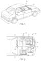
- FIG. 1is a schematic view of an embodiment of an xEV, in accordance with an embodiment of the present approach
- FIG. 2is a partial schematic view of the xEV of FIG. 1 , illustrating power distribution throughout the xEV, in accordance with an embodiment of the present approach;
- FIG. 3is a perspective view of a prismatic battery cell that may be used in the battery module of FIG. 2 ;
- FIG. 4is a schematic representation of an electrical interconnection scheme having sense connection points external to a relay used in the battery module of FIG. 2 ;
- FIG. 5is a schematic representation of an electrical interconnection scheme having sense connection points internal to a relay used in the battery module of FIG. 2 , in accordance with an embodiment of the present approach;
- FIG. 6is a diagrammatic view of a connector having only switch control lines plugged into a relay, where sensing lines are coupled to the external terminals of the relay;
- FIG. 7is a diagrammatic view of a connector that integrates switch control lines and voltage sensing lines, where the relay includes internal conductors that connect the voltage sensing lines to internal terminals of the relay.
- the battery systems described hereinmay be used to provide power to various types of electric vehicles (xEVs) and other high voltage energy storage/expending applications (e.g., electrical grid power storage systems).
- Such battery systemsmay include one or more battery modules, where each battery module may have a housing and a number of battery cells (e.g., lithium ion (Li-ion) electrochemical cells) arranged within the housing to provide particular voltages and/or currents useful to power, for example, one or more components of an xEV.
- battery modules in accordance with present embodimentsmay be incorporated with or provide power to stationary power systems (e.g., non-automotive systems).
- the measured voltagecan be used to monitor and control the operation of the battery module or its associated components.
- a battery control modulemay monitor the voltage to determine whether the battery module is capable of supplying a sufficient amount of power to various components (e.g., various loads internal or external to the battery module). The battery control module may also determine when the battery module is near the end of its lifetime, based at least on the voltage produced by the battery module over time, and may notify the user accordingly.
- measurement electronicssuch as voltage sensors, may be electrically connected to one or more connection points within the battery module.
- such measurement electronics and sensorsare often associated with conductors, e.g., sensing lines or conductors, used for measurement and communication, and the routing and connection of these conductors can introduce complexity and cost associated with the battery module.
- the measurement electronicsmay be connected to one or more connection points located internal to the relay using a connector that integrates the switch control lines of the relay and the sensing conductors.
- the connections between the measurement electronics and the one or more connection points on a relaymay be routed in a manner similar to the connections between the switch control lines and the relay, and the external connections of the sensing conductors can be eliminated.
- connection points on the relaymay be routed around other components and may be made without the use of additional devices (e.g., ring terminals and fasteners) or methods of securing such connections (e.g., welding).
- additional devicese.g., ring terminals and fasteners
- methods of securing such connectionse.g., welding
- connection pointsmay also be used to provide power to one or more electronic devices (e.g., a control module) in the battery module. That is, the connection points may be used to provide power to the electronic devices without utilizing a separate connection between the electronic devices and the associated power source.
- battery cells within the battery modulemay apply power to the electronic devices via two connection points, one of which is located within the relay.
- another battery modulemay also provide power to the electronic devices via two connection points, one of which is located within the relay.
- power provided to the electronic devicesmay be routed through the relay and the connector, as well as through other sensing points in the battery module, thereby simplifying wiring and connection schemes.
- the relaymay include sense connection points that are used both as a sensing point and a source of power for the electronics internal to the battery module without having a separate connection.
- the battery control modulemay be configured to select the appropriate power source based on various factors, such as the state of charge of the power sources, the temperature of the power sources, and so on. These power supply configuration may simplify the wiring scheme of the battery module and may also increase the reliability and redundancy of the power source for the electronic devices.
- FIG. 1is a perspective view of an embodiment of a vehicle 10 , which may utilize a regenerative braking system.
- vehicle 10which may utilize a regenerative braking system.
- the techniques described hereinare adaptable to other vehicles that capture/store electrical energy with a battery, which may include electric-powered and gas-powered vehicles.
- the battery system 12may be placed in a location in the vehicle 10 that would have housed a traditional battery system.
- the vehicle 10may include the battery system 12 positioned similarly to a lead-acid battery of a typical combustion-engine vehicle (e.g., under the hood of the vehicle 10 ).
- the battery system 12may be positioned to facilitate managing temperature of the battery system 12 .
- positioning a battery system 12 under the hood of the vehicle 10may enable an air duct to channel airflow over the battery system 12 and cool the battery system 12 .
- the battery system 12includes an energy storage component 14 coupled to an ignition system 16 , an alternator 18 , a vehicle console 20 , and optionally to an electric motor 22 .
- the energy storage component 14may capture/store electrical energy generated in the vehicle 10 and output electrical energy to power electrical devices in the vehicle 10 .
- the battery system 12may supply power to components of the vehicle's electrical system, which may include radiator cooling fans, climate control systems, electric power steering systems, active suspension systems, auto park systems, electric oil pumps, electric super/turbochargers, electric water pumps, heated windscreen/defrosters, window lift motors, vanity lights, tire pressure monitoring systems, sunroof motor controls, power seats, alarm systems, infotainment systems, navigation features, lane departure warning systems, electric parking brakes, external lights, or any combination thereof.
- the energy storage component 14supplies power to the vehicle console 20 and the ignition system 16 , which may be used to start (e.g., crank) the internal combustion engine 24 .
- the energy storage component 14may capture electrical energy generated by the alternator 18 and/or the electric motor 22 .
- the alternator 18may generate electrical energy while the internal combustion engine 24 is running. More specifically, the alternator 18 may convert the mechanical energy produced by the rotation of the internal combustion engine 24 into electrical energy.
- the electric motor 22may generate electrical energy by converting mechanical energy produced by the movement of the vehicle 10 (e.g., rotation of the wheels) into electrical energy.
- the energy storage component 14may capture electrical energy generated by the alternator 18 and/or the electric motor 22 during regenerative braking.
- the alternator 18 and/or the electric motor 22are generally referred to herein as a regenerative braking system.
- the energy storage component 14may be electrically coupled to the vehicle's electric system via a system bus 26 .
- the bus 26may enable the energy storage component 14 to receive electrical energy generated by the alternator 18 and/or the electric motor 22 . Additionally, the bus 26 may enable the energy storage component 14 to output electrical energy to the ignition system 16 and/or the vehicle console 20 . Accordingly, when a 12 volt battery system 12 is used, the bus 26 may carry electrical power typically between 8-18 volts.
- the energy storage component 14may include multiple battery modules.
- the energy storage component 14includes a lithium ion (e.g., a first) battery module 28 and a lead-acid (e.g., a second) battery module 30 , which each of which may include one or more battery cells.
- the energy storage component 14may include any number of battery modules.
- the lithium ion battery module 28 and lead-acid battery module 30are depicted adjacent to one another, they may be positioned in different areas around the vehicle.
- the lead-acid battery modulemay be positioned in or about the interior of the vehicle 10 while the lithium ion battery module 28 may be positioned under the hood of the vehicle 10 .
- the energy storage component 14may include multiple battery modules to utilize multiple different battery chemistries.
- performance of the battery system 12may be improved since the lithium ion battery chemistry generally has a higher coulombic efficiency and/or a higher power charge acceptance rate (e.g., higher maximum charge current or charge voltage) than the lead-acid battery chemistry. As such, the capture, storage, and/or distribution efficiency of the battery system 12 may be improved.
- the battery system 12may additionally include a control module 32 .
- the control module 32may control operations of components in the battery system 12 , such as relays (e.g., switches) within energy storage component 14 , the alternator 18 , and/or the electric motor 22 .
- the control module 32may regulate amount of electrical energy captured/supplied by each battery module 28 or 30 , perform load balancing between the battery modules 28 and 30 , determine a state of charge of each battery module 28 or 30 , sense operation parameters such as the voltage and temperature of each battery module 28 or 30 , control voltage output by the alternator 18 and/or the electric motor 22 , and the like.
- the control module 32is illustrated in FIG. 2 as being separate from the energy storage component 14 , it may be integrated into the energy storage component 14 or integrated into one or more battery modules 28 and 30 .
- the control unit 32may include one or more processors 34 and one or more memories 36 . More specifically, the processor 34 may include one or more application specific integrated circuits (ASICs), one or more field programmable gate arrays (FPGAs), one or more general purpose processors, or any combination thereof, under software or firmware control as appropriate. Additionally, the memory 36 may include volatile memory, such as random access memory (RANI), and/or non-volatile memory, such as read-only memory (ROM), optical drives, hard disc drives, or solid-state drives. In some embodiments, the control unit 32 may include portions of a vehicle control unit (VCU) and/or a separate battery control module.
- VCUvehicle control unit
- the battery modules in the energy storage component 14may be connected in any suitable arrangement, for the purposes of the examples discussed herein, the lithium ion battery module 28 and the lead-acid battery module 30 are connected in parallel across their terminals. In other words, the lithium ion battery module 28 and the lead-acid battery module 30 may be coupled in parallel to the vehicle's electrical system via the bus 26 . Furthermore, as discussed in detail below, one or more of the battery modules in the energy storage component 14 may include a relay that may perform various functions, such as selectively coupling and decoupling the battery module from the system bus 26 .
- the battery modules 28 and 30may contain any suitable type of battery cell or cells as deemed appropriate for the particular application. Further, if a lithium ion battery module 28 is used, it may include any appropriate type of battery cells, such as cylindrical, prismatic or pouch cells. To the extent that prismatic cells are used, each of the prismatic cells may be similar to the battery cell 44 illustrated in FIG. 3 . As defined herein, a prismatic battery cell 44 may include a prismatic case that is generally rectangular in shape. In contrast to pouch cells, the prismatic casing is formed from a relatively inflexible, hard (e.g., metallic or plastic) material.
- each prismatic battery cellmay include a top casing portion 35 , where a set of cell terminals 37 and 38 (e.g., positive and negative cell terminals) may be located, although such terminals may be located elsewhere depending upon the design of a particular prismatic cell.
- One or more cell vents 39may also be located on the top casing portion 35 or other suitable location.
- the prismatic cell casing 40also includes a bottom casing portion 41 positioned opposite the top casing portion 35 .
- First and second sides 42 and 43which may be straight or rounded, may extend between the bottom and top casing portions 41 and 35 in respective positions corresponding to the cell terminals 37 and 38 .
- First and second faces 49 and 51which may be flat (as shown) or rounded, may couple the first and second sides 42 and 43 at opposing ends of each battery cell 44 .
- present embodiments of the lithium ion battery module 28may include one or more electrical connection points within the lithium ion battery module 28 for sensing.
- one or more of the electrical connection pointsmay be located on or within a battery module relay system in the lithium ion battery module 28 (e.g., using a connector associated with the relay).
- FIGS. 4 and 5depict relay connection architectures that may be associated with the lithium ion battery module 28 .
- the present embodimentsare described with respect to a mechanical relay, it should be appreciated that the lithium ion battery module 28 may employ any suitable power switching device, such as an insulating gate bipolar transistor (IGBT), power MOSFET, thyristor, etc.
- IGBTinsulating gate bipolar transistor
- the relay 48includes a switch control, such as a coil 50 that can be energized and deenergized to cause a switch 54 to move between an open and closed position to connect or disconnect, respectively, the battery cells 44 on one side 52 of the switch 54 to the system bus 26 on the other side 56 of the switch 54 .
- the relay 48may be configured such that the relay 48 connects or disconnects the battery cells 44 to a positive or negative terminal of the energy storage component 14 .
- the relay 48may be disposed within the group of battery cells 44 such that the relay 48 is configured to control the amount of voltage or current produced by the battery cells 44 as a whole (e.g., by connecting or disconnecting battery cells 44 in series or in parallel to produce the desired voltage or current).
- the relay 48may be a mono-stable or a hi-stable relay or, more generally, may be any type of relay suitable for use in accordance with the present approaches.
- the relay 48may be driven by a relay driver 58 , which may be one of several electronic devices within the control module 32 .
- the relay driver 58sends signals on relay control lines 65 to the coil 50 , and the relay control lines 65 may be coupled to the relay 48 via a connector 68 .
- control module 32may monitor and control some or all of the components of the lithium ion battery module 28 .
- control module 32may be configured to control the lithium ion battery module 28 or other components of the vehicle 10 based on the voltage produced by the lithium ion battery module 28 .
- the control module 32may include measurement electronics 62 , such as sensors and voltage and/or temperature detection circuitry.
- the measurement electronics 62may be connected to one or more sense connection points 64 (shown as 64 A- 64 D) within the lithium ion battery module 28 by respective sensing conductors 66 (shown as 66 A- 66 D).
- the sense connection points 64may be considered to include locations within the lithium ion battery module 28 to which the measurement electronics 62 are electrically connected to sense parameters that facilitate control of the lithium ion battery module 28 .
- the sense connection points 64 A and 64 Bprovide an indication of the voltage across the battery cells 44
- the sense connection points 64 C and 64 Dprovide an indication of the voltage on the system bus 26 .
- the sense connection points 64 A and 64 Care disposed outside of the housing of the relay 48 such that the sensing conductors 66 A and 66 C are routed around other components. Further, devices and methods of securing connections such as ring terminals, fasteners, and welding may be used to create the connections between the sensing conductors 66 A and 66 C and the sense connection points 64 A and 64 C.
- the lithium ion battery module 28may include one or more sense connection points 64 A and 64 C located within the housing of the relay 48 .
- the sense connection points 64 A and 64 Cmay be located at each side 52 and 56 , respectively, of the switch 54 , and these connection points 64 A and 64 C may have conductors internal to the relay 48 that link the sense connection points 64 A and 64 C to a terminal 69 so that they can make contact with external sensing conductors 66 A and 66 C.
- using the sense connection points 64 A and 64 C internal to the relay 48may reduce the complexity of the connections and routing associated with the measurement electronics 62 , sensing conductors 66 , and the various battery connection points 64 .
- the sensing conductors 66 A and 66 C between the sense connection points 64 A and 64 C and the measurement electronics 62may be routed in a similar manner to the connections between the relay control lines 65 and the relay 48 , rather than separately. Further, the sensing conductors 66 A and 66 C may be integrated into the same connector 68 with the relay control lines 65 .
- the sense connection points 64may be used to provide power to the control module 32 without a separate connection (i.e., via the sense connection points 64 A and 64 C and the sensing conductors 66 A and 66 C).
- the battery cells 44may, for example, provide power to the control module 32 via the sense connection points 64 A and 64 B.
- the battery cells 44may apply power at the sense connection points 64 A and 64 B, which is then provided to the control module 32 by the sensing conductors 66 A and 66 B, respectively. That is, in addition to providing sensing data to the measurement electronics 62 , the sensing conductors 66 may also provide power to the control module 32 .
- the lead-acid battery module 30which is coupled to the system bus 26 in parallel to the lithium ion battery module 28 , may provide power to the control module 32 via the sense connection points 64 C and 64 D and the sensing conductors 66 C and 66 D. Further, in these embodiments, the control module 32 may configure either the battery cells 44 or the lead-acid battery module 30 to power the control module 32 based on various parameters of the battery cells 44 and the lead-acid battery module 30 , such as state of charge, temperature, etc.
- Using the battery cells 44 or the lead-acid battery module 30 to power the control module 32 via the sense connection points 64 and the sensing conductors 66may further simplify the wiring scheme of the lithium ion battery module 28 and may also increase the reliability and redundancy of the power source for the control module 32 .
- One or more of the disclosed embodimentsmay provide one or more technical effects useful for monitoring the voltage produced by a battery module.
- certain embodimentsmay reduce the complexity of connecting measurement electronics to various locations within the battery module for sensing.
- the present sense connection pointsresult in connections to the measurement electronics that may be routed in similar manner to connections between the relay coil and a relay driver. Indeed, both types of connections may be made using an integrated connector.
- the technical effects and technical problems in the specificationare exemplary and are not limiting. It should be noted that the embodiments described in the specification may have other technical effects and can solve other technical problems.
Landscapes
- Engineering & Computer Science (AREA)
- Power Engineering (AREA)
- Mechanical Engineering (AREA)
- Sustainable Energy (AREA)
- Sustainable Development (AREA)
- Transportation (AREA)
- Life Sciences & Earth Sciences (AREA)
- Secondary Cells (AREA)
- Charge And Discharge Circuits For Batteries Or The Like (AREA)
- Manufacturing & Machinery (AREA)
- Chemical & Material Sciences (AREA)
- Chemical Kinetics & Catalysis (AREA)
- Electrochemistry (AREA)
- General Chemical & Material Sciences (AREA)
Abstract
Description
Claims (12)
Priority Applications (1)
| Application Number | Priority Date | Filing Date | Title |
|---|---|---|---|
| US17/331,316US11887796B2 (en) | 2014-09-30 | 2021-05-26 | Integrated connector having sense and switching conductors for a relay used in a battery module |
Applications Claiming Priority (3)
| Application Number | Priority Date | Filing Date | Title |
|---|---|---|---|
| US14/502,732US9947497B2 (en) | 2014-09-30 | 2014-09-30 | Integrated connector having sense and switching conductors for a relay used in a battery module |
| US15/913,436US11037748B2 (en) | 2014-09-30 | 2018-03-06 | Integrated connector having sense and switching conductors for a relay used in a battery module |
| US17/331,316US11887796B2 (en) | 2014-09-30 | 2021-05-26 | Integrated connector having sense and switching conductors for a relay used in a battery module |
Related Parent Applications (1)
| Application Number | Title | Priority Date | Filing Date |
|---|---|---|---|
| US15/913,436DivisionUS11037748B2 (en) | 2014-09-30 | 2018-03-06 | Integrated connector having sense and switching conductors for a relay used in a battery module |
Publications (2)
| Publication Number | Publication Date |
|---|---|
| US20210280381A1 US20210280381A1 (en) | 2021-09-09 |
| US11887796B2true US11887796B2 (en) | 2024-01-30 |
Family
ID=54200047
Family Applications (3)
| Application Number | Title | Priority Date | Filing Date |
|---|---|---|---|
| US14/502,732Active2036-07-01US9947497B2 (en) | 2014-09-30 | 2014-09-30 | Integrated connector having sense and switching conductors for a relay used in a battery module |
| US15/913,436ActiveUS11037748B2 (en) | 2014-09-30 | 2018-03-06 | Integrated connector having sense and switching conductors for a relay used in a battery module |
| US17/331,316Active2034-12-07US11887796B2 (en) | 2014-09-30 | 2021-05-26 | Integrated connector having sense and switching conductors for a relay used in a battery module |
Family Applications Before (2)
| Application Number | Title | Priority Date | Filing Date |
|---|---|---|---|
| US14/502,732Active2036-07-01US9947497B2 (en) | 2014-09-30 | 2014-09-30 | Integrated connector having sense and switching conductors for a relay used in a battery module |
| US15/913,436ActiveUS11037748B2 (en) | 2014-09-30 | 2018-03-06 | Integrated connector having sense and switching conductors for a relay used in a battery module |
Country Status (4)
| Country | Link |
|---|---|
| US (3) | US9947497B2 (en) |
| EP (1) | EP3201039B1 (en) |
| CN (1) | CN107107771B (en) |
| WO (1) | WO2016053517A1 (en) |
Families Citing this family (15)
| Publication number | Priority date | Publication date | Assignee | Title |
|---|---|---|---|---|
| KR101521985B1 (en)* | 2014-06-18 | 2015-05-29 | 주식회사 경신 | Apparatus for transmitting power and control method thereof |
| US9947497B2 (en) | 2014-09-30 | 2018-04-17 | Johnson Controls Technology Company | Integrated connector having sense and switching conductors for a relay used in a battery module |
| US9610845B2 (en)* | 2014-12-30 | 2017-04-04 | GM Global Technology Operations LLC | Powertrain for a vehicle |
| US11072246B2 (en)* | 2015-03-11 | 2021-07-27 | University Of Washington | Electrochemical cell diagnostic systems and methods using second order and higher harmonic components |
| KR102455574B1 (en)* | 2016-06-14 | 2022-10-17 | 존 이. 워터스 | Battery module and system for remote command and control therefor |
| US10974606B2 (en)* | 2016-08-31 | 2021-04-13 | Cps Technology Holdings Llc | Bi-stable relay |
| US10005366B1 (en)* | 2016-12-02 | 2018-06-26 | GM Global Technology Operations LLC | Powertrain with high-power distribution module and high-current ring terminal connection for the same |
| US20180342364A1 (en)* | 2017-05-29 | 2018-11-29 | Lithionics Llc | Control method for bi-stable contactors with full component redundancy |
| US10679811B2 (en)* | 2017-09-12 | 2020-06-09 | Littelfuse, Inc. | Wide operating range relay controller system |
| JP6795552B2 (en)* | 2018-06-26 | 2020-12-02 | 住友電装株式会社 | Power relay device |
| KR102656482B1 (en)* | 2018-09-19 | 2024-04-11 | 삼성에스디아이 주식회사 | Battery pack and means of transportation having the battery pack |
| US10998595B2 (en)* | 2018-11-08 | 2021-05-04 | GM Global Technology Operations LLC | Modular vehicle battery |
| JP7410113B2 (en)* | 2021-12-23 | 2024-01-09 | 住友電装株式会社 | electrical connection unit |
| US12330623B2 (en) | 2022-05-04 | 2025-06-17 | Toyota Motor North America, Inc. | Vehicle battery element management |
| CN220180725U (en)* | 2023-07-21 | 2023-12-15 | 法雷奥新能源汽车(深圳)有限公司 | Relay device, power distribution system, and vehicle |
Citations (40)
| Publication number | Priority date | Publication date | Assignee | Title |
|---|---|---|---|---|
| US4870296A (en)* | 1987-07-03 | 1989-09-26 | Saab-Scania Aktiebolag | Control device for a main-light circuit of a motor vehicle |
| US4883728A (en) | 1987-03-03 | 1989-11-28 | Pita Witehira | Battery systems |
| US5175484A (en) | 1988-09-26 | 1992-12-29 | Power Beat International, Ltd. | Electrical power distribution |
| US6020718A (en) | 1996-07-01 | 2000-02-01 | Fujitsu Limited | Battery capacity predicting method, battery unit and apparatus using battery unit |
| US6121750A (en) | 1997-12-09 | 2000-09-19 | Glory Win International Group Limited | Two terminal battery |
| US6259978B1 (en) | 1996-12-06 | 2001-07-10 | Union Switch & Signal, Inc. | Programmable relay driver |
| US20020195996A1 (en)* | 2001-04-25 | 2002-12-26 | Toshiyuki Nakatsuji | Battery pack and battery pack checking method |
| US6573621B2 (en) | 2000-12-01 | 2003-06-03 | S-B Power Tool Company | AC/DC power supply system for power tools |
| US6657833B2 (en) | 2000-12-08 | 2003-12-02 | Toyota Jidosha Kabushiki Kaisha | Relay welding detector and detecting method |
| US20040053083A1 (en) | 2002-09-18 | 2004-03-18 | Nissan Motor Co., Ltd. | Vehicular electric power generation control apparatus |
| US20070014055A1 (en) | 2005-07-14 | 2007-01-18 | Ness Keith D | Apparatus and method for relay contact arc suppression |
| US7176654B2 (en) | 2002-11-22 | 2007-02-13 | Milwaukee Electric Tool Corporation | Method and system of charging multi-cell lithium-based batteries |
| US20070091547A1 (en)* | 2005-10-21 | 2007-04-26 | Yazaki Corporation | Electric junction box |
| US7433182B2 (en) | 2004-12-17 | 2008-10-07 | Mitac Technology Corp. | Plug-and-expand battery module |
| US7446433B2 (en) | 2004-01-23 | 2008-11-04 | American Power Conversion Corporation | Methods and apparatus for providing uninterruptible power |
| US7615885B2 (en) | 2006-01-31 | 2009-11-10 | Lear Corporation | Power connection device for battery terminal clamp |
| US7635983B2 (en) | 2007-01-09 | 2009-12-22 | Myers Power Products, Inc. | Battery testing apparatus that controls a switch to allow current to flow from the battery to a utility power source |
| US7679325B2 (en) | 2005-04-07 | 2010-03-16 | Samsung Sdi Co., Ltd. | Battery management system and driving method for cutting off and coupling battery module from/to external device |
| US7709977B2 (en) | 1999-10-18 | 2010-05-04 | Nucellsys Gmbh | Method and arrangement for controlling a switching connection between the electrical outputs of a fuel cell and an isolated electrical network |
| US7746031B2 (en) | 2005-03-17 | 2010-06-29 | Toyota Jidosha Kabushiki Kaisha | Monitoring device for power supply system |
| US20110001352A1 (en) | 2009-07-01 | 2011-01-06 | Denso Corporation | Power source apparatus for vehicle |
| US7880432B2 (en) | 2005-10-20 | 2011-02-01 | Samsung Sdi Co., Ltd. | Battery management system and battery management method |
| US20110155485A1 (en) | 2009-12-28 | 2011-06-30 | Hitachi, Ltd. | Electrical Storage Device |
| US20110196545A1 (en) | 2009-05-28 | 2011-08-11 | Toyota Jidosha Kabushiki Kaisha | Charging system, vehicle, and charging system control method |
| US8129952B2 (en) | 2009-04-16 | 2012-03-06 | Valence Technology, Inc. | Battery systems and operational methods |
| US20120235473A1 (en) | 2011-03-16 | 2012-09-20 | Johnson Controls Technology Company | Systems and methods for overcharge protection and charge balance in combined energy source systems |
| US20120244404A1 (en) | 2009-10-14 | 2012-09-27 | Kem Obasih | Prismatic cell system with thermal management features |
| US8307222B2 (en) | 2009-09-25 | 2012-11-06 | Dell Products, Lp | Flexible cell battery systems and methods for powering information handling systems |
| US20130033101A1 (en)* | 2011-08-01 | 2013-02-07 | Bayerische Motoren Werke Aktiengesellschaft | Vehicle with a Power Distributor and a Control Unit |
| US8467159B2 (en) | 2009-03-03 | 2013-06-18 | Lg Chem., Ltd. | Apparatus and method for controlling a relay in electric drive vehicle |
| US8536826B2 (en) | 2009-09-15 | 2013-09-17 | Renesas Electronics Corporation | Data processing system, electronic vehicle and maintenance service system |
| US8541978B2 (en)* | 2009-11-20 | 2013-09-24 | Panasonic Corporation | Feed control device |
| US8629581B2 (en) | 2009-06-10 | 2014-01-14 | A123 Systems, Inc. | System and method for communicating notice to limit degradation within a battery pack |
| US20140062493A1 (en) | 2012-09-06 | 2014-03-06 | Johnson Controls Technology Llc | High voltage connector system and method |
| US8802259B2 (en) | 2010-08-16 | 2014-08-12 | Lg Chem, Ltd. | Battery pack of compact structure |
| US20140356656A1 (en) | 2013-05-31 | 2014-12-04 | Laurence Lujun Chen | Intelligent Battery Management System and Method for Optimizing Battery Set to the Best Performance |
| US20150028877A1 (en) | 2012-03-12 | 2015-01-29 | Eaton Corporation | Relay including processor providing control and/or monitoring |
| US9156356B2 (en)* | 2012-02-08 | 2015-10-13 | GTR Development LLC | Intelligent battery disconnect |
| US20160156258A1 (en) | 2013-07-19 | 2016-06-02 | Calsonic Kansei Corporation | Power source control device and method for detecting relay abnormality |
| US9947497B2 (en) | 2014-09-30 | 2018-04-17 | Johnson Controls Technology Company | Integrated connector having sense and switching conductors for a relay used in a battery module |
Family Cites Families (3)
| Publication number | Priority date | Publication date | Assignee | Title |
|---|---|---|---|---|
| KR101121757B1 (en) | 2007-11-07 | 2012-03-23 | 에스케이이노베이션 주식회사 | Safety Apparatus and Protection Method of secondary Battery for Electric Vehicle Using Switch |
| JP5575506B2 (en) | 2010-02-26 | 2014-08-20 | 三洋電機株式会社 | Vehicle power supply device and vehicle equipped with the power supply device |
| US20140141287A1 (en)* | 2012-11-19 | 2014-05-22 | Delphi Technologies, Inc. | Battery pack and battery control module |
- 2014
- 2014-09-30USUS14/502,732patent/US9947497B2/enactiveActive
- 2015
- 2015-08-27WOPCT/US2015/047104patent/WO2016053517A1/enactiveApplication Filing
- 2015-08-27EPEP15771311.6Apatent/EP3201039B1/enactiveActive
- 2015-08-27CNCN201580056666.1Apatent/CN107107771B/enactiveActive
- 2018
- 2018-03-06USUS15/913,436patent/US11037748B2/enactiveActive
- 2021
- 2021-05-26USUS17/331,316patent/US11887796B2/enactiveActive
Patent Citations (40)
| Publication number | Priority date | Publication date | Assignee | Title |
|---|---|---|---|---|
| US4883728A (en) | 1987-03-03 | 1989-11-28 | Pita Witehira | Battery systems |
| US4870296A (en)* | 1987-07-03 | 1989-09-26 | Saab-Scania Aktiebolag | Control device for a main-light circuit of a motor vehicle |
| US5175484A (en) | 1988-09-26 | 1992-12-29 | Power Beat International, Ltd. | Electrical power distribution |
| US6020718A (en) | 1996-07-01 | 2000-02-01 | Fujitsu Limited | Battery capacity predicting method, battery unit and apparatus using battery unit |
| US6259978B1 (en) | 1996-12-06 | 2001-07-10 | Union Switch & Signal, Inc. | Programmable relay driver |
| US6121750A (en) | 1997-12-09 | 2000-09-19 | Glory Win International Group Limited | Two terminal battery |
| US7709977B2 (en) | 1999-10-18 | 2010-05-04 | Nucellsys Gmbh | Method and arrangement for controlling a switching connection between the electrical outputs of a fuel cell and an isolated electrical network |
| US6573621B2 (en) | 2000-12-01 | 2003-06-03 | S-B Power Tool Company | AC/DC power supply system for power tools |
| US6657833B2 (en) | 2000-12-08 | 2003-12-02 | Toyota Jidosha Kabushiki Kaisha | Relay welding detector and detecting method |
| US20020195996A1 (en)* | 2001-04-25 | 2002-12-26 | Toshiyuki Nakatsuji | Battery pack and battery pack checking method |
| US20040053083A1 (en) | 2002-09-18 | 2004-03-18 | Nissan Motor Co., Ltd. | Vehicular electric power generation control apparatus |
| US7176654B2 (en) | 2002-11-22 | 2007-02-13 | Milwaukee Electric Tool Corporation | Method and system of charging multi-cell lithium-based batteries |
| US7446433B2 (en) | 2004-01-23 | 2008-11-04 | American Power Conversion Corporation | Methods and apparatus for providing uninterruptible power |
| US7433182B2 (en) | 2004-12-17 | 2008-10-07 | Mitac Technology Corp. | Plug-and-expand battery module |
| US7746031B2 (en) | 2005-03-17 | 2010-06-29 | Toyota Jidosha Kabushiki Kaisha | Monitoring device for power supply system |
| US7679325B2 (en) | 2005-04-07 | 2010-03-16 | Samsung Sdi Co., Ltd. | Battery management system and driving method for cutting off and coupling battery module from/to external device |
| US20070014055A1 (en) | 2005-07-14 | 2007-01-18 | Ness Keith D | Apparatus and method for relay contact arc suppression |
| US7880432B2 (en) | 2005-10-20 | 2011-02-01 | Samsung Sdi Co., Ltd. | Battery management system and battery management method |
| US20070091547A1 (en)* | 2005-10-21 | 2007-04-26 | Yazaki Corporation | Electric junction box |
| US7615885B2 (en) | 2006-01-31 | 2009-11-10 | Lear Corporation | Power connection device for battery terminal clamp |
| US7635983B2 (en) | 2007-01-09 | 2009-12-22 | Myers Power Products, Inc. | Battery testing apparatus that controls a switch to allow current to flow from the battery to a utility power source |
| US8467159B2 (en) | 2009-03-03 | 2013-06-18 | Lg Chem., Ltd. | Apparatus and method for controlling a relay in electric drive vehicle |
| US8129952B2 (en) | 2009-04-16 | 2012-03-06 | Valence Technology, Inc. | Battery systems and operational methods |
| US20110196545A1 (en) | 2009-05-28 | 2011-08-11 | Toyota Jidosha Kabushiki Kaisha | Charging system, vehicle, and charging system control method |
| US8629581B2 (en) | 2009-06-10 | 2014-01-14 | A123 Systems, Inc. | System and method for communicating notice to limit degradation within a battery pack |
| US20110001352A1 (en) | 2009-07-01 | 2011-01-06 | Denso Corporation | Power source apparatus for vehicle |
| US8536826B2 (en) | 2009-09-15 | 2013-09-17 | Renesas Electronics Corporation | Data processing system, electronic vehicle and maintenance service system |
| US8307222B2 (en) | 2009-09-25 | 2012-11-06 | Dell Products, Lp | Flexible cell battery systems and methods for powering information handling systems |
| US20120244404A1 (en) | 2009-10-14 | 2012-09-27 | Kem Obasih | Prismatic cell system with thermal management features |
| US8541978B2 (en)* | 2009-11-20 | 2013-09-24 | Panasonic Corporation | Feed control device |
| US20110155485A1 (en) | 2009-12-28 | 2011-06-30 | Hitachi, Ltd. | Electrical Storage Device |
| US8802259B2 (en) | 2010-08-16 | 2014-08-12 | Lg Chem, Ltd. | Battery pack of compact structure |
| US20120235473A1 (en) | 2011-03-16 | 2012-09-20 | Johnson Controls Technology Company | Systems and methods for overcharge protection and charge balance in combined energy source systems |
| US20130033101A1 (en)* | 2011-08-01 | 2013-02-07 | Bayerische Motoren Werke Aktiengesellschaft | Vehicle with a Power Distributor and a Control Unit |
| US9156356B2 (en)* | 2012-02-08 | 2015-10-13 | GTR Development LLC | Intelligent battery disconnect |
| US20150028877A1 (en) | 2012-03-12 | 2015-01-29 | Eaton Corporation | Relay including processor providing control and/or monitoring |
| US20140062493A1 (en) | 2012-09-06 | 2014-03-06 | Johnson Controls Technology Llc | High voltage connector system and method |
| US20140356656A1 (en) | 2013-05-31 | 2014-12-04 | Laurence Lujun Chen | Intelligent Battery Management System and Method for Optimizing Battery Set to the Best Performance |
| US20160156258A1 (en) | 2013-07-19 | 2016-06-02 | Calsonic Kansei Corporation | Power source control device and method for detecting relay abnormality |
| US9947497B2 (en) | 2014-09-30 | 2018-04-17 | Johnson Controls Technology Company | Integrated connector having sense and switching conductors for a relay used in a battery module |
Non-Patent Citations (1)
| Title |
|---|
| International Search Report and Written Opinion of the International Searching Authority dated Nov. 24, 2015 for PCT/US2015/047104 filed Aug. 27, 2015. |
Also Published As
| Publication number | Publication date |
|---|---|
| US20160093456A1 (en) | 2016-03-31 |
| CN107107771A (en) | 2017-08-29 |
| EP3201039B1 (en) | 2022-01-05 |
| US20180197706A1 (en) | 2018-07-12 |
| CN107107771B (en) | 2019-12-03 |
| EP3201039A1 (en) | 2017-08-09 |
| US9947497B2 (en) | 2018-04-17 |
| WO2016053517A1 (en) | 2016-04-07 |
| US20210280381A1 (en) | 2021-09-09 |
| US11037748B2 (en) | 2021-06-15 |
Similar Documents
| Publication | Publication Date | Title |
|---|---|---|
| US11887796B2 (en) | Integrated connector having sense and switching conductors for a relay used in a battery module | |
| EP3243235B1 (en) | Snap-in extensions and guide walls for bus bar bridges of a battery module | |
| US11394072B2 (en) | Cell assembly for a battery module | |
| US11309604B2 (en) | Thermal epoxy and positioning of electrochemical cells | |
| US9705121B2 (en) | Lead frame for a battery module | |
| US11112463B2 (en) | Integrated battery sensor for multiple battery modules | |
| US10076969B2 (en) | Battery systems and methods for bi-directional current control | |
| US10543795B2 (en) | Battery module connector barrel | |
| US10673050B2 (en) | Battery module terminal system and method | |
| EP3201975B1 (en) | Battery module bus bar connection assembly | |
| US11495834B2 (en) | Turnable carrier for electrical components of a battery module | |
| EP3314679B1 (en) | Sensor hold down finger of a battery module | |
| EP3925022B1 (en) | Sensor for battery module |
Legal Events
| Date | Code | Title | Description |
|---|---|---|---|
| FEPP | Fee payment procedure | Free format text:ENTITY STATUS SET TO UNDISCOUNTED (ORIGINAL EVENT CODE: BIG.); ENTITY STATUS OF PATENT OWNER: LARGE ENTITY | |
| AS | Assignment | Owner name:JOHNSON CONTROLS TECHNOLOGY COMPANY, MICHIGAN Free format text:ASSIGNMENT OF ASSIGNORS INTEREST;ASSIGNORS:DULLE, RONALD J.;FARRELL, ANTHONY E.;DEKEUSTER, RICHARD M.;REEL/FRAME:056486/0362 Effective date:20140929 | |
| AS | Assignment | Owner name:CPS TECHNOLOGY HOLDINGS LLC, NEW YORK Free format text:ASSIGNMENT OF ASSIGNORS INTEREST;ASSIGNOR:JOHNSON CONTROLS TECHNOLOGY COMPANY;REEL/FRAME:056502/0239 Effective date:20190430 | |
| STPP | Information on status: patent application and granting procedure in general | Free format text:DOCKETED NEW CASE - READY FOR EXAMINATION | |
| STPP | Information on status: patent application and granting procedure in general | Free format text:NON FINAL ACTION MAILED | |
| STPP | Information on status: patent application and granting procedure in general | Free format text:FINAL REJECTION MAILED | |
| STPP | Information on status: patent application and granting procedure in general | Free format text:DOCKETED NEW CASE - READY FOR EXAMINATION | |
| AS | Assignment | Owner name:CITIBANK, N.A., AS COLLATERAL AGENT, NEW YORK Free format text:FIRST LIEN PATENT SECURITY AGREEMENT;ASSIGNORS:CLARIOS ADVANCED SOLUTIONS LLC;CPS TECHNOLOGY HOLDINGS LLC;REEL/FRAME:064272/0599 Effective date:20230713 Owner name:CITIBANK, N.A., AS COLLATERAL AGENT, NEW YORK Free format text:ABL PATENT SECURITY AGREEMENT;ASSIGNORS:CLARIOS ADVANCED SOLUTIONS LLC;CPS TECHNOLOGY HOLDINGS LLC;REEL/FRAME:064272/0566 Effective date:20230713 | |
| STPP | Information on status: patent application and granting procedure in general | Free format text:NOTICE OF ALLOWANCE MAILED -- APPLICATION RECEIVED IN OFFICE OF PUBLICATIONS | |
| STPP | Information on status: patent application and granting procedure in general | Free format text:NOTICE OF ALLOWANCE MAILED -- APPLICATION RECEIVED IN OFFICE OF PUBLICATIONS | |
| STPP | Information on status: patent application and granting procedure in general | Free format text:PUBLICATIONS -- ISSUE FEE PAYMENT RECEIVED | |
| STPP | Information on status: patent application and granting procedure in general | Free format text:PUBLICATIONS -- ISSUE FEE PAYMENT VERIFIED | |
| STCF | Information on status: patent grant | Free format text:PATENTED CASE |