US11885958B2 - Systems and methods for a dual axis resonant scanning mirror - Google Patents
Systems and methods for a dual axis resonant scanning mirrorDownload PDFInfo
- Publication number
- US11885958B2 US11885958B2US16/241,849US201916241849AUS11885958B2US 11885958 B2US11885958 B2US 11885958B2US 201916241849 AUS201916241849 AUS 201916241849AUS 11885958 B2US11885958 B2US 11885958B2
- Authority
- US
- United States
- Prior art keywords
- axis
- sensor
- mirror
- primary
- data
- Prior art date
- Legal status (The legal status is an assumption and is not a legal conclusion. Google has not performed a legal analysis and makes no representation as to the accuracy of the status listed.)
- Active, expires
Links
Images


Classifications
- G—PHYSICS
- G02—OPTICS
- G02B—OPTICAL ELEMENTS, SYSTEMS OR APPARATUS
- G02B26/00—Optical devices or arrangements for the control of light using movable or deformable optical elements
- G02B26/08—Optical devices or arrangements for the control of light using movable or deformable optical elements for controlling the direction of light
- G02B26/10—Scanning systems
- G02B26/101—Scanning systems with both horizontal and vertical deflecting means, e.g. raster or XY scanners
- G—PHYSICS
- G01—MEASURING; TESTING
- G01S—RADIO DIRECTION-FINDING; RADIO NAVIGATION; DETERMINING DISTANCE OR VELOCITY BY USE OF RADIO WAVES; LOCATING OR PRESENCE-DETECTING BY USE OF THE REFLECTION OR RERADIATION OF RADIO WAVES; ANALOGOUS ARRANGEMENTS USING OTHER WAVES
- G01S17/00—Systems using the reflection or reradiation of electromagnetic waves other than radio waves, e.g. lidar systems
- G01S17/02—Systems using the reflection of electromagnetic waves other than radio waves
- G01S17/06—Systems determining position data of a target
- G—PHYSICS
- G01—MEASURING; TESTING
- G01S—RADIO DIRECTION-FINDING; RADIO NAVIGATION; DETERMINING DISTANCE OR VELOCITY BY USE OF RADIO WAVES; LOCATING OR PRESENCE-DETECTING BY USE OF THE REFLECTION OR RERADIATION OF RADIO WAVES; ANALOGOUS ARRANGEMENTS USING OTHER WAVES
- G01S7/00—Details of systems according to groups G01S13/00, G01S15/00, G01S17/00
- G01S7/48—Details of systems according to groups G01S13/00, G01S15/00, G01S17/00 of systems according to group G01S17/00
- G01S7/481—Constructional features, e.g. arrangements of optical elements
- G01S7/4817—Constructional features, e.g. arrangements of optical elements relating to scanning
- G—PHYSICS
- G01—MEASURING; TESTING
- G01S—RADIO DIRECTION-FINDING; RADIO NAVIGATION; DETERMINING DISTANCE OR VELOCITY BY USE OF RADIO WAVES; LOCATING OR PRESENCE-DETECTING BY USE OF THE REFLECTION OR RERADIATION OF RADIO WAVES; ANALOGOUS ARRANGEMENTS USING OTHER WAVES
- G01S7/00—Details of systems according to groups G01S13/00, G01S15/00, G01S17/00
- G01S7/48—Details of systems according to groups G01S13/00, G01S15/00, G01S17/00 of systems according to group G01S17/00
- G01S7/481—Constructional features, e.g. arrangements of optical elements
- G01S7/4818—Constructional features, e.g. arrangements of optical elements using optical fibres
- G—PHYSICS
- G01—MEASURING; TESTING
- G01S—RADIO DIRECTION-FINDING; RADIO NAVIGATION; DETERMINING DISTANCE OR VELOCITY BY USE OF RADIO WAVES; LOCATING OR PRESENCE-DETECTING BY USE OF THE REFLECTION OR RERADIATION OF RADIO WAVES; ANALOGOUS ARRANGEMENTS USING OTHER WAVES
- G01S7/00—Details of systems according to groups G01S13/00, G01S15/00, G01S17/00
- G01S7/48—Details of systems according to groups G01S13/00, G01S15/00, G01S17/00 of systems according to group G01S17/00
- G01S7/497—Means for monitoring or calibrating
- G01S7/4972—Alignment of sensor
- G—PHYSICS
- G02—OPTICS
- G02B—OPTICAL ELEMENTS, SYSTEMS OR APPARATUS
- G02B26/00—Optical devices or arrangements for the control of light using movable or deformable optical elements
- G02B26/08—Optical devices or arrangements for the control of light using movable or deformable optical elements for controlling the direction of light
- G02B26/0816—Optical devices or arrangements for the control of light using movable or deformable optical elements for controlling the direction of light by means of one or more reflecting elements
- G02B26/0833—Optical devices or arrangements for the control of light using movable or deformable optical elements for controlling the direction of light by means of one or more reflecting elements the reflecting element being a micromechanical device, e.g. a MEMS mirror, DMD
- G—PHYSICS
- G02—OPTICS
- G02B—OPTICAL ELEMENTS, SYSTEMS OR APPARATUS
- G02B5/00—Optical elements other than lenses
- G02B5/08—Mirrors
- G—PHYSICS
- G02—OPTICS
- G02B—OPTICAL ELEMENTS, SYSTEMS OR APPARATUS
- G02B5/00—Optical elements other than lenses
- G02B5/20—Filters
- G—PHYSICS
- G02—OPTICS
- G02B—OPTICAL ELEMENTS, SYSTEMS OR APPARATUS
- G02B6/00—Light guides; Structural details of arrangements comprising light guides and other optical elements, e.g. couplings
- G02B6/0001—Light guides; Structural details of arrangements comprising light guides and other optical elements, e.g. couplings specially adapted for lighting devices or systems
- G02B6/0011—Light guides; Structural details of arrangements comprising light guides and other optical elements, e.g. couplings specially adapted for lighting devices or systems the light guides being planar or of plate-like form
- G02B6/0066—Light guides; Structural details of arrangements comprising light guides and other optical elements, e.g. couplings specially adapted for lighting devices or systems the light guides being planar or of plate-like form characterised by the light source being coupled to the light guide
- G02B6/0073—Light emitting diode [LED]
Definitions
- the present disclosurerelates generally to systems and methods for a scanning mirror for sensor systems and more particularly to the application of a dual axis resonant scanning mirror in a light detection and ranging (LIDAR) system.
- LIDARlight detection and ranging
- a scanning mirrorcan provide a horizontal field of view, a vertical field of view, a robust refresh rate that supports a cloud point.
- the performance of existing solutions for dual-axis scanning mirrorsmay be limited by a number of factors.
- a primary axismay need to be driven independently of the motion of a secondary axis. This can be a challenge because the primary axis motion involves movement of components that are positioned on the secondary axis.
- a light detectorsuch as a LIDAR system, may require a feedback mechanism based on where it is scanning at any given moment for assurance of positional accuracy.
- a scanning mirror assemblycomprising several components, can be mounted to a scanner base via a secondary axis.
- This structuremakes it relatively easy to mechanically induce tension across the secondary axis of resonant spring.
- itmay impose challenges by inducing similar tension in the perpendicular (and suspended) primary axis.
- the tension in each axisis important for isolating and decoupling the motion from the other axis and other external perturbations, such that each axis can be driven with no influence other than its driving mechanism.
- a dual axis resonant scanning mirrorcan be an efficient solution for acquiring light signals for these sensor systems.
- FIG. 1depicts the operation of a light detection and ranging system according to embodiments of the present document.
- FIG. 2 Aillustrates the operation of a light detection and ranging system and multiple return light signals according to embodiments of the present document.
- FIG. 2 Bdepicts a LIDAR system with a oscillating mirror according to embodiments of the present document.
- FIG. 3 Adepicts a distributed sensor system installed in an automobile utilizing a suite of sensors coupled to a microcontroller (MCU) according to embodiments of the present document.
- MCUmicrocontroller
- FIG. 3 Bdepicts the framework for a sensor system according to embodiments of the current disclosure.
- FIG. 3 Cdepicts the operation of an MCU in an autonomous driving system utilizing sensor modules and a sensor bus according to embodiments of the current disclosure.
- FIGS. 3 D and 3 Eillustrate methods for dynamically configuring different sensors and sensor types within an autonomous navigation system according to embodiments of the current disclosure.
- FIG. 3 Fillustrates a method for updating calibration parameters in a calibration engine according to embodiments of the current disclosure.
- FIG. 4 A and FIG. 4 Bdepict configurable sensor architectures according to embodiments of the current disclosure.
- FIG. 4 Cillustrates a lissajous scan pattern and resolution according to embodiments of the present disclosure.
- FIGS. 4 D , FIG. 4 E , and FIG. 4 Fillustrate scan resolutions for a field of view (FOV) according to embodiments of the present disclosure.
- FOVfield of view
- FIG. 4 Gillustrates a specific scanning pattern for a sensor module comprising eight sensors according to embodiments of the present disclosure.
- FIG. 4 H and FIG. 4 Iillustrates exemplary sensor square and pie wedge configurations according to embodiments of the present disclosure.
- FIG. 4 Jillustrates a sensor system that supports detection of objects with various sensor types including LIDAR, infrared radiation (IR), ambient light modalities to detect range, reflectivity, temperature and color respectively according to embodiments of the present disclosure.
- LIDARinfrared radiation
- IRinfrared radiation
- FIG. 5 Adepicts a scanning mirror assembly according to embodiments of the present disclosure.
- FIG. 5 Bdepicts a scanning mirror assembly with additional secondary axis coil magnets positioned on a scanner base 512 according to embodiments of the present document.
- FIG. 6depicts a primary access tensioning mechanism for a scanning mirror according to embodiments of the present disclosure.
- FIG. 7depicts optical position sensor for a scanning mirror according to embodiments of the present document.
- FIG. 8depicts ever-orthogonal electromagnetic drive coils according to embodiments of the present document.
- FIG. 9depicts coaxial drive coils and propulsion magnets according to embodiments of the present document.
- FIG. 10graphically illustrates a method of determining the real time mirror position for a scanning mirror according to embodiments of the present document.
- FIG. 11depicts a simplified block diagram of a computing device/information handling system for an automotive application, in accordance with embodiments of the present document.
- connections between components or systems within the figuresare not intended to be limited to direct connections. Rather, data between these components may be modified, re-formatted, or otherwise changed by intermediary components. Also, additional or fewer connections may be used. It shall also be noted that the terms “coupled,” “connected,” or “communicatively coupled” shall be understood to include direct connections, indirect connections through one or more intermediary devices, and wireless connections.
- a service, function, or resourceis not limited to a single service, function, or resource; usage of these terms may refer to a grouping of related services, functions, or resources, which may be distributed or aggregated.
- a light detection and ranging systemsuch as a LIDAR system, may be a tool to measure the shape and contour of the environment surrounding the system.
- LIDAR systemsmay be applied to numerous applications including both autonomous navigation and aerial mapping of a surface.
- LIDAR systemsemit a light pulse that is subsequently reflected off an object within the environment in which a system operates. The time each pulse travels from being emitted to being received may be measured (i.e., time-of-flight “TOF”) to determine the distance between the object and the LIDAR system.
- TOFtime-of-flight
- lightmay be emitted from a rapidly firing laser.
- Laser lighttravels through a medium and reflects off points of things in the environment like buildings, tree branches and vehicles.
- the reflected light energyreturns to a LIDAR receiver (detector) where it is recorded and used to map the environment.
- FIG. 1depicts operation 100 of a light detection and ranging components 102 and data analysis & interpretation 109 according to embodiments of the present document.
- Light detection and ranging components 102may comprise a transmitter 104 that transmits emitted light signal 110 , receiver 106 comprising a detector, and system control and data acquisition 108 .
- Emitted light signal 110propagates through a medium and reflects off object 112 .
- Return light signal 114propagates through the medium and is received by receiver 106 .
- System control and data acquisition 108may control the light emission by transmitter 104 and the data acquisition may record the return light signal 114 detected by receiver 106 .
- Data analysis & interpretation 109may receive an output via connection 116 from system control and data acquisition 108 and perform data analysis functions.
- Connection 116may be implemented with a wireless or non-contact communication method.
- Transmitter 104 and receiver 106may include optical lens and mirrors (not shown).
- Transmitter 104may emit a laser beam having a plurality of pulses in a particular sequence.
- light detection and ranging components 102 and data analysis & interpretation 109comprise a LIDAR system.
- a design element of receiver 106is a horizontal field of view (FOV) and a vertical field of view (FOV).
- the horizontal FOVis 60 degrees and vertical FOV is 10 degrees.
- the horizontal FOVis 120 degrees and vertical FOV is 40 degrees.
- the FOVmay be considered a scanning area for a LIDAR system.
- FIG. 2 Aillustrates the operation 200 of light detection and ranging system 202 including multiple return light signals: (1) return signal 203 and (2) return signal 205 according to embodiments of the present document.
- Light detection and ranging system 202may be a LIDAR system. Due to the laser's beam divergence, a single laser firing often hits multiple objects producing multiple returns. The light detection and ranging system 202 may analyze multiple returns and may report either the strongest return, the last return, or both returns. Per FIG. 2 A , light detection and ranging system 202 emits a laser in the direction of near wall 204 and far wall 208 .
- Return signal 203may have a shorter TOF and a stronger received signal strength compared with return signal 205 .
- Light detection and ranging system 202may record both returns only if the distance between the two objects is greater than minimum distance. In both single and multiple return LIDAR systems, it is important that the return signal is accurately associated with the transmitted light signal so that an accurate TOF is calculated.
- LIDAR systemmay capture distance data in a 2-D (i.e. single plane) point cloud manner.
- LIDAR systemsmay be often used in industrial applications and may be often repurposed for surveying, mapping, autonomous navigation, and other uses.
- Some embodiments of these devicesrely on the use of a single laser emitter/detector pair combined with some type of moving mirror to effect scanning across at least one plane. This mirror not only reflects the emitted light from the diode, but may also reflect the return light to the detector.
- Use of a oscillating mirror in this applicationmay be a means to achieving 90-180-360 degrees of azimuth (horizontal) view while simplifying both the system design and manufacturability.
- the 2-D point cloudmay be expanded to form a 3-D point cloud, where multiple 2-D clouds are used, each pointing at a different elevation (vertical) angle.
- Design elements of the receiver of light detection and ranging system 202include the horizontal FOV and the vertical FOV.
- FIG. 2 Bdepicts a LIDAR system 250 with a oscillating mirror according to embodiments of the present document.
- LIDAR system 250employs a single laser emitter/detector combined with a oscillating mirror to effectively scan across a plane. Distance measurements performed by such a system are effectively two-dimensional (i.e., planar), and the captured distance points are rendered as a 2-D (i.e., single plane) point cloud.
- oscillating mirrorsare oscillated at very fast speeds e.g., thousands of revolutions per minute.
- a oscillating mirrormay also be referred to as a spinning mirror.
- LIDAR system 250comprises laser electronics 252 , which comprises a single light emitter and light detector.
- the emitted laser signal 251may be directed to a fixed mirror 254 , which reflects the emitted laser signal 251 to oscillating mirror 256 .
- oscillating mirror 256“rotates”, the emitted laser signal 251 may reflect off object 258 in its propagation path.
- the reflected signal 253may be coupled to the detector in laser electronics 252 via the oscillating mirror 256 and fixed mirror 254 .
- Design elements of the receiver of LIDAR system 250include the horizontal FOV and the vertical FOV, which defines a scanning area.
- FIG. 3 Adepicts a distributed sensor system 300 installed in an automobile utilizing a suite of sensors coupled to an MCU 302 according to embodiments of the present disclosure.
- the suite of sensorsincludes sensor module 304 , sensor module 306 , sensor module 308 , sensor module 310 and sensor module 312 .
- sensor moduleis intended to be broadly defined and includes implementations of single sensor modules and multi-sensor modules.
- the types of sensor(s) within a sensor modulemay vary depending on the configuration of the system.
- a sensor modulemay comprise a single sensor (hereinafter, “single sensor module”) such as a LiDAR sensor or multiple sensors (hereinafter, “multi-sensor module”).
- a multi-sensor modulemay comprise a plurality of integrated sensors, a plurality of discrete sensors or a combination thereof.
- the multi-sensor modulemay also comprise a plurality of LiDAR sensors or a plurality of different types of sensors that are correlated within the module.
- the suite of sensor modulesmay be distributed in a variety of location on the vehicle. Correlated sensor data from the various sensor modules are provided to the MCU 302 for analysis and decision processing.
- the connectivity between the sensor modules and the MCU 302is provided by a sensor bus that may transmit the different sensor data in a serial manner (there may be other embodiments in which sensor data is transmitted on a parallel bus).
- a sensor modulemay comprise a single sensor or multiple sensors and support various types of sensors such as a LIDAR transceiver, thermal/far IR sensor, visible/near IR sensor or other types of sensor known to one of skill in the art.
- the sensor structuremay have various shapes including a modular design that is rectangular or a wedge shaped that may be tiled together and/or stacked and may allow for a design that can go around corners. These different sensor shapes allow configurability of the sensor module including configurability of FOV, sensor range, etc. Based on the particular configuration of the sensor module and corresponding FOV, different scan patterns and resolutions may be implemented.
- MCU 302may be coupled to an Autonomous Driving System Control Unit (hereinafter, “ADSCU”) 301 .
- ADSCU 301may provide sensor instructions and information to MCU 302 .
- FIG. 3 Bdepicts the framework for a sensor system 320 according to embodiments of the current disclosure.
- Sensor system 322may be supported by MCU 324 and its associated software.
- Sensor system 322may include scan mirror 326 , ASICs 328 , firmware 330 and sensors 332 .
- scan mirror 326may be a dual axis resonant scanning mirror.
- sensors 332may support a combination of sensor modules as described above and may include various sensor types including LIDAR, Color (RGB), thermal (Far-IR) or other sensor types known to one of skill in the art.
- the sensor system 320is able to receive data signals from a combination of sensor modules, correlate the sensor data and timely process the correlated sensor data in order to make timely decisions based thereon.
- a plurality of techniquesmay be applied to the sensor system to collate data from the multiple sensor modules.
- data from the distributed sensorscan be multiplexed to provide a unified data packet and coupled via a sensor bus to a microcontroller.
- FIG. 3 Cdepicts the operation of an MCU 348 in an autonomous driving system 340 utilizing sensor module 352 and bus 358 according to embodiments of the disclosure.
- an object 341 within the autonomous navigation environmentis detected by one or more sensor modules 352 .
- the structure and type of sensor(s) within the sensor module 352may vary based on design and/or preference.
- the autonomous driving system 340may support multiple configurations and redundancies based on the number, types and locations of sensor modules 352 installed around the vehicle.
- Sensor modules 352may be activated based on the application and external conditions. For example, when an automobile is being driven on an open highway a fewer number of sensors and/or sensor modules may be activated relative to when an automobile is being driven within heavy traffic. Additionally, sensors and/or sensor modules may be activated based on a particular mode in which an automobile is operating. For example, particular sensors may be activated if a vehicle is operating is a pilot mode as compared to an autonomous mode. This dynamic activation of sensors is another aspect of the configurability of the sensor network, which allows the system to be dynamically adapted to its environment both at installation as well as during operation.
- Sensor module(s) 352may detect an object 341 across a plurality of sensors and separately couple their detected data signals (shown as data streams 1 thru n) 354 to multiplexer 356 .
- Multiplexer 356combines the channels of different sensed data and generates a unified data packet correlating the data from each of the sensors.
- the unified data packetcomprises range and reflectivity data from LIDAR transceiver, color/RGB data from a camera, temperature data from a far infrared detector.
- other sensor types from other region of electromagnetic spectrumsuch as acoustics, radar or sonar may be included.
- the sensor module 352may include various combinations of sensor module(s), sensor types and sensor configurations.
- the unified data packetis coupled to a bus 358 , which is typically serial but may also be parallel in nature.
- the data from the multiple sensors and/or sensor modulesmay be multiplexed and coupled via bus 358 to a microcontroller MCU 348 .
- MCU 348interacts with an autonomous driving system control unit (hereinafter, “ADSCU”) 342 to receive the configuration and parameters for data acquisition from sensors.
- ADSCUautonomous driving system control unit
- the MCU 348may receive external conditions and information about the motion of the car.
- MCU 348comprises data processing element 349 , demultiplexer 350 , calibration engine 351 and driver 353 .
- the de-multiplexer 350receives the data serially from multiple sensor modules and uses the calibration parameter from the calibration engine to transform the data as if it is coming from a sensor (i.e., on a sensor channel basis).
- Calibration engine 351provides the transforms between different sensors and/or sensor modules. In certain examples, these transforms are initialized to factory settings and constantly updated over time.
- the data processing element 349comprises single or multiple embedded algorithms for computing information such as object detection, velocity estimation, localization to roads and external maps.
- Driver 353is responsible for activating the sensors and/or sensor modules of interest, and also providing the clock triggers.
- the demultiplexer 350de-multiplexes the unified serial data packet of sensor data and associates the data with a corresponding sensor and/or sensor module. Thereafter, this data is provided to the calibration engine 351 , which generates transform information based on calibration parameters received from ADSCU 342 .
- the demultiplexer 350also receives the spatial transform information and integrates it with the de-multiplexed unified serial data packet of sensor data into a particular format such as a point cloud format.
- the ADSCU 342may provide sensor instructions to MCU 302 .
- ADSCU 342is the computer in the automobile and is an element manufactured into the vehicle.
- ADSCU 342receives an input in the form of a point cloud from data processing 349 , a component of MCU 348 .
- the ADSCU 342may generate calibration parameters maps 343 , odometer 344 , and lighting conditions 345 .
- Other embodimentsmay have other calibration parameters and utilize a different mix of calibration parameters.
- the odometer, lighting conditions and external mapmay be provided to the MCU 348 from another device within the vehicle.
- ADSCU 342may also generate sensor configurations 346 including sensor type configurations, field of view, frame rate and region of interest.
- the region of interestmay be, for example, a pedestrian crosswalk or a driving lane.
- the autonomous driving system 340can filter out amounts of unwanted raw data for the actual tracking.
- MCU 348homogenizes and decouples the different types of sensor data. With dynamic feedback from the ADSCU 342 in the form of calibration parameters and sensor configuration, MCU 348 can dynamically configure sensors and/or sensor modules across different configurations and space in an autonomous automobile environment.
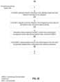
- FIGS. 3 D and 3 Eillustrate methods 360 and 361 for dynamically configuring multi-sensor modules across different types of sensors and space according to embodiments of the current disclosure comprises the following steps:
- de-multiplex unified data packet into homogeneous sensor datastep 372 .
- a point cloudcomprising the homogeneous sensor data and the transform data and send to ADSCU (step 380 )
- step 382determine/adjust control of the vehicle based on the point cloud and generate updated sensor configurations and calibration parameters
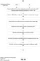
- FIG. 3 Fillustrates a method 390 for updating calibration parameters in a calibration engine according to embodiments of the current disclosure comprises the following steps:
- each sensor modulemay be configured to operate in accordance with a preferred set of parameters.
- FIG. 4 Adepicts sensor module 400 and FIG. 4 B depicts sensor module 402 from which configurable operational parameters may be defined.
- This configurabilitynot only allows for FOV definition but also sensor type configuration within a sensor module. Additionally, this configurability may be implemented at installation or in real-time during operation of the system.
- the sensor modulesmay be configured by defining directionality of one or more sensors within the sensor module using the physical structure of the sensor or by the inclusion of directionality elements (e.g., wedges) that define a direction of a corresponding sensor. As shown in FIG.
- sensor module 402may comprise a plurality of sensors 406 - 413 that are coupled together in particular architecture such that a combination of individual sensor FOVs is stitched together to create a broader FOV of the sensor module.
- This configurability of sensor modulesallows a user to effectively build unique sensor modules by combining the different sensors into diverse architectures.
- the configurabilityis further enhanced by the ability to include different sensor types within the sensor module to enhance performance relative to environmental characteristics in which the module operates.
- a sensor module 402has a horizontal FOV and vertical FOV that corresponds to the combination of sensors 406 - 413 .
- the operational characteristics of each sensor 406 - 413 within the module 402are combined to provide an enhanced modular FOV. These operational characteristics include the directionality of a sensor, the range of a sensor, the FOV of a sensor, the type of a sensor and other characteristics known to one of skill in the art.
- particular sensors within a modulemay be activated or deactivated depending on the environment in which the system is operating.
- particular sensorsmay function as redundant elements in case one or more of the sensors fails or becomes temporarily inoperable.
- the FOV of the sensor modulenot only depends on the specific operational characteristics of each sensor but also on the manner in which data from these sensors is correlated and combined.
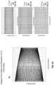
- FIG. 4 Cillustrates a specific example Lissajous scan pattern and resolution 432 based on different vertical FOVs of a sensor according to embodiments of the present disclosure.
- Scan 432illustrates a vertical scan and a horizontal scan resulting from different vertical FOV configurations of a sensor.
- FIG. 4 Cillustrates the scan resolutions for different FOVs.
- FIG. 4 DvFOV 434 illustrates the scan resolution with a 2.5 degree FOV.
- FIG. 4 EvFOV 436 illustrates the scan resolution with a 5 degree FOV.
- FIG. 4 FvFOV 438 illustrates the scan resolution with a 10 degree FOV.
- the resolution achieved with a 2.5 degree FOVis twice as dense as the resolution achieved with a 5 degree FOV.
- the resolution achieved with a 5 degree FOVis twice as dense as the resolution achieved with a 10 degree FOV.
- This exampleillustrates the configurability of a sensor and its resultant affect on scan pattern and resolution.
- One skilled in the artwill recognize that numerous patterns and resolutions may be achieved by configuring a sensor in accordance with aspects of the present disclosure.
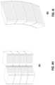
- FIG. 4 Gillustrates an exemplary scanning pattern 440 for a sensor system comprising eight sensors within a sensor module according to embodiments of the present disclosure.
- Scanning pattern 440may be obtained using sensor module architecture 402 in which data sensed across the eight sensors is combined to provide enhanced resolution and field of view.
- Scanning pattern 440comprises scan 446 , scan 447 , scan 448 , scan 449 , scan 450 , scan 451 , scan 452 , and scan 453 that are correlated and processed to generate the pattern.
- the total field of view for sensor module architecture 402is approximately 40 degrees by 120 degrees.
- One skilled in the artwill recognize that a diverse of modular FOVs and other module performance characteristics may be achieved by modifying the way in which sensors are coupled together, the specific parameters of the sensors and the methods in which the sensor data is correlated and analyzed.
- FIG. 4 H and FIG. 4 Iillustrates sensor module configurations 461 and 462 , respectively, according to various embodiments of the invention. These configurations are intended to be exemplary and not limiting to the scope of the invention.
- a sensor module configurationmay be a square or rectangle shape, as illustrated in configuration 461 , in which individual sensor shapes are configured to provide particular operational characteristics within the module.
- Configuration 461comprises two stacked sets of sensors in which physical structures define a FOV for each sensor. For example, physical size and directionality of a sensor may provide different angular and spatial scanning characteristics that are used within the sensor module. As a result, sensor shape and relative locations of the sensors provide a particular scan resolution and FOV.
- a sensor module configurationmay be a wedge shape, as illustrated in configuration 462 , in which physical wedge elements define the directionality of sensors within the module.
- the sensorsare LiDAR sensors with corresponding operational characteristics that allow an MCU to build an enhanced scan pattern with preferred resolution.
- the performance of the sensor systemmay be further enhanced in some embodiments by the inclusion of different sensor types within a sensor module.
- LIDAR sensorsprovide unique capabilities for autonomous driving based primarily on the rate and accuracy at which these sensors operate. These LiDAR sensors create an accurate map that can be quickly and unambiguously processed to make rapid navigation decisions with minimal error.
- certain embodiments of the present inventionsupport non-LiDAR sensors that may be included within a sensor module to supplement the LiDAR sensor data.
- This multi-sensor moduleemploying different types of sensors present unique challenges in the correlation of sensed data across these sensors. Different types of sensors may have different rates of data collection resulting in a more difficult correlation across time. Additionally, different sensors that are closely collocated within the module may be subject to parallax error because data are taken from different vantage points. Accordingly, the use of different types of sensors within a single sensor module further complicates the correlation problem previously described as well as introduces additional complexities within the data analysis and response processing of the system.
- Various embodiments of the inventionprovide a more efficient manner for sensor data correlation across diverse types of sensors by physically combining the different sensors within a single module package.
- This multi-sensor moduleemploying different sensors insures that there is a 1:1 correspondence between data points from the various sensors.
- the sensor data streamcan be presented to the autonomous systems with the various sensor-type data, already combined into a correlated data packet.
- the autonomous system bandwidthcan then be focused on the task of navigation rather than preprocessing and correlation of the mixed data sets.
- the LIDAR detectorcan also passively measure ambient light from the scene to effectively render a passive grayscale value associated with each LIDAR channel.
- the color of an objectcarries important information about its relevance. For example, stop signs and stoplights are red, yellow means caution, green may mean “information” or safe to go and so forth.
- Another key aspect of the real worldis that it is full of living creatures.
- faults in such algorithmshave been demonstrated and may result in errors within the sensor system.
- One key feature of most living animal creatures that an autonomous system may encounteris that they are warm blooded and generally have a different temperature than their surrounding environment. This characteristic can make it possible to monitor the temperature of objects with various thermal detection technologies.
- a thermal sensorincorporated into the LIDAR sensor
- yet another data typecan be incorporated into the single data packet for each data point reported by the sensor, namely the temperature of the associate object.
- the ability to instantly classifies the object as a living creaturehas obvious benefits to rapid autonomous system decision making.
- correlation of diverse sensor datamay be used to derive a confidence factor of an identified object so that a processed response may take into account the likelihood of an object being one type of object versus another type.
- Thermal sensorsprovide real-time 3D thermo-spatial information, allowing for more intelligent machine vision.
- an array of photodetectors sensitive to long IR electromagnetic radiation serving alongside a scanning LIDAR systemcan simultaneously localize objects in a 3D environment and discriminate warm objects (such as living beings) from other objects in a conventional automotive environment.
- Active-tracking systemcan deliver real-time digital information (as opposed to a passive tracking system that delivers a trigger signal) regarding the location and temperature of warm objects to a vehicle control system.
- a single detectorcan provide data over a large area by implementing a fast scanning mechanism.
- a large and dense array of channelscan provide thermo-spatial data of in all directions and with high resolution.
- detectorscan be arranged so that the data is both temporally and spatially correlated with the LiDAR channels.
- sensor typesmay be included within a sensor module and used to improve the performance of the sensor system.
- these different sensor typesmay be used to enhance the performance of a LiDAR system and provide greater accuracy based on certain correlated aspects of sensed data relative to LiDAR data.
- FIG. 4 Jillustrates a sensor system 480 that supports detection of an object 482 using different types of sensors within a sensor module 484 according to various embodiments of the invention.
- a sensor module 484may comprise various combinations of a LiDAR sensor, thermal/far infrared radiation (IR) sensor, visible/near IR sensor as well as other sensor types known to one of skill in the art.
- the sensor module 484receives signals from different sensor types relative to a sensed object 482 .
- the sensor data from each different type of sensoris captured and provided to a multiplexer 488 along corresponding channels 490 - 494 . This data may subsequently be represented on a single cloud point for further processing.
- sensor 484 amay comprise an array of photodetectors sensitive to long IR electromagnetic radiation. Sensor 484 a can simultaneously localize objects in a 3D environment and discriminate warm objects (such as living beings) from other objects in a conventional automotive environment. Sensor 484 b (Visible/NearIR Channel) detects RGB color characteristics of ambient light and may also include sensors to detect other light sources such as near infrared light. Sensor 484 d may also include a sensor for another region of electromagnetic spectrum such as acoustics, radar or sonar. These sensors 484 a , 484 b and 484 d are used to supplement the LiDAR sensor 484 c to provide an enhanced sensor system performance.
- Data multiplexer 488generates a unified data packet 495 representing the correlated data from the different sensors 484 a - d in a unified data packet.
- the datais correlated in that they are acquired from the same point in space (or nearly the same point and unified in that they are bundled into a single data packet).
- LIDAR systemsare implemented with a scanning mirror, as noted in FIG. 2 B , LIDAR system 250 . While providing a solution for scanning, scanning mirror embodiments may be challenged to achieve performance and cost objectives. Some of the challenges can include: 1) a small dual axis mirror, in which each axis is moving by similar electromagnetic mechanisms can generate crosstalk between each of these electromagnetic mechanisms causing perturbations in the motion; 2) a primary axis may need to be driven independently of the motion of a secondary axis and vice versa.
- This actionmay be a challenge because the primary axis motion involves movement of components that are positioned on the secondary axis; 3) a light detector, such as a LIDAR system, may require a feedback mechanism based on where it is scanning at any given moment for assurance of positional accuracy; 4) a scanning mirror assembly, comprising several components, may be mounted to a scanner base via a secondary axis.
- This structuremay make it relatively easy to mechanically induce tension across the secondary axis of resonant spring.
- itmay impose challenges in inducing similar tension in the perpendicular (and suspended) primary axis.
- the tension in each axisis important for isolating and decoupling the motion from the other axis and other external perturbations, such that each axis can be driven with no influence other than its driving mechanism.
- a dual axis resonant scanning mirrorcan be an efficient solution for acquiring light signals for these sensor systems and can overcome the aforementioned issues.
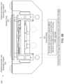
- FIG. 5depicts a scanning mirror assembly 500 according to embodiments of the present disclosure.
- Scanning mirror assembly 500comprises a dual axis resonant scanning mirror.
- a Sensor modulemay incorporate an embodiment of scanning mirror assembly 500 .
- the scanning mirror assembly 500may be composed of the resonant spring 504 , resonant spring assembly 506 , the rocking chair 510 (with electromagnetic drive coils), the scanner base 512 with a set of two secondary axis propulsion magnets 516 , the mirror 502 with a spacer and primary axis propulsion magnets 514 , and the optical sense board 508 .
- Resonant spring 504is a component of resonant spring assembly 506 .
- primary axis 606(not shown in FIG. 5 . See FIG. 6 ) may be driven to resonate with a frequency around 200 Hz in the horizontal axis based on movement by the primary axis propulsion magnets 514 .
- primary axis 606may be driven to resonate with a frequency around 125 Hz in the horizontal axis based on movement by the primary axis propulsion magnets 514 .
- the total optical deflectioncan be +/ ⁇ 30 degrees (60 degrees total).
- the secondary axis 602can be selectively controlled via a servomechanism with a maximum optical deflection of +/ ⁇ 5 degrees (10 degrees total) (not shown in FIG. 5 . See FIG. 6 ).
- the rotation around the secondary axismay be based on the movement of the rocking chair 510 relative to the scanner base 512 .
- the resonant spring assembly 506may be composed of the resonant spring 504 sandwiched in between two frames (coefficient of thermal expansion (CTE) Delta Tensioners), which can create tension across the primary axis upon brazing the assembly, as will be further discussed relative to FIG. 6 .
- the resonant spring assembly 506 , mirror 502 (w/spacer and primary axis propulsion magnets 514 ), and rocking chair 510are all suspended by the secondary axis 602 of the resonant spring 504 .
- the resonant spring assembly 506can be adhered directly to the rocking chair 510 , which contains both the primary axis EM drive coil 802 and secondary axis electromagnetic drive coils 806 .
- electromagticmay be referred to as “EM”. These coils will be further discussed relative to FIG. 8 .
- Mirror 502may sit on top of a mechanical spacer which may sit directly on the primary axis of the resonant spring 504 .
- each secondary axis EM drive coil 806which are embedded into the legs of the rocking chair 510 that extend into the ‘trenches’ of the scanner base 512 (shown in FIG. 5 . and FIG. 8 ).
- This structureplaces each secondary axis EM drive coils 806 adjacent to a set of two secondary axis propulsion magnets 516 which are stationary and adhered to the scanner base 512 .
- This set of two secondary axis propulsion magnets 516are oriented with opposite polarity such that as current is passed through the coil, one magnet will attract the coil and the other will repel it. With the attraction and repulsion of each secondary axis coil synced, rocking chair 510 can rotate about the secondary axis of the resonant spring 504 .
- FIG. 5 Bdepicts a scanning mirror assembly 550 with additional secondary axis coil magnets 556 positioned on a scanner base 512 according to embodiments of the present document.
- the secondary axis propulsion magnets 556are adhered to the scanner base 512 and are positioned on the inside of the legs of the rocking chair 510 to increase the EM interaction and the amount the secondary axis that can be deflected (not shown).
- Secondary axis propulsion magnets 556are positioned on scanner base 512 such that their polarity is the same as those as secondary axis propulsion magnets 516 that are positioned on the outside, as illustrated in FIG. 5 A . These positioning increases the interaction of the secondary axis coils 806 of FIG.
- optical fiber 706Inserted through a hole in both the resonant spring 504 and a mirror spacer, there is an optical fiber 706 that may be butted up against mirror 502 (optical fiber 706 not shown in FIG. 5 . See FIG. 7 ).
- Optical fiber 706may be impregnated with a dye that fluoresces in a visible wavelength when exposed to UV light. The fluoresced light is then guided down optical fiber 706 and illuminates a region of a PSD 710 (position sensitive detector), that may sit on scanner base 512 , which can provide real time mirror position sensing. This structure is further discussed relative to FIG. 7 .
- a sensor system that incorporates scanning mirror assembly 500can provide a single channel subsystem. In some embodiments, this subsystem is facilitated via Sensor 400 and Sensor 401 of FIG. 4 A .
- Sensor 400 and Sensor 401can support a scan field maximum of approximately 60 ⁇ 10 degrees, and a scan field minimum of approximately 60 ⁇ 2.5 degrees.
- An 8 channel composite systemcan incorporate 8 Sensor modules. Each Sensor module incorporates a scanning mirror assembly 500 . In some embodiments, this composite system is facilitated via sensor architecture 402 of FIG. 4 A . Sensor architecture 402 can support a scan field maximum of approximately 120 ⁇ 40 degrees, and a scan field minimum of approximately 120 ⁇ 10 degrees.
- the Sensor modulemay have a firing rate of 160 kHz, a range of approximately 100 meters, a mean resolution of 0.1 degrees minimum, and a spot divergence of 0.5 mRad. All values are approximate. In other embodiments, the firing rate may be 400 kHz.
- FIG. 6depicts a primary access tensioning mechanism 600 for a scanning mirror according to embodiments of the present disclosure.
- This structuremakes it relatively easy to mechanically induce tension across the secondary axis of resonant spring 504 .
- the structuremay impose challenges with inducing similar tension in the perpendicular (and suspended) primary axis 606 .
- the tension in each axiscan be important for isolating and decoupling the motion from the other axis and other external perturbations, such that each axis can be driven with no influence other than its driving mechanism.
- the primary axis torsion spring required under tensions 604is illustrated in FIG. 6 .
- a solution to this problemmay comprise a brazed resonant spring assembly 610 that is devised such that upon soldering/brazing the components together and cooling, tension is induced across the primary axis 606 due to a slight mismatch in CTE (coefficient of thermal expansion).
- FIG. 6also illustrates an exploded resonant spring assembly 616 , with resonant spring 504 and CTE Delta tensioners 614 .
- the brazed resonant spring assembly 610is composed of the resonant spring 504 , which is sandwiched in between two CTE Delta tensioners 614 .
- the CTE Delta tensioners 614are composed of a material that has a slightly lower CTE than that of resonant spring 504 .
- FIG. 7depicts optical position sensor 700 for a scanning mirror according to embodiments of the present document.
- a light detectorsuch as a LIDAR system, may require a feedback mechanism based on where it is scanning at any given moment for assurance of positional accuracy. This assurance may be achieved in a LIDAR system by sensing the position of mirror 502 .
- Necessary criteria for the sensing mechanisminclude high accuracy, small form factor, limited or no additional mass to the moving components, and limited or no interaction with the moving components.
- a solution that may meet the aforementioned criteriamay comprise an optical position sensor 700 that is composed of components: a dye impregnated into an optical fiber 706 , PSD 710 , a UV/IR filter 712 , UV LED 708 , UV LED 709 , prism 702 , prism 703 , and the optical sense PCB.
- Optical fiber 706is specifically impregnated with a dye that fluoresces in the visible spectrum when illuminated with UV light.
- Optical fiber 706may be inserted though the resonant spring 504 and a mirror spacer, and butted up against the backside of mirror 502 such that its axis is normal to the plane of mirror 502 at all times.
- Optical fiber 706may be illuminated with two UV LEDs sitting on the PCB.
- the UV lightcan be guided towards optical fiber 706 , which is dye impregnated, via prism 702 or prism 703 , which sit directly on top of UV LED 708 or UV LED 709 , respectively.
- the number of UV LEDs and prismsmay vary in optical fiber embodiments. For example, but without limitation, in one embodiment, there may be only one UV LED and one corresponding prism. In other embodiments, there may be more than two UV LEDs and more than two corresponding prisms.
- PSD 710When optical fiber 706 fluoresces due to its illumination from the UV LED 708 and UV LED 709 , the visible fluoresced light can be guided down optical fiber 706 to PSD 710 , which may measure the position of the light spot on its active surface.
- the position of the light spot on its active surfacehas a direct relation to the position of mirror 502 , and thus a specific position in the point cloud generated by the mirror's scan.
- a UV/IR filter 712may be required on top of the PSD 710 in order to filter out the UV light from the UV LEDs as well as the IR light from a laser.
- the lasermay be a component of a LIDAR system. Every component of the optical position sensor 700 , except the optical fiber 706 , will sit stationary on the scanner base 512 .
- a sensor modulemay include an embodiment of optical position sensor 700 .
- FIG. 8depicts ever-orthogonal EM drive coils 800 according to embodiments of the present document.
- rocking chair 510has been implemented in some embodiments allows for each axes' drive coil(s), and thus their magnetic fields, to always be orthogonal to each other, regardless of the motion of the whole assembly.
- the primary axis EM drive coil 802is wrapped around the rocking chair 510 in a groove that is just under the plane which the resonant spring assembly sits on. This coil's magnetic field interacts with two magnets placed on either side of the primary axis 606 under mirror 502 .
- the secondary axis EM drive coils 806are embedded into the legs of rocking chair 510 , which extend down into the ‘trenches’ of scanner base 512 . This places each secondary axis EM drive coils 806 adjacent to a set of two secondary axis propulsion magnets 516 , which are stationary and adhered to scanner base 512 . Each set of two secondary axis propulsion magnets 516 are oriented with opposite polarity such that as current is passed through the coil, one magnet will attract the coil and the other will repel it. With the attraction and repulsion of each secondary axis coil synced, rocking chair 510 can rotate about the secondary axis 602 of the resonant spring 504 . As previously noted, FIG. 5 B depicts a scanning mirror assembly 550 with additional secondary axis coil magnets 556 positioned on a scanner base 512 .
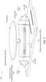
- FIG. 9depicts coaxial drive coils and propulsion magnets 900 according to embodiments of the present document.
- FIG. 9may address the following problem statement: The primary axis needs to be driven independently of the motion of secondary axis 602 . This situation is a challenge because secondary axis 602 motion involves “rocking” the rocking chair 510 on which all of the components of the primary axis 606 sit.
- the primary axis EM drive coil 802may be wound around rocking chair 510 into a groove that is just directly under the plane on which resonant spring assembly 610 is adhered. See drive coil 904 .
- the primary axis propulsion magnets 514are adhered to the bottom of resonant spring (under each end of the mirror spacer), such that they are both coaxial relative primary axis EM drive coil 802 .
- the primary axis propulsion magnets 514are placed such that they have opposite polarity relative to each other, and sit across primary axis 606 from each other under the mirror 502 .
- the induced magnetic fieldforces one magnet up and the other down, which causes the mirror to rotate about the primary axis 606 .
- FIG. 10graphically illustrates a method 1000 of determining the real time mirror positioning for a scanning mirror according to embodiments of the present document. The method comprises the steps of:
- step 1010Determining real time mirror positioning.
- a system for a dual axis resonant scanning mirrormay comprise a resonant spring assembly; a rocking chair with electromagnetic drive coils; a scanner base with secondary axis propulsion magnets; a mirror with a spacer and two primary axis propulsion magnets; and an optical position sense assembly.
- the optical position sense assemblymay comprise a dye impregnated optical fiber, a positive sensitive detector, a UV/IR filter, two UV LEDs with two corresponding prisms.
- dye in the dye impregnated optical fiberfluoresces due to its illumination from the two UV LEDs, visible fluoresced light may be guided down the dye impregnated optical fiber to the positive sensitive detector, which determines mirror positioning.
- the positioning of the mirroris indicated by a light spot on an active surface of the positive sensitive detector.
- an optical position sensorcomprises two or more uv leds with two or more corresponding prisms.
- the systemfurther may comprise: i) a primary axis that resonates at a frequency in an horizontal axis with an primary optical deflection, and ii) a secondary axis that is selectively controlled via a servomechanism to operate in a vertical axis with a secondary optical deflection.
- the primary axismay be driven independent of motion of the secondary axis, and vice-versa, and the primary axis motion involves movement of components that are positioned on the secondary axis.
- the primary axismay have a maximum primary optical deflection of +/ ⁇ 30 degrees
- the secondary axismay have a maximum secondary optical deflection of +/ ⁇ 5 degrees.
- the resonant spring assemblymay comprise a resonant spring sandwiched between two frames that create tension across a primary axis upon brazing the resonant spring assembly.
- the two framescomprise a coefficient of thermal expansion delta tensioners.
- the resonant spring assembly, mirror, and rocking chairmay be suspended by a secondary axis of the resonant spring.
- the resonant spring assemblyis adhered to the rocking chair, which comprises primary and secondary axis electromagnetic drive coils.
- the mirrorsits on the spacer, which sits directly on the primary axis of resonant springs, and wherein the two primary axis propulsion magnets sit underneath the mirror with one primary axis propulsion magnet on each side of the primary axis.
- the electromagnetic drive coilsmay comprise a primary axis electromagnetic drive coil and a set of two secondary axis electromagnetic drive coils, and wherein magnetic fields of i) the primary axis electromagnetic drive coil, and ii) the set of two secondary axis electromagnetic drive coils, are orthogonal to each other, regardless of motion of the system.
- the primary axis electromagnetic drive coilis wrapped around the rocking chair under a plane that a resonant spring sits on, and the magnetic field of the primary axis electromagnetic drive coil interacts with the two primary axis propulsion magnets that are placed on either side of the primary axis under the mirror, causing optical deflection.
- the set of two secondary axis electromagnetic drive coilssynchronize with a set of two secondary axis propulsion magnets, causing the rocking chair to rotate around a second axis of a resonant spring.
- aspects of the present patent documentmay be directed to or implemented on information handling systems/computing systems.
- a computing systemmay include any instrumentality or aggregate of instrumentalities operable to compute, calculate, determine, classify, process, transmit, receive, retrieve, originate, route, switch, store, display, communicate, manifest, detect, record, reproduce, handle, or utilize any form of information, intelligence, or data for business, scientific, control, or other purposes.
- a computing systemmay be a personal computer (e.g., laptop), tablet computer, phablet, personal digital assistant (PDA), smart phone, smart watch, smart package, server (e.g., blade server or rack server), a network storage device, or any other suitable device and may vary in size, shape, performance, functionality, and price.
- the computing systemmay include random access memory (RAM), one or more processing resources such as a central processing unit (CPU) or hardware or software control logic, ROM, and/or other types of memory.
- Additional components of the computing systemmay include one or more disk drives, one or more network ports for communicating with external devices as well as various input and output (I/O) devices, such as a keyboard, a mouse, touchscreen and/or a video display.
- the computing systemmay also include one or more buses operable to transmit communications between the various hardware components.
- FIG. 11depicts a simplified block diagram of a computing device/information handling system (or computing system) according to embodiments of the present disclosure. It will be understood that the functionalities shown for system 1100 may operate to support various embodiments of an information handling system—although it shall be understood that an information handling system may be differently configured and include different components.
- system 1100includes one or more central processing units (CPU) 1101 that provides computing resources and controls the computer.
- CPU 1101may be implemented with a microprocessor or the like, and may also include one or more graphics processing units (GPU) 1117 and/or a floating point coprocessor for mathematical computations.
- System 1100may also include a system memory 1102 , which may be in the form of random-access memory (RAM), read-only memory (ROM), or both.
- RAMrandom-access memory
- ROMread-only memory
- An input controller 1103represents an interface to various input device(s) 1104 , such as a keyboard, mouse, or stylus. There may also be a wireless controller 1105 , which communicates with a wireless device 1106 .
- System 1100may also include a storage controller 1107 for interfacing with one or more storage devices 1108 each of which includes a storage medium such as magnetic tape or disk, or an optical medium that might be used to record programs of instructions for operating systems, utilities, and applications, which may include embodiments of programs that implement various aspects of the present invention.
- Storage device(s) 1108may also be used to store processed data or data to be processed in accordance with the invention.
- System 1100may also include a display controller 1109 for providing an interface to a display device 1111 , which may be a cathode ray tube (CRT), a thin film transistor (TFT) display, or other type of display.
- the computing system 1100may also include an automotive signal controller 1112 for communicating with an automotive system 1113 .
- a communications controller 1114may interface with one or more communication devices 1115 , which enables system 1100 to connect to remote devices through any of a variety of networks including the Internet, a cloud resource (e.g., an Ethernet cloud, an Fiber Channel over Ethernet (FCoE)/Data Center Bridging (DCB) cloud, etc.), a local area network (LAN), a wide area network (WAN), a storage area network (SAN) or through any suitable electromagnetic carrier signals including infrared signals.
- a cloud resourcee.g., an Ethernet cloud, an Fiber Channel over Ethernet (FCoE)/Data Center Bridging (DCB) cloud, etc.
- FCoEFiber Channel over Ethernet
- DCBData Center Bridging
- LANlocal area network
- WANwide area network
- SANstorage area network
- electromagnetic carrier signalsincluding infrared signals.
- bus 1116may represent more than one physical bus.
- various system componentsmay or may not be in physical proximity to one another.
- input data and/or output datamay be remotely transmitted from one physical location to another.
- programs that implement various aspects of this inventionmay be accessed from a remote location (e.g., a server) over a network.
- Such data and/or programsmay be conveyed through any of a variety of machine-readable medium including, but are not limited to: magnetic media such as hard disks, floppy disks, and magnetic tape; optical media such as CD-ROMs and holographic devices; magneto-optical media; and hardware devices that are specially configured to store or to store and execute program code, such as application specific integrated circuits (ASICs), programmable logic devices (PLDs), flash memory devices, and ROM and RAM devices.
- ASICsapplication specific integrated circuits
- PLDsprogrammable logic devices
- flash memory devicesROM and RAM devices.
- Embodiments of the present inventionmay be encoded upon one or more non-transitory computer-readable media with instructions for one or more processors or processing units to cause steps to be performed.
- the one or more non-transitory computer-readable mediashall include volatile and non-volatile memory.
- alternative implementationsare possible, including a hardware implementation or a software/hardware implementation.
- Hardware-implemented functionsmay be realized using ASIC(s), programmable arrays, digital signal processing circuitry, or the like. Accordingly, the “means” terms in any claims are intended to cover both software and hardware implementations.
- the term “computer-readable medium or media” as used hereinincludes software and/or hardware having a program of instructions embodied thereon, or a combination thereof.
- embodiments of the present inventionmay further relate to computer products with a non-transitory, tangible computer-readable medium that have computer code thereon for performing various computer-implemented operations.
- the media and computer codemay be those specially designed and constructed for the purposes of the present invention, or they may be of the kind known or available to those having skill in the relevant arts.
- Examples of tangible computer-readable mediainclude, but are not limited to: magnetic media such as hard disks, floppy disks, and magnetic tape; optical media such as CD-ROMs and holographic devices; magneto-optical media; and hardware devices that are specially configured to store or to store and execute program code, such as application specific integrated circuits (ASICs), programmable logic devices (PLDs), flash memory devices, and ROM and RAM devices.
- ASICsapplication specific integrated circuits
- PLDsprogrammable logic devices
- flash memory devicesand ROM and RAM devices.
- Examples of computer codeinclude machine code, such as produced by a compiler, and files containing higher level code that are executed by a computer using an interpreter.
- Embodiments of the present inventionmay be implemented in whole or in part as machine-executable instructions that may be in program modules that are executed by a processing device.
- Examples of program modulesinclude libraries, programs, routines, objects, components, and data structures. In distributed computing environments, program modules may be physically located in settings that are local, remote, or both.
Landscapes
- Physics & Mathematics (AREA)
- General Physics & Mathematics (AREA)
- Engineering & Computer Science (AREA)
- Optics & Photonics (AREA)
- Computer Networks & Wireless Communication (AREA)
- Radar, Positioning & Navigation (AREA)
- Remote Sensing (AREA)
- Electromagnetism (AREA)
- Microelectronics & Electronic Packaging (AREA)
- Optical Radar Systems And Details Thereof (AREA)
Abstract
Description
Claims (16)
Priority Applications (2)
| Application Number | Priority Date | Filing Date | Title |
|---|---|---|---|
| US16/241,849US11885958B2 (en) | 2019-01-07 | 2019-01-07 | Systems and methods for a dual axis resonant scanning mirror |
| PCT/US2020/012633WO2020146429A1 (en) | 2019-01-07 | 2020-01-07 | Systems and methods for a dual axis resonant scanning mirror |
Applications Claiming Priority (1)
| Application Number | Priority Date | Filing Date | Title |
|---|---|---|---|
| US16/241,849US11885958B2 (en) | 2019-01-07 | 2019-01-07 | Systems and methods for a dual axis resonant scanning mirror |
Publications (2)
| Publication Number | Publication Date |
|---|---|
| US20200218062A1 US20200218062A1 (en) | 2020-07-09 |
| US11885958B2true US11885958B2 (en) | 2024-01-30 |
Family
ID=71403745
Family Applications (1)
| Application Number | Title | Priority Date | Filing Date |
|---|---|---|---|
| US16/241,849Active2042-04-19US11885958B2 (en) | 2019-01-07 | 2019-01-07 | Systems and methods for a dual axis resonant scanning mirror |
Country Status (2)
| Country | Link |
|---|---|
| US (1) | US11885958B2 (en) |
| WO (1) | WO2020146429A1 (en) |
Families Citing this family (2)
| Publication number | Priority date | Publication date | Assignee | Title |
|---|---|---|---|---|
| CN112436887B (en)* | 2020-12-02 | 2025-04-04 | 徐州江煤科技有限公司 | Mine-use intrinsically safe optical fiber identification instrument |
| CN116135496A (en)* | 2021-11-17 | 2023-05-19 | 富泰京精密电子(烟台)有限公司 | autonomous mobile robot |
Citations (596)
| Publication number | Priority date | Publication date | Assignee | Title |
|---|---|---|---|---|
| DE930909C (en) | 1943-03-30 | 1955-07-28 | Hans Dr-Ing Thoma | Hydraulic transmission system |
| US3064252A (en) | 1952-03-31 | 1962-11-13 | Arthur A Varela | Height finding radar system |
| US3373441A (en) | 1966-06-17 | 1968-03-12 | Ernest A. Zadig | Laser speed detector |
| US3551845A (en) | 1968-05-09 | 1970-12-29 | Gen Systems Inc | Transistor-magnetic oscillators incorporating voltage reference means to regulate the output frequency |
| US3636250A (en) | 1964-02-26 | 1972-01-18 | Andrew V Haeff | Apparatus for scanning and reproducing a three-dimensional representation of an object |
| US3686514A (en) | 1971-07-16 | 1972-08-22 | Ney Co J M | Slip ring assembly |
| US3730633A (en) | 1970-12-31 | 1973-05-01 | Aerotherm Corp | Photometric detector and measuring system |
| US3781111A (en) | 1972-03-16 | 1973-12-25 | Nasa | Short range laser obstacle detector |
| US3862415A (en) | 1972-10-31 | 1975-01-21 | Gen Electric | Opto-electronic object detector using semiconductor light source |
| US3897150A (en) | 1972-04-03 | 1975-07-29 | Hughes Aircraft Co | Scanned laser imaging and ranging system |
| US3921081A (en) | 1974-10-30 | 1975-11-18 | Gen Electric | Pulse generator for producing pulses of definable width |
| US4179216A (en) | 1977-05-31 | 1979-12-18 | Franz Plasser Bahnbaumaschinen-Industriegesellschaft M.B.H. | Apparatus for measuring the profile of a railroad tunnel |
| US4199697A (en) | 1978-07-05 | 1980-04-22 | Northern Telecom Limited | Pulse amplitude modulation sampling gate including filtering |
| US4201442A (en) | 1978-10-02 | 1980-05-06 | Sperry Corporation | Liquid crystal switching coupler matrix |
| US4212534A (en) | 1977-09-30 | 1980-07-15 | Siemens Aktiengesellschaft | Device for contact-free measuring of the distance of a surface of an object from a reference plane |
| US4220103A (en) | 1978-08-10 | 1980-09-02 | Aisin Seiki Kabushiki Kaisha | Auxiliary table for sewing machines of a free arm type |
| GB2041687A (en) | 1978-12-18 | 1980-09-10 | Decca Ltd | Narrow beam scanning radar or lidar |
| DE3134815A1 (en) | 1981-09-03 | 1983-03-24 | Fa. Carl Zeiss, 7920 Heidenheim | Area protection |
| DE3216313A1 (en) | 1982-05-03 | 1983-11-03 | Johann F. Dipl.-Phys. 2000 Hamburg Hipp | CONTROL ELECTRONIC DEVICE FOR ELECTROOPTICAL DISTANCE METER WITH LIGHT PULSE RUNNING MEASUREMENT METHOD |
| DE3216312A1 (en) | 1982-05-03 | 1983-11-03 | Johann F. Dipl.-Phys. 2000 Hamburg Hipp | Circuit arrangement for operating pulse-laser diodes |
| CH641583A5 (en) | 1978-04-28 | 1984-02-29 | Zellweger Uster Ag | ROOM MONITORING DEVICE WITH WARNING AND PROTECTIVE ZONES. |
| US4477184A (en) | 1979-01-19 | 1984-10-16 | Nissan Motor Company, Limited | Obstacle detection system for use in vehicles |
| US4516837A (en) | 1983-02-22 | 1985-05-14 | Sperry Corporation | Electro-optical switch for unpolarized optical signals |
| EP0185816A1 (en) | 1984-12-27 | 1986-07-02 | THE GENERAL ELECTRIC COMPANY, p.l.c. | A vehicle guidance and control system |
| US4634272A (en) | 1982-06-02 | 1987-01-06 | Nissan Motor Company, Limited | Optical radar system with an array of photoelectric sensors |
| US4656462A (en) | 1984-04-25 | 1987-04-07 | Matsushita Electric Works, Ltd. | Object detecting apparatus including photosensors for restricted detection area |
| US4681433A (en) | 1978-07-20 | 1987-07-21 | Kern & Co. Ag. | Method and apparatus for measuring relative position |
| US4700301A (en) | 1983-11-02 | 1987-10-13 | Dyke Howard L | Method of automatically steering agricultural type vehicles |
| US4730932A (en) | 1986-01-31 | 1988-03-15 | Kabushiki Kaisha Toshiba | Transmissivity inspection apparatus |
| US4742337A (en) | 1985-08-28 | 1988-05-03 | Telenot Electronic Gmbh | Light-curtain area security system |
| DE3701340A1 (en) | 1986-10-17 | 1988-07-28 | Bayerische Motoren Werke Ag | Obstruction detection device |
| US4834531A (en) | 1985-10-31 | 1989-05-30 | Energy Optics, Incorporated | Dead reckoning optoelectronic intelligent docking system |
| DE3741259A1 (en) | 1987-12-05 | 1989-06-15 | Hipp Johann F | Method and device for the autonomous steering of a vehicle |
| US4862257A (en) | 1988-07-07 | 1989-08-29 | Kaman Aerospace Corporation | Imaging lidar system |
| DE3808972A1 (en) | 1988-03-17 | 1989-10-05 | Hipp Johann F | Device for continuous tracking and position measurement of an object |
| US4895440A (en) | 1988-08-22 | 1990-01-23 | Spectra-Physics, Inc. | Laser-based measurement system |
| US4896343A (en) | 1988-05-02 | 1990-01-23 | Saunders Allan M | Radiation apparatus with distance mapper for dose control |
| US4902126A (en) | 1988-02-09 | 1990-02-20 | Fibertek, Inc. | Wire obstacle avoidance system for helicopters |
| DE3821892C1 (en) | 1988-06-29 | 1990-02-22 | Johann F. Dipl.-Phys. 2000 Hamburg De Hipp | Method and device for position measurement of container repositioning vehicles |
| EP0361188A2 (en) | 1988-09-29 | 1990-04-04 | Fraunhofer-Gesellschaft Zur Förderung Der Angewandten Forschung E.V. | Method for safeguarding a vehicle against collision, and vehicle so safeguarded |
| US4916536A (en) | 1988-11-07 | 1990-04-10 | Flir Systems, Inc. | Imaging range finder and method |
| US4944036A (en) | 1970-12-28 | 1990-07-24 | Hyatt Gilbert P | Signature filter system |
| US4952911A (en) | 1988-05-18 | 1990-08-28 | Eastman Kodak Company | Scanning intrusion detection device |
| US4967183A (en) | 1988-05-18 | 1990-10-30 | Eastman Kodak Company | Method of intrusion detection over a wide area |
| EP0396865A2 (en) | 1989-05-12 | 1990-11-14 | DORNIER GmbH | Optical radar |
| JPH036407A (en) | 1989-06-03 | 1991-01-11 | Daido Steel Co Ltd | Outer circumferential shape measuring device |
| EP0412398A1 (en) | 1989-08-08 | 1991-02-13 | Siemens Aktiengesellschaft | Dug volume measure according to the cutting profile of a bucket wheel excavator or the like |
| EP0412399A1 (en) | 1989-08-08 | 1991-02-13 | Siemens Aktiengesellschaft | Dug volume control for a bucket wheel excavator |
| EP0412395A1 (en) | 1989-08-08 | 1991-02-13 | Siemens Aktiengesellschaft | Bucket wheel excavator steering for building planned surfaces |
| EP0412400A1 (en) | 1989-08-08 | 1991-02-13 | Siemens Aktiengesellschaft | Collision safety device for earth moving machines |
| US5004916A (en) | 1989-07-28 | 1991-04-02 | Ncr Corporation | Scanning system having automatic laser shutdown upon detection of defective scanning element motion |
| US5006721A (en) | 1990-03-23 | 1991-04-09 | Perceptron, Inc. | Lidar scanning system |
| US5023888A (en) | 1972-07-24 | 1991-06-11 | Martin Marietta Corporation | Pulse code recognition method and system |
| US5026156A (en) | 1972-07-24 | 1991-06-25 | Martin Marietta Corporation | Method and system for pulse interval modulation |
| US5033819A (en) | 1989-02-10 | 1991-07-23 | Asahi Kogaku Kogyo Kabushiki Kaisha | Light intercepting device in lens barrel |
| US5059008A (en) | 1990-03-26 | 1991-10-22 | General Electric Company | Wide angle beam steerer using translation of plural lens arrays |
| EP0468175A2 (en) | 1990-12-21 | 1992-01-29 | Kaman Aerospace Corporation | Imaging lidar system employing multipulse single and multiple range gating |
| DE4040894C1 (en) | 1990-12-20 | 1992-04-30 | Eltro Gmbh, Gesellschaft Fuer Strahlungstechnik, 6900 Heidelberg, De | Motor vehicle parking aid using pulsed laser - evaluates signal reflected from obstacle and received by semiconductor diode at rear corner of vehicle |
| EP0486430A2 (en) | 1990-11-12 | 1992-05-20 | Beat Decoi | Light barrier |
| DE4115747A1 (en) | 1991-05-14 | 1992-11-19 | Hipp Johann F | Object and vehicle warning system - uses laser range finder as scanner to identify obstructions or objects ahead of vehicle and issues warning to driver |
| US5175694A (en) | 1990-02-08 | 1992-12-29 | The United States Of America As Represented By The Secretary Of The Navy | Centroid target tracking system utilizing parallel processing of digital data patterns |
| US5177768A (en) | 1991-11-22 | 1993-01-05 | Bell Communications Research, Inc. | Spread-time code division multiple access technique with arbitrary spectral shaping |
| DE4124192A1 (en) | 1991-07-20 | 1993-01-21 | Dornier Luftfahrt | Optical rangefinder for spacing between moving road vehicles - measures propagation time of infrared reflection from preceding vehicle, and gives warning of too near approach |
| DE4127168A1 (en) | 1991-08-16 | 1993-02-18 | Spies Martin J Dipl Ing Fh | Multi-mode signal processor for distance measurement, e.g. between vehicles - has transmitter, receiver, and estimation processor comparing processed data with distance prognosis windows |
| DE4137550A1 (en) | 1990-03-10 | 1993-03-11 | Daimler Benz Ag | Vision improving appts., partic. for vehicle - has semiconductor laser assembly with linear array of several semiconductor laser elements. |
| US5210586A (en) | 1990-06-27 | 1993-05-11 | Siemens Aktiengesellschaft | Arrangement for recognizing obstacles for pilots of low-flying aircraft |
| US5212533A (en) | 1990-11-14 | 1993-05-18 | Kabushiki Kaisha Topcon | Light wave distance meter |
| US5241315A (en) | 1992-08-13 | 1993-08-31 | The United States Of America As Represented By The Administrator Of The National Aeronautics And Space Administration | Micro pulse laser radar |
| US5241481A (en) | 1987-06-22 | 1993-08-31 | Arnex Handelsbolag | Method and a device for laser optical navigation |
| JPH05240940A (en) | 1992-02-26 | 1993-09-21 | Toshihiro Tsumura | Optical measuring system |
| US5249157A (en) | 1990-08-22 | 1993-09-28 | Kollmorgen Corporation | Collision avoidance system |
| DE4215272A1 (en) | 1991-06-15 | 1993-11-11 | Leuze Electronic Gmbh & Co | Transmitter, receiver and circuit for photoelectric intruder detection - evaluates time difference between zero-crossings of signals from photodetector output shaper and modulation-oscillator-driven Schmitt trigger |
| US5291261A (en) | 1990-02-06 | 1994-03-01 | Motorola, Inc. | Optical object detection system incorporating fiber optic coupling |
| US5309212A (en) | 1992-09-04 | 1994-05-03 | Yaskawa Electric Corporation | Scanning rangefinder with range to frequency conversion |
| US5314037A (en) | 1993-01-22 | 1994-05-24 | Shaw David C H | Automobile collision avoidance system |
| US5319201A (en) | 1991-01-29 | 1994-06-07 | The Proximeter Company Limited | Proximity detector |
| DE4340756A1 (en) | 1992-12-08 | 1994-06-09 | Sick Optik Elektronik Erwin | Laser range finder, e.g. for driverless transport system - measures distance using pulse travel time and light deflection angle to determine position of object in measuring region |
| DE4243631A1 (en) | 1992-12-22 | 1994-06-23 | Siemens Ag | Method for controlling a spoil conveyor bridge and spoil conveyor bridge |
| CA2089105A1 (en) | 1993-02-09 | 1994-08-10 | Denis Jacob | Borehole laser cavity monitoring system |
| US5357331A (en) | 1991-07-02 | 1994-10-18 | Flockencier Stuart W | System for processing reflected energy signals |
| JPH06289136A (en) | 1993-03-30 | 1994-10-18 | Sumitomo Electric Ind Ltd | Distance measuring device |
| JPH06288725A (en) | 1993-04-01 | 1994-10-18 | Daido Steel Co Ltd | Diameter measuring device of wire rod |
| US5365218A (en) | 1991-09-14 | 1994-11-15 | Deutsche Aerospace Ag | System for guarding property including a mobile laser unit |
| EP0653720A2 (en) | 1993-11-17 | 1995-05-17 | Symbol Technologies Inc. | Method and apparatus for reading two-dimensional bar code symbols with an elongated laser line |
| EP0656868A1 (en) | 1992-08-28 | 1995-06-14 | Johann F Hipp | Process and device for controlling a portainer. |
| JPH07167609A (en) | 1993-10-20 | 1995-07-04 | Tokyo Electric Power Co Inc:The | Optical vibration detector |
| EP0665446A2 (en) | 1993-11-12 | 1995-08-02 | Nec Corporation | Light beam scanner and integrated laser arrangement used for the scanner |
| CN1106534A (en) | 1993-09-09 | 1995-08-09 | 株式会社拓普康 | Target reflector detection system |
| DE4411448A1 (en) | 1994-03-31 | 1995-10-05 | Sick Optik Elektronik Erwin | Monitoring method for detecting person or vehicle in defined area |
| DE4412044A1 (en) | 1994-04-08 | 1995-10-12 | Leuze Electronic Gmbh & Co | Opto-electronic system for detecting objects in monitoring region |
| US5463384A (en) | 1991-02-11 | 1995-10-31 | Auto-Sense, Ltd. | Collision avoidance system for vehicles |
| US5465142A (en) | 1993-04-30 | 1995-11-07 | Northrop Grumman Corporation | Obstacle avoidance system for helicopters and other aircraft |
| US5515156A (en) | 1993-07-29 | 1996-05-07 | Omron Corporation | Electromagentic wave generating device and a distance measuring device |
| RU2061224C1 (en) | 1993-07-05 | 1996-05-27 | Валерий Михайлович Волынкин | Lydar |
| US5546188A (en) | 1992-11-23 | 1996-08-13 | Schwartz Electro-Optics, Inc. | Intelligent vehicle highway system sensor and method |
| US5563706A (en) | 1993-08-24 | 1996-10-08 | Nikon Corporation | Interferometric surface profiler with an alignment optical member |
| DE19512644A1 (en) | 1995-04-05 | 1996-10-10 | Bayerische Motoren Werke Ag | Method for avoiding a collision of a motor vehicle |
| DE19512681A1 (en) | 1995-04-07 | 1996-10-10 | Hipp Johann | Safety device for collision avoidance of driverless vehicles |
| US5572219A (en) | 1995-07-07 | 1996-11-05 | General Electric Company | Method and apparatus for remotely calibrating a phased array system used for satellite communication |
| JPH0997925A (en) | 1995-09-29 | 1997-04-08 | Pioneer Electron Corp | Light-emitting element driver circuit |
| US5691687A (en) | 1995-07-03 | 1997-11-25 | The United States Of America As Represented By The Administrator Of The National Aeronautics And Space Administration | Contactless magnetic slip ring |
| US5710417A (en) | 1988-10-21 | 1998-01-20 | Symbol Technologies, Inc. | Bar code reader for reading both one dimensional and two dimensional symbologies with programmable resolution |
| US5742384A (en) | 1996-05-02 | 1998-04-21 | Lockheed Martin Corporation | Compact scanning infrared countermeasure emitter |
| US5745050A (en) | 1994-10-21 | 1998-04-28 | Mitsubishi Denki Kabushiki Kaisha | Obstacle detection apparatus for vehicles |
| US5757501A (en) | 1995-08-17 | 1998-05-26 | Hipp; Johann | Apparatus for optically sensing obstacles in front of vehicles |
| US5757677A (en) | 1994-09-08 | 1998-05-26 | Trimble Navigation Limited | Compensation for differences in receiver signals and in satellite signals |
| DE4345448C2 (en) | 1992-12-08 | 1998-07-30 | Sick Ag | Laser range finder, e.g. for driverless transport system |
| US5789739A (en) | 1995-10-26 | 1998-08-04 | Sick Ag | Optical detection device for determining the position of an indicator medium |
| US5793491A (en) | 1992-12-30 | 1998-08-11 | Schwartz Electro-Optics, Inc. | Intelligent vehicle highway system multi-lane sensor and method |
| US5805468A (en) | 1995-05-09 | 1998-09-08 | Erwin Sick Gmbh Optik-Elektronik | Method and apparatus for determining the light transit time over a measurement path arranged between a measuring apparatus and a reflecting object |
| US5808728A (en) | 1994-10-21 | 1998-09-15 | Mitsubishi Denki Kabushiki Kaisha | Vehicle environment monitoring system |
| US5847817A (en) | 1997-01-14 | 1998-12-08 | Mcdonnell Douglas Corporation | Method for extending range and sensitivity of a fiber optic micro-doppler ladar system and apparatus therefor |
| US5847815A (en) | 1996-10-22 | 1998-12-08 | Thomson-Csf | Monostatic lidar system |
| WO1999003080A1 (en) | 1997-07-11 | 1999-01-21 | Laser Guard Ltd. | Intruder detector system |
| DE19727792A1 (en) | 1997-06-30 | 1999-02-04 | Sick Ag | Light scanner for detecting objects within scanning range |
| EP0897120A2 (en) | 1997-08-13 | 1999-02-17 | Schmersal-EOT GmbH & Co. KG | Apparatus for localisation of objects penetrating a monitored space |
| US5877688A (en) | 1995-04-12 | 1999-03-02 | Matsushita Electric Industrial Co., Ltd. | Thermal object measuring apparatus |
| US5889479A (en) | 1994-03-02 | 1999-03-30 | Johann Hipp | Apparatus for guiding the pilot of an aircraft approaching its parking position |
| DE19741731A1 (en) | 1997-09-22 | 1999-04-01 | Sick Ag | System for optical scanning surface, especially cavities and inner spaces |
| DE19741730A1 (en) | 1997-09-22 | 1999-04-01 | Sick Ag | Method to determine surface contour of objects |
| US5895984A (en) | 1995-12-13 | 1999-04-20 | Leica Geosystems Ag | Circuit arrangement for feeding a pulse output stage |
| EP0913707A1 (en) | 1997-10-31 | 1999-05-06 | LAP GmbH Laser Applikationen | Method for contactless measurement of the distance to an object using the principle of laser triangulation |
| US5903386A (en) | 1998-01-20 | 1999-05-11 | Northrop Grumman Corporation | Tilted primary clamshell lens laser scanner |
| DE19752145A1 (en) | 1997-11-25 | 1999-05-27 | Hipp Johann F | Optical supervision arrangement for vehicle interior |
| DE19717399A1 (en) | 1997-04-24 | 1999-06-17 | Spies Martin Dipl Ing Fh | Arrangement for determining the distances and types of objects, e.g. vehicles |
| DE19757849A1 (en) | 1997-12-24 | 1999-07-08 | Hipp Johann F | Scanner for arrangement for optical detection of objects |
| DE19757848A1 (en) | 1997-12-24 | 1999-07-08 | Johann Hipp | Optical detection apparatus |
| US5923910A (en) | 1995-02-22 | 1999-07-13 | Asahi Kogaku Kogyo Kabushiki Kaisha | Distance measuring apparatus |
| DE19757847A1 (en) | 1997-12-24 | 1999-07-15 | Hipp Johann F | Scanner for optical object detection arrangement, especially in immediate vicinity of motor vehicles |
| US5942688A (en) | 1994-11-18 | 1999-08-24 | Mitsubishi Denki Kabushiki Kaisha | Apparatus and method for detecting a measurable quantity of an object |
| EP0937996A2 (en) | 1998-02-18 | 1999-08-25 | Schmersal-EOT GmbH & Co. KG | Transit-time of light counter with correcting circuit |
| US5949530A (en) | 1996-02-27 | 1999-09-07 | Sick Ag | Laser range finding apparatus |
| US5953110A (en) | 1998-04-23 | 1999-09-14 | H.N. Burns Engineering Corporation | Multichannel laser radar |
| JPH11264871A (en) | 1998-03-17 | 1999-09-28 | Komatsu Ltd | Monitoring mechanism of vehicle obstacle detection device |
| DE19757840C1 (en) | 1997-12-24 | 1999-09-30 | Johann F Hipp | Optical object detection and range measuring device for autonomous vehicle |
| DE19815149A1 (en) | 1998-04-03 | 1999-10-07 | Leuze Electronic Gmbh & Co | Arrangement of optoelectronic distance sensors for detecting objects |
| US5991011A (en) | 1996-11-14 | 1999-11-23 | Sick Ag | Laser distance finding apparatus |
| EP0967492A1 (en) | 1998-06-24 | 1999-12-29 | Schmersal-EOT GmbH & Co. KG | Method for opto-electronic surveillance of a guard area |
| US6034803A (en) | 1997-04-30 | 2000-03-07 | K2 T, Inc. | Method and apparatus for directing energy based range detection sensor |
| US6043868A (en) | 1996-08-23 | 2000-03-28 | Laser Technology, Inc. | Distance measurement and ranging instrument having a light emitting diode-based transmitter |
| WO2000025089A1 (en) | 1998-10-28 | 2000-05-04 | Measurement Devices Limited | Apparatus and method for obtaining 3d images |
| US6069565A (en) | 1992-10-20 | 2000-05-30 | Rosemount Aerospace Inc. | System for detecting ice or snow on surface which specularly reflects light |
| DE19902903C1 (en) | 1999-01-26 | 2000-05-31 | Schmersal Eot Gmbh & Co Kg | Arrangement for locating object entering monitored space has light scattering test zone on reception mirror outside effective zone for received light to deflect part of incident light to receiver |
| US6088085A (en) | 1997-02-05 | 2000-07-11 | Sick Ag | Range measurement apparatus |
| US6091071A (en) | 1996-04-18 | 2000-07-18 | Sick Ag | Opto-electronic sensor |
| US6100539A (en) | 1997-01-20 | 2000-08-08 | Sick Ag | Light sensor with evaluation of the light transit time |
| DE19911375A1 (en) | 1999-03-15 | 2000-09-21 | Johann F Hipp | Missile position detection device for practice firing, includes transmitter for transmitting light-beam into zone of intersection of fields of view |
| US6137566A (en) | 1999-02-24 | 2000-10-24 | Eoo, Inc. | Method and apparatus for signal processing in a laser radar receiver |
| EP1046938A2 (en) | 1999-04-23 | 2000-10-25 | Sick AG | Connection device |
| DE19919925A1 (en) | 1999-04-30 | 2000-11-16 | Siemens Ag | Arrangement and method for the simultaneous measurement of the speed and the surface shape of moving objects |
| DE19927501A1 (en) | 1999-05-22 | 2000-11-23 | Volkswagen Ag | Transmitter for laser scanner has laser light source for generating laser light beam(s) that is radiated in rotary manner and that has vertically expanding beam profile |
| US6153878A (en) | 1997-08-13 | 2000-11-28 | Schmersal-Eot Gmbh & Co. Kg | Device for locating objects penetrating into a region of space to be monitored |
| EP1055937A2 (en) | 1999-05-22 | 2000-11-29 | Volkswagen Aktiengesellschaft | Receiver device for a laser scanner |
| US6157294A (en) | 1997-12-27 | 2000-12-05 | Honda Giken Kogyo Kabushiki Kaisha | Vehicle obstacle detecting system |
| JP2001050723A (en) | 1999-08-11 | 2001-02-23 | Minolta Co Ltd | Distance measuring equipment |
| US6201236B1 (en) | 1997-11-13 | 2001-03-13 | Auto Sense Ltd. | Detection system with improved noise tolerance |
| DE19936440A1 (en) | 1999-08-03 | 2001-03-15 | Leuze Electronic Gmbh & Co | Optoelectronic device for detecting objects, uses transmitters to emit light rays, receiver to pick up transmitted light rays, and multiple receiving elements fitted at preset distances from each other |
| WO2001031608A1 (en) | 1999-10-27 | 2001-05-03 | Sick Ag | Device for controlling the flow of traffic at a crossroads, especially for controlling traffic lights |
| DE19953007A1 (en) | 1999-10-27 | 2001-05-03 | Johann F Hipp | Device to monitor traffic in two-lane street in multi-storey car park, has sensor unit to emit two spaced light beams and evaluation unit to detect cars from profile of beam meeting points |
| DE19953009A1 (en) | 1999-10-27 | 2001-05-03 | Johann Hipp | Device to monitor occupancy of designated parking spaces has sensor unit arranged above designated spaces with laser beam transmitter and detector to monitor presence of vehicles in spaces |
| DE19953006A1 (en) | 1999-10-27 | 2001-05-03 | Johann F Hipp | Device for controlling traffic flow near junction, especially with traffic lights, evaluates fan beam incident point profile, associates with individual spatially related incident point object groups |
| DE19953010A1 (en) | 1999-10-27 | 2001-05-03 | Johann F Hipp | Device to control passage of vehicles for multi-storey car park, has sensor unit to emit two spaced light beams and evaluation unit to detect cars from profile of beam meeting points |
| US6259714B1 (en) | 1997-09-09 | 2001-07-10 | Mitsubishi Denki Kabushiki Kaisha | Power source control apparatus for laser diode |
| US20010011289A1 (en) | 1998-05-29 | 2001-08-02 | Michael A. Davis | Method for improving the accuracy in the determination of a waveform center of a waveform signal |
| JP2001216592A (en) | 2000-02-03 | 2001-08-10 | Mitsubishi Cable Ind Ltd | Road surface state detector of road |
| US20010017718A1 (en) | 1996-06-24 | 2001-08-30 | Nikon Corporation | Film image reading device and storage medium which stores the control process for the film image reading device |
| JP2001256576A (en) | 2000-03-09 | 2001-09-21 | Ishikawajima Harima Heavy Ind Co Ltd | Fire monitoring system |
| US6297844B1 (en) | 1999-11-24 | 2001-10-02 | Cognex Corporation | Video safety curtain |
| EP1148345A1 (en) | 2000-04-19 | 2001-10-24 | Schmersal-EOT GmbH & Co. KG | Apparatus for localisation of objects penetrating a monitored space |
| US20010035946A1 (en) | 1998-11-24 | 2001-11-01 | Hamamatsu Photonics K.K | Light-projecting/receiving unit and omnidirectional distance detecting apparatus |
| US6321172B1 (en) | 1998-02-12 | 2001-11-20 | Schmersal-Eot Gmbh & Co. Kg | Method for configuring sensors |
| EP1160718A2 (en) | 2000-05-29 | 2001-12-05 | Sick Ag | Laser scanner |
| DE10025511C1 (en) | 2000-05-23 | 2001-12-06 | Schmersal Eot Gmbh & Co Kg | Object location device for surveillance system with integrated detection of soiling level of housing window |
| US6327806B1 (en) | 1996-09-25 | 2001-12-11 | Firearms Research Limited | Optical sighting devices |
| US6329800B1 (en) | 2000-10-17 | 2001-12-11 | Sigmatel | Method and apparatus for reducing power consumption in driver circuits |
| US6335789B1 (en) | 1998-02-25 | 2002-01-01 | Honda Giken Kogyo Kabushiki Kaisha | Optical radar system |
| US20020003617A1 (en) | 1999-03-18 | 2002-01-10 | Guenter Doemens | Spatially resolving range-finding system |
| EP1174733A2 (en) | 2000-07-21 | 2002-01-23 | Leuze electronic GmbH + Co. | Optical sensor |
| JP2002031528A (en) | 2000-07-14 | 2002-01-31 | Asia Air Survey Co Ltd | Spatial information generator for mobile mapping |
| US6365429B1 (en) | 1998-12-30 | 2002-04-02 | Xerox Corporation | Method for nitride based laser diode with growth substrate removed using an intermediate substrate |
| US20020060784A1 (en) | 2000-07-19 | 2002-05-23 | Utah State University | 3D multispectral lidar |
| US6396577B1 (en) | 2001-03-19 | 2002-05-28 | Thomas P. Ramstack | Lidar-based air defense system |
| US6420698B1 (en) | 1997-04-24 | 2002-07-16 | Cyra Technologies, Inc. | Integrated system for quickly and accurately imaging and modeling three-dimensional objects |
| US20020109074A1 (en) | 2000-12-28 | 2002-08-15 | Mamoru Uchida | Semiconductor device, optoelectronic board, and production methods therefor |
| US6441889B1 (en) | 2000-11-29 | 2002-08-27 | P.A.T.C.O. Properties, Inc. | LIDAR with increased emitted laser power |
| US6442476B1 (en) | 1998-04-15 | 2002-08-27 | Research Organisation | Method of tracking and sensing position of objects |
| US6441363B1 (en) | 1999-02-24 | 2002-08-27 | Siemens Vdo Automotive Corporation | Vehicle occupant sensing system |
| US20020117545A1 (en) | 2000-06-07 | 2002-08-29 | Metrologic Instruments, Inc. | Method of and system for producing images of objects using planar laser illumination beams and image detection arrays |
| DE10110420A1 (en) | 2001-03-05 | 2002-09-12 | Sick Ag | Device for determining a distance profile |
| US6473079B1 (en) | 1996-04-24 | 2002-10-29 | Cyra Technologies, Inc. | Integrated system for quickly and accurately imaging and modeling three-dimensional objects |
| DE10114362A1 (en) | 2001-03-22 | 2002-10-31 | Martin Spies | Hybrid laser scanner system for distance measurement has rotated pulsed light source, only one detector with light sensitive element with circular surface and diameter of slot aperture |
| DE10127417A1 (en) | 2001-06-06 | 2002-12-12 | Ibeo Automobile Sensor Gmbh | Transport protocol system for communication between units and a host using data packets with identification |
| EP1267177A1 (en) | 2001-06-15 | 2002-12-18 | IBEO Automobile Sensor GmbH | Method and device for objects location finding in space |
| DE10128954A1 (en) | 2001-06-15 | 2002-12-19 | Ibeo Automobile Sensor Gmbh | Monitoring method of spatial areas for moving or stationary objects using a laser scanning system, e.g. for monitoring the area in front of a motor vehicle, ensures that only one object is detected in an overlapping zone |
| US6504712B2 (en) | 1999-06-01 | 2003-01-07 | Showa Denka K.K. | Heat sinks for CPUs for use in personal computers |
| US6509958B2 (en) | 2000-05-31 | 2003-01-21 | Sick Ag | Method for distance measurement and a distance measuring device |
| EP1286178A2 (en) | 2001-08-23 | 2003-02-26 | IBEO Automobile Sensor GmbH | Method for optical ground detection |
| EP1286181A1 (en) | 2001-08-20 | 2003-02-26 | IBEO Automobile Sensor GmbH | Driving of vehicles |
| US20030041079A1 (en) | 2001-08-14 | 2003-02-27 | Cidra Corporation | Method for reducing skew in a real-time centroid calculation |
| EP1288677A2 (en) | 2001-09-03 | 2003-03-05 | Sick AG | Optoelectronic detecting device with a memory device |
| US20030043364A1 (en) | 2001-09-04 | 2003-03-06 | Jamieson James R. | System and method of measuring flow velocity in three axes |
| DE10141055A1 (en) | 2001-08-22 | 2003-03-06 | Ibeo Automobile Sensor Gmbh | Detecting and tracking objects involves associating at least one object with object box as static characteristic representing extent of object in image plane, using dynamic state variables |
| US20030043363A1 (en) | 2001-09-04 | 2003-03-06 | Jamieson James R. | Combined loas and lidar system |
| WO2003019234A1 (en) | 2001-08-22 | 2003-03-06 | Ibeo Automobile Sensor Gmbh | Method for detecting and tracking objects |
| EP1291673A2 (en) | 2001-09-03 | 2003-03-12 | Sick AG | Optoelectronic distance measuring device |
| EP1291674A2 (en) | 2001-09-03 | 2003-03-12 | IBEO Automobile Sensor GmbH | Method for recognising and tracking objects |
| DE10143060A1 (en) | 2001-09-03 | 2003-03-20 | Sick Ag | Vehicle laser scanner transmits wide beam front towards moving deflector, causing reflective front to adopt various orientations in scanned space |
| US20030057533A1 (en) | 1999-12-21 | 2003-03-27 | Francesco Lemmi | Amorphous silicon sensor with micro-spring interconnects for achieving high uniformity in integrated light-emitting sources |
| EP1298012A2 (en) | 2001-09-28 | 2003-04-02 | IBEO Automobile Sensor GmbH | Method for recognizing and tracking objects |
| EP1298454A2 (en) | 2001-09-28 | 2003-04-02 | IBEO Automobile Sensor GmbH | Method for recognising and tracking objects |
| EP1298453A2 (en) | 2001-09-28 | 2003-04-02 | IBEO Automobile Sensor GmbH | Method for recognising and tracking objects |
| US20030066977A1 (en) | 2001-09-03 | 2003-04-10 | Sick Ag | Optoelectronic distance measuring device |
| EP1302784A2 (en) | 2001-10-09 | 2003-04-16 | IBEO Automobile Sensor GmbH | Method for determining visibility |
| DE10148070A1 (en) | 2001-09-28 | 2003-04-17 | Ibeo Automobile Sensor Gmbh | Recognition and tracking of objects in e.g. road scene using laser scanner, detects further object characteristics which are used for segment-object-allocation |
| EP1304583A2 (en) | 2001-10-22 | 2003-04-23 | IBEO Automobile Sensor GmbH | Method for recognising and/or tracking objects |
| US20030076485A1 (en) | 2001-06-29 | 2003-04-24 | Ruff William C. | Ladar system for detecting objects |
| DE10146692A1 (en) | 2001-09-21 | 2003-04-30 | Martin Spies | Hybrid distance image sensor uses rotation of polygonal deflection rod for simultaneous deflection of transmission and reception surfaces for electromagnetic waves |
| DE10151983A1 (en) | 2001-10-22 | 2003-04-30 | Ibeo Automobile Sensor Gmbh | Method for automatic documentation of a traffic accident and recording of the layout of vehicles and objects involved in it, by use of a laser measurement device with an associated differential global positioning system |
| EP1306690A2 (en) | 2001-09-28 | 2003-05-02 | IBEO Automobile Sensor GmbH | Method for recognising and tracking objects |
| EP1308747A2 (en) | 2001-10-22 | 2003-05-07 | IBEO Automobile Sensor GmbH | Opto-electronic detecting device |
| WO2003040755A1 (en) | 2001-11-08 | 2003-05-15 | Siemens Aktiengesellschaft | Laser grid for measuring distance |
| US20030090646A1 (en) | 2001-11-09 | 2003-05-15 | Johannes Riegl | Apparatus for taking up an object space |
| US6593582B2 (en) | 2001-05-11 | 2003-07-15 | Science & Engineering Services, Inc. | Portable digital lidar system |
| DE10162668A1 (en) | 2001-12-19 | 2003-07-17 | Martin Spies | Auto adaptive signal processing for measuring a distance using electromagnetic pulse propagation time process, e.g. for adaptive cruise control or vehicle collision prevention |
| US20030163030A1 (en) | 2002-02-25 | 2003-08-28 | Arriaga Moises A. | Hollow endoscopy |
| US6621764B1 (en) | 1997-04-30 | 2003-09-16 | Thomas Smith | Weapon location by acoustic-optic sensor fusion |
| EP1355128A1 (en) | 2002-04-18 | 2003-10-22 | Sick Ag | Automatic alignment of a sensor |
| DE10217295A1 (en) | 2002-04-18 | 2003-11-06 | Ibeo Automobile Sensor Gmbh | Determination of the alignment of an optoelectronic sensor |
| US6646725B1 (en) | 2001-07-11 | 2003-11-11 | Iowa Research Foundation | Multiple beam lidar system for wind measurement |
| US6650402B2 (en) | 2000-02-10 | 2003-11-18 | Oceanit Laboratories, Inc. | Omni-directional cloud height indicator |
| JP2003336447A (en) | 2002-05-21 | 2003-11-28 | Nabco Ltd | Automatic door device and its touch sensor |
| DE10222797A1 (en) | 2002-05-23 | 2003-12-04 | Sick Ag | Instrument determining distance between sensor and object by triangulation, employs analyzer and separate compensating beam |
| US6665063B2 (en) | 2001-09-04 | 2003-12-16 | Rosemount Aerospace Inc. | Distributed laser obstacle awareness system |
| US6670905B1 (en) | 1999-06-14 | 2003-12-30 | Escort Inc. | Radar warning receiver with position and velocity sensitive functions |
| DE10229408A1 (en) | 2002-06-29 | 2004-01-15 | Leuze Electronic Gmbh + Co Kg | Optical sensor for detecting objects or edges, has receiving lens for focussing light from detection region onto row of receiving elements |
| US6682478B2 (en) | 2001-02-08 | 2004-01-27 | Olympus Optical Co., Ltd. | Endoscope apparatus with an insertion part having a small outer diameter which includes and object optical system |
| US6687373B1 (en) | 1999-08-24 | 2004-02-03 | Nortel Networks Limited | Heusristics for optimum beta factor and filter order determination in echo canceler systems |
| US6687033B2 (en) | 2000-01-19 | 2004-02-03 | Sick Ag | Optical scanning device |
| US20040021852A1 (en) | 2002-02-04 | 2004-02-05 | Deflumere Michael E. | Reentry vehicle interceptor with IR and variable FOV laser radar |
| WO2004019293A2 (en) | 2002-08-23 | 2004-03-04 | Ibeo Automobile Sensor Gmbh | Monitoring the environment of an object with adjustable monitoring criteria |
| US6710324B2 (en) | 2001-10-29 | 2004-03-23 | Sick Ag | Optoelectronic distance measuring device |
| EP1403657A1 (en) | 2002-09-25 | 2004-03-31 | IBEO Automobile Sensor GmbH | Optoelectronic detecting device |
| US20040066500A1 (en) | 2002-10-02 | 2004-04-08 | Gokturk Salih Burak | Occupancy detection and measurement system and method |
| DE10244640A1 (en) | 2002-09-25 | 2004-04-08 | Ibeo Automobile Sensor Gmbh | Optoelectronic position monitoring system for use on road vehicle uses laser scanner and sensor module with mirror set at angle on shaft with calibration disk driven by electric motor |
| DE10244643A1 (en) | 2002-09-25 | 2004-04-08 | Ibeo Automobile Sensor Gmbh | Optoelectronic position monitoring system for road vehicle has two pulsed lasers, sensor and mechanical scanner with rotating mirror at 45 degrees to shaft with calibration disk adjacent to reader |
| DE10244638A1 (en) | 2002-09-25 | 2004-04-08 | Ibeo Automobile Sensor Gmbh | Position monitoring system for use on road vehicle uses pulsed lasers, sensor module and mechanical scanner with mirror set at angle on shaft with calibration disk driven by electric motor |
| EP1408318A1 (en) | 2002-10-11 | 2004-04-14 | Sick AG | Sensor |
| WO2004036245A2 (en) | 2002-09-25 | 2004-04-29 | Ibeo Automobile Sensor Gmbh | Optoelectronic detection device |
| EP1418444A1 (en) | 2002-11-11 | 2004-05-12 | IBEO Automobile Sensor GmbH | Method for determining the yaw rate of a vehicle |
| DE10258794A1 (en) | 2002-12-16 | 2004-06-24 | Ibeo Automobile Sensor Gmbh | Detecting/tracking objects, e.g. before vehicles, involves using object profile from image points to predict contours for objects in preceding cycle starting from respective profile in preceding cycle |
| US20040134879A1 (en) | 2002-10-16 | 2004-07-15 | Lake Shore Cryotronics, Inc. | Method of manufacturing a spectral filter for green and longer wavelengths |
| US20040150810A1 (en) | 2003-01-31 | 2004-08-05 | Muenter Steven E. | Laser range finding apparatus |
| DE10303015A1 (en) | 2003-01-27 | 2004-08-12 | Daimlerchrysler Ag | Device for detecting environment around motor vehicle, uses system with rotating laser scanner and catadioptric camera |
| JP2004241915A (en) | 2003-02-04 | 2004-08-26 | Sumitomo Electric Ind Ltd | Optical transmitting / receiving module, optical transmitting module and optical receiving module |
| US6789527B2 (en) | 2000-09-04 | 2004-09-14 | Robert Bosch Gmbh | Method for adaptively controlling knocking of a gasoline direct fuel injection internal combustion engine, and a corresponding device |
| EP1460454A2 (en) | 2003-03-19 | 2004-09-22 | IBEO Automobile Sensor GmbH | Method for combined processing of high resolution images and video images |
| US6798527B2 (en) | 2001-04-27 | 2004-09-28 | Minolta Co., Ltd. | Three-dimensional shape-measuring system |
| US20040213463A1 (en) | 2003-04-22 | 2004-10-28 | Morrison Rick Lee | Multiplexed, spatially encoded illumination system for determining imaging and range estimation |
| US6812450B2 (en) | 2001-03-05 | 2004-11-02 | Sick Ag | Method and an apparatus for monitoring a protected zone |
| EP1475764A2 (en) | 2003-05-02 | 2004-11-10 | IBEO Automobile Sensor GmbH | Method and apparatus for calculating the probability of a collision between a vehicle and an object |
| US20040240706A1 (en) | 2003-05-28 | 2004-12-02 | Trw Automotive U.S. Llc | Method and apparatus for determining an occupant' s head location in an actuatable occupant restraining system |
| US20040240710A1 (en) | 2001-08-07 | 2004-12-02 | Ulrich Lages | Method for determining a model roadway |
| US20040247157A1 (en) | 2001-06-15 | 2004-12-09 | Ulrich Lages | Method for preparing image information |
| JP2004348575A (en) | 2003-05-23 | 2004-12-09 | Foundation For The Promotion Of Industrial Science | Three-dimensional model construction system and its program |
| DE10331529A1 (en) | 2003-07-11 | 2005-01-27 | Ibeo Automobile Sensor Gmbh | Optoelectronic detection device, especially laser scanner, has inlet and outlet surfaces for electromagnetic radiation confined within housing having spherical shape |
| CN1576123A (en) | 2003-07-03 | 2005-02-09 | 黄保家 | Anticollision system for motor vehicle |
| CN2681085Y (en) | 2003-07-22 | 2005-02-23 | 烟台麦特电子有限公司 | Apparatus for measuring three dimensional size using laser |
| EP1515157A1 (en) | 2003-09-09 | 2005-03-16 | IBEO Automobile Sensor GmbH | Optoelectronic detecting device |
| JP2005070840A (en) | 2003-08-25 | 2005-03-17 | East Japan Railway Co | 3D model creation device, 3D model creation method, and 3D model creation program |
| US6876790B2 (en) | 2002-05-17 | 2005-04-05 | Science & Engineering Services, Inc. | Method of coupling a laser signal to an optical carrier |
| US6879419B2 (en) | 2002-12-05 | 2005-04-12 | Northrop Grumman Corporation | Laser scanner with peripheral scanning capability |
| EP1531343A1 (en) | 2003-11-14 | 2005-05-18 | IBEO Automobile Sensor GmbH | Method for tracking objects |
| EP1531342A1 (en) | 2003-11-14 | 2005-05-18 | IBEO Automobile Sensor GmbH | Method of detecting pedestrians |
| EP1548351A2 (en) | 2003-12-23 | 2005-06-29 | Leuze lumiflex GmbH + Co. KG | Device for monitoring an area at a machine |
| EP1557694A1 (en) | 2004-01-26 | 2005-07-27 | IBEO Automobile Sensor GmbH | Object sorting process |
| EP1557693A1 (en) | 2004-01-26 | 2005-07-27 | IBEO Automobile Sensor GmbH | Method for tracking objects |
| EP1557692A1 (en) | 2004-01-26 | 2005-07-27 | IBEO Automobile Sensor GmbH | Method for detecting marked hazardous locations and/or road works in the vicinity of roadways |
| EP1557691A1 (en) | 2004-01-26 | 2005-07-27 | IBEO Automobile Sensor GmbH | Method for recognizing markings on a road |
| US20050168720A1 (en) | 2004-02-04 | 2005-08-04 | Nidec Corporation | Scanning Rangefinder |
| DE102004010197A1 (en) | 2004-03-02 | 2005-09-15 | Ibeo Automobile Sensor Gmbh | Digital board or car navigation system function checking procedure uses separate object detection imaging system for comparison |
| US20050211893A1 (en) | 2002-04-10 | 2005-09-29 | Paschalidis Nicholas P | Time of flight system on a chip |
| DE102004014041A1 (en) | 2004-03-19 | 2005-10-13 | Martin Spies | Air and ground vehicle obstruction detection system has multiple channel range measurement system in rotating head with colour and contrast measurement |
| US20050232466A1 (en) | 2004-04-19 | 2005-10-20 | Ibeo Automobile Sensor Gmbh | Method of recognizing and/or tracking objects |
| JP2005297863A (en) | 2004-04-14 | 2005-10-27 | Bunpei Sono | Safety system of vehicle |
| US20050246065A1 (en) | 2004-05-03 | 2005-11-03 | Benoit Ricard | Volumetric sensor for mobile robotics |
| US20050248749A1 (en) | 2004-05-10 | 2005-11-10 | Ibeo Automobile Sensor Gmbh | Method and an apparatus for distance measurement |
| US6969558B2 (en) | 1992-10-13 | 2005-11-29 | General Electric Company | Low sulfur article having a platinum-aluminide protective layer, and its preparation |
| US20050279914A1 (en) | 2004-03-16 | 2005-12-22 | Jerry Dimsdale | Contact-free slip ring for survey instrumentation |
| US20060007350A1 (en) | 2004-07-12 | 2006-01-12 | Honeywell International, Inc. | Rotatable wireless electrical coupler |
| US20060073621A1 (en) | 2004-10-01 | 2006-04-06 | Palo Alto Research Center Incorporated | Group III-nitride based HEMT device with insulating GaN/AlGaN buffer layer |
| US7030968B2 (en) | 2000-11-24 | 2006-04-18 | Mensi | Device for the three-dimensional recording of a scene using laser emission |
| CN2773714Y (en) | 2005-02-21 | 2006-04-19 | 王治平 | Laser scanning detector |
| US20060089765A1 (en) | 2004-10-22 | 2006-04-27 | Pack Robert T | System and method for behavior based control of an autonomous vehicle |
| US7041962B2 (en) | 2002-07-05 | 2006-05-09 | Sick Ag | Laser scanning apparatus |
| US20060100783A1 (en) | 2004-10-21 | 2006-05-11 | Sick Ag | Monitoring the surroundings of a vehicle |
| DE102005050824A1 (en) | 2004-11-17 | 2006-05-24 | Heidelberger Druckmaschinen Ag | Dangerous area protecting method for use in sheet rotation printing machine, involves monitoring dangerous area by sensor, detecting position of object penetrating cross section and activating machine based on detected position |
| US20060132635A1 (en) | 2004-12-20 | 2006-06-22 | Land Jay E | Single axis CCD time gated ladar sensor |
| JP2006177843A (en) | 2004-12-24 | 2006-07-06 | Pulstec Industrial Co Ltd | Three-dimensional shape measuring apparatus |
| DE102005003827A1 (en) | 2005-01-26 | 2006-07-27 | Fraunhofer-Gesellschaft zur Förderung der angewandten Forschung e.V. | Interactive device for cooperation between a person and a robot unit at a work station with a robot unit has sensor units to detect how close the person is |
| US20060176697A1 (en) | 2005-02-08 | 2006-08-10 | Arruda Steven S | Combination light fixture and motion sensor apparatus |
| US20060186326A1 (en) | 2005-02-21 | 2006-08-24 | Takashi Ito | Wave receiving apparatus and distance measuring apparatus |
| US20060197867A1 (en) | 2005-03-02 | 2006-09-07 | Peter Johnson | Imaging head and imaging system |
| US7106424B2 (en) | 2003-03-11 | 2006-09-12 | Rosemount Aerospace Inc. | Compact laser altimeter system |
| EP1700763A2 (en) | 2005-03-11 | 2006-09-13 | Sick Ag | System for securing door closed access openings on passenger transport vehicles |
| US20060231771A1 (en) | 2004-11-19 | 2006-10-19 | Science & Engineering Services, Inc. | Enhanced portable digital lidar system |
| US7129971B2 (en) | 2000-02-16 | 2006-10-31 | Immersive Media Company | Rotating scan self-cleaning camera |
| US7130672B2 (en) | 2000-09-25 | 2006-10-31 | Critisense Ltd. | Apparatus and method for monitoring tissue vitality parameters |
| DE102005019233A1 (en) | 2005-04-26 | 2006-11-09 | Sick Ag | Object e.g. person, optical detection device for use in e.g. automated production site, has laser scanner, and tilted mirror arranged in form of interior reflected cover part section of truncated cone in circulation area of beam |
| US20060290920A1 (en) | 2004-07-08 | 2006-12-28 | Ibeo Automobile Sensor Gmbh | Method for the calibration of a distance image sensor |
| US20070024956A1 (en) | 2005-07-27 | 2007-02-01 | United States Of America As Represented By The Administrator Of The National Aeronautics And Spac | Optical Source and Apparatus for Remote Sensing |
| US20070035624A1 (en) | 1999-09-03 | 2007-02-15 | Arete Associates | Lidar with streak-tube imaging, including hazard detection in marine applications; related optics |
| US7190465B2 (en) | 2001-08-30 | 2007-03-13 | Z + F Zoller & Froehlich Gmbh | Laser measurement system |
| US20070071056A1 (en) | 2005-09-09 | 2007-03-29 | Ye Chen | Laser ranging with large-format VCSEL array |
| US20070121095A1 (en) | 2005-11-28 | 2007-05-31 | Robert Lewis | Distance measurement device with short range optics |
| US7240314B1 (en) | 2004-06-04 | 2007-07-03 | Magma Design Automation, Inc. | Redundantly tied metal fill for IR-drop and layout density optimization |
| US7248342B1 (en) | 2003-02-14 | 2007-07-24 | United States Of America As Represented By The Administrator Of The National Aeronautics And Space Administration | Three-dimension imaging lidar |
| US20070181810A1 (en) | 2006-02-06 | 2007-08-09 | Tan Michael R T | Vertical cavity surface emitting laser (VCSEL) array laser scanner |
| US20070201027A1 (en) | 2006-02-07 | 2007-08-30 | Doushkina Valentina V | Innovative Raster-Mirror Optical Detection System For Bistatic Lidar |
| US20070219720A1 (en) | 2006-03-16 | 2007-09-20 | The Gray Insurance Company | Navigation and control system for autonomous vehicles |
| US7281891B2 (en) | 2003-02-28 | 2007-10-16 | Qinetiq Limited | Wind turbine control having a lidar wind speed measurement apparatus |
| US20070241955A1 (en) | 2003-12-19 | 2007-10-18 | Robert Bosch Gmbh | System Having Two or More Sensors |
| US7295298B2 (en) | 2001-06-05 | 2007-11-13 | Ibeo Automobile Sensor Gmbh | Detection method and a detection apparatus |
| US20070272841A1 (en) | 2006-05-25 | 2007-11-29 | Microvision, Inc. | Method and apparatus for capturing an image of a moving object |
| US7313424B2 (en) | 2002-03-20 | 2007-12-25 | Critisense Ltd. | Diagnosis of body metabolic emergency state |
| US7315377B2 (en) | 2003-02-10 | 2008-01-01 | University Of Virginia Patent Foundation | System and method for remote sensing and/or analyzing spectral properties of targets and/or chemical species for detection and identification thereof |
| US20080002176A1 (en) | 2005-07-08 | 2008-01-03 | Lockheed Martin Corporation | Lookdown and loitering ladar system |
| US7319777B2 (en) | 2001-04-04 | 2008-01-15 | Instro Precision Limited | Image analysis apparatus |
| US20080013896A1 (en) | 2006-06-28 | 2008-01-17 | Salzberg Jose B | Miniature optical transceiver |
| WO2008008970A2 (en) | 2006-07-13 | 2008-01-17 | Velodyne Acoustics, Inc | High definition lidar system |
| US20080074640A1 (en) | 2006-09-22 | 2008-03-27 | Walsh Gregory C | Lidar system |
| US20080079371A1 (en) | 2006-09-26 | 2008-04-03 | Samsung Electronics Co., Ltd. | Led lighting device and a method for controlling the same |
| US7358819B2 (en) | 2006-01-17 | 2008-04-15 | Rockwell Automation Technologies, Inc. | Reduced-size sensor circuit |
| EP1914564A1 (en) | 2006-10-19 | 2008-04-23 | Sick Ag | Optical detection device |
| JP2008102000A (en) | 2006-10-18 | 2008-05-01 | Matsushita Electric Works Ltd | Spatial information detector using intensity-modulated light |
| US7373473B2 (en) | 2004-03-10 | 2008-05-13 | Leica Geosystems Hds Llc | System and method for efficient storage and manipulation of extremely large amounts of scan data |
| EP1927867A1 (en) | 2006-12-02 | 2008-06-04 | Sick Ag | Optoelectronic multiple plane sensor and method for detecting objects |
| US7388655B2 (en) | 2006-09-20 | 2008-06-17 | Hokuyo Automatic Co., Ltd. | High-precision laser rangefinder using burst emission |
| US20080154495A1 (en) | 1997-10-22 | 2008-06-26 | Intelligent Technologies International, Inc. | Inertial Measurement Unit for Aircraft |
| EP1939652A1 (en) | 2006-12-19 | 2008-07-02 | Sick Ag | Object identification sensor |
| US20080170826A1 (en) | 2007-01-16 | 2008-07-17 | Applied Optical Materials | Misalignment-tolerant optical coupler/connector |
| EP1947377A1 (en) | 2007-01-10 | 2008-07-23 | Sick Ag | Opto-electronic scanner |
| US7408462B2 (en) | 2004-09-16 | 2008-08-05 | Sick Ag | Control of monitored zone |
| US20080186501A1 (en) | 2005-01-12 | 2008-08-07 | University Of Florid Research Foundation, Inc. | Full Circumferential Scanning Oct Intravascular Imaging Probe Based On Scanning Mems Mirror |
| DE102007013023A1 (en) | 2007-03-19 | 2008-09-25 | Ibeo Automobile Sensor Gmbh | Recursive method for providing raster card, involves assigning actual individual value to free lattice cell of single measuring raster, where actual individual value is based on distance from free lattice cell to ambient environment sensor |
| EP1983354A1 (en) | 2007-04-20 | 2008-10-22 | IBEO Automobile Sensor GmbH | Optoelectronic scanner |
| JP2008258695A (en) | 2007-03-31 | 2008-10-23 | Nohmi Bosai Ltd | House information board |
| US20080258695A1 (en) | 2007-04-19 | 2008-10-23 | Luminus Devices, Inc. | Switching device integrated with light emitting device |
| US20080302971A1 (en) | 2006-10-26 | 2008-12-11 | Searete Llc | Variable multi-stage waveform detector |
| EP2003471A1 (en) | 2007-06-11 | 2008-12-17 | IBEO Automobile Sensor GmbH | Retractable radar device |
| US20090010644A1 (en) | 2002-02-01 | 2009-01-08 | Cubic Corporation | Integrated optical communication and range finding system and applications thereof |
| US7477360B2 (en) | 2005-02-11 | 2009-01-13 | Deltasphere, Inc. | Method and apparatus for displaying a 2D image data set combined with a 3D rangefinder data set |
| US7480031B2 (en) | 2006-06-10 | 2009-01-20 | Sick Ag | Scanner |
| US20090026503A1 (en) | 2007-07-25 | 2009-01-29 | Renesas Technology Corp. | Semiconductor device |
| US20090045359A1 (en) | 2006-10-18 | 2009-02-19 | Minoru Kumahara | Spatial information detecting apparatus |
| US20090085901A1 (en) | 2007-09-28 | 2009-04-02 | Osram Sylvania, Inc. | Light emitting diode driver providing current and power control |
| US20090122295A1 (en) | 2006-03-07 | 2009-05-14 | Eaton Robert B | Increasing measurement rate in time of flight measurement apparatuses |
| US20090168045A1 (en) | 2007-12-28 | 2009-07-02 | Industrial Technology Research Institute | Three-dimensional surround scanning device and method thereof |
| US7583364B1 (en) | 2004-03-19 | 2009-09-01 | University Corporation For Atmospheric Research | High pulse-energy, eye-safe lidar system |
| US20090218475A1 (en) | 2008-01-24 | 2009-09-03 | Semiconductor Energy Laboratory Co., Ltd. | Laser Annealing Apparatus and Method |
| US7589826B2 (en) | 2006-12-20 | 2009-09-15 | Sick Ag | Laser scanner |
| WO2009120706A2 (en) | 2008-03-28 | 2009-10-01 | Electro Scientific Industries, Inc. | Autofocus method and apparatus for wafer scribing |
| US7619477B2 (en) | 2006-01-18 | 2009-11-17 | International Rectifier Corporation | Current sense amplifier for voltage converter |
| US7623222B2 (en) | 2004-12-18 | 2009-11-24 | Leica Geosystems Ag | Single-channel heterodyne distance-measuring method |
| US20090299633A1 (en) | 2008-05-29 | 2009-12-03 | Delphi Technologies, Inc. | Vehicle Pre-Impact Sensing System Having Terrain Normalization |
| US7640068B2 (en) | 2006-07-03 | 2009-12-29 | Trimble Ab | Surveying instrument and method of controlling a surveying instrument |
| US20090323737A1 (en) | 2008-06-12 | 2009-12-31 | Inphase Technologies, Inc. | System and devices for improving external cavity diode lasers using wavelength and mode sensors and compact optical paths |
| US7642946B2 (en) | 2008-04-07 | 2010-01-05 | Broadcom Corporation | Successive approximation analog to digital converter |
| US20100006760A1 (en) | 2004-04-13 | 2010-01-14 | Science & Engineering Services, Inc. | Ultraviolet lidar for detection of biological warfare agents |
| US20100045965A1 (en) | 2008-08-19 | 2010-02-25 | Rosemount Aerospace Inc. | Lidar system using a pseudo-random pulse sequence |
| US20100046953A1 (en) | 2008-05-02 | 2010-02-25 | Shaw Gary A | Agile-beam laser array transmitter |
| JP2010060309A (en) | 2008-09-01 | 2010-03-18 | Ihi Corp | Laser radar and method of monitoring boundary by same |
| US20100067070A1 (en) | 2008-09-18 | 2010-03-18 | Nippon Sheet Glass Company, Limited | Image reading device |
| US20100074532A1 (en) | 2006-11-21 | 2010-03-25 | Mantisvision Ltd. | 3d geometric modeling and 3d video content creation |
| US20100073780A1 (en) | 2008-09-22 | 2010-03-25 | Oki Data Corporation | Lens array unit, optical head and information processing apparatus |
| US7697581B2 (en) | 2004-03-16 | 2010-04-13 | Leica Geosystems Ag | Laser operation for survey instruments |
| EP2177931A2 (en) | 2008-10-17 | 2010-04-21 | Diehl BGT Defence GmbH & Co.KG | Device for recording images of an object scene |
| US20100134596A1 (en) | 2006-03-31 | 2010-06-03 | Reinhard Becker | Apparatus and method for capturing an area in 3d |
| US7746271B2 (en) | 2006-08-28 | 2010-06-29 | Ibeo Automobile Sensor Gmbh | Method for determining the global position |
| US20100188722A1 (en) | 2006-02-20 | 2010-07-29 | Sanyo Electric Co., Ltd. | Beam irradiation apparatus |
| US20100198487A1 (en) | 2006-01-17 | 2010-08-05 | Rudolph Vollmer | Method and apparatus for identifying through traffic |
| US20100204964A1 (en) | 2009-02-09 | 2010-08-12 | Utah State University | Lidar-assisted multi-image matching for 3-d model and sensor pose refinement |
| US20100239139A1 (en) | 2009-03-18 | 2010-09-23 | Microsoft Corporation | Centroid processing |
| US20100258708A1 (en) | 2007-12-06 | 2010-10-14 | U.S. Government As Represented By The Secretary Of The Army | Method and system for lidar using quantum properties |
| US20100265077A1 (en) | 2009-04-16 | 2010-10-21 | Humble Travis S | Tampering Detection System Using Quantum-Mechanical Systems |
| US20100271615A1 (en) | 2009-02-20 | 2010-10-28 | Digital Signal Corporation | System and Method for Generating Three Dimensional Images Using Lidar and Video Measurements |
| US20100302528A1 (en) | 2009-06-02 | 2010-12-02 | Velodyne Acoustics, Inc. | Color lidar scanner |
| US7868665B2 (en) | 2002-03-05 | 2011-01-11 | Nova R&D, Inc. | Integrated circuit and sensor for imaging |
| US20110028859A1 (en) | 2009-07-31 | 2011-02-03 | Neuropace, Inc. | Methods, Systems and Devices for Monitoring a Target in a Neural System and Facilitating or Controlling a Cell Therapy |
| US20110040482A1 (en) | 2008-04-18 | 2011-02-17 | Bae Systems Plc | Lidars |
| JP2011069726A (en) | 2009-09-25 | 2011-04-07 | Hamamatsu Photonics Kk | Distance image acquisition apparatus |
| US20110176183A1 (en) | 2010-01-21 | 2011-07-21 | Nippon Sheet Glass Company, Limited | Erecting equal-magnification lens array plate and image reading device |
| US20110211188A1 (en) | 2010-03-01 | 2011-09-01 | Juenemann Otto | Compact laser rangefinder |
| US20110216304A1 (en) | 2006-07-13 | 2011-09-08 | Velodyne Acoustics, Inc. | High definition lidar system |
| US20110228068A1 (en) | 2010-03-19 | 2011-09-22 | Lightspeed Genomics, Inc. | Synthetic aperture optics imaging method using minimum selective excitation patterns |
| US20110228073A1 (en) | 2010-03-19 | 2011-09-22 | Lightspeed Genomics, Inc. | Illumination apparatus optimized for synthetic aperture optics imaging using minimum selective excitation patterns |
| US20110235018A1 (en) | 2010-03-25 | 2011-09-29 | Hokuyo Automatic Co., Ltd. | Scanning-type distance measuring apparatus |
| US8031331B2 (en) | 2006-01-13 | 2011-10-04 | Leica Geosystems Ag | Coordinate measurement instrument |
| US8042056B2 (en) | 2004-03-16 | 2011-10-18 | Leica Geosystems Ag | Browsers for large geometric data visualization |
| US20110280265A1 (en) | 2010-05-14 | 2011-11-17 | Institut National D'optique | Driver circuit for the direct modulation of a laser diode |
| US20110305250A1 (en) | 2010-03-05 | 2011-12-15 | TeraDiode, Inc. | Wavelength beam combining based pulsed lasers |
| US20110316494A1 (en) | 2010-06-28 | 2011-12-29 | Toshiba Lighting & Technology Corporation | Switching power supply device, switching power supply circuit, and electrical equipment |
| US8107056B1 (en) | 2008-09-17 | 2012-01-31 | University Of Central Florida Research Foundation, Inc. | Hybrid optical distance sensor |
| US20120038903A1 (en) | 2010-08-16 | 2012-02-16 | Ball Aerospace & Technologies Corp. | Electronically steered flash lidar |
| US8139685B2 (en) | 2005-05-10 | 2012-03-20 | Qualcomm Incorporated | Systems, methods, and apparatus for frequency control |
| US8203702B1 (en) | 2005-06-13 | 2012-06-19 | ARETé ASSOCIATES | Optical system |
| DE102011089636A1 (en) | 2010-12-22 | 2012-06-28 | PMD Technologie GmbH | Light propagation time camera system, has evaluation unit connected with light propagation time sensor and photosensor and designed to start distance measurement depending on signals of photosensor |
| US20120195597A1 (en) | 2009-10-14 | 2012-08-02 | Robert Anderson Malaney | Location verification in quantum communications |
| US8274037B2 (en) | 2010-01-27 | 2012-09-25 | Intersil Americas Inc. | Automatic calibration technique for time of flight (TOF) transceivers |
| EP2503360A1 (en) | 2011-03-25 | 2012-09-26 | Baumer Innotec AG | Method for optically detecting at least partially transparent objects and use of a light source and an optical sensor |
| US8310653B2 (en) | 2008-12-25 | 2012-11-13 | Kabushiki Kaisha Topcon | Laser scanner, laser scanner measuring system, calibration method for laser scanner measuring system and target for calibration |
| US20120287417A1 (en) | 2011-05-11 | 2012-11-15 | Yvan Mimeault | Multiple-field-of-view scannerless optical rangefinder in high ambient background light |
| WO2012172526A1 (en) | 2011-06-17 | 2012-12-20 | Leddartech Inc. | System and method for traffic side detection and characterization |
| US20130024176A2 (en) | 2009-06-17 | 2013-01-24 | Stephen Woodford | Determining hemodynamic performance |
| US20130038915A1 (en) | 2011-08-10 | 2013-02-14 | Nippon Sheet Glass Company, Limited | Erecting equal-magnification lens array plate, optical scanning unit, and image reading device |
| US20130050486A1 (en) | 2011-08-29 | 2013-02-28 | Aerovironment, Inc | System and Method of High-Resolution Digital Data Image Transmission |
| US20130050144A1 (en) | 2011-08-30 | 2013-02-28 | Synaptics Incorporated | Interference sensing within a display device with an integrated sensing device |
| US20130070239A1 (en) | 2005-06-09 | 2013-03-21 | Analog Modules Inc. | Laser spot tracking with off-axis angle detection |
| US20130094960A1 (en) | 2011-10-14 | 2013-04-18 | Robert Bowyer | Estimation of wind properties using a light detection and ranging device |
| US20130093583A1 (en) | 2011-10-14 | 2013-04-18 | Alan D. Shapiro | Automotive panel warning and protection system |
| JP2013104771A (en) | 2011-11-14 | 2013-05-30 | Ricoh Co Ltd | Optical scanner and laser radar device |
| US20130151198A1 (en) | 2009-03-31 | 2013-06-13 | Jerry G. Brown | Method and system for determination of detection probability of a target object based on a range |
| US20130168673A1 (en) | 2012-01-03 | 2013-07-04 | International Business Machines Corporation | Intra Die Variation Monitor Using Through-Silicon Via |
| US20130206967A1 (en) | 2012-02-15 | 2013-08-15 | Primesense Ltd. | Integrated optoelectronic modules |
| JP2013187528A (en) | 2012-03-12 | 2013-09-19 | Furukawa Electric Co Ltd:The | Light-emitting element drive |
| US20130242283A1 (en) | 2012-03-16 | 2013-09-19 | Advanced Scientific Concepts, Inc. | Personal ladar sensor |
| US20130241761A1 (en) | 2012-03-16 | 2013-09-19 | Nikon Corporation | Beam steering for laser radar and other uses |
| US20130258312A1 (en) | 2012-03-27 | 2013-10-03 | PulsedLight, LLC, | Optical distance measurement device |
| US20130286404A1 (en) | 2010-11-16 | 2013-10-31 | Thunder Bay Regional Research Institute | Methods and apparatus for alignment of interferometer |
| US20130300479A1 (en) | 2008-08-13 | 2013-11-14 | Pierre F. Thibault | Method and device for generating short pulses |
| US20130314711A1 (en) | 2007-06-18 | 2013-11-28 | Leddartech Inc. | Method for detecting objects with light |
| US8605262B2 (en) | 2010-06-23 | 2013-12-10 | The United States Of America As Represented By The Administrator Of The National Aeronautics And Space Administration | Time shifted PN codes for CW LiDAR, radar, and sonar |
| US20130336375A1 (en) | 2010-11-19 | 2013-12-19 | Nokia Corporation | Handling complex signal parameters |
| US20130342366A1 (en) | 2012-06-22 | 2013-12-26 | GM Global Technology Operations LLC | Alert systems and methods for a vehicle |
| WO2013191133A1 (en) | 2012-06-18 | 2013-12-27 | 富士フイルム株式会社 | Inspection device and inspection method for pattern phase difference filter |
| US20140043309A1 (en) | 2012-08-10 | 2014-02-13 | Nakhoon Go | Distance detecting device and image processing apparatus including the same |
| US20140063483A1 (en) | 2012-08-31 | 2014-03-06 | Steven X. Li | Apparatus, method, and computer program for a resolution-enhanced pseudo-noise code technique |
| US20140063189A1 (en) | 2012-08-28 | 2014-03-06 | Digital Signal Corporation | System and Method for Refining Coordinate-Based Three-Dimensional Images Obtained from a Three-Dimensional Measurement System |
| US20140071234A1 (en) | 2012-09-10 | 2014-03-13 | Marshall Reed Millett | Multi-dimensional data capture of an environment using plural devices |
| US20140078519A1 (en) | 2012-09-14 | 2014-03-20 | Faro Technologies, Inc. | Laser Scanner |
| US20140104592A1 (en) | 2012-10-11 | 2014-04-17 | An-chun Tien | Power efficient pulsed laser driver for time of flight cameras |
| US20140152975A1 (en) | 2012-12-04 | 2014-06-05 | Texas Instruments Incorporated | Method for dynamically adjusting the operating parameters of a tof camera according to vehicle speed |
| US20140176657A1 (en) | 2012-02-29 | 2014-06-26 | Nippon Sheet Glass Company, Limited | Lens array unit, erecting equal-magnification lens array, optical scanning unit, image reading device, and image writing device |
| US20140240317A1 (en) | 2013-02-28 | 2014-08-28 | Lg Electronics Inc. | Distance detecting device capable of increasing power of output light and image processing apparatus including the same |
| US20140240721A1 (en) | 2011-10-14 | 2014-08-28 | Iee International Electronics & Engineerings S.A. | Spatially selective detection using a dynamic mask in an image plane |
| US20140253369A1 (en) | 2013-03-05 | 2014-09-11 | Subcarrier Systems Corporation | Method and apparatus for reducing satellite position message payload by adaptive data compression techniques |
| US20140274093A1 (en) | 2013-03-15 | 2014-09-18 | Isco International, Llc | Method and apparatus for avoiding interference |
| US20140267848A1 (en) | 2013-03-15 | 2014-09-18 | Omnivision Technologies, Inc. | Image sensor with pixels having increased optical crosstalk |
| US20140259715A1 (en) | 2011-12-21 | 2014-09-18 | Carl Zeiss Industrielle Messtechnik Gmbh | Method for coupling two system components of a measuring device, in particular a coordinate measuring device |
| US20140293263A1 (en) | 2013-03-28 | 2014-10-02 | James Justice | LIDAR Comprising Polyhedron Transmission and Receiving Scanning Element |
| JP2014190736A (en) | 2013-03-26 | 2014-10-06 | Denso Wave Inc | Laser radar device |
| US8875409B2 (en) | 2010-01-20 | 2014-11-04 | Faro Technologies, Inc. | Coordinate measurement machines with removable accessories |
| US20140347650A1 (en) | 2011-12-23 | 2014-11-27 | Leica Geosystems Ag | Distance-measuring device alignment |
| US20150002852A1 (en) | 2013-06-26 | 2015-01-01 | Zygo Corporation | Coherence scanning interferometry using phase shifted interferometrty signals |
| US20150015895A1 (en) | 2013-07-10 | 2015-01-15 | Faro Technologies, Inc. | Three-dimensional measurement device having three-dimensional overview camera |
| US20150035437A1 (en) | 2013-08-05 | 2015-02-05 | Peter J. Panopoulos | Led lighting system |
| US20150055117A1 (en) | 2013-08-20 | 2015-02-26 | Google Inc. | Devices and Methods for a Rotating LIDAR Platform with a Shared Transmit/Receive Path |
| US8976340B2 (en) | 2011-04-15 | 2015-03-10 | Advanced Scientific Concepts, Inc. | Ladar sensor for landing, docking and approach |
| US8995478B1 (en) | 2014-04-08 | 2015-03-31 | Tekhnoscan-Lab LLC | Passively mode-locked pulsed fiber laser |
| US20150101234A1 (en) | 2011-06-23 | 2015-04-16 | Allen Priest | Control system for directing power to a laser assembly |
| US20150116695A1 (en) | 2013-10-28 | 2015-04-30 | Texas Instruments Incorporated | Light radar signal processing apparatus, systems and methods |
| US20150131080A1 (en) | 2013-11-12 | 2015-05-14 | Facet Technology Corp. | Methods and Apparatus for Array Based Lidar Systems with Reduced Interference |
| US20150144806A1 (en) | 2012-05-29 | 2015-05-28 | Macquarie University | Two-directional scanning for luminescence microscopy |
| WO2015079300A1 (en) | 2013-11-28 | 2015-06-04 | Toyota Jidosha Kabushiki Kaisha | Autonomous moving object |
| US9063549B1 (en) | 2013-03-06 | 2015-06-23 | Google Inc. | Light detection and ranging device with oscillating mirror driven by magnetically interactive coil |
| RU2554279C2 (en) | 2010-10-04 | 2015-06-27 | Валерий Васильевич Баланюк | Laser distance meter |
| US9069080B2 (en) | 2013-05-24 | 2015-06-30 | Advanced Scientific Concepts, Inc. | Automotive auxiliary ladar sensor |
| US9069061B1 (en) | 2011-07-19 | 2015-06-30 | Ball Aerospace & Technologies Corp. | LIDAR with analog memory |
| US20150185325A1 (en) | 2013-12-27 | 2015-07-02 | Mando Corporation | Tof camera for vehicle and method for driving the same |
| WO2015104572A1 (en) | 2014-01-08 | 2015-07-16 | Dh Technologies Development Pte. Ltd. | Detector current amplification with current gain transformer followed by transimpedance amplifier |
| US9086273B1 (en) | 2013-03-08 | 2015-07-21 | Google Inc. | Microrod compression of laser beam in combination with transmit lens |
| US20150202939A1 (en) | 2013-03-08 | 2015-07-23 | Advanced Scientific Concepts, Inc. | Ladar enabled impact mitigation system |
| US9093969B2 (en) | 2012-08-15 | 2015-07-28 | Skyworks Solutions, Inc. | Systems, circuits and methods related to controllers for radio-frequency power amplifiers |
| US20150219765A1 (en) | 2007-03-21 | 2015-08-06 | Lockheed Martin Corporation | Frequency quadrupled laser using thulium-doped fiber amplifier and method |
| US20150219764A1 (en) | 2014-02-06 | 2015-08-06 | GM Global Technology Operations LLC | Low cost small size lidar for automotive |
| US20150226853A1 (en) | 2014-02-12 | 2015-08-13 | Electronics And Telecommunications Research Institute | Laser radar apparatus and method of acquiring image thereof |
| US9110154B1 (en) | 2014-02-19 | 2015-08-18 | Raytheon Company | Portable programmable ladar test target |
| US9128190B1 (en) | 2013-03-06 | 2015-09-08 | Google Inc. | Light steering device with an array of oscillating reflective slats |
| US20150260843A1 (en) | 2014-03-13 | 2015-09-17 | Pulsedlight, Inc. | Lidar optical scanner system |
| JP2015169491A (en) | 2014-03-06 | 2015-09-28 | 株式会社ミツトヨ | Displacement detector and displacement detection method |
| US9151940B2 (en) | 2012-12-05 | 2015-10-06 | Kla-Tencor Corporation | Semiconductor inspection and metrology system using laser pulse multiplier |
| US20150293228A1 (en) | 2014-04-11 | 2015-10-15 | Facet Technology Corp. | Methods and apparatus for object detection and identification in a multiple detector lidar array |
| US20150293224A1 (en) | 2013-05-09 | 2015-10-15 | Quanergy Systems, Inc. | Solid state optical phased array lidar and method of using same |
| US20150303216A1 (en) | 2010-10-26 | 2015-10-22 | Socionext Inc. | Semiconductor device |
| RU2567469C2 (en) | 2013-03-20 | 2015-11-10 | Общество с Ограниченной Ответственностью "Научно-Производственное Предприятие"Лазерные системы" | Lidar of differential absorption on mobile medium |
| US9191260B1 (en) | 1999-04-05 | 2015-11-17 | Lightworks Ii, Llc | Method and apparatus to determine a match between signals |
| US20150346325A1 (en) | 2012-03-07 | 2015-12-03 | Vectronix Ag | Distance measuring device |
| CN103278808B (en) | 2013-05-28 | 2015-12-23 | 中国科学院合肥物质科学研究院 | A kind of multi-thread scanning type laser radar installations |
| EP2963445A2 (en) | 2014-07-03 | 2016-01-06 | Advanced Scientific Concepts, Inc. | Ladar sensor for a dense environment |
| US20160009410A1 (en) | 2014-07-08 | 2016-01-14 | Sikorsky Aircraft Corporation | Lidar-based shipboard tracking and state estimation for autonomous landing |
| US20160014309A1 (en) | 2014-07-08 | 2016-01-14 | Flir Systems, Inc. | Gimbal system with imbalance compensation |
| US9239959B1 (en) | 2013-04-08 | 2016-01-19 | Lockheed Martin Corporation | Multi-resolution, wide field-of-view, unmanned ground vehicle navigation sensor |
| USRE45854E1 (en) | 2006-07-03 | 2016-01-19 | Faro Technologies, Inc. | Method and an apparatus for capturing three-dimensional data of an area of space |
| US20160021713A1 (en) | 2008-11-17 | 2016-01-21 | Express Imaging Systems, Llc | Electronic control to regulate power for solid-state lighting and methods thereof |
| US9246041B1 (en) | 2012-04-26 | 2016-01-26 | Id Quantique Sa | Apparatus and method for allowing avalanche photodiode based single-photon detectors to be driven by the same electrical circuit in gated and in free-running modes |
| US20160041266A1 (en) | 2014-08-11 | 2016-02-11 | Gerard Dirk Smits | Three-dimensional triangulation and time-of-flight based tracking systems and methods |
| US20160049058A1 (en) | 2014-08-12 | 2016-02-18 | Tyco Fire & Security Gmbh | Electronic article surveillance systems implementing methods for determining security tag locations |
| RU2575766C1 (en) | 2014-12-11 | 2016-02-20 | ОАО "Национальный центр лазерных систем и комплексов "Астрофизика" | Laser locator |
| US9285477B1 (en) | 2013-01-25 | 2016-03-15 | Apple Inc. | 3D depth point cloud from timing flight of 2D scanned light beam pulses |
| US9286538B1 (en) | 2014-05-01 | 2016-03-15 | Hrl Laboratories, Llc | Adaptive 3D to 2D projection for different height slices and extraction of robust morphological features for 3D object recognition |
| US20160098620A1 (en) | 2013-03-11 | 2016-04-07 | 1626628 Ontario Limited | Method and system for object identification |
| US9310197B2 (en) | 2011-05-26 | 2016-04-12 | Hilti Aktiengesellschaft | Measuring device for measuring distance |
| WO2016056545A1 (en) | 2014-10-09 | 2016-04-14 | コニカミノルタ株式会社 | Scanning optical system and light projection and reception device |
| US20160117431A1 (en) | 2014-10-22 | 2016-04-28 | Jin-Tae Kim | Integrated circuit and method of designing layout of the same |
| US20160154105A1 (en) | 2014-12-02 | 2016-06-02 | Sick Ag | Optoelectronic sensor |
| US20160161600A1 (en) | 2013-08-19 | 2016-06-09 | Quanergy Systems, Inc. | Optical phased array lidar system and method of using same |
| US20160191173A1 (en) | 2012-04-10 | 2016-06-30 | Robert Anderson Malaney | Location Verification in Quantum Communications |
| US9383753B1 (en) | 2012-09-26 | 2016-07-05 | Google Inc. | Wide-view LIDAR with areas of special attention |
| US20160209499A1 (en) | 2015-01-16 | 2016-07-21 | Shingo Suzuki | Object detection device, sensing device, movable body device, and object detection method |
| US20160210487A1 (en) | 2013-07-25 | 2016-07-21 | Hand Held Products, Inc. | Code symbol reading system having adjustable object detection |
| US20160245919A1 (en) | 2015-02-20 | 2016-08-25 | Apple Inc. | Actuated optical element for light beam scanning device |
| US20160259038A1 (en) | 2015-03-05 | 2016-09-08 | Facet Technology Corp. | Methods and Apparatus for Increased Precision and Improved Range in a Multiple Detector LiDAR Array |
| JP2016164983A (en) | 2015-03-02 | 2016-09-08 | 晶元光電股▲ふん▼有限公司 | Led drive and associated lighting system |
| US9453914B2 (en) | 2011-09-08 | 2016-09-27 | Continental Advanced Lidar Solutions Us, Inc. | Terrain mapping LADAR system |
| US20160279808A1 (en) | 2015-03-27 | 2016-09-29 | Irobot Corporation | Rotatable coupling |
| US20160300484A1 (en) | 2014-09-05 | 2016-10-13 | Halliburton Energy Services, Inc. | Electromagnetic signal booster |
| WO2016162568A1 (en) | 2015-04-10 | 2016-10-13 | The European Atomic Energy Community (Euratom), Represented By The European Commission | Method and device for real-time mapping and localization |
| US20160306032A1 (en) | 2013-11-22 | 2016-10-20 | Brent S. SCHWARZ | Lidar scanner calibration |
| US20160313445A1 (en) | 2012-03-16 | 2016-10-27 | Advanced Scientific Concepts, Inc. | Personal ladar sensor |
| US20160327646A1 (en) | 2015-05-07 | 2016-11-10 | GM Global Technology Operations LLC | Pseudo random sequences in array lidar systems |
| US20160345820A1 (en) | 2015-05-28 | 2016-12-01 | Cylite Pty Ltd | High resolution 3-d spectral domain optical imaging apparatus and method |
| US20160363659A1 (en) | 2015-06-15 | 2016-12-15 | Humatics Corporation | High-precision time of flight measurement systems |
| US20160365846A1 (en) | 2015-06-15 | 2016-12-15 | David Wyland | Precision measurements and calibrations for timing generators |
| US9529079B1 (en) | 2015-03-26 | 2016-12-27 | Google Inc. | Multiplexed multichannel photodetector |
| US20170005465A1 (en) | 2015-06-30 | 2017-01-05 | David C. Wyland | Analog limit on digitally set pulse widths |
| DE202015009250U1 (en) | 2014-10-24 | 2017-01-16 | Analog Devices, Inc. | Active compensation for phase tracking errors in runtime cameras |
| US20170026633A1 (en) | 2015-05-28 | 2017-01-26 | University College Cork - National University Of Ireland, Cork | Coded access optical sensor |
| WO2017033419A1 (en) | 2015-08-24 | 2017-03-02 | パナソニックIpマネジメント株式会社 | Substance detecting device, substance detecting system, and substance detecting method |
| US9612436B1 (en)* | 2014-08-12 | 2017-04-04 | Ball Aerospace & Technologies Corp. | High-speed scanner-tracker |
| US9634156B2 (en) | 2012-05-25 | 2017-04-25 | Sensl Technologies Ltd. | Semiconductor photomultiplier and readout method |
| US20170146639A1 (en) | 2015-11-20 | 2017-05-25 | Texas Instruments Incorporated | Compact chip scale lidar solution |
| US20170146640A1 (en) | 2015-11-25 | 2017-05-25 | Velodyne Lidar, Inc. | Three Dimensional LIDAR System With Targeted Field of View |
| US20170153319A1 (en) | 2015-11-30 | 2017-06-01 | Luminar Technologies, Inc. | Lidar system with distributed laser and multiple sensor heads |
| WO2017089063A1 (en) | 2015-11-26 | 2017-06-01 | Valeo Schalter Und Sensoren Gmbh | Laser scanner and motor vehicle having a laser scanner |
| EP3185038A1 (en) | 2015-12-23 | 2017-06-28 | Sick Ag | Optoelectronic sensor and method for measuring a distance |
| US20170214861A1 (en) | 2015-05-22 | 2017-07-27 | Massachusetts Institute Of Technology | Rapid and precise optically multiplexed imaging |
| US20170220876A1 (en) | 2017-04-20 | 2017-08-03 | GM Global Technology Operations LLC | Systems and methods for visual classification with region proposals |
| WO2017132703A1 (en) | 2016-01-31 | 2017-08-03 | Velodyne Lidar, Inc. | Multiple pulse, lidar based 3-d imaging |
| US20170219713A1 (en) | 2015-03-25 | 2017-08-03 | Waymo Llc | Vehicle with Multiple Light Detection and Ranging Devices (LIDARs) |
| CN107037444A (en) | 2017-06-07 | 2017-08-11 | 深圳大学 | Optical system and laser radar |
| US9735885B1 (en) | 2013-01-30 | 2017-08-15 | Hrl Laboratories, Llc | Chip-scale mid-IR scanning frequency modulated coherent ladar receiver |
| US20170242102A1 (en) | 2016-02-18 | 2017-08-24 | Aeye, Inc. | Ladar System with Dichroic Photodetector for Tracking the Targeting of a Scanning Ladar Transmitter |
| WO2017149370A1 (en) | 2016-03-01 | 2017-09-08 | Brightway Vision Ltd. | Gated imaging apparatus, system and method |
| US20170269198A1 (en) | 2016-03-21 | 2017-09-21 | Velodyne Lidar, Inc. | LIDAR Based 3-D Imaging With Varying Illumination Field Density |
| US20170269209A1 (en) | 2016-03-21 | 2017-09-21 | Velodyne Lidar, Inc. | LIDAR Based 3-D Imaging With Varying Pulse Repetition |
| US20170269215A1 (en) | 2016-03-19 | 2017-09-21 | Velodyne Lidar, Inc. | Integrated Illumination And Detection For LIDAR Based 3-D Imaging |
| US9772607B2 (en) | 2013-08-23 | 2017-09-26 | Sicpa Holding Sa | Method and system for authenticating a device |
| US9778362B2 (en) | 2014-06-13 | 2017-10-03 | Thales | Relative speed measuring doppler LiDAR |
| US20170307736A1 (en) | 2016-04-22 | 2017-10-26 | OPSYS Tech Ltd. | Multi-Wavelength LIDAR System |
| WO2017193269A1 (en) | 2016-05-10 | 2017-11-16 | 深圳市速腾聚创科技有限公司 | Multiline lidar |
| US20170329010A1 (en) | 2016-05-10 | 2017-11-16 | Texas Instruments Incorporated | Methods and apparatus for lidar operation with pulse position modulation |
| WO2017210418A1 (en) | 2016-06-01 | 2017-12-07 | Velodyne Lidar, Inc. | Multiple pixel scanning lidar |
| CN206773192U (en) | 2017-06-19 | 2017-12-19 | 上海禾赛光电科技有限公司 | Laser radar based on multiple non-uniform Distribution lasers |
| USRE46672E1 (en) | 2006-07-13 | 2018-01-16 | Velodyne Lidar, Inc. | High definition LiDAR system |
| US20180019155A1 (en) | 2016-07-12 | 2018-01-18 | Brooks Automation, Inc. | Substrate processing apparatus |
| US20180058197A1 (en) | 2015-12-28 | 2018-03-01 | Halliburton Energy Services, Inc. | Distributed optical sensing using compressive sampling |
| US20180059219A1 (en) | 2016-08-31 | 2018-03-01 | Qualcomm Incorporated | Multi-beam position sensing devices |
| US20180074382A1 (en) | 2016-09-09 | 2018-03-15 | Samsung Electronics Co., Ltd. | Phase modulation active device, method of driving the same, and optical apparatus including the phase modulation active device |
| US20180081041A1 (en) | 2016-09-22 | 2018-03-22 | Apple Inc. | LiDAR with irregular pulse sequence |
| US20180100924A1 (en) | 2015-04-07 | 2018-04-12 | Ernst Brinkmeyer | Stray-light tolerant lidar measurement system and stray-light tolerant lidar measurement method |
| US20180106902A1 (en) | 2015-04-28 | 2018-04-19 | Hamamatsu Photonics K.K. | Distance measurement device |
| US20180131449A1 (en) | 2015-05-18 | 2018-05-10 | Lasermotive, Inc. | Multi-layered safety system |
| CN108061884A (en) | 2017-11-10 | 2018-05-22 | 无锡英菲感知技术有限公司 | A kind of shared window laser radar system based on micro mirror |
| CN207457499U (en) | 2017-11-14 | 2018-06-05 | 北京万集科技股份有限公司 | A kind of MEMS galvanometers synchronizing signal feedback device and laser radar |
| US9989629B1 (en) | 2017-03-30 | 2018-06-05 | Luminar Technologies, Inc. | Cross-talk mitigation using wavelength switching |
| CN207457508U (en) | 2017-08-08 | 2018-06-05 | 上海禾赛光电科技有限公司 | Laser radar system based on two-dimensional scanning mirrors |
| US10003168B1 (en) | 2017-10-18 | 2018-06-19 | Luminar Technologies, Inc. | Fiber laser with free-space components |
| US20180168539A1 (en) | 2015-04-09 | 2018-06-21 | Avaz Surgical, Llc | Device and System for Placing Securing Device Within Bone |
| WO2018125823A1 (en) | 2016-12-30 | 2018-07-05 | Panosense, Inc. | Lidar system |
| US20180188360A1 (en) | 2016-12-30 | 2018-07-05 | Panosense, Inc. | Laser power calibration and correction |
| US20180261975A1 (en) | 2017-03-07 | 2018-09-13 | Sensl Technologies Ltd. | Laser driver |
| US20180267151A1 (en) | 2017-03-20 | 2018-09-20 | Velodyne Lidar, Inc. | LIDAR Based 3-D Imaging With Structured Light And Integrated Illumination And Detection |
| US20180275249A1 (en) | 2017-03-22 | 2018-09-27 | Luminar Technologies, Inc. | Scan patterns for lidar systems |
| US20180284274A1 (en) | 2017-03-31 | 2018-10-04 | Luminar Technologies, Inc. | Multispectral lidar system |
| US20180284227A1 (en) | 2017-03-31 | 2018-10-04 | Velodyne Lidar, Inc. | Integrated LIDAR Illumination Power Control |
| US10109183B1 (en) | 2016-12-30 | 2018-10-23 | Panosense Inc. | Interface for transferring data between a non-rotating body and a rotating body |
| WO2018196001A1 (en) | 2017-04-28 | 2018-11-01 | SZ DJI Technology Co., Ltd. | Sensing assembly for autonomous driving |
| US20180321360A1 (en) | 2017-05-08 | 2018-11-08 | Velodyne Lidar, Inc. | LIDAR Data Acquisition And Control |
| US20180364098A1 (en) | 2017-06-14 | 2018-12-20 | UbiQD, Inc. | Fiber-coupled broadband light source |
| CN109116367A (en) | 2018-06-27 | 2019-01-01 | 上海禾赛光电科技有限公司 | A kind of laser radar |
| US20190001442A1 (en) | 2015-09-09 | 2019-01-03 | Electro Scientific Industries, Inc. | Laser processing apparatus, methods of laser-processing workpieces and related arrangements |
| CN106443699B (en) | 2016-09-09 | 2019-02-15 | 深圳市砝石激光雷达有限公司 | A kind of multi-composite type laser radar apparatus and corresponding scan method |
| US10244187B2 (en) | 2009-05-20 | 2019-03-26 | Continental Advanced Lidar Solutions Us, Llc. | 3-dimensional hybrid camera and production system |
| CN106597471B (en) | 2016-11-08 | 2019-05-24 | 上海禾赛光电科技有限公司 | Vehicle and method with transparent barriers object automatic detection function |
| CN208902906U (en) | 2018-09-03 | 2019-05-24 | 上海禾赛光电科技有限公司 | Shading piece, the lens group with light-shielding structure and laser radar |
| US20190178991A1 (en) | 2017-12-08 | 2019-06-13 | Velodyne Lidar, Inc. | Systems and methods for improving detection of a return signal in a light ranging and detection system |
| US10393874B2 (en) | 2014-07-02 | 2019-08-27 | Robert Bosch Gmbh | Distance measuring device |
| US20190293764A1 (en) | 2016-11-30 | 2019-09-26 | Sony Semiconductor Solutions Corporation | Apparatus and method |
| US10436904B2 (en) | 2015-04-15 | 2019-10-08 | The Boeing Company | Systems and methods for modular LADAR scanning |
| US20200025879A1 (en) | 2017-12-07 | 2020-01-23 | Ouster, Inc. | Light ranging system with opposing circuit boards |
| US20200025896A1 (en) | 2018-01-10 | 2020-01-23 | Velodyne Lidar, Inc. | LIDAR Based Distance Measurements With Tiered Power Control |
| US20200064452A1 (en) | 2018-08-24 | 2020-02-27 | Velodyne Lidar, Inc. | Systems and methods for mitigating optical crosstalk in a light ranging and detection system |
| US20200088851A1 (en) | 2018-09-18 | 2020-03-19 | Velodyne Lidar, Inc. | Multi-Channel LIDAR Illumination Driver |
| US10613203B1 (en) | 2019-07-01 | 2020-04-07 | Velodyne Lidar, Inc. | Interference mitigation for light detection and ranging |
| US20200144971A1 (en) | 2018-11-06 | 2020-05-07 | Velodyne Lidar, Inc. | Systems and methods for tia base current detection and compensation |
| US10684464B2 (en)* | 2014-10-08 | 2020-06-16 | Optotune Ag | Device for tilting an optical element, particularly a mirror |
| US10754034B1 (en) | 2015-09-30 | 2020-08-25 | Near Earth Autonomy, Inc. | Apparatus for redirecting field of view of lidar scanner, and lidar scanner including same |
- 2019
- 2019-01-07USUS16/241,849patent/US11885958B2/enactiveActive
- 2020
- 2020-01-07WOPCT/US2020/012633patent/WO2020146429A1/ennot_activeCeased
Patent Citations (674)
| Publication number | Priority date | Publication date | Assignee | Title |
|---|---|---|---|---|
| DE930909C (en) | 1943-03-30 | 1955-07-28 | Hans Dr-Ing Thoma | Hydraulic transmission system |
| US3064252A (en) | 1952-03-31 | 1962-11-13 | Arthur A Varela | Height finding radar system |
| US3636250A (en) | 1964-02-26 | 1972-01-18 | Andrew V Haeff | Apparatus for scanning and reproducing a three-dimensional representation of an object |
| US3373441A (en) | 1966-06-17 | 1968-03-12 | Ernest A. Zadig | Laser speed detector |
| US3551845A (en) | 1968-05-09 | 1970-12-29 | Gen Systems Inc | Transistor-magnetic oscillators incorporating voltage reference means to regulate the output frequency |
| US4944036A (en) | 1970-12-28 | 1990-07-24 | Hyatt Gilbert P | Signature filter system |
| US3730633A (en) | 1970-12-31 | 1973-05-01 | Aerotherm Corp | Photometric detector and measuring system |
| US3686514A (en) | 1971-07-16 | 1972-08-22 | Ney Co J M | Slip ring assembly |
| US3781111A (en) | 1972-03-16 | 1973-12-25 | Nasa | Short range laser obstacle detector |
| US3897150A (en) | 1972-04-03 | 1975-07-29 | Hughes Aircraft Co | Scanned laser imaging and ranging system |
| US5023888A (en) | 1972-07-24 | 1991-06-11 | Martin Marietta Corporation | Pulse code recognition method and system |
| US5026156A (en) | 1972-07-24 | 1991-06-25 | Martin Marietta Corporation | Method and system for pulse interval modulation |
| US3862415A (en) | 1972-10-31 | 1975-01-21 | Gen Electric | Opto-electronic object detector using semiconductor light source |
| US3921081A (en) | 1974-10-30 | 1975-11-18 | Gen Electric | Pulse generator for producing pulses of definable width |
| US4179216A (en) | 1977-05-31 | 1979-12-18 | Franz Plasser Bahnbaumaschinen-Industriegesellschaft M.B.H. | Apparatus for measuring the profile of a railroad tunnel |
| US4212534A (en) | 1977-09-30 | 1980-07-15 | Siemens Aktiengesellschaft | Device for contact-free measuring of the distance of a surface of an object from a reference plane |
| CH641583A5 (en) | 1978-04-28 | 1984-02-29 | Zellweger Uster Ag | ROOM MONITORING DEVICE WITH WARNING AND PROTECTIVE ZONES. |
| US4199697A (en) | 1978-07-05 | 1980-04-22 | Northern Telecom Limited | Pulse amplitude modulation sampling gate including filtering |
| US4681433A (en) | 1978-07-20 | 1987-07-21 | Kern & Co. Ag. | Method and apparatus for measuring relative position |
| US4220103A (en) | 1978-08-10 | 1980-09-02 | Aisin Seiki Kabushiki Kaisha | Auxiliary table for sewing machines of a free arm type |
| US4201442A (en) | 1978-10-02 | 1980-05-06 | Sperry Corporation | Liquid crystal switching coupler matrix |
| GB2041687A (en) | 1978-12-18 | 1980-09-10 | Decca Ltd | Narrow beam scanning radar or lidar |
| US4477184A (en) | 1979-01-19 | 1984-10-16 | Nissan Motor Company, Limited | Obstacle detection system for use in vehicles |
| DE3134815A1 (en) | 1981-09-03 | 1983-03-24 | Fa. Carl Zeiss, 7920 Heidenheim | Area protection |
| DE3216313A1 (en) | 1982-05-03 | 1983-11-03 | Johann F. Dipl.-Phys. 2000 Hamburg Hipp | CONTROL ELECTRONIC DEVICE FOR ELECTROOPTICAL DISTANCE METER WITH LIGHT PULSE RUNNING MEASUREMENT METHOD |
| DE3216312A1 (en) | 1982-05-03 | 1983-11-03 | Johann F. Dipl.-Phys. 2000 Hamburg Hipp | Circuit arrangement for operating pulse-laser diodes |
| US4634272A (en) | 1982-06-02 | 1987-01-06 | Nissan Motor Company, Limited | Optical radar system with an array of photoelectric sensors |
| US4516837A (en) | 1983-02-22 | 1985-05-14 | Sperry Corporation | Electro-optical switch for unpolarized optical signals |
| US4700301A (en) | 1983-11-02 | 1987-10-13 | Dyke Howard L | Method of automatically steering agricultural type vehicles |
| US4656462A (en) | 1984-04-25 | 1987-04-07 | Matsushita Electric Works, Ltd. | Object detecting apparatus including photosensors for restricted detection area |
| EP0185816A1 (en) | 1984-12-27 | 1986-07-02 | THE GENERAL ELECTRIC COMPANY, p.l.c. | A vehicle guidance and control system |
| US4742337A (en) | 1985-08-28 | 1988-05-03 | Telenot Electronic Gmbh | Light-curtain area security system |
| US4834531A (en) | 1985-10-31 | 1989-05-30 | Energy Optics, Incorporated | Dead reckoning optoelectronic intelligent docking system |
| US4730932A (en) | 1986-01-31 | 1988-03-15 | Kabushiki Kaisha Toshiba | Transmissivity inspection apparatus |
| DE3701340A1 (en) | 1986-10-17 | 1988-07-28 | Bayerische Motoren Werke Ag | Obstruction detection device |
| US5241481A (en) | 1987-06-22 | 1993-08-31 | Arnex Handelsbolag | Method and a device for laser optical navigation |
| DE3741259A1 (en) | 1987-12-05 | 1989-06-15 | Hipp Johann F | Method and device for the autonomous steering of a vehicle |
| US4902126A (en) | 1988-02-09 | 1990-02-20 | Fibertek, Inc. | Wire obstacle avoidance system for helicopters |
| DE3808972A1 (en) | 1988-03-17 | 1989-10-05 | Hipp Johann F | Device for continuous tracking and position measurement of an object |
| US4896343A (en) | 1988-05-02 | 1990-01-23 | Saunders Allan M | Radiation apparatus with distance mapper for dose control |
| US4952911A (en) | 1988-05-18 | 1990-08-28 | Eastman Kodak Company | Scanning intrusion detection device |
| US4967183A (en) | 1988-05-18 | 1990-10-30 | Eastman Kodak Company | Method of intrusion detection over a wide area |
| DE3821892C1 (en) | 1988-06-29 | 1990-02-22 | Johann F. Dipl.-Phys. 2000 Hamburg De Hipp | Method and device for position measurement of container repositioning vehicles |
| US4862257A (en) | 1988-07-07 | 1989-08-29 | Kaman Aerospace Corporation | Imaging lidar system |
| US4895440A (en) | 1988-08-22 | 1990-01-23 | Spectra-Physics, Inc. | Laser-based measurement system |
| EP0361188A2 (en) | 1988-09-29 | 1990-04-04 | Fraunhofer-Gesellschaft Zur Förderung Der Angewandten Forschung E.V. | Method for safeguarding a vehicle against collision, and vehicle so safeguarded |
| US5710417A (en) | 1988-10-21 | 1998-01-20 | Symbol Technologies, Inc. | Bar code reader for reading both one dimensional and two dimensional symbologies with programmable resolution |
| US4916536A (en) | 1988-11-07 | 1990-04-10 | Flir Systems, Inc. | Imaging range finder and method |
| US5033819A (en) | 1989-02-10 | 1991-07-23 | Asahi Kogaku Kogyo Kabushiki Kaisha | Light intercepting device in lens barrel |
| EP0396865A2 (en) | 1989-05-12 | 1990-11-14 | DORNIER GmbH | Optical radar |
| JPH036407A (en) | 1989-06-03 | 1991-01-11 | Daido Steel Co Ltd | Outer circumferential shape measuring device |
| US5004916A (en) | 1989-07-28 | 1991-04-02 | Ncr Corporation | Scanning system having automatic laser shutdown upon detection of defective scanning element motion |
| EP0412400A1 (en) | 1989-08-08 | 1991-02-13 | Siemens Aktiengesellschaft | Collision safety device for earth moving machines |
| EP0412398A1 (en) | 1989-08-08 | 1991-02-13 | Siemens Aktiengesellschaft | Dug volume measure according to the cutting profile of a bucket wheel excavator or the like |
| EP0412399A1 (en) | 1989-08-08 | 1991-02-13 | Siemens Aktiengesellschaft | Dug volume control for a bucket wheel excavator |
| EP0412395A1 (en) | 1989-08-08 | 1991-02-13 | Siemens Aktiengesellschaft | Bucket wheel excavator steering for building planned surfaces |
| US5291261A (en) | 1990-02-06 | 1994-03-01 | Motorola, Inc. | Optical object detection system incorporating fiber optic coupling |
| US5175694A (en) | 1990-02-08 | 1992-12-29 | The United States Of America As Represented By The Secretary Of The Navy | Centroid target tracking system utilizing parallel processing of digital data patterns |
| DE4137550A1 (en) | 1990-03-10 | 1993-03-11 | Daimler Benz Ag | Vision improving appts., partic. for vehicle - has semiconductor laser assembly with linear array of several semiconductor laser elements. |
| US5006721A (en) | 1990-03-23 | 1991-04-09 | Perceptron, Inc. | Lidar scanning system |
| US5059008A (en) | 1990-03-26 | 1991-10-22 | General Electric Company | Wide angle beam steerer using translation of plural lens arrays |
| US5210586A (en) | 1990-06-27 | 1993-05-11 | Siemens Aktiengesellschaft | Arrangement for recognizing obstacles for pilots of low-flying aircraft |
| US5249157A (en) | 1990-08-22 | 1993-09-28 | Kollmorgen Corporation | Collision avoidance system |
| EP0486430A2 (en) | 1990-11-12 | 1992-05-20 | Beat Decoi | Light barrier |
| US5212533A (en) | 1990-11-14 | 1993-05-18 | Kabushiki Kaisha Topcon | Light wave distance meter |
| DE4040894C1 (en) | 1990-12-20 | 1992-04-30 | Eltro Gmbh, Gesellschaft Fuer Strahlungstechnik, 6900 Heidelberg, De | Motor vehicle parking aid using pulsed laser - evaluates signal reflected from obstacle and received by semiconductor diode at rear corner of vehicle |
| EP0468175A2 (en) | 1990-12-21 | 1992-01-29 | Kaman Aerospace Corporation | Imaging lidar system employing multipulse single and multiple range gating |
| US5319201A (en) | 1991-01-29 | 1994-06-07 | The Proximeter Company Limited | Proximity detector |
| US5463384A (en) | 1991-02-11 | 1995-10-31 | Auto-Sense, Ltd. | Collision avoidance system for vehicles |
| DE4115747A1 (en) | 1991-05-14 | 1992-11-19 | Hipp Johann F | Object and vehicle warning system - uses laser range finder as scanner to identify obstructions or objects ahead of vehicle and issues warning to driver |
| DE4215272A1 (en) | 1991-06-15 | 1993-11-11 | Leuze Electronic Gmbh & Co | Transmitter, receiver and circuit for photoelectric intruder detection - evaluates time difference between zero-crossings of signals from photodetector output shaper and modulation-oscillator-driven Schmitt trigger |
| US5357331A (en) | 1991-07-02 | 1994-10-18 | Flockencier Stuart W | System for processing reflected energy signals |
| DE4124192A1 (en) | 1991-07-20 | 1993-01-21 | Dornier Luftfahrt | Optical rangefinder for spacing between moving road vehicles - measures propagation time of infrared reflection from preceding vehicle, and gives warning of too near approach |
| DE4127168A1 (en) | 1991-08-16 | 1993-02-18 | Spies Martin J Dipl Ing Fh | Multi-mode signal processor for distance measurement, e.g. between vehicles - has transmitter, receiver, and estimation processor comparing processed data with distance prognosis windows |
| US5365218A (en) | 1991-09-14 | 1994-11-15 | Deutsche Aerospace Ag | System for guarding property including a mobile laser unit |
| US5177768A (en) | 1991-11-22 | 1993-01-05 | Bell Communications Research, Inc. | Spread-time code division multiple access technique with arbitrary spectral shaping |
| JPH05240940A (en) | 1992-02-26 | 1993-09-21 | Toshihiro Tsumura | Optical measuring system |
| US5241315A (en) | 1992-08-13 | 1993-08-31 | The United States Of America As Represented By The Administrator Of The National Aeronautics And Space Administration | Micro pulse laser radar |
| EP0656868A1 (en) | 1992-08-28 | 1995-06-14 | Johann F Hipp | Process and device for controlling a portainer. |
| US5309212A (en) | 1992-09-04 | 1994-05-03 | Yaskawa Electric Corporation | Scanning rangefinder with range to frequency conversion |
| US6969558B2 (en) | 1992-10-13 | 2005-11-29 | General Electric Company | Low sulfur article having a platinum-aluminide protective layer, and its preparation |
| US6069565A (en) | 1992-10-20 | 2000-05-30 | Rosemount Aerospace Inc. | System for detecting ice or snow on surface which specularly reflects light |
| US5757472A (en) | 1992-11-23 | 1998-05-26 | Schwartz Electro-Optics, Inc. | Intelligent vehicle highway system sensor and method |
| US5546188A (en) | 1992-11-23 | 1996-08-13 | Schwartz Electro-Optics, Inc. | Intelligent vehicle highway system sensor and method |
| DE4345448C2 (en) | 1992-12-08 | 1998-07-30 | Sick Ag | Laser range finder, e.g. for driverless transport system |
| DE4345446C2 (en) | 1992-12-08 | 1998-07-30 | Sick Ag | Laser range finder, e.g. for driverless transport system |
| DE4340756A1 (en) | 1992-12-08 | 1994-06-09 | Sick Optik Elektronik Erwin | Laser range finder, e.g. for driverless transport system - measures distance using pulse travel time and light deflection angle to determine position of object in measuring region |
| DE4243631A1 (en) | 1992-12-22 | 1994-06-23 | Siemens Ag | Method for controlling a spoil conveyor bridge and spoil conveyor bridge |
| US5793491A (en) | 1992-12-30 | 1998-08-11 | Schwartz Electro-Optics, Inc. | Intelligent vehicle highway system multi-lane sensor and method |
| US5314037A (en) | 1993-01-22 | 1994-05-24 | Shaw David C H | Automobile collision avoidance system |
| CA2089105A1 (en) | 1993-02-09 | 1994-08-10 | Denis Jacob | Borehole laser cavity monitoring system |
| JPH06289136A (en) | 1993-03-30 | 1994-10-18 | Sumitomo Electric Ind Ltd | Distance measuring device |
| JPH06288725A (en) | 1993-04-01 | 1994-10-18 | Daido Steel Co Ltd | Diameter measuring device of wire rod |
| US5465142A (en) | 1993-04-30 | 1995-11-07 | Northrop Grumman Corporation | Obstacle avoidance system for helicopters and other aircraft |
| RU2061224C1 (en) | 1993-07-05 | 1996-05-27 | Валерий Михайлович Волынкин | Lydar |
| US5515156A (en) | 1993-07-29 | 1996-05-07 | Omron Corporation | Electromagentic wave generating device and a distance measuring device |
| US5563706A (en) | 1993-08-24 | 1996-10-08 | Nikon Corporation | Interferometric surface profiler with an alignment optical member |
| CN1106534A (en) | 1993-09-09 | 1995-08-09 | 株式会社拓普康 | Target reflector detection system |
| JPH07167609A (en) | 1993-10-20 | 1995-07-04 | Tokyo Electric Power Co Inc:The | Optical vibration detector |
| EP0665446A2 (en) | 1993-11-12 | 1995-08-02 | Nec Corporation | Light beam scanner and integrated laser arrangement used for the scanner |
| EP0653720A2 (en) | 1993-11-17 | 1995-05-17 | Symbol Technologies Inc. | Method and apparatus for reading two-dimensional bar code symbols with an elongated laser line |
| US5889479A (en) | 1994-03-02 | 1999-03-30 | Johann Hipp | Apparatus for guiding the pilot of an aircraft approaching its parking position |
| DE4411448A1 (en) | 1994-03-31 | 1995-10-05 | Sick Optik Elektronik Erwin | Monitoring method for detecting person or vehicle in defined area |
| US5903355A (en) | 1994-03-31 | 1999-05-11 | Erwin Sick Gmbh Optik-Elektronik | Method and apparatus for checking a predetermined monitoring area |
| DE4412044A1 (en) | 1994-04-08 | 1995-10-12 | Leuze Electronic Gmbh & Co | Opto-electronic system for detecting objects in monitoring region |
| US5757677A (en) | 1994-09-08 | 1998-05-26 | Trimble Navigation Limited | Compensation for differences in receiver signals and in satellite signals |
| US5808728A (en) | 1994-10-21 | 1998-09-15 | Mitsubishi Denki Kabushiki Kaisha | Vehicle environment monitoring system |
| US5745050A (en) | 1994-10-21 | 1998-04-28 | Mitsubishi Denki Kabushiki Kaisha | Obstacle detection apparatus for vehicles |
| US5942688A (en) | 1994-11-18 | 1999-08-24 | Mitsubishi Denki Kabushiki Kaisha | Apparatus and method for detecting a measurable quantity of an object |
| US5923910A (en) | 1995-02-22 | 1999-07-13 | Asahi Kogaku Kogyo Kabushiki Kaisha | Distance measuring apparatus |
| DE19512644A1 (en) | 1995-04-05 | 1996-10-10 | Bayerische Motoren Werke Ag | Method for avoiding a collision of a motor vehicle |
| DE19512681A1 (en) | 1995-04-07 | 1996-10-10 | Hipp Johann | Safety device for collision avoidance of driverless vehicles |
| US5877688A (en) | 1995-04-12 | 1999-03-02 | Matsushita Electric Industrial Co., Ltd. | Thermal object measuring apparatus |
| US5805468A (en) | 1995-05-09 | 1998-09-08 | Erwin Sick Gmbh Optik-Elektronik | Method and apparatus for determining the light transit time over a measurement path arranged between a measuring apparatus and a reflecting object |
| US5691687A (en) | 1995-07-03 | 1997-11-25 | The United States Of America As Represented By The Administrator Of The National Aeronautics And Space Administration | Contactless magnetic slip ring |
| US5572219A (en) | 1995-07-07 | 1996-11-05 | General Electric Company | Method and apparatus for remotely calibrating a phased array system used for satellite communication |
| US5757501A (en) | 1995-08-17 | 1998-05-26 | Hipp; Johann | Apparatus for optically sensing obstacles in front of vehicles |
| JPH0997925A (en) | 1995-09-29 | 1997-04-08 | Pioneer Electron Corp | Light-emitting element driver circuit |
| US5793163A (en) | 1995-09-29 | 1998-08-11 | Pioneer Electronic Corporation | Driving circuit for light emitting element |
| US5789739A (en) | 1995-10-26 | 1998-08-04 | Sick Ag | Optical detection device for determining the position of an indicator medium |
| US5895984A (en) | 1995-12-13 | 1999-04-20 | Leica Geosystems Ag | Circuit arrangement for feeding a pulse output stage |
| US5949530A (en) | 1996-02-27 | 1999-09-07 | Sick Ag | Laser range finding apparatus |
| US6091071A (en) | 1996-04-18 | 2000-07-18 | Sick Ag | Opto-electronic sensor |
| US6473079B1 (en) | 1996-04-24 | 2002-10-29 | Cyra Technologies, Inc. | Integrated system for quickly and accurately imaging and modeling three-dimensional objects |
| US5742384A (en) | 1996-05-02 | 1998-04-21 | Lockheed Martin Corporation | Compact scanning infrared countermeasure emitter |
| US20010017718A1 (en) | 1996-06-24 | 2001-08-30 | Nikon Corporation | Film image reading device and storage medium which stores the control process for the film image reading device |
| US6043868A (en) | 1996-08-23 | 2000-03-28 | Laser Technology, Inc. | Distance measurement and ranging instrument having a light emitting diode-based transmitter |
| US6327806B1 (en) | 1996-09-25 | 2001-12-11 | Firearms Research Limited | Optical sighting devices |
| US5847815A (en) | 1996-10-22 | 1998-12-08 | Thomson-Csf | Monostatic lidar system |
| US5991011A (en) | 1996-11-14 | 1999-11-23 | Sick Ag | Laser distance finding apparatus |
| US5847817A (en) | 1997-01-14 | 1998-12-08 | Mcdonnell Douglas Corporation | Method for extending range and sensitivity of a fiber optic micro-doppler ladar system and apparatus therefor |
| US6100539A (en) | 1997-01-20 | 2000-08-08 | Sick Ag | Light sensor with evaluation of the light transit time |
| US6088085A (en) | 1997-02-05 | 2000-07-11 | Sick Ag | Range measurement apparatus |
| DE19717399A1 (en) | 1997-04-24 | 1999-06-17 | Spies Martin Dipl Ing Fh | Arrangement for determining the distances and types of objects, e.g. vehicles |
| US6420698B1 (en) | 1997-04-24 | 2002-07-16 | Cyra Technologies, Inc. | Integrated system for quickly and accurately imaging and modeling three-dimensional objects |
| US6034803A (en) | 1997-04-30 | 2000-03-07 | K2 T, Inc. | Method and apparatus for directing energy based range detection sensor |
| US6621764B1 (en) | 1997-04-30 | 2003-09-16 | Thomas Smith | Weapon location by acoustic-optic sensor fusion |
| DE19727792A1 (en) | 1997-06-30 | 1999-02-04 | Sick Ag | Light scanner for detecting objects within scanning range |
| WO1999003080A1 (en) | 1997-07-11 | 1999-01-21 | Laser Guard Ltd. | Intruder detector system |
| US6153878A (en) | 1997-08-13 | 2000-11-28 | Schmersal-Eot Gmbh & Co. Kg | Device for locating objects penetrating into a region of space to be monitored |
| EP0897120A2 (en) | 1997-08-13 | 1999-02-17 | Schmersal-EOT GmbH & Co. KG | Apparatus for localisation of objects penetrating a monitored space |
| US6259714B1 (en) | 1997-09-09 | 2001-07-10 | Mitsubishi Denki Kabushiki Kaisha | Power source control apparatus for laser diode |
| DE19741731A1 (en) | 1997-09-22 | 1999-04-01 | Sick Ag | System for optical scanning surface, especially cavities and inner spaces |
| DE19741730A1 (en) | 1997-09-22 | 1999-04-01 | Sick Ag | Method to determine surface contour of objects |
| US20080154495A1 (en) | 1997-10-22 | 2008-06-26 | Intelligent Technologies International, Inc. | Inertial Measurement Unit for Aircraft |
| EP0913707A1 (en) | 1997-10-31 | 1999-05-06 | LAP GmbH Laser Applikationen | Method for contactless measurement of the distance to an object using the principle of laser triangulation |
| US6201236B1 (en) | 1997-11-13 | 2001-03-13 | Auto Sense Ltd. | Detection system with improved noise tolerance |
| DE19752145A1 (en) | 1997-11-25 | 1999-05-27 | Hipp Johann F | Optical supervision arrangement for vehicle interior |
| DE19757847A1 (en) | 1997-12-24 | 1999-07-15 | Hipp Johann F | Scanner for optical object detection arrangement, especially in immediate vicinity of motor vehicles |
| DE19757849A1 (en) | 1997-12-24 | 1999-07-08 | Hipp Johann F | Scanner for arrangement for optical detection of objects |
| DE19757840C1 (en) | 1997-12-24 | 1999-09-30 | Johann F Hipp | Optical object detection and range measuring device for autonomous vehicle |
| DE19757848A1 (en) | 1997-12-24 | 1999-07-08 | Johann Hipp | Optical detection apparatus |
| US6157294A (en) | 1997-12-27 | 2000-12-05 | Honda Giken Kogyo Kabushiki Kaisha | Vehicle obstacle detecting system |
| US5903386A (en) | 1998-01-20 | 1999-05-11 | Northrop Grumman Corporation | Tilted primary clamshell lens laser scanner |
| US6321172B1 (en) | 1998-02-12 | 2001-11-20 | Schmersal-Eot Gmbh & Co. Kg | Method for configuring sensors |
| EP0937996A2 (en) | 1998-02-18 | 1999-08-25 | Schmersal-EOT GmbH & Co. KG | Transit-time of light counter with correcting circuit |
| US6335789B1 (en) | 1998-02-25 | 2002-01-01 | Honda Giken Kogyo Kabushiki Kaisha | Optical radar system |
| JPH11264871A (en) | 1998-03-17 | 1999-09-28 | Komatsu Ltd | Monitoring mechanism of vehicle obstacle detection device |
| DE19815149A1 (en) | 1998-04-03 | 1999-10-07 | Leuze Electronic Gmbh & Co | Arrangement of optoelectronic distance sensors for detecting objects |
| US6442476B1 (en) | 1998-04-15 | 2002-08-27 | Research Organisation | Method of tracking and sensing position of objects |
| US5953110A (en) | 1998-04-23 | 1999-09-14 | H.N. Burns Engineering Corporation | Multichannel laser radar |
| US20010011289A1 (en) | 1998-05-29 | 2001-08-02 | Michael A. Davis | Method for improving the accuracy in the determination of a waveform center of a waveform signal |
| EP0967492A1 (en) | 1998-06-24 | 1999-12-29 | Schmersal-EOT GmbH & Co. KG | Method for opto-electronic surveillance of a guard area |
| DE19828000A1 (en) | 1998-06-24 | 2000-01-13 | Schmersal Eot Gmbh & Co Kg | Method for optoelectronic monitoring of a protected area |
| WO2000025089A1 (en) | 1998-10-28 | 2000-05-04 | Measurement Devices Limited | Apparatus and method for obtaining 3d images |
| US20010035946A1 (en) | 1998-11-24 | 2001-11-01 | Hamamatsu Photonics K.K | Light-projecting/receiving unit and omnidirectional distance detecting apparatus |
| US6365429B1 (en) | 1998-12-30 | 2002-04-02 | Xerox Corporation | Method for nitride based laser diode with growth substrate removed using an intermediate substrate |
| DE19902903C1 (en) | 1999-01-26 | 2000-05-31 | Schmersal Eot Gmbh & Co Kg | Arrangement for locating object entering monitored space has light scattering test zone on reception mirror outside effective zone for received light to deflect part of incident light to receiver |
| US6441363B1 (en) | 1999-02-24 | 2002-08-27 | Siemens Vdo Automotive Corporation | Vehicle occupant sensing system |
| US6137566A (en) | 1999-02-24 | 2000-10-24 | Eoo, Inc. | Method and apparatus for signal processing in a laser radar receiver |
| DE19911375A1 (en) | 1999-03-15 | 2000-09-21 | Johann F Hipp | Missile position detection device for practice firing, includes transmitter for transmitting light-beam into zone of intersection of fields of view |
| US20020003617A1 (en) | 1999-03-18 | 2002-01-10 | Guenter Doemens | Spatially resolving range-finding system |
| US6636300B2 (en) | 1999-03-18 | 2003-10-21 | Siemens Aktiengesellschaft | Spatially resolving range-finding system |
| US9191260B1 (en) | 1999-04-05 | 2015-11-17 | Lightworks Ii, Llc | Method and apparatus to determine a match between signals |
| EP1046938A2 (en) | 1999-04-23 | 2000-10-25 | Sick AG | Connection device |
| DE19919925A1 (en) | 1999-04-30 | 2000-11-16 | Siemens Ag | Arrangement and method for the simultaneous measurement of the speed and the surface shape of moving objects |
| DE19927501A1 (en) | 1999-05-22 | 2000-11-23 | Volkswagen Ag | Transmitter for laser scanner has laser light source for generating laser light beam(s) that is radiated in rotary manner and that has vertically expanding beam profile |
| EP1055937A2 (en) | 1999-05-22 | 2000-11-29 | Volkswagen Aktiengesellschaft | Receiver device for a laser scanner |
| US6504712B2 (en) | 1999-06-01 | 2003-01-07 | Showa Denka K.K. | Heat sinks for CPUs for use in personal computers |
| US6670905B1 (en) | 1999-06-14 | 2003-12-30 | Escort Inc. | Radar warning receiver with position and velocity sensitive functions |
| DE19936440A1 (en) | 1999-08-03 | 2001-03-15 | Leuze Electronic Gmbh & Co | Optoelectronic device for detecting objects, uses transmitters to emit light rays, receiver to pick up transmitted light rays, and multiple receiving elements fitted at preset distances from each other |
| JP2001050723A (en) | 1999-08-11 | 2001-02-23 | Minolta Co Ltd | Distance measuring equipment |
| US6687373B1 (en) | 1999-08-24 | 2004-02-03 | Nortel Networks Limited | Heusristics for optimum beta factor and filter order determination in echo canceler systems |
| US20070035624A1 (en) | 1999-09-03 | 2007-02-15 | Arete Associates | Lidar with streak-tube imaging, including hazard detection in marine applications; related optics |
| DE19953007A1 (en) | 1999-10-27 | 2001-05-03 | Johann F Hipp | Device to monitor traffic in two-lane street in multi-storey car park, has sensor unit to emit two spaced light beams and evaluation unit to detect cars from profile of beam meeting points |
| DE19953009A1 (en) | 1999-10-27 | 2001-05-03 | Johann Hipp | Device to monitor occupancy of designated parking spaces has sensor unit arranged above designated spaces with laser beam transmitter and detector to monitor presence of vehicles in spaces |
| WO2001031608A1 (en) | 1999-10-27 | 2001-05-03 | Sick Ag | Device for controlling the flow of traffic at a crossroads, especially for controlling traffic lights |
| DE19953010A1 (en) | 1999-10-27 | 2001-05-03 | Johann F Hipp | Device to control passage of vehicles for multi-storey car park, has sensor unit to emit two spaced light beams and evaluation unit to detect cars from profile of beam meeting points |
| DE19953006A1 (en) | 1999-10-27 | 2001-05-03 | Johann F Hipp | Device for controlling traffic flow near junction, especially with traffic lights, evaluates fan beam incident point profile, associates with individual spatially related incident point object groups |
| US6297844B1 (en) | 1999-11-24 | 2001-10-02 | Cognex Corporation | Video safety curtain |
| US20030057533A1 (en) | 1999-12-21 | 2003-03-27 | Francesco Lemmi | Amorphous silicon sensor with micro-spring interconnects for achieving high uniformity in integrated light-emitting sources |
| US6687033B2 (en) | 2000-01-19 | 2004-02-03 | Sick Ag | Optical scanning device |
| JP2001216592A (en) | 2000-02-03 | 2001-08-10 | Mitsubishi Cable Ind Ltd | Road surface state detector of road |
| US6650402B2 (en) | 2000-02-10 | 2003-11-18 | Oceanit Laboratories, Inc. | Omni-directional cloud height indicator |
| US7129971B2 (en) | 2000-02-16 | 2006-10-31 | Immersive Media Company | Rotating scan self-cleaning camera |
| JP2001256576A (en) | 2000-03-09 | 2001-09-21 | Ishikawajima Harima Heavy Ind Co Ltd | Fire monitoring system |
| EP1148345A1 (en) | 2000-04-19 | 2001-10-24 | Schmersal-EOT GmbH & Co. KG | Apparatus for localisation of objects penetrating a monitored space |
| DE10025511C1 (en) | 2000-05-23 | 2001-12-06 | Schmersal Eot Gmbh & Co Kg | Object location device for surveillance system with integrated detection of soiling level of housing window |
| EP1160718A2 (en) | 2000-05-29 | 2001-12-05 | Sick Ag | Laser scanner |
| US6509958B2 (en) | 2000-05-31 | 2003-01-21 | Sick Ag | Method for distance measurement and a distance measuring device |
| US20050023353A1 (en) | 2000-06-07 | 2005-02-03 | Tsikos Constantine J. | Method of and system for acquiring and analyzing information about the physical attributes of objects using planar laser illumination beams, velocity-driven auto-focusing and auto-zoom imaging optics, and height and velocity controlled image detection arrays |
| US6742707B1 (en) | 2000-06-07 | 2004-06-01 | Metrologic Instruments, Inc. | Method of speckle-noise pattern reduction and apparatus therefor based on reducing the spatial-coherence of the planar laser illumination beam before the beam illuminates the target object by applying spatial phase shifting techniques during the transmission of the plib theretowards |
| US20020117545A1 (en) | 2000-06-07 | 2002-08-29 | Metrologic Instruments, Inc. | Method of and system for producing images of objects using planar laser illumination beams and image detection arrays |
| US7131586B2 (en) | 2000-06-07 | 2006-11-07 | Metrologic Instruments, Inc. | Method of and apparatus for reducing speckle-pattern noise in a planar laser illumination and imaging (PLIIM) based system |
| JP2002031528A (en) | 2000-07-14 | 2002-01-31 | Asia Air Survey Co Ltd | Spatial information generator for mobile mapping |
| US20020060784A1 (en) | 2000-07-19 | 2002-05-23 | Utah State University | 3D multispectral lidar |
| US6664529B2 (en) | 2000-07-19 | 2003-12-16 | Utah State University | 3D multispectral lidar |
| EP1174733A2 (en) | 2000-07-21 | 2002-01-23 | Leuze electronic GmbH + Co. | Optical sensor |
| US6789527B2 (en) | 2000-09-04 | 2004-09-14 | Robert Bosch Gmbh | Method for adaptively controlling knocking of a gasoline direct fuel injection internal combustion engine, and a corresponding device |
| US7130672B2 (en) | 2000-09-25 | 2006-10-31 | Critisense Ltd. | Apparatus and method for monitoring tissue vitality parameters |
| US6329800B1 (en) | 2000-10-17 | 2001-12-11 | Sigmatel | Method and apparatus for reducing power consumption in driver circuits |
| US7030968B2 (en) | 2000-11-24 | 2006-04-18 | Mensi | Device for the three-dimensional recording of a scene using laser emission |
| US6441889B1 (en) | 2000-11-29 | 2002-08-27 | P.A.T.C.O. Properties, Inc. | LIDAR with increased emitted laser power |
| US20020109074A1 (en) | 2000-12-28 | 2002-08-15 | Mamoru Uchida | Semiconductor device, optoelectronic board, and production methods therefor |
| US6682478B2 (en) | 2001-02-08 | 2004-01-27 | Olympus Optical Co., Ltd. | Endoscope apparatus with an insertion part having a small outer diameter which includes and object optical system |
| US6812450B2 (en) | 2001-03-05 | 2004-11-02 | Sick Ag | Method and an apparatus for monitoring a protected zone |
| DE10110420A1 (en) | 2001-03-05 | 2002-09-12 | Sick Ag | Device for determining a distance profile |
| US6747747B2 (en) | 2001-03-05 | 2004-06-08 | Sick Ag | Apparatus for determining a distance profile |
| US6396577B1 (en) | 2001-03-19 | 2002-05-28 | Thomas P. Ramstack | Lidar-based air defense system |
| DE10114362A1 (en) | 2001-03-22 | 2002-10-31 | Martin Spies | Hybrid laser scanner system for distance measurement has rotated pulsed light source, only one detector with light sensitive element with circular surface and diameter of slot aperture |
| US7319777B2 (en) | 2001-04-04 | 2008-01-15 | Instro Precision Limited | Image analysis apparatus |
| US6798527B2 (en) | 2001-04-27 | 2004-09-28 | Minolta Co., Ltd. | Three-dimensional shape-measuring system |
| US6593582B2 (en) | 2001-05-11 | 2003-07-15 | Science & Engineering Services, Inc. | Portable digital lidar system |
| US7295298B2 (en) | 2001-06-05 | 2007-11-13 | Ibeo Automobile Sensor Gmbh | Detection method and a detection apparatus |
| DE10127417A1 (en) | 2001-06-06 | 2002-12-12 | Ibeo Automobile Sensor Gmbh | Transport protocol system for communication between units and a host using data packets with identification |
| EP1267177A1 (en) | 2001-06-15 | 2002-12-18 | IBEO Automobile Sensor GmbH | Method and device for objects location finding in space |
| EP1267178A1 (en) | 2001-06-15 | 2002-12-18 | IBEO Automobile Sensor GmbH | Method for processing a high definition picture |
| US7570793B2 (en) | 2001-06-15 | 2009-08-04 | Ibeo Automobile Sensor Gmbh | Correction method for data of a plurality of optoelectronic sensors |
| DE10128954A1 (en) | 2001-06-15 | 2002-12-19 | Ibeo Automobile Sensor Gmbh | Monitoring method of spatial areas for moving or stationary objects using a laser scanning system, e.g. for monitoring the area in front of a motor vehicle, ensures that only one object is detected in an overlapping zone |
| US20040247157A1 (en) | 2001-06-15 | 2004-12-09 | Ulrich Lages | Method for preparing image information |
| US20030076485A1 (en) | 2001-06-29 | 2003-04-24 | Ruff William C. | Ladar system for detecting objects |
| US6646725B1 (en) | 2001-07-11 | 2003-11-11 | Iowa Research Foundation | Multiple beam lidar system for wind measurement |
| US20040240710A1 (en) | 2001-08-07 | 2004-12-02 | Ulrich Lages | Method for determining a model roadway |
| US20030041079A1 (en) | 2001-08-14 | 2003-02-27 | Cidra Corporation | Method for reducing skew in a real-time centroid calculation |
| EP1286181A1 (en) | 2001-08-20 | 2003-02-26 | IBEO Automobile Sensor GmbH | Driving of vehicles |
| WO2003019234A1 (en) | 2001-08-22 | 2003-03-06 | Ibeo Automobile Sensor Gmbh | Method for detecting and tracking objects |
| DE10141055A1 (en) | 2001-08-22 | 2003-03-06 | Ibeo Automobile Sensor Gmbh | Detecting and tracking objects involves associating at least one object with object box as static characteristic representing extent of object in image plane, using dynamic state variables |
| EP1286178A2 (en) | 2001-08-23 | 2003-02-26 | IBEO Automobile Sensor GmbH | Method for optical ground detection |
| US7190465B2 (en) | 2001-08-30 | 2007-03-13 | Z + F Zoller & Froehlich Gmbh | Laser measurement system |
| EP1291674A2 (en) | 2001-09-03 | 2003-03-12 | IBEO Automobile Sensor GmbH | Method for recognising and tracking objects |
| US6759649B2 (en) | 2001-09-03 | 2004-07-06 | Sick Ag | Optoelectronic detection device |
| US20030066977A1 (en) | 2001-09-03 | 2003-04-10 | Sick Ag | Optoelectronic distance measuring device |
| EP1288677A2 (en) | 2001-09-03 | 2003-03-05 | Sick AG | Optoelectronic detecting device with a memory device |
| EP1300715A2 (en) | 2001-09-03 | 2003-04-09 | Sick AG | Optoelectronic detecting device |
| DE10143060A1 (en) | 2001-09-03 | 2003-03-20 | Sick Ag | Vehicle laser scanner transmits wide beam front towards moving deflector, causing reflective front to adopt various orientations in scanned space |
| EP1291673A2 (en) | 2001-09-03 | 2003-03-12 | Sick AG | Optoelectronic distance measuring device |
| US20030043364A1 (en) | 2001-09-04 | 2003-03-06 | Jamieson James R. | System and method of measuring flow velocity in three axes |
| US20030043363A1 (en) | 2001-09-04 | 2003-03-06 | Jamieson James R. | Combined loas and lidar system |
| US6665063B2 (en) | 2001-09-04 | 2003-12-16 | Rosemount Aerospace Inc. | Distributed laser obstacle awareness system |
| DE10146692A1 (en) | 2001-09-21 | 2003-04-30 | Martin Spies | Hybrid distance image sensor uses rotation of polygonal deflection rod for simultaneous deflection of transmission and reception surfaces for electromagnetic waves |
| DE10148070A1 (en) | 2001-09-28 | 2003-04-17 | Ibeo Automobile Sensor Gmbh | Recognition and tracking of objects in e.g. road scene using laser scanner, detects further object characteristics which are used for segment-object-allocation |
| EP1306690A2 (en) | 2001-09-28 | 2003-05-02 | IBEO Automobile Sensor GmbH | Method for recognising and tracking objects |
| EP1298453A2 (en) | 2001-09-28 | 2003-04-02 | IBEO Automobile Sensor GmbH | Method for recognising and tracking objects |
| EP1298012A2 (en) | 2001-09-28 | 2003-04-02 | IBEO Automobile Sensor GmbH | Method for recognizing and tracking objects |
| EP1298454A2 (en) | 2001-09-28 | 2003-04-02 | IBEO Automobile Sensor GmbH | Method for recognising and tracking objects |
| EP1302784A2 (en) | 2001-10-09 | 2003-04-16 | IBEO Automobile Sensor GmbH | Method for determining visibility |
| DE10151983A1 (en) | 2001-10-22 | 2003-04-30 | Ibeo Automobile Sensor Gmbh | Method for automatic documentation of a traffic accident and recording of the layout of vehicles and objects involved in it, by use of a laser measurement device with an associated differential global positioning system |
| EP1308747A2 (en) | 2001-10-22 | 2003-05-07 | IBEO Automobile Sensor GmbH | Opto-electronic detecting device |
| EP1304583A2 (en) | 2001-10-22 | 2003-04-23 | IBEO Automobile Sensor GmbH | Method for recognising and/or tracking objects |
| US6710324B2 (en) | 2001-10-29 | 2004-03-23 | Sick Ag | Optoelectronic distance measuring device |
| WO2003040755A1 (en) | 2001-11-08 | 2003-05-15 | Siemens Aktiengesellschaft | Laser grid for measuring distance |
| US20030090646A1 (en) | 2001-11-09 | 2003-05-15 | Johannes Riegl | Apparatus for taking up an object space |
| DE10162668A1 (en) | 2001-12-19 | 2003-07-17 | Martin Spies | Auto adaptive signal processing for measuring a distance using electromagnetic pulse propagation time process, e.g. for adaptive cruise control or vehicle collision prevention |
| US20090245788A1 (en) | 2002-02-01 | 2009-10-01 | Cubic Corporation | Integrated optical communication and range finding system and application thereof |
| US20090142053A1 (en) | 2002-02-01 | 2009-06-04 | Cubic Corporation | Integrated optical communication and range finding system and application thereof |
| US20090010644A1 (en) | 2002-02-01 | 2009-01-08 | Cubic Corporation | Integrated optical communication and range finding system and applications thereof |
| US20040021852A1 (en) | 2002-02-04 | 2004-02-05 | Deflumere Michael E. | Reentry vehicle interceptor with IR and variable FOV laser radar |
| US20030163030A1 (en) | 2002-02-25 | 2003-08-28 | Arriaga Moises A. | Hollow endoscopy |
| US7868665B2 (en) | 2002-03-05 | 2011-01-11 | Nova R&D, Inc. | Integrated circuit and sensor for imaging |
| US7313424B2 (en) | 2002-03-20 | 2007-12-25 | Critisense Ltd. | Diagnosis of body metabolic emergency state |
| US20050211893A1 (en) | 2002-04-10 | 2005-09-29 | Paschalidis Nicholas P | Time of flight system on a chip |
| EP1355128A1 (en) | 2002-04-18 | 2003-10-22 | Sick Ag | Automatic alignment of a sensor |
| DE10217295A1 (en) | 2002-04-18 | 2003-11-06 | Ibeo Automobile Sensor Gmbh | Determination of the alignment of an optoelectronic sensor |
| US6876790B2 (en) | 2002-05-17 | 2005-04-05 | Science & Engineering Services, Inc. | Method of coupling a laser signal to an optical carrier |
| JP2003336447A (en) | 2002-05-21 | 2003-11-28 | Nabco Ltd | Automatic door device and its touch sensor |
| DE10222797A1 (en) | 2002-05-23 | 2003-12-04 | Sick Ag | Instrument determining distance between sensor and object by triangulation, employs analyzer and separate compensating beam |
| DE10229408A1 (en) | 2002-06-29 | 2004-01-15 | Leuze Electronic Gmbh + Co Kg | Optical sensor for detecting objects or edges, has receiving lens for focussing light from detection region onto row of receiving elements |
| US7041962B2 (en) | 2002-07-05 | 2006-05-09 | Sick Ag | Laser scanning apparatus |
| WO2004019293A2 (en) | 2002-08-23 | 2004-03-04 | Ibeo Automobile Sensor Gmbh | Monitoring the environment of an object with adjustable monitoring criteria |
| DE10244638A1 (en) | 2002-09-25 | 2004-04-08 | Ibeo Automobile Sensor Gmbh | Position monitoring system for use on road vehicle uses pulsed lasers, sensor module and mechanical scanner with mirror set at angle on shaft with calibration disk driven by electric motor |
| EP1403657A1 (en) | 2002-09-25 | 2004-03-31 | IBEO Automobile Sensor GmbH | Optoelectronic detecting device |
| US7345271B2 (en) | 2002-09-25 | 2008-03-18 | Ibeo Automobile Sensor Gmbh | Optoelectric sensing device with common deflection device |
| DE10244643A1 (en) | 2002-09-25 | 2004-04-08 | Ibeo Automobile Sensor Gmbh | Optoelectronic position monitoring system for road vehicle has two pulsed lasers, sensor and mechanical scanner with rotating mirror at 45 degrees to shaft with calibration disk adjacent to reader |
| DE10244640A1 (en) | 2002-09-25 | 2004-04-08 | Ibeo Automobile Sensor Gmbh | Optoelectronic position monitoring system for use on road vehicle uses laser scanner and sensor module with mirror set at angle on shaft with calibration disk driven by electric motor |
| WO2004036245A2 (en) | 2002-09-25 | 2004-04-29 | Ibeo Automobile Sensor Gmbh | Optoelectronic detection device |
| US20040066500A1 (en) | 2002-10-02 | 2004-04-08 | Gokturk Salih Burak | Occupancy detection and measurement system and method |
| EP1408318A1 (en) | 2002-10-11 | 2004-04-14 | Sick AG | Sensor |
| US20040134879A1 (en) | 2002-10-16 | 2004-07-15 | Lake Shore Cryotronics, Inc. | Method of manufacturing a spectral filter for green and longer wavelengths |
| EP1418444A1 (en) | 2002-11-11 | 2004-05-12 | IBEO Automobile Sensor GmbH | Method for determining the yaw rate of a vehicle |
| US6879419B2 (en) | 2002-12-05 | 2005-04-12 | Northrop Grumman Corporation | Laser scanner with peripheral scanning capability |
| US20060115113A1 (en) | 2002-12-16 | 2006-06-01 | Ibeo Autobile Sensor Gmbh | Method for the recognition and tracking of objects |
| DE10258794A1 (en) | 2002-12-16 | 2004-06-24 | Ibeo Automobile Sensor Gmbh | Detecting/tracking objects, e.g. before vehicles, involves using object profile from image points to predict contours for objects in preceding cycle starting from respective profile in preceding cycle |
| DE10303015A1 (en) | 2003-01-27 | 2004-08-12 | Daimlerchrysler Ag | Device for detecting environment around motor vehicle, uses system with rotating laser scanner and catadioptric camera |
| US20040150810A1 (en) | 2003-01-31 | 2004-08-05 | Muenter Steven E. | Laser range finding apparatus |
| JP2004241915A (en) | 2003-02-04 | 2004-08-26 | Sumitomo Electric Ind Ltd | Optical transmitting / receiving module, optical transmitting module and optical receiving module |
| US7315377B2 (en) | 2003-02-10 | 2008-01-01 | University Of Virginia Patent Foundation | System and method for remote sensing and/or analyzing spectral properties of targets and/or chemical species for detection and identification thereof |
| US7248342B1 (en) | 2003-02-14 | 2007-07-24 | United States Of America As Represented By The Administrator Of The National Aeronautics And Space Administration | Three-dimension imaging lidar |
| US7281891B2 (en) | 2003-02-28 | 2007-10-16 | Qinetiq Limited | Wind turbine control having a lidar wind speed measurement apparatus |
| US7106424B2 (en) | 2003-03-11 | 2006-09-12 | Rosemount Aerospace Inc. | Compact laser altimeter system |
| EP1460454A2 (en) | 2003-03-19 | 2004-09-22 | IBEO Automobile Sensor GmbH | Method for combined processing of high resolution images and video images |
| US20040213463A1 (en) | 2003-04-22 | 2004-10-28 | Morrison Rick Lee | Multiplexed, spatially encoded illumination system for determining imaging and range estimation |
| EP1475764A2 (en) | 2003-05-02 | 2004-11-10 | IBEO Automobile Sensor GmbH | Method and apparatus for calculating the probability of a collision between a vehicle and an object |
| JP2004348575A (en) | 2003-05-23 | 2004-12-09 | Foundation For The Promotion Of Industrial Science | Three-dimensional model construction system and its program |
| US20040240706A1 (en) | 2003-05-28 | 2004-12-02 | Trw Automotive U.S. Llc | Method and apparatus for determining an occupant' s head location in an actuatable occupant restraining system |
| US7089114B1 (en) | 2003-07-03 | 2006-08-08 | Baojia Huang | Vehicle collision avoidance system and method |
| CN1576123A (en) | 2003-07-03 | 2005-02-09 | 黄保家 | Anticollision system for motor vehicle |
| DE10331529A1 (en) | 2003-07-11 | 2005-01-27 | Ibeo Automobile Sensor Gmbh | Optoelectronic detection device, especially laser scanner, has inlet and outlet surfaces for electromagnetic radiation confined within housing having spherical shape |
| CN2681085Y (en) | 2003-07-22 | 2005-02-23 | 烟台麦特电子有限公司 | Apparatus for measuring three dimensional size using laser |
| JP2005070840A (en) | 2003-08-25 | 2005-03-17 | East Japan Railway Co | 3D model creation device, 3D model creation method, and 3D model creation program |
| DE10341548A1 (en) | 2003-09-09 | 2005-03-31 | Ibeo Automobile Sensor Gmbh | Optoelectronic detection device |
| EP1515157A1 (en) | 2003-09-09 | 2005-03-16 | IBEO Automobile Sensor GmbH | Optoelectronic detecting device |
| EP1531342A1 (en) | 2003-11-14 | 2005-05-18 | IBEO Automobile Sensor GmbH | Method of detecting pedestrians |
| EP1531343A1 (en) | 2003-11-14 | 2005-05-18 | IBEO Automobile Sensor GmbH | Method for tracking objects |
| US20070241955A1 (en) | 2003-12-19 | 2007-10-18 | Robert Bosch Gmbh | System Having Two or More Sensors |
| EP1548351A2 (en) | 2003-12-23 | 2005-06-29 | Leuze lumiflex GmbH + Co. KG | Device for monitoring an area at a machine |
| EP1557694A1 (en) | 2004-01-26 | 2005-07-27 | IBEO Automobile Sensor GmbH | Object sorting process |
| EP1557693A1 (en) | 2004-01-26 | 2005-07-27 | IBEO Automobile Sensor GmbH | Method for tracking objects |
| EP1557692A1 (en) | 2004-01-26 | 2005-07-27 | IBEO Automobile Sensor GmbH | Method for detecting marked hazardous locations and/or road works in the vicinity of roadways |
| EP1557691A1 (en) | 2004-01-26 | 2005-07-27 | IBEO Automobile Sensor GmbH | Method for recognizing markings on a road |
| US20050168720A1 (en) | 2004-02-04 | 2005-08-04 | Nidec Corporation | Scanning Rangefinder |
| DE102004010197A1 (en) | 2004-03-02 | 2005-09-15 | Ibeo Automobile Sensor Gmbh | Digital board or car navigation system function checking procedure uses separate object detection imaging system for comparison |
| US7373473B2 (en) | 2004-03-10 | 2008-05-13 | Leica Geosystems Hds Llc | System and method for efficient storage and manipulation of extremely large amounts of scan data |
| US8042056B2 (en) | 2004-03-16 | 2011-10-18 | Leica Geosystems Ag | Browsers for large geometric data visualization |
| US7697581B2 (en) | 2004-03-16 | 2010-04-13 | Leica Geosystems Ag | Laser operation for survey instruments |
| US20050279914A1 (en) | 2004-03-16 | 2005-12-22 | Jerry Dimsdale | Contact-free slip ring for survey instrumentation |
| US7583364B1 (en) | 2004-03-19 | 2009-09-01 | University Corporation For Atmospheric Research | High pulse-energy, eye-safe lidar system |
| DE102004014041A1 (en) | 2004-03-19 | 2005-10-13 | Martin Spies | Air and ground vehicle obstruction detection system has multiple channel range measurement system in rotating head with colour and contrast measurement |
| US20100006760A1 (en) | 2004-04-13 | 2010-01-14 | Science & Engineering Services, Inc. | Ultraviolet lidar for detection of biological warfare agents |
| JP2005297863A (en) | 2004-04-14 | 2005-10-27 | Bunpei Sono | Safety system of vehicle |
| US7684590B2 (en) | 2004-04-19 | 2010-03-23 | Ibeo Automobile Sensor Gmbh | Method of recognizing and/or tracking objects |
| US20050232466A1 (en) | 2004-04-19 | 2005-10-20 | Ibeo Automobile Sensor Gmbh | Method of recognizing and/or tracking objects |
| US20050246065A1 (en) | 2004-05-03 | 2005-11-03 | Benoit Ricard | Volumetric sensor for mobile robotics |
| US20050248749A1 (en) | 2004-05-10 | 2005-11-10 | Ibeo Automobile Sensor Gmbh | Method and an apparatus for distance measurement |
| US7240314B1 (en) | 2004-06-04 | 2007-07-03 | Magma Design Automation, Inc. | Redundantly tied metal fill for IR-drop and layout density optimization |
| US20060290920A1 (en) | 2004-07-08 | 2006-12-28 | Ibeo Automobile Sensor Gmbh | Method for the calibration of a distance image sensor |
| US20060007350A1 (en) | 2004-07-12 | 2006-01-12 | Honeywell International, Inc. | Rotatable wireless electrical coupler |
| US7408462B2 (en) | 2004-09-16 | 2008-08-05 | Sick Ag | Control of monitored zone |
| US20060073621A1 (en) | 2004-10-01 | 2006-04-06 | Palo Alto Research Center Incorporated | Group III-nitride based HEMT device with insulating GaN/AlGaN buffer layer |
| US20060100783A1 (en) | 2004-10-21 | 2006-05-11 | Sick Ag | Monitoring the surroundings of a vehicle |
| US20060089765A1 (en) | 2004-10-22 | 2006-04-27 | Pack Robert T | System and method for behavior based control of an autonomous vehicle |
| DE102005050824A1 (en) | 2004-11-17 | 2006-05-24 | Heidelberger Druckmaschinen Ag | Dangerous area protecting method for use in sheet rotation printing machine, involves monitoring dangerous area by sensor, detecting position of object penetrating cross section and activating machine based on detected position |
| US20060231771A1 (en) | 2004-11-19 | 2006-10-19 | Science & Engineering Services, Inc. | Enhanced portable digital lidar system |
| US7741618B2 (en) | 2004-11-19 | 2010-06-22 | Science & Engineering Services, Inc. | Enhanced portable digital lidar system |
| US7623222B2 (en) | 2004-12-18 | 2009-11-24 | Leica Geosystems Ag | Single-channel heterodyne distance-measuring method |
| US20060132635A1 (en) | 2004-12-20 | 2006-06-22 | Land Jay E | Single axis CCD time gated ladar sensor |
| JP2006177843A (en) | 2004-12-24 | 2006-07-06 | Pulstec Industrial Co Ltd | Three-dimensional shape measuring apparatus |
| US20080186501A1 (en) | 2005-01-12 | 2008-08-07 | University Of Florid Research Foundation, Inc. | Full Circumferential Scanning Oct Intravascular Imaging Probe Based On Scanning Mems Mirror |
| DE102005003827A1 (en) | 2005-01-26 | 2006-07-27 | Fraunhofer-Gesellschaft zur Förderung der angewandten Forschung e.V. | Interactive device for cooperation between a person and a robot unit at a work station with a robot unit has sensor units to detect how close the person is |
| US20060176697A1 (en) | 2005-02-08 | 2006-08-10 | Arruda Steven S | Combination light fixture and motion sensor apparatus |
| US7477360B2 (en) | 2005-02-11 | 2009-01-13 | Deltasphere, Inc. | Method and apparatus for displaying a 2D image data set combined with a 3D rangefinder data set |
| CN2773714Y (en) | 2005-02-21 | 2006-04-19 | 王治平 | Laser scanning detector |
| US20060186326A1 (en) | 2005-02-21 | 2006-08-24 | Takashi Ito | Wave receiving apparatus and distance measuring apparatus |
| US20060197867A1 (en) | 2005-03-02 | 2006-09-07 | Peter Johnson | Imaging head and imaging system |
| EP1700763A2 (en) | 2005-03-11 | 2006-09-13 | Sick Ag | System for securing door closed access openings on passenger transport vehicles |
| DE102005019233A1 (en) | 2005-04-26 | 2006-11-09 | Sick Ag | Object e.g. person, optical detection device for use in e.g. automated production site, has laser scanner, and tilted mirror arranged in form of interior reflected cover part section of truncated cone in circulation area of beam |
| US8139685B2 (en) | 2005-05-10 | 2012-03-20 | Qualcomm Incorporated | Systems, methods, and apparatus for frequency control |
| US8451432B2 (en) | 2005-06-09 | 2013-05-28 | Analog-Modules, Inc. | Laser spot tracking with off-axis angle detection |
| US20130070239A1 (en) | 2005-06-09 | 2013-03-21 | Analog Modules Inc. | Laser spot tracking with off-axis angle detection |
| US8203702B1 (en) | 2005-06-13 | 2012-06-19 | ARETé ASSOCIATES | Optical system |
| US20080002176A1 (en) | 2005-07-08 | 2008-01-03 | Lockheed Martin Corporation | Lookdown and loitering ladar system |
| US20070024956A1 (en) | 2005-07-27 | 2007-02-01 | United States Of America As Represented By The Administrator Of The National Aeronautics And Spac | Optical Source and Apparatus for Remote Sensing |
| US20070071056A1 (en) | 2005-09-09 | 2007-03-29 | Ye Chen | Laser ranging with large-format VCSEL array |
| US20070121095A1 (en) | 2005-11-28 | 2007-05-31 | Robert Lewis | Distance measurement device with short range optics |
| US8031331B2 (en) | 2006-01-13 | 2011-10-04 | Leica Geosystems Ag | Coordinate measurement instrument |
| US20100198487A1 (en) | 2006-01-17 | 2010-08-05 | Rudolph Vollmer | Method and apparatus for identifying through traffic |
| US7358819B2 (en) | 2006-01-17 | 2008-04-15 | Rockwell Automation Technologies, Inc. | Reduced-size sensor circuit |
| US7619477B2 (en) | 2006-01-18 | 2009-11-17 | International Rectifier Corporation | Current sense amplifier for voltage converter |
| US20070181810A1 (en) | 2006-02-06 | 2007-08-09 | Tan Michael R T | Vertical cavity surface emitting laser (VCSEL) array laser scanner |
| US7544945B2 (en) | 2006-02-06 | 2009-06-09 | Avago Technologies General Ip (Singapore) Pte. Ltd. | Vertical cavity surface emitting laser (VCSEL) array laser scanner |
| US20070201027A1 (en) | 2006-02-07 | 2007-08-30 | Doushkina Valentina V | Innovative Raster-Mirror Optical Detection System For Bistatic Lidar |
| US20100188722A1 (en) | 2006-02-20 | 2010-07-29 | Sanyo Electric Co., Ltd. | Beam irradiation apparatus |
| US20090122295A1 (en) | 2006-03-07 | 2009-05-14 | Eaton Robert B | Increasing measurement rate in time of flight measurement apparatuses |
| US7944548B2 (en) | 2006-03-07 | 2011-05-17 | Leica Geosystems Ag | Increasing measurement rate in time of flight measurement apparatuses |
| US20070219720A1 (en) | 2006-03-16 | 2007-09-20 | The Gray Insurance Company | Navigation and control system for autonomous vehicles |
| US20100134596A1 (en) | 2006-03-31 | 2010-06-03 | Reinhard Becker | Apparatus and method for capturing an area in 3d |
| US20070272841A1 (en) | 2006-05-25 | 2007-11-29 | Microvision, Inc. | Method and apparatus for capturing an image of a moving object |
| US7480031B2 (en) | 2006-06-10 | 2009-01-20 | Sick Ag | Scanner |
| US20080013896A1 (en) | 2006-06-28 | 2008-01-17 | Salzberg Jose B | Miniature optical transceiver |
| US7640068B2 (en) | 2006-07-03 | 2009-12-29 | Trimble Ab | Surveying instrument and method of controlling a surveying instrument |
| USRE45854E1 (en) | 2006-07-03 | 2016-01-19 | Faro Technologies, Inc. | Method and an apparatus for capturing three-dimensional data of an area of space |
| US8767190B2 (en) | 2006-07-13 | 2014-07-01 | Velodyne Acoustics, Inc. | High definition LiDAR system |
| USRE47942E1 (en) | 2006-07-13 | 2020-04-14 | Velodyne Lindar, Inc. | High definition lidar system |
| WO2008008970A2 (en) | 2006-07-13 | 2008-01-17 | Velodyne Acoustics, Inc | High definition lidar system |
| US7969558B2 (en) | 2006-07-13 | 2011-06-28 | Velodyne Acoustics Inc. | High definition lidar system |
| US20110216304A1 (en) | 2006-07-13 | 2011-09-08 | Velodyne Acoustics, Inc. | High definition lidar system |
| USRE46672E1 (en) | 2006-07-13 | 2018-01-16 | Velodyne Lidar, Inc. | High definition LiDAR system |
| US20100020306A1 (en) | 2006-07-13 | 2010-01-28 | Velodyne Acoustics, Inc. | High definition lidar system |
| US7746271B2 (en) | 2006-08-28 | 2010-06-29 | Ibeo Automobile Sensor Gmbh | Method for determining the global position |
| US7388655B2 (en) | 2006-09-20 | 2008-06-17 | Hokuyo Automatic Co., Ltd. | High-precision laser rangefinder using burst emission |
| US20080074640A1 (en) | 2006-09-22 | 2008-03-27 | Walsh Gregory C | Lidar system |
| US20080079371A1 (en) | 2006-09-26 | 2008-04-03 | Samsung Electronics Co., Ltd. | Led lighting device and a method for controlling the same |
| US20090045359A1 (en) | 2006-10-18 | 2009-02-19 | Minoru Kumahara | Spatial information detecting apparatus |
| JP2008102000A (en) | 2006-10-18 | 2008-05-01 | Matsushita Electric Works Ltd | Spatial information detector using intensity-modulated light |
| EP1914564A1 (en) | 2006-10-19 | 2008-04-23 | Sick Ag | Optical detection device |
| US20080302971A1 (en) | 2006-10-26 | 2008-12-11 | Searete Llc | Variable multi-stage waveform detector |
| US20100074532A1 (en) | 2006-11-21 | 2010-03-25 | Mantisvision Ltd. | 3d geometric modeling and 3d video content creation |
| EP1927867A1 (en) | 2006-12-02 | 2008-06-04 | Sick Ag | Optoelectronic multiple plane sensor and method for detecting objects |
| EP1939652A1 (en) | 2006-12-19 | 2008-07-02 | Sick Ag | Object identification sensor |
| US7589826B2 (en) | 2006-12-20 | 2009-09-15 | Sick Ag | Laser scanner |
| EP1947377A1 (en) | 2007-01-10 | 2008-07-23 | Sick Ag | Opto-electronic scanner |
| US20080170826A1 (en) | 2007-01-16 | 2008-07-17 | Applied Optical Materials | Misalignment-tolerant optical coupler/connector |
| DE102007013023A1 (en) | 2007-03-19 | 2008-09-25 | Ibeo Automobile Sensor Gmbh | Recursive method for providing raster card, involves assigning actual individual value to free lattice cell of single measuring raster, where actual individual value is based on distance from free lattice cell to ambient environment sensor |
| US20150219765A1 (en) | 2007-03-21 | 2015-08-06 | Lockheed Martin Corporation | Frequency quadrupled laser using thulium-doped fiber amplifier and method |
| JP2008258695A (en) | 2007-03-31 | 2008-10-23 | Nohmi Bosai Ltd | House information board |
| US20080258695A1 (en) | 2007-04-19 | 2008-10-23 | Luminus Devices, Inc. | Switching device integrated with light emitting device |
| EP1983354A1 (en) | 2007-04-20 | 2008-10-22 | IBEO Automobile Sensor GmbH | Optoelectronic scanner |
| EP2003471A1 (en) | 2007-06-11 | 2008-12-17 | IBEO Automobile Sensor GmbH | Retractable radar device |
| US20130314711A1 (en) | 2007-06-18 | 2013-11-28 | Leddartech Inc. | Method for detecting objects with light |
| US20090026503A1 (en) | 2007-07-25 | 2009-01-29 | Renesas Technology Corp. | Semiconductor device |
| US20090085901A1 (en) | 2007-09-28 | 2009-04-02 | Osram Sylvania, Inc. | Light emitting diode driver providing current and power control |
| US20100258708A1 (en) | 2007-12-06 | 2010-10-14 | U.S. Government As Represented By The Secretary Of The Army | Method and system for lidar using quantum properties |
| US20090168045A1 (en) | 2007-12-28 | 2009-07-02 | Industrial Technology Research Institute | Three-dimensional surround scanning device and method thereof |
| US20090218475A1 (en) | 2008-01-24 | 2009-09-03 | Semiconductor Energy Laboratory Co., Ltd. | Laser Annealing Apparatus and Method |
| WO2009120706A2 (en) | 2008-03-28 | 2009-10-01 | Electro Scientific Industries, Inc. | Autofocus method and apparatus for wafer scribing |
| US7642946B2 (en) | 2008-04-07 | 2010-01-05 | Broadcom Corporation | Successive approximation analog to digital converter |
| US20110040482A1 (en) | 2008-04-18 | 2011-02-17 | Bae Systems Plc | Lidars |
| US20100046953A1 (en) | 2008-05-02 | 2010-02-25 | Shaw Gary A | Agile-beam laser array transmitter |
| US20090299633A1 (en) | 2008-05-29 | 2009-12-03 | Delphi Technologies, Inc. | Vehicle Pre-Impact Sensing System Having Terrain Normalization |
| US20090323737A1 (en) | 2008-06-12 | 2009-12-31 | Inphase Technologies, Inc. | System and devices for improving external cavity diode lasers using wavelength and mode sensors and compact optical paths |
| US20130300479A1 (en) | 2008-08-13 | 2013-11-14 | Pierre F. Thibault | Method and device for generating short pulses |
| US8072582B2 (en) | 2008-08-19 | 2011-12-06 | Rosemount Aerospace Inc. | Lidar system using a pseudo-random pulse sequence |
| US20100045965A1 (en) | 2008-08-19 | 2010-02-25 | Rosemount Aerospace Inc. | Lidar system using a pseudo-random pulse sequence |
| JP2010060309A (en) | 2008-09-01 | 2010-03-18 | Ihi Corp | Laser radar and method of monitoring boundary by same |
| US8107056B1 (en) | 2008-09-17 | 2012-01-31 | University Of Central Florida Research Foundation, Inc. | Hybrid optical distance sensor |
| US20100067070A1 (en) | 2008-09-18 | 2010-03-18 | Nippon Sheet Glass Company, Limited | Image reading device |
| US20100073780A1 (en) | 2008-09-22 | 2010-03-25 | Oki Data Corporation | Lens array unit, optical head and information processing apparatus |
| EP2177931A2 (en) | 2008-10-17 | 2010-04-21 | Diehl BGT Defence GmbH & Co.KG | Device for recording images of an object scene |
| US20160021713A1 (en) | 2008-11-17 | 2016-01-21 | Express Imaging Systems, Llc | Electronic control to regulate power for solid-state lighting and methods thereof |
| US8310653B2 (en) | 2008-12-25 | 2012-11-13 | Kabushiki Kaisha Topcon | Laser scanner, laser scanner measuring system, calibration method for laser scanner measuring system and target for calibration |
| US20100204964A1 (en) | 2009-02-09 | 2010-08-12 | Utah State University | Lidar-assisted multi-image matching for 3-d model and sensor pose refinement |
| US20100271615A1 (en) | 2009-02-20 | 2010-10-28 | Digital Signal Corporation | System and Method for Generating Three Dimensional Images Using Lidar and Video Measurements |
| US20100239139A1 (en) | 2009-03-18 | 2010-09-23 | Microsoft Corporation | Centroid processing |
| US20130151198A1 (en) | 2009-03-31 | 2013-06-13 | Jerry G. Brown | Method and system for determination of detection probability of a target object based on a range |
| US20100265077A1 (en) | 2009-04-16 | 2010-10-21 | Humble Travis S | Tampering Detection System Using Quantum-Mechanical Systems |
| US8077047B2 (en) | 2009-04-16 | 2011-12-13 | Ut-Battelle, Llc | Tampering detection system using quantum-mechanical systems |
| US10244187B2 (en) | 2009-05-20 | 2019-03-26 | Continental Advanced Lidar Solutions Us, Llc. | 3-dimensional hybrid camera and production system |
| US8675181B2 (en) | 2009-06-02 | 2014-03-18 | Velodyne Acoustics, Inc. | Color LiDAR scanner |
| US20100302528A1 (en) | 2009-06-02 | 2010-12-02 | Velodyne Acoustics, Inc. | Color lidar scanner |
| US20130024176A2 (en) | 2009-06-17 | 2013-01-24 | Stephen Woodford | Determining hemodynamic performance |
| US20110028859A1 (en) | 2009-07-31 | 2011-02-03 | Neuropace, Inc. | Methods, Systems and Devices for Monitoring a Target in a Neural System and Facilitating or Controlling a Cell Therapy |
| JP2011069726A (en) | 2009-09-25 | 2011-04-07 | Hamamatsu Photonics Kk | Distance image acquisition apparatus |
| US20120195597A1 (en) | 2009-10-14 | 2012-08-02 | Robert Anderson Malaney | Location verification in quantum communications |
| US8875409B2 (en) | 2010-01-20 | 2014-11-04 | Faro Technologies, Inc. | Coordinate measurement machines with removable accessories |
| US20110176183A1 (en) | 2010-01-21 | 2011-07-21 | Nippon Sheet Glass Company, Limited | Erecting equal-magnification lens array plate and image reading device |
| US8274037B2 (en) | 2010-01-27 | 2012-09-25 | Intersil Americas Inc. | Automatic calibration technique for time of flight (TOF) transceivers |
| US20110211188A1 (en) | 2010-03-01 | 2011-09-01 | Juenemann Otto | Compact laser rangefinder |
| US20110305250A1 (en) | 2010-03-05 | 2011-12-15 | TeraDiode, Inc. | Wavelength beam combining based pulsed lasers |
| US20110228073A1 (en) | 2010-03-19 | 2011-09-22 | Lightspeed Genomics, Inc. | Illumination apparatus optimized for synthetic aperture optics imaging using minimum selective excitation patterns |
| US20110228068A1 (en) | 2010-03-19 | 2011-09-22 | Lightspeed Genomics, Inc. | Synthetic aperture optics imaging method using minimum selective excitation patterns |
| US20110235018A1 (en) | 2010-03-25 | 2011-09-29 | Hokuyo Automatic Co., Ltd. | Scanning-type distance measuring apparatus |
| US20110280265A1 (en) | 2010-05-14 | 2011-11-17 | Institut National D'optique | Driver circuit for the direct modulation of a laser diode |
| US8605262B2 (en) | 2010-06-23 | 2013-12-10 | The United States Of America As Represented By The Administrator Of The National Aeronautics And Space Administration | Time shifted PN codes for CW LiDAR, radar, and sonar |
| US20110316494A1 (en) | 2010-06-28 | 2011-12-29 | Toshiba Lighting & Technology Corporation | Switching power supply device, switching power supply circuit, and electrical equipment |
| US8736818B2 (en) | 2010-08-16 | 2014-05-27 | Ball Aerospace & Technologies Corp. | Electronically steered flash LIDAR |
| US20120038903A1 (en) | 2010-08-16 | 2012-02-16 | Ball Aerospace & Technologies Corp. | Electronically steered flash lidar |
| RU2554279C2 (en) | 2010-10-04 | 2015-06-27 | Валерий Васильевич Баланюк | Laser distance meter |
| US20150303216A1 (en) | 2010-10-26 | 2015-10-22 | Socionext Inc. | Semiconductor device |
| US20130286404A1 (en) | 2010-11-16 | 2013-10-31 | Thunder Bay Regional Research Institute | Methods and apparatus for alignment of interferometer |
| US20130336375A1 (en) | 2010-11-19 | 2013-12-19 | Nokia Corporation | Handling complex signal parameters |
| DE102011089636A1 (en) | 2010-12-22 | 2012-06-28 | PMD Technologie GmbH | Light propagation time camera system, has evaluation unit connected with light propagation time sensor and photosensor and designed to start distance measurement depending on signals of photosensor |
| EP2503360A1 (en) | 2011-03-25 | 2012-09-26 | Baumer Innotec AG | Method for optically detecting at least partially transparent objects and use of a light source and an optical sensor |
| US8976340B2 (en) | 2011-04-15 | 2015-03-10 | Advanced Scientific Concepts, Inc. | Ladar sensor for landing, docking and approach |
| WO2012153309A2 (en) | 2011-05-11 | 2012-11-15 | Leddartech Inc. | Multiple-field-of-view scannerless optical rangefinder in high ambient background light |
| US20120287417A1 (en) | 2011-05-11 | 2012-11-15 | Yvan Mimeault | Multiple-field-of-view scannerless optical rangefinder in high ambient background light |
| US9310197B2 (en) | 2011-05-26 | 2016-04-12 | Hilti Aktiengesellschaft | Measuring device for measuring distance |
| WO2012172526A1 (en) | 2011-06-17 | 2012-12-20 | Leddartech Inc. | System and method for traffic side detection and characterization |
| US9059562B2 (en) | 2011-06-23 | 2015-06-16 | Daylight Solutions, Inc. | Control system for directing power to a laser assembly |
| US20150101234A1 (en) | 2011-06-23 | 2015-04-16 | Allen Priest | Control system for directing power to a laser assembly |
| US9069061B1 (en) | 2011-07-19 | 2015-06-30 | Ball Aerospace & Technologies Corp. | LIDAR with analog memory |
| US20130038915A1 (en) | 2011-08-10 | 2013-02-14 | Nippon Sheet Glass Company, Limited | Erecting equal-magnification lens array plate, optical scanning unit, and image reading device |
| US20130050486A1 (en) | 2011-08-29 | 2013-02-28 | Aerovironment, Inc | System and Method of High-Resolution Digital Data Image Transmission |
| US20130050144A1 (en) | 2011-08-30 | 2013-02-28 | Synaptics Incorporated | Interference sensing within a display device with an integrated sensing device |
| US9453914B2 (en) | 2011-09-08 | 2016-09-27 | Continental Advanced Lidar Solutions Us, Inc. | Terrain mapping LADAR system |
| US20130093583A1 (en) | 2011-10-14 | 2013-04-18 | Alan D. Shapiro | Automotive panel warning and protection system |
| US20130094960A1 (en) | 2011-10-14 | 2013-04-18 | Robert Bowyer | Estimation of wind properties using a light detection and ranging device |
| US20140240721A1 (en) | 2011-10-14 | 2014-08-28 | Iee International Electronics & Engineerings S.A. | Spatially selective detection using a dynamic mask in an image plane |
| JP2013104771A (en) | 2011-11-14 | 2013-05-30 | Ricoh Co Ltd | Optical scanner and laser radar device |
| US20140259715A1 (en) | 2011-12-21 | 2014-09-18 | Carl Zeiss Industrielle Messtechnik Gmbh | Method for coupling two system components of a measuring device, in particular a coordinate measuring device |
| US20140347650A1 (en) | 2011-12-23 | 2014-11-27 | Leica Geosystems Ag | Distance-measuring device alignment |
| US9194701B2 (en) | 2011-12-23 | 2015-11-24 | Leica Geosystems Ag | Distance-measuring device alignment |
| US20130168673A1 (en) | 2012-01-03 | 2013-07-04 | International Business Machines Corporation | Intra Die Variation Monitor Using Through-Silicon Via |
| US20130206967A1 (en) | 2012-02-15 | 2013-08-15 | Primesense Ltd. | Integrated optoelectronic modules |
| US20140176657A1 (en) | 2012-02-29 | 2014-06-26 | Nippon Sheet Glass Company, Limited | Lens array unit, erecting equal-magnification lens array, optical scanning unit, image reading device, and image writing device |
| US20150346325A1 (en) | 2012-03-07 | 2015-12-03 | Vectronix Ag | Distance measuring device |
| JP2013187528A (en) | 2012-03-12 | 2013-09-19 | Furukawa Electric Co Ltd:The | Light-emitting element drive |
| US20130242283A1 (en) | 2012-03-16 | 2013-09-19 | Advanced Scientific Concepts, Inc. | Personal ladar sensor |
| US20130241761A1 (en) | 2012-03-16 | 2013-09-19 | Nikon Corporation | Beam steering for laser radar and other uses |
| US20160313445A1 (en) | 2012-03-16 | 2016-10-27 | Advanced Scientific Concepts, Inc. | Personal ladar sensor |
| US20130258312A1 (en) | 2012-03-27 | 2013-10-03 | PulsedLight, LLC, | Optical distance measurement device |
| US20160191173A1 (en) | 2012-04-10 | 2016-06-30 | Robert Anderson Malaney | Location Verification in Quantum Communications |
| US9246041B1 (en) | 2012-04-26 | 2016-01-26 | Id Quantique Sa | Apparatus and method for allowing avalanche photodiode based single-photon detectors to be driven by the same electrical circuit in gated and in free-running modes |
| US9634156B2 (en) | 2012-05-25 | 2017-04-25 | Sensl Technologies Ltd. | Semiconductor photomultiplier and readout method |
| US20150144806A1 (en) | 2012-05-29 | 2015-05-28 | Macquarie University | Two-directional scanning for luminescence microscopy |
| WO2013191133A1 (en) | 2012-06-18 | 2013-12-27 | 富士フイルム株式会社 | Inspection device and inspection method for pattern phase difference filter |
| US20130342366A1 (en) | 2012-06-22 | 2013-12-26 | GM Global Technology Operations LLC | Alert systems and methods for a vehicle |
| US20140043309A1 (en) | 2012-08-10 | 2014-02-13 | Nakhoon Go | Distance detecting device and image processing apparatus including the same |
| US9093969B2 (en) | 2012-08-15 | 2015-07-28 | Skyworks Solutions, Inc. | Systems, circuits and methods related to controllers for radio-frequency power amplifiers |
| US20140063189A1 (en) | 2012-08-28 | 2014-03-06 | Digital Signal Corporation | System and Method for Refining Coordinate-Based Three-Dimensional Images Obtained from a Three-Dimensional Measurement System |
| US20140063483A1 (en) | 2012-08-31 | 2014-03-06 | Steven X. Li | Apparatus, method, and computer program for a resolution-enhanced pseudo-noise code technique |
| US20140071234A1 (en) | 2012-09-10 | 2014-03-13 | Marshall Reed Millett | Multi-dimensional data capture of an environment using plural devices |
| US20140078519A1 (en) | 2012-09-14 | 2014-03-20 | Faro Technologies, Inc. | Laser Scanner |
| US9383753B1 (en) | 2012-09-26 | 2016-07-05 | Google Inc. | Wide-view LIDAR with areas of special attention |
| US20140104592A1 (en) | 2012-10-11 | 2014-04-17 | An-chun Tien | Power efficient pulsed laser driver for time of flight cameras |
| US20140152975A1 (en) | 2012-12-04 | 2014-06-05 | Texas Instruments Incorporated | Method for dynamically adjusting the operating parameters of a tof camera according to vehicle speed |
| US9151940B2 (en) | 2012-12-05 | 2015-10-06 | Kla-Tencor Corporation | Semiconductor inspection and metrology system using laser pulse multiplier |
| US9285477B1 (en) | 2013-01-25 | 2016-03-15 | Apple Inc. | 3D depth point cloud from timing flight of 2D scanned light beam pulses |
| US9735885B1 (en) | 2013-01-30 | 2017-08-15 | Hrl Laboratories, Llc | Chip-scale mid-IR scanning frequency modulated coherent ladar receiver |
| US20140240317A1 (en) | 2013-02-28 | 2014-08-28 | Lg Electronics Inc. | Distance detecting device capable of increasing power of output light and image processing apparatus including the same |
| US20140253369A1 (en) | 2013-03-05 | 2014-09-11 | Subcarrier Systems Corporation | Method and apparatus for reducing satellite position message payload by adaptive data compression techniques |
| US9250327B2 (en) | 2013-03-05 | 2016-02-02 | Subcarrier Systems Corporation | Method and apparatus for reducing satellite position message payload by adaptive data compression techniques |
| US9128190B1 (en) | 2013-03-06 | 2015-09-08 | Google Inc. | Light steering device with an array of oscillating reflective slats |
| US9063549B1 (en) | 2013-03-06 | 2015-06-23 | Google Inc. | Light detection and ranging device with oscillating mirror driven by magnetically interactive coil |
| US9086273B1 (en) | 2013-03-08 | 2015-07-21 | Google Inc. | Microrod compression of laser beam in combination with transmit lens |
| US20150202939A1 (en) | 2013-03-08 | 2015-07-23 | Advanced Scientific Concepts, Inc. | Ladar enabled impact mitigation system |
| US20160098620A1 (en) | 2013-03-11 | 2016-04-07 | 1626628 Ontario Limited | Method and system for object identification |
| US20140274093A1 (en) | 2013-03-15 | 2014-09-18 | Isco International, Llc | Method and apparatus for avoiding interference |
| US20140267848A1 (en) | 2013-03-15 | 2014-09-18 | Omnivision Technologies, Inc. | Image sensor with pixels having increased optical crosstalk |
| RU2567469C2 (en) | 2013-03-20 | 2015-11-10 | Общество с Ограниченной Ответственностью "Научно-Производственное Предприятие"Лазерные системы" | Lidar of differential absorption on mobile medium |
| JP2014190736A (en) | 2013-03-26 | 2014-10-06 | Denso Wave Inc | Laser radar device |
| US20140293263A1 (en) | 2013-03-28 | 2014-10-02 | James Justice | LIDAR Comprising Polyhedron Transmission and Receiving Scanning Element |
| US9239959B1 (en) | 2013-04-08 | 2016-01-19 | Lockheed Martin Corporation | Multi-resolution, wide field-of-view, unmanned ground vehicle navigation sensor |
| US20150293224A1 (en) | 2013-05-09 | 2015-10-15 | Quanergy Systems, Inc. | Solid state optical phased array lidar and method of using same |
| US10132928B2 (en) | 2013-05-09 | 2018-11-20 | Quanergy Systems, Inc. | Solid state optical phased array lidar and method of using same |
| US9069080B2 (en) | 2013-05-24 | 2015-06-30 | Advanced Scientific Concepts, Inc. | Automotive auxiliary ladar sensor |
| CN103278808B (en) | 2013-05-28 | 2015-12-23 | 中国科学院合肥物质科学研究院 | A kind of multi-thread scanning type laser radar installations |
| US20150002852A1 (en) | 2013-06-26 | 2015-01-01 | Zygo Corporation | Coherence scanning interferometry using phase shifted interferometrty signals |
| US20150015895A1 (en) | 2013-07-10 | 2015-01-15 | Faro Technologies, Inc. | Three-dimensional measurement device having three-dimensional overview camera |
| US20160210487A1 (en) | 2013-07-25 | 2016-07-21 | Hand Held Products, Inc. | Code symbol reading system having adjustable object detection |
| US20150035437A1 (en) | 2013-08-05 | 2015-02-05 | Peter J. Panopoulos | Led lighting system |
| US20160161600A1 (en) | 2013-08-19 | 2016-06-09 | Quanergy Systems, Inc. | Optical phased array lidar system and method of using same |
| US10126412B2 (en) | 2013-08-19 | 2018-11-13 | Quanergy Systems, Inc. | Optical phased array lidar system and method of using same |
| US20150055117A1 (en) | 2013-08-20 | 2015-02-26 | Google Inc. | Devices and Methods for a Rotating LIDAR Platform with a Shared Transmit/Receive Path |
| US9772607B2 (en) | 2013-08-23 | 2017-09-26 | Sicpa Holding Sa | Method and system for authenticating a device |
| US20150116695A1 (en) | 2013-10-28 | 2015-04-30 | Texas Instruments Incorporated | Light radar signal processing apparatus, systems and methods |
| US20150131080A1 (en) | 2013-11-12 | 2015-05-14 | Facet Technology Corp. | Methods and Apparatus for Array Based Lidar Systems with Reduced Interference |
| US20160306032A1 (en) | 2013-11-22 | 2016-10-20 | Brent S. SCHWARZ | Lidar scanner calibration |
| WO2015079300A1 (en) | 2013-11-28 | 2015-06-04 | Toyota Jidosha Kabushiki Kaisha | Autonomous moving object |
| US20150185325A1 (en) | 2013-12-27 | 2015-07-02 | Mando Corporation | Tof camera for vehicle and method for driving the same |
| WO2015104572A1 (en) | 2014-01-08 | 2015-07-16 | Dh Technologies Development Pte. Ltd. | Detector current amplification with current gain transformer followed by transimpedance amplifier |
| US20150219764A1 (en) | 2014-02-06 | 2015-08-06 | GM Global Technology Operations LLC | Low cost small size lidar for automotive |
| US20150226853A1 (en) | 2014-02-12 | 2015-08-13 | Electronics And Telecommunications Research Institute | Laser radar apparatus and method of acquiring image thereof |
| US9110154B1 (en) | 2014-02-19 | 2015-08-18 | Raytheon Company | Portable programmable ladar test target |
| JP2015169491A (en) | 2014-03-06 | 2015-09-28 | 株式会社ミツトヨ | Displacement detector and displacement detection method |
| US20150260843A1 (en) | 2014-03-13 | 2015-09-17 | Pulsedlight, Inc. | Lidar optical scanner system |
| US8995478B1 (en) | 2014-04-08 | 2015-03-31 | Tekhnoscan-Lab LLC | Passively mode-locked pulsed fiber laser |
| US20150293228A1 (en) | 2014-04-11 | 2015-10-15 | Facet Technology Corp. | Methods and apparatus for object detection and identification in a multiple detector lidar array |
| US9286538B1 (en) | 2014-05-01 | 2016-03-15 | Hrl Laboratories, Llc | Adaptive 3D to 2D projection for different height slices and extraction of robust morphological features for 3D object recognition |
| US9778362B2 (en) | 2014-06-13 | 2017-10-03 | Thales | Relative speed measuring doppler LiDAR |
| US10393874B2 (en) | 2014-07-02 | 2019-08-27 | Robert Bosch Gmbh | Distance measuring device |
| EP2963445A2 (en) | 2014-07-03 | 2016-01-06 | Advanced Scientific Concepts, Inc. | Ladar sensor for a dense environment |
| US20160003946A1 (en) | 2014-07-03 | 2016-01-07 | Advanced Scientific Concepts, Inc. | Ladar sensor for a dense environment |
| US20160009410A1 (en) | 2014-07-08 | 2016-01-14 | Sikorsky Aircraft Corporation | Lidar-based shipboard tracking and state estimation for autonomous landing |
| US20160014309A1 (en) | 2014-07-08 | 2016-01-14 | Flir Systems, Inc. | Gimbal system with imbalance compensation |
| US20160041266A1 (en) | 2014-08-11 | 2016-02-11 | Gerard Dirk Smits | Three-dimensional triangulation and time-of-flight based tracking systems and methods |
| US9612436B1 (en)* | 2014-08-12 | 2017-04-04 | Ball Aerospace & Technologies Corp. | High-speed scanner-tracker |
| US20160049058A1 (en) | 2014-08-12 | 2016-02-18 | Tyco Fire & Security Gmbh | Electronic article surveillance systems implementing methods for determining security tag locations |
| US20160300484A1 (en) | 2014-09-05 | 2016-10-13 | Halliburton Energy Services, Inc. | Electromagnetic signal booster |
| US10684464B2 (en)* | 2014-10-08 | 2020-06-16 | Optotune Ag | Device for tilting an optical element, particularly a mirror |
| WO2016056545A1 (en) | 2014-10-09 | 2016-04-14 | コニカミノルタ株式会社 | Scanning optical system and light projection and reception device |
| US20160117431A1 (en) | 2014-10-22 | 2016-04-28 | Jin-Tae Kim | Integrated circuit and method of designing layout of the same |
| DE202015009250U1 (en) | 2014-10-24 | 2017-01-16 | Analog Devices, Inc. | Active compensation for phase tracking errors in runtime cameras |
| US20160154105A1 (en) | 2014-12-02 | 2016-06-02 | Sick Ag | Optoelectronic sensor |
| RU2575766C1 (en) | 2014-12-11 | 2016-02-20 | ОАО "Национальный центр лазерных систем и комплексов "Астрофизика" | Laser locator |
| US20160209499A1 (en) | 2015-01-16 | 2016-07-21 | Shingo Suzuki | Object detection device, sensing device, movable body device, and object detection method |
| US20160245919A1 (en) | 2015-02-20 | 2016-08-25 | Apple Inc. | Actuated optical element for light beam scanning device |
| JP2016164983A (en) | 2015-03-02 | 2016-09-08 | 晶元光電股▲ふん▼有限公司 | Led drive and associated lighting system |
| US20160262228A1 (en) | 2015-03-02 | 2016-09-08 | Epistar Corporation | LED Driver and Illumination System Related to the Same |
| US20160259038A1 (en) | 2015-03-05 | 2016-09-08 | Facet Technology Corp. | Methods and Apparatus for Increased Precision and Improved Range in a Multiple Detector LiDAR Array |
| US20170219713A1 (en) | 2015-03-25 | 2017-08-03 | Waymo Llc | Vehicle with Multiple Light Detection and Ranging Devices (LIDARs) |
| US10120079B2 (en) | 2015-03-25 | 2018-11-06 | Waymo Llc | Vehicle with multiple light detection and ranging devices (LIDARS) |
| US9529079B1 (en) | 2015-03-26 | 2016-12-27 | Google Inc. | Multiplexed multichannel photodetector |
| US9964632B1 (en) | 2015-03-26 | 2018-05-08 | Waymo Llc | Multiplexed multichannel photodetector |
| US20160279808A1 (en) | 2015-03-27 | 2016-09-29 | Irobot Corporation | Rotatable coupling |
| US20180100924A1 (en) | 2015-04-07 | 2018-04-12 | Ernst Brinkmeyer | Stray-light tolerant lidar measurement system and stray-light tolerant lidar measurement method |
| US20180168539A1 (en) | 2015-04-09 | 2018-06-21 | Avaz Surgical, Llc | Device and System for Placing Securing Device Within Bone |
| WO2016162568A1 (en) | 2015-04-10 | 2016-10-13 | The European Atomic Energy Community (Euratom), Represented By The European Commission | Method and device for real-time mapping and localization |
| US10436904B2 (en) | 2015-04-15 | 2019-10-08 | The Boeing Company | Systems and methods for modular LADAR scanning |
| US20180106902A1 (en) | 2015-04-28 | 2018-04-19 | Hamamatsu Photonics K.K. | Distance measurement device |
| US20160327646A1 (en) | 2015-05-07 | 2016-11-10 | GM Global Technology Operations LLC | Pseudo random sequences in array lidar systems |
| US20180131449A1 (en) | 2015-05-18 | 2018-05-10 | Lasermotive, Inc. | Multi-layered safety system |
| US20170214861A1 (en) | 2015-05-22 | 2017-07-27 | Massachusetts Institute Of Technology | Rapid and precise optically multiplexed imaging |
| US20160345820A1 (en) | 2015-05-28 | 2016-12-01 | Cylite Pty Ltd | High resolution 3-d spectral domain optical imaging apparatus and method |
| US20170026633A1 (en) | 2015-05-28 | 2017-01-26 | University College Cork - National University Of Ireland, Cork | Coded access optical sensor |
| US20160365846A1 (en) | 2015-06-15 | 2016-12-15 | David Wyland | Precision measurements and calibrations for timing generators |
| US20160363659A1 (en) | 2015-06-15 | 2016-12-15 | Humatics Corporation | High-precision time of flight measurement systems |
| US20170005465A1 (en) | 2015-06-30 | 2017-01-05 | David C. Wyland | Analog limit on digitally set pulse widths |
| WO2017033419A1 (en) | 2015-08-24 | 2017-03-02 | パナソニックIpマネジメント株式会社 | Substance detecting device, substance detecting system, and substance detecting method |
| US20190001442A1 (en) | 2015-09-09 | 2019-01-03 | Electro Scientific Industries, Inc. | Laser processing apparatus, methods of laser-processing workpieces and related arrangements |
| US10754034B1 (en) | 2015-09-30 | 2020-08-25 | Near Earth Autonomy, Inc. | Apparatus for redirecting field of view of lidar scanner, and lidar scanner including same |
| US20170146639A1 (en) | 2015-11-20 | 2017-05-25 | Texas Instruments Incorporated | Compact chip scale lidar solution |
| US20170146640A1 (en) | 2015-11-25 | 2017-05-25 | Velodyne Lidar, Inc. | Three Dimensional LIDAR System With Targeted Field of View |
| WO2017089063A1 (en) | 2015-11-26 | 2017-06-01 | Valeo Schalter Und Sensoren Gmbh | Laser scanner and motor vehicle having a laser scanner |
| US20170153319A1 (en) | 2015-11-30 | 2017-06-01 | Luminar Technologies, Inc. | Lidar system with distributed laser and multiple sensor heads |
| US20170299721A1 (en) | 2015-11-30 | 2017-10-19 | Luminar Technologies, Inc. | Lidar system |
| EP3185038A1 (en) | 2015-12-23 | 2017-06-28 | Sick Ag | Optoelectronic sensor and method for measuring a distance |
| US20180058197A1 (en) | 2015-12-28 | 2018-03-01 | Halliburton Energy Services, Inc. | Distributed optical sensing using compressive sampling |
| US10309213B2 (en) | 2015-12-28 | 2019-06-04 | Halliburton Energy Services, Inc. | Distributed optical sensing using compressive sampling |
| US20170219695A1 (en) | 2016-01-31 | 2017-08-03 | Velodyne Lidar, Inc. | Multiple Pulse, LIDAR Based 3-D Imaging |
| US20200249321A1 (en) | 2016-01-31 | 2020-08-06 | Velodyne Lidar, Inc. | Multiple pulse, lidar based 3-d imaging |
| WO2017132703A1 (en) | 2016-01-31 | 2017-08-03 | Velodyne Lidar, Inc. | Multiple pulse, lidar based 3-d imaging |
| US20200319311A1 (en) | 2016-01-31 | 2020-10-08 | Velodyne Lidar, Inc. | Multiple pulse, lidar based 3-d imaging |
| US11137480B2 (en) | 2016-01-31 | 2021-10-05 | Velodyne Lidar Usa, Inc. | Multiple pulse, LIDAR based 3-D imaging |
| US10627490B2 (en) | 2016-01-31 | 2020-04-21 | Velodyne Lidar, Inc. | Multiple pulse, LIDAR based 3-D imaging |
| US20170242102A1 (en) | 2016-02-18 | 2017-08-24 | Aeye, Inc. | Ladar System with Dichroic Photodetector for Tracking the Targeting of a Scanning Ladar Transmitter |
| US20190056498A1 (en) | 2016-03-01 | 2019-02-21 | Brightway Vision Ltd. | Gated imaging apparatus, system and method |
| WO2017149370A1 (en) | 2016-03-01 | 2017-09-08 | Brightway Vision Ltd. | Gated imaging apparatus, system and method |
| US10018726B2 (en) | 2016-03-19 | 2018-07-10 | Velodyne Lidar, Inc. | Integrated illumination and detection for LIDAR based 3-D imaging |
| US20190011563A1 (en) | 2016-03-19 | 2019-01-10 | Velodyne Lidar, Inc. | Integrated Illumination And Detection For LIDAR Based 3-D Imaging |
| WO2017164989A1 (en) | 2016-03-19 | 2017-09-28 | Velodyne Lidar, Inc. | Integrated illumination and detection for lidar based 3-d imaging |
| US20170269215A1 (en) | 2016-03-19 | 2017-09-21 | Velodyne Lidar, Inc. | Integrated Illumination And Detection For LIDAR Based 3-D Imaging |
| US9983297B2 (en) | 2016-03-21 | 2018-05-29 | Veloyne Lidar, Inc. | LIDAR based 3-D imaging with varying illumination field density |
| US20170269209A1 (en) | 2016-03-21 | 2017-09-21 | Velodyne Lidar, Inc. | LIDAR Based 3-D Imaging With Varying Pulse Repetition |
| WO2017165316A1 (en) | 2016-03-21 | 2017-09-28 | Velodyne Lidar, Inc. | Lidar based 3-d imaging with varying pulse repetition |
| US10048374B2 (en) | 2016-03-21 | 2018-08-14 | Velodyne Lidar, Inc. | LIDAR based 3-D imaging with varying pulse repetition |
| US20170269198A1 (en) | 2016-03-21 | 2017-09-21 | Velodyne Lidar, Inc. | LIDAR Based 3-D Imaging With Varying Illumination Field Density |
| US20170307736A1 (en) | 2016-04-22 | 2017-10-26 | OPSYS Tech Ltd. | Multi-Wavelength LIDAR System |
| US20170329010A1 (en) | 2016-05-10 | 2017-11-16 | Texas Instruments Incorporated | Methods and apparatus for lidar operation with pulse position modulation |
| WO2017193269A1 (en) | 2016-05-10 | 2017-11-16 | 深圳市速腾聚创科技有限公司 | Multiline lidar |
| US20170350983A1 (en) | 2016-06-01 | 2017-12-07 | Velodyne Lidar, Inc. | Multiple Pixel Scanning LIDAR |
| WO2017210418A1 (en) | 2016-06-01 | 2017-12-07 | Velodyne Lidar, Inc. | Multiple pixel scanning lidar |
| US20200319343A1 (en) | 2016-06-01 | 2020-10-08 | Velodyne Lidar, Inc. | Multiple pixel scanning lidar |
| US20200142070A1 (en) | 2016-06-01 | 2020-05-07 | Velodyne Lidar, Inc. | Multiple Pixel Scanning LIDAR |
| US10393877B2 (en) | 2016-06-01 | 2019-08-27 | Velodyne Lidar, Inc. | Multiple pixel scanning LIDAR |
| US20190369258A1 (en) | 2016-06-01 | 2019-12-05 | Velodyne Lidar, Inc. | Multiple Pixel Scanning LIDAR |
| US10983218B2 (en) | 2016-06-01 | 2021-04-20 | Velodyne Lidar Usa, Inc. | Multiple pixel scanning LIDAR |
| US20190369257A1 (en) | 2016-06-01 | 2019-12-05 | Velodyne Lidar, Inc. | Multiple Pixel Scanning LIDAR |
| US20180019155A1 (en) | 2016-07-12 | 2018-01-18 | Brooks Automation, Inc. | Substrate processing apparatus |
| US20180059219A1 (en) | 2016-08-31 | 2018-03-01 | Qualcomm Incorporated | Multi-beam position sensing devices |
| US20180074382A1 (en) | 2016-09-09 | 2018-03-15 | Samsung Electronics Co., Ltd. | Phase modulation active device, method of driving the same, and optical apparatus including the phase modulation active device |
| CN106443699B (en) | 2016-09-09 | 2019-02-15 | 深圳市砝石激光雷达有限公司 | A kind of multi-composite type laser radar apparatus and corresponding scan method |
| US20180081041A1 (en) | 2016-09-22 | 2018-03-22 | Apple Inc. | LiDAR with irregular pulse sequence |
| CN106597471B (en) | 2016-11-08 | 2019-05-24 | 上海禾赛光电科技有限公司 | Vehicle and method with transparent barriers object automatic detection function |
| US20190293764A1 (en) | 2016-11-30 | 2019-09-26 | Sony Semiconductor Solutions Corporation | Apparatus and method |
| WO2018125823A1 (en) | 2016-12-30 | 2018-07-05 | Panosense, Inc. | Lidar system |
| US20180188360A1 (en) | 2016-12-30 | 2018-07-05 | Panosense, Inc. | Laser power calibration and correction |
| US10109183B1 (en) | 2016-12-30 | 2018-10-23 | Panosense Inc. | Interface for transferring data between a non-rotating body and a rotating body |
| US20180261975A1 (en) | 2017-03-07 | 2018-09-13 | Sensl Technologies Ltd. | Laser driver |
| US20180267151A1 (en) | 2017-03-20 | 2018-09-20 | Velodyne Lidar, Inc. | LIDAR Based 3-D Imaging With Structured Light And Integrated Illumination And Detection |
| US10330780B2 (en) | 2017-03-20 | 2019-06-25 | Velodyne Lidar, Inc. | LIDAR based 3-D imaging with structured light and integrated illumination and detection |
| US20180275249A1 (en) | 2017-03-22 | 2018-09-27 | Luminar Technologies, Inc. | Scan patterns for lidar systems |
| US9989629B1 (en) | 2017-03-30 | 2018-06-05 | Luminar Technologies, Inc. | Cross-talk mitigation using wavelength switching |
| US10386465B2 (en) | 2017-03-31 | 2019-08-20 | Velodyne Lidar, Inc. | Integrated LIDAR illumination power control |
| US10094925B1 (en) | 2017-03-31 | 2018-10-09 | Luminar Technologies, Inc. | Multispectral lidar system |
| US20180284227A1 (en) | 2017-03-31 | 2018-10-04 | Velodyne Lidar, Inc. | Integrated LIDAR Illumination Power Control |
| US20180284274A1 (en) | 2017-03-31 | 2018-10-04 | Luminar Technologies, Inc. | Multispectral lidar system |
| US20200191915A1 (en) | 2017-03-31 | 2020-06-18 | Velodyne Lidar, Inc. | Integrated LIDAR Illumination Power Control |
| US20190339365A1 (en) | 2017-03-31 | 2019-11-07 | Velodyne Lidar, Inc. | Integrated LIDAR Illumination Power Control |
| US20190361092A1 (en) | 2017-03-31 | 2019-11-28 | Velodyne Lidar, Inc. | Integrated LIDAR Illumination Power Control |
| US10627491B2 (en) | 2017-03-31 | 2020-04-21 | Velodyne Lidar, Inc. | Integrated LIDAR illumination power control |
| US20170220876A1 (en) | 2017-04-20 | 2017-08-03 | GM Global Technology Operations LLC | Systems and methods for visual classification with region proposals |
| WO2018196001A1 (en) | 2017-04-28 | 2018-11-01 | SZ DJI Technology Co., Ltd. | Sensing assembly for autonomous driving |
| US20200166613A1 (en) | 2017-05-08 | 2020-05-28 | Velodyne Lidar, Inc. | Lidar data acquisition and control |
| US10545222B2 (en) | 2017-05-08 | 2020-01-28 | Velodyne Lidar, Inc. | LIDAR data acquisition and control |
| US20180321360A1 (en) | 2017-05-08 | 2018-11-08 | Velodyne Lidar, Inc. | LIDAR Data Acquisition And Control |
| CN107037444A (en) | 2017-06-07 | 2017-08-11 | 深圳大学 | Optical system and laser radar |
| US20180364098A1 (en) | 2017-06-14 | 2018-12-20 | UbiQD, Inc. | Fiber-coupled broadband light source |
| CN206773192U (en) | 2017-06-19 | 2017-12-19 | 上海禾赛光电科技有限公司 | Laser radar based on multiple non-uniform Distribution lasers |
| CN207457508U (en) | 2017-08-08 | 2018-06-05 | 上海禾赛光电科技有限公司 | Laser radar system based on two-dimensional scanning mirrors |
| US10003168B1 (en) | 2017-10-18 | 2018-06-19 | Luminar Technologies, Inc. | Fiber laser with free-space components |
| CN108061884A (en) | 2017-11-10 | 2018-05-22 | 无锡英菲感知技术有限公司 | A kind of shared window laser radar system based on micro mirror |
| CN207457499U (en) | 2017-11-14 | 2018-06-05 | 北京万集科技股份有限公司 | A kind of MEMS galvanometers synchronizing signal feedback device and laser radar |
| US20200025879A1 (en) | 2017-12-07 | 2020-01-23 | Ouster, Inc. | Light ranging system with opposing circuit boards |
| US20190178991A1 (en) | 2017-12-08 | 2019-06-13 | Velodyne Lidar, Inc. | Systems and methods for improving detection of a return signal in a light ranging and detection system |
| US20200348401A1 (en) | 2017-12-08 | 2020-11-05 | Velodyne Lidar, Inc. | Systems and methods for improving detection of a return signal in a light ranging and detection system |
| US20200025896A1 (en) | 2018-01-10 | 2020-01-23 | Velodyne Lidar, Inc. | LIDAR Based Distance Measurements With Tiered Power Control |
| WO2020001535A1 (en) | 2018-06-27 | 2020-01-02 | 上海禾赛光电科技有限公司 | Laser radar |
| CN109116367A (en) | 2018-06-27 | 2019-01-01 | 上海禾赛光电科技有限公司 | A kind of laser radar |
| US20200064452A1 (en) | 2018-08-24 | 2020-02-27 | Velodyne Lidar, Inc. | Systems and methods for mitigating optical crosstalk in a light ranging and detection system |
| CN208902906U (en) | 2018-09-03 | 2019-05-24 | 上海禾赛光电科技有限公司 | Shading piece, the lens group with light-shielding structure and laser radar |
| US10712434B2 (en) | 2018-09-18 | 2020-07-14 | Velodyne Lidar, Inc. | Multi-channel LIDAR illumination driver |
| US20200292678A1 (en) | 2018-09-18 | 2020-09-17 | Velodyne Lidar, Inc. | Multi-channel lidar illumination driver |
| US20200088851A1 (en) | 2018-09-18 | 2020-03-19 | Velodyne Lidar, Inc. | Multi-Channel LIDAR Illumination Driver |
| US20200144971A1 (en) | 2018-11-06 | 2020-05-07 | Velodyne Lidar, Inc. | Systems and methods for tia base current detection and compensation |
| US10613203B1 (en) | 2019-07-01 | 2020-04-07 | Velodyne Lidar, Inc. | Interference mitigation for light detection and ranging |
Non-Patent Citations (526)
| Title |
|---|
| Accetta et al., Active Electro-Optical Systems, The Infrared and Electro-Optical Systems Handbook (1993, ed. by Clifton Fox), pp. 3-76. (IPR Nos. '255 and'256 Exhibit 2158). |
| Acuity Laser, Principles Of Measurement Used By Laser Sensors, https://www.acuitylaser.com/measurement-principles (2018), 4 pages. (IPR Nos. '255 and'256 Exhibit 1075). |
| Acuity, Acuity Aluminum Billet Scalping Production Information webpage (Brennan Deposition Exhibit 14) (last visited Dec. 28, 2018), 2 pages. (IPR Nos. '255 and'256 Exhibit 2184). |
| Acuity, Acuity AR700 Laser Displacement Sensor Product Information webpage (Brennan Deposition Exhibit 13) (last visited Dec. 28, 2018), 9 pages. (IPR Nos. '255 and'256 Exhibit 2183). |
| Acuity, Acuity Drill Pipe Runout Product Information webpage (Brennan Deposition Exhibit 12) (last visited Dec. 28, 2018), 2 pages. (IPR Nos. '255 and'256 Exhibit 2182). |
| Acuity, Acuity Short Range Sensors Product Information webpage (Brennan Deposition Exhibit 11) (last visited Dec. 30, 2018), 3 pages. (IPR Nos. '255 and'256 Exhibit 2181). |
| Aiestaran et al. "A Fluorescent Linear Optical Fiber Position Sensor" Elsevier B.V. May 21, 2008 (4 pages). |
| Albota, "Three-dimensional imaging laser RADAR with a photon-counting avalanche photodiode array and microchip laser," Applied optics, vol. 41, No. 36 (Dec. 20, 2002), 8 pages. |
| Alhashimi, et al., Statistical Modeling and Calibration of Triangulation Lidars, Scitepress—Science and Technology Publications (2016), pp. 308-317. (IPR Nos. '255 and'256 Exhibit 1069). |
| Amann, Laser ranging: a critical review of usual techniques for distance measurement, 40(1) Society of Photo-Optical Instrumentation Engineers (Jan. 2001), pp. 10-19. (IPR Nos. '255 and'256 Exhibit 2148). |
| American National Standard for Safe Use of Lasers, ANSI Z136.1-2014, Laser Institute of America (Dec. 10, 2013), pp. 27-34 and 216-219. (IPR Nos. '255 and'256 Exhibit 1142). |
| American National Standard for Safe Use of Lasers, Laser Institute of America (Jun. 28, 2000), 184 pages. (IPR Nos. '255 and'256 Exhibit 2005). |
| American National Standards Institute, "Procedures for the Development and Coordination of American National Standards" (Mar. 22, 1995), 50 pages. (IPR Nos. '255 and '256 Exhibit 1040). |
| American Petroleum Institute, "Specification for Line Pipe," API Specification 5L, 43rd Ed. (2004), 166 pages. (IPR Nos. '255 and '256 Exhibit 1139). |
| Aood Technology Limited, "Electrical Slip Rings vs. Rotating Electrical Connectors" (2013), 3 pages. (IPR Nos. '255 and '256 Exhibit 1032). |
| Aufrere, et al., Perception for collision avoidance and autonomous driving, The Robots Institute, Carnegie Mellon University (2003), 14 pages (IPR Nos. '255 and'256 Exhibit 2140). |
| Aull, et al., "Geiger-Mode Avalanche Photodiodes for Three Dimensional Imaging," Lincoln Laboratory Journal (2002), 16 pages. (IPR Nos. '255 and '256 Exhibit 1021), Lincoln Laboratory Journal, vol. 13, No. 2, 2002, pp. 335-350. |
| Automotive Lidar, Market Presentation titled "Robotic Cars LiDAR Market in Million Dollars" (Apr. 2018), 86 pages. (IPR Nos. '255 and '256 Exhibit 2113). |
| Avalanche Photodiode: A User Guide (2011), 8 pages. (IPR Nos. '255 and'256 Exhibit 1019). |
| Beer, et al., Mechanics of Materials, McGraw Hill Companies, 4th Ed. (2006), pp. 750 and 752. (IPR Nos. '255 and'256 Exhibit 1140). |
| Berkovic et al., Optical Methods for Distance and Displacement Measurements, Advances in Optics and Photonics (Sep. 11, 2012), pp. 441-471. (IPR Nos. '255 and'256 Exhibit 2007). |
| Besl, Active, Optical Range Imaging Sensors Machine Visions and Applications (1988), Springer-Verlag New York Inc., pp. 1:127-152 (IPR Nos. '255 and'256 Exhibit 1015). |
| Blais, NRC-CNRC, Review of 20 Years of Range Sensor Development, National Research Council Canada (Jan. 2004), pp. 231-243 (IPR Nos. '255 and'256 Exhibit 2141). |
| Bordone, et al., "Development of a high-resolution laser radar for 3D imaging in artwork cataloging," Proceedings of SPIE, vol. 5131 (2003), 6 pages. (IPR Nos. '255 and '256 Exhibit 1016). |
| Bornstein, "Where am I? Sensors and Methods for Mobile Robot Positioning" (1996), pp. 95-112. |
| Brennan, Drawing of I-beam by Dr. Brennan (Brennan Deposition Exhibit 16), (Jan. 4, 2019), 1 page. (IPR Nos. '255 and'256 Exhibit 2186). |
| Brustein et al., How a Billion-Dollar Autonomous Vehicle Startup Lost Its Way, Bloomberg https://www.bloomberg.com/news/features/2018-08-13/how-a-billiondollar-autonomous-vehicle-startup-lost-its-way (Aug. 13, 2018), 7 pages. (IPR Nos. '255 and'256 Exhibit 2098). |
| Business Wire, Press Release Distribution webpage, https://services.businesswire.com/press-release-distribution (Dec. 21, 2018), 2 pages. (IPR Nos. '255 and'256 Exhibit 1143). |
| Businesswire, Velodyne Displays Solid State, Highest Performing LiDAR for ADAS, Businesswire https://www.businesswire.com/news/home/20180107005088/en/Velodyne-Displays-Solid-State-Highest-Performing-LiDAR (Jan. 7, 2018), 2 pages. (IPR Nos. '255 and'256 Exhibit 2097). |
| Businesswire, Velodyne LiDar Awarded "Industry Choice Company of the Year" at TU-Automotive Detroit Conference, Businesswire, https://www.businesswire.com/news/home/20180608005700/en/Velodyne-LiDAR-Awarded-%E2%80%9CIndustry-Choice-Company-Year%E2%80%9D (Jun. 8, 2018), 1 page. (IPR Nos. '255 and '256 Exhibit 2096). |
| Cameron, An Introduction to LIDAR: The Key Self-Driving Car Sensor, Voyage https://news.voyage.auto/an-introduction-to-lidar-the-key-self-drivingcar-sensor-a7e405590cff (May 9, 2017), 14 pages. (IPR Nos. '255 and'256 Exhibit 2074). |
| Canadian Patent Office, Office Action, App. No. CA 3,012,003 (dated Aug. 28, 2019), 3 pages. |
| Canadian Patent Office, Office Action, App. No. CA 3,012,003 (dated Jul. 16, 2021), 4 pages. |
| Canadian Patent Office, Office Action, App. No. CA 3,012,003 (dated Sep. 18, 2020), 4 pages. |
| Canadian Patent Office, Office Action, App. No. CA 3,017,735 (dated Aug. 28, 2019), 3 pages. |
| Canadian Patent Office, Office Action, App. No. CA 3,017,811 (dated Aug. 28, 2019), 3 pages. |
| Canadian Patent Office, Office Action, App. No. CA 3,024,510 (dated Jun. 23, 2021), 5 pages. |
| Canadian Patent Office, Office Action, App. No. CA 3,024,510 (dated Oct. 16, 2020), 6 pages. |
| Canbus, https://web.archive.org/web/20040520021138/ http:/canbus.us:80/ (May 20, 2004), 3 pages. (IPR Nos. '255 and'256 Exhibit 1088). |
| Carson, N. "Defending GPS against the Spoofing Threat using Network Based Detection and 3, 15,20 Successive Interference Cancellation". Auburn University. Nov. 2015, 35 pages. |
| Chapman, "Introduction to Laser Safety" (Sep. 10, 2007), 19 pages. |
| Chellapilla, Lidar: The Smartest Sensor on a Self Driving Car, LinkedIn.com https://www.linkedin.com/pulse/lidar-smartest-sensor-self-driving-carkumar-chellapill (Jul. 31, 2017), 8 pages. (IPR Nos. '255 and'256 Exhibit 2075). |
| Cheung, Spinning laser maker is the real winner of the Urban Challenge, Tech Guru Daily, available at http://www.tgdaily.com/trendwatch-features/34750-spinning-laser-maker-is-the-real-winner (Nov. 7, 2007), 7 pages. (IPR Nos. '255 and'256 Exhibit 2091). |
| Code of Federal Regulations, Food and Drugs Rule—Performance Standards for Light-Emitting Products, 21 C.F.R. § 1040.10 (2005). |
| Copper Development Association Inc., Copper Tube Handbook—Industry Standard Guide for the Design and Installation of Copper Piping Systems, CDA Publication A4015-14.17: Copper Tube Handbook (2016), 96 pages. (IPR Nos. '255 and'256 Exhibit 2139). |
| Cravotta, "Operating alone," EDN (Dec. 5, 2005), 6 pages. |
| Daido, Daido Special Steel Co. home page, https://web.archive.org/web/20051227070229/http:/daido.co.jp/ (Dec. 27, 2005), 1 page. (IPR Nos. '255 and'256 Exhibit 1087). |
| Daido, Daido steel drilling equipment page, https://web.archive.org/web/20050406120958/ http:/www.daido.co.jp:80/english/products/applipro/energy/dri.html (Apr. 6, 2005), 1 page. (IPR Nos. '255 and'256 Exhibit 1083). |
| Daido, Daido steel petroleum components, https://web.archive.org/web/20050406121643/ http:/www.daido.co.jp:80/english/products/applipro/energy/petro.htm (Apr. 6, 2005), 1 page. (IPR Nos. '255 and'256 Exhibit 1084). |
| Daido, Daido steel rebar page, https://web.archive.org/web/20051201010951/ http:/www.daido.co.jp:80/products/stainless/ik_shokai.html (Dec. 1, 2005), 2 pages. (IPR Nos. '255 and'256 Exhibit 1086). |
| D'Allegro, Meet the Inventor Trying to Bring LiDAR to the Masses, The Drive http://www.thedrive.com/sheetmetal/15567/meet-the-inventor-trying-to bring-lidar-to-the-masses (Oct. 28, 2017), 5 pages. (IPR Nos. '255 and'256 Exhibit 2072). |
| Darpa, 2005 Darpa Challenge Info page https://web.archive.org/web/20051214033009/ http:/www.darpa.mil:80/grandchallenge/ (Nov. 17, 2005), 1 page. (IPR Nos. '255 and'256 Exhibit 1092). |
| Darpa, 2005 DARPA Team Papers https://web.archive.org/web/20051213010211/ http:/www.darpa.mil:80/grandchallenge/techpapers.html (Dec. 13, 2005), 2 pages. (IPR Nos. '255 and'256 Exhibit 1093). |
| Darpa, Grand Challenge '05—Frequently Asked Questions, DARPA.com, http://archive.darpa.mil/grandchallenge05/qa.html ) (2005), 3 pages. (IPR Nos. '255 and'256 Exhibit 2143). |
| DARPA, Grand Challenge Media—Frequently Asked Questions (Media),DARPA.com, http://archive.darpa.mil/grandchallenge04/media_faq.htm (2004), 3 pages. (IPR Nos. '255 and'256 Exhibit 2142). |
| Darpa, PDF found on Team DAD paper URL, https://web.archive.org/web/20051213015642/ http:/www.darpa.mil:80/grandchallenge/TechPapers/TeamDAD.pdf (Aug. 6, 2005), pp. 1-12. (IPR Nos. '255 and'256 Exhibit 1094). |
| Darpa, Urban Challenge, DARPA.com, http://archive.darpa.mil/grandchallenge/ ("DARPA Archive") (2007), 4 pages. (IPR Nos. '255 and '256 Exhibit 2144). |
| Dehong, et al., Design and Implementation of LiDAR Navigation System Based On Triangulation Measurement, 29th Chinese Control and Decision Conference (CCDC) (May 2017), 59 pages. (IPR Nos. '255 and'256 Exhibit 1136). |
| Doyle, Velodyne HDL-64E Laser Rangefinder (LIDAR) Pseudo-Disassembled, Hizook (Jan. 4, 2009), 7 pages. (IPR Nos. '255 and'256 Exhibit 2046). |
| Engineering Toolbox, The Engineering Toolbox Copper Tubes—ASTM B88 Datasheet (last accessed Jul. 10, 2018), 4 pages. (IPR Nos. '255 and'256 Exhibit 2137). |
| English Translation of Notice of Reasons for Rejection, JP Application No. 2021-056430, dated May 31, 2022 (5 pages). |
| English Translation, JP Application No. 2019-553816, Notice of Reasons for Rejection, dated Dec. 8, 2021 (1 page). |
| English, et al., The Complementary Nature of triangulation and ladar technologies, 5791 Proceedings of SPIE (May 19, 2005), pp. 29-41. (IPR Nos. '255 and'256 Exhibit 2162). |
| Esacademy, Betting on CAN, https://web.archive.org/web/20040609170940/ http:/www.esacademy.com:80/faq/docs/bettingcan/traditional.htm (Jun. 9, 2004), 1 page. (IPR Nos. '255 and'256 Exhibit 1089). |
| European Patent Office, Communication for EP 18 774 795.1-1206, dated May 30, 2022 (8 pages). |
| European Patent Office, Communication Pursuant to Rules 70(2) and 70a(2) EPC, App. No. 18771534.7 (dated Jan. 14, 2021), 1 page. |
| European Patent Office, Communication, Application No. 18886541.4 dated Jul. 16, 2021. |
| European Patent Office, Examination Report, Appl. No. 17745112.7 (dated Aug. 30, 2021), 5 pages. |
| European Patent Office, Examination Report, Appl. No. 17745112.7 (dated Jul. 1, 2020), 6 pages. |
| European Patent Office, Examination Report, Appl. No. 17807474.6 (dated Nov. 24, 2021), 6 pages. |
| European Patent Office, Office Action, App. No. 17770748.6 (dated Sep. 14, 2020), 10 pages. |
| European Patent Office, Office Action, App. No. 17770926.8 (dated Sep. 9, 2020), 5 pages. |
| European Patent Office, Office Action, App. No. 18886541.4 (dated Jun. 3, 2020), 3 pages. |
| European Patent Office, Office Action, App. No. EP 07840406.8 (dated Mar. 15, 2011) 7 pages. |
| European Patent Office, Office Action, App. No. EP 11166432.2 (dated Jan. 29, 2019), 3 pages. |
| European Patent Office, Office Action, App. No. EP 11166432.2 (dated Oct. 14, 2016), 4 pages. |
| European Patent Office, Office Action, App. No. EP 11166432.2 (dated Oct. 5, 2015), 4 pages. |
| European Patent Office, Office Action, App. No. EP 11166432.2 (dated Oct. 7, 2019), 6 pages. |
| Ewald et al., Object Detection with Laser Scanners for Automotive Applications, IFAC Control in Transportation Systems (2000), pp. 369-372. (IPR Nos. '255 and'256 Exhibit 2191). |
| Excelitas Technologies, "Avalanche Photodiode. A User Guide", 2011 Excelitas Technologies Corp., pp. 1-8. |
| Extended European Search Report of Appl. No. 19875552.2 dated Aug. 23, 2021, 10 pages. |
| Extended European Search Report, EP Appl. No. 19863803.3, dated Mar. 18, 2022, 12 pages. |
| Extended Search Report, EP App. No. 18774795.1, dated Nov. 11, 2020, 9 pages. |
| Extended Search Report, EP App. No. 18798447.1, dated Dec. 10, 2020, 7 pages. |
| Extended Search Report, EP App. No. 18886541.4, dated Jun. 29, 2021, 9 pages. |
| Fast Company, The World's 50 Most Innovative Companies 2017, https://www.fastcompany.com/most-innovative-companies/2017 (last visited Feb. 26, 2018), 5 pages. (IPR Nos. '255 and '256 Exhibit 2077). |
| Fischer, "Rapid Measurement and Mapping of Tracer Gas Concentrations in a Large Indoor Space" (May 2000), 27 pages. |
| Ford Media Center, Ford Tripling Autonomous Vehicle Development Fleet, Accelerating on-road Testing of Sensors and Software (Jan. 5, 2016), 4 pages. (IPR Nos. '255 and'256 Exhibit 2066). |
| Fox, "Active electro-optical systems," The infrared and electro-optical systems handbook, vol. 6 (1993), pp. 1-80. |
| Frost et al., Driving the Future of Autonomous Navigation—Whitepaper for Analysis of LIDAR technology for advanced safety, https://velodynelidar.com/docs/papers/FROST-ON-LiDAR.pdf (2016), 30 pages. (IPR Nos. '255 and'256 Exhibit 1130). |
| Fuerstenberg, et al., Multilayer Laserscanner for Robust Object Tracking and Classification in Urban Traffic Scenes, 9th World Congress on Intelligent Transport Systems (2002), 14 pages. (IPR Nos. '255 and'256 Exhibit 1079), pp. 1-10. |
| Fuerstenberg, et al., Pedestrian Recognition and Tracking of Vehicles using a vehicle based Multilayer Laserscanner, IEEE (2002), 12 pages. (IPR Nos. '255 and'256 Exhibit 2192). |
| Fuerstenberg, Pedestrian detection and classification by laserscanners, (2003), 8 pages. |
| Furstenberg, et al., New Sensor for 360 Vehicle Surveillance—Innovative Approach to Stop & Go, Lane Assistance and Pedestrian Recognition (May 2001), 5 pages. (IPR Nos. '255 and'256 Exhibit 2190). |
| Gargiulo, Velodyne Lidar Tops Winning Urban Challenge Vehicles, Business Wire (Nov. 6, 2007), 2 pages. (IPR Nos. '255 and'256 Exhibit 2082). |
| Garmin, How the LIDAR-Lite v3/v3HP works with reflective surfaces, GARMIN.com, https://support.garmin.com/en-US/?faq=IVeHYIKwChAYOqCVhQiJ67 (last visited Aug. 24, 2018), 2 pages. (IPR Nos. '255 and'256 Exhibit 2145). |
| Glennie et al., Temporal Stability of the Velodyne HDL-64E S2 Scanner for High Accuracy Scanning Applications, MDPI Remote Sensing (Mar. 14, 2011), 15 pages. (IPR Nos. '255 and'256 Exhibit 2057). |
| Glennie, C., et al., "A Comparison of Laser Scanners for Mobile Mapping Applications," Abstract and slides for a presentation given in 2011, 22 pages. |
| Glennie, C., et al., "Static Calibration and Analysis of the Velodyne HDL-64E S2 for High Accuracy Mobile Scanning," Remote Sensing 2010, 2: pp. 1610-1624. |
| Glennie, Performance analysis of a kinematic terrestrial LiDAR scanning system, MAPPS/ASPRS 2006 fall conference (Nov. 6-10, 2006), 9 pages. |
| Glennie, Reign of Point Clouds: A Kinematic Terrestrial LiDAR Scanning System (2007), pp. 22-31. |
| Gustavson, "Diode-laser radar for low-cost weapon guidance," SPIE vol. 1633, Laser radar VII (1992), pp. 1-12. |
| Hall, et al., Team DAD Technical Paper, DARPA Grand Challenge 2005, XP-002543336, Aug. 26, 2005, pp. 1-12. (IPR Nos. '255 and'256 Exhibit 1081). |
| Hamamatsu, CCD area image sensor S7030/S7031 Series Back-thinned FFT-CCD Datasheet (2006), 8 pages. (IPR Nos. '255 and'256 Exhibit 2123). |
| Hamamatsu,CCD Image Sensors Webpage ("CCD Image Sensors") (Feb. 2, 2006), 1 page. (IPR Nos. '255 and '256 Exhibit 2124). |
| Hamamatsu, Image Sensor Selection guide (Dec. 2003), 20 pages. (IPR Nos. '255 and'256 Exhibit 2128). |
| Hamamatsu, Image Sensors Webpage (Mar. 17, 2006), 1 page. (IPR Nos. '255 and'256 Exhibit 2160). |
| Hamamatsu, One-dimensional PSD Plastic package, 1-D PSD with plastic package Datasheet ("1-D PSD Datasheet") (2004), 5 pages. (IPR Nos. '255 and '256 Exhibit 2118). |
| Hamamatsu, One-Dimensional PSD Webpage, One-dimensional (Mar. 17, 2006), 1 page. (IPR Nos. '255 and'256 Exhibit 2119). |
| Hamamatsu, Photodiode Technical Information, 18 pages. (IPR Nos. '255 and'256 Exhibit 2129). |
| Hamamatsu, Position Sensitive Detectors ("PSDs") Webpage, One-dimensional and Two-dimensional (Mar. 17, 2006), 1 page. (IPR Nos. '255 and '256 Exhibit 2117). |
| Hamamatsu, S4111-46Q Si Photodiode Array Webpage (Oct. 22, 2005), 1 page. (IPR Nos. '255 and'256 Exhibit 2135). |
| Hamamatsu, Si photodiode array—S4111/S4114 series 16, 35, 46 element Si photodiode array for UV to NIR Datasheet (Jul. 2004), 4 pages. (IPR Nos. '255 and'256 Exhibit 2134). |
| Hamamatsu, Silicon Photodiode Array Webpage (Feb. 2, 2006), 1 page. (IPR Nos. '255 and'256 Exhibit 2130). |
| Hamamatsu, Technical Information, SD-25—Characteristics and use of FFT-CCD area image sensor (Aug. 2003), 27 pages. (IPR Nos. '255 and'256 Exhibit 2126). |
| Hamamatsu, Technical Information, SD-28—Characteristics and use of Si APD (Avalanche Photodiode) (Aug. 2001), 12 pages. (IPR Nos. '255 and'256 Exhibit 2127). |
| Hamamatsu, Two-dimensional PSD S1300 Datasheet (Dec. 19, 2005), 1 page. (IPR Nos. '255 and'256 Exhibit 2121). |
| Hamamatsu, Two-dimensional PSDs S1200, S1300, S1880, S1881, S2044—Non-discrete position sensor utilizing photodiode surface resistance Datasheet (2003), 6 pages. (IPR Nos. '255 and'256 Exhibit 2120). |
| Hamamatsu, Two-dimensional PSDs Webpage (Mar. 17, 2006), 1 page. (IPR Nos. '255 and'256 Exhibit 2122). |
| Hamatsu, Opto-Semiconductor Handbook, Si APD, MMPC (Chapter 3), ("APD Handbook"), available at https://www.hamamatsu.com/us/en/hamamatsu/overview/bsd/solid_state_division/related_documents.html (2014), 25 pages. (IPR Nos. '255 and '256 Exhibit 2006). |
| Hancock, "Laser Intensity Based Obstacle Detecting and Tracking" (Jan. 1999), pp. 45-65. |
| Haran et al., Infrared Reflectivy of Pedestrian Mannequin for Autonomous Emergency Braking Testing, IEEE 19th International Conference on Intelligent Transportation Systems (ITSC) (2016), 6 pages. (IPR Nos. '255 and'256 Exhibit 2168). |
| Heenan, et al., Feature-Level Map Building and Object Recognition for Intersection Safety Applications, in Advanced Microsystems for Automotive Applications (Jurgen Valldorf and Wolfgang Gessner eds.) (2005), pp. 505-519. (IPR Nos. '255 and'256 Exhibit 2199). |
| Hergert et al., The WITS$ guide to selecting a photodetector, Hamamatsu.com, https://hub.hamamatsu.com/us/en/technical-note/WITS-guide-detectorselection/index.html (Jul. 2015), 16 pages. (IPR Nos. '255 and'256 Exhibit 2133). |
| IBEO, "IBEO about," https://web.archive.org/web/20040606111631/http:/www.ibeoas.de:80/html/about/about (2004). |
| IBEO, "IBEO data and prices," https://web.archive.org/web/20041209025137/ http://www.ibeoas.de:80/html/prod/prod_dataprices.html (2004), 2 pages. |
| IBEO, "IBEO history," https://web.archive.org/web/20040807161657/, http:/www.ibeoas.de:80/html/about/ab_history.html (2004), 1 page. |
| IBEO, "IBEO LD Multilayer data sheet," https://web.archive.org/web/20031003201743/ http://www.ibeoas.de:80/html/prod/prod_Id_multi.html (2003), 1 page. |
| IBEO, "IBEO Motiv sensor," https://web.archive.org/web/20040113062910/, http://www.ibeoas.de:80/html/rd/rd_rs_motiv.htm (1997-2000), 1 page. |
| IBEO, "IBEO multilayer tech" (2004), 1 page. |
| IBEO, "IBEO multitarget capability," https://web.archive.org/web/20040323030746/, http/:www.ibeoas.de:80/html/knho/knho-senstech-mlc.html (2004), 1 page. |
| IBEO, "IBEO products," https://web.archive.org/web/20040606115118/http/:www.ibeoas.de:80/html/prod/prod.html (2004), 1 page. |
| IBEO, "IBEO products," https://web.archive.org/web/20041011011528/ http://www.ibeoas.de:80/html/prod/prod.html (2004), 1 page. |
| IBEO, "IBEO publications," https://web.archive.org/web/20031208175052/ http://www.ibeoas.de:80/html/public/public.html (2003), 2 pages. |
| IBEO, "IBEO roadmap," https://web.archive.org/web/20041209032449/http:/www.ibeoas.de:80/html/prod/prod_roadmap.html (2004), 1 page. |
| IBEO, "IBEO Time of Flight" (2004), 1 page. |
| IBEO, "IBEO," https://web.archive.org/web/20040202131331/http:/www.ibeo-as.de:8 (2004), 1 page. |
| Ibeo, Ibeo about page, https://web.archive.org/web/20040606111631/ http:/www.ibeoas.de:80/html/about/about (Jun. 6, 2004), 1 page. (IPR Nos. '255 and'256 Exhibit 1103). |
| Ibeo, Ibeo Alasca, https://web.archive.org/web/20031001091407/ http:/www.ibeoas.de:80/html/prod/prod_alasca.html (Oct. 1, 2003), 1 page. (IPR Nos. '255 and'256 Exhibit 1099). |
| Ibeo, Ibeo Automobile Sensor GmbH—Scanner Technology webpage (Brennan Deposition Exhibit 1) (Mar. 23, 2004), 1 page. (IPR Nos. '255 and'256 Exhibit 2171). |
| Ibeo, Ibeo Automobile Sensor GmbH—The ALASCA project webpage (Brennan Deposition Exhibit 2) (Oct. 6, 2003), 1 page. (IPR Nos. '255 and'256 Exhibit 2172). |
| Ibeo, Ibeo Available products, https://web.archive.org/web/20041011011528/ http://www.ibeoas.de:80/html/prod/prod.html (Oct. 11, 2004), 1 page. (IPR Nos. '255 and'256 Exhibit 1108). |
| Ibeo, Ibeo data sheet re available products, https://web.archive.org/web/20041209025137/ http://www.ibeoas.de:80/html/prod/prod_dataprices.html (Dec. 9, 2004), 2 pages. (IPR Nos. '255 and'256 Exhibit 1107). |
| Ibeo, Ibeo history, https://web.archive.org/web/20040807161657/ http:/www.ibeoas.de:80/html/about/ab_history.html (Aug. 7, 2004), 1 page. (IPR Nos. '255 and'256 Exhibit 1104). |
| Ibeo, Ibeo home page, https://web.archive.org/web/20040202131331/ http:/www.ibeo-as.de:8 (Feb. 2, 2004), 1 page. (IPR Nos. '255 and'256 Exhibit 1102). |
| Ibeo, Ibeo LD Multilayer data sheet, https://web.archive.org/web/20031003201743/ http://www.ibeoas.de:80/html/prod/prod_Id_multi.html (Oct. 3, 2003), 1 page. (IPR Nos. '255 and'256 Exhibit 1111). |
| Ibeo, Ibeo Motiv sensor, https://web.archive.org/web/20040113062910/ http://www.ibeoas.de:80/html/rd/rd_rs_motiv.htm (Jan. 13, 2004), 1 page. (IPR Nos. '255 and'256 Exhibit 1110). |
| Ibeo, Ibeo multilayer tech, (Jan. 8, 2004), 1 page. (IPR Nos. '255 and'256 Exhibit 1097). |
| Ibeo, Ibeo multilayer technology page with moving graphic, Archive.org (Jan. 8, 2004), 1 page. (IPR Nos. '255 and'256 Exhibit 1096). |
| Ibeo, Ibeo multitarget capability, https://web.archive.org/web/20040323030746/ http:/www.ibeoas.de:80/html/knho/knho_senstech_mlc.html (Mar. 23, 2004), 1 page. (IPR Nos. '255 and'256 Exhibit 1101). |
| Ibeo, Ibeo products page, https://web.archive.org/web/20040606115118/ http:/www.ibeoas.de:80/html/prod/prod.html (Jun. 6, 2004), 1 page. (IPR Nos. '255 and'256 Exhibit 1100). |
| Ibeo, Ibeo publications page, https://web.archive.org/web/20031208175052/ http://www.ibeoas.de:80/html/public/public.html (Dec. 8, 2003), 2 pages. (IPR Nos. '255 and'256 Exhibit 1109). |
| Ibeo, Ibeo Roadmap, https://web.archive.org/web/20041209032449/ http:/www.ibeoas.de:80/html/prod/prod_roadmap.html (Dec. 9, 2004), 1 page. (IPR Nos. '255 and'256 Exhibit 1105). |
| Ibeo, Ibeo time of flight with moving graphic, (Jan. 8, 2004), 1 page. (IPR Nos. '255 and'256 Exhibit 1095). |
| Ibeo, Ibeo Time of Flight, (Jan. 8, 2004), 1 page. (IPR Nos. '255 and'256 Exhibit 1098). |
| Informed Infrastructure, Velodyne LiDAR Division Announces Agreement with Caterpillar for Laser Imaging Technology, Informed Infrastructure http://informedinfrastructure.com/25630/velodynes-lidar-divisionannounces-agreement-with-caterpillar-for-laser-imaging-technology-2/ (Aug. 8, 2012), 3 pages. (IPR Nos. '255 and'256 Exhibit 2079). |
| Inter Parties Review Decision Denying Petitioner's Request for Rehearing (May 21, 2020), 26 pages. (IPR No. 2018-00255). |
| Inter Parties Review Decision: Institution of Inter Partes Review (May 25, 2018), 11 pages. (IPR No. 2018-00255). |
| Inter Parties Review Decision: Petitioner's Motion to Submit Supplemental Information Pursuant to 37 C.F.R. § 42.123(b) (Aug. 8, 2018), 4 pages. (IPR No. 2018-00255). |
| Inter Parties Review Declaration of Dr. James F. Brennan III (Nov. 29, 2017), 172 pages. (IPR Nos. '255 and'256 Exhibit 1002). |
| Inter Parties Review Final Written Decision (May 23, 2019), 40 pages. (IPR No. 2018-00255). |
| Inter Parties Review Patent Owner's Contingent Motion to Amend (Public Version—Redacted) (Sep. 28, 2018), 56 pages. (IPR No. 2018-00255). |
| Inter Parties Review Patent Owner's Preliminary Response (Public Version—Redacted) (Mar. 7, 2018), 72 pages. (IPR No. 2018-00255). |
| Inter Parties Review Patent Owner's Reply in Support of Its Contingent Motion to Amend (Jan. 16, 2019), 33 pages. (IPR No. 2018-00255). |
| Inter Parties Review Patent Owner's Response (Public Version—Redacted) (Sep. 28, 2018), 92 pages. (IPR No. 2018-00255). |
| Inter Parties Review Patent Owner's Surreply (Jan. 16, 2019), 50 pages. (IPR No. 2018- 00255). |
| Inter Parties Review Patent Owner's Updated Exhibit List (Feb. 11, 2019), 21 pages. (IPR No. 2018-00255). |
| Inter Parties Review Petition for Inter Partes Review of U.S. Pat. No. 7,969,558 (Claims 1-4, 8, and 9) (IPR No. 2018-00255, Quanergy Systems, Inc. v. Velodyne Lidar, Inc.) (Nov. 29, 2017), 67 pages. (IPR No. 2018-00255). |
| Inter Parties Review Petitioner Quanergy's Opposition to Patent Owner's Contingent Motion to Amend (Dec. 21, 2018), 35 pages. (IPR No. 2018-00255). |
| Inter Parties Review Petitioner Quanergy's Surreply to Patent Owner's Contingent Motion to Amend (Jan. 30, 2019), 17 pages. (IPR No. 2018-00255). |
| Inter Parties Review Petitioner Quanergy's Sur-Surreply (Jan. 30, 2019), 9 pages. (IPR No. 2018-00255). |
| Inter Parties Review Petitioner's Motion to Submit Supplemental Information Pursuant to 37 C.F.R. § 42.123(b) (Aug. 6, 2018), 16 pages. (IPR No. 2018-00255). |
| Inter Parties Review Petitioner's Reply to Patent Owner's Response (Dec. 21, 2018), 38 pages. (IPR No. 2018-00255). |
| Inter Parties Review Petitioner's Request for Rehearing (Jun. 24, 2019), 20 pages. (IPR No. 2018-00255). |
| Inter Parties Review Petitioner's Unopposed Motion to Submit Replacement Petition and Supplemental Declaration (Nov. 5, 2018), 9 pages. (IPR No. 2018-00255). |
| Inter Parties Review Petitioner's Updated Exhibit List (Jan. 30, 2019), 13 pages. (IPR No. 2018-00255). |
| Inter Parties Review Record of Oral Hearing (Feb. 27, 2019), 126 pages. (IPR Nos. 2018-00255 and 2018-00256). |
| Inter Parties Review Replacement Petition for Inter Partes Review of U.S. Pat. No. 7,969,558 (Claims 1-4, 8, and 9), 71 pages. (IPR No. 2018-00255). |
| Inter Parties Review, Chris Butler Affidavit and Exhibit (Dec. 18, 2018), 33 pages. (IPR Nos. '255 and'256 Exhibit 1066). |
| Inter Parties Review, Chris Butler Affidavit and Exhibit (Dec. 20, 2018), 52 pages. (IPR Nos. '255 and'256 Exhibit 1067). |
| Inter Parties Review, Decision Denying Petitioner's Request for Rehearing (May 21, 2020), 26 pages. (IPR No. 2018-00256). |
| Inter Parties Review, Decision: Institution of Inter Partes Review (May 25, 2018), 12 pages. (IPR No. 2018-00256). |
| Inter Parties Review, Decision: Petitioner's Motion to Submit Supplemental Information Pursuant to 37 C.F.R. § 42.123(b) (Aug. 8, 2018), 4 pages. (IPR No. 2018-00256). |
| Inter Parties Review, Declaration of Dr. Sylvia Hall-Ellis (Nov. 29, 2017), 93 pages. (IPR Nos. '255 and'256 Exhibit 1041). |
| Inter Parties Review, Declaration of J. Gary Eden, Ph.D. in Support of Patent Owner's Preliminary Responses (Public Version—Redacted) (Mar. 7, 2018), 120 pages. (IPR Nos. '255 and '256 Exhibit 2003). |
| Inter Parties Review, Declaration of J. Gary Eden, Ph.D. in Support of Patent Owner's Reply in Support of Its Motion to Amend (Jan. 16, 2019), 71 pages. (IPR Nos. '255 and '256 Exhibit 2202). |
| Inter Parties Review, Declaration of J. Gary Eden, Ph.D. in Support of Patent Owner's Responses and Motions to Amend (Public Version—Redacted) (Sep. 27, 2018), 202 pages. (IPR Nos. '255 and '256 Exhibit 2115). |
| Inter Parties Review, Declaration of James F. Brennan, III in Support of Petitioner's Replies and Oppositions to Motions to Amend (Dec. 21, 2018), 93 pages. (IPR Nos. '255 and '256 Exhibit 1063). |
| Inter Parties Review, Declaration of Sylvia Hall-Ellis (Dec. 21, 2018), 146 pages. (IPR Nos. '255 and'256 Exhibit 1065). |
| Inter Parties Review, Defendant Velodyne's Answer and Counterclaim, Quanergy Systems, Inc., v. Velodyne Lidar, Inc., No. 5:16-cv-05251-EJD (N.D. Cal.) ECF No. 36 (Dec. 5, 2016), 56 pages. (IPR Nos. '255 and '256 Exhibit 2080). |
| Inter Parties Review, Deposition of James F. Brennan, III, Quanergy Systems, Inc. v. Velodyne Lidar, Inc., Nos. IPR2018-00255 andIPR2018-00256 (Aug. 23, 2018), 241 pages. (IPR Nos. '255 and'256 Exhibit 2156). |
| Inter Parties Review, Deposition of James F. Brennan, III, Quanergy Systems, Inc. v. Velodyne Lidar, Inc., Nos. IPR2018-00255 andIPR2018-00256 (Jan. 4, 2019), 267 pages. (IPR Nos. '255 and'256 Exhibit 2194). |
| Inter Parties Review, Deposition Transcript of J. Gary Eden, Ph.D (taken Nov. 27, 2018), 285 pages. (IPR Nos. '255 and'256 Exhibit 1064). |
| Inter Parties Review, Deposition Transcript of J. Gary Eden, Ph.D (taken on Jan. 22, 2019), 368 pages. (IPR Nos. '255 and'256 Exhibit 1150). |
| Inter Parties Review, Eden Deposition Exhibit 10—Are processor algorithms key to safe self-driving cars?—EDN Asia (https: //www.ednasia.com/ news /article/areprocessor-algorithms- key-to-safe-self-driving-cars) (Jul. 7, 2016), 7 pages. (IPR Nos. '255 and'256 Exhibit 1160). |
| Inter Parties Review, Eden Deposition Exhibit 11—Steve Taranovich's profile (https://www.edn.com/user/steve.taranovich) (Jan. 22, 2019), 4 pages. (IPR Nos. '255 and '256 Exhibit 1161). |
| Inter Parties Review, Eden Deposition Exhibit 12—Instrumentation and Control (http://www.Instrumentation.co.za /article.aspx?pklarticleid=1664) (Feb. 2002), 4 pages. (IPR Nos. '255 and'256 Exhibit 1162). |
| Inter Parties Review, Eden Deposition Exhibit 13—IBEO on board: ibeo LUX 4L / ibeo LUX 8L / ibeo LUX HD Data Sheet (Jul. 2017), 2 pages. (IPR Nos. '255 and'256 Exhibit 1163). |
| Inter Parties Review, Eden Deposition Exhibit 1—Unmanned Vehicles Come of Age: The DARPA Grand Challenge (2006), pp. 26-29. (IPR Nos. '255 and'256 Exhibit 1151). |
| Inter Parties Review, Eden Deposition Exhibit 2—Driver Reaction Time in Crash Avoidance Research: validation of a Driving Simulator Study on a Test Track; Article in Human Factors and Ergonomics Society Annual Meeting Proceedings, Jul. 2000, 5 pages. (IPR Nos. '255 and'256 Exhibit 1152). |
| Inter Parties Review, Eden Deposition Exhibit 3—Axis of Rotation diagram (Jan. 22, 2019), 1 page. (IPR Nos. '255 and'256 Exhibit 1153). |
| Inter Parties Review, Eden Deposition Exhibit 4—Parallel Line and Plane—from Wolfram MathWorld (http://mathworld.wolfram.com/ParallelLineandPlane.html) (Jan. 22, 2019), 1 page. (IPR Nos. '255 and'256 Exhibit 1154). |
| Inter Parties Review, Eden Deposition Exhibit 5—Quasi-3D Scanning with Laserscanners: Introduction from 2D to 3D (2001), 7 pages. (IPR Nos. '255 and'256 Exhibit 1155). |
| Inter Parties Review, Eden Deposition Exhibit 6—L-Gage LT3 Long-Range Time-of-Flight Laser Distance-Gauging Sensors (2002), 12 pages. (IPR Nos. '255 and'256 Exhibit 1156). |
| Inter Parties Review, Eden Deposition Exhibit 7—About Ibeo: Our Mission (https://www.ibeoas.com/aboutibeo) (Jan. 21, 2019), 10 pages. (IPR Nos. '255 and'256 Exhibit 1157). |
| Inter Parties Review, Eden Deposition Exhibit 8—Automotive Industry; Explore Our Key Industries (https://velodynelidar.com/industry.html) (2019), 6 pages. (IPR Nos. '255 and'256 Exhibit 1158). |
| Inter Parties Review, Eden Deposition Exhibit 9—Leddar Tech, Solid-State LiDARs: Enabling the Automotive Industry Towards Autonomous Driving (2018), 6 pages. (IPR Nos. '255 and'256 Exhibit 1159). |
| Inter Parties Review, Excerpt from Beautiful Data, Edited by Toby Segaran and Jeff Hammerbacher (Jul. 2009), pp. 150-153. (IPR Nos. '255 and'256 Exhibit 2014). |
| Inter Parties Review, Excerpt from James T. Luxon and David E. Parker, Industrial Lasers and Their Applications, Prentice-Hall (1985), pp. 56, 68-70, 124-125, 145, 150-151, and 154-159. (IPR Nos. '255 and'256 Exhibit 2009). |
| Inter Parties Review, Excerpt from Peter W. Milonni and Joseph Eberly, Lasers (1988), pp. 585-589. (IPR Nos. '255 and'256 Exhibit 2011). |
| Inter Parties Review, Excerpt from Raymond T. Measures, Laser Remote Sensing, Fundamentals and Applications (1992), pp. 205 and 213-214. (IPR Nos. '255 and'256 Exhibit 2010). |
| Inter Parties Review, Excerpt from Stephan Lugomer, Laser Technology, Laser Driven Processes, Prentice-Hall (1990), pp. 302-311. (IPR Nos. '255 and'256 Exhibit 2008). |
| Inter Parties Review, Excerpt from William V. Smith, Laser Applications (1970), pp. 23-27. (IPR Nos. '255 and'256 Exhibit 2012). |
| Inter Parties Review, Excerpts of Deposition of Craig L. Glennie, Ph.D., Quanergy Systems, Inc., v. Velodyne Lidar, Inc., No. 5:16-cv-05251-EJD (N.D. Cal.) (Jun. 27, 2017), 6 pages. (IPR Nos. '255 and'256 Exhibit 2016). |
| Inter Parties Review, Final Written Decision (May 23, 2019), 41 pages. (IPR No. 2018- 00256). |
| Inter Parties Review, Images of Generator Rotors (Brennan Deposition Exhibit 8) (2018), 2 pages. (IPR Nos. '255 and'256 Exhibit 2178). |
| Inter Parties Review, Listing of Labelled Substitute Claims (2018), 17 pages. (IPR Nos. '255 and'256 Exhibit 1076). |
| Inter Parties Review, Patent Owner's Contingent Motion to Amend (Public Version—Redacted) (Sep. 28, 2018), 57 pages. (IPR No. 2018-00256). |
| Inter Parties Review, Patent Owner's Preliminary Response (Public Version—Redacted) (Mar. 7, 2018), 73 pages. (IPR No. 2018-00256). |
| Inter Parties Review, Patent Owner's Reply in Support of Its Contingent Motion to Amend (Jan. 16, 2019), 33 pages. (IPR No. 2018-00256). |
| Inter Parties Review, Patent Owner's Response (Public Version—Redacted) (Sep. 28, 2018), 92 pages. (IPR No. 2018-00256). |
| Inter Parties Review, Patent Owner's Surreply (Jan. 16, 2019), 50 pages. (IPR No. 2018- 00256). |
| Inter Parties Review, Patent Owner's Updated Exhibit List (Feb. 11, 2019), 20 pages. (IPR No. 2018-00256). |
| Inter Parties Review, Petition for Inter Partes Review of U.S. Pat. No. 7,969,558 (Claims 16-19 and 23-25) (IPR No. 2018-00256, Quanergy Systems, Inc. v. Velodyne Lidar, Inc.) (Nov. 29, 2017), 73 pages. (IPR No. 2018-00256). |
| Inter Parties Review, Petitioner Quanergy's Opposition to Patent Owner's Contingent Motion to Amend (Dec. 21, 2018), 35 pages. (IPR No. 2018-00256). |
| Inter Parties Review, Petitioner Quanergy's Surreply to Patent Owner's Contingent Motion to Amend (Jan. 30, 2019), 17 pages. (IPR No. 2018-00256). |
| Inter Parties Review, Petitioner Quanergy's Sur-Surreply (Jan. 30, 2019), 9 pages. (IPR No. 2018-00256). |
| Inter Parties Review, Petitioner's Motion to Submit Supplemental Information Pursuant to 37 C.F.R. § 42.123(b) (Aug. 6, 2018), 16 pages. (IPR No. 2018-00256). |
| Inter Parties Review, Petitioner's Reply to Patent Owner's Response (Dec. 21, 2018), 37 pages. (IPR No. 2018-00256). |
| Inter Parties Review, Petitioner's Request for Rehearing (Jun. 24, 2019), 20 pages. (IPR No. 2018-00256). |
| Inter Parties Review, Petitioner's Unopposed Motion to Submit Replacement Petition and Supplemental Declaration (Nov. 5, 2018), 9 pages. (IPR No. 2018-00256). |
| Inter Parties Review, Petitioner's Updated Exhibit List (Jan. 30, 2019), 15 pages. (IPR No. 2018-00256). |
| Inter Parties Review, PTAB Conference Call, Quanergy Systems, Inc. v. Velodyne Lidar, Inc., Nos. IPR2018-00255 and2018-00256 (Jan. 11, 2019), 27 pages. (IPR Nos. '255 and'256 Exhibit 2204). |
| Inter Parties Review, Quanergy Invalidity Contentions Claim Chart, U.S. Pat. No. 7,969,558 (Mizuno), Quanergy Systems, Inc. v. Velodyne LiDAR, Inc., Case No. 5:16-cv-5251-EJD (Mar. 27, 2017), 17 pages. (IPR Nos. '255 and'256 Exhibit 1127). |
| Inter Parties Review, Quanergy Invalidity Contentions Claim Chart, U.S. Pat. No. 7,969,558 (PILAR), Quanergy Systems, Inc. v. Velodyne LiDAR, Inc., Case No. 5:16-cv-5251-EJD (Mar. 27, 2017), 13 pages. (IPR Nos. '255 and'256 Exhibit 1128). |
| Inter Parties Review, Quanergy M8 Lidar Sensor Datasheet, 2 pages. (IPR Nos. '255 and'256 Exhibit 2071). |
| Inter Parties Review, Quanergy Systems Inc.'s Invalidity Contentions and Production of Documents Pursuant to Patent Local Rules 3-3 and 3-4, Quanergy Systems, Inc. v. Velodyne LiDAR, Inc., Case No. 5:16-cv-5251-EJD (Mar. 27, 2017), 24 pages. (IPR Nos. '255 and '256 Exhibit 1126). |
| Inter Parties Review, Quanergy's Objected-to Demonstrative Slides of Patent Owner (2019), 16 pages. (IPR Nos. '255 and '256 Exhibit 1164). |
| Inter Parties Review, Redlined Supplemental Declaration of Dr. James F. Brennan III (2018), 171 pages. (IPR Nos. '255 and'256 Exhibit 1062). |
| Inter Parties Review, Replacement Petition for Inter Partes Review of U.S. Pat. No. 7,969,558 (Claims 16-19 and 23-25) (2018) 76 pages. (IPR No. 2018-00256). |
| Inter Parties Review, Transcript of Sep. 13, 2018 Conference Call, Quanergy Systems, Inc. v. Velodyne Lidar, Inc., Nos. IPR2018-00255 andIPR2018-00256 (Sep. 13, 2018), 21 pages. (IPR Nos. '255 and'256 Exhibit 2116). |
| International Electrotechnical Commission, "Safety of laser products—part 1: equipment classification and requirements," International Standard IEC 60825-1, edition 1.2 (Aug. 2001), 122 pages. |
| International Electrotechnical Commission, "Safety of laser products—part 1: equipment classification and requirements," International Standard IEC 60825-1, edition 2.0 (2007), 104 pages. |
| International Search Report of PCT/CN2019/093266 dated Sep. 30, 2019, 3 pages. |
| Internet Archive Web Page: Laser Components (2004), 1 page. (IPR Nos. '255 and'256 Exhibit 1023). |
| Internet Archive Web Page: Laser Components: High Powered Pulsed Laser Diodes 905D3J08-Series (2004), 6 pages. (IPR Nos. '255 and'256 Exhibit 1024). |
| Internet Archive Webpage: Mercotac 3-Conductor Rotary Electrical Connectors (Mar. 2006), 1 page. (IPR Nos. '255 and'256 Exhibit 1031). |
| IPO Education Foundation, Inventor of the Year Award, https://www.ipoef.org/inventor-of-the-year/ (2018), 5 pages. (IPR Nos. '255 and'256 Exhibit 2207). |
| irdajp.org, IrDA Infrared Data Association, http://www.irdajp.org/irdajp.info (2018), 3 pages. (IPR Nos. '255 and'256 Exhibit 1134). |
| Janocha, Actuators: Basics and Applications, Springer (2004), pp. 85-153. (IPR Nos. '255 and'256 Exhibit 1080). |
| Japanese Patent Office, JP Application No. 2018-563105, Notice of Reasons for Rejection dated Apr. 6, 2021, 6 pages. |
| Japanese Patent Office, JP Application No. 2018-563105, Notice of Reasons for Rejection dated Feb. 1, 2022, 9 pages. |
| Japanese Patent Office, JP Application No. 2019-553816, Notice of Reasons for Rejection, dated Dec. 8, 2014 (4 pages). |
| Japanese Patent Office, JP Application No. 2021-056430, Notice of Reasons for Rejection, dated May 31, 2022, 4 pages. |
| Japanese Patent Office, Notice of Reasons for Rejections, App. No. 2018-549918 (dated Jan. 26, 2021), 4 pages. |
| Japanese Patent Office, Office Action, App. No. 2018-540039 (dated Aug. 17, 2021), 3 pages. |
| Japanese Patent Office, Office Action, App. No. 2018-563105 (dated Apr. 6, 2021), 6 pages. |
| Japanese Patent Office, Office Action, App. No. 2019-500215 (dated Dec. 8, 2020), 5 pages. |
| Japanese Patent Office, Office Action, App. No. 2019-540039 (dated Dec. 8, 2020), 5 pages. |
| Japanese Patent Office, Petitioner's Translation of Mizuno Japanese Patent Publication No. H3-6407 (1991), 15 pages. (IPR Nos. '255 and '256 Exhibit 1058). |
| Jelalian, "Laser Radar Systems" (1992), 1 page. |
| Juberts, et al., "Status report on next generation LADAR for driving unmanned ground vehicles" Mobile Robots XVII, edited by Douglas W. Gage, Proceedings of SPIE, vol. 5609, 2004, pp. 1-12. |
| Kaempchen, Feature-Level Fusion of Laser Scanner and Video Data for Advanced Drive Assistance Systems (Ph.D. Dissertation, Ulm University) (2007), 248 pages. (IPR Nos. '255 and'256 Exhibit 2198). |
| Kaufmann, Choosing Your Detector, OE Magazine (Mar. 2005), 3 pages. (IPR Nos. '255 and'256 Exhibit 2150). |
| Kaufmann, Light Levels and Noise—Guide Detector Choices, Photonics Spectra 149 (Jul. 2000), 4 pages. (IPR Nos. '255 and'256 Exhibit 2151). |
| Kawata, "Development of ultra-small lightweight optical range sensor system", 2005 IEEE/RSJ International Conference on Intelligent Robots and Systems, Edmonton, AB, Canada, Aug. 2-6, 2005, pp. 58-63 (IPR Nos. '255 and '256 Exhibit 1033). |
| Kilpelä, "Precise pulsed time-of-flight laser range finder for industrial distance measurements," Review of Scientific Instruments (Apr. 2001), 13 pages. (IPR Nos. '255 and '256 Exhibit 1005). |
| Kilpela, Excerpt of Pulsed Time-of-Flight Laser Range Finder Techniques for Fast, High Precision Measurement Applications, at Fig. 24 (Academic dissertation, University of Oulu (Brennan Deposition Exhibit 15) (2004), 1 page. (IPR Nos. '255 and'256 Exhibit 2185). |
| Kilpela, Pulsed Time-of-Flight Laser Range Finder Techniques for Fast, High Precision Measurement Applications (Academic dissertation, University of Oulu) (2004), 98 pages. (IPR Nos. '255 and'256 Exhibit 2152). |
| Kluge, Laserscanner for Automotive Applications (May 2001), 5 pages. (IPR Nos. '255 and'256 Exhibit 2196). |
| Kohanbash, "Lidar fundamentals—robots for roboticists" (May 5, 2014), 6 pages. |
| Lages, Laserscanner for Obstacle Detection in Advanced Microsystems for Automotive Applications Yearbook (S. Kruger et al. eds.) (2002), pp. 136-140. (IPR Nos. '255 and'256 Exhibit 2200). |
| Lamon, "The SmarTer for ELROB 2006—a vehicle for fully autonomous navigation and mapping in outdoor environments" (2005), 14 pages. |
| Langheim, et al., Sensing of Car Environment at Low Speed Driving, Carsense (2002), 14 pages. (IPR Nos. '255 and'256 Exhibit 2193). |
| Laser Components Produkte, Laser Components IG, Inc., 2004, 1 page. |
| Laser Components, "High Power Pulsed Laser Diodes 905D3J08-Series", Laser Components IG, Inc., 2004, 6 pages. |
| Laser Components, https:/web.archive.org/web/20041205172904/http:www.lasercomponents.com (2004), 1 page. (IPR Nos. '255 and'256 Exhibit 1023). |
| Liu, et al., "Coupling Study of a Rotary Capacitive Power Transfer System" Industrial Technology, 2009. ICIT 2009. IEEE International Conference, IEEE, Piscataway, NJ, USA, Feb. 10, 2009, pp. 1-6. |
| Maatta et al., A High-Precision Time-to-Digital Converter for Pulsed Time-of-Flight Laser Radar Applications, 47 IEEE No. 2, 521 (Apr. 1998), pp. 521-536. (IPR Nos. '255 and'256 Exhibit 2161). |
| Macadam, Understanding and Modeling the Human Driver, 40 Vehicle System Dynamics, Nos. 1-3 (2003), pp. 101-134. (IPR Nos. '255 and'256 Exhibit 2205). |
| Makynen, Position-Sensitive Devices and Sensor System for Optical Tracking and Displacement Sensing Applications (Academic Dissertation, University of Oulu (2000), 121 pages. (IPR Nos. '255 and'256 Exhibit 2153). |
| Manandhar, "Auto-Extraction of Urban Features from Vehicle-Borne Laser Data", Centre for Spatial Information Science, The University of Tokyo, Japan; Symposium on Geospatial Theory, Processing Applications, Ottawa (2002) 6 pages. (IPR Nos. '255 and '256 Exhibit 1017). |
| Marino, "A compact 3D imaging laser RADAR system using Geiger-mode APD arrays: system and measurements," Proceedings of SPIE—The international society for optical engineering (Aug. 2003), 16 pages. |
| Marino, "Jigsaw: A Foliage-Penetrating 3D Imaging Laser Radar System" (2005), pp. 23-36. |
| McManamon, "Optical Phased Array Technology," Proceedings of the IEEE, vol. 84, No. 2 (Feb. 1996), pp. 268-298. |
| Melle, et al., "How to select avalanche photodiodes," Laser Focus World (Oct. 1, 1995), 9 pages. (IPR Nos. '255 and '256 Exhibit 1020). |
| MERCOTAC Model 305, Electrical Slip Rings, https://web.archive.org/web/200602100652519/www.mercotac.com/html/305.htm (Feb. 2006), 3 pages. |
| Mercotac, 3-Conductor Rotary Electrical Connectors https://web.archive.org/web/20060317120209/http://www.mercotac.com:80/html/threeconductor.html (Mar. 2006), 1 page. |
| Merriam, How to Use Lidar with the raspberry PI, Hackaday, https://hackaday.com/2016/01/22/how-to-use-lidar-with-the-raspberry-pi/ (Jan. 22, 2016), 13 pages. (IPR Nos. '255 and'256 Exhibit 1072). |
| Merriam-Webster, Aperture definition, https://web.archive.org/web/20170817144540/https://www.merriam-webster.com/dictionary/aperture (Aug. 17, 2017), 4 pages. |
| Milenkovic, "Introduction to Lidar," Newfor2014 Summer School (Jul. 2014), 77 pages (IPR. Nos. '255 and '256, Exhibit 2166). |
| Morsy et al., "Multispectral LiDAR Data for Land Cover Classification of Urban Areas," Sensors 17(5), 958 (2017), 21 pages. |
| MTI Instruments Inc., An Introduction to Laser Triangulation Sensors, https://www.azosensors.com/article.aspx?ArticleID=523 (Aug. 28, 2014), 9 pages. (IPR Nos. '255 and'256 Exhibit 2154). |
| Nagappan, "Adaptive Cruise Control: Laser Diodes as an Alternative to Millimeter Wave Radars" (Sep. 2005), pp. 1-5. |
| National Highway Traffic Safety Administration (NHTSA), DOT, Final Rule Federal Motor Vehicle Safety Standards; Tire Pressure Monitoring Systems Controls and Displays (2005), 222 pages. (IPR Nos. '255 and'256 Exhibit 1141). |
| Neff, "The Laser That's Changing the World," Prometheus Books (2018), pp. 193-204 and 270-271. |
| Office of the Federal Register National Archives and Records Administration, "Code of Federal Regulations, 21, Parts 800 to 1299, Revised as of Apr. 1, 2005, Food and Drugs", Apr. 1, 2005, pp. 1-23. |
| Ogurtsov, et al., "High Accuracy ranging with Yb3+-doped fiber-ring frequency-shifted feedback laser with phase-modulated seed," Optics Communications (2006), pp. 266-273. (IPR Nos. '255 and '256 Exhibit 1042). |
| Ohnsman, How A 34-Year-Old Audio Equipment Company is Leading the Self-Driving Car Revolution, Forbes (Aug. 8, 2017), 7 pages. (IPR Nos. '255 and'256 Exhibit 2040). |
| Ohr, "War raises stakes of next DARPA bot race," EDN (Aug. 15, 2005), 3 pages. |
| Omron, Technical Explanation for Displacement Sensors and Measurement Sensors, CSM_Displacemente_LineWidth_TG_E_2_1 (2018), 8 pages. (IPR Nos. '255 and'256 Exhibit 2149). |
| Oshkosh, "Team Terramax: DARPA Grand Challenge 2005" (Oct. 2005), pp. 1-14. |
| Ou-Yang, et al., "High-dynamic-range laser range finders based on a novel multimodulated frequency method," Optical Engineering (Dec. 2006), 6 pages. (IPR Nos. '255 and '256 Exhibit 1043). |
| Overton, First Sensor expands supply agreement for APDs used in Velodyne lidar systems, Laser Focus World (Feb. 15, 2017), 2 pages. (IPR Nos. '255 and'256 Exhibit 2039). |
| Ozguner, "Team TerraMax and the DARPA Grand Challenge: a General Overview," IEEE Intelligent Vehicles Symposium (2004), 6 pages. |
| Panasonic, Measurement Sensors: Specular vs Diffuse, Panasonic Blog, https://na.industrial.panasonic.com/blog/measurement-sensorsspecular-vs-diffuse (Dec. 7, 2011), 2 pages. (IPR Nos. '255 and'256 Exhibit 2155). |
| PCT International Search Report and Written Opinion, App. No. PCT/US2007/073490, (2008), 10 pages. |
| PCT International Search Report and Written Opinion, App. No. PCT/US2010/037129, dated Jul. 27, 2010, 6 pages. |
| PCT International Search Report and Written Opinion, App. No. PCT/US2017/015869, dated Apr. 10, 2017, 12 pages. |
| PCT International Search Report and Written Opinion, App. No. PCT/US2017/015874, dated May 23, 2017, 12 pages. |
| PCT International Search Report and Written Opinion, App. No. PCT/US2017/015877, dated Apr. 13, 2017, 13 pages. |
| PCT International Search Report and Written Opinion, App. No. PCT/US2017/023259, dated May 31, 2017, 10 pages. |
| PCT International Search Report and Written Opinion, App. No. PCT/US2017/023261, dated May 26, 2017, 11 pages. |
| PCT International Search Report and Written Opinion, App. No. PCT/US2017/023262, dated Jun. 5, 2017, 9 pages. |
| PCT International Search Report and Written Opinion, App. No. PCT/US2017/035427, dated Aug. 29, 2017, 10 pages. |
| PCT International Search Report and Written Opinion, App. No. PCT/US2017/036865, dated Sep. 26, 2017, 10 pages. |
| PCT International Search Report and Written Opinion, App. No. PCT/US2017/047543, dated Nov. 27, 2017, 11 pages. |
| PCT International Search Report and Written Opinion, App. No. PCT/US2018/023283, dated Jun. 1, 2018, 9 pages. |
| PCT International Search Report and Written Opinion, App. No. PCT/US2018/025395, dated Jun. 25, 2018, 14 pages. |
| PCT International Search Report and Written Opinion, App. No. PCT/US2018/031682, dated Sep. 17, 2018, 12 pages. |
| PCT International Search Report and Written Opinion, App. No. PCT/US2018/050934, dated Nov. 20, 2018, 10 pages. |
| PCT International Search Report and Written Opinion, App. No. PCT/US2018/051497, dated Nov. 28, 2018, 11 pages. |
| PCT International Search Report and Written Opinion, App. No. PCT/US2018/059062, dated Jan. 16, 2019, 6 pages. |
| PCT International Search Report and Written Opinion, App. No. PCT/US2018/059452, dated Jan. 16, 2019, 12 pages. |
| PCT International Search Report and Written Opinion, App. No. PCT/US2019/016259, dated Apr. 26, 2019, 6 pages. |
| PCT International Search Report and Written Opinion, App. No. PCT/US2019/046412, dated Jun. 24, 2020, 10 pages. |
| PCT International Search Report and Written Opinion, App. No. PCT/US2019/046419, dated Oct. 29, 2019, 14 pages. |
| PCT International Search Report and Written Opinion, App. No. PCT/US2019/046422, dated Dec. 3, 2019, 9 pages. |
| PCT International Search Report and Written Opinion, App. No. PCT/US2019/046573, dated Nov. 15, 2019, 9 pages. |
| PCT International Search Report and Written Opinion, App. No. PCT/US2019/051729, dated Nov. 20, 2019, 7 pages. |
| PCT Search Report and Written Opinion (Corrected), App. No. PCT/US2020/026925, dated May 12, 2020, 5 pages. |
| PCT Search Report and Written Opinion, App. No. PCT/US2020/012633, dated Jun. 2, 2020, 13 pages. |
| PCT Search Report and Written Opinion, App. No. PCT/US2020/012635, dated Jun. 4, 2020, 10 pages. |
| Piatek et al., LiDAR: A photonics guide to autonomous vehicle market, Hamamatsu.com, https://hub.hamamatsu.com/us/en/application-note/LiDAR-competingtechnologies-automotive/index.html (Nov. 18, 2017), 6 pages. (IPR Nos. '255 and'256 Exhibit 2136). |
| Piatek, Measuring distance with light, Hamamatsu.com, https://hub.hamamatsu.com/us/en/application-note/measuringdistance-with-light/index.html (Apr. 2, 2015), 18 pages. (IPR Nos. '255 and'256 Exhibit 2132). |
| Piatek, Presentation entitled ‘LiDAR and Other Techniques—Measuring Distance with Light for Automotive Industry’, authored by Slawomir Piatek, Technical Consultant, Hamamatsu Corp. (Dec. 6, 2017), 66 pages. (IPR Nos. '255 and'256 Exhibit 2131). |
| Popper, Guiding Light, The Billion-Dollar Widget Steering the Driverless Car Industry, The Verge (Oct. 18, 2017), 17 pages. (IPR Nos. '255 and'256 Exhibit 2076). |
| Qing, "Method of 3D visualization using laser radar on board of mobile robot," Journal of Jilin University (Information Science Ed.), vol. 22 (Jul. 2004), 4 pages. |
| Quanergy Systems, Inc. v. Velodyne LiDAR, Inc. (N.D. Cal.), Case No. 5:16-cv-05251, "Plaintiff Quanergy Systems, Inc.'s Amended Invalidity Contentions Pursuant to Patent Local Rule 3-3," May 23, 2017, 238 pages. |
| Quanergy Systems, Inc. v. Velodyne LiDAR, Inc. (N.D. Cal.), Case No. 5:16-cv-05251, "Plaintiff Quanergy Systems, Inc.'s Invalidity Contentions and Production of Documents Pursuant to Patent Local Rules 3-3 and 3-4," Mar. 27, 2017, 24 pages. |
| Quanergy Systems, Inc. v. Velodyne LiDAR, Inc. (N.D. Cal.), Case No. 5:16-cv-05251, Amended Complaint, Nov. 18, 2016, 6 pages. |
| Quanergy Systems, Inc. v. Velodyne LiDAR, Inc. (N.D. Cal.), Case No. 5:16-cv-05251, Answer to Counterclaim, (Jan. 16, 2017) 9 pages. |
| Quanergy Systems, Inc. v. Velodyne LiDAR, Inc. (N.D. Cal.), Case No. 5:16-cv-05251, Defendant Velodyne's Answer and Counterclaim, Dec. 5, 2016, 20 pages. |
| Quanergy Systems, Inc. v. Velodyne LiDAR, Inc. (N.D. Cal.), Complaint, Case No. 5:16-cv-05251 (Sep. 13, 2016), 21 pages. |
| Ramsey et al., Use Scenarios to Plan for Autonomous Vehicle Adoption, Gartner (Jun. 26, 2017), 17 pages. (IPR Nos. '255 and'256 Exhibit 2064). |
| Reutebuch, "LiDAR: an Emerging Tool for Multiple Resource Inventory," Journal of Forestry (Sep. 2005) 7 pages. |
| Reymann et al., Improving LiDAR Point Cloud Classification using Intensities and Multiple Echoes, IEE/RSJ International Conference on Intelligent Robots and Systems (Sep. 2015), 8 pages. (IPR Nos. '255 and'256 Exhibit 2167). |
| Richmond et al., Polarimetric Imaging Laser Radar (PILAR) Program. In Advanced Sensory Payloads for UAV, Meeting Proceedings RTO-MP-SET-092, Paper 19. Neuilly-sur-seine, France: RTO (May 1, 2005), 35 pages. (IPR Nos. '255 and'256 Exhibit 1129). |
| Riegl LMS-Q120, http://web.archive.org/web/20050113054822/ http:/www.riegl.com/industrial_scanners_/lms_q120_/q120_all_.htm (2005), 4 pages. |
| Riegl, "Riegl LMS-Z210" (2003), 8 pages. |
| Robots for Roboticists, Lidar Fundamentals, http://robotsforroboticists.com/lidar-fundamentals/ (May 5, 2014), 6 pages. (IPR Nos. '255 and'256 Exhibit 1068). |
| Ros-Drivers—Error in packet rate for the VLP-32C #142, GitHub Forum (Jan. 29, 2018), 1 page. (IPR Nos. '255 and'256 Exhibit 2041). |
| Russian Patent Office, Office Action, App. No. 2020121407 (dated Jul. 23, 2020), 5 pages. |
| Russian Patent Office, Office Action, App. No. 2021107542 (dated Mar. 23, 2022), 14 pages. |
| Russian Search Report for Appl. No. 2021107542 dated Aug. 13, 2019, 4 pages. |
| Russian Search Report for Appl. No. 2021110675 dated Feb. 1, 2022, 2 pages. |
| Saleh, "Fundamentals of Photonics" vol. 2, Wiley-Interscience Publication, 1991, pp. 342-383, 494-541, and 592-695. (IPR Nos. '255 and '256 Exhibit 1008). |
| Satterfield, B., et al., "Advancing Robotics: The Urban Challenge Effect," Journal of Aerospace Computing, Information, and Communication, vol. 5, Dec. 2008, pp. 530-542. |
| Search Report and Opinion, EP App. No. 07840406.8, dated Sep. 8, 2009, 6 pages. |
| Search Report and Opinion, EP App. No. 11166432.2, dated Jul. 28, 2011, 7 pages. |
| Search Report and Opinion, EP App. No. 17745112.7, dated Aug. 27, 2019, 8 pages. |
| Search Report and Opinion, EP App. No. 17770748.6, dated Oct. 22, 2019, 10 pages. |
| Search Report and Opinion, EP App. No. 17770926.8, dated Oct. 29, 2019, 11 pages. |
| Search Report and Opinion, EP App. No. 17770928.4, dated Oct. 29, 2019, 10 pages. |
| Search Report and Opinion, EP App. No. 17807474.6, dated Dec. 9, 2019, 9 pages. |
| Sensick, "DME 2000 / DME 3000: Precise non-contact distance determination," Sensick Catalogue (2006), pp. 450-457. (IPR Nos. '255 and '256 Exhibit 1073). |
| Sick DME 2000 Operating Instructions (Excerpt) (Brennan Deposition Exhibit 9) (May 2002), 42 pages. (IPR Nos. '255 and'256 Exhibit 2179). |
| Sick Laser Triangulation Sensors Product Information (Brennan Deposition Exhibit 6) (Jun. 25, 2018), 76 pages. (IPR Nos. '255 and'256 Exhibit 2176). |
| Sick LMS 200/ LMS 211/ LMS 220 / LMS 221/ LMS 291 Laser Measurement Systems—Technical Description (Brennan Deposition Exhibit 4) (Jun. 2003), 40 pages. (IPR Nos. '255 and'256 Exhibit 2174). |
| Sick LMS200/211/221/291 Laser Measurement Systems—Technical Description (Brennan Deposition Exhibit 3) (2006), 48 pages. (IPR Nos. '255 and'256 Exhibit 2173). |
| Sick Sensick Measuring Distance with Light—Distance Sensors Product Overview (Brennan Deposition Exhibit 10) (2004), 12 pages. (IPR Nos. '255 and'256 Exhibit 2180). |
| Sick, "Distance Sensors," https://web.archive.org/web/20041213053807/http:/www.lpc-uk.com:80/sick/sickdist.htm (Dec. 13, 2004), 3 pages. |
| Sick, Sick ToF sensors at close range, https://web.archive.org/web/20040607070720/ http:/www.sick.de:80/de/products/categories/industrial/distancesensors/dme2000/en.html (Jun. 7, 2004), 2 pages. (IPR Nos. '255 and'256 Exhibit 1082). |
| Singh, "Cyclone: A Laser Scanner for Mobile Robot Navigation" (Sep. 1991), pp. 1-18. |
| Skolnik, "Introduction to radar systems," Second edition, McGraw-Hill book company (1980), pp. 1-3. |
| Skolnik, "Radar Handbook" Second Edition, McGraw-Hill Publishing Company, 1990, pp. 1-1191. |
| Song et al., Assessing the Possibility of Land-Cover Classification Using LiDAR Intensity Data, Commission III, PCV02 (2002), 4 pages. (IPR Nos. '255 and'256 Exhibit 2169). |
| Spies, "Extended Eyes—Sense and Avoid," Presented at the 2006 International Aerospace Exhibition, Berlin (May 2006), 22 pages. |
| Stone, "Performance analysis of next-generation LADAR for manufacturing, construction, and mobility" (May 2004), 198 pages. |
| Strang, Drawing of cross-section of I-beam by Jonathan Strang (Brennan Deposition Exhibit 5), (2018) 1 page. (IPR Nos. '255 and'256 Exhibit 2175). |
| strata-gee.com, Velodyne President Calls Strata-gee to Set the Record Straight, https://www.strata-gee.com/velodyne-president-calls-strata-gee-setrecord-straight/ (Jun. 26, 2014), 6 pages. (IPR Nos. '255 and'256 Exhibit 1137). |
| Strawa et al., The Measurement of Aerosol Optical Properties Using Continuous Wave Cavity Ring-Down Techniques, 20 Journal of Atmospheric and Oceanic Technology 454 (Apr. 2003), pp. 454-465. (IPR Nos. '255 and'256 Exhibit 2090). |
| Supplementary European Search Report EP App. No. 17807474, dated Dec. 9, 2019, 9 pages. |
| Tarakanov, et al., "Picosecond pulse generation by internal gain switching in laser diodes," Journal of Applied Physics 95:223 (Mar. 2004), pp. 2223-2229. (IPR Nos. '255 and '256 Exhibit 1044). |
| Taranovich, Are processor algorithms key to safe self-driving cars? EDN Asia, https://www.ednasia.com/news/article/are-processor-algorithms-key-tosafe-self-driving-cars (Jul. 7, 2016), 11 pages. (IPR Nos. '255 and'256 Exhibit 2206). |
| Taylor, An Introduction to Error Analysis—The Study of Uncertainties in Physical Measurements, Oxford University Press (1982), pp. 81-137. (IPR Nos. '255 and'256 Exhibit 1138). |
| The American Heritage Dictionary of the English Language, Houghton Mifflin Company, 3d ed. (1996), pp. 1497, 1570, 1697, 1762, and 1804. (IPR Nos. '255 and'256 Exhibit 1018). |
| The American Society of Mechanical Engineers, Welded and Seamless Wrought Steel Pipe, ASME B36.10M-2004 (Oct. 25, 2004), 26 pages. (IPR Nos. '255 and'256 Exhibit 2138). |
| The Laser Institute of America, "American National Standard of Safe Use of Lasers" ANSI Z136.1-2000, Revision of Ansi Z136.1-1993, Second Printing 2003, 32 pages. |
| Thin Lens Equation, http://hyperphysics.phyastr.gsu.edu/hbase/geoopt/lenseq.html (last visited Dec. 30, 2018) (Brennan Deposition Exhibit 7), 4 pages. (IPR Nos. '255 and'256 Exhibit 2177). |
| Thomas, "A procedure for multiple-pulse maximum permissible exposure determination under the Z136.1-2000 American national standard for safe use of lasers," Journal of Laser Applications, Aug. 2001, vol. 13, No. 4, pp. 134-140. |
| Thrun, "Probabilistic Terrain Analysis for High-Speed Desert Driving" (Oct. 2005), 7 pages. |
| Trepagnier, "Team gray technical paper," DARPA grand challenge 2005 (Aug. 28, 2005), 14 pages. |
| Turk, et al., VITS—A Vision System for Autonomous Land Vehicle Navigation, 10 IEEE No. 3 (May 1988), pp. 342-361. (IPR Nos. '255 and'256 Exhibit 2147). |
| U.S. Appl. No. 11/777,802, filed Jul. 13, 2007, Hall. |
| U.S. Appl. No. 13/109,901, filed May 17, 2011, Hall et al. |
| U.S. Appl. No. 15/180,580, filed Jun. 13, 2016, Hall et al. |
| U.S. Appl. No. 15/339,790, filed Oct. 31, 2016, Hall et al. |
| U.S. Appl. No. 15/420,384, filed Jan. 31, 2017, Hall et al. |
| U.S. Appl. No. 15/464,221, filed Mar. 30, 2017, Hall et al. |
| U.S. Appl. No. 15/464,227, filed Mar. 30, 2017, Hall et al. |
| U.S. Appl. No. 15/610,975, filed Jun. 1, 2017, Hall et al. |
| U.S. Appl. No. 15/700,543, filed Sep. 11, 2017, Hall et al. |
| U.S. Appl. No. 15/700,558, filed Sep. 11, 2017, Hall et al. |
| U.S. Appl. No. 15/700,571, filed Sep. 11, 2017, Hall et al. |
| U.S. Appl. No. 15/700,836, filed Sep. 11, 2017, Hall et al. |
| U.S. Appl. No. 15/700,844, filed Sep. 11, 2017, Hall et al. |
| U.S. Appl. No. 15/700,959, filed Sep. 11, 2017, Hall et al. |
| U.S. Appl. No. 15/700,965, filed Sep. 11, 2017, Hall et al. |
| U.S. Appl. No. 15/835,983, filed Dec. 8, 2017, Hall et al. |
| U.S. Appl. No. 15/926,095, filed Mar. 30, 2018, Hall et al. |
| U.S. Appl. No. 15/941,302, filed Mar. 30, 2018. |
| U.S. Appl. No. 15/974,527, filed May 8, 2018, Hall et al. |
| U.S. Appl. No. 16/030,780, filed Jul. 9, 2018, Hall et al. |
| U.S. Appl. No. 16/112,273, filed Aug. 24, 2018, Avlas et al. |
| U.S. Appl. No. 16/181,523, filed Nov. 6, 2018, Pinto et al. |
| U.S. Appl. No. 16/241,963, filed Jan. 7, 2019, Hall et al. |
| U.S. Appl. No. 16/459,557, filed Jul. 1, 2019, Rekow et al. |
| U.S. Appl. No. 16/510,680, filed Jul. 12, 2019, Hall et al. |
| U.S. Appl. No. 16/510,710, filed Jul. 12, 2019, Hall et al. |
| U.S. Appl. No. 16/510,749, filed Jul. 12, 2019, Hall et al. |
| U.S. Appl. No. 16/546,131, filed Aug. 20, 2019, Hall et al. |
| U.S. Appl. No. 16/546,184, filed Aug. 20, 2019, Hall et al. |
| U.S. Appl. No. 16/546,206, filed Aug. 20, 2019, Hall et al. |
| U.S. Appl. No. 16/748,498, filed Jan. 21, 2020, Hall et al. |
| U.S. Appl. No. 16/841,506, filed Apr. 6, 2020, Rekow et al. |
| U.S. Appl. No. 16/842,491, filed Apr. 7, 2020, Hall et al. |
| U.S. Appl. No. 16/854,755, filed Apr. 21, 2020, Hall et al. |
| U.S. Appl. No. 16/905,843, filed Jun. 18, 2020, Hall et al. |
| U.S. Appl. No. 16/905,849, filed Jun. 18, 2020, Hall et al. |
| U.S. Appl. No. 16/909,306, filed Jun. 23, 2020, Hall et al. |
| U.S. Appl. No. 16/909,846, filed Jun. 23, 2020, Hall et al. |
| U.S. Appl. No. 16/912,648, filed Jun. 25, 2020, Hall et al. |
| U.S. District Court, Claim Construction Order, Quanergy Systems, Inc. v. Velodyne LiDAR, Inc., Case No. 5:16-cv-5251-EJD (Oct. 4, 2017), 33 pages. (IPR Nos. '255 and'256 Exhibit 1027). |
| U.S. International Trade Commission, Investigation No. 337-TA-1173, "Complainant Velodyne and Respondent Hesai's Joint Notice," Jul. 9, 2020, 3 pages. |
| U.S. International Trade Commission, Investigation No. 337-TA-1173, "Complainant Velodyne Lidar Inc.'s Motion for Summary Determination," Public Version, Mar. 6, 2020, 168 pages. |
| U.S. International Trade Commission, Investigation No. 337-TA-1173, "Complainant Velodyne Lidar Inc.'s Opposition to Respondent Hesai's Motion for Summary Determination of Invalidity of U.S. Pat. No. 7,969,558," Public Version, Mar. 18, 2020, 184 pages. |
| U.S. International Trade Commission, Investigation No. 337-TA-1173, "Complainant Velodyne Lidar Inc.'s Opposition to Respondent Hesai's Motion to Amend," Public Version, Feb. 28, 2020, 108 pages. |
| U.S. International Trade Commission, Investigation No. 337-TA-1173, "Complainant Velodyne Lidar, Inc.'s Disclosure of Domestic Industry Products," Nov. 8, 2019, 3 pages. |
| U.S. International Trade Commission, Investigation No. 337-TA-1173, "Complainant Velodyne Lidar, Inc.'s Motion in Limine No. 3 to Exclude Evidence and Testimony that Krumes Discloses any Limitations of Claims 2 and 9 of the '558 Patent," Sep. 2, 2020, 26 pages. |
| U.S. International Trade Commission, Investigation No. 337-TA-1173, "Complainant Velodyne's Motion in Limine No. 1 to Limit the Testimony of Robosense's Expert, Jason Janet, PhD.," Public Version, Sep. 2, 2020, 34 pages. |
| U.S. International Trade Commission, Investigation No. 337-TA-1173, "Complainant Velodyne's Motion in Limine No. 2 to Exclude any Testimony from Dr. Janet Regarding an Alleged Motivation to Combine or Reasonable Expectation of Success," Public Version, Sep. 2, 2020, 22 pages. |
| U.S. International Trade Commission, Investigation No. 337-TA-1173, "Complainant Velodyne's Supplemental Motion for Summary Determination Regarding Inventorship," Public Version, Sep. 10, 2020, 26 pages. |
| U.S. International Trade Commission, Investigation No. 337-TA-1173, "Complaint of Velodyne Lidar, Inc. Under Section 337 of the Tariff Act of 1930, as Amended," Aug. 15, 2019, 45 pages. |
| U.S. International Trade Commission, Investigation No. 337-TA-1173, "Hesai's Motion for Leave to Amend Its Response to the Complaint and Notice of Investigation," Public Version, Feb. 18, 2020, 82 pages. |
| U.S. International Trade Commission, Investigation No. 337-TA-1173, "Hesai's Unopposed Motion for Leave to File a Reply in Support of Its Motion to Amend Its Response to the Complaint and Notice of Investigation," Public Version, Mar. 6, 2020, 30 pages. |
| U.S. International Trade Commission, Investigation No. 337-TA-1173, "Initial Determination Granting Joint Motion for Termination of the Investigation as to Respondent Hesai Based on a Settlement and Request for Limited Service of Settlement Agreement under CFR §210.21(b)," Public Version, Jul. 13, 2020, 4 pages. |
| U.S. International Trade Commission, Investigation No. 337-TA-1173, "Joint Chart of Substantive Legal Issues Being Litigated," Sep. 17, 2020, 5 pages. |
| U.S. International Trade Commission, Investigation No. 337-TA-1173, "Joint Chart of Substantive Legal Issues Being Litigated," Sep. 8, 2020, 6 pages. |
| U.S. International Trade Commission, Investigation No. 337-TA-1173, "Joint Motion for and Memorandum in Support of Termination of the Investigation as to Respondent Hesai Based on a Settlement and Request for Limited Service of Settlement Agreement under 19 CFR §210.21(b)," Public Version, Jul. 8, 2020, 77 pages. |
| U.S. International Trade Commission, Investigation No. 337-TA-1173, "Order No. 26: Granting Hesai's Motion for Leave to Amend Its Response to the Complaint and Notice of Investigation," May 7, 2020, 6 pages. |
| U.S. International Trade Commission, Investigation No. 337-TA-1173, "Order No. 27: Denying without Prejudice Velodyne's Motion for Summary Determination," Public Version, May 12, 2020, 11 pages. |
| U.S. International Trade Commission, Investigation No. 337-TA-1173, "Respondent Hesai Photonics Technology Co., Ltd.'s Notice of Prior Art," Nov. 13, 2019, 35 pages. |
| U.S. International Trade Commission, Investigation No. 337-TA-1173, "Respondent Hesai's Motion for Summary Determination of Invalidity of U.S. Pat. No. 7,969,558," Public Version, Mar. 6, 2020, 109 pages. |
| U.S. International Trade Commission, Investigation No. 337-TA-1173, "Respondent Robosense's Notice of Prior Art," Nov. 13, 2019, 34 pages. |
| U.S. International Trade Commission, Investigation No. 337-TA-1173, "Respondent Robosense's Opposition to Complainant Velodyne's Motion in Limine No. 3 to Exclude Evidence and Testimony That Krumes Discloses Any Limitations of Claims 2 and 9 of the '558 Patent," Sep. 9, 2020, 10 pages. |
| U.S. International Trade Commission, Investigation No. 337-TA-1173, "Respondent Robosense's Response in Opposition to Complainant Velodyne Lidar, Inc.'s Motion in Limine No. 1," Sep. 9, 2020, 11 pages. |
| U.S. International Trade Commission, Investigation No. 337-TA-1173, "Respondent RoboSense's Response in Opposition to Complainant Velodyne Lidar, Inc.'s Renewed Motion for Summary Determination Regarding Inventorship," Public Version, Sep. 8, 2020, 12 pages. |
| U.S. International Trade Commission, Investigation No. 337-TA-1173, "Respondent Robosense's Response in Opposition to Complainant''s Motion in Limine No. 2," Sep. 9, 2020, 13 pages. |
| U.S. International Trade Commission, Investigation No. 337-TA-1173, "Respondent Suteng Innovation Technology Co., Ltd.'s Response to the Complaint and Notice of Investigation," Public Version, Oct. 21, 2019, 31 pages. |
| U.S. International Trade Commission, Investigation No. 337-TA-1173, "Respondents' Memorandum in Opposition to Complainant Velodyne Lidar Inc.'s Motion for Summary Determination," Public Version, Mar. 18, 2020, 190 pages. |
| U.S. International Trade Commission, Investigation No. 337-TA-1173, "Respondents' Response to the Complaint and Notice of Investigation," Public Version, Oct. 21, 2019, 36 pages. |
| U.S. International Trade Commission, Investigation No. 337-TA-1173, Appendix B to Respondent's Response to the Complaint and Notice of Investigation, Oct. 21, 2019, pp. 1-4. |
| U.S. Patent Office, Information Disclosure Statement, U.S. Appl. No. 10/391,383 (U.S. Pat. No. 7,130,672, Pewzner) (Aug. 3, 2005), 8 pages. |
| U.S. Patent Office, Information Disclosure Statement, U.S. Appl. No. 10/508,232 (U.S. Pat. No. 7,313,424, Mayevsky) (Apr. 21, 2006), 17 pages. |
| Ullrich, et al., "High-performance 3D-imaging laser sensor," Proceedings of SPIE vol. 3707 (Jun. 1999), pp. 658-664. (IPR Nos. '255 and '256 Exhibit 1014). |
| Ultra Puck, VLP-32C Data Sheet (2018), 2 pages. (IPR Nos. '255 and'256 Exhibit 2093). |
| Urmson, "High speed navigation of unrehearsed terrain: red team technology for grand challenge 2004" (Jun. 1, 2004), 47 pages. |
| Usgs, Eros CalVal Center of Excellence (ECCOE), https://calval.cr.usgs.gov/wordpress/wpcontent/uploads/JACIE_files/JACIE06/Files/312Habib.pdf (Dec. 21, 2018), 3 pages. (IPR Nos. '255 and'256 Exhibit 1071). |
| Uwinnipeg, Centripetal Acceleration, Uwinnipeg.ca, http://theory.uwinnipeg.ca/physics/circ/node6.html (1997), 2 pages. (IPR Nos. '255 and'256 Exhibit 2157). |
| Velodyne Acoustics, Inc., Motor Specification, Merlin Project, Rev. E1 Initial Engineering Release (Apr. 29, 2009), 1 page. (IPR Nos. '255 and'256 Exhibit 2020). |
| Velodyne Acoustics, Inc., Motor Winding Specs., P2.0 , E2 Changed Material (Mar. 10, 2010), 1 page. (IPR Nos. '255 and'256 Exhibit 2022). |
| Velodyne Acoustics, Inc., Outline Drawing HDL-64E S3 Envelope Drawing, Rev. A (Apr. 21, 2015), 1 page. (IPR Nos. '255 and'256 Exhibit 2094). |
| Velodyne Lidar Products, PowerPoint (Jan. 18, 2017), 9 pages. (IPR Nos. '255 and'256 Exhibit 2031). |
| Velodyne Lidar, CAD Drawing of MotorStat-38in, HDL-64E (2018), 1 page. (IPR Nos. '255 and'256 Exhibit 2063). |
| Velodyne Lidar, CAD Drawing of MotorStat3in, HDL-64E(2018), 1 page. (IPR Nos. '255 and'256 Exhibit 2021). |
| Velodyne Lidar, CAD Drawing of Rotor, HDL-64E (2018), 1 page. (IPR Nos. '255 and'256 Exhibit 2026). |
| Velodyne Lidar, CAD Drawing of RotorAI, HDL-64E (2018), 1 page. (IPR Nos. '255 and'256 Exhibit 2027). |
| Velodyne Lidar, Envelope Hi Res VLP-16 Drawings, Rev. A (Jun. 30, 2016), 4 pages. (IPR Nos. '255 and'256 Exhibit 2061). |
| Velodyne Lidar, Excerpts of Business Records (2007-2012), 2 pages. (IPR Nos. '255 and'256 Exhibit 2084). |
| Velodyne Lidar, Excerpts of VLP-32C User Manual, 63-9325 Rev. B (2018), 26 pages. (IPR Nos. '255 and'256 Exhibit 2034). |
| Velodyne Lidar, First Sensor Annual Report (2016), pp. 1-143. (IPR Nos. '255 and'256 Exhibit 2038). |
| Velodyne Lidar, HDL-32E Data Sheet (2017), 2 pages. (IPR Nos. '255 and'256 Exhibit 2042). |
| Velodyne Lidar, HDL-32E Envelope Drawing (2018), 1 page. (IPR Nos. '255 and'256 Exhibit 2043). |
| Velodyne Lidar, HDL-32E Supported Sensors, Poly Synch Docs 2.3.2, http://docs.polysync.io/sensors/velodyne-hdl-32e/ (2018), 7 pages. (IPR Nos. '255 and'256 Exhibit 2055). |
| Velodyne Lidar, HDL-32E User's Manual and Programing Guide (Aug. 2016), 29 pages. (IPR Nos. '255 and '256 Exhibit 2044). |
| Velodyne Lidar, HDL-64E Data Sheet (2018), 2 pages. (IPR Nos. '255 and'256 Exhibit 2069). |
| Velodyne Lidar, HDL-64E S2 and S2.1 User's Manual and Programming Guide (Nov. 2012), 43 pages. (IPR Nos. '255 and '256 Exhibit 2050). |
| Velodyne Lidar, HDL-64E S2 Datasheet (Mar. 2010), 2 pages. (IPR Nos. '255 and'256 Exhibit 2047). |
| Velodyne Lidar, HDL-64E S3 Data Sheet (2016), 2 pages. (IPR Nos. '255 and'256 Exhibit 2048). |
| Velodyne Lidar, HDL-64E S3 User's Manual and Programming Guide (May 2013), 54 pages. (IPR Nos. '255 and '256 Exhibit 2051). |
| Velodyne Lidar, HDL-64E User's Manual (Mar. 2008), 21 pages. (IPR Nos. '255 and '256 Exhibit 2052). |
| Velodyne Lidar, Inc. v. Hesai Photonics Technology Co., Ltd. (N.D. Cal.), Complaint, Case No. 5:19-cv-04742 (Aug. 13, 2019), 13 pages. |
| Velodyne Lidar, Inc. v. Sunteng Innovation Technology Co., Ltd. ("Robosense") (N.D. Cal.), Complaint, Case No. 5:19-cv-04746 (Aug. 13, 2019), 13 pages. |
| Velodyne Lidar, Inc., Production Worksheet Detector, Item #24-AD5009 in Production, AD500-9 Nir Photodiode (Jan. 18, 2018), 1 page. (IPR Nos. '255 and'256 Exhibit 2024). |
| Velodyne Lidar, Inc., Production Worksheet, Item #30-AD230CER2 in Production, APD, 230UM, Ceramic Submount (Jan. 17, 2018), 1 pages. (IPR Nos. '255 and'256 Exhibit 2023). |
| Velodyne Lidar, It Began With a Race . . . 16 Years of Velodyne LiDAR, Velodyne LiDAR Blog, available at http://velodynelidar.com/blog/it-began-with-a-race/ (2018), 8 pages. (IPR Nos. '255 and'256 Exhibit 2070). |
| Velodyne Lidar, Product Guide (2018), 1 page. (IPR Nos. '255 and'256 Exhibit 2058). |
| Velodyne Lidar, Puck, Real-time 3D Lidar Sensor, VLP-16 Data Sheet (2017), 2 pages. (IPR Nos. '255 and'256 Exhibit 2060). |
| Velodyne Lidar, Ultra Puck™ VLP-32 Data Sheet (2014), 2 pages. (IPR Nos. '255 and'256 Exhibit 2032). |
| Velodyne Lidar, Velodyne Donates LiDAR and Robotic Artifacts to Smithsonian, Point of Engineering, Point of Beginning (May 23, 2011), 2 pages. (IPR Nos. '255 and'256 Exhibit 2078). |
| Velodyne Lidar, VLP-16 User's Manual and Programming Guide (Mar. 2016), 49 pages. (IPR Nos. '255 and '256 Exhibit 2062). |
| Velodyne Lidar, VLP-32C User Manual, 63-9325 Rev. B. (Feb. 2, 2018), 136 pages. (IPR Nos. '255 and'256 Exhibit 2114). |
| Velodyne Lidar, Webserver User Guide VLP-16 & HDL-32E (63-6266 Rev A) (Nov. 2015), 32 pages. (IPR Nos. '255 and'256 Exhibit 2013). |
| Velodyne Lidar, White Paper, Velodyne's HDL-64E: A High Definition Lidar Sensor for 3-D Applications (Oct. 2007), 7 pages. (IPR Nos. '255 and '256 Exhibit 2059). |
| Velodyne, Velodyne HDL Applications, https://web.archive.org/web/20080716041931/ http://www.velodyne.com:80/lidar/technology/applications.aspx (Jul. 16, 2008), 1 page. (IPR Nos. '255 and'256 Exhibit 1106). |
| Velodyne, Velodyne HDL-64E user manual, https://web.archive.org/web/20081117092628/ http://www.velodyne.com/lidar/products/manual/HDL-64E%20Manual.pdf (Nov. 17, 2008), 23 pages. (IPR Nos. '255 and'256 Exhibit 1090). |
| Velodyne, Velodyne—High Definition Lidar—Overview https://web.archive.org/web/20071107104255/ http://www.velodyne.com:80/lidar/products/overview.aspx (Nov. 7, 2007), 1 page. (IPR Nos. '255 and'256 Exhibit 1091). |
| Velodynelidar, Data to Improve the Cost, Convenience and Safety of Motor Vehicles, https://velodynelidar.com/industry.html (2018), 6 pages. (IPR Nos. '255 and'256 Exhibit 1125). |
| Weber, Where to? A History of Autonomous Vehicles, Computer History Museum, https://support.garmin.com/en-US/?faq=IVeHYIKwChAYOqCVhQiJ67 (May 8, 2014), 23 pages. (IPR Nos. '255 and'256 Exhibit 2146). |
| Westinghouse, "AN/TPS-43 E Tactical Radar System" (1999), pp. 1-14. |
| Widmann, "Development of Collision Avoidance Systems at Delphi Automotive Systems" (1998), pp. 353-358. |
| Wikipedia, "Cassegrain reflector," Dec. 12, 2014, 5 pages (downloaded from Internet Archive, Sep. 29, 2020). |
| Wikipedia, "Laser" (Nov. 10, 2017), 25 pages. (IPR Nos. '255 and '256 Exhibit 1022). |
| Willhoeft et al., "Quasi-3D Scanning with Laserscanners," IBEO Automobile Sensor, 8th World Congress on Intelligent Transport Systems—Quasi-3D Scanning (2001), IBEO Automobile Sensor, 8th World Congress on Intelligent Transport Systems—Quasi-3D Scanning (2001), 12 pages. (IPR Nos. '255 and '256 Exhibit 1077). |
| Williams, Bias Voltage and Current Sense Circuits for Avalanche Photodiodes—Feeding and Reading the APD, Linear Technology AN92-1 (Nov. 2012), 32 pages. (IPR Nos. '255 and'256 Exhibit 2125). |
| Williams, Driverless cars yield to reality: It's a long road ahead, PC World (Jul. 8, 2013), 6 pages. (IPR Nos. '255 and '256 Exhibit 2073). |
| Written Opinion for PCT/CN2019/093266 dated Sep. 23, 2019, 4 pages. |
| Wulf et al., "Fast 3D Scanning Methods for Laser Measurement Systems, CSCS-14, 14th Int'l Conference on Control Systems and Computer Science" (Jul. 2003), pp. 312-317. (IPR Nos. '255 and '256 Exhibit 1078). |
| Wulf, "2D Mapping of Cluttered Indoor Environments by Means of 3D Perception," Proceedings of the 2004 IEEE International Conference on Robotics & Automation (Apr. 2004), pp. 4204-4209. |
| Yang, et al., "Performance of a large-area avalanche photodiode at low temperature for scintillation detection," Nuclear Instruments and Methods in Physics Research (2003), pp. 388-393 (IPR Nos. '255 and '256 Exhibit 1034). |
| Yu et al., A New 3D Map Reconstruction Based Mobile Robot Navigation, IEEE (2006), 4 pages. (IPR Nos. '255 and'256 Exhibit 2189). |
| Zappa, et al., SPADA: Single-Photon Avalanche Diode Arrays, IEEE Photonics Technology Letters, vol. 17, No. 3 (Mar. 2005), 9 pages. (IPR Nos. '255 and'256 Exhibit 1135). |
| Zhao, "A vehicle-borne urban 3-D acquisition system using single-row laser range scanners," IEEE transactions on systems, man, and cybernetics, vol. 33, No. 4 (Aug. 2003), pp. 658-666. |
| Zhao, "Reconstructing Textured CAD Model of Urban Environment Using Vehicle-Borne Laser Range Scanners and Line Cameras," Lecture Notes in Computer Science, vol. 2095 (2001), pp. 284-297. |
| Zheng, "The Technique of Land 3D Laser Scanning and Imaging Surveying," Railway Aerial Survey, vol. 2 (2003), 3 pages. |
Also Published As
| Publication number | Publication date |
|---|---|
| WO2020146429A1 (en) | 2020-07-16 |
| US20200218062A1 (en) | 2020-07-09 |
Similar Documents
| Publication | Publication Date | Title |
|---|---|---|
| US12013464B2 (en) | Environment sensing system and movable platform | |
| JP7046420B2 (en) | LIDAR systems and methods with adjustable resolution and fail-safe operation | |
| US10591599B2 (en) | Laser range finder with enhanced utilization of a remote located mirror | |
| US10649072B2 (en) | LiDAR device based on scanning mirrors array and multi-frequency laser modulation | |
| US12032063B2 (en) | Application specific integrated circuits for lidar sensor and multi-type sensor systems | |
| CN104898125B (en) | The small-sized LIDAR of low cost for automobile | |
| US20220326355A1 (en) | Detection apparatus, detection system, detection method, and movable device | |
| US20250035787A1 (en) | Systems And Methods For A Configurable Sensor System | |
| CN111033306A (en) | Light detection and ranging (LIDAR) device range aliasing resilience through multiple hypotheses | |
| US20230314571A1 (en) | Detection apparatus, scanning unit, movable platform, and control method of detection apparatus | |
| KR101867967B1 (en) | Polyhedron optical structure for 360˚ laser scanning and 3d lidar system comprising the same | |
| KR20170018037A (en) | Dynamic tracking system and automatic guidance method based on 3d time-of-flight cameras | |
| KR20160112876A (en) | LIDAR Apparatus | |
| CN114375408A (en) | System and method for modifying a LIDAR field of view | |
| US20230090576A1 (en) | Dynamic control and configuration of autonomous navigation systems | |
| US11885958B2 (en) | Systems and methods for a dual axis resonant scanning mirror | |
| US12111398B2 (en) | LiDAR and ambience signal fusion in lidar receiver | |
| CN111587381A (en) | Method for adjusting motion speed of scanning element, distance measuring device and mobile platform | |
| HK40063588A (en) | Dynamic control and configuration of autonomous navigation systems | |
| EP3938801A1 (en) | A method for locating a retro-reflecting object on a tool | |
| US20230176217A1 (en) | Lidar and ambience signal separation and detection in lidar receiver | |
| WO2022040937A1 (en) | Laser scanning device and laser scanning system | |
| CN111025322A (en) | Laser target identification system and method based on modulated wave | |
| CN117008142A (en) | Ranging system and mobile platform |
Legal Events
| Date | Code | Title | Description |
|---|---|---|---|
| FEPP | Fee payment procedure | Free format text:ENTITY STATUS SET TO UNDISCOUNTED (ORIGINAL EVENT CODE: BIG.); ENTITY STATUS OF PATENT OWNER: LARGE ENTITY | |
| AS | Assignment | Owner name:VELODYNE LIDAR, INC., CALIFORNIA Free format text:ASSIGNMENT OF ASSIGNORS INTEREST;ASSIGNORS:HALL, DAVID;GOPALAN, ANAND;REKOW, MATTHEW;AND OTHERS;REEL/FRAME:047961/0001 Effective date:20190107 | |
| AS | Assignment | Owner name:VELODYNE LIDAR USA, INC., CALIFORNIA Free format text:MERGER AND CHANGE OF NAME;ASSIGNORS:VL MERGER SUB INC.;VELODYNE LIDAR, INC.;VELODYNE LIDAR USA, INC.;REEL/FRAME:054438/0260 Effective date:20200929 | |
| STPP | Information on status: patent application and granting procedure in general | Free format text:NON FINAL ACTION MAILED | |
| STPP | Information on status: patent application and granting procedure in general | Free format text:RESPONSE TO NON-FINAL OFFICE ACTION ENTERED AND FORWARDED TO EXAMINER | |
| STPP | Information on status: patent application and granting procedure in general | Free format text:NON FINAL ACTION MAILED | |
| AS | Assignment | Owner name:HERCULES CAPITAL, INC., AS AGENT, CALIFORNIA Free format text:SECURITY INTEREST;ASSIGNOR:VELODYNE LIDAR USA, INC.;REEL/FRAME:063593/0463 Effective date:20230509 | |
| STPP | Information on status: patent application and granting procedure in general | Free format text:FINAL REJECTION MAILED | |
| STPP | Information on status: patent application and granting procedure in general | Free format text:RESPONSE AFTER FINAL ACTION FORWARDED TO EXAMINER | |
| STPP | Information on status: patent application and granting procedure in general | Free format text:NOTICE OF ALLOWANCE MAILED -- APPLICATION RECEIVED IN OFFICE OF PUBLICATIONS | |
| AS | Assignment | Owner name:VELODYNE LIDAR USA, INC., CALIFORNIA Free format text:RELEASE OF INTELLECTUAL PROPERTY SECURITY AGREEMENT RECORDED AT REEL/FRAME NO. 063593/0463;ASSIGNOR:HERCULES CAPITAL, INC.;REEL/FRAME:065350/0801 Effective date:20231025 | |
| STPP | Information on status: patent application and granting procedure in general | Free format text:PUBLICATIONS -- ISSUE FEE PAYMENT VERIFIED | |
| STCF | Information on status: patent grant | Free format text:PATENTED CASE |