US11885874B2 - Acoustic distance measuring circuit and method for low frequency modulated (LFM) chirp signals - Google Patents
Acoustic distance measuring circuit and method for low frequency modulated (LFM) chirp signalsDownload PDFInfo
- Publication number
- US11885874B2 US11885874B2US16/378,722US201916378722AUS11885874B2US 11885874 B2US11885874 B2US 11885874B2US 201916378722 AUS201916378722 AUS 201916378722AUS 11885874 B2US11885874 B2US 11885874B2
- Authority
- US
- United States
- Prior art keywords
- signal
- chirp
- input signal
- sensing circuit
- input
- Prior art date
- Legal status (The legal status is an assumption and is not a legal conclusion. Google has not performed a legal analysis and makes no representation as to the accuracy of the status listed.)
- Active, expires
Links
- 238000000034methodMethods0.000titleclaimsdescription7
- 230000004044responseEffects0.000claimsabstractdescription31
- 238000001514detection methodMethods0.000claimsdescription27
- 238000004364calculation methodMethods0.000claimsdescription8
- 238000005259measurementMethods0.000claimsdescription8
- 238000009795derivationMethods0.000claimsdescription7
- 238000005096rolling processMethods0.000claimsdescription3
- 238000001914filtrationMethods0.000claims2
- 238000010586diagramMethods0.000description14
- 238000001228spectrumMethods0.000description10
- 230000005540biological transmissionEffects0.000description6
- 230000009977dual effectEffects0.000description3
- 230000000977initiatory effectEffects0.000description3
- 230000009471actionEffects0.000description2
- 238000002592echocardiographyMethods0.000description2
- 230000035945sensitivityEffects0.000description2
- 230000008859changeEffects0.000description1
- 230000000694effectsEffects0.000description1
- 230000007613environmental effectEffects0.000description1
- 230000006870functionEffects0.000description1
- 230000003993interactionEffects0.000description1
- 238000012986modificationMethods0.000description1
- 230000004048modificationEffects0.000description1
- 230000001902propagating effectEffects0.000description1
- 230000001629suppressionEffects0.000description1
- 230000000007visual effectEffects0.000description1
Images


Classifications
- G—PHYSICS
- G01—MEASURING; TESTING
- G01S—RADIO DIRECTION-FINDING; RADIO NAVIGATION; DETERMINING DISTANCE OR VELOCITY BY USE OF RADIO WAVES; LOCATING OR PRESENCE-DETECTING BY USE OF THE REFLECTION OR RERADIATION OF RADIO WAVES; ANALOGOUS ARRANGEMENTS USING OTHER WAVES
- G01S7/00—Details of systems according to groups G01S13/00, G01S15/00, G01S17/00
- G01S7/52—Details of systems according to groups G01S13/00, G01S15/00, G01S17/00 of systems according to group G01S15/00
- G01S7/534—Details of non-pulse systems
- G01S7/536—Extracting wanted echo signals
- G—PHYSICS
- G01—MEASURING; TESTING
- G01S—RADIO DIRECTION-FINDING; RADIO NAVIGATION; DETERMINING DISTANCE OR VELOCITY BY USE OF RADIO WAVES; LOCATING OR PRESENCE-DETECTING BY USE OF THE REFLECTION OR RERADIATION OF RADIO WAVES; ANALOGOUS ARRANGEMENTS USING OTHER WAVES
- G01S15/00—Systems using the reflection or reradiation of acoustic waves, e.g. sonar systems
- G01S15/02—Systems using the reflection or reradiation of acoustic waves, e.g. sonar systems using reflection of acoustic waves
- G01S15/06—Systems determining the position data of a target
- G01S15/08—Systems for measuring distance only
- G01S15/10—Systems for measuring distance only using transmission of interrupted, pulse-modulated waves
- G—PHYSICS
- G01—MEASURING; TESTING
- G01S—RADIO DIRECTION-FINDING; RADIO NAVIGATION; DETERMINING DISTANCE OR VELOCITY BY USE OF RADIO WAVES; LOCATING OR PRESENCE-DETECTING BY USE OF THE REFLECTION OR RERADIATION OF RADIO WAVES; ANALOGOUS ARRANGEMENTS USING OTHER WAVES
- G01S15/00—Systems using the reflection or reradiation of acoustic waves, e.g. sonar systems
- G01S15/02—Systems using the reflection or reradiation of acoustic waves, e.g. sonar systems using reflection of acoustic waves
- G01S15/06—Systems determining the position data of a target
- G01S15/08—Systems for measuring distance only
- G01S15/32—Systems for measuring distance only using transmission of continuous waves, whether amplitude-, frequency-, or phase-modulated, or unmodulated
- G01S15/34—Systems for measuring distance only using transmission of continuous waves, whether amplitude-, frequency-, or phase-modulated, or unmodulated using transmission of continuous, frequency-modulated waves while heterodyning the received signal, or a signal derived therefrom, with a locally-generated signal related to the contemporaneously transmitted signal
- G—PHYSICS
- G01—MEASURING; TESTING
- G01S—RADIO DIRECTION-FINDING; RADIO NAVIGATION; DETERMINING DISTANCE OR VELOCITY BY USE OF RADIO WAVES; LOCATING OR PRESENCE-DETECTING BY USE OF THE REFLECTION OR RERADIATION OF RADIO WAVES; ANALOGOUS ARRANGEMENTS USING OTHER WAVES
- G01S15/00—Systems using the reflection or reradiation of acoustic waves, e.g. sonar systems
- G01S15/88—Sonar systems specially adapted for specific applications
- G01S15/93—Sonar systems specially adapted for specific applications for anti-collision purposes
- G—PHYSICS
- G01—MEASURING; TESTING
- G01S—RADIO DIRECTION-FINDING; RADIO NAVIGATION; DETERMINING DISTANCE OR VELOCITY BY USE OF RADIO WAVES; LOCATING OR PRESENCE-DETECTING BY USE OF THE REFLECTION OR RERADIATION OF RADIO WAVES; ANALOGOUS ARRANGEMENTS USING OTHER WAVES
- G01S7/00—Details of systems according to groups G01S13/00, G01S15/00, G01S17/00
- G01S7/52—Details of systems according to groups G01S13/00, G01S15/00, G01S17/00 of systems according to group G01S15/00
- G01S7/52001—Auxiliary means for detecting or identifying sonar signals or the like, e.g. sonar jamming signals
- G—PHYSICS
- G01—MEASURING; TESTING
- G01S—RADIO DIRECTION-FINDING; RADIO NAVIGATION; DETERMINING DISTANCE OR VELOCITY BY USE OF RADIO WAVES; LOCATING OR PRESENCE-DETECTING BY USE OF THE REFLECTION OR RERADIATION OF RADIO WAVES; ANALOGOUS ARRANGEMENTS USING OTHER WAVES
- G01S7/00—Details of systems according to groups G01S13/00, G01S15/00, G01S17/00
- G01S7/52—Details of systems according to groups G01S13/00, G01S15/00, G01S17/00 of systems according to group G01S15/00
- G01S7/52017—Details of systems according to groups G01S13/00, G01S15/00, G01S17/00 of systems according to group G01S15/00 particularly adapted to short-range imaging
- G01S7/52023—Details of receivers
- G01S7/52025—Details of receivers for pulse systems
- G01S7/52026—Extracting wanted echo signals
- G—PHYSICS
- G01—MEASURING; TESTING
- G01S—RADIO DIRECTION-FINDING; RADIO NAVIGATION; DETERMINING DISTANCE OR VELOCITY BY USE OF RADIO WAVES; LOCATING OR PRESENCE-DETECTING BY USE OF THE REFLECTION OR RERADIATION OF RADIO WAVES; ANALOGOUS ARRANGEMENTS USING OTHER WAVES
- G01S7/00—Details of systems according to groups G01S13/00, G01S15/00, G01S17/00
- G01S7/52—Details of systems according to groups G01S13/00, G01S15/00, G01S17/00 of systems according to group G01S15/00
- G01S7/523—Details of pulse systems
- G01S7/524—Transmitters
- G—PHYSICS
- G01—MEASURING; TESTING
- G01S—RADIO DIRECTION-FINDING; RADIO NAVIGATION; DETERMINING DISTANCE OR VELOCITY BY USE OF RADIO WAVES; LOCATING OR PRESENCE-DETECTING BY USE OF THE REFLECTION OR RERADIATION OF RADIO WAVES; ANALOGOUS ARRANGEMENTS USING OTHER WAVES
- G01S7/00—Details of systems according to groups G01S13/00, G01S15/00, G01S17/00
- G01S7/52—Details of systems according to groups G01S13/00, G01S15/00, G01S17/00 of systems according to group G01S15/00
- G01S7/523—Details of pulse systems
- G01S7/526—Receivers
- G01S7/527—Extracting wanted echo signals
Definitions
- the present disclosurerelates generally to electrical and electronic circuits, and more particularly to acoustic distance measuring systems.
- Acoustic measuring systems and distance measuring systemsare utilized in a variety of applications.
- acoustic measuring systemsare utilized to measure obstacle distance in applications ranging from automotive systems to fossil discovery.
- Acoustic measuring systemsgenerally operate by first transmitting a pulse of acoustic energy, creating a sound wave. Then a measurement of the time of flight of the sound wave is recorded. The time of flight, which is the time from transmission of the sound wave until a reflection of the sound wave is received, determines the distance of the obstacle.
- Automotive applications that utilize acoustic measuring systemsrequire reliable detection of the presence of obstacles within a broad measurement range.
- single modulation acoustic measuring sensorshave reliable detection at a short distance detection range or a long-distance detection range, but not both. For example, some acoustic sensors are reliable at minimum distance detection, but limited in the maximum distance detection. Similarly, other acoustic measuring sensors have reliable maximum distance detection, but are limited in the minimum distance detection.
- FIG. 1illustrates in block diagram form an acoustic distance measuring system according to one embodiment
- FIG. 2illustrates in block diagram form an acoustic distance measuring circuit for use in the acoustic distance measuring system of FIG. 1 ;
- FIG. 3illustrates in block diagram form a sensing circuit that can be used to implement the sensing circuit of FIG. 2 according to an embodiment
- FIG. 4illustrates graphs depicting frequency spectra of a transmitted chirp and a received echo of the transmitted chirp when high and low channel finite impulse response coefficients are applied by the digital filter of the sensing circuit of FIG. 3 ;
- FIG. 5illustrates a timing diagram for calculating the frequency shift of an input signal received by the controller of the sensing circuit of FIG. 2 according to an embodiment
- FIG. 6illustrates a graph showing the processing output of the transmit channel high and receive channel high associated with the sensing circuit of FIG. 3 ;
- FIG. 7illustrates a graph showing the processing output of the transmit channel high and receive channel low associated with the sensing circuit of FIG. 3 .
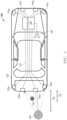
- FIG. 1illustrates in block diagram form an acoustic distance measuring system 100 according to one embodiment.
- Acoustic distance measuring system 100 in FIG. 1includes an automotive device 102 , a controller 104 , a loudspeaker 164 , a set of transmission lines 112 , a set of sensors 110 , an obstacle 120 , a long-range distance 132 , and a short-range distance 133 .
- a system controller, such as controller 104is situated on or within automotive device 102 , and provides an electrical signal corresponding to an audible output to loudspeaker 164 .
- Automotive device 102is communicatively connected to controller 104 .
- Controller 104has an output for connecting to one or more acoustic transducers, such as sensors 110 a - d.
- Controller 104has an input also connected to each of sensors 110 a - d.
- controller 104has an output for providing an output signal to loudspeaker 164 .
- sensors 110 a - dare ultrasonic sensors that emit an ultrasonic pulse, or acoustic signal as described herein, that reflects off of obstacle 118 and/or 120 when obstacle 118 and/or 120 is within the wave field of the acoustic signal.
- the acoustic signalis generally emitted above frequencies of audible sound.
- the reflected pulse signal (echo) or random noiseis received by one or more of sensors 110 a - d. Detection of the echo generates an output signal for use by controller 104 .
- Each of sensors 110 a - dis capable of creating an acoustic signal, and sensing a reflected pulse signal, or echo, when obstacle 118 and/or 120 is encountered.
- controller 104operates as a controller for acoustic distance measuring system 100 , generating an acoustic signal for sensors 110 a - d at a first time.
- Sensors 110 a - dare susceptible to receiving echo signals when a transmitted acoustic signal encounters an obstacle. The received echo signals are utilized to identify obstacle 118 and/or 120 within long-range distance 132 and short-range distance 133 .
- Controller 104transmits signals to sensors 110 a - d, via transmission lines 112 , and responsively, sensors 110 a - d output the acoustic signals.
- the acoustic signal generated by each sensor 110 a - dtravels away from a respective sensor 110 a - d and propagates through air.
- controller 104stops transmission of the acoustic signal
- controller 104monitors sensors 110 a - d for echo signals that may be caused by interruptions to the propagating acoustic signal.
- obstacle 118 and/or 120is detected, an echo is received at one or more of sensors 110 a - d.
- the received echo signalis processed by a respective sensor 110 a - d to determine if the received echo signal is approximately equal to the frequency slope of the transmitted acoustic signal. If the frequency slope of the acoustic signal is not approximately equal to the received echo signal the object is not present.
- Controller 104reports detection of obstacle 118 and/or 120 with respect to the surface of obstacle 118 and/or 120 that is closest to a respective sensor 110 a - d when the object is near a detection area associated with long-range distance 132 and/or short-range distance 133 . Reliable detection for obstacles of varying distances, shapes, height, and obscure dimensions, is needed. Additionally, avoiding false obstacle detection due to varying thresholds during severe noise conditions is a desirable characteristic. Acoustic distance measuring system 100 compensates for these problems as described further.
- FIG. 2illustrates in block diagram form an acoustic distance measuring circuit 200 for use in the acoustic distance measuring system of FIG. 1 according to one embodiment.
- Acoustic distance measuring circuit 200includes controller 104 and a sensor 202 .
- Sensor 202can be, for example, one sensor from among the set of sensors 110 of FIG. 1 .
- Sensor 202includes a frequency generator 208 , a transmitter amplifier 212 , an acoustic transducer 214 , and a sensing circuit 220 .
- Controller 104has an output connected to frequency generator 208 for providing a control signal, and an input for receiving a frequency slope signal to determine the presence of an object in a manner that will be described below.
- Frequency generator 208has an input for receiving the control signal, and an output connected to transmitter amplifier 212 .
- Transmitter amplifier 212has an input for receiving the electrical signal from frequency generator 208 , and an output connected to acoustic transducer 214 for providing an amplified electrical signal.
- Acoustic transducer 214has an input connected to the output of transmitter amplifier 212 , and an output. Acoustic transducer 214 vibrates in air to create a sound wave and produces an electrical signal at the output in response to environmental sound waves that cause the sensor to vibrate. Acoustic transducer 214 may be, for example, a piezoelectric sensor.
- Sensing circuit 220has an input connected to the output of acoustic transducer 214 , and an output for providing a frequency slope signal in response to a frequency slope of a received signal if the signal power is above a threshold, or a null value otherwise.
- Controller 104has an input for receiving the frequency slope signal. Controller 104 is for example, a control system that operates the acoustic distance measuring system of FIG. 1 .
- controller 104provides the control signal to frequency generator 208 .
- Frequency generator 208generates a signal and provides the generated signal to transmitter amplifier 212 as an electrical signal, at a first time.
- Transmitter amplifier 212amplifies the power of the signal generated by frequency generator 208 and provides the electrical signal to acoustic transducer 214 .
- frequency generator 208provides an un-amplified signal to acoustic transducer 214 .
- Acoustic transducer 214vibrates and generates an acoustic signal that corresponds to the input signal provided.
- acoustic transducer 214vibrates in response to changes in air pressure that may be formed by echo signals or random noise, and then transmits the received input signal to sensing circuit 220 .
- sensing circuit 220in response to receiving an input signal having low energy, interprets it as including only random noise and outputs a null value to controller 104 , but in response to receiving an input signal having sufficient energy, sensing circuit 220 outputs the frequency slope of the received input signal.
- Controller 104compares the frequency slope of the received input signal to a known frequency slope of the control signal. In response to the frequency slope of the input signal and the known frequency slope of the control signal being approximately equal, controller 104 detects the presence of an object.
- FIG. 3illustrates in block diagram form a sensing circuit 300 that can be used to implement sensing circuit 220 of FIG. 2 according to one embodiment.
- Sensing circuit 300includes an analog-to-digital converter 302 and a digital sensing circuit 350 .
- Digital sensing circuit 350includes, generally, an in-phase/quadrature (I/Q) digital mixer 303 , a digital filter 304 , a memory 310 for storing finite impulse response (FIR) filter coefficients, a phase derivation circuit 316 , a slope calculation module 318 , a magnitude detector 322 , a comparator circuit 326 , a register 324 for storing a near range threshold, and a multiplexer 320 .
- I/Qin-phase/quadrature
- FIRfinite impulse response
- Analog-to-digital converter 302has an input connected to the output of a transducer (for example, acoustic transducer 214 of FIG. 2 ) for receiving an input signal, and an output.
- I/Q digital mixer 303has an input connected to the output of analog-to-digital converter 302 , an input for receiving a mixing signal FTX, and first and second outputs for providing an in-phase signal and a quadrature signal, respectively, that corresponds to an amplitude and a phase of the signal input from the acoustic transducer in the complex plane.
- Digital filter 304includes an in-phase finite impulse response filter labeled “FIR I ” 306 and a quadrature finite impulse response filter labeled “FIR Q ” 308 .
- FIR I 306has an input connected to the first output of I/Q digital mixer 303 , an input connected to memory 310 for receiving FIR filter coefficients, and an output for providing a filtered in-phase signal.
- FIR Q 308has an input connected to the second output of I/Q digital mixer 303 , an input connected to memory 310 for receiving FIR filter coefficients, and an output for providing a filtered quadrature signal.
- Phase derivation circuit 316has an input connected to the output of digital filter 304 for receiving the filtered in-phase signal, an input connected to the output of digital filter 304 for receiving the filtered quadrature signal, and an output for providing the frequency of the complex signal represented by the filtered in-phase signal and the filtered quadrature signal.
- Slope calculation module 318has an input connected to the output of phase derivation circuit 316 for receiving the frequency of the complex signal, and an output for providing the frequency slope.
- Magnitude detector 322has an input connected to the output of digital filter 304 for receiving the filtered in-phase signal, an input connected to the output of digital filter 304 for receiving the filtered quadrature signal, and an output for providing a magnitude signal.
- Comparator 326has an input connected to the output of magnitude detector 322 , an input for receiving a predetermined magnitude threshold (register 324 ), and an output for providing the magnitude of the signal, if the magnitude of the signal is greater than register 324 .
- Multiplexer 320has an input for receiving the input signal frequency slope from slope calculation module 318 , an input for receiving a null value, a control input connected to the output of comparator circuit 326 , and an output connected to the input of controller 104 .
- Register 324can be configured according to the dimensional position of acoustic transducer 214 and a measured effect of the background noise detected by acoustic transducer 214 to avoid false detection of obstacles.
- Sensing circuit 220uses the near range threshold provided by register 324 to define a minimal magnitude of energy in a received signal that may reflect an obstacle in response to the transmission of the acoustic signal from the acoustic transducer.
- digital sensing circuit 350receives a signal that includes the echo of the chirp signal, if an object reflects it back, as the input signal at I/Q digital mixer 303 .
- the input signalis a digitally converted signal received from acoustic transducer 214 of FIG. 2 (or a receiver amplifier if incorporated) that may include echo signals received by acoustic transducer 214 produced by reflections off physical objects.
- the chirp signalis frequency modulated and is represented by frequency sweep in the input signal. Once reverberations are finished shortly after the transmitted signal has been sent, a chirp echo signal can be detected for near range object detection.
- I/Q digital mixer 303shifts the input signal to sum and difference frequencies, in which the difference frequency is at baseband (zero frequency). I/Q digital mixer 303 outputs both an in-phase component and a quadrature component of the received signal.
- Digital filter 304receives the in-phase signal at FIR I 306 and the quadrature signal at FIR Q 308 , where the quadrature signal is a quadrature component of the received signal.
- FIR I 306has an input for receiving FIR filter coefficients stored in memory 310 selected according to the channel being evaluated.
- Memory 310includes high channel FIR filter coefficients 312 and low channel FIR filter coefficients 314 for selectively applying to a corresponding number of samples of the input signal to implement an FIR filter.
- Digital sensing circuit 350applies high channel FIR filter coefficients 312 when detecting an echo signal from a high channel chirp, and low channel FIR filter coefficients 314 when detecting an echo signal from a low channel chirp.
- Phase derivation circuit 316receives the filtered I and Q signals and outputs the frequency of the input signal as the change in phase over time, or
- Slope calculation module 318calculates the slope of the frequency over a rolling period of time corresponding to the duration of the transmitted chirp signal, and outputs the frequency slope.
- Magnitude detector 322receives the filtered in-phase portion of the input signal and filtered quadrature portion of the input signal, and outputs the magnitude signal representing the energy in the input signal.
- Comparator circuit 326receives the magnitude of the input signal and the near range threshold value from register 324 , and outputs a ‘1’ when the magnitude of the input signal exceeds the near range threshold, and a ‘0’ otherwise.
- Multiplexer 320outputs the frequency slope in response to the magnitude of the input signal being greater than the near range threshold value, and a null value represented by the number zero otherwise.
- controller 104receives the frequency slope of the input signal and compares the frequency slope of the input signal to the known frequency slope of the transmitted chirp signal. Controller 104 detects an object if the frequency slope of the input signal corresponds to the chirp signal frequency slope, i.e. if it is approximately equal to the chirp signal frequency slope. In response to detecting the presence of the object, controller 104 determines the distance of the object. The frequency shift of the slope of the transmitted chirp signal and the slope of the received echo is constant. Controller 104 extrapolates the frequency of the chirp signal, and then calculates the difference between the frequency slope of the input signal and an extrapolated chirp frequency to determine the object distance. Controller 104 provides a distance measurement signal in response to calculating the object distance.
- the detection coverage for objects within the short-range and long-range of acoustic distance measuring system 100is increased by transmitting chirps on two sensors and receiving on two or more sensors 202 in parallel.
- Controller 104transmits chirps on two sensors 202 , for example, sensors 110 b and 110 c.
- Each transducertransmits a high or a low chirp signal.
- Each sensing circuit 300receives input signals that correspond to the transmitted signals, therefore each sensor receives on both the high and low frequency channels. In response to the presence of an object, sensing circuit 300 utilizes the received echoes to triangulate a more precise position of the object.
- the first sensing circuittransmits a high chirp signal and the second sensing circuit transmits a low chirp signal.
- Each sensing circuitreceives a direct input signal and an indirect input signal.
- the direct input signal of the first sensing circuitcorrelates to the high chirp signal, and the indirect input signal correlates to the low chirp signal.
- the direct input signal of the second sensing circuitcorrelates to the low chirp signal, and the indirect input signal correlates to the high chirp signal.
- acoustic distance measuring system 100calculates a more precise position of the object using triangulation.
- Controller 104determines at least one distance point of the object from each of the first and second sensing circuit based on the direct and indirect signal inputs.
- Controller 104determines a first distance measurement from the first sensing circuit, a second distance measurement from the second sensing circuit, and a known distance between the first and second sensing circuit. Utilizing the determined points, controller 104 calculates a more precise position of the object, for example cartesian coordinates of the object relative to at least one of the sensors.
- Sensing circuit 300enables parallel reception and detection of both high and low frequency channels. Sensing circuit 300 determines the chirp echo slope while concurrently improving signal resolution to provide accurate short-range and long-range object detection. By incorporating slope calculation module 318 , acoustic distance measuring circuit 100 is able to detect objects within a wide distance range of approximately 0.20 meters to greater than 7 meters using single modulation with parallel reception and detection on dual frequency channels.
- FIG. 4illustrates graphs depicting frequency spectra of a transmitted chirp and a received echo of the transmitted chirp when high and low channel finite impulse response coefficients are applied by digital filter 304 of sensing circuit 300 of FIG. 3 .
- FIG. 4includes high channel FIR coefficients spectra 410 and low channel FIR coefficients spectra 420 .
- High channel FIR coefficients spectra 410includes normalized transmit (Tx) spectrum and receive (Rx) sensitivity magnitude (arbitrary units) 412 situated on the y-axis and delta frequency (kilohertz) 414 situated on the x-axis.
- high channel FIR coefficients spectra 410includes high channel Tx chirp signal 416 and Rx chirp signal 418 .
- low channel FIR coefficients spectra 420includes Tx spectrum and Rx sensitivity magnitude (arbitrary units) 412 situated on the y-axis and delta frequency (kilohertz) 414 situated on the x-axis.
- Low channel FIR coefficients spectra 420further includes low channel Tx chirp signal 426 and receive chirp signal 428 .
- digital filter 304is a dual channel complex filter that receives the in-phase portion of the input signal and the quadrature portion of the input signal.
- Digital filter 304is set to either the high channel or the low channel and suppresses the signal from the non-selected channel.
- the high channel and the low channel frequenciesare close to one another, therefore a filter having high suppression of noise and high order is utilized to separate the two channels.
- a sufficient number of samples and a corresponding number of coefficientsare used to provide sharp attenuation outside of the selected frequency range to separate the two channels.
- Digital filter 304uses either high channel coefficients 312 or low channel coefficients 314 to suppress received signal content that is not indicative of the transmitted chirp.
- each sensorIn response to two sensors transmitting at different frequencies in parallel, each sensor detects on both frequency channels in parallel using time multiplexing. In response to sufficient energy in the filtered high and/or low channel signals, sensing circuit 300 calculates a frequency slope of the filtered signal in the frequency bandwidth of digital filter 304 . The remaining circuitry of sensing circuit 300 detects whether the filtered signal has sufficient energy to calculate a meaningful frequency slope.
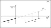
- FIG. 5illustrates a timing diagram for calculating the frequency shift of an input signal received by the controller of the sensing circuit of FIG. 2 according to one embodiment.
- Timing diagram 500includes frequency 502 (arbitrary units) situated on the y-axis and time 504 (arbitrary units) situated on the x-axis. Additionally, timing diagram 500 includes a Tx chirp signal frequency waveform 505 , an extrapolated Tx chirp signal frequency waveform 508 , and a received signal frequency waveform 510 .
- Tx chirp signal frequency waveform 505has a characteristic frequency slope.
- Extrapolated Tx chirp signal frequency waveform 508is a visual representation of Tx chirp signal frequency waveform 505 extended in time and whose slope remains constant.
- sensing circuit 300calculates both the frequency of the input signal as a function of time, and if the input signal has sufficient energy, the slope of the input signal. If an actual chirp echo is received due to the generated pulse signal interacting with an object, the frequency profile is substantially the same as the frequency profile of the Tx chirp signal frequency, causing their frequency slopes to be approximately equal. Moreover, if an actual chirp echo is detected, then the frequency shift between extrapolated Tx chirp signal frequency waveform 508 and received signal frequency waveform 510 corresponds to the distance of the obstacle from the sensor. Thus, by extrapolating the Tx chirp signal frequency slope and measuring the difference in frequency between it and the received signal frequency after detecting the actual chirp echo, acoustic distance measuring circuit 200 conveniently and accurately measures distance.
- FIG. 6illustrates a graph showing the processing output of the transmit channel high and receive channel high associated with the sensing circuit of FIG. 3 .
- Transmit (Tx) channel high and receive (Rx) channel high timing diagram 600includes a magnitude scale (millivolts) 602 situated on the left y-axis, a distance scale (centimeters) 604 situated on the x-axis, and a delta frequency scale (Hertz) 606 situated on the right y-axis. Additionally, Tx channel high and Rx channel high timing diagram 600 include an end-of-reverberations point 608 , a high frequency channel magnitude 612 , a magnitude near signal 614 , a frequency slope near signal 616 , and a magnitude low signal 618 .
- End-of-reverberations point 608identifies the point in which object detection begins.
- High frequency channel magnitude 612is the magnitude of the input signal subsequent to being filtered by a complex filter, for example digital filter 304 ( FIG. 3 ).
- High frequency channel magnitude 612is compared to the noise threshold (register 324 ) and identifies a true signal vs noise is received by digital filter 304 .
- Frequency slope near signal 616depicts there is a down chirp signal that results in a frequency slope after end-of-reverberations point 608 due to interaction with an object.
- Frequency slope near signal 616is provided to controller 104 .
- Controller 104compares frequency slope near signal 616 to the transmitted chirp signal slope.
- High frequency channel magnitude 612depicts the object is initially detected at 40 cm. Controller 104 calculates the delta frequency of frequency slope near signal 616 and the transmitted chirp signal to determine a more precise distance of the object.
- FIG. 7illustrates a graph showing the processing output of the transmit channel high and receive channel low associated with the sensing circuit of FIG. 3 .
- Tx channel high and Rx channel low timing diagram 700includes magnitude scale (millivolts) 702 situated on the left y-axis, distance (centimeter) 704 situated on the x-axis, and delta frequency (Hertz) 706 situated on the right y-axis. Additionally, Tx channel high and Rx channel low timing diagram 700 includes end-of-reverberations point 708 , high frequency channel magnitude 712 , magnitude near signal 714 , and frequency near signal 716 .
- End-of-reverberations point 708identifies the point in which object detection begins.
- High frequency channel magnitude 712is the magnitude of the input signal subsequent to being filtered by a complex filter, for example digital filter 304 ( FIG. 3 ).
- High frequency channel magnitude 712is compared to the noise threshold (register 324 ) and identifies a true signal vs noise is received by digital filter 304 .
- Frequency near signal 716depicts there is a random frequency signal before end-of-reverberations point 708 and an approximately zero magnitude measurement for frequency near signal 716 after end-of-reverberations point 708 . There is no slope for frequency near signal 716 , therefore no object is detected object.
- the disclosed techniquecan be used in both dual-channel (multi-channel) and single-channel acoustic distance measuring systems.
- Both dual-channel (multi-channel) and single-channel acoustic distance measuring systemsutilize single modulation acoustic measuring sensors for reliable detection at both short and long-distance detection range, concurrently.
- the dual-channel acoustic distance measuring systemutilizes true dual channel recognition to detect an echo concurrently at both high and low channels.
- the single-channel acoustic distance measuring systemtransmits and receives on multiple sensors in parallel to enable detection of an echo, due to object detection, at both high and low channels.
- the true dual-channel detection provided by the single modulation sensorsadvantageously enables echoes received from an obstacle at a close distance (for example less than 0.15 meters) and long distances (for example greater than 7 meters), to be detected in parallel.
Landscapes
- Engineering & Computer Science (AREA)
- Radar, Positioning & Navigation (AREA)
- Remote Sensing (AREA)
- Physics & Mathematics (AREA)
- Computer Networks & Wireless Communication (AREA)
- General Physics & Mathematics (AREA)
- Acoustics & Sound (AREA)
- Measurement Of Velocity Or Position Using Acoustic Or Ultrasonic Waves (AREA)
Abstract
Description
Claims (20)
Priority Applications (3)
| Application Number | Priority Date | Filing Date | Title |
|---|---|---|---|
| US16/378,722US11885874B2 (en) | 2018-12-19 | 2019-04-09 | Acoustic distance measuring circuit and method for low frequency modulated (LFM) chirp signals |
| CN201910915627.2ACN111413699B (en) | 2018-12-19 | 2019-09-26 | Acoustic distance measurement circuit and method for Low Frequency Modulated (LFM) chirp signals |
| DE202019107029.3UDE202019107029U1 (en) | 2018-12-19 | 2019-12-17 | Acoustic distance measuring circuit |
Applications Claiming Priority (2)
| Application Number | Priority Date | Filing Date | Title |
|---|---|---|---|
| US201862782135P | 2018-12-19 | 2018-12-19 | |
| US16/378,722US11885874B2 (en) | 2018-12-19 | 2019-04-09 | Acoustic distance measuring circuit and method for low frequency modulated (LFM) chirp signals |
Publications (2)
| Publication Number | Publication Date |
|---|---|
| US20200200898A1 US20200200898A1 (en) | 2020-06-25 |
| US11885874B2true US11885874B2 (en) | 2024-01-30 |
Family
ID=69412300
Family Applications (1)
| Application Number | Title | Priority Date | Filing Date |
|---|---|---|---|
| US16/378,722Active2041-12-24US11885874B2 (en) | 2018-12-19 | 2019-04-09 | Acoustic distance measuring circuit and method for low frequency modulated (LFM) chirp signals |
Country Status (3)
| Country | Link |
|---|---|
| US (1) | US11885874B2 (en) |
| CN (1) | CN111413699B (en) |
| DE (1) | DE202019107029U1 (en) |
Families Citing this family (10)
| Publication number | Priority date | Publication date | Assignee | Title |
|---|---|---|---|---|
| US20220091244A1 (en)* | 2019-01-18 | 2022-03-24 | University Of Washington | Systems, apparatuses, and methods for acoustic motion tracking |
| US11442155B2 (en)* | 2019-10-02 | 2022-09-13 | Semiconductor Components Industries, Llc | Devices, systems and processes for detecting saturation of received echo signals |
| US11216714B2 (en)* | 2020-01-02 | 2022-01-04 | The Boeing Company | Electronically scannable device for radio-frequency identification |
| US11759822B2 (en) | 2020-01-21 | 2023-09-19 | Semiconductor Components Industries, Llc | Devices, systems and processes for improving frequency measurements during reverberation periods for ultra-sonic transducers |
| US11520027B2 (en) | 2020-02-14 | 2022-12-06 | Semiconductor Components Industries, Llc | Devices, systems and processes for ultra-short range detection of obstacles |
| US11405730B2 (en) | 2020-05-08 | 2022-08-02 | Semiconductor Components Industries, Llc | Multichannel minimum distance chirp echo detection |
| US11443728B2 (en) | 2020-12-18 | 2022-09-13 | Semiconductor Components Industries, Llc | Echo detection with background noise based screening |
| US12007476B2 (en)* | 2021-09-13 | 2024-06-11 | Magna Electronics Inc. | Method for detecting objects via a vehicular sensing system |
| US11899106B1 (en)* | 2022-10-05 | 2024-02-13 | Semiconductor Components Industries, Llc | Dual-channel acoustic distance measurement circuit and method |
| US12111395B2 (en) | 2023-01-30 | 2024-10-08 | Semiconductor Components Industries, Llc | Acoustic sensing of proximate obstacles |
Citations (49)
| Publication number | Priority date | Publication date | Assignee | Title |
|---|---|---|---|---|
| US4253067A (en)* | 1978-12-11 | 1981-02-24 | Rockwell International Corporation | Baseband differentially phase encoded radio signal detector |
| US4969131A (en)* | 1969-07-09 | 1990-11-06 | The United States Of America As Represented By The Secretary Of The Navy | Automatic detection and classification equipment for high resolution sonar |
| DE4242700A1 (en)* | 1992-12-17 | 1994-06-23 | Bosch Gmbh Robert | Procedure for measuring the distance and speed of objects |
| DE4407369A1 (en)* | 1994-03-05 | 1995-09-14 | Grieshaber Vega Kg | Transition time measurement method |
| WO1996004588A1 (en)* | 1994-08-05 | 1996-02-15 | Acuson Corporation | Method and apparatus for doppler receive beamformer system |
| US5600675A (en)* | 1994-09-07 | 1997-02-04 | General Electric Company | Ultrasonic imager having improved bandwidth |
| US5708436A (en)* | 1996-06-24 | 1998-01-13 | Northrop Grumman Corporation | Multi-mode radar system having real-time ultra high resolution synthetic aperture radar (SAR) capability |
| CN1173226A (en)* | 1994-12-19 | 1998-02-11 | 加利福尼亚大学 | A Pulse Radar with Scan Interval Gate |
| EP0825718A1 (en)* | 1994-06-24 | 1998-02-25 | Roscoe C. Williams Limited | Oscillator circuit |
| DE19523693A1 (en)* | 1992-06-05 | 1998-05-14 | Thomson Csf | High linearity frequency modulated ramp generator for radar altimeter |
| US5841811A (en)* | 1994-10-07 | 1998-11-24 | Massachusetts Institute Of Technology | Quadrature sampling system and hybrid equalizer |
| CN1226117A (en)* | 1998-02-11 | 1999-08-18 | 三星电子株式会社 | Decimation of baseband DTV signals in digital television signal receivers |
| DE19953790A1 (en)* | 1999-11-09 | 2001-05-10 | Bosch Gmbh Robert | Object detection system for cars has a multiple beam FMCW radar sensor mounted on the car which measures the distance and speed of reflecting objects |
| US6248071B1 (en)* | 2000-01-28 | 2001-06-19 | U-Systems, Inc. | Demodulating wide-band ultrasound signals |
| WO2001050152A1 (en)* | 1999-12-29 | 2001-07-12 | Robert Bosch Gmbh | Method for measuring the distance and speed of objects |
| US6573732B1 (en) | 1999-05-04 | 2003-06-03 | Ssi Technologies, Inc. | Dynamic range sensor and method of detecting near field echo signals |
| DE10303587A1 (en)* | 2003-01-30 | 2004-08-12 | Robert Bosch Gmbh | Angle-resolving location device for motor vehicles has multi-beam radar sensor, evaluation device has device that filters amplitudes with at least one amplitude received in preceding measurement cycle |
| US20040260506A1 (en)* | 2000-11-15 | 2004-12-23 | Jones Aled Wynne | Tag tracking |
| US20050046597A1 (en)* | 2003-08-18 | 2005-03-03 | Hutchison Michael C. | Traffic light signal system using radar-based target detection and tracking |
| US20060036171A1 (en)* | 2004-07-23 | 2006-02-16 | Betriebsforschungsinstitut Vdeh-Institut Fur Angewandte Forschung Gmbh | Signal processing apparatus for an ultrasound transducer, ultrasound receiver and method for operating an ultrasound receiver |
| WO2006034896A1 (en)* | 2004-09-30 | 2006-04-06 | Robert Bosch Gmbh | Method and device for identifying an imminent collision |
| DE102006061670A1 (en)* | 2006-12-28 | 2008-07-03 | Robert Bosch Gmbh | Driver assistance system radar e.g. frequency modulated continuous wave radar, operating method for use in motor vehicle, involves determining distance and/or relative velocity of objects based on two difference signals |
| US20080272957A1 (en)* | 2007-04-23 | 2008-11-06 | Thomas Schoeberl | Method and device for determining the relative velocity of objects |
| DE102009013300A1 (en)* | 2008-04-23 | 2009-10-29 | Continental Automotive Gmbh | Radar device for detecting distance or movement of object, has transmitting unit and receiving unit, where transmitting unit has signal generator designed for generating two frequencies modulated high frequency signals |
| US20100085233A1 (en)* | 2006-10-06 | 2010-04-08 | Adc Automotive Distance Control Systems Gmbh | Radar system for detecting the surroundings with compensation of interfering signals |
| WO2010115651A1 (en)* | 2009-04-07 | 2010-10-14 | Robert Bosch Gmbh | Fmcw radar sensor and method for frequency matching |
| US7957223B2 (en) | 2005-03-16 | 2011-06-07 | Ametek, Inc. | Ultrasonic ranging in the near zone |
| US20110182519A1 (en)* | 2010-01-27 | 2011-07-28 | Intersil Americas Inc. | Gesture recognition with principal component anaysis |
| EP2366997A1 (en)* | 2010-03-17 | 2011-09-21 | Esaote S.p.A. | Method and device for determining the structural organization of an object with ultrasounds |
| US20120013503A1 (en)* | 2009-01-29 | 2012-01-19 | Stefan Heilmann | Method for detecting precipitaton using a radar locating device for motor vehicles |
| US20140331772A1 (en) | 2011-05-09 | 2014-11-13 | Albrecht Klotz | Ultrasonic measuring system having a reduced minimum range and method for detecting an obstacle |
| US20140347208A1 (en)* | 2013-05-24 | 2014-11-27 | Robert Bosch Gmbh | Method for evaluating obstacles in a driver assistance system for motor vehicles |
| WO2015120132A1 (en)* | 2014-02-07 | 2015-08-13 | The Regents Of The University Of California | Frequency tuning and/or frequency tracking of a mechanical system with low sensitivity to electrical feedthrough |
| US9151840B2 (en) | 2012-03-09 | 2015-10-06 | Semiconductor Components Industries, Llc | Semiconductor device and method of forming same for acoustic sensing of close proximity objects |
| US20150331772A1 (en) | 2014-05-15 | 2015-11-19 | Netapp, Inc. | Methods for updating diagnostic tools on a hardware device and devices thereof |
| US20160084941A1 (en)* | 2014-09-19 | 2016-03-24 | Delphi Technologies, Inc. | Radar system with phase based multi-target detection |
| CN105572660A (en)* | 2014-10-30 | 2016-05-11 | 恩智浦有限公司 | Radar ambiguity resolving detector |
| US20160213258A1 (en)* | 2014-12-24 | 2016-07-28 | Bahman LASHKARI | Methods for generating multiple mismatched coded excitation signals |
| DE102017209628A1 (en)* | 2017-06-08 | 2018-12-13 | Robert Bosch Gmbh | FMCW radar sensor for motor vehicles |
| WO2019008640A1 (en)* | 2017-07-03 | 2019-01-10 | 三菱電機株式会社 | Signal processing device, signal processing method, signal processing program, and radar system |
| US20190242972A1 (en)* | 2018-02-08 | 2019-08-08 | Infineon Technologies Ag | Radar sensing with phase correction |
| WO2019219263A1 (en)* | 2018-05-17 | 2019-11-21 | Robert Bosch Gmbh | Method for phase calibration of high-frequency components of a radar sensor |
| EP3572828A1 (en)* | 2018-05-24 | 2019-11-27 | The Boeing Company | Combined radar and communications system using common signal waveform |
| US10502824B2 (en)* | 2015-11-09 | 2019-12-10 | Infineon Technologies Ag | Frequency modulation scheme for FMCW radar |
| KR20200004583A (en)* | 2018-07-04 | 2020-01-14 | 홍익대학교 산학협력단 | Method and apparatus for detecting object |
| US20200124699A1 (en)* | 2018-10-19 | 2020-04-23 | Infineon Technologies Ag | Fmcw radar with interference signal suppression |
| DE112018004296T5 (en)* | 2017-09-28 | 2020-05-14 | Denso Corporation | OBJECT DETECTING DEVICE |
| WO2020110896A1 (en)* | 2018-11-28 | 2020-06-04 | 株式会社デンソー | Radar device |
| US11536831B2 (en)* | 2020-06-15 | 2022-12-27 | Gm Cruise Holdings Llc | Systems and methods for high velocity resolution high update rate radar for autonomous vehicles |
Family Cites Families (18)
| Publication number | Priority date | Publication date | Assignee | Title |
|---|---|---|---|---|
| US4553221A (en)* | 1970-12-28 | 1985-11-12 | Hyatt Gilbert P | Digital filtering system |
| US4280203A (en)* | 1979-09-14 | 1981-07-21 | Westinghouse Electric Corp. | Sonar beam forming utilizing the chirp Z-transform |
| US4357709A (en)* | 1979-11-12 | 1982-11-02 | Racal-Mesl Limited | Apparatus for regenerating signals within a frequency band |
| GB2208770A (en)* | 1987-08-14 | 1989-04-12 | Philips Electronic Associated | Chirp ranging & velocity measurement |
| US7054229B2 (en)* | 2002-04-30 | 2006-05-30 | The Johns Hopkins University | Multi-line towed acoustic array shape measurement unit |
| US7814783B2 (en)* | 2005-06-20 | 2010-10-19 | Windbidco Pty Ltd | Sodar sounding of the lower atmosphere |
| US8699299B2 (en)* | 2010-04-26 | 2014-04-15 | Semiconductor Components Industries, Llc | Self-tuning acoustic measurement system |
| US8665668B2 (en)* | 2010-09-17 | 2014-03-04 | Vivid Engineering, Inc. | Ultrasonic distance measurement controller |
| DE102011088346B4 (en)* | 2011-12-13 | 2022-01-05 | Robert Bosch Gmbh | Device for detecting acoustic signals and the associated method |
| AU2013327392B2 (en)* | 2012-10-02 | 2017-11-02 | Windbidco Pty Ltd | Method for improving performance of a Sodar system |
| US9304148B2 (en)* | 2012-10-23 | 2016-04-05 | Tektronix, Inc. | Internal chirp generator with time aligned acquisition in a mixed-domain oscilloscope |
| DE102013211846A1 (en)* | 2013-06-21 | 2014-12-24 | Robert Bosch Gmbh | Method for operating an environment detection system of a vehicle |
| CN104240422B (en)* | 2014-08-22 | 2017-01-11 | 电子科技大学 | Ultrasonic wave space monitoring anti-theft method based on distance images |
| US10345445B2 (en)* | 2015-11-02 | 2019-07-09 | Semiconductor Components Industries, Llc | Circuit for acoustic distance measuring |
| US10234549B2 (en)* | 2016-03-08 | 2019-03-19 | Semiconductor Components Industries, Llc | Circuit for acoustic distance time of flight compensation |
| US10444350B2 (en)* | 2016-07-26 | 2019-10-15 | Semiconductor Components Industries, Llc | Obstacle monitoring using motion-compensated distance |
| US20180160226A1 (en)* | 2016-12-05 | 2018-06-07 | Semiconductor Components Industries, Llc | Reducing or eliminating transducer reverberation |
| CN107290429A (en)* | 2017-07-10 | 2017-10-24 | 无锡海鹰电子医疗系统有限公司 | Ultrasound measurement system and detection method for detecting deep structure crack |
- 2019
- 2019-04-09USUS16/378,722patent/US11885874B2/enactiveActive
- 2019-09-26CNCN201910915627.2Apatent/CN111413699B/enactiveActive
- 2019-12-17DEDE202019107029.3Upatent/DE202019107029U1/enactiveActive
Patent Citations (53)
| Publication number | Priority date | Publication date | Assignee | Title |
|---|---|---|---|---|
| US4969131A (en)* | 1969-07-09 | 1990-11-06 | The United States Of America As Represented By The Secretary Of The Navy | Automatic detection and classification equipment for high resolution sonar |
| US4253067A (en)* | 1978-12-11 | 1981-02-24 | Rockwell International Corporation | Baseband differentially phase encoded radio signal detector |
| DE19523693A1 (en)* | 1992-06-05 | 1998-05-14 | Thomson Csf | High linearity frequency modulated ramp generator for radar altimeter |
| DE4242700A1 (en)* | 1992-12-17 | 1994-06-23 | Bosch Gmbh Robert | Procedure for measuring the distance and speed of objects |
| DE4407369A1 (en)* | 1994-03-05 | 1995-09-14 | Grieshaber Vega Kg | Transition time measurement method |
| EP0825718A1 (en)* | 1994-06-24 | 1998-02-25 | Roscoe C. Williams Limited | Oscillator circuit |
| WO1996004588A1 (en)* | 1994-08-05 | 1996-02-15 | Acuson Corporation | Method and apparatus for doppler receive beamformer system |
| US5600675A (en)* | 1994-09-07 | 1997-02-04 | General Electric Company | Ultrasonic imager having improved bandwidth |
| US5841811A (en)* | 1994-10-07 | 1998-11-24 | Massachusetts Institute Of Technology | Quadrature sampling system and hybrid equalizer |
| CN1173226A (en)* | 1994-12-19 | 1998-02-11 | 加利福尼亚大学 | A Pulse Radar with Scan Interval Gate |
| US5708436A (en)* | 1996-06-24 | 1998-01-13 | Northrop Grumman Corporation | Multi-mode radar system having real-time ultra high resolution synthetic aperture radar (SAR) capability |
| CN1226117A (en)* | 1998-02-11 | 1999-08-18 | 三星电子株式会社 | Decimation of baseband DTV signals in digital television signal receivers |
| US6573732B1 (en) | 1999-05-04 | 2003-06-03 | Ssi Technologies, Inc. | Dynamic range sensor and method of detecting near field echo signals |
| DE19953790A1 (en)* | 1999-11-09 | 2001-05-10 | Bosch Gmbh Robert | Object detection system for cars has a multiple beam FMCW radar sensor mounted on the car which measures the distance and speed of reflecting objects |
| WO2001050152A1 (en)* | 1999-12-29 | 2001-07-12 | Robert Bosch Gmbh | Method for measuring the distance and speed of objects |
| US6248071B1 (en)* | 2000-01-28 | 2001-06-19 | U-Systems, Inc. | Demodulating wide-band ultrasound signals |
| US20040260506A1 (en)* | 2000-11-15 | 2004-12-23 | Jones Aled Wynne | Tag tracking |
| US7024331B2 (en)* | 2000-11-15 | 2006-04-04 | Scientific Generics Limited | Tag tracking |
| DE10303587A1 (en)* | 2003-01-30 | 2004-08-12 | Robert Bosch Gmbh | Angle-resolving location device for motor vehicles has multi-beam radar sensor, evaluation device has device that filters amplitudes with at least one amplitude received in preceding measurement cycle |
| US20050046597A1 (en)* | 2003-08-18 | 2005-03-03 | Hutchison Michael C. | Traffic light signal system using radar-based target detection and tracking |
| US20060036171A1 (en)* | 2004-07-23 | 2006-02-16 | Betriebsforschungsinstitut Vdeh-Institut Fur Angewandte Forschung Gmbh | Signal processing apparatus for an ultrasound transducer, ultrasound receiver and method for operating an ultrasound receiver |
| WO2006034896A1 (en)* | 2004-09-30 | 2006-04-06 | Robert Bosch Gmbh | Method and device for identifying an imminent collision |
| US7957223B2 (en) | 2005-03-16 | 2011-06-07 | Ametek, Inc. | Ultrasonic ranging in the near zone |
| US20100085233A1 (en)* | 2006-10-06 | 2010-04-08 | Adc Automotive Distance Control Systems Gmbh | Radar system for detecting the surroundings with compensation of interfering signals |
| DE102006061670A1 (en)* | 2006-12-28 | 2008-07-03 | Robert Bosch Gmbh | Driver assistance system radar e.g. frequency modulated continuous wave radar, operating method for use in motor vehicle, involves determining distance and/or relative velocity of objects based on two difference signals |
| US20080272957A1 (en)* | 2007-04-23 | 2008-11-06 | Thomas Schoeberl | Method and device for determining the relative velocity of objects |
| DE102009013300A1 (en)* | 2008-04-23 | 2009-10-29 | Continental Automotive Gmbh | Radar device for detecting distance or movement of object, has transmitting unit and receiving unit, where transmitting unit has signal generator designed for generating two frequencies modulated high frequency signals |
| US20120013503A1 (en)* | 2009-01-29 | 2012-01-19 | Stefan Heilmann | Method for detecting precipitaton using a radar locating device for motor vehicles |
| WO2010115651A1 (en)* | 2009-04-07 | 2010-10-14 | Robert Bosch Gmbh | Fmcw radar sensor and method for frequency matching |
| US20110182519A1 (en)* | 2010-01-27 | 2011-07-28 | Intersil Americas Inc. | Gesture recognition with principal component anaysis |
| EP2366997A1 (en)* | 2010-03-17 | 2011-09-21 | Esaote S.p.A. | Method and device for determining the structural organization of an object with ultrasounds |
| US20140331772A1 (en) | 2011-05-09 | 2014-11-13 | Albrecht Klotz | Ultrasonic measuring system having a reduced minimum range and method for detecting an obstacle |
| US9151840B2 (en) | 2012-03-09 | 2015-10-06 | Semiconductor Components Industries, Llc | Semiconductor device and method of forming same for acoustic sensing of close proximity objects |
| US20140347208A1 (en)* | 2013-05-24 | 2014-11-27 | Robert Bosch Gmbh | Method for evaluating obstacles in a driver assistance system for motor vehicles |
| US20160380640A1 (en)* | 2014-02-07 | 2016-12-29 | The Regents Of The University Of California | Frequency tuning and/or frequency tracking of a mechanical system with low sensitivity to electrical feedthrough |
| WO2015120132A1 (en)* | 2014-02-07 | 2015-08-13 | The Regents Of The University Of California | Frequency tuning and/or frequency tracking of a mechanical system with low sensitivity to electrical feedthrough |
| US20150331772A1 (en) | 2014-05-15 | 2015-11-19 | Netapp, Inc. | Methods for updating diagnostic tools on a hardware device and devices thereof |
| US20160084941A1 (en)* | 2014-09-19 | 2016-03-24 | Delphi Technologies, Inc. | Radar system with phase based multi-target detection |
| CN105572660A (en)* | 2014-10-30 | 2016-05-11 | 恩智浦有限公司 | Radar ambiguity resolving detector |
| US20160213258A1 (en)* | 2014-12-24 | 2016-07-28 | Bahman LASHKARI | Methods for generating multiple mismatched coded excitation signals |
| US10502824B2 (en)* | 2015-11-09 | 2019-12-10 | Infineon Technologies Ag | Frequency modulation scheme for FMCW radar |
| DE102017209628A1 (en)* | 2017-06-08 | 2018-12-13 | Robert Bosch Gmbh | FMCW radar sensor for motor vehicles |
| WO2019008640A1 (en)* | 2017-07-03 | 2019-01-10 | 三菱電機株式会社 | Signal processing device, signal processing method, signal processing program, and radar system |
| DE112018004296T5 (en)* | 2017-09-28 | 2020-05-14 | Denso Corporation | OBJECT DETECTING DEVICE |
| US20190242972A1 (en)* | 2018-02-08 | 2019-08-08 | Infineon Technologies Ag | Radar sensing with phase correction |
| US11016171B2 (en)* | 2018-02-08 | 2021-05-25 | Infineon Technologies Ag | Radar sensing with phase correction |
| WO2019219263A1 (en)* | 2018-05-17 | 2019-11-21 | Robert Bosch Gmbh | Method for phase calibration of high-frequency components of a radar sensor |
| EP3572828A1 (en)* | 2018-05-24 | 2019-11-27 | The Boeing Company | Combined radar and communications system using common signal waveform |
| US20190361113A1 (en)* | 2018-05-24 | 2019-11-28 | The Boeing Company | Combined Radar and Communications System Using Common Signal Waveform |
| KR20200004583A (en)* | 2018-07-04 | 2020-01-14 | 홍익대학교 산학협력단 | Method and apparatus for detecting object |
| US20200124699A1 (en)* | 2018-10-19 | 2020-04-23 | Infineon Technologies Ag | Fmcw radar with interference signal suppression |
| WO2020110896A1 (en)* | 2018-11-28 | 2020-06-04 | 株式会社デンソー | Radar device |
| US11536831B2 (en)* | 2020-06-15 | 2022-12-27 | Gm Cruise Holdings Llc | Systems and methods for high velocity resolution high update rate radar for autonomous vehicles |
Also Published As
| Publication number | Publication date |
|---|---|
| DE202019107029U1 (en) | 2020-01-20 |
| CN111413699A (en) | 2020-07-14 |
| US20200200898A1 (en) | 2020-06-25 |
| CN111413699B (en) | 2024-09-10 |
Similar Documents
| Publication | Publication Date | Title |
|---|---|---|
| US11885874B2 (en) | Acoustic distance measuring circuit and method for low frequency modulated (LFM) chirp signals | |
| CN209894972U (en) | Acoustic distance measuring circuit | |
| US11112495B2 (en) | Method for acoustic distance time of flight compensation | |
| KR102157507B1 (en) | Circuit for acoustic distance measuring | |
| US10120073B2 (en) | Method for operating a surroundings-detection system of a vehicle | |
| CN101173986B (en) | Ultrasonic distance measuring apparatus without blind zone | |
| CN112912761B (en) | Ultrasound echo processing in the presence of Doppler shift | |
| WO2015118024A1 (en) | Radar level gauge system with multiple receiver branches | |
| KR20180012222A (en) | Obstacle monitoring using motion-compensated distance | |
| CN109696680B (en) | High-precision ultrasonic ranging device and method based on phase detection | |
| US11520439B1 (en) | Self-adaptive ultra-sonic touch sensor | |
| KR101665786B1 (en) | Method and apparatus for measuring a distance using ultrasonic waves | |
| CN112162289A (en) | Ultrasonic ranging method and device | |
| JPH08201514A (en) | Ultrasonic distance measuring device | |
| CN114578363B (en) | Ultrasonic detection system and method | |
| KR102806682B1 (en) | A sensing method and a controller for an acoustic transducer | |
| US20240192362A1 (en) | Signal processing device, sound wave system, and vehicle | |
| JP2024127010A (en) | Ultrasonic object detection device and ultrasonic object detection method | |
| JPH09288181A (en) | Highly accurate sea bottom detector and fishfinder equipped with the detector | |
| JPWO2023026666A5 (en) | ||
| Papageorgiou et al. | Accurate displacement measurement based on the frequency variation monitoring of ultrasonic signals | |
| JPH04286981A (en) | Automobile collision prevention radar |
Legal Events
| Date | Code | Title | Description |
|---|---|---|---|
| AS | Assignment | Owner name:SEMICONDUCTOR COMPONENTS INDUSTRIES, LLC, ARIZONA Free format text:ASSIGNMENT OF ASSIGNORS INTEREST;ASSIGNORS:HUSTAVA, MAREK;SUCHY, TOMAS;REEL/FRAME:048828/0565 Effective date:20190409 | |
| FEPP | Fee payment procedure | Free format text:ENTITY STATUS SET TO UNDISCOUNTED (ORIGINAL EVENT CODE: BIG.); ENTITY STATUS OF PATENT OWNER: LARGE ENTITY | |
| STPP | Information on status: patent application and granting procedure in general | Free format text:DOCKETED NEW CASE - READY FOR EXAMINATION | |
| AS | Assignment | Owner name:DEUTSCHE BANK AG NEW YORK BRANCH, AS COLLATERAL AGENT, NEW YORK Free format text:SECURITY INTEREST;ASSIGNOR:SEMICONDUCTOR COMPONENTS INDUSTRIES, LLC;REEL/FRAME:050156/0421 Effective date:20190812 | |
| STPP | Information on status: patent application and granting procedure in general | Free format text:NON FINAL ACTION MAILED | |
| STPP | Information on status: patent application and granting procedure in general | Free format text:RESPONSE TO NON-FINAL OFFICE ACTION ENTERED AND FORWARDED TO EXAMINER | |
| STPP | Information on status: patent application and granting procedure in general | Free format text:FINAL REJECTION MAILED | |
| AS | Assignment | Owner name:SEMICONDUCTOR COMPONENTS INDUSTRIES, LLC, ARIZONA Free format text:RELEASE OF SECURITY INTEREST IN PATENTS PREVIOUSLY RECORDED AT REEL 050156, FRAME 0421;ASSIGNOR:DEUTSCHE BANK AG NEW YORK BRANCH, AS COLLATERAL AGENT;REEL/FRAME:064615/0639 Effective date:20230816 | |
| STPP | Information on status: patent application and granting procedure in general | Free format text:RESPONSE AFTER FINAL ACTION FORWARDED TO EXAMINER | |
| STPP | Information on status: patent application and granting procedure in general | Free format text:NOTICE OF ALLOWANCE MAILED -- APPLICATION RECEIVED IN OFFICE OF PUBLICATIONS | |
| STPP | Information on status: patent application and granting procedure in general | Free format text:PUBLICATIONS -- ISSUE FEE PAYMENT RECEIVED | |
| STPP | Information on status: patent application and granting procedure in general | Free format text:PUBLICATIONS -- ISSUE FEE PAYMENT VERIFIED | |
| STCF | Information on status: patent grant | Free format text:PATENTED CASE |