US11885593B2 - Mounting rail for firearm - Google Patents
Mounting rail for firearmDownload PDFInfo
- Publication number
- US11885593B2 US11885593B2US17/782,019US202017782019AUS11885593B2US 11885593 B2US11885593 B2US 11885593B2US 202017782019 AUS202017782019 AUS 202017782019AUS 11885593 B2US11885593 B2US 11885593B2
- Authority
- US
- United States
- Prior art keywords
- rail
- recess
- catch
- housing
- mounting rail
- Prior art date
- Legal status (The legal status is an assumption and is not a legal conclusion. Google has not performed a legal analysis and makes no representation as to the accuracy of the status listed.)
- Active
Links
Images


Classifications
- F—MECHANICAL ENGINEERING; LIGHTING; HEATING; WEAPONS; BLASTING
- F41—WEAPONS
- F41G—WEAPON SIGHTS; AIMING
- F41G11/00—Details of sighting or aiming apparatus; Accessories
- F41G11/001—Means for mounting tubular or beam shaped sighting or aiming devices on firearms
- F41G11/003—Mountings with a dove tail element, e.g. "Picatinny rail systems"
Definitions
- the present disclosureconcerns the field of firearms, more specifically a mounting rail and a firearm equipped with such a rail.
- U.S. Pat. No. 8,091,265 B2discloses a firearm with a ‘picatinny rail’.
- This railallows for the attachment of one or more accessories.
- This railalso comprises a printed circuit board that provides electrical contacts for one or more accessories requiring an electrical power supply.
- the printed circuit boardis housed in a recess formed between two rows of attachment catches. The electrical contacts are arranged on a free surface of the printed circuit board between the two rows.
- this solutionhas the disadvantage that the printed circuit board is exposed to the outside.
- the printed circuit boardconsists of less resistant materials such as resin and ductile conductive metals.
- the printed circuit boardmay easily be damaged following one or more shocks. As a result, it must be regularly replaced in order to ensure that it performs to specification. Of even more critical significance, however, is the fact that a failure of this PCB may be particularly problematic in operation.
- US2011/0010979discloses a ‘picatinny rail’ in which recesses are arranged in the flat upper surface to allow for the passage of electrical connections, with each recess being positioned between opposite flanks belonging, respectively, to two catches directly adjacent to the recess or in a central portion of the flat surface that forms the top of a catch.
- the weakness of these two design alternativesis that the dimensions of the recesses are not compatible with larger electrical interfaces.
- the railconsists of two pieces, which limits its strength.
- WO2011/079233discloses a ‘picatinny rail’ comprising holes arranged in the flat upper surface of the rail, with each hole being positioned between two opposite flanks of adjacent teeth. This solution has the same defects as that of the document discussed supra.
- the objective of the present disclosureis to address at least one of the disadvantages of the aforementioned prior art. More specifically, the objective of the present disclosure is to improve the protection of the PCB and/or improve the mechanical strength of the resultant rail.
- the present disclosureconcerns a mounting rail for a firearm, wherein the rail comprises at least one catch arranged one a flat upper surface of the rail, wherein the at least one catch serves as a means of fixation for at least one accessory, wherein the rail comprises a housing that extends longitudinally, wherein the housing serves to receive a PCB allowing for an electrical connection with the at least one accessory, characterized in that the housing is partially defined by at least one recess, the/each recess is arranged between two opposite flanks of the/each corresponding catch, and a top of the/each corresponding catch extends transversely on either side of a median plane of the rail above the recess.
- the mounting railcomprises one or more of the following technical characteristics in any possible adequate combination:
- the present disclosurealso concerns a firearm comprising a mounting rail and a PCB inserted in the housing of the rail, characterized in that the rail is a mounting rail according to the present disclosure.
- the present disclosuremay also concern a method for producing a mounting rail for a firearm.
- the methodcomprises a step of providing a rail, a step of machining to form catches regularly spaced apart on a flat upper surface, and a step of machining the lower surface, characterized in that some material is hollowed out so as to form at least one recess extending vertically from the lower surface of the rail to a ceiling arranged in one of the catches, wherein the recess has a length greater than the thickness of the corresponding catch at the level of the line at its base.
- the step of machining the lower surfacemay be carried out before that of the upper surface.
- the advantageous embodiments of the respective subject-matter of the present disclosureare equally applicable to the other subject-matter of the present disclosure.
- each object of the present disclosurecan be combined with the others.
- the respective subject-matter of the present disclosurecan also be combined with the embodiments in the description, which can also be combined with one another.
- the measures proposed by the present disclosureare of value in that they facilitate the maintenance of the PCB. They make it possible to reduce the weight of the rail whilst making it more rigid. Moreover, they provide a rail with a one-piece structure that makes the weapon lighter whilst maintaining the same level of strength. By taking the measures proposed by the present disclosure, the electrical contacts on the printed circuit remain easily accessible for accessories without being exposed to a risk of damage.
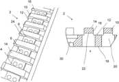
- FIG. 1is a schematic perspective view of the rail according to the present disclosure.
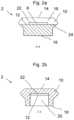
- FIGS. 2 a and 2 bshow a cross-section of the rail along the width of the rail at the level of a hollow area and top of a catch, respectively.
- FIG. 3shows a section through a median plane of the rail according to the present disclosure.
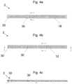
- FIGS. 4 a , 4 b , and 4 cshow a top view, bottom view, and median section of the rail as a whole.
- FIG. 1is a perspective view of a mounting rail 2 according to the present disclosure.
- the rail 2serves to support the attachment of one or more accessories that assist in firing, such as a laser aiming device. Certain accessories require a power supply and/or a data exchange connection.
- a PCB 4is included that comprises a series of electrical contact points 6 .
- the PCB 4is held within a sheath-shaped housing 8 arranged within the rail 2 .
- the rail 2has catches (or teeth) 10 distributed at a regular interval over a flat upper surface 12 of the rail 2 in a longitudinal direction.
- the flat upper surface 12comprises flat surfaces that define hollow spaces between the catches 10 .
- the catches 10serve as a means of attachment for the one or more accessories.
- the catches 10extend transversely on either side of a median plane of the rail 2 .
- the PCB 4is held within the housing 8 .
- the sheath-shaped housing 8is arranged partially in the bases of the catches 10 .
- the tops 14 of the catches 10serve as protection against any shocks.
- the tops 14may each have a flat surface that is parallel to the flat upper surface 12 of the rail 2 .
- the rail 2may be mounted on a flat upper, lower, or lateral surface of a firearm (not shown), which may, for example, be a submachine gun.
- each catch 10extends transversely on either side of the median plane of the rail 2 , above the housing 8 .
- the median plane of the rail 2extends longitudinally, and is perpendicular to the flat upper surface 12 .
- FIGS. 2 a and 2 bshow a cross-section of the rail 2 along the width of the rail at the level of the hollow area and top 14 of a catch 10 .
- a recess 20is formed in the base of the catch 10 .
- the recesshas a ceiling 22 arranged below the top 14 of the corresponding catch 10 .
- the recess 20may have a rectangular cross-section in a plane parallel to the top surface 12 and/or a bottom surface 18 of the rail 2 .
- the width of the housingmay be less than 80 or 60% of the width of the rail 2 .
- the ceiling 22 of each recess 22may be arranged at a height between 10 and 60% of the height of the corresponding catch 10 , relative to the line 24 at the base of the corresponding catch 10 .
- FIG. 3shows that the housing 8 is defined in part by two recesses 20 arranged between two opposite flanks 16 of the corresponding catches 10 .
- each recess 20extends in the longitudinal direction between the two flanks of the corresponding catch 10 .
- each recess 20extends vertically from the lower surface 18 of the rail 2 to the ceiling 22 of the corresponding catch 10 .
- the length of each recess 20is greater than the thickness of the corresponding catch 10 at the level of, and below, its baseline 24 .
- the baseline 24is defined by the intersection between the flanks 16 of the catch 10 in question and the upper flat surface 12 .
- the housing 8is further defined by areas of the flat upper surface 12 . These areas correspond to the flat surfaces that define the hollow spaces between the catches.
- Each area of the flat upper surfacealso serves to hold the PCB 4 in place.
- Each catch 10may be rectangular in the median plane of the rail 2 .
- the center of each recess 20coincides with the center of each corresponding catch 10 along an axis perpendicular to the upper surface 12 .
- the length of the recess 20may be between 100 and 120% of the thickness of the corresponding catch 10 at the level of its base or below it in the body of the rail 2 .
- FIG. 4shows top and bottom views, and a median section of the mounting rail 2 according to the present disclosure as a whole.
- the rail 2may comprise attachment holes 30 formed, on the one hand, at the ends of the rail 2 , and, on the other, in an intermediate area of the rail 2 .
- the areas surrounding the holes 30each have additional catches that may also serve as means of attachment for one or more accessories. These catches are recessed in their central part in order to form passages for the corresponding mounting screws.
- the present disclosuremay also concern a method of manufacture that is not shown.
- the methodmay comprise a step of providing a rail 2 having catches 10 formed on a flat upper surface 12 and spaced apart at a regular interval, and a step of machining the lower surface 18 .
- a series of recesses 20may be made by a single milling head of a machine tool or by multiple heads operating simultaneously.
- Each recess 20 in the materialextends vertically from the lower surface 18 to the ceiling 22 arranged in the corresponding catch 10 , with the ceiling 22 being positioned above the upper surface 12 and the recess 20 having a length greater than the thickness of the corresponding catch 10 at the level of its baseline 24 .
- each recess 20is centered on the associated catch 10 along an axis perpendicular to the upper surface 12 .
- the machiningmay be carried out from top to bottom with the rail 26 mounted upside-down on its bench, or from bottom to top with the rail 26 mounted right-side up on its bench.
- the railmay be moving or fixed.
- the step of machining the lower surface 18may be carried out before that of the upper surface 18 .
Landscapes
- Engineering & Computer Science (AREA)
- General Engineering & Computer Science (AREA)
- Mounting Of Printed Circuit Boards And The Like (AREA)
- Casings For Electric Apparatus (AREA)
- Clamps And Clips (AREA)
- Fittings On The Vehicle Exterior For Carrying Loads, And Devices For Holding Or Mounting Articles (AREA)
- Joining Of Building Structures In Genera (AREA)
- Mounting Components In General For Electric Apparatus (AREA)
Abstract
Description
The present disclosure concerns the field of firearms, more specifically a mounting rail and a firearm equipped with such a rail.
Published patent document U.S. Pat. No. 8,091,265 B2 discloses a firearm with a ‘picatinny rail’. This rail allows for the attachment of one or more accessories. This rail also comprises a printed circuit board that provides electrical contacts for one or more accessories requiring an electrical power supply. In this document, the printed circuit board is housed in a recess formed between two rows of attachment catches. The electrical contacts are arranged on a free surface of the printed circuit board between the two rows. However, this solution has the disadvantage that the printed circuit board is exposed to the outside. Moreover, the printed circuit board consists of less resistant materials such as resin and ductile conductive metals. Thus, the printed circuit board (PCB) may easily be damaged following one or more shocks. As a result, it must be regularly replaced in order to ensure that it performs to specification. Of even more critical significance, however, is the fact that a failure of this PCB may be particularly problematic in operation.
Lastly, the reduction of the cross-section of the attachment catches also causes stability and mechanical strength issues for the rail, and reduces the support surfaces for the accessories attached to it.
Picatinny rails for firearms have already been proposed in order to address this issue:
US2011/0010979 discloses a ‘picatinny rail’ in which recesses are arranged in the flat upper surface to allow for the passage of electrical connections, with each recess being positioned between opposite flanks belonging, respectively, to two catches directly adjacent to the recess or in a central portion of the flat surface that forms the top of a catch. However, the weakness of these two design alternatives is that the dimensions of the recesses are not compatible with larger electrical interfaces. Moreover, the rail consists of two pieces, which limits its strength.
WO2011/079233 discloses a ‘picatinny rail’ comprising holes arranged in the flat upper surface of the rail, with each hole being positioned between two opposite flanks of adjacent teeth. This solution has the same defects as that of the document discussed supra.
The objective of the present disclosure is to address at least one of the disadvantages of the aforementioned prior art. More specifically, the objective of the present disclosure is to improve the protection of the PCB and/or improve the mechanical strength of the resultant rail.
The present disclosure concerns a mounting rail for a firearm, wherein the rail comprises at least one catch arranged one a flat upper surface of the rail, wherein the at least one catch serves as a means of fixation for at least one accessory, wherein the rail comprises a housing that extends longitudinally, wherein the housing serves to receive a PCB allowing for an electrical connection with the at least one accessory, characterized in that the housing is partially defined by at least one recess, the/each recess is arranged between two opposite flanks of the/each corresponding catch, and a top of the/each corresponding catch extends transversely on either side of a median plane of the rail above the recess.
In one advantageous embodiment of the present disclosure, the mounting rail comprises one or more of the following technical characteristics in any possible adequate combination:
- the/each recess opens onto the two opposite flanks of the corresponding catch;
- the/each recess is formed in the base of the corresponding catch;
- the/each recess has a ceiling arranged below the top of the/each corresponding catch;
- the ceiling of the/each recess is arranged at a height of between 10% and 60% of the height of the/each corresponding catch relative to a line at the base of the catch;
- the/each recess has a length greater than or equal to the thickness of the/each corresponding catch on the level of, or below, the line at the base of the catch;
- the length of the/each recess is between 100% and 120% of the thickness of the corresponding catch;
- the/each catch extends from a lower surface of the rail to the ceiling of the/each corresponding catch;
- the/each recess has a rectangular cross-section on a plane parallel to the flat upper surface and/or the lower surface of the rail;
- the/each recess extends along an axis perpendicular to the flat upper surface and/or the lower surface of the rail;
- the center of the/each recess coincides with the center of the/each corresponding catch along the axis perpendicular to the flat upper surface and/or the lower surface of the rail;
- the housing has a rectangular cross-section;
- the width of the housing is less than 80% or 60% of the width of the rail;
- the at least one catch comprises a series of catches distributed at a regular interval on the flat upper surface of the rail in the longitudinal direction;
- the rail comprises at least one attachment hole formed at one end or in an intermediate area of the rail;
- the at least one attachment hole is arranged on the level of an additional catch, wherein the original catch is hollow at its center;
- the housing is further defined by at least one area of the flat upper surface, wherein the at least one area is a flat surface adjacent to the corresponding catch;
- the mounting rail conforms to standard MIL-STD-1913 (Picatinny).
The present disclosure also concerns a firearm comprising a mounting rail and a PCB inserted in the housing of the rail, characterized in that the rail is a mounting rail according to the present disclosure.
The present disclosure may also concern a method for producing a mounting rail for a firearm. The method comprises a step of providing a rail, a step of machining to form catches regularly spaced apart on a flat upper surface, and a step of machining the lower surface, characterized in that some material is hollowed out so as to form at least one recess extending vertically from the lower surface of the rail to a ceiling arranged in one of the catches, wherein the recess has a length greater than the thickness of the corresponding catch at the level of the line at its base. Alternatively, the step of machining the lower surface may be carried out before that of the upper surface.
Generally, the advantageous embodiments of the respective subject-matter of the present disclosure are equally applicable to the other subject-matter of the present disclosure. To the extent possible, each object of the present disclosure can be combined with the others. The respective subject-matter of the present disclosure can also be combined with the embodiments in the description, which can also be combined with one another.
The measures proposed by the present disclosure are of value in that they facilitate the maintenance of the PCB. They make it possible to reduce the weight of the rail whilst making it more rigid. Moreover, they provide a rail with a one-piece structure that makes the weapon lighter whilst maintaining the same level of strength. By taking the measures proposed by the present disclosure, the electrical contacts on the printed circuit remain easily accessible for accessories without being exposed to a risk of damage.
Other characteristics and benefits of this disclosure will be better understood by reference to the description and drawings.
As shown inFIGS.2aand2b , the top of eachcatch 10 extends transversely on either side of the median plane of therail 2, above thehousing 8. The median plane of therail 2 extends longitudinally, and is perpendicular to the flatupper surface 12.FIGS.2aand2b show a cross-section of therail 2 along the width of the rail at the level of the hollow area and top14 of acatch 10. As shown inFIGS.2aand2b , arecess 20 is formed in the base of thecatch 10. The recess has aceiling 22 arranged below the top14 of thecorresponding catch 10. Moreover, therecess 20 may have a rectangular cross-section in a plane parallel to thetop surface 12 and/or abottom surface 18 of therail 2. The width of the housing may be less than 80 or 60% of the width of therail 2. Theceiling 22 of eachrecess 22 may be arranged at a height between 10 and 60% of the height of thecorresponding catch 10, relative to theline 24 at the base of thecorresponding catch 10.
The present disclosure may also concern a method of manufacture that is not shown. The method may comprise a step of providing arail 2 havingcatches 10 formed on a flatupper surface 12 and spaced apart at a regular interval, and a step of machining thelower surface 18. During the machining step, a series ofrecesses 20 may be made by a single milling head of a machine tool or by multiple heads operating simultaneously. Eachrecess 20 in the material extends vertically from thelower surface 18 to theceiling 22 arranged in thecorresponding catch 10, with theceiling 22 being positioned above theupper surface 12 and therecess 20 having a length greater than the thickness of thecorresponding catch 10 at the level of itsbaseline 24. Advantageously, eachrecess 20 is centered on the associatedcatch 10 along an axis perpendicular to theupper surface 12. The machining may be carried out from top to bottom with the rail26 mounted upside-down on its bench, or from bottom to top with the rail26 mounted right-side up on its bench. During machining, the rail may be moving or fixed. Likewise, the step of machining thelower surface 18 may be carried out before that of theupper surface 18.
Furthermore, the description comprises embodiments of the present disclosure in accordance with the following clauses:
- 1. A mounting rail (2) for a firearm, wherein the rail (2) comprises at least one catch (10) arranged on a flat upper surface (12) of the rail (2), wherein the at least one catch (10) serves as a means of fixation for at least one accessory, wherein the rail (2) comprises a housing (8) that extends longitudinally, wherein the housing (8) is suited to receive a printed circuit board allowing for an electrical connection with the at least one accessory,
- characterized in that the housing (8) is partially defined by at least one recess (22), the/each recess (22) is arranged between two opposite flanks (16) of the/each corresponding catch (10), a top (14) of the/each corresponding catch (10) extends transversely on either side of a median plane of the rail (2) above the recess (8).
- 2. Rail (2) according to clause 1, characterized in that the/each recess (22) has a ceiling (22) arranged beneath the top (14) of the/each corresponding catch (10).
- 3. Rail (2) according to the foregoing clause, characterized in that the ceiling (22) of the/each recess is arranged at a height of between 10 and 60% of the height of the/each corresponding catch (10) relative to a line (24) at the base of the catch (10).
- 4. Rail (2) according to the foregoing clause, characterized in that the/each recess (20) has a length greater than or equal to the thickness of the/each corresponding catch (10) on the level of or below the line (24) at the base of the catch (10).
- 5. Rail (2) according to the foregoing clause, characterized in that the length of the/each recess (20) is between 100 and 120% of the thickness of the corresponding catch (10).
- 6. Rail (2) according to any of clauses 2-5, characterized in that the/each recess (20) extends from a lower surface (18) of the rail to the ceiling (22) of the/each corresponding catch (10).
- 7. Rail (2) according to the foregoing clause, characterized in that the/each recess has a rectangular cross-section on a plane parallel to the flat upper surface (12) and/or the lower surface (18) of the rail (2).
- 8. Rail (2) according to
clause 6 or 7, characterized in that the/each recess (20) extends along an axis perpendicular to the flat upper surface (12) and/or the lower surface (18) of the rail (2). - 9. Rail (2) according to
clause 8, characterized in that the center of the/each recess coincides with the center of the/each corresponding catch (10) along the axis perpendicular to the flat upper surface (12) and/or the lower surface (18) of the rail (2). - 10. Rail (2) according to any of the foregoing clauses, characterized in that the housing (8) has a rectangular cross-section.
- 11. Rail (2) according to any of the foregoing clauses, characterized in that the width of the housing (8) is less than 80 or 60% of the width of the rail (2).
- 12. Rail (2) according to any of the foregoing clauses, characterized in that the at least one catch (10) comprises a series of catches (10) distributed at a regular interval on the flat upper surface (12) of the rail (2) in the longitudinal direction.
- 13. Rail (2) according to any of the foregoing clauses, characterized in that the rail (2) comprises at least one attachment hole (30) formed at one end of, or in an intermediate area of, the rail (2).
- 14. Rail (2) according to the foregoing clause, characterized in that the at least one attachment hole (30) is arranged at the level of an additional catch, wherein the catch (10) is hollow in its center.
- 15. Firearm comprising a mounting rail (2) and a printed circuit board (4) inserted in the housing (8) of the rail (2), characterized in that the rail (2) is a rail (2) according to any of clauses 1-13.
- 16. Rail (2) according to any of clauses 1-14, characterized in that the/each recess (20) opens onto the two opposite flanks (16) of the corresponding catch (10).
- 17. Rail (2) according to any of clauses 1-14 or 16, characterized in that the/each recess (20) is formed in the base of the corresponding catch (10).
Claims (13)
1. A mounting rail for a firearm, wherein the rail comprises:
at least two catches arranged on a flat upper surface of the rail, wherein the at least two catches serve as a means of fixation for at least one accessory,
wherein the rail comprises a housing that extends longitudinally in a longitudinal direction, wherein the housing is adapted to receive a printed circuit board configured to provide an electrical connection with the at least one accessory,
wherein the housing is partially defined by at least two recesses, each recess is arranged between and opens onto two opposite flanks of the corresponding catch, such that a top of the corresponding catch extends transversely on either side of a median plane of the rail above the recess, and in that each recess has a ceiling arranged beneath the top of the corresponding catch;
wherein the ceiling of each recess is disposed at a height of between 10% and 60% of the height of the corresponding catch relative to a line at a base of the catch, wherein the line is defined by an intersection of one of the two opposed flanks and the upper surface;
wherein each recess extends from a lower surface of the rail to the ceiling.
2. The mounting rail ofclaim 1 , wherein each recess has a length between two opposed walls defining the recess in the longitudinal direction greater than or equal to a thickness of the corresponding catch, in the longitudinal direction, on the level of the line at the base of the catch.
3. The mounting rail ofclaim 2 , wherein the length of each recess is between 100% and 120% of the thickness of the corresponding catch.
4. The mounting rail ofclaim 1 , wherein each recess has a rectangular cross-section on a plane parallel to the flat upper surface and/or the lower surface of the rail.
5. The mounting rail ofclaim 1 , wherein each recess extends along an axis perpendicular to the flat upper surface and/or the lower surface of the rail.
6. The mounting rail ofclaim 5 , wherein the center of each recess coincides with the center of the corresponding catch along the axis perpendicular to the flat upper surface and/or the lower surface of the rail.
7. The mounting rail ofclaim 1 , wherein the housing has a rectangular cross-section.
8. The mounting rail ofclaim 1 , wherein a width of the housing is less than 80% of a width of the rail.
9. The mounting rail ofclaim 1 , wherein the at least two catches comprise a series of catches distributed at regular intervals on the flat upper surface of the rail in a longitudinal direction.
10. The mounting rail ofclaim 1 , wherein the rail comprises at least one attachment hole formed at one end of, or in an intermediate area of, the rail.
11. The mounting rail ofclaim 10 , wherein the at least one attachment hole is arranged at the level of an additional catch, wherein the catch is hollow in its center.
12. A firearm comprising:
the mounting rail ofclaim 1 ; and
a printed circuit board inserted in the housing of the rail.
13. The firearm according toclaim 12 , wherein the printed circuit board extends over an entire width of the housing.
Applications Claiming Priority (4)
| Application Number | Priority Date | Filing Date | Title |
|---|---|---|---|
| EP19215191.8 | 2019-12-11 | ||
| EP19215191 | 2019-12-11 | ||
| EP19215191.8AEP3835709A1 (en) | 2019-12-11 | 2019-12-11 | Mounting rail for a firearm |
| PCT/EP2020/085581WO2021116310A1 (en) | 2019-12-11 | 2020-12-10 | Mounting rail for firearm |
Publications (2)
| Publication Number | Publication Date |
|---|---|
| US20230023146A1 US20230023146A1 (en) | 2023-01-26 |
| US11885593B2true US11885593B2 (en) | 2024-01-30 |
Family
ID=68886793
Family Applications (1)
| Application Number | Title | Priority Date | Filing Date |
|---|---|---|---|
| US17/782,019ActiveUS11885593B2 (en) | 2019-12-11 | 2020-12-10 | Mounting rail for firearm |
Country Status (5)
| Country | Link |
|---|---|
| US (1) | US11885593B2 (en) |
| EP (2) | EP3835709A1 (en) |
| AU (1) | AU2020399205A1 (en) |
| IL (1) | IL293802A (en) |
| WO (1) | WO2021116310A1 (en) |
Cited By (1)
| Publication number | Priority date | Publication date | Assignee | Title |
|---|---|---|---|---|
| US20250085080A1 (en)* | 2023-09-13 | 2025-03-13 | Wilcox Industries Corp. | Power and data retrofit for weapon accessory rail |
Citations (123)
| Publication number | Priority date | Publication date | Assignee | Title |
|---|---|---|---|---|
| US5033219A (en)* | 1990-02-06 | 1991-07-23 | Emerging Technologies, Inc. | Modular laser aiming system |
| US5669174A (en)* | 1993-06-08 | 1997-09-23 | Teetzel; James W. | Laser range finding apparatus |
| US5822905A (en)* | 1994-02-23 | 1998-10-20 | Teetzel; James W. | Firearm hand grips for controlling an electronic module |
| US20020191282A1 (en)* | 2001-06-19 | 2002-12-19 | Edwards Ralph C. | Modular scope |
| US6622416B2 (en)* | 2001-01-04 | 2003-09-23 | Surefire, Llc | Target and navigation illuminators for firearms |
| US6779288B1 (en)* | 2003-05-29 | 2004-08-24 | Surefire, Llc | Accessory mounts for firearms |
| US6931775B2 (en)* | 2002-06-05 | 2005-08-23 | Lockheed Martin Corporation | Remote control module for a vehicle |
| USRE39465E1 (en)* | 2001-03-09 | 2007-01-16 | Swan Richard E | Modular sleeve yoke |
| US7243454B1 (en)* | 2005-04-02 | 2007-07-17 | Tango Down, Llc | Integrated pressure switch pocket for a vertical fore grip |
| US20080134562A1 (en)* | 2006-11-01 | 2008-06-12 | Wilcox Industries Corp. | Modular flashlight apparatus for firearm |
| US7438430B2 (en)* | 2004-04-29 | 2008-10-21 | Surefire, Llc | Light beam generator apparatus |
| US7525203B1 (en)* | 2005-08-11 | 2009-04-28 | Jeffrey Racho | Back-up electric power generator for electronic components attached to automatic firearms |
| US7548697B2 (en)* | 2006-05-12 | 2009-06-16 | Edison Hudson | Method and device for controlling a remote vehicle |
| US7559169B2 (en)* | 2006-03-20 | 2009-07-14 | Asia Optical Co., Inc. | Firearm aiming and photographing compound apparatus and laser sight |
| US7584569B2 (en)* | 2005-08-19 | 2009-09-08 | Lasermax, Inc. | Target illuminating assembly having integrated magazine tube and barrel clamp with laser sight |
| US7627975B1 (en)* | 2007-02-12 | 2009-12-08 | Steve Hines | Electrified handguard |
| US7640690B2 (en)* | 2006-07-27 | 2010-01-05 | Steve Hines | Stock interface |
| US20100031552A1 (en)* | 2008-07-16 | 2010-02-11 | Lasermax, Inc. | Firearm assembly |
| US7676975B2 (en)* | 2007-08-16 | 2010-03-16 | Breaching Technologies, Inc. | Tactical foregrip assembly |
| US20100083553A1 (en)* | 2008-10-03 | 2010-04-08 | Nanomaterials Discovery Corporation | Firearm Having Central Power Source and Integrated Data Bus to both Power and Control Multiple Accessories |
| US7730820B2 (en)* | 2006-07-17 | 2010-06-08 | Anthrotronix, Inc. | Mounted isometric controller |
| US20100154276A1 (en)* | 2005-06-22 | 2010-06-24 | Kim Paul Y | Accessory mount apparatus |
| US20100175293A1 (en)* | 2009-01-11 | 2010-07-15 | Steve Hines | Two piece rail system for firearm |
| US20100180485A1 (en)* | 2009-01-16 | 2010-07-22 | Prototype Productions, Inc. | Rifle accessory rail, communication, and power transfer system - power distribution |
| US20100192443A1 (en)* | 2009-01-16 | 2010-08-05 | Prototype Productions, Inc. | Rifle accessory rail, communication, and power transfer system - communication |
| US20100192446A1 (en)* | 2009-02-05 | 2010-08-05 | Rubik Darian | Mounting rail |
| US20100192444A1 (en)* | 2009-01-16 | 2010-08-05 | Prototype Productions, Inc. | Rifle accessory rail, communication, and power transfer system - rail contacts |
| US20100192448A1 (en)* | 2009-02-05 | 2010-08-05 | Rubik Darian | Mounting rail |
| US20100218410A1 (en)* | 2009-01-16 | 2010-09-02 | Prototype Productions, Inc. | Accessory mount for rifle accessory rail, communication, and power transfer system - accessory attachment |
| US20100242332A1 (en)* | 2004-03-22 | 2010-09-30 | Teetzel James W | Hand grip apparatus for firearm |
| US7818910B2 (en)* | 2004-09-29 | 2010-10-26 | The United States Of America As Represented By The Secretary Of The Army | Weapon integrated controller |
| US20100275489A1 (en)* | 2009-01-16 | 2010-11-04 | Prototype Productions, Inc. | Rifle accessory rail, communication, and power transfer system-battery pack |
| US20100281725A1 (en)* | 2009-05-05 | 2010-11-11 | Awis Llc | System and Method for the Remote Measurement of the Ammunition Level, Recording and Display of the current level |
| US20110000120A1 (en)* | 2006-09-28 | 2011-01-06 | John Thompson | Power rail system |
| US20110010979A1 (en)* | 2009-07-16 | 2011-01-20 | Lasermax, Inc. | Mounting rail assembly for firearms |
| US20110030257A1 (en)* | 2009-08-04 | 2011-02-10 | Gwillim Jr Reese C | Device for indicating low ammunition in a firearm magazine |
| US20110031928A1 (en)* | 2007-12-21 | 2011-02-10 | Soar Roger J | Soldier system wireless power and data transmission |
| US20110061284A1 (en)* | 2009-01-16 | 2011-03-17 | Prototype Productions, Inc. | System for providing electrical power to accessories mounted on the powered rail of a weapon |
| US20110089894A1 (en)* | 2007-12-21 | 2011-04-21 | Soar Roger J | Contactless battery charging apparel |
| US7953369B2 (en)* | 1999-06-21 | 2011-05-31 | Access Business Group International Llc | System and method for inductive power supply control using remote device power requirements |
| US20110126622A1 (en)* | 2009-05-29 | 2011-06-02 | Turner Brian P | Apparatus and method for monitoring projectile emission and charging an energy storage device |
| WO2011079233A2 (en) | 2009-12-23 | 2011-06-30 | Reset, Inc. | Communication and power distribution system and segmented rail adapter |
| US7975419B2 (en)* | 2009-02-05 | 2011-07-12 | Rubik Darian | Mounting rail |
| US20110173865A1 (en)* | 2010-01-15 | 2011-07-21 | Colt Canada Corporation | Rail for inductively powering firearm accessories |
| US8028459B2 (en)* | 2009-05-15 | 2011-10-04 | The Otis Patent Trust | Integrated rail system and method for making and using same |
| US8028460B2 (en)* | 2009-05-15 | 2011-10-04 | The Otis Patent Trust | Integrated rail system and method for making and using same |
| US20110239354A1 (en)* | 2010-02-02 | 2011-10-06 | Wilcox Industries Corp. | Helmet mounting system and mounting shoe interface |
| US20110283585A1 (en)* | 2009-01-16 | 2011-11-24 | Prototype Productions, Inc. | System for providing electrical power to accessories mounted on the powered rail of a weapon |
| US8091265B1 (en)* | 2007-01-10 | 2012-01-10 | Wilcox Industries Corp. | Floating rail system for firearm |
| US20120055061A1 (en)* | 2010-07-27 | 2012-03-08 | Crimson Trace Inc. | Modular vertical foregrip |
| US8141288B2 (en)* | 2009-01-16 | 2012-03-27 | Prototype Productions, Inc. | Rugged low light reflectivity electrical contact |
| US20120144716A1 (en)* | 2009-01-16 | 2012-06-14 | Prototype Productions, Inc. | Communication and control of accessories mounted on the powered rail of a weapon |
| US20120180364A1 (en)* | 2009-03-19 | 2012-07-19 | Techni As | Voltage-free connector integrated in a weapon rail |
| US20120180363A1 (en)* | 2011-01-18 | 2012-07-19 | Prototype Productions, Inc. | Apparatus for mounting accessories on the accessory rail of a weapon |
| US20120192476A1 (en)* | 2010-01-15 | 2012-08-02 | David Walter Compton | Apparatus and method for inductively powering and networking a rail of a firearm |
| US20120266514A1 (en)* | 2010-01-11 | 2012-10-25 | Michal Frank J | Gun rail attachments, components, accessories and systems |
| US20130036646A1 (en)* | 2011-08-10 | 2013-02-14 | Charles Rubac | Modular Accessory System For Rifle |
| US20130047482A1 (en)* | 2011-08-23 | 2013-02-28 | Tyco Electronics Corporation | Communication connector system for a weapon |
| US20130047486A1 (en)* | 2011-08-25 | 2013-02-28 | Leapers, Inc. | Adapter |
| US20130104439A1 (en)* | 2011-11-01 | 2013-05-02 | Steve Hines | Powering firearm accessories with a false battery |
| US20130104438A1 (en)* | 2011-11-01 | 2013-05-02 | Steve Hines | Battery adaptive device |
| US8443539B2 (en)* | 2009-01-16 | 2013-05-21 | Prototype Productions Incorporated Ventures Two, Llc | Rail contacts for accessories mounted on the powered rail of a weapon |
| US8464459B1 (en)* | 2008-04-11 | 2013-06-18 | James Summers | Weapon control device |
| US20130185978A1 (en)* | 2012-01-24 | 2013-07-25 | Prototype Productions, Inc. | Communication and control of accessories mounted on the powered rail of a weapon |
| US20130229716A1 (en)* | 2012-03-01 | 2013-09-05 | Cubic Corporation | Tactical riflescope with smartphone dock |
| US20140007485A1 (en)* | 2012-07-03 | 2014-01-09 | Enrique Castejon, SR. | Wireless Remote Aiming Systems |
| US20140047754A1 (en)* | 2010-01-15 | 2014-02-20 | David Walter Compton | Apparatus and method for powering and networking a rail of a firearm |
| US20140059911A1 (en)* | 2012-08-30 | 2014-03-06 | Tycon Electronics Corporation | Powered rail system for a weapon |
| US20140130392A1 (en)* | 2012-10-16 | 2014-05-15 | Tyco Electronics Corporation | Communication connector system for a weapon |
| US20140184476A1 (en)* | 2012-12-31 | 2014-07-03 | Trackingpoint, Inc. | Heads Up Display for a Gun Scope of a Small Arms Firearm |
| US20140290110A1 (en)* | 2013-04-01 | 2014-10-02 | Gunnegate, LLC | Methods and Systems for Enhancing Firearm Safety Through Wireless Network Monitoring |
| US20140360073A1 (en)* | 2013-04-01 | 2014-12-11 | Gunnegate, LLC | Methods and Systems for Enhancing Firearm Safety Through Wireless Network Monitoring |
| US20140360077A1 (en)* | 2013-03-27 | 2014-12-11 | Craig M. Miller | Powered tactical rail (aka picatinny rail) system and method of using the same |
| US8919025B2 (en)* | 2006-10-06 | 2014-12-30 | Colt's Manufacturing Company Llc | Firearm having a removable hand guard |
| US20150020427A1 (en)* | 2010-01-15 | 2015-01-22 | David Walter Compton | Apparatus and method for powering and networking a rail of a firearm |
| US20150041538A1 (en)* | 2012-02-09 | 2015-02-12 | Wilcox Industries Corp. | Weapon video display system employing smartphone or other portable computing device |
| US20150115880A1 (en)* | 2007-12-21 | 2015-04-30 | Cynetic Designs Ltd. | Wireless inductive charging of weapon system energy source |
| US20150241166A1 (en)* | 2012-03-13 | 2015-08-27 | Stephen Charles Hines | Powered Forward Module |
| US20150285599A1 (en)* | 2010-01-15 | 2015-10-08 | Warren Downing | Networked battle system or firearm |
| US20150300786A1 (en)* | 2010-01-15 | 2015-10-22 | Colt Canada Corporation | Networked battle system or firearm |
| US9200867B1 (en)* | 2014-01-08 | 2015-12-01 | Richard E. Swan | Modular integrated powered handguard and accessory mount system for combat weapons |
| US20160018185A1 (en)* | 2014-07-15 | 2016-01-21 | Qioptiq Limited | Weapon accessory bracket |
| US20160025462A1 (en)* | 2010-01-15 | 2016-01-28 | Warren Downing | Networked battle system or firearm |
| US20160061560A1 (en)* | 2014-08-26 | 2016-03-03 | Fxd, Llc | Auxiliary device mounting system for firearms |
| US20160209169A1 (en)* | 2015-01-19 | 2016-07-21 | CQB Optics, LLC | Laser aiming and illumination device for a weapons platform |
| US20160216082A1 (en)* | 2015-01-22 | 2016-07-28 | Colt Canada Corporation | Sensor pack for firearm |
| US20160327371A1 (en)* | 2015-05-04 | 2016-11-10 | Wilcox Industries Corp. | Powered accessory platform for weapon |
| US20160377383A1 (en)* | 2010-01-15 | 2016-12-29 | Colt Canada Corporation | Networked battle system or firearm |
| US20170010073A1 (en)* | 2010-01-15 | 2017-01-12 | Colt Canada Ip Holding Partnership | Networked battle system with heads up display |
| US20170122706A1 (en)* | 2015-11-03 | 2017-05-04 | N2 Imaging Systems, LLC | Non-contact optical connections for firearm accessories |
| US20170205202A1 (en)* | 2016-01-18 | 2017-07-20 | Wilcox Industries Corp. | Modular powered platform for weapon |
| US20170212160A1 (en)* | 2015-09-24 | 2017-07-27 | ConnectDER | Electric meter with interconnection of der and communications |
| US20180328698A1 (en)* | 2017-05-15 | 2018-11-15 | T-Worx Holdings, LLC | System and method for networking firearm-mounted devices, and video capture and transmission from a firearm |
| US20190049221A1 (en)* | 2017-07-20 | 2019-02-14 | Trent Zimmer | Firearm accessory electrical distribution system |
| US10337836B2 (en)* | 2016-01-27 | 2019-07-02 | Fabbrica D'armi Pietro Beretta S.P.A. | Guide for firearm |
| US20190353461A1 (en)* | 2018-05-17 | 2019-11-21 | Sensors Unlimited, Inc. | Hybrid tactical rails with slow speed and high speed data buses |
| US20190353462A1 (en)* | 2018-05-17 | 2019-11-21 | Sensors Unlimited, Inc. | Tactical rails, tactical rail systems, and firearm assemblies having tactical rails |
| US20190376755A1 (en)* | 2018-06-06 | 2019-12-12 | Wilcox Industries Corp. | Weapon system with operator identification |
| US20200033096A1 (en)* | 2018-07-25 | 2020-01-30 | Trijicon, Inc. | Powered mount for firearm |
| US10578396B2 (en)* | 2014-12-01 | 2020-03-03 | Wilcox Industries Corp. | Modular grenade launcher system |
| US20200132414A1 (en)* | 2018-10-29 | 2020-04-30 | RailScales LLC | Fixed iron sight and accessories |
| US20200141700A1 (en)* | 2018-11-07 | 2020-05-07 | N2 Imaging Systems, LLC | Adjustable-power data rail on a digital weapon sight |
| US20200217613A1 (en)* | 2017-02-14 | 2020-07-09 | Axon Enterprise, Inc. | Mounting systems and methods for positioning a detector on a weapon holster |
| US10712123B2 (en)* | 2017-06-08 | 2020-07-14 | Springfield, Inc. | Free floating handguard anchoring system |
| US20200232737A1 (en)* | 2019-01-21 | 2020-07-23 | Special Tactical Services, Llc | Systems and methods for weapon event detection |
| US10809038B2 (en)* | 2018-09-21 | 2020-10-20 | WHG Properties, LLC | Firearm handguard alignment methods and systems |
| US20200355464A1 (en)* | 2016-11-30 | 2020-11-12 | James Clinton Estes, III | Pistol Activity Recording Device |
| US10871344B2 (en)* | 2018-12-19 | 2020-12-22 | Ambimjb, Llc | Firearm with self-deploying stock |
| US20210088310A1 (en)* | 2019-09-25 | 2021-03-25 | Crimson Trace Corporation | Low profile rail mount for firearm |
| US10976131B1 (en)* | 2020-01-17 | 2021-04-13 | T-Worx Holdings, LLC | Firearm with electrical power source |
| US10982927B2 (en)* | 2018-11-09 | 2021-04-20 | Christopher Michael Bonesteel | Firearm accessory hand guard |
| US20210148667A1 (en)* | 2017-07-14 | 2021-05-20 | Mustang Industrial Design, Inc. | Auto-loading hammer-type firearm with selectable live fire and training modes |
| US11067367B2 (en)* | 2018-01-22 | 2021-07-20 | Rade Tecnologías, S.L. | Weapon communication method and system |
| US11085714B2 (en)* | 2017-03-07 | 2021-08-10 | Heckler & Koch Gmbh | Automatic firearm housing apparatus and related methods |
| US20210247159A1 (en)* | 2017-03-08 | 2021-08-12 | Sturm, Ruger & Company, Inc. | Electromagnetic firing system for firearm with interruptable trigger control |
| US11156420B1 (en)* | 2019-05-29 | 2021-10-26 | Alarm.Com Incorporated | Smart firearm safety device |
| US20210348862A1 (en)* | 2017-01-06 | 2021-11-11 | F.M. Products Inc | Firearm With Forward Charging System |
| US20210372737A1 (en)* | 2020-02-19 | 2021-12-02 | Maztech Industries, LLC | Weapon system with multi-function single-view scope |
| US20210391892A1 (en)* | 2020-04-02 | 2021-12-16 | T-Worx Holdings, LLC | High-throughput data communication for rail-mounted devices |
| US11262167B2 (en)* | 2018-02-02 | 2022-03-01 | Leapers, Inc. | Quick mount for a rail |
| US20220065575A1 (en)* | 2017-01-27 | 2022-03-03 | Armaments Research Company Inc. | Weapon usage monitoring system with historical usage analytics |
| US20220074690A1 (en)* | 2020-09-09 | 2022-03-10 | Belami Christian Lloyd | System and methods for remote monitoring of weapons with alerts to enable rapid awareness of unauthorized events |
| US20230168068A1 (en)* | 2021-04-05 | 2023-06-01 | GBRS Group | Systems and Methods for Multi-Accessory Mount Assembly for a Firearm |
- 2019
- 2019-12-11EPEP19215191.8Apatent/EP3835709A1/ennot_activeWithdrawn
- 2020
- 2020-12-10EPEP20820217.6Apatent/EP4073459B1/enactiveActive
- 2020-12-10ILIL293802Apatent/IL293802A/enunknown
- 2020-12-10AUAU2020399205Apatent/AU2020399205A1/enactivePending
- 2020-12-10WOPCT/EP2020/085581patent/WO2021116310A1/ennot_activeCeased
- 2020-12-10USUS17/782,019patent/US11885593B2/enactiveActive
Patent Citations (161)
| Publication number | Priority date | Publication date | Assignee | Title |
|---|---|---|---|---|
| US5033219A (en)* | 1990-02-06 | 1991-07-23 | Emerging Technologies, Inc. | Modular laser aiming system |
| US5669174A (en)* | 1993-06-08 | 1997-09-23 | Teetzel; James W. | Laser range finding apparatus |
| US5822905A (en)* | 1994-02-23 | 1998-10-20 | Teetzel; James W. | Firearm hand grips for controlling an electronic module |
| US7953369B2 (en)* | 1999-06-21 | 2011-05-31 | Access Business Group International Llc | System and method for inductive power supply control using remote device power requirements |
| US6622416B2 (en)* | 2001-01-04 | 2003-09-23 | Surefire, Llc | Target and navigation illuminators for firearms |
| USRE39465E1 (en)* | 2001-03-09 | 2007-01-16 | Swan Richard E | Modular sleeve yoke |
| US20020191282A1 (en)* | 2001-06-19 | 2002-12-19 | Edwards Ralph C. | Modular scope |
| US6931775B2 (en)* | 2002-06-05 | 2005-08-23 | Lockheed Martin Corporation | Remote control module for a vehicle |
| US6779288B1 (en)* | 2003-05-29 | 2004-08-24 | Surefire, Llc | Accessory mounts for firearms |
| US20100242332A1 (en)* | 2004-03-22 | 2010-09-30 | Teetzel James W | Hand grip apparatus for firearm |
| US7841120B2 (en)* | 2004-03-22 | 2010-11-30 | Wilcox Industries Corp. | Hand grip apparatus for firearm |
| US7438430B2 (en)* | 2004-04-29 | 2008-10-21 | Surefire, Llc | Light beam generator apparatus |
| US7818910B2 (en)* | 2004-09-29 | 2010-10-26 | The United States Of America As Represented By The Secretary Of The Army | Weapon integrated controller |
| US7464495B2 (en)* | 2005-04-02 | 2008-12-16 | Tango Down, Inc. | Integrated pressure switch pocket for a vertical fore grip |
| US7243454B1 (en)* | 2005-04-02 | 2007-07-17 | Tango Down, Llc | Integrated pressure switch pocket for a vertical fore grip |
| US7908784B2 (en)* | 2005-06-22 | 2011-03-22 | Surefire, Llc | Accessory mount apparatus |
| US20100154276A1 (en)* | 2005-06-22 | 2010-06-24 | Kim Paul Y | Accessory mount apparatus |
| US7525203B1 (en)* | 2005-08-11 | 2009-04-28 | Jeffrey Racho | Back-up electric power generator for electronic components attached to automatic firearms |
| US20090108589A1 (en)* | 2005-08-11 | 2009-04-30 | Jeffrey Racho | Back-up electric power generator for electronic components attached to automatic firearms |
| US7584569B2 (en)* | 2005-08-19 | 2009-09-08 | Lasermax, Inc. | Target illuminating assembly having integrated magazine tube and barrel clamp with laser sight |
| US7559169B2 (en)* | 2006-03-20 | 2009-07-14 | Asia Optical Co., Inc. | Firearm aiming and photographing compound apparatus and laser sight |
| US7548697B2 (en)* | 2006-05-12 | 2009-06-16 | Edison Hudson | Method and device for controlling a remote vehicle |
| US7730820B2 (en)* | 2006-07-17 | 2010-06-08 | Anthrotronix, Inc. | Mounted isometric controller |
| US7640690B2 (en)* | 2006-07-27 | 2010-01-05 | Steve Hines | Stock interface |
| US8347541B1 (en)* | 2006-09-28 | 2013-01-08 | Wolf Pac Technologies Corp. | Power rail system |
| US20110000120A1 (en)* | 2006-09-28 | 2011-01-06 | John Thompson | Power rail system |
| US8151505B2 (en)* | 2006-09-28 | 2012-04-10 | Wolf Pac Technologies Corp. | Power rail system |
| US8919025B2 (en)* | 2006-10-06 | 2014-12-30 | Colt's Manufacturing Company Llc | Firearm having a removable hand guard |
| US20080134562A1 (en)* | 2006-11-01 | 2008-06-12 | Wilcox Industries Corp. | Modular flashlight apparatus for firearm |
| US7866083B2 (en)* | 2006-11-01 | 2011-01-11 | Wilcox Industries Corp. | Modular flashlight apparatus for firearm |
| US8091265B1 (en)* | 2007-01-10 | 2012-01-10 | Wilcox Industries Corp. | Floating rail system for firearm |
| US7627975B1 (en)* | 2007-02-12 | 2009-12-08 | Steve Hines | Electrified handguard |
| US7676975B2 (en)* | 2007-08-16 | 2010-03-16 | Breaching Technologies, Inc. | Tactical foregrip assembly |
| US20110031928A1 (en)* | 2007-12-21 | 2011-02-10 | Soar Roger J | Soldier system wireless power and data transmission |
| US7994752B2 (en)* | 2007-12-21 | 2011-08-09 | Cynetic Designs Ltd. | Contactless battery charging apparel |
| US20150115880A1 (en)* | 2007-12-21 | 2015-04-30 | Cynetic Designs Ltd. | Wireless inductive charging of weapon system energy source |
| US20110089894A1 (en)* | 2007-12-21 | 2011-04-21 | Soar Roger J | Contactless battery charging apparel |
| US8464459B1 (en)* | 2008-04-11 | 2013-06-18 | James Summers | Weapon control device |
| US8458944B2 (en)* | 2008-07-16 | 2013-06-11 | Lasermax, Inc. | Firearm assembly |
| US8225542B2 (en)* | 2008-07-16 | 2012-07-24 | Lasermax, Inc. | Firearm assembly |
| US20100031552A1 (en)* | 2008-07-16 | 2010-02-11 | Lasermax, Inc. | Firearm assembly |
| US20120285064A1 (en)* | 2008-07-16 | 2012-11-15 | Lasermax, Inc. | Firearm assembly |
| US20100083553A1 (en)* | 2008-10-03 | 2010-04-08 | Nanomaterials Discovery Corporation | Firearm Having Central Power Source and Integrated Data Bus to both Power and Control Multiple Accessories |
| US20100175293A1 (en)* | 2009-01-11 | 2010-07-15 | Steve Hines | Two piece rail system for firearm |
| US20110061284A1 (en)* | 2009-01-16 | 2011-03-17 | Prototype Productions, Inc. | System for providing electrical power to accessories mounted on the powered rail of a weapon |
| US20120144716A1 (en)* | 2009-01-16 | 2012-06-14 | Prototype Productions, Inc. | Communication and control of accessories mounted on the powered rail of a weapon |
| US8448368B2 (en)* | 2009-01-16 | 2013-05-28 | Prototype Productions Incorporated Ventures Two, Llc | Rifle accessory rail, communication, and power transfer system—rail contacts |
| US8322064B2 (en)* | 2009-01-16 | 2012-12-04 | Prototype Poductions Incorporated Ventures Two, LLC | System for providing electrical power to accessories mounted on the powered rail of a weapon |
| US20190310051A1 (en)* | 2009-01-16 | 2019-10-10 | Prototype Productions Incorporated Ventures Two, Llc | Accessory mount for rifle accessory rail, communication, and power transfer system - accessory attachment |
| US20100192444A1 (en)* | 2009-01-16 | 2010-08-05 | Prototype Productions, Inc. | Rifle accessory rail, communication, and power transfer system - rail contacts |
| US8402683B2 (en)* | 2009-01-16 | 2013-03-26 | Prototype Productions Incorporated Ventures Two, Llc | Rifle accessory rail, communication, and power transfer system-battery pack |
| US8397418B2 (en)* | 2009-01-16 | 2013-03-19 | Prototype Productions Incorporated Ventures Two, Llc | System for providing electrical power to accessories mounted on the powered |
| US9285185B2 (en)* | 2009-01-16 | 2016-03-15 | Prototype Productions Incorporated Ventures Two, Llc | System for providing electrical power to accessories mounted on the powered rail of a weapon |
| US20110283585A1 (en)* | 2009-01-16 | 2011-11-24 | Prototype Productions, Inc. | System for providing electrical power to accessories mounted on the powered rail of a weapon |
| US20100192443A1 (en)* | 2009-01-16 | 2010-08-05 | Prototype Productions, Inc. | Rifle accessory rail, communication, and power transfer system - communication |
| US20100275489A1 (en)* | 2009-01-16 | 2010-11-04 | Prototype Productions, Inc. | Rifle accessory rail, communication, and power transfer system-battery pack |
| US8516731B2 (en)* | 2009-01-16 | 2013-08-27 | Prototype Productions Incorporated Ventures Two, Llc | Communication and control of accessories mounted on the powered rail of a weapon |
| US8141288B2 (en)* | 2009-01-16 | 2012-03-27 | Prototype Productions, Inc. | Rugged low light reflectivity electrical contact |
| US8146282B2 (en)* | 2009-01-16 | 2012-04-03 | Prototype Productions, Inc. | System for providing electrical power to accessories mounted on the powered rail of a weapon |
| US20100180485A1 (en)* | 2009-01-16 | 2010-07-22 | Prototype Productions, Inc. | Rifle accessory rail, communication, and power transfer system - power distribution |
| US20100218410A1 (en)* | 2009-01-16 | 2010-09-02 | Prototype Productions, Inc. | Accessory mount for rifle accessory rail, communication, and power transfer system - accessory attachment |
| US8443539B2 (en)* | 2009-01-16 | 2013-05-21 | Prototype Productions Incorporated Ventures Two, Llc | Rail contacts for accessories mounted on the powered rail of a weapon |
| US20100192448A1 (en)* | 2009-02-05 | 2010-08-05 | Rubik Darian | Mounting rail |
| US8104211B2 (en)* | 2009-02-05 | 2012-01-31 | Rubik Darian | Battery powered mounting rail |
| US20100192446A1 (en)* | 2009-02-05 | 2010-08-05 | Rubik Darian | Mounting rail |
| US7975419B2 (en)* | 2009-02-05 | 2011-07-12 | Rubik Darian | Mounting rail |
| US20120180364A1 (en)* | 2009-03-19 | 2012-07-19 | Techni As | Voltage-free connector integrated in a weapon rail |
| US8769856B2 (en)* | 2009-03-19 | 2014-07-08 | Techni As | Voltage-free connector integrated in a weapon rail |
| US20100281725A1 (en)* | 2009-05-05 | 2010-11-11 | Awis Llc | System and Method for the Remote Measurement of the Ammunition Level, Recording and Display of the current level |
| US8028460B2 (en)* | 2009-05-15 | 2011-10-04 | The Otis Patent Trust | Integrated rail system and method for making and using same |
| US8028459B2 (en)* | 2009-05-15 | 2011-10-04 | The Otis Patent Trust | Integrated rail system and method for making and using same |
| US20110126622A1 (en)* | 2009-05-29 | 2011-06-02 | Turner Brian P | Apparatus and method for monitoring projectile emission and charging an energy storage device |
| US20110010979A1 (en)* | 2009-07-16 | 2011-01-20 | Lasermax, Inc. | Mounting rail assembly for firearms |
| US8413362B2 (en)* | 2009-07-16 | 2013-04-09 | Lasermax, Inc. | Mounting rail assembly for firearms |
| US20110030257A1 (en)* | 2009-08-04 | 2011-02-10 | Gwillim Jr Reese C | Device for indicating low ammunition in a firearm magazine |
| US20130061504A1 (en)* | 2009-12-23 | 2013-03-14 | Michael Jon Malherbe | Communication and power distribution system and segmented rail adapter |
| WO2011079233A2 (en) | 2009-12-23 | 2011-06-30 | Reset, Inc. | Communication and power distribution system and segmented rail adapter |
| US20120266514A1 (en)* | 2010-01-11 | 2012-10-25 | Michal Frank J | Gun rail attachments, components, accessories and systems |
| US20150300786A1 (en)* | 2010-01-15 | 2015-10-22 | Colt Canada Corporation | Networked battle system or firearm |
| US20140047754A1 (en)* | 2010-01-15 | 2014-02-20 | David Walter Compton | Apparatus and method for powering and networking a rail of a firearm |
| US20170010073A1 (en)* | 2010-01-15 | 2017-01-12 | Colt Canada Ip Holding Partnership | Networked battle system with heads up display |
| US20150020427A1 (en)* | 2010-01-15 | 2015-01-22 | David Walter Compton | Apparatus and method for powering and networking a rail of a firearm |
| US20150285599A1 (en)* | 2010-01-15 | 2015-10-08 | Warren Downing | Networked battle system or firearm |
| US20160025462A1 (en)* | 2010-01-15 | 2016-01-28 | Warren Downing | Networked battle system or firearm |
| US20110173865A1 (en)* | 2010-01-15 | 2011-07-21 | Colt Canada Corporation | Rail for inductively powering firearm accessories |
| US10477618B2 (en)* | 2010-01-15 | 2019-11-12 | Colt Canada Ip Holding Partnership | Networked battle system or firearm |
| US20120192476A1 (en)* | 2010-01-15 | 2012-08-02 | David Walter Compton | Apparatus and method for inductively powering and networking a rail of a firearm |
| US20160377383A1 (en)* | 2010-01-15 | 2016-12-29 | Colt Canada Corporation | Networked battle system or firearm |
| US20110239354A1 (en)* | 2010-02-02 | 2011-10-06 | Wilcox Industries Corp. | Helmet mounting system and mounting shoe interface |
| US20120055061A1 (en)* | 2010-07-27 | 2012-03-08 | Crimson Trace Inc. | Modular vertical foregrip |
| US8490313B2 (en)* | 2011-01-18 | 2013-07-23 | Prototype Productions Incorporated Ventures Two, Llc | Apparatus for mounting accessories on the accessory rail of a weapon |
| US20120180363A1 (en)* | 2011-01-18 | 2012-07-19 | Prototype Productions, Inc. | Apparatus for mounting accessories on the accessory rail of a weapon |
| US20130036646A1 (en)* | 2011-08-10 | 2013-02-14 | Charles Rubac | Modular Accessory System For Rifle |
| US8635798B2 (en)* | 2011-08-23 | 2014-01-28 | Tyco Electronics Corporation | Communication connector system for a weapon |
| US20130047482A1 (en)* | 2011-08-23 | 2013-02-28 | Tyco Electronics Corporation | Communication connector system for a weapon |
| US20130047486A1 (en)* | 2011-08-25 | 2013-02-28 | Leapers, Inc. | Adapter |
| US20130104439A1 (en)* | 2011-11-01 | 2013-05-02 | Steve Hines | Powering firearm accessories with a false battery |
| US20130104438A1 (en)* | 2011-11-01 | 2013-05-02 | Steve Hines | Battery adaptive device |
| US8776422B2 (en)* | 2012-01-24 | 2014-07-15 | Prototype Productions, Inc. | Communication and control of accessories mounted on the powered rail of a weapon |
| US20130185978A1 (en)* | 2012-01-24 | 2013-07-25 | Prototype Productions, Inc. | Communication and control of accessories mounted on the powered rail of a weapon |
| US20150041538A1 (en)* | 2012-02-09 | 2015-02-12 | Wilcox Industries Corp. | Weapon video display system employing smartphone or other portable computing device |
| US20130229716A1 (en)* | 2012-03-01 | 2013-09-05 | Cubic Corporation | Tactical riflescope with smartphone dock |
| US9279639B2 (en)* | 2012-03-13 | 2016-03-08 | Stephen Charles Hines | Powered forward module |
| US20150241166A1 (en)* | 2012-03-13 | 2015-08-27 | Stephen Charles Hines | Powered Forward Module |
| US20140007485A1 (en)* | 2012-07-03 | 2014-01-09 | Enrique Castejon, SR. | Wireless Remote Aiming Systems |
| US20140059911A1 (en)* | 2012-08-30 | 2014-03-06 | Tycon Electronics Corporation | Powered rail system for a weapon |
| US20140130392A1 (en)* | 2012-10-16 | 2014-05-15 | Tyco Electronics Corporation | Communication connector system for a weapon |
| US20140184476A1 (en)* | 2012-12-31 | 2014-07-03 | Trackingpoint, Inc. | Heads Up Display for a Gun Scope of a Small Arms Firearm |
| US20140360077A1 (en)* | 2013-03-27 | 2014-12-11 | Craig M. Miller | Powered tactical rail (aka picatinny rail) system and method of using the same |
| US20140290110A1 (en)* | 2013-04-01 | 2014-10-02 | Gunnegate, LLC | Methods and Systems for Enhancing Firearm Safety Through Wireless Network Monitoring |
| US20140360073A1 (en)* | 2013-04-01 | 2014-12-11 | Gunnegate, LLC | Methods and Systems for Enhancing Firearm Safety Through Wireless Network Monitoring |
| US9200867B1 (en)* | 2014-01-08 | 2015-12-01 | Richard E. Swan | Modular integrated powered handguard and accessory mount system for combat weapons |
| US20160018185A1 (en)* | 2014-07-15 | 2016-01-21 | Qioptiq Limited | Weapon accessory bracket |
| US20160061560A1 (en)* | 2014-08-26 | 2016-03-03 | Fxd, Llc | Auxiliary device mounting system for firearms |
| US10578396B2 (en)* | 2014-12-01 | 2020-03-03 | Wilcox Industries Corp. | Modular grenade launcher system |
| US20160209169A1 (en)* | 2015-01-19 | 2016-07-21 | CQB Optics, LLC | Laser aiming and illumination device for a weapons platform |
| US20160216082A1 (en)* | 2015-01-22 | 2016-07-28 | Colt Canada Corporation | Sensor pack for firearm |
| US20160327371A1 (en)* | 2015-05-04 | 2016-11-10 | Wilcox Industries Corp. | Powered accessory platform for weapon |
| US10551149B2 (en)* | 2015-05-04 | 2020-02-04 | Wilcox Industries Corp. | Powered accessory platform for weapon |
| US20170212160A1 (en)* | 2015-09-24 | 2017-07-27 | ConnectDER | Electric meter with interconnection of der and communications |
| US11162763B2 (en)* | 2015-11-03 | 2021-11-02 | N2 Imaging Systems, LLC | Non-contact optical connections for firearm accessories |
| US20170122706A1 (en)* | 2015-11-03 | 2017-05-04 | N2 Imaging Systems, LLC | Non-contact optical connections for firearm accessories |
| US20170205202A1 (en)* | 2016-01-18 | 2017-07-20 | Wilcox Industries Corp. | Modular powered platform for weapon |
| US10557687B2 (en)* | 2016-01-18 | 2020-02-11 | Wilcox Industries Corp. | Modular powered platform for weapon |
| US10337836B2 (en)* | 2016-01-27 | 2019-07-02 | Fabbrica D'armi Pietro Beretta S.P.A. | Guide for firearm |
| US20200355464A1 (en)* | 2016-11-30 | 2020-11-12 | James Clinton Estes, III | Pistol Activity Recording Device |
| US20210348862A1 (en)* | 2017-01-06 | 2021-11-11 | F.M. Products Inc | Firearm With Forward Charging System |
| US20220065575A1 (en)* | 2017-01-27 | 2022-03-03 | Armaments Research Company Inc. | Weapon usage monitoring system with historical usage analytics |
| US20200217613A1 (en)* | 2017-02-14 | 2020-07-09 | Axon Enterprise, Inc. | Mounting systems and methods for positioning a detector on a weapon holster |
| US11085714B2 (en)* | 2017-03-07 | 2021-08-10 | Heckler & Koch Gmbh | Automatic firearm housing apparatus and related methods |
| US20210247159A1 (en)* | 2017-03-08 | 2021-08-12 | Sturm, Ruger & Company, Inc. | Electromagnetic firing system for firearm with interruptable trigger control |
| US20180328698A1 (en)* | 2017-05-15 | 2018-11-15 | T-Worx Holdings, LLC | System and method for networking firearm-mounted devices, and video capture and transmission from a firearm |
| US20200124383A1 (en)* | 2017-05-15 | 2020-04-23 | T-Worx Holdings, LLC | System and method for networking firearm-mounted devices |
| US11231253B2 (en)* | 2017-05-15 | 2022-01-25 | T-Worx Holdings, LLC | System and method for networking firearm-mounted devices |
| US10458754B2 (en)* | 2017-05-15 | 2019-10-29 | T-Worx Holdings, LLC | System and method for networking firearm-mounted devices |
| US11131525B2 (en)* | 2017-06-08 | 2021-09-28 | Springfield, Inc. | Free floating handguard anchoring system |
| US20220260335A1 (en)* | 2017-06-08 | 2022-08-18 | Springfield, Inc. | Free floating handguard anchoring system |
| US10712123B2 (en)* | 2017-06-08 | 2020-07-14 | Springfield, Inc. | Free floating handguard anchoring system |
| US20210148667A1 (en)* | 2017-07-14 | 2021-05-20 | Mustang Industrial Design, Inc. | Auto-loading hammer-type firearm with selectable live fire and training modes |
| US20190049221A1 (en)* | 2017-07-20 | 2019-02-14 | Trent Zimmer | Firearm accessory electrical distribution system |
| US11067367B2 (en)* | 2018-01-22 | 2021-07-20 | Rade Tecnologías, S.L. | Weapon communication method and system |
| US11262167B2 (en)* | 2018-02-02 | 2022-03-01 | Leapers, Inc. | Quick mount for a rail |
| US20190353461A1 (en)* | 2018-05-17 | 2019-11-21 | Sensors Unlimited, Inc. | Hybrid tactical rails with slow speed and high speed data buses |
| US20190353462A1 (en)* | 2018-05-17 | 2019-11-21 | Sensors Unlimited, Inc. | Tactical rails, tactical rail systems, and firearm assemblies having tactical rails |
| US20210140742A1 (en)* | 2018-05-17 | 2021-05-13 | N2 Imaging Systems, LLC | Tactical rails, tactical rail systems, and firearm assemblies having tactical rails |
| US10753709B2 (en)* | 2018-05-17 | 2020-08-25 | Sensors Unlimited, Inc. | Tactical rails, tactical rail systems, and firearm assemblies having tactical rails |
| US20190376755A1 (en)* | 2018-06-06 | 2019-12-12 | Wilcox Industries Corp. | Weapon system with operator identification |
| US20200033096A1 (en)* | 2018-07-25 | 2020-01-30 | Trijicon, Inc. | Powered mount for firearm |
| US10809038B2 (en)* | 2018-09-21 | 2020-10-20 | WHG Properties, LLC | Firearm handguard alignment methods and systems |
| US20200132414A1 (en)* | 2018-10-29 | 2020-04-30 | RailScales LLC | Fixed iron sight and accessories |
| US20200141700A1 (en)* | 2018-11-07 | 2020-05-07 | N2 Imaging Systems, LLC | Adjustable-power data rail on a digital weapon sight |
| US10982927B2 (en)* | 2018-11-09 | 2021-04-20 | Christopher Michael Bonesteel | Firearm accessory hand guard |
| US10871344B2 (en)* | 2018-12-19 | 2020-12-22 | Ambimjb, Llc | Firearm with self-deploying stock |
| US20200232737A1 (en)* | 2019-01-21 | 2020-07-23 | Special Tactical Services, Llc | Systems and methods for weapon event detection |
| US11156420B1 (en)* | 2019-05-29 | 2021-10-26 | Alarm.Com Incorporated | Smart firearm safety device |
| US20210088310A1 (en)* | 2019-09-25 | 2021-03-25 | Crimson Trace Corporation | Low profile rail mount for firearm |
| US10976131B1 (en)* | 2020-01-17 | 2021-04-13 | T-Worx Holdings, LLC | Firearm with electrical power source |
| US20210372737A1 (en)* | 2020-02-19 | 2021-12-02 | Maztech Industries, LLC | Weapon system with multi-function single-view scope |
| US20210391892A1 (en)* | 2020-04-02 | 2021-12-16 | T-Worx Holdings, LLC | High-throughput data communication for rail-mounted devices |
| US20220074690A1 (en)* | 2020-09-09 | 2022-03-10 | Belami Christian Lloyd | System and methods for remote monitoring of weapons with alerts to enable rapid awareness of unauthorized events |
| US20230168068A1 (en)* | 2021-04-05 | 2023-06-01 | GBRS Group | Systems and Methods for Multi-Accessory Mount Assembly for a Firearm |
Non-Patent Citations (1)
| Title |
|---|
| International Search Report and Written Opinion of the International Searching Authority from the European Patent Office, in PCT/EP2020/085581 dated Mar. 22 2021, which is an international application corresponding to this U.S. application. |
Cited By (1)
| Publication number | Priority date | Publication date | Assignee | Title |
|---|---|---|---|---|
| US20250085080A1 (en)* | 2023-09-13 | 2025-03-13 | Wilcox Industries Corp. | Power and data retrofit for weapon accessory rail |
Also Published As
| Publication number | Publication date |
|---|---|
| EP4073459B1 (en) | 2023-11-08 |
| WO2021116310A1 (en) | 2021-06-17 |
| EP4073459C0 (en) | 2023-11-08 |
| US20230023146A1 (en) | 2023-01-26 |
| EP3835709A1 (en) | 2021-06-16 |
| EP4073459A1 (en) | 2022-10-19 |
| AU2020399205A1 (en) | 2022-07-07 |
| IL293802A (en) | 2022-08-01 |
Similar Documents
| Publication | Publication Date | Title |
|---|---|---|
| US11885593B2 (en) | Mounting rail for firearm | |
| US5346404A (en) | Surface mounting connector | |
| US20080005952A1 (en) | Accessory Rail for a Rifle | |
| US11346622B2 (en) | Firearm chassis | |
| US20040009034A1 (en) | Fastening device for an aiming telescope on a weapon | |
| RU2739266C1 (en) | Tool for billet machining | |
| US7297031B2 (en) | Re-configurable electrical connectors | |
| KR101211462B1 (en) | Power connector | |
| EP1987915B1 (en) | Apparatus for fabricating a plurality of turbine components | |
| ES2989862T3 (en) | System for fixing a plurality of battery packs in a stacked manner on top of each other on board a ship, comprising captive screws, power supply unit and associated fixing method | |
| US12332022B2 (en) | Optics mount and riser system for a firearm | |
| ES2983558T3 (en) | System for securing a plurality of battery packs in a stacked manner on top of each other on board a ship, comprising braces, power supply block and associated securing method | |
| ES2515197T3 (en) | Industrial transport vehicle | |
| CN211028607U (en) | Laser cutting machine workbench | |
| US20210102693A1 (en) | Light emitter | |
| US20250279600A1 (en) | Card edge connector mounted on a circuit board | |
| CN210878254U (en) | Oil spout ring welding frock | |
| CN209665361U (en) | A kind of slide unit mould group | |
| US8469723B2 (en) | Re-configurable electrical connectors | |
| CN112781379B (en) | Sintering machine trolley railing, sintering machine trolley and tooling | |
| CN211468570U (en) | Beam assembly for vehicle | |
| CN219379845U (en) | Fixing tool | |
| DE102014101787B4 (en) | Procedure for building an LED light module | |
| KR101049568B1 (en) | Cutting tool for cutting grooves with variable length and width holders | |
| CN211297400U (en) | Rack rail and housing for securing 19 inch industry standard equipment in housing |
Legal Events
| Date | Code | Title | Description |
|---|---|---|---|
| AS | Assignment | Owner name:FN HERSTAL S.A., BELGIUM Free format text:ASSIGNMENT OF ASSIGNORS INTEREST;ASSIGNOR:LIBOTTE, HUGUES;REEL/FRAME:060088/0972 Effective date:20201210 | |
| FEPP | Fee payment procedure | Free format text:ENTITY STATUS SET TO UNDISCOUNTED (ORIGINAL EVENT CODE: BIG.); ENTITY STATUS OF PATENT OWNER: LARGE ENTITY | |
| STPP | Information on status: patent application and granting procedure in general | Free format text:DOCKETED NEW CASE - READY FOR EXAMINATION | |
| STPP | Information on status: patent application and granting procedure in general | Free format text:NON FINAL ACTION MAILED | |
| STPP | Information on status: patent application and granting procedure in general | Free format text:NOTICE OF ALLOWANCE MAILED -- APPLICATION RECEIVED IN OFFICE OF PUBLICATIONS | |
| STPP | Information on status: patent application and granting procedure in general | Free format text:PUBLICATIONS -- ISSUE FEE PAYMENT RECEIVED | |
| STPP | Information on status: patent application and granting procedure in general | Free format text:PUBLICATIONS -- ISSUE FEE PAYMENT VERIFIED | |
| STCF | Information on status: patent grant | Free format text:PATENTED CASE |