US11885328B2 - Scroll device with an integrated cooling loop - Google Patents
Scroll device with an integrated cooling loopDownload PDFInfo
- Publication number
- US11885328B2 US11885328B2US17/868,609US202217868609AUS11885328B2US 11885328 B2US11885328 B2US 11885328B2US 202217868609 AUS202217868609 AUS 202217868609AUS 11885328 B2US11885328 B2US 11885328B2
- Authority
- US
- United States
- Prior art keywords
- cooling fluid
- scroll
- cooling
- heatsink
- cross holes
- Prior art date
- Legal status (The legal status is an assumption and is not a legal conclusion. Google has not performed a legal analysis and makes no representation as to the accuracy of the status listed.)
- Active
Links
Images


Classifications
- F—MECHANICAL ENGINEERING; LIGHTING; HEATING; WEAPONS; BLASTING
- F04—POSITIVE - DISPLACEMENT MACHINES FOR LIQUIDS; PUMPS FOR LIQUIDS OR ELASTIC FLUIDS
- F04C—ROTARY-PISTON, OR OSCILLATING-PISTON, POSITIVE-DISPLACEMENT MACHINES FOR LIQUIDS; ROTARY-PISTON, OR OSCILLATING-PISTON, POSITIVE-DISPLACEMENT PUMPS
- F04C18/00—Rotary-piston pumps specially adapted for elastic fluids
- F04C18/02—Rotary-piston pumps specially adapted for elastic fluids of arcuate-engagement type, i.e. with circular translatory movement of co-operating members, each member having the same number of teeth or tooth-equivalents
- F04C18/0207—Rotary-piston pumps specially adapted for elastic fluids of arcuate-engagement type, i.e. with circular translatory movement of co-operating members, each member having the same number of teeth or tooth-equivalents both members having co-operating elements in spiral form
- F04C18/0215—Rotary-piston pumps specially adapted for elastic fluids of arcuate-engagement type, i.e. with circular translatory movement of co-operating members, each member having the same number of teeth or tooth-equivalents both members having co-operating elements in spiral form where only one member is moving
- F—MECHANICAL ENGINEERING; LIGHTING; HEATING; WEAPONS; BLASTING
- F04—POSITIVE - DISPLACEMENT MACHINES FOR LIQUIDS; PUMPS FOR LIQUIDS OR ELASTIC FLUIDS
- F04C—ROTARY-PISTON, OR OSCILLATING-PISTON, POSITIVE-DISPLACEMENT MACHINES FOR LIQUIDS; ROTARY-PISTON, OR OSCILLATING-PISTON, POSITIVE-DISPLACEMENT PUMPS
- F04C29/00—Component parts, details or accessories of pumps or pumping installations, not provided for in groups F04C18/00 - F04C28/00
- F04C29/04—Heating; Cooling; Heat insulation
Definitions
- the present disclosurerelates to scroll devices such as compressors, expanders, or vacuum pumps, and more particularly to scroll devices with liquid cooling.
- Scroll deviceshave been used as compressors, expanders, pumps, and vacuum pumps for many years. In general, they have been limited to a single stage of compression (or expansion) due to the complexity of two or more stages.
- a single stage scroll vacuum pumpa spiral involute or scroll orbits within a fixed spiral or scroll upon a stationery plate.
- a motorturns a shaft that causes the orbiting scroll to orbit eccentrically within the fixed scroll. The eccentric orbit forces a gas through and out of pockets created between the orbiting scroll and the fixed scroll, thus creating a vacuum in a container in fluid communication with the scroll device.
- An expanderoperates with the same principle, but with expanding gas causing the orbiting scroll to orbit in reverse and, in some embodiments, to drive a generator.
- compressorsit is understood that a vacuum pump can be substituted for a compressor and that an expander can be an alternate usage when the scrolls operate in reverse from an expanding gas.
- Scroll type compressors and vacuum pumpsgenerate heat as part of the compression or pumping process.
- the higher the pressure ratiothe higher the temperature of the compressed fluid.
- the compressorIn order to keep the compressor hardware to a reasonable temperature, the compressor must be cooled or damage to the hardware may occur. In some cases, cooling is accomplished by blowing cool ambient air over the compressor components.
- scroll type expandersexperience a drop in temperature due to the expansion of the working fluid, which reduces overall power output. As a result, scroll type expanders may be insulated to limit the temperature drop and corresponding decrease in power output.
- a scroll devicecomprises a cooling fluid reservoir; a fixed scroll comprising a first involute; an orbiting scroll comprising a body, a second involute extending from the body, and a set of cross holes extending through the body from a first end of the body to a second end of the body, the orbiting scroll mounted to the fixed scroll via a mechanical coupling, the orbiting scroll configured to orbit relative to the fixed scroll around an orbital axis; and an integrated cooling loop comprising a cooling fluid flow path running from the cooling fluid reservoir to the set of cross holes and back to the cooling fluid reservoir, wherein cooling fluid routes along the cooling fluid flow path.
- the set of cross holesare through-holes extending linearly from the first end of the body through the second end of the body.
- cooling fluid reservoiris disposed on the fixed scroll.
- any of the aspects hereinfurther comprising at least one flexible conduit coupled to the cooling fluid reservoir and the set of cross holes, the at least one flexible conduit configured to route the cooling fluid between the cooling fluid reservoir and the set of cross holes.
- the at least one flexible conduitcurves around the orbital axis from the first end of the body to the second end of the body.
- the set of cross holescomprises four cross holes.
- any of the aspects hereinfurther comprising a cross hole inlet disposed near the first end and a cross hole outlet disposed near the second end, each of the cross hole inlet and the cross hole outlet in fluid communication with the at least one flexible conduit.
- a heatsink attached to the fixed scrollcomprising a set of cooling fluid fins disposed on a first side and a set of air fins disposed on a second side opposite the first side, wherein the set of cooling fluid fins extend into the cooling fluid reservoir and in contact with the cooling fluid routing along the cooling fluid flow path, wherein the cooling fluid reservoir is sealed by the first side of the heatsink preventing cooling fluid from reaching the set of air fins, and wherein a heat conduction path runs from the set of cooling fluid fins disposed in the cooling fluid reservoir through the heatsink to the set of air fins disposed external to the cooling fluid reservoir.
- a scroll devicecomprises: a fixed scroll comprising a first involute and a cooling chamber; an orbiting scroll comprising a body, a second involute extending from the body, and one or more passageways extending through the body from a first end of the body to a second end of the body, the orbiting scroll mounted to the fixed scroll via a mechanical coupling, the orbiting scroll configured to orbit relative to the fixed scroll around an orbital axis; and an integrated cooling loop comprising a cooling fluid flow path running from the cooling chamber to the one or more passageways and back to the cooling chamber, wherein cooling fluid routes along the cooling fluid flow path.
- the one or more passagewayscomprises a set of cross holes.
- the set of cross holesare through-holes extending linearly from the first end of the body through the second end of the body.
- the set of cross holescomprises four cross holes.
- any of the aspects hereinfurther comprising at least one flexible conduit coupled to the cooling chamber and the one or more passageways, the at least one flexible conduit configured to route the cooling fluid between the cooling chamber and the one or more passageways.
- the at least one flexible conduitcurves radially around the orbital axis from the first end of the body to the second end of the body.
- a heatsink attached to the fixed scrollcomprising a set of cooling fluid fins disposed on a first side and a set of air fins disposed on a second side opposite the first side, wherein the set of cooling fluid fins extend into the cooling chamber and in contact with the cooling fluid routing along the cooling fluid flow path, wherein the cooling chamber is sealed by the first side of the heatsink preventing cooling fluid from reaching the set of air fins, and wherein a heat conduction path runs from the set of cooling fluid fins disposed in the cooling fluid chamber through the heatsink to the set of air fins disposed external to the cooling chamber.
- a scroll devicecomprises: a fixed scroll comprising a first involute and a cooling fluid reservoir disposed on a side of the fixed scroll opposite the first involute; an orbiting scroll comprising a second involute and a set of cross holes extending from a first end to a second end, the orbiting scroll mounted to the fixed scroll via a mechanical coupling, the orbiting scroll configured to orbit relative to the fixed scroll around an orbital axis; an integrated cooling loop comprising a cooling fluid flow path running from the cooling fluid reservoir to the set of cross holes and back to the cooling fluid reservoir, wherein cooling fluid routes along the cooling fluid flow path; and a heatsink attached to the fixed scroll and comprising a set of cooling fluid fins disposed on a first side and a set of air fins disposed on a second side opposite the first side, wherein the set of cooling fluid fins extend into the cooling fluid reservoir and in contact with the cooling fluid routing along the cooling fluid flow path, wherein the cooling fluid reservoir is sealed by the first side of the
- scroll devicerefers to scroll compressors, scroll vacuum pumps, and similar mechanical devices.
- scroll deviceas used herein also encompasses scroll expanders, with the understanding that scroll expanders absorb heat rather than generating heat, such that the various aspects and elements described herein for cooling scroll devices other than scroll expanders may be used for heating scroll expanders (e.g., using warm liquid).
- each of the expressions “at least one of A, B and C”, “at least one of A, B, or C”, “one or more of A, B, and C”, “one or more of A, B, or C” and “A, B, and/or C”means A alone, B alone, C alone, A and B together, A and C together, B and C together, or A, B and C together.
- each one of A, B, and C in the above expressionsrefers to an element, such as X, Y, and Z, or class of elements, such as X 1 —X n , Y 1 —Y m , and Z 1 —Z o
- the phraseis intended to refer to a single element selected from X, Y, and Z, a combination of elements selected from the same class (e.g., X 1 and X 2 ) as well as a combination of elements selected from two or more classes (e.g., Y 1 and Z o ).
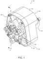
- FIG. 1is a perspective view of a scroll device according to at least one embodiment of the present disclosure
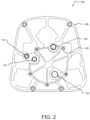
- FIG. 2is a front elevation view of a scroll device according to at least one embodiment of the present disclosure
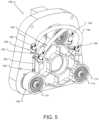
- FIG. 3is a side elevation view of a scroll device with a housing removed according to at least one embodiment of the present disclosure
- FIG. 4is a front perspective view of a fixed scroll and an orbiting scroll according to at least one embodiment of the present disclosure
- FIG. 5is a rear perspective view of an orbiting scroll and a fixed scroll according to at least one embodiment of the present disclosure
- FIG. 6is a rear perspective view of an orbiting scroll according to at least one embodiment of the present disclosure.
- FIG. 7is a side elevation view of an orbiting scroll according to at least one embodiment of the present disclosure.
- FIG. 8is a cross-sectional perspective view of an orbiting scroll taken along line B-B shown in FIG. 7 according to at least one embodiment of the present disclosure
- FIG. 9is a cross-sectional side elevation view of the scroll device taken along line A-A shown in FIG. 1 according to at least one embodiment of the present disclosure
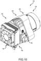
- FIG. 10is a perspective view of a scroll device according to at least one embodiment of the present disclosure.
- FIG. 11is an exploded perspective view of a cooling system of a scroll device according to at least one embodiment of the present disclosure.
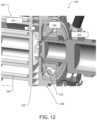
- FIG. 12is a detail perspective view of a coupling of a scroll device according to at least one embodiment of the present disclosure.
- FIG. 13is a schematic diagram illustrating the arrangement of an orbital scroll jacket that moves fluid using centrifugal forces and vortex flow according to at least one embodiment of the present disclosure.
- the present disclosureprovides a scroll device that utilizes a self-contained liquid cooling loop to improve heat transfer from the orbiting scroll.
- cooling the orbiting scrollis difficult due to limitations with cooling fins and air flow.
- Liquid coolingis an effective method of removing thermal energy away from the orbiting scroll.
- Using the same cooling fluid to cool the fixed scroll and orbiting scrollalso reduces the temperature difference between the two scrolls. Operation with scrolls at differing temperatures can cause potential issues from thermal expansion (e.g., due to a mismatch in thermal expansion between one scroll and the other, etc.).
- the scroll device 100comprises a housing 102 and a motor 104 .
- the motor 104may be mounted, fastened, or otherwise attached to the housing 102 .
- the scroll device 100comprises a fixed scroll 106 mated to an orbiting scroll 108 .
- the scroll device 100also includes three idler shafts 110 , 112 , 114 (visible in FIG. 5 ) being spaced approximately 120° apart. It will be appreciated that in some embodiments, the scroll device 100 may have more than or fewer than three idler shafts and the idler shafts may be spaced apart from one another at any combination of angles.
- the fixed scroll 106also has a first inlet 116 , a first outlet 118 , a second inlet 120 , and a second outlet 122 , as shown in FIG. 2 .
- the first inlet 116allows a cooling fluid such as, for example, a liquid (not shown) to be directed into, or enter, the scroll device 100 and into a cooling path and the first outlet 118 allows the cooling fluid to exit the cooling path and the scroll device 100 .
- the cooling fluidmay be supplied by a cooling fluid source to the first inlet 116 and the cooling fluid may be received into the cooling fluid source (or a separate cooling fluid storage) from the first outlet 118 .
- the cooling pathmay be a closed loop within the scroll device 100 and the first inlet 116 and the first outlet 118 may be closed once cooling fluid is delivered to the scroll device 100 .
- the second inlet 120may receive a working fluid and the second outlet 122 may discharge the working fluid.
- the scroll device 100may comprise an integrated aftercooler 124 comprising an aftercooler plate 126 and an aftercooler cover 128 .
- the integrated aftercooler 124may be configured to provide cooling or heating to the working fluid after the working fluid has been compressed or expanded, as will be described in more detail in conjunction with FIG. 9 . It will be appreciated that in some embodiments, the scroll device 100 may not include the integrated aftercooler 124 .
- FIG. 3a side elevation view of the scroll device 100 without the housing 102 is shown.
- the fixed scroll 106is operatively coupled, or mated, to the orbiting scroll 108 , as described above.
- the orbiting scroll 108is driven by a crankshaft 130 (visible in FIG. 9 ) connected to the motor 104 and the motor 104 is used to drive the crankshaft 130 .
- the motor 104may be an electric motor.
- the crankshaft 130 and the motor 104are mounted in the housing 102 .
- An opposite end of the crankshaft 130engages the crankshaft bearing 132 (visible in FIG. 9 ).
- the crankshaft 130is eccentric, which allows the crankshaft 130 to drive the orbiting scroll 108 (via the crankshaft bearing 132 ) in an orbiting motion relative to the fixed scroll 106 .
- the orbiting scroll 108has a first involute 162 (shown in FIGS. 6 and 9 ) and the fixed scroll 106 has a second involute 164 (shown in FIG. 9 ).
- a pair of balance weightsmay be positioned co-axially with the first involute to dynamically balance the orbiting scroll 108 .
- a pair of counterweightsmay be positioned on the crankshaft 130 to dynamically balance the orbiting scroll 108 .
- the orbiting scroll 108is coupled to the crankshaft 130 that moves or orbits the orbiting scroll 108 eccentrically, following a fixed path with respect to the fixed scroll 106 , creating a series of crescent-shaped pockets between the two scrolls.
- a scroll compressorduring operation the working fluid moves from the periphery (inlet) towards the center (discharge) through increasingly smaller pockets, generating compression. Similar principles apply for a scroll vacuum pump and a scroll expander.
- the idler shafts 110 , 112 , 114are supported by front bearings 134 in the orbiting scroll 108 and the rear bearings 136 in the fixed scroll 106 (see, e.g., FIG. 9 ).
- a center line of each of the idler shafts 110 , 112 , 114is offset from a center line of the crankshaft 130 .
- a labyrinth sealmay be used.
- the labyrinth sealmay be positioned between the bearings or after the rear bearing. It will be appreciated that in other embodiments any seal may be used to seal working fluid within the crankshaft.
- the scroll device 100comprises flexible conduits 138 and 140 for routing cooling fluid between or among one or more cooling fluid flow paths of the scroll device 100 , as will be described in more detail in conjunction with FIGS. 4 - 9 .
- the scroll device 100may not include the flexible conduits 138 , 140 or may include one flexible conduit, two flexible conduits, or more than two flexible conduits.
- the flexible conduit 138 , 140may curve (e.g., radially) around an orbital axis 142 (shown in FIG. 3 ) from a first side to a second side opposite the first side.
- the fixed scroll 106may comprise a cooling chamber 144 having one or more walls 146 defining a fixed scroll cooling path.
- the cooling chamber 144may also comprise a cooling chamber inlet 148 through which cooling fluid may be received from the flexible conduit 140 and a cooling chamber outlet 150 through which the cooling fluid may exit the cooling chamber 144 via the first outlet 118 .
- the cooling chamber 144may be configured to cool both the fixed scroll 106 (and more specifically, the involutes of the fixed scroll 106 ) and the discharge gas in the integrated aftercooler 124 .
- the cooling fluid flow pathmay enter the flexible conduit 138 via the first inlet 116 as represented by arrow 152 , flow through the flexible conduit 138 to one or more cooling passageways 154 (shown in FIGS. 7 and 9 ) as represented by arrow 156 , exit the one or more cooling passageways 154 and enter the flexible conduit 140 as represented by arrow 158 (visible in FIG. 5 ), flow through the flexible conduit 140 and exit the flexible conduit 140 as represented by arrow 160 , enter the cooling chamber 144 via the cooling chamber inlet 148 as represented by arrow 161 , and exit the cooling chamber 144 via the cooling chamber outlet 150 as represented by arrow 164 .
- the cooling fluid flow pathmay be reversed in some instances.
- the cooling fluid flow path as shownis an example cooling fluid flow path and the cooling fluid flow path may be defined by any number of cooling chambers, passageways, conduits, inlets, and/or outlets.
- FIGS. 6 - 8the orbiting scroll 108 of the scroll device 100 is shown in isolation for clarity.
- the orbiting scroll 108is shown in a rear perspective view
- FIG. 7the orbiting scroll 108 is shown in a side elevation view
- the orbiting scroll 108is shown in a cross-sectional perspective view taken along line B-B shown in FIG. 7 .
- the orbiting scroll 108includes a cooling fluid inlet 168 configured to receive cooling fluid into one or more cooling passageways 154 (visible in FIG. 9 ) represented by the arrow 156 and a cooling fluid outlet 170 through which the cooling fluid may exit the one or more cooling passageways 154 represented by the arrow 158 .
- the positioning of the cooling fluid inlet 168 and the cooling fluid outlet 170may be reversed. It will be further appreciated that in some embodiments, the cooling fluid inlet 168 and the cooling fluid outlet 170 may be positioned elsewhere on the orbiting scroll 108 .
- the one or more cooling passageways 154may comprise cross holes 172 (e.g., shown in FIGS. 7 and 8 ) formed in the orbiting scroll 108 . It will be appreciated that the one or more cooling passageways 154 may comprise passageways of other shapes or sizes. Further, the one or more cooling passageways 154 may comprise one passageway or more than one passageway.
- the cross holes 172may correspond to through holes passing through a body 174 of the orbiting scroll 108 and adjacent to involutes of the orbiting scroll 108 .
- the flexible conduits 138 , 140may be coupled to the cross holes 172 .
- this couplingmay allow cooling fluid to flow through the cross holes 172 and cool the body 174 of the orbiting scroll 108 .
- the cross holes 172may be machined into, or otherwise formed in, the orbiting scroll 108 .
- the cross holes 172receive the cooling fluid from the flexible conduits 138 , 140 and may cool the crank bearing and the hottest location on the orbiting scroll 108 .
- the hottest location on the orbiting scroll 108may be a location where the orbiting scroll 108 and the fixed scroll 106 contact each other, which causes high temperature gas and thermal expansion of the scroll involute.
- the cross holes 172may extend from a first end 176 to a second end 178 of the orbiting scroll 108 . As illustrated, for example, in FIGS. 7 and 8 , the cross holes 172 comprise four cross holes. It will be appreciated that in some embodiments the cross holes 172 may comprise any number of holes, for example, one cross hole, two cross holes, or more than two cross holes. The cross holes 172 may extend linearly adjacent and in parallel to each other from the first end 176 to the second end 178 . It will be appreciated that in some embodiments the cross holes 172 may extend at various angles to each other and/or may be spaced apart, or offset a distance, from one another.
- two additional holes 180may be formed in the body 174 of the orbiting scroll 108 for securing a cover 182 (e.g., as shown in FIG. 5 ) to the orbiting scroll 108 .
- These additional holes 180may be disposed outside of an area of the one or more passageways 154 .
- the additional holes 180may be in the first end 176 and/or the second end 178 of the body 174 .
- the additional holes 180may be configured as through-holes that pass through the body 174 of the orbiting scroll 180 .
- the cover 182may be, for example, a plate.
- the holes 180may be at least partially tapped (e.g., at the first end 176 and/or the second end 178 ) to receive screws 184 for securing the cover 182 to the orbiting scroll 108 .
- the holes 180may receive pins for securing the cover 182 to the orbiting scroll 108 .
- the cover 182may be coupled to the orbiting scroll 108 .
- a cover 182may be attached to the first end 176 and/or the second end 178 .
- the arrangement of the cover 182 shown in the rear perspective view of FIG. 5may be mirrored to illustrate the arrangement of a cover 182 that is attached to the second end 178 .
- the scroll device 100may be substantially symmetrical (e.g., having one or more components that are symmetrical, etc.) about a plane that passes through a center of the scroll device 100 .
- the cross holes 172can be easily machined with minimal setups using, for example, a horizontal mill.
- the cross holes 172may be machined, or otherwise formed, in the orbiting scroll 108 such that the cross holes 172 do not break through into a space of the involute of the orbiting scroll 108 .
- the cooling fluidmay be contained within the circuit, or cooling loop, of the scroll device 100 .
- the cross holes 172may be inexpensive to machine and form, and may also reduce the number of components of a cooling system of the scroll device 100 .
- the fixed scroll 106 and/or the orbiting scroll 108may have the cooling passageways 154 and/or the cooling chamber 144 .
- the fixed scroll 106 and the orbiting scroll 108may each comprise one or more cooling passageways.
- the orbiting scroll 108may comprise a cooling chamber and the fixed scroll 106 may comprise one or more cooling passageways 154 .
- FIG. 9a cross-sectional side elevation view of the scroll device 100 taken along line A-A shown in FIG. 1 is shown.
- the scroll device 100may comprise the integrated aftercooler 124 .
- the aftercooler plate 126may at least partially define the cooling chamber 144 of the fixed scroll 106 .
- the aftercooler plate 126also comprises one or more walls 186 extending from the aftercooler plate 126 , which together with the aftercooler cover 128 define an aftercooler chamber 188 .
- the aftercooler plate 126With coolant in the cooling chamber 144 formed by the aftercooler plate 126 and the fixed scroll 106 , and discharge gas flowing through a discharge gas flow path defined at least in part by the one or more of walls 186 and the aftercooler plate 126 , the aftercooler plate 126 is the only thing separating the discharge gas from the coolant. As a result, heat transfer occurs across the aftercooler plate 126 , with heat from the hot discharge gas being transferred to and absorbed by the coolant in the cooling chamber 144 . The discharge gas therefore cools as it flows through the integrated aftercooler 124 , and exits the second outlet 122 at a lower temperature than the temperature at which the discharge gas entered aftercooler chamber 188 .
- U.S. Patent Publication No. 2020/0408201which is herein incorporated by reference in its entirety, describes an integrated aftercooler 124 in further detail.
- one or more O-rings or other seals or gasketsmay be provided between the fixed scroll 106 and the aftercooler plate 126 and/or between the orbiting scroll 108 and the cooling passageways cover(s) 182 .
- cooling fluidmay be delivered to the orbiting scroll 108 and/or the fixed scroll 106 using any combination of delivery mechanisms and/or components.
- a cooling loopmay be open or closed.
- the cooling loopmay be self-contained, whereas in other embodiments, the cooling loop may comprise a separate cooling source and/or reservoir for receiving spent cooling fluid.
- cooling fluidmay be delivered to and from the orbiting scroll 108 using the crankshaft 130 .
- the scroll device 100may not include, for example, flexible conduits.
- cooling fluidmay be delivered to the orbiting scroll 108 using the crankshaft 130 and one or more idler shafts 110 , 112 , 114 .
- cooling fluidmay be delivered to the orbiting scroll 108 using the crankshaft 130 and flexible conduits 138 , 140 .
- context, and description of the flexible conduits 138 , 140can also be found in U.S. Patent Publication No. 2020/0408201, the entirety of which is hereby incorporated by reference herein for all purposes.
- cooling fluidmay be delivered to and from the orbiting scroll 108 via the crankshaft 130 , one or more idler shafts 110 , 112 , 114 , and/or the flexible conduits 138 , 140 .
- cooling fluidmay be delivered to the orbiting scroll 108 using the crankshaft 130 and may exit the orbiting scroll 108 into a reservoir.
- the scroll device 100may comprise various bearings to support one or more components of the scroll device 100 .
- the scroll device 100may comprise crankshaft bearings 190 to support the crankshaft 130 and/or idler bearings such as bearings 134 , 136 to support one or more of the idler shafts 110 , 112 , 114 .
- FIGS. 10 and 11a perspective view of the scroll device 100 with a cooling assembly 192 and an exploded perspective view of the cooling assembly 192 are respectively shown.
- the cooling assembly 192may comprise a heatsink 196 coupled with a fan 194 .
- the cooling assembly 192may be mounted directly to the fixed scroll 106 of the scroll device 100 and may be in direct contact with the cooling fluid.
- the fixed scroll 106may comprise a recessed section 198 that acts as a coolant reservoir.
- the cooling assembly 192may form an integrated cooling system.
- the heatsink 196comprises fins 199 which may be formed from, for example, aluminum. More specifically, the heatsink 196 comprises a plurality of air fins 199 A disposed on one side of a body 197 of the heatsink 196 and a plurality of coolant fins 199 B disposed on the other side of the body 197 of the heatsink 196 .
- the heatsink 196may be fastened, clamped, or otherwise attached to the fixed scroll 106 such that the plurality of coolant fins 199 B are disposed, at least partially, in the recessed section 198 (e.g., a coolant reservoir).
- the body 197 of the heatsink 196may be sealed against a sealing face of the fixed scroll 106 via a gasket, O-ring, etc. This sealed interface ensures that the cooling fluid remains inside the coolant loop of the integrated cooling system.
- the cooling fluidmay flow into the recessed section 198 via a first coolant flow port 195 and then flow between and around the plurality of coolant fins 199 B disposed therein.
- the coolantmay then flow out of the coolant reservoir via a second coolant flow port (e.g., disposed opposite the first coolant flow port).
- the plurality of coolant fins 199 B on the back side of the cooling assembly 192extends into the recessed portion 198 , thereby improving heat transfer to the heatsink 196 .
- a conductive thermal pathmay be provided between the sealed recessed portion 198 (e.g., a coolant reservoir) and the outside environment of the scroll device 100 via the body 197 of the heatsink 196 .
- FIG. 12a detailed cross-sectional view of a scroll device 200 and an impeller 202 are shown.
- the scroll device 200may be the same as or similar to the scroll device 100 described above in conjunction with FIGS. 1 - 11 .
- an orbiting scroll 208(which may be the same as or similar to the orbiting scroll 108 of the scroll device 100 described above) of the scroll device 200 may comprise an orbiting scroll cooling chamber 244 enclosed by an orbiting scroll cooling jacket 220 .
- the scroll device 200may utilize the impeller 202 inside of the orbiting scroll cooling chamber 244 to circulate coolant throughout the cooling loop.
- the impeller 202may use a magnetic coupling 226 between the impeller 202 and the crankshaft 230 to drive the impeller 202 without the use of additional seals.
- the impeller 202may be made from a plastic and/or resin material (e.g., polyetheretherketone, polyoxymethylene, etc.) and/or some other lightweight, low friction, material.
- the impeller 202may spin, or rotate, inside the orbiting scroll cooling chamber 244 the magnets 226 , which are attached to the crankshaft 230 and magnetically coupled to magnets 226 of the impeller 202 , spin on the other side of a thin wall 232 separating the orbiting scroll cooling jacket 220 and the orbiting scroll cooling chamber 244 from the crankshaft 230 .
- the scroll device 200may utilize the inherent circular motion of the orbiting scroll 208 to create a vortex flow in the orbiting scroll cooling chamber 244 .
- the orbiting scroll cooling jacket 220may use this vortex flow to propel coolant out of the orbiting scroll 108 , and back to a reservoir on a fixed scroll 206 (which may be the same as or similar to the fixed scroll 106 of the scroll device 100 described above) of the scroll device 200 .
- a check valvemay be used to ensure one way flow between a fixed scroll cooling jacket (not shown) and the orbiting scroll cooling jacket 220 . As shown in FIG.
- FIG. 13a schematic diagram illustrates the arrangement of the orbital scroll cooling jacket 220 that moves fluid using centrifugal forces and vortex flow generated by the motion of the orbiting scroll 208 in accordance with embodiments of the present disclosure.
- fluidenters an inlet 240 and the centrifugal forces and vortex flow cause the fluid to exit at an outlet 242 .
- a movement of the crankshaftmay engender a circular or elliptical orbiting movement of a corresponding part associated with the cooling loop. This orbiting movement may cause the coolant to move throughout the coolant loop integrated cooling system.
- a scroll devicemay comprise any combination of components described herein.
- a scroll devicemay comprise an orbiting scroll with one or more passageways such as the one or more passageways 154 and a cooling assembly such as the cooling assembly 192 coupled to a fixed scroll.
- a scroll devicemay comprise an orbiting scroll with a cooling chamber and an impeller such as the impeller 202 disposed in the cooling chamber to circulate cooling fluid.
- a cooling assemblysuch as the cooling assembly 192 may be coupled to a fixed scroll and/or the fixed scroll may comprise one or more cooling passageways such as the one or more cooling passageways 154 .
- the present disclosurein various aspects, embodiments, and/or configurations, includes components, methods, processes, systems and/or apparatus substantially as depicted and described herein, including various aspects, embodiments, configurations embodiments, subcombinations, and/or subsets thereof.
- the present disclosurein various aspects, embodiments, and/or configurations, includes providing devices and processes in the absence of items not depicted and/or described herein or in various aspects, embodiments, and/or configurations hereof, including in the absence of such items as may have been used in previous devices or processes, e.g., for improving performance, achieving ease and/or reducing cost of implementation.
Landscapes
- Engineering & Computer Science (AREA)
- Mechanical Engineering (AREA)
- General Engineering & Computer Science (AREA)
- Rotary Pumps (AREA)
- Applications Or Details Of Rotary Compressors (AREA)
Abstract
Description
Claims (20)
Priority Applications (1)
| Application Number | Priority Date | Filing Date | Title |
|---|---|---|---|
| US17/868,609US11885328B2 (en) | 2021-07-19 | 2022-07-19 | Scroll device with an integrated cooling loop |
Applications Claiming Priority (3)
| Application Number | Priority Date | Filing Date | Title |
|---|---|---|---|
| US202163223388P | 2021-07-19 | 2021-07-19 | |
| US202263298118P | 2022-01-10 | 2022-01-10 | |
| US17/868,609US11885328B2 (en) | 2021-07-19 | 2022-07-19 | Scroll device with an integrated cooling loop |
Publications (2)
| Publication Number | Publication Date |
|---|---|
| US20230020439A1 US20230020439A1 (en) | 2023-01-19 |
| US11885328B2true US11885328B2 (en) | 2024-01-30 |
Family
ID=84890941
Family Applications (1)
| Application Number | Title | Priority Date | Filing Date |
|---|---|---|---|
| US17/868,609ActiveUS11885328B2 (en) | 2021-07-19 | 2022-07-19 | Scroll device with an integrated cooling loop |
Country Status (1)
| Country | Link |
|---|---|
| US (1) | US11885328B2 (en) |
Families Citing this family (2)
| Publication number | Priority date | Publication date | Assignee | Title |
|---|---|---|---|---|
| US10865793B2 (en) | 2016-12-06 | 2020-12-15 | Air Squared, Inc. | Scroll type device having liquid cooling through idler shafts |
| JP2025143706A (en)* | 2024-03-19 | 2025-10-02 | サンデン株式会社 | Scroll Compressor |
Citations (285)
| Publication number | Priority date | Publication date | Assignee | Title |
|---|---|---|---|---|
| US801182A (en) | 1905-06-26 | 1905-10-03 | Leon Creux | Rotary engine. |
| DE460936C (en) | 1925-05-05 | 1928-06-11 | Otto Hardung | Ice or cooling machine with rotating evaporator and condenser housings |
| US2079118A (en) | 1935-01-19 | 1937-05-04 | Rheinmetall Borsig Ag | Combined turbine and steam generator |
| GB513827A (en) | 1937-01-06 | 1939-10-23 | American Centrifugal Corp | Improvements in or relating to the treatment and disposal of sewage and like waste material |
| US2330121A (en) | 1940-10-04 | 1943-09-21 | Jack & Heintz Inc | Motor cooling system |
| US2475247A (en) | 1944-05-22 | 1949-07-05 | Mikulasek John | Planetary piston fluid displacement mechanism |
| US2968157A (en) | 1956-05-03 | 1961-01-17 | Walter I Cronan | Closed circuit steam turbine marine motor |
| US3011694A (en) | 1958-09-12 | 1961-12-05 | Alsacienne Constr Meca | Encapsuling device for expanders, compressors or the like |
| US3262573A (en) | 1963-02-11 | 1966-07-26 | Little Inc A | Filter apparatus |
| US3470704A (en) | 1967-01-10 | 1969-10-07 | Frederick W Kantor | Thermodynamic apparatus and method |
| US3600114A (en) | 1968-07-22 | 1971-08-17 | Leybold Heraeus Verwaltung | Involute pump |
| US3613368A (en) | 1970-05-08 | 1971-10-19 | Du Pont | Rotary heat engine |
| US3802809A (en) | 1971-06-01 | 1974-04-09 | P Vulliez | Completely dry and fluid-tight vacuum pumps |
| US3842596A (en) | 1970-07-10 | 1974-10-22 | V Gray | Methods and apparatus for heat transfer in rotating bodies |
| US3874827A (en) | 1973-10-23 | 1975-04-01 | Niels O Young | Positive displacement scroll apparatus with axially radially compliant scroll member |
| US3884599A (en) | 1973-06-11 | 1975-05-20 | Little Inc A | Scroll-type positive fluid displacement apparatus |
| US3924977A (en) | 1973-06-11 | 1975-12-09 | Little Inc A | Positive fluid displacement apparatus |
| US3986799A (en) | 1975-11-03 | 1976-10-19 | Arthur D. Little, Inc. | Fluid-cooled, scroll-type, positive fluid displacement apparatus |
| US3986852A (en) | 1975-04-07 | 1976-10-19 | E. I. Du Pont De Nemours And Company | Rotary cooling and heating apparatus |
| US3994636A (en) | 1975-03-24 | 1976-11-30 | Arthur D. Little, Inc. | Axial compliance means with radial sealing for scroll-type apparatus |
| US3994635A (en) | 1975-04-21 | 1976-11-30 | Arthur D. Little, Inc. | Scroll member and scroll-type apparatus incorporating the same |
| US3994633A (en) | 1975-03-24 | 1976-11-30 | Arthur D. Little, Inc. | Scroll apparatus with pressurizable fluid chamber for axial scroll bias |
| US3999400A (en) | 1970-07-10 | 1976-12-28 | Gray Vernon H | Rotating heat pipe for air-conditioning |
| US4065279A (en) | 1976-09-13 | 1977-12-27 | Arthur D. Little, Inc. | Scroll-type apparatus with hydrodynamic thrust bearing |
| US4069673A (en) | 1975-10-01 | 1978-01-24 | The Laitram Corporation | Sealed turbine engine |
| US4082484A (en) | 1977-01-24 | 1978-04-04 | Arthur D. Little, Inc. | Scroll-type apparatus with fixed throw crank drive mechanism |
| US4121438A (en) | 1976-09-13 | 1978-10-24 | Arthur D. Little, Inc. | Coupling member for orbiting machinery |
| US4129405A (en) | 1977-06-17 | 1978-12-12 | Arthur D. Little, Inc. | Scroll-type liquid pump with transfer passages in end plate |
| GB2002455A (en) | 1977-08-15 | 1979-02-21 | Ingersoll Rand Co | Positive fluid displacement apparatus |
| US4160629A (en) | 1977-06-17 | 1979-07-10 | Arthur D. Little, Inc. | Liquid immersible scroll pump |
| US4178143A (en) | 1978-03-30 | 1979-12-11 | The United States Of America As Represented By The Secretary Of The Navy | Relative orbiting motion by synchronoously rotating scroll impellers |
| US4192152A (en) | 1978-04-14 | 1980-03-11 | Arthur D. Little, Inc. | Scroll-type fluid displacement apparatus with peripheral drive |
| US4199308A (en) | 1978-10-02 | 1980-04-22 | Arthur D. Little, Inc. | Axial compliance/sealing means for improved radial sealing for scroll apparatus and scroll apparatus incorporating the same |
| US4216661A (en) | 1977-12-09 | 1980-08-12 | Hitachi, Ltd. | Scroll compressor with means for end plate bias and cooled gas return to sealed compressor spaces |
| GB1575684A (en) | 1976-06-28 | 1980-09-24 | Ultra Centrifuge Nederland Nv | Installation proveded with a hollow rotor |
| JPS5619369A (en) | 1979-07-25 | 1981-02-24 | Toshiba Corp | Non-commutator motor for driving compressor of refrigerator, etc. |
| US4259043A (en) | 1977-06-17 | 1981-03-31 | Arthur D. Little, Inc. | Thrust bearing/coupling component for orbiting scroll-type machinery and scroll-type machinery incorporating the same |
| US4300875A (en) | 1978-07-15 | 1981-11-17 | Leybold-Heraeus Gmbh | Positive displacement machine with elastic suspension |
| US4334840A (en) | 1979-01-26 | 1982-06-15 | Kayaba Kogyo Kabushiki Kaisha | Gear pump or motor with serrated grooves on inner wall for break-in operation |
| US4340339A (en) | 1979-02-17 | 1982-07-20 | Sankyo Electric Company Limited | Scroll type compressor with oil passageways through the housing |
| JPS57171002A (en) | 1981-04-13 | 1982-10-21 | Ebara Corp | Scroll type machine |
| US4368802A (en) | 1980-07-03 | 1983-01-18 | Rockwell International Corporation | Pressurized lubrication system |
| US4382754A (en) | 1980-11-20 | 1983-05-10 | Ingersoll-Rand Company | Scroll-type, positive fluid displacement apparatus with diverse clearances between scroll elements |
| US4395205A (en) | 1981-02-12 | 1983-07-26 | Arthur D. Little, Inc. | Mechanically actuated tip seals for scroll apparatus and scroll apparatus embodying the same |
| US4395885A (en) | 1981-10-08 | 1983-08-02 | Cozby Enterprises, Inc. | Unitary steam engine |
| US4403494A (en) | 1981-03-02 | 1983-09-13 | Arthur D. Little, Inc. | Method of fabricating scroll members by coining and tools therefor |
| US4411605A (en) | 1981-10-29 | 1983-10-25 | The Trane Company | Involute and laminated tip seal of labyrinth type for use in a scroll machine |
| US4415317A (en) | 1981-02-09 | 1983-11-15 | The Trane Company | Wrap element and tip seal for use in fluid apparatus of the scroll type |
| US4416597A (en) | 1981-02-09 | 1983-11-22 | The Trane Company | Tip seal back-up member for use in fluid apparatus of the scroll type |
| US4424010A (en) | 1981-10-19 | 1984-01-03 | Arthur D. Little, Inc. | Involute scroll-type positive displacement rotary fluid apparatus with orbiting guide means |
| US4436495A (en) | 1981-03-02 | 1984-03-13 | Arthur D. Little, Inc. | Method of fabricating two-piece scroll members for scroll apparatus and resulting scroll members |
| US4457674A (en) | 1981-10-12 | 1984-07-03 | Sanden Corporation | High efficiency scroll type compressor with wrap portions having different axial heights |
| US4462771A (en) | 1981-02-09 | 1984-07-31 | The Trane Company | Wrap element and tip seal for use in fluid apparatus of the scroll type and method for making same |
| US4463591A (en) | 1981-03-02 | 1984-08-07 | Arthur D. Little, Inc. | Method of fabricating scroll members by coining and tools therefor |
| US4472120A (en) | 1982-07-15 | 1984-09-18 | Arthur D. Little, Inc. | Scroll type fluid displacement apparatus |
| US4475346A (en) | 1982-12-06 | 1984-10-09 | Helix Technology Corporation | Refrigeration system with linear motor trimming of displacer movement |
| US4477238A (en) | 1983-02-23 | 1984-10-16 | Sanden Corporation | Scroll type compressor with wrap portions of different axial heights |
| US4478562A (en) | 1978-07-28 | 1984-10-23 | Barmag Barmer Maschinenfabrik Ag | Oil lubrication of vacuum pump with pulsating oil feed |
| US4511091A (en) | 1983-01-06 | 1985-04-16 | Augusto Vasco | Method and apparatus for recycling thermoplastic scrap |
| US4512066A (en) | 1981-03-02 | 1985-04-23 | Arthur D. Little, Inc. | Method of fabricating scroll members |
| US4515539A (en) | 1983-09-01 | 1985-05-07 | Mitsubishi Denki Kabushiki Kaisha | Scroll-type hydraulic machine with two axially spaced scroll mechanisms |
| JPS60135691A (en) | 1983-12-23 | 1985-07-19 | Hitachi Ltd | scroll fluid machine |
| US4673339A (en) | 1984-07-20 | 1987-06-16 | Kabushiki Kaisha Toshiba | Scroll compressor with suction port in stationary end plate |
| US4718836A (en) | 1984-07-23 | 1988-01-12 | Normetex | Reciprocating completely sealed fluid-tight vacuum pump |
| US4722676A (en) | 1985-10-25 | 1988-02-02 | Sanden Corporation | Axial sealing mechanism for scroll type fluid displacement apparatus |
| US4726100A (en) | 1986-12-17 | 1988-02-23 | Carrier Corporation | Method of manufacturing a rotary scroll machine with radial clearance control |
| US4730375A (en) | 1984-05-18 | 1988-03-15 | Mitsubishi Denki Kabushiki Kaisha | Method for the assembly of a scroll-type apparatus |
| US4732550A (en) | 1985-11-27 | 1988-03-22 | Mitsubishi Denki Kabushiki Kaisha | Scroll fluid machine with fine regulation elements in grooves having stepped portion |
| US4756675A (en) | 1986-06-27 | 1988-07-12 | Mitsubishi Denki Kabushiki Kaisha | Scroll type fluid transferring machine with separate motor driving each scroll |
| JPS63173870A (en) | 1987-01-09 | 1988-07-18 | Kashiyama Kogyo Kk | Whole system rotary scroll fluid machine |
| US4802831A (en) | 1986-04-11 | 1989-02-07 | Hitachi, Ltd. | Fluid machine with resin-coated scroll members |
| US4832586A (en) | 1987-06-26 | 1989-05-23 | Volkswagen Ag | Drive assembly with different eccentricities |
| US4867657A (en) | 1988-06-29 | 1989-09-19 | American Standard Inc. | Scroll compressor with axially balanced shaft |
| US4875839A (en) | 1987-03-20 | 1989-10-24 | Kabushiki Kaisha Toshiba | Scroll member for use in a positive displacement device, and a method for manufacturing the same |
| US4892469A (en) | 1981-04-03 | 1990-01-09 | Arthur D. Little, Inc. | Compact scroll-type fluid compressor with swing-link driving means |
| US4911621A (en) | 1988-06-20 | 1990-03-27 | Arthur D. Little, Inc. | Scroll fluid device using flexible toothed ring synchronizer |
| US4918930A (en) | 1988-09-13 | 1990-04-24 | Helix Technology Corporation | Electronically controlled cryopump |
| US4927340A (en) | 1988-08-19 | 1990-05-22 | Arthur D. Little, Inc. | Synchronizing and unloading system for scroll fluid device |
| JPH02275083A (en) | 1989-04-13 | 1990-11-09 | Mitsubishi Electric Corp | Full system rotary scroll vacuum pump |
| US4990072A (en) | 1988-07-20 | 1991-02-05 | Aginfor Ag Fur Industrielle Forschung | Rotating helical charger with axially movable displacement disk |
| US5013226A (en) | 1987-07-16 | 1991-05-07 | Mitsubishi Denki K. K. | Rotating scroll machine with balance weights |
| US5037280A (en) | 1987-02-04 | 1991-08-06 | Mitsubishi Denki K.K. | Scroll fluid machine with coupling between rotating scrolls |
| JPH03185287A (en) | 1989-12-13 | 1991-08-13 | Shin Meiwa Ind Co Ltd | Scroll type fluid device |
| US5040956A (en) | 1989-12-18 | 1991-08-20 | Carrier Corporation | Magnetically actuated seal for scroll compressor |
| US5044904A (en) | 1990-01-17 | 1991-09-03 | Tecumseh Products Company | Multi-piece scroll members utilizing interconnecting pins and method of making same |
| US5051079A (en) | 1990-01-17 | 1991-09-24 | Tecumseh Products Company | Two-piece scroll member with recessed welded joint |
| US5051075A (en) | 1990-02-20 | 1991-09-24 | Arthur D. Little, Inc. | Gearing system having interdigited teeth with convex and concave surface portions |
| US5082430A (en) | 1989-04-08 | 1992-01-21 | Aginfor Ag Fur Industrielle Forschung | Rotating spiral compressor with reinforced spiral ribs |
| US5099658A (en) | 1990-11-09 | 1992-03-31 | American Standard Inc. | Co-rotational scroll apparatus with optimized coupling |
| US5108274A (en) | 1989-12-25 | 1992-04-28 | Mitsubishi Denki Kabushiki Kaisha | Scroll-type fluid machine with counter-weight |
| US5127809A (en) | 1990-02-21 | 1992-07-07 | Hitachi, Ltd. | Scroll compressor with reinforcing ribs on the orbiting scroll |
| US5142885A (en) | 1991-04-19 | 1992-09-01 | American Standard Inc. | Method and apparatus for enhanced scroll stability in a co-rotational scroll |
| US5149255A (en) | 1990-02-20 | 1992-09-22 | Arthur D. Little, Inc. | Gearing system having interdigital concave-convex teeth formed as invalutes or multi-faceted polygons |
| US5157928A (en) | 1988-09-13 | 1992-10-27 | Helix Technology Corporation | Electronically controlled cryopump |
| US5160253A (en) | 1990-07-20 | 1992-11-03 | Tokico Ltd. | Scroll type fluid apparatus having sealing member in recess forming suction space |
| EP0513824A2 (en) | 1991-05-17 | 1992-11-19 | Kao Corporation | Process for producing nonionic detergent granules |
| US5176004A (en) | 1991-06-18 | 1993-01-05 | Helix Technology Corporation | Electronically controlled cryopump and network interface |
| US5214932A (en) | 1991-01-25 | 1993-06-01 | Abdelmalek Fawzy T | Hermetically sealed electric driven gas compressor - expander for refrigeration |
| US5217360A (en) | 1989-11-02 | 1993-06-08 | Matsushita Electric Industrial Co., Ltd. | Scroll compressor with swirling impeller biased by cooled lubricant |
| JPH05157076A (en) | 1991-11-29 | 1993-06-22 | Mitsubishi Heavy Ind Ltd | Scroll type fluid machine |
| US5222882A (en) | 1992-02-20 | 1993-06-29 | Arthur D. Little, Inc. | Tip seal supporting structure for a scroll fluid device |
| US5224849A (en) | 1992-02-20 | 1993-07-06 | Arthur D. Little, Inc. | Compliance mounting mechanism for scroll fluid device |
| US5228309A (en) | 1992-09-02 | 1993-07-20 | Arthur D. Little, Inc. | Portable self-contained power and cooling system |
| US5232355A (en) | 1991-05-17 | 1993-08-03 | Mitsubishi Denki K.K. | Scroll-type fluid apparatus having a labyrinth and oil seals surrounding a scroll shaft |
| US5242284A (en) | 1990-05-11 | 1993-09-07 | Sanyo Electric Co., Ltd. | Scroll compressor having limited axial movement between rotating scroll members |
| US5247795A (en) | 1992-04-01 | 1993-09-28 | Arthur D. Little, Inc. | Scroll expander driven compressor assembly |
| USRE34413E (en) | 1988-08-19 | 1993-10-19 | Arthur D. Little, Inc. | Synchronizer and unloading system for scroll fluid device |
| US5256042A (en) | 1992-02-20 | 1993-10-26 | Arthur D. Little, Inc. | Bearing and lubrication system for a scroll fluid device |
| US5258046A (en) | 1991-02-13 | 1993-11-02 | Iwata Air Compressor Mfg. Co., Ltd. | Scroll-type fluid machinery with seals for the discharge port and wraps |
| US5265431A (en) | 1991-06-18 | 1993-11-30 | Helix Technology Corporation | Electronically controlled cryopump and network interface |
| US5286179A (en) | 1992-02-20 | 1994-02-15 | Arthur D. Little, Inc. | Thermal isolation arrangement for scroll fluid device |
| US5295808A (en) | 1991-03-29 | 1994-03-22 | Hitachi, Ltd. | Synchronous rotating type scroll fluid machine |
| US5314316A (en) | 1992-10-22 | 1994-05-24 | Arthur D. Little, Inc. | Scroll apparatus with reduced inlet pressure drop |
| US5328341A (en) | 1993-07-22 | 1994-07-12 | Arthur D. Little, Inc. | Synchronizer assembly for a scroll fluid device |
| US5338159A (en) | 1991-11-25 | 1994-08-16 | American Standard Inc. | Co-rotational scroll compressor supercharger device |
| US5354184A (en) | 1992-02-20 | 1994-10-11 | Arthur D. Little, Inc. | Windage loss reduction arrangement for scroll fluid device |
| US5358387A (en) | 1991-05-29 | 1994-10-25 | Hitachi Ltd. | Oil-free scroll compressor |
| US5397223A (en) | 1993-01-19 | 1995-03-14 | Aginfor Ag Fur Industrielle Forschung | Positive-displacement machine operating by the spiral principle |
| JPH07109981A (en) | 1993-10-13 | 1995-04-25 | Nippondenso Co Ltd | Scroll fluid machinery |
| US5417554A (en) | 1994-07-19 | 1995-05-23 | Ingersoll-Rand Company | Air cooling system for scroll compressors |
| US5443368A (en) | 1993-07-16 | 1995-08-22 | Helix Technology Corporation | Turbomolecular pump with valves and integrated electronic controls |
| US5449279A (en) | 1993-09-22 | 1995-09-12 | American Standard Inc. | Pressure biased co-rotational scroll apparatus with enhanced lubrication |
| US5466134A (en) | 1994-04-05 | 1995-11-14 | Puritan Bennett Corporation | Scroll compressor having idler cranks and strengthening and heat dissipating ribs |
| JPH07324688A (en) | 1994-05-30 | 1995-12-12 | Daikin Ind Ltd | Co-rotating scroll fluid machine |
| US5496161A (en) | 1993-12-28 | 1996-03-05 | Tokico Ltd. | Scroll fluid apparatus having an inclined wrap surface |
| JPH08261182A (en) | 1995-03-20 | 1996-10-08 | Tokico Ltd | Scroll type fluid machinery |
| US5609478A (en) | 1995-11-06 | 1997-03-11 | Alliance Compressors | Radial compliance mechanism for corotating scroll apparatus |
| US5616015A (en) | 1995-06-07 | 1997-04-01 | Varian Associates, Inc. | High displacement rate, scroll-type, fluid handling apparatus |
| US5632613A (en) | 1992-12-17 | 1997-05-27 | Goldstar Co., Ltd. | Lubricating device for horizontal type hermetic compressor |
| US5637942A (en) | 1994-10-18 | 1997-06-10 | Arthur D. Little, Inc. | Aerodynamic drag reduction arrangement for use with high speed rotating elements |
| US5640854A (en) | 1995-06-07 | 1997-06-24 | Copeland Corporation | Scroll machine having liquid injection controlled by internal valve |
| EP0780576A2 (en) | 1995-12-21 | 1997-06-25 | Anest Iwata Corporation | Scroll fluid apparatus |
| US5746719A (en) | 1996-10-25 | 1998-05-05 | Arthur D. Little, Inc. | Fluid flow control system incorporating a disposable pump cartridge |
| US5752816A (en) | 1996-10-10 | 1998-05-19 | Air Squared,Inc. | Scroll fluid displacement apparatus with improved sealing means |
| US5759020A (en) | 1994-04-05 | 1998-06-02 | Air Squared, Inc. | Scroll compressor having tip seals and idler crank assemblies |
| US5800140A (en) | 1996-10-25 | 1998-09-01 | Arthur D. Little, Inc. | Compact scroll fluid device |
| US5803723A (en) | 1995-11-20 | 1998-09-08 | Tokico Ltd. | Scroll fluid machine having surface coating layers on wraps thereof |
| US5836752A (en) | 1996-10-18 | 1998-11-17 | Sanden International (U.S.A.), Inc. | Scroll-type compressor with spirals of varying pitch |
| US5842843A (en) | 1995-11-30 | 1998-12-01 | Anest Iwata Corporation | Scroll fluid machine having a cooling passage inside the drive shaft |
| US5857844A (en) | 1996-12-09 | 1999-01-12 | Carrier Corporation | Scroll compressor with reduced height orbiting scroll wrap |
| US5873711A (en) | 1996-10-30 | 1999-02-23 | Carrier Corporation | Scroll compressor with reduced separating force between fixed and orbiting scroll members |
| US5938419A (en) | 1997-01-17 | 1999-08-17 | Anest Iwata Corporation | Scroll fluid apparatus having an intermediate seal member with a compressed fluid passage therein |
| US5951268A (en) | 1995-02-24 | 1999-09-14 | S.B.P.V. (Societe Des Brevets P. Vulliez) | Sperial vacuum pump having a metal bellows for limiting circular translation movement |
| US5961297A (en) | 1995-02-28 | 1999-10-05 | Iwata Air Compressor Mfg. Co., Ltd. | Oil-free two stage scroll vacuum pump and method for controlling the same pump |
| US5987894A (en) | 1996-07-16 | 1999-11-23 | Commissariat A L'energie Atomique | Temperature lowering apparatus using cryogenic expansion with the aid of spirals |
| US6008557A (en) | 1996-09-24 | 1999-12-28 | Robert Bosch Gmbh | Bearing assembly having a slinger disk seal element |
| US6022195A (en) | 1988-09-13 | 2000-02-08 | Helix Technology Corporation | Electronically controlled vacuum pump with control module |
| US6050792A (en) | 1999-01-11 | 2000-04-18 | Air-Squared, Inc. | Multi-stage scroll compressor |
| US6068459A (en) | 1998-02-19 | 2000-05-30 | Varian, Inc. | Tip seal for scroll-type vacuum pump |
| US6074185A (en) | 1998-11-27 | 2000-06-13 | General Motors Corporation | Scroll compressor with improved tip seal |
| US6098048A (en) | 1998-08-12 | 2000-08-01 | Vnu Marketing Information Services, Inc. | Automated data collection for consumer driving-activity survey |
| JP2000213475A (en) | 1999-01-25 | 2000-08-02 | Hitachi Koki Co Ltd | Scroll type vacuum pump |
| DE19957425A1 (en) | 1998-12-02 | 2000-08-24 | Gerd Degener | Energy converter for utilising environmental heat energy has heat exchanger and expansion device with eccentric rotor for utilising evaporation and condensation of working medium |
| US6129530A (en) | 1998-09-28 | 2000-10-10 | Air Squared, Inc. | Scroll compressor with a two-piece idler shaft and two piece scroll plates |
| US6190145B1 (en) | 1998-10-15 | 2001-02-20 | Anest Iwata Corporation | Scroll fluid machine |
| US6193487B1 (en) | 1998-10-13 | 2001-02-27 | Mind Tech Corporation | Scroll-type fluid displacement device for vacuum pump application |
| US6213970B1 (en) | 1993-12-30 | 2001-04-10 | Stryker Corporation | Surgical suction irrigation |
| US20010012485A1 (en) | 1988-09-13 | 2001-08-09 | Helix Technology Corporation | Electronically controlled cryopump |
| US6283737B1 (en) | 2000-06-01 | 2001-09-04 | Westinghouse Air Brake Technologies Corporation | Oiless rotary scroll air compressor antirotation assembly |
| CN1314899A (en) | 1998-07-01 | 2001-09-26 | 武田药品工业株式会社 | Retinoid-associated receptor regulators |
| US20010038800A1 (en) | 2000-03-06 | 2001-11-08 | Hideyuki Kimura | Scroll fluid machine |
| US20010043878A1 (en) | 2000-03-31 | 2001-11-22 | Sullivan Timothy J. | Involute spiral wrap device |
| US6328545B1 (en) | 2000-06-01 | 2001-12-11 | Westinghouse Air Brake Technologies Corporation | Oiless rotary scroll air compressor crankshaft assembly |
| JP2002013493A (en) | 2000-06-01 | 2002-01-18 | Westinghouse Air Brake Technologies Corp | Lubricating device for anti-rotation assembly of scroll compressor, improved lubricating device, and scroll compressor including anti-rotation device and improved lubricating device for anti-rotation device |
| US20020011332A1 (en) | 2000-07-06 | 2002-01-31 | Oh Sai Kee | Refrigerant tube for heat exchangers |
| US20020039534A1 (en) | 2000-09-29 | 2002-04-04 | Kabushiki Kaisha Toyota Jidoshokki | Scroll compressor having an electric motor incorporated |
| US6379134B2 (en)* | 2000-05-16 | 2002-04-30 | Sanden Corporation | Scroll compressor having paired fixed and moveable scrolls |
| US20020071779A1 (en) | 2000-09-29 | 2002-06-13 | Takahiro Moroi | Scroll-type compressor with an integrated motor and a compact cooling system |
| US20020094277A1 (en) | 1993-07-16 | 2002-07-18 | Helix Technology Corporation | Electronically controlled vacuum pump |
| JP2002227779A (en) | 2001-02-05 | 2002-08-14 | Anest Iwata Corp | Scroll fluid machinery |
| US6434943B1 (en) | 2000-10-03 | 2002-08-20 | George Washington University | Pressure exchanging compressor-expander and methods of use |
| US6439864B1 (en) | 1999-01-11 | 2002-08-27 | Air Squared, Inc. | Two stage scroll vacuum pump with improved pressure ratio and performance |
| US20030017070A1 (en) | 2001-07-19 | 2003-01-23 | Takahiro Moroi | Compressor incorporated with motor and its cooling jacket |
| US6511308B2 (en) | 1998-09-28 | 2003-01-28 | Air Squared, Inc. | Scroll vacuum pump with improved performance |
| US20030026721A1 (en) | 2001-08-01 | 2003-02-06 | Takahiro Moroi | Scroll type compressor |
| US20030053922A1 (en) | 2001-09-19 | 2003-03-20 | Anest Iwata Corporation | Scroll-type fluid machine |
| US20030138339A1 (en) | 2002-01-24 | 2003-07-24 | Scancarello Marc J. | Powder metal scrolls |
| US6644946B2 (en) | 2001-01-22 | 2003-11-11 | Kabushiki Kaisha Toyota Jidoshokki | Scroll type compressor |
| JP2003343459A (en) | 2002-05-28 | 2003-12-03 | Anest Iwata Corp | Scroll fluid machine and oxygen generating device |
| US20030223898A1 (en) | 2001-12-28 | 2003-12-04 | Anest Iwata Corporation | Scroll fluid machine and assembling method thereof |
| US6663364B2 (en) | 2001-01-26 | 2003-12-16 | Kabushiki Kaisha Toyota Jidoshokki | Scroll type compressor |
| WO2004008829A2 (en) | 2002-07-22 | 2004-01-29 | Hunt Robert D | Turbines utilizing jet propulsion for rotation |
| US20040020206A1 (en) | 2001-05-07 | 2004-02-05 | Sullivan Timothy J. | Heat energy utilization system |
| US6712589B2 (en) | 2001-04-17 | 2004-03-30 | Kabushiki Kaisha Toyota Jidoshokki | Scroll compressors |
| US6736622B1 (en) | 2003-05-28 | 2004-05-18 | Scroll Technologies | Scroll compressor with offset scroll members |
| US20040184940A1 (en) | 2003-02-05 | 2004-09-23 | Yoshiyuki Nakane | Compressor for and method of simultaneously cooling and cleaning gas |
| EP1464838A2 (en) | 2003-03-31 | 2004-10-06 | Kabushiki Kaisha Toyota Jidoshokki | Compressor |
| US20040241030A1 (en) | 2003-05-23 | 2004-12-02 | Anest Iwata Corporation | Scroll fluid machine |
| US20040255591A1 (en) | 2003-06-20 | 2004-12-23 | Denso Corporation Nippon Soken | Fluid machine for converting heat into mechanical rotational force |
| US20050025651A1 (en) | 2001-07-10 | 2005-02-03 | Masato Sowa | Compressor, method and jig for balancing the same |
| US20050031469A1 (en) | 2002-05-30 | 2005-02-10 | Anest Iwata Corporation | Scroll fluid machine comprising compressing and expanding sections |
| US6922999B2 (en) | 2003-03-05 | 2005-08-02 | Anest Iwata Corporation | Single-winding multi-stage scroll expander |
| US20050169788A1 (en) | 2003-12-26 | 2005-08-04 | Yuji Komai | Scroll type fluid machinery |
| GB0513827D0 (en) | 2005-07-06 | 2005-08-10 | Ball Stephen J | Household waste/rubbish bin |
| US20050220649A1 (en) | 2004-03-30 | 2005-10-06 | Anest Iwata Corporation | Scroll fluid machine |
| US20060016184A1 (en) | 2004-07-22 | 2006-01-26 | Simon Matthew H | Hydraulic reservoir with integrated heat exchanger |
| US20060045783A1 (en) | 2004-08-28 | 2006-03-02 | Ken Yanagisawa | Scroll fluid machine |
| US20060045760A1 (en) | 2004-08-24 | 2006-03-02 | Haller David K | Compressor assembly with pressure relief valve fittings |
| US20060130495A1 (en) | 2004-07-13 | 2006-06-22 | Dieckmann John T | System and method of refrigeration |
| US7111467B2 (en) | 2001-02-23 | 2006-09-26 | Brooks Automation, Inc. | Ultra-low temperature closed-loop recirculating gas chilling system |
| US20060216180A1 (en) | 2002-05-30 | 2006-09-28 | Anest Iwata Corporation | Scroll fluid machine comprising compressing and expanding sections |
| US7124585B2 (en) | 2002-02-15 | 2006-10-24 | Korea Institute Of Machinery & Materials | Scroll-type expander having heating structure and scroll-type heat exchange system employing the expander |
| US7144383B2 (en) | 1993-04-19 | 2006-12-05 | Stryker Corporation | Surgical/medical irrigating handpiece with variable speed pump, integrated suction and battery pack |
| US7181928B2 (en) | 2004-06-29 | 2007-02-27 | York International Corporation | System and method for cooling a compressor motor |
| US20070071626A1 (en) | 2005-09-28 | 2007-03-29 | Anest Iwata Corporation | Seal in a scroll fluid machine |
| US7201568B2 (en) | 2002-11-29 | 2007-04-10 | Kabushiki Kaisha Hitachi Seisakusho | Scroll fluid machine |
| US20070098511A1 (en) | 2003-06-24 | 2007-05-03 | Makino Milling Machine Co., Ltd. | Spindle unit of machine tool |
| US20070104602A1 (en) | 2005-11-08 | 2007-05-10 | Hidetoshi Ishikawa | Scroll fluid machine |
| US20070108934A1 (en) | 2005-11-15 | 2007-05-17 | York International Corporation | Application of a switched reluctance motion control system in a chiller system |
| US7234310B2 (en) | 2002-09-18 | 2007-06-26 | Brooks Automation, Inc. | Very low temperature refrigeration system having a scroll compressor with liquid injection |
| US20070172373A1 (en) | 2006-01-26 | 2007-07-26 | Scroll Laboratories, Llc | Scroll-type fluid displacement apparatus with fully compliant floating scrolls |
| US20070231174A1 (en) | 2006-03-28 | 2007-10-04 | Yuki Ishizuki | Scroll fluid machine |
| US20070269327A1 (en) | 2006-05-22 | 2007-11-22 | Nanjing Aotecar Refrigerating Compressor Co., Ltd. | Constant Pressure Type and Fully Enclosed Scroll Compressor for Vehicle |
| US7306439B2 (en) | 2004-09-29 | 2007-12-11 | Anest Iwata Corporation | Orbiting scroll in a scroll fluid machine |
| US7314358B2 (en) | 2006-03-13 | 2008-01-01 | Anest Iwata Corporation | Scroll fluid machine having an adjustment member for correcting an error in orbiting motion between fixed and orbiting scrolls |
| US7329108B2 (en) | 2005-09-30 | 2008-02-12 | Anest Iwata Corporation | Scroll fluid machine |
| US20080159888A1 (en) | 2006-12-28 | 2008-07-03 | Anest Iwata Corporation | fluid machine connected to a drive source via a magnetic coupling |
| US20080193311A1 (en) | 2005-01-21 | 2008-08-14 | V.G.B. | Multi-Shaft Vacuum Pump With Circular Translation Cycle |
| US20080206083A1 (en) | 2007-02-28 | 2008-08-28 | Kazutaka Suefuji | Seal system and scroll type fluid machine |
| US7458152B2 (en) | 2004-05-31 | 2008-12-02 | Anest Iwata Corporation | Method of manufacturing an orbiting scroll in a scroll fluid machine |
| WO2009050126A1 (en) | 2007-10-17 | 2009-04-23 | Eneftech Innovation Sa | Scroll device for compression or expansion |
| US20090148327A1 (en) | 2007-12-07 | 2009-06-11 | Preston Henry Carter | Rotary postive displacement combustor engine |
| US20090246055A1 (en) | 2008-03-26 | 2009-10-01 | Rance Andrew Stehouwer | Discharge chamber for dual drive scroll compressor |
| US20090304536A1 (en) | 2008-06-09 | 2009-12-10 | Kabushiki Kaisha Toyota Jidoshokki | Motor-driven compressor |
| US20100044320A1 (en) | 2008-08-20 | 2010-02-25 | Tiax, Llc | Chemical reactors |
| US20100111740A1 (en) | 2008-10-30 | 2010-05-06 | Scroll Laboratories, Inc. | Scroll-type fluid displacement apparatus with improved cooling system |
| US20100287954A1 (en) | 2009-03-25 | 2010-11-18 | Jayden Harman | Supersonic Cooling System |
| US7836696B2 (en) | 2006-04-17 | 2010-11-23 | Denso Corporation | Fluid machine, rankine cycle and control method |
| JP2011012629A (en) | 2009-07-03 | 2011-01-20 | Daikin Industries Ltd | Scroll compressor |
| US7942655B2 (en) | 2006-02-14 | 2011-05-17 | Air Squared, Inc. | Advanced scroll compressor, vacuum pump, and expander |
| US20110129362A1 (en) | 2009-11-30 | 2011-06-02 | Hirotaka Kameya | Water-injection type scroll air compressor |
| US7980078B2 (en) | 2008-03-31 | 2011-07-19 | Mccutchen Co. | Vapor vortex heat sink |
| US8007260B2 (en) | 2007-03-30 | 2011-08-30 | Anest Iwata Corporation | Scroll fluid machine having a coupling mechanism to allow relative orbiting movement of scrolls |
| US8087260B2 (en) | 2007-01-18 | 2012-01-03 | Panasonic Corporation | Fluid machine and refrigeration cycle apparatus |
| US8186980B2 (en) | 2008-03-31 | 2012-05-29 | Hitachi, Ltd. | Scroll-type fluid machine that reduces centrifugal force of an orbiting scroll |
| US20120134862A1 (en) | 2009-08-14 | 2012-05-31 | Edwards Limited | Scroll pump |
| US20120240847A1 (en) | 2011-03-25 | 2012-09-27 | Toyota Motor Engineering & Manufacturing North America, Inc. | Flexible Shaft Assemblies |
| US8328544B2 (en) | 2008-12-26 | 2012-12-11 | Hitachi Industrial Equipment Systems Co., Ltd. | Bearings of a scroll type machine with crank mechanism |
| US20130149179A1 (en) | 2010-09-30 | 2013-06-13 | Anest Iwata Corporation | Scroll fluid machine |
| US8484974B1 (en) | 2009-10-28 | 2013-07-16 | Lockheed Martin Corporation | Dual-phase thermal electricity generator |
| US20130207396A1 (en) | 2012-02-14 | 2013-08-15 | Kabushiki Kaisha Kobe Seiko Sho (Kobe Steel, Ltd.) | Power generation apparatus |
| WO2013121900A1 (en) | 2012-02-14 | 2013-08-22 | 株式会社日本自動車部品総合研究所 | Scroll compressor |
| US8523544B2 (en) | 2010-04-16 | 2013-09-03 | Air Squared, Inc. | Three stage scroll vacuum pump |
| US20130232975A1 (en) | 2011-08-09 | 2013-09-12 | Robert W. Saffer | Compact energy cycle construction utilizing some combination of a scroll type expander, pump, and compressor for operating according to a rankine, an organic rankine, heat pump, or combined organic rankine and heat pump cycle |
| US20140023540A1 (en) | 2012-07-23 | 2014-01-23 | Emerson Climate Technologies, Inc. | Anti-wear coatings for scroll compressor wear surfaces |
| US8668479B2 (en) | 2010-01-16 | 2014-03-11 | Air Squad, Inc. | Semi-hermetic scroll compressors, vacuum pumps, and expanders |
| US8674525B2 (en) | 2007-07-09 | 2014-03-18 | Universiteit Gent | Combined heat power system |
| CN103790826A (en) | 2012-10-31 | 2014-05-14 | 日立空调·家用电器株式会社 | Sealed scroll compressor for helium |
| US20140260364A1 (en) | 2013-03-15 | 2014-09-18 | Whirlpool Corporation | Specialty cooling features using extruded evaporator |
| US8858203B2 (en) | 2009-03-02 | 2014-10-14 | Hitachi Industrial Equipment Systems Co., Ltd. | Scroll fluid machine |
| CN104235018A (en) | 2014-07-29 | 2014-12-24 | 卢能才 | Scroll-type machinery |
| US9022758B2 (en) | 2012-03-23 | 2015-05-05 | Bitzer Kuehlmaschinenbau Gmbh | Floating scroll seal with retaining ring |
| CN104632636A (en) | 2014-02-21 | 2015-05-20 | 珠海格力电器股份有限公司 | Compressor, cooling method of compressor and cold water type air conditioning unit |
| US9074598B2 (en) | 2011-08-09 | 2015-07-07 | Air Squared Manufacturing, Inc. | Scroll type device including compressor and expander functions in a single scroll plate pair |
| US9115719B2 (en) | 2012-11-30 | 2015-08-25 | Hitachi Industrial Equipment Systems Co., Ltd. | Scroll fluid machine with cooling fan and passage |
| WO2015164453A2 (en) | 2014-04-22 | 2015-10-29 | Afshari Thomas | Fluid delivery system with a shaft having a through-passage |
| CN105402134A (en) | 2015-12-18 | 2016-03-16 | 珠海格力节能环保制冷技术研究中心有限公司 | Oil-proofing cover and scroll compressor comprising same |
| US20170067469A1 (en) | 2014-03-06 | 2017-03-09 | Pierburg Pump Technology Gmbh | Automotive electric liquid pump |
| US20170074265A1 (en) | 2015-09-10 | 2017-03-16 | Anest Iwata Corporation | Scroll fluid machine |
| US9657733B2 (en) | 2013-12-16 | 2017-05-23 | Wabco Compressor Manufacturing Co. | Compressor for a vehicle air supply system |
| WO2017089745A1 (en) | 2015-11-26 | 2017-06-01 | Edwards Limited | Dry vacuum scroll pump |
| US20170284284A1 (en) | 2016-04-05 | 2017-10-05 | Toyota Jidosha Kabushiki Kaisha | Internal combustion engine |
| US20170306956A1 (en) | 2014-09-17 | 2017-10-26 | Liebherr-Aerospace Toulouse Sas | Compression device and scroll compressor using such a compression device |
| EP3239526A1 (en) | 2014-12-24 | 2017-11-01 | Valeo Japan Co., Ltd. | Electrically driven scroll compressor |
| US20170321699A1 (en) | 2016-05-06 | 2017-11-09 | Powerex-Iwata Air Technology Inc. | Compressor system |
| US20180163726A1 (en)* | 2016-12-06 | 2018-06-14 | Bryce R. Shaffer | Scroll type device having liquid cooling through idler shafts |
| US10221852B2 (en)* | 2006-02-14 | 2019-03-05 | Air Squared, Inc. | Multi stage scroll vacuum pumps and related scroll devices |
| US10400771B2 (en) | 2016-12-09 | 2019-09-03 | Air Squared, Inc. | Eccentric compensating torsional drive system |
| US20190277289A1 (en) | 2018-03-12 | 2019-09-12 | Lg Electronics Inc. | Scroll compressor |
| US20190293070A1 (en) | 2016-06-02 | 2019-09-26 | Trane International Inc. | Scroll compressor with partial load capacity |
| US20190338779A1 (en)* | 2018-05-04 | 2019-11-07 | Air Squared, Inc. | Liquid cooling of fixed and orbiting scroll compressor, expander or vacuum pump |
| US20190353162A1 (en) | 2017-02-07 | 2019-11-21 | Ntn Corporation | Tip seal for scroll compressor |
| US10508543B2 (en) | 2015-05-07 | 2019-12-17 | Air Squared, Inc. | Scroll device having a pressure plate |
| US20200025199A1 (en) | 2018-07-17 | 2020-01-23 | Air Squared, Inc. | Dual drive co-rotating spinning scroll compressor or expander |
| US20200040892A1 (en) | 2018-08-02 | 2020-02-06 | Tiax Llc | Liquid refrigerant pump |
| US20200063735A1 (en) | 2017-10-02 | 2020-02-27 | Mitsubishi Heavy Industries, Ltd. | Co-rotating scroll compressor |
| US10683865B2 (en) | 2006-02-14 | 2020-06-16 | Air Squared, Inc. | Scroll type device incorporating spinning or co-rotating scrolls |
| CN111765078A (en) | 2020-07-06 | 2020-10-13 | 珠海格力节能环保制冷技术研究中心有限公司 | Scroll compressor and electrical appliance having the same |
| US10890187B2 (en) | 2016-03-31 | 2021-01-12 | Mitsubishi Electric Corporation | Scroll compressor witha lubricant supply system and refrigeration cycle apparatus having the scroll compressor |
| US11047389B2 (en) | 2010-04-16 | 2021-06-29 | Air Squared, Inc. | Multi-stage scroll vacuum pumps and related scroll devices |
| US11067080B2 (en) | 2018-07-17 | 2021-07-20 | Air Squared, Inc. | Low cost scroll compressor or vacuum pump |
| US20220170462A1 (en) | 2020-11-30 | 2022-06-02 | Air Squared, Inc. | Liquid cooling of a scroll type compressor with liquid supply through the crankshaft |
| US20220268281A1 (en) | 2021-02-24 | 2022-08-25 | Air Squared, Inc. | High-speed gear-driven spinning scroll |
| US11473572B2 (en) | 2019-06-25 | 2022-10-18 | Air Squared, Inc. | Aftercooler for cooling compressed working fluid |
| US11530703B2 (en) | 2018-07-18 | 2022-12-20 | Air Squared, Inc. | Orbiting scroll device lubrication |
- 2022
- 2022-07-19USUS17/868,609patent/US11885328B2/enactiveActive
Patent Citations (325)
| Publication number | Priority date | Publication date | Assignee | Title |
|---|---|---|---|---|
| US801182A (en) | 1905-06-26 | 1905-10-03 | Leon Creux | Rotary engine. |
| DE460936C (en) | 1925-05-05 | 1928-06-11 | Otto Hardung | Ice or cooling machine with rotating evaporator and condenser housings |
| US2079118A (en) | 1935-01-19 | 1937-05-04 | Rheinmetall Borsig Ag | Combined turbine and steam generator |
| GB513827A (en) | 1937-01-06 | 1939-10-23 | American Centrifugal Corp | Improvements in or relating to the treatment and disposal of sewage and like waste material |
| US2330121A (en) | 1940-10-04 | 1943-09-21 | Jack & Heintz Inc | Motor cooling system |
| US2475247A (en) | 1944-05-22 | 1949-07-05 | Mikulasek John | Planetary piston fluid displacement mechanism |
| US2968157A (en) | 1956-05-03 | 1961-01-17 | Walter I Cronan | Closed circuit steam turbine marine motor |
| US3011694A (en) | 1958-09-12 | 1961-12-05 | Alsacienne Constr Meca | Encapsuling device for expanders, compressors or the like |
| US3262573A (en) | 1963-02-11 | 1966-07-26 | Little Inc A | Filter apparatus |
| US3470704A (en) | 1967-01-10 | 1969-10-07 | Frederick W Kantor | Thermodynamic apparatus and method |
| US3600114A (en) | 1968-07-22 | 1971-08-17 | Leybold Heraeus Verwaltung | Involute pump |
| US3613368A (en) | 1970-05-08 | 1971-10-19 | Du Pont | Rotary heat engine |
| US3999400A (en) | 1970-07-10 | 1976-12-28 | Gray Vernon H | Rotating heat pipe for air-conditioning |
| US3842596A (en) | 1970-07-10 | 1974-10-22 | V Gray | Methods and apparatus for heat transfer in rotating bodies |
| US3802809A (en) | 1971-06-01 | 1974-04-09 | P Vulliez | Completely dry and fluid-tight vacuum pumps |
| US3884599A (en) | 1973-06-11 | 1975-05-20 | Little Inc A | Scroll-type positive fluid displacement apparatus |
| US3924977A (en) | 1973-06-11 | 1975-12-09 | Little Inc A | Positive fluid displacement apparatus |
| US3874827A (en) | 1973-10-23 | 1975-04-01 | Niels O Young | Positive displacement scroll apparatus with axially radially compliant scroll member |
| US3994636A (en) | 1975-03-24 | 1976-11-30 | Arthur D. Little, Inc. | Axial compliance means with radial sealing for scroll-type apparatus |
| US3994633A (en) | 1975-03-24 | 1976-11-30 | Arthur D. Little, Inc. | Scroll apparatus with pressurizable fluid chamber for axial scroll bias |
| US3986852A (en) | 1975-04-07 | 1976-10-19 | E. I. Du Pont De Nemours And Company | Rotary cooling and heating apparatus |
| US3994635A (en) | 1975-04-21 | 1976-11-30 | Arthur D. Little, Inc. | Scroll member and scroll-type apparatus incorporating the same |
| US4069673A (en) | 1975-10-01 | 1978-01-24 | The Laitram Corporation | Sealed turbine engine |
| US3986799A (en) | 1975-11-03 | 1976-10-19 | Arthur D. Little, Inc. | Fluid-cooled, scroll-type, positive fluid displacement apparatus |
| GB1575684A (en) | 1976-06-28 | 1980-09-24 | Ultra Centrifuge Nederland Nv | Installation proveded with a hollow rotor |
| US4065279A (en) | 1976-09-13 | 1977-12-27 | Arthur D. Little, Inc. | Scroll-type apparatus with hydrodynamic thrust bearing |
| US4121438A (en) | 1976-09-13 | 1978-10-24 | Arthur D. Little, Inc. | Coupling member for orbiting machinery |
| US4082484A (en) | 1977-01-24 | 1978-04-04 | Arthur D. Little, Inc. | Scroll-type apparatus with fixed throw crank drive mechanism |
| US4082484B1 (en) | 1977-01-24 | 1983-06-21 | ||
| US4259043A (en) | 1977-06-17 | 1981-03-31 | Arthur D. Little, Inc. | Thrust bearing/coupling component for orbiting scroll-type machinery and scroll-type machinery incorporating the same |
| US4129405A (en) | 1977-06-17 | 1978-12-12 | Arthur D. Little, Inc. | Scroll-type liquid pump with transfer passages in end plate |
| US4160629A (en) | 1977-06-17 | 1979-07-10 | Arthur D. Little, Inc. | Liquid immersible scroll pump |
| US4157234A (en) | 1977-08-15 | 1979-06-05 | Ingersoll-Rand Company | Scroll-type two stage positive fluid displacement apparatus |
| GB2002455A (en) | 1977-08-15 | 1979-02-21 | Ingersoll Rand Co | Positive fluid displacement apparatus |
| US4216661A (en) | 1977-12-09 | 1980-08-12 | Hitachi, Ltd. | Scroll compressor with means for end plate bias and cooled gas return to sealed compressor spaces |
| US4178143A (en) | 1978-03-30 | 1979-12-11 | The United States Of America As Represented By The Secretary Of The Navy | Relative orbiting motion by synchronoously rotating scroll impellers |
| US4192152A (en) | 1978-04-14 | 1980-03-11 | Arthur D. Little, Inc. | Scroll-type fluid displacement apparatus with peripheral drive |
| US4300875A (en) | 1978-07-15 | 1981-11-17 | Leybold-Heraeus Gmbh | Positive displacement machine with elastic suspension |
| US4478562A (en) | 1978-07-28 | 1984-10-23 | Barmag Barmer Maschinenfabrik Ag | Oil lubrication of vacuum pump with pulsating oil feed |
| US4199308A (en) | 1978-10-02 | 1980-04-22 | Arthur D. Little, Inc. | Axial compliance/sealing means for improved radial sealing for scroll apparatus and scroll apparatus incorporating the same |
| US4334840A (en) | 1979-01-26 | 1982-06-15 | Kayaba Kogyo Kabushiki Kaisha | Gear pump or motor with serrated grooves on inner wall for break-in operation |
| US4340339A (en) | 1979-02-17 | 1982-07-20 | Sankyo Electric Company Limited | Scroll type compressor with oil passageways through the housing |
| JPS5619369A (en) | 1979-07-25 | 1981-02-24 | Toshiba Corp | Non-commutator motor for driving compressor of refrigerator, etc. |
| US4368802A (en) | 1980-07-03 | 1983-01-18 | Rockwell International Corporation | Pressurized lubrication system |
| US4382754A (en) | 1980-11-20 | 1983-05-10 | Ingersoll-Rand Company | Scroll-type, positive fluid displacement apparatus with diverse clearances between scroll elements |
| US4416597A (en) | 1981-02-09 | 1983-11-22 | The Trane Company | Tip seal back-up member for use in fluid apparatus of the scroll type |
| US4415317A (en) | 1981-02-09 | 1983-11-15 | The Trane Company | Wrap element and tip seal for use in fluid apparatus of the scroll type |
| US4462771A (en) | 1981-02-09 | 1984-07-31 | The Trane Company | Wrap element and tip seal for use in fluid apparatus of the scroll type and method for making same |
| US4395205A (en) | 1981-02-12 | 1983-07-26 | Arthur D. Little, Inc. | Mechanically actuated tip seals for scroll apparatus and scroll apparatus embodying the same |
| US4436495A (en) | 1981-03-02 | 1984-03-13 | Arthur D. Little, Inc. | Method of fabricating two-piece scroll members for scroll apparatus and resulting scroll members |
| US4512066A (en) | 1981-03-02 | 1985-04-23 | Arthur D. Little, Inc. | Method of fabricating scroll members |
| US4463591A (en) | 1981-03-02 | 1984-08-07 | Arthur D. Little, Inc. | Method of fabricating scroll members by coining and tools therefor |
| US4403494A (en) | 1981-03-02 | 1983-09-13 | Arthur D. Little, Inc. | Method of fabricating scroll members by coining and tools therefor |
| US4892469A (en) | 1981-04-03 | 1990-01-09 | Arthur D. Little, Inc. | Compact scroll-type fluid compressor with swing-link driving means |
| JPS57171002A (en) | 1981-04-13 | 1982-10-21 | Ebara Corp | Scroll type machine |
| US4395885A (en) | 1981-10-08 | 1983-08-02 | Cozby Enterprises, Inc. | Unitary steam engine |
| US4457674A (en) | 1981-10-12 | 1984-07-03 | Sanden Corporation | High efficiency scroll type compressor with wrap portions having different axial heights |
| US4424010A (en) | 1981-10-19 | 1984-01-03 | Arthur D. Little, Inc. | Involute scroll-type positive displacement rotary fluid apparatus with orbiting guide means |
| US4411605A (en) | 1981-10-29 | 1983-10-25 | The Trane Company | Involute and laminated tip seal of labyrinth type for use in a scroll machine |
| US4472120A (en) | 1982-07-15 | 1984-09-18 | Arthur D. Little, Inc. | Scroll type fluid displacement apparatus |
| US4475346A (en) | 1982-12-06 | 1984-10-09 | Helix Technology Corporation | Refrigeration system with linear motor trimming of displacer movement |
| US4511091A (en) | 1983-01-06 | 1985-04-16 | Augusto Vasco | Method and apparatus for recycling thermoplastic scrap |
| US4477238A (en) | 1983-02-23 | 1984-10-16 | Sanden Corporation | Scroll type compressor with wrap portions of different axial heights |
| US4515539A (en) | 1983-09-01 | 1985-05-07 | Mitsubishi Denki Kabushiki Kaisha | Scroll-type hydraulic machine with two axially spaced scroll mechanisms |
| JPS60135691A (en) | 1983-12-23 | 1985-07-19 | Hitachi Ltd | scroll fluid machine |
| US4730375A (en) | 1984-05-18 | 1988-03-15 | Mitsubishi Denki Kabushiki Kaisha | Method for the assembly of a scroll-type apparatus |
| US4673339A (en) | 1984-07-20 | 1987-06-16 | Kabushiki Kaisha Toshiba | Scroll compressor with suction port in stationary end plate |
| US4718836A (en) | 1984-07-23 | 1988-01-12 | Normetex | Reciprocating completely sealed fluid-tight vacuum pump |
| US4722676A (en) | 1985-10-25 | 1988-02-02 | Sanden Corporation | Axial sealing mechanism for scroll type fluid displacement apparatus |
| US4732550A (en) | 1985-11-27 | 1988-03-22 | Mitsubishi Denki Kabushiki Kaisha | Scroll fluid machine with fine regulation elements in grooves having stepped portion |
| US4802831A (en) | 1986-04-11 | 1989-02-07 | Hitachi, Ltd. | Fluid machine with resin-coated scroll members |
| US4756675A (en) | 1986-06-27 | 1988-07-12 | Mitsubishi Denki Kabushiki Kaisha | Scroll type fluid transferring machine with separate motor driving each scroll |
| US4726100A (en) | 1986-12-17 | 1988-02-23 | Carrier Corporation | Method of manufacturing a rotary scroll machine with radial clearance control |
| JPS63173870A (en) | 1987-01-09 | 1988-07-18 | Kashiyama Kogyo Kk | Whole system rotary scroll fluid machine |
| US5037280A (en) | 1987-02-04 | 1991-08-06 | Mitsubishi Denki K.K. | Scroll fluid machine with coupling between rotating scrolls |
| US4875839A (en) | 1987-03-20 | 1989-10-24 | Kabushiki Kaisha Toshiba | Scroll member for use in a positive displacement device, and a method for manufacturing the same |
| US4832586A (en) | 1987-06-26 | 1989-05-23 | Volkswagen Ag | Drive assembly with different eccentricities |
| US5013226A (en) | 1987-07-16 | 1991-05-07 | Mitsubishi Denki K. K. | Rotating scroll machine with balance weights |
| US4911621A (en) | 1988-06-20 | 1990-03-27 | Arthur D. Little, Inc. | Scroll fluid device using flexible toothed ring synchronizer |
| US4867657A (en) | 1988-06-29 | 1989-09-19 | American Standard Inc. | Scroll compressor with axially balanced shaft |
| US4990072A (en) | 1988-07-20 | 1991-02-05 | Aginfor Ag Fur Industrielle Forschung | Rotating helical charger with axially movable displacement disk |
| USRE34413E (en) | 1988-08-19 | 1993-10-19 | Arthur D. Little, Inc. | Synchronizer and unloading system for scroll fluid device |
| US4927340A (en) | 1988-08-19 | 1990-05-22 | Arthur D. Little, Inc. | Synchronizing and unloading system for scroll fluid device |
| US5157928A (en) | 1988-09-13 | 1992-10-27 | Helix Technology Corporation | Electronically controlled cryopump |
| US6318093B2 (en) | 1988-09-13 | 2001-11-20 | Helix Technology Corporation | Electronically controlled cryopump |
| US5343708A (en) | 1988-09-13 | 1994-09-06 | Helix Technology Corporation | Electronically controlled cryopump |
| US20020104320A1 (en) | 1988-09-13 | 2002-08-08 | Helix Technology Corporation | Electronically controlled cryopump |
| US6461113B1 (en) | 1988-09-13 | 2002-10-08 | Helix Technology Corporation | Electronically controlled vacuum pump |
| US6460351B2 (en) | 1988-09-13 | 2002-10-08 | Helix Technology Corporation | Electronically controlled cryopump |
| US5450316A (en) | 1988-09-13 | 1995-09-12 | Helix Technology Corporation | Electronic process controller having password override |
| US20030051487A1 (en) | 1988-09-13 | 2003-03-20 | Helix Technology Corporation | Electronically controlled cryopump |
| US6022195A (en) | 1988-09-13 | 2000-02-08 | Helix Technology Corporation | Electronically controlled vacuum pump with control module |
| US4918930A (en) | 1988-09-13 | 1990-04-24 | Helix Technology Corporation | Electronically controlled cryopump |
| US6755028B2 (en) | 1988-09-13 | 2004-06-29 | Helix Technology Corporation | Electronically controlled cryopump |
| US20010012485A1 (en) | 1988-09-13 | 2001-08-09 | Helix Technology Corporation | Electronically controlled cryopump |
| US20050081536A1 (en) | 1988-09-13 | 2005-04-21 | Helix Technology Corporation | Cryopump temperature control of arrays |
| US20040194477A1 (en) | 1988-09-13 | 2004-10-07 | Helix Technology Corporation | Electronically controlled vacuum pump gauge |
| US5082430A (en) | 1989-04-08 | 1992-01-21 | Aginfor Ag Fur Industrielle Forschung | Rotating spiral compressor with reinforced spiral ribs |
| JPH02275083A (en) | 1989-04-13 | 1990-11-09 | Mitsubishi Electric Corp | Full system rotary scroll vacuum pump |
| US5217360A (en) | 1989-11-02 | 1993-06-08 | Matsushita Electric Industrial Co., Ltd. | Scroll compressor with swirling impeller biased by cooled lubricant |
| JPH03185287A (en) | 1989-12-13 | 1991-08-13 | Shin Meiwa Ind Co Ltd | Scroll type fluid device |
| US5040956A (en) | 1989-12-18 | 1991-08-20 | Carrier Corporation | Magnetically actuated seal for scroll compressor |
| US5108274A (en) | 1989-12-25 | 1992-04-28 | Mitsubishi Denki Kabushiki Kaisha | Scroll-type fluid machine with counter-weight |
| US5051079A (en) | 1990-01-17 | 1991-09-24 | Tecumseh Products Company | Two-piece scroll member with recessed welded joint |
| US5044904A (en) | 1990-01-17 | 1991-09-03 | Tecumseh Products Company | Multi-piece scroll members utilizing interconnecting pins and method of making same |
| US5149255A (en) | 1990-02-20 | 1992-09-22 | Arthur D. Little, Inc. | Gearing system having interdigital concave-convex teeth formed as invalutes or multi-faceted polygons |
| US5051075A (en) | 1990-02-20 | 1991-09-24 | Arthur D. Little, Inc. | Gearing system having interdigited teeth with convex and concave surface portions |
| US5127809A (en) | 1990-02-21 | 1992-07-07 | Hitachi, Ltd. | Scroll compressor with reinforcing ribs on the orbiting scroll |
| US5242284A (en) | 1990-05-11 | 1993-09-07 | Sanyo Electric Co., Ltd. | Scroll compressor having limited axial movement between rotating scroll members |
| US5160253A (en) | 1990-07-20 | 1992-11-03 | Tokico Ltd. | Scroll type fluid apparatus having sealing member in recess forming suction space |
| US5099658A (en) | 1990-11-09 | 1992-03-31 | American Standard Inc. | Co-rotational scroll apparatus with optimized coupling |
| US5214932A (en) | 1991-01-25 | 1993-06-01 | Abdelmalek Fawzy T | Hermetically sealed electric driven gas compressor - expander for refrigeration |
| US5258046A (en) | 1991-02-13 | 1993-11-02 | Iwata Air Compressor Mfg. Co., Ltd. | Scroll-type fluid machinery with seals for the discharge port and wraps |
| US5295808A (en) | 1991-03-29 | 1994-03-22 | Hitachi, Ltd. | Synchronous rotating type scroll fluid machine |
| US5142885A (en) | 1991-04-19 | 1992-09-01 | American Standard Inc. | Method and apparatus for enhanced scroll stability in a co-rotational scroll |
| EP0513824A2 (en) | 1991-05-17 | 1992-11-19 | Kao Corporation | Process for producing nonionic detergent granules |
| US5232355A (en) | 1991-05-17 | 1993-08-03 | Mitsubishi Denki K.K. | Scroll-type fluid apparatus having a labyrinth and oil seals surrounding a scroll shaft |
| US5358387A (en) | 1991-05-29 | 1994-10-25 | Hitachi Ltd. | Oil-free scroll compressor |
| US5176004A (en) | 1991-06-18 | 1993-01-05 | Helix Technology Corporation | Electronically controlled cryopump and network interface |
| US5265431A (en) | 1991-06-18 | 1993-11-30 | Helix Technology Corporation | Electronically controlled cryopump and network interface |
| US5338159A (en) | 1991-11-25 | 1994-08-16 | American Standard Inc. | Co-rotational scroll compressor supercharger device |
| JPH05157076A (en) | 1991-11-29 | 1993-06-22 | Mitsubishi Heavy Ind Ltd | Scroll type fluid machine |
| US5354184A (en) | 1992-02-20 | 1994-10-11 | Arthur D. Little, Inc. | Windage loss reduction arrangement for scroll fluid device |
| US5222882A (en) | 1992-02-20 | 1993-06-29 | Arthur D. Little, Inc. | Tip seal supporting structure for a scroll fluid device |
| US5224849A (en) | 1992-02-20 | 1993-07-06 | Arthur D. Little, Inc. | Compliance mounting mechanism for scroll fluid device |
| US5256042A (en) | 1992-02-20 | 1993-10-26 | Arthur D. Little, Inc. | Bearing and lubrication system for a scroll fluid device |
| US5286179A (en) | 1992-02-20 | 1994-02-15 | Arthur D. Little, Inc. | Thermal isolation arrangement for scroll fluid device |
| US5247795A (en) | 1992-04-01 | 1993-09-28 | Arthur D. Little, Inc. | Scroll expander driven compressor assembly |
| US5228309A (en) | 1992-09-02 | 1993-07-20 | Arthur D. Little, Inc. | Portable self-contained power and cooling system |
| US5314316A (en) | 1992-10-22 | 1994-05-24 | Arthur D. Little, Inc. | Scroll apparatus with reduced inlet pressure drop |
| US5632613A (en) | 1992-12-17 | 1997-05-27 | Goldstar Co., Ltd. | Lubricating device for horizontal type hermetic compressor |
| US5397223A (en) | 1993-01-19 | 1995-03-14 | Aginfor Ag Fur Industrielle Forschung | Positive-displacement machine operating by the spiral principle |
| US7144383B2 (en) | 1993-04-19 | 2006-12-05 | Stryker Corporation | Surgical/medical irrigating handpiece with variable speed pump, integrated suction and battery pack |
| US6902378B2 (en) | 1993-07-16 | 2005-06-07 | Helix Technology Corporation | Electronically controlled vacuum pump |
| US5443368A (en) | 1993-07-16 | 1995-08-22 | Helix Technology Corporation | Turbomolecular pump with valves and integrated electronic controls |
| US20050196284A1 (en) | 1993-07-16 | 2005-09-08 | Helix Technology Corporation | Electronically controlled vacuum pump |
| US20020094277A1 (en) | 1993-07-16 | 2002-07-18 | Helix Technology Corporation | Electronically controlled vacuum pump |
| US5328341A (en) | 1993-07-22 | 1994-07-12 | Arthur D. Little, Inc. | Synchronizer assembly for a scroll fluid device |
| US5616016A (en) | 1993-09-22 | 1997-04-01 | Alliance Compressors | Pressure biased co-rotational scroll apparatus with enhanced lubrication |
| US5720602A (en) | 1993-09-22 | 1998-02-24 | American Standard Inc. | Pressure biased co-rotational scroll apparatus with enhanced lubrication |
| US5449279A (en) | 1993-09-22 | 1995-09-12 | American Standard Inc. | Pressure biased co-rotational scroll apparatus with enhanced lubrication |
| US5462419A (en) | 1993-09-22 | 1995-10-31 | American Standard Inc. | Pressure biased co-rotational scroll apparatus with enhanced lubrication |
| JPH07109981A (en) | 1993-10-13 | 1995-04-25 | Nippondenso Co Ltd | Scroll fluid machinery |
| US5496161A (en) | 1993-12-28 | 1996-03-05 | Tokico Ltd. | Scroll fluid apparatus having an inclined wrap surface |
| US7297133B2 (en) | 1993-12-30 | 2007-11-20 | Stryker Corporation | Surgical suction irrigator |
| US6213970B1 (en) | 1993-12-30 | 2001-04-10 | Stryker Corporation | Surgical suction irrigation |
| US6623445B1 (en) | 1993-12-30 | 2003-09-23 | Stryker Corporation | Surgical suction irrigator |
| US5632612A (en) | 1994-04-05 | 1997-05-27 | Air Squared, Inc. | Scroll compressor having a tip seal |
| US5466134A (en) | 1994-04-05 | 1995-11-14 | Puritan Bennett Corporation | Scroll compressor having idler cranks and strengthening and heat dissipating ribs |
| US5759020A (en) | 1994-04-05 | 1998-06-02 | Air Squared, Inc. | Scroll compressor having tip seals and idler crank assemblies |
| JPH07324688A (en) | 1994-05-30 | 1995-12-12 | Daikin Ind Ltd | Co-rotating scroll fluid machine |
| US5417554A (en) | 1994-07-19 | 1995-05-23 | Ingersoll-Rand Company | Air cooling system for scroll compressors |
| US5637942A (en) | 1994-10-18 | 1997-06-10 | Arthur D. Little, Inc. | Aerodynamic drag reduction arrangement for use with high speed rotating elements |
| US5951268A (en) | 1995-02-24 | 1999-09-14 | S.B.P.V. (Societe Des Brevets P. Vulliez) | Sperial vacuum pump having a metal bellows for limiting circular translation movement |
| US5961297A (en) | 1995-02-28 | 1999-10-05 | Iwata Air Compressor Mfg. Co., Ltd. | Oil-free two stage scroll vacuum pump and method for controlling the same pump |
| JPH08261182A (en) | 1995-03-20 | 1996-10-08 | Tokico Ltd | Scroll type fluid machinery |
| US5616015A (en) | 1995-06-07 | 1997-04-01 | Varian Associates, Inc. | High displacement rate, scroll-type, fluid handling apparatus |
| US5855473A (en) | 1995-06-07 | 1999-01-05 | Varian Associates, Inc. | High displacement rate,scroll-type, fluid handling apparatus |
| US5640854A (en) | 1995-06-07 | 1997-06-24 | Copeland Corporation | Scroll machine having liquid injection controlled by internal valve |
| US5609478A (en) | 1995-11-06 | 1997-03-11 | Alliance Compressors | Radial compliance mechanism for corotating scroll apparatus |
| US5803723A (en) | 1995-11-20 | 1998-09-08 | Tokico Ltd. | Scroll fluid machine having surface coating layers on wraps thereof |
| US5842843A (en) | 1995-11-30 | 1998-12-01 | Anest Iwata Corporation | Scroll fluid machine having a cooling passage inside the drive shaft |
| US6186755B1 (en) | 1995-11-30 | 2001-02-13 | Anest Iwata Corporation | Scroll fluid machine having a heat pipe inside the drive shaft |
| EP0780576A2 (en) | 1995-12-21 | 1997-06-25 | Anest Iwata Corporation | Scroll fluid apparatus |
| US5987894A (en) | 1996-07-16 | 1999-11-23 | Commissariat A L'energie Atomique | Temperature lowering apparatus using cryogenic expansion with the aid of spirals |
| US6008557A (en) | 1996-09-24 | 1999-12-28 | Robert Bosch Gmbh | Bearing assembly having a slinger disk seal element |
| US5752816A (en) | 1996-10-10 | 1998-05-19 | Air Squared,Inc. | Scroll fluid displacement apparatus with improved sealing means |
| US5836752A (en) | 1996-10-18 | 1998-11-17 | Sanden International (U.S.A.), Inc. | Scroll-type compressor with spirals of varying pitch |
| US5800140A (en) | 1996-10-25 | 1998-09-01 | Arthur D. Little, Inc. | Compact scroll fluid device |
| US5746719A (en) | 1996-10-25 | 1998-05-05 | Arthur D. Little, Inc. | Fluid flow control system incorporating a disposable pump cartridge |
| US5873711A (en) | 1996-10-30 | 1999-02-23 | Carrier Corporation | Scroll compressor with reduced separating force between fixed and orbiting scroll members |
| US5857844A (en) | 1996-12-09 | 1999-01-12 | Carrier Corporation | Scroll compressor with reduced height orbiting scroll wrap |
| US6179590B1 (en) | 1997-01-17 | 2001-01-30 | Anest Iwata Corporation | Scroll fluid apparatus having axial adjustment mechanisms for the scrolls |
| US5938419A (en) | 1997-01-17 | 1999-08-17 | Anest Iwata Corporation | Scroll fluid apparatus having an intermediate seal member with a compressed fluid passage therein |
| US6068459A (en) | 1998-02-19 | 2000-05-30 | Varian, Inc. | Tip seal for scroll-type vacuum pump |
| CN1314899A (en) | 1998-07-01 | 2001-09-26 | 武田药品工业株式会社 | Retinoid-associated receptor regulators |
| US6098048A (en) | 1998-08-12 | 2000-08-01 | Vnu Marketing Information Services, Inc. | Automated data collection for consumer driving-activity survey |
| US6129530A (en) | 1998-09-28 | 2000-10-10 | Air Squared, Inc. | Scroll compressor with a two-piece idler shaft and two piece scroll plates |
| US6511308B2 (en) | 1998-09-28 | 2003-01-28 | Air Squared, Inc. | Scroll vacuum pump with improved performance |
| US6193487B1 (en) | 1998-10-13 | 2001-02-27 | Mind Tech Corporation | Scroll-type fluid displacement device for vacuum pump application |
| US6190145B1 (en) | 1998-10-15 | 2001-02-20 | Anest Iwata Corporation | Scroll fluid machine |
| US6074185A (en) | 1998-11-27 | 2000-06-13 | General Motors Corporation | Scroll compressor with improved tip seal |
| DE19957425A1 (en) | 1998-12-02 | 2000-08-24 | Gerd Degener | Energy converter for utilising environmental heat energy has heat exchanger and expansion device with eccentric rotor for utilising evaporation and condensation of working medium |
| US6050792A (en) | 1999-01-11 | 2000-04-18 | Air-Squared, Inc. | Multi-stage scroll compressor |
| US6439864B1 (en) | 1999-01-11 | 2002-08-27 | Air Squared, Inc. | Two stage scroll vacuum pump with improved pressure ratio and performance |
| JP2000213475A (en) | 1999-01-25 | 2000-08-02 | Hitachi Koki Co Ltd | Scroll type vacuum pump |
| US20010038800A1 (en) | 2000-03-06 | 2001-11-08 | Hideyuki Kimura | Scroll fluid machine |
| US6464467B2 (en) | 2000-03-31 | 2002-10-15 | Battelle Memorial Institute | Involute spiral wrap device |
| US20010043878A1 (en) | 2000-03-31 | 2001-11-22 | Sullivan Timothy J. | Involute spiral wrap device |
| US6379134B2 (en)* | 2000-05-16 | 2002-04-30 | Sanden Corporation | Scroll compressor having paired fixed and moveable scrolls |
| US6328545B1 (en) | 2000-06-01 | 2001-12-11 | Westinghouse Air Brake Technologies Corporation | Oiless rotary scroll air compressor crankshaft assembly |
| US6283737B1 (en) | 2000-06-01 | 2001-09-04 | Westinghouse Air Brake Technologies Corporation | Oiless rotary scroll air compressor antirotation assembly |
| JP2002013493A (en) | 2000-06-01 | 2002-01-18 | Westinghouse Air Brake Technologies Corp | Lubricating device for anti-rotation assembly of scroll compressor, improved lubricating device, and scroll compressor including anti-rotation device and improved lubricating device for anti-rotation device |
| US20020011332A1 (en) | 2000-07-06 | 2002-01-31 | Oh Sai Kee | Refrigerant tube for heat exchangers |
| US20020039534A1 (en) | 2000-09-29 | 2002-04-04 | Kabushiki Kaisha Toyota Jidoshokki | Scroll compressor having an electric motor incorporated |
| US20020071779A1 (en) | 2000-09-29 | 2002-06-13 | Takahiro Moroi | Scroll-type compressor with an integrated motor and a compact cooling system |
| US6434943B1 (en) | 2000-10-03 | 2002-08-20 | George Washington University | Pressure exchanging compressor-expander and methods of use |
| US6644946B2 (en) | 2001-01-22 | 2003-11-11 | Kabushiki Kaisha Toyota Jidoshokki | Scroll type compressor |
| US6663364B2 (en) | 2001-01-26 | 2003-12-16 | Kabushiki Kaisha Toyota Jidoshokki | Scroll type compressor |
| JP2002227779A (en) | 2001-02-05 | 2002-08-14 | Anest Iwata Corp | Scroll fluid machinery |
| US7111467B2 (en) | 2001-02-23 | 2006-09-26 | Brooks Automation, Inc. | Ultra-low temperature closed-loop recirculating gas chilling system |
| US6712589B2 (en) | 2001-04-17 | 2004-03-30 | Kabushiki Kaisha Toyota Jidoshokki | Scroll compressors |
| US20040020206A1 (en) | 2001-05-07 | 2004-02-05 | Sullivan Timothy J. | Heat energy utilization system |
| US20050025651A1 (en) | 2001-07-10 | 2005-02-03 | Masato Sowa | Compressor, method and jig for balancing the same |
| US20030017070A1 (en) | 2001-07-19 | 2003-01-23 | Takahiro Moroi | Compressor incorporated with motor and its cooling jacket |
| US20030026721A1 (en) | 2001-08-01 | 2003-02-06 | Takahiro Moroi | Scroll type compressor |
| US20030053922A1 (en) | 2001-09-19 | 2003-03-20 | Anest Iwata Corporation | Scroll-type fluid machine |
| US6905320B2 (en) | 2001-09-19 | 2005-06-14 | Anest Iwata Corporation | Scroll-type fluid machine |
| US20030223898A1 (en) | 2001-12-28 | 2003-12-04 | Anest Iwata Corporation | Scroll fluid machine and assembling method thereof |
| US20030138339A1 (en) | 2002-01-24 | 2003-07-24 | Scancarello Marc J. | Powder metal scrolls |
| US7124585B2 (en) | 2002-02-15 | 2006-10-24 | Korea Institute Of Machinery & Materials | Scroll-type expander having heating structure and scroll-type heat exchange system employing the expander |
| JP2003343459A (en) | 2002-05-28 | 2003-12-03 | Anest Iwata Corp | Scroll fluid machine and oxygen generating device |
| US20050031469A1 (en) | 2002-05-30 | 2005-02-10 | Anest Iwata Corporation | Scroll fluid machine comprising compressing and expanding sections |
| US20060216180A1 (en) | 2002-05-30 | 2006-09-28 | Anest Iwata Corporation | Scroll fluid machine comprising compressing and expanding sections |
| WO2004008829A2 (en) | 2002-07-22 | 2004-01-29 | Hunt Robert D | Turbines utilizing jet propulsion for rotation |
| US7234310B2 (en) | 2002-09-18 | 2007-06-26 | Brooks Automation, Inc. | Very low temperature refrigeration system having a scroll compressor with liquid injection |
| US7201568B2 (en) | 2002-11-29 | 2007-04-10 | Kabushiki Kaisha Hitachi Seisakusho | Scroll fluid machine |
| US20040184940A1 (en) | 2003-02-05 | 2004-09-23 | Yoshiyuki Nakane | Compressor for and method of simultaneously cooling and cleaning gas |
| US6922999B2 (en) | 2003-03-05 | 2005-08-02 | Anest Iwata Corporation | Single-winding multi-stage scroll expander |
| EP1464838A2 (en) | 2003-03-31 | 2004-10-06 | Kabushiki Kaisha Toyota Jidoshokki | Compressor |
| US20040241030A1 (en) | 2003-05-23 | 2004-12-02 | Anest Iwata Corporation | Scroll fluid machine |
| US6736622B1 (en) | 2003-05-28 | 2004-05-18 | Scroll Technologies | Scroll compressor with offset scroll members |
| US7249459B2 (en) | 2003-06-20 | 2007-07-31 | Denso Corporation | Fluid machine for converting heat energy into mechanical rotational force |
| US20040255591A1 (en) | 2003-06-20 | 2004-12-23 | Denso Corporation Nippon Soken | Fluid machine for converting heat into mechanical rotational force |
| US20070098511A1 (en) | 2003-06-24 | 2007-05-03 | Makino Milling Machine Co., Ltd. | Spindle unit of machine tool |
| US20050169788A1 (en) | 2003-12-26 | 2005-08-04 | Yuji Komai | Scroll type fluid machinery |
| US20050220649A1 (en) | 2004-03-30 | 2005-10-06 | Anest Iwata Corporation | Scroll fluid machine |
| US7458152B2 (en) | 2004-05-31 | 2008-12-02 | Anest Iwata Corporation | Method of manufacturing an orbiting scroll in a scroll fluid machine |
| US7181928B2 (en) | 2004-06-29 | 2007-02-27 | York International Corporation | System and method for cooling a compressor motor |
| US7861541B2 (en) | 2004-07-13 | 2011-01-04 | Tiax Llc | System and method of refrigeration |
| US20060130495A1 (en) | 2004-07-13 | 2006-06-22 | Dieckmann John T | System and method of refrigeration |
| US7458414B2 (en) | 2004-07-22 | 2008-12-02 | Parker-Hannifin Corporation | Hydraulic reservoir with integrated heat exchanger |
| US20060016184A1 (en) | 2004-07-22 | 2006-01-26 | Simon Matthew H | Hydraulic reservoir with integrated heat exchanger |
| US20060045760A1 (en) | 2004-08-24 | 2006-03-02 | Haller David K | Compressor assembly with pressure relief valve fittings |
| US20060045783A1 (en) | 2004-08-28 | 2006-03-02 | Ken Yanagisawa | Scroll fluid machine |
| US7306439B2 (en) | 2004-09-29 | 2007-12-11 | Anest Iwata Corporation | Orbiting scroll in a scroll fluid machine |
| US20080193311A1 (en) | 2005-01-21 | 2008-08-14 | V.G.B. | Multi-Shaft Vacuum Pump With Circular Translation Cycle |
| GB0513827D0 (en) | 2005-07-06 | 2005-08-10 | Ball Stephen J | Household waste/rubbish bin |
| US20070071626A1 (en) | 2005-09-28 | 2007-03-29 | Anest Iwata Corporation | Seal in a scroll fluid machine |
| US7329108B2 (en) | 2005-09-30 | 2008-02-12 | Anest Iwata Corporation | Scroll fluid machine |
| US20070104602A1 (en) | 2005-11-08 | 2007-05-10 | Hidetoshi Ishikawa | Scroll fluid machine |
| US7439702B2 (en) | 2005-11-15 | 2008-10-21 | York International Corporation | Application of a switched reluctance motion control system in a chiller system |
| US20070108934A1 (en) | 2005-11-15 | 2007-05-17 | York International Corporation | Application of a switched reluctance motion control system in a chiller system |
| US20070172373A1 (en) | 2006-01-26 | 2007-07-26 | Scroll Laboratories, Llc | Scroll-type fluid displacement apparatus with fully compliant floating scrolls |
| US10221852B2 (en)* | 2006-02-14 | 2019-03-05 | Air Squared, Inc. | Multi stage scroll vacuum pumps and related scroll devices |
| US10683865B2 (en) | 2006-02-14 | 2020-06-16 | Air Squared, Inc. | Scroll type device incorporating spinning or co-rotating scrolls |
| US7942655B2 (en) | 2006-02-14 | 2011-05-17 | Air Squared, Inc. | Advanced scroll compressor, vacuum pump, and expander |
| US7314358B2 (en) | 2006-03-13 | 2008-01-01 | Anest Iwata Corporation | Scroll fluid machine having an adjustment member for correcting an error in orbiting motion between fixed and orbiting scrolls |
| US20070231174A1 (en) | 2006-03-28 | 2007-10-04 | Yuki Ishizuki | Scroll fluid machine |
| US7836696B2 (en) | 2006-04-17 | 2010-11-23 | Denso Corporation | Fluid machine, rankine cycle and control method |
| US20070269327A1 (en) | 2006-05-22 | 2007-11-22 | Nanjing Aotecar Refrigerating Compressor Co., Ltd. | Constant Pressure Type and Fully Enclosed Scroll Compressor for Vehicle |
| US20080159888A1 (en) | 2006-12-28 | 2008-07-03 | Anest Iwata Corporation | fluid machine connected to a drive source via a magnetic coupling |
| US8087260B2 (en) | 2007-01-18 | 2012-01-03 | Panasonic Corporation | Fluid machine and refrigeration cycle apparatus |
| US20080206083A1 (en) | 2007-02-28 | 2008-08-28 | Kazutaka Suefuji | Seal system and scroll type fluid machine |
| US8007260B2 (en) | 2007-03-30 | 2011-08-30 | Anest Iwata Corporation | Scroll fluid machine having a coupling mechanism to allow relative orbiting movement of scrolls |
| US8674525B2 (en) | 2007-07-09 | 2014-03-18 | Universiteit Gent | Combined heat power system |
| WO2009050126A1 (en) | 2007-10-17 | 2009-04-23 | Eneftech Innovation Sa | Scroll device for compression or expansion |
| US20100254835A1 (en) | 2007-10-17 | 2010-10-07 | Malick Kane | Scroll device integrating a feed pump |
| US20090148327A1 (en) | 2007-12-07 | 2009-06-11 | Preston Henry Carter | Rotary postive displacement combustor engine |
| US20090246055A1 (en) | 2008-03-26 | 2009-10-01 | Rance Andrew Stehouwer | Discharge chamber for dual drive scroll compressor |
| US7980078B2 (en) | 2008-03-31 | 2011-07-19 | Mccutchen Co. | Vapor vortex heat sink |
| US8186980B2 (en) | 2008-03-31 | 2012-05-29 | Hitachi, Ltd. | Scroll-type fluid machine that reduces centrifugal force of an orbiting scroll |
| US20090304536A1 (en) | 2008-06-09 | 2009-12-10 | Kabushiki Kaisha Toyota Jidoshokki | Motor-driven compressor |
| US7906016B2 (en) | 2008-08-20 | 2011-03-15 | Tiax Llc | Chemical reactors |
| US20100044320A1 (en) | 2008-08-20 | 2010-02-25 | Tiax, Llc | Chemical reactors |
| US20100111740A1 (en) | 2008-10-30 | 2010-05-06 | Scroll Laboratories, Inc. | Scroll-type fluid displacement apparatus with improved cooling system |
| US8328544B2 (en) | 2008-12-26 | 2012-12-11 | Hitachi Industrial Equipment Systems Co., Ltd. | Bearings of a scroll type machine with crank mechanism |
| US8858203B2 (en) | 2009-03-02 | 2014-10-14 | Hitachi Industrial Equipment Systems Co., Ltd. | Scroll fluid machine |
| US20100287954A1 (en) | 2009-03-25 | 2010-11-18 | Jayden Harman | Supersonic Cooling System |
| JP2011012629A (en) | 2009-07-03 | 2011-01-20 | Daikin Industries Ltd | Scroll compressor |
| US20120134862A1 (en) | 2009-08-14 | 2012-05-31 | Edwards Limited | Scroll pump |
| US8484974B1 (en) | 2009-10-28 | 2013-07-16 | Lockheed Martin Corporation | Dual-phase thermal electricity generator |
| US20110129362A1 (en) | 2009-11-30 | 2011-06-02 | Hirotaka Kameya | Water-injection type scroll air compressor |
| US8668479B2 (en) | 2010-01-16 | 2014-03-11 | Air Squad, Inc. | Semi-hermetic scroll compressors, vacuum pumps, and expanders |
| US9885358B2 (en) | 2010-04-16 | 2018-02-06 | Air Squared, Inc. | Three stage scroll vacuum pump |
| US8523544B2 (en) | 2010-04-16 | 2013-09-03 | Air Squared, Inc. | Three stage scroll vacuum pump |
| US11047389B2 (en) | 2010-04-16 | 2021-06-29 | Air Squared, Inc. | Multi-stage scroll vacuum pumps and related scroll devices |
| US9028230B2 (en) | 2010-04-16 | 2015-05-12 | Air Squared, Inc. | Three stage scroll vacuum pump |
| US20130149179A1 (en) | 2010-09-30 | 2013-06-13 | Anest Iwata Corporation | Scroll fluid machine |
| US20120240847A1 (en) | 2011-03-25 | 2012-09-27 | Toyota Motor Engineering & Manufacturing North America, Inc. | Flexible Shaft Assemblies |
| US10774690B2 (en) | 2011-08-09 | 2020-09-15 | Air Squared, Inc. | Compact energy cycle construction utilizing some combination of a scroll type expander, pump, and compressor for operating according to a rankine, an organic rankine, heat pump, or combined organic rankine and heat pump cycle |
| US9784139B2 (en) | 2011-08-09 | 2017-10-10 | Air Squared, Inc. | Compact energy cycle construction utilizing some combination of a scroll type expander, pump, and compressor for operating according to a rankine, an organic rankine, heat pump, or combined organic rankine and heat pump cycle |
| US9074598B2 (en) | 2011-08-09 | 2015-07-07 | Air Squared Manufacturing, Inc. | Scroll type device including compressor and expander functions in a single scroll plate pair |
| US10519815B2 (en) | 2011-08-09 | 2019-12-31 | Air Squared, Inc. | Compact energy cycle construction utilizing some combination of a scroll type expander, pump, and compressor for operating according to a rankine, an organic rankine, heat pump or combined organic rankine and heat pump cycle |
| US20130232975A1 (en) | 2011-08-09 | 2013-09-12 | Robert W. Saffer | Compact energy cycle construction utilizing some combination of a scroll type expander, pump, and compressor for operating according to a rankine, an organic rankine, heat pump, or combined organic rankine and heat pump cycle |
| US20130207396A1 (en) | 2012-02-14 | 2013-08-15 | Kabushiki Kaisha Kobe Seiko Sho (Kobe Steel, Ltd.) | Power generation apparatus |
| WO2013121900A1 (en) | 2012-02-14 | 2013-08-22 | 株式会社日本自動車部品総合研究所 | Scroll compressor |
| US9022758B2 (en) | 2012-03-23 | 2015-05-05 | Bitzer Kuehlmaschinenbau Gmbh | Floating scroll seal with retaining ring |
| US20140023540A1 (en) | 2012-07-23 | 2014-01-23 | Emerson Climate Technologies, Inc. | Anti-wear coatings for scroll compressor wear surfaces |
| CN103790826A (en) | 2012-10-31 | 2014-05-14 | 日立空调·家用电器株式会社 | Sealed scroll compressor for helium |
| US9115719B2 (en) | 2012-11-30 | 2015-08-25 | Hitachi Industrial Equipment Systems Co., Ltd. | Scroll fluid machine with cooling fan and passage |
| US20140260364A1 (en) | 2013-03-15 | 2014-09-18 | Whirlpool Corporation | Specialty cooling features using extruded evaporator |
| US9657733B2 (en) | 2013-12-16 | 2017-05-23 | Wabco Compressor Manufacturing Co. | Compressor for a vehicle air supply system |
| CN104632636A (en) | 2014-02-21 | 2015-05-20 | 珠海格力电器股份有限公司 | Compressor, cooling method of compressor and cold water type air conditioning unit |
| US20170067469A1 (en) | 2014-03-06 | 2017-03-09 | Pierburg Pump Technology Gmbh | Automotive electric liquid pump |
| US20170045046A1 (en) | 2014-04-22 | 2017-02-16 | Project Phoenix, LLC | Fluid Delivery System With A Shaft Having A Through-Passage |
| WO2015164453A2 (en) | 2014-04-22 | 2015-10-29 | Afshari Thomas | Fluid delivery system with a shaft having a through-passage |
| CN104235018A (en) | 2014-07-29 | 2014-12-24 | 卢能才 | Scroll-type machinery |
| US20170306956A1 (en) | 2014-09-17 | 2017-10-26 | Liebherr-Aerospace Toulouse Sas | Compression device and scroll compressor using such a compression device |
| EP3239526A1 (en) | 2014-12-24 | 2017-11-01 | Valeo Japan Co., Ltd. | Electrically driven scroll compressor |
| US10508543B2 (en) | 2015-05-07 | 2019-12-17 | Air Squared, Inc. | Scroll device having a pressure plate |
| US20170074265A1 (en) | 2015-09-10 | 2017-03-16 | Anest Iwata Corporation | Scroll fluid machine |
| WO2017089745A1 (en) | 2015-11-26 | 2017-06-01 | Edwards Limited | Dry vacuum scroll pump |
| CN105402134A (en) | 2015-12-18 | 2016-03-16 | 珠海格力节能环保制冷技术研究中心有限公司 | Oil-proofing cover and scroll compressor comprising same |
| US10890187B2 (en) | 2016-03-31 | 2021-01-12 | Mitsubishi Electric Corporation | Scroll compressor witha lubricant supply system and refrigeration cycle apparatus having the scroll compressor |
| US20170284284A1 (en) | 2016-04-05 | 2017-10-05 | Toyota Jidosha Kabushiki Kaisha | Internal combustion engine |
| US20170321699A1 (en) | 2016-05-06 | 2017-11-09 | Powerex-Iwata Air Technology Inc. | Compressor system |
| US20190293070A1 (en) | 2016-06-02 | 2019-09-26 | Trane International Inc. | Scroll compressor with partial load capacity |
| US20210071669A1 (en) | 2016-12-06 | 2021-03-11 | Air Squared, Inc. | Scroll type device having liquid cooling through idler shafts |
| US20180163726A1 (en)* | 2016-12-06 | 2018-06-14 | Bryce R. Shaffer | Scroll type device having liquid cooling through idler shafts |
| US10865793B2 (en) | 2016-12-06 | 2020-12-15 | Air Squared, Inc. | Scroll type device having liquid cooling through idler shafts |
| US10400771B2 (en) | 2016-12-09 | 2019-09-03 | Air Squared, Inc. | Eccentric compensating torsional drive system |
| US20190353162A1 (en) | 2017-02-07 | 2019-11-21 | Ntn Corporation | Tip seal for scroll compressor |
| US20200063735A1 (en) | 2017-10-02 | 2020-02-27 | Mitsubishi Heavy Industries, Ltd. | Co-rotating scroll compressor |
| US20190277289A1 (en) | 2018-03-12 | 2019-09-12 | Lg Electronics Inc. | Scroll compressor |
| US20190338779A1 (en)* | 2018-05-04 | 2019-11-07 | Air Squared, Inc. | Liquid cooling of fixed and orbiting scroll compressor, expander or vacuum pump |
| US11454241B2 (en) | 2018-05-04 | 2022-09-27 | Air Squared, Inc. | Liquid cooling of fixed and orbiting scroll compressor, expander or vacuum pump |
| US20200025199A1 (en) | 2018-07-17 | 2020-01-23 | Air Squared, Inc. | Dual drive co-rotating spinning scroll compressor or expander |
| US11067080B2 (en) | 2018-07-17 | 2021-07-20 | Air Squared, Inc. | Low cost scroll compressor or vacuum pump |
| US11530703B2 (en) | 2018-07-18 | 2022-12-20 | Air Squared, Inc. | Orbiting scroll device lubrication |
| US20200040892A1 (en) | 2018-08-02 | 2020-02-06 | Tiax Llc | Liquid refrigerant pump |
| US11473572B2 (en) | 2019-06-25 | 2022-10-18 | Air Squared, Inc. | Aftercooler for cooling compressed working fluid |
| CN111765078A (en) | 2020-07-06 | 2020-10-13 | 珠海格力节能环保制冷技术研究中心有限公司 | Scroll compressor and electrical appliance having the same |
| US20220170462A1 (en) | 2020-11-30 | 2022-06-02 | Air Squared, Inc. | Liquid cooling of a scroll type compressor with liquid supply through the crankshaft |
| US20220268281A1 (en) | 2021-02-24 | 2022-08-25 | Air Squared, Inc. | High-speed gear-driven spinning scroll |
Non-Patent Citations (25)
| Title |
|---|
| "Digital Scroll Compressor Technology," Wikipedia, 2010, 3 pages [retrieved online from: en.wikipedia.org/wiki/Digital_Scroll_Compressor_Technology]. |
| "Heat Pump and Refrigeration Cycle," Wikipedia, last updated May 10, 2013, 4 pages [retrieved online from: en.wikipedia.org/wiki/Heat_pump_and_refrigeration_cycle]. |
| "Involute," Wikipedia, last modified Jun. 2, 2012, 5 pages [retrieved online from: en.wikipedia.org/wiki/Involute]. |
| "Oldham Coupler," Wikipedia, last modified, Feb. 9, 2010, 2 pages [retrieved online from: en.wikipedia.org/wiki/Oldham_coupler]. |
| "Operating Manual: OM WGZC-2 Water-Cooled Scroll Compressor Chillers," McQuay International, 2010, 102 pages. |
| "Organic Rankine Cycle," Wikipedia, last modified May 19, 2013, 4 pages [retrieved online from: en.wikipedia.org/wiki/Organic_Rankine_Cycle]. |
| "R410A // Hermetic Scroll Compressors," Bitzer, 2016, 12 pages. |
| "Rankine Cycle," Wikipedia, last modified Apr. 29, 2013, 4 pages [retrieved online from: en.wikipedia.org/wiki/Rankine_cycle]. |
| "Refrigeration Technologies: scroll-compressor chillers," Misto, last modified Jan. 2013, 7 pages. |
| "Scroll Compressor," Wikipedia, last modified Apr. 24, 2013, 3 pages [retrieved online from: en.wikipedia.org/wiki/Scroll_compressor]. |
| "Thrust Bearing," Wikipedia, last modified Dec. 19, 2012, 2 pages [retrieved online from: en.wikipedia.org/wiki/Thrust_bearing]. |
| Decision to Grant for Japan Patent Application No. 2020-561761, dated Feb. 15, 2022 6 pages. |
| Extended European Search Report for European Patent Application No. 18917539.1, dated Jan. 4, 2022 7 pages. |
| International Preliminary Report on Patentability for International (PCT) Patent Application No. PCT/US2018/064427, dated Nov. 19, 2020 8 pages. |
| International Search Report and Written Opinion for International (PCT) Patent Application No. PCT/US2018/064427, dated Feb. 5, 2019 14 pages. |
| Notice of Allowance for U.S. Appl. No. 16/213,111, dated Apr. 26, 2022 10 pages. |
| Notice of Allowance for U.S. Appl. No. 16/912,537, dated May 25, 2022 8 pages. |
| Notice of Allowance with English Translation for China Patent Application No. 201980029887.8, dated Jun. 28, 2022 6 pages. |
| Official Action (English Translation) for China Patent Application No. 201980029887.8, dated Dec. 3, 2021 10 pages. |
| Official Action for U.S. Appl. No. 16/213, 111, dated Sep. 30, 2020 22 pages. |
| Official Action for U.S. Appl. No. 16/213,111, dated Dec. 8, 2021 23 pages. |
| Official Action for U.S. Appl. No. 16/213,111, dated May 4, 2021 25 pages. |
| Official Action for U.S. Appl. No. 16/912,537, dated Jan. 26, 2022 15 pages. |
| Official Action for U.S. Appl. No. 17/679,936, dated Oct. 27, 2022 16 pages. |
| Official Action with English Translation for Japan Patent Application No. 2020-561761, dated Sep. 21, 2021 6 pages. |
Also Published As
| Publication number | Publication date |
|---|---|
| US20230020439A1 (en) | 2023-01-19 |
Similar Documents
| Publication | Publication Date | Title |
|---|---|---|
| JP6985527B2 (en) | Scroll device with liquid to cool through idler shaft | |
| US12044226B2 (en) | Liquid cooling aftercooler | |
| US11885328B2 (en) | Scroll device with an integrated cooling loop | |
| EP3788262B1 (en) | Liquid cooling of fixed and orbiting scroll compressor, expander or vacuum pump | |
| US9028230B2 (en) | Three stage scroll vacuum pump | |
| US11933299B2 (en) | Dual drive co-rotating spinning scroll compressor or expander | |
| US10221852B2 (en) | Multi stage scroll vacuum pumps and related scroll devices | |
| US11898557B2 (en) | Liquid cooling of a scroll type compressor with liquid supply through the crankshaft | |
| KR20070086950A (en) | Small rotary compressor and manufacturing method thereof | |
| US2898032A (en) | Sealed motor-compressor unit | |
| KR20100115749A (en) | Method and system for rotor cooling | |
| US12116895B2 (en) | Multistage pump body and multistage gas pump | |
| US20220242199A1 (en) | Fluid machine | |
| US11686311B1 (en) | Drive shaft connector with counterweight and blades for cooling pump motor | |
| US20250052243A1 (en) | Scroll device with parallel path cooling | |
| US12006937B2 (en) | Fluid pump with integrated cowling and discharge muffler | |
| JP2022141378A (en) | Rotating electrical machine units, compressors, and refrigeration equipment |
Legal Events
| Date | Code | Title | Description |
|---|---|---|---|
| FEPP | Fee payment procedure | Free format text:ENTITY STATUS SET TO UNDISCOUNTED (ORIGINAL EVENT CODE: BIG.); ENTITY STATUS OF PATENT OWNER: SMALL ENTITY | |
| FEPP | Fee payment procedure | Free format text:ENTITY STATUS SET TO SMALL (ORIGINAL EVENT CODE: SMAL); ENTITY STATUS OF PATENT OWNER: SMALL ENTITY | |
| STPP | Information on status: patent application and granting procedure in general | Free format text:DOCKETED NEW CASE - READY FOR EXAMINATION | |
| AS | Assignment | Owner name:AIR SQUARED, INC., COLORADO Free format text:ASSIGNMENT OF ASSIGNORS INTEREST;ASSIGNORS:NICHOLAS, NATHAN D.;MESWARD, JOSHUA R.;WILSON, JOHN P.D.;SIGNING DATES FROM 20220929 TO 20221024;REEL/FRAME:061697/0756 | |
| STPP | Information on status: patent application and granting procedure in general | Free format text:FINAL REJECTION MAILED | |
| STPP | Information on status: patent application and granting procedure in general | Free format text:RESPONSE AFTER FINAL ACTION FORWARDED TO EXAMINER | |
| STPP | Information on status: patent application and granting procedure in general | Free format text:ADVISORY ACTION MAILED | |
| STPP | Information on status: patent application and granting procedure in general | Free format text:DOCKETED NEW CASE - READY FOR EXAMINATION | |
| STPP | Information on status: patent application and granting procedure in general | Free format text:NOTICE OF ALLOWANCE MAILED -- APPLICATION RECEIVED IN OFFICE OF PUBLICATIONS | |
| STPP | Information on status: patent application and granting procedure in general | Free format text:AWAITING TC RESP, ISSUE FEE PAYMENT RECEIVED | |
| STPP | Information on status: patent application and granting procedure in general | Free format text:PUBLICATIONS -- ISSUE FEE PAYMENT VERIFIED | |
| STCF | Information on status: patent grant | Free format text:PATENTED CASE | |
| AS | Assignment | Owner name:AIR SQUARED, LLC, COLORADO Free format text:CHANGE OF NAME;ASSIGNOR:AIR SQUARED, INC.;REEL/FRAME:072144/0860 Effective date:20231113 |