US11883655B2 - Systems and methods for treatment of pancreatic cancer - Google Patents
Systems and methods for treatment of pancreatic cancerDownload PDFInfo
- Publication number
- US11883655B2 US11883655B2US17/182,436US202117182436AUS11883655B2US 11883655 B2US11883655 B2US 11883655B2US 202117182436 AUS202117182436 AUS 202117182436AUS 11883655 B2US11883655 B2US 11883655B2
- Authority
- US
- United States
- Prior art keywords
- stimulation lead
- electric field
- medical device
- electrodes
- duodenum
- Prior art date
- Legal status (The legal status is an assumption and is not a legal conclusion. Google has not performed a legal analysis and makes no representation as to the accuracy of the status listed.)
- Active
Links
Images


Classifications
- A—HUMAN NECESSITIES
- A61—MEDICAL OR VETERINARY SCIENCE; HYGIENE
- A61N—ELECTROTHERAPY; MAGNETOTHERAPY; RADIATION THERAPY; ULTRASOUND THERAPY
- A61N1/00—Electrotherapy; Circuits therefor
- A61N1/18—Applying electric currents by contact electrodes
- A61N1/32—Applying electric currents by contact electrodes alternating or intermittent currents
- A61N1/36—Applying electric currents by contact electrodes alternating or intermittent currents for stimulation
- A61N1/36002—Cancer treatment, e.g. tumour
- A—HUMAN NECESSITIES
- A61—MEDICAL OR VETERINARY SCIENCE; HYGIENE
- A61N—ELECTROTHERAPY; MAGNETOTHERAPY; RADIATION THERAPY; ULTRASOUND THERAPY
- A61N1/00—Electrotherapy; Circuits therefor
- A61N1/02—Details
- A61N1/04—Electrodes
- A61N1/05—Electrodes for implantation or insertion into the body, e.g. heart electrode
- A61N1/0507—Electrodes for the digestive system
- A61N1/0509—Stomach and intestinal electrodes
- A—HUMAN NECESSITIES
- A61—MEDICAL OR VETERINARY SCIENCE; HYGIENE
- A61N—ELECTROTHERAPY; MAGNETOTHERAPY; RADIATION THERAPY; ULTRASOUND THERAPY
- A61N1/00—Electrotherapy; Circuits therefor
- A61N1/02—Details
- A61N1/08—Arrangements or circuits for monitoring, protecting, controlling or indicating
- A—HUMAN NECESSITIES
- A61—MEDICAL OR VETERINARY SCIENCE; HYGIENE
- A61N—ELECTROTHERAPY; MAGNETOTHERAPY; RADIATION THERAPY; ULTRASOUND THERAPY
- A61N1/00—Electrotherapy; Circuits therefor
- A61N1/18—Applying electric currents by contact electrodes
- A61N1/32—Applying electric currents by contact electrodes alternating or intermittent currents
- A61N1/36—Applying electric currents by contact electrodes alternating or intermittent currents for stimulation
- A61N1/36007—Applying electric currents by contact electrodes alternating or intermittent currents for stimulation of urogenital or gastrointestinal organs, e.g. for incontinence control
- A—HUMAN NECESSITIES
- A61—MEDICAL OR VETERINARY SCIENCE; HYGIENE
- A61N—ELECTROTHERAPY; MAGNETOTHERAPY; RADIATION THERAPY; ULTRASOUND THERAPY
- A61N1/00—Electrotherapy; Circuits therefor
- A61N1/18—Applying electric currents by contact electrodes
- A61N1/32—Applying electric currents by contact electrodes alternating or intermittent currents
- A61N1/36—Applying electric currents by contact electrodes alternating or intermittent currents for stimulation
- A61N1/36014—External stimulators, e.g. with patch electrodes
- A61N1/3603—Control systems
- A61N1/36034—Control systems specified by the stimulation parameters
- A—HUMAN NECESSITIES
- A61—MEDICAL OR VETERINARY SCIENCE; HYGIENE
- A61N—ELECTROTHERAPY; MAGNETOTHERAPY; RADIATION THERAPY; ULTRASOUND THERAPY
- A61N1/00—Electrotherapy; Circuits therefor
- A61N1/40—Applying electric fields by inductive or capacitive coupling ; Applying radio-frequency signals
- A—HUMAN NECESSITIES
- A61—MEDICAL OR VETERINARY SCIENCE; HYGIENE
- A61N—ELECTROTHERAPY; MAGNETOTHERAPY; RADIATION THERAPY; ULTRASOUND THERAPY
- A61N1/00—Electrotherapy; Circuits therefor
- A61N1/18—Applying electric currents by contact electrodes
- A61N1/32—Applying electric currents by contact electrodes alternating or intermittent currents
- A61N1/36—Applying electric currents by contact electrodes alternating or intermittent currents for stimulation
- A61N1/36014—External stimulators, e.g. with patch electrodes
- A61N1/36017—External stimulators, e.g. with patch electrodes with leads or electrodes penetrating the skin
Definitions
- Embodiments hereinrelate to medical devices and methods for using the same to treat cancerous tumors within a bodily tissue. More specifically, embodiments herein relate to using medical devices configured to generate therapeutic electric fields at the site of a pancreatic cancerous tumor.
- first-line therapiessuch as surgery, radiation therapy, and chemotherapy.
- second-line therapiescan include radioactive seeding, cryotherapy, hormone or biologics therapy, ablation, and the like. Combinations of first-line therapies and second-line therapies can also be a benefit to patients if one particular therapy on its own is not effective.
- Cancerous tumorscan form if one normal cell in any part of the body mutates and then begins to grow and multiply too much and too quickly. Cancerous tumors can be a result of a genetic mutation to the cellular DNA or RNA that arises during cell division, an external stimulus such as ionizing or non-ionizing radiation, exposure to a carcinogen, or a result of a hereditary gene mutation. Regardless of the etiology, many cancerous tumors are the result of unchecked rapid cellular division.
- pancreasreleases enzymes that aid digestion and produces hormones that help to manage blood sugar.
- Pancreatic cancerbegins in the tissues of the pancreas.
- Pancreatic cancercan develop from two kinds of cells in the pancreas: exocrine cells and neuroendocrine cells, such as islet cells.
- exocrine typeis more common and is usually found at an advanced stage.
- Pancreatic neuroendocrine tumorsare less common.
- Mitosisis the process of cellular division that is a part of the cell cycle for all somatic cells in the body, including many types of cancerous cells. Mitosis includes four basic phases: prophase, metaphase, anaphase, and telophase. Just prior to prophase, a cell will copy its chromosomes to create two identical sister chromatids. During prophase, the chromosomes start to condense and the nuclear membrane surrounding the nucleus disappears. The mitotic spindle also begins to form during prophase.
- the mitotic spindleincludes a self-organized bipolar array of microtubules and centrosomes.
- Microtubulesare generally formed from the polymerization of the highly polar alpha-tubulin and beta-tubulin proteins.
- Centrosomesare similarly protein-based organelles, two of which migrate to opposite sides of the dividing cell at this phase. The negatively charged end of the microtubules attach to the centrosomes. The positively charged end of the microtubules radiate toward the equator of the dividing cell where they eventually attach to a kinetochore of each sister chromatid.
- Metaphasecan be defined by all chromosomes being aligned at the equator of the dividing cell and bound in the mitotic spindle. An equal number of sister chromatids are then pulled toward opposite ends of the cell during anaphase. Once all chromosomes have been separated, the process of telophase begins, where the cell membrane begins to form a cleavage furrow between the two newly forming sister cells, and cell division becomes complete once the cells physically separate from one another in a process called cytokinesis.
- a medical device systemhaving an electric field generating circuit configured to generate one or more electric fields, and control circuitry in communication with the electric field generating circuit.
- the control circuitrycan be configured to control delivery of the one or more electric fields from the at least one electric field generating circuit.
- the systemcan include one or more electrodes disposed on a first stimulation lead to deliver the electric fields to a site of a cancerous tumor within a patient and one or more electrodes disposed on a second stimulation lead to deliver the electric fields to the site of a cancerous tumor within a patient.
- the first and second stimulation leadscan be configured to be implanted on or about a duodenum.
- the control circuitrycan be configured to cause the electric field generating circuit to generate one or more electric fields at frequencies selected from a range of between 10 kHz to 1 MHz.
- the first stimulation leadcan be configured to be affixed to an anterior exterior surface of the duodenum and the second stimulation lead is configured to be affixed to a posterior exterior surface of the duodenum.
- At least one of the first and second stimulation leadscan include one or more thermal shielding pads disposed thereon.
- the thermal shielding padsare configured to pivot around the first or second stimulation lead.
- At least one of the first and second stimulation leadscan include one or more electrical field blocking pads disposed thereon.
- the electrical field blocking padscan include at least one of a metal grid and a metalized material.
- systemfurther can include one or more attachment anchors disposed along the first or second stimulation lead.
- the attachment anchorsare configured to pivot around the first or second stimulation lead.
- systemfurther can include a housing, the control circuitry disposed within the housing.
- the electrodes on the first stimulation lead or the electrodes on the second stimulation leadare arranged in a grid.
- the systemcan include four or more electrodes disposed on the first stimulation lead to deliver the electric fields to a site of the cancerous tumor within the patient and four or more electrodes disposed on the second stimulation lead to deliver the electric fields to a site of the cancerous tumor within the patient.
- a method of treating pancreatic cancerincluding positioning a first electrical stimulation lead on or about a posterior exterior surface of a duodenum of a patient, positioning a second electrical stimulation lead on or about an anterior exterior surface of the duodenum of the patient, and generating an electrical field between at least one pair of electrodes disposed on the electrical stimulation leads, the electric field having frequencies within a range of between 10 kHz to 1 MHz.
- the methodfurther can include suturing the first electrical stimulation lead and the second electrical stimulation lead to the duodenum.
- the methodfurther can include positioning one or more thermal shielding pads about at least one of the first and second stimulation leads.
- the thermal shielding padscan be configured to pivot around the first or second stimulation lead.
- the methodfurther can include positioning one or more electrical field blocking pads about at least one of the first and second stimulation leads.
- the electrical field blocking padscan include at least one of a metal grid and a metalized material.
- one or more attachment anchorsdisposed along the first or second stimulation lead.
- the attachment anchorscan be configured to pivot around the first or second stimulation lead.
- the electrodes on the first stimulation lead or the electrodes on the second stimulation leadcan be arranged in a grid pattern.
- FIG. 1is a schematic view of a patient in accordance with various embodiments herein.
- FIG. 2is a schematic view of a medical device system in accordance with various embodiments herein.
- FIG. 3is a schematic view of electrical stimulation leads in accordance with various embodiments herein.
- FIG. 4is a schematic view of electrical stimulation leads in accordance with various embodiments herein.
- FIG. 5is a schematic view of a medical device system in accordance with various embodiments herein.
- FIG. 6is a schematic view of a medical device system in accordance with various embodiments herein.
- FIG. 7is a cross-sectional view of a portion of an electrical stimulation lead as taken along line 6 - 6 ′ in accordance with various embodiments herein.
- FIG. 8is a cross-sectional view of a portion of an electrical stimulation lead as taken along line 6 - 6 ′ in accordance with various embodiments herein.
- FIG. 9is a cross-sectional view of a portion of an electrical stimulation lead as taken along line 6 - 6 ′ in accordance with various embodiments herein.
- FIG. 10is a flow chart of a method in accordance with various embodiments herein.
- FIG. 11is a schematic view of a medical device in accordance with various embodiments herein.
- FIG. 12is a schematic view of a medical device in accordance with various embodiments herein.
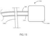
- FIG. 13is a schematic view of a medical device in accordance with various embodiments herein.
- FIG. 14is a schematic cross-sectional view of medical device in accordance with various embodiments herein.
- FIG. 15is a schematic diagram of components of a medical device in accordance with various embodiments herein.
- FIG. 16is a plot of an exemplary electric field in accordance with various embodiments herein.
- FIG. 17is a plot of an exemplary electric field in accordance with various embodiments herein.
- FIG. 18is a schematic view of a portion of a stimulation lead in accordance with various embodiment herein.
- first-line therapiesto treat cancerous tumors can include surgery, radiation therapy, and chemotherapy.
- first-line therapieshave undesirable concomitant side effects, such as fatigue, hair loss, immunosuppression, and long surgical recovery times, to name a few.
- alternating electric fieldscan disrupt mitosis within a cancerous tumor by interfering with the dipole alignment of key proteins involved in cellular division; tubulin and septin in particular.
- the polymerization of tubulin proteins that form microtubule spindle fiberscan be disrupted, thus preventing the formation of spindle fibers required for chromosome separation. This can halt cellular division at the metaphase stage of mitosis.
- an alternating electric fieldcan halt polymerization of already growing spindle fibers, leading to incomplete spindles and unequal chromosome separation during anaphase, should the cell survive that long. In each case, halting microtubule spindle formation and unequal chromosome separation during anaphase caused by incomplete polymerization of microtubules can result in apoptosis (i.e., programmed cell death).
- alternating electric fieldscan lead to increased electric field density near the cleavage furrow of the dividing cells during telophase.
- An increased electric field density in the region of the cleavage furrowcan result in dielectrophoresis of charged macromolecules, such as proteins and nucleic acids, toward the high electric field density at the furrow.
- the unequal concentration of key macromolecules required for cellular division at the site of the cleavage furrowcan disrupt the final separation of the sister cells during telophase and eventually lead to apoptosis.
- the small intestine or small bowelis an organ in the gastrointestinal tract where most of the end absorption of nutrients and minerals from food takes place.
- the duodenumis the first part of the small intestine immediately beyond the stomach, leading to the jejunum.
- the duodenumhas a “C” shape and curves around and outlines the head of the pancreas.
- electrical stimulation leadscan be implanted on or about the duodenum following the “C” shape. This provides an ideal position for the leads to deliver electrical fields to the site of a cancerous tumor within the pancreas of a patient and therefore treat pancreatic cancer.
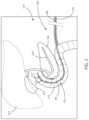
- FIG. 1a schematic view of a patient 102 is shown in accordance with various embodiments herein.
- the patient 102has internal organs 104 .
- the internal organs 104 showninclude a duodenum 106 and a pancreas 108 .
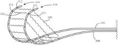
- FIG. 2a schematic view of a medical device system 200 is shown in accordance with various embodiments herein.
- the internal organs 104 shown in this viewinclude the duodenum 106 , pancreas 108 , pancreatic duct 220 , gallbladder 222 , and liver 224 .
- the duodenum 106includes an anterior surface 214 and a posterior surface (not shown in this view).
- the medical device system 200also includes a first stimulation lead 208 and a second stimulation lead 210 .
- the medical device system 200can include at least one electric field generating circuit configured to generate one or more electric fields, and control circuitry in communication with the electric field generating circuit.
- the control circuitrycan be configured to control delivery of the one or more electric fields from the at least one electric field generating circuit.
- the first stimulation lead 208 and the second stimulation lead 210can be used to deliver the electric fields to the site of a cancerous tumor within a patient.
- the first stimulation lead 208can include a first plurality of electrodes 212 .
- the number of electrodes on the first stimulation lead 208can vary.
- the first stimulation lead 208can include 1, 2, 3, 4, 5, 6, 7, 8, 10, 12, 15, 20, 25, 30, 40, or more electrodes, or a number of electrodes falling within a range between any of the foregoing.
- the first stimulation lead 208can also include a curved portion 216 .
- the degree of curvaturecan be about 30, 35, 40, 45, 50, 55, 60, 65, 70, 80, 90, 100, 110, 120, 130, 140, 160, 180, 200, 220, 240, 260, 280, 300, 320, 340, or 360 or more, or an amount of curvature falling within a range between any of the foregoing.
- the second stimulation lead 210can a plurality of electrodes and a curved portion (not shown in this view).
- the number of electrodes on the second stimulation lead 210can be the same or different as the number of electrodes on the first stimulation lead 208 . It will be appreciated that more than a first stimulation lead and second stimulation lead can be used in the embodiments herein. Further, in some embodiments, only a single stimulation may be used.
- the electrodescan take on many different forms and configurations.
- the electrodescan be spaced out along an electrical stimulation lead.
- the electrodes on at least one of the first stimulation lead or the electrodes on the second stimulation leadcan be arranged in a grid pattern. Many different materials can be used to form the electrodes.
- the electrodescan include a conductive metal.
- the electrodescan include one or more of stainless steel, iridium oxide, platinum, aluminum, or the like.
- the first stimulation lead 208can be configured to be affixed to or otherwise positioned adjacent to an anterior exterior surface of the duodenum 106 .
- the first stimulation lead 208can be sutured to the duodenum 106 .
- the first stimulation lead 208can be otherwise attached to the duodenum 106 such as with staples, clips, bands, medical adhesive, or the like.
- the second stimulation lead 210is configured to be affixed to or otherwise positioned adjacent to a posterior exterior surface of the duodenum 106 .
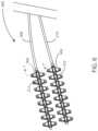
- the duodenum(not shown in this view) can include an anterior surface 214 and a posterior surface 314 .
- a medical device system(not shown in this view) includes a first stimulation lead 208 with electrodes 212 disposed thereon.
- the medical device systemalso includes a second stimulation lead 210 with a second set of electrodes 312 disposed thereon.
- Electric fieldscan be generated between pairs of electrodes.
- electrical fieldscan be generated between pairs of electrodes disposed on the same lead or pairs of electrodes with electrodes disposed on separate leads.
- electric fieldscan be generated along at least a first vector 320 .
- the electric fieldscan also be generated along at least a second vector 322 .
- the vectorscan be at least partially perpendicular to one another.
- embodiments hereininclude more than just those with two electrical stimulation leads.
- embodiments hereincan include those with 1, 2, 3, 4, 5, 6, 7, or 8 or more electrical stimulation leads.
- Vectors for electrical stimulation hereincan be complex and include more than 1 to 1 relationships of electrodes. For example, a single electrode may pair with multiple ground electrodes creating a dense and complex electrical stimulation field.
- FIG. 4a schematic view of electrical stimulation leads is shown in accordance with various embodiments herein.
- FIG. 4is generally similar to FIG. 3 .
- vector 320is part of a one to many relationship between electrodes for generating an electrical field.
- FIG. 5a schematic view of a medical device system 200 is shown in accordance with various embodiments herein.
- the internal organs 104 shown hereinclude a duodenum 106 , pancreas 108 , pancreatic duct 220 , gallbladder 222 and liver 224 .
- the medical device system 200also includes a first stimulation lead 208 with electrodes 212 disposed thereon.
- the first stimulation lead 208also includes a curved portion 216 .
- the medical device system 200also includes a second stimulation lead 210 , which can also include electrodes disposed thereon.
- attachment anchors 502can be disposed along the first stimulation lead 208 or the second stimulation lead 210 .
- the attachment anchors 502can define apertures such as to allow for suturing.
- the attachment anchors 502can take other shapes or forms.
- the attachment anchors 502can take on the form of posts, arms, hooks, hoops, or the like.
- the attachment anchors 502can be configured to pivot around the first stimulation lead 208 or second stimulation lead 210 .
- the attachment anchorscan include an aperture through which the electrical stimulation lead can pass but not be bonded thereto.
- attachment anchorscan take on many different shapes or forms.
- the attachment anchorscan take on the form of loops or partial loops.
- attachment anchorscan include relatively flat portions or pads that can be configured to directly interface with a surface of the duodenum.
- the medical device systemincludes a first stimulation lead 208 with electrodes 212 and surface contact members 602 , which can serve as a form of attachment anchor.
- the medical device systemalso includes a second stimulation lead 210 including a second set of electrodes 312 and surface contact members 602 .
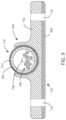
- a stimulation leadpasses through a surface contact member 602 .
- the stimulation leadincludes a lead body 704 , an electrode 212 (such as a ring electrode) disposed on the lead body 704 , and (optionally) a guidewire lumen 706 disposed in the lead body.
- the first stimulation leadalso includes electrical conductors 708 disposed therein. At least one electrical conductor 708 can be in electrical communication with the electrode 212 .
- the surface contact member 602includes contact member body 702 and suture apertures 710 disposed therein.
- the contact member body 702can include a surface 750 therein configured for contact with a surface of the duodenum.
- the surface 750can be flat or slightly curved (such as concave).
- the contact member body 702can be made of a flexible material such that the surface 750 can bend in order to provide a good fit against curving surface of the duodenum.
- the size of the surface (or width of the surface)can vary.
- the surface 750has a width that is at least about 1.5, 2, 3, 4, 5, 6, 7, 8, or 10 times the width (or diameter) of the stimulation lead, or an amount falling within a range between any of the foregoing.
- the surface contact member 602can include a window 716 (or aperture or opening) so as to expose at least a portion of the electrode 212 .
- the window 716can be disposed on a side of the surface contact member 602 that is opposite from the surface 750 (or contact surface).
- the window 716can expose at least about 5, 10, 15, 20, 25, 30, 40, 50, 60, 70, 80, 90, 100, 120, 140, 160 or more degrees of the circumference of the electrode 212 , or an amount falling within a range between any of the foregoing.
- the window 716has a width that is less than the diameter of the stimulation lead in order to hold the same within the surface contact member 602 .
- the surface contact member 602can be configured to pivot 730 about the stimulation leads.
- the surface contact member 602can fit tightly with the stimulation lead such that it will pivot about the stimulation lead, but retain its position if force is not applied.
- a stimulation leadpasses through a surface contact member 602 .
- the stimulation leadincludes a lead body 704 , an electrode 212 (such as a ring electrode) disposed on the lead body 704 , and (optionally) a guidewire lumen 706 disposed in the lead body.
- the first stimulation leadalso includes electrical conductors 708 disposed therein. At least one electrical conductor 708 can be in electrical communication with the electrode 212 .
- the surface contact member 602includes contact member body 702 and suture apertures 710 disposed therein.
- thermal shielding pads 802can be included to shield the duodenum and/or other tissues from thermal damage.
- the thermal shielding pads 802can be configured to pivot around the first or second stimulation lead 210 as the surface contact members 602 pivot.
- the thermal shielding pads 802can be made of various materials.
- the thermal shielding pads 802can formed of a polymer.
- the thermal shielding pads 802can be formed of a metal, a composite, a ceramic, or the like.
- the thermal shielding pads 802can be porous and in other embodiment non-porous.
- a stimulation leadpasses through a surface contact member 602 .
- the stimulation leadincludes a lead body 704 and a guidewire lumen 706 disposed therein.
- the first stimulation leadalso includes electrical conductors 708 disposed therein.
- the surface contact member 602includes contact member body 702 and suture apertures 710 disposed therein.
- electrical field blocking pads 902can be included to shield the duodenum and/or other tissues from electrical stimulation/electrical fields.
- the electrical field blocking pads 902can be configured to pivot around the first or second stimulation lead 210 as the surface contact members 602 pivot.
- the electrical field blocking pads 902can include a metal. In various embodiments, the electrical field blocking pads 902 can include at least one of a metal grid, a wire grid, a metal sheet, and a metalized material.
- the methodcan include an operation of positioning 1002 a first electrical stimulation lead on or about a posterior exterior surface of a duodenum of a patient, the first electrical stimulation lead comprising a first plurality of electrodes disposed thereon.
- the methodcan include an operation of positioning 1004 a second electrical stimulation lead on or about an anterior exterior surface of the duodenum of the patient, the second electrical stimulation lead comprising a second plurality of electrodes disposed thereon.
- the methodcan include an operation of generating 1006 an electrical field between at least one pair of electrodes selected from the first plurality and the second plurality disposed on the electrical stimulation lead, the electric field having frequencies within a range of between 10 kilohertz (kHz) to 1 megahertz (MHz) or higher.
- kHzkilohertz
- MHzmegahertz
- Embodiments of systems and devices hereincan include those that are entirely implanted as well as those that have both implanted and external components.
- the medical device 1102can be an implantable medical device. It will be appreciated that the features of medical device 1102 can be included in any of the medical devices described herein.
- the medical device 1102can include header 1104 and implantable housing 1106 .
- the first stimulation lead 208 and the second stimulation lead 210can connect to the header 1104 .
- Circuitry and other components for operation of the medical device 1102can be disposed within the housing 206 and/or the header 204 .
- the medical device 1102can be implanted within a patient in various places such as within the abdomen, in a subpectoral position, a submammary position, or the like.
- the medical device 1102can include an external power supply unit 1240 that is disposed outside of the dermis 1202 of a subject.
- the external power supply unit 1240can be connected to a wireless power transmission device or antenna 1218 .
- the medical device 1102can also include a wireless power receiving device or antenna 1222 . Power can be exchanged wirelessly in various ways including, but not limited to, via induction.
- the medical device 1102can include an internal control unit 1224 (that can include various circuitry and other components for operation of the medical device such as elements described further below).
- the internal control unit 1224can be connected to the first stimulation lead 208 and the second stimulation lead 210 .
- components of the systemcan pass through the dermis of the patient.
- the medical device 1102can include an external power and control unit 1340 that is disposed outside of the dermis 1202 of a subject.
- the external power and control unit 1340can be connected to the first stimulation lead 208 and the second stimulation lead 210 .
- the first stimulation lead 208 and the second stimulation lead 210can pass through the dermis 1202 of the subject.
- Housing 206can define an interior volume 1402 that can be hollow and that in some embodiments is hermetically sealed off from the area 1404 outside of medical device 202 . In some embodiments the housing 206 can be filled with components and/or structural materials such that it is non-hollow.
- the medical device 1102can include control circuitry 1406 , which can include various components 1408 , 1410 , 1412 , 1414 , 1416 , and 1418 disposed within housing 206 .
- the medical device 202can also include an antenna 1424 , to allow for unidirectional or bidirectional wireless data communication.
- the components of medical device 202can include an inductive energy receiver coil (not shown) communicatively coupled or attached thereto to facilitate transcutaneous recharging of the medical device via recharging circuitry.
- control circuitry 1406can include, but are not limited to, a microprocessor, memory circuit (such as random access memory (RAM) and/or read only memory (ROM)), recorder circuitry, controller circuit, a telemetry circuit, a power supply circuit (such as a battery), a timing circuit, and an application specific integrated circuit (ASIC), a recharging circuit, amongst others.
- Control circuitry 1406can be in communication with an electric field generating circuit 1420 that can be configured to generate electric current to create one or more electric fields.
- the electric field generating circuit 1420can be integrated with the control circuitry 1406 or can be a separate component from control circuitry 1406 .
- Control circuitry 1406can be configured to control delivery of electric current from the electric field generating circuit 1420 .
- the electric field generating circuit 1420can be present in a portion of the medical device that is external to the body.
- control circuitry 1406can be configured to direct the electric field generating circuit 1420 to deliver an electric field using one or more frequencies selected from a range of within 10 kHz to 1 MHz or higher. In some embodiments, the control circuitry 1406 can be configured to direct the electric field generating circuit 1420 to deliver an electric field at one or more frequencies selected from a range of within 100 kHz to 500 kHz. In some embodiments, the control circuitry 1406 can be configured to direct the electric field generating circuit 1420 to deliver an electric field at one or more frequencies selected from a range of within 100 kHz to 300 kHz. In some embodiments, the control circuitry 1406 can be configured to direct the electric field generating circuit 1420 to periodically deliver an electric field using one or more frequencies greater than 1 MHz.
- the electric fieldcan be effective in disrupting cellular mitosis in cancerous cells.
- the electric fieldcan be delivered to the site of a cancerous tumor along more than one vector.
- the electric fieldcan be delivered along at least one vector, including at least one of the lead electrodes.
- at least two vectors with spatial diversity between the two vectorscan be used.
- the vectorscan be spatially separated (e.g., the vectors can be disposed at an angle with respect to one another) by at least about 10, 20, 30, 40, 50, 60, 70, 80 or 90 degrees.
- a desired electric field strengthcan be achieved by delivering an electric current between two electrodes.
- the specific current and voltage at which the electric field is deliveredcan vary and can be adjusted to achieve the desired electric field strength at the site of the tissue to be treated.
- the control circuitry 1406can be configured to direct the electric field generating circuit 1420 to deliver an electric field using currents ranging from 1 milliamp (mAmp) to 1000 mAmp to the site of a cancerous tumor.
- the control circuitry 1406can be configured to direct the electric field generating circuit 1420 to deliver an electric field using currents ranging from 20 mAmp to 500 mAmp to the site of a cancerous tumor.
- the control circuitry 1406can be configured to direct the electric field generating circuit 1420 to deliver an electric field using currents ranging from 30 mAmp to 300 mAmp to the site of a cancerous tumor.
- control circuitry 1406can be configured to direct the electric field generating circuit 1420 to deliver an electric field using currents including 1 mAmp, 2 mAmp, 3 mAmp, 4 mAmp, 5 mAmp, 6 mAmp, 7 mAmp, 8 mAmp, 9 mAmp, 10 mAmp, 15 mAmp, 20 mAmp, 25 mAmp, 30 mAmp, 35 mAmp, 40 mAmp, 45 mAmp, 50 mAmp, 60 mAmp, 70 mAmp, 80 mAmp, 90 mAmp, 100 mAmp, 125 mAmp, 150 mAmp, 175 mAmp, 200 mAmp, 225 mAmp, 250 mAmp, 275 mAmp, 300 mAmp, 325 mAmp, 350 mAmp, 375 mAmp, 400 mAmp, 425 mAmp,
- control circuitrycan be configured to direct the electric field generating circuit 1420 to deliver an electric field at a current falling within a range, wherein any of the forgoing currents can serve as the lower or upper bound of the range, provided that the lower bound of the range is a value less than the upper bound of the range.
- control circuitry 1406can be configured to direct the electric field generating circuit 1420 to deliver an electric field using voltages ranging from 1 root-mean-square voltage (V rms ) to 50 V rms to the site of a cancerous tumor. In some embodiments, the control circuitry 1406 can be configured to direct the electric field generating circuit 1420 to deliver an electric field using voltages ranging from 5 V rms to 30 V rms to the site of a cancerous tumor. In some embodiments, the control circuitry 1406 can be configured to direct the electric field generating circuit 1420 to deliver an electric field using voltages ranging from 10 V rms to 20 V rms to the site of a cancerous tumor.
- V rmsroot-mean-square voltage
- control circuitry 1406can be configured to direct the electric field generating circuit 1420 to deliver an electric field using one or more voltages including 1 V rms , 2 V rms , 3 V rms , 4 V rms , 5 V rms , 6 V rms , 7 V rms , 8 V rms , 9 V rms , 10 V rms , 15 V rms , 20 V rms , 25 V rms , 30 V rms , 35 V rms , 40 V rms , 45 V rms , or 50 V rms .
- control circuitrycan be configured to direct the electric field generating circuit 1420 to deliver an electric field using a voltage falling within a range, wherein any of the forgoing voltages can serve as the lower or upper bound of the range, provided that the lower bound of the range is a value less than the upper bound of the range.
- control circuitry 1406can be configured to direct the electric field generating circuit 1420 to deliver and electric field using one or more frequencies including 10 kHz, 20 kHz, 30 kHz, 40 kHz, 50 kHz, 60 kHz, 70 kHz, 80 kHz, 90 kHz, 100 kHz, 125 kHz, 150 kHz, 175 kHz, 200 kHz, 225 kHz, 250 kHz, 275 kHz, 300 kHz, 325 kHz, 350 kHz, 375 kHz, 400 kHz, 425 kHz, 450 kHz, 475 kHz, 500 kHz, 525 kHz, 550 kHz, 575 kHz, 600 kHz, 625 kHz, 650 kHz, 675 kHz, 700 kHz, 725 kHz, 750 kHz, 775 kHz, 800 kHz, 825 kHz, 850 kHz,
- control circuitry 1406can be configured to direct the electric field generating circuit 1420 to generate one or more applied electric field strengths selected from a range of within 0.25 volts per centimeter (V/cm) to 1000 V/cm. In some embodiments, the control circuitry 1406 can be configured to direct the electric field generating circuit 1420 to generate one or more applied electric field strengths of greater than 3 V/cm. In some embodiments, the control circuitry 1406 can be configured to direct the electric field generating circuit 1420 to generate one or more applied electric field strengths selected from a range of within 1 V/cm to 10 V/cm. In some embodiments, the control circuitry 1406 can be configured to direct the electric field generating circuit 1420 to generate one or more applied electric field strengths selected from a range of within 3 V/cm to 5 V/cm.
- control circuitry 1406can be configured to direct the electric field generating circuit 1420 to generate one or more applied electric field strengths including 0.25 V/cm, 0.5 V/cm, 0.75 V/cm, 1.0 V/cm, 2.0 V/cm, 3.0 V/cm, 5.0 V/cm, 6.0 V/cm, 7.0 V/cm, 8.0 V/cm, 9.0 V/cm, 10.0 V/cm, 20.0 V/cm, 30.0 V/cm, 40.0 V/cm, 50.0 V/cm, 60.0 V/cm, 70.0 V/cm, 80.0 V/cm, 90.0 V/cm, 100.0 V/cm, 125.0 V/cm, 150.0 V/cm, 175.0 V/cm, 200.0 V/cm, 225.0 V/cm, 250.0 V/cm, 275.0 V/cm, 300.0 V/cm, 325.0 V/cm, 350.0 V/cm, 375.0 V/cm,
- the electric field generating circuit 1420can generate an electric field having a field strength at a treatment site falling within a range, wherein any of the foregoing field strengths can serve as the upper or lower bound of the range, provided that the upper bound is greater than the lower bound.
- control circuitry 1406can be configured to direct the electric field generating circuit 1420 to deliver an electric field via leads 208 , 210 to the site of a cancerous tumor located within a bodily tissue. In other embodiments, the control circuitry 1406 can be configured to direct the electric field generating circuit 1420 to deliver an electric field via the housing 206 of medical device 202 to the site of a cancerous tumor located within a bodily tissue. In other embodiments, the control circuitry 1406 can be configured to direct the electric field generating circuit 1420 to deliver an electric field between leads 208 , 210 and the housing 206 of medical device 202 . In some embodiments, one or more leads 208 , 210 can be in electrical communication with the electric field generating circuit 1420 .
- the one or more leads 208 , 210can include one or more electrodes ( 212 and 312 , respectively as shown, e.g., in FIGS. 3 & 6 ) disposed along the length of the leads 208 , 210 , where the electrodes 212 and 312 can be in electrical communication with the electric field generating circuit 1420 .
- various components within medical device 202can include an electric field sensing circuit 1422 configured to generate a signal corresponding to sensed electric fields.
- Electric field sensing circuit 1422can be integrated with control circuitry 1406 or it can be separate from control circuitry 1406 .
- Sensing electrodescan be disposed on or adjacent to the housing of the medical device, on one or more leads connected to the housing, on a separate device implanted near or in the tumor, or any combination of these locations.
- the electric field sensing circuit 1422can include a first sensing electrode 1432 and a second sensing electrode 1434 .
- the housing 206itself can serve as a sensing electrode for the electric field sensing circuit 1422 .
- the electrodes 1432 and 1434can be in communication with the electric field sensing circuit 1422 .
- the electric field sensing circuit 1422can measure the electrical potential difference (voltage) between the first electrode 1432 and the second electrode 1434 .
- the electric field sensing circuit 1422can measure the electrical potential difference (voltage) between the first electrode 1432 or second electrode 1434 , and an electrode disposed along the length of one or more leads 208 , 210 .
- the electric field sensing circuitcan be configured to measure sensed electric fields and to record electric field strength in V/cm.
- the electric field sensing circuit 1422can additionally measure an electrical potential difference between the first electrode 1432 or the second electrode 1434 and the housing 206 itself.
- the medical devicecan include a third electrode 1436 , which can be an electric field sensing electrode or an electric field generating electrode.
- one or more sensing electrodescan be disposed along an electrical stimulation lead and can serve as additional locations for sensing an electric field. Many combinations can be imagined for measuring electrical potential difference between electrodes disposed along the length of one or more leads 208 , 210 and the housing 206 in accordance with the embodiments herein. It will be appreciated that field sensing electrodes and field generating electrodes herein can be one in the same in various embodiments.
- one or more leadscan be in electrical communication with the electric field generating circuit 1420 .
- the one or more leads 208 , 210can include one or more electrodes.
- the one or more electrodes 212 and 312 as shown in FIGS. 2 - 6can be any combination of electric field sensing electrodes or electric field generating electrodes, depicted as 1508 and 1512 and described in reference to FIG. 11 .
- various electrical conductorssuch as electrical conductors 1426 and 1428 , can pass from the header 204 through a feed-through structure 1430 and into the interior volume 1402 of medical device 202 .
- the electrical conductors 1426 and 1428can serve to provide electrical communication between the one or more leads 208 , 210 and control circuitry 1406 disposed within the interior volume 1402 of the housing 206 .
- recorder circuitrycan be configured to record the data produced by the electric field sensing circuit 1422 and record time stamps regarding the same.
- the control circuitry 1406can be hardwired to execute various functions, while in other embodiments the control circuitry 1406 can be directed to implement instructions executing on a microprocessor or other external computation device.
- a telemetry circuitcan also be provided for communicating with external computation devices such as a programmer, a home-based unit, and/or a mobile unit (e.g. a cellular phone, personal computer, smart phone, tablet computer, and the like).
- FIG. 15Elements of various embodiments of the medical devices described herein are shown in FIG. 15 . However, it will be appreciated that some embodiments can include additional elements beyond those shown in FIG. 15 . In addition, some embodiments may lack some elements shown in FIG. 15 .
- the medical devices as embodied hereincan gather information through one or more sensing channels and can output information through one or more field generating channels.
- a microprocessor 1502can communicate with a memory 1504 via a bidirectional data bus.
- the microprocessor 1502can be in electric communication with power supply circuit 1520 .
- the memory 1504can include read only memory (ROM) or random access memory (RAM) for program storage and RAM for data storage.
- the microprocessor 1502can also be connected to a telemetry interface 1518 for communicating with external devices such as a programmer, a home-based unit and/or a mobile unit (e.g. a cellular phone, personal computer, smart phone, tablet computer, and the like) or directly to the cloud or another communication network as facilitated by a cellular or other data communication network.
- external devicessuch as a programmer, a home-based unit and/or a mobile unit (e.g. a cellular phone, personal computer, smart phone, tablet computer, and the like) or directly to the cloud or another communication network as facilitated by a cellular or other data communication network.
- the medical devicecan include an inductive energy receiver coil interface (not shown) communicatively coupled or attached thereto to facilitate transcutaneous recharging of the medical device.
- the medical devices hereincan include one or more electric field sensing electrodes 1508 and one or more electric field sensor channel interfaces 1506 that can communicate with a port of microprocessor 1502 .
- the medical devicescan also include one or more electric field generating electrodes 1512 and one or more electric field generating channel interfaces 1510 and one or more electric field generating circuits 1420 that can communicate with a port of microprocessor 1502 .
- the medical devicescan also include one or more other sensors 1516 , such as physiological sensors, respiration sensors, or chemical sensors, and one or more other sensor channel interfaces 1514 that can communicate with a port of microprocessor 1502 .
- the channel interfaces 1506 , 1510 , and 1514can include various components such as analog-to-digital converters for digitizing signal inputs, sensing amplifiers, registers which can be written to by the control circuitry in order to adjust the gain and threshold values for the sensing amplifiers, source drivers, modulators, demodulators, multiplexers, and the like.
- the medical devices hereincan include an electric field generating circuit configured to generate one or more electric fields at or near a site of the cancerous tumor.
- the medical devices hereincan include control circuitry in communication with the electric field generating circuit, the control circuitry configured to control delivery of the one or more electric fields from the electric field generating circuit at or near the site of the cancerous tumor.
- the control circuitrycan cause the electric field generating circuit to generate one or more electric fields at frequencies selected from a range of between 10 kHz to 1 MHz at the site of a cancerous tumor located within a bodily tissue, the one or more electric fields effective to delay mitosis and cause mitotic synchronization within a proportion of the cancerous cell population.
- the medical devicefurther can include one or more electrical leads in electrical communication with the electric field generating circuit.
- the medical devices hereininclude a medical device system for treating a cancerous tumor.
- the medical device housingcan include an electric field generating circuit configured to generate one or more electric fields at or near a site of the cancerous tumor, the cancerous tumor including a cancerous cell population.
- the medical device systemcan include control circuitry in communication with the electric field generating circuit, where the control circuitry is configured to control delivery of the one or more electric fields from the electric field generating circuit at or near the site of the cancerous tumor.
- the medical device systemcan include a drug delivery catheter for administering one or more chemotherapeutic agents at or near the site of the cancerous tumor.
- the control circuitry of the medical device systemcauses the electric field generating circuit to generate one or more electric fields at frequencies selected from a range of between 10 kHz to 1 MHz at the site of a cancerous tumor located within a bodily tissue, the one or more electric fields effective to delay mitosis and cause mitotic synchronization within a proportion of the cancerous cell population.
- the medical devices hereincan include a medical device for treating a cancerous tumor located within a patient.
- the medical devicecan include an electric field generating circuit configured to generate one or more electric fields at or near a site of the cancerous tumor, the cancerous tumor including a cancerous cell population.
- the medical devicecan include control circuitry in communication with the electric field generating circuit.
- the control circuitry of the medical devicecontrols delivery of the one or more electric fields from the electric field generating circuit at or near the site of the cancerous tumor by following a predefined schedule that causes the electric fields to vary in at least one of intensity and frequency over the course of a defined time period of at least six hours.
- the medical devices hereincan include a medical device for of treating a cancerous tumor, including one or more implantable electrodes configured for placement on the inside of a body of a patient with the cancerous tumor.
- the medical devicecan include one or more external electrodes configured for placement on an outside surface of the body of the patient.
- the medical devicecan include an electric field generating circuit configured for generating an electric field between at least one pair of electrodes according to a predefined schedule, the electric field having frequencies within a range of between 10 kHz to 1 MHz.
- the medical devicecan include control circuitry configured for receiving a pause command from the patient, wherein the pause command causes cessation of generating the electric field.
- the electric fields applied to the cancerous tumors using the methods hereincan be applied using a variety of modalities.
- Exemplary therapeutic parameter setscan include those that implement the following concepts: sweeping through a range of frequencies; stacking of one or more frequencies simultaneously; stepping through one or more frequencies sequentially; the spatial or temporal delivery of one or more electric fields; sweeping through a range of electric field strengths; applying an effective rotating electric field; modulating a voltage control mode or a current control mode; implementing one or more duty cycles; pulse width modulation; manipulation of the electrical waveform shape and/or pulse sequence; and the occasional use of high frequency or high electric fields strength pulses.
- the therapeutic parameter setscan be programmed into a medical device to operate autonomously, or they can be queried and manipulated by the patient or a clinician using an external computation device such as a programmer, a home-based unit, and/or a mobile unit (e.g. a cellular phone, personal computer, smart phone, tablet computer, and the like).
- the therapeutic parameter setscan be wirelessly communicated to the medical device from an external computation device. Frequencies and/or electric field strengths suitable for use in any of the therapeutic parameter sets herein are discussed above with respect to electric field generating circuit.
- one or more therapeutic parameter setscan be implemented simultaneously. In other embodiments, one or more therapeutic parameter sets can be implemented in an alternating fashion.
- an electric fieldcan be applied to the site of a cancerous tumor by sweeping through a range of frequencies.
- exemplary plot 1602shows an alternating electric field, where the frequency increases over time.
- FIG. 17shows the change in frequency as a function of time in exemplary plot 1702 during a programmed therapy parameter.
- a frequency sweepcan include sweeping from a minimum frequency up to a maximum frequency.
- a frequency sweepcan include sweeping from a maximum frequency down to a minimum frequency.
- sweeping from a minimum frequency up to a maximum frequency and sweeping from the maximum frequency down to the minimum frequencycan be repeated as many times as desired throughout the duration of the delivery of the electric field from the electric field generating circuit.
- a frequency sweepcan include alternating between a first frequency sweep covering a range of about 100 kHz to 300 kHz and a second frequency sweep covering a range about 200 kHz to 500 kHz. It will be appreciated that sweeping through a first and second frequency range as described can be performed indefinitely throughout the course of the therapy.
- the second frequency sweep (range)can be at higher frequencies than the first frequency sweep (range).
- the first frequency sweep (range)can be at higher frequencies than the second frequency sweep (range).
- Frequency ranges for the first and second frequency rangescan be any range including specific frequencies recited above with respect to electric field generating circuit 1420 , provided that the lower end of each range is a value less than the upper end of each range. At times, it may be beneficial to have some amount of overlap between the frequency range of the first and second frequency sweep.
- some electrodes of a medical devicecan be used as sensing electrodes.
- feedback obtained during electric field therapycan be used to monitor the effectiveness of treating a cancerous tumor with the therapy.
- Datacan be measured for parameters such as impedance, capacitance, field strength, etc. to direct a particular course of treatment.
- impedancecan change as the size or cellular makeup of the tumor changes. Therefore, impedance can be monitored during the course of an electric field therapy in order to determine if the cancerous tumor is responding to therapy.
- an increase in impedance of the tissue in a treatment area including a cancerous tumorcan be indicative of tumor regression.
- a decrease or no observed change in impedance of the tissue in a treatment areacan be indicative of tumor progression or lack of change in the tumor respectively.
- Other physiological properties associated with a cancerous tumorsuch as blood flow, metabolite concentrations, systemic cancer markers, and temperature can also be used in conjunction with impedance analysis to monitor the progression or regression of a cancerous tumor in response to electric field therapy.
- Therapy parametersincluding, but not limited to, one or more of the amplitude, frequency, pulse width, waveform, directionality, vector, and/or duty cycle of the electric field therapy can be modulated and/or changed, tuned or otherwise altered based on measured values for at least one of impedance, capacitance, field strength, etc.
- electrodes as disposed on electrical stimulation leadscan take on many different forms.
- FIG. 18a schematic view is shown of a portion of a stimulation lead 1808 in accordance with various embodiment herein.
- a plurality of electrodes 212are disposed on the stimulation lead 1808 .
- the electrodes 212are arrayed in a grid pattern.
- the electrodes 212may not be arrayed in a grid pattern.
- Many different configurations for electrodesare contemplated herein.
- the phrase “configured”describes a system, apparatus, or other structure that is constructed or configured to perform a particular task or adopt a particular configuration.
- the phrase “configured”can be used interchangeably with other similar phrases such as arranged and configured, constructed and arranged, constructed, manufactured and arranged, and the like.
Landscapes
- Health & Medical Sciences (AREA)
- Life Sciences & Earth Sciences (AREA)
- Animal Behavior & Ethology (AREA)
- General Health & Medical Sciences (AREA)
- Biomedical Technology (AREA)
- Nuclear Medicine, Radiotherapy & Molecular Imaging (AREA)
- Radiology & Medical Imaging (AREA)
- Veterinary Medicine (AREA)
- Public Health (AREA)
- Engineering & Computer Science (AREA)
- Heart & Thoracic Surgery (AREA)
- Cardiology (AREA)
- Hospice & Palliative Care (AREA)
- Oncology (AREA)
- Gastroenterology & Hepatology (AREA)
- Neurology (AREA)
- Biophysics (AREA)
- Electrotherapy Devices (AREA)
Abstract
Description
Claims (20)
Priority Applications (1)
| Application Number | Priority Date | Filing Date | Title |
|---|---|---|---|
| US17/182,436US11883655B2 (en) | 2020-02-24 | 2021-02-23 | Systems and methods for treatment of pancreatic cancer |
Applications Claiming Priority (2)
| Application Number | Priority Date | Filing Date | Title |
|---|---|---|---|
| US202062980811P | 2020-02-24 | 2020-02-24 | |
| US17/182,436US11883655B2 (en) | 2020-02-24 | 2021-02-23 | Systems and methods for treatment of pancreatic cancer |
Publications (2)
| Publication Number | Publication Date |
|---|---|
| US20210260370A1 US20210260370A1 (en) | 2021-08-26 |
| US11883655B2true US11883655B2 (en) | 2024-01-30 |
Family
ID=74885054
Family Applications (1)
| Application Number | Title | Priority Date | Filing Date |
|---|---|---|---|
| US17/182,436ActiveUS11883655B2 (en) | 2020-02-24 | 2021-02-23 | Systems and methods for treatment of pancreatic cancer |
Country Status (4)
| Country | Link |
|---|---|
| US (1) | US11883655B2 (en) |
| EP (1) | EP4110455B1 (en) |
| CN (1) | CN115515674A (en) |
| WO (1) | WO2021173509A1 (en) |
Cited By (4)
| Publication number | Priority date | Publication date | Assignee | Title |
|---|---|---|---|---|
| US12109412B2 (en) | 2019-04-22 | 2024-10-08 | Boston Scientific Scimed, Inc. | Combination electrical and chemotherapeutic treatment of cancer |
| US12186553B2 (en) | 2019-04-23 | 2025-01-07 | Boston Scientific Scimed, Inc. | Electrical stimulation for cancer treatment with internal and external electrodes |
| US12311168B2 (en) | 2019-04-22 | 2025-05-27 | Boston Scientific Scimed, Inc. | Electrical stimulation devices for cancer treatment |
| US12403306B2 (en) | 2017-10-23 | 2025-09-02 | Cardiac Pacemakers, Inc. | Electric field shaping leads for treatment of cancer |
Families Citing this family (6)
| Publication number | Priority date | Publication date | Assignee | Title |
|---|---|---|---|---|
| US11338135B2 (en) | 2017-10-23 | 2022-05-24 | Cardiac Pacemakers, Inc. | Medical devices for cancer therapy with electric field shaping elements |
| WO2020219337A1 (en) | 2019-04-22 | 2020-10-29 | Boston Scientific Scimed, Inc. | Systems for administering electrical stimulation to treat cancer |
| US11850422B2 (en) | 2019-04-23 | 2023-12-26 | Boston Scientific Scimed, Inc. | Electrodes for electrical stimulation to treat cancer |
| US11712561B2 (en) | 2019-04-23 | 2023-08-01 | Boston Scientific Scimed, Inc. | Electrical stimulation with thermal treatment or thermal monitoring |
| CN116617577B (en)* | 2023-06-05 | 2024-03-26 | 浙江大学 | A closed-loop controllable tumor electric field treatment system |
| WO2025160435A1 (en)* | 2024-01-26 | 2025-07-31 | Medtronic, Inc. | Electric field therapy for pancreatic cancer |
Citations (185)
| Publication number | Priority date | Publication date | Assignee | Title |
|---|---|---|---|---|
| US4016886A (en) | 1974-11-26 | 1977-04-12 | The United States Of America As Represented By The United States Energy Research And Development Administration | Method for localizing heating in tumor tissue |
| US5099838A (en) | 1988-12-15 | 1992-03-31 | Medtronic, Inc. | Endocardial defibrillation electrode system |
| US5324328A (en) | 1992-08-05 | 1994-06-28 | Siemens Pacesetter, Inc. | Conductor for a defibrillator patch lead |
| US5397342A (en) | 1993-06-07 | 1995-03-14 | Cardiac Pacemakers, Inc. | Resilient structurally coupled and electrically independent electrodes |
| WO1995013113A1 (en) | 1993-11-08 | 1995-05-18 | Zomed International, Inc. | Device for treating cancer and non-maligant tumors and methods |
| WO1995026911A1 (en) | 1994-04-01 | 1995-10-12 | Akzo Nobel N.V. | Clamping straps with safety mechanism for container covers |
| US5582609A (en) | 1993-10-14 | 1996-12-10 | Ep Technologies, Inc. | Systems and methods for forming large lesions in body tissue using curvilinear electrode elements |
| WO1996039966A1 (en) | 1995-06-07 | 1996-12-19 | Cordis Webster, Inc. | Catheter with a spirally wound flat ribbon electrode |
| US5834051A (en) | 1995-11-07 | 1998-11-10 | Medtronic, Inc. | Intramuscular stimulation lead with enhanced infection resistance |
| WO2001058371A1 (en) | 2000-02-08 | 2001-08-16 | Gyrus Medical Limited | An electrosurgical instrument and an electrosurgery system including such an instrument |
| WO2001067098A1 (en) | 2000-03-03 | 2001-09-13 | Btg International Limited | Electrical impedance measuring method for differentiating tissue types |
| US20010044643A1 (en) | 2000-02-02 | 2001-11-22 | The Catholic University Of America | Use of electromagnetic fields in cancer and other therapies |
| US20020026183A1 (en) | 1998-05-05 | 2002-02-28 | Simpson John A. | Electrode having composition-matched, common-lead thermocouple wire for providing multiple temperature-sensitive junctions |
| US6366808B1 (en) | 2000-03-13 | 2002-04-02 | Edward A. Schroeppel | Implantable device and method for the electrical treatment of cancer |
| US20020049485A1 (en) | 1999-11-29 | 2002-04-25 | Medtronic, Inc. | Medical electrical lead having bending stiffnesses which increase in the distal direction |
| US20020065544A1 (en) | 1999-11-29 | 2002-05-30 | Medtronic, Inc. | Medical electrical lead having variable bending stiffness |
| US20030020416A1 (en) | 2001-07-24 | 2003-01-30 | Harison Toshiba Lighting Corp. | Discharge lamp ignition device, equipment and image forming apparatus |
| US20030069623A1 (en)* | 2001-10-10 | 2003-04-10 | Paul Stypulkowski | Implantable percutaneous stimulation lead with lead carrier |
| US20030204161A1 (en) | 2002-04-25 | 2003-10-30 | Bozidar Ferek-Petric | Implantable electroporation therapy device and method for using same |
| US6673623B1 (en) | 2000-09-12 | 2004-01-06 | Novocure, Inc. | Methods and compositions that control lipid production |
| US20040010290A1 (en) | 1999-04-09 | 2004-01-15 | Schroeppel Edward A. | Method and device for treating cancer with electrical therapy in conjunction with chemotherapeutic agents and radiation therapy |
| US20040158288A1 (en) | 2001-06-07 | 2004-08-12 | Yona Keisari | Method and apparatus for treating tumors using low strength electric fields |
| US20040162600A1 (en) | 2003-02-14 | 2004-08-19 | Medtronic, Inc. | Reverse wound electrodes |
| US20040176804A1 (en) | 2000-02-17 | 2004-09-09 | Yoram Palti | Apparatus and method for optimizing tumor treatment efficiency by electric fields |
| US20040215296A1 (en) | 1999-11-16 | 2004-10-28 | Barrx, Inc. | System and method for treating abnormal epithelium in an esophagus |
| US20050004507A1 (en) | 2000-03-13 | 2005-01-06 | Oncostim. Inc. | Method and device for treating cancer with electrical therapy in conjunction with chemotherapeutic agents and radiation therapy |
| US20050043894A1 (en) | 2003-08-22 | 2005-02-24 | Fernandez Dennis S. | Integrated biosensor and simulation system for diagnosis and therapy |
| US6868289B2 (en) | 2002-10-02 | 2005-03-15 | Standen Ltd. | Apparatus for treating a tumor or the like and articles incorporating the apparatus for treatment of the tumor |
| US20050096584A1 (en) | 2003-10-29 | 2005-05-05 | Bozidar Ferek-Petric | Implantable electroporation therapy device and method for using same |
| US20050209642A1 (en) | 2000-02-17 | 2005-09-22 | Yoram Palti | Treating a tumor or the like with electric fields at different orientations |
| US20050222623A1 (en) | 2004-04-06 | 2005-10-06 | Oncostim Inc., A Minnesota Corporation | Partially implantable system for the electrical treatment of cancer |
| US20050222646A1 (en) | 2004-04-06 | 2005-10-06 | Kai Kroll | Method and device for treating cancer with modified output electrical therapy |
| US20050288730A1 (en) | 2002-04-08 | 2005-12-29 | Mark Deem | Methods and apparatus for renal neuromodulation |
| US20060024802A1 (en) | 2002-11-29 | 2006-02-02 | Evotec Oai Ag | Fluidic microsystem comprising field-forming passivation layers provided on microelectrodes |
| WO2006047833A1 (en) | 2004-11-08 | 2006-05-11 | Continence Control Systems International Pty Ltd | An implantable electrode arrangement |
| AU2005301103A1 (en) | 2004-11-08 | 2006-05-11 | Continence Control Systems International Pty Ltd | An implantable electrode arrangement |
| US20060149341A1 (en) | 2004-12-07 | 2006-07-06 | Yoram Palti | Electrodes for applying an electric field in-vivo over an extended period of time |
| US20060190053A1 (en) | 2002-03-22 | 2006-08-24 | Dobak John D Iii | Neural stimulation for treatment of metabolic syndrome and type 2 diabetes |
| US20060259099A1 (en) | 2005-03-11 | 2006-11-16 | Medtronic, Inc. | Shifting between electrode combinations in electrical stimulation device |
| US20060282122A1 (en) | 2005-06-08 | 2006-12-14 | Yoram Palti | Treating cancer with electric fields that are guided to desired locations within a body |
| US7162310B2 (en) | 2004-05-10 | 2007-01-09 | Pacesetter, Inc. | Flat wire helix electrode used in screw-in cardiac stimulation leads |
| US20070033660A1 (en) | 2002-10-02 | 2007-02-08 | Yoram Palti | Method for selectively destroying dividing cells |
| US20070179550A1 (en) | 2006-01-30 | 2007-08-02 | Dennis Charles L | Intravascular medical device |
| US20070225766A1 (en) | 2005-10-03 | 2007-09-27 | Yoram Palti | Optimizing characteristics of an electric field to increase the field's effect on proliferating cells |
| US20070239244A1 (en) | 2006-04-11 | 2007-10-11 | Pacesetter, Inc. | Intrapericardial lead |
| US20070239213A1 (en) | 2006-04-05 | 2007-10-11 | Yoram Palti | Treating cancer using electromagnetic fields in combination with other treatment regimens |
| US20070270675A1 (en) | 2006-05-17 | 2007-11-22 | Michael John Kane | Implantable Medical Device with Chemical Sensor and Related Methods |
| US20070270916A1 (en) | 2006-05-18 | 2007-11-22 | Fischell Robert E | Cardiac pacemaker with integrated battery |
| US20080058669A1 (en) | 2001-05-14 | 2008-03-06 | Pacesetter, Inc. | Methods for measuring impedances associated with the heart |
| US20080071350A1 (en) | 2006-09-18 | 2008-03-20 | Boston Scientific Scimed, Inc. | Endoprostheses |
| US20080086073A1 (en) | 2006-10-10 | 2008-04-10 | Mcdaniel Benjamin | Multi-region staged inflation balloon |
| US20080097424A1 (en) | 2006-10-20 | 2008-04-24 | Asthmatx, Inc. | Electrode markers and methods of use |
| WO2008089360A1 (en) | 2007-01-17 | 2008-07-24 | The Cleveland Clinic Foundation | Apparatus and methods for treating pulmonary conditions |
| US20080195227A1 (en) | 2007-02-08 | 2008-08-14 | Boling C Lance | Drug eluting lead systems |
| US20080208271A1 (en) | 2007-02-28 | 2008-08-28 | Cardiac Pacemakers, Inc. | High Frequency Stimulation for Treatment of Atrial Fibrillation |
| US7449021B2 (en) | 1996-07-16 | 2008-11-11 | Arthrocare Corporation | Systems and methods for electrosurgical tissue contraction within the spine |
| WO2009036457A1 (en) | 2007-09-14 | 2009-03-19 | Lazure Technologies, Llc | Multi-layer electrode ablation probe and related methods |
| US20090076500A1 (en) | 2007-09-14 | 2009-03-19 | Lazure Technologies, Llc | Multi-tine probe and treatment by activation of opposing tines |
| US7524274B2 (en) | 2003-11-07 | 2009-04-28 | Cytyc Corporation | Tissue positioning systems and methods for use with radiation therapy |
| US20090192381A1 (en) | 2008-01-30 | 2009-07-30 | Brockway Brian P | Minimally Invasive Physiologic Parameter Recorder and Introducer System |
| US20090234211A1 (en) | 2008-03-13 | 2009-09-17 | Cardiac Pacemakers, Inc. | Systems and Methods for Myocardial Ischemia Detection |
| US20100016936A1 (en) | 2001-04-13 | 2010-01-21 | Greatbatch Ltd. | Frequency selective passive component networks for implantable leads of active implantable medical devices utilizing an energy dissipating surface |
| US7656205B2 (en) | 2008-01-21 | 2010-02-02 | National Taiwan University | Dual-injection locked frequency dividing circuit |
| CN101693875A (en) | 2009-09-30 | 2010-04-14 | 重庆大学 | Cell electrofusion chip device based on columnar microelectrode array and electrofusion method |
| US20100198298A1 (en) | 2005-06-28 | 2010-08-05 | Arkady Glukhovsky | Implant system and method using implanted passive conductors for routing electrical current |
| US20100261994A1 (en) | 2009-04-09 | 2010-10-14 | Rafael Davalos | Integration of very short electric pulses for minimally to noninvasive electroporation |
| TW201039699A (en) | 2009-04-28 | 2010-11-01 | Masayuki Kumada | Method and device for forming hollow electron cloud with high density by laser |
| US20100298895A1 (en) | 2008-10-07 | 2010-11-25 | Roozbeh Ghaffari | Systems, methods, and devices using stretchable or flexible electronics for medical applications |
| US20100331938A1 (en) | 2009-06-30 | 2010-12-30 | Medtronic, Inc. | Implantable medical device lead |
| US7890183B2 (en) | 2000-02-17 | 2011-02-15 | Novocure Ltd. | Treating parasites with electric fields |
| JP2011030734A (en) | 2009-07-31 | 2011-02-17 | Nidek Co Ltd | Visual restoration aiding device and method of manufacturing the same |
| US20110071608A1 (en) | 2009-09-23 | 2011-03-24 | Lake Region Manufacturing, Inc. d/b/a Lake Region Medical | Guidewire-style pacing lead |
| US20110125215A1 (en) | 2009-11-25 | 2011-05-26 | Medtronic, Inc. | Medical electrical stimulation with implantable simulated case electrode |
| US20110137229A1 (en) | 2000-02-17 | 2011-06-09 | Yoram Palti | Treating bacteria with electric fields |
| US20110238057A1 (en) | 2010-02-16 | 2011-09-29 | Angiodynamics, Inc. | Dual Bracketed Energy Delivery Probe and Method of Use |
| US20120035616A1 (en) | 2009-04-30 | 2012-02-09 | Medtronic, Inc. | Steering an implantable medical lead via a rotational coupling to a stylet |
| US8170648B2 (en) | 2004-11-22 | 2012-05-01 | Bard Peripheral Vascular, Inc. | Removable localizing wire |
| US8175698B2 (en) | 2000-02-17 | 2012-05-08 | Novocure Ltd. | Treating bacteria with electric fields |
| US20120130444A1 (en) | 2009-04-24 | 2012-05-24 | Medtronic, Inc. | Incontinence therapy |
| US20120158122A1 (en) | 2010-12-20 | 2012-06-21 | Graftcraft I Goeteborg Ab | Removable stent and method of production |
| US20120158072A1 (en) | 2010-12-15 | 2012-06-21 | Boston Scientific Neuromodulation Corporation | Systems and methods for making and using leads for electrical stimulation systems with improved rf compatibility |
| US8229555B2 (en) | 2002-10-02 | 2012-07-24 | Novocure Ltd. | Probe for treating a tumor or the like |
| CN202365923U (en) | 2011-12-07 | 2012-08-08 | 北京天助畅运医疗技术股份有限公司 | Renal nerve radiofrequency ablation coating electrode |
| USRE43618E1 (en) | 2000-02-17 | 2012-08-28 | Novocure Ltd | Method and apparatus for destroying dividing cells |
| US20120232615A1 (en) | 2011-03-07 | 2012-09-13 | Giancarlo Barolat | Modular Limb Peripheral Nerve Stimulation System and Method of Use |
| US20130023946A1 (en) | 2011-03-30 | 2013-01-24 | Board Of Regents, The University Of Texas | Low Power Apparatus and Method to Measure Complex Electrical Admittance or Impedance |
| WO2013052590A1 (en) | 2011-10-04 | 2013-04-11 | Vessix Vascular, Inc. | Apparatus and method for treatment of in-stent restenosis |
| US8465533B2 (en) | 2007-03-06 | 2013-06-18 | Novocure Limited | Treating cancer using electromagnetic fields in combination with photodynamic therapy |
| US20130165916A1 (en) | 2011-12-23 | 2013-06-27 | Vessix Vascular, Inc. | Methods and apparatuses for remodeling tissue of or adjacent to a body passage |
| US8483821B2 (en) | 2009-07-27 | 2013-07-09 | Cardiac Pacemakers, Inc. | Blood volume redistribution therapy for heart failure |
| US20130204068A1 (en) | 2011-12-15 | 2013-08-08 | The Board Of Trustees Of The Leland Stanford Junior University | Apparatus and Methods For Treating Pulmonary Hypertension |
| US20130261711A1 (en) | 2008-07-16 | 2013-10-03 | Frank Sivo | Methods to arrest cancer cell growth and proliferation using electromagnetic energy delivered via electromagnetic coil systems |
| US20130261706A1 (en) | 2012-03-30 | 2013-10-03 | Neuropace, Inc. | Systems and methods for applying rapid sequential electrode stimulation |
| US20130289664A1 (en) | 2012-04-26 | 2013-10-31 | Medtronic, Inc. | Movement Patterns for Electrical Stimulation Therapy |
| US20130310898A1 (en) | 2012-05-16 | 2013-11-21 | Sorn Crm S.A.S | Cardiac or cerebral vessel microlead with electrode ring |
| US20140005753A1 (en) | 2012-06-30 | 2014-01-02 | Boston Scientific Neuromodulation Corporation | System and method for compounding low-frequency sources for high-frequency neuromodulation |
| US20140052227A1 (en) | 2011-01-28 | 2014-02-20 | Medtronic ,Inc. | Implantable Medical Leads and Systems that Utilize Reflection Points to Control Induced Radio Frequency Energy |
| US20140107511A1 (en) | 2012-10-08 | 2014-04-17 | Perminova Inc. | Internet-based system for evaluating ecg waveforms to determine the presence of p-mitrale and p-pulmonale |
| US8715203B2 (en) | 2007-09-17 | 2014-05-06 | Novocure Limited | Composite electrode |
| US20140142670A1 (en) | 2012-11-21 | 2014-05-22 | Cardiac Pacemakers, Inc. | Medical electrodes with layered coatings |
| US8805466B2 (en) | 2008-11-11 | 2014-08-12 | Shifamed Holdings, Llc | Low profile electrode assembly |
| US20140276811A1 (en) | 2013-03-13 | 2014-09-18 | Boston Scientific Scimed, Inc. | Steerable ablation device with linear ionically conductive balloon |
| US20140276781A1 (en) | 2013-03-15 | 2014-09-18 | Florent Beani | Method and system for delivering a tissue treatment using a balloon-catheter system |
| US20140350653A1 (en) | 2012-06-13 | 2014-11-27 | Mainstay Medical Limited | Electrode leads for use with implantable neuromuscular electrical stimulator |
| US20150005804A1 (en) | 2011-01-17 | 2015-01-01 | Nicholas Franano | Expandable body device and method of use |
| US8956352B2 (en) | 2010-10-25 | 2015-02-17 | Medtronic Ardian Luxembourg S.A.R.L. | Catheter apparatuses having multi-electrode arrays for renal neuromodulation and associated systems and methods |
| US20150066024A1 (en) | 2006-09-14 | 2015-03-05 | Lazure Technologies, Llc | Device and method for destruction of cancer cells |
| US20150134022A1 (en) | 2011-05-13 | 2015-05-14 | Chong Il Lee | Cell electric stimulator with separate electrodes for electrical field shaping and for stimulation |
| US20150180161A1 (en) | 2013-12-19 | 2015-06-25 | Medtronic, Inc. | Implantable medical electrical leads and connector assemblies thereof |
| WO2015100451A1 (en) | 2013-12-27 | 2015-07-02 | M.O.E. Medical Devices Llc | Applying electric field treatment to parts of the body |
| US20150182282A1 (en) | 2011-09-17 | 2015-07-02 | M.O.E. Medical Devices Llc | Electrode Geometries and Method for Applying Electric Field Treatment to Parts of the Body |
| CN204698678U (en) | 2015-04-15 | 2015-10-14 | 杭州睿笛生物科技有限公司 | Nanosecond pulse tumour ablation array electrode |
| US9179974B2 (en) | 2013-03-15 | 2015-11-10 | Medtronic Ardian Luxembourg S.A.R.L. | Helical push wire electrode |
| EP2942023A2 (en) | 2014-05-06 | 2015-11-11 | Jr. Eric R. Cosman | Electrosurgical generator |
| US20150320995A1 (en) | 2014-05-07 | 2015-11-12 | Medtronic, Inc. | Electrode construction for implantable medical electrical leads |
| US20150374992A1 (en) | 2010-03-11 | 2015-12-31 | Mainstay Medical Limited | Modular stimulator for treatment of back pain, implantable rf ablation system and methods of use |
| US20160022986A1 (en) | 2014-07-25 | 2016-01-28 | Loyalty Based Innovations, LLC | Apparatus and method for treating multiple tumors in patients with metastatic disease by electric fields |
| US20160029960A1 (en) | 2013-03-27 | 2016-02-04 | Autonomix Medical, Inc. | Systems and methods for neurological traffic and/or receptor functional evaluation and/or modification |
| US20160068598A1 (en) | 2013-04-12 | 2016-03-10 | University Of Louisville Research Foundation, Inc. | Anti-cd19 compositions and methods for treating cancer |
| US9283383B2 (en) | 2011-08-26 | 2016-03-15 | Peter Osypka | Implantable epicardial electrode assembly |
| US20160082258A1 (en) | 2004-09-08 | 2016-03-24 | Jeffery M. Kramer | Selective stimulation to modulate the sympathetic nervous system |
| WO2016065263A1 (en) | 2014-10-24 | 2016-04-28 | Medtronic, Inc. | Medical electrical lead |
| US20160129276A1 (en) | 2013-06-03 | 2016-05-12 | Shelley Fried | Magnetic neural stimulator and method of activation of neural tissue with same |
| US20160128767A1 (en) | 2013-06-05 | 2016-05-12 | Metavention, Inc. | Modulation of targeted nerve fibers |
| US9427278B2 (en) | 2002-09-24 | 2016-08-30 | Atricure, Inc. | Electrophysiology electrode having multiple power connections and electrophysiology devices including the same |
| US20160250476A1 (en) | 2015-02-26 | 2016-09-01 | Medtronic, Inc. | Therapy program selection for electrical stimulation therapy based on a volume of tissue activation |
| US20160250483A1 (en) | 2015-02-27 | 2016-09-01 | Pacesetter, Inc. | Systems And Methods For Implantable Medical Device Communication |
| WO2016149575A1 (en) | 2015-03-19 | 2016-09-22 | Old Dominion University | Synergistic regulated cell death induction with hsp90 inhibitors and nanosecond pulsed electric fields |
| WO2016168485A1 (en) | 2015-04-17 | 2016-10-20 | David Robinson | An implantable neuro-stimulation device |
| WO2016179712A1 (en) | 2015-05-14 | 2016-11-17 | London Health Sciences Centre Research Inc. | Intratumoral modulation therapy |
| US20160331459A1 (en) | 2015-05-12 | 2016-11-17 | National University Of Ireland, Galway | Devices for therapeutic nasal neuromodulation and associated methods and systems |
| WO2016199142A1 (en) | 2015-06-10 | 2016-12-15 | Hadasit Medical Research Services And Development Ltd. | Implantable monitoring device |
| US9526911B1 (en) | 2010-04-27 | 2016-12-27 | Lazure Scientific, Inc. | Immune mediated cancer cell destruction, systems and methods |
| US20170007310A1 (en) | 2014-07-16 | 2017-01-12 | Fractyl Laboratories, Inc. | Systems, devices and methods for performing medical procedures in the intestine |
| US20170035496A1 (en) | 2015-08-05 | 2017-02-09 | Boston Scientific Scimed, Inc. | Expandable balloon mapping and ablation device |
| US20170049514A1 (en) | 2013-02-25 | 2017-02-23 | Cosman Medical, Inc. | Catheter System |
| US20170065339A1 (en) | 2014-05-07 | 2017-03-09 | Iowa Approach Inc. | Methods and apparatus for selective tissue ablation |
| US20170105793A1 (en) | 2015-10-15 | 2017-04-20 | Boston Scientific Scimed, Inc. | Energy delivery devices and related methods of use |
| US9630022B2 (en) | 2007-04-08 | 2017-04-25 | Immunolight, Llc. | Plasmonic assisted systems and methods for interior energy-activation from an exterior source |
| US20170120041A1 (en) | 2015-10-28 | 2017-05-04 | Novocure Limited | TTField Treatment with Optimization of Electrode Positions on the Head Based on MRI-Based Conductivity Measurements |
| US9655669B2 (en) | 2013-05-06 | 2017-05-23 | Novocure Limited | Optimizing treatment using TTFields by changing the frequency during the course of long term tumor treatment |
| CN106823145A (en) | 2017-03-24 | 2017-06-13 | 长沙普特斯科技有限公司 | A kind of device of use amplitude modulation electric field treatment tumour |
| US20170173340A1 (en) | 2015-12-22 | 2017-06-22 | Akshay Ashok Gupte | Systems and methods to provide sympathetic modulation therapy |
| WO2017123981A1 (en) | 2016-01-15 | 2017-07-20 | Rfemb Holdings, Llc | Immunologic treatment of cancer |
| US20170215939A1 (en) | 2013-05-06 | 2017-08-03 | Novocure Limited | Optimizing Treatment Using TTfields by Changing the Frequency During the Course of Long Term Tumor Treatment |
| US20170251976A1 (en) | 2014-08-27 | 2017-09-07 | Neuronano Ab | Method of implantation of a medical device into neural tissue |
| US20170266371A1 (en) | 2016-03-15 | 2017-09-21 | CalXStars Business Accelerator, Inc. | Stimulator, pump & composition |
| US20170281955A1 (en) | 2016-03-31 | 2017-10-05 | Cardiac Pacemakers, Inc. | Implantable medical device with rechargeable battery |
| US20170281934A1 (en) | 2016-04-04 | 2017-10-05 | Novocure Limited | Reducing Motility of Cancer Cells Using Tumor Treating Fields (TTFields) |
| US20170312501A1 (en) | 2016-04-29 | 2017-11-02 | Pacesetter, Inc. | Retrievable intrapericardial electrotherapy lead |
| US20170333702A1 (en)* | 2016-05-17 | 2017-11-23 | Boston Scientific Neuromodulation Corporation | Systems and method for anchoring a lead for neurostimulation of a target anatomy |
| US20180001075A1 (en) | 2016-06-30 | 2018-01-04 | Novocure Limited | Arrays for Longitudinal Delivery of TTFields to a Body |
| US20180008708A1 (en) | 2016-07-10 | 2018-01-11 | Novocure Limited | Synchronizing Tumor Cells to the G2/M Phase Using TTFields Combined with Taxane or Other Anti-Microtubule Agents |
| US20180021563A1 (en) | 2015-03-09 | 2018-01-25 | Koninklijke Philips N.V. | Iontophoretic device, arrangement and method |
| US20180050200A1 (en) | 2016-08-18 | 2018-02-22 | Novocure Limited | Temperature Measurement in Arrays for Delivering TTFields |
| US9910453B2 (en) | 2015-09-25 | 2018-03-06 | Novocure Limited | High voltage, high efficiency sine wave generator with pre-set frequency and adjustable amplitude |
| US20180154142A1 (en) | 2016-12-05 | 2018-06-07 | Old Dominion University Research Foundation | Methods and devices for treatment of tumors with nano-pulse stimulation |
| US20180221088A1 (en) | 2014-03-27 | 2018-08-09 | Biosense Webster (Israel) Ltd. | Temperature measurement in catheter |
| US20180246079A1 (en) | 2015-11-20 | 2018-08-30 | Acea Biosciences, Inc. | Cell-substrate impedance monitoring of cancer cells |
| WO2018207103A1 (en) | 2017-05-08 | 2018-11-15 | Cardio Technology Sp. Z O.O. | A system and a method for treating tumors, especially intracranial tumors |
| US20190008555A1 (en) | 2017-07-06 | 2019-01-10 | Stimdia Medical, Inc. | Flexible Electrical Lead |
| US10238862B2 (en) | 2009-10-05 | 2019-03-26 | The Regents Of The University Of California | Extracranial implantable devices, systems and methods for the treatment of medical disorders |
| US10265530B1 (en) | 2014-05-29 | 2019-04-23 | Stimwave Technologies Incorporated | Simulation with electrode arrays |
| US20190117972A1 (en)* | 2017-10-23 | 2019-04-25 | Cardiac Pacemakers, Inc. | Medical devices for cancer therapy with electric field shaping elements |
| US20190117969A1 (en) | 2017-10-23 | 2019-04-25 | Cardiac Pacemakers, Inc. | Medical devices for treatment of cancer with electric fields |
| US20190117971A1 (en) | 2017-10-23 | 2019-04-25 | Cardiac Pacemakers, Inc. | Volume-filling leads for treatment of cancer with electric fields |
| US20190117970A1 (en) | 2017-10-23 | 2019-04-25 | Cardiac Pacemakers, Inc. | Electric field shaping leads for treatment of cancer |
| US20190117973A1 (en) | 2017-10-23 | 2019-04-25 | Cardiac Pacemakers, Inc. | Electric field cancer therapy devices with feedback mechanisms and diagnostics |
| US20190255344A1 (en) | 2018-02-20 | 2019-08-22 | University Of Iowa Research Foundation | Therapeutic systems using magnetic and electric fields |
| US20190321624A1 (en)* | 2018-04-23 | 2019-10-24 | Cardiac Pacemakers, Inc. | Subcutaneous lead fixation member |
| US10471254B2 (en) | 2014-05-12 | 2019-11-12 | Virginia Tech Intellectual Properties, Inc. | Selective modulation of intracellular effects of cells using pulsed electric fields |
| US20200009377A1 (en) | 2018-07-03 | 2020-01-09 | Edwin Chang | Using Alternating Electric Fields to Increase Cell Membrane Permeability |
| US20200330758A1 (en) | 2019-04-22 | 2020-10-22 | Boston Scientific Scimed, Inc. | Combination electrical and chemotherapeutic treatment of cancer |
| US20200330756A1 (en) | 2019-04-22 | 2020-10-22 | Boston Scientific Scimed, Inc. | Electrical stimulation devices for cancer treatment |
| US20200330757A1 (en) | 2019-04-22 | 2020-10-22 | Boston Scientific Scimed, Inc. | Systems for administering electrical stimulation to treat cancer |
| WO2020219521A1 (en) | 2019-04-23 | 2020-10-29 | Boston Scientific Scimed, Inc. | Electrical stimulation with thermal treatment or thermal monitoring |
| US20200338345A1 (en) | 2019-04-23 | 2020-10-29 | Boston Scientific Scimed, Inc. | Electrodes for electrical stimulation to treat cancer |
| US20200338344A1 (en) | 2019-04-23 | 2020-10-29 | Boston Scientific Scimed, Inc. | Electrical stimulation for cancer treatment with internal and external electrodes |
| US20210339015A1 (en)* | 2020-04-30 | 2021-11-04 | Medtronic, Inc. | Stimulation lead with electrodes configured for sensing and stimulation over a partial circumference |
| US11331493B2 (en) | 2015-09-11 | 2022-05-17 | Nalu Medical, Inc. | Apparatus for peripheral or spinal stimulation |
| US20220241586A1 (en)* | 2019-05-09 | 2022-08-04 | Incube Labs, Llc | Anchor system for retaining a device in tissue |
| US20220288388A1 (en)* | 2019-05-24 | 2022-09-15 | Inspire Medical Systems, Inc. | Systems and methods for treating incontinence |
| US20220296907A1 (en) | 2021-03-22 | 2022-09-22 | Cardiac Pacemakers, Inc. | Rechargeable systems for delivering electrical stimulation therapy for cancer therapy |
| US20230218894A1 (en) | 2022-01-11 | 2023-07-13 | Mayo Foundation For Medical Education And Research | Implantable cancer therapy electrodes with reduced mri artifacts |
| WO2023137008A1 (en) | 2022-01-11 | 2023-07-20 | Cardiac Pacemakers, Inc. | Implantable cancer therapy electrodes with reduced mri artifacts |
Family Cites Families (1)
| Publication number | Priority date | Publication date | Assignee | Title |
|---|---|---|---|---|
| CN1254218C (en)* | 2004-04-22 | 2006-05-03 | 上海交通大学 | Needle type cold and hot alternative tumor therapeutic head |
- 2021
- 2021-02-23CNCN202180013870.0Apatent/CN115515674A/enactivePending
- 2021-02-23EPEP21712639.0Apatent/EP4110455B1/enactiveActive
- 2021-02-23WOPCT/US2021/019160patent/WO2021173509A1/ennot_activeCeased
- 2021-02-23USUS17/182,436patent/US11883655B2/enactiveActive
Patent Citations (271)
| Publication number | Priority date | Publication date | Assignee | Title |
|---|---|---|---|---|
| US4016886A (en) | 1974-11-26 | 1977-04-12 | The United States Of America As Represented By The United States Energy Research And Development Administration | Method for localizing heating in tumor tissue |
| US5099838A (en) | 1988-12-15 | 1992-03-31 | Medtronic, Inc. | Endocardial defibrillation electrode system |
| US5324328A (en) | 1992-08-05 | 1994-06-28 | Siemens Pacesetter, Inc. | Conductor for a defibrillator patch lead |
| US5397342A (en) | 1993-06-07 | 1995-03-14 | Cardiac Pacemakers, Inc. | Resilient structurally coupled and electrically independent electrodes |
| US5582609A (en) | 1993-10-14 | 1996-12-10 | Ep Technologies, Inc. | Systems and methods for forming large lesions in body tissue using curvilinear electrode elements |
| WO1995013113A1 (en) | 1993-11-08 | 1995-05-18 | Zomed International, Inc. | Device for treating cancer and non-maligant tumors and methods |
| US5458597A (en) | 1993-11-08 | 1995-10-17 | Zomed International | Device for treating cancer and non-malignant tumors and methods |
| WO1995026911A1 (en) | 1994-04-01 | 1995-10-12 | Akzo Nobel N.V. | Clamping straps with safety mechanism for container covers |
| WO1996039966A1 (en) | 1995-06-07 | 1996-12-19 | Cordis Webster, Inc. | Catheter with a spirally wound flat ribbon electrode |
| US5834051A (en) | 1995-11-07 | 1998-11-10 | Medtronic, Inc. | Intramuscular stimulation lead with enhanced infection resistance |
| US7449021B2 (en) | 1996-07-16 | 2008-11-11 | Arthrocare Corporation | Systems and methods for electrosurgical tissue contraction within the spine |
| US20020026183A1 (en) | 1998-05-05 | 2002-02-28 | Simpson John A. | Electrode having composition-matched, common-lead thermocouple wire for providing multiple temperature-sensitive junctions |
| US20040010290A1 (en) | 1999-04-09 | 2004-01-15 | Schroeppel Edward A. | Method and device for treating cancer with electrical therapy in conjunction with chemotherapeutic agents and radiation therapy |
| US20120203307A1 (en) | 1999-04-09 | 2012-08-09 | Schroeppel Edward A | Method and device for treating abnormal tissue growth with electrical therapy |
| US20040215296A1 (en) | 1999-11-16 | 2004-10-28 | Barrx, Inc. | System and method for treating abnormal epithelium in an esophagus |
| US20020049485A1 (en) | 1999-11-29 | 2002-04-25 | Medtronic, Inc. | Medical electrical lead having bending stiffnesses which increase in the distal direction |
| US20020065544A1 (en) | 1999-11-29 | 2002-05-30 | Medtronic, Inc. | Medical electrical lead having variable bending stiffness |
| US20010044643A1 (en) | 2000-02-02 | 2001-11-22 | The Catholic University Of America | Use of electromagnetic fields in cancer and other therapies |
| WO2001058371A1 (en) | 2000-02-08 | 2001-08-16 | Gyrus Medical Limited | An electrosurgical instrument and an electrosurgery system including such an instrument |
| US8175698B2 (en) | 2000-02-17 | 2012-05-08 | Novocure Ltd. | Treating bacteria with electric fields |
| US9750934B2 (en) | 2000-02-17 | 2017-09-05 | Novocure Limited | Treating bacteria with electric fields |
| US7565205B2 (en) | 2000-02-17 | 2009-07-21 | Standen Ltd. | Treating a tumor or the like with electric fields at different orientations |
| US20160346536A1 (en) | 2000-02-17 | 2016-12-01 | Novocure Limited | Treating Bacteria with Electric Fields |
| US7805201B2 (en) | 2000-02-17 | 2010-09-28 | Standen Ltd. | Treating a tumor or the like with an electric field |
| US20040176804A1 (en) | 2000-02-17 | 2004-09-09 | Yoram Palti | Apparatus and method for optimizing tumor treatment efficiency by electric fields |
| US8447396B2 (en) | 2000-02-17 | 2013-05-21 | Novocure Ltd. | Treating bacteria with electric fields |
| US9056203B2 (en) | 2000-02-17 | 2015-06-16 | Novocure Limited | Treating bacteria with electric fields |
| US7890183B2 (en) | 2000-02-17 | 2011-02-15 | Novocure Ltd. | Treating parasites with electric fields |
| US9039674B2 (en) | 2000-02-17 | 2015-05-26 | Novocure Limited | Treating bacteria with electric fields |
| US20110137229A1 (en) | 2000-02-17 | 2011-06-09 | Yoram Palti | Treating bacteria with electric fields |
| US9440068B2 (en) | 2000-02-17 | 2016-09-13 | Novocure, Ltd | Treating bacteria with electric fields |
| US20050209642A1 (en) | 2000-02-17 | 2005-09-22 | Yoram Palti | Treating a tumor or the like with electric fields at different orientations |
| US8447395B2 (en) | 2000-02-17 | 2013-05-21 | Novocure Ltd | Treating bacteria with electric fields |
| USRE43618E1 (en) | 2000-02-17 | 2012-08-28 | Novocure Ltd | Method and apparatus for destroying dividing cells |
| WO2001067098A1 (en) | 2000-03-03 | 2001-09-13 | Btg International Limited | Electrical impedance measuring method for differentiating tissue types |
| US6366808B1 (en) | 2000-03-13 | 2002-04-02 | Edward A. Schroeppel | Implantable device and method for the electrical treatment of cancer |
| US20050004507A1 (en) | 2000-03-13 | 2005-01-06 | Oncostim. Inc. | Method and device for treating cancer with electrical therapy in conjunction with chemotherapeutic agents and radiation therapy |
| US6673623B1 (en) | 2000-09-12 | 2004-01-06 | Novocure, Inc. | Methods and compositions that control lipid production |
| US20100016936A1 (en) | 2001-04-13 | 2010-01-21 | Greatbatch Ltd. | Frequency selective passive component networks for implantable leads of active implantable medical devices utilizing an energy dissipating surface |
| US20080058669A1 (en) | 2001-05-14 | 2008-03-06 | Pacesetter, Inc. | Methods for measuring impedances associated with the heart |
| US20040158288A1 (en) | 2001-06-07 | 2004-08-12 | Yona Keisari | Method and apparatus for treating tumors using low strength electric fields |
| US20030020416A1 (en) | 2001-07-24 | 2003-01-30 | Harison Toshiba Lighting Corp. | Discharge lamp ignition device, equipment and image forming apparatus |
| US20030069623A1 (en)* | 2001-10-10 | 2003-04-10 | Paul Stypulkowski | Implantable percutaneous stimulation lead with lead carrier |
| US20060190053A1 (en) | 2002-03-22 | 2006-08-24 | Dobak John D Iii | Neural stimulation for treatment of metabolic syndrome and type 2 diabetes |
| US20050288730A1 (en) | 2002-04-08 | 2005-12-29 | Mark Deem | Methods and apparatus for renal neuromodulation |
| US20030204161A1 (en) | 2002-04-25 | 2003-10-30 | Bozidar Ferek-Petric | Implantable electroporation therapy device and method for using same |
| US9427278B2 (en) | 2002-09-24 | 2016-08-30 | Atricure, Inc. | Electrophysiology electrode having multiple power connections and electrophysiology devices including the same |
| US6868289B2 (en) | 2002-10-02 | 2005-03-15 | Standen Ltd. | Apparatus for treating a tumor or the like and articles incorporating the apparatus for treatment of the tumor |
| JP2006513739A (en) | 2002-10-02 | 2006-04-27 | スタンデン・リミテッド | Device for treating tumors and the like, and a product equipped with a device for treating tumors |
| EP2281603A2 (en) | 2002-10-02 | 2011-02-09 | Standen Ltd. | Apparatus for treating a tumor by an electric field |
| US8229555B2 (en) | 2002-10-02 | 2012-07-24 | Novocure Ltd. | Probe for treating a tumor or the like |
| US20070033660A1 (en) | 2002-10-02 | 2007-02-08 | Yoram Palti | Method for selectively destroying dividing cells |
| US20050240173A1 (en) | 2002-10-02 | 2005-10-27 | Yoram Palti | Treating a tumor or the like with an electric field that is focused at a target region |
| US20060024802A1 (en) | 2002-11-29 | 2006-02-02 | Evotec Oai Ag | Fluidic microsystem comprising field-forming passivation layers provided on microelectrodes |
| US20040162600A1 (en) | 2003-02-14 | 2004-08-19 | Medtronic, Inc. | Reverse wound electrodes |
| US6920361B2 (en) | 2003-02-14 | 2005-07-19 | Medtronic, Inc. | Reverse wound electrodes |
| US20050043894A1 (en) | 2003-08-22 | 2005-02-24 | Fernandez Dennis S. | Integrated biosensor and simulation system for diagnosis and therapy |
| US20050096584A1 (en) | 2003-10-29 | 2005-05-05 | Bozidar Ferek-Petric | Implantable electroporation therapy device and method for using same |
| US8500713B2 (en) | 2003-10-29 | 2013-08-06 | Medtronic, Inc. | Implantable electroporation therapy device and method for using same |
| US7524274B2 (en) | 2003-11-07 | 2009-04-28 | Cytyc Corporation | Tissue positioning systems and methods for use with radiation therapy |
| US20050222623A1 (en) | 2004-04-06 | 2005-10-06 | Oncostim Inc., A Minnesota Corporation | Partially implantable system for the electrical treatment of cancer |
| US20050222646A1 (en) | 2004-04-06 | 2005-10-06 | Kai Kroll | Method and device for treating cancer with modified output electrical therapy |
| US7720549B2 (en) | 2004-04-06 | 2010-05-18 | Oncostim, Inc. | Partially implantable system for the electrical treatment of abnormal tissue growth |
| US20120283726A1 (en) | 2004-04-23 | 2012-11-08 | Palti Yoram Prof | Treating a tumor or the like with electric fields at different frequencies |
| WO2005115535A2 (en) | 2004-04-23 | 2005-12-08 | Novocure Ltd. | Treating a tumor or the like with electric fields at different frequencies |
| US8244345B2 (en) | 2004-04-23 | 2012-08-14 | Novocure Ltd | Treating a tumor or the like with electric fields at different frequencies |
| JP2007533389A (en) | 2004-04-23 | 2007-11-22 | ノヴォキュアー・リミテッド | Treatment of tumors by electric fields of different frequencies |
| US8706261B2 (en) | 2004-04-23 | 2014-04-22 | Novocure Ltd. | Treating a tumor or the like with electric fields at different frequencies |
| US7162310B2 (en) | 2004-05-10 | 2007-01-09 | Pacesetter, Inc. | Flat wire helix electrode used in screw-in cardiac stimulation leads |
| US20160082258A1 (en) | 2004-09-08 | 2016-03-24 | Jeffery M. Kramer | Selective stimulation to modulate the sympathetic nervous system |
| WO2006041881A2 (en) | 2004-10-05 | 2006-04-20 | Ardian, Inc. | Methods and apparatus for renal neuromodulation |
| JP2008515544A (en) | 2004-10-05 | 2008-05-15 | アーディアン インコーポレイテッド | NEURONAL MODULATION METHOD AND DEVICE THEREOF |
| WO2006047833A1 (en) | 2004-11-08 | 2006-05-11 | Continence Control Systems International Pty Ltd | An implantable electrode arrangement |
| US20080275524A1 (en) | 2004-11-08 | 2008-11-06 | Continence Control Systems International Pty. Ltd. | Implantable Electrode Arrangement |
| AU2005301103A1 (en) | 2004-11-08 | 2006-05-11 | Continence Control Systems International Pty Ltd | An implantable electrode arrangement |
| US8170648B2 (en) | 2004-11-22 | 2012-05-01 | Bard Peripheral Vascular, Inc. | Removable localizing wire |
| JP2008532564A (en) | 2004-12-07 | 2008-08-21 | スタンデン・リミテッド | Electrodes for applying an electric field to a living body over a long period of time |
| EP2161054A1 (en) | 2004-12-07 | 2010-03-10 | Standen Ltd. | Electrodes for applying an electric field in-vivo over an extended period of time |
| US7715921B2 (en) | 2004-12-07 | 2010-05-11 | Standen Ltd. | Electrodes for applying an electric field in-vivo over an extended period of time |
| US20060149341A1 (en) | 2004-12-07 | 2006-07-06 | Yoram Palti | Electrodes for applying an electric field in-vivo over an extended period of time |
| US20060259099A1 (en) | 2005-03-11 | 2006-11-16 | Medtronic, Inc. | Shifting between electrode combinations in electrical stimulation device |
| US20060282122A1 (en) | 2005-06-08 | 2006-12-14 | Yoram Palti | Treating cancer with electric fields that are guided to desired locations within a body |
| JP2008541974A (en) | 2005-06-08 | 2008-11-27 | スタンデン・リミテッド | Treatment of cancer with an electric field guided to a desired location in the body |
| US20100198298A1 (en) | 2005-06-28 | 2010-08-05 | Arkady Glukhovsky | Implant system and method using implanted passive conductors for routing electrical current |
| US20070225766A1 (en) | 2005-10-03 | 2007-09-27 | Yoram Palti | Optimizing characteristics of an electric field to increase the field's effect on proliferating cells |
| US8718756B2 (en) | 2005-10-03 | 2014-05-06 | Novocure Limited | Optimizing characteristics of an electric field to increase the field's effect on proliferating cells |
| US7917227B2 (en) | 2005-10-03 | 2011-03-29 | Standen Ltd. | Optimizing characteristics of an electric field to increase the field's effect on proliferating cells |
| US20070179550A1 (en) | 2006-01-30 | 2007-08-02 | Dennis Charles L | Intravascular medical device |
| US8019414B2 (en) | 2006-04-05 | 2011-09-13 | Novocure Ltd. | Treating cancer using electromagnetic fields in combination with other treatment regimens |
| US20070239213A1 (en) | 2006-04-05 | 2007-10-11 | Yoram Palti | Treating cancer using electromagnetic fields in combination with other treatment regimens |
| US8406870B2 (en) | 2006-04-05 | 2013-03-26 | Novocure Ltd. | Treating cancer using electromagnetic fields in combination with other treatment regimens |
| US20070239244A1 (en) | 2006-04-11 | 2007-10-11 | Pacesetter, Inc. | Intrapericardial lead |
| US7809441B2 (en) | 2006-05-17 | 2010-10-05 | Cardiac Pacemakers, Inc. | Implantable medical device with chemical sensor and related methods |
| US20070270675A1 (en) | 2006-05-17 | 2007-11-22 | Michael John Kane | Implantable Medical Device with Chemical Sensor and Related Methods |
| US20070270916A1 (en) | 2006-05-18 | 2007-11-22 | Fischell Robert E | Cardiac pacemaker with integrated battery |
| US9308039B2 (en) | 2006-09-14 | 2016-04-12 | Lazure Scientific, Inc. | Ablation probe with deployable electrodes |
| US20150066024A1 (en) | 2006-09-14 | 2015-03-05 | Lazure Technologies, Llc | Device and method for destruction of cancer cells |
| US8002821B2 (en) | 2006-09-18 | 2011-08-23 | Boston Scientific Scimed, Inc. | Bioerodible metallic ENDOPROSTHESES |
| US20080071350A1 (en) | 2006-09-18 | 2008-03-20 | Boston Scientific Scimed, Inc. | Endoprostheses |
| US20080086073A1 (en) | 2006-10-10 | 2008-04-10 | Mcdaniel Benjamin | Multi-region staged inflation balloon |
| US20080097424A1 (en) | 2006-10-20 | 2008-04-24 | Asthmatx, Inc. | Electrode markers and methods of use |
| WO2008089360A1 (en) | 2007-01-17 | 2008-07-24 | The Cleveland Clinic Foundation | Apparatus and methods for treating pulmonary conditions |
| US20080195227A1 (en) | 2007-02-08 | 2008-08-14 | Boling C Lance | Drug eluting lead systems |
| US20080208271A1 (en) | 2007-02-28 | 2008-08-28 | Cardiac Pacemakers, Inc. | High Frequency Stimulation for Treatment of Atrial Fibrillation |
| US9023090B2 (en) | 2007-03-06 | 2015-05-05 | Novocure Limited | Treating cancer using electromagnetic fields in combination with photodynamic therapy |
| US8465533B2 (en) | 2007-03-06 | 2013-06-18 | Novocure Limited | Treating cancer using electromagnetic fields in combination with photodynamic therapy |
| US9023091B2 (en) | 2007-03-06 | 2015-05-05 | Novocure Limited | Treating cancer using electromagnetic fields in combination with photodynamic therapy |
| US10029117B2 (en) | 2007-04-08 | 2018-07-24 | Immunolight, Llc | Systems and methods for interior energy-activation from an exterior source |
| US9630022B2 (en) | 2007-04-08 | 2017-04-25 | Immunolight, Llc. | Plasmonic assisted systems and methods for interior energy-activation from an exterior source |
| WO2009036457A1 (en) | 2007-09-14 | 2009-03-19 | Lazure Technologies, Llc | Multi-layer electrode ablation probe and related methods |
| US20090076500A1 (en) | 2007-09-14 | 2009-03-19 | Lazure Technologies, Llc | Multi-tine probe and treatment by activation of opposing tines |
| WO2009036459A1 (en) | 2007-09-14 | 2009-03-19 | Lazure Technologies, Llc | Multi-tine probe and treatment by activation of opposing tines |
| US8764675B2 (en) | 2007-09-17 | 2014-07-01 | Novocure Ltd | Composite electrode |
| US8715203B2 (en) | 2007-09-17 | 2014-05-06 | Novocure Limited | Composite electrode |
| US7656205B2 (en) | 2008-01-21 | 2010-02-02 | National Taiwan University | Dual-injection locked frequency dividing circuit |
| US20090192381A1 (en) | 2008-01-30 | 2009-07-30 | Brockway Brian P | Minimally Invasive Physiologic Parameter Recorder and Introducer System |
| US20090234211A1 (en) | 2008-03-13 | 2009-09-17 | Cardiac Pacemakers, Inc. | Systems and Methods for Myocardial Ischemia Detection |
| US20130261711A1 (en) | 2008-07-16 | 2013-10-03 | Frank Sivo | Methods to arrest cancer cell growth and proliferation using electromagnetic energy delivered via electromagnetic coil systems |
| US20100298895A1 (en) | 2008-10-07 | 2010-11-25 | Roozbeh Ghaffari | Systems, methods, and devices using stretchable or flexible electronics for medical applications |
| US8805466B2 (en) | 2008-11-11 | 2014-08-12 | Shifamed Holdings, Llc | Low profile electrode assembly |
| US20100261994A1 (en) | 2009-04-09 | 2010-10-14 | Rafael Davalos | Integration of very short electric pulses for minimally to noninvasive electroporation |
| US20120130444A1 (en) | 2009-04-24 | 2012-05-24 | Medtronic, Inc. | Incontinence therapy |
| TW201039699A (en) | 2009-04-28 | 2010-11-01 | Masayuki Kumada | Method and device for forming hollow electron cloud with high density by laser |
| US20120035616A1 (en) | 2009-04-30 | 2012-02-09 | Medtronic, Inc. | Steering an implantable medical lead via a rotational coupling to a stylet |
| US20100331938A1 (en) | 2009-06-30 | 2010-12-30 | Medtronic, Inc. | Implantable medical device lead |
| US8483821B2 (en) | 2009-07-27 | 2013-07-09 | Cardiac Pacemakers, Inc. | Blood volume redistribution therapy for heart failure |
| US20130289649A1 (en) | 2009-07-27 | 2013-10-31 | Cardiac Pacemakers, Inc. | Blood volume redistribution therapy for heart failure |
| JP2011030734A (en) | 2009-07-31 | 2011-02-17 | Nidek Co Ltd | Visual restoration aiding device and method of manufacturing the same |
| US9387323B2 (en) | 2009-09-23 | 2016-07-12 | Lake Region Manufacturing, Inc. | Guidewire-style pacing lead |
| US20110071608A1 (en) | 2009-09-23 | 2011-03-24 | Lake Region Manufacturing, Inc. d/b/a Lake Region Medical | Guidewire-style pacing lead |
| CN101693875A (en) | 2009-09-30 | 2010-04-14 | 重庆大学 | Cell electrofusion chip device based on columnar microelectrode array and electrofusion method |
| US10238862B2 (en) | 2009-10-05 | 2019-03-26 | The Regents Of The University Of California | Extracranial implantable devices, systems and methods for the treatment of medical disorders |
| US20110125215A1 (en) | 2009-11-25 | 2011-05-26 | Medtronic, Inc. | Medical electrical stimulation with implantable simulated case electrode |
| US20110238057A1 (en) | 2010-02-16 | 2011-09-29 | Angiodynamics, Inc. | Dual Bracketed Energy Delivery Probe and Method of Use |
| US9248278B2 (en) | 2010-03-11 | 2016-02-02 | Mainstay Medical Limited | Modular stimulator for treatment of back pain, implantable RF ablation system and methods of use |
| US20150374992A1 (en) | 2010-03-11 | 2015-12-31 | Mainstay Medical Limited | Modular stimulator for treatment of back pain, implantable rf ablation system and methods of use |
| US9526911B1 (en) | 2010-04-27 | 2016-12-27 | Lazure Scientific, Inc. | Immune mediated cancer cell destruction, systems and methods |
| US20170189098A1 (en) | 2010-04-27 | 2017-07-06 | Lazure Scientific, Inc. | Immune mediated cancer cell destruction, systems and methods |
| US8956352B2 (en) | 2010-10-25 | 2015-02-17 | Medtronic Ardian Luxembourg S.A.R.L. | Catheter apparatuses having multi-electrode arrays for renal neuromodulation and associated systems and methods |
| US20120158072A1 (en) | 2010-12-15 | 2012-06-21 | Boston Scientific Neuromodulation Corporation | Systems and methods for making and using leads for electrical stimulation systems with improved rf compatibility |
| US20120158122A1 (en) | 2010-12-20 | 2012-06-21 | Graftcraft I Goeteborg Ab | Removable stent and method of production |
| US20150005804A1 (en) | 2011-01-17 | 2015-01-01 | Nicholas Franano | Expandable body device and method of use |
| US20140052227A1 (en) | 2011-01-28 | 2014-02-20 | Medtronic ,Inc. | Implantable Medical Leads and Systems that Utilize Reflection Points to Control Induced Radio Frequency Energy |
| US20120232615A1 (en) | 2011-03-07 | 2012-09-13 | Giancarlo Barolat | Modular Limb Peripheral Nerve Stimulation System and Method of Use |
| US10376177B2 (en) | 2011-03-30 | 2019-08-13 | Admittance Technologies, Inc. | Low power apparatus and method to measure complex electrical admittance or impedance |
| US20130023946A1 (en) | 2011-03-30 | 2013-01-24 | Board Of Regents, The University Of Texas | Low Power Apparatus and Method to Measure Complex Electrical Admittance or Impedance |
| US20150134022A1 (en) | 2011-05-13 | 2015-05-14 | Chong Il Lee | Cell electric stimulator with separate electrodes for electrical field shaping and for stimulation |
| US9283383B2 (en) | 2011-08-26 | 2016-03-15 | Peter Osypka | Implantable epicardial electrode assembly |
| US20150182282A1 (en) | 2011-09-17 | 2015-07-02 | M.O.E. Medical Devices Llc | Electrode Geometries and Method for Applying Electric Field Treatment to Parts of the Body |
| WO2013052590A1 (en) | 2011-10-04 | 2013-04-11 | Vessix Vascular, Inc. | Apparatus and method for treatment of in-stent restenosis |
| CN202365923U (en) | 2011-12-07 | 2012-08-08 | 北京天助畅运医疗技术股份有限公司 | Renal nerve radiofrequency ablation coating electrode |
| US9005100B2 (en) | 2011-12-15 | 2015-04-14 | The Board Of Trustees Of The Leland Stanford Jr. University | Apparatus and methods for treating pulmonary hypertension |
| US20130204068A1 (en) | 2011-12-15 | 2013-08-08 | The Board Of Trustees Of The Leland Stanford Junior University | Apparatus and Methods For Treating Pulmonary Hypertension |
| US20130165916A1 (en) | 2011-12-23 | 2013-06-27 | Vessix Vascular, Inc. | Methods and apparatuses for remodeling tissue of or adjacent to a body passage |
| US20130261706A1 (en) | 2012-03-30 | 2013-10-03 | Neuropace, Inc. | Systems and methods for applying rapid sequential electrode stimulation |
| US20130289664A1 (en) | 2012-04-26 | 2013-10-31 | Medtronic, Inc. | Movement Patterns for Electrical Stimulation Therapy |
| US20130310898A1 (en) | 2012-05-16 | 2013-11-21 | Sorn Crm S.A.S | Cardiac or cerebral vessel microlead with electrode ring |
| US20140350653A1 (en) | 2012-06-13 | 2014-11-27 | Mainstay Medical Limited | Electrode leads for use with implantable neuromuscular electrical stimulator |
| US20140005753A1 (en) | 2012-06-30 | 2014-01-02 | Boston Scientific Neuromodulation Corporation | System and method for compounding low-frequency sources for high-frequency neuromodulation |
| US20140107511A1 (en) | 2012-10-08 | 2014-04-17 | Perminova Inc. | Internet-based system for evaluating ecg waveforms to determine the presence of p-mitrale and p-pulmonale |
| US20140142670A1 (en) | 2012-11-21 | 2014-05-22 | Cardiac Pacemakers, Inc. | Medical electrodes with layered coatings |
| US20170049514A1 (en) | 2013-02-25 | 2017-02-23 | Cosman Medical, Inc. | Catheter System |
| US20140276811A1 (en) | 2013-03-13 | 2014-09-18 | Boston Scientific Scimed, Inc. | Steerable ablation device with linear ionically conductive balloon |
| US20140276781A1 (en) | 2013-03-15 | 2014-09-18 | Florent Beani | Method and system for delivering a tissue treatment using a balloon-catheter system |
| US9179974B2 (en) | 2013-03-15 | 2015-11-10 | Medtronic Ardian Luxembourg S.A.R.L. | Helical push wire electrode |
| US20160029960A1 (en) | 2013-03-27 | 2016-02-04 | Autonomix Medical, Inc. | Systems and methods for neurological traffic and/or receptor functional evaluation and/or modification |
| US20160068598A1 (en) | 2013-04-12 | 2016-03-10 | University Of Louisville Research Foundation, Inc. | Anti-cd19 compositions and methods for treating cancer |
| US9655669B2 (en) | 2013-05-06 | 2017-05-23 | Novocure Limited | Optimizing treatment using TTFields by changing the frequency during the course of long term tumor treatment |
| US20170215939A1 (en) | 2013-05-06 | 2017-08-03 | Novocure Limited | Optimizing Treatment Using TTfields by Changing the Frequency During the Course of Long Term Tumor Treatment |
| US20160129276A1 (en) | 2013-06-03 | 2016-05-12 | Shelley Fried | Magnetic neural stimulator and method of activation of neural tissue with same |
| US20160128767A1 (en) | 2013-06-05 | 2016-05-12 | Metavention, Inc. | Modulation of targeted nerve fibers |
| US20150180161A1 (en) | 2013-12-19 | 2015-06-25 | Medtronic, Inc. | Implantable medical electrical leads and connector assemblies thereof |
| JP2017504404A (en) | 2013-12-27 | 2017-02-09 | モー メディカル デバイセス エルエルシーMoe Medical Devices LLC | Application of electric field therapy to body parts |
| WO2015100451A1 (en) | 2013-12-27 | 2015-07-02 | M.O.E. Medical Devices Llc | Applying electric field treatment to parts of the body |
| US20180221088A1 (en) | 2014-03-27 | 2018-08-09 | Biosense Webster (Israel) Ltd. | Temperature measurement in catheter |
| EP2942023A2 (en) | 2014-05-06 | 2015-11-11 | Jr. Eric R. Cosman | Electrosurgical generator |
| US20150320995A1 (en) | 2014-05-07 | 2015-11-12 | Medtronic, Inc. | Electrode construction for implantable medical electrical leads |
| US20170065339A1 (en) | 2014-05-07 | 2017-03-09 | Iowa Approach Inc. | Methods and apparatus for selective tissue ablation |
| US10471254B2 (en) | 2014-05-12 | 2019-11-12 | Virginia Tech Intellectual Properties, Inc. | Selective modulation of intracellular effects of cells using pulsed electric fields |
| US10265530B1 (en) | 2014-05-29 | 2019-04-23 | Stimwave Technologies Incorporated | Simulation with electrode arrays |
| US20170007310A1 (en) | 2014-07-16 | 2017-01-12 | Fractyl Laboratories, Inc. | Systems, devices and methods for performing medical procedures in the intestine |
| US20160022986A1 (en) | 2014-07-25 | 2016-01-28 | Loyalty Based Innovations, LLC | Apparatus and method for treating multiple tumors in patients with metastatic disease by electric fields |
| US9833617B2 (en) | 2014-07-25 | 2017-12-05 | Loyalty Based Innovations, LLC | Apparatus and method for treating multiple tumors in patients with metastatic disease by electric fields |
| US20170251976A1 (en) | 2014-08-27 | 2017-09-07 | Neuronano Ab | Method of implantation of a medical device into neural tissue |
| WO2016065263A1 (en) | 2014-10-24 | 2016-04-28 | Medtronic, Inc. | Medical electrical lead |
| US20160250476A1 (en) | 2015-02-26 | 2016-09-01 | Medtronic, Inc. | Therapy program selection for electrical stimulation therapy based on a volume of tissue activation |
| US20160250483A1 (en) | 2015-02-27 | 2016-09-01 | Pacesetter, Inc. | Systems And Methods For Implantable Medical Device Communication |
| US20180021563A1 (en) | 2015-03-09 | 2018-01-25 | Koninklijke Philips N.V. | Iontophoretic device, arrangement and method |
| WO2016149575A1 (en) | 2015-03-19 | 2016-09-22 | Old Dominion University | Synergistic regulated cell death induction with hsp90 inhibitors and nanosecond pulsed electric fields |
| US20180110978A1 (en) | 2015-03-19 | 2018-04-26 | Old Dominion University Research Foundation | Synergistic regulated cell death induction with hsp90 inhibitors and nanosecond pulsed electric fields |
| CN204698678U (en) | 2015-04-15 | 2015-10-14 | 杭州睿笛生物科技有限公司 | Nanosecond pulse tumour ablation array electrode |
| WO2016168485A1 (en) | 2015-04-17 | 2016-10-20 | David Robinson | An implantable neuro-stimulation device |
| US20160331459A1 (en) | 2015-05-12 | 2016-11-17 | National University Of Ireland, Galway | Devices for therapeutic nasal neuromodulation and associated methods and systems |
| WO2016179712A1 (en) | 2015-05-14 | 2016-11-17 | London Health Sciences Centre Research Inc. | Intratumoral modulation therapy |
| US20180289954A1 (en) | 2015-05-14 | 2018-10-11 | London Health Sciences Centre Research Inc. | Intratumoral modulation therapy |
| WO2016199142A1 (en) | 2015-06-10 | 2016-12-15 | Hadasit Medical Research Services And Development Ltd. | Implantable monitoring device |
| US20170035496A1 (en) | 2015-08-05 | 2017-02-09 | Boston Scientific Scimed, Inc. | Expandable balloon mapping and ablation device |
| US11331493B2 (en) | 2015-09-11 | 2022-05-17 | Nalu Medical, Inc. | Apparatus for peripheral or spinal stimulation |
| US9910453B2 (en) | 2015-09-25 | 2018-03-06 | Novocure Limited | High voltage, high efficiency sine wave generator with pre-set frequency and adjustable amplitude |
| US20170105793A1 (en) | 2015-10-15 | 2017-04-20 | Boston Scientific Scimed, Inc. | Energy delivery devices and related methods of use |
| US20170120041A1 (en) | 2015-10-28 | 2017-05-04 | Novocure Limited | TTField Treatment with Optimization of Electrode Positions on the Head Based on MRI-Based Conductivity Measurements |
| US20180246079A1 (en) | 2015-11-20 | 2018-08-30 | Acea Biosciences, Inc. | Cell-substrate impedance monitoring of cancer cells |
| US20170173340A1 (en) | 2015-12-22 | 2017-06-22 | Akshay Ashok Gupte | Systems and methods to provide sympathetic modulation therapy |
| WO2017123981A1 (en) | 2016-01-15 | 2017-07-20 | Rfemb Holdings, Llc | Immunologic treatment of cancer |
| US20170266371A1 (en) | 2016-03-15 | 2017-09-21 | CalXStars Business Accelerator, Inc. | Stimulator, pump & composition |
| US20170281955A1 (en) | 2016-03-31 | 2017-10-05 | Cardiac Pacemakers, Inc. | Implantable medical device with rechargeable battery |
| US11191956B2 (en) | 2016-04-04 | 2021-12-07 | Novocure Gmbh | Reducing motility of cancer cells using tumor treating fields (TTFields) |
| US20170281934A1 (en) | 2016-04-04 | 2017-10-05 | Novocure Limited | Reducing Motility of Cancer Cells Using Tumor Treating Fields (TTFields) |
| US20170312501A1 (en) | 2016-04-29 | 2017-11-02 | Pacesetter, Inc. | Retrievable intrapericardial electrotherapy lead |
| US20170333702A1 (en)* | 2016-05-17 | 2017-11-23 | Boston Scientific Neuromodulation Corporation | Systems and method for anchoring a lead for neurostimulation of a target anatomy |
| US20180001075A1 (en) | 2016-06-30 | 2018-01-04 | Novocure Limited | Arrays for Longitudinal Delivery of TTFields to a Body |
| US20180001078A1 (en) | 2016-06-30 | 2018-01-04 | Novocure Limited | Arrays for Longitudinal Delivery of TTFields to a Body |
| US20180008708A1 (en) | 2016-07-10 | 2018-01-11 | Novocure Limited | Synchronizing Tumor Cells to the G2/M Phase Using TTFields Combined with Taxane or Other Anti-Microtubule Agents |
| US20180050200A1 (en) | 2016-08-18 | 2018-02-22 | Novocure Limited | Temperature Measurement in Arrays for Delivering TTFields |
| US20180154142A1 (en) | 2016-12-05 | 2018-06-07 | Old Dominion University Research Foundation | Methods and devices for treatment of tumors with nano-pulse stimulation |
| CN106823145A (en) | 2017-03-24 | 2017-06-13 | 长沙普特斯科技有限公司 | A kind of device of use amplitude modulation electric field treatment tumour |
| WO2018207103A1 (en) | 2017-05-08 | 2018-11-15 | Cardio Technology Sp. Z O.O. | A system and a method for treating tumors, especially intracranial tumors |
| US20190008555A1 (en) | 2017-07-06 | 2019-01-10 | Stimdia Medical, Inc. | Flexible Electrical Lead |
| US20190117970A1 (en) | 2017-10-23 | 2019-04-25 | Cardiac Pacemakers, Inc. | Electric field shaping leads for treatment of cancer |
| US20190117969A1 (en) | 2017-10-23 | 2019-04-25 | Cardiac Pacemakers, Inc. | Medical devices for treatment of cancer with electric fields |
| WO2019084011A1 (en) | 2017-10-23 | 2019-05-02 | Cardiac Pacemakers, Inc. | Medical devices for treatment of cancer with electric fields |
| WO2019084021A1 (en) | 2017-10-23 | 2019-05-02 | Cardiac Pacemakers, Inc. | Electric field cancer therapy devices with feedback mechanisms and diagnostics |
| WO2019084003A1 (en) | 2017-10-23 | 2019-05-02 | Cardiac Pacemakers, Inc. | Medical devices for cancer therapy with electric field shaping elements |
| WO2019084016A1 (en) | 2017-10-23 | 2019-05-02 | Cardiac Pacemakers, Inc. | VOLUME FILLING WIRES FOR THE TREATMENT OF CANCER USING ELECTRIC FIELDS |
| US20190117973A1 (en) | 2017-10-23 | 2019-04-25 | Cardiac Pacemakers, Inc. | Electric field cancer therapy devices with feedback mechanisms and diagnostics |
| US11338135B2 (en) | 2017-10-23 | 2022-05-24 | Cardiac Pacemakers, Inc. | Medical devices for cancer therapy with electric field shaping elements |
| US20190117972A1 (en)* | 2017-10-23 | 2019-04-25 | Cardiac Pacemakers, Inc. | Medical devices for cancer therapy with electric field shaping elements |
| US20190117971A1 (en) | 2017-10-23 | 2019-04-25 | Cardiac Pacemakers, Inc. | Volume-filling leads for treatment of cancer with electric fields |
| WO2019084013A1 (en) | 2017-10-23 | 2019-05-02 | Cardiac Pacemakers, Inc. | Electric field shaping leads for treatment of cancer |
| AU2018354157A1 (en) | 2017-10-23 | 2020-05-14 | Cardiac Pacemakers, Inc. | Medical devices for treatment of cancer with electric fields |
| AU2018354159A1 (en) | 2017-10-23 | 2020-05-14 | Cardiac Pacemakers, Inc. | Electric field shaping leads for treatment of cancer |
| CN111263656A (en) | 2017-10-23 | 2020-06-09 | 心脏起搏器公司 | Medical device for cancer treatment using electric field shaping elements |
| CN111263618A (en) | 2017-10-23 | 2020-06-09 | 心脏起搏器公司 | Volume-filled lead for treating cancer using electric field |
| CN111278504A (en) | 2017-10-23 | 2020-06-12 | 心脏起搏器公司 | Electric field cancer treatment equipment with feedback mechanism and diagnosis function |
| CN111432872A (en) | 2017-10-23 | 2020-07-17 | 心脏起搏器公司 | Medical device for treating cancer using electric field |
| CN111465429A (en) | 2017-10-23 | 2020-07-28 | 心脏起搏器公司 | Electric field shaping lead for treating cancer |
| EP3700626A1 (en) | 2017-10-23 | 2020-09-02 | Cardiac Pacemakers, Inc. | Medical devices for cancer therapy with electric field shaping elements |
| EP3700451A1 (en) | 2017-10-23 | 2020-09-02 | Cardiac Pacemakers, Inc. | Volume-filling leads for treatment of cancer with electric fields |
| EP3700621A1 (en) | 2017-10-23 | 2020-09-02 | Cardiac Pacemakers, Inc. | Medical devices for treatment of cancer with electric fields |
| EP3700623A1 (en) | 2017-10-23 | 2020-09-02 | Cardiac Pacemakers, Inc. | Electric field cancer therapy devices with feedback mechanisms and diagnostics |
| EP3700627A1 (en) | 2017-10-23 | 2020-09-02 | Cardiac Pacemakers, Inc. | Electric field shaping leads for treatment of cancer |
| JP2021500201A (en) | 2017-10-23 | 2021-01-07 | カーディアック ペースメイカーズ, インコーポレイテッド | Medical device for cancer treatment using electric field |
| JP2021500200A (en) | 2017-10-23 | 2021-01-07 | カーディアック ペースメイカーズ, インコーポレイテッド | Medical device for cancer treatment with electroplastic elements |
| JP2021500202A (en) | 2017-10-23 | 2021-01-07 | カーディアック ペースメイカーズ, インコーポレイテッド | Electric field shaping leads for cancer treatment |
| JP2021500204A (en) | 2017-10-23 | 2021-01-07 | カーディアック ペースメイカーズ, インコーポレイテッド | Electric field cancer treatment device with feedback mechanism and diagnostic function |
| JP2021500203A (en) | 2017-10-23 | 2021-01-07 | カーディアック ペースメイカーズ, インコーポレイテッド | Capacity-filled leads for electric field cancer treatment |
| US20190255344A1 (en) | 2018-02-20 | 2019-08-22 | University Of Iowa Research Foundation | Therapeutic systems using magnetic and electric fields |
| US20190321624A1 (en)* | 2018-04-23 | 2019-10-24 | Cardiac Pacemakers, Inc. | Subcutaneous lead fixation member |
| US20200009377A1 (en) | 2018-07-03 | 2020-01-09 | Edwin Chang | Using Alternating Electric Fields to Increase Cell Membrane Permeability |
| US20200330756A1 (en) | 2019-04-22 | 2020-10-22 | Boston Scientific Scimed, Inc. | Electrical stimulation devices for cancer treatment |
| US20200330758A1 (en) | 2019-04-22 | 2020-10-22 | Boston Scientific Scimed, Inc. | Combination electrical and chemotherapeutic treatment of cancer |
| US11691006B2 (en) | 2019-04-22 | 2023-07-04 | Boston Scientific Scimed, Inc. | Electrical stimulation devices for cancer treatment |
| WO2020219337A1 (en) | 2019-04-22 | 2020-10-29 | Boston Scientific Scimed, Inc. | Systems for administering electrical stimulation to treat cancer |
| US11420049B2 (en) | 2019-04-22 | 2022-08-23 | Boston Scientific Scimed, Inc. | Systems for administering electrical stimulation to treat cancer |
| WO2020219339A1 (en) | 2019-04-22 | 2020-10-29 | Boston Scientific Scimed, Inc. | Combination electrical and chemotherapeutic treatment of cancer |
| US20200330757A1 (en) | 2019-04-22 | 2020-10-22 | Boston Scientific Scimed, Inc. | Systems for administering electrical stimulation to treat cancer |
| WO2020219336A1 (en) | 2019-04-22 | 2020-10-29 | Boston Scientific Scimed, Inc. | Electrical stimulation devices for cancer treatment |
| US11712561B2 (en) | 2019-04-23 | 2023-08-01 | Boston Scientific Scimed, Inc. | Electrical stimulation with thermal treatment or thermal monitoring |
| US11607542B2 (en) | 2019-04-23 | 2023-03-21 | Boston Scientific Scimed, Inc. | Electrical stimulation for cancer treatment with internal and external electrodes |
| WO2020219517A2 (en) | 2019-04-23 | 2020-10-29 | Boston Scientific Scimed, Inc. | Electrical stimulation for cancer treatment with internal and external electrodes |
| US20200338346A1 (en) | 2019-04-23 | 2020-10-29 | Boston Scientific Scimed, Inc. | Electrical stimulation with thermal treatment or thermal monitoring |
| US20200338344A1 (en) | 2019-04-23 | 2020-10-29 | Boston Scientific Scimed, Inc. | Electrical stimulation for cancer treatment with internal and external electrodes |
| WO2020219521A1 (en) | 2019-04-23 | 2020-10-29 | Boston Scientific Scimed, Inc. | Electrical stimulation with thermal treatment or thermal monitoring |
| US20200338345A1 (en) | 2019-04-23 | 2020-10-29 | Boston Scientific Scimed, Inc. | Electrodes for electrical stimulation to treat cancer |
| WO2020219519A1 (en) | 2019-04-23 | 2020-10-29 | Boston Scientific Scimed, Inc. | Electrodes for electrical stimulation to treat cancer |
| US20220241586A1 (en)* | 2019-05-09 | 2022-08-04 | Incube Labs, Llc | Anchor system for retaining a device in tissue |
| US20220288388A1 (en)* | 2019-05-24 | 2022-09-15 | Inspire Medical Systems, Inc. | Systems and methods for treating incontinence |
| US20210339015A1 (en)* | 2020-04-30 | 2021-11-04 | Medtronic, Inc. | Stimulation lead with electrodes configured for sensing and stimulation over a partial circumference |
| US20220296907A1 (en) | 2021-03-22 | 2022-09-22 | Cardiac Pacemakers, Inc. | Rechargeable systems for delivering electrical stimulation therapy for cancer therapy |
| US20230218894A1 (en) | 2022-01-11 | 2023-07-13 | Mayo Foundation For Medical Education And Research | Implantable cancer therapy electrodes with reduced mri artifacts |
| WO2023137008A1 (en) | 2022-01-11 | 2023-07-20 | Cardiac Pacemakers, Inc. | Implantable cancer therapy electrodes with reduced mri artifacts |
Non-Patent Citations (216)
| Title |
|---|
| "Communication Pursuant to Article 94(2) EPC," for European Patent Application No. 18801138.1 dated Jun. 7, 2021 (7 pages). |
| "Communication Pursuant to Article 94(3) EPC," for European Patent Application No. 18800411.3 dated Dec. 22, 2022 (5 pages). |
| "Communication Pursuant to Article 94(3) EPC," for European Patent Application No. 18801137.3 dated Mar. 5, 2021 (4 pages). |
| "Communication Pursuant to Article 94(3) EPC," for European Patent Application No. 18801137.3 dated Sep. 15, 2021 (4 pages). |
| "Communication Pursuant to Article 94(3) EPC," for European Patent Application No. 18801138.1 dated Aug. 29, 2022 (5 pages). |
| "Communication Pursuant to Article 94(3) EPC," for European Patent Application No. 18801138.1 dated Jul. 7, 2023 (5 pages). |
| "Communication Pursuant to Article 94(3) EPC," for European Patent Application No. 18801138.1 dated Jun. 7, 2021 (7 pages). |
| "Communication Pursuant to Article 94(3) EPC," for European Patent Application No. 20724333.8 dated Mar. 17, 2023 (6 pages). |
| "Decision of Rejection," for Japanese Patent Application No. 2020-54219 dated Oct. 19, 2021 (6 pages) with English Translation. |
| "Decision of Rejection," for Japanese Patent Application No. 2020-542719 dated Oct. 19, 2021 (3 pages) No English Translation. |
| "Decision of Rejection," for Japanese Patent Application No. 2021-562795 dated Mar. 28, 2023 (6 pages) with English translation. |
| "Decision of Rejection," for Japanese Patent Application No. 2021-562797 dated May 16, 2023 (10 pages), with English translation. |
| "Examination Report," for Australian Patent Application No. 2018354162 dated Apr. 21, 2021 (5 pages). |
| "Examination Report," for Australian Patent Application No. 2018354162 dated Feb. 4, 2021 (5 pages). |
| "Examination Report," for Canadian Patent Application No. 3,079,213 dated Jul. 12, 2021 (4 pages). |
| "Examination Report," for Canadian Patent Application No. 3,079,282 dated Jul. 14, 2021 (4 pages). |
| "Examination Report," for Canadian Patent Application No. 3,079,314 dated Jul. 14, 2021 (4 pages). |
| "Final Office Action," for Japanese Patent Application No. 2020-542721 dated Mar. 7, 2023 (5 pages) with English translation. |
| "Final Office Action," for U.S. Appl. No. 16/166,957 dated Mar. 7, 2023 (49 pages). |
| "Final Office Action," for U.S. Appl. No. 16/166,957 dated May 18, 2022 (35 pages). |
| "Final Office Action," for U.S. Appl. No. 16/167,079 dated Jun. 23, 2021 (34 pages). |
| "Final Office Action," for U.S. Appl. No. 16/167,079 dated May 27, 2022 (29 pages). |
| "Final Office Action," for U.S. Appl. No. 16/167,087 dated Aug. 2, 2021 (25 pages). |
| "Final Office Action," for U.S. Appl. No. 16/167,087 dated Mar. 6, 2023 (30 pages). |
| "Final Office Action," for U.S. Appl. No. 16/167,087 dated May 18, 2022 (26 pages). |
| "Final Office Action," for U.S. Appl. No. 16/167,140 dated Dec. 27, 2021 (30 pages). |
| "Final Office Action," for U.S. Appl. No. 16/167,140 dated May 24, 2023 (41 pages). |
| "Final Office Action," for U.S. Appl. No. 16/850,712 dated Jul. 5, 2022 (16 pages). |
| "Final Office Action," for U.S. Appl. No. 16/850,720 dated Nov. 15, 2021 (15 pages). |
| "Final Office Action," for U.S. Appl. No. 16/850,728 dated Jun. 26, 2023 (26 pages). |
| "Final Office Action," for U.S. Appl. No. 16/855,421 dated Nov. 5, 2021 (25 pages). |
| "Final Office Action," for U.S. Appl. No. 16/855,433 dated Feb. 1, 2022 (20 pages). |
| "Final Office Action," for U.S. Appl. No. 16/855,433 dated May 3, 2023 (25 pages). |
| "First Examination Report," for Australian Patent Application No. 2018354149 dated Jul. 29, 2020 (5 pages). |
| "First Examination Report," for Australian Patent Application No. 2018354157 dated Jul. 31, 2020 (5 pages). |
| "First Examination Report," for Australian Patent Application No. 2018354159 dated Aug. 12, 2020 (5 pages). |
| "First Examination Report," for Australian Patent Application No. 2018354162 dated Sep. 29, 2020 (8 pages). |
| "First Examination Report," for Australian Patent Application No. 2018354167 dated Sep. 14, 2020 (5 pages). |
| "First Office Action," for Chinese Patent Application No. 201880068852.0 dated Mar. 15, 2023 (9 pages). |
| "First Office Action," for Chinese Patent Application No. 201880068896.3 dated Apr. 13, 2021 (17 pages) with English Summary. |
| "First Office Action," for Chinese Patent Application No. 201880068897.8 dated Sep. 21, 2022 (11 pages) with English Summary. |
| "First Office Action," for Chinese Patent Application No. 201880078117.8 dated Jul. 20, 2021 (14 pages) with English Summary. |
| "First Office Action," for Chinese Patent Application No. 201880078118.2 dated Mar. 27, 2023 (17 pages) with English translation. |
| "International Preliminary Report on Patentability," for PCT Application No. PCT/US2018/057104 dated May 7, 2020 (8 pages). |
| "International Preliminary Report on Patentability," for PCT Application No. PCT/US2018/057115 dated May 7, 2020 (9 pages). |
| "International Preliminary Report on Patentability," for PCT Application No. PCT/US2018/057117 dated May 7, 2020 (8 pages). |
| "International Preliminary Report on Patentability," for PCT Application No. PCT/US2018/057120 dated May 7, 2020 (8 pages). |
| "International Preliminary Report on Patentability," for PCT Application No. PCT/US2018/057127 dated May 7, 2020 (8 pages). |
| "International Preliminary Report on Patentability," for PCT Application No. PCT/US2020/028508 dated Nov. 4, 2021 (8 pages). |
| "International Preliminary Report on Patentability," for PCT Application No. PCT/US2020/028509 dated Nov. 4, 2021 (9 pages). |
| "International Preliminary Report on Patentability," for PCT Application No. PCT/US2020/028512 dated Nov. 4, 2021 (8 pages). |
| "International Preliminary Report on Patentability," for PCT Application No. PCT/US2020/029270 dated Nov. 4, 2021 (11 pages). |
| "International Preliminary Report on Patentability," for PCT Application No. PCT/US2020/029274 dated Nov. 4, 2021 (13 pages). |
| "International Preliminary Report on Patentability," for PCT Application No. PCT/US2020/029277 dated Nov. 4, 2021 (10 pages). |
| "International Preliminary Report on Patentability," for PCT Application No. PCT/US2021/019160 dated Sep. 9, 2022 (10 pages). |
| "International Search Report and Written Opinion," for PCT Application No. PCT/US2018/057104 dated Dec. 20, 2018 (14 pages). |
| "International Search Report and Written Opinion," for PCT Application No. PCT/US2018/057115 dated Jan. 4, 2019 (13 pages). |
| "International Search Report and Written Opinion," for PCT Application No. PCT/US2018/057117 dated Dec. 20, 2018 (14 pages). |
| "International Search Report and Written Opinion," for PCT Application No. PCT/US2018/057120 dated Dec. 19, 2018 (14 pages). |
| "International Search Report and Written Opinion," for PCT Application No. PCT/US2018/057127 dated Jan. 18, 2019 (12 pages). |
| "International Search Report and Written Opinion," for PCT Application No. PCT/US2020/028508 dated Aug. 3, 2020 (13 pages). |
| "International Search Report and Written Opinion," for PCT Application No. PCT/US2020/028509 dated Jun. 30, 2020 (15 pages). |
| "International Search Report and Written Opinion," for PCT Application No. PCT/US2020/028512 dated Jul. 13, 2020 (14 pages). |
| "International Search Report and Written Opinion," for PCT Application No. PCT/US2020/029270 dated Oct. 26, 2020 (19 pages). |
| "International Search Report and Written Opinion," for PCT Application No. PCT/US2020/029274 dated Aug. 28, 2020 (19 pages). |
| "International Search Report and Written Opinion," for PCT Application No. PCT/US2020/029277 dated Jul. 13, 2020 (15 pages). |
| "International Search Report and Written Opinion," for PCT Application No. PCT/US2021/019160 dated Jun. 2, 2021 (15 pages). |
| "International Search Report and Written Opinion," for PCT Application No. PCT/US2022/021161 dated Jun. 22, 2022 (15 pages). |
| "International Search Report and Written Opinion," for PCT Application No. PCT/US2023/010469 dated Apr. 12, 2023 (19 pages). |
| "Invitation to Pay Additional Fees," for PCT Application No. PCT/US2020/029270 dated Aug. 28, 2020 (14 pages). |
| "Invitation to Pay Additional Fees," for PCT Application No. PCT/US2020/029274 dated Jul. 7, 2020 (13 pages). |
| "Non-Final Office Action," for U.S. Appl. No. 16/166,957 dated Dec. 22, 2021 (39 pages). |
| "Non-Final Office Action," for U.S. Appl. No. 16/166,957 dated Sep. 29, 2022 (41 pages). |
| "Non-Final Office Action," for U.S. Appl. No. 16/167,079 dated Feb. 17, 2022 (37 pages). |
| "Non-Final Office Action," for U.S. Appl. No. 16/167,079 dated Mar. 23, 2023 (40 pages). |
| "Non-Final Office Action," for U.S. Appl. No. 16/167,087 dated Dec. 22, 2021 (24 pages). |
| "Non-Final Office Action," for U.S. Appl. No. 16/167,087 dated Mar. 31, 2021 (28 pages). |
| "Non-Final Office Action," for U.S. Appl. No. 16/167,087 dated Sep. 15, 2022 (24 pages). |
| "Non-Final Office Action," for U.S. Appl. No. 16/167,116 dated Sep. 3, 2021 (29 pages). |
| "Non-Final Office Action," for U.S. Appl. No. 16/167,140 dated Jul. 12, 2021 (32 pages). |
| "Non-Final Office Action," for U.S. Appl. No. 16/167,140 dated May 27, 2022 (25 pages). |
| "Non-Final Office Action," for U.S. Appl. No. 16/167,140 dated Nov. 15, 2022 (29 pages). |
| "Non-Final Office Action," for U.S. Appl. No. 16/850,712 dated Jan. 21, 2022 (40 pages). |
| "Non-Final Office Action," for U.S. Appl. No. 16/850,712 dated Oct. 6, 2022 (11 pages). |
| "Non-Final Office Action," for U.S. Appl. No. 16/850,720 dated Aug. 24, 2021 (32 pages). |
| "Non-Final Office Action," for U.S. Appl. No. 16/850,728 dated Jan. 24, 2023 (68 pages). |
| "Non-Final Office Action," for U.S. Appl. No. 16/855,421 dated Jun. 7, 2022 (21 pages). |
| "Non-Final Office Action," for U.S. Appl. No. 16/855,421 dated May 28, 2021 (37 pages). |
| "Non-Final Office Action," for U.S. Appl. No. 16/855,433 dated May 27, 2022 (18 pages). |
| "Non-Final Office Action," for U.S. Appl. No. 16/855,433 dated Nov. 17, 2022 (39 pages). |
| "Non-Final Office Action," for U.S. Appl. No. 16/855,433 dated Sep. 8, 2021 (32 pages). |
| "Non-Final Office Action," for U.S. Appl. No. 16/855,448 dated Nov. 7, 2022 (58 pages). |
| "Notice of Allowance," for U.S. Appl. No. 16/167,116 dated Jan. 26, 2022 (19 pages). |
| "Notice of Allowance," for U.S. Appl. No. 16/850,720 dated Apr. 14, 2022 (17 pages). |
| "Notice of Allowance," for U.S. Appl. No. 16/850.712 dated Feb. 7, 2023 (14 pages). |
| "Notice of Allowance," for U.S. Appl. No. 16/855,421 dated Nov. 16, 2022 (17 pages). |
| "Notice of Allowance," for U.S. Appl. No. 16/855,448 dated Mar. 8, 2023 (19 pages). |
| "Novocure Announces Launch of the inovitro™," Laboratory Research System, Press Release, 2 pages, Nov. 21, 2013., 2 pages. |
| "Office Action Response," for Canadian Patent Application No. 3,079,289 filed Jul. 18, 2022 (17 pages). |
| "Office Action Response," for Canadian Patent Application No. 3,079,314 filed Aug. 11, 2022 (7 pages). |
| "Office Action," for Canadian Patent Application No. 3,079,213 dated Apr. 20, 2022 (6 pages). |
| "Office Action," for Canadian Patent Application No. 3,079,213 dated Dec. 5, 2022 (4 pages). |
| "Office Action," for Canadian Patent Application No. 3,079,289 dated Jul. 6, 2023 (3 pages). |
| "Office Action," for Canadian Patent Application No. 3,079,289 dated Mar. 24, 2022 (8 pages). |
| "Office Action," for Canadian Patent Application No. 3,079,289 dated May 28, 2021 (4 pages). |
| "Office Action," for Canadian Patent Application No. 3,079,289 dated Nov. 28, 2022 (7 pages). |
| "Office Action," for Canadian Patent Application No. 3,079,314 dated Apr. 29, 2022 (3 pages). |
| "Office Action," for Canadian Patent Application No. 3,079,316 dated Jun. 3, 2022 (3 pages). |
| "Office Action," for Canadian Patent Application No. 3,079,316 dated Oct. 27, 2021 (4 pages). |
| "Office Action," for Japanese Patent Application No. 2020-542718 dated Feb. 9, 2021 11 pages) with English Translation. |
| "Office Action," for Japanese Patent Application No. 2020-542718 dated Oct. 19, 2021 (3 pages) No English Translation. |
| "Office Action," for Japanese Patent Application No. 2020-542719 dated Jun. 1, 2021 (9 pages) with English Translation. |
| "Office Action," for Japanese Patent Application No. 2020-542720 dated May 11, 2021 (13 pages) with English Translation. |
| "Office Action," for Japanese Patent Application No. 2020-542721 dated Feb. 9, 2021 (10 pages) with English Summary. |
| "Office Action," for Japanese Patent Application No. 2020-542721 dated Jan. 4, 2022 (2 pages) No English Translation. |
| "Office Action," for Japanese Patent Application No. 2020-542722 dated Feb. 9, 2021 (5 pages) with English Summary. |
| "Office Action," for Japanese Patent Application No. 2020-542722 dated Oct. 26, 2021 (9 pages) with English Translation. |
| "Office Action," for Japanese Patent Application No. 2021-562795 dated Nov. 15, 2022 (5 pages) with English Translation. |
| "Office Action," for Japanese Patent Application No. 2021-562797 dated Nov. 22, 2022 (9 pages), with English Translation. |
| "Office Action," for Japanese Patent Application No. 2021-562798 dated Nov. 15, 2022 (14 pages), with English translation. |
| "Office Action," for Japanese Patent Application No. 2021-562966 dated Nov. 29, 2022 (11 pages) with English Translation. |
| "Office Action," for Japanese Patent Application No. 2021-562972 dated May 5, 2023 (12 pages), with English translation. |
| "Office Action," for Japanese Patent Application No. 2021-562972 dated Nov. 8, 2022 (26 pages) with English Translation. |
| "Optune®—Elevate Expectations / Patient Information and Operation Manual," Novocure™, www.optune.com, 46, pages, Jan. 2019., 46. |
| "Response to Communication Pursuant to Art. 94(3) EPC," for European Patent Application No. 18801137.3 filed Jan. 13, 2022 (8 pages). |
| "Response to Communication Pursuant to Article 94(3) EPC," for European Patent Application No. 18800411.3 filed May 2, 2023 (11 pages). |
| "Response to Communication Pursuant to Article 94(3) EPC," for European Patent Application No. 18801138.1 filed Mar. 8, 2023 (10 pages). |
| "Response to Communication Pursuant to Article 94(3) EPC," for European Patent Application No. 18801138.1 filed Oct. 15, 2021 (10 pages). |
| "Response to Communication Pursuant to Article 94(3) EPC," for European Patent Application No. 20724333.8 filed Jul. 25, 2023 (28 pages). |
| "Response to Communication Pursuant to Rules 161 (1) and 162 EPC," for European Patent Application No. 18800411.3 filed Dec. 9, 2020 (11 pages). |
| "Response to Communication Pursuant to Rules 161 (1) and 162 EPC," for European Patent Application No. 18801134.0 filed Dec. 11, 2020 (9 pages). |
| "Response to Communication Pursuant to Rules 161 (1) and 162 EPC," for European Patent Application No. 18801138.1 filed Dec. 11, 2020 (16 pages). |
| "Response to Communication Pursuant to Rules 161(1) and 162 EPC," for European Patent Application No. 18801136.5 filed Dec. 10, 2020 (8 pages). |
| "Response to Communication Pursuant to Rules 161(1) and 162 EPC," for European Patent Application No. 18801137.3 filed Dec. 10, 2020 (7 pages). |
| "Response to Communication Pursuant to Rules 161(1) and 162 EPC," for European Patent Application No. 20724332.0 filed May 11, 2022 (24 pages). |
| "Response to Communication Pursuant to Rules 161(1) and 162 EPC," for European Patent Application No. 20724333.8 filed Jun. 8, 2022 (8 pages). |
| "Response to Communication Pursuant to Rules 161(1) and 162 EPC," for European Patent Application No. 20724702.4 filed May 11, 2022 (24 pages). |
| "Response to Communication Pursuant to Rules 161(1) and 162 EPC," for European Patent Application No. 20724703.2 filed Jun. 8, 2022 (12 pages). |
| "Response to Communication Pursuant to Rules 161(1) and 162 EPC," for European Patent Application No. 20727417.6 filed Jun. 1, 2022 (8 pages). |
| "Response to Communication Pursuant to Rules 161(1) and 162 EPC," for European Patent Application No. 21712639.0 filed Jan. 20, 2023 (26 pages). |
| "Response to Examination Report," for Australian Patent Application No. 2018354149 filed Dec. 21, 2020 (14 pages). |
| "Response to Examination Report," for Australian Patent Application No. 2018354157 filed Dec. 31, 2020 (17 pages). |
| "Response to Examination Report," for Australian Patent Application No. 2018354159 filed Jan. 18, 2021 (21 pages). |
| "Response to Examination Report," for Australian Patent Application No. 2018354162 filed Jan. 28, 2021 (15 pages). |
| "Response to Examination Report," for Australian Patent Application No. 2018354162 filed Jul. 13, 2021 (18 pages). |
| "Response to Examination Report," for Australian Patent Application No. 2018354162 filed Mar. 30, 2021 (15 pages). |
| "Response to Examination Report," for Australian Patent Application No. 2018354167 filed Jan. 28, 2021 (17 pages). |
| "Response to Examination Report," for Canadian Patent Application No. 3,079,213 filed Nov. 10, 2021 (13 pages). |
| "Response to Examination Report," for Canadian Patent Application No. 3,079,282 filed Nov. 10, 2021 (13 pages). |
| "Response to Final Rejection mailed on," dated Aug. 2, 2021 for U.S. Appl. No. 16/167,087, submitted via EFS-Web on Nov. 1, 2021, 12 pages. |
| "Response to Final Rejection," dated Dec. 27, 2021 and Advisory Action dated Mar. 9, 2022 for U.S. Appl. No. 16/167,140, submitted via EFS-Web on Mar. 25, 2022, 11 pages. |
| "Response to Final Rejection," dated Dec. 27, 2021 for U.S. Appl. No. 16/167,140, submitted via EFS-Web on Feb. 9, 2022, 9 pages. |
| "Response to Final Rejection," dated Feb. 1, 2022 for U.S. Appl. No. 16/855,433, submitted via EFS-Web on May 2, 2022, 9 pages. |
| "Response to Final Rejection," dated Jul. 5, 2022 and Advisory Action dated Sep. 15, 2022 for U.S. Appl. No. 16/850,712, submitted via EFS-Web on Sep. 23, 2022, 10 pages. |
| "Response to Final Rejection," dated Jul. 5, 2022 for U.S. Appl. No. 16/850,712, submitted via EFS-Web on Sep. 6, 2022, 10 pages. |
| "Response to Final Rejection," dated Jun. 23, 2021 and the Advisory Action dated Oct. 15, 2021 for U.S. Appl. No. 16/167,079, submitted via EFS-Web on Oct. 21, 2021, 19 pages. |
| "Response to Final Rejection," dated Jun. 23, 2021 for U.S. Appl. No. 16/167,079, submitted via EFS-Web on Sep. 9, 2021, 16 pages. |
| "Response to Final Rejection," dated Mar. 6, 2023 for U.S. Appl. No. 16/167,087, submitted via EFS-Web on Jun. 6, 2023, 10 pages. |
| "Response to Final Rejection," dated Mar. 7, 2023 for U.S. Appl. No. 16/166,957, submitted via EFS-Web on Jun. 7, 2023, 18 pages. |
| "Response to Final Rejection," dated May 14, 2021 and Advisory Action dated Aug. 26, 2021 for U.S. Appl. No. 16/166,957, submitted via EFS-Web on Sep. 10, 2021. |
| "Response to Final Rejection," dated May 14, 2021 for U.S. Appl. No. 16/166,957, submitted via EFS-Web on Aug. 5, 2021, 18 pages. |
| "Response to Final Rejection," dated May 18, 2022 for U.S. Appl. No. 16/166,957, submitted via EFS-Web on Aug. 18, 2022, 14 pages. |
| "Response to Final Rejection," dated May 18, 2022 for U.S. Appl. No. 16/167,087, submitted via EFS-Web on Aug. 18, 2022, 9 pages. |
| "Response to Final Rejection," dated May 27, 2022 for U.S. Appl. No. 16/167,079, submitted via EFS-Web on Aug. 26, 2022, 12 pages. |
| "Response to Final Rejection," dated May 3, 2023, for U.S. Appl. No. 16/855,433, submitted via EFS-Web on Aug. 2, 2023, 10 pages. |
| "Response to Final Rejection," dated Nov. 15, 2021 for U.S. Appl. No. 16/850,720, submitted via EFS-Web on Feb. 11, 2022, 12 pages. |
| "Response to Final Rejection," dated Nov. 5, 2021 and Advisory Action dated Feb. 9, 2022 for U.S. Appl. No. 16/855,421, submitted via EFS-Web on Mar. 4, 2022. |
| "Response to Final Rejection," dated Nov. 5, 2021 for U.S. Appl. No. 16/855,421, submitted via EFS-Web on Jan. 5, 2022, 11 pages. |
| "Response to Non-Final Rejection," dated Aug. 24, 2021 for U.S. Appl. No. 16/850,720, submitted via EFS-Web on Nov. 1, 2021, 11 pages. |
| "Response to Non-Final Rejection," dated Dec. 22, 2021 for U.S. Appl. No. 16/166,957, submitted via EFS-Web on Mar. 22, 2022, 13 pages. |
| "Response to Non-Final Rejection," dated Dec. 22, 2021 for U.S. Appl. No. 16/167,087, submitted via EFS-Web on Mar. 22, 2022, 9 pages. |
| "Response to Non-Final Rejection," dated Feb. 17, 2022 for U.S. Appl. No. 16/167,079, submitted via EFS-Web on May 3, 2022, 11 pages. |
| "Response to Non-Final Rejection," dated Jan. 21, 2022 for U.S. Appl. No. 16/850,712, submitted via EFS-Web on Mar. 21, 2022, 10 pages. |
| "Response to Non-Final Rejection," dated Jan. 24, 2023 for U.S. Appl. No. 16/850,728, submitted via EFS-Web on Apr. 20, 2023, 8 pages. |
| "Response to Non-Final Rejection," dated Jan. 6, 2021 for U.S. Appl. No. 16/267,079, submitted via EFS-Web on Apr. 6, 2021, 19 pages. |
| "Response to Non-Final Rejection," dated Jul. 12, 2021 for U.S. Appl. No. 16/167,140, submitted via EFS-Web on Oct. 12, 2021, 16 pages. |
| "Response to Non-Final Rejection," dated Jun. 7, 2022 for U.S. Appl. No. 16/855,421, submitted via EFS-Web on Sep. 7, 2022, 9 pages. |
| "Response to Non-Final Rejection," dated Mar. 23, 2023 for U.S. Appl. No. 16/167,079, submitted via EFS-Web on Jun. 23, 2023, 12 pages. |
| "Response to Non-Final Rejection," dated Mar. 31, 2021 for U.S. Appl. No. 16/167,087, submitted via EFS-Web on Jun. 23, 2021, 12 pages. |
| "Response to Non-Final Rejection," dated May 27, 2022 for U.S. Appl. No. 16/167,140, submitted via EFS-Web on Aug. 25, 2022, 14 pages. |
| "Response to Non-Final Rejection," dated May 27, 2022 for U.S. Appl. No. 16/855,433, submitted via EFS-Web on Aug. 25, 2022, 9 pages. |
| "Response to Non-Final Rejection," dated May 28, 2021 for U.S. Appl. No. 16/855,421, submitted via EFS-Web on Aug. 20, 2021, 11 pages. |
| "Response to Non-Final Rejection," dated Nov. 15, 2022, based on U.S. Appl. No. 16/167,140, submitted via EFS- Web on Feb. 15, 2023, 12 pages. |
| "Response to Non-Final Rejection," dated Nov. 7, 2022 for U.S. Appl. No. 16/855,448, submitted via EFS-Web on Feb. 7, 2023, 9 pages. |
| "Response to Non-Final Rejection," dated Oct. 6, 2022 for U.S. Appl. No. 16/850,712, submitted via EFS-Web on Jan. 4, 2023,10 pages. |
| "Response to Non-Final Rejection," dated Sep. 15, 2022 for U.S. Appl. No. 16/167,087, submitted via EFS-Web on Dec. 13, 2022, 8 pages. |
| "Response to Non-Final Rejection," dated Sep. 29, 2022 for U.S. Appl. No. 16/166,957, submitted via EFS-Web on Dec. 13, 2022, 16 pages. |
| "Response to Non-Final Rejection," dated Sep. 3, 2021 for U.S. Appl. No. 16/167,116, submitted via EFS-Web on Nov. 2, 2021, 14 pages. |
| "Response to Non-Final Rejection," dated Sep. 8, 2021 for U.S. Appl. No. 16/855,433, submitted via EFS-Web on Nov. 2, 2021, 12 pages. |
| "Response to Non-Final Rejection," for U.S. Appl. No. 16/855,433, dated Nov. 17, 2022, submitted via EFS-Web on Feb. 17, 2023, 11 pages. |
| "Response to Office Action," for Canadian Patent Application No. 3,079,213 filed Aug. 10, 2022 (10 pages). |
| "Response to Office Action," for Canadian Patent Application No. 3,079,213 filed Mar. 8, 2023 (6 pages). |
| "Response to Office Action," for Canadian Patent Application No. 3,079,289 filed Mar. 24, 2023 (18 pages). |
| "Response to Office Action," for Canadian Patent Application No. 3,079,289 filed with CIPO Sep. 23, 2021 (17 pages). |
| "Response to Office Action," for Canadian Patent Application No. 3,079,314 filed Nov. 12, 2021 (14 pages). |
| "Response to Office Action," for Canadian Patent Application No. 3,079,316 filed Dec. 31, 2021 (15 pages). |
| "Response to Second Examination Report," for Australian Patent Application No. 2018354149 filed Apr. 13, 2021 (19 pages). |
| "Second Examination Report," for Australian Patent Application No. 2018354149 dated Jan. 8, 2021 (4 pages). |
| "Second Office Action," for Chinese Patent Application No. 201880068896.3 dated Oct. 20, 2021 (6 pages), No. English translation. |
| "Second Office Action," for Chinese Patent Application No. 201880068897.8 dated Feb. 27, 2023 (9 pages) with English Summary. |
| "Second Office Action," for Japanese Patent Application No. 2021-562798 dated May 9, 2023 (11 pages) with English translation. |
| "Second Office Action," for Japanese Patent Application No. 2021-562966 dated Jun. 13, 2023 (9 pages), with English translation. |
| "Third Office Action," for Chinese Patent Application No. 201880068897.8 dated Jun. 9, 2023 (10 pages) with English Summary. |
| "Third Office Action," for Japanese Patent Application No. 2020-542721 dated Aug. 23, 2022 (9 pages) with English translation. |
| Di Sebastiano, Andrea R. et al., "Preclinical Outcomes of Intratumoral Modulation Therapy for Glioblastoma," Scientific Reports (2018) 8:7301 (11 pages). |
| File History for U.S. Appl. No. 16/166,957 downloaded Jun. 9, 2021 (592 pages). |
| File History for U.S. Appl. No. 16/167,079 downloaded Jun. 9, 2021 (413 pages). |
| File History for U.S. Appl. No. 16/167,087 downloaded Jun. 9, 2021 (412 pages). |
| File History for U.S. Appl. No. 16/167,116 downloaded Jun. 9, 2021 (369 pages). |
| File History for U.S. Appl. No. 16/167,140 downloaded Jun. 9, 2021 (275 pages). |
| Giladi, Moshe et al., "Mitotic Spindle Disruption by Alternating Electric Fields Leads to Improper Chromosome Segregation and Mitotic Catastrophe in Cancer Cells," Sci Rep 5, 18046 (2016), 16 pages. |
| Kirson, Eilon D et al., "Disruption of Cancer Cell Replication by Alternating Electric Fields," Cancer Research 64, 3288-3295, May 1, 2004 (8 pages). |
| Notice of Opposition for European Patent Application No. 18801134.0 on behalf of Novocure Gmbh, dated Jun. 28, 2022 (36 pages). |
| Notice of Opposition for European Patent No. 3700627 filed Aug. 24, 2022 (20 pages). |
| Wang, Lijun et al., "Tumour Cell Membrane Poration and Ablation by Pulsed Low-Intensity Electric Field with Carbon Nanotubes," Int. J. Mol. Sci. 2015, 16, 6890-6901 (12 pages). |
| Xu, Hu et al., "In Vitro Validation of Intratumoral Modulation Therapy for Glioblastoma," Anticancer Research 36:71-80 (2016), 10 pages. |
Cited By (4)
| Publication number | Priority date | Publication date | Assignee | Title |
|---|---|---|---|---|
| US12403306B2 (en) | 2017-10-23 | 2025-09-02 | Cardiac Pacemakers, Inc. | Electric field shaping leads for treatment of cancer |
| US12109412B2 (en) | 2019-04-22 | 2024-10-08 | Boston Scientific Scimed, Inc. | Combination electrical and chemotherapeutic treatment of cancer |
| US12311168B2 (en) | 2019-04-22 | 2025-05-27 | Boston Scientific Scimed, Inc. | Electrical stimulation devices for cancer treatment |
| US12186553B2 (en) | 2019-04-23 | 2025-01-07 | Boston Scientific Scimed, Inc. | Electrical stimulation for cancer treatment with internal and external electrodes |
Also Published As
| Publication number | Publication date |
|---|---|
| EP4110455B1 (en) | 2024-05-22 |
| CN115515674A (en) | 2022-12-23 |
| EP4110455A1 (en) | 2023-01-04 |
| WO2021173509A1 (en) | 2021-09-02 |
| US20210260370A1 (en) | 2021-08-26 |
Similar Documents
| Publication | Publication Date | Title |
|---|---|---|
| US11883655B2 (en) | Systems and methods for treatment of pancreatic cancer | |
| EP3700623B1 (en) | Electric field cancer therapy devices with feedback mechanisms and diagnostics | |
| US12186553B2 (en) | Electrical stimulation for cancer treatment with internal and external electrodes | |
| EP3700626B1 (en) | Medical devices for cancer therapy with electric field shaping elements | |
| EP3700627B2 (en) | Electric field shaping leads for treatment of cancer | |
| EP3700451B1 (en) | Volume-filling leads for treatment of cancer with electric fields | |
| CN113766950A (en) | Electrical stimulation with thermal therapy or thermal monitoring |
Legal Events
| Date | Code | Title | Description |
|---|---|---|---|
| FEPP | Fee payment procedure | Free format text:ENTITY STATUS SET TO UNDISCOUNTED (ORIGINAL EVENT CODE: BIG.); ENTITY STATUS OF PATENT OWNER: LARGE ENTITY | |
| AS | Assignment | Owner name:BOSTON SCIENTIFIC SCIMED, INC., MINNESOTA Free format text:ASSIGNMENT OF ASSIGNORS INTEREST;ASSIGNORS:SRIVASTAVA, KYLE HARISH;KOYA, VIJAY;WILLIAMS, THOMAS LEE;AND OTHERS;SIGNING DATES FROM 20210111 TO 20210125;REEL/FRAME:056374/0045 | |
| STPP | Information on status: patent application and granting procedure in general | Free format text:DOCKETED NEW CASE - READY FOR EXAMINATION | |
| STPP | Information on status: patent application and granting procedure in general | Free format text:NON FINAL ACTION MAILED | |
| STPP | Information on status: patent application and granting procedure in general | Free format text:RESPONSE TO NON-FINAL OFFICE ACTION ENTERED AND FORWARDED TO EXAMINER | |
| STPP | Information on status: patent application and granting procedure in general | Free format text:FINAL REJECTION MAILED | |
| STPP | Information on status: patent application and granting procedure in general | Free format text:RESPONSE AFTER FINAL ACTION FORWARDED TO EXAMINER | |
| STPP | Information on status: patent application and granting procedure in general | Free format text:DOCKETED NEW CASE - READY FOR EXAMINATION | |
| STPP | Information on status: patent application and granting procedure in general | Free format text:NON FINAL ACTION MAILED | |
| STPP | Information on status: patent application and granting procedure in general | Free format text:FINAL REJECTION MAILED | |
| STPP | Information on status: patent application and granting procedure in general | Free format text:DOCKETED NEW CASE - READY FOR EXAMINATION | |
| STPP | Information on status: patent application and granting procedure in general | Free format text:NOTICE OF ALLOWANCE MAILED -- APPLICATION RECEIVED IN OFFICE OF PUBLICATIONS | |
| STPP | Information on status: patent application and granting procedure in general | Free format text:PUBLICATIONS -- ISSUE FEE PAYMENT RECEIVED | |
| STPP | Information on status: patent application and granting procedure in general | Free format text:PUBLICATIONS -- ISSUE FEE PAYMENT VERIFIED | |
| STCF | Information on status: patent grant | Free format text:PATENTED CASE |