US11883262B2 - Component positioning and stress relief for sensor enabled wound dressings - Google Patents
Component positioning and stress relief for sensor enabled wound dressingsDownload PDFInfo
- Publication number
- US11883262B2 US11883262B2US16/604,545US201816604545AUS11883262B2US 11883262 B2US11883262 B2US 11883262B2US 201816604545 AUS201816604545 AUS 201816604545AUS 11883262 B2US11883262 B2US 11883262B2
- Authority
- US
- United States
- Prior art keywords
- wound
- layer
- electronic
- substrate
- dressing
- Prior art date
- Legal status (The legal status is an assumption and is not a legal conclusion. Google has not performed a legal analysis and makes no representation as to the accuracy of the status listed.)
- Active, expires
Links
- 239000000463materialSubstances0.000claimsabstractdescription192
- 239000000853adhesiveSubstances0.000claimsabstractdescription150
- 230000001070adhesive effectEffects0.000claimsabstractdescription150
- 239000000758substrateSubstances0.000claimsdescription177
- 239000002250absorbentSubstances0.000claimsdescription113
- 230000002745absorbentEffects0.000claimsdescription109
- 239000012530fluidSubstances0.000claimsdescription98
- 239000011248coating agentSubstances0.000claimsdescription83
- 238000000576coating methodMethods0.000claimsdescription83
- 238000002560therapeutic procedureMethods0.000claimsdescription26
- JOYRKODLDBILNP-UHFFFAOYSA-NEthyl urethaneChemical compoundCCOC(N)=OJOYRKODLDBILNP-UHFFFAOYSA-N0.000claimsdescription15
- 239000004433Thermoplastic polyurethaneSubstances0.000claimsdescription15
- 229920002803thermoplastic polyurethanePolymers0.000claimsdescription15
- 238000004891communicationMethods0.000claimsdescription12
- 238000012544monitoring processMethods0.000claimsdescription5
- 238000000034methodMethods0.000abstractdescription129
- 206010052428WoundDiseases0.000description918
- 208000027418Wounds and injuryDiseases0.000description918
- 239000010410layerSubstances0.000description627
- 210000001519tissueAnatomy0.000description43
- 230000005540biological transmissionEffects0.000description38
- 239000000835fiberSubstances0.000description32
- 210000000416exudates and transudateAnatomy0.000description31
- 239000007788liquidSubstances0.000description29
- 239000006260foamSubstances0.000description28
- 230000008569processEffects0.000description28
- 239000004744fabricSubstances0.000description25
- 238000004519manufacturing processMethods0.000description20
- 125000006850spacer groupChemical group0.000description19
- 239000010408filmSubstances0.000description18
- 229920001296polysiloxanePolymers0.000description18
- 229920002678cellulosePolymers0.000description15
- 239000001913celluloseSubstances0.000description15
- 235000010980celluloseNutrition0.000description15
- 238000009581negative-pressure wound therapyMethods0.000description15
- 230000035876healingEffects0.000description13
- 229920000642polymerPolymers0.000description13
- 238000005520cutting processMethods0.000description12
- 239000000203mixtureSubstances0.000description12
- 230000003287optical effectEffects0.000description12
- 229920000728polyesterPolymers0.000description12
- 230000002829reductive effectEffects0.000description12
- 238000007789sealingMethods0.000description11
- 239000004593EpoxySubstances0.000description10
- 239000003570airSubstances0.000description10
- 238000007906compressionMethods0.000description10
- 230000006835compressionEffects0.000description10
- 239000000499gelSubstances0.000description10
- 238000012545processingMethods0.000description10
- -1alkyl sulphonateChemical compound0.000description9
- 239000000945fillerSubstances0.000description9
- 239000007789gasSubstances0.000description9
- 238000001029thermal curingMethods0.000description9
- XLYOFNOQVPJJNP-UHFFFAOYSA-NwaterSubstancesOXLYOFNOQVPJJNP-UHFFFAOYSA-N0.000description9
- 208000004210Pressure UlcerDiseases0.000description8
- 230000001684chronic effectEffects0.000description8
- 238000005516engineering processMethods0.000description8
- 239000012528membraneSubstances0.000description8
- 229920006264polyurethane filmPolymers0.000description8
- 239000004820Pressure-sensitive adhesiveSubstances0.000description7
- 230000002209hydrophobic effectEffects0.000description7
- 239000011148porous materialSubstances0.000description7
- 230000001154acute effectEffects0.000description6
- 230000008859changeEffects0.000description6
- 238000001723curingMethods0.000description6
- 208000014674injuryDiseases0.000description6
- 238000005259measurementMethods0.000description6
- 238000005476solderingMethods0.000description6
- 230000000699topical effectEffects0.000description6
- 239000004698PolyethyleneSubstances0.000description5
- 239000004642PolyimideSubstances0.000description5
- NIXOWILDQLNWCW-UHFFFAOYSA-Nacrylic acid groupChemical groupC(C=C)(=O)ONIXOWILDQLNWCW-UHFFFAOYSA-N0.000description5
- 125000000217alkyl groupChemical group0.000description5
- 230000001580bacterial effectEffects0.000description5
- 230000006870functionEffects0.000description5
- 230000035699permeabilityEffects0.000description5
- 229920000573polyethylenePolymers0.000description5
- 229920001721polyimidePolymers0.000description5
- 229920002635polyurethanePolymers0.000description5
- 239000004814polyurethaneSubstances0.000description5
- 230000008733traumaEffects0.000description5
- OKTJSMMVPCPJKN-UHFFFAOYSA-NCarbonChemical compound[C]OKTJSMMVPCPJKN-UHFFFAOYSA-N0.000description4
- 208000034656ContusionsDiseases0.000description4
- 241001465754MetazoaSpecies0.000description4
- 239000004952PolyamideSubstances0.000description4
- 239000004697PolyetherimideSubstances0.000description4
- 229920005830Polyurethane FoamPolymers0.000description4
- 239000003522acrylic cementSubstances0.000description4
- 239000012790adhesive layerSubstances0.000description4
- 238000003491arrayMethods0.000description4
- 230000004888barrier functionEffects0.000description4
- 230000008901benefitEffects0.000description4
- 230000006378damageEffects0.000description4
- 238000013461designMethods0.000description4
- 150000004676glycansChemical class0.000description4
- 238000005286illuminationMethods0.000description4
- 229920002647polyamidePolymers0.000description4
- 229920001601polyetherimidePolymers0.000description4
- 229920001282polysaccharidePolymers0.000description4
- 239000005017polysaccharideSubstances0.000description4
- 239000011496polyurethane foamSubstances0.000description4
- 239000013464silicone adhesiveSubstances0.000description4
- 238000006467substitution reactionMethods0.000description4
- 238000012546transferMethods0.000description4
- 238000002604ultrasonographyMethods0.000description4
- 229920002134Carboxymethyl cellulosePolymers0.000description3
- 229920003043Cellulose fiberPolymers0.000description3
- 206010056340Diabetic ulcerDiseases0.000description3
- BQCADISMDOOEFD-UHFFFAOYSA-NSilverChemical compound[Ag]BQCADISMDOOEFD-UHFFFAOYSA-N0.000description3
- 208000002847Surgical WoundDiseases0.000description3
- 208000000558Varicose UlcerDiseases0.000description3
- 230000009471actionEffects0.000description3
- 239000004599antimicrobialSubstances0.000description3
- 230000015572biosynthetic processEffects0.000description3
- 239000008280bloodSubstances0.000description3
- 210000004369bloodAnatomy0.000description3
- 230000017531blood circulationEffects0.000description3
- 239000001768carboxy methyl celluloseSubstances0.000description3
- 239000002131composite materialSubstances0.000description3
- 230000009519contusionEffects0.000description3
- 230000032798delaminationEffects0.000description3
- 239000000834fixativeSubstances0.000description3
- 208000015181infectious diseaseDiseases0.000description3
- 150000002632lipidsChemical class0.000description3
- 239000002245particleSubstances0.000description3
- 230000037361pathwayEffects0.000description3
- 229910052709silverInorganic materials0.000description3
- 239000004332silverSubstances0.000description3
- 238000001356surgical procedureMethods0.000description3
- 208000037816tissue injuryDiseases0.000description3
- 230000029663wound healingEffects0.000description3
- RYGMFSIKBFXOCR-UHFFFAOYSA-NCopperChemical compound[Cu]RYGMFSIKBFXOCR-UHFFFAOYSA-N0.000description2
- 206010014989Epidermolysis bullosaDiseases0.000description2
- 208000035874ExcoriationDiseases0.000description2
- QIVBCDIJIAJPQS-VIFPVBQESA-NL-tryptophaneChemical compoundC1=CC=C2C(C[C@H](N)C(O)=O)=CNC2=C1QIVBCDIJIAJPQS-VIFPVBQESA-N0.000description2
- 208000034693LacerationDiseases0.000description2
- 206010030113OedemaDiseases0.000description2
- 239000004696Poly ether ether ketoneSubstances0.000description2
- 229920000297RayonPolymers0.000description2
- 229910021607Silver chlorideInorganic materials0.000description2
- 208000025865UlcerDiseases0.000description2
- 230000003187abdominal effectEffects0.000description2
- 238000005299abrasionMethods0.000description2
- 238000010521absorption reactionMethods0.000description2
- 229920006243acrylic copolymerPolymers0.000description2
- 150000008052alkyl sulfonatesChemical class0.000description2
- 239000003242anti bacterial agentSubstances0.000description2
- 230000000845anti-microbial effectEffects0.000description2
- 229940088710antibiotic agentDrugs0.000description2
- 230000002238attenuated effectEffects0.000description2
- 230000009286beneficial effectEffects0.000description2
- 230000000903blocking effectEffects0.000description2
- QDHFHIQKOVNCNC-UHFFFAOYSA-Nbutane-1-sulfonic acidChemical groupCCCCS(O)(=O)=OQDHFHIQKOVNCNC-UHFFFAOYSA-N0.000description2
- 235000010948carboxy methyl celluloseNutrition0.000description2
- 239000008112carboxymethyl-celluloseSubstances0.000description2
- 230000003197catalytic effectEffects0.000description2
- 239000003795chemical substances by applicationSubstances0.000description2
- 229920001577copolymerPolymers0.000description2
- 229910052802copperInorganic materials0.000description2
- 239000010949copperSubstances0.000description2
- 238000007405data analysisMethods0.000description2
- 238000010586diagramMethods0.000description2
- 229920001971elastomerPolymers0.000description2
- 239000000806elastomerSubstances0.000description2
- 238000005538encapsulationMethods0.000description2
- 229920002313fluoropolymerPolymers0.000description2
- 238000003384imaging methodMethods0.000description2
- 238000003475laminationMethods0.000description2
- 238000000608laser ablationMethods0.000description2
- 238000002386leachingMethods0.000description2
- 230000031700light absorptionEffects0.000description2
- 230000007257malfunctionEffects0.000description2
- 239000011159matrix materialSubstances0.000description2
- 239000004745nonwoven fabricSubstances0.000description2
- 238000012856packingMethods0.000description2
- 229920002530polyetherether ketonePolymers0.000description2
- 239000011112polyethylene naphthalateSubstances0.000description2
- 229920001343polytetrafluoroethylenePolymers0.000description2
- 239000004810polytetrafluoroethyleneSubstances0.000description2
- 239000004800polyvinyl chlorideSubstances0.000description2
- 229920000915polyvinyl chloridePolymers0.000description2
- KCXFHTAICRTXLI-UHFFFAOYSA-Npropane-1-sulfonic acidChemical groupCCCS(O)(=O)=OKCXFHTAICRTXLI-UHFFFAOYSA-N0.000description2
- 125000001436propyl groupChemical group[H]C([*])([H])C([H])([H])C([H])([H])[H]0.000description2
- 238000002106pulse oximetryMethods0.000description2
- 230000002787reinforcementEffects0.000description2
- HKZLPVFGJNLROG-UHFFFAOYSA-Msilver monochlorideChemical compound[Cl-].[Ag+]HKZLPVFGJNLROG-UHFFFAOYSA-M0.000description2
- 230000003595spectral effectEffects0.000description2
- 238000003860storageMethods0.000description2
- 239000000126substanceSubstances0.000description2
- 125000001273sulfonato groupChemical group[O-]S(*)(=O)=O0.000description2
- 210000001066surgical stomaAnatomy0.000description2
- 229920002994synthetic fiberPolymers0.000description2
- 239000004753textileSubstances0.000description2
- 230000000472traumatic effectEffects0.000description2
- 231100000397ulcerToxicity0.000description2
- FKOZPUORKCHONH-UHFFFAOYSA-N2-methylpropane-1-sulfonic acidChemical compoundCC(C)CS(O)(=O)=OFKOZPUORKCHONH-UHFFFAOYSA-N0.000description1
- VRBFTYUMFJWSJY-UHFFFAOYSA-N28804-46-8Chemical compoundClC1CC(C=C2)=CC=C2C(Cl)CC2=CC=C1C=C2VRBFTYUMFJWSJY-UHFFFAOYSA-N0.000description1
- OURSFPZPOXNNKX-UHFFFAOYSA-N3-sulfopropanoic acidChemical compoundOC(=O)CCS(O)(=O)=OOURSFPZPOXNNKX-UHFFFAOYSA-N0.000description1
- 241000894006BacteriaSpecies0.000description1
- 229920000049Carbon (fiber)Polymers0.000description1
- 102000008186CollagenHuman genes0.000description1
- 108010035532CollagenProteins0.000description1
- 229920001651CyanoacrylatePolymers0.000description1
- 102000004127CytokinesHuman genes0.000description1
- 108090000695CytokinesProteins0.000description1
- 206010011985Decubitus ulcerDiseases0.000description1
- 208000008960Diabetic footDiseases0.000description1
- 229920006347ElastollanPolymers0.000description1
- 239000001856Ethyl celluloseSubstances0.000description1
- ZZSNKZQZMQGXPY-UHFFFAOYSA-NEthyl celluloseChemical compoundCCOCC1OC(OC)C(OCC)C(OCC)C1OC1C(O)C(O)C(OC)C(CO)O1ZZSNKZQZMQGXPY-UHFFFAOYSA-N0.000description1
- 206010063560Excessive granulation tissueDiseases0.000description1
- 208000003790Foot UlcerDiseases0.000description1
- 108010010803GelatinProteins0.000description1
- 102000001554HemoglobinsHuman genes0.000description1
- 108010054147HemoglobinsProteins0.000description1
- 239000004831Hot glueSubstances0.000description1
- 229920000663Hydroxyethyl cellulosePolymers0.000description1
- 239000004354Hydroxyethyl celluloseSubstances0.000description1
- 229920002153Hydroxypropyl cellulosePolymers0.000description1
- 206010061598ImmunodeficiencyDiseases0.000description1
- 208000005230Leg UlcerDiseases0.000description1
- 208000018501Lymphatic diseaseDiseases0.000description1
- MWCLLHOVUTZFKS-UHFFFAOYSA-NMethyl cyanoacrylateChemical compoundCOC(=O)C(=C)C#NMWCLLHOVUTZFKS-UHFFFAOYSA-N0.000description1
- 239000004677NylonSubstances0.000description1
- 239000004825One-part adhesiveSubstances0.000description1
- CBENFWSGALASAD-UHFFFAOYSA-NOzoneChemical compound[O-][O+]=OCBENFWSGALASAD-UHFFFAOYSA-N0.000description1
- 239000002033PVDF binderSubstances0.000description1
- CYTYCFOTNPOANT-UHFFFAOYSA-NPerchloroethyleneChemical groupClC(Cl)=C(Cl)ClCYTYCFOTNPOANT-UHFFFAOYSA-N0.000description1
- 208000005764Peripheral Arterial DiseaseDiseases0.000description1
- 208000030831Peripheral arterial occlusive diseaseDiseases0.000description1
- 239000004743PolypropyleneSubstances0.000description1
- 239000004372Polyvinyl alcoholSubstances0.000description1
- 206010040943Skin UlcerDiseases0.000description1
- 238000000862absorption spectrumMethods0.000description1
- DPXJVFZANSGRMM-UHFFFAOYSA-Nacetic acid;2,3,4,5,6-pentahydroxyhexanal;sodiumChemical compound[Na].CC(O)=O.OCC(O)C(O)C(O)C(O)C=ODPXJVFZANSGRMM-UHFFFAOYSA-N0.000description1
- 239000013543active substanceSubstances0.000description1
- 230000009692acute damageEffects0.000description1
- 230000002411adverseEffects0.000description1
- 239000000443aerosolSubstances0.000description1
- 238000005054agglomerationMethods0.000description1
- 230000002776aggregationEffects0.000description1
- 229940045714alkyl sulfonate alkylating agentDrugs0.000description1
- 125000005227alkyl sulfonate groupChemical group0.000description1
- 230000004075alterationEffects0.000description1
- 239000012080ambient airSubstances0.000description1
- 238000004458analytical methodMethods0.000description1
- QVGXLLKOCUKJST-UHFFFAOYSA-Natomic oxygenChemical compound[O]QVGXLLKOCUKJST-UHFFFAOYSA-N0.000description1
- 238000003287bathingMethods0.000description1
- 239000011230binding agentSubstances0.000description1
- 239000007767bonding agentSubstances0.000description1
- DQXBYHZEEUGOBF-UHFFFAOYSA-Nbut-3-enoic acid;etheneChemical compoundC=C.OC(=O)CC=CDQXBYHZEEUGOBF-UHFFFAOYSA-N0.000description1
- BRXCDHOLJPJLLT-UHFFFAOYSA-Nbutane-2-sulfonic acidChemical compoundCCC(C)S(O)(=O)=OBRXCDHOLJPJLLT-UHFFFAOYSA-N0.000description1
- 125000000484butyl groupChemical group[H]C([*])([H])C([H])([H])C([H])([H])C([H])([H])[H]0.000description1
- 239000003990capacitorSubstances0.000description1
- 229910052799carbonInorganic materials0.000description1
- 125000004432carbon atomChemical groupC*0.000description1
- 239000004917carbon fiberSubstances0.000description1
- 230000005465channelingEffects0.000description1
- 230000009693chronic damageEffects0.000description1
- 239000012459cleaning agentSubstances0.000description1
- 229920001436collagenPolymers0.000description1
- 238000011109contaminationMethods0.000description1
- 239000013039cover filmSubstances0.000description1
- 239000013078crystalSubstances0.000description1
- 230000001419dependent effectEffects0.000description1
- 230000001627detrimental effectEffects0.000description1
- 230000004069differentiationEffects0.000description1
- 239000003814drugSubstances0.000description1
- 238000005108dry cleaningMethods0.000description1
- 239000002355dual-layerSubstances0.000description1
- 230000000694effectsEffects0.000description1
- CCIVGXIOQKPBKL-UHFFFAOYSA-MethanesulfonateChemical compoundCCS([O-])(=O)=OCCIVGXIOQKPBKL-UHFFFAOYSA-M0.000description1
- 229920001249ethyl cellulosePolymers0.000description1
- 235000019325ethyl celluloseNutrition0.000description1
- 125000001495ethyl groupChemical group[H]C([H])([H])C([H])([H])*0.000description1
- 239000005038ethylene vinyl acetateSubstances0.000description1
- 238000001704evaporationMethods0.000description1
- 230000008020evaporationEffects0.000description1
- 210000003414extremityAnatomy0.000description1
- 238000001125extrusionMethods0.000description1
- 239000003925fatSubstances0.000description1
- 239000002657fibrous materialSubstances0.000description1
- 238000001914filtrationMethods0.000description1
- 229920002457flexible plasticPolymers0.000description1
- 229920005570flexible polymerPolymers0.000description1
- 210000002683footAnatomy0.000description1
- 238000009472formulationMethods0.000description1
- 229920000159gelatinPolymers0.000description1
- 239000008273gelatinSubstances0.000description1
- 235000019322gelatineNutrition0.000description1
- 235000011852gelatine dessertsNutrition0.000description1
- 239000003292glueSubstances0.000description1
- 210000001126granulation tissueAnatomy0.000description1
- 239000010439graphiteSubstances0.000description1
- 229910002804graphiteInorganic materials0.000description1
- 229920001903high density polyethylenePolymers0.000description1
- 239000004700high-density polyethyleneSubstances0.000description1
- 239000012943hotmeltSubstances0.000description1
- 230000036571hydrationEffects0.000description1
- 238000006703hydration reactionMethods0.000description1
- 239000000416hydrocolloidSubstances0.000description1
- 235000019447hydroxyethyl celluloseNutrition0.000description1
- 239000001863hydroxypropyl celluloseSubstances0.000description1
- 235000010977hydroxypropyl celluloseNutrition0.000description1
- 239000001866hydroxypropyl methyl celluloseSubstances0.000description1
- 229920003088hydroxypropyl methyl cellulosePolymers0.000description1
- 235000010979hydroxypropyl methyl celluloseNutrition0.000description1
- UFVKGYZPFZQRLF-UHFFFAOYSA-Nhydroxypropyl methyl celluloseChemical compoundOC1C(O)C(OC)OC(CO)C1OC1C(O)C(O)C(OC2C(C(O)C(OC3C(C(O)C(O)C(CO)O3)O)C(CO)O2)O)C(CO)O1UFVKGYZPFZQRLF-UHFFFAOYSA-N0.000description1
- 238000010348incorporationMethods0.000description1
- 230000001939inductive effectEffects0.000description1
- 230000002458infectious effectEffects0.000description1
- 230000004054inflammatory processEffects0.000description1
- 238000001802infusionMethods0.000description1
- 239000012784inorganic fiberSubstances0.000description1
- 229910052500inorganic mineralInorganic materials0.000description1
- 229920000592inorganic polymerPolymers0.000description1
- 210000003127kneeAnatomy0.000description1
- 238000010030laminatingMethods0.000description1
- 210000002414legAnatomy0.000description1
- 230000000670limiting effectEffects0.000description1
- 229910001416lithium ionInorganic materials0.000description1
- 210000003141lower extremityAnatomy0.000description1
- 208000018555lymphatic system diseaseDiseases0.000description1
- 238000012423maintenanceMethods0.000description1
- 230000000873masking effectEffects0.000description1
- 230000007246mechanismEffects0.000description1
- 238000002844meltingMethods0.000description1
- 230000008018meltingEffects0.000description1
- VNWKTOKETHGBQD-UHFFFAOYSA-NmethaneChemical compoundCVNWKTOKETHGBQD-UHFFFAOYSA-N0.000description1
- 229920000609methyl cellulosePolymers0.000description1
- 125000002496methyl groupChemical group[H]C([H])([H])*0.000description1
- 239000001923methylcelluloseSubstances0.000description1
- 235000010981methylcelluloseNutrition0.000description1
- 239000012982microporous membraneSubstances0.000description1
- 239000011707mineralSubstances0.000description1
- 239000002480mineral oilSubstances0.000description1
- 238000012986modificationMethods0.000description1
- 230000004048modificationEffects0.000description1
- 230000002969morbidEffects0.000description1
- 238000000465mouldingMethods0.000description1
- 229920005615natural polymerPolymers0.000description1
- 230000007383nerve stimulationEffects0.000description1
- 235000016709nutritionNutrition0.000description1
- 230000035764nutritionEffects0.000description1
- 229920001778nylonPolymers0.000description1
- 239000003921oilSubstances0.000description1
- 239000003960organic solventSubstances0.000description1
- 239000001301oxygenSubstances0.000description1
- 229910052760oxygenInorganic materials0.000description1
- 238000002640oxygen therapyMethods0.000description1
- 244000052769pathogenSpecies0.000description1
- 230000035515penetrationEffects0.000description1
- 238000000554physical therapyMethods0.000description1
- 239000002985plastic filmSubstances0.000description1
- 229920001200poly(ethylene-vinyl acetate)Polymers0.000description1
- 229920000052poly(p-xylylene)Polymers0.000description1
- 229920002401polyacrylamidePolymers0.000description1
- 229920000058polyacrylatePolymers0.000description1
- 239000004417polycarbonateSubstances0.000description1
- 229920000515polycarbonatePolymers0.000description1
- 229920001155polypropylenePolymers0.000description1
- 229920002451polyvinyl alcoholPolymers0.000description1
- 229920001289polyvinyl etherPolymers0.000description1
- 229920002981polyvinylidene fluoridePolymers0.000description1
- 229920000036polyvinylpyrrolidonePolymers0.000description1
- 239000001267polyvinylpyrrolidoneSubstances0.000description1
- 235000013855polyvinylpyrrolidoneNutrition0.000description1
- 239000000843powderSubstances0.000description1
- 238000007639printingMethods0.000description1
- 230000000541pulsatile effectEffects0.000description1
- 230000005855radiationEffects0.000description1
- 230000003134recirculating effectEffects0.000description1
- 238000011084recoveryMethods0.000description1
- 230000009467reductionEffects0.000description1
- 230000002940repellentEffects0.000description1
- 239000005871repellentSubstances0.000description1
- 230000004044responseEffects0.000description1
- 230000002441reversible effectEffects0.000description1
- 238000000926separation methodMethods0.000description1
- 239000010703siliconSubstances0.000description1
- 229910052710siliconInorganic materials0.000description1
- 239000002356single layerSubstances0.000description1
- 235000019812sodium carboxymethyl celluloseNutrition0.000description1
- 229920001027sodium carboxymethylcellulosePolymers0.000description1
- 229910000679solderInorganic materials0.000description1
- 238000001228spectrumMethods0.000description1
- 239000007921spraySubstances0.000description1
- 230000007480spreadingEffects0.000description1
- 238000003892spreadingMethods0.000description1
- 239000004094surface-active agentSubstances0.000description1
- 229920005613synthetic organic polymerPolymers0.000description1
- 238000012360testing methodMethods0.000description1
- 229950011008tetrachloroethyleneDrugs0.000description1
- 229940124597therapeutic agentDrugs0.000description1
- 238000004861thermometryMethods0.000description1
- 229920001169thermoplasticPolymers0.000description1
- 230000009772tissue formationEffects0.000description1
- 230000007704transitionEffects0.000description1
- 230000005068transpirationEffects0.000description1
- 230000035899viabilityEffects0.000description1
- 238000012800visualizationMethods0.000description1
- 239000011782vitaminSubstances0.000description1
- 229940088594vitaminDrugs0.000description1
- 239000001993waxSubstances0.000description1
- 230000003313weakening effectEffects0.000description1
- 238000003466weldingMethods0.000description1
- 230000010388wound contractionEffects0.000description1
- 239000002076α-tocopherolSubstances0.000description1
- GVJHHUAWPYXKBD-IEOSBIPESA-Nα-tocopherolChemical compoundOC1=C(C)C(C)=C2O[C@@](CCC[C@H](C)CCC[C@H](C)CCCC(C)C)(C)CCC2=C1CGVJHHUAWPYXKBD-IEOSBIPESA-N0.000description1
- 235000004835α-tocopherolNutrition0.000description1
Images


Classifications
- A—HUMAN NECESSITIES
- A61—MEDICAL OR VETERINARY SCIENCE; HYGIENE
- A61F—FILTERS IMPLANTABLE INTO BLOOD VESSELS; PROSTHESES; DEVICES PROVIDING PATENCY TO, OR PREVENTING COLLAPSING OF, TUBULAR STRUCTURES OF THE BODY, e.g. STENTS; ORTHOPAEDIC, NURSING OR CONTRACEPTIVE DEVICES; FOMENTATION; TREATMENT OR PROTECTION OF EYES OR EARS; BANDAGES, DRESSINGS OR ABSORBENT PADS; FIRST-AID KITS
- A61F13/00—Bandages or dressings; Absorbent pads
- A61F13/05—Bandages or dressings; Absorbent pads specially adapted for use with sub-pressure or over-pressure therapy, wound drainage or wound irrigation, e.g. for use with negative-pressure wound therapy [NPWT]
- A61F13/00068—
- A—HUMAN NECESSITIES
- A61—MEDICAL OR VETERINARY SCIENCE; HYGIENE
- A61F—FILTERS IMPLANTABLE INTO BLOOD VESSELS; PROSTHESES; DEVICES PROVIDING PATENCY TO, OR PREVENTING COLLAPSING OF, TUBULAR STRUCTURES OF THE BODY, e.g. STENTS; ORTHOPAEDIC, NURSING OR CONTRACEPTIVE DEVICES; FOMENTATION; TREATMENT OR PROTECTION OF EYES OR EARS; BANDAGES, DRESSINGS OR ABSORBENT PADS; FIRST-AID KITS
- A61F13/00—Bandages or dressings; Absorbent pads
- A61F13/00051—Accessories for dressings
- A61F13/00055—Saturation indicators
- A61F13/0216—
- A—HUMAN NECESSITIES
- A61—MEDICAL OR VETERINARY SCIENCE; HYGIENE
- A61F—FILTERS IMPLANTABLE INTO BLOOD VESSELS; PROSTHESES; DEVICES PROVIDING PATENCY TO, OR PREVENTING COLLAPSING OF, TUBULAR STRUCTURES OF THE BODY, e.g. STENTS; ORTHOPAEDIC, NURSING OR CONTRACEPTIVE DEVICES; FOMENTATION; TREATMENT OR PROTECTION OF EYES OR EARS; BANDAGES, DRESSINGS OR ABSORBENT PADS; FIRST-AID KITS
- A61F13/00—Bandages or dressings; Absorbent pads
- A61F13/02—Adhesive bandages or dressings
- A61F13/0276—Apparatus or processes for manufacturing adhesive dressings or bandages
- A61F13/0289—Apparatus or processes for manufacturing adhesive dressings or bandages manufacturing of adhesive dressings
- A—HUMAN NECESSITIES
- A61—MEDICAL OR VETERINARY SCIENCE; HYGIENE
- A61M—DEVICES FOR INTRODUCING MEDIA INTO, OR ONTO, THE BODY; DEVICES FOR TRANSDUCING BODY MEDIA OR FOR TAKING MEDIA FROM THE BODY; DEVICES FOR PRODUCING OR ENDING SLEEP OR STUPOR
- A61M1/00—Suction or pumping devices for medical purposes; Devices for carrying-off, for treatment of, or for carrying-over, body-liquids; Drainage systems
- A61M1/71—Suction drainage systems
- A61M1/73—Suction drainage systems comprising sensors or indicators for physical values
- A—HUMAN NECESSITIES
- A61—MEDICAL OR VETERINARY SCIENCE; HYGIENE
- A61M—DEVICES FOR INTRODUCING MEDIA INTO, OR ONTO, THE BODY; DEVICES FOR TRANSDUCING BODY MEDIA OR FOR TAKING MEDIA FROM THE BODY; DEVICES FOR PRODUCING OR ENDING SLEEP OR STUPOR
- A61M1/00—Suction or pumping devices for medical purposes; Devices for carrying-off, for treatment of, or for carrying-over, body-liquids; Drainage systems
- A61M1/90—Negative pressure wound therapy devices, i.e. devices for applying suction to a wound to promote healing, e.g. including a vacuum dressing
- A61M1/91—Suction aspects of the dressing
- A61M1/915—Constructional details of the pressure distribution manifold
- A—HUMAN NECESSITIES
- A61—MEDICAL OR VETERINARY SCIENCE; HYGIENE
- A61M—DEVICES FOR INTRODUCING MEDIA INTO, OR ONTO, THE BODY; DEVICES FOR TRANSDUCING BODY MEDIA OR FOR TAKING MEDIA FROM THE BODY; DEVICES FOR PRODUCING OR ENDING SLEEP OR STUPOR
- A61M1/00—Suction or pumping devices for medical purposes; Devices for carrying-off, for treatment of, or for carrying-over, body-liquids; Drainage systems
- A61M1/90—Negative pressure wound therapy devices, i.e. devices for applying suction to a wound to promote healing, e.g. including a vacuum dressing
- A61M1/95—Negative pressure wound therapy devices, i.e. devices for applying suction to a wound to promote healing, e.g. including a vacuum dressing with sensors for exudate composition
- A—HUMAN NECESSITIES
- A61—MEDICAL OR VETERINARY SCIENCE; HYGIENE
- A61F—FILTERS IMPLANTABLE INTO BLOOD VESSELS; PROSTHESES; DEVICES PROVIDING PATENCY TO, OR PREVENTING COLLAPSING OF, TUBULAR STRUCTURES OF THE BODY, e.g. STENTS; ORTHOPAEDIC, NURSING OR CONTRACEPTIVE DEVICES; FOMENTATION; TREATMENT OR PROTECTION OF EYES OR EARS; BANDAGES, DRESSINGS OR ABSORBENT PADS; FIRST-AID KITS
- A61F13/00—Bandages or dressings; Absorbent pads
- A61F2013/00361—Plasters
- A61F2013/00902—Plasters containing means
- A61F2013/0094—Plasters containing means for sensing physical parameters
- A—HUMAN NECESSITIES
- A61—MEDICAL OR VETERINARY SCIENCE; HYGIENE
- A61M—DEVICES FOR INTRODUCING MEDIA INTO, OR ONTO, THE BODY; DEVICES FOR TRANSDUCING BODY MEDIA OR FOR TAKING MEDIA FROM THE BODY; DEVICES FOR PRODUCING OR ENDING SLEEP OR STUPOR
- A61M1/00—Suction or pumping devices for medical purposes; Devices for carrying-off, for treatment of, or for carrying-over, body-liquids; Drainage systems
- A61M1/90—Negative pressure wound therapy devices, i.e. devices for applying suction to a wound to promote healing, e.g. including a vacuum dressing
- A61M1/96—Suction control thereof
- A61M1/962—Suction control thereof having pumping means on the suction site, e.g. miniature pump on dressing or dressing capable of exerting suction
- A—HUMAN NECESSITIES
- A61—MEDICAL OR VETERINARY SCIENCE; HYGIENE
- A61M—DEVICES FOR INTRODUCING MEDIA INTO, OR ONTO, THE BODY; DEVICES FOR TRANSDUCING BODY MEDIA OR FOR TAKING MEDIA FROM THE BODY; DEVICES FOR PRODUCING OR ENDING SLEEP OR STUPOR
- A61M2205/00—General characteristics of the apparatus
- A61M2205/33—Controlling, regulating or measuring
- A61M2205/3306—Optical measuring means
- A—HUMAN NECESSITIES
- A61—MEDICAL OR VETERINARY SCIENCE; HYGIENE
- A61M—DEVICES FOR INTRODUCING MEDIA INTO, OR ONTO, THE BODY; DEVICES FOR TRANSDUCING BODY MEDIA OR FOR TAKING MEDIA FROM THE BODY; DEVICES FOR PRODUCING OR ENDING SLEEP OR STUPOR
- A61M2205/00—General characteristics of the apparatus
- A61M2205/33—Controlling, regulating or measuring
- A61M2205/3317—Electromagnetic, inductive or dielectric measuring means
- A—HUMAN NECESSITIES
- A61—MEDICAL OR VETERINARY SCIENCE; HYGIENE
- A61M—DEVICES FOR INTRODUCING MEDIA INTO, OR ONTO, THE BODY; DEVICES FOR TRANSDUCING BODY MEDIA OR FOR TAKING MEDIA FROM THE BODY; DEVICES FOR PRODUCING OR ENDING SLEEP OR STUPOR
- A61M2205/00—General characteristics of the apparatus
- A61M2205/33—Controlling, regulating or measuring
- A61M2205/3368—Temperature
- A—HUMAN NECESSITIES
- A61—MEDICAL OR VETERINARY SCIENCE; HYGIENE
- A61M—DEVICES FOR INTRODUCING MEDIA INTO, OR ONTO, THE BODY; DEVICES FOR TRANSDUCING BODY MEDIA OR FOR TAKING MEDIA FROM THE BODY; DEVICES FOR PRODUCING OR ENDING SLEEP OR STUPOR
- A61M2230/00—Measuring parameters of the user
- A61M2230/20—Blood composition characteristics
- A61M2230/205—Blood composition characteristics partial oxygen pressure (P-O2)
Definitions
- Embodiments of the present disclosurerelate to apparatuses, systems, and methods for the treatment of wounds, for example using dressings in combination with negative pressure wound therapy, or non-negative pressure wound therapy.
- TNP therapysometimes referred to as vacuum assisted closure, negative pressure wound therapy (NPWT), or reduced pressure wound therapy, is widely recognized as a beneficial mechanism for improving the healing rate of a wound.
- NNPWTnegative pressure wound therapy
- Such therapyis applicable to a broad range of wounds such as incisional wounds, open wounds and abdominal wounds or the like.
- prior art dressings for use in negative pressure wound therapy or other wound therapyprovide little visualization or information of the condition of the wound site beneath the dressing. This can require the dressing to be changed prematurely before the desired level of wound healing has occurred or, for absorbent dressings, prior to the full absorbent capacity of the dressing being reached to allow the clinician to inspect the healing and status of the wound.
- Some current dressingshave limited or unsatisfactory methods or features of providing information of conditions of the wound.
- FIG. 1 Aillustrates a negative pressure wound treatment system according to some embodiments
- FIG. 1 Billustrates a wound dressing according to some embodiments
- FIG. 2illustrates a sensor array illustrating the sensor placement incorporated into a wound dressing according to some embodiments
- FIG. 3 Aillustrates a flexible sensor array including a sensor array portion, a tail portion and a connector pad end portion according to some embodiments
- FIG. 3 Billustrates flexible circuit boards with different sensor array geometries according to some embodiments
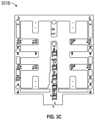
- FIG. 3 Cillustrates the sensor array portion 301 B of a sensor array shown in FIG. 3 B ;
- FIG. 3 Dillustrates a flexible sensor array incorporated into a perforated wound contact layer according to some embodiments
- FIG. 3 Eillustrates a control module according to some embodiments
- FIGS. 4 A- 4 Fillustrate a wound dressing with a plurality of electronic components according to some embodiments
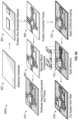
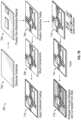
- FIGS. 5 A- 5 Dillustrate a wound dressing with a plurality of electronic components according to some embodiments
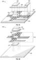
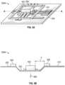
- FIGS. 6 A- 6 B and 7 A- 7 Billustrate processes for making wound dressings with a plurality of electronic components according to some embodiments
- FIG. 8illustrates indexing according to some embodiments.
- a wound monitoring and/or therapy apparatusincludes a wound dressing having a substantially stretchable wound contact layer including a wound facing side and a non-wound facing side opposite the wound facing side, the wound facing side of the wound contact layer configured to be positioned in contact with a wound, the wound facing side or the non-wound facing side of the wound contact layer supporting a plurality of electronic components and a plurality of electronic connections that connect at least some of the plurality of the electronic components, and the wound facing side or the non-wound facing side of the wound contact layer supporting the plurality of electronic components and the plurality of electronic connections including a first region of substantially non-stretchable material that supports at least one electronic component from the plurality of electronic components.
- the at least one electronic componentcan be attached to the first region of substantially non-stretchable material with adhesive material.
- the apparatus of the preceding paragraphcan include one or more of the following features.
- the wound facing side or the non-wound facing side of the wound contact layer supporting the plurality of electronic components and the plurality of electronic connectionscan include a second region of substantially non-stretchable material that supports at least one electronic connection from the plurality of electronic connections.
- the wound contact layercan include a substrate supporting the plurality of electronic components and the plurality of electronic connections and a conformal coating covering at least the plurality of electronic components and the plurality of electronic connections, the conformal coating configured to prevent fluid from coming into contact with the plurality of electronic components and the plurality of electronic connections.
- the substratecan be formed from thermoplastic polyurethane and the conformal coating can be formed from urethane.
- the wound contact layercan include a plurality of perforations configured to allow fluid to pass through the wound contact layer when negative pressure is applied to the wound.
- the plurality of perforationscan be further configured to allow substantially unidirectional flow of fluid through the wound contact layer to prevent fluid removed from the wound from flowing back toward the wound.
- the apparatus of any of the preceding paragraphscan include one or more of the following features.
- the wound facing side of the wound contact layercan include a region of additional adhesive material configured to position the at least one electronic component in the wound.
- the wound facing side or the non-wound facing side of the wound contact layer supporting the plurality of electronic components and the plurality of electronic connectionscan include a third region of substantially non-stretchable material that encloses the at least one electronic component.
- the at least one electronic componentcan be one or more of a sensor, a light emitter, a processor, or a communications controller.
- Plurality of electronic connectionscan include a plurality of electrical traces.
- the apparatuscan include a negative pressure source configured to be fluidically connected to the wound dressing.
- the wound dressingcan further include an absorbent layer positioned over the non-wound facing side of the wound contact layer and a backing layer positioned over the absorbent layer.
- the wound contact layercan be sealed to the backing layer.
- the backing layercan include a port configured to fluidically connect the wound dressing to a negative pressure source.
- At least one of the adhesive material or the additional adhesive materialcan be thermally curable.
- At least the wound facing side of the wound contact layercan support the plurality of electronic components and the plurality of electronic connections.
- At least the non-wound facing side of the wound contact layercan support the plurality of electronic components and the plurality of electronic connections.
- a method of manufacturing a wound dressingincludes providing a substantially stretchable wound contact layer including a wound facing side and a non-wound facing side opposite the wound facing side, the wound facing side of the wound contact layer configured to be positioned in contact with a wound, positioning a first region of substantially non-stretchable material on the wound facing side or the non-wound facing side of the wound contact layer, positioning adhesive material in at least a portion of the first region; and positioning a plurality of electronic components and a plurality of electronic connections on the wound facing side or the non-wound facing side of the wound contact layer.
- the at least one electronic component from the plurality of electronic componentscan be supported by the first region of substantially non-stretchable material, and the at least one electronic component can be attached to the first region of substantially non-stretchable material with the adhesive material.
- the wound contact layercan include a substrate, and the method can further include perforating the substrate around the plurality of electronic components and the plurality of electronic connections and applying conformal coating over at least the plurality of electronic components and the plurality of electronic connections, the conformal coating configured to prevent fluid from coming into contact with the plurality of electronic components and the plurality of electronic connections.
- the methodcan further include identifying a plurality of locations of the plurality of electronic components and the plurality of electronic connections on the substrate prior to perforating the substrate around the plurality of electronic components and the plurality of electronic connections.
- Identifying the plurality of locationscan include identifying one or more of: a location of an RFID chip or antenna positioned on the substrate or a location of an electronic connection configured to be connected to an electronic component external to the substrate.
- the methodcan further include applying a region of additional adhesive material to the wound facing side of the wound contact layer, the additional adhesive material configured to position the at least one electronic component in the wound.
- the method of any of the preceding paragraphscan include one or more of the following features.
- the methodcan include further identifying a location of the at least one electronic component prior to applying the region of additional adhesive material.
- the wound contact layercan include a substrate, and the method can further include applying conformal coating over at least the plurality of electronic components and the plurality of electronic connections, the conformal coating configured to prevent fluid from coming into contact with the plurality of electronic components and the plurality of electronic connections.
- the methodcan further include applying a region of adhesive material to the wound facing side of the wound contact layer, the adhesive material configured to position the at least one electronic component in the wound, and perforating the substrate around the plurality of electronic components and the plurality of electronic connections.
- the method of any of the preceding paragraphscan include one or more of the following features.
- the methodcan further include identifying a plurality of locations of the plurality of electronic components and the plurality of electronic connections on the substrate prior to perforating the substrate around the plurality of electronic components and the plurality of electronic connections.
- the methodcan further include identifying a location of the at least one electronic component prior to applying the region of adhesive material. Identifying the plurality of locations can include identifying one or more of a location of an RFID chip or antenna positioned on the substrate or a location of an electronic connection configured to be connected to an electronic component external to the substrate.
- the methodcan further include positioning a second region of substantially non-stretchable material on the wound facing side or the non-wound facing side of the wound contact layer and supporting at least one electronic connection from the plurality of electronic connections on the second region.
- the method of any of the preceding paragraphscan include one or more of the following features.
- the methodcan further include enclosing the at least one electronic component by a third region of substantially non-stretchable material positioned on the wound facing side or the non-wound facing side of the wound contact layer supporting the plurality of electronic components and the plurality of electronic connections.
- the methodcan further include cutting the wound contact layer along at least one cutting line to separate a region of the wound contact layer including the plurality of electronic components and the plurality of electronic connections and attaching the region of the wound contact layer to one or more of an absorbent layer or a backing layer to form a wound dressing.
- the substratecan be formed from thermoplastic polyurethane and the conformal coating can be formed from urethane.
- the methodcan further include curing at least one of the adhesive material or the additional adhesive material.
- the methodcan further include thermally curing the adhesive material during soldering of the at least one electronic component to at least one electronic connection of the one or more electronic connections.
- the plurality of electronic components and the plurality of electronic connectionscan be positioned at least on the wound facing side of the wound contact layer.
- the plurality of electronic components and the plurality of electronic connectionscan be positioned at least on the non-wound facing side of the wound contact layer.
- a wound therapy apparatusincludes a wound dressing including a substantially stretchable wound contact layer including a wound facing side and a non-wound facing side opposite the wound facing side, the wound facing side of the wound contact layer configured to be positioned in contact with a wound, the non-wound facing side of the wound contact layer supporting a plurality of electronic components and a plurality of electronic connections that connect at least some of the plurality of the electronic components, the non-wound facing side of the wound contact layer including a first region of substantially non-stretchable material that supports at least one electronic component from the plurality of electronic components.
- the apparatus of any of the preceding paragraphscan include one or more of the following features.
- the non-wound facing side of the wound contact layercan include a second region of substantially non-stretchable material that supports at least one electronic connection from the plurality of electronic connections.
- the wound contact layercan include a substrate supporting the plurality of electronic components and the plurality of electronic connections and a conformal coating covering at least the plurality of electronic components and the plurality of electronic connections, the conformal coating configured to prevent fluid from coming into contact with the plurality of electronic components and the plurality of electronic connections.
- the substratecan be formed from thermoplastic polyurethane and the conformal coating can be formed from urethane.
- the wound contact layercan include a plurality of perforations configured to allow fluid to pass through the wound contact layer when negative pressure is applied to the wound.
- the plurality of perforationscan be further configured to allow substantially unidirectional flow of fluid through the wound contact layer to prevent fluid removed from the wound from flowing back toward the wound.
- the wound facing side of the wound contact layercan include a region of adhesive material configured to position the at least one electronic component in the wound.
- the non-wound facing side of the wound contact layercan include a third region of substantially non-stretchable material that encloses the at least one electronic component.
- the apparatus of any of the preceding paragraphscan include one or more of the following features.
- the at least one electronic component caminclude one or more of a sensor, a light emitter, a processor, or a communications controller.
- the plurality of electronic connectionscan include a plurality of electrical traces.
- the apparatuscan include a negative pressure source configured to be fluidically connected to the wound dressing.
- the wound dressingcan further include an absorbent layer positioned over the non-wound facing side of the wound contact layer and a backing layer positioned over the absorbent layer.
- the wound contact layercan be sealed to the backing layer.
- the apparatuscan further include a port on the backing layer, the port configured to fluidically connect the wound dressing to a negative pressure source.
- a method of manufacturing a wound dressingincludes providing a substantially stretchable wound contact layer including a wound facing side and a non-wound facing side opposite the wound facing side, the wound facing side of the wound contact layer configured to be positioned in contact with a wound, positioning a first region of substantially non-stretchable material on the non-wound facing side of the wound contact layer, and positioning a plurality of electronic components and a plurality of electronic connections on the non-wound facing side of the wound contact layer, wherein at least one electronic component from the plurality of electronic components is supported by the first region of substantially non-stretchable material.
- the wound contact layercan include a substrate, and the method can further include perforating the substrate around the plurality of electronic components and the plurality of electronic connections and applying conformal coating over at least the plurality of electronic components and the plurality of electronic connections, the conformal coating configured to prevent fluid from coming into contact with the plurality of electronic components and the plurality of electronic connections.
- the methodcan further include identifying a plurality of locations of the plurality of electronic components and the plurality of electronic connections on the substrate prior to perforating the substrate around the plurality of electronic components and the plurality of electronic connections.
- Identifying the plurality of locationscan include identifying one or more of: a location of an RFID chip or antenna positioned on the substrate or a location of an electronic connection configured to be connected to an electronic component external to the substrate.
- the methodcan further include applying a region of adhesive material to the wound facing side of the wound contact layer, the adhesive material configured to position the at least one electronic component in the wound.
- the methodcan further include identifying a location of the at least one electronic component prior to applying the region of adhesive material.
- the wound contact layercan include a substrate, and wherein the method can further include applying conformal coating over at least the plurality of electronic components and the plurality of electronic connections, the conformal coating configured to prevent fluid from coming into contact with the plurality of electronic components and the plurality of electronic connections.
- the methodcan further include applying a region of adhesive material to the wound facing side of the wound contact layer, the adhesive material configured to position the at least one electronic component in the wound and perforating the substrate around the plurality of electronic components and the plurality of electronic connections.
- the methodcan further include identifying a plurality of locations of the plurality of electronic components and the plurality of electronic connections on the substrate prior to perforating the substrate around the plurality of electronic components and the plurality of electronic connections.
- the methodcan further include identifying a location of the at least one electronic component prior to applying the region of adhesive material.
- Identifying the plurality of locationscan include identifying one or more of: a location of an RFID chip or antenna positioned on the substrate or a location of an electronic connection configured to be connected to an electronic component external to the substrate.
- the methodcan further include positioning a second region of substantially non-stretchable material on the non-wound facing side of the wound contact layer and supporting at least one electronic connection from the plurality of electronic connections on the second region.
- the methodcan further include enclosing the at least one electronic component by a third region of substantially non-stretchable material positioned on the non-wound facing side of the wound contact layer.
- the methodcan further include cutting the wound contact layer along at least one cutting line to separate a region of the wound contact layer including the plurality of electronic components and the plurality of electronic connections and attaching the region of the wound contact layer to one or more of an absorbent layer or a backing layer to form a wound dressing.
- the substratecan be formed thermoplastic polyurethane and the conformal coating can be formed from urethane.
- a wound therapy apparatusincludes a wound dressing including a substantially stretchable wound contact layer including a wound facing side and a non-wound facing side opposite the wound facing side, the wound facing side of the wound contact layer configured to be positioned in contact with a wound, the wound facing side of the wound contact layer supporting a plurality of electronic components and a plurality of electronic connections that connect at least some of the plurality of the electronic components, and the wound facing side of the wound contact layer including a first region of substantially non-stretchable material that supports at least one electronic component from the plurality of electronic components.
- the apparatus of any of the preceding paragraphscan include one or more of the following features.
- the wound facing side of the wound contact layercan include a second region of substantially non-stretchable material that supports at least one electronic connection from the plurality of electronic connections.
- the wound contact layercan include a substrate supporting the plurality of electronic components and the plurality of electronic connections and a conformal coating covering at least the plurality of electronic components and the plurality of electronic connections, the conformal coating configured to prevent fluid from coming into contact with the plurality of electronic components and the plurality of electronic connections.
- the substratecan be formed from thermoplastic polyurethane and the conformal coating can be formed from urethane.
- the wound contact layercan include a plurality of perforations configured to allow fluid to pass through the wound contact layer when negative pressure is applied to the wound.
- the plurality of perforationscan be further configured to allow substantially unidirectional flow of fluid through the wound contact layer to prevent fluid removed from the wound from flowing back toward the wound.
- the apparatus of any of the preceding paragraphscan include one or more of the following features.
- the wound facing side of the wound contact layercan include a region of adhesive material configured to position the at least one electronic component in the wound.
- the wound facing side of the wound contact layercan include a third region of substantially non-stretchable material that encloses the at least one electronic component.
- the at least one electronic componentcan include one or more of a sensor, a light emitter, a processor, or a communications controller.
- Plurality of electronic connectionscan include a plurality of electrical traces.
- the apparatuscan further include a negative pressure source configured to be fluidically connected to the wound dressing.
- the wound dressingcan include an absorbent layer positioned over the non-wound facing side of the wound contact layer and a backing layer positioned over the absorbent layer.
- the wound contact layercan be sealed to the backing layer.
- the apparatuscan further include a port on the backing layer, the port configured to fluidically connect the wound dressing to a negative pressure source.
- a method of manufacturing a wound dressingincludes providing a substantially stretchable wound contact layer including a wound facing side and a non-wound facing side opposite the wound facing side, the wound facing side of the wound contact layer configured to be positioned in contact with a wound, positioning a first region of substantially non-stretchable material on the wound facing side of the wound contact layer, and positioning a plurality of electronic components and a plurality of electronic connections on the wound facing side of the wound contact layer, wherein at least one electronic component from the plurality of electronic components is supported by the first region of substantially non-stretchable material.
- the wound contact layercan include a substrate, and the method can further include perforating the substrate around the plurality of electronic components and the plurality of electronic connections and applying conformal coating over at least the plurality of electronic components and the plurality of electronic connections, the conformal coating configured to prevent fluid from coming into contact with the plurality of electronic components and the plurality of electronic connections.
- the methodcan include identifying a plurality of locations of the plurality of electronic components and the plurality of electronic connections on the substrate prior to perforating the substrate around the plurality of electronic components and the plurality of electronic connections.
- Identifying the plurality of locationscan include identifying one or more of: a location of an RFID chip or antenna positioned on the substrate or a location of an electronic connection configured to be connected to an electronic component external to the substrate.
- the methodcan include applying a region of adhesive material to the wound facing side of the wound contact layer, the adhesive material configured to position the at least one electronic component in the wound.
- the methodcan include identifying a location of the at least one electronic component prior to applying the region of adhesive material.
- the wound contact layercan include a substrate, and the method can further include applying conformal coating over at least the plurality of electronic components and the plurality of electronic connections, the conformal coating configured to prevent fluid from coming into contact with the plurality of electronic components and the plurality of electronic connections.
- the methodcan include applying a region of adhesive material to the wound facing side of the wound contact layer, the adhesive material configured to position the at least one electronic component in the wound, and perforating the substrate around the plurality of electronic components and the plurality of electronic connections.
- the methodcan include identifying a plurality of locations of the plurality of electronic components and the plurality of electronic connections on the substrate prior to perforating the substrate around the plurality of electronic components and the plurality of electronic connections.
- the methodcan include identifying a location of the at least one electronic component prior to applying the region of adhesive material. Identifying the plurality of locations can include identifying one or more of: a location of an RFID chip or antenna positioned on the substrate or a location of an electronic connection configured to be connected to an electronic component external to the substrate
- the method of any of the preceding paragraphscan include one or more of the following features.
- the methodcan include positioning a second region of substantially non-stretchable material on the wound facing side of the wound contact layer and supporting at least one electronic connection from the plurality of electronic connections on the second region.
- the methodcan include enclosing the at least one electronic component by a third region of substantially non-stretchable material positioned on the wound facing side of the wound contact layer.
- the methodcan include cutting the wound contact layer along at least one cutting line to separate a region of the wound contact layer including the plurality of electronic components and the plurality of electronic connections and attaching the region of the wound contact layer to one or more of an absorbent layer or a backing layer to form a wound dressing.
- the substratecan be formed thermoplastic polyurethane and the conformal coating can be formed from urethane.
- a wound therapy apparatusincludes a wound dressing including a substantially stretchable wound contact layer including a wound facing side and a non-wound facing side opposite the wound facing side, the wound facing side of the wound contact layer configured to be positioned in contact with a wound, the wound facing side of the wound contact layer supporting a plurality of electronic components and a plurality of electronic connections that connect at least some of the plurality of the electronic components, and the wound facing side of the wound contact layer including a first region of substantially non-stretchable material that supports at least one electronic component from the plurality of electronic components, wherein the at least one electronic component is attached to the first region of substantially non-stretchable material with adhesive material.
- the apparatus of any of the preceding paragraphscan include one or more of the following features.
- the wound facing side of the wound contact layercan include a second region of substantially non-stretchable material that supports at least one electronic connection from the plurality of electronic connections.
- the wound contact layercan include a substrate supporting the plurality of electronic components and the plurality of electronic connections and a conformal coating covering at least the plurality of electronic components and the plurality of electronic connections, the conformal coating configured to prevent fluid from coming into contact with the plurality of electronic components and the plurality of electronic connections.
- the substratecan be formed from thermoplastic polyurethane and the conformal coating can be formed from urethane.
- the wound contact layercan include a plurality of perforations configured to allow fluid to pass through the wound contact layer when negative pressure is applied to the wound.
- the plurality of perforationscan be further configured to allow substantially unidirectional flow of fluid through the wound contact layer to prevent fluid removed from the wound from flowing back toward the wound.
- the apparatus of any of the preceding paragraphscan include one or more of the following features.
- the wound facing side of the wound contact layercan include a region of additional adhesive material configured to position the at least one electronic component in the wound.
- the wound facing side of the wound contact layercan include a third region of substantially non-stretchable material that encloses the at least one electronic component.
- the at least one electronic componentcan include one or more of a sensor, a light emitter, a processor, or a communications controller.
- Plurality of electronic connectionscan include a plurality of electrical traces.
- the apparatuscan further include a negative pressure source configured to be fluidically connected to the wound dressing.
- the wound dressingcan include an absorbent layer positioned over the non-wound facing side of the wound contact layer and a backing layer positioned over the absorbent layer.
- the wound contact layercan be sealed to the backing layer.
- the apparatuscan further include a port on the backing layer, the port configured to fluidically connect the wound dressing to a negative pressure source.
- Adhesive materialcan be thermally curable.
- a method of manufacturing a wound dressingincludes providing a substantially stretchable wound contact layer including a wound facing side and a non-wound facing side opposite the wound facing side, the wound facing side of the wound contact layer configured to be positioned in contact with a wound, positioning a first region of substantially non-stretchable material on the wound facing side of the wound contact layer, and positioning a plurality of electronic components and a plurality of electronic connections on the wound facing side of the wound contact layer, wherein at least one electronic component from the plurality of electronic components is supported by the first region of substantially non-stretchable material, and wherein at least one electronic component is attached to the first region of substantially non-stretchable material with adhesive material.
- the wound contact layercan include a substrate, and wherein the method can further include perforating the substrate around the plurality of electronic components and the plurality of electronic connections and applying conformal coating over at least the plurality of electronic components and the plurality of electronic connections, the conformal coating configured to prevent fluid from coming into contact with the plurality of electronic components and the plurality of electronic connections.
- the methodcan further include identifying a plurality of locations of the plurality of electronic components and the plurality of electronic connections on the substrate prior to perforating the substrate around the plurality of electronic components and the plurality of electronic connections. Identifying the plurality of locations can include identifying one or more of: a location of an RFID chip or antenna positioned on the substrate or a location of an electronic connection configured to be connected to an electronic component external to the substrate.
- the method of any of the preceding paragraphscan include one or more of the following features.
- the methodcan further include applying a region of additional adhesive material to the wound facing side of the wound contact layer, the additional adhesive material configured to position the at least one electronic component in the wound.
- the methodcan further include identifying a location of the at least one electronic component prior to applying the region of additional adhesive material.
- the wound contact layercan include a substrate, and the method can further include applying conformal coating over at least the plurality of electronic components and the plurality of electronic connections, the conformal coating configured to prevent fluid from coming into contact with the plurality of electronic components and the plurality of electronic connections.
- the methodcan further include applying a region of adhesive material to the wound facing side of the wound contact layer, the adhesive material configured to position the at least one electronic component in the wound and perforating the substrate around the plurality of electronic components and the plurality of electronic connections.
- the method of any of the preceding paragraphscan include one or more of the following features.
- the methodcan further include identifying a plurality of locations of the plurality of electronic components and the plurality of electronic connections on the substrate prior to perforating the substrate around the plurality of electronic components and the plurality of electronic connections.
- the methodcan further include identifying a location of the at least one electronic component prior to applying the region of adhesive material. Identifying the plurality of locations can include identifying one or more of: a location of an RFID chip or antenna positioned on the substrate or a location of an electronic connection configured to be connected to an electronic component external to the substrate.
- the method of any of the preceding paragraphscan include one or more of the following features.
- the methodcan further include positioning a second region of substantially non-stretchable material on the wound facing side of the wound contact layer and supporting at least one electronic connection from the plurality of electronic connections on the second region.
- the methodcan further include enclosing the at least one electronic component by a third region of substantially non-stretchable material positioned on the wound facing side of the wound contact layer.
- the methodcan further include cutting the wound contact layer along at least one cutting line to separate a region of the wound contact layer including the plurality of electronic components and the plurality of electronic connections and attaching the region of the wound contact layer to one or more of an absorbent layer or a backing layer to form a wound dressing.
- the substratecan be formed thermoplastic polyurethane and the conformal coating can be formed from urethane.
- the adhesive materialcan be thermally curable.
- a wound monitoring and/or therapy apparatusincludes a wound dressing having a substantially stretchable wound contact layer including a wound facing side and a non-wound facing side opposite the wound facing side, the wound facing side of the wound contact layer configured to be positioned in contact with a wound, at least the wound facing side of the wound contact layer supporting a plurality of electronic components and a plurality of electronic connections that connect at least some of the plurality of the electronic components, and the wound facing side of the wound contact layer including a first region of substantially non-stretchable material that supports at least one electronic component from the plurality of electronic components.
- the at least one electronic componentcan be attached to the first region of substantially non-stretchable material with adhesive material.
- the apparatus of the preceding paragraphcan include one or more of the following features.
- the wound facing side of the wound contact layercan include a second region of substantially non-stretchable material that supports at least one electronic connection from the plurality of electronic connections.
- the wound contact layercan include a substrate supporting the plurality of electronic components and the plurality of electronic connections and a conformal coating covering at least the plurality of electronic components and the plurality of electronic connections, the conformal coating configured to prevent fluid from coming into contact with the plurality of electronic components and the plurality of electronic connections.
- the substratecan be formed from thermoplastic polyurethane and the conformal coating is formed from urethane.
- the wound contact layercan include a plurality of perforations configured to allow fluid to pass through the wound contact layer when negative pressure is applied to the wound. The plurality of perforations can be further configured to allow substantially unidirectional flow of fluid through the wound contact layer to prevent fluid removed from the wound from flowing back toward the wound.
- the apparatus of any of the preceding paragraphscan include one or more of the following features.
- the wound facing side of the wound contact layercan include a region of additional adhesive material configured to position the at least one electronic component in the wound.
- the wound facing side of the wound contact layercan include a third region of substantially non-stretchable material that encloses the at least one electronic component.
- the at least one electronic componentcan be one or more of a sensor, a light emitter, a processor, or a communications controller.
- Plurality of electronic connectionscan include a plurality of electrical traces.
- the apparatuscan include a negative pressure source configured to be fluidically connected to the wound dressing.
- the wound dressingcan further include an absorbent layer positioned over the non-wound facing side of the wound contact layer and a backing layer positioned over the absorbent layer.
- the wound contact layercan be sealed to the backing layer.
- the backing layercan include a port configured to fluidically connect the wound dressing to a negative pressure source. At least one of the adhesive material or the additional adhesive material can be thermally curable.
- a method of manufacturing a wound dressingincludes providing a substantially stretchable wound contact layer including a wound facing side and a non-wound facing side opposite the wound facing side, the wound facing side of the wound contact layer configured to be positioned in contact with a wound, positioning a first region of substantially non-stretchable material on the wound facing side of the wound contact layer, positioning adhesive material in at least a portion of the first region; and positioning a plurality of electronic components and a plurality of electronic connections at least on the wound facing side of the wound contact layer.
- the at least one electronic component from the plurality of electronic componentscan be supported by the first region of substantially non-stretchable material, and the at least one electronic component can be attached to the first region of substantially non-stretchable material with the adhesive material.
- the wound contact layercan include a substrate, and the method can further include perforating the substrate around the plurality of electronic components and the plurality of electronic connections and applying conformal coating over at least the plurality of electronic components and the plurality of electronic connections, the conformal coating configured to prevent fluid from coming into contact with the plurality of electronic components and the plurality of electronic connections.
- the methodcan further include identifying a plurality of locations of the plurality of electronic components and the plurality of electronic connections on the substrate prior to perforating the substrate around the plurality of electronic components and the plurality of electronic connections.
- Identifying the plurality of locationscan include identifying one or more of: a location of an RFID chip or antenna positioned on the substrate or a location of an electronic connection configured to be connected to an electronic component external to the substrate.
- the methodcan further include applying a region of additional adhesive material to the wound facing side of the wound contact layer, the additional adhesive material configured to position the at least one electronic component in the wound.
- the method of any of the preceding paragraphscan include one or more of the following features.
- the methodcan include further identifying a location of the at least one electronic component prior to applying the region of additional adhesive material.
- the wound contact layercan include a substrate, and the method can further include applying conformal coating over at least the plurality of electronic components and the plurality of electronic connections, the conformal coating configured to prevent fluid from coming into contact with the plurality of electronic components and the plurality of electronic connections.
- the methodcan further include applying a region of adhesive material to the wound facing side of the wound contact layer, the adhesive material configured to position the at least one electronic component in the wound, and perforating the substrate around the plurality of electronic components and the plurality of electronic connections.
- the method of any of the preceding paragraphscan include one or more of the following features.
- the methodcan further include identifying a plurality of locations of the plurality of electronic components and the plurality of electronic connections on the substrate prior to perforating the substrate around the plurality of electronic components and the plurality of electronic connections.
- the methodcan further include identifying a location of the at least one electronic component prior to applying the region of adhesive material. Identifying the plurality of locations can include identifying one or more of a location of an RFID chip or antenna positioned on the substrate or a location of an electronic connection configured to be connected to an electronic component external to the substrate.
- the methodcan further include positioning a second region of substantially non-stretchable material on the wound facing side of the wound contact layer and supporting at least one electronic connection from the plurality of electronic connections on the second region.
- the method of any of the preceding paragraphscan include one or more of the following features.
- the methodcan further include enclosing the at least one electronic component by a third region of substantially non-stretchable material positioned on the wound facing side of the wound contact layer.
- the methodcan further include cutting the wound contact layer along at least one cutting line to separate a region of the wound contact layer including the plurality of electronic components and the plurality of electronic connections and attaching the region of the wound contact layer to one or more of an absorbent layer or a backing layer to form a wound dressing.
- the substratecan be formed from thermoplastic polyurethane and the conformal coating is formed from urethane.
- the methodcan further include curing at least one of the adhesive material or the additional adhesive material.
- the methodcan further include thermally curing the adhesive material during soldering of the at least one electronic component to at least one electronic connection of the one or more electronic connections.
- Embodiments disclosed hereinrelate to apparatuses and methods of treating a wound with or without reduced pressure, including for example a source of negative pressure and wound dressing components and apparatuses.
- the apparatuses and components comprising the wound overlay and packing materials or internal layers, if any,are sometimes collectively referred to herein as dressings.
- the wound dressingcan be provided to be utilized without reduced pressure.
- any reference to a wound hereincan refer to a wound on a human or animal body, and any reference to a body herein can refer to a human or animal body.
- the disclosed technology embodimentsmay relate to preventing or minimizing damage to physiological tissue or living tissue, or to the treatment of damaged tissue (for example, a wound as described herein).
- woundmay include an injury to living tissue may be caused by a cut, blow, or other impact, typically one in which the skin is cut or broken.
- a woundmay be a chronic or acute injury. Acute wounds occur as a result of surgery or trauma. They move through the stages of healing within a predicted timeframe. Chronic wounds typically begin as acute wounds. The acute wound can become a chronic wound when it does not follow the healing stages resulting in a lengthened recovery. It is believed that the transition from acute to chronic wound can be due to a patient being immuno-compromised.
- Chronic woundsmay include for example: venous ulcers (such as those that occur in the legs), which account for the majority of chronic wounds and mostly affect the elderly, diabetic ulcers (for example, foot or ankle ulcers), peripheral arterial disease, pressure ulcers, or epidermolysis bullosa (EB).
- venous ulcerssuch as those that occur in the legs
- diabetic ulcersfor example, foot or ankle ulcers
- peripheral arterial diseasefor example, pressure ulcers, or epidermolysis bullosa (EB).
- EBepidermolysis bullosa
- woundsinclude, but are not limited to, abdominal wounds or other large or incisional wounds, either as a result of surgery, trauma, sterniotomies, fasciotomies, or other conditions, dehisced wounds, acute wounds, chronic wounds, subacute and dehisced wounds, traumatic wounds, flaps and skin grafts, lacerations, abrasions, contusions, burns, diabetic ulcers, pressure ulcers, stoma, surgical wounds, trauma and venous ulcers or the like.
- Woundsmay also include a deep tissue injury.
- Deep tissue injuryis a term proposed by the National Pressure Ulcer Advisory Panel (NPUAP) to describe a unique form of pressure ulcers. These ulcers have been described by clinicians for many years with terms such as purple pressure ulcers, ulcers that are likely to deteriorate and bruises on bony prominences.
- NPUAPNational Pressure Ulcer Advisory Panel
- Woundmay also include tissue at risk of becoming a wound as discussed herein.
- tissue at riskmay include tissue over a bony protuberance (at risk of deep tissue injury/insult) or pre-surgical tissue (for example, knee tissue) that may has the potential to be cut (for example, for joint replacement/surgical alteration/reconstruction).
- Some embodimentsrelate to methods of treating a wound with the technology disclosed herein in conjunction with one or more of the following: advanced footwear, turning a patient, offloading (such as, offloading diabetic foot ulcers), treatment of infection, systemix, antimicrobial, antibiotics, surgery, removal of tissue, affecting blood flow, physiotherapy, exercise, bathing, nutrition, hydration, nerve stimulation, ultrasound, electrostimulation, oxygen therapy, microwave therapy, active agents ozone, antibiotics, antimicrobials, or the like.
- offloadingsuch as, offloading diabetic foot ulcers
- treatment of infectionsystemix
- antimicrobialantibiotics
- surgeryremoval of tissue, affecting blood flow, physiotherapy, exercise, bathing, nutrition, hydration, nerve stimulation, ultrasound, electrostimulation, oxygen therapy, microwave therapy, active agents ozone, antibiotics, antimicrobials, or the like.
- a woundmay be treated using topical negative pressure and/or traditional advanced wound care, which is not aided by the using of applied negative pressure (may also be referred to as non-negative pressure therapy).
- Advanced wound caremay include use of an absorbent dressing, an occlusive dressing, use of an antimicrobial and/or debriding agents in a wound dressing or adjunct, a pad (for example, a cushioning or compressive therapy, such as stockings or bandages), or the like.
- a padfor example, a cushioning or compressive therapy, such as stockings or bandages
- treatment of such woundscan be performed using traditional wound care, wherein a dressing can be applied to the wound to facilitate and promote healing of the wound.
- Some embodimentsrelate to methods of manufacturing a wound dressing comprising providing a wound dressing as disclosed herein.
- wound dressingsthat may be utilized in conjunction with the disclosed technology include any known dressing in the art.
- the technologyis applicable to negative pressure therapy treatment as well as non-negative pressure therapy treatment.
- a wound dressingcomprises one or more absorbent layer(s).
- the absorbent layermay be a foam or a superabsorbent.
- wound dressingsmay comprise a dressing layer including a polysaccharide or modified polysaccharide, a polyvinylpyrrolidone, a polyvinyl alcohol, a polyvinyl ether, a polyurethane, a polyacrylate, a polyacrylamide, collagen, or gelatin or mixtures thereof.
- dressing layerscomprising the polymers listed are known in the art as being useful for forming a wound dressing layer for either negative pressure therapy or non-negative pressure therapy.
- the polymer matrixmay be a polysaccharide or modified polysaccharide.
- the polymer matrixmay be a cellulose.
- Cellulose materialmay include hydrophilically modified cellulose such as methyl cellulose, carboxymethyl cellulose (CMC), carboxymethyl cellulose (CEC), ethyl cellulose, propyl cellulose, hydroxyethyl cellulose, hydroxypropyl cellulose, hydroxypropylmethyl cellulose, carboxyethyl sulphonate cellulose, cellulose alkyl sulphonate, or mixtures thereof.
- hydrophilically modified cellulosesuch as methyl cellulose, carboxymethyl cellulose (CMC), carboxymethyl cellulose (CEC), ethyl cellulose, propyl cellulose, hydroxyethyl cellulose, hydroxypropyl cellulose, hydroxypropylmethyl cellulose, carboxyethyl sulphonate cellulose, cellulose alkyl sulphonate, or mixtures thereof.
- cellulose materialmay be cellulose alkyl sulphonate.
- the alkyl moiety of the alkyl sulphonate substituent groupmay have an alkyl group having 1 to 6 carbon atoms, such as methyl, ethyl, propyl, or butyl.
- the alkyl moietymay be branched or unbranched, and hence suitable propyl sulphonate substituents may be 1- or 2-methyl-ethylsulphonate.
- Butyl sulphonate substituentsmay be 2-ethyl-ethylsulphonate, 2,2-dimethyl-ethylsulphonate, or 1,2-dimethyl-ethylsulphonate.
- the alkyl sulphonate substituent groupmay be ethyl sulphonate.
- the cellulose alkyl sulphonateis described in WO10061225, US2016/114074, US2006/0142560, or U.S. Pat. No. 5,703,225, the disclosures of which are hereby incorporated by reference in their entirety.
- Cellulose alkyl sulfonatesmay have varying degrees of substitution, the chain length of the cellulose backbone structure, and the structure of the alkyl sulfonate substituent. Solubility and absorbency are largely dependent on the degree of substitution: as the degree of substitution is increased, the cellulose alkyl sulfonate becomes increasingly soluble. It follows that, as solubility increases, absorbency increases.
- a wound dressingalso comprises a top or cover layer.
- the thickness of the wound dressing disclosed hereinmay be between 1 to 20, or 2 to 10, or 3 to 7 mm.
- a non-negative pressure wound dressing suitable for providing protection at a wound sitemay comprise:
- the obscuring elementmay be partially translucent.
- the obscuring elementmay be a masking layer.
- the non-negative pressure wound dressingmay further comprise a region in or adjacent the obscuring element for allowing viewing of the absorbent layer.
- the obscuring element layermay be provided over a central region of the absorbent layer and not over a border region of the absorbent layer.
- the obscuring elementis of hydrophilic material or is coated with a hydrophilic material.
- the obscuring elementmay comprise a three-dimensional knitted spacer fabric.
- the spacer fabricis known in the art and may include a knitted spacer fabric layer.
- the obscuring elementmay further comprise an indicator for indicating the need to change the dressing.
- the obscuring elementis provided as a layer at least partially over the absorbent layer, further from a wound site than the absorbent layer in use.
- the non-negative pressure wound dressingmay further comprise a plurality of openings in the obscuring element for allowing fluid to move therethrough.
- the obscuring elementmay comprise, or may be coated with, a material having size-exclusion properties for selectively permitting or preventing passage of molecules of a predetermined size or weight.
- the obscuring elementmay be configured to at least partially mask light radiation having wavelength of 600 nm and less.
- the obscuring elementmay be configured to reduce light absorption by 50% or more.
- the obscuring elementmay be configured to yield a CIE L* value of 50 or more, and optionally 70 or more. In some embodiments, the obscuring element may be configured to yield a CIE L* value of 70 or more.
- the non-negative pressure wound dressingmay further comprise at least one of a wound contact layer, a foam layer, an odor control element, a pressure-resistant layer and a cover layer.
- the cover layeris present, and the cover layer is a translucent film.
- the translucent filmhas a moisture vapour permeability of 500 g/m2/24 hours or more.
- the translucent filmmay be a bacterial barrier.
- the non-negative pressure wound dressing as disclosed hereincomprises the wound contact layer and the absorbent layer overlies the wound contact layer.
- the wound contact layercarries an adhesive portion for forming a substantially fluid tight seal over the wound site.
- the non-negative pressure wound dressing as disclosed hereinmay comprise the obscuring element and the absorbent layer being provided as a single layer.
- the non-negative pressure wound dressing disclosed hereincomprises the foam layer, and the obscuring element is of a material comprising components that may be displaced or broken by movement of the obscuring element.
- the non-negative pressure wound dressingcomprises an odor control element, and in another embodiment the dressing does not include an odor control element.
- the odor control elementmay be dispersed within or adjacent the absorbent layer or the obscuring element.
- the odor control elementmay be provided as a layer sandwiched between the foam layer and the absorbent layer.
- the disclosed technology for a non-negative pressure wound dressingcomprises a method of manufacturing a wound dressing, comprising: providing an absorbent layer for absorbing wound exudate; and providing an obscuring element for at least partially obscuring a view of wound exudate absorbed by the absorbent layer in use.
- the non-negative pressure wound dressingis may be suitable for providing protection at a wound site, comprising: an absorbent layer for absorbing wound exudate; and a shielding layer provided over the absorbent layer, and further from a wound-facing side of the wound dressing than the absorbent layer.
- the shielding layermay be provided directly over the absorbent layer.
- the shielding layercomprises a three-dimensional spacer fabric layer.
- the shielding layerincreases the area over which a pressure applied to the dressing is transferred by 25% or more or the initial area of application.
- the shielding layerincreases the area over which a pressure applied to the dressing is transferred by 50% or more, and optionally by 100% or more, and optionally by 200% or more.
- the shielding layermay comprise 2 or more sub-layers, wherein a first sub-layer comprises through holes and a further sub-layer comprises through holes and the through holes of the first sub-layer are offset from the through holes of the further sub-layer.
- the non-negative pressure wound dressing as disclosed hereinmay further comprise a permeable cover layer for allowing the transmission of gas and vapour therethrough, the cover layer provided over the shielding layer, wherein through holes of the cover layer are offset from through holes of the shielding layer.
- the non-negative pressure wound dressingmay be suitable for treatment of pressure ulcers.
- the non-negative pressure wound dressingmay be a multi-layered wound dressing comprising: a fibrous absorbent layer for absorbing exudate from a wound site; and a support layer configured to reduce shrinkage of at least a portion of the wound dressing.
- the multi-layered wound dressing disclosed hereinfurther comprises a liquid impermeable film layer, wherein the support layer is located between the absorbent layer and the film layer.
- the support layer disclosed hereinmay comprise a net.
- the netmay comprise a geometric structure having a plurality of substantially geometric apertures extending therethrough.
- the geometric structuremay for example comprise a plurality of bosses substantially evenly spaced and joined by polymer strands to form the substantially geometric apertures between the polymer strands.
- the netmay be formed from high density polyethylene.
- the aperturesmay have an area from 0.005 to 0.32 mm 2 .
- the support layermay have a tensile strength from 0.05 to 0.06 Nm.
- the support layermay have a thickness of from 50 to 150 ⁇ m.
- the support layeris located directly adjacent the absorbent layer.
- the support layeris bonded to fibers in a top surface of the absorbent layer.
- the support layermay further comprise a bonding layer, wherein the support layer is heat laminated to the fibers in the absorbent layer via the bonding layer.
- the bonding layermay comprise a low melting point adhesive such as ethylene-vinyl acetate adhesive.
- the multi-layered wound dressing disclosed hereinfurther comprises an adhesive layer attaching the film layer to the support layer.
- the multi-layered wound dressing disclosed hereinfurther comprises a wound contact layer located adjacent the absorbent layer for positioning adjacent a wound.
- the multi-layered wound dressingmay further comprise a fluid transport layer between the wound contact layer and the absorbent layer for transporting exudate away from a wound into the absorbent layer.
- the disclosed technologymay be incorporated in a wound dressing comprising a vertically lapped material comprising: a first layer of an absorbing layer of material, and a second layer of material, wherein the first layer being constructed from at least one layer of non-woven textile fibers, the non-woven textile fibers being folded into a plurality of folds to form a pleated structure.
- the wound dressingfurther comprises a second layer of material that is temporarily or permanently connected to the first layer of material.
- the vertically lapped materialhas been slitted.
- the first layerhas a pleated structure having a depth determined by the depth of pleats or by the slitting width.
- the first layer of materialmay be a moldable, lightweight, fiber-based material, blend of material or composition layer.
- the first layer of materialmay comprise one or more of manufactured fibers from synthetic, natural or inorganic polymers, natural fibers of a cellulosic, proteinaceous or mineral source.
- the wound dressingmay comprise two or more layers of the absorbing layer of material vertically lapped material stacked one on top of the other, wherein the two or more layers have the same or different densities or composition.
- the wound dressingmay in some embodiments comprise only one layer of the absorbing layer of material vertically lapped material.
- the absorbing layer of materialis a blend of natural or synthetic, organic or inorganic fibers, and binder fibers, or bicomponent fibers typically PET with a low melt temperature PET coating to soften at specified temperatures and to act as a bonding agent in the overall blend.
- the absorbing layer of materialmay be a blend of 5 to 95% thermoplastic polymer, and 5 to 95 wt % of a cellulose or derivative thereof.
- the wound dressing disclosed hereinhas a second layer comprises a foam or a dressing fixative.
- the foammay be a polyurethane foam.
- the polyurethane foammay have an open or closed pore structure.
- the dressing fixativemay include bandages, tape, gauze, or backing layer.
- the wound dressing as disclosed hereincomprises the absorbing layer of material connected directly to a second layer by lamination or by an adhesive, and the second layer is connected to a dressing fixative layer.
- the adhesivemay be an acrylic adhesive, or a silicone adhesive.
- the wound dressing as disclosed hereinfurther comprises layer of a superabsorbent fiber, or a viscose fiber or a polyester fiber.
- the wound dressing as disclosed hereinfurther comprises a backing layer.
- the backing layermay be a transparent or opaque film.
- the backing layercomprises a polyurethane film (typically a transparent polyurethane film).
- the non-negative pressure wound dressingmay comprise an absorbent component for a wound dressing, the component comprising a wound contacting layer comprising gel forming fibers bound to a foam layer, wherein the foam layer is bound directly to the wound contact layer by an adhesive, polymer based melt layer, by flame lamination or by ultrasound.
- the absorbent componentmay be in a sheet form.
- the wound contacting layermay comprise a layer of woven or non-woven or knitted gel forming fibers.
- the foam layermay be an open cell foam, or closed cell foam, typically an open cell foam.
- the foam layeris a hydrophilic foam.
- the wound dressingmay comprise the component that forms an island in direct contact with the wound surrounded by periphery of adhesive that adheres the dressing to the wound.
- the adhesivemay be a silicone or acrylic adhesive, typically a silicone adhesive.
- the wound dressingmay be covered by a film layer on the surface of the dressing furthest from the wound.
- the non-negative pressure wound dressingmay comprise a multi layered wound dressing for use on wounds producing high levels of exudate, characterized in that the dressing comprising: a transmission layer having an MVTR of at least 300 gm2/24 hours, an absorbent core comprising gel forming fibers capable of absorbing and retaining exudate, a wound contacting layer comprising gel forming fibers which transmits exudate to the absorbent core and a keying layer positioned on the absorbent core, the absorbent core and wound contacting layer limiting the lateral spread of exudate in the dressing to the region of the wound.
- the dressingcomprising: a transmission layer having an MVTR of at least 300 gm2/24 hours, an absorbent core comprising gel forming fibers capable of absorbing and retaining exudate, a wound contacting layer comprising gel forming fibers which transmits exudate to the absorbent core and a keying layer positioned on the absorbent core, the absorbent core and wound contacting layer limiting the lateral spread of exudate in
- the wound dressingmay be capable of handling at least 6 g (or 8 g and 15 g) of fluid per 10 cm2 of dressing in 24 hours.
- the wound dressingmay comprise gel forming fibers that are chemically modified cellulosic fibers in the form of a fabric.
- the fibersmay include carboxymethylated cellulose fibers, typically sodium carboxymethylcellulose fiber.
- the wound dressingmay comprise a wound contact layer with a lateral wicking rate from 5 mm per minute to 40 mm per minute.
- the wound contact layermay have a fiber density between 25 gm2 and 55 gm2, such as 35 gm2.
- the absorbent coremay have an absorbency of exudate of at least 10 g/g, and typically a rate of lateral wicking of less the 20 mm per minute.
- the absorbent coremay have a blend in the range of up to 25% cellulosic fibers by weight and 75% to 100% gel forming fibers by weight.
- the absorbent coremay have a blend in the range of up to 50% cellulosic fibers by weight and 50% to 100% gel forming fibers by weight.
- the blendis in the range of 50% cellulosic fibers by weight and 50% gel forming fibers by weight.
- the fiber density in the absorbent coremay be between 150 gm2 and 250 gm2, or about 200 gm2.
- the wound dressing when wetmay have shrinkage that is less than 25% or less than 15% of its original size/dimension.
- the wound dressingmay comprise a transmission layer and the layer is a foam.
- the transmission layermay be a polyurethane foam laminated to a polyurethane film.
- the wound dressingmay comprise one or more layers selected from the group comprising a soluble medicated film layer; an odor-absorbing layer; a spreading layer and an additional adhesive layer.
- the wound dressingmay be 2 mm and 4 mm thick.
- the wound dressingmay be characterized in that the keying layer bonds the absorbent core to a neighboring layer.
- the keying layermay be positioned on either the wound facing side of the absorbent core or the non-wound facing side of the absorbent core.
- the keying layeris positioned between the absorbent core and the wound contact layer.
- the keying layeris a polyamide web.
- the non-negative pressure wound dressingmay be a compression bandage.
- Compression bandagesare known for use in the treatment of oedema and other venous and lymphatic disorders, e.g., of the lower limbs.
- a compression bandage systemstypically employ multiple layers including a padding layer between the skin and the compression layer or layers.
- the compression bandagemay be useful for wounds such as handling venous leg ulcers.
- the compression bandagein some embodiments may comprise a bandage system comprising an inner skin facing layer and an elastic outer layer, the inner layer comprising a first ply of foam and a second ply of an absorbent nonwoven web, the inner layer and outer layer being sufficiently elongated so as to be capable of being wound about a patient's limb.
- a compression bandage of this typeis disclosed in WO99/58090, the entirety of which is hereby incorporated by reference.
- the compression bandage systemcomprises: a) an inner skin facing, elongated, elastic bandage comprising: (i) an elongated, elastic substrate, and
- treatment of such woundscan be performed using negative pressure wound therapy, wherein a reduced or negative pressure can be applied to the wound to facilitate and promote healing of the wound.
- wound dressing and methods as disclosed hereinmay be applied to other parts of the body, and are not necessarily limited to treatment of wounds.
- TNPtopical negative pressure
- negative pressure wound therapyassists in the closure and healing of many forms of “hard to heal” wounds by reducing tissue oedema; encouraging blood flow and granular tissue formation; removing excess exudate and may reduce bacterial load (and thus infection risk).
- the therapyallows for less disturbance of a wound leading to more rapid healing.
- TNP therapy systemsmay also assist on the healing of surgically closed wounds by removing fluid and by helping to stabilize the tissue in the apposed position of closure.
- a further beneficial use of TNP therapycan be found in grafts and flaps where removal of excess fluid is important and close proximity of the graft to tissue is required in order to ensure tissue viability.
- Negative pressure therapycan be used for the treatment of open or chronic wounds that are too large to spontaneously close or otherwise fail to heal by means of applying negative pressure to the site of the wound.
- Topical negative pressure (TNP) therapy or negative pressure wound therapy (NPWT)involves placing a cover that is impermeable or semi-permeable to fluids over the wound, using various means to seal the cover to the tissue of the patient surrounding the wound, and connecting a source of negative pressure (such as a vacuum pump) to the cover in a manner so that negative pressure is created and maintained under the cover. It is believed that such negative pressures promote wound healing by facilitating the formation of granulation tissue at the wound site and assisting the body's normal inflammatory process while simultaneously removing excess fluid, which may contain adverse cytokines or bacteria.
- NPWTcan include many different types of materials and layers, for example, gauze, pads, foam pads or multi-layer wound dressings.
- a multi-layer wound dressingis the PICO dressing, available from Smith & Nephew, includes a wound contact layer and a superabsorbent layer beneath a backing layer to provide a canister-less system for treating a wound with NPWT.
- the wound dressingmay be sealed to a suction port providing connection to a length of tubing, which may be used to pump fluid out of the dressing or to transmit negative pressure from a pump to the wound dressing.
- RENASYS-F, RENASYS-G, RENASYS-AB, and RENASYS-F/ABavailable from Smith & Nephew
- NPWT wound dressings and systemsare additional examples of NPWT wound dressings and systems.
- Another example of a multi-layer wound dressingis the ALLEVYN Life dressing, available from Smith & Nephew, which includes a moist wound environment dressing that is used to treat the wound without the use of negative pressure.
- reduced or negative pressure levelsrepresent pressure levels relative to normal ambient atmospheric pressure, which can correspond to 760 mmHg (or 1 atm, 29.93 inHg, 101.325 kPa, 14.696 psi, etc.).
- a negative pressure value of ⁇ X mmHgreflects absolute pressure that is X mmHg below 760 mmHg or, in other words, an absolute pressure of (760 ⁇ X) mmHg.
- negative pressure that is “less” or “smaller” than X mmHgcorresponds to pressure that is closer to atmospheric pressure (such as, ⁇ 40 mmHg is less than ⁇ 60 mmHg).
- Negative pressure that is “more” or “greater” than ⁇ X mmHgcorresponds to pressure that is further from atmospheric pressure (such as, ⁇ 80 mmHg is more than ⁇ 60 mmHg).
- local ambient atmospheric pressureis used as a reference point, and such local atmospheric pressure may not necessarily be, for example, 760 mmHg.
- the negative pressure range for some embodiments of the present disclosurecan be approximately ⁇ 80 mmHg, or between about ⁇ 20 mmHg and ⁇ 200 mmHg. Note that these pressures are relative to normal ambient atmospheric pressure, which can be 760 mmHg. Thus, ⁇ 200 mmHg would be about 560 mmHg in practical terms.
- the pressure rangecan be between about ⁇ 40 mmHg and ⁇ 150 mmHg.
- a pressure range of up to ⁇ 75 mmHg, up to ⁇ 80 mmHg or over ⁇ 80 mmHgcan be used.
- a pressure range of below ⁇ 75 mmHgcan be used.
- a pressure range of over approximately ⁇ 100 mmHg, or even ⁇ 150 mmHgcan be supplied by the negative pressure apparatus.
- increased wound contractioncan lead to increased tissue expansion in the surrounding wound tissue.
- This effectmay be increased by varying the force applied to the tissue, for example by varying the negative pressure applied to the wound over time, possibly in conjunction with increased tensile forces applied to the wound via embodiments of the wound closure devices.
- negative pressuremay be varied over time for example using a sinusoidal wave, square wave, or in synchronization with one or more patient physiological indices (such as, heartbeat). Examples of such applications where additional disclosure relating to the preceding may be found include U.S. Pat. No. 8,235,955, titled “Wound treatment apparatus and method,” issued on Aug. 7, 2012; and U.S. Pat. No. 7,753,894, titled “Wound cleansing apparatus with stress,” issued Jul. 13, 2010. The disclosures of both of these patents are hereby incorporated by reference in their entirety.
- Embodiments of the wound dressings, wound dressing components, wound treatment apparatuses and methods described hereinmay also be used in combination or in addition to those described in International Application No. PCT/IB2013/001469, filed May 22, 2013, published as WO 2013/175306 A2 on Nov. 28, 2013, titled “APPARATUSES AND METHODS FOR NEGATIVE PRESSURE WOUND THERAPY,” U.S. patent application Ser. No. 14/418,908, filed Jan. 30, 2015, published as US 2015/0190286 A1 on Jul. 9, 2015, titled “WOUND DRESSING AND METHOD OF TREATMENT,” the disclosures of which are hereby incorporated by reference in their entireties.
- Embodiments of the wound dressings, wound dressing components, wound treatment apparatuses and methods described hereinmay also be used in combination or in addition to those described in U.S. patent application Ser. No. 13/092,042, filed Apr. 21, 2011, published as US2011/0282309, titled “WOUND DRESSING AND METHOD OF USE,” and U.S. patent application Ser. No. 14/715,527, filed May 18, 2015, published as US2016/0339158 A1 on Nov.
- TNP wound treatmentcomprising a wound dressing in combination with a pump or associated electronics described herein may also be used in combination or in addition to those described in International Application PCT/EP2016/059329 filed Apr. 26, 2016, published as WO 2016/174048 on Nov. 3, 2016, entitled “REDUCED PRESSURE APPARATUS AND METHODS,” the disclosure of which is hereby incorporated by reference in its entirety.
- FIG. 1 Aillustrates an embodiment of a negative or reduced pressure wound treatment (or TNP) system 100 comprising a wound filler 130 placed inside a wound cavity 110 , the wound cavity sealed by a wound cover 120 .
- the wound filler 130 in combination with the wound cover 120can be referred to as wound dressing.
- a single or multi lumen tube or conduit 140is connected the wound cover 120 with a pump assembly 150 configured to supply reduced pressure.
- the wound cover 120can be in fluidic communication with the wound cavity 110 .
- the pump assemblycan be a canisterless pump assembly (meaning that exudate is collected in the wound dressing or is transferred via tube 140 for collection to another location).
- any of the pump assembly embodiments disclosed hereincan be configured to include or support a canister.
- any of the pump assembly embodimentscan be mounted to or supported by the dressing, or adjacent to the dressing.
- the wound filler 130can be any suitable type, such as hydrophilic or hydrophobic foam, gauze, inflatable bag, and so on.
- the wound filler 130can be conformable to the wound cavity 110 such that it substantially fills the cavity.
- the wound cover 120can provide a substantially fluid impermeable seal over the wound cavity 110 .
- the wound cover 120can have a top side and a bottom side, and the bottom side adhesively (or in any other suitable manner) seals with wound cavity 110 .
- the conduit 140 or lumen or any other conduit or lumen disclosed hereincan be formed from polyurethane, PVC, nylon, polyethylene, silicone, or any other suitable material.
- the wound cover 120can have a port (not shown) configured to receive an end of the conduit 140 .
- the portcan be Renays Soft Port available from Smith & Nephew.
- the conduit 140can otherwise pass through or under the wound cover 120 to supply reduced pressure to the wound cavity 110 so as to maintain a desired level of reduced pressure in the wound cavity.
- the conduit 140can be any suitable article configured to provide at least a substantially sealed fluid flow pathway between the pump assembly 150 and the wound cover 120 , so as to supply the reduced pressure provided by the pump assembly 150 to wound cavity 110 .
- the wound cover 120 and the wound filler 130can be provided as a single article or an integrated single unit. In some embodiments, no wound filler is provided and the wound cover by itself may be considered the wound dressing.
- the wound dressingmay then be connected, via the conduit 140 , to a source of negative pressure, such as the pump assembly 150 .
- the pump assembly 150can be miniaturized and portable, although larger conventional pumps such can also be used.
- the wound cover 120can be located over a wound site to be treated.
- the wound cover 120can form a substantially sealed cavity or enclosure over the wound site.
- the wound cover 120can be configured to have a film having a high water vapour permeability to enable the evaporation of surplus fluid, and can have a superabsorbing material contained therein to safely absorb wound exudate.
- a woundit is to be understood that the term wound is to be broadly construed and encompasses open and closed wounds in which skin is torn, cut or punctured or where trauma causes a contusion, or any other surficial or other conditions or imperfections on the skin of a patient or otherwise that benefit from reduced pressure treatment.
- a woundis thus broadly defined as any damaged region of tissue where fluid may or may not be produced.
- woundsinclude, but are not limited to, acute wounds, chronic wounds, surgical incisions and other incisions, subacute and dehisced wounds, traumatic wounds, flaps and skin grafts, lacerations, abrasions, contusions, burns, diabetic ulcers, pressure ulcers, stoma, surgical wounds, trauma and venous ulcers or the like.
- the components of the TNP system described hereincan be particularly suited for incisional wounds that exude a small amount of wound exudate.
- Some embodiments of the systemare designed to operate without the use of an exudate canister. Some embodiments can be configured to support an exudate canister. In some embodiments, configuring the pump assembly 150 and tubing 140 so that the tubing 140 can be quickly and easily removed from the pump assembly 150 can facilitate or improve the process of dressing or pump changes, if necessary. Any of the pump embodiments disclosed herein can be configured to have any suitable connection between the tubing and the pump.
- the pump assembly 150can be configured to deliver negative pressure of approximately ⁇ 80 mmHg, or between about ⁇ 20 mmHg and 200 mmHg in some implementations. Note that these pressures are relative to normal ambient atmospheric pressure thus, ⁇ 200 mmHg would be about 560 mmHg in practical terms.
- the pressure rangecan be between about ⁇ 40 mmHg and ⁇ 150 mmHg. Alternatively a pressure range of up to ⁇ 75 mmHg, up to ⁇ 80 mmHg or over ⁇ 80 mmHg can be used. Also a pressure range of below ⁇ 75 mmHg can be used. Alternatively a pressure range of over approximately ⁇ 100 mmHg, or even 150 mmHg, can be supplied by the pump assembly 150 .
- the wound filler 130is inserted into the wound cavity 110 and wound cover 120 is placed so as to seal the wound cavity 110 .
- the pump assembly 150provides a source of a negative pressure to the wound cover 120 , which is transmitted to the wound cavity 110 via the wound filler 130 .
- Fluid(such as, wound exudate) is drawn through the conduit 140 , and can be stored in a canister. In some embodiments, fluid is absorbed by the wound filler 130 or one or more absorbent layers (not shown).
- Wound dressingsthat may be utilized with the pump assembly and other embodiments of the present application include Renasys-F, Renasys-G, Renasys AB, and Pico Dressings available from Smith & Nephew. Further description of such wound dressings and other components of a negative pressure wound therapy system that may be used with the pump assembly and other embodiments of the present application are found in U.S. Patent Publication Nos. 2011/0213287, 2011/0282309, 2012/0116334, 2012/0136325, and 2013/0110058, which are incorporated by reference in their entirety. In other embodiments, other suitable wound dressings can be utilized.
- FIG. 1 Billustrates a cross-section through a wound dressing 155 according to some embodiments.
- FIG. 1 Balso illustrates a fluidic connector 160 according to some embodiments.
- the wound dressing 155can be similar to the wound dressing described in International Patent Publication WO2013175306 A2, which is incorporated by reference in its entirety.
- the wound dressing 155can be any wound dressing embodiment disclosed herein or any combination of features of any number of wound dressing embodiments disclosed herein, can be located over a wound site to be treated.
- the wound dressing 155may be placed as to form a sealed cavity over the wound, such as the wound cavity 110 .
- the wound dressing 155includes a top or cover layer, or backing layer 220 attached to an optional wound contact layer 222 , both of which are described in greater detail below.
- These two layers 220 , 222can be joined or sealed together so as to define an interior space or chamber.
- This interior space or chambermay comprise additional structures that may be adapted to distribute or transmit negative pressure, store wound exudate and other fluids removed from the wound, and other functions which will be explained in greater detail below. Examples of such structures, described below, include a transmission layer 226 and an absorbent layer 221 .
- the upper layer, top layer, or layer aboverefers to a layer furthest from the surface of the skin or wound while the dressing is in use and positioned over the wound.
- the lower surface, lower layer, bottom layer, or layer belowrefers to the layer that is closest to the surface of the skin or wound while the dressing is in use and positioned over the wound.
- the wound contact layer 222can be a polyurethane layer or polyethylene layer or other flexible layer which is perforated, for example via a hot pin process, laser ablation process, ultrasound process or in some other way or otherwise made permeable to liquid and gas.
- the wound contact layer 222has a lower surface 224 (for example, facing the wound) and an upper surface 223 (for example, facing away from the wound).
- the perforations 225can comprise through holes in the wound contact layer 222 which enable fluid to flow through the layer 222 .
- the wound contact layer 222helps prevent tissue ingrowth into the other material of the wound dressing. In some embodiments, the perforations are small enough to meet this requirement while still allowing fluid to flow therethrough.
- the wound contact layer 222may help maintain the integrity of the entire dressing 155 while also creating an air tight seal around the absorbent pad in order to maintain negative pressure at the wound.
- the wound contact layeris configured to allow unidirectional or substantially one-way or unidirectional flow of fluid through the wound contact layer when negative pressure is applied to the wound.
- the wound contact layercan permit fluid to flow away from the wound through the wound contact layer, but not allow fluid to flow back toward the wound.
- the perforations in the wound contact layerare configured to permit such one-way or unidirectional flow of fluid through the wound contact layer.
- the wound contact layer 222may also act as a carrier for an optional lower and upper adhesive layer (not shown).
- a lower pressure sensitive adhesivemay be provided on the lower surface 224 of the wound dressing 155 whilst an upper pressure sensitive adhesive layer may be provided on the upper surface 223 of the wound contact layer.
- the pressure sensitive adhesivewhich may be a silicone, hot melt, hydrocolloid or acrylic based adhesive or other such adhesives, may be formed on both sides or optionally on a selected one or none of the sides of the wound contact layer. When a lower pressure sensitive adhesive layer is utilized may be helpful to adhere the wound dressing 155 to the skin around a wound site.
- the wound contact layermay comprise perforated polyurethane film.
- the lower surface of the filmmay be provided with a silicone pressure sensitive adhesive and the upper surface may be provided with an acrylic pressure sensitive adhesive, which may help the dressing maintain its integrity.
- a polyurethane film layermay be provided with an adhesive layer on both its upper surface and lower surface, and all three layers may be perforated together.
- a layer 226 of porous materialcan be located above the wound contact layer 222 .
- This porous layer, or transmission layer, 226allows transmission of fluid including liquid and gas away from a wound site into upper layers of the wound dressing.
- the transmission layer 226can ensure that an open air channel can be maintained to communicate negative pressure over the wound area even when the absorbent layer has absorbed substantial amounts of exudates.
- the layer 226can remain open under the typical pressures that will be applied during negative pressure wound therapy as described above, so that the whole wound site sees an equalized negative pressure.
- the layer 226may be formed of a material having a three dimensional structure. For example, a knitted or woven spacer fabric (for example Baltex 7970 weft knitted polyester) or a non-woven fabric could be used.
- the transmission layer 226comprises a 3D polyester spacer fabric layer including a top layer (that is to say, a layer distal from the wound-bed in use) which is a 84/144 textured polyester, and a bottom layer (that is to say, a layer which lies proximate to the wound bed in use) which is a 10 denier flat polyester and a third layer formed sandwiched between these two layers which is a region defined by a knitted polyester viscose, cellulose or the like monofilament fiber. Other materials and other linear mass densities of fiber could of course be used.
- top spacer fabricthus has more filaments in a yarn used to form it than the number of filaments making up the yarn used to form the bottom spacer fabric layer.
- This differential between filament counts in the spaced apart layershelps control moisture flow across the transmission layer.
- the top layeris made from a yarn having more filaments than the yarn used in the bottom layer, liquid tends to be wicked along the top layer more than the bottom layer.
- this differentialtends to draw liquid away from the wound bed and into a central region of the dressing where the absorbent layer 221 helps lock the liquid away or itself wicks the liquid onwards towards the cover layer where it can be transpired.
- the 3D fabricmay be treated with a dry cleaning agent (such as, but not limited to, Perchloro Ethylene) to help remove any manufacturing products such as mineral oils, fats or waxes used previously which might interfere with the hydrophilic capabilities of the transmission layer.
- a dry cleaning agentsuch as, but not limited to, Perchloro Ethylene
- An additional manufacturing stepcan subsequently be carried in which the 3D spacer fabric is washed in a hydrophilic agent (such as, but not limited to, Feran Ice 30 g/l available from the Rudolph Group). This process step helps ensure that the surface tension on the materials is so low that liquid such as water can enter the fabric as soon as it contacts the 3D knit fabric. This also aids in controlling the flow of the liquid insult component of any exudates.
- a layer 221 of absorbent materialcan be provided above the transmission layer 226 .
- the absorbent materialwhich comprise a foam or non-woven natural or synthetic material, and which may optionally comprise a super-absorbent material, forms a reservoir for fluid, particularly liquid, removed from the wound site.
- the layer 221may also aid in drawing fluids towards the backing layer 220 .
- the material of the absorbent layer 221may also prevent liquid collected in the wound dressing 155 from flowing freely within the dressing, and can act so as to contain any liquid collected within the dressing.
- the absorbent layer 221also helps distribute fluid throughout the layer via a wicking action so that fluid is drawn from the wound site and stored throughout the absorbent layer. This helps prevent agglomeration in areas of the absorbent layer.
- the capacity of the absorbent materialmust be sufficient to manage the exudates flow rate of a wound when negative pressure is applied. Since in use the absorbent layer experiences negative pressures the material of the absorbent layer is chosen to absorb liquid under such circumstances. A number of materials exist that are able to absorb liquid when under negative pressure, for example superabsorber material.
- the absorbent layer 221may typically be manufactured from ALLEVYNTM foam, Freudenberg 114-224-4 or Chem-PositeTM11C-450.
- the absorbent layer 221may comprise a composite comprising superabsorbent powder, fibrous material such as cellulose, and bonding fibers.
- the compositeis an airlaid, thermally-bonded composite.
- the absorbent layer 221is a layer of non-woven cellulose fibers having super-absorbent material in the form of dry particles dispersed throughout.
- Use of the cellulose fibersintroduces fast wicking elements which help quickly and evenly distribute liquid taken up by the dressing.
- the juxtaposition of multiple strand-like fibersleads to strong capillary action in the fibrous pad which helps distribute liquid. In this way, the super-absorbent material is efficiently supplied with liquid.
- the wicking actionalso assists in bringing liquid into contact with the upper cover layer to aid increase transpiration rates of the dressing.
- An aperture, hole, or orifice 227can be provided in the backing layer 220 to allow a negative pressure to be applied to the dressing 155 .
- the fluidic connector 160is attached or sealed to the top of the backing layer 220 over the orifice 227 made into the dressing 155 , and communicates negative pressure through the orifice 227 .
- a length of tubingmay be coupled at a first end to the fluidic connector 160 and at a second end to a pump unit (not shown) to allow fluids to be pumped out of the dressing.
- a length of tubingmay be coupled at a first end of the fluidic connector such that the tubing, or conduit, extends away from the fluidic connector parallel or substantially to the top surface of the dressing.
- the fluidic connector 160may be adhered and sealed to the backing layer 220 using an adhesive such as an acrylic, cyanoacrylate, epoxy, UV curable or hot melt adhesive.
- the fluidic connector 160may be formed from a soft polymer, for example a polyethylene, a polyvinyl chloride, a silicone or polyurethane having a hardness of 30 to 90 on the Shore A scale. In some embodiments, the fluidic connector 160 may be made from a soft or conformable material.
- the absorbent layer 221includes at least one through hole 228 located so as to underlie the fluidic connector 160 .
- the through hole 228may in some embodiments be the same size as the opening 227 in the backing layer, or may be bigger or smaller.
- a single through holecan be used to produce an opening underlying the fluidic connector 160 .
- multiple openingscould alternatively be utilized.
- one or multiple openingsmay be made in the absorbent layer and the obscuring layer in registration with each respective fluidic connector.
- the use of through holes in the super-absorbent layermay provide a fluid flow pathway which remains unblocked in particular when the absorbent layer is near saturation.
- the aperture or through-hole 228can be provided in the absorbent layer 221 beneath the orifice 227 such that the orifice is connected directly to the transmission layer 226 as illustrated in FIG. 1 B .
- no aperturemay be provided in the absorbent layer 221 , or alternatively a plurality of apertures underlying the orifice 227 may be provided.
- additional layerssuch as another transmission layer or an obscuring layer such as described in International Patent Publication WO2014020440, the entirety of which is hereby incorporated by reference, may be provided over the absorbent layer 221 and beneath the backing layer 220 .
- the backing layer 220is can be gas impermeable, but moisture vapor permeable, and can extend across the width of the wound dressing 155 .
- the backing layer 220which may for example be a polyurethane film (for example, Elastollan SP9109) having a pressure sensitive adhesive on one side, is impermeable to gas and this layer thus operates to cover the wound and to seal a wound cavity over which the wound dressing is placed. In this way an effective chamber is made between the backing layer 220 and a wound site where a negative pressure can be established.
- the backing layer 220can be sealed to the wound contact layer 222 in a border region around the circumference of the dressing, ensuring that no air is drawn in through the border area, for example via adhesive or welding techniques.
- the backing layer 220protects the wound from external bacterial contamination (bacterial barrier) and allows liquid from wound exudates to be transferred through the layer and evaporated from the film outer surface.
- the backing layer 220can include two layers; a polyurethane film and an adhesive pattern spread onto the film.
- the polyurethane filmcan be moisture vapor permeable and may be manufactured from a material that has an increased water transmission rate when wet. In some embodiments the moisture vapor permeability of the backing layer increases when the backing layer becomes wet. The moisture vapor permeability of the wet backing layer may be up to about ten times more than the moisture vapor permeability of the dry backing layer.
- the absorbent layer 221may be of a greater area than the transmission layer 226 , such that the absorbent layer overlaps the edges of the transmission layer 226 , thereby ensuring that the transmission layer does not contact the backing layer 220 .
- Thisprovides an outer channel of the absorbent layer 221 that is in direct contact with the wound contact layer 222 , which aids more rapid absorption of exudates to the absorbent layer. Furthermore, this outer channel ensures that no liquid is able to pool around the circumference of the wound cavity, which may otherwise seep through the seal around the perimeter of the dressing leading to the formation of leaks.
- the absorbent layer 221may define a smaller perimeter than that of the backing layer 220 , such that a boundary or border region is defined between the edge of the absorbent layer 221 and the edge of the backing layer 220 .
- one embodiment of the wound dressing 155comprises an aperture 228 in the absorbent layer 221 situated underneath the fluidic connector 160 .
- a wound facing portion of the fluidic connectormay thus come into contact with the transmission layer 226 , which can thus aid in transmitting negative pressure to the wound site even when the absorbent layer 221 is filled with wound fluids.
- Some embodimentsmay have the backing layer 220 be at least partly adhered to the transmission layer 226 .
- the aperture 228is at least 1-2 mm larger than the diameter of the wound facing portion of the fluidic connector 11 , or the orifice 227 .
- the fluidic connector 160 and through holemay be located in an off-center position. Such a location may permit the dressing 155 to be positioned onto a patient such that the fluidic connector 160 is raised in relation to the remainder of the dressing 155 . So positioned, the fluidic connector 160 and the filter 214 may be less likely to come into contact with wound fluids that could prematurely occlude the filter 214 so as to impair the transmission of negative pressure to the wound site.
- the fluidic connector 160some embodiments include a sealing surface 216 , a bridge 211 with a proximal end (closer to the negative pressure source) and a distal end 140 , and a filter 214 .
- the sealing surface 216can form the applicator that is sealed to the top surface of the wound dressing.
- a bottom layer of the fluidic connector 160may comprise the sealing surface 216 .
- the fluidic connector 160may further comprise an upper surface vertically spaced from the sealing surface 216 , which in some embodiments is defined by a separate upper layer of the fluidic connector. In other embodiments the upper surface and the lower surface may be formed from the same piece of material.
- the sealing surface 216may comprise at least one aperture 229 therein to communicate with the wound dressing.
- the filter 214may be positioned across the opening 229 in the sealing surface, and may span the entire opening 229 .
- the sealing surface 216may be configured for sealing the fluidic connector to the cover layer of the wound dressing, and may comprise an adhesive or weld.
- the sealing surface 216may be placed over an orifice in the cover layer with optional spacer elements 215 configured to create a gap between the filter 214 and the transmission layer 226 .
- the sealing surface 216may be positioned over an orifice in the cover layer and an aperture in the absorbent layer 220 , permitting the fluidic connector 160 to provide air flow through the transmission layer 226 .
- the bridge 211may comprise a first fluid passage 212 in communication with a source of negative pressure, the first fluid passage 212 comprising a porous material, such as a 3D knitted material, which may be the same or different than the porous layer 226 described previously.
- the bridge 211can be encapsulated by at least one flexible film layer 208 , 210 having a proximal and distal end and configured to surround the first fluid passage 212 , the distal end of the flexible film being connected the sealing surface 216 .
- the filter 214is configured to substantially prevent wound exudate from entering the bridge, and spacer elements 215 are configured to prevent the fluidic connector from contacting the transmission layer 226 . These elements will be described in greater detail below.
- Some embodimentsmay further comprise an optional second fluid passage positioned above the first fluid passage 212 .
- some embodimentsmay provide for an air leak may be disposed at the proximal end of the top layer that is configured to provide an air path into the first fluid passage 212 and dressing 155 similar to the suction adapter as described in U.S. Pat. No. 8,801,685, which is incorporated by reference herein in its entirety.
- the fluid passage 212is constructed from a compliant material that is flexible and that also permits fluid to pass through it if the spacer is kinked or folded over.
- Suitable materials for the fluid passage 212include without limitation foams, including open-cell foams such as polyethylene or polyurethane foam, meshes, 3D knitted fabrics, non-woven materials, and fluid channels.
- the fluid passage 212may be constructed from materials similar to those described above in relation to the transmission layer 226 .
- such materials used in the fluid passage 212not only permit greater patient comfort, but may also provide greater kink resistance, such that the fluid passage 212 is still able to transfer fluid from the wound toward the source of negative pressure while being kinked or bent.
- the fluid passage 212may be comprised of a wicking fabric, for example a knitted or woven spacer fabric (such as a knitted polyester 3D fabric, Baltex 7970®, or Gehring 879®) or a nonwoven fabric. These materials selected can be suited to channeling wound exudate away from the wound and for transmitting negative pressure or vented air to the wound site, and may also confer a degree of kinking or occlusion resistance to the fluid passage 212 .
- the wicking fabricmay have a three-dimensional structure, which in some cases may aid in wicking fluid or transmitting negative pressure.
- the wicking fabricmay comprise several layers of material stacked or layered over each other, which may in some cases be useful in preventing the fluid passage 212 from collapsing under the application of negative pressure.
- the wicking fabric used in the fluid passage 212may be between 1.5 mm and 6 mm; more preferably, the wicking fabric may be between 3 mm and 6 mm thick, and may be comprised of either one or several individual layers of wicking fabric.
- the fluid passage 212may be between 1.2-3 mm thick, and preferably thicker than 1.5 mm.
- a suction adapter used with a dressing which retains liquid such as wound exudatemay employ hydrophobic layers in the fluid passage 212 , and only gases may travel through the fluid passage 212 .
- the materials used in the systemcan be conformable and soft, which may help to avoid pressure ulcers and other complications which may result from a wound treatment system being pressed against the skin of a patient.
- the filter element 214is impermeable to liquids, but permeable to gases, and is provided to act as a liquid barrier and to ensure that no liquids are able to escape from the wound dressing 155 .
- the filter element 214may also function as a bacterial barrier.
- the pore sizeis 0.2 ⁇ m.
- Suitable materials for the filter material of the filter element 214include 0.2 micron GoreTM expanded PTFE from the MMT range, PALL VersaporeTM 200R, and DonaldsonTM TX6628. Larger pore sizes can also be used but these may require a secondary filter layer to ensure full bioburden containment.
- the filter elementcan be attached or sealed to the port or the cover film over the orifice.
- the filter element 214may be molded into the fluidic connector 160 , or may be adhered to one or both of the top of the cover layer and bottom of the suction adapter 160 using an adhesive such as, but not limited to, a UV cured adhesive.
- filter element 214More generally a microporous membrane can be used which is a thin, flat sheet of polymeric material, this contains billions of microscopic pores. Depending upon the membrane chosen these pores can range in size from 0.01 to more than 10 micrometers. Microporous membranes are available in both hydrophilic (water filtering) and hydrophobic (water repellent) forms.
- filter element 214comprises a support layer and an acrylic copolymer membrane formed on the support layer.
- the wound dressing 155according to certain embodiments uses microporous hydrophobic membranes (MHMs). Numerous polymers may be employed to form MHMs.
- the MHMsmay be formed from one or more of PTFE, polypropylene, PVDF and acrylic copolymer. All of these optional polymers can be treated in order to obtain specific surface characteristics that can be both hydrophobic and oleophobic. As such these will repel liquids with low surface tensions such as multi-vitamin infusions, lipids, surfactants, oils and organic solvents.
- MHMsblock liquids whilst allowing air to flow through the membranes. They are also highly efficient air filters eliminating potentially infectious aerosols and particles. A single piece of MH is well known as an option to replace mechanical valves or vents. Incorporation of MHMs can thus reduce product assembly costs improving profits and costs/benefit ratio to a patient.
- the filter element 214may also include an odor absorbent material, for example activated charcoal, carbon fiber cloth or Vitec Carbotec-RT Q2003073 foam, or the like.
- an odor absorbent materialmay form a layer of the filter element 214 or may be sandwiched between microporous hydrophobic membranes within the filter element. The filter element 214 thus enables gas to be exhausted through the orifice. Liquid, particulates and pathogens however are contained in the dressing.
- the wound dressing 155may comprise spacer elements 215 in conjunction with the fluidic connector 160 and the filter 214 . With the addition of such spacer elements 215 the fluidic connector 160 and filter 214 may be supported out of direct contact with the absorbent layer 220 or the transmission layer 226 .
- the absorbent layer 220may also act as an additional spacer element to keep the filter 214 from contacting the transmission layer 226 . Accordingly, with such a configuration contact of the filter 214 with the transmission layer 226 and wound fluids during use may thus be minimized.
- some wound dressingscomprise a perforated wound contact layer with silicone adhesive on the skin-contact face and acrylic adhesive on the reverse.
- a transmission layer or a 3D spacer fabric padAbove this bordered layer sits a transmission layer or a 3D spacer fabric pad.
- an absorbent layerAbove the transmission layer, sits an absorbent layer.
- the absorbent layercan include a superabsorbent non-woven (NW) pad.
- the absorbent layercan over-border the transmission layer by approximately 5 mm at the perimeter.
- the absorbent layercan have an aperture or through-hole toward one end. The aperture can be about 10 mm in diameter.
- a backing layerOver the transmission layer and absorbent layer lies a backing layer.
- the backing layercan be a high moisture vapor transmission rate (MVTR) film, pattern coated with acrylic adhesive.
- MVTRmoisture vapor transmission rate
- the high MVTR film and wound contact layerencapsulate the transmission layer and absorbent layer, creating a perimeter border of approximately 20 mm.
- the backing layercan have a 10 mm aperture that overlies the aperture in the absorbent layer.
- Above the holecan be bonded a fluidic connector that comprises a liquid-impermeable, gas-permeable semi-permeable membrane (SPM) or filter that overlies the aforementioned apertures.
- SPMliquid-impermeable, gas-permeable semi-permeable membrane
- a wound dressingthat incorporates a number of sensors can be utilized in order to monitor characteristics of a wound as it heals. Collecting data from the wounds that heal well, and from those that do not, can provide useful insights towards identifying measurands to indicate whether a wound is on a healing trajectory.
- a number of sensor technologiescan be used in wound dressings or one or more components forming part of an overall wound dressing apparatus.
- FIGS. 2 and 3 Dwhich depict wound dressings 250 and 320 with sensor arrays according to some embodiments
- one or more sensorscan be incorporated onto or into a wound contact layer, which may be a perforated wound contact layer as shown in FIG. 3 D .
- the wound contact layer in FIGS. 2 and 3 Dis illustrated as having a square shape, but it will be appreciated that the wound contact layer may have other shapes such as rectangular, circular, oval, etc.
- the sensor integrated wound contact layercan be provided as an individual material layer that is placed over the wound area and then covered by a wound dressing apparatus or components of a wound dressing apparatus, such as gauze, foam or other wound packing material, a superabsorbent layer, a drape, a fully integrated dressing like the Pico or Allevyn Life dressing, etc.
- the sensor integrated wound contact layermay be part of a single unit dressing such as described herein.
- the sensor-integrated wound contact layercan be placed in contact with the wound and will allow fluid to pass through the contact layer while causing little to no damage to the tissue in the wound.
- the sensor-integrated wound contact layercan be made of a flexible material such as silicone and can incorporate antimicrobials or other therapeutic agents known in the art.
- the sensor-integrated wound contact layercan incorporate adhesives that adhere to wet or dry tissue.
- the sensors or sensor arraycan be incorporated into or encapsulated within other components of the wound dressing such as the absorbent layer or spacer layer described above.
- five sensorscan be used, including, for instance, sensors for temperature (such as, 25 thermistor sensors, in a 5 ⁇ 5 array, ⁇ 20 mm pitch), oxygen saturation or SpO2 (such as, 4 or 5 SpO2 sensors, in a single line from the center of the wound contact layer to the edge thereof, 10 mm pitch), tissue color (such as, 10 optical sensors, in 2 ⁇ 5 array, ⁇ 20 mm pitch; not all 5 sensors in each row of the array need be aligned), pH (such as, by measuring colour of a pH sensitive pad, optionally using the same optical sensors as for tissue colour), and conductivity (such as, 9 conductivity contacts, in a 3 ⁇ 3 array, ⁇ 40 mm pitch).
- sensors for temperaturesuch as, 25 thermistor sensors, in a 5 ⁇ 5 array, ⁇ 20 mm pitch
- oxygen saturation or SpO2such as, 4 or 5 SpO2 sensors, in a single line from the center of the wound contact layer to the edge thereof, 10 mm pitch
- tissue colorsuch as, 10 optical sensors
- the SpO2 sensorscan be arranged in a single line from the center of or near the center of the wound contact layer to the edge of the wound contact layer.
- the line of SpO2 sensorscan allow the sensor to take measurements in the middle of the wound, at the edge or the wound, or on intact skin to measure changes between the various regions.
- the wound contact layer or sensor arraycan be larger than the size of the wound to cover the entire surface area of the wound as well as the surrounding intact skin. The larger size of the wound contact layer and/or sensor array and the multiple sensors can provide more information about the wound area than if the sensor was only placed in the center of the wound or in only one area at a time.
- the sensorscan be incorporated onto flexible circuit boards formed of flexible polymers including polyamide, polyimide (PI), polyester, polyethylene naphthalate (PEN), polyetherimide (PEI), along with various fluropolymers (FEP) and copolymers, or any material known in the art.
- the sensor arraycan be incorporated into a two-layer flexible circuit.
- the circuit boardcan be a multi-layer flexible circuit board.
- these flexible circuitscan be incorporated into any layer of the wound dressing.
- a flexible circuitcan be incorporated into a wound contact layer.
- the flexible circuitcan be incorporated into a wound contact layer similar to the wound contact layer described with reference to FIG. 1 B .
- the wound contact layercan have cutouts or slits that allow for one or more sensors to protrude out of the lower surface of the wound contact layer and contact the wound area directly.
- the sensor-integrated wound contact layercan include a first and second wound contact layer with the flexible circuit board sandwiched between the two layers of wound contact layer material.
- the first wound contact layerhas a lower surface intended to be in contact with the wound and an upper surface intended to be in contact with flexible circuit board.
- the second wound contact layerhas a lower surface intended to be in contact with the flexible circuit board and an upper surface intended to be in contact with a wound dressings or one or more components forming part of an overall wound dressing apparatus.
- the upper surface of the first wound contact layer and the lower surface of the second wound contact layercan be adhered together with the flexible circuit board sandwiched between the two layers.
- the one or more sensors of the flexible circuit boardcan be fully encapsulated or covered by the wound contact layers to prevent contact with moisture or fluid in the wound.
- the first wound contact layercan have cutouts or slits that allow for one or more sensors to protrude out of the lower surface and contact the wound area directly.
- the one or more SpO2 sensors as shown in FIG. 3 Dare shown protruding out the bottom surface of the wound contact layer.
- the SpO2 sensorscan be mounted directly on a lower surface of the first wound contact layer.
- Some or all of the sensors and electrical or electronic componentsmay be potted or encapsulated (for example, rendered waterproof or liquid-proof) with a polymer, for example, silicon or epoxy based polymers. The encapsulation with a polymer can prevent ingress of fluid and leaching of chemicals from the components.
- the wound contact layer materialcan seal the components from water ingress and leaching of chemicals.
- gathering and processing information related to the woundcan utilize three components, including a sensor array, a control or processing module, and software. These components are described in more detail herein.
- FIG. 3 Aillustrates a flexible sensor array circuit board 300 that includes a sensor array portion 301 , a tail portion 302 , and a connector pad end portion 303 according to some embodiments.
- the sensor array portion 301can include the sensors and associated circuitry.
- the sensor array circuit board 300can include a long tail portion 302 extending from the sensor array portion 301 .
- the connector pad end portion 303can be enabled to connect to a control module or other processing unit to receive the data from the sensor array circuit.
- the long tail portion 302can allow the control module to be placed distant from the wound, such as for example in a more convenient location away from the wound.
- FIG. 3 Billustrates embodiments of the flexible circuit boards with four different sensor array geometries 301 A, 301 B, 301 C, and 301 D according to some embodiments.
- the illustrated embodimentsinclude tail portions 302 A, 302 B. 302 C, and 302 D.
- four different sensor array geometries showncan be implemented in flexible circuits. While FIG. 3 B show four different sensor array formats and configurations, the design 301 B and 302 B also includes the connector pads end portion 303 configured to provide electrical or electronic connection between the sponsor array 301 B and a control module.
- One or more of the designs in 301 A, 301 C, or 301 Dcan also include a connector pads end portion, such as the portion 303 , to allow flexible circuit boards 301 A, 301 C, or 301 D to communicate with a control module or other processing unit.
- the sensor arraycommunicates with the control module wirelessly and the tail portion may be omitted.
- FIG. 3 Cshows the sensor array portion 301 B of the sensor array design shown of FIG. 3 B in more detail.
- the sensor array portioncan include a plurality of portions that extend either around a perimeter of a wound dressing component such as a wound contact layer, or inward from an outer edge of the wound dressing component.
- the illustrated embodimentsinclude a plurality of linearly extending portions that may be parallel to edges of a wound dressing component, and in some embodiments, follow the entire perimeter of the wound dressing component.
- the sensor array portionmay comprise a first plurality of parallel linearly extending portions that are perpendicular to a second plurality of parallel linearly extending portions.
- linearly extending portionsmay also have different lengths and may extend inward to different locations within an interior of a wound dressing component.
- the sensor array portionpreferably does not cover the entire wound dressing component, so that gaps are formed between portions of the sensor array. As shown in FIG. 2 , this allows some, and possibly a majority of the wound dressing component to be uncovered by the sensor array.
- the sensor array portion 301may not block a majority of the perforations in the wound contact layer.
- the sensor arraymay also be perforated or shaped to match the perforations in the wound contact layer to minimize the blocking of perforations to fluid flow.
- FIG. 3 Dillustrates a flexible sensor array incorporated into a perforated wound contact layer 320 according to some embodiments.
- the sensor arraycan be sandwiched between two films or wound contact layers.
- the wound contact layerscan have perforations formed as slits or holes as described herein that are small enough to help prevent tissue ingrowth into the wound dressing while allowing wound exudate to flow into the dressing.
- the wound contact layerscan have one or more slits that increase flexibility of the wound contact layer with integrated sensor array.
- one of the wound contact layerscan have extra cut outs to accommodate the sensors so that they can contact the skin directly.
- Connectivity for the sensor arraycan vary depending on the various sensors and sensor array designs utilized. In some embodiments, for example as shown in FIG. 3 B , a total of 79 connections can be used to connect the components of the sensor array.
- the sensor arrayscan be terminated in two parallel 40-way 0.5 mm pitch Flat Flexible Cable (FFC) contact surfaces, with terminals on the top surface, designed to be connected to an FFC connector such as Molex 54104-4031.
- FFCFlat Flexible Cable
- one or more of thermistors, conductivity sensors, SpO2 sensors, or color sensorscan be used on the sensor array to provide information relating to conditions of the wound.
- the sensor array and individual sensorscan assist a clinician in monitoring the healing of the wound.
- the one or more sensorscan operate individually or in coordination with each other to provide data relating to the wound and wound healing characteristics.
- Temperature sensorscan use thermocouples or thermistors to measure temperature.
- the thermistorscan be used to measure or track the temperature of the underlying wound or the thermal environment within the wound dressing.
- the thermometry sensorscan be calibrated and the data obtained from the sensors can be processed to provide information about the wound environment.
- an ambient sensor measuring ambient air temperaturecan also be used to assist in eliminating problems associated with environment temperature shifts.
- Optical sensorscan be used to measure wound appearance using an RGB sensor with an illumination source.
- both the RGB sensor and the illumination sourcewould be pressed up against the skin, such that light would penetrate into the tissue and take on the spectral features of the tissue itself.
- Light propagation in tissuecan be dominated by two major phenomena, scattering and attenuation.
- attenuationas light passes through tissue, its intensity may be lost due to absorption by various components of the tissue. Blue light tends to be attenuated heavily, whilst light at the red end of the spectrum tends to be attenuated least.
- Scattering processescan be more complex, and can have various “regimes” which must be considered.
- the first aspect of scatteringis based on the size of the scattering centre compared with the wavelength of incident light. If the scattering center is much smaller than the wavelength of light, then Rayleigh scattering can be assumed. If the scattering center is on the order of the wavelength of light, then a more detailed Mie scattering formulation must be considered.
- Another factor involved in scattering lightis the distance between input and output of the scattering media. If the mean free path of the light (the distance between scattering events) is much larger than the distance travelled, then ballistic photon transport is assumed. In the case of tissue, scatting events are approximately 100 microns apart—so a 1 mm path distance would effectively randomise the photon direction and the system would enter a diffusive regime.
- Ultra bright light emitting diodesLEDs
- an RGB sensorRGB sensor
- polyester optical filterscan be used as components of the optical sensors to measure through tissue color differentiation.
- a colorcan be measured from light which has passed through the tissue first for a given geometry. This can include color sensing from diffuse scattered light, from an LED in contact with the skin.
- an LEDcan be used with an RGB sensor nearby to detect the light which has diffused through the tissue.
- the optical sensorscan image with diffuse internal light or surface reflected light.
- the optical sensorscan be used to measure autofluorescence.
- Autofluorescenceis used because the tissue is absorbing light at one wavelength, and emitting at another. Additionally, dead tissue may not auto-fluoresce and so this could be a very strong indication as to if the tissue is healthy or not. Due to blue light (or even UV light) having such a short penetration depth, it may be very useful for example to have a UV light with a red sensitive photodiode nearby (or some other wavelength shifted band) to act as a binary test for healthy tissue, which would auto-fluoresce at a very particular wavelength.
- Conductivity sensorscan be used to determine the difference between living and dead tissue or to show a change in impedance due to a wound being opened up in morbid tissue.
- Conductivity sensorscan include Ag/AgCl electrodes and an impedance analyser.
- the conductivity sensorscan be used to measure the change of impedance of a region of wound growth by measuring the impedance of the surrounding tissue/area.
- the sensor arraycan utilize conductivity sensors to measure the change in conductivity on perimeter electrodes due to a wound size or wound shape change.
- the conductivity sensorscan be used in the wound bed or on the perimeter of the wound.
- pH changing padscan be used as a pH sensor.
- a spectrometer and a broadband white light sourcecan be used to measure the spectral response of the pH dye.
- the illumination and imagingcan be provided on the surface of the wound dressing that is in contact with the wound and at the same side as the fluid application, the bottom surface.
- the illumination and imaging sourcecan be provided on the surface of the wound dressing opposite the bottom surface and away from fluid application or the top surface of the dressing.
- pulse oximetry SpO2 sensorscan be used. To measure how oxygenated the blood is and the pulsatile blood flow can be observed. Pulse oximetry measurements work by taking a time resolved measurement of light absorption/transmission in tissue at two different optical wavelengths. When hemoglobin becomes oxygenated, its absorption spectrum changes with regards to non-oxygenated blood. By taking a measurement at two different wavelengths, one gains a ratio metric measure of how oxygenated the blood is.
- the components in the sensor arraycan be connected through multiple connections.
- the thermistorscan be arranged in groups of five. Each thermistor is nominally 10 k ⁇ , and each group of five has a common ground. There are five groups of thermistors, giving a total of 30 connections.
- each color sensorrequires six connections, however five of these are common to every sensor, giving a total of 15 connections. Power and ground are considered separately.
- the pH sensorscan be a color-change discs, and can be sensed using the color sensors described above. Therefore, the pH sensors require no additional connections.
- the sensor arraycan include 25 thermistor (Murata NCP15WB473E03RC), 9 conductivity terminal, 5 SpO2 (ADPD144RI), 10 RGB LED (such as KPTF-1616RGBC-13), 10 RGB Color Sensor, 10 FET, a printed circuit board (PCB), and an assembly.
- a control modulecan be used to interface with the sensor array.
- the control modulecan contain a power source, such as batteries, and electronics to drive the sensors.
- the control modulecan also log data at appropriate intervals and allow data transfer to an external computing device, such as a personal computer (PC).
- the control modulecan be customized to have various features depending on the sensors used in the sensor array and the data collected by the sensors.
- the control modulecan be comfortable enough and small enough to be worn continuously for several weeks.
- the control modulecan be positioned near the wound dressing or on the wound dressing. In some embodiments, the control module can be positioned in a remote location from the wound dressing and accompanying sensor array.
- the control modulecan communicate with the sensor array and wound dressing through electrical wires or through wireless communication whether positioned on the dressing, near the dressing, or remote from the wound dressing.
- the control modulecan be adapted to be utilized with different sensor arrays and can enable easy replacement of the sensor array.
- control modulecan include various requirements and combination of features including but not limited to the features listed in Table 1 below.
- FIG. 3 Eillustrates a block diagram 330 of a control module according to some embodiments.
- the block diagram of the control moduleincludes a conductivity driver box 391 displaying features of the conductivity driver.
- Box 392shows the features of the thermistor interface and box 393 shows the features of the optical interface.
- the control modulecan include a controller or microprocessor with features similar to those shown in box 394 .
- Real time clock (RTC), Status LEDs, USB connector, Serial Flash, and Debug Connectorcan be included as features of the control module as shown in FIG. 3 E .
- the microprocessorcan have one or more of the following features: 2.4 GHz or another suitable frequency radio (either integrated, or external); Supplied Bluetooth software stack; SPI interface; USB (or UART for external USB driver); I2C; 3 channel PWM; 32 GPIO; or 6-channel ADC.
- the devicecan require at least 48 I/O pins or possibly more due to banking limitations.
- Bluetooth stacktypically requires ⁇ 20 kB on-board Flash, so a minimum of 32 kB can be required. In some embodiment, 64 kB can be required if complex data processing is considered.
- the processor corecan be ARM Cortex M4 or a similar processor core.
- the partscan include ST's STM32L433LC or STM32F302R8, which would require an external radio, or NXP's Kinetis KW range including integrated radio.
- control modulecan include a memory component where the amount of local storage depends on the sample rate and resolution of the sensors. For example, an estimated data requirement of 256 Mb (32 MB) can be met by using a serial Flash device from a number of manufacturers (Micron, Spansion).
- the control modulecan utilize one or more analogue switches.
- analogue switcheswith good on resistance and reasonable bandwidth can be used.
- Analog Devices' ADG72 or NXP's NX3L4051HRcan be used. Based on the initial system architecture, 8 of these will be required.
- the control modulecan incorporate a power source, such as a battery.
- a power sourcesuch as a battery.
- a 300 mWh/day batterycan be used.
- thisis 2100 mWh.
- Thiscould be provided by: a 10 days, non-rechargeable, ER14250 (14.5 mm diameter ⁇ 25 mm) LiSOCl2 cell; or a 7 days, rechargeable, Li 14500 (14.5 mm diameter ⁇ 500 mm) Li-Ion.
- the control modulecan incorporate a real time clock (RTC).
- RTCreal time clock
- the RTCcan be chosen from any RTC devices with crystal.
- the control modulecan also include miscellaneous resistors, capacitors, connectors, charge controllers, and other power supplies.
- the PCB of the control modulecan be a 4-layer board, approximately 50 mm ⁇ 20 mm, or 25 mm ⁇ 40 mm.
- the type of PCB usedcan be largely driven by connection requirements to sensor array.
- the enclosure of the control modulecan be a two part moulding, with clip features to allow easy access for changing sensor arrays or batteries.
- the data collected through the sensor arraycan be passed through the control module and processed by host software.
- the softwaremay be executed on a processing device.
- the processing devicecan be a PC, tablet, smartphone, or other computer capable of running host software.
- the processing device executing the softwarecan be in communication with the control module through electrical wires or through wireless communication.
- the softwaremay be configured to provide access to the data held on the control module, but not to perform big-data analysis.
- the host softwarecan include an interface to the control module via Bluetooth or USB.
- the host softwarecan read the status of control module, download logged data from control module, upload sample rate control to control module, convert data from control module into format suitable for processing by big-data analysis engine, or upload data to cloud for processing by analysis engine.
- the softwaremay be developed for PC (Windows/Linux), tablet or smartphone (Android/iOS), or for multiple platforms.
- a source of negative pressure(such as a pump) and some or all other components of the topical negative pressure system, such as power source(s), sensor(s), connector(s), user interface component(s) (such as button(s), switch(es), speaker(s), screen(s), etc.) and the like, can be integral with the wound dressing.
- the componentscan be integrated below, within, on top of, or adjacent to the backing layer.
- the wound dressingcan include a second cover layer or a second filter layer for positioning over the layers of the wound dressing and any of the integrated components.
- the second cover layercan be the upper most layer of the dressing or can be a separate envelope that enclosed the integrated components of the topical negative pressure system.
- the upper layer, top layer, or layer aboverefers to a layer furthest from the surface of the skin or wound while the dressing is in use and positioned over the wound.
- the lower surface, lower layer, bottom layer, or layer belowrefers to the layer that is closest to the surface of the skin or wound while the dressing is in use and positioned over the wound.
- electrical or electronic componentscan be placed or positioned on or embedded in one or more wound dressing components, which can be placed in or on the wound, skin, or both the wound and the skin.
- one or more electronic componentscan be positioned on a wound contact layer side that faces the wound, such as the lower surface 224 of the wound contact layer 222 in FIG. 1 B .
- one or more electronic componentscan be positioned on a wound contact layer side that faces away from the wound, such as the upper surface 223 of the wound contact layer 222 in FIG. 1 B .
- the wound contact layercan be flexible, elastic, or stretchable or substantially flexible, elastic, or stretchable in order to conform to or cover the wound.
- the wound contact layercan be made from a stretchable or substantially stretchable material, such as one or more of polyurethane, thermoplastic polyurethane (TPU), silicone, polycarbonate, polyethylene, polyimide, polyamide, polyester, polyethelene tetraphthalate (PET), polybutalene tetreaphthalate (PBT), polyethylene naphthalate (PEN), polyetherimide (PEI), along with various fluropolymers (FEP) and copolymers, or another suitable material.
- one or more electronic componentscan be alternatively or additionally placed or positioned on or embedded in any one or more of a transmission layer, absorbent layer, backing layer, or any other suitable layer of the wound dressing.
- the wound contact layermay not be stretchable or flexible.
- undesirable or excessive localized strain or stressmay be exerted on the one or more electronic components, such as on the supporting area or mountings of an electronic component, when the wound is dressed with the wound dressing and the wound contact layer is positioned in or over the wound.
- stresscan be due to patient movement, changes in the shape or size of the wound (such as, due to its healing), or the like.
- Such stressmay cause movement, dislodgment, or malfunction of the one or more electronic components (for example, creation of an open circuit from a pin or another connector becoming disconnected).
- one or more stiff, rigid, or non-stretchable or substantially stiff, rigid, or non-stretchable regionscan be mounted, positioned, or placed on the wound contact layer (or another suitable wound dressing component) for supporting one or more electronic components.
- Mounting, positioning, or placing one or more electronic components in the one or more non-stretchable or substantially non-stretchable regionscan prevent formation of localized stress or assist with maintenance of the position of the one or more electronic components with respect to the wound.
- one or more electronic componentscan be alternatively or additionally be flexible, such as mounted or printed on or supported by one or more flexible materials.
- flexible plastic sheets or substratessuch as polyimide, polyether ether ketone (PEEK), polyester, silicone, or the like, can be used.
- FIGS. 4 A- 4 Fillustrate a wound dressing 400 with a plurality of electronic components according to some embodiments.
- a sheet or substrate 430is configured to support one or more electronic components, including an electronic component or module 402 with a plurality of connectors 404 and a plurality of electronic connections 410 , and non-stretchable or substantially non-stretchable regions 422 and 424 .
- the substrate 430can be a stretchable or substantially stretchable wound contact layer as described herein.
- the electronic module 402can be any electronic component described herein, such as a sensor, light source (such as an LED, temperature sensor, optical sensor, etc.), controller or processor (such as a communication processor), or the like.
- Electronic connections 410can be tracks printed on the substrate 430 , such as using conductive copper, conductive ink (such as silver ink, silver/silver chloride ink, copper ink, graphite ink, carbon ink, dielectric ink, etc.), or the like. At least some of the electronic connections 410 can be flexible or stretchable or substantially flexible or stretchable.
- One or more connectors 404can be configured to electronically connect the electronic module 402 to the electronic connections 410 (as illustrated in FIG. 4 B ), which in turn can be connected to other electronic modules (not shown) positioned on the substrate 430 , on or in other components of the wound dressing, or external to the wound dressing.
- Connectors 404can be pins, leads, bumps, pads, or the like. Additionally or alternatively a socket can be used to support and electronically connect the electronic module 402 .
- the electronic module 402can be held in place on the substrate 430 via the one or more connectors 404 .
- the connectors 404can be soldered or otherwise electrically connected to the electronic connections 410 .
- Such arrangementcan carry the risk of the electronic module 402 becoming dislodged in use when the wound dressing is positioned in the wound. Dislodgment of the electronic module 402 and it falling into the wound (such as the wound cavity) would be detrimental to patient safety particularly because the electronic module 402 may be quite small.
- adhesive 406can be applied to securely affix or attach the electronic module 402 to the substrate 430 . As illustrated in FIG. 4 A , the adhesive 406 can securely affix or attach the electronic module 402 to a region 422 .
- Adhesive 406can provide mechanical reinforcement additionally to the reinforcement provided by the one or more connectors 404 .
- Adhesive 406can be epoxy or any other suitable glue.
- Adhesive 406can be thermally curable or curable by any other suitable means.
- the substrate 430can include a flexible circuit board as described herein.
- the electronic module 402Prior to soldering the connectors 404 , the electronic module 402 can be affixed to the circuit board using adhesive 406 , such as heat curable epoxy.
- the adhesive 406can be cured prior or at the same time as the soldering. For instance, if wave soldering is used, the adhesive 406 can be cured as a result of heat produced by wave soldering.
- the flexible circuit boardcan be a dual layer circuit board, and additional electronic modules can be similarly affixed to the other side of the circuit board.
- conductive adhesivecan be used instead of or in addition to the connectors 404 .
- Additional electronic componentscan be similarly attached or affixed.
- one or more electronic tracks 410can also be similarly attached or affixed using adhesive.
- one or more electronic components or tracks positioned on the side of the wound dressing 400 facing away from the woundcan be similarly attached or affixed using adhesive.
- ESDelectrostatic discharge
- Adhesivemay conduct charge away from the electronic components (for example, to a ground plane) to prevent damage to the electronics.
- regions 422 and 424can include non-stretchable or substantially non-stretchable material, such as one or more of suitable adhesive, epoxy, polyester, polyimide, polyamide, PET, PBT, or another type of material with a high Young's modulus.
- One or more of the regions 422 and 424can be printed on the substrate 430 .
- printing material on a substratecan include one or more of laminating, adhering, or any other suitable technique.
- a flexible circuit boardcan be positioned on the region 422 .
- FIG. 4 Billustrates components (illustrated in FIG. 4 A ) positioned on the substrate 430 .
- the electronic module 402is mounted to or supported by the region 422 .
- a portion or part of the electronic connections 410is mounted to or supported by the region 424 .
- Also illustratedare slits, holes, or perforations formed in the substrate 430 according to some embodiments.
- the substrate 430can be perforated using one or more of a cold pin perforation, hot pin perforation, laser ablation perforation, ultrasonic or ultrasound perforation, or the like to make the wound contact layer permeable to liquid and gas.
- one or more utilized perforation processescan generate either a flat or substantially substrate around the hole or an uneven surface (such as donut-shaped surface). Having a flat or substantially flat substrate can assist in generating a homogenous layer when conformal coating is applied (such as, via spray, brush, extrusion dye, or the like as described herein). Further, using a perforation process that leaves the surface of the substrate uneven or substantially uneven can introduce a greater risk of dislodging one or more components, such as the electronic connections 410 or the electronic module 402 when perforations are made around the components.
- perforationsare made or patterned around one or more components placed on the substrate 430 , such as the electronic connections 410 , the electronic module 402 , or the regions 422 or 424 .
- component indexingcan be used to automatically locate position of the one or more components on the substrate 430 so that the one or more components are not damaged by perforations.
- the substratecan be perforated before one or more components illustrated in FIG. 4 A as placed on the substrate.
- FIGS. 4 C and 4 Fillustrate optional application of one or more of coating 440 or one or more adhesive regions 452 , 454 , 456 according to some embodiments.
- FIG. 4 Cillustrates wound dressing 400 with one or more electronic modules positioned on the side of the substrate 430 facing the wound.
- FIG. 4 Fillustrates wound dressing 400 with one or more electronic modules positioned on the side of the substrate 430 facing away from the wound.
- Coating 440can be conformal coating configured to encapsulate or coat one or more of the substrate 430 or components supported by the substrate, such as the electronic connections 410 or the electronic module 402 .
- Coating 440can provide biocompatibility, shield or protect the electronics from coming into contact with fluids, or the like.
- Coating 440can be one or more of a suitable polymer, adhesive, such as 1165 or 1072-M UV, light, or thermal curable or cured adhesive, Optimax adhesive (such as, NovaChem Optimax 8002-LV), parylene (such as, Parylene C), silicone, epoxy, urethane, acrylated urethane, or another suitable biocompatible and stretchable material.
- Coating 440can be thin, such as about 100 microns thick, less than about 100 microns thick, or more than about 100 microns thick. Coating 440 can be applied and cured using one or more of UV, light, or thermal curing.
- coating 440can be applied on the other side of the substrate 430 (or side facing away from the wound) to the components particularly if the substrate is not impermeable to fluid. In certain implementations, coating 440 can be applied on the other side of the substrate 430 (or the wound facing side) particularly if the substrate is not impermeable to fluid. In some embodiments, coating is optional.
- first adhesive region 452can be shaped, sized, or positioned to affix the electronic module 402 in contact with or relative to a first specific or particular part of the wound, such as a first specific or particular area, region, or location in contact with or relative to the wound.
- Adhesive region 452can be shaped and sized similarly to the region 422 or the electronic module 402 to affix the module to a particular location in the wound.
- adhesive region 452can be shaped and sized similarly to the region 422 or the electronic module 402 , but the region 452 can be positioned to overly the region 422 or the electronic module 402 on the opposite, wound facing side of the wound contact layer to affix or position the module to a particular location in the wound.
- second adhesive region 454can be shaped, sized, or positioned to affix the portion or part of the electronic connections 410 supported by the region 424 relative to a second specific or particular part of the wound, such as a second specific or particular area, region, or location in contact with or relative to the wound.
- Adhesive materialcan be one or more of silicone, such as two-part silicone, one-part silicone, gel, epoxy, acrylic-based material, or another suitable material.
- Adhesivecan be applied and cured using one or more of UV, light, or thermal curing.
- adhesivecan be printed, sprayed, coated, or the like and then cured by UV, light, thermal curing, catalytic, water vapor, or the like. In some embodiments, adhesive is optional.
- one or more adhesive regionscan be patterned to position or affix specific components in particular areas, regions, or locations in contact with or relative to the wound even while the substrate 430 is under stress or strain. While the substrate may strain between the adhesive regions, the electronic module 402 , such as a sensor, will remain in the same location in contact with or relative to the wound (due to the adhesive region 452 ), thus maintaining the most repeatable signal, and the portion or the part of the electronic connections 410 will remain in the same location in contact with or relative to the wound such that it will not be dragged across the wound (due to the adhesive region 454 ) when the substrate 430 undergoes strain.
- the electronic module 402such as a sensor
- the supporting area or mountings of the electronic module 402will not be put under as much stress because the body (for instance, the skin, which may strain about 20%) will relieve some of the stress (for example, due to the attachment of the wound contact layer to the wound by the one or more adhesive regions) and the substrate will yield around the electronic module. Similar stress relief can be provided to the portion of the electronic connection 410 which is overlaid by the adhesive region 454 . This can prevent malfunction of the one or more electronic components.
- pattern of the adhesive regionscan be based on the positioning of the one or more electronic components, which can be determined using indexing as described herein. As explained herein, it may be desirable to pattern the adhesive to equalize the stress or strain on the wound contact layer. Adhesive can be patterned to strengthen or support certain areas or regions, such as regions where one or more electronic components are placed, while weakening (or making less rigid) other regions to distribute the stress or to avoid straining the one or more electrical components. For example, it may be desirable to cover at least 50% or more of the wound facing surface of the wound contact layer with the adhesive. In certain implementations, adhesive can be applied to cover or substantially cover the entire wound facing side of the wound contact layer.
- adhesive material used to form the one or more adhesive regionscan be non-stretchable or substantially non-stretchable.
- One or more regions of the non-stretchable or substantially non-stretchable material, such as regions 422 and 424may not be used or may be sized or shaped differently from one or more adhesive regions.
- any or all of the one or more adhesive regionscan be positioned on the coating 440 , between the coating 440 and the substrate 430 , between the one or more modules 402 and the substrate 430 (such as to affix the one or more modules to the substrate), or between the one or more modules 402 and the coating 440 .
- FIGS. 4 D- 4 Eillustrate attachment of one or more electronic modules 402 to the substrate 430 according to some embodiments.
- FIG. 4 Dillustrates various components before attachment to the substrate 430
- FIG. 4 Eillustrates various components after attachment to the substrate 430 .
- one or more regions 470can be included or formed on the substrate 430 .
- the region 470can be formed approximately at the center of a region where an electronic module 402 is intended to be positioned on the substrate 430 .
- the electronic module 402can then be securely mounted on or supported by the region 470 .
- the region 470can be formed from adhesive material, such one or more of silicone (for example, two-part silicone, one-part silicone, etc.), gel, epoxy, acrylic-based material, or another suitable material.
- Adhesivecan be applied and cured using one or more of UV, light, or thermal curing.
- adhesivecan be printed, sprayed, coated, or the like and then cured by UV, light, thermal curing, catalytic, water vapor, or the like.
- the region 470is formed from epoxy that is thermally curable, and which is cured (for example, in a reflow oven) when solder (illustrated as 480 in FIG. 4 E ) is melted to connect the connectors 404 of the electronic module to connectors 480 positioned on the substrate 430 .
- Connectors 480are configured to provide electrical connection to the one or more electronic connections 410 .
- one or more regions 470provide thermally conductive pathways from the one or more electronic modules 402 to the substrate 430 in order to dissipate heat produced by the one or more electronic modules.
- the one or more regions 470can additionally or alternatively function as an electrical isolator.
- the one or more regions 470can ensure that the one or more electronic modules 402 are mounted correctly and securely before, as described herein, addition of the coating 440 .
- the coating 440can be designed to flow under the one or more electronic modules 402 prior to being cured, including the one or more regions 470 on the substrate 430 can reduce the distance that the coating 440 needs to flow and can minimize the chance of air bubbles being left under the one or more electronic modules 402 .
- one or more regions 470can be similarly used to attach or position portions or entireties of one or more electronic connections 410 on the substrate 403 . In some cases, one or more regions 470 can function similarly and provide similar advantages as the adhesive region 406 illustrated in FIG. 4 A and described herein.
- FIGS. 4 A- 4 EAlthough a single electronic module 402 and region 470 is illustrated in FIGS. 4 A- 4 E , in certain implementations, a plurality of electronic modules and regions can be used.
- One or more of the additional electronic modules or one or more electronic connections 410 interconnecting the electronic module 402 and the additional electronic modulescan be placed on one or more additional non-stretchable or substantially non-stretchable regions. Additionally or alternatively, adhesive regions can be placed to further affix the one or more electronic modules or electronic connections in contact with or relative to the wound as described herein.
- FIG. 5 Aillustrates a wound dressing 500 A with a plurality of components according to some embodiments.
- the wound dressing 500 Aincludes the electronic module 402 and electronic connections 410 .
- a non-stretchable or substantially non-stretchable region 550can be formed around the periphery of the module 402 to enclose or substantially enclose the module 402 .
- Region 550can be formed from the same or different material as regions 422 or 424 . Region 550 can absorb or sustain strain rather than exposing the module 402 to the strain.
- region 550can be configured to form a shape that tessellates or substantially tessellates (for example, is a single shape without or substantially gaps or overlapping portions). This can aid in distributing the strain on or across the region 550 while reducing the strain on one or more electronic components. For example, for a particular global strain applied to the dressing, local strains will vary above the global strain value (on or across the region 550 ) and below the global strain value (on or across one or more electronic components).
- FIG. 5 Billustrates a sectional view of the wound dressing 500 A along the line A-A when strain or stress is applied to the dressing.
- the substrate 430may be able to strain and move the module 402 in the z-plane (for example, downward and away from the wound as illustrated by an arrow 560 ) to minimize pressure exerted by the module 402 on the wound or the skin.
- the module 402can be pushed away from the wound, but may still maintain contact with or touch the wound or the skin. This can prevent or limit patient discomfort from the module 402 digging into the wound when the substrate 430 undergoes strain, while maintaining the desired positioning of the module 402 in the wound.
- the region 550may not fully enclose the module 402 , such as leave one or more sides of the module not enclosed. In certain cases, distance d separating the region 550 from the module 402 may vary around the periphery of the module 402 . In certain cases, one or more other regions such as the region 550 can be used. For example, another region can be utilized to enclose or substantially enclose the part of the electronic connections 410 that is supported by the region 424 . Such another region can be used additionally or instead of the region 424 .
- connections in the form of concertinacan be used. This may allow a larger global strain of the substrate for a smaller local strain of an individual connection track with the trade-off that, for example, the track will occupy a greater proportion of the substrate.
- one or more thinner tracksmay be used as strain gauges to identify strain between intentionally fixed (for example, by adhesive) hard points.
- one or more strain gaugescan be used to identify whether the wound dressing has been removed or one or more regions of the adhesive, such as regions 452 , 454 , or 456 failed (for example, became dislodged). For example, a loss of the expected movement and corresponding strain may identify removal or de-bonding of one or more adhesive regions. Measured strain can be compared to one or more thresholds that respectively correspond to removal of the dressing (for example, indicating little or no strain on the entire dressing), dislodgment of one or more adhesive regions (for example, indicating little or no strain on a particular region which has been dislodged), or the like.
- semi-elastic conductive adhesivesuch as epoxy with silver particles, anisotropic adhesive, or another suitable adhesive, can be used to mount one or more electronic components on the substrate 430 . This can allow some lateral flexibility to the mounting when stress is applied to the wound dressing. In some cases, such mounting can be used in addition to or instead of a mounting on a non-stretchable or substantially non-stretchable region as described herein.
- FIGS. 5 C- 5 Dillustrate a wound dressing 500 B that is similar to the dressing illustrated in FIGS. 5 A- 5 B , but that includes one or more electronic components on the side of the substrate 430 facing away from a wound.
- the substrate 430may be able to strain and move the module 402 in the z-plane (for example, upward and away from the wound as illustrated by an arrow 560 ) to minimize pressure exerted by the module 402 on the wound or the skin.
- the module 402can be pushed away from the wound
- FIG. 6 Aillustrates a process 600 A for manufacturing or making wound dressing, such as the wound dressing 400 or 500 A, according to some embodiments. Although a single region of wound contact layer associated with a single dressing is shown, the process 600 A can be used to manufacture a plurality of wound contact layers for a plurality of dressings in parallel or substantially in parallel (see FIG. 8 ). Process 600 A can be performed by an assembly or manufacturing machine.
- Process 600 Acan begin in step or block 602 , in which a substrate is provided.
- the substratecan be made out of elastomer (for example, TPU).
- one or more non-stretchable or substantially non-stretchable regionscan be placed or positioned on the substrate. Such one or more regions can be printed on the substrate to provide stress or strain relief for one or more components.
- one or more conductive electronic connectionscan be positioned or placed on the substrate (for example, one or more tracks can be printed with conductive ink).
- one or more electronic componentscan be mounted or positioned on the substrate. The one or more electronic components or connections can be securely affixed to the substrate using adhesive as described herein. As illustrated, an electronic module can be mounted or positioned on a non-stretchable or substantially non-stretchable region.
- perforationscan be made in the substrate, which can be performed using indexing as described herein.
- coatingcan optionally be applied to the one or more electronic components (such as modules or connections) or other regions of the substrate.
- the coatingcan be conformal coating.
- the coatingcan be urethane coating that is applied and cured using one or more of UV, light, or thermal curing.
- perforating the substrate prior to applying conformal coatingallows the conformal coating (which can be about 100 microns thick) to flow through one or more the perforated holes and bond to the substrate inside (for example, during curing of the conformal coating). This can reduce or minimize the possibility of coating or encapsulation failure.
- one or more regions of adhesiveare optionally applied, which can be performed using indexing as described herein.
- adhesivecan be silicone and can be applied and cured using one or more of UV, light, or thermal curing.
- the wound contact layer for an individual dressing(for example, a system) can be cut or separated from a sheet or web of wound contact layer that includes wound contact layer for a plurality of other dressings. Such cutting can be performed using indexing as described herein.
- FIG. 6 Billustrates a process 600 B for manufacturing or making wound dressing, such as the wound dressing 400 or 500 B, according to some embodiments.
- Process 600 Bdiffers from the process 600 A in that in block 614 adhesive is applied to wound facing side of the substrate, which is opposite from the side of the substrate that supports the one or more electronic components.
- FIG. 7 Aillustrates a process 700 A for manufacturing or making wound dressing, such as the wound dressing 400 or 500 A, according to some embodiments. Although a single region of wound contact layer associated with a single dressing is shown, the process 700 A can be used to manufacture a plurality of wound contact layers for a plurality of dressings in parallel or substantially in parallel (see FIG. 8 ). Process 700 A can be performed by an assembly or manufacturing machine.
- Process 700 Acan begin in step or block 702 , in which a substrate is provided.
- the substratecan be made out of elastomer (for example, TPU).
- one or more non-stretchable or substantially non-stretchable regionscan be placed or positioned on the substrate. Such one or more regions can be printed on the substrate to provide stress or strain relief for one or more components.
- one or more conductive electronic connectionscan be positioned or placed on the substrate (for example, one or more tracks can be printed with conductive ink).
- one or more electronic componentscan be mounted or positioned on the substrate. The one or more electronic components or connections can be affixed to the substrate using adhesive as described herein. As illustrated, an electronic module can be mounted or positioned on a non-stretchable or substantially non-stretchable region.
- coatingcan optionally be applied to the one or more electronic components (such as modules or connections) or other regions of the substrate.
- the coatingcan be conformal coating.
- the coatingcan be urethane coating.
- one or more regions of adhesiveare optionally applied, which can be performed using indexing as described herein.
- adhesivecan be silicone.
- curingcan be performed to bond, strengthen, or harden one or more of the coating or the adhesive.
- one or more of UV, light, or thermal curingcan be performed.
- perforationscan be made in the substrate, which can be performed using indexing as described herein. Perforations can be made through adhesive where applicable (for example, where the adhesive does not overly one or more electronic components).
- perforating the substrate after applying conformal coatingcan cause separation of delamination of the coating from the substrate. For example, using hot pin perforation may cause delamination. This can be prevented by making oversized holes (such as, by over-boring during hot pin perforation) to account for the reduction in diameter of one or more holes caused by the conformal coating being in the one or more holes or by using another perforation technique, such as ultrasonic or laser perforation, that does not cause delamination.
- adhesive coatingcan be patterned around the individual perforations.
- applying adhesive before perforatingcan result in the adhesive being coated over the position of the perforations, which can increase the adhesive area and ease the positional requirements of the one or more electronic components in contact with or relative to the wound.
- an intermediate or sacrificial layermay be used above an ultrasonic transducer or sonotrode when ultrasonic perforation is utilized.
- Such sacrificial layer(which can be PET or another suitable material) could be fused to the removed substrate during the perforation so when peeled off, all the removed substrate would come with the sacrificial layer.
- First sacrificial layercan be placed between the ultrasonic transducer and the wound contact layer, and second sacrificial layer can be placed between the wound contact layer and an anvil.
- the substrate and conformal coatingcould be bonded or cauterized together by the ultrasonic or laser pulse when ultrasonic or laser perforation is used.
- the wound contact layer for an individual dressingcan be cut or separated from a sheet or web of wound contact layer that includes wound contact layer for a plurality of other dressings. Such cutting can be performed using indexing as described herein.
- FIG. 7 Billustrates a process 700 B for manufacturing or making wound dressing, such as the wound dressing 400 or 500 B, according to some embodiments.
- Process 700 Bdiffers from the process 700 A in that in block 712 adhesive is applied to wound facing side of the substrate, which is opposite from the side of the substrate that supports the one or more electronic components.
- handling of the web of wound contact layercan be performed using one or more of a bed, soft rollers, a sacrificial, reciprocal, or recirculating soft layer laid as a release liner over the side of the substrate facing the wound or facing away from the wound, side mount and slide, or rollers with sections removed to line up with the components (for example, one or more electronic connections, but not electronic modules will take roller contact).
- a side-handling barcould be used to ensure that the web holding these devices is always run on rollers on the substrate side facing the wound or facing away from the wound while still maintaining tension.
- FIG. 8illustrates indexing according to some embodiments.
- a plurality of wound dressings 800such as the dressing 400 , 500 A, or 500 B, are shown on a wound contact layer sheet.
- Vertical and horizontal cut lines 810separate individual wound contact layers or platforms associated with individual wound dressings.
- the sheetcan be moved or fed through an assembly or manufacturing machine that manufactures wound dressings in the direction indicated by the arrow 840 (or in the opposite direction).
- the machinecan make cuts along the cut lines 810 to separate the dressings 800 as the sheet is fed through the machine.
- identification of the position or one or more electronic componentscan be automatically performed using indexing.
- Indexingcan be performed by the manufacturing machine, such as by one or more processors or controllers of the manufacturing machine.
- a plurality of electronic connectionssuch as connections 820 , can be identified and used to determine the boundary of the wound dressing.
- the plurality of electronic connections 820can be used to connect an electronic component external to the wound contact layer or the dressing, such as a controller (for example, via connector pad end portion 303 illustrated in FIG. 3 ).
- one or more RFID indicators 830can be embedded in one or more of predetermined, particular, or known locations the sheet, and one or more positions of the one or more indicators can be identified by the machine.
- RFID readercan be used to determine the position of the RFID indicator(s). Using positioning information of the plurality of the electronic connections 820 or RFID indicator(s), locations of the individual wound dressings 800 and one or more electronic components on an individual wound dressing can be determined.
- positioning informationcan be used to perforate the substrate or apply one or more adhesive regions. For example, using positioning information, locations of one or more electronic components or connections can be determined, and perforations can be made around the one or more electronic components or connections as described herein. Additionally or alternatively, one or more adhesive regions can be applied in a pattern according to the locations of one or more electronic components or connections as described herein.
- patterned adhesivesuch as silicone
- patterned adhesivecan be laid down by a programmable patterned drum or robot.
- Two-part adhesivecan be thermally cured.
- one-part adhesivecan be applied to the entire or substantially entire wound facing side of the wound contact layer and one or more of UV, light, or thermal curing can be applied using a mask so that only locations of interest are cured to form one or more adhesive regions.
- any value of a threshold, limit, duration, etc. provided hereinis not intended to be absolute and, thereby, can be approximate.
- any threshold, limit, duration, etc. provided hereincan be fixed or varied either automatically or by a user.
- relative terminologysuch as exceeds, greater than, less than, etc. in relation to a reference value is intended to also encompass being equal to the reference value. For example, exceeding a reference value that is positive can encompass being equal to or greater than the reference value.
- relative terminologysuch as exceeds, greater than, less than, etc. in relation to a reference value is intended to also encompass an inverse of the disclosed relationship, such as below, less than, greater than, etc. in relations to the reference value.
- blocks of the various processesmay be described in terms of determining whether a value meets or does not meet a particular threshold, the blocks can be similarly understood, for example, in terms of a value (i) being below or above a threshold or (ii) satisfying or not satisfying a threshold.
- the various components illustrated in the figuresmay be implemented as software or firmware on a processor, controller, ASIC, FPGA, or dedicated hardware.
- Hardware componentssuch as controllers, processors, ASICs, FPGAs, and the like, can include logic circuitry.
- the features and attributes of the specific embodiments disclosed abovemay be combined in different ways to form additional embodiments, all of which fall within the scope of the present disclosure.
- the term “or”is used in its inclusive sense (and not in its exclusive sense) so that when used, for example, to connect a list of elements, the term “or” means one, some, or all of the elements in the list.
- the term “each,” as used herein, in addition to having its ordinary meaning,can mean any subset of a set of elements to which the term “each” is applied.
- the terms “generally parallel” and “substantially parallel”refer to a value, amount, or characteristic that departs from exactly parallel by less than or equal to 15 degrees, 10 degrees, 5 degrees, 3 degrees, 1 degree, or 0.1 degree.
Landscapes
- Health & Medical Sciences (AREA)
- Heart & Thoracic Surgery (AREA)
- Engineering & Computer Science (AREA)
- General Health & Medical Sciences (AREA)
- Veterinary Medicine (AREA)
- Vascular Medicine (AREA)
- Life Sciences & Earth Sciences (AREA)
- Animal Behavior & Ethology (AREA)
- Biomedical Technology (AREA)
- Public Health (AREA)
- Anesthesiology (AREA)
- Hematology (AREA)
- Manufacturing & Machinery (AREA)
- Media Introduction/Drainage Providing Device (AREA)
- Materials For Medical Uses (AREA)
- Electric Connection Of Electric Components To Printed Circuits (AREA)
- Measuring And Recording Apparatus For Diagnosis (AREA)
- Measurement Of Length, Angles, Or The Like Using Electric Or Magnetic Means (AREA)
- Prostheses (AREA)
Abstract
Description
- an absorbent layer for absorbing wound exudate and
- an obscuring element for at least partially obscuring a view of wound exudate absorbed by the absorbent layer in use.
| TABLE 1 |
| OPTIONAL FEATURES FOR |
| 7 day operation from a single set of batteries |
| 28 day local, non-volatile, storage capacity |
| Easy to charge, or to replace battery |
| Wireless link to PC/tablet (such as Bluetooth) |
| Wired link to PC (optional, micro-USB) |
| Drive electronics for thermistors |
| Drive electronics for conductivity sensors |
| Drive electronics for optical sensors |
| Drive electronics for SpO2 sensors |
| Power management |
| Real Time Clock (RTC) to allow accurate data logging, |
| and correlation with other measurands |
| Ability to change sample rates and intervals |
| (useful for SpO2) for each sensor |
| Indication of status via LED, such as (Green: Awake; Flashing green: |
| Charging; Blue: Wireless link established; Flashing blue: Wireless data |
| transfer; Yellow: Wired link established; Flashing yellow: Wired data |
| transfer; Red: Battery low; Flashing red: Battery very low |
Claims (18)
Priority Applications (1)
| Application Number | Priority Date | Filing Date | Title |
|---|---|---|---|
| US16/604,545US11883262B2 (en) | 2017-04-11 | 2018-04-11 | Component positioning and stress relief for sensor enabled wound dressings |
Applications Claiming Priority (8)
| Application Number | Priority Date | Filing Date | Title |
|---|---|---|---|
| US201762484321P | 2017-04-11 | 2017-04-11 | |
| US201762484316P | 2017-04-11 | 2017-04-11 | |
| US201762524564P | 2017-06-25 | 2017-06-25 | |
| GB1800057.0 | 2018-01-03 | ||
| GB1800057 | 2018-01-03 | ||
| GBGB1800057.0AGB201800057D0 (en) | 2018-01-03 | 2018-01-03 | Component Positioning And stress Relief For Sensor Enabled Wound Dressings |
| PCT/EP2018/059333WO2018189265A1 (en) | 2017-04-11 | 2018-04-11 | Component positioning and stress relief for sensor enabled wound dressings |
| US16/604,545US11883262B2 (en) | 2017-04-11 | 2018-04-11 | Component positioning and stress relief for sensor enabled wound dressings |
Related Parent Applications (1)
| Application Number | Title | Priority Date | Filing Date |
|---|---|---|---|
| PCT/EP2018/059333A-371-Of-InternationalWO2018189265A1 (en) | 2017-04-11 | 2018-04-11 | Component positioning and stress relief for sensor enabled wound dressings |
Related Child Applications (2)
| Application Number | Title | Priority Date | Filing Date |
|---|---|---|---|
| US18/530,657ContinuationUS12245920B2 (en) | 2017-04-11 | 2023-12-06 | Component positioning and stress relief for sensor enabled wound dressings |
| US18/530,657DivisionUS12245920B2 (en) | 2017-04-11 | 2023-12-06 | Component positioning and stress relief for sensor enabled wound dressings |
Publications (2)
| Publication Number | Publication Date |
|---|---|
| US20210128364A1 US20210128364A1 (en) | 2021-05-06 |
| US11883262B2true US11883262B2 (en) | 2024-01-30 |
Family
ID=68318127
Family Applications (3)
| Application Number | Title | Priority Date | Filing Date |
|---|---|---|---|
| US16/604,545Active2038-07-18US11883262B2 (en) | 2017-04-11 | 2018-04-11 | Component positioning and stress relief for sensor enabled wound dressings |
| US18/530,657ActiveUS12245920B2 (en) | 2017-04-11 | 2023-12-06 | Component positioning and stress relief for sensor enabled wound dressings |
| US19/023,051PendingUS20250152429A1 (en) | 2017-04-11 | 2025-01-15 | Component positioning and stress relief for sensor enabled wound dressings |
Family Applications After (2)
| Application Number | Title | Priority Date | Filing Date |
|---|---|---|---|
| US18/530,657ActiveUS12245920B2 (en) | 2017-04-11 | 2023-12-06 | Component positioning and stress relief for sensor enabled wound dressings |
| US19/023,051PendingUS20250152429A1 (en) | 2017-04-11 | 2025-01-15 | Component positioning and stress relief for sensor enabled wound dressings |
Country Status (7)
| Country | Link |
|---|---|
| US (3) | US11883262B2 (en) |
| EP (1) | EP3609449A1 (en) |
| JP (1) | JP7235673B2 (en) |
| CN (1) | CN110650713B (en) |
| AU (1) | AU2018253383B2 (en) |
| CA (1) | CA3059516A1 (en) |
| SG (1) | SG11201909449TA (en) |
Cited By (3)
| Publication number | Priority date | Publication date | Assignee | Title |
|---|---|---|---|---|
| US20200383837A1 (en)* | 2017-10-18 | 2020-12-10 | Smith & Nephew Plc | Fluid management for sensor enabled wound therapy dressings and systems |
| US12161792B2 (en) | 2017-11-16 | 2024-12-10 | Convatec Limited | Fluid collection apparatus |
| US12370300B2 (en) | 2019-08-15 | 2025-07-29 | T.J.Smith And Nephew, Limited | Systems and methods for monitoring essential performance of wound therapy |
Families Citing this family (45)
| Publication number | Priority date | Publication date | Assignee | Title |
|---|---|---|---|---|
| US10531977B2 (en) | 2014-04-17 | 2020-01-14 | Coloplast A/S | Thermoresponsive skin barrier appliances |
| EP3635733A1 (en) | 2017-05-15 | 2020-04-15 | Smith & Nephew plc | Negative pressure wound therapy system using eulerian video magnification |
| DK3729456T3 (en) | 2017-12-22 | 2022-03-07 | Coloplast As | MONITORING DEVICE FOR AN OSTOMY SYSTEM AND ASSOCIATED METHOD FOR OPERATING A MONITORING DEVICE |
| WO2019120438A1 (en) | 2017-12-22 | 2019-06-27 | Coloplast A/S | Tools and methods for placing an ostomy appliance on a user |
| AU2018391313B2 (en) | 2017-12-22 | 2024-05-02 | Coloplast A/S | Accessory devices of an ostomy system, and related methods for communicating operating state |
| LT4032510T (en) | 2017-12-22 | 2025-08-25 | Coloplast A/S | BASE BOARD WITH SELECTIVE SENSOR POINTS AND METHOD FOR MANUFACTURING THEREOF |
| EP4248920A3 (en) | 2017-12-22 | 2023-12-27 | Coloplast A/S | Ostomy appliance system, monitor device, and method of monitoring an ostomy appliance |
| EP3727231B2 (en) | 2017-12-22 | 2025-03-12 | Coloplast A/S | Processing schemes for an ostomy system, monitor device for an ostomy appliance and related methods |
| US11707377B2 (en) | 2017-12-22 | 2023-07-25 | Coloplast A/S | Coupling part with a hinge for a medical base plate and sensor assembly part |
| US10799385B2 (en) | 2017-12-22 | 2020-10-13 | Coloplast A/S | Ostomy appliance with layered base plate |
| US10849781B2 (en) | 2017-12-22 | 2020-12-01 | Coloplast A/S | Base plate for an ostomy appliance |
| WO2019120442A1 (en) | 2017-12-22 | 2019-06-27 | Coloplast A/S | Sensor assembly part and a base plate for an ostomy appliance and a device for connecting to a base plate or a sensor assembly part |
| EP4245273A3 (en) | 2017-12-22 | 2023-11-08 | Coloplast A/S | Base plate and sensor assembly of an ostomy system having a leakage sensor |
| EP3727219B1 (en) | 2017-12-22 | 2023-08-09 | Coloplast A/S | Moisture detecting base plate for an ostomy appliance and a system for determining moisture propagation in a base plate and/or a sensor assembly part |
| US20210369490A1 (en)* | 2017-12-22 | 2021-12-02 | Coloplast A/S | Base plate and sensor assembly part of a medical system having a moisture sensor |
| EP3727245B1 (en) | 2017-12-22 | 2025-04-30 | Coloplast A/S | Data transmission schemes for an ostomy system, monitoring device for an ostomy device, and associated methods |
| EP4032511A1 (en) | 2017-12-22 | 2022-07-27 | Coloplast A/S | Ostomy appliance with sensing zones |
| US10500084B2 (en) | 2017-12-22 | 2019-12-10 | Coloplast A/S | Accessory devices of an ostomy system, and related methods for communicating leakage state |
| US11607334B2 (en) | 2017-12-22 | 2023-03-21 | Coloplast A/S | Base plate for a medical appliance, a monitor device and a system for a medical appliance |
| US11471318B2 (en) | 2017-12-22 | 2022-10-18 | Coloplast A/S | Data collection schemes for a medical appliance and related methods |
| JP7462558B2 (en) | 2017-12-22 | 2024-04-05 | コロプラスト アクティーゼルスカブ | Ostomy system and monitor device with angular leak detection - Patents.com |
| JP2021508269A (en) | 2017-12-22 | 2021-03-04 | コロプラスト アクティーゼルスカブ | A method for manufacturing a base plate for an ostomy orthosis and a sensor assembly part for the base plate, and a base plate and a sensor assembly part. |
| EP4042987B1 (en) | 2017-12-22 | 2025-02-12 | Coloplast A/S | Monitor device of an ostomy system having a connector for coupling to both a base plate and an accessory device |
| LT3727228T (en) | 2017-12-22 | 2022-08-10 | Coloplast A/S | MAIN BOARD AND SENSOR STRUCTURE PART FOR OSTOMY DEVICE AND METHOD OF MANUFACTURING THE MAIN BOARD AND SENSOR STRUCTURE PART |
| WO2019120441A1 (en) | 2017-12-22 | 2019-06-27 | Coloplast A/S | Sensor assembly part and a base plate for an ostomy appliance and a method for manufacturing a sensor assembly part and a base plate |
| EP4631480A2 (en) | 2018-02-20 | 2025-10-15 | Coloplast A/S | Accessory devices of an ostomy system, and related methods for changing an ostomy appliance based on future operating state |
| US12208029B2 (en) | 2018-02-20 | 2025-01-28 | Coloplast A/S | Base plate having a mechanical and electrical connector |
| WO2019161861A1 (en) | 2018-02-20 | 2019-08-29 | Coloplast A/S | Sensor assembly part and a base plate for an ostomy appliance and a device for connecting to a base plate and/or a sensor assembly part |
| US11998474B2 (en) | 2018-03-15 | 2024-06-04 | Coloplast A/S | Apparatus and methods for navigating ostomy appliance user to changing room |
| US11903728B2 (en) | 2018-03-15 | 2024-02-20 | Coloplast A/S | Methods of configuring medical notifications and related accessory devices |
| EP3837520B1 (en) | 2018-08-15 | 2025-10-08 | Coloplast A/S | Accessory device of an ostomy system and related methods for issue identification |
| EP3897482B1 (en) | 2018-12-20 | 2025-07-16 | Coloplast A/S | Ostomy condition classification with image data transformation, devices and related methods |
| EP3897481B1 (en) | 2018-12-20 | 2023-08-09 | Coloplast A/S | Ostomy condition classification with masking, devices and related methods |
| US20220143297A1 (en)* | 2019-01-30 | 2022-05-12 | Smith & Nephew Plc | Sensor integrated dressings and systems |
| GB201901242D0 (en)* | 2019-01-30 | 2019-03-20 | Smith & Nephew | Optical sensing systems and methods for sensing enabled wound dressings and systems |
| US11612512B2 (en) | 2019-01-31 | 2023-03-28 | Coloplast A/S | Moisture detecting base plate for an ostomy appliance and a system for determining moisture propagation in a base plate and/or a sensor assembly part |
| KR102825171B1 (en) | 2019-01-31 | 2025-06-25 | 컬러플라스트 에이/에스 | Sensor patch for ostomy/urinary device |
| US20200246175A1 (en)* | 2019-01-31 | 2020-08-06 | Coloplast A/S | Base plate and a sensor assembly part for an ostomy appliance |
| WO2020156624A1 (en) | 2019-01-31 | 2020-08-06 | Coloplast A/S | Application of a stomal sensor patch |
| CN113365582B (en) | 2019-01-31 | 2024-12-31 | 科洛普拉斯特公司 | Stoma Sensor Patch |
| US12257172B2 (en) | 2019-02-28 | 2025-03-25 | Coloplast A/S | Sensor patch for attachment to a base plate |
| GB201918856D0 (en)* | 2019-12-19 | 2020-02-05 | Smith & Nephew | Sensor integrated dressings and systems |
| CN115038870B (en)* | 2020-01-29 | 2025-01-24 | 康沃特克有限公司 | Pump Assemblies and Wound Therapy Devices |
| EP4512377A3 (en) | 2020-04-14 | 2025-04-30 | Coloplast A/S | METHOD FOR A MONITORING DEVICE FOR A PERSONAL CARE SYSTEM |
| GB202117252D0 (en) | 2021-11-30 | 2022-01-12 | Convatec Ltd | Method of forming an Ostomy pouch |
Citations (427)
| Publication number | Priority date | Publication date | Assignee | Title |
|---|---|---|---|---|
| US3896802A (en) | 1974-04-19 | 1975-07-29 | American Cyanamid Co | Flexible flocked dressing |
| GB1476894A (en) | 1974-04-19 | 1977-06-16 | American Cyanamid Co | Surgical dressing |
| US4334530A (en) | 1980-09-12 | 1982-06-15 | Hassell Donald S | Indicia-bearing adhesive bandages |
| US5090410A (en) | 1989-06-28 | 1992-02-25 | Datascope Investment Corp. | Fastener for attaching sensor to the body |
| US5253654A (en) | 1992-04-30 | 1993-10-19 | Thomas Berten R | Orthopedic weight monitor |
| US5635201A (en) | 1992-03-30 | 1997-06-03 | Molnlycke Ab | Method and an arrangement for manufacturing wound dressings, and a wound dressing manufactured in accordance with the method |
| US5642096A (en) | 1992-03-20 | 1997-06-24 | Paromed Medizintechnik Gmbh | Device for prevention of ulcers in the feet of diabetes patients |
| US5678448A (en) | 1994-01-14 | 1997-10-21 | Fullen Systems, Inc. | System for continuously measuring forces applied by the foot |
| US5690610A (en) | 1991-03-04 | 1997-11-25 | Nichiban Co., Ltd. | Adhesive material for hemostasis and a method for hemostasis |
| GB2316171A (en) | 1996-07-29 | 1998-02-18 | Thames Medical Ltd | Pulse Oximeter |
| US5836990A (en) | 1997-09-19 | 1998-11-17 | Medtronic, Inc. | Method and apparatus for determining electrode/tissue contact |
| WO2000021433A1 (en) | 1998-10-15 | 2000-04-20 | Sensidyne | Reusable pulse oximeter probe and disposable bandage apparatus |
| WO2000043046A2 (en) | 1999-01-21 | 2000-07-27 | Rhoda Zione | Wound management system and wound dressing |
| US6095992A (en) | 1998-04-06 | 2000-08-01 | Augustine Medical, Inc. | Wound treatment apparatus for normothermic treatment of wounds |
| US6178342B1 (en) | 1993-09-09 | 2001-01-23 | Vasamedics | Surface perfusion pressure monitoring system |
| US20020016536A1 (en) | 1999-03-12 | 2002-02-07 | Cas Medical Systems, Inc. | Laser diode optical transducer assembly for non-invasive spectrophotometric blood oxygenation monitoring |
| US6381482B1 (en) | 1998-05-13 | 2002-04-30 | Georgia Tech Research Corp. | Fabric or garment with integrated flexible information infrastructure |
| US20020135752A1 (en) | 2000-03-28 | 2002-09-26 | Konstantin Sokolov | Methods and apparatus for polarized reflectance spectroscopy |
| US6517484B1 (en) | 2000-02-28 | 2003-02-11 | Wilk Patent Development Corporation | Ultrasonic imaging system and associated method |
| US20030033032A1 (en) | 2001-07-02 | 2003-02-13 | Lind Michael A. | Application specific intelligent microsensors |
| US6551252B2 (en) | 2000-04-17 | 2003-04-22 | Vivometrics, Inc. | Systems and methods for ambulatory monitoring of physiological signs |
| US6560483B1 (en)* | 2000-10-18 | 2003-05-06 | Minnesota High-Tech Resources, Llc | Iontophoretic delivery patch |
| WO2003067229A1 (en) | 2002-02-06 | 2003-08-14 | The University Of Nottingham | Examination of superficial regions of a body |
| US20030208148A1 (en) | 1999-11-01 | 2003-11-06 | Sullivan John Patrick | Adhesive bandage with soft, three-dimensional toy figure |
| US20030210810A1 (en) | 2002-05-08 | 2003-11-13 | Gee, James W. | Method and apparatus for detecting structures of interest |
| US20030216630A1 (en) | 2002-01-25 | 2003-11-20 | Inotech Medical Systems, Inc. | Conductivity reconstruction based on inverse finite element measurements in a tissue monitoring system |
| US6731987B1 (en) | 1998-11-09 | 2004-05-04 | Iomed, Inc. | Electrode for the transferring an electric current through a patient's skin |
| US20040230132A1 (en) | 2003-02-07 | 2004-11-18 | Alfred E. Mann Institute For Biomedical Engineering At The | Surgical drain with positioning and protective features |
| US20050088832A1 (en) | 2003-10-24 | 2005-04-28 | Po-Chang Su | ESD protection structure and device utilizing the same |
| US20050240107A1 (en) | 2003-04-17 | 2005-10-27 | Research Foundation Of The City University Of New York | Detecting human cancer through spectral optical imaging using key water absorption wavelengths |
| US20050280531A1 (en) | 2004-06-18 | 2005-12-22 | Fadem Kalford C | Device and method for transmitting physiologic data |
| US20060052678A1 (en) | 2004-09-02 | 2006-03-09 | Drinan Darrel D | Monitoring platform for wound and ulcer monitoring and detection |
| US20060058690A1 (en) | 2004-09-10 | 2006-03-16 | Optical Sensors, Inc. | Method and instrument for automated measurement of skin perfusion pressure |
| NL1027236C2 (en) | 2004-10-13 | 2006-04-18 | Innova Medical V O F | Dressing for a wounded part comprises an orientation-indicating device for helping to orient the body part with respect to the horizontal |
| WO2006041997A2 (en) | 2004-10-05 | 2006-04-20 | Tomophase Corporation | Cross-sectional mapping of spectral absorbance features |
| US7077832B2 (en) | 1997-05-27 | 2006-07-18 | Kci Licensing, Inc. | Process and device for application of active substances to a wound surface |
| US7088591B2 (en) | 2002-11-06 | 2006-08-08 | Konica Minolta Holdings, Inc. | Printed circuit board and method for installing printed circuit board onto electro-conductive housing |
| US20060181791A1 (en) | 2003-07-31 | 2006-08-17 | Van Beek Michael C | Method and apparatus for determining a property of a fluid which flows through a biological tubular structure with variable numerical aperture |
| US20060234383A1 (en) | 2003-02-19 | 2006-10-19 | Nigel Gough | Tissue assessment |
| US20060241495A1 (en) | 2005-03-23 | 2006-10-26 | Eastman Kodak Company | Wound healing monitoring and treatment |
| US20060271004A1 (en)* | 2003-02-28 | 2006-11-30 | Petersen Johann F | Method of preparing closure components suitable for use in diapers |
| EP1734858A1 (en) | 2004-03-22 | 2006-12-27 | Bodymedia, Inc. | Non-invasive temperature monitoring device |
| US20070055209A1 (en) | 2005-09-07 | 2007-03-08 | Patel Harish A | Self contained wound dressing apparatus |
| WO2007030379A2 (en) | 2005-09-06 | 2007-03-15 | Optical Sensors Incorporated | System for automated measurement of skin perfusion pressure |
| US7201063B2 (en) | 2004-04-30 | 2007-04-10 | Taylor Geoffrey L | Normal force gradient/shear force sensors and method of measuring internal biological tissue stress |
| US7206623B2 (en) | 2000-05-02 | 2007-04-17 | Sensys Medical, Inc. | Optical sampling interface system for in vivo measurement of tissue |
| US20070173892A1 (en) | 2004-03-08 | 2007-07-26 | Jesper Fleischer | Method and an apparatus for measuring of physiological parameters |
| US20070191754A1 (en) | 2006-02-13 | 2007-08-16 | Adel Aali | Wound shield |
| US7289205B2 (en) | 2003-09-19 | 2007-10-30 | The General Hospital Corporation | Fluorescence polarization imaging devices and methods |
| US20070260421A1 (en) | 2006-05-03 | 2007-11-08 | Nike, Inc. | Athletic or other performance sensing systems |
| US20070293748A1 (en) | 2004-06-24 | 2007-12-20 | Redsense Medical Ab | Means and Method for Detection of Blood Leakage from Wounds |
| US7316652B2 (en) | 2002-01-23 | 2008-01-08 | Bang & Olufsen Medicom A/S | Blood pressure measuring device with a cuff of two openable concave shell parts |
| WO2008006150A1 (en) | 2006-07-11 | 2008-01-17 | Citech Research Ip Pty Ltd | Bio-activity data capture and transmission |
| WO2008010604A1 (en) | 2006-07-19 | 2008-01-24 | School Juridical Person Kitasato Gakuen | Blood vessel imaging device and system for analyzing blood vessel distribution |
| US20080081973A1 (en) | 2006-09-28 | 2008-04-03 | Nellcor Puritan Bennett Incorporated | System and method for mitigating interference in pulse oximetry |
| US20080167535A1 (en) | 2002-08-22 | 2008-07-10 | Stivoric John M | Devices and systems for contextual and physiological-based reporting, entertainment, control of other devices, health assessment and therapy |
| US7429255B2 (en) | 1999-04-30 | 2008-09-30 | Medtronic, Inc. | Closed loop medicament pump |
| US20080258717A1 (en) | 2005-12-22 | 2008-10-23 | Claudia Hannelore Igney | Magnetic Induction Tomography System and Method |
| US20080287747A1 (en) | 2005-02-28 | 2008-11-20 | Michael Mestrovic | Flexible Electronic Device |
| US20080306407A1 (en) | 2005-03-29 | 2008-12-11 | Pressure Medical Ltd. | Bandage Pressure Sensor |
| US20080319282A1 (en) | 2005-10-16 | 2008-12-25 | Bao Tran | Patient monitoring apparatus |
| US20080319283A1 (en) | 2007-06-19 | 2008-12-25 | Astron Clinica Limited | Method and apparatus for measuring skin texture |
| US20090076363A1 (en)* | 2007-09-14 | 2009-03-19 | Corventis, Inc. | Adherent Device with Multiple Physiological Sensors |
| US7520875B2 (en) | 2001-04-06 | 2009-04-21 | Mattioli Engineering Ltd. | Method and apparatus for skin absorption enhancement and transdermal drug delivery |
| US7521292B2 (en) | 2004-06-04 | 2009-04-21 | The Board Of Trustees Of The University Of Illinois | Stretchable form of single crystal silicon for high performance electronics on rubber substrates |
| WO2009052607A1 (en) | 2007-10-24 | 2009-04-30 | Perceptronix Medical Inc. | Method and apparatus for microvascular oxygenation imaging |
| US20090149800A1 (en) | 2007-12-10 | 2009-06-11 | Isis Biopolymer Llc | Iontophoretic drug delivery device and software application |
| US20090177110A1 (en) | 2008-01-08 | 2009-07-09 | Cardiac Pacemakers, Inc | Impedance measurement and demodulation using implantable device |
| US20090177051A1 (en) | 2008-01-09 | 2009-07-09 | Heal-Ex, Llc | Systems and methods for providing sub-dressing wound analysis and therapy |
| US7569742B2 (en) | 2005-09-07 | 2009-08-04 | Tyco Healthcare Group Lp | Self contained wound dressing with micropump |
| US20090209830A1 (en) | 2006-07-06 | 2009-08-20 | Richard Nagle | Method and apparatus for monitoring external physical parameters having an influence on the onset or progression of a medical condition |
| US20090234206A1 (en) | 2007-11-27 | 2009-09-17 | Sanna Gaspard | Medical device for diagnosing pressure ulcers |
| US20090245601A1 (en) | 2008-03-31 | 2009-10-01 | Immersion Corporation | Locating Blood Vessels |
| WO2009120951A2 (en) | 2008-03-28 | 2009-10-01 | Nordson Corporation | Automated conformal coating inspection system and methods of use |
| JP2009225863A (en) | 2008-03-19 | 2009-10-08 | Nemoto Kyorindo:Kk | Double-sided adhesive sheet with peeling sheet |
| WO2009141777A1 (en) | 2008-05-23 | 2009-11-26 | Koninklijke Philips Electronics N.V. | A substrate layer adapted to carry sensors, actuators or electrical components |
| US7625117B2 (en) | 2006-03-03 | 2009-12-01 | Haslett James W | Bandage with sensors |
| US20100022990A1 (en) | 2008-07-25 | 2010-01-28 | Boehringer Technologies, L.P. | Pump system for negative pressure wound therapy and improvements thereon |
| US20100025831A1 (en) | 2003-12-15 | 2010-02-04 | Semiconductor Energy Laboratory Co., Ltd. | Method for manufacturing thin film integrated circuit device, noncontact thin film integrated circuit device and method for manufacturing the same, and idtag and coin including the noncontact thin film integrated circuit device |
| WO2010020919A1 (en) | 2008-08-22 | 2010-02-25 | Koninklijke Philips Electronics N.V. | Monitoring of a fluid accumulation in a body of a person |
| US7687678B2 (en) | 2007-05-10 | 2010-03-30 | Cisco Technology, Inc. | Electronic bandage with flexible electronic controller |
| US20100166252A1 (en) | 2008-12-31 | 2010-07-01 | Motorola, Inc. | Method and apparatus for determining blood oxygenation using a mobile communication device |
| US20100168727A1 (en) | 2006-10-10 | 2010-07-01 | Medical Device Innovations Limited | Oesophageal treatment apparatus |
| WO2010105053A2 (en) | 2009-03-13 | 2010-09-16 | Corventis, Inc. | Acute patient management for military and emergency applications |
| US20100305473A1 (en) | 2006-11-28 | 2010-12-02 | Yuzhakov Vadim V | Tissue conforming microneedle device for drug delivery or biological fluid collection |
| US7846141B2 (en) | 2002-09-03 | 2010-12-07 | Bluesky Medical Group Incorporated | Reduced pressure treatment system |
| US20110004088A1 (en) | 2009-05-13 | 2011-01-06 | Kurt Paul Grossman | The ecg shirt |
| US20110015591A1 (en) | 2009-07-14 | 2011-01-20 | Southwest Research Institute | Wound Healing Sensor Techniques |
| US7877866B1 (en) | 2005-10-26 | 2011-02-01 | Second Sight Medical Products, Inc. | Flexible circuit electrode array and method of manufacturing the same |
| US7884258B2 (en) | 2004-04-13 | 2011-02-08 | Boehringer Technologies, L.P. | Wound contact device |
| US20110054283A1 (en) | 2009-08-13 | 2011-03-03 | Michael Simms Shuler | Methods and dressing systems for promoting healing of injured tissue |
| US7904133B2 (en) | 2004-02-27 | 2011-03-08 | Koninklijke Philips Electronics N.V. | Wearable wireless device for monitoring, analyzing and communicating physiological status |
| US7922676B2 (en) | 2003-09-10 | 2011-04-12 | Power Paper, Ltd. | Disposable electric bandage |
| US20110092958A1 (en) | 2008-06-13 | 2011-04-21 | Premco Medical Systems, Inc. | Wound treatment apparatus and method |
| US7945302B2 (en) | 2002-12-05 | 2011-05-17 | University Of Ulster | Wound mapping system |
| US7942869B2 (en) | 2004-10-05 | 2011-05-17 | Koninklijke Philips Electronics N.V. | Skin treatment device with radiation emission protection |
| US20110130697A1 (en) | 2007-12-06 | 2011-06-02 | Richard Nagle | Wound treatment device and method |
| US20110140703A1 (en) | 2008-02-13 | 2011-06-16 | Board Of Regents, University Of Texas System | Amorphous irox film ph sensor |
| WO2011082420A1 (en) | 2010-01-04 | 2011-07-07 | John Stephan | Illuminatable apparatus and method of manufacturing same |
| US20110190639A1 (en) | 2010-02-02 | 2011-08-04 | Commissariat a L'Energie Atomique et Aux Energies Altematives | Bi-Spectral Peroperative Optical Probe |
| US20110218757A1 (en) | 2009-10-01 | 2011-09-08 | Mc10, Inc. | Methods and apparatus having power control features for conformal sensing of change in motion of a body part |
| US8019401B1 (en) | 2006-12-04 | 2011-09-13 | Smithmarks, Inc. | Stretchable electrode and method of making physiologic measurements |
| WO2011113070A1 (en) | 2010-03-07 | 2011-09-15 | Centauri Medical, INC. | Systems, devices and methods for preventing, detecting, and treating pressure-induced ischemia, pressure ulcers, and other conditions |
| US8032210B2 (en) | 2005-10-06 | 2011-10-04 | Spinematrix, Inc. | EMG diagnostic system and method |
| US20110245682A1 (en) | 2010-03-31 | 2011-10-06 | Timothy Mark Robinson | System and method for locating fluid leaks at a drape using sensing techniques |
| WO2011123848A1 (en) | 2010-04-02 | 2011-10-06 | Brightex Bio-Photonics Llc | Methods and systems for imaging and modeling skin using polarized lighting |
| US20110242532A1 (en) | 2010-03-31 | 2011-10-06 | Nellcor Puritan Bennett Llc | Biodegradable fibers for sensing |
| US8060174B2 (en) | 2005-04-15 | 2011-11-15 | Dexcom, Inc. | Analyte sensing biointerface |
| US20110301441A1 (en) | 2007-01-05 | 2011-12-08 | Myskin, Inc. | Analytic methods of tissue evaluation |
| US8079247B2 (en) | 2006-12-04 | 2011-12-20 | Zephyr Technology Corporation | Impact detection system |
| US20120029307A1 (en) | 2010-07-27 | 2012-02-02 | Carefusion 303, Inc. | Vital-signs monitor with spaced electrodes |
| US20120029306A1 (en) | 2010-07-27 | 2012-02-02 | Carefusion 303, Inc. | Vital-signs monitor with encapsulation arrangement |
| US20120029410A1 (en) | 2009-02-14 | 2012-02-02 | Christoph Koenig | Apparatus for detecting moisture for an apparatus for monitoring the access to a patient, in particular for monitoring the vascular access during extracorporeal blood treatment |
| US8111165B2 (en) | 2002-10-02 | 2012-02-07 | Orthocare Innovations Llc | Active on-patient sensor, method and system |
| US20120071742A1 (en)* | 2010-09-22 | 2012-03-22 | Nellcor Puritan Bennett Llc | Remanufacturing a stacked adhesive medical sensor |
| US20120116485A1 (en) | 2008-02-21 | 2012-05-10 | Medx Health Corp. | Phototherapy device for illuminating the periphery of a wound and phototherapy system incorporating the same |
| US20120112347A1 (en) | 2010-06-11 | 2012-05-10 | Helmut Eckhardt | Flexible electronic devices and related methods |
| US8182425B2 (en) | 2010-05-18 | 2012-05-22 | Johnson & Johnson Consumer Companies, Inc. | Method for measuring skin hydration |
| EP2454990A2 (en) | 2010-11-17 | 2012-05-23 | Harald Pötzschke | Wound monitoring with textile systems for transforming measuring parameters |
| US20120165717A1 (en) | 2010-12-22 | 2012-06-28 | Convatec Technologies Inc. | Medical compression product, system utilizing such product, and program for use therewith |
| US20120190956A1 (en) | 2009-07-10 | 2012-07-26 | University Of Strathclyde | Wound dressing with impedance sensor |
| US20120190989A1 (en) | 2009-08-17 | 2012-07-26 | The Regents Of The University Of California | Distributed external and internal wireless sensor systems for characterization of surface and subsurface biomedical structure and condition |
| US8238996B2 (en) | 2006-12-05 | 2012-08-07 | Tyco Healthcare Group Lp | Electrode array |
| US8241231B2 (en) | 2006-03-27 | 2012-08-14 | Siemens Aktiengesellschaft | Device, sensor, sensor element and method for measuring the profile of a spinal column and for measuring changes in the profile of the spinal column |
| US20120265120A1 (en) | 2011-04-15 | 2012-10-18 | Beisang Iii Art | Systems and methods for reducing the proliferation of microorganisms |
| WO2012141999A1 (en) | 2011-04-12 | 2012-10-18 | Kci Licensing, Inc. | Absorbent polymer dressings, systems, and methods employing evaporative devices |
| US20120271265A1 (en) | 2011-04-20 | 2012-10-25 | Frederick Michael Langdon | Zero-Strain Stretch Laminate with Enhanced Strength, Appearance and Tactile Features, and Absorbent Articles Having Components Formed Therefrom |
| KR20120119523A (en) | 2011-04-21 | 2012-10-31 | 방부복 | Blood vessel indicating device |
| US20120277559A1 (en) | 2009-12-08 | 2012-11-01 | Matthias Kohl-Bareis | Apparatus for Measuring Blood Parameters |
| US8332053B1 (en) | 2009-04-28 | 2012-12-11 | Hrl Laboratories, Llc | Method for fabrication of a stretchable electronic skin |
| US20120316538A1 (en) | 2003-09-08 | 2012-12-13 | Jeremy Heiser | Osmotic Wound Vacuum System |
| US8333874B2 (en) | 2005-12-09 | 2012-12-18 | Flexible Medical Systems, Llc | Flexible apparatus and method for monitoring and delivery |
| US20120330252A1 (en) | 2011-06-24 | 2012-12-27 | Benjamin Stokes | Medical drapes, devices, and systems employing a holographically-formed polymer dispersed liquid crystal (h-pdlc) device |
| KR101224629B1 (en) | 2012-09-05 | 2013-01-22 | 주식회사 뉴피아 | Dermal patch using light |
| US8366692B2 (en) | 2008-01-08 | 2013-02-05 | Richard Scott Weston | Sustained variable negative pressure wound treatment and method of controlling same |
| US20130041235A1 (en) | 2009-12-16 | 2013-02-14 | John A. Rogers | Flexible and Stretchable Electronic Systems for Epidermal Electronics |
| WO2013026999A1 (en) | 2011-08-19 | 2013-02-28 | Pulse Innovate Ltd | A wound management system |
| EP2565630A1 (en) | 2011-09-02 | 2013-03-06 | CSEM Centre Suisse D'electronique Et De Microtechnique SA | Dye-doped gelatin-coated optical fibers for in situ monitoring of protease activity in wounds |
| US20130064772A1 (en) | 2011-09-08 | 2013-03-14 | Indicator Systems International, Inc. | Infection activated wound caring compositions and devices |
| WO2013044226A2 (en) | 2011-09-24 | 2013-03-28 | President And Fellows Of Harvard College | Artificial skin and elastic strain sensor |
| US20130123722A1 (en) | 2011-11-11 | 2013-05-16 | Kci Licensing, Inc. | Dressings, systems, and methods for treating a wound on a patient's limb employing liquid control |
| US20130121544A1 (en) | 2010-05-08 | 2013-05-16 | The Regents Of The University Of California | Method, system, and apparatus for pressure image registration |
| US20130151223A1 (en) | 2011-12-12 | 2013-06-13 | David S. Zamierowski | Simulation and control system and method using contact, pressure waves and factor controls for cell regeneration, tissue closure and related applications |
| US20130200268A1 (en) | 2011-09-28 | 2013-08-08 | Mc10, Inc. | Electronics for detection of a property of a surface |
| US20130261409A1 (en) | 2010-11-30 | 2013-10-03 | Srikant Pathak | Sensing Patch Applications |
| US20130274629A1 (en) | 2012-04-12 | 2013-10-17 | Elwha LLC a limited liability company of the State of Delaware | Appurtenances for reporting information regarding wound dressings |
| WO2013155193A1 (en) | 2012-04-12 | 2013-10-17 | Elwha Llc | Appurtenances for reporting information regarding wound dressings |
| US20130271278A1 (en) | 2012-04-12 | 2013-10-17 | Elwha LLC a limited liability company of the State of Delaware | Computational methods and systems for reporting information regarding appurtenances to wound dressings |
| US20130274563A1 (en) | 2012-04-12 | 2013-10-17 | Elwha Llc | Appurtenances to cavity wound dressings |
| US8579872B2 (en) | 2010-10-27 | 2013-11-12 | Kci Licensing, Inc. | Reduced-pressure systems, dressings, and methods employing a wireless pump |
| US20130317367A1 (en) | 2010-05-04 | 2013-11-28 | Michael Simms Shuler | Method and system for providing versatile nirs sensors |
| DE102012211015A1 (en) | 2012-06-27 | 2014-01-02 | Robert Bosch Gmbh | Wound dressing device has wound-contact region, wound analysis region, cover layer region and evaluation unit, where wound analysis region is arranged between wound-contact region and cover layer region |
| US20140012108A1 (en) | 2012-07-06 | 2014-01-09 | Covidien | Angiosome-based perfusion monitoring system |
| US20140018637A1 (en) | 2012-07-12 | 2014-01-16 | Oakwell - Cayman Company | Cloud-Based Monitoring of Medical Devices |
| US20140024905A1 (en) | 2011-01-19 | 2014-01-23 | The Regents Of The University Of California | Apparatus, systems, and methods for tissue oximetry and perfusion imaging |
| US20140031663A1 (en) | 2011-02-03 | 2014-01-30 | Isansys Lifecare Limited | Health Monitoring |
| US8644911B1 (en) | 2006-06-30 | 2014-02-04 | Hypermed Imaging, Inc. | OxyVu-1 hyperspectral tissue oxygenation (HTO) measurement system |
| WO2014020443A2 (en) | 2012-08-01 | 2014-02-06 | Smith & Nephew Pcl | Wound dressing and method of treatment |
| KR20140024743A (en) | 2012-08-21 | 2014-03-03 | 삼성전기주식회사 | Jig for manufacturing touch panel |
| WO2014036577A1 (en) | 2012-09-06 | 2014-03-13 | Ima Integrated Microsystems Austria Gmbh | Method for monitoring wound healing |
| US20140072190A1 (en) | 2012-09-07 | 2014-03-13 | Massachusetts Institute Of Technology | Linear-Based Eulerian Motion Modulation |
| US20140075658A1 (en) | 2012-03-30 | 2014-03-20 | Aaron McGuin | Wrap for human appendage |
| US8682442B2 (en) | 2008-01-24 | 2014-03-25 | University Of Ulster | Electrical wound healing system and method |
| US20140107498A1 (en) | 2012-10-17 | 2014-04-17 | Nokia Corporation | Wearable Apparatus and Associated Methods |
| US20140107495A1 (en) | 2012-10-17 | 2014-04-17 | Nokia Corporation | Wearable Apparatus and Associated Methods |
| KR20140058041A (en) | 2012-11-06 | 2014-05-14 | 주식회사 오라컴 | Flexible Circuit Board Vacuum Adsorption Jig Device |
| US20140147611A1 (en) | 2012-11-23 | 2014-05-29 | Sure Flash Llc | Conformable Preconditioned Adhesive Sealing Tape |
| US8788009B2 (en) | 2008-07-18 | 2014-07-22 | Flexcon Company, Inc. | High impedance signal detection systems and methods for use in electrocardiogram detection systems |
| US8783948B2 (en) | 2010-06-29 | 2014-07-22 | Indian Institute Of Technology Kanpur | Flexible temperature sensor and sensor array |
| US20140206947A1 (en) | 2013-01-23 | 2014-07-24 | Jonathan Isserow | Heating device using exothermic chemical reaction |
| WO2014116816A1 (en) | 2013-01-23 | 2014-07-31 | Avery Dennison Corporation | Wireless sensor patches and methods of manufacturing |
| US8800386B2 (en) | 2008-03-15 | 2014-08-12 | Stryker Corporation | Force sensing sheet |
| US20140235166A1 (en) | 2013-02-17 | 2014-08-21 | Fitbit, Inc. | System and method for wireless device pairing |
| US8818478B2 (en) | 2011-03-31 | 2014-08-26 | Adidas Ag | Sensor garment |
| US20140243709A1 (en) | 2013-02-28 | 2014-08-28 | Hill-Rom Services, Inc. | Pressure Sensing Pad, Method of Making the Same, Pressure Sensing System, and Pressure Map Display |
| US8848187B2 (en) | 2010-03-05 | 2014-09-30 | Seiko Epson Corporation | Spectroscopic sensor device and electronic equipment |
| US20140296749A1 (en) | 2013-03-26 | 2014-10-02 | Lawrence G. Reid, Jr. | Body Monitoring System and Method |
| US20140303463A1 (en) | 2005-02-09 | 2014-10-09 | M. Ries Robinson | Methods and Apparatuses for Noninvasive Determinations of Analytes |
| US20140298928A1 (en)* | 2012-04-12 | 2014-10-09 | Elwha Llc | Wound dressing monitoring systems including appurtenances for wound dressings |
| US20140298927A1 (en)* | 2012-04-12 | 2014-10-09 | Elwha LLC, a limited liability company of the State of Delaware | Appurtenances including sensors for reporting information regarding wound dressings |
| US20140324120A1 (en) | 2012-02-02 | 2014-10-30 | The United States Government, as represented by the Department of Vaterans Affairs | Integrated Surface Stimulation Device for Pain Management and Wound Therapy |
| US20140343478A1 (en) | 2013-05-16 | 2014-11-20 | Excelitas Technologies Corp. | Visible Light Photo-Disinfection Patch |
| US20140340857A1 (en) | 2013-05-14 | 2014-11-20 | Mc10, Inc. | Conformal electronics including nested serpentine interconnects |
| US8894590B2 (en) | 2009-01-13 | 2014-11-25 | Laboratoires Urgo | Interface pressure measurement system |
| US20140350882A1 (en) | 2013-05-21 | 2014-11-27 | Orpyx Medical Technologies Inc. | Pressure data acquisition assembly |
| US8925392B2 (en) | 2012-01-30 | 2015-01-06 | Sensoria Inc. | Sensors, interfaces and sensor systems for data collection and integrated remote monitoring of conditions at or near body surfaces |
| US8934957B2 (en) | 2005-09-29 | 2015-01-13 | Tilak Kithsiri Dias | Contact sensors |
| US8934965B2 (en) | 2011-06-03 | 2015-01-13 | The Board Of Trustees Of The University Of Illinois | Conformable actively multiplexed high-density surface electrode array for brain interfacing |
| US20150018792A1 (en) | 2012-01-30 | 2015-01-15 | Commissariat A L'energie Atomique Et Aux Energies Alternatives | Wound Dressing Provided with a Detection System |
| US20150025343A1 (en) | 2013-07-22 | 2015-01-22 | The Rockefeller University | System and method for optical detection of skin disease |
| US8948839B1 (en) | 2013-08-06 | 2015-02-03 | L.I.F.E. Corporation S.A. | Compression garments having stretchable and conductive ink |
| US8943897B2 (en) | 2009-12-30 | 2015-02-03 | Societe de Commercialisation des Produits de la Recherche Appliquee—Socpra-Sciences et Genie S.E.C. | Carbon nanotubes based sensing elements and system for monitoring and mapping force, strain and stress |
| DE102013013013A1 (en) | 2013-08-06 | 2015-02-12 | Daniel Scharfen | Device and method of a signaling channel based on vibration transmission for pairing wireless devices |
| US8974428B2 (en) | 2011-11-01 | 2015-03-10 | J&M Shuler Medical, Inc. | Mechanical wound therapy for sub-atmospheric wound care system |
| US8997588B2 (en) | 2012-09-29 | 2015-04-07 | Stryker Corporation | Force detecting mat with multiple sensor types |
| US9000251B2 (en) | 2010-08-26 | 2015-04-07 | Combat Medical Systems, Llc | Draining wound dressing |
| US20150138330A1 (en) | 2013-11-19 | 2015-05-21 | Qualcomm Incorporated | Detection of an object's varying features with a non-stationary device |
| US20150141767A1 (en) | 2013-10-02 | 2015-05-21 | The Board Of Trustees Of The University Of Illinois | Organ Mounted Electronics |
| US9042075B2 (en) | 2013-03-04 | 2015-05-26 | Nokia Technologies Oy | Apparatus and method for water protection of an electronic device |
| US20150148760A1 (en) | 2012-05-22 | 2015-05-28 | Smith & Nephew Plc | Apparatuses and methods for wound therapy |
| US20150150479A1 (en) | 2012-08-14 | 2015-06-04 | Terumo Kabushiki Kaisha | Device for measuring the amount of water in a subject's body |
| US20150159066A1 (en)* | 2011-11-25 | 2015-06-11 | Smith & Nephew Plc | Composition, apparatus, kit and method and uses thereof |
| US20150182166A1 (en) | 2012-07-10 | 2015-07-02 | Conor L. Evans | System and method for monitoring and treating a surface of a subject |
| WO2015103556A1 (en) | 2014-01-05 | 2015-07-09 | Zipline Medical, Inc. | Instrumented wound closure device |
| WO2015112095A1 (en) | 2014-01-23 | 2015-07-30 | Agency For Science, Technology And Research | Smart belt for breathing and heart rate monitoring |
| US20150223716A1 (en) | 2013-05-15 | 2015-08-13 | Polar Electro Oy | Heart activity sensor structure |
| US20150257644A1 (en) | 2014-03-12 | 2015-09-17 | Zansors Llc | Wireless ecg acquisition and monitoring device and system |
| US20150265191A1 (en) | 2012-11-16 | 2015-09-24 | Philip Harding | Electrochemical determination of infection |
| US20150292968A1 (en) | 2012-10-27 | 2015-10-15 | President And Fellows Of Harvard College | Multi-axis force sensing soft artificial skin |
| US20150313533A1 (en) | 2014-05-04 | 2015-11-05 | Scott J. Rapp | Fiber optic based devices and methods for monitoring soft tissue |
| US20150313476A1 (en) | 2005-04-14 | 2015-11-05 | Hildalgo Limited | Apparatus and system for monitoring |
| WO2015168720A1 (en) | 2014-05-07 | 2015-11-12 | University Of South Australia | Wound sensor, system and method |
| US20150327777A1 (en) | 2014-05-14 | 2015-11-19 | Stryker Corporation | Tissue monitoring apparatus and system |
| US9192531B2 (en) | 2013-11-27 | 2015-11-24 | Chuan-Shih Wu | Intelligent sensing device with warning function |
| US20150335254A1 (en) | 2013-01-08 | 2015-11-26 | Mc10, Inc. | Application For Monitoring A Property Of A Surface |
| US20150335288A1 (en) | 2013-06-06 | 2015-11-26 | Tricord Holdings, Llc | Modular physiologic monitoring systems, kits, and methods |
| US20150335287A1 (en) | 2013-01-02 | 2015-11-26 | Fibrotx Oü | Device to measure analytes in the skin |
| US20150351970A1 (en) | 2013-01-11 | 2015-12-10 | Smith & Nephew Plc | Moisture indicator dressing |
| US20150359485A1 (en) | 2014-06-17 | 2015-12-17 | MAD Apparel, Inc. | Biometric signal conduction system and method of manufacture |
| US9220455B2 (en)* | 2010-05-08 | 2015-12-29 | The Regents Of The University Of California | SEM scanner sensing apparatus, system and methodology for early detection of ulcers |
| US9226402B2 (en) | 2012-06-11 | 2015-12-29 | Mc10, Inc. | Strain isolation structures for stretchable electronics |
| US20150374309A1 (en) | 2013-02-01 | 2015-12-31 | Daniel L. Farkas | Method and system for characterizing tissue in three dimensions using multimode optical measurements |
| CN105232229A (en) | 2015-10-19 | 2016-01-13 | 中国人民解放军第四军医大学 | Intelligent wireless sensing dressing capable of being used for monitoring wound surface heeling in real time |
| US20160015962A1 (en)* | 2014-07-16 | 2016-01-21 | Mehdi Shokoueinejad Maragheh | Smart Patch For Wound Management |
| US20160022223A1 (en) | 2013-03-13 | 2016-01-28 | The Regents Of The University Of California | Multi-modal depth-resolved tissue status monitor |
| US20160029900A1 (en) | 2006-08-29 | 2016-02-04 | Vasamed, Inc. | Method and system for assessing severity and stage of peripheral arterial disease and lower extremity wounds using angiosome mapping |
| US20160030132A1 (en) | 2010-08-20 | 2016-02-04 | Manhattan Technologies, Llc | Surgical component navigation systems and methods |
| US20160038083A1 (en)* | 2014-08-08 | 2016-02-11 | Orn, Inc. | Garment including integrated sensor components and feedback components |
| US20160038045A1 (en) | 2014-08-07 | 2016-02-11 | Apple Inc. | Motion artifact removal by time domain projection |
| WO2016025438A1 (en) | 2014-08-11 | 2016-02-18 | The Board Of Trustees Of The University Of Illinois | Epidermal devices for analysis of temperature and thermal transport characteristics |
| US20160051147A1 (en) | 2014-08-21 | 2016-02-25 | Irmed | System and method for noninvasive analysis of subcutaneous tissue |
| WO2016030752A1 (en) | 2014-08-25 | 2016-03-03 | Bainisha Cvba | Elastic sensor |
| US20160058999A1 (en)* | 2013-05-02 | 2016-03-03 | Vomaris Innovations, Inc. | Expandable Wound Dressings |
| US20160058380A1 (en) | 2014-08-26 | 2016-03-03 | Dexcom, Inc. | Systems and methods for securing a continuous analyte sensor to a host |
| US20160069743A1 (en) | 2014-06-18 | 2016-03-10 | Innopix, Inc. | Spectral imaging system for remote and noninvasive detection of target substances using spectral filter arrays and image capture arrays |
| US20160066854A1 (en) | 2014-09-05 | 2016-03-10 | VivaLnk Limited (Cayman Islands) | Electronic Stickers with Modular Structures |
| US9282897B2 (en) | 2012-02-13 | 2016-03-15 | MedHab, LLC | Belt-mounted movement sensor system |
| CN105395184A (en) | 2015-12-04 | 2016-03-16 | 华中科技大学 | Biological tissue blood flow, blood oxygen and blood volume multi-parameter detection method and device |
| US20160074234A1 (en) | 2013-04-16 | 2016-03-17 | Drexel University | Radial compression utilizing a shape-memory alloy |
| US20160081580A1 (en) | 2013-05-23 | 2016-03-24 | Tampereen Teknillinen Yliopisto | Arrangement for facilitating wound healing, a method for measuring wound healing and a wound dressing |
| US20160081601A1 (en) | 2014-09-22 | 2016-03-24 | Qualcomm Incorporated | Pulse Oximeter With An Accelerometer |
| US20160100987A1 (en) | 2013-05-24 | 2016-04-14 | Smith & Nephew Plc | Moisture indicating system |
| US20160100790A1 (en) | 2014-10-08 | 2016-04-14 | Revealix, Inc. | Automated systems and methods for skin assessment and early detection of a latent pathogenic bio-signal anomaly |
| US20160101282A1 (en) | 2013-05-23 | 2016-04-14 | Åbo Akademi University | An arrangement for facilitating wound healing, a method for measuring wound healing and a wound dressing |
| US9314175B2 (en)* | 2010-07-08 | 2016-04-19 | TCI3—Pressure Applications, LLC | Compartment syndrome monitoring systems and methods |
| WO2016058032A1 (en) | 2014-10-17 | 2016-04-21 | Andmine Pty Ltd | Improvements to positional feedback devices |
| US9320473B2 (en)* | 2007-02-27 | 2016-04-26 | J&M Shuler, Inc. | Method and system for monitoring oxygenation levels of a compartment for detecting conditions of a compartment syndrome |
| US20160129469A1 (en) | 2014-11-11 | 2016-05-12 | The Regents Of The University Of California | Imprinter for conformal coating of three-dimensional surfaces |
| WO2016073777A1 (en) | 2014-11-05 | 2016-05-12 | The Regents Of The University Of California | Telemedical wearable sensing system for management of chronic venous disorders |
| US20160143534A1 (en) | 2014-11-21 | 2016-05-26 | Elwha Llc | Systems to monitor body portions for injury after impact |
| US20160157779A1 (en) | 2014-12-08 | 2016-06-09 | Intel Corporation | Wearable sensor apparatus with multiple flexible substrates |
| US20160165719A1 (en) | 2014-12-05 | 2016-06-09 | VivaLnk Limited (Cayman Islands) | Stretchable electronic patch having a foldable circuit layer |
| US20160166438A1 (en)* | 2014-12-16 | 2016-06-16 | Absorbest Ab | Wound dressing with a sensor |
| US9372123B2 (en) | 2013-08-05 | 2016-06-21 | Mc10, Inc. | Flexible temperature sensor including conformable electronics |
| KR20160071044A (en) | 2014-12-11 | 2016-06-21 | 한국과학기술원 | Paper substrare and method of preparing the same, sensor using paper substrare and method of preparing the same |
| WO2016100218A1 (en) | 2014-12-15 | 2016-06-23 | Robert Bosch Gmbh | Modular deformable platform |
| US9378450B1 (en)* | 2014-12-05 | 2016-06-28 | Vivalnk, Inc | Stretchable electronic patch having a circuit layer undulating in the thickness direction |
| WO2016109744A1 (en) | 2014-12-31 | 2016-07-07 | Sensoria Inc. | Sensors, interfaces and sensor systems for data collection and integrated monitoring of conditions at or near body surfaces |
| US9386947B2 (en) | 1999-05-27 | 2016-07-12 | Kci Licensing, Inc. | System for combined transcutaneous blood gas monitoring and negative pressure wound treatment |
| WO2016110564A1 (en) | 2015-01-08 | 2016-07-14 | Ecole Polytechnique Federale De Lausanne (Epfl) | Synthetic skin for recording and modulating physiological activities |
| US20160213269A1 (en) | 2015-01-28 | 2016-07-28 | City University Of Hong Kong | Apparatus for detection of electrical signals of a biological subject and electrode thereof, and method of manufacture thereof |
| US9402988B2 (en) | 2014-05-06 | 2016-08-02 | West Affum Holdings Corp. | Wearable medical system with stretch-cable assembly |
| US9408573B2 (en) | 2011-08-11 | 2016-08-09 | Sotera Wireless, Inc. | Patient interface for reusable optical sensor |
| US20160232807A1 (en) | 2013-10-07 | 2016-08-11 | Mc10, Inc. | Conformal sensor systems for sensing and analysis |
| US20160228049A1 (en) | 2015-02-06 | 2016-08-11 | Nxp B.V. | Wound monitoring |
| US20160242331A1 (en) | 2015-02-17 | 2016-08-18 | Samsung Electronics Co., Ltd. | Electromagnetic shield structure for electronic device |
| US9427179B2 (en) | 2007-08-22 | 2016-08-30 | Sensoria Inc. | System, garment and method |
| US20160249810A1 (en) | 2014-03-21 | 2016-09-01 | Hypermed Imaging, Inc. | Compact light sensors with symmetrical lighting |
| US9439599B2 (en)* | 2011-03-11 | 2016-09-13 | Proteus Digital Health, Inc. | Wearable personal body associated device with various physical configurations |
| US20160262672A1 (en) | 2013-10-08 | 2016-09-15 | Smith & Nephew Plc | Ph indicator dressing |
| US20160262687A1 (en) | 2013-11-04 | 2016-09-15 | Imperial Innovations Limited | Biomechanical activity monitoring |
| US20160270700A1 (en) | 2015-03-20 | 2016-09-22 | Intel Corporation | Wearable apparatus with a stretch sensor |
| US20160287177A1 (en) | 2013-11-22 | 2016-10-06 | Mc10, Inc. | Conformal Sensor Systems for Sensing and Analysis of Cardiac Activity |
| US20160302729A1 (en) | 2013-12-11 | 2016-10-20 | The Board Of Regents Of The University Of Texas System | Devices and methods for parameter measurement |
| US20160310023A1 (en) | 2013-12-05 | 2016-10-27 | Veriskin, Inc. | Skin perfusion monitoring device |
| US9483726B2 (en)* | 2014-12-10 | 2016-11-01 | VivaLnk Inc. | Three dimensional electronic patch |
| WO2016174048A1 (en) | 2015-04-27 | 2016-11-03 | Smith & Nephew Plc | Reduced pressure apparatuses |
| US20160317057A1 (en) | 2014-10-22 | 2016-11-03 | VivaLnk, Inc. | Compliant wearable patch capable of measuring electrical signals |
| CN106102322A (en) | 2015-04-30 | 2016-11-09 | 奥瑞卡姆株式会社 | Flexible printed circuit board installs additional uses vacuum fixture system |
| US9494474B2 (en) | 2013-04-03 | 2016-11-15 | Texavie Technologies Inc. | Core-shell nanofiber textiles for strain sensing, and methods of their manufacture |
| US20160331322A1 (en) | 2015-03-25 | 2016-11-17 | Misfit, Inc. | Apparatuses, devices, and methods for measuring fluid pressure variation in an insole |
| US20160331263A1 (en) | 2015-05-13 | 2016-11-17 | Ep Solutions Sa | Customizable Electrophysiological Mapping Electrode Patch Systems, Devices, Components and Methods |
| WO2016187136A1 (en) | 2015-05-15 | 2016-11-24 | Veriskin, Inc. | Cutaneous blood flow monitoring device |
| US20160338591A1 (en) | 2015-05-21 | 2016-11-24 | Hill-Rom Services, Inc. | Systems and methods for mitigating tissue breakdown |
| US9516758B2 (en) | 2008-10-07 | 2016-12-06 | Mc10, Inc. | Extremely stretchable electronics |
| US20160354001A1 (en) | 2012-05-07 | 2016-12-08 | Jill Buckley | Patient monitoring devices and systems |
| US20160367192A1 (en) | 2015-06-16 | 2016-12-22 | Misfit, Inc. | Apparatuses, methods, and systems for measuring insole deformation |
| US20160367406A1 (en) | 2013-03-20 | 2016-12-22 | Kelly Annette Vanscoy Barnett | Intelligent textile soft tissue compression support and method of use |
| US20160367189A1 (en) | 2014-01-06 | 2016-12-22 | Interaxon Inc. | Wearable apparatus for brain sensors |
| US9526439B2 (en) | 2004-04-16 | 2016-12-27 | University Of Strathclyde | Wound dressings and performance measurement of such dressings |
| WO2016205872A1 (en) | 2015-06-26 | 2016-12-29 | Impedimed Limited | Impedance methods and apparatuses using arrays of bipolar electrodes |
| WO2016205881A1 (en) | 2015-06-23 | 2016-12-29 | Ti2 Medical Pty Ltd | Anisotropically conductive material for use with a biological surface |
| US20170000407A1 (en) | 2014-01-23 | 2017-01-05 | Smith & Nephew Plc | Systems and methods for wound monitoring |
| US20170007853A1 (en) | 2015-07-10 | 2017-01-12 | Medtronic, Inc. | Physiological monitoring for ultrasound therapy |
| WO2017009130A1 (en) | 2015-07-16 | 2017-01-19 | Carag Ag | Multifunctional wound treatment dressing |
| US9551701B2 (en) | 2010-01-04 | 2017-01-24 | Commissariat à l'Energie Atomique et aux Energies Alternatives | Method for detecting analyte in a bodily fluid, and dressing for implementing such a method |
| US9554484B2 (en) | 2012-03-30 | 2017-01-24 | The Board Of Trustees Of The University Of Illinois | Appendage mountable electronic devices conformable to surfaces |
| US20170027498A1 (en) | 2010-04-22 | 2017-02-02 | Leaf Healthcare, Inc. | Devices, Systems, and Methods for Preventing, Detecting, and Treating Pressure-Induced Ischemia, Pressure Ulcers, and Other Conditions |
| WO2017021965A2 (en) | 2015-08-06 | 2017-02-09 | Upright Technologies Ltd. | Body movement feedback system and method |
| WO2017021006A1 (en) | 2015-08-04 | 2017-02-09 | Infineon Technologies Ag | Body parameter monitoring device |
| US9572507B2 (en) | 2014-09-10 | 2017-02-21 | Dymedix Corporation | Combination physiologic sensor |
| US9582072B2 (en) | 2013-09-17 | 2017-02-28 | Medibotics Llc | Motion recognition clothing [TM] with flexible electromagnetic, light, or sonic energy pathways |
| WO2017033058A1 (en) | 2015-08-24 | 2017-03-02 | L.I.F.E. Corporation S.A. | Physiological monitoring garments with enhanced sensor stabilization |
| US9585620B2 (en) | 2010-07-27 | 2017-03-07 | Carefusion 303, Inc. | Vital-signs patch having a flexible attachment to electrodes |
| US9587991B2 (en) | 2008-05-23 | 2017-03-07 | Koninklijke Philips N.V. | Substrate layer adapted to carry sensors, actuators or electrical components |
| WO2017041014A1 (en) | 2015-09-02 | 2017-03-09 | The General Hospital Corporation | Electroencephalogram monitoring system and method of use of the same |
| WO2017037479A1 (en) | 2015-09-04 | 2017-03-09 | Footfalls And Heartbeats (Uk) Limited | Combined textile pressure and optic sensor |
| US9592007B2 (en) | 2014-05-23 | 2017-03-14 | Samsung Electronics Co., Ltd. | Adjustable wearable system having a modular sensor platform |
| CN206007676U (en) | 2016-07-04 | 2017-03-15 | 广东美捷威通生物科技有限公司 | The wet temperature control spraying burn and scald treatment system of intelligence control |
| WO2017041387A1 (en) | 2015-09-12 | 2017-03-16 | 深圳市前海颐老科技有限公司 | Smart sensor used for measuring extent of wound healing, and method for fabricating same |
| WO2017041385A1 (en) | 2015-09-12 | 2017-03-16 | 深圳市前海颐老科技有限公司 | System and method for monitoring extent of wound healing |
| WO2017041386A1 (en) | 2015-09-12 | 2017-03-16 | 深圳市前海颐老科技有限公司 | System and method for monitoring extent of wound infection |
| US20170079740A1 (en) | 2014-02-21 | 2017-03-23 | Covidien Lp | Instrument for optically detecting tissue attributes |
| US9603560B2 (en) | 2012-01-26 | 2017-03-28 | The University Of Akron | Flexible electrode for detecting changes in temperature, humidity, and sodium ion concentration in sweat |
| US20170086519A1 (en) | 2014-05-15 | 2017-03-30 | Sensoria, Inc. | Gloves with sensors for monitoring and analysis of position, pressure and movement |
| US20170086709A1 (en) | 2014-05-19 | 2017-03-30 | The Regents Of The University Of California | Fetal health monitor |
| US9610388B2 (en) | 2011-10-31 | 2017-04-04 | Smith & Nephew, Inc. | Apparatuses and methods for detecting leaks in a negative pressure wound therapy system |
| US9613911B2 (en) | 2013-02-06 | 2017-04-04 | The Board Of Trustees Of The University Of Illinois | Self-similar and fractal design for stretchable electronics |
| CN206063466U (en) | 2016-07-04 | 2017-04-05 | 广东美捷威通生物科技有限公司 | Intelligence control wet combustion treatment of scald system |
| US20170095208A1 (en) | 2014-03-17 | 2017-04-06 | Ait Austrian Institute Of Technology Gmbh | Device For Determining The Condition Of A Person's Skin |
| US9629584B2 (en) | 2010-11-17 | 2017-04-25 | Smart Solutions Technologies, S.L. | Sensor for acquiring physiological signals |
| US20170146474A1 (en) | 2015-11-20 | 2017-05-25 | International Business Machines Corporation | Flexible and stretchable sensors formed by patterned spalling |
| US20170156621A1 (en) | 2015-12-08 | 2017-06-08 | Carnegie Mellon University | Electronic Structures on Swollen Hydrogels |
| US20170156594A1 (en) | 2015-12-07 | 2017-06-08 | Bodymedia, Inc. | Systems, methods, and devices to determine and predict physilogical states of individuals and to administer therapy, reports, notifications, and the like therefor |
| US20170156658A1 (en) | 2014-06-16 | 2017-06-08 | The Regents Of The University Of California | Methods and apparatus for monitoring wound healing using impedance spectroscopy |
| US9675238B2 (en) | 2011-08-10 | 2017-06-13 | Fujifilm Corporation | Endoscopic device |
| US20170164876A1 (en) | 2014-07-17 | 2017-06-15 | Elwha Llc | Monitoring body movement or condition according to motion regimen with conformal electronics |
| US20170164865A1 (en) | 2011-09-01 | 2017-06-15 | Mc10, Inc. | Electronics for detection of a condition of tissue |
| US20170172439A1 (en) | 2014-04-07 | 2017-06-22 | North Carolina State University | Electrodes and sensors having nanowires |
| US9687195B2 (en) | 2003-11-04 | 2017-06-27 | The United States Of America As Represented By The Secretary Of The Army | Life sign detection and health state assessment system |
| WO2017119996A1 (en) | 2016-01-06 | 2017-07-13 | Kci Liecensing, Inc. | System and methods for the treatment of wounds with dressing having closed cells |
| US20170202711A1 (en)* | 2016-01-19 | 2017-07-20 | Andrei Cernasov | Wound treatment system and method |
| US9717565B2 (en) | 2015-01-21 | 2017-08-01 | Covidien Lp | Wirelessly detectable objects for use in medical procedures and methods of making same |
| US20170231015A1 (en) | 2016-02-05 | 2017-08-10 | Lg Electronics Inc. | Iot device, mobile terminal and method for controlling the iot device with vibration pairing |
| US20170224271A1 (en) | 2016-02-10 | 2017-08-10 | Hill-Rom Services, Inc. | Pressure ulcer detection systems and methods |
| US20170258972A1 (en) | 2008-03-12 | 2017-09-14 | Bluesky Medical Group Inc. | Negative pressure dressing and method of using same |
| EP3231478A1 (en) | 2016-04-13 | 2017-10-18 | Oncotherm Kft. | Radiofrequency hyperthermia device with double impedance matching system |
| US20170304510A1 (en) | 2012-03-12 | 2017-10-26 | Smith & Nephew, Plc | Reduced pressure apparatus and methods |
| US20170319075A1 (en) | 2014-11-27 | 2017-11-09 | Koninklijke Philips N.V. | Imaging device and method for generating an image of a patient |
| WO2017195038A1 (en) | 2016-05-13 | 2017-11-16 | Smith & Nephew Plc | Sensor enabled wound monitoring and therapy apparatus |
| US20170326004A1 (en) | 2016-05-10 | 2017-11-16 | Kci Licensing, Inc. | Flexible Means For Determining The Extent Of Debridement Required To Remove Non-Viable Tissue |
| US9829471B2 (en) | 2013-10-08 | 2017-11-28 | Smith & Nephew Plc | pH indicator device and formulation |
| WO2017205728A1 (en) | 2016-05-26 | 2017-11-30 | Wound Care And Rehab Medicine Llc | Pressure and vacuum sensors, systems, and associated methods |
| WO2017214188A1 (en) | 2016-06-06 | 2017-12-14 | University Of Massachusetts | Systems and methods for prevention of pressure ulcers |
| US20170367644A1 (en) | 2016-06-27 | 2017-12-28 | Claris Healthcare Inc. | Apparatus and Method for Monitoring Rehabilitation from Joint Surgery |
| US20180008177A1 (en) | 2011-08-19 | 2018-01-11 | Murata Manufacturing Co., Ltd. | Biosensor |
| US9907103B2 (en) | 2013-05-31 | 2018-02-27 | Yulong Computer Telecommunication Scientific (Shenzhen) Co., Ltd. | Mobile terminal, wearable device, and equipment pairing method |
| WO2018035612A1 (en) | 2016-08-24 | 2018-03-01 | Mimosa Diagnostics Inc. | Multispectral mobile tissue assessment |
| US20180055697A1 (en) | 2016-08-26 | 2018-03-01 | Vener8 Technologies | Moisture detection and notification system |
| US20180055359A1 (en)* | 2015-04-15 | 2018-03-01 | King Abdullah University Of Science And Technology | Wound dressing with reusable electronics for wireless monitoring |
| US20180056087A1 (en) | 2016-08-26 | 2018-03-01 | Adolfo Ribeiro | Wearable Micro-LED Healing Bandage |
| US20180070880A1 (en) | 2015-03-20 | 2018-03-15 | The Trustees Of Dartmouth College | Systems and methods for enhancing uptake of therapeutic agent from bloodstream into disease sit |
| US20180074547A1 (en) | 2016-09-15 | 2018-03-15 | Blackberry Limited | Application of modulated vibrations in docking scenarios |
| WO2018060417A1 (en) | 2016-09-30 | 2018-04-05 | Smith & Nephew Plc | Negative pressure wound treatment apparatuses and methods with integrated electronics |
| WO2018064569A1 (en) | 2016-09-30 | 2018-04-05 | The Regents Of The University Of California | Multi-modal depth-resolved tissue status and contact pressure monitor |
| US20180116559A1 (en)* | 2015-04-06 | 2018-05-03 | Bando Chemical Industries, Ltd. | Capacitive sensor sheet and sensor device |
| US20180132287A1 (en) | 2016-11-04 | 2018-05-10 | Htc Corporation | Method, electronic apparatus and recording medium for establishing wireless connection through vibration |
| US10004643B2 (en) | 2011-12-07 | 2018-06-26 | Kci Licensing, Inc. | Synthetic granulating gauze for use with reduced-pressure treatment systems |
| WO2018115461A1 (en) | 2016-12-22 | 2018-06-28 | Fleming Medical Ltd. | A dressing system |
| US20180192514A1 (en) | 2015-08-21 | 2018-07-05 | Amogreentech Co., Ltd. | Wearable flexible printed circuit board and method of manufacturing the same |
| US20180200414A1 (en) | 2014-12-29 | 2018-07-19 | Smith & Nephew Plc | Negative pressure wound therapy apparatus and methods for operating the apparatus |
| US20180206758A1 (en) | 2015-08-26 | 2018-07-26 | Kimberly-Clark Worldwide, Inc. | Hand held devices for magnetic induction tomography |
| WO2018144946A1 (en) | 2017-02-03 | 2018-08-09 | Bruin Biometrics, Llc | Measurement of susceptibility to diabetic foot ulcers |
| WO2018144943A1 (en) | 2017-02-03 | 2018-08-09 | Bruin Biometrics, Llc | Measurement of edema |
| WO2018144941A1 (en) | 2017-02-03 | 2018-08-09 | Bruin Biometrics, Llc | Measurement of tissue viability |
| WO2018144938A1 (en) | 2017-02-03 | 2018-08-09 | Bruin Biometrics, Llc | Bisymmetric comparison of sub-epidermal moisture values |
| US20180235484A1 (en) | 2017-02-22 | 2018-08-23 | Covidien Lp | Methods of determining tissue viability |
| WO2018162735A1 (en) | 2017-03-09 | 2018-09-13 | Smith & Nephew Plc | Imaging apparatus and method of imaging blood vessels in a target region of tissue |
| WO2018162728A2 (en) | 2017-03-09 | 2018-09-13 | Smith & Nephew Plc | Device, apparatus and method of determining skin perfusion pressure |
| WO2018162736A1 (en) | 2017-03-09 | 2018-09-13 | Smith & Nephew Plc | Wound dressing, patch member and method of sensing one or more wound parameters |
| WO2018162732A1 (en) | 2017-03-09 | 2018-09-13 | Smith & Nephew Plc | Apparatus and method for imaging blood in a target region of tissue |
| US10080524B1 (en) | 2017-12-08 | 2018-09-25 | VivaLnk, Inc. | Wearable thermometer patch comprising a temperature sensor array |
| US10086117B2 (en) | 2012-06-28 | 2018-10-02 | Kci Licensing, Inc. | Wound connection pad with RFID and integrated strain gauge pressure sensor |
| WO2018185138A1 (en) | 2017-04-04 | 2018-10-11 | Roche Diabetes Care Gmbh | Body-wearable medical device |
| WO2018189265A1 (en) | 2017-04-11 | 2018-10-18 | Smith & Nephew Plc | Component positioning and stress relief for sensor enabled wound dressings |
| US10117705B2 (en) | 2011-05-16 | 2018-11-06 | Covidien Lp | Optical recognition of tissue and vessels |
| WO2018209090A1 (en) | 2017-05-11 | 2018-11-15 | Kent State University | Microcirculation assessment device |
| WO2018211458A1 (en) | 2017-05-17 | 2018-11-22 | Uvic Industry Partnerships Inc. | Wound covering for wound monitoring and therapeutic agent delivery |
| WO2018210692A1 (en) | 2017-05-15 | 2018-11-22 | Smith & Nephew Plc | Wound analysis device and method |
| WO2018210693A1 (en) | 2017-05-15 | 2018-11-22 | Smith & Nephew Plc | Negative pressure wound therapy system using eulerian video magnification |
| EP3409190A1 (en) | 2017-05-31 | 2018-12-05 | CutoSense Oy | Measuring wound healing |
| US10152789B2 (en) | 2014-07-25 | 2018-12-11 | Covidien Lp | Augmented surgical reality environment |
| GB2563602A (en) | 2017-06-19 | 2018-12-26 | Middlesex Univ Higher Education Corporation | Method and apparatus for imaging |
| WO2018234443A1 (en) | 2017-06-23 | 2018-12-27 | Smith & Nephew Plc | POSITIONING SENSORS FOR MONITORING OR PROCESSING SENSOR ACTIVATED WAFER |
| US10182740B2 (en) | 2015-04-24 | 2019-01-22 | Bruin Biometrics, Llc | Apparatus and methods for determining damaged tissue using sub-epidermal moisture measurements |
| US20190021911A1 (en) | 2016-03-07 | 2019-01-24 | Smith & Nephew Plc | Wound treatment apparatuses and methods with negative pressure source integrated into wound dressing |
| WO2019020550A2 (en) | 2017-07-25 | 2019-01-31 | Smith & Nephew Plc | Biocompatible encapsulation and component stress relief for sensor enabled negative pressure wound therapy dressings |
| WO2019020551A1 (en) | 2017-07-25 | 2019-01-31 | Smith & Nephew Plc | Skewing pads for impedance measurement |
| WO2019020666A1 (en) | 2017-07-25 | 2019-01-31 | Smith & Nephew Plc | Restriction of sensor-monitored region for sensor-enabled wound dressings |
| WO2019030384A2 (en) | 2017-08-10 | 2019-02-14 | Smith & Nephew Plc | Positioning of sensors for sensor enabled wound monitoring or therapy |
| US10209213B2 (en) | 2014-02-27 | 2019-02-19 | 3M Innovative Properties Company | Flexible sensor patch and method of using the same |
| US10207031B2 (en) | 2010-12-08 | 2019-02-19 | Convatec Technologies Inc. | Integrated system for assessing wound exudates |
| US20190060126A1 (en) | 2017-08-30 | 2019-02-28 | Hill-Rom Services, Inc. | Systems for monitoring wounds and wound dressing status and systems for protecting wounds |
| WO2019048638A1 (en) | 2017-09-10 | 2019-03-14 | Smith & Nephew Plc | Sensor enabled wound therapy dressings and systems implementing cybersecurity |
| WO2019048624A1 (en) | 2017-09-10 | 2019-03-14 | Smith & Nephew Plc | Systems and methods for inspection of encapsulation and components in sensor equipped wound dressings |
| US20190076298A1 (en) | 2016-03-14 | 2019-03-14 | Smith & Nephew Plc | Wound dressing apparatus with flexible display |
| WO2019048626A1 (en) | 2017-09-10 | 2019-03-14 | Smith & Nephew Plc | Electrostatic discharge protection for sensors in wound therapy |
| US20190083025A1 (en) | 2017-09-12 | 2019-03-21 | Hill-Rom Services, Inc. | Devices, systems, and methods for monitoring wounds |
| WO2019063488A2 (en) | 2017-09-26 | 2019-04-04 | Smith & Nephew Plc | Sensor positioning and optical sensing for sensor enabled wound therapy dressings and systems |
| WO2019067264A1 (en) | 2017-09-29 | 2019-04-04 | Kci Licensing, Inc. | Dressing exhibiting low tissue ingrowth and negative-pressure treatment method |
| WO2019063481A1 (en) | 2017-09-27 | 2019-04-04 | Smith & Nephew Plc | Ph sensing for sensor enabled negative pressure wound monitoring and therapy apparatuses |
| WO2019072531A1 (en) | 2017-09-28 | 2019-04-18 | Smith & Nephew Plc | Neurostimulation and monitoring using sensor enabled wound monitoring and therapy apparatus |
| WO2019076967A2 (en) | 2017-10-18 | 2019-04-25 | Smith & Nephew Plc | Fluid management for sensor enabled wound therapy dressings and systems |
| US20190133812A1 (en) | 2017-11-09 | 2019-05-09 | 11 Health and Technologies Inc. | Ostomy monitoring system and method |
| US10285620B2 (en) | 2015-10-07 | 2019-05-14 | Samsung Electronics Co., Ltd. | Apparatus and method of measuring bio signal |
| WO2019096828A1 (en) | 2017-11-15 | 2019-05-23 | Smith & Nephew Plc | Integrated sensor enabled wound monitoring and/or therapy dressings and systems |
| US20190159938A1 (en) | 2016-04-26 | 2019-05-30 | Smith & Nephew Plc | Wound dressings and methods of use with integrated negative pressure source having a fluid ingress inhibition component |
| US20190175098A1 (en) | 2017-12-07 | 2019-06-13 | Bruin Biometrics, Llc | SEM Trend Analysis |
| US10321862B2 (en) | 2011-02-13 | 2019-06-18 | Cas Medical Systems, Inc. | NIRS sensor assembly including electrically conductive and optically transparent EMI shielding |
| EP3499510A1 (en) | 2017-12-14 | 2019-06-19 | Koninklijke Philips N.V. | System and method for monitoring wound healing |
| US20190192066A1 (en) | 2015-12-23 | 2019-06-27 | Coloplast A/S | Moisture Assessment System and Method for Wound Care |
| WO2019140449A1 (en) | 2018-01-15 | 2019-07-18 | Kci Licensing, Inc. | Systems and methods for controlling negative pressure therapy with fluid instillation therapy |
| WO2019140444A1 (en) | 2018-01-15 | 2019-07-18 | Kci Licensing, Inc. | Systems and methods for sensing properties of wound exudates |
| WO2019140448A1 (en) | 2018-01-15 | 2019-07-18 | Kci Licensing, Inc. | Systems and methods for controlling negative pressure therapy using properties of fluids from a tissue site |
| WO2019140441A2 (en) | 2018-01-15 | 2019-07-18 | Kci Licensing, Inc. | Wound sensor and diagnostics system for wound therapy applications |
| US20190231939A1 (en) | 2016-09-29 | 2019-08-01 | Smith & Nephew Plc | Protection of electronics in negative pressure wound therapy systems |
| KR20190105898A (en) | 2018-03-06 | 2019-09-18 | 에릭스바이오(주) | Antimicrobial Dressing Band Using Optical Pulse |
| WO2019193141A1 (en) | 2018-04-05 | 2019-10-10 | Smith & Nephew Plc | Negative pressure wound treatment apparatuses and methods with integrated electronics |
| US10463773B2 (en) | 2005-09-07 | 2019-11-05 | Smith & Nephew, Inc. | Wound dressing with vacuum reservoir |
| US20200008299A1 (en)* | 2016-10-21 | 2020-01-02 | Bao Tran | Flexible printed electronics |
| US20200147407A1 (en) | 2013-03-15 | 2020-05-14 | Pavel V. Efremkin | Apparatus and Method for Treatment of Wounds and Skin Medical Conditions at a Predetermined Skin Area |
| US20200330258A1 (en) | 2017-12-22 | 2020-10-22 | Coloplast A/S | Sensor assembly part and a base plate for a medical appliance and a method for manufacturing a sensor assembly part and a base plate |
| US10857038B2 (en) | 2012-11-12 | 2020-12-08 | Kci Licensing, Inc. | Externally-applied patient interface system and method |
| US11026847B2 (en) | 2014-06-02 | 2021-06-08 | Zdzislaw Harry Piotrowski | Systems and methods for wound healing |
| US20210212855A1 (en) | 2018-02-05 | 2021-07-15 | Coloplast A/S | Medical system and monitor device with sensor unit |
| US11229553B2 (en) | 2016-08-16 | 2022-01-25 | Synaptive Medical Inc. | Dressing apparatus and methods for facilitating healing |
| US11647922B2 (en) | 2017-03-15 | 2023-05-16 | California Institute Of Technology | Smart bandage |
Family Cites Families (2)
| Publication number | Priority date | Publication date | Assignee | Title |
|---|---|---|---|---|
| US20090209896A1 (en) | 2008-02-19 | 2009-08-20 | Selevan James R | Method and apparatus for time-dependent and temperature-dependent clinical alert |
| US10959884B2 (en) | 2016-04-08 | 2021-03-30 | Fiomet Ventures, Inc. | Pressure-sensing negative pressure therapy sponges and methods for the creation and use thereof |
- 2018
- 2018-04-11CACA3059516Apatent/CA3059516A1/enactivePending
- 2018-04-11CNCN201880031703.7Apatent/CN110650713B/enactiveActive
- 2018-04-11SGSG11201909449Tpatent/SG11201909449TA/enunknown
- 2018-04-11AUAU2018253383Apatent/AU2018253383B2/enactiveActive
- 2018-04-11USUS16/604,545patent/US11883262B2/enactiveActive
- 2018-04-11JPJP2019555440Apatent/JP7235673B2/enactiveActive
- 2018-04-11EPEP18717353.9Apatent/EP3609449A1/enactivePending
- 2023
- 2023-12-06USUS18/530,657patent/US12245920B2/enactiveActive
- 2025
- 2025-01-15USUS19/023,051patent/US20250152429A1/enactivePending
Patent Citations (452)
| Publication number | Priority date | Publication date | Assignee | Title |
|---|---|---|---|---|
| GB1476894A (en) | 1974-04-19 | 1977-06-16 | American Cyanamid Co | Surgical dressing |
| US3896802A (en) | 1974-04-19 | 1975-07-29 | American Cyanamid Co | Flexible flocked dressing |
| US4334530A (en) | 1980-09-12 | 1982-06-15 | Hassell Donald S | Indicia-bearing adhesive bandages |
| US5090410A (en) | 1989-06-28 | 1992-02-25 | Datascope Investment Corp. | Fastener for attaching sensor to the body |
| US5690610A (en) | 1991-03-04 | 1997-11-25 | Nichiban Co., Ltd. | Adhesive material for hemostasis and a method for hemostasis |
| US5642096A (en) | 1992-03-20 | 1997-06-24 | Paromed Medizintechnik Gmbh | Device for prevention of ulcers in the feet of diabetes patients |
| US5635201A (en) | 1992-03-30 | 1997-06-03 | Molnlycke Ab | Method and an arrangement for manufacturing wound dressings, and a wound dressing manufactured in accordance with the method |
| US5253654A (en) | 1992-04-30 | 1993-10-19 | Thomas Berten R | Orthopedic weight monitor |
| US6178342B1 (en) | 1993-09-09 | 2001-01-23 | Vasamedics | Surface perfusion pressure monitoring system |
| US5678448A (en) | 1994-01-14 | 1997-10-21 | Fullen Systems, Inc. | System for continuously measuring forces applied by the foot |
| GB2316171A (en) | 1996-07-29 | 1998-02-18 | Thames Medical Ltd | Pulse Oximeter |
| US7077832B2 (en) | 1997-05-27 | 2006-07-18 | Kci Licensing, Inc. | Process and device for application of active substances to a wound surface |
| US5836990A (en) | 1997-09-19 | 1998-11-17 | Medtronic, Inc. | Method and apparatus for determining electrode/tissue contact |
| US6095992A (en) | 1998-04-06 | 2000-08-01 | Augustine Medical, Inc. | Wound treatment apparatus for normothermic treatment of wounds |
| US6381482B1 (en) | 1998-05-13 | 2002-04-30 | Georgia Tech Research Corp. | Fabric or garment with integrated flexible information infrastructure |
| WO2000021433A1 (en) | 1998-10-15 | 2000-04-20 | Sensidyne | Reusable pulse oximeter probe and disposable bandage apparatus |
| US6731987B1 (en) | 1998-11-09 | 2004-05-04 | Iomed, Inc. | Electrode for the transferring an electric current through a patient's skin |
| WO2000043046A2 (en) | 1999-01-21 | 2000-07-27 | Rhoda Zione | Wound management system and wound dressing |
| US20020016536A1 (en) | 1999-03-12 | 2002-02-07 | Cas Medical Systems, Inc. | Laser diode optical transducer assembly for non-invasive spectrophotometric blood oxygenation monitoring |
| US7429255B2 (en) | 1999-04-30 | 2008-09-30 | Medtronic, Inc. | Closed loop medicament pump |
| US9386947B2 (en) | 1999-05-27 | 2016-07-12 | Kci Licensing, Inc. | System for combined transcutaneous blood gas monitoring and negative pressure wound treatment |
| US20030208148A1 (en) | 1999-11-01 | 2003-11-06 | Sullivan John Patrick | Adhesive bandage with soft, three-dimensional toy figure |
| US6517484B1 (en) | 2000-02-28 | 2003-02-11 | Wilk Patent Development Corporation | Ultrasonic imaging system and associated method |
| US20020135752A1 (en) | 2000-03-28 | 2002-09-26 | Konstantin Sokolov | Methods and apparatus for polarized reflectance spectroscopy |
| US6551252B2 (en) | 2000-04-17 | 2003-04-22 | Vivometrics, Inc. | Systems and methods for ambulatory monitoring of physiological signs |
| US7206623B2 (en) | 2000-05-02 | 2007-04-17 | Sensys Medical, Inc. | Optical sampling interface system for in vivo measurement of tissue |
| US6560483B1 (en)* | 2000-10-18 | 2003-05-06 | Minnesota High-Tech Resources, Llc | Iontophoretic delivery patch |
| US7520875B2 (en) | 2001-04-06 | 2009-04-21 | Mattioli Engineering Ltd. | Method and apparatus for skin absorption enhancement and transdermal drug delivery |
| US20030033032A1 (en) | 2001-07-02 | 2003-02-13 | Lind Michael A. | Application specific intelligent microsensors |
| US7316652B2 (en) | 2002-01-23 | 2008-01-08 | Bang & Olufsen Medicom A/S | Blood pressure measuring device with a cuff of two openable concave shell parts |
| US20030216630A1 (en) | 2002-01-25 | 2003-11-20 | Inotech Medical Systems, Inc. | Conductivity reconstruction based on inverse finite element measurements in a tissue monitoring system |
| WO2003067229A1 (en) | 2002-02-06 | 2003-08-14 | The University Of Nottingham | Examination of superficial regions of a body |
| US20030210810A1 (en) | 2002-05-08 | 2003-11-13 | Gee, James W. | Method and apparatus for detecting structures of interest |
| US20140232516A1 (en) | 2002-08-22 | 2014-08-21 | Bodymedia, Inc. | Contextual and presence sensing to operate electronic devices |
| US8663106B2 (en)* | 2002-08-22 | 2014-03-04 | Bodymedia, Inc. | Non-invasive temperature monitoring device |
| US20080167535A1 (en) | 2002-08-22 | 2008-07-10 | Stivoric John M | Devices and systems for contextual and physiological-based reporting, entertainment, control of other devices, health assessment and therapy |
| US9204806B2 (en) | 2002-08-22 | 2015-12-08 | Bodymedia, Inc. | Apparatus using temperature data to make predictions about an individual |
| US20140203797A1 (en) | 2002-08-22 | 2014-07-24 | Bodymedia, Inc. | Social contact sensing |
| US7846141B2 (en) | 2002-09-03 | 2010-12-07 | Bluesky Medical Group Incorporated | Reduced pressure treatment system |
| US8111165B2 (en) | 2002-10-02 | 2012-02-07 | Orthocare Innovations Llc | Active on-patient sensor, method and system |
| US7088591B2 (en) | 2002-11-06 | 2006-08-08 | Konica Minolta Holdings, Inc. | Printed circuit board and method for installing printed circuit board onto electro-conductive housing |
| US7945302B2 (en) | 2002-12-05 | 2011-05-17 | University Of Ulster | Wound mapping system |
| US20040230132A1 (en) | 2003-02-07 | 2004-11-18 | Alfred E. Mann Institute For Biomedical Engineering At The | Surgical drain with positioning and protective features |
| US20060234383A1 (en) | 2003-02-19 | 2006-10-19 | Nigel Gough | Tissue assessment |
| US20060271004A1 (en)* | 2003-02-28 | 2006-11-30 | Petersen Johann F | Method of preparing closure components suitable for use in diapers |
| US20050240107A1 (en) | 2003-04-17 | 2005-10-27 | Research Foundation Of The City University Of New York | Detecting human cancer through spectral optical imaging using key water absorption wavelengths |
| US20060181791A1 (en) | 2003-07-31 | 2006-08-17 | Van Beek Michael C | Method and apparatus for determining a property of a fluid which flows through a biological tubular structure with variable numerical aperture |
| US20120316538A1 (en) | 2003-09-08 | 2012-12-13 | Jeremy Heiser | Osmotic Wound Vacuum System |
| US7922676B2 (en) | 2003-09-10 | 2011-04-12 | Power Paper, Ltd. | Disposable electric bandage |
| US7289205B2 (en) | 2003-09-19 | 2007-10-30 | The General Hospital Corporation | Fluorescence polarization imaging devices and methods |
| US20050088832A1 (en) | 2003-10-24 | 2005-04-28 | Po-Chang Su | ESD protection structure and device utilizing the same |
| US9687195B2 (en) | 2003-11-04 | 2017-06-27 | The United States Of America As Represented By The Secretary Of The Army | Life sign detection and health state assessment system |
| US20100025831A1 (en) | 2003-12-15 | 2010-02-04 | Semiconductor Energy Laboratory Co., Ltd. | Method for manufacturing thin film integrated circuit device, noncontact thin film integrated circuit device and method for manufacturing the same, and idtag and coin including the noncontact thin film integrated circuit device |
| US7904133B2 (en) | 2004-02-27 | 2011-03-08 | Koninklijke Philips Electronics N.V. | Wearable wireless device for monitoring, analyzing and communicating physiological status |
| US20070173892A1 (en) | 2004-03-08 | 2007-07-26 | Jesper Fleischer | Method and an apparatus for measuring of physiological parameters |
| EP1734858A1 (en) | 2004-03-22 | 2006-12-27 | Bodymedia, Inc. | Non-invasive temperature monitoring device |
| EP2574275A2 (en) | 2004-03-22 | 2013-04-03 | BodyMedia, Inc. | Non-Invasive Temperature Monitoring Device |
| US7884258B2 (en) | 2004-04-13 | 2011-02-08 | Boehringer Technologies, L.P. | Wound contact device |
| US9526439B2 (en) | 2004-04-16 | 2016-12-27 | University Of Strathclyde | Wound dressings and performance measurement of such dressings |
| US7201063B2 (en) | 2004-04-30 | 2007-04-10 | Taylor Geoffrey L | Normal force gradient/shear force sensors and method of measuring internal biological tissue stress |
| US7521292B2 (en) | 2004-06-04 | 2009-04-21 | The Board Of Trustees Of The University Of Illinois | Stretchable form of single crystal silicon for high performance electronics on rubber substrates |
| US20050280531A1 (en) | 2004-06-18 | 2005-12-22 | Fadem Kalford C | Device and method for transmitting physiologic data |
| US20070293748A1 (en) | 2004-06-24 | 2007-12-20 | Redsense Medical Ab | Means and Method for Detection of Blood Leakage from Wounds |
| US20100268111A1 (en) | 2004-09-02 | 2010-10-21 | Philometron, Inc. | Monitoring platform for wound and ulcer monitoring and detection |
| US20060052678A1 (en) | 2004-09-02 | 2006-03-09 | Drinan Darrel D | Monitoring platform for wound and ulcer monitoring and detection |
| US20060058690A1 (en) | 2004-09-10 | 2006-03-16 | Optical Sensors, Inc. | Method and instrument for automated measurement of skin perfusion pressure |
| WO2006041997A2 (en) | 2004-10-05 | 2006-04-20 | Tomophase Corporation | Cross-sectional mapping of spectral absorbance features |
| US7942869B2 (en) | 2004-10-05 | 2011-05-17 | Koninklijke Philips Electronics N.V. | Skin treatment device with radiation emission protection |
| NL1027236C2 (en) | 2004-10-13 | 2006-04-18 | Innova Medical V O F | Dressing for a wounded part comprises an orientation-indicating device for helping to orient the body part with respect to the horizontal |
| US20140303463A1 (en) | 2005-02-09 | 2014-10-09 | M. Ries Robinson | Methods and Apparatuses for Noninvasive Determinations of Analytes |
| US20080287747A1 (en) | 2005-02-28 | 2008-11-20 | Michael Mestrovic | Flexible Electronic Device |
| US20060241495A1 (en) | 2005-03-23 | 2006-10-26 | Eastman Kodak Company | Wound healing monitoring and treatment |
| US20080306407A1 (en) | 2005-03-29 | 2008-12-11 | Pressure Medical Ltd. | Bandage Pressure Sensor |
| US20150313476A1 (en) | 2005-04-14 | 2015-11-05 | Hildalgo Limited | Apparatus and system for monitoring |
| US8060174B2 (en) | 2005-04-15 | 2011-11-15 | Dexcom, Inc. | Analyte sensing biointerface |
| WO2007030379A2 (en) | 2005-09-06 | 2007-03-15 | Optical Sensors Incorporated | System for automated measurement of skin perfusion pressure |
| US7838717B2 (en) | 2005-09-07 | 2010-11-23 | Tyco Healthcare Group Lp | Self contained wound dressing with micropump |
| US20070055209A1 (en) | 2005-09-07 | 2007-03-08 | Patel Harish A | Self contained wound dressing apparatus |
| US10201644B2 (en) | 2005-09-07 | 2019-02-12 | Smith & Nephew, Inc. | Self contained wound dressing with micropump |
| US7569742B2 (en) | 2005-09-07 | 2009-08-04 | Tyco Healthcare Group Lp | Self contained wound dressing with micropump |
| US8829263B2 (en) | 2005-09-07 | 2014-09-09 | Smith & Nephew, Inc. | Self contained wound dressing with micropump |
| US10463773B2 (en) | 2005-09-07 | 2019-11-05 | Smith & Nephew, Inc. | Wound dressing with vacuum reservoir |
| US8207392B2 (en) | 2005-09-07 | 2012-06-26 | Tyco Healthcare Group Lp | Self contained wound dressing with micropump |
| US8934957B2 (en) | 2005-09-29 | 2015-01-13 | Tilak Kithsiri Dias | Contact sensors |
| US8032210B2 (en) | 2005-10-06 | 2011-10-04 | Spinematrix, Inc. | EMG diagnostic system and method |
| US20080319282A1 (en) | 2005-10-16 | 2008-12-25 | Bao Tran | Patient monitoring apparatus |
| US7877866B1 (en) | 2005-10-26 | 2011-02-01 | Second Sight Medical Products, Inc. | Flexible circuit electrode array and method of manufacturing the same |
| US8333874B2 (en) | 2005-12-09 | 2012-12-18 | Flexible Medical Systems, Llc | Flexible apparatus and method for monitoring and delivery |
| US20080258717A1 (en) | 2005-12-22 | 2008-10-23 | Claudia Hannelore Igney | Magnetic Induction Tomography System and Method |
| US20070191754A1 (en) | 2006-02-13 | 2007-08-16 | Adel Aali | Wound shield |
| US7625117B2 (en) | 2006-03-03 | 2009-12-01 | Haslett James W | Bandage with sensors |
| US8241231B2 (en) | 2006-03-27 | 2012-08-14 | Siemens Aktiengesellschaft | Device, sensor, sensor element and method for measuring the profile of a spinal column and for measuring changes in the profile of the spinal column |
| US20070260421A1 (en) | 2006-05-03 | 2007-11-08 | Nike, Inc. | Athletic or other performance sensing systems |
| US8644911B1 (en) | 2006-06-30 | 2014-02-04 | Hypermed Imaging, Inc. | OxyVu-1 hyperspectral tissue oxygenation (HTO) measurement system |
| US20090209830A1 (en) | 2006-07-06 | 2009-08-20 | Richard Nagle | Method and apparatus for monitoring external physical parameters having an influence on the onset or progression of a medical condition |
| WO2008006150A1 (en) | 2006-07-11 | 2008-01-17 | Citech Research Ip Pty Ltd | Bio-activity data capture and transmission |
| WO2008010604A1 (en) | 2006-07-19 | 2008-01-24 | School Juridical Person Kitasato Gakuen | Blood vessel imaging device and system for analyzing blood vessel distribution |
| US20160029900A1 (en) | 2006-08-29 | 2016-02-04 | Vasamed, Inc. | Method and system for assessing severity and stage of peripheral arterial disease and lower extremity wounds using angiosome mapping |
| US20080081973A1 (en) | 2006-09-28 | 2008-04-03 | Nellcor Puritan Bennett Incorporated | System and method for mitigating interference in pulse oximetry |
| US20100168727A1 (en) | 2006-10-10 | 2010-07-01 | Medical Device Innovations Limited | Oesophageal treatment apparatus |
| US20100305473A1 (en) | 2006-11-28 | 2010-12-02 | Yuzhakov Vadim V | Tissue conforming microneedle device for drug delivery or biological fluid collection |
| US8079247B2 (en) | 2006-12-04 | 2011-12-20 | Zephyr Technology Corporation | Impact detection system |
| US8019401B1 (en) | 2006-12-04 | 2011-09-13 | Smithmarks, Inc. | Stretchable electrode and method of making physiologic measurements |
| US8238996B2 (en) | 2006-12-05 | 2012-08-07 | Tyco Healthcare Group Lp | Electrode array |
| US20110301441A1 (en) | 2007-01-05 | 2011-12-08 | Myskin, Inc. | Analytic methods of tissue evaluation |
| US9320473B2 (en)* | 2007-02-27 | 2016-04-26 | J&M Shuler, Inc. | Method and system for monitoring oxygenation levels of a compartment for detecting conditions of a compartment syndrome |
| US7687678B2 (en) | 2007-05-10 | 2010-03-30 | Cisco Technology, Inc. | Electronic bandage with flexible electronic controller |
| US20080319283A1 (en) | 2007-06-19 | 2008-12-25 | Astron Clinica Limited | Method and apparatus for measuring skin texture |
| US9427179B2 (en) | 2007-08-22 | 2016-08-30 | Sensoria Inc. | System, garment and method |
| US8116841B2 (en)* | 2007-09-14 | 2012-02-14 | Corventis, Inc. | Adherent device with multiple physiological sensors |
| US20090076363A1 (en)* | 2007-09-14 | 2009-03-19 | Corventis, Inc. | Adherent Device with Multiple Physiological Sensors |
| WO2009052607A1 (en) | 2007-10-24 | 2009-04-30 | Perceptronix Medical Inc. | Method and apparatus for microvascular oxygenation imaging |
| US20090234206A1 (en) | 2007-11-27 | 2009-09-17 | Sanna Gaspard | Medical device for diagnosing pressure ulcers |
| US20110130697A1 (en) | 2007-12-06 | 2011-06-02 | Richard Nagle | Wound treatment device and method |
| US20090149800A1 (en) | 2007-12-10 | 2009-06-11 | Isis Biopolymer Llc | Iontophoretic drug delivery device and software application |
| US9192700B2 (en) | 2008-01-08 | 2015-11-24 | Bluesky Medical Group, Inc. | Sustained variable negative pressure wound treatment and method of controlling same |
| US20090177110A1 (en) | 2008-01-08 | 2009-07-09 | Cardiac Pacemakers, Inc | Impedance measurement and demodulation using implantable device |
| US20190001032A1 (en) | 2008-01-08 | 2019-01-03 | Bluesky Medical Group Inc. | Sustained variable negative pressure wound treatment and method of controlling same |
| US9999711B2 (en) | 2008-01-08 | 2018-06-19 | Bluesky Medical Group Inc. | Sustained variable negative pressure wound treatment and method of controlling same |
| US8366692B2 (en) | 2008-01-08 | 2013-02-05 | Richard Scott Weston | Sustained variable negative pressure wound treatment and method of controlling same |
| US20090177051A1 (en) | 2008-01-09 | 2009-07-09 | Heal-Ex, Llc | Systems and methods for providing sub-dressing wound analysis and therapy |
| US8682442B2 (en) | 2008-01-24 | 2014-03-25 | University Of Ulster | Electrical wound healing system and method |
| US20110140703A1 (en) | 2008-02-13 | 2011-06-16 | Board Of Regents, University Of Texas System | Amorphous irox film ph sensor |
| US20120116485A1 (en) | 2008-02-21 | 2012-05-10 | Medx Health Corp. | Phototherapy device for illuminating the periphery of a wound and phototherapy system incorporating the same |
| US20170258972A1 (en) | 2008-03-12 | 2017-09-14 | Bluesky Medical Group Inc. | Negative pressure dressing and method of using same |
| US8800386B2 (en) | 2008-03-15 | 2014-08-12 | Stryker Corporation | Force sensing sheet |
| JP2009225863A (en) | 2008-03-19 | 2009-10-08 | Nemoto Kyorindo:Kk | Double-sided adhesive sheet with peeling sheet |
| WO2009120951A2 (en) | 2008-03-28 | 2009-10-01 | Nordson Corporation | Automated conformal coating inspection system and methods of use |
| US20090245601A1 (en) | 2008-03-31 | 2009-10-01 | Immersion Corporation | Locating Blood Vessels |
| US9587991B2 (en) | 2008-05-23 | 2017-03-07 | Koninklijke Philips N.V. | Substrate layer adapted to carry sensors, actuators or electrical components |
| WO2009141777A1 (en) | 2008-05-23 | 2009-11-26 | Koninklijke Philips Electronics N.V. | A substrate layer adapted to carry sensors, actuators or electrical components |
| US20110092958A1 (en) | 2008-06-13 | 2011-04-21 | Premco Medical Systems, Inc. | Wound treatment apparatus and method |
| US8480641B2 (en) | 2008-06-13 | 2013-07-09 | Premco Medical Systems, Inc. | Negative pressure wound treatment apparatus and method |
| US8788009B2 (en) | 2008-07-18 | 2014-07-22 | Flexcon Company, Inc. | High impedance signal detection systems and methods for use in electrocardiogram detection systems |
| US20100022990A1 (en) | 2008-07-25 | 2010-01-28 | Boehringer Technologies, L.P. | Pump system for negative pressure wound therapy and improvements thereon |
| WO2010020919A1 (en) | 2008-08-22 | 2010-02-25 | Koninklijke Philips Electronics N.V. | Monitoring of a fluid accumulation in a body of a person |
| US9516758B2 (en) | 2008-10-07 | 2016-12-06 | Mc10, Inc. | Extremely stretchable electronics |
| US20100166252A1 (en) | 2008-12-31 | 2010-07-01 | Motorola, Inc. | Method and apparatus for determining blood oxygenation using a mobile communication device |
| US8894590B2 (en) | 2009-01-13 | 2014-11-25 | Laboratoires Urgo | Interface pressure measurement system |
| US20120029410A1 (en) | 2009-02-14 | 2012-02-02 | Christoph Koenig | Apparatus for detecting moisture for an apparatus for monitoring the access to a patient, in particular for monitoring the vascular access during extracorporeal blood treatment |
| WO2010105053A2 (en) | 2009-03-13 | 2010-09-16 | Corventis, Inc. | Acute patient management for military and emergency applications |
| US8332053B1 (en) | 2009-04-28 | 2012-12-11 | Hrl Laboratories, Llc | Method for fabrication of a stretchable electronic skin |
| US20110004088A1 (en) | 2009-05-13 | 2011-01-06 | Kurt Paul Grossman | The ecg shirt |
| US20120190956A1 (en) | 2009-07-10 | 2012-07-26 | University Of Strathclyde | Wound dressing with impedance sensor |
| US20110015591A1 (en) | 2009-07-14 | 2011-01-20 | Southwest Research Institute | Wound Healing Sensor Techniques |
| US20110054283A1 (en) | 2009-08-13 | 2011-03-03 | Michael Simms Shuler | Methods and dressing systems for promoting healing of injured tissue |
| US20120190989A1 (en) | 2009-08-17 | 2012-07-26 | The Regents Of The University Of California | Distributed external and internal wireless sensor systems for characterization of surface and subsurface biomedical structure and condition |
| US20110218757A1 (en) | 2009-10-01 | 2011-09-08 | Mc10, Inc. | Methods and apparatus having power control features for conformal sensing of change in motion of a body part |
| US20120277559A1 (en) | 2009-12-08 | 2012-11-01 | Matthias Kohl-Bareis | Apparatus for Measuring Blood Parameters |
| US20130041235A1 (en) | 2009-12-16 | 2013-02-14 | John A. Rogers | Flexible and Stretchable Electronic Systems for Epidermal Electronics |
| US8943897B2 (en) | 2009-12-30 | 2015-02-03 | Societe de Commercialisation des Produits de la Recherche Appliquee—Socpra-Sciences et Genie S.E.C. | Carbon nanotubes based sensing elements and system for monitoring and mapping force, strain and stress |
| WO2011082420A1 (en) | 2010-01-04 | 2011-07-07 | John Stephan | Illuminatable apparatus and method of manufacturing same |
| US9551701B2 (en) | 2010-01-04 | 2017-01-24 | Commissariat à l'Energie Atomique et aux Energies Alternatives | Method for detecting analyte in a bodily fluid, and dressing for implementing such a method |
| US20110190639A1 (en) | 2010-02-02 | 2011-08-04 | Commissariat a L'Energie Atomique et Aux Energies Altematives | Bi-Spectral Peroperative Optical Probe |
| US8848187B2 (en) | 2010-03-05 | 2014-09-30 | Seiko Epson Corporation | Spectroscopic sensor device and electronic equipment |
| WO2011113070A1 (en) | 2010-03-07 | 2011-09-15 | Centauri Medical, INC. | Systems, devices and methods for preventing, detecting, and treating pressure-induced ischemia, pressure ulcers, and other conditions |
| US20110245682A1 (en) | 2010-03-31 | 2011-10-06 | Timothy Mark Robinson | System and method for locating fluid leaks at a drape using sensing techniques |
| US20110242532A1 (en) | 2010-03-31 | 2011-10-06 | Nellcor Puritan Bennett Llc | Biodegradable fibers for sensing |
| WO2011123848A1 (en) | 2010-04-02 | 2011-10-06 | Brightex Bio-Photonics Llc | Methods and systems for imaging and modeling skin using polarized lighting |
| US20170027498A1 (en) | 2010-04-22 | 2017-02-02 | Leaf Healthcare, Inc. | Devices, Systems, and Methods for Preventing, Detecting, and Treating Pressure-Induced Ischemia, Pressure Ulcers, and Other Conditions |
| US20130317367A1 (en) | 2010-05-04 | 2013-11-28 | Michael Simms Shuler | Method and system for providing versatile nirs sensors |
| US20130121544A1 (en) | 2010-05-08 | 2013-05-16 | The Regents Of The University Of California | Method, system, and apparatus for pressure image registration |
| US9220455B2 (en)* | 2010-05-08 | 2015-12-29 | The Regents Of The University Of California | SEM scanner sensing apparatus, system and methodology for early detection of ulcers |
| US8182425B2 (en) | 2010-05-18 | 2012-05-22 | Johnson & Johnson Consumer Companies, Inc. | Method for measuring skin hydration |
| US20120112347A1 (en) | 2010-06-11 | 2012-05-10 | Helmut Eckhardt | Flexible electronic devices and related methods |
| US8783948B2 (en) | 2010-06-29 | 2014-07-22 | Indian Institute Of Technology Kanpur | Flexible temperature sensor and sensor array |
| US9314175B2 (en)* | 2010-07-08 | 2016-04-19 | TCI3—Pressure Applications, LLC | Compartment syndrome monitoring systems and methods |
| US20120029306A1 (en) | 2010-07-27 | 2012-02-02 | Carefusion 303, Inc. | Vital-signs monitor with encapsulation arrangement |
| US20120029307A1 (en) | 2010-07-27 | 2012-02-02 | Carefusion 303, Inc. | Vital-signs monitor with spaced electrodes |
| US9585620B2 (en) | 2010-07-27 | 2017-03-07 | Carefusion 303, Inc. | Vital-signs patch having a flexible attachment to electrodes |
| US20160030132A1 (en) | 2010-08-20 | 2016-02-04 | Manhattan Technologies, Llc | Surgical component navigation systems and methods |
| US9000251B2 (en) | 2010-08-26 | 2015-04-07 | Combat Medical Systems, Llc | Draining wound dressing |
| US20120071742A1 (en)* | 2010-09-22 | 2012-03-22 | Nellcor Puritan Bennett Llc | Remanufacturing a stacked adhesive medical sensor |
| US8579872B2 (en) | 2010-10-27 | 2013-11-12 | Kci Licensing, Inc. | Reduced-pressure systems, dressings, and methods employing a wireless pump |
| EP2454990A2 (en) | 2010-11-17 | 2012-05-23 | Harald Pötzschke | Wound monitoring with textile systems for transforming measuring parameters |
| US9629584B2 (en) | 2010-11-17 | 2017-04-25 | Smart Solutions Technologies, S.L. | Sensor for acquiring physiological signals |
| US20130261409A1 (en) | 2010-11-30 | 2013-10-03 | Srikant Pathak | Sensing Patch Applications |
| US20190134280A1 (en) | 2010-12-08 | 2019-05-09 | Convatec Technologies Inc. | Integrated system for assessing wound exudates |
| US10207031B2 (en) | 2010-12-08 | 2019-02-19 | Convatec Technologies Inc. | Integrated system for assessing wound exudates |
| US20120165717A1 (en) | 2010-12-22 | 2012-06-28 | Convatec Technologies Inc. | Medical compression product, system utilizing such product, and program for use therewith |
| US20140024905A1 (en) | 2011-01-19 | 2014-01-23 | The Regents Of The University Of California | Apparatus, systems, and methods for tissue oximetry and perfusion imaging |
| US20140031663A1 (en) | 2011-02-03 | 2014-01-30 | Isansys Lifecare Limited | Health Monitoring |
| US10321862B2 (en) | 2011-02-13 | 2019-06-18 | Cas Medical Systems, Inc. | NIRS sensor assembly including electrically conductive and optically transparent EMI shielding |
| US9439599B2 (en)* | 2011-03-11 | 2016-09-13 | Proteus Digital Health, Inc. | Wearable personal body associated device with various physical configurations |
| US8818478B2 (en) | 2011-03-31 | 2014-08-26 | Adidas Ag | Sensor garment |
| WO2012141999A1 (en) | 2011-04-12 | 2012-10-18 | Kci Licensing, Inc. | Absorbent polymer dressings, systems, and methods employing evaporative devices |
| US20120265120A1 (en) | 2011-04-15 | 2012-10-18 | Beisang Iii Art | Systems and methods for reducing the proliferation of microorganisms |
| US20120271265A1 (en) | 2011-04-20 | 2012-10-25 | Frederick Michael Langdon | Zero-Strain Stretch Laminate with Enhanced Strength, Appearance and Tactile Features, and Absorbent Articles Having Components Formed Therefrom |
| KR20120119523A (en) | 2011-04-21 | 2012-10-31 | 방부복 | Blood vessel indicating device |
| US10117705B2 (en) | 2011-05-16 | 2018-11-06 | Covidien Lp | Optical recognition of tissue and vessels |
| US8934965B2 (en) | 2011-06-03 | 2015-01-13 | The Board Of Trustees Of The University Of Illinois | Conformable actively multiplexed high-density surface electrode array for brain interfacing |
| US20120330252A1 (en) | 2011-06-24 | 2012-12-27 | Benjamin Stokes | Medical drapes, devices, and systems employing a holographically-formed polymer dispersed liquid crystal (h-pdlc) device |
| US9675238B2 (en) | 2011-08-10 | 2017-06-13 | Fujifilm Corporation | Endoscopic device |
| US9408573B2 (en) | 2011-08-11 | 2016-08-09 | Sotera Wireless, Inc. | Patient interface for reusable optical sensor |
| WO2013026999A1 (en) | 2011-08-19 | 2013-02-28 | Pulse Innovate Ltd | A wound management system |
| US20180008177A1 (en) | 2011-08-19 | 2018-01-11 | Murata Manufacturing Co., Ltd. | Biosensor |
| US20170164865A1 (en) | 2011-09-01 | 2017-06-15 | Mc10, Inc. | Electronics for detection of a condition of tissue |
| EP2565630A1 (en) | 2011-09-02 | 2013-03-06 | CSEM Centre Suisse D'electronique Et De Microtechnique SA | Dye-doped gelatin-coated optical fibers for in situ monitoring of protease activity in wounds |
| US20130064772A1 (en) | 2011-09-08 | 2013-03-14 | Indicator Systems International, Inc. | Infection activated wound caring compositions and devices |
| WO2013044226A2 (en) | 2011-09-24 | 2013-03-28 | President And Fellows Of Harvard College | Artificial skin and elastic strain sensor |
| US20130200268A1 (en) | 2011-09-28 | 2013-08-08 | Mc10, Inc. | Electronics for detection of a property of a surface |
| US9610388B2 (en) | 2011-10-31 | 2017-04-04 | Smith & Nephew, Inc. | Apparatuses and methods for detecting leaks in a negative pressure wound therapy system |
| US8974428B2 (en) | 2011-11-01 | 2015-03-10 | J&M Shuler Medical, Inc. | Mechanical wound therapy for sub-atmospheric wound care system |
| US9393354B2 (en) | 2011-11-01 | 2016-07-19 | J&M Shuler Medical, Inc. | Mechanical wound therapy for sub-atmospheric wound care system |
| US20130123722A1 (en) | 2011-11-11 | 2013-05-16 | Kci Licensing, Inc. | Dressings, systems, and methods for treating a wound on a patient's limb employing liquid control |
| US20150159066A1 (en)* | 2011-11-25 | 2015-06-11 | Smith & Nephew Plc | Composition, apparatus, kit and method and uses thereof |
| US10004643B2 (en) | 2011-12-07 | 2018-06-26 | Kci Licensing, Inc. | Synthetic granulating gauze for use with reduced-pressure treatment systems |
| US20130151223A1 (en) | 2011-12-12 | 2013-06-13 | David S. Zamierowski | Simulation and control system and method using contact, pressure waves and factor controls for cell regeneration, tissue closure and related applications |
| US9603560B2 (en) | 2012-01-26 | 2017-03-28 | The University Of Akron | Flexible electrode for detecting changes in temperature, humidity, and sodium ion concentration in sweat |
| US8925392B2 (en) | 2012-01-30 | 2015-01-06 | Sensoria Inc. | Sensors, interfaces and sensor systems for data collection and integrated remote monitoring of conditions at or near body surfaces |
| US20150018792A1 (en) | 2012-01-30 | 2015-01-15 | Commissariat A L'energie Atomique Et Aux Energies Alternatives | Wound Dressing Provided with a Detection System |
| US20140324120A1 (en) | 2012-02-02 | 2014-10-30 | The United States Government, as represented by the Department of Vaterans Affairs | Integrated Surface Stimulation Device for Pain Management and Wound Therapy |
| US9282897B2 (en) | 2012-02-13 | 2016-03-15 | MedHab, LLC | Belt-mounted movement sensor system |
| US10046096B2 (en) | 2012-03-12 | 2018-08-14 | Smith & Nephew Plc | Reduced pressure apparatus and methods |
| US20170304510A1 (en) | 2012-03-12 | 2017-10-26 | Smith & Nephew, Plc | Reduced pressure apparatus and methods |
| US9554484B2 (en) | 2012-03-30 | 2017-01-24 | The Board Of Trustees Of The University Of Illinois | Appendage mountable electronic devices conformable to surfaces |
| US20140075658A1 (en) | 2012-03-30 | 2014-03-20 | Aaron McGuin | Wrap for human appendage |
| WO2013155193A1 (en) | 2012-04-12 | 2013-10-17 | Elwha Llc | Appurtenances for reporting information regarding wound dressings |
| US20140298928A1 (en)* | 2012-04-12 | 2014-10-09 | Elwha Llc | Wound dressing monitoring systems including appurtenances for wound dressings |
| US20140298927A1 (en)* | 2012-04-12 | 2014-10-09 | Elwha LLC, a limited liability company of the State of Delaware | Appurtenances including sensors for reporting information regarding wound dressings |
| US20130274629A1 (en) | 2012-04-12 | 2013-10-17 | Elwha LLC a limited liability company of the State of Delaware | Appurtenances for reporting information regarding wound dressings |
| US20130271278A1 (en) | 2012-04-12 | 2013-10-17 | Elwha LLC a limited liability company of the State of Delaware | Computational methods and systems for reporting information regarding appurtenances to wound dressings |
| US20130274563A1 (en) | 2012-04-12 | 2013-10-17 | Elwha Llc | Appurtenances to cavity wound dressings |
| US20160354001A1 (en) | 2012-05-07 | 2016-12-08 | Jill Buckley | Patient monitoring devices and systems |
| US20150148760A1 (en) | 2012-05-22 | 2015-05-28 | Smith & Nephew Plc | Apparatuses and methods for wound therapy |
| US9226402B2 (en) | 2012-06-11 | 2015-12-29 | Mc10, Inc. | Strain isolation structures for stretchable electronics |
| DE102012211015A1 (en) | 2012-06-27 | 2014-01-02 | Robert Bosch Gmbh | Wound dressing device has wound-contact region, wound analysis region, cover layer region and evaluation unit, where wound analysis region is arranged between wound-contact region and cover layer region |
| US10086117B2 (en) | 2012-06-28 | 2018-10-02 | Kci Licensing, Inc. | Wound connection pad with RFID and integrated strain gauge pressure sensor |
| US20140012108A1 (en) | 2012-07-06 | 2014-01-09 | Covidien | Angiosome-based perfusion monitoring system |
| US20150182166A1 (en) | 2012-07-10 | 2015-07-02 | Conor L. Evans | System and method for monitoring and treating a surface of a subject |
| US20140018637A1 (en) | 2012-07-12 | 2014-01-16 | Oakwell - Cayman Company | Cloud-Based Monitoring of Medical Devices |
| WO2014020443A2 (en) | 2012-08-01 | 2014-02-06 | Smith & Nephew Pcl | Wound dressing and method of treatment |
| US20150150479A1 (en) | 2012-08-14 | 2015-06-04 | Terumo Kabushiki Kaisha | Device for measuring the amount of water in a subject's body |
| KR20140024743A (en) | 2012-08-21 | 2014-03-03 | 삼성전기주식회사 | Jig for manufacturing touch panel |
| KR101224629B1 (en) | 2012-09-05 | 2013-01-22 | 주식회사 뉴피아 | Dermal patch using light |
| WO2014036577A1 (en) | 2012-09-06 | 2014-03-13 | Ima Integrated Microsystems Austria Gmbh | Method for monitoring wound healing |
| US20140072190A1 (en) | 2012-09-07 | 2014-03-13 | Massachusetts Institute Of Technology | Linear-Based Eulerian Motion Modulation |
| US8997588B2 (en) | 2012-09-29 | 2015-04-07 | Stryker Corporation | Force detecting mat with multiple sensor types |
| US20140107498A1 (en) | 2012-10-17 | 2014-04-17 | Nokia Corporation | Wearable Apparatus and Associated Methods |
| US20140107495A1 (en) | 2012-10-17 | 2014-04-17 | Nokia Corporation | Wearable Apparatus and Associated Methods |
| US20150292968A1 (en) | 2012-10-27 | 2015-10-15 | President And Fellows Of Harvard College | Multi-axis force sensing soft artificial skin |
| KR20140058041A (en) | 2012-11-06 | 2014-05-14 | 주식회사 오라컴 | Flexible Circuit Board Vacuum Adsorption Jig Device |
| US10857038B2 (en) | 2012-11-12 | 2020-12-08 | Kci Licensing, Inc. | Externally-applied patient interface system and method |
| US20150265191A1 (en) | 2012-11-16 | 2015-09-24 | Philip Harding | Electrochemical determination of infection |
| US20140147611A1 (en) | 2012-11-23 | 2014-05-29 | Sure Flash Llc | Conformable Preconditioned Adhesive Sealing Tape |
| US20150335287A1 (en) | 2013-01-02 | 2015-11-26 | Fibrotx Oü | Device to measure analytes in the skin |
| US20150335254A1 (en) | 2013-01-08 | 2015-11-26 | Mc10, Inc. | Application For Monitoring A Property Of A Surface |
| US20150351970A1 (en) | 2013-01-11 | 2015-12-10 | Smith & Nephew Plc | Moisture indicator dressing |
| US20140206947A1 (en) | 2013-01-23 | 2014-07-24 | Jonathan Isserow | Heating device using exothermic chemical reaction |
| WO2014116816A1 (en) | 2013-01-23 | 2014-07-31 | Avery Dennison Corporation | Wireless sensor patches and methods of manufacturing |
| US20150374309A1 (en) | 2013-02-01 | 2015-12-31 | Daniel L. Farkas | Method and system for characterizing tissue in three dimensions using multimode optical measurements |
| US9613911B2 (en) | 2013-02-06 | 2017-04-04 | The Board Of Trustees Of The University Of Illinois | Self-similar and fractal design for stretchable electronics |
| US20140235166A1 (en) | 2013-02-17 | 2014-08-21 | Fitbit, Inc. | System and method for wireless device pairing |
| US20140243709A1 (en) | 2013-02-28 | 2014-08-28 | Hill-Rom Services, Inc. | Pressure Sensing Pad, Method of Making the Same, Pressure Sensing System, and Pressure Map Display |
| US9042075B2 (en) | 2013-03-04 | 2015-05-26 | Nokia Technologies Oy | Apparatus and method for water protection of an electronic device |
| US20160022223A1 (en) | 2013-03-13 | 2016-01-28 | The Regents Of The University Of California | Multi-modal depth-resolved tissue status monitor |
| US20200147407A1 (en) | 2013-03-15 | 2020-05-14 | Pavel V. Efremkin | Apparatus and Method for Treatment of Wounds and Skin Medical Conditions at a Predetermined Skin Area |
| US20160367406A1 (en) | 2013-03-20 | 2016-12-22 | Kelly Annette Vanscoy Barnett | Intelligent textile soft tissue compression support and method of use |
| US20140296749A1 (en) | 2013-03-26 | 2014-10-02 | Lawrence G. Reid, Jr. | Body Monitoring System and Method |
| US9494474B2 (en) | 2013-04-03 | 2016-11-15 | Texavie Technologies Inc. | Core-shell nanofiber textiles for strain sensing, and methods of their manufacture |
| US20160074234A1 (en) | 2013-04-16 | 2016-03-17 | Drexel University | Radial compression utilizing a shape-memory alloy |
| US20160058999A1 (en)* | 2013-05-02 | 2016-03-03 | Vomaris Innovations, Inc. | Expandable Wound Dressings |
| US9511215B2 (en) | 2013-05-02 | 2016-12-06 | Vomaris Innovations, Inc. | Expandable wound dressings |
| US20140340857A1 (en) | 2013-05-14 | 2014-11-20 | Mc10, Inc. | Conformal electronics including nested serpentine interconnects |
| US20150223716A1 (en) | 2013-05-15 | 2015-08-13 | Polar Electro Oy | Heart activity sensor structure |
| US20140343478A1 (en) | 2013-05-16 | 2014-11-20 | Excelitas Technologies Corp. | Visible Light Photo-Disinfection Patch |
| US20140350882A1 (en) | 2013-05-21 | 2014-11-27 | Orpyx Medical Technologies Inc. | Pressure data acquisition assembly |
| US20160101282A1 (en) | 2013-05-23 | 2016-04-14 | Åbo Akademi University | An arrangement for facilitating wound healing, a method for measuring wound healing and a wound dressing |
| US20160081580A1 (en) | 2013-05-23 | 2016-03-24 | Tampereen Teknillinen Yliopisto | Arrangement for facilitating wound healing, a method for measuring wound healing and a wound dressing |
| US20160100987A1 (en) | 2013-05-24 | 2016-04-14 | Smith & Nephew Plc | Moisture indicating system |
| US9907103B2 (en) | 2013-05-31 | 2018-02-27 | Yulong Computer Telecommunication Scientific (Shenzhen) Co., Ltd. | Mobile terminal, wearable device, and equipment pairing method |
| US20150335288A1 (en) | 2013-06-06 | 2015-11-26 | Tricord Holdings, Llc | Modular physiologic monitoring systems, kits, and methods |
| US20150025343A1 (en) | 2013-07-22 | 2015-01-22 | The Rockefeller University | System and method for optical detection of skin disease |
| US9372123B2 (en) | 2013-08-05 | 2016-06-21 | Mc10, Inc. | Flexible temperature sensor including conformable electronics |
| US8948839B1 (en) | 2013-08-06 | 2015-02-03 | L.I.F.E. Corporation S.A. | Compression garments having stretchable and conductive ink |
| DE102013013013A1 (en) | 2013-08-06 | 2015-02-12 | Daniel Scharfen | Device and method of a signaling channel based on vibration transmission for pairing wireless devices |
| US9582072B2 (en) | 2013-09-17 | 2017-02-28 | Medibotics Llc | Motion recognition clothing [TM] with flexible electromagnetic, light, or sonic energy pathways |
| US20150141767A1 (en) | 2013-10-02 | 2015-05-21 | The Board Of Trustees Of The University Of Illinois | Organ Mounted Electronics |
| US20160232807A1 (en) | 2013-10-07 | 2016-08-11 | Mc10, Inc. | Conformal sensor systems for sensing and analysis |
| US20160262672A1 (en) | 2013-10-08 | 2016-09-15 | Smith & Nephew Plc | Ph indicator dressing |
| US10288590B2 (en) | 2013-10-08 | 2019-05-14 | Smith & Nephew Plc | PH indicator device and formulation |
| US9829471B2 (en) | 2013-10-08 | 2017-11-28 | Smith & Nephew Plc | pH indicator device and formulation |
| US20160262687A1 (en) | 2013-11-04 | 2016-09-15 | Imperial Innovations Limited | Biomechanical activity monitoring |
| US20150138330A1 (en) | 2013-11-19 | 2015-05-21 | Qualcomm Incorporated | Detection of an object's varying features with a non-stationary device |
| US20160287177A1 (en) | 2013-11-22 | 2016-10-06 | Mc10, Inc. | Conformal Sensor Systems for Sensing and Analysis of Cardiac Activity |
| US9192531B2 (en) | 2013-11-27 | 2015-11-24 | Chuan-Shih Wu | Intelligent sensing device with warning function |
| US20160310023A1 (en) | 2013-12-05 | 2016-10-27 | Veriskin, Inc. | Skin perfusion monitoring device |
| US20160302729A1 (en) | 2013-12-11 | 2016-10-20 | The Board Of Regents Of The University Of Texas System | Devices and methods for parameter measurement |
| US20160310140A1 (en)* | 2014-01-05 | 2016-10-27 | Zipline Medical, Inc. | Instrumented wound closure device |
| WO2015103556A1 (en) | 2014-01-05 | 2015-07-09 | Zipline Medical, Inc. | Instrumented wound closure device |
| US20160367189A1 (en) | 2014-01-06 | 2016-12-22 | Interaxon Inc. | Wearable apparatus for brain sensors |
| US20170000407A1 (en) | 2014-01-23 | 2017-01-05 | Smith & Nephew Plc | Systems and methods for wound monitoring |
| WO2015112095A1 (en) | 2014-01-23 | 2015-07-30 | Agency For Science, Technology And Research | Smart belt for breathing and heart rate monitoring |
| US20170079740A1 (en) | 2014-02-21 | 2017-03-23 | Covidien Lp | Instrument for optically detecting tissue attributes |
| US10209213B2 (en) | 2014-02-27 | 2019-02-19 | 3M Innovative Properties Company | Flexible sensor patch and method of using the same |
| US20150257644A1 (en) | 2014-03-12 | 2015-09-17 | Zansors Llc | Wireless ecg acquisition and monitoring device and system |
| US20170095208A1 (en) | 2014-03-17 | 2017-04-06 | Ait Austrian Institute Of Technology Gmbh | Device For Determining The Condition Of A Person's Skin |
| US20160249810A1 (en) | 2014-03-21 | 2016-09-01 | Hypermed Imaging, Inc. | Compact light sensors with symmetrical lighting |
| US20170172439A1 (en) | 2014-04-07 | 2017-06-22 | North Carolina State University | Electrodes and sensors having nanowires |
| US20150313533A1 (en) | 2014-05-04 | 2015-11-05 | Scott J. Rapp | Fiber optic based devices and methods for monitoring soft tissue |
| US9402988B2 (en) | 2014-05-06 | 2016-08-02 | West Affum Holdings Corp. | Wearable medical system with stretch-cable assembly |
| WO2015168720A1 (en) | 2014-05-07 | 2015-11-12 | University Of South Australia | Wound sensor, system and method |
| US20150327777A1 (en) | 2014-05-14 | 2015-11-19 | Stryker Corporation | Tissue monitoring apparatus and system |
| US20170086519A1 (en) | 2014-05-15 | 2017-03-30 | Sensoria, Inc. | Gloves with sensors for monitoring and analysis of position, pressure and movement |
| US20170086709A1 (en) | 2014-05-19 | 2017-03-30 | The Regents Of The University Of California | Fetal health monitor |
| US9592007B2 (en) | 2014-05-23 | 2017-03-14 | Samsung Electronics Co., Ltd. | Adjustable wearable system having a modular sensor platform |
| US11026847B2 (en) | 2014-06-02 | 2021-06-08 | Zdzislaw Harry Piotrowski | Systems and methods for wound healing |
| US20170156658A1 (en) | 2014-06-16 | 2017-06-08 | The Regents Of The University Of California | Methods and apparatus for monitoring wound healing using impedance spectroscopy |
| US20150359485A1 (en) | 2014-06-17 | 2015-12-17 | MAD Apparel, Inc. | Biometric signal conduction system and method of manufacture |
| US20160069743A1 (en) | 2014-06-18 | 2016-03-10 | Innopix, Inc. | Spectral imaging system for remote and noninvasive detection of target substances using spectral filter arrays and image capture arrays |
| US20160015962A1 (en)* | 2014-07-16 | 2016-01-21 | Mehdi Shokoueinejad Maragheh | Smart Patch For Wound Management |
| US20170164876A1 (en) | 2014-07-17 | 2017-06-15 | Elwha Llc | Monitoring body movement or condition according to motion regimen with conformal electronics |
| US10152789B2 (en) | 2014-07-25 | 2018-12-11 | Covidien Lp | Augmented surgical reality environment |
| US20160038045A1 (en) | 2014-08-07 | 2016-02-11 | Apple Inc. | Motion artifact removal by time domain projection |
| US20160038083A1 (en)* | 2014-08-08 | 2016-02-11 | Orn, Inc. | Garment including integrated sensor components and feedback components |
| WO2016025438A1 (en) | 2014-08-11 | 2016-02-18 | The Board Of Trustees Of The University Of Illinois | Epidermal devices for analysis of temperature and thermal transport characteristics |
| US20160051147A1 (en) | 2014-08-21 | 2016-02-25 | Irmed | System and method for noninvasive analysis of subcutaneous tissue |
| WO2016030752A1 (en) | 2014-08-25 | 2016-03-03 | Bainisha Cvba | Elastic sensor |
| US20160058380A1 (en) | 2014-08-26 | 2016-03-03 | Dexcom, Inc. | Systems and methods for securing a continuous analyte sensor to a host |
| US20160066854A1 (en) | 2014-09-05 | 2016-03-10 | VivaLnk Limited (Cayman Islands) | Electronic Stickers with Modular Structures |
| US9572507B2 (en) | 2014-09-10 | 2017-02-21 | Dymedix Corporation | Combination physiologic sensor |
| US20160081601A1 (en) | 2014-09-22 | 2016-03-24 | Qualcomm Incorporated | Pulse Oximeter With An Accelerometer |
| US20160100790A1 (en) | 2014-10-08 | 2016-04-14 | Revealix, Inc. | Automated systems and methods for skin assessment and early detection of a latent pathogenic bio-signal anomaly |
| WO2016058032A1 (en) | 2014-10-17 | 2016-04-21 | Andmine Pty Ltd | Improvements to positional feedback devices |
| US20160317057A1 (en) | 2014-10-22 | 2016-11-03 | VivaLnk, Inc. | Compliant wearable patch capable of measuring electrical signals |
| WO2016073777A1 (en) | 2014-11-05 | 2016-05-12 | The Regents Of The University Of California | Telemedical wearable sensing system for management of chronic venous disorders |
| US20160129469A1 (en) | 2014-11-11 | 2016-05-12 | The Regents Of The University Of California | Imprinter for conformal coating of three-dimensional surfaces |
| US20160143534A1 (en) | 2014-11-21 | 2016-05-26 | Elwha Llc | Systems to monitor body portions for injury after impact |
| US20170319075A1 (en) | 2014-11-27 | 2017-11-09 | Koninklijke Philips N.V. | Imaging device and method for generating an image of a patient |
| US9378450B1 (en)* | 2014-12-05 | 2016-06-28 | Vivalnk, Inc | Stretchable electronic patch having a circuit layer undulating in the thickness direction |
| US20160165719A1 (en) | 2014-12-05 | 2016-06-09 | VivaLnk Limited (Cayman Islands) | Stretchable electronic patch having a foldable circuit layer |
| US20160157779A1 (en) | 2014-12-08 | 2016-06-09 | Intel Corporation | Wearable sensor apparatus with multiple flexible substrates |
| US9483726B2 (en)* | 2014-12-10 | 2016-11-01 | VivaLnk Inc. | Three dimensional electronic patch |
| KR20160071044A (en) | 2014-12-11 | 2016-06-21 | 한국과학기술원 | Paper substrare and method of preparing the same, sensor using paper substrare and method of preparing the same |
| WO2016100218A1 (en) | 2014-12-15 | 2016-06-23 | Robert Bosch Gmbh | Modular deformable platform |
| EP3034054A1 (en) | 2014-12-16 | 2016-06-22 | Absorbest AB | Wound dressing with a sensor and method for manufacturing the same |
| US20160166438A1 (en)* | 2014-12-16 | 2016-06-16 | Absorbest Ab | Wound dressing with a sensor |
| US20180200414A1 (en) | 2014-12-29 | 2018-07-19 | Smith & Nephew Plc | Negative pressure wound therapy apparatus and methods for operating the apparatus |
| WO2016109744A1 (en) | 2014-12-31 | 2016-07-07 | Sensoria Inc. | Sensors, interfaces and sensor systems for data collection and integrated monitoring of conditions at or near body surfaces |
| WO2016110564A1 (en) | 2015-01-08 | 2016-07-14 | Ecole Polytechnique Federale De Lausanne (Epfl) | Synthetic skin for recording and modulating physiological activities |
| US9717565B2 (en) | 2015-01-21 | 2017-08-01 | Covidien Lp | Wirelessly detectable objects for use in medical procedures and methods of making same |
| US20160213269A1 (en) | 2015-01-28 | 2016-07-28 | City University Of Hong Kong | Apparatus for detection of electrical signals of a biological subject and electrode thereof, and method of manufacture thereof |
| US20160228049A1 (en) | 2015-02-06 | 2016-08-11 | Nxp B.V. | Wound monitoring |
| US20160242331A1 (en) | 2015-02-17 | 2016-08-18 | Samsung Electronics Co., Ltd. | Electromagnetic shield structure for electronic device |
| US20160270700A1 (en) | 2015-03-20 | 2016-09-22 | Intel Corporation | Wearable apparatus with a stretch sensor |
| US20180070880A1 (en) | 2015-03-20 | 2018-03-15 | The Trustees Of Dartmouth College | Systems and methods for enhancing uptake of therapeutic agent from bloodstream into disease sit |
| US20160331322A1 (en) | 2015-03-25 | 2016-11-17 | Misfit, Inc. | Apparatuses, devices, and methods for measuring fluid pressure variation in an insole |
| US20180116559A1 (en)* | 2015-04-06 | 2018-05-03 | Bando Chemical Industries, Ltd. | Capacitive sensor sheet and sensor device |
| US20180055359A1 (en)* | 2015-04-15 | 2018-03-01 | King Abdullah University Of Science And Technology | Wound dressing with reusable electronics for wireless monitoring |
| US10182740B2 (en) | 2015-04-24 | 2019-01-22 | Bruin Biometrics, Llc | Apparatus and methods for determining damaged tissue using sub-epidermal moisture measurements |
| US20180296397A1 (en) | 2015-04-27 | 2018-10-18 | Smith & Nephew Plc | Reduced pressure apparatuses and methods |
| WO2016174048A1 (en) | 2015-04-27 | 2016-11-03 | Smith & Nephew Plc | Reduced pressure apparatuses |
| CN106102322A (en) | 2015-04-30 | 2016-11-09 | 奥瑞卡姆株式会社 | Flexible printed circuit board installs additional uses vacuum fixture system |
| US20160331263A1 (en) | 2015-05-13 | 2016-11-17 | Ep Solutions Sa | Customizable Electrophysiological Mapping Electrode Patch Systems, Devices, Components and Methods |
| WO2016187136A1 (en) | 2015-05-15 | 2016-11-24 | Veriskin, Inc. | Cutaneous blood flow monitoring device |
| US20160338591A1 (en) | 2015-05-21 | 2016-11-24 | Hill-Rom Services, Inc. | Systems and methods for mitigating tissue breakdown |
| US20160367192A1 (en) | 2015-06-16 | 2016-12-22 | Misfit, Inc. | Apparatuses, methods, and systems for measuring insole deformation |
| WO2016205881A1 (en) | 2015-06-23 | 2016-12-29 | Ti2 Medical Pty Ltd | Anisotropically conductive material for use with a biological surface |
| WO2016205872A1 (en) | 2015-06-26 | 2016-12-29 | Impedimed Limited | Impedance methods and apparatuses using arrays of bipolar electrodes |
| US20170007853A1 (en) | 2015-07-10 | 2017-01-12 | Medtronic, Inc. | Physiological monitoring for ultrasound therapy |
| WO2017009130A1 (en) | 2015-07-16 | 2017-01-19 | Carag Ag | Multifunctional wound treatment dressing |
| US20180116877A1 (en) | 2015-07-16 | 2018-05-03 | Carag Ag | Multifunctional wound treatment dressing |
| WO2017021006A1 (en) | 2015-08-04 | 2017-02-09 | Infineon Technologies Ag | Body parameter monitoring device |
| WO2017021965A2 (en) | 2015-08-06 | 2017-02-09 | Upright Technologies Ltd. | Body movement feedback system and method |
| US20180192514A1 (en) | 2015-08-21 | 2018-07-05 | Amogreentech Co., Ltd. | Wearable flexible printed circuit board and method of manufacturing the same |
| WO2017033058A1 (en) | 2015-08-24 | 2017-03-02 | L.I.F.E. Corporation S.A. | Physiological monitoring garments with enhanced sensor stabilization |
| US20180206758A1 (en) | 2015-08-26 | 2018-07-26 | Kimberly-Clark Worldwide, Inc. | Hand held devices for magnetic induction tomography |
| WO2017041014A1 (en) | 2015-09-02 | 2017-03-09 | The General Hospital Corporation | Electroencephalogram monitoring system and method of use of the same |
| WO2017037479A1 (en) | 2015-09-04 | 2017-03-09 | Footfalls And Heartbeats (Uk) Limited | Combined textile pressure and optic sensor |
| WO2017041387A1 (en) | 2015-09-12 | 2017-03-16 | 深圳市前海颐老科技有限公司 | Smart sensor used for measuring extent of wound healing, and method for fabricating same |
| WO2017041385A1 (en) | 2015-09-12 | 2017-03-16 | 深圳市前海颐老科技有限公司 | System and method for monitoring extent of wound healing |
| WO2017041386A1 (en) | 2015-09-12 | 2017-03-16 | 深圳市前海颐老科技有限公司 | System and method for monitoring extent of wound infection |
| US10285620B2 (en) | 2015-10-07 | 2019-05-14 | Samsung Electronics Co., Ltd. | Apparatus and method of measuring bio signal |
| CN105232229A (en) | 2015-10-19 | 2016-01-13 | 中国人民解放军第四军医大学 | Intelligent wireless sensing dressing capable of being used for monitoring wound surface heeling in real time |
| US20170146474A1 (en) | 2015-11-20 | 2017-05-25 | International Business Machines Corporation | Flexible and stretchable sensors formed by patterned spalling |
| CN105395184A (en) | 2015-12-04 | 2016-03-16 | 华中科技大学 | Biological tissue blood flow, blood oxygen and blood volume multi-parameter detection method and device |
| US20170156594A1 (en) | 2015-12-07 | 2017-06-08 | Bodymedia, Inc. | Systems, methods, and devices to determine and predict physilogical states of individuals and to administer therapy, reports, notifications, and the like therefor |
| US20170156621A1 (en) | 2015-12-08 | 2017-06-08 | Carnegie Mellon University | Electronic Structures on Swollen Hydrogels |
| US20190192066A1 (en) | 2015-12-23 | 2019-06-27 | Coloplast A/S | Moisture Assessment System and Method for Wound Care |
| WO2017119996A1 (en) | 2016-01-06 | 2017-07-13 | Kci Liecensing, Inc. | System and methods for the treatment of wounds with dressing having closed cells |
| US20170202711A1 (en)* | 2016-01-19 | 2017-07-20 | Andrei Cernasov | Wound treatment system and method |
| US20170231015A1 (en) | 2016-02-05 | 2017-08-10 | Lg Electronics Inc. | Iot device, mobile terminal and method for controlling the iot device with vibration pairing |
| US20170224271A1 (en) | 2016-02-10 | 2017-08-10 | Hill-Rom Services, Inc. | Pressure ulcer detection systems and methods |
| US20190021911A1 (en) | 2016-03-07 | 2019-01-24 | Smith & Nephew Plc | Wound treatment apparatuses and methods with negative pressure source integrated into wound dressing |
| US20190076298A1 (en) | 2016-03-14 | 2019-03-14 | Smith & Nephew Plc | Wound dressing apparatus with flexible display |
| EP3231478A1 (en) | 2016-04-13 | 2017-10-18 | Oncotherm Kft. | Radiofrequency hyperthermia device with double impedance matching system |
| US20190159938A1 (en) | 2016-04-26 | 2019-05-30 | Smith & Nephew Plc | Wound dressings and methods of use with integrated negative pressure source having a fluid ingress inhibition component |
| US20170326004A1 (en) | 2016-05-10 | 2017-11-16 | Kci Licensing, Inc. | Flexible Means For Determining The Extent Of Debridement Required To Remove Non-Viable Tissue |
| US20190290496A1 (en) | 2016-05-13 | 2019-09-26 | Smith & Nephew Plc | Sensor enabled wound monitoring and therapy apparatus |
| WO2017195038A1 (en) | 2016-05-13 | 2017-11-16 | Smith & Nephew Plc | Sensor enabled wound monitoring and therapy apparatus |
| WO2017205728A1 (en) | 2016-05-26 | 2017-11-30 | Wound Care And Rehab Medicine Llc | Pressure and vacuum sensors, systems, and associated methods |
| WO2017214188A1 (en) | 2016-06-06 | 2017-12-14 | University Of Massachusetts | Systems and methods for prevention of pressure ulcers |
| US20170367644A1 (en) | 2016-06-27 | 2017-12-28 | Claris Healthcare Inc. | Apparatus and Method for Monitoring Rehabilitation from Joint Surgery |
| CN206063466U (en) | 2016-07-04 | 2017-04-05 | 广东美捷威通生物科技有限公司 | Intelligence control wet combustion treatment of scald system |
| CN206007676U (en) | 2016-07-04 | 2017-03-15 | 广东美捷威通生物科技有限公司 | The wet temperature control spraying burn and scald treatment system of intelligence control |
| US11229553B2 (en) | 2016-08-16 | 2022-01-25 | Synaptive Medical Inc. | Dressing apparatus and methods for facilitating healing |
| WO2018035612A1 (en) | 2016-08-24 | 2018-03-01 | Mimosa Diagnostics Inc. | Multispectral mobile tissue assessment |
| US20180055697A1 (en) | 2016-08-26 | 2018-03-01 | Vener8 Technologies | Moisture detection and notification system |
| US20180056087A1 (en) | 2016-08-26 | 2018-03-01 | Adolfo Ribeiro | Wearable Micro-LED Healing Bandage |
| US20180074547A1 (en) | 2016-09-15 | 2018-03-15 | Blackberry Limited | Application of modulated vibrations in docking scenarios |
| US20190231939A1 (en) | 2016-09-29 | 2019-08-01 | Smith & Nephew Plc | Protection of electronics in negative pressure wound therapy systems |
| WO2018064569A1 (en) | 2016-09-30 | 2018-04-05 | The Regents Of The University Of California | Multi-modal depth-resolved tissue status and contact pressure monitor |
| WO2018060417A1 (en) | 2016-09-30 | 2018-04-05 | Smith & Nephew Plc | Negative pressure wound treatment apparatuses and methods with integrated electronics |
| US20200008299A1 (en)* | 2016-10-21 | 2020-01-02 | Bao Tran | Flexible printed electronics |
| US20180132287A1 (en) | 2016-11-04 | 2018-05-10 | Htc Corporation | Method, electronic apparatus and recording medium for establishing wireless connection through vibration |
| WO2018115461A1 (en) | 2016-12-22 | 2018-06-28 | Fleming Medical Ltd. | A dressing system |
| WO2018144943A1 (en) | 2017-02-03 | 2018-08-09 | Bruin Biometrics, Llc | Measurement of edema |
| WO2018144938A1 (en) | 2017-02-03 | 2018-08-09 | Bruin Biometrics, Llc | Bisymmetric comparison of sub-epidermal moisture values |
| WO2018144941A1 (en) | 2017-02-03 | 2018-08-09 | Bruin Biometrics, Llc | Measurement of tissue viability |
| WO2018144946A1 (en) | 2017-02-03 | 2018-08-09 | Bruin Biometrics, Llc | Measurement of susceptibility to diabetic foot ulcers |
| US20180235484A1 (en) | 2017-02-22 | 2018-08-23 | Covidien Lp | Methods of determining tissue viability |
| WO2018162732A1 (en) | 2017-03-09 | 2018-09-13 | Smith & Nephew Plc | Apparatus and method for imaging blood in a target region of tissue |
| WO2018162736A1 (en) | 2017-03-09 | 2018-09-13 | Smith & Nephew Plc | Wound dressing, patch member and method of sensing one or more wound parameters |
| WO2018162728A2 (en) | 2017-03-09 | 2018-09-13 | Smith & Nephew Plc | Device, apparatus and method of determining skin perfusion pressure |
| WO2018162735A1 (en) | 2017-03-09 | 2018-09-13 | Smith & Nephew Plc | Imaging apparatus and method of imaging blood vessels in a target region of tissue |
| US11647922B2 (en) | 2017-03-15 | 2023-05-16 | California Institute Of Technology | Smart bandage |
| WO2018185138A1 (en) | 2017-04-04 | 2018-10-11 | Roche Diabetes Care Gmbh | Body-wearable medical device |
| WO2018189265A1 (en) | 2017-04-11 | 2018-10-18 | Smith & Nephew Plc | Component positioning and stress relief for sensor enabled wound dressings |
| WO2018209090A1 (en) | 2017-05-11 | 2018-11-15 | Kent State University | Microcirculation assessment device |
| WO2018210693A1 (en) | 2017-05-15 | 2018-11-22 | Smith & Nephew Plc | Negative pressure wound therapy system using eulerian video magnification |
| WO2018210692A1 (en) | 2017-05-15 | 2018-11-22 | Smith & Nephew Plc | Wound analysis device and method |
| WO2018211458A1 (en) | 2017-05-17 | 2018-11-22 | Uvic Industry Partnerships Inc. | Wound covering for wound monitoring and therapeutic agent delivery |
| EP3409190A1 (en) | 2017-05-31 | 2018-12-05 | CutoSense Oy | Measuring wound healing |
| GB2563602A (en) | 2017-06-19 | 2018-12-26 | Middlesex Univ Higher Education Corporation | Method and apparatus for imaging |
| WO2018234443A1 (en) | 2017-06-23 | 2018-12-27 | Smith & Nephew Plc | POSITIONING SENSORS FOR MONITORING OR PROCESSING SENSOR ACTIVATED WAFER |
| WO2019020550A2 (en) | 2017-07-25 | 2019-01-31 | Smith & Nephew Plc | Biocompatible encapsulation and component stress relief for sensor enabled negative pressure wound therapy dressings |
| WO2019020551A1 (en) | 2017-07-25 | 2019-01-31 | Smith & Nephew Plc | Skewing pads for impedance measurement |
| WO2019020666A1 (en) | 2017-07-25 | 2019-01-31 | Smith & Nephew Plc | Restriction of sensor-monitored region for sensor-enabled wound dressings |
| WO2019030384A2 (en) | 2017-08-10 | 2019-02-14 | Smith & Nephew Plc | Positioning of sensors for sensor enabled wound monitoring or therapy |
| US20190060126A1 (en) | 2017-08-30 | 2019-02-28 | Hill-Rom Services, Inc. | Systems for monitoring wounds and wound dressing status and systems for protecting wounds |
| WO2019048624A1 (en) | 2017-09-10 | 2019-03-14 | Smith & Nephew Plc | Systems and methods for inspection of encapsulation and components in sensor equipped wound dressings |
| WO2019048626A1 (en) | 2017-09-10 | 2019-03-14 | Smith & Nephew Plc | Electrostatic discharge protection for sensors in wound therapy |
| WO2019048638A1 (en) | 2017-09-10 | 2019-03-14 | Smith & Nephew Plc | Sensor enabled wound therapy dressings and systems implementing cybersecurity |
| US20190083025A1 (en) | 2017-09-12 | 2019-03-21 | Hill-Rom Services, Inc. | Devices, systems, and methods for monitoring wounds |
| WO2019063488A2 (en) | 2017-09-26 | 2019-04-04 | Smith & Nephew Plc | Sensor positioning and optical sensing for sensor enabled wound therapy dressings and systems |
| WO2019063481A1 (en) | 2017-09-27 | 2019-04-04 | Smith & Nephew Plc | Ph sensing for sensor enabled negative pressure wound monitoring and therapy apparatuses |
| WO2019072531A1 (en) | 2017-09-28 | 2019-04-18 | Smith & Nephew Plc | Neurostimulation and monitoring using sensor enabled wound monitoring and therapy apparatus |
| WO2019067264A1 (en) | 2017-09-29 | 2019-04-04 | Kci Licensing, Inc. | Dressing exhibiting low tissue ingrowth and negative-pressure treatment method |
| WO2019076967A2 (en) | 2017-10-18 | 2019-04-25 | Smith & Nephew Plc | Fluid management for sensor enabled wound therapy dressings and systems |
| US20190133812A1 (en) | 2017-11-09 | 2019-05-09 | 11 Health and Technologies Inc. | Ostomy monitoring system and method |
| WO2019096828A1 (en) | 2017-11-15 | 2019-05-23 | Smith & Nephew Plc | Integrated sensor enabled wound monitoring and/or therapy dressings and systems |
| US20190175098A1 (en) | 2017-12-07 | 2019-06-13 | Bruin Biometrics, Llc | SEM Trend Analysis |
| US10080524B1 (en) | 2017-12-08 | 2018-09-25 | VivaLnk, Inc. | Wearable thermometer patch comprising a temperature sensor array |
| EP3499510A1 (en) | 2017-12-14 | 2019-06-19 | Koninklijke Philips N.V. | System and method for monitoring wound healing |
| US20200330258A1 (en) | 2017-12-22 | 2020-10-22 | Coloplast A/S | Sensor assembly part and a base plate for a medical appliance and a method for manufacturing a sensor assembly part and a base plate |
| WO2019140441A2 (en) | 2018-01-15 | 2019-07-18 | Kci Licensing, Inc. | Wound sensor and diagnostics system for wound therapy applications |
| WO2019140448A1 (en) | 2018-01-15 | 2019-07-18 | Kci Licensing, Inc. | Systems and methods for controlling negative pressure therapy using properties of fluids from a tissue site |
| WO2019140444A1 (en) | 2018-01-15 | 2019-07-18 | Kci Licensing, Inc. | Systems and methods for sensing properties of wound exudates |
| WO2019140449A1 (en) | 2018-01-15 | 2019-07-18 | Kci Licensing, Inc. | Systems and methods for controlling negative pressure therapy with fluid instillation therapy |
| US20210212855A1 (en) | 2018-02-05 | 2021-07-15 | Coloplast A/S | Medical system and monitor device with sensor unit |
| KR20190105898A (en) | 2018-03-06 | 2019-09-18 | 에릭스바이오(주) | Antimicrobial Dressing Band Using Optical Pulse |
| WO2019193141A1 (en) | 2018-04-05 | 2019-10-10 | Smith & Nephew Plc | Negative pressure wound treatment apparatuses and methods with integrated electronics |
Non-Patent Citations (23)
| Title |
|---|
| "Little Miss Plasters", kidstravelclub.co.uk., accessed Aug. 26, 2016, in 2 pages. URL: http://www.kidstravelclub.co.uk/little-miss-girls-childrens-plasters. |
| Aubakir, B. et al., "Vital Sign Monitoring Utilizing Eulerian Video Magnification and Thermography", 2016 38th Annual International Conference of the IEEE Engineering in Medicine and Biology Society, Aug. 16, 2016, pp. 3527-3530, in 4 pages. |
| Bandodkar, A. et al., "Battery-free, skin-interfaced microfluidic/electronic systems for simultaneous electrochemical, colorimetric, and volumetric analysis of sweat", Science Advances, vol. 5(1), Jan. 18, 2019, in 16 pages. URL: http://advances.sciencemag.org/content/5/1/eaav3294. |
| Cauwe, M. et al., "Technology development for a low-cost, roll-to-roll chip embedding solution based on PET foils", 18th European Microelectronics and Packaging Conference (EMPC), IEEE, Sep. 12, 2011, in 6 pages. |
| Definition of "Encapsulant" Merriam-Webster Dictionary, https://www.mwrriam-webster.com/dictionary/encapsulant, accessed Feb. 1, 2022. (Year: 2022).* |
| Definition of "Encapsulating" Merriam-Webster Dictionary, https://www.mwrriam-webster.com/dictionary/encapsulating, accessed Feb. 1, 2022. (Year: 2022).* |
| Farooqui, M. et al., "Low Cost Inkjet Printed Smart Bandage for Wireless Monitoring of Chronic Wounds", Scientific Reports, vol. 6, Jun. 29, 2016, in 14 pages. |
| Geng, Y. et al., "A Hybrid Low Power Biopatch for Body Surface Potential Measurement", IEEE Journal of Biomedical and Health Informatics, vol. 17(3), May 1, 2013, XP011506375. |
| Great Britain Office Action, re GB Application No. 1800057.0, dated Apr. 27, 2018. |
| Iannetta, R.A. et al., "Successful case histories of polymer based circuitry on flexible film substrates", Electro/94 International Conference Proceedings Combined Volumes, IEEE, May 10-12, 1994, XP010149465. |
| International Preliminary Report on Patentability, re PCT Application No. PCT/EP2018/059333, dated Oct. 24, 2019. |
| International Search Report and Written Opinion, re PCT Application No. PCT/EP2018/059333, dated Jun. 5, 2018. |
| Jinto, G. et al., "Reliability of Plastic-Encapsulated Electronic Components in Supersaturated Steam Environments", IEEE Transactions on Components, Packaging, and Manufacturing Technology, vol. 5, No. 10, Oct. 2015, in 9 pages. |
| Lu, B. et al., "A study of the autofluorescence of parylene materials for [mu]TAS applications", Lab on Chip, vol. 10, No. 14, Jul. 2010, pp. 1826-1834, in 9 pages. |
| McLeod, A. et al., "Motion Magnification for Endoscopic Surgery", Progress in Biomedical Optics and Imaging, SPIE—International Society for Optical Engineering, Mar. 12, 2014, vol. 9036, in 8 pages. |
| Mehmood N., et al., "Applications of Modern Sensors and Wireless Technology in Effective Wound Management: Modern Sensors and Wireless Technology," Journal of Biomedical Materials Research Part B, vol. 102, May 1, 2014, XP055739544, pp. 885-895. |
| Mostafalu, P. et al., "Wireless Flexible Smart Bandage for Continuous Monitoring of Wound Oxygenation", IEEE Transactions on Biomedical Circuits and Systems, vol. 9, No. 5, Oct. 2015, pp. 670-677, in 8 pages. |
| Narusawa, H., "The corona discharge causes short destruction that had bad influence on a power switching circuit", Adphox Corporation, Jan. 1, 2009, in 12 pages. URL: http://www.adphox.co.jp/keisokuki/ke-english-corona/CORONA_DISCHARGE_EN.pdf. |
| Raviglione, A. et al., "Real-Time Smart Textile-Based System to Monitor Pressure Offloading of Diabetic Foot Ulcers", Journal of Diabetes Science and Technology, vol. 11, Sep. 2017, in 5 pages. |
| Rose, D. et al., "Adhesive RFID Sensor Patch for Monitoring of Sweat Electrolytes", IEEE Transactions on Biomedical Engineering, vol. 62(6), Jun. 2015 (first published Nov. 11, 2015), in 9 pages. |
| Wakita, J. et al., "Variations in Optical Absorption and Fluorescence Spectra for Polyimide Thin Films Caused by Structural Isomerism", J. Photopolym. Sci. Technol. Jan. 1, 2003, in 1 page. |
| Willis, B., "Conformal Coating Inspection & Coating Faults", Vision Engineering, Jul. 21, 2016, in 35 pages. URL: http://www.visioneng.com/wp-content/uploads/2017/11/Confirmal-Coating-Inspection-and-Defects.21JUL16.pdf. |
| Willis, B., "Guide to Conformal Coating & Cleaning Defects Contents", Mar. 1, 2014, in 31 pages. URL: http://coatingguide.smartgroup.org/Files%20pdf/Coating%20Defects%20V2%2014March2014.pdf. |
Cited By (3)
| Publication number | Priority date | Publication date | Assignee | Title |
|---|---|---|---|---|
| US20200383837A1 (en)* | 2017-10-18 | 2020-12-10 | Smith & Nephew Plc | Fluid management for sensor enabled wound therapy dressings and systems |
| US12161792B2 (en) | 2017-11-16 | 2024-12-10 | Convatec Limited | Fluid collection apparatus |
| US12370300B2 (en) | 2019-08-15 | 2025-07-29 | T.J.Smith And Nephew, Limited | Systems and methods for monitoring essential performance of wound therapy |
Also Published As
| Publication number | Publication date |
|---|---|
| US20210128364A1 (en) | 2021-05-06 |
| CN110650713B (en) | 2022-06-24 |
| CA3059516A1 (en) | 2018-10-18 |
| CN110650713A (en) | 2020-01-03 |
| AU2018253383B2 (en) | 2024-05-09 |
| US20240197538A1 (en) | 2024-06-20 |
| JP7235673B2 (en) | 2023-03-08 |
| EP3609449A1 (en) | 2020-02-19 |
| SG11201909449TA (en) | 2019-11-28 |
| US12245920B2 (en) | 2025-03-11 |
| AU2018253383A1 (en) | 2019-10-31 |
| US20250152429A1 (en) | 2025-05-15 |
| JP2020519320A (en) | 2020-07-02 |
Similar Documents
| Publication | Publication Date | Title |
|---|---|---|
| US12245920B2 (en) | Component positioning and stress relief for sensor enabled wound dressings | |
| US20240269005A1 (en) | Sensor positioning and optical sensing for sensor enabled wound therapy dressings and systems | |
| US12114994B2 (en) | Sensor enabled wound therapy dressings and systems implementing cybersecurity | |
| US20250152428A1 (en) | Fluid management for sensor enabled wound therapy dressings and systems | |
| US20230181374A1 (en) | Biocompatible encapsulation and component stress relief for sensor enabled negative pressure wound therapy dressings | |
| US12409071B2 (en) | Component positioning and encapsulation for sensor enabled wound dressings | |
| WO2018189265A1 (en) | Component positioning and stress relief for sensor enabled wound dressings | |
| US11076997B2 (en) | Restriction of sensor-monitored region for sensor-enabled wound dressings | |
| US20250090380A1 (en) | Systems and method for applying biocompatible encapsulation to sensor enabled wound monitoring and therapy dressings |
Legal Events
| Date | Code | Title | Description |
|---|---|---|---|
| FEPP | Fee payment procedure | Free format text:ENTITY STATUS SET TO UNDISCOUNTED (ORIGINAL EVENT CODE: BIG.); ENTITY STATUS OF PATENT OWNER: LARGE ENTITY | |
| STPP | Information on status: patent application and granting procedure in general | Free format text:NON FINAL ACTION MAILED | |
| STPP | Information on status: patent application and granting procedure in general | Free format text:RESPONSE TO NON-FINAL OFFICE ACTION ENTERED AND FORWARDED TO EXAMINER | |
| STPP | Information on status: patent application and granting procedure in general | Free format text:NON FINAL ACTION MAILED | |
| STPP | Information on status: patent application and granting procedure in general | Free format text:FINAL REJECTION MAILED | |
| AS | Assignment | Owner name:T.J.SMITH AND NEPHEW,LIMITED, UNITED KINGDOM Free format text:ASSIGNMENT OF ASSIGNORS INTEREST;ASSIGNORS:COLE, EMMA;HUNT, ALLAN KENNETH FRAZER GRUGEON;STEWARD, DANIEL;REEL/FRAME:060378/0843 Effective date:20170426 Owner name:SMITH & NEPHEW PLC, UNITED KINGDOM Free format text:ASSIGNMENT OF ASSIGNORS INTEREST;ASSIGNOR:SMITH & NEPHEW, INC.;REEL/FRAME:059940/0056 Effective date:20180326 Owner name:SMITH & NEPHEW, INC., TENNESSEE Free format text:ASSIGNMENT OF ASSIGNORS INTEREST;ASSIGNOR:QUINTANAR, FELIX CLARENCE;REEL/FRAME:059940/0035 Effective date:20180109 Owner name:SMITH & NEPHEW, INC., TENNESSEE Free format text:ASSIGNMENT OF ASSIGNORS INTEREST;ASSIGNOR:QUINTANAR, FELIX C.;REEL/FRAME:059940/0027 Effective date:20170725 Owner name:SMITH & NEPHEW, INC., TENNESSEE Free format text:ASSIGNMENT OF ASSIGNORS INTEREST;ASSIGNOR:SMITH & NEPHEW PLC;REEL/FRAME:059939/0958 Effective date:20170731 Owner name:SMITH & NEPHEW PLC, UNITED KINGDOM Free format text:ASSIGNMENT OF ASSIGNORS INTEREST;ASSIGNOR:T.J.SMITH AND NEPHEW,LIMITED;REEL/FRAME:059939/0954 Effective date:20170526 | |
| STPP | Information on status: patent application and granting procedure in general | Free format text:DOCKETED NEW CASE - READY FOR EXAMINATION | |
| STPP | Information on status: patent application and granting procedure in general | Free format text:NON FINAL ACTION MAILED | |
| STPP | Information on status: patent application and granting procedure in general | Free format text:RESPONSE TO NON-FINAL OFFICE ACTION ENTERED AND FORWARDED TO EXAMINER | |
| STPP | Information on status: patent application and granting procedure in general | Free format text:FINAL REJECTION MAILED | |
| STPP | Information on status: patent application and granting procedure in general | Free format text:NON FINAL ACTION MAILED | |
| STPP | Information on status: patent application and granting procedure in general | Free format text:RESPONSE TO NON-FINAL OFFICE ACTION ENTERED AND FORWARDED TO EXAMINER | |
| STPP | Information on status: patent application and granting procedure in general | Free format text:NOTICE OF ALLOWANCE MAILED -- APPLICATION RECEIVED IN OFFICE OF PUBLICATIONS | |
| STPP | Information on status: patent application and granting procedure in general | Free format text:AWAITING TC RESP., ISSUE FEE NOT PAID | |
| STPP | Information on status: patent application and granting procedure in general | Free format text:NOTICE OF ALLOWANCE MAILED -- APPLICATION RECEIVED IN OFFICE OF PUBLICATIONS | |
| STPP | Information on status: patent application and granting procedure in general | Free format text:PUBLICATIONS -- ISSUE FEE PAYMENT RECEIVED | |
| STPP | Information on status: patent application and granting procedure in general | Free format text:PUBLICATIONS -- ISSUE FEE PAYMENT VERIFIED | |
| STCF | Information on status: patent grant | Free format text:PATENTED CASE |