US11883131B2 - Triaxial fiber optic force sensing catheter - Google Patents
Triaxial fiber optic force sensing catheterDownload PDFInfo
- Publication number
- US11883131B2 US11883131B2US16/781,682US202016781682AUS11883131B2US 11883131 B2US11883131 B2US 11883131B2US 202016781682 AUS202016781682 AUS 202016781682AUS 11883131 B2US11883131 B2US 11883131B2
- Authority
- US
- United States
- Prior art keywords
- fiber optic
- force sensing
- sensing assembly
- structural member
- optic force
- Prior art date
- Legal status (The legal status is an assumption and is not a legal conclusion. Google has not performed a legal analysis and makes no representation as to the accuracy of the status listed.)
- Active, expires
Links
Images


Classifications
- A—HUMAN NECESSITIES
- A61—MEDICAL OR VETERINARY SCIENCE; HYGIENE
- A61B—DIAGNOSIS; SURGERY; IDENTIFICATION
- A61B5/00—Measuring for diagnostic purposes; Identification of persons
- A61B5/0059—Measuring for diagnostic purposes; Identification of persons using light, e.g. diagnosis by transillumination, diascopy, fluorescence
- A61B5/0082—Measuring for diagnostic purposes; Identification of persons using light, e.g. diagnosis by transillumination, diascopy, fluorescence adapted for particular medical purposes
- A61B5/0084—Measuring for diagnostic purposes; Identification of persons using light, e.g. diagnosis by transillumination, diascopy, fluorescence adapted for particular medical purposes for introduction into the body, e.g. by catheters
- A—HUMAN NECESSITIES
- A61—MEDICAL OR VETERINARY SCIENCE; HYGIENE
- A61B—DIAGNOSIS; SURGERY; IDENTIFICATION
- A61B1/00—Instruments for performing medical examinations of the interior of cavities or tubes of the body by visual or photographical inspection, e.g. endoscopes; Illuminating arrangements therefor
- A61B1/00064—Constructional details of the endoscope body
- A61B1/00071—Insertion part of the endoscope body
- A61B1/0008—Insertion part of the endoscope body characterised by distal tip features
- A61B1/00096—Optical elements
- A—HUMAN NECESSITIES
- A61—MEDICAL OR VETERINARY SCIENCE; HYGIENE
- A61B—DIAGNOSIS; SURGERY; IDENTIFICATION
- A61B1/00—Instruments for performing medical examinations of the interior of cavities or tubes of the body by visual or photographical inspection, e.g. endoscopes; Illuminating arrangements therefor
- A61B1/00064—Constructional details of the endoscope body
- A61B1/00071—Insertion part of the endoscope body
- A61B1/0008—Insertion part of the endoscope body characterised by distal tip features
- A61B1/00097—Sensors
- A—HUMAN NECESSITIES
- A61—MEDICAL OR VETERINARY SCIENCE; HYGIENE
- A61B—DIAGNOSIS; SURGERY; IDENTIFICATION
- A61B17/00—Surgical instruments, devices or methods
- A61B17/32—Surgical cutting instruments
- A61B17/3205—Excision instruments
- A61B17/3207—Atherectomy devices working by cutting or abrading; Similar devices specially adapted for non-vascular obstructions
- A61B17/320758—Atherectomy devices working by cutting or abrading; Similar devices specially adapted for non-vascular obstructions with a rotating cutting instrument, e.g. motor driven
- A—HUMAN NECESSITIES
- A61—MEDICAL OR VETERINARY SCIENCE; HYGIENE
- A61B—DIAGNOSIS; SURGERY; IDENTIFICATION
- A61B18/00—Surgical instruments, devices or methods for transferring non-mechanical forms of energy to or from the body
- A61B18/04—Surgical instruments, devices or methods for transferring non-mechanical forms of energy to or from the body by heating
- A61B18/12—Surgical instruments, devices or methods for transferring non-mechanical forms of energy to or from the body by heating by passing a current through the tissue to be heated, e.g. high-frequency current
- A61B18/14—Probes or electrodes therefor
- A61B18/1492—Probes or electrodes therefor having a flexible, catheter-like structure, e.g. for heart ablation
- A—HUMAN NECESSITIES
- A61—MEDICAL OR VETERINARY SCIENCE; HYGIENE
- A61B—DIAGNOSIS; SURGERY; IDENTIFICATION
- A61B5/00—Measuring for diagnostic purposes; Identification of persons
- A61B5/24—Detecting, measuring or recording bioelectric or biomagnetic signals of the body or parts thereof
- A61B5/25—Bioelectric electrodes therefor
- A61B5/279—Bioelectric electrodes therefor specially adapted for particular uses
- A61B5/28—Bioelectric electrodes therefor specially adapted for particular uses for electrocardiography [ECG]
- A61B5/283—Invasive
- A61B5/287—Holders for multiple electrodes, e.g. electrode catheters for electrophysiological study [EPS]
- A—HUMAN NECESSITIES
- A61—MEDICAL OR VETERINARY SCIENCE; HYGIENE
- A61B—DIAGNOSIS; SURGERY; IDENTIFICATION
- A61B5/00—Measuring for diagnostic purposes; Identification of persons
- A61B5/68—Arrangements of detecting, measuring or recording means, e.g. sensors, in relation to patient
- A61B5/6846—Arrangements of detecting, measuring or recording means, e.g. sensors, in relation to patient specially adapted to be brought in contact with an internal body part, i.e. invasive
- A61B5/6847—Arrangements of detecting, measuring or recording means, e.g. sensors, in relation to patient specially adapted to be brought in contact with an internal body part, i.e. invasive mounted on an invasive device
- A61B5/6848—Needles
- A61B5/6849—Needles in combination with a needle set
- A—HUMAN NECESSITIES
- A61—MEDICAL OR VETERINARY SCIENCE; HYGIENE
- A61B—DIAGNOSIS; SURGERY; IDENTIFICATION
- A61B5/00—Measuring for diagnostic purposes; Identification of persons
- A61B5/68—Arrangements of detecting, measuring or recording means, e.g. sensors, in relation to patient
- A61B5/6846—Arrangements of detecting, measuring or recording means, e.g. sensors, in relation to patient specially adapted to be brought in contact with an internal body part, i.e. invasive
- A61B5/6885—Monitoring or controlling sensor contact pressure
- A—HUMAN NECESSITIES
- A61—MEDICAL OR VETERINARY SCIENCE; HYGIENE
- A61B—DIAGNOSIS; SURGERY; IDENTIFICATION
- A61B90/00—Instruments, implements or accessories specially adapted for surgery or diagnosis and not covered by any of the groups A61B1/00 - A61B50/00, e.g. for luxation treatment or for protecting wound edges
- A61B90/06—Measuring instruments not otherwise provided for
- A—HUMAN NECESSITIES
- A61—MEDICAL OR VETERINARY SCIENCE; HYGIENE
- A61M—DEVICES FOR INTRODUCING MEDIA INTO, OR ONTO, THE BODY; DEVICES FOR TRANSDUCING BODY MEDIA OR FOR TAKING MEDIA FROM THE BODY; DEVICES FOR PRODUCING OR ENDING SLEEP OR STUPOR
- A61M25/00—Catheters; Hollow probes
- A—HUMAN NECESSITIES
- A61—MEDICAL OR VETERINARY SCIENCE; HYGIENE
- A61M—DEVICES FOR INTRODUCING MEDIA INTO, OR ONTO, THE BODY; DEVICES FOR TRANSDUCING BODY MEDIA OR FOR TAKING MEDIA FROM THE BODY; DEVICES FOR PRODUCING OR ENDING SLEEP OR STUPOR
- A61M25/00—Catheters; Hollow probes
- A61M25/0043—Catheters; Hollow probes characterised by structural features
- A61M25/0054—Catheters; Hollow probes characterised by structural features with regions for increasing flexibility
- A—HUMAN NECESSITIES
- A61—MEDICAL OR VETERINARY SCIENCE; HYGIENE
- A61M—DEVICES FOR INTRODUCING MEDIA INTO, OR ONTO, THE BODY; DEVICES FOR TRANSDUCING BODY MEDIA OR FOR TAKING MEDIA FROM THE BODY; DEVICES FOR PRODUCING OR ENDING SLEEP OR STUPOR
- A61M25/00—Catheters; Hollow probes
- A61M25/0067—Catheters; Hollow probes characterised by the distal end, e.g. tips
- A61M25/0074—Dynamic characteristics of the catheter tip, e.g. openable, closable, expandable or deformable
- A—HUMAN NECESSITIES
- A61—MEDICAL OR VETERINARY SCIENCE; HYGIENE
- A61M—DEVICES FOR INTRODUCING MEDIA INTO, OR ONTO, THE BODY; DEVICES FOR TRANSDUCING BODY MEDIA OR FOR TAKING MEDIA FROM THE BODY; DEVICES FOR PRODUCING OR ENDING SLEEP OR STUPOR
- A61M25/00—Catheters; Hollow probes
- A61M25/0067—Catheters; Hollow probes characterised by the distal end, e.g. tips
- A61M25/0082—Catheter tip comprising a tool
- G—PHYSICS
- G01—MEASURING; TESTING
- G01L—MEASURING FORCE, STRESS, TORQUE, WORK, MECHANICAL POWER, MECHANICAL EFFICIENCY, OR FLUID PRESSURE
- G01L5/00—Apparatus for, or methods of, measuring force, work, mechanical power, or torque, specially adapted for specific purposes
- G01L5/16—Apparatus for, or methods of, measuring force, work, mechanical power, or torque, specially adapted for specific purposes for measuring several components of force
- G01L5/166—Apparatus for, or methods of, measuring force, work, mechanical power, or torque, specially adapted for specific purposes for measuring several components of force using photoelectric means
- A—HUMAN NECESSITIES
- A61—MEDICAL OR VETERINARY SCIENCE; HYGIENE
- A61B—DIAGNOSIS; SURGERY; IDENTIFICATION
- A61B1/00—Instruments for performing medical examinations of the interior of cavities or tubes of the body by visual or photographical inspection, e.g. endoscopes; Illuminating arrangements therefor
- A61B1/06—Instruments for performing medical examinations of the interior of cavities or tubes of the body by visual or photographical inspection, e.g. endoscopes; Illuminating arrangements therefor with illuminating arrangements
- A61B1/07—Instruments for performing medical examinations of the interior of cavities or tubes of the body by visual or photographical inspection, e.g. endoscopes; Illuminating arrangements therefor with illuminating arrangements using light-conductive means, e.g. optical fibres
- A—HUMAN NECESSITIES
- A61—MEDICAL OR VETERINARY SCIENCE; HYGIENE
- A61B—DIAGNOSIS; SURGERY; IDENTIFICATION
- A61B18/00—Surgical instruments, devices or methods for transferring non-mechanical forms of energy to or from the body
- A61B18/02—Surgical instruments, devices or methods for transferring non-mechanical forms of energy to or from the body by cooling, e.g. cryogenic techniques
- A—HUMAN NECESSITIES
- A61—MEDICAL OR VETERINARY SCIENCE; HYGIENE
- A61B—DIAGNOSIS; SURGERY; IDENTIFICATION
- A61B90/00—Instruments, implements or accessories specially adapted for surgery or diagnosis and not covered by any of the groups A61B1/00 - A61B50/00, e.g. for luxation treatment or for protecting wound edges
- A61B90/06—Measuring instruments not otherwise provided for
- A61B2090/064—Measuring instruments not otherwise provided for for measuring force, pressure or mechanical tension
- A61B2090/065—Measuring instruments not otherwise provided for for measuring force, pressure or mechanical tension for measuring contact or contact pressure
- A—HUMAN NECESSITIES
- A61—MEDICAL OR VETERINARY SCIENCE; HYGIENE
- A61B—DIAGNOSIS; SURGERY; IDENTIFICATION
- A61B2562/00—Details of sensors; Constructional details of sensor housings or probes; Accessories for sensors
- A61B2562/02—Details of sensors specially adapted for in-vivo measurements
- A—HUMAN NECESSITIES
- A61—MEDICAL OR VETERINARY SCIENCE; HYGIENE
- A61B—DIAGNOSIS; SURGERY; IDENTIFICATION
- A61B2562/00—Details of sensors; Constructional details of sensor housings or probes; Accessories for sensors
- A61B2562/02—Details of sensors specially adapted for in-vivo measurements
- A61B2562/0261—Strain gauges
- A61B2562/0266—Optical strain gauges
Definitions
- the disclosed inventionrelates generally to force sensing devices capable of resolving the magnitude and direction of a force vector. More specifically, the invention relates to a force sensing tip to aid in the positioning of catheters used in humans or animals, or for serving as feedback elements in robotic surgical systems.
- catheter-based diagnostic and treatment systemsFor many years, exploration and treatment of various organs or vessels has been possible using catheter-based diagnostic and treatment systems. Such catheters are introduced through a vessel leading to the cavity of the organ to be explored or treated or alternatively may be introduced directly through an incision made in the wall of the organ. In this manner, the patient avoids the trauma and extended recuperation times typically associated with open surgical procedures.
- mappingmay be performed, for example, when it is desired to selectively ablate current pathways within a heart to treat atrial fibrillation. Often, the mapping procedure is complicated by difficulties in locating the zone(s) to be treated due to periodic movement of the heart throughout the cardiac cycle.
- mapping systemsrely on manual feedback of the catheter and/or impedance measurements to determine when the catheter is properly positioned in the vessel or organ. Those systems do not measure contact forces with the vessel or organ wall or detect contact forces applied by the catheter against the organ or vessel wall that may modify the true wall location. Instead, previously known mapping methods are time-consuming, dependent upon the skill of the clinician, and cannot compensate for artifacts created by excessive contact forces.
- the cathetermay comprise any of a number of end effectors, such as but not limited to RF ablation electrodes, rotary or scissor action cutting heads, laser ablation system, injection or sewing needles, fluid conveyance systems, forceps, manipulators, mapping electrodes, endoscopic vision systems and therapeutic delivery systems such as genetic impregnation devices. Exemplary systems are described, for example, in U.S. Pat. Nos. 6,120,520, 6,102,926, 5,575,787, 5,409,000 and 5,423,807.
- the creation of a gap between the end effector of the treatment system and the tissue wallmay render the treatment ineffective, and inadequately ablate the tissue zone.
- the end effector of the cathetercontacts the tissue wall with excessive force, it may inadvertently puncture the tissue, resulting in cardiac tamponade.
- a catheter-based diagnostic or treatment systemthat permits sensing of the load applied to the distal extremity of the catheter, including periodic loads arising from movement of the organ or tissue. It further would be desirable to have a load sensing system coupled to control operation of the end effector, so that the end effector is operated, either manually or automatically, only when the contact force is detected to fall within a predetermined range.
- U.S. Pat. No. 6,695,808proposes several solutions to measure the force vector arising from contact with the tissue surface, including mechanical, capacitive, inductive and resistive pressure sensing devices.
- One drawback of such devicesis that they are relatively complex and must be sealed to prevent blood or other liquids from disturbing the measurements.
- load sensing devicesmay result in an increase in the insertion profile of the distal extremity of the catheter.
- sensors of the types described in that patentmay be subject to electromagnetic interference.
- diagnostic and treatment apparatussuch as a catheter or guide wire
- diagnostic and treatment apparatusthat permits sensing of loads applied to a distal extremity of the apparatus, but which do not substantially increase the insertion profile of the apparatus.
- diagnostic and treatment apparatussuch as a catheter and guide wire, that permits computation of forces applied to a distal extremity of the apparatus, and which are substantially immune to electromagnetic interference.
- Recent advances in catheter technologyhave included the use of fiber optic force sensors to detect the reactive force at the distal extremity of an end effector when placed in contact with the interior wall of a vessel or organ.
- an article by J. Peirs et al.entitled “Design of an Optical Force Sensor for Force Feedback during Minimally Invasive Robotic Surgery,” published by Katholieke Universiteit Leuven, Belgium, describes a tri-axial force sensor for use generating force feedback systems in a robotic surgery system.
- the apparatusincludes a plurality of optical fibers that direct light onto a mirrored surface disposed adjacent to a distal tip of the device.
- the intensity of the light reflected from the mirrored surfaceis measured and may be correlated to the force required to impose a predetermined amount of flexure to the distal tip.
- the articledescribes a flexible and compact structure that may be used to produce variations in light intensity responsive to contact forces that deform the structure.
- Fiber optic strain sensing cathetersare typically limited to resolving forces to within approximately ⁇ 1-gm of force.
- the tri-axial force sensorstend to involve complex machining and fabrication to achieve the desired isolation effect.
- a fiber optic touch sensing catheter having greater sensitivity (higher resolution) and that is relatively easy to fabricatewould be welcome.
- Various embodiments of the inventioninclude a structural member that improves the sensitivity of the force resolution over existing fiber optic strain sensing catheters by up to an order of magnitude. Some embodiments are further characterized as having a reduced profile over existing devices.
- the flexures of the various embodiments of the present inventioninclude a cross-section having a stiffness (area moment of inertia) about a first axis that is on the order of 20 times less than the stiffness of a second axis that is orthogonal to the first axis.
- the relatively small stiffness about the first axiscauses the flexure to bend preferentially due to moments about the first axis while bending about the second, orthogonal axis is minimal, thereby transferring the torsional forces about the second orthogonal axis onto other portions of the structural member.
- the flexuresenable isolation of moments and moment forces about the first axis.
- a structural memberdefines a longitudinal axis and includes a plurality of segments that are adjacent each other in a serial arrangement along the longitudinal axis. Adjacent segments may define a gap therebetween, each gap being bridged by a flexure.
- a plurality of fiber opticsoperatively coupled with the structural member.
- the flexuremay define a cross-section on a plane orthogonal to the longitudinal axis, the cross-section defining an area centroid, and a first inertial axis and a second inertial axis may be defined as passing through the area centroid.
- the second inertial axismay be normal to the first inertial axis and intersect the longitudinal axis of the structural member.
- the area moment of inertia about the second inertial axismay be at least ten times greater than the area moment of inertia about the first inertial axis.
- Certain embodiments of the inventioninclude a flexible elongated body having a proximal end and a distal extremity.
- a fiber optic force sensing assemblymay be disposed within the flexible elongated body proximate the distal extremity, the fiber optic force sensing assembly comprising a structural member having an outer surface and defining a longitudinal axis.
- the structural membermay also include a plurality of segments that are adjacent each other in a serial arrangement along the longitudinal axis, the segments being bridged by flexures located between adjacent of the segments.
- Each of the flexuresmay define a portion of the outer surface of the structural member.
- the plurality of segmentsmay further define a plurality of gaps, each of the plurality of gaps being located between adjacent of the plurality of segments.
- a plurality of fiber opticsmay be disposed on the structural member, each of the plurality of fiber optics having a distal end disposed adjacent one of the plurality of gaps and oriented for emission of light onto and for collection of light reflected from the segment adjacent the one of the plurality of gaps.
- the distance between the distal end of the fiber optic and the segment adjacent the one of the plurality of gapshas a dimension that varies in response to a degree of deformation of the structural member when a contact force is imposed on the structural member.
- the distal end of said fiber optic and said segment adjacent said one of said plurality of gapsmay define an interferometric resonator for inference of the distance of deflection.
- FIG. 1is a block diagram of a strain sensing system in an embodiment of the invention
- FIG. 1 Ais a schematic depiction of an interferometric fiber optic sensor in for use in an embodiment of the invention
- FIG. 1 Bis a schematic depiction of a fiber Bragg grating optical strain sensor in for use in an embodiment of the invention
- FIG. 2is a partial cutaway view of a distal portion of a catheter assembly having a fiber optic force sensing assembly in an embodiment of the invention
- FIG. 3is an enlarged perspective view of a fiber optic force sensing assembly that utilizes an intensity or an interferometric measurement in an embodiment of the invention
- FIG. 4is an elevation view of the fiber optic force sensing assembly of FIG. 3 ;
- FIGS. 5 through 8are sectional views of the fiber optic force sensing assembly of FIG. 4 ;
- FIG. 9is an enlarged sectional view of a flexure defining a circular segment in an embodiment of the invention.
- FIG. 10is a partial enlarged view of the fiber optic force sensing assembly of FIG. 3 ;
- FIGS. 11 A and 11 Bdepict the deflection of the fiber optic force sensing assembly of FIG. 3 under an axial load and a lateral load, respectively;
- FIG. 12is an enlarged perspective view of a fiber optic force sensing assembly that utilizes a Fabry-Perot strain sensor in an embodiment of the invention
- FIG. 12 Ais a sectional view of a Fabry-Perot strain sensor of FIG. 12 ;
- FIG. 13is an elevation view of the fiber optic force sensing assembly of FIG. 12 ;
- FIGS. 14 through 16are sectional views of the fiber optic force sensing assembly of FIG. 13 ;
- FIG. 17is an enlarged perspective partial cutaway view of a second fiber optic force sensing assembly that utilizes a fiber Bragg grating strain sensor in an embodiment of the invention
- FIG. 18is an elevation view of the fiber optic force sensing assembly of FIG. 17 ;
- FIGS. 19 through 21are sectional views of the fiber optic force sensing assembly of FIG. 18 .
- the strain sensing system 70may comprise an electromagnetic source 72 , a coupler 74 , a receiver 76 , an operator console 77 operatively coupled with a microprocessor 78 and a storage device 79 .
- the electromagnetic source 72outputs a transmitted radiation 80 of electromagnetic radiation that is substantially steady state in nature, such as a laser or a broadband light source.
- a transmission line 82such as a fiber optic cable carries the transmitted radiation 80 to the coupler 74 , which directs the transmitted radiation 80 through a transmitting/receiving line 84 and through a fiber optic element 83 ( FIG.
- the fiber optic element 83 of the catheter assembly 87 and transmitting/receiving line 84may be coupled through a connector 86 as depicted in FIG. 1 .
- the catheter assembly 87may have a width and a length suitable for insertion into a bodily vessel or organ.
- the catheter assembly 87comprises a proximal portion 87 a , a middle portion 87 b and a distal portion 87 c .
- the distal portion 87 cmay include an end effector 88 which may house the fiber optic strain sensing element 90 .
- the catheter assemblymay be of a hollow construction (i.e. having a lumen) or of a non-hollow construction (i.e. no lumen), depending on the application.
- an interferometric fiber optic strain sensor 90 ais depicted as the fiber optic strain sensing element 90 in an embodiment of the invention.
- the transmitted radiation 80enters an interferometric gap 85 within the interferometric fiber optic strain sensor 90 a .
- a portion of the radiation that enters the interferometric gap 85is returned to the fiber optic cable of the catheter assembly 87 as a modulated waveform 89 a .
- the various components of the interferometric fiber optic strain sensor 90 amay comprise a structure that is integral the fiber optic element 83 (e.g., FIG. 12 A ).
- the fiber optic element 83may cooperate with the structure to which it is mounted to form the interferometric gap 85 (e.g., FIG. 10 ).
- a fiber Bragg grating strain sensor 90 bis depicted as the fiber optic strain sensing element 90 in an embodiment of the invention.
- the transmitted radiation 80enters a fiber Bragg grating 91 , the gratings of which are typically integral with the fiber optic element 83 and reflect only a portion 89 b of the transmitted radiation 80 about a central wavelength ⁇ .
- the central wavelength ⁇ at which the portion 89 b is reflectedis a function of the spacing between the gratings of the fiber Bragg grating. Therefore, the central wavelength ⁇ is indicative of the strain on the fiber Bragg grating strain sensor 90 b relative to some reference state.
- the reflected radiation 89is transmitted back through the transmitting/receiving line 84 to the receiver 76 .
- the strain sensing system 70may interrogate the fiber optic strain sensing element 90 at an exemplary and non-limiting rate of 10-Hz.
- the receiver 76is selected to correspond with the type of strain sensing element 90 utilized. That is, the receiver in the depicted embodiments is selected to either detect the frequency of the modulated waveform 89 a for use with the interferometric fiber optic strain sensor 90 a , or to resolve the central wavelength of the reflected portion 89 b for use with fiber Bragg grating strain sensor 90 b .
- the receiver 76manipulates and/or converts the incoming reflected radiation 89 into digital signals for processing by the microprocessor 78 .
- the fiber optic force sensing assembly 92may be configured to structural deformations in a structural member 102 caused by a force F imposed on a distal extremity 94 of the catheter, e.g., when distal extremity 94 contacts the wall of a bodily vessel or organ.
- one or more end effectors 88 of different kindse.g., mapping electrodes or ablation electrodes, such as are known in the art for diagnosis or treatment of a vessel or organ may be utilized with the invention.
- the catheter assembly 87may be configured as an electrophysiology catheter for performing cardiac mapping and ablation.
- the catheter assembly 87may be configured to deliver drugs or bioactive agents to a vessel or organ wall or to perform minimally invasive procedures such as transmyocardial revascularization or cryo-ablation.
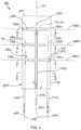
- the fiber optic force sensing assembly 92including the structural member 102 and a plurality of fiber optics 104 is depicted in an embodiment of the invention.
- the structural member 102defines a longitudinal axis 110 and includes an outer surface 112 .
- the structural member 102is divided into a plurality of segments 116 , identified in FIGS. 3 through 10 as a base segment 118 , a proximal segment 120 , a middle segment 122 and a distal segment 124 .
- the segments 116may be adjacent each other in a serial arrangement along the longitudinal axis 110 .
- the segments 116may be bridged by a plurality of flexure portions 128 , identified individually as flexure portions 128 a , 128 b and 128 c , thus defining a plurality of neutral axes 130 , identified individually as neutral axes 130 a , 130 b and 130 c .
- Each neutral axis 130constitutes the location within the respective flexure portion 128 that the stress is zero when subject to pure bending in any direction.
- adjacent members of the segments 116may define a plurality of gaps 136 , each having a separation dimension.
- the gaps 136are identified as 136 a through 136 c .
- the separation dimensions of the gaps 136 a , 136 b and 136 cmay be of the same approximate magnitude (as depicted) or of different magnitudes (not depicted). It is further noted that while the separation dimensions of the gaps 136 are depicted as being uniform, the separation dimension may vary in the lateral direction across a given gap 136 a , 136 b , 136 c .
- Each gap 136 a , 136 b and 136 cmay define a corresponding central plane 138 a , 138 b and 138 c located equidistant between adjacent ones of the segments 116 .
- the structural member 102may include a plurality of grooves 142 (identified in FIGS. 3 through 10 as grooves 142 a , 142 b and 142 c ) that are formed on the outer surface 112 .
- the grooves 142may be spaced rotationally equidistant (i.e. spaced 120° apart) about the longitudinal axis 110 and may be oriented in a substantially axial direction along the structural member 102 .
- Each of the groovesmay terminate at a respective one of the gaps 136 .
- the groove 142 amay extend along the base segment 118 , the proximal segment 120 and the middle segment 122 , terminating at the gap 136 a .
- groove 142 bmay extend along the base segment 118 and the proximal segment 120 , terminating at the gap 136 b .
- groove 142 cmay extend along the base segment 118 , terminating at the gap 136 c.
- the fiber optics 104(identified in FIGS. 3 through 10 as fiber optics 104 a , 104 b and 104 c ) define a plurality of light propagation axes 148 and distal ends 150 (identified in FIGS. 3 through 10 as distal ends 148 a through 148 c and 150 a through 150 c , respectively).
- the fiber optics 104may be disposed in the grooves 142 (identified in FIGS. 3 through 10 as 142 a , 142 b and 142 c ) such that the distal ends 150 terminate at the gaps 136 .
- the fiber optic 104 amay extend along the groove 142 a , terminating proximate or within the gap 136 a .
- fiber optics 104 b and 104 cmay extend along the grooves 142 b and 142 c , respectively, terminating proximate or within the gaps 136 b and 136 c , respectively.
- each of the light propagation axes 148 of the fiber optics 104are subtended by a respective one of the segments 116 .
- the light propagation axis 148 ais subtended by a surface 154 a of the distal segment 124 , which defines the boundary of the gap 136 a opposite the distal end 150 a .
- the surfaces 154 of the segments 116 that are proximate the subtended light propagation axes 148may be made highly reflective.
- the gaps 136may be formed so that they extend laterally through a major portion of the structural member 102 . Also, the gaps 136 may be oriented to extend substantially normal to the longitudinal axis 110 (as depicted) or at an acute angle with respect to the longitudinal axis.
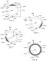
- the structural membercomprises a hollow cylindrical tube 156 with the gaps 136 comprising slots 158 that are formed from one side of the hollow cylindrical tube 156 and are transverse to the longitudinal axis 110 , extending through the longitudinal axis 110 and across the inner diameter 160 of the hollow cylindrical tube 156 to a depth 162 ( FIG. 5 ).
- the flexure portions 128remain, defining a circular segment.
- the depth 162 of the slots 158 traverse the inner diameter 160 of the hollow cylindrical tube 156can be varied to establish a desired flexibility of the flexure. That is, the greater the depth 162 the more flexible the flexure portion 128 .
- the slots 156may be formed by the various ways available to the artisan, such as but not limited to sawing, laser cutting or electro-discharge machining (EDM).
- the slots 158may be formed so that the flexure portions 128 define non-coincident neutral axes 130 . That is, neutral axis 130 a is located at a circumferential position about the longitudinal axis 110 that substantially differs from the circumferential position of the neutral axes 130 b and 130 c .
- the neutral axes 130may be, but need not be, diametrically opposed to the location of the distal end 150 of the fiber optic 104 that terminates in the same gap 136 as is bridged by the respective flexure portion 128 .
- flexure portion 128 amay be diametrically opposed to distal end 150 a , and so on.
- a cross-section 164 of the flexure portions 128is depicted in FIG. 9 .
- the cross-sectionis characterized by an area centroid C that corresponds with the neutral axis 130 , and as having inertial axes x-x and y-y that are orthogonal, and where the inertial axis x-x identifies the axis about which the area moment of inertia is minimum.
- the circular segment geometryprovides substantially greater stiffness about inertial axis y-y than about inertial axis x-x. Consider a circular segment having an angle of ⁇ /2 radians (90°).
- the area moment of inertia about the inertial axis y-yis about twenty times greater than the area moment of inertia about the inertial axis x-x. Accordingly, forces that cause a moment about inertial axis y-y will typically cause very little bending relative to the same moment being applied about inertial axis x-x. Therefore, moments about inertial axis y-y will tend to be transferred as a torsional force between adjacent sections, whereas moments about inertial axis x-x will tend to cause a deflection.
- a deflection beam length 163is defined as the distance between the neutral axis 130 and the center of the distal end 150 of the corresponding fiber optic 104 , the distance being normal to the inertial axis x-x.
- each gap 136enables an interferometric gap 166 to be defined between the distal end 150 of the respective fiber optic 104 and the high reflective surface 154 .
- An “interferometric gap” as used hereinis a gap having the attributes an interferometric resonator, such as found in a Michelson interferometer or a Fabry-Perot resonator.
- a “gap interferometer” as used hereinis an interferometer that utilizes an interferometric gap to produce an interference pattern.
- the interferometric gap 166may be characterized as having an operative length 167 , defined as the distance between the distal end 150 and the high reflective surface 154 and which may differ from the dimension of the respective gap 136 .
- the operative length 167establishes the characteristics of the interference pattern reflected back from the interferometric gap 166 .
- the distal ends 150may be faced with a semi-reflecting surface or coating 168 that re-reflects a portion of the light reflected from the high reflective surface 154 while substantially transmitting the remaining portion of the reflected light therethrough for detection by the strain sensing system 70 .
- lightis transmitted and reflected back across the respective gaps 136 , with the reflected light being collected by the distal end 150 of the respective fiber optic 104 .
- the intensity of the reflected light collected by a given fiber optic 104may vary with the distance between the distal end 150 and the high reflective surface 154 .
- Embodiments that utilize the variation of reflected light intensitymay utilize distal ends 150 that are exposed rather than face with the semi-reflecting surface or coating 168 , thereby increasing the amount of light that can be detected.
- the fiber optics 104are bonded to the structural member 102 with an adhesive or bonding material 170 .
- the fiber optics 104may be press fit or otherwise fastened to the structural member 102 .
- the fiber optic 104may be bonded to the segment 116 adjacent the respective gap 136 to be interrogated.
- fiber optic 104 bmay be mounted within the portion of groove 142 b that is formed on the middle segment 122 . The remainder of the fiber optic 104 b may be left to slide freely within the remainder of the groove 142 b . By this arrangement, the fiber optic 104 b will not form a structural bridge between adjacent segments, which would inhibit the flexibility of the fiber optic force sensing assembly 92 .
- FIGS. 11 A and 11 Boperation of the fiber optic force sensing assembly 92 in response to an axial force FA and a lateral force FL, respectively, is depicted in an embodiment of the invention.
- the axial force FAcauses the segments 116 to bend about the inertial axes x-x of the various flexure portions 128 in substantially a pure bending action, thus causing the dimension of the gaps 136 proximate the distal ends 150 of the fiber optics 104 to decrease ( FIG. 11 A ).
- Thiscauses the operative lengths 167 of the interferometric gaps 166 to decrease, thereby causing a change in the frequencies of the interferometric patterns sustained across the interferometric gaps 166 .
- the lateral force FLwill generally cause a more complex deformation of the structural member 102 .
- the lateral force FLis applied substantially parallel to the inertial axis y-y of flexure portion 128 a . This causes flexure portion 128 a to translate a moment between distal segment 124 and middle segment 122 while causing a negligible change in the dimension of gap 136 a .
- the translated momentcauses flexure portions 128 b and 128 c to bend about their respective inertial axes x-x, which in turn causes the gap 136 b to close proximate distal end 150 b of fiber optic 104 b and the gap 136 c to open proximate the distal end 150 c of fiber optic 104 c .
- neither flexure portion 128 b or 128 care in pure bending because lateral force FL does not act normal to the respective inertial axes x-x.
- the degree of bending about the inertial axes x-xwill generally be proportional to the component of the lateral force FL that acts normal thereto.
- FIGS. 11 A and 11 Bshow a purely axial and a purely lateral force, respectively, but that a combined force vector in three-dimensional space having an axial and a lateral component will combine the general effects depicted by superposition. Accordingly, a force vector in three-dimensional space can be resolved by calibrating the response of the fiber optic force sensing assembly under these pure loads and superimposing the various responses to infer the axial and lateral components.
- the characteristics of the modulated waveform 89 aare determined in part by the dimension of the interferometric gap 85 .
- the fiber optic force sensing assembly 92is configured so that the interferometric gap 85 will vary when the structural member 102 experiences an axial strain. A change in the axial strain will cause a proportional change in the dimension of the interferometric gap 85 , thereby altering the characteristic of the modulated waveform 89 a transmitted to the receiver 76 .
- the preceding embodimentscan provide a mechanical amplification of the change in the interferometric gap 85 relative to the strain experienced by the flexure portions 128 .
- the deflection of the segments 116 at a position normal to the inertial axis x-x of a respective one of the flexure portions 128is proportional to the deflection beam length 163 between the neutral axis 130 and the respective location of the distal end 150 of the respective fiber optic 104 . Accordingly, change in the dimension of the gap 136 will be greatest at a location that is diametrically opposed to the neutral axis 130 . Accordingly, for embodiments where the distal ends 150 of the fiber optics 104 in diametric opposition to the neutral axes 130 (as depicted herein), the fiber optics 104 are in a position of greatest sensitivity.
- the structural member 102may be fabricated from other forms besides a hollow cylindrical tube, including but not limited to tubes or rods that define a square, rectangular or cross-shaped cross-section.
- the structural member 102may comprise a metallic material, such as titanium or platinum/iridium, or a non-metallic material such as a polymer or ceramic.
- the gaps 136 and flexure portions 128may be sized so that the change in the operative lengths 167 due to application of forces FA and FL is of substantially higher sensitivity than the change caused thermal expansion or contraction of the structural member 102 under operation.
- the material for structural member 102may be selected to mitigate against the effects of thermal expansion.
- the structural member 102may be constructed of a material having a low coefficient of thermal expansion, such as fused quartz, aluminum oxides such as alumina (Al 2 O 3 ), liquid crystal polymer, or from metal/ceramic composites such as Invar designed to for a low coefficient of thermal expansion relative to metals.
- the adhesive or bonding material 170may comprise a glue or epoxy.
- the bonding material 170may be selected to closely match the coefficient of thermal expansion (CTE) of the structural member 102 and/or fiber optics 104 , or to provide a CTE that is between the CTEs of the structural member 102 and fiber optics 104 to provide a transition therebetween.
- the bonding material 170may also be chosen for flexibility so that the thermal growth of the adhesive film does not impose a substantial strain on the fiber optics 104 . Use of a very thin film of bonding material 170 may, in some instances, mitigate the effects of differential thermal expansion.
- the fiber optics 104may be bonded directly to the polymer using a bonding technique that involves the use of a solvent designed to cause the polymer to melt or flow while not affecting the material of the fiber optics 104 .
- the solventmay be applied to an area or zone of the structural member 102 where the fiber optics 104 are to be mounted, and the fiber optics 104 placed thereon.
- the fiber optics 104may be temporarily held in place on the zone or area of the structural member 102 and the solvent applied to both.
- the flowing of the materialcauses a bond between the structural member 102 and the outer surface of the fiber optics 104 .
- the solventmay be removed by a process such as washing or evaporation to arrest the melting process.
- the reflective surfaces 154may be fabricated by polishing a metallic structural member 102 , or by depositing a reflective material on either of a metallic or a non-metallic structural member 102 .
- Representative and non-limiting dimensions for the structural memberare approximately 1- to 10-mm in length, approximately 0.3- to 3-mm in diameter, and gap dimensions of approximately 15- to 100-micrometers.
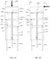
- a fiber optic force sensing assembly 192 including a structural member 196is depicted in an embodiment of the invention.
- the structural member 196includes many of the same aspects as the structural member 102 of FIGS. 3 through 9 , which are labeled in the respective figures with the same numerical references.
- the fiber optic force sensing assembly 192includes fiber optics 202 (identified in FIGS. 12 through 16 as fiber optics 202 a , 202 b and 202 c ) each operatively coupled to a respective one of a plurality of Fabry-Perot strain sensors 198 (identified as 198 a , 198 b and 198 c ).
- Fabry-Perot strain sensors of the general configuration presented in FIG. 12 Aare commercially available from FISO Technologies of Quebec, QC, Canada.
- the operation of the Fabry-Perot strain sensors 198is depicted in FIG. 12 A .
- the fiber optic 202is split into a transmitting element 204 a and a reflecting element 204 b , each being anchored at opposing ends of a hollow tube 206 .
- the transmitting and reflecting elements 204 a and 204 bare positioned to define an interferometric gap 205 therebetween having an operative length 207 .
- the free end of the transmitting element 204 amay be faced with a semi-reflecting surface 200 a
- the free end of the reflecting element 204 bmay be faced with a reflecting surface 200 b.
- the fiber optics 202may be positioned along the grooves 142 so that the respective Fabry-Perot strain sensor 198 is bridged between by the respective fiber optic 202 and across segments 116 that are adjacent each other.
- fiber optic 202 amay be positioned within groove 142 a so that the Fabry-Perot strain sensor 198 a bridges the gap 136 a between the middle segment 122 and the distal segment 124 .
- fiber optics 202 b and 202 cmay be positioned so that Fabry-Perot sensors 198 b and 198 c to bridge the gaps 136 b and 136 c , respectively.
- the fiber optic 202may be operatively coupled to both the adjacent segments 116 that the fiber optic 202 bridges.
- the fiber optics 202may be attached using the adhesive or bonding material 170 to the segments 116 , as best seen in FIGS. 14 through 16 .
- the bonding material 170is applied only to the segments 116 that are adjacent the gap 136 bridged by the fiber optic 202 .
- fiber optic 202 ais attached only to the middle and distal segments 122 and 124 ( FIGS. 14 and 15 ), but not to the proximal segment 120 ( FIG. 16 ) or the base segment 118 .
- the grooves 142may also extend the full length of the structural member 196 , as depicted in FIG. 12 , as there is no need for the structural member 196 to reflect light back into the fiber optics 202 .
- a fiber optic force sensing assembly 208is depicted in an embodiment of the invention.
- the fiber optic force sensing assembly 208utilizes fiber optics 202 having a fiber Bragg grating strain sensor 214 .
- the fiber optics 202are disposed on an interior surface 210 of a structural member 212 . Accordingly, the structural member 212 need not include grooves that run axially on the exterior surface. Otherwise, the fiber optics 202 are aligned along the length of the structural member 212 and attached to the interior surface 210 so that the fiber Bragg grating strain sensors 214 fixedly bridge adjacent segments 116 . Again, the fiber optics 202 may be affixed to the interior surface 212 using the bonding material 170 .
- the structural member 196 , 212In operation, when a force is applied at or near the distal extremity 94 of either of the structural members 196 or 212 , the structural member 196 , 212 will have a tendency to flex, for example, as depicted in FIGS. 11 A and 11 B .
- the fiber optics 202being fixedly attached to adjacent segments 116 causes a restorative or reactive force that limits deflection between the segments 116 of the structural member 196 .
- the reactive forceswhich may be a compressive force or a tension force, causes a strain across the strain sensors of the fiber optics 202 (Fabry-Perot strain sensors 198 of the fiber optic force sensing assembly 192 or fiber Bragg grating strain sensors 214 of the fiber optic force sensing assembly 208 ).
- the fiber optic force sensing assembly 192may be configured so that the axial force and strain exerted on the fiber optics 202 is at a desired level.
- the diameter of the fiber optics 202will have an effect on the strain imposed on the fiber Bragg grating strain sensor 214 , with smaller diameter fiber optics providing a greater strain per unit of axial force.
- the geometry of the flexure portions 128will affect the magnitude of the force that is transferred to the fiber optics 202 . That is, a flexure portion 128 having a greater stiffness (i.e. a greater area moment of inertia about the inertial axis x-x) will transfer less force to the respective fiber optic 202 .
- the magnitude of the reactive forcewill vary with the normal distance between the fiber optic 202 and the inertial axis x-x, with the reactive force generally increasing as the normal distance decreases.
- the reactive force for a single fiber optic located at the deflection beam length 163( FIG. 7 ) will be less than for a single fiber optic located on the structural element 102 that defines a normal distance between the optic 202 and the inertial axis x-x that is shorter than the deflection beam length 163 .
- the strain sensed by a fiber optic strain sensormay be tailored to provide a desired sensitivity.
- the ratio of the flexure axial force to the fiber optic axial forcecan range from 0.2 to 5.
- the depicted embodimentspresent a single fiber optic diametrically opposed to the neutral axis of a respective flexure (e.g., fiber optic 202 a in diametric opposition to neutral axis 130 a ), the invention is not so limited.
- the fiber optics of the various embodimentsmay be located on the structural body at a location other than diametric opposition with respect to the neutral axis of a given flexure.
- the number of fiber optics utilized for detecting the forces exertedmay be greater than one.
- a configuration utilizing a fiber optic strain sensormay include a pair of fiber optic strain sensors, each located at a circumferential location on the structural member that defines restorative moment arms about the inertial axis x-x that are of equal magnitude. It is further noted that the Fabry-Perot detection schemes and the fiber Bragg grating detection schemes may each be present on the same fiber optic force sensing assembly.
- the straincauses the interferometric gap of the Fabry-Perot strain sensor 198 to change and the frequency of the returned modulated waveform to shift in frequency.
- the frequency changecan be calibrated to correspond to the reactive force using known techniques.
- the straincauses a shift in the central wavelength of the light that is reflected by the respective fiber Bragg grating strain sensor 214 , which can be calibrated to correspond to the reactive force using known techniques.
- the inventionmay be practiced in other embodiments not disclosed herein, such as endoscopic or additional intravascular applications.
- various aspects of the disclosed embodimentsmay be utilized in a diagnostic catheter for optimizing or otherwise improving the placement of excitation electrodes for baroreflex activation.
- Other aspects of the disclosed embodimentsmay find application in endoscopic applications, such as orthoscopic surgery or entry through open orifices such as the throat, nose or anus without departing from the spirit of the invention.
Landscapes
- Health & Medical Sciences (AREA)
- Life Sciences & Earth Sciences (AREA)
- Surgery (AREA)
- Engineering & Computer Science (AREA)
- Biomedical Technology (AREA)
- Heart & Thoracic Surgery (AREA)
- Animal Behavior & Ethology (AREA)
- General Health & Medical Sciences (AREA)
- Public Health (AREA)
- Veterinary Medicine (AREA)
- Molecular Biology (AREA)
- Medical Informatics (AREA)
- Biophysics (AREA)
- Physics & Mathematics (AREA)
- Pathology (AREA)
- Nuclear Medicine, Radiotherapy & Molecular Imaging (AREA)
- Anesthesiology (AREA)
- Pulmonology (AREA)
- Hematology (AREA)
- Cardiology (AREA)
- Optics & Photonics (AREA)
- Radiology & Medical Imaging (AREA)
- Otolaryngology (AREA)
- Plasma & Fusion (AREA)
- Oral & Maxillofacial Surgery (AREA)
- General Physics & Mathematics (AREA)
- Vascular Medicine (AREA)
- Physiology (AREA)
- Length Measuring Devices By Optical Means (AREA)
- Endoscopes (AREA)
- Instruments For Viewing The Inside Of Hollow Bodies (AREA)
Abstract
Description
Claims (20)
Priority Applications (1)
| Application Number | Priority Date | Filing Date | Title |
|---|---|---|---|
| US16/781,682US11883131B2 (en) | 2006-06-09 | 2020-02-04 | Triaxial fiber optic force sensing catheter |
Applications Claiming Priority (6)
| Application Number | Priority Date | Filing Date | Title |
|---|---|---|---|
| US11/450,072US8048063B2 (en) | 2006-06-09 | 2006-06-09 | Catheter having tri-axial force sensor |
| US14371809P | 2009-01-09 | 2009-01-09 | |
| US12/352,426US8567265B2 (en) | 2006-06-09 | 2009-01-12 | Triaxial fiber optic force sensing catheter |
| US14/064,898US9597036B2 (en) | 2006-06-09 | 2013-10-28 | Triaxial fiber optic force sensing catheter and method of use |
| US15/424,914US10596346B2 (en) | 2006-06-09 | 2017-02-06 | Triaxial fiber optic force sensing catheter |
| US16/781,682US11883131B2 (en) | 2006-06-09 | 2020-02-04 | Triaxial fiber optic force sensing catheter |
Related Parent Applications (1)
| Application Number | Title | Priority Date | Filing Date |
|---|---|---|---|
| US15/424,914DivisionUS10596346B2 (en) | 2006-06-09 | 2017-02-06 | Triaxial fiber optic force sensing catheter |
Publications (2)
| Publication Number | Publication Date |
|---|---|
| US20200171272A1 US20200171272A1 (en) | 2020-06-04 |
| US11883131B2true US11883131B2 (en) | 2024-01-30 |
Family
ID=42136136
Family Applications (4)
| Application Number | Title | Priority Date | Filing Date |
|---|---|---|---|
| US12/352,426Active2030-01-24US8567265B2 (en) | 2006-06-09 | 2009-01-12 | Triaxial fiber optic force sensing catheter |
| US14/064,898Active2027-12-12US9597036B2 (en) | 2006-06-09 | 2013-10-28 | Triaxial fiber optic force sensing catheter and method of use |
| US15/424,914Active2026-06-15US10596346B2 (en) | 2006-06-09 | 2017-02-06 | Triaxial fiber optic force sensing catheter |
| US16/781,682Active2029-02-06US11883131B2 (en) | 2006-06-09 | 2020-02-04 | Triaxial fiber optic force sensing catheter |
Family Applications Before (3)
| Application Number | Title | Priority Date | Filing Date |
|---|---|---|---|
| US12/352,426Active2030-01-24US8567265B2 (en) | 2006-06-09 | 2009-01-12 | Triaxial fiber optic force sensing catheter |
| US14/064,898Active2027-12-12US9597036B2 (en) | 2006-06-09 | 2013-10-28 | Triaxial fiber optic force sensing catheter and method of use |
| US15/424,914Active2026-06-15US10596346B2 (en) | 2006-06-09 | 2017-02-06 | Triaxial fiber optic force sensing catheter |
Country Status (5)
| Country | Link |
|---|---|
| US (4) | US8567265B2 (en) |
| EP (1) | EP2385802B1 (en) |
| JP (2) | JP5416225B2 (en) |
| CN (1) | CN102341053B (en) |
| WO (1) | WO2010079418A1 (en) |
Families Citing this family (177)
| Publication number | Priority date | Publication date | Assignee | Title |
|---|---|---|---|---|
| US8545488B2 (en) | 2004-09-17 | 2013-10-01 | The Spectranetics Corporation | Cardiovascular imaging system |
| US20100312129A1 (en) | 2005-01-26 | 2010-12-09 | Schecter Stuart O | Cardiovascular haptic handle system |
| US8075498B2 (en) | 2005-03-04 | 2011-12-13 | Endosense Sa | Medical apparatus system having optical fiber load sensing capability |
| US8182433B2 (en)* | 2005-03-04 | 2012-05-22 | Endosense Sa | Medical apparatus system having optical fiber load sensing capability |
| US8496647B2 (en) | 2007-12-18 | 2013-07-30 | Intuitive Surgical Operations, Inc. | Ribbed force sensor |
| EP2363073B1 (en) | 2005-08-01 | 2015-10-07 | St. Jude Medical Luxembourg Holding S.à.r.l. | Medical apparatus system having optical fiber load sensing capability |
| US8672936B2 (en)* | 2005-10-13 | 2014-03-18 | St. Jude Medical, Atrial Fibrillation Division, Inc. | Systems and methods for assessing tissue contact |
| US8406901B2 (en)* | 2006-04-27 | 2013-03-26 | Medtronic, Inc. | Sutureless implantable medical device fixation |
| US8567265B2 (en)* | 2006-06-09 | 2013-10-29 | Endosense, SA | Triaxial fiber optic force sensing catheter |
| US8048063B2 (en)* | 2006-06-09 | 2011-11-01 | Endosense Sa | Catheter having tri-axial force sensor |
| US9492657B2 (en)* | 2006-11-30 | 2016-11-15 | Medtronic, Inc. | Method of implanting a medical device including a fixation element |
| US8622935B1 (en) | 2007-05-25 | 2014-01-07 | Endosense Sa | Elongated surgical manipulator with body position and distal force sensing |
| DE102007037262B3 (en)* | 2007-08-07 | 2008-12-04 | Deutsches Zentrum für Luft- und Raumfahrt e.V. | Force moment sensor for robot hand finger tip, has glass fibers fixed in platforms and receiving only longitudinal forces when orthogonal forces are exerted on platform while another platform is fixed, where fibers are applied with coating |
| US8561473B2 (en) | 2007-12-18 | 2013-10-22 | Intuitive Surgical Operations, Inc. | Force sensor temperature compensation |
| US8298227B2 (en)* | 2008-05-14 | 2012-10-30 | Endosense Sa | Temperature compensated strain sensing catheter |
| US8491574B2 (en)* | 2009-03-30 | 2013-07-23 | Intuitive Surgical Operations, Inc. | Polarization and temperature insensitive surgical instrument force transducer |
| EP2467689B1 (en)* | 2009-08-21 | 2019-12-25 | St. Jude Medical, Cardiology Division, Inc. | Flexible sensors and related systems for determining forces applied to an object, such as a surgical instrument |
| WO2011033421A1 (en) | 2009-09-15 | 2011-03-24 | Koninklijke Philips Electronics N.V. | Medical ultrasound device with force detection |
| US8906013B2 (en) | 2010-04-09 | 2014-12-09 | Endosense Sa | Control handle for a contact force ablation catheter |
| US8380276B2 (en)* | 2010-08-16 | 2013-02-19 | Biosense Webster, Inc. | Catheter with thin film pressure sensing distal tip |
| US8736212B2 (en) | 2010-12-16 | 2014-05-27 | St. Jude Medical, Atrial Fibrillation Division, Inc. | System and method of automatic detection and prevention of motor runaway |
| US10112045B2 (en) | 2010-12-29 | 2018-10-30 | Medtronic, Inc. | Implantable medical device fixation |
| US9775982B2 (en) | 2010-12-29 | 2017-10-03 | Medtronic, Inc. | Implantable medical device fixation |
| EP2491883B1 (en)* | 2011-02-24 | 2014-06-18 | VascoMed GmbH | Catheter and catheter arrangement |
| US8942828B1 (en) | 2011-04-13 | 2015-01-27 | Stuart Schecter, LLC | Minimally invasive cardiovascular support system with true haptic coupling |
| CN103607961B (en)* | 2011-04-14 | 2016-12-14 | 圣犹达医疗用品卢森堡控股有限公司 | Compact force sensor for conduit |
| US9510786B2 (en)* | 2011-06-22 | 2016-12-06 | Biosense Webster (Israel) Ltd. | Optical pressure measurement |
| US9014789B2 (en) | 2011-09-22 | 2015-04-21 | The George Washington University | Systems and methods for visualizing ablated tissue |
| AU2012312066C1 (en) | 2011-09-22 | 2016-06-16 | 460Medical, Inc. | Systems and methods for visualizing ablated tissue |
| EP2586363A1 (en) | 2011-10-24 | 2013-05-01 | VascoMed GmbH | Catheter and catheter system |
| KR101839444B1 (en)* | 2011-10-31 | 2018-04-27 | 삼성전자 주식회사 | Force sensing apparatus and robot arm including the force sensing apparatus |
| KR101912716B1 (en)* | 2011-11-01 | 2018-10-30 | 삼성전자주식회사 | Robot arm including force sensing apparatus |
| CA2855704C (en) | 2011-11-14 | 2019-05-07 | Commonwealth Scientific And Industrial Research Organisation | An optical sensing apparatus |
| US20140257139A1 (en)* | 2011-11-16 | 2014-09-11 | Commonwealth Scientific And Industrial Research Organisation | Optical sensing device |
| JP6441679B2 (en) | 2011-12-09 | 2018-12-19 | メタベンション インコーポレイテッド | Therapeutic neuromodulation of the liver system |
| US9039700B2 (en)* | 2011-12-29 | 2015-05-26 | St. Jude Medical, Atrial Fibrillation Division, Inc. | Irrigated ablation catheter with contact force sensing mechanism |
| CN103239241A (en)* | 2012-02-07 | 2013-08-14 | 森斯奥普蒂克股份公司 | Optical force measuring element and microsurgical device |
| EP2626680B1 (en) | 2012-02-07 | 2015-10-07 | Sensoptic SA | Optical force sensing element and microsurgical instrument |
| US9854982B2 (en) | 2012-03-26 | 2018-01-02 | Medtronic, Inc. | Implantable medical device deployment within a vessel |
| US9220906B2 (en) | 2012-03-26 | 2015-12-29 | Medtronic, Inc. | Tethered implantable medical device deployment |
| US9717421B2 (en) | 2012-03-26 | 2017-08-01 | Medtronic, Inc. | Implantable medical device delivery catheter with tether |
| US9339197B2 (en) | 2012-03-26 | 2016-05-17 | Medtronic, Inc. | Intravascular implantable medical device introduction |
| US10485435B2 (en) | 2012-03-26 | 2019-11-26 | Medtronic, Inc. | Pass-through implantable medical device delivery catheter with removeable distal tip |
| US9833625B2 (en) | 2012-03-26 | 2017-12-05 | Medtronic, Inc. | Implantable medical device delivery with inner and outer sheaths |
| US10022190B2 (en) | 2012-04-04 | 2018-07-17 | Universite Libre De Bruxelles | Optical force transducer |
| US8945113B2 (en)* | 2012-04-05 | 2015-02-03 | Covidien Lp | Electrosurgical tissue ablation systems capable of detecting excessive bending of a probe and alerting a user |
| SG194305A1 (en)* | 2012-04-16 | 2013-11-29 | Agency Science Tech & Res | Guide wire arrangement |
| US10013082B2 (en) | 2012-06-05 | 2018-07-03 | Stuart Schecter, LLC | Operating system with haptic interface for minimally invasive, hand-held surgical instrument |
| US9023039B2 (en)* | 2012-07-19 | 2015-05-05 | Covidien Lp | Electrosurgical device including an optical sensor |
| FR2993656B1 (en)* | 2012-07-23 | 2015-05-15 | Lasstec | DEVICE FOR PERIPHERAL MEASUREMENT OF CONSTRAINTS |
| US9351648B2 (en) | 2012-08-24 | 2016-05-31 | Medtronic, Inc. | Implantable medical device electrode assembly |
| EP2703797A1 (en)* | 2012-08-30 | 2014-03-05 | Nederlandse Organisatie voor toegepast -natuurwetenschappelijk onderzoek TNO | Pressure sensing assembly |
| EP2711676B1 (en)* | 2012-09-20 | 2020-10-07 | VascoMed GmbH | Fiber-optic force sensor, force measurement device and catheter |
| WO2014138095A1 (en)* | 2013-03-04 | 2014-09-12 | The Board Of Trustees Of The Leland Stanford Junior University | Apparatuses involving elongated-medical instrument for sensing tissue interaction forces |
| US9623211B2 (en) | 2013-03-13 | 2017-04-18 | The Spectranetics Corporation | Catheter movement control |
| US11642169B2 (en) | 2013-03-14 | 2023-05-09 | The Spectranetics Corporation | Smart multiplexed medical laser system |
| US9757200B2 (en) | 2013-03-14 | 2017-09-12 | The Spectranetics Corporation | Intelligent catheter |
| US10758308B2 (en) | 2013-03-14 | 2020-09-01 | The Spectranetics Corporation | Controller to select optical channel parameters in a catheter |
| US9174024B1 (en) | 2013-03-15 | 2015-11-03 | St. Jude Medical Luxembourg Holdings S.À.R.L. | Steering control mechanisms for catheters |
| US9066726B2 (en)* | 2013-03-15 | 2015-06-30 | Medtronic Ardian Luxembourg S.A.R.L. | Multi-electrode apposition judgment using pressure elements |
| US9095682B2 (en) | 2013-04-30 | 2015-08-04 | St. Jude Medical Luxembourg Holding S.À.R.L. | Control handles for catheters |
| AU2014274903B2 (en) | 2013-06-05 | 2019-03-07 | Medtronic Ireland Manufacturing Unlimited Company | Modulation of targeted nerve fibers |
| CN104248471B (en)* | 2013-06-27 | 2016-09-07 | 中国科学院沈阳自动化研究所 | A kind of robot assisted beveled tip flexible needle lancing system and method |
| CN104586499B (en)* | 2013-10-30 | 2016-11-23 | 上海微创电生理医疗科技有限公司 | A kind of catheter |
| JP6737705B2 (en) | 2013-11-14 | 2020-08-12 | ザ・ジョージ・ワシントン・ユニバーシティThe George Washingtonuniversity | Method of operating system for determining depth of injury site and system for generating images of heart tissue |
| JP2017500550A (en) | 2013-11-20 | 2017-01-05 | ザ・ジョージ・ワシントン・ユニバーシティThe George Washingtonuniversity | System and method for hyperspectral analysis of cardiac tissue |
| US10299826B2 (en)* | 2013-12-18 | 2019-05-28 | Sensoptic Sa | Needle for invasive medical use and needle assembly |
| US10987168B2 (en) | 2014-05-29 | 2021-04-27 | Spectranetics Llc | System and method for coordinated laser delivery and imaging |
| US9549781B2 (en)* | 2014-05-30 | 2017-01-24 | The Johns Hopkins University | Multi-force sensing surgical instrument and method of use for robotic surgical systems |
| CN105310768B (en)* | 2014-07-31 | 2017-11-24 | 乐普(北京)医疗器械股份有限公司 | Based on the method that multiple sensors are encapsulated on deformation of guide tube body |
| CN107072738A (en)* | 2014-09-30 | 2017-08-18 | 皇家飞利浦有限公司 | Fiber triggering with optical shape sensing |
| EP3215001A4 (en) | 2014-11-03 | 2018-04-04 | Luxcath, LLC | Systems and methods for assessment of contact quality |
| KR102499045B1 (en) | 2014-11-03 | 2023-02-10 | 더 조지 워싱턴 유니버시티 | Systems and methods for lesion assessment |
| CA2969129A1 (en) | 2014-12-03 | 2016-06-09 | Metavention, Inc. | Systems and methods for modulating nerves or other tissue |
| US10646275B2 (en) | 2014-12-30 | 2020-05-12 | Regents Of The University Of Minnesota | Laser catheter with use of determined material type in vascular system in ablation of material |
| US10646274B2 (en)* | 2014-12-30 | 2020-05-12 | Regents Of The University Of Minnesota | Laser catheter with use of reflected light and force indication to determine material type in vascular system |
| US10646118B2 (en) | 2014-12-30 | 2020-05-12 | Regents Of The University Of Minnesota | Laser catheter with use of reflected light to determine material type in vascular system |
| US9810594B2 (en) | 2015-01-08 | 2017-11-07 | Kulite Semiconductor Products, Inc. | Thermally stable high temperature pressure and acceleration optical interferometric sensors |
| US9952067B2 (en) | 2015-05-06 | 2018-04-24 | Kulite Semiconductor Products, Inc. | Systems and methods for optical measurements using multiple beam interferometric sensors |
| CN104596686B (en)* | 2015-01-09 | 2017-05-10 | 吉林大学 | Drilling type three-dimensional ground stress monitoring sensing device based on optical fiber sensing technology |
| US10564057B2 (en) | 2015-03-23 | 2020-02-18 | Farrokh Janabi-Sharifi | Temperature invariant force and torque sensor assemblies |
| US10492871B2 (en)* | 2015-05-01 | 2019-12-03 | Intuitive Surgical Operations, Inc. | Fiber management in medical instrument backend |
| US10378883B2 (en) | 2015-05-15 | 2019-08-13 | Intuitive Surgical Operations, Inc. | Force sensing in a distal region of an instrument including single-core or multi-core optical fiber |
| CN106175922A (en)* | 2015-05-27 | 2016-12-07 | 乐普(北京)医疗器械股份有限公司 | A kind of method measuring catheter pressure stress |
| EP3304017B1 (en)* | 2015-05-29 | 2021-10-13 | Ablacon Inc. | Elongated medical device suitable for intravascular insertion and optical force sensing assembly for an elongated medical device |
| EP3321046B1 (en)* | 2015-07-09 | 2020-03-18 | Kawasaki Jukogyo Kabushiki Kaisha | Turning device and medical instrument |
| US10779904B2 (en) | 2015-07-19 | 2020-09-22 | 460Medical, Inc. | Systems and methods for lesion formation and assessment |
| WO2017041889A2 (en)* | 2015-09-07 | 2017-03-16 | Ablacon Inc. | Elongated medical device suitable for intravascular insertion and method of making an elongated medical device suitable for intravascular insertion |
| US10507056B2 (en) | 2015-10-01 | 2019-12-17 | General Electric Company | System and method for representation and visualization of catheter applied force and power |
| CN105343984A (en)* | 2015-10-14 | 2016-02-24 | 乐普(北京)医疗器械股份有限公司 | Guide wire |
| US10231789B2 (en)* | 2015-12-18 | 2019-03-19 | Biosense Webster (Israel) Ltd. | Using force sensor to give angle of ultrasound beam |
| US11445937B2 (en)* | 2016-01-07 | 2022-09-20 | St. Jude Medical International Holding S.À R.L. | Medical device with multi-core fiber for optical sensing |
| US10234344B2 (en) | 2016-02-04 | 2019-03-19 | Ofs Fitel, Llc | Compact multicore fiberoptic device for sensing components of force |
| CN109069840B (en) | 2016-02-04 | 2022-03-15 | 心脏起搏器股份公司 | Delivery system with force sensor for leadless cardiac devices |
| US10524859B2 (en) | 2016-06-07 | 2020-01-07 | Metavention, Inc. | Therapeutic tissue modulation devices and methods |
| US10905329B2 (en) | 2016-06-09 | 2021-02-02 | Biosense Webster (Israel) Ltd. | Multi-function conducting elements for a catheter |
| WO2018035122A1 (en) | 2016-08-16 | 2018-02-22 | Intuitive Surgical Operations, Inc. | Augmented accuracy using large diameter shape fiber |
| US10245115B2 (en) | 2016-09-06 | 2019-04-02 | Intuitive Surgical Operations, Inc. | Fiber optic sensing of tool strain or tool angle |
| US11911093B2 (en) | 2016-09-12 | 2024-02-27 | Biosense Webster (Israel) Ltd. | Irrigation system for a catheter |
| US20180071009A1 (en)* | 2016-09-12 | 2018-03-15 | Biosense Webster (Israel) Ltd. | Ablation catheter with strain gauges |
| US11013556B2 (en)* | 2016-09-26 | 2021-05-25 | St. Jude Medical, Cardiology Division, Inc. | Cardiac catheter with deformable body |
| US11045109B2 (en) | 2016-10-26 | 2021-06-29 | St. Jude Medical, Cardiology Division, Inc. | Navigational electrode with magnetic tracking coil |
| WO2018142350A1 (en) | 2017-02-03 | 2018-08-09 | St. Jude Medical International Holding S.á r.l. | Optical force sensing catheter system |
| KR102116164B1 (en) | 2017-02-03 | 2020-05-27 | 재단법인 아산사회복지재단 | System and method for three-dimensional mapping of heart using sensing information of catheter |
| US11259778B2 (en) | 2017-03-22 | 2022-03-01 | Boston Scientific Scimed Inc. | All optical atrial ablation device |
| EP3600012B1 (en) | 2017-03-23 | 2024-09-18 | The General Hospital Corporation | Apparatus for in situ three-dimensional reconstruction of luminal structures |
| US12029545B2 (en) | 2017-05-30 | 2024-07-09 | Biosense Webster (Israel) Ltd. | Catheter splines as location sensors |
| US10768061B2 (en)* | 2017-06-27 | 2020-09-08 | Fibos Inc. | Optical sensor having π-phase shifted Bragg grating and optical sensing system using same |
| KR102054551B1 (en)* | 2017-08-02 | 2019-12-12 | 재단법인 아산사회복지재단 | Catheter using the fbg optical fiber for shape and contact force sensing and catheter system thereby |
| JP6924287B2 (en) | 2017-08-02 | 2021-08-25 | セント・ジュード・メディカル・インターナショナル・ホールディング・エスエーアールエルSt. Jude Medical International Holding S.a,r.l. | Optical force detection catheter system |
| KR102030237B1 (en)* | 2017-08-02 | 2019-10-08 | 재단법인 아산사회복지재단 | Catheter using the optical fiber for force sensing and catheter system thereby |
| US12161393B2 (en) | 2018-03-13 | 2024-12-10 | St. Jude Medical International Holding S.á r.l. | Force sensing catheter system |
| CN108433814B (en)* | 2018-03-16 | 2019-12-24 | 微创(上海)医疗机器人有限公司 | Surgical robot system and surgical instrument thereof |
| WO2019193545A1 (en) | 2018-04-05 | 2019-10-10 | St. Jude Medical International Holding S.À R.L | Force sensing catheter system |
| US20190314083A1 (en) | 2018-04-11 | 2019-10-17 | Biosense Webster (Israel) Ltd. | Flexible Multi-Arm Catheter with Diametrically Opposed Sensing Electrodes |
| US11857268B2 (en)* | 2018-05-02 | 2024-01-02 | Koninklijke Philips N.V. | Optical shape sensing device with integrated force sensing region and tip integration |
| EP4218643B1 (en)* | 2018-06-08 | 2025-07-16 | St. Jude Medical International Holding S.à r.l. | One fiber force and shape sensing |
| US10874850B2 (en) | 2018-09-28 | 2020-12-29 | Medtronic, Inc. | Impedance-based verification for delivery of implantable medical devices |
| DE18205821T1 (en) | 2018-11-13 | 2020-12-24 | Gtx Medical B.V. | CONTROL SYSTEM FOR MOTION RECONSTRUCTION AND / OR RECOVERY FOR A PATIENT |
| US11045628B2 (en) | 2018-12-11 | 2021-06-29 | Biosense Webster (Israel) Ltd. | Balloon catheter with high articulation |
| US11207016B2 (en) | 2018-12-28 | 2021-12-28 | Biosense Webster (Israel) Ltd. | Mapping ECG signals using a multipole electrode assembly |
| WO2020171998A2 (en) | 2019-02-21 | 2020-08-27 | St. Jude Medical, Cardiology Division, Inc. | Systems and methods for assessing ablation lesions |
| EP4243578A3 (en) | 2019-03-27 | 2023-10-25 | St. Jude Medical, Cardiology Division, Inc. | Ablation catheter tip with flexible electronic circuitry |
| WO2020194216A1 (en) | 2019-03-27 | 2020-10-01 | St. Jude Medical, Cardiology Division, Inc. | Ablation catheter tip with flexible electronic circuitry |
| EP3927266A1 (en) | 2019-04-10 | 2021-12-29 | St. Jude Medical International Holding S.à r.l. | Ablation catheter tip with flexible electronic circuitry |
| US20200323585A1 (en) | 2019-04-10 | 2020-10-15 | St. Jude Medical International Holding S.À R.L. | Ablation catheter tip with flexible electronic circuitry |
| US11357570B2 (en)* | 2019-04-19 | 2022-06-14 | Lake Region Manufacturing, Inc. | Ablation catheter with fiber Bragg grating strain sensors |
| US11850051B2 (en) | 2019-04-30 | 2023-12-26 | Biosense Webster (Israel) Ltd. | Mapping grid with high density electrode array |
| US11331475B2 (en) | 2019-05-07 | 2022-05-17 | Medtronic, Inc. | Tether assemblies for medical device delivery systems |
| US12151100B2 (en) | 2019-05-07 | 2024-11-26 | Medtronic, Inc. | Tether assemblies for medical device delivery systems |
| US11712172B2 (en) | 2019-07-18 | 2023-08-01 | Biosense Webster (Israel) Ltd. | Visual guidance for positioning a distal end of a medical probe |
| EP3972510A1 (en) | 2019-08-29 | 2022-03-30 | St. Jude Medical, Cardiology Division, Inc. | Force sensing catheter including sealed electrode tip assembly and methods of assembling same |
| CN110631745B (en)* | 2019-09-23 | 2021-10-22 | 桂林电子科技大学 | Pressure sensing element and pressure sensing system |
| US11079292B2 (en)* | 2019-10-15 | 2021-08-03 | Futek Advanced Sensor Technology, Inc. | Guide jacket force sensor |
| US11963798B2 (en) | 2019-11-14 | 2024-04-23 | Medtronic, Inc. | Optical force sensor with a catheter/sheath |
| EP4017391A1 (en) | 2019-11-26 | 2022-06-29 | St. Jude Medical, Cardiology Division, Inc. | Ablation catheter tip with flexible electronic circuitry |
| WO2021105903A1 (en) | 2019-11-26 | 2021-06-03 | St. Jude Medical, Cardiology Division, Inc. | Ablation catheter tip with flexible electronic circuitry |
| US11950930B2 (en) | 2019-12-12 | 2024-04-09 | Biosense Webster (Israel) Ltd. | Multi-dimensional acquisition of bipolar signals from a catheter |
| CN111397773B (en)* | 2019-12-17 | 2021-07-30 | 浙江工业大学 | A kind of flexible fingertip touch sensor and preparation method thereof |
| US11517218B2 (en) | 2019-12-20 | 2022-12-06 | Biosense Webster (Israel) Ltd. | Selective graphical presentation of electrophysiological parameters |
| EP4087511A4 (en) | 2020-01-08 | 2024-02-14 | 460Medical, Inc. | Systems and methods for optical interrogation of ablation lesions |
| US11086073B2 (en) | 2020-01-10 | 2021-08-10 | Lake Region Manufacturing, Inc. | Guidewire having a fiber optic force sensor with a mirror having a patterned reflectance |
| US11474310B2 (en) | 2020-02-28 | 2022-10-18 | Bard Access Systems, Inc. | Optical connection systems and methods thereof |
| CN215461207U (en) | 2020-02-28 | 2022-01-11 | 巴德阿克塞斯系统股份有限公司 | Catheter and medical instrument monitoring system |
| CN113332561A (en) | 2020-03-03 | 2021-09-03 | 巴德阿克塞斯系统股份有限公司 | System and method for optical shape sensing and electrical signal conduction |
| WO2021202589A1 (en) | 2020-03-30 | 2021-10-07 | Bard Access Systems, Inc. | Optical and electrical diagnostic systems and methods thereof |
| CN111637956B (en)* | 2020-05-25 | 2021-11-16 | 湖北交投智能检测股份有限公司 | Bridge span monitoring system and monitoring method based on polarized light |
| US12232874B2 (en) | 2020-05-29 | 2025-02-25 | Biosense Webster (Israel) Ltd. | Electrode apparatus for diagnosis of arrhythmias |
| CN111839442B (en)* | 2020-06-08 | 2021-09-07 | 北京交通大学 | A fiber grating sensor and flexible ureteroscope |
| US11987017B2 (en) | 2020-06-08 | 2024-05-21 | Biosense Webster (Israel) Ltd. | Features to assist in assembly and testing of devices |
| FR3111980B1 (en)* | 2020-06-25 | 2022-07-01 | Safran | METHOD AND DEVICE FOR PHYSICAL MEASUREMENT OF ENVIRONMENTAL AND OPERATIONAL CONDITIONS |
| US11585712B2 (en) | 2020-08-21 | 2023-02-21 | Simmonds Precision Products, Inc. | Fiber optic load sensors and systems therefor |
| US12048479B2 (en) | 2020-09-10 | 2024-07-30 | Biosense Webster (Israel) Ltd. | Surface mounted electrode catheter |
| US11950841B2 (en) | 2020-09-22 | 2024-04-09 | Biosense Webster (Israel) Ltd. | Basket catheter having insulated ablation electrodes and diagnostic electrodes |
| US11950840B2 (en) | 2020-09-22 | 2024-04-09 | Biosense Webster (Israel) Ltd. | Basket catheter having insulated ablation electrodes |
| US12082875B2 (en) | 2020-09-24 | 2024-09-10 | Biosense Webster (Israel) Ltd | Balloon catheter having a coil for sensing tissue temperature and position of the balloon |
| US11974803B2 (en) | 2020-10-12 | 2024-05-07 | Biosense Webster (Israel) Ltd. | Basket catheter with balloon |
| CN114344514A (en) | 2020-10-13 | 2022-04-15 | 巴德阿克塞斯系统股份有限公司 | Disinfection enclosure for fiber optic connectors and method thereof |
| US11585706B2 (en) | 2020-10-14 | 2023-02-21 | Lake Region Manufacturing, Inc. | Guidewire with fiber Bragg grating strain sensors |
| CN114518075A (en) | 2020-11-18 | 2022-05-20 | 巴德阿克塞斯系统股份有限公司 | fiber optic stylet holder |
| WO2022115624A1 (en) | 2020-11-24 | 2022-06-02 | Bard Access Systems, Inc. | Steerable fiber optic shape sensing enabled elongated medical instrument |
| US12201786B2 (en) | 2020-12-17 | 2025-01-21 | Biosense Webster (Israel) Ltd. | Measurement of distal end dimension of catheters using magnetic fields |
| US11918383B2 (en) | 2020-12-21 | 2024-03-05 | Biosense Webster (Israel) Ltd. | Visualizing performance of catheter electrodes |
| US12064170B2 (en) | 2021-05-13 | 2024-08-20 | Biosense Webster (Israel) Ltd. | Distal assembly for catheter with lumens running along spines |
| US12364426B2 (en) | 2021-08-12 | 2025-07-22 | Biosense Webster (Israel) Ltd. | Electro-anatomical mapping and annotation presented in electrophysiological procedures |
| US12004804B2 (en) | 2021-09-09 | 2024-06-11 | Biosense Webster (Israel) Ltd. | Basket catheter with mushroom shape distal tip |
| US12011280B2 (en) | 2021-10-04 | 2024-06-18 | Biosense Webster (Israel) Ltd. | Electrophysiological mapping in the presence of injury current |
| US12419683B2 (en) | 2021-12-22 | 2025-09-23 | Biosense Webster (Israel) Ltd. | Irreversible electroporation with shorted electrodes |
| US12318149B2 (en) | 2022-03-08 | 2025-06-03 | Bard Access Systems, Inc. | Medical shape sensing devices and systems |
| US12426956B2 (en) | 2022-03-16 | 2025-09-30 | Bard Access Systems, Inc. | Medical system and method for monitoring medical device insertion and illumination patterns |
| US12089815B2 (en)* | 2022-03-17 | 2024-09-17 | Bard Access Systems, Inc. | Fiber optic medical systems and devices with atraumatic tip |
| CN114858336B (en)* | 2022-05-17 | 2023-12-01 | 重庆交通大学 | Low-coupling fiber grating three-dimensional force sensor |
| CN115290243B (en)* | 2022-07-19 | 2024-10-29 | 天津大学 | Three-dimensional force sensor and measuring system for minimally invasive surgery |
| CN115500930A (en)* | 2022-09-14 | 2022-12-23 | 苏州艾科脉医疗技术有限公司 | A kind of ablation catheter, ablation device and ablation system |
| CN116973009A (en)* | 2023-09-04 | 2023-10-31 | 北京佰为深科技发展有限公司 | Force sensor and force sensing catheter |
| CN117309217B (en)* | 2023-09-28 | 2024-09-13 | 明澈生物科技(苏州)有限公司 | Guide wire tip three-dimensional force sensor based on Fabry-Perot interference microcavity |
| WO2025152925A1 (en)* | 2024-01-15 | 2025-07-24 | 北京佰为深科技发展有限公司 | Force sensor, force sensing catheter, ablation device and medical apparatus |
Citations (163)
| Publication number | Priority date | Publication date | Assignee | Title |
|---|---|---|---|---|
| DE3020785A1 (en) | 1980-05-31 | 1981-12-10 | Erich 7993 Kressbronn Brosa | Measurement transducer for insertion in narrow tubular bodies - contains shearing force strain gauges located at points of weakness |
| US4757194A (en) | 1986-10-10 | 1988-07-12 | Oxbridge, Inc. | Methods and apparatus for sensing the mechanical application of force |
| EP0281405A2 (en) | 1987-03-06 | 1988-09-07 | THE UNITED STATES OF AMERICA as represented by the Secretary United States Department of Commerce | Oxyhydrogen catalytic thermal tip for angioplasty and the like |
| US4873989A (en) | 1984-03-08 | 1989-10-17 | Optical Technologies, Inc. | Fluid flow sensing apparatus for in vivo and industrial applications employing novel optical fiber pressure sensors |
| DE3828550A1 (en) | 1988-08-23 | 1990-03-01 | Rheinmetall Gmbh | Force measuring ring |
| US4918492A (en) | 1987-03-24 | 1990-04-17 | Electricite De France - Service National | Michaelson optical fiber interferometer and its application in particular in the measurement of temperatures |
| US4966597A (en) | 1988-11-04 | 1990-10-30 | Cosman Eric R | Thermometric cardiac tissue ablation electrode with ultra-sensitive temperature detection |
| US4983034A (en) | 1987-12-10 | 1991-01-08 | Simmonds Precision Products, Inc. | Composite integrity monitoring |
| US5014709A (en) | 1989-06-13 | 1991-05-14 | Biologic Systems Corp. | Method and apparatus for high resolution holographic imaging of biological tissue |
| US5018529A (en) | 1986-06-25 | 1991-05-28 | Radisensor Ab | Miniaturized sensor for physiological pressure measurements |
| US5065010A (en) | 1990-08-30 | 1991-11-12 | Camino Laboratories | Fiber optic measurement system having a reference conductor for controlling the energy level of the light source |
| US5104392A (en) | 1985-03-22 | 1992-04-14 | Massachusetts Institute Of Technology | Laser spectro-optic imaging for diagnosis and treatment of diseased tissue |
| US5122137A (en) | 1990-04-27 | 1992-06-16 | Boston Scientific Corporation | Temperature controlled rf coagulation |
| US5178153A (en) | 1984-03-08 | 1993-01-12 | Einzig Robert E | Fluid flow sensing apparatus for in vivo and industrial applications employing novel differential optical fiber pressure sensors |
| US5201317A (en) | 1988-06-06 | 1993-04-13 | Sumitomo Electric Industries, Ltd. | Diagnostic and therapeutic catheter |
| US5202939A (en) | 1992-07-21 | 1993-04-13 | Institut National D'optique | Fabry-perot optical sensing device for measuring a physical parameter |
| US5279793A (en) | 1992-09-01 | 1994-01-18 | Glass Alexander J | Optical osmometer for chemical detection |
| US5289256A (en) | 1992-02-15 | 1994-02-22 | Daimler-Benz Ag | Integrated-optics expansion interferometer in an extension-metrological neutral environment |
| US5321501A (en) | 1991-04-29 | 1994-06-14 | Massachusetts Institute Of Technology | Method and apparatus for optical imaging with means for controlling the longitudinal range of the sample |
| US5321510A (en) | 1989-11-13 | 1994-06-14 | Texas Instruments Incorporated | Serial video processor |
| US5348019A (en) | 1992-09-18 | 1994-09-20 | The Board Of Regents Of The University Of Oklahoma | Optical fiber pressure sensing catheter |
| US5396887A (en) | 1993-09-23 | 1995-03-14 | Cardiac Pathways Corporation | Apparatus and method for detecting contact pressure |
| US5409000A (en) | 1993-09-14 | 1995-04-25 | Cardiac Pathways Corporation | Endocardial mapping and ablation system utilizing separately controlled steerable ablation catheter with ultrasonic imaging capabilities and method |
| US5423807A (en) | 1992-04-16 | 1995-06-13 | Implemed, Inc. | Cryogenic mapping and ablation catheter |
| US5446546A (en) | 1993-07-02 | 1995-08-29 | The Boeing Company | Laser interferometric single piece force transducer |
| US5575787A (en) | 1993-09-20 | 1996-11-19 | Abela Laser Systems, Inc. | Cardiac ablation catheters and method |
| US5594819A (en) | 1995-07-26 | 1997-01-14 | Electric Power Research Institute | Field-mountable fiber optic sensors for long term strain monitoring in hostile environments |
| US5633494A (en) | 1991-07-31 | 1997-05-27 | Danisch; Lee | Fiber optic bending and positioning sensor with selected curved light emission surfaces |
| US5645065A (en) | 1991-09-04 | 1997-07-08 | Navion Biomedical Corporation | Catheter depth, position and orientation location system |
| WO1997029678A2 (en) | 1996-02-15 | 1997-08-21 | Biosense Inc. | Catheter calibration and usage monitoring system |
| US5662108A (en) | 1992-09-23 | 1997-09-02 | Endocardial Solutions, Inc. | Electrophysiology mapping system |
| WO1997032182A1 (en) | 1996-02-27 | 1997-09-04 | Massachusetts Institute Of Technology | Method and apparatus for performing optical measurements using a fiber optic imaging guidewire, catheter or endoscope |
| WO1997038637A1 (en) | 1996-04-12 | 1997-10-23 | Novacept | A moisture transport system for contact electrocoagulation |
| JPH09297078A (en) | 1996-05-01 | 1997-11-18 | Atsuhiko Yamagami | Sense sensor by image-processing |
| US5688267A (en) | 1995-05-01 | 1997-11-18 | Ep Technologies, Inc. | Systems and methods for sensing multiple temperature conditions during tissue ablation |
| US5693043A (en) | 1985-03-22 | 1997-12-02 | Massachusetts Institute Of Technology | Catheter for laser angiosurgery |
| US5696863A (en) | 1982-08-06 | 1997-12-09 | Kleinerman; Marcos Y. | Distributed fiber optic temperature sensors and systems |
| WO1998019044A1 (en) | 1996-10-25 | 1998-05-07 | Geoforschungszentrum Potsdam | Anchoring device with strain measurement system |
| JPH10137200A (en) | 1996-11-15 | 1998-05-26 | Tokai Rika Co Ltd | Catheter with sensor mechanism |
| US5769847A (en) | 1994-06-27 | 1998-06-23 | Ep Technologies, Inc. | Systems and methods for controlling tissue ablation using multiple temperature sensing elements |
| US5772590A (en) | 1992-06-30 | 1998-06-30 | Cordis Webster, Inc. | Cardiovascular catheter with laterally stable basket-shaped electrode array with puller wire |
| US5782828A (en) | 1996-12-11 | 1998-07-21 | Irvine Biomedical, Inc. | Ablation catheter with multiple flexible curves |
| US5798521A (en) | 1996-02-27 | 1998-08-25 | The United States Of America As Represented By The Administrator Of The National Aeronautics And Space Administration | Apparatus and method for measuring strain in bragg gratings |
| US5807265A (en) | 1996-01-09 | 1998-09-15 | Kabushiki Kaisha Tokai Rika Denki Seisakusho | Catheter having pressure detecting ability |
| US5833688A (en) | 1997-02-24 | 1998-11-10 | Boston Scientific Corporation | Sensing temperature with plurality of catheter sensors |
| US5844927A (en) | 1995-03-20 | 1998-12-01 | Optoplan As | Optical fiber distributed feedback laser |
| US5859717A (en) | 1997-02-14 | 1999-01-12 | Corning Oca Corporation | Multiplexing device with precision optical block |
| US5904658A (en) | 1996-08-23 | 1999-05-18 | Osteobiologics, Inc. | Hand-held materials tester |
| US5906614A (en) | 1991-11-08 | 1999-05-25 | Ep Technologies, Inc. | Tissue heating and ablation systems and methods using predicted temperature for monitoring and control |
| EP0934728A2 (en) | 1997-11-25 | 1999-08-11 | Eclipse Surgical Technologies, Inc. | Selective treatment of endocardial/myocardial boundary |
| WO1999045994A1 (en) | 1998-03-11 | 1999-09-16 | Dalia Beyar | Remote control catheterization |
| US5967978A (en) | 1993-01-29 | 1999-10-19 | Cardima, Inc. | Intravascular sensing device |
| US6039743A (en) | 1996-01-11 | 2000-03-21 | Intella Interventional Systems, Inc. | Guide wire having distal extremity with adjustable support characteristic and method |
| US6056436A (en) | 1997-02-20 | 2000-05-02 | University Of Maryland | Simultaneous measurement of temperature and strain using optical sensors |
| US6063078A (en) | 1997-03-12 | 2000-05-16 | Medtronic, Inc. | Method and apparatus for tissue ablation |
| US6066130A (en) | 1988-10-24 | 2000-05-23 | The General Hospital Corporation | Delivering laser energy |
| US6088088A (en) | 1999-03-31 | 2000-07-11 | Hewlett-Packard Company | Chromatic dispersion measurement scheme having high frequency resolution |
| JP2000227367A (en) | 1999-02-04 | 2000-08-15 | Shibaura Institute Of Technology | Force sensor using optical fiber and control system using the same |
| US6102926A (en) | 1996-12-02 | 2000-08-15 | Angiotrax, Inc. | Apparatus for percutaneously performing myocardial revascularization having means for sensing tissue parameters and methods of use |
| US6113593A (en) | 1999-02-01 | 2000-09-05 | Tu; Lily Chen | Ablation apparatus having temperature and force sensing capabilities |
| US6113590A (en) | 1997-11-22 | 2000-09-05 | Forschungszentrum Karlsruhe Gmbh | Heart catheter with means for measuring the contact |
| US6120520A (en) | 1997-05-27 | 2000-09-19 | Angiotrax, Inc. | Apparatus and methods for stimulating revascularization and/or tissue growth |
| US6120476A (en) | 1997-12-01 | 2000-09-19 | Cordis Webster, Inc. | Irrigated tip catheter |
| US6129667A (en) | 1998-02-02 | 2000-10-10 | General Electric Company | Luminal diagnostics employing spectral analysis |
| US6133593A (en) | 1999-07-23 | 2000-10-17 | The United States Of America As Represented By The Secretary Of The Navy | Channel design to reduce impact ionization in heterostructure field-effect transistors |
| US6173091B1 (en) | 1997-11-17 | 2001-01-09 | Northrop Grumman Corporation | Fiber optic Fabry-Perot sensor for measuring absolute strain |
| US6171275B1 (en) | 1998-12-03 | 2001-01-09 | Cordis Webster, Inc. | Irrigated split tip electrode catheter |
| US6175669B1 (en) | 1998-03-30 | 2001-01-16 | The Regents Of The Universtiy Of California | Optical coherence domain reflectometry guidewire |
| US6197023B1 (en) | 1997-04-01 | 2001-03-06 | Axel Muntermann | Apparatus and process for catheter ablation |
| US6210346B1 (en) | 1989-10-11 | 2001-04-03 | Edwards Lifesciences Corp. | Method for inserting an intracranial catheter and for monitoring intracranial pressure in a mammal |
| US6217574B1 (en) | 1998-12-03 | 2001-04-17 | Cordis Webster | System and method for measuring subsurface temperature of tissue during ablation |
| US6226542B1 (en) | 1998-07-24 | 2001-05-01 | Biosense, Inc. | Three-dimensional reconstruction of intrabody organs |
| US6226551B1 (en) | 1999-05-11 | 2001-05-01 | Cardiac Pacemakers, Inc. | Wide-band evoked response sensing for capture verification |
| WO2001033165A1 (en) | 1999-10-29 | 2001-05-10 | Advanced Sensor Technology, Llc | Optical fiber navigation system |
| US6246898B1 (en) | 1995-03-28 | 2001-06-12 | Sonometrics Corporation | Method for carrying out a medical procedure using a three-dimensional tracking and imaging system |
| US6256090B1 (en) | 1997-07-31 | 2001-07-03 | University Of Maryland | Method and apparatus for determining the shape of a flexible body |
| US6262822B1 (en) | 1998-05-13 | 2001-07-17 | Jds Fitel Inc. | Circuit for monitoring optical signals |
| US6266542B1 (en) | 1998-09-24 | 2001-07-24 | Ericsson Inc. | Accessory allowing hands-free operation of a cellular telephone |
| US6272371B1 (en) | 1997-01-03 | 2001-08-07 | Biosense Inc. | Bend-responsive catheter |
| US6276215B1 (en) | 1997-12-05 | 2001-08-21 | Optoplan As | Sensor for measuring strain |
| US20010021843A1 (en) | 2000-03-13 | 2001-09-13 | Siemens Aktiengesellschaft | Medical instrument for insertion into an examination subject, and medical examination/treatment device employing same |
| WO2001074252A2 (en) | 2000-03-31 | 2001-10-11 | Rita Medical Systems Inc. | Tissue biopsy and treatment apparatus and method |
| US6310990B1 (en) | 2000-03-16 | 2001-10-30 | Cidra Corporation | Tunable optical structure featuring feedback control |
| US6324918B1 (en) | 2000-06-05 | 2001-12-04 | Center For Tribology, Inc. | Bidirectional force sensor |
| WO2002019903A1 (en) | 2000-09-07 | 2002-03-14 | Optomed As | Fiber optic probes |
| WO2002019898A2 (en) | 2000-09-07 | 2002-03-14 | Optomed As | Multi-parameter fiber optic probes |
| WO2002023148A1 (en) | 2000-09-15 | 2002-03-21 | Endevco Corporation | Fiber optic pressure sensor |
| US6370412B1 (en) | 1999-10-07 | 2002-04-09 | Massachusetts Institute Of Technology | Method and apparatus for guiding ablative therapy of abnormal biological electrical excitation |
| US20020041722A1 (en) | 2000-08-01 | 2002-04-11 | Johnson Gregg A. | Optical sensing device containing fiber bragg gratings |
| US20020057859A1 (en) | 1999-09-28 | 2002-05-16 | Walter Donald J. | System and method for measuring stress during processing of an optical fiber |
| US6398778B1 (en) | 1999-06-18 | 2002-06-04 | Photonics Research Ontario | Optical fiber diffuser |
| US20020072680A1 (en) | 2000-12-12 | 2002-06-13 | Schock Robert B. | Intra-aortic balloon catheter having a fiberoptic sensor |
| WO2002047751A2 (en) | 2000-12-12 | 2002-06-20 | Datascope Investment Corp. | Intra-aortic balloon catheter having a fiberoptic sensor |
| US6425894B1 (en) | 2000-07-12 | 2002-07-30 | Biosense Webster, Inc. | Ablation catheter with electrode temperature monitoring |
| US6451009B1 (en) | 2000-09-12 | 2002-09-17 | The Regents Of The University Of California | OCDR guided laser ablation device |
| US6458123B1 (en) | 2000-04-27 | 2002-10-01 | Biosense Webster, Inc. | Ablation catheter with positional sensor |
| US6466811B1 (en) | 1999-05-13 | 2002-10-15 | Daig Corporation | Device for the mapping of cardiac arrhyhmia foci |
| US6470286B1 (en) | 1999-06-03 | 2002-10-22 | Robert Bosch Corporation | Ultrasound transducer temperature compensation methods, apparatus and programs |
| US6471710B1 (en) | 1999-08-13 | 2002-10-29 | Advanced Sensor Technology, Llc | Probe position sensing system and method of employment of same |
| US6546271B1 (en) | 1999-10-01 | 2003-04-08 | Bioscience, Inc. | Vascular reconstruction |
| US6547780B1 (en) | 1985-07-31 | 2003-04-15 | Cardiofocus, Inc. | Infrared laser catheter system |
| US6558378B2 (en) | 1998-05-05 | 2003-05-06 | Cardiac Pacemakers, Inc. | RF ablation system and method having automatic temperature control |
| US6563970B1 (en) | 1998-02-27 | 2003-05-13 | Abb Research Ltd. | Pressure sensor with fibre-integrated bragg grating, comprising an integrated temperature sensor with fibre-integrated bragg grating |
| US6572804B2 (en) | 2000-10-18 | 2003-06-03 | Borden Chemical, Inc. | Method for making building panels having low edge thickness swelling |
| US6660001B2 (en) | 2000-01-21 | 2003-12-09 | Providence Health System-Oregon | Myocardial revascularization-optical reflectance catheter and method |
| WO2004002303A1 (en) | 2002-06-26 | 2004-01-08 | Endosense S.A. | Catheterization method and system |
| US6695808B2 (en) | 2000-03-23 | 2004-02-24 | Scimed Life Systems, Inc. | Pressure sensor for therapeutic delivery device and method |
| US6701931B2 (en) | 1996-10-22 | 2004-03-09 | Epicor Medical, Inc. | Methods and devices for ablation |
| US20040082844A1 (en) | 1998-03-05 | 2004-04-29 | Vardi Gil M. | Optical-acoustic imaging device |
| US20040165810A1 (en) | 2003-02-20 | 2004-08-26 | Fuji Photo Optical Co., Ltd. | Device for detecting three-dimensional shapes of elongated flexible body |
| US20040206365A1 (en) | 2003-03-31 | 2004-10-21 | Knowlton Edward Wells | Method for treatment of tissue |
| US20040243119A1 (en) | 1999-08-23 | 2004-12-02 | Cryocath Technologies Inc. | Endovascular cryotreatment catheter |
| US6852109B2 (en) | 2002-06-11 | 2005-02-08 | Intraluminal Therapeutics, Inc. | Radio frequency guide wire assembly with optical coherence reflectometry guidance |
| US20050062979A1 (en) | 2003-09-04 | 2005-03-24 | Yizheng Zhu | Optical fiber pressure and acceleration sensor fabricated on a fiber endface |
| US6898338B2 (en) | 2001-06-18 | 2005-05-24 | Weatherford/Lamb, Inc. | Fabry-Perot sensing element based on a large-diameter optical waveguide |
| WO2005059510A2 (en) | 2003-12-11 | 2005-06-30 | The Regents Of The University Of California | Catheter-based mid-infrared reflectance and reflectance generated absorption spectroscopy |
| US6915048B2 (en) | 2001-06-18 | 2005-07-05 | Cidra Corporation | Fabry-perot filter/resonator |
| US6947637B2 (en) | 2001-08-09 | 2005-09-20 | Corning Incorporated | Measurement of fiber strain during processing |
| US6955675B2 (en) | 2001-03-01 | 2005-10-18 | Cardiac Pacemakers, Inc. | Ablation catheter with transducer for providing one or more of pressure, temperature and fluid flow data for use in controlling ablation therapy |
| US6986769B2 (en) | 2000-08-21 | 2006-01-17 | Biosense Webster, Inc. | Ablation catheter with cooled linear electrode |
| US20060013523A1 (en) | 2004-07-16 | 2006-01-19 | Luna Innovations Incorporated | Fiber optic position and shape sensing device and method relating thereto |
| US20060045408A1 (en) | 2004-08-27 | 2006-03-02 | Jones Martin P W | Structural member bend radius and shape sensor and measurement apparatus |
| US20060100610A1 (en) | 2004-03-05 | 2006-05-11 | Wallace Daniel T | Methods using a robotic catheter system |
| US7050662B2 (en) | 2003-11-19 | 2006-05-23 | Em Photonics, Inc. | Fiber Bragg grating compression sensor system |
| US20060133715A1 (en) | 2004-12-22 | 2006-06-22 | Claude Belleville | Fiber optic pressure sensor for catheter use |
| US20060200049A1 (en) | 2005-03-04 | 2006-09-07 | Giovanni Leo | Medical apparatus system having optical fiber load sensing capability |
| US7114938B2 (en) | 1995-11-15 | 2006-10-03 | Regents Of The University Of Minnesota | Lithographic apparatus for molding ultrafine features |
| US20060263002A1 (en) | 2005-05-18 | 2006-11-23 | The Regents Of The University Of California | Silicon fiber optic sensors |
| US20070014490A1 (en) | 2000-05-23 | 2007-01-18 | Silverbrook Research Pty Ltd | Optical force sensor |
| US7173713B2 (en) | 2004-03-04 | 2007-02-06 | Virginia Tech Intellectual Properties, Inc. | Optical fiber sensors for harsh environments |
| WO2007015139A2 (en) | 2005-08-01 | 2007-02-08 | Endosense Sa | Medical apparatus system having optical fiber load sensing capability |
| US20070043338A1 (en) | 2004-03-05 | 2007-02-22 | Hansen Medical, Inc | Robotic catheter system and methods |
| US20070041019A1 (en) | 2003-10-03 | 2007-02-22 | Siegmar Schmidt | Rugged fabry-perot pressure sensor |
| US20070065077A1 (en) | 2004-07-16 | 2007-03-22 | Luna Innovations Incorporated | Fiber Optic Position and Shape Sensing Device and Method Relating Thereto |
| WO2007050960A2 (en) | 2005-10-27 | 2007-05-03 | St. Jude Medical, Atrial Fibrillation Division, Inc. | Systems and methods for electrode contact assessment |
| US20070151390A1 (en) | 2005-03-30 | 2007-07-05 | Blumenkranz Stephen J | Force and Torque Sensing For Surgical Instruments |
| US20070151391A1 (en) | 2005-12-30 | 2007-07-05 | Intultive Surgical Inc. | Modular force sensor |
| US20070156019A1 (en) | 2005-12-30 | 2007-07-05 | Larkin David Q | Robotic surgery system including position sensors using fiber bragg gratings |
| US7241986B2 (en) | 2003-10-08 | 2007-07-10 | Mississippi State University | Fiber ringdown pressure/force sensors |
| US20070265503A1 (en) | 2006-03-22 | 2007-11-15 | Hansen Medical, Inc. | Fiber optic instrument sensing system |
| WO2008000246A2 (en) | 2006-06-29 | 2008-01-03 | Werthschuetzky Roland | Force sensor and method for detecting at least one force component |
| US20080009750A1 (en) | 2006-06-09 | 2008-01-10 | Endosense Sa | Catheter having tri-axial force sensor |
| WO2008003307A2 (en) | 2006-07-06 | 2008-01-10 | Werthschuetzky Roland | Force sensor for the detection of a force vector |
| WO2008045958A2 (en) | 2006-10-12 | 2008-04-17 | St. Jude Medical, Atrial Fibrillation Division, Inc. | Systems and methods for assessing tissue contact |
| US20080294144A1 (en) | 2007-05-24 | 2008-11-27 | Giovanni Leo | Touch Sensing Catheter |
| US7460964B2 (en) | 2003-09-16 | 2008-12-02 | Toudai Tlo, Ltd. | Force vector reconstruction method using optical tactile sensor |
| US7466879B2 (en) | 2003-05-22 | 2008-12-16 | Nanyang Technological University | Fiber optic force sensor for measuring shear force |
| US7491957B2 (en) | 2005-11-02 | 2009-02-17 | Minebea Co., Ltd. | Optical displacement sensor |
| US20090138007A1 (en) | 2007-10-08 | 2009-05-28 | Assaf Govari | High-sensitivity pressure-sensing probe |
| US20090177095A1 (en) | 2006-06-09 | 2009-07-09 | Nicolas Aeby | Triaxial fiber optic force sensing catheter |
| WO2009114955A1 (en) | 2008-03-19 | 2009-09-24 | Kistler Holding Ag | Optical measuring element having a single-piece structure |
| US20090287092A1 (en) | 2008-05-14 | 2009-11-19 | Giovanni Leo | Temperature compensated strain sensing catheter |
| US20090306650A1 (en) | 2008-06-06 | 2009-12-10 | Assaf Govari | Catheter with bendable tip |
| US20100063478A1 (en) | 2008-09-09 | 2010-03-11 | Thomas Vaino Selkee | Force-sensing catheter with bonded center strut |
| US20100087835A1 (en) | 2005-12-30 | 2010-04-08 | Blumenkranz Stephen J | Wireless force sensor on a distal portion of a surgical instrument and method |
| US20100094163A1 (en) | 2007-03-07 | 2010-04-15 | Koninklijke Philips Electronics N.V. | Medical apparatus with a sensor for detecting a force |
| US20110087112A1 (en) | 2005-08-01 | 2011-04-14 | Giovanni Leo | Medical apparatus system having optical fiber load sensing |
| US20120265102A1 (en) | 2011-04-14 | 2012-10-18 | Giovanni Leo | Compact force sensor for catheters |
| CN103239241A (en) | 2012-02-07 | 2013-08-14 | 森斯奥普蒂克股份公司 | Optical force measuring element and microsurgical device |
| US8622935B1 (en) | 2007-05-25 | 2014-01-07 | Endosense Sa | Elongated surgical manipulator with body position and distal force sensing |
| EP2047797B1 (en) | 2007-10-08 | 2014-04-16 | Biosense Webster, Inc. | Catheter with pressure sensing |
| CN104244808A (en) | 2012-04-04 | 2014-12-24 | 布鲁塞尔大学 | Optical force transducer |
| CN104284710A (en) | 2012-03-16 | 2015-01-14 | 三菱丽阳株式会社 | Method for producing porous hollow fiber membrane and spinning device |
Family Cites Families (7)
| Publication number | Priority date | Publication date | Assignee | Title |
|---|---|---|---|---|
| JPH07328128A (en)* | 1994-06-08 | 1995-12-19 | Mitsubishi Cable Ind Ltd | Optical fiber type tactile sensor |
| JPH08166298A (en)* | 1994-12-13 | 1996-06-25 | Mitsubishi Cable Ind Ltd | Optical fiber type tactile sensor |
| US5622108A (en)* | 1996-01-30 | 1997-04-22 | Universal Screenprinting Systems, Inc. | Screen printing machine |
| JPH09297076A (en) | 1996-05-07 | 1997-11-18 | Meidensha Corp | Method for reducing stall torque of alternating current dynamometer |
| US7785273B2 (en)* | 2003-09-22 | 2010-08-31 | Boston Scientific Scimed, Inc. | Guidewire with reinforcing member |
| CN101048101B (en)* | 2004-06-07 | 2012-11-14 | 诺瓦尔外科系统公司 | Articulation mechanism with flexibly articulated links |
| CN104248471B (en) | 2013-06-27 | 2016-09-07 | 中国科学院沈阳自动化研究所 | A kind of robot assisted beveled tip flexible needle lancing system and method |
- 2009
- 2009-01-12USUS12/352,426patent/US8567265B2/enactiveActive
- 2010
- 2010-01-08WOPCT/IB2010/000021patent/WO2010079418A1/enactiveApplication Filing
- 2010-01-08EPEP10705179.9Apatent/EP2385802B1/enactiveActive
- 2010-01-08CNCN201080008299.5Apatent/CN102341053B/enactiveActive
- 2010-01-08JPJP2011544939Apatent/JP5416225B2/enactiveActive
- 2013
- 2013-10-28USUS14/064,898patent/US9597036B2/enactiveActive
- 2013-11-14JPJP2013236122Apatent/JP5773463B2/enactiveActive
- 2017
- 2017-02-06USUS15/424,914patent/US10596346B2/enactiveActive
- 2020
- 2020-02-04USUS16/781,682patent/US11883131B2/enactiveActive
Patent Citations (192)
| Publication number | Priority date | Publication date | Assignee | Title |
|---|---|---|---|---|
| DE3020785A1 (en) | 1980-05-31 | 1981-12-10 | Erich 7993 Kressbronn Brosa | Measurement transducer for insertion in narrow tubular bodies - contains shearing force strain gauges located at points of weakness |
| US5696863A (en) | 1982-08-06 | 1997-12-09 | Kleinerman; Marcos Y. | Distributed fiber optic temperature sensors and systems |
| US5178153A (en) | 1984-03-08 | 1993-01-12 | Einzig Robert E | Fluid flow sensing apparatus for in vivo and industrial applications employing novel differential optical fiber pressure sensors |
| US4873989A (en) | 1984-03-08 | 1989-10-17 | Optical Technologies, Inc. | Fluid flow sensing apparatus for in vivo and industrial applications employing novel optical fiber pressure sensors |
| US5693043A (en) | 1985-03-22 | 1997-12-02 | Massachusetts Institute Of Technology | Catheter for laser angiosurgery |
| US5104392A (en) | 1985-03-22 | 1992-04-14 | Massachusetts Institute Of Technology | Laser spectro-optic imaging for diagnosis and treatment of diseased tissue |
| US6547780B1 (en) | 1985-07-31 | 2003-04-15 | Cardiofocus, Inc. | Infrared laser catheter system |
| US5018529A (en) | 1986-06-25 | 1991-05-28 | Radisensor Ab | Miniaturized sensor for physiological pressure measurements |
| US4757194A (en) | 1986-10-10 | 1988-07-12 | Oxbridge, Inc. | Methods and apparatus for sensing the mechanical application of force |
| EP0281405A2 (en) | 1987-03-06 | 1988-09-07 | THE UNITED STATES OF AMERICA as represented by the Secretary United States Department of Commerce | Oxyhydrogen catalytic thermal tip for angioplasty and the like |
| US4918492A (en) | 1987-03-24 | 1990-04-17 | Electricite De France - Service National | Michaelson optical fiber interferometer and its application in particular in the measurement of temperatures |
| US4983034A (en) | 1987-12-10 | 1991-01-08 | Simmonds Precision Products, Inc. | Composite integrity monitoring |
| US5201317A (en) | 1988-06-06 | 1993-04-13 | Sumitomo Electric Industries, Ltd. | Diagnostic and therapeutic catheter |
| DE3828550A1 (en) | 1988-08-23 | 1990-03-01 | Rheinmetall Gmbh | Force measuring ring |
| US6066130A (en) | 1988-10-24 | 2000-05-23 | The General Hospital Corporation | Delivering laser energy |
| US4966597A (en) | 1988-11-04 | 1990-10-30 | Cosman Eric R | Thermometric cardiac tissue ablation electrode with ultra-sensitive temperature detection |
| US5014709A (en) | 1989-06-13 | 1991-05-14 | Biologic Systems Corp. | Method and apparatus for high resolution holographic imaging of biological tissue |
| US6210346B1 (en) | 1989-10-11 | 2001-04-03 | Edwards Lifesciences Corp. | Method for inserting an intracranial catheter and for monitoring intracranial pressure in a mammal |
| US5321510A (en) | 1989-11-13 | 1994-06-14 | Texas Instruments Incorporated | Serial video processor |
| US5122137A (en) | 1990-04-27 | 1992-06-16 | Boston Scientific Corporation | Temperature controlled rf coagulation |
| US5065010A (en) | 1990-08-30 | 1991-11-12 | Camino Laboratories | Fiber optic measurement system having a reference conductor for controlling the energy level of the light source |
| US6134003A (en) | 1991-04-29 | 2000-10-17 | Massachusetts Institute Of Technology | Method and apparatus for performing optical measurements using a fiber optic imaging guidewire, catheter or endoscope |
| US5321501A (en) | 1991-04-29 | 1994-06-14 | Massachusetts Institute Of Technology | Method and apparatus for optical imaging with means for controlling the longitudinal range of the sample |
| US5633494A (en) | 1991-07-31 | 1997-05-27 | Danisch; Lee | Fiber optic bending and positioning sensor with selected curved light emission surfaces |
| US5645065A (en) | 1991-09-04 | 1997-07-08 | Navion Biomedical Corporation | Catheter depth, position and orientation location system |
| US5906614A (en) | 1991-11-08 | 1999-05-25 | Ep Technologies, Inc. | Tissue heating and ablation systems and methods using predicted temperature for monitoring and control |
| US5289256A (en) | 1992-02-15 | 1994-02-22 | Daimler-Benz Ag | Integrated-optics expansion interferometer in an extension-metrological neutral environment |
| US5423807A (en) | 1992-04-16 | 1995-06-13 | Implemed, Inc. | Cryogenic mapping and ablation catheter |
| US5772590A (en) | 1992-06-30 | 1998-06-30 | Cordis Webster, Inc. | Cardiovascular catheter with laterally stable basket-shaped electrode array with puller wire |
| US5202939A (en) | 1992-07-21 | 1993-04-13 | Institut National D'optique | Fabry-perot optical sensing device for measuring a physical parameter |
| US5392117A (en) | 1992-07-21 | 1995-02-21 | Institut National D'optique | Fabry-Perot optical sensing device for measuring a physical parameter |
| US5279793A (en) | 1992-09-01 | 1994-01-18 | Glass Alexander J | Optical osmometer for chemical detection |
| US5348019A (en) | 1992-09-18 | 1994-09-20 | The Board Of Regents Of The University Of Oklahoma | Optical fiber pressure sensing catheter |
| US5662108A (en) | 1992-09-23 | 1997-09-02 | Endocardial Solutions, Inc. | Electrophysiology mapping system |
| US5967978A (en) | 1993-01-29 | 1999-10-19 | Cardima, Inc. | Intravascular sensing device |
| US5446546A (en) | 1993-07-02 | 1995-08-29 | The Boeing Company | Laser interferometric single piece force transducer |
| US5409000A (en) | 1993-09-14 | 1995-04-25 | Cardiac Pathways Corporation | Endocardial mapping and ablation system utilizing separately controlled steerable ablation catheter with ultrasonic imaging capabilities and method |
| US5575787A (en) | 1993-09-20 | 1996-11-19 | Abela Laser Systems, Inc. | Cardiac ablation catheters and method |
| US5396887A (en) | 1993-09-23 | 1995-03-14 | Cardiac Pathways Corporation | Apparatus and method for detecting contact pressure |
| US5769847A (en) | 1994-06-27 | 1998-06-23 | Ep Technologies, Inc. | Systems and methods for controlling tissue ablation using multiple temperature sensing elements |
| US5844927A (en) | 1995-03-20 | 1998-12-01 | Optoplan As | Optical fiber distributed feedback laser |
| US6246898B1 (en) | 1995-03-28 | 2001-06-12 | Sonometrics Corporation | Method for carrying out a medical procedure using a three-dimensional tracking and imaging system |
| US5688267A (en) | 1995-05-01 | 1997-11-18 | Ep Technologies, Inc. | Systems and methods for sensing multiple temperature conditions during tissue ablation |
| US5594819A (en) | 1995-07-26 | 1997-01-14 | Electric Power Research Institute | Field-mountable fiber optic sensors for long term strain monitoring in hostile environments |
| US7114938B2 (en) | 1995-11-15 | 2006-10-03 | Regents Of The University Of Minnesota | Lithographic apparatus for molding ultrafine features |
| US5807265A (en) | 1996-01-09 | 1998-09-15 | Kabushiki Kaisha Tokai Rika Denki Seisakusho | Catheter having pressure detecting ability |
| US6039743A (en) | 1996-01-11 | 2000-03-21 | Intella Interventional Systems, Inc. | Guide wire having distal extremity with adjustable support characteristic and method |
| US6266551B1 (en) | 1996-02-15 | 2001-07-24 | Biosense, Inc. | Catheter calibration and usage monitoring system |
| WO1997029678A2 (en) | 1996-02-15 | 1997-08-21 | Biosense Inc. | Catheter calibration and usage monitoring system |
| US5798521A (en) | 1996-02-27 | 1998-08-25 | The United States Of America As Represented By The Administrator Of The National Aeronautics And Space Administration | Apparatus and method for measuring strain in bragg gratings |
| WO1997032182A1 (en) | 1996-02-27 | 1997-09-04 | Massachusetts Institute Of Technology | Method and apparatus for performing optical measurements using a fiber optic imaging guidewire, catheter or endoscope |
| WO1997038637A1 (en) | 1996-04-12 | 1997-10-23 | Novacept | A moisture transport system for contact electrocoagulation |
| JPH09297078A (en) | 1996-05-01 | 1997-11-18 | Atsuhiko Yamagami | Sense sensor by image-processing |
| US5904658A (en) | 1996-08-23 | 1999-05-18 | Osteobiologics, Inc. | Hand-held materials tester |
| US6701931B2 (en) | 1996-10-22 | 2004-03-09 | Epicor Medical, Inc. | Methods and devices for ablation |
| WO1998019044A1 (en) | 1996-10-25 | 1998-05-07 | Geoforschungszentrum Potsdam | Anchoring device with strain measurement system |
| JPH10137200A (en) | 1996-11-15 | 1998-05-26 | Tokai Rika Co Ltd | Catheter with sensor mechanism |
| US6102926A (en) | 1996-12-02 | 2000-08-15 | Angiotrax, Inc. | Apparatus for percutaneously performing myocardial revascularization having means for sensing tissue parameters and methods of use |
| US5782828A (en) | 1996-12-11 | 1998-07-21 | Irvine Biomedical, Inc. | Ablation catheter with multiple flexible curves |
| US6272371B1 (en) | 1997-01-03 | 2001-08-07 | Biosense Inc. | Bend-responsive catheter |
| US5859717A (en) | 1997-02-14 | 1999-01-12 | Corning Oca Corporation | Multiplexing device with precision optical block |
| US6056436A (en) | 1997-02-20 | 2000-05-02 | University Of Maryland | Simultaneous measurement of temperature and strain using optical sensors |
| US5833688A (en) | 1997-02-24 | 1998-11-10 | Boston Scientific Corporation | Sensing temperature with plurality of catheter sensors |
| US6063078A (en) | 1997-03-12 | 2000-05-16 | Medtronic, Inc. | Method and apparatus for tissue ablation |
| US6197023B1 (en) | 1997-04-01 | 2001-03-06 | Axel Muntermann | Apparatus and process for catheter ablation |
| US6120520A (en) | 1997-05-27 | 2000-09-19 | Angiotrax, Inc. | Apparatus and methods for stimulating revascularization and/or tissue growth |
| US6256090B1 (en) | 1997-07-31 | 2001-07-03 | University Of Maryland | Method and apparatus for determining the shape of a flexible body |
| US6173091B1 (en) | 1997-11-17 | 2001-01-09 | Northrop Grumman Corporation | Fiber optic Fabry-Perot sensor for measuring absolute strain |
| US6113590A (en) | 1997-11-22 | 2000-09-05 | Forschungszentrum Karlsruhe Gmbh | Heart catheter with means for measuring the contact |
| EP0934728A2 (en) | 1997-11-25 | 1999-08-11 | Eclipse Surgical Technologies, Inc. | Selective treatment of endocardial/myocardial boundary |
| US6602242B1 (en) | 1997-12-01 | 2003-08-05 | Biosense Webster, Inc. | Irrigated tip catheter |
| US6120476A (en) | 1997-12-01 | 2000-09-19 | Cordis Webster, Inc. | Irrigated tip catheter |
| US6276215B1 (en) | 1997-12-05 | 2001-08-21 | Optoplan As | Sensor for measuring strain |
| US6129667A (en) | 1998-02-02 | 2000-10-10 | General Electric Company | Luminal diagnostics employing spectral analysis |
| US6563970B1 (en) | 1998-02-27 | 2003-05-13 | Abb Research Ltd. | Pressure sensor with fibre-integrated bragg grating, comprising an integrated temperature sensor with fibre-integrated bragg grating |
| US20040082844A1 (en) | 1998-03-05 | 2004-04-29 | Vardi Gil M. | Optical-acoustic imaging device |
| WO1999045994A1 (en) | 1998-03-11 | 1999-09-16 | Dalia Beyar | Remote control catheterization |
| US6175669B1 (en) | 1998-03-30 | 2001-01-16 | The Regents Of The Universtiy Of California | Optical coherence domain reflectometry guidewire |
| US6558378B2 (en) | 1998-05-05 | 2003-05-06 | Cardiac Pacemakers, Inc. | RF ablation system and method having automatic temperature control |
| US6262822B1 (en) | 1998-05-13 | 2001-07-17 | Jds Fitel Inc. | Circuit for monitoring optical signals |
| US6226542B1 (en) | 1998-07-24 | 2001-05-01 | Biosense, Inc. | Three-dimensional reconstruction of intrabody organs |
| US6266542B1 (en) | 1998-09-24 | 2001-07-24 | Ericsson Inc. | Accessory allowing hands-free operation of a cellular telephone |
| US6217574B1 (en) | 1998-12-03 | 2001-04-17 | Cordis Webster | System and method for measuring subsurface temperature of tissue during ablation |
| US6171275B1 (en) | 1998-12-03 | 2001-01-09 | Cordis Webster, Inc. | Irrigated split tip electrode catheter |
| US6113593A (en) | 1999-02-01 | 2000-09-05 | Tu; Lily Chen | Ablation apparatus having temperature and force sensing capabilities |
| JP2000227367A (en) | 1999-02-04 | 2000-08-15 | Shibaura Institute Of Technology | Force sensor using optical fiber and control system using the same |
| US6088088A (en) | 1999-03-31 | 2000-07-11 | Hewlett-Packard Company | Chromatic dispersion measurement scheme having high frequency resolution |
| US6226551B1 (en) | 1999-05-11 | 2001-05-01 | Cardiac Pacemakers, Inc. | Wide-band evoked response sensing for capture verification |
| US6466811B1 (en) | 1999-05-13 | 2002-10-15 | Daig Corporation | Device for the mapping of cardiac arrhyhmia foci |
| US6470286B1 (en) | 1999-06-03 | 2002-10-22 | Robert Bosch Corporation | Ultrasound transducer temperature compensation methods, apparatus and programs |
| US6398778B1 (en) | 1999-06-18 | 2002-06-04 | Photonics Research Ontario | Optical fiber diffuser |
| US6133593A (en) | 1999-07-23 | 2000-10-17 | The United States Of America As Represented By The Secretary Of The Navy | Channel design to reduce impact ionization in heterostructure field-effect transistors |
| US6471710B1 (en) | 1999-08-13 | 2002-10-29 | Advanced Sensor Technology, Llc | Probe position sensing system and method of employment of same |
| US20040243119A1 (en) | 1999-08-23 | 2004-12-02 | Cryocath Technologies Inc. | Endovascular cryotreatment catheter |
| US20020057859A1 (en) | 1999-09-28 | 2002-05-16 | Walter Donald J. | System and method for measuring stress during processing of an optical fiber |
| US6546271B1 (en) | 1999-10-01 | 2003-04-08 | Bioscience, Inc. | Vascular reconstruction |
| US6370412B1 (en) | 1999-10-07 | 2002-04-09 | Massachusetts Institute Of Technology | Method and apparatus for guiding ablative therapy of abnormal biological electrical excitation |
| WO2001033165A1 (en) | 1999-10-29 | 2001-05-10 | Advanced Sensor Technology, Llc | Optical fiber navigation system |
| US6660001B2 (en) | 2000-01-21 | 2003-12-09 | Providence Health System-Oregon | Myocardial revascularization-optical reflectance catheter and method |
| US20010021843A1 (en) | 2000-03-13 | 2001-09-13 | Siemens Aktiengesellschaft | Medical instrument for insertion into an examination subject, and medical examination/treatment device employing same |
| US6470205B2 (en) | 2000-03-13 | 2002-10-22 | Siemens Aktiengesellschaft | Medical instrument for insertion into an examination subject, and medical examination/treatment device employing same |
| US6310990B1 (en) | 2000-03-16 | 2001-10-30 | Cidra Corporation | Tunable optical structure featuring feedback control |
| US6695808B2 (en) | 2000-03-23 | 2004-02-24 | Scimed Life Systems, Inc. | Pressure sensor for therapeutic delivery device and method |
| WO2001074252A2 (en) | 2000-03-31 | 2001-10-11 | Rita Medical Systems Inc. | Tissue biopsy and treatment apparatus and method |
| US6458123B1 (en) | 2000-04-27 | 2002-10-01 | Biosense Webster, Inc. | Ablation catheter with positional sensor |
| US20070014490A1 (en) | 2000-05-23 | 2007-01-18 | Silverbrook Research Pty Ltd | Optical force sensor |
| US6324918B1 (en) | 2000-06-05 | 2001-12-04 | Center For Tribology, Inc. | Bidirectional force sensor |
| US6425894B1 (en) | 2000-07-12 | 2002-07-30 | Biosense Webster, Inc. | Ablation catheter with electrode temperature monitoring |
| US6674928B2 (en) | 2000-08-01 | 2004-01-06 | The United States Of America As Represented By The Secretary Of The Navy | Optical sensing device containing fiber Bragg gratings |
| US20020041722A1 (en) | 2000-08-01 | 2002-04-11 | Johnson Gregg A. | Optical sensing device containing fiber bragg gratings |
| US6986769B2 (en) | 2000-08-21 | 2006-01-17 | Biosense Webster, Inc. | Ablation catheter with cooled linear electrode |
| US20020041723A1 (en) | 2000-09-07 | 2002-04-11 | Erlend Ronnekleiv | Multi-parameter fiber optic probes |
| WO2002019898A2 (en) | 2000-09-07 | 2002-03-14 | Optomed As | Multi-parameter fiber optic probes |
| WO2002019903A1 (en) | 2000-09-07 | 2002-03-14 | Optomed As | Fiber optic probes |
| US6451009B1 (en) | 2000-09-12 | 2002-09-17 | The Regents Of The University Of California | OCDR guided laser ablation device |
| WO2002023148A1 (en) | 2000-09-15 | 2002-03-21 | Endevco Corporation | Fiber optic pressure sensor |
| US6572804B2 (en) | 2000-10-18 | 2003-06-03 | Borden Chemical, Inc. | Method for making building panels having low edge thickness swelling |
| US20020072680A1 (en) | 2000-12-12 | 2002-06-13 | Schock Robert B. | Intra-aortic balloon catheter having a fiberoptic sensor |
| WO2002047751A2 (en) | 2000-12-12 | 2002-06-20 | Datascope Investment Corp. | Intra-aortic balloon catheter having a fiberoptic sensor |
| US6955675B2 (en) | 2001-03-01 | 2005-10-18 | Cardiac Pacemakers, Inc. | Ablation catheter with transducer for providing one or more of pressure, temperature and fluid flow data for use in controlling ablation therapy |
| US6898338B2 (en) | 2001-06-18 | 2005-05-24 | Weatherford/Lamb, Inc. | Fabry-Perot sensing element based on a large-diameter optical waveguide |
| US20050213870A1 (en) | 2001-06-18 | 2005-09-29 | Weatherford/Lamb, Inc. | Fabry-perot sensing element based on a large-diameter optical waveguide |
| US6915048B2 (en) | 2001-06-18 | 2005-07-05 | Cidra Corporation | Fabry-perot filter/resonator |
| US6947637B2 (en) | 2001-08-09 | 2005-09-20 | Corning Incorporated | Measurement of fiber strain during processing |
| US6852109B2 (en) | 2002-06-11 | 2005-02-08 | Intraluminal Therapeutics, Inc. | Radio frequency guide wire assembly with optical coherence reflectometry guidance |
| WO2004002303A1 (en) | 2002-06-26 | 2004-01-08 | Endosense S.A. | Catheterization method and system |
| US20040165810A1 (en) | 2003-02-20 | 2004-08-26 | Fuji Photo Optical Co., Ltd. | Device for detecting three-dimensional shapes of elongated flexible body |
| JP2004251779A (en) | 2003-02-20 | 2004-09-09 | Fuji Photo Optical Co Ltd | Three-dimensional shape detector for long flexible member |
| US6868195B2 (en) | 2003-02-20 | 2005-03-15 | Fuji Photo Optical Co., Ltd. | Device for detecting three-dimensional shapes of elongated flexible body |
| US20040206365A1 (en) | 2003-03-31 | 2004-10-21 | Knowlton Edward Wells | Method for treatment of tissue |
| US7466879B2 (en) | 2003-05-22 | 2008-12-16 | Nanyang Technological University | Fiber optic force sensor for measuring shear force |
| US20050062979A1 (en) | 2003-09-04 | 2005-03-24 | Yizheng Zhu | Optical fiber pressure and acceleration sensor fabricated on a fiber endface |
| US7460964B2 (en) | 2003-09-16 | 2008-12-02 | Toudai Tlo, Ltd. | Force vector reconstruction method using optical tactile sensor |
| US20070041019A1 (en) | 2003-10-03 | 2007-02-22 | Siegmar Schmidt | Rugged fabry-perot pressure sensor |
| US7241986B2 (en) | 2003-10-08 | 2007-07-10 | Mississippi State University | Fiber ringdown pressure/force sensors |
| US7050662B2 (en) | 2003-11-19 | 2006-05-23 | Em Photonics, Inc. | Fiber Bragg grating compression sensor system |
| WO2005059510A2 (en) | 2003-12-11 | 2005-06-30 | The Regents Of The University Of California | Catheter-based mid-infrared reflectance and reflectance generated absorption spectroscopy |
| US7173713B2 (en) | 2004-03-04 | 2007-02-06 | Virginia Tech Intellectual Properties, Inc. | Optical fiber sensors for harsh environments |
| US20060100610A1 (en) | 2004-03-05 | 2006-05-11 | Wallace Daniel T | Methods using a robotic catheter system |
| US20070043338A1 (en) | 2004-03-05 | 2007-02-22 | Hansen Medical, Inc | Robotic catheter system and methods |
| US20060013523A1 (en) | 2004-07-16 | 2006-01-19 | Luna Innovations Incorporated | Fiber optic position and shape sensing device and method relating thereto |
| US20070065077A1 (en) | 2004-07-16 | 2007-03-22 | Luna Innovations Incorporated | Fiber Optic Position and Shape Sensing Device and Method Relating Thereto |
| US20060045408A1 (en) | 2004-08-27 | 2006-03-02 | Jones Martin P W | Structural member bend radius and shape sensor and measurement apparatus |
| US20060133715A1 (en) | 2004-12-22 | 2006-06-22 | Claude Belleville | Fiber optic pressure sensor for catheter use |
| US8182433B2 (en) | 2005-03-04 | 2012-05-22 | Endosense Sa | Medical apparatus system having optical fiber load sensing capability |
| US8961436B2 (en) | 2005-03-04 | 2015-02-24 | St. Jude Medical Luxembourg Holding S.á.r.l. | Medical apparatus system having optical fiber load sensing capability |
| US20120179068A1 (en) | 2005-03-04 | 2012-07-12 | Endosense Sa | Medical Apparatus System Having Optical Fiber Load Sensing Capability |
| US8932288B2 (en) | 2005-03-04 | 2015-01-13 | Endosense Sa | Medical apparatus system having optical fiber load sensing capability |
| US20070060847A1 (en) | 2005-03-04 | 2007-03-15 | Giovanni Leo | Medical apparatus system having optical fiber load sensing capability |
| WO2006092707A1 (en) | 2005-03-04 | 2006-09-08 | Endosense Sa | Medical apparatus system having optical fiber load sensing capability |
| US8075498B2 (en) | 2005-03-04 | 2011-12-13 | Endosense Sa | Medical apparatus system having optical fiber load sensing capability |
| US20060200049A1 (en) | 2005-03-04 | 2006-09-07 | Giovanni Leo | Medical apparatus system having optical fiber load sensing capability |
| US20120078138A1 (en) | 2005-03-04 | 2012-03-29 | Endosense Sa | Medical apparatus system having optical fiber load sensing capability |
| US20070151390A1 (en) | 2005-03-30 | 2007-07-05 | Blumenkranz Stephen J | Force and Torque Sensing For Surgical Instruments |
| US20060263002A1 (en) | 2005-05-18 | 2006-11-23 | The Regents Of The University Of California | Silicon fiber optic sensors |
| US20110087112A1 (en) | 2005-08-01 | 2011-04-14 | Giovanni Leo | Medical apparatus system having optical fiber load sensing |
| WO2007015139A2 (en) | 2005-08-01 | 2007-02-08 | Endosense Sa | Medical apparatus system having optical fiber load sensing capability |
| EP1909650A2 (en) | 2005-08-01 | 2008-04-16 | Endosense S.A. | Medical apparatus system having optical fiber load sensing capability |
| US8894589B2 (en) | 2005-08-01 | 2014-11-25 | Endosense Sa | Medical apparatus system having optical fiber load sensing capability |
| WO2007015139A3 (en) | 2005-08-01 | 2007-04-12 | Endosense Sa | Medical apparatus system having optical fiber load sensing capability |
| WO2007050960A2 (en) | 2005-10-27 | 2007-05-03 | St. Jude Medical, Atrial Fibrillation Division, Inc. | Systems and methods for electrode contact assessment |
| US7491957B2 (en) | 2005-11-02 | 2009-02-17 | Minebea Co., Ltd. | Optical displacement sensor |
| US20100087835A1 (en) | 2005-12-30 | 2010-04-08 | Blumenkranz Stephen J | Wireless force sensor on a distal portion of a surgical instrument and method |
| WO2007111737A2 (en) | 2005-12-30 | 2007-10-04 | Intuitive Surgical, Inc. | Force and torque sensing for surgical instruments |
| US20070156019A1 (en) | 2005-12-30 | 2007-07-05 | Larkin David Q | Robotic surgery system including position sensors using fiber bragg gratings |
| US20070151391A1 (en) | 2005-12-30 | 2007-07-05 | Intultive Surgical Inc. | Modular force sensor |
| US20070265503A1 (en) | 2006-03-22 | 2007-11-15 | Hansen Medical, Inc. | Fiber optic instrument sensing system |
| US20080009750A1 (en) | 2006-06-09 | 2008-01-10 | Endosense Sa | Catheter having tri-axial force sensor |
| US20090177095A1 (en) | 2006-06-09 | 2009-07-09 | Nicolas Aeby | Triaxial fiber optic force sensing catheter |
| US8567265B2 (en)* | 2006-06-09 | 2013-10-29 | Endosense, SA | Triaxial fiber optic force sensing catheter |
| US8435232B2 (en) | 2006-06-09 | 2013-05-07 | Nicolas Aeby | Catheter having tri-axial force sensor |
| US10596346B2 (en)* | 2006-06-09 | 2020-03-24 | St. Jude Medical International Holding S.À R.L. | Triaxial fiber optic force sensing catheter |
| US8048063B2 (en) | 2006-06-09 | 2011-11-01 | Endosense Sa | Catheter having tri-axial force sensor |
| WO2008000246A2 (en) | 2006-06-29 | 2008-01-03 | Werthschuetzky Roland | Force sensor and method for detecting at least one force component |
| WO2008003307A2 (en) | 2006-07-06 | 2008-01-10 | Werthschuetzky Roland | Force sensor for the detection of a force vector |
| WO2008045958A2 (en) | 2006-10-12 | 2008-04-17 | St. Jude Medical, Atrial Fibrillation Division, Inc. | Systems and methods for assessing tissue contact |
| US20100094163A1 (en) | 2007-03-07 | 2010-04-15 | Koninklijke Philips Electronics N.V. | Medical apparatus with a sensor for detecting a force |
| US8157789B2 (en) | 2007-05-24 | 2012-04-17 | Endosense Sa | Touch sensing catheter |
| US20080294144A1 (en) | 2007-05-24 | 2008-11-27 | Giovanni Leo | Touch Sensing Catheter |
| US8622935B1 (en) | 2007-05-25 | 2014-01-07 | Endosense Sa | Elongated surgical manipulator with body position and distal force sensing |
| US10905855B2 (en)* | 2007-05-25 | 2021-02-02 | St. Jude Medical International Holding S.ár.l. | Elongated surgical manipulator with body position and distal force sensing |
| US20090138007A1 (en) | 2007-10-08 | 2009-05-28 | Assaf Govari | High-sensitivity pressure-sensing probe |
| EP2047797B1 (en) | 2007-10-08 | 2014-04-16 | Biosense Webster, Inc. | Catheter with pressure sensing |
| WO2009114955A1 (en) | 2008-03-19 | 2009-09-24 | Kistler Holding Ag | Optical measuring element having a single-piece structure |
| US20100328675A1 (en) | 2008-03-19 | 2010-12-30 | Kistler Holding Ag | Optical measuring element having a single-piece structure |
| US20090287092A1 (en) | 2008-05-14 | 2009-11-19 | Giovanni Leo | Temperature compensated strain sensing catheter |
| US20090306650A1 (en) | 2008-06-06 | 2009-12-10 | Assaf Govari | Catheter with bendable tip |
| US20100063478A1 (en) | 2008-09-09 | 2010-03-11 | Thomas Vaino Selkee | Force-sensing catheter with bonded center strut |
| US20120265102A1 (en) | 2011-04-14 | 2012-10-18 | Giovanni Leo | Compact force sensor for catheters |
| CN103239241A (en) | 2012-02-07 | 2013-08-14 | 森斯奥普蒂克股份公司 | Optical force measuring element and microsurgical device |
| CN104284710A (en) | 2012-03-16 | 2015-01-14 | 三菱丽阳株式会社 | Method for producing porous hollow fiber membrane and spinning device |
| CN104244808A (en) | 2012-04-04 | 2014-12-24 | 布鲁塞尔大学 | Optical force transducer |
Non-Patent Citations (53)
| Title |
|---|
| "Endosense achieves ISO 13485 certification", Aug. 12, 2008, 1 pg. |
| "Endosense launches TOCCATA clinical study", Multi-center European Safety Study on Groundbreaking Technology for the Treatment of Atrial Arrhythmias, Oct. 7, 2008, 1 pg. |
| "Endosense receives CE mark for Tacticath force-sensing ablation catheter", May 4, 2009, 1 pg. |
| "Endosense unveils five groundbreaking abstracts on contact force measurement for catheter ablation", May 13, 2008, 1 pg. |
| "Hansen Medical product brochure", Artisan extend Control Catheter, Unknown publication date, 2 pgs. |
| "Hansen Medical product brochure", Sensie Robotic Catheter System, Unknown publication date, 7 pgs. |
| "IntelliSense Fine Force Technology", Hansen Medical (website) http://www.hansenmedical.com/products/intellisense.aspx, Sep. 22, 2009, 1 pg. |
| "Precision Photonics Corporation", Basic Physics and Design of Etalons, 2003, 1-5. |
| "The Unique Force Sensor Ablation Catheter", www.endosense.com/site/product.htm, Mar. 14, 2007, 1 pg. |
| Barb, et al., "Versatile, High-Speed Force Transducer Using a Laser Diode Beam as an Optical Lever", Journal of Applied Physiology, vol. 88, No. 1, 2000, 308-314. |
| Barrett, et al., "Extrinsic Fabry-Perot Interometer for Measuring the Stiffness of Ciliary Bundles of Hair Cells", IEEE Transactions on Biomedical Engineering, vol. 46, No. 3, Mar. 1999, 331-339. |
| Brown, "Development of Biollouin Scattering Based Distributed Fiber-Optic Strain Sensor", The University of New Brunswick, 2001. 2 pgs. |
| Calkins, et al., "HRS/EHRA/ECAS Expert Consensus Statement on Catheter and Surgical Ablation of Atrial Fibrillation: Recommendations of Personnel, Policy, Procedures and Follow-up", Eurospace (2007) 9, 335-379. |
| Cappato, et al., "Worldwide Survey on the Methods, Efficacy, and Safety of Catheter Ablation for Human Atrial Fibrillation", Journal of the American Heart Association, 2005, 7 pgs. |
| Del Villar, et al., "Optimization of Sensitivity in Long Period Fiber Gratings with Overlay Deposition", Optic Express, vol. 13, No. 1, Jan. 10, 2005, 56-69. |
| Dickmann, "Experiment 03, Fabry Perot Resonator", 2003, 1-19. |
| DuPont, "DuPont Zenite LCP liquid crystal polymer resin", Product and Property Guide, K-15415, May 2006. 35 pgs. |
| Erdemir, et al., "Fiberoptic Measurement of Tendon Forces is Influenced by Skin Movement Artifact", Journal of Biomechanics, vol. 36, No. 3, 449-455, Mar. 2003. |
| European Office Action, "European Office Action for EP Application No. 06710474.5", dated Aug. 24, 2009. 4 pgs. |
| European Office Action, "European Office Action for EP Application No. 06710474.5", dated Feb. 16, 2009. 3 pgs. |
| European Office Action, "European Office Action for EP Application No. 09746251.9", dated Jan. 24, 2012. 4 pgs. |
| European Office Action, EP Application No. 067951863, dated Aug. 9, 2011. 5 pgs. |
| European Office Action, EP Application No. 11158967.7, dated Aug. 10, 2011. 8 pgs. |
| Fearn, et al., "An Optical Fiber Transducer for Single Myofibril Force Measurement", IEEE Transactions on Biomedical Engineering, vol. 40, No. 11, 1993, 1127-1132. |
| Fernandez, et al., "Multi-component force sensor based on multi-plexed fibre Bragg grating strain sensors", Meas. Sci. Technol. 12, 2001, 1-4. |
| Fiso Technologies, "Technical Note, Principle of Fiber-Optic Sensors", Unknown Publication Date, 2 pgs. |
| Fiso, "FOS-N Strain Sensor", FISO Technologies Inc. Canada, 2006, 2 pgs. |
| Fuster, et al., "ACC/AHA/ESC 2006 Guidelines for the Management of Patients with Atrial Fibrillation", Circulation Journal of the American Heart Association, 2006, e319-e321. |
| Hasin, et al., "Miniature Force Transducer for Myocardial Stimulation and Local Tension Measurements", IEEE Transactions on Biomedical Engineering, vol. BME-26, No. 2, Feb. 1979, 104-105. |
| International Search Report, "ISR and Writen Opinion for International Application No. PCT/IB2009/051967", dated Mar. 16, 2010. 4 pgs. |
| International Search Report, International Application No. PCT/IB2010/000021, dated May 27, 2010. |
| International Search Report, PCT Application No. PCT/IB2008/002675, 1 pg. |
| Komi, et al., "Optic Fibre as a Transducer of Tendomuscular Forces", European Journal of Applied Physiology and Occupational Physiology, Vo. 72, No. 3, 1996, 278-280. |
| Lo, "Using in-fiber Bragg-grating sensors for measuring axial strain and temperature simultaneously on surfaces of structures", Optical Engineering, vol. 37, Aug. 1998, 2272-2276. |
| Luna Innovations, "EFPI Techniques for Strain and Displacement Sensing", Rec. C, Aug. 1999, 6 pgs. |
| Luna Innovations, "Fiber Optic Bragg Grating Sensor", www.lunainnovations.com/products/shape.asp, Aug. 2005, 18 pgs. |
| Meller, "Extrinsic Fabry-Perot Interferometer System Using Wavelength Modulated Source", Dec. 1996, 57 pgs. |
| Natale, et al., "Venice Chart International Consensus Document on Atrial Fibrillation Ablation", Journal of Cardiovascular Electrophysiology, vol. 18, No. 5, 2007, 560-580. |
| Naudi, "Application of optical fiber sensor in civil structural monitoring", Proceedings of the SPIE—The International Society for Optical Engineering SPIE—Int. Soc. Opt. Eng USA, vol. 4328, 2001, 1-10. |
| Notification, "Notification of the First Chinese Office Action for Chinese Application No. 20068007106.8", dated May 8, 2009. 4 pgs. |
| NTT Innovative Technology, "Fiber-Optic Strain-Monitoring Technology: BOTDR (Brillouin Optical Time Domain Reflectometer)", http://www.ntt-tech.jp/technology/C316.html. 2 pgs. Jul. 18, 2005. |
| Paris-Seely, et al., "A Compliance-Independent Pressure Transducer for Biomedical Device-Tissue Interfacesm", Biomedical Instrumentation & Technology, vol. 34, No. 6, Nov.-Dec. 2000, 423-31. |
| Park, et al., "Force Sensing Robot Fingers using embedded Fiber Bragg Grating Sensors and Shap Deposition Manugacturing", Center for Design Research, Stanford University, Intelligent Fiber Optic Systems Corporation, Santa Clara, California. 7 pgs. Unknown Publication Date. |
| Peirs, et al., "A micro optical force sensor for force feedback during minimally invasive robotic surgery", Sensors and Actuators A 115, 2004, 447-455. |
| Peirs, et al., "Design of an Optical Force Sensor for Force Feedback during Minimally Invasive Robotic Surgery", Katholieke Universiteit Leuven, Dept. of Mechanical Engineering, Celestijnenlaan 300B, 3001 Leuven, Belgium, Unknown Publication Date, 4 pgs. |
| Rao, "Recent progress in applications of in-fibre Bragg grating sensors", Optics and Lasers in Engineering Elseiver UK, vol. 31, No. 4, Apr. 1999, 297-324. |
| Schmidt, et al., "Fiber-Optic Extrinsic Fabry-Perot Interoferometer Strain Sensor with <50 pm Displacement Resolution Using Three-Wavelength Digital Phase Demodulation", Optic Express, vol. 8, No. 8, Apr. 9, 2001, 475-480. |
| Sensei X Robotic, "Sensei X Robotic Catheter System for Electrophysiology Procedures", MedGadget, Sep. 18, 2009. 4 pgs. |
| Shah, et al., "Evaluation of a New Catheter Sensor for Real-Time Measurement of Tissue Contact", Heart Rhythm Society, vol. 3, Issue 5 (Supplement), S75-576, AB36-6, May 2006, 1 pg. |
| Van Uffelen, et al. "Anchoring points for fibre optic strain sensors". Optical Techniques for Smart Structures and Structural Monitoring. 1 pg. Feb. 17, 1997. |
| Xiao, et al. "Fiber optic pressure sensor with self-compensation capability for harsh environment applications". Optical Engineering 44(5), 054-403, XP-002527158. May 2005. 10 pgs. |
| Yokoyama, et al. "Novel Radiofrequency Ablation Catheter with Contact Force Sensor Predicts Lesion Size and Incidence of Steam Pop in Canine Model". Heart Rhythm Society, vol. 4, Issue 5 (Supplement), S340-S341, p. 05-106. 1 pg. May 2007. |
| Zhang, et al. "On SDM/WDM FBG Sensor Net for Shape Detection of Endoscope".Proceedings of the IEEE, International Conference on Mechatronics and Automation, Niagra Falls, Canada. Jul. 2005. pp. 1986-1991. |
Also Published As
| Publication number | Publication date |
|---|---|
| CN102341053A (en) | 2012-02-01 |
| US20090177095A1 (en) | 2009-07-09 |
| US9597036B2 (en) | 2017-03-21 |
| WO2010079418A1 (en) | 2010-07-15 |
| JP5416225B2 (en) | 2014-02-12 |
| JP5773463B2 (en) | 2015-09-02 |
| JP2014140622A (en) | 2014-08-07 |
| US20140121537A1 (en) | 2014-05-01 |
| US10596346B2 (en) | 2020-03-24 |
| US20170209667A1 (en) | 2017-07-27 |
| EP2385802A1 (en) | 2011-11-16 |
| CN102341053B (en) | 2015-01-07 |
| US20200171272A1 (en) | 2020-06-04 |
| JP2012514514A (en) | 2012-06-28 |
| EP2385802B1 (en) | 2013-08-21 |
| US8567265B2 (en) | 2013-10-29 |
Similar Documents
| Publication | Publication Date | Title |
|---|---|---|
| US11883131B2 (en) | Triaxial fiber optic force sensing catheter | |
| US20230200736A1 (en) | Compact force sensor for catheters | |
| US20210282893A1 (en) | Medical apparatus system having optical fiber load sensing capability | |
| US8894589B2 (en) | Medical apparatus system having optical fiber load sensing capability |
Legal Events
| Date | Code | Title | Description |
|---|---|---|---|
| FEPP | Fee payment procedure | Free format text:ENTITY STATUS SET TO UNDISCOUNTED (ORIGINAL EVENT CODE: BIG.); ENTITY STATUS OF PATENT OWNER: LARGE ENTITY | |
| STPP | Information on status: patent application and granting procedure in general | Free format text:DOCKETED NEW CASE - READY FOR EXAMINATION | |
| AS | Assignment | Owner name:ST. JUDE MEDICAL GVA SARL, SWITZERLAND Free format text:CHANGE OF NAME;ASSIGNOR:ENDOSENSE SA;REEL/FRAME:059391/0573 Effective date:20140109 Owner name:ENDOSENSE SA, SWITZERLAND Free format text:ASSIGNMENT OF ASSIGNORS INTEREST;ASSIGNORS:LEO, GIOVANNI;AEBY, NICOLAS;REEL/FRAME:059391/0490 Effective date:20090220 Owner name:ST JUDE MEDICAL INTERNATIONAL HOLDING S.A R.L., LUXEMBOURG Free format text:ASSIGNMENT OF ASSIGNORS INTEREST;ASSIGNOR:ST. JUDE MEDICAL LUXEMBOURG HOLDING S.A R.L.;REEL/FRAME:059391/0714 Effective date:20151215 Owner name:ST. JUDE MEDICAL LUXEMBOURG HOLDING S.A.R.L., LUXEMBOURG Free format text:ASSIGNMENT OF ASSIGNORS INTEREST;ASSIGNOR:ST. JUDE MEDICAL GVA SARL;REEL/FRAME:059391/0648 Effective date:20140801 | |
| STPP | Information on status: patent application and granting procedure in general | Free format text:NON FINAL ACTION MAILED | |
| STPP | Information on status: patent application and granting procedure in general | Free format text:RESPONSE TO NON-FINAL OFFICE ACTION ENTERED AND FORWARDED TO EXAMINER | |
| STPP | Information on status: patent application and granting procedure in general | Free format text:NOTICE OF ALLOWANCE MAILED -- APPLICATION RECEIVED IN OFFICE OF PUBLICATIONS | |
| STPP | Information on status: patent application and granting procedure in general | Free format text:PUBLICATIONS -- ISSUE FEE PAYMENT RECEIVED | |
| STPP | Information on status: patent application and granting procedure in general | Free format text:PUBLICATIONS -- ISSUE FEE PAYMENT VERIFIED | |
| STCF | Information on status: patent grant | Free format text:PATENTED CASE |