US11880493B2 - Wearable devices in a controlled environment - Google Patents
Wearable devices in a controlled environmentDownload PDFInfo
- Publication number
- US11880493B2 US11880493B2US15/469,992US201715469992AUS11880493B2US 11880493 B2US11880493 B2US 11880493B2US 201715469992 AUS201715469992 AUS 201715469992AUS 11880493 B2US11880493 B2US 11880493B2
- Authority
- US
- United States
- Prior art keywords
- wearable device
- information
- user interface
- location
- controlled environment
- Prior art date
- Legal status (The legal status is an assumption and is not a legal conclusion. Google has not performed a legal analysis and makes no representation as to the accuracy of the status listed.)
- Active, expires
Links
Images


Classifications
- G—PHYSICS
- G06—COMPUTING OR CALCULATING; COUNTING
- G06F—ELECTRIC DIGITAL DATA PROCESSING
- G06F21/00—Security arrangements for protecting computers, components thereof, programs or data against unauthorised activity
- G06F21/60—Protecting data
- G06F21/62—Protecting access to data via a platform, e.g. using keys or access control rules
- G06F21/629—Protecting access to data via a platform, e.g. using keys or access control rules to features or functions of an application
- A—HUMAN NECESSITIES
- A61—MEDICAL OR VETERINARY SCIENCE; HYGIENE
- A61B—DIAGNOSIS; SURGERY; IDENTIFICATION
- A61B5/00—Measuring for diagnostic purposes; Identification of persons
- A61B5/117—Identification of persons
- A—HUMAN NECESSITIES
- A61—MEDICAL OR VETERINARY SCIENCE; HYGIENE
- A61B—DIAGNOSIS; SURGERY; IDENTIFICATION
- A61B5/00—Measuring for diagnostic purposes; Identification of persons
- A61B5/117—Identification of persons
- A61B5/1171—Identification of persons based on the shapes or appearances of their bodies or parts thereof
- A—HUMAN NECESSITIES
- A61—MEDICAL OR VETERINARY SCIENCE; HYGIENE
- A61B—DIAGNOSIS; SURGERY; IDENTIFICATION
- A61B5/00—Measuring for diagnostic purposes; Identification of persons
- A61B5/68—Arrangements of detecting, measuring or recording means, e.g. sensors, in relation to patient
- A61B5/6801—Arrangements of detecting, measuring or recording means, e.g. sensors, in relation to patient specially adapted to be attached to or worn on the body surface
- A61B5/6802—Sensor mounted on worn items
- A61B5/681—Wristwatch-type devices
- G—PHYSICS
- G06—COMPUTING OR CALCULATING; COUNTING
- G06F—ELECTRIC DIGITAL DATA PROCESSING
- G06F1/00—Details not covered by groups G06F3/00 - G06F13/00 and G06F21/00
- G06F1/16—Constructional details or arrangements
- G06F1/1613—Constructional details or arrangements for portable computers
- G06F1/1615—Constructional details or arrangements for portable computers with several enclosures having relative motions, each enclosure supporting at least one I/O or computing function
- G06F1/1624—Constructional details or arrangements for portable computers with several enclosures having relative motions, each enclosure supporting at least one I/O or computing function with sliding enclosures, e.g. sliding keyboard or display
- G—PHYSICS
- G06—COMPUTING OR CALCULATING; COUNTING
- G06F—ELECTRIC DIGITAL DATA PROCESSING
- G06F1/00—Details not covered by groups G06F3/00 - G06F13/00 and G06F21/00
- G06F1/16—Constructional details or arrangements
- G06F1/1613—Constructional details or arrangements for portable computers
- G06F1/163—Wearable computers, e.g. on a belt
- G—PHYSICS
- G06—COMPUTING OR CALCULATING; COUNTING
- G06F—ELECTRIC DIGITAL DATA PROCESSING
- G06F1/00—Details not covered by groups G06F3/00 - G06F13/00 and G06F21/00
- G06F1/16—Constructional details or arrangements
- G06F1/1613—Constructional details or arrangements for portable computers
- G06F1/1633—Constructional details or arrangements of portable computers not specific to the type of enclosures covered by groups G06F1/1615 - G06F1/1626
- G06F1/1662—Details related to the integrated keyboard
- G06F1/1673—Arrangements for projecting a virtual keyboard
- G—PHYSICS
- G06—COMPUTING OR CALCULATING; COUNTING
- G06F—ELECTRIC DIGITAL DATA PROCESSING
- G06F21/00—Security arrangements for protecting computers, components thereof, programs or data against unauthorised activity
- G06F21/30—Authentication, i.e. establishing the identity or authorisation of security principals
- G06F21/31—User authentication
- G06F21/34—User authentication involving the use of external additional devices, e.g. dongles or smart cards
- G—PHYSICS
- G06—COMPUTING OR CALCULATING; COUNTING
- G06F—ELECTRIC DIGITAL DATA PROCESSING
- G06F3/00—Input arrangements for transferring data to be processed into a form capable of being handled by the computer; Output arrangements for transferring data from processing unit to output unit, e.g. interface arrangements
- G06F3/01—Input arrangements or combined input and output arrangements for interaction between user and computer
- G06F3/03—Arrangements for converting the position or the displacement of a member into a coded form
- G06F3/041—Digitisers, e.g. for touch screens or touch pads, characterised by the transducing means
- G06F3/042—Digitisers, e.g. for touch screens or touch pads, characterised by the transducing means by opto-electronic means
- G06F3/0425—Digitisers, e.g. for touch screens or touch pads, characterised by the transducing means by opto-electronic means using a single imaging device like a video camera for tracking the absolute position of a single or a plurality of objects with respect to an imaged reference surface, e.g. video camera imaging a display or a projection screen, a table or a wall surface, on which a computer generated image is displayed or projected
- G06F3/0426—Digitisers, e.g. for touch screens or touch pads, characterised by the transducing means by opto-electronic means using a single imaging device like a video camera for tracking the absolute position of a single or a plurality of objects with respect to an imaged reference surface, e.g. video camera imaging a display or a projection screen, a table or a wall surface, on which a computer generated image is displayed or projected tracking fingers with respect to a virtual keyboard projected or printed on the surface
- G—PHYSICS
- G06—COMPUTING OR CALCULATING; COUNTING
- G06F—ELECTRIC DIGITAL DATA PROCESSING
- G06F3/00—Input arrangements for transferring data to be processed into a form capable of being handled by the computer; Output arrangements for transferring data from processing unit to output unit, e.g. interface arrangements
- G06F3/01—Input arrangements or combined input and output arrangements for interaction between user and computer
- G06F3/048—Interaction techniques based on graphical user interfaces [GUI]
- G06F3/0481—Interaction techniques based on graphical user interfaces [GUI] based on specific properties of the displayed interaction object or a metaphor-based environment, e.g. interaction with desktop elements like windows or icons, or assisted by a cursor's changing behaviour or appearance
- G06F3/0482—Interaction with lists of selectable items, e.g. menus
- G—PHYSICS
- G06—COMPUTING OR CALCULATING; COUNTING
- G06F—ELECTRIC DIGITAL DATA PROCESSING
- G06F3/00—Input arrangements for transferring data to be processed into a form capable of being handled by the computer; Output arrangements for transferring data from processing unit to output unit, e.g. interface arrangements
- G06F3/01—Input arrangements or combined input and output arrangements for interaction between user and computer
- G06F3/048—Interaction techniques based on graphical user interfaces [GUI]
- G06F3/0484—Interaction techniques based on graphical user interfaces [GUI] for the control of specific functions or operations, e.g. selecting or manipulating an object, an image or a displayed text element, setting a parameter value or selecting a range
- G06F3/04847—Interaction techniques to control parameter settings, e.g. interaction with sliders or dials
- G—PHYSICS
- G06—COMPUTING OR CALCULATING; COUNTING
- G06F—ELECTRIC DIGITAL DATA PROCESSING
- G06F3/00—Input arrangements for transferring data to be processed into a form capable of being handled by the computer; Output arrangements for transferring data from processing unit to output unit, e.g. interface arrangements
- G06F3/01—Input arrangements or combined input and output arrangements for interaction between user and computer
- G06F3/048—Interaction techniques based on graphical user interfaces [GUI]
- G06F3/0484—Interaction techniques based on graphical user interfaces [GUI] for the control of specific functions or operations, e.g. selecting or manipulating an object, an image or a displayed text element, setting a parameter value or selecting a range
- G06F3/0485—Scrolling or panning
- G—PHYSICS
- G06—COMPUTING OR CALCULATING; COUNTING
- G06F—ELECTRIC DIGITAL DATA PROCESSING
- G06F3/00—Input arrangements for transferring data to be processed into a form capable of being handled by the computer; Output arrangements for transferring data from processing unit to output unit, e.g. interface arrangements
- G06F3/01—Input arrangements or combined input and output arrangements for interaction between user and computer
- G06F3/048—Interaction techniques based on graphical user interfaces [GUI]
- G06F3/0487—Interaction techniques based on graphical user interfaces [GUI] using specific features provided by the input device, e.g. functions controlled by the rotation of a mouse with dual sensing arrangements, or of the nature of the input device, e.g. tap gestures based on pressure sensed by a digitiser
- G06F3/0488—Interaction techniques based on graphical user interfaces [GUI] using specific features provided by the input device, e.g. functions controlled by the rotation of a mouse with dual sensing arrangements, or of the nature of the input device, e.g. tap gestures based on pressure sensed by a digitiser using a touch-screen or digitiser, e.g. input of commands through traced gestures
- G06F3/04883—Interaction techniques based on graphical user interfaces [GUI] using specific features provided by the input device, e.g. functions controlled by the rotation of a mouse with dual sensing arrangements, or of the nature of the input device, e.g. tap gestures based on pressure sensed by a digitiser using a touch-screen or digitiser, e.g. input of commands through traced gestures for inputting data by handwriting, e.g. gesture or text
- G—PHYSICS
- G06—COMPUTING OR CALCULATING; COUNTING
- G06F—ELECTRIC DIGITAL DATA PROCESSING
- G06F3/00—Input arrangements for transferring data to be processed into a form capable of being handled by the computer; Output arrangements for transferring data from processing unit to output unit, e.g. interface arrangements
- G06F3/01—Input arrangements or combined input and output arrangements for interaction between user and computer
- G06F3/048—Interaction techniques based on graphical user interfaces [GUI]
- G06F3/0487—Interaction techniques based on graphical user interfaces [GUI] using specific features provided by the input device, e.g. functions controlled by the rotation of a mouse with dual sensing arrangements, or of the nature of the input device, e.g. tap gestures based on pressure sensed by a digitiser
- G06F3/0488—Interaction techniques based on graphical user interfaces [GUI] using specific features provided by the input device, e.g. functions controlled by the rotation of a mouse with dual sensing arrangements, or of the nature of the input device, e.g. tap gestures based on pressure sensed by a digitiser using a touch-screen or digitiser, e.g. input of commands through traced gestures
- G06F3/04886—Interaction techniques based on graphical user interfaces [GUI] using specific features provided by the input device, e.g. functions controlled by the rotation of a mouse with dual sensing arrangements, or of the nature of the input device, e.g. tap gestures based on pressure sensed by a digitiser using a touch-screen or digitiser, e.g. input of commands through traced gestures by partitioning the display area of the touch-screen or the surface of the digitising tablet into independently controllable areas, e.g. virtual keyboards or menus
- H—ELECTRICITY
- H04—ELECTRIC COMMUNICATION TECHNIQUE
- H04L—TRANSMISSION OF DIGITAL INFORMATION, e.g. TELEGRAPHIC COMMUNICATION
- H04L63/00—Network architectures or network communication protocols for network security
- H04L63/10—Network architectures or network communication protocols for network security for controlling access to devices or network resources
- H04L63/102—Entity profiles
- H—ELECTRICITY
- H04—ELECTRIC COMMUNICATION TECHNIQUE
- H04W—WIRELESS COMMUNICATION NETWORKS
- H04W12/00—Security arrangements; Authentication; Protecting privacy or anonymity
- H04W12/08—Access security
- H—ELECTRICITY
- H04—ELECTRIC COMMUNICATION TECHNIQUE
- H04W—WIRELESS COMMUNICATION NETWORKS
- H04W12/00—Security arrangements; Authentication; Protecting privacy or anonymity
- H04W12/30—Security of mobile devices; Security of mobile applications
- H04W12/33—Security of mobile devices; Security of mobile applications using wearable devices, e.g. using a smartwatch or smart-glasses
- A—HUMAN NECESSITIES
- A61—MEDICAL OR VETERINARY SCIENCE; HYGIENE
- A61B—DIAGNOSIS; SURGERY; IDENTIFICATION
- A61B5/00—Measuring for diagnostic purposes; Identification of persons
- A61B5/01—Measuring temperature of body parts ; Diagnostic temperature sensing, e.g. for malignant or inflamed tissue
- A—HUMAN NECESSITIES
- A61—MEDICAL OR VETERINARY SCIENCE; HYGIENE
- A61B—DIAGNOSIS; SURGERY; IDENTIFICATION
- A61B5/00—Measuring for diagnostic purposes; Identification of persons
- A61B5/02—Detecting, measuring or recording for evaluating the cardiovascular system, e.g. pulse, heart rate, blood pressure or blood flow
- A61B5/024—Measuring pulse rate or heart rate
- A—HUMAN NECESSITIES
- A61—MEDICAL OR VETERINARY SCIENCE; HYGIENE
- A61B—DIAGNOSIS; SURGERY; IDENTIFICATION
- A61B5/00—Measuring for diagnostic purposes; Identification of persons
- A61B5/145—Measuring characteristics of blood in vivo, e.g. gas concentration or pH-value ; Measuring characteristics of body fluids or tissues, e.g. interstitial fluid or cerebral tissue
- A61B5/14542—Measuring characteristics of blood in vivo, e.g. gas concentration or pH-value ; Measuring characteristics of body fluids or tissues, e.g. interstitial fluid or cerebral tissue for measuring blood gases
- G—PHYSICS
- G06—COMPUTING OR CALCULATING; COUNTING
- G06F—ELECTRIC DIGITAL DATA PROCESSING
- G06F2221/00—Indexing scheme relating to security arrangements for protecting computers, components thereof, programs or data against unauthorised activity
- G06F2221/21—Indexing scheme relating to G06F21/00 and subgroups addressing additional information or applications relating to security arrangements for protecting computers, components thereof, programs or data against unauthorised activity
- G06F2221/2111—Location-sensitive, e.g. geographical location, GPS
- H—ELECTRICITY
- H04—ELECTRIC COMMUNICATION TECHNIQUE
- H04L—TRANSMISSION OF DIGITAL INFORMATION, e.g. TELEGRAPHIC COMMUNICATION
- H04L67/00—Network arrangements or protocols for supporting network services or applications
- H04L67/01—Protocols
- H04L67/12—Protocols specially adapted for proprietary or special-purpose networking environments, e.g. medical networks, sensor networks, networks in vehicles or remote metering networks
Definitions
- This disclosurerelates to wearable devices having a dynamic interface and a method for their use within a controlled environment.
- administratorsmay provide opportunities for entertainment and communication to inmates through restricted access to mobile devices such as tablets and/or smart phones.
- mobile devicessuch as tablets and/or smart phones.
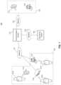
- FIG. 1illustrates a block diagram of an exemplary wearable device communication system, according to embodiments of the present disclosure.
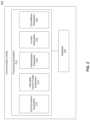
- FIG. 2illustrates a block diagram of an exemplary communication center for use in the exemplary wearable device communication system of FIG. 1 , according to embodiments of the present disclosure.
- FIG. 3illustrates a block diagram of an exemplary wearable device for use in the exemplary wearable device communication system of FIG. 1 , according to embodiments of the present disclosure.
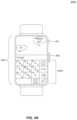
- FIG. 4 Aillustrates a wearable device having an exemplary interface for use in the exemplary wearable device communication system of FIG. 1 , according to embodiments of the present disclosure.
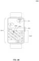
- FIG. 4 Billustrates a wearable device having another exemplary interface for use in the exemplary wearable device communication system of FIG. 1 , according to embodiments of the present disclosure.
- FIG. 4 Cillustrates a wearable device having another exemplary interface for use in the exemplary wearable device communication system of FIG. 1 , according to embodiments of the present disclosure.
- FIG. 4 Dillustrates a wearable device having another exemplary interface for use in the exemplary wearable device communication system of FIG. 1 , according to embodiments of the present disclosure.
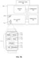
- FIG. 5illustrates a wearable device having an exemplary physical interface for use in the exemplary wearable device communication system of FIG. 1 , according to embodiments of the present disclosure.
- FIG. 6illustrates a wearable device having an exemplary virtual interface for use in the exemplary wearable device communication system of FIG. 1 , according to embodiments of the present disclosure.
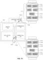
- FIG. 7 Aillustrates a controlled environment having distributed power and/or network beacons, according to embodiments of the present disclosure.
- FIGS. 7 B- 7 Dillustrate a wearable device having an exemplary interface customized for use in different locations of the controlled environment of FIG. 5 A , according to embodiments of the present disclosure.
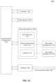
- FIG. 8illustrates a flowchart diagram of a method for customizing input interface of a wearable device for use in the exemplary wearable device communication system of FIG. 1 , according to embodiments of the present disclosure.
- FIG. 9illustrates a flowchart diagram of a method for customizing interface of a wearable device for use in the exemplary wearable device communication system of FIG. 1 , according to embodiments of the present disclosure.
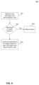
- FIG. 10illustrates a flowchart diagram of a method for determining whether to allow removal of a wearable device, according to embodiments of the present disclosure.
- FIG. 11illustrates a flowchart diagram of a method of conducting surveillance using wearable devices in the exemplary wearable device communication system of FIG. 1 , according to embodiments of the present disclosure.
- FIG. 12illustrates a block diagram of a general purpose computer that may be used to perform various aspects of the present disclosure.
- Embodimentsmay be implemented in hardware (e.g., circuits), firmware, software, or any combination thereof. Embodiments may also be implemented as instructions stored on a machine-readable medium, which may be read and executed by one or more processors.
- a machine-readable mediummay include any mechanism for storing or transmitting information in a form readable by a machine (e.g., a computing device).
- a machine-readable mediummay include read only memory (ROM); random access memory (RAM); magnetic disk storage media; optical storage media; flash memory devices; electrical, optical, acoustical or other forms of propagated signals (e.g., carrier waves, infrared signals, digital signals, etc.), and others.
- firmware, software, routines, instructionsmay be described herein as performing certain actions. However, it should be appreciated that such descriptions are merely for convenience and that such actions in fact result from computing devices, processors, controllers, or other devices executing the firmware, software, routines, instructions, etc. Further, any of the implementation variations may be carried out by a general purpose computer, as described below.
- any reference to the term “module”shall be understood to include at least one of software, firmware, and hardware (such as one or more circuit, microchip, or device, or any combination thereof), and any combination thereof.
- each modulemay include one, or more than one, component within an actual device, and each component that forms a part of the described module may function either cooperatively or independently of any other component forming a part of the module.
- multiple modules described hereinmay represent a single component within an actual device. Further, components within a module may be in a single device or distributed among multiple devices in a wired or wireless manner.
- FIG. 1illustrates a block diagram of an exemplary wearable device communication system 100 , according to embodiments of the present disclosure.
- wearable device communication system 100includes communication center 110 which is configured to transmit information between inmate communication system 120 , outsider communication system 130 , and/or monitoring center 140 .
- An inmate of wearable device communication systemutilizes inmate communication system 120 in a number of ways including receiving wearable device information from communication center 110 , transmitting wearable device information to communication center 110 , and communicating with an outside party utilizing outsider communication system 130 .
- wearable device informationincludes voice calls, video calls, text messages, email messages, multimedia content (e.g., video, music, educational programs, games), interface information (e.g., inputs received on an input interface at inmate communication system 120 , outputs to be displayed on inmate communication system 120 ), control information, browser information, and/or application information from applications stored on inmate communication system 120 .
- multimedia contente.g., video, music, educational programs, games
- interface informatione.g., inputs received on an input interface at inmate communication system 120 , outputs to be displayed on inmate communication system 120
- control informatione.g., browser information, and/or application information from applications stored on inmate communication system 120 .
- inmate communication system 120includes one or more devices provided to inmates within a controlled environment, such as a correctional facility, and where the one or more devices include wearable devices 121 A- 121 C.
- Inmate communication system 120can further include devices such as a companion wireless communication device 122 , wireless access point 123 (e.g., gateway or router), and/or kiosk 124 .
- wearable devices 121 A- 121 Care watches having a touchscreen interface.
- wearable devicesalso refers to devices that can be inserted within an inmate's body. Such devices can be configured to provide locator and inmate identification functionality. Such devices can be powered by a blood battery electrolyte system.
- wearable devices 121 A- 121 Chave wireless communication capabilities.
- wearable device 121 Acommunicates with network 101 through a connection with wireless communication device 122 .
- the communication with wireless communication device 122may be a wireless connection, such as BluetoothTM or Wi-Fi connections, or through a wired connection such as with a USB cable.
- wearable device 121 Bcommunicates with network 101 through a connection with wireless access point 123 .
- the communication with wireless access point 123may be a wireless connection, such as BluetoothTM or Wi-Fi connections.
- wearable device 121 Ccommunicates with network 101 through a connection with kiosk 124 .
- the communication with kiosk 124may be a wireless connection, such as BluetoothTM or Wi-Fi connections.
- Wireless communication device 122can be implemented as any mobile device such as, but not limited to, a smartphone, a tablet, or a laptop device.
- Inmate communication system 120connects to communication center 110 via network 101 , which may include any or all of a Local-Area Network (LAN), a Wide-Area Network (WAN), or the Internet, depending on the location of communication center 110 in relation to inmate communication system 120 .
- network 101is implemented as a LAN when communication center 110 and inmate communication system 120 are both located at a controlled environment.
- network 101is implemented as a WAN or the Internet when communication center 110 is located at a different location than inmate communication system 120 .
- Outsider communication system 130is communicatively coupled to communication center 110 and includes one or more devices available to outsiders to the controlled environment and includes any and all communications devices such as a wireless communication device 131 and/or computer station 132 .
- outside communication system 130may be located within the controlled environment, such as in a designated area or room of the controlled environment. In another embodiment, outside communication system 130 may be located outside of the controlled environment such as in the outsider's home.
- Outsider communication system 130connects to communication center 110 via network 103 , which may include any or all of a WAN, the Internet, and/or a Public Switched Telephone Network (PSTN).
- PSTNPublic Switched Telephone Network
- the WANmay facilitate communications with other nearby prisons, such as those within the same county, state, etc.
- wearable device communication system 100also includes monitoring center 140 for monitoring wearable devices 121 A- 121 C within wearable device communication system 100 .
- Monitoring of wearable devices 121 A- 121 Cincludes but is not limited to monitoring user inputs, the user interface being displayed, and communications to and from wearable devices 121 A- 121 C.
- monitoring by monitoring center 140can occur both automatically and manually (e.g., initiated a reviewer).
- Monitoring center 140receives communications and data from communication center 110 via network 105 , which may include any or all of a LAN, a WAN, or the Internet.
- Monitoring center 140receives wearable device information related to interactions and communications involving all devices including wearable devices 121 A- 121 C in wearable device communication system 100 through communication center 110 .
- Monitoring center 140may store and/or analyze the received interactions and communications.
- Monitoring center 140may further provide instructions to devices in wearable device communication system 100 based on the analysis performed on the received interactions and communications.
- the wearable device informationincludes but is not limited to an audio stream, a video stream, actions performed by the users on their wearable device, content viewed by users through their wearable device, data, such as biometric data, regarding the wearer of each wearable device, and/or content requested by users through their wearable device.
- monitoring centermay provide instructions to affect certain functionality of the wearable devices. Such instructions include but are not limited to modifying a dynamic user interface of the wearable device, modifying the content that may be viewed or utilized by the inmate, and/or transmitting communications to be output to the inmate through the wearable devices.
- a dynamic user interfaceis a graphical user interface that is adapted based on any number of conditions including but not limited to a user's typing history, applications, location of the wearable device, and administrative rules provided by authorized personnel of the controlled environment. Modifying the dynamic user interface includes providing different input interfaces through which the inmate may provide input for applications on the wearable device. For example, wearable devices with touchscreen displays such as wearable devices 121 A- 121 C may have different keyboards and/or interfaces based on different applications or locations within the controlled environment. Modifying the dynamic user interface of the wearable device may include selecting a different keyboard for use by the user based, but are not limited to, different applications, preferences of the user, and/or location of the wearable device within the controlled environment.
- modifying the dynamic user interfaceincludes adjusting the content that can be accessed on a wearable device.
- monitoring center 140may send a control signal to any of wearable devices 121 A- 121 C based on a context of the wearable devices 121 A- 121 C.
- the control signalmay cause wearable devices 121 A- 121 C to display only certain applications and to display certain applications as not being accessible.
- Contextscan include but are not limited to different applications, preferences of the user, and/or location of the wearable device within the controlled environment.
- the authorized contentis any content authorized to be provided to and/or utilized by one of wearable devices 121 A- 121 C.
- authorized contentincludes a list of accessible websites, games, multimedia content, applications such as a word processing application, a text messaging application, a video conference application, and a multimedia application.
- contentis authorized on an individual basis (i.e., applies only to a specific user or users and/or specific wearable devices based on, for example, the profile information) or on a global basis (i.e., applies to all wearable devices in wearable device communication system 100 through communication center 110 ).
- Monitoring center 140can modify user profiles to include information that indicates the content for which users and/or wearable devices are authorized and not authorized. For global restrictions, monitoring center 140 can send information that indicates the content that is authorized and not authorized for all users of wearable device communication system 100 .
- FIG. 2illustrates a block diagram of communication center 200 , according to embodiments of the present disclosure.
- communication center 200represents an exemplary embodiment of communication center 110 of FIG. 1 .
- Communication center 200includes but is not limited to processing subsystem 210 and database 222 .
- Processing subsystem 210includes one or more processors, computers, or servers identified as subsystems and can be constructed as individual physical hardware devices, or as virtual devices, such as a virtual server. The number of processing subsystems can be scaled to match the number of simultaneous user connections desired to be supported by an wearable device communication system such as wearable device communication system 100 of FIG. 1 .
- Processing subsystem 210includes but is not limited to communication subsystem 212 , profile subsystem, 214 , authentication subsystem 216 , content subsystem 218 , and surveillance subsystem 220 .
- communication subsystem 212controls the routing of communications to an end destination such as one or more wearable devices within inmate communication system 120 , one or more devices within outsider communication system 130 , or monitoring center 140 .
- Communication subsystem 212performs switching required to electrically connect the one or more devices within inmate communication system 120 and one or more devices within outsider communication system 130 .
- communication subsystem 212logs communication information, including time of communications and parties involved in the communications, and stores the logs and communications as files. The files stored by communication subsystem 212 can be stored indefinitely for use by monitoring center 140 in monitoring and investigation of an inmate and/or communication.
- Communication subsystem 212also determines whether a communication should be monitored such that privileged communications such as attorney/client, doctor/client, or investigative communications are not monitored. Criteria for monitoring a communication may be based on jurisdictional requirements and/or identities of the parties.
- communication subsystem 212is configured to receive contact information such as a phone number, email address, internet protocol address or other identifying data of the users of a wearable device.
- the received contact informationmay be used by each of the subsystems of the communication center 200 for identifying respective data and processes related to the contact information, such as purported identities of parties involved in the communication.
- communication subsystem 212is also configured to perform format conversion of non-real time communications. Conversion of incoming and outgoing communications are performed, as needed, to be compatible with inmate communication device 120 , outsider communication device 130 , or monitoring center 140 . The format conversion includes conversion of incoming communications and outgoing communications to be compatible with inmate communication system 120 or the monitoring center 130 . Further, because communication subsystem 212 receives and transmits communications by way of a network, in an exemplary embodiment, communication subsystem 212 is configured to decrypt received communications and encrypt transmitting communications, for security purposes.
- Wearable device profile subsystem 214obtains and stores profile information on parties registered to use wearable devices and communicate via wearable device communication system 100 .
- profile subsystem 214stores inmate profiles and outsider profiles.
- Profile subsystem 214obtains information related to the parties from one or more of (a) a jail management system (JMS) or an offender management system (OMS) operated by the jurisdiction of the correctional facility, (b) public database containing information on the parties, or (c) a questionnaire provided by a web page, a personal approved number (PAN) list, or booking information.
- Information obtained by wearable device profile subsystem 214may include personal information such as previous residences or correctional facilities, authorized contacts, family members, languages, special needs, medication requirements, etc.
- wearable device profile subsystem 214also performs a registration process for those parties not enrolled or registered to use wearable device communication system 100 . During the registration process, or at a later time, wearable device profile subsystem 214 determines accommodations and settings associated with a party and/or a party is able to select preferred settings for a communication. These accommodations and settings include, but are not limited to, preferences of each user of wearable device communication system 100 , such as favorite websites, purchased content, and/or preferences for applications. Profile information can also include a user's medical history which could be utilized in medical applications, applications authorized to be used by the user, applications restricted from use by the user, and a user's typing history such as most frequently used words and most frequently used letters.
- wearable device profile subsystem 214also receives authorization information indicating content that is authorized and not authorized for each profile.
- the informationmay be received from a monitoring system such as monitoring center 140 as illustrated in FIG. 1 .
- Profile subsystem 214can store the authorization information internally or in database 222 . If the information is specific to a user or user(s), wearable device profile system 214 can also store the information as part of the user or user(s) profile(s).
- the authorization informationis used to customize the interfaces of wearable device 300 by limiting or allowing access to the content by users of wearable device 300 .
- wearable device profile subsystem 214also includes administrator preferences provided by an administrator of wearable device communication system 100 , such as a designated employee of the controlled environment. Administrator rules allow and restrict actions that can be performed within wearable device communication system 100 . Administrator rules have higher priority than the preferences specified in the user profiles. In an embodiment, administrator preferences include global preferences that influence all users of wearable devices and inmate-specific preferences that only apply to specific inmates.
- Administrator rulesgenerally limit or allow actions that can be performed by users when using wearable devices. For example, the administrator can restrict all inmates and outsiders from accessing websites deemed to be inappropriate or certain applications and/or specify specific websites or applications that may be accessed while using wearable devices. Administrator rules can also specify allowable applications in specific areas in the controlled environment and restricted applications in specific areas in the controlled environment. As discussed above, an administrator can implement such restrictions on a global (all inmates of wearable devices) or inmate-specific basis.
- profiles in wearable device profile subsystem 214controls content that is available to users for use on their wearable devices based on authorization information indicating authorized content and unauthorized content and administrator rules.
- the authorization informationcan be specific to a user or user(s) and/or applied globally to all users of wearable devices.
- Authorization informationcan indicate that a user or user(s) are not allowed to access certain content, such as websites, games, and/or applications, while using a wearable device. For example, if a user's profile indicates that the user is not allowed to access certain applications in a certain location of the controlled environment, the user would be prevented from being presented that information when the user and the wearable device are determined to be within the certain location.
- authentication subsystem 216collects and stores identity data of inmates and outsiders authorized to access wearable device communication system 100 .
- Identity dataincludes but is not limited to at least one of a username and password data, challenge questions, challenge answers, biometric data, device data such as make and model of a communication device, and/or location data.
- Biometric dataincludes one or more of a finger print, a hand print, a voice sample, an iris or retinal sample, an image of the user (2D or 3D), a hand geometry, a signature identification, an infrared camera identification, or any other biometric as deemed appropriate.
- the challenge question form of identity datamay be a series of challenge questions, or a single challenge question such as the last four digits of an inmate's social security number, mother's maiden name, and the like.
- Authentication subsystem 216is further configured to facilitate a secure communication between parties receiving/transmitting a communication by performing identity verifications to authenticate identities of purported parties.
- the identity verificationincludes logon verifications, such as username and password verifications, biometric verification, response to challenge questions, device verification, and/or location verification.
- authentication subsystem 216tracks a user's biometric information from wearable devices. Authentication subsystem 216 can utilize the tracked biometric information to authenticate the user of the wearable devices. For example, when an inmate is issued a wearable device, the inmate's biometric information may be associated with the specific wearable device. Biometric information can include but is not limited to heart rate information, oxygen levels, fingerprint information, and/or voice information. In this manner, the monitoring center may passively authenticate users of wearable devices to ensure that the users are allowed to use their wearable devices. Authentication subsystem 216 can also, with the permission of the wearer of the wearable device, transmit biometric information to a doctor for participation in a remote telemedicine program where the doctor can attempt to diagnose or otherwise assist the wearer with medical advice.
- authentication subsystem 216can also perform identity verification by receiving identity information such as one or more of a username and password, a response to a challenge question(s), a keypad or touch pad entry, a voice sample, a fingerprint sample, a retinal sample, a facial image (2D or 3D), device information such as a make and model of the communication device, and/or a location of the communication device, from a communication device (such as a device of inmate communication system 120 or outsider communication system 130 ) and comparing the identity information of the purported party with stored identity data that is associated with a wearable device.
- Authentication subsystem 216also uses the collected information to register users of wearable device communication system 100 .
- authentication subsystem 216also stores administrative rules that control how content can be displayed on wearable devices in wearable device communication system 100 .
- administrative rulesallow authorized personnel to control actions performed and communications transmitted within wearable device communication system 100 .
- Administrative rulescan be provided by and stored in monitoring center 140 .
- Administrative rulesallow for authorized personnel associated with the controlled environment to remotely control functionality of the wearable device including the dynamic user interface and operations of components of the wearable device.
- Administrative rulesspecify authorized functions that may be performed by a wearable device including the specific operations of components of the wearable device. Examples of authorized functions include, but are not limited to, displaying dynamic user interfaces, displaying available applications, video recording (e.g., for video calls), audio recording, access to applications, and/or activating a surveillance mode such as biometric surveillance or environmental surveillance.
- an administrative rulecan also specify which components of the wearable device are allowed to function. For example, authorized personnel can push or otherwise transmit a rule to deactivate the video module of a user who is using the camera of the wearable device for inappropriate purposes.
- functionality of wearable devicescan be configured to operate with corresponding administrative rules. For example, a controlled environment may establish an administrative rule that prevents all wearable devices from allowing inmates to access any applications while inmates are walking between areas in the controlled environment. Administrative rules can also contain identifiers that allow wearable devices to verify that the administrative rules are from authorized personnel of the controlled environment and prevent unauthorized rules from modifying the interfaces of the wearable devices.
- Content subsystem 218is responsible for retrieving and routing content to and from inmate communication system 120 such as wearable devices 121 A- 121 C.
- Content subsystem 218can be implemented as any number of servers, and is configured to facilitate the provision of content (e.g., games, applications, multimedia, emails, web) to inmate communication system 120 .
- content subsystem 218retrieves content from a content source such as database 222 , which is located in communication center 200 .
- database 222may be located in monitoring center 140 or distributed between communication center 200 and monitoring center 140 . All content that can be provided within wearable communication system 100 is pre-screened and authenticated by the controlled environment, such as through communication center 200 .
- Content subsystem 218is configured to receive requests identifying content to be provided to inmate communication system 120 .
- surveillance subsystem 220consists of any number of servers, and manages and facilitates communications between subsystems of communication center 200 and devices external to the communication center, such as any device within inmate communication system 120 and outsider communication system 130 .
- Surveillance subsystem 220is responsible for receiving surveillance information from wearable devices 121 A- 121 C.
- Surveillance informationcan detected by certain modules of each wearable device and includes but is not limited to a user's biometric information and environmental conditions of the user's current environment. Environmental conditions include audio information detected by a microphone of a wearable device and video information detected by a camera of the wearable device.
- Surveillance subsystem 220receives surveillance information from wearable devices and can provide the surveillance information to a monitoring center for storage and analysis.
- surveillance subsystem 220also enables surveillance capability by allowing for monitoring center 140 to remotely activate wearable devices 121 A- 121 C.
- surveillance capabilityincludes but is not limited to performing surveillance of users of wearable devices and performing surveillance of current conditions of the controlled environment in which the wearable devices are distributed.
- surveillance of users of wearable devicesincludes monitoring a user's biometric information (e.g., heart rate, oxygen levels, and/or temperature) such as through a biometric module in the wearable device and/or monitoring a user's interactions with his wearable device.
- biometric informatione.g., heart rate, oxygen levels, and/or temperature
- Surveillance of the controlled environmentincludes activating a microphone and/or camera of the wearable device to record current conditions of the controlled environment.
- Monitoring center 140may receive the recorded information for analysis. In this manner, monitoring center 140 can utilize wearable devices to monitor and view the current physical surroundings of all users in wearable device communication system 100 . Any and all information from any of wearable devices could be routed to monitoring center 140 through communication center 200 .
- surveillance subsystem 220can correlate surveillance information with stored profiles of the user(s).
- surveillance subsystem 220can store the surveillance information in database 222 and associate the surveillance information, such as a user's biometric information or a user's recorded conversation, with the user's profile in database 222 and/or wearable device profile subsystem 214 .
- the user's profilewhen storing the user's biometric information, may include the user's medical history which can be utilized when the user starts a medical application, such as a telemedicine application, on a wearable device to allow a doctor, who may be located at a remote location, to examine the user's information to perform a limited diagnosis or assist the user with certain medical actions, such as injection of medicine using a needless jet syringe applicator associated with the medical application.
- a medical applicationsuch as a telemedicine application
- a wearable deviceto allow a doctor, who may be located at a remote location, to examine the user's information to perform a limited diagnosis or assist the user with certain medical actions, such as injection of medicine using a needless jet syringe applicator associated with the medical application.
- Database 222consists of any number of databases and/or servers, and stores and organizes data in a relational database.
- Database 222runs a database management system, such as MYSQLTM, to provide an example.
- Database 222includes approved content that can be provided to users of inmate communication system 120 while using a wearable device.
- Database 222also includes organized data such that respective identity data, authentication data, jurisdictional requirements and rules, and settings that are indexed and linked to allow access to data for each of the parties involved in a communication and data associated with each of the parties.
- FIG. 3illustrates a block diagram of wearable device 300 , according to embodiments of the present disclosure.
- Wearable device 300may be an exemplary embodiment of any of wearable devices 121 A- 121 C as illustrated in FIG. 1 .
- wearable device 300includes position module 310 , processor circuitry 320 , communication interfaces 330 , display 340 , locking module 350 , and input/output circuitry 360 , which all may be communicatively coupled to each other.
- Position module 310provides location functionality that allows wearable device 300 to receive and provide location-related information.
- position module 310includes GPS module 311 .
- Position modulecan provide location information, such as GPS coordinates, to a monitoring center, such as monitoring center 140 . The monitoring center may then utilize the GPS coordinates to determine the location and/or specific room within the controlled environment in which wearable device 300 is located.
- Position module 310may also include indoor positioning systems (IPS) technology, accelerometers, and/or gyroscopes to determine position and motion of wearable device 300 .
- IPSindoor positioning systems
- Processor circuitry 320includes one or more processors 321 , circuitry, and/or logic configured to control the overall operation of communication device 300 , including the operation of position module 310 , communication interfaces 330 , display 340 , locking module 350 , and input/output modules 360 .
- Processor circuitry 321further includes memory 322 to store data and instructions.
- Memory 322may be any well-known volatile and/or non-volatile memory that is removable and/or non-removable.
- Communication interfaces 330include one or more transceivers, transmitters, and/or receivers that communicate via a wireless interface, such as through one or more antennas 322 , or a wired interface, such as through a USB cable.
- communication interface 330includes a component, such as a Bluetooth transceiver, that enables Bluetooth communication between wearable device 300 and an external device that also has Bluetooth capability, such as a smartphone, a tablet, a wireless headset, and/or wireless earbuds.
- communication interfaces 330are configured to transmit and receive communications between an inmate and an outsider via network 101 and network 103 , as illustrated in FIG. 1 .
- communication interfaces 330connect wearable device 300 with other devices such as a mobile device, a kiosk, an access point, a beacon, and/or external input devices such as a keyboard, mouse, camera, or touch interface.
- Display 340is a component for displaying content to a user.
- display 340is a touchscreen and receives touch inputs from a user of wearable device 300 .
- display 340can also include a holographic projector 341 for projecting content onto an external surface such as a table or a user's forearm.
- content displayed on display 340 and content projected by holographic projector 341are different and can interact with each other.
- content displayed on display 340can be a text window that displays messages sent, messages received, and messages drafted while content projected by holographic projector 341 can be a keyboard that interacts with the text window on display 340 .
- Locking module 350is a component that prevents users of wearable devices from removing the wearable devices.
- wearable devicesare permanently attached to users. Permanently attached means that the user of the wearable device cannot remove the wearable device under any condition.
- the useris an inmate and the controlled environment is a prison. Only authorized personnel such as an administrator of the controlled environment may remove a permanently attached wearable device.
- authorized personnelcan remotely send a signal (e.g., over a network) to locking module 350 to unlock the wearable device.
- authorized personneluse a physical device that transmits a signal when in certain proximity to the wearable device to locking module 350 to unlock the wearable device.
- wearable devicesare semi-permanently attached to users.
- Semi-permanently attachedmeans that the user of the wearable device can remove the wearable device but only under certain conditions.
- locking module 350may provide a timer functionality which keeps the wearable device locked for a specific period of time (e.g., for 10 hours) or a specific period of the day (e.g., between 7:00 AM and 10:00 PM).
- wearable devicesdo not include locking module 350 . In such embodiments, wearable devices are not locked and may be removed at the discretion of their users.
- wearable device 300includes integrated input/output circuitry 360 which includes audio module 361 , gesture module 362 , beacon module 363 , power module 364 , surveillance module 365 , video module(s) 366 , authentication module(s) 367 , user interface module 368 , and biometric module 369 .
- Audio module 361can include circuitry for receiving and transmitting audio such as a microphone and speakers.
- Gesture module 362can include circuitry for receiving touch gestures received on display 340 and translating the touch gestures to commands and/or instructions for controlling wearable devices. For example, a touch gesture received in the context of a text application may be translated to a specific letter. Gesture module 362 may perform the translation and issue an instruction for displaying the specific letter on display 340 .
- Beacon module 363can include circuitry for communicating with access points (or beacons) distributed in various locations of the controlled environment. Beacons and their functionality are discussed in further detail with respect to FIGS. 7 A- 7 D .
- Power module 364can include circuitry for providing power to wearable device 300 .
- power module 364can be implemented as a rechargeable battery.
- power module 364is a wireless rechargeable battery which can be recharged through a variety of methods including inductive charging and radio-frequency (RF) charging.
- Inductive chargingincludes power module 364 receiving electromagnetic fields and converting the received electromagnetic fields into energy to charge or power wearable device 300 .
- wearable device 300 having a power module 364 that is charged through inductive chargingmay be placed on an inductive charging pad.
- RF chargingincludes power module 364 receiving signals such as radio-frequency signals and converting the signals into power for use by wearable device 300 .
- power module 364can be a blood battery electrolyte module that relies on electrolytes in the blood to generate power for wearable device 300 .
- power module 364is a rechargeable battery that is charged through a physical connection to wearable device 300 .
- a charging cable or connector that is connected to a power outletcan be attached to wearable device 300 that supplies a charge to power module 364 .
- Surveillance module 365can include circuitry that enables remote activation and remote control of the surveillance functionality of wearable device 300 (e.g., a surveillance mode). For example, when receiving an appropriate signal from a monitoring center and/or authorized personnel such as through communication interface 330 , surveillance module 365 activates the appropriate components of wearable device for conducting the requested surveillance. For example, the authorized personnel may request that wearable device 300 begin recording audio. Based on the request, surveillance module 365 can activate audio module 361 which can include a microphone and initiate recording of ambient sounds from the surrounding physical environment based on the received signal from authorized personnel. Conversely, the signal to begin surveillance may be provided through wearable device 300 such as through a gesture or command from a user of wearable device 300 .
- the usermay initiate a biometric surveillance feature such as recording the user's heart rate or oxygen levels through an application on wearable device 300 .
- surveillance module 365may activate biometric module 369 and begin recording the requested biometric information of the user.
- surveillance module 365can operate in the background without providing any indication to the user of the wearable device that surveillance functionality has been activated.
- the monitoring centeractivates the surveillance mode which results in activating the appropriate modules as a group as discussed above.
- the monitoring centercan activate individual modules, such as audio module 361 or biometric module 369 , separately.
- Surveillance module 365can also include circuitry that enables remote deactivation of the surveillance functionality of wearable device 300 .
- monitoring center and/or authorized personnelcan send a signal to remotely deactivate the surveillance mode, which results in deactivating corresponding modules as a group, or can send a signal that remotely deactivates individual modules.
- Video module(s) 366can include circuitry for receiving and transmitting video such as a camera.
- the camerais utilized for capturing visual information regarding the physical environment being viewed by a user of wearable device 300 .
- Information from the camerais provided to communication center for processing by communication center 220 .
- Authentication module 367can include circuitry for ensuring that the user of the wearable device is allowed to use wearable device. Authentication module 367 can utilize username/password, voice signatures, fingerprints, retinal or iris information, and facial information to verify the identity of the user. For example, authentication module 367 can interact with audio module 361 to receive a user's voice information, video module 366 to receive a user's iris or facial information, and/or biometric module 369 to receive a user's heartbeat or fingerprint information. Authentication module 367 can also include circuitry for verifying commands or instructions received from authorized personnel.
- User interface module 368can include circuitry for controlling dynamic user interfaces displayed by wearable device 300 on display 340 and/or by holographic projector 341 . User interface module 368 can customize and modify dynamic user interfaces based on a user of wearable device 300 , the location of wearable device 300 , and based on signals received from authorized personnel. User interface module 368 is responsible for the dynamic user interface of wearable device 300 . As will be discussed further below with respect to FIGS. 4 A- 4 D and FIGS. 7 A- 7 D , the user interface of wearable device 300 dynamically adapts based on user information, wearable device location, and any other information such as administrator rules. Accordingly, user interface module 368 provides a dynamic user interface for wearable device 300 .
- Biometric module 369can include circuitry for receiving and tracking biometric information from a user of wearable device 300 such as a heart rate monitor, oxygen level detector, and fingerprint detector. Biometric information may be provided to authentication subsystem 216 for processing.
- FIGS. 4 A- 4 D, 5 , and 6Exemplary usage of wearable device 300 in a controlled environment will be described with respect to FIGS. 4 A- 4 D, 5 , and 6 .
- the exemplary usage described in FIGS. 4 A- 4 D, 5 , and 6can be performed by processing logic that can comprise hardware (e.g., circuitry, dedicated logic, programmable logic, microcode, etc.), software (e.g., instructions executing on a processing device), or a combination thereof.
- FIGS. 4 A- 4 D, 5 , and 6are described with respect to FIGS. 1 - 3 but are not limited to these example embodiments.
- FIGS. 4 A- 4 D, 5 , and 6is described with respect to wearable device 300 of FIG. 3 but may apply to any of wearable devices 121 A- 121 C of FIG. 1 .
- FIG. 4 Aillustrates exemplary wearable device 400 A which includes a power button 401 , a scroll/select mechanism 402 , and a display 403 .
- Scroll/select mechanism 402can be used as a physical mechanism for controlling a dynamic user interface on display 403 .
- scroll/select mechanism 402can be implemented as a wheel that a user can rotate up and down.
- rotating scroll/select mechanism 402upward moves a cursor up within the dynamic user interface.
- rotating scroll/select mechanism 402downward moves a cursor down within the dynamic user interface.
- scroll/select mechanism 402may also be a button that can be depressed to activate a context-sensitive command (e.g., to select a highlighted icon or link).
- Display 403is a capacitive or resistive touchscreen display that is capable of receiving touch inputs from a user's finger and/or touch implement such as a stylus.
- display 403displays an input interface 404 A such as a keyboard that allows a user of wearable device 400 A to input information.
- Input interface 404 Amay comprise any number of software icons that correspond to inputs that may be selected by a user. For example, when implemented as a keyboard, input interface 404 A displays alphanumeric keys.
- Wearable device 400 Amay adjust a display setting, a configuration setting, and the input type of input interface 404 A based on a number of factors including a user profile and/or administrative rules.
- Examples of a display settinginclude but are not limited to colors and size of the software keys or letters of input interface 404 A.
- An example of a configuration settinginclude but not limited to the layout of input interface 404 A.
- the layout of input interface 404 Aincludes arrangement of the software keys and letters.
- Examples of input typesinclude keyboards and gesture areas as will be discussed in further detail with regard to FIGS. 4 B- 4 D .
- FIG. 4 Billustrates exemplary wearable device 400 B having display 403 displaying input interface 404 B.
- Software keys of input interface 404 Bhas been customized to display an emphasized letter 405 B that the user wishes to select.
- a user of wearable device 400 Bselects the “F” of input interface 404 B by performing three successive short presses of software key 405 .
- a short pressis a touch of a predetermined period of time (e.g., less than 2 seconds).
- the time between each successive short pressis a second predetermined period of time (e.g., less than 2 seconds).
- a first short press of software key 405 Aselects “D”; a second short press of software key 405 A within a predetermined period of time after the first short press selects “E”; and a third short press of software key 405 A within a predetermined period of time after the second short press selects “F.”
- each short press of software key 405 Aresults in displaying emphasized letter 405 B.
- User of wearable device 400 Bmay send the displayed emphasized letter 405 B (e.g., “E”) to an application (e.g., messaging application) by long pressing software key 405 .
- FIG. 4 Cillustrates exemplary wearable device 400 C having display 403 display input interface 404 C.
- Input interface 404 Chas a different display setting and a different configuration setting than input interface 404 A.
- a component of wearable device 400 Csuch as user interface module 368 , can modify display and configuration settings of input interface 404 C based on a user profile the current application displayed on display 403 , and/or a context of wearable device 400 C.
- wearable device 400 Ccan have access to a user's most frequently used phrases or letters based on the user's history with wearable device. This user information can be stored in user interface module 368 and/or in wearable profile device subsystem 214 of communication center 200 .
- wearable device 400 Cmay retrieve the user profile which contains information regarding the user's typing habits such as the user's typing history and the user's most used phrases and letters.
- the user profilecan also include information that associates the user information with applications of wearable device 400 C.
- the user profilecan store a user's typing habits in an messaging application, the user's typing habits in a browsing application, and the user's typing habits in a telephone application. Accordingly, in some embodiments, when the user starts a messaging application, wearable device 400 C may adjust a configuration setting such as an arrangement of the letters of input interface 404 C to emphasize the user's most used letters for the messaging application.
- input interface 404 Cprovides a dynamic interface that changes based on the user's habits, user's preferences, and the application in which the user is currently interacting.
- the user profilemay indicate that the user types “How are you” frequently in a messaging application and wearable device 400 C may customize input interface 404 C to emphasize each letter 407 A, 407 B, 407 C, 407 D, 407 E, 407 F, 407 G, and 407 H of the frequently used phrase.
- the user profilecould indicate another most frequently used phrase, and input interface 404 C could dynamically change the configuration of the alphanumeric keys based on the user profile.
- Wearable device 400 Cmay also adjust a display setting such as bolding the first letter of each software key to emphasize the user's most used letters 407 A, 407 B, 407 C, 407 D, 407 E, 407 F, 407 G, and 407 H for the messaging application.
- wearable device 400 Cmay customize settings of the input interface 404 C based on a context of wearable device 400 C.
- Contextcan include but is not limited to a location, a certain mode, and/or a signal received from a communication center.
- FIG. 4 Dillustrates exemplary wearable device 400 D having display 403 display input interface 404 D.
- Input interface 404 Dcan include a gesture area 408 for receiving touch input from a user of wearable device 400 D.
- Input interface 404 Dhas a different input type than input interfaces 404 A-C.
- the usercan provide touch gestures in gesture area 408 .
- a component of wearable device 400 Dsuch as gesture module 362 , translates gestures received through gesture area 408 into a corresponding command or instruction, such as a specific letter corresponding to the touch gesture.
- gesture module 362translates a circular motion received in gesture area 408 into the letter “O.”
- gesturesare associated with the particular application currently displayed on display 403 . For example, gesture module 362 translate the circulation motion into the letter “O” for a messaging application but into a command for repeating a song in a media application.
- FIG. 5illustrates exemplary wearable device 500 which includes a power button 501 , a scroll/select mechanism 502 , and a display 503 .
- Scroll/select mechanism 502operates similarly to scroll/select mechanism 402 as discussed above with respect to FIGS. 4 A- 4 D .
- Display 503may situated on a sliding mechanism (not shown) that allows a user or wearable device 500 to move display 503 a predetermined distance upward.
- Physical keyboard 504can be situated underneath display 503 such that physical keyboard 504 is revealed when display 503 is moved upward the predetermined distance upward.
- Physical keyboard 504can be implemented having any number of physical keys that allows the user to provide inputs to applications on wearable device 500 . In some embodiments, physical keyboard 504 can be implemented as a QWERTY style keyboard.
- FIG. 6illustrates exemplary wearable device 600 which includes power button 601 , a scroll/select mechanism 602 , display 603 , and holographic projector 604 .
- holographic projector 604projects a virtual keyboard 605 onto a surface external to wearable device 600 such as the user's forearm.
- Holographic projector 604also includes a fingertip detector for detecting and determining a position of the user's fingertip in relation to the virtual keyboard 605 . Based on determining the user's fingertip position, a component of wearable device 600 , such as user interface module 368 , translates the fingertip position into a corresponding command, such as a specific letter of virtual keyboard 605 .
- User interface module 368can then send the translated command to an application for an appropriate action, such as displaying the specific letter on display 603 .
- FIGS. 7 A- 7 D and 8 - 11Exemplary usage of wearable device communication system 100 in a controlled environment will be described with respect to FIGS. 7 A- 7 D and 8 - 11 , according to some embodiments.
- the exemplary usage described in FIGS. 7 A- 7 Dcan be performed by processing logic that can comprise hardware (e.g., circuitry, dedicated logic, programmable logic, microcode, etc.), software (e.g., instructions executing on a processing device), or a combination thereof.
- FIGS. 7 A- 7 Dare described with respect to FIGS. 1 - 3 but are not limited to these example embodiments.
- FIGS. 7 A- 7 Dis described with respect to wearable device 300 but may apply to any of wearable devices 121 A- 121 C.
- FIGS. 7 A- 7 Ddepict various dynamic user interfaces of wearable device 300 based on a location within a controlled environment 700 .
- FIG. 7 Adepicts an exemplary embodiment of a controlled environment 700 .
- controlled environment 700includes beacons or access points 701 A- 701 E. Beacons 701 A- 701 E are distributed throughout controlled environment 700 and provide several functions to wearable devices within controlled environment 700 . Functions include but are not limited to wireless networking, radio-frequency waves for providing power, and/or location determination.
- controlled environment 700also includes dining hall 702 , commissary 703 , library 704 , cell block 705 , exercise yard 706 , and hallway 707 .
- each area of controlled environment 700such as beacon 701 A in cell block 705 , beacon 701 B in dining hall 702 , beacon 701 C in library 704 , beacon 701 D in commissary 703 , beacon 701 E in exercise yard 706 , and beacon 701 F in hallway 707 .
- Each beacon 701 A- 701 Fcan act as an access point and provide a wireless network connection to any wearable devices located in the same area as beacon 701 A- 701 F.
- FIG. 7 Bdepicts an exemplary embodiment of controlled environment 700 with a wearable device 710 located near beacon 701 A in cell block 705 .
- applications 711 A, 711 B, 711 C, 711 D, 711 E, 711 F, and 711 Gare displayed on display 711 of wearable device 710 based on wearable device 710 being located within cell block 705 .
- beacon 701 Adetects wearable device 710 and provides information regarding wearable device 710 , such as wearable device 710 's location in cell block 705 , to a monitoring center, such as monitoring center 140 .
- Wearable device 710may customize functionality based on its location such as through beacon module 363 or based on a remote signal from a monitoring center.
- the remote signalcan be based on any number of factors including a user profile of the user of wearable device 700 , the location of wearable device 700 , a certain time of day, and/or administrator's preferences. Examples of customizing functionality include providing certain applications that can be accessed through display 711 of wearable device 710 .
- controlled environmentis a prison
- a useris an inmate of the prison
- a user profileis an inmate profile.
- wearable device 710 in cell block 705permits a user to access applications 711 A, 711 B, 711 C, 711 D, 711 E, 711 F, and 711 G. This permission can be based on any number of factors including but not limited to the user's profile and/or administrative rules associated with the user and/or area of controlled environment 700 .
- a user's profileindicates the applications to which the user has access through a wearable device.
- Wearable device 710can first verify that any administrative rules are authentic (e.g., received from authorized personnel of controlled environment 700 ). For example, wearable device 710 can confirm that administrative rules have an appropriate signature or decrypt the administrative rules using a private key provided to wearable device 710 by controlled environment 710 .
- administrative rulesindicate the applications that are allowed for a particular user and/or in a particular area of controlled environment 700 .
- an administrative rulecan indicate that all applications are accessible when wearable device 710 is located within cell block 705 .
- This rulecan be applied to a particular user or all users.
- a component in wearable device 710such as user interface module 363 , can modify the dynamic user interface to allow a user access to the available applications.
- the administrative rulecan be specific to the user of wearable device 710 or can be applied to all users. For example, one user may allowed to use all available applications while in his cell block while another user may be restricted to only certain applications while in his cell block.
- FIG. 7 Cdepicts an exemplary embodiment of controlled environment 700 with a wearable device 710 A located near beacon 701 F in hallway 707 and wearable device 710 B located near beacon 701 E in exercise yard. Based on user profiles for the users of wearable devices 710 A and 710 B and/or administrative rules associated with the areas of controlled environment 700 , wearable devices 710 A and 710 B determine that its users are not allowed to access any applications.
- a component of wearable devices 710 A and 710 Bmodifies the applications 711 A, 711 B, 711 C, 711 D, 711 E, 711 F, and 711 G on display 711 such that a user cannot select any application while wearable devices 710 A and 710 B are determined to still located in hallway 707 and exercise yard 706 , respectively.
- wearable devices 710 A and 710 Bmay remove applications from being displayed or grey out applications to indicate that the applications are not available.
- FIG. 7 Ddepicts an exemplary embodiment of controlled environment 700 with a wearable device 710 C located near beacon 701 C in library 704 and a wearable device 710 D located near beacon 701 D in commissary 703 .
- wearable devices 710 C and 710 DBased on user profiles for the users of wearable devices 710 C and 710 D and/or administrative rules associated with the users and/or particular locations, wearable devices 710 C and 710 D modify the applications that can be selected by their respective users. For example, based on a user profile for the user of wearable device 710 C and/or administrative rules associated with the user and/or library 704 , wearable device 710 C determines that only “Education” application 711 G is accessible while wearable device 710 C is located in library 704 .
- wearable device 710 Cmodifies the dynamic user interface to allow user to only select “Education” application 711 G and prevent the user from selecting other applications 711 A-F. For example, wearable device 710 C may grey out applications 711 A-F to indicate that the applications are not available for selection.
- wearable device 710 Ddetermines that only the “Order” application 711 D is accessible while wearable device 710 D is located in commissary 703 . Based on this determination, wearable device 710 D modifies the dynamic user interface to allow user to only select “Order” application 711 D and prevent the user from selecting other applications 711 A-C and 711 E-G. For example, wearable device 710 D may grey out applications 711 A-C and 711 E-G to indicate that the applications are not available for selection.
- FIGS. 8 - 11Operations of operating wearable devices in a controlled environment will be described with respect to FIGS. 8 - 11 .
- the exemplary operations described in FIGS. 8 - 11can be performed by processing logic that can comprise hardware (e.g., circuitry, dedicated logic, programmable logic, microcode, etc.), software (e.g., instructions executing on a processing device), or a combination thereof.
- FIGS. 8 - 11are described with respect to FIGS. 1 - 3 but are not limited to these example embodiments.
- FIGS. 8 - 11contain methods of operation for wearable devices in wearable device communication system 100 , the operations are not limited to the order described below, and various operations can be performed in a different order. Further, two or more operations of each method can be performed simultaneously with each other.
- FIG. 8illustrates a flowchart diagram of a method 800 for customizing an input interface on a wearable device, such as wearable device 300 of FIG. 3 or wearable device 400 A of FIG. 4 A , according to embodiments of the present disclosure.
- Method 800can be performed by processing logic that can comprise hardware (e.g., circuitry, dedicated logic, programmable logic, microcode, etc.), software (e.g., instructions executing on a processing device), or a combination thereof. It is to be appreciated that not all steps may be needed to perform the disclosure provided herein. Further, some of the steps may be performed simultaneously, or in a different order than shown in FIG. 8 , as will be understood by a person of ordinary skill in the art.
- wearable device 300retrieves user information, such as a user profile, and administrative rules.
- the user informationcan be the user's profile which can be located in wearable device profile subsystem 214 .
- the user informationcan specify the user's typing habits, typing history, most frequently used letters, most frequently used phrases, and/or applications authorized to be used by the user.
- the administrative rulescontrol authorized functions that can be performed by wearable device 300 as specified by authorized personnel of the controlled environment and can be retrieved from authentication subsystem 216 .
- administrative rulescan allow or restrict certain interfaces based on a specific user or all users and/or based on a location of wearable device 300 .
- retrieving administrative rulesincludes verifying that the administrative rules are from an authorized source, such as a monitoring center of a prison.
- wearable device 300downloads administrative rules at predetermined times (e.g., 3:00 AM) or at predetermined intervals (e.g., every day).
- Wearable device 300can store downloaded administrative rules in memory, such as memory 322 .
- wearable device 300can download administrative rules as needed. For example, wearable device 300 can download the appropriate administrative rule (if any), when wearable device 300 detects its location in a certain area of the controlled environment.
- the administrative rulescan be pushed to wearable device 300 at the discretion of the controlled environment.
- wearable device 300may be provided to users with base administrative rules already pre-loaded into memory 322 . These base administrative rules can specific basic functions that can be performed by wearable device 300 . Additional authorized functions can be added later through the additional administrative rules provided to wearable device 300 .
- wearable device 300determines whether it is necessary to detect the application currently being used by the user and displayed on display 340 . This determination is based on the retrieved user information and/or the retrieved administrative rules. For example, the retrieved user information can specify the user's preference that a virtual keyboard be customized based on the type of application so that the user may have a different virtual keyboard for different applications. If yes, in 803 , wearable device 300 determines the current application being used by the user. If no, in 804 , wearable device 300 determines whether it is necessary to detect its location within a specific area of the controlled environment. This determination is based on the retrieved user information and/or the retrieved administrative rules.
- the location detectioncan be based on the wearable device's 300 proximity to a beacon, based on GPS coordinates, or a combination thereof. If yes, in 805 , wearable device 300 determines its current location. Alternatively, wearable device 300 may receive location information from a monitoring center, such as monitoring center 140 . In 806 , wearable device 300 displays an customized input interface based on the user information, administrative rules, and if applicable, the detected location of wearable device 300 and the current application.
- FIG. 9illustrates a flowchart diagram of a method 900 for customizing applications wearable device, such as wearable device 300 of FIG. 3 or wearable device 400 A of FIG. 4 A , according to embodiments of the present disclosure.
- Method 900can be performed by processing logic that can comprise hardware (e.g., circuitry, dedicated logic, programmable logic, microcode, etc.), software (e.g., instructions executing on a processing device), or a combination thereof. It is to be appreciated that not all steps may be needed to perform the disclosure provided herein. Further, some of the steps may be performed simultaneously, or in a different order than shown in FIG. 9 , as will be understood by a person of ordinary skill in the art.
- wearable device 300retrieves user information, such as a user profile, and administrative rules.
- user informationcan be included in the user's profile and the administrative rules control authorized functions of wearable device 300 as specified by authorized personnel which allow or restrict access to certain features of wearable device 300 .
- administrative rulescan allow or restrict a specific user's access to certain applications, allow or restrict all users' access to certain applications, and allow and/or restrict access, of either a specific user or all users, to certain applications in certain locations of the controlled environment.
- retrieving administrative rulesincludes verifying that the administrative rules are from an authorized source, such as a monitoring center of a prison.
- wearable device 300determines whether it is necessary to detect the location of wearable device 300 . This determination is based on the retrieved user information and/or the retrieved administrative rules. For example, a retrieved administrative rule can specify location-specific functionality of wearable device 300 such as access or restricted access to certain applications. If yes, in 903 , wearable device 300 detects its location. Location detection features are discussed above with respect to FIG. 8 . In 904 , wearable device customizes the applications that can be accessed by the user based on the user information, the administrative rules and, if applicable, the location of wearable device 300 .
- FIG. 10illustrates a flowchart diagram of a method 1000 for removal of wearable device, such as wearable device 300 of FIG. 3 or wearable device 400 A of FIG. 4 A , from a user according to embodiments of the present disclosure.
- Method 1000can be performed by processing logic that can comprise hardware (e.g., circuitry, dedicated logic, programmable logic, microcode, etc.), software (e.g., instructions executing on a processing device), or a combination thereof. It is to be appreciated that not all steps may be needed to perform the disclosure provided herein. Further, some of the steps may be performed simultaneously, or in a different order than shown in FIG. 10 , as will be understood by a person of ordinary skill in the art.
- wearable device 300detects an attempt by the user to remove wearable device 300 .
- Wearable device 300can transmit a signal indicating the removal attempt to monitoring center 140 .
- wearable device 300determines whether it is classified as a permanent wearable.
- a permanent wearableis a wearable device that cannot be removed by the user of the wearable device and is permanently attached to the user unless removed by authorized personnel of the controlled environment. If yes, wearable device 300 determines whether any administrative command is detected.
- An administrative commandcan include but is not limited to a remote signal that is received over a network or a signal from a physical device located proximate to wearable device 300 (e.g., an RF key fob). If there is no administrative command, locking module 350 of wearable device 300 does not allow the user to remove wearable device 300 at 1008 . If there is an administrative command, locking module 350 allows the user to remove wearable device 300 at 1007 .
- wearable device 300is not permanent, then wearable device 300 is considered to be a semi-permanent wearable at 1004 .
- wearable devicesare not generally allowed to be removed by the users (e.g., inmates) within the controlled environment. Accordingly, in some embodiments, wearable device 300 is either permanently or semi-permanently attached to the user.
- wearable device 300next determines whether a locking timer has elapsed.
- a locking timerindicates a predetermined time in which wearable device 300 must be attached to the user. For example, a locking timer that specifies 10 hours indicates that wearable device 300 must be attached to the user for 10 hours before wearable device 300 can be removed.
- an administrator or monitoring centercan remotely set a specific time for the locking timer of each wearable device in the controlled environment.
- wearable device 300next determines whether it is located in an approved location at 1006 . For example, users can be restricted to removing wearable devices only in certain locations such as the user's specific cell block. Approved locations can be specified in the user's profile and/or by an administrative rule. If the locking timer has elapsed and wearable device 300 is located in an approved location, then wearable device 300 allows the user to remove wearable device 300 at 1007 . If neither condition is met, locking module 350 of wearable device 300 does not allow the user to remove wearable device 300 at 1008 .
- FIG. 11illustrates a flowchart diagram of a method 1100 for activating a surveillance mode for a wearable device, such as wearable device 300 of FIG. 3 or wearable device 400 A of FIG. 4 A , according to embodiments of the present disclosure.
- Method 1100can be performed by processing logic that can comprise hardware (e.g., circuitry, dedicated logic, programmable logic, microcode, etc.), software (e.g., instructions executing on a processing device), or a combination thereof. It is to be appreciated that not all steps may be needed to perform the disclosure provided herein. Further, some of the steps may be performed simultaneously, or in a different order than shown in FIG. 11 , as will be understood by a person of ordinary skill in the art.
- an administrative computersuch as monitoring center 140 selects at least one wearable device within the controlled environment.
- the administrative computercan allow for selection of the wearable device through a dynamic user interface that displays all wearable devices within the controlled environment as icons in the dynamic user interface.
- authorized personnelcan select each wearable device by clicking on the corresponding icon.
- selection of wearable devicesmay be accomplished through administrative rules.
- Monitoring center 140may push or otherwise transmit administrative rules that automatically trigger surveillance modes based on certain conditions as determined by wearable devices.
- an administrative rulecan specify that a wearable device associated with a user, who is known to have a heart or medical condition, of the controlled environment should activate a biometric mode of the wearable device when the wearable device (and therefore the user) is determined to be in the exercise yard.
- an administrative rulecan specify that a wearable device associated with another user, who is suspected to be discussing illegal activity with fellow users, should activate an environmental mode to record ambient sounds, when the wearable device is determined to be near other wearable devices or in the dining area.
- the administrative computerremotely activates a particular surveillance mode in the selected wearable deices.
- remotely activating wearable devicesincludes the transmission of appropriate administrative rules that control the surveillance modes of the selected wearable devices.
- surveillance modeincludes but is not limited to biometric surveillance of the user and environmental surveillance.
- Biometric surveillanceincludes activating components of wearable device 300 , such as surveillance module 365 and biometric module 369 , for monitoring, recording, and transmitting biometric information of the user.
- Biometric surveillanceincludes but is not limited to monitoring heart rate information, oxygen levels, and temperature of the user.
- Wearable device 300can then transmit biometric information to a remote application, such as a telemedicine application located at a monitoring center.
- Environmental surveillanceincludes activating components of wearable device 300 , such as audio module 361 , surveillance module 365 , and video module 366 , for monitoring, recording, and transmitting environmental information surrounding wearable device 300 .
- Environmental surveillanceincludes but is not limited to audio recordings, video recordings, and a temperature of the area of controlled environment in which wearable device 300 is located.
- the administrative computerreceives surveillance information from the selected wearable devices depending on the activated surveillance mode. For example, the administrative computer will receive biometric information regarding users of selected wearable devices if biometric surveillance is activated and/or environmental information regarding a physical environment surrounding the selected wearable devices if environmental surveillance mode is activated.
- the administrative computerstores the received surveillance information in a database, such as in database 222 . Surveillance information may then be later analyzed by software, by authorized personnel, or used to monitor the controlled environment. In some embodiments, the stored biometric information may be transmitted to another external party such as a doctor which would allow the user to receive remote diagnosis based on his biometric information.
- the administrative computermay then deactivate the mode which results in deactivating the modules. Alternatively, wearable device 300 may continue operating with the modules activated.
- Embodiments of the present disclosurecan be implemented in hardware, or as a combination of software and hardware. Consequently, embodiments of the disclosure may be implemented in the environment of a computer system or other processing system.
- the methods of FIGS. 8 - 11can be implemented in the environment of one or more computer systems or other processing systems.
- An example of such a computer system 1200is shown in FIG. 12 .
- One or more of the modules depicted in the previous figurescan be at least partially implemented on one or more distinct computer systems 1200 .
- Computer system 1200includes one or more processors, such as processor 1204 .
- Processor 1204can be a special purpose or a general purpose digital signal processor.
- Processor 1204is connected to a communication infrastructure 1202 (for example, a bus or network).
- a communication infrastructure 1202for example, a bus or network.
- Various software implementationsare described in terms of this exemplary computer system. After reading this description, it will become apparent to a person skilled in the relevant art(s) how to implement the disclosure using other computer systems and/or computer architectures.
- Computer system 1200also includes a main memory 1206 , preferably random access memory (RAM), and may also include a secondary memory 1208 .
- Secondary memory 1208may include, for example, a hard disk drive 1210 and/or a removable storage drive 1212 , representing a floppy disk drive, a magnetic tape drive, an optical disk drive, or the like.
- Removable storage drive 1212reads from and/or writes to a removable storage unit 1216 in a well-known manner.
- Removable storage unit 1216represents a floppy disk, magnetic tape, optical disk, or the like, which is read by and written to by removable storage drive 1212 .
- removable storage unit 1216includes a computer usable storage medium having stored therein computer software and/or data.
- secondary memory 1208may include other similar means for allowing computer programs or other instructions to be loaded into computer system 1200 .
- Such meansmay include, for example, a removable storage unit 1218 and an interface 1214 .
- Examples of such meansmay include a program cartridge and cartridge interface (such as that found in video game devices), a removable memory chip (such as an EPROM, or PROM) and associated socket, a thumb drive and USB port, and other removable storage units 1218 and interfaces 1214 which allow software and data to be transferred from removable storage unit 1218 to computer system 1200 .
- Computer system 1200may also include a communications interface 1220 .
- Communications interface 1220allows software and data to be transferred between computer system 1200 and external devices. Examples of communications interface 1220 may include a modem, a network interface (such as an Ethernet card), a communications port, a PCMCIA slot and card, etc.
- Software and data transferred via communications interface 1220are in the form of signals which may be electronic, electromagnetic, optical, or other signals capable of being received by communications interface 1220 . These signals are provided to communications interface 1220 via a communications path 1222 .
- Communications path 1222carries signals and may be implemented using wire or cable, fiber optics, a phone line, a cellular phone link, an RF link and other communications channels.
- computer program mediumand “computer readable medium” are used to generally refer to tangible storage media such as removable storage units 1216 and 1218 or a hard disk installed in hard disk drive 1210 . These computer program products are means for providing software to computer system 1200 .
- Computer programsare stored in main memory 1206 and/or secondary memory 1208 . Computer programs may also be received via communications interface 1220 . Such computer programs, when executed, enable the computer system 1200 to implement the present disclosure as discussed herein. In particular, the computer programs, when executed, enable processor 1204 to implement the processes of the present disclosure, such as any of the methods described herein. Accordingly, such computer programs represent controllers of the computer system 1200 . Where the disclosure is implemented using software, the software may be stored in a computer program product and loaded into computer system 1200 using removable storage drive 1212 , interface 1214 , or communications interface 1220 .
- features of the disclosureare implemented primarily in hardware using, for example, hardware components such as application-specific integrated circuits (ASICs) and gate arrays.
- ASICsapplication-specific integrated circuits
- gate arraysgate arrays
Landscapes
- Engineering & Computer Science (AREA)
- Theoretical Computer Science (AREA)
- General Engineering & Computer Science (AREA)
- Physics & Mathematics (AREA)
- General Physics & Mathematics (AREA)
- Computer Hardware Design (AREA)
- Human Computer Interaction (AREA)
- Health & Medical Sciences (AREA)
- Life Sciences & Earth Sciences (AREA)
- Computer Security & Cryptography (AREA)
- General Health & Medical Sciences (AREA)
- Heart & Thoracic Surgery (AREA)
- Animal Behavior & Ethology (AREA)
- Public Health (AREA)
- Veterinary Medicine (AREA)
- Surgery (AREA)
- Molecular Biology (AREA)
- Medical Informatics (AREA)
- Biophysics (AREA)
- Biomedical Technology (AREA)
- Pathology (AREA)
- Computer Networks & Wireless Communication (AREA)
- Signal Processing (AREA)
- Software Systems (AREA)
- Mathematical Physics (AREA)
- Computing Systems (AREA)
- Multimedia (AREA)
- Bioethics (AREA)
- User Interface Of Digital Computer (AREA)
- Cardiology (AREA)
- Physiology (AREA)
- Measuring And Recording Apparatus For Diagnosis (AREA)
Abstract
Description
Claims (20)
Priority Applications (7)
| Application Number | Priority Date | Filing Date | Title |
|---|---|---|---|
| US15/469,992US11880493B2 (en) | 2017-03-27 | 2017-03-27 | Wearable devices in a controlled environment |
| EP18778036.6AEP3603148B1 (en) | 2017-03-27 | 2018-03-27 | Wearable devices in a controlled environment |
| AU2018244305AAU2018244305A1 (en) | 2017-03-27 | 2018-03-27 | Wearable devices in a controlled environment |
| MX2019011645AMX2019011645A (en) | 2017-03-27 | 2018-03-27 | WEARABLE DEVICES IN A CONTROLLED ENVIRONMENT. |
| PCT/US2018/024611WO2018183361A1 (en) | 2017-03-27 | 2018-03-27 | Wearable devices in a controlled environment |
| CA3058167ACA3058167A1 (en) | 2017-03-27 | 2018-03-27 | Wearable devices in a controlled environment |
| US18/534,053US12299177B2 (en) | 2017-03-27 | 2023-12-08 | Wearable devices in a controlled environment |
Applications Claiming Priority (1)
| Application Number | Priority Date | Filing Date | Title |
|---|---|---|---|
| US15/469,992US11880493B2 (en) | 2017-03-27 | 2017-03-27 | Wearable devices in a controlled environment |
Related Child Applications (1)
| Application Number | Title | Priority Date | Filing Date |
|---|---|---|---|
| US18/534,053ContinuationUS12299177B2 (en) | 2017-03-27 | 2023-12-08 | Wearable devices in a controlled environment |
Publications (2)
| Publication Number | Publication Date |
|---|---|
| US20180275859A1 US20180275859A1 (en) | 2018-09-27 |
| US11880493B2true US11880493B2 (en) | 2024-01-23 |
Family
ID=63581847
Family Applications (2)
| Application Number | Title | Priority Date | Filing Date |
|---|---|---|---|
| US15/469,992Active2040-01-19US11880493B2 (en) | 2017-03-27 | 2017-03-27 | Wearable devices in a controlled environment |
| US18/534,053ActiveUS12299177B2 (en) | 2017-03-27 | 2023-12-08 | Wearable devices in a controlled environment |
Family Applications After (1)
| Application Number | Title | Priority Date | Filing Date |
|---|---|---|---|
| US18/534,053ActiveUS12299177B2 (en) | 2017-03-27 | 2023-12-08 | Wearable devices in a controlled environment |
Country Status (6)
| Country | Link |
|---|---|
| US (2) | US11880493B2 (en) |
| EP (1) | EP3603148B1 (en) |
| AU (1) | AU2018244305A1 (en) |
| CA (1) | CA3058167A1 (en) |
| MX (1) | MX2019011645A (en) |
| WO (1) | WO2018183361A1 (en) |
Families Citing this family (19)
| Publication number | Priority date | Publication date | Assignee | Title |
|---|---|---|---|---|
| US12379217B2 (en) | 2014-11-30 | 2025-08-05 | Raymond Anthony Joao | Personal monitoring apparatus and method |
| WO2018081795A1 (en) | 2016-10-31 | 2018-05-03 | Zipline Medical, Inc. | Systems and methods for monitoring physical therapy of the knee and other joints |
| US10721624B2 (en) | 2017-02-17 | 2020-07-21 | Global Tel*Link Corporation | Security system for inmate wireless devices |
| US11880493B2 (en) | 2017-03-27 | 2024-01-23 | Global Tel*Link Corporation | Wearable devices in a controlled environment |
| US10366599B1 (en)* | 2017-09-15 | 2019-07-30 | Global Tel*Link Corporation | Communication devices for guards of controlled environments |
| US10650663B2 (en)* | 2018-01-01 | 2020-05-12 | Bi Incorporated | Systems and methods for multi-device restriction zone maintenance |
| GB2574074B (en) | 2018-07-27 | 2020-05-20 | Mclaren Applied Tech Ltd | Time synchronisation |
| US11488466B2 (en)* | 2018-11-26 | 2022-11-01 | Ray P. Lewis | Wearable personal or public safety device |
| US20210383989A1 (en)* | 2019-02-28 | 2021-12-09 | Hewlett-Packard Development Company, L.P. | Parameter adjustments to human interface devices |
| US11765547B2 (en) | 2019-07-30 | 2023-09-19 | Raymond Anthony Joao | Personal monitoring apparatus and methods |
| GB2588236B (en) | 2019-10-18 | 2024-03-20 | Mclaren Applied Ltd | Gyroscope bias estimation |
| US11775780B2 (en) | 2021-03-01 | 2023-10-03 | Raymond Anthony Joao | Personal monitoring apparatus and methods |
| US11868595B2 (en)* | 2021-06-11 | 2024-01-09 | Roku, Inc. | Intelligent user interface customization for one-handed use |
| USD1053901S1 (en) | 2021-11-05 | 2024-12-10 | Howmedica Osteonics Corp. | Display screen or portion thereof with graphical user interface |
| USD1067239S1 (en) | 2021-11-05 | 2025-03-18 | Howmedica Osteonics Corp. | Display screen or portion thereof with animated graphical user interface |
| USD1084008S1 (en) | 2021-11-05 | 2025-07-15 | Howmedica Osteonics Corp. | Display screen or portion thereof with graphical user interface |
| US12061471B2 (en)* | 2022-03-01 | 2024-08-13 | Logistics and Supply Chain MultiTech R&D Centre Limited | Wearable remote control device and tracking system |
| US20240119826A1 (en)* | 2022-10-06 | 2024-04-11 | Raymond Anthony Joao | Personal monitoring apparatus and method |
| WO2025054585A1 (en)* | 2023-09-08 | 2025-03-13 | T Stamp Inc. | Multi-factor authentication using tamper-resistant band and biometric data |
Citations (102)
| Publication number | Priority date | Publication date | Assignee | Title |
|---|---|---|---|---|
| US4495386A (en) | 1982-03-29 | 1985-01-22 | Astech, Inc. | Telephone extension system utilizing power line carrier signals |
| US5255306A (en) | 1991-01-10 | 1993-10-19 | Bi Inc. | Cellular interface unit for use with an electronic house arrest monitoring system |
| US5896556A (en) | 1997-06-13 | 1999-04-20 | Conifer Corporation | Apparatus and method for providing a telephone connection over a coax cable distribution system |
| US6054928A (en)* | 1998-06-04 | 2000-04-25 | Lemelson Jerome H. | Prisoner tracking and warning system and corresponding methods |
| US6058173A (en) | 1998-02-19 | 2000-05-02 | Lhs Group Inc. | Real-time call rating and debiting system |
| US20020071537A1 (en) | 1994-04-19 | 2002-06-13 | Jay L. Gainsboro | Computer-based method and apparatus for controlling, monitoring, recording and reporting telephone access |
| US20020125886A1 (en)* | 2001-03-12 | 2002-09-12 | International Business Machines Corporation | Access to applications of an electronic processing device solely based on geographic location |
| US20030036381A1 (en) | 2001-08-16 | 2003-02-20 | Nec Corporation | Wireless communication system with data changing/updating function |
| US20030086546A1 (en) | 2002-04-29 | 2003-05-08 | Richard Falcone | Systems and methods for offering a service to a party associated with a blocked call |
| US20030126470A1 (en) | 2001-12-24 | 2003-07-03 | Worldcom, Inc. | Investigation and reporting of inmate security threats |
| US20030198325A1 (en) | 2002-04-20 | 2003-10-23 | Bayne Anthony J. | Pre-paid calling and voice messaging services for inmates |
| US20030224764A1 (en) | 2002-05-31 | 2003-12-04 | Baker Nathan Bryant | Technique for providing information assistance with restrictions |
| US6668045B1 (en) | 2000-10-30 | 2003-12-23 | T-Netix, Inc. | Message screening, delivery and billing system |
| US20040210773A1 (en)* | 2003-04-16 | 2004-10-21 | Charles Markosi | System and method for network security |
| US6965590B1 (en) | 2000-02-29 | 2005-11-15 | Texas Instruments Incorporated | Dynamic slave selection in frequency hopping wireless communications |
| US20050265529A1 (en) | 2004-03-11 | 2005-12-01 | Hogg John S Jr | Switching call types in real-time |
| US20060062355A1 (en) | 2004-09-17 | 2006-03-23 | Rhonda Leonard | System and method for restricted telephone message delivery |
| US20060176169A1 (en) | 2004-12-17 | 2006-08-10 | The Regents Of The University Of California | System for sensing environmental conditions |
| US7106843B1 (en) | 1994-04-19 | 2006-09-12 | T-Netix, Inc. | Computer-based method and apparatus for controlling, monitoring, recording and reporting telephone access |
| US20070047694A1 (en) | 2005-08-08 | 2007-03-01 | Jean Bouchard | Method, system and apparatus for communicating data associated with a user of a voice communication device |
| US20070057763A1 (en) | 2005-09-12 | 2007-03-15 | Imation Corp. | Wireless handheld device with local biometric authentication |
| US7218993B2 (en) | 2002-10-04 | 2007-05-15 | Fujitsu Limited | Robot system and autonomous mobile robot |
| US7254708B2 (en) | 2002-03-05 | 2007-08-07 | Intel Corporation | Apparatus and method for wireless device set-up and authentication using audio authentication—information |
| US7280816B2 (en) | 2004-12-23 | 2007-10-09 | Agere Systems Inc. | Techniques for monitoring mobile telecommunications for shared accounts |
| US7333798B2 (en) | 2002-08-08 | 2008-02-19 | Value Added Communications, Inc. | Telecommunication call management and monitoring system |
| US20080057976A1 (en) | 2006-02-17 | 2008-03-06 | Evercom Systems, Inc. | Wireless communications control in a controlled environment facility |
| US7363330B1 (en)* | 1999-06-07 | 2008-04-22 | Symantec Corporation | Work monitor with file synchronization |
| US7366782B2 (en) | 2003-04-14 | 2008-04-29 | At&T Corp. | Systems and methods for termination of session initiation protocol |
| US20080200156A1 (en) | 2007-02-16 | 2008-08-21 | Mary Anne Hicks | Methods and apparatus to provide medical information using a communication system |
| US20090080629A1 (en) | 2007-09-26 | 2009-03-26 | Rokosky James P | System and method for controlling free phone calls through an institutional phone system |
| US7529357B1 (en) | 2003-08-15 | 2009-05-05 | Evercom Systems, Inc. | Inmate management and call processing systems and methods |
| US7587067B1 (en) | 2004-07-09 | 2009-09-08 | 50, Llc | Method and system for monitoring individuals |
| US20090265106A1 (en)* | 2006-05-12 | 2009-10-22 | Michael Bearman | Method and System for Determining a Potential Relationship between Entities and Relevance Thereof |
| US20100062833A1 (en) | 2008-09-10 | 2010-03-11 | Igt | Portable Gaming Machine Emergency Shut Down Circuitry |
| US20100153951A1 (en)* | 2008-12-17 | 2010-06-17 | Computer Parenting, Llc | Operating system shutdown reversal and remote web monitoring |
| US7742581B2 (en) | 2004-11-24 | 2010-06-22 | Value-Added Communications, Inc. | Electronic messaging exchange |
| US20100189228A1 (en) | 2009-01-27 | 2010-07-29 | Serge Seyfetdinov | System and method for electronic notification in institutional communication |
| US20100222179A1 (en)* | 2009-02-27 | 2010-09-02 | Sinclair Temple | Presenting information to users during an activity, such as information from a previous or concurrent outdoor, physical activity |
| US7804941B2 (en) | 2006-06-30 | 2010-09-28 | Securus Technologies, Inc. | Systems and methods for message delivery in a controlled environment facility |
| US20100260173A1 (en) | 2009-04-08 | 2010-10-14 | Timothy Johnson | Apparatus and methods for bridging calls or data between heterogenous network domains |
| US7860222B1 (en) | 2003-11-24 | 2010-12-28 | Securus Technologies, Inc. | Systems and methods for acquiring, accessing, and analyzing investigative information |
| US7899167B1 (en) | 2003-08-15 | 2011-03-01 | Securus Technologies, Inc. | Centralized call processing |
| US20110158223A1 (en) | 2009-12-31 | 2011-06-30 | Bce Inc. | Method, system network and computer-readable media for controlling outgoing telephony calls to cause initiation of call features |
| US20110213618A1 (en) | 2009-08-26 | 2011-09-01 | Ron Hodge | System and Method for Automating Correctional Facilities |
| US20110237226A1 (en) | 2010-03-23 | 2011-09-29 | Anil Dhuna | Guardian system for a cognitively-impaired individual |
| US8031052B2 (en) | 2006-11-22 | 2011-10-04 | Securus Technologies, Inc. | Systems and methods for radio frequency identification |
| US20120099714A1 (en) | 2009-02-12 | 2012-04-26 | Value-Added Communications, Inc. | System and method for controlled call handling |
| US20120252411A1 (en) | 2011-03-30 | 2012-10-04 | Qualcomm Incorporated | Continuous voice authentication for a mobile device |
| US20120262271A1 (en) | 2011-04-18 | 2012-10-18 | Richard Torgersrud | Interactive audio/video system and device for use in a secure facility |
| US20130012234A1 (en)* | 2011-07-06 | 2013-01-10 | Tufty Steven | Systems and Methods for Position Tracking and Reporting of Objects |
| US8370206B2 (en) | 2007-09-14 | 2013-02-05 | Keefe Commissary Network, L.L.C. | Method, medium, and system for an inmate privilege kiosk |
| US8428559B2 (en) | 2009-09-29 | 2013-04-23 | Christopher Anthony Silva | Method for recording mobile phone calls |
| US8498937B1 (en) | 2011-11-11 | 2013-07-30 | Tech Friends, Inc. | Managing financial accounts associated with residents of controlled-environment facilities |
| US20130263227A1 (en) | 2011-04-18 | 2013-10-03 | Telmate, Llc | Secure communication systems and methods |
| US8571525B2 (en) | 2010-02-25 | 2013-10-29 | Cellco Partnership | Reassigned mobile message notifications |
| US20130293378A1 (en) | 2005-05-06 | 2013-11-07 | Omnilink Systems, Inc. | System and method for monitoring a wireless tracking device |
| US8584019B1 (en)* | 2012-08-29 | 2013-11-12 | Mitesh Gala | Location-based and other criteria-based establishment management systems and methods |
| US8639926B2 (en) | 2010-10-29 | 2014-01-28 | Novell, Inc. | Techniques for mobile device authentication |
| US20140032691A1 (en) | 2011-10-11 | 2014-01-30 | Citrix Systems, Inc. | Policy-Based Application Management |
| US8646056B2 (en) | 2007-05-17 | 2014-02-04 | U.S. Cellular Corporation | User-friendly multifactor mobile authentication |
| US20140044242A1 (en) | 2005-01-28 | 2014-02-13 | Global Tel*Link Corp. | Voice Message Exchange |
| US20140089849A1 (en) | 2012-09-24 | 2014-03-27 | Lg Electronics Inc. | Image display apparatus and method for operating the same |
| US20140108649A1 (en) | 2012-10-15 | 2014-04-17 | Citrix Systems, Inc. | Configuring and providing profiles that manage execution of mobile applications |
| US20140109174A1 (en) | 2012-10-15 | 2014-04-17 | Citrix Systems, Inc. | Providing Virtualized Private Network Tunnels |
| US20140115466A1 (en) | 2012-04-26 | 2014-04-24 | Liveperson, Inc. | Dynamic User Interface Customization |
| US20140149506A1 (en)* | 2012-11-29 | 2014-05-29 | Ebay Inc. | Automatic population of a network accessible content collection |
| US20140219432A1 (en) | 2012-12-21 | 2014-08-07 | Tw Vending, Inc. | Telecommunications technology |
| US8832374B1 (en)* | 2011-11-14 | 2014-09-09 | Union Supply Company, Inc. | Providing electronic content to residents of controlled-environment facilities |
| US20140267547A1 (en) | 2013-03-15 | 2014-09-18 | Telmate, Llc | Handheld video visitation |
| US20140280559A1 (en)* | 2013-03-15 | 2014-09-18 | Telmate Llc | Inmate network priming |
| US20140266703A1 (en)* | 2013-03-15 | 2014-09-18 | Codex Corporation | Automating offender documentation with rfid |
| US20140282868A1 (en) | 2013-03-15 | 2014-09-18 | Micah Sheller | Method And Apparatus To Effect Re-Authentication |
| US20140273929A1 (en) | 2013-03-15 | 2014-09-18 | Telmate Llc | Method and system for financing of inmate mobile devices |
| US20140287715A1 (en) | 2013-03-22 | 2014-09-25 | Global Tel*Link Corp. | Multifunction Wireless Device |
| US8917848B2 (en) | 2013-03-15 | 2014-12-23 | Telmate, Llc | Call management for secure facilities |
| US20150077245A1 (en)* | 2011-06-17 | 2015-03-19 | The Reseach Foundation of State University of New York | Detecting and responding to sentinel events |
| US20150097961A1 (en)* | 2013-08-09 | 2015-04-09 | Russell URE | System, Method and Apparatus for Remote Monitoring |
| US9094500B1 (en) | 2014-07-02 | 2015-07-28 | Securus Technologies, Inc. | Controlled communication between residents of controlled-environment facilities |
| US20150215254A1 (en)* | 2014-01-30 | 2015-07-30 | World Emergency Network - Nevada Ltd. | Inmate Communication System |
| US20150237052A1 (en) | 2014-02-18 | 2015-08-20 | Nagravision S.A. | User identification based access control |
| US20150242629A1 (en) | 2014-02-24 | 2015-08-27 | Ca, Inc. | Smart containerization of mobile computing device resources |
| US9124763B2 (en) | 2012-02-01 | 2015-09-01 | Homewav, Llc | Method and apparatus for providing both audio/video visitation and VOIP telephonic visitation originated either by an inmate or by an outside visitor directly between inmates of a prison and an outside visitor without need of intervention by prison personnel |
| US9129230B2 (en)* | 2007-04-04 | 2015-09-08 | Pathfinders International, Llc | Virtual badge, device and method |
| US9143886B1 (en)* | 2012-10-16 | 2015-09-22 | Sprint Communications Company L.P. | Pre-provisioning and de-provisioning functions for a mobile system |
| US20160034046A1 (en)* | 2014-08-01 | 2016-02-04 | Nuance Communications, Inc. | System and methods for determining keyboard input in the presence of multiple contact points |
| US9262604B2 (en) | 2012-02-01 | 2016-02-16 | Blackberry Limited | Method and system for locking an electronic device |
| US20160055323A1 (en) | 2014-08-19 | 2016-02-25 | Airwatch, Llc | Authentication via accelerometer |
| US20160088021A1 (en) | 2014-09-24 | 2016-03-24 | Oracle International Corporation | Policy-based compliance management and remediation of devices in an enterprise system |
| US20160127378A1 (en) | 2013-12-31 | 2016-05-05 | Keefe Group, Llc | Internet access authorization and regulation systems and methods for controlled environment of an institutional facility |
| WO2016125063A1 (en)* | 2015-02-03 | 2016-08-11 | Koninklijke Philips N.V. | Electronically lockable wearable device |
| US20160267257A1 (en) | 2015-03-13 | 2016-09-15 | Citrix Systems, Inc. | Enforcing Licensing Policies Using an Application Wrapper |
| US9491176B1 (en) | 2014-08-28 | 2016-11-08 | Google Inc. | Monitoring content consumption by restricted account |
| US20160330084A1 (en) | 2012-07-09 | 2016-11-10 | Eturi Corp. | Information throttle based on compliance with electronic communication rules |
| US20160346607A1 (en)* | 2015-05-29 | 2016-12-01 | Jonathan Rapfogel | Apparatus for monitoring and encouraging physical exercise |
| US20170061006A1 (en) | 2015-08-25 | 2017-03-02 | International Business Machines Corporation | System and methods for dynamic generation of object storage datasets from existing file datasets |
| US20170084150A1 (en) | 2015-02-28 | 2017-03-23 | Kris Keyton | Person of interest location confirmation system |
| US9622079B2 (en)* | 2014-03-12 | 2017-04-11 | Accenture Global Services Limited | Secure distribution of electronic content |
| US20170177892A1 (en) | 2015-12-16 | 2017-06-22 | Architecture Technology Corporation | Multi-domain application execution management |
| US20170193622A1 (en) | 2015-12-31 | 2017-07-06 | Maison R. Rosado | Method of Remotely Monitoring and Tracking Individuals Under Probation and/or House Arrest |
| US20170222977A1 (en)* | 2016-02-01 | 2017-08-03 | Airwatch Llc | Configuring network security based on device management characteristics |
| US9892242B1 (en) | 2017-04-28 | 2018-02-13 | Global Tel*Link Corporation | Unified enterprise management of wireless devices in a controlled environment |
| US10104198B1 (en)* | 2015-09-14 | 2018-10-16 | Tp Lab, Inc. | System and method to deliver an electronic document over a data network |
Family Cites Families (10)
| Publication number | Priority date | Publication date | Assignee | Title |
|---|---|---|---|---|
| DE102005006037A1 (en)* | 2005-02-08 | 2006-08-10 | Deutsche Telekom Ag | Method and device for monitoring the care of persons in need of care |
| US20120007735A1 (en)* | 2010-07-07 | 2012-01-12 | Paragon Gps, Inc. | Wearable Device and System for Tracking a Person's Location |
| US20120050532A1 (en)* | 2010-08-30 | 2012-03-01 | Paragon Gps, Inc. | Electronic Latch and Locking Device for a Personal Locating and Tracking Device |
| US9819788B2 (en)* | 2014-04-22 | 2017-11-14 | Graham Dugoni | System and apparatus for selectively limiting user control of an electronic device |
| KR101855392B1 (en)* | 2014-11-05 | 2018-05-08 | 전자부품연구원 | Wearable device including modular function block and method for extending function of wearable device using thereof |
| CN105160806B (en)* | 2015-08-24 | 2018-09-04 | 广州三星通信技术研究有限公司 | Realize the wearable device and its alarm method of alarm |
| CN205176494U (en)* | 2015-10-19 | 2016-04-20 | 曹后军 | Children's safety wrist -watch |
| US20180227754A1 (en)* | 2015-12-10 | 2018-08-09 | Yuri Luis Dario Paez Velazquez | Wearable data device with deactivation security feature |
| CN105894726A (en)* | 2016-04-25 | 2016-08-24 | 捷开通讯(深圳)有限公司 | Children anti-kidnapping method of intelligent wearable device and intelligent wearable device |
| US11880493B2 (en) | 2017-03-27 | 2024-01-23 | Global Tel*Link Corporation | Wearable devices in a controlled environment |
- 2017
- 2017-03-27USUS15/469,992patent/US11880493B2/enactiveActive
- 2018
- 2018-03-27EPEP18778036.6Apatent/EP3603148B1/enactiveActive
- 2018-03-27MXMX2019011645Apatent/MX2019011645A/enunknown
- 2018-03-27AUAU2018244305Apatent/AU2018244305A1/ennot_activeAbandoned
- 2018-03-27WOPCT/US2018/024611patent/WO2018183361A1/ennot_activeCeased
- 2018-03-27CACA3058167Apatent/CA3058167A1/enactivePending
- 2023
- 2023-12-08USUS18/534,053patent/US12299177B2/enactiveActive
Patent Citations (127)
| Publication number | Priority date | Publication date | Assignee | Title |
|---|---|---|---|---|
| US4495386A (en) | 1982-03-29 | 1985-01-22 | Astech, Inc. | Telephone extension system utilizing power line carrier signals |
| US5255306A (en) | 1991-01-10 | 1993-10-19 | Bi Inc. | Cellular interface unit for use with an electronic house arrest monitoring system |
| US20020071537A1 (en) | 1994-04-19 | 2002-06-13 | Jay L. Gainsboro | Computer-based method and apparatus for controlling, monitoring, recording and reporting telephone access |
| US20070041545A1 (en) | 1994-04-19 | 2007-02-22 | Gainsboro Jay L | Computer-based method and apparatus for controlling, monitoring, recording and reporting telephone access |
| US7106843B1 (en) | 1994-04-19 | 2006-09-12 | T-Netix, Inc. | Computer-based method and apparatus for controlling, monitoring, recording and reporting telephone access |
| US5896556A (en) | 1997-06-13 | 1999-04-20 | Conifer Corporation | Apparatus and method for providing a telephone connection over a coax cable distribution system |
| US6058173A (en) | 1998-02-19 | 2000-05-02 | Lhs Group Inc. | Real-time call rating and debiting system |
| US6054928A (en)* | 1998-06-04 | 2000-04-25 | Lemelson Jerome H. | Prisoner tracking and warning system and corresponding methods |
| US7363330B1 (en)* | 1999-06-07 | 2008-04-22 | Symantec Corporation | Work monitor with file synchronization |
| US6965590B1 (en) | 2000-02-29 | 2005-11-15 | Texas Instruments Incorporated | Dynamic slave selection in frequency hopping wireless communications |
| US6668045B1 (en) | 2000-10-30 | 2003-12-23 | T-Netix, Inc. | Message screening, delivery and billing system |
| US20020125886A1 (en)* | 2001-03-12 | 2002-09-12 | International Business Machines Corporation | Access to applications of an electronic processing device solely based on geographic location |
| US20030036381A1 (en) | 2001-08-16 | 2003-02-20 | Nec Corporation | Wireless communication system with data changing/updating function |
| US20030126470A1 (en) | 2001-12-24 | 2003-07-03 | Worldcom, Inc. | Investigation and reporting of inmate security threats |
| US7085359B2 (en) | 2001-12-24 | 2006-08-01 | Mci, Llc | Investigation and reporting of inmate security threats |
| US7254708B2 (en) | 2002-03-05 | 2007-08-07 | Intel Corporation | Apparatus and method for wireless device set-up and authentication using audio authentication—information |
| US20030198325A1 (en) | 2002-04-20 | 2003-10-23 | Bayne Anthony J. | Pre-paid calling and voice messaging services for inmates |
| US20030086546A1 (en) | 2002-04-29 | 2003-05-08 | Richard Falcone | Systems and methods for offering a service to a party associated with a blocked call |
| US20030224764A1 (en) | 2002-05-31 | 2003-12-04 | Baker Nathan Bryant | Technique for providing information assistance with restrictions |
| US7333798B2 (en) | 2002-08-08 | 2008-02-19 | Value Added Communications, Inc. | Telecommunication call management and monitoring system |
| US7218993B2 (en) | 2002-10-04 | 2007-05-15 | Fujitsu Limited | Robot system and autonomous mobile robot |
| US7366782B2 (en) | 2003-04-14 | 2008-04-29 | At&T Corp. | Systems and methods for termination of session initiation protocol |
| US20040210773A1 (en)* | 2003-04-16 | 2004-10-21 | Charles Markosi | System and method for network security |
| US7899167B1 (en) | 2003-08-15 | 2011-03-01 | Securus Technologies, Inc. | Centralized call processing |
| US7529357B1 (en) | 2003-08-15 | 2009-05-05 | Evercom Systems, Inc. | Inmate management and call processing systems and methods |
| US7860222B1 (en) | 2003-11-24 | 2010-12-28 | Securus Technologies, Inc. | Systems and methods for acquiring, accessing, and analyzing investigative information |
| US20050265529A1 (en) | 2004-03-11 | 2005-12-01 | Hogg John S Jr | Switching call types in real-time |
| US7587067B1 (en) | 2004-07-09 | 2009-09-08 | 50, Llc | Method and system for monitoring individuals |
| US20060062355A1 (en) | 2004-09-17 | 2006-03-23 | Rhonda Leonard | System and method for restricted telephone message delivery |
| US7742581B2 (en) | 2004-11-24 | 2010-06-22 | Value-Added Communications, Inc. | Electronic messaging exchange |
| US20060176169A1 (en) | 2004-12-17 | 2006-08-10 | The Regents Of The University Of California | System for sensing environmental conditions |
| US7280816B2 (en) | 2004-12-23 | 2007-10-09 | Agere Systems Inc. | Techniques for monitoring mobile telecommunications for shared accounts |
| US20140044242A1 (en) | 2005-01-28 | 2014-02-13 | Global Tel*Link Corp. | Voice Message Exchange |
| US9282188B2 (en) | 2005-01-28 | 2016-03-08 | Value-Added Communications, Inc. | Voice message exchange |
| US9871915B2 (en) | 2005-01-28 | 2018-01-16 | Value Added Communications, Inc. | Voice message exchange |
| US20130293378A1 (en) | 2005-05-06 | 2013-11-07 | Omnilink Systems, Inc. | System and method for monitoring a wireless tracking device |
| US20070047694A1 (en) | 2005-08-08 | 2007-03-01 | Jean Bouchard | Method, system and apparatus for communicating data associated with a user of a voice communication device |
| US20070057763A1 (en) | 2005-09-12 | 2007-03-15 | Imation Corp. | Wireless handheld device with local biometric authentication |
| US8019354B2 (en) | 2006-02-17 | 2011-09-13 | Securus Technologies, Inc. | Wireless communications control in a controlled environment facility |
| US20080057976A1 (en) | 2006-02-17 | 2008-03-06 | Evercom Systems, Inc. | Wireless communications control in a controlled environment facility |
| US20090265106A1 (en)* | 2006-05-12 | 2009-10-22 | Michael Bearman | Method and System for Determining a Potential Relationship between Entities and Relevance Thereof |
| US7804941B2 (en) | 2006-06-30 | 2010-09-28 | Securus Technologies, Inc. | Systems and methods for message delivery in a controlled environment facility |
| US8031052B2 (en) | 2006-11-22 | 2011-10-04 | Securus Technologies, Inc. | Systems and methods for radio frequency identification |
| US20080200156A1 (en) | 2007-02-16 | 2008-08-21 | Mary Anne Hicks | Methods and apparatus to provide medical information using a communication system |
| US9129230B2 (en)* | 2007-04-04 | 2015-09-08 | Pathfinders International, Llc | Virtual badge, device and method |
| US8646056B2 (en) | 2007-05-17 | 2014-02-04 | U.S. Cellular Corporation | User-friendly multifactor mobile authentication |
| US20130179210A1 (en) | 2007-09-14 | 2013-07-11 | Keefe Commissary Network, L.L.C. | Inmate privilege kiosk methods, systems and user interface |
| US8370206B2 (en) | 2007-09-14 | 2013-02-05 | Keefe Commissary Network, L.L.C. | Method, medium, and system for an inmate privilege kiosk |
| US20090080629A1 (en) | 2007-09-26 | 2009-03-26 | Rokosky James P | System and method for controlling free phone calls through an institutional phone system |
| US20100062833A1 (en) | 2008-09-10 | 2010-03-11 | Igt | Portable Gaming Machine Emergency Shut Down Circuitry |
| US20100153951A1 (en)* | 2008-12-17 | 2010-06-17 | Computer Parenting, Llc | Operating system shutdown reversal and remote web monitoring |
| US20100189228A1 (en) | 2009-01-27 | 2010-07-29 | Serge Seyfetdinov | System and method for electronic notification in institutional communication |
| US20120099714A1 (en) | 2009-02-12 | 2012-04-26 | Value-Added Communications, Inc. | System and method for controlled call handling |
| US20100222179A1 (en)* | 2009-02-27 | 2010-09-02 | Sinclair Temple | Presenting information to users during an activity, such as information from a previous or concurrent outdoor, physical activity |
| US20100260173A1 (en) | 2009-04-08 | 2010-10-14 | Timothy Johnson | Apparatus and methods for bridging calls or data between heterogenous network domains |
| US20110213618A1 (en) | 2009-08-26 | 2011-09-01 | Ron Hodge | System and Method for Automating Correctional Facilities |
| US8428559B2 (en) | 2009-09-29 | 2013-04-23 | Christopher Anthony Silva | Method for recording mobile phone calls |
| US20110158223A1 (en) | 2009-12-31 | 2011-06-30 | Bce Inc. | Method, system network and computer-readable media for controlling outgoing telephony calls to cause initiation of call features |
| US8571525B2 (en) | 2010-02-25 | 2013-10-29 | Cellco Partnership | Reassigned mobile message notifications |
| US20110237226A1 (en) | 2010-03-23 | 2011-09-29 | Anil Dhuna | Guardian system for a cognitively-impaired individual |
| US8639926B2 (en) | 2010-10-29 | 2014-01-28 | Novell, Inc. | Techniques for mobile device authentication |
| US20120252411A1 (en) | 2011-03-30 | 2012-10-04 | Qualcomm Incorporated | Continuous voice authentication for a mobile device |
| US20120262271A1 (en) | 2011-04-18 | 2012-10-18 | Richard Torgersrud | Interactive audio/video system and device for use in a secure facility |
| US20130263227A1 (en) | 2011-04-18 | 2013-10-03 | Telmate, Llc | Secure communication systems and methods |
| US20150077245A1 (en)* | 2011-06-17 | 2015-03-19 | The Reseach Foundation of State University of New York | Detecting and responding to sentinel events |
| US20130012234A1 (en)* | 2011-07-06 | 2013-01-10 | Tufty Steven | Systems and Methods for Position Tracking and Reporting of Objects |
| US20140032691A1 (en) | 2011-10-11 | 2014-01-30 | Citrix Systems, Inc. | Policy-Based Application Management |
| US20130311364A1 (en) | 2011-11-11 | 2013-11-21 | Tech Friends, Inc. | Managing Financial Accounts Associated with Residents of Controlled-Environment Facilities |
| US8498937B1 (en) | 2011-11-11 | 2013-07-30 | Tech Friends, Inc. | Managing financial accounts associated with residents of controlled-environment facilities |
| US8832374B1 (en)* | 2011-11-14 | 2014-09-09 | Union Supply Company, Inc. | Providing electronic content to residents of controlled-environment facilities |
| US20140379843A1 (en) | 2011-11-14 | 2014-12-25 | Union Supply Group, Inc. | Providing Electronic Content to Residents of Controlled-Environment Facilities |
| US9124763B2 (en) | 2012-02-01 | 2015-09-01 | Homewav, Llc | Method and apparatus for providing both audio/video visitation and VOIP telephonic visitation originated either by an inmate or by an outside visitor directly between inmates of a prison and an outside visitor without need of intervention by prison personnel |
| US9262604B2 (en) | 2012-02-01 | 2016-02-16 | Blackberry Limited | Method and system for locking an electronic device |
| US20140115466A1 (en) | 2012-04-26 | 2014-04-24 | Liveperson, Inc. | Dynamic User Interface Customization |
| US20160330084A1 (en) | 2012-07-09 | 2016-11-10 | Eturi Corp. | Information throttle based on compliance with electronic communication rules |
| US8584019B1 (en)* | 2012-08-29 | 2013-11-12 | Mitesh Gala | Location-based and other criteria-based establishment management systems and methods |
| US20140089849A1 (en) | 2012-09-24 | 2014-03-27 | Lg Electronics Inc. | Image display apparatus and method for operating the same |
| US20140108649A1 (en) | 2012-10-15 | 2014-04-17 | Citrix Systems, Inc. | Configuring and providing profiles that manage execution of mobile applications |
| US20140109174A1 (en) | 2012-10-15 | 2014-04-17 | Citrix Systems, Inc. | Providing Virtualized Private Network Tunnels |
| US9143886B1 (en)* | 2012-10-16 | 2015-09-22 | Sprint Communications Company L.P. | Pre-provisioning and de-provisioning functions for a mobile system |
| US20140149506A1 (en)* | 2012-11-29 | 2014-05-29 | Ebay Inc. | Automatic population of a network accessible content collection |
| US20140219432A1 (en) | 2012-12-21 | 2014-08-07 | Tw Vending, Inc. | Telecommunications technology |
| US20140273929A1 (en) | 2013-03-15 | 2014-09-18 | Telmate Llc | Method and system for financing of inmate mobile devices |
| US8917848B2 (en) | 2013-03-15 | 2014-12-23 | Telmate, Llc | Call management for secure facilities |
| US20140282868A1 (en) | 2013-03-15 | 2014-09-18 | Micah Sheller | Method And Apparatus To Effect Re-Authentication |
| US20140266703A1 (en)* | 2013-03-15 | 2014-09-18 | Codex Corporation | Automating offender documentation with rfid |
| US20140280559A1 (en)* | 2013-03-15 | 2014-09-18 | Telmate Llc | Inmate network priming |
| US20140267547A1 (en) | 2013-03-15 | 2014-09-18 | Telmate, Llc | Handheld video visitation |
| US9232051B2 (en) | 2013-03-15 | 2016-01-05 | Intelmate Llc | Call management for secure facilities |
| US9866680B2 (en) | 2013-03-22 | 2018-01-09 | Global Tel*Link Corporation | Multifunction wireless device |
| US20170208468A1 (en) | 2013-03-22 | 2017-07-20 | Global Tel*Link Corporation | Multifunction wireless device |
| US9674338B2 (en) | 2013-03-22 | 2017-06-06 | Global Tel*Link Corporation | Multifunction wireless device |
| US9888108B2 (en) | 2013-03-22 | 2018-02-06 | Global Tel*Link Corporation | Multifunction wireless device |
| US9661128B2 (en) | 2013-03-22 | 2017-05-23 | Global Tel*Link Corporation | Multifunction wireless device |
| US20160066182A1 (en) | 2013-03-22 | 2016-03-03 | Global Tel*Link Corp. | Multifunction Wireless Device |
| US20140287715A1 (en) | 2013-03-22 | 2014-09-25 | Global Tel*Link Corp. | Multifunction Wireless Device |
| US9614955B2 (en) | 2013-03-22 | 2017-04-04 | Global Tel*Link Corporation | Multifunction wireless device |
| US9307386B2 (en) | 2013-03-22 | 2016-04-05 | Global Tel*Link Corporation | Multifunction wireless device |
| US9614954B2 (en) | 2013-03-22 | 2017-04-04 | Global Tel*Link, Corp. | Multifunction wireless device |
| US20160219146A1 (en) | 2013-03-22 | 2016-07-28 | Global Tel*Link Corp. | Multifunction Wireless Device |
| US20160381219A1 (en) | 2013-03-22 | 2016-12-29 | Global Tel*Link Corporation | Multifunction Wireless Device |
| US20160381556A1 (en) | 2013-03-22 | 2016-12-29 | Global Tel*Link Corporation | Multifunction Wireless Device |
| US20160381212A1 (en) | 2013-03-22 | 2016-12-29 | Global Tel*Link Corporation | Multifunction Wireless Device |
| US20150097961A1 (en)* | 2013-08-09 | 2015-04-09 | Russell URE | System, Method and Apparatus for Remote Monitoring |
| US9843589B2 (en)* | 2013-12-31 | 2017-12-12 | Keefe Group, Llc | Internet access authorization and regulation systems and methods for controlled environment of an institutional facility |
| US20160127378A1 (en) | 2013-12-31 | 2016-05-05 | Keefe Group, Llc | Internet access authorization and regulation systems and methods for controlled environment of an institutional facility |
| US20150215254A1 (en)* | 2014-01-30 | 2015-07-30 | World Emergency Network - Nevada Ltd. | Inmate Communication System |
| US20150237052A1 (en) | 2014-02-18 | 2015-08-20 | Nagravision S.A. | User identification based access control |
| US20150242629A1 (en) | 2014-02-24 | 2015-08-27 | Ca, Inc. | Smart containerization of mobile computing device resources |
| US9622079B2 (en)* | 2014-03-12 | 2017-04-11 | Accenture Global Services Limited | Secure distribution of electronic content |
| US9094500B1 (en) | 2014-07-02 | 2015-07-28 | Securus Technologies, Inc. | Controlled communication between residents of controlled-environment facilities |
| US20160034046A1 (en)* | 2014-08-01 | 2016-02-04 | Nuance Communications, Inc. | System and methods for determining keyboard input in the presence of multiple contact points |
| US20160055323A1 (en) | 2014-08-19 | 2016-02-25 | Airwatch, Llc | Authentication via accelerometer |
| US9491176B1 (en) | 2014-08-28 | 2016-11-08 | Google Inc. | Monitoring content consumption by restricted account |
| US9973828B1 (en)* | 2014-08-28 | 2018-05-15 | Google Llc | Monitoring content consumption by restricted account |
| US20160088021A1 (en) | 2014-09-24 | 2016-03-24 | Oracle International Corporation | Policy-based compliance management and remediation of devices in an enterprise system |
| WO2016125063A1 (en)* | 2015-02-03 | 2016-08-11 | Koninklijke Philips N.V. | Electronically lockable wearable device |
| US20180014778A1 (en)* | 2015-02-03 | 2018-01-18 | Koninklijke Philips N.V. | Electronically lockable wearable device |
| US20170084150A1 (en) | 2015-02-28 | 2017-03-23 | Kris Keyton | Person of interest location confirmation system |
| US20160267257A1 (en) | 2015-03-13 | 2016-09-15 | Citrix Systems, Inc. | Enforcing Licensing Policies Using an Application Wrapper |
| US20160346607A1 (en)* | 2015-05-29 | 2016-12-01 | Jonathan Rapfogel | Apparatus for monitoring and encouraging physical exercise |
| US20170061006A1 (en) | 2015-08-25 | 2017-03-02 | International Business Machines Corporation | System and methods for dynamic generation of object storage datasets from existing file datasets |
| US10104198B1 (en)* | 2015-09-14 | 2018-10-16 | Tp Lab, Inc. | System and method to deliver an electronic document over a data network |
| US20170177892A1 (en) | 2015-12-16 | 2017-06-22 | Architecture Technology Corporation | Multi-domain application execution management |
| US20170193622A1 (en) | 2015-12-31 | 2017-07-06 | Maison R. Rosado | Method of Remotely Monitoring and Tracking Individuals Under Probation and/or House Arrest |
| US20170222977A1 (en)* | 2016-02-01 | 2017-08-03 | Airwatch Llc | Configuring network security based on device management characteristics |
| US9892242B1 (en) | 2017-04-28 | 2018-02-13 | Global Tel*Link Corporation | Unified enterprise management of wireless devices in a controlled environment |
Non-Patent Citations (9)
| Title |
|---|
| "Criminal Calls: A Review of the Bureau of Prisons′ Management of Inmate Telephone Privileges," U.S. Department of Justice, Office of the Inspector General, Aug. 1999, 166 pages. |
| European Search Report and Opinion directed to European Patent Application No. 14769931.8, dated Oct. 26, 2016; 10 pages. |
| International Search Report and Written Opinion of the International Searching Authority directed to related International Patent Application No. PCT/US2018/024611, dated Jun. 11, 2018; 7 pages. |
| International Search Report and Written Opinion of the International Searching Authority, directed to related International Patent Application No. PCT/US14/31339, dated Nov. 6, 2014; 19 pages. |
| Knox, "The Problem of Gangs and Security Threat Groups (STG's) in American Prisons Today: Recent Research Findings From the 2004 Prison Gang Survey," National Gang Crime Research Center, 2005; 67 pages. |
| Rey, R.F., ed., "Engineering and Operations in the Bell System," 2nd Edition, AT&T Bell Laboratories: Murray Hill, NJ, 1983, 884 pages. |
| Rosenberg, et al., "SIP: Session Initial Protocol," Network Working Group, Standard Track, Jun. 2002; 269 pages. |
| U.S. Appl. No. 61/801,861, "Handheld Video Visitation," to Torgersrud, et al., filed Mar. 15, 2013. |
| Winterdyk et al., "Managing Prison Gangs," Journal of Criminal Justice, vol. 38, 2010; pp. 730-736. |
Also Published As
| Publication number | Publication date |
|---|---|
| EP3603148B1 (en) | 2022-10-12 |
| EP3603148A4 (en) | 2020-12-09 |
| US20180275859A1 (en) | 2018-09-27 |
| EP3603148A1 (en) | 2020-02-05 |
| US20240184926A1 (en) | 2024-06-06 |
| AU2018244305A1 (en) | 2019-11-14 |
| US12299177B2 (en) | 2025-05-13 |
| WO2018183361A1 (en) | 2018-10-04 |
| CA3058167A1 (en) | 2018-10-04 |
| MX2019011645A (en) | 2019-12-19 |
Similar Documents
| Publication | Publication Date | Title |
|---|---|---|
| US12299177B2 (en) | Wearable devices in a controlled environment | |
| JP6609367B2 (en) | Authentication system built into electronic devices | |
| US10867026B1 (en) | Authentication and control interface of a security system | |
| US11405469B2 (en) | System and method for personalized virtual reality experience in a controlled environment | |
| US10522154B2 (en) | Voice signature for user authentication to electronic device | |
| US20160226865A1 (en) | Motion based authentication systems and methods | |
| US20180276895A1 (en) | Personalized augmented reality in a controlled environment | |
| EP3149984B1 (en) | Dynamic authorization | |
| CA2769898C (en) | Login method based on direction of gaze | |
| KR20150046766A (en) | Unlocking process mehtod, apparatus and device for terminal | |
| CN104125335A (en) | Method, device and system for managing authority | |
| EP3699789A1 (en) | Method and device for security verification and mobile terminal | |
| CN108171037A (en) | Using startup method, terminal and computer storage media | |
| CN109254661B (en) | Image display method, image display device, storage medium and electronic equipment | |
| US20250184334A1 (en) | Companion device authentication | |
| US9715584B2 (en) | Biometric receipt | |
| WO2019196655A1 (en) | Mode switching method and apparatus, and computer-readable storage medium, and terminal | |
| US20220345464A1 (en) | Companion device authentication | |
| US10038727B1 (en) | Controlled environment communication system |
Legal Events
| Date | Code | Title | Description |
|---|---|---|---|
| STPP | Information on status: patent application and granting procedure in general | Free format text:DOCKETED NEW CASE - READY FOR EXAMINATION | |
| AS | Assignment | Owner name:GLOBAL TEL*LINK CORPORATION, VIRGINIA Free format text:ASSIGNMENT OF ASSIGNORS INTEREST;ASSIGNOR:HODGE, STEPHEN L.;REEL/FRAME:046166/0021 Effective date:20170322 | |
| AS | Assignment | Owner name:VALUE-ADDED COMMUNICATIONS, INC., VIRGINIA Free format text:RELEASE BY SECURED PARTY;ASSIGNOR:CREDIT SUISSE AG, CAYMAN ISLANDS BRANCH;REEL/FRAME:047687/0260 Effective date:20181129 Owner name:GLOBAL TEL*LINK CORPORATION, VIRGINIA Free format text:RELEASE BY SECURED PARTY;ASSIGNOR:CREDIT SUISSE AG, CAYMAN ISLANDS BRANCH;REEL/FRAME:047687/0260 Effective date:20181129 Owner name:GLOBAL TEL*LINK CORPORATION, VIRGINIA Free format text:RELEASE BY SECURED PARTY;ASSIGNOR:CREDIT SUISSE AG, CAYMAN ISLANDS BRANCH;REEL/FRAME:047687/0287 Effective date:20181129 Owner name:DSI-ITI, LLC, VIRGINIA Free format text:RELEASE BY SECURED PARTY;ASSIGNOR:CREDIT SUISSE AG, CAYMAN ISLANDS BRANCH;REEL/FRAME:047687/0260 Effective date:20181129 Owner name:VALUE-ADDED COMMUNICATIONS, INC., VIRGINIA Free format text:RELEASE BY SECURED PARTY;ASSIGNOR:CREDIT SUISSE AG, CAYMAN ISLANDS BRANCH;REEL/FRAME:047687/0287 Effective date:20181129 Owner name:DSI-ITI, LLC, VIRGINIA Free format text:RELEASE BY SECURED PARTY;ASSIGNOR:CREDIT SUISSE AG, CAYMAN ISLANDS BRANCH;REEL/FRAME:047687/0287 Effective date:20181129 Owner name:GLOBAL TEL*LINK CORPORATION, VIRGINIA Free format text:RELEASE BY SECURED PARTY;ASSIGNOR:CREDIT SUISSE AG, CAYMAN ISLANDS BRANCH;REEL/FRAME:047687/0913 Effective date:20181129 Owner name:DSI-ITI, LLC, VIRGINIA Free format text:RELEASE BY SECURED PARTY;ASSIGNOR:CREDIT SUISSE AG, CAYMAN ISLANDS BRANCH;REEL/FRAME:047687/0913 Effective date:20181129 Owner name:VALUE-ADDED COMMUNICATIONS, INC., VIRGINIA Free format text:RELEASE BY SECURED PARTY;ASSIGNOR:CREDIT SUISSE AG, CAYMAN ISLANDS BRANCH;REEL/FRAME:047687/0913 Effective date:20181129 Owner name:GLOBAL TEL*LINK CORPORATION, VIRGINIA Free format text:RELEASE BY SECURED PARTY;ASSIGNOR:CREDIT SUISSE AG, CAYMAN ISLANDS BRANCH;REEL/FRAME:047692/0815 Effective date:20181129 Owner name:VALUE-ADDED COMMUNICATIONS, INC., VIRGINIA Free format text:RELEASE BY SECURED PARTY;ASSIGNOR:CREDIT SUISSE AG, CAYMAN ISLANDS BRANCH;REEL/FRAME:047692/0815 Effective date:20181129 Owner name:DSI-ITI, LLC, VIRGINIA Free format text:RELEASE BY SECURED PARTY;ASSIGNOR:CREDIT SUISSE AG, CAYMAN ISLANDS BRANCH;REEL/FRAME:047692/0815 Effective date:20181129 | |
| AS | Assignment | Owner name:CREDIT SUISSE AG, CAYMAN ISLANDS BRANCH, NEW YORK Free format text:SECURITY INTEREST;ASSIGNORS:GLOBAL TEL*LINK CORPORATION;DSI-ITI, INC.;VALUE-ADDED COMMUNICATIONS, INC.;AND OTHERS;REEL/FRAME:048788/0014 Effective date:20181129 Owner name:CREDIT SUISSE AG, CAYMAN ISLANDS BRANCH, NEW YORK Free format text:SECURITY INTEREST;ASSIGNORS:GLOBAL TEL*LINK CORPORATION;DSI-ITI, INC.;VALUE-ADDED COMMUNICATIONS, INC.;AND OTHERS;REEL/FRAME:047720/0576 Effective date:20181129 | |
| STPP | Information on status: patent application and granting procedure in general | Free format text:NON FINAL ACTION MAILED | |
| STPP | Information on status: patent application and granting procedure in general | Free format text:FINAL REJECTION MAILED | |
| STPP | Information on status: patent application and granting procedure in general | Free format text:DOCKETED NEW CASE - READY FOR EXAMINATION | |
| STPP | Information on status: patent application and granting procedure in general | Free format text:NON FINAL ACTION MAILED | |
| STPP | Information on status: patent application and granting procedure in general | Free format text:RESPONSE TO NON-FINAL OFFICE ACTION ENTERED AND FORWARDED TO EXAMINER | |
| STPP | Information on status: patent application and granting procedure in general | Free format text:FINAL REJECTION MAILED | |
| STPP | Information on status: patent application and granting procedure in general | Free format text:DOCKETED NEW CASE - READY FOR EXAMINATION | |
| STPP | Information on status: patent application and granting procedure in general | Free format text:NON FINAL ACTION MAILED | |
| STPP | Information on status: patent application and granting procedure in general | Free format text:DOCKETED NEW CASE - READY FOR EXAMINATION | |
| STPP | Information on status: patent application and granting procedure in general | Free format text:NOTICE OF ALLOWANCE MAILED -- APPLICATION RECEIVED IN OFFICE OF PUBLICATIONS | |
| STPP | Information on status: patent application and granting procedure in general | Free format text:AWAITING TC RESP, ISSUE FEE PAYMENT VERIFIED | |
| STPP | Information on status: patent application and granting procedure in general | Free format text:PUBLICATIONS -- ISSUE FEE PAYMENT VERIFIED | |
| STCF | Information on status: patent grant | Free format text:PATENTED CASE | |
| AS | Assignment | Owner name:INTELMATE LLC, CALIFORNIA Free format text:RELEASE BY SECURED PARTY;ASSIGNOR:UBS AG CAYMAN ISLANDS BRANCH (AS SUCCESSOR IN INTEREST TO CREDIT SUISSE AG, CAYMAN ISLANDS BRANCH);REEL/FRAME:069175/0165 Effective date:20240806 Owner name:RENOVO SOFTWARE, INC., MINNESOTA Free format text:RELEASE BY SECURED PARTY;ASSIGNOR:UBS AG CAYMAN ISLANDS BRANCH (AS SUCCESSOR IN INTEREST TO CREDIT SUISSE AG, CAYMAN ISLANDS BRANCH);REEL/FRAME:069175/0165 Effective date:20240806 Owner name:TOUCHPAY HOLDINGS, LLC, TEXAS Free format text:RELEASE BY SECURED PARTY;ASSIGNOR:UBS AG CAYMAN ISLANDS BRANCH (AS SUCCESSOR IN INTEREST TO CREDIT SUISSE AG, CAYMAN ISLANDS BRANCH);REEL/FRAME:069175/0165 Effective date:20240806 Owner name:VALUE-ADDED COMMUNICATIONS, INC., TEXAS Free format text:RELEASE BY SECURED PARTY;ASSIGNOR:UBS AG CAYMAN ISLANDS BRANCH (AS SUCCESSOR IN INTEREST TO CREDIT SUISSE AG, CAYMAN ISLANDS BRANCH);REEL/FRAME:069175/0165 Effective date:20240806 Owner name:DSI-ITI, INC., VIRGINIA Free format text:RELEASE BY SECURED PARTY;ASSIGNOR:UBS AG CAYMAN ISLANDS BRANCH (AS SUCCESSOR IN INTEREST TO CREDIT SUISSE AG, CAYMAN ISLANDS BRANCH);REEL/FRAME:069175/0165 Effective date:20240806 Owner name:GLOBAL TEL*LINK CORPORATION, VIRGINIA Free format text:RELEASE BY SECURED PARTY;ASSIGNOR:UBS AG CAYMAN ISLANDS BRANCH (AS SUCCESSOR IN INTEREST TO CREDIT SUISSE AG, CAYMAN ISLANDS BRANCH);REEL/FRAME:069175/0165 Effective date:20240806 Owner name:INTELMATE LLC, CALIFORNIA Free format text:RELEASE BY SECURED PARTY;ASSIGNOR:UBS AG CAYMAN ISLANDS BRANCH (AS SUCCESSOR IN INTEREST TO CREDIT SUISSE AG, CAYMAN ISLANDS BRANCH);REEL/FRAME:069177/0067 Effective date:20240806 Owner name:RENOVO SOFTWARE, INC., MINNESOTA Free format text:RELEASE BY SECURED PARTY;ASSIGNOR:UBS AG CAYMAN ISLANDS BRANCH (AS SUCCESSOR IN INTEREST TO CREDIT SUISSE AG, CAYMAN ISLANDS BRANCH);REEL/FRAME:069177/0067 Effective date:20240806 Owner name:TOUCHPAY HOLDINGS, LLC, TEXAS Free format text:RELEASE BY SECURED PARTY;ASSIGNOR:UBS AG CAYMAN ISLANDS BRANCH (AS SUCCESSOR IN INTEREST TO CREDIT SUISSE AG, CAYMAN ISLANDS BRANCH);REEL/FRAME:069177/0067 Effective date:20240806 Owner name:VALUE-ADDED COMMUNICATIONS, INC., TEXAS Free format text:RELEASE BY SECURED PARTY;ASSIGNOR:UBS AG CAYMAN ISLANDS BRANCH (AS SUCCESSOR IN INTEREST TO CREDIT SUISSE AG, CAYMAN ISLANDS BRANCH);REEL/FRAME:069177/0067 Effective date:20240806 Owner name:DSI-ITI, INC., VIRGINIA Free format text:RELEASE BY SECURED PARTY;ASSIGNOR:UBS AG CAYMAN ISLANDS BRANCH (AS SUCCESSOR IN INTEREST TO CREDIT SUISSE AG, CAYMAN ISLANDS BRANCH);REEL/FRAME:069177/0067 Effective date:20240806 Owner name:GLOBAL TEL*LINK CORPORATION, VIRGINIA Free format text:RELEASE BY SECURED PARTY;ASSIGNOR:UBS AG CAYMAN ISLANDS BRANCH (AS SUCCESSOR IN INTEREST TO CREDIT SUISSE AG, CAYMAN ISLANDS BRANCH);REEL/FRAME:069177/0067 Effective date:20240806 | |
| AS | Assignment | Owner name:TEXAS CAPITAL BANK, AS COLLATERAL AGENT, TEXAS Free format text:PATENT SECURITY AGREEMENT;ASSIGNORS:GLOBAL TEL*LINK CORPORATION;DSI-ITI, INC.;VALUE-ADDED COMMUNICATIONS, INC.;AND OTHERS;REEL/FRAME:068510/0764 Effective date:20240806 | |
| CC | Certificate of correction |