US11877756B2 - Systems and methods for decorticating the sacroiliac joint - Google Patents
Systems and methods for decorticating the sacroiliac jointDownload PDFInfo
- Publication number
- US11877756B2 US11877756B2US17/447,550US202117447550AUS11877756B2US 11877756 B2US11877756 B2US 11877756B2US 202117447550 AUS202117447550 AUS 202117447550AUS 11877756 B2US11877756 B2US 11877756B2
- Authority
- US
- United States
- Prior art keywords
- cutter
- bore
- drive shaft
- joint
- lateral extent
- Prior art date
- Legal status (The legal status is an assumption and is not a legal conclusion. Google has not performed a legal analysis and makes no representation as to the accuracy of the status listed.)
- Active, expires
Links
Images


Classifications
- A—HUMAN NECESSITIES
- A61—MEDICAL OR VETERINARY SCIENCE; HYGIENE
- A61B—DIAGNOSIS; SURGERY; IDENTIFICATION
- A61B17/00—Surgical instruments, devices or methods
- A61B17/16—Instruments for performing osteoclasis; Drills or chisels for bones; Trepans
- A61B17/1613—Component parts
- A61B17/1615—Drill bits, i.e. rotating tools extending from a handpiece to contact the worked material
- A—HUMAN NECESSITIES
- A61—MEDICAL OR VETERINARY SCIENCE; HYGIENE
- A61B—DIAGNOSIS; SURGERY; IDENTIFICATION
- A61B17/00—Surgical instruments, devices or methods
- A61B17/00234—Surgical instruments, devices or methods for minimally invasive surgery
- A—HUMAN NECESSITIES
- A61—MEDICAL OR VETERINARY SCIENCE; HYGIENE
- A61B—DIAGNOSIS; SURGERY; IDENTIFICATION
- A61B17/00—Surgical instruments, devices or methods
- A61B17/16—Instruments for performing osteoclasis; Drills or chisels for bones; Trepans
- A61B17/1613—Component parts
- A61B17/1615—Drill bits, i.e. rotating tools extending from a handpiece to contact the worked material
- A61B17/1617—Drill bits, i.e. rotating tools extending from a handpiece to contact the worked material with mobile or detachable parts
- A—HUMAN NECESSITIES
- A61—MEDICAL OR VETERINARY SCIENCE; HYGIENE
- A61B—DIAGNOSIS; SURGERY; IDENTIFICATION
- A61B17/00—Surgical instruments, devices or methods
- A61B17/16—Instruments for performing osteoclasis; Drills or chisels for bones; Trepans
- A61B17/1613—Component parts
- A61B17/1622—Drill handpieces
- A—HUMAN NECESSITIES
- A61—MEDICAL OR VETERINARY SCIENCE; HYGIENE
- A61B—DIAGNOSIS; SURGERY; IDENTIFICATION
- A61B17/00—Surgical instruments, devices or methods
- A61B17/16—Instruments for performing osteoclasis; Drills or chisels for bones; Trepans
- A61B17/1613—Component parts
- A61B17/1633—Sleeves, i.e. non-rotating parts surrounding the bit shaft, e.g. the sleeve forming a single unit with the bit shaft
- A—HUMAN NECESSITIES
- A61—MEDICAL OR VETERINARY SCIENCE; HYGIENE
- A61B—DIAGNOSIS; SURGERY; IDENTIFICATION
- A61B17/00—Surgical instruments, devices or methods
- A61B17/16—Instruments for performing osteoclasis; Drills or chisels for bones; Trepans
- A61B17/1662—Instruments for performing osteoclasis; Drills or chisels for bones; Trepans for particular parts of the body
- A61B17/1664—Instruments for performing osteoclasis; Drills or chisels for bones; Trepans for particular parts of the body for the hip
- A—HUMAN NECESSITIES
- A61—MEDICAL OR VETERINARY SCIENCE; HYGIENE
- A61B—DIAGNOSIS; SURGERY; IDENTIFICATION
- A61B17/00—Surgical instruments, devices or methods
- A61B17/16—Instruments for performing osteoclasis; Drills or chisels for bones; Trepans
- A61B17/1662—Instruments for performing osteoclasis; Drills or chisels for bones; Trepans for particular parts of the body
- A61B17/1671—Instruments for performing osteoclasis; Drills or chisels for bones; Trepans for particular parts of the body for the spine
- A—HUMAN NECESSITIES
- A61—MEDICAL OR VETERINARY SCIENCE; HYGIENE
- A61B—DIAGNOSIS; SURGERY; IDENTIFICATION
- A61B17/00—Surgical instruments, devices or methods
- A61B17/16—Instruments for performing osteoclasis; Drills or chisels for bones; Trepans
- A61B17/17—Guides or aligning means for drills, mills, pins or wires
- A61B17/1703—Guides or aligning means for drills, mills, pins or wires using imaging means, e.g. by X-rays
- A—HUMAN NECESSITIES
- A61—MEDICAL OR VETERINARY SCIENCE; HYGIENE
- A61B—DIAGNOSIS; SURGERY; IDENTIFICATION
- A61B90/00—Instruments, implements or accessories specially adapted for surgery or diagnosis and not covered by any of the groups A61B1/00 - A61B50/00, e.g. for luxation treatment or for protecting wound edges
- A61B90/39—Markers, e.g. radio-opaque or breast lesions markers
- A61B2090/3937—Visible markers
- A—HUMAN NECESSITIES
- A61—MEDICAL OR VETERINARY SCIENCE; HYGIENE
- A61B—DIAGNOSIS; SURGERY; IDENTIFICATION
- A61B90/00—Instruments, implements or accessories specially adapted for surgery or diagnosis and not covered by any of the groups A61B1/00 - A61B50/00, e.g. for luxation treatment or for protecting wound edges
- A61B90/39—Markers, e.g. radio-opaque or breast lesions markers
- A61B2090/3983—Reference marker arrangements for use with image guided surgery
- A—HUMAN NECESSITIES
- A61—MEDICAL OR VETERINARY SCIENCE; HYGIENE
- A61B—DIAGNOSIS; SURGERY; IDENTIFICATION
- A61B34/00—Computer-aided surgery; Manipulators or robots specially adapted for use in surgery
- A61B34/20—Surgical navigation systems; Devices for tracking or guiding surgical instruments, e.g. for frameless stereotaxis
Definitions
- Embodiments of the disclosurerelate generally to fixation or fusion of a bone joint, and more specifically, to decorticating a joint in preparation for joint fixation or fusion.
- Sacroiliac joint (SI-Joint) fusionis a surgical procedure that is performed to alleviate pain coming from the SI-Joint in patients who have failed to receive adequate pain relief with non-surgical treatments of the SI-Joint.
- SI-Joint fusionarthrodesis
- degenerative sacroiliitisinflammatory sacroiliitis, iatrogenic instability of the sacroiliac joint, osteitis condensans ilii, or traumatic fracture dislocation of the pelvis.
- screws and screws with plateswere used as the standard instrumentation for sacro-iliac fusion.
- SI-Joint fusionconsisted of an open surgical approach to the SI-Joint from an anterior, a posterior, or a lateral direction. The surgeon would then debride (remove) the cartilage from the articular portion of the joint and the interosseous ligament from the fibrous portion of the joint. These open approaches require a large incision and deep soft tissue dissection to approach the damaged, subluxed, dislocated, fractured, or degenerative SI-Joint.
- a typical technique for placing implantsinvolves placement of one or multiple implants from a lateral to medial direction across the SI-Joint. These implants are placed with a starting point on the lateral aspect of the ilium. The implants are then directed across the ilium, across the sacroiliac joint and into the sacrum.
- the systemsinclude an elongated soft tissue protector, an elongated drive shaft and a cutter.
- the elongated soft tissue protectorhas a bore extending therethrough.
- the borehas a non-circular lateral cross-section, a maximum lateral extent and a minimum lateral extent.
- the elongated drive shafthas a proximal and a distal end.
- the cuttermay be located on or near the distal end of the drive shaft.
- the cutterhas a non-circular lateral cross-section, a maximum lateral extent and a minimum lateral extent.
- the maximum lateral extent of the cutteris greater than the minimum lateral extent of the bore but is no greater than the maximum lateral extent of the bore.
- the bore of the soft tissue protectoris configured to slidably receive the cutter therethrough.
- the minimum lateral extent of the boreprevents the maximum lateral extent of the cutter from rotating when inside the bore but allows the drive shaft to rotate when the cutter is extended from a distal end of the bore.
- the bore of the soft tissue protectorhas a rectilinear lateral cross-sectional profile.
- the rectilinear lateral cross-sectional profilemay be generally triangular in shape.
- the systemmay further include a body that is provided with a cylindrical bore therethrough, wherein the cylindrical bore is configured to slidably and rotatably receive the drive shaft.
- the bodymay be configured to be slidably received within the bore of soft tissue protector.
- the drive shaft and cutterare provided with a longitudinal bore sized to slide over a guide pin.
- the proximal end of the drive shaftis provided with a handle configured to allow the drive shaft to be manually rotated and moved longitudinally relative to the soft tissue protector.
- the proximal end of the drive shaftmay be provided with an indexing feature configured to show a rotational orientation of the drive shaft and the cutter relative to the soft tissue protector so that the cutter can be aligned with and retracted into the soft tissue protector.
- the systemincludes a navigation array mounted near the proximal end of the drive shaft.
- the arrayincludes a plurality of emitters or reflectors located at predetermined and unique distances from one another to generate a signal to aid in navigation of the cutter with regard to a reference frame associated with a patient on an imaging system.
- a method of decorticating at least one bone surfaceincludes the steps of forming an implant bore across a first bone into a space between the first bone and an adjacent second bone, inserting a cutter of a decorticating device through the implant bore, and rotating the cutter.
- the implant borehas a non-circular lateral cross-section, a maximum lateral extent and a minimum lateral extent.
- the cutterhas a non-circular lateral cross-section, a maximum lateral extent and a minimum lateral extent.
- the maximum lateral extent of the cutteris greater than the minimum lateral extent of the implant bore but no greater than the maximum lateral extent of the implant bore.
- the maximum lateral extent of the cutterextends laterally beyond the implant bore and decorticates a surface of at least one of the first and second bones.
- the first boneis an ilium and the second bone is a sacrum.
- the methodmay further include withdrawing the cutter from the implant bore and placing an implant into the implant bore.
- the implant borehas a rectilinear lateral cross-sectional profile.
- the rectilinear lateral cross-sectional profilemay be generally triangular in shape.
- the methodfurther includes inserting a guide pin across the first bone and into the second bone, and sliding the cutter of the decortication device over the guide pin.
- the decorticating devicefurther comprises a handle and a drive shaft interconnecting the handle to the cutter.
- the methodmay further include manually manipulating the handle to rotate the cutter and to move the cutter longitudinally relative to the implant bore.
- the handle or a proximal end of the drive shaftmay be provided with an indexing feature configured to show a rotational orientation of the drive shaft and the cutter relative to the implant bore.
- the methodfurther includes manipulating the handle to align the cutter with and retract the cutter through the non-circular implant bore.
- systems for decorticating at least one bone surfaceinclude an elongated drive shaft, an elongated body and a non-symmetrical offset cutter.
- the elongated bodyhas a central longitudinal axis and a bore extending therethrough.
- the boreis parallel to and laterally offset from the central longitudinal axis and is configured to slidably and rotatably receive the drive shaft therethrough.
- the non-symmetrical offset cutteris located on or near a distal end of the drive shaft.
- the cutterhas a profile that fits within a lateral cross-section of the elongated body in at least one orientation and extends laterally outside of the cross-section when the drive shaft and cutter are rotated.
- the lateral cross-section of the elongated bodyhas a rectilinear profile.
- the rectilinear profilemay be generally triangular in shape.
- the systemfurther includes a navigation array mounted near a proximal end of the drive shaft.
- the arrayincludes a plurality of emitters or reflectors located at predetermined and unique distances from one another to generate a signal to aid in navigation of the cutter with regard to a reference frame associated with a patient on an imaging system.
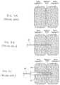
- FIGS. 1 and 2are, respectively, anterior and posterior anatomic views of the human hip girdle comprising the sacrum and the hip bones (the right ilium, and the left ilium), the sacrum being connected with both hip bones at the sacroiliac joint (in shorthand, the SI-Joint).
- FIGS. 3 and 4are embodiments of various implants that can be used for the fusion or fixation of a joint or two bone segments.
- FIG. 5illustrates an axial section view of the SI-Joint with an implant for the fixation of the SI-Joint using a lateral approach that goes laterally through the ilium, the SI-Joint, and into the sacrum S1.
- FIG. 6illustrates an axial section view of the SI-Joint with an implant for the fixation of the SI-Joint using a postero-lateral approach entering from the posterior iliac spine of the ilium, angling through the SI-Joint, and terminating in the sacral alae.
- FIGS. 7 A- 7 Dare side section views of the formation of a broached bore in bone according to one embodiment of the disclosure.
- FIGS. 7 E and 7 Fillustrate the assembly of a soft tissue protector system for placement over a guide wire.
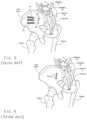
- FIGS. 8 to 10are anatomic views showing, respectively, a pre-implanted perspective, implanted perspective, and implanted anterior view, the implantation of three implant structures for the fixation of the SI-Joint using a lateral approach through the ilium, the SI-Joint, and into the sacrum.
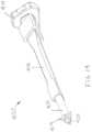
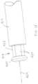
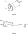
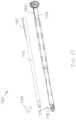
- FIG. 11 Ais a perspective view showing an exemplary embodiment of a decorticating system constructed according to aspects of the present disclosure.
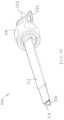
- FIG. 11 Bis an enlarged perspective view showing the cutter of the system of FIG. 11 A .
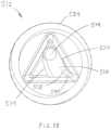
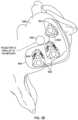
- FIG. 12is an end view depicting an exemplary decortication area provided by the system of FIG. 11 A .
- FIG. 13 Ais a perspective view showing another exemplary cutter that may be used with the system of FIG. 11 A .
- FIG. 13 Bis a perspective view showing another exemplary cutter that may be used with the system of FIG. 11 A .
- FIG. 14is a perspective view showing another exemplary embodiment of a decorticating system.
- FIG. 15is an enlarged perspective view showing the distal end of the system of FIG. 14 .
- FIG. 16is a perspective view showing another exemplary embodiment of a decorticating system.
- FIG. 17is an exploded view showing the components of the system of FIG. 16 .
- FIG. 18is an enlarged end view showing the distal end of the system of FIG. 16 .
- FIG. 19is an enlarged perspective view showing the concave side and radially outward side of the cutter of FIG. 16 .
- FIG. 20is an enlarged side view showing the concave side of the cutter of FIG. 16 .
- FIG. 21is an enlarged perspective view showing the convex side and radially outward side of the cutter of FIG. 16 .
- FIG. 22is an enlarged end view showing the radially outward side of the cutter of FIG. 16 .
- FIG. 23is an end view depicting an exemplary decortication area provided by the system of FIG. 16 when used in a single apex of a triangular soft tissue protector.
- FIG. 24is an end view depicting an exemplary decortication area provided by the system of FIG. 16 when used in all three apexes of a triangular soft tissue protector.
- FIG. 25is a perspective view showing an impactor tool configured for use with the system of FIG. 16 .
- FIG. 26is a perspective view showing a removal tool configured for use with the system of FIG. 16 .
- FIG. 27is a perspective view showing another exemplary embodiment of a decorticating system.
- FIG. 28is an exploded view showing the components of the system of FIG. 27 .
- FIG. 29is a perspective view showing another exemplary embodiment of a decorticating system.
- FIG. 30is a perspective view showing another exemplary embodiment of a decorticating system.
- FIG. 31is an enlarged perspective view showing the distal end of the system of FIG. 30 .
- FIG. 32is a perspective view showing a longitudinal cross-section of another exemplary embodiment of a decorticating system in a retracted state.
- FIG. 33is a side view showing a longitudinal cross-section of the system of FIG. 32 in a retracted state.
- FIG. 34is a perspective view showing another exemplary embodiment of a decorticating system, with the outer components shown in a transparent fashion so that inner features may be seen.
- FIG. 35is an exploded view showing the components of the system of FIG. 34 , with the outer components shown in a transparent fashion so that inner features may be seen.
- FIG. 36is a perspective view showing another exemplary embodiment of a decorticating system, with the outer components shown in a transparent fashion so that inner features may be seen.
- FIG. 37is an exploded view showing the components of the system of FIG. 36 , with the outer components shown in a transparent fashion so that inner features may be seen.
- FIG. 38is a side view showing the right side of a sacrum with the ilium removed for clarity, with an extra channel formed across the SI-Joint according to aspects of the disclosure to aid in decorticating the bone joint.
- FIG. 39is a perspective view showing an exemplary embodiment of a decorticating decortication system having navigational features.
- FIG. 40is a perspective view showing another exemplary embodiment of a decorticating system in a closed state.
- FIG. 41is a perspective view showing the decorticating system of FIG. 40 in an open state.
- FIG. 42is an exploded view showing the components of the decorticating system of FIG. 40 .
- FIG. 43is a pair of distal tip end views showing another exemplary embodiment of a decorticating system in both a closed state (upper inset) and an open state (lower inset.)
- FIG. 44is an exploded view showing the components of another exemplary embodiment of a decorticating system
- a joint of a patientcan be decorticated or selectively decorticated in order to promote bone regeneration and fusion at the implant site.
- Many types of hardwareare available both for the fixation of bones that are fractured and for the fixation of bones that are to be fused (arthrodesed). While the following examples focus on the SI-Joint, the methods, instrumentation and implants disclosed herein may be used for decortication of other body joints as well.
- the human hip girdleis made up of three large bones joined by three relatively immobile joints.
- One of the bonesis called the sacrum and it lies at the bottom of the lumbar spine, where it connects with the L5 vertebra.
- the other two bonesare commonly called “hip bones” and are technically referred to as the right ilium and-the left ilium.
- the sacrumconnects with both hip bones at the sacroiliac joint (in shorthand, the SI-Joint).
- the SI-Jointfunctions in the transmission of forces from the spine to the lower extremities, and vice-versa.
- the SI-Jointhas been described as a pain generator for up to 22% of lower back pain patients.
- sacroiliac joint fusionis typically indicated as surgical treatment, e.g., for degenerative sacroiliitis, inflammatory sacroiliitis, iatrogenic instability of the sacroiliac joint, osteitis condensans ilii, or traumatic fracture dislocation of the pelvis.
- screws or screws with platesare used for sacro-iliac fusion.
- articular cartilagemay be removed from the “synovial joint” portion of the SI-Joint. This can require a large incision to approach the damaged, subluxed, dislocated, fractured, or degenerated joint. The large incision and removal of tissue can cause significant trauma to the patient, resulting in pain and increasing the time to heal after surgery.
- screw type implantstend to be susceptible to rotation and loosening, especially in joints that are subjected to torsional forces, such as the SI-Joint. Excessive movement of the implant after implantation may result in the failure of the implant to incorporate and fuse with the bone, which may result in the need to remove and replace the failed implant.
- FIG. 3 and FIG. 4illustrate straight implants 10 and 20 , respectively, with a solid elongate body 12 or 12 ′ that can be used for the fixation or fusion of two bone segments.
- the implant 10 shown in FIG. 3is cylindrical and can optionally have screw threads along the exterior of the implant body. As mentioned above, cylindrical screw type implants can suffer from excessive rotation.
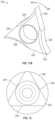
- the implant 20 in FIG. 4which has a non-cylindrical cross-sectional area.
- the implant 20can have a triangular cross-sectional area, although other rectilinear cross-sectional profiles may be used as well, including rectangular, hexagonal and the like.
- Non-cylindrical implantsneed not have a strict rectilinear cross-sectional profile in order to resist rotation.
- a cross-sectional area that is non-circularwill generally suffice.
- a tear drop shaped cross-sectional area, or a cross-sectional area with at least one apexcan resist rotation.
- Other non-circular cross-sectional geometries that may not have a rectilinear componentcan also work, such as oval cross-sections.
- FIG. 5illustrates insertion of the implant 10 or 20 of FIG. 3 or FIG. 4 across the SI-Joint using a lateral approach that goes laterally through the ilium, across the SI-Joint, and into the sacrum.
- FIG. 6illustrates insertion of the same implant across the SI-Joint using a postero-lateral approach entering from the posterior iliac spine of the ilium, angling through the SI-Joint, and terminating in the sacral alae.
- the implants and instrumentation described hereintypically can be inserted across the SI-Joint according to one of these two approaches, or with a similar approach.
- Elongated, stem-like implant structures 10 or 20 like those shown in FIGS. 3 and 4make possible the fixation of the SI-Joint in a minimally invasive manner.
- These implant structurescan be effectively implanted through the use a lateral surgical approach (as shown in FIG. 5 ).
- the proceduremay be aided by conventional lateral, inlet, and outlet visualization techniques, e.g., using X-ray image intensifiers such as a C-arms or fluoroscopes to produce a live image feed, which is displayed on a TV screen.
- one or more implant structures 20are introduced laterally through the ilium, the SI-Joint, and into the sacrum. This path and resulting placement of the implant structure(s) 20 are best shown in FIGS. 9 and 10 . In the illustrated embodiment, three implant structures 20 are placed in this manner. Also in the illustrated embodiment, the implant structures 20 are rectilinear in cross section and triangular in this case, but it should be appreciated that implant structures 20 of other rectilinear cross sections can be used. Additionally, in some procedures (not discussed in further detail herein), implants may be introduced into the SI-Joint from an anterior direction. Further information on anterior techniques may be found in co-pending U.S. patent application Pub. No. 2015/0105828 filed Oct. 15, 2014 and entitled “Implant Placement”. The decortication instruments and methods disclosed herein and variants thereof may also be utilized in these anterior procedures.
- the physiciandiagnoses the SI-Joint segments that are to be fixated or fused (arthrodesed) using, e.g., the Fortin finger test, thigh thrust, FABER, Gaenslen's, compression, distraction, and or diagnostic SI-Joint injection.
- the physicianAided by lateral, inlet, and outlet C-arm views, and with the patient lying in a prone position, the physician aligns the greater sciatic notches and then the alae (using lateral visualization) to provide a true lateral position.
- a 3 cm incisionis made starting aligned with the posterior cortex of the sacral canal, followed by blunt tissue separation to the ilium.
- the guide pin 38(with pin sleeve (not shown)) (e.g., a Steinmann Pin) is started resting on the ilium at a position inferior to the sacrum end plate and just anterior to the sacral canal.
- the guide pin 38In the outlet view, the guide pin 38 should be parallel to the sacrum end plate at a shallow angle anterior (e.g., 15 degree to 20 degree off the floor, as FIG. 10 shows). In a lateral view, the guide pin 38 should be posterior to the sacrum anterior wall. In the outlet view, the guide pin 38 should be superior to the first sacral foramen and lateral of mid-line. This corresponds generally to the sequence shown diagrammatically in FIGS. 7 A and 7 B .
- a soft tissue protector (not shown), and a drill sleeve (not shown) within the soft tissue protectormay be slipped over the guide pin 38 and firmly against the ilium before removing the guide pin sleeve (not shown).
- a pilot bore 42may be drilled with cannulated drill bit 40 , as is diagrammatically shown in FIG. 7 C .
- the pilot bore 42may extend through the ilium, through the SI-Joint, and into the sacrum.
- the drill bit 40 and drill sleeve(not shown) are then removed.
- a shaped broach 44may be tapped into the pilot bore 42 over the guide pin 38 (and through the soft tissue protector, not shown) to create a broached bore 48 with the desired profile for the implant structure 20 , which, in the illustrated embodiment, is triangular. This generally corresponds to the sequence shown diagrammatically in FIG. 7 D .
- the triangular profile of the broached bore 48is also shown in FIG. 8 .
- FIGS. 7 E and 7 Fillustrate an embodiment of the assembly of a soft tissue protector or dilator or delivery sleeve 200 with a drill sleeve 202 , a guide pin sleeve 204 and a handle 206 .
- the drill sleeve 202 and guide pin sleeve 204can be inserted within the soft tissue protector 200 to form a soft tissue protector assembly 210 that can slide over the guide pin 208 until bony contact is achieved.
- the soft tissue protector 200can be any one of the soft tissue protectors or dilators or delivery sleeves disclosed herein.
- an expandable dilator or delivery sleeve 200can be used in place of a conventional soft tissue dilator.
- the expandable dilatorcan be slid over the guide pin and then expanded before the drill sleeve 202 and/or guide pin sleeve 204 are inserted within the expandable dilator. In other embodiments, insertion of the drill sleeve 202 and/or guide pin sleeve 204 within the expandable dilator can be used to expand the expandable dilator.
- a dilatorcan be used to open a channel though the tissue prior to sliding the soft tissue protector assembly 210 over the guide pin.
- the dilator(s)can be placed over the guide pin, using for example a plurality of sequentially larger dilators or using an expandable dilator. After the channel has been formed through the tissue, the dilator(s) can be removed and the soft tissue protector assembly can be slid over the guide pin.
- the expandable dilatorcan serve as a soft tissue protector after being expanded. For example, after expansion the drill sleeve and guide pin sleeve can be inserted into the expandable dilator.
- a triangular implant structure 20can be now tapped through the soft tissue protector over the guide pin 38 through the ilium, across the SI-Joint, and into the sacrum, until the proximal end of the implant structure 20 is flush against the lateral wall of the ilium (see also FIGS. 5 and 10 ).
- the guide pin 38 and soft tissue protectorare withdrawn, leaving the implant structure 20 residing in the broached passageway, flush with the lateral wall of the ilium (see FIGS. 5 and 10 ).
- two additional implant structures 20are implanted in this manner, as FIG. 9 best shows.
- the proximal ends of the implant structures 20are left proud of the lateral wall of the ilium, such that they extend 1, 2, 3 or 4 mm outside of the ilium. This ensures that the implants 20 engage the hard cortical portion of the ilium rather than just the softer cancellous portion, through which they might migrate if there was no structural support from hard cortical bone.
- the hard cortical bonecan also bear the loads or forces typically exerted on the bone by the implant 20 .
- the implant structures 20are sized according to the local anatomy.
- representative implant structures 20can range in size, depending upon the local anatomy, from about 35 mm to about 60 mm in length, and about a 7 mm inscribed diameter (i.e. a triangle having a height of about 10.5 mm and a base of about 12 mm).
- the morphology of the local structurescan be generally understood by medical professionals using textbooks of human skeletal anatomy along with their knowledge of the site and its disease or injury. The physician is also able to ascertain the dimensions of the implant structure 20 based upon prior analysis of the morphology of the targeted bone using, for example, plain film x-ray, fluoroscopic x-ray, or MM or CT scanning.
- one or more implant structures 20can be individually inserted in a minimally invasive fashion across the SI-Joint, as has been described.
- Conventional tissue access tools, obturators, cannulas, and/or drillscan be used for this purpose.
- the novel tissue access tools described above and in U.S. Provisional Patent Application No. 61/609,043, titled “TISSUE DILATOR AND PROTECTOR” and filed Mar. 9, 2012, and in U.S. Published Application No. 2017/0007409, titled “SYSTEMS, DEVICES, AND METHODS FOR JOINT FUSION” and filed Jul. 12, 2016,can also be used.
- No joint preparation, removal of cartilage, or scrapingare required before formation of the insertion path or insertion of the implant structures 20 , so a minimally invasive insertion path sized approximately at or about the maximum outer diameter of the implant structures 20 can be formed.
- the implant structures 20can obviate the need for autologous bone graft material, additional pedicle screws and/or rods, hollow modular anchorage screws, cannulated compression screws, threaded cages within the joint, or fracture fixation screws. Still, in the physician's discretion, bone graft material and other fixation instrumentation can be used in combination with the implant structures 20 .
- implant structures 20can be used, depending on the size of the patient and the size of the implant structures 20 .
- the patientAfter installation, the patient would be advised to prevent or reduce loading of the SI-Joint while fusion occurs. This could be about a six to twelve week period or more, depending on the health of the patient and his or her adherence to post-op protocol.
- the implant structures 20make possible surgical techniques that are less invasive than traditional open surgery with no extensive soft tissue stripping.
- the lateral approach to the SI-Jointprovides a straightforward surgical approach that complements the minimally invasive surgical techniques.
- the profile and design of the implant structures 20minimize or reduce rotation and micromotion.
- Rigid implant structures 20 made from titaniumprovide immediate post-op SI-Joint stability.
- a bony in-growth region 24 comprising a porous plasma spray coating with irregular surfacesupports stable bone fixation/fusion.
- the implant structures 20 and surgical approachesmake possible the placement of larger fusion surface areas designed to maximize post-surgical weight bearing capacity and provide a biomechanically rigorous implant designed specifically to stabilize the heavily loaded SI-Joint.
- a fenestrated matrix implantmay be used, providing cavities in which to pack bone growth material, and or providing additional surface area for bone on-growth, in-growth and or through-growth.
- the implantcan be inserted across three or more cortical walls. For example, after insertion the implant can traverse two cortical walls of the ilium and at least one cortical wall of the sacrum.
- the cortical boneis much denser and stronger than cancellous bone and can better withstand the large stresses found in the SI-Joint.
- the implantcan spread the load across more load bearing structures, thereby reducing the amount of load borne by each structure.
- movement of the implant within the bone after implantationis reduced by providing structural support in three locations around the implant versus two locations.
- the implant(s) 10 or 20may be placed in the implant bore(s) 48 ( FIG. 8 ) with no additional preparation of the SI-Joint.
- all or portions of the articulating surfaces of the SI-Jointmay be decorticated, typically prior to placing the implant(s), as will now be described.
- Cutting instrument 300is provided with a main body 310 which has triangular portions 312 and 314 at its distal and proximal ends, respectively. Triangular portions 312 and 314 are configured to be slidably received within the triangular bore of the soft tissue protector 200 shown in FIG. 7 E and prevent body 310 from rotating within soft tissue protector 200 .
- a stop 316may be located proximal to the proximal triangular portion 314 . Stop 316 is configured to abut against the proximal end of soft tissue protector 200 to limit the distal travel of body 310 into soft tissue protector 200 .
- Body 310is provided with a cylindrical bore therethrough along its longitudinal axis for slidably and rotatably receiving drive shaft 318 .
- Drive shaft 318may be provided with a longitudinal bore 320 sized to slide over guide pin 208 (shown in FIG. 7 E .)
- Cutter 322may be located on or near the distal end of drive shaft 318 , and affixed thereto by threading, welding, press fitting, adhesive, or other suitable attachment means such that cutter 322 rotates in unison with drive shaft 318 .
- a handle 324may be provided at the proximal end of drive shaft 318 to allow an operator to manually rotate cutter 322 .
- a motor or other drive mechanism(not shown) may be coupled to drive shaft 318 to allow automatic rotation.
- cutter 322is provided with three radially extending cutting tips, each extending the same distance from bore 320 and the axis of rotation.
- Cutter 322is shaped and sized to fit through the triangular bore of soft tissue protector 200 (shown in FIG. 7 E ) and through the triangular bore 48 broached in the bone (shown in FIG. 7 D .)
- handle 324shown in FIG. 11 A
- cutter 322may be rotated in the space or joint between bone segments by rotating handle 324 ( FIG. 11 A .) When rotated, cutter 322 will cut into the face of Bone Segment 1 (e.g. the ilium) and or the face of Bone Segment 2 (e.g. the sacrum), creating a circular region of decortication.
- Bone Segment 1e.g. the ilium
- Bone Segment 2e.g. the sacrum
- At least one edge of cutter 322may be provided with a flat portion 326 and a curved portion 328 .
- flat portion(s) 326engage with the bone to decorticate
- curved portion(s) 328engage with the bone to decorticate.
- a generally radially extending edge of curved portion(s) 328may be provided with a chamfer 334 and an opposite generally radially extending edge may be left sharp, as shown in FIG. 11 B .
- the radially extending edges on both sides of curved portion(s) 328may be left sharp. While the illustrated embodiment shows a cutter 322 having three teeth or cutting extensions, other embodiments (not shown) may have one, two or more than three teeth.
- Cutter 322may be sized to completely fill the interior cross-section of the soft tissue protector 200 so that the reach of its cutting tips when rotated outside of this cross-section can be maximized.
- the outer circle 340 in FIG. 12depicts the area reached by cutter 322 .
- the generally triangular area 342 within circle 340represents the cross-sectional area of broached bore 48 formed in the bone, and the cross-sectional area of the implant.
- the three shaded segments 344represent the decorticated area of the bone face (i.e.
- the total decorticated area of the three segments 344is about 0.64 cm 2 (on one side of the joint.) In typical procedures wherein both sides of the joint are decorticated, this area is generally the same on both joint surfaces.
- the cross sectional area of the triangular working channel of the soft tissue protector 200is also about 0.64 cm 2 (having a base of 1.05 cm and a height of 1.212 cm.) Accordingly, the decorticated area of the joint provided by this exemplary instrument may be about equal to the working channel it passes through.
- the axial thickness of cutter 322is 3 mm. In some embodiments, the axial thickness of cutter 322 may be sized to be thicker than the space or joint between the bone segments so that the surfaces of both bone segments can be decorticated at the same time. In other embodiments, the axial thickness of cutter 322 may be sized to be thinner than the space or joint between the bone segments so that only one of the surfaces of the bone segments can be decorticated, or so that one surface can first be decorticated, cutter 322 can be moved axially, and then the other surface can be decorticated. In such embodiments, the surgeon is provided with the ability to decorticate each surface independently, with different depths of decortication, different amounts of force applied, etc.
- handle 324may be provided with one or more flat portions 346 and or other clocking/indexing features showing the rotational orientation of drive shaft 318 and cutter 322 relative to soft tissue protector 200 .
- flat portion 346By aligning flat portion 346 with one of the flat sides of stop 316 , the surgeon can see that cutter 322 is rotationally lined up with the triangular bore of soft tissue protector 200 so that cutter 322 may be withdrawn through the triangular bore.
- a ball detent feature, magnets, lights and or soundmay be provided to aid in determining when cutter 322 is properly aligned for withdrawal.
- cutting instrument 300may be used to decorticate bone surface(s) as follows. As previously described, an incision through soft tissue may be made and a guide pin 208 (shown in FIG. 7 F ) may be placed along a desired path where an implant is to be inserted. A pin sleeve 204 , drill sleeve 202 and soft tissue protector 200 (shown in FIG. 7 E ) may be placed over the guide pin 208 until the distal end of soft tissue protector contacts an outer bone surface (such as a lateral surface of an ilium.) Pin sleeve 204 may then be removed and replaced with a cannulated drill bit over the guide pin 208 to begin forming a bore through the first bone segment (e.g.
- the drill bit and drill sleeve 202may then be removed and a triangular shaped broach may be passed over the guide pin and through soft tissue protector 200 to complete the bore.
- the broachmay then be removed and cutter instrument 300 inserted over guide wire 322 such that cutter 322 passes through soft tissue protector 200 , through the first bone segment and into the space or joint between the bone segments (e.g. the SI-Joint.) Imaging, such as a fluoroscope, may be used to confirm that cutter 322 is located in the desired location within the joint.
- Handle 324may then be rotated in one or both directions to decorticate one or both surfaces of the joint.
- cutter 322may be further advanced distally and or retracted proximally.
- Cutting instrument 300may then be removed and a triangular shaped implant passed over guide wire 322 , through soft tissue protector 200 , and tapped into place across the joint.
- guide wire 322 and soft tissue protector 200may be removed and the incision closed.
- a guide pinis not used, is placed later in the procedure, and or is removed earlier than described above.
- the drill bitis not cannulated or is not used.
- bone graftsuch as autograft and/or other bone growth inducing material may be placed in the decorticated area, before and/or after an implant is placed.
- a triangular componentmay be provided distal to the cutting element for guiding the cutting element toward the implant bore formed on the opposite side of the bone joint, and or for stabilizing the cutting element during operation.
- Cutter 322 Bmay be provided with curved and or straight, flexible metal bristles, ribbons, or blades 326 B. As cutter 322 B is rotated the bristles are able to deflect/flex to conform to the SI-Joint's irregular surfaces. The flexible bristles can scrape through the joint cartilage, scratch the cortical bone, but not cut away the cortical bone. This leaves the cortical wall intact for better implant support.
- the cartilageis captured by the bristles like a whisk and can be removed by re-aligning the cutter with the implant bore and removing the instrument from the bone. While the illustrated embodiment shows cutter 322 B having bristles all in a line, other embodiments, such as cutter 322 C shown in FIG. 13 B , may have multiple bristles that point in other directions while still maintaining a substantially triangular shape.
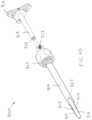
- FIG. 14another exemplary embodiment of a decorticating system and method is shown.
- the construction and use of cutting instrument 400 illustrated in FIG. 14is similar to that of cutting instrument 300 illustrated in FIG. 11 A .
- cutting instrument 400is provided with a larger knob 410 at the proximal end of drive shaft 412 in order to allow the surgeon to apply more torque to cutter 414 at the distal end of drive shaft 412 .
- Knob 410may be generally triangular in shape as shown, to more easily identify the angular orientation of cutter 414 when aligning it with the main body 416 prior to retracting cutter 414 through the soft tissue protector, as previously described.
- FIG. 15an enlarged view of the distal end of drive shaft 412 of cutting instrument 400 is shown with cutter 414 removed.
- Cutter 414(shown in FIG. 14 ) is provided with a central hexagonal through bore (not shown.)
- the distal end of drive shaft 412is provided with a mating hexagonal rod portion 418 as shown in FIG. 15 , configured to be slidably received through the hexagonal bore in cutter 414 .
- Retainer ring 420is attached to hexagonal rod portion 418 as shown in FIG. 15 to retain cutter 414 in place on rod portion 418 .
- cutter 414 of cutting instrument 400would rotate in the same way as cutter 322 of cutting instrument 300 shown in FIG. 11 A (i.e. would remain in a plane perpendicular to the axis of rotation 422 .)
- the outer surfaces 422 of hexagonal rod portion 418each have a convex curvature.
- hexagonal rod portion 418is thicker at its center than at its proximal and distal ends. This arrangement allows cutter 414 to tip in either direction relative to axis 424 . In some embodiments, cutter 414 may tip up to plus or minus 5 degrees from perpendicular.
- cutter 414may tip more than 5 degrees. Allowing cutter 414 to assume an angle that is not perpendicular to the axis of rotation 424 can be beneficial in situations where the implant bore is not formed perpendicular to the bone joint. For example, if an implant bore in made across an SI-Joint such that the bore crosses the joint's articulating surfaces at an 85 degree angle, allowing cutter 414 to tip to a matching angle of 85 degrees allows cutter 414 to more uniformly decorticate the surfaces of the SI-Joint around the bore implant.
- the hexagonal rod portion 418 and the hexagonal bore in cutter 414may be replaced with a resilient material (such as Tygon® or other biocompatible polymer) at the distal end of the drive shaft 412 and or central hub section of cutter 414 .
- a resilient materialsuch as Tygon® or other biocompatible polymer
- the angle of the cuttermay be actively controlled or adjusted.
- one or more movable pinsmay be provided through the main body of the cutting instrument. When a pin is pushed distally against the proximal side of the cutter, that side of the cutter is angled away from the pin and the cutter's angle relative to the axis of rotation is actively changed from being perpendicular to non-perpendicular. As the cutter rotates, it maintains this set angle, even if forces from the bone joint may be urging it back towards perpendicular.
- the distal end of the pin(s)directly contact a circular race located on the proximal side of the cutter.
- the distal end of the pin(s)contact a ring that is set to a desired angle, and the ring in turn urges the cutter to the desired angle. If the pin(s) are connected to the ring, they may be pushed or pulled by the surgeon to change the angle of the ring and cutter.
- FIG. 16is a perspective view showing cutting instrument 500
- FIG. 17is an exploded view showing individual components of the instrument
- FIG. 18is an enlarged end view showing the distal end of instrument 500 .
- Cutting instrument 500is similar in construction and use to the previously described instruments.
- Cutting instrument 500may be provided with a cutter 510 , main body 512 , drive shaft 514 , washer 516 , adjustable stop 518 , handle 520 and set screw 522 .
- Triangularly shaped main body 512may have a reduced cross-section near its distal end to enable it to more freely pass through an implant bore in bone, while the larger cross-section at the proximal end maintains a sliding fit with a soft tissue protector (not shown), as previously described.
- drive shaft 514may be stepped down at its distal end as shown in FIG. 17 .
- Drive shaft 514is received through a bore in main body 512 that is off-axis or laterally displaced from the longitudinal centerline of main body 512 , as best seen in FIG. 18 .
- Non-symmetrical cutter 510is attached to the distal end of drive shaft 514 such that its profile fits within the cross-section of the soft tissue protector and implant bore in at least one orientation.
- This arrangement of an off-axis drive shaft 514 and non-symmetrical cutter 510allows the cutter to reach farther away laterally from main body 512 into the bone joint when the drive shaft and cutter are rotated.
- cutter 510when cutter 510 is rotated in one direction, its leading edge comprises a concave or scooped cutting edge, and when rotated in the opposite direction the leading edge comprises a convex cutting edge.
- main body 512may be provided with external threads 524 configured to mate with internal threads 526 within adjustable stop 518 . Rotation of stop 518 then causes the stop to move proximally or distally with respect to main body 512 , such that the depth that cutter 510 can travel may be adjusted.
- Handle 520may be attached to the proximal end of drive shaft 514 to allow a surgeon to rotate cutter 510 . Handle 520 may also be shaped and angularly oriented similar to cutter 510 so the surgeon has a visual indication of what cutter 510 is doing inside the implant bore.
- the proximal end of drive shaft 514is provided with a flat portion on one side which protrudes from the proximal end of main body 524 , through washer 516 and into a D-shaped mating hole in handle 520 to maintain a proper orientation between drive shaft 514 and handle 520 . Similar features (not shown) may be provided between cutter 510 and the distal end of drive shaft 514 to maintain a desired angular orientation between the two.
- Set screw 522may be threadably engaged with handle 520 , offset from the axis of rotation of drive shaft 514 and handle 520 .
- a detent bore(not shown) may be provided in the proximal end of main body 512 for receiving the distal end of set screw 522 when it is distally advanced through handle 520 .
- a surgeonmay lock the angular orientation of cutter 510 by threading set screw 522 into its detent so that the cutter is aligned for passing through the soft tissue protector and into the implant bore in the bone segment(s).
- set screw 522may be unscrewed until it is withdrawn from the detent bore in main body 512 , thereby allowing cutter 510 to be rotated by handle 520 .
- set screw 522Before cutter 510 is withdrawn from the joint along with main body 512 through the soft tissue protector, set screw 522 can be aligned with the detent bore so that set screw 522 may be threaded into it. In other embodiments (not shown), an indicia line or other marking may be used instead of or in addition to handle 520 to indicate when cutter 510 is in a proper orientation for removal.
- off-axis cutting instrument 500may be cannulated so as to slide over a guide wire that has been placed into the joint.
- a handle at the proximal end of drive shaft 514may be configured so that it may be rotated without interfering with the guide wire.
- a removable wrenchmay be provided such that additional torque may be applied to the cutter.
- FIGS. 19 - 22various enlarged views of cutter 510 are shown.
- the proximal side of cutter 510is facing generally up.
- FIG. 19is a perspective view showing the concave side 530 and radially outward side 532 of cutter 510
- FIG. 20is a side view showing concave side 530
- FIG. 21is perspective view showing the convex side 534 and radially outward side 532
- FIG. 22is an end view showing the radially outward side 532 .
- Cutter 510may be provided with a bore 536 for receiving the distal end of the drive shaft, as previously described.
- the proximal (top) and distal (bottom) faces of cutter 510may each be provided with an inner scraper 538 and an outer scraper 540 (also shown in FIG. 18 .)
- the main arm of cutter 510 that protrudes radially outward from bore 536is 2 mm thick, and scrapers 538 and 540 each protrude axially 0.5 mm from the arm, resulting in a maximum cutter arm thickness of 3 mm.
- the concave side 530 of cutter 510may be provided with flat section and a curved section radially outward from the flat section (best seen in FIG. 18 .) Concave side 530 may also be provided with a round-bottom channel or scoop 542 extending along a portion of its length, with beveled cutting edges located above and below channel 542 . On the opposite side of the cutting arm, convex side 534 may be configured with a single, large, curved bevel, as best seen in FIGS. 21 and 22 .
- cutter tool 500is first operated in a counterclockwise direction such that convex side 534 is the leading edge of cutter 510 , then operated in a clockwise direction such that concave side 530 becomes the leading edge. This allows convex side 534 to first cut through the cartilage of the joint, then allows concave side 530 to scrape the cartilage from the bone faces. Scrapers or teeth 538 and 540 on both ends of cutter 510 allow for further scraping of cartilage. In some embodiments the scooped side of the cutter when rotated directs cartilage and or bone tissue into the implant bore.
- the decortication area produced by off-axis cutter system 500is shown.
- the outer circle 590 in FIG. 23depicts the area reached by cutter 510 when it is located in the upper apex of main body 512 .
- the generally triangular area 592 within circle 590represents the cross-sectional area of broached bore 48 formed in the bone, and the cross-sectional area of the implant.
- the shaded areai.e. the area inside circle 590 but outside triangular area 592 ) represents the decorticated area of the bone. In some embodiments, this decorticated area is about 1.48 cm2 (on one side of the joint.) In typical procedures wherein both sides of the joint are decorticated, this area is generally the same on both joint surfaces.
- the cross sectional area of the triangular working channel of the soft tissue protector 200is also about 0.64 cm2 (having a base of 1.05 cm and a height of 1.212 cm.) Accordingly, the decorticated area of the joint provided by this exemplary instrument may be more than double that of the working channel it passes through.
- off-axis cutter 510may be operated in all three apices of the soft tissue protector to achieve an even larger area of decortication.
- main body 512 of instrument 500may be introduced into a soft tissue protector in one orientation as described above to achieve the decortication pattern depicted in FIG. 23 .
- main body 512is withdrawn, rotated 120 degrees, and reinserted into the soft tissue protector to decorticate around another apex of the soft tissue protector. This procedure is repeated until the area around all three apexes is decorticated, as depicted by the 3-lobed area 594 in FIG. 24 .
- the shaded areai.e. the area inside perimeter 594 but outside triangular area 592 ) represents the decorticated area of the bone.
- this decorticated areais about 2.81 cm2 (on one side of the joint.) In typical procedures wherein both sides of the joint are decorticated, this area is generally the same on both joint surfaces. These areas are almost double the areas depicted in FIG. 23 when cutting instrument 500 is used in only one apex of the soft tissue protector.
- the cross sectional area of the triangular working channel of the soft tissue protector 200is also about 0.64 cm2 (having a base of 1.05 cm and a height of 1.212 cm.) Accordingly, the decorticated area of the joint provided by this exemplary instrument may be more than four times that of the working channel it passes through.
- an impactor tool 600is shown for use with off-axis cutter system 500 .
- Impactor 600may be provided with a cupped distal end 610 as shown, for mating with the proximal end of adjustable stop 518 (shown in FIG. 16 .)
- a cutout portion 612may be provided in the cupped distal end 610 so that impactor 600 may be slid on to the proximal end of cutter instrument 500 from the side before moving the cupped end distally over stop 518 .
- Cutout portion 612may also be configured to allow handle 520 (also shown in FIG. 16 ) to extend therethrough.
- the proximal end 614 of impactor 600may be provided with an enlarged impact surface against which a hammer may be used. With this arrangement, the distal end of cutter instrument 500 may be tapped into place through the implant bore in the bone using a hammer, without damaging the components located on the proximal end of main body 512 .
- a removal tool 620is shown for use with off-axis cutter system 500 .
- the distal end of removal tool 620may be half-cylinder shaped so that it may be slid onto adjustable stop 518 (shown in FIG. 16 ) from the side.
- the distal end of removal tool 620may be provided with a radially inwardly extending lip 630 configured to engage the distal underside of adjustable stop 518 .
- the middle of removal tool 620may comprise a rod portion 632 configured to slidably receive a weighted handle member (not shown.)
- An enlarged head portion 634may be provided at the proximal end of rod portion 632 as shown, to captivate the weighted handle member on the rod portion and provide it with an impact surface.
- removal tool 620may be operated as a slide hammer (also known as a slap hammer) to apply impact force to the distal side of stop 518 so that cutter tool 500 may be pulled out from the implant bore formed in the bone.
- FIG. 27is a perspective view showing cutting instrument 650
- FIG. 28is an exploded view showing components of the instrument.
- Cutting instrument 650is similar in construction and use to the previously described instruments.
- Cutting instrument 650may be provided with a main tube 660 , a nitinol strip 662 , and a cap rod 664 .
- Main tube 660may be provided with a handle 666 at its proximal end for rotating the instrument about its longitudinal axis.
- a window 668may be provided to allow a distal loop 670 of the nitinol strip 662 to be alternately extended and retracted through the window 668 .
- cap rod 664has a semi-circular cross-section, with the flat side facing down (not seen in the figures.)
- nitinol strip 662extends along the flat bottom side of cap rod 664 , up along the rounded distal end of cap rod 664 , and into slot 672 .
- Cap rod 664 and strip 662are received within a central bore (not shown) in tube 660 .
- An upwardly curved surfacemay be provided at the distal end of the central bore to help guide strip 662 from the end of the central bore out through window 668 .
- one or both edges of the distal loop 670 of strip 662are left square, and in other embodiments one or both edges are sharpened.
- the distal end of instrument 650may be advanced through a soft tissue protector as with previously described embodiments and into a bone joint of a patient.
- Loop 670 of strip 662remains retracted within tube 660 (or only slightly protruding through window 668 ) as instrument 650 is being advanced.
- window 668is positioned within the joint space, a proximal portion of strip 662 may be distally advanced, such as with a handle or other means (not shown.)
- the radial extension of loop 670may be varied depending on how far strip 662 is distally advanced, but the width of loop 670 is held to a predetermined constant width by the proximal and distal edges of window 668 .
- handle 666is turned in one or both directions to decorticate one or both sides of the joint.
- the proximal portion of strip 662is then retracted proximally to retract loop 670 into window 668 so that instrument 650 may be withdrawn.
- instrument 650may be used in conjunction with a guidewire (not shown.) With the guidewire in place across a bone joint, main tube 660 may be advanced along the guidewire without nitinol strip 662 and cap rod 664 in place inside the tube. The guidewire may then be removed from the joint and nitinol strip 662 and cap rod 664 inserted through main tube 660 .
- instrument 650may be configured to allow nitinol strip 662 and cap rod 664 to be inserted into main tube 660 before it is placed over the guidewire and into the bone joint.
- Cutting instrument 680is very similar in construction and use to decorticating system 650 shown in FIGS. 27 and 28 . However, instead of having a nitinol strip 662 with a U-shaped distal end 670 (as best seen in FIG. 28 ), cutting instrument 680 is provided with a nitinol strip 690 having a lollipop-shaped distal end 692 . One or both edges of distal end 692 may be sharpened as shown. A series of holes and or protrusions may also be provided such as those shown to allow distal end 692 to have a rasp-like action.
- an annular-shaped decorticated areais formed when distal end 692 is rotated about the longitudinal axis of instrument 680 . Leaving non-decorticated bone directly adjacent to the implant may increase the stability of the implant. By making a full revolution with distal end 692 , a donut-shaped cut is made around the implant bore. Alternatively, a partial revolution may be made, leaving an arc of decorticated area, with a central non-decorticated region connected to an outward non-decorticated region. In some embodiments, this arc extends 120 degrees.
- distal end 692may be extended, rotated a partial revolution, retracted and further rotated (so that it is no longer decorticating bone), extended again, and further rotated, to create multiple arcs of decorticated area.
- the central non-decorticated regionmay be connected to the outward non-decorticated region by two or more spokes of non-decorticated bone.
- FIG. 30is a perspective view showing cutting instrument 700 in an expanded state
- FIG. 31is an enlarged view showing the distal end of the instrument in the expanded state.
- Cutting instrument 700is similar in construction and use to the previously described instruments.
- Cutting instrument 700may be provided with a main body 710 , inner body 712 , connecting arm 714 and cutting arm 716 .
- Inner body 712may be partially received in a bore in main body 710 , and may slidably move distally and proximally with respect to main body 710 , as depicted by Arrow A in FIG. 30 .
- connecting arm 714may be pivotally connected to the distal end of inner body 712 by a first pin (not shown) located on axis 718 .
- the distal end of connecting arm 714may be pivotally connected to a mid-portion of cutting arm 716 by a second pin (not shown) located on axis 720 .
- the distal end of cutting arm 716may be pivotally connected to a distal portion of main body 710 by a third pin (not shown) located on axis 722 .
- connecting arm 714moves radially outward to the position shown as the proximal end rotates about axis 718 .
- connecting arm 714 and cutting arm 716move radially inward to a retracted position (not shown.)
- connecting arm 714 and cutting arm 716are in the retracted position, they fit into complementary shaped recesses in the distal end of main body 710 such that the assembly generally forms a cylindrical shape. In some embodiments, this cylindrical shape does not exceed 7 mm, allowing the distal end of instrument 700 to fit within a 7 mm bore in the bone.
- cutting instrument 700may be rotated to allow cutting arm 716 to decorticate the bone joint.
- connecting arm 714may serve as a cutter as well, or instead of arm 716 .
- FIG. 32is a perspective view and FIG. 33 is a side view, both showing longitudinal cross-sections of cutting instrument 730 in a retracted state.
- Cutting instrument 730is similar in construction and use to the previously described instruments.
- Cutting instrument 730may be provided with a main tube 740 , a wedge 742 , an actuation knob 744 , a cutting piece 746 , and a compression spring 748 .
- wedge 742is an elongated rod with a ramp formed on its distal end and external threads formed on its proximal end. Wedge 742 may be received within a central bore of main tube 740 . Inter-engaging features (not shown) may be provided on main tube 740 and wedge 742 to allow longitudinal movement but prevent rotational movement with respect to one another. The proximal end of main tube 740 may be provided with an outwardly protruding ring 750 or similar feature to captivate actuation knob 744 on main tube 740 , prevent it from moving longitudinally but allow it to rotate with respect to main tube 740 and wedge 742 .
- the proximal end of wedge 742may be provided with external threads that mate with the internal threads of actuation knob 744 , such that when knob 744 is turned in one direction wedge 742 is driven distally, and when turned in the opposite direction knob 744 drives wedge 742 proximally.
- the distal end of main tube 740may be provided with a window 752 which permits cutting piece 746 to move radially outward from a retracted position (as shown) to an extended position (not shown), in which a portion of cutting piece 746 extends beyond the outer diameter of main tube 740 .
- Cutting piece 746may be provided with a portion that engages with the ramp formed on the distal end of wedge 742 .
- FIG. 34is a perspective view showing cutting instrument 760
- FIG. 35is an exploded view showing components of the instrument, with both figures showing the outer components in a transparent fashion so that inner features may be seen.
- Cutting instrument 760is similar in construction and use to the previously described instruments.
- Cutting instrument 760may be provided with a main body 770 , a drive rod 772 and a cutter arm 774 .
- Drive rod 772may be slidably received within a central bore in main body 770 .
- Cutter arm 774may be pivotably attached to the distal end of drive rod 772 with a pin (not shown.)
- the distal end of main body 770may be provided with a window 776 radially connecting the central bore of main body 770 with the exterior.
- An outwardly extending ramp 778may be provided at the distal end of the central bore such that when drive rod 772 and cutter arm 774 are urged in a distal direction, a distal, curved portion of cutter arm 774 engages with ramp 778 and cutter arm 774 is pivoted radially outward through window 776 .
- instrument 760may be rotated to decorticate the bone joint. Pulling proximally on drive rod 772 causes the proximal side of cutter arm 774 to contact the proximal side of window 776 , causing cutter arm 774 to retract within main body 770 .
- a longitudinally extending spline 780 or similar featuremay be provided on the exterior of drive rod 772 for mating with a groove 782 located on the interior of main body 770 .
- This arrangementallows drive rod 772 to slide longitudinally but not rotate inside main body 770 , to preserve the correct orientation of cutter arm 774 with respect to window 776 .
- the main bodymay be provided with telescoping features to allow its length to be adjusted.
- FIG. 36is a perspective view showing cutting instrument 800
- FIG. 37is an exploded view showing components of the instrument, with both figures showing the outer components in a transparent fashion so that inner features may be seen.
- Cutting instrument 800is similar in construction and use to the previously described instruments.
- Cutting instrument 800may be provided with a main assembly 810 and a rasp assembly 812 that fits over the distal portion of main assembly 810 .
- the distal tip of main assembly 810is provided with a broach 814 .
- Broach 814may have a triangular cross-section as shown, for forming a channel across a bone joint for receiving a triangular implant.
- the distal end of rasp assembly 812may be provided with a flexible, tubular-shaped wire rasp 816 . Both FIGS. 36 and 37 show rasp 816 in a radially retracted state. Rasp 816 may be connected to an actuation handle 818 by a slotted tube 820 .
- longitudinal rails 822project radially inward from the inside diameter of a main tubular portion of main assembly 810 and through the elongated slots of slotted tube 820 . This arrangement allows rasp assembly 812 to move axially but not rotate with respect to main assembly 810 .
- the distal end of instrument 800is tapped across a bone joint as broach 814 forms or further forms an implant bore in the bone segments on either side of the bone joint.
- Rasp 816is positioned such that its center generally resides in the joint space.
- Actuation handle 818is then pushed distally, causing tubular rasp 816 to be pushed against the proximal side of broach 814 , foreshorten and expand into the joint space.
- the central portion of rasp 816will generally take on a disc shape having a larger diameter, and a thickness generally equal to the width of the joint space.
- the proximal and distal portions of rasp 816may maintain their original cylindrical shape.
- Instrument 800may then be rotated, causing rasp 816 to decorticate bone face(s) of the joint.
- instrument 800By urging instrument 800 in the proximal and or distal direction(s), more force may be applied to one bone face as rasp 816 is rotated.
- actuation handle 818may be pulled proximally to retract rasp 816 toward its original shape so that it may be removed from the bone joint.
- FIG. 38shows the right lateral side of a sacrum 838 , with the ilium removed for clarity.
- one or more extra channelsmay be formed in the bone to aid in decorticating the bone joint. These channels may have a circular, triangular, or other shape.
- an extra triangular channel(not shown) may be formed through the right ilium and into and/or across an SI-Joint. The extra channel may be formed parallel to one or more implant bores 850 . This extra channel is not used to receive an implant 852 as are the other three channels 850 shown in FIG. 38 .
- the decortication instrumentmay be used to decorticate or aid in decorticating the area(s) around the implant bore(s) 850 , and or it may be used to decorticate an area 840 around the extra bore.
- the decortication instrumentmay be used to decorticate or aid in decorticating the area(s) around the implant bore(s) 850 , and or it may be used to decorticate an area 840 around the extra bore.
- three implant bores 850are created across the SI-Joint, each for receiving an implant 852 .
- bores 850 and the extra boreare used to decorticate the bone joint adjacent to each bore, such as previously described. Bone graft chips or other filler material may be placed into the extra channel after it is used for decortication.
- the typical spacing between implantsis about 15 mm.
- some or all of the boomerang shaped articular region 854 of the SI-Jointis decorticated. In some embodiments, decortication is performed posterior or dorsal to the articular region.
- navigation array 870may be permanently or removably mounted near the proximal end of drive shaft 318 of decortication system 300 .
- four emitters or reflectors 880are located at predetermined and unique distances from one another on array 870 to generate a signal representing the trajectory, depth and or orientation of cutter 322 relative to a portion of a patient's anatomy.
- navigation array 870may include tracking devices capable of being tracked by a corresponding sensor array, such as, for example, a tracking device that actively generates light signals, acoustic signals, magnetic signals, electromagnetic signals and or radiologic signals.
- Array 870may passively reflect such signals that are then received by a corresponding sensor array.
- four reflectors 880may be provided in the form of reflective spheres of a predetermined diameter whose positions are tracked by navigation system cameras. Further details on how such navigation systems may be implemented can be found in the following references: U.S. Pat. No. RE45,484 to Foley et al., U.S. Pat. No. 8,467,851 to Mire et al., U.S. Pat. No.
- Medtroniccurrently provides a navigation array under the product name SureTrak® for use with their StealthStation® surgical imaging and navigation system.
- FIG. 40shows cutting instrument 900 in a closed state
- FIG. 41shows the instrument in an open state
- FIG. 42is an exploded view showing components of the instrument.
- System 900includes three thin blades 910 to help align the cutter 912 with the instrument body 914 as it's being advanced and removed from the pelvis and soft tissue protector.
- Instrument 900further includes handle 916 , drive shaft 918 , adjustable stop 920 , ball-nose spring plunger 922 , and washer stop 924 (shown only in FIG. 42 .)
- the proximal ends of blades 910may be rigidly attached to recesses 925 located at the distal end of body 914 .
- drive shaft 918may be provided with two detents 926 and 928 .
- Each detentis configured to alternately engage with ball-nose spring plunger 922 when it is threaded into the proximal end of body 914 .
- Handle 916may be used to pull drive shaft 918 proximally so that plunger 922 engages with distal detent 926 and cutter 912 is retracted into blades 910 as shown in FIG. 40 , or to push drive shaft 918 distally so that plunger 922 engages with proximal detent 928 and cutter 912 is extended from blades 910 as shown in FIG. 41 .
- Cutter 912may be placed in the retracted state as shown in FIG. 40 when instrument 900 is being moved into and out of the patient, and may be placed in the extended state as shown in FIG. 41 when being used to decorticate a bone joint.
- FIG. 43shows a distal tip end view of instrument 940 , both in a closed position (upper inset figure) and an open position (lower inset figure.)
- Instrument 940has a tubular body 950 , a drive shaft 952 located within the body 950 , and a decorticating wire 954 having ends attached to both the drive shaft 952 and tubular body 950 .
- wire 954is wound around drive shaft 952 and retracted within body 950 , as shown in the upper inset.
- wire 954at least partially unwinds from drive shaft 952 and extends radially outward through an opening in body 950 , as shown in the lower inset.
- the distal tip of instrument 940may be advanced into the bone joint of a patient when the instrument is in the closed position.
- the instrumentmay then be moved into its open position as described above to extend the cutting wire 954 , and the entire instrument may then be rotated about its longitudinal axis to decorticate the bone joint with wire 954 .
- the wire 954may then be retracted again to remove the instrument from the patient.
- wire 954 of instrument 940may be coated with an abrasive.
- Wire 954may include attached cutters, barbs, sharp edges, a square cross-section, twisted filaments, lines/slots cut therein, etc. (not shown.)
- FIG. 44is an exploded view showing components of system 970 .
- System 970includes an outer tube 980 , an inner drive shaft 982 , a handle 984 attached to the proximal end of drive shaft 982 , a right-hand threaded tube 986 , a left-hand threaded tube 988 , and a cutting band 990 spanning between tubes 986 and 988 as shown.
- Inner drive shaft 982is received within a central bore of outer tube 980 and retained there by a retainer clip 992 .
- drive shaft 982is provided with a right-hand threaded section 994 and a left-hand threaded section 996 for receiving right-hand threaded tube 986 and left-hand threaded tube 988 , respectively.
- Slots 998are provided in outer tube 980 to receive radially extending tabs on threaded tubes 986 and 988 , to prevent tubes 986 and 988 from rotating but allowing them to translate axially with respect to outer tube 980 and inner drive shaft 982 .
- pins 999may pass through slots 998 and be connected to tubes 986 and 988 , as depicted in FIG. 44 .
- inner drive shaft 982may be rotated with respect to outer tube 980 by using handle 984 .
- turning drive shaft 982 in one directioncauses threaded tubes 986 and 988 to move closer together
- turning drive shaft 982 in the opposite directioncauses threaded tubes 986 and 988 to move farther apart.
- a middle portion of band 990extends radially outward from inner drive shaft 982 and through a window 1000 in outer tube 980 .
- the farther handle 984is rotated, the farther band 990 extends outwardly through window.
- the distance between its two extending portionsin the axial direction of the instrument
- band 990With band 990 retracted within outer tube 980 , the distal end of instrument 970 may be inserted into a bone joint in a manner similar to previously described embodiments. Band 990 may then be extended through window 1000 in outer tube 980 and the instrument rotated to decorticate the bone joint. In some embodiments, the center tip of band 990 is extended about 10 to 15 mm outside of window 1000 . In some embodiments, band 990 is extended to a first radius to decorticate a first inner region of the joint, and then further extended to at least a second radius to decorticate a second outer region of the joint. After the joint has been sufficiently decorticated, band 990 may be retracted into outer tube 980 by turning handle 984 in an opposite direction and instrument 970 may be withdrawn from the patient.
- references to a structure or feature that is disposed “adjacent” another featuremay have portions that overlap or underlie the adjacent feature.
- spatially relative termssuch as “under”, “below”, “lower”, “over”, “upper” and the like, may be used herein for ease of description to describe one element or feature's relationship to another element(s) or feature(s) as illustrated in the figures. It will be understood that the spatially relative terms are intended to encompass different orientations of the device in use or operation in addition to the orientation depicted in the figures. For example, if a device in the figures is inverted, elements described as “under” or “beneath” other elements or features would then be oriented “over” the other elements or features. Thus, the exemplary term “under” can encompass both an orientation of over and under.
- the devicemay be otherwise oriented (rotated 90 degrees or at other orientations) and the spatially relative descriptors used herein interpreted accordingly.
- the terms “upwardly”, “downwardly”, “vertical”, “horizontal” and the likeare used herein for the purpose of explanation only unless specifically indicated otherwise.
- first and secondmay be used herein to describe various features/elements (including steps), these features/elements should not be limited by these terms, unless the context indicates otherwise. These terms may be used to distinguish one feature/element from another feature/element. Thus, a first feature/element discussed below could be termed a second feature/element, and similarly, a second feature/element discussed below could be termed a first feature/element without departing from the teachings of the present disclosure.
- a numeric valuemay have a value that is +/ ⁇ 0.1% of the stated value (or range of values), +/ ⁇ 1% of the stated value (or range of values), +/ ⁇ 2% of the stated value (or range of values), +/ ⁇ 5% of the stated value (or range of values), +/ ⁇ 10% of the stated value (or range of values), etc.
- Any numerical values given hereinshould also be understood to include about or approximately that value, unless the context indicates otherwise. For example, if the value “10” is disclosed, then “about 10” is also disclosed. Any numerical range recited herein is intended to include all sub-ranges subsumed therein.
Landscapes
- Health & Medical Sciences (AREA)
- Life Sciences & Earth Sciences (AREA)
- Surgery (AREA)
- Nuclear Medicine, Radiotherapy & Molecular Imaging (AREA)
- Biomedical Technology (AREA)
- Public Health (AREA)
- Veterinary Medicine (AREA)
- Engineering & Computer Science (AREA)
- General Health & Medical Sciences (AREA)
- Heart & Thoracic Surgery (AREA)
- Medical Informatics (AREA)
- Molecular Biology (AREA)
- Animal Behavior & Ethology (AREA)
- Oral & Maxillofacial Surgery (AREA)
- Dentistry (AREA)
- Orthopedic Medicine & Surgery (AREA)
- Pathology (AREA)
- Radiology & Medical Imaging (AREA)
- Surgical Instruments (AREA)
Abstract
Description
This application is a continuation of U.S. application Ser. No. 16/143,061, filed Sep. 26, 2018, which claims the benefit of U.S. Provisional Application No. 62/563,271, filed Sep. 26, 2017, each of which is herein incorporated by reference in its entirety.
All publications and patent applications mentioned in this specification are herein incorporated by reference for all intents and purposes to the same extent as if each individual publication or patent application was specifically and individually indicated to be incorporated by reference.
Embodiments of the disclosure relate generally to fixation or fusion of a bone joint, and more specifically, to decorticating a joint in preparation for joint fixation or fusion.
Sacroiliac joint (SI-Joint) fusion is a surgical procedure that is performed to alleviate pain coming from the SI-Joint in patients who have failed to receive adequate pain relief with non-surgical treatments of the SI-Joint. Some conditions of the SI-Joint that may be treated with SI-Joint fusion (arthrodesis) are: degenerative sacroiliitis, inflammatory sacroiliitis, iatrogenic instability of the sacroiliac joint, osteitis condensans ilii, or traumatic fracture dislocation of the pelvis. Historically, screws and screws with plates were used as the standard instrumentation for sacro-iliac fusion. An SI-Joint fusion consisted of an open surgical approach to the SI-Joint from an anterior, a posterior, or a lateral direction. The surgeon would then debride (remove) the cartilage from the articular portion of the joint and the interosseous ligament from the fibrous portion of the joint. These open approaches require a large incision and deep soft tissue dissection to approach the damaged, subluxed, dislocated, fractured, or degenerative SI-Joint.
With more recent advancements in SI-Joint surgery, a typical technique for placing implants involves placement of one or multiple implants from a lateral to medial direction across the SI-Joint. These implants are placed with a starting point on the lateral aspect of the ilium. The implants are then directed across the ilium, across the sacroiliac joint and into the sacrum.
No debridement or decortication of the articular surfaces of the SI-Joint is done in many SI-Joint fusion procedures performed today. However, some surgeons believe that decortication of the joint would promote faster and stronger fusion of the joint.
Accordingly, it would be desirable to provide systems and methods for decorticating portions of the SI-Joint in a minimally invasive fashion during SI-Joint fusion surgery.
According to aspects of the disclosure, systems and methods for decorticating at least one bone surface are provided. In some embodiments, the systems include an elongated soft tissue protector, an elongated drive shaft and a cutter. The elongated soft tissue protector has a bore extending therethrough. The bore has a non-circular lateral cross-section, a maximum lateral extent and a minimum lateral extent. The elongated drive shaft has a proximal and a distal end. The cutter may be located on or near the distal end of the drive shaft. The cutter has a non-circular lateral cross-section, a maximum lateral extent and a minimum lateral extent. The maximum lateral extent of the cutter is greater than the minimum lateral extent of the bore but is no greater than the maximum lateral extent of the bore. The bore of the soft tissue protector is configured to slidably receive the cutter therethrough. The minimum lateral extent of the bore prevents the maximum lateral extent of the cutter from rotating when inside the bore but allows the drive shaft to rotate when the cutter is extended from a distal end of the bore.
In some embodiments, the bore of the soft tissue protector has a rectilinear lateral cross-sectional profile. The rectilinear lateral cross-sectional profile may be generally triangular in shape. The system may further include a body that is provided with a cylindrical bore therethrough, wherein the cylindrical bore is configured to slidably and rotatably receive the drive shaft. The body may be configured to be slidably received within the bore of soft tissue protector. In some embodiments, the drive shaft and cutter are provided with a longitudinal bore sized to slide over a guide pin.
In some embodiments, the proximal end of the drive shaft is provided with a handle configured to allow the drive shaft to be manually rotated and moved longitudinally relative to the soft tissue protector. The proximal end of the drive shaft may be provided with an indexing feature configured to show a rotational orientation of the drive shaft and the cutter relative to the soft tissue protector so that the cutter can be aligned with and retracted into the soft tissue protector. In some embodiments, the system includes a navigation array mounted near the proximal end of the drive shaft. The array includes a plurality of emitters or reflectors located at predetermined and unique distances from one another to generate a signal to aid in navigation of the cutter with regard to a reference frame associated with a patient on an imaging system.
In some embodiments, a method of decorticating at least one bone surface includes the steps of forming an implant bore across a first bone into a space between the first bone and an adjacent second bone, inserting a cutter of a decorticating device through the implant bore, and rotating the cutter. In this embodiment, the implant bore has a non-circular lateral cross-section, a maximum lateral extent and a minimum lateral extent. The cutter has a non-circular lateral cross-section, a maximum lateral extent and a minimum lateral extent. The maximum lateral extent of the cutter is greater than the minimum lateral extent of the implant bore but no greater than the maximum lateral extent of the implant bore. In the cutter rotating step, the maximum lateral extent of the cutter extends laterally beyond the implant bore and decorticates a surface of at least one of the first and second bones.
In some embodiments of the above methods, the first bone is an ilium and the second bone is a sacrum. The method may further include withdrawing the cutter from the implant bore and placing an implant into the implant bore. In some embodiments, the implant bore has a rectilinear lateral cross-sectional profile. The rectilinear lateral cross-sectional profile may be generally triangular in shape. In some embodiments, the method further includes inserting a guide pin across the first bone and into the second bone, and sliding the cutter of the decortication device over the guide pin.
In some embodiments, the decorticating device further comprises a handle and a drive shaft interconnecting the handle to the cutter. The method may further include manually manipulating the handle to rotate the cutter and to move the cutter longitudinally relative to the implant bore. The handle or a proximal end of the drive shaft may be provided with an indexing feature configured to show a rotational orientation of the drive shaft and the cutter relative to the implant bore. In some embodiments, the method further includes manipulating the handle to align the cutter with and retract the cutter through the non-circular implant bore.
In some embodiments, systems for decorticating at least one bone surface include an elongated drive shaft, an elongated body and a non-symmetrical offset cutter. The elongated body has a central longitudinal axis and a bore extending therethrough. The bore is parallel to and laterally offset from the central longitudinal axis and is configured to slidably and rotatably receive the drive shaft therethrough. The non-symmetrical offset cutter is located on or near a distal end of the drive shaft. The cutter has a profile that fits within a lateral cross-section of the elongated body in at least one orientation and extends laterally outside of the cross-section when the drive shaft and cutter are rotated.
In some embodiments of the above systems, the lateral cross-section of the elongated body has a rectilinear profile. The rectilinear profile may be generally triangular in shape. In some embodiments, the system further includes a navigation array mounted near a proximal end of the drive shaft. The array includes a plurality of emitters or reflectors located at predetermined and unique distances from one another to generate a signal to aid in navigation of the cutter with regard to a reference frame associated with a patient on an imaging system.
A better understanding of the features and advantages of the present disclosure will be obtained by reference to the following detailed description that sets forth illustrative embodiments, in which the principles of the disclosure are utilized, and the accompanying drawings of which:
A joint of a patient can be decorticated or selectively decorticated in order to promote bone regeneration and fusion at the implant site. Many types of hardware are available both for the fixation of bones that are fractured and for the fixation of bones that are to be fused (arthrodesed). While the following examples focus on the SI-Joint, the methods, instrumentation and implants disclosed herein may be used for decortication of other body joints as well.
Referring toFIGS.1 and2 , the human hip girdle is made up of three large bones joined by three relatively immobile joints. One of the bones is called the sacrum and it lies at the bottom of the lumbar spine, where it connects with the L5 vertebra. The other two bones are commonly called “hip bones” and are technically referred to as the right ilium and-the left ilium. The sacrum connects with both hip bones at the sacroiliac joint (in shorthand, the SI-Joint).
The SI-Joint functions in the transmission of forces from the spine to the lower extremities, and vice-versa. The SI-Joint has been described as a pain generator for up to 22% of lower back pain patients.
To relieve pain generated from the SI-Joint, sacroiliac joint fusion is typically indicated as surgical treatment, e.g., for degenerative sacroiliitis, inflammatory sacroiliitis, iatrogenic instability of the sacroiliac joint, osteitis condensans ilii, or traumatic fracture dislocation of the pelvis. In some currently performed procedures, screws or screws with plates are used for sacro-iliac fusion. At the time of the procedure, articular cartilage may be removed from the “synovial joint” portion of the SI-Joint. This can require a large incision to approach the damaged, subluxed, dislocated, fractured, or degenerated joint. The large incision and removal of tissue can cause significant trauma to the patient, resulting in pain and increasing the time to heal after surgery.
In addition, screw type implants tend to be susceptible to rotation and loosening, especially in joints that are subjected to torsional forces, such as the SI-Joint. Excessive movement of the implant after implantation may result in the failure of the implant to incorporate and fuse with the bone, which may result in the need to remove and replace the failed implant.
Referring toFIGS.7-10 , an exemplary method for fixation of the SI-Joint will be described. Elongated, stem-like implant structures FIGS.3 and4 make possible the fixation of the SI-Joint in a minimally invasive manner. These implant structures can be effectively implanted through the use a lateral surgical approach (as shown inFIG.5 ). The procedure may be aided by conventional lateral, inlet, and outlet visualization techniques, e.g., using X-ray image intensifiers such as a C-arms or fluoroscopes to produce a live image feed, which is displayed on a TV screen.
In this exemplary embodiment, one ormore implant structures 20 are introduced laterally through the ilium, the SI-Joint, and into the sacrum. This path and resulting placement of the implant structure(s)20 are best shown inFIGS.9 and10 . In the illustrated embodiment, threeimplant structures 20 are placed in this manner. Also in the illustrated embodiment, theimplant structures 20 are rectilinear in cross section and triangular in this case, but it should be appreciated thatimplant structures 20 of other rectilinear cross sections can be used. Additionally, in some procedures (not discussed in further detail herein), implants may be introduced into the SI-Joint from an anterior direction. Further information on anterior techniques may be found in co-pending U.S. patent application Pub. No. 2015/0105828 filed Oct. 15, 2014 and entitled “Implant Placement”. The decortication instruments and methods disclosed herein and variants thereof may also be utilized in these anterior procedures.
Before undertaking a lateral implantation procedure, the physician diagnoses the SI-Joint segments that are to be fixated or fused (arthrodesed) using, e.g., the Fortin finger test, thigh thrust, FABER, Gaenslen's, compression, distraction, and or diagnostic SI-Joint injection.
Aided by lateral, inlet, and outlet C-arm views, and with the patient lying in a prone position, the physician aligns the greater sciatic notches and then the alae (using lateral visualization) to provide a true lateral position. A 3 cm incision is made starting aligned with the posterior cortex of the sacral canal, followed by blunt tissue separation to the ilium. From the lateral view, the guide pin38 (with pin sleeve (not shown)) (e.g., a Steinmann Pin) is started resting on the ilium at a position inferior to the sacrum end plate and just anterior to the sacral canal. In the outlet view, theguide pin 38 should be parallel to the sacrum end plate at a shallow angle anterior (e.g., 15 degree to 20 degree off the floor, asFIG.10 shows). In a lateral view, theguide pin 38 should be posterior to the sacrum anterior wall. In the outlet view, theguide pin 38 should be superior to the first sacral foramen and lateral of mid-line. This corresponds generally to the sequence shown diagrammatically inFIGS.7A and7B . A soft tissue protector (not shown), and a drill sleeve (not shown) within the soft tissue protector, may be slipped over theguide pin 38 and firmly against the ilium before removing the guide pin sleeve (not shown).
Over the guide pin38 (and through the soft tissue protector and drill sleeve), a pilot bore42 may be drilled with cannulateddrill bit 40, as is diagrammatically shown inFIG.7C . The pilot bore42 may extend through the ilium, through the SI-Joint, and into the sacrum. Thedrill bit 40 and drill sleeve (not shown) are then removed.
A shapedbroach 44 may be tapped into the pilot bore42 over the guide pin38 (and through the soft tissue protector, not shown) to create a broached bore48 with the desired profile for theimplant structure 20, which, in the illustrated embodiment, is triangular. This generally corresponds to the sequence shown diagrammatically inFIG.7D . The triangular profile of the broached bore48 is also shown inFIG.8 .
In some embodiments, a dilator can be used to open a channel though the tissue prior to sliding the softtissue protector assembly 210 over the guide pin. The dilator(s) can be placed over the guide pin, using for example a plurality of sequentially larger dilators or using an expandable dilator. After the channel has been formed through the tissue, the dilator(s) can be removed and the soft tissue protector assembly can be slid over the guide pin. In some embodiments, the expandable dilator can serve as a soft tissue protector after being expanded. For example, after expansion the drill sleeve and guide pin sleeve can be inserted into the expandable dilator.
As shown inFIGS.8 and9 , atriangular implant structure 20 can be now tapped through the soft tissue protector over theguide pin 38 through the ilium, across the SI-Joint, and into the sacrum, until the proximal end of theimplant structure 20 is flush against the lateral wall of the ilium (see alsoFIGS.5 and10 ). Theguide pin 38 and soft tissue protector are withdrawn, leaving theimplant structure 20 residing in the broached passageway, flush with the lateral wall of the ilium (seeFIGS.5 and10 ). In the illustrated embodiment, twoadditional implant structures 20 are implanted in this manner, asFIG.9 best shows. In other embodiments, the proximal ends of theimplant structures 20 are left proud of the lateral wall of the ilium, such that they extend 1, 2, 3 or 4 mm outside of the ilium. This ensures that theimplants 20 engage the hard cortical portion of the ilium rather than just the softer cancellous portion, through which they might migrate if there was no structural support from hard cortical bone. The hard cortical bone can also bear the loads or forces typically exerted on the bone by theimplant 20.
Theimplant structures 20 are sized according to the local anatomy. For the SI-Joint,representative implant structures 20 can range in size, depending upon the local anatomy, from about 35 mm to about 60 mm in length, and about a 7 mm inscribed diameter (i.e. a triangle having a height of about 10.5 mm and a base of about 12 mm). The morphology of the local structures can be generally understood by medical professionals using textbooks of human skeletal anatomy along with their knowledge of the site and its disease or injury. The physician is also able to ascertain the dimensions of theimplant structure 20 based upon prior analysis of the morphology of the targeted bone using, for example, plain film x-ray, fluoroscopic x-ray, or MM or CT scanning.
Using a lateral approach, one ormore implant structures 20 can be individually inserted in a minimally invasive fashion across the SI-Joint, as has been described. Conventional tissue access tools, obturators, cannulas, and/or drills can be used for this purpose. Alternatively, the novel tissue access tools described above and in U.S. Provisional Patent Application No. 61/609,043, titled “TISSUE DILATOR AND PROTECTOR” and filed Mar. 9, 2012, and in U.S. Published Application No. 2017/0007409, titled “SYSTEMS, DEVICES, AND METHODS FOR JOINT FUSION” and filed Jul. 12, 2016, can also be used. No joint preparation, removal of cartilage, or scraping are required before formation of the insertion path or insertion of theimplant structures 20, so a minimally invasive insertion path sized approximately at or about the maximum outer diameter of theimplant structures 20 can be formed.
Theimplant structures 20 can obviate the need for autologous bone graft material, additional pedicle screws and/or rods, hollow modular anchorage screws, cannulated compression screws, threaded cages within the joint, or fracture fixation screws. Still, in the physician's discretion, bone graft material and other fixation instrumentation can be used in combination with theimplant structures 20.
In a representative procedure, one to six, or perhaps up to eight,implant structures 20 can be used, depending on the size of the patient and the size of theimplant structures 20. After installation, the patient would be advised to prevent or reduce loading of the SI-Joint while fusion occurs. This could be about a six to twelve week period or more, depending on the health of the patient and his or her adherence to post-op protocol.
Theimplant structures 20 make possible surgical techniques that are less invasive than traditional open surgery with no extensive soft tissue stripping. The lateral approach to the SI-Joint provides a straightforward surgical approach that complements the minimally invasive surgical techniques. The profile and design of theimplant structures 20 minimize or reduce rotation and micromotion.Rigid implant structures 20 made from titanium provide immediate post-op SI-Joint stability. A bony in-growth region 24 comprising a porous plasma spray coating with irregular surface supports stable bone fixation/fusion. Theimplant structures 20 and surgical approaches make possible the placement of larger fusion surface areas designed to maximize post-surgical weight bearing capacity and provide a biomechanically rigorous implant designed specifically to stabilize the heavily loaded SI-Joint. In some embodiments, a fenestrated matrix implant may be used, providing cavities in which to pack bone growth material, and or providing additional surface area for bone on-growth, in-growth and or through-growth.
To improve the stability and weight bearing capacity of the implant, the implant can be inserted across three or more cortical walls. For example, after insertion the implant can traverse two cortical walls of the ilium and at least one cortical wall of the sacrum. The cortical bone is much denser and stronger than cancellous bone and can better withstand the large stresses found in the SI-Joint. By crossing three or more cortical walls, the implant can spread the load across more load bearing structures, thereby reducing the amount of load borne by each structure. In addition, movement of the implant within the bone after implantation is reduced by providing structural support in three locations around the implant versus two locations.
Further details of bone joint implants and methods of use can be found in U.S. Pat. No. 8,308,779 entitled “SYSTEMS AND METHODS FOR THE FIXATION OR FUSION OF BONE” filed Feb. 25, 2008, U.S. Pat. No. 7,922,765 entitled “SYSTEMS AND METHODS FOR THE FIXATION OR FUSION OF BONE” filed Mar. 24, 2005, U.S. Pat. No. 8,986,348 entitled “SYSTEMS AND METHODS FOR THE FUSION OF THE SACRAL-ILIAC JOINT” filed Oct. 5, 2010, and U.S. Pat. No. 8,414,648 entitled “APPARATUS, SYSTEMS, AND METHODS FOR ACHIEVING TRANS-ILIAC LUMBAR FUSION” filed Dec. 6, 2010
In the previously described methods, the implant(s)10 or20 (FIGS.3 and4 ) may be placed in the implant bore(s)48 (FIG.8 ) with no additional preparation of the SI-Joint. In other embodiments, according to aspects of the present disclosure, all or portions of the articulating surfaces of the SI-Joint may be decorticated, typically prior to placing the implant(s), as will now be described.
Referring toFIG.11A , an exemplary embodiment of a decorticating system and method is shown. Cuttinginstrument 300 is provided with amain body 310 which hastriangular portions Triangular portions soft tissue protector 200 shown inFIG.7E and preventbody 310 from rotating withinsoft tissue protector 200. Astop 316 may be located proximal to the proximaltriangular portion 314. Stop316 is configured to abut against the proximal end ofsoft tissue protector 200 to limit the distal travel ofbody 310 intosoft tissue protector 200.
In the embodiment illustrated inFIG.11A ,cutter 322 is provided with three radially extending cutting tips, each extending the same distance frombore 320 and the axis of rotation.Cutter 322 is shaped and sized to fit through the triangular bore of soft tissue protector200 (shown inFIG.7E ) and through the triangular bore48 broached in the bone (shown inFIG.7D .) During operation, handle324 (shown inFIG.11A ) may be used todistally advance cutter 322 through the distal end of thesoft tissue protector 200, through broached bore48 in Bone Segment1 (such as the ilium, depicted inFIG.7D ), and into the space or joint between the bone segments (such as generally between the articulating surfaces of the SI-Joint, as depicted inFIG.7D .) Oncecutter 322 is no longer constrained bysoft tissue protector 200 and broached bore48, it may be rotated in the space or joint between bone segments by rotating handle324 (FIG.11A .) When rotated,cutter 322 will cut into the face of Bone Segment1 (e.g. the ilium) and or the face of Bone Segment2 (e.g. the sacrum), creating a circular region of decortication.
Referring toFIG.11B , at least one edge ofcutter 322 may be provided with aflat portion 326 and acurved portion 328. Whencutter 322 is rotated in afirst direction 330, flat portion(s)326 engage with the bone to decorticate, and when rotated in as second direction332, curved portion(s)328 engage with the bone to decorticate. In some embodiments, a generally radially extending edge of curved portion(s)328 may be provided with achamfer 334 and an opposite generally radially extending edge may be left sharp, as shown inFIG.11B . In other embodiments (not shown), the radially extending edges on both sides of curved portion(s)328 may be left sharp. While the illustrated embodiment shows acutter 322 having three teeth or cutting extensions, other embodiments (not shown) may have one, two or more than three teeth.
In some embodiments, the axial thickness ofcutter 322 is 3 mm. In some embodiments, the axial thickness ofcutter 322 may be sized to be thicker than the space or joint between the bone segments so that the surfaces of both bone segments can be decorticated at the same time. In other embodiments, the axial thickness ofcutter 322 may be sized to be thinner than the space or joint between the bone segments so that only one of the surfaces of the bone segments can be decorticated, or so that one surface can first be decorticated,cutter 322 can be moved axially, and then the other surface can be decorticated. In such embodiments, the surgeon is provided with the ability to decorticate each surface independently, with different depths of decortication, different amounts of force applied, etc.
As shown inFIG.11A , handle324 may be provided with one or moreflat portions 346 and or other clocking/indexing features showing the rotational orientation ofdrive shaft 318 andcutter 322 relative tosoft tissue protector 200. By aligningflat portion 346 with one of the flat sides ofstop 316, the surgeon can see thatcutter 322 is rotationally lined up with the triangular bore ofsoft tissue protector 200 so thatcutter 322 may be withdrawn through the triangular bore. In some embodiments, a ball detent feature, magnets, lights and or sound may be provided to aid in determining whencutter 322 is properly aligned for withdrawal.
According to aspects of the present disclosure, cuttinginstrument 300 may be used to decorticate bone surface(s) as follows. As previously described, an incision through soft tissue may be made and a guide pin208 (shown inFIG.7F ) may be placed along a desired path where an implant is to be inserted. Apin sleeve 204,drill sleeve 202 and soft tissue protector200 (shown inFIG.7E ) may be placed over theguide pin 208 until the distal end of soft tissue protector contacts an outer bone surface (such as a lateral surface of an ilium.)Pin sleeve 204 may then be removed and replaced with a cannulated drill bit over theguide pin 208 to begin forming a bore through the first bone segment (e.g. ilium) and into the second bone segment (e.g. sacrum) for receiving an implant. The drill bit anddrill sleeve 202 may then be removed and a triangular shaped broach may be passed over the guide pin and throughsoft tissue protector 200 to complete the bore. The broach may then be removed andcutter instrument 300 inserted overguide wire 322 such thatcutter 322 passes throughsoft tissue protector 200, through the first bone segment and into the space or joint between the bone segments (e.g. the SI-Joint.) Imaging, such as a fluoroscope, may be used to confirm thatcutter 322 is located in the desired location within the joint. Handle324 may then be rotated in one or both directions to decorticate one or both surfaces of the joint. During the decortication process,cutter 322 may be further advanced distally and or retracted proximally. Cuttinginstrument 300 may then be removed and a triangular shaped implant passed overguide wire 322, throughsoft tissue protector 200, and tapped into place across the joint. After the implant placement is confirmed with imaging,guide wire 322 andsoft tissue protector 200 may be removed and the incision closed. In some embodiments, a guide pin is not used, is placed later in the procedure, and or is removed earlier than described above. In some embodiments, the drill bit is not cannulated or is not used. In some embodiments, bone graft such as autograft and/or other bone growth inducing material may be placed in the decorticated area, before and/or after an implant is placed.
In an embodiment similar tosystem 300 shown inFIG.11A , a triangular component (not shown) may be provided distal to the cutting element for guiding the cutting element toward the implant bore formed on the opposite side of the bone joint, and or for stabilizing the cutting element during operation.
Referring toFIG.13A , anotherexemplary cutter 322B is shown which may be used instead ofcutter 322 oninstrument 300 as previously described.Cutter 322B may be provided with curved and or straight, flexible metal bristles, ribbons, orblades 326B. Ascutter 322B is rotated the bristles are able to deflect/flex to conform to the SI-Joint's irregular surfaces. The flexible bristles can scrape through the joint cartilage, scratch the cortical bone, but not cut away the cortical bone. This leaves the cortical wall intact for better implant support. Also, as the flexible bristles scratch away the cartilage, the cartilage is captured by the bristles like a whisk and can be removed by re-aligning the cutter with the implant bore and removing the instrument from the bone. While the illustrated embodiment showscutter 322B having bristles all in a line, other embodiments, such ascutter 322C shown inFIG.13B , may have multiple bristles that point in other directions while still maintaining a substantially triangular shape.
Referring toFIG.14 , another exemplary embodiment of a decorticating system and method is shown. The construction and use of cuttinginstrument 400 illustrated inFIG.14 is similar to that of cuttinginstrument 300 illustrated inFIG.11A . As shown inFIG.14 , cuttinginstrument 400 is provided with alarger knob 410 at the proximal end ofdrive shaft 412 in order to allow the surgeon to apply more torque tocutter 414 at the distal end ofdrive shaft 412.Knob 410 may be generally triangular in shape as shown, to more easily identify the angular orientation ofcutter 414 when aligning it with themain body 416 prior to retractingcutter 414 through the soft tissue protector, as previously described.
Referring toFIG.15 , an enlarged view of the distal end ofdrive shaft 412 of cuttinginstrument 400 is shown withcutter 414 removed. Cutter414 (shown inFIG.14 ) is provided with a central hexagonal through bore (not shown.) The distal end ofdrive shaft 412 is provided with a matinghexagonal rod portion 418 as shown inFIG.15 , configured to be slidably received through the hexagonal bore incutter 414.Retainer ring 420 is attached tohexagonal rod portion 418 as shown inFIG.15 to retaincutter 414 in place onrod portion 418.
If theouter surfaces 422 ofhexagonal rod portion 418 were parallel to the centrallongitudinal axis 424 ofdrive shaft 412,cutter 414 of cuttinginstrument 400 would rotate in the same way ascutter 322 of cuttinginstrument 300 shown inFIG.11A (i.e. would remain in a plane perpendicular to the axis ofrotation 422.) However, in this embodiment theouter surfaces 422 ofhexagonal rod portion 418 each have a convex curvature. In other words,hexagonal rod portion 418 is thicker at its center than at its proximal and distal ends. This arrangement allowscutter 414 to tip in either direction relative toaxis 424. In some embodiments,cutter 414 may tip up to plus or minus 5 degrees from perpendicular. In other embodiments (not shown),cutter 414 may tip more than 5 degrees. Allowingcutter 414 to assume an angle that is not perpendicular to the axis ofrotation 424 can be beneficial in situations where the implant bore is not formed perpendicular to the bone joint. For example, if an implant bore in made across an SI-Joint such that the bore crosses the joint's articulating surfaces at an 85 degree angle, allowingcutter 414 to tip to a matching angle of 85 degrees allowscutter 414 to more uniformly decorticate the surfaces of the SI-Joint around the bore implant.
In other embodiments (not shown), thehexagonal rod portion 418 and the hexagonal bore incutter 414 may be replaced with a resilient material (such as Tygon® or other biocompatible polymer) at the distal end of thedrive shaft 412 and or central hub section ofcutter 414. Such an arrangement allows the cutter to have a passively compliant angle, as described above.
In other embodiments (not shown), the angle of the cutter may be actively controlled or adjusted. In some embodiments, one or more movable pins may be provided through the main body of the cutting instrument. When a pin is pushed distally against the proximal side of the cutter, that side of the cutter is angled away from the pin and the cutter's angle relative to the axis of rotation is actively changed from being perpendicular to non-perpendicular. As the cutter rotates, it maintains this set angle, even if forces from the bone joint may be urging it back towards perpendicular. In some embodiments, the distal end of the pin(s) directly contact a circular race located on the proximal side of the cutter. In other embodiments, the distal end of the pin(s) contact a ring that is set to a desired angle, and the ring in turn urges the cutter to the desired angle. If the pin(s) are connected to the ring, they may be pushed or pulled by the surgeon to change the angle of the ring and cutter.
Referring now toFIGS.16-18 , another exemplary embodiment of a decorticating system and method is shown.FIG.16 is a perspective view showingcutting instrument 500,FIG.17 is an exploded view showing individual components of the instrument, andFIG.18 is an enlarged end view showing the distal end ofinstrument 500. Cuttinginstrument 500 is similar in construction and use to the previously described instruments. Cuttinginstrument 500 may be provided with acutter 510,main body 512,drive shaft 514,washer 516,adjustable stop 518, handle520 and setscrew 522.
Triangularly shapedmain body 512 may have a reduced cross-section near its distal end to enable it to more freely pass through an implant bore in bone, while the larger cross-section at the proximal end maintains a sliding fit with a soft tissue protector (not shown), as previously described. Similarly, driveshaft 514 may be stepped down at its distal end as shown inFIG.17 . Driveshaft 514 is received through a bore inmain body 512 that is off-axis or laterally displaced from the longitudinal centerline ofmain body 512, as best seen inFIG.18 .Non-symmetrical cutter 510 is attached to the distal end ofdrive shaft 514 such that its profile fits within the cross-section of the soft tissue protector and implant bore in at least one orientation. This arrangement of an off-axis drive shaft 514 andnon-symmetrical cutter 510 allows the cutter to reach farther away laterally frommain body 512 into the bone joint when the drive shaft and cutter are rotated. As can be seen inFIG.18 , whencutter 510 is rotated in one direction, its leading edge comprises a concave or scooped cutting edge, and when rotated in the opposite direction the leading edge comprises a convex cutting edge.
As best seen inFIG.17 ,main body 512 may be provided withexternal threads 524 configured to mate withinternal threads 526 withinadjustable stop 518. Rotation ofstop 518 then causes the stop to move proximally or distally with respect tomain body 512, such that the depth thatcutter 510 can travel may be adjusted.
Handle520 may be attached to the proximal end ofdrive shaft 514 to allow a surgeon to rotatecutter 510. Handle520 may also be shaped and angularly oriented similar tocutter 510 so the surgeon has a visual indication of whatcutter 510 is doing inside the implant bore. In some embodiments, the proximal end ofdrive shaft 514 is provided with a flat portion on one side which protrudes from the proximal end ofmain body 524, throughwasher 516 and into a D-shaped mating hole inhandle 520 to maintain a proper orientation betweendrive shaft 514 and handle520. Similar features (not shown) may be provided betweencutter 510 and the distal end ofdrive shaft 514 to maintain a desired angular orientation between the two.
Setscrew 522 may be threadably engaged withhandle 520, offset from the axis of rotation ofdrive shaft 514 and handle520. A detent bore (not shown) may be provided in the proximal end ofmain body 512 for receiving the distal end ofset screw 522 when it is distally advanced throughhandle 520. With this arrangement, a surgeon may lock the angular orientation ofcutter 510 by threading setscrew 522 into its detent so that the cutter is aligned for passing through the soft tissue protector and into the implant bore in the bone segment(s). Once the cutter is in position within the joint, setscrew 522 may be unscrewed until it is withdrawn from the detent bore inmain body 512, thereby allowingcutter 510 to be rotated byhandle 520. Beforecutter 510 is withdrawn from the joint along withmain body 512 through the soft tissue protector, setscrew 522 can be aligned with the detent bore so that setscrew 522 may be threaded into it. In other embodiments (not shown), an indicia line or other marking may be used instead of or in addition to handle520 to indicate whencutter 510 is in a proper orientation for removal.
In some embodiments (not shown), off-axis cutting instrument 500 may be cannulated so as to slide over a guide wire that has been placed into the joint. In such embodiments, a handle at the proximal end ofdrive shaft 514 may be configured so that it may be rotated without interfering with the guide wire. In some embodiments (cannulated or non-cannulated), a removable wrench may be provided such that additional torque may be applied to the cutter.
Referring toFIGS.19-22 , various enlarged views ofcutter 510 are shown. In each view, the proximal side ofcutter 510 is facing generally up.FIG.19 is a perspective view showing theconcave side 530 and radiallyoutward side 532 ofcutter 510,FIG.20 is a side view showingconcave side 530,FIG.21 is perspective view showing theconvex side 534 and radiallyoutward side 532, andFIG.22 is an end view showing the radiallyoutward side 532.
Theconcave side 530 ofcutter 510 may be provided with flat section and a curved section radially outward from the flat section (best seen inFIG.18 .)Concave side 530 may also be provided with a round-bottom channel or scoop542 extending along a portion of its length, with beveled cutting edges located above and belowchannel 542. On the opposite side of the cutting arm,convex side 534 may be configured with a single, large, curved bevel, as best seen inFIGS.21 and22 .
In some implementations,cutter tool 500 is first operated in a counterclockwise direction such thatconvex side 534 is the leading edge ofcutter 510, then operated in a clockwise direction such thatconcave side 530 becomes the leading edge. This allowsconvex side 534 to first cut through the cartilage of the joint, then allowsconcave side 530 to scrape the cartilage from the bone faces. Scrapers orteeth cutter 510 allow for further scraping of cartilage. In some embodiments the scooped side of the cutter when rotated directs cartilage and or bone tissue into the implant bore.
Referring toFIGS.23 and24 , the decortication area produced by off-axis cutter system 500 is shown. Theouter circle 590 inFIG.23 depicts the area reached bycutter 510 when it is located in the upper apex ofmain body 512. The generallytriangular area 592 withincircle 590 represents the cross-sectional area of broached bore48 formed in the bone, and the cross-sectional area of the implant. The shaded area (i.e. the area insidecircle 590 but outside triangular area592) represents the decorticated area of the bone. In some embodiments, this decorticated area is about 1.48 cm2 (on one side of the joint.) In typical procedures wherein both sides of the joint are decorticated, this area is generally the same on both joint surfaces. These areas are more than double those depicted inFIG.12 for on-axis cutting instrument 300. In some embodiments, the cross sectional area of the triangular working channel of thesoft tissue protector 200 is also about 0.64 cm2 (having a base of 1.05 cm and a height of 1.212 cm.) Accordingly, the decorticated area of the joint provided by this exemplary instrument may be more than double that of the working channel it passes through.
In some procedures, off-axis cutter 510 may be operated in all three apices of the soft tissue protector to achieve an even larger area of decortication. In other words,main body 512 ofinstrument 500 may be introduced into a soft tissue protector in one orientation as described above to achieve the decortication pattern depicted inFIG.23 . Thenmain body 512 is withdrawn, rotated 120 degrees, and reinserted into the soft tissue protector to decorticate around another apex of the soft tissue protector. This procedure is repeated until the area around all three apexes is decorticated, as depicted by the 3-lobed area 594 inFIG.24 . The shaded area (i.e. the area insideperimeter 594 but outside triangular area592) represents the decorticated area of the bone. In some embodiments, this decorticated area is about 2.81 cm2 (on one side of the joint.) In typical procedures wherein both sides of the joint are decorticated, this area is generally the same on both joint surfaces. These areas are almost double the areas depicted inFIG.23 when cuttinginstrument 500 is used in only one apex of the soft tissue protector. In some embodiments, the cross sectional area of the triangular working channel of thesoft tissue protector 200 is also about 0.64 cm2 (having a base of 1.05 cm and a height of 1.212 cm.) Accordingly, the decorticated area of the joint provided by this exemplary instrument may be more than four times that of the working channel it passes through.
Referring toFIG.25 , animpactor tool 600 is shown for use with off-axis cutter system 500.Impactor 600 may be provided with a cuppeddistal end 610 as shown, for mating with the proximal end of adjustable stop518 (shown inFIG.16 .) Acutout portion 612 may be provided in the cuppeddistal end 610 so thatimpactor 600 may be slid on to the proximal end ofcutter instrument 500 from the side before moving the cupped end distally overstop 518.Cutout portion 612 may also be configured to allow handle520 (also shown inFIG.16 ) to extend therethrough. Theproximal end 614 ofimpactor 600 may be provided with an enlarged impact surface against which a hammer may be used. With this arrangement, the distal end ofcutter instrument 500 may be tapped into place through the implant bore in the bone using a hammer, without damaging the components located on the proximal end ofmain body 512.
Referring toFIG.26 , aremoval tool 620 is shown for use with off-axis cutter system 500. The distal end ofremoval tool 620 may be half-cylinder shaped so that it may be slid onto adjustable stop518 (shown inFIG.16 ) from the side. The distal end ofremoval tool 620 may be provided with a radially inwardly extendinglip 630 configured to engage the distal underside ofadjustable stop 518. The middle ofremoval tool 620 may comprise arod portion 632 configured to slidably receive a weighted handle member (not shown.) Anenlarged head portion 634 may be provided at the proximal end ofrod portion 632 as shown, to captivate the weighted handle member on the rod portion and provide it with an impact surface. With this arrangement,removal tool 620 may be operated as a slide hammer (also known as a slap hammer) to apply impact force to the distal side ofstop 518 so thatcutter tool 500 may be pulled out from the implant bore formed in the bone.
Referring now toFIGS.27-28 , another exemplary embodiment of a decorticating system and method is shown.FIG.27 is a perspective view showingcutting instrument 650, andFIG.28 is an exploded view showing components of the instrument. Cuttinginstrument 650 is similar in construction and use to the previously described instruments. Cuttinginstrument 650 may be provided with amain tube 660, anitinol strip 662, and acap rod 664.Main tube 660 may be provided with ahandle 666 at its proximal end for rotating the instrument about its longitudinal axis. At the distal end ofmain tube 660, awindow 668 may be provided to allow adistal loop 670 of thenitinol strip 662 to be alternately extended and retracted through thewindow 668.
In this embodiment,cap rod 664 has a semi-circular cross-section, with the flat side facing down (not seen in the figures.) Wheninstrument 650 is assembled,nitinol strip 662 extends along the flat bottom side ofcap rod 664, up along the rounded distal end ofcap rod 664, and intoslot 672.Cap rod 664 andstrip 662 are received within a central bore (not shown) intube 660. An upwardly curved surface (not shown) may be provided at the distal end of the central bore to help guidestrip 662 from the end of the central bore out throughwindow 668. In some embodiments one or both edges of thedistal loop 670 ofstrip 662 are left square, and in other embodiments one or both edges are sharpened.
In operation, the distal end ofinstrument 650 may be advanced through a soft tissue protector as with previously described embodiments and into a bone joint of a patient.Loop 670 ofstrip 662 remains retracted within tube660 (or only slightly protruding through window668) asinstrument 650 is being advanced. Oncewindow 668 is positioned within the joint space, a proximal portion ofstrip 662 may be distally advanced, such as with a handle or other means (not shown.) In this embodiment, the radial extension ofloop 670 may be varied depending on howfar strip 662 is distally advanced, but the width ofloop 670 is held to a predetermined constant width by the proximal and distal edges ofwindow 668. Afterloop 670 has been extended to a desired length, handle666 is turned in one or both directions to decorticate one or both sides of the joint. The proximal portion ofstrip 662 is then retracted proximally to retractloop 670 intowindow 668 so thatinstrument 650 may be withdrawn.
In some embodiments,instrument 650 may be used in conjunction with a guidewire (not shown.) With the guidewire in place across a bone joint,main tube 660 may be advanced along the guidewire withoutnitinol strip 662 andcap rod 664 in place inside the tube. The guidewire may then be removed from the joint andnitinol strip 662 andcap rod 664 inserted throughmain tube 660. Alternatively,instrument 650 may be configured to allownitinol strip 662 andcap rod 664 to be inserted intomain tube 660 before it is placed over the guidewire and into the bone joint.
Referring now toFIG.29 , another exemplary embodiment of a decorticating system and method is shown. Cuttinginstrument 680 is very similar in construction and use to decorticatingsystem 650 shown inFIGS.27 and28 . However, instead of having anitinol strip 662 with a U-shaped distal end670 (as best seen inFIG.28 ), cuttinginstrument 680 is provided with anitinol strip 690 having a lollipop-shapeddistal end 692. One or both edges ofdistal end 692 may be sharpened as shown. A series of holes and or protrusions may also be provided such as those shown to allowdistal end 692 to have a rasp-like action. With this arrangement, an annular-shaped decorticated area is formed whendistal end 692 is rotated about the longitudinal axis ofinstrument 680. Leaving non-decorticated bone directly adjacent to the implant may increase the stability of the implant. By making a full revolution withdistal end 692, a donut-shaped cut is made around the implant bore. Alternatively, a partial revolution may be made, leaving an arc of decorticated area, with a central non-decorticated region connected to an outward non-decorticated region. In some embodiments, this arc extends 120 degrees. In other embodiments,distal end 692 may be extended, rotated a partial revolution, retracted and further rotated (so that it is no longer decorticating bone), extended again, and further rotated, to create multiple arcs of decorticated area. Using such a method, the central non-decorticated region may be connected to the outward non-decorticated region by two or more spokes of non-decorticated bone.
Referring now toFIGS.30-31 , another exemplary embodiment of a decorticating system and method is shown.FIG.30 is a perspective view showingcutting instrument 700 in an expanded state, andFIG.31 is an enlarged view showing the distal end of the instrument in the expanded state. Cuttinginstrument 700 is similar in construction and use to the previously described instruments. Cuttinginstrument 700 may be provided with amain body 710,inner body 712, connectingarm 714 and cuttingarm 716.Inner body 712 may be partially received in a bore inmain body 710, and may slidably move distally and proximally with respect tomain body 710, as depicted by Arrow A inFIG.30 .
As best seen inFIG.31 , the proximal end of connectingarm 714 may be pivotally connected to the distal end ofinner body 712 by a first pin (not shown) located onaxis 718. The distal end of connectingarm 714 may be pivotally connected to a mid-portion of cuttingarm 716 by a second pin (not shown) located onaxis 720. The distal end of cuttingarm 716 may be pivotally connected to a distal portion ofmain body 710 by a third pin (not shown) located onaxis 722. With this arrangement, the first pin onaxis 718 and the third in onaxis 722 are both constrained from translating in a radial direction, whereas the second pin onaxis 720 is not. As such, wheninner body 712 is moved distally, the distal end of connectingarm 714 moves radially outward to the position shown as the proximal end rotates aboutaxis 718. This drives the proximal portion of cuttingarm 716 radially outward to the positions shown as the distal end pivots aboutaxis 722. Wheninner body 712 is moved proximally, connectingarm 714 and cuttingarm 716 move radially inward to a retracted position (not shown.) When connectingarm 714 and cuttingarm 716 are in the retracted position, they fit into complementary shaped recesses in the distal end ofmain body 710 such that the assembly generally forms a cylindrical shape. In some embodiments, this cylindrical shape does not exceed 7 mm, allowing the distal end ofinstrument 700 to fit within a 7 mm bore in the bone.
In operation, when cuttingarm 716 is extended as just described, cuttinginstrument 700 may be rotated to allow cuttingarm 716 to decorticate the bone joint. In some embodiments, connectingarm 714 may serve as a cutter as well, or instead ofarm 716.
Referring now toFIGS.32-33 , another exemplary embodiment of a decorticating system and method is shown.FIG.32 is a perspective view andFIG.33 is a side view, both showing longitudinal cross-sections of cuttinginstrument 730 in a retracted state. Cuttinginstrument 730 is similar in construction and use to the previously described instruments. Cuttinginstrument 730 may be provided with amain tube 740, awedge 742, anactuation knob 744, acutting piece 746, and acompression spring 748.
In this embodiment,wedge 742 is an elongated rod with a ramp formed on its distal end and external threads formed on its proximal end.Wedge 742 may be received within a central bore ofmain tube 740. Inter-engaging features (not shown) may be provided onmain tube 740 andwedge 742 to allow longitudinal movement but prevent rotational movement with respect to one another. The proximal end ofmain tube 740 may be provided with an outwardlyprotruding ring 750 or similar feature to captivateactuation knob 744 onmain tube 740, prevent it from moving longitudinally but allow it to rotate with respect tomain tube 740 andwedge 742. The proximal end ofwedge 742 may be provided with external threads that mate with the internal threads ofactuation knob 744, such that whenknob 744 is turned in onedirection wedge 742 is driven distally, and when turned in theopposite direction knob 744 driveswedge 742 proximally.
The distal end ofmain tube 740 may be provided with awindow 752 which permits cuttingpiece 746 to move radially outward from a retracted position (as shown) to an extended position (not shown), in which a portion of cuttingpiece 746 extends beyond the outer diameter ofmain tube 740. Cuttingpiece 746 may be provided with a portion that engages with the ramp formed on the distal end ofwedge 742. With this arrangement, whenactuation knob 744 driveswedge 742 distally,wedge 742 in turn drives a portion of cuttingpiece 746 radially outward throughwindow 752 against the force ofcompression spring 748. With cuttingpiece 746 extended,instrument 730 may be rotated to decorticate a bone joint. Whenwedge 742 is driven proximally byknob 744,spring 748returns cutting piece 746 to the retracted position.
Referring now toFIGS.34-35 , another exemplary embodiment of a decorticating system and method is shown.FIG.34 is a perspective view showingcutting instrument 760, andFIG.35 is an exploded view showing components of the instrument, with both figures showing the outer components in a transparent fashion so that inner features may be seen. Cuttinginstrument 760 is similar in construction and use to the previously described instruments. Cuttinginstrument 760 may be provided with amain body 770, adrive rod 772 and acutter arm 774.
Driverod 772 may be slidably received within a central bore inmain body 770.Cutter arm 774 may be pivotably attached to the distal end ofdrive rod 772 with a pin (not shown.) The distal end ofmain body 770 may be provided with awindow 776 radially connecting the central bore ofmain body 770 with the exterior. An outwardly extendingramp 778 may be provided at the distal end of the central bore such that whendrive rod 772 andcutter arm 774 are urged in a distal direction, a distal, curved portion ofcutter arm 774 engages withramp 778 andcutter arm 774 is pivoted radially outward throughwindow 776. Oncecutter arm 774 is radially extended,instrument 760 may be rotated to decorticate the bone joint. Pulling proximally ondrive rod 772 causes the proximal side ofcutter arm 774 to contact the proximal side ofwindow 776, causingcutter arm 774 to retract withinmain body 770.
A longitudinally extendingspline 780 or similar feature may be provided on the exterior ofdrive rod 772 for mating with agroove 782 located on the interior ofmain body 770. This arrangement allowsdrive rod 772 to slide longitudinally but not rotate insidemain body 770, to preserve the correct orientation ofcutter arm 774 with respect towindow 776. In some embodiments, the main body may be provided with telescoping features to allow its length to be adjusted.
Referring now toFIGS.36-37 , another exemplary embodiment of a decorticating system and method is shown.FIG.36 is a perspective view showingcutting instrument 800, andFIG.37 is an exploded view showing components of the instrument, with both figures showing the outer components in a transparent fashion so that inner features may be seen. Cuttinginstrument 800 is similar in construction and use to the previously described instruments. Cuttinginstrument 800 may be provided with amain assembly 810 and arasp assembly 812 that fits over the distal portion ofmain assembly 810.
In this embodiment, the distal tip ofmain assembly 810 is provided with abroach 814.Broach 814 may have a triangular cross-section as shown, for forming a channel across a bone joint for receiving a triangular implant. The distal end ofrasp assembly 812 may be provided with a flexible, tubular-shapedwire rasp 816. BothFIGS.36 and37 show rasp 816 in a radially retracted state.Rasp 816 may be connected to anactuation handle 818 by a slottedtube 820. Whenrasp assembly 812 is assembled withmain assembly 810,longitudinal rails 822 project radially inward from the inside diameter of a main tubular portion ofmain assembly 810 and through the elongated slots of slottedtube 820. This arrangement allowsrasp assembly 812 to move axially but not rotate with respect tomain assembly 810.
In operation, the distal end ofinstrument 800 is tapped across a bone joint asbroach 814 forms or further forms an implant bore in the bone segments on either side of the bone joint.Rasp 816 is positioned such that its center generally resides in the joint space. Actuation handle818 is then pushed distally, causingtubular rasp 816 to be pushed against the proximal side ofbroach 814, foreshorten and expand into the joint space. Once expanded (not shown), the central portion ofrasp 816 will generally take on a disc shape having a larger diameter, and a thickness generally equal to the width of the joint space. The proximal and distal portions ofrasp 816 may maintain their original cylindrical shape.Instrument 800 may then be rotated, causingrasp 816 to decorticate bone face(s) of the joint. By urginginstrument 800 in the proximal and or distal direction(s), more force may be applied to one bone face asrasp 816 is rotated. In some embodiments, because of the braided wire structure ofrasp 816, it is able to provide a more resilient force against the bone surfaces of the joint than a fixed cutting blade, resulting in a more uniform decortication of the joint. After the joint has been decorticated, actuation handle818 may be pulled proximally to retractrasp 816 toward its original shape so that it may be removed from the bone joint.
Referring toFIG.38 , a further aspect of the disclosure will be described.FIG.38 shows the right lateral side of asacrum 838, with the ilium removed for clarity. In some embodiments, one or more extra channels may be formed in the bone to aid in decorticating the bone joint. These channels may have a circular, triangular, or other shape. For example, an extra triangular channel (not shown) may be formed through the right ilium and into and/or across an SI-Joint. The extra channel may be formed parallel to one or more implant bores850. This extra channel is not used to receive animplant 852 as are the other threechannels 850 shown inFIG.38 . Instead, it is formed to receive a decortication instrument (not shown), such as those described herein. The decortication instrument may be used to decorticate or aid in decorticating the area(s) around the implant bore(s)850, and or it may be used to decorticate anarea 840 around the extra bore. In the example shown inFIG.38 , three implant bores850 are created across the SI-Joint, each for receiving animplant 852. Before theimplants 852 are placed inbores 850, bores850 and the extra bore are used to decorticate the bone joint adjacent to each bore, such as previously described. Bone graft chips or other filler material may be placed into the extra channel after it is used for decortication. In some embodiments, the typical spacing between implants is about 15 mm. In some embodiments, some or all of the boomerang shapedarticular region 854 of the SI-Joint is decorticated. In some embodiments, decortication is performed posterior or dorsal to the articular region.
Referring toFIG.39 , features may be provided on or added to the decortication instruments described herein to aid in navigation of the instrument, particularly with regard to a reference frame associated with a patient on an imaging system. For example,navigation array 870 may be permanently or removably mounted near the proximal end ofdrive shaft 318 ofdecortication system 300. In the exemplary embodiment shown, four emitters orreflectors 880 are located at predetermined and unique distances from one another onarray 870 to generate a signal representing the trajectory, depth and or orientation ofcutter 322 relative to a portion of a patient's anatomy. In some embodiments,navigation array 870 may include tracking devices capable of being tracked by a corresponding sensor array, such as, for example, a tracking device that actively generates light signals, acoustic signals, magnetic signals, electromagnetic signals and or radiologic signals.Array 870 may passively reflect such signals that are then received by a corresponding sensor array. For example, fourreflectors 880 may be provided in the form of reflective spheres of a predetermined diameter whose positions are tracked by navigation system cameras. Further details on how such navigation systems may be implemented can be found in the following references: U.S. Pat. No. RE45,484 to Foley et al., U.S. Pat. No. 8,467,851 to Mire et al., U.S. Pat. No. 6,556,857 to Estes et al., and U.S. Pat. No. 9,451,999 to Simpson et al. Medtronic currently provides a navigation array under the product name SureTrak® for use with their StealthStation® surgical imaging and navigation system.
Referring toFIGS.40-42 , another exemplary embodiment of a decorticating system and method is shown.FIG.40 shows cutting instrument 900 in a closed state,FIG.41 shows the instrument in an open state, andFIG.42 is an exploded view showing components of the instrument.System 900 includes threethin blades 910 to help align thecutter 912 with theinstrument body 914 as it's being advanced and removed from the pelvis and soft tissue protector.Instrument 900 further includeshandle 916,drive shaft 918,adjustable stop 920, ball-nose spring plunger 922, and washer stop924 (shown only inFIG.42 .) The proximal ends ofblades 910 may be rigidly attached torecesses 925 located at the distal end ofbody 914.
As shown inFIG.42 ,drive shaft 918 may be provided with twodetents nose spring plunger 922 when it is threaded into the proximal end ofbody 914. Handle916 may be used to pulldrive shaft 918 proximally so thatplunger 922 engages withdistal detent 926 andcutter 912 is retracted intoblades 910 as shown inFIG.40 , or to pushdrive shaft 918 distally so thatplunger 922 engages withproximal detent 928 andcutter 912 is extended fromblades 910 as shown inFIG.41 .Cutter 912 may be placed in the retracted state as shown inFIG.40 wheninstrument 900 is being moved into and out of the patient, and may be placed in the extended state as shown inFIG.41 when being used to decorticate a bone joint.
Referring toFIG.43 , another exemplary embodiment of a decorticating system and method is shown.FIG.43 shows a distal tip end view ofinstrument 940, both in a closed position (upper inset figure) and an open position (lower inset figure.)Instrument 940 has atubular body 950, adrive shaft 952 located within thebody 950, and adecorticating wire 954 having ends attached to both thedrive shaft 952 andtubular body 950. Whendrive shaft 952 is turned in one direction relative to the body (clockwise inFIG.43 ),wire 954 is wound arounddrive shaft 952 and retracted withinbody 950, as shown in the upper inset. Whendrive shaft 952 is turned in the opposite direction,wire 954 at least partially unwinds fromdrive shaft 952 and extends radially outward through an opening inbody 950, as shown in the lower inset.
In operation, the distal tip ofinstrument 940 may be advanced into the bone joint of a patient when the instrument is in the closed position. The instrument may then be moved into its open position as described above to extend thecutting wire 954, and the entire instrument may then be rotated about its longitudinal axis to decorticate the bone joint withwire 954. Thewire 954 may then be retracted again to remove the instrument from the patient.
In some embodiments,wire 954 ofinstrument 940 may be coated with an abrasive.Wire 954 may include attached cutters, barbs, sharp edges, a square cross-section, twisted filaments, lines/slots cut therein, etc. (not shown.)
Referring toFIG.44 , another exemplary embodiment of a decorticating system and method is shown.FIG.44 is an exploded view showing components ofsystem 970.System 970 includes anouter tube 980, aninner drive shaft 982, ahandle 984 attached to the proximal end ofdrive shaft 982, a right-hand threadedtube 986, a left-hand threadedtube 988, and acutting band 990 spanning betweentubes Inner drive shaft 982 is received within a central bore ofouter tube 980 and retained there by aretainer clip 992. The distal end ofdrive shaft 982 is provided with a right-hand threadedsection 994 and a left-hand threadedsection 996 for receiving right-hand threadedtube 986 and left-hand threadedtube 988, respectively.Slots 998 are provided inouter tube 980 to receive radially extending tabs on threadedtubes tubes outer tube 980 andinner drive shaft 982. Alternatively, pins999 may pass throughslots 998 and be connected totubes FIG.44 .
In operation,inner drive shaft 982 may be rotated with respect toouter tube 980 by usinghandle 984. With the previously described arrangement of right and left-hand threaded tubes ondrive shaft 982, turningdrive shaft 982 in one direction causes threadedtubes drive shaft 982 in the opposite direction causes threadedtubes tubes band 990 extends radially outward frominner drive shaft 982 and through awindow 1000 inouter tube 980. Thefarther handle 984 is rotated, thefarther band 990 extends outwardly through window. However, in some embodiments, regardless of the distance that band990 extends throughwindow 1000, the distance between its two extending portions (in the axial direction of the instrument) remains essentially the same, controlled by the axial width ofwindow 1000.
Withband 990 retracted withinouter tube 980, the distal end ofinstrument 970 may be inserted into a bone joint in a manner similar to previously described embodiments. Band990 may then be extended throughwindow 1000 inouter tube 980 and the instrument rotated to decorticate the bone joint. In some embodiments, the center tip ofband 990 is extended about 10 to 15 mm outside ofwindow 1000. In some embodiments,band 990 is extended to a first radius to decorticate a first inner region of the joint, and then further extended to at least a second radius to decorticate a second outer region of the joint. After the joint has been sufficiently decorticated,band 990 may be retracted intoouter tube 980 by turninghandle 984 in an opposite direction andinstrument 970 may be withdrawn from the patient.
When a feature or element is herein referred to as being “on” another feature or element, it can be directly on the other feature or element or intervening features and/or elements may also be present. In contrast, when a feature or element is referred to as being “directly on” another feature or element, there are no intervening features or elements present. It will also be understood that, when a feature or element is referred to as being “connected”, “attached” or “coupled” to another feature or element, it can be directly connected, attached or coupled to the other feature or element or intervening features or elements may be present. In contrast, when a feature or element is referred to as being “directly connected”, “directly attached” or “directly coupled” to another feature or element, there are no intervening features or elements present. Although described or shown with respect to one embodiment, the features and elements so described or shown can apply to other embodiments. It will also be appreciated by those of skill in the art that references to a structure or feature that is disposed “adjacent” another feature may have portions that overlap or underlie the adjacent feature.
Terminology used herein is for the purpose of describing particular embodiments only and is not intended to be limiting of the invention. For example, as used herein, the singular forms “a”, “an” and “the” are intended to include the plural forms as well, unless the context clearly indicates otherwise. It will be further understood that the terms “comprises” and/or “comprising,” when used in this specification, specify the presence of stated features, steps, operations, elements, and/or components, but do not preclude the presence or addition of one or more other features, steps, operations, elements, components, and/or groups thereof. As used herein, the term “and/or” includes any and all combinations of one or more of the associated listed items and may be abbreviated as “/”.
Spatially relative terms, such as “under”, “below”, “lower”, “over”, “upper” and the like, may be used herein for ease of description to describe one element or feature's relationship to another element(s) or feature(s) as illustrated in the figures. It will be understood that the spatially relative terms are intended to encompass different orientations of the device in use or operation in addition to the orientation depicted in the figures. For example, if a device in the figures is inverted, elements described as “under” or “beneath” other elements or features would then be oriented “over” the other elements or features. Thus, the exemplary term “under” can encompass both an orientation of over and under. The device may be otherwise oriented (rotated 90 degrees or at other orientations) and the spatially relative descriptors used herein interpreted accordingly. Similarly, the terms “upwardly”, “downwardly”, “vertical”, “horizontal” and the like are used herein for the purpose of explanation only unless specifically indicated otherwise.
Although the terms “first” and “second” may be used herein to describe various features/elements (including steps), these features/elements should not be limited by these terms, unless the context indicates otherwise. These terms may be used to distinguish one feature/element from another feature/element. Thus, a first feature/element discussed below could be termed a second feature/element, and similarly, a second feature/element discussed below could be termed a first feature/element without departing from the teachings of the present disclosure.
Throughout this specification and the claims which follow, unless the context requires otherwise, the word “comprise”, and variations such as “comprises” and “comprising” means various components can be co-jointly employed in the methods and articles (e.g., compositions and apparatuses including device and methods). For example, the term “comprising” will be understood to imply the inclusion of any stated elements or steps but not the exclusion of any other elements or steps.
As used herein in the specification and claims, including as used in the examples and unless otherwise expressly specified, all numbers may be read as if prefaced by the word “about” or “approximately,” even if the term does not expressly appear. The phrase “about” or “approximately” may be used when describing magnitude and/or position to indicate that the value and/or position described is within a reasonable expected range of values and/or positions. For example, a numeric value may have a value that is +/−0.1% of the stated value (or range of values), +/−1% of the stated value (or range of values), +/−2% of the stated value (or range of values), +/−5% of the stated value (or range of values), +/−10% of the stated value (or range of values), etc. Any numerical values given herein should also be understood to include about or approximately that value, unless the context indicates otherwise. For example, if the value “10” is disclosed, then “about 10” is also disclosed. Any numerical range recited herein is intended to include all sub-ranges subsumed therein. It is also understood that when a value is disclosed that “less than or equal to” the value, “greater than or equal to the value” and possible ranges between values are also disclosed, as appropriately understood by the skilled artisan. For example, if the value “X” is disclosed the “less than or equal to X” as well as “greater than or equal to X” (e.g., where X is a numerical value) is also disclosed. It is also understood that the throughout the application, data is provided in a number of different formats, and that this data, represents endpoints and starting points, and ranges for any combination of the data points. For example, if a particular data point “10” and a particular data point “15” are disclosed, it is understood that greater than, greater than or equal to, less than, less than or equal to, and equal to 10 and 15 are considered disclosed as well as between 10 and 15. It is also understood that each unit between two particular units are also disclosed. For example, if 10 and 15 are disclosed, then 11, 12, 13, and 14 are also disclosed.
Although various illustrative embodiments are described above, any of a number of changes may be made to various embodiments without departing from the scope of the disclosure as described by the claims. For example, the order in which various described method steps are performed may often be changed in alternative embodiments, and in other alternative embodiments one or more method steps may be skipped altogether. Optional features of various device and system embodiments may be included in some embodiments and not in others. Therefore, the foregoing description is provided primarily for exemplary purposes and should not be interpreted to limit the scope of the disclosure as it is set forth in the claims.
The examples and illustrations included herein show, by way of illustration and not of limitation, specific embodiments in which the subject matter may be practiced. As mentioned, other embodiments may be utilized and derived there from, such that structural and logical substitutions and changes may be made without departing from the scope of this disclosure. Such embodiments of the inventive subject matter may be referred to herein individually or collectively by the term “invention” merely for convenience and without intending to voluntarily limit the scope of this application to any single invention or inventive concept, if more than one is, in fact, disclosed. Thus, although specific embodiments have been illustrated and described herein, any arrangement calculated to achieve the same purpose may be substituted for the specific embodiments shown. This disclosure is intended to cover any and all adaptations or variations of various embodiments. Combinations of the above embodiments, and other embodiments not specifically described herein, will be apparent to those of skill in the art upon reviewing the above description.
Claims (13)
1. A system for decorticating at least one bone surface, the system comprising:
an elongated soft tissue protector having a bore extending therethrough, the bore having a non-circular lateral cross-section, a maximum lateral extent and a minimum lateral extent;
an elongated drive shaft having a proximal and a distal end; and
a cutter located on or near the distal end of the drive shaft, the cutter having a non-circular lateral cross-section, a maximum lateral extent and a minimum lateral extent, the maximum lateral extent of the cutter being greater than the minimum lateral extent of the bore but no greater than the maximum lateral extent of the bore,
wherein the bore of the soft tissue protector is configured to slidably receive the cutter therethrough, wherein the minimum lateral extent of the bore prevents the maximum lateral extent of the cutter from rotating when inside the bore but allows the drive shaft to rotate when the cutter is extended from a distal end of the bore.
2. The system ofclaim 1 , wherein the bore of the soft tissue protector has a rectilinear lateral cross-sectional profile.
3. The system ofclaim 2 , wherein the rectilinear lateral cross-sectional profile is generally triangular in shape.
4. The system ofclaim 1 , wherein the system further comprises a body that is provided with a cylindrical bore therethrough, wherein the cylindrical bore is configured to slidably and rotatably receive the drive shaft, and wherein the body is configured to be slidably received within the bore of soft tissue protector.
5. The system ofclaim 1 , wherein the drive shaft and cutter are provided with a longitudinal bore sized to slide over a guide pin.
6. The system ofclaim 1 , wherein the proximal end of the drive shaft is provided with a handle configured to allow the drive shaft to be manually rotated and moved longitudinally relative to the soft tissue protector.
7. The system ofclaim 1 , wherein the proximal end of the drive shaft is provided with an indexing feature configured to show a rotational orientation of the drive shaft and the cutter relative to the soft tissue protector so that the cutter can be aligned with and retracted into the soft tissue protector.
8. The system ofclaim 1 , further comprising a navigation array mounted near the proximal end of the drive shaft, the array including a plurality of emitters or reflectors located at predetermined and unique distances from one another to generate a signal to aid in navigation of the cutter with regard to a reference frame associated with a patient on an imaging system.
9. A system for decorticating at least one bone surface, the system comprising:
an elongated drive shaft;
an elongated body having a central longitudinal axis, the body having a bore extending therethrough, wherein the bore is parallel to and laterally offset from the central longitudinal axis, wherein the bore is configured to slidably and rotatably receive the drive shaft therethrough; and
a non-symmetrical offset cutter located on or near a distal end of the drive shaft, the cutter having a profile that fits within a lateral cross-section of the elongated body in at least one orientation and extends laterally outside of the cross-section when the drive shaft and cutter are rotated.
10. The system ofclaim 9 , wherein the lateral cross-section of the elongated body has a rectilinear profile.
11. The system ofclaim 10 , wherein the rectilinear profile is generally triangular in shape.
12. The system ofclaim 9 , further comprising a navigation array mounted near a proximal end of the drive shaft, the array including a plurality of emitters or reflectors located at predetermined and unique distances from one another to generate a signal to aid in navigation of the cutter with regard to a reference frame associated with a patient on an imaging system.
13. A method of decorticating at least one bone surface, the method comprising:
forming an implant bore across a first bone into a space between the first bone and an adjacent second bone, the implant bore having a non-circular lateral cross-section, a maximum lateral extent and a minimum lateral extent;
inserting a cutter of a decorticating device through the non-circular implant bore and into the space between the first and second bones, the cutter having a non-circular lateral cross-section, a maximum lateral extent and a minimum lateral extent, the maximum lateral extent of the cutter being greater than the minimum lateral extent of the implant bore but no greater than the maximum lateral extent of the implant bore; and
rotating the cutter of the decorticating device such that the maximum lateral extent of the cutter extends laterally beyond the implant bore and decorticates a surface of at least one of the first and second bones.
Priority Applications (2)
| Application Number | Priority Date | Filing Date | Title |
|---|---|---|---|
| US17/447,550US11877756B2 (en) | 2017-09-26 | 2021-09-13 | Systems and methods for decorticating the sacroiliac joint |
| US18/527,030US20240206885A1 (en) | 2017-09-26 | 2023-12-01 | Systems and methods for decorticating the sacroiliac joint |
Applications Claiming Priority (3)
| Application Number | Priority Date | Filing Date | Title |
|---|---|---|---|
| US201762563271P | 2017-09-26 | 2017-09-26 | |
| US16/143,061US11116519B2 (en) | 2017-09-26 | 2018-09-26 | Systems and methods for decorticating the sacroiliac joint |
| US17/447,550US11877756B2 (en) | 2017-09-26 | 2021-09-13 | Systems and methods for decorticating the sacroiliac joint |
Related Parent Applications (1)
| Application Number | Title | Priority Date | Filing Date |
|---|---|---|---|
| US16/143,061ContinuationUS11116519B2 (en) | 2017-09-26 | 2018-09-26 | Systems and methods for decorticating the sacroiliac joint |
Related Child Applications (1)
| Application Number | Title | Priority Date | Filing Date |
|---|---|---|---|
| US18/527,030ContinuationUS20240206885A1 (en) | 2017-09-26 | 2023-12-01 | Systems and methods for decorticating the sacroiliac joint |
Publications (2)
| Publication Number | Publication Date |
|---|---|
| US20220096098A1 US20220096098A1 (en) | 2022-03-31 |
| US11877756B2true US11877756B2 (en) | 2024-01-23 |
Family
ID=65807011
Family Applications (3)
| Application Number | Title | Priority Date | Filing Date |
|---|---|---|---|
| US16/143,061Active2038-12-23US11116519B2 (en) | 2017-09-26 | 2018-09-26 | Systems and methods for decorticating the sacroiliac joint |
| US17/447,550Active2039-07-13US11877756B2 (en) | 2017-09-26 | 2021-09-13 | Systems and methods for decorticating the sacroiliac joint |
| US18/527,030PendingUS20240206885A1 (en) | 2017-09-26 | 2023-12-01 | Systems and methods for decorticating the sacroiliac joint |
Family Applications Before (1)
| Application Number | Title | Priority Date | Filing Date |
|---|---|---|---|
| US16/143,061Active2038-12-23US11116519B2 (en) | 2017-09-26 | 2018-09-26 | Systems and methods for decorticating the sacroiliac joint |
Family Applications After (1)
| Application Number | Title | Priority Date | Filing Date |
|---|---|---|---|
| US18/527,030PendingUS20240206885A1 (en) | 2017-09-26 | 2023-12-01 | Systems and methods for decorticating the sacroiliac joint |
Country Status (3)
| Country | Link |
|---|---|
| US (3) | US11116519B2 (en) |
| EP (1) | EP3687422A4 (en) |
| WO (1) | WO2019067584A1 (en) |
Cited By (2)
| Publication number | Priority date | Publication date | Assignee | Title |
|---|---|---|---|---|
| US12213886B2 (en) | 2012-03-09 | 2025-02-04 | Si-Bone Inc. | Systems, devices, and methods for joint fusion |
| US12433733B2 (en) | 2023-08-15 | 2025-10-07 | Si-Bone Inc. | Pelvic stabilization implants, methods of use and manufacture |
Families Citing this family (19)
| Publication number | Priority date | Publication date | Assignee | Title |
|---|---|---|---|---|
| US20180228621A1 (en) | 2004-08-09 | 2018-08-16 | Mark A. Reiley | Apparatus, systems, and methods for the fixation or fusion of bone |
| EP3818947B1 (en) | 2012-05-04 | 2023-08-30 | SI-Bone, Inc. | Fenestrated implant |
| WO2014145902A1 (en) | 2013-03-15 | 2014-09-18 | Si-Bone Inc. | Implants for spinal fixation or fusion |
| US11147688B2 (en) | 2013-10-15 | 2021-10-19 | Si-Bone Inc. | Implant placement |
| JP6542362B2 (en) | 2014-09-18 | 2019-07-10 | エスアイ−ボーン・インコーポレイテッドSi−Bone, Inc. | Matrix implant |
| US10166033B2 (en) | 2014-09-18 | 2019-01-01 | Si-Bone Inc. | Implants for bone fixation or fusion |
| US11116519B2 (en) | 2017-09-26 | 2021-09-14 | Si-Bone Inc. | Systems and methods for decorticating the sacroiliac joint |
| ES3011907T3 (en) | 2018-03-28 | 2025-04-08 | Si Bone Inc | Threaded implants for use across bone segments |
| EP4613244A2 (en) | 2019-02-14 | 2025-09-10 | SI-Bone Inc. | Implants for spinal fixation and or fusion |
| US11369419B2 (en) | 2019-02-14 | 2022-06-28 | Si-Bone Inc. | Implants for spinal fixation and or fusion |
| US20220304672A1 (en)* | 2019-08-29 | 2022-09-29 | Musc Foundation For Research Development | Decorticating Screw |
| US11154402B1 (en) | 2019-10-04 | 2021-10-26 | Pain TEQ, LLC | Instrumentation for fusing a sacroiliac joint |
| EP4037618A4 (en) | 2019-10-04 | 2023-12-13 | PTL Opco LLC | Allograft implant for fusing a sacroiliac joint |
| US11058550B2 (en) | 2019-10-04 | 2021-07-13 | Pain TEQ, LLC | Allograft implant for fusing a sacroiliac joint |
| JP7646654B2 (en) | 2019-11-21 | 2025-03-17 | エスアイ-ボーン・インコーポレイテッド | Rod coupling assembly for bone stabilization construct - Patent application |
| AU2020392121B2 (en) | 2019-11-27 | 2025-05-22 | Si-Bone, Inc. | Bone stabilizing implants and methods of placement across SI joints |
| EP4072452A4 (en) | 2019-12-09 | 2023-12-20 | SI-Bone, Inc. | Sacro-iliac joint stabilizing implants and methods of implantation |
| EP4259015A4 (en) | 2020-12-09 | 2024-09-11 | SI-Bone, Inc. | SACROILIAC JOINT STABILIZATION IMPLANTS AND METHODS OF IMPLANTATION |
| US11931053B2 (en) | 2022-08-04 | 2024-03-19 | PTL Opco, LLC | Single-use joint decorticator apparatus |
Citations (900)
| Publication number | Priority date | Publication date | Assignee | Title |
|---|---|---|---|---|
| US1951278A (en) | 1932-02-13 | 1934-03-13 | Ericsson Ernst Axel Johan | Fracture nail |
| US2136471A (en) | 1937-06-30 | 1938-11-15 | Rudolph H Schneider | Bone pin |
| US2243717A (en) | 1938-09-20 | 1941-05-27 | Moreira Franciseo Elias Godoy | Surgical device |
| US2414882A (en) | 1943-09-24 | 1947-01-28 | Herschel Leiter H | Fracture reduction apparatus |
| US2562419A (en) | 1948-04-05 | 1951-07-31 | George L Ferris | Expansion nut setting tool |
| US2675801A (en) | 1954-04-20 | Intramedbllary nail | ||
| US2697433A (en) | 1951-12-04 | 1954-12-21 | Max A Zehnder | Device for accurately positioning and guiding guide wires used in the nailing of thefemoral neck |
| US3076453A (en) | 1961-01-16 | 1963-02-05 | Raymond G Tronzo | Hip nail |
| US3506982A (en) | 1965-06-21 | 1970-04-21 | Cleveland Clinic | Endoprosthetic joints |
| US3694821A (en) | 1970-11-02 | 1972-10-03 | Walter D Moritz | Artificial skeletal joint |
| US3709218A (en) | 1970-04-24 | 1973-01-09 | W Halloran | Combination intramedullary fixation and external bone compression apparatus |
| US3744488A (en) | 1971-06-08 | 1973-07-10 | J Cox | Bone splint |
| US4059115A (en) | 1976-06-14 | 1977-11-22 | Georgy Stepanovich Jumashev | Surgical instrument for operation of anterior fenestrated spondylodessis in vertebral osteochondrosis |
| US4156943A (en) | 1977-08-24 | 1979-06-05 | Collier John P | High-strength porous prosthetic device and process for making the same |
| US4197645A (en) | 1976-07-06 | 1980-04-15 | Scheicher Hans M F | Drill head and bone drill |
| US4292964A (en) | 1979-01-19 | 1981-10-06 | Ulrich Max B | Method of and apparatus for pinning a fractured pelvis |
| US4341206A (en) | 1978-12-19 | 1982-07-27 | Synthes Ag | Device for producing a hole in a bone |
| US4344190A (en) | 1979-07-25 | 1982-08-17 | University Of Exeter | Plugs for the medullary canal of a bone |
| US4399813A (en) | 1981-01-22 | 1983-08-23 | Barber Forest C | Apparatus and method for removing a prosthesis embedded in skeletal bone |
| US4423721A (en) | 1978-09-04 | 1984-01-03 | Schwarzkopf Development Corporation | Device for insertion and extraction of medullary nails |
| US4475545A (en) | 1982-12-06 | 1984-10-09 | Ender Hans G | Bone-nail |
| JPS59200642A (en) | 1983-04-28 | 1984-11-14 | 三菱鉱業セメント株式会社 | Bone fixing nail |
| US4501269A (en) | 1981-12-11 | 1985-02-26 | Washington State University Research Foundation, Inc. | Process for fusing bone joints |
| US4569338A (en) | 1984-02-09 | 1986-02-11 | Edwards Charles C | Sacral fixation device |
| US4612918A (en) | 1984-10-16 | 1986-09-23 | Barclay Slocum | Method of eliminating canine cauda equina syndrome |
| US4622959A (en) | 1985-03-05 | 1986-11-18 | Marcus Randall E | Multi-use femoral intramedullary nail |
| US4630601A (en) | 1982-05-18 | 1986-12-23 | Howmedica International, Inc. | Bone nail for the treatment of fractures |
| US4638799A (en) | 1985-06-13 | 1987-01-27 | Moore Robert R | Needle guide apparatus for discolysis procedures |
| US4657550A (en) | 1984-12-21 | 1987-04-14 | Daher Youssef H | Buttressing device usable in a vertebral prosthesis |
| US4743256A (en) | 1985-10-04 | 1988-05-10 | Brantigan John W | Surgical prosthetic implant facilitating vertebral interbody fusion and method |
| US4773402A (en) | 1985-09-13 | 1988-09-27 | Isola Implants, Inc. | Dorsal transacral surgical implant |
| US4787378A (en) | 1986-09-08 | 1988-11-29 | Sodhi Jitendra S | Self-retaining nail for fracture of neck of femur |
| US4790303A (en) | 1987-03-11 | 1988-12-13 | Acromed Corporation | Apparatus and method for securing bone graft |
| US4834757A (en) | 1987-01-22 | 1989-05-30 | Brantigan John W | Prosthetic implant |
| US4846162A (en) | 1987-09-14 | 1989-07-11 | Moehring H David | Orthopedic nail and method of bone fracture fixation |
| US4877019A (en) | 1986-12-02 | 1989-10-31 | Pierre Vives | Intramedullary nail and apparatus for its insertion |
| US4898186A (en) | 1986-09-11 | 1990-02-06 | Gunze Limited | Osteosynthetic pin |
| US4904261A (en) | 1987-08-06 | 1990-02-27 | A. W. Showell (Surgicraft) Limited | Spinal implants |
| US4950270A (en) | 1989-02-03 | 1990-08-21 | Boehringer Mannheim Corporation | Cannulated self-tapping bone screw |
| US4961740A (en) | 1988-10-17 | 1990-10-09 | Surgical Dynamics, Inc. | V-thread fusion cage and method of fusing a bone joint |
| US4969888A (en) | 1989-02-09 | 1990-11-13 | Arie Scholten | Surgical protocol for fixation of osteoporotic bone using inflatable device |
| US4981481A (en) | 1987-10-06 | 1991-01-01 | Mecron Medizinische Produkte Gmbh | Marrow nail for the treatment of bone fractures according to the marrow cavity nailing procedure and marrow nail tool |
| US5034011A (en) | 1990-08-09 | 1991-07-23 | Advanced Spine Fixation Systems Incorporated | Segmental instrumentation of the posterior spine |
| US5034013A (en) | 1989-04-24 | 1991-07-23 | Zimmer Inc. | Intramedullary nail |
| US5035697A (en) | 1990-03-20 | 1991-07-30 | Synthes (U.S.A.) | Orthopedic medullary nail |
| US5041118A (en) | 1989-04-28 | 1991-08-20 | Implant Technology Inc. | Femoral broach |
| US5053035A (en) | 1990-05-24 | 1991-10-01 | Mclaren Alexander C | Flexible intramedullary fixation rod |
| US5059193A (en) | 1989-11-20 | 1991-10-22 | Spine-Tech, Inc. | Expandable spinal implant and surgical method |
| US5066296A (en) | 1989-02-02 | 1991-11-19 | Pfizer Hopsital Products Group, Inc. | Apparatus for treating a fracture |
| US5098434A (en) | 1990-11-28 | 1992-03-24 | Boehringer Mannheim Corporation | Porous coated bone screw |
| US5102414A (en) | 1988-12-10 | 1992-04-07 | Imz Fertigungs-Und Vertriebsgesellschaft Fur Dentale Technologie Mbh | Implantable fixing device for extraoral applications |
| US5108397A (en) | 1990-04-19 | 1992-04-28 | Joseph White | Method and apparatus for stabilization of pelvic fractures |
| US5122141A (en) | 1990-08-30 | 1992-06-16 | Zimmer, Inc. | Modular intramedullary nail |
| US5139498A (en) | 1988-10-18 | 1992-08-18 | Astudillo Ley Freddy R | Device for closing sternum in heart surgery |
| US5139500A (en) | 1989-05-08 | 1992-08-18 | Schwartz Nathan H | Bone attachment system |
| US5147367A (en) | 1991-02-22 | 1992-09-15 | Ellis Alfred B | Drill pin guide and method for orthopedic surgery |
| US5147402A (en) | 1990-12-05 | 1992-09-15 | Sulzer Brothers Limited | Implant for ingrowth of osseous tissue |
| US5190551A (en) | 1990-12-14 | 1993-03-02 | Zimmer, Inc. | Controlled apparatus and method for extracting cement mantles from bone recesses |
| US5197961A (en) | 1992-05-12 | 1993-03-30 | Castle Tris S | Toenail extender |
| JPH05176942A (en) | 1991-06-24 | 1993-07-20 | Howmedica Internatl Inc | Fracture fixture between intramedullary trochanter |
| JPH05184615A (en) | 1991-07-15 | 1993-07-27 | Smith & Nephew Richards Inc | Prosthesis for orthopaedic surgery |
| US5242444A (en) | 1991-11-04 | 1993-09-07 | University Of Florida | Lumbosacral fixation and fusion method and device |
| US5298254A (en) | 1989-09-21 | 1994-03-29 | Osteotech, Inc. | Shaped, swollen demineralized bone and its use in bone repair |
| US5334205A (en) | 1993-06-30 | 1994-08-02 | The United States Of America As Represented By The Secretary Of The Air Force | Sacroiliac joint fixation guide |
| US5380325A (en) | 1992-11-06 | 1995-01-10 | Biomat | Osteosynthesis device for spinal consolidation |
| US5390683A (en) | 1991-02-22 | 1995-02-21 | Pisharodi; Madhavan | Spinal implantation methods utilizing a middle expandable implant |
| US5433718A (en) | 1992-08-20 | 1995-07-18 | Brinker; Mark | Antibiotic eluding intramedullary nail apparatus |
| US5443466A (en) | 1991-12-13 | 1995-08-22 | Shah; Mrugesh K. | Method and apparatus for treating fractures of a bone |
| US5458638A (en) | 1989-07-06 | 1995-10-17 | Spine-Tech, Inc. | Non-threaded spinal implant |
| US5470334A (en) | 1991-03-05 | 1995-11-28 | Linvatec Corporation | Bioabsorbable interference bone fixation screw |
| US5480402A (en) | 1993-08-05 | 1996-01-02 | Kim; Andrew C. | Shoulder compression interlocking system |
| CN1128944A (en) | 1988-06-13 | 1996-08-14 | 卡林技术公司 | Apparatus and method of inserting spinal implants |
| US5569249A (en) | 1994-07-15 | 1996-10-29 | Smith & Nephew Richards Inc. | Cannulated modular intramedullary nail |
| US5591235A (en) | 1995-03-15 | 1997-01-07 | Kuslich; Stephen D. | Spinal fixation device |
| US5593409A (en) | 1988-06-13 | 1997-01-14 | Sofamor Danek Group, Inc. | Interbody spinal fusion implants |
| US5607424A (en) | 1995-04-10 | 1997-03-04 | Tropiano; Patrick | Domed cage |
| US5609636A (en) | 1994-05-23 | 1997-03-11 | Spine-Tech, Inc. | Spinal implant |
| US5609635A (en) | 1988-06-28 | 1997-03-11 | Michelson; Gary K. | Lordotic interbody spinal fusion implants |
| US5626616A (en) | 1995-05-31 | 1997-05-06 | Speece; Conrad A. | Sacroiliac joint mobilization device |
| JPH09149906A (en) | 1995-11-29 | 1997-06-10 | Nagoya Rashi Seisakusho:Kk | Tool for curing bone disease |
| US5643264A (en) | 1995-09-13 | 1997-07-01 | Danek Medical, Inc. | Iliac screw |
| US5645599A (en) | 1994-07-26 | 1997-07-08 | Fixano | Interspinal vertebral implant |
| WO1997031517A2 (en) | 1995-03-27 | 1997-08-28 | Sdgi Holdings, Inc. | Spinal fusion implants and tools for insertion and revision |
| US5667510A (en) | 1995-08-03 | 1997-09-16 | Combs; C. Robert | Joint fixation system and method |
| US5669909A (en) | 1995-03-27 | 1997-09-23 | Danek Medical, Inc. | Interbody fusion device and method for restoration of normal spinal anatomy |
| US5672178A (en) | 1996-01-05 | 1997-09-30 | Petersen; Thomas D. | Fixation pin |
| US5683391A (en) | 1995-06-07 | 1997-11-04 | Danek Medical, Inc. | Anterior spinal instrumentation and method for implantation and revision |
| US5709683A (en) | 1995-12-19 | 1998-01-20 | Spine-Tech, Inc. | Interbody bone implant having conjoining stabilization features for bony fusion |
| US5713904A (en) | 1997-02-12 | 1998-02-03 | Third Millennium Engineering, Llc | Selectively expandable sacral fixation screw-sleeve device |
| US5716358A (en) | 1994-12-02 | 1998-02-10 | Johnson & Johnson Professional, Inc. | Directional bone fixation device |
| US5725581A (en) | 1992-10-29 | 1998-03-10 | Medevelop Ab | Anchoring element supporting prostheses or a joint mechanism for a reconstructed joint |
| JPH1085231A (en) | 1996-09-18 | 1998-04-07 | Takiron Co Ltd | Bone joint pin |
| US5743912A (en) | 1995-08-23 | 1998-04-28 | Biomat | Upper femoral epiphysis osteosynthesis implant |
| US5759035A (en) | 1995-11-03 | 1998-06-02 | Ricci; Fernando | Bone fusion dental implant with hybrid anchor |
| US5766174A (en) | 1995-09-26 | 1998-06-16 | Orthologic Corporation | Intramedullary bone fixation device |
| US5766252A (en) | 1995-01-24 | 1998-06-16 | Osteonics Corp. | Interbody spinal prosthetic implant and method |
| US5766261A (en) | 1996-02-01 | 1998-06-16 | Osteonics Corp. | Femoral revision broach with modular trial components and method |
| US5788699A (en) | 1993-03-18 | 1998-08-04 | Endocare Ag | Drill section, as well as kirschner wires, bone routers and the like equipped with such a drill section |
| CN1190882A (en) | 1995-06-07 | 1998-08-19 | 加里·K·米切尔森 | Frusto-conical interbody spinal fusion implant |
| US5800440A (en) | 1997-03-18 | 1998-09-01 | Johnson & Johnson Professional, Inc. | Device for inserting a surgical pin |
| US5868749A (en) | 1996-04-05 | 1999-02-09 | Reed; Thomas M. | Fixation devices |
| US5897556A (en) | 1997-06-02 | 1999-04-27 | Sdgi Holdings, Inc. | Device for supporting weak bony structures |
| US5928239A (en) | 1998-03-16 | 1999-07-27 | University Of Washington | Percutaneous surgical cavitation device and method |
| US5941885A (en) | 1996-10-08 | 1999-08-24 | Jackson; Roger P. | Tools for use in installing osteosynthesis apparatus utilizing set screw with break-off head |
| US5961554A (en) | 1996-12-31 | 1999-10-05 | Janson; Frank S | Intervertebral spacer |
| US5961522A (en) | 1997-11-10 | 1999-10-05 | Mehdizadeh; Hamid M. | Laminectomy chisel and guide apparatus |
| JPH11318931A (en) | 1998-05-20 | 1999-11-24 | Ikufumi Yamada | Intramedullary nail facilitating distal lateral fixing and nail pulling |
| US6010507A (en) | 1998-07-24 | 2000-01-04 | Rudloff; David A. C. | Repair of bone fracture using flexible fully or partially cannulated compression/decompression fixation element |
| US6015409A (en) | 1994-05-25 | 2000-01-18 | Sdgi Holdings, Inc. | Apparatus and method for spinal fixation and correction of spinal deformities |
| US6030162A (en) | 1998-12-18 | 2000-02-29 | Acumed, Inc. | Axial tension screw |
| US6053916A (en) | 1999-02-17 | 2000-04-25 | Moore; Michael R. | Sacroiliac implant |
| US6056749A (en) | 1999-03-15 | 2000-05-02 | Spineology, Inc. | Method and device for fixing and correcting spondylolisthesis anteriorly |
| US6066175A (en) | 1993-02-16 | 2000-05-23 | Henderson; Fraser C. | Fusion stabilization chamber |
| US6086589A (en) | 1999-02-02 | 2000-07-11 | Spineology, Inc. | Method and device for fixing spondylolisthesis posteriorly |
| US6096080A (en) | 1998-05-06 | 2000-08-01 | Cortek, Inc. | Apparatus for spinal fusion using implanted devices |
| US6120292A (en) | 1995-12-04 | 2000-09-19 | Institut Straumann Ag | Healing cap for dental implants |
| US6120504A (en) | 1998-12-10 | 2000-09-19 | Biomet Inc. | Intramedullary nail having dual distal bore formation |
| US6143031A (en) | 1995-10-20 | 2000-11-07 | Synthes (U.S.A.) | Intervertebral implant with compressible shaped hollow element |
| US6197062B1 (en) | 1999-01-11 | 2001-03-06 | Howmedica Osteonics, Corp. | Modular shoulder prosthesis system |
| WO2001017445A1 (en) | 1999-09-03 | 2001-03-15 | Depuy International Limited | Bone splint |
| US6206924B1 (en) | 1999-10-20 | 2001-03-27 | Interpore Cross Internat | Three-dimensional geometric bio-compatible porous engineered structure for use as a bone mass replacement or fusion augmentation device |
| US6210442B1 (en) | 1996-07-15 | 2001-04-03 | Aesculap Ag & Co. Kg | Implant for vertebral body fusion |
| US6214049B1 (en) | 1999-01-14 | 2001-04-10 | Comfort Biomedical, Inc. | Method and apparatus for augmentating osteointegration of prosthetic implant devices |
| US6221074B1 (en) | 1999-06-10 | 2001-04-24 | Orthodyne, Inc. | Femoral intramedullary rod system |
| US6224607B1 (en) | 1999-01-25 | 2001-05-01 | Gary K. Michelson | Instrumentation and method for creating an intervertebral space for receiving an implant |
| US6241732B1 (en) | 1998-11-03 | 2001-06-05 | David W. Overaker | Biocompatible absorbable rivets and pins for use in surgical procedures |
| US6264657B1 (en) | 1998-04-21 | 2001-07-24 | Depuy Acromed, Inc. | Method for removing devices from bone |
| US6270528B1 (en) | 1998-08-06 | 2001-08-07 | Sdgi Holdings, Inc. | Composited intervertebral bone spacers |
| US20010012942A1 (en) | 1998-04-09 | 2001-08-09 | Estes Bradley T. | Method and instrumentation for posterior interbody fusion |
| US6302885B1 (en) | 1998-01-15 | 2001-10-16 | Holger K. Essiger | Bone nail |
| US6306140B1 (en) | 2001-01-17 | 2001-10-23 | Synthes (Usa) | Bone screw |
| US6319253B1 (en) | 1998-03-05 | 2001-11-20 | Synthes (U.S.A) | Intramedullary nail with locking hole |
| US20010047207A1 (en) | 1998-10-30 | 2001-11-29 | Michelson Gary K. | Self-broaching, rotatable, push-in interbody spinal fusion implant and method for deployment thereof |
| US20010046518A1 (en) | 1998-08-14 | 2001-11-29 | Amarpreet S. Sawhney | Methods of using in situ hydration of hydrogel articles for sealing or augmentation of tissue or vessels |
| US20010049529A1 (en) | 1996-11-12 | 2001-12-06 | Cachia Victor V. | Bone fixation system |
| US20020019637A1 (en) | 1999-10-21 | 2002-02-14 | George Frey | Devices and techniques for a posterior lateral disc space approach |
| US20020029043A1 (en) | 1999-02-04 | 2002-03-07 | Michael Ahrens | Bone screw |
| US20020038123A1 (en) | 2000-09-20 | 2002-03-28 | Visotsky Jeffrey L. | Osteotomy implant |
| JP2002509753A (en) | 1998-04-01 | 2002-04-02 | ビオンクス インプランツ オサケユイチア | Biologically absorbable surgical fasteners for treating tissue |
| US20020049497A1 (en) | 2000-10-11 | 2002-04-25 | Mason Michael D. | Graftless spinal fusion device |
| WO2002038054A2 (en) | 2000-11-10 | 2002-05-16 | Biedermann Motech Gmbh | Bone screw |
| US6406498B1 (en) | 1998-09-04 | 2002-06-18 | Bionx Implants Oy | Bioactive, bioabsorbable surgical composite material |
| US20020077641A1 (en) | 1988-06-13 | 2002-06-20 | Michelson Gary Karlin | Apparatus and method of inserting spinal implants |
| US6409768B1 (en) | 2000-03-16 | 2002-06-25 | Slobodan Tepic | Screw anchored joint prosthesis |
| US20020082598A1 (en) | 2000-06-23 | 2002-06-27 | Teitelbaum George P. | Percutaneous vertebral fusion system |
| US6436139B1 (en) | 1999-02-04 | 2002-08-20 | Sdgi Holdings, Inc. | Interbody fusion device with anti-rotation features |
| US20020120335A1 (en) | 2001-02-28 | 2002-08-29 | Angelucci Christopher M. | Laminoplasty implants and methods of use |
| US20020120275A1 (en) | 2001-02-26 | 2002-08-29 | Arthrex, Inc. | Torque driver for interference screw |
| US20020128652A1 (en) | 1999-12-03 | 2002-09-12 | Ferree Bret A. | Version with markings to show changes made |
| US6451020B1 (en) | 1997-01-02 | 2002-09-17 | St. Francis Medical Technologies, Inc. | Spine distraction implant and method |
| US20020143335A1 (en) | 2001-03-30 | 2002-10-03 | Von Hoffmann Gerard | Distal bone anchors for bone fixation with secondary compression |
| US20020151903A1 (en) | 2001-04-12 | 2002-10-17 | Asahi Kogaku Kogyo Kabushiki Kaisha | Surgical instrument |
| US6471707B1 (en) | 2001-05-11 | 2002-10-29 | Biomet | Bone screw having bioresorbable proximal shaft portion |
| US20020169507A1 (en) | 2000-12-14 | 2002-11-14 | David Malone | Interbody spine fusion cage |
| US6485518B1 (en) | 1999-12-10 | 2002-11-26 | Nuvasive | Facet screw and bone allograft intervertebral support and fusion system |
| US20020183858A1 (en) | 2001-06-05 | 2002-12-05 | Contiliano Joseph H. | Attachment of absorbable tissue scaffolds to scaffold fixation devices |
| US6497707B1 (en) | 1999-07-23 | 2002-12-24 | Ethicon, Inc. | Graft fixation device combination |
| US20020198527A1 (en) | 2001-06-21 | 2002-12-26 | Helmut Muckter | Implantable screw for stabilization of a joint or a bone fracture |
| US20030018336A1 (en) | 2001-07-17 | 2003-01-23 | Mark Vandewalle | Intramedullary nail with modular sleeve |
| WO2003007839A2 (en) | 2001-07-16 | 2003-01-30 | Depuy Products, Inc. | Devices form naturally occurring biologically derived |
| US6517541B1 (en) | 1998-12-23 | 2003-02-11 | Nenad Sesic | Axial intramedullary screw for the osteosynthesis of long bones |
| US6520969B2 (en) | 1997-12-19 | 2003-02-18 | Stryker Technologies Corporation | Guide-pin placement device |
| US6524314B1 (en) | 2001-08-24 | 2003-02-25 | John C. Dean | Interlocking intramedullary nail |
| US6527775B1 (en) | 2000-09-22 | 2003-03-04 | Piper Medical, Inc. | Intramedullary interlocking fixation device for the distal radius |
| EP1287796A1 (en) | 2001-09-04 | 2003-03-05 | Biorthex Inc. | Intervertebral fusion device |
| US20030050642A1 (en) | 1997-02-12 | 2003-03-13 | Reinhold Schmieding | Transverse fixation technique for ACL reconstruction using bone-tendon-bone graft |
| JP2003511198A (en) | 1999-10-20 | 2003-03-25 | エスディージーアイ・ホールディングス・インコーポレーテッド | Orthopedic implants |
| US20030065332A1 (en) | 2001-09-28 | 2003-04-03 | Ethicon, Inc. | Self-tapping resorbable two-piece bone screw |
| US20030074000A1 (en) | 2001-10-17 | 2003-04-17 | Roth Christoph Andreas | Bone fixation system |
| US20030078660A1 (en) | 2001-02-15 | 2003-04-24 | Dale Clifford | Orthopedic implant and method for orthopedic treatment |
| US6556857B1 (en) | 2000-10-24 | 2003-04-29 | Sdgi Holdings, Inc. | Rotation locking driver for image guided instruments |
| US20030083668A1 (en) | 2001-10-30 | 2003-05-01 | Christopher Rogers | Slaphammer tool |
| US20030083688A1 (en) | 2001-10-30 | 2003-05-01 | Simonson Robert E. | Configured and sized cannula |
| US6558386B1 (en) | 2000-02-16 | 2003-05-06 | Trans1 Inc. | Axial spinal implant and method and apparatus for implanting an axial spinal implant within the vertebrae of the spine |
| US20030088251A1 (en) | 2001-11-05 | 2003-05-08 | Braun John T | Devices and methods for the correction and treatment of spinal deformities |
| US6565566B1 (en) | 2000-03-22 | 2003-05-20 | Spinal Concepts, Inc. | Sacral screw assembly and method |
| US20030097131A1 (en) | 2001-11-16 | 2003-05-22 | Schon Lew C. | Modular, blade-rod, intramedullary fixation device |
| US6575899B1 (en) | 1999-10-20 | 2003-06-10 | Sdgi Holdings, Inc. | Methods and instruments for endoscopic interbody surgical techniques |
| US6575991B1 (en) | 1999-06-17 | 2003-06-10 | Inrad, Inc. | Apparatus for the percutaneous marking of a lesion |
| US6579293B1 (en) | 2000-08-02 | 2003-06-17 | Rama E. Chandran | Intramedullary rod with interlocking oblique screw for tibio-calcaneal arthrodesis |
| US6582431B1 (en) | 1997-02-06 | 2003-06-24 | Howmedica Osteonics Corp. | Expandable non-threaded spinal fusion device |
| US6582467B1 (en) | 2000-10-31 | 2003-06-24 | Vertelink Corporation | Expandable fusion cage |
| US6595998B2 (en) | 2001-03-08 | 2003-07-22 | Spinewave, Inc. | Tissue distraction device |
| US20030139815A1 (en) | 1997-08-27 | 2003-07-24 | University Of Florida Tissue Bank | Cortical bone-based composite implants |
| US6602293B1 (en) | 1996-11-01 | 2003-08-05 | The Johns Hopkins University | Polymeric composite orthopedic implant |
| US6605090B1 (en) | 2000-10-25 | 2003-08-12 | Sdgi Holdings, Inc. | Non-metallic implant devices and intra-operative methods for assembly and fixation |
| US6607530B1 (en) | 1999-05-10 | 2003-08-19 | Highgate Orthopedics, Inc. | Systems and methods for spinal fixation |
| US6620163B1 (en) | 1997-02-11 | 2003-09-16 | Gary K. Michelson | Anterior cervical plating system and bone screw |
| US20030181979A1 (en) | 2002-01-23 | 2003-09-25 | Ferree Bret A. | Bone reinforcers |
| US20030181982A1 (en) | 2002-03-04 | 2003-09-25 | Spineology, Inc. | No-profile, lumbo-sacral fixation device and method |
| US6635059B2 (en) | 2001-01-03 | 2003-10-21 | Bernard L. Randall | Cannulated locking screw system especially for transiliac implant |
| US20030199983A1 (en) | 1999-05-05 | 2003-10-23 | Michelson Gary K. | Interbody spinal fusion implants with end cap for locking vertebral body penetrating members |
| JP2003533329A (en) | 2000-05-25 | 2003-11-11 | セー. セブラン,リオネル | Fixation system for fixing objects to bone |
| JP2003534046A (en) | 2000-05-26 | 2003-11-18 | フェリー、ブレット、エイ. | Bone reinforcement |
| US20030229358A1 (en) | 2001-07-16 | 2003-12-11 | Errico Joseph P. | Wedge plate inserter/impactor and related methods for use in implanting an artificial intervertebral disc |
| US20030233146A1 (en) | 2002-06-18 | 2003-12-18 | Alexander Grinberg | Intervertebral disc |
| US20030233147A1 (en) | 1998-05-06 | 2003-12-18 | Nicholson James E. | Device for spinal fusion |
| US6666868B2 (en) | 2001-03-02 | 2003-12-23 | Medicinelodge, Inc. | Two-part orthopedic fastener |
| US6669529B1 (en) | 2003-02-25 | 2003-12-30 | Joseph L. Scaries | Turkey call |
| US6673075B2 (en) | 2001-02-23 | 2004-01-06 | Albert N. Santilli | Porous intervertebral spacer |
| WO2004002344A1 (en) | 2002-06-26 | 2004-01-08 | Synthes Ag Chur | Bone fixing element |
| US20040010315A1 (en) | 2002-03-29 | 2004-01-15 | Song John K. | Self-expanding intervertebral device |
| US20040024458A1 (en) | 2000-12-22 | 2004-02-05 | Jacques Senegas | Intervertebral implant with deformable wedge |
| US6692501B2 (en) | 2000-12-14 | 2004-02-17 | Gary K. Michelson | Spinal interspace shaper |
| US20040034422A1 (en) | 2001-07-16 | 2004-02-19 | Errico Joseph P. | Intervertebral spacer device having a circumferentially buried wire mesh endplate attachment device |
| US6712852B1 (en) | 2002-09-30 | 2004-03-30 | Depuy Spine, Inc. | Laminoplasty cage |
| US20040073216A1 (en) | 2000-10-05 | 2004-04-15 | The Cleveland Clinic Foundation | Apparatus and method for attaching adjacent bones |
| US20040073314A1 (en) | 2002-03-21 | 2004-04-15 | White John L. | Vertebral body and disc space replacement devices |
| US6723099B1 (en) | 2001-11-08 | 2004-04-20 | Biomet, Inc. | Three sided tack for bone fixation |
| US6723100B2 (en) | 2001-07-27 | 2004-04-20 | Biedermann Motech Gmbh | Bone screw and fastening tool for same |
| JP2004121841A (en) | 2002-10-04 | 2004-04-22 | Biedermann Motech Gmbh | Bone screw, bone fixing device, and retaining element for screwing into bone screw |
| US20040082955A1 (en) | 2001-03-30 | 2004-04-29 | Zirkle Lewis G. | Method and apparatus for locating and stabilizing an orthopedic implant |
| US20040087948A1 (en) | 2002-08-29 | 2004-05-06 | Loubert Suddaby | Spinal facet fixation device |
| US20040097927A1 (en) | 2001-02-13 | 2004-05-20 | Yeung Jeffrey E. | Intervertebral disc repair |
| US6740118B2 (en) | 2002-01-09 | 2004-05-25 | Sdgi Holdings, Inc. | Intervertebral prosthetic joint |
| WO2004043277A1 (en) | 2002-11-13 | 2004-05-27 | Neurortho Implants Design, Llc | Anchoring system for fixing objects to bones |
| US6743257B2 (en) | 2000-12-19 | 2004-06-01 | Cortek, Inc. | Dynamic implanted intervertebral spacer |
| US20040106925A1 (en) | 2002-11-25 | 2004-06-03 | Culbert Brad S. | Soft tissue anchor and method of using same |
| US20040117022A1 (en) | 2002-12-13 | 2004-06-17 | Theirry Marnay | Intervertebral implant, insertion tool and method of inserting same |
| US20040127990A1 (en) | 2002-12-31 | 2004-07-01 | Bartish, Charles M. | Novel banana cage |
| US20040138750A1 (en) | 2002-10-29 | 2004-07-15 | St. Francis Medical Technologies, Inc. | Artificial vertebral disk replacement implant with a spacer and method |
| US20040138753A1 (en) | 2003-01-07 | 2004-07-15 | Ferree Bret A. | Artificial disc replacements with articulating components |
| USD493533S1 (en) | 2003-02-14 | 2004-07-27 | Nuvasive, Inc. | Intervertebral implant |
| US20040147929A1 (en) | 2002-12-20 | 2004-07-29 | Biedermann Motech Gmbh | Tubular element for an implant for use in spine or bone surgery and implant having such an element |
| US20040158324A1 (en) | 2001-02-27 | 2004-08-12 | Robert Lange | Medical implant |
| US20040176287A1 (en) | 2001-06-08 | 2004-09-09 | Harrison Andrew James | Bmp binding proteins for use in bone or cartilage regeneration |
| US20040176853A1 (en) | 2003-03-05 | 2004-09-09 | Sennett Andrew R. | Apparatus and method for spinal fusion using posteriorly implanted devices |
| US20040181282A1 (en) | 2002-10-29 | 2004-09-16 | Zucherman James F. | Interspinous process apparatus and method with a selectably expandable spacer |
| US6793656B1 (en) | 1992-03-17 | 2004-09-21 | Sdgi Holdings, Inc. | Systems and methods for fixation of adjacent vertebrae |
| US20040186572A1 (en) | 2002-12-19 | 2004-09-23 | Co-Linge Ag | Pair of lumbar interbody implants and method of fusing together adjoining vertebrae bodies |
| US20040210221A1 (en) | 2000-10-25 | 2004-10-21 | Jeffrey Kozak | Anterior lumbar plate and method |
| US20040230305A1 (en) | 2002-09-24 | 2004-11-18 | Bogomir Gorensek | Stabilizing device for intervertebral disc, and methods thereof |
| US6827740B1 (en) | 1999-12-08 | 2004-12-07 | Gary K. Michelson | Spinal implant surface configuration |
| US20040260286A1 (en) | 1999-10-08 | 2004-12-23 | Ferree Bret A. | Intradiscal devices with anti-extrusion keels |
| US20040267369A1 (en) | 2002-04-25 | 2004-12-30 | Matthew Lyons | Artificial intervertebral disc |
| US20050015146A1 (en) | 2001-11-15 | 2005-01-20 | Rene Louis | Posterior vertebral joint prosthesis |
| US20050015059A1 (en) | 2003-07-15 | 2005-01-20 | Spinal Generations | Method and device for delivering medicine to bone |
| WO2005009729A2 (en) | 2003-07-24 | 2005-02-03 | Tecomet, Inc. | Assembled non-random foams |
| US20050033435A1 (en) | 2003-08-04 | 2005-02-10 | Spine Next | Intervertebral disk prosthesis |
| US20050037319A1 (en) | 2003-08-11 | 2005-02-17 | Bulard Ronald A. | Dental implant system |
| US20050049590A1 (en) | 2003-03-07 | 2005-03-03 | Neville Alleyne | Spinal implant with securement spikes |
| US20050055023A1 (en) | 2002-07-23 | 2005-03-10 | Advanced Orthopaedic Solutions, Inc. | Intramedullary nail for long bone fractures |
| US20050070905A1 (en) | 2003-09-29 | 2005-03-31 | Lisa Donnelly | Method of performing anterior cruciate ligament reconstruction using biodegradable interference screw |
| US20050071004A1 (en) | 2001-10-01 | 2005-03-31 | Paul Re | Apparatus and method for reconstructing a ligament |
| US20050075641A1 (en) | 2003-10-03 | 2005-04-07 | Linvatec Corporation | Osteotomy system |
| US20050080415A1 (en) | 2003-10-14 | 2005-04-14 | Keyer Thomas R. | Polyaxial bone anchor and method of spinal fixation |
| US20050107878A1 (en) | 2000-12-05 | 2005-05-19 | Stryker Spine | Spinal intervertebral implant adjustable in situ |
| US20050113919A1 (en) | 2000-02-16 | 2005-05-26 | Cragg Andrew H. | Prosthetic nucleus apparatus |
| US20050124993A1 (en) | 2002-12-02 | 2005-06-09 | Chappuis James L. | Facet fusion system |
| US20050131409A1 (en) | 2003-12-10 | 2005-06-16 | Alan Chervitz | Linked bilateral spinal facet implants and methods of use |
| US20050137605A1 (en) | 2003-10-23 | 2005-06-23 | Assell Robert L. | Guide pin for guiding instrumentation along a soft tissue tract to a point on the spine |
| US20050143837A1 (en) | 2002-06-27 | 2005-06-30 | Ferree Bret A. | Arthroplasty devices configured to reduce shear stress |
| US20050149192A1 (en) | 2003-11-20 | 2005-07-07 | St. Francis Medical Technologies, Inc. | Intervertebral body fusion cage with keels and implantation method |
| US20050159749A1 (en) | 2004-01-16 | 2005-07-21 | Expanding Orthopedics, Inc. | Bone fracture treatment devices and methods of their use |
| US20050159812A1 (en) | 2004-01-16 | 2005-07-21 | Dinger Fred B.Iii | Bone-tendon-bone implant |
| US20050165398A1 (en) | 2004-01-26 | 2005-07-28 | Reiley Mark A. | Percutaneous spine distraction implant systems and methods |
| US20050192572A1 (en) | 2004-02-27 | 2005-09-01 | Custom Spine, Inc. | Medialised rod pedicle screw assembly |
| US20050216082A1 (en) | 2004-03-25 | 2005-09-29 | Zimmer Spine, Inc. | Threaded intervertebral implant |
| US20050228384A1 (en) | 1997-01-02 | 2005-10-13 | St. Francis Medical Technologies, Inc. | Spinous process implant with tethers |
| US20050246021A1 (en) | 2004-04-29 | 2005-11-03 | Ringeisen Timothy A | Compressed porous materials suitable for implant |
| US20050251146A1 (en) | 2002-07-19 | 2005-11-10 | Martz Erik O | Chisels and procedure for insertion of spinal implant in a spinal disc space |
| US20050273101A1 (en) | 2004-05-28 | 2005-12-08 | Aesculap Ag & Co. Kg | Bone screw and osteosynthesis device |
| US20050277940A1 (en) | 2004-06-15 | 2005-12-15 | Neff James R | Dynamic compression device and driving tool |
| US20060004396A1 (en) | 2004-07-02 | 2006-01-05 | Easley James C | Torsional pineapple dissection tip |
| US6984235B2 (en) | 1993-01-21 | 2006-01-10 | Acumed Llc | System for fusing joints |
| WO2006003316A1 (en) | 2004-06-11 | 2006-01-12 | Perception Raisonnement Action En Medecine | Pin for attaching a support member to a bone |
| US6989033B1 (en) | 1992-09-17 | 2006-01-24 | Karlheinz Schmidt | Implant for recreating verterbrae and tubular bones |
| US6991461B2 (en) | 2001-12-28 | 2006-01-31 | Gittleman Neal B | Expandable dental implant apparatus |
| US6993406B1 (en) | 2003-04-24 | 2006-01-31 | Sandia Corporation | Method for making a bio-compatible scaffold |
| US20060036247A1 (en) | 1993-06-10 | 2006-02-16 | Karlin Technology, Inc. | Distractor for use in spinal surgery |
| US20060036252A1 (en) | 2004-08-12 | 2006-02-16 | Baynham Bret O | Polyaxial screw |
| US20060036251A1 (en) | 2004-08-09 | 2006-02-16 | Reiley Mark A | Systems and methods for the fixation or fusion of bone |
| JP2006506181A (en) | 2002-11-20 | 2006-02-23 | ミレニアム メディカル テクノロジーズ, インコーポレイテッド | Compression bone fragment wire |
| WO2006023793A2 (en) | 2004-08-20 | 2006-03-02 | Triage Medical, Inc. | Method and apparatus for delivering an agent |
| US20060054171A1 (en) | 2004-09-15 | 2006-03-16 | Bruce Dall | Method and apparatus of approaching a joint |
| US20060058800A1 (en) | 2002-12-03 | 2006-03-16 | Trans1 Inc. | Methods and apparatus for provision of therapy to adjacent motion segments |
| US20060062825A1 (en) | 2004-04-19 | 2006-03-23 | Maria Maccecchini | Method of implanting a sterile, active agent-coated material and composition made according to same |
| US7018416B2 (en) | 2000-07-06 | 2006-03-28 | Zimmer Spine, Inc. | Bone implants and methods |
| US20060084986A1 (en) | 2004-09-30 | 2006-04-20 | Depuy Spine, Inc. | Instrument and method for the insertion and alignment of an intervertebral implant |
| US20060089656A1 (en) | 2004-10-22 | 2006-04-27 | Sdgi Holdings, Inc. | Revision instruments |
| US20060111779A1 (en) | 2004-11-22 | 2006-05-25 | Orthopedic Development Corporation, A Florida Corporation | Minimally invasive facet joint fusion |
| US20060129247A1 (en) | 1993-11-01 | 2006-06-15 | Bioment Manufacturing Corp. | Intramedullary compliant fixation |
| US20060142772A1 (en) | 2004-12-29 | 2006-06-29 | Ralph James D | Surgical fasteners and related implant devices having bioabsorbable components |
| WO2006074321A2 (en) | 2003-11-20 | 2006-07-13 | Arthrosurface, Inc. | System and method for retrograde procedure |
| US20060161163A1 (en) | 2003-07-11 | 2006-07-20 | Konsei Shino | Instrument for reconstructing ligament and method of reconstructing ligament |
| US20060178673A1 (en) | 2005-02-09 | 2006-08-10 | Arthrocare Corporation | Lockable slide hammer and gripping apparatus |
| US20060195094A1 (en) | 2005-02-15 | 2006-08-31 | Mcgraw J K | Percutaneous spinal stabilization device and method |
| US20060217717A1 (en) | 2005-03-24 | 2006-09-28 | Dale Whipple | Methods and devices for stabilizing a bone anchor |
| US7118579B2 (en) | 2001-02-04 | 2006-10-10 | Sdgi Holdings, Inc. | Instrumentation for inserting an expandable interbody spinal fusion implant |
| US20060241600A1 (en) | 2005-03-23 | 2006-10-26 | Ensign Michael D | Percutaneous pedicle screw assembly |
| US20060241776A1 (en) | 2005-04-21 | 2006-10-26 | Biomet Manufacturing Corp. | Method and apparatus for use of porous implants |
| WO2006116850A1 (en) | 2005-05-02 | 2006-11-09 | Kinetic Spine Technologies Inc. | Artificial vertebral body |
| US20060271054A1 (en) | 2005-05-10 | 2006-11-30 | Sucec Matthew C | Bone connector with pivotable joint |
| US7147666B1 (en) | 1997-11-26 | 2006-12-12 | Bernard Francis Grisoni | Monolithic implants with openings |
| US20060293662A1 (en) | 2005-06-13 | 2006-12-28 | Boyer Michael L Ii | Spinous process spacer |
| US20070027544A1 (en) | 2005-07-28 | 2007-02-01 | Altiva Corporation | Spinal cage implant |
| US7175663B1 (en) | 2003-10-08 | 2007-02-13 | Biomet Manufacturing Corp. | Shoulder implant assembly |
| US20070038219A1 (en) | 2005-07-08 | 2007-02-15 | Wilfried Matthis | Bone anchoring element |
| US20070049933A1 (en) | 2005-08-30 | 2007-03-01 | Ahn Sae Y | Multi-axial spinal pedicle screw |
| US20070066977A1 (en) | 2004-10-22 | 2007-03-22 | Assell Robert L | Exchange system for axial spinal procedures |
| US20070088362A1 (en) | 2004-10-26 | 2007-04-19 | Bonutti,Ip, Llc | Apparatus and methods for surgery |
| US20070093841A1 (en) | 2005-09-23 | 2007-04-26 | Thomas Hoogland | Surgical drill, a set of surgical drills, a system for cutting bone and a method for removing bone |
| US20070093898A1 (en) | 2005-09-26 | 2007-04-26 | Schwab Frank J | Transforaminal hybrid implant |
| US7211085B2 (en) | 2001-03-01 | 2007-05-01 | Warsaw Orthopedic, Inc. | Dynamic lordotic guard with movable extensions for creating an implantation space posteriorly in the lumbar spine and method for use thereof |
| US20070106383A1 (en) | 2005-10-03 | 2007-05-10 | Abdou M S | Devices and methods for inter-vertebral orthopedic device placement |
| US7223269B2 (en) | 2002-12-02 | 2007-05-29 | Chappuis James L | Facet fusion system |
| US20070149976A1 (en) | 2003-08-29 | 2007-06-28 | Gerraspine A.G. | Method for resurfacing a lumbar articular facet |
| US20070156241A1 (en) | 2004-08-09 | 2007-07-05 | Reiley Mark A | Systems and methods for the fixation or fusion of bone |
| US20070156246A1 (en) | 2003-08-29 | 2007-07-05 | Meswania Jayantilal M | Shoulder joint prosthetic system |
| US20070156144A1 (en) | 2004-06-24 | 2007-07-05 | Dieter Ulrich | Intramedullary nail |
| US20070161985A1 (en) | 2005-12-05 | 2007-07-12 | Kentomia, Llc . | Screws configured to engage bones, and methods of attaching implants to skeletal regions |
| US20070161989A1 (en) | 2005-12-20 | 2007-07-12 | Sdgi Holdings, Inc. | Vertebral implant inserter and method of use |
| US20070173820A1 (en) | 2006-01-13 | 2007-07-26 | Sdgi Holdings, Inc. | Materials, devices, and methods for treating multiple spinal regions including the anterior region |
| US20070219634A1 (en) | 2004-09-21 | 2007-09-20 | Greenhalgh E S | Expandable support device and method of use |
| US20070233146A1 (en) | 2006-01-27 | 2007-10-04 | Stryker Corporation | Low pressure delivery system and method for delivering a solid and liquid mixture into a target site for medical treatment |
| US20070233080A1 (en) | 2006-03-20 | 2007-10-04 | Sean Joo Na | Poly-axial bone screw mating seat |
| US20070233247A1 (en) | 2005-09-26 | 2007-10-04 | Schwab Frank J | Hybrid intervertebral spinal fusion implant |
| US20070250166A1 (en) | 2006-04-25 | 2007-10-25 | Sdgi Holdings, Inc. | Facet fusion implants and methods of use |
| US20070270879A1 (en) | 2006-04-19 | 2007-11-22 | Depuy Spine, Inc. | Sacroiliac joint fusion alignment guide |
| US20070270833A1 (en) | 2006-02-07 | 2007-11-22 | Bonutti Peter M | Methods and devices for trauma welding |
| US20070282443A1 (en) | 1997-03-07 | 2007-12-06 | Disc-O-Tech Medical Technologies Ltd. | Expandable element |
| US7314488B2 (en) | 1999-10-22 | 2008-01-01 | Inbone Technologies, Inc. | Intramedullary guidance systems and methods for installing ankle replacement prostheses |
| US20080021461A1 (en) | 2006-07-24 | 2008-01-24 | Warsaw Orthopedic Inc. | Spinal stabilization and reconstruction with fusion rods |
| US20080021455A1 (en) | 2006-07-21 | 2008-01-24 | Depuy Spine, Inc. | Articulating Sacral or Iliac Connector |
| US20080021480A1 (en) | 2006-07-21 | 2008-01-24 | Spinefrontier Lls | System and method for spine fixation |
| US20080021456A1 (en) | 2006-07-21 | 2008-01-24 | Depuy Spine, Inc. | Sacral or iliac cross connector |
| US20080021454A1 (en) | 2006-07-21 | 2008-01-24 | Depuy Spine, Inc. | Sacral or iliac connector |
| US7335205B2 (en) | 2001-03-02 | 2008-02-26 | Woodwelding Ag | Implants, device and method for joining tissue parts |
| US7338500B2 (en) | 2004-04-20 | 2008-03-04 | Chappuis James L | Internal pedicle insulator apparatus and method of use |
| US20080071356A1 (en) | 2005-04-27 | 2008-03-20 | Stout Medical Group, L.P. | Expandable support device and methods of use |
| US20080109083A1 (en) | 1995-10-16 | 2008-05-08 | Van Hoeck James E | Intervertebral spacers |
| US20080125868A1 (en) | 2004-12-13 | 2008-05-29 | Rickard Branemark | Implant And An Implant Member |
| US20080132901A1 (en) | 2006-09-05 | 2008-06-05 | Coligne Ag | Spinal implant and instrument |
| US20080140082A1 (en) | 2006-07-17 | 2008-06-12 | Eren Erdem | Kit and methods for medical procedures within a sacrum |
| US20080147079A1 (en) | 2006-12-15 | 2008-06-19 | Spinefrontier Lls | Guidance system,tools and devices for spinal fixation |
| US20080154374A1 (en) | 2006-12-20 | 2008-06-26 | Robert David Labrom | Joint implant and a surgical method associated therewith |
| US20080161810A1 (en) | 2006-10-18 | 2008-07-03 | Warsaw Orthopedic, Inc. | Guide and Cutter for Contouring Facet Joints and Methods of Use |
| US20080183204A1 (en) | 2005-07-14 | 2008-07-31 | Stout Medical Group, L.P. | Expandable support device and method of use |
| US20080234758A1 (en) | 2007-02-26 | 2008-09-25 | Depuy Spine, Inc. | Intra-facet fixation device and method of use |
| US20080255666A1 (en) | 2007-04-13 | 2008-10-16 | Depuy Spine, Inc. | Facet fixation and fusion wedge and method of use |
| US20080255562A1 (en) | 2007-04-13 | 2008-10-16 | Warsaw Orthopedic, Inc. | Cutting instrument and method of use for preparing an osteochondral plug for implantation |
| US20080255622A1 (en) | 2007-04-13 | 2008-10-16 | Depuy Spine, Inc. | Facet fixation and fusion screw and washer assembly and method of use |
| US20080255618A1 (en) | 2007-04-13 | 2008-10-16 | Depuy Spine, Inc. | Articulating facet fusion screw |
| US20080255664A1 (en) | 2007-04-10 | 2008-10-16 | Mdesign International | Percutaneously deliverable orthopedic joint device |
| US20080255667A1 (en) | 2007-04-13 | 2008-10-16 | Horton Kenneth L | Allograft spinal facet fusion system |
| US20080275454A1 (en) | 2007-05-04 | 2008-11-06 | Geibel Paul T | Lumbar pedicular-facet fixation system and instrumentation |
| US7452369B2 (en) | 2004-10-18 | 2008-11-18 | Barry Richard J | Spine microsurgery techniques, training aids and implants |
| US7452359B1 (en) | 1988-06-13 | 2008-11-18 | Warsaw Orthopedic, Inc. | Apparatus for inserting spinal implants |
| JP2008540036A (en) | 2005-05-19 | 2008-11-20 | ユニジーン ラボラトリーズ インコーポレイテッド | Bone implant device and method of use thereof |
| US20080294202A1 (en) | 2005-04-25 | 2008-11-27 | Joseph Peterson | Bone Anchor With Locking Cap and Method of Spinal Fixation |
| US20080306554A1 (en) | 2007-06-11 | 2008-12-11 | Mckinley Laurence M | Osseointegration and biointegration coatings for bone screw implants |
| US20090012529A1 (en) | 2007-07-02 | 2009-01-08 | Jason Blain | Device and method for delivery of multiple heterogenous orthopedic implants |
| US20090018660A1 (en) | 2007-07-13 | 2009-01-15 | Roush Thomas F | Hybrid fusion/arthroplasty device |
| US20090024174A1 (en) | 2007-07-17 | 2009-01-22 | Stark John G | Bone screws and particular applications to sacroiliac joint fusion |
| US7481831B2 (en) | 1999-08-09 | 2009-01-27 | Marctec, Llc. | Method of securing tissue |
| US20090037148A1 (en) | 2003-12-05 | 2009-02-05 | The Regents Of The University Of Michigan | Biodegradable/bioresorbable tissue augmentation/reconstruction device |
| US20090036927A1 (en) | 2007-05-22 | 2009-02-05 | Tov Vestgaarden | Method and apparatus for spinal facet fusion |
| US20090043393A1 (en) | 2004-06-30 | 2009-02-12 | Synergy Disc Replacement, Inc. | Artificial Spinal Disc |
| WO2009025884A2 (en) | 2007-04-25 | 2009-02-26 | Jmea Corporation | Implants with selectively applied bone growth promotion agent |
| WO2009029074A1 (en) | 2007-08-31 | 2009-03-05 | Ilion Medical Llc | Sacroiliac joint immobilzation |
| US20090082869A1 (en) | 2007-09-14 | 2009-03-26 | Slemker Tracy C | Double ended pyramid adapter |
| US20090082810A1 (en) | 2007-09-21 | 2009-03-26 | Jmea Corporation | Spinal Fixation with Selectively Applied Bone Growth Promoting Agent |
| US20090099610A1 (en) | 2007-10-12 | 2009-04-16 | Donald Johnson | Methods of stabilizing the sacroiliac joint |
| US20090099602A1 (en) | 2007-09-11 | 2009-04-16 | Kamran Aflatoon | Method of lateral facet approach, decompression and fusion using screws and staples as well as arthroplasty |
| US20090105770A1 (en) | 2007-10-23 | 2009-04-23 | Gregory Berrevoets | Rod Coupling Assembly and Methods for Bone Fixation |
| US7527649B1 (en) | 2002-02-15 | 2009-05-05 | Nuvasive, Inc. | Intervertebral implant and related methods |
| US20090118771A1 (en) | 2007-04-11 | 2009-05-07 | Eduardo Gonzalez-Hernandez | Curved assembly for reattachment of fragmented bone segments |
| US20090131986A1 (en) | 2007-11-19 | 2009-05-21 | David Lee | Method and apparatus for spinal facet joint fusion using irregularly shaped cortical bone implants |
| US20090138053A1 (en) | 2007-09-25 | 2009-05-28 | Zyga Technology, Inc. | Method and apparatus for facet joint stabilization |
| JP2009521990A (en) | 2005-12-28 | 2009-06-11 | イントリンジック セラピューティックス インコーポレイテッド | Apparatus and method for bone fixation |
| US20090157119A1 (en) | 2007-10-29 | 2009-06-18 | Horace Winston Hale | Orthopedic fixation mechanism |
| US20090163920A1 (en) | 2007-07-03 | 2009-06-25 | Stephen Hochschuler | Facet fusion implant |
| US20090171394A1 (en) | 2007-12-18 | 2009-07-02 | Abdou M S | Devices And Methods For The Treatment Of Facet Joint Disease |
| US20090187247A1 (en) | 2008-01-23 | 2009-07-23 | Metcalf Jr Newton H | Spinal implant having a resorbable anchor device for temporarily securing an interbody device to adjacent upper and lower vertebrae |
| US7569059B2 (en) | 2005-04-20 | 2009-08-04 | Arthroscopic Innovations Llc | Method and apparatus for surgical repair |
| US7569054B2 (en) | 1988-06-13 | 2009-08-04 | Warsaw Orthopedic, Inc. | Tubular member having a passage and opposed bone contacting extensions |
| US20090216238A1 (en) | 2008-02-27 | 2009-08-27 | Stark John G | Tools for performing less invasive orthopedic joint procedures |
| JP2009533159A (en) | 2006-04-14 | 2009-09-17 | ブラックストーン メディカル,インコーポレイティド | System and method for percutaneous facet joint fixation |
| US7601155B2 (en) | 2003-05-20 | 2009-10-13 | Petersen Thomas D | Instruments and method for minimally invasive surgery for total hips |
| US7608098B1 (en) | 2004-11-09 | 2009-10-27 | Biomet Sports Medicine, Llc | Bone fixation device |
| US7608097B2 (en) | 2003-04-29 | 2009-10-27 | Millennium Medical Technologies | Bone screw with fluid delivery structure |
| US20090270929A1 (en) | 2008-04-24 | 2009-10-29 | Loubert Suddaby | Facet joint fixation device |
| US20090287254A1 (en) | 2008-05-13 | 2009-11-19 | Warsaw Orthopedic, Inc. | Ilio-Sacral Connector System and Method |
| US20090312798A1 (en) | 2008-06-16 | 2009-12-17 | Armando Varela | Transfacet fixation assembly and related surgical methods |
| US20090319043A1 (en) | 2007-08-16 | 2009-12-24 | Mcdevitt Dennis | Helicoil interference fixation system for attaching a graft ligament to a bone |
| US20090324678A1 (en) | 2004-07-16 | 2009-12-31 | Spinal Restoration, Inc. | Methods and kits for treating joints and soft tissues |
| US20100003638A1 (en) | 2008-07-02 | 2010-01-07 | Michael Collins | Modular implant with secured porous portion |
| US7648509B2 (en) | 2003-03-10 | 2010-01-19 | Ilion Medical Llc | Sacroiliac joint immobilization |
| US20100022535A1 (en) | 2004-04-21 | 2010-01-28 | Sk Chemicals Co., Ltd. | 2-Pyridyl substituted imidazoles as ALK5 and/or ALK4 Inhibitors |
| US20100076502A1 (en) | 2007-02-09 | 2010-03-25 | Alphatec Spine, Inc. | Curvilinear spinal access method and device |
| US20100081107A1 (en) | 2008-09-25 | 2010-04-01 | Frank Bagambisa | Apparatus for explanting a dental implant from a human or animal bone |
| US20100094295A1 (en) | 2004-06-29 | 2010-04-15 | Depuy Products, Inc. | Minimally Invasive Bone Broach |
| US20100094290A1 (en) | 2008-10-09 | 2010-04-15 | Rahul Vaidya | Method for minimally invasive treatment of unstable pelvic ring injuries with an internal anterior fixator and posterior lliosacral screws |
| US20100094420A1 (en) | 2004-07-02 | 2010-04-15 | Grohowski Jr Joseph A | Porous Bone Fixation Device |
| US7699852B2 (en) | 2003-11-19 | 2010-04-20 | Zimmer Spine, Inc. | Fenestrated bone tap and method |
| US20100106195A1 (en) | 2005-03-24 | 2010-04-29 | Depuy Spine, Inc. | Low profile spinal tethering methods |
| US20100114317A1 (en) | 2007-09-07 | 2010-05-06 | Intrinsic Therapeutics, Inc. | Impaction grafting for vertebral fusion |
| US20100114174A1 (en) | 2008-10-30 | 2010-05-06 | Bryan Jones | Systems and Methods for Delivering Bone Cement to a Bone Anchor |
| US7727235B2 (en) | 2005-06-29 | 2010-06-01 | Ethicon, Inc. | Medical fixation devices with improved torsional drive head |
| US20100137990A1 (en) | 2007-02-20 | 2010-06-03 | National University Of Ireland, Galway | Porous Substrates for Implantation |
| US20100145461A1 (en) | 2002-03-11 | 2010-06-10 | Landry Michael E | Instrumentation and procedure for implanting spinal implant devices |
| JP2010137016A (en) | 2008-12-15 | 2010-06-24 | Kobayashi Pharmaceut Co Ltd | Osteosynthesis implement |
| US20100160977A1 (en) | 2008-10-14 | 2010-06-24 | Gephart Matthew P | Low Profile Dual Locking Fixation System and Offset Anchor Member |
| US20100168798A1 (en) | 2008-12-30 | 2010-07-01 | Clineff Theodore D | Bioactive composites of polymer and glass and method for making same |
| US7758646B2 (en) | 2002-12-17 | 2010-07-20 | Amedica Corporation | Total disc implant |
| US20100191292A1 (en) | 2004-02-17 | 2010-07-29 | Demeo Joseph | Oriented polymer implantable device and process for making same |
| CN101795632A (en) | 2008-08-27 | 2010-08-04 | 余志威 | Conical interspinous apparatus and a method of performing interspinous distraction |
| US7780704B2 (en) | 2006-03-10 | 2010-08-24 | Custom Spine, Inc. | Spinal cross-connector |
| WO2010105196A1 (en) | 2009-03-13 | 2010-09-16 | University Of Toledo | Removable anchoring pedicle screw |
| US20100262242A1 (en) | 2009-04-09 | 2010-10-14 | Kris Chavatte | Minimally invasive spine augmentation and stabilization system and method |
| US20100268228A1 (en) | 2009-03-20 | 2010-10-21 | Minsurg International, Inc. | Surgical methods and tools |
| US20100280619A1 (en) | 2006-09-15 | 2010-11-04 | Hansen Yuan | Systems and methods for sizing, inserting and securing an implant in intervertebral space |
| US20100280622A1 (en) | 2004-09-14 | 2010-11-04 | Aeolin, Llc | System and method for spinal fusion |
| US20100286778A1 (en) | 2007-04-18 | 2010-11-11 | Lukas Eisermann | Textile-Based Spinal Implant and Related Methods |
| US7846162B2 (en) | 2005-05-18 | 2010-12-07 | Sonoma Orthopedic Products, Inc. | Minimally invasive actuable bone fixation devices |
| US7850732B2 (en) | 2006-12-11 | 2010-12-14 | Warsaw Orthopedic, Inc. | Sacral prosthesis and surgical method |
| US7857832B2 (en) | 2004-12-08 | 2010-12-28 | Interventional Spine, Inc. | Method and apparatus for spinal stabilization |
| US20100331893A1 (en) | 2009-06-26 | 2010-12-30 | Wyatt Drake Geist | K-Wire And Method For Surgical Procedures |
| US20100331851A1 (en) | 2009-06-24 | 2010-12-30 | Huene Donald | Surgical slap hammer |
| US20110009966A1 (en) | 2001-01-23 | 2011-01-13 | Michelson Gary K | Implant with openings adapted to receive bone screws |
| US20110009869A1 (en) | 2009-05-11 | 2011-01-13 | Marino James F | Transiliac-transsacral method of performing lumbar spinal interventions |
| WO2011010463A1 (en) | 2009-07-22 | 2011-01-27 | 株式会社ネクスト21 | Artificial bone constructing unit and artificial bone constructing system |
| US20110022089A1 (en) | 2009-07-24 | 2011-01-27 | Zyga Technology, Inc | Systems and methods for facet joint treatment |
| US20110040362A1 (en) | 2004-11-15 | 2011-02-17 | Neil Godara | Methods of Treating the Sacroiliac Region of a Patient's Body |
| US7892265B2 (en) | 2006-12-28 | 2011-02-22 | Mi4Spine, Llc | Surgical screw including a body that facilitates bone in-growth |
| US20110046737A1 (en) | 2009-08-19 | 2011-02-24 | Jacques Teisen | Method and apparatus for augmenting bone |
| US20110060373A1 (en) | 2009-09-09 | 2011-03-10 | Russell Thomas A | Bone screws and methods of use thereof |
| US20110060375A1 (en) | 2004-10-26 | 2011-03-10 | Bonutti Peter M | Expandable introducer system and methods |
| US20110066190A1 (en) | 2009-09-14 | 2011-03-17 | Konrad Schaller | Humeral Head Fixation Device for Osteoporotic Bone |
| US7909832B2 (en) | 2001-03-01 | 2011-03-22 | Warsaw Orthopedic, Inc. | Retractor for percutaneous surgery in a patient and method for use thereof |
| US20110082551A1 (en) | 2007-11-27 | 2011-04-07 | Kilian Kraus | Intervertebral implant |
| US20110093020A1 (en) | 2009-09-14 | 2011-04-21 | Yangguan Wu | Poly-porous hollow screw for target delivery of growth factors and stem cells:the design and potential clinical application |
| US20110098817A1 (en) | 2009-10-28 | 2011-04-28 | Warsaw Orthopedic, Inc. | Sacro-iliac joint implant system and method |
| US20110098816A1 (en) | 2009-10-28 | 2011-04-28 | Warsaw Orthopedic, Inc. | Sacro-iliac joint implant system and method |
| US20110098747A1 (en) | 2009-04-15 | 2011-04-28 | Synthes Usa, Llc | Arcuate fixation member |
| US20110106175A1 (en) | 2009-10-30 | 2011-05-05 | Warsaw Orthopedic, Inc. | Bone Engaging Implant With Adjustment Saddle |
| US7942879B2 (en) | 2003-12-30 | 2011-05-17 | Depuy Products, Inc. | Minimally invasive bone miller apparatus |
| US7951176B2 (en) | 2003-05-30 | 2011-05-31 | Synthes Usa, Llc | Bone plate |
| US20110153018A1 (en) | 2003-10-15 | 2011-06-23 | Biomet Sports Medicine, Llc | Method and Apparatus for Graft Fixation |
| US20110160866A1 (en) | 2008-09-02 | 2011-06-30 | Synthes Usa, Llc | Intervertebral implant with blades for connecting to adjacent vertebral bodies |
| US20110184520A1 (en) | 2010-01-27 | 2011-07-28 | Warsaw Orthopedic, Inc. | Sacro-iliac joint implant, method and apparatus |
| US20110184417A1 (en) | 2010-01-27 | 2011-07-28 | Zimmer, Inc. | Distal relief for a surgical device |
| US20110184518A1 (en) | 2010-01-22 | 2011-07-28 | Warsaw Orthopedic, Inc. | Sacro-iliac joint implant |
| US20110184519A1 (en) | 2010-01-26 | 2011-07-28 | Warsaw Orthopedic, Inc. | Sacro-iliac joint implant system, method and instrument |
| US20110196372A1 (en) | 2008-10-31 | 2011-08-11 | Robert Reid, Inc. | Bone Fixing Material and Thighbone Fixing System |
| US20110213432A1 (en) | 2009-06-26 | 2011-09-01 | Wyatt Drake Geist | Guidewire And Method For Surgical Procedures |
| WO2011110865A2 (en) | 2010-03-11 | 2011-09-15 | Biomet Ltd | Tibial prosthetic component for a partial or unicondylar bearing knee replacement, method of selecting such a tibial prosthetic component, method of implanting such a tibial prosthetic component and a kit for a surgeon |
| US20110230966A1 (en) | 2010-03-18 | 2011-09-22 | Warsaw Orthopedic, Inc. | Sacro-iliac implant system, method and apparatus |
| US20110238124A1 (en) | 2009-03-10 | 2011-09-29 | Richelsoph Marc E | Active bone screw |
| US20110238181A1 (en) | 2010-03-29 | 2011-09-29 | Warsaw Orthopedic, Inc., A Indiana Corporation | Sacro-iliac joint implant system and method |
| US20110245930A1 (en) | 2008-10-29 | 2011-10-06 | Smith & Nephew, Inc. | Porous surface layers with increased surface roughness and implants incorporating the same |
| WO2011124874A1 (en) | 2010-04-09 | 2011-10-13 | Castrol Limited | Closure and container combination and method |
| US20110257755A1 (en) | 2009-01-08 | 2011-10-20 | Philippe Bellemere | Orthopaedic implant for arthroplasty of the fingers |
| US20110264229A1 (en) | 2010-01-13 | 2011-10-27 | Jcbd, Llc | Sacroiliac joint fixation system |
| US8052728B2 (en) | 2007-07-31 | 2011-11-08 | Zimmer Spine, Inc. | Method for stabilizing a facet joint |
| US20110276098A1 (en) | 2010-05-05 | 2011-11-10 | Lutz Biedermann | Receiving part for receiving a rod for coupling the rod to a bone anchoring element, bone anchoring device, method and tool for assembling the same |
| US8062365B2 (en) | 2003-08-04 | 2011-11-22 | Warsaw Orthopedic, Inc. | Bone supporting devices with bio-absorbable end members |
| US8066709B2 (en) | 1996-07-31 | 2011-11-29 | Warsaw Orthopedic, Inc. | Distractor with opening |
| US8066705B2 (en) | 1988-06-13 | 2011-11-29 | Warsaw Orthopedic, Inc. | Instrumentation for the endoscopic correction of spinal disease |
| US20110295272A1 (en) | 2010-05-28 | 2011-12-01 | Zyga Technology, Inc. | Radial deployment surgical tool |
| WO2011149557A1 (en) | 2010-05-27 | 2011-12-01 | Stout Medical Group, L.P. | Support device and method for use |
| US20110295370A1 (en) | 2010-06-01 | 2011-12-01 | Sean Suh | Spinal Implants and Methods of Use Thereof |
| US20110313471A1 (en) | 2010-06-18 | 2011-12-22 | Spine Wave, Inc. | Screw driver for a multiaxial bone screw |
| US20110313532A1 (en) | 2010-06-18 | 2011-12-22 | Jessee Hunt | Bone implant interface system and method |
| US20110319995A1 (en) | 2010-06-24 | 2011-12-29 | Voellmicke John C | Enhanced Cage Insertion Device |
| US20120004730A1 (en) | 2005-03-24 | 2012-01-05 | Cardinal Spine, Llc | End cap and connector for a spinal implant |
| US8092505B2 (en) | 2008-01-28 | 2012-01-10 | Acumed Llc | Bone nail |
| WO2012015976A1 (en) | 2010-07-27 | 2012-02-02 | Ginn Richard S | System for sacro-iliac stabilization |
| EP2070481B1 (en) | 2000-12-22 | 2012-02-08 | Tyco Healthcare Group LP | Suture screw |
| US20120035667A1 (en) | 2010-08-06 | 2012-02-09 | Warsaw Orthopedic, Inc. | Locking mechanisms for pivoting bone anchors |
| US8142481B2 (en) | 2004-10-25 | 2012-03-27 | X-Spine Systems, Inc. | Pedicle screw systems and methods of assembling/installing the same |
| US20120083887A1 (en) | 2010-10-05 | 2012-04-05 | Alphatec Spine, Inc. | Intervertebral device and methods of use |
| WO2012048008A1 (en) | 2004-08-09 | 2012-04-12 | Si-Bone, Inc. | Systems and methods for the fixation or fusion of bone using compressive implants |
| US20120179256A1 (en) | 1999-10-22 | 2012-07-12 | Reiley Mark A | Facet Arthroplasty Devices and Methods |
| US8221499B2 (en) | 1994-11-30 | 2012-07-17 | Biomet 3I, Llc | Infection-blocking dental implant |
| US20120191191A1 (en) | 2011-01-21 | 2012-07-26 | Warsaw Orthopedic | Implant system and method for stabilization of a sacro-iliac joint |
| US20120215315A1 (en) | 2010-01-22 | 2012-08-23 | Stephen Hochschuler | Apparatus and method for stabilizing adjacent bone portions |
| US8257398B2 (en) | 2003-06-18 | 2012-09-04 | Jackson Roger P | Polyaxial bone screw with cam capture |
| US20120226318A1 (en) | 2009-11-09 | 2012-09-06 | Spinewelding Ag | Medical device, apparatus, and surgical method |
| US8268099B2 (en) | 2002-11-08 | 2012-09-18 | Howmedica Osteonics Corp. | Laser-produced porous surface |
| DE102011001264A1 (en) | 2011-03-14 | 2012-09-20 | Aesculap Ag | Surgical K-wire and surgical screw system |
| US20120253398A1 (en) | 2011-03-30 | 2012-10-04 | Warsaw Orthopedic, Inc. | Sacroiliac terminal anchor device and method |
| US20120259372A1 (en) | 2007-01-19 | 2012-10-11 | Pbj, Llc | Orthopedic screw insert |
| US20120271424A1 (en) | 2009-11-06 | 2012-10-25 | Mark Crawford | Spinal surgery apparatus and method |
| US20120277866A1 (en) | 2011-04-28 | 2012-11-01 | Prakasam Kalluri | Angled Bullet-Nose Banana Cage |
| US8308783B2 (en) | 2008-08-11 | 2012-11-13 | Arch Day Design, Llc | Collapsible bone screw apparatus |
| US20120296428A1 (en) | 2010-01-13 | 2012-11-22 | Jcbd, Llc | Systems for and methods of fusing a sacroiliac joint |
| US8317862B2 (en) | 2008-10-10 | 2012-11-27 | Marcus Troger | Method for replacing a ligament in a knee |
| US20120323285A1 (en) | 2011-06-09 | 2012-12-20 | Zyga Technology, Inc. | Bone screw |
| WO2013000071A1 (en) | 2011-06-28 | 2013-01-03 | Spinologics Inc. | Bone screw, and bone fixation system and method |
| US8348950B2 (en) | 2010-01-04 | 2013-01-08 | Zyga Technology, Inc. | Sacroiliac fusion system |
| US8350186B2 (en) | 2005-12-30 | 2013-01-08 | Howmedica Osteonics Corp. | Laser-produced implants |
| US20130018427A1 (en) | 2011-07-15 | 2013-01-17 | Khiem Pham | Screw Implants For Bone Fusion |
| US20130030529A1 (en) | 2011-07-29 | 2013-01-31 | Jessee Hunt | Implant interface system and method |
| US20130030456A1 (en) | 2010-01-04 | 2013-01-31 | Zyga Technology Inc. | Sacroiliac fusion system |
| US20130035727A1 (en) | 2011-08-04 | 2013-02-07 | Devin Datta | Surgical devices and methods providing sacroiliac stabilization |
| US20130053963A1 (en) | 2011-08-23 | 2013-02-28 | Alan S. Davenport | Lumbar fusion device |
| US20130053902A1 (en) | 2011-08-24 | 2013-02-28 | Jeffrey L. Trudeau | Apparatus and methods for immobilization and fusion of a synovial joint |
| US20130053852A1 (en) | 2011-08-23 | 2013-02-28 | Flexmedex, LLC | Tissue removal device and method |
| US20130053854A1 (en) | 2011-08-31 | 2013-02-28 | Biomet Manufacturing Corp. | Patient-specific sacroiliac guides and associated methods |
| US8394129B2 (en) | 2011-03-10 | 2013-03-12 | Interventional Spine, Inc. | Method and apparatus for minimally invasive insertion of intervertebral implants |
| US8398635B2 (en) | 2008-10-09 | 2013-03-19 | Rahul Vaidya | Method and apparatus for minimally invasive treatment of unstable pelvic ring injuries |
| US8398682B2 (en) | 2003-06-18 | 2013-03-19 | Roger P. Jackson | Polyaxial bone screw assembly |
| US20130072984A1 (en) | 2011-09-21 | 2013-03-21 | James C. Robinson | Fenestrated bone screws and methods of bone fastening and stabilization |
| US20130085535A1 (en) | 2011-09-21 | 2013-04-04 | Flexmedex, LLC | Support device and method |
| US8414648B2 (en) | 2004-08-09 | 2013-04-09 | Si-Bone Inc. | Apparatus, systems, and methods for achieving trans-iliac lumbar fusion |
| WO2013052807A2 (en) | 2011-10-05 | 2013-04-11 | H. Lee Moffitt Cancer Center And Research Institute, Inc. | Bone fusion system |
| US20130096683A1 (en) | 2011-04-07 | 2013-04-18 | II Richard A. Kube | Interbody Cage for Spinal Fusion and Method of Implanting Interbody Cages into Spines |
| US8425570B2 (en) | 2004-08-09 | 2013-04-23 | Si-Bone Inc. | Apparatus, systems, and methods for achieving anterior lumbar interbody fusion |
| US8430930B2 (en) | 2008-12-18 | 2013-04-30 | 4-Web, Inc. | Truss implant |
| US20130116793A1 (en) | 2010-07-23 | 2013-05-09 | Privelop-Spine Ag | Surgical implant |
| US20130123935A1 (en) | 2011-11-03 | 2013-05-16 | Jessee Hunt | Method of length preservation during bone repair |
| US20130123850A1 (en) | 2011-08-31 | 2013-05-16 | Biomet Manufacturing Corp. | Patient-specific sacroiliac and pedicle guides |
| US8444693B2 (en) | 2004-08-09 | 2013-05-21 | Si-Bone Inc. | Apparatus, systems, and methods for achieving lumbar facet fusion |
| US20130131678A1 (en) | 2010-06-03 | 2013-05-23 | The University Of North Carolina At Chapel Hill | Threaded elastic intramedullary nails devices and methods |
| US8449585B2 (en) | 2009-11-05 | 2013-05-28 | K2M, Inc. | Semi-constrained bone screw |
| US20130144343A1 (en) | 2011-11-01 | 2013-06-06 | Imds Corporation | Sacroiliac Fusion Cage |
| US8467851B2 (en) | 2005-09-21 | 2013-06-18 | Medtronic Navigation, Inc. | Method and apparatus for positioning a reference frame |
| US20130158609A1 (en) | 2011-12-14 | 2013-06-20 | Synthes Usa, Llc | Device for compression across fractures |
| US8470004B2 (en) | 2004-08-09 | 2013-06-25 | Si-Bone Inc. | Apparatus, systems, and methods for stabilizing a spondylolisthesis |
| US8475505B2 (en) | 2008-08-13 | 2013-07-02 | Smed-Ta/Td, Llc | Orthopaedic screws |
| US20130172736A1 (en) | 2012-01-03 | 2013-07-04 | Samy Abdou | Devices and methods for the diagnosis and treatment of sacro-iliac joint disease |
| US20130203088A1 (en) | 2010-08-16 | 2013-08-08 | Niklas Thomas Baerlecken | Methods and means for diagnosing spondylarthritis using autoantibody markers |
| WO2013119907A1 (en) | 2012-02-08 | 2013-08-15 | 4-Web, Inc. | Prosthetic implant for ball and socket joints and method of use |
| US8529608B2 (en) | 2009-04-28 | 2013-09-10 | Osteomed Llc | Bone plate with a transfixation screw hole |
| US20130237988A1 (en) | 2012-03-09 | 2013-09-12 | Richard G. Mauldin | Revision tool and method |
| US20130245763A1 (en) | 2012-03-09 | 2013-09-19 | Richard G. Mauldin | Threaded implant |
| US20130245703A1 (en) | 2012-03-02 | 2013-09-19 | Interventional Spine, Inc. | Method and apparatus for sacroiliac joint fixation |
| US20130267836A1 (en) | 2012-03-09 | 2013-10-10 | Richard G. Mauldin | Guide pin |
| US20130267961A1 (en) | 2012-03-09 | 2013-10-10 | Richard G. Mauldin | Impactor |
| US20130267989A1 (en) | 2012-03-09 | 2013-10-10 | Richard G. Mauldin | Tissue dilator and protector |
| US20130274890A1 (en) | 2012-04-17 | 2013-10-17 | Warsaw Orthopedic, Inc. | Interbody bone implant device |
| US8597299B2 (en) | 2006-11-03 | 2013-12-03 | Innovative Spine, Llc | Instrumentation and method for providing surgical access to a spine |
| US20130325129A1 (en) | 2012-05-30 | 2013-12-05 | Ossaware Biotech Co., Ltd. | Textured implant device |
| US8608802B2 (en) | 2009-11-20 | 2013-12-17 | Zimmer Knee Creations, Inc. | Implantable devices for subchondral treatment of joint pain |
| USD697209S1 (en) | 2012-09-24 | 2014-01-07 | NuTech Spine, Inc. | Sacroiliac joint implant |
| US20140012340A1 (en) | 2012-07-05 | 2014-01-09 | Warsaw Orthopedic, Inc. | Sacro-iliac joint implant system and method |
| US20140012334A1 (en) | 2012-07-03 | 2014-01-09 | Warsaw Orthopedic, Inc. | Mutiple zone bone fastener |
| US20140012384A1 (en) | 2011-07-12 | 2014-01-09 | Spinesmith Partners, L.P. | Interbody fusion device and associated methods |
| DE102012106336A1 (en) | 2012-07-13 | 2014-01-16 | Aesculap Ag | Bone screw for use in bone fixation system for connecting two bone portions, has distal screw part and proximal screw part, where distal screw part has distal bone thread, and proximal screw part has proximal bone thread |
| US20140031939A1 (en) | 2012-07-25 | 2014-01-30 | Steve Wolfe | Mesh spacer hybrid |
| US20140031935A1 (en) | 2010-01-13 | 2014-01-30 | Jcbd, Llc | Systems for and methods of fusing a sacroiliac joint |
| US20140031938A1 (en) | 2012-07-26 | 2014-01-30 | Beat Lechmann | Expandable Implant |
| US20140031934A1 (en) | 2012-07-26 | 2014-01-30 | Warsaw Orthopedic, Inc. | Sacro-iliac joint implant system and method |
| US8641737B2 (en) | 2006-04-06 | 2014-02-04 | Biedermann Technologies Gmbh & Co. Kg | Bone anchoring device |
| US20140046380A1 (en) | 2012-08-09 | 2014-02-13 | Wilson Theophilo Asfora | Joint fusion |
| US8663332B1 (en) | 2012-12-13 | 2014-03-04 | Ouroboros Medical, Inc. | Bone graft distribution system |
| US20140074175A1 (en) | 2012-09-05 | 2014-03-13 | Signus Medizintechnik Gmbh | Implant for pelvic ring fractures |
| US8672986B2 (en) | 2003-04-10 | 2014-03-18 | DePuy Synthes Products, LLC | Device for temporarily splinting toes |
| US20140088707A1 (en) | 2010-01-13 | 2014-03-27 | Jcbd, Llc | Systems and methods of fusing a sacroiliac joint |
| US20140121776A1 (en) | 2012-09-25 | 2014-05-01 | 4Web, Inc. | Programmable implants and methods of using programmable implants to repair bone structures |
| US20140135927A1 (en) | 2012-11-12 | 2014-05-15 | Paul Pavlov | Interbody interference implant and instrumentation |
| US20140142700A1 (en) | 2010-01-13 | 2014-05-22 | Jcbd, Llc | Sacroiliac joint implant system |
| US20140172027A1 (en) | 2012-12-05 | 2014-06-19 | Biedermann Technologies Gmbh & Co. Kg | Dynamic bone anchor and method of manufacturing the same |
| US8778026B2 (en) | 2012-03-09 | 2014-07-15 | Si-Bone Inc. | Artificial SI joint |
| US20140200618A1 (en) | 2010-01-13 | 2014-07-17 | Jcbd, Llc | Systems and methods for fusing a sacroiliac joint and anchoring an orthopedic appliance |
| US20140207240A1 (en) | 2013-01-24 | 2014-07-24 | Michael R. Stoffman | Percutaneous sacroiliac joint implant and method for surgically inserting and securing the implant into the sacroiliac joint |
| US20140257294A1 (en) | 2013-03-07 | 2014-09-11 | Philippe Gédet | Improvements in and relating to implants |
| US20140257408A1 (en) | 2013-03-07 | 2014-09-11 | Warsaw Orthopedic, Inc. | Surgical implant system and method |
| US20140277165A1 (en) | 2013-03-14 | 2014-09-18 | NuTech Spine, Inc. | Sacroiliac Joint Stabilization Method |
| US20140277463A1 (en) | 2013-03-15 | 2014-09-18 | Scott A. Yerby | Long implant for sacroiliac joint fusion |
| US20140276851A1 (en) | 2013-03-15 | 2014-09-18 | Bret W. SCHNEIDER | Systems and methods for removing an implant |
| US20140277460A1 (en) | 2013-03-15 | 2014-09-18 | Orthocision, Inc. | Method and implant system for sacroiliac joint fixation and fusion |
| WO2014145902A1 (en) | 2013-03-15 | 2014-09-18 | Si-Bone Inc. | Implants for spinal fixation or fusion |
| US20140276846A1 (en)* | 2013-03-15 | 2014-09-18 | Richard G. Mauldin | Systems and methods for implanting bone graft and implant |
| US20140277462A1 (en) | 2013-03-15 | 2014-09-18 | Scott A. Yerby | Implants for facet fusion |
| US20140288650A1 (en) | 2013-03-15 | 2014-09-25 | 4Web, Inc. | Motion preservation implant and methods |
| US20140288649A1 (en) | 2013-03-15 | 2014-09-25 | 4Web, Inc. | Traumatic bone fracture repair systems and methods |
| US8845693B2 (en) | 2011-04-27 | 2014-09-30 | Jeffrey Scott Smith | Tulip head apparatus |
| US20140296982A1 (en) | 2013-03-01 | 2014-10-02 | Bones And Spine Surgery Inc. | Minimally invasive method and surgical tools for trans-psoas approach |
| EP2796104A1 (en) | 2011-12-19 | 2014-10-29 | Beijing Akec Medical Co., Ltd. | Fusion type intraspinal fixing screw |
| US8888827B2 (en) | 2011-07-15 | 2014-11-18 | Globus Medical, Inc. | Orthopedic fixation devices and methods of installation thereof |
| US20140364917A1 (en) | 2010-01-22 | 2014-12-11 | Frontier Medical Devices, Inc. | Apparatus and method for stabilizing adjacent bone portions |
| US8926670B2 (en) | 2003-06-18 | 2015-01-06 | Roger P. Jackson | Polyaxial bone screw assembly |
| US20150012051A1 (en) | 2013-07-03 | 2015-01-08 | Interventional Spine, Inc. | Method and apparatus for sacroiliac joint fixation |
| US8945193B2 (en) | 2010-07-20 | 2015-02-03 | X-Spine Systems, Inc. | Minimally invasive spinal facet compression screw and system for bone joint fusion and fixation |
| US8945190B2 (en) | 2002-07-19 | 2015-02-03 | Interventional Spine, Inc. | Method and apparatus for spinal fixation |
| US20150039037A1 (en) | 2013-07-30 | 2015-02-05 | Jcbd, Llc | Systems for and methods of preparing a sacroiliac joint for fusion |
| US8951254B2 (en) | 2008-10-21 | 2015-02-10 | Ww Technology Ag | Method for fusing a human or animal joint as well as fusion device and tool set for carrying out the method |
| US8951295B2 (en) | 2008-04-21 | 2015-02-10 | Total Connect Spine, Llc | Posterior spinal fastener |
| US8979911B2 (en) | 2009-10-13 | 2015-03-17 | The Royal Institution For The Advancement Of Learning/Mcgill University | Porous bone screw |
| US20150080951A1 (en) | 2013-09-14 | 2015-03-19 | Paonan Biotech Co., Ltd. | Vertebral fixation apparatus |
| US20150080972A1 (en) | 2013-09-16 | 2015-03-19 | Spinefrontier Inc | System amd method for bone fusing implants and implant insertion tools |
| US20150094765A1 (en) | 2013-07-30 | 2015-04-02 | Jcbd, Llc | Implants, systems, and methods for fusing a sacroiliac joint |
| JP2015510506A (en) | 2012-02-01 | 2015-04-09 | オラムド エルティーディー. | Compositions containing protease inhibitors, compositions comprising the compositions, and methods of making and using the compositions |
| USRE45484E1 (en) | 1997-11-20 | 2015-04-21 | Medtronic Navigation, Inc. | Image guided awl/tap/screwdriver |
| US20150112444A1 (en) | 2013-10-18 | 2015-04-23 | Camber Spine Technologies, LLC | Sacroiliac Joint Implants and Implantation Methods |
| US20150147397A1 (en) | 2012-05-17 | 2015-05-28 | Cartiheal (2009) Ltd. | Biomatrix Hydrogels and Methods of Use Thereof |
| US9044321B2 (en) | 2012-03-09 | 2015-06-02 | Si-Bone Inc. | Integrated implant |
| US20150150683A1 (en) | 2012-07-20 | 2015-06-04 | Jcbd, Llc | Orthopedic anchoring system and methods |
| US9060876B1 (en) | 2015-01-20 | 2015-06-23 | Ouroboros Medical, Inc. | Stabilized intervertebral scaffolding systems |
| US20150173904A1 (en) | 2013-12-19 | 2015-06-25 | IIion Medical LLC | Bone implants for orthopedic procedures and corresponding methods |
| US20150173805A1 (en) | 2013-07-30 | 2015-06-25 | Jcbd, Llc | Systems for and methods of fusing a sacroiliac joint |
| US20150182268A1 (en) | 2013-03-15 | 2015-07-02 | Jcbd, Llc | Systems and methods for fusing a sacroiliac joint and anchoring an orthopedic appliance |
| US20150190149A1 (en) | 2014-01-09 | 2015-07-09 | Zyga Technology, Inc. | Undercutting system for use in conjunction with sacroiliac fusion |
| US20150190187A1 (en) | 2014-01-03 | 2015-07-09 | Spinologics Inc. | Bone screw fixation system |
| US9089371B1 (en) | 2014-09-19 | 2015-07-28 | Globus Medical Inc. | Orthopedic stabilization devices and methods for installation thereof |
| US20150209094A1 (en) | 2014-01-27 | 2015-07-30 | Biomet Trauma, LLC | Porous bone screw |
| USD738498S1 (en) | 2013-12-16 | 2015-09-08 | George Frey | Sacroiliac surgical guide |
| US20150250513A1 (en) | 2012-11-05 | 2015-09-10 | Christophe De Lavigne Sainte Suzanne | Intraosseous screw for fixing a bone fragment or a transplant to a bone and method for manufacturing such an intraosseous screw |
| US9131955B2 (en) | 2012-01-20 | 2015-09-15 | Swofford Ideas, Llc | Anesthesia in bone joints |
| US20150257892A1 (en) | 2008-01-17 | 2015-09-17 | DePuy Synthes Products, Inc. | Expandable intervertebral implant and associated method of manufacturing the same |
| US9149286B1 (en) | 2010-11-12 | 2015-10-06 | Flexmedex, LLC | Guidance tool and method for use |
| EP2590576B1 (en) | 2010-07-07 | 2015-10-14 | Matthew Adam Yalizis | Compression bone screw |
| US20150313720A1 (en) | 2014-05-01 | 2015-11-05 | Morgan Packard Lorio | Sacroiliac joint fastener, systems, and methods of using the same |
| US20150320450A1 (en) | 2014-05-12 | 2015-11-12 | DePuy Synthes Products, Inc. | Sacral fixation system |
| US20150320451A1 (en) | 2014-05-12 | 2015-11-12 | DePuy Synthes Products, Inc. | Sacral fixation system |
| US9198676B2 (en) | 2011-07-26 | 2015-12-01 | Howmedica Osteonics Corp. | PCL guides for drilling tibial and femoral tunnels |
| US20150342753A1 (en) | 2014-05-27 | 2015-12-03 | Jcbd, Llc | Systems for and Methods of Diagnosing and Treating a Sacroiliac Joint Disorder |
| US9220535B2 (en) | 2010-10-26 | 2015-12-29 | Christian Röbling | Process for introducing a stabilizing element into a vertebral column |
| US20160000488A1 (en) | 2014-07-03 | 2016-01-07 | Mayo Foundation For Medical Education And Research | Sacroiliac joint fusion screw and method |
| US20160016630A1 (en) | 2014-07-16 | 2016-01-21 | Ford Global Technologies, Llc | Bicycle frame joint locking mechanism |
| US20160022429A1 (en) | 2010-08-24 | 2016-01-28 | Flexmedex, LLC | Support device and method for use |
| US20160095711A1 (en) | 2010-07-30 | 2016-04-07 | Igip, Llc | Spacer For Spinal Implant |
| US20160095721A1 (en) | 2014-10-04 | 2016-04-07 | Quandary Medical Llc | Trans-osseous oblique lumbosacral fusion system and method |
| US20160100870A1 (en) | 2014-08-01 | 2016-04-14 | Ldr Medical | Bone Implants |
| US9314286B2 (en) | 2005-02-15 | 2016-04-19 | Zimmer, Inc. | Bone screw with multiple thread profiles for far cortical locking and flexible engagement to a bone |
| US9314348B2 (en) | 2014-06-04 | 2016-04-19 | Wenzel Spine, Inc. | Bilaterally expanding intervertebral body fusion device |
| US20160106479A1 (en) | 2014-10-21 | 2016-04-21 | Warsaw Orthopedic, Inc. | Spinal implant system and method |
| US20160106477A1 (en) | 2014-10-21 | 2016-04-21 | Warsaw Orthopedic, Inc. | Spinal implant system and method |
| US20160120661A1 (en) | 2014-10-24 | 2016-05-05 | Quandary Medical, Llc | Minimally invasive approaches, methods and apparatuses to accomplish sacroiliac fusion |
| US20160143671A1 (en) | 2014-11-26 | 2016-05-26 | Ex Technology, Llc | Method and apparatus for joint fusion |
| US9358047B2 (en) | 2011-07-15 | 2016-06-07 | Globus Medical, Inc. | Orthopedic fixation devices and methods of installation thereof |
| US9358057B1 (en) | 2015-02-25 | 2016-06-07 | Amendia, Inc. | Sacroiliac screw |
| US20160157908A1 (en) | 2014-07-24 | 2016-06-09 | Renovis Surgical Technologies, Inc. | Bone screw incorporating a porous surface formed by an additive manufacturing process |
| US20160166301A1 (en) | 2014-12-16 | 2016-06-16 | Arthrex, Inc. | Surgical implant with porous region |
| US20160175113A1 (en) | 2014-12-22 | 2016-06-23 | Dsan Technology Llc | Sacroiliac joint fusion systems and methods |
| US9375243B1 (en) | 2012-09-24 | 2016-06-28 | VGI Medical, LLC | Method for deploying a fusion device for sacroiliac joint fusion |
| US20160184103A1 (en) | 2012-02-09 | 2016-06-30 | Mx Orthopedics, Corp. | Porous coating for orthopedic implant utilizing porous, shape memory materials |
| US20160213487A1 (en) | 2015-01-27 | 2016-07-28 | K2M, Inc. | Spinal implant |
| US20160242912A1 (en) | 2003-06-25 | 2016-08-25 | Biedermann Technologies Gmbh & Co. Kg | Tissue integration design for seamless implant fixation |
| US20160242820A1 (en) | 2015-02-25 | 2016-08-25 | Amendia, Inc. | Sacroiliac screw |
| US9445852B2 (en) | 2003-07-15 | 2016-09-20 | Spinal Generations, Llc | Method and device for delivering medicine to bone |
| US9451999B2 (en) | 2013-10-10 | 2016-09-27 | Warsaw Orthopedic, Inc. | Surgical instrument adaptor |
| US9452065B1 (en) | 2013-12-18 | 2016-09-27 | Robert Charles Hill | Sacroiliac joint exposure, fusion, and debridement |
| US20160287301A1 (en) | 2015-04-03 | 2016-10-06 | Life Spine, Inc. | Bone Compression Screws |
| US20160287171A1 (en) | 2015-04-01 | 2016-10-06 | Paul Sand | Neuromonitoring systems and methods for bone fixation or fusion procedures |
| US20160310188A1 (en) | 2015-04-27 | 2016-10-27 | Trinity Orthopedics, Llc | Devices and Methods for Sacroiliac Joint Arthrodesis and Fixation |
| US20160310197A1 (en) | 2015-04-23 | 2016-10-27 | Camber Spine Technologies, LLC | System for sacroiliac joint fusion |
| US20160324656A1 (en) | 2015-04-29 | 2016-11-10 | Institute for Musculoskeletal Science and Education, Ltd. | Coiled implants and systems and methods of use thereof |
| US9498264B2 (en) | 2014-03-06 | 2016-11-22 | University Of British Columbia | Shape adaptable intramedullary fixation device |
| US9510872B2 (en) | 2013-03-15 | 2016-12-06 | Jcbd, Llc | Spinal stabilization system |
| US9517095B2 (en) | 2013-11-16 | 2016-12-13 | Rahul Vaidya | Method and apparatus for minimally invasive treatment of unstable pelvic ring injuries combined with hip arthroplasty |
| US20170014235A1 (en) | 2004-12-30 | 2017-01-19 | Howmedica Osteonics Corp. | Laser-produced porous structure |
| US20170020573A1 (en) | 2015-07-20 | 2017-01-26 | Amendia, Inc. | Pedicle screw tulip assembly with multi-segmented member |
| EP2749238B1 (en) | 2012-12-27 | 2017-03-01 | Wright Medical Technology, Inc. | Percutaneous flaring hammertoe fixation implant |
| US9603644B2 (en) | 2012-08-07 | 2017-03-28 | Spinal Generations, Llc | Methods and devices for delivery of medicine to bone |
| US20170086885A1 (en) | 2015-09-30 | 2017-03-30 | Amendia, Inc. | Angled offset tulip assembly |
| USD783821S1 (en) | 2015-07-22 | 2017-04-11 | Alevio, Llc | Bone screw |
| US20170128214A1 (en) | 2010-09-21 | 2017-05-11 | Spinewelding Ag | Device for repairing a human or animal joint |
| US20170128083A1 (en) | 2015-10-23 | 2017-05-11 | RELIGN Corporation | Arthroscopic devices and methods |
| US20170135737A1 (en) | 2009-02-24 | 2017-05-18 | Flex Technology, Inc. | Flexible fastening device for industrial use |
| US20170135733A1 (en) | 2013-03-15 | 2017-05-18 | Jcbd, Llc | Systems and methods for fusing a sacroiliac joint and anchoring an orthopedic appliance |
| US9655656B2 (en) | 2015-01-20 | 2017-05-23 | Amendia, Inc. | Modular pedicle screw assembly with a snap tulip |
| US9662157B2 (en) | 2014-09-18 | 2017-05-30 | Si-Bone Inc. | Matrix implant |
| US9662158B2 (en) | 2004-08-09 | 2017-05-30 | Si-Bone Inc. | Systems and methods for the fixation or fusion of bone at or near a sacroiliac joint |
| US20170156879A1 (en) | 2015-12-02 | 2017-06-08 | Brian Patrick Janowski | Helical lock spacer, instruments and methods |
| US20170156880A1 (en) | 2015-12-07 | 2017-06-08 | Nexus Spine, L.L.C. | Porous Interbody Spacer |
| US20170202511A1 (en) | 2014-06-26 | 2017-07-20 | Vertera, Inc. | Porous lumbar and cervical medical devices and processes for producing same |
| EP2887899B1 (en) | 2012-08-27 | 2017-08-02 | Globus Medical, Inc. | Improved fenestrated bone screw |
| US20170216036A1 (en) | 2014-10-16 | 2017-08-03 | Additive Innovations, Llc | Additive manufactured titanium bone device |
| WO2017147140A1 (en) | 2016-02-22 | 2017-08-31 | Conventus Orthopaedics, Inc. | Apparatus and methods for spine and sacroiliac joint repair |
| WO2017147537A1 (en) | 2016-02-26 | 2017-08-31 | Activortho, Inc. | Active compression apparatus, methods of assembly and methods of use |
| US20170246000A1 (en) | 2014-10-31 | 2017-08-31 | RIOS Medical AG | Implant assembly for the sacroiliac joint |
| US20170258498A1 (en) | 2016-03-08 | 2017-09-14 | West End Bay Partners, Llc | Sacroiliac Joint Stabilization And Fixation Devices And Related Methods |
| US20170258606A1 (en) | 2015-10-21 | 2017-09-14 | Thomas Afzal | 3d printed osteogenesis scaffold |
| US20170258506A1 (en) | 2016-03-08 | 2017-09-14 | West End Bay Partners, Llc | Injection Devices For Joint Fixation And Related Methods |
| US9763802B2 (en) | 2013-03-14 | 2017-09-19 | Atlas Spine, Inc. | Transpedicular nucleus replacement system |
| US9763695B2 (en) | 2014-11-14 | 2017-09-19 | Warsaw Orthopedic, Inc. | Spinal implant system and method |
| US20170266007A1 (en) | 2014-11-27 | 2017-09-21 | Materialise N.V. | Bone screw |
| US9775648B2 (en) | 2012-11-13 | 2017-10-03 | Louis E. Greenberg | Orthopedic implant having non-circular cross section and method of use thereof |
| US20170296344A1 (en) | 2016-04-14 | 2017-10-19 | Cutting Edge Spine Llc | Implants and techniques for tissue fixation and fusion |
| US20170303938A1 (en) | 2016-04-25 | 2017-10-26 | Imds Llc | Joint fusion instrumentation and methods |
| US9808298B2 (en) | 2013-04-09 | 2017-11-07 | Smith & Nephew, Inc. | Open-architecture interference screw |
| US9808299B2 (en) | 2012-01-31 | 2017-11-07 | The University Of Toledo | Bioactive fusion device |
| US9808337B2 (en) | 2010-03-10 | 2017-11-07 | Smith & Nephew, Inc. | Composite interference screws and drivers |
| US20170333205A1 (en) | 2016-05-03 | 2017-11-23 | Ldr Medical | Vertebral System, Implant and Inserts for Vertebral System |
| US20170348034A1 (en) | 2016-06-03 | 2017-12-07 | Quandary Medical, Llc | Method and apparatus for minimally invasive posterolateral spinal fusion |
| US9839448B2 (en) | 2013-10-15 | 2017-12-12 | Si-Bone Inc. | Implant placement |
| US9848889B2 (en) | 2010-01-20 | 2017-12-26 | Conventus Orthopaedics, Inc. | Apparatus and methods for bone access and cavity preparation |
| US9848892B2 (en) | 2002-10-02 | 2017-12-26 | Biedermann Technologies Gmbh & Co. Kg | Bone anchoring element |
| US20180008256A1 (en) | 2016-07-05 | 2018-01-11 | Mortise Medical, LLC | Extra joint stabilization construct |
| US9883874B1 (en) | 2013-03-08 | 2018-02-06 | Vg Innovations, Llc | Tool and method for implanting fusion device into sacroiliac joint |
| US20180036041A1 (en) | 2009-10-12 | 2018-02-08 | Globus Medical, Inc. | Trans-iliac connector |
| US9888911B2 (en) | 2012-05-28 | 2018-02-13 | Nlt Spine Ltd. | Surgical impaling member |
| US20180042652A1 (en) | 2011-07-15 | 2018-02-15 | Globus Medical, Inc. | Screw implants for bone fusion |
| US20180042735A1 (en) | 2014-10-04 | 2018-02-15 | Mis Ip Holdings Llc | System and method for spinal surgery utilizing a low-diameter sheathed portal shielding an oblique lateral approach through kambin's triangle |
| US20180104063A1 (en) | 2016-10-18 | 2018-04-19 | Spinecraft, LLC | Structure for facilitating bone attachment |
| US20180104068A1 (en) | 2016-10-18 | 2018-04-19 | Institute for Musculoskeletal Science and Education, Ltd. | Implant With Deployable Blades |
| US9949776B2 (en) | 2010-05-28 | 2018-04-24 | Warsaw Orhtopedic, Inc. | Awl-tipped pedicle screw and method of implanting same |
| US9949843B2 (en) | 2004-08-09 | 2018-04-24 | Si-Bone Inc. | Apparatus, systems, and methods for the fixation or fusion of bone |
| US20180110624A1 (en) | 2016-10-24 | 2018-04-26 | Corelink, Llc | Interbody spacer for spinal fusion |
| US20180110626A1 (en) | 2016-10-25 | 2018-04-26 | Institute for Musculoskeletal Science and Education, Ltd. | Implant With Protected Fusion Zones |
| USD816843S1 (en) | 2017-06-07 | 2018-05-01 | Alevio, Llc | Orthopedic implant |
| US9993277B2 (en) | 2010-03-08 | 2018-06-12 | Conventus Orthopaedics, Inc. | Apparatus and methods for securing a bone implant |
| US9993276B2 (en) | 2013-03-15 | 2018-06-12 | Innovision, Inc. | Bone screws and methods of use thereof |
| US9999449B2 (en) | 2004-10-26 | 2018-06-19 | P Tech, Llc | Devices and methods for stabilizing tissue and implants |
| US20180200063A1 (en) | 2016-06-27 | 2018-07-19 | Globus Medical, Inc. | Intervertebral spacer with chamfered edges |
| US20180214192A1 (en) | 2017-01-27 | 2018-08-02 | Zimmer, Inc. | Porous fixation devices and methods |
| EP2341852B1 (en) | 2008-08-29 | 2018-08-15 | SMed-TA/TD, LLC | Orthopaedic implant |
| US20180228613A1 (en) | 2017-02-14 | 2018-08-16 | HD LifeSciences LLC | Methods of Designing High X-Ray Lucency Lattice Structures |
| US20180228617A1 (en) | 2015-08-11 | 2018-08-16 | Sc Medica | Device for maintaining an intervertebral space |
| US20180228621A1 (en) | 2004-08-09 | 2018-08-16 | Mark A. Reiley | Apparatus, systems, and methods for the fixation or fusion of bone |
| US20180235643A1 (en) | 2008-12-01 | 2018-08-23 | Dsan Technology, Llc | Bone fusion system and method |
| US20180243097A1 (en) | 2017-02-24 | 2018-08-30 | HD LifeSciences LLC | Implants and Methods of Designing and Manufacturing Devices with a Reduced Volumetric Density |
| US20180256361A1 (en) | 2017-03-13 | 2018-09-13 | Institute for Musculoskeletal Science and Education, Ltd. | Implant with supported helical members |
| US20180256352A1 (en) | 2017-03-13 | 2018-09-13 | Institute for Musculoskeletal Science and Education, Ltd. | Implant With Bone Contacting Elements Having Helical And Undulating Planar Geometries |
| US20180256351A1 (en) | 2017-03-13 | 2018-09-13 | Institute for Musculoskeletal Science and Education, Ltd. | Implant With Structural Members Arranged Around A Ring |
| US20180280139A1 (en) | 2017-04-01 | 2018-10-04 | HD LifeSciences LLC | Fluid Interface System for Implants |
| US20180280140A1 (en) | 2017-04-01 | 2018-10-04 | HD LifeSciences LLC | Anisotropic Biocompatible Lattice Structure |
| US20180289504A1 (en) | 2017-04-11 | 2018-10-11 | Quandary Medical, Llc | Fenestrated spinal implant |
| US20180296227A1 (en) | 2011-11-14 | 2018-10-18 | The University Of British Columbia | Intramedullary fixation system for management of pelvic and acetabular fractures |
| US20180296347A1 (en) | 2015-04-29 | 2018-10-18 | Institute of Musculoskeletal Science & Educations, Ltd. | Implant With Curved Bone Contacting Elements |
| US20180296363A1 (en) | 2017-04-18 | 2018-10-18 | Bret Michael Berry | Interbody fusion implant |
| USD831828S1 (en) | 2017-07-12 | 2018-10-23 | NuTech Spine, Inc. | Spinal implant |
| US20180303520A1 (en) | 2017-04-21 | 2018-10-25 | Sharad Rajpal | Methods, implants, and tools for fusion of sacroiliac joints |
| US20180303623A1 (en) | 2017-04-19 | 2018-10-25 | Life Spine, Inc. | Stand-Alone ALIF Spine Implants |
| US20180303624A1 (en) | 2017-04-19 | 2018-10-25 | Life Spine, Inc. | Steerable TLIF Spine Implants |
| US20180317971A1 (en) | 2017-05-04 | 2018-11-08 | Warsaw Orthopedic, Inc | Spinal implant system and method |
| US20180360512A1 (en) | 2011-07-15 | 2018-12-20 | Globus Medical, Inc. | Screw implants for bone fusion |
| US20180368894A1 (en) | 2015-11-18 | 2018-12-27 | Stryker European Holdings I, Llc | Orthopedic locking screw for an orthopedic fastening system |
| US10166033B2 (en) | 2014-09-18 | 2019-01-01 | Si-Bone Inc. | Implants for bone fixation or fusion |
| US10166022B2 (en) | 2014-09-29 | 2019-01-01 | Biomet C.V. | Method and apparatus for bone fixation |
| US20190000636A1 (en) | 2017-06-29 | 2019-01-03 | Mantiz Logitech Co., Ltd. | Spinal implant with unit structure printed using 3d printer |
| US20190008562A1 (en) | 2017-07-07 | 2019-01-10 | K2M, Inc. | Surgical implant and methods of additive manufacturing |
| US10179014B1 (en) | 2012-06-01 | 2019-01-15 | Nuvasive, Inc. | Systems and methods for promoting sacroiliac joint fusion |
| US10188403B2 (en) | 2013-04-24 | 2019-01-29 | T.A.G. Medical Devices—Agriculture Cooperative Ltd. | Bone material removal devices |
| US10188442B2 (en) | 2016-07-14 | 2019-01-29 | Cm Developpement | Cannulated bone screw and methods of use therefof |
| US10194951B2 (en) | 2005-05-10 | 2019-02-05 | Roger P. Jackson | Polyaxial bone anchor with compound articulation and pop-on shank |
| US20190046684A1 (en) | 2016-03-04 | 2019-02-14 | Mirus Llc | Stent Device For Spinal Fusion |
| US10219885B2 (en) | 2004-06-14 | 2019-03-05 | Boston Scientific Scimed, Inc. | Systems, methods and devices relating to implantable supportive slings |
| US10219841B1 (en) | 2017-10-25 | 2019-03-05 | Foundation Fusion Solutions, LLC | Bone structure coupling systems and methods of use |
| US20190076258A1 (en) | 2017-09-14 | 2019-03-14 | Craig Black | Medical Devices, Medical Device Precursors, and Methods of Making Medical Devices |
| US20190076266A1 (en) | 2017-09-08 | 2019-03-14 | Pioneer Surgical Technology, Inc. | Intervertebral implants, instruments, and methods |
| US20190083270A1 (en) | 2017-09-20 | 2019-03-21 | Stryker European Holdings I, Llc | Spinal implants |
| US20190091027A1 (en) | 2016-10-18 | 2019-03-28 | Spinecraft, LLC | Structure for facilitating bone attachment |
| US10245076B2 (en) | 2013-03-18 | 2019-04-02 | Fitzbionics Limited | Method of installing a spinal implant assembly |
| US10258380B2 (en) | 2010-11-30 | 2019-04-16 | Genossis Llc | Bone compression and fixation devices |
| US10258393B2 (en) | 2015-10-27 | 2019-04-16 | Konstantin Caploon | Self-compressing implant |
| US10258394B2 (en) | 2014-10-14 | 2019-04-16 | The University Of British Columbia | Systems and methods for intermedullary bone fixation |
| US20190117827A1 (en) | 2017-10-25 | 2019-04-25 | Mirus Llc | Medical Devices |
| USD847336S1 (en) | 2017-10-31 | 2019-04-30 | Sicage Llc | Parallel surgical guide spacer |
| US10271882B2 (en) | 2009-12-03 | 2019-04-30 | Biedermann Technologies Gmbh & Co. Kg | Bone screw |
| USD846977S1 (en) | 2016-05-12 | 2019-04-30 | Innovate Orthopaedics Limited | Screw |
| US20190125408A1 (en) | 2017-10-31 | 2019-05-02 | Sicage Llc | Bone Cage With Helically Arranged Fenestrations |
| US20190125371A1 (en) | 2017-10-31 | 2019-05-02 | Sicage Llc | Press System for Setting a Surgical Device |
| US10278737B2 (en) | 2008-01-10 | 2019-05-07 | Jeffrey Scott Smith | Pedicle screw |
| USD847994S1 (en) | 2017-10-31 | 2019-05-07 | Sicage Llc | Bone screw |
| US20190133783A1 (en) | 2015-12-16 | 2019-05-09 | Nuvasive, Inc. | Porous Spinal Fusion Implant |
| US20190133769A1 (en) | 2017-11-06 | 2019-05-09 | Kevin D. Tetsworth | Truss implant with rounded corners |
| US10285745B2 (en) | 2016-07-05 | 2019-05-14 | Zavation Medical Products Llc | Orthopedic screws |
| US20190142606A1 (en) | 2016-05-27 | 2019-05-16 | Mobarn Medical Devices, Llc | Interbody Fusion Cages |
| US10292778B2 (en) | 2014-04-24 | 2019-05-21 | Globus Medical, Inc. | Surgical instrument holder for use with a robotic surgical system |
| EP3484387A1 (en) | 2016-07-18 | 2019-05-22 | Sail Fusion, LLC | Implant and method for posterior sacroiliac fusion |
| US20190150910A1 (en) | 2017-04-01 | 2019-05-23 | HD LifeSciences LLC | Bone Anchors and Screws |
| US20190151113A1 (en) | 2017-11-21 | 2019-05-23 | Institute for Musculoskeletal Science and Education, Ltd. | Implant with Improved Flow Characteristics |
| US20190151114A1 (en) | 2017-11-21 | 2019-05-23 | Institute for Musculoskeletal Science and Education, Ltd. | Implant with Improved Bone Contact |
| USD850616S1 (en) | 2017-10-31 | 2019-06-04 | Sicage Llc | Parallel surgical guide spacer |
| US10314631B2 (en) | 2013-12-17 | 2019-06-11 | H. Lee Moffitt Cancer Center And Research Institute, Inc. | Transdiscal screw |
| US10321937B2 (en) | 2011-08-25 | 2019-06-18 | Medos International Sarl | Bone anchors |
| US20190183653A1 (en) | 2017-12-15 | 2019-06-20 | Innovasis, Inc. | Interbody Spinal Fusion Implant with Support Struts |
| US10335204B2 (en) | 2012-01-30 | 2019-07-02 | Biedermann Technologies Gmbh & Co. Kg | Bone anchoring device |
| US10335217B2 (en) | 2016-05-13 | 2019-07-02 | Aesculap Ag | Pedicle screw with large-diameter bone thread |
| US10335202B2 (en) | 2013-11-08 | 2019-07-02 | Blackstone Medical, Inc. | Lockable pedicle fastener |
| US10335211B2 (en) | 2004-01-26 | 2019-07-02 | DePuy Synthes Products, Inc. | Highly-versatile variable-angle bone plate system |
| US10335206B2 (en) | 2012-11-06 | 2019-07-02 | Globus Medical, Inc. | Low profile connectors |
| US10335212B2 (en) | 2013-03-14 | 2019-07-02 | Orthofix S.R.L. | Variable angle screws, plates and systems |
| US10342586B2 (en) | 2003-08-26 | 2019-07-09 | DePuy Synthes Products, Inc. | Bone plate |
| US10349986B2 (en) | 2017-04-20 | 2019-07-16 | Warsaw Orthopedic, Inc. | Spinal implant system and method |
| US10349983B2 (en) | 2003-05-22 | 2019-07-16 | Alphatec Spine, Inc. | Pivotal bone anchor assembly with biased bushing for pre-lock friction fit |
| US10357287B2 (en) | 2008-09-05 | 2019-07-23 | DePuy Synthes Products, Inc. | Bone fixation assembly |
| US10363073B2 (en) | 2016-07-13 | 2019-07-30 | Medos International Sàrl | Bone anchor assemblies and related instrumentation |
| US10363070B2 (en) | 2009-06-15 | 2019-07-30 | Roger P. Jackson | Pivotal bone anchor assemblies with pressure inserts and snap on articulating retainers |
| US10363140B2 (en) | 2012-03-09 | 2019-07-30 | Si-Bone Inc. | Systems, device, and methods for joint fusion |
| US10363143B2 (en) | 2015-04-16 | 2019-07-30 | Seth L. Neubardt | Harvesting bone graft material for use in spinal and other bone fusion surgeries |
| US20190231554A1 (en) | 2018-01-31 | 2019-08-01 | Institute for Musculoskeletal Science and Education, Ltd. | Implant with internal support members |
| US10368919B2 (en) | 2010-07-22 | 2019-08-06 | Globus Medical, Inc. | Sacral-iliac stabilization system |
| US20190239935A1 (en) | 2018-02-02 | 2019-08-08 | Stryker European Holdings I, Llc | Orthopedic Screw and Porous Structures Thereof |
| US20190247094A1 (en) | 2011-07-15 | 2019-08-15 | Globus Medical, Inc. | Orthopedic fixation devices and methods of installation thereof |
| US20190254840A1 (en) | 2016-09-16 | 2019-08-22 | Mirus Llc | Interbody fusion devices and related methods of manufacture |
| US20190262048A1 (en) | 2018-02-23 | 2019-08-29 | SIJ Surgical, LLC | Apparatus, system and method for fusion of bone |
| US20190262049A1 (en) | 2017-08-01 | 2019-08-29 | Warsaw Orthopedic, Inc. | Spinal implant and method of manufacture |
| US10413332B2 (en) | 2016-04-25 | 2019-09-17 | Imds Llc | Joint fusion implant and methods |
| US20190290441A1 (en) | 2018-03-26 | 2019-09-26 | DePuy Synthes Products, Inc. | Three-dimensional porous structures for bone ingrowth and methods for producing |
| US10426533B2 (en) | 2012-05-04 | 2019-10-01 | Si-Bone Inc. | Fenestrated implant |
| US20190298528A1 (en) | 2018-03-28 | 2019-10-03 | Derek P. LINDSEY | Threaded implants and methods of use across bone segments |
| US20190298542A1 (en) | 2010-07-23 | 2019-10-03 | Privelop-Spine Ag | Surgical implant |
| US10456268B2 (en) | 2016-02-26 | 2019-10-29 | Ldr Medical, S.A.S. | System of spinal arthodesis implants |
| US20190328546A1 (en) | 2018-03-21 | 2019-10-31 | Life Spine, Inc. | Steerable TLIF Spine Implant, Installer, and Method of Installation |
| US10463402B2 (en) | 2016-07-13 | 2019-11-05 | Medos International Sàrl | Bone anchor assemblies and related instrumentation |
| US20190343640A1 (en) | 2010-01-13 | 2019-11-14 | Jcbd, Llc | Method of fusing a sacroiliac joint with an implant via posterior access |
| US20190343567A1 (en) | 2018-05-09 | 2019-11-14 | Warsaw Orthopedic, Inc. | Bone screw and method of manufacture |
| US20190343645A1 (en) | 2018-05-08 | 2019-11-14 | Globus Medical, Inc. | Intervertebral spinal implant |
| US20190343644A1 (en) | 2018-05-08 | 2019-11-14 | Globus Medical, Inc. | Intervertebral spinal implant |
| US20190343564A1 (en) | 2018-05-09 | 2019-11-14 | Warsaw Orthopedic, Inc. | Bone screw and method of manufacture |
| US20190343652A1 (en) | 2018-05-08 | 2019-11-14 | Globus Medical, Inc. | Intervertebral spinal implant |
| US20190343565A1 (en) | 2018-05-09 | 2019-11-14 | Warsaw Orthopedic, Inc. | Bone screw and method of manufacture |
| US20190343566A1 (en) | 2018-05-09 | 2019-11-14 | Warsaw Orthopedic, Inc. | Bone screw and method of manufacture |
| US10478227B2 (en) | 2011-07-15 | 2019-11-19 | Globus Medical, Inc. | Orthopedic fixation devices and methods of installation thereof |
| US10485596B2 (en) | 2016-12-06 | 2019-11-26 | Medos International Sàrl | Longitudinally-adjustable bone anchors and related methods |
| US10492841B2 (en) | 2014-07-10 | 2019-12-03 | Crossroads Extremity Systems, Llc | Bone implant and means of insertion |
| US10492921B2 (en) | 2015-04-29 | 2019-12-03 | Institute for Musculoskeletal Science and Education, Ltd. | Implant with arched bone contacting elements |
| US20190388131A1 (en) | 2018-06-20 | 2019-12-26 | Life Spine, Inc. | Bone Screw Implant for Sacroiliac Joint Fusion |
| US20190388242A1 (en) | 2018-06-25 | 2019-12-26 | Nexus Spine, L.L.C. | Interbody Inserter |
| US20200000595A1 (en) | 2016-06-07 | 2020-01-02 | HD LifeSciences LLC | High X-Ray Lucency Lattice Structures |
| US10531898B2 (en) | 2015-07-03 | 2020-01-14 | Orthopaedic & Spine Development (Osd) | Sacroiliac fixation implantat for an intervertebral linking rod |
| US10531904B2 (en) | 2014-04-30 | 2020-01-14 | Eric D. Kolb | Bone screw with apertures |
| US10537340B2 (en) | 2014-10-19 | 2020-01-21 | T.A.G. Medical Devices—Agriculture Cooperative Ltd. | Kit including a guiding system and a bone material removal device |
| US20200022817A1 (en) | 2018-07-20 | 2020-01-23 | Spinefrontier, Inc | System amd method for bone fusing implants |
| US20200038069A1 (en) | 2018-07-26 | 2020-02-06 | HD LifeSciences LLC | Dynamic Implant Fixation Plate |
| US10555758B2 (en) | 2015-08-05 | 2020-02-11 | Woven Orthopedic Technologies, Llc | Tapping devices, systems and methods for use in bone tissue |
| US20200046512A1 (en) | 2018-08-09 | 2020-02-13 | Stryker European Operations Holdings, LLC | Interbody Implants and Optimization Features Thereof |
| EP3616634A1 (en) | 2018-08-27 | 2020-03-04 | Globus Medical, Inc. | Screw implants for bone fusion |
| US20200069431A1 (en) | 2016-06-23 | 2020-03-05 | Frank H. Boehm, Jr. | Minimally invasive surgical systems for fusion of the sacroiliac joint |
| US10588677B2 (en) | 2014-08-05 | 2020-03-17 | Woven Orthopedic Technologies, Llc | Woven retention devices, systems and methods |
| US10588676B2 (en) | 2015-01-30 | 2020-03-17 | L&K Biomed Co., Ltd. | Bone fusion device |
| US10595917B2 (en) | 2018-03-21 | 2020-03-24 | Thomas Stuart Loftus | Bone screw and tool for use therewith |
| US10603087B2 (en) | 2008-01-14 | 2020-03-31 | Conventus Orthopaedics, Inc. | Apparatus and methods for fracture repair |
| US10603055B2 (en) | 2017-09-15 | 2020-03-31 | Jcbd, Llc | Systems for and methods of preparing and fusing a sacroiliac joint |
| US10603054B2 (en) | 2017-10-31 | 2020-03-31 | Sicage Llc | Parallel guide for surgical implants |
| US20200100822A1 (en) | 2018-10-02 | 2020-04-02 | Kenneth I. Lipow | Fasteners and system for providing fasteners in bone |
| US10610370B2 (en) | 2013-03-14 | 2020-04-07 | Atlas Spine, Inc. | Polyaxial cannulated screw |
| US10610276B2 (en) | 2016-10-05 | 2020-04-07 | Bluewater Medical GmbH | Screw |
| US10610728B2 (en) | 2016-12-27 | 2020-04-07 | Bootymaker, Llc | Devices and methods for targeted isolation and exercising of the gluteal muscles |
| US10610275B2 (en) | 2015-02-03 | 2020-04-07 | Biomech Innovations Sa | Device for variable fixation of bone fragments |
| US10617453B2 (en) | 2015-10-16 | 2020-04-14 | Nuvasive Specialized Orthopedics, Inc. | Adjustable devices for treating arthritis of the knee |
| US20200129214A1 (en) | 2018-10-26 | 2020-04-30 | Nextremity Solutions, Inc. | Bone coupling device and method |
| US20200146721A1 (en) | 2017-05-31 | 2020-05-14 | Nazar Sadiq | Threaded Joint for Supporting and Stabilizing a Rear Fracture of the Pelvic Ring or for Stabilizing and Stiffening the Sacroiliac Joint |
| US20200149137A1 (en) | 2017-07-11 | 2020-05-14 | Mirus Llc | Tungsten and Rhenium Alloy For Medical Device |
| US10653454B2 (en) | 2007-07-13 | 2020-05-19 | Mighty Oak Medical, Inc. | Spinal fixation systems |
| US10653455B2 (en) | 2017-09-12 | 2020-05-19 | Warsaw Orthopedic, Inc. | Spinal implant system and methods of use |
| US10660684B2 (en) | 2015-10-19 | 2020-05-26 | L&K Biomed Co., Ltd. | Surgical screw and fusion device using same |
| US10660679B2 (en) | 2015-10-19 | 2020-05-26 | L&K Biomed Co., Ltd. | Surgical screw and fusion device using the same |
| US10660657B2 (en) | 2016-02-11 | 2020-05-26 | T.A.G. Medical Devices—Agriculture Cooperative Ltd. | Bone material removal device and a method for use thereof |
| US10667923B2 (en) | 2016-10-31 | 2020-06-02 | Warsaw Orthopedic, Inc. | Sacro-iliac joint implant system and method |
| US10682437B2 (en) | 2015-07-02 | 2020-06-16 | Mirus Llc | Molybdenum alloys for medical devices |
| US10711334B2 (en) | 2013-10-09 | 2020-07-14 | Mirus Llc | Metal alloy for medical devices |
| US10729475B2 (en) | 2011-03-21 | 2020-08-04 | Ronald C. Childs | Sleeve for bone fixation device |
| US10729482B2 (en) | 2015-03-13 | 2020-08-04 | Medacta International Sa | Bone fixation device |
| US20200246158A1 (en) | 2011-01-06 | 2020-08-06 | Darren L. BERGEY | Compressive, orthopedic, anchoring apparatus and method |
| US10743995B2 (en) | 2015-07-02 | 2020-08-18 | First Ray, LLC | Orthopedic fasterners, instruments and methods |
| US20200261240A1 (en) | 2019-02-14 | 2020-08-20 | Si-Bone Inc. | Implants for spinal fixation and or fusion |
| US20200268525A1 (en) | 2019-02-14 | 2020-08-27 | Si-Bone Inc. | Implants for spinal fixation and or fusion |
| US10758285B2 (en) | 2016-08-24 | 2020-09-01 | Integrity Implants Inc. | Length adjustable modular screw system |
| USD895111S1 (en) | 2018-06-04 | 2020-09-01 | Mighty Oak Medical, Inc. | Sacro-iliac guide |
| US10792074B2 (en) | 2007-01-22 | 2020-10-06 | Roger P. Jackson | Pivotal bone anchor assemly with twist-in-place friction fit insert |
| US20200315669A1 (en) | 2017-03-10 | 2020-10-08 | Board Of Trustees Of Michigan State University | Apparatus and method for minimally invasive osteosynthesis of sacroiliac luxations/fractures |
| US20200315666A1 (en) | 2011-07-15 | 2020-10-08 | Globus Medical, Inc. | Orthopedic fixation devices and methods of installation thereof |
| US20200315647A1 (en) | 2014-04-28 | 2020-10-08 | Boston Scientific Scimed, Inc. | Tissue Resectors with Cutting Wires, Hand Operated Tissue Resecting Systems and Associated Methods |
| US10799367B2 (en) | 2011-10-05 | 2020-10-13 | H. Lee Moffitt Cancer Center And Research Institute, Inc. | Bone fusion system |
| US10799277B2 (en) | 2015-04-02 | 2020-10-13 | Versitech Limited | Anti-penetration bone implant device and method |
| US10806597B2 (en) | 2016-03-30 | 2020-10-20 | Medicrea International | Method for making an implant, notably a vertebral or intervertebral implant, and implant obtained by this method |
| US10842634B2 (en) | 2014-05-02 | 2020-11-24 | The Royal Institution For The Advancement Of Learning/Mcgill University | Structural porous biomaterial and implant formed of same |
| US10842511B2 (en) | 2017-09-05 | 2020-11-24 | Cutting Edge Spine Llc | Instruments for guiding placement of implants |
| US20200375750A1 (en) | 2018-06-15 | 2020-12-03 | Advance Research System, Llc | Systems and methods for fusion of sacroiliac joint |
| USD904615S1 (en) | 2017-10-31 | 2020-12-08 | Sicage Llc | Bone screw |
| US10856922B2 (en) | 2017-06-07 | 2020-12-08 | Warsaw Orthopedic, Inc. | Spinal implant system and method |
| USD905232S1 (en) | 2015-03-25 | 2020-12-15 | Orthocision Inc. | Surgical cannula |
| US10864029B2 (en) | 2018-01-26 | 2020-12-15 | West End Bay Partners, Llc | Sacroiliac joint stabilization and fixation devices and related methods |
| US20210022882A1 (en) | 2018-03-26 | 2021-01-28 | The Regents Of The University Of California | Medical Implants And Other Articles of Manufacture Based On Trabecular Bone Lattices |
| US10905472B2 (en) | 2018-02-28 | 2021-02-02 | Globus Medical, Inc. | Method and apparatus for performing medial-to-lateral sacroiliac fusion |
| US10912654B2 (en) | 2016-12-13 | 2021-02-09 | Apical Healthcare Solutions Inc. | Method and apparatus for fusing a joint |
| US10939944B2 (en) | 2018-04-18 | 2021-03-09 | Glw, Inc. | Removable orthopedic screws |
| US10959830B2 (en) | 2016-01-07 | 2021-03-30 | Innovate Orthopaedics Limited | Fixation device |
| EP2408389B1 (en) | 2009-02-23 | 2021-04-14 | Crocker Spinal, L.L.C. | Press-on link for surgical screws |
| US20210107093A1 (en) | 2018-02-06 | 2021-04-15 | Warsaw Orthopedic Inc. | System and method of manufacture for spinal implant |
| US10987142B2 (en) | 2017-08-04 | 2021-04-27 | K2M, Inc. | Pelvic wedge |
| US10993754B2 (en) | 2017-05-12 | 2021-05-04 | Cutting Edge Spine Llc | Implants for tissue fixation and fusion |
| US20210153911A1 (en) | 2019-11-27 | 2021-05-27 | Si-Bone Inc. | Bone stabilizing implants and methods of placement across si joints |
| USD921898S1 (en) | 2017-12-22 | 2021-06-08 | Orthocision Inc. | Helical implant |
| US20210169660A1 (en) | 2019-12-09 | 2021-06-10 | Si-Bone Inc. | Sacro-iliac joint stabilizing implants and methods of implantation |
| US11033309B2 (en) | 2015-09-28 | 2021-06-15 | Homayoun H. Zadeh | Modular bone screw for surgical fixation to bone |
| US11052229B2 (en) | 2017-08-15 | 2021-07-06 | Corelink, Llc | Devices and methods for guidewire extension in spinal surgery |
| US11058443B2 (en) | 2016-09-23 | 2021-07-13 | Medacta International Sa | Disposable guide device for spinal surgery |
| US20210228360A1 (en) | 2012-09-25 | 2021-07-29 | 4Web, Inc. | Sacroiliac joint fusion systems and methods |
| US20210236146A1 (en) | 2017-09-15 | 2021-08-05 | Jcbd, Llc | Minimally invasive systems for and methods of preparing and fusing a sacroiliac joint during interventional procedures |
| US11116519B2 (en) | 2017-09-26 | 2021-09-14 | Si-Bone Inc. | Systems and methods for decorticating the sacroiliac joint |
| US11116557B2 (en) | 2017-12-06 | 2021-09-14 | Stryker European Operations Holdings Llc | Orthopedic locking screw |
| US11147688B2 (en) | 2013-10-15 | 2021-10-19 | Si-Bone Inc. | Implant placement |
| US11147591B2 (en) | 2004-11-10 | 2021-10-19 | Roger P Jackson | Pivotal bone anchor receiver assembly with threaded closure |
| US11147597B2 (en) | 2004-02-27 | 2021-10-19 | Roger P Jackson | Dynamic spinal stabilization assemblies, tool set and method |
| US20210338454A1 (en) | 2015-10-21 | 2021-11-04 | Mca Group, Llc | 3d printed osteogenesis scaffold |
| US11172939B2 (en) | 2013-03-15 | 2021-11-16 | Jcbd, Llc | Systems for and methods of preparing a sacroiliac joint for fusion |
| US20210353337A1 (en) | 2018-02-01 | 2021-11-18 | Genesys Spine | Material directing orthopedic anchor |
| US20210393408A1 (en) | 2010-07-27 | 2021-12-23 | Tenon Medical, Inc. | Methods for Sacroiliac Joint Stabilization |
| US20210393409A1 (en) | 2010-07-27 | 2021-12-23 | Tenon Medical, Inc. | Systems for Sacroiliac Joint Stabilization |
| US11224467B2 (en) | 2016-02-26 | 2022-01-18 | Activortho, Inc. | Active compression apparatus, methods of assembly and methods of use |
| US11259854B2 (en) | 2016-08-12 | 2022-03-01 | Sota Orthopaedics Limited | Orthopaedic device |
| US11266767B2 (en) | 2014-06-24 | 2022-03-08 | Mirus Llc | Metal alloys for medical devices |
| US11273043B1 (en) | 2018-06-15 | 2022-03-15 | Advance Research System, Llc | System and method for fusion of sacroiliac joint |
| US11284798B2 (en) | 2014-05-27 | 2022-03-29 | Jcbd, Llc | Systems for and methods of diagnosing and treating a sacroiliac joint disorder |
| US11284887B2 (en) | 2014-07-10 | 2022-03-29 | Crossroads Extremity Systems, Llc | Bone implant with means for multi directional force and means of insertion |
| US11298747B2 (en) | 2017-05-18 | 2022-04-12 | Howmedica Osteonics Corp. | High fatigue strength porous structure |
| USD951455S1 (en) | 2011-07-27 | 2022-05-10 | Tenon Medical, Inc. | Sacroiliac joint stabilization prosthesis |
| US11419654B2 (en) | 2018-08-24 | 2022-08-23 | Blue Sky Technologies, LLC | Surgical fastener |
| US20220273448A1 (en) | 2010-07-27 | 2022-09-01 | Tenon Medical, Inc. | Methods for Sacroiliac Joint Stabilization |
| US20220273447A1 (en) | 2010-07-27 | 2022-09-01 | Tenon Medical, Inc. | Methods for Sacroiliac Joint Stabilization |
| US20220296378A1 (en) | 2010-07-27 | 2022-09-22 | Tenon Medical, Inc. | Methods and Prostheses for Stabilizing Bone Structures |
| US11452548B2 (en) | 2017-04-21 | 2022-09-27 | Stryker Corporation | Stabilization system, implant, and methods for preventing relative motion between sections of tissue |
| US20220304814A1 (en) | 2010-07-27 | 2022-09-29 | Tenon Medical, Inc. | Prostheses for Stabilizing Bone Structures |
- 2018
- 2018-09-26USUS16/143,061patent/US11116519B2/enactiveActive
- 2018-09-26WOPCT/US2018/052909patent/WO2019067584A1/ennot_activeCeased
- 2018-09-26EPEP18862407.6Apatent/EP3687422A4/ennot_activeWithdrawn
- 2021
- 2021-09-13USUS17/447,550patent/US11877756B2/enactiveActive
- 2023
- 2023-12-01USUS18/527,030patent/US20240206885A1/enactivePending
Patent Citations (1039)
| Publication number | Priority date | Publication date | Assignee | Title |
|---|---|---|---|---|
| US2675801A (en) | 1954-04-20 | Intramedbllary nail | ||
| US1951278A (en) | 1932-02-13 | 1934-03-13 | Ericsson Ernst Axel Johan | Fracture nail |
| US2136471A (en) | 1937-06-30 | 1938-11-15 | Rudolph H Schneider | Bone pin |
| US2243717A (en) | 1938-09-20 | 1941-05-27 | Moreira Franciseo Elias Godoy | Surgical device |
| US2414882A (en) | 1943-09-24 | 1947-01-28 | Herschel Leiter H | Fracture reduction apparatus |
| US2562419A (en) | 1948-04-05 | 1951-07-31 | George L Ferris | Expansion nut setting tool |
| US2697433A (en) | 1951-12-04 | 1954-12-21 | Max A Zehnder | Device for accurately positioning and guiding guide wires used in the nailing of thefemoral neck |
| US3076453A (en) | 1961-01-16 | 1963-02-05 | Raymond G Tronzo | Hip nail |
| US3506982A (en) | 1965-06-21 | 1970-04-21 | Cleveland Clinic | Endoprosthetic joints |
| US3709218A (en) | 1970-04-24 | 1973-01-09 | W Halloran | Combination intramedullary fixation and external bone compression apparatus |
| US3694821A (en) | 1970-11-02 | 1972-10-03 | Walter D Moritz | Artificial skeletal joint |
| US3744488A (en) | 1971-06-08 | 1973-07-10 | J Cox | Bone splint |
| US4059115A (en) | 1976-06-14 | 1977-11-22 | Georgy Stepanovich Jumashev | Surgical instrument for operation of anterior fenestrated spondylodessis in vertebral osteochondrosis |
| US4197645A (en) | 1976-07-06 | 1980-04-15 | Scheicher Hans M F | Drill head and bone drill |
| US4156943A (en) | 1977-08-24 | 1979-06-05 | Collier John P | High-strength porous prosthetic device and process for making the same |
| US4423721A (en) | 1978-09-04 | 1984-01-03 | Schwarzkopf Development Corporation | Device for insertion and extraction of medullary nails |
| US4341206A (en) | 1978-12-19 | 1982-07-27 | Synthes Ag | Device for producing a hole in a bone |
| US4292964A (en) | 1979-01-19 | 1981-10-06 | Ulrich Max B | Method of and apparatus for pinning a fractured pelvis |
| US4344190A (en) | 1979-07-25 | 1982-08-17 | University Of Exeter | Plugs for the medullary canal of a bone |
| US4399813A (en) | 1981-01-22 | 1983-08-23 | Barber Forest C | Apparatus and method for removing a prosthesis embedded in skeletal bone |
| US4501269A (en) | 1981-12-11 | 1985-02-26 | Washington State University Research Foundation, Inc. | Process for fusing bone joints |
| US4630601A (en) | 1982-05-18 | 1986-12-23 | Howmedica International, Inc. | Bone nail for the treatment of fractures |
| US4475545A (en) | 1982-12-06 | 1984-10-09 | Ender Hans G | Bone-nail |
| JPS59200642A (en) | 1983-04-28 | 1984-11-14 | 三菱鉱業セメント株式会社 | Bone fixing nail |
| US4569338A (en) | 1984-02-09 | 1986-02-11 | Edwards Charles C | Sacral fixation device |
| US4612918A (en) | 1984-10-16 | 1986-09-23 | Barclay Slocum | Method of eliminating canine cauda equina syndrome |
| US4657550A (en) | 1984-12-21 | 1987-04-14 | Daher Youssef H | Buttressing device usable in a vertebral prosthesis |
| US4622959A (en) | 1985-03-05 | 1986-11-18 | Marcus Randall E | Multi-use femoral intramedullary nail |
| US4638799A (en) | 1985-06-13 | 1987-01-27 | Moore Robert R | Needle guide apparatus for discolysis procedures |
| US4773402A (en) | 1985-09-13 | 1988-09-27 | Isola Implants, Inc. | Dorsal transacral surgical implant |
| US4743256A (en) | 1985-10-04 | 1988-05-10 | Brantigan John W | Surgical prosthetic implant facilitating vertebral interbody fusion and method |
| US4787378A (en) | 1986-09-08 | 1988-11-29 | Sodhi Jitendra S | Self-retaining nail for fracture of neck of femur |
| US4898186A (en) | 1986-09-11 | 1990-02-06 | Gunze Limited | Osteosynthetic pin |
| US4877019A (en) | 1986-12-02 | 1989-10-31 | Pierre Vives | Intramedullary nail and apparatus for its insertion |
| US4834757A (en) | 1987-01-22 | 1989-05-30 | Brantigan John W | Prosthetic implant |
| US4878915A (en) | 1987-01-22 | 1989-11-07 | Brantigan John W | Surgical prosthetic implant facilitating vertebral interbody fusion |
| US4790303A (en) | 1987-03-11 | 1988-12-13 | Acromed Corporation | Apparatus and method for securing bone graft |
| US4904261A (en) | 1987-08-06 | 1990-02-27 | A. W. Showell (Surgicraft) Limited | Spinal implants |
| US4846162A (en) | 1987-09-14 | 1989-07-11 | Moehring H David | Orthopedic nail and method of bone fracture fixation |
| US4981481A (en) | 1987-10-06 | 1991-01-01 | Mecron Medizinische Produkte Gmbh | Marrow nail for the treatment of bone fractures according to the marrow cavity nailing procedure and marrow nail tool |
| US7452359B1 (en) | 1988-06-13 | 2008-11-18 | Warsaw Orthopedic, Inc. | Apparatus for inserting spinal implants |
| US7686805B2 (en) | 1988-06-13 | 2010-03-30 | Warsaw Orthopedic, Inc. | Methods for distraction of a disc space |
| CN1128944A (en) | 1988-06-13 | 1996-08-14 | 卡林技术公司 | Apparatus and method of inserting spinal implants |
| US5593409A (en) | 1988-06-13 | 1997-01-14 | Sofamor Danek Group, Inc. | Interbody spinal fusion implants |
| US20020077641A1 (en) | 1988-06-13 | 2002-06-20 | Michelson Gary Karlin | Apparatus and method of inserting spinal implants |
| US7534254B1 (en) | 1988-06-13 | 2009-05-19 | Warsaw Orthopedic, Inc. | Threaded frusto-conical interbody spinal fusion implants |
| US7569054B2 (en) | 1988-06-13 | 2009-08-04 | Warsaw Orthopedic, Inc. | Tubular member having a passage and opposed bone contacting extensions |
| US8066705B2 (en) | 1988-06-13 | 2011-11-29 | Warsaw Orthopedic, Inc. | Instrumentation for the endoscopic correction of spinal disease |
| US5609635A (en) | 1988-06-28 | 1997-03-11 | Michelson; Gary K. | Lordotic interbody spinal fusion implants |
| US4961740A (en) | 1988-10-17 | 1990-10-09 | Surgical Dynamics, Inc. | V-thread fusion cage and method of fusing a bone joint |
| US4961740B1 (en) | 1988-10-17 | 1997-01-14 | Surgical Dynamics Inc | V-thread fusion cage and method of fusing a bone joint |
| US5139498A (en) | 1988-10-18 | 1992-08-18 | Astudillo Ley Freddy R | Device for closing sternum in heart surgery |
| US5102414A (en) | 1988-12-10 | 1992-04-07 | Imz Fertigungs-Und Vertriebsgesellschaft Fur Dentale Technologie Mbh | Implantable fixing device for extraoral applications |
| US5066296A (en) | 1989-02-02 | 1991-11-19 | Pfizer Hopsital Products Group, Inc. | Apparatus for treating a fracture |
| US4950270A (en) | 1989-02-03 | 1990-08-21 | Boehringer Mannheim Corporation | Cannulated self-tapping bone screw |
| US4969888A (en) | 1989-02-09 | 1990-11-13 | Arie Scholten | Surgical protocol for fixation of osteoporotic bone using inflatable device |
| US5034013A (en) | 1989-04-24 | 1991-07-23 | Zimmer Inc. | Intramedullary nail |
| US5041118A (en) | 1989-04-28 | 1991-08-20 | Implant Technology Inc. | Femoral broach |
| US5139500A (en) | 1989-05-08 | 1992-08-18 | Schwartz Nathan H | Bone attachment system |
| US6287343B1 (en) | 1989-07-06 | 2001-09-11 | Sulzer Spine-Tech, Inc. | Threaded spinal implant with bone ingrowth openings |
| US5458638A (en) | 1989-07-06 | 1995-10-17 | Spine-Tech, Inc. | Non-threaded spinal implant |
| US5298254A (en) | 1989-09-21 | 1994-03-29 | Osteotech, Inc. | Shaped, swollen demineralized bone and its use in bone repair |
| US5059193A (en) | 1989-11-20 | 1991-10-22 | Spine-Tech, Inc. | Expandable spinal implant and surgical method |
| US5035697A (en) | 1990-03-20 | 1991-07-30 | Synthes (U.S.A.) | Orthopedic medullary nail |
| US5108397A (en) | 1990-04-19 | 1992-04-28 | Joseph White | Method and apparatus for stabilization of pelvic fractures |
| US5053035A (en) | 1990-05-24 | 1991-10-01 | Mclaren Alexander C | Flexible intramedullary fixation rod |
| US5034011A (en) | 1990-08-09 | 1991-07-23 | Advanced Spine Fixation Systems Incorporated | Segmental instrumentation of the posterior spine |
| US5122141A (en) | 1990-08-30 | 1992-06-16 | Zimmer, Inc. | Modular intramedullary nail |
| US5098434A (en) | 1990-11-28 | 1992-03-24 | Boehringer Mannheim Corporation | Porous coated bone screw |
| US5147402A (en) | 1990-12-05 | 1992-09-15 | Sulzer Brothers Limited | Implant for ingrowth of osseous tissue |
| US5190551A (en) | 1990-12-14 | 1993-03-02 | Zimmer, Inc. | Controlled apparatus and method for extracting cement mantles from bone recesses |
| US5390683A (en) | 1991-02-22 | 1995-02-21 | Pisharodi; Madhavan | Spinal implantation methods utilizing a middle expandable implant |
| US5147367A (en) | 1991-02-22 | 1992-09-15 | Ellis Alfred B | Drill pin guide and method for orthopedic surgery |
| US5470334A (en) | 1991-03-05 | 1995-11-28 | Linvatec Corporation | Bioabsorbable interference bone fixation screw |
| JPH05176942A (en) | 1991-06-24 | 1993-07-20 | Howmedica Internatl Inc | Fracture fixture between intramedullary trochanter |
| JPH05184615A (en) | 1991-07-15 | 1993-07-27 | Smith & Nephew Richards Inc | Prosthesis for orthopaedic surgery |
| US5242444A (en) | 1991-11-04 | 1993-09-07 | University Of Florida | Lumbosacral fixation and fusion method and device |
| US5443466A (en) | 1991-12-13 | 1995-08-22 | Shah; Mrugesh K. | Method and apparatus for treating fractures of a bone |
| US6793656B1 (en) | 1992-03-17 | 2004-09-21 | Sdgi Holdings, Inc. | Systems and methods for fixation of adjacent vertebrae |
| US5197961A (en) | 1992-05-12 | 1993-03-30 | Castle Tris S | Toenail extender |
| US5433718A (en) | 1992-08-20 | 1995-07-18 | Brinker; Mark | Antibiotic eluding intramedullary nail apparatus |
| US6989033B1 (en) | 1992-09-17 | 2006-01-24 | Karlheinz Schmidt | Implant for recreating verterbrae and tubular bones |
| US5725581A (en) | 1992-10-29 | 1998-03-10 | Medevelop Ab | Anchoring element supporting prostheses or a joint mechanism for a reconstructed joint |
| US5380325A (en) | 1992-11-06 | 1995-01-10 | Biomat | Osteosynthesis device for spinal consolidation |
| US6984235B2 (en) | 1993-01-21 | 2006-01-10 | Acumed Llc | System for fusing joints |
| US6066175A (en) | 1993-02-16 | 2000-05-23 | Henderson; Fraser C. | Fusion stabilization chamber |
| US5788699A (en) | 1993-03-18 | 1998-08-04 | Endocare Ag | Drill section, as well as kirschner wires, bone routers and the like equipped with such a drill section |
| US20060036247A1 (en) | 1993-06-10 | 2006-02-16 | Karlin Technology, Inc. | Distractor for use in spinal surgery |
| US20060058793A1 (en) | 1993-06-10 | 2006-03-16 | Karlin Technology, Inc. | Distractor for use in spinal surgery |
| US7887565B2 (en) | 1993-06-10 | 2011-02-15 | Warsaw Orthopedic, Inc. | Apparatus and method for sequential distraction |
| US5334205A (en) | 1993-06-30 | 1994-08-02 | The United States Of America As Represented By The Secretary Of The Air Force | Sacroiliac joint fixation guide |
| US5480402A (en) | 1993-08-05 | 1996-01-02 | Kim; Andrew C. | Shoulder compression interlocking system |
| US20060129247A1 (en) | 1993-11-01 | 2006-06-15 | Bioment Manufacturing Corp. | Intramedullary compliant fixation |
| US5609636A (en) | 1994-05-23 | 1997-03-11 | Spine-Tech, Inc. | Spinal implant |
| US5658337A (en) | 1994-05-23 | 1997-08-19 | Spine-Tech, Inc. | Intervertebral fusion implant |
| US6015409A (en) | 1994-05-25 | 2000-01-18 | Sdgi Holdings, Inc. | Apparatus and method for spinal fixation and correction of spinal deformities |
| US5569249A (en) | 1994-07-15 | 1996-10-29 | Smith & Nephew Richards Inc. | Cannulated modular intramedullary nail |
| US5645599A (en) | 1994-07-26 | 1997-07-08 | Fixano | Interspinal vertebral implant |
| US8221499B2 (en) | 1994-11-30 | 2012-07-17 | Biomet 3I, Llc | Infection-blocking dental implant |
| US5716358A (en) | 1994-12-02 | 1998-02-10 | Johnson & Johnson Professional, Inc. | Directional bone fixation device |
| US5766252A (en) | 1995-01-24 | 1998-06-16 | Osteonics Corp. | Interbody spinal prosthetic implant and method |
| US5591235A (en) | 1995-03-15 | 1997-01-07 | Kuslich; Stephen D. | Spinal fixation device |
| US5669909A (en) | 1995-03-27 | 1997-09-23 | Danek Medical, Inc. | Interbody fusion device and method for restoration of normal spinal anatomy |
| WO1997031517A2 (en) | 1995-03-27 | 1997-08-28 | Sdgi Holdings, Inc. | Spinal fusion implants and tools for insertion and revision |
| US5607424A (en) | 1995-04-10 | 1997-03-04 | Tropiano; Patrick | Domed cage |
| US5626616A (en) | 1995-05-31 | 1997-05-06 | Speece; Conrad A. | Sacroiliac joint mobilization device |
| US6302914B1 (en) | 1995-06-07 | 2001-10-16 | Gary Karlin Michelson | Lordotic interbody spinal fusion implants |
| US5683391A (en) | 1995-06-07 | 1997-11-04 | Danek Medical, Inc. | Anterior spinal instrumentation and method for implantation and revision |
| CN1190882A (en) | 1995-06-07 | 1998-08-19 | 加里·K·米切尔森 | Frusto-conical interbody spinal fusion implant |
| US5667510A (en) | 1995-08-03 | 1997-09-16 | Combs; C. Robert | Joint fixation system and method |
| US5743912A (en) | 1995-08-23 | 1998-04-28 | Biomat | Upper femoral epiphysis osteosynthesis implant |
| US5643264A (en) | 1995-09-13 | 1997-07-01 | Danek Medical, Inc. | Iliac screw |
| US5766174A (en) | 1995-09-26 | 1998-06-16 | Orthologic Corporation | Intramedullary bone fixation device |
| US20080109083A1 (en) | 1995-10-16 | 2008-05-08 | Van Hoeck James E | Intervertebral spacers |
| US6143031A (en) | 1995-10-20 | 2000-11-07 | Synthes (U.S.A.) | Intervertebral implant with compressible shaped hollow element |
| US5759035A (en) | 1995-11-03 | 1998-06-02 | Ricci; Fernando | Bone fusion dental implant with hybrid anchor |
| JPH09149906A (en) | 1995-11-29 | 1997-06-10 | Nagoya Rashi Seisakusho:Kk | Tool for curing bone disease |
| US6120292A (en) | 1995-12-04 | 2000-09-19 | Institut Straumann Ag | Healing cap for dental implants |
| US5709683A (en) | 1995-12-19 | 1998-01-20 | Spine-Tech, Inc. | Interbody bone implant having conjoining stabilization features for bony fusion |
| US5672178A (en) | 1996-01-05 | 1997-09-30 | Petersen; Thomas D. | Fixation pin |
| US5766261A (en) | 1996-02-01 | 1998-06-16 | Osteonics Corp. | Femoral revision broach with modular trial components and method |
| US5868749A (en) | 1996-04-05 | 1999-02-09 | Reed; Thomas M. | Fixation devices |
| US6210442B1 (en) | 1996-07-15 | 2001-04-03 | Aesculap Ag & Co. Kg | Implant for vertebral body fusion |
| US8066709B2 (en) | 1996-07-31 | 2011-11-29 | Warsaw Orthopedic, Inc. | Distractor with opening |
| JPH1085231A (en) | 1996-09-18 | 1998-04-07 | Takiron Co Ltd | Bone joint pin |
| US5941885A (en) | 1996-10-08 | 1999-08-24 | Jackson; Roger P. | Tools for use in installing osteosynthesis apparatus utilizing set screw with break-off head |
| US6602293B1 (en) | 1996-11-01 | 2003-08-05 | The Johns Hopkins University | Polymeric composite orthopedic implant |
| US20010049529A1 (en) | 1996-11-12 | 2001-12-06 | Cachia Victor V. | Bone fixation system |
| US5961554A (en) | 1996-12-31 | 1999-10-05 | Janson; Frank S | Intervertebral spacer |
| US20050228384A1 (en) | 1997-01-02 | 2005-10-13 | St. Francis Medical Technologies, Inc. | Spinous process implant with tethers |
| US6451020B1 (en) | 1997-01-02 | 2002-09-17 | St. Francis Medical Technologies, Inc. | Spine distraction implant and method |
| US6582431B1 (en) | 1997-02-06 | 2003-06-24 | Howmedica Osteonics Corp. | Expandable non-threaded spinal fusion device |
| US6620163B1 (en) | 1997-02-11 | 2003-09-16 | Gary K. Michelson | Anterior cervical plating system and bone screw |
| US20030050642A1 (en) | 1997-02-12 | 2003-03-13 | Reinhold Schmieding | Transverse fixation technique for ACL reconstruction using bone-tendon-bone graft |
| US5713904A (en) | 1997-02-12 | 1998-02-03 | Third Millennium Engineering, Llc | Selectively expandable sacral fixation screw-sleeve device |
| US20070282443A1 (en) | 1997-03-07 | 2007-12-06 | Disc-O-Tech Medical Technologies Ltd. | Expandable element |
| US5800440A (en) | 1997-03-18 | 1998-09-01 | Johnson & Johnson Professional, Inc. | Device for inserting a surgical pin |
| US5897556A (en) | 1997-06-02 | 1999-04-27 | Sdgi Holdings, Inc. | Device for supporting weak bony structures |
| US20030139815A1 (en) | 1997-08-27 | 2003-07-24 | University Of Florida Tissue Bank | Cortical bone-based composite implants |
| US5961522A (en) | 1997-11-10 | 1999-10-05 | Mehdizadeh; Hamid M. | Laminectomy chisel and guide apparatus |
| USRE45484E1 (en) | 1997-11-20 | 2015-04-21 | Medtronic Navigation, Inc. | Image guided awl/tap/screwdriver |
| US7147666B1 (en) | 1997-11-26 | 2006-12-12 | Bernard Francis Grisoni | Monolithic implants with openings |
| US6520969B2 (en) | 1997-12-19 | 2003-02-18 | Stryker Technologies Corporation | Guide-pin placement device |
| US6302885B1 (en) | 1998-01-15 | 2001-10-16 | Holger K. Essiger | Bone nail |
| US6319253B1 (en) | 1998-03-05 | 2001-11-20 | Synthes (U.S.A) | Intramedullary nail with locking hole |
| US5928239A (en) | 1998-03-16 | 1999-07-27 | University Of Washington | Percutaneous surgical cavitation device and method |
| JP2002509753A (en) | 1998-04-01 | 2002-04-02 | ビオンクス インプランツ オサケユイチア | Biologically absorbable surgical fasteners for treating tissue |
| US20010012942A1 (en) | 1998-04-09 | 2001-08-09 | Estes Bradley T. | Method and instrumentation for posterior interbody fusion |
| US6264657B1 (en) | 1998-04-21 | 2001-07-24 | Depuy Acromed, Inc. | Method for removing devices from bone |
| US20030233147A1 (en) | 1998-05-06 | 2003-12-18 | Nicholson James E. | Device for spinal fusion |
| US6096080A (en) | 1998-05-06 | 2000-08-01 | Cortek, Inc. | Apparatus for spinal fusion using implanted devices |
| JPH11318931A (en) | 1998-05-20 | 1999-11-24 | Ikufumi Yamada | Intramedullary nail facilitating distal lateral fixing and nail pulling |
| US6010507A (en) | 1998-07-24 | 2000-01-04 | Rudloff; David A. C. | Repair of bone fracture using flexible fully or partially cannulated compression/decompression fixation element |
| US6270528B1 (en) | 1998-08-06 | 2001-08-07 | Sdgi Holdings, Inc. | Composited intervertebral bone spacers |
| US20010046518A1 (en) | 1998-08-14 | 2001-11-29 | Amarpreet S. Sawhney | Methods of using in situ hydration of hydrogel articles for sealing or augmentation of tissue or vessels |
| US6406498B1 (en) | 1998-09-04 | 2002-06-18 | Bionx Implants Oy | Bioactive, bioabsorbable surgical composite material |
| US20010047207A1 (en) | 1998-10-30 | 2001-11-29 | Michelson Gary K. | Self-broaching, rotatable, push-in interbody spinal fusion implant and method for deployment thereof |
| US7396365B2 (en) | 1998-10-30 | 2008-07-08 | Warsaw Orthopedic, Inc. | Method for inserting a fusion cage having a height substantially the same as the height between adjacent vertebral endplates |
| US6241732B1 (en) | 1998-11-03 | 2001-06-05 | David W. Overaker | Biocompatible absorbable rivets and pins for use in surgical procedures |
| US6120504A (en) | 1998-12-10 | 2000-09-19 | Biomet Inc. | Intramedullary nail having dual distal bore formation |
| US6030162A (en) | 1998-12-18 | 2000-02-29 | Acumed, Inc. | Axial tension screw |
| US6517541B1 (en) | 1998-12-23 | 2003-02-11 | Nenad Sesic | Axial intramedullary screw for the osteosynthesis of long bones |
| US6197062B1 (en) | 1999-01-11 | 2001-03-06 | Howmedica Osteonics, Corp. | Modular shoulder prosthesis system |
| US6214049B1 (en) | 1999-01-14 | 2001-04-10 | Comfort Biomedical, Inc. | Method and apparatus for augmentating osteointegration of prosthetic implant devices |
| US6224607B1 (en) | 1999-01-25 | 2001-05-01 | Gary K. Michelson | Instrumentation and method for creating an intervertebral space for receiving an implant |
| US6086589A (en) | 1999-02-02 | 2000-07-11 | Spineology, Inc. | Method and device for fixing spondylolisthesis posteriorly |
| US6436139B1 (en) | 1999-02-04 | 2002-08-20 | Sdgi Holdings, Inc. | Interbody fusion device with anti-rotation features |
| US20020029043A1 (en) | 1999-02-04 | 2002-03-07 | Michael Ahrens | Bone screw |
| US6053916A (en) | 1999-02-17 | 2000-04-25 | Moore; Michael R. | Sacroiliac implant |
| US6056749A (en) | 1999-03-15 | 2000-05-02 | Spineology, Inc. | Method and device for fixing and correcting spondylolisthesis anteriorly |
| US20030199983A1 (en) | 1999-05-05 | 2003-10-23 | Michelson Gary K. | Interbody spinal fusion implants with end cap for locking vertebral body penetrating members |
| US6607530B1 (en) | 1999-05-10 | 2003-08-19 | Highgate Orthopedics, Inc. | Systems and methods for spinal fixation |
| US6221074B1 (en) | 1999-06-10 | 2001-04-24 | Orthodyne, Inc. | Femoral intramedullary rod system |
| US6575991B1 (en) | 1999-06-17 | 2003-06-10 | Inrad, Inc. | Apparatus for the percutaneous marking of a lesion |
| US6497707B1 (en) | 1999-07-23 | 2002-12-24 | Ethicon, Inc. | Graft fixation device combination |
| US7481831B2 (en) | 1999-08-09 | 2009-01-27 | Marctec, Llc. | Method of securing tissue |
| WO2001017445A1 (en) | 1999-09-03 | 2001-03-15 | Depuy International Limited | Bone splint |
| US20040260286A1 (en) | 1999-10-08 | 2004-12-23 | Ferree Bret A. | Intradiscal devices with anti-extrusion keels |
| US7537616B1 (en) | 1999-10-20 | 2009-05-26 | Warsaw Orthopedic, Inc. | Impacted orthopedic bone support implant |
| US6206924B1 (en) | 1999-10-20 | 2001-03-27 | Interpore Cross Internat | Three-dimensional geometric bio-compatible porous engineered structure for use as a bone mass replacement or fusion augmentation device |
| JP2003511198A (en) | 1999-10-20 | 2003-03-25 | エスディージーアイ・ホールディングス・インコーポレーテッド | Orthopedic implants |
| US6575899B1 (en) | 1999-10-20 | 2003-06-10 | Sdgi Holdings, Inc. | Methods and instruments for endoscopic interbody surgical techniques |
| US20020019637A1 (en) | 1999-10-21 | 2002-02-14 | George Frey | Devices and techniques for a posterior lateral disc space approach |
| US7314488B2 (en) | 1999-10-22 | 2008-01-01 | Inbone Technologies, Inc. | Intramedullary guidance systems and methods for installing ankle replacement prostheses |
| US20120179256A1 (en) | 1999-10-22 | 2012-07-12 | Reiley Mark A | Facet Arthroplasty Devices and Methods |
| US20020128652A1 (en) | 1999-12-03 | 2002-09-12 | Ferree Bret A. | Version with markings to show changes made |
| US6827740B1 (en) | 1999-12-08 | 2004-12-07 | Gary K. Michelson | Spinal implant surface configuration |
| US6485518B1 (en) | 1999-12-10 | 2002-11-26 | Nuvasive | Facet screw and bone allograft intervertebral support and fusion system |
| US6558386B1 (en) | 2000-02-16 | 2003-05-06 | Trans1 Inc. | Axial spinal implant and method and apparatus for implanting an axial spinal implant within the vertebrae of the spine |
| US20050113919A1 (en) | 2000-02-16 | 2005-05-26 | Cragg Andrew H. | Prosthetic nucleus apparatus |
| US6409768B1 (en) | 2000-03-16 | 2002-06-25 | Slobodan Tepic | Screw anchored joint prosthesis |
| US6565566B1 (en) | 2000-03-22 | 2003-05-20 | Spinal Concepts, Inc. | Sacral screw assembly and method |
| JP2003533329A (en) | 2000-05-25 | 2003-11-11 | セー. セブラン,リオネル | Fixation system for fixing objects to bone |
| JP2003534046A (en) | 2000-05-26 | 2003-11-18 | フェリー、ブレット、エイ. | Bone reinforcement |
| US20020082598A1 (en) | 2000-06-23 | 2002-06-27 | Teitelbaum George P. | Percutaneous vertebral fusion system |
| US7018416B2 (en) | 2000-07-06 | 2006-03-28 | Zimmer Spine, Inc. | Bone implants and methods |
| US6579293B1 (en) | 2000-08-02 | 2003-06-17 | Rama E. Chandran | Intramedullary rod with interlocking oblique screw for tibio-calcaneal arthrodesis |
| US20020038123A1 (en) | 2000-09-20 | 2002-03-28 | Visotsky Jeffrey L. | Osteotomy implant |
| US6527775B1 (en) | 2000-09-22 | 2003-03-04 | Piper Medical, Inc. | Intramedullary interlocking fixation device for the distal radius |
| US20040073216A1 (en) | 2000-10-05 | 2004-04-15 | The Cleveland Clinic Foundation | Apparatus and method for attaching adjacent bones |
| JP2004516866A (en) | 2000-10-11 | 2004-06-10 | メイスン、マイケル・ディ | Spinal fusion devices that do not require transplantation |
| US20020049497A1 (en) | 2000-10-11 | 2002-04-25 | Mason Michael D. | Graftless spinal fusion device |
| US6556857B1 (en) | 2000-10-24 | 2003-04-29 | Sdgi Holdings, Inc. | Rotation locking driver for image guided instruments |
| US6605090B1 (en) | 2000-10-25 | 2003-08-12 | Sdgi Holdings, Inc. | Non-metallic implant devices and intra-operative methods for assembly and fixation |
| US20040210221A1 (en) | 2000-10-25 | 2004-10-21 | Jeffrey Kozak | Anterior lumbar plate and method |
| US6582467B1 (en) | 2000-10-31 | 2003-06-24 | Vertelink Corporation | Expandable fusion cage |
| US20150320469A1 (en) | 2000-11-10 | 2015-11-12 | Biedermann Technologies Gmbh & Co. Kg | Bone screw |
| JP2004512895A (en) | 2000-11-10 | 2004-04-30 | ビーダーマン・モテーク・ゲゼルシャフト・ミット・ベシュレンクタ・ハフツング | Bone screw |
| WO2002038054A2 (en) | 2000-11-10 | 2002-05-16 | Biedermann Motech Gmbh | Bone screw |
| US20050107878A1 (en) | 2000-12-05 | 2005-05-19 | Stryker Spine | Spinal intervertebral implant adjustable in situ |
| US20070083265A1 (en) | 2000-12-14 | 2007-04-12 | Malone David G | Devices and methods for facilitating controlled bone growth or repair |
| US6692501B2 (en) | 2000-12-14 | 2004-02-17 | Gary K. Michelson | Spinal interspace shaper |
| US20020169507A1 (en) | 2000-12-14 | 2002-11-14 | David Malone | Interbody spine fusion cage |
| US20040225360A1 (en) | 2000-12-14 | 2004-11-11 | Malone David G. | Devices and methods for facilitating controlled bone growth or repair |
| US6743257B2 (en) | 2000-12-19 | 2004-06-01 | Cortek, Inc. | Dynamic implanted intervertebral spacer |
| US20040024458A1 (en) | 2000-12-22 | 2004-02-05 | Jacques Senegas | Intervertebral implant with deformable wedge |
| EP2070481B1 (en) | 2000-12-22 | 2012-02-08 | Tyco Healthcare Group LP | Suture screw |
| US6635059B2 (en) | 2001-01-03 | 2003-10-21 | Bernard L. Randall | Cannulated locking screw system especially for transiliac implant |
| US6306140B1 (en) | 2001-01-17 | 2001-10-23 | Synthes (Usa) | Bone screw |
| US20110009966A1 (en) | 2001-01-23 | 2011-01-13 | Michelson Gary K | Implant with openings adapted to receive bone screws |
| US7118579B2 (en) | 2001-02-04 | 2006-10-10 | Sdgi Holdings, Inc. | Instrumentation for inserting an expandable interbody spinal fusion implant |
| US20040097927A1 (en) | 2001-02-13 | 2004-05-20 | Yeung Jeffrey E. | Intervertebral disc repair |
| US20030078660A1 (en) | 2001-02-15 | 2003-04-24 | Dale Clifford | Orthopedic implant and method for orthopedic treatment |
| US6673075B2 (en) | 2001-02-23 | 2004-01-06 | Albert N. Santilli | Porous intervertebral spacer |
| US20020120275A1 (en) | 2001-02-26 | 2002-08-29 | Arthrex, Inc. | Torque driver for interference screw |
| US20040158324A1 (en) | 2001-02-27 | 2004-08-12 | Robert Lange | Medical implant |
| US20020120335A1 (en) | 2001-02-28 | 2002-08-29 | Angelucci Christopher M. | Laminoplasty implants and methods of use |
| US7909832B2 (en) | 2001-03-01 | 2011-03-22 | Warsaw Orthopedic, Inc. | Retractor for percutaneous surgery in a patient and method for use thereof |
| US7211085B2 (en) | 2001-03-01 | 2007-05-01 | Warsaw Orthopedic, Inc. | Dynamic lordotic guard with movable extensions for creating an implantation space posteriorly in the lumbar spine and method for use thereof |
| US6666868B2 (en) | 2001-03-02 | 2003-12-23 | Medicinelodge, Inc. | Two-part orthopedic fastener |
| US7335205B2 (en) | 2001-03-02 | 2008-02-26 | Woodwelding Ag | Implants, device and method for joining tissue parts |
| US6595998B2 (en) | 2001-03-08 | 2003-07-22 | Spinewave, Inc. | Tissue distraction device |
| US20040082955A1 (en) | 2001-03-30 | 2004-04-29 | Zirkle Lewis G. | Method and apparatus for locating and stabilizing an orthopedic implant |
| US20020143334A1 (en) | 2001-03-30 | 2002-10-03 | Hoffmann Gerard Von | Method and apparatus for bone fixation with secondary compression |
| US20020143335A1 (en) | 2001-03-30 | 2002-10-03 | Von Hoffmann Gerard | Distal bone anchors for bone fixation with secondary compression |
| US20020151903A1 (en) | 2001-04-12 | 2002-10-17 | Asahi Kogaku Kogyo Kabushiki Kaisha | Surgical instrument |
| US6471707B1 (en) | 2001-05-11 | 2002-10-29 | Biomet | Bone screw having bioresorbable proximal shaft portion |
| US20020183858A1 (en) | 2001-06-05 | 2002-12-05 | Contiliano Joseph H. | Attachment of absorbable tissue scaffolds to scaffold fixation devices |
| US20040176287A1 (en) | 2001-06-08 | 2004-09-09 | Harrison Andrew James | Bmp binding proteins for use in bone or cartilage regeneration |
| US20020198527A1 (en) | 2001-06-21 | 2002-12-26 | Helmut Muckter | Implantable screw for stabilization of a joint or a bone fracture |
| US20040034422A1 (en) | 2001-07-16 | 2004-02-19 | Errico Joseph P. | Intervertebral spacer device having a circumferentially buried wire mesh endplate attachment device |
| US20030032961A1 (en) | 2001-07-16 | 2003-02-13 | Pelo Mark Joseph | Devices from naturally occurring biologically derived materials |
| WO2003007839A2 (en) | 2001-07-16 | 2003-01-30 | Depuy Products, Inc. | Devices form naturally occurring biologically derived |
| US20030229358A1 (en) | 2001-07-16 | 2003-12-11 | Errico Joseph P. | Wedge plate inserter/impactor and related methods for use in implanting an artificial intervertebral disc |
| US20030018336A1 (en) | 2001-07-17 | 2003-01-23 | Mark Vandewalle | Intramedullary nail with modular sleeve |
| US6723100B2 (en) | 2001-07-27 | 2004-04-20 | Biedermann Motech Gmbh | Bone screw and fastening tool for same |
| US6524314B1 (en) | 2001-08-24 | 2003-02-25 | John C. Dean | Interlocking intramedullary nail |
| EP1287796A1 (en) | 2001-09-04 | 2003-03-05 | Biorthex Inc. | Intervertebral fusion device |
| US20030065332A1 (en) | 2001-09-28 | 2003-04-03 | Ethicon, Inc. | Self-tapping resorbable two-piece bone screw |
| US20050071004A1 (en) | 2001-10-01 | 2005-03-31 | Paul Re | Apparatus and method for reconstructing a ligament |
| US20030074000A1 (en) | 2001-10-17 | 2003-04-17 | Roth Christoph Andreas | Bone fixation system |
| US20030083688A1 (en) | 2001-10-30 | 2003-05-01 | Simonson Robert E. | Configured and sized cannula |
| US20030083668A1 (en) | 2001-10-30 | 2003-05-01 | Christopher Rogers | Slaphammer tool |
| US20030088251A1 (en) | 2001-11-05 | 2003-05-08 | Braun John T | Devices and methods for the correction and treatment of spinal deformities |
| US6723099B1 (en) | 2001-11-08 | 2004-04-20 | Biomet, Inc. | Three sided tack for bone fixation |
| US20050015146A1 (en) | 2001-11-15 | 2005-01-20 | Rene Louis | Posterior vertebral joint prosthesis |
| US20030097131A1 (en) | 2001-11-16 | 2003-05-22 | Schon Lew C. | Modular, blade-rod, intramedullary fixation device |
| US6991461B2 (en) | 2001-12-28 | 2006-01-31 | Gittleman Neal B | Expandable dental implant apparatus |
| US6740118B2 (en) | 2002-01-09 | 2004-05-25 | Sdgi Holdings, Inc. | Intervertebral prosthetic joint |
| US20030181979A1 (en) | 2002-01-23 | 2003-09-25 | Ferree Bret A. | Bone reinforcers |
| US7527649B1 (en) | 2002-02-15 | 2009-05-05 | Nuvasive, Inc. | Intervertebral implant and related methods |
| US20030181982A1 (en) | 2002-03-04 | 2003-09-25 | Spineology, Inc. | No-profile, lumbo-sacral fixation device and method |
| US20100145461A1 (en) | 2002-03-11 | 2010-06-10 | Landry Michael E | Instrumentation and procedure for implanting spinal implant devices |
| US20040073314A1 (en) | 2002-03-21 | 2004-04-15 | White John L. | Vertebral body and disc space replacement devices |
| US20040010315A1 (en) | 2002-03-29 | 2004-01-15 | Song John K. | Self-expanding intervertebral device |
| US20040267369A1 (en) | 2002-04-25 | 2004-12-30 | Matthew Lyons | Artificial intervertebral disc |
| US20030233146A1 (en) | 2002-06-18 | 2003-12-18 | Alexander Grinberg | Intervertebral disc |
| WO2004002344A1 (en) | 2002-06-26 | 2004-01-08 | Synthes Ag Chur | Bone fixing element |
| US20050143837A1 (en) | 2002-06-27 | 2005-06-30 | Ferree Bret A. | Arthroplasty devices configured to reduce shear stress |
| US20050251146A1 (en) | 2002-07-19 | 2005-11-10 | Martz Erik O | Chisels and procedure for insertion of spinal implant in a spinal disc space |
| US8945190B2 (en) | 2002-07-19 | 2015-02-03 | Interventional Spine, Inc. | Method and apparatus for spinal fixation |
| US20050055023A1 (en) | 2002-07-23 | 2005-03-10 | Advanced Orthopaedic Solutions, Inc. | Intramedullary nail for long bone fractures |
| US20040087948A1 (en) | 2002-08-29 | 2004-05-06 | Loubert Suddaby | Spinal facet fixation device |
| US20040230305A1 (en) | 2002-09-24 | 2004-11-18 | Bogomir Gorensek | Stabilizing device for intervertebral disc, and methods thereof |
| US6712852B1 (en) | 2002-09-30 | 2004-03-30 | Depuy Spine, Inc. | Laminoplasty cage |
| US9848892B2 (en) | 2002-10-02 | 2017-12-26 | Biedermann Technologies Gmbh & Co. Kg | Bone anchoring element |
| JP2004121841A (en) | 2002-10-04 | 2004-04-22 | Biedermann Motech Gmbh | Bone screw, bone fixing device, and retaining element for screwing into bone screw |
| US20040181282A1 (en) | 2002-10-29 | 2004-09-16 | Zucherman James F. | Interspinous process apparatus and method with a selectably expandable spacer |
| US20040138750A1 (en) | 2002-10-29 | 2004-07-15 | St. Francis Medical Technologies, Inc. | Artificial vertebral disk replacement implant with a spacer and method |
| US8268099B2 (en) | 2002-11-08 | 2012-09-18 | Howmedica Osteonics Corp. | Laser-produced porous surface |
| WO2004043277A1 (en) | 2002-11-13 | 2004-05-27 | Neurortho Implants Design, Llc | Anchoring system for fixing objects to bones |
| JP2006506181A (en) | 2002-11-20 | 2006-02-23 | ミレニアム メディカル テクノロジーズ, インコーポレイテッド | Compression bone fragment wire |
| US20040106925A1 (en) | 2002-11-25 | 2004-06-03 | Culbert Brad S. | Soft tissue anchor and method of using same |
| US7223269B2 (en) | 2002-12-02 | 2007-05-29 | Chappuis James L | Facet fusion system |
| US20050124993A1 (en) | 2002-12-02 | 2005-06-09 | Chappuis James L. | Facet fusion system |
| US20110238074A1 (en) | 2002-12-03 | 2011-09-29 | Arthrosurface Inc. | System and Method for Retrograde Procedure |
| US20060058800A1 (en) | 2002-12-03 | 2006-03-16 | Trans1 Inc. | Methods and apparatus for provision of therapy to adjacent motion segments |
| US20110029019A1 (en) | 2002-12-03 | 2011-02-03 | Trans1 Inc. | Assemblies for provision of therapy to motion segments |
| US20040117022A1 (en) | 2002-12-13 | 2004-06-17 | Theirry Marnay | Intervertebral implant, insertion tool and method of inserting same |
| US7758646B2 (en) | 2002-12-17 | 2010-07-20 | Amedica Corporation | Total disc implant |
| US20040186572A1 (en) | 2002-12-19 | 2004-09-23 | Co-Linge Ag | Pair of lumbar interbody implants and method of fusing together adjoining vertebrae bodies |
| US20040147929A1 (en) | 2002-12-20 | 2004-07-29 | Biedermann Motech Gmbh | Tubular element for an implant for use in spine or bone surgery and implant having such an element |
| US20040127990A1 (en) | 2002-12-31 | 2004-07-01 | Bartish, Charles M. | Novel banana cage |
| US20040138753A1 (en) | 2003-01-07 | 2004-07-15 | Ferree Bret A. | Artificial disc replacements with articulating components |
| USD493533S1 (en) | 2003-02-14 | 2004-07-27 | Nuvasive, Inc. | Intervertebral implant |
| US6669529B1 (en) | 2003-02-25 | 2003-12-30 | Joseph L. Scaries | Turkey call |
| US20040176853A1 (en) | 2003-03-05 | 2004-09-09 | Sennett Andrew R. | Apparatus and method for spinal fusion using posteriorly implanted devices |
| US20050049590A1 (en) | 2003-03-07 | 2005-03-03 | Neville Alleyne | Spinal implant with securement spikes |
| US20100131011A1 (en) | 2003-03-10 | 2010-05-27 | Ilion Medical, Inc. | Sacroiliac joint immobilization |
| US7648509B2 (en) | 2003-03-10 | 2010-01-19 | Ilion Medical Llc | Sacroiliac joint immobilization |
| US8672986B2 (en) | 2003-04-10 | 2014-03-18 | DePuy Synthes Products, LLC | Device for temporarily splinting toes |
| US6993406B1 (en) | 2003-04-24 | 2006-01-31 | Sandia Corporation | Method for making a bio-compatible scaffold |
| US7608097B2 (en) | 2003-04-29 | 2009-10-27 | Millennium Medical Technologies | Bone screw with fluid delivery structure |
| US7601155B2 (en) | 2003-05-20 | 2009-10-13 | Petersen Thomas D | Instruments and method for minimally invasive surgery for total hips |
| US10349983B2 (en) | 2003-05-22 | 2019-07-16 | Alphatec Spine, Inc. | Pivotal bone anchor assembly with biased bushing for pre-lock friction fit |
| US7951176B2 (en) | 2003-05-30 | 2011-05-31 | Synthes Usa, Llc | Bone plate |
| US8398682B2 (en) | 2003-06-18 | 2013-03-19 | Roger P. Jackson | Polyaxial bone screw assembly |
| US8257398B2 (en) | 2003-06-18 | 2012-09-04 | Jackson Roger P | Polyaxial bone screw with cam capture |
| US8926670B2 (en) | 2003-06-18 | 2015-01-06 | Roger P. Jackson | Polyaxial bone screw assembly |
| US8936623B2 (en) | 2003-06-18 | 2015-01-20 | Roger P. Jackson | Polyaxial bone screw assembly |
| US20160242912A1 (en) | 2003-06-25 | 2016-08-25 | Biedermann Technologies Gmbh & Co. Kg | Tissue integration design for seamless implant fixation |
| US20060161163A1 (en) | 2003-07-11 | 2006-07-20 | Konsei Shino | Instrument for reconstructing ligament and method of reconstructing ligament |
| US9445852B2 (en) | 2003-07-15 | 2016-09-20 | Spinal Generations, Llc | Method and device for delivering medicine to bone |
| US20050015059A1 (en) | 2003-07-15 | 2005-01-20 | Spinal Generations | Method and device for delivering medicine to bone |
| WO2005009729A2 (en) | 2003-07-24 | 2005-02-03 | Tecomet, Inc. | Assembled non-random foams |
| US20050112397A1 (en) | 2003-07-24 | 2005-05-26 | Rolfe Jonathan L. | Assembled non-random foams |
| US20050033435A1 (en) | 2003-08-04 | 2005-02-10 | Spine Next | Intervertebral disk prosthesis |
| US8062365B2 (en) | 2003-08-04 | 2011-11-22 | Warsaw Orthopedic, Inc. | Bone supporting devices with bio-absorbable end members |
| US20050037319A1 (en) | 2003-08-11 | 2005-02-17 | Bulard Ronald A. | Dental implant system |
| US10342586B2 (en) | 2003-08-26 | 2019-07-09 | DePuy Synthes Products, Inc. | Bone plate |
| US20070149976A1 (en) | 2003-08-29 | 2007-06-28 | Gerraspine A.G. | Method for resurfacing a lumbar articular facet |
| US20070156246A1 (en) | 2003-08-29 | 2007-07-05 | Meswania Jayantilal M | Shoulder joint prosthetic system |
| US20050070905A1 (en) | 2003-09-29 | 2005-03-31 | Lisa Donnelly | Method of performing anterior cruciate ligament reconstruction using biodegradable interference screw |
| US20050075641A1 (en) | 2003-10-03 | 2005-04-07 | Linvatec Corporation | Osteotomy system |
| US7175663B1 (en) | 2003-10-08 | 2007-02-13 | Biomet Manufacturing Corp. | Shoulder implant assembly |
| US20050080415A1 (en) | 2003-10-14 | 2005-04-14 | Keyer Thomas R. | Polyaxial bone anchor and method of spinal fixation |
| US20110153018A1 (en) | 2003-10-15 | 2011-06-23 | Biomet Sports Medicine, Llc | Method and Apparatus for Graft Fixation |
| US20050137605A1 (en) | 2003-10-23 | 2005-06-23 | Assell Robert L. | Guide pin for guiding instrumentation along a soft tissue tract to a point on the spine |
| US20080065093A1 (en) | 2003-10-23 | 2008-03-13 | Trans1 Inc. | Guide pin introducer for guiding instrumentation through soft tissue to a point on the spine |
| US7699852B2 (en) | 2003-11-19 | 2010-04-20 | Zimmer Spine, Inc. | Fenestrated bone tap and method |
| WO2006074321A2 (en) | 2003-11-20 | 2006-07-13 | Arthrosurface, Inc. | System and method for retrograde procedure |
| US20050149192A1 (en) | 2003-11-20 | 2005-07-07 | St. Francis Medical Technologies, Inc. | Intervertebral body fusion cage with keels and implantation method |
| US20090037148A1 (en) | 2003-12-05 | 2009-02-05 | The Regents Of The University Of Michigan | Biodegradable/bioresorbable tissue augmentation/reconstruction device |
| US20050131409A1 (en) | 2003-12-10 | 2005-06-16 | Alan Chervitz | Linked bilateral spinal facet implants and methods of use |
| US7942879B2 (en) | 2003-12-30 | 2011-05-17 | Depuy Products, Inc. | Minimally invasive bone miller apparatus |
| US20050159749A1 (en) | 2004-01-16 | 2005-07-21 | Expanding Orthopedics, Inc. | Bone fracture treatment devices and methods of their use |
| US20050159812A1 (en) | 2004-01-16 | 2005-07-21 | Dinger Fred B.Iii | Bone-tendon-bone implant |
| CN1909848A (en) | 2004-01-16 | 2007-02-07 | 扩展整形外科公司 | Fracture Treatment Device |
| US10335211B2 (en) | 2004-01-26 | 2019-07-02 | DePuy Synthes Products, Inc. | Highly-versatile variable-angle bone plate system |
| US20050165398A1 (en) | 2004-01-26 | 2005-07-28 | Reiley Mark A. | Percutaneous spine distraction implant systems and methods |
| JP2007535973A (en) | 2004-02-17 | 2007-12-13 | ファセット ソリューションズ インコーポレイテッド | Spinal intervertebral joint implant |
| US20100191292A1 (en) | 2004-02-17 | 2010-07-29 | Demeo Joseph | Oriented polymer implantable device and process for making same |
| US20050192572A1 (en) | 2004-02-27 | 2005-09-01 | Custom Spine, Inc. | Medialised rod pedicle screw assembly |
| US11147597B2 (en) | 2004-02-27 | 2021-10-19 | Roger P Jackson | Dynamic spinal stabilization assemblies, tool set and method |
| US20050216082A1 (en) | 2004-03-25 | 2005-09-29 | Zimmer Spine, Inc. | Threaded intervertebral implant |
| US20060062825A1 (en) | 2004-04-19 | 2006-03-23 | Maria Maccecchini | Method of implanting a sterile, active agent-coated material and composition made according to same |
| US7338500B2 (en) | 2004-04-20 | 2008-03-04 | Chappuis James L | Internal pedicle insulator apparatus and method of use |
| US20100022535A1 (en) | 2004-04-21 | 2010-01-28 | Sk Chemicals Co., Ltd. | 2-Pyridyl substituted imidazoles as ALK5 and/or ALK4 Inhibitors |
| US20050246021A1 (en) | 2004-04-29 | 2005-11-03 | Ringeisen Timothy A | Compressed porous materials suitable for implant |
| US20050273101A1 (en) | 2004-05-28 | 2005-12-08 | Aesculap Ag & Co. Kg | Bone screw and osteosynthesis device |
| WO2006003316A1 (en) | 2004-06-11 | 2006-01-12 | Perception Raisonnement Action En Medecine | Pin for attaching a support member to a bone |
| US10219885B2 (en) | 2004-06-14 | 2019-03-05 | Boston Scientific Scimed, Inc. | Systems, methods and devices relating to implantable supportive slings |
| US20050277940A1 (en) | 2004-06-15 | 2005-12-15 | Neff James R | Dynamic compression device and driving tool |
| US20070156144A1 (en) | 2004-06-24 | 2007-07-05 | Dieter Ulrich | Intramedullary nail |
| US20100094295A1 (en) | 2004-06-29 | 2010-04-15 | Depuy Products, Inc. | Minimally Invasive Bone Broach |
| US20090043393A1 (en) | 2004-06-30 | 2009-02-12 | Synergy Disc Replacement, Inc. | Artificial Spinal Disc |
| US20060004396A1 (en) | 2004-07-02 | 2006-01-05 | Easley James C | Torsional pineapple dissection tip |
| US20100094420A1 (en) | 2004-07-02 | 2010-04-15 | Grohowski Jr Joseph A | Porous Bone Fixation Device |
| US20090324678A1 (en) | 2004-07-16 | 2009-12-31 | Spinal Restoration, Inc. | Methods and kits for treating joints and soft tissues |
| US10004547B2 (en) | 2004-08-09 | 2018-06-26 | Si-Bone Inc. | Systems and methods for the fixation or fusion of bone at or near a sacroiliac joint |
| US9375323B2 (en) | 2004-08-09 | 2016-06-28 | Si-Bone Inc. | Apparatus, systems, and methods for achieving trans-iliac lumbar fusion |
| US8414648B2 (en) | 2004-08-09 | 2013-04-09 | Si-Bone Inc. | Apparatus, systems, and methods for achieving trans-iliac lumbar fusion |
| US8986348B2 (en) | 2004-08-09 | 2015-03-24 | Si-Bone Inc. | Systems and methods for the fusion of the sacral-iliac joint |
| US8920477B2 (en) | 2004-08-09 | 2014-12-30 | Si-Bone Inc. | Apparatus, systems, and methods for stabilizing a spondylolisthesis |
| US8425570B2 (en) | 2004-08-09 | 2013-04-23 | Si-Bone Inc. | Apparatus, systems, and methods for achieving anterior lumbar interbody fusion |
| US20070156241A1 (en) | 2004-08-09 | 2007-07-05 | Reiley Mark A | Systems and methods for the fixation or fusion of bone |
| US8444693B2 (en) | 2004-08-09 | 2013-05-21 | Si-Bone Inc. | Apparatus, systems, and methods for achieving lumbar facet fusion |
| US8470004B2 (en) | 2004-08-09 | 2013-06-25 | Si-Bone Inc. | Apparatus, systems, and methods for stabilizing a spondylolisthesis |
| US9039743B2 (en) | 2004-08-09 | 2015-05-26 | Si-Bone Inc. | Systems and methods for the fusion of the sacral-iliac joint |
| WO2012048008A1 (en) | 2004-08-09 | 2012-04-12 | Si-Bone, Inc. | Systems and methods for the fixation or fusion of bone using compressive implants |
| US9956013B2 (en) | 2004-08-09 | 2018-05-01 | Si-Bone Inc. | Systems and methods for the fixation or fusion of bone |
| US20060036251A1 (en) | 2004-08-09 | 2006-02-16 | Reiley Mark A | Systems and methods for the fixation or fusion of bone |
| US9820789B2 (en) | 2004-08-09 | 2017-11-21 | Si-Bone Inc. | Systems and methods for the fixation or fusion of bone |
| US8202305B2 (en) | 2004-08-09 | 2012-06-19 | Si-Bone Inc. | Systems and methods for the fixation or fusion of bone |
| US8388667B2 (en) | 2004-08-09 | 2013-03-05 | Si-Bone, Inc. | Systems and methods for the fixation or fusion of bone using compressive implants |
| US8858601B2 (en) | 2004-08-09 | 2014-10-14 | Si-Bone Inc. | Apparatus, systems, and methods for achieving lumbar facet fusion |
| US9949843B2 (en) | 2004-08-09 | 2018-04-24 | Si-Bone Inc. | Apparatus, systems, and methods for the fixation or fusion of bone |
| US8308779B2 (en) | 2004-08-09 | 2012-11-13 | Si-Bone, Inc. | Systems and methods for the fixation or fusion of bone |
| US8734462B2 (en) | 2004-08-09 | 2014-05-27 | Si-Bone Inc. | Systems and methods for the fixation or fusion of bone using compressive implants |
| US8840651B2 (en) | 2004-08-09 | 2014-09-23 | Si-Bone Inc. | Systems and methods for the fixation or fusion of bone |
| US9486264B2 (en) | 2004-08-09 | 2016-11-08 | Si-Bone Inc. | Systems and methods for the fixation or fusion of bone using compressive implants |
| US9492201B2 (en) | 2004-08-09 | 2016-11-15 | Si-Bone Inc. | Apparatus, systems and methods for achieving anterior lumbar interbody fusion |
| US20180228621A1 (en) | 2004-08-09 | 2018-08-16 | Mark A. Reiley | Apparatus, systems, and methods for the fixation or fusion of bone |
| US9561063B2 (en) | 2004-08-09 | 2017-02-07 | Si-Bone Inc. | Systems and methods for the fixation or fusion of bone |
| US9622783B2 (en) | 2004-08-09 | 2017-04-18 | Si-Bone Inc. | Systems and methods for the fixation or fusion of bone |
| US9662128B2 (en) | 2004-08-09 | 2017-05-30 | Si-Bone Inc. | Systems and methods for the fusion of the sacral-iliac joint |
| US9662158B2 (en) | 2004-08-09 | 2017-05-30 | Si-Bone Inc. | Systems and methods for the fixation or fusion of bone at or near a sacroiliac joint |
| US20080065215A1 (en) | 2004-08-09 | 2008-03-13 | Inbone Technologies, Inc. | Systems and methods for the fixation or fusion of bone |
| US9675394B2 (en) | 2004-08-09 | 2017-06-13 | Si-Bone Inc. | Systems and methods for the fixation or fusion of bone at or near a sacroiliac joint |
| US9743969B2 (en) | 2004-08-09 | 2017-08-29 | Si-Bone Inc. | Systems and methods for the fixation or fusion of bone |
| US8840623B2 (en) | 2004-08-09 | 2014-09-23 | Si-Bone Inc. | Systems and methods for the fixation or fusion of bone |
| US7922765B2 (en) | 2004-08-09 | 2011-04-12 | Si-Bone, Inc. | Systems and methods for the fixation or fusion of bone |
| US20060036252A1 (en) | 2004-08-12 | 2006-02-16 | Baynham Bret O | Polyaxial screw |
| WO2006023793A2 (en) | 2004-08-20 | 2006-03-02 | Triage Medical, Inc. | Method and apparatus for delivering an agent |
| US20100280622A1 (en) | 2004-09-14 | 2010-11-04 | Aeolin, Llc | System and method for spinal fusion |
| US20060054171A1 (en) | 2004-09-15 | 2006-03-16 | Bruce Dall | Method and apparatus of approaching a joint |
| US20070219634A1 (en) | 2004-09-21 | 2007-09-20 | Greenhalgh E S | Expandable support device and method of use |
| US20060084986A1 (en) | 2004-09-30 | 2006-04-20 | Depuy Spine, Inc. | Instrument and method for the insertion and alignment of an intervertebral implant |
| US7452369B2 (en) | 2004-10-18 | 2008-11-18 | Barry Richard J | Spine microsurgery techniques, training aids and implants |
| US20070066977A1 (en) | 2004-10-22 | 2007-03-22 | Assell Robert L | Exchange system for axial spinal procedures |
| US20060089656A1 (en) | 2004-10-22 | 2006-04-27 | Sdgi Holdings, Inc. | Revision instruments |
| US8142481B2 (en) | 2004-10-25 | 2012-03-27 | X-Spine Systems, Inc. | Pedicle screw systems and methods of assembling/installing the same |
| US20070088362A1 (en) | 2004-10-26 | 2007-04-19 | Bonutti,Ip, Llc | Apparatus and methods for surgery |
| US20100106194A1 (en) | 2004-10-26 | 2010-04-29 | P Tech, Llc | Stabilizing a spinal anatomical structure |
| US20110060375A1 (en) | 2004-10-26 | 2011-03-10 | Bonutti Peter M | Expandable introducer system and methods |
| US9999449B2 (en) | 2004-10-26 | 2018-06-19 | P Tech, Llc | Devices and methods for stabilizing tissue and implants |
| US7608098B1 (en) | 2004-11-09 | 2009-10-27 | Biomet Sports Medicine, Llc | Bone fixation device |
| US11147591B2 (en) | 2004-11-10 | 2021-10-19 | Roger P Jackson | Pivotal bone anchor receiver assembly with threaded closure |
| US20110040362A1 (en) | 2004-11-15 | 2011-02-17 | Neil Godara | Methods of Treating the Sacroiliac Region of a Patient's Body |
| US20060111779A1 (en) | 2004-11-22 | 2006-05-25 | Orthopedic Development Corporation, A Florida Corporation | Minimally invasive facet joint fusion |
| US7708761B2 (en) | 2004-11-22 | 2010-05-04 | Minsurg International, Inc. | Spinal plug for a minimally invasive facet joint fusion system |
| US7857832B2 (en) | 2004-12-08 | 2010-12-28 | Interventional Spine, Inc. | Method and apparatus for spinal stabilization |
| US20080125868A1 (en) | 2004-12-13 | 2008-05-29 | Rickard Branemark | Implant And An Implant Member |
| US20060142772A1 (en) | 2004-12-29 | 2006-06-29 | Ralph James D | Surgical fasteners and related implant devices having bioabsorbable components |
| US20170014235A1 (en) | 2004-12-30 | 2017-01-19 | Howmedica Osteonics Corp. | Laser-produced porous structure |
| US20060178673A1 (en) | 2005-02-09 | 2006-08-10 | Arthrocare Corporation | Lockable slide hammer and gripping apparatus |
| US9314286B2 (en) | 2005-02-15 | 2016-04-19 | Zimmer, Inc. | Bone screw with multiple thread profiles for far cortical locking and flexible engagement to a bone |
| US20060195094A1 (en) | 2005-02-15 | 2006-08-31 | Mcgraw J K | Percutaneous spinal stabilization device and method |
| US20060241600A1 (en) | 2005-03-23 | 2006-10-26 | Ensign Michael D | Percutaneous pedicle screw assembly |
| US20060217717A1 (en) | 2005-03-24 | 2006-09-28 | Dale Whipple | Methods and devices for stabilizing a bone anchor |
| US20100106195A1 (en) | 2005-03-24 | 2010-04-29 | Depuy Spine, Inc. | Low profile spinal tethering methods |
| US20120004730A1 (en) | 2005-03-24 | 2012-01-05 | Cardinal Spine, Llc | End cap and connector for a spinal implant |
| US7569059B2 (en) | 2005-04-20 | 2009-08-04 | Arthroscopic Innovations Llc | Method and apparatus for surgical repair |
| US20060241776A1 (en) | 2005-04-21 | 2006-10-26 | Biomet Manufacturing Corp. | Method and apparatus for use of porous implants |
| US20080294202A1 (en) | 2005-04-25 | 2008-11-27 | Joseph Peterson | Bone Anchor With Locking Cap and Method of Spinal Fixation |
| US20080071356A1 (en) | 2005-04-27 | 2008-03-20 | Stout Medical Group, L.P. | Expandable support device and methods of use |
| WO2006116850A1 (en) | 2005-05-02 | 2006-11-09 | Kinetic Spine Technologies Inc. | Artificial vertebral body |
| US10194951B2 (en) | 2005-05-10 | 2019-02-05 | Roger P. Jackson | Polyaxial bone anchor with compound articulation and pop-on shank |
| US20060271054A1 (en) | 2005-05-10 | 2006-11-30 | Sucec Matthew C | Bone connector with pivotable joint |
| US7846162B2 (en) | 2005-05-18 | 2010-12-07 | Sonoma Orthopedic Products, Inc. | Minimally invasive actuable bone fixation devices |
| JP2008540036A (en) | 2005-05-19 | 2008-11-20 | ユニジーン ラボラトリーズ インコーポレイテッド | Bone implant device and method of use thereof |
| US20200345508A1 (en) | 2005-05-24 | 2020-11-05 | Si-Bone Inc. | Apparatus, systems, and methods for the fixation or fusion of bone |
| US20200345507A1 (en) | 2005-05-24 | 2020-11-05 | Si-Bone Inc. | Apparatus, systems, and methods for the fixation or fusion of bone |
| US20200345510A1 (en) | 2005-05-24 | 2020-11-05 | Si-Bone Inc. | Apparatus, systems, and methods for the fixation or fusion of bone |
| US20200345509A1 (en) | 2005-05-24 | 2020-11-05 | Si-Bone Inc. | Apparatus, systems, and methods for the fixation or fusion of bone |
| US20060293662A1 (en) | 2005-06-13 | 2006-12-28 | Boyer Michael L Ii | Spinous process spacer |
| US7727235B2 (en) | 2005-06-29 | 2010-06-01 | Ethicon, Inc. | Medical fixation devices with improved torsional drive head |
| US20070038219A1 (en) | 2005-07-08 | 2007-02-15 | Wilfried Matthis | Bone anchoring element |
| US20080183204A1 (en) | 2005-07-14 | 2008-07-31 | Stout Medical Group, L.P. | Expandable support device and method of use |
| US20070027544A1 (en) | 2005-07-28 | 2007-02-01 | Altiva Corporation | Spinal cage implant |
| US20070049933A1 (en) | 2005-08-30 | 2007-03-01 | Ahn Sae Y | Multi-axial spinal pedicle screw |
| US8467851B2 (en) | 2005-09-21 | 2013-06-18 | Medtronic Navigation, Inc. | Method and apparatus for positioning a reference frame |
| US20070093841A1 (en) | 2005-09-23 | 2007-04-26 | Thomas Hoogland | Surgical drill, a set of surgical drills, a system for cutting bone and a method for removing bone |
| US20070093898A1 (en) | 2005-09-26 | 2007-04-26 | Schwab Frank J | Transforaminal hybrid implant |
| US20070233247A1 (en) | 2005-09-26 | 2007-10-04 | Schwab Frank J | Hybrid intervertebral spinal fusion implant |
| US20070106383A1 (en) | 2005-10-03 | 2007-05-10 | Abdou M S | Devices and methods for inter-vertebral orthopedic device placement |
| US20070161985A1 (en) | 2005-12-05 | 2007-07-12 | Kentomia, Llc . | Screws configured to engage bones, and methods of attaching implants to skeletal regions |
| US20070161989A1 (en) | 2005-12-20 | 2007-07-12 | Sdgi Holdings, Inc. | Vertebral implant inserter and method of use |
| JP2009521990A (en) | 2005-12-28 | 2009-06-11 | イントリンジック セラピューティックス インコーポレイテッド | Apparatus and method for bone fixation |
| US8350186B2 (en) | 2005-12-30 | 2013-01-08 | Howmedica Osteonics Corp. | Laser-produced implants |
| US20070173820A1 (en) | 2006-01-13 | 2007-07-26 | Sdgi Holdings, Inc. | Materials, devices, and methods for treating multiple spinal regions including the anterior region |
| US20070233146A1 (en) | 2006-01-27 | 2007-10-04 | Stryker Corporation | Low pressure delivery system and method for delivering a solid and liquid mixture into a target site for medical treatment |
| US20070270833A1 (en) | 2006-02-07 | 2007-11-22 | Bonutti Peter M | Methods and devices for trauma welding |
| US7780704B2 (en) | 2006-03-10 | 2010-08-24 | Custom Spine, Inc. | Spinal cross-connector |
| US20070233080A1 (en) | 2006-03-20 | 2007-10-04 | Sean Joo Na | Poly-axial bone screw mating seat |
| US8641737B2 (en) | 2006-04-06 | 2014-02-04 | Biedermann Technologies Gmbh & Co. Kg | Bone anchoring device |
| JP2009533159A (en) | 2006-04-14 | 2009-09-17 | ブラックストーン メディカル,インコーポレイティド | System and method for percutaneous facet joint fixation |
| US20070270879A1 (en) | 2006-04-19 | 2007-11-22 | Depuy Spine, Inc. | Sacroiliac joint fusion alignment guide |
| US20070250166A1 (en) | 2006-04-25 | 2007-10-25 | Sdgi Holdings, Inc. | Facet fusion implants and methods of use |
| US20080140082A1 (en) | 2006-07-17 | 2008-06-12 | Eren Erdem | Kit and methods for medical procedures within a sacrum |
| US20080021455A1 (en) | 2006-07-21 | 2008-01-24 | Depuy Spine, Inc. | Articulating Sacral or Iliac Connector |
| US20080021456A1 (en) | 2006-07-21 | 2008-01-24 | Depuy Spine, Inc. | Sacral or iliac cross connector |
| US20080021480A1 (en) | 2006-07-21 | 2008-01-24 | Spinefrontier Lls | System and method for spine fixation |
| US20080021454A1 (en) | 2006-07-21 | 2008-01-24 | Depuy Spine, Inc. | Sacral or iliac connector |
| US20080021461A1 (en) | 2006-07-24 | 2008-01-24 | Warsaw Orthopedic Inc. | Spinal stabilization and reconstruction with fusion rods |
| US20080132901A1 (en) | 2006-09-05 | 2008-06-05 | Coligne Ag | Spinal implant and instrument |
| US20100280619A1 (en) | 2006-09-15 | 2010-11-04 | Hansen Yuan | Systems and methods for sizing, inserting and securing an implant in intervertebral space |
| US20080161810A1 (en) | 2006-10-18 | 2008-07-03 | Warsaw Orthopedic, Inc. | Guide and Cutter for Contouring Facet Joints and Methods of Use |
| US8597299B2 (en) | 2006-11-03 | 2013-12-03 | Innovative Spine, Llc | Instrumentation and method for providing surgical access to a spine |
| US7850732B2 (en) | 2006-12-11 | 2010-12-14 | Warsaw Orthopedic, Inc. | Sacral prosthesis and surgical method |
| US20080147079A1 (en) | 2006-12-15 | 2008-06-19 | Spinefrontier Lls | Guidance system,tools and devices for spinal fixation |
| US20080154374A1 (en) | 2006-12-20 | 2008-06-26 | Robert David Labrom | Joint implant and a surgical method associated therewith |
| US7892265B2 (en) | 2006-12-28 | 2011-02-22 | Mi4Spine, Llc | Surgical screw including a body that facilitates bone in-growth |
| US20120259372A1 (en) | 2007-01-19 | 2012-10-11 | Pbj, Llc | Orthopedic screw insert |
| US8951293B2 (en) | 2007-01-19 | 2015-02-10 | Nuvasive, Inc. | Orthopedic screw insert |
| US10792074B2 (en) | 2007-01-22 | 2020-10-06 | Roger P. Jackson | Pivotal bone anchor assemly with twist-in-place friction fit insert |
| US20100076502A1 (en) | 2007-02-09 | 2010-03-25 | Alphatec Spine, Inc. | Curvilinear spinal access method and device |
| US20100137990A1 (en) | 2007-02-20 | 2010-06-03 | National University Of Ireland, Galway | Porous Substrates for Implantation |
| US20080234758A1 (en) | 2007-02-26 | 2008-09-25 | Depuy Spine, Inc. | Intra-facet fixation device and method of use |
| US20080255664A1 (en) | 2007-04-10 | 2008-10-16 | Mdesign International | Percutaneously deliverable orthopedic joint device |
| US20090118771A1 (en) | 2007-04-11 | 2009-05-07 | Eduardo Gonzalez-Hernandez | Curved assembly for reattachment of fragmented bone segments |
| US20080255622A1 (en) | 2007-04-13 | 2008-10-16 | Depuy Spine, Inc. | Facet fixation and fusion screw and washer assembly and method of use |
| US20080255618A1 (en) | 2007-04-13 | 2008-10-16 | Depuy Spine, Inc. | Articulating facet fusion screw |
| US7901439B2 (en) | 2007-04-13 | 2011-03-08 | Horton Kenneth L | Allograft spinal facet fusion system |
| US20080255667A1 (en) | 2007-04-13 | 2008-10-16 | Horton Kenneth L | Allograft spinal facet fusion system |
| US20080255562A1 (en) | 2007-04-13 | 2008-10-16 | Warsaw Orthopedic, Inc. | Cutting instrument and method of use for preparing an osteochondral plug for implantation |
| US20080255666A1 (en) | 2007-04-13 | 2008-10-16 | Depuy Spine, Inc. | Facet fixation and fusion wedge and method of use |
| US8894685B2 (en) | 2007-04-13 | 2014-11-25 | DePuy Synthes Products, LLC | Facet fixation and fusion screw and washer assembly and method of use |
| US20100286778A1 (en) | 2007-04-18 | 2010-11-11 | Lukas Eisermann | Textile-Based Spinal Implant and Related Methods |
| WO2009025884A2 (en) | 2007-04-25 | 2009-02-26 | Jmea Corporation | Implants with selectively applied bone growth promotion agent |
| US20080275454A1 (en) | 2007-05-04 | 2008-11-06 | Geibel Paul T | Lumbar pedicular-facet fixation system and instrumentation |
| US20090036927A1 (en) | 2007-05-22 | 2009-02-05 | Tov Vestgaarden | Method and apparatus for spinal facet fusion |
| US20080306554A1 (en) | 2007-06-11 | 2008-12-11 | Mckinley Laurence M | Osseointegration and biointegration coatings for bone screw implants |
| US20090012529A1 (en) | 2007-07-02 | 2009-01-08 | Jason Blain | Device and method for delivery of multiple heterogenous orthopedic implants |
| US20090163920A1 (en) | 2007-07-03 | 2009-06-25 | Stephen Hochschuler | Facet fusion implant |
| US10653454B2 (en) | 2007-07-13 | 2020-05-19 | Mighty Oak Medical, Inc. | Spinal fixation systems |
| US20090018660A1 (en) | 2007-07-13 | 2009-01-15 | Roush Thomas F | Hybrid fusion/arthroplasty device |
| US20110178561A1 (en) | 2007-07-13 | 2011-07-21 | Roush Thomas F | Hybrid fusion/arthroplasty apparatus and methods |
| US20090024174A1 (en) | 2007-07-17 | 2009-01-22 | Stark John G | Bone screws and particular applications to sacroiliac joint fusion |
| US8052728B2 (en) | 2007-07-31 | 2011-11-08 | Zimmer Spine, Inc. | Method for stabilizing a facet joint |
| US20090319043A1 (en) | 2007-08-16 | 2009-12-24 | Mcdevitt Dennis | Helicoil interference fixation system for attaching a graft ligament to a bone |
| WO2009029074A1 (en) | 2007-08-31 | 2009-03-05 | Ilion Medical Llc | Sacroiliac joint immobilzation |
| US20100114317A1 (en) | 2007-09-07 | 2010-05-06 | Intrinsic Therapeutics, Inc. | Impaction grafting for vertebral fusion |
| US20090099602A1 (en) | 2007-09-11 | 2009-04-16 | Kamran Aflatoon | Method of lateral facet approach, decompression and fusion using screws and staples as well as arthroplasty |
| US20090082869A1 (en) | 2007-09-14 | 2009-03-26 | Slemker Tracy C | Double ended pyramid adapter |
| US20090082810A1 (en) | 2007-09-21 | 2009-03-26 | Jmea Corporation | Spinal Fixation with Selectively Applied Bone Growth Promoting Agent |
| US20090138053A1 (en) | 2007-09-25 | 2009-05-28 | Zyga Technology, Inc. | Method and apparatus for facet joint stabilization |
| US20090099610A1 (en) | 2007-10-12 | 2009-04-16 | Donald Johnson | Methods of stabilizing the sacroiliac joint |
| US20090105770A1 (en) | 2007-10-23 | 2009-04-23 | Gregory Berrevoets | Rod Coupling Assembly and Methods for Bone Fixation |
| US20090157119A1 (en) | 2007-10-29 | 2009-06-18 | Horace Winston Hale | Orthopedic fixation mechanism |
| US8961571B2 (en) | 2007-11-19 | 2015-02-24 | David Lee | Method and apparatus for spinal facet joint fusion using irregularly shaped cortical bone implants |
| US20090131986A1 (en) | 2007-11-19 | 2009-05-21 | David Lee | Method and apparatus for spinal facet joint fusion using irregularly shaped cortical bone implants |
| US20110082551A1 (en) | 2007-11-27 | 2011-04-07 | Kilian Kraus | Intervertebral implant |
| US20090171394A1 (en) | 2007-12-18 | 2009-07-02 | Abdou M S | Devices And Methods For The Treatment Of Facet Joint Disease |
| US10278737B2 (en) | 2008-01-10 | 2019-05-07 | Jeffrey Scott Smith | Pedicle screw |
| US10603087B2 (en) | 2008-01-14 | 2020-03-31 | Conventus Orthopaedics, Inc. | Apparatus and methods for fracture repair |
| US20150257892A1 (en) | 2008-01-17 | 2015-09-17 | DePuy Synthes Products, Inc. | Expandable intervertebral implant and associated method of manufacturing the same |
| US20090187247A1 (en) | 2008-01-23 | 2009-07-23 | Metcalf Jr Newton H | Spinal implant having a resorbable anchor device for temporarily securing an interbody device to adjacent upper and lower vertebrae |
| US8092505B2 (en) | 2008-01-28 | 2012-01-10 | Acumed Llc | Bone nail |
| US20160249940A1 (en) | 2008-02-27 | 2016-09-01 | John G. Stark | Tools for performing less invasive orthopedic joint procedures |
| US10682150B2 (en) | 2008-02-27 | 2020-06-16 | llion Medical, Inc. | Tools for performing less invasive orthopedic joint procedures |
| US20090216238A1 (en) | 2008-02-27 | 2009-08-27 | Stark John G | Tools for performing less invasive orthopedic joint procedures |
| US8951295B2 (en) | 2008-04-21 | 2015-02-10 | Total Connect Spine, Llc | Posterior spinal fastener |
| US20090270929A1 (en) | 2008-04-24 | 2009-10-29 | Loubert Suddaby | Facet joint fixation device |
| US20090287254A1 (en) | 2008-05-13 | 2009-11-19 | Warsaw Orthopedic, Inc. | Ilio-Sacral Connector System and Method |
| US20090312798A1 (en) | 2008-06-16 | 2009-12-17 | Armando Varela | Transfacet fixation assembly and related surgical methods |
| US20100003638A1 (en) | 2008-07-02 | 2010-01-07 | Michael Collins | Modular implant with secured porous portion |
| US8308783B2 (en) | 2008-08-11 | 2012-11-13 | Arch Day Design, Llc | Collapsible bone screw apparatus |
| US8475505B2 (en) | 2008-08-13 | 2013-07-02 | Smed-Ta/Td, Llc | Orthopaedic screws |
| CN101795632A (en) | 2008-08-27 | 2010-08-04 | 余志威 | Conical interspinous apparatus and a method of performing interspinous distraction |
| EP2341852B1 (en) | 2008-08-29 | 2018-08-15 | SMed-TA/TD, LLC | Orthopaedic implant |
| US20110160866A1 (en) | 2008-09-02 | 2011-06-30 | Synthes Usa, Llc | Intervertebral implant with blades for connecting to adjacent vertebral bodies |
| US10357287B2 (en) | 2008-09-05 | 2019-07-23 | DePuy Synthes Products, Inc. | Bone fixation assembly |
| US20100081107A1 (en) | 2008-09-25 | 2010-04-01 | Frank Bagambisa | Apparatus for explanting a dental implant from a human or animal bone |
| US20100094290A1 (en) | 2008-10-09 | 2010-04-15 | Rahul Vaidya | Method for minimally invasive treatment of unstable pelvic ring injuries with an internal anterior fixator and posterior lliosacral screws |
| US8398635B2 (en) | 2008-10-09 | 2013-03-19 | Rahul Vaidya | Method and apparatus for minimally invasive treatment of unstable pelvic ring injuries |
| US8317862B2 (en) | 2008-10-10 | 2012-11-27 | Marcus Troger | Method for replacing a ligament in a knee |
| US20100160977A1 (en) | 2008-10-14 | 2010-06-24 | Gephart Matthew P | Low Profile Dual Locking Fixation System and Offset Anchor Member |
| US8951254B2 (en) | 2008-10-21 | 2015-02-10 | Ww Technology Ag | Method for fusing a human or animal joint as well as fusion device and tool set for carrying out the method |
| US20110245930A1 (en) | 2008-10-29 | 2011-10-06 | Smith & Nephew, Inc. | Porous surface layers with increased surface roughness and implants incorporating the same |
| US20100114174A1 (en) | 2008-10-30 | 2010-05-06 | Bryan Jones | Systems and Methods for Delivering Bone Cement to a Bone Anchor |
| US20110196372A1 (en) | 2008-10-31 | 2011-08-11 | Robert Reid, Inc. | Bone Fixing Material and Thighbone Fixing System |
| US20180235643A1 (en) | 2008-12-01 | 2018-08-23 | Dsan Technology, Llc | Bone fusion system and method |
| JP2010137016A (en) | 2008-12-15 | 2010-06-24 | Kobayashi Pharmaceut Co Ltd | Osteosynthesis implement |
| US8430930B2 (en) | 2008-12-18 | 2013-04-30 | 4-Web, Inc. | Truss implant |
| US20100168798A1 (en) | 2008-12-30 | 2010-07-01 | Clineff Theodore D | Bioactive composites of polymer and glass and method for making same |
| US20110257755A1 (en) | 2009-01-08 | 2011-10-20 | Philippe Bellemere | Orthopaedic implant for arthroplasty of the fingers |
| EP2408389B1 (en) | 2009-02-23 | 2021-04-14 | Crocker Spinal, L.L.C. | Press-on link for surgical screws |
| US20170135737A1 (en) | 2009-02-24 | 2017-05-18 | Flex Technology, Inc. | Flexible fastening device for industrial use |
| US20110238124A1 (en) | 2009-03-10 | 2011-09-29 | Richelsoph Marc E | Active bone screw |
| WO2010105196A1 (en) | 2009-03-13 | 2010-09-16 | University Of Toledo | Removable anchoring pedicle screw |
| US20170209155A1 (en) | 2009-03-20 | 2017-07-27 | David Peteresen | Surgical devices and methods for immobilizing a sacroilial joint |
| US20100268228A1 (en) | 2009-03-20 | 2010-10-21 | Minsurg International, Inc. | Surgical methods and tools |
| US10245044B2 (en) | 2009-03-20 | 2019-04-02 | David Petersen | Surgical devices and methods for immobilizing a sacroilial joint |
| US20100262242A1 (en) | 2009-04-09 | 2010-10-14 | Kris Chavatte | Minimally invasive spine augmentation and stabilization system and method |
| US20110098747A1 (en) | 2009-04-15 | 2011-04-28 | Synthes Usa, Llc | Arcuate fixation member |
| US8529608B2 (en) | 2009-04-28 | 2013-09-10 | Osteomed Llc | Bone plate with a transfixation screw hole |
| US20110009869A1 (en) | 2009-05-11 | 2011-01-13 | Marino James F | Transiliac-transsacral method of performing lumbar spinal interventions |
| US10363070B2 (en) | 2009-06-15 | 2019-07-30 | Roger P. Jackson | Pivotal bone anchor assemblies with pressure inserts and snap on articulating retainers |
| US20100331851A1 (en) | 2009-06-24 | 2010-12-30 | Huene Donald | Surgical slap hammer |
| US20100331893A1 (en) | 2009-06-26 | 2010-12-30 | Wyatt Drake Geist | K-Wire And Method For Surgical Procedures |
| US20110213432A1 (en) | 2009-06-26 | 2011-09-01 | Wyatt Drake Geist | Guidewire And Method For Surgical Procedures |
| WO2011010463A1 (en) | 2009-07-22 | 2011-01-27 | 株式会社ネクスト21 | Artificial bone constructing unit and artificial bone constructing system |
| US20110022089A1 (en) | 2009-07-24 | 2011-01-27 | Zyga Technology, Inc | Systems and methods for facet joint treatment |
| US20110046737A1 (en) | 2009-08-19 | 2011-02-24 | Jacques Teisen | Method and apparatus for augmenting bone |
| US20110060373A1 (en) | 2009-09-09 | 2011-03-10 | Russell Thomas A | Bone screws and methods of use thereof |
| US20110066190A1 (en) | 2009-09-14 | 2011-03-17 | Konrad Schaller | Humeral Head Fixation Device for Osteoporotic Bone |
| US20110093020A1 (en) | 2009-09-14 | 2011-04-21 | Yangguan Wu | Poly-porous hollow screw for target delivery of growth factors and stem cells:the design and potential clinical application |
| US20180036041A1 (en) | 2009-10-12 | 2018-02-08 | Globus Medical, Inc. | Trans-iliac connector |
| US8979911B2 (en) | 2009-10-13 | 2015-03-17 | The Royal Institution For The Advancement Of Learning/Mcgill University | Porous bone screw |
| US20110098816A1 (en) | 2009-10-28 | 2011-04-28 | Warsaw Orthopedic, Inc. | Sacro-iliac joint implant system and method |
| US20110098817A1 (en) | 2009-10-28 | 2011-04-28 | Warsaw Orthopedic, Inc. | Sacro-iliac joint implant system and method |
| US20110106175A1 (en) | 2009-10-30 | 2011-05-05 | Warsaw Orthopedic, Inc. | Bone Engaging Implant With Adjustment Saddle |
| US8449585B2 (en) | 2009-11-05 | 2013-05-28 | K2M, Inc. | Semi-constrained bone screw |
| EP2496162B1 (en) | 2009-11-05 | 2018-10-31 | K2M, Inc. | Semi-constrained bone screw |
| US20120271424A1 (en) | 2009-11-06 | 2012-10-25 | Mark Crawford | Spinal surgery apparatus and method |
| US20120226318A1 (en) | 2009-11-09 | 2012-09-06 | Spinewelding Ag | Medical device, apparatus, and surgical method |
| US8608802B2 (en) | 2009-11-20 | 2013-12-17 | Zimmer Knee Creations, Inc. | Implantable devices for subchondral treatment of joint pain |
| US10271882B2 (en) | 2009-12-03 | 2019-04-30 | Biedermann Technologies Gmbh & Co. Kg | Bone screw |
| US20130030456A1 (en) | 2010-01-04 | 2013-01-31 | Zyga Technology Inc. | Sacroiliac fusion system |
| US8348950B2 (en) | 2010-01-04 | 2013-01-08 | Zyga Technology, Inc. | Sacroiliac fusion system |
| US9662124B2 (en) | 2010-01-04 | 2017-05-30 | Zyga Technology, Inc. | Sacroiliac fusion system |
| US20200222195A1 (en) | 2010-01-04 | 2020-07-16 | Rti Surgical, Inc. | Sacroiliac fusion system |
| CN102361601A (en) | 2010-01-13 | 2012-02-22 | Jcbd公司 | Sacroiliac joint fixation and fusion system |
| US20140142700A1 (en) | 2010-01-13 | 2014-05-22 | Jcbd, Llc | Sacroiliac joint implant system |
| US20120095560A1 (en) | 2010-01-13 | 2012-04-19 | Jcbd, Llc | Systems for and methods of fusing a sacroiliac joint |
| US9757154B2 (en) | 2010-01-13 | 2017-09-12 | Jcbd, Llc | Systems and methods for fusing a sacroiliac joint and anchoring an orthopedic appliance |
| US20140031935A1 (en) | 2010-01-13 | 2014-01-30 | Jcbd, Llc | Systems for and methods of fusing a sacroiliac joint |
| US20140088707A1 (en) | 2010-01-13 | 2014-03-27 | Jcbd, Llc | Systems and methods of fusing a sacroiliac joint |
| US9788961B2 (en) | 2010-01-13 | 2017-10-17 | Jcbd, Llc | Sacroiliac joint implant system |
| US10034676B2 (en) | 2010-01-13 | 2018-07-31 | Jcbd, Llc | Systems for and methods of fusing a sacroiliac joint |
| US10058430B2 (en) | 2010-01-13 | 2018-08-28 | Jcbd, Llc | Methods of fusing a sacroiliac joint with an additively manufactured sacroiliac joint implant |
| US20120296428A1 (en) | 2010-01-13 | 2012-11-22 | Jcbd, Llc | Systems for and methods of fusing a sacroiliac joint |
| US20110264229A1 (en) | 2010-01-13 | 2011-10-27 | Jcbd, Llc | Sacroiliac joint fixation system |
| US20190343640A1 (en) | 2010-01-13 | 2019-11-14 | Jcbd, Llc | Method of fusing a sacroiliac joint with an implant via posterior access |
| US20190388228A1 (en) | 2010-01-13 | 2019-12-26 | Jcbd, Llc | Sacroiliac joint implant system |
| US20140200618A1 (en) | 2010-01-13 | 2014-07-17 | Jcbd, Llc | Systems and methods for fusing a sacroiliac joint and anchoring an orthopedic appliance |
| US20160324643A1 (en) | 2010-01-13 | 2016-11-10 | Jcbd, Llc | Methods of fusing a sacroiliac joint |
| US10517734B2 (en) | 2010-01-13 | 2019-12-31 | Jcbd, Llc | Single implant sacroiliac joint fusion system using a posterior approach for minimal tissue disruption |
| US10596003B2 (en) | 2010-01-13 | 2020-03-24 | Jcbd, Llc | Sacroiliac joint implant system |
| US9848889B2 (en) | 2010-01-20 | 2017-12-26 | Conventus Orthopaedics, Inc. | Apparatus and methods for bone access and cavity preparation |
| US20170143513A1 (en) | 2010-01-22 | 2017-05-25 | Jason Sandstrom | Apparatus and method for stabilizing adjacent bone portions |
| US20110184518A1 (en) | 2010-01-22 | 2011-07-28 | Warsaw Orthopedic, Inc. | Sacro-iliac joint implant |
| US20140364917A1 (en) | 2010-01-22 | 2014-12-11 | Frontier Medical Devices, Inc. | Apparatus and method for stabilizing adjacent bone portions |
| US20120215315A1 (en) | 2010-01-22 | 2012-08-23 | Stephen Hochschuler | Apparatus and method for stabilizing adjacent bone portions |
| US20110184519A1 (en) | 2010-01-26 | 2011-07-28 | Warsaw Orthopedic, Inc. | Sacro-iliac joint implant system, method and instrument |
| US20110184417A1 (en) | 2010-01-27 | 2011-07-28 | Zimmer, Inc. | Distal relief for a surgical device |
| US20110184520A1 (en) | 2010-01-27 | 2011-07-28 | Warsaw Orthopedic, Inc. | Sacro-iliac joint implant, method and apparatus |
| US9993277B2 (en) | 2010-03-08 | 2018-06-12 | Conventus Orthopaedics, Inc. | Apparatus and methods for securing a bone implant |
| US9808337B2 (en) | 2010-03-10 | 2017-11-07 | Smith & Nephew, Inc. | Composite interference screws and drivers |
| WO2011110865A2 (en) | 2010-03-11 | 2011-09-15 | Biomet Ltd | Tibial prosthetic component for a partial or unicondylar bearing knee replacement, method of selecting such a tibial prosthetic component, method of implanting such a tibial prosthetic component and a kit for a surgeon |
| US20110230966A1 (en) | 2010-03-18 | 2011-09-22 | Warsaw Orthopedic, Inc. | Sacro-iliac implant system, method and apparatus |
| US20110238181A1 (en) | 2010-03-29 | 2011-09-29 | Warsaw Orthopedic, Inc., A Indiana Corporation | Sacro-iliac joint implant system and method |
| WO2011124874A1 (en) | 2010-04-09 | 2011-10-13 | Castrol Limited | Closure and container combination and method |
| US20110276098A1 (en) | 2010-05-05 | 2011-11-10 | Lutz Biedermann | Receiving part for receiving a rod for coupling the rod to a bone anchoring element, bone anchoring device, method and tool for assembling the same |
| WO2011149557A1 (en) | 2010-05-27 | 2011-12-01 | Stout Medical Group, L.P. | Support device and method for use |
| US20110295272A1 (en) | 2010-05-28 | 2011-12-01 | Zyga Technology, Inc. | Radial deployment surgical tool |
| US9949776B2 (en) | 2010-05-28 | 2018-04-24 | Warsaw Orhtopedic, Inc. | Awl-tipped pedicle screw and method of implanting same |
| US20110295370A1 (en) | 2010-06-01 | 2011-12-01 | Sean Suh | Spinal Implants and Methods of Use Thereof |
| US20130131678A1 (en) | 2010-06-03 | 2013-05-23 | The University Of North Carolina At Chapel Hill | Threaded elastic intramedullary nails devices and methods |
| US20110313471A1 (en) | 2010-06-18 | 2011-12-22 | Spine Wave, Inc. | Screw driver for a multiaxial bone screw |
| US20110313532A1 (en) | 2010-06-18 | 2011-12-22 | Jessee Hunt | Bone implant interface system and method |
| US20110319995A1 (en) | 2010-06-24 | 2011-12-29 | Voellmicke John C | Enhanced Cage Insertion Device |
| EP2590576B1 (en) | 2010-07-07 | 2015-10-14 | Matthew Adam Yalizis | Compression bone screw |
| US8945193B2 (en) | 2010-07-20 | 2015-02-03 | X-Spine Systems, Inc. | Minimally invasive spinal facet compression screw and system for bone joint fusion and fixation |
| US10368919B2 (en) | 2010-07-22 | 2019-08-06 | Globus Medical, Inc. | Sacral-iliac stabilization system |
| US20190298542A1 (en) | 2010-07-23 | 2019-10-03 | Privelop-Spine Ag | Surgical implant |
| US20130116793A1 (en) | 2010-07-23 | 2013-05-09 | Privelop-Spine Ag | Surgical implant |
| US20220296377A1 (en) | 2010-07-27 | 2022-09-22 | Tenon Medical, Inc. | Methods for Sacroiliac Joint Stabilization |
| US20220304814A1 (en) | 2010-07-27 | 2022-09-29 | Tenon Medical, Inc. | Prostheses for Stabilizing Bone Structures |
| US20220273448A1 (en) | 2010-07-27 | 2022-09-01 | Tenon Medical, Inc. | Methods for Sacroiliac Joint Stabilization |
| US20210393409A1 (en) | 2010-07-27 | 2021-12-23 | Tenon Medical, Inc. | Systems for Sacroiliac Joint Stabilization |
| US20210393408A1 (en) | 2010-07-27 | 2021-12-23 | Tenon Medical, Inc. | Methods for Sacroiliac Joint Stabilization |
| US20130231746A1 (en) | 2010-07-27 | 2013-09-05 | Tenon Medical, Inc. | System for sacro-iliac stabilization |
| US20130218215A1 (en) | 2010-07-27 | 2013-08-22 | Tenon Medical, Inc. | Method for sacro-iliac stabilization |
| US20220273447A1 (en) | 2010-07-27 | 2022-09-01 | Tenon Medical, Inc. | Methods for Sacroiliac Joint Stabilization |
| US20220296378A1 (en) | 2010-07-27 | 2022-09-22 | Tenon Medical, Inc. | Methods and Prostheses for Stabilizing Bone Structures |
| US20220304813A1 (en) | 2010-07-27 | 2022-09-29 | Tenon Medical, Inc. | Systems for Sacroiliac Joint Stabilization |
| WO2012015976A1 (en) | 2010-07-27 | 2012-02-02 | Ginn Richard S | System for sacro-iliac stabilization |
| US20160095711A1 (en) | 2010-07-30 | 2016-04-07 | Igip, Llc | Spacer For Spinal Implant |
| US20120035667A1 (en) | 2010-08-06 | 2012-02-09 | Warsaw Orthopedic, Inc. | Locking mechanisms for pivoting bone anchors |
| US20130203088A1 (en) | 2010-08-16 | 2013-08-08 | Niklas Thomas Baerlecken | Methods and means for diagnosing spondylarthritis using autoantibody markers |
| US20160022429A1 (en) | 2010-08-24 | 2016-01-28 | Flexmedex, LLC | Support device and method for use |
| US20170128214A1 (en) | 2010-09-21 | 2017-05-11 | Spinewelding Ag | Device for repairing a human or animal joint |
| US20120083887A1 (en) | 2010-10-05 | 2012-04-05 | Alphatec Spine, Inc. | Intervertebral device and methods of use |
| US9220535B2 (en) | 2010-10-26 | 2015-12-29 | Christian Röbling | Process for introducing a stabilizing element into a vertebral column |
| US20130197590A1 (en) | 2010-11-03 | 2013-08-01 | Zyga Technology, Inc. | Sacroiliac fusion system |
| US20140088596A1 (en) | 2010-11-03 | 2014-03-27 | Zyga Technology, Inc. | Method of repairing sacroiliac fusion |
| US9149286B1 (en) | 2010-11-12 | 2015-10-06 | Flexmedex, LLC | Guidance tool and method for use |
| US10258380B2 (en) | 2010-11-30 | 2019-04-16 | Genossis Llc | Bone compression and fixation devices |
| US20200246158A1 (en) | 2011-01-06 | 2020-08-06 | Darren L. BERGEY | Compressive, orthopedic, anchoring apparatus and method |
| US20120191191A1 (en) | 2011-01-21 | 2012-07-26 | Warsaw Orthopedic | Implant system and method for stabilization of a sacro-iliac joint |
| US8394129B2 (en) | 2011-03-10 | 2013-03-12 | Interventional Spine, Inc. | Method and apparatus for minimally invasive insertion of intervertebral implants |
| DE102011001264A1 (en) | 2011-03-14 | 2012-09-20 | Aesculap Ag | Surgical K-wire and surgical screw system |
| US10729475B2 (en) | 2011-03-21 | 2020-08-04 | Ronald C. Childs | Sleeve for bone fixation device |
| US20120253398A1 (en) | 2011-03-30 | 2012-10-04 | Warsaw Orthopedic, Inc. | Sacroiliac terminal anchor device and method |
| US20130096683A1 (en) | 2011-04-07 | 2013-04-18 | II Richard A. Kube | Interbody Cage for Spinal Fusion and Method of Implanting Interbody Cages into Spines |
| US8845693B2 (en) | 2011-04-27 | 2014-09-30 | Jeffrey Scott Smith | Tulip head apparatus |
| US20120277866A1 (en) | 2011-04-28 | 2012-11-01 | Prakasam Kalluri | Angled Bullet-Nose Banana Cage |
| US20120323285A1 (en) | 2011-06-09 | 2012-12-20 | Zyga Technology, Inc. | Bone screw |
| WO2013000071A1 (en) | 2011-06-28 | 2013-01-03 | Spinologics Inc. | Bone screw, and bone fixation system and method |
| US20140012384A1 (en) | 2011-07-12 | 2014-01-09 | Spinesmith Partners, L.P. | Interbody fusion device and associated methods |
| US8888827B2 (en) | 2011-07-15 | 2014-11-18 | Globus Medical, Inc. | Orthopedic fixation devices and methods of installation thereof |
| US20200315666A1 (en) | 2011-07-15 | 2020-10-08 | Globus Medical, Inc. | Orthopedic fixation devices and methods of installation thereof |
| US20180360512A1 (en) | 2011-07-15 | 2018-12-20 | Globus Medical, Inc. | Screw implants for bone fusion |
| US20190247094A1 (en) | 2011-07-15 | 2019-08-15 | Globus Medical, Inc. | Orthopedic fixation devices and methods of installation thereof |
| US10478227B2 (en) | 2011-07-15 | 2019-11-19 | Globus Medical, Inc. | Orthopedic fixation devices and methods of installation thereof |
| US20180042652A1 (en) | 2011-07-15 | 2018-02-15 | Globus Medical, Inc. | Screw implants for bone fusion |
| US9358047B2 (en) | 2011-07-15 | 2016-06-07 | Globus Medical, Inc. | Orthopedic fixation devices and methods of installation thereof |
| US20130018427A1 (en) | 2011-07-15 | 2013-01-17 | Khiem Pham | Screw Implants For Bone Fusion |
| US10335216B2 (en) | 2011-07-15 | 2019-07-02 | Globus Medical, Inc. | Screw implants for bone fusion |
| US9198676B2 (en) | 2011-07-26 | 2015-12-01 | Howmedica Osteonics Corp. | PCL guides for drilling tibial and femoral tunnels |
| USD951455S1 (en) | 2011-07-27 | 2022-05-10 | Tenon Medical, Inc. | Sacroiliac joint stabilization prosthesis |
| US20130030529A1 (en) | 2011-07-29 | 2013-01-31 | Jessee Hunt | Implant interface system and method |
| US20130035727A1 (en) | 2011-08-04 | 2013-02-07 | Devin Datta | Surgical devices and methods providing sacroiliac stabilization |
| US20130053852A1 (en) | 2011-08-23 | 2013-02-28 | Flexmedex, LLC | Tissue removal device and method |
| US20130053963A1 (en) | 2011-08-23 | 2013-02-28 | Alan S. Davenport | Lumbar fusion device |
| US20130053902A1 (en) | 2011-08-24 | 2013-02-28 | Jeffrey L. Trudeau | Apparatus and methods for immobilization and fusion of a synovial joint |
| US10321937B2 (en) | 2011-08-25 | 2019-06-18 | Medos International Sarl | Bone anchors |
| US20130053854A1 (en) | 2011-08-31 | 2013-02-28 | Biomet Manufacturing Corp. | Patient-specific sacroiliac guides and associated methods |
| US9603613B2 (en) | 2011-08-31 | 2017-03-28 | Biomet Manufacturing, Llc | Patient-specific sacroiliac guides and associated methods |
| US20130123850A1 (en) | 2011-08-31 | 2013-05-16 | Biomet Manufacturing Corp. | Patient-specific sacroiliac and pedicle guides |
| US20160374727A1 (en) | 2011-09-21 | 2016-12-29 | Flexmedex, LLC | Support device and method |
| US20130085535A1 (en) | 2011-09-21 | 2013-04-04 | Flexmedex, LLC | Support device and method |
| US20130072984A1 (en) | 2011-09-21 | 2013-03-21 | James C. Robinson | Fenestrated bone screws and methods of bone fastening and stabilization |
| US20140277139A1 (en) | 2011-10-05 | 2014-09-18 | University Of South Florida | Bone fusion system |
| WO2013052807A2 (en) | 2011-10-05 | 2013-04-11 | H. Lee Moffitt Cancer Center And Research Institute, Inc. | Bone fusion system |
| US10799367B2 (en) | 2011-10-05 | 2020-10-13 | H. Lee Moffitt Cancer Center And Research Institute, Inc. | Bone fusion system |
| US9615856B2 (en) | 2011-11-01 | 2017-04-11 | Imds Llc | Sacroiliac fusion cage |
| US20130144343A1 (en) | 2011-11-01 | 2013-06-06 | Imds Corporation | Sacroiliac Fusion Cage |
| US20130123935A1 (en) | 2011-11-03 | 2013-05-16 | Jessee Hunt | Method of length preservation during bone repair |
| US20180296227A1 (en) | 2011-11-14 | 2018-10-18 | The University Of British Columbia | Intramedullary fixation system for management of pelvic and acetabular fractures |
| US20150216566A1 (en) | 2011-12-14 | 2015-08-06 | DePuy Synthes Products, Inc. | Device for Compression Across Fractures |
| US20130158609A1 (en) | 2011-12-14 | 2013-06-20 | Synthes Usa, Llc | Device for compression across fractures |
| EP2796104A1 (en) | 2011-12-19 | 2014-10-29 | Beijing Akec Medical Co., Ltd. | Fusion type intraspinal fixing screw |
| US20130172736A1 (en) | 2012-01-03 | 2013-07-04 | Samy Abdou | Devices and methods for the diagnosis and treatment of sacro-iliac joint disease |
| US9131955B2 (en) | 2012-01-20 | 2015-09-15 | Swofford Ideas, Llc | Anesthesia in bone joints |
| US10335204B2 (en) | 2012-01-30 | 2019-07-02 | Biedermann Technologies Gmbh & Co. Kg | Bone anchoring device |
| US9808299B2 (en) | 2012-01-31 | 2017-11-07 | The University Of Toledo | Bioactive fusion device |
| JP2015510506A (en) | 2012-02-01 | 2015-04-09 | オラムド エルティーディー. | Compositions containing protease inhibitors, compositions comprising the compositions, and methods of making and using the compositions |
| US20130218282A1 (en) | 2012-02-08 | 2013-08-22 | Jessee Hunt | Prosthetic implant for ball and socket joints and method of use |
| WO2013119907A1 (en) | 2012-02-08 | 2013-08-15 | 4-Web, Inc. | Prosthetic implant for ball and socket joints and method of use |
| US20160184103A1 (en) | 2012-02-09 | 2016-06-30 | Mx Orthopedics, Corp. | Porous coating for orthopedic implant utilizing porous, shape memory materials |
| US20130245703A1 (en) | 2012-03-02 | 2013-09-19 | Interventional Spine, Inc. | Method and apparatus for sacroiliac joint fixation |
| US20130237988A1 (en) | 2012-03-09 | 2013-09-12 | Richard G. Mauldin | Revision tool and method |
| US20190159901A1 (en) | 2012-03-09 | 2019-05-30 | Si-Bone Inc. | Integrated implant |
| US10363140B2 (en) | 2012-03-09 | 2019-07-30 | Si-Bone Inc. | Systems, device, and methods for joint fusion |
| US20140330382A1 (en) | 2012-03-09 | 2014-11-06 | Richard G. Mauldin | Artificial si joint |
| US8778026B2 (en) | 2012-03-09 | 2014-07-15 | Si-Bone Inc. | Artificial SI joint |
| US20130267836A1 (en) | 2012-03-09 | 2013-10-10 | Richard G. Mauldin | Guide pin |
| US20130267961A1 (en) | 2012-03-09 | 2013-10-10 | Richard G. Mauldin | Impactor |
| US20220280303A1 (en) | 2012-03-09 | 2022-09-08 | Si-Bone Inc. | Integrated implant |
| US20130267989A1 (en) | 2012-03-09 | 2013-10-10 | Richard G. Mauldin | Tissue dilator and protector |
| US10201427B2 (en) | 2012-03-09 | 2019-02-12 | Si-Bone Inc. | Integrated implant |
| US9044321B2 (en) | 2012-03-09 | 2015-06-02 | Si-Bone Inc. | Integrated implant |
| US20190343641A1 (en) | 2012-03-09 | 2019-11-14 | Si-Bone Inc. | Systems, devices, and methods for joint fusion |
| US20130245763A1 (en) | 2012-03-09 | 2013-09-19 | Richard G. Mauldin | Threaded implant |
| US20190343653A1 (en) | 2012-04-17 | 2019-11-14 | Warsaw Orthopedic, Inc. | Interbody bone implant device |
| US20130274890A1 (en) | 2012-04-17 | 2013-10-17 | Warsaw Orthopedic, Inc. | Interbody bone implant device |
| US20220151668A1 (en) | 2012-05-04 | 2022-05-19 | Si-Bone Inc. | Fenestrated implant |
| US20200008850A1 (en) | 2012-05-04 | 2020-01-09 | Si-Bone Inc. | Fenestrated implant |
| US10426533B2 (en) | 2012-05-04 | 2019-10-01 | Si-Bone Inc. | Fenestrated implant |
| US20150147397A1 (en) | 2012-05-17 | 2015-05-28 | Cartiheal (2009) Ltd. | Biomatrix Hydrogels and Methods of Use Thereof |
| US9888911B2 (en) | 2012-05-28 | 2018-02-13 | Nlt Spine Ltd. | Surgical impaling member |
| US20130325129A1 (en) | 2012-05-30 | 2013-12-05 | Ossaware Biotech Co., Ltd. | Textured implant device |
| US10179014B1 (en) | 2012-06-01 | 2019-01-15 | Nuvasive, Inc. | Systems and methods for promoting sacroiliac joint fusion |
| US20140012334A1 (en) | 2012-07-03 | 2014-01-09 | Warsaw Orthopedic, Inc. | Mutiple zone bone fastener |
| US20140012340A1 (en) | 2012-07-05 | 2014-01-09 | Warsaw Orthopedic, Inc. | Sacro-iliac joint implant system and method |
| DE102012106336A1 (en) | 2012-07-13 | 2014-01-16 | Aesculap Ag | Bone screw for use in bone fixation system for connecting two bone portions, has distal screw part and proximal screw part, where distal screw part has distal bone thread, and proximal screw part has proximal bone thread |
| US9554909B2 (en) | 2012-07-20 | 2017-01-31 | Jcbd, Llc | Orthopedic anchoring system and methods |
| US20150150683A1 (en) | 2012-07-20 | 2015-06-04 | Jcbd, Llc | Orthopedic anchoring system and methods |
| US20140031939A1 (en) | 2012-07-25 | 2014-01-30 | Steve Wolfe | Mesh spacer hybrid |
| US20140031934A1 (en) | 2012-07-26 | 2014-01-30 | Warsaw Orthopedic, Inc. | Sacro-iliac joint implant system and method |
| US20140031938A1 (en) | 2012-07-26 | 2014-01-30 | Beat Lechmann | Expandable Implant |
| US9603644B2 (en) | 2012-08-07 | 2017-03-28 | Spinal Generations, Llc | Methods and devices for delivery of medicine to bone |
| US20150238203A1 (en) | 2012-08-09 | 2015-08-27 | Wilson Theophilo Asfora | System for joint fusion |
| US20140046380A1 (en) | 2012-08-09 | 2014-02-13 | Wilson Theophilo Asfora | Joint fusion |
| US9526548B2 (en) | 2012-08-09 | 2016-12-27 | Asfora Ip, Llc | System for joint fusion |
| US9566100B2 (en) | 2012-08-09 | 2017-02-14 | Asfora Ip, Llc | Screw for joint fusion |
| EP2887899B1 (en) | 2012-08-27 | 2017-08-02 | Globus Medical, Inc. | Improved fenestrated bone screw |
| US20140074175A1 (en) | 2012-09-05 | 2014-03-13 | Signus Medizintechnik Gmbh | Implant for pelvic ring fractures |
| USD697209S1 (en) | 2012-09-24 | 2014-01-07 | NuTech Spine, Inc. | Sacroiliac joint implant |
| US20170049488A1 (en) | 2012-09-24 | 2017-02-23 | VGI Medical, LLC | Method for deploying a fusion device for sacroiliac joint fusion |
| US9375243B1 (en) | 2012-09-24 | 2016-06-28 | VGI Medical, LLC | Method for deploying a fusion device for sacroiliac joint fusion |
| US20140121776A1 (en) | 2012-09-25 | 2014-05-01 | 4Web, Inc. | Programmable implants and methods of using programmable implants to repair bone structures |
| US20210228360A1 (en) | 2012-09-25 | 2021-07-29 | 4Web, Inc. | Sacroiliac joint fusion systems and methods |
| US20150250513A1 (en) | 2012-11-05 | 2015-09-10 | Christophe De Lavigne Sainte Suzanne | Intraosseous screw for fixing a bone fragment or a transplant to a bone and method for manufacturing such an intraosseous screw |
| US10335206B2 (en) | 2012-11-06 | 2019-07-02 | Globus Medical, Inc. | Low profile connectors |
| US20140135927A1 (en) | 2012-11-12 | 2014-05-15 | Paul Pavlov | Interbody interference implant and instrumentation |
| US9775648B2 (en) | 2012-11-13 | 2017-10-03 | Louis E. Greenberg | Orthopedic implant having non-circular cross section and method of use thereof |
| US20140172027A1 (en) | 2012-12-05 | 2014-06-19 | Biedermann Technologies Gmbh & Co. Kg | Dynamic bone anchor and method of manufacturing the same |
| US8663332B1 (en) | 2012-12-13 | 2014-03-04 | Ouroboros Medical, Inc. | Bone graft distribution system |
| EP2749238B1 (en) | 2012-12-27 | 2017-03-01 | Wright Medical Technology, Inc. | Percutaneous flaring hammertoe fixation implant |
| US20140207240A1 (en) | 2013-01-24 | 2014-07-24 | Michael R. Stoffman | Percutaneous sacroiliac joint implant and method for surgically inserting and securing the implant into the sacroiliac joint |
| US20140296982A1 (en) | 2013-03-01 | 2014-10-02 | Bones And Spine Surgery Inc. | Minimally invasive method and surgical tools for trans-psoas approach |
| US20140257294A1 (en) | 2013-03-07 | 2014-09-11 | Philippe Gédet | Improvements in and relating to implants |
| US20140257408A1 (en) | 2013-03-07 | 2014-09-11 | Warsaw Orthopedic, Inc. | Surgical implant system and method |
| US9883874B1 (en) | 2013-03-08 | 2018-02-06 | Vg Innovations, Llc | Tool and method for implanting fusion device into sacroiliac joint |
| US9763802B2 (en) | 2013-03-14 | 2017-09-19 | Atlas Spine, Inc. | Transpedicular nucleus replacement system |
| US10610370B2 (en) | 2013-03-14 | 2020-04-07 | Atlas Spine, Inc. | Polyaxial cannulated screw |
| US20140277165A1 (en) | 2013-03-14 | 2014-09-18 | NuTech Spine, Inc. | Sacroiliac Joint Stabilization Method |
| US10335212B2 (en) | 2013-03-14 | 2019-07-02 | Orthofix S.R.L. | Variable angle screws, plates and systems |
| US10245087B2 (en) | 2013-03-15 | 2019-04-02 | Jcbd, Llc | Systems and methods for fusing a sacroiliac joint and anchoring an orthopedic appliance |
| US20140288649A1 (en) | 2013-03-15 | 2014-09-25 | 4Web, Inc. | Traumatic bone fracture repair systems and methods |
| US10433880B2 (en) | 2013-03-15 | 2019-10-08 | Jcbd, Llc | Systems and methods for fusing a sacroiliac joint and anchoring an orthopedic appliance |
| US20170135733A1 (en) | 2013-03-15 | 2017-05-18 | Jcbd, Llc | Systems and methods for fusing a sacroiliac joint and anchoring an orthopedic appliance |
| US20140276851A1 (en) | 2013-03-15 | 2014-09-18 | Bret W. SCHNEIDER | Systems and methods for removing an implant |
| US20140288650A1 (en) | 2013-03-15 | 2014-09-25 | 4Web, Inc. | Motion preservation implant and methods |
| US10426539B2 (en) | 2013-03-15 | 2019-10-01 | Orthocision Inc. | Method and implant system for sacroiliac joint fixation and fusion |
| US20150250611A1 (en) | 2013-03-15 | 2015-09-10 | Orthocision Inc. | Method and implant system for sacroiliac joint fixation and fusion |
| US11172939B2 (en) | 2013-03-15 | 2021-11-16 | Jcbd, Llc | Systems for and methods of preparing a sacroiliac joint for fusion |
| US20140277463A1 (en) | 2013-03-15 | 2014-09-18 | Scott A. Yerby | Long implant for sacroiliac joint fusion |
| US9936983B2 (en) | 2013-03-15 | 2018-04-10 | Si-Bone Inc. | Implants for spinal fixation or fusion |
| US20180256232A1 (en) | 2013-03-15 | 2018-09-13 | Innovision, Inc. | Bone screws and methods of use thereof |
| US9510872B2 (en) | 2013-03-15 | 2016-12-06 | Jcbd, Llc | Spinal stabilization system |
| US20140276846A1 (en)* | 2013-03-15 | 2014-09-18 | Richard G. Mauldin | Systems and methods for implanting bone graft and implant |
| US10959758B2 (en) | 2013-03-15 | 2021-03-30 | Si-Bone Inc. | Implants for spinal fixation or fusion |
| US20140277462A1 (en) | 2013-03-15 | 2014-09-18 | Scott A. Yerby | Implants for facet fusion |
| US20140277460A1 (en) | 2013-03-15 | 2014-09-18 | Orthocision, Inc. | Method and implant system for sacroiliac joint fixation and fusion |
| US20150250612A1 (en) | 2013-03-15 | 2015-09-10 | Orthocision Inc. | Method and implant system for sacroiliac joint fixation and fusion |
| US20210212734A1 (en) | 2013-03-15 | 2021-07-15 | Si-Bone Inc. | Implants for spinal fixation or fusion |
| US10993757B2 (en) | 2013-03-15 | 2021-05-04 | Orthocision Inc. | Method and implant system for sacroiliac joint fixation and fusion |
| US9993276B2 (en) | 2013-03-15 | 2018-06-12 | Innovision, Inc. | Bone screws and methods of use thereof |
| US10321945B2 (en) | 2013-03-15 | 2019-06-18 | Orthocision Inc. | Method and implant system for sacroiliac joint fixation and fusion |
| WO2014145902A1 (en) | 2013-03-15 | 2014-09-18 | Si-Bone Inc. | Implants for spinal fixation or fusion |
| US20150182268A1 (en) | 2013-03-15 | 2015-07-02 | Jcbd, Llc | Systems and methods for fusing a sacroiliac joint and anchoring an orthopedic appliance |
| US10245076B2 (en) | 2013-03-18 | 2019-04-02 | Fitzbionics Limited | Method of installing a spinal implant assembly |
| US9808298B2 (en) | 2013-04-09 | 2017-11-07 | Smith & Nephew, Inc. | Open-architecture interference screw |
| US10188403B2 (en) | 2013-04-24 | 2019-01-29 | T.A.G. Medical Devices—Agriculture Cooperative Ltd. | Bone material removal devices |
| US20150012051A1 (en) | 2013-07-03 | 2015-01-08 | Interventional Spine, Inc. | Method and apparatus for sacroiliac joint fixation |
| US20150039037A1 (en) | 2013-07-30 | 2015-02-05 | Jcbd, Llc | Systems for and methods of preparing a sacroiliac joint for fusion |
| US20150173805A1 (en) | 2013-07-30 | 2015-06-25 | Jcbd, Llc | Systems for and methods of fusing a sacroiliac joint |
| US20150094765A1 (en) | 2013-07-30 | 2015-04-02 | Jcbd, Llc | Implants, systems, and methods for fusing a sacroiliac joint |
| US20150080951A1 (en) | 2013-09-14 | 2015-03-19 | Paonan Biotech Co., Ltd. | Vertebral fixation apparatus |
| US20150080972A1 (en) | 2013-09-16 | 2015-03-19 | Spinefrontier Inc | System amd method for bone fusing implants and implant insertion tools |
| US10711334B2 (en) | 2013-10-09 | 2020-07-14 | Mirus Llc | Metal alloy for medical devices |
| US9451999B2 (en) | 2013-10-10 | 2016-09-27 | Warsaw Orthopedic, Inc. | Surgical instrument adaptor |
| US11147688B2 (en) | 2013-10-15 | 2021-10-19 | Si-Bone Inc. | Implant placement |
| US9839448B2 (en) | 2013-10-15 | 2017-12-12 | Si-Bone Inc. | Implant placement |
| US20220031474A1 (en) | 2013-10-15 | 2022-02-03 | Si-Bone Inc. | Implant placement |
| US20150112444A1 (en) | 2013-10-18 | 2015-04-23 | Camber Spine Technologies, LLC | Sacroiliac Joint Implants and Implantation Methods |
| US10335202B2 (en) | 2013-11-08 | 2019-07-02 | Blackstone Medical, Inc. | Lockable pedicle fastener |
| US9517095B2 (en) | 2013-11-16 | 2016-12-13 | Rahul Vaidya | Method and apparatus for minimally invasive treatment of unstable pelvic ring injuries combined with hip arthroplasty |
| USD738498S1 (en) | 2013-12-16 | 2015-09-08 | George Frey | Sacroiliac surgical guide |
| US10314631B2 (en) | 2013-12-17 | 2019-06-11 | H. Lee Moffitt Cancer Center And Research Institute, Inc. | Transdiscal screw |
| US9452065B1 (en) | 2013-12-18 | 2016-09-27 | Robert Charles Hill | Sacroiliac joint exposure, fusion, and debridement |
| US20150173904A1 (en) | 2013-12-19 | 2015-06-25 | IIion Medical LLC | Bone implants for orthopedic procedures and corresponding methods |
| US20150190187A1 (en) | 2014-01-03 | 2015-07-09 | Spinologics Inc. | Bone screw fixation system |
| US20150190149A1 (en) | 2014-01-09 | 2015-07-09 | Zyga Technology, Inc. | Undercutting system for use in conjunction with sacroiliac fusion |
| US20150209094A1 (en) | 2014-01-27 | 2015-07-30 | Biomet Trauma, LLC | Porous bone screw |
| US9498264B2 (en) | 2014-03-06 | 2016-11-22 | University Of British Columbia | Shape adaptable intramedullary fixation device |
| US20170020585A1 (en) | 2014-03-06 | 2017-01-26 | University Of British Columbia | Shape adaptable intramedullary fixation device |
| US10292778B2 (en) | 2014-04-24 | 2019-05-21 | Globus Medical, Inc. | Surgical instrument holder for use with a robotic surgical system |
| US20200315647A1 (en) | 2014-04-28 | 2020-10-08 | Boston Scientific Scimed, Inc. | Tissue Resectors with Cutting Wires, Hand Operated Tissue Resecting Systems and Associated Methods |
| US10531904B2 (en) | 2014-04-30 | 2020-01-14 | Eric D. Kolb | Bone screw with apertures |
| US20150313720A1 (en) | 2014-05-01 | 2015-11-05 | Morgan Packard Lorio | Sacroiliac joint fastener, systems, and methods of using the same |
| US10842634B2 (en) | 2014-05-02 | 2020-11-24 | The Royal Institution For The Advancement Of Learning/Mcgill University | Structural porous biomaterial and implant formed of same |
| US20150320451A1 (en) | 2014-05-12 | 2015-11-12 | DePuy Synthes Products, Inc. | Sacral fixation system |
| US10064670B2 (en) | 2014-05-12 | 2018-09-04 | DePuy Synthes Products, Inc. | Sacral fixation system |
| US20150320450A1 (en) | 2014-05-12 | 2015-11-12 | DePuy Synthes Products, Inc. | Sacral fixation system |
| US20150342753A1 (en) | 2014-05-27 | 2015-12-03 | Jcbd, Llc | Systems for and Methods of Diagnosing and Treating a Sacroiliac Joint Disorder |
| US11284798B2 (en) | 2014-05-27 | 2022-03-29 | Jcbd, Llc | Systems for and methods of diagnosing and treating a sacroiliac joint disorder |
| US9314348B2 (en) | 2014-06-04 | 2016-04-19 | Wenzel Spine, Inc. | Bilaterally expanding intervertebral body fusion device |
| US11266767B2 (en) | 2014-06-24 | 2022-03-08 | Mirus Llc | Metal alloys for medical devices |
| US20170202511A1 (en) | 2014-06-26 | 2017-07-20 | Vertera, Inc. | Porous lumbar and cervical medical devices and processes for producing same |
| US20160000488A1 (en) | 2014-07-03 | 2016-01-07 | Mayo Foundation For Medical Education And Research | Sacroiliac joint fusion screw and method |
| US11284887B2 (en) | 2014-07-10 | 2022-03-29 | Crossroads Extremity Systems, Llc | Bone implant with means for multi directional force and means of insertion |
| US10492841B2 (en) | 2014-07-10 | 2019-12-03 | Crossroads Extremity Systems, Llc | Bone implant and means of insertion |
| US20160016630A1 (en) | 2014-07-16 | 2016-01-21 | Ford Global Technologies, Llc | Bicycle frame joint locking mechanism |
| US20160157908A1 (en) | 2014-07-24 | 2016-06-09 | Renovis Surgical Technologies, Inc. | Bone screw incorporating a porous surface formed by an additive manufacturing process |
| US20170224393A1 (en) | 2014-08-01 | 2017-08-10 | Ldr Medical | Bone implants |
| US20160100870A1 (en) | 2014-08-01 | 2016-04-14 | Ldr Medical | Bone Implants |
| US10588677B2 (en) | 2014-08-05 | 2020-03-17 | Woven Orthopedic Technologies, Llc | Woven retention devices, systems and methods |
| US11071573B2 (en) | 2014-09-18 | 2021-07-27 | Si-Bone Inc. | Matrix implant |
| US9662157B2 (en) | 2014-09-18 | 2017-05-30 | Si-Bone Inc. | Matrix implant |
| US10166033B2 (en) | 2014-09-18 | 2019-01-01 | Si-Bone Inc. | Implants for bone fixation or fusion |
| US20190133613A1 (en) | 2014-09-18 | 2019-05-09 | Mark A. Reiley | Implants for bone fixation or fusion |
| US20200008817A1 (en) | 2014-09-18 | 2020-01-09 | Si-Bone Inc. | Implants for bone fixation or fusion |
| US10194962B2 (en) | 2014-09-18 | 2019-02-05 | Si-Bone Inc. | Matrix implant |
| US9089371B1 (en) | 2014-09-19 | 2015-07-28 | Globus Medical Inc. | Orthopedic stabilization devices and methods for installation thereof |
| US10166022B2 (en) | 2014-09-29 | 2019-01-01 | Biomet C.V. | Method and apparatus for bone fixation |
| US20180042735A1 (en) | 2014-10-04 | 2018-02-15 | Mis Ip Holdings Llc | System and method for spinal surgery utilizing a low-diameter sheathed portal shielding an oblique lateral approach through kambin's triangle |
| US20160095721A1 (en) | 2014-10-04 | 2016-04-07 | Quandary Medical Llc | Trans-osseous oblique lumbosacral fusion system and method |
| US10258394B2 (en) | 2014-10-14 | 2019-04-16 | The University Of British Columbia | Systems and methods for intermedullary bone fixation |
| US10898333B2 (en) | 2014-10-16 | 2021-01-26 | Ht Medical Llc | Additive manufactured titanium bone device |
| US20170216036A1 (en) | 2014-10-16 | 2017-08-03 | Additive Innovations, Llc | Additive manufactured titanium bone device |
| US10537340B2 (en) | 2014-10-19 | 2020-01-21 | T.A.G. Medical Devices—Agriculture Cooperative Ltd. | Kit including a guiding system and a bone material removal device |
| US20160106477A1 (en) | 2014-10-21 | 2016-04-21 | Warsaw Orthopedic, Inc. | Spinal implant system and method |
| US20160106479A1 (en) | 2014-10-21 | 2016-04-21 | Warsaw Orthopedic, Inc. | Spinal implant system and method |
| US20160120661A1 (en) | 2014-10-24 | 2016-05-05 | Quandary Medical, Llc | Minimally invasive approaches, methods and apparatuses to accomplish sacroiliac fusion |
| US20170246000A1 (en) | 2014-10-31 | 2017-08-31 | RIOS Medical AG | Implant assembly for the sacroiliac joint |
| US9763695B2 (en) | 2014-11-14 | 2017-09-19 | Warsaw Orthopedic, Inc. | Spinal implant system and method |
| US20160143671A1 (en) | 2014-11-26 | 2016-05-26 | Ex Technology, Llc | Method and apparatus for joint fusion |
| US20170266007A1 (en) | 2014-11-27 | 2017-09-21 | Materialise N.V. | Bone screw |
| US20160166301A1 (en) | 2014-12-16 | 2016-06-16 | Arthrex, Inc. | Surgical implant with porous region |
| US20160175113A1 (en) | 2014-12-22 | 2016-06-23 | Dsan Technology Llc | Sacroiliac joint fusion systems and methods |
| US9655656B2 (en) | 2015-01-20 | 2017-05-23 | Amendia, Inc. | Modular pedicle screw assembly with a snap tulip |
| US9060876B1 (en) | 2015-01-20 | 2015-06-23 | Ouroboros Medical, Inc. | Stabilized intervertebral scaffolding systems |
| US20160213487A1 (en) | 2015-01-27 | 2016-07-28 | K2M, Inc. | Spinal implant |
| US10588676B2 (en) | 2015-01-30 | 2020-03-17 | L&K Biomed Co., Ltd. | Bone fusion device |
| US10610275B2 (en) | 2015-02-03 | 2020-04-07 | Biomech Innovations Sa | Device for variable fixation of bone fragments |
| US20160242820A1 (en) | 2015-02-25 | 2016-08-25 | Amendia, Inc. | Sacroiliac screw |
| US9358057B1 (en) | 2015-02-25 | 2016-06-07 | Amendia, Inc. | Sacroiliac screw |
| US10729482B2 (en) | 2015-03-13 | 2020-08-04 | Medacta International Sa | Bone fixation device |
| USD905232S1 (en) | 2015-03-25 | 2020-12-15 | Orthocision Inc. | Surgical cannula |
| USD922568S1 (en) | 2015-03-25 | 2021-06-15 | Orthocision Inc. | Surgical cannula |
| US20160287171A1 (en) | 2015-04-01 | 2016-10-06 | Paul Sand | Neuromonitoring systems and methods for bone fixation or fusion procedures |
| US10799277B2 (en) | 2015-04-02 | 2020-10-13 | Versitech Limited | Anti-penetration bone implant device and method |
| US20160287301A1 (en) | 2015-04-03 | 2016-10-06 | Life Spine, Inc. | Bone Compression Screws |
| US10932838B2 (en) | 2015-04-03 | 2021-03-02 | Life Spine, Inc. | Bone compression screws |
| US10363143B2 (en) | 2015-04-16 | 2019-07-30 | Seth L. Neubardt | Harvesting bone graft material for use in spinal and other bone fusion surgeries |
| US20160310197A1 (en) | 2015-04-23 | 2016-10-27 | Camber Spine Technologies, LLC | System for sacroiliac joint fusion |
| US20160310188A1 (en) | 2015-04-27 | 2016-10-27 | Trinity Orthopedics, Llc | Devices and Methods for Sacroiliac Joint Arthrodesis and Fixation |
| US20160324656A1 (en) | 2015-04-29 | 2016-11-10 | Institute for Musculoskeletal Science and Education, Ltd. | Coiled implants and systems and methods of use thereof |
| US20180296347A1 (en) | 2015-04-29 | 2018-10-18 | Institute of Musculoskeletal Science & Educations, Ltd. | Implant With Curved Bone Contacting Elements |
| US10492921B2 (en) | 2015-04-29 | 2019-12-03 | Institute for Musculoskeletal Science and Education, Ltd. | Implant with arched bone contacting elements |
| US10682437B2 (en) | 2015-07-02 | 2020-06-16 | Mirus Llc | Molybdenum alloys for medical devices |
| US10743995B2 (en) | 2015-07-02 | 2020-08-18 | First Ray, LLC | Orthopedic fasterners, instruments and methods |
| US10531898B2 (en) | 2015-07-03 | 2020-01-14 | Orthopaedic & Spine Development (Osd) | Sacroiliac fixation implantat for an intervertebral linking rod |
| US20170020573A1 (en) | 2015-07-20 | 2017-01-26 | Amendia, Inc. | Pedicle screw tulip assembly with multi-segmented member |
| USD783821S1 (en) | 2015-07-22 | 2017-04-11 | Alevio, Llc | Bone screw |
| US10555758B2 (en) | 2015-08-05 | 2020-02-11 | Woven Orthopedic Technologies, Llc | Tapping devices, systems and methods for use in bone tissue |
| US20180228617A1 (en) | 2015-08-11 | 2018-08-16 | Sc Medica | Device for maintaining an intervertebral space |
| US11033309B2 (en) | 2015-09-28 | 2021-06-15 | Homayoun H. Zadeh | Modular bone screw for surgical fixation to bone |
| US20170086885A1 (en) | 2015-09-30 | 2017-03-30 | Amendia, Inc. | Angled offset tulip assembly |
| US10617453B2 (en) | 2015-10-16 | 2020-04-14 | Nuvasive Specialized Orthopedics, Inc. | Adjustable devices for treating arthritis of the knee |
| US10660684B2 (en) | 2015-10-19 | 2020-05-26 | L&K Biomed Co., Ltd. | Surgical screw and fusion device using same |
| US10660679B2 (en) | 2015-10-19 | 2020-05-26 | L&K Biomed Co., Ltd. | Surgical screw and fusion device using the same |
| US20210338454A1 (en) | 2015-10-21 | 2021-11-04 | Mca Group, Llc | 3d printed osteogenesis scaffold |
| US20170258606A1 (en) | 2015-10-21 | 2017-09-14 | Thomas Afzal | 3d printed osteogenesis scaffold |
| US20170128083A1 (en) | 2015-10-23 | 2017-05-11 | RELIGN Corporation | Arthroscopic devices and methods |
| US11006985B2 (en) | 2015-10-27 | 2021-05-18 | Konstantin A. Caploon | Self-compressing implant |
| US10258393B2 (en) | 2015-10-27 | 2019-04-16 | Konstantin Caploon | Self-compressing implant |
| US20180368894A1 (en) | 2015-11-18 | 2018-12-27 | Stryker European Holdings I, Llc | Orthopedic locking screw for an orthopedic fastening system |
| US20170156879A1 (en) | 2015-12-02 | 2017-06-08 | Brian Patrick Janowski | Helical lock spacer, instruments and methods |
| US20170156880A1 (en) | 2015-12-07 | 2017-06-08 | Nexus Spine, L.L.C. | Porous Interbody Spacer |
| US20190133783A1 (en) | 2015-12-16 | 2019-05-09 | Nuvasive, Inc. | Porous Spinal Fusion Implant |
| US10959830B2 (en) | 2016-01-07 | 2021-03-30 | Innovate Orthopaedics Limited | Fixation device |
| US10660657B2 (en) | 2016-02-11 | 2020-05-26 | T.A.G. Medical Devices—Agriculture Cooperative Ltd. | Bone material removal device and a method for use thereof |
| US20170360570A1 (en) | 2016-02-22 | 2017-12-21 | Conventus Orthopaedics, Inc. | Apparatus and methods for spine and sacroiliac joint repair |
| WO2017147140A1 (en) | 2016-02-22 | 2017-08-31 | Conventus Orthopaedics, Inc. | Apparatus and methods for spine and sacroiliac joint repair |
| US10456268B2 (en) | 2016-02-26 | 2019-10-29 | Ldr Medical, S.A.S. | System of spinal arthodesis implants |
| US11224467B2 (en) | 2016-02-26 | 2022-01-18 | Activortho, Inc. | Active compression apparatus, methods of assembly and methods of use |
| WO2017147537A1 (en) | 2016-02-26 | 2017-08-31 | Activortho, Inc. | Active compression apparatus, methods of assembly and methods of use |
| US20190046684A1 (en) | 2016-03-04 | 2019-02-14 | Mirus Llc | Stent Device For Spinal Fusion |
| US20170258498A1 (en) | 2016-03-08 | 2017-09-14 | West End Bay Partners, Llc | Sacroiliac Joint Stabilization And Fixation Devices And Related Methods |
| US20170258506A1 (en) | 2016-03-08 | 2017-09-14 | West End Bay Partners, Llc | Injection Devices For Joint Fixation And Related Methods |
| US10806597B2 (en) | 2016-03-30 | 2020-10-20 | Medicrea International | Method for making an implant, notably a vertebral or intervertebral implant, and implant obtained by this method |
| US20170296344A1 (en) | 2016-04-14 | 2017-10-19 | Cutting Edge Spine Llc | Implants and techniques for tissue fixation and fusion |
| US9833321B2 (en) | 2016-04-25 | 2017-12-05 | Imds Llc | Joint fusion instrumentation and methods |
| US20170303938A1 (en) | 2016-04-25 | 2017-10-26 | Imds Llc | Joint fusion instrumentation and methods |
| US10413332B2 (en) | 2016-04-25 | 2019-09-17 | Imds Llc | Joint fusion implant and methods |
| US20170333205A1 (en) | 2016-05-03 | 2017-11-23 | Ldr Medical | Vertebral System, Implant and Inserts for Vertebral System |
| USD846977S1 (en) | 2016-05-12 | 2019-04-30 | Innovate Orthopaedics Limited | Screw |
| US10335217B2 (en) | 2016-05-13 | 2019-07-02 | Aesculap Ag | Pedicle screw with large-diameter bone thread |
| US20190142606A1 (en) | 2016-05-27 | 2019-05-16 | Mobarn Medical Devices, Llc | Interbody Fusion Cages |
| US20170348034A1 (en) | 2016-06-03 | 2017-12-07 | Quandary Medical, Llc | Method and apparatus for minimally invasive posterolateral spinal fusion |
| US20200000595A1 (en) | 2016-06-07 | 2020-01-02 | HD LifeSciences LLC | High X-Ray Lucency Lattice Structures |
| US20200069431A1 (en) | 2016-06-23 | 2020-03-05 | Frank H. Boehm, Jr. | Minimally invasive surgical systems for fusion of the sacroiliac joint |
| US20180200063A1 (en) | 2016-06-27 | 2018-07-19 | Globus Medical, Inc. | Intervertebral spacer with chamfered edges |
| US20180008256A1 (en) | 2016-07-05 | 2018-01-11 | Mortise Medical, LLC | Extra joint stabilization construct |
| US10285745B2 (en) | 2016-07-05 | 2019-05-14 | Zavation Medical Products Llc | Orthopedic screws |
| US10682131B2 (en) | 2016-07-05 | 2020-06-16 | Crossroads Extremity Systems, Llc | Intra joint stabilization construct |
| US10363073B2 (en) | 2016-07-13 | 2019-07-30 | Medos International Sàrl | Bone anchor assemblies and related instrumentation |
| US10463402B2 (en) | 2016-07-13 | 2019-11-05 | Medos International Sàrl | Bone anchor assemblies and related instrumentation |
| US10188442B2 (en) | 2016-07-14 | 2019-01-29 | Cm Developpement | Cannulated bone screw and methods of use therefof |
| US10603176B2 (en) | 2016-07-18 | 2020-03-31 | Sail Fusion, Llc | Implant and method for posterior sacroiliac fusion |
| EP3484387A1 (en) | 2016-07-18 | 2019-05-22 | Sail Fusion, LLC | Implant and method for posterior sacroiliac fusion |
| US20200397491A1 (en) | 2016-08-11 | 2020-12-24 | Mighty Oak Medical, Inc. | Fixation devices having fenestrations and methods for using the same |
| US10758283B2 (en) | 2016-08-11 | 2020-09-01 | Mighty Oak Medical, Inc. | Fixation devices having fenestrations and methods for using the same |
| US11259854B2 (en) | 2016-08-12 | 2022-03-01 | Sota Orthopaedics Limited | Orthopaedic device |
| US10758285B2 (en) | 2016-08-24 | 2020-09-01 | Integrity Implants Inc. | Length adjustable modular screw system |
| US20190254840A1 (en) | 2016-09-16 | 2019-08-22 | Mirus Llc | Interbody fusion devices and related methods of manufacture |
| US11058443B2 (en) | 2016-09-23 | 2021-07-13 | Medacta International Sa | Disposable guide device for spinal surgery |
| US10610276B2 (en) | 2016-10-05 | 2020-04-07 | Bluewater Medical GmbH | Screw |
| US20180104068A1 (en) | 2016-10-18 | 2018-04-19 | Institute for Musculoskeletal Science and Education, Ltd. | Implant With Deployable Blades |
| US20180104063A1 (en) | 2016-10-18 | 2018-04-19 | Spinecraft, LLC | Structure for facilitating bone attachment |
| US20190091027A1 (en) | 2016-10-18 | 2019-03-28 | Spinecraft, LLC | Structure for facilitating bone attachment |
| US20180110624A1 (en) | 2016-10-24 | 2018-04-26 | Corelink, Llc | Interbody spacer for spinal fusion |
| US20180110626A1 (en) | 2016-10-25 | 2018-04-26 | Institute for Musculoskeletal Science and Education, Ltd. | Implant With Protected Fusion Zones |
| US10667923B2 (en) | 2016-10-31 | 2020-06-02 | Warsaw Orthopedic, Inc. | Sacro-iliac joint implant system and method |
| US10485596B2 (en) | 2016-12-06 | 2019-11-26 | Medos International Sàrl | Longitudinally-adjustable bone anchors and related methods |
| US10912654B2 (en) | 2016-12-13 | 2021-02-09 | Apical Healthcare Solutions Inc. | Method and apparatus for fusing a joint |
| US10610728B2 (en) | 2016-12-27 | 2020-04-07 | Bootymaker, Llc | Devices and methods for targeted isolation and exercising of the gluteal muscles |
| US20180214192A1 (en) | 2017-01-27 | 2018-08-02 | Zimmer, Inc. | Porous fixation devices and methods |
| US20180228613A1 (en) | 2017-02-14 | 2018-08-16 | HD LifeSciences LLC | Methods of Designing High X-Ray Lucency Lattice Structures |
| US20180243097A1 (en) | 2017-02-24 | 2018-08-30 | HD LifeSciences LLC | Implants and Methods of Designing and Manufacturing Devices with a Reduced Volumetric Density |
| US20200315669A1 (en) | 2017-03-10 | 2020-10-08 | Board Of Trustees Of Michigan State University | Apparatus and method for minimally invasive osteosynthesis of sacroiliac luxations/fractures |
| US20180256351A1 (en) | 2017-03-13 | 2018-09-13 | Institute for Musculoskeletal Science and Education, Ltd. | Implant With Structural Members Arranged Around A Ring |
| US20180256352A1 (en) | 2017-03-13 | 2018-09-13 | Institute for Musculoskeletal Science and Education, Ltd. | Implant With Bone Contacting Elements Having Helical And Undulating Planar Geometries |
| US20180256361A1 (en) | 2017-03-13 | 2018-09-13 | Institute for Musculoskeletal Science and Education, Ltd. | Implant with supported helical members |
| US20180280139A1 (en) | 2017-04-01 | 2018-10-04 | HD LifeSciences LLC | Fluid Interface System for Implants |
| US20180280140A1 (en) | 2017-04-01 | 2018-10-04 | HD LifeSciences LLC | Anisotropic Biocompatible Lattice Structure |
| US20190150910A1 (en) | 2017-04-01 | 2019-05-23 | HD LifeSciences LLC | Bone Anchors and Screws |
| US20180289504A1 (en) | 2017-04-11 | 2018-10-11 | Quandary Medical, Llc | Fenestrated spinal implant |
| US20180296363A1 (en) | 2017-04-18 | 2018-10-18 | Bret Michael Berry | Interbody fusion implant |
| US20180303624A1 (en) | 2017-04-19 | 2018-10-25 | Life Spine, Inc. | Steerable TLIF Spine Implants |
| US20180303623A1 (en) | 2017-04-19 | 2018-10-25 | Life Spine, Inc. | Stand-Alone ALIF Spine Implants |
| US10349986B2 (en) | 2017-04-20 | 2019-07-16 | Warsaw Orthopedic, Inc. | Spinal implant system and method |
| US11452548B2 (en) | 2017-04-21 | 2022-09-27 | Stryker Corporation | Stabilization system, implant, and methods for preventing relative motion between sections of tissue |
| US20180303520A1 (en) | 2017-04-21 | 2018-10-25 | Sharad Rajpal | Methods, implants, and tools for fusion of sacroiliac joints |
| US20180317971A1 (en) | 2017-05-04 | 2018-11-08 | Warsaw Orthopedic, Inc | Spinal implant system and method |
| US10993754B2 (en) | 2017-05-12 | 2021-05-04 | Cutting Edge Spine Llc | Implants for tissue fixation and fusion |
| US11298747B2 (en) | 2017-05-18 | 2022-04-12 | Howmedica Osteonics Corp. | High fatigue strength porous structure |
| US20200146721A1 (en) | 2017-05-31 | 2020-05-14 | Nazar Sadiq | Threaded Joint for Supporting and Stabilizing a Rear Fracture of the Pelvic Ring or for Stabilizing and Stiffening the Sacroiliac Joint |
| USD816843S1 (en) | 2017-06-07 | 2018-05-01 | Alevio, Llc | Orthopedic implant |
| US10856922B2 (en) | 2017-06-07 | 2020-12-08 | Warsaw Orthopedic, Inc. | Spinal implant system and method |
| US20190000636A1 (en) | 2017-06-29 | 2019-01-03 | Mantiz Logitech Co., Ltd. | Spinal implant with unit structure printed using 3d printer |
| US20190008562A1 (en) | 2017-07-07 | 2019-01-10 | K2M, Inc. | Surgical implant and methods of additive manufacturing |
| US20200149137A1 (en) | 2017-07-11 | 2020-05-14 | Mirus Llc | Tungsten and Rhenium Alloy For Medical Device |
| USD831828S1 (en) | 2017-07-12 | 2018-10-23 | NuTech Spine, Inc. | Spinal implant |
| EP3661441A1 (en) | 2017-08-01 | 2020-06-10 | Warsaw Orthopedic, Inc. | Spinal implant and method of manufacture |
| US20190262049A1 (en) | 2017-08-01 | 2019-08-29 | Warsaw Orthopedic, Inc. | Spinal implant and method of manufacture |
| US10987142B2 (en) | 2017-08-04 | 2021-04-27 | K2M, Inc. | Pelvic wedge |
| US11052229B2 (en) | 2017-08-15 | 2021-07-06 | Corelink, Llc | Devices and methods for guidewire extension in spinal surgery |
| US10842511B2 (en) | 2017-09-05 | 2020-11-24 | Cutting Edge Spine Llc | Instruments for guiding placement of implants |
| US20190076266A1 (en) | 2017-09-08 | 2019-03-14 | Pioneer Surgical Technology, Inc. | Intervertebral implants, instruments, and methods |
| US10653455B2 (en) | 2017-09-12 | 2020-05-19 | Warsaw Orthopedic, Inc. | Spinal implant system and methods of use |
| US20190076258A1 (en) | 2017-09-14 | 2019-03-14 | Craig Black | Medical Devices, Medical Device Precursors, and Methods of Making Medical Devices |
| US10603055B2 (en) | 2017-09-15 | 2020-03-31 | Jcbd, Llc | Systems for and methods of preparing and fusing a sacroiliac joint |
| US20210236146A1 (en) | 2017-09-15 | 2021-08-05 | Jcbd, Llc | Minimally invasive systems for and methods of preparing and fusing a sacroiliac joint during interventional procedures |
| US20190083270A1 (en) | 2017-09-20 | 2019-03-21 | Stryker European Holdings I, Llc | Spinal implants |
| US11116519B2 (en) | 2017-09-26 | 2021-09-14 | Si-Bone Inc. | Systems and methods for decorticating the sacroiliac joint |
| US20190117827A1 (en) | 2017-10-25 | 2019-04-25 | Mirus Llc | Medical Devices |
| US10219841B1 (en) | 2017-10-25 | 2019-03-05 | Foundation Fusion Solutions, LLC | Bone structure coupling systems and methods of use |
| USD847336S1 (en) | 2017-10-31 | 2019-04-30 | Sicage Llc | Parallel surgical guide spacer |
| USD850616S1 (en) | 2017-10-31 | 2019-06-04 | Sicage Llc | Parallel surgical guide spacer |
| USD875931S1 (en) | 2017-10-31 | 2020-02-18 | Sicage Llc | Parallel surgical guide spacer |
| US10603054B2 (en) | 2017-10-31 | 2020-03-31 | Sicage Llc | Parallel guide for surgical implants |
| US20190125408A1 (en) | 2017-10-31 | 2019-05-02 | Sicage Llc | Bone Cage With Helically Arranged Fenestrations |
| USD904615S1 (en) | 2017-10-31 | 2020-12-08 | Sicage Llc | Bone screw |
| US20190125371A1 (en) | 2017-10-31 | 2019-05-02 | Sicage Llc | Press System for Setting a Surgical Device |
| USD847994S1 (en) | 2017-10-31 | 2019-05-07 | Sicage Llc | Bone screw |
| US20190133769A1 (en) | 2017-11-06 | 2019-05-09 | Kevin D. Tetsworth | Truss implant with rounded corners |
| US20190151113A1 (en) | 2017-11-21 | 2019-05-23 | Institute for Musculoskeletal Science and Education, Ltd. | Implant with Improved Flow Characteristics |
| US20190151114A1 (en) | 2017-11-21 | 2019-05-23 | Institute for Musculoskeletal Science and Education, Ltd. | Implant with Improved Bone Contact |
| US11116557B2 (en) | 2017-12-06 | 2021-09-14 | Stryker European Operations Holdings Llc | Orthopedic locking screw |
| US20190183653A1 (en) | 2017-12-15 | 2019-06-20 | Innovasis, Inc. | Interbody Spinal Fusion Implant with Support Struts |
| USD921898S1 (en) | 2017-12-22 | 2021-06-08 | Orthocision Inc. | Helical implant |
| USD935025S1 (en) | 2017-12-22 | 2021-11-02 | Orthocision Inc. | Helical implant |
| US10864029B2 (en) | 2018-01-26 | 2020-12-15 | West End Bay Partners, Llc | Sacroiliac joint stabilization and fixation devices and related methods |
| US20190231554A1 (en) | 2018-01-31 | 2019-08-01 | Institute for Musculoskeletal Science and Education, Ltd. | Implant with internal support members |
| US20210353337A1 (en) | 2018-02-01 | 2021-11-18 | Genesys Spine | Material directing orthopedic anchor |
| US20190239935A1 (en) | 2018-02-02 | 2019-08-08 | Stryker European Holdings I, Llc | Orthopedic Screw and Porous Structures Thereof |
| EP3593745A2 (en) | 2018-02-02 | 2020-01-15 | Stryker European Holdings I, LLC | Orthopedic screw and porous structures thereof |
| US20210107093A1 (en) | 2018-02-06 | 2021-04-15 | Warsaw Orthopedic Inc. | System and method of manufacture for spinal implant |
| US20190262048A1 (en) | 2018-02-23 | 2019-08-29 | SIJ Surgical, LLC | Apparatus, system and method for fusion of bone |
| US10905472B2 (en) | 2018-02-28 | 2021-02-02 | Globus Medical, Inc. | Method and apparatus for performing medial-to-lateral sacroiliac fusion |
| US10595917B2 (en) | 2018-03-21 | 2020-03-24 | Thomas Stuart Loftus | Bone screw and tool for use therewith |
| US20190328546A1 (en) | 2018-03-21 | 2019-10-31 | Life Spine, Inc. | Steerable TLIF Spine Implant, Installer, and Method of Installation |
| US20190290441A1 (en) | 2018-03-26 | 2019-09-26 | DePuy Synthes Products, Inc. | Three-dimensional porous structures for bone ingrowth and methods for producing |
| US20210022882A1 (en) | 2018-03-26 | 2021-01-28 | The Regents Of The University Of California | Medical Implants And Other Articles of Manufacture Based On Trabecular Bone Lattices |
| US20190298528A1 (en) | 2018-03-28 | 2019-10-03 | Derek P. LINDSEY | Threaded implants and methods of use across bone segments |
| US10939944B2 (en) | 2018-04-18 | 2021-03-09 | Glw, Inc. | Removable orthopedic screws |
| US20190343645A1 (en) | 2018-05-08 | 2019-11-14 | Globus Medical, Inc. | Intervertebral spinal implant |
| US20190343652A1 (en) | 2018-05-08 | 2019-11-14 | Globus Medical, Inc. | Intervertebral spinal implant |
| US20190343644A1 (en) | 2018-05-08 | 2019-11-14 | Globus Medical, Inc. | Intervertebral spinal implant |
| US20190343565A1 (en) | 2018-05-09 | 2019-11-14 | Warsaw Orthopedic, Inc. | Bone screw and method of manufacture |
| US20190343567A1 (en) | 2018-05-09 | 2019-11-14 | Warsaw Orthopedic, Inc. | Bone screw and method of manufacture |
| US20190343564A1 (en) | 2018-05-09 | 2019-11-14 | Warsaw Orthopedic, Inc. | Bone screw and method of manufacture |
| US20190343566A1 (en) | 2018-05-09 | 2019-11-14 | Warsaw Orthopedic, Inc. | Bone screw and method of manufacture |
| USD895111S1 (en) | 2018-06-04 | 2020-09-01 | Mighty Oak Medical, Inc. | Sacro-iliac guide |
| US20200375750A1 (en) | 2018-06-15 | 2020-12-03 | Advance Research System, Llc | Systems and methods for fusion of sacroiliac joint |
| US11273043B1 (en) | 2018-06-15 | 2022-03-15 | Advance Research System, Llc | System and method for fusion of sacroiliac joint |
| US20190388131A1 (en) | 2018-06-20 | 2019-12-26 | Life Spine, Inc. | Bone Screw Implant for Sacroiliac Joint Fusion |
| US20190388242A1 (en) | 2018-06-25 | 2019-12-26 | Nexus Spine, L.L.C. | Interbody Inserter |
| US20200022817A1 (en) | 2018-07-20 | 2020-01-23 | Spinefrontier, Inc | System amd method for bone fusing implants |
| US20200038069A1 (en) | 2018-07-26 | 2020-02-06 | HD LifeSciences LLC | Dynamic Implant Fixation Plate |
| US20200046512A1 (en) | 2018-08-09 | 2020-02-13 | Stryker European Operations Holdings, LLC | Interbody Implants and Optimization Features Thereof |
| US11419654B2 (en) | 2018-08-24 | 2022-08-23 | Blue Sky Technologies, LLC | Surgical fastener |
| US11419653B2 (en) | 2018-08-24 | 2022-08-23 | Blue Sky Technologies, LLC | Surgical fastener |
| EP3616634A1 (en) | 2018-08-27 | 2020-03-04 | Globus Medical, Inc. | Screw implants for bone fusion |
| US20200100822A1 (en) | 2018-10-02 | 2020-04-02 | Kenneth I. Lipow | Fasteners and system for providing fasteners in bone |
| US20200129214A1 (en) | 2018-10-26 | 2020-04-30 | Nextremity Solutions, Inc. | Bone coupling device and method |
| US20200261240A1 (en) | 2019-02-14 | 2020-08-20 | Si-Bone Inc. | Implants for spinal fixation and or fusion |
| US20200268525A1 (en) | 2019-02-14 | 2020-08-27 | Si-Bone Inc. | Implants for spinal fixation and or fusion |
| US20210153911A1 (en) | 2019-11-27 | 2021-05-27 | Si-Bone Inc. | Bone stabilizing implants and methods of placement across si joints |
| US20220273446A1 (en) | 2019-11-27 | 2022-09-01 | Si-Bone Inc. | Bone stabilizing implants and methods of placement across si joints |
| US20210169660A1 (en) | 2019-12-09 | 2021-06-10 | Si-Bone Inc. | Sacro-iliac joint stabilizing implants and methods of implantation |
Non-Patent Citations (16)
| Title |
|---|
| Acumed: Acutrak Headless Compressioin Screw (product information); 12 pgs; © 2005; retrieved Sep. 25, 2014 from http://www.rcsed.ac.uk/fellows/Ivanrensburg/classification/surgtech/acumed/manuals/acutrak-brochure%200311.pdf. |
| Al-Khayer et al.; Percutaneous sacroiliac joint arthrodesis, a novel technique; J Spinal Disord Tech; vol. 21; No. 5; pp. 359-363; Jul. 2008. |
| Follini et al.; U.S. Appl. No. 17/777,679 entitled "Rod coupling assemblies for bone stabilization constructs," filed May 18, 2022. |
| Khurana et al.; Percutaneous fusion of the sacroiliac joint with hollow modular anchorage screws, clinical and radiological outcome; J Bone Joint Surg; vol. 91-B; No. 5; pp. 627-631; May 2009. |
| Lindsey et al.; U.S. Appl. No. 18/066,872 entitled "Threaded implants and methods of use across bone segments," filed Dec. 15, 2022. |
| Lu et al.; Mechanical properties of porous materials; Journal of Porous Materials; 6(4); pp. 359-368; Nov. 1, 1999. |
| Mauldin et al.; U.S. Appl. No. 17/650,473 entitled "Fenestrated implant," filed Feb. 9, 2022. |
| Mauldin et al.; U.S. Appl. No. 17/805,165 entitled "Systems, device, and methods for joint fusion," filed Jun. 2, 2022. |
| Mauldin et al.; U.S. Appl. No. 17/822,360 entitled "Fenestrated implant," filed Aug. 25, 2022. |
| Mesiwala et al.; U.S. Appl. No. 17/649,265 entitled "Implants for spinal fixation and or fusion," filed Jan. 28, 2022. |
| Mesiwala et al.; U.S. Appl. No. 17/649,296 entitled "Implants for spinal fixation and or fusion," filed Jan. 28, 2022. |
| Peretz et al.; The internal bony architecture of the sacrum; Spine; 23(9); pp. 971-974; May 1, 1998. |
| Richards et al.; Bone density and cortical thickness in normal, osteopenic, and osteoporotic sacra; Journal of Osteoporosis; 2010(ID 504078); 5 pgs; Jun. 9, 2010. |
| Schneider et al.; U.S. Appl. No. 17/443,388 entitled "Matrix implant," filed Jul. 26, 2021. |
| Stuart et al.; U.S. Appl. No. 17/812,945 entitled "Sacro-iliac joint stabilizing implants and methods of implantation," filed Jul. 15, 2022. |
| Wise et al.; Minimally invasive sacroiliac arthrodesis, outcomes of a new technique; J Spinal Disord Tech; vol. 21; No. 8; pp. 579-584; Dec. 2008. |
Cited By (2)
| Publication number | Priority date | Publication date | Assignee | Title |
|---|---|---|---|---|
| US12213886B2 (en) | 2012-03-09 | 2025-02-04 | Si-Bone Inc. | Systems, devices, and methods for joint fusion |
| US12433733B2 (en) | 2023-08-15 | 2025-10-07 | Si-Bone Inc. | Pelvic stabilization implants, methods of use and manufacture |
Also Published As
| Publication number | Publication date |
|---|---|
| WO2019067584A1 (en) | 2019-04-04 |
| US11116519B2 (en) | 2021-09-14 |
| US20190090888A1 (en) | 2019-03-28 |
| US20220096098A1 (en) | 2022-03-31 |
| EP3687422A4 (en) | 2021-09-22 |
| EP3687422A1 (en) | 2020-08-05 |
| US20240206885A1 (en) | 2024-06-27 |
Similar Documents
| Publication | Publication Date | Title |
|---|---|---|
| US11877756B2 (en) | Systems and methods for decorticating the sacroiliac joint | |
| US12285342B2 (en) | Method and apparatus for minimally invasive insertion of intervertebral implants | |
| US12427028B2 (en) | Threaded implants and methods of use across bone segments | |
| US11484420B2 (en) | Method and apparatus for minimally invasive insertion of intervertebral implants | |
| US11547443B2 (en) | Method and apparatus for minimally invasive insertion of intervertebral implants | |
| US10898342B2 (en) | Method and apparatus for minimally invasive insertion of intervertebral implants | |
| US20130267836A1 (en) | Guide pin | |
| US20140257489A1 (en) | Method and apparatus for minimally invasive insertion of intervertebral implants | |
| US20250248715A1 (en) | Systems, devices, and methods for preparing bone to receive an implant |
Legal Events
| Date | Code | Title | Description |
|---|---|---|---|
| FEPP | Fee payment procedure | Free format text:ENTITY STATUS SET TO UNDISCOUNTED (ORIGINAL EVENT CODE: BIG.); ENTITY STATUS OF PATENT OWNER: SMALL ENTITY | |
| FEPP | Fee payment procedure | Free format text:ENTITY STATUS SET TO SMALL (ORIGINAL EVENT CODE: SMAL); ENTITY STATUS OF PATENT OWNER: SMALL ENTITY | |
| STPP | Information on status: patent application and granting procedure in general | Free format text:DOCKETED NEW CASE - READY FOR EXAMINATION | |
| AS | Assignment | Owner name:SI-BONE INC., CALIFORNIA Free format text:ASSIGNMENT OF ASSIGNORS INTEREST;ASSIGNORS:SAND, PAUL;SCHNEIDER, BRET;KAHN, PATRICK;AND OTHERS;SIGNING DATES FROM 20180930 TO 20181130;REEL/FRAME:060009/0521 | |
| STPP | Information on status: patent application and granting procedure in general | Free format text:NOTICE OF ALLOWANCE MAILED -- APPLICATION RECEIVED IN OFFICE OF PUBLICATIONS | |
| STPP | Information on status: patent application and granting procedure in general | Free format text:PUBLICATIONS -- ISSUE FEE PAYMENT RECEIVED | |
| STPP | Information on status: patent application and granting procedure in general | Free format text:PUBLICATIONS -- ISSUE FEE PAYMENT VERIFIED | |
| STCF | Information on status: patent grant | Free format text:PATENTED CASE |