US11872792B2 - Composite core with reinforced areas and method - Google Patents
Composite core with reinforced areas and methodDownload PDFInfo
- Publication number
- US11872792B2 US11872792B2US16/482,204US201816482204AUS11872792B2US 11872792 B2US11872792 B2US 11872792B2US 201816482204 AUS201816482204 AUS 201816482204AUS 11872792 B2US11872792 B2US 11872792B2
- Authority
- US
- United States
- Prior art keywords
- core member
- reinforced material
- strips
- intermediate core
- section
- Prior art date
- Legal status (The legal status is an assumption and is not a legal conclusion. Google has not performed a legal analysis and makes no representation as to the accuracy of the status listed.)
- Active, expires
Links
Images


Classifications
- B—PERFORMING OPERATIONS; TRANSPORTING
- B32—LAYERED PRODUCTS
- B32B—LAYERED PRODUCTS, i.e. PRODUCTS BUILT-UP OF STRATA OF FLAT OR NON-FLAT, e.g. CELLULAR OR HONEYCOMB, FORM
- B32B37/00—Methods or apparatus for laminating, e.g. by curing or by ultrasonic bonding
- B32B37/14—Methods or apparatus for laminating, e.g. by curing or by ultrasonic bonding characterised by the properties of the layers
- B32B37/144—Methods or apparatus for laminating, e.g. by curing or by ultrasonic bonding characterised by the properties of the layers using layers with different mechanical or chemical conditions or properties, e.g. layers with different thermal shrinkage, layers under tension during bonding
- B—PERFORMING OPERATIONS; TRANSPORTING
- B29—WORKING OF PLASTICS; WORKING OF SUBSTANCES IN A PLASTIC STATE IN GENERAL
- B29D—PRODUCING PARTICULAR ARTICLES FROM PLASTICS OR FROM SUBSTANCES IN A PLASTIC STATE
- B29D99/00—Subject matter not provided for in other groups of this subclass
- B29D99/001—Producing wall or panel-like structures, e.g. for hulls, fuselages, or buildings
- B29D99/0014—Producing wall or panel-like structures, e.g. for hulls, fuselages, or buildings provided with ridges or ribs, e.g. joined ribs
- B—PERFORMING OPERATIONS; TRANSPORTING
- B32—LAYERED PRODUCTS
- B32B—LAYERED PRODUCTS, i.e. PRODUCTS BUILT-UP OF STRATA OF FLAT OR NON-FLAT, e.g. CELLULAR OR HONEYCOMB, FORM
- B32B15/00—Layered products comprising a layer of metal
- B32B15/04—Layered products comprising a layer of metal comprising metal as the main or only constituent of a layer, which is next to another layer of the same or of a different material
- B32B15/08—Layered products comprising a layer of metal comprising metal as the main or only constituent of a layer, which is next to another layer of the same or of a different material of synthetic resin
- B32B15/085—Layered products comprising a layer of metal comprising metal as the main or only constituent of a layer, which is next to another layer of the same or of a different material of synthetic resin comprising polyolefins
- B—PERFORMING OPERATIONS; TRANSPORTING
- B32—LAYERED PRODUCTS
- B32B—LAYERED PRODUCTS, i.e. PRODUCTS BUILT-UP OF STRATA OF FLAT OR NON-FLAT, e.g. CELLULAR OR HONEYCOMB, FORM
- B32B15/00—Layered products comprising a layer of metal
- B32B15/04—Layered products comprising a layer of metal comprising metal as the main or only constituent of a layer, which is next to another layer of the same or of a different material
- B32B15/08—Layered products comprising a layer of metal comprising metal as the main or only constituent of a layer, which is next to another layer of the same or of a different material of synthetic resin
- B32B15/09—Layered products comprising a layer of metal comprising metal as the main or only constituent of a layer, which is next to another layer of the same or of a different material of synthetic resin comprising polyesters
- B—PERFORMING OPERATIONS; TRANSPORTING
- B32—LAYERED PRODUCTS
- B32B—LAYERED PRODUCTS, i.e. PRODUCTS BUILT-UP OF STRATA OF FLAT OR NON-FLAT, e.g. CELLULAR OR HONEYCOMB, FORM
- B32B15/00—Layered products comprising a layer of metal
- B32B15/18—Layered products comprising a layer of metal comprising iron or steel
- B—PERFORMING OPERATIONS; TRANSPORTING
- B32—LAYERED PRODUCTS
- B32B—LAYERED PRODUCTS, i.e. PRODUCTS BUILT-UP OF STRATA OF FLAT OR NON-FLAT, e.g. CELLULAR OR HONEYCOMB, FORM
- B32B15/00—Layered products comprising a layer of metal
- B32B15/20—Layered products comprising a layer of metal comprising aluminium or copper
- B—PERFORMING OPERATIONS; TRANSPORTING
- B32—LAYERED PRODUCTS
- B32B—LAYERED PRODUCTS, i.e. PRODUCTS BUILT-UP OF STRATA OF FLAT OR NON-FLAT, e.g. CELLULAR OR HONEYCOMB, FORM
- B32B21/00—Layered products comprising a layer of wood, e.g. wood board, veneer, wood particle board
- B32B21/04—Layered products comprising a layer of wood, e.g. wood board, veneer, wood particle board comprising wood as the main or only constituent of a layer, which is next to another layer of the same or of a different material
- B32B21/08—Layered products comprising a layer of wood, e.g. wood board, veneer, wood particle board comprising wood as the main or only constituent of a layer, which is next to another layer of the same or of a different material of synthetic resin
- B—PERFORMING OPERATIONS; TRANSPORTING
- B32—LAYERED PRODUCTS
- B32B—LAYERED PRODUCTS, i.e. PRODUCTS BUILT-UP OF STRATA OF FLAT OR NON-FLAT, e.g. CELLULAR OR HONEYCOMB, FORM
- B32B27/00—Layered products comprising a layer of synthetic resin
- B32B27/06—Layered products comprising a layer of synthetic resin as the main or only constituent of a layer, which is next to another layer of the same or of a different material
- B32B27/08—Layered products comprising a layer of synthetic resin as the main or only constituent of a layer, which is next to another layer of the same or of a different material of synthetic resin
- B—PERFORMING OPERATIONS; TRANSPORTING
- B32—LAYERED PRODUCTS
- B32B—LAYERED PRODUCTS, i.e. PRODUCTS BUILT-UP OF STRATA OF FLAT OR NON-FLAT, e.g. CELLULAR OR HONEYCOMB, FORM
- B32B27/00—Layered products comprising a layer of synthetic resin
- B32B27/32—Layered products comprising a layer of synthetic resin comprising polyolefins
- B—PERFORMING OPERATIONS; TRANSPORTING
- B32—LAYERED PRODUCTS
- B32B—LAYERED PRODUCTS, i.e. PRODUCTS BUILT-UP OF STRATA OF FLAT OR NON-FLAT, e.g. CELLULAR OR HONEYCOMB, FORM
- B32B27/00—Layered products comprising a layer of synthetic resin
- B32B27/36—Layered products comprising a layer of synthetic resin comprising polyesters
- B—PERFORMING OPERATIONS; TRANSPORTING
- B32—LAYERED PRODUCTS
- B32B—LAYERED PRODUCTS, i.e. PRODUCTS BUILT-UP OF STRATA OF FLAT OR NON-FLAT, e.g. CELLULAR OR HONEYCOMB, FORM
- B32B3/00—Layered products comprising a layer with external or internal discontinuities or unevennesses, or a layer of non-planar shape; Layered products comprising a layer having particular features of form
- B32B3/02—Layered products comprising a layer with external or internal discontinuities or unevennesses, or a layer of non-planar shape; Layered products comprising a layer having particular features of form characterised by features of form at particular places, e.g. in edge regions
- B32B3/06—Layered products comprising a layer with external or internal discontinuities or unevennesses, or a layer of non-planar shape; Layered products comprising a layer having particular features of form characterised by features of form at particular places, e.g. in edge regions for securing layers together; for attaching the product to another member, e.g. to a support, or to another product, e.g. groove/tongue, interlocking
- B—PERFORMING OPERATIONS; TRANSPORTING
- B32—LAYERED PRODUCTS
- B32B—LAYERED PRODUCTS, i.e. PRODUCTS BUILT-UP OF STRATA OF FLAT OR NON-FLAT, e.g. CELLULAR OR HONEYCOMB, FORM
- B32B3/00—Layered products comprising a layer with external or internal discontinuities or unevennesses, or a layer of non-planar shape; Layered products comprising a layer having particular features of form
- B32B3/02—Layered products comprising a layer with external or internal discontinuities or unevennesses, or a layer of non-planar shape; Layered products comprising a layer having particular features of form characterised by features of form at particular places, e.g. in edge regions
- B32B3/08—Layered products comprising a layer with external or internal discontinuities or unevennesses, or a layer of non-planar shape; Layered products comprising a layer having particular features of form characterised by features of form at particular places, e.g. in edge regions characterised by added members at particular parts
- B—PERFORMING OPERATIONS; TRANSPORTING
- B32—LAYERED PRODUCTS
- B32B—LAYERED PRODUCTS, i.e. PRODUCTS BUILT-UP OF STRATA OF FLAT OR NON-FLAT, e.g. CELLULAR OR HONEYCOMB, FORM
- B32B3/00—Layered products comprising a layer with external or internal discontinuities or unevennesses, or a layer of non-planar shape; Layered products comprising a layer having particular features of form
- B32B3/10—Layered products comprising a layer with external or internal discontinuities or unevennesses, or a layer of non-planar shape; Layered products comprising a layer having particular features of form characterised by a discontinuous layer, i.e. formed of separate pieces of material
- B32B3/12—Layered products comprising a layer with external or internal discontinuities or unevennesses, or a layer of non-planar shape; Layered products comprising a layer having particular features of form characterised by a discontinuous layer, i.e. formed of separate pieces of material characterised by a layer of regularly- arranged cells, e.g. a honeycomb structure
- B—PERFORMING OPERATIONS; TRANSPORTING
- B32—LAYERED PRODUCTS
- B32B—LAYERED PRODUCTS, i.e. PRODUCTS BUILT-UP OF STRATA OF FLAT OR NON-FLAT, e.g. CELLULAR OR HONEYCOMB, FORM
- B32B3/00—Layered products comprising a layer with external or internal discontinuities or unevennesses, or a layer of non-planar shape; Layered products comprising a layer having particular features of form
- B32B3/26—Layered products comprising a layer with external or internal discontinuities or unevennesses, or a layer of non-planar shape; Layered products comprising a layer having particular features of form characterised by a particular shape of the outline of the cross-section of a continuous layer; characterised by a layer with cavities or internal voids ; characterised by an apertured layer
- B32B3/28—Layered products comprising a layer with external or internal discontinuities or unevennesses, or a layer of non-planar shape; Layered products comprising a layer having particular features of form characterised by a particular shape of the outline of the cross-section of a continuous layer; characterised by a layer with cavities or internal voids ; characterised by an apertured layer characterised by a layer comprising a deformed thin sheet, i.e. the layer having its entire thickness deformed out of the plane, e.g. corrugated, crumpled
- B—PERFORMING OPERATIONS; TRANSPORTING
- B32—LAYERED PRODUCTS
- B32B—LAYERED PRODUCTS, i.e. PRODUCTS BUILT-UP OF STRATA OF FLAT OR NON-FLAT, e.g. CELLULAR OR HONEYCOMB, FORM
- B32B37/00—Methods or apparatus for laminating, e.g. by curing or by ultrasonic bonding
- B32B37/14—Methods or apparatus for laminating, e.g. by curing or by ultrasonic bonding characterised by the properties of the layers
- B32B37/146—Methods or apparatus for laminating, e.g. by curing or by ultrasonic bonding characterised by the properties of the layers whereby one or more of the layers is a honeycomb structure
- B—PERFORMING OPERATIONS; TRANSPORTING
- B32—LAYERED PRODUCTS
- B32B—LAYERED PRODUCTS, i.e. PRODUCTS BUILT-UP OF STRATA OF FLAT OR NON-FLAT, e.g. CELLULAR OR HONEYCOMB, FORM
- B32B37/00—Methods or apparatus for laminating, e.g. by curing or by ultrasonic bonding
- B32B37/14—Methods or apparatus for laminating, e.g. by curing or by ultrasonic bonding characterised by the properties of the layers
- B32B37/15—Methods or apparatus for laminating, e.g. by curing or by ultrasonic bonding characterised by the properties of the layers with at least one layer being manufactured and immediately laminated before reaching its stable state, e.g. in which a layer is extruded and laminated while in semi-molten state
- B32B37/153—Methods or apparatus for laminating, e.g. by curing or by ultrasonic bonding characterised by the properties of the layers with at least one layer being manufactured and immediately laminated before reaching its stable state, e.g. in which a layer is extruded and laminated while in semi-molten state at least one layer is extruded and immediately laminated while in semi-molten state
- B—PERFORMING OPERATIONS; TRANSPORTING
- B32—LAYERED PRODUCTS
- B32B—LAYERED PRODUCTS, i.e. PRODUCTS BUILT-UP OF STRATA OF FLAT OR NON-FLAT, e.g. CELLULAR OR HONEYCOMB, FORM
- B32B38/00—Ancillary operations in connection with laminating processes
- B32B38/18—Handling of layers or the laminate
- B—PERFORMING OPERATIONS; TRANSPORTING
- B32—LAYERED PRODUCTS
- B32B—LAYERED PRODUCTS, i.e. PRODUCTS BUILT-UP OF STRATA OF FLAT OR NON-FLAT, e.g. CELLULAR OR HONEYCOMB, FORM
- B32B7/00—Layered products characterised by the relation between layers; Layered products characterised by the relative orientation of features between layers, or by the relative values of a measurable parameter between layers, i.e. products comprising layers having different physical, chemical or physicochemical properties; Layered products characterised by the interconnection of layers
- B32B7/04—Interconnection of layers
- B32B7/08—Interconnection of layers by mechanical means
- C—CHEMISTRY; METALLURGY
- C08—ORGANIC MACROMOLECULAR COMPOUNDS; THEIR PREPARATION OR CHEMICAL WORKING-UP; COMPOSITIONS BASED THEREON
- C08J—WORKING-UP; GENERAL PROCESSES OF COMPOUNDING; AFTER-TREATMENT NOT COVERED BY SUBCLASSES C08B, C08C, C08F, C08G or C08H
- C08J9/00—Working-up of macromolecular substances to porous or cellular articles or materials; After-treatment thereof
- C08J9/36—After-treatment
- C08J9/40—Impregnation
- C08J9/405—Impregnation with polymerisable compounds
- E—FIXED CONSTRUCTIONS
- E04—BUILDING
- E04C—STRUCTURAL ELEMENTS; BUILDING MATERIALS
- E04C2/00—Building elements of relatively thin form for the construction of parts of buildings, e.g. sheet materials, slabs, or panels
- E04C2/30—Building elements of relatively thin form for the construction of parts of buildings, e.g. sheet materials, slabs, or panels characterised by the shape or structure
- E04C2/34—Building elements of relatively thin form for the construction of parts of buildings, e.g. sheet materials, slabs, or panels characterised by the shape or structure composed of two or more spaced sheet-like parts
- E04C2/36—Building elements of relatively thin form for the construction of parts of buildings, e.g. sheet materials, slabs, or panels characterised by the shape or structure composed of two or more spaced sheet-like parts spaced apart by transversely-placed strip material, e.g. honeycomb panels
- E04C2/365—Building elements of relatively thin form for the construction of parts of buildings, e.g. sheet materials, slabs, or panels characterised by the shape or structure composed of two or more spaced sheet-like parts spaced apart by transversely-placed strip material, e.g. honeycomb panels by honeycomb structures
- E—FIXED CONSTRUCTIONS
- E04—BUILDING
- E04C—STRUCTURAL ELEMENTS; BUILDING MATERIALS
- E04C2/00—Building elements of relatively thin form for the construction of parts of buildings, e.g. sheet materials, slabs, or panels
- E04C2/30—Building elements of relatively thin form for the construction of parts of buildings, e.g. sheet materials, slabs, or panels characterised by the shape or structure
- E04C2/38—Building elements of relatively thin form for the construction of parts of buildings, e.g. sheet materials, slabs, or panels characterised by the shape or structure with attached ribs, flanges, or the like, e.g. framed panels
- E04C2/388—Building elements of relatively thin form for the construction of parts of buildings, e.g. sheet materials, slabs, or panels characterised by the shape or structure with attached ribs, flanges, or the like, e.g. framed panels with a frame of other materials, e.g. fibres, plastics
- B—PERFORMING OPERATIONS; TRANSPORTING
- B32—LAYERED PRODUCTS
- B32B—LAYERED PRODUCTS, i.e. PRODUCTS BUILT-UP OF STRATA OF FLAT OR NON-FLAT, e.g. CELLULAR OR HONEYCOMB, FORM
- B32B2250/00—Layers arrangement
- B32B2250/03—3 layers
- B—PERFORMING OPERATIONS; TRANSPORTING
- B32—LAYERED PRODUCTS
- B32B—LAYERED PRODUCTS, i.e. PRODUCTS BUILT-UP OF STRATA OF FLAT OR NON-FLAT, e.g. CELLULAR OR HONEYCOMB, FORM
- B32B2250/00—Layers arrangement
- B32B2250/40—Symmetrical or sandwich layers, e.g. ABA, ABCBA, ABCCBA
- B—PERFORMING OPERATIONS; TRANSPORTING
- B32—LAYERED PRODUCTS
- B32B—LAYERED PRODUCTS, i.e. PRODUCTS BUILT-UP OF STRATA OF FLAT OR NON-FLAT, e.g. CELLULAR OR HONEYCOMB, FORM
- B32B2262/00—Composition or structural features of fibres which form a fibrous or filamentary layer or are present as additives
- B32B2262/10—Inorganic fibres
- B32B2262/101—Glass fibres
- B—PERFORMING OPERATIONS; TRANSPORTING
- B32—LAYERED PRODUCTS
- B32B—LAYERED PRODUCTS, i.e. PRODUCTS BUILT-UP OF STRATA OF FLAT OR NON-FLAT, e.g. CELLULAR OR HONEYCOMB, FORM
- B32B2307/00—Properties of the layers or laminate
- B32B2307/50—Properties of the layers or laminate having particular mechanical properties
- B32B2307/54—Yield strength; Tensile strength
- B—PERFORMING OPERATIONS; TRANSPORTING
- B32—LAYERED PRODUCTS
- B32B—LAYERED PRODUCTS, i.e. PRODUCTS BUILT-UP OF STRATA OF FLAT OR NON-FLAT, e.g. CELLULAR OR HONEYCOMB, FORM
- B32B2307/00—Properties of the layers or laminate
- B32B2307/70—Other properties
- B32B2307/732—Dimensional properties
- B—PERFORMING OPERATIONS; TRANSPORTING
- B32—LAYERED PRODUCTS
- B32B—LAYERED PRODUCTS, i.e. PRODUCTS BUILT-UP OF STRATA OF FLAT OR NON-FLAT, e.g. CELLULAR OR HONEYCOMB, FORM
- B32B2419/00—Buildings or parts thereof
- B—PERFORMING OPERATIONS; TRANSPORTING
- B32—LAYERED PRODUCTS
- B32B—LAYERED PRODUCTS, i.e. PRODUCTS BUILT-UP OF STRATA OF FLAT OR NON-FLAT, e.g. CELLULAR OR HONEYCOMB, FORM
- B32B2479/00—Furniture
- B—PERFORMING OPERATIONS; TRANSPORTING
- B32—LAYERED PRODUCTS
- B32B—LAYERED PRODUCTS, i.e. PRODUCTS BUILT-UP OF STRATA OF FLAT OR NON-FLAT, e.g. CELLULAR OR HONEYCOMB, FORM
- B32B2553/00—Packaging equipment or accessories not otherwise provided for
- B—PERFORMING OPERATIONS; TRANSPORTING
- B32—LAYERED PRODUCTS
- B32B—LAYERED PRODUCTS, i.e. PRODUCTS BUILT-UP OF STRATA OF FLAT OR NON-FLAT, e.g. CELLULAR OR HONEYCOMB, FORM
- B32B2605/00—Vehicles
- B—PERFORMING OPERATIONS; TRANSPORTING
- B32—LAYERED PRODUCTS
- B32B—LAYERED PRODUCTS, i.e. PRODUCTS BUILT-UP OF STRATA OF FLAT OR NON-FLAT, e.g. CELLULAR OR HONEYCOMB, FORM
- B32B2605/00—Vehicles
- B32B2605/18—Aircraft
- B—PERFORMING OPERATIONS; TRANSPORTING
- B32—LAYERED PRODUCTS
- B32B—LAYERED PRODUCTS, i.e. PRODUCTS BUILT-UP OF STRATA OF FLAT OR NON-FLAT, e.g. CELLULAR OR HONEYCOMB, FORM
- B32B3/00—Layered products comprising a layer with external or internal discontinuities or unevennesses, or a layer of non-planar shape; Layered products comprising a layer having particular features of form
- B32B3/26—Layered products comprising a layer with external or internal discontinuities or unevennesses, or a layer of non-planar shape; Layered products comprising a layer having particular features of form characterised by a particular shape of the outline of the cross-section of a continuous layer; characterised by a layer with cavities or internal voids ; characterised by an apertured layer
- B32B3/266—Layered products comprising a layer with external or internal discontinuities or unevennesses, or a layer of non-planar shape; Layered products comprising a layer having particular features of form characterised by a particular shape of the outline of the cross-section of a continuous layer; characterised by a layer with cavities or internal voids ; characterised by an apertured layer characterised by an apertured layer, the apertures going through the whole thickness of the layer, e.g. expanded metal, perforated layer, slit layer regular cells B32B3/12
- B—PERFORMING OPERATIONS; TRANSPORTING
- B32—LAYERED PRODUCTS
- B32B—LAYERED PRODUCTS, i.e. PRODUCTS BUILT-UP OF STRATA OF FLAT OR NON-FLAT, e.g. CELLULAR OR HONEYCOMB, FORM
- B32B7/00—Layered products characterised by the relation between layers; Layered products characterised by the relative orientation of features between layers, or by the relative values of a measurable parameter between layers, i.e. products comprising layers having different physical, chemical or physicochemical properties; Layered products characterised by the interconnection of layers
- B32B7/04—Interconnection of layers
- B32B7/12—Interconnection of layers using interposed adhesives or interposed materials with bonding properties
- Y—GENERAL TAGGING OF NEW TECHNOLOGICAL DEVELOPMENTS; GENERAL TAGGING OF CROSS-SECTIONAL TECHNOLOGIES SPANNING OVER SEVERAL SECTIONS OF THE IPC; TECHNICAL SUBJECTS COVERED BY FORMER USPC CROSS-REFERENCE ART COLLECTIONS [XRACs] AND DIGESTS
- Y10—TECHNICAL SUBJECTS COVERED BY FORMER USPC
- Y10T—TECHNICAL SUBJECTS COVERED BY FORMER US CLASSIFICATION
- Y10T428/00—Stock material or miscellaneous articles
- Y10T428/249921—Web or sheet containing structurally defined element or component
- Y10T428/249953—Composite having voids in a component [e.g., porous, cellular, etc.]
Definitions
- Composite materialsmay have a plastic core disposed between two outer metal sheets.
- DURAPLATE® composite panelsthat have a high-density polyethylene plastic core (HDPE) fastened between two high-strength, high-tension steel plates.
- HDPEhigh-density polyethylene plastic core
- Cores of composite panelsmay be constructed from a plurality of structures including a network of cells.
- One such network of cellsis made from an arrangement of hexagons that produce a honeycomb structure with alternating geometric structures and air pockets.
- partially hollow coresuse less plastic than completely solid cores, cutting down on material costs. Additionally, the partially hollow cores weigh less than completely solid cores and have higher density to strength ratios. However, some cores may lack the strength required for mechanical fastening used in many commercial applications.
- a method of producing a composite core member along a production lineis disclosed.
- the core memberis designed to be used within a composite panel of a tractor trailer.
- the methodcomprises the steps of providing an intermediate core member comprising a reinforced material positioned on at least one end of the intermediate core member and producing at least two strips of reinforced material.
- the intermediate core memberis inserted between the strips of reinforced material and the strips of reinforced material are coupled to a first side and a second side of the intermediate core member to form the core member.
- the methodmay further comprise a step of providing a partially hollow honeycomb structure as the intermediate core member.
- the step of providing the partially hollow honeycomb structurefurther includes the steps of vacuum forming a thermoplastic sheet of material into a plurality of pairs of shapes on a production line, and providing the thermoplastic sheet of material with shapes onto a conveyor belt.
- the conveyor beltoperates at a lower speed than a speed of the production line to cause the pairs of shapes to bunch up and form the partially hollow honeycomb structure.
- the step of providing the intermediate core memberfurther comprises operating the production line in a first state of operation for a first time period to form the partially hollow honeycomb structure and operating the production line in a second state of operation different from the first state of operation to form a gap in the partially hollow honeycomb structure.
- the step of providing the intermediate core memberfurther comprises operating the production line for a first time period to form the partially hollow honeycomb structure and operating the production line at an increased speed for a second time period to collapse at least a portion of the partially hollow honeycomb structure.
- the second state of operationincludes the production line being operated for a second time period, wherein the second time period is less than the first time period.
- a ratio between the first time period and the second time periodmay range between about 10:1 to about 7:1.
- the second state of operationincludes the step of interrupting the vacuum forming step.
- the second state of operationincludes the step of increasing an operating speed of the production line from a normal speed to an accelerated speed.
- the methodfurther comprises the steps of providing a gap in the honeycomb structure and inserting the reinforced material into the gap.
- the methodfurther comprises a lamination step after the coupling step.
- the methodfurther comprises a step of cutting the composite core member to a predetermined length and a predetermined width.
- the predetermined lengthis between about 2 meters to about 4 meters and the predetermined width is between about 0.75 meters to about 2 meters.
- the methodfurther comprises the steps of fastening a first sheet to a front face of the core member and fastening a second sheet to a rear face of the core member.
- the step of providing an intermediate core memberis performed on a first production line and the step of producing at least two strips of reinforced material is performed on a second production line separate from the first production line.
- the methodfurther comprises a step of guiding the at least two strips of reinforced material toward the intermediate core member.
- the step of producing the at least two strips of reinforced materialcomprises extruding the at least two strips of reinforced material.
- the at least two strips of reinforced materialare extruded with a predetermined gap therebetween.
- the step of coupling the at least two strips of reinforced material to the first side and the second side of the intermediate core membercomprises thermally welding one of the at least two strips of reinforced material to the first side and the other of the at least two strips to the second side of the intermediate core member.
- a method of producing a composite core member along a production lineis also disclosed.
- the core memberis used as a core within a composite panel of a tractor trailer.
- the methodcomprises the steps of providing a honeycomb core member including a plurality of hollow areas, inserting a filler material within the hollow areas of the honeycomb core member using at least one dispensing device, and solidifying the filler material within the honeycomb core member via a lamination process.
- the step of providing the honeycomb core membermay also comprise the steps of vacuum forming a thermoplastic sheet of material into a plurality of pairs of shapes on a production line, and providing the thermoplastic sheet of material with shapes onto a conveyor belt.
- the conveyor beltoperates at a lower speed than a speed of the production line to cause the pairs of shapes to bunch up and form the honeycomb core member.
- the methodfurther comprises a step of cutting the composite core member to a predetermined length and a predetermined width.
- the predetermined lengthis between about 2 meters to about 4 meters and the predetermined width is between about 0.75 meters to about 2 meters.
- the methodfurther comprises the steps of fastening a first sheet to a front face of the composite core member and fastening a second sheet to a rear face of the comprise core member.
- the step of providing the honeycomb core memberis performed on a first production line and the step of inserting the filler material within the hollow areas of the honeycomb core member using at least one dispensing device is performed on a second production line.
- the filler materialis a plastic resin. In some embodiments, the filler material is a carbon dioxide filled plastic resin.
- the step of inserting the filler material within the hollow areas of the core member using the dispending devicecomprises a step of inserting the filler within the hollow areas of the core member that circumscribe a perimeter of the core member.
- the methodfurther comprises the step of expanding the filler material.
- the step of inserting the filler material within the hollow areas of the honeycomb core member using the dispensing devicecomprises inserting a first filler material within the hollow areas of the core member and inserting a second filler material within the hollow areas of the core member.
- the step of inserting the filler material within the hollow areas of the honeycomb core membercomprises partially filling the hollow areas of the honeycomb core member.
- a composite panelconfigured for a use in a sidewall and a door of a tractor trailer is also disclosed.
- the composite panelincludes an outer sheet, an inner sheet, and a core member positioned between the inner sheet and the outer sheet, wherein the core member includes a reinforced material that circumscribes an entirety of a perimeter of the core member.
- the outer sheet and the inner sheetcomprise a material selected from the group consisting of a metal, a fibre-reinforced plastic, and a glass reinforced plastic.
- the core memberfurther comprises a partially hollow structure.
- the reinforced materialcomprises an upper portion, a lower portion, a first side portion, and a second side portion.
- the upper portionextends outwardly from the partially hollow structure between about 2 centimeter to about 25 centimeters.
- the lower portionextends outwardly from the partially hollow structure between about 10 centimeters to about 30 centimeters.
- the first side portionextends outwardly from a left side of the partially hollow structure between about 3 centimeters to about 15 centimeters.
- the second side portionextends outwardly from a right side of the partially hollow structure between about 3 centimeters to about 15 centimeters.
- the upper portion, the lower portion, the first side portion, and the second side portion of the reinforced materialhave the same composition.
- the partially hollow structurecomprises over about 90% of a volume of the core member.
- the partially hollow structureis a honeycomb cell network comprising a plurality of hexagonal cells.
- the partially hollow structurecomprises a material selected from the group consisting of high density polyethylene, high density polypropylene, low density polyethylene, polyethylene terephthalate, polypropylene, and combinations thereof.
- the reinforced materialcomprises a material selected from the group consisting of high density polyethylene, high density polypropylene, low density polyethylene, polyethylene terephthalate, polypropylene.
- the composite panelhas a length dimension ranging between about 2.5 meters to about 3.5 meters.
- the composite panelhas a width dimension ranging between about 1 meter to about 2 meters.
- the partially hollow structure and the reinforced materialcomprise the same composition, but a different volumetric mass density.
- the outer sheet and the inner sheetare bonded to the core member by an adhesive.
- the adhesiveis a modified polyethylene.
- the partially hollow structureis thermally welded to the reinforced material.
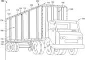
- FIG. 1is a perspective view of a trailer having sidewalls that include a plurality of composite panels
- FIG. 2is an isometric view of one of the composite panels of FIG. 1 having two outer sheets and an inner core member;
- FIG. 3is an isometric view of the inner core member of the composite panel of FIG. 2 including a primary structure and a reinforced material;
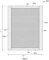
- FIG. 4is a top elevational view of the inner core member of FIG. 3 ;
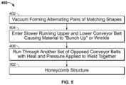
- FIG. 5is a flow chart for an example methodology used to make the continuous honeycomb structure of FIG. 3 ;
- FIG. 6is an isometric view of a portion of a plurality of panels on a production line undergoing the method of FIG. 5 ;
- FIG. 7depicts an illustrative process or method for making the inner core member of FIGS. 3 and 4 ;
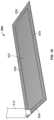
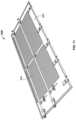
- FIG. 8is an isometric view of an intermediate core that is produced during the method of FIG. 7 ;
- FIG. 9depicts an alternative process or method for making the inner core member of FIGS. 3 and 4 ;
- FIG. 10is an isometric view of an inner core member being filled with a reinforcing material along a plurality of exterior edges according to the process of FIG. 9 ;
- FIG. 11is an isometric view of a trailer door including a composite panel made according to one of the processes described herein.
- FIG. 1depicts a tractor trailer assembly 100 including a trailer 102 designed to carry cargo and a tractor 104 having an engine and a cab section.
- the trailer 102may be substantially rectangular and may be defined by one or more sidewalls 106 , a front end wall assembly 108 , a roof assembly 110 , and a rear end wall assembly (not shown), which may include an overhead door. Further, the trailer 102 may be defined by a floor assembly (not depicted) disposed opposite the roof assembly 110 .
- the rear end wall assemblymay include two doors mounted in a conventional manner such that the doors are hingedly coupled to and swing between an open position and a closed position. Further, the trailer 102 may be releasably coupled to the tractor 104 by conventional means, such as a fifth wheel, for example.
- each sidewall 106 , the front end wall assembly 108 , the roof assembly 110 , the floor assembly, and/or the rear end wall assembly of the trailer 102may be made from one or more composite panels 112 .
- the composite panels 112may be coupled to each other using a number of different fasteners and/or joint configurations.
- the composite panels 112may be coupled to each other via joint configurations 114 including a logistics plate (not shown) and/or a splicing plate 116 .
- the composite panels 112may be coupled together along a longitudinal axis using rivets, screws, welding adhesives or the like.
- the composite panels 112may be coupled to a top rail 118 and a bottom rail 120 using a plurality of fasteners 122 , e.g., rivets, screws, adhesives, or the like.
- One or more composite panels 112may also be coupled to one or more vertically oriented rails 124 , 126 that are aligned with and substantially parallel to a longitudinal axis A of the trailer 102 using a fastener 122 , e.g., a rivet.
- the vertical rails 124 , 126may be disposed between the panels 112 at various points along the length of the trailer 102 .
- joint configurations and other fastenersmay also be used to couple adjacent composite panels 112 together, composite panels 112 to the top rail 118 and/or the bottom rails 120 , and/or the composite panels 112 to the vertical rails 124 , 126 .
- FIG. 2depicts a portion of one composite panel 112 that is provided in the form of an inner sheet 200 , an outer sheet 202 positioned opposite of the inner sheet 200 , and a core member 204 positioned between the inner sheet 200 and the outer sheet 202 .
- the inner sheet 200 and the outer sheet 202may be formed from high-strength, high-tension steel plates, aluminum, other metals, and/or other alloys.
- the inner sheet 200 and the outer sheet 202independently, may be formed from a reinforced plastic or polymer, such as a fibre-reinforced plastic and/or a glass-reinforced plastic.
- the inner sheet 200 and outer sheet 202may also be formed from other materials including, for example, bioplastics, wood, thermoplastic, polymers, and other materials.
- the core member 204may be provided in the form of a thermoplastic material that will be described in more detail below.
- the inner sheet 200 and the outer sheet 202may be bonded to the core member 204 by a suitable adhesive layer (not shown).
- the inner sheet 200 and the outer sheet 202are bonded to the core member 204 by a suitable flexible adhesive bonding film such as, for example, modified polyethylene. It may be understood that other suitable adhesives or joining mechanisms may also be used as well.
- each panel 112When fully assembled, the outer sheets 202 of each panel 112 cooperate to form an exterior surface of the sidewalls 106 , the front end wall assembly 108 , and/or the rear end wall assembly (not shown) of the trailer 102 , while the inner sheets 200 of each panel 112 cooperate to form an interior surface of the sidewalls 106 , the front end wall assembly 108 , and/or the rear end wall assembly (not shown) of the trailer 102 .
- FIGS. 3 and 4depicts the core member 204 of a single composite panel 112 , which is substantially rectangular and generally corresponds to the shape and size of each of the inner sheet 200 and outer sheet 202 .
- the core member 204may include a first section 302 and a reinforced section or second section 304 . Further, the core member 204 may be defined by a first end 306 a and a second end 306 b disposed at opposing ends of the core member 204 , and a first lateral edge 308 a and a second lateral edge 308 b , on opposing sides of the core member 204 .
- first end 306 a and the second end 306 bdefine a length dimension L of the core member 204 and the first and the second lateral edges 308 a , 308 b define a width dimension W of the core member 204 .
- the core member 204may be provided in a variety of shapes and sizes. With reference to FIGS. 3 and 4 , the length dimension L and the width dimension W of the core member 204 may generally define the size and shape of the core member 204 . In some embodiments, the length dimension L may range between about 1 meter to about 16 meters. In particular embodiments, the length dimension L may range from about 2 meters to about 4 meters, or between about 2.5 meters to about 3 meters. Further, in some embodiments, the width dimension W may range between about 0.5 meters to about 4 meters. In particular embodiments, the width dimension W may range between about 0.75 meters to about 2 meters, or between about 1 meter to about 1.5 meters. The core member 204 may also have a predetermined height or thickness.
- the core member 204has a predetermined thickness between about 3 millimeters to about 15 millimeters and, in particular embodiments, the core member 204 may have a predetermined thickness between about 5 millimeters to about 10 millimeters. It should be understood that the length, width, and thickness dimensions of the core member 204 may be modified such that the core member 204 would be suitable in other applications referenced herein.
- the core member 204may also be defined by a first section 302 and one or more second sections 304 .
- the second section 304may be structurally different with respect to the first section 302 and/or each other. Further, the second section 304 may be materially or compositionally different with respect to the first section 302 and/or to another second section 304 .
- the first section 302may comprise a continuous honeycomb thermoplastic cell network, e.g., a honeycomb structure.
- the continuous honeycomb thermoplastic cell networkmay include a plurality of hexagonal cells that are substantially hollow.
- the first section 302may include a cell network of polygonal, arcuate, and/or sinusoidal cells that are substantially hollow.
- the first section/first section 302is typically described as a honeycomb structure throughout, it should be appreciated that the first section 302 may comprise another material that is defined by a lower density than that of the material of the second section 304 .
- the second section 304 of the core member 204may be generally defined by a reinforced material.
- the reinforced materialis a solid or a substantially solid material and, in particular embodiments, is a solid or substantially solid plastic material.
- the first section 302may be surrounded on all sides by the second sections 304 .
- the thickness of the second sections 304may vary with respect to each other, or may be the same.
- the second sections 304may be disposed around the entire perimeter of the core member 204 .
- the second section 304includes two strips of solid plastic reinforced material located adjacent both the first end 306 a and the second end 306 b of the core member 204 , and two strips of solid plastic reinforced material located adjacent both the first lateral edges 308 a and the second lateral edge 308 b .
- the second section 304may also be defined by a greater volumetric density as compared to the first section 302 .
- the second sections 304may also be disposed within the core member 204 .
- the second sections 304may be placed anywhere within or around the core member 204 where additional support is desired.
- the second sections 304may be strategically placed in areas to prevent bolts, rivets, or the like from crushing the core member 204 .
- the second sections 304may only be disposed on one edge of the core member 204 .
- the first section 302extends in the width dimension W and/or the length dimension L of the core member 204 almost the entire length and/or width thereof, but terminates adjacent the second sections 304 , described in more detail below.
- the second sections 304may define the first end 306 a , the second end 306 b , the first lateral edge 308 a , and/or the second lateral edge 308 b of the core member 204 .
- the second sections 304may extend a predetermined distance above, below, to the left, and/or to the right of the first section 302 .
- the second section 304may extend above the first section 302 between about 1 centimeter to about 100 centimeters, or between about 1 centimeter to about 50 centimeters, or between about 2 centimeters to about 25 centimeters.
- the second section 304may extend below the first section 302 between about 1 centimeter to about 100 centimeters, or between about 1 centimeter to about 50 centimeters, or between about 10 centimeters to about 30 centimeters.
- the second section 304may extend to the left of the first section 302 between about 1 centimeter to about 100 centimeters, or between about 1 centimeter to about 50 centimeters, or between about 3 centimeters to about 15 centimeters.
- the second section 304may extend to the right of the first section 302 between about 1 centimeter to about 100 centimeters, or between about 1 centimeter to about 50 centimeters, or between about 3 centimeters to about 15 centimeters.
- the first section 302(i.e., the honeycomb structure) comprises over about 50%, over about 60%, over about 70%, over about 80%, or over about 90% of the entire volume of the core member 204 .
- the first section 302may be designed to reduce the weight of the core member 204 , as compared to a core member having a completely solid core structure, while maintaining desired core strength. Further, the first section 302 may use less plastic as compared to a solid plastic core material.
- the honeycomb cell networkmay be formed from other hollow webbed structures (including, for example, squares, parallelograms, triangles, and the like) and is not be limited to hexagonal honeycomb structures.
- the first section 302 of the core member 204may comprise other materials that are at least partially perforated, mesh, embossed, or any other type of material that could be thermally welded or tie layer bonded to the inner sheet 200 and/or the outer sheet 202 .
- the core member 204may have one or more reinforced plastic materials, i.e., second sections 304 , which may be welded or otherwise secured to the first section 302 at outer edges or within interior areas thereof.
- the second section 304may be designed and strategically located to be coupled to the top rail 118 and/or the bottom rail 120 of the trailer 102 by a suitable joining member or fastener 122 , such as the aforementioned bolts or rivets, for example.
- a suitable joining member or fastener 122such as the aforementioned bolts or rivets, for example.
- the addition of one or more solid reinforced materials or second sections 304 into the core membermay significantly increase the strength of the composite panel 112 in certain desired locations, e.g., a location of fastening.
- the solid reinforced material or second sections 304may increase the fastener pull out strength when compared to composites that comprise complete honeycomb material cores.
- the second sections 304may be positioned so that when the composite panel 112 is attached to the top rail 118 , for example, the fastener 122 extends through the second section 304 of the core member 204 , as opposed to extending through the first section 302 .
- the first section 302 and the second section 304 of the core member 204may be formed from a thermoplastic, such as a high density polyethylene, i.e., HPDE, or a high density polypropylene.
- a thermoplasticsuch as a high density polyethylene, i.e., HPDE, or a high density polypropylene.
- the first section 302 and second section 304may be formed from other suitable materials.
- the first section 302 and the second section 304may each, individually, be formed from a low density polyethylene, i.e., LDPE, a polyethylene terephthalate, i.e., PET, a polypropylene, i.e., PP, or the like.
- first section 302 and the second section 304 of the core member 204may comprise the same material
- process and methodology to form the first section 302 and the second section 304 of the core member 204may be different with respect to each other and is described in more detail below.
- the first section 302 and the second section 304 of the core member 204may be defined by different properties including, for example, density, tensile strength, and the like.
- FIGS. 5 and 6depict an illustrative process or method 400 for making the first section 302 of the core member 204 .
- Exemplary processes or methods for making a honeycomb structureare described in detail in International Publication No. WO 2008/141688 A2, the entirety of which is hereby incorporated by reference herein.
- the process 400is schematically illustrated with steps 402 , 404 , and 406 .
- a flat sheet 408 of thin deformable materialmay be fed to the process 400 as a starting material.
- the flat sheet 408may be one of a thermoplastic polymer, a low density polyethylene, a polyethylene terephthalate, a polypropylene, a fiber composite, a plastically deformable paper, a deformable metal sheet, or the like.
- step 402comprises the step of vacuum forming the thin sheet 408 into alternating pairs of matching shapes.
- the sheet 408may be intermittingly vacuum formed to produce a plurality of deformed regions 410 and a plurality of non-deformed regions 412 positioned therebetween.
- the deformed regions 410are generally three-dimensional and include one or more individual cells 414 of predetermined shape and size.
- the predetermined shape and size of the cells 414determine the structure of the first section 302 of the core member 204 .
- the cells 414are substantially trapezoidal to produce, when folded, a honeycomb structure.
- Alternative embodimentsmay include a cell with a polygonal structure, a sinusoidal or arcuate shape, a rectangular design, or the like. Further, the walls of the cells 414 may be substantially linear, bowed, curved, etc. to produce the first section 302 with a desired structure.
- the vacuum formed mating pairs or cells 414enter onto a conveyor belt.
- the conveyor beltincludes an upper conveyor belt 416 and a lower conveyor belt 418 that are running at a speed that is relatively slower than a speed of the incoming material.
- the slower speed of the lower conveyor belt 418may cause the incoming vacuum formed mating pairs or cells 414 to bunch up, wrinkle, and/or stand up to produce a plastic network 420 , e.g., a plastic honeycomb network.
- the materialmay be formed into alternating pairs of trapezoidal cells that, when folded, form completed hexagonal shapes.
- the bunched up honeycomb structure or plastic network 420enter a second conveyor belt (not shown).
- the second conveyor beltmay be provided as opposed conveyor belts, i.e., one conveyor positioned above the plastic network 420 and one conveyor positioned below the plastic network 420 .
- the conveyor beltsmay apply a predetermined amount of heat at a predetermined temperature and/or a predetermined amount of force may be applied at a predetermined pressure to consolidate and/or weld the plastic network 420 together to produce the first section 302 . Additional heat and/or pressure may be applied in step 406 to calibrate the first section 302 to the desired final thickness and/or the desired final height.
- the predetermined temperature applied in step 406may range between about 40° C. to about 250° C. In some embodiments, the predetermined temperature may range between about 100° C. to 200° C. or between about 160° C. to about 190° C. Further, the predetermined pressure may range from about 1 MPa to about 100 MPa. In particular embodiments, the predetermined pressure may range between about 15 MPa to about 40 MPa, or between about 25 MPa to about 30 MPa.
- the heat and/or pressuremay be applied for a predetermined amount of time in order to consolidate and/or weld the plastic network 420 together and/or weld the first section 302 to the second section 304 . Further, the heat and/or pressure may be applied for a predetermined amount of time in order to calibrate the first section 302 to a desired thickness.
- the method 400may be altered to produce a core member 204 comprising the first section 302 and the second section 304 .
- the vacuum forming process occurring in step 402 of the process 400may be intermittently turned off or interrupted.
- a gap(not shown) of thin plastic material may be produced. Then the reinforced material or second section 304 may be inserted into the aforementioned gap.
- the vacuum forming process or the method 400may intermittently speed up.
- the vacuum forming process or the method 400may be sped up to cause the material in step 404 to bunch up, wrinkle, and/or stand up at a faster pace than when the process 400 is operated at a normal operating speed, which results in the cells 414 and/or a portion of the plastic network 420 to collapse.
- a portion of the plastic network 420may collapse, thereby causing the material to pack more tightly together to form a solid reinforced section that is substantially similar in structure and function to the second sections 304 .
- a section of the first section 302may be run through a heated platen press or similar process to compress various sections of the first section 302 to create bands of compressed material, i.e., gaps, into which the reinforced material or second section 304 may be inserted therein.
- FIG. 7depicts one method 500 for constructing the core member 204 .
- the method or process 500may be a continuous process, whereby the composite panels 112 may be produced continuously.
- the method 500may be undertaken on a standalone production line, whereby discrete sheets or composite panels 112 may be formed in a batch manner or on a one to one basis.
- the method 500has two starting materials with a first production line 502 and a second production line 504 .
- the first production lineincludes steps 506 , 508 , and 510
- the second production lineincludes steps 512 , 514 , 516 , 518 , and 520 .
- the first section 302 of the core member 204may provided to the first production line 502 in the step 506 .
- the first section 302may be produced off line or purchased premade and may be provided in a predetermined size. In other embodiments, the first section 302 may be made in a production line onsite.
- the first section 302may be provided by the method 400 and may be about 107 cm wide, about 244 cm long, and about 1.1 cm thick.
- the first section 302 of the core member 204may be provided as a honeycomb material, perforated, mesh, embossed, or any type of core that could be thermally welded or tie layer bonded to the inner sheet 200 and/or outer sheet 202 .
- the first section 302 of the core member 204may be attached to the reinforced material or second section 304 along the first end 306 a . Further, second sections 304 may also be attached to the first section 302 of the core member 204 .
- the second sections 304 attached to the core member 204may be provided as a strip of foamed thermoplastic (HDPE or PP) having dimensions of about 107 cm wide, 36 cm long, and about 1 cm thick.
- the first section 302 of the core member 204may be attached to the second section 304 via a form of thermal welding using infrared, hot air, or other suitable technology.
- the end result of step 508may be an intermediate core 550 with a unitary structure that comprises the first section 302 of the core member 204 being attached to the second section 304 along the first end 306 a and the second end 306 b .
- the intermediate core 550may include the second section attached only to the first end 306 a or only attached to the second end 306 b.
- the intermediate core 550may be substantially rectangular and may be defined by the first end 306 a and the second end 306 b disposed at opposing ends of the intermediate core 550 , and a first lateral edge 552 a and a second lateral edge 552 b , on opposing sides of the core member 204 .
- the first end 306 a and the second end 306 bdefine a length dimension L 2 of the intermediate core 550
- the first lateral edge 552 a and the second lateral edge 552 bdefine a width dimension W 2 of the intermediate core 550 .
- the intermediate core 550may be provided in a variety of shapes and sizes. With reference to FIG. 8 , the length dimension L 2 and the width dimension W 2 of the intermediate core 550 may generally define the size and shape of the intermediate core 550 . In some embodiments, the length dimension L 2 may range between about 1 meter to about 16 meters. In particular embodiments, the length dimension L 2 may range from about 2 meters to about 4 meters, or between about 2.5 meters to about 3 meters.
- the width dimension W 2may range between about 0.5 meters to about 4 meters. In particular embodiments, the width dimension W 2 may range between about 0.75 meters to about 2 meters, or between about 1 meter to about 1.5 meters.
- the intermediate core 550may also have a predetermined height or thickness. In some embodiments, the intermediate core 550 has a predetermined thickness between about 3 millimeters to about 15 millimeters and, in particular embodiments, the intermediate core 550 may have a predetermined thickness between about 5 millimeters to about 10 millimeters. It should be understood that the length, width, and thickness dimensions of the intermediate core 550 may be modified such that the intermediate core 550 would be suitable in other applications referenced herein.
- the intermediate core 550may be delivered line side to the second production line 504 in step 510 .
- the second production line 504may include an extrusion line that produces two continuous parallel strips of the reinforced material or second sections 304 that are separated by a predetermined width.
- each strip of the second section 304may be provided having a width dimension of between about 12 cm to about 17 cm, with a gap created between the parallel strips of about 107 cm to about 117 cm.
- the second sections 304 produced by step 512may be separated by a predetermined width relatively equal to the width W 2 .
- stacks of the intermediate cores produced from step 510may be delivered lineside to the second production line 504 and may be automatically inserted between the continuous parallel strips of the second sections 304 of step 512 .
- the intermediate cores 505may be inserted one-behind-the-other or in a head-to-tail fashion, such that there is no gap between the inserted intermediate cores 550 .
- the two continuous parallel strips of the second sections 304may be guided toward and coupled to the intermediate core 550 using heat applications including, but not limited to, infrared or hot air systems.
- the intermediate core 550 and the second sections 304may also be coupled using other joining techniques or applications including, for example, adhesives.
- the result of step 516may be a continuous ribbon of core members 204 having the second sections 304 along opposing sides and at spaced intervals in the transverse direction with respect to the longitudinal axis of the core members 204 .
- step 518the continuous ribbon of core members 204 enter step 518 , which includes a lamination process that is designed to increase the strength and durability of the core members 204 .
- the core members 204may be cut and/or trimmed to a desired size in step 520 . Therefore, the result of step 520 may be a core member 204 having the length L and the width W.
- the length Lmay be about 280 cm and the width W may be about 125 cm.
- the core member 204may include about 10 cm to about 20 cm of the second section 304 on a top end thereof for top rail fastening and from about 15 cm to about 25 cm of the second section 304 on a bottom end thereof for bottom rail fastening. Further, approximately 7 cm to about 10 cm of second section 304 may be provided on opposing edges 308 a , 308 b for seam fastening.
- FIG. 9depicts an alternative process or method 600 for making the core member 204 .
- the first section 302 of the core member 204may first be provided to the production line in step 602 .
- the first section 302 of the core member 204may be produced off line, purchased pre-made, and/or produced on site with a predetermined size.
- the first section 302 of the core member 204 in the present embodimentmay include a hollow structure that is the same or similar to the honeycomb core described previously.
- the first section 302may also include portions that are mesh, perforated, or embossed.
- a filler material 608may be inserted into areas within the core member 204 using a dispensing device 610 .
- the filler material 608may be a plastic resin that solidifies during a lamination process.
- the filler material 608may also be any suitable material that may be inserted into one or more predefined areas of the core member 204 to increase the material strength of the structure.
- FIG. 10is a schematic representation of step 604 , with the filler material 608 being inserted around the perimeter of the core member 204 using the dispensing device 610 .
- the filler material 608may be inserted into a variety of locations within the core member 204 .
- the dispensing device 610may be mounted on an X-Y axis to allow the dispensing device 610 to dispense the filler material 608 to any desired location within the core member 204 and, therefore, should not be limited to the perimeter of the core member 204 .
- a plurality of dispensing devicesmay be used to insert the filler material 608 .
- the filler material 608may be provided as a carbon dioxide filled plastic resin.
- the filler material 608may solidify (during a lamination process or otherwise) to produce areas within the core member 204 that include the filler material 608 .
- the filler material 608is the aforementioned carbon dioxide filled plastic resin
- the carbon dioxide filled plastic resinmay expand to completely fill, or substantially completely fill, the hollow structures within the core member 204 .
- the result of step 606may be the core member 204 having a plurality of sections that are reinforced with the filler material 608 .
- the filler material 608may circumscribe the entirety of the core member 204 such that the filler material 608 is continuous along each edge of the core member 204 .
- the second sections 304may be strategically placed anywhere within or around the core member 204 where support may be desired. Therefore, the dispensing device 610 may also be used to place the filler material 608 along only one edge of the core member 204 or any area within the core member 204 .
- FIG. 11depicts one application of the core member 204 produced in any of the methods described herein. More specifically, in FIG. 11 , the core member 204 is provided within a rear door 620 of the trailer 102 and at least portions of the inner sheet 200 and the outer sheet 202 may be provided on opposing sides of the core member 204 .
- the core member 204may be provided with a plurality of discrete or continuous areas that are reinforced according to the methods described herein.
- the reinforced areas of the core member 204may correspond to the areas in which various door components are attached to the core member 204 .
- reinforced areas or second sections 304may be provided at opposing ends of the door 620 and/or along the exterior edges of the door 620 where hinges, lock rod fastening, and/or other components are joined to the door 620 .
- the reinforced material or second sections 304may be provided in the core member 204 to help provide additional fastening strength, additional compression strength, increased puncture and impact resistance, and/or other structural requirements.
- composite panel 112 and the core member 204 discussed hereinhave been discussed with respect to a tractor trailer application, it should be appreciated that the composite panel 112 , core member 204 , and/or any associated parts may be used in other applications such as, for example, other automotive and transportation applications, furniture applications, architecture applications and building materials, packing materials and logistics applications, aerospace applications, and the like.
Landscapes
- Engineering & Computer Science (AREA)
- Architecture (AREA)
- Mechanical Engineering (AREA)
- Chemical & Material Sciences (AREA)
- Structural Engineering (AREA)
- Civil Engineering (AREA)
- Materials Engineering (AREA)
- Polymers & Plastics (AREA)
- Organic Chemistry (AREA)
- Medicinal Chemistry (AREA)
- Chemical Kinetics & Catalysis (AREA)
- Health & Medical Sciences (AREA)
- Life Sciences & Earth Sciences (AREA)
- Wood Science & Technology (AREA)
- Laminated Bodies (AREA)
Abstract
Description
- This application is a U.S. National Stage of PCT Application No. PCT/US2018/015984 filed on Jan. 30, 2018 which claims priority under 35 U.S.C. § 119 to U.S. Provisional Patent Application No. 62/451,930 filed on Jan. 30, 2017, the entire contents of which are incorporated herein by reference.
Claims (20)
Priority Applications (1)
| Application Number | Priority Date | Filing Date | Title |
|---|---|---|---|
| US16/482,204US11872792B2 (en) | 2017-01-30 | 2018-01-30 | Composite core with reinforced areas and method |
Applications Claiming Priority (3)
| Application Number | Priority Date | Filing Date | Title |
|---|---|---|---|
| US201762451930P | 2017-01-30 | 2017-01-30 | |
| PCT/US2018/015984WO2018140955A1 (en) | 2017-01-30 | 2018-01-30 | Composite core with reinforced areas and method |
| US16/482,204US11872792B2 (en) | 2017-01-30 | 2018-01-30 | Composite core with reinforced areas and method |
Publications (2)
| Publication Number | Publication Date |
|---|---|
| US20200223204A1 US20200223204A1 (en) | 2020-07-16 |
| US11872792B2true US11872792B2 (en) | 2024-01-16 |
Family
ID=62978782
Family Applications (1)
| Application Number | Title | Priority Date | Filing Date |
|---|---|---|---|
| US16/482,204Active2040-04-27US11872792B2 (en) | 2017-01-30 | 2018-01-30 | Composite core with reinforced areas and method |
Country Status (5)
| Country | Link |
|---|---|
| US (1) | US11872792B2 (en) |
| EP (1) | EP3574159A4 (en) |
| CA (1) | CA3052066A1 (en) |
| MX (1) | MX2019009048A (en) |
| WO (1) | WO2018140955A1 (en) |
Families Citing this family (1)
| Publication number | Priority date | Publication date | Assignee | Title |
|---|---|---|---|---|
| US12312014B2 (en) | 2020-03-30 | 2025-05-27 | Teijin Automotive Technologies, Inc. | Composite material modular utility vehicle construct |
Citations (158)
| Publication number | Priority date | Publication date | Assignee | Title |
|---|---|---|---|---|
| US2294930A (en) | 1941-04-07 | 1942-09-08 | Minnesota Mining & Mfg | Reflex light reflector |
| US2719809A (en) | 1954-10-14 | 1955-10-04 | Weisberg Baer Co | Method of making hollow panel structural units |
| US2934372A (en) | 1958-01-16 | 1960-04-26 | Great Dane Trailers Inc | Vehicle body and structural elements therefor |
| US3072225A (en) | 1955-10-17 | 1963-01-08 | Solar Aircraft Co | Honeycomb sandwich structure |
| US3249659A (en) | 1961-07-19 | 1966-05-03 | Allied Chem | Method of making laminated panel structures |
| US3420023A (en) | 1966-06-02 | 1969-01-07 | Roher Bohm Ltd | Baffle unit |
| US3515615A (en) | 1964-09-05 | 1970-06-02 | Sumitomo Bakelite Co | Method for bonding synthetic resin sheets and metal sheets |
| US3617351A (en) | 1969-10-17 | 1971-11-02 | Hercules Inc | Process of coating with an olefin polymer |
| US3817671A (en) | 1970-09-01 | 1974-06-18 | J Lemelson | Apparatus for forming sheet material |
| US4128369A (en) | 1975-12-10 | 1978-12-05 | Hazelett Strip-Casting Corporation | Continuous apparatus for forming products from thermoplastic polymeric material having three-dimensional patterns and surface textures |
| GB2000465A (en) | 1977-06-28 | 1979-01-10 | Messerschmitt Boelkow Blohm | Method of preparing or connecting components of prefabricated light- weight materials. |
| US4336294A (en)* | 1980-02-07 | 1982-06-22 | Max Meier | Coated boards of wooden material in particular for use in furniture |
| US4340129A (en) | 1980-05-01 | 1982-07-20 | Cabot Corporation | Acoustical laminate construction and attenuated systems comprising same |
| US4557100A (en) | 1983-02-07 | 1985-12-10 | The Boeing Company | Unitary fastener insert for structural sandwich panels |
| US4578297A (en) | 1985-07-11 | 1986-03-25 | Mobil Oil Corporation | Polymer film/polymer foam laminate and heat-resistant container fabricated therefrom |
| US4701369A (en) | 1986-04-23 | 1987-10-20 | Mobil Oil Corporation | Opaque polymer film laminate having an absorbent surface |
| US4708757A (en) | 1986-07-21 | 1987-11-24 | Guthrie Walker L | Method of forming corrugated panel |
| US4709781A (en) | 1984-11-16 | 1987-12-01 | Austria Metall Aktiengesellschaft | Sound-damping and heat-insulating composite plate |
| US4783287A (en) | 1983-02-11 | 1988-11-08 | Isovolta Osterreichische Isolierstoffwerke Aktiengesellschaft | Method for the continuous production of foam material |
| US4796397A (en) | 1987-09-21 | 1989-01-10 | Capaul Raymond W | Demountable panel structure |
| US4817264A (en) | 1987-08-10 | 1989-04-04 | Shur-Lok Corporation | Fastener and assembly process |
| US4879152A (en) | 1989-02-15 | 1989-11-07 | Green Patrick H | Composite panel structure |
| US4930266A (en) | 1988-02-26 | 1990-06-05 | Minnesota Mining And Manufacturing Company | Abrasive sheeting having individually positioned abrasive granules |
| US4940279A (en) | 1989-03-16 | 1990-07-10 | Fruehauf Corporation | Cargo vehicle wall construction |
| WO1990014943A1 (en) | 1989-05-30 | 1990-12-13 | Phillips Petroleum Company | Composite cellular sandwich structure |
| JPH0387461A (en) | 1989-08-30 | 1991-04-12 | Nippon Steel Chem Co Ltd | Soundproof floor material |
| US5042395A (en) | 1988-11-15 | 1991-08-27 | Messerschmitt-Bolkow-Blohm Gmbh | Composite vehicle body having sandwich panels integrally formed with frame parts to form individual body modules which are connected to other body modules to form the vehicle body |
| US5066531A (en) | 1989-09-05 | 1991-11-19 | Ametek | Variable thickness foam plank |
| WO1993000845A1 (en) | 1991-07-01 | 1993-01-21 | Raven Marketing, Inc. | Cushioning structure |
| US5186996A (en) | 1989-12-29 | 1993-02-16 | Matec Holding Ag | Sound damping multi-layer structure |
| US5214991A (en) | 1990-08-30 | 1993-06-01 | Hitachi, Ltd. | Punching apparatus |
| US5275848A (en) | 1990-10-02 | 1994-01-04 | Mitsui Petrochemical Industries, Ltd. | Process for preparing a laminate of metal and a polyolefin resin |
| US5328744A (en) | 1990-10-09 | 1994-07-12 | E. I. Du Pont De Nemours And Company | Panel having a core with thermoplastic resin facings |
| US5507405A (en) | 1993-12-16 | 1996-04-16 | Great Dane Trailers, Inc. | Thermally insulated cargo container |
| CA2165016A1 (en) | 1994-12-23 | 1996-06-24 | Henk Joppen | Processes and apparatuses for perforating smooth, closed-cell surfaces of open-cell plastic foam sheets |
| US5554246A (en) | 1995-01-12 | 1996-09-10 | Anthony Industries, Inc. | Air infiltration barrier laminate and process for preparing same |
| US5580636A (en) | 1993-09-17 | 1996-12-03 | Alusutsse-Lonza Services Ltd. | Welded composite panels |
| US5604021A (en) | 1994-12-23 | 1997-02-18 | Ohio Mattress Company Licensing And Components Group | Multi-layer support pad having regions of differing firmness |
| US5698308A (en) | 1994-12-16 | 1997-12-16 | Toray Industries, Inc. | Polyester film for use of a laminate with a metal plate |
| US5698153A (en) | 1994-04-29 | 1997-12-16 | The Boeing Co. | Method of prescoring foam board |
| US5702798A (en) | 1994-06-20 | 1997-12-30 | Nippon Petrochemicals Company, Limited | Composite material with controlled elasticity |
| US5718965A (en) | 1994-12-22 | 1998-02-17 | Toyo Boseki Kabushiki Kaisha | Biaxially oriented polyamide film having surface protrusions |
| US5774972A (en) | 1996-03-22 | 1998-07-07 | Wabash National Corporation | Method of punching a composite plate |
| US5779847A (en) | 1996-04-22 | 1998-07-14 | Hoechst Celanese Corporation | Process for high performance, permeable fibrous structure |
| US5851342A (en) | 1996-11-14 | 1998-12-22 | Material Sciences Corporation | Method and apparatus for forming a laminate |
| US5860693A (en) | 1996-09-12 | 1999-01-19 | Wabash National Corporation | Composite joint configuration |
| US5899037A (en) | 1997-07-29 | 1999-05-04 | Josey; Gary L. | Composite wall structure |
| US5919545A (en) | 1996-07-18 | 1999-07-06 | Alusuisse Technology & Management Ltd. | Composite panel |
| US5979684A (en) | 1995-07-14 | 1999-11-09 | Toray Industries, Inc, | Cargo container |
| US5997076A (en) | 1998-07-27 | 1999-12-07 | Wabash National Corporation | Logistics at composite panel vertical joints |
| US6007890A (en) | 1993-11-19 | 1999-12-28 | The Dow Chemical Company | Acoustic insulating panels or elements |
| WO2000024559A1 (en) | 1998-10-23 | 2000-05-04 | Vantico Ag | Method for filling and reinforcing honeycomb sandwich panels |
| US6080495A (en) | 1997-10-27 | 2000-06-27 | Wright; John | Structural panels with metal faces and corrugated plastic core |
| US6199939B1 (en) | 1999-09-17 | 2001-03-13 | Wabash Technology Corporation | Composite joint configuration |
| US6220651B1 (en) | 1996-09-12 | 2001-04-24 | Wabash Technology Corporation | Composite joint configuration |
| US6266865B1 (en) | 1999-09-17 | 2001-07-31 | Wabash Technology Corporation | Method of punching a composite plate |
| US20010011832A1 (en) | 1997-08-28 | 2001-08-09 | Wabash Technology Corporation | Foamed core composite plate for use in trailer walls and doors |
| US6276748B1 (en) | 1998-03-17 | 2001-08-21 | Western Sear Trucks Inc. | Lightweight cab/sleeper for trucks |
| US20020014302A1 (en) | 2000-07-13 | 2002-02-07 | Kazak Composites, Incorporated | Method for incorporating rigid elements into the core of composite structural members in a pultrusion process |
| US6355302B1 (en) | 1999-12-10 | 2002-03-12 | 3M Innovative Properties Company | Continuous process for making high performance retroreflective fabric |
| US6368721B1 (en) | 1998-03-26 | 2002-04-09 | Mitsui Chemicals, Inc. | Laminated film |
| US6383559B1 (en) | 1995-12-07 | 2002-05-07 | Fuji Photo Film Co., Ltd. | Anti-reflection film and display device having the same |
| WO2002044493A1 (en) | 2000-11-30 | 2002-06-06 | Kwokleung Kwan | A honeycomb paenl assembly |
| US20020098341A1 (en) | 2000-12-07 | 2002-07-25 | Schiffer Daniel K. | Biodegradable breathable film and laminate |
| US20020176960A1 (en) | 2001-03-08 | 2002-11-28 | Alex Nadezhdin | Composite board with OSB faces |
| US6537413B1 (en) | 1998-06-05 | 2003-03-25 | Peguform France | Method of making a reinforced composite panel of the cellular-core sandwich type, and a panel obtained by performing such a method |
| US6546694B2 (en) | 2001-04-24 | 2003-04-15 | Dofasco Inc. | Light-weight structural panel |
| US20030186029A1 (en) | 2001-09-27 | 2003-10-02 | Kinyosha Co., Ltd. | Compressible printing blanket and method of manufacturing a compressible printing blanket |
| JP2003285397A (en) | 2002-03-27 | 2003-10-07 | Nihon Tetra Pak Kk | Food packaging materials |
| US6638636B2 (en) | 2001-08-28 | 2003-10-28 | Kimberly-Clark Worldwide, Inc. | Breathable multilayer films with breakable skin layers |
| US6680017B1 (en) | 1995-11-21 | 2004-01-20 | Bayer Ag | Device and process for the production of plastics/metal composite panels |
| US20040055248A1 (en) | 2002-09-20 | 2004-03-25 | Grillos Emmanuel J. | Internally stiffened composite panels and methods for their manufacture |
| USRE38508E1 (en) | 1997-06-28 | 2004-04-27 | Laminators Incorporated | Structural panels with metal faces and corrugated plastic core |
| US6824851B1 (en) | 1999-10-08 | 2004-11-30 | Milwaukee Composites, Inc. | Panels utilizing a precured reinforced core and method of manufacturing the same |
| US6843525B2 (en) | 2001-10-30 | 2005-01-18 | Patent Holding Company | Reinforced composite vehicle load floor of the cellular core sandwich-type |
| US6866492B2 (en) | 2001-06-06 | 2005-03-15 | Bpb Plc | Gypsum board forming device |
| US20050087899A1 (en) | 2003-10-22 | 2005-04-28 | L&L Products, Inc. | Baffle and method of forming same |
| US20050123720A1 (en) | 2003-12-09 | 2005-06-09 | Tokuhito Suzuki | Laminate sheet having reinforcement film and method of manufacturing the same |
| WO2005077654A1 (en) | 2004-02-13 | 2005-08-25 | Heinrich Kuper Gmbh & Co. Kg | Device and method for producing sandwich panels |
| JP2005238622A (en) | 2004-02-26 | 2005-09-08 | Toray Ind Inc | White laminated polyester film for thermal transfer recording |
| US20050204561A1 (en) | 2003-05-07 | 2005-09-22 | Byung-Shik Kim | Continuous manufacturing system for composite aluminum panels |
| US20050225118A1 (en) | 2004-04-12 | 2005-10-13 | Oren David D | Sidewall construction and methods of making the same |
| US20050257893A1 (en) | 2004-05-07 | 2005-11-24 | Bayer Materialscience Ag | Apparatus and process for the production of sandwich composite elements |
| US7017981B2 (en) | 2002-03-20 | 2006-03-28 | Webasto Vehicle Systems International Gmbh | Roof module for a motor vehicle and process for producing same |
| US7056567B2 (en) | 2000-10-17 | 2006-06-06 | General Electric | Fiber-reinforced composite structure |
| US20060241542A1 (en) | 2005-01-28 | 2006-10-26 | Gudnason Palmar I | Wound dressing and method for manufacturing the same |
| US7128365B2 (en) | 2002-08-13 | 2006-10-31 | Webasto Vehicle Systems International Gmbh | Motor vehicle body part |
| WO2006128632A1 (en) | 2005-05-28 | 2006-12-07 | Airbus Deutschland Gmbh | Sandwich structure having a frequency-selective double-wall behavior |
| US20070004813A1 (en) | 2004-09-16 | 2007-01-04 | Eastman Chemical Company | Compositions for the preparation of void-containing articles |
| US20070056687A1 (en) | 2005-09-14 | 2007-03-15 | Brinner Timothy A | Structural composite laminate, and process of making same |
| US7255822B2 (en) | 2002-01-31 | 2007-08-14 | Owens-Corning Fiberglas Technology Inc. | Process for manufacturing a composite sheet |
| US20070196681A1 (en) | 2004-11-15 | 2007-08-23 | Taryn Biggs | Laminate panel and process for production thereof |
| US20070256379A1 (en) | 2006-05-08 | 2007-11-08 | Edwards Christopher M | Composite panels |
| US7338696B2 (en) | 2002-04-25 | 2008-03-04 | Airbus France | Perforated adhesive film and its manufacturing process |
| US20080111393A1 (en) | 2006-09-27 | 2008-05-15 | Ehrlich Rodney P | Composite panel for a trailer wall |
| US20080116718A1 (en) | 2006-11-21 | 2008-05-22 | Lewallen Wilfred E | Logistics panel for use in a sidewall of a trailer |
| WO2008141688A2 (en) | 2007-05-22 | 2008-11-27 | Econcore N.V. | Elastic honeycomb sheet, its production process and equipment to produce |
| US7553435B2 (en) | 2004-01-23 | 2009-06-30 | Vec Industries, L.L.C. | Method and apparatus for molding composite articles |
| US20090202785A1 (en) | 2006-03-11 | 2009-08-13 | W. Döllken & Co. GmbH | Reinforcement strip for a composite panel |
| DE102008020976A1 (en) | 2008-04-25 | 2009-10-29 | Fritz Egger Gmbh & Co. | Method for producing a lightweight board for furniture construction |
| US20090297763A1 (en) | 2005-12-23 | 2009-12-03 | Premium Aircraft Interiors Group Ltd. | Composite panel |
| EP2133184A1 (en) | 2008-06-11 | 2009-12-16 | BIESSE S.p.A. | Panel of wood or the like, and method and machine for the manufacturing thereof |
| US20090324905A1 (en) | 2008-06-30 | 2009-12-31 | Howard Martin Welch | Elastic multilayer composite including pattern unbonded elastic materials, articles containing same, and methods of making same |
| WO2010050242A1 (en) | 2008-10-31 | 2010-05-06 | キョーラク株式会社 | Sandwich panel, method of forming core material for sandwich panel, and method of forming sandwich panel |
| US7722122B2 (en) | 2007-07-28 | 2010-05-25 | John Mittelstadt | Portable support including a pillow |
| WO2010069994A2 (en) | 2008-12-19 | 2010-06-24 | Inter Ikea Systems B.V. [Nl] | Building units for furniture, and method for manufacturing of such building units |
| US7758487B2 (en) | 2003-02-24 | 2010-07-20 | Rutgers, The State University Of New Jersey | Technology for continuous folding of sheet materials into a honeycomb-like configuration |
| US7785518B2 (en) | 2007-01-19 | 2010-08-31 | Vec Industries, L.L.C. | Method and apparatus for molding composite articles |
| US20100227087A1 (en) | 2007-09-19 | 2010-09-09 | Valter Naldi | Panel and relative manufacturing system and method |
| US7814658B2 (en) | 2003-11-20 | 2010-10-19 | Otkrytoe Aktsionernoe Obschestvo “Kazansky Nauchno-Isledovatelsky Institut Aviatsionnoi Tekhnologii” | Method for production of sandwich panels with zigzag corrugated core |
| US7842147B2 (en) | 2007-01-31 | 2010-11-30 | M.C. Gill Corporation | Composite panel having in-situ thermoset foamed core |
| US20110089183A1 (en) | 2007-10-02 | 2011-04-21 | Herbert Gundelsheimer | Composite panel and its production |
| US20110095574A1 (en) | 2009-10-28 | 2011-04-28 | Boulder Electric Vehicle | Composite land vehicle frame |
| US20110135862A1 (en) | 2008-04-30 | 2011-06-09 | Takehiko Sumi | Core material for sandwich panel, method of molding core material for sandwich panel, sandwich panel, and method of molding sandwich panel |
| US8087494B2 (en) | 2005-05-13 | 2012-01-03 | United States Of America As Represented By The Administrator Of The National Aeronautics And Space Administration | Method of making a composite panel having subsonic transverse wave speed characteristics |
| US20120040135A1 (en) | 2008-12-04 | 2012-02-16 | Jon Micheal Werthen | Sandwich Panel, Support Member for Use in a Sandwich Panel and Aircraft Provided with Such a Sandwich Panel |
| US20120040131A1 (en)* | 2010-08-10 | 2012-02-16 | Speer Dwaine D | Composite Panel Having Perforated Foam Core |
| US8336933B2 (en) | 2010-11-04 | 2012-12-25 | Sabic Innovative Plastics Ip B.V. | Energy absorbing device and methods of making and using the same |
| US8584433B2 (en) | 2011-02-24 | 2013-11-19 | The Yokohama Rubber Co., Ltd. | Structure for installing insert nut in a panel |
| US20140044914A1 (en) | 2011-05-02 | 2014-02-13 | Didier Kurtz | Self-stiffened composite panel particularly for aircraft floors and method for manufacturing the same |
| US8663523B2 (en) | 2006-12-05 | 2014-03-04 | Bradford Company | Folded product made from extruded profile and method of making same |
| US8690233B2 (en) | 2012-04-23 | 2014-04-08 | Global Ip Holdings, Llc | Carpeted automotive vehicle load floor having a living hinge |
| US20140127452A1 (en) | 2010-11-09 | 2014-05-08 | Magna Steyr Fahzeugtechnik AG & Co. KG | Honeycomb core, method of producing a honeycomb core, and sandwich panel comprising a honeycomb core |
| US8726613B2 (en) | 2010-08-10 | 2014-05-20 | Korea Aerospace Research Institute | Composite honeycomb sandwich panel equipped with composite-rail aluminum I-shape side insert |
| US20140178636A1 (en) | 2012-12-20 | 2014-06-26 | Compal Electronics, Inc. | Composite material and method of forming the same |
| US8764089B2 (en) | 2012-04-23 | 2014-07-01 | Global Ip Holdings, Llc | Compression-molded composite panel including a living hinge having a score line which functions as a style line |
| US8770344B2 (en) | 2010-07-13 | 2014-07-08 | Bellmax Acoustic Pty Ltd. | Acoustic panel |
| US8795465B2 (en) | 2012-04-23 | 2014-08-05 | Global Ip Holdings, Llc | Method of making a sandwich-type composite panel having a living hinge and panel obtained by performing the method |
| US8795807B2 (en) | 2012-11-29 | 2014-08-05 | Global Ip Holdings, Llc | Assembly including a compression-molded composite component having a sandwich structure and a unitarily connected second component |
| US8808833B2 (en) | 2012-11-30 | 2014-08-19 | Global Ip Holdings, Llc | Compression-molded composite component having a sandwich structure and having integrally formed strengthening structures |
| US8808831B2 (en) | 2012-04-23 | 2014-08-19 | Global Ip Holdings, Llc | Sandwich-type, structural, composite component including at least one hingedly-connected portion, cargo management system and automotive vehicle load floor utilizing the component |
| US8808828B2 (en) | 2012-04-23 | 2014-08-19 | Global Ip Holdings, Llc | Cargo management system including a vehicle load floor to compartmentalize a cargo area |
| US8808827B2 (en) | 2012-11-27 | 2014-08-19 | Global Ip Holdings, Llc | Cargo management system including a vehicle load floor having a vehicle component restraining feature |
| US8808829B2 (en) | 2012-04-23 | 2014-08-19 | Global Ip Holdings, Llc | Assembly including a compression-molded, composite panel locally reinforced adjacent a living hinge of the assembly |
| US8808830B2 (en) | 2012-04-23 | 2014-08-19 | Global Ip Holdings, Llc | Sandwich-type, structural, composite component having a cut-out feature with a substantially hidden core, assembly utilizing same and panel for use in a vehicle load floor assembly |
| US8808834B2 (en) | 2012-11-28 | 2014-08-19 | Global Ip Holdings, Llc | Sandwich-type, structural, composite panel having a pattern of depressions formed at a lower outer surface thereof and stiffening supports received and retained therein |
| US8808835B2 (en) | 2012-11-28 | 2014-08-19 | Global Ip Holdings, Llc | System including a panel assembly having a container and a compression-molded, composite cover for covering the container |
| US8834985B2 (en) | 2012-11-30 | 2014-09-16 | Global Ip Holdings, Llc | Sandwich-type composite component having imprinted 3-D structures which provide at least one pattern at an outer surface of the component |
| US8852711B2 (en) | 2012-04-23 | 2014-10-07 | Global Ip Holdings, Llc | Carpeted, vehicle load floor including a pivotable cover segmented into articulated, sectional members |
| US8859074B2 (en) | 2012-04-23 | 2014-10-14 | Global Ip Holdings, Llc | Sandwich-type, generally planar, structural member having an attachment feature and assembly utilizing same |
| US8883285B2 (en) | 2012-04-23 | 2014-11-11 | Global Ip Holdings, Llc | Sandwich-type, composite component such as motor vehicle component and unitary structural assembly utilizing same |
| US8945327B2 (en) | 2010-01-22 | 2015-02-03 | Daimler Ag | Sandwich component and method for the production thereof |
| US8995138B2 (en) | 2012-04-23 | 2015-03-31 | Global Ip Holdings, Llc | Assembly including a compression-molded, composite panel with a hinged mounting flange |
| US9010834B2 (en) | 2012-04-23 | 2015-04-21 | Global Ip Holdings, Llc | Cargo management system for a vehicle and including a pair of opposing cargo trim panels, each of which is made by a composite, compression molding process and has a wood grain finish |
| US20150130220A1 (en) | 2012-04-23 | 2015-05-14 | Global Ip Holdings, Llc | Cargo management system including a vehicle load floor having a cellulose-based core and made by a composite, compression molding process and having a wood grain finish |
| US20150130221A1 (en) | 2012-04-23 | 2015-05-14 | Global Ip Holdings, Llc | Cargo management system including an automotive vehicle seat having a cargo trim panel made by a composite, compression molding process and having a wood grain finish |
| US20150132532A1 (en) | 2012-04-23 | 2015-05-14 | Global Ip Holdings, Llc | Method of making a sandwich-type composite panel having a cellulose-based core and a living hinge and panel obtained by performing the method |
| US20150145276A1 (en) | 2012-04-23 | 2015-05-28 | Global Ip Holdings, Llc | Assembly including a compression-molded, composite panel having a cellulose-based core and a hinged mounting flange |
| US9126537B2 (en) | 2012-04-23 | 2015-09-08 | Global Ip Holdings, Llc | Cargo management system including an automotive vehicle seat having a cargo trim panel made by a composite, compression molding process and having a wood grain finish |
| US20150273810A1 (en) | 2012-09-28 | 2015-10-01 | Friul Intagli Industries Spa | Method and apparatus for making double panels |
| US20150306840A1 (en) | 2014-04-29 | 2015-10-29 | Samuel Joseph Ferguson, JR. | Sturdy Gypsum Composite Decorative Surface and Method for Making Sturdy Gypsum Composite Decorative Surface |
| US20150375449A1 (en)* | 2013-02-12 | 2015-12-31 | Printec Gmbh | Media-free, temperature-assisted adhesive connection method |
| US9308945B2 (en) | 2012-04-23 | 2016-04-12 | Global Ip Holdings, Llc | Cargo management system including a vehicle load floor made by a composite, compression molding process and having a wood grain finish |
| USRE45991E1 (en) | 2012-04-23 | 2016-05-03 | Global Ip Holdings, Llc | Carpeted, automotive vehicle, load floor including a pivotable cover having a decorative, backside, noise-management, covering |
| US9346375B2 (en) | 2012-04-23 | 2016-05-24 | Global Ip Holdings, Llc | Cargo management system for a vehicle and including a pair of opposing cargo trim panels, each of which is made by a composite, compression molding process and has a wood grain finish |
| US20160176149A1 (en) | 2014-12-22 | 2016-06-23 | Vixen Composites, LLC | Vehicle floor system |
| US9550336B2 (en) | 2006-12-05 | 2017-01-24 | Bradford Company | Method of making sandwich-like product starting with extruded profile |
| US10239566B2 (en) | 2016-02-24 | 2019-03-26 | Wabash National, L.P. | Composite floor for a dry truck body |
- 2018
- 2018-01-30MXMX2019009048Apatent/MX2019009048A/enunknown
- 2018-01-30CACA3052066Apatent/CA3052066A1/enactivePending
- 2018-01-30WOPCT/US2018/015984patent/WO2018140955A1/ennot_activeCeased
- 2018-01-30EPEP18744152.2Apatent/EP3574159A4/ennot_activeWithdrawn
- 2018-01-30USUS16/482,204patent/US11872792B2/enactiveActive
Patent Citations (180)
| Publication number | Priority date | Publication date | Assignee | Title |
|---|---|---|---|---|
| US2294930A (en) | 1941-04-07 | 1942-09-08 | Minnesota Mining & Mfg | Reflex light reflector |
| US2719809A (en) | 1954-10-14 | 1955-10-04 | Weisberg Baer Co | Method of making hollow panel structural units |
| US3072225A (en) | 1955-10-17 | 1963-01-08 | Solar Aircraft Co | Honeycomb sandwich structure |
| US2934372A (en) | 1958-01-16 | 1960-04-26 | Great Dane Trailers Inc | Vehicle body and structural elements therefor |
| US3249659A (en) | 1961-07-19 | 1966-05-03 | Allied Chem | Method of making laminated panel structures |
| US3515615A (en) | 1964-09-05 | 1970-06-02 | Sumitomo Bakelite Co | Method for bonding synthetic resin sheets and metal sheets |
| US3420023A (en) | 1966-06-02 | 1969-01-07 | Roher Bohm Ltd | Baffle unit |
| US3617351A (en) | 1969-10-17 | 1971-11-02 | Hercules Inc | Process of coating with an olefin polymer |
| US3817671A (en) | 1970-09-01 | 1974-06-18 | J Lemelson | Apparatus for forming sheet material |
| US4128369A (en) | 1975-12-10 | 1978-12-05 | Hazelett Strip-Casting Corporation | Continuous apparatus for forming products from thermoplastic polymeric material having three-dimensional patterns and surface textures |
| GB2000465A (en) | 1977-06-28 | 1979-01-10 | Messerschmitt Boelkow Blohm | Method of preparing or connecting components of prefabricated light- weight materials. |
| US4336294A (en)* | 1980-02-07 | 1982-06-22 | Max Meier | Coated boards of wooden material in particular for use in furniture |
| US4340129A (en) | 1980-05-01 | 1982-07-20 | Cabot Corporation | Acoustical laminate construction and attenuated systems comprising same |
| US4557100A (en) | 1983-02-07 | 1985-12-10 | The Boeing Company | Unitary fastener insert for structural sandwich panels |
| US4783287A (en) | 1983-02-11 | 1988-11-08 | Isovolta Osterreichische Isolierstoffwerke Aktiengesellschaft | Method for the continuous production of foam material |
| US4709781A (en) | 1984-11-16 | 1987-12-01 | Austria Metall Aktiengesellschaft | Sound-damping and heat-insulating composite plate |
| US4578297A (en) | 1985-07-11 | 1986-03-25 | Mobil Oil Corporation | Polymer film/polymer foam laminate and heat-resistant container fabricated therefrom |
| US4701369A (en) | 1986-04-23 | 1987-10-20 | Mobil Oil Corporation | Opaque polymer film laminate having an absorbent surface |
| US4708757A (en) | 1986-07-21 | 1987-11-24 | Guthrie Walker L | Method of forming corrugated panel |
| US4817264A (en) | 1987-08-10 | 1989-04-04 | Shur-Lok Corporation | Fastener and assembly process |
| US4796397A (en) | 1987-09-21 | 1989-01-10 | Capaul Raymond W | Demountable panel structure |
| US4930266A (en) | 1988-02-26 | 1990-06-05 | Minnesota Mining And Manufacturing Company | Abrasive sheeting having individually positioned abrasive granules |
| US5042395A (en) | 1988-11-15 | 1991-08-27 | Messerschmitt-Bolkow-Blohm Gmbh | Composite vehicle body having sandwich panels integrally formed with frame parts to form individual body modules which are connected to other body modules to form the vehicle body |
| US4879152A (en) | 1989-02-15 | 1989-11-07 | Green Patrick H | Composite panel structure |
| US4940279A (en) | 1989-03-16 | 1990-07-10 | Fruehauf Corporation | Cargo vehicle wall construction |
| WO1990014943A1 (en) | 1989-05-30 | 1990-12-13 | Phillips Petroleum Company | Composite cellular sandwich structure |
| JPH0387461A (en) | 1989-08-30 | 1991-04-12 | Nippon Steel Chem Co Ltd | Soundproof floor material |
| US5066531A (en) | 1989-09-05 | 1991-11-19 | Ametek | Variable thickness foam plank |
| US5186996A (en) | 1989-12-29 | 1993-02-16 | Matec Holding Ag | Sound damping multi-layer structure |
| US5214991A (en) | 1990-08-30 | 1993-06-01 | Hitachi, Ltd. | Punching apparatus |
| US5275848A (en) | 1990-10-02 | 1994-01-04 | Mitsui Petrochemical Industries, Ltd. | Process for preparing a laminate of metal and a polyolefin resin |
| US5328744A (en) | 1990-10-09 | 1994-07-12 | E. I. Du Pont De Nemours And Company | Panel having a core with thermoplastic resin facings |
| WO1993000845A1 (en) | 1991-07-01 | 1993-01-21 | Raven Marketing, Inc. | Cushioning structure |
| US5580636A (en) | 1993-09-17 | 1996-12-03 | Alusutsse-Lonza Services Ltd. | Welded composite panels |
| US6007890A (en) | 1993-11-19 | 1999-12-28 | The Dow Chemical Company | Acoustic insulating panels or elements |
| US5507405A (en) | 1993-12-16 | 1996-04-16 | Great Dane Trailers, Inc. | Thermally insulated cargo container |
| US5698153A (en) | 1994-04-29 | 1997-12-16 | The Boeing Co. | Method of prescoring foam board |
| US5702798A (en) | 1994-06-20 | 1997-12-30 | Nippon Petrochemicals Company, Limited | Composite material with controlled elasticity |
| US5698308A (en) | 1994-12-16 | 1997-12-16 | Toray Industries, Inc. | Polyester film for use of a laminate with a metal plate |
| US5718965A (en) | 1994-12-22 | 1998-02-17 | Toyo Boseki Kabushiki Kaisha | Biaxially oriented polyamide film having surface protrusions |
| US5604021A (en) | 1994-12-23 | 1997-02-18 | Ohio Mattress Company Licensing And Components Group | Multi-layer support pad having regions of differing firmness |
| CA2165016A1 (en) | 1994-12-23 | 1996-06-24 | Henk Joppen | Processes and apparatuses for perforating smooth, closed-cell surfaces of open-cell plastic foam sheets |
| US5554246A (en) | 1995-01-12 | 1996-09-10 | Anthony Industries, Inc. | Air infiltration barrier laminate and process for preparing same |
| US5979684A (en) | 1995-07-14 | 1999-11-09 | Toray Industries, Inc, | Cargo container |
| US6680017B1 (en) | 1995-11-21 | 2004-01-20 | Bayer Ag | Device and process for the production of plastics/metal composite panels |
| US6383559B1 (en) | 1995-12-07 | 2002-05-07 | Fuji Photo Film Co., Ltd. | Anti-reflection film and display device having the same |
| US5774972A (en) | 1996-03-22 | 1998-07-07 | Wabash National Corporation | Method of punching a composite plate |
| US5779847A (en) | 1996-04-22 | 1998-07-14 | Hoechst Celanese Corporation | Process for high performance, permeable fibrous structure |
| US5919545A (en) | 1996-07-18 | 1999-07-06 | Alusuisse Technology & Management Ltd. | Composite panel |
| US7069702B2 (en) | 1996-09-12 | 2006-07-04 | Wabash National, L.P. | Composite joint configuration |
| US20020109377A1 (en) | 1996-09-12 | 2002-08-15 | Wabash Technology Corporation | Composite joint configuration |
| US20060028050A1 (en) | 1996-09-12 | 2006-02-09 | Ehrlich Rodney P | Composite joint configuration |
| US6412854B2 (en) | 1996-09-12 | 2002-07-02 | Wabash Technology Corporation | Composite joint configuration |
| US6220651B1 (en) | 1996-09-12 | 2001-04-24 | Wabash Technology Corporation | Composite joint configuration |
| US20040217631A1 (en) | 1996-09-12 | 2004-11-04 | Ehrlich Rodney P. | Composite joint configuration |
| US6986546B2 (en) | 1996-09-12 | 2006-01-17 | Wabash National, L.P. | Composite joint configuration |
| US5860693A (en) | 1996-09-12 | 1999-01-19 | Wabash National Corporation | Composite joint configuration |
| US5851342A (en) | 1996-11-14 | 1998-12-22 | Material Sciences Corporation | Method and apparatus for forming a laminate |
| USRE38508E1 (en) | 1997-06-28 | 2004-04-27 | Laminators Incorporated | Structural panels with metal faces and corrugated plastic core |
| US5899037A (en) | 1997-07-29 | 1999-05-04 | Josey; Gary L. | Composite wall structure |
| US20010011832A1 (en) | 1997-08-28 | 2001-08-09 | Wabash Technology Corporation | Foamed core composite plate for use in trailer walls and doors |
| US6080495A (en) | 1997-10-27 | 2000-06-27 | Wright; John | Structural panels with metal faces and corrugated plastic core |
| US6276748B1 (en) | 1998-03-17 | 2001-08-21 | Western Sear Trucks Inc. | Lightweight cab/sleeper for trucks |
| US6368721B1 (en) | 1998-03-26 | 2002-04-09 | Mitsui Chemicals, Inc. | Laminated film |
| US6537413B1 (en) | 1998-06-05 | 2003-03-25 | Peguform France | Method of making a reinforced composite panel of the cellular-core sandwich type, and a panel obtained by performing such a method |
| US5997076A (en) | 1998-07-27 | 1999-12-07 | Wabash National Corporation | Logistics at composite panel vertical joints |
| WO2000024559A1 (en) | 1998-10-23 | 2000-05-04 | Vantico Ag | Method for filling and reinforcing honeycomb sandwich panels |
| US6635202B1 (en) | 1998-10-23 | 2003-10-21 | Vantico Inc. | Method for filling and reinforcing honeycomb sandwich panels |
| US6266865B1 (en) | 1999-09-17 | 2001-07-31 | Wabash Technology Corporation | Method of punching a composite plate |
| US6199939B1 (en) | 1999-09-17 | 2001-03-13 | Wabash Technology Corporation | Composite joint configuration |
| US6824851B1 (en) | 1999-10-08 | 2004-11-30 | Milwaukee Composites, Inc. | Panels utilizing a precured reinforced core and method of manufacturing the same |
| US6355302B1 (en) | 1999-12-10 | 2002-03-12 | 3M Innovative Properties Company | Continuous process for making high performance retroreflective fabric |
| US20020014302A1 (en) | 2000-07-13 | 2002-02-07 | Kazak Composites, Incorporated | Method for incorporating rigid elements into the core of composite structural members in a pultrusion process |
| US7056567B2 (en) | 2000-10-17 | 2006-06-06 | General Electric | Fiber-reinforced composite structure |
| WO2002044493A1 (en) | 2000-11-30 | 2002-06-06 | Kwokleung Kwan | A honeycomb paenl assembly |
| US20020098341A1 (en) | 2000-12-07 | 2002-07-25 | Schiffer Daniel K. | Biodegradable breathable film and laminate |
| US20020176960A1 (en) | 2001-03-08 | 2002-11-28 | Alex Nadezhdin | Composite board with OSB faces |
| US6852386B2 (en) | 2001-03-08 | 2005-02-08 | Norbord Inc. | Composite board with OSB faces |
| US6546694B2 (en) | 2001-04-24 | 2003-04-15 | Dofasco Inc. | Light-weight structural panel |
| US6866492B2 (en) | 2001-06-06 | 2005-03-15 | Bpb Plc | Gypsum board forming device |
| US6638636B2 (en) | 2001-08-28 | 2003-10-28 | Kimberly-Clark Worldwide, Inc. | Breathable multilayer films with breakable skin layers |
| US20030186029A1 (en) | 2001-09-27 | 2003-10-02 | Kinyosha Co., Ltd. | Compressible printing blanket and method of manufacturing a compressible printing blanket |
| US6843525B2 (en) | 2001-10-30 | 2005-01-18 | Patent Holding Company | Reinforced composite vehicle load floor of the cellular core sandwich-type |
| US7255822B2 (en) | 2002-01-31 | 2007-08-14 | Owens-Corning Fiberglas Technology Inc. | Process for manufacturing a composite sheet |
| US7017981B2 (en) | 2002-03-20 | 2006-03-28 | Webasto Vehicle Systems International Gmbh | Roof module for a motor vehicle and process for producing same |
| JP2003285397A (en) | 2002-03-27 | 2003-10-07 | Nihon Tetra Pak Kk | Food packaging materials |
| US7338696B2 (en) | 2002-04-25 | 2008-03-04 | Airbus France | Perforated adhesive film and its manufacturing process |
| US7128365B2 (en) | 2002-08-13 | 2006-10-31 | Webasto Vehicle Systems International Gmbh | Motor vehicle body part |
| US20040055248A1 (en) | 2002-09-20 | 2004-03-25 | Grillos Emmanuel J. | Internally stiffened composite panels and methods for their manufacture |
| US7758487B2 (en) | 2003-02-24 | 2010-07-20 | Rutgers, The State University Of New Jersey | Technology for continuous folding of sheet materials into a honeycomb-like configuration |
| US20050204561A1 (en) | 2003-05-07 | 2005-09-22 | Byung-Shik Kim | Continuous manufacturing system for composite aluminum panels |
| US7155797B2 (en) | 2003-05-07 | 2007-01-02 | Byung Shik Kim | Continuous manufacturing system for composite aluminum panels |
| US20050087899A1 (en) | 2003-10-22 | 2005-04-28 | L&L Products, Inc. | Baffle and method of forming same |
| US7814658B2 (en) | 2003-11-20 | 2010-10-19 | Otkrytoe Aktsionernoe Obschestvo “Kazansky Nauchno-Isledovatelsky Institut Aviatsionnoi Tekhnologii” | Method for production of sandwich panels with zigzag corrugated core |
| US20050123720A1 (en) | 2003-12-09 | 2005-06-09 | Tokuhito Suzuki | Laminate sheet having reinforcement film and method of manufacturing the same |
| US7553435B2 (en) | 2004-01-23 | 2009-06-30 | Vec Industries, L.L.C. | Method and apparatus for molding composite articles |
| WO2005077654A1 (en) | 2004-02-13 | 2005-08-25 | Heinrich Kuper Gmbh & Co. Kg | Device and method for producing sandwich panels |
| JP2005238622A (en) | 2004-02-26 | 2005-09-08 | Toray Ind Inc | White laminated polyester film for thermal transfer recording |
| US7014253B2 (en) | 2004-04-12 | 2006-03-21 | David D. Oren | Sidewall construction and methods of making the same |
| US20050225118A1 (en) | 2004-04-12 | 2005-10-13 | Oren David D | Sidewall construction and methods of making the same |
| US20050257893A1 (en) | 2004-05-07 | 2005-11-24 | Bayer Materialscience Ag | Apparatus and process for the production of sandwich composite elements |
| US7540932B2 (en) | 2004-05-07 | 2009-06-02 | Bayer Materialscience Ag | Apparatus and process for the production of sandwich composite elements |
| US20070004813A1 (en) | 2004-09-16 | 2007-01-04 | Eastman Chemical Company | Compositions for the preparation of void-containing articles |
| US20070196681A1 (en) | 2004-11-15 | 2007-08-23 | Taryn Biggs | Laminate panel and process for production thereof |
| US20060241542A1 (en) | 2005-01-28 | 2006-10-26 | Gudnason Palmar I | Wound dressing and method for manufacturing the same |
| US8087494B2 (en) | 2005-05-13 | 2012-01-03 | United States Of America As Represented By The Administrator Of The National Aeronautics And Space Administration | Method of making a composite panel having subsonic transverse wave speed characteristics |
| WO2006128632A1 (en) | 2005-05-28 | 2006-12-07 | Airbus Deutschland Gmbh | Sandwich structure having a frequency-selective double-wall behavior |
| US20070056687A1 (en) | 2005-09-14 | 2007-03-15 | Brinner Timothy A | Structural composite laminate, and process of making same |
| US8273208B2 (en) | 2005-09-14 | 2012-09-25 | Intrinsix, Llc | Structural composite laminate, and process of making same |
| US8524351B2 (en) | 2005-12-23 | 2013-09-03 | Zodiac Seats Uk Limited | Composite panel |
| US20090297763A1 (en) | 2005-12-23 | 2009-12-03 | Premium Aircraft Interiors Group Ltd. | Composite panel |
| US20090202785A1 (en) | 2006-03-11 | 2009-08-13 | W. Döllken & Co. GmbH | Reinforcement strip for a composite panel |
| US20070256379A1 (en) | 2006-05-08 | 2007-11-08 | Edwards Christopher M | Composite panels |
| US20080111393A1 (en) | 2006-09-27 | 2008-05-15 | Ehrlich Rodney P | Composite panel for a trailer wall |
| US7722112B2 (en) | 2006-09-27 | 2010-05-25 | Wabash National, L.P. | Composite panel for a trailer wall |
| US20090206631A1 (en) | 2006-11-21 | 2009-08-20 | Lewallen Wilfred E | Logistics panel for use in a sidewall of a trailer |
| US20080116718A1 (en) | 2006-11-21 | 2008-05-22 | Lewallen Wilfred E | Logistics panel for use in a sidewall of a trailer |
| US8663523B2 (en) | 2006-12-05 | 2014-03-04 | Bradford Company | Folded product made from extruded profile and method of making same |
| US9550336B2 (en) | 2006-12-05 | 2017-01-24 | Bradford Company | Method of making sandwich-like product starting with extruded profile |
| US8845947B2 (en) | 2007-01-19 | 2014-09-30 | Vec Industries, L.L.C. | Method and apparatus for molding composite articles |
| US7785518B2 (en) | 2007-01-19 | 2010-08-31 | Vec Industries, L.L.C. | Method and apparatus for molding composite articles |
| US7842147B2 (en) | 2007-01-31 | 2010-11-30 | M.C. Gill Corporation | Composite panel having in-situ thermoset foamed core |
| WO2008141688A2 (en) | 2007-05-22 | 2008-11-27 | Econcore N.V. | Elastic honeycomb sheet, its production process and equipment to produce |
| US7722122B2 (en) | 2007-07-28 | 2010-05-25 | John Mittelstadt | Portable support including a pillow |
| US20100227087A1 (en) | 2007-09-19 | 2010-09-09 | Valter Naldi | Panel and relative manufacturing system and method |
| US20110089183A1 (en) | 2007-10-02 | 2011-04-21 | Herbert Gundelsheimer | Composite panel and its production |
| DE102008020976A1 (en) | 2008-04-25 | 2009-10-29 | Fritz Egger Gmbh & Co. | Method for producing a lightweight board for furniture construction |
| US20110135862A1 (en) | 2008-04-30 | 2011-06-09 | Takehiko Sumi | Core material for sandwich panel, method of molding core material for sandwich panel, sandwich panel, and method of molding sandwich panel |
| US20140349077A1 (en) | 2008-04-30 | 2014-11-27 | Kyoraku Co., Ltd. | Core material for sandwich panel, method of molding core material for sandwich panel, sandwich panel, and method of molding sandwich panel |
| EP2133184A1 (en) | 2008-06-11 | 2009-12-16 | BIESSE S.p.A. | Panel of wood or the like, and method and machine for the manufacturing thereof |
| US20090324905A1 (en) | 2008-06-30 | 2009-12-31 | Howard Martin Welch | Elastic multilayer composite including pattern unbonded elastic materials, articles containing same, and methods of making same |
| US20110250384A1 (en) | 2008-10-31 | 2011-10-13 | Takehiko Sumi | Sandwich panel, method of forming core material for sandwich panel, and method of forming sandwich panel |
| US9283895B2 (en) | 2008-10-31 | 2016-03-15 | Kyoraku Co., Ltd. | Sandwich panel, method of forming core material for sandwich panel, and method of forming sandwich panel |
| WO2010050242A1 (en) | 2008-10-31 | 2010-05-06 | キョーラク株式会社 | Sandwich panel, method of forming core material for sandwich panel, and method of forming sandwich panel |
| US20120040135A1 (en) | 2008-12-04 | 2012-02-16 | Jon Micheal Werthen | Sandwich Panel, Support Member for Use in a Sandwich Panel and Aircraft Provided with Such a Sandwich Panel |
| WO2010069994A2 (en) | 2008-12-19 | 2010-06-24 | Inter Ikea Systems B.V. [Nl] | Building units for furniture, and method for manufacturing of such building units |
| US20110095574A1 (en) | 2009-10-28 | 2011-04-28 | Boulder Electric Vehicle | Composite land vehicle frame |
| US8945327B2 (en) | 2010-01-22 | 2015-02-03 | Daimler Ag | Sandwich component and method for the production thereof |
| US8770344B2 (en) | 2010-07-13 | 2014-07-08 | Bellmax Acoustic Pty Ltd. | Acoustic panel |
| US20120040131A1 (en)* | 2010-08-10 | 2012-02-16 | Speer Dwaine D | Composite Panel Having Perforated Foam Core |
| US8726613B2 (en) | 2010-08-10 | 2014-05-20 | Korea Aerospace Research Institute | Composite honeycomb sandwich panel equipped with composite-rail aluminum I-shape side insert |
| US9908315B2 (en) | 2010-08-10 | 2018-03-06 | Wabash National, L.P. | Composite panel having perforated foam core and method of making the same |
| US20140345795A1 (en) | 2010-08-10 | 2014-11-27 | Dwaine D. Speer | Composite panel having perforated foam core and method of making the same |
| US8336933B2 (en) | 2010-11-04 | 2012-12-25 | Sabic Innovative Plastics Ip B.V. | Energy absorbing device and methods of making and using the same |
| US8474583B2 (en) | 2010-11-04 | 2013-07-02 | Sabic Innovative Plastics Ip B.V. | Impact device and methods of making and using the same |
| US20140127452A1 (en) | 2010-11-09 | 2014-05-08 | Magna Steyr Fahzeugtechnik AG & Co. KG | Honeycomb core, method of producing a honeycomb core, and sandwich panel comprising a honeycomb core |
| US8584433B2 (en) | 2011-02-24 | 2013-11-19 | The Yokohama Rubber Co., Ltd. | Structure for installing insert nut in a panel |
| US20140044914A1 (en) | 2011-05-02 | 2014-02-13 | Didier Kurtz | Self-stiffened composite panel particularly for aircraft floors and method for manufacturing the same |
| US8808829B2 (en) | 2012-04-23 | 2014-08-19 | Global Ip Holdings, Llc | Assembly including a compression-molded, composite panel locally reinforced adjacent a living hinge of the assembly |
| US9010834B2 (en) | 2012-04-23 | 2015-04-21 | Global Ip Holdings, Llc | Cargo management system for a vehicle and including a pair of opposing cargo trim panels, each of which is made by a composite, compression molding process and has a wood grain finish |
| US8808828B2 (en) | 2012-04-23 | 2014-08-19 | Global Ip Holdings, Llc | Cargo management system including a vehicle load floor to compartmentalize a cargo area |
| US8808830B2 (en) | 2012-04-23 | 2014-08-19 | Global Ip Holdings, Llc | Sandwich-type, structural, composite component having a cut-out feature with a substantially hidden core, assembly utilizing same and panel for use in a vehicle load floor assembly |
| US8764089B2 (en) | 2012-04-23 | 2014-07-01 | Global Ip Holdings, Llc | Compression-molded composite panel including a living hinge having a score line which functions as a style line |
| US9346375B2 (en) | 2012-04-23 | 2016-05-24 | Global Ip Holdings, Llc | Cargo management system for a vehicle and including a pair of opposing cargo trim panels, each of which is made by a composite, compression molding process and has a wood grain finish |
| USRE45991E1 (en) | 2012-04-23 | 2016-05-03 | Global Ip Holdings, Llc | Carpeted, automotive vehicle, load floor including a pivotable cover having a decorative, backside, noise-management, covering |
| US8690233B2 (en) | 2012-04-23 | 2014-04-08 | Global Ip Holdings, Llc | Carpeted automotive vehicle load floor having a living hinge |
| US8852711B2 (en) | 2012-04-23 | 2014-10-07 | Global Ip Holdings, Llc | Carpeted, vehicle load floor including a pivotable cover segmented into articulated, sectional members |
| US8859074B2 (en) | 2012-04-23 | 2014-10-14 | Global Ip Holdings, Llc | Sandwich-type, generally planar, structural member having an attachment feature and assembly utilizing same |
| US8883285B2 (en) | 2012-04-23 | 2014-11-11 | Global Ip Holdings, Llc | Sandwich-type, composite component such as motor vehicle component and unitary structural assembly utilizing same |
| US8808831B2 (en) | 2012-04-23 | 2014-08-19 | Global Ip Holdings, Llc | Sandwich-type, structural, composite component including at least one hingedly-connected portion, cargo management system and automotive vehicle load floor utilizing the component |
| US9308945B2 (en) | 2012-04-23 | 2016-04-12 | Global Ip Holdings, Llc | Cargo management system including a vehicle load floor made by a composite, compression molding process and having a wood grain finish |
| US8795465B2 (en) | 2012-04-23 | 2014-08-05 | Global Ip Holdings, Llc | Method of making a sandwich-type composite panel having a living hinge and panel obtained by performing the method |
| US8995138B2 (en) | 2012-04-23 | 2015-03-31 | Global Ip Holdings, Llc | Assembly including a compression-molded, composite panel with a hinged mounting flange |
| US9126537B2 (en) | 2012-04-23 | 2015-09-08 | Global Ip Holdings, Llc | Cargo management system including an automotive vehicle seat having a cargo trim panel made by a composite, compression molding process and having a wood grain finish |
| US20150130220A1 (en) | 2012-04-23 | 2015-05-14 | Global Ip Holdings, Llc | Cargo management system including a vehicle load floor having a cellulose-based core and made by a composite, compression molding process and having a wood grain finish |
| US20150130221A1 (en) | 2012-04-23 | 2015-05-14 | Global Ip Holdings, Llc | Cargo management system including an automotive vehicle seat having a cargo trim panel made by a composite, compression molding process and having a wood grain finish |
| US20150132532A1 (en) | 2012-04-23 | 2015-05-14 | Global Ip Holdings, Llc | Method of making a sandwich-type composite panel having a cellulose-based core and a living hinge and panel obtained by performing the method |
| US20150145276A1 (en) | 2012-04-23 | 2015-05-28 | Global Ip Holdings, Llc | Assembly including a compression-molded, composite panel having a cellulose-based core and a hinged mounting flange |
| US20150273810A1 (en) | 2012-09-28 | 2015-10-01 | Friul Intagli Industries Spa | Method and apparatus for making double panels |
| US8808827B2 (en) | 2012-11-27 | 2014-08-19 | Global Ip Holdings, Llc | Cargo management system including a vehicle load floor having a vehicle component restraining feature |
| US8808835B2 (en) | 2012-11-28 | 2014-08-19 | Global Ip Holdings, Llc | System including a panel assembly having a container and a compression-molded, composite cover for covering the container |
| US8808834B2 (en) | 2012-11-28 | 2014-08-19 | Global Ip Holdings, Llc | Sandwich-type, structural, composite panel having a pattern of depressions formed at a lower outer surface thereof and stiffening supports received and retained therein |
| US8795807B2 (en) | 2012-11-29 | 2014-08-05 | Global Ip Holdings, Llc | Assembly including a compression-molded composite component having a sandwich structure and a unitarily connected second component |
| US8808833B2 (en) | 2012-11-30 | 2014-08-19 | Global Ip Holdings, Llc | Compression-molded composite component having a sandwich structure and having integrally formed strengthening structures |
| US8834985B2 (en) | 2012-11-30 | 2014-09-16 | Global Ip Holdings, Llc | Sandwich-type composite component having imprinted 3-D structures which provide at least one pattern at an outer surface of the component |
| US20140178636A1 (en) | 2012-12-20 | 2014-06-26 | Compal Electronics, Inc. | Composite material and method of forming the same |
| US20150375449A1 (en)* | 2013-02-12 | 2015-12-31 | Printec Gmbh | Media-free, temperature-assisted adhesive connection method |
| US20150306840A1 (en) | 2014-04-29 | 2015-10-29 | Samuel Joseph Ferguson, JR. | Sturdy Gypsum Composite Decorative Surface and Method for Making Sturdy Gypsum Composite Decorative Surface |
| US20160176149A1 (en) | 2014-12-22 | 2016-06-23 | Vixen Composites, LLC | Vehicle floor system |
| US10239566B2 (en) | 2016-02-24 | 2019-03-26 | Wabash National, L.P. | Composite floor for a dry truck body |
Non-Patent Citations (6)
| Title |
|---|
| Extended European Search Report, in related EU Application No. 18 744 152.2 , dated Jul. 20, 2020, 5 pages. |
| Final Rejection dated Apr. 9, 2014, for U.S. Appl. No. 13/204,762, 17 pages; obtained from USPTO records, U.S. Pat. No. 9,908,315. |
| International Search Report and Written Opinion issued in corresponding PCT/US2018/015984 dated Apr. 19, 2018, 7 pages. |
| International Search Report and Written Opinion issued in corresponding PCT/US2018/018151 dated Apr. 5, 2018, 6 pages. |
| Non-Final Rejection dated Oct. 1, 2013, for U.S. Appl. No. 13/204,762, 18 pages; obtained from USPTO records, U.S. Pat. No. 9,908,315. |
| Non-Final Rejection dated Sep. 1, 2009, for U.S. Appl. No. 11/859,014, 8 pages; obtained from USPTO records, U.S. Pat. No. 9,908,315. |
Also Published As
| Publication number | Publication date |
|---|---|
| EP3574159A4 (en) | 2020-08-19 |
| EP3574159A1 (en) | 2019-12-04 |
| WO2018140955A1 (en) | 2018-08-02 |
| MX2019009048A (en) | 2019-12-05 |
| US20200223204A1 (en) | 2020-07-16 |
| CA3052066A1 (en) | 2018-08-02 |
Similar Documents
| Publication | Publication Date | Title |
|---|---|---|
| US6742974B2 (en) | Composite panel having a securing track incorporated therein and associated apparatuses and methods | |
| CA2933333C (en) | Sandwich structure | |
| US11318702B2 (en) | Hybrid composite panel and method | |
| US7909379B2 (en) | Kit and bulkhead assembly for cargo vehicles | |
| US10479413B1 (en) | Vehicle floor and subassemblies thereof | |
| US20160264082A1 (en) | Light-weight energy absorption assembly for a vehicle impact system | |
| EP2015920B1 (en) | Method for manufacturing a composite construction element | |
| US20100064946A1 (en) | Material handling platform, components and methods of production thereof | |
| CA2361537A1 (en) | Reinforced channel-shaped structural member methods | |
| US11059259B2 (en) | Composite core with reinforced plastic strips and method thereof | |
| US20130020831A1 (en) | Inner wall liner for a refrigerated trailer wall panel | |
| EP1963091A1 (en) | Composite panel | |
| US11872792B2 (en) | Composite core with reinforced areas and method | |
| US11772715B2 (en) | Composite panel with connecting strip and method | |
| US11008051B2 (en) | Interlocking composite core and method | |
| JP2002525244A (en) | Method and apparatus for manufacturing van-type carrier and van-type carrier manufactured thereby | |
| EP2712790B1 (en) | Curved vehicle roof with reinforcement and damping element | |
| CA2925515C (en) | Lightweight modular structural panel | |
| DE102017003242A1 (en) | Packaging for disc-shaped cargo such as glass | |
| US7299938B2 (en) | Freight container for air transport | |
| US20240317328A1 (en) | Composite panel and method for forming the same | |
| DE102017006960A1 (en) | Packaging for disc-shaped cargo such as glass | |
| DE102016005485A1 (en) | Packaging for edge-sensitive cargo |
Legal Events
| Date | Code | Title | Description |
|---|---|---|---|
| FEPP | Fee payment procedure | Free format text:ENTITY STATUS SET TO UNDISCOUNTED (ORIGINAL EVENT CODE: BIG.); ENTITY STATUS OF PATENT OWNER: LARGE ENTITY | |
| STPP | Information on status: patent application and granting procedure in general | Free format text:APPLICATION DISPATCHED FROM PREEXAM, NOT YET DOCKETED | |
| AS | Assignment | Owner name:WELLS FARGO CAPITAL FINANCE, LLC, AS AGENT, ILLINOIS Free format text:SECURITY INTEREST;ASSIGNORS:WABASH NATIONAL CORPORATION;WABASH NATIONAL, L.P.;REEL/FRAME:053913/0524 Effective date:20200928 | |
| AS | Assignment | Owner name:WELLS FARGO BANK, NATIONAL ASSOCIATION, AS COLLATERAL AGENT, ILLINOIS Free format text:SECURITY INTEREST;ASSIGNOR:WABASH NATIONAL CORPORATION;REEL/FRAME:054145/0084 Effective date:20200928 | |
| AS | Assignment | Owner name:WABASH NATIONAL, L.P., INDIANA Free format text:ASSIGNMENT OF ASSIGNORS INTEREST;ASSIGNOR:BAKER, LEONARD;REEL/FRAME:054468/0515 Effective date:20201114 | |
| STPP | Information on status: patent application and granting procedure in general | Free format text:DOCKETED NEW CASE - READY FOR EXAMINATION | |
| STPP | Information on status: patent application and granting procedure in general | Free format text:NON FINAL ACTION MAILED | |
| AS | Assignment | Owner name:WELLS FARGO BANK, NATIONAL ASSOCIATION, AS COLLATERAL AGENT, ILLINOIS Free format text:RELEASE BY SECURED PARTY;ASSIGNOR:WABASH NATIONAL CORPORATION;REEL/FRAME:057751/0563 Effective date:20211007 | |
| STPP | Information on status: patent application and granting procedure in general | Free format text:RESPONSE TO NON-FINAL OFFICE ACTION ENTERED AND FORWARDED TO EXAMINER | |
| STPP | Information on status: patent application and granting procedure in general | Free format text:NON FINAL ACTION MAILED | |
| STPP | Information on status: patent application and granting procedure in general | Free format text:RESPONSE TO NON-FINAL OFFICE ACTION ENTERED AND FORWARDED TO EXAMINER | |
| STPP | Information on status: patent application and granting procedure in general | Free format text:AWAITING TC RESP., ISSUE FEE NOT PAID | |
| STPP | Information on status: patent application and granting procedure in general | Free format text:NOTICE OF ALLOWANCE MAILED -- APPLICATION RECEIVED IN OFFICE OF PUBLICATIONS | |
| STPP | Information on status: patent application and granting procedure in general | Free format text:PUBLICATIONS -- ISSUE FEE PAYMENT RECEIVED | |
| STPP | Information on status: patent application and granting procedure in general | Free format text:PUBLICATIONS -- ISSUE FEE PAYMENT VERIFIED | |
| STCF | Information on status: patent grant | Free format text:PATENTED CASE |