US11872384B2 - Method of operating a blood pump having a magnetically levitated impeller - Google Patents
Method of operating a blood pump having a magnetically levitated impellerDownload PDFInfo
- Publication number
- US11872384B2 US11872384B2US17/338,287US202117338287AUS11872384B2US 11872384 B2US11872384 B2US 11872384B2US 202117338287 AUS202117338287 AUS 202117338287AUS 11872384 B2US11872384 B2US 11872384B2
- Authority
- US
- United States
- Prior art keywords
- impeller
- blood pump
- blood
- controller
- rotation
- Prior art date
- Legal status (The legal status is an assumption and is not a legal conclusion. Google has not performed a legal analysis and makes no representation as to the accuracy of the status listed.)
- Active, expires
Links
- 210000004369bloodAnatomy0.000titleclaimsabstractdescription145
- 239000008280bloodSubstances0.000titleclaimsabstractdescription145
- 238000000034methodMethods0.000titleclaimsabstractdescription51
- 230000017531blood circulationEffects0.000claimsabstractdescription56
- 238000005339levitationMethods0.000claimsabstractdescription28
- 230000008569processEffects0.000claimsdescription3
- 230000005291magnetic effectEffects0.000description30
- XEEYBQQBJWHFJM-UHFFFAOYSA-NIronChemical compound[Fe]XEEYBQQBJWHFJM-UHFFFAOYSA-N0.000description18
- 230000000541pulsatile effectEffects0.000description12
- 230000000875corresponding effectEffects0.000description10
- 230000008859changeEffects0.000description9
- 230000007704transitionEffects0.000description9
- 230000005355Hall effectEffects0.000description8
- 238000013459approachMethods0.000description7
- 230000002093peripheral effectEffects0.000description7
- 230000006870functionEffects0.000description6
- 229910052742ironInorganic materials0.000description6
- 206010019280Heart failuresDiseases0.000description5
- JPOPEORRMSDUIP-UHFFFAOYSA-N1,2,4,5-tetrachloro-3-(2,3,5,6-tetrachlorophenyl)benzeneChemical compoundClC1=CC(Cl)=C(Cl)C(C=2C(=C(Cl)C=C(Cl)C=2Cl)Cl)=C1ClJPOPEORRMSDUIP-UHFFFAOYSA-N0.000description4
- 230000005672electromagnetic fieldEffects0.000description4
- 230000004907fluxEffects0.000description4
- 230000003993interactionEffects0.000description4
- 238000012986modificationMethods0.000description4
- 230000004048modificationEffects0.000description4
- 230000004044responseEffects0.000description4
- 230000002861ventricularEffects0.000description4
- 210000005240left ventricleAnatomy0.000description3
- 206010007559Cardiac failure congestiveDiseases0.000description2
- 210000000709aortaAnatomy0.000description2
- 230000008901benefitEffects0.000description2
- 210000000601blood cellAnatomy0.000description2
- 230000004087circulationEffects0.000description2
- 230000035602clottingEffects0.000description2
- 238000004891communicationMethods0.000description2
- 238000010276constructionMethods0.000description2
- 230000001276controlling effectEffects0.000description2
- 238000010586diagramMethods0.000description2
- 230000000694effectsEffects0.000description2
- 239000003302ferromagnetic materialSubstances0.000description2
- 239000012530fluidSubstances0.000description2
- 238000010348incorporationMethods0.000description2
- 230000007774longtermEffects0.000description2
- 239000000463materialSubstances0.000description2
- 238000005259measurementMethods0.000description2
- 239000000725suspensionSubstances0.000description2
- 230000009466transformationEffects0.000description2
- 238000005303weighingMethods0.000description2
- 208000000059DyspneaDiseases0.000description1
- 206010013975DyspnoeasDiseases0.000description1
- 206010020772HypertensionDiseases0.000description1
- 229910000831SteelInorganic materials0.000description1
- 208000007536ThrombosisDiseases0.000description1
- 210000001015abdomenAnatomy0.000description1
- 208000019269advanced heart failureDiseases0.000description1
- 230000002411adverseEffects0.000description1
- 210000001367arteryAnatomy0.000description1
- 239000004020conductorSubstances0.000description1
- 230000002596correlated effectEffects0.000description1
- 230000001419dependent effectEffects0.000description1
- 238000009111destination therapyMethods0.000description1
- 238000006073displacement reactionMethods0.000description1
- 230000036541healthEffects0.000description1
- 230000004217heart functionEffects0.000description1
- 230000017525heat dissipationEffects0.000description1
- 239000012528membraneSubstances0.000description1
- 238000012544monitoring processMethods0.000description1
- 230000007935neutral effectEffects0.000description1
- 230000000737periodic effectEffects0.000description1
- 230000004962physiological conditionEffects0.000description1
- 238000004382pottingMethods0.000description1
- 238000012545processingMethods0.000description1
- 230000004088pulmonary circulationEffects0.000description1
- 238000005086pumpingMethods0.000description1
- 210000005241right ventricleAnatomy0.000description1
- 208000013220shortness of breathDiseases0.000description1
- 239000010959steelSubstances0.000description1
- 239000013589supplementSubstances0.000description1
- 238000001356surgical procedureMethods0.000description1
- 208000024891symptomDiseases0.000description1
- 238000011144upstream manufacturingMethods0.000description1
- 230000002792vascularEffects0.000description1
- 238000004804windingMethods0.000description1
Images


Classifications
- A—HUMAN NECESSITIES
- A61—MEDICAL OR VETERINARY SCIENCE; HYGIENE
- A61M—DEVICES FOR INTRODUCING MEDIA INTO, OR ONTO, THE BODY; DEVICES FOR TRANSDUCING BODY MEDIA OR FOR TAKING MEDIA FROM THE BODY; DEVICES FOR PRODUCING OR ENDING SLEEP OR STUPOR
- A61M60/00—Blood pumps; Devices for mechanical circulatory actuation; Balloon pumps for circulatory assistance
- A61M60/50—Details relating to control
- A61M60/508—Electronic control means, e.g. for feedback regulation
- A61M60/538—Regulation using real-time blood pump operational parameter data, e.g. motor current
- A—HUMAN NECESSITIES
- A61—MEDICAL OR VETERINARY SCIENCE; HYGIENE
- A61M—DEVICES FOR INTRODUCING MEDIA INTO, OR ONTO, THE BODY; DEVICES FOR TRANSDUCING BODY MEDIA OR FOR TAKING MEDIA FROM THE BODY; DEVICES FOR PRODUCING OR ENDING SLEEP OR STUPOR
- A61M60/00—Blood pumps; Devices for mechanical circulatory actuation; Balloon pumps for circulatory assistance
- A61M60/10—Location thereof with respect to the patient's body
- A61M60/122—Implantable pumps or pumping devices, i.e. the blood being pumped inside the patient's body
- A61M60/165—Implantable pumps or pumping devices, i.e. the blood being pumped inside the patient's body implantable in, on, or around the heart
- A61M60/178—Implantable pumps or pumping devices, i.e. the blood being pumped inside the patient's body implantable in, on, or around the heart drawing blood from a ventricle and returning the blood to the arterial system via a cannula external to the ventricle, e.g. left or right ventricular assist devices
- A—HUMAN NECESSITIES
- A61—MEDICAL OR VETERINARY SCIENCE; HYGIENE
- A61M—DEVICES FOR INTRODUCING MEDIA INTO, OR ONTO, THE BODY; DEVICES FOR TRANSDUCING BODY MEDIA OR FOR TAKING MEDIA FROM THE BODY; DEVICES FOR PRODUCING OR ENDING SLEEP OR STUPOR
- A61M60/00—Blood pumps; Devices for mechanical circulatory actuation; Balloon pumps for circulatory assistance
- A61M60/20—Type thereof
- A61M60/205—Non-positive displacement blood pumps
- A61M60/216—Non-positive displacement blood pumps including a rotating member acting on the blood, e.g. impeller
- A61M60/226—Non-positive displacement blood pumps including a rotating member acting on the blood, e.g. impeller the blood flow through the rotating member having mainly radial components
- A61M60/232—Centrifugal pumps
- A—HUMAN NECESSITIES
- A61—MEDICAL OR VETERINARY SCIENCE; HYGIENE
- A61M—DEVICES FOR INTRODUCING MEDIA INTO, OR ONTO, THE BODY; DEVICES FOR TRANSDUCING BODY MEDIA OR FOR TAKING MEDIA FROM THE BODY; DEVICES FOR PRODUCING OR ENDING SLEEP OR STUPOR
- A61M60/00—Blood pumps; Devices for mechanical circulatory actuation; Balloon pumps for circulatory assistance
- A61M60/40—Details relating to driving
- A61M60/403—Details relating to driving for non-positive displacement blood pumps
- A61M60/422—Details relating to driving for non-positive displacement blood pumps the force acting on the blood contacting member being electromagnetic, e.g. using canned motor pumps
- A—HUMAN NECESSITIES
- A61—MEDICAL OR VETERINARY SCIENCE; HYGIENE
- A61M—DEVICES FOR INTRODUCING MEDIA INTO, OR ONTO, THE BODY; DEVICES FOR TRANSDUCING BODY MEDIA OR FOR TAKING MEDIA FROM THE BODY; DEVICES FOR PRODUCING OR ENDING SLEEP OR STUPOR
- A61M60/00—Blood pumps; Devices for mechanical circulatory actuation; Balloon pumps for circulatory assistance
- A61M60/50—Details relating to control
- A61M60/508—Electronic control means, e.g. for feedback regulation
- A61M60/538—Regulation using real-time blood pump operational parameter data, e.g. motor current
- A61M60/546—Regulation using real-time blood pump operational parameter data, e.g. motor current of blood flow, e.g. by adapting rotor speed
- A—HUMAN NECESSITIES
- A61—MEDICAL OR VETERINARY SCIENCE; HYGIENE
- A61M—DEVICES FOR INTRODUCING MEDIA INTO, OR ONTO, THE BODY; DEVICES FOR TRANSDUCING BODY MEDIA OR FOR TAKING MEDIA FROM THE BODY; DEVICES FOR PRODUCING OR ENDING SLEEP OR STUPOR
- A61M60/00—Blood pumps; Devices for mechanical circulatory actuation; Balloon pumps for circulatory assistance
- A61M60/80—Constructional details other than related to driving
- A61M60/802—Constructional details other than related to driving of non-positive displacement blood pumps
- A61M60/818—Bearings
- A61M60/82—Magnetic bearings
- A61M60/822—Magnetic bearings specially adapted for being actively controlled
- A—HUMAN NECESSITIES
- A61—MEDICAL OR VETERINARY SCIENCE; HYGIENE
- A61M—DEVICES FOR INTRODUCING MEDIA INTO, OR ONTO, THE BODY; DEVICES FOR TRANSDUCING BODY MEDIA OR FOR TAKING MEDIA FROM THE BODY; DEVICES FOR PRODUCING OR ENDING SLEEP OR STUPOR
- A61M60/00—Blood pumps; Devices for mechanical circulatory actuation; Balloon pumps for circulatory assistance
- A61M60/80—Constructional details other than related to driving
- A61M60/855—Constructional details other than related to driving of implantable pumps or pumping devices
- A61M60/857—Implantable blood tubes
- A—HUMAN NECESSITIES
- A61—MEDICAL OR VETERINARY SCIENCE; HYGIENE
- A61M—DEVICES FOR INTRODUCING MEDIA INTO, OR ONTO, THE BODY; DEVICES FOR TRANSDUCING BODY MEDIA OR FOR TAKING MEDIA FROM THE BODY; DEVICES FOR PRODUCING OR ENDING SLEEP OR STUPOR
- A61M60/00—Blood pumps; Devices for mechanical circulatory actuation; Balloon pumps for circulatory assistance
- A61M60/80—Constructional details other than related to driving
- A61M60/855—Constructional details other than related to driving of implantable pumps or pumping devices
- A61M60/861—Connections or anchorings for connecting or anchoring pumps or pumping devices to parts of the patient's body
- A61M60/863—Apex rings
- A—HUMAN NECESSITIES
- A61—MEDICAL OR VETERINARY SCIENCE; HYGIENE
- A61M—DEVICES FOR INTRODUCING MEDIA INTO, OR ONTO, THE BODY; DEVICES FOR TRANSDUCING BODY MEDIA OR FOR TAKING MEDIA FROM THE BODY; DEVICES FOR PRODUCING OR ENDING SLEEP OR STUPOR
- A61M60/00—Blood pumps; Devices for mechanical circulatory actuation; Balloon pumps for circulatory assistance
- A61M60/80—Constructional details other than related to driving
- A61M60/855—Constructional details other than related to driving of implantable pumps or pumping devices
- A61M60/871—Energy supply devices; Converters therefor
- A61M60/88—Percutaneous cables
- A—HUMAN NECESSITIES
- A61—MEDICAL OR VETERINARY SCIENCE; HYGIENE
- A61M—DEVICES FOR INTRODUCING MEDIA INTO, OR ONTO, THE BODY; DEVICES FOR TRANSDUCING BODY MEDIA OR FOR TAKING MEDIA FROM THE BODY; DEVICES FOR PRODUCING OR ENDING SLEEP OR STUPOR
- A61M2205/00—General characteristics of the apparatus
- A61M2205/33—Controlling, regulating or measuring
- A61M2205/3317—Electromagnetic, inductive or dielectric measuring means
- A—HUMAN NECESSITIES
- A61—MEDICAL OR VETERINARY SCIENCE; HYGIENE
- A61M—DEVICES FOR INTRODUCING MEDIA INTO, OR ONTO, THE BODY; DEVICES FOR TRANSDUCING BODY MEDIA OR FOR TAKING MEDIA FROM THE BODY; DEVICES FOR PRODUCING OR ENDING SLEEP OR STUPOR
- A61M2205/00—General characteristics of the apparatus
- A61M2205/33—Controlling, regulating or measuring
- A61M2205/3331—Pressure; Flow
- A61M2205/3334—Measuring or controlling the flow rate
- A—HUMAN NECESSITIES
- A61—MEDICAL OR VETERINARY SCIENCE; HYGIENE
- A61M—DEVICES FOR INTRODUCING MEDIA INTO, OR ONTO, THE BODY; DEVICES FOR TRANSDUCING BODY MEDIA OR FOR TAKING MEDIA FROM THE BODY; DEVICES FOR PRODUCING OR ENDING SLEEP OR STUPOR
- A61M2205/00—General characteristics of the apparatus
- A61M2205/33—Controlling, regulating or measuring
- A61M2205/3365—Rotational speed
- A—HUMAN NECESSITIES
- A61—MEDICAL OR VETERINARY SCIENCE; HYGIENE
- A61M—DEVICES FOR INTRODUCING MEDIA INTO, OR ONTO, THE BODY; DEVICES FOR TRANSDUCING BODY MEDIA OR FOR TAKING MEDIA FROM THE BODY; DEVICES FOR PRODUCING OR ENDING SLEEP OR STUPOR
- A61M2205/00—General characteristics of the apparatus
- A61M2205/82—Internal energy supply devices
- A61M2205/8206—Internal energy supply devices battery-operated
- A61M2205/8212—Internal energy supply devices battery-operated with means or measures taken for minimising energy consumption
- A—HUMAN NECESSITIES
- A61—MEDICAL OR VETERINARY SCIENCE; HYGIENE
- A61M—DEVICES FOR INTRODUCING MEDIA INTO, OR ONTO, THE BODY; DEVICES FOR TRANSDUCING BODY MEDIA OR FOR TAKING MEDIA FROM THE BODY; DEVICES FOR PRODUCING OR ENDING SLEEP OR STUPOR
- A61M60/00—Blood pumps; Devices for mechanical circulatory actuation; Balloon pumps for circulatory assistance
- A61M60/10—Location thereof with respect to the patient's body
- A61M60/122—Implantable pumps or pumping devices, i.e. the blood being pumped inside the patient's body
- A61M60/126—Implantable pumps or pumping devices, i.e. the blood being pumped inside the patient's body implantable via, into, inside, in line, branching on, or around a blood vessel
- A61M60/148—Implantable pumps or pumping devices, i.e. the blood being pumped inside the patient's body implantable via, into, inside, in line, branching on, or around a blood vessel in line with a blood vessel using resection or like techniques, e.g. permanent endovascular heart assist devices
Definitions
- Ventricular assist devicesknown as VADs, often include an implantable blood pump and are used for both short-term (i.e., days, months) and long-term applications (i.e., years or a lifetime) where a patient's heart is incapable of providing adequate circulation, commonly referred to as heart failure or congestive heart failure.
- heart failurecongestive heart failure
- Heart Associationmore than five million Americans are living with heart failure, with about 670,000 new cases diagnosed every year. People with heart failure often have shortness of breath and fatigue. Years of living with blocked arteries and/or high blood pressure can leave a heart too weak to pump enough blood to the body. As symptoms worsen, advanced heart failure develops.
- a patient suffering from heart failuremay use a VAD while awaiting a heart transplant or as a long term destination therapy.
- a patientmay also use a VAD while recovering from heart surgery.
- a VADcan supplement a weak heart (i.e., partial support) or can effectively replace the natural heart's function.
- the flow rate of blood pumped by a VADis an important parameter for both control of the blood pump and for informing a health care professional regarding the level of circulatory support provided to the patient by the VAD.
- Direct blood flow rate measurementmay be undesirable with respect to additional components, such a flow rate sensor, that would be used to directly measure the flow rate of blood pumped by the VAD.
- additional componentsmay add to the complexity and size of the VAD, thereby potentially making the VAD more expensive and occupy more space within the patient.
- a flow rate sensormay increase the rate of thrombosis (blood clot formation) as a result of the interface between the flow rate sensor and the blood flow.
- flow rate in a VADmay be estimated.
- the blood flow rate in a VADcan be estimated based on the amount of electrical power consumed by the VAD.
- estimated flow rate based on electrical power consumed by the VADmay not be sufficiently accurate. As such, improved approaches for estimating blood flow rate in a VAD are desirable.
- Improved methods for estimating blood flow rate in a blood circulation assist systeminclude determining an impeller position parameter.
- the impeller position parameter and impeller rotational speedare used to estimate the blood flow rate, thereby more accurately estimating the blood flow rate as opposed to estimating the blood flow rate based solely on impeller rotational rate and electrical power consumed by the blood pump.
- a blood circulation assist systemthat estimates the flow rate of blood pumped based in part on impeller position.
- the systemincludes a blood pump and a controller operatively coupled with the blood pump.
- the blood pumpincludes an impeller disposed within a blood flow channel of the blood pump and a motor stator operable to magnetically rotate the impeller.
- the impellerhas an impeller axis of rotation around which the impeller is rotated.
- the motor statoris operable to magnetically levitate the impeller within the blood flow channel transverse to the impeller axis of rotation.
- the controlleris configured to determine an impeller rotational speed for the impeller, determine an amount of a drive current used to rotate the impeller, and determine at least one impeller transverse position parameter.
- the at least one impeller transverse position parameteris based on at least one of (1) an amount of a bearing current that is used to levitate the impeller transverse to the impeller axis of rotation, and (2) a position of the impeller within the blood flow channel transverse to the impeller axis of rotation.
- the controlleris configured to estimate a flow rate of blood pumped by the blood pump based on the impeller rotational speed and the drive current when the drive current is below a first drive current threshold.
- the controlleris configured to estimate the flow rate based on the impeller rotational speed and the at least one impeller transverse position parameter when the drive current is above the first drive current threshold.
- the controllercan estimate the flow rate based on the impeller rotational speed, the drive current, and the at least one impeller position parameter.
- the controllercan be configured to estimate the flow rate based on the impeller rotational speed, the drive current, and the at least one impeller transverse position parameter when the drive current is between a second drive current threshold and a third drive current threshold.
- the first drive current thresholdvaries based on the impeller rotational speed. In many embodiments, the first drive current threshold is based on characteristics of variation in the amount of bearing current used to levitate the impeller transverse to the impeller axis of rotation in response to variation in the impeller rotational speed. For example, the first drive current threshold can be selected such that the amount of bearing current used to levitate the impeller transverse to the impeller axis increases in response to a decrease in the impeller rotational speed for drive currents above the first drive current threshold.
- the impellerimpels the blood centrifugally and the blood pumped by the blood pump is output in a direction transverse to the impeller axis of rotation.
- the non-symmetric nature of the blood flow outputinduces eccentricity in the transverse position of the impeller that varies with respect to the flow rate of the blood pumped.
- the at least one impeller transverse position parametercan be indicative of an amount of eccentricity of the impeller within the blood flow channel.
- the systemcan include at least one sensor generating output indicative of the position of the impeller within the blood flow channel transverse to the impeller axis of rotation.
- the at least one sensorcan include a plurality of hall sensors generating output indicative of magnetic flux levels of the motor stator that are indicative of the position of the impeller within the blood flow channel transverse to the impeller axis of rotation.
- the controlleroperates the blood pump to substantially minimize power consumption.
- the controllercan be configured to control the amount of a bearing current that is used to levitate the impeller transverse to the impeller axis of rotation so as to substantially minimize power consumption of the blood pump.
- the controlleris configured to control eccentricity of the impeller within the blood flow channel so as to substantially minimize power consumption of the blood pump.
- the flow rateis estimated based on a target or measured eccentricity of the impeller within the blood flow channel when the drive current is above the first drive current threshold.
- the controlleris configured to estimate a pressure differential across the impeller based on the at least one impeller transverse position parameter.
- the pressure differentialcan be a function an off-center position for the impeller to minimize bearing current.
- a methodfor estimating blood flow rate in a blood circulation assist system.
- the methodincludes magnetically rotating an impeller around an impeller axis of rotation within a blood flow channel of a blood pump.
- the impelleris magnetically levitated within the blood flow channel transverse to the impeller axis of rotation.
- a controller operatively coupled with the blood pumpdetermines an impeller rotational speed for the impeller.
- the controllerdetermines at least one impeller transverse position parameter.
- the at least one impeller transverse position parameteris based on at least one of (1) an amount of a bearing current that is used to levitate the impeller transverse to the impeller axis of rotation, and (2) a target or measured position of the impeller within the blood flow channel transverse to the impeller axis of rotation.
- the controllerestimates a flow rate of blood pumped by the blood pump based on the impeller rotational speed and the at least one impeller transverse position parameter.
- the methodfurther includes estimating flow rate for some operating regimes based on a drive current used to rotate the impeller.
- the controllercan determine an amount of a drive current used to rotate the impeller.
- the controllercan estimate a flow rate of blood pumped by the blood pump based on the impeller rotational speed and the drive current.
- the flow rateis estimated: (1) based on the impeller rotational speed and the drive current when the drive current is below a first drive current threshold, and (2) based on the impeller rotational speed and the at least one impeller transverse position parameter when the drive current is above the first drive threshold.
- the first drive currentcan be determined using any suitable approach.
- the methodcan include selecting the first drive current such that the amount of bearing current used to levitate the impeller transverse to the impeller axis increases in response to a decrease in the impeller rotational speed for drive currents above the first drive current threshold.
- the methodcan estimate the flow rate based on the impeller rotational speed, the drive current, and the at least one impeller transverse position parameter.
- the methodcan include determining, with the controller, an amount of a drive current used to rotate the impeller.
- the controllercan estimate the flow rate based on the impeller rotational speed, the drive current, and the at least one impeller transverse position parameter when the drive current is between a second drive current threshold and a third drive current threshold.
- the blood pumpis controlled to substantially minimize power consumption of the blood pump.
- the methodcan include controlling the amount of the bearing current used to levitate the impeller transverse to the impeller axis of rotation so as to substantially minimize power consumption of the blood pump.
- the blood pumpis configured and operated so that the transverse position of the impeller within the blood flow channel varies as a function of flow rate of the blood pump for at least a range of blood flow rates.
- the blood pumpis configured such that the impeller impels the blood centrifugally and the blood pumped by the blood pump is output in a direction transverse to the impeller axis of rotation.
- the methodcan include processing, with the controller, output from a plurality of hall sensors indicative of magnetic flux levels used to levitate the impeller within the blood flow channel to determine eccentricity of the impeller within the blood flow channel.
- the at least one impeller transverse position parameteris indicative of the determined eccentricity or a target eccentricity.
- the methodincludes estimating, with the controller, a pressure differential across the impeller based on the at least one impeller transverse position parameter.
- the controllercan estimate the pressure differential across the impeller based on an off-center position for the impeller to minimize bearing current.
- FIG. 1is an illustration of a mechanical circulatory support system implanted in a patient's body, in accordance with many embodiments.
- FIG. 2is an exploded view of certain components of the circulatory support system of FIG. 1 .
- FIG. 3is an illustration of a blood pump in an operational position implanted in a patient's body.
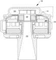
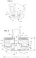
- FIG. 4is a cross-sectional view of the blood pump of FIG. 3 .
- FIG. 5is a partial cut-away perspective view of a stator of a blood pump.
- FIG. 6is an illustration of an embodiment of a Hall Sensor assembly for the blood pump of FIG. 3 .
- FIG. 7is a schematic diagram of a control system architecture of the mechanical support system of FIG. 1 .
- FIG. 8graphically illustrates deviations between flow rates estimated based on power consumption and measured flow rates for an example blood pump.
- FIG. 9shows a cross-sectional view of a centrifugal blood pump, in accordance with many embodiments.
- FIG. 10schematically illustrates impeller eccentricity, in accordance with many embodiments.
- FIG. 11shows a simplified schematic view of an impeller levitated via a motor stator, in accordance with many embodiments.
- FIG. 12is a plot showing observed correlations between measured flow rate and pump parameters including torque and impeller eccentricity values.
- FIG. 13is a simplified schematic illustration of a control architecture for generating current applied to levitation coils of a blood pump to transversely levitate an impeller, in accordance with many embodiments.
- FIG. 14is a plot showing an observed correlation between measured flow and impeller drive current for an example blood pump operated at 3000 rpm.
- FIG. 15is a plot showing an observed correlation between measured flow and target transverse eccentricity of the impeller of the example blood pump of FIG. 14 operated at 3000 rpm.
- FIG. 16is a plot showing an observed correlation between measured flow and impeller drive current for the example blood pump of FIG. 14 operated at 9000 rpm.
- FIG. 17is a plot showing an observed correlation between measured flow and target transverse eccentricity of the impeller of the example blood pump of FIG. 14 operated at 9000 rpm.
- FIG. 18is a plot showing bearing current variations during pulsatile mode operation of the example blood pump of FIG. 14 operated at a nominal 7000 rpm and 10 L/min.
- FIG. 19is a plot showing bearing current variations during pulsatile mode operation of the example blood pump of FIG. 14 operated at a nominal 7000 rpm and 7 L/min.
- FIG. 20is a plot showing bearing current variations during pulsatile mode operation of the example blood pump of FIG. 14 operated at a nominal 7000 rpm and 3 L/min.
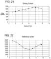
- FIG. 21is a plot showing an observed correlation between measured flow and impeller drive current for the example blood pump of FIG. 14 operated at 7000 rpm.
- FIG. 22is a plot showing an observed correlation between measured flow and target transverse eccentricity of the impeller of the example blood pump of FIG. 14 operated at 7000 rpm.
- FIG. 23graphically illustrates deviations between flow rates estimated based on power consumption and target impeller eccentricity and measured flow rates for the example blood pump of FIG. 14 , in accordance with many embodiments.
- FIG. 1is an illustration of a mechanical circulatory support system 10 implanted in a patient's body 12 .
- the mechanical circulatory support system 10includes an implantable blood pump assembly 14 , a ventricular cuff 16 , an outflow cannula 18 , an external system controller 20 , and power sources 22 .
- the implantable blood pump assembly 14can include a VAD that is attached to an apex of the left ventricle, as illustrated, or the right ventricle, or both ventricles of the heart 24 .
- the VADcan include a centrifugal pump (as shown) that is capable of pumping the entire output delivered to the left ventricle from the pulmonary circulation (i.e., up to 10 liters per minute).
- a centrifugal pumpas shown
- Related blood pumps applicable to the present inventionare described in greater detail below and in U.S. Pat. Nos.
- the blood pump assembly 14can be attached to the heart 24 via the ventricular cuff 16 , which can be sewn to the heart 24 and coupled to the blood pump 14 .
- the other end of the blood pump 14connects to the ascending aorta via the outflow cannula 18 so that the VAD effectively diverts blood from the weakened ventricle and propels it to the aorta for circulation through the rest of the patient's vascular system.
- FIG. 1illustrates the mechanical circulatory support system 10 during battery 22 powered operation.
- a driveline 26that exits through the patient's abdomen 28 connects the implanted blood pump assembly 14 to the external system controller 20 , which monitors system 10 operation.
- Related controller systems applicable to the present inventionare described in greater detail below and in U.S. Pat. Nos. 5,888,242, 6,991,595, 8,323,174, 8,449,444, 8,506,471, 8,597,350, and 8,657,733, EP 1812094, and U.S. Patent Publication Nos. 2005/0071001 and 2013/0314047, all of which are incorporated herein by reference for all purposes in their entirety.
- the system 10can be powered by either one, two, or more batteries 22 .
- system controller 20 and power source 22are illustrated outside/external to the patient body, the driveline 26 , the system controller 20 and/or the power source 22 can be partially or fully implantable within the patient, as separate components or integrated with the blood pump assembly 14 . Examples of such modifications are further described in U.S. Pat. Nos. 8,562,508 and 9,079,043, all of which are incorporated herein by reference for all purposes in their entirety.
- a left ventricular assist blood pump assembly 100 having a circular shaped housing 110is implanted in a patient's body with a first face 111 of the housing 110 positioned against the patient's heart H and a second face 113 of the housing 110 facing away from the heart H.
- the first face 111 of the housing 110includes an inlet cannula 112 extending into the left ventricle LV of the heart H.
- the second face 113 of the housing 110has a chamfered edge 114 to avoid irritating other tissue that may come into contact with the blood pump assembly 100 , such as the patient's diaphragm.
- a stator 120 and electronics 130 of the pump assembly 100are positioned on the inflow side of the housing toward first face 111 , and a rotor 140 of the pump assembly 100 is positioned along the second face 113 .
- This positioning of the stator 120 , electronics 130 , and rotor 140permits the edge 114 to be chamfered along the contour of the rotor 140 , as illustrated in at least FIGS. 2 - 4 , for example.
- the blood pump assembly 100includes a dividing wall 115 within the housing 110 defining a blood flow conduit 103 .
- the blood flow conduit 103extends from an inlet opening 101 of the inlet cannula 112 through the stator 120 to an outlet opening 105 defined by the housing 110 .
- the rotor 140is positioned within the blood flow conduit 103 .
- the stator 120is disposed circumferentially about a first portion 140 a of the rotor 140 , for example about a permanent magnet 141 .
- the stator 120is also positioned relative to the rotor 140 such that, in use, blood flows within the blood flow conduit 103 through the stator 120 before reaching the rotor 140 .
- the permanent magnet 141has a permanent magnetic north pole N and a permanent magnetic south pole S for combined active and passive magnetic levitation of the rotor 140 and for rotation of the rotor 140 .
- the rotor 140also has a second portion 140 b that includes impeller blades 143 .
- the impeller blades 143are located within a volute 107 of the blood flow conduit such that the impeller blades 143 are located proximate to the second face 113 of the housing 110 .
- the puck-shaped housing 110further includes a peripheral wall 116 that extends between the first face 111 and a removable cap 118 .
- the peripheral wall 116is formed as a hollow circular cylinder having a width W between opposing portions of the peripheral wall 116 .
- the housing 110also has a thickness T between the first face 111 and the second face 113 that is less than the width W.
- the thickness Tis from about 0.5 inches to about 1.5 inches, and the width W is from about 1 inch to about 4 inches.
- the width Wcan be approximately 2 inches, and the thickness T can be approximately 1 inch.
- the peripheral wall 116encloses an internal compartment 117 that surrounds the dividing wall 115 and the blood flow conduit 103 , with the stator 120 and the electronics 130 disposed in the internal compartment 117 about the dividing wall 115 .
- the removable cap 118includes the second face 113 , the chamfered edge 114 , and defines the outlet opening 105 .
- the cap 118can be threadedly engaged with the peripheral wall 116 to seal the cap 118 in engagement with the peripheral wall 116 .
- the cap 118includes an inner surface 118 a of the cap 118 that defines the volute 107 that is in fluid communication with the outlet opening 105 .
- the electronics 130are positioned adjacent to the first face 111 and the stator 120 is positioned adjacent to the electronics 130 on an opposite side of the electronics 130 from the first face 111 .
- the electronics 130include circuit boards 131 and various components carried on the circuit boards 131 to control the operation of the pump 100 (e.g., magnetic levitation and/or drive of the rotor) by controlling the electrical supply to the stator 120 .
- the housing 110is configured to receive the circuit boards 131 within the internal compartment 117 generally parallel to the first face 111 for efficient use of the space within the internal compartment 117 .
- the circuit boardsalso extend radially-inward towards the dividing wall 115 and radially-outward towards the peripheral wall 116 .
- the internal compartment 117is generally sized no larger than necessary to accommodate the circuit boards 131 , and space for heat dissipation, material expansion, potting materials, and/or other elements used in installing the circuit boards 131 .
- the external shape of the housing 110 proximate the first face 111generally fits the shape of the circuits boards 131 closely to provide external dimensions that are not much greater than the dimensions of the circuit boards 131 .
- the stator 120includes a back iron 121 and pole pieces 123 a - 123 f arranged at intervals around the dividing wall 115 .
- the back iron 121extends around the dividing wall 115 and is formed as a generally flat disc of a ferromagnetic material, such as steel, in order to conduct magnetic flux.
- the back iron 121is arranged beside the control electronics 130 and provides a base for the pole pieces 123 a - 123 f.
- Each of the pole piece 123 a - 123 fis L-shaped and has a drive coil 125 for generating an electromagnetic field to rotate the rotor 140 .
- the pole piece 123 ahas a first leg 124 a that contacts the back iron 121 and extends from the back iron 121 towards the second face 113 .
- the pole piece 123 acan also have a second leg 124 b that extends from the first leg 124 a through an opening of a circuit board 131 towards the dividing wall 115 proximate the location of the permanent magnet 141 of the rotor 140 .
- each of the second legs 124 b of the pole pieces 123 a - 123 fis sticking through an opening of the circuit board 131 .
- each of the first legs 124 a of the pole pieces 123 a - 123 fis sticking through an opening of the circuit board 131 .
- the openings of the circuit boardare enclosing the first legs 124 a of the pole pieces 123 a - 123 f.
- the implantable blood pump 100can include one or more Hall sensors that may provide an output voltage, which is directly proportional to a strength of a magnetic field that is located in between at least one of the pole pieces 123 a - 123 f and the permanent magnet 141 , and the output voltage may provide feedback to the control electronics 130 of the pump 100 to determine if the rotor 140 and/or the permanent magnet 141 is not at its intended position for the operation of the pump 100 .
- a position of the rotor 140 and/or the permanent magnet 141can be adjusted, e.g., the rotor 140 or the permanent magnet 141 may be pushed or pulled towards a center of the blood flow conduit 103 or towards a center of the stator 120 .
- Each of the pole pieces 123 a - 123 falso has a levitation coil 127 for generating an electromagnetic field to control the radial position of the rotor 140 .
- Each of the drive coils 125 and the levitation coils 127includes multiple windings of a conductor around the pole pieces 123 a - 123 f .
- each of the drive coils 125is wound around two adjacent ones of the pole pieces 123 , such as pole pieces 123 d and 123 e , and each levitation coil 127 is wound around a single pole piece.
- the drive coils 125 and the levitation coils 127are wound around the first legs of the pole pieces 123 , and magnetic flux generated by passing electrical current though the coils 125 and 127 during use is conducted through the first legs and the second legs of the pole pieces 123 and the back iron 121 .
- the drive coils 125 and the levitation coils 127 of the stator 120are arranged in opposing pairs and are controlled to drive the rotor and to radially levitate the rotor 140 by generating electromagnetic fields that interact with the permanent magnetic poles S and N of the permanent magnet 141 .
- stator 120includes both the drive coils 125 and the levitation coils 127 , only a single stator is needed to levitate the rotor 140 using only passive and active magnetic forces.
- the permanent magnet 141 in this configurationhas only one magnetic moment and is formed from a monolithic permanent magnetic body 141 .
- the stator 120can be controlled as discussed in U.S. Pat. No. 6,351,048, the entire contents of which are incorporated herein by reference for all purposes.
- the control electronics 130 and the stator 120receive electrical power from a remote power supply via a cable 119 ( FIG. 3 ). Further related patents, namely U.S. Pat. Nos.
- the rotor 140is arranged within the housing 110 such that its permanent magnet 141 is located upstream of impeller blades in a location closer to the inlet opening 101 .
- the permanent magnet 141is received within the blood flow conduit 103 proximate the second legs 124 b of the pole pieces 123 to provide the passive axial centering force though interaction of the permanent magnet 141 and ferromagnetic material of the pole pieces 123 .
- the permanent magnet 141 of the rotor 140 and the dividing wall 115form a gap 108 between the permanent magnet 141 and the dividing wall 115 when the rotor 140 is centered within the dividing wall 115 .
- the gap 108may be from about 0.2 millimeters to about 2 millimeters.
- the gap 108can be approximately 1 millimeter.
- the north permanent magnetic pole N and the south permanent magnetic pole S of the permanent magnet 141provide a permanent magnetic attractive force between the rotor 140 and the stator 120 that acts as a passive axial centering force that tends to maintain the rotor 140 generally centered within the stator 120 and tends to resist the rotor 140 from moving towards the first face 111 or towards the second face 113 .
- the rotor 140also includes a shroud 145 that covers the ends of the impeller blades 143 facing the second face 113 that assists in directing blood flow into the volute 107 .
- the shroud 145 and the inner surface 118 a of the cap 118form a gap 109 between the shroud 145 and the inner surface 118 a when the rotor 140 is levitated by the stator 120 .
- the gap 109is from about 0.2 millimeters to about 2 millimeters. For example, the gap 109 is approximately 1 millimeter.
- the gaps 108 and 109are large enough to allow adequate blood flow to limit clot formation that may occur if the blood is allowed to become stagnant.
- the gaps 108 and 109are also large enough to limit pressure forces on the blood cells such that the blood is not damaged when flowing through the pump 100 .
- the gaps 108 and 109are too large to provide a meaningful hydrodynamic suspension effect. That is to say, the blood does not act as a bearing within the gaps 108 and 109 , and the rotor is only magnetically-levitated.
- the gaps 108 and 109are sized and dimensioned so the blood flowing through the gaps forms a film that provides a hydrodynamic suspension effect. In this manner, the rotor can be suspended by magnetic forces, hydrodynamic forces, or both.
- the rotor 140is radially suspended by active control of the levitation coils 127 as discussed above, and because the rotor 140 is axially suspended by passive interaction of the permanent magnet 141 and the stator 120 , no rotor levitation components are needed proximate the second face 113 .
- the incorporation of all the components for rotor levitation in the stator 120i.e., the levitation coils 127 and the pole pieces 123 ) allows the cap 118 to be contoured to the shape of the impeller blades 143 and the volute 107 . Additionally, incorporation of all the rotor levitation components in the stator 120 eliminates the need for electrical connectors extending from the compartment 117 to the cap 118 , which allows the cap to be easily installed and/or removed and eliminates potential sources of pump failure.
- the drive coils 125 of the stator 120generates electromagnetic fields through the pole pieces 123 that selectively attract and repel the magnetic north pole N and the magnetic south pole S of the rotor 140 to cause the rotor 140 to rotate within stator 120 .
- the one or more Hall sensorsmay sense a current position of the rotor 140 and/or the permanent magnet 141 , wherein the output voltage of the one or more Hall sensors may be used to selectively attract and repel the magnetic north pole N and the magnetic south pole S of the rotor 140 to cause the rotor 140 to rotate within stator 120 .
- the impeller blades 143force blood into the volute 107 such that blood is forced out of the outlet opening 105 .
- the rotordraws blood into pump 100 through the inlet opening 101 .
- the bloodflows through the inlet opening 101 and flows through the control electronics 130 and the stator 120 toward the rotor 140 .
- Bloodflows through the aperture 141 a of the permanent magnet 141 and between the impeller blades 143 , the shroud 145 , and the permanent magnet 141 , and into the volute 107 .
- Bloodalso flows around the rotor 140 , through the gap 108 and through the gap 109 between the shroud 145 and the inner surface 118 a of the cap 118 .
- the bloodexits the volute 107 through the outlet opening 105 , which may be coupled to an outflow cannula.
- FIG. 6shows a Hall Sensor assembly 200 for the blood pump assembly 14 , in accordance with many embodiments.
- the Hall Sensor assembly 200includes a printed circuit board (PCB) 202 and individual Hall Effect sensors 208 supported by the printed circuit board 202 .
- Eight axi-symmetric Hall Effect sensors 208are placed in a rigid, plastic mechanical carrier 210 and the PCB 202 is placed onto the mechanical carrier 210 .
- the mechanical carrier 210uses guide rails 212 to locate electrically neutral rigid PCB portions 214 attached to the top edges of the Hall Effect sensors 208 and to locate the PCB 202 .
- the Hall Effect sensors 208are configured to transduce a position of the rotor 140 of the pump 100 .
- the Hall Effect sensors 208are supported so as to be standing orthogonally relative to the PCB 202 and a longest edge of each of the Hall Effect sensors 208 is aligned to possess an orthogonal component with respect to the surface of the PCB 202 .
- Each of the Hall Effect sensors 208generate an output voltage, which is directly proportional to a strength of a magnetic field that is located in between at least one of the pole pieces 123 a - 123 f and the permanent magnet 141 .
- the voltage output by each of the Hall Effect sensors 208is received by the control electronics 130 , which processes the sensor output voltages to determine the position and orientation of the rotor 140 .
- the determined position and orientation of the rotor 140is used to determine if the rotor 140 is not at its intended position for the operation of the pump 100 .
- a position of the rotor 140 and/or the permanent magnet 141may be adjusted, for example, the rotor 140 or the permanent magnet 141 may be pushed or pulled towards a center of the blood flow conduit 103 or towards a center of the stator 120 .
- the determined position of the rotor 140can also be used to determine rotor eccentricity or a target rotor eccentricity, which can be used as described herein to estimate flow rate of blood pumped by the blood pump assembly 100 .
- FIG. 7is a schematic diagram of a control system architecture of the mechanical support system of FIG. 1 .
- the driveline 26couples the implanted blood pump assembly 100 to the external system controller 20 , which monitors system operation via various software applications.
- the blood pump assembly 100itself also includes several software applications that are executable by the on board electronics 130 (e.g., processors) for various functions, such as to control radial levitation and/or drive of the rotor of the pump assembly 100 during operation.
- the external system controller 20can in turn be coupled to batteries 22 or a power module 30 that connect to an AC electrical outlet.
- the external system controller 20can also include an emergency backup battery (EBB) to power the system (e.g., when the batteries 22 are depleted) and a membrane overlay, including Bluetooth capabilities for wireless data communication.
- EBBemergency backup battery
- An external computer having a system monitor 32 that is configurable by an operator, such as clinician or patient,may further be coupled to the circulatory support system for configuring the external system controller 20 , implanted blood pump assembly 100 , and/or patient specific parameters, updating software on the external system controller 20 and/or implanted blood pump assembly 100 , monitoring system operation, and/or as a conduit for system inputs or outputs.
- EBBemergency backup battery
- FIG. 8graphically illustrates example deviations between measured flow rate for an example blood pump and flow rates (220-3000, 220-4000, 220-5000, 220-6000, 220-7000, 220-8000, 220-9000) estimated for the example blood pump based on power consumption and rotor rotation rate for a number of different impeller rotation rates.
- the estimated flow ratewould correspond to an exact estimated flow 222 that is equal to the measured flow rate.
- the same estimated flow rate of 8.0 L/mincorresponds to two different actual measured flow rates of about 7.8 L/min and 10.6 L/min.
- the actual power consumptiondrops with increasing flow rate thereby resulting in increasing magnitude of error between the estimate flow rate 220-9000 and the exact estimated flow 222 .
- Such a doubled value characteristiccan also be seen in the data displayed in FIG. 8 for impeller rotation rates of 4000 rpm to 9000 rpm.
- estimating flow rate based only on impeller rotation rate and power consumptioncan result in significant relative error for actual pump flow rates at the high end of the actual flow rate range.
- one or more additional flow rate related parametersare employed to produce more accurate flow rate estimates.
- estimated flow rate for at least some ranges of flow rateis based on an actual or target impeller transverse eccentricity.
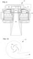
- FIG. 9shows a cross-sectional view of the centrifugal blood pump 14 , in accordance with many embodiments.
- the rotor 140is magnetically levitated in the blood flow channel 103 via magnetic interaction between the permanent magnet 141 and the motor stator 120 .
- the bloodflows through the center of the rotor 140 and is impelled into an axially non-symmetric output chamber 224 from which the blood is output from the blood pump 14 via the outlet 105 shown in FIG. 4 .
- the rotoris subjected to a transverse force that is reacted via magnetic interaction between the permanent magnet 141 and the motor stator 120 .
- the motor stator 120can be controlled so as to keep the rotor 140 centered within the blood flow channel
- the power consumption of the blood pump 14can be reduced by allowing the position of the rotor 140 to deviate from being centered in the blood flow channel 103 .
- minimizing the power consumption of the blood pump 14 over a range of operating conditionsresults in target impeller eccentricity that varies as a function of flow rate over at least a range of operating conditions so as to enable use of the target impeller eccentricity as a parameter from which to estimate flow rate.
- FIG. 10schematically illustrates impeller eccentricity that occurs in the presence of transverse force being applied to the rotor 140 and minimization of the power consumption of the blood pump 14 .
- FIG. 11shows a simplified cross-sectional schematic view of the rotor 140 levitated via the motor stator 120 .
- the output from the Hall sensors 208is processed to determine the transverse position of the rotor 140 in both X and Y directions.
- the displacement of the rotor 140 from a centered reference position in each of the X and Y directionscan be combined to generate a total vector sum eccentricity of the rotor 140 from the centered reference position.
- FIG. 12is a plot showing observed correlations between measured flow rate and pump parameters including torque and impeller eccentricity values for an example pump operated at 9000 rpm.
- the torque 226increases with flow up to a flow rate of about 9.5 L/min and then drops thereafter.
- the torque 226is proportional to drive current and is double valued in the shaded range of flow rate greater than 7.5 L/min. Accordingly, estimation of pump flow rate based on the torque 226 for flow rates greater than about 9.5 L/min may produce increasingly more relative error between the estimated flow rate and the actual flow rate.
- the total rotor eccentricity 228which is the vector sum of the X-direction rotor eccentricity 230 and the Y-direction rotor eccentricity 232 , is single valued in the shaded range of flow rate greater than 7.5 L/min, and can therefore be employed to estimate flow rate at least in some or all of the shaded flow rate range of greater than 7.5 L/min.
- FIG. 13is a simplified schematic illustration of a bearing current controller 250 for generating current applied to the levitation coils 127 of the blood pump 14 to transversely levitate the rotor 140 , in accordance with many embodiments.
- the bearing current controller 250includes a magnetic center proportional-integral-derivative (PID) controller 252 , a position PID controller 254 , and a current PID controller 256 .
- PIDmagnetic center proportional-integral-derivative
- the current generatedis applied to the levitation coils 127 to controllably levitate the rotor 140 .
- the resulting position of the rotor 140(signal 258 ) is determined from the output of the Hall sensors 208 .
- the bearing current controller 250employs a three-level cascaded PID control method.
- the ultimate feedback signalis the bearing current 260 therefore the bearing current controller 250 is configured to minimize bearing current to reduce power consumption of the blood pump 14 .
- the resulting bearing currentis different reflecting the different forces on the rotor from the impelled blood.
- there are two bearing currentsbecause there are two separate bearing coils on the stator 120 (two for each direction).
- a Park transformationis applied to change the coordinates from stator referenced directions (X and Y) to the rotor referenced directions (d and q directions).
- Two separate bearing current controllers 250are used to control the current applied to the levitation coils 127 —one for each of the d and q directions.
- the direction dis aligned along the rotor N-S dimension.
- the direction qis perpendicular to the direction d.
- the directions d and qdefine a plane perpendicular to the direction of flow through the center of the rotor 140 .
- the magnetic center PID controller 252generates reference signals for the position PID controller 254 defining a target off-center position for the rotor (in the d-q coordinate system) to minimize bearing current.
- the position PID controller 254generates reference signals for the bearing current in the d-q coordinate system.
- the current PID controller 254calculates the bearing current in the d-q coordinate system and then applies an inverse Park transformation to generate current output for application to the levitation coils 127 to control levitation of the rotor 140 in each of the two separate directions (X and Y).
- Signals 262 , 264 , 266 , 268 , 260 , 258 generated by the bearing current controller 250were studied for possible use in estimating flow rate. Because of the cascaded control structure employed, the signals 262 , 264 , 266 , 268 , 260 , 258 generated by the bearing current controller 250 show similar trend of changes when flow rate is changed, although the trend direction may be reversed because of the negative feedback sign change. Signals 266 , 268 , 260 , 258 show high run-to-run variation and noise-to-signal ratio is high due to the bearing current and center position feedback signals have significant disturbance induced from the fluid field. Signal 262 and signal 264 are more stable because the feedback signal is the bearing current after a low pass filter.
- Signal 264is the target reference rotor center position, which is even more stable than signal 262 , because the gain in the magnetic center PID controller 252 is zero.
- the magnetic center PID controller 252imposes 20 dB attenuation from DC up to a frequency. Accordingly, the target reference rotor center position signal 264 , which defines the target off-center position for the rotor (in the d-q coordinate system) to minimize bearing current, provides a suitable signal that can be processed to estimate flow rate of the blood pump.
- each of the target reference rotor center signals 264 from the two bearing current controllers 250can be combined to calculate a target reference rotor center value corresponding to a total target eccentric distance of the target off-center position for the rotor from the center of the blood flow channel of the blood pump.
- FIG. 14is a plot showing an observed correlation between measured flow and impeller drive current for an example blood pump operated at 3000 rpm.
- the corresponding drive current used to rotate the impellershows a substantially linear increase from about 288 counts to about 318 counts.
- the increase in drive current with increased measured flow ratediminishes down to no significant increase in drive current for measured flow rate between 3.5 L/min and 4.0 L/min. Accordingly, estimated flow rate based only on drive current for impeller rotation rate of 3000 rpm may deviate increasingly from actual flow rate for flow rates above 2.5 L/min.
- FIG. 15is a plot showing an observed correlation between measured flow and the target reference center value of the example blood pump of FIG. 14 operated at 3000 rpm. As illustrated in FIG. 15 , for measured flow rates from 1 L/min to 3.5 L/min, the corresponding target reference center value shows a substantially linear increase. Therefore, the target reference center value can be used to increase the accuracy of estimated flow rate, at least in the 2.5 L/min to 3.5 L/min range for the example blood pump of FIG. 14 operated at 3000 rpm.
- FIG. 16is a plot showing an observed correlation between measured flow and impeller drive current for the example blood pump of FIG. 14 operated at 9000 rpm.
- the corresponding drive current used to rotate the impellershows a substantially linear increase from about 1120 counts to about 1750 counts. From about 10.0 L/min to about 11.0 L/min, the corresponding drive current used to rotate the impeller shows no significant change. Above 11.0 L/min, the corresponding drive current used to rotate the impeller drops down to about 1600 counts at about 13.0 L/min flow rate. Accordingly, estimated flow rate based only on drive current for impeller rotation rate of 9000 rpm may deviate increasingly from actual flow rate for flow rates above 10.0 L/min.
- FIG. 17is a plot showing an observed correlation between measured flow and the target reference center value of the example blood pump of FIG. 14 operated at 9000 rpm.
- the corresponding target reference center valueshows a substantially linear decrease.
- the corresponding target reference center valueshows no significant change.
- the corresponding target reference center valueexhibits a substantially linear increase with increasing flow rate. Therefore, the target reference center value can be used to increase the accuracy of estimated flow rate, at least in the 9.0 L/min and higher range for the example blood pump of FIG. 14 operated at 9000 rpm.
- the target reference center valueis correlated with flow rate.
- the target reference center valuealso has bell curve shape meaning it also has double value problem for use in estimating flow rate, its double value range is different from the double value range of the driving current. Accordingly, one method that can be used to overcome the estimation error arising from the double valued nature of the driving current and flow rate correlation is to combine the driving current with the target reference center to predict the flow rate, for example, switching from driving current to the target reference center when driving current is in the double value range.
- One methodselects a single flow rate value to switch for each particular rotor rotational rate. For example, when driving current is higher than 1600 counts in FIG. 16 , driving current is in the double value range, so the flow can be estimated based on target reference center instead of drive current when the driving current is higher than 1600 counts.
- a second method for determining what flow rate to switch between estimating flow rate based on driving current and estimating flow rate based on target reference centeris based on how the bearing current varies in response to a pulsatile variation in the rotation rate of the rotor.
- the merit of the second methodis that no calibration variable is involved in the second method's algorithm based switching, which may therefore be more robust in implementation.
- the rotor rotational rateis periodically varied to simulate natural blood pulse. On a periodic basis, the rotor rotational rate is temporarily reduced from the current nominal rotational rate, then temporarily increased from the reduced rate to a rate greater than the current nominal rotation rate, and then reduced back down to the current nominal rotational rate.
- FIGS. 18 through 20show the bearing currents filtered by the low pass filter and decomposed into d-q coordinates for different flow rates for a rotor rotation rate of 7000 rpm.
- the left subfigureis for the d axis, and right for the q axis.
- the d axis bearing current transitiongoes up then down at 10 L/min, and goes down then up at 3 L/min.
- FIG. 21is a plot showing an observed correlation between measured flow and impeller drive current for the example blood pump of FIG. 14 operated at 7000 rpm.
- FIG. 22is a plot showing an observed correlation between measured flow and target reference center of the impeller of the example blood pump of FIG. 14 operated at 7000 rpm. As shown in FIG. 22 , the target reference center value bottoms at 6 L/min. Therefore the slope of the target reference center curve with flow is reversed at 6 L/min, which causes the difference in pulsatile transition of the related rotor levitation current.
- This pulsatile transition change in bearing currentcan be used to set an estimation parameter having either a value of 0.0 or 1.0 based on whether the shape of the pulsatile transition change in bearing current indicates that the current nominal flow rate is lower or higher than the flow rate at which the target reference center curve bottoms.
- the estimation parametercan then be used to switch between estimating flow rate based on drive current when the flow rate is below the flow rate at which the target reference center curve bottoms and estimating flow rate based on target reference center value when the flow rate is above the flow rate at which the target reference center bottoms.
- FIGS. 21 and 22show that for an example pump operated at 7000 rpm, driving current is a good estimator until about 7 L/min.
- the estimation parametercan be set to 1.0 at 7 L/min and higher so that the target reference center value can be used to estimate flow rate for flow rates of 7 L/min or higher.
- Calibrationcan also be done to fit the target reference center signal with the flow rate.
- a weighing methodcan be used to put less weight on the target reference center signal when the pulsatile transition change in the bearing current indicates a flow rate corresponding to approximately the bottom of the target reference signal, and gradually add more weight to reference center signal at higher flow rate. The accuracy of this weighing method is illustrated in FIG. 23 , which graphically illustrates deviations between the resulting measured flow rate and actual flow rate for the example blood pump of FIG. 14 .
- any suitable existing curve fitting techniquescan be used to estimate flow rate based on any suitable combination of rotor rotation rate, drive current, and target reference center.
- two or more different curve fitscan be used to cover the entire range of flow rates. For example, one curve fit can be used to estimate flow rate at the low range of flow rates where flow rate is primarily a function of driving current, a second curve fit can be used at the high range of flow rates based on target reference center, and a third curve fit can be used at the mid-range of flow rates based on both driving current and target flow rate.
- Other bearing current related parameterscan also be used.
- the bearing currentcan be controlled to keep the rotor centered in the blood flow channel and the variation in the bearing current, which will be greater if the rotor is kept centered, can be used as another parameter in addition to rotor driving current to estimate flow rate.
- the parameters related to impeller position described hereincan be used alone or in combination to estimate pressure differential across the impeller (i.e., difference in pressure on the output side of the impeller to pressure on the input side of the impeller) in addition to or instead of estimating flow.
- pressure differential across the impelleri.e., difference in pressure on the output side of the impeller to pressure on the input side of the impeller
- the impeller eccentricity for minimum bearing currentappears to be solely or mostly dependent upon the pressure differential across the impeller.
- the pressure differential across the impellercan be estimated using a suitable function of the parameters related to impeller position described herein.
- any suitable additional operational parameter of the blood pumpsuch as pump rotational speed, impeller drive current, and/or estimated blood flow through the pump, can be used alone or in any suitable combination in addition to the parameters related to impeller position described herein to estimate the pressure differential across the impeller.
- the pressure differential across the impellercan be derived from the flow rate of blood through the blood pump and vice versa.
- the resulting estimated pressure differentialcan be used in any suitable way, including as a parameter on which operation of the pump is based to produce desired pressure differential across the pump suitable for particular patient physiological conditions and/or to detect and react to adverse pump conditions.
Landscapes
- Health & Medical Sciences (AREA)
- Heart & Thoracic Surgery (AREA)
- Engineering & Computer Science (AREA)
- Cardiology (AREA)
- Biomedical Technology (AREA)
- Anesthesiology (AREA)
- Mechanical Engineering (AREA)
- Hematology (AREA)
- Life Sciences & Earth Sciences (AREA)
- Animal Behavior & Ethology (AREA)
- General Health & Medical Sciences (AREA)
- Public Health (AREA)
- Veterinary Medicine (AREA)
- External Artificial Organs (AREA)
- Structures Of Non-Positive Displacement Pumps (AREA)
Abstract
Description
Claims (18)
Priority Applications (1)
| Application Number | Priority Date | Filing Date | Title |
|---|---|---|---|
| US17/338,287US11872384B2 (en) | 2015-07-20 | 2021-06-03 | Method of operating a blood pump having a magnetically levitated impeller |
Applications Claiming Priority (5)
| Application Number | Priority Date | Filing Date | Title |
|---|---|---|---|
| US201562194608P | 2015-07-20 | 2015-07-20 | |
| US15/214,099US9901666B2 (en) | 2015-07-20 | 2016-07-19 | Flow estimation using hall-effect sensors for measuring impeller eccentricity |
| US15/873,427US10300184B2 (en) | 2015-07-20 | 2018-01-17 | Flow estimation using hall-effect sensors |
| US16/382,686US11040188B2 (en) | 2015-07-20 | 2019-04-12 | Flow estimation using hall-effect sensors and/or magnetic bearing currents |
| US17/338,287US11872384B2 (en) | 2015-07-20 | 2021-06-03 | Method of operating a blood pump having a magnetically levitated impeller |
Related Parent Applications (1)
| Application Number | Title | Priority Date | Filing Date |
|---|---|---|---|
| US16/382,686ContinuationUS11040188B2 (en) | 2015-07-20 | 2019-04-12 | Flow estimation using hall-effect sensors and/or magnetic bearing currents |
Publications (2)
| Publication Number | Publication Date |
|---|---|
| US20210290936A1 US20210290936A1 (en) | 2021-09-23 |
| US11872384B2true US11872384B2 (en) | 2024-01-16 |
Family
ID=57834610
Family Applications (4)
| Application Number | Title | Priority Date | Filing Date |
|---|---|---|---|
| US15/214,099Active2036-08-12US9901666B2 (en) | 2015-07-20 | 2016-07-19 | Flow estimation using hall-effect sensors for measuring impeller eccentricity |
| US15/873,427ActiveUS10300184B2 (en) | 2015-07-20 | 2018-01-17 | Flow estimation using hall-effect sensors |
| US16/382,686Active2036-11-22US11040188B2 (en) | 2015-07-20 | 2019-04-12 | Flow estimation using hall-effect sensors and/or magnetic bearing currents |
| US17/338,287Active2037-05-24US11872384B2 (en) | 2015-07-20 | 2021-06-03 | Method of operating a blood pump having a magnetically levitated impeller |
Family Applications Before (3)
| Application Number | Title | Priority Date | Filing Date |
|---|---|---|---|
| US15/214,099Active2036-08-12US9901666B2 (en) | 2015-07-20 | 2016-07-19 | Flow estimation using hall-effect sensors for measuring impeller eccentricity |
| US15/873,427ActiveUS10300184B2 (en) | 2015-07-20 | 2018-01-17 | Flow estimation using hall-effect sensors |
| US16/382,686Active2036-11-22US11040188B2 (en) | 2015-07-20 | 2019-04-12 | Flow estimation using hall-effect sensors and/or magnetic bearing currents |
Country Status (3)
| Country | Link |
|---|---|
| US (4) | US9901666B2 (en) |
| EP (1) | EP3325035B1 (en) |
| WO (1) | WO2017015268A1 (en) |
Cited By (16)
| Publication number | Priority date | Publication date | Assignee | Title |
|---|---|---|---|---|
| US12064615B2 (en) | 2018-05-30 | 2024-08-20 | Kardion Gmbh | Axial-flow pump for a ventricular assist device and method for producing an axial-flow pump for a ventricular assist device |
| US12107474B2 (en) | 2018-05-16 | 2024-10-01 | Kardion Gmbh | End-face rotating joint for transmitting torques |
| US12144976B2 (en) | 2018-06-21 | 2024-11-19 | Kardion Gmbh | Method and device for detecting a wear condition of a ventricular assist device and for operating same, and ventricular assist device |
| US12178554B2 (en) | 2018-06-06 | 2024-12-31 | Kardion Gmbh | Systems and methods for determining a viscosity of a fluid |
| US12194287B2 (en) | 2018-05-30 | 2025-01-14 | Kardion Gmbh | Method of manufacturing electrical conductor tracks in a region of an intravascular blood pump |
| US12201821B2 (en) | 2018-06-06 | 2025-01-21 | Kardion Gmbh | Method for determining a flow rate of a fluid flowing through an implanted vascular support system, and implantable vascular support system |
| US12201823B2 (en) | 2018-05-30 | 2025-01-21 | Kardion Gmbh | Line device for conducting a blood flow for a heart support system, heart support system, and method for producing a line device |
| US12222267B2 (en) | 2018-06-06 | 2025-02-11 | Kardion Gmbh | Analysis device and method for analyzing a viscosity of a fluid |
| US12257424B2 (en) | 2018-06-06 | 2025-03-25 | Kardion Gmbh | Implantable ventricular assist system and method for operating same |
| US12263333B2 (en) | 2018-06-21 | 2025-04-01 | Kardion Gmbh | Stator vane device for guiding the flow of a fluid flowing out of an outlet opening of a ventricular assist device, ventricular assist device with stator vane device, method for operating a stator vane device and manufacturing method |
| US12311160B2 (en) | 2018-06-06 | 2025-05-27 | Kardion Gmbh | Method and system for determining the speed of sound in a fluid in the region of a cardiac support system |
| US12310708B2 (en) | 2018-06-06 | 2025-05-27 | Kardion Gmbh | Systems and methods for determining a flow speed of a fluid flowing through a cardiac assist device |
| US12324906B2 (en) | 2018-06-06 | 2025-06-10 | Kardion Gmbh | Systems and methods for determining a total blood volume flow in a cardiac support system and vascular support system |
| US12377256B2 (en) | 2018-06-06 | 2025-08-05 | Kardion Gmbh | Cardiac support system flow measurement using pressure sensors |
| US12383727B2 (en) | 2018-05-30 | 2025-08-12 | Kardion Gmbh | Motor housing module for a heart support system, and heart support system and method for mounting a heart support system |
| US12390633B2 (en) | 2018-08-07 | 2025-08-19 | Kardion Gmbh | Bearing device for a heart support system, and method for rinsing a space in a bearing device for a heart support system |
Families Citing this family (46)
| Publication number | Priority date | Publication date | Assignee | Title |
|---|---|---|---|---|
| EP3324840A4 (en) | 2015-07-20 | 2019-03-20 | Tc1 Llc | TENSIOMETER FOR FLOW ESTIMATION |
| US9901666B2 (en) | 2015-07-20 | 2018-02-27 | Tc1 Llc | Flow estimation using hall-effect sensors for measuring impeller eccentricity |
| WO2017120451A2 (en) | 2016-01-06 | 2017-07-13 | Bivacor Inc. | Heart pump with impeller rotational speed control |
| WO2018183568A1 (en) | 2017-03-29 | 2018-10-04 | Tc1 Llc | Pressure sensing ventricular assist devices and methods of use |
| US10780209B2 (en) | 2017-03-29 | 2020-09-22 | Tc1 Llc | Adjusting pump protocol based on irregular heart rhythm |
| US11065436B2 (en) | 2017-03-29 | 2021-07-20 | Tc1 Llc | Communication methods and architecture for heart treatment systems |
| EP3606577B1 (en) | 2017-04-05 | 2025-07-30 | Bivacor Inc. | Heart pump drive and bearing |
| CA3066361A1 (en) | 2017-06-07 | 2018-12-13 | Shifamed Holdings, Llc | Intravascular fluid movement devices, systems, and methods of use |
| WO2019094963A1 (en) | 2017-11-13 | 2019-05-16 | Shifamed Holdings, Llc | Intravascular fluid movement devices, systems, and methods of use |
| CN112004563B (en) | 2018-02-01 | 2024-08-06 | 施菲姆德控股有限责任公司 | Intravascular blood pump and methods of use and manufacture |
| EP4461341A3 (en) | 2018-03-15 | 2025-01-15 | Tc1 Llc | Systems for preventing right heart failure |
| US11167123B2 (en) | 2018-03-19 | 2021-11-09 | Tc1 Llc | Coordinated ventricular assist and cardiac rhythm management devices and methods |
| EP3793631B1 (en)* | 2018-05-17 | 2024-06-26 | HeartWare, Inc. | Current-speed relationship for instantaneous suction detection algorithm in lvads |
| EP3574932A1 (en) | 2018-05-28 | 2019-12-04 | Berlin Heart GmbH | Blood pump |
| EP3581216A1 (en)* | 2018-06-11 | 2019-12-18 | Universität Zürich | Blood pump for mechanical circulatory support for fontan patients |
| US11241570B2 (en) | 2018-07-17 | 2022-02-08 | Tc1 Llc | Systems and methods for inertial sensing for VAD diagnostics and closed loop control |
| US12161857B2 (en) | 2018-07-31 | 2024-12-10 | Shifamed Holdings, Llc | Intravascular blood pumps and methods of use |
| EP3856274B1 (en) | 2018-09-25 | 2024-04-17 | Tc1 Llc | Adaptive speed control algorithms and controllers for optimizing flow in ventricular assist devices |
| WO2020073047A1 (en) | 2018-10-05 | 2020-04-09 | Shifamed Holdings, Llc | Intravascular blood pumps and methods of use |
| CN109612376A (en)* | 2018-12-24 | 2019-04-12 | 郑州云海信息技术有限公司 | A method and system for monitoring cabinet assembly accuracy using a hall sensor array |
| US12097016B2 (en)* | 2019-03-14 | 2024-09-24 | Abiomed, Inc. | Blood flow rate measurement system |
| EP3969074A1 (en)* | 2019-05-17 | 2022-03-23 | Nupulsecv, Inc. | Intravascularly delivered blood pumps and associated devices, systems, and methods |
| WO2021011473A1 (en) | 2019-07-12 | 2021-01-21 | Shifamed Holdings, Llc | Intravascular blood pumps and methods of manufacture and use |
| US11654275B2 (en) | 2019-07-22 | 2023-05-23 | Shifamed Holdings, Llc | Intravascular blood pumps with struts and methods of use and manufacture |
| US12121713B2 (en) | 2019-09-25 | 2024-10-22 | Shifamed Holdings, Llc | Catheter blood pumps and collapsible blood conduits |
| EP4501393A3 (en) | 2019-09-25 | 2025-04-09 | Shifamed Holdings, LLC | Catheter blood pumps and collapsible pump housings |
| WO2021062265A1 (en) | 2019-09-25 | 2021-04-01 | Shifamed Holdings, Llc | Intravascular blood pump systems and methods of use and control thereof |
| CN112807565A (en)* | 2019-10-30 | 2021-05-18 | 深圳核心医疗科技有限公司 | Magnetic suspension blood pump |
| WO2021096706A1 (en) | 2019-11-12 | 2021-05-20 | Fresenius Medical Care Deutschland Gmbh | Blood treatment systems |
| EP4058087A1 (en) | 2019-11-12 | 2022-09-21 | Fresenius Medical Care Deutschland GmbH | Blood treatment systems |
| EP4058088A1 (en) | 2019-11-12 | 2022-09-21 | Fresenius Medical Care Deutschland GmbH | Blood treatment systems |
| EP4058079A1 (en) | 2019-11-12 | 2022-09-21 | Fresenius Medical Care Deutschland GmbH | Blood treatment systems |
| EP4058095A1 (en) | 2019-11-12 | 2022-09-21 | Fresenius Medical Care Deutschland GmbH | Blood treatment systems |
| CN114728116A (en) | 2019-11-12 | 2022-07-08 | 费森尤斯医疗护理德国有限责任公司 | Blood treatment system |
| EP4072650A4 (en) | 2019-12-11 | 2024-01-10 | Shifamed Holdings, LLC | Descending aorta and vena cava blood pumps |
| US12352279B2 (en)* | 2020-07-03 | 2025-07-08 | Iwaki Co., Ltd. | Rotary drive device and pump |
| AU2021360124A1 (en)* | 2020-10-15 | 2023-06-22 | Cardiobionic Pty Ltd | Ventricular assist system and method |
| EP4479124A1 (en) | 2022-02-16 | 2024-12-25 | Tc1 Llc | Real time heart rate monitoring for close loop control and/or artificial pulse synchronization of implantable ventricular assist devices |
| CN114796850A (en)* | 2022-02-25 | 2022-07-29 | 上海炫脉医疗科技有限公司 | Method for controlling the speed of a heart assist system |
| EP4531982A1 (en) | 2022-05-26 | 2025-04-09 | Tc1 Llc | Tri-axis accelerometers for patient physiologic monitoring and closed loop control of implantable ventricular assist devices |
| CN115779260A (en)* | 2022-11-24 | 2023-03-14 | 上海炫脉医疗科技有限公司 | Systems and methods for estimating the position of an invasive blood pump |
| KR20240148258A (en)* | 2023-04-03 | 2024-10-11 | 레비트로닉스 게엠베하 | An electromagnetic rotary drive and a centrifugal pump |
| WO2024242960A1 (en) | 2023-05-16 | 2024-11-28 | Bivacor Inc. | Parameter calculation of a blood pump |
| US20250088073A1 (en)* | 2023-09-11 | 2025-03-13 | Levitronix Gmbh | Magnetic levitation device and a centrifugal pump |
| CN117282017B (en)* | 2023-10-07 | 2024-06-14 | 心擎医疗(苏州)股份有限公司 | Interventional pump flow estimation method, device, equipment and ventricular assist device |
| WO2025137296A1 (en) | 2023-12-22 | 2025-06-26 | Tc1 Llc | Utilization of a left-ventricular pressure sensor for measurement of left-atrial and aortic pressure |
Citations (103)
| Publication number | Priority date | Publication date | Assignee | Title |
|---|---|---|---|---|
| US5695471A (en) | 1996-02-20 | 1997-12-09 | Kriton Medical, Inc. | Sealless rotary blood pump with passive magnetic radial bearings and blood immersed axial bearings |
| US5708346A (en) | 1994-01-10 | 1998-01-13 | Sulzer Electronics Ag | Method and control apparatus for controlling an AC-machine |
| US5725357A (en) | 1995-04-03 | 1998-03-10 | Ntn Corporation | Magnetically suspended type pump |
| US5888242A (en) | 1996-11-01 | 1999-03-30 | Nimbus, Inc. | Speed control system for implanted blood pumps |
| US5947703A (en) | 1996-01-31 | 1999-09-07 | Ntn Corporation | Centrifugal blood pump assembly |
| US5951263A (en) | 1995-04-19 | 1999-09-14 | Nimbus, Inc. | Implantable electric axial-flow blood pump with blood-cooled bearing |
| US6053705A (en) | 1996-09-10 | 2000-04-25 | Sulzer Electronics Ag | Rotary pump and process to operate it |
| US6071093A (en) | 1996-10-18 | 2000-06-06 | Abiomed, Inc. | Bearingless blood pump and electronic drive system |
| US6100618A (en) | 1995-04-03 | 2000-08-08 | Sulzer Electronics Ag | Rotary machine with an electromagnetic rotary drive |
| US6116862A (en) | 1996-06-25 | 2000-09-12 | Medos Medizintechnik Gmbh | Blood pump |
| US6135943A (en) | 1998-08-07 | 2000-10-24 | Cardiac Assist Technologies, Inc. | Non-invasive flow indicator for a rotary blood pump |
| US6149683A (en) | 1998-10-05 | 2000-11-21 | Kriton Medical, Inc. | Power system for an implantable heart pump |
| US6176822B1 (en) | 1998-03-31 | 2001-01-23 | Impella Cardiotechnik Gmbh | Intracardiac blood pump |
| US6186665B1 (en) | 1999-01-26 | 2001-02-13 | Nimbus, Inc. | Motor rotor bearing assembly for a blood pump |
| US6222290B1 (en) | 1998-08-24 | 2001-04-24 | Sulzer Electronics Ag | Sensor arrangement in an electromagnetic rotary drive and a method for the operation of a rotary drive of this kind |
| US6234772B1 (en) | 1999-04-28 | 2001-05-22 | Kriton Medical, Inc. | Rotary blood pump |
| US6249067B1 (en) | 1998-08-24 | 2001-06-19 | Sulzer Electronics Ag | Method and sensor arrangement for the determination of the radial position of a permanent magnetic rotor |
| US6264635B1 (en) | 1998-12-03 | 2001-07-24 | Kriton Medical, Inc. | Active magnetic bearing system for blood pump |
| US6278251B1 (en) | 1998-09-24 | 2001-08-21 | Sulzer Electronics Ag | Permanent magnetically excited electrical rotary drive |
| US20010031210A1 (en) | 1996-06-26 | 2001-10-18 | Antaki James F. | Blood pump having a magnetically suspended rotor |
| US6351048B1 (en) | 1999-06-22 | 2002-02-26 | Levitronix Llc | Electrical rotary drive |
| US6468041B2 (en) | 2000-05-25 | 2002-10-22 | Ntn Corporation | Magnetically levitated apparatus |
| US6575717B2 (en) | 1999-12-27 | 2003-06-10 | Ntn Corporation | Magnetically levitated pump |
| US6589030B2 (en) | 2000-06-20 | 2003-07-08 | Ntn Corporation | Magnetically levitated pump apparatus |
| US6605032B2 (en) | 1997-10-02 | 2003-08-12 | Micromed Technology, Inc. | Implantable pump system |
| US20030163019A1 (en) | 2002-02-28 | 2003-08-28 | Goldowsky Michael P. | Magnetic suspension blood pump |
| US6626644B2 (en) | 2000-10-30 | 2003-09-30 | Ntn Corporation | Magnetically levitated pump and controlling circuit |
| US6634224B1 (en) | 1998-07-10 | 2003-10-21 | Levitronix Llc | Method for the determination of the pressure in and/or of the through-flow through a pump |
| US20030223879A1 (en) | 2002-01-28 | 2003-12-04 | Terumo Kabushiki Kaisha | Centrifugal fluid pump assembly |
| US6688861B2 (en) | 1996-02-20 | 2004-02-10 | Heartware, Inc. | Sealless rotary blood pump |
| WO2004017818A2 (en) | 2002-08-21 | 2004-03-04 | Medquest Products,Inc. | Rotary blood pump diagnostics and cardiac output controller |
| US6707200B2 (en) | 2000-11-14 | 2004-03-16 | Airex Corporation | Integrated magnetic bearing |
| US6817836B2 (en) | 2002-09-10 | 2004-11-16 | Miwatec Incorporated | Methods and apparatus for controlling a continuous flow rotary blood pump |
| US20040228724A1 (en) | 2001-03-14 | 2004-11-18 | Capone Christopher D. | Touch down of blood pump impellers |
| US20040241019A1 (en) | 2003-05-28 | 2004-12-02 | Michael Goldowsky | Passive non-contacting smart bearing suspension for turbo blood-pumps |
| US20050071001A1 (en) | 2003-09-30 | 2005-03-31 | Robert Jarvik | Artificial heart power and control system |
| US6879074B2 (en) | 2000-07-16 | 2005-04-12 | Levitronix Llc | Stator field providing torque and levitation |
| US20050196293A1 (en) | 1999-04-23 | 2005-09-08 | Ayre Peter J. | Rotary blood pump and control system therefor |
| US20050267322A1 (en) | 2004-05-25 | 2005-12-01 | Larose Jeffrey A | Sensorless flow estimation for implanted ventricle assist device |
| US6991595B2 (en) | 2002-04-19 | 2006-01-31 | Thoratec Corporation | Adaptive speed control for blood pump |
| WO2006055745A2 (en) | 2004-11-16 | 2006-05-26 | Micromed Cardivascular, Inc. | Remote data monitor for heart pump system |
| US7112903B1 (en) | 1997-08-25 | 2006-09-26 | Levitronix Llc | Magnetically journalled rotational arrangement including a rotor for generating a unipolar bias magnetic flux |
| US7138776B1 (en) | 1999-07-08 | 2006-11-21 | Heartware, Inc. | Method and apparatus for controlling brushless DC motors in implantable medical devices |
| US7150711B2 (en) | 2001-04-30 | 2006-12-19 | Berlin Heart Ag | Method for controlling an assist pump for fluid delivery systems with pulsatile pressure |
| US20070078293A1 (en) | 2005-10-05 | 2007-04-05 | Shambaugh Charles R Jr | Impeller for a rotary ventricular assist device |
| US7229474B2 (en) | 2001-04-30 | 2007-06-12 | Berlin Heart Ag | Method for controlling the position of a permanent magnetically supported rotating component |
| US7239098B2 (en) | 2002-06-13 | 2007-07-03 | Halliburton Energy Services, Inc. | Digital adaptive sensorless commutational drive controller for a brushless DC motor |
| US7284956B2 (en) | 2002-09-10 | 2007-10-23 | Miwatec Co., Ltd. | Methods and apparatus for controlling a continuous flow rotary blood pump |
| US20080021394A1 (en) | 2006-01-13 | 2008-01-24 | Larose Jeffrey A | Stabilizing drive for contactless rotary blood pump impeller |
| US7462019B1 (en) | 1998-04-22 | 2008-12-09 | Allarie Paul E | Implantable centrifugal blood pump with hybrid magnetic bearings |
| US7497116B2 (en) | 2004-04-15 | 2009-03-03 | Sun Medical Technology Research Corporation | Flow rate estimation method of blood pump |
| US7511443B2 (en) | 2002-09-26 | 2009-03-31 | Barrett Technology, Inc. | Ultra-compact, high-performance motor controller and method of using same |
| US20090203957A1 (en) | 2008-02-08 | 2009-08-13 | Larose Jeffrey A | Ventricular assist device for intraventricular placement |
| US7645225B2 (en) | 2000-03-27 | 2010-01-12 | Alexander Medvedev | Chronic performance control system for rotodynamic blood pumps |
| US7699588B2 (en) | 2003-07-04 | 2010-04-20 | Jostra Ag | Centrifugal pump |
| US7699586B2 (en) | 2004-12-03 | 2010-04-20 | Heartware, Inc. | Wide blade, axial flow pump |
| US20100130809A1 (en) | 2007-04-05 | 2010-05-27 | Micromed Technology, Inc. | Blood pump system |
| US20100241223A1 (en) | 2007-06-06 | 2010-09-23 | WorldHeart, Inc. | Wearable vad controller with reserve battery |
| US20100327687A1 (en) | 2009-06-24 | 2010-12-30 | Victor Iannello | Systems, Devices, and/or Methods for Managing Magnetic Bearings |
| US20110071337A1 (en) | 2008-03-26 | 2011-03-24 | Cardio Assist Ltd. | Heart assist device |
| US7951062B2 (en) | 2002-01-07 | 2011-05-31 | Micromed Technology, Inc. | Blood pump system and method of operation |
| US20110237863A1 (en) | 2008-09-26 | 2011-09-29 | WorldHeart, Inc. | Magnetically-levitated blood pump with optimization method enabling miniaturization |
| US20110243759A1 (en) | 2008-12-08 | 2011-10-06 | Takayoshi Ozaki | Centrifugal pump apparatus |
| US20110313237A1 (en) | 2008-10-28 | 2011-12-22 | Hi-Lex Corporation | Medical device or instrument having porous structure |
| US20120046514A1 (en) | 2010-08-20 | 2012-02-23 | Kevin Bourque | Implantable blood pump |
| US8152493B2 (en) | 2007-04-30 | 2012-04-10 | Hearthware Inc. | Centrifugal rotary blood pump with impeller having a hydrodynamic thrust bearing surface |
| US8157720B2 (en) | 2006-01-27 | 2012-04-17 | Circulite, Inc. | Heart assist system |
| US20120095281A1 (en) | 2010-10-13 | 2012-04-19 | Reichenbach Steven H | Pumping blood |
| US20120226097A1 (en) | 2005-06-06 | 2012-09-06 | Smith William A | Blood pump |
| US20120245681A1 (en) | 2011-01-21 | 2012-09-27 | Fernando Casas | Flow estimation in a blood pump |
| US8303482B2 (en) | 2004-09-07 | 2012-11-06 | Micromed | Method and system for physiologic control of a blood pump |
| US8323174B2 (en) | 2010-10-22 | 2012-12-04 | Nupulse, Inc. | Skin interface for ventricular assist device |
| US20130030240A1 (en) | 2011-06-27 | 2013-01-31 | Heinrich Schima | Flow estimation in a blood pump |
| US8382830B2 (en) | 2007-06-06 | 2013-02-26 | World Heart Corporation | Implantable VAD with replaceable percutaneous cable |
| US20130096364A1 (en) | 2011-10-13 | 2013-04-18 | Steven H. Reichenbach | Pump and method for mixed flow blood pumping |
| US20130121821A1 (en) | 2010-07-12 | 2013-05-16 | Terumo Kabushiki Kaisha | Centrifugal pump apparatus |
| US20130127253A1 (en) | 2011-11-21 | 2013-05-23 | Joseph Stark | Transcutaneous power transmission utilizing non-planar resonators |
| US8449444B2 (en) | 2009-02-27 | 2013-05-28 | Thoratec Corporation | Blood flow meter |
| US20130170970A1 (en) | 2010-09-14 | 2013-07-04 | Terumo Kabushiki Kaisha | Centrifugal pump apparatus |
| US8506471B2 (en) | 2010-09-24 | 2013-08-13 | Thoratec Corporation | Generating artificial pulse |
| US8517699B2 (en) | 2008-12-16 | 2013-08-27 | Cleveland Clinic Foundation | Centrifugal pump with offset volute |
| US20130225909A1 (en) | 2012-02-27 | 2013-08-29 | Terumo Kabushiki Kaisha | Quick-Connect Outflow Tube for Ventricular Assist Device |
| US8556795B2 (en) | 2010-11-23 | 2013-10-15 | Minnetronix Inc. | Portable controller with integral power source for mechanical circulation support systems |
| US8562508B2 (en) | 2009-12-30 | 2013-10-22 | Thoratec Corporation | Mobility-enhancing blood pump system |
| US20130314047A1 (en) | 2012-05-24 | 2013-11-28 | Heartware, Inc. | Low-power battery pack with safety system |
| US8597350B2 (en) | 2010-12-09 | 2013-12-03 | Heartware, Inc. | Controller and power source for implantable blood pump |
| US20130331934A1 (en) | 2012-06-08 | 2013-12-12 | Cameron International Corporation | Artificial heart system |
| US8652024B1 (en) | 2013-01-23 | 2014-02-18 | Thoratec Corporation | Sterilizable cable system for implantable blood pump |
| US8657733B2 (en) | 2005-11-04 | 2014-02-25 | Thoratec Corporation | Control systems for rotary blood pumps |
| US20140100413A1 (en) | 2011-01-21 | 2014-04-10 | Heartware, Inc. | Suction detection on an axial blood pump using bemf data |
| US8764621B2 (en) | 2011-07-11 | 2014-07-01 | Vascor, Inc. | Transcutaneous power transmission and communication for implanted heart assist and other devices |
| US20140194985A1 (en) | 2013-01-04 | 2014-07-10 | Heartware, Inc. | Controller and power source for implantable blood pump |
| US20140275723A1 (en) | 2013-03-14 | 2014-09-18 | Circulite, Inc. | Magnetically levitated and driven blood pump and method for using the same |
| US20140303426A1 (en) | 2013-04-05 | 2014-10-09 | Circulite, Inc. | Implantable blood pump, blood pump system, and method for data transfer in a blood pump system |
| US8870739B2 (en) | 2010-08-06 | 2014-10-28 | Heartware, Inc. | Conduit device for use with a ventricular assist device |
| US20140357937A1 (en) | 2013-06-04 | 2014-12-04 | Heartware, Inc. | Axial flow pump pressure algorithm |
| US20150051438A1 (en) | 2013-08-14 | 2015-02-19 | Heartware, Inc. | Impeller for axial flow pump |
| US20150367048A1 (en) | 2014-06-18 | 2015-12-24 | Heartware, Inc. | Methods and Devices For Identifying Suction Events |
| WO2016001284A2 (en) | 2014-07-03 | 2016-01-07 | Berlin Heart Gmbh | Method and heart support system for determining an outlet pressure |
| US20160144092A1 (en) | 2014-11-26 | 2016-05-26 | Heartware, Inc. | Fiducial point optimization |
| US20160235898A1 (en) | 2015-02-12 | 2016-08-18 | Thoratec Corporation | Alternating pump gaps |
| US20170021070A1 (en) | 2015-07-20 | 2017-01-26 | Thoratec Corporation | Strain gauge for flow estimation |
| US9901666B2 (en)* | 2015-07-20 | 2018-02-27 | Tc1 Llc | Flow estimation using hall-effect sensors for measuring impeller eccentricity |
- 2016
- 2016-07-19USUS15/214,099patent/US9901666B2/enactiveActive
- 2016-07-19EPEP16828404.0Apatent/EP3325035B1/enactiveActive
- 2016-07-19WOPCT/US2016/042922patent/WO2017015268A1/ennot_activeCeased
- 2018
- 2018-01-17USUS15/873,427patent/US10300184B2/enactiveActive
- 2019
- 2019-04-12USUS16/382,686patent/US11040188B2/enactiveActive
- 2021
- 2021-06-03USUS17/338,287patent/US11872384B2/enactiveActive
Patent Citations (123)
| Publication number | Priority date | Publication date | Assignee | Title |
|---|---|---|---|---|
| US5708346A (en) | 1994-01-10 | 1998-01-13 | Sulzer Electronics Ag | Method and control apparatus for controlling an AC-machine |
| US5725357A (en) | 1995-04-03 | 1998-03-10 | Ntn Corporation | Magnetically suspended type pump |
| US6100618A (en) | 1995-04-03 | 2000-08-08 | Sulzer Electronics Ag | Rotary machine with an electromagnetic rotary drive |
| US5951263A (en) | 1995-04-19 | 1999-09-14 | Nimbus, Inc. | Implantable electric axial-flow blood pump with blood-cooled bearing |
| US5947703A (en) | 1996-01-31 | 1999-09-07 | Ntn Corporation | Centrifugal blood pump assembly |
| US5695471A (en) | 1996-02-20 | 1997-12-09 | Kriton Medical, Inc. | Sealless rotary blood pump with passive magnetic radial bearings and blood immersed axial bearings |
| US6688861B2 (en) | 1996-02-20 | 2004-02-10 | Heartware, Inc. | Sealless rotary blood pump |
| US6116862A (en) | 1996-06-25 | 2000-09-12 | Medos Medizintechnik Gmbh | Blood pump |
| US20010031210A1 (en) | 1996-06-26 | 2001-10-18 | Antaki James F. | Blood pump having a magnetically suspended rotor |
| US6053705A (en) | 1996-09-10 | 2000-04-25 | Sulzer Electronics Ag | Rotary pump and process to operate it |
| US6071093A (en) | 1996-10-18 | 2000-06-06 | Abiomed, Inc. | Bearingless blood pump and electronic drive system |
| US5888242A (en) | 1996-11-01 | 1999-03-30 | Nimbus, Inc. | Speed control system for implanted blood pumps |
| US7112903B1 (en) | 1997-08-25 | 2006-09-26 | Levitronix Llc | Magnetically journalled rotational arrangement including a rotor for generating a unipolar bias magnetic flux |
| US6605032B2 (en) | 1997-10-02 | 2003-08-12 | Micromed Technology, Inc. | Implantable pump system |
| US6176822B1 (en) | 1998-03-31 | 2001-01-23 | Impella Cardiotechnik Gmbh | Intracardiac blood pump |
| US7462019B1 (en) | 1998-04-22 | 2008-12-09 | Allarie Paul E | Implantable centrifugal blood pump with hybrid magnetic bearings |
| US6634224B1 (en) | 1998-07-10 | 2003-10-21 | Levitronix Llc | Method for the determination of the pressure in and/or of the through-flow through a pump |
| US6135943A (en) | 1998-08-07 | 2000-10-24 | Cardiac Assist Technologies, Inc. | Non-invasive flow indicator for a rotary blood pump |
| US6222290B1 (en) | 1998-08-24 | 2001-04-24 | Sulzer Electronics Ag | Sensor arrangement in an electromagnetic rotary drive and a method for the operation of a rotary drive of this kind |
| US6355998B1 (en) | 1998-08-24 | 2002-03-12 | Levitronix Llc | Sensor arrangement in an electromagnetic rotary drive and a method for the operation of a rotary drive of this kind |
| US6249067B1 (en) | 1998-08-24 | 2001-06-19 | Sulzer Electronics Ag | Method and sensor arrangement for the determination of the radial position of a permanent magnetic rotor |
| US6278251B1 (en) | 1998-09-24 | 2001-08-21 | Sulzer Electronics Ag | Permanent magnetically excited electrical rotary drive |
| US6149683A (en) | 1998-10-05 | 2000-11-21 | Kriton Medical, Inc. | Power system for an implantable heart pump |
| US6264635B1 (en) | 1998-12-03 | 2001-07-24 | Kriton Medical, Inc. | Active magnetic bearing system for blood pump |
| US6186665B1 (en) | 1999-01-26 | 2001-02-13 | Nimbus, Inc. | Motor rotor bearing assembly for a blood pump |
| US20050196293A1 (en) | 1999-04-23 | 2005-09-08 | Ayre Peter J. | Rotary blood pump and control system therefor |
| US6234772B1 (en) | 1999-04-28 | 2001-05-22 | Kriton Medical, Inc. | Rotary blood pump |
| US6351048B1 (en) | 1999-06-22 | 2002-02-26 | Levitronix Llc | Electrical rotary drive |
| US7138776B1 (en) | 1999-07-08 | 2006-11-21 | Heartware, Inc. | Method and apparatus for controlling brushless DC motors in implantable medical devices |
| US6575717B2 (en) | 1999-12-27 | 2003-06-10 | Ntn Corporation | Magnetically levitated pump |
| US7645225B2 (en) | 2000-03-27 | 2010-01-12 | Alexander Medvedev | Chronic performance control system for rotodynamic blood pumps |
| US6468041B2 (en) | 2000-05-25 | 2002-10-22 | Ntn Corporation | Magnetically levitated apparatus |
| US6589030B2 (en) | 2000-06-20 | 2003-07-08 | Ntn Corporation | Magnetically levitated pump apparatus |
| US6879074B2 (en) | 2000-07-16 | 2005-04-12 | Levitronix Llc | Stator field providing torque and levitation |
| US6626644B2 (en) | 2000-10-30 | 2003-09-30 | Ntn Corporation | Magnetically levitated pump and controlling circuit |
| US6707200B2 (en) | 2000-11-14 | 2004-03-16 | Airex Corporation | Integrated magnetic bearing |
| US20040228724A1 (en) | 2001-03-14 | 2004-11-18 | Capone Christopher D. | Touch down of blood pump impellers |
| US7229474B2 (en) | 2001-04-30 | 2007-06-12 | Berlin Heart Ag | Method for controlling the position of a permanent magnetically supported rotating component |
| US7150711B2 (en) | 2001-04-30 | 2006-12-19 | Berlin Heart Ag | Method for controlling an assist pump for fluid delivery systems with pulsatile pressure |
| US7951062B2 (en) | 2002-01-07 | 2011-05-31 | Micromed Technology, Inc. | Blood pump system and method of operation |
| US20030223879A1 (en) | 2002-01-28 | 2003-12-04 | Terumo Kabushiki Kaisha | Centrifugal fluid pump assembly |
| US20030163019A1 (en) | 2002-02-28 | 2003-08-28 | Goldowsky Michael P. | Magnetic suspension blood pump |
| US6991595B2 (en) | 2002-04-19 | 2006-01-31 | Thoratec Corporation | Adaptive speed control for blood pump |
| US7239098B2 (en) | 2002-06-13 | 2007-07-03 | Halliburton Energy Services, Inc. | Digital adaptive sensorless commutational drive controller for a brushless DC motor |
| US6949066B2 (en) | 2002-08-21 | 2005-09-27 | World Heart Corporation | Rotary blood pump diagnostics and cardiac output controller |
| WO2004017818A2 (en) | 2002-08-21 | 2004-03-04 | Medquest Products,Inc. | Rotary blood pump diagnostics and cardiac output controller |
| US7284956B2 (en) | 2002-09-10 | 2007-10-23 | Miwatec Co., Ltd. | Methods and apparatus for controlling a continuous flow rotary blood pump |
| US6817836B2 (en) | 2002-09-10 | 2004-11-16 | Miwatec Incorporated | Methods and apparatus for controlling a continuous flow rotary blood pump |
| US7854631B2 (en) | 2002-09-26 | 2010-12-21 | Barrett Technology, Inc. | Ultra-compact, high-performance motor controller |
| US7511443B2 (en) | 2002-09-26 | 2009-03-31 | Barrett Technology, Inc. | Ultra-compact, high-performance motor controller and method of using same |
| US20040241019A1 (en) | 2003-05-28 | 2004-12-02 | Michael Goldowsky | Passive non-contacting smart bearing suspension for turbo blood-pumps |
| US7699588B2 (en) | 2003-07-04 | 2010-04-20 | Jostra Ag | Centrifugal pump |
| US20050071001A1 (en) | 2003-09-30 | 2005-03-31 | Robert Jarvik | Artificial heart power and control system |
| US7497116B2 (en) | 2004-04-15 | 2009-03-03 | Sun Medical Technology Research Corporation | Flow rate estimation method of blood pump |
| US7861582B2 (en) | 2004-04-15 | 2011-01-04 | Sun Medical Technology Research Corporation | Flow rate estimation method of blood pump |
| US20050267322A1 (en) | 2004-05-25 | 2005-12-01 | Larose Jeffrey A | Sensorless flow estimation for implanted ventricle assist device |
| US7887479B2 (en) | 2004-05-25 | 2011-02-15 | Heartware, Inc. | Sensorless flow estimation for implanted ventricle assist device |
| US8506470B2 (en) | 2004-05-25 | 2013-08-13 | Heartware, Inc. | Sensorless flow estimation for implanted ventricle assist device |
| US7591777B2 (en) | 2004-05-25 | 2009-09-22 | Heartware Inc. | Sensorless flow estimation for implanted ventricle assist device |
| US8303482B2 (en) | 2004-09-07 | 2012-11-06 | Micromed | Method and system for physiologic control of a blood pump |
| WO2006055745A2 (en) | 2004-11-16 | 2006-05-26 | Micromed Cardivascular, Inc. | Remote data monitor for heart pump system |
| EP1812094A2 (en) | 2004-11-16 | 2007-08-01 | Micromed Cardiovascular, Inc. | Remote data monitor for heart pump system |
| US7699586B2 (en) | 2004-12-03 | 2010-04-20 | Heartware, Inc. | Wide blade, axial flow pump |
| US8668473B2 (en) | 2004-12-03 | 2014-03-11 | Heartware, Inc. | Axial flow pump with multi-grooved rotor |
| US8007254B2 (en) | 2004-12-03 | 2011-08-30 | Heartware, Inc. | Axial flow pump with multi-grooved rotor |
| US20120226097A1 (en) | 2005-06-06 | 2012-09-06 | Smith William A | Blood pump |
| US20070078293A1 (en) | 2005-10-05 | 2007-04-05 | Shambaugh Charles R Jr | Impeller for a rotary ventricular assist device |
| US8657733B2 (en) | 2005-11-04 | 2014-02-25 | Thoratec Corporation | Control systems for rotary blood pumps |
| US20080021394A1 (en) | 2006-01-13 | 2008-01-24 | Larose Jeffrey A | Stabilizing drive for contactless rotary blood pump impeller |
| US7976271B2 (en) | 2006-01-13 | 2011-07-12 | Heartware, Inc. | Stabilizing drive for contactless rotary blood pump impeller |
| US7997854B2 (en) | 2006-01-13 | 2011-08-16 | Heartware, Inc. | Shrouded thrust bearings |
| US8157720B2 (en) | 2006-01-27 | 2012-04-17 | Circulite, Inc. | Heart assist system |
| US20100130809A1 (en) | 2007-04-05 | 2010-05-27 | Micromed Technology, Inc. | Blood pump system |
| US8152493B2 (en) | 2007-04-30 | 2012-04-10 | Hearthware Inc. | Centrifugal rotary blood pump with impeller having a hydrodynamic thrust bearing surface |
| US8382830B2 (en) | 2007-06-06 | 2013-02-26 | World Heart Corporation | Implantable VAD with replaceable percutaneous cable |
| US20100241223A1 (en) | 2007-06-06 | 2010-09-23 | WorldHeart, Inc. | Wearable vad controller with reserve battery |
| US20090203957A1 (en) | 2008-02-08 | 2009-08-13 | Larose Jeffrey A | Ventricular assist device for intraventricular placement |
| US20110071337A1 (en) | 2008-03-26 | 2011-03-24 | Cardio Assist Ltd. | Heart assist device |
| US20110237863A1 (en) | 2008-09-26 | 2011-09-29 | WorldHeart, Inc. | Magnetically-levitated blood pump with optimization method enabling miniaturization |
| US20110313237A1 (en) | 2008-10-28 | 2011-12-22 | Hi-Lex Corporation | Medical device or instrument having porous structure |
| US20110243759A1 (en) | 2008-12-08 | 2011-10-06 | Takayoshi Ozaki | Centrifugal pump apparatus |
| US8517699B2 (en) | 2008-12-16 | 2013-08-27 | Cleveland Clinic Foundation | Centrifugal pump with offset volute |
| US8449444B2 (en) | 2009-02-27 | 2013-05-28 | Thoratec Corporation | Blood flow meter |
| US20100327687A1 (en) | 2009-06-24 | 2010-12-30 | Victor Iannello | Systems, Devices, and/or Methods for Managing Magnetic Bearings |
| US8562508B2 (en) | 2009-12-30 | 2013-10-22 | Thoratec Corporation | Mobility-enhancing blood pump system |
| US20130121821A1 (en) | 2010-07-12 | 2013-05-16 | Terumo Kabushiki Kaisha | Centrifugal pump apparatus |
| US8870739B2 (en) | 2010-08-06 | 2014-10-28 | Heartware, Inc. | Conduit device for use with a ventricular assist device |
| US20120046514A1 (en) | 2010-08-20 | 2012-02-23 | Kevin Bourque | Implantable blood pump |
| US20130170970A1 (en) | 2010-09-14 | 2013-07-04 | Terumo Kabushiki Kaisha | Centrifugal pump apparatus |
| US8506471B2 (en) | 2010-09-24 | 2013-08-13 | Thoratec Corporation | Generating artificial pulse |
| US20120095281A1 (en) | 2010-10-13 | 2012-04-19 | Reichenbach Steven H | Pumping blood |
| US9265870B2 (en) | 2010-10-13 | 2016-02-23 | Thoratec Corporation | Pumping blood |
| US8323174B2 (en) | 2010-10-22 | 2012-12-04 | Nupulse, Inc. | Skin interface for ventricular assist device |
| US8556795B2 (en) | 2010-11-23 | 2013-10-15 | Minnetronix Inc. | Portable controller with integral power source for mechanical circulation support systems |
| US8956275B2 (en) | 2010-11-23 | 2015-02-17 | Minnetronix Inc. | Portable controller with integral power source for mechanical circulation support systems |
| US8597350B2 (en) | 2010-12-09 | 2013-12-03 | Heartware, Inc. | Controller and power source for implantable blood pump |
| US20120245681A1 (en) | 2011-01-21 | 2012-09-27 | Fernando Casas | Flow estimation in a blood pump |
| US9511179B2 (en) | 2011-01-21 | 2016-12-06 | Heartware, Inc. | Flow estimation in a blood pump |
| US20140100413A1 (en) | 2011-01-21 | 2014-04-10 | Heartware, Inc. | Suction detection on an axial blood pump using bemf data |
| US8897873B2 (en) | 2011-06-27 | 2014-11-25 | Heartware, Inc. | Flow estimation in a blood pump |
| US20130030240A1 (en) | 2011-06-27 | 2013-01-31 | Heinrich Schima | Flow estimation in a blood pump |
| US8764621B2 (en) | 2011-07-11 | 2014-07-01 | Vascor, Inc. | Transcutaneous power transmission and communication for implanted heart assist and other devices |
| US20130096364A1 (en) | 2011-10-13 | 2013-04-18 | Steven H. Reichenbach | Pump and method for mixed flow blood pumping |
| US20130127253A1 (en) | 2011-11-21 | 2013-05-23 | Joseph Stark | Transcutaneous power transmission utilizing non-planar resonators |
| US20130225909A1 (en) | 2012-02-27 | 2013-08-29 | Terumo Kabushiki Kaisha | Quick-Connect Outflow Tube for Ventricular Assist Device |
| US20130314047A1 (en) | 2012-05-24 | 2013-11-28 | Heartware, Inc. | Low-power battery pack with safety system |
| US20130331934A1 (en) | 2012-06-08 | 2013-12-12 | Cameron International Corporation | Artificial heart system |
| US20140194985A1 (en) | 2013-01-04 | 2014-07-10 | Heartware, Inc. | Controller and power source for implantable blood pump |
| US8652024B1 (en) | 2013-01-23 | 2014-02-18 | Thoratec Corporation | Sterilizable cable system for implantable blood pump |
| US20140275723A1 (en) | 2013-03-14 | 2014-09-18 | Circulite, Inc. | Magnetically levitated and driven blood pump and method for using the same |
| US8882477B2 (en) | 2013-03-14 | 2014-11-11 | Circulite, Inc. | Magnetically levitated and driven blood pump and method for using the same |
| US20140303426A1 (en) | 2013-04-05 | 2014-10-09 | Circulite, Inc. | Implantable blood pump, blood pump system, and method for data transfer in a blood pump system |
| US20140357937A1 (en) | 2013-06-04 | 2014-12-04 | Heartware, Inc. | Axial flow pump pressure algorithm |
| US20150051438A1 (en) | 2013-08-14 | 2015-02-19 | Heartware, Inc. | Impeller for axial flow pump |
| US20150367048A1 (en) | 2014-06-18 | 2015-12-24 | Heartware, Inc. | Methods and Devices For Identifying Suction Events |
| WO2016001284A2 (en) | 2014-07-03 | 2016-01-07 | Berlin Heart Gmbh | Method and heart support system for determining an outlet pressure |
| EP3164168A2 (en) | 2014-07-03 | 2017-05-10 | Berlin Heart GmbH | Method and heart support system for determining an outlet pressure |
| US20160144092A1 (en) | 2014-11-26 | 2016-05-26 | Heartware, Inc. | Fiducial point optimization |
| US20160235898A1 (en) | 2015-02-12 | 2016-08-18 | Thoratec Corporation | Alternating pump gaps |
| US20170021070A1 (en) | 2015-07-20 | 2017-01-26 | Thoratec Corporation | Strain gauge for flow estimation |
| US9901666B2 (en)* | 2015-07-20 | 2018-02-27 | Tc1 Llc | Flow estimation using hall-effect sensors for measuring impeller eccentricity |
| US10300184B2 (en)* | 2015-07-20 | 2019-05-28 | Tc1 Llc | Flow estimation using hall-effect sensors |
| US11040188B2 (en)* | 2015-07-20 | 2021-06-22 | Tc1 Llc | Flow estimation using hall-effect sensors and/or magnetic bearing currents |
Non-Patent Citations (1)
| Title |
|---|
| Khare , "Estimation and Control of the Pump Pressure Rise and Flow from Intrinsic Parameters for a Magnetically-Levitated Axial Blood Pump, Rochester Institute of Technology", UMP Microform 1460273, ProQuest LLC, 2009, pp. 1-124. |
Cited By (16)
| Publication number | Priority date | Publication date | Assignee | Title |
|---|---|---|---|---|
| US12107474B2 (en) | 2018-05-16 | 2024-10-01 | Kardion Gmbh | End-face rotating joint for transmitting torques |
| US12201823B2 (en) | 2018-05-30 | 2025-01-21 | Kardion Gmbh | Line device for conducting a blood flow for a heart support system, heart support system, and method for producing a line device |
| US12383727B2 (en) | 2018-05-30 | 2025-08-12 | Kardion Gmbh | Motor housing module for a heart support system, and heart support system and method for mounting a heart support system |
| US12064615B2 (en) | 2018-05-30 | 2024-08-20 | Kardion Gmbh | Axial-flow pump for a ventricular assist device and method for producing an axial-flow pump for a ventricular assist device |
| US12194287B2 (en) | 2018-05-30 | 2025-01-14 | Kardion Gmbh | Method of manufacturing electrical conductor tracks in a region of an intravascular blood pump |
| US12257424B2 (en) | 2018-06-06 | 2025-03-25 | Kardion Gmbh | Implantable ventricular assist system and method for operating same |
| US12201821B2 (en) | 2018-06-06 | 2025-01-21 | Kardion Gmbh | Method for determining a flow rate of a fluid flowing through an implanted vascular support system, and implantable vascular support system |
| US12222267B2 (en) | 2018-06-06 | 2025-02-11 | Kardion Gmbh | Analysis device and method for analyzing a viscosity of a fluid |
| US12178554B2 (en) | 2018-06-06 | 2024-12-31 | Kardion Gmbh | Systems and methods for determining a viscosity of a fluid |
| US12311160B2 (en) | 2018-06-06 | 2025-05-27 | Kardion Gmbh | Method and system for determining the speed of sound in a fluid in the region of a cardiac support system |
| US12310708B2 (en) | 2018-06-06 | 2025-05-27 | Kardion Gmbh | Systems and methods for determining a flow speed of a fluid flowing through a cardiac assist device |
| US12324906B2 (en) | 2018-06-06 | 2025-06-10 | Kardion Gmbh | Systems and methods for determining a total blood volume flow in a cardiac support system and vascular support system |
| US12377256B2 (en) | 2018-06-06 | 2025-08-05 | Kardion Gmbh | Cardiac support system flow measurement using pressure sensors |
| US12263333B2 (en) | 2018-06-21 | 2025-04-01 | Kardion Gmbh | Stator vane device for guiding the flow of a fluid flowing out of an outlet opening of a ventricular assist device, ventricular assist device with stator vane device, method for operating a stator vane device and manufacturing method |
| US12144976B2 (en) | 2018-06-21 | 2024-11-19 | Kardion Gmbh | Method and device for detecting a wear condition of a ventricular assist device and for operating same, and ventricular assist device |
| US12390633B2 (en) | 2018-08-07 | 2025-08-19 | Kardion Gmbh | Bearing device for a heart support system, and method for rinsing a space in a bearing device for a heart support system |
Also Published As
| Publication number | Publication date |
|---|---|
| US20210290936A1 (en) | 2021-09-23 |
| US9901666B2 (en) | 2018-02-27 |
| WO2017015268A1 (en) | 2017-01-26 |
| US11040188B2 (en) | 2021-06-22 |
| EP3325035B1 (en) | 2020-12-16 |
| US10300184B2 (en) | 2019-05-28 |
| US20170021071A1 (en) | 2017-01-26 |
| EP3325035A1 (en) | 2018-05-30 |
| US20190231954A1 (en) | 2019-08-01 |
| EP3325035A4 (en) | 2019-03-13 |
| US20180140760A1 (en) | 2018-05-24 |
Similar Documents
| Publication | Publication Date | Title |
|---|---|---|
| US11872384B2 (en) | Method of operating a blood pump having a magnetically levitated impeller | |
| US11806517B2 (en) | Impeller displacement based flow estimation | |
| US11998730B2 (en) | Adaptive speed control algorithms and controllers for optimizing flow in ventricular assist devices | |
| US12383725B2 (en) | Bearingless implantable blood pump | |
| US9709061B2 (en) | Impeller position compensation using field oriented control | |
| EP2419160B1 (en) | Heart pump controller | |
| US8632449B2 (en) | Heart pump controller | |
| WO2025137296A1 (en) | Utilization of a left-ventricular pressure sensor for measurement of left-atrial and aortic pressure |
Legal Events
| Date | Code | Title | Description |
|---|---|---|---|
| FEPP | Fee payment procedure | Free format text:ENTITY STATUS SET TO UNDISCOUNTED (ORIGINAL EVENT CODE: BIG.); ENTITY STATUS OF PATENT OWNER: LARGE ENTITY | |
| AS | Assignment | Owner name:THORATEC LLC, CALIFORNIA Free format text:CHANGE OF NAME;ASSIGNOR:THORATEC CORPORATION;REEL/FRAME:057073/0267 Effective date:20151112 Owner name:TC1 LLC, MINNESOTA Free format text:ASSIGNMENT OF ASSIGNORS INTEREST;ASSIGNOR:THORATEC LLC;REEL/FRAME:056477/0616 Effective date:20161220 Owner name:THORATEC CORPORATION, CALIFORNIA Free format text:ASSIGNMENT OF ASSIGNORS INTEREST;ASSIGNOR:COTTER, CHRISTOPHER J.;REEL/FRAME:056438/0628 Effective date:20161212 | |
| STPP | Information on status: patent application and granting procedure in general | Free format text:DOCKETED NEW CASE - READY FOR EXAMINATION | |
| STPP | Information on status: patent application and granting procedure in general | Free format text:NON FINAL ACTION MAILED | |
| STPP | Information on status: patent application and granting procedure in general | Free format text:RESPONSE TO NON-FINAL OFFICE ACTION ENTERED AND FORWARDED TO EXAMINER | |
| STPP | Information on status: patent application and granting procedure in general | Free format text:NOTICE OF ALLOWANCE MAILED -- APPLICATION RECEIVED IN OFFICE OF PUBLICATIONS | |
| STPP | Information on status: patent application and granting procedure in general | Free format text:PUBLICATIONS -- ISSUE FEE PAYMENT RECEIVED | |
| STPP | Information on status: patent application and granting procedure in general | Free format text:PUBLICATIONS -- ISSUE FEE PAYMENT VERIFIED | |
| STCF | Information on status: patent grant | Free format text:PATENTED CASE |