US11872155B2 - Inserter - Google Patents
InserterDownload PDFInfo
- Publication number
- US11872155B2 US11872155B2US16/792,748US202016792748AUS11872155B2US 11872155 B2US11872155 B2US 11872155B2US 202016792748 AUS202016792748 AUS 202016792748AUS 11872155 B2US11872155 B2US 11872155B2
- Authority
- US
- United States
- Prior art keywords
- inserter
- slider
- handle
- insertion tube
- intrauterine system
- Prior art date
- Legal status (The legal status is an assumption and is not a legal conclusion. Google has not performed a legal analysis and makes no representation as to the accuracy of the status listed.)
- Active, expires
Links
Images


Classifications
- A—HUMAN NECESSITIES
- A61—MEDICAL OR VETERINARY SCIENCE; HYGIENE
- A61F—FILTERS IMPLANTABLE INTO BLOOD VESSELS; PROSTHESES; DEVICES PROVIDING PATENCY TO, OR PREVENTING COLLAPSING OF, TUBULAR STRUCTURES OF THE BODY, e.g. STENTS; ORTHOPAEDIC, NURSING OR CONTRACEPTIVE DEVICES; FOMENTATION; TREATMENT OR PROTECTION OF EYES OR EARS; BANDAGES, DRESSINGS OR ABSORBENT PADS; FIRST-AID KITS
- A61F6/00—Contraceptive devices; Pessaries; Applicators therefor
- A61F6/06—Contraceptive devices; Pessaries; Applicators therefor for use by females
- A61F6/14—Contraceptive devices; Pessaries; Applicators therefor for use by females intra-uterine type
- A61F6/18—Inserters or removers
- A—HUMAN NECESSITIES
- A61—MEDICAL OR VETERINARY SCIENCE; HYGIENE
- A61F—FILTERS IMPLANTABLE INTO BLOOD VESSELS; PROSTHESES; DEVICES PROVIDING PATENCY TO, OR PREVENTING COLLAPSING OF, TUBULAR STRUCTURES OF THE BODY, e.g. STENTS; ORTHOPAEDIC, NURSING OR CONTRACEPTIVE DEVICES; FOMENTATION; TREATMENT OR PROTECTION OF EYES OR EARS; BANDAGES, DRESSINGS OR ABSORBENT PADS; FIRST-AID KITS
- A61F6/00—Contraceptive devices; Pessaries; Applicators therefor
- A61F6/06—Contraceptive devices; Pessaries; Applicators therefor for use by females
- A61F6/14—Contraceptive devices; Pessaries; Applicators therefor for use by females intra-uterine type
- A61F6/142—Wirelike structures, e.g. loops, rings, spirals
- A—HUMAN NECESSITIES
- A61—MEDICAL OR VETERINARY SCIENCE; HYGIENE
- A61M—DEVICES FOR INTRODUCING MEDIA INTO, OR ONTO, THE BODY; DEVICES FOR TRANSDUCING BODY MEDIA OR FOR TAKING MEDIA FROM THE BODY; DEVICES FOR PRODUCING OR ENDING SLEEP OR STUPOR
- A61M31/00—Devices for introducing or retaining media, e.g. remedies, in cavities of the body
- A—HUMAN NECESSITIES
- A61—MEDICAL OR VETERINARY SCIENCE; HYGIENE
- A61F—FILTERS IMPLANTABLE INTO BLOOD VESSELS; PROSTHESES; DEVICES PROVIDING PATENCY TO, OR PREVENTING COLLAPSING OF, TUBULAR STRUCTURES OF THE BODY, e.g. STENTS; ORTHOPAEDIC, NURSING OR CONTRACEPTIVE DEVICES; FOMENTATION; TREATMENT OR PROTECTION OF EYES OR EARS; BANDAGES, DRESSINGS OR ABSORBENT PADS; FIRST-AID KITS
- A61F6/00—Contraceptive devices; Pessaries; Applicators therefor
- A61F6/06—Contraceptive devices; Pessaries; Applicators therefor for use by females
- A61F6/14—Contraceptive devices; Pessaries; Applicators therefor for use by females intra-uterine type
- A61F6/142—Wirelike structures, e.g. loops, rings, spirals
- A61F6/144—Wirelike structures, e.g. loops, rings, spirals with T-configuration
Definitions
- the present inventionrelates to an inserter for positioning an intrauterine device or an intrauterine system in the uterus as well as to a kit comprising an intrauterine system and an inserter.
- IUDsmechanical and copper wire-containing intrauterine devices
- IUSsdrug containing cylinder
- insertersare constructed for introducing the device into the uterus in a contracted state. These inserters usually comprise an insertion tube having a relatively narrow diameter and a rounded, blunt end which will pass through the cervical canal easily and will not damage or injure the fundus upon contact therewith, and a plunger inside the insertion tube. Prior to insertion the device, whether an IUD or an IUS, is usually retracted into the insertion tube either by means of string(s) attached to the device and intended for the removal of the device from the uterus, or by pushing the device into the insertion tube by a plunger with inserters having a special window to adapt the device in the expanded shape (see for example GB 1 403 393).
- the insertion tube with the device thereinis introduced through the cervical canal into the uterus.
- the deviceis released either by pushing the plunger towards the uterus or by holding the plunger steady and by retracting the insertion tube outwards.
- the deviceis supposed to resume its original expanded shape.
- Simple rod-shaped insertershave been suggested for inserting relatively small or sufficiently flexible intrauterine devices in their original, expanded shape by using a push-in technique. With these inserters the correct positioning and a secure attachment of an IUS or IUD on the inserter as well as proper handling of the removal strings may be difficult.
- the European patent application EP 1 691 740relates to an inserter, with which the correct positioning and directional stiffness of the device in the inserter prior to and during insertion can be ensured, for instance, by shaping the forward end of the plunger such that the IUS assumes a specified constant configuration when drawn into the insertion tube. The IUS will thus not be twisted during insertion.
- European patent EP 798 999relates to an inserter, which allows the correct positioning of an IUS also in those cases in which the elongate member of a T-shaped device contains active material, which involves a diameter larger than that of an elongate member of a copper-wire IUD.
- the insertercomprises a plunger, a handle attached to the plunger, a string for the removal of the IUS, a cleft on the end of the handle to lock the string(s) in such a way that the IUS remains immobile in relation to the plunger, and an insertion tube around the plunger.
- the IUSis drawn into the insertion tube by pushing the tube over the device or by pulling on the removal threads whereafter the threads are manually locked in the cleft.
- the relative movement of the plunger and the protective tubeis restricted by a stop member or stop members to ascertain that the correct configuration of the IUS is achieved.
- the stop membersensure that the front edge of the insertion tube is stopped in a configuration in which the hemispherical tips of the T-wings remain partly uncovered by the insertion tube but the wings nevertheless remain pressed against each other.
- document WO 2007/075086shows an applicator for inserting an IUD, wherein the end of the applicator has two recesses for receiving the flexible arms of the IUD, and for fixing them during insertion.
- Document NL 8601570shows an IUD comprising a rod which one end is secured to a ring of resilient material. The IUD, when inserted, is positioned on an insertion tube such that the rod is inside the tube and the ring outside of it.
- inserters described in these documentsovercome many of the problems encountered with the conventional inserters, but the string(s) still need to be handled and manually locked. Further, the inserters are designed primarily for the insertion of the conventional devices which are to be inserted in a compressed configuration. Therefore there is still need for an improved kit comprising an intrauterine system and an inserter.
- An object of the inventionis to provide a simple, easy to use inserter and kit comprising an intrauterine system and an inserter for the positioning of an intrauterine system in the uterus by solving at least partially at least some of the problems mentioned above.
- An object of the inventionis particularly to provide an inserter and a kit with which, during the insertion process, no manual handling of the strings as such is needed.
- a further object of the inventionis to provide an inserter having an improved system for locking and releasing the removal strings of an IUS in the necessary steps during the insertion process.
- a typical inserter for an intrauterine system according to the present inventioncomprises a handle and an insertion tube having a first end and a second end, and being arranged in connection with the handle. The inserter is characterized in that the first end of the insertion tube comprises at least one frame slot for receiving a frame of the intrauterine system.
- a typical kit comprising an inserter and an intrauterine system, according to the present invention,is such that
- FIG. 1illustrates a general overview of an inserter that is part of a kit according to an embodiment of the invention.
- FIGS. 2 A and 2 Billustrate an operating principle of an inserter that is part of a kit according to an embodiment of the invention.
- FIGS. 3 A and 3 Billustrate a an operating principle of an inserter that is part of a kit according to another embodiment of the invention.
- FIGS. 4 A and 4 Billustrate a locking means usable in an embodiment of the invention.
- FIGS. 5 A and 5 Billustrate a locking means usable in another embodiment of the invention.
- FIGS. 6 A and 6 Billustrate a locking means usable in yet another embodiment of the invention.
- FIGS. 7 A and 7 Billustrate a locking means usable in still a further embodiment of the invention.
- FIGS. 8 A and 8 Billustrate a locking means usable in a further embodiment of the invention.
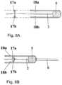
- FIGS. 9 A, 9 B, 9 C and 9 Dillustrate intrauterine systems and their positioning on an inserter according to some embodiments of the invention.
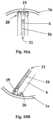
- FIGS. 10 A and 10 Billustrate some details of FIG. 9 B .
- a typical inserter for an intrauterine systemcomprises a handle and an insertion tube having a first end and a second end, and being arranged in connection with the handle.
- the inserteris characterized in that the first end of the insertion tube comprises at least one frame slot for receiving a frame of the intrauterine system.
- the inventiontherefore provides an easy to use inserter and kit comprising the device and the inserter, by which only few simple steps are needed to prepare for the insertion and to securely install and position an intrauterine system into the uterus.
- the therapeutic componentis a component capable of inducing a therapeutic effect, for example by releasing an active agent such as copper ions or hormones.
- first endsare typically meant the ends that are closer to the uterus during the insertion of the intrauterine system.
- Second endsare the ends opposite to the first ends.
- IUS or IUD and removal stringsare used when describing the preferred embodiment of the present invention, but these are not to be construed as limiting the claims.
- the inserteris further characterised in that
- the second end of the insertion tubeis directly attached to the handle.
- the longitudinal opening on the handlecan also be quite narrow and does not need to be symmetrically positioned on the handle and with respect to the longitudinal axis.
- a typical kit comprising an inserter and an intrauterine system, according to the present invention,is such that
- the therapeutic componentis selected from the group consisting of a reservoir for active agent, a metallic wire and a combination thereof.
- the reservoirmay essentially consist of an elastomer and an active agent, or the metal wire can be made of copper.
- the reservoir of the intrauterine systemessentially consists of an elastomer and an active agent.
- the reservoircan be for example as described in WO 2003/017971, U.S. Pat. Nos. 6,056,976, 6,299,027 or WO 00/00550, the contents of which are hereby incorporated by reference.
- the elastomercan be for example an elastomer composition comprising a siloxane based elastomer, a thermoplastic polyurethane, a thermoplastic polyurethane elastomer, ethyl vinyl acetate, a polyolefin-based elastomer, a silicone containing thermoplastic polyurethane or a mixture of at least two of these.
- the reservoirmay also be of a core and membrane-type, wherein both parts are preferably made of an elastomer composition.
- the intrauterine systemalso preferably comprises strings for removal, location or detection of the system, as well as at least one image enhancing means for improving the detection and/or location of the system.
- the image enhancing meanscan be for example selected from the group consisting of
- the therapeutic componentis connected to the frame in at least one point.
- the intrauterine systemcan be connected to the inserter for example via at least one connection part.
- the connection partis preferably designed such that it enhances the retention of the device on the inserter prior and during the insertion of the device.
- connection partcan be for example a hollow knob, adapted to receive a pin, one of these parts being arranged on the intrauterine system and the other on the inserter. Another option is to use a traditional ball joint. A person skilled in the art is readily able to find a suitable solution for this connection part.
- the first end of the insertion tubecomprises at least one connection slot for receiving the connection part of the intrauterine system.
- the first end of the plungermay comprise a slot for receiving the intrauterine system, for example for receiving the second end of the frame or of the therapeutic component of the intrauterine system.
- the first end of the insertion tubemay also comprise two diagonally symmetrical connection slots for receiving the connection part of the intrauterine system. It is naturally possible that there are more than two connection slots, such as three, four, five or six slots.
- the connection partthen preferably comprises suitable parts fitting to these connections slots.
- the connection partcan also be made to fit on the plunger. If a plunger is used, it can be designed to receive the therapeutic component or the frame.
- the first end of the insertion tubecomprises at least one frame slot for receiving the frame of the intrauterine system.
- the first end of the insertion tubemay also comprise two diagonally symmetrical frame slots for receiving the frame of the intrauterine system.
- the number of frame slotscan also be higher, such as three, four, five or six.
- the frame slotscan be parallel to the longitudinal axis of the insertion tube or non-parallel to it.
- the frame slotscan for example be straight or slightly curved with respect to the outer surface of the insertion tube, in order for allowing the frame to be released.
- the frame slotsare preferably narrow enough to prevent the therapeutic component from slipping out and long enough to allow the movement of the therapeutic component and the stretching/compression of the frame during the insertion step.
- the insertion tubeis large enough for containing the therapeutic component.
- the frame slot(s) together with connection partsassure that the intrauterine system will be securely fitted and in the correct configuration during the insertion.
- the shape of the frame of the deviceis selected from the group consisting of annular, circular, oval, spiral, toroidal, triangular, polygonal, almond-shape, shield-shape and diamond-shape.
- the frameis also preferably made of an elastic material, such as an elastomer composition as mentioned above in connection with the reservoir.
- the framemay include, for example as a core material, thin metallic wire made for example from a metallic memory material or other suitable material that is elastic enough for allowing the insertion, i.e. collapsing during the insertion through the cervical canal but returning to its original shape once in place in the uterus.
- the therapeutic component of the intrauterine systemis preferably at least mainly arranged inside the insertion tube and the frame of the intrauterine system is preferably at least mainly arranged outside the insertion tube.
- the inserterfurther comprises a flange arranged on the insertion tube. This flange can be adjusted to correspond to the depth of the uterus in order to correctly position the device during its insertion.
- the first end of the opening and the first end of the sliderform a first pair of stop members, and the second end of the opening and the second end of the slider form a second pair of stop members.
- a part of the handlecan thus comprise an opening having a first end and a second end and running in the longitudinal direction of the plunger.
- the openingcan have at the first end a channel in which the insertion tube can slide in the longitudinal direction.
- the insertion tubeis attached to the slider or to a means which can be used to move the slider and preferably forms at least a part of the slider.
- the slider and the insertion tubewill be pulled backwards past the plunger the distance determined by the second pair of stop members, formed by the rear surface of the means to move the slider and the surface at the second end of the opening.
- the handlecan have many shapes and is designed for easy handling of the inserter even by using only one hand.
- the plunger attached to the handleis advantageously hollow or has a groove or bore running in the axial direction thus allowing the string(s) to slide freely in it, without any risk of them getting jammed between the plunger and the insertion tube.
- the first end, i.e. the forward end of the plungeris preferably suitably shaped to have for example a notch, an indentation, an eyelet, a funnel or a groove to adapt the lower end of the device and to enable the optimal and secure positioning of the device on the plunger.
- the forward parts (parts directed towards the uterus) of the plunger and the insertion tubecan be straight or curved so as to conform to the anatomy of the uterus.
- these partsare made from a flexible material in order to avoid perforation of the uterus.
- the slider mechanismis preferably inside the handle and comprises at least one elongated element, which can be moved in the longitudinal direction of the plunger.
- the slidercomprises a means to move the slider, which preferably is a part of the slider, and the insertion tube attached to said means.
- the slidercomprises at least two elements, preferably parallel, which are combined on at least one point by a transversal member.
- the transversal membermay form means, for example a knob or switch, by which the slider can be moved.
- the handlecan comprise one or more means to connect the slider elements and to facilitate the movement of the slider, for example a support, a shoulder, a holder, a saddle, a groove or a slot.
- the sliderpreferably comprises at least one structural element, for example an extension, which is capable to generate the necessary operation of a locking means to keep the strings immobilized during storage or during preparatory steps before insertion and/or to release the string(s) when the slider is moved to the backward position.
- at least one structural elementfor example an extension, which is capable to generate the necessary operation of a locking means to keep the strings immobilized during storage or during preparatory steps before insertion and/or to release the string(s) when the slider is moved to the backward position.
- the inserter according to the present inventionmay thus also comprise locking means for reversibly locking the intrauterine system in relation to the plunger, said locking means being controllable by the slider and/or the insertion tube.
- This means that the locking meanscan also be controlled by a part of the slider and/or of the insertion tube, such as an extension of either or both of them.
- the reversible locking of the intrauterine systemcan be for example achieved by locking the removal string or strings of the intrauterine system, in such a way that the device remains immobile in relation to the plunger during the necessary steps prior to and during insertion but can be released after the IUS has correctly been positioned in the uterus. Therefore no manual handling of the strings as such is needed, which increases security and hygiene.
- the locking meansis any arrangement which, induced by the movement of the slider or of the means to move the slider and the insertion tube, can immobilise the removal string(s) to hold the IUS in a stable position and/or to release the string(s) after insertion to release the IUS.
- the inventionrelates to a locking means which comprises an object capable of reversibly preventing or allowing the movement of the string(s) by at least partly moving or pivoting from the original position, for example rotating around a shaft or an axle, and vertically or horizontally attached to the handle.
- the objectmay have several shapes and may be for example round or rod-shaped, wedge, polygonal or rectangular with rounded or sharp corners.
- the surface of the objectpreferably comprises one or more extensions having variable size and shape, for example a knob, a rib or a switch.
- a part or an extension of the slider or of the insertion tubeis pressed against at least one extension of the object thus changing its orientation enough relative to the original position to cause release of the string(s).
- the objecthas a slot or pinhole through which the string(s) run.
- the locking meansmay also comprise at least one counterpart against which the string(s) are pressed by the object and thus reversibly immobilized in the locking position.
- the counterparthas a suitable shape adapted to fit at least some part of the surface of the object.
- An extension, or extensions of the objectcan be used to keep the object and the counterpart in a fixed configuration until the slider is moved backwards to release the IUS.
- the counterpartpreferably has a suitable design to keep the string(s) in proper direction, for example a slot or pinhole through which the string(s) run.
- the object and said at least one counterparthave preferably a suitable length and diameter to fit inside the handle.
- the locking meansthus comprises
- the main partcomprises an opening or a slot in a diagonal direction through essentially the whole diameter of the main part, adapted to receive at least one removal string of the intrauterine system.
- the locking meanscan be for example mounted on the handle of the inserter.
- the opening or slot of the main partis adapted to receive a removal string of the intrauterine system.
- the locking meanscomprises
- the main parthas essentially the shape of a cylinder, or it is of triangular shape, or of any other suitable shape.
- the slidercomprises an extension adapted to abut on the abutment surface of the first extension of the main part of the locking means.
- the locking meanscomprises a main part comprising a first extension and a second extension arranged, in their initial position, to be essentially in contact with each other to from a blocking, wherein the slider, a part of the slider, the insertion tube or a part of the insertion tube is arranged to protrude into the main part of the locking means so as to separate the first and second extensions from each other.
- the locking meanscould also be welding, gluing, cutting, knot or adhesion.
- the stringscould thus be for example attached to the body of the inserter by welding (for example by heating), gluing with glue or attaching with an adhesive agent (such as sticker).
- the slider or the insertion tubewould then release the attachment when moving to release the device.
- Other optionscould be a knot or other mechanical hindrance, when the slot provided for the strings is larger in the releasing position.
- the slidercould also comprise a blade that cuts the strings loose from the inserter.
- the locking meanscan be of any other kind than those specifically listed above as well as a combination thereof.
- the string(s)are locked but they are released automatically by the slider, when it is drawn backwards in order to release the IUS.
- the sliderAs compared to previous inserters there is no need to manually handle the removal strings during the preparatory steps and during insertion, which eliminates the possibility of user-made mistakes.
- the present inventionalso relates to a use of the kit according to the invention. Any details and embodiments listed above naturally apply mutatis mutandis to the use according to the invention.
- the present inventionalso relates to a method for positioning an intrauterine system in a uterus of a patient, wherein the method uses a kit according to the present invention.
- the methodcomprises the steps of
- the methodadvantageously contains, as a second step, setting the flange to show the correct insertion depth.
- the methodmay also comprise, after the introduction of the inserter into the uterus, the step of moving the slider towards the second end of the opening until the second end of the opening is in contact with the second end of the slider, thus releasing the intrauterine system from the inserter.
- the inserteris introduced into the uterus until the IUS is in the correct location, which is determined beforehand by using a probe and preferably shown by the flange set at the correct insertion depth.
- the slideris then moved towards the second end of the opening until the second end of the opening is in contact with the second end of the slider, thus releasing the intrauterine system from the inserter.
- the inserteris then removed and the IUS remains in place. The inserter thus allows easy and secure positioning of an IUS.
- slider and the corresponding reference numberare used to designate both the slider itself and the means to move the slider attached to the slider.
- the term slideris used for convenience of reading.
- FIG. 1illustrates a general overview of an inserter according to the invention.
- the insertercomprises a handle 3 , a plunger 2 attached to the handle, a slider 5 , an insertion tube 6 around the plunger, the second end of the insertion tube being attached to the slider or to the means to move the slider.
- the inserteralso comprises means for reversibly locking the string(s) (not shown) in such a way that the IUS remains immobile in relation to the plunger during the necessary steps prior to and during insertion, and again for releasing the string(s) and the IUS after it has been inserted.
- the inserterfurther comprises an opening 8 in a part of the handle, a channel 9 in which the insertion tube slides in the longitudinal direction, and a flange 4 , which can be adjusted so that its distance from the front end of the intrauterine system corresponds to the depth of the uterus.
- the part of the handle 3 that is closer to its first endhas an opening 8 having a first end 8 a and a second end 8 b , which opening runs in the direction of the plunger 2 and has at its first end a channel 9 in which the insertion tube 6 slides in the longitudinal direction.
- the first end 5 a of the slider 5abuts the first end 8 a of the opening 8 of the handle 3 .
- the surface of the second end 5 b of the slider 5 and the surface at the second end 8 b of the opening 8together form a pair of stop members.
- the insertion tubeis attached to the slider 5 .
- the slider and the insertion tubecan be moved backwards until the surfaces 5 b and 8 b contact each other.
- the locking meansare arranged inside the handle 3 and are thus not visible.
- FIGS. 2 A and 2 Billustrate an operating principle of an inserter according to an embodiment of the invention.
- FIG. 2 Ashows an inserter and an almond-shaped IUS 1 in a configuration as they are in a sterilized package.
- the IUSis placed in the first end (i.e. the front end, i.e. the entry into the uterus) of the inserter so that the drug containing reservoir of the device is inside the insertion tube 6 with the bottom tip of the frame, the reservoir or the loop abutting the end of the plunger (shown with reference number 2 a ).
- the means to move the slider 5is on the basic position, and the removal string(s) ( 7 , shown in the FIG. 2 B ) inside the inserter are tightened and locked by the locking means.
- FIG. 2 Billustrates the procedure to release the IUS.
- the device in the configuration according to FIG. 2 Ais introduced into the uterus until the IUS is in the correct location, where after the device is released from the insertion tube.
- the insertion tubeis retracted towards the handle by moving the slider 5 backwards until the surface 5 b of the slider abuts the surface 8 b of the opening 8 .
- the distance the slider and the insertion tube can be movedhas been selected to indicate clearly the moment at which the IUS has completely been released from the insertion tube moving towards the handle.
- FIGS. 3 A and 3 Billustrate another embodiment of the invention, an operating principle of an inserter which does not have a plunger or a slider.
- the frame of the IUSis marked with the reference number 1 a , and the therapeutic component with reference number 1 b.
- FIGS. 4 A and 4 Billustrate a locking means according to an embodiment of the invention.
- the locking meansare arranged preferably at the inside of the handle 3 , on any of the inside surfaces of the handle.
- the locking meansare used to immobilise and release the string(s) of the IUS.
- FIG. 4 Aillustrates a locking means according to an embodiment of the invention comprising a main part 10 having essentially the shape of a cylinder and comprising an opening 12 there through in a diagonal direction.
- the string(s) 7 of the IUSpass through the opening 12 .
- the main part 10is rotatably mounted on the handle, on a shaft or an axle (not shown).
- the locking meansalso comprises a counterpart 11 , such that in the locking position the string(s) are immobilized between the counterpart and the main part.
- the counterpartthus has a suitable shape adapted to fit to a part of the surface of the main part.
- FIGS. 5 A and 5 Billustrate a locking means according to another embodiment of the invention.
- FIG. 5 Aillustrates an object similar to the one presented in FIG. 4 A , but having a different construction of the extension 10 a.
- FIGS. 6 A and 6 Billustrate a locking means according to yet another embodiment of the invention.
- Thisis a side view of a cylindrically shaped locking means, having a main part 13 which comprises two extensions 13 a and 13 b .
- the locking meanscan rotate around a shaft or an axle 14 and is preferably attached to a shorter side of the inner surface of the handle.
- the locking meansalso comprises a counterpart 15 such that the string(s) 7 are immobilised between the counterpart 15 and the extension 13 b .
- the counterpart 15has a suitable shape adapted to fit to a part of the surface of the extension 13 b .
- the handlecan also comprise a groove in which the string(s) run (not shown).
- FIGS. 7 A and 7 Billustrate a locking means according to an embodiment of the invention.
- the locking means 16comprises two extensions 16 a and 16 b to immobilize the strings as shown in FIG. 7 A .
- the slider 5 and the insertion tube 6move backwards the slider and/or the insertion tube protrudes into the locking means at least partly to expand the means enough to separate the extensions and to release the strings, as shown in FIG. 7 B .
- FIGS. 8 A and 8 Billustrate a locking means according to a further embodiment of the invention.
- the locking meanscomprises two parts 17 a and 17 b to immobilize the strings as shown in FIG. 8 A , said parts being able to move or turn from the original position.
- the slider 5has two extensions 18 a and 18 b . When the slider 5 and the insertion tube 6 move backwards the slider extensions turn the locking parts 17 a and 17 b apart from each other enough to release the strings, as shown in FIG. 8 B .
- FIGS. 9 A and 9 Billustrate an intrauterine system and its positioning on the inserter according to an embodiment of the invention.
- the intrauterine systemhas a frame 1 a and a therapeutic component 1 b and it is positioned in the insertion tube 6 .
- the intrauterine systemis connected to the inserter via one connection part 19 .
- the first end of the insertion tube 6comprises one connection slot 20 for receiving the connection part 19 .
- the therapeutic componentis essentially completely and the frame essentially only partly positioned in a frame slot 21 .
- FIGS. 9 C and 9 Dillustrate another intrauterine system and its positioning on the inserter according to another embodiment of the invention.
- the intrauterine systemhas the same parts as in FIGS. 9 A and 9 B .
- the therapeutic componentis essentially completely positioned inside the insertion tube and the frame is essentially completely outside the insertion tube.
- FIGS. 10 A and 10 Billustrate some details of FIG. 9 B , namely the first end of the insertion tube 6 and the connection of the intrauterine system on the insertion tube.
Landscapes
- Health & Medical Sciences (AREA)
- General Health & Medical Sciences (AREA)
- Veterinary Medicine (AREA)
- Biomedical Technology (AREA)
- Heart & Thoracic Surgery (AREA)
- Public Health (AREA)
- Life Sciences & Earth Sciences (AREA)
- Animal Behavior & Ethology (AREA)
- Engineering & Computer Science (AREA)
- Reproductive Health (AREA)
- Vascular Medicine (AREA)
- Anesthesiology (AREA)
- Hematology (AREA)
- Orthopedics, Nursing, And Contraception (AREA)
- Infusion, Injection, And Reservoir Apparatuses (AREA)
- Surgical Instruments (AREA)
- Materials For Medical Uses (AREA)
- Coating Apparatus (AREA)
Abstract
Description
- the inserter is according to the present invention,
- the intrauterine system comprises a therapeutic component and a continuous, closed frame, the therapeutic component being connected to the frame at at least one point, and
- the therapeutic component of the intrauterine system is at least mainly arranged inside the first end of the insertion tube and the frame of the intrauterine system is at least mainly arranged outside the first end of the insertion tube.
- the handle has a longitudinal opening at its first end, said opening having a longitudinal axis parallel to the longitudinal axis of the inserter, a first end and a second end, and the inserter further comprises
- a movable slider arranged in said longitudinal opening and having a first end and a second end,
- a plunger attached to the handle, the second end of the insertion tube being attached to the slider.
- the inserter is according to the present invention,
- the intrauterine system comprises a therapeutic component and a continuous, closed frame, the therapeutic component being connected to the frame at at least one point, and
- the therapeutic component of the intrauterine system is at least mainly arranged inside the first end of the insertion tube and the frame of the intrauterine system is at least mainly arranged outside the first end of the insertion tube.
- a) an inert metal coating on at least part of the body of the intrauterine system;
- b) inert metal inserts, clips, rings or sleeves fixedly positioned on the body of the intrauterine system;
- c) metal or ferromagnetic powder or particles or suitable metal or alkali metal salts mixed during the compounding step in the raw materials of the frame, core matrix or membrane of the intrauterine system, and
- d) a metallic cup, connector, adapter, clamp, sleeve or holder fixed at a suitable position on the frame, which can also be used to anchor or join the therapeutic component onto the frame.
- a main part,
- a first extension of the main part having an abutment surface,
- a counterpart adapted to form a blocking together with the main part, wherein the locking means is rotatably mounted on the inserter.
- a main part,
- a first extension of the main part having an abutment surface,
- a second extension of the main part having a wedge-like shape,
- a counterpart, wherein the second extension is adapted to form a blocking together with the counterpart and the locking means is rotatably mounted on the inserter.
- a first locking part and a second locking part movably mounted on the inserter and arranged, in their initial position, to be essentially in contact with each other to form a blocking, and
- a first protrusion and a second protrusion arranged on a location selected from the group consisting of the inner surface of the insertion tube, the outer surface of the insertion tube, the inner surface of the slider and the outer surface of the slider, wherein the first and second protrusions are arranged to move the first and second locking parts when moving the slider or the insertion tube.
Claims (9)
Priority Applications (2)
| Application Number | Priority Date | Filing Date | Title |
|---|---|---|---|
| US16/792,748US11872155B2 (en) | 2008-09-17 | 2020-02-17 | Inserter |
| US18/524,681US20240173163A1 (en) | 2008-09-17 | 2023-11-30 | Inserter |
Applications Claiming Priority (12)
| Application Number | Priority Date | Filing Date | Title |
|---|---|---|---|
| FI20085870AFI20085870A0 (en) | 2008-09-17 | 2008-09-17 | An inserter |
| FI20085871 | 2008-09-17 | ||
| FI20085870 | 2008-09-17 | ||
| FI20085871AFI20085871A0 (en) | 2008-09-17 | 2008-09-17 | inserter |
| PCT/FI2009/050738WO2010031902A1 (en) | 2008-09-17 | 2009-09-16 | An inserter |
| US201113119401A | 2011-03-16 | 2011-03-16 | |
| US13/771,066US20130152942A1 (en) | 2008-09-17 | 2013-02-19 | Inserter |
| US14/088,329US9452082B2 (en) | 2008-09-17 | 2013-11-22 | Inserter |
| US15/245,042US9615965B2 (en) | 2008-09-17 | 2016-08-23 | Inserter |
| US15/470,870US20170196728A1 (en) | 2008-09-17 | 2017-03-27 | Inserter |
| US15/891,187US10561524B2 (en) | 2008-09-17 | 2018-02-07 | Inserter |
| US16/792,748US11872155B2 (en) | 2008-09-17 | 2020-02-17 | Inserter |
Related Parent Applications (1)
| Application Number | Title | Priority Date | Filing Date |
|---|---|---|---|
| US15/891,187ContinuationUS10561524B2 (en) | 2008-09-17 | 2018-02-07 | Inserter |
Related Child Applications (1)
| Application Number | Title | Priority Date | Filing Date |
|---|---|---|---|
| US18/524,681ContinuationUS20240173163A1 (en) | 2008-09-17 | 2023-11-30 | Inserter |
Publications (2)
| Publication Number | Publication Date |
|---|---|
| US20200179159A1 US20200179159A1 (en) | 2020-06-11 |
| US11872155B2true US11872155B2 (en) | 2024-01-16 |
Family
ID=42039110
Family Applications (8)
| Application Number | Title | Priority Date | Filing Date |
|---|---|---|---|
| US13/119,401AbandonedUS20110166508A1 (en) | 2008-09-17 | 2009-09-16 | inserter |
| US13/771,066AbandonedUS20130152942A1 (en) | 2008-09-17 | 2013-02-19 | Inserter |
| US14/088,329ActiveUS9452082B2 (en) | 2008-09-17 | 2013-11-22 | Inserter |
| US15/245,042ActiveUS9615965B2 (en) | 2008-09-17 | 2016-08-23 | Inserter |
| US15/470,870AbandonedUS20170196728A1 (en) | 2008-09-17 | 2017-03-27 | Inserter |
| US15/891,187ActiveUS10561524B2 (en) | 2008-09-17 | 2018-02-07 | Inserter |
| US16/792,748Active2030-12-12US11872155B2 (en) | 2008-09-17 | 2020-02-17 | Inserter |
| US18/524,681PendingUS20240173163A1 (en) | 2008-09-17 | 2023-11-30 | Inserter |
Family Applications Before (6)
| Application Number | Title | Priority Date | Filing Date |
|---|---|---|---|
| US13/119,401AbandonedUS20110166508A1 (en) | 2008-09-17 | 2009-09-16 | inserter |
| US13/771,066AbandonedUS20130152942A1 (en) | 2008-09-17 | 2013-02-19 | Inserter |
| US14/088,329ActiveUS9452082B2 (en) | 2008-09-17 | 2013-11-22 | Inserter |
| US15/245,042ActiveUS9615965B2 (en) | 2008-09-17 | 2016-08-23 | Inserter |
| US15/470,870AbandonedUS20170196728A1 (en) | 2008-09-17 | 2017-03-27 | Inserter |
| US15/891,187ActiveUS10561524B2 (en) | 2008-09-17 | 2018-02-07 | Inserter |
Family Applications After (1)
| Application Number | Title | Priority Date | Filing Date |
|---|---|---|---|
| US18/524,681PendingUS20240173163A1 (en) | 2008-09-17 | 2023-11-30 | Inserter |
Country Status (18)
| Country | Link |
|---|---|
| US (8) | US20110166508A1 (en) |
| EP (1) | EP2349143B2 (en) |
| JP (1) | JP5390618B2 (en) |
| KR (1) | KR101612579B1 (en) |
| CN (1) | CN102159162B (en) |
| AU (1) | AU2009294545B2 (en) |
| BR (1) | BRPI0919071B1 (en) |
| CA (1) | CA2736020C (en) |
| DK (1) | DK2349143T4 (en) |
| ES (1) | ES2424984T5 (en) |
| HR (1) | HRP20130510T4 (en) |
| IL (1) | IL211058A (en) |
| MX (1) | MX2011002670A (en) |
| PL (1) | PL2349143T5 (en) |
| PT (1) | PT2349143E (en) |
| RU (1) | RU2494706C2 (en) |
| WO (1) | WO2010031902A1 (en) |
| ZA (1) | ZA201100900B (en) |
Families Citing this family (25)
| Publication number | Priority date | Publication date | Assignee | Title |
|---|---|---|---|---|
| FI20080523A0 (en)† | 2008-09-17 | 2008-09-17 | Bayer Schering Pharma Oy | An inserter |
| ES2424984T5 (en) | 2008-09-17 | 2017-02-16 | Bayer Oy | Inserter |
| FI20080524A0 (en) | 2008-09-17 | 2008-09-17 | Bayer Schering Pharma Oy | An inserter |
| US11992431B2 (en) | 2008-09-17 | 2024-05-28 | Bayer Oy | Inserter |
| USD791318S1 (en)* | 2009-09-14 | 2017-07-04 | Bayer Oy | Inserter |
| CN103209663B (en) | 2010-10-18 | 2016-08-10 | 碧奥塞普蒂夫股份有限公司 | For device or medicine are inserted endoceliac method and apparatus |
| JP6068350B2 (en) | 2010-10-29 | 2017-01-25 | オディセア・ファルマ・ソシエテ・プリベ・ア・レスポンサビリテ・リミテOdyssea Pharma S.P.R.L. | Intrauterine insertion device |
| FI122579B (en) | 2010-10-29 | 2012-03-30 | Bayer Oy | inserter |
| US8608738B2 (en) | 2010-12-06 | 2013-12-17 | Soulor Surgical, Inc. | Apparatus for treating a portion of a reproductive system and related methods of use |
| US10028858B2 (en) | 2011-07-11 | 2018-07-24 | Medicines360 | Intrauterine systems, IUD insertion devices, and related methods and kits therefor |
| US9265652B2 (en) | 2012-08-14 | 2016-02-23 | Contramed, Llc | Intrauterine contraceptive device |
| US9089418B2 (en) | 2012-08-14 | 2015-07-28 | Contramed, Llc | Intrauterine contraceptive device |
| US8858515B2 (en)* | 2012-12-06 | 2014-10-14 | S. Douglas Cornell | Antimicrobial sanitizer system |
| US10188546B2 (en) | 2013-10-14 | 2019-01-29 | Sebela Vlc Limited | Intrauterine device with controlled copper ion elution |
| US10918516B2 (en) | 2013-10-14 | 2021-02-16 | Sebela Vlc Limited | Intrauterine device with controlled copper ion elution |
| US9180040B2 (en) | 2013-10-18 | 2015-11-10 | Contramed, Llc | Intrauterine device with retrieval thread |
| GB201405414D0 (en)* | 2014-03-26 | 2014-05-07 | Northwood Medical Innovations Ltd | Surgical introducer |
| JOP20190071A1 (en)* | 2016-10-06 | 2019-04-04 | Bayer Oy | An arrangement for an intrauterine system and its inserter |
| US11571328B2 (en) | 2018-04-09 | 2023-02-07 | Medicines360 | IUD insertion devices |
| US12290196B2 (en)* | 2018-06-25 | 2025-05-06 | Eugene Lloyd Hiebert | Thermal retention coverings for use with temperature probes |
| KR102531201B1 (en) | 2018-07-19 | 2023-05-11 | 엘지전자 주식회사 | Robot cleaner |
| CA3160029A1 (en) | 2019-10-09 | 2021-04-15 | Steven R. Bacich | Apparatus and method for everting catheter for iud delivery and placement in the uterine cavity |
| US11571329B2 (en) | 2019-11-21 | 2023-02-07 | Coopersurgical, Inc. | Packaging systems for implantable devices and related methods |
| DE102020122654A1 (en)* | 2020-08-31 | 2022-03-03 | Gaplast Gmbh | implant syringe |
| USD1070085S1 (en) | 2022-03-17 | 2025-04-08 | Pregna International Limited | Intra-uterine inserter |
Citations (74)
| Publication number | Priority date | Publication date | Assignee | Title |
|---|---|---|---|---|
| GB1039011A (en) | 1963-01-10 | 1966-08-17 | Valer Flax | Improvements in blow moulded containers and their manufacture |
| US3533406A (en) | 1968-09-18 | 1970-10-13 | Population Council Inc | Intrauterine contraceptive device |
| US3656483A (en) | 1970-01-15 | 1972-04-18 | Biolog Concepts Inc | Intrauterine medicator |
| US3783861A (en) | 1971-06-11 | 1974-01-08 | Searle & Co | Inserter for intrauterine devices |
| US3794025A (en) | 1971-10-07 | 1974-02-26 | Robins Co Inc A H | Intrauterine device saddle inserter |
| US3896819A (en) | 1969-04-01 | 1975-07-29 | Alejandro Zaffaroni | IUD having a replenishing drug reservoir |
| GB1403393A (en) | 1971-10-07 | 1975-08-28 | Robins Co Inc A H | Inserters for intrauterine devices |
| US3902483A (en) | 1974-08-21 | 1975-09-02 | Alza Corp | Intrauterine device with locator means for indicating uterine position of device |
| US3918444A (en)* | 1974-03-27 | 1975-11-11 | Alza Corp | Apparatus for inserting an intrauterine device |
| GB1486994A (en) | 1974-02-14 | 1977-09-28 | Multilan Sa | Contraceptive means including an intra-uterine device |
| US4143656A (en) | 1977-03-28 | 1979-03-13 | Ortho Pharmaceutical Corporation | Instrument and method for inserting an intrauterine contraceptive device |
| GB1543841A (en) | 1975-07-16 | 1979-04-11 | Searle & Co | Instrument for positioning an intrauterine device |
| US4341728A (en) | 1979-12-20 | 1982-07-27 | The Population Council, Inc. | Method for making an IUD with shrinking of a medicated attachment onto a support |
| US4353363A (en) | 1978-11-23 | 1982-10-12 | Angel Sopena Quesada | Intrauterine spermicide |
| US4413985A (en) | 1981-09-02 | 1983-11-08 | The United States Of America As Represented By The Dept. Of Health & Human Services | Hydrocephalic antenatal vent for intrauterine treatment (HAVIT) |
| US4562835A (en) | 1984-01-23 | 1986-01-07 | Ortho Pharmaceutical (Canada) Ltd. | Streamlined T-shaped intrauterine device |
| US4578075A (en) | 1982-12-20 | 1986-03-25 | Alza Corporation | Delivery system housing a plurality of delivery devices |
| US4578076A (en) | 1984-03-20 | 1986-03-25 | The Population Council, Inc. | Medicated intracervical and intrauterine devices |
| EP0191957A1 (en) | 1984-12-21 | 1986-08-27 | Akzo N.V. | Assembly of intra-uterine contraceptive device and inserter |
| US4655204A (en) | 1982-07-19 | 1987-04-07 | Societe Europeenne De Recherche D'instrumentations Medicales Company | Intrauterine contraceptive device for animals such as female dogs |
| US4678463A (en) | 1984-03-01 | 1987-07-07 | Millar Thomas D | Devices for insertion into a body cavity of an animal and/or applicators therefor |
| DE8712168U1 (en) | 1987-09-08 | 1987-10-22 | Naučno-proizvodstvennoe ob"edinenie Medinstrument, Kazan | Device for introducing contraceptive devices into the uterine cavity |
| NL8601570A (en) | 1986-06-17 | 1988-01-18 | Futura Nova Bv | Intra-uterine contraceptive device has rod secured to ring - having max. length equal to ring dia. and rod may carry e.g. copper coil or spermicidal or therapeutic agent |
| US4721105A (en)* | 1984-03-29 | 1988-01-26 | Dirk Wildemeersch | Device for fixing an intra-uterine contraceptive device to the uterine wall |
| US4724832A (en) | 1984-09-18 | 1988-02-16 | Strubel Bernd Jochen | Size-variable intrauterine pressay and contraceptive device |
| FI882466L (en) | 1987-05-25 | 1988-11-26 | Ketasa Ag | GRAVIDITETSFOERHINDRANDE ANORDNING. |
| US4805628A (en) | 1982-12-06 | 1989-02-21 | Indianapolis Center For Advanced Research, Inc. | Ultrasound contrast media for medically implantable and insertable devices |
| US4949732A (en) | 1989-08-24 | 1990-08-21 | Gyno Pharma Inc. | Apparatus for insertion and fixation of an intra uterine contraceptive device to the uterine fundus |
| US5146931A (en) | 1988-08-15 | 1992-09-15 | Kurz Karl Heinz | Device to be placed in the uterus |
| US5217450A (en) | 1989-07-21 | 1993-06-08 | Carter Holt Harvey Plastic Products Group Limited | Retention devices |
| US5224493A (en) | 1991-01-30 | 1993-07-06 | Cadco Corporation | Contraceptive intracervical device and novel nonsystemic agents for the prevention of conception and disease |
| US5370129A (en) | 1992-08-28 | 1994-12-06 | Db Inserters, Inc. | IUD inserting apparatus |
| WO1995028901A1 (en) | 1994-04-25 | 1995-11-02 | Akzo Nobel N.V. | Intrauterine device tray having one attachment site |
| US5494047A (en) | 1994-03-16 | 1996-02-27 | Van Os; Willem A. A. | Intrauterine contraceptive device |
| WO1996018365A1 (en) | 1994-12-15 | 1996-06-20 | Leiras Oy | Inserter for the positioning of an intrauterine device |
| WO1996029026A2 (en) | 1995-03-09 | 1996-09-26 | Jury Vasilievich Borodin | Intrauterine contraceptive device |
| WO1999005958A2 (en) | 1997-07-31 | 1999-02-11 | Circon Corporation | Medical instrument system for piercing through tissue |
| DE29819558U1 (en) | 1998-11-03 | 1999-02-11 | Riek, Siegfried, Dr.med., 78628 Rottweil | Handle with integrated mechanism for the defined manipulation of insertion devices for inserting an intrauterine device (TUP) into the uterine cavity |
| EP0948948A2 (en) | 1998-04-07 | 1999-10-13 | Riek, Siegfried, Dr. med. | Applicator for inserting an intra-uterine contraceptive device |
| WO2000000550A1 (en) | 1998-06-30 | 2000-01-06 | Leiras Oy | A membrane or matrix for controlling the permeation rate of drugs |
| DE29919662U1 (en) | 1999-11-09 | 2000-02-03 | Riek, Siegfried, Dr.med., 78628 Rottweil | Introducer for the insertion of an intrauterine contraceptive device |
| US6056976A (en) | 1998-11-12 | 2000-05-02 | Leiras Oy | Elastomer, its preparation and use |
| US6103256A (en) | 1997-06-24 | 2000-08-15 | Hoechst Marion Roussel | Intravaginal drug delivery device |
| US6119696A (en) | 1996-04-22 | 2000-09-19 | Turin; Enrique Horacio | Intrauterine device for use as a contraceptive means in female dogs and methods of insertion thereof |
| WO2001013832A1 (en) | 1999-08-23 | 2001-03-01 | Conceptus, Inc. | Insertion/deployment catheter system for intrafallopian contraception |
| US6278057B1 (en) | 1997-05-02 | 2001-08-21 | General Science And Technology Corp. | Medical devices incorporating at least one element made from a plurality of twisted and drawn wires at least one of the wires being a nickel-titanium alloy wire |
| US6299027B1 (en) | 1999-12-27 | 2001-10-09 | Courtesy Corporation | Valve controlled dispensing closure |
| US6476079B1 (en) | 1999-12-23 | 2002-11-05 | Leiras Oy | Devices for the delivery of drugs having antiprogestinic properties |
| CN1377635A (en) | 2001-03-29 | 2002-11-06 | 华中科技大学同济医学院 | Fixed contraception device introducer |
| WO2003017971A1 (en) | 2001-08-31 | 2003-03-06 | Schering Oy | Drug delivery system |
| US6588429B1 (en) | 1999-04-16 | 2003-07-08 | Dirk Wildemeersch | Method for retaining and actuating an inter-uterine device inserter and inserter enabling said method to be carried out |
| US6652548B2 (en) | 2000-03-31 | 2003-11-25 | Bacchus Vascular Inc. | Expansible shearing catheters for thrombus removal |
| WO2005048893A1 (en) | 2003-11-19 | 2005-06-02 | Schering Oy | Plunger |
| USD525705S1 (en) | 2004-01-23 | 2006-07-25 | Familplan Consulting Ltd Oy | Intrauterine device for releasing steroids |
| WO2007075086A1 (en) | 2005-12-27 | 2007-07-05 | Willem Arthur Adriaan Van Os | Intrauterine device and applicator for introducing the same into the uterus |
| US7252839B2 (en) | 2002-09-18 | 2007-08-07 | Schering Oy | Delivery system and a manufacturing process of a delivery system |
| US7294135B2 (en) | 2003-03-20 | 2007-11-13 | Medtronic Vascular, Inc | Control handle for intraluminal devices |
| CN201042478Y (en) | 2007-05-17 | 2008-04-02 | 安会芹 | Intrauterine ring placing device |
| US20080095825A1 (en) | 2005-01-25 | 2008-04-24 | Charles-Dominique Lafont | Method for Making a Reservoir Containing an Active Substance Diffused through the Reservoir and Installation Therefor |
| FI20080523A0 (en) | 2008-09-17 | 2008-09-17 | Bayer Schering Pharma Oy | An inserter |
| WO2010031902A1 (en) | 2008-09-17 | 2010-03-25 | Bayer Schering Pharma Oy | An inserter |
| JP2010510444A (en) | 2006-11-17 | 2010-04-02 | ソニー エリクソン モバイル コミュニケーションズ, エービー | Hinge mechanism with spring force |
| WO2010082197A2 (en) | 2009-01-18 | 2010-07-22 | Ilan Bar-Am | Novel intra uterine device |
| WO2010112095A1 (en) | 2009-04-03 | 2010-10-07 | Bio Material Systems Nv/Sa | Improvement to intrauterine copper contraceptive devices |
| US7926488B2 (en) | 2003-12-11 | 2011-04-19 | Familplan Consulting Ltd. Oy | Frame of an intrauterine system |
| WO2011080164A1 (en) | 2009-12-21 | 2011-07-07 | Pat&Co Bvba | Improvements to frameless intrauterine devices and systems |
| US8573222B2 (en) | 2010-03-21 | 2013-11-05 | David Weintraub | Intrauterine device and inserter for the same |
| USD718435S1 (en) | 2012-05-30 | 2014-11-25 | Medicines360 | Intrauterine insertion device |
| US20150107598A1 (en) | 2013-10-18 | 2015-04-23 | Contramed, Llc | Intrauterine device with retrieval thread |
| US20170027739A1 (en) | 2015-07-30 | 2017-02-02 | Medicines360 | Iud loading devices and methods for inserting an iud into an insertion device |
| USD791318S1 (en) | 2009-09-14 | 2017-07-04 | Bayer Oy | Inserter |
| US10149784B2 (en) | 2010-10-29 | 2018-12-11 | Bayer Oy | Inserter for an intrauterine system |
| US20210298942A1 (en) | 2008-09-17 | 2021-09-30 | Bayer Oy | Inserter |
| US11432958B2 (en) | 2008-09-17 | 2022-09-06 | Bayer Oy | Inserter |
Family Cites Families (20)
| Publication number | Priority date | Publication date | Assignee | Title |
|---|---|---|---|---|
| US3678927A (en) | 1968-03-18 | 1972-07-25 | Samuel Soichet | Intra uterine device and injector thereof |
| JPS621614U (en)* | 1985-06-19 | 1987-01-08 | ||
| SU1377063A1 (en) | 1985-12-10 | 1988-02-28 | Казанский государственный медицинский институт им.С.В.Курашова | Instrument for removing intrauterine contraceptives |
| RU1804811C (en)* | 1989-11-28 | 1993-03-30 | Витебский центр научно-технического творчества молодежи | Intrauterine contraceptive |
| RU2070007C1 (en)* | 1992-04-08 | 1996-12-10 | Александр Петрович Линецкий | Intrauterine contraceptive device |
| RU2106837C1 (en)* | 1995-05-26 | 1998-03-20 | Сергей Павлович Беляев | Intrauterine contraception means |
| US6709667B1 (en) | 1999-08-23 | 2004-03-23 | Conceptus, Inc. | Deployment actuation system for intrafallopian contraception |
| US8257244B2 (en) | 2001-08-01 | 2012-09-04 | Anecova Sa | Intrauterine device, method of making such a device and method for putting active elements within the uterine cavity |
| BE1014635A3 (en) | 2002-02-12 | 2004-02-03 | Wildemeersch Dirk | |
| GB0307082D0 (en) | 2003-03-27 | 2003-04-30 | Gyne Ideas Ltd | Drug delivery device and method |
| US7699056B2 (en) | 2004-06-10 | 2010-04-20 | Conceptus, Inc. | Medical devices and methods of making and using such devices |
| US20070056591A1 (en) | 2005-09-15 | 2007-03-15 | Mcswain Hugh | Fallopian tube occlusion devices and methods |
| IL173762A0 (en) | 2006-02-16 | 2006-07-05 | David Braver Dr | A device and method for the prolonged delivery of an active agent to a body cavity |
| US20080167598A1 (en)* | 2007-01-10 | 2008-07-10 | The Procter & Gamble Company | Active applicator |
| EP2057972A1 (en) | 2007-11-07 | 2009-05-13 | N.V. Organon | Intrauterine deposit |
| FI20085277A0 (en) | 2008-04-02 | 2008-04-02 | Bayer Schering Pharma Oy | Intrauterine system |
| EP2140860A1 (en) | 2008-07-03 | 2010-01-06 | Bayer Schering Pharma Oy | An improved method of contraception |
| US7902708B2 (en) | 2009-01-07 | 2011-03-08 | Shimon Elmaleh | Electro-magnetic motor generator system |
| US8568374B2 (en) | 2009-05-04 | 2013-10-29 | Merck Sharp & Dohme B.V. | Intrauterine system |
| US20110061659A1 (en) | 2009-09-17 | 2011-03-17 | Julian Cruzada | Minimally invasive delivery devices and methods |
- 2009
- 2009-09-16ESES09736608.2Tpatent/ES2424984T5/enactiveActive
- 2009-09-16BRBRPI0919071Apatent/BRPI0919071B1/enactiveIP Right Grant
- 2009-09-16CNCN2009801365490Apatent/CN102159162B/enactiveActive
- 2009-09-16WOPCT/FI2009/050738patent/WO2010031902A1/enactiveApplication Filing
- 2009-09-16PLPL09736608Tpatent/PL2349143T5/enunknown
- 2009-09-16EPEP09736608.2Apatent/EP2349143B2/enactiveActive
- 2009-09-16AUAU2009294545Apatent/AU2009294545B2/enactiveActive
- 2009-09-16HRHRP20130510TTpatent/HRP20130510T4/enunknown
- 2009-09-16JPJP2011527363Apatent/JP5390618B2/enactiveActive
- 2009-09-16DKDK09736608.2Tpatent/DK2349143T4/enactive
- 2009-09-16MXMX2011002670Apatent/MX2011002670A/enactiveIP Right Grant
- 2009-09-16KRKR1020117005914Apatent/KR101612579B1/enactiveActive
- 2009-09-16CACA2736020Apatent/CA2736020C/enactiveActive
- 2009-09-16RURU2011115057/14Apatent/RU2494706C2/enactive
- 2009-09-16USUS13/119,401patent/US20110166508A1/ennot_activeAbandoned
- 2009-09-16PTPT97366082Tpatent/PT2349143E/enunknown
- 2011
- 2011-02-03ILIL211058Apatent/IL211058A/enactiveIP Right Grant
- 2011-02-03ZAZA2011/00900Apatent/ZA201100900B/enunknown
- 2013
- 2013-02-19USUS13/771,066patent/US20130152942A1/ennot_activeAbandoned
- 2013-11-22USUS14/088,329patent/US9452082B2/enactiveActive
- 2016
- 2016-08-23USUS15/245,042patent/US9615965B2/enactiveActive
- 2017
- 2017-03-27USUS15/470,870patent/US20170196728A1/ennot_activeAbandoned
- 2018
- 2018-02-07USUS15/891,187patent/US10561524B2/enactiveActive
- 2020
- 2020-02-17USUS16/792,748patent/US11872155B2/enactiveActive
- 2023
- 2023-11-30USUS18/524,681patent/US20240173163A1/enactivePending
Patent Citations (92)
| Publication number | Priority date | Publication date | Assignee | Title |
|---|---|---|---|---|
| GB1039011A (en) | 1963-01-10 | 1966-08-17 | Valer Flax | Improvements in blow moulded containers and their manufacture |
| US3533406A (en) | 1968-09-18 | 1970-10-13 | Population Council Inc | Intrauterine contraceptive device |
| US3896819A (en) | 1969-04-01 | 1975-07-29 | Alejandro Zaffaroni | IUD having a replenishing drug reservoir |
| US3656483A (en) | 1970-01-15 | 1972-04-18 | Biolog Concepts Inc | Intrauterine medicator |
| US3783861A (en) | 1971-06-11 | 1974-01-08 | Searle & Co | Inserter for intrauterine devices |
| US3794025A (en) | 1971-10-07 | 1974-02-26 | Robins Co Inc A H | Intrauterine device saddle inserter |
| GB1403393A (en) | 1971-10-07 | 1975-08-28 | Robins Co Inc A H | Inserters for intrauterine devices |
| GB1486994A (en) | 1974-02-14 | 1977-09-28 | Multilan Sa | Contraceptive means including an intra-uterine device |
| US3918444A (en)* | 1974-03-27 | 1975-11-11 | Alza Corp | Apparatus for inserting an intrauterine device |
| CA1033247A (en) | 1974-03-27 | 1978-06-20 | Bruce Pharriss | Apparatus for inserting an intrauterine device |
| US3902483A (en) | 1974-08-21 | 1975-09-02 | Alza Corp | Intrauterine device with locator means for indicating uterine position of device |
| GB1543841A (en) | 1975-07-16 | 1979-04-11 | Searle & Co | Instrument for positioning an intrauterine device |
| US4143656A (en) | 1977-03-28 | 1979-03-13 | Ortho Pharmaceutical Corporation | Instrument and method for inserting an intrauterine contraceptive device |
| US4353363A (en) | 1978-11-23 | 1982-10-12 | Angel Sopena Quesada | Intrauterine spermicide |
| US4341728A (en) | 1979-12-20 | 1982-07-27 | The Population Council, Inc. | Method for making an IUD with shrinking of a medicated attachment onto a support |
| US4413985A (en) | 1981-09-02 | 1983-11-08 | The United States Of America As Represented By The Dept. Of Health & Human Services | Hydrocephalic antenatal vent for intrauterine treatment (HAVIT) |
| US4655204A (en) | 1982-07-19 | 1987-04-07 | Societe Europeenne De Recherche D'instrumentations Medicales Company | Intrauterine contraceptive device for animals such as female dogs |
| US4805628A (en) | 1982-12-06 | 1989-02-21 | Indianapolis Center For Advanced Research, Inc. | Ultrasound contrast media for medically implantable and insertable devices |
| US4578075A (en) | 1982-12-20 | 1986-03-25 | Alza Corporation | Delivery system housing a plurality of delivery devices |
| US4562835A (en) | 1984-01-23 | 1986-01-07 | Ortho Pharmaceutical (Canada) Ltd. | Streamlined T-shaped intrauterine device |
| US4678463A (en) | 1984-03-01 | 1987-07-07 | Millar Thomas D | Devices for insertion into a body cavity of an animal and/or applicators therefor |
| US4578076A (en) | 1984-03-20 | 1986-03-25 | The Population Council, Inc. | Medicated intracervical and intrauterine devices |
| US4721105A (en)* | 1984-03-29 | 1988-01-26 | Dirk Wildemeersch | Device for fixing an intra-uterine contraceptive device to the uterine wall |
| US4724832A (en) | 1984-09-18 | 1988-02-16 | Strubel Bernd Jochen | Size-variable intrauterine pressay and contraceptive device |
| EP0191957A1 (en) | 1984-12-21 | 1986-08-27 | Akzo N.V. | Assembly of intra-uterine contraceptive device and inserter |
| NL8601570A (en) | 1986-06-17 | 1988-01-18 | Futura Nova Bv | Intra-uterine contraceptive device has rod secured to ring - having max. length equal to ring dia. and rod may carry e.g. copper coil or spermicidal or therapeutic agent |
| FI882466L (en) | 1987-05-25 | 1988-11-26 | Ketasa Ag | GRAVIDITETSFOERHINDRANDE ANORDNING. |
| DE8712168U1 (en) | 1987-09-08 | 1987-10-22 | Naučno-proizvodstvennoe ob"edinenie Medinstrument, Kazan | Device for introducing contraceptive devices into the uterine cavity |
| US5146931A (en) | 1988-08-15 | 1992-09-15 | Kurz Karl Heinz | Device to be placed in the uterus |
| US5217450A (en) | 1989-07-21 | 1993-06-08 | Carter Holt Harvey Plastic Products Group Limited | Retention devices |
| US4949732A (en) | 1989-08-24 | 1990-08-21 | Gyno Pharma Inc. | Apparatus for insertion and fixation of an intra uterine contraceptive device to the uterine fundus |
| US5224493A (en) | 1991-01-30 | 1993-07-06 | Cadco Corporation | Contraceptive intracervical device and novel nonsystemic agents for the prevention of conception and disease |
| US5370129A (en) | 1992-08-28 | 1994-12-06 | Db Inserters, Inc. | IUD inserting apparatus |
| US5494047A (en) | 1994-03-16 | 1996-02-27 | Van Os; Willem A. A. | Intrauterine contraceptive device |
| WO1995028901A1 (en) | 1994-04-25 | 1995-11-02 | Akzo Nobel N.V. | Intrauterine device tray having one attachment site |
| WO1996018365A1 (en) | 1994-12-15 | 1996-06-20 | Leiras Oy | Inserter for the positioning of an intrauterine device |
| EP0798999A1 (en) | 1994-12-15 | 1997-10-08 | Leiras Oy | Inserter for the positioning of an intrauterine device |
| US5785053A (en)* | 1994-12-15 | 1998-07-28 | Leiras Oy | Inserter for the positioning of an intrauterine device |
| WO1996029026A2 (en) | 1995-03-09 | 1996-09-26 | Jury Vasilievich Borodin | Intrauterine contraceptive device |
| US6119696A (en) | 1996-04-22 | 2000-09-19 | Turin; Enrique Horacio | Intrauterine device for use as a contraceptive means in female dogs and methods of insertion thereof |
| US6278057B1 (en) | 1997-05-02 | 2001-08-21 | General Science And Technology Corp. | Medical devices incorporating at least one element made from a plurality of twisted and drawn wires at least one of the wires being a nickel-titanium alloy wire |
| US6103256A (en) | 1997-06-24 | 2000-08-15 | Hoechst Marion Roussel | Intravaginal drug delivery device |
| WO1999005958A2 (en) | 1997-07-31 | 1999-02-11 | Circon Corporation | Medical instrument system for piercing through tissue |
| EP0948948A2 (en) | 1998-04-07 | 1999-10-13 | Riek, Siegfried, Dr. med. | Applicator for inserting an intra-uterine contraceptive device |
| WO2000000550A1 (en) | 1998-06-30 | 2000-01-06 | Leiras Oy | A membrane or matrix for controlling the permeation rate of drugs |
| DE29819558U1 (en) | 1998-11-03 | 1999-02-11 | Riek, Siegfried, Dr.med., 78628 Rottweil | Handle with integrated mechanism for the defined manipulation of insertion devices for inserting an intrauterine device (TUP) into the uterine cavity |
| US6056976A (en) | 1998-11-12 | 2000-05-02 | Leiras Oy | Elastomer, its preparation and use |
| US6588429B1 (en) | 1999-04-16 | 2003-07-08 | Dirk Wildemeersch | Method for retaining and actuating an inter-uterine device inserter and inserter enabling said method to be carried out |
| WO2001013832A1 (en) | 1999-08-23 | 2001-03-01 | Conceptus, Inc. | Insertion/deployment catheter system for intrafallopian contraception |
| DE29919662U1 (en) | 1999-11-09 | 2000-02-03 | Riek, Siegfried, Dr.med., 78628 Rottweil | Introducer for the insertion of an intrauterine contraceptive device |
| US6476079B1 (en) | 1999-12-23 | 2002-11-05 | Leiras Oy | Devices for the delivery of drugs having antiprogestinic properties |
| US6299027B1 (en) | 1999-12-27 | 2001-10-09 | Courtesy Corporation | Valve controlled dispensing closure |
| US6652548B2 (en) | 2000-03-31 | 2003-11-25 | Bacchus Vascular Inc. | Expansible shearing catheters for thrombus removal |
| CN1377635A (en) | 2001-03-29 | 2002-11-06 | 华中科技大学同济医学院 | Fixed contraception device introducer |
| WO2003017971A1 (en) | 2001-08-31 | 2003-03-06 | Schering Oy | Drug delivery system |
| US7252839B2 (en) | 2002-09-18 | 2007-08-07 | Schering Oy | Delivery system and a manufacturing process of a delivery system |
| US7294135B2 (en) | 2003-03-20 | 2007-11-13 | Medtronic Vascular, Inc | Control handle for intraluminal devices |
| WO2005048893A1 (en) | 2003-11-19 | 2005-06-02 | Schering Oy | Plunger |
| EP1691740A1 (en) | 2003-11-19 | 2006-08-23 | Schering Oy | Plunger |
| US20070129734A1 (en) | 2003-11-19 | 2007-06-07 | Ilkka Jutila | Plunger |
| US7926488B2 (en) | 2003-12-11 | 2011-04-19 | Familplan Consulting Ltd. Oy | Frame of an intrauterine system |
| USD525705S1 (en) | 2004-01-23 | 2006-07-25 | Familplan Consulting Ltd Oy | Intrauterine device for releasing steroids |
| US20080095825A1 (en) | 2005-01-25 | 2008-04-24 | Charles-Dominique Lafont | Method for Making a Reservoir Containing an Active Substance Diffused through the Reservoir and Installation Therefor |
| WO2007075086A1 (en) | 2005-12-27 | 2007-07-05 | Willem Arthur Adriaan Van Os | Intrauterine device and applicator for introducing the same into the uterus |
| JP2010510444A (en) | 2006-11-17 | 2010-04-02 | ソニー エリクソン モバイル コミュニケーションズ, エービー | Hinge mechanism with spring force |
| CN201042478Y (en) | 2007-05-17 | 2008-04-02 | 安会芹 | Intrauterine ring placing device |
| WO2010031902A1 (en) | 2008-09-17 | 2010-03-25 | Bayer Schering Pharma Oy | An inserter |
| US10561524B2 (en) | 2008-09-17 | 2020-02-18 | Bayer Oy | Inserter |
| US11432958B2 (en) | 2008-09-17 | 2022-09-06 | Bayer Oy | Inserter |
| US20220273487A1 (en) | 2008-09-17 | 2022-09-01 | Bayer Oy | Inserter |
| FI20080523A0 (en) | 2008-09-17 | 2008-09-17 | Bayer Schering Pharma Oy | An inserter |
| US20110162656A1 (en) | 2008-09-17 | 2011-07-07 | Ilkka Jutila | inserter |
| US20220265466A1 (en) | 2008-09-17 | 2022-08-25 | Bayer Oy | Inserter |
| US20220265465A1 (en) | 2008-09-17 | 2022-08-25 | Bayer Oy | Inserter |
| US20210298942A1 (en) | 2008-09-17 | 2021-09-30 | Bayer Oy | Inserter |
| US10987244B2 (en) | 2008-09-17 | 2021-04-27 | Bayer Oy | Inserter |
| US9452082B2 (en) | 2008-09-17 | 2016-09-27 | Bayer Oy | Inserter |
| WO2010031900A1 (en) | 2008-09-17 | 2010-03-25 | Bayer Schering Pharma Oy | An inserter |
| US9615965B2 (en) | 2008-09-17 | 2017-04-11 | Bayer Oy | Inserter |
| US9668912B2 (en) | 2008-09-17 | 2017-06-06 | Bayer Oy | Inserter |
| US20170196728A1 (en) | 2008-09-17 | 2017-07-13 | Bayer Oy | Inserter |
| WO2010082197A2 (en) | 2009-01-18 | 2010-07-22 | Ilan Bar-Am | Novel intra uterine device |
| WO2010112095A1 (en) | 2009-04-03 | 2010-10-07 | Bio Material Systems Nv/Sa | Improvement to intrauterine copper contraceptive devices |
| USD791318S1 (en) | 2009-09-14 | 2017-07-04 | Bayer Oy | Inserter |
| USD810289S1 (en) | 2009-09-14 | 2018-02-13 | Bayer Oy | Inserter |
| WO2011080164A1 (en) | 2009-12-21 | 2011-07-07 | Pat&Co Bvba | Improvements to frameless intrauterine devices and systems |
| US8573222B2 (en) | 2010-03-21 | 2013-11-05 | David Weintraub | Intrauterine device and inserter for the same |
| US10149784B2 (en) | 2010-10-29 | 2018-12-11 | Bayer Oy | Inserter for an intrauterine system |
| USD718435S1 (en) | 2012-05-30 | 2014-11-25 | Medicines360 | Intrauterine insertion device |
| US20170202701A1 (en) | 2013-10-18 | 2017-07-20 | Contramed, Llc | Intrauterine device with retrieval thread |
| US20150107598A1 (en) | 2013-10-18 | 2015-04-23 | Contramed, Llc | Intrauterine device with retrieval thread |
| US20170027739A1 (en) | 2015-07-30 | 2017-02-02 | Medicines360 | Iud loading devices and methods for inserting an iud into an insertion device |
Non-Patent Citations (56)
| Title |
|---|
| EPO, Notice of Opposition to European Patent No. EP2352470, Sep. 26, 2013, 19 pages. |
| EPO, Reply to the Notice of Opposition to European Patent No. EP2352470, Apr. 25, 2014, 28 pages. |
| Johnson, et al., "Insertion and Removal of Intrauterine Devices", American Family Physician, vol. 71, No. 1, Jan. 1, 2005, pp. 95-102. |
| merriam-webster.com, "adhesion", Retrieved from Internet: https://www.merriam-webster.com/dictionary/adhesion, 2023, 1 page. |
| USPTO, Ex Parte Quayle Action for Design U.S. Appl. No. 29/558,312, Feb. 6, 2017, 16 pages. |
| USPTO, Ex Parte Quayle Action for U.S. Appl. No. 17/743,249, Jun. 27, 2023, 7 pages. |
| USPTO, Final Office Action for U.S. Appl. No. 14/590,969, dated Jul. 20, 2016, 14 pages. |
| USPTO, Final Office Action for U.S. Appl. No. 15/589,789, dated May 6, 2020, 8 pages. |
| USPTO, Final Office Action for U.S. Appl. No. 17/239,417, dated May 31, 2023, 21 pages. |
| USPTO, Final Office Action for U.S. Appl. No. 17/743,213, dated Jun. 14, 2023, 29 pages. |
| USPTO, Final Office Action received for U.S. Appl. No. 13/119,397, dated Jan. 12, 2016, 21 pages. |
| USPTO, Final Office Action received for U.S. Appl. No. 13/119,397, dated Sep. 5, 2014, 28 pages. |
| USPTO, Final Office Action received for U.S. Appl. No. 14/088,329, dated Jan. 30, 2015, 18 pages. |
| USPTO, Non-final Office Action for Design U.S. Appl. No. 29/558,311, dated Oct. 24, 2017, 8 pages. |
| USPTO, Non-final Office Action for U.S. Appl. No. 13/119,401, dated Aug. 17, 2012, 11 pages. |
| USPTO, Non-final Office Action for U.S. Appl. No. 13/771,066, dated May 22, 2013, 10 pages. |
| USPTO, Non-final Office Action for U.S. Appl. No. 15/245,042, dated Oct. 11, 2016, 6 pages. |
| USPTO, Non-final Office Action for U.S. Appl. No. 15/470,870, dated Apr. 17, 2017, 12 pages. |
| USPTO, Non-final Office Action for U.S. Appl. No. 15/470,870, dated May 23, 2017, 7 pages. |
| USPTO, Non-final Office Action for U.S. Appl. No. 15/589,789, dated Dec. 30, 2019, 17 pages. |
| USPTO, Non-final Office Action for U.S. Appl. No. 15/589,789, dated May 29, 2019, 17 pages. |
| USPTO, Non-final Office Action for U.S. Appl. No. 15/891,187, dated Nov. 2, 2018, 9 pages. |
| USPTO, Non-final Office Action for U.S. Appl. No. 17/239,417, dated Dec. 22, 2022, 18 pages. |
| USPTO, Non-final Office Action for U.S. Appl. No. 17/239,417, dated Oct. 3, 2023, 19 pages. |
| USPTO, Non-final Office Action for U.S. Appl. No. 17/239,428, dated Jun. 21, 2023, 11 pages. |
| USPTO, Non-final Office Action for U.S. Appl. No. 17/743,213, dated Jan. 26, 2023, 30 pages. |
| USPTO, Non-final Office Action for U.S. Appl. No. 17/743,213, dated Sep. 26, 2023, 26 pages. |
| USPTO, Non-final Office Action for U.S. Appl. No. 17/743,236, dated Feb. 10, 2023, 14 pages. |
| USPTO, Non-final Office Action for U.S. Appl. No. 17/743,249, dated Feb. 8, 2023, 30 pages. |
| USPTO, Non-Final Office Action mailed in U.S. Appl. No. 13/119,401, dated Aug. 17, 2012. |
| USPTO, Non-Final Office Action mailed in U.S. Appl. No. 13/771,066, dated May 22, 2013, 10 pages. |
| USPTO, Non-Final Office Action received for U.S. Appl. No. 13/119,397, dated May 5, 2015, 23 pages. |
| USPTO, Non-Final Office Action received for U.S. Appl. No. 13/119,397, dated Nov. 19, 2013, 19 pages. |
| USPTO, Non-Final Office Action received for U.S. Appl. No. 14/088,329, dated Apr. 9, 2014, 19 pages. |
| USPTO, Non-Final Office Action received for U.S. Appl. No. 14/088,329, dated Dec. 3, 2015, 19 pages. |
| USPTO, Non-Final Office Action received in U.S. Appl. No. 13/119,399, dated Oct. 4, 2012, 22 pages. |
| USPTO, Non-Final Office Action received in U.S. Appl. No. 13/857,134, dated Jul. 7, 2014, 19 pages. |
| USPTO, Non-Final Office Action received in U.S. Appl. No. 14/590,969, dated Jan. 29, 2016, 20 pages. |
| USPTO, Notice of Allowance for Design U.S. Appl. No. 29/558,312, dated Mar. 8, 2017, 5 pages. |
| USPTO, Notice of Allowance for Design U.S. Appl. No. 29/605,236, dated Oct. 3, 2017, 19 pages. |
| USPTO, Notice of Allowance for U.S. Appl. No. 13/119,397, dated Apr. 5, 2017, 12 pages. |
| USPTO, Notice of Allowance for U.S. Appl. No. 14/088,329, dated May 18, 2016, 8 pages. |
| USPTO, Notice of Allowance for U.S. Appl. No. 14/590,969, dated Mar. 8, 2017, 10 pages. |
| USPTO, Notice of Allowance for U.S. Appl. No. 15/245,042, dated Feb. 10, 2017, 8 pages. |
| USPTO, Notice of Allowance for U.S. Appl. No. 15/470,870, dated Nov. 8, 2017, 25 pages. |
| USPTO, Notice of Allowance for U.S. Appl. No. 15/589,789, dated Dec. 31, 2020, 9 pages. |
| USPTO, Notice of Allowance for U.S. Appl. No. 15/647,104, dated Oct. 18, 2019, 10 pages. |
| USPTO, Notice of Allowance for U.S. Appl. No. 15/891,187, dated Jun. 21, 2019, 8 pages. |
| USPTO, Notice of Allowance for U.S. Appl. No. 15/891,187, dated Oct. 9, 2019, 8 pages. |
| USPTO, Notice of Allowance for U.S. Appl. No. 16/813,340, dated Apr. 22, 2022, 10 pages. |
| USPTO, Notice of Allowance for U.S. Appl. No. 17/743,236, dated Aug. 10, 2023, 12 pages. |
| USPTO, Notice of Allowance for U.S. Appl. No. 17/743,249, dated Sep. 8, 2023, 11 pages. |
| WIPO, International Preliminary Report on Patentability mailed in PCT Application No. PCT/FI2009/050733, dated Mar. 22, 2011, 6 pages. |
| WIPO, International Preliminary Report on Patentability mailed in PCT Application No. PCT/FI2009/050735, dated Mar. 22, 2011, 6 pages. |
| WIPO, International Search Report and Written Opinion mailed in PCT Application No. PCT/FI2009/050733, dated Dec. 23, 2009, 8 pages. |
| WIPO, International Search Report and Written Opinion mailed in PCT Application No. PCT/FI2009/050735, dated Dec. 10, 2009, 8 pages. |
Also Published As
Similar Documents
| Publication | Publication Date | Title |
|---|---|---|
| US11872155B2 (en) | Inserter | |
| US11432958B2 (en) | Inserter | |
| US10149784B2 (en) | Inserter for an intrauterine system | |
| HK1155351B (en) | An inserter |
Legal Events
| Date | Code | Title | Description |
|---|---|---|---|
| FEPP | Fee payment procedure | Free format text:ENTITY STATUS SET TO UNDISCOUNTED (ORIGINAL EVENT CODE: BIG.); ENTITY STATUS OF PATENT OWNER: LARGE ENTITY | |
| STPP | Information on status: patent application and granting procedure in general | Free format text:APPLICATION DISPATCHED FROM PREEXAM, NOT YET DOCKETED | |
| AS | Assignment | Owner name:BAYER OY, FINLAND Free format text:ASSIGNMENT OF ASSIGNORS INTEREST;ASSIGNORS:LYYTIKAEINEN, HEIKKI;JUTILA, ILKKA;ALONSO, ULLA CALVO;AND OTHERS;SIGNING DATES FROM 20110223 TO 20110307;REEL/FRAME:055850/0001 | |
| STPP | Information on status: patent application and granting procedure in general | Free format text:DOCKETED NEW CASE - READY FOR EXAMINATION | |
| STPP | Information on status: patent application and granting procedure in general | Free format text:NON FINAL ACTION MAILED | |
| STPP | Information on status: patent application and granting procedure in general | Free format text:RESPONSE TO NON-FINAL OFFICE ACTION ENTERED AND FORWARDED TO EXAMINER | |
| STPP | Information on status: patent application and granting procedure in general | Free format text:FINAL REJECTION MAILED | |
| STPP | Information on status: patent application and granting procedure in general | Free format text:NON FINAL ACTION MAILED | |
| STPP | Information on status: patent application and granting procedure in general | Free format text:RESPONSE TO NON-FINAL OFFICE ACTION ENTERED AND FORWARDED TO EXAMINER | |
| STPP | Information on status: patent application and granting procedure in general | Free format text:AWAITING TC RESP., ISSUE FEE NOT PAID | |
| STPP | Information on status: patent application and granting procedure in general | Free format text:NOTICE OF ALLOWANCE MAILED -- APPLICATION RECEIVED IN OFFICE OF PUBLICATIONS | |
| STPP | Information on status: patent application and granting procedure in general | Free format text:PUBLICATIONS -- ISSUE FEE PAYMENT RECEIVED Free format text:AWAITING TC RESP, ISSUE FEE PAYMENT RECEIVED | |
| STPP | Information on status: patent application and granting procedure in general | Free format text:PUBLICATIONS -- ISSUE FEE PAYMENT VERIFIED | |
| STCF | Information on status: patent grant | Free format text:PATENTED CASE |