US11871943B2 - Alignment instruments and methods for use in total ankle replacement - Google Patents
Alignment instruments and methods for use in total ankle replacementDownload PDFInfo
- Publication number
- US11871943B2 US11871943B2US17/671,853US202217671853AUS11871943B2US 11871943 B2US11871943 B2US 11871943B2US 202217671853 AUS202217671853 AUS 202217671853AUS 11871943 B2US11871943 B2US 11871943B2
- Authority
- US
- United States
- Prior art keywords
- alignment
- joint
- pin
- surgical method
- shim
- Prior art date
- Legal status (The legal status is an assumption and is not a legal conclusion. Google has not performed a legal analysis and makes no representation as to the accuracy of the status listed.)
- Active
Links
Images


Classifications
- A—HUMAN NECESSITIES
- A61—MEDICAL OR VETERINARY SCIENCE; HYGIENE
- A61B—DIAGNOSIS; SURGERY; IDENTIFICATION
- A61B17/00—Surgical instruments, devices or methods
- A61B17/16—Instruments for performing osteoclasis; Drills or chisels for bones; Trepans
- A61B17/17—Guides or aligning means for drills, mills, pins or wires
- A61B17/1739—Guides or aligning means for drills, mills, pins or wires specially adapted for particular parts of the body
- A61B17/1775—Guides or aligning means for drills, mills, pins or wires specially adapted for particular parts of the body for the foot or ankle
- A—HUMAN NECESSITIES
- A61—MEDICAL OR VETERINARY SCIENCE; HYGIENE
- A61B—DIAGNOSIS; SURGERY; IDENTIFICATION
- A61B17/00—Surgical instruments, devices or methods
- A61B17/14—Surgical saws
- A61B17/15—Guides therefor
- A—HUMAN NECESSITIES
- A61—MEDICAL OR VETERINARY SCIENCE; HYGIENE
- A61B—DIAGNOSIS; SURGERY; IDENTIFICATION
- A61B17/00—Surgical instruments, devices or methods
- A61B17/56—Surgical instruments or methods for treatment of bones or joints; Devices specially adapted therefor
- A61B17/58—Surgical instruments or methods for treatment of bones or joints; Devices specially adapted therefor for osteosynthesis, e.g. bone plates, screws or setting implements
- A61B17/68—Internal fixation devices, including fasteners and spinal fixators, even if a part thereof projects from the skin
- A—HUMAN NECESSITIES
- A61—MEDICAL OR VETERINARY SCIENCE; HYGIENE
- A61B—DIAGNOSIS; SURGERY; IDENTIFICATION
- A61B90/00—Instruments, implements or accessories specially adapted for surgery or diagnosis and not covered by any of the groups A61B1/00 - A61B50/00, e.g. for luxation treatment or for protecting wound edges
- A61B90/10—Instruments, implements or accessories specially adapted for surgery or diagnosis and not covered by any of the groups A61B1/00 - A61B50/00, e.g. for luxation treatment or for protecting wound edges for stereotaxic surgery, e.g. frame-based stereotaxis
- A61B90/11—Instruments, implements or accessories specially adapted for surgery or diagnosis and not covered by any of the groups A61B1/00 - A61B50/00, e.g. for luxation treatment or for protecting wound edges for stereotaxic surgery, e.g. frame-based stereotaxis with guides for needles or instruments, e.g. arcuate slides or ball joints
- A61B90/13—Instruments, implements or accessories specially adapted for surgery or diagnosis and not covered by any of the groups A61B1/00 - A61B50/00, e.g. for luxation treatment or for protecting wound edges for stereotaxic surgery, e.g. frame-based stereotaxis with guides for needles or instruments, e.g. arcuate slides or ball joints guided by light, e.g. laser pointers
- A—HUMAN NECESSITIES
- A61—MEDICAL OR VETERINARY SCIENCE; HYGIENE
- A61B—DIAGNOSIS; SURGERY; IDENTIFICATION
- A61B90/00—Instruments, implements or accessories specially adapted for surgery or diagnosis and not covered by any of the groups A61B1/00 - A61B50/00, e.g. for luxation treatment or for protecting wound edges
- A61B90/10—Instruments, implements or accessories specially adapted for surgery or diagnosis and not covered by any of the groups A61B1/00 - A61B50/00, e.g. for luxation treatment or for protecting wound edges for stereotaxic surgery, e.g. frame-based stereotaxis
- A61B90/14—Fixators for body parts, e.g. skull clamps; Constructional details of fixators, e.g. pins
- A—HUMAN NECESSITIES
- A61—MEDICAL OR VETERINARY SCIENCE; HYGIENE
- A61F—FILTERS IMPLANTABLE INTO BLOOD VESSELS; PROSTHESES; DEVICES PROVIDING PATENCY TO, OR PREVENTING COLLAPSING OF, TUBULAR STRUCTURES OF THE BODY, e.g. STENTS; ORTHOPAEDIC, NURSING OR CONTRACEPTIVE DEVICES; FOMENTATION; TREATMENT OR PROTECTION OF EYES OR EARS; BANDAGES, DRESSINGS OR ABSORBENT PADS; FIRST-AID KITS
- A61F2/00—Filters implantable into blood vessels; Prostheses, i.e. artificial substitutes or replacements for parts of the body; Appliances for connecting them with the body; Devices providing patency to, or preventing collapsing of, tubular structures of the body, e.g. stents
- A61F2/02—Prostheses implantable into the body
- A61F2/30—Joints
- A61F2/42—Joints for wrists or ankles; for hands, e.g. fingers; for feet, e.g. toes
- A61F2/4202—Joints for wrists or ankles; for hands, e.g. fingers; for feet, e.g. toes for ankles
- A—HUMAN NECESSITIES
- A61—MEDICAL OR VETERINARY SCIENCE; HYGIENE
- A61F—FILTERS IMPLANTABLE INTO BLOOD VESSELS; PROSTHESES; DEVICES PROVIDING PATENCY TO, OR PREVENTING COLLAPSING OF, TUBULAR STRUCTURES OF THE BODY, e.g. STENTS; ORTHOPAEDIC, NURSING OR CONTRACEPTIVE DEVICES; FOMENTATION; TREATMENT OR PROTECTION OF EYES OR EARS; BANDAGES, DRESSINGS OR ABSORBENT PADS; FIRST-AID KITS
- A61F2/00—Filters implantable into blood vessels; Prostheses, i.e. artificial substitutes or replacements for parts of the body; Appliances for connecting them with the body; Devices providing patency to, or preventing collapsing of, tubular structures of the body, e.g. stents
- A61F2/02—Prostheses implantable into the body
- A61F2/30—Joints
- A61F2/46—Special tools for implanting artificial joints
- A61F2/4603—Special tools for implanting artificial joints for insertion or extraction of endoprosthetic joints or of accessories thereof
- A61F2/4606—Special tools for implanting artificial joints for insertion or extraction of endoprosthetic joints or of accessories thereof of wrists or ankles; of hands, e.g. fingers; of feet, e.g. toes
- A—HUMAN NECESSITIES
- A61—MEDICAL OR VETERINARY SCIENCE; HYGIENE
- A61B—DIAGNOSIS; SURGERY; IDENTIFICATION
- A61B17/00—Surgical instruments, devices or methods
- A61B17/56—Surgical instruments or methods for treatment of bones or joints; Devices specially adapted therefor
- A61B17/58—Surgical instruments or methods for treatment of bones or joints; Devices specially adapted therefor for osteosynthesis, e.g. bone plates, screws or setting implements
- A61B17/68—Internal fixation devices, including fasteners and spinal fixators, even if a part thereof projects from the skin
- A61B2017/681—Alignment, compression, or distraction mechanisms
- A—HUMAN NECESSITIES
- A61—MEDICAL OR VETERINARY SCIENCE; HYGIENE
- A61B—DIAGNOSIS; SURGERY; IDENTIFICATION
- A61B90/00—Instruments, implements or accessories specially adapted for surgery or diagnosis and not covered by any of the groups A61B1/00 - A61B50/00, e.g. for luxation treatment or for protecting wound edges
- A61B90/06—Measuring instruments not otherwise provided for
- A61B2090/061—Measuring instruments not otherwise provided for for measuring dimensions, e.g. length
- A—HUMAN NECESSITIES
- A61—MEDICAL OR VETERINARY SCIENCE; HYGIENE
- A61B—DIAGNOSIS; SURGERY; IDENTIFICATION
- A61B90/00—Instruments, implements or accessories specially adapted for surgery or diagnosis and not covered by any of the groups A61B1/00 - A61B50/00, e.g. for luxation treatment or for protecting wound edges
- A61B90/06—Measuring instruments not otherwise provided for
- A61B2090/067—Measuring instruments not otherwise provided for for measuring angles
- A—HUMAN NECESSITIES
- A61—MEDICAL OR VETERINARY SCIENCE; HYGIENE
- A61B—DIAGNOSIS; SURGERY; IDENTIFICATION
- A61B90/00—Instruments, implements or accessories specially adapted for surgery or diagnosis and not covered by any of the groups A61B1/00 - A61B50/00, e.g. for luxation treatment or for protecting wound edges
- A61B90/39—Markers, e.g. radio-opaque or breast lesions markers
- A61B2090/3966—Radiopaque markers visible in an X-ray image
- A—HUMAN NECESSITIES
- A61—MEDICAL OR VETERINARY SCIENCE; HYGIENE
- A61B—DIAGNOSIS; SURGERY; IDENTIFICATION
- A61B5/00—Measuring for diagnostic purposes; Identification of persons
- A61B5/45—For evaluating or diagnosing the musculoskeletal system or teeth
- A61B5/4538—Evaluating a particular part of the muscoloskeletal system or a particular medical condition
- A61B5/4595—Evaluating the ankle
Definitions
- the present disclosurerelates generally to general, podiatric, and orthopaedic surgery related to joint deformities. More specifically, but not exclusively, the present disclosure relates to instruments, systems, and methods for maintaining, correcting and/or resurfacing joint surfaces.
- implant alignment or guide systemsattach to a patient, such as to one or more bones of an extremity of the patient.
- a patientsuch as to one or more bones of an extremity of the patient.
- an alignment guideis typically attached to the patient's foot and along the length of the tibia bone (e.g., via pins, k-wire or other removable mechanical fasteners).
- a joint-line referencing systemwhich includes, for example, an alignment arm having a body with a first portion and a second portion.
- the first portion and the second portionsdefine a first side and a second side.
- the first portionhas at least one first pin tube through-hole extending from the first side to the second side.
- the second portionhas a first opening on the first side.
- a first pin tube guide memberis receivable in the at least one first pin tube through-hole.
- the first pin tube guide memberhas a passageway therethrough.
- An angelwing alignment memberincludes a portion receivable in the at least one first opening of the alignment arm.
- An alignment footis secured to the second portion, and the alignment foot has a handle extending away from the first side and a shim extending away from the second side.
- the shimis positionable in a joint between a first bone and a second bone, the alignment arm is alignable relative to a first bone, and the pin tube guide is operable for securing a pin into the first bone.
- a surgical methodincludes, for example, providing the above joint-line referencing system placing the shim of the alignment foot into a joint between a tibia and a talus of a patient, inserting the pin tube guide member in the at least one pin tube hole of the alignment arm, moving the handle of the alignment foot to orient the alignment arm, inserting a first pin in the passageway of the pin tube guide member and into the tibia of the patient, and removing the joint-line referencing system from the joint and the first pin.
- a surgical methodincludes, for example, providing the above joint-line referencing system, placing the shim of the alignment foot into a joint between a tibia and a talus of a patient, inserting the pin tube guide member in the at least one first pin tube through-hole of the alignment arm, inserting a second pin tube guide member in a second pin tube hole of the alignment arm, moving the handle of the alignment foot to orient the alignment arm, inserting a first pin in the first passageway of the first pin tube guide member and into the tibia of the patient, inserting a second pin in the second passageway of the second pin tube guide member and into the tibia of the patient, and removing the joint-line referencing system from the joint and the first and second pins.
- a surgical methodincludes, for example, placing a shim into a joint between a first bone and a second bone of a patient, moving a handle operably attached to the shim to position and/or orient an alignment arm relative to the first bone, inserting a first pin through a hole of the alignment arm and into the first bone, and removing the shim from the joint and the alignment arm from the first pin.
- a joint line pointerin another embodiment, includes, for example, a body and an elongated handle.
- the bodyincludes a first side, a second side, and an upper portion having a coupling member for coupling to an alignment system.
- the elongated handleincludes a first end attached to a first side of said body.
- a lower portion of the bodyincludes a first laterally-extending portion having a distal end extending between said first side and said second side, and a second laterally-extending portion having a distal end extending between said first side and said second side.
- the first and second laterally-extending portionsare alignable with a joint line between a first bone and a second bone.
- FIG. 1is a perspective view of a joint-line referencing system, according to an embodiment of the present disclosure
- FIG. 2is a front elevational view of the joint-line referencing system of FIG. 1 , according to an embodiment of the present disclosure
- FIG. 3is a rear elevational view of the joint-line referencing system of FIG. 1 , according to an embodiment of the present disclosure
- FIG. 4is a first side elevational view of the joint-line referencing system of FIG. 1 , according to an embodiment of the present disclosure
- FIG. 5is a second side elevational view of the joint-line referencing system of FIG. 1 , according to an embodiment of the present disclosure
- FIG. 6is a top view of the joint-line referencing system of FIG. 1 , according to an embodiment of the present disclosure
- FIG. 7is a bottom view of the joint-line referencing system of FIG. 1 , according to an embodiment of the present disclosure
- FIG. 8is an exploded, top perspective view of the joint-line referencing system of FIG. 1 , according to an embodiment of the present disclosure
- FIG. 9is an exploded, top perspective view of the joint-line referencing system of FIG. 1 , according to an embodiment of the present disclosure
- FIG. 10is an exploded, bottom perspective view of the joint-line referencing system of FIG. 1 , according to an embodiment of the present disclosure
- FIG. 11is an exploded, bottom perspective view of the joint-line referencing system of FIG. 1 , according to an embodiment of the present disclosure
- FIG. 12is a front elevational view of the joint-line referencing system of FIG. 1 positioned relative to a patient's lower extremity, according to an embodiment of the present disclosure
- FIG. 13is a side elevational view of the joint-line referencing system of FIG. 12 and a pin attached to the patient's lower extremity, according to an embodiment of the present disclosure
- FIG. 14is a perspective view of the joint-line referencing system of FIG. 12 and a pin attached to a patient's lower extremity, according to an embodiment of the present disclosure
- FIG. 15is a perspective view of the patient's lower extremity with the pin attached to the patient's lower extremity after removal of the joint-line referencing system of FIG. 12 , according to an embodiment of the present disclosure
- FIG. 16is a perspective view of the patient's lower extremity and the pin of FIG. 15 , and a tibia alignment guide (TAG) tower, according to an embodiment of the present disclosure
- FIG. 17is a side elevational view of the lower extremity, the pin, and the TAG tower of FIG. 16 , according to an embodiment of the present disclosure
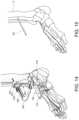
- FIG. 18is an enlarged, front elevational view of the proximal portion of the patient's lower extremity and the TAG tower of FIG. 16 , according to an embodiment of the present disclosure
- FIG. 19is an enlarged, front elevational view of the distal portion of the patient's lower extremity and the TAG tower of FIG. 16 , according to an embodiment of the present disclosure
- FIG. 20is a top perspective view of a joint-line referencing system, according to an embodiment of the present disclosure.
- FIG. 21is a top perspective view of the joint-line referencing system of FIG. 20 , according to an embodiment of the present disclosure.
- FIG. 22is a bottom perspective view of the joint-line referencing system of FIG. 20 , according to an embodiment of the present disclosure
- FIG. 23is a side elevational view of the joint-line referencing system of FIG. 20 , according to an embodiment of the present disclosure.
- FIG. 24is a front elevational view of the joint-line referencing system of FIG. 20 , according to an embodiment of the present disclosure
- FIG. 25is a perspective view of the joint-line referencing system of FIG. 20 and pins attached to a patient's lower extremity, according to an embodiment of the present disclosure
- FIG. 26is a perspective view of the patient's lower extremity with the pins attached to the patient's lower extremity after removal of the joint-line referencing system of FIG. 20 , according to an embodiment of the present disclosure
- FIG. 27is a front view of a fast-track alignment system, according to an embodiment of the present disclosure.
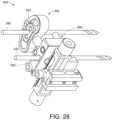
- FIG. 28is a bottom perspective view of the fast-track alignment system of FIG. 27 , according to an embodiment of the present disclosure.
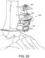
- FIG. 29is a perspective view of the fast-track alignment system of FIG. 27 positioned on a patient's lower extremity with a sizing block coupled to the distal end of the fast-track alignment system and an angelwing alignment member coupled to the sizing block, according to an embodiment of the present disclosure;
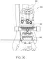
- FIG. 30is an enlarged, front view of the fast-track alignment system of FIG. 29 and the patient's lower extremity, according to an embodiment of the present disclosure
- FIG. 31is a perspective view of a fast-track alignment system and a joint line pointer positioned on a patient's lower extremity, according to an embodiment of the present disclosure
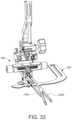
- FIG. 32is a front elevational view of the fast-track alignment system and the joint line pointer of FIG. 31 , according to an embodiment of the present disclosure
- FIG. 33is a perspective view of the fast-track alignment system and the joint line pointer of FIG. 31 , according to an embodiment of the present disclosure
- FIG. 34is a perspective view of the fast-track alignment system and the joint line pointer of FIG. 31 , according to an embodiment of the present disclosure
- FIG. 35is an exploded, top perspective view of the fast-track alignment system and the joint line pointer of FIG. 31 , according to an embodiment of the present disclosure
- FIG. 36is an exploded, bottom perspective view of the fast-track alignment system and the joint line pointer of FIG. 31 , according to an embodiment of the present disclosure
- FIG. 37is a perspective view of the joint line pointer of FIG. 31 , according to an embodiment of the present disclosure.
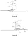
- FIG. 38is a front elevational view of the joint line pointer of FIG. 37 , according to an embodiment of the present disclosure.
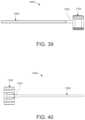
- FIG. 39is a side elevational view of the joint line pointer of FIG. 37 , according to an embodiment of the present disclosure.
- FIG. 40is a top view of the joint line pointer of FIG. 37 , according to an embodiment of the present disclosure.
- FIG. 41is a perspective view of a joint line pointer, according to an embodiment of the present disclosure.
- FIG. 42is a perspective view of the joint line pointer of FIG. 41 , according to an embodiment of the present disclosure.
- FIG. 43is a side elevational view of the joint line pointer of FIG. 41 , according to an embodiment of the present disclosure.
- FIG. 44is a top view of the joint line pointer of FIG. 41 , according to an embodiment of the present disclosure.
- FIG. 45is a perspective view of a joint-line referencing system, according to an embodiment of the present disclosure.
- FIG. 46is a front elevational view of the alignment arm, angelwing alignment member, and alignment foot of the joint-line referencing system of FIG. 45 , according to an embodiment of the present disclosure
- FIG. 47is a rear elevational view of the alignment arm, angelwing alignment member, and alignment foot of the joint-line referencing system of FIG. 45 , according to an embodiment of the present disclosure
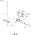
- FIG. 48is a first side elevational view of the alignment arm, angelwing alignment member, and alignment foot of the joint-line referencing system of FIG. 45 , according to an embodiment of the present disclosure
- FIG. 49is a second side elevational view of the alignment arm, angelwing alignment member, and alignment foot of the joint-line referencing system of FIG. 45 , according to an embodiment of the present disclosure
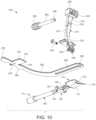
- FIG. 50is a top view of the alignment arm, angelwing alignment member, and alignment foot of the joint-line referencing system of FIG. 45 , according to an embodiment of the present disclosure
- FIG. 51is a bottom view of the alignment arm, angelwing alignment member, and alignment foot of the joint-line system of FIG. 45 , according to an embodiment of the present disclosure
- FIG. 52is an exploded, top perspective view of the alignment arm, angelwing alignment member, and alignment foot of the joint-line referencing system of FIG. 45 , according to an embodiment of the present disclosure
- FIG. 53is an exploded, bottom perspective view of the alignment arm and alignment foot of the joint-line referencing system of FIG. 45 , according to an embodiment of the present disclosure
- FIG. 54is an enlarged, front perspective view of the alignment arm of the joint-line referencing system of FIG. 45 , according to an embodiment of the present disclosure
- FIG. 55is an enlarged, rear perspective view of the alignment arm of the joint-line referencing system of FIG. 45 , according to an embodiment of the present disclosure
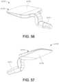
- FIG. 56is an enlarged, top perspective view of the shim of the alignment foot of the joint-line referencing system of FIG. 45 , according to an embodiment of the present disclosure
- FIG. 57is a bottom perspective view of the shim of FIG. 56 , according to an embodiment of the present disclosure.
- FIG. 58is a top view of the shim of FIG. 56 , according to an embodiment of the present disclosure.
- FIG. 59is a side view of the shim of FIG. 58 , according to an embodiment of the present disclosure.
- FIG. 60is a front view of the joint-line referencing system of FIG. 45 positioned relative to a patient's lower extremity, according to an embodiment of the present disclosure
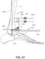
- FIG. 61is a side view of the joint-line referencing system of FIG. 60 and pins attached to the patient's lower extremity, according to an embodiment of the present disclosure
- FIG. 62is a perspective view of the joint-line referencing system of FIG. 45 with a laser alignment system, according to an embodiment of the present disclosure
- FIG. 63is a perspective view of the laser alignment system of FIG. 62 , according to an embodiment of the present disclosure.
- FIG. 64is a perspective view, partially cut away, of the laser alignment system of FIG. 62 , according to an embodiment of the present disclosure
- FIG. 65is an exploded perspective view of the laser alignment system of FIG. 62 , according to an embodiment of the present disclosure.
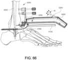
- FIG. 66is a side perspective view of the joint-line referencing system and laser alignment system of FIG. 62 aligned with a patient's lower extremity, according to an embodiment of the present disclosure
- FIG. 67is a front perspective view of the joint-line referencing system and the laser alignment system of FIG. 66 aligned with a patient's lower extremity, according to an embodiment of the present disclosure
- FIG. 68is a flowchart of a surgical method, according to an embodiment of the present disclosure.
- FIG. 69is a flowchart of a surgical method, according to an embodiment of the present disclosure.
- the present disclosureis directed to instruments, guides, systems and related methods for, for example, total ankle replacement prostheses.
- the instruments, guides, systems and related methodsmay facilitate preparation of a tibia and/or talus of a patient for implantation of a total ankle prosthesis therein.
- the instruments, guides, systems and related methodsmay also facilitate selection of a particular size of a tibial trialing component, tibial implant component, a talus trialing component, a talus implant component, and/or a tibial insert of the total ankle prosthesis that suits the patient.
- the instruments, guides, systems and methodsfacilitate proper alignment of the implant with the mechanical axis of an extremity of a patient.
- the instruments, guides, systems and methodsmay facilitate bone resection and implantation of an implant into one or more bones so that the implant is properly aligned with the mechanical axis (or another axis or anatomical axis or reference point) of the extremity of a patient.
- the instruments, guides, systems and methods of the present disclosuremay be utilized with any anatomical structure(s) of a patient to facilitate bone resection and alignment of an implant with an axis (e.g., mechanical axis, weight-bearing axis, anatomical axis, etc.) of one or more anatomical structures of interest.
- an axise.g., mechanical axis, weight-bearing axis, anatomical axis, etc.
- proximal, distal, anterior or plantar, posterior or dorsal, medial, lateral, superior and inferiorare defined by their standard usage for indicating a particular part or portion of a bone, joint (or any other anatomical structure) or implant according to the relative disposition of the natural bone, joint (or any other anatomical structure) or directional terms of reference.
- proximalmeans the portion of a device or instrument nearest the torso
- distalindicates the portion of the device or instrument farthest from the torso.
- anterioris a direction towards the front side of the body
- posteriormeans a direction towards the back side of the body
- medialmeans towards the midline of the body
- lateralis a direction towards the sides or away from the midline of the body
- superiormeans a direction above and “inferior” means a direction below another object or structure.
- distalrefers to the top of the foot and the term “plantar” refers the bottom of the foot.
- positions or directionsmay be used herein with reference to anatomical structures or surfaces.
- the bones of the foot, ankle and lower legmay be used to describe the surfaces, positions, directions or orientations of the instruments, guides, systems and related methods (and components thereof).
- the instruments, guides, systems and related methods, and the aspects, components, features and the like thereof, disclosed hereinmay be described with respect to one side of the body (e.g., the left or right ankle) for brevity purposes.
- the instruments, guides, systems and related methods, and the aspects, components, features and the like thereof, described and/or illustrated hereinmay be changed, varied, modified, reconfigured or otherwise altered for use or association with another side of the body for a same or similar purpose without departing from the spirit and scope of the disclosure.
- the instruments, guides, systems and related methods, and the aspects, components, features and the like thereof, described herein with respect to the right ankle of a patientmay be mirrored so that they likewise function with the left ankle of the patient.
- instruments, guides, systems and related methods, and the aspects, components, features and the like thereof, disclosed hereinare described with respect to the ankle for brevity purposes, but it should be understood that the instruments, guides, systems and related methods (and components thereof) may be used with other joints of a human body (or other mammalian body).
- the present disclosuremay provide implant guides, devices, systems, and methods for total ankle replacements and correction of bone deformities in the foot and ankle.
- the joint-line referencing systems described hereinmay optimize positioning designed to fit the talar and tibial curvature in both anterior-posterior and medial-lateral directions.
- the joint-line referencing systemsmay allow for the streamlining of surgical techniques, improvement in the accuracy of surgery set-up procedures, and reduction of the likelihood of misplacement of bone screws.
- the joint-line referencing system 100is operable with a tibia alignment guide (TAG) tower 300 ( FIG. 16 ), as described in greater detail below.
- TAGtibia alignment guide
- the joint-line referencing system 100may include, for example, an alignment arm 200 , a pin tube guide member 250 , an angelwing alignment member 260 , and an alignment foot 110 having a handle 150 and a curved shim 112 .
- the alignment arm 200may include a body 210 having a first portion 212 and a second portion 214 .
- the first portion 212 of the alignment arm 200may include a pin tube holder 220 defining at least one pin tube through-hole 222 for receiving the pin tube guide member 250 .
- a pin tube through-hole 216is operable for receiving a second pin tube guide member ( FIG. 20 ) for use with a fast-track alignment system 600 ( FIG. 27 ) as described in greater detail below.
- the at least one pin tube through-hole 222may be separate individual side-by-side holes or a plurality of overlapping pin tube through-holes that allow for anatomic variations.
- the at least one pin tube through-hole 222may be, for example, three holes as shown in the depicted embodiment to allow for anatomic variations.
- the at least one pin tube through-hole 222 (and the pin tube through-hole 216 )may be oblong or elongated to allow easier removal of the shim 112 from the joint while leaving one or more pins or guidewires in place, for example, by reducing binding, as described below.
- the second portion 214 of the alignment arm 200may include a base portion 230 having a slot 232 for receiving an auxiliary alignment instrument such as a tab 274 of the angelwing alignment member 260 , or a laser alignment device (not shown), or other suitable alignment device.
- a distal end of the base portion 230may further include a hinge portion with a first hinge arm or first female hinge member 234 and a spaced-apart second hinge arm or second female hinge member 234 , which members have aligned hinge pin openings 236 .
- the pin tube guide member 250may contain a knob 252 coupled to a first end of a shaft 254 .
- the shaft 254is sized for extending through one of the plurality of pin tube through-holes 222 and 216 .
- the pin tube guide member 250includes a passageway 256 extending through the knob 252 and the shaft 254 .
- the second end of the shaft 254may be, for example, tapered.
- the pin tube guide member 250may be, for example, sized and shaped or configured to receive a 3.0 millimeter (mm) or other size bone-pin.
- the angelwing alignment member 260may have a body 262 .
- the body 262may be a planar member having an L-shaped configuration defining a first end portion 276 and a second end portion 268 .
- the tab 274extends from first end portion 276 .
- the tab 274may be, for example, sized and shaped to be received in or engage the slot 232 of the alignment arm 200 .
- the body 262may include cutouts 270 to assist in insertion of tab 274 into the slot 232 of the base portion 230 of the alignment arm 200 .
- the second end portion 268may include an elongated slot 264 with an enlarged opening for receiving and coupling to an elongate auxiliary alignment member or a rod 280 ( FIG. 16 ).
- the angelwing alignment member 260allows a surgeon to assess the tibial slope.
- the rod 280may be movably coupled to the angelwing alignment member 260 , such as within the slot 264 of the angelwing alignment member 260 , which slot may extend anteriorly-posteriorly.
- the rod 280may be oriented perpendicular (in at least one direction) or normal to the angelwing alignment member 260 , and thereby perpendicular (in at least one direction) or normal to the joint line referenced by the slot 232 in base portion 230 and the angelwing alignment member 260 .
- the rod 280may thereby allow a user to determine/evaluate the alignment (e.g., sagittal alignment) and/or orientation (e.g., sagittal slope and/or coronal slope) of the joint line of the anatomical configuration/structures of the patient (e.g., an ankle joint) and/or of a particular implant replacing such configuration/structures (e.g., a total ankle replacement implant) implanted on/in a resected bone that is resected (at least partially).
- alignmente.g., sagittal alignment
- orientatione.g., sagittal slope and/or coronal slope
- a particular implantreplacing such configuration/structures (e.g., a total ankle replacement implant) implanted on/in a resected bone that is resected (at least partially).
- the alignment foot 110may include the handle 150 attached to the curved shim 112 .
- the curved shimmay include curved alignment feet 120 having spaced apart ends 118 ( FIG. 1 ).
- the curved alignment feet 120are designed to fit the talar and tibial curvature in anterior-posterior and medial-lateral directions.
- a portion 136 disposed between the handle 150 and the curved shim 112may include hinge pin opening 138 .
- the handle 150is pivotally attached to alignment arm 200 with the portion 136 ( FIG. 8 ) being positioned between hinge members 234 via a fastener pin 240 ( FIG. 8 ) or other suitable pivoting member.
- the pivotable connectionallows a surgeon to adjust the tibia slope.
- the first portion 212 of alignment arm 200is disposed at an angle A relative to the second portion 214 .
- the angled relationshipprovides an offset/clearance to allow for “negative” tibia slope.
- the alignment arm 200may be, for example, straight or may include a bend, curve or angulation between the first portion and the second portion.
- the handle 150allows a surgeon to orient the joint-line referencing system 100 in transverse plane or internal-external rotation.
- FIGS. 12 - 19illustrate an alignment procedure, which includes a joint-line referencing (JLR) and the tibia alignment guide (TAG) technique for use in a TAR surgery, according to an embodiment of the present disclosure.
- JLRjoint-line referencing
- TAGtibia alignment guide
- a surgical methodincludes placing the shim 112 ( FIG. 1 ) of the alignment foot 110 into the joint 10 between the tibia 12 and the talus 14 of the patient. Specifically, the shim 112 is placed between the tibia plafond and the superior talar dome.
- the handle 150may be used, for example, to position and/or orient the alignment foot 110 , and thus, the coupled alignment arm 200 , in a transverse plane (i.e., internal-external rotation).
- the angelwing alignment member 260is inserted into the slot 232 ( FIG. 8 ) of the base portion 230 ( FIG. 8 ) of the alignment arm 200 may be used by a surgeon to assess the tibial slope.
- the joint-line referencing system 100may be utilized and positioned and/or orientated with respect to any axis X-X of the anatomical structure of interest.
- a pin 290inserted in pin hole 256 ( FIG. 8 ) of guide member 250 and drilled into the tibia 12 , as shown in FIG. 14 .
- the inserted pin 290secures the selected tibial slope and internal-external rotation.
- the joint line referencing system 100may be removed, whereby the pin 290 remains inserted into the tibia 12 .
- the pin tube guide member 250FIG. 14
- the alignment arm 200FIG. 14
- the irregular shaped pin tube through-holes 222allow for movement and removal of the joint-line reference system 100 .
- the pin 290serves as the starting point for the next portion of the surgical procedure, i.e., the TAG technique.
- a second pin 390may then be drilled into the proximal tibial tubercle to support the TAG tower 300 on the pins 290 and 390 , and with the TAG tower 300 aligned on the patient's tibia 12 .
- a surgeonmay align the tibial slope.
- the surgeonmay use an alignment method of their choice, for example, (1) use gap or “finger-breadths” at the proximal and distal ends, (2) use the angelwing alignment member 260 to align with the distal tibia and ankle joint, or (3) use the lateral rod 280 ( FIG. 17 ) aligned to the tibial axis.
- a tibial sizing template 400may be coupled to the distal end of the TAG tower 300 using a locking-cam screw. Thereafter, a first knob 302 and a second knob 304 are tightened to lock the TAG tower 300 to the pins 290 and 390 , and thus, to the patient's tibia 12 .
- a varus-valgus alignmentmay be performed.
- the varus-valgus alignmentmay be performed using a varus-valgus alignment housing or double-lead screw housing 500 .
- the housing 500may include a double-lead screw 510 .
- the double-lead screw housing 500allows the user to adjust varus-valgus alignment by allowing for rotation about the screw 510 .
- the rotationis achieved by turning the knobs 512 and 514 positioned at the medial and lateral sides of the screw 510 .
- an internal-external rotation locking screw 550may be loosened to allow for internal-external rotation adjustment of the TAG tower 300 .
- the TAG tower 300may include, for example, indicators to allow the user to easily determine whether the tower 300 is internally or externally rotated or if the TAG tower 300 is positioned at neutral.
- the TAG tower 500may also include a rack-and-pinion gear box 560 .
- the rack-and pinion gear box 560allows for adjustment of a distal-proximate position of a sizing template 400 .
- a ball-plunger 565 and locking screw 567may, for example, provide friction and lock the position of the rack-and pinion gear box 560 .
- the distal end of the TAG tower 300may also include a second or distal varus-valgus alignment housing or double-lead screw housing 590 .
- the second housing 590allows for medial-lateral position adjustments.
- the second housing 590may include, for example, a double-lead screw 591 positioned along the longitudinal axis of the second housing 590 .
- the second housing 590may also include two knobs 592 and 594 for translating the coupling member 597 in the medial-lateral direction.
- a locking screw or locking cam screw 599may be used to fix the medial-lateral position of the attached sizing template 400 .
- the adjustment stepsmay use radiographic markers on the sizing template to properly size, align and position the instruments. Suitable alignment systems and sizing templates are described in international patent application PCT/US2019/029978, filed May 1, 2019, and entitled “Laser-Based Implant Alignment And Resection Guide Systems And Related Methods,” the entire contents being incorporated in herein by reference.
- FIGS. 20 - 24illustrate a joint-line referencing system 101 , according to an embodiment of the present disclosure.
- the joint-line referencing system 101may be operable with a fast-track alignment system 600 ( FIG. 27 ) as described in greater detail below.
- the joint-line referencing system 101may be essentially the same as the joint-line referencing system 100 ( FIGS. 1 - 11 ) having, for example, the alignment arm 200 , the first pin tube guide member 250 , the angelwing alignment member 260 , the alignment foot 110 having the handle 150 and the curved shim 112 as described above, but with the exception of a second pin tube guide member 251 .
- FIG. 25 - 30illustrate an alignment procedure, which includes a joint-line referencing and a fast-track alignment technique for use in a TAR surgery, according to an embodiment of the present disclosure.
- the method of using the joint-line referencing system for this techniqueis similar to the joint-line referencing system to TAG technique, except that an additional or second 3.0 mm pin is drilled into the distal tibia of the patient. As will be appreciated, the second pin takes the place of the proximal pin used in the TAG technique.
- the surgical methodincludes placing the shim 112 ( FIG. 21 ) of the alignment foot 150 into the joint between the tibia 12 and the talus 14 of the patient. Specifically, the shim is placed between the tibia plafond and the superior talar dome.
- the handle 150may be used, for example, to position and/or orient the alignment foot 110 , and thus, the coupled alignment arm 200 , in the transverse plane (i.e., internal-external rotation).
- the angelwing alignment member 260is inserted into the slot 232 ( FIG. 8 ) of the base portion 230 ( FIG. 8 ) and used by a surgeon to assess the tibial slope.
- the joint-line referencing systemmay be utilized and positioned and/or orientated with respect to any axis of the anatomical structure of interest.
- a first pin 290is inserted in pin hole 256 ( FIG. 20 ) of the first pint tube guide member 250 and drilled into the tibia 12
- a second pin 292is inserted in a pin hole 257 ( FIG. 21 ) of the second pin tube guide member 251 and drilled into the tibia 12 as shown in FIG.
- the inserted pins 290 sand 292secure the selected tibial slope and internal-external rotation.
- the irregular shaped pin tube through-holes 222 ( FIG. 21 ) in the pin tube holder 220 ( FIG. 21 ) and the pin tube through-holes 216 ( FIG. 21 )accommodate leaving the pins 290 and 292 in the patient's tibia upon removing the joint-line referencing system 101 .
- the joint line referencing system 101may be removed, whereby the pins 290 and 292 remain inserted into the tibia 12 of the patient.
- the pin tube guide members 250FIG. 25
- the alignment arm 200may be removed from the pins 290 , 292 and the shim 112 ( FIG. 21 ) removed from the joint.
- These two pinsare the starting point for the supporting the fast-track alignment system 600 ( FIG. 27 ).
- the pins 290 and 292serve as the starting point for the next portion of the surgical procedure, i.e., the fast-track technique.
- FIG. 27illustrates the fast-track alignment system 600 according to an embodiment of the present disclosure.
- the fast-track alignment system 600may include a rack-and-pinion gear box 660 , a distal varus-valgus alignment housing or double-lead screw housing 690 , and a coupling member 697 .
- the rack-and-pinion gear box 660 , the distal varus-valgus alignment housing or double-lead screw housing 690 , and the coupling member 697may be the same or essentially the same as the rack-and-pinion gear box, the distal varus-valgus alignment housing or double-lead screw housing, and the coupling member as described above in connection with the TAG tower 300 ( FIG. 16 ).
- this portion of the fast-track alignment systemmay be reused from the TAG tower 300 ( FIG. 16 ).
- the rack-and-pinion gear box 660may include a pin hole 662 extending therethrough and in which the pin 292 may extend.
- a distal portion 650 of the fast-track alignment system 600may be modular and operably attachable to the distal portion the rack-and-pinion gear-box 660 using, for example, a quarter-turn mechanism.
- the distal portion 650may include a curved channel 658 ( FIG. 27 ) in which is operably retained a sliding member 659 ( FIG. 27 ) having pin-holes 652 within a 3-hole pattern which holes 652 are similarly or identically distanced a distance D from the pin-hole 662 through the rack-and-pinion gear-box 660 .
- the pin-hole 662may be a circular or an elongated hole. The distance D may match that of the joint-line reference shim.
- the fast-track alignment system 600is slid over the two 3.0 mm bone pins 290 and 292 .
- the tibial slopeis defined/locked by the angle/direction of these pins.
- a pin-locking knobmay be tightened.
- the varus-valgus alignmentis adjusted by loosening the locking screw 670 ( FIG. 27 ).
- the pin-hole 662 in the rack-and-pinion gear-box 660aligns over the distal pin 292 . This allows the user to adjust internal-external rotation by loosening an internal-external rotation locking screw 680 ( FIG. 27 ).
- the distal-proximal and medial-lateral adjustmentsare made similarly to the TAG method described above.
- a joint line pointer 1000for adjusting an alignment guide or alignment system, according to an embodiment of the present disclosure.
- the joint line pointer 1000may be employed for generally setting internal and external rotation of the alignment guide such as a fast-track alignment system 900 .
- Additional alignment devicesmay include the angelwing alignment member 260 , and a medial gutter tool 2000 .
- the fast-track alignment system 900may be positioned on pins 290 and 292 installed using the joint-line referencing system 101 ( FIG. 20 ) described above, or the joint-line referencing system 4000 ( FIG. 45 ) described below.
- the fast-track alignment system 900may include a first translation mechanism or medial lateral adjustment member, a second translation mechanism or distal proximal adjustment member, and third translation mechanism or varus-valgus adjustment member, similar to the adjustment member and systems described above with the fast-track alignment system 600 ( FIG. 27 ).
- the joint line pointer 1000may generally include a body 1100 and a handle 1200 having one end 1202 attached to body 1100 .
- body 1000may include an upper portion 1002 and lower portion 1004 .
- the upper portion 1002may include a coupling member 1110 that is receivable in the coupling member 910 ( FIG. 32 ) of the fast-track alignment system 900 ( FIG. 32 ).
- the lower portion 1004includes a slot 1032 for receiving a tab 274 ( FIG. 35 ) of the angelwing alignment member 260 ( FIG. 35 ) and laterally-extending portions 1112 for assessing the joint line.
- FIGS. 41 - 44illustrates another joint line pointer 3000 , according to an embodiment of the present disclosure.
- the joint line pointer 3000may generally include a body 3100 and a handle 3200 having one end 3202 attached to body 3100 .
- the body 3000may include an upper portion 3002 and lower portion 3004 .
- the upper portion 3002may include a coupling member 3110 that is receivable in the coupling member 910 ( FIG. 32 ) of the fast-track alignment system 900 ( FIG. 32 ).
- the lower portion 3004includes a through opening 3300 and laterally-extending feet 3115 . The feet extended medially and laterally to indicate the joint line.
- the medial gutter tool 2000may having an elongated body 2010 having a first portion 2002 and a second portion 2004 .
- the first portion 2002may be Y-shaped, and the second portion 2004 may be a reduced or tapered distal end.
- the joint line pointersuch as the joint line pointer 1000 (or the joint line pointer 3000 ( FIG. 41 )
- the medial gutter tool 2000may be operably employed by a surgeon to move and align the fast-track alignment system 900 in proper orientation relative to the lower extremity of the patient.
- the medial gutter tool 2000may be used along the medial gutter plane or to a determined gutter bisection.
- the fast-track alignment systemmay be operably lockably secured in place on the pins attached to the lower extremity of the patient's tibia.
- the joint line pointer and gutter toolmay be used with the any of the above TAR and fast-track alignment systems.
- the above alignment systemse.g., TAG and fast-track alignment systems, joint line pointers, and gutter tools may be operably usable with suitable resection guides and other tools for performing total ankle replacement.
- the above alignment systemsmay be operable with the resection guides described in U.S. provisional patent application No. 62/898,615, filed Sep. 11, 2019, and entitled “Resection Guides, Sweeping Reamers, And Methods For Use In Total Ankle Replacement”, the entire contents being incorporated in herein by reference.
- Other suitable fast-track alignment systemmay be used with the joint-line reference systems of the present disclosure.
- suitable fast-track alignment systemsare described in U.S. Provisional Application No. 62/899,703 filed Sep.
- suitable tibial alignment guide systemmay be used with the joint-line reference systems of the present disclosure.
- suitable tibial alignment guide systemsare described in U.S. Provisional Application No. 62/899,740, filed Sep. 12, 2019, entitled “Joint Replacement Alignment Guides, Systems And Methods Of Use And Assembly”, which is hereby incorporated by reference in its entirety.
- FIG. 45illustrates a joint-line referencing system 4000 , according to an embodiment of the present disclosure.
- the joint-line referencing system 4000is operable with the TAG tower 300 ( FIG. 16 ), the fast-track alignment system 600 ( FIG. 27 ), and/or with a laser alignment system 5000 ( FIG. 62 ).
- the joint-line referencing system 4000may include, for example, an alignment foot 4100 having a handle 4150 and a flat shim 4170 , an alignment arm 4200 , a first pin tube guide member 4250 , a second pin tube guide member 4251 , an angelwing alignment member 4300 , and an alignment rod 4400 .
- the alignment arm 4200may include a body 4210 having a first portion 4212 , a second portion 4214 , a first side 4213 , and a second side 4215 .
- the first portion 4212 of the alignment arm 4200may include a pin tube holder 4220 defining at least one pin tube through-hole 4222 extending from the first side 4213 to the second side 4215 for receiving the pin tube guide member 4250 ( FIG. 45 ).
- a pin tube through-hole 4216extends from the first side 4213 to the second side 4215 and is operable for receiving the second pin tube guide member 4250 ( FIG. 45 ) for use with, for example, the fast-track alignment system 600 ( FIG.
- the at least one pin tube through-holes 4222may be separate individual side-by-side openings or a plurality of overlapping pin tube openings that allow for anatomic variations.
- the at least one pin tube through-hole 4222may be, for example, three holes as shown in the depicted embodiment to allow for anatomic variations.
- the pin tube through-holes 4222 and the pin tube through-hole 4216may be circular for receiving the cylindrical pin tube 4250 ( FIG. 45 ).
- the alignment armmay define a longitudinal axis Z
- pin tube through-hole 4216may define an axis X 1 .
- Each of the pin tube through-holes 4222may define axes X 2 , X 3 , and X 4 .
- the second portion 4214 of the alignment arm 4200may include a first base portion 4230 having an opening such as a slot 4232 opening onto the first side 4213 for receiving an auxiliary alignment instrument such as a tab 4370 ( FIG. 52 ) of the angelwing alignment member 4300 ( FIG. 52 ), or a laser alignment device (not shown), or other suitable alignment device.
- the second portion 4214 of the alignment arm 4200may include a spaced apart second base portion 4240 having an opening such as a slot 4242 on the first side 4213 for receiving an auxiliary alignment instrument such as the laser alignment device 5000 ( FIG. 62 ) as described below.
- Slots 4232 and 4242may extend through body 4210 of alignment arm 4200 and be configured to open onto the first side 4213 and second side 4215 .
- the openings 4232 and 4242may be configured to allow for orienting the alignment angelwing member and/or the laser.
- each of the slots 4232 and 4242may define axes X 5 and X 6 , respectively.
- Pin tube through-hole axis X 1 -X 4 and slot axis X 5 and X 6may be parallel to each other, and disposed at 90 degrees from axis Z of the alignment arm.
- a distal end of the first base portion 4230may further include an outwardly-extending tab 4260 having a through-hole 4266 extending therethrough.
- a pair of pin holes 4261 and 4263may extend through the outwardly extending tab 4260 for use with pins 4265 ( FIG. 52 ) to attach the alignment foot 4100 ( FIG. 45 ) to alignment arm 4200 as described below.
- the pin tube guide members 4250 and 4251may be essentially the same as pin tube guide members 250 ( FIG. 1 ) described above.
- the angelwing alignment member 4300may essentially the same as the angelwing alignment member 260 ( FIG. 1 ) described above.
- the angelwing alignment member 4300allows a surgeon to assess the tibial slope.
- the alignment rod 4400may be movably coupled to the wing member 4300 , such as within an elongated opening 4364 of the angelwing alignment member 4300 , which elongated opening may extend anteriorly-posteriorly.
- the rod 4400may be oriented perpendicularly (in at least one direction) or normal to the angelwing alignment member 4300 , and thereby perpendicular (in at least one direction) or normal to the joint line referenced by the slot 4232 ( FIG. 54 ) in the first base portion 4230 ( FIG. 54 ), the slot 4242 ( FIG. 54 ) in the second base portion 4240 ( FIG.
- the rod 4400may thereby allow a surgeon to determine/evaluate the alignment (e.g., sagittal alignment) and/or orientation (e.g., sagittal slope and/or coronal slope) of the joint line of the anatomical configuration/structures of the patient (e.g., an ankle joint) and/or of a particular implant replacing such configuration/structures (e.g., a total ankle replacement implant) implanted on/in a resected bone that is resected (at least partially).
- alignmente.g., sagittal alignment
- orientatione.g., sagittal slope and/or coronal slope
- a particular implantreplacing such configuration/structures (e.g., a total ankle replacement implant) implanted on/in a resected bone that is resected (at least partially).
- the alignment foot 4100may include the handle 4150 and the flat shim 4170 operably attachable to the alignment arm 4200 .
- the handle 4150may be fixedly attachable to the alignment arm 4200 with a connector portion 4151 of the handle 4150 receivable in the through-hole 4266 (best shown in FIG. 54 ) via a fastener pin 4152 ( FIG. 53 ), or screw, or other suitable fastening member.
- the shim 4170is fixedly attachable to the alignment arm 4200 with a connector portion 4171 of the shim 4170 receivable in the through-hole 4266 (best shown in FIG. 55 ) via a fastener pin 4172 ( FIG.
- the fixed connection of the handle 4150 , the shim 4170 , and the alignment arm 4200allows a surgeon using the handle 4150 to adjust the position and orientation of the joint-line referencing system 4100 ( FIG. 45 ) relative to, for example, a joint between adjacent bones.
- the handle 4150may be planar to easily allow a surgeon to grasp and reposition the handle, and thus position and orient the joint-line referencing system 4100 ( FIG. 45 ).
- the shim 4170may include the connector 4171 and a generally planar portion 4174 having a first flat surface 4175 and a second flat surface 4176 .
- the shim 4170may be a generally square planar member with rounded corners and with the first flat surface 4175 and the second flat surface 4176 tapering towards a distal end of the shim. For example, as shown in FIG.
- the first flat surface 4175 and the second flat surfacemay be disposed at an angle S of about 0 degrees to about 10 degrees, about 2 degrees to about 8 degrees, about 4 degrees to about 6 degrees, about 0 degrees, 2 degrees, about 4 degrees, about 5 degrees, about 6 degrees, about 7 degrees, about 8 degrees, or disposed at any suitable angle.
- the shim 4170is designed to fit in the joint between adjacent bones such as between the talus and tibia of an ankle joint in anterior-posterior and medial-lateral directions.
- the generally planar portion 4174 of the shim 4170may define a longitudinal axis X 7 parallel with the axes of the pin though-holes and slots in the alignment arm 4200 ( FIG. 54 .).
- the connector 4171 of the shim 4170is offset relative to the generally planar portion 4174 . This allows, as shown in FIG. 49 , for the generally planar portion 4174 of the shim 4170 to be disposed parallel and in line with angelwing alignment member 4300 in the assembled joint line referencing system 4000 ( FIG. 45 ).
- FIGS. 60 and 61illustrate the initial steps of an alignment procedure, which may subsequently include the joint-line referencing system 4000 for use in the TAG technique in a TAR surgery, according to an embodiment of the present disclosure.
- the initial steps of an alignment proceduremay include placing the shim 4170 ( FIG. 61 ) of the alignment foot 4100 ( FIG. 61 ) into the joint 10 between, e.g., the tibia 12 and the talus 14 of the patient. Specifically, the shim 4170 ( FIG. 61 ) is placed between the tibia plafond and the superior talar dome.
- the handle 4150 ( FIG. 61 )may be used, for example, to position and/or orient the alignment foot 4100 , and thus, the coupled alignment arm 4200 , in the transverse plane (i.e., internal-external rotation).
- the angelwing alignment member 4300 inserted into the slot 4232 ( FIG. 54 ) of the base portion 4230 ( FIG. 54 )may be used by a surgeon to assess the tibial slope.
- the rod 4400may be used to determine/evaluate the alignment (e.g., sagittal alignment) and/or orientation (e.g., sagittal slope and/or coronal slope) of the joint line of the anatomical configuration/structures of the patient (e.g., an ankle joint).
- the joint-line referencing system 4000may be utilized and positioned and/or orientated with respect to any axis X-X of the anatomical structure of interest.
- a first pin 4290is inserted in pin hole 4256 ( FIG. 45 ) of first guide member 4250 and drilled into the tibia 12 .
- the inserted pin 4290secures the selected tibial slope and internal-external rotation.
- the joint line referencing system 4000may be removed, whereby the first pin 4290 remains inserted into the tibia 12 .
- the pin tube guide member 4250may be removed, and simultaneously the alignment arm 4200 may be removed from the pin 4290 and the shim 4170 removed from the joint.
- the first pin 4290serves as the starting point for the next portion of the surgical procedure, i.e., the TAG technique.
- the inserted pin 4290may be employed with a tibia alignment guide (TAG) technique for use in a TAR surgery, for example, as illustrated in FIGS. 16 - 19 and described above.
- TAGtibia alignment guide
- the initial steps of an alignment proceduremay subsequently include the joint-line referencing system 4000 for use in the fast-track alignment technique in a TAR surgery.
- the initial steps of an alignment proceduremay include placing the shim 4170 ( FIG. 61 ) of the alignment foot 4100 ( FIG. 61 ) into the joint 10 between, e.g., the tibia 12 and the talus 14 of the patient. Specifically, the shim 4170 ( FIG. 61 ) is placed between the tibia plafond and the superior talar dome.
- the handle 4150 ( FIG. 61 )may be used, for example, to position and/or orient the alignment foot 4100 , and thus, the coupled alignment arm 4200 , in the transverse plane (i.e., internal-external rotation).
- the angelwing alignment member 4300is inserted into the slot 4232 ( FIG. 54 ) of the base portion 4230 ( FIG. 54 ) may be used by a surgeon to assess the tibial slope.
- the rod 4400may be used to determine/evaluate the alignment (e.g., sagittal alignment) and/or orientation (e.g., sagittal slope and/or coronal slope) of the joint line of the anatomical configuration/structures of the patient (e.g., an ankle joint).
- the joint-line referencing system 4000may be utilized and positioned and/or orientated with respect to any axis X-X of the anatomical structure of interest.
- a first pin 4290is inserted in pin hole 4256 ( FIG. 45 ) of first guide member 4250 ( FIG. 61 ) and drilled into the tibia 12
- a second pin 4292( FIG. 61 ) is inserted in the pin hole of the second pin tube guide member 4251 ( FIG. 61 ) and drilled into the tibia 12 .
- the inserted pins 4290 ( FIG. 61 ) and 4292 ( FIG. 61 )secure the selected tibial slope and internal-external rotation.
- the method of using the joint-line referencing system for this techniqueis similar to the joint-line referencing system to the TAG technique, except that the additional second pin 4292 is drilled into the distal tibia of the patient. As will be appreciated, the second pin 4292 takes the place of the proximal pin used in the TAG technique.
- the joint line referencing system 4000may be removed, whereby the first pin 4290 and the second pin 4292 remain inserted into the tibia 12 .
- the pin tube guide members 4250 ( FIG. 61 ) and 4251 ( FIG. 61 )may be removed, and simultaneously the alignment arm 4200 may be removed from the pins 4290 , 4292 and the shim 4170 ( FIG. 61 ) removed from the joint.
- These two pinsare the starting point for the supporting, for example, the fast-track alignment system 600 ( FIG. 27 ).
- the pins 4290 and 4292serve as the starting point for the next portion of the surgical procedure, i.e., the fast-track technique.
- the inserted pins 4290 and 4292may be employed with the fast-track alignment system 600 ( FIG. 27 ) for use in a TAR surgery, for example, as illustrated in FIGS. 27 - 30 and described above.
- the joint-line referencing system 4000 with a laser alignment system 5000may be operable with the TAG tower 300 ( FIG. 16 ) or with the fast-track alignment system 600 ( FIG. 27 ) for use in a TAR surgery.
- the laser alignment system 5000may be operably connected to the joint-line referencing system 4000 via the slot 4242 ( FIG. 54 ) of base member 4240 ( FIG. 54 ) of alignment arm 4200 .
- the laser alignment system 5000may generally include a housing 5100 , a laser device 5200 , an insert shim 5300 , a power source holder or battery holder 5400 ( FIG. 64 ), and one or more power sources such as a plurality of batteries 5600 ( FIG. 64 ).
- a distal end of the insert shim 5300extends from the housing 5100 .
- the distal end of the insert shim 5300is receivable in the slot 4242 ( FIG. 54 ) of base member 4240 ( FIG. 62 ) of the alignment arm 4200 ( FIG. 63 ).
- the housing 5100may include a first half 5110 and a second half 5120 .
- the laser device 5200may be disposed at an angle relative to the insert shim 5300 .
- the insert shim 5300may include a first portion 5310 and a second portion 5350 .
- the first portion 5310 of the insert shim 5300may have a distal end 5311 and a proximal end 5312 having a cutout 5314 configured and angled for receiving and positioning the laser device 5200 .
- the second portion 5350 of the insert shim 5300may have a distal end 5351 and a proximal end 5352 .
- the distal end 5351may act as an electrical switch for turning on the laser device 5200 when the distal end of the insert shim is inserted in slot 4242 ( FIG. 54 ) of alignment arm 42 ( FIG. 54 ).
- FIGS. 66 and 67illustrate the joint-line referencing system 4000 with the laser alignment system 5000 aligned relative to a patient's lower extremity, according to an embodiment of the present disclosure.
- the combination of the alignment foot 4100 ( FIG. 66 ), alignment arm 4200 , the angelwing alignment member 4300 , the alignment rod 4400 , and the laser alignment system 5000may be used by a surgeon to orient and position joint-line referencing system 4000 relative to a patient's lower extremity.
- the laser alignment system 5000may emit laser light therefrom orientated at a fixed angle relative to alignment arm 4200 .
- the emitted and projected laser lightmay be in a plane over an angle W resulting in an illuminated laser line 5500 (illustrated in dashed lines in FIG. 67 ) on the patient's lower extremity (e.g., on the outer skin surface of the patent's lower extremity) when the distal end 5351 ( FIG. 65 ) acting as a switch activates the laser device 5000 ( FIG. 66 ).
- the laser light line 5500can be aligned to the alignment axis (e.g., an anatomical or mechanical axis) of the anatomical configuration/structures of the patient via the surgeon positioning and orientating the joint-line referencing system 4000 .
- the laser device 5200may be configured to emit a fan shaped laser light plane with a fan angle within the range of about 1 degree to about 75 degrees (e.g., 1, 5, 10, 20, 30, 45, 60, or 75 degrees). In some embodiments, the laser device 5200 may be configured to emit a fan shaped laser light plane with a fan angle of about 60 degrees. In some embodiments, the laser device 5200 may be configured to emit a laser light plane with a beam angle of less than 3 rad. In alternative embodiments, the laser light may emanate in configurations other than a laser line (i.e., the incident light may form a point or dot).
- the laser device 5200may be configured to emit at least one secondary linear laser line (not shown) (e.g., via a fan shaped laser light plane), which may be orientated perpendicular to the linear laser line 5500 .
- the secondary linear laser linemay further assist the surgeon in properly positioning and orienting the joint-line referencing system 4000 with respect to the anatomical configuration/structures of the patient (e.g., to the alignment axis (e.g., an anatomical or mechanical axis) of the anatomical configuration/structures of interest).
- FIG. 68illustrates a surgical method 6000 , according to an embodiment of the present disclosure.
- the method 6000may include at 6100 placing a shim into a joint between a first bone and a second bone of a patient, at 6200 moving a handle operably attached to the shim to position and/or orient an alignment arm relative to the first bone, at 6300 inserting a first pin through a hole of the alignment arm and into the first bone, at 6400 removing the shim from the joint and the alignment arm from the first pin, at 6500 installing an alignment guide on the installed first pin, and at 6600 using a cutting guide operably attached to the alignment guide to resect a portion of the first bone and/or the second bone.
- FIG. 69illustrates a surgical method 7000 , according to an embodiment of the present disclosure.
- the method 7000may include at 7100 , placing a shim into a joint between a first bone and a second bone of a patient, at 7200 moving a handle operably attached to the shim to position and/or orient an alignment arm relative to the first bone, at 7300 inserting a first pin through a first hole of the alignment arm and into the first bone, at 7400 inserting a second pin through a second hole of the alignment arm and into the first bone, at 7500 removing the shim from the joint and the alignment arm from the first and the second pins, at 7600 installing an alignment guide on the installed pins, at 7700 using a cutting guide operably attached to the alignment guide to resect a portion of the first bone and/or the second bone.
- joint line systems and methods of the present disclosuremay be configured to provide alignment (e.g., manipulation to achieve alignment) in three planes (e.g., along or in the sagittal, coronal and transverse planes), covering six degrees of freedom.
- alignmente.g., manipulation to achieve alignment
- three planese.g., along or in the sagittal, coronal and transverse planes
- a method or article that “comprises”, “has”, “includes” or “contains” one or more steps or elementspossesses those one or more steps or elements, but is not limited to possessing only those one or more steps or elements.
- a step of a method or an element of an article that “comprises”, “has”, “includes” or “contains” one or more featurespossesses those one or more features, but is not limited to possessing only those one or more features. Any examples of parameters are not exclusive of other parameters of the disclosed embodiments.
- the terms “comprising,” “has,” “including,” “containing,” and other grammatical variants thereofencompass the terms “consisting of” and “consisting essentially of.”
- the phrase “consisting essentially of” or grammatical variants thereof when used hereinare to be taken as specifying the stated features, integers, steps or components but do not preclude the addition of one or more additional features, integers, steps, components or groups thereof but only if the additional features, integers, steps, components or groups thereof do not materially alter the basic and novel characteristics of the claimed compositions or methods.
- each rangeis intended to be a shorthand format for presenting information, where the range is understood to encompass each discrete point within the range as if the same were fully set forth herein.
Landscapes
- Health & Medical Sciences (AREA)
- Life Sciences & Earth Sciences (AREA)
- Surgery (AREA)
- Orthopedic Medicine & Surgery (AREA)
- General Health & Medical Sciences (AREA)
- Engineering & Computer Science (AREA)
- Biomedical Technology (AREA)
- Heart & Thoracic Surgery (AREA)
- Animal Behavior & Ethology (AREA)
- Public Health (AREA)
- Veterinary Medicine (AREA)
- Oral & Maxillofacial Surgery (AREA)
- Medical Informatics (AREA)
- Molecular Biology (AREA)
- Nuclear Medicine, Radiotherapy & Molecular Imaging (AREA)
- Transplantation (AREA)
- Pathology (AREA)
- Dentistry (AREA)
- Vascular Medicine (AREA)
- Cardiology (AREA)
- Physics & Mathematics (AREA)
- Optics & Photonics (AREA)
- Neurology (AREA)
- Physical Education & Sports Medicine (AREA)
- Neurosurgery (AREA)
- Surgical Instruments (AREA)
Abstract
Description
Claims (20)
Priority Applications (2)
| Application Number | Priority Date | Filing Date | Title |
|---|---|---|---|
| US17/671,853US11871943B2 (en) | 2018-12-13 | 2022-02-15 | Alignment instruments and methods for use in total ankle replacement |
| US18/453,856US12178453B2 (en) | 2018-12-13 | 2023-08-22 | Alignment instruments and methods for use in total ankle replacement |
Applications Claiming Priority (5)
| Application Number | Priority Date | Filing Date | Title |
|---|---|---|---|
| US201862779436P | 2018-12-13 | 2018-12-13 | |
| US201962899655P | 2019-09-12 | 2019-09-12 | |
| PCT/US2019/066149WO2020123899A1 (en) | 2018-12-13 | 2019-12-13 | Alignment instruments and methods for use in total ankle replacement |
| US17/345,406US11246610B2 (en) | 2018-12-13 | 2021-06-11 | Alignment instruments and methods for use in total ankle replacement |
| US17/671,853US11871943B2 (en) | 2018-12-13 | 2022-02-15 | Alignment instruments and methods for use in total ankle replacement |
Related Parent Applications (1)
| Application Number | Title | Priority Date | Filing Date |
|---|---|---|---|
| US17/345,406ContinuationUS11246610B2 (en) | 2018-12-13 | 2021-06-11 | Alignment instruments and methods for use in total ankle replacement |
Related Child Applications (1)
| Application Number | Title | Priority Date | Filing Date |
|---|---|---|---|
| US18/453,856ContinuationUS12178453B2 (en) | 2018-12-13 | 2023-08-22 | Alignment instruments and methods for use in total ankle replacement |
Publications (2)
| Publication Number | Publication Date |
|---|---|
| US20220167999A1 US20220167999A1 (en) | 2022-06-02 |
| US11871943B2true US11871943B2 (en) | 2024-01-16 |
Family
ID=71077515
Family Applications (3)
| Application Number | Title | Priority Date | Filing Date |
|---|---|---|---|
| US17/345,406ActiveUS11246610B2 (en) | 2018-12-13 | 2021-06-11 | Alignment instruments and methods for use in total ankle replacement |
| US17/671,853ActiveUS11871943B2 (en) | 2018-12-13 | 2022-02-15 | Alignment instruments and methods for use in total ankle replacement |
| US18/453,856ActiveUS12178453B2 (en) | 2018-12-13 | 2023-08-22 | Alignment instruments and methods for use in total ankle replacement |
Family Applications Before (1)
| Application Number | Title | Priority Date | Filing Date |
|---|---|---|---|
| US17/345,406ActiveUS11246610B2 (en) | 2018-12-13 | 2021-06-11 | Alignment instruments and methods for use in total ankle replacement |
Family Applications After (1)
| Application Number | Title | Priority Date | Filing Date |
|---|---|---|---|
| US18/453,856ActiveUS12178453B2 (en) | 2018-12-13 | 2023-08-22 | Alignment instruments and methods for use in total ankle replacement |
Country Status (5)
| Country | Link |
|---|---|
| US (3) | US11246610B2 (en) |
| EP (1) | EP3893769A4 (en) |
| AU (1) | AU2019397526B2 (en) |
| CA (1) | CA3122542A1 (en) |
| WO (1) | WO2020123899A1 (en) |
Cited By (1)
| Publication number | Priority date | Publication date | Assignee | Title |
|---|---|---|---|---|
| US20230132273A1 (en)* | 2020-04-13 | 2023-04-27 | Wright Medical Technology, Inc. | Alignment devices for use in correction of bone deformities |
Families Citing this family (10)
| Publication number | Priority date | Publication date | Assignee | Title |
|---|---|---|---|---|
| ES3035609T3 (en) | 2018-04-30 | 2025-09-05 | Paragon 28 Inc | Laser-based implant alignment and resection guide systems |
| WO2020123899A1 (en) | 2018-12-13 | 2020-06-18 | Paragon 28, Inc. | Alignment instruments and methods for use in total ankle replacement |
| EP3893767B1 (en) | 2018-12-13 | 2025-07-23 | Paragon 28, Inc. | Patient specific instruments |
| EP3893765A4 (en) | 2018-12-13 | 2023-03-29 | Paragon 28, Inc. | Total ankle replacement surgical method |
| EP3893772A4 (en) | 2018-12-13 | 2022-11-23 | Paragon 28, Inc. | RESECTION GUIDES, SCAN REAMERS AND METHODS FOR USE IN TOTAL ANKLE REPLACEMENT |
| US12114872B2 (en)* | 2021-03-30 | 2024-10-15 | Wright Medical Technology, Inc. | Alignment guide, systems, and methods |
| WO2023141617A1 (en)* | 2022-01-21 | 2023-07-27 | Arthrex, Inc. | Total ankle replacement alignment reference wing and sizing guides |
| US20230346395A1 (en)* | 2022-04-27 | 2023-11-02 | Wright Medical Technology, Inc. | Methods and system for extramedullary guidance |
| US12433532B2 (en)* | 2022-06-02 | 2025-10-07 | Wright Medical Technology, Inc. | Flexion/extension surgical guides and methods of using the same |
| EP4593728A2 (en)* | 2022-09-29 | 2025-08-06 | Paragon 28, Inc. | Implants, instrumentation, and surgical methods for ankle arthroplasty procedures |
Citations (119)
| Publication number | Priority date | Publication date | Assignee | Title |
|---|---|---|---|---|
| US3710473A (en) | 1971-06-28 | 1973-01-16 | Caterpillar Tractor Co | Method of manufacturing a heat exchanger |
| US3750652A (en) | 1971-03-05 | 1973-08-07 | J Sherwin | Knee retractor |
| US4899761A (en) | 1988-03-31 | 1990-02-13 | Brown Mark D | Apparatus and method for measuring spinal instability |
| FR2700462A1 (en) | 1993-01-19 | 1994-07-22 | Medimplant | Guide instrument for making holes for foot joint implant |
| US5429121A (en) | 1991-03-20 | 1995-07-04 | Per Jettman | Surgical retractor |
| US5628750A (en) | 1995-06-30 | 1997-05-13 | U.S. Medical Products, Inc. | Tibial resection guide alignment apparatus and method |
| US5702464A (en) | 1996-02-20 | 1997-12-30 | Smith & Nephew Inc. | Modular trial tibial insert |
| US6033440A (en) | 1997-03-13 | 2000-03-07 | Prosthetic Design, Inc. | Adjustable pyramidal link plate assembly for a prosthetic limb |
| US6241729B1 (en) | 1998-04-09 | 2001-06-05 | Sdgi Holdings, Inc. | Method and instrumentation for posterior interbody fusion |
| US6261296B1 (en) | 1998-10-02 | 2001-07-17 | Synthes U.S.A. | Spinal disc space distractor |
| US6551316B1 (en) | 2001-03-02 | 2003-04-22 | Beere Precision Medical Instruments, Inc. | Selective compression and distraction instrument |
| US20030105467A1 (en) | 2001-11-30 | 2003-06-05 | Ralph James D. | Distraction instrument for use in anterior cervical fixation surgery |
| US20030204265A1 (en) | 2002-04-29 | 2003-10-30 | Short Timothy J. | Ankle implant |
| US20030225416A1 (en) | 2002-05-21 | 2003-12-04 | Bonvallet Todd C. | Instruments and techniques for separating bony structures |
| US6673116B2 (en) | 1999-10-22 | 2004-01-06 | Mark A. Reiley | Intramedullary guidance systems and methods for installing ankle replacement prostheses |
| JP2004130109A (en) | 2002-08-26 | 2004-04-30 | Depuy Products Inc | Foot joint fixation guide and method therefor |
| US6739068B1 (en) | 2003-01-06 | 2004-05-25 | Pilling Weck Incorporated | Pliers with jaw spacing and load measuring readings |
| US20050021039A1 (en) | 2003-02-04 | 2005-01-27 | Howmedica Osteonics Corp. | Apparatus for aligning an instrument during a surgical procedure |
| US20050049603A1 (en) | 2002-07-23 | 2005-03-03 | Ortho Development Corporation | Knee balancing block |
| US20050070897A1 (en) | 2003-09-29 | 2005-03-31 | Petersen Thomas D. | Laser triangulation of the femoral head for total knee arthroplasty alignment instruments and surgical method |
| US20050267600A1 (en) | 2004-05-27 | 2005-12-01 | Haberman Louis J | Alignment assembly for a prosthesis |
| US20050288792A1 (en) | 2004-06-23 | 2005-12-29 | Landes Mark D | Modular ankle prosthesis and associated method |
| US7025790B2 (en) | 2002-06-27 | 2006-04-11 | Concepts In Medicine Iii, L.L.C. | Ankle joint prosthesis and its method of implantation |
| US20060142870A1 (en) | 2004-08-19 | 2006-06-29 | Shawn Robinson | Modular total ankle prosthesis apparatuses, systems and methods, and systems and methods for bone resection and prosthetic implantation |
| WO2006099270A2 (en) | 2005-03-14 | 2006-09-21 | Topez Orthopedics, Inc. | Ankle replacement system |
| US20060247646A1 (en) | 2005-04-28 | 2006-11-02 | Bihary Diane L | Finely adjustable resection assembly |
| US7153281B2 (en) | 2002-10-30 | 2006-12-26 | Mekanika, Inc | Apparatus and method for measuring instability of a motion segment unit of a spine |
| US20070043375A1 (en) | 2005-02-17 | 2007-02-22 | Lucas Anissian | Method and system for determining resection guidelines for joint replacement surgical procedures |
| US20070073296A1 (en) | 2005-09-13 | 2007-03-29 | Panchbhavi Vinod K | Surgical laser guide and method of use |
| US20070073405A1 (en) | 2005-09-29 | 2007-03-29 | Dominique Verhulst | Motion segment repair system |
| US20070173858A1 (en) | 2001-06-14 | 2007-07-26 | Alexandria Research Technologies, Llc | Apparatus and Method for Sculpting the Surface of a Joint |
| US20070270783A1 (en) | 2004-06-22 | 2007-11-22 | Lukas Zumsteg | Device for Placing or Removing Joints or Joints Sockets |
| US20080015599A1 (en) | 2006-06-21 | 2008-01-17 | Howmedica Osteonics Corp. | Unicondylar knee implants and insertion methods therefor |
| US20080082169A1 (en) | 2006-09-28 | 2008-04-03 | Gittings Darin C | Tool systems for implanting prosthetic intervertebral discs |
| US20080103603A1 (en) | 2006-10-26 | 2008-05-01 | Beat Hintermann | Ankle prosthesis with neutral position adjustment |
| US20080114369A1 (en) | 2006-11-14 | 2008-05-15 | Howmedica Osteonics Corp. | Adjustable resection guide |
| US20080269757A1 (en) | 2007-04-26 | 2008-10-30 | Mcminn Derek James Wallace | Alignment device |
| US7468075B2 (en) | 2001-05-25 | 2008-12-23 | Conformis, Inc. | Methods and compositions for articular repair |
| US7534263B2 (en) | 2001-05-25 | 2009-05-19 | Conformis, Inc. | Surgical tools facilitating increased accuracy, speed and simplicity in performing joint arthroplasty |
| US7547327B2 (en) | 2003-10-03 | 2009-06-16 | Howmedica Osteonics Corp. | Expandable augment trial |
| US20090209964A1 (en) | 2006-06-14 | 2009-08-20 | Jean-Claude Yeung | Trephine designed for removal of a bone core and equipped with a device guiding it inside the bone and combining a drill bit and tubular cutting tool |
| US20090234360A1 (en) | 2006-12-12 | 2009-09-17 | Vladimir Alexander | Laser assisted total joint arthroplasty |
| US7618451B2 (en) | 2001-05-25 | 2009-11-17 | Conformis, Inc. | Patient selectable joint arthroplasty devices and surgical tools facilitating increased accuracy, speed and simplicity in performing total and partial joint arthroplasty |
| US20090312807A1 (en) | 2008-06-13 | 2009-12-17 | The Foundry, Llc | Methods and apparatus for joint distraction |
| US20100121334A1 (en) | 2007-07-09 | 2010-05-13 | Pierre Couture | Universal positioning device for orthopedic surgery and method of use thereof |
| US20100161077A1 (en) | 2008-07-11 | 2010-06-24 | Orthocare Innovations Llc | Robotic prosthesis alignment device and alignment surrogate device |
| US7744601B2 (en) | 2001-11-28 | 2010-06-29 | Wright Medical Technology, Inc. | Instrumentation for minimally invasive unicompartmental knee replacement |
| US20100217338A1 (en) | 2009-02-24 | 2010-08-26 | Wright Medical Technology, Inc. | Patient Specific Surgical Guide Locator and Mount |
| WO2010122034A1 (en) | 2009-04-21 | 2010-10-28 | Tornier | Foot positioning system and method |
| US20100331848A1 (en)* | 2009-05-29 | 2010-12-30 | Richard Michael Smith | Methods and Apparatus for Performing Knee Arthroplasty |
| US7981158B2 (en) | 2001-05-25 | 2011-07-19 | Conformis, Inc. | Patient selectable joint arthroplasty devices and surgical tools |
| US20110218542A1 (en) | 2009-04-13 | 2011-09-08 | Lian George J | Systems and instrumentalities for use in total ankle replacement surgery |
| US20110218543A1 (en) | 2009-07-24 | 2011-09-08 | OrthAlign, Inc. | Systems and methods for joint replacement |
| US8092465B2 (en) | 2006-06-09 | 2012-01-10 | Biomet Manufacturing Corp. | Patient specific knee alignment guide and associated method |
| US8114091B2 (en) | 2006-01-24 | 2012-02-14 | Tornier | Surgical instrumentation kit for inserting an ankle prosthesis |
| US20120053592A1 (en) | 2010-08-27 | 2012-03-01 | Greatbatch Medical S.A. | Offset Cup Impactor With a Grasping Plate for Double Mobility Implants |
| US8147557B2 (en) | 2007-03-30 | 2012-04-03 | Depuy Products, Inc. | Mobile bearing insert having offset dwell point |
| US20120101504A1 (en) | 2010-10-22 | 2012-04-26 | Zimmer, Inc. | Flexible attachment for an extramedullary surgical instrument |
| US20120130434A1 (en) | 2009-02-24 | 2012-05-24 | Wright Medical Technology, Inc. | Orthopedic surgical guide |
| US20120130376A1 (en) | 2008-06-25 | 2012-05-24 | Small Bone Innovations, Inc. | Surgical instrumentation and methods of use for implanting a prosthesis |
| US20120158152A1 (en) | 2010-12-17 | 2012-06-21 | Zimmer, Inc. | Provisional tibial prosthesis system |
| US20120232558A1 (en) | 2011-03-07 | 2012-09-13 | Sascha Berberich | Medical Puncturing Device |
| US20120259335A1 (en) | 2005-05-20 | 2012-10-11 | Smith & Nephew, Inc. | Patello-femoral joint implant and instrumentation |
| US20120271314A1 (en) | 2009-02-24 | 2012-10-25 | Wright Medical Technology, Inc. | Orthopedic surgical guide |
| US20120277745A1 (en)* | 2009-04-21 | 2012-11-01 | Emmanuel Lizee | Systems and methods for positioning a foot in ankle arthrodesis |
| CN102770067A (en) | 2009-11-20 | 2012-11-07 | 膝部创造物有限责任公司 | Coordinate mapping system for joint treatment |
| US8357166B2 (en) | 2007-09-30 | 2013-01-22 | Depuy Products, Inc. | Customized patient-specific instrumentation and method for performing a bone re-cut |
| US20130085499A1 (en) | 2009-04-13 | 2013-04-04 | George John Lian | Custom Radiographically Designed Cutting Guides and Instruments for Use in Total Ankle Replacement Surgery |
| US20130116797A1 (en) | 2011-11-04 | 2013-05-09 | Tornier Sas | Surgical instrumentation assembly for positioning an ankle prosthesis |
| US8439951B2 (en) | 2006-11-30 | 2013-05-14 | Paradigm Spine, Llc | Interlaminar-interspinous vertebral stabilization system |
| JP5379966B2 (en) | 2006-10-26 | 2013-12-25 | ニューディール ソシエテ パー アクシオン シンプリファイド | Artificial ankle joint with neutral position adjustment |
| US20140018931A1 (en) | 2012-07-10 | 2014-01-16 | Zimmer, Inc. | Attachments for orthopedic implants |
| US20140025127A1 (en) | 2009-12-11 | 2014-01-23 | Small Bone Innovations, Inc. | Ankle Fusion Device, Instrumentation and Methods |
| US20140128979A1 (en) | 2011-11-15 | 2014-05-08 | Baxano Surgical, Inc. | Implants for Spinal Therapy |
| US20140163563A1 (en) | 2012-12-12 | 2014-06-12 | Wright Medical Technology, Inc. | Instrument for intra-operative implant templating using fluoroscopy |
| US20140236157A1 (en) | 2003-10-14 | 2014-08-21 | Univ. Of Iowa Research Foundation | Positioning device for ankle joint replacement surgery |
| US20140336658A1 (en) | 2012-12-27 | 2014-11-13 | Wright Medical Technology, Inc. | Ankle replacement system and method |
| US20140371865A1 (en) | 2011-12-07 | 2014-12-18 | Smith & Nephew, Inc. | Posterior stabilized insert trial with adjustable post |
| US8951260B2 (en) | 2001-05-25 | 2015-02-10 | Conformis, Inc. | Surgical cutting guide |
| US8951259B2 (en) | 2001-05-25 | 2015-02-10 | Conformis, Inc. | Patient selectable joint arthroplasty devices and surgical tools |
| US8965088B2 (en) | 2002-11-07 | 2015-02-24 | Conformis, Inc. | Methods for determining meniscal size and shape and for devising treatment |
| US8979866B2 (en) | 2012-07-30 | 2015-03-17 | Wright Medical Technology, Inc. | Surgical tool |
| US20150157467A1 (en)* | 2012-12-27 | 2015-06-11 | Wright Medical Technology, Inc. | Ankle replacement system and method |
| US20150265265A1 (en) | 2014-03-19 | 2015-09-24 | Warsaw Orthopedic, Inc. | Surgical instrumentation and method |
| US20150282952A1 (en) | 2009-05-19 | 2015-10-08 | DePuy Synthes Product, Inc. | Dynamic trial implants |
| US20150305753A1 (en) | 2012-12-27 | 2015-10-29 | Wright Medical Technology, Inc. | Ankle replacement system and method |
| US20150313727A1 (en) | 2014-04-30 | 2015-11-05 | II David W. Waite | Tibial trial system for a knee prosthesis |
| US20150359642A1 (en) | 2012-03-30 | 2015-12-17 | Zimmer, Inc. | Tibial prosthesis systems, kits, and methods |
| US9220518B2 (en) | 2012-05-08 | 2015-12-29 | Zimmer, Inc. | Porous spacers, instruments, and methods for foot and ankle fusion |
| US20160074053A1 (en) | 2010-08-11 | 2016-03-17 | Biomet Manufacturing, Llc. | Ligament balancer and drill guide |
| US9326780B2 (en) | 2006-02-06 | 2016-05-03 | Conformis, Inc. | Patient selectable joint arthroplasty devices and surgical tools incorporating anatomical relief |
| WO2016074733A1 (en) | 2014-11-13 | 2016-05-19 | Episurf Ip-Management Ab | Surgical kit for repair of articular surfaces in the talocrural joint including surgical saw guide |
| US9351773B2 (en) | 2004-07-02 | 2016-05-31 | DePuy Synthes Products, Inc. | Compressor-distractor |
| US9402640B2 (en) | 2012-12-12 | 2016-08-02 | Wright Medical Technology, Inc. | Alignment guide with embedded features for intra-operative fluoro-checks |
| US20160278754A1 (en) | 2015-03-24 | 2016-09-29 | Omnilife Science, Inc. | Orthopedic joint distraction device |
| US9480571B2 (en) | 2012-12-27 | 2016-11-01 | Wright Medical Technology, Inc. | Ankle replacement system and method |
| US20170079670A1 (en) | 2001-03-05 | 2017-03-23 | Puget Bioventures Llc | Method and apparatus for femoral resection alignment |
| US20170112586A1 (en) | 2015-10-22 | 2017-04-27 | Straight Shot, LLC | Surgical implant alignment device |
| US20170238946A1 (en) | 2008-07-24 | 2017-08-24 | OrthAlign, Inc. | Systems and methods for joint replacement |
| WO2017164862A1 (en) | 2016-03-23 | 2017-09-28 | Wright Medical Technology, Inc | Fixation apparatus and method for total ankle replacement |
| CN107361883A (en) | 2017-08-01 | 2017-11-21 | 北京安颂科技有限公司 | Cone locking knee-joint prosthesis |
| US20170354425A1 (en) | 2015-01-27 | 2017-12-14 | Kyocera Corporation | Surgical measurement instrument |
| US20180125663A1 (en) | 2016-09-16 | 2018-05-10 | Dt Medtech Llc | Ankle prosthesis and methods of using the same |
| US20180146970A1 (en) | 2012-12-27 | 2018-05-31 | Wright Medical Technology, Inc. | Ankle replacement system and method |
| US20180177513A1 (en) | 2015-03-13 | 2018-06-28 | Wright Medical Technology, Inc. | Patient-specific surgical devices, systems, and methods |
| US20180221074A1 (en) | 2012-12-28 | 2018-08-09 | Paragon 28, Inc. | Alignment guide apparatus, methods and systems |
| US10058335B2 (en) | 2013-02-07 | 2018-08-28 | Snu R&Db Foundation | Modularized patient-specific registration guide and system using same |
| US20180263639A1 (en) | 2012-12-27 | 2018-09-20 | Wright Medical Technology, Inc. | Ankle replacement system and method |
| US20180280069A1 (en) | 2017-03-30 | 2018-10-04 | Paragon 28, Inc. | Bone fixation system, assembly, implants, devices, alignment guides, and methods of use |
| US20180280038A1 (en) | 2015-03-25 | 2018-10-04 | E. Marlowie Goble | Knee instruments and methods |
| KR20180108949A (en) | 2017-03-23 | 2018-10-05 | 주식회사 코렌텍 | Detachable Knee Trial |
| CN108969162A (en) | 2018-07-27 | 2018-12-11 | 深圳清华大学研究院 | A kind of intervertebral motion retaining device |
| WO2019091537A1 (en) | 2017-11-13 | 2019-05-16 | Hafez Mahmoud Alm El Din | A three-in-one patient-specific template for usage in ankle replacement surgeries |
| WO2019213122A1 (en) | 2018-04-30 | 2019-11-07 | Paragon 28, Inc. | Laser-based implant alignment and resection guide systems and related methods |
| WO2020123899A1 (en) | 2018-12-13 | 2020-06-18 | Paragon 28, Inc. | Alignment instruments and methods for use in total ankle replacement |
| WO2020124052A1 (en) | 2018-12-13 | 2020-06-18 | Paragon 28, Inc. | Instruments, guides and related methods for total ankle replacement |
| WO2020123295A1 (en) | 2018-12-13 | 2020-06-18 | Paragon 28, Inc. | Resection guides, sweeping reamers, and methods for use in total ankle replacement |
| WO2020124056A1 (en) | 2018-12-13 | 2020-06-18 | Paragon 28, Inc. | Total ankle replacement surgical method |
| WO2020124047A1 (en) | 2018-12-13 | 2020-06-18 | Paragon 28, Inc. | Distractors having attachable paddles, impaction devices, and methods for use in total ankle replacement |
- 2019
- 2019-12-13WOPCT/US2019/066149patent/WO2020123899A1/ennot_activeCeased
- 2019-12-13AUAU2019397526Apatent/AU2019397526B2/enactiveActive
- 2019-12-13CACA3122542Apatent/CA3122542A1/enactivePending
- 2019-12-13EPEP19895128.7Apatent/EP3893769A4/enactivePending
- 2021
- 2021-06-11USUS17/345,406patent/US11246610B2/enactiveActive
- 2022
- 2022-02-15USUS17/671,853patent/US11871943B2/enactiveActive
- 2023
- 2023-08-22USUS18/453,856patent/US12178453B2/enactiveActive
Patent Citations (154)
| Publication number | Priority date | Publication date | Assignee | Title |
|---|---|---|---|---|
| US3750652A (en) | 1971-03-05 | 1973-08-07 | J Sherwin | Knee retractor |
| US3710473A (en) | 1971-06-28 | 1973-01-16 | Caterpillar Tractor Co | Method of manufacturing a heat exchanger |
| US4899761A (en) | 1988-03-31 | 1990-02-13 | Brown Mark D | Apparatus and method for measuring spinal instability |
| US5429121A (en) | 1991-03-20 | 1995-07-04 | Per Jettman | Surgical retractor |
| FR2700462A1 (en) | 1993-01-19 | 1994-07-22 | Medimplant | Guide instrument for making holes for foot joint implant |
| US5628750A (en) | 1995-06-30 | 1997-05-13 | U.S. Medical Products, Inc. | Tibial resection guide alignment apparatus and method |
| US5702464A (en) | 1996-02-20 | 1997-12-30 | Smith & Nephew Inc. | Modular trial tibial insert |
| US6033440A (en) | 1997-03-13 | 2000-03-07 | Prosthetic Design, Inc. | Adjustable pyramidal link plate assembly for a prosthetic limb |
| US6241729B1 (en) | 1998-04-09 | 2001-06-05 | Sdgi Holdings, Inc. | Method and instrumentation for posterior interbody fusion |
| US6261296B1 (en) | 1998-10-02 | 2001-07-17 | Synthes U.S.A. | Spinal disc space distractor |
| US20010029377A1 (en) | 1998-10-02 | 2001-10-11 | Synthes U.S.A. | Spinal disc space distractor |
| US6673116B2 (en) | 1999-10-22 | 2004-01-06 | Mark A. Reiley | Intramedullary guidance systems and methods for installing ankle replacement prostheses |
| US6875236B2 (en) | 1999-10-22 | 2005-04-05 | Advanced Total Ankles, Inc. | Intramedullary guidance systems and methods for installing ankle replacement prostheses |
| US6551316B1 (en) | 2001-03-02 | 2003-04-22 | Beere Precision Medical Instruments, Inc. | Selective compression and distraction instrument |
| US20170079670A1 (en) | 2001-03-05 | 2017-03-23 | Puget Bioventures Llc | Method and apparatus for femoral resection alignment |
| US9186161B2 (en) | 2001-05-25 | 2015-11-17 | Conformis, Inc. | Surgical tools for arthroplasty |
| US9125673B2 (en) | 2001-05-25 | 2015-09-08 | Conformis, Inc. | Joint arthroplasty devices and surgical tools |
| US8585708B2 (en) | 2001-05-25 | 2013-11-19 | Conformis, Inc. | Patient selectable joint arthroplasty devices and surgical tools |
| US8460304B2 (en) | 2001-05-25 | 2013-06-11 | Conformis, Inc. | Joint arthroplasty devices and surgical tools |
| US8657827B2 (en) | 2001-05-25 | 2014-02-25 | Conformis, Inc. | Surgical tools for arthroplasty |
| US8366771B2 (en) | 2001-05-25 | 2013-02-05 | Conformis, Inc. | Surgical tools facilitating increased accuracy, speed and simplicity in performing joint arthroplasty |
| US8951260B2 (en) | 2001-05-25 | 2015-02-10 | Conformis, Inc. | Surgical cutting guide |
| US8951259B2 (en) | 2001-05-25 | 2015-02-10 | Conformis, Inc. | Patient selectable joint arthroplasty devices and surgical tools |
| US9023050B2 (en) | 2001-05-25 | 2015-05-05 | Conformis, Inc. | Surgical tools for arthroplasty |
| US9066728B2 (en) | 2001-05-25 | 2015-06-30 | Conformis, Inc. | Surgical tools facilitating increased accuracy, speed and simplicity in performing joint arthroplasty |
| US9072531B2 (en) | 2001-05-25 | 2015-07-07 | Conformis, Inc. | Patient selectable joint arthroplasty devices and surgical tools |
| US9107680B2 (en) | 2001-05-25 | 2015-08-18 | Conformis, Inc. | Patient selectable joint arthroplasty devices and surgical tools |
| US9125672B2 (en) | 2001-05-25 | 2015-09-08 | Conformis, Inc. | Joint arthroplasty devices and surgical tools |
| US7468075B2 (en) | 2001-05-25 | 2008-12-23 | Conformis, Inc. | Methods and compositions for articular repair |
| US8617172B2 (en) | 2001-05-25 | 2013-12-31 | Conformis, Inc. | Joint arthroplasty devices and surgical tools |
| US8105330B2 (en) | 2001-05-25 | 2012-01-31 | Conformis, Inc. | Patient selectable joint arthroplasty devices and surgical tools |
| US8083745B2 (en) | 2001-05-25 | 2011-12-27 | Conformis, Inc. | Surgical tools for arthroplasty |
| US8062302B2 (en) | 2001-05-25 | 2011-11-22 | Conformis, Inc. | Surgical tools for arthroplasty |
| US7534263B2 (en) | 2001-05-25 | 2009-05-19 | Conformis, Inc. | Surgical tools facilitating increased accuracy, speed and simplicity in performing joint arthroplasty |
| US7981158B2 (en) | 2001-05-25 | 2011-07-19 | Conformis, Inc. | Patient selectable joint arthroplasty devices and surgical tools |
| US7618451B2 (en) | 2001-05-25 | 2009-11-17 | Conformis, Inc. | Patient selectable joint arthroplasty devices and surgical tools facilitating increased accuracy, speed and simplicity in performing total and partial joint arthroplasty |
| US9358018B2 (en) | 2001-05-25 | 2016-06-07 | Conformis, Inc. | Joint arthroplasty devices and surgical tools |
| US20070173858A1 (en) | 2001-06-14 | 2007-07-26 | Alexandria Research Technologies, Llc | Apparatus and Method for Sculpting the Surface of a Joint |
| US7744601B2 (en) | 2001-11-28 | 2010-06-29 | Wright Medical Technology, Inc. | Instrumentation for minimally invasive unicompartmental knee replacement |
| US20030105467A1 (en) | 2001-11-30 | 2003-06-05 | Ralph James D. | Distraction instrument for use in anterior cervical fixation surgery |
| US20030204265A1 (en) | 2002-04-29 | 2003-10-30 | Short Timothy J. | Ankle implant |
| US20030225416A1 (en) | 2002-05-21 | 2003-12-04 | Bonvallet Todd C. | Instruments and techniques for separating bony structures |
| US7025790B2 (en) | 2002-06-27 | 2006-04-11 | Concepts In Medicine Iii, L.L.C. | Ankle joint prosthesis and its method of implantation |
| US20050049603A1 (en) | 2002-07-23 | 2005-03-03 | Ortho Development Corporation | Knee balancing block |
| JP2004130109A (en) | 2002-08-26 | 2004-04-30 | Depuy Products Inc | Foot joint fixation guide and method therefor |
| US7153281B2 (en) | 2002-10-30 | 2006-12-26 | Mekanika, Inc | Apparatus and method for measuring instability of a motion segment unit of a spine |
| US8965088B2 (en) | 2002-11-07 | 2015-02-24 | Conformis, Inc. | Methods for determining meniscal size and shape and for devising treatment |
| US6739068B1 (en) | 2003-01-06 | 2004-05-25 | Pilling Weck Incorporated | Pliers with jaw spacing and load measuring readings |
| US20050021039A1 (en) | 2003-02-04 | 2005-01-27 | Howmedica Osteonics Corp. | Apparatus for aligning an instrument during a surgical procedure |
| US20050070897A1 (en) | 2003-09-29 | 2005-03-31 | Petersen Thomas D. | Laser triangulation of the femoral head for total knee arthroplasty alignment instruments and surgical method |
| US7547327B2 (en) | 2003-10-03 | 2009-06-16 | Howmedica Osteonics Corp. | Expandable augment trial |
| US20140236157A1 (en) | 2003-10-14 | 2014-08-21 | Univ. Of Iowa Research Foundation | Positioning device for ankle joint replacement surgery |
| US20050267600A1 (en) | 2004-05-27 | 2005-12-01 | Haberman Louis J | Alignment assembly for a prosthesis |
| US20070270783A1 (en) | 2004-06-22 | 2007-11-22 | Lukas Zumsteg | Device for Placing or Removing Joints or Joints Sockets |
| US20050288792A1 (en) | 2004-06-23 | 2005-12-29 | Landes Mark D | Modular ankle prosthesis and associated method |
| US9351773B2 (en) | 2004-07-02 | 2016-05-31 | DePuy Synthes Products, Inc. | Compressor-distractor |
| US20060142870A1 (en) | 2004-08-19 | 2006-06-29 | Shawn Robinson | Modular total ankle prosthesis apparatuses, systems and methods, and systems and methods for bone resection and prosthetic implantation |
| US20070043375A1 (en) | 2005-02-17 | 2007-02-22 | Lucas Anissian | Method and system for determining resection guidelines for joint replacement surgical procedures |
| US20060229730A1 (en) | 2005-03-14 | 2006-10-12 | Topez Orthopedics, Inc. | Ankle replacement system |
| WO2006099270A2 (en) | 2005-03-14 | 2006-09-21 | Topez Orthopedics, Inc. | Ankle replacement system |
| US20060247646A1 (en) | 2005-04-28 | 2006-11-02 | Bihary Diane L | Finely adjustable resection assembly |
| US20120259335A1 (en) | 2005-05-20 | 2012-10-11 | Smith & Nephew, Inc. | Patello-femoral joint implant and instrumentation |
| US20070073296A1 (en) | 2005-09-13 | 2007-03-29 | Panchbhavi Vinod K | Surgical laser guide and method of use |
| US20070073405A1 (en) | 2005-09-29 | 2007-03-29 | Dominique Verhulst | Motion segment repair system |
| US8114091B2 (en) | 2006-01-24 | 2012-02-14 | Tornier | Surgical instrumentation kit for inserting an ankle prosthesis |
| US9220517B2 (en) | 2006-02-06 | 2015-12-29 | Conformis, Inc. | Patient selectable joint arthroplasty devices and surgical tools |
| US9326780B2 (en) | 2006-02-06 | 2016-05-03 | Conformis, Inc. | Patient selectable joint arthroplasty devices and surgical tools incorporating anatomical relief |
| US8092465B2 (en) | 2006-06-09 | 2012-01-10 | Biomet Manufacturing Corp. | Patient specific knee alignment guide and associated method |
| US20090209964A1 (en) | 2006-06-14 | 2009-08-20 | Jean-Claude Yeung | Trephine designed for removal of a bone core and equipped with a device guiding it inside the bone and combining a drill bit and tubular cutting tool |
| US20080015599A1 (en) | 2006-06-21 | 2008-01-17 | Howmedica Osteonics Corp. | Unicondylar knee implants and insertion methods therefor |
| US20080082169A1 (en) | 2006-09-28 | 2008-04-03 | Gittings Darin C | Tool systems for implanting prosthetic intervertebral discs |
| JP5379966B2 (en) | 2006-10-26 | 2013-12-25 | ニューディール ソシエテ パー アクシオン シンプリファイド | Artificial ankle joint with neutral position adjustment |
| US20080103603A1 (en) | 2006-10-26 | 2008-05-01 | Beat Hintermann | Ankle prosthesis with neutral position adjustment |
| US20080114369A1 (en) | 2006-11-14 | 2008-05-15 | Howmedica Osteonics Corp. | Adjustable resection guide |
| US8439951B2 (en) | 2006-11-30 | 2013-05-14 | Paradigm Spine, Llc | Interlaminar-interspinous vertebral stabilization system |
| US20090234360A1 (en) | 2006-12-12 | 2009-09-17 | Vladimir Alexander | Laser assisted total joint arthroplasty |
| US8147557B2 (en) | 2007-03-30 | 2012-04-03 | Depuy Products, Inc. | Mobile bearing insert having offset dwell point |
| US20080269757A1 (en) | 2007-04-26 | 2008-10-30 | Mcminn Derek James Wallace | Alignment device |
| US20100121334A1 (en) | 2007-07-09 | 2010-05-13 | Pierre Couture | Universal positioning device for orthopedic surgery and method of use thereof |
| US20130060253A1 (en) | 2007-07-09 | 2013-03-07 | Pierre Couture | Universal positioning device for orthopedic surgery and method of use thereof |
| US8357166B2 (en) | 2007-09-30 | 2013-01-22 | Depuy Products, Inc. | Customized patient-specific instrumentation and method for performing a bone re-cut |
| US20090312807A1 (en) | 2008-06-13 | 2009-12-17 | The Foundry, Llc | Methods and apparatus for joint distraction |
| US20160135815A1 (en) | 2008-06-25 | 2016-05-19 | Stryker European Holdings I, Llc | Surgical instrumentation and methods of use for implanting a prosthesis |
| US20120130376A1 (en) | 2008-06-25 | 2012-05-24 | Small Bone Innovations, Inc. | Surgical instrumentation and methods of use for implanting a prosthesis |
| US20100161077A1 (en) | 2008-07-11 | 2010-06-24 | Orthocare Innovations Llc | Robotic prosthesis alignment device and alignment surrogate device |
| US20170238946A1 (en) | 2008-07-24 | 2017-08-24 | OrthAlign, Inc. | Systems and methods for joint replacement |
| US20120271314A1 (en) | 2009-02-24 | 2012-10-25 | Wright Medical Technology, Inc. | Orthopedic surgical guide |
| US20180317940A1 (en) | 2009-02-24 | 2018-11-08 | Microport Orthopedics Holdings Inc. | Orthopedic surgical guide |
| US20100217338A1 (en) | 2009-02-24 | 2010-08-26 | Wright Medical Technology, Inc. | Patient Specific Surgical Guide Locator and Mount |
| CN102405024A (en) | 2009-02-24 | 2012-04-04 | 瑞特医疗技术公司 | Patient-specific surgical guide positioners and mounts |
| US20120130434A1 (en) | 2009-02-24 | 2012-05-24 | Wright Medical Technology, Inc. | Orthopedic surgical guide |
| US20130085499A1 (en) | 2009-04-13 | 2013-04-04 | George John Lian | Custom Radiographically Designed Cutting Guides and Instruments for Use in Total Ankle Replacement Surgery |
| US20110218542A1 (en) | 2009-04-13 | 2011-09-08 | Lian George J | Systems and instrumentalities for use in total ankle replacement surgery |
| WO2010122034A1 (en) | 2009-04-21 | 2010-10-28 | Tornier | Foot positioning system and method |
| US20120277745A1 (en)* | 2009-04-21 | 2012-11-01 | Emmanuel Lizee | Systems and methods for positioning a foot in ankle arthrodesis |
| US20150282952A1 (en) | 2009-05-19 | 2015-10-08 | DePuy Synthes Product, Inc. | Dynamic trial implants |
| US20100331848A1 (en)* | 2009-05-29 | 2010-12-30 | Richard Michael Smith | Methods and Apparatus for Performing Knee Arthroplasty |
| US20110218543A1 (en) | 2009-07-24 | 2011-09-08 | OrthAlign, Inc. | Systems and methods for joint replacement |
| CN102770067A (en) | 2009-11-20 | 2012-11-07 | 膝部创造物有限责任公司 | Coordinate mapping system for joint treatment |
| US20140025127A1 (en) | 2009-12-11 | 2014-01-23 | Small Bone Innovations, Inc. | Ankle Fusion Device, Instrumentation and Methods |
| US20160074053A1 (en) | 2010-08-11 | 2016-03-17 | Biomet Manufacturing, Llc. | Ligament balancer and drill guide |
| US20120053592A1 (en) | 2010-08-27 | 2012-03-01 | Greatbatch Medical S.A. | Offset Cup Impactor With a Grasping Plate for Double Mobility Implants |
| US20120101504A1 (en) | 2010-10-22 | 2012-04-26 | Zimmer, Inc. | Flexible attachment for an extramedullary surgical instrument |
| US20120158152A1 (en) | 2010-12-17 | 2012-06-21 | Zimmer, Inc. | Provisional tibial prosthesis system |
| US20120232558A1 (en) | 2011-03-07 | 2012-09-13 | Sascha Berberich | Medical Puncturing Device |
| US20130116797A1 (en) | 2011-11-04 | 2013-05-09 | Tornier Sas | Surgical instrumentation assembly for positioning an ankle prosthesis |
| US20140128979A1 (en) | 2011-11-15 | 2014-05-08 | Baxano Surgical, Inc. | Implants for Spinal Therapy |
| US20140371865A1 (en) | 2011-12-07 | 2014-12-18 | Smith & Nephew, Inc. | Posterior stabilized insert trial with adjustable post |
| US20150359642A1 (en) | 2012-03-30 | 2015-12-17 | Zimmer, Inc. | Tibial prosthesis systems, kits, and methods |
| US9220518B2 (en) | 2012-05-08 | 2015-12-29 | Zimmer, Inc. | Porous spacers, instruments, and methods for foot and ankle fusion |
| US20140018931A1 (en) | 2012-07-10 | 2014-01-16 | Zimmer, Inc. | Attachments for orthopedic implants |
| US8979866B2 (en) | 2012-07-30 | 2015-03-17 | Wright Medical Technology, Inc. | Surgical tool |
| US20140163563A1 (en) | 2012-12-12 | 2014-06-12 | Wright Medical Technology, Inc. | Instrument for intra-operative implant templating using fluoroscopy |
| US9402640B2 (en) | 2012-12-12 | 2016-08-02 | Wright Medical Technology, Inc. | Alignment guide with embedded features for intra-operative fluoro-checks |
| US20180263639A1 (en) | 2012-12-27 | 2018-09-20 | Wright Medical Technology, Inc. | Ankle replacement system and method |
| US20180146970A1 (en) | 2012-12-27 | 2018-05-31 | Wright Medical Technology, Inc. | Ankle replacement system and method |
| US20140336658A1 (en) | 2012-12-27 | 2014-11-13 | Wright Medical Technology, Inc. | Ankle replacement system and method |
| US10321922B2 (en) | 2012-12-27 | 2019-06-18 | Wright Medical Technology, Inc. | Ankle replacement system and method |
| US20150305753A1 (en) | 2012-12-27 | 2015-10-29 | Wright Medical Technology, Inc. | Ankle replacement system and method |
| US20190133612A1 (en) | 2012-12-27 | 2019-05-09 | Wright Medical Technologies, Inc. | Ankle replacement system and method |
| US9480571B2 (en) | 2012-12-27 | 2016-11-01 | Wright Medical Technology, Inc. | Ankle replacement system and method |
| US20160367269A9 (en) | 2012-12-27 | 2016-12-22 | Wright Medical Technology, Inc. | Ankle replacement system and method |
| US20150157467A1 (en)* | 2012-12-27 | 2015-06-11 | Wright Medical Technology, Inc. | Ankle replacement system and method |
| US20150157339A1 (en) | 2012-12-27 | 2015-06-11 | Wright Medical Technology, Inc. | Ankle replacement system and method |
| US20150182273A1 (en) | 2012-12-27 | 2015-07-02 | Wright Medical Technology, Inc. | Ankle replacement system and method |
| US20180243023A1 (en) | 2012-12-27 | 2018-08-30 | Wright Medical Technology, Inc. | Ankle replacement system and method |
| US20180177511A1 (en) | 2012-12-27 | 2018-06-28 | Wright Medical Technology, Inc. | Ankle replacement system and method |
| US9974588B2 (en) | 2012-12-27 | 2018-05-22 | Wright Medical Technology, Inc. | Ankle replacement system and method |
| US9918724B2 (en) | 2012-12-27 | 2018-03-20 | Wright Medical Technology, Inc. | Ankle replacement system and method |
| US9907561B2 (en) | 2012-12-27 | 2018-03-06 | Wright Medical Technologies, Inc. | Ankle replacement system and method |
| US20180221074A1 (en) | 2012-12-28 | 2018-08-09 | Paragon 28, Inc. | Alignment guide apparatus, methods and systems |
| US10058335B2 (en) | 2013-02-07 | 2018-08-28 | Snu R&Db Foundation | Modularized patient-specific registration guide and system using same |
| US20150265265A1 (en) | 2014-03-19 | 2015-09-24 | Warsaw Orthopedic, Inc. | Surgical instrumentation and method |
| US20150313727A1 (en) | 2014-04-30 | 2015-11-05 | II David W. Waite | Tibial trial system for a knee prosthesis |
| WO2016074733A1 (en) | 2014-11-13 | 2016-05-19 | Episurf Ip-Management Ab | Surgical kit for repair of articular surfaces in the talocrural joint including surgical saw guide |
| US20170325826A1 (en)* | 2014-11-13 | 2017-11-16 | Episurf Ip-Management Ab | Surgical kit for repair of articular surfaces in the talocrural joint including surgical saw guide |
| US20170354425A1 (en) | 2015-01-27 | 2017-12-14 | Kyocera Corporation | Surgical measurement instrument |
| US20180177513A1 (en) | 2015-03-13 | 2018-06-28 | Wright Medical Technology, Inc. | Patient-specific surgical devices, systems, and methods |
| US20160278754A1 (en) | 2015-03-24 | 2016-09-29 | Omnilife Science, Inc. | Orthopedic joint distraction device |
| US20180280038A1 (en) | 2015-03-25 | 2018-10-04 | E. Marlowie Goble | Knee instruments and methods |
| US20170112586A1 (en) | 2015-10-22 | 2017-04-27 | Straight Shot, LLC | Surgical implant alignment device |
| WO2017164862A1 (en) | 2016-03-23 | 2017-09-28 | Wright Medical Technology, Inc | Fixation apparatus and method for total ankle replacement |
| US20180125663A1 (en) | 2016-09-16 | 2018-05-10 | Dt Medtech Llc | Ankle prosthesis and methods of using the same |
| KR20180108949A (en) | 2017-03-23 | 2018-10-05 | 주식회사 코렌텍 | Detachable Knee Trial |
| US20180280069A1 (en) | 2017-03-30 | 2018-10-04 | Paragon 28, Inc. | Bone fixation system, assembly, implants, devices, alignment guides, and methods of use |
| CN107361883A (en) | 2017-08-01 | 2017-11-21 | 北京安颂科技有限公司 | Cone locking knee-joint prosthesis |
| WO2019091537A1 (en) | 2017-11-13 | 2019-05-16 | Hafez Mahmoud Alm El Din | A three-in-one patient-specific template for usage in ankle replacement surgeries |
| WO2019213122A1 (en) | 2018-04-30 | 2019-11-07 | Paragon 28, Inc. | Laser-based implant alignment and resection guide systems and related methods |
| CN108969162A (en) | 2018-07-27 | 2018-12-11 | 深圳清华大学研究院 | A kind of intervertebral motion retaining device |
| WO2020123899A1 (en) | 2018-12-13 | 2020-06-18 | Paragon 28, Inc. | Alignment instruments and methods for use in total ankle replacement |
| WO2020124052A1 (en) | 2018-12-13 | 2020-06-18 | Paragon 28, Inc. | Instruments, guides and related methods for total ankle replacement |
| WO2020123295A1 (en) | 2018-12-13 | 2020-06-18 | Paragon 28, Inc. | Resection guides, sweeping reamers, and methods for use in total ankle replacement |
| WO2020124056A1 (en) | 2018-12-13 | 2020-06-18 | Paragon 28, Inc. | Total ankle replacement surgical method |
| WO2020124047A1 (en) | 2018-12-13 | 2020-06-18 | Paragon 28, Inc. | Distractors having attachable paddles, impaction devices, and methods for use in total ankle replacement |
Non-Patent Citations (2)
| Title |
|---|
| International Preliminary Report on Patentability for International Application No. PCT/US2019/066149, dated Jun. 8, 2021, 9 pages, International Bureau of WIPO. |
| International Search Report and Written Opinion for international patent application No. PCT/US2019/066149 (published as WO 2020/123899), 12 pages, dated Apr. 14, 2020. |
Cited By (2)
| Publication number | Priority date | Publication date | Assignee | Title |
|---|---|---|---|---|
| US20230132273A1 (en)* | 2020-04-13 | 2023-04-27 | Wright Medical Technology, Inc. | Alignment devices for use in correction of bone deformities |
| US12285180B2 (en)* | 2020-04-13 | 2025-04-29 | Wright Medical Technology, Inc. | Alignment devices for use in correction of bone deformities |
Also Published As
| Publication number | Publication date |
|---|---|
| US20220167999A1 (en) | 2022-06-02 |
| EP3893769A1 (en) | 2021-10-20 |
| US20210298771A1 (en) | 2021-09-30 |
| US20230389944A1 (en) | 2023-12-07 |
| US11246610B2 (en) | 2022-02-15 |
| AU2019397526B2 (en) | 2025-07-03 |
| US12178453B2 (en) | 2024-12-31 |
| WO2020123899A1 (en) | 2020-06-18 |
| AU2019397526A1 (en) | 2021-07-29 |
| CA3122542A1 (en) | 2020-06-18 |
| EP3893769A4 (en) | 2022-12-14 |
Similar Documents
| Publication | Publication Date | Title |
|---|---|---|
| US12178453B2 (en) | Alignment instruments and methods for use in total ankle replacement | |
| US12156664B2 (en) | Resection guides, sweeping reamers, and methods for use in total ankle replacement | |
| US5683397A (en) | Distal femoral cutting guide apparatus for use in knee joint replacement surgery | |
| US5702460A (en) | Revision femoral trial prosthesis | |
| US8002841B2 (en) | Method of preparing an ankle joint for replacement, joint prosthesis, and cutting alignment apparatus for use in performing an arthroplasty procedure | |
| US7621920B2 (en) | Adjustable cut guide | |
| US6558391B2 (en) | Methods and tools for femoral resection in primary knee surgery | |
| US8882777B2 (en) | Indicator device for use with a surgical guide instrument | |
| US20100010493A1 (en) | Orthopaedic cutting guide instrument | |
| US11819224B2 (en) | Patient specific instruments and methods of use | |
| EP0809477A2 (en) | Trial knee prosthesis and bone preparation system | |
| US20250107810A1 (en) | Cutting Guide Systems and Methods | |
| CN117241745A (en) | Cutting guidance system and method |
Legal Events
| Date | Code | Title | Description |
|---|---|---|---|
| FEPP | Fee payment procedure | Free format text:ENTITY STATUS SET TO UNDISCOUNTED (ORIGINAL EVENT CODE: BIG.); ENTITY STATUS OF PATENT OWNER: SMALL ENTITY | |
| FEPP | Fee payment procedure | Free format text:ENTITY STATUS SET TO SMALL (ORIGINAL EVENT CODE: SMAL); ENTITY STATUS OF PATENT OWNER: SMALL ENTITY | |
| STPP | Information on status: patent application and granting procedure in general | Free format text:DOCKETED NEW CASE - READY FOR EXAMINATION | |
| AS | Assignment | Owner name:MIDCAP FUNDING IV TRUST, MARYLAND Free format text:SECURITY AGREEMENT SUPPLEMENT (REVOLVING));ASSIGNORS:PARAGON 28, INC.;PARAGON ADVANCED TECHNOLOGIES, INC.;REEL/FRAME:062354/0016 Effective date:20221209 Owner name:MIDCAP FINANCIAL TRUST, MARYLAND Free format text:SECURITY AGREEMENT SUPPLEMENT (TERM);ASSIGNORS:PARAGON 28, INC.;PARAGON ADVANCED TECHNOLOGIES, INC.;REEL/FRAME:062354/0006 Effective date:20221209 | |
| STPP | Information on status: patent application and granting procedure in general | Free format text:NOTICE OF ALLOWANCE MAILED -- APPLICATION RECEIVED IN OFFICE OF PUBLICATIONS | |
| STPP | Information on status: patent application and granting procedure in general | Free format text:PUBLICATIONS -- ISSUE FEE PAYMENT VERIFIED | |
| STPP | Information on status: patent application and granting procedure in general | Free format text:WITHDRAW FROM ISSUE AWAITING ACTION | |
| STPP | Information on status: patent application and granting procedure in general | Free format text:NOTICE OF ALLOWANCE MAILED -- APPLICATION RECEIVED IN OFFICE OF PUBLICATIONS | |
| AS | Assignment | Owner name:ARES CAPITAL CORPORATION, NEW YORK Free format text:SECURITY INTEREST;ASSIGNORS:PARAGON 28, INC.;PARAGON ADVANCED TECHNOLOGIES, INC.;REEL/FRAME:065448/0214 Effective date:20231102 | |
| AS | Assignment | Owner name:PARAGON ADVANCED TECHNOLOGIES, INC., COLORADO Free format text:RELEASE OF INTELLECTUAL PROPERTY SECURITY INTEREST AT REEL/FRAME NO. 62354/0006;ASSIGNOR:MIDCAP FINANCIAL TRUST, AS AGENT;REEL/FRAME:065548/0313 Effective date:20231102 Owner name:PARAGON 28, INC., COLORADO Free format text:RELEASE OF INTELLECTUAL PROPERTY SECURITY INTEREST AT REEL/FRAME NO. 62354/0006;ASSIGNOR:MIDCAP FINANCIAL TRUST, AS AGENT;REEL/FRAME:065548/0313 Effective date:20231102 | |
| AS | Assignment | Owner name:PARAGON ADVANCED TECHNOLOGIES, INC., COLORADO Free format text:RELEASE OF INTELLECTUAL PROPERTY SECURITY INTEREST AT REEL/FRAME NO. 62354/0016;ASSIGNOR:MIDCAP FUNDING IV TRUST, AS AGENT;REEL/FRAME:065548/0364 Effective date:20231102 Owner name:PARAGON 28, INC., COLORADO Free format text:RELEASE OF INTELLECTUAL PROPERTY SECURITY INTEREST AT REEL/FRAME NO. 62354/0016;ASSIGNOR:MIDCAP FUNDING IV TRUST, AS AGENT;REEL/FRAME:065548/0364 Effective date:20231102 | |
| STPP | Information on status: patent application and granting procedure in general | Free format text:PUBLICATIONS -- ISSUE FEE PAYMENT RECEIVED | |
| STPP | Information on status: patent application and granting procedure in general | Free format text:PUBLICATIONS -- ISSUE FEE PAYMENT VERIFIED | |
| FEPP | Fee payment procedure | Free format text:PETITION RELATED TO MAINTENANCE FEES GRANTED (ORIGINAL EVENT CODE: PTGR); ENTITY STATUS OF PATENT OWNER: SMALL ENTITY | |
| STCF | Information on status: patent grant | Free format text:PATENTED CASE | |
| AS | Assignment | Owner name:PARAGON ADVANCED TECHNOLOGIES, INC., COLORADO Free format text:RELEASE BY SECURED PARTY;ASSIGNOR:ARES CAPITAL CORPORATION;REEL/FRAME:070908/0038 Effective date:20250421 Owner name:PARAGON 28, INC., COLORADO Free format text:RELEASE BY SECURED PARTY;ASSIGNOR:ARES CAPITAL CORPORATION;REEL/FRAME:070908/0038 Effective date:20250421 |