US11868918B2 - Managing a fleet of devices - Google Patents
Managing a fleet of devicesDownload PDFInfo
- Publication number
- US11868918B2 US11868918B2US17/301,054US202117301054AUS11868918B2US 11868918 B2US11868918 B2US 11868918B2US 202117301054 AUS202117301054 AUS 202117301054AUS 11868918 B2US11868918 B2US 11868918B2
- Authority
- US
- United States
- Prior art keywords
- workflow
- devices
- standby
- standby device
- pat
- Prior art date
- Legal status (The legal status is an assumption and is not a legal conclusion. Google has not performed a legal analysis and makes no representation as to the accuracy of the status listed.)
- Active
Links
Images


Classifications
- G—PHYSICS
- G06—COMPUTING OR CALCULATING; COUNTING
- G06Q—INFORMATION AND COMMUNICATION TECHNOLOGY [ICT] SPECIALLY ADAPTED FOR ADMINISTRATIVE, COMMERCIAL, FINANCIAL, MANAGERIAL OR SUPERVISORY PURPOSES; SYSTEMS OR METHODS SPECIALLY ADAPTED FOR ADMINISTRATIVE, COMMERCIAL, FINANCIAL, MANAGERIAL OR SUPERVISORY PURPOSES, NOT OTHERWISE PROVIDED FOR
- G06Q10/00—Administration; Management
- G06Q10/06—Resources, workflows, human or project management; Enterprise or organisation planning; Enterprise or organisation modelling
- G06Q10/063—Operations research, analysis or management
- G06Q10/0633—Workflow analysis
- G—PHYSICS
- G06—COMPUTING OR CALCULATING; COUNTING
- G06Q—INFORMATION AND COMMUNICATION TECHNOLOGY [ICT] SPECIALLY ADAPTED FOR ADMINISTRATIVE, COMMERCIAL, FINANCIAL, MANAGERIAL OR SUPERVISORY PURPOSES; SYSTEMS OR METHODS SPECIALLY ADAPTED FOR ADMINISTRATIVE, COMMERCIAL, FINANCIAL, MANAGERIAL OR SUPERVISORY PURPOSES, NOT OTHERWISE PROVIDED FOR
- G06Q10/00—Administration; Management
- G06Q10/06—Resources, workflows, human or project management; Enterprise or organisation planning; Enterprise or organisation modelling
- G06Q10/063—Operations research, analysis or management
- G06Q10/0631—Resource planning, allocation, distributing or scheduling for enterprises or organisations
- G—PHYSICS
- G06—COMPUTING OR CALCULATING; COUNTING
- G06Q—INFORMATION AND COMMUNICATION TECHNOLOGY [ICT] SPECIALLY ADAPTED FOR ADMINISTRATIVE, COMMERCIAL, FINANCIAL, MANAGERIAL OR SUPERVISORY PURPOSES; SYSTEMS OR METHODS SPECIALLY ADAPTED FOR ADMINISTRATIVE, COMMERCIAL, FINANCIAL, MANAGERIAL OR SUPERVISORY PURPOSES, NOT OTHERWISE PROVIDED FOR
- G06Q10/00—Administration; Management
- G06Q10/06—Resources, workflows, human or project management; Enterprise or organisation planning; Enterprise or organisation modelling
- G06Q10/063—Operations research, analysis or management
- G06Q10/0637—Strategic management or analysis, e.g. setting a goal or target of an organisation; Planning actions based on goals; Analysis or evaluation of effectiveness of goals
- G—PHYSICS
- G06—COMPUTING OR CALCULATING; COUNTING
- G06Q—INFORMATION AND COMMUNICATION TECHNOLOGY [ICT] SPECIALLY ADAPTED FOR ADMINISTRATIVE, COMMERCIAL, FINANCIAL, MANAGERIAL OR SUPERVISORY PURPOSES; SYSTEMS OR METHODS SPECIALLY ADAPTED FOR ADMINISTRATIVE, COMMERCIAL, FINANCIAL, MANAGERIAL OR SUPERVISORY PURPOSES, NOT OTHERWISE PROVIDED FOR
- G06Q10/00—Administration; Management
- G06Q10/06—Resources, workflows, human or project management; Enterprise or organisation planning; Enterprise or organisation modelling
- G06Q10/063—Operations research, analysis or management
- G06Q10/0639—Performance analysis of employees; Performance analysis of enterprise or organisation operations
Definitions
- the present disclosurerelates to systems and methods for managing a fleet of devices, for example, one or more devices that have been deployed in a workflow environment. More particularly, but without limitation, the present disclosure concerns systems and methods for deploying devices in a workflow environment and assigning jobs to those devices, for managing performance objectives, for introducing a standby device into a workflow environment, and for performing jobs in a workflow environment. Further, these methods generally allow users to manage a fleet of devices without requiring much knowledge or skill pertaining to information technology.
- a fleet of devicesit is common for a fleet of devices to be deployed in a workflow environment.
- a fleet of devicesmay be deployed across a large enterprise, which may include numerous workflow environments and/or numerous devices within a given workflow environment. Managing a large fleet of devices presents several challenges which are addressed by the present disclosure.
- the quality of outputs from a given devicecan be managed to some degree by periodically sampling outputs and testing the samples for various quality parameters, and then taking appropriate action when the test results indicate an issue with output quality.
- quality issuesmay go undetected for some time and/or quality issues may be unanticipated, for example, when outputs are only periodically sampled for quality testing. Quality issues that go undetected may lead to further undesirable outcomes, such as unsalable or unusable outputs, rework, downtime for devices, customer complaints, and the like.
- an issue with output qualitymay require downtime for a workflow device until the issue has been resolved.
- a multitude of factorsmay cause the time when maintenance or service is required for a given device to vary as between different devices and/or as between different workflow environments.
- maintenance or service requirements for devicesmay go undetected for some time and/or such requirements may be unanticipated. If a device goes too long without maintenance or service, the device may experience a failure or performance or quality issues may arise; but on the other hand, if maintenance or service is performed too frequently, costs will be incurred that may otherwise have been avoidable.
- a device failuremay occur unexpectedly, and eventually a device will reach the end of its useful life. It would therefore be advantageous to provide improved methods for managing maintenance or service, for responding to failures, and for managing useful life, of a device or fleet of devices, including managing maintenance or service schedules, detecting or predicting maintenance or service issues, and timely responding to such issues.
- a given outputmay be producible with any one or more different devices.
- a given devicemay be configurable with any one or more different configurations. Such configurations may include a selection of component parts, consumables, and settings for the device. Operations of an enterprise, a workflow environment, or a given device may be affected by the selection of a device and/or by the selection of a configuration for a device. For example, such sections may impact output quality, maintenance or service requirements, uptime, productivity, and/or operating costs, of a device, a workflow environment, and/or an enterprise.
- the present disclosureseeks to address the foregoing shortcomings and needs, for example, by providing systems and methods that utilize devices having a verification system which allows for improved monitoring of output parameters, which output parameters may then be utilized in the systems and methods for managing fleets of devices disclosed herein, including, without limitation, systems and methods for managing performance objectives, systems and methods for managing maintenance and service requirements, systems and methods for managing the selection of devices device configurations, and/or systems and methods for deploying or introducing devices into workflow environments.
- the standby deviceWhen introducing a standby device into a workflow environment in place of a workflow device, generally the standby device may require firmware, software, applications, and/or settings identical to or compatible with the workflow device being replaced.
- a fleet of devicesmay comprise several workflow devices having various different configurations, including different firmware, software, applications, and/or settings. For example, different configurations may be desirable to configure devices for various different jobs or users. Additionally, in some situations different configurations may be required as between differing device models in order to configure each of them to perform a given job in a workflow environment, and/or different configurations may be desirable for managing performance objectives.
- workflow environmentsthere may be a large number of workflow devices that need to be managed, and some enterprises may encompass multiple workflow environments. Accordingly, some workflow environments may have multiple different devices with multiple different configurations. Such multiple different devices and/or multiple different configurations may require various differing combinations of firmware, software, applications, and/or settings, which may become burdensome to manage. Oftentimes, it would be impractical to maintain a separate standby device for each different workflow device or for each different configuration. For example, it may be cost prohibitive to maintain a large number of standby devices. Instead, it would be desirable to maintain an optimally small number of standby devices, preferably having a given standby device configurable to perform various different jobs corresponding to several different workflow devices and/or configurable according to different factors that may be relevant for managing performance objectives.
- a technically proficient support staffgenerally has been required to setup and maintain device networks in which a server manages a fleet of devices.
- a technically proficient support staffalso generally has been required to configure devices with appropriate firmware, software, applications, and settings and to keep the various firmware, software, applications, and settings information organized and up to date.
- configuration informationtends to become mixed up or lost, especially when managing a large number of devices and/or a large number of different configurations.
- the time required to configure a standby devicee.g., replicate a workflow device on a standby device
- introduce the standby device into a workflow environmentis another issue which tends to directly impact uptime or productivity, and correspondingly operating costs and profitability, of the workflow environment.
- the systems and methods in the present disclosuremay be performed without requiring a server to manage the devices in the workflow environment, thereby offsetting costs associated with network hardware, software, and/or support staff. Additionally, these systems and methods allow for an optimally small number of standby devices in a workflow environment, preferably with a given standby device being capable of replicating multiple different workflow devices, and/or multiple workflow devices with different configurations from one another.
- the present disclosureadditionally addresses these shortcomings and needs by providing improved systems and methods for replicating a workflow device on a standby device and methods for performing jobs in a workflow environment.
- the present disclosureembraces methods of managing a fleet of devices.
- a device networkwhich includes a plurality of workflow devices.
- One or more of the plurality of workflow devicesinclude a printer configured to produce printed media and/or indicia, and an inline scanner configured to obtain device information pertaining to printed media and/or indicia produced by the printer.
- the device informationmay pertain at least in part to printed media and/or indicia produced by such one or more workflow devices.
- the device informationmay include a digital image of the printed media and/or indicia.
- the device informationmay correspond to one or more jobs, such as jobs having been at least partially performed by one or more workflow devices from among the plurality.
- the device informationis analyzed, which for example, may include comparing at least some device information to a parameter value.
- an instructionis sent to at least one location on the device network.
- the deviation from the parameter valuemay correspond to printed media and/or indicia produced by one or more devices.
- the instructiontriggers an action responsive to address the deviation.
- the actionmay include assigning one or more jobs to a different device, scheduling maintenance for one or more workflow devices from among the plurality, and/or changing an input parameter for at least one workflow device from among the plurality.
- the input parametermay include print logic.
- the plurality of workflow devicesmay include a first device, a second device, and optionally an Nth device.
- the actionmay include assigning one or more jobs from the first device to the second device, in which case the second device would be the different device. Additionally, or in the alternative, the action may include assigning one or more jobs from the second device to the third device, in which case the third device would be the different device. Further, the action may include assigning one or more jobs from the first device to the different device and scheduling maintenance for the second device.
- the device networkmay further include a standby device.
- the actionmay include triggering the standby device to be introduced into a workflow environment, in which case the standby device would be the different device.
- a parameter valuemay be based at least in part on a quality metric corresponding to printed media and/or indicia.
- the quality metricmay be based at least in part on a value corresponding to or more of: print growth, print shrinkage, ink spread, edge determination, minimum reflectance, symbol contrast, minimum edge contrast, modulation, printing defects, quiet zone, and decodability, cell contrast, cell modulation, fixed pattern damage, unused error correction, axial non-uniformity, and grade non-uniformity.
- the quality metricmay be based at least in part on one or more OCR quality parameters, including character inside fit, character outside fit, character, position, background noise, and character evaluation value (CEV) grade.
- CEVcharacter evaluation value
- the parameter valuemay be based at least in part on a scan parameter or a grade for such printed media and/or indicia, such as an overall symbol grade for indicia. Additionally, or in the alternative, a parameter value may be based at least in part on a performance objective. Such a parameter value may include a quality value, a productivity value, and/or a cost value. A quality value may include any parameter value that has a quality component. A productivity value may include any parameter value that has a productivity component. A cost value may include any parameter value that has a cost component.
- the performance objective(e.g., the quality value, a productivity value, and/or a cost value) may be based at least in part on the scan parameter or the grade for the printed media and/or indicia, such as the overall symbol grade for such indicia.
- the actionmay include changing an input parameter for at least one workflow device in order to change the parameter value based on the performance objective.
- a device networkincludes a plurality of workflow devices, at least some of which include a verification system.
- a devicemay include a production system integrated with a verification system.
- a plurality of devicesmay include a first device having a production system and a second device having a verification system. The first device and the second device may be communicatively coupled.
- a production systemmay be configured to produce outputs, and a verification system may be configured to obtain device information pertaining to outputs.
- Device information at least in part pertaining to outputs produced by one or more of the workflow devices from among the pluralityis compared to a parameter value, and responsive to detecting a deviation from the parameter value, an instruction is sent to at least one location on the device network.
- one or more devicesmay include a printer configured to produce printed media and/or indicia, and/or a scanner/verifier configured to obtain device information pertaining to the printed media and/or indicia.
- the scannermay be an inline scanner.
- the device informationmay include a digital image of the printed media and/or indicia.
- Device information obtained by the verification systemis compared to a parameter value, and in response to having detected a deviation from a parameter value, an instruction is sent to at least one location on the device network. The instruction triggers an action responsive to address the deviation.
- a system for managing a fleet of devicesmay include a plurality of workflow devices and a device server. At least some of the workflow devices include a printer configured to produce printed media and/or indicia, and at least some of the workflow devices include a scanner configured to obtain device information pertaining to the printed media and/or indicia.
- the device serveris configured to: compare device information to a parameter value, and to send an instruction to at least one location on the device network in response to a deviation from the parameter value having been detected. The instruction triggers an action responsive to address such deviation.
- a device networkresiding on the network are a plurality of workflow devices, each having been assigned a job in a workflow environment, and one or more standby devices, each residing on standby to one or more of the workflow devices.
- the plurality of workflow devicesmay each have configuration data stored in memory thereof, and in some embodiments, the configuration data stored in one workflow device differs in at least one respect from configuration data stored in at least one additional workflow device.
- the workflow devicemay cause the configuration data (e.g., a firmware file, a software file, an application file, and/or settings information) stored in memory thereof to be sent to a standby device selected from among the one or more standby devices, and responsive to receiving the configuration data, the selected standby device may be configured to install firmware, software, and/or an application in memory of the standby device and configure settings of the standby device according to the settings information.
- the standby devicethen may be introduced into the workflow environment, for example, in substitution for the workflow device, and may begin performing an assigned job in the workflow environment.
- one or more standby deviceseach broadcast status information to at least one of the plurality of workflow devices.
- the status informationmay include an identity and a location (e.g., an IP address), and a status indicating availability of the device (e.g., for introducing the workflow device into the workflow environment).
- a workflow deviceselects a standby device based at least in part on status information.
- the configuration data sent to the standby devicediffers from configuration data stored in memory of at least one other workflow device from among the plurality.
- the triggering eventmay include detecting one or more of: a device failure, scheduled downtime, a production requirement, a loss of connectivity in respect of another workflow device, a standby device, or another device or resource on a device network, a deviation from a parameter value, and a user input.
- the present disclosureembraces methods of configuring a standby device for a job in a workflow environment.
- a workflow device and a standby deviceare provided, and the workflow device and the standby device are in communication with one another, and the workflow device has configuration data (e.g., a firmware file, a software file, an application file, and/or settings information) stored in memory thereof.
- Configuration datais sent from the workflow device to the standby device, and responsive to receiving the configuration data, the standby device installs the firmware, software, and/or an application in memory of the standby device and configures settings of the standby device according to the settings information.
- the present disclosureembraces methods of performing a job in a workflow environment.
- a first device and a second deviceare provided, and the first device and the second device are in communication with one another, and the first device has configuration data (e.g., a firmware file, a software file, an application file, and/or settings information) stored in memory of the first device.
- configuration datae.g., a firmware file, a software file, an application file, and/or settings information
- a jobis performed using the first device, and then responsive to a triggering event, configuration data from the first device is sent to the second device.
- the second deviceinstalls the firmware, software, and/or an application in memory of the second device and configures settings of the second device according to the settings information; and then the job is further performed using the second device.
- a standby devicebroadcasts status information to a workflow device.
- the status informationmay include an identity, a location, and a status indicating availability of the standby device.
- a workflow device and a standby devicereside on a device network additionally comprising at least one additional workflow device.
- Each workflow devicemay have configuration data stored in memory thereof, and the configuration data may differ in at least one respect from the configuration data stored in memory of the at least one additional workflow device.
- configuration data sent to a standby devicecorresponds to a first job assigned to a workflow device.
- the first jobmay differ in at least one respect from a second job assigned to one of the at least one additional workflow devices.
- the standby devicemay be configured to perform the first job upon installing firmware in memory of the standby device and configuring settings of the standby device according to settings information.
- configuration datais sent from a workflow device to a standby device automatically in response to a triggering event.
- the triggering eventmay include detecting one or more of: a device failure, scheduled downtime, a production requirement, a loss of connectivity in respect of another workflow device, a standby device, or another device or resource on a device network, a deviation from a parameter value, and a user input.
- a standby devicemay be introduced into a workflow environment, optionally in substitution for a workflow device.
- the standby devicemay broadcast updated status information to at least one other device residing on a device network.
- updated status informationmay include an identity, a location, and a status indicating that the device has been removed from standby and/or introduced into a workflow environment.
- configuration data(e.g., a firmware file, a software file, an application file, and/or settings information) is stored in memory of a first standby device selected from among one or more standby devices, and responsive to a triggering event having occurred, the first standby device may be configured to identify a standby device from among the one or more standby devices, and to install firmware, software, and/or an application in memory of one of the one or more standby devices, and configure settings of such standby device according to the settings information.
- the standby device identified by the first standby devicemay be the first standby device itself, or another standby device identified from a plurality of standby devices.
- the identified standby devicethen may be introduced into the workflow environment, for example, in substitution for a workflow device, and may begin performing an assigned job in the workflow environment.
- a device networkwhich includes a plurality of workflow devices, one or more standby devices each residing on standby to one or more of the workflow devices, and memory storage.
- the memory storagehas configuration data corresponding to one or more of the workflow devices stored thereon.
- the configuration dataincludes firmware and settings information corresponding to the respective job assigned to the one or more workflow devices.
- the workflow devicesmay include printers configured to produce printed media and/or indicia, and inline scanners configured to obtain device information pertaining to printed media and/or indicia produced by the printer.
- the device informationmay pertain at least in part to printed media and/or indicia produced by such workflow devices.
- the device informationmay include a digital image of the printed media and/or indicia.
- the device informationmay correspond to one or more jobs, such as jobs having been at least partially performed by one or more workflow devices from among the plurality.
- the device informationis analyzed, which for example, may include comparing at least some device information to a parameter value.
- an instructionis sent to at least one location on the device network.
- the deviation from the parameter valuemay correspond to printed media and/or indicia produced by one or more devices.
- the instructiontriggers one or more actions responsive to address the deviation.
- the one or more actionsmay include causing configuration data to be sent to a standby device selected from among the one or more standby devices.
- the standby deviceinstalls the respective firmware in memory of the standby device and configures settings of the standby device according to the respective settings information.
- the standby deviceis then introduced into the workflow environment, for example, in substitution for one or more workflow devices from among the plurality.
- One or more jobs having been assigned to the one or more workflow devicesare assigned to the standby device having been introduced into the workflow environment, for example, when the standby device is ready to perform the one or more jobs.
- the one or more actionsmay additionally include changing an input parameter for at least one workflow device from among the plurality, and/or changing an input parameter for at least one standby device from among the plurality.
- the input parametermay include print logic. Additionally, maintenance may be scheduled for at least one workflow devices from among the plurality and/or for at least one standby device from among the plurality.
- the plurality of workflow devicesmay include a first device, a second device, and optionally a third device.
- the deviation from the parametermay correspond to printed media and/or indicia produced by the first device, and the standby device may be introduced into the workflow environment in substitution for the second device, with the first device remaining in the workflow environment to perform the respective job having been assigned to the first device. Additionally, maintenance may be scheduled for the second device.
- the configuration data sent to the standby devicediffers from configuration data corresponding to at least one other workflow device from among the plurality.
- the configuration data sent to the standby devicemay correspond at least in part to a first job assigned to the workflow devices, which first job differs in at least one respect from a second job assigned to at least one additional workflow device from among the plurality.
- a standby devicemay be selected from among the plurality over at least one additional standby device, based at least in part on the standby device being configurable to perform the first job assigned to the workflow devices.
- a workflow device and a standby devicemay include a production system and/or a verification system.
- the production systemmay be configured to produce outputs, and the verification system may be configured to obtain device information pertaining to outputs.
- the production systemmay be a printer configured to produce printed media and/or indicia, and the verification system may be a scanner configured to obtain device information pertaining to the printed media and/or indicia.
- the firmwareis installed in memory of the standby device and the settings of the standby device are configured according to the settings information. Additionally, an input parameter for the workflow device may be changed and/or an input parameter for the standby device may be changed.
- the standby deviceis introduced into the workflow environment in substitution for the workflow device one or more jobs having been assigned to the workflow devices are assigned to the standby device, for example, when the standby device is ready to perform the one or more jobs.
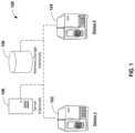
- FIG. 1schematically depicts one embodiment of a device network.
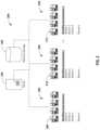
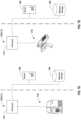
- FIG. 2schematically depicts one embodiment of a device network having a plurality of workflow environments.
- FIG. 6schematically depicts yet another embodiment of a device network having a plurality of workflow devices and a plurality of standby devices.
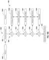
- FIGS. 7 A through 7 Fschematically depict various embodiments of one or more devices having a production system and/or a verification.
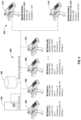
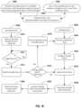
- FIG. 8 Ais a flow chart showing one embodiment of steps or features configured for managing a fleet of devices.
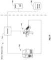
- FIG. 8 Bschematically depicts one embodiment of a device network configured for managing a fleet of devices.
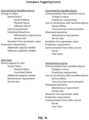
- FIG. 8 Dis a flow chart showing exemplary analytical techniques which might be utilized when managing a fleet of devices.
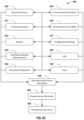
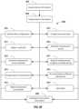
- FIG. 8 Eis a flow chart showing one embodiment of steps or features configured for comparing one or more aspects of device information to one or more parameter values.
- FIG. 8 Fis a flow chart showing exemplary device instructions which might be utilized when managing a fleet of devices.
- FIG. 9schematically depicts yet another embodiment of a device network configured for managing a fleet of devices.
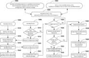
- FIGS. 10 A through 10 Fdepict flow charts showing various exemplary schema for managing a fleet of devices.
- FIGS. 11 A through 11 Cshows exemplary formula which may be utilized when optimizing for performance objectives.
- FIG. 12is a flow chart showing an exemplary embodiment of steps or features configured for addressing quality assurance matters.
- FIG. 13is a flow chart showing yet another embodiment of steps or features configured for managing a fleet of devices.
- FIG. 14shows an exemplary list of triggering events for introducing a standby device into a workflow environment.
- FIG. 15schematically depicts an exemplary sequence of steps or features for configuring a standby device for introducing a standby device into a workflow environment.
- FIG. 16schematically depicts a standby device having been introduced into a workflow environment, in place of a workflow device having been removed from the workflow environment.
- FIG. 17shows an exploded view of one embodiment of a graphical user interface of a standby device, indicating that the standby device is ready to be introduced into a workflow environment.
- FIG. 18is a flow chart showing one embodiment of steps or features configured for managing a fleet of devices, additionally embracing one embodiment of steps or features for configuring a standby device for a job in a workflow environment, and one embodiment of steps or features for performing a job in a workflow environment.
- FIG. 19is a flow chart showing another embodiment of steps or features configured for managing a fleet of devices, additionally embracing another embodiment of steps or features for configuring a standby device for a job in a workflow environment, and another embodiment of steps or features for performing a job in a workflow environment.
- the present disclosuredescribes systems and methods for deploying devices in a workflow environment and assigning jobs to those devices, for managing process parameters of devices, for introducing a standby device into a workflow environment, and for performing jobs in a workflow environment.
- jobsmay include any tasks assigned to a workflow device, or any functionality for which a workflow device is utilized, in a workflow environment.
- Numerous specific detailsare set forth in order to provide a thorough understanding of the present disclosure. It will be apparent, however, to one skilled in the art that the presently disclosed methods may be performed without some or all of these specific details. In other instances, well known aspects have not been described in detail in order not to unnecessarily obscure the present disclosure. The following detailed description is therefore not to be taken in a limiting sense, and it is intended that other embodiments are within the scope of the present disclosure.
- a device networkmay include one or more workflow devices 100 , 200 , 300 , 400 , 500 , 600 .
- the workflow devicesmay be deployed in a workflow environment, and jobs may be assigned to the workflow devices.
- a device networkmay additionally include one or more standby devices (e.g., FIGS. 3 - 6 , 302 , 402 , 502 , 602 ), residing on standby to one or more of the plurality of workflow devices.
- a standby devicemay be introduced into a workflow environment as or when needed, and jobs also may be assigned to the standby device.
- a workflow environmentmay include any environment where devices are used perform jobs in a workflow.
- devicessuch as printers and scanners, which may be used in environments such as warehouses, distribution centers, or manufacturing facilities, in workflows such as receiving, assembly, order fulfillment, and shipping.
- workflowssuch as receiving, assembly, order fulfillment, and shipping.
- Further exemplary devices and exemplary workflow environmentsare discussed below.
- Each workflow devicemay be assigned a job to perform in the workflow environment, and/or each workflow device may be assigned to a user or group of users who use the assigned workflow device to perform various jobs in the workflow environment.
- a device networkmay include a first device 102 , and a second device 104 .
- the first device 102may be a workflow device
- the second device 104may be a standby device or a workflow device.
- a device networkmay include a plurality of workflow environments.
- the exemplary device network shown in FIG. 2includes a first workflow environment 202 , a second workflow environment 204 , and an N-th workflow environment 206 .
- Each workflow environmentmay include one or more devices 208 , 210 , 212 , which may include one or more workflow devices and one or more standby devices.
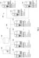
- an exemplary device networkmay include a plurality of workflow devices 300 and at least one standby device 302 . More particularly but without limitation, the exemplary device network of FIG. 3 includes a first workflow device 304 , a second workflow device 306 , an Nth workflow device 308 , and at least one standby device 302 . For purposes of clarity, in some embodiments a device network may alternatively include a single workflow device 102 and a single standby device 104 .
- a device networkmay also include a server 106 and memory storage 108 .
- the servermay be used for managing the fleet of devices in accordance with the present disclosure.
- a server 106may be used for acquiring device information, for analyzing device information, and/or for sending device instructions.
- the server 106may be used for managing communications between devices on a device network, for example, when managing performance objectives as discussed below.
- the server 106may be used, for example, for general networking purposes such as assigning IP addresses.
- the server 106may be omitted in accordance with the present disclosure, which offsets costs associated with network hardware, software, and/or technical/skilled support staff.
- memory storagemay be accessible via the device network (e.g., a database), and/or memory storage may be housed within one or more of the devices (e.g., a workflow device, a standby device) or directly connected to one or more of the devices (e.g., external flash memory).
- the device networke.g., a database
- the devicese.g., a workflow device, a standby device
- directly connected to one or more of the devicese.g., external flash memory
- a device networkmay include a very large number of workflow devices and a relatively small number of standby devices.
- an exemplary device networkincludes fifty (50) workflow devices 400 (workflow devices 4-49 omitted for clarity), and a relatively smaller plurality standby devices 402 .
- FIG. 5shows another exemplary device network which includes two hundred fifty (250) workflow devices 500 (workflow devices 4-249 omitted for clarity), and one or more standby devices 502 .
- the workflow devices 400 / 500 respectively shown in FIGS. 4 and 5include a first workflow device 404 / 504 , a second workflow device 406 / 506 , a third workflow device 408 / 508 , and a fourth workflow device 410 / 510 .
- the plurality of standby devices 402 shown in FIG. 4includes a first standby device 412 , a second standby device 414 , and a third standby device 416 .
- the first standby device 412which is shown as being available for workflow devices 1-50, is designated as the primary standby device.
- the primary standby devicewill be the first device selected from among the plurality of standby devices for introduction into the workflow environment.
- the primary standby devicemay be responsible for assigning, and may assign, other standby device from among the plurality of standby devices for introduction into the workflow environment.
- the one or more standby devices 502 shown in FIG. 5include a first standby device 512 , and a second standby device 514 .
- the first standby device 512which is shown as being available for workflow devices 1-100, is designated as the primary standby device for those workflow devices.
- the second standby device 514which is shown as being available for workflow devices 101-250, is designated as the primary standby device for those workflow devices.
- the present disclosuremay be implemented with a wide variety of different types and number of devices (workflow devices and/or standby devices), and the type and total number of devices may be increased or decreased to accommodate the particular implementation.
- the workflow devicesare printers, such as label printers.
- printersmay be deployed in a workflow environment such as a packaging and labeling facility or a distribution center, with each such printer having responsibility for an assigned type of printing job. This may include, for example, printing an assigned type of material, printing for a particular production line, or on-demand printing.
- the workflow devicesare handheld scanners, such as barcode scanners or RFID scanners. As an example, such scanners may be deployed to a group of users who use the scanners to perform various scanning jobs, such as shipping and receiving in a parcel facility or distribution center.
- a device networkmay include a combination of different types of devices.
- a plurality of workflow devices 600are provided, which includes a first scanner 604 and a second scanner 606 , and a first printer 608 and a second printer 610 .
- the device networkthere is provided on the device network at least one standby device that is configurable to perform the job assigned to such workflow device, and preferably, an optimally small number of standby devices.
- a plurality of standby devices 602includes a first standby device (e.g., a handheld scanner) 612 and a second standby device (e.g., a printer) 614 .
- the first standby device 612is configurable to perform the job assigned to the first workflow device 604 and the second workflow device 606
- the second standby device 614is configurable to perform the job assigned to the third workflow device 608 and the fourth workflow device 610 .
- exemplary device networks shown in FIGS. 1 - 6are not intended to be limiting. Rather, the present disclosure may be implemented with an unlimited variety of workflow devices in an unlimited variety of workflow environments, and further examples are provided below. As will be appreciated by those skilled in the art, often times, a fleet of devices may include different workflow devices (e.g., different features or functionalities) and/or multiple workflow devices with different configurations (e.g., different firmware, different software, different applications, and/or different settings).
- a device networkmay include identical devices, common devices (e.g., not identical, but sharing some common feature, functionality, or configuration), different devices (e.g., devices that typically would not be assigned to the same job because of some different feature, functionality, or configuration), or a combination of identical devices, common devices, and different devices.
- Such differencesmay arise for any number of reasons. For example, in some workflow environments there may be several different jobs, and a different workflow device or a different configuration may be required or preferred over others when performing a given job. Similarly, different users may require or prefer a different workflow device or a different configuration. Additionally, with respect to replacements and upgrades, it is common for only a subset of a fleet of devices to be replaced or upgraded, resulting in a fleet of devices with various differences. Likewise, when new devices are added to an existing fleet, it is common for the new devices to have differences over the preexisting devices. Accordingly, it can be expected that the number of differences among various devices in a fleet increase as the size of the fleet increases. Yet, it is an object of the present disclosure to provide an optimally small number of standby devices to accommodate workflow device failures and downtime for even a very large fleet of devices, and even when the fleet of devices includes several various different devices and/or different configurations.
- various devices on a device networkcommunicate with one another, for example, so that a standby device can be introduced into a workflow environment when needed.
- Any communication protocolmay be used, such as TCP/IP.
- a server 106such as a DHCP server, may provide IP addresses to the various devices on the device network.
- a device networkmay be configured as a LAN, a WAN, or any other network configuration.
- a device networkmay utilize wireless network or a Bluetooth technology.
- network management softwaremay be utilized.
- Each devicemay communicate with any other device, as desired by the skilled artisan.
- a standby devicecommunicates to at least one workflow device, and additionally or alternatively, a workflow device communicates to at least one standby device.
- a device networkmay include different devices, and devices on the network may communicate either only with other devices with some commonality (e.g., common feature, common functionalities, common models, common configuration), or devices on the network may communicate both to common devices and different devices. Accordingly, such communications may be broadcast, multicast, unicast, or any other desired routing scheme.
- some commonalitye.g., common feature, common functionalities, common models, common configuration
- devices on the networkmay communicate both to common devices and different devices. Accordingly, such communications may be broadcast, multicast, unicast, or any other desired routing scheme.
- the at least one standby device 302may communicate with each of the plurality of workflow devices 300 .
- each of the plurality of workflow devices 300may communicate with the at least one standby device 302 , and/or to one another.
- the first workflow device 304may communicate with a standby device 302 , and/or to the second workflow device 306 and the Nth workflow device 308 .
- workflow devices and standby devicesmay be configured to communicate only to other compatible devices.
- the first standby device 412shows as being available for workflow devices 1-50 (and is shown as being the primary standby device)
- the second standby device 414shows as being available for workflow devices 1-25
- the third standby device 416shows as being available for workflow devices 26-50.
- availabilitymay be based on configurability of the devices, prioritization of the standby devices allocation to workflow devices, or other criteria that may be selected by the skilled artisan.
- the first workflow device 404may be configured to communicate with the first standby device 412 (i.e., the primary standby device), but not the second standby device 414 or the third standby device 416 ; whereas the first standby device 412 may be configured to communicate with all of the workflow devices 400 , as being the primary standby device to all of them.
- the second workflow device 406may be configured to communicate with the second standby device 414 and to the third standby device 416
- the second standby device 414may be configured to communicate with the second workflow device 406 and to the third workflow device 408 .
- the fourth workflow device 410 and the third standby device 416may be configured to communicate with one another.
- a devicesends communications comprising status information to one or more other devices on the device network, for example, to allow the one or more other devices to ascertain the status of the device sending the communications.
- Status informationmay include an identity, a location, and a status for the device.
- a communication sent by a workflow devicemay include, for example, information that would allow other devices on the device network to ascertain that the workflow device is residing on the device network, the identity and location of the workflow device, a job and/or user assigned to the workflow device, whether or not the workflow device is functioning properly, and/or the compatibility requirements of the device.
- Communications sent by a standby devicemay include, for example, information that would allow other devices on the device network to ascertain that the standby device is residing on the network, the identity and location of the standby device, the status of the device, whether the device is available for replicating, and/or the compatibility of the standby device to be configured for various jobs and/or users in the workflow environment.
- some device networksmay include a very large number of workflow devices, such ten or more, fifty or more, one hundred or more, or even one thousand or more workflow devices.
- a device networkhas a very large number of workflow devices
- methods of managing a fleet of devices in accordance with the present disclosureallow for an optimally small number of standby devices.
- the present disclosureadvantageously reduces the cost of providing and maintaining standby devices for a workflow environment, for example, because fewer standby devices are necessary to accommodate the standby requirements of the workflow environment.
- the methods provided by the present disclosurecan be especially advantageous for high-volume workflow environments.
- the skilled artisancan select the optimal number of standby devices, for example, based on the number of workflow devices deployed in a workflow environment and the likelihood that any one or more of those devices may experience downtime.
- the optimal number of standby devicesthe skilled artisan may also consider maintenance requirements and service intervals for various devices, as well as the extent to which a given standby device would be configurable to perform the various jobs to which the workflow devices are assigned, or to accommodate requirements of the various users.
- Exemplary ratios for the number of workflow devices per compatible standby deviceinclude, without limitation from 1:1 to 1000:1 or greater, for example, 10:1, 20:1, 50:1, 100:1, 1000:1 or greater.
- Various embodiments of the present disclosureembrace systems and methods for managing performance objectives for a device or a fleet of devices, including systems and methods for managing output quality, productivity or uptime, and/or cost-efficiency.
- the systems and methods disclosed hereinembrace obtaining information directly or indirectly from one or more devices among a fleet, and utilizing such information manage a fleet of devices or individual devices from among the fleet.
- the fleet of devicesmay include multiple different workflow environments, or a subset of devices within a workflow environment.
- Information obtained from a device or fleet of devicesmay be used to manage that same device or fleet, and/or such information may be used to manage a different device or a different fleet of devices other than that from which the information was obtained.
- the information obtained from devices deployed in one workflow environmentmay be used to manage devices in that same workflow environment, and/or such information may be used to manage one or more different workflow environments.
- information obtained from one enterprisemay be utilized to manage devices or workflow environments within that enterprise, and/or such information may be used to manage one or more different enterprises.
- the systems and methods disclosed hereinutilize devices having a production system and/or a verification system.
- a production systemmay be configured to produce outputs
- a verification systemmay be configured to verify outputs.
- frequent verificationsmay be obtained, up to and including verifying every output.
- frequent verificationsmay be obtained for only a subset of outputs, including verifying every N-th output produced by a device as may be appropriate for the particular setting, such as every 2 nd output, every 3 rd output, every 4 th output, every 10 th output, every 100 th output, every 1,000 th output, or even further between verifications when appropriate.
- the skilled artisanmay select a frequency of verification by balancing the probability of a meaningful deviation from an output parameter (e.g., a statistically significant deviation, a deviation constituting a failed output, etc.) as between N-number of outputs against the cost of verifying outputs more frequently and the consequences in the event that such deviation between N-number of outputs goes undetected.
- an output parametere.g., a statistically significant deviation, a deviation constituting a failed output, etc.
- providing a production system integrated with or communicatively coupled with a verification systemmay make verifying every output a feasible option, particularly in settings where independent verification of every output would be impractical.
- exemplary devicesutilize a verification system (e.g., a verification system integrated with or communicatively coupled with a production system) to acquire device information including information pertaining to outputs and/or information pertaining to verifications, which device information may then be utilized in the systems and methods for managing fleets of devices disclosed herein, including, without limitation, systems and methods for managing performance objectives, systems and methods for managing maintenance and service requirements, systems and methods for managing the selection of devices device configurations, and/or systems and methods for deploying or introducing devices into workflow environments.
- a verification systeme.g., a verification system integrated with or communicatively coupled with a production system
- an exemplary devicemay be a single device having both a production system and a verification system.
- an exemplary device comprising a production systemmay be communicatively coupled to another exemplary device comprising a verification system.
- FIG. 7 Ashows a schematic depicting one embodiment of an exemplary device 700 having a production system integrated with a verification system.
- a production system 702produces outputs 704
- a verification system 706verifies the outputs 704 produced by the production system 702 , providing verified outputs 708 .
- a processor 710communicatively couples the production system 702 and the verification system 706 .
- the exemplary device 700may be in communication with a server 106 (for example to manage communications between the exemplary device 700 and other devices on a device network), and memory storage 108 may be provided (for example to store device information).
- a first device 700includes a production system 702
- a second device 712includes a verification system 706
- the production system 702 and the verification system 706are communicatively coupled.
- the production system 702produces outputs 704
- the verification system 706verifies the outputs 704 produced by the production system 702 , providing verified outputs 708 .
- the first device 700 and the second device 712are communicatively coupled, for example, by a first processor 710 and a second processor 714 . Both the first device 700 and the second device 712 may be in communication with the server 106 (for example to manage communications between the exemplary device 700 and other devices on a device network), and memory storage 108 may be provided (for example store device information).
- FIGS. 7 C through 7 Fshow exemplary embodiments of devices having a printing assembly and/or a scanner/verifier assembly which may be utilized in accordance with the present disclosure. It is to be understood, however, that other exemplary devices are disclosed herein which also may be utilized in various embodiments, and the skilled artisan will appreciate that even further, additional devices are within the spirit and scope of the present disclosure.
- an exemplary device 700may include a production system 702 (e.g., a printing assembly) and a verification system 706 (e.g., a scanner/verifier assembly) integrated into a single device, such as a printer having an inline scanner/verifier or an “all-in-one” printer/scanner device (e.g. FIG. 7 A, 7 C ).
- a production system 702e.g., a printing assembly
- a verification system 706e.g., a scanner/verifier assembly
- a first device 700may include a printing assembly
- a second device 712may include a scanner/verifier assembly (e.g., FIGS.
- the separate devicesmay be communicatively coupled, providing a production system 702 (e.g., a printing assembly) integrated with and a verification system 706 (e.g., a scanner/verifier assembly).
- a production system 702may include a printing assembly.
- the production system 702provides outputs 704 .
- the outputsmay include printed media and/or indicia having been printed on such printed media.
- a verification system 706may include a scanner/verifier assembly, and the verified outputs may include printed media and/or indicia having been verified by the scanner/verifier assembly; and/or scanned images, glyphs, indicia, or other material having been printed on such verified printed media.
- the production systemmay include a scanner/verifier assembly
- the outputs and/or verified outputsmay include printed media and/or indicia having been verified by the scanner/verifier assembly; and/or scanned images, glyphs, indicia, or other items having been printed on such verified printed media.
- an outputmay include any product or result produced by or obtained from a device or production system
- a verification systemmay include any system or device configured to measure or verify a characteristic or feature of such output, producing verified outputs.
- Verified outputsmay include any product or result produced by or obtained from a device or production system that has been verified by a verification system.
- an exemplary system or device 700is provided, which in some embodiments includes a production system integrated with a verification system.
- the system or device 700includes integrated within a single device, both a production system 716 , which in an exemplary embodiment includes a printing assembly, and a verification system 718 , which in an exemplary embodiment includes an in-line scanner/verifier assembly.
- the production system 716 and the verification system 718 shown in FIG. 7 Cmay be provided as separate devices.
- FIG. 7 Calso encompasses embodiments in which a printing assembly and a scanner/verifier assembly are provided as stand-alone or separate devices, such as respectively shown in FIG.
- FIG. 7 Dprinting assembly/production system 716
- FIG. 7 Escanner/verifier assembly/verification system 718
- a production system 716 and a verification system 718may be provided as stand-alone or separate devices, yet communicatively coupled with one another, for example providing a printing assembly/production system 716 integrated with a scanner/verifier assembly/verification system 718 .
- an exemplary system or device 700may comprise a thermal transfer printer.
- any other printing or marking devicesmay be utilized in accordance with the present disclosure, and further examples are provided herein.
- Printing assembliessuch as the exemplary thermal transfer printer shown in FIG. 7 C are well known in the art, and thus will be discussed only in brief detail.
- a drive assembly 724includes a stepper motor 726 and a platen roller 728 .
- the stepper motor 726advances the platen roller 728 in discrete increments, which, in turn, advances printable medium 730 between the platen roller 728 and one or more print heads 732 in a printing direction shown by an arrow 734 .
- the position of the printable medium 730may be tracked with a processor 710 associated with a counter which maintains a count of the steps taken by the stepper motor 726 .
- a tachometer or other conventional devicemay be used to track the position of the printable medium either directly, or indirectly.
- the one or more print heads 732are activated by a print driver 736 .
- the print driver 736is driven by print commands which are generated by print logic.
- the print commandscomprise retrieved print data in combination with a system clock signal or strobe signal under control of the printer processor 700 to ensure proper timing and spacing of successive sequential parts of the images, glyphs, indicia, or other items to be printed or marked by the one or more print heads 732 .
- the one or more print heads 732have an array of print elements 738 , and are operable for printing or marking a plurality of sequential parts of such images, glyphs, indicia, or other items onto a corresponding plurality of sequential segments of the printable medium 730 , producing printed media 740 .
- the print driver 736uses the print commands generated by the print logic to provide energizing signals to the array of print elements 730 of the print head 732 .
- the energizing signalsactivate the print elements 730 , which when activated are effective to place a mark on the respective sequential segment of the printable medium 730 .
- the thermal transfer printer of the embodiment shown in FIG. 7 Cwhen an individual print element 738 is energized, heat is generated, and such heat is transferred to an adjacent region of thermally sensitive print ribbon 742 .
- the print ribbon 742contains ink, which when melted by heat transferred from one or more printer elements 738 releases from the print ribbon 742 and transfers to the printable medium 730 , thereby applying a mark on the respective sequential segment of the printable medium 730 .
- a thermally sensitive printing mediummay be used, as is conventional for thermal printers.
- the printable medium 730may comprise a web of thermally sensitive material such as heat-sensitive paper or plastic.
- the print head 732 shown in FIG. 7 Cis a thermal print head, other print heads may be used, such as in laser printers, ink drop printers, dot-peen printers, and further examples as disclosed herein. The operation of print heads is conventional and well-known and, for the sake of brevity and clarity, will not be described in further detail.
- printed media 740advances past a scanner/verifier assembly 718 , which comprises an image head or scanner 744 .
- the image head 744is configured to capture information about the images, glyphs, indicia, or other items or sequential parts thereof produced by the printing or marking assembly 716 .
- the image head 744optically images, digitizes, or samples at least a portion of such images, glyphs, indicia, or other items printed by the print head 732 .
- the scanner/verifier assembly 718takes advantage of the motion of the printed media 740 past the image head 744 to successively capture each portion of printed images, glyphs, indicia, or other items as the printed images, glyphs, indicia, or other items advances past the image head.
- the image head 744contains an array of photosensitive elements, such as in a charged coupled device (“CCD”) having, for example, linear active surface pixel elements.
- CCDcharged coupled device
- several imaging samplesmay be taken as the printed media 740 advances past the image head 744 .
- Several imaging samples of printed media and/or indiciamay be aggregate to provide a digitized representation or image of an entire printed media and/or indicia.
- the digitized image and/or imaging samplesmay be stored in memory storage 108 for further processing or analysis in accordance with the present disclosure.
- Other known image headsmay also be used, including vidicons, two-dimensional semiconductor arrays, and two-dimensional CCD arrays. Operation of such a CCD image head is described in further detail in U.S. Pat. No. 6,042,279, the entirety of which is hereby incorporated by reference into the present disclosure.
- the printing assembly 716may include a recorder 748 , operable for recording the rate sensed at which the drive assembly 724 imparts motive force to the printable medium 730 .
- the scanner/verifier assembly 718may include a controller 750 , operable for setting a rate at which the image head 744 evaluates (optically images, digitizes, or samples) the printed media and/or indicia or sequential parts thereof.
- a data linkmay be provided, operable for communicatively coupling the printing assembly 716 and the scanner/verifier assembly 718 .
- the printing assembly 716may provide the scanner/verifier assembly with data from the recorder 748 (e.g., data relating to the rate sensed at which the drive assembly imparts motive force to the printable medium), and the scanner/verifier assembly 718 may carry out operations responsive to receiving data from the printing assembly (e.g., setting a rate at which the image head evaluates the printed media and/or indicia or sequential parts thereof).
- data from the recorder 748e.g., data relating to the rate sensed at which the drive assembly imparts motive force to the printable medium
- the scanner/verifier assembly 718may carry out operations responsive to receiving data from the printing assembly (e.g., setting a rate at which the image head evaluates the printed media and/or indicia or sequential parts thereof).
- a production system 702may include an instrument, and a verification system 706 may include a calibration device for calibrating the instrument; the outputs 704 may be instrument readings, and the verified outputs 708 may be verified instrument readings.
- exemplary instrumentsinclude electronic scales and flow meters.
- a production system 702may include a dimensioner (e.g., a weighing and volume measuring system for measuring three-dimensional objects such as packages, parcels, pallets, cartons, and boxes), and a verification system 706 may include a scale or a calibration device for calibrating the dimensioner; the outputs 704 may be measurements obtained from the dimensioner, and the verified outputs 708 may be verified measurements.
- a dimensionere.g., a weighing and volume measuring system for measuring three-dimensional objects such as packages, parcels, pallets, cartons, and boxes
- a verification system 706may include a scale or a calibration device for calibrating the dimensioner; the outputs 704 may be measurements obtained from the dimensioner, and the verified outputs 708 may be verified measurements.
- Such other production systems and/or verification systemsmay include any device or combination of devices that may be within the contemplation of the skilled artisan, many of which other devices are disclosed herein, and all of which are within the spirit and scope of the present disclosure.
- various embodiments of the systems and methods for managing a fleet of devices 800may include any one or more steps or features configured for: acquiring device information 802 , analyzing device information 804 , and sending device instructions based on device information 806 .
- Device networksmay be configured to provide a plurality of devices, any one or more of which may be utilized in systems and methods disclosed herein.
- FIG. 8 Bshows an exemplary device network (e.g., the exemplary device network of FIG. 2 ), which may include features configured for receiving device information 802 , analyzing device information 804 , and sending device instructions 806 .
- Device informationmay be acquired from any one or more devices, and optionally stored in memory storage 108 (e.g., FIGS. 1 - 9 ). Such device information may be subjected to analysis using any one or more analytical techniques, and device information may be sent to one or more devices or other locations on a device network based, at least in part, on such device information.
- An exemplary device networkmay include one or more workflow environments, such as a first workflow environment 202 , a second workflow environment 204 , and an N-th workflow environment 206 .
- Each such workflow environmentmay include one or more devices, such as a first plurality of devices 208 , a second plurality of devices 210 , and a third plurality of devices 212 .
- a device networkmay be configured to acquire device information 802 from any one or more of such devices.
- exemplary systems and methodsmay be configured for acquiring device information 802 including any one or more of: information pertaining to an individual device 808 ; information pertaining to a workflow environment 810 , which may include information pertaining to one or more individual devices 808 ; and/or information pertaining to a device enterprise 812 , which may include information pertaining to one or more workflow environments 810 and/or information pertaining to one or more individual devices 808 .
- a server 106may be provided, for example, to manage communications between devices on the device network.
- Memory storage 108may be provided, for example, to store device information.
- Device informationmay be analyzed with respect to an individual device, a workflow environment (which may include aggregated information from multiple devices), or a whole enterprise (which may include aggregated information from multiple workflow environments and/or from multiple devices).
- exemplary systems and methodsmay be configured for analyzing device information 804 including any one or more of: analyzing information pertaining to an individual device 814 ; analyzing information pertaining to a workflow environment 816 , which may include analyzing information pertaining to one or more individual devices 814 ; and/or analyzing information pertaining to a device enterprise 818 , which may include analyzing information pertaining to one or more workflow environments and/or analyzing information pertaining to one or more individual devices 814 .
- Device instructionsmay be sent to one or more locations on a device network, including one or more devices or other locations such as a server 106 or memory storage 108 .
- exemplary systems and methodsmay be configured for sending device instructions 806 , which may include any one or more of: sending instructions pertaining to an individual device 820 ; sending instructions pertaining to a workflow environment 822 , which may include sending instructions pertaining to one or more individual devices 820 ; and/or sending instructions pertaining to a device enterprise 824 , which may include sending instructions pertaining to one or more workflow environments 822 and/or sending instructions pertaining to one or more individual devices 820 .
- Device informationmay be acquired directly from any one or more devices, or indirectly from other locations on a device network such as a server 106 or memory storage 108 . Any such device information or combinations thereof may be utilized in accordance with the present disclosure.
- a flow chartis shown, depicting exemplary types of device information which might be acquired 802 in various embodiments.
- exemplary systems and methodsmay be configured for acquiring device information pertaining to any one or more of: identities or locations of devices 830 , process parameters 831 , outputs of devices 832 , verifications/quality measurements 833 , performance objectives (e.g., quality, productivity, cost) 834 , environmental parameters 835 , components and/or consumables utilized by devices 836 , device configurations or settings 837 , jobs assigned to devices 838 , and users assigned to devices 839 .
- Aspects of such device informationmay be relationally associated to one another, for example in a database housed in memory storage 108 .
- Information pertaining to components and/or consumablesmay include, for example, information about print heads, drums, rollers, toner, ink, printing ribbon, printable medium, and any other replaceable parts or consumable items. Such information may include a consumption rate, a count or estimate of a supply/level/useful life remaining, an alarm for low-supply/low-level/low-useful-life alarms, a maintenance or service requirement with respect to a component and/or consumable, and the like.
- device informationmay include information about printed media produced by the printing assembly, such as information about printed media and/or indicia having been printed thereon.
- device informationmay include information about scans having been obtained by the scanner/verifier assembly, such as information about printed media and/or indicia having been printed by a printing assembly.
- Information about scansmay include a digital image of printed media and/or indicia obtained by the scanner/verifier assembly.
- a device for purposes of the present disclosuremay include any device or combination of devices that may be within the contemplation of the skilled artisan, many of which are disclosed herein, and all of which are within the spirit and scope of the present disclosure.
- a deviceincludes a thermal transfer printer, and device information includes information about a printing ribbon supply and/or information about a printable medium supply, such as low supply, or similar information about other consumables or components.
- a deviceincludes a laser toner printer, and device information includes information about a toner supply and/or information about a printable medium supply, such as low supply, or similar information about other consumables or components.
- a deviceincludes an ink drop printer, and device information includes information about an ink supply and/or information about a printable medium supply, such as low supply, or similar information about other consumables or components.
- a deviceincludes a point-of-sale device (e.g., a cash register, a payment console, etc.), and device information includes information about an ink supply and/or information about a printable medium supply, such as low supply, or similar information about other consumables or components.
- a printersequentially produces a plurality of indicia or other items and a scanner obtains a digital image of each and every indicia or other item from among the plurality.
- a scannermay obtain a digital image of a subset of the indicia or other items from among the plurality.
- a scannermay obtain a digital image of every N-th indicia or other item produced by the printer, such as every 2 nd indicia or other item, every 3 rd indicia or other item, every 4 th indicia or other item, every 10 th indicia or other item, every 100 th indicia or other item.
- a triggering event as discussed belowmay be based at least in part on an aspect of device information.
- acquiring device informationmay include generating further device information 840 .
- Such further device informationmay include outputs from data management activities, such as: extracting a subset of data from device information, e.g., for further processing or storage; cleaning device information, e.g., to remove corrupt or inaccurate data; annotating device information, e.g., with comments, explanations, or to provide context; integrating device information, e.g., to combine device information from multiple sources such as combining device information from multiple devices, multiple workflow environments, multiple device networks, multiple enterprises, and/or combining device information with different data such as data from business intelligence systems, enterprise resource management systems, and the like; and/or providing data visualizations or other data representations, for example to present data in a readable, aesthetically pleasing, or otherwise user-friendly format.
- any such device informationmay be relationally associated with other device information, for example, for further processing in accordance with the present disclosure.
- exemplary systems and methodsmay be configured for analyzing device information (i.e., any one or more aspects thereof) utilizing any one or more of the following analytical techniques: association rule learning 850 , classification tree analysis 851 , genetic algorithms 852 , machine learning 853 , regression analysis 854 , identification of outliers/unusual data segments 855 , data interpretation 856 , data modeling 857 , predictive analytics 858 , and preventative strategies 859 .
- analyzing device informationmay include generating further device information 860 , for example, information resulting from or based on any of the foregoing analytical techniques having been performed on device information and/or data from other sources.
- one or more aspects of device informationmay be compared to one or more parameter values.
- FIG. 8 Ea flow chart is shown, depicting an exemplary comparison of one or more aspects of device information to one or more parameter values.
- a first aspect of device information 870is compared to a first parameter value 872 .
- a first instruction 874is sent, based on the deviation from the first parameter value having been detected.
- the first instructionmay be sent to at least one location on the device network.
- a second aspect of device information 870can be compared to a second parameter value 876 .
- a second instructionis sent, based on the deviation from the second parameter value.
- the second instructioncan be sent to at least one location on the device network.
- the first aspect of device information 870may be compared to the second parameter value 876 . Comparison of the first aspect of device information 870 to the second parameter value 876 may occur separately from comparison of the first aspect of device information to the first parameter value 872 , and/or following comparison of the first aspect of device information to the first parameter value.
- the first aspect of device informationmay be compared to the second parameter value 876 when a deviation from the first parameter value has not been detected 880 .
- the first aspect of device informationmay be compared to the second parameter value 876 when a deviation from the first parameter value has been detected 880 , such as to ascertain whether a deviation from both the first parameter value and the second parameter value.
- the first parameter value 872 and/or the second parameter value 876may each include a value corresponding to one or more of: a process parameter, an output, a measurement or verification of an output, a performance objective, an environmental parameter, a component or consumable, a setting, a job, or a user, or combinations these. Additionally, or in the alternative, a parameter value may correspond to an output from any one or more analytical techniques.
- device informationcomprising information about indicia having been produced by a printing assembly and/or information about scans having been obtained by a scanner/verifier assembly.
- the information about scansmay include a digital image of printed media and/or indicia obtained by the scanner/verifier assembly.
- One or more aspects of such device informationare compared to one or more parameter values, which may include parameter values based on verifications and/or quality measurements for printed media and/or indicia, and/or performance objectives for producing printed media and/or indicia.
- such parametersmay pertain to physical characteristics of printed media and/or indicia or corresponding quality metrics (such as observed from analyzing a digital image of such printed media and/or indicia).
- the quality metricmay be based on standards, including ANSI/ISO standards pertaining to printed media and/or indicia.
- standardsmay include one or more of: an ANSI/ISO standard grading structure (e.g., ISO/IEC 15415, 15416, 30116, or 29158), AIM (Association for Automatic Identification and Mobility) Direct Part Mark (DPM) Quality Guideline DPM-1-2006, USPS Merlin standards, and/or customized or user-defined standards.
- the device informationmay include one or more values (e.g., measured or calculated values) attributable to one or more of such physical characteristics or corresponding quality measurements for printed media and/or indicia, and the one or more parameter values may include process control parameter values, such as specification targets, control limits, and the like, for such physical characteristics or corresponding quality measurements.
- valuese.g., measured or calculated values
- process control parameter valuessuch as specification targets, control limits, and the like
- the physical characteristics of printed media and/or indicia which may be evaluatedinclude print growth, print shrinkage, ink spread, edge determination, minimum reflectance, symbol contrast, minimum edge contrast, modulation, printing defects, quiet zone, and decodability. These characteristics are well known in the art, and are described in the ANSI/ISO guidelines.
- the physical characteristics of printed media and/or indicia which may be evaluatedinclude decodability, cell contrast, cell modulation, fixed pattern damage, unused error correction, axial non-uniformity, minimum reflectance, and grade non-uniformity. These characteristics are well known in the art, and are described in the DPM Quality Guideline.
- the physical characteristics of printed media and/or indicia which may be evaluatedinclude OCR quality parameters, including character inside fit, character outside fit, character, position, background noise, and character evaluation value (CEV) grade.
- OCR quality parametersincluding character inside fit, character outside fit, character, position, background noise, and character evaluation value (CEV) grade.
- device informationmay include one or more values (e.g., measured or calculated values) attributable to the scan parameter or grade for the printed media (e.g., as determined by an ANSI/ISO standard or other grading structure), and the one or more parameter values may include process control parameter values, such as specification targets, control limits, and the like for such scan parameter or grade.
- device informationmay include one or more values (e.g., measured or calculated values) attributable to the scan parameter or overall symbol grade for indicia (e.g., as determined by an ANSI/ISO standard or other grading structure), and the one or more parameter values may include process control parameter values, such as specification targets, control limits, and the like for such scan parameter or symbol grade.
- device informationmay include information about performance objectives for producing outputs, such as a quality value, a productivity value, and/or a cost value
- the one or more parameter valuesmay include process control parameter values, such as specification targets, control limits, and the like for such performance objectives.
- device informationmay include status information for one or more devices, such as whether the device or various systems or components thereof are showing as operational, or whether the device or any such systems or components has presented an error message, or has experienced a failure, or a loss of connectivity in respect of another workflow device, a standby device, or another device or resource on a device network.
- Analyzing device informationmay include ascertaining any one or more aspects of such status information. For example, a parameter value may be configured to correspond to one or more aspects of status information, and a deviation from the parameter value would exist when the device status does not correspond to the parameter value.
- analyzing device informationmay include ascertaining the occurrence of a triggering event.
- triggering eventsare discussed in more detail below.
- a triggering eventis a device failure.
- a triggering eventmay give rise to a deviation from a parameter value.
- a parameter valuemay be configured to the absence of a triggering event, and a deviation from the parameter value would exist upon the occurrence of a triggering event.
- a deviation from a parameter valuemay give rise to a triggering event.
- any one or more device instructionsmay be sent to any one or more locations on a device network. Such instructions may be sent to a location associated with a device, such as a processor or memory storage. For example, device instructions may be sent to a processor 710 / 714 , a server 106 , and/or memory storage 108 . In an exemplary embodiment, device instructions may be sent in response to a deviation from a parameter value having been detected.
- exemplary systems and methodsmay be configured for sending device instructions 806 (and/or for receiving device instructions), including instructions directed towards any one or more of the following operations: developing a fleet configuration 870 , assigning a useful life for one or more devices 871 , generating a maintenance or service schedule for one or more devices 872 , assigning one or more jobs to one or more devices and/or one or more users 873 , selecting components/consumables 874 , changing one or more input parameters 875 , scheduling maintenance or service for one or more devices 876 , requesting a standby device 877 , re-routing job(s) or otherwise assigning job(s) to different devices and/or users 878 , and stopping jobs 879 .
- sending device instructionsmay include generating further device information 880 , for example, device information pertaining to device instructions having been sent to one or more devices.
- device instructionsmay be directed towards developing a fleet configuration 870 .
- Such fleet configurationmay include a selection of devices to be introduced into a workflow environment, for example to perform one or more jobs and/or for use by one or more users.
- the fleet configurationmay be provided for an enterprise, a workflow environment, and/or for one or more jobs or one or more users or groups of users, such as a subset of jobs or users within an enterprise or a workflow environment.
- device instructionsmay be directed towards assigning a useful life for one or more devices 871 , and/or a maintenance or service schedule for one or more devices 872 .
- a useful lifemay be assigned and/or a maintenance schedule may be generated based on an analysis of device information pertaining to the performance of one or more devices.
- device informationmay include information about utilization or uptime or expected utilization or uptime of one or more devices, information about maintenance requirements, schedules, or expected schedules, information about failure rates or expected failure rates, and/or information about device performance or expected performance relative to performance objectives.
- device instructionsmay be directed towards assigning one or more jobs to one or more devices and/or one or more users 873 .
- jobsmay be assigned to devices or users based on information about the availability, utilization, capabilities, and/or performance of one or more devices with respect to which jobs might be assigned.
- Such assignmentsmay include nascent assignments and/or changes to assignments for jobs having been assigned.
- device instructionsmay be directed towards selecting components and/or consumables 874 .
- components and/or consumablesmay be selected based on information about the availability, utilization, capabilities, and/or performance of such components and/or consumables, and/or of one or more devices when utilizing such components and/or consumables.
- Such device instructionsmay include, for example, initiating orders or order schedules, or changing orders or order schedules; and/or selecting or changing components or consumables for use with one or more devices.
- components and/or consumablesincludes print heads, drums, rollers, toner, ink, printing ribbon, printable medium, and any other replaceable parts or consumable items.
- device instructionsmay be directed towards changing one or more input parameters 875 .
- input parametersmay include, for example, set points, manipulated variables, tuning algorithms, controller logic, and other process control parameters.
- Device instructions for changing input parametersmay be directed towards one or more devices. For example, input parameters may be changed to adjust the operation or performance of an individual device, or to adjust the operation of a plurality of devices simultaneously. In addition, or in the alternative, input parameters may be changed to adjust an interaction as between two or more devices.
- device instructionsmay be directed towards scheduling maintenance or service for one or more devices 876 , requesting a standby device and/or configuring a standby device 877 , re-routing job(s) or otherwise assigning job(s) to different devices and/or users 878 , and/or stopping jobs 789 .
- Scheduling maintenance or servicemay include scheduling based on ascertaining that a device presently requires maintenance or service, or predicting that a device may require maintenance or service at some time. Stopping jobs may include stopping jobs in progress, and/or stopping jobs in queue.
- a standby devicemay be requested to be introduced into a workflow environment, for example, to provide additional capacity to meet output requirements, and/or to replace a workflow device.
- a standby devicemay take the place of a workflow device, for example, in response to detecting a deviation from a parameter value with respect to the workflow device, and/or in response to a triggering event as discussed in more detail below.
- a standby devicemay be configured as discussed in more detail below.
- device instructionsmay be directed towards forward-looking activities, such as may be associated with deploying a new fleet of devices having a configuration tailored to given performance objectives.
- device instructionsmay be directed towards backwards-looking activities, such as may be associated with making changes to a fleet of devices based on past performance of other devices in order to better meet given performance objectives.
- device instructionsmay be directed towards real-time management of a fleet of devices, such as may be associated with managing performance objectives. At least the types of device instructions disclosed herein may be directed towards any such forward-looking, backwards-looking, or real-time management of performance objectives. Further types of device information will be apparent to those skilled in the art.
- Performance objectives for a device or a fleet of devicesmay be managed utilizing one or more aspects of the systems and methods disclosed herein, including any one or more steps or features configured for: acquiring device information 802 , analyzing device information 804 , and sending device instructions based on device information 806 .
- the exemplary device network 900may include one or more workflow environments, such as a first workflow environment 902 and a second workflow environment 904 .
- the first workflow environmentincludes one or more devices, such as a first device within the first workflow environment 906 , a second device within the first workflow environment 908 , and an N-th device within the first workflow environment 910 .
- the second workflow environmentalso includes one or more devices, such as a first device within the second workflow environment 906 , a second device within the second workflow environment 908 , and an N-th device within the second workflow environment 910 .
- a server 106 and memory storage 108also are provided.
- the server 106may be used to manage communications between devices on the device network.
- Memory storage 108may be used to store device information.
- Device information 802may be obtained from the first workflow environment and/or from the second workflow environment. Such device information may pertain to a workflow environment as a whole (e.g., as to all of the devices in the workflow environment, including workflow devices, and optionally including standby devices), or such device information may pertain to a subset of devices in the workflow environment (e.g., one or more workflow devices and/or one or more standby devices).
- some or all of such device informationmay be stored in memory storage 108 .
- Some or all of the device information received and/or stored in memory storagemay be analyzed 804 in accordance with the present disclosure.
- Device instructions 806may be sent to the first workflow environment and/or to the second workflow environment.
- Such device instructionsmay pertain to a workflow environment as a whole (e.g., as to all of the devices in the workflow environment, including workflow devices, and optionally including standby devices), or such device instructions may pertain to a subset of devices in the workflow environment (e.g., one or more workflow devices and/or one or more standby devices).
- device information 802may be obtained from one or more devices within the first workflow environment (e.g., the first device within the first workflow environment 906 ), and device instructions 806 may pertain to one or more devices within the first workflow environment (e.g., the first device within the first workflow environment 906 ).
- device information 802may be obtained from one or more devices within the first workflow environment (e.g., the first device within the first workflow environment 906 ), and device instructions 806 may pertain to one or more devices within the second workflow environment (e.g., the first device within the first workflow environment 906 ).
- device information 802may be obtained from a first device within the first workflow environment 906 , and device instructions 806 may pertain to the first device within the first workflow environment 906 .
- device information 802may be obtained from a first device within the first workflow environment 906 , and device instructions 806 may pertain to a second device within the first workflow environment 906 .
- device information 802may be obtained from a first device within the first workflow environment 906 , and device instructions 806 may pertain to a first device within the second workflow environment 910 .
- FIGS. 10 A through 10 Fshow various exemplary schema for managing one or more devices, utilizing exemplary combinations of various features or steps configured for acquiring device information 802 , analyzing device information 804 , and sending device instructions 806 .
- device information 802may be acquired from any one or more devices, which may include a first device 1002 and an N-th device 1004 .
- the device informationmay include, for example, one or more of the exemplary types of device information shown in FIG.
- One or more aspects of device information 802are subject to analysis using any one or more analytical techniques 804 .
- Such analytical techniquesmay include, for example, one or more of the analytical techniques shown in FIGS. 8 D and/or 8 E .
- FIG. 10 Aone or more aspects of device information are compared to one or more parameters.
- one or more instructionsare sent.
- the one or more instructionsmay be sent to at least one location on the device network.
- the one or more instructionsmay be sent to one or more locations associated with one or more devices, such as to a location associated with the first device 1002 and/or to a location associated with the N-th device 1004 .
- the one or more instructionsmay include, for example, one or more of the exemplary device instructions shown in FIG. 8 F .
- device informationis acquired 802 from one or more devices.
- the one or more devicesmay include a first device 1002 and/or one or more additional devices 1004 (e.g., a second device).
- the first device 1002 and the one or more additional devices 1004(e.g., the second device) may be located within the same workflow environment and enterprise, or the first device may be located in a separate workflow environment and/or a separate enterprise from the one or more additional devices. Further, the one or more additional devices may be located among one or more workflow environments and/or enterprises.
- the device informationmay correspond, for example, to one or more jobs having been performed or partially performed by the one or more devices.
- One or more aspects of the device informationare compared to one or more parameter values, and responsive to detecting one or more deviations from such one or more parameter values, one or more instructions are set to one or more locations on a device network.
- an aspect of device informationmay be compared to a parameter value (e.g., a first parameter value 1006 , a second parameter value 1008 , a third parameter value 1010 , a fourth parameter value 1012 , a fifth parameter value 1014 , and/or an N-th parameter value (not shown)).
- one or more instructionsmay be sent to one or more locations on the device network (e.g., a first instruction 1016 , a second instruction 1018 , a third instruction 1020 , a fourth instruction 1022 , a fifth instruction 1024 , and/or an N-th instruction (not shown)).
- the one or more instructionsmay trigger one or more actions, which may be responsive to address such deviation.
- the one or more actionsmay correspond to carrying out any device instruction, such as the exemplary device instructions shown in FIG. 8 F .
- the one or more instructions and corresponding one or more actionsinclude: stopping a job or jobs 1016 , requesting a standby device 1018 , re-routing a job or jobs, or otherwise assigning a job or jobs to a different device or user 1020 , scheduling maintenance 1022 , and/or changing an input parameter, such as a process parameter 1024 .
- the location on the device network to which such instructions are sentmay be, for example, a location associated with the first device 1102 and/or the N-th device 1104 .
- further device informationmay be generated 840 , for example, pertaining to any one or more of the steps of acquiring device information 802 , analyzing device information 804 , and sending device instructions 806 .
- device information associated with a first device 1002is acquired 802 .
- the device informationis analyzed 804 , with one or more aspects of the device information being compared to one or more parameter values (e.g., 1026 and/or 1028 in FIG. 10 B ; and/or 1032 and/or 1040 in FIG. 10 C ), and responsive to a detecting deviation from a parameter value, one or more instructions are respectively sent (e.g., 1027 , 1029 , and/or 1030 in FIG. 10 B ; and/or 1033 , 1042 , 1044 , 1046 , and/or 1048 in FIG. 10 C ) to a location on the device network associated with the first device 1002 , triggering action responsive to address the respective deviation.
- one or more instructionsare respectively sent (e.g., 1027 , 1029 , and/or 1030 in FIG. 10 B ; and/or 1033 , 1042 , 1044 , 1046 , and/or 1048 in FIG. 10 C )
- a first aspect of the device information 802is compared to a first parameter value 1026 , and responsive to detecting a deviation from the first parameter value, a first instruction 1027 is sent to at least one location on the device network, triggering a first action responsive to address such deviation.
- the first actionmay comprise scheduling maintenance for the first device.
- the first aspect of the device information 802is compared to a second parameter value 1028 , and responsive to detecting a deviation from the second parameter value, a second instruction 1029 and/or 1030 is sent to at least one location on the device network, and/or a third instruction 1029 or 1030 are sent to at least one location on the device network, triggering a second action, and optionally, a third action responsive to address such deviation.
- a second aspect of the device informationmay be compared to the first parameter value 1032 and/or the second parameter value 1028 , similarly triggering instructions and corresponding actions responsive to detecting deviations from parameter values. In some embodiments, as shown in FIG.
- the second actionmay comprise stopping one or more jobs assigned to the first device, and the third action may comprise re-routing one or more jobs from the first device, or otherwise assigning such jobs to a different device or user.
- the second actionmay comprise both stopping jobs and re-routing.
- a first aspect of the device information 802is compared to a first parameter value 1032 , and responsive to detecting a deviation from the first parameter value, a first instruction 1033 is sent to at least one location on the device network, triggering a first action responsive to address such deviation.
- the first actionmay comprise changing an input parameter for the first device.
- the first aspect of the device information 802is compared to a second parameter value 1034 , and responsive to detecting a deviation from the second parameter value, one or more instructions 1035 , 1036 , 1037 , and/or 1038 are sent to at least one location on the device network, triggering one or more actions responsive to address such deviation.
- a second aspect of the device informationmay be compared to the first parameter value 1032 and/or the second parameter value 1034 , similarly triggering one or more instructions and one or more corresponding actions responsive to detecting deviations from parameter values. In some embodiments, as shown in FIG.
- the one or more actionsmay comprise: stopping one or more jobs assigned to the first device, requesting a standby device (e.g., to be introduced into the workflow environment in place of the first device), re-routing one or more jobs from the first device, or otherwise assigning such jobs to a different device or user, and/or scheduling maintenance for the first device.
- a standby devicee.g., to be introduced into the workflow environment in place of the first device
- one or more aspects of device information 802 associated with a first device 1002are compared to one or more parameter values 1040 , 1041 , 1042 , 1043 , and/or 1044 , and responsive to detecting a deviation from one or more of the parameter values, one or more instructions instruction 1045 , 1046 , 1047 , 1048 , and/or 1049 are sent to at least one location on the device network, triggering one or more actions with respect to one or more additional devices 1004 (e.g., a second device).
- one or more aspects of the device information 802 associated with the one or more additional devices 1004e.g.
- the second deviceare compared to one or more parameter values 1050 , 1051 , 1052 , 1053 , and/or 1054 , and responsive to detecting a deviation from one or more of the parameter values, one or more instructions instruction 1055 , 1056 , 1057 , 1058 , and/or 1059 are sent to at least one location on the device network, triggering one or more actions with respect to the first device 1002 .
- device informationis acquired 802 , and the device information may be associated with a first device 1002 and/or one or more additional devices 1004 (e.g., a second device).
- the device informationis analyzed 804 , with one or more aspects of the device information being compared to one or more parameter values (e.g., 1060 / 1066 ), and responsive to a detecting deviation from a parameter value, one or more instructions are respectively sent, triggering action associated with the first device 1002 (e.g., 1062 , 1067 , 1068 , 1069 , and/or 1070 ) and/or triggering action associated with the one or more additional devices 1004 (e.g., 1064 and/or 1072 ).
- the parameter valuesmay be identical or different as between the first device 1002 and the one or more additional devices 1004 . For example, as shown in FIG.
- a first aspect of device information 802(which may be based on information pertaining to the first device 1002 and/or one or more additional devices 1004 ) is compared to a first parameter value 1060 , and responsive to detecting a deviation from the first parameter value, a first instruction is sent to at least one location on the device network, triggering a first action with respect to the first device 1062 and/or with respect to the one or more additional devices 1064 .
- the first actionmay comprise changing an input parameter value for the first device and/or for the second device.
- the instruction triggering changing an input parameter value 1062 for the first device 1002may be based on information pertaining to the one or more additional devices 1004 (in addition to, or as an alternative to, information pertaining to the first device 1002 ).
- the instruction triggering changing an input parameter value 1064 for the one or more additional devices 1004may be based on information pertaining to the first device 1002 (in addition to, or as an alternative to, information pertaining to the one or more additional devices 1004 ).
- the first aspect of the device information 802(which may be based on information pertaining to the first device 1002 and/or one or more additional devices 1004 ) is compared to one or more additional parameter values 1066 , and responsive to detecting a deviation from one or more of the one or more additional parameter value, one or more additional instructions are respectively sent to at least one location on the device network, triggering one or more additional actions with respect to the first device 1062 and/or with respect to the one or more additional devices 1064 .
- one or more additional aspects of device informationmay be compared to the first parameter value 1060 and/or to the one or more additional parameter values 1066 , similarly triggering instructions and corresponding actions responsive to detecting deviations from parameter values.
- the one or more additional actionsmay include: stopping one or more jobs, requesting a standby device, re-routing one or more jobs or otherwise assigning jobs to a different device or user, and/or scheduling maintenance, in each case with respect to the first device 1062 and/or with respect to the one or more additional devices 1064 .
- the first deviceAs shown in FIG. 10 F , with respect to the first device, one or more jobs are stopped, a standby device has been requested, one or more jobs have been re-routed or otherwise assigned to a different device, and maintenance has been scheduled; and with respect to one or more additional devices, maintenance has been scheduled.
- maintenancemay be scheduled 1072 for one or more additional devices 1004 , thereby causing maintenance to be carried out on the one or more additional devices 1004 based on information pertaining to the first device 1002 , potentially avoiding a future stopping of jobs (e.g., because of a device failure, a quality issue, and/or unplanned maintenance) with respect to the one or more additional devices.
- one or more parameter valuesmay be based on predictive analytics or other analytical techniques disclosed herein. For example, when detecting a deviation from a parameter value corresponding to a first device 1002 , predictive analytics or other analytical techniques in accordance with the present disclosure may provide information based upon which instructions may be sent to locations on the device network associated with one or more other devices 1004 (e.g. a second device), thereby triggering actions with respect to such one or more other devices 1004 based on having detected a deviation from a parameter value corresponding to the first device 1002 .
- one or more other devices 1004e.g. a second device
- predictive analytics or other analytical techniquesmay provide information based upon which instructions may be sent to locations on the device network associated with the first device 1002 , thereby triggering actions with respect to the first device 1002 based on having detected a deviation from a parameter value corresponding to the one or more other devices 1004 .
- a parameter value itselfe.g., 1050 , et seq.
- information, predictive analytics, or other analytical techniques associated with the first device 1002may provide the basis for a parameter value (e.g., 1040 , et seq.) corresponding to the one or more other devices 1004 .
- a first devicemay be a printer having an inline scanner, and a second device may be a printer without an inline scanner.
- a first devicemay be a printer and a second device may be a scanner.
- a fleet of devicesmay be provided in which all of the devices are printers having an inline scanner.
- the device informationmay correspond to one or more jobs having been performed or partially performed by one or more devices.
- the device informationmay comprise one or more digital images of printed media and/or indicia. The printed media and/or indicia may have been produced by one or more of such devices, and/or the digital images may have been obtained by one or more of such devices.
- a parameter valuemay be based on a scan parameter or a grade for such indicia, such as an overall symbol grade for such indicia.
- a parameter valuemay be based on a scan parameter or a grade for printed media and/or indicia produced by a printer (such as an overall symbol grade for such indicia), and/or any other quality metric corresponding to the printed media and/or indicia.
- a quality metricmay be based on a value corresponding to or more of: print growth, print shrinkage, ink spread, edge determination, minimum reflectance, symbol contrast, minimum edge contrast, modulation, printing defects, quiet zone, and decodability, cell contrast, cell modulation, fixed pattern damage, unused error correction, axial non-uniformity, and grade non-uniformity.
- Other quality metricsare discussed herein, and even further quality metrics will be within the contemplation of the skilled artisan, all of which are within the spirit and scope of the present disclosure.
- a deviation from a parameter valuemay correspond to one or more jobs having been performed or partially performed by a first device 1002 (e.g., an output produced by the first device), and responsive to detecting the deviation, one or more instructions may be sent to at least one location on the device network, triggering one or more actions with respect to one or more additional devices 1004 .
- the one or more actionsmay include re-routing or otherwise assigning one or more jobs from a second device to a third device 1020 from among the one or more additional devices 1065 .
- the one or more actionsmay include one or more of: stopping a job or jobs 1016 , requesting a standby device 1018 , scheduling maintenance 1022 , and/or changing an input parameter, such as a process parameter 1024 .
- the one or more additional devices 1004may include a standby device (e.g., FIGS. 3 through 6 ), and the one or more actions may include triggering the standby device to be introduced into a workflow environment.
- a standby devicee.g., FIGS. 3 through 6
- the one or more actionsmay include triggering the standby device to be introduced into a workflow environment.
- Various embodiments of the present disclosureembrace systems and methods for optimizing a device or a fleet of devices for one or more performance objectives, including quality, productivity, and cost factors.
- device information pertaining to performance objectivesmay be acquired 802 , analyzed 804 , and provide a basis for sending device instructions 806 , all in accordance with the present disclosure.
- various performance objectivesmay have an inversely proportional correlation to one another (e.g., quality vs. cost, quality vs. productivity, productivity vs. cost), such that tradeoffs between competing objectives may exist under a certain configuration or across a certain range of configurations.
- various performance objectivesmay have a proportional correlation to one another, such that a combination of at least two performance objectives may be improved or optimized correspondingly (e.g., without requiring a tradeoff as between the performance objectives) under a certain configuration or across a certain range of configurations. Accordingly, various embodiments further embrace systems and methods for analyzing and selecting from among various alternatives, for example, to optimize a device or a fleet of devices for one or more performance objectives.
- a given outputmay be producible with any one or more different devices.
- a given devicemay be configurable according to any one or more different alternatives.
- a workflow environment and/or an enterprisemay be configurable according to any one or more different alternatives.
- the alternatives for a workflow environment configurationinclude all of the possible alternative configurations for each of the devices in the workflow environment.
- the alternatives for an enterprise configurationinclude all of the possible alternative configurations for each workflow environment in the enterprise and all of the possible alternative configurations for each of the devices therein. As examples, such alternatives may include a selection of component parts, consumables, process parameters, configurations, and settings for a device or devices.
- Factors that may be relevantinclude the selection of a device or devices, configurations for a device or devices, jobs and/or users assigned to a device or devices, maintenance schedules, performance objectives, and environmental factors such as temperature, humidity, airborne particulates, etc.
- a multitude of different factorsmay be relevant, and/or the magnitude with which various relevant factors directly or indirectly impact performance objectives may differ as between different devices, as between different workflow environments, and/or as between different enterprises.
- relevant factorsmay be identified using analytical techniques as discussed herein.
- one or more devices having a verification systemare provided.
- devices having a production system 702 and a verification system 704such as those shown in FIGS. 7 A through 7 F may be used.
- a verification systemmay be configured to verify outputs from a device, and in various embodiments frequent verifications may be obtained, up to and including verifying every output from a device.
- Device informationmay be acquired from one or more devices, including device information obtained from devices having a verification system. Such device information may be analyzed according to the present disclosure to optimize for various performance objectives.
- a device or a fleet of devicesmay be optimized for output quality.
- Output quality from one or more devicesmay be analyzed or compared, for example, by producing and verifying outputs under a first series of conditions 1102 and under a second series of conditions 1104 , with the first series of conditions 1102 differing from the second series of conditions 1104 by at least one factor.
- Device information acquired under the respective conditionsmay be analyzed to ascertain any difference in output quality.
- a multitude of factorsmay be relevant, and a multitude of different conditions may be compared to one another.
- output quality from one or more workflow environmentsmay be analyzed or compared, for example, by aggregating output quality information from the devices within the workflow environment under a first series of conditions 1106 and under a second series of conditions 1108 .
- output quality from one or more enterprisesmay be analyzed or compared, for example, by aggregating output quality information from the workflow environments within the enterprise under a first series of conditions 1110 and under a second series of conditions 1112 .
- a device or a fleet of devicesmay be optimized for productivity.
- Productivity from one or more devicesmay be analyzed or compared, for example, by producing and verifying outputs under a first series of conditions 1114 and under a second series of conditions 1116 , with the first series of conditions 1114 differing from the second series of conditions 1116 by at least one factor.
- Device information acquired under the respective conditionsmay be analyzed to ascertain any difference in productivity.
- a multitude of factorsmay be relevant, and a multitude of different conditions may be compared to one another.
- productivity from one or more workflow environmentsmay be analyzed or compared, for example, by aggregating productivity information from the devices within the workflow environment under a first series of conditions 1118 and under a second series of conditions 1120 .
- productivity from one or more enterprisesmay be analyzed or compared, for example, by aggregating productivity information from the workflow environments within the enterprise under a first series of conditions 1122 and under a second series of conditions 1124 .
- a device or a fleet of devicesmay be optimized for various cost factors.
- Costs factors associated with one or more devicesmay be analyzed or compared, for example, by producing and verifying outputs under a first series of conditions 1126 and under a second series of conditions 1128 , with the first series of conditions 1126 differing from the second series of conditions 1128 by at least one factor.
- Device information acquired under the respective conditionsmay be analyzed to ascertain any difference in one or more cost factors.
- a multitude of factorsmay be relevant, and a multitude of different conditions may be compared to one another.
- cost information from one or more workflow environmentsmay be analyzed or compared, for example, by aggregating cost information from the devices within the workflow environment under a first series of conditions 1130 and under a second series of conditions 1132 .
- cost information from one or more enterprisesmay be analyzed or compared, for example, by aggregating cost information from the workflow environments within the enterprise under a first series of conditions 1134 and under a second series of conditions 1136 .
- parameter values based on performance objectivesmay be provided.
- such parameter valuesmay include a quality value, a productivity value, and/or a cost value.
- Device informationmay be analyzed 804 with respect to any such parameter value based on a performance objective, and device instructions may be sent 806 with the objective of optimizing for one or more performance objectives.
- device instructionsmay be operative to change (i.e., increase or decrease) a parameter value. For example, responsive to detecting a deviation from a parameter value based on a performance objective corresponding to one or more devices (or one or more workflow environments or enterprises), an input parameter for one or more devices may be changed.
- Such change to the input parametermay be operative to change a quality value, a productivity value, and/or a cost value. For example, when a deviation from a parameter value indicates that a quality value and/or a productivity value are too low, and/or a cost value is too high, such deviation may trigger one or more instructions responsive to the deviation.
- Example input parameters which may be changed or variedinclude heat settings for one or more print elements of a print head and/or printing speed. Such heat settings and/or printing speed may be changed or varied, for example, to optimize a scan parameter or a grade for printed media and/or indicia, such as an overall symbol grade for such indicia.
- heat settings and/or printing speedmay impact output quality (e.g., various scan parameters and/or the grade for printed media, such as the overall symbol grade for the indicia), productivity (e.g., production rate, useful life, maintenance/service schedules), and/or cost (e.g., production costs, component/consumables costs, downtime costs, utilization costs, re-work costs).
- output qualitye.g., various scan parameters and/or the grade for printed media, such as the overall symbol grade for the indicia
- productivitye.g., production rate, useful life, maintenance/service schedules
- coste.g., production costs, component/consumables costs, downtime costs, utilization costs, re-work costs
- heat settings and/or printing speedmay be increased or decreased to optimize for output quality, productivity, and/or cost.
- Heat settings and/or print speedmay be increased or decreased individually or together, and the increases and/or decreases may be made correspondingly (e.g., increasing both or decreasing both) or
- Example components and/or consumables which may be changed or variedinclude print heads, drums, rollers, toner, ink, printing ribbon, printable medium, and any other replaceable parts or consumable items.
- output qualitye.g., various scan parameters and/or grade for printed media, such as the overall symbol grade for the indicia
- productivitye.g., printing speed, production rate, useful life of components or devices, maintenance/service schedules
- coste.g., production costs, component/consumables costs, downtime costs, utilization costs, re-work costs.
- various components and/or consumablesmay be changed or varied to optimize for output quality, productivity, and/or cost.
- a trade-offmay exist as between one or more of output quality, productivity, and/or cost.
- Output qualitymay be decreased in favor of increasing productivity and/or reducing cost.
- productivitymay be decreased and/or cost may be increased, in favor of increasing output quality.
- various scan parameters and/or grade for printed mediamay decrease because of a change to one or more parameters such as heat settings and/or print speed (e.g., while still maintaining an adequate grade (e.g., overall symbol grade) or other output quality parameters), in favor of increased productivity and/or reduced cost resulting from such change.
- various scan parameters and/or grade for printed mediamay increase because of a change to one or more parameters such as heat settings and/or print speed, resulting in decreased productivity and/or increased cost.
- a component and/or consumablemay be exchange for a less expensive alternative, resulting in a decrease to output quality (e.g., while still maintaining an adequate grade (e.g., overall symbol grade) or other output quality parameters for printed media and/or indicia), in favor of increased productivity and/or reduced cost resulting from such change.
- a component and/or consumablemay be exchange for a more expensive alternative, resulting in an increase to output quality and/or productivity.
- various performance objectivesmay have a proportional correlation to one another, such that a combination of at least two performance objectives may be improved or optimized correspondingly (e.g., without requiring a tradeoff as between the performance objectives) under a certain configuration or across a certain range of configurations.
- optimizing for performance objectives in accordance with the present disclosuremay reveal a combination of input parameters which provide: an increase in quality corresponding with an increase in productivity and/or a decrease in cost; and/or an increase in productivity corresponding with an increase in productivity and/or a decrease in cost; and/or a decrease in cost corresponding with an increase in quality and/or an increase in productivity.
- the systems and methods disclosed hereinmay be configured to address quality assurance matters.
- device information pertaining to verifications obtained from one or more devicesmay be used as evidence as to the nature of the outputs produced by those devices.
- Such informationmay be useful in the event of an issue with output quality, such as an output failure, a complaint or other inquiry pertaining to output quality.
- outputsare produced 1202 , outputs are verified 1204 , and outputs are distributed 1206 .
- the outputsmay be printed media and/or indicia printed on a printable medium.
- Device informationis stored 802 , which in an exemplary embodiment includes information pertaining to a plurality of verified outputs (e.g., outputs 1 through N).
- the information pertaining to verified outputsmay include digital images of the printed media and/or indicia (e.g., a digital image of each item of printed media and/or indicia 1 through N).
- Such verificationsmay be obtained from a device having a verification system, such as a printer having an inline scanner.
- information pertaining to verified outputsmay include device information showing that a device or devices have been maintained or services according to a schedule or other requirements.
- Such device informationmay include maintenance or service schedules, requirements, and/or records for a device or devices.
- the device informationmay be analyzed 804 , and optionally, additional device information may be generated 840 .
- additional device informationalso may be stored, for example, in memory storage 108 .
- device information pertaining to the output or outputsis retrieved 1210 from memory storage 108 .
- the device information retrievedmay include the verification information obtained by a verification system.
- the device information retrievedmay include a digital image of the printed media and/or indicia.
- the device information retrievedmay also include maintenance or service information (e.g., schedules, requirements, and/or records). Additionally, the device information retrieved may include other pertinent information, such as information about what device produced the output, its configuration and settings, quality information, and any other pertinent information as the skilled artisan may desire.
- a response to the inquiryis then provided 1212 .
- a response to an inquiry 1212may be based on device information.
- a response to an inquiry 1212may be to provide device information (optionally including verification information and/or maintenance or service information) as evidence of the nature of the output or outputs to which the inquiry pertains.
- the response to the inquirymay be to send device instructions 806 in accordance with the present disclosure.
- the inquiry 1208 and/or the device information having been retrieved in response to the inquiry 1212may for the basis for sending device instructions 806 .
- Various embodiments of the present disclosureembrace systems and methods for managing a fleet of devices, including systems and methods for introducing a standby device into a workflow environment, and for performing jobs in a workflow environment.
- some embodiments of these systems and methods 1300may include any one or more steps or features configured for: ascertaining when a standby device is needed, or may become needed, for a job in a workflow environment 1302 ; selecting a standby device from among a plurality of standby devices 1304 ; configuring a standby device for a job in a workflow environment 1306 ; and/or introducing a standby device into a workflow environment 1308 .
- a current or potential need for a standby devicemay arise at an unexpected or unpredictable time, for example, when a workflow device experiences a failure or when additional capacity is needed to meet unanticipated productivity fluctuations or production requirements in a workflow environment.
- a need for a standby devicecan be predicted or otherwise known in advance, in which case downtime for a workflow device can be scheduled.
- a need for a standby devicecan be triggered when a workflow device has an upcoming maintenance requirement (e.g., replacement of components that tend to wear out), when a service interval becomes due (e.g., clean the device, refill supplies, or recharge batteries), or when fluctuating production requirements are pre-planned.
- one or more devices on a device networkare configured to ascertain a triggering event, indicating a current or potential need for a standby device.
- a triggering eventmay correspond to any one or more events indicating a current or potential need for a standby device, including expected or unexpected events and predictable or unpredictable needs.
- exemplary triggering eventsare shown. Any one or more triggering events may be utilized with various embodiments of the methods disclosed herein.
- the exemplary triggering events shown in FIG. 14include triggering events ascertained by a workflow device, triggering events ascertained by a standby device, triggering events corresponding to an input from a user, and/or triggering events ascertained by a server.
- the various triggering events shown in FIG. 14may be ascertained by either one or more of a workflow device, a standby device, or a server, and/or may correspond to an input from a user, and such triggering events are not exclusive to any one source. Additionally, other triggering events will be appreciated by those skilled in the art, all of which are within the spirit and scope of the present disclosure.
- a triggering eventmay be ascertained by a workflow device.
- the workflow devicemay then communicate the existence of the triggering event to one or more standby devices.
- triggering events ascertained by a standby devicemay include a change in status, such as a device failure or scheduled downtime.
- a device failuremay include a general failure or a physical failure such as a damaged or worn-out component, a software failure, or a loss of connectivity in respect of another workflow device, a standby device, or another device or resource on a device network.
- Scheduled downtimemay include a maintenance requirement, or a service interval becoming due.
- a loss of connectivityincludes both known and unknown reasons for the loss of connectivity.
- a triggering eventmay be ascertained by a standby device.
- a triggering event ascertained by a standby devicemay include any of the triggering events ascertained by a workflow device.
- one or more standby devicesmonitor communications sent by one or more workflow devices, and ascertain based on that communication that a standby device is needed or may become needed for a job in the workflow environment. This may also include ascertaining a loss of connectivity with a workflow device, for example, as indicated by the workflow device having communicated an offline status message or from a period of time having gone by without having received a communication from the workflow device.
- a standby devicealso may ascertain a current or potential need for a standby device independently from any communications from other devices, for example, by calculating a passage of time corresponding to scheduled downtime for a workflow device, such as a maintenance requirement or a service interval; or production requirements. Additionally, a standby device may ascertain a triggering event based on information from other sources, such as information from a server or information from a user input. For example, a server may communicate information pertaining to production requirements or scheduled downtime for workflow devices.
- triggering eventmay correspond to a user input.
- user inputmay be in the form of pressing a button or otherwise selecting on a user interface, either on a workflow device, a standby device, or any other interface associated with a device network.
- a triggering event indicating a current or potential need for a standby devicemay include any one or more of the foregoing examples. Additionally, a triggering event may be based on a wide variety of other indicators which will be apparent to those skilled in the art in view of the present disclosure.
- a device networkincludes a plurality of standby devices and it will therefore sometimes be necessary to select a standby device from among the plurality.
- the selected standby devicecan then be configured as required and introduced into the workflow environment.
- a standby devicemay be selected from among a plurality of standby devices based on any one or more appropriate factors.
- a standby devicemay be selected from among a plurality of standby devices based on: whether the standby device is configurable to perform a job; whether and the extent to which the standby device requires configuration (e.g., to install firmware, software/apps, apply settings); whether the standby device is presently available for use or whether the standby device has been allocated to or reserved for other purposes; a period of time remaining until the device becomes due for a maintenance requirement or a service interval or other scheduled downtime; the age or generation of the device; or other factors which may be useful or desirable.
- theremay be only a single option from among the plurality of standby devices, for example, when only one of the standby devices is available or compatible for a given job in a workflow environment.
- a device networkmay have only a single standby device, in which case there would be no alternatives to choose from.
- the selection of a standby devicemay be carried out by a user, by a workflow device, or by a standby device. For example, a user may choose a standby device from a menu of options on a user interface or by pressing a button on a keypad. A user may make such a selection from a workflow device, the workflow device then communicating such selection to the selected standby device. Additionally, or alternatively, a user may select a standby device on a user interface, such as an interface for the standby device being selected, an interface for a workflow device being removed from the workflow environment, or a separate interface.
- a workflow devicemay automatically choose a standby device based on one or more predefined factors, such as those mentioned above. For example, a workflow device may identify the presence of one or more standby devices on a device network, and then choose a standby device from among those identified. In some embodiments, a workflow device may choose a standby device from among a plurality based on the standby device having been designated as a primary standby device. In some embodiments, a standby device may be selected by a user, for example via a user interface associated with one or more standby devices. Such a selection by a user may be utilized, for example, in the event of a loss of connectivity that renders features configured for automatic selection of a standby device inoperable.
- a standby devicemay ascertain an order of selection from among a plurality of standby devices, as for any one or more workflow devices on a device network. Such order of selection may be based on any one or more predefined factors, such as those mentioned above. For example, in some embodiments, a first standby device may ascertain that it is available and configurable to perform a first job presently allocated to a first workflow device, and that based on one or more predefined factors, no other standby devices have priority with respect to the first job allocated to the first workflow device. The first standby device would then self-select when ascertaining a current or potential need with respect to the first job allocated to the first workflow device.
- a second standby devicemay ascertain that it is available and configurable to perform the first job, and also available and configurable to perform a second job presently allocated to a second workflow device, and that based on one or more predefined factors, the first standby device has priority over the second standby device with respect to the first job allocated to the first workflow device, and that the second standby device has priority over the first standby device with respect to the second job allocated to the second workflow device.
- the second standby devicewould then self-select when ascertaining a current or potential need with respect to the second job.
- the second standby devicewould then self-select over the priority allocated to the first standby device when the second standby device ascertains that the first standby device is unavailable (e.g., in the event of the device being offline or in the event of a device failure).
- a device network having a plurality of standby devicesmay include a primary standby device and at least one additional standby device, and the primary standby device may select a standby device from among the plurality, to be introduced into the workflow environment, based on any one or more factors disclosed herein.
- a device networkmay include a first standby device, a second standby device, and a third standby device, in which the first standby device has been designated the primary standby device.
- the primary standby devicemay select the second standby device over the third standby device, such that the second standby device would be introduced into the workflow environment.
- the primary standby devicemay self-select, such that the primary standby device itself would be introduced into the workflow environment over the second standby device and the third standby device.
- a standby devicemay be selected by a user (e.g., via a user interface associated with one or more standby devices), for example, in the event of a loss of connectivity that renders features configured for automatic selection of a standby device inoperable. The selection may be based on any one or more considerations, such as what jobs have been assigned to the respective devices and which of the devices are configurable to perform those jobs, performance objectives such as output quality, productivity, or cost associated with respective devices, or other considerations in accordance with the present disclosure. Other considerations will be apparent to those skilled in the art.
- a standby devicemay be selected in advance, prior to a triggering event, to be introduced into a workflow environment upon the occurrence of a given triggering event.
- a first standby device 412shows as being available for all of the workflow devices 400 on the device network, and as such has been designated as the primary standby device. Accordingly, when a triggering event occurs with respect to the device network 400 of FIG. 4 , the first standby device 400 will be selected. As shown in FIG.
- a first standby device 512shows as being available for workflow devices 1-100, and as such has been designated as the primary standby device as to those devices; and a second standby device 514 shows as being available for workflow devices 101-250, and as such has been designated as the primary standby device as to those devices. Accordingly, the device network 500 of FIG. 5 , the first standby device 512 will be selected when a triggering event occurs with respect to one of workflow devices 1-100, and the second standby device 514 will be selected when a triggering event occurs with respect to one of workflow devices 101-250.
- a standby devicemay require configuration before introducing the standby device into a workflow environment.
- Configurationmay include installing firmware, installing software/applications, and/or configuring settings of the standby device.
- a standby devicemay have a configuration that differs from what is required or preferred to carry out a job in a workflow environment, and/or from what is required or preferred by a user. In such instances the standby device can be configured accordingly.
- configuring a standby deviceincludes applying a configuration to the standby device according to requirements or preferences corresponding to a job in a workflow environment and/or a user profile.
- configuring a standby deviceincludes replicating a workflow device on a standby device, for example, configuring the standby device so that the standby device and the workflow device each have the same version of firmware, software, and/or application, and/or the same settings and/or user profile. Additionally, or in the alternative, configuring a standby device also may include applying a configuration to a standby device so that the standby device will be operable to perform a job in a workflow environment, such as a job assigned to the workflow device.
- a workflow devicemay have a configuration which is incompatible with the standby device, but in some of those instances there may be a different configuration whereby the standby device would be operable to perform a job assigned to the workflow device. This may occur, for example, when a standby device is not backwards-compatible with a workflow device, but the standby device may nevertheless be configurable for a job in the workflow environment.
- a standby devicemay already have a configuration that accords to requirements or preferences corresponding to a job in a workflow environment and/or a user profile.
- a standby devicemay have been previously configured, and in some instances, introduced into a workflow environment and then subsequently returned to standby status, or a standby device may have been pre-configured prior to having been introduced to standby status.
- a standby devicehas a default configuration.
- the default configurationmay be selected by the skilled artisan, for example, to accommodate one or more configurations of workflow devices.
- the default configurationmay be selected to allow the standby device to be introduced into a workflow environment in place of a maximum or optimum number of workflow devices having different configurations.
- the default configurationalso may correspond to a configuration of a workflow device, for example, when a plurality of workflow devices is provided, each having a configuration that is the same or similar to one another, a standby device may be provided with a default configuration corresponding to such configuration of the plurality of workflow devices.
- the default configurationmay be a replica of the configuration applied to one or more workflow devices, and/or a configuration otherwise according to requirements or preferences corresponding to a job in a workflow environment and/or a user profile.
- a default configurationWhen a standby device has a default configuration corresponds to some, but not all, of a plurality of workflow devices with respect to which the standby device is available and configurable, the default configuration can be superseded or overwritten as needed to configure the standby device accordingly.
- a default configurationmay be automatically updated as and when defaults change, for example, to update a standby device configuration with new firmware, software, applications and/or settings as the defaults for those items change over time.
- Example settingsmay include, for example, settings associated with: the device network, one or more devices on a device network, a workflow, one or more jobs in a workflow, a user, a group of users, and/or user preferences.
- settingsmay include, for example, settings associated with media dimensions, printing quality, printing speed, and/or special printing command languages.
- settingsmay include, for example, settings associated with interface compatibility, symbology, terminal type, control characters, packet mode, access point links, and/or feedback (visual, audible, tactile).
- Such defaultsmay be changed over time, for example, to keep the standby devices up to date with changes in configurations to workflow devices.
- a standby devicemay be updated with a new default configuration so as to correspond to those workflow devices for which the standby device has been designated as the primary standby device (e.g., FIGS. 2 and 3 ), or so that the default configuration would correspond to the configuration for a majority of workflow devices on a device network and/or those devices otherwise most likely to invoke a triggering event.
- a default configurationmay be provided as to one or more standby devices which corresponds to a configuration of one or more workflow devices, so that such standby devices will not require configuration (or further configuration may be minimized) in the event of a triggering event corresponding to those workflow devices.
- configuration data corresponding to a workflow deviceis sent to a standby device.
- Such configuration datamay include a firmware installation file, a software installation file, an application installation file, and/or settings information.
- the configuration datamay be sent to a standby device in response to a trigger event, in response to a standby device having ascertained the presence of new configuration data, in response to the standby device having been selected for a job in a workflow environment, and/or a user input.
- Configuration data corresponding to a workflow devicemay be housed in memory storage 108 ( FIGS. 1 - 10 ).
- Memory storage 108may be located within any one or more of the workflow devices or standby devices on a device network, and/or may be an external storage device (e.g., external flash memory) directly connected to any one or more of the workflow devices or standby devices. Additionally, or in the alternative, memory storage 108 may be an external storage device accessible on a device network.
- the workflow devicemay be configured to send configuration data to a standby device, for example, in response to a trigger event corresponding to the workflow device, or upon the workflow device having selected the standby device for a job in a workflow environment, and/or a user input.
- the standby devicemay then automatically apply the configuration data thereby updating its own configuration and or a configuration of another standby device, in each case for example, installing firmware, software, and/or software, and applying settings according to settings information.
- the standby devicemay extract configuration data from memory storage 108 , which may be located within any one or more of the workflow devices or standby devices on a device network, and/or may be an external storage device (e.g., external flash memory) directly connected to any one or more of the workflow devices or standby devices.
- a first standby device 412is provided having memory storage 108 associated therewith, and housed within the memory storage is configuration data corresponding to one or more workflow devices.
- the first standby device 412in this instance designated as the primary standby device, identifies a standby device to be introduced into the workflow environment and configures the identified standby device according to the appropriate configuration data housed in memory storage.
- the identified standby devicemay be the first standby device 412 ( FIG. 7 ), or a second standby device 414 (not shown).
- the third standby device 416would not be identified for introduction into the workflow environment in place of the second workflow device 406 because the third standby device shows as being available only for workflow devices 26-50, and not the second workflow device.
- the configuration sequencemay be commenced 1500 at any time, such as automatically in response to a trigger event, in response to a standby device having ascertained the presence of new configuration data, in response to the standby device having been selected for a job in a workflow environment, and/or in response to a user input.
- the standby devicemay be configured to carry out the configuration sequence autonomously, such as by self-executing installation files.
- the configuration sequencebegins by checking the firmware 1502 .
- the configuration datamay contain multiple instances of firmware which may correspond to different functionalities of the device.
- Each instance of firmware in the configuration datais compared to the firmware presently installed on the standby device 1504 .
- the firmware in the configuration datawill be installed on the standby device 1506 and the firmware settings will be configured 1508 .
- the configuration sequenceproceeds to check each instance of software 1510 , comparing the software presently installed on the standby device to the software in the configuration data 1512 .
- the instance of software in the configuration datawill be installed 1514 , and the software settings will be configured 1516 .
- the configuration sequencefurther proceeds to check each application 1518 , comparing each application presently installed on the standby device to the application in the configuration data 1520 .
- the application in the configuration datawill be installed 1522 , and the application settings will be configured 1524 .
- the configuration sequencefurther proceeds to check miscellaneous settings (e.g., settings other than firmware settings, software settings, or application settings, already having been configured) 1526 , comparing each miscellaneous setting of the standby device to the settings information in the configuration data 1528 .
- miscellaneous settingse.g., settings other than firmware settings, software settings, or application settings, already having been configured
- a standby devicemay need to be introduced into a workflow environment before the standby device begins performing a job in the workflow environment.
- a standby devicehas been introduced into the workflow environment of FIG. 4 in place of a workflow device having been removed from the workflow environment.
- a plurality of workflow devices 400 and one or more of standby devices 402are provided.
- a first standby device 412has been designated as the primary standby device.
- one of the other standby devicese.g. a second standby device 414
- the primary standby devicenot shown.
- the first standby device 412has been introduced into the workflow environment 1600 (with newly assigned identity “Work Flow Device 2-SB1”), leaving a standby vacancy 1602 .
- the first standby devicehas been introduced in place of a workflow device 406 having been removed from the workflow environment 1604 .
- a second standby deviceis then designated as the primary standby device, the previous primary standby device 412 (i.e., the first standby device) having been introduced into the workflow environment.
- a plurality of standby devicesmay be designated as a primary standby device, each as to a respective subset of workflow devices on a device network. As more particularly shown in FIG.
- a second standby device 414which is shown as being available for workflow devices 1-25 ( FIG. 4 ), has now been designated as the primary standby device for workflow devices 1, 2-SB1, and 3-25 1606
- a third standby device 416which is shown as being available for workflow devices 26-50, has been designated as the primary device for those workflow devices 1608 .
- the first standby device 412may have been identified for introduction into the workflow environment by based on its availability for the second workflow device 406 .
- the second standby device 414may have been identified (not shown) as also being available for the second workflow device.
- a determination as between the first standby device and the second standby devicemay be carried out by the primary standby device, in this case, the first standby device 412 .
- the second standby device 414may identify the first standby device 412 or the second standby device 414 for introduction into the workflow environment.
- Introducing the first standby device 412 (or alternatively the second standby device 414 ) into the workflow environmentmay include assigning the standby device a new IP address corresponding to the job in the workflow environment.
- the standby device 412may be located in an area separate from the workflow environment, such as a standby station, and a user may need to physically obtain the standby device and bring it to the workflow environment.
- one or more standby devices 402such as printers (e.g., label printers or barcode printers) or handheld scanners (e.g., RFID scanners or barcode scanners), may be placed on standby status in a convenient location nearby a workflow environment, such as in a break room.
- the one or more standby devices 402may be staged in a workflow environment, where the standby devices can immediately begin performing a job upon having been introduced into the workflow environment.
- one or more standby devices 402such as printers (e.g., label printers or barcode printers) or handheld scanners (e.g., RFID scanners or barcode scanners), may be staged on standby status alongside one or more workflow printers, such that the standby device may begin performing a job without needing to be physically moved into position in a workflow environment.
- one or more devices on the device networkautomatically perform all or some of the steps for introducing a standby device into a workflow environment.
- a standby devicemay be configured to reboot and assign itself a new IP address corresponding to a job in the workflow environment.
- the IP addressmay be assigned by a server 106 ( FIGS. 1 - 9 ) on the device network.
- the standby devicemay also be configured to provide an indication to a user that the standby device has been or is ready to be introduced into the workflow environment.
- FIG. 17shows an exemplary indication to a user.
- a plurality of standby devices 1700is provided, and from among the plurality a first standby device 1702 is being introduced into a workflow environment.
- the standby device 1702includes a user interface 1704 , which provides an indication 1706 to the user.
- the indicationmay be configured to provide various information to the user, for example, to inform the user that the standby device is ready for service, which workflow device the standby device is to replace, and the new identify for the device in the workflow environment.
- the usermay simply begin using the standby device in the workflow environment, or alternatively, a user input may be required to complete the process of introducing the standby device into the workflow environment such as by moving the device into position.
- a device networkis provided, and residing on the network are a plurality of workflow devices 1800 , each having been assigned a job in a workflow environment, and a one or more standby devices 1802 , each residing on standby to one or more of the workflow devices.
- the plurality of workflow devicesmay each have configuration data in memory storage, and in some embodiments, the configuration data stored in one workflow device differs in at least one respect from configuration data stored in at least one additional workflow device.
- the configuration datamay include a firmware installation file, a software installation file, an application installation file, and/or settings information.
- one or more standby devicesmay be set to standby mode, with a default configuration corresponding to one or more of the plurality of workflow devices.
- the default configurationmay include firmware, software, applications, and settings corresponding to a predetermined standby configuration.
- a device networkincludes one or more workflow devices which are in communication with one or more standby devices, for example, periodically broadcasting status information to one another 1804 .
- the devicesmay broadcast status updates at any step in the sequence shown in FIG. 18 .
- workflow devicesmay be in communication with one another, and/or standby devices may be in communication with one another.
- one or more standby deviceseach broadcast status information to at least one of the plurality of workflow devices.
- the status informationmay include an identity, a location, and a status indicating availability of the standby device, e.g., for replicating.
- the standby devicesmay broadcast their standby status with their unique communications address to the one or more workflow devices, and each workflow device will know of the existence of the one or more standby devices, and their respective addresses.
- the one or more standby devicesincludes a primary standby device as to one or more of the workflow devices, the status as a primary standby device will also be communicated to at least those workflow devices.
- the device networkincludes a workflow device 1806 and a standby device 1808 .
- the workflow device 1806may perform a job in a workflow environment 1810 ; however, the sequence in FIG. 18 may also commence prior to the workflow device having performed a job.
- the workflow deviceascertains a triggering event 1812 (e.g., an exemplary triggering event from FIG. 14 )
- the workflow deviceidentifies a standby device 1808 to be introduced into the workflow environment 1814 .
- the standby devicemay be identified based on status information communicated by the one or more standby devices.
- the workflow deviceidentifies the standby device over at least one additional standby device based on a first job having been assigned to the workflow device, and the standby device has been identified as being configurable to perform the first job.
- the workflow device 1806 or the standby device 1808may ascertain whether the standby device has a configuration that matches the configuration of the workflow device, or whether the standby device otherwise requires any configuration data 1816 .
- the configuration data matches and/or the standby device does not otherwise require any configuration datafor example, when the standby device configuration is a replica of the workflow device configuration, the standby device status is updated 1824 , and the standby device is introduced into the workflow environment 1828 .
- the workflow deviceWhen the standby device 1808 has a configuration that does not match the configuration of the workflow device, or when the standby device otherwise requires some configuration data 1816 , the workflow device then sends the appropriate configuration data to the standby device 1818 .
- the workflow devicesends the appropriate configuration data to the standby device after the standby device has been identified 1814 .
- the configuration datamay be sent automatically in response to the triggering event, or a user may initiate the sending of configuration data.
- the step of sending some or all of the configuration datamay be omitted, for example, when the standby device standby device already has a configuration that accords to requirements or preferences corresponding to a job in a workflow environment and/or a user profile, even though the configuration data does not match precisely (not shown).
- the configuration data sent to the standby devicediffers from configuration data stored in memory of at least one other workflow device from among the plurality.
- the configuration datamay correspond to a first job assigned to the workflow device, and in some embodiments, the first job may differ in at least one respect from a second job assigned to one of the other workflow devices.
- a first job and a second jobmay be any two jobs.
- a first job and a second jobmay include, respectively: printing a first type of labels and printing a second type of labels; printing media for a first production line and printing media for a second production line; printing as requested by a first user and printing as requested by a second user.
- a first job and a second jobmay include, respectively: scanning barcodes having a first symbology and scanning barcodes having a second symbology; scanning materials for a first production line and scanning materials for a second production line; scanning as requested by a first user and scanning as requested by a second user. Further examples are discussed below.
- the standby devicereceives the configuration data 1820 (e.g., a firmware installation file, a software or application installation file, and/or settings information), optionally communicating to other devices that it is no longer available as a standby device to the other workflow devices (not shown), and then the standby device configures itself accordingly 1822 , including for example, installing firmware, installing software, installing applications, and/or configuring settings of the standby device according to settings information.
- the standby devicewill have a configuration that is a replica of the configuration for the workflow device.
- the standby device 1808is configured to perform a job that was assigned to the workflow device 1806 .
- the status of the standby deviceis updated 1824 , and optionally, a next standby device is assigned as a primary standby device 1826 .
- a next standby deviceis assigned as a primary standby device 1826 .
- the first standby device 412is designated as the primary standby device, and as shown in FIG. 16 , has been introduced into the workflow environment.
- the second standby device 414 and/or the third standby device 416may be designated as a primary standby device ( FIG. 16 ).
- the standby device 1808is then introduced into the workflow environment 1828 , and optionally, the standby device 1808 may begin performing an assigned job in the workflow environment 1830 , which may include performing the job assigned to the workflow device 1806 , and/or a different job.
- configuration data corresponding to multiple different workflow devices and/or multiple workflow devices having different configurationsare housed in memory storage 108 ( FIGS. 1 - 9 ; not shown in FIG. 18 ).
- the memory storagemay be an external memory storage device, such as a memory storage device directly connected to the standby device 1808 .
- each standby devicemay have memory storage 108 housed therein.
- configuration data corresponding to multiple different workflow devices and/or multiple workflow devices having different configurationsmay be housed in memory storage of each of the standby devices.
- such configuration datamay be transferred or copied to the next standby device having been assigned 1826 , and/or the memory storage directly connected to the standby device 1808 may be disconnected therefrom and then connected to the next standby device.
- the standby device 1808may provide an indication to a user, for example, as shown in FIG. 17 .
- the workflow device 1806may be removed from the workflow environment, for example, when the standby device is introduced into the workflow environment in substitution for the workflow device.
- a device networkis provided, and residing on the network are a plurality of workflow devices 1900 , each having been assigned a job in a workflow environment, and a one or more standby devices 1902 , each residing on standby to one or more of the workflow devices.
- a workflow devicemay be configured to announce its presence on the device network and sent its configuration data to be housed in memory storage 108 , for example, when the workflow device is first added to the device network.
- the plurality of workflow devicesmay each have configuration data in memory storage, and in some embodiments, the configuration data stored in one workflow device differs in at least one respect from configuration data stored in at least one additional workflow device.
- the configuration datamay include a firmware installation file, a software installation file, an application installation file, and/or settings information.
- one or more standby devicesmay be set to standby mode, with a default configuration corresponding to one or more of the plurality of workflow devices.
- the default configurationmay include firmware, software, applications, and settings information corresponding to a predetermined standby configuration.
- a workflow devicemay be configured to identify a standby device from among the one or more standby devices 1902 to be introduced into the workflow environment upon the occurrence of a triggering event.
- a standby devicemay be configured to identify a workflow device from among the plurality of workflow devices 1900 , for which the standby device will serve in a standby capacity.
- a primary standby devicemay be configured to assign one or more other standby devices to serve in a standby capacity to one or more workflow devices.
- a device networkincludes one or more workflow devices which are in communication with one or more standby devices, for example, periodically broadcasting status information to one another 1904 .
- the devicesmay broadcast status updates at any step in the sequence shown in FIG. 19 .
- workflow devicesmay be in communication with one another, and/or standby devices may be in communication with one another.
- one or more standby deviceseach broadcast status information to at least one of the plurality of workflow devices.
- the status informationmay include an identity, a location, and a status indicating availability of the standby device, e.g., for replicating.
- the standby devicesmay broadcast their standby status with their unique communications address to the one or more workflow devices, and each workflow device will know of the existence of the one or more standby devices, and their respective addresses.
- the one or more standby devicesincludes a primary standby device as to one or more of the workflow devices, the status as a primary standby device will also be communicated to at least those workflow devices.
- the device networkincludes a first workflow device 1906 and a first standby device 1908 .
- the first standby device 1908may be a primary standby device ( FIGS. 4 and 5 ).
- the one or more standby devices 1902may make up a plurality of standby devices 402 , 502 , 602 ( FIGS. 4 - 6 ).
- the first workflow device 1906may perform a job in a workflow environment 1910 ; however, the sequence in FIG. 19 may also commence prior to the workflow device having performed a job.
- configuration data corresponding to multiple different workflow devices and/or multiple workflow devices having different configurationsare housed in memory storage 108 ( FIGS. 1 - 9 ; not shown in FIG. 19 ).
- the memory storagemay be an external memory storage device, such as a memory storage device directly connected to the first standby device 1908 .
- each standby devicemay have memory storage 108 housed therein.
- configuration data corresponding to multiple different workflow devices and/or multiple workflow devices having different configurationsmay be housed in memory storage 108 .
- the first standby device 1908optionally ascertains whether the first workflow device 1906 has any configuration data that is new or that has been changed 1912 .
- the first standby device 1908for example a primary standby device as to multiple workflow devices, may ascertain at step 1912 whether any one or more workflow devices have configuration data that is new or that has been changed, and/or whether any additional workflow devices have been added to the device network which have configuration data not already housed in memory storage 108 or which differs from the configuration data in memory storage.
- This stepmay optionally be repeated periodically to check for new devices having been added to the device network (e.g., workflow devices and/or standby devices) and then optionally assign standby devices to workflow devices accordingly, and/or to check for new configuration data, and/or changes to configuration data, and then update configuration data housed in memory storage accordingly.
- device networke.g., workflow devices and/or standby devices
- the first standby device 1908When the presence of a new workflow device and/or new or changed configuration data is identified, the first standby device 1908 requests the appropriate configuration data 1914 from the appropriate workflow device.
- the requested configuration datamay be all of the configuration data corresponding to the workflow device, or only the configuration data that is new or has been changed.
- the workflow devicereceives the request for configuration data 1916 , and the appropriate configuration data is sent to the first standby device 1918 .
- the first standby device 1908receives the configuration data 1920 , and saves the configuration data in memory storage 1922 , such as memory storage 108 .
- the first standby device 1918may configure itself according to the new or changed configuration data having been received (not shown), for example, when the new or changed configuration data corresponds to a workflow device for which the first standby device has been designated a primary standby device.
- the first workflow device 1006may optionally further perform a job in the workflow environment 1924 .
- configuration datamay be requested automatically 1914 , and/or configuration data may be sent automatically 1918 , in response to a triggering event (not shown), or a user may initiate the sending of configuration data (not shown).
- the configuration data sent to the standby devicediffers from configuration data stored in memory of at least one other workflow device from among the plurality.
- the configuration datamay correspond to a first job assigned to the workflow device, and in some embodiments, the first job may differ in at least one respect from a second job assigned to one of the other workflow devices.
- a standby deviceis identified for introducing into the workflow environment 1928 .
- the standby device to be introduced into the workflow environmentmay be predetermined.
- the first standby device 1908will be introduced into the workflow environment on the occurrence of a triggering event. This pre-determination may be based, for example, on the first standby device being available to perform a job assigned to the first workflow device 1906 , and/or by virtue of the first standby device having been designated as the primary standby device.
- the first standby deviceis not necessarily the primary standby device; but rather, in some embodiments, a different standby device may be designated the primary standby device, and in some embodiments, none of the standby devices are designated the primary standby device.
- the standby device to be introduced into the workflow environment on the occurrence of a triggering eventremains undetermined (not shown), and a standby device will be identified when a triggering event occurs.
- the standby devicemay be identified 1928 by the first standby device 1908 , which may include self-selecting the first standby device or selecting a different standby device from among a plurality of standby devices.
- Such identifying a standby devicemay be based on status information communicated by the one or more standby devices such as availability of a standby device as to one or more of the workflow devices, and/or configuration information housed in memory storage pertaining to configurability of a standby device to perform a job in the workflow environment.
- the first workflow device 1906may identify a standby device to be introduced into the workflow environment over at least one additional standby device based on a first job having been assigned to the workflow device, and the standby device has been identified as being configurable to perform the first job.
- the sequence depicted in FIG. 19proceeds with optionally ascertaining whether the standby device to be introduced into the workflow environment has a configuration that matches or otherwise is compatible with a required configuration, or whether any configuration data is required 1930 .
- the required configurationmay include a configuration corresponding to the relevant workflow device, (e.g., the first workflow device 1906 ), and/or a configuration needed to carry out a required job in the workflow environment.
- a determination as to whether configuration data is requiredmay be carried out by the first workflow device 1906 and/or by the first standby device 1908 .
- the standby device configurationis a replica of the configuration of the first workflow device 1906
- the standby device statusis updated 1936
- the standby deviceis introduced into the workflow environment 1940 .
- the appropriate configuration datais selected from memory storage 1932 (e.g., memory storage 108 ).
- the selected configuration datamay include, for example, a firmware installation file, a software installation file, an application installation file, and/or settings information.
- the selectionmay be carried out by the first standby device 1908 (e.g., when the first standby device 1908 is designated as the primary standby device), and/or another standby device the plurality (e.g., the standby device to be introduced into the workflow environment).
- the selectionmay be carried out by a user (e.g., via a user interface), for example, in the event of a loss of connectivity that renders features configured for automatic selection by a standby device inoperable.
- communicationsmay be transmitted among the devices indicating that the standby device to be introduced into the workflow environment is no longer available as a standby device to the other workflow devices (not shown).
- the appropriate configurationis selected from memory storage 1932 (e.g., memory storage 108 ).
- the standby device to be introduced into the workflow environmentis configured accordingly 1934 , including for example, installing firmware, installing software, installing applications, and/or configuring settings of the standby device according to settings information.
- the standby device so configuredmay be the first standby device 1908 or another standby device on the device network.
- the configurationmay be carried out by the first standby device 1908 , or, if different, the standby device to be introduced into the workflow environment.
- the standby devicewhen introducing a standby device into the workflow environment in place of a workflow device, following the standby device to be introduced having been configured, such standby device will have a configuration that is a replica of the configuration for the workflow device.
- the standby deviceis configured to perform a job that was assigned to the workflow device.
- the status of the standby device to be introduced into the workflow environmentis updated 1936 , and optionally, when the standby device to be introduced had been a primary standby device, a next standby device is assigned as a primary standby device 1938 .
- the first standby device 412is designated as the primary standby device, and as shown in FIG. 16 , has been introduced into the workflow environment.
- the second standby device 414 and/or the third standby device 416may be designated as a primary standby device ( FIG. 16 ).
- the first standby device 1908is then introduced into the workflow environment 1040 , and optionally, the first standby device 1908 may begin performing an assigned job in the workflow environment 1942 , which may include performing the job assigned to the workflow device, and/or a different job.
- configuration data in memory storage 108e.g., memory within the first standby device 1908
- additional memory storage 108corresponding to the next standby device having been assigned (e.g., memory within such next standby device)
- memory storage directly connected to the first standby device 1908may be disconnected therefrom and then connected to the next standby device.
- the first standby device 1908(and/or another standby device having been identified to be introduced into the workflow environment) may provide an indication to a user, for example, as shown in FIG. 17 .
- the first workflow device 1906may be removed from the workflow environment, for example, when the standby device is introduced into the workflow environment in substitution for the workflow device.
- the present disclosuremay utilize any variety of devices or combinations of devices that may be within the contemplation of those skilled in the art.
- the present disclosuremay be implemented using one or more of the following types of devices, or combinations thereof: a printer, a barcode scanner, a mobile phone, a computer device (e.g., a desktop, a laptop, a tablet), an RFID device, a wearable device, a copy machine, a fax machine, an image or document scanner, a point-of-sale device an instrument (e.g.
- a measurement instrumentsuch as an electronic scale, or a flow meter
- a calibration devicee.g., a device for calibrating one or more other devices such as instruments
- a dimensionere.g., a weighing and volume measuring system for measuring three-dimensional objects such as packages, parcels, pallets, cartons, and boxes.
- a printermay include a printer with an integrated or in-line scanner/verifier, desktop printer, an “all-in-one” printer, an industrial printer, a mobile printer, a bar-code printer, a label printer, a ticket printer, a tag printer, an ink-drop printer, a laser printer, a thermal printer, a thermal transfer printer, a 3-D printer, a dot-peen printer, a laser-marking or laser-engraving printer, an electro-chemical etching printer, a circuit printer, a point-of-sale device (e.g., a cash register, a payment console, etc.), or any other printer.
- a barcode scannermay include a barcode verifier, a handheld barcode scanner, a general duty barcode scanner, a healthcare barcode scanner, an in-counter barcode scanner, an industrial barcode scanner, a hands-free barcode scanner, a pocket barcode scanner, a wearable barcode scanner (e.g., a hands-free scanning device), a point-of-sale device (e.g., a cash register, a payment console, etc.), a dimensioner, or any other scanner.
- a computer devicemay include a handheld computer, a cold-storage computer, a healthcare mobile computer, a hazardous location computer, a vehicle-mounted computer, a wearable computer (e.g., a hands-free computing device).
- An RFID devicemay include an RFID antenna, a RFID reader (e.g., a fixed, desktop, or handheld RFID reader), an RFID printer (e.g., a fixed, desktop, or handheld RFID printer), a vehicle-mounted RFID device (e.g., an RFID antenna, reader, or printer), or any other RFID device.
- a wearable devicemay include a headset, wearable printer, a wearable scanner, or a wearable computer.
- Devicesmay include industrial devices, desktop devices, mobile devices. As an example, but without limitation, the foregoing devices may be implemented in various embodiments of the present disclosure including a verification system.
- a workflow environmentmay include: a warehouse, a distribution center or operation (e.g., an inbound/receiving workflow, a forklift/vehicle workflow, order fulfillment/picking workflow, and outbound/shipping workflow), a manufacturing facility or operation (e.g., an automated labeling workflow, a part picking workflow, a part marking workflow, a kitting workflow, an assembly workflow, an inspection workflow), a transportation facility or operation, a healthcare facility or operation (e.g., an admission workflow, a bedside point-of-care workflow, a medication, surgery, or treatment workflow, a specimen collection workflow, a laboratory services workflow, a pharmacy workflow, a medical supply tracking workflow), a logistics center or operation, a retail location or operation (e.g., a point-of-sale workflow, a customer engagement workflow, a mobile marketing workflow, a store operations workflow, a grocery store or grocery workflow, a restaurant or foodservices location or workflow, a general or specialty retail location or
- jobsmay include printing material, scanning material, receiving a call, initiating a call, transmitting data, receiving data, copying data.
- jobsmay differ from among one another based any one or more characteristics of the respective jobs. Such differences include different workflows, different inputs, different outputs, different specifications, different quality, and different users.
- ASICsApplication Specific Integrated Circuits
- FPGAsField Programmable Gate Arrays
- DSPsdigital signal processors
- ASICsApplication Specific Integrated Circuits
- FPGAsField Programmable Gate Arrays
- DSPsdigital signal processors
- aspects and/or features of the embodiments disclosed herein, in whole or in part,can be equivalently implemented in integrated circuits, as one or more computer programs running on one or more computers (e.g., as one or more programs running on one or more computer systems), as one or more programs running on one or more processors (e.g., as one or more programs running on one or more microprocessors), as firmware, or as virtually any combination thereof, and that designing the circuitry and/or writing the code for the software and or firmware would be well within the skill of one of ordinary skill in the art in light of the present disclosure.
- a signal bearing mediainclude, but are not limited to, the following: recordable type media such as volatile and non-volatile memory devices, floppy and other removable disks, hard disk drives, SSD drives, flash drives, optical discs (e.g., CD ROMs, DVDs, etc.), and computer memory; and transmission type media such as digital and analog communication links using TDM or IP based communication links (e.g., packet links).
- recordable type mediasuch as volatile and non-volatile memory devices, floppy and other removable disks, hard disk drives, SSD drives, flash drives, optical discs (e.g., CD ROMs, DVDs, etc.), and computer memory
- transmission type mediasuch as digital and analog communication links using TDM or IP based communication links (e.g., packet links).
- electrical circuitryincludes, but is not limited to, electrical circuitry having at least one discrete electrical circuit, electrical circuitry having at least one integrated circuit, electrical circuitry having at least one application specific integrated circuit, electrical circuitry forming a general purpose computing device configured by a computer program (e.g., a general purpose computer configured by a computer program which at least partially carries out processes and/or devices described herein, or a microprocessor configured by a computer program which at least partially carries out processes and/or devices described herein), electrical circuitry forming a memory device (e.g., forms of random access memory), and/or electrical circuitry forming a communications device (e.g., a modem, communications switch, or optical-electrical equipment).
- a computer programe.g., a general purpose computer configured by a computer program which at least partially carries out processes and/or devices described herein, or a microprocessor configured by a computer program which at least partially carries out processes and/or devices described herein
- electrical circuitry forming a memory device
- a typical data processing systemgenerally includes one or more of a system unit housing, a video display device, a memory such as volatile and non-volatile memory, processors such as microprocessors and digital signal processors, computational entities such as operating systems, drivers, graphical user interfaces, and applications programs, one or more interaction devices, such as a touch pad or screen, and/or control systems including feedback loops and control elements (e.g., feedback for sensing temperature; control heaters for adjusting temperature).
- a typical data processing systemmay be implemented utilizing any suitable commercially available components, such as those typically found in data computing/communication and/or network computing/communication systems.
- any two components herein combined to achieve a particular functionalitycan be seen as “associated with” each other such that the desired functionality is achieved, irrespective of architectures or intermedial components.
- any two components so associatedcan also be viewed as being “operably connected”, or “operably coupled”, to each other to achieve the desired functionality.
- operably couplableinclude but are not limited to physically mateable and/or physically interacting components and/or wirelessly interactable and/or wirelessly interacting components and/or logically interacting and/or logically interactable components.
Landscapes
- Business, Economics & Management (AREA)
- Human Resources & Organizations (AREA)
- Engineering & Computer Science (AREA)
- Strategic Management (AREA)
- Entrepreneurship & Innovation (AREA)
- Economics (AREA)
- Educational Administration (AREA)
- Development Economics (AREA)
- Operations Research (AREA)
- Marketing (AREA)
- Game Theory and Decision Science (AREA)
- Quality & Reliability (AREA)
- Tourism & Hospitality (AREA)
- Physics & Mathematics (AREA)
- General Business, Economics & Management (AREA)
- General Physics & Mathematics (AREA)
- Theoretical Computer Science (AREA)
- Facsimiles In General (AREA)
- Management, Administration, Business Operations System, And Electronic Commerce (AREA)
Abstract
Description
- U.S. Pat. Nos. 6,832,725; 7,128,266;
- U.S. Pat. Nos. 7,159,783; 7,413,127;
- U.S. Pat. Nos. 7,726,575; 8,294,969;
- U.S. Pat. Nos. 8,317,105; 8,322,622;
- U.S. Pat. Nos. 8,366,005; 8,371,507;
- U.S. Pat. Nos. 8,376,233; 8,381,979;
- U.S. Pat. Nos. 8,390,909; 8,408,464;
- U.S. Pat. Nos. 8,408,468; 8,408,469;
- U.S. Pat. Nos. 8,424,768; 8,448,863;
- U.S. Pat. Nos. 8,457,013; 8,459,557;
- U.S. Pat. Nos. 8,469,272; 8,474,712;
- U.S. Pat. Nos. 8,479,992; 8,490,877;
- U.S. Pat. Nos. 8,517,271; 8,523,076;
- U.S. Pat. Nos. 8,528,818; 8,544,737;
- U.S. Pat. Nos. 8,548,242; 8,548,420;
- U.S. Pat. Nos. 8,550,335; 8,550,354;
- U.S. Pat. Nos. 8,550,357; 8,556,174;
- U.S. Pat. Nos. 8,556,176; 8,556,177;
- U.S. Pat. Nos. 8,559,767; 8,599,957;
- U.S. Pat. Nos. 8,561,895; 8,561,903;
- U.S. Pat. Nos. 8,561,905; 8,565,107;
- U.S. Pat. Nos. 8,571,307; 8,579,200;
- U.S. Pat. Nos. 8,583,924; 8,584,945;
- U.S. Pat. Nos. 8,587,595; 8,587,697;
- U.S. Pat. Nos. 8,588,869; 8,590,789;
- U.S. Pat. Nos. 8,596,539; 8,596,542;
- U.S. Pat. Nos. 8,596,543; 8,599,271;
- U.S. Pat. Nos. 8,599,957; 8,600,158;
- U.S. Pat. Nos. 8,600,167; 8,602,309;
- U.S. Pat. Nos. 8,608,053; 8,608,071;
- U.S. Pat. Nos. 8,611,309; 8,615,487;
- U.S. Pat. Nos. 8,616,454; 8,621,123;
- U.S. Pat. Nos. 8,622,303; 8,628,013;
- U.S. Pat. Nos. 8,628,015; 8,628,016;
- U.S. Pat. Nos. 8,629,926; 8,630,491;
- U.S. Pat. Nos. 8,635,309; 8,636,200;
- U.S. Pat. Nos. 8,636,212; 8,636,215;
- U.S. Pat. Nos. 8,636,224; 8,638,806;
- U.S. Pat. Nos. 8,640,958; 8,640,960;
- U.S. Pat. Nos. 8,643,717; 8,646,692;
- U.S. Pat. Nos. 8,646,694; 8,657,200;
- U.S. Pat. Nos. 8,659,397; 8,668,149;
- U.S. Pat. Nos. 8,678,285; 8,678,286;
- U.S. Pat. Nos. 8,682,077; 8,687,282;
- U.S. Pat. Nos. 8,692,927; 8,695,880;
- U.S. Pat. Nos. 8,698,949; 8,717,494;
- U.S. Pat. Nos. 8,717,494; 8,720,783;
- U.S. Pat. Nos. 8,723,804; 8,723,904;
- U.S. Pat. No. 8,727,223; U.S. Pat. No. D702,237;
- U.S. Pat. Nos. 8,740,082; 8,740,085;
- U.S. Pat. Nos. 8,746,563; 8,750,445;
- U.S. Pat. Nos. 8,752,766; 8,756,059;
- U.S. Pat. Nos. 8,757,495; 8,760,563;
- U.S. Pat. Nos. 8,763,909; 8,777,108;
- U.S. Pat. Nos. 8,777,109; 8,779,898;
- U.S. Pat. Nos. 8,781,520; 8,783,573;
- U.S. Pat. Nos. 8,789,757; 8,789,758;
- U.S. Pat. Nos. 8,789,759; 8,794,520;
- U.S. Pat. Nos. 8,794,522; 8,794,525;
- U.S. Pat. Nos. 8,794,526; 8,798,367;
- U.S. Pat. Nos. 8,807,431; 8,807,432;
- U.S. Pat. Nos. 8,820,630; 8,822,848;
- U.S. Pat. Nos. 8,824,692; 8,824,696;
- U.S. Pat. Nos. 8,842,849; 8,844,822;
- U.S. Pat. Nos. 8,844,823; 8,849,019;
- U.S. Pat. Nos. 8,851,383; 8,854,633;
- U.S. Pat. Nos. 8,866,963; 8,868,421;
- U.S. Pat. Nos. 8,868,519; 8,868,802;
- U.S. Pat. Nos. 8,868,803; 8,870,074;
- U.S. Pat. Nos. 8,879,639; 8,880,426;
- U.S. Pat. Nos. 8,881,983; 8,881,987;
- U.S. Pat. Nos. 8,903,172; 8,908,995;
- U.S. Pat. Nos. 8,910,870; 8,910,875;
- U.S. Pat. Nos. 8,914,290; 8,914,788;
- U.S. Pat. Nos. 8,915,439; 8,915,444;
- U.S. Pat. Nos. 8,916,789; 8,918,250;
- U.S. Pat. Nos. 8,918,564; 8,925,818;
- U.S. Pat. Nos. 8,939,374; 8,942,480;
- U.S. Pat. Nos. 8,944,313; 8,944,327;
- U.S. Pat. Nos. 8,944,332; 8,950,678;
- U.S. Pat. Nos. 8,967,468; 8,971,346;
- U.S. Pat. Nos. 8,976,030; 8,976,368;
- U.S. Pat. Nos. 8,978,981; 8,978,983;
- U.S. Pat. Nos. 8,978,984; 8,985,456;
- U.S. Pat. Nos. 8,985,457; 8,985,459;
- U.S. Pat. Nos. 8,985,461; 8,988,578;
- U.S. Pat. Nos. 8,988,590; 8,991,704;
- U.S. Pat. Nos. 8,996,194; 8,996,384;
- U.S. Pat. Nos. 9,002,641; 9,007,368;
- U.S. Pat. Nos. 9,010,641; 9,015,513;
- U.S. Pat. Nos. 9,016,576; 9,022,288;
- U.S. Pat. Nos. 9,030,964; 9,033,240;
- U.S. Pat. Nos. 9,033,242; 9,036,054;
- U.S. Pat. Nos. 9,037,344; 9,038,911;
- U.S. Pat. Nos. 9,038,915; 9,047,098;
- U.S. Pat. Nos. 9,047,359; 9,047,420;
- U.S. Pat. Nos. 9,047,525; 9,047,531;
- U.S. Pat. Nos. 9,053,055; 9,053,378;
- U.S. Pat. Nos. 9,053,380; 9,058,526;
- U.S. Pat. Nos. 9,064,165; 9,064,167;
- U.S. Pat. Nos. 9,064,168; 9,064,254;
- U.S. Pat. Nos. 9,066,032; 9,070,032;
- U.S. Design Pat. No. D716,285;
- U.S. Design Pat. No. D723,560;
- U.S. Design Pat. No. D730,357;
- U.S. Design Pat. No. D730,901;
- U.S. Design Pat. No. D730,902;
- U.S. Design Pat. No. D733,112;
- U.S. Design Pat. No. D734,339;
- International Publication No. 2013/163789;
- International Publication No. 2013/173985;
- International Publication No. 2014/019130;
- International Publication No. 2014/110495;
- U.S. Patent Application Publication No. 2008/U.S. Pat. No. 0,185,432;
- U.S. Patent Application Publication No. 2009/U.S. Pat. No. 0,134,221;
- U.S. Patent Application Publication No. 2010/U.S. Pat. No. 0,177,080;
- U.S. Patent Application Publication No. 2010/U.S. Pat. No. 0,177,076;
- U.S. Patent Application Publication No. 2010/U.S. Pat. No. 0,177,707;
- U.S. Patent Application Publication No. 2010/U.S. Pat. No. 0,177,749;
- U.S. Patent Application Publication No. 2010/U.S. Pat. No. 0,265,880;
- U.S. Patent Application Publication No. 2011/U.S. Pat. No. 0,202,554;
- U.S. Patent Application Publication No. 2012/U.S. Pat. No. 0,111,946;
- U.S. Patent Application Publication No. 2012/U.S. Pat. No. 0,168,511;
- U.S. Patent Application Publication No. 2012/U.S. Pat. No. 0,168,512;
- U.S. Patent Application Publication No. 2012/U.S. Pat. No. 0,193,423;
- U.S. Patent Application Publication No. 2012/U.S. Pat. No. 0,203,647;
- U.S. Patent Application Publication No. 2012/U.S. Pat. No. 0,223,141;
- U.S. Patent Application Publication No. 2012/U.S. Pat. No. 0,228,382;
- U.S. Patent Application Publication No. 2012/U.S. Pat. No. 0,248,188;
- U.S. Patent Application Publication No. 2013/U.S. Pat. No. 0,043,312;
- U.S. Patent Application Publication No. 2013/U.S. Pat. No. 0,082,104;
- U.S. Patent Application Publication No. 2013/U.S. Pat. No. 0,175,341;
- U.S. Patent Application Publication No. 2013/U.S. Pat. No. 0,175,343;
- U.S. Patent Application Publication No. 2013/U.S. Pat. No. 0,257,744;
- U.S. Patent Application Publication No. 2013/U.S. Pat. No. 0,257,759;
- U.S. Patent Application Publication No. 2013/U.S. Pat. No. 0,270,346;
- U.S. Patent Application Publication No. 2013/U.S. Pat. No. 0,287,258;
- U.S. Patent Application Publication No. 2013/U.S. Pat. No. 0,292,475;
- U.S. Patent Application Publication No. 2013/U.S. Pat. No. 0,292,477;
- U.S. Patent Application Publication No. 2013/U.S. Pat. No. 0,293,539;
- U.S. Patent Application Publication No. 2013/U.S. Pat. No. 0,293,540;
- U.S. Patent Application Publication No. 2013/U.S. Pat. No. 0,306,728;
- U.S. Patent Application Publication No. 2013/U.S. Pat. No. 0,306,731;
- U.S. Patent Application Publication No. 2013/U.S. Pat. No. 0,307,964;
- U.S. Patent Application Publication No. 2013/U.S. Pat. No. 0,308,625;
- U.S. Patent Application Publication No. 2013/U.S. Pat. No. 0,313,324;
- U.S. Patent Application Publication No. 2013/U.S. Pat. No. 0,313,325;
- U.S. Patent Application Publication No. 2013/U.S. Pat. No. 0,342,717;
- U.S. Patent Application Publication No. 2014/U.S. Pat. No. 0,001,267;
- U.S. Patent Application Publication No. 2014/U.S. Pat. No. 0,008,439;
- U.S. Patent Application Publication No. 2014/U.S. Pat. No. 0,025,584;
- U.S. Patent Application Publication No. 2014/U.S. Pat. No. 0,034,734;
- U.S. Patent Application Publication No. 2014/U.S. Pat. No. 0,036,848;
- U.S. Patent Application Publication No. 2014/U.S. Pat. No. 0,039,693;
- U.S. Patent Application Publication No. 2014/U.S. Pat. No. 0,042,814;
- U.S. Patent Application Publication No. 2014/U.S. Pat. No. 0,049,120;
- U.S. Patent Application Publication No. 2014/U.S. Pat. No. 0,049,635;
- U.S. Patent Application Publication No. 2014/U.S. Pat. No. 0,061,306;
- U.S. Patent Application Publication No. 2014/U.S. Pat. No. 0,063,289;
- U.S. Patent Application Publication No. 2014/U.S. Pat. No. 0,066,136;
- U.S. Patent Application Publication No. 2014/U.S. Pat. No. 0,067,692;
- U.S. Patent Application Publication No. 2014/U.S. Pat. No. 0,070,005;
- U.S. Patent Application Publication No. 2014/U.S. Pat. No. 0,071,840;
- U.S. Patent Application Publication No. 2014/U.S. Pat. No. 0,074,746;
- U.S. Patent Application Publication No. 2014/U.S. Pat. No. 0,076,974;
- U.S. Patent Application Publication No. 2014/U.S. Pat. No. 0,078,341;
- U.S. Patent Application Publication No. 2014/U.S. Pat. No. 0,078,345;
- U.S. Patent Application Publication No. 2014/U.S. Pat. No. 0,097,249;
- U.S. Patent Application Publication No. 2014/U.S. Pat. No. 0,098,792;
- U.S. Patent Application Publication No. 2014/U.S. Pat. No. 0,100,813;
- U.S. Patent Application Publication No. 2014/U.S. Pat. No. 0,103,115;
- U.S. Patent Application Publication No. 2014/U.S. Pat. No. 0,104,413;
- U.S. Patent Application Publication No. 2014/U.S. Pat. No. 0,104,414;
- U.S. Patent Application Publication No. 2014/U.S. Pat. No. 0,104,416;
- U.S. Patent Application Publication No. 2014/U.S. Pat. No. 0,104,451;
- U.S. Patent Application Publication No. 2014/U.S. Pat. No. 0,106,594;
- U.S. Patent Application Publication No. 2014/U.S. Pat. No. 0,106,725;
- U.S. Patent Application Publication No. 2014/U.S. Pat. No. 0,108,010;
- U.S. Patent Application Publication No. 2014/U.S. Pat. No. 0,108,402;
- U.S. Patent Application Publication No. 2014/U.S. Pat. No. 0,110,485;
- U.S. Patent Application Publication No. 2014/U.S. Pat. No. 0,114,530;
- U.S. Patent Application Publication No. 2014/U.S. Pat. No. 0,124,577;
- U.S. Patent Application Publication No. 2014/U.S. Pat. No. 0,124,579;
- U.S. Patent Application Publication No. 2014/U.S. Pat. No. 0,125,842;
- U.S. Patent Application Publication No. 2014/U.S. Pat. No. 0,125,853;
- U.S. Patent Application Publication No. 2014/U.S. Pat. No. 0,125,999;
- U.S. Patent Application Publication No. 2014/U.S. Pat. No. 0,129,378;
- U.S. Patent Application Publication No. 2014/U.S. Pat. No. 0,131,438;
- U.S. Patent Application Publication No. 2014/U.S. Pat. No. 0,131,441;
- U.S. Patent Application Publication No. 2014/U.S. Pat. No. 0,131,443;
- U.S. Patent Application Publication No. 2014/U.S. Pat. No. 0,131,444;
- U.S. Patent Application Publication No. 2014/U.S. Pat. No. 0,131,445;
- U.S. Patent Application Publication No. 2014/U.S. Pat. No. 0,131,448;
- U.S. Patent Application Publication No. 2014/U.S. Pat. No. 0,133,379;
- U.S. Patent Application Publication No. 2014/U.S. Pat. No. 0,136,208;
- U.S. Patent Application Publication No. 2014/U.S. Pat. No. 0,140,585;
- U.S. Patent Application Publication No. 2014/U.S. Pat. No. 0,151,453;
- U.S. Patent Application Publication No. 2014/U.S. Pat. No. 0,152,882;
- U.S. Patent Application Publication No. 2014/U.S. Pat. No. 0,158,770;
- U.S. Patent Application Publication No. 2014/U.S. Pat. No. 0,159,869;
- U.S. Patent Application Publication No. 2014/U.S. Pat. No. 0,166,755;
- U.S. Patent Application Publication No. 2014/U.S. Pat. No. 0,166,759;
- U.S. Patent Application Publication No. 2014/U.S. Pat. No. 0,168,787;
- U.S. Patent Application Publication No. 2014/U.S. Pat. No. 0,175,165;
- U.S. Patent Application Publication No. 2014/U.S. Pat. No. 0,175,172;
- U.S. Patent Application Publication No. 2014/U.S. Pat. No. 0,191,644;
- U.S. Patent Application Publication No. 2014/U.S. Pat. No. 0,191,913;
- U.S. Patent Application Publication No. 2014/U.S. Pat. No. 0,197,238;
- U.S. Patent Application Publication No. 2014/U.S. Pat. No. 0,197,239;
- U.S. Patent Application Publication No. 2014/U.S. Pat. No. 0,197,304;
- U.S. Patent Application Publication No. 2014/U.S. Pat. No. 0,214,631;
- U.S. Patent Application Publication No. 2014/U.S. Pat. No. 0,217,166;
- U.S. Patent Application Publication No. 2014/U.S. Pat. No. 0,217,180;
- U.S. Patent Application Publication No. 2014/U.S. Pat. No. 0,231,500;
- U.S. Patent Application Publication No. 2014/U.S. Pat. No. 0,232,930;
- U.S. Patent Application Publication No. 2014/U.S. Pat. No. 0,247,315;
- U.S. Patent Application Publication No. 2014/U.S. Pat. No. 0,263,493;
- U.S. Patent Application Publication No. 2014/U.S. Pat. No. 0,263,645;
- U.S. Patent Application Publication No. 2014/U.S. Pat. No. 0,267,609;
- U.S. Patent Application Publication No. 2014/U.S. Pat. No. 0,270,196;
- U.S. Patent Application Publication No. 2014/U.S. Pat. No. 0,270,229;
- U.S. Patent Application Publication No. 2014/U.S. Pat. No. 0,278,387;
- U.S. Patent Application Publication No. 2014/U.S. Pat. No. 0,278,391;
- U.S. Patent Application Publication No. 2014/U.S. Pat. No. 0,282,210;
- U.S. Patent Application Publication No. 2014/U.S. Pat. No. 0,284,384;
- U.S. Patent Application Publication No. 2014/U.S. Pat. No. 0,288,933;
- U.S. Patent Application Publication No. 2014/U.S. Pat. No. 0,297,058;
- U.S. Patent Application Publication No. 2014/U.S. Pat. No. 0,299,665;
- U.S. Patent Application Publication No. 2014/U.S. Pat. No. 0,312,121;
- U.S. Patent Application Publication No. 2014/U.S. Pat. No. 0,319,220;
- U.S. Patent Application Publication No. 2014/U.S. Pat. No. 0,319,221;
- U.S. Patent Application Publication No. 2014/U.S. Pat. No. 0,326,787;
- U.S. Patent Application Publication No. 2014/U.S. Pat. No. 0,332,590;
- U.S. Patent Application Publication No. 2014/U.S. Pat. No. 0,344,943;
- U.S. Patent Application Publication No. 2014/U.S. Pat. No. 0,346,233;
- U.S. Patent Application Publication No. 2014/U.S. Pat. No. 0,351,317;
- U.S. Patent Application Publication No. 2014/U.S. Pat. No. 0,353,373;
- U.S. Patent Application Publication No. 2014/U.S. Pat. No. 0,361,073;
- U.S. Patent Application Publication No. 2014/U.S. Pat. No. 0,361,082;
- U.S. Patent Application Publication No. 2014/U.S. Pat. No. 0,362,184;
- U.S. Patent Application Publication No. 2014/U.S. Pat. No. 0,363,015;
- U.S. Patent Application Publication No. 2014/U.S. Pat. No. 0,369,511;
- U.S. Patent Application Publication No. 2014/U.S. Pat. No. 0,374,483;
- U.S. Patent Application Publication No. 2014/U.S. Pat. No. 0,374,485;
- U.S. Patent Application Publication No. 2015/U.S. Pat. No. 0,001,301;
- U.S. Patent Application Publication No. 2015/U.S. Pat. No. 0,001,304;
- U.S. Patent Application Publication No. 2015/U.S. Pat. No. 0,003,673;
- U.S. Patent Application Publication No. 2015/U.S. Pat. No. 0,009,338;
- U.S. Patent Application Publication No. 2015/U.S. Pat. No. 0,009,610;
- U.S. Patent Application Publication No. 2015/U.S. Pat. No. 0,014,416;
- U.S. Patent Application Publication No. 2015/U.S. Pat. No. 0,021,397;
- U.S. Patent Application Publication No. 2015/U.S. Pat. No. 0,028,102;
- U.S. Patent Application Publication No. 2015/U.S. Pat. No. 0,028,103;
- U.S. Patent Application Publication No. 2015/U.S. Pat. No. 0,028,104;
- U.S. Patent Application Publication No. 2015/U.S. Pat. No. 0,029,002;
- U.S. Patent Application Publication No. 2015/U.S. Pat. No. 0,032,709;
- U.S. Patent Application Publication No. 2015/U.S. Pat. No. 0,039,309;
- U.S. Patent Application Publication No. 2015/U.S. Pat. No. 0,039,878;
- U.S. Patent Application Publication No. 2015/U.S. Pat. No. 0,040,378;
- U.S. Patent Application Publication No. 2015/U.S. Pat. No. 0,048,168;
- U.S. Patent Application Publication No. 2015/U.S. Pat. No. 0,049,347;
- U.S. Patent Application Publication No. 2015/U.S. Pat. No. 0,051,992;
- U.S. Patent Application Publication No. 2015/U.S. Pat. No. 0,053,766;
- U.S. Patent Application Publication No. 2015/U.S. Pat. No. 0,053,768;
- U.S. Patent Application Publication No. 2015/U.S. Pat. No. 0,053,769;
- U.S. Patent Application Publication No. 2015/U.S. Pat. No. 0,060,544;
- U.S. Patent Application Publication No. 2015/U.S. Pat. No. 0,062,366;
- U.S. Patent Application Publication No. 2015/U.S. Pat. No. 0,063,215;
- U.S. Patent Application Publication No. 2015/U.S. Pat. No. 0,063,676;
- U.S. Patent Application Publication No. 2015/U.S. Pat. No. 0,069,130;
- U.S. Patent Application Publication No. 2015/U.S. Pat. No. 0,071,819;
- U.S. Patent Application Publication No. 2015/U.S. Pat. No. 0,083,800;
- U.S. Patent Application Publication No. 2015/U.S. Pat. No. 0,086,114;
- U.S. Patent Application Publication No. 2015/U.S. Pat. No. 0,088,522;
- U.S. Patent Application Publication No. 2015/U.S. Pat. No. 0,096,872;
- U.S. Patent Application Publication No. 2015/U.S. Pat. No. 0,099,557;
- U.S. Patent Application Publication No. 2015/U.S. Pat. No. 0,100,196;
- U.S. Patent Application Publication No. 2015/U.S. Pat. No. 0,102,109;
- U.S. Patent Application Publication No. 2015/U.S. Pat. No. 0,115,035;
- U.S. Patent Application Publication No. 2015/U.S. Pat. No. 0,127,791;
- U.S. Patent Application Publication No. 2015/U.S. Pat. No. 0,128,116;
- U.S. Patent Application Publication No. 2015/U.S. Pat. No. 0,129,659;
- U.S. Patent Application Publication No. 2015/U.S. Pat. No. 0,133,047;
- U.S. Patent Application Publication No. 2015/U.S. Pat. No. 0,134,470;
- U.S. Patent Application Publication No. 2015/U.S. Pat. No. 0,136,851;
- U.S. Patent Application Publication No. 2015/U.S. Pat. No. 0,136,854;
- U.S. Patent Application Publication No. 2015/U.S. Pat. No. 0,142,492;
- U.S. Patent Application Publication No. 2015/U.S. Pat. No. 0,144,692;
- U.S. Patent Application Publication No. 2015/U.S. Pat. No. 0,144,698;
- U.S. Patent Application Publication No. 2015/U.S. Pat. No. 0,144,701;
- U.S. Patent Application Publication No. 2015/U.S. Pat. No. 0,149,946;
- U.S. Patent Application Publication No. 2015/U.S. Pat. No. 0,161,429;
- U.S. Patent Application Publication No. 2015/U.S. Pat. No. 0,169,925;
- U.S. Patent Application Publication No. 2015/U.S. Pat. No. 0,169,929;
- U.S. Patent Application Publication No. 2015/U.S. Pat. No. 0,178,523;
- U.S. Patent Application Publication No. 2015/U.S. Pat. No. 0,178,534;
- U.S. Patent Application Publication No. 2015/U.S. Pat. No. 0,178,535;
- U.S. Patent Application Publication No. 2015/U.S. Pat. No. 0,178,536;
- U.S. Patent Application Publication No. 2015/U.S. Pat. No. 0,178,537;
- U.S. Patent Application Publication No. 2015/U.S. Pat. No. 0,181,093;
- U.S. Patent Application Publication No. 2015/U.S. Pat. No. 0,181,109;
- U.S. patent application Ser. No. 13/367,978 for a Laser Scanning Module Employing an Elastomeric U-Hinge Based Laser Scanning Assembly, filed Feb. 7, 2012 (Feng et al.);
- U.S. patent application Ser. No. 29/458,405 for an Electronic Device, filed Jun. 19, 2013 (Fitch et al.);
- U.S. patent application Ser. No. 29/459,620 for an Electronic Device Enclosure, filed Jul. 2, 2013 (London et al.);
- U.S. patent application Ser. No. 29/468,118 for an Electronic Device Case, filed Sep. 26, 2013 (Oberpriller et al.);
- U.S. patent application Ser. No. 14/150,393 for Indicia-reader Having Unitary Construction Scanner, filed Jan. 8, 2014 (Colavito et al.);
- U.S. patent application Ser. No. 14/200,405 for Indicia Reader for Size-Limited Applications filed Mar. 7, 2014 (Feng et al.);
- U.S. patent application Ser. No. 14/231,898 for Hand-Mounted Indicia-Reading Device with Finger Motion Triggering filed Apr. 1, 2014 (Van Horn et al.);
- U.S. patent application Ser. No. 29/486,759 for an Imaging Terminal, filed Apr. 2, 2014 (Oberpriller et al.);
- U.S. patent application Ser. No. 14/257,364 for Docking System and Method Using Near Field Communication filed Apr. 21, 2014 (Showering);
- U.S. patent application Ser. No. 14/264,173 for Autofocus Lens System for Indicia Readers filed Apr. 29, 2014 (Ackley et al.);
- U.S. patent application Ser. No. 14/277,337 for MULTIPURPOSE OPTICAL READER, filed May 14, 2014 (Jovanovski et al.);
- U.S. patent application Ser. No. 14/283,282 for TERMINAL HAVING ILLUMINATION AND FOCUS CONTROL filed May 21, 2014 (Liu et al.);
- U.S. patent application Ser. No. 14/327,827 for a MOBILE-PHONE ADAPTER FOR ELECTRONIC TRANSACTIONS, filed Jul. 10, 2014 (Hejl);
- U.S. patent application Ser. No. 14/334,934 for a SYSTEM AND METHOD FOR INDICIA VERIFICATION, filed Jul. 18, 2014 (Hejl);
- U.S. patent application Ser. No. 14/339,708 for LASER SCANNING CODE SYMBOL READING SYSTEM, filed Jul. 24, 2014 (Xian et al.);
- U.S. patent application Ser. No. 14/340,627 for an AXIALLY REINFORCED FLEXIBLE SCAN ELEMENT, filed Jul. 25, 2014 (Rueblinger et al.);
- U.S. patent application Ser. No. 14/446,391 for MULTIFUNCTION POINT OF SALE APPARATUS WITH OPTICAL SIGNATURE CAPTURE filed Jul. 30, 2014 (Good et al.);
- U.S. patent application Ser. No. 14/452,697 for INTERACTIVE INDICIA READER, filed Aug. 6, 2014 (Todeschini);
- U.S. patent application Ser. No. 14/453,019 for DIMENSIONING SYSTEM WITH GUIDED ALIGNMENT, filed Aug. 6, 2014 (Li et al.);
- U.S. patent application Ser. No. 14/462,801 for MOBILE COMPUTING DEVICE WITH DATA COGNITION SOFTWARE, filed on Aug. 19, 2014 (Todeschini et al.);
- U.S. patent application Ser. No. 14/483,056 for VARIABLE DEPTH OF FIELD BARCODE SCANNER filed Sep. 10, 2014 (McCloskey et al.);
- U.S. patent application Ser. No. 14/513,808 for IDENTIFYING INVENTORY ITEMS IN A STORAGE FACILITY filed Oct. 14, 2014 (Singel et al.);
- U.S. patent application Ser. No. 14/519,195 for HANDHELD DIMENSIONING SYSTEM WITH FEEDBACK filed Oct. 21, 2014 (Laffargue et al.);
- U.S. patent application Ser. No. 14/519,179 for DIMENSIONING SYSTEM WITH MULTIPATH INTERFERENCE MITIGATION filed Oct. 21, 2014 (Thuries et al.);
- U.S. patent application Ser. No. 14/519,211 for SYSTEM AND METHOD FOR DIMENSIONING filed Oct. 21, 2014 (Ackley et al.);
- U.S. patent application Ser. No. 14/519,233 for HANDHELD DIMENSIONER WITH DATA-QUALITY INDICATION filed Oct. 21, 2014 (Laffargue et al.);
- U.S. patent application Ser. No. 14/519,249 for HANDHELD DIMENSIONING SYSTEM WITH MEASUREMENT-CONFORMANCE FEEDBACK filed Oct. 21, 2014 (Ackley et al.);
- U.S. patent application Ser. No. 14/527,191 for METHOD AND SYSTEM FOR RECOGNIZING SPEECH USING WILDCARDS IN AN EXPECTED RESPONSE filed Oct. 29, 2014 (Braho et al.);
- U.S. patent application Ser. No. 14/529,563 for ADAPTABLE INTERFACE FOR A MOBILE COMPUTING DEVICE filed Oct. 31, 2014 (Schoon et al.);
- U.S. patent application Ser. No. 14/529,857 for BARCODE READER WITH SECURITY FEATURES filed Oct. 31, 2014 (Todeschini et al.);
- U.S. patent application Ser. No. 14/398,542 for PORTABLE ELECTRONIC DEVICES HAVING A SEPARATE LOCATION TRIGGER UNIT FOR USE IN CONTROLLING AN APPLICATION UNIT filed Nov. 3, 2014 (Bian et al.);
- U.S. patent application Ser. No. 14/531,154 for DIRECTING AN INSPECTOR THROUGH AN INSPECTION filed Nov. 3, 2014 (Miller et al.);
- U.S. patent application Ser. No. 14/533,319 for BARCODE SCANNING SYSTEM USING WEARABLE DEVICE WITH EMBEDDED CAMERA filed Nov. 5, 2014 (Todeschini);
- U.S. patent application Ser. No. 14/535,764 for CONCATENATED EXPECTED RESPONSES FOR SPEECH RECOGNITION filed Nov. 7, 2014 (Braho et al.);
- U.S. patent application Ser. No. 14/568,305 for AUTO-CONTRAST VIEWFINDER FOR AN INDICIA READER filed Dec. 12, 2014 (Todeschini);
- U.S. patent application Ser. No. 14/573,022 for DYNAMIC DIAGNOSTIC INDICATOR GENERATION filed Dec. 17, 2014 (Goldsmith);
- U.S. patent application Ser. No. 14/578,627 for SAFETY SYSTEM AND METHOD filed Dec. 22, 2014 (Ackley et al.);
- U.S. patent application Ser. No. 14/580,262 for MEDIA GATE FOR THERMAL TRANSFER PRINTERS filed Dec. 23, 2014 (Bowles);
- U.S. patent application Ser. No. 14/590,024 for SHELVING AND PACKAGE LOCATING SYSTEMS FOR DELIVERY VEHICLES filed Jan. 6, 2015 (Payne);
- U.S. patent application Ser. No. 14/596,757 for SYSTEM AND METHOD FOR DETECTING BARCODE PRINTING ERRORS filed Jan. 14, 2015 (Ackley);
- U.S. patent application Ser. No. 14/416,147 for OPTICAL READING APPARATUS HAVING VARIABLE SETTINGS filed Jan. 21, 2015 (Chen et al.);
- U.S. patent application Ser. No. 14/614,706 for DEVICE FOR SUPPORTING AN ELECTRONIC TOOL ON A USER'S HAND filed Feb. 5, 2015 (Oberpriller et al.);
- U.S. patent application Ser. No. 14/614,796 for CARGO APPORTIONMENT TECHNIQUES filed Feb. 5, 2015 (Morton et al.);
- U.S. patent application Ser. No. 29/516,892 for TABLE COMPUTER filed Feb. 6, 2015 (Bidwell et al.);
- U.S. patent application Ser. No. 14/619,093 for METHODS FOR TRAINING A SPEECH RECOGNITION SYSTEM filed Feb. 11, 2015 (Pecorari);
- U.S. patent application Ser. No. 14/628,708 for DEVICE, SYSTEM, AND METHOD FOR DETERMINING THE STATUS OF CHECKOUT LANES filed Feb. 23, 2015 (Todeschini);
- U.S. patent application Ser. No. 14/630,841 for TERMINAL INCLUDING IMAGING ASSEMBLY filed Feb. 25, 2015 (Gomez et al.);
- U.S. patent application Ser. No. 14/635,346 for SYSTEM AND METHOD FOR RELIABLE STORE-AND-FORWARD DATA HANDLING BY ENCODED INFORMATION READING TERMINALS filed Mar. 2, 2015 (Sevier);
- U.S. patent application Ser. No. 29/519,017 for SCANNER filed Mar. 2, 2015 (Zhou et al.);
- U.S. patent application Ser. No. 14/405,278 for DESIGN PATTERN FOR SECURE STORE filed Mar. 9, 2015 (Zhu et al.);
- U.S. patent application Ser. No. 14/660,970 for DECODABLE INDICIA READING TERMINAL WITH COMBINED ILLUMINATION filed Mar. 18, 2015 (Kearney et al.);
- U.S. patent application Ser. No. 14/661,013 for REPROGRAMMING SYSTEM AND METHOD FOR DEVICES INCLUDING PROGRAMMING SYMBOL filed Mar. 18, 2015 (Soule et al.);
- U.S. patent application Ser. No. 14/662,922 for MULTIFUNCTION POINT OF SALE SYSTEM filed Mar. 19, 2015 (Van Horn et al.);
- U.S. patent application Ser. No. 14/663,638 for VEHICLE MOUNT COMPUTER WITH CONFIGURABLE IGNITION SWITCH BEHAVIOR filed Mar. 20, 2015 (Davis et al.);
- U.S. patent application Ser. No. 14/664,063 for METHOD AND APPLICATION FOR SCANNING A BARCODE WITH A SMART DEVICE WHILE CONTINUOUSLY RUNNING AND DISPLAYING AN APPLICATION ON THE SMART DEVICE DISPLAY filed Mar. 20, 2015 (Todeschini);
- U.S. patent application Ser. No. 14/669,280 for TRANSFORMING COMPONENTS OF A WEB PAGE TO VOICE PROMPTS filed Mar. 26, 2015 (Funyak et al.);
- U.S. patent application Ser. No. 14/674,329 for AIMER FOR BARCODE SCANNING filed Mar. 31, 2015 (Bidwell);
- U.S. patent application Ser. No. 14/676,109 for INDICIA READER filed Apr. 1, 2015 (Huck);
- U.S. patent application Ser. No. 14/676,327 for DEVICE MANAGEMENT PROXY FOR SECURE DEVICES filed Apr. 1, 2015 (Yeakley et al.);
- U.S. patent application Ser. No. 14/676,898 for NAVIGATION SYSTEM CONFIGURED TO INTEGRATE MOTION SENSING DEVICE INPUTS filed Apr. 2, 2015 (Showering);
- U.S. patent application Ser. No. 14/679,275 for DIMENSIONING SYSTEM CALIBRATION SYSTEMS AND METHODS filed Apr. 6, 2015 (Laffargue et al.);
- U.S. patent application Ser. No. 29/523,098 for HANDLE FOR A TABLET COMPUTER filed Apr. 7, 2015 (Bidwell et al.);
- U.S. patent application Ser. No. 14/682,615 for SYSTEM AND METHOD FOR POWER MANAGEMENT OF MOBILE DEVICES filed Apr. 9, 2015 (Murawski et al.);
- U.S. patent application Ser. No. 14/686,822 for MULTIPLE PLATFORM SUPPORT SYSTEM AND METHOD filed Apr. 15, 2015 (Qu et al.);
- U.S. patent application Ser. No. 14/687,289 for SYSTEM FOR COMMUNICATION VIA A PERIPHERAL HUB filed Apr. 15, 2015 (Kohtz et al.);
- U.S. patent application Ser. No. 29/524,186 for SCANNER filed Apr. 17, 2015 (Zhou et al.);
- U.S. patent application Ser. No. 14/695,364 for MEDICATION MANAGEMENT SYSTEM filed Apr. 24, 2015 (Sewell et al.);
- U.S. patent application Ser. No. 14/695,923 for SECURE UNATTENDED NETWORK AUTHENTICATION filed Apr. 24, 2015 (Kubler et al.);
- U.S. patent application Ser. No. 29/525,068 for TABLET COMPUTER WITH REMOVABLE SCANNING DEVICE filed Apr. 27, 2015 (Schulte et al.);
- U.S. patent application Ser. No. 14/699,436 for SYMBOL READING SYSTEM HAVING PREDICTIVE DIAGNOSTICS filed Apr. 29, 2015 (Nahill et al.);
- U.S. patent application Ser. No. 14/702,110 for SYSTEM AND METHOD FOR REGULATING BARCODE DATA INJECTION INTO A RUNNING APPLICATION ON A SMART DEVICE filed May 1, 2015 (Todeschini et al.);
- U.S. patent application Ser. No. 14/702,979 for TRACKING BATTERY CONDITIONS filed May 4, 2015 (Young et al.);
- U.S. patent application Ser. No. 14/704,050 for INTERMEDIATE LINEAR POSITIONING filed May 5, 2015 (Charpentier et al.);
- U.S. patent application Ser. No. 14/705,012 for HANDS-FREE HUMAN MACHINE INTERFACE RESPONSIVE TO A DRIVER OF A VEHICLE filed May 6, 2015 (Fitch et al.);
- U.S. patent application Ser. No. 14/705,407 for METHOD AND SYSTEM TO PROTECT SOFTWARE-BASED NETWORK-CONNECTED DEVICES FROM ADVANCED PERSISTENT THREAT filed May 6, 2015 (Hussey et al.);
- U.S. patent application Ser. No. 14/707,037 for SYSTEM AND METHOD FOR DISPLAY OF INFORMATION USING A VEHICLE-MOUNT COMPUTER filed May 8, 2015 (Chamberlin);
- U.S. patent application Ser. No. 14/707,123 for APPLICATION INDEPENDENT DEX/UCS INTERFACE filed May 8, 2015 (Pape);
- U.S. patent application Ser. No. 14/707,492 for METHOD AND APPARATUS FOR READING OPTICAL INDICIA USING A PLURALITY OF DATA SOURCES filed May 8, 2015 (Smith et al.);
- U.S. patent application Ser. No. 14/710,666 for PRE-PAID USAGE SYSTEM FOR ENCODED INFORMATION READING TERMINALS filed May 13, 2015 (Smith);
- U.S. patent application Ser. No. 29/526,918 for CHARGING BASE filed May 14, 2015 (Fitch et al.);
- U.S. patent application Ser. No. 14/715,672 for AUGUMENTED REALITY ENABLED HAZARD DISPLAY filed May 19, 2015 (Venkatesha et al.);
- U.S. patent application Ser. No. 14/715,916 for EVALUATING IMAGE VALUES filed May 19, 2015 (Ackley);
- U.S. patent application Ser. No. 14/722,608 for INTERACTIVE USER INTERFACE FOR CAPTURING A DOCUMENT IN AN IMAGE SIGNAL filed May 27, 2015 (Showering et al.);
- U.S. patent application Ser. No. 29/528,165 for IN-COUNTER BARCODE SCANNER filed May 27, 2015 (Oberpriller et al.);
- U.S. patent application Ser. No. 14/724,134 for ELECTRONIC DEVICE WITH WIRELESS PATH SELECTION CAPABILITY filed May 28, 2015 (Wang et al.);
- U.S. patent application Ser. No. 14/724,849 for METHOD OF PROGRAMMING THE DEFAULT CABLE INTERFACE SOFTWARE IN AN INDICIA READING DEVICE filed May 29, 2015 (Barten);
- U.S. patent application Ser. No. 14/724,908 for IMAGING APPARATUS HAVING IMAGING ASSEMBLY filed May 29, 2015 (Barber et al.);
- U.S. patent application Ser. No. 14/725,352 for APPARATUS AND METHODS FOR MONITORING ONE OR MORE PORTABLE DATA TERMINALS (Caballero et al.);
- U.S. patent application Ser. No. 29/528,590 for ELECTRONIC DEVICE filed May 29, 2015 (Fitch et al.);
- U.S. patent application Ser. No. 29/528,890 for MOBILE COMPUTER HOUSING filed Jun. 2, 2015 (Fitch et al.);
- U.S. patent application Ser. No. 14/728,397 for DEVICE MANAGEMENT USING VIRTUAL INTERFACES CROSS-REFERENCE TO RELATED APPLICATIONS filed Jun. 2, 2015 (Caballero);
- U.S. patent application Ser. No. 14/732,870 for DATA COLLECTION MODULE AND SYSTEM filed Jun. 8, 2015 (Powilleit);
- U.S. patent application Ser. No. 29/529,441 for INDICIA READING DEVICE filed Jun. 8, 2015 (Zhou et al.);
- U.S. patent application Ser. No. 14/735,717 for INDICIA-READING SYSTEMS HAVING AN INTERFACE WITH A USER'S NERVOUS SYSTEM filed Jun. 10, 2015 (Todeschini);
- U.S. patent application Ser. No. 14/738,038 for METHOD OF AND SYSTEM FOR DETECTING OBJECT WEIGHING INTERFERENCES filed Jun. 12, 2015 (Amundsen et al.);
- U.S. patent application Ser. No. 14/740,320 for TACTILE SWITCH FOR A MOBILE ELECTRONIC DEVICE filed Jun. 16, 2015 (Bandringa);
- U.S. patent application Ser. No. 14/740,373 for CALIBRATING A VOLUME DIMENSIONER filed Jun. 16, 2015 (Ackley et al.);
- U.S. patent application Ser. No. 14/742,818 for INDICIA READING SYSTEM EMPLOYING DIGITAL GAIN CONTROL filed Jun. 18, 2015 (Xian et al.);
- U.S. patent application Ser. No. 14/743,257 for WIRELESS MESH POINT PORTABLE DATA TERMINAL filed Jun. 18, 2015 (Wang et al.);
- U.S. patent application Ser. No. 29/530,600 for CYCLONE filed Jun. 18, 2015 (Vargo et al);
- U.S. patent application Ser. No. 14/744,633 for IMAGING APPARATUS COMPRISING IMAGE SENSOR ARRAY HAVING SHARED GLOBAL SHUTTER CIRCUITRY filed Jun. 19, 2015 (Wang);
- U.S. patent application Ser. No. 14/744,836 for CLOUD-BASED SYSTEM FOR READING OF DECODABLE INDICIA filed Jun. 19, 2015 (Todeschini et al.);
- U.S. patent application Ser. No. 14/745,006 for SELECTIVE OUTPUT OF DECODED MESSAGE DATA filed Jun. 19, 2015 (Todeschini et al.);
- U.S. patent application Ser. No. 14/747,197 for OPTICAL PATTERN PROJECTOR filed Jun. 23, 2015 (Thuries et al.);
- U.S. patent application Ser. No. 14/747,490 for DUAL-PROJECTOR THREE-DIMENSIONAL SCANNER filed Jun. 23, 2015 (Jovanovski et al.); and
- U.S. patent application Ser. No. 14/748,446 for CORDLESS INDICIA READER WITH A MULTIFUNCTION COIL FOR WIRELESS CHARGING AND EAS DEACTIVATION, filed Jun. 24, 2015 (Xie et al.).
Claims (20)
Priority Applications (2)
| Application Number | Priority Date | Filing Date | Title |
|---|---|---|---|
| US17/301,054US11868918B2 (en) | 2017-06-30 | 2021-03-23 | Managing a fleet of devices |
| US18/520,306US12293319B2 (en) | 2017-06-30 | 2023-11-27 | Managing a fleet of devices |
Applications Claiming Priority (2)
| Application Number | Priority Date | Filing Date | Title |
|---|---|---|---|
| US15/638,522US10977594B2 (en) | 2017-06-30 | 2017-06-30 | Managing a fleet of devices |
| US17/301,054US11868918B2 (en) | 2017-06-30 | 2021-03-23 | Managing a fleet of devices |
Related Parent Applications (1)
| Application Number | Title | Priority Date | Filing Date |
|---|---|---|---|
| US15/638,522ContinuationUS10977594B2 (en) | 2017-06-30 | 2017-06-30 | Managing a fleet of devices |
Related Child Applications (1)
| Application Number | Title | Priority Date | Filing Date |
|---|---|---|---|
| US18/520,306ContinuationUS12293319B2 (en) | 2017-06-30 | 2023-11-27 | Managing a fleet of devices |
Publications (2)
| Publication Number | Publication Date |
|---|---|
| US20210216926A1 US20210216926A1 (en) | 2021-07-15 |
| US11868918B2true US11868918B2 (en) | 2024-01-09 |
Family
ID=64738174
Family Applications (3)
| Application Number | Title | Priority Date | Filing Date |
|---|---|---|---|
| US15/638,522Active2040-02-05US10977594B2 (en) | 2017-06-30 | 2017-06-30 | Managing a fleet of devices |
| US17/301,054ActiveUS11868918B2 (en) | 2017-06-30 | 2021-03-23 | Managing a fleet of devices |
| US18/520,306ActiveUS12293319B2 (en) | 2017-06-30 | 2023-11-27 | Managing a fleet of devices |
Family Applications Before (1)
| Application Number | Title | Priority Date | Filing Date |
|---|---|---|---|
| US15/638,522Active2040-02-05US10977594B2 (en) | 2017-06-30 | 2017-06-30 | Managing a fleet of devices |
Family Applications After (1)
| Application Number | Title | Priority Date | Filing Date |
|---|---|---|---|
| US18/520,306ActiveUS12293319B2 (en) | 2017-06-30 | 2023-11-27 | Managing a fleet of devices |
Country Status (1)
| Country | Link |
|---|---|
| US (3) | US10977594B2 (en) |
Cited By (1)
| Publication number | Priority date | Publication date | Assignee | Title |
|---|---|---|---|---|
| US12293119B2 (en)* | 2018-01-26 | 2025-05-06 | Hand Held Products, Inc. | Removably couplable printer and verifier assembly |
Families Citing this family (4)
| Publication number | Priority date | Publication date | Assignee | Title |
|---|---|---|---|---|
| US11496373B2 (en)* | 2021-01-26 | 2022-11-08 | Juniper Networks, Inc. | Enhanced conversation interface for network management |
| CN113281987B (en)* | 2021-04-30 | 2022-09-06 | 共享智能铸造产业创新中心有限公司 | Switching method between multiple transfer equipment |
| US12372930B2 (en)* | 2021-12-01 | 2025-07-29 | United Microelectronics Corp. | Recipe verifying method, recipe verifying server, and smart manufacturing controlling system using the same |
| US12040934B1 (en) | 2021-12-17 | 2024-07-16 | Juniper Networks, Inc. | Conversational assistant for obtaining network information |
Citations (437)
| Publication number | Priority date | Publication date | Assignee | Title |
|---|---|---|---|---|
| US4414579A (en) | 1979-12-28 | 1983-11-08 | International Business Machines Corporation | Information transmitting and receiving station utilizing a copier-printer |
| US5488223A (en) | 1994-09-13 | 1996-01-30 | Intermec Corporation | System and method for automatic selection of printer control parameters |
| US5564841A (en) | 1994-09-13 | 1996-10-15 | Intermec Corporation | System and method for dynamic adjustment of bar code printer parameters |
| US5689755A (en) | 1994-04-21 | 1997-11-18 | Sharp Kabushiki Kaisha | Distributed interconnected image forming system |
| US5717841A (en) | 1993-04-20 | 1998-02-10 | Xerox Corporation | Method and apparatus for providing operator selected deferred action for inactive print jobs |
| US6041229A (en) | 1996-02-09 | 2000-03-21 | Nokia Mobile Phones, Ltd. | Transferring information |
| US6042279A (en) | 1998-01-22 | 2000-03-28 | Intermec Ip Corporation | Method and apparatus for printing with real-time print quality correction, such as in one or two dimensional bar code printing |
| US6157465A (en) | 1996-12-26 | 2000-12-05 | Canon Kabushiki Kaisha | System for transferring jobs between processing units based upon content of job and ability of unit to perform job |
| US6279000B1 (en) | 1996-12-26 | 2001-08-21 | Canon Kabushiki Kaisha | Information processing apparatus for managing schedule data and a method therefor |
| US20010048833A1 (en) | 2000-05-25 | 2001-12-06 | Takeo Katsuda | Image forming device, a method of controlling image forming device, and a computer program product for controlling image forming device |
| US20020015166A1 (en) | 1996-12-26 | 2002-02-07 | Masanori Wakai | Information processing system and method therefor |
| US20020089692A1 (en) | 2001-01-11 | 2002-07-11 | Ferlitsch Andrew R. | Methods and systems for printing error recovery |
| US20020143423A1 (en) | 2000-07-06 | 2002-10-03 | Robert Huber | Scheduling system for an electronics manufacturing plant |
| US20020145747A1 (en) | 2001-04-05 | 2002-10-10 | Burquist Joseph L. | System and method for automatic document verification |
| US6477570B1 (en) | 1996-12-26 | 2002-11-05 | Canon Kabushiki Kaisha | Information processing system and method therefor |
| US20020178080A1 (en)* | 2001-05-24 | 2002-11-28 | Kelly Ly | Web vehicle ordering system |
| US20030007178A1 (en) | 1996-12-26 | 2003-01-09 | Suresh Jeyachandran | Information processing apparatus and control method therefor |
| US20030020938A1 (en) | 2001-07-12 | 2003-01-30 | Fujitsu Limited | Printer firmware installation method, printer and printer system |
| US20030090697A1 (en) | 2001-11-09 | 2003-05-15 | Hewlett-Packard Co. | Printer that redirects jobs to buddy printer |
| US20030142351A1 (en) | 2002-01-25 | 2003-07-31 | Canon Kabushiki Kaisha | Print system and method of controlling its user interface |
| US6665425B1 (en) | 1999-12-16 | 2003-12-16 | Xerox Corporation | Systems and methods for automated image quality based diagnostics and remediation of document processing systems |
| JP2004042514A (en) | 2002-07-15 | 2004-02-12 | Honda Motor Co Ltd | Screen printing apparatus, method for producing printed film using this apparatus, and method for producing resin molded article |
| US6728947B1 (en)* | 1998-06-05 | 2004-04-27 | R. R. Donnelley & Sons Company | Workflow distributing apparatus and method |
| US20040085590A1 (en) | 2002-10-31 | 2004-05-06 | Kurt Thiessen | Modifying an image based on image quality |
| US20040136030A1 (en) | 2002-07-26 | 2004-07-15 | Kazuhito Gassho | Print job management system |
| US6832725B2 (en) | 1999-10-04 | 2004-12-21 | Hand Held Products, Inc. | Optical reader comprising multiple color illumination |
| US20050046875A1 (en) | 2003-08-27 | 2005-03-03 | Gibson Jason Edward | Method and system for dynamically configuring printing device settings |
| US20050238205A1 (en) | 2004-04-22 | 2005-10-27 | Fuji Xerox Co., Ltd. | Image reading apparatus |
| US20060033956A1 (en) | 1999-11-02 | 2006-02-16 | Canon Kabushiki Kaisha | Image processing apparatus and system and control method therefor, image data processing method, image forming apparatus and control method therefor, controller, and storage medium |
| US7128266B2 (en) | 2003-11-13 | 2006-10-31 | Metrologic Instruments. Inc. | Hand-supportable digital imaging-based bar code symbol reader supporting narrow-area and wide-area modes of illumination and image capture |
| US7159783B2 (en) | 2002-03-28 | 2007-01-09 | Hand Held Products, Inc. | Customizable optical reader |
| US20070063048A1 (en) | 2005-09-14 | 2007-03-22 | Havens William H | Data reader apparatus having an adaptive lens |
| US20070136467A1 (en)* | 2005-12-06 | 2007-06-14 | Masci Joseph M | Device Substitution |
| US20070150329A1 (en)* | 2005-12-22 | 2007-06-28 | Canon Kabushiki Kaisha | Just-in-time workflow |
| US20070153311A1 (en) | 2005-12-29 | 2007-07-05 | Carling Richard R | Print job cost estimate method and system |
| US20070180089A1 (en) | 2006-01-31 | 2007-08-02 | Kenny Fok | Apparatus and methods for providing configurable task management of a wireless device |
| US20070233543A1 (en) | 2006-03-29 | 2007-10-04 | Canon Kabushiki Kaisha | Information processing apparatus, workflow generating method, and workflow generating program |
| US20080144084A1 (en) | 2006-12-15 | 2008-06-19 | Xerox Corporation | Method for managing one or more print processing queues |
| US20080189693A1 (en) | 2007-02-02 | 2008-08-07 | Rabindra Pathak | Remote firmware management for electronic devices |
| US7413127B2 (en) | 2001-07-13 | 2008-08-19 | Hand Held Products, Inc. | Optical reader for classifying an image |
| US20090027729A1 (en) | 2001-11-21 | 2009-01-29 | International Business Machines Corporation | Method, apparatus and article of manufacture for modifying printing based upon direct on-the-fly media characteristic parameters |
| US20090033970A1 (en) | 2007-08-01 | 2009-02-05 | Xerox Corporation | Color job reprint set-up for a printing system |
| US7509642B1 (en) | 2003-09-17 | 2009-03-24 | Sprint Communications Company L.P. | Method and system for automatically providing network-transaction-status updates |
| US20090134221A1 (en) | 2000-11-24 | 2009-05-28 | Xiaoxun Zhu | Tunnel-type digital imaging-based system for use in automated self-checkout and cashier-assisted checkout operations in retail store environments |
| US20090138869A1 (en)* | 2007-11-27 | 2009-05-28 | Managelq, Inc. | Methods and apparatus for storing and transmitting historical configuration data associated with information technology assets |
| US20090164533A1 (en) | 2000-03-30 | 2009-06-25 | Niration Network Group, L.L.C. | Method of Managing Workloads and Associated Distributed Processing System |
| US20090273808A1 (en) | 2008-04-14 | 2009-11-05 | Xerox Corporation | Resubmission to alternate printers to help efficient printing and space planning |
| US20090303502A1 (en) | 2008-06-06 | 2009-12-10 | Xeros Corporation | Print device selection in a networked print job environment |
| US7726575B2 (en) | 2007-08-10 | 2010-06-01 | Hand Held Products, Inc. | Indicia reading terminal having spatial measurement functionality |
| US20100177749A1 (en) | 2009-01-13 | 2010-07-15 | Metrologic Instruments, Inc. | Methods of and apparatus for programming and managing diverse network components, including electronic-ink based display devices, in a mesh-type wireless communication network |
| US20100180016A1 (en) | 2006-05-19 | 2010-07-15 | Belden Inc. | Automated network device configuration and network deployment |
| US20100177076A1 (en) | 2009-01-13 | 2010-07-15 | Metrologic Instruments, Inc. | Edge-lit electronic-ink display device for use in indoor and outdoor environments |
| US20100177080A1 (en) | 2009-01-13 | 2010-07-15 | Metrologic Instruments, Inc. | Electronic-ink signage device employing thermal packaging for outdoor weather applications |
| US20100177707A1 (en) | 2009-01-13 | 2010-07-15 | Metrologic Instruments, Inc. | Method and apparatus for increasing the SNR at the RF antennas of wireless end-devices on a wireless communication network, while minimizing the RF power transmitted by the wireless coordinator and routers |
| US20100195155A1 (en) | 2008-01-23 | 2010-08-05 | Reischling Press, Inc. | Multiproduct printing workflow system with dynamic cadence |
| US20100265880A1 (en) | 2006-01-19 | 2010-10-21 | Markku Rautiola | Convert ip telephony network into a mobile core network |
| US7821662B2 (en) | 2005-12-13 | 2010-10-26 | Canon Kabushiki Kaisha | Information processing apparatus and job processing apparatus |
| US7916327B2 (en) | 2005-12-13 | 2011-03-29 | Canon Kabushiki Kaisha | Apparatus, method, and program for automatically generating a set of possible print job workflows and selecting a most secure print job workflow from the set of possible print job workflows |
| US20110075192A1 (en) | 2009-09-29 | 2011-03-31 | Konica Minolta Systems Laboratory, Inc. | Method for managing re-assignment of print jobs in case of printer errors |
| US20110161652A1 (en)* | 2009-12-28 | 2011-06-30 | Ricoh Company, Ltd. | System, apparatus, and method for inhibiting operation that modifies program configuration |
| US20110202554A1 (en) | 2010-02-18 | 2011-08-18 | Hand Held Products, Inc. | Remote device management system and method |
| US20110228668A1 (en) | 2010-03-22 | 2011-09-22 | Infosys Technologies Limited | Method and system for automatic failover of distributed query processing using distributed shared memory |
| US20120111946A1 (en) | 2010-11-09 | 2012-05-10 | Metrologic Instruments, Inc. | Scanning assembly for laser based bar code scanners |
| US20120143648A1 (en)* | 2010-12-03 | 2012-06-07 | Salesforce.Com, Inc. | Mechanism for facilitating dynamic visual workflow and task generation in an on-demand services environment |
| US20120179625A1 (en) | 2011-01-06 | 2012-07-12 | Cardinal Logistics Management Corporation | Dynamic Workflow for Remote Devices |
| US20120193423A1 (en) | 2011-01-31 | 2012-08-02 | Metrologic Instruments Inc | Code symbol reading system supporting operator-dependent system configuration parameters |
| US20120203647A1 (en) | 2011-02-09 | 2012-08-09 | Metrologic Instruments, Inc. | Method of and system for uniquely responding to code data captured from products so as to alert the product handler to carry out exception handling procedures |
| US20120223141A1 (en) | 2011-03-01 | 2012-09-06 | Metrologic Instruments, Inc. | Digital linear imaging system employing pixel processing techniques to composite single-column linear images on a 2d image detection array |
| US20120257917A1 (en) | 2011-04-06 | 2012-10-11 | International Business Machine Corporation | Print Quality Verification System |
| US8294969B2 (en) | 2009-09-23 | 2012-10-23 | Metrologic Instruments, Inc. | Scan element for use in scanning light and method of making the same |
| US20120268544A1 (en) | 2009-10-12 | 2012-10-25 | Munechika Stacy M | Printer nonuniformity compensation for halftone screens |
| US8317105B2 (en) | 2003-11-13 | 2012-11-27 | Metrologic Instruments, Inc. | Optical scanning system having an extended programming mode and method of unlocking restricted extended classes of features and functionalities embodied therewithin |
| US8322622B2 (en) | 2010-11-09 | 2012-12-04 | Metrologic Instruments, Inc. | Hand-supportable digital-imaging based code symbol reading system supporting motion blur reduction using an accelerometer sensor |
| US8336761B1 (en) | 2011-09-15 | 2012-12-25 | Honeywell International, Inc. | Barcode verification |
| US8366005B2 (en) | 2003-11-13 | 2013-02-05 | Metrologic Instruments, Inc. | Hand-supportable digital image capture and processing system supporting a multi-tier modular software architecture |
| US8371507B2 (en) | 2007-10-08 | 2013-02-12 | Metrologic Instruments, Inc. | Method of selectively projecting scan lines in a multiple-line barcode scanner |
| US8376233B2 (en) | 2011-06-15 | 2013-02-19 | Metrologic Instruments, Inc. | Bar code symbol reading system employing an extremely elongated laser scanning beam capable of reading poor and damaged quality bar code symbols with improved levels of performance |
| US20130043312A1 (en) | 2011-08-15 | 2013-02-21 | Metrologic Instruments, Inc. | Code symbol reading system employing dynamically-elongated laser scanning beams for improved levels of performance |
| US8381979B2 (en) | 2011-01-31 | 2013-02-26 | Metrologic Instruments, Inc. | Bar code symbol reading system employing EAS-enabling faceplate bezel |
| US8390909B2 (en) | 2009-09-23 | 2013-03-05 | Metrologic Instruments, Inc. | Molded elastomeric flexural elements for use in a laser scanning assemblies and scanners, and methods of manufacturing, tuning and adjusting the same |
| CN102968285A (en) | 2012-10-25 | 2013-03-13 | 北京奇虎科技有限公司 | System for triggering printing operation through movable storage device |
| US8400658B2 (en) | 2008-06-04 | 2013-03-19 | Canon Kabushiki Kaisha | Network device and workflow processing system |
| US8408469B2 (en) | 2010-10-07 | 2013-04-02 | Metrologic Instruments, Inc. | Laser scanning assembly having an improved scan angle-multiplication factor |
| US8408468B2 (en) | 2010-12-13 | 2013-04-02 | Metrologic Instruments, Inc. | Method of and system for reading visible and/or invisible code symbols in a user-transparent manner using visible/invisible illumination source switching during data capture and processing operations |
| US8408464B2 (en) | 2011-02-03 | 2013-04-02 | Metrologic Instruments, Inc. | Auto-exposure method using continuous video frames under controlled illumination |
| US8424768B2 (en) | 2009-04-09 | 2013-04-23 | Metrologic Instruments, Inc. | Trigger mechanism for hand held devices |
| US20130132941A1 (en) | 2010-11-19 | 2013-05-23 | Mobile Iron, Inc. | Management of mobile applications |
| US8448863B2 (en) | 2010-12-13 | 2013-05-28 | Metrologic Instruments, Inc. | Bar code symbol reading system supporting visual or/and audible display of product scan speed for throughput optimization in point of sale (POS) environments |
| US8457013B2 (en) | 2009-01-13 | 2013-06-04 | Metrologic Instruments, Inc. | Wireless dual-function network device dynamically switching and reconfiguring from a wireless network router state of operation into a wireless network coordinator state of operation in a wireless communication network |
| US8459557B2 (en) | 2011-03-10 | 2013-06-11 | Metrologic Instruments, Inc. | Dual laser scanning code symbol reading system employing automatic object presence detector for automatic laser source selection |
| US8469272B2 (en) | 2011-03-29 | 2013-06-25 | Metrologic Instruments, Inc. | Hybrid-type bioptical laser scanning and imaging system supporting digital-imaging based bar code symbol reading at the surface of a laser scanning window |
| US8474712B2 (en) | 2011-09-29 | 2013-07-02 | Metrologic Instruments, Inc. | Method of and system for displaying product related information at POS-based retail checkout systems |
| US20130175341A1 (en) | 2012-01-10 | 2013-07-11 | Sean Philip Kearney | Hybrid-type bioptical laser scanning and digital imaging system employing digital imager with field of view overlapping field of field of laser scanning subsystem |
| US8490877B2 (en) | 2010-11-09 | 2013-07-23 | Metrologic Instruments, Inc. | Digital-imaging based code symbol reading system having finger-pointing triggered mode of operation |
| US20130208315A1 (en) | 2010-10-01 | 2013-08-15 | Jun Zeng | Generating Workflow Sequences for Print Jobs |
| US8523076B2 (en) | 2012-01-10 | 2013-09-03 | Metrologic Instruments, Inc. | Omnidirectional laser scanning bar code symbol reader generating a laser scanning pattern with a highly non-uniform scan density with respect to line orientation |
| US8544737B2 (en) | 2002-01-11 | 2013-10-01 | Hand Held Products, Inc. | Terminal including imaging assembly |
| US8548420B2 (en) | 2007-10-05 | 2013-10-01 | Hand Held Products, Inc. | Panic button for data collection device |
| US20130257744A1 (en) | 2012-03-29 | 2013-10-03 | Intermec Technologies Corporation | Piezoelectric tactile interface |
| US20130257759A1 (en) | 2012-03-29 | 2013-10-03 | Intermec Technologies Corporation | Interleaved piezoelectric tactile interface |
| US8550354B2 (en) | 2011-02-17 | 2013-10-08 | Hand Held Products, Inc. | Indicia reader system with wireless communication with a headset |
| US8550357B2 (en) | 2010-12-08 | 2013-10-08 | Metrologic Instruments, Inc. | Open air indicia reader stand |
| US8550335B2 (en) | 2012-03-09 | 2013-10-08 | Honeywell International, Inc. | Encoded information reading terminal in communication with peripheral point-of-sale devices |
| US8559767B2 (en) | 2001-01-22 | 2013-10-15 | Welch Allyn Data Collection, Inc. | Imaging apparatus having imaging assembly |
| US8556176B2 (en) | 2011-09-26 | 2013-10-15 | Metrologic Instruments, Inc. | Method of and apparatus for managing and redeeming bar-coded coupons displayed from the light emitting display surfaces of information display devices |
| US8556174B2 (en) | 2007-08-16 | 2013-10-15 | Hand Held Products, Inc. | Data collection system having EIR terminal interface node |
| US8556177B2 (en) | 2005-05-31 | 2013-10-15 | Hand Held Products, Inc. | System including bar coded wristband |
| US8561905B2 (en) | 2011-06-15 | 2013-10-22 | Metrologic Instruments, Inc. | Hybrid-type bioptical laser scanning and digital imaging system supporting automatic object motion detection at the edges of a 3D scanning volume |
| US8565107B2 (en) | 2010-09-24 | 2013-10-22 | Hand Held Products, Inc. | Terminal configurable for use within an unknown regulatory domain |
| US8561903B2 (en) | 2011-01-31 | 2013-10-22 | Hand Held Products, Inc. | System operative to adaptively select an image sensor for decodable indicia reading |
| US8571307B2 (en) | 2010-11-16 | 2013-10-29 | Hand Held Products, Inc. | Method and system operative to process monochrome image data |
| US20130290963A1 (en)* | 2010-12-20 | 2013-10-31 | Hewlett-Packard Development Company, L.P. | Workflow-Enhancing Device, System and Method |
| US20130292477A1 (en) | 1999-10-04 | 2013-11-07 | Hand Held Products, Inc. | Image sensor based optical reader |
| US20130293539A1 (en) | 2012-05-04 | 2013-11-07 | Intermec Ip Corp. | Volume dimensioning systems and methods |
| WO2013163789A1 (en) | 2012-04-30 | 2013-11-07 | Honeywell International Inc. | Hardware-based image data binarization in an indicia reading terminal |
| US8583924B2 (en) | 2009-07-01 | 2013-11-12 | Hand Held Products, Inc. | Location-based feature enablement for mobile terminals |
| US8579200B2 (en) | 2010-01-15 | 2013-11-12 | Hand Held Products, Inc. | Parallel decoding scheme for an indicia reader |
| US8587697B2 (en) | 1997-03-28 | 2013-11-19 | Hand Held Products, Inc. | Method and apparatus for compensating pixel values in an imaging system |
| US8584945B2 (en) | 2007-11-14 | 2013-11-19 | Hand Held Products, Inc. | Encoded information reading terminal with wireless path selection capability |
| US8587595B2 (en) | 2009-10-01 | 2013-11-19 | Hand Held Products, Inc. | Low power multi-core decoder system and method |
| US8588869B2 (en) | 2010-01-19 | 2013-11-19 | Hand Held Products, Inc. | Power management scheme for portable data collection devices utilizing location and position sensors |
| US20130306731A1 (en) | 2011-01-31 | 2013-11-21 | Hand Held Products ,Inc. | Indicia reading terminal operable for data input on two sides |
| US20130306728A1 (en) | 2012-05-15 | 2013-11-21 | Intermec Ip Corp. | Systems and methods to read machine-readable symbols |
| US20130308625A1 (en) | 2012-05-16 | 2013-11-21 | Samsung Electronics Co., Ltd. | Method and apparatus for performing synchronization in device-to-device network |
| US20130307964A1 (en) | 2012-05-15 | 2013-11-21 | Honeywell International Inc. d/b/a Honeywell Scanning and Mobility | Terminals and methods for dimensioning objects |
| US8590789B2 (en) | 2011-09-14 | 2013-11-26 | Metrologic Instruments, Inc. | Scanner with wake-up mode |
| US20130313325A1 (en) | 2012-05-25 | 2013-11-28 | Metrologic Instruments, Inc. | Laser scanning code symbol reading system employing programmable decode time-window filtering |
| US20130313324A1 (en) | 1994-03-04 | 2013-11-28 | Hand Held Products, Inc. | Optical reading apparatus having image sensor |
| WO2013173985A1 (en) | 2012-05-23 | 2013-11-28 | Honeywell International Inc. | Portable electronic devices having a separate location trigger unit for use in controlling an application unit |
| US20130318397A1 (en) | 2012-05-23 | 2013-11-28 | Shawn Jamison | Automated Build, Deploy, and Testing Environment for Firmware |
| US8600158B2 (en) | 2010-11-16 | 2013-12-03 | Hand Held Products, Inc. | Method and system operative to process color image data |
| US8600167B2 (en) | 2010-05-21 | 2013-12-03 | Hand Held Products, Inc. | System for capturing a document in an image signal |
| US8599271B2 (en) | 2011-01-31 | 2013-12-03 | Hand Held Products, Inc. | Apparatus, system, and method of use of imaging assembly on mobile terminal |
| US8599957B2 (en) | 2005-05-13 | 2013-12-03 | Ems Technologies, Inc. | Method and system for communicating information in a digital signal |
| US8596539B2 (en) | 2009-08-12 | 2013-12-03 | Hand Held Products, Inc. | Imaging terminal having image sensor and lens assembly |
| US8596542B2 (en) | 2002-06-04 | 2013-12-03 | Hand Held Products, Inc. | Apparatus operative for capture of image data |
| US8596543B2 (en) | 2009-10-20 | 2013-12-03 | Hand Held Products, Inc. | Indicia reading terminal including focus element with expanded range of focus distances |
| US8611309B2 (en) | 2008-02-21 | 2013-12-17 | Ynjiun P. Wang | Roaming encoded information reading terminal |
| US8608053B2 (en) | 2012-04-30 | 2013-12-17 | Honeywell International Inc. | Mobile communication terminal configured to display multi-symbol decodable indicia |
| US8608071B2 (en) | 2011-10-17 | 2013-12-17 | Honeywell Scanning And Mobility | Optical indicia reading terminal with two image sensors |
| US8615487B2 (en) | 2004-01-23 | 2013-12-24 | Garrison Gomez | System and method to store and retrieve identifier associated information content |
| US8621123B2 (en) | 2011-10-06 | 2013-12-31 | Honeywell International Inc. | Device management using virtual interfaces |
| US20140001267A1 (en) | 2012-06-29 | 2014-01-02 | Honeywell International Inc. Doing Business As (D.B.A.) Honeywell Scanning & Mobility | Indicia reading terminal with non-uniform magnification |
| US8622303B2 (en) | 2003-01-09 | 2014-01-07 | Hand Held Products, Inc. | Decoding utilizing image data |
| WO2014007968A1 (en) | 2012-07-05 | 2014-01-09 | Apple Inc. | Peer-peer device activation and setup |
| US8628015B2 (en) | 2008-10-31 | 2014-01-14 | Hand Held Products, Inc. | Indicia reading terminal including frame quality evaluation processing |
| US8630491B2 (en) | 2007-05-03 | 2014-01-14 | Andrew Longacre, Jr. | System and method to manipulate an image |
| US8628016B2 (en) | 2011-06-17 | 2014-01-14 | Hand Held Products, Inc. | Terminal operative for storing frame of image data |
| US8628013B2 (en) | 2011-12-13 | 2014-01-14 | Honeywell International Inc. | Apparatus comprising image sensor array and illumination control |
| US8629926B2 (en) | 2011-11-04 | 2014-01-14 | Honeywell International, Inc. | Imaging apparatus comprising image sensor array having shared global shutter circuitry |
| US8635309B2 (en) | 2007-08-09 | 2014-01-21 | Hand Held Products, Inc. | Methods and apparatus to change a feature set on data collection devices |
| US20140025584A1 (en) | 2010-12-09 | 2014-01-23 | Metrologic Instruments, Inc | Indicia encoding system with integrated purchase and payment information |
| US8636200B2 (en) | 2011-02-08 | 2014-01-28 | Metrologic Instruments, Inc. | MMS text messaging for hand held indicia reader |
| US8636224B2 (en) | 2004-10-05 | 2014-01-28 | Hand Held Products, Inc. | System and method to automatically discriminate between different data types |
| US8636215B2 (en) | 2011-06-27 | 2014-01-28 | Hand Held Products, Inc. | Decodable indicia reading terminal with optical filter |
| US8636212B2 (en) | 2011-08-24 | 2014-01-28 | Metrologic Instruments, Inc. | Decodable indicia reading terminal with indicia analysis functionality |
| US8638806B2 (en) | 2007-05-25 | 2014-01-28 | Hand Held Products, Inc. | Wireless mesh point portable data terminal |
| US8640958B2 (en) | 2010-01-21 | 2014-02-04 | Honeywell International, Inc. | Indicia reading terminal including optical filter |
| US8640960B2 (en) | 2011-06-27 | 2014-02-04 | Honeywell International Inc. | Optical filter for image and barcode scanning |
| US8643717B2 (en) | 2009-03-04 | 2014-02-04 | Hand Held Products, Inc. | System and method for measuring irregular objects with a single camera |
| WO2014019130A1 (en) | 2012-07-31 | 2014-02-06 | Honeywell International Inc. | Optical reading apparatus having variable settings |
| US20140039693A1 (en) | 2012-08-02 | 2014-02-06 | Honeywell Scanning & Mobility | Input/output connector contact cleaning |
| US8646692B2 (en) | 2011-09-30 | 2014-02-11 | Hand Held Products, Inc. | Devices and methods employing dual target auto exposure |
| US8646694B2 (en) | 2008-12-16 | 2014-02-11 | Hand Held Products, Inc. | Indicia reading terminal including frame processing |
| US20140042814A1 (en) | 2012-08-09 | 2014-02-13 | Honeywell Scanning & Mobility | Current-limiting battery usage within a corded electronic device |
| US20140049635A1 (en) | 2012-08-20 | 2014-02-20 | Intermec Ip Corp. | Volume dimensioning system calibration systems and methods |
| US20140049120A1 (en) | 2012-08-20 | 2014-02-20 | Intermec Ip Corp. | Trigger device for mobile computing device |
| US8659397B2 (en) | 2010-07-22 | 2014-02-25 | Vocollect, Inc. | Method and system for correctly identifying specific RFID tags |
| US8657200B2 (en) | 2011-06-20 | 2014-02-25 | Metrologic Instruments, Inc. | Indicia reading terminal with color frame processing |
| US20140067692A1 (en) | 2012-09-03 | 2014-03-06 | Hand Held Products, Inc. | Authenticating Parcel Consignees with Indicia Decoding Devices |
| US20140061306A1 (en) | 2012-08-31 | 2014-03-06 | Hand Held Products, Inc. | Pairing method for wireless scanner via rfid |
| US8668149B2 (en) | 2009-09-16 | 2014-03-11 | Metrologic Instruments, Inc. | Bar code reader terminal and methods for operating the same having misread detection apparatus |
| US20140071840A1 (en) | 2012-09-11 | 2014-03-13 | Hand Held Products, Inc., doing business as Honeywell Scanning & Mobility | Mobile computer configured to select wireless communication network |
| US20140074746A1 (en) | 2012-09-07 | 2014-03-13 | Hand Held Products Inc. doing business as (d.b.a) Honeywell Scanning & Mobility | Package source verification |
| US8682077B1 (en) | 2000-11-28 | 2014-03-25 | Hand Held Products, Inc. | Method for omnidirectional processing of 2D images including recognizable characters |
| US8678286B2 (en) | 2011-01-31 | 2014-03-25 | Honeywell Scanning & Mobility | Method and apparatus for reading optical indicia using a plurality of data sources |
| US8678285B2 (en) | 2011-09-20 | 2014-03-25 | Metrologic Instruments, Inc. | Method of and apparatus for multiplying raster scanning lines by modulating a multi-cavity laser diode |
| US20140085665A1 (en) | 2012-09-26 | 2014-03-27 | Electronics For Imaging, Inc. | Production planning and monitoring in inkjet devices |
| US8687282B2 (en) | 2006-12-15 | 2014-04-01 | Hand Held Products, Inc. | Focus module and components with actuator |
| US8692927B2 (en) | 2011-01-19 | 2014-04-08 | Hand Held Products, Inc. | Imaging terminal having focus control |
| USD702237S1 (en) | 2013-01-11 | 2014-04-08 | Hand Held Products, Inc. | Imaging terminal |
| CN103718604A (en) | 2011-06-21 | 2014-04-09 | 诺基亚公司 | Method, apparatus and computer program product for providing optimized handover preparation and execution operations |
| US20140100813A1 (en) | 2012-10-04 | 2014-04-10 | Hand Held Products, Inc. doing business as Honeywell Scanning & Mobility | Measuring object dimensions using mobile computer |
| US8698949B2 (en) | 2010-01-08 | 2014-04-15 | Hand Held Products, Inc. | Terminal having plurality of operating modes |
| US8695880B2 (en) | 2011-12-22 | 2014-04-15 | Honeywell International, Inc. | Imaging devices and methods for inhibiting or removing captured aiming pattern |
| US20140106594A1 (en) | 2012-10-16 | 2014-04-17 | Hand Held Products, Inc. | Replaceable connector |
| US20140104416A1 (en) | 2012-10-16 | 2014-04-17 | Hand Held Products, Inc. | Dimensioning system |
| US20140104451A1 (en) | 2012-10-16 | 2014-04-17 | Hand Held Products, Inc. | Android bound service camera initialization |
| US20140104414A1 (en) | 2012-10-16 | 2014-04-17 | Hand Held Products, Inc. | Dimensioning system |
| US20140108010A1 (en) | 2012-10-11 | 2014-04-17 | Intermec Ip Corp. | Voice-enabled documents for facilitating operational procedures |
| US20140106725A1 (en) | 2012-10-16 | 2014-04-17 | Hand Held Products, Inc. | Distraction Avoidance System |
| US8702000B2 (en) | 2001-01-22 | 2014-04-22 | Hand Held Products, Inc. | Reading apparatus having partial frame operating mode |
| US20140110485A1 (en) | 2012-10-24 | 2014-04-24 | Honeywell International Inc. | Chip on board based highly integrated imager |
| US20140114530A1 (en) | 2012-10-19 | 2014-04-24 | Hand Held Products, Inc. | Vehicle computer system with transparent display |
| US8717494B2 (en) | 2010-08-11 | 2014-05-06 | Hand Held Products, Inc. | Optical reading device with improved gasket |
| US20140129378A1 (en) | 2012-11-07 | 2014-05-08 | Hand Held Products, Inc. | Computer-assisted shopping and product location |
| US8723804B2 (en) | 2005-02-11 | 2014-05-13 | Hand Held Products, Inc. | Transaction terminal and adaptor therefor |
| US8723904B2 (en) | 2009-09-25 | 2014-05-13 | Intermec Ip Corp. | Mobile printer with optional battery accessory |
| US8720783B2 (en) | 2004-11-05 | 2014-05-13 | Hand Held Products, Inc. | Device and system for processing image data representing bar codes |
| US20140131443A1 (en) | 2012-11-15 | 2014-05-15 | Hand Held Products, Inc. doing business as Honeywell Scanning & Mobility | Mobile computer configured to read multiple decodable indicia |
| US20140136208A1 (en) | 2012-11-14 | 2014-05-15 | Intermec Ip Corp. | Secure multi-mode communication between agents |
| US20140131444A1 (en) | 2012-11-13 | 2014-05-15 | Hand Held Products, Inc. doing business as Honeywell Scanning & Mobility | Imaging apparatus having lens element |
| US20140131448A1 (en) | 2012-11-14 | 2014-05-15 | Hand Held Products, Inc. | Apparatus comprising light sensing assemblies with range assisted gain control |
| US8727223B2 (en) | 2006-06-09 | 2014-05-20 | Hand Held Products, Inc. | Indicia reading apparatus having image sensor array |
| US8740082B2 (en) | 2012-02-21 | 2014-06-03 | Metrologic Instruments, Inc. | Laser scanning bar code symbol reading system having intelligent scan sweep angle adjustment capabilities over the working range of the system for optimized bar code symbol reading performance |
| US8740085B2 (en) | 2012-02-10 | 2014-06-03 | Honeywell International Inc. | System having imaging assembly for use in output of image data |
| US20140152882A1 (en) | 2012-12-04 | 2014-06-05 | Hand Held Products, Inc. | Mobile device having object-identification interface |
| US8746563B2 (en) | 2012-06-10 | 2014-06-10 | Metrologic Instruments, Inc. | Laser scanning module with rotatably adjustable laser scanning assembly |
| US20140159869A1 (en) | 2012-12-07 | 2014-06-12 | Hand Held Products Inc. | Reading rfid tags in defined spatial locations |
| US20140158770A1 (en) | 2007-06-28 | 2014-06-12 | Hand Held Products, Inc. doing business as Honeywell Scanning & Mobility | Bar code reading terminal with video capturing mode |
| US8756059B2 (en) | 2005-02-04 | 2014-06-17 | Vocollect, Inc. | Method and system for considering information about an expected response when performing speech recognition |
| US8752766B2 (en) | 2012-05-07 | 2014-06-17 | Metrologic Instruments, Inc. | Indicia reading system employing digital gain control |
| US20140166759A1 (en) | 2012-09-25 | 2014-06-19 | Honeywell International, Inc. doing business as Honeywell Scanning & Mobility | Package-on-package based integrated circuit chip imager |
| US20140168787A1 (en) | 2006-12-15 | 2014-06-19 | Hand Held Products, Inc. | Apparatus and method comprising deformable lens element |
| US20140166755A1 (en) | 2012-09-25 | 2014-06-19 | Honeywell International, Inc. d/b/a Honeywell Scanning & Mobility | Encoded information reading terminal with multiple imaging assemblies |
| US8757495B2 (en) | 2010-09-03 | 2014-06-24 | Hand Held Products, Inc. | Encoded information reading terminal with multi-band antenna |
| US8760563B2 (en) | 2010-10-19 | 2014-06-24 | Hand Held Products, Inc. | Autofocusing optical imaging device |
| US20140176984A1 (en) | 2012-12-20 | 2014-06-26 | Konica Minolta, Inc. | Printing system, image forming apparatus and proxy response method |
| US20140175172A1 (en) | 2010-12-30 | 2014-06-26 | Hand Held Products, Inc. | Terminal having illumination and exposure control |
| US20140175165A1 (en) | 2012-12-21 | 2014-06-26 | Honeywell Scanning And Mobility | Bar code scanner with integrated surface authentication |
| US8763909B2 (en) | 2011-01-04 | 2014-07-01 | Hand Held Products, Inc. | Terminal comprising mount for supporting a mechanical component |
| US20140185078A1 (en) | 2012-12-31 | 2014-07-03 | International Business Machines Corporation | Print job distribution within a printing system |
| US20140191913A1 (en) | 2013-01-09 | 2014-07-10 | Intermec Ip Corp. | Techniques for standardizing antenna architecture |
| US20140191644A1 (en) | 2013-01-08 | 2014-07-10 | Hand Held Products, Inc. | Electronic device enclosure |
| US8777108B2 (en) | 2012-03-23 | 2014-07-15 | Honeywell International, Inc. | Cell phone reading mode using image timer |
| US8779898B2 (en) | 2011-08-17 | 2014-07-15 | Hand Held Products, Inc. | Encoded information reading terminal with micro-electromechanical radio frequency front end |
| US8777109B2 (en) | 2012-10-04 | 2014-07-15 | Hand Held Products, Inc. | Customer facing imaging systems and methods for obtaining images |
| US8781520B2 (en) | 2010-01-26 | 2014-07-15 | Hand Held Products, Inc. | Mobile device having hybrid keypad |
| US20140197239A1 (en) | 2013-01-14 | 2014-07-17 | Hand Held Products, Inc. | Laser scanning module employing a laser scanning assembly having elastomeric wheel hinges |
| US20140197238A1 (en) | 2011-09-09 | 2014-07-17 | Metrologic Instruments, Inc. | Terminal having image data format conversion |
| WO2014110495A2 (en) | 2013-01-11 | 2014-07-17 | Hand Held Products, Inc. | System, method, and computer-readable medium for managing edge devices |
| US8783573B2 (en) | 2008-12-02 | 2014-07-22 | Hand Held Products, Inc. | Indicia reading terminal having plurality of optical assemblies |
| US8789757B2 (en) | 2011-02-02 | 2014-07-29 | Metrologic Instruments, Inc. | POS-based code symbol reading system with integrated scale base and system housing having an improved produce weight capturing surface design |
| US8789758B2 (en) | 2003-05-12 | 2014-07-29 | Hand Held Products, Inc. | Picture taking reading apparatus |
| US8789759B2 (en) | 2012-05-18 | 2014-07-29 | Metrologic Instruments, Inc. | Laser scanning code symbol reading system employing multi-channel scan data signal processing with synchronized digital gain control (SDGC) for full range scanning |
| US20140214631A1 (en) | 2013-01-31 | 2014-07-31 | Intermec Technologies Corporation | Inventory assistance device and method |
| US8794522B2 (en) | 2001-05-15 | 2014-08-05 | Hand Held Products, Inc. | Image capture apparatus and method |
| US8794525B2 (en) | 2011-09-28 | 2014-08-05 | Metologic Insturments, Inc. | Method of and system for detecting produce weighing interferences in a POS-based checkout/scale system |
| US8798367B2 (en) | 2011-01-31 | 2014-08-05 | Metrologic Instruments, Inc. | Optical imager and method for correlating a medication package with a patient |
| US8794520B2 (en) | 2008-09-30 | 2014-08-05 | Hand Held Products, Inc. | Method and apparatus for operating indicia reading terminal including parameter determination |
| US8794526B2 (en) | 2007-06-04 | 2014-08-05 | Hand Held Products, Inc. | Indicia reading terminal processing plurality of frames of image data responsively to trigger signal activation |
| US20140217180A1 (en) | 2011-06-08 | 2014-08-07 | Metrologic Instruments, Inc. | Indicia decoding device with security lock |
| US20140232930A1 (en) | 2013-02-20 | 2014-08-21 | Hand Held Products, Inc. | Optical redirection adapter |
| US8824696B2 (en) | 2011-06-14 | 2014-09-02 | Vocollect, Inc. | Headset signal multiplexing system and method |
| US8824692B2 (en) | 2011-04-20 | 2014-09-02 | Vocollect, Inc. | Self calibrating multi-element dipole microphone |
| US8822848B2 (en) | 2011-09-02 | 2014-09-02 | Metrologic Instruments, Inc. | Bioptical point of sale (POS) checkout system employing a retractable weigh platter support subsystem |
| US8820630B2 (en) | 2011-12-06 | 2014-09-02 | Honeywell International, Inc. | Hand held bar code readers or mobile computers with cloud computing services |
| US20140257906A1 (en) | 2013-03-08 | 2014-09-11 | Trimble Navigation Limited | Workflow Management Method and System |
| US20140278391A1 (en) | 2013-03-12 | 2014-09-18 | Intermec Ip Corp. | Apparatus and method to classify sound to detect speech |
| US20140267609A1 (en) | 2013-03-13 | 2014-09-18 | Intermec Ip Corp. | Systems and methods for enhancing dimensioning, for example volume dimensioning |
| US20140277596A1 (en) | 2013-03-15 | 2014-09-18 | Fisher-Rosemount Systems, Inc. | Method and apparatus for managing a work flow in a process plant |
| US20140270196A1 (en) | 2013-03-15 | 2014-09-18 | Vocollect, Inc. | Method and system for mitigating delay in receiving audio stream during production of sound from audio stream |
| US20140278387A1 (en) | 2013-03-14 | 2014-09-18 | Vocollect, Inc. | System and method for improving speech recognition accuracy in a work environment |
| US20140263645A1 (en) | 2012-09-10 | 2014-09-18 | Hand Held Products, Inc. doing business as Honeywell Scanning & Mobility | Optical indicia reading apparatus with multiple image sensors |
| US20140282210A1 (en) | 2013-03-14 | 2014-09-18 | Hand Held Products, Inc. | User interface facilitating specification of a desired data format for an indicia reading apparatus |
| US20140263493A1 (en) | 2013-03-15 | 2014-09-18 | Vocollect, Inc. | Headband variable stiffness |
| US20140270229A1 (en) | 2013-03-15 | 2014-09-18 | Vocollect, Inc. | Method and system for power delivery to a headset |
| US8842849B2 (en) | 2006-02-06 | 2014-09-23 | Vocollect, Inc. | Headset terminal with speech functionality |
| US20140284384A1 (en) | 2011-11-07 | 2014-09-25 | Honeywell Scanning And Mobility | Optical indicia reading terminal with color image sensor |
| US8844823B2 (en) | 2011-09-15 | 2014-09-30 | Metrologic Instruments, Inc. | Laser scanning system employing an optics module capable of forming a laser beam having an extended depth of focus (DOF) over the laser scanning field |
| US20140297058A1 (en) | 2013-03-28 | 2014-10-02 | Hand Held Products, Inc. | System and Method for Capturing and Preserving Vehicle Event Data |
| US8854633B2 (en) | 2012-06-29 | 2014-10-07 | Intermec Ip Corp. | Volume dimensioning system and method employing time-of-flight camera |
| US8851383B2 (en) | 2006-01-05 | 2014-10-07 | Hand Held Products, Inc. | Data collection system having reconfigurable data collection terminal |
| US20140300916A1 (en) | 2013-04-03 | 2014-10-09 | Gerald Donald Boldt | Print recovery for printing systems |
| US8868421B2 (en) | 2005-02-04 | 2014-10-21 | Vocollect, Inc. | Methods and systems for identifying errors in a speech recognition system |
| US8868519B2 (en) | 2011-05-27 | 2014-10-21 | Vocollect, Inc. | System and method for generating and updating location check digits |
| US8868802B2 (en) | 2009-10-14 | 2014-10-21 | Hand Held Products, Inc. | Method of programming the default cable interface software in an indicia reading device |
| US8868803B2 (en) | 2011-10-06 | 2014-10-21 | Honeywell Internation Inc. | Managing data communication between a peripheral device and a host |
| US8870074B1 (en) | 2013-09-11 | 2014-10-28 | Hand Held Products, Inc | Handheld indicia reader having locking endcap |
| US8880426B2 (en) | 2012-01-30 | 2014-11-04 | Honeywell International, Inc. | Methods and systems employing time and/or location data for use in transactions |
| US8879639B2 (en) | 2011-01-31 | 2014-11-04 | Hand Held Products, Inc. | Adaptive video capture decode system |
| US8881987B2 (en) | 2005-08-26 | 2014-11-11 | Hand Held Products, Inc. | Data collection device having dynamic access to multiple wireless networks |
| US8881983B2 (en) | 2011-12-13 | 2014-11-11 | Honeywell International Inc. | Optical readers and methods employing polarization sensing of light from decodable indicia |
| US20140336795A1 (en) | 2013-05-09 | 2014-11-13 | Rockwell Automation Technologies, Inc. | Remote assistance via a cloud platform for industrial automation |
| US20140344943A1 (en) | 2013-05-20 | 2014-11-20 | Hand Held Products, Inc. | System and method for securing sensitive data |
| US20140346233A1 (en) | 2011-09-09 | 2014-11-27 | Metrologic Instruments, Inc. | Imaging based barcode scanner engine with multiple elements supported on a common printed circuit board |
| US20140351317A1 (en) | 2013-05-24 | 2014-11-27 | Hand Held Products, Inc. | System for providing a continuous communication link with a symbol reading device |
| US8903172B2 (en) | 2011-11-17 | 2014-12-02 | Honeywell International, Inc. | Imaging terminal operative for decoding |
| US8908995B2 (en) | 2009-01-12 | 2014-12-09 | Intermec Ip Corp. | Semi-automatic dimensioning with imager on a portable device |
| US20140362184A1 (en) | 2013-06-07 | 2014-12-11 | Hand Held Products, Inc. | Method of Error Correction for 3D Imaging Device |
| US20140361082A1 (en) | 2013-06-07 | 2014-12-11 | Hand Held Products, Inc. | System and Method for Reading Code Symbols at Long Range Using Source Power Control |
| US8914788B2 (en) | 2009-07-01 | 2014-12-16 | Hand Held Products, Inc. | Universal connectivity for non-universal devices |
| US8910870B2 (en) | 2010-08-06 | 2014-12-16 | Hand Held Products, Inc. | System and method for document processing |
| US8914290B2 (en) | 2011-05-20 | 2014-12-16 | Vocollect, Inc. | Systems and methods for dynamically improving user intelligibility of synthesized speech in a work environment |
| US8916789B2 (en) | 2012-09-14 | 2014-12-23 | Intermec Ip Corp. | Access door with integrated switch actuator |
| US8915444B2 (en) | 2007-03-13 | 2014-12-23 | Hand Held Products, Inc. | Imaging module having lead frame supported light source or sources |
| US8915439B2 (en) | 2012-02-06 | 2014-12-23 | Metrologic Instruments, Inc. | Laser scanning modules embodying silicone scan element with torsional hinges |
| US8918250B2 (en) | 2013-05-24 | 2014-12-23 | Hand Held Products, Inc. | System and method for display of information using a vehicle-mount computer |
| US20140374485A1 (en) | 2013-06-20 | 2014-12-25 | Hand Held Products, Inc. | System and Method for Reading Code Symbols Using a Variable Field of View |
| US20140374483A1 (en) | 2012-02-15 | 2014-12-25 | Honeywell International Inc. | Encoded information reading terminal including http server |
| US20150001301A1 (en) | 2011-09-26 | 2015-01-01 | Metrologic Instruments, Inc. | Optical indicia reading terminal with combined illumination |
| US20150001304A1 (en) | 2013-06-26 | 2015-01-01 | Hand Held Products, Inc. | Code symbol reading system having adaptive autofocus |
| US20150003673A1 (en) | 2013-07-01 | 2015-01-01 | Hand Held Products, Inc. | Dimensioning system |
| US20150009610A1 (en) | 2013-07-02 | 2015-01-08 | Hand Held Products, Inc. | Electronic device case |
| US20150021397A1 (en) | 2013-07-22 | 2015-01-22 | Hand Held Products, Inc. | System and method for selectively reading code symbols |
| US20150028104A1 (en) | 2012-01-17 | 2015-01-29 | Honeywell International Inc. | Industrial design for consumer device based scanning and mobility |
| US20150028103A1 (en) | 2013-07-25 | 2015-01-29 | Hand Held Products, Inc. | Code symbol reading system having adjustable object detection |
| US20150028102A1 (en) | 2011-06-20 | 2015-01-29 | Metrologic Instruments, Inc. | Indicia reading terminal with color frame processing |
| US8944327B2 (en) | 2010-11-09 | 2015-02-03 | Hand Held Products, Inc. | Using a user's application to configure user scanner |
| US8944332B2 (en) | 2006-08-04 | 2015-02-03 | Intermec Ip Corp. | Testing automatic data collection devices, such as barcode, RFID and/or magnetic stripe readers |
| US8944313B2 (en) | 2012-06-29 | 2015-02-03 | Honeywell International Inc. | Computer configured to display multimedia content |
| US8950678B2 (en) | 2010-11-17 | 2015-02-10 | Hand Held Products, Inc. | Barcode reader with edge detection enhancement |
| US20150040378A1 (en) | 2013-08-07 | 2015-02-12 | Hand Held Products, Inc. | Method for manufacturing laser scanners |
| US20150053768A1 (en) | 2012-03-01 | 2015-02-26 | Honeywell International Inc. | Method of using camera sensor interface to transfer multiple channels of scan data using an image format |
| US20150053769A1 (en) | 2013-08-26 | 2015-02-26 | Intermec Ip Corp. | Automatic data collection apparatus and method |
| USD723560S1 (en) | 2013-07-03 | 2015-03-03 | Hand Held Products, Inc. | Scanner |
| US8971346B2 (en) | 2007-04-30 | 2015-03-03 | Hand Held Products, Inc. | System and method for reliable store-and-forward data handling by encoded information reading terminals |
| US20150062366A1 (en) | 2012-04-27 | 2015-03-05 | Honeywell International, Inc. | Method of improving decoding speed based on off-the-shelf camera phone |
| US20150063676A1 (en) | 2013-08-30 | 2015-03-05 | Hand Held Products, Inc. | System and Method for Package Dimensioning |
| US8976368B2 (en) | 2011-09-15 | 2015-03-10 | Intermec Ip Corp. | Optical grid enhancement for improved motor location |
| US8976030B2 (en) | 2012-04-24 | 2015-03-10 | Metrologic Instruments, Inc. | Point of sale (POS) based checkout system supporting a customer-transparent two-factor authentication process during product checkout operations |
| US20150071819A1 (en) | 2013-09-06 | 2015-03-12 | Hand Held Products, Inc. | Device having light source to reduce surface pathogens |
| US8978983B2 (en) | 2012-06-01 | 2015-03-17 | Honeywell International, Inc. | Indicia reading apparatus having sequential row exposure termination times |
| US8978981B2 (en) | 2012-06-27 | 2015-03-17 | Honeywell International Inc. | Imaging apparatus having imaging lens |
| US8978984B2 (en) | 2013-02-28 | 2015-03-17 | Hand Held Products, Inc. | Indicia reading terminals and methods for decoding decodable indicia employing light field imaging |
| US8985457B2 (en) | 2003-07-03 | 2015-03-24 | Hand Held Products, Inc. | Reprogramming system and method for devices including programming symbol |
| US8985459B2 (en) | 2011-06-30 | 2015-03-24 | Metrologic Instruments, Inc. | Decodable indicia reading terminal with combined illumination |
| US8988578B2 (en) | 2012-02-03 | 2015-03-24 | Honeywell International Inc. | Mobile computing device with improved image preview functionality |
| US8985461B2 (en) | 2013-06-28 | 2015-03-24 | Hand Held Products, Inc. | Mobile device having an improved user interface for reading code symbols |
| US8988590B2 (en) | 2011-03-28 | 2015-03-24 | Intermec Ip Corp. | Two-dimensional imager with solid-state auto-focus |
| US20150086114A1 (en) | 2013-09-24 | 2015-03-26 | Hand Held Products, Inc. | Augmented-reality signature capture |
| US8991704B2 (en) | 2011-12-14 | 2015-03-31 | Intermec Ip Corp. | Snap-on module for selectively installing receiving element(s) to a mobile device |
| US8996194B2 (en) | 2011-01-03 | 2015-03-31 | Ems Technologies, Inc. | Vehicle mount computer with configurable ignition switch behavior |
| US8996384B2 (en) | 2009-10-30 | 2015-03-31 | Vocollect, Inc. | Transforming components of a web page to voice prompts |
| US9002641B2 (en) | 2012-10-05 | 2015-04-07 | Hand Held Products, Inc. | Navigation system configured to integrate motion sensing device inputs |
| US8998091B2 (en) | 2011-06-15 | 2015-04-07 | Metrologic Instruments, Inc. | Hybrid-type bioptical laser scanning and digital imaging system supporting automatic object motion detection at the edges of a 3D scanning volume |
| US9007368B2 (en) | 2012-05-07 | 2015-04-14 | Intermec Ip Corp. | Dimensioning system calibration systems and methods |
| US20150102109A1 (en) | 2013-10-14 | 2015-04-16 | Hand Held Products, Inc. | Indicia reader |
| US9010641B2 (en) | 2010-12-07 | 2015-04-21 | Hand Held Products, Inc. | Multiple platform support system and method |
| US9015513B2 (en) | 2011-11-03 | 2015-04-21 | Vocollect, Inc. | Receiving application specific individual battery adjusted battery use profile data upon loading of work application for managing remaining power of a mobile device |
| US9016576B2 (en) | 2012-05-21 | 2015-04-28 | Metrologic Instruments, Inc. | Laser scanning code symbol reading system providing improved control over the length and intensity characteristics of a laser scan line projected therefrom using laser source blanking control |
| US20150115035A1 (en) | 2013-10-29 | 2015-04-30 | Hand Held Products, Inc. | Hybrid system and method for reading indicia |
| US9022288B2 (en) | 2012-09-05 | 2015-05-05 | Metrologic Instruments, Inc. | Symbol reading system having predictive diagnostics |
| US20150128116A1 (en) | 2012-01-18 | 2015-05-07 | Enyi Chen | Web-based scan-task enabled system and method of and apparatus for developing and deploying the same on a client-server network |
| US20150133047A1 (en) | 2013-11-08 | 2015-05-14 | Hand Held Products, Inc. | System for configuring indicia readers using nfc technology |
| US20150134470A1 (en) | 2013-11-08 | 2015-05-14 | Hand Held Products, Inc. | Self-checkout shopping system |
| US9037344B2 (en) | 2013-05-24 | 2015-05-19 | Hand Held Products, Inc. | System and method for display of information using a vehicle-mount computer |
| US9033242B2 (en) | 2012-09-21 | 2015-05-19 | Intermec Ip Corp. | Multiple focusable fields of view, such as a universal bar code symbol scanner |
| US20150142492A1 (en) | 2013-11-19 | 2015-05-21 | Hand Held Products, Inc. | Voice-based health monitor including a vocal energy level monitor |
| US20150136854A1 (en) | 2012-05-08 | 2015-05-21 | Honeywell International Inc. | Encoded information reading terminal with replaceable imaging assembly |
| US9038915B2 (en) | 2011-01-31 | 2015-05-26 | Metrologic Instruments, Inc. | Pre-paid usage system for encoded information reading terminals |
| USD730357S1 (en) | 2013-07-03 | 2015-05-26 | Hand Held Products, Inc. | Scanner |
| US20150144701A1 (en) | 2013-11-25 | 2015-05-28 | Hand Held Products, Inc. | Indicia-reading system |
| US20150144692A1 (en) | 2013-11-22 | 2015-05-28 | Hand Held Products, Inc. | System and method for indicia reading and verification |
| US20150144698A1 (en) | 2012-06-20 | 2015-05-28 | Metrologic Instruments, Inc. | Laser scanning code symbol reading system providing control over length of laser scan line projected onto a scanned object using dynamic range-dependent scan angle control |
| USD730902S1 (en) | 2012-11-05 | 2015-06-02 | Hand Held Products, Inc. | Electronic device |
| US9047531B2 (en) | 2010-05-21 | 2015-06-02 | Hand Held Products, Inc. | Interactive user interface for capturing a document in an image signal |
| US9047359B2 (en) | 2007-02-01 | 2015-06-02 | Hand Held Products, Inc. | Apparatus and methods for monitoring one or more portable data terminals |
| USD730901S1 (en) | 2014-06-24 | 2015-06-02 | Hand Held Products, Inc. | In-counter barcode scanner |
| US9053380B2 (en) | 2012-06-22 | 2015-06-09 | Honeywell International, Inc. | Removeable scanning module for mobile communication terminal |
| US9053378B1 (en) | 2013-12-12 | 2015-06-09 | Hand Held Products, Inc. | Laser barcode scanner |
| US20150161427A1 (en) | 2013-12-10 | 2015-06-11 | Honeywell International Inc. | Barcode imaging |
| US20150161429A1 (en) | 2013-12-10 | 2015-06-11 | Hand Held Products, Inc. | High dynamic-range indicia reading system |
| US9058526B2 (en) | 2010-02-11 | 2015-06-16 | Hand Held Products, Inc. | Data collection module and system |
| US20150169925A1 (en) | 2012-06-27 | 2015-06-18 | Honeywell International Inc. | Encoded information reading terminal with micro-projector |
| US9064168B2 (en) | 2012-12-14 | 2015-06-23 | Hand Held Products, Inc. | Selective output of decoded message data |
| US9064165B2 (en) | 2012-03-28 | 2015-06-23 | Metrologic Instruments, Inc. | Laser scanning system using laser beam sources for producing long and short wavelengths in combination with beam-waist extending optics to extend the depth of field thereof while resolving high resolution bar code symbols having minimum code element widths |
| US9064254B2 (en) | 2012-05-17 | 2015-06-23 | Honeywell International Inc. | Cloud-based system for reading of decodable indicia |
| US20150178535A1 (en) | 2012-06-01 | 2015-06-25 | Honeywell International, Inc. Doing Business As (D.B.A.) Honeywell Scanning and Mobility | Indicia reading apparatus |
| US9070032B2 (en) | 2013-04-10 | 2015-06-30 | Hand Held Products, Inc. | Method of programming a symbol reading system |
| US20150193645A1 (en) | 2014-01-08 | 2015-07-09 | Hand Held Products, Inc. | Indicia-reader having unitary-construction |
| USD734339S1 (en) | 2013-12-05 | 2015-07-14 | Hand Held Products, Inc. | Indicia scanner |
| US9082023B2 (en) | 2013-09-05 | 2015-07-14 | Hand Held Products, Inc. | Method for operating a laser scanner |
| US20150204671A1 (en) | 2012-10-05 | 2015-07-23 | Hand Held Products, Inc. | Navigation system configured to integrate motion sensing device inputs |
| US20150210199A1 (en) | 2014-01-24 | 2015-07-30 | Hand Held Products, Inc. | Shelving and package locating systems for delivery vehicles |
| US20150220753A1 (en) | 2012-06-18 | 2015-08-06 | Qi Zhu | Design pattern for secure store |
| US20150254485A1 (en) | 2014-03-07 | 2015-09-10 | Hand Held Products, Inc. | Indicia reader for size-limited applications |
| US20150343708A1 (en) | 2014-05-27 | 2015-12-03 | Osiris Biomed 3D, Llc | Medical 3d printing conex |
| US9224022B2 (en) | 2014-04-29 | 2015-12-29 | Hand Held Products, Inc. | Autofocus lens system for indicia readers |
| US9224027B2 (en) | 2014-04-01 | 2015-12-29 | Hand Held Products, Inc. | Hand-mounted indicia-reading device with finger motion triggering |
| US9230140B1 (en) | 2014-12-30 | 2016-01-05 | Hand Held Products, Inc. | System and method for detecting barcode printing errors |
| USD747321S1 (en) | 2013-07-02 | 2016-01-12 | Hand Held Products, Inc. | Electronic device enclosure |
| US20160014251A1 (en) | 2014-07-10 | 2016-01-14 | Hand Held Products, Inc. | Mobile-phone adapter for electronic transactions |
| US9248640B2 (en) | 2011-12-07 | 2016-02-02 | Intermec Ip Corp. | Method and apparatus for improving registration and skew end of line checking in production |
| US9250712B1 (en) | 2015-03-20 | 2016-02-02 | Hand Held Products, Inc. | Method and application for scanning a barcode with a smart device while continuously running and displaying an application on the smart device display |
| US9258033B2 (en) | 2014-04-21 | 2016-02-09 | Hand Held Products, Inc. | Docking system and method using near field communication |
| US20160040982A1 (en) | 2014-08-06 | 2016-02-11 | Hand Held Products, Inc. | Dimensioning system with guided alignment |
| US20160042241A1 (en) | 2014-08-06 | 2016-02-11 | Hand Held Products, Inc. | Interactive indicia reader |
| US9262633B1 (en) | 2014-10-31 | 2016-02-16 | Hand Held Products, Inc. | Barcode reader with security features |
| US20160057230A1 (en) | 2014-08-19 | 2016-02-25 | Hand Held Products, Inc. | Mobile computing device with data cognition software |
| US9310609B2 (en) | 2014-07-25 | 2016-04-12 | Hand Held Products, Inc. | Axially reinforced flexible scan element |
| US20160109224A1 (en) | 2014-10-21 | 2016-04-21 | Hand Held Products, Inc. | Dimensioning system with multipath interference mitigation |
| US20160112643A1 (en) | 2014-10-21 | 2016-04-21 | Hand Held Products, Inc. | Handheld dimensioner with data-quality indication |
| US20160109219A1 (en) | 2014-10-21 | 2016-04-21 | Hand Held Products, Inc. | Handheld dimensioning system with measurement-conformance feedback |
| US20160109220A1 (en) | 2014-10-21 | 2016-04-21 | Hand Held Products, Inc. | Handheld dimensioning system with feedback |
| US20160112631A1 (en) | 2014-10-21 | 2016-04-21 | Hand Held Products, Inc. | System and method for dimensioning |
| US20160125873A1 (en) | 2014-10-29 | 2016-05-05 | Hand Held Products, Inc. | Method and system for recognizing speech using wildcards in an expected response |
| US20160124516A1 (en) | 2014-10-31 | 2016-05-05 | Hand Held Products, Inc. | Adaptable interface for a mobile computing device |
| US20160125217A1 (en) | 2014-11-05 | 2016-05-05 | Hand Held Products, Inc. | Barcode scanning system using wearable device with embedded camera |
| US20160125342A1 (en) | 2014-11-03 | 2016-05-05 | Hand Held Products, Inc. | Directing an inspector through an inspection |
| US20160133253A1 (en) | 2014-11-07 | 2016-05-12 | Hand Held Products, Inc. | Concatenated expected responses for speech recognition |
| US20160132595A1 (en) | 2014-11-07 | 2016-05-12 | Rockwell Automation Technologies, Inc. | Dynamic search engine for an industrial environment |
| US9342724B2 (en) | 2014-09-10 | 2016-05-17 | Honeywell International, Inc. | Variable depth of field barcode scanner |
| US20160171720A1 (en) | 2014-12-12 | 2016-06-16 | Hand Held Products, Inc. | Auto-contrast viewfinder for an indicia reader |
| US20160178479A1 (en) | 2014-12-17 | 2016-06-23 | Hand Held Products, Inc. | Dynamic diagnostic indicator generation |
| US20160180678A1 (en) | 2014-12-22 | 2016-06-23 | Hand Held Products, Inc. | Safety system and method |
| US9375945B1 (en) | 2014-12-23 | 2016-06-28 | Hand Held Products, Inc. | Media gate for thermal transfer printers |
| US20160189087A1 (en) | 2014-12-30 | 2016-06-30 | Hand Held Products, Inc,. | Cargo Apportionment Techniques |
| USD760719S1 (en) | 2014-10-20 | 2016-07-05 | Hand Held Products, Inc. | Scanner |
| US9390596B1 (en) | 2015-02-23 | 2016-07-12 | Hand Held Products, Inc. | Device, system, and method for determining the status of checkout lanes |
| USD762604S1 (en) | 2013-06-19 | 2016-08-02 | Hand Held Products, Inc. | Electronic device |
| US9412242B2 (en) | 2014-04-04 | 2016-08-09 | Hand Held Products, Inc. | Multifunction point of sale system |
| US20160227912A1 (en) | 2015-02-05 | 2016-08-11 | Hand Held Products, Inc. | Device for supporting an electronic tool on a user's hand |
| US20160232891A1 (en) | 2015-02-11 | 2016-08-11 | Hand Held Products, Inc. | Methods for training a speech recognition system |
| US9443123B2 (en) | 2014-07-18 | 2016-09-13 | Hand Held Products, Inc. | System and method for indicia verification |
| US9443222B2 (en) | 2014-10-14 | 2016-09-13 | Hand Held Products, Inc. | Identifying inventory items in a storage facility |
| US20160292477A1 (en) | 2015-03-31 | 2016-10-06 | Hand Held Products, Inc. | Aimer for barcode scanning |
| US20160294779A1 (en) | 2015-04-01 | 2016-10-06 | Hand Held Products, Inc | Device management proxy for secure devices |
| US20160306769A1 (en) | 2015-04-15 | 2016-10-20 | Hand Held Products, Inc. | System for communication via a peripheral hub |
| US9478113B2 (en) | 2014-06-27 | 2016-10-25 | Hand Held Products, Inc. | Cordless indicia reader with a multifunction coil for wireless charging and EAS deactivation |
| US20160314276A1 (en) | 2015-04-24 | 2016-10-27 | Hand Held Products, Inc. | Medication management system |
| US20160314294A1 (en) | 2015-04-24 | 2016-10-27 | Hand Held Products, Inc. | Secure unattended network authentication |
| US20160330218A1 (en) | 2015-05-06 | 2016-11-10 | Hand Held Products, Inc. | Method and system to protect software-based network-connected devices from advanced persistent threat |
| US20160327930A1 (en) | 2015-05-05 | 2016-11-10 | Hand Held Products, Inc. | Intermediate linear positioning |
| USD771631S1 (en) | 2015-06-02 | 2016-11-15 | Hand Held Products, Inc. | Mobile computer housing |
| US20160343176A1 (en) | 2015-05-19 | 2016-11-24 | Hand Held Products, Inc. | Evaluating image values |
| WO2016186614A1 (en) | 2015-05-15 | 2016-11-24 | Hewlett Packard Enterprise Development Lp | Redirecting a print job |
| US20160364586A1 (en) | 2015-06-10 | 2016-12-15 | Hand Held Products, Inc. | Indicia-reading systems having an interface with a user's nervous system |
| US20160377414A1 (en) | 2015-06-23 | 2016-12-29 | Hand Held Products, Inc. | Optical pattern projector |
| USD777166S1 (en) | 2015-04-07 | 2017-01-24 | Hand Held Products, Inc. | Handle for a tablet computer |
| US20170046104A1 (en) | 2014-05-16 | 2017-02-16 | Oce-Technologies B.V. | Method for predicting consumption of supply material in a printing system |
| US20170046603A1 (en) | 2015-08-12 | 2017-02-16 | Hand Held Products, Inc. | Evaluating symbol images |
| USD783601S1 (en) | 2015-04-27 | 2017-04-11 | Hand Held Products, Inc. | Tablet computer with removable scanning device |
| USD785636S1 (en) | 2013-09-26 | 2017-05-02 | Hand Held Products, Inc. | Electronic device case |
| USD785617S1 (en) | 2015-02-06 | 2017-05-02 | Hand Held Products, Inc. | Tablet computer |
| USD790546S1 (en) | 2014-12-15 | 2017-06-27 | Hand Held Products, Inc. | Indicia reading device |
| USD790505S1 (en) | 2015-06-18 | 2017-06-27 | Hand Held Products, Inc. | Wireless audio headset |
| US9857167B2 (en) | 2015-06-23 | 2018-01-02 | Hand Held Products, Inc. | Dual-projector three-dimensional scanner |
| US9892876B2 (en) | 2015-06-16 | 2018-02-13 | Hand Held Products, Inc. | Tactile switch for a mobile electronic device |
| US9978088B2 (en) | 2015-05-08 | 2018-05-22 | Hand Held Products, Inc. | Application independent DEX/UCS interface |
| US10007112B2 (en) | 2015-05-06 | 2018-06-26 | Hand Held Products, Inc. | Hands-free human machine interface responsive to a driver of a vehicle |
| US10038716B2 (en) | 2015-05-01 | 2018-07-31 | Hand Held Products, Inc. | System and method for regulating barcode data injection into a running application on a smart device |
| US10066982B2 (en) | 2015-06-16 | 2018-09-04 | Hand Held Products, Inc. | Calibrating a volume dimensioner |
| US10360728B2 (en) | 2015-05-19 | 2019-07-23 | Hand Held Products, Inc. | Augmented reality device, system, and method for safety |
| US10401436B2 (en) | 2015-05-04 | 2019-09-03 | Hand Held Products, Inc. | Tracking battery conditions |
| US10644944B2 (en) | 2017-06-30 | 2020-05-05 | Datamax-O'neil Corporation | Managing a fleet of devices |
| US10649833B1 (en) | 2017-07-13 | 2020-05-12 | EMC IP Holding Company LLC | Consensus-based remediation of offerings' problems |
Family Cites Families (6)
| Publication number | Priority date | Publication date | Assignee | Title |
|---|---|---|---|---|
| US20020103861A1 (en)* | 2001-01-31 | 2002-08-01 | Janz Susan M. | Manipulating fleet devices in an index |
| US9413707B2 (en)* | 2014-04-11 | 2016-08-09 | ACR Development, Inc. | Automated user task management |
| US20160291940A1 (en)* | 2014-07-07 | 2016-10-06 | Symphony Teleca Corporation | Remote Embedded Device Update Platform Apparatuses, Methods and Systems |
| WO2016025524A1 (en)* | 2014-08-11 | 2016-02-18 | Nodeprime, Inc. | Systems for managing datacenters |
| US11605037B2 (en)* | 2016-07-20 | 2023-03-14 | Fisher-Rosemount Systems, Inc. | Fleet management system for portable maintenance tools |
| US20180024847A1 (en)* | 2016-07-22 | 2018-01-25 | Fisher-Rosemount Systems, Inc. | Help system for a portable industrial device |
- 2017
- 2017-06-30USUS15/638,522patent/US10977594B2/enactiveActive
- 2021
- 2021-03-23USUS17/301,054patent/US11868918B2/enactiveActive
- 2023
- 2023-11-27USUS18/520,306patent/US12293319B2/enactiveActive
Patent Citations (577)
| Publication number | Priority date | Publication date | Assignee | Title |
|---|---|---|---|---|
| US4414579A (en) | 1979-12-28 | 1983-11-08 | International Business Machines Corporation | Information transmitting and receiving station utilizing a copier-printer |
| US5717841A (en) | 1993-04-20 | 1998-02-10 | Xerox Corporation | Method and apparatus for providing operator selected deferred action for inactive print jobs |
| US8602309B2 (en) | 1994-03-04 | 2013-12-10 | Hand Held Products, Inc. | Bar code reading device for reading 1D or 2D bar code symbols |
| US20130313324A1 (en) | 1994-03-04 | 2013-11-28 | Hand Held Products, Inc. | Optical reading apparatus having image sensor |
| US5689755A (en) | 1994-04-21 | 1997-11-18 | Sharp Kabushiki Kaisha | Distributed interconnected image forming system |
| US5488223A (en) | 1994-09-13 | 1996-01-30 | Intermec Corporation | System and method for automatic selection of printer control parameters |
| US5564841A (en) | 1994-09-13 | 1996-10-15 | Intermec Corporation | System and method for dynamic adjustment of bar code printer parameters |
| US6041229A (en) | 1996-02-09 | 2000-03-21 | Nokia Mobile Phones, Ltd. | Transferring information |
| US6279000B1 (en) | 1996-12-26 | 2001-08-21 | Canon Kabushiki Kaisha | Information processing apparatus for managing schedule data and a method therefor |
| US6157465A (en) | 1996-12-26 | 2000-12-05 | Canon Kabushiki Kaisha | System for transferring jobs between processing units based upon content of job and ability of unit to perform job |
| US20020015166A1 (en) | 1996-12-26 | 2002-02-07 | Masanori Wakai | Information processing system and method therefor |
| US6477570B1 (en) | 1996-12-26 | 2002-11-05 | Canon Kabushiki Kaisha | Information processing system and method therefor |
| US20030007178A1 (en) | 1996-12-26 | 2003-01-09 | Suresh Jeyachandran | Information processing apparatus and control method therefor |
| US8587697B2 (en) | 1997-03-28 | 2013-11-19 | Hand Held Products, Inc. | Method and apparatus for compensating pixel values in an imaging system |
| US20140063289A1 (en) | 1997-03-28 | 2014-03-06 | Hand Held Products. Inc. | Method and apparatus for compensating for fixed pattern noise in an imaging system |
| US6042279A (en) | 1998-01-22 | 2000-03-28 | Intermec Ip Corporation | Method and apparatus for printing with real-time print quality correction, such as in one or two dimensional bar code printing |
| US6728947B1 (en)* | 1998-06-05 | 2004-04-27 | R. R. Donnelley & Sons Company | Workflow distributing apparatus and method |
| US20130292477A1 (en) | 1999-10-04 | 2013-11-07 | Hand Held Products, Inc. | Image sensor based optical reader |
| US6832725B2 (en) | 1999-10-04 | 2004-12-21 | Hand Held Products, Inc. | Optical reader comprising multiple color illumination |
| US20060033956A1 (en) | 1999-11-02 | 2006-02-16 | Canon Kabushiki Kaisha | Image processing apparatus and system and control method therefor, image data processing method, image forming apparatus and control method therefor, controller, and storage medium |
| US6665425B1 (en) | 1999-12-16 | 2003-12-16 | Xerox Corporation | Systems and methods for automated image quality based diagnostics and remediation of document processing systems |
| US20090164533A1 (en) | 2000-03-30 | 2009-06-25 | Niration Network Group, L.L.C. | Method of Managing Workloads and Associated Distributed Processing System |
| US20010048833A1 (en) | 2000-05-25 | 2001-12-06 | Takeo Katsuda | Image forming device, a method of controlling image forming device, and a computer program product for controlling image forming device |
| US20020143423A1 (en) | 2000-07-06 | 2002-10-03 | Robert Huber | Scheduling system for an electronics manufacturing plant |
| US20090134221A1 (en) | 2000-11-24 | 2009-05-28 | Xiaoxun Zhu | Tunnel-type digital imaging-based system for use in automated self-checkout and cashier-assisted checkout operations in retail store environments |
| US8682077B1 (en) | 2000-11-28 | 2014-03-25 | Hand Held Products, Inc. | Method for omnidirectional processing of 2D images including recognizable characters |
| US20020089692A1 (en) | 2001-01-11 | 2002-07-11 | Ferlitsch Andrew R. | Methods and systems for printing error recovery |
| US9582696B2 (en) | 2001-01-22 | 2017-02-28 | Hand Held Products, Inc. | Imaging apparatus having imaging assembly |
| US20140299665A1 (en) | 2001-01-22 | 2014-10-09 | Hand Held Products, Inc. | Reading apparatus having partial frame operating mode |
| US8702000B2 (en) | 2001-01-22 | 2014-04-22 | Hand Held Products, Inc. | Reading apparatus having partial frame operating mode |
| US8559767B2 (en) | 2001-01-22 | 2013-10-15 | Welch Allyn Data Collection, Inc. | Imaging apparatus having imaging assembly |
| US9047525B2 (en) | 2001-01-22 | 2015-06-02 | Hand Held Products, Inc. | Imaging apparatus having imaging assembly |
| US20020145747A1 (en) | 2001-04-05 | 2002-10-10 | Burquist Joseph L. | System and method for automatic document verification |
| US8794522B2 (en) | 2001-05-15 | 2014-08-05 | Hand Held Products, Inc. | Image capture apparatus and method |
| US20020178080A1 (en)* | 2001-05-24 | 2002-11-28 | Kelly Ly | Web vehicle ordering system |
| US20030020938A1 (en) | 2001-07-12 | 2003-01-30 | Fujitsu Limited | Printer firmware installation method, printer and printer system |
| US7413127B2 (en) | 2001-07-13 | 2008-08-19 | Hand Held Products, Inc. | Optical reader for classifying an image |
| US20140231500A1 (en) | 2001-07-13 | 2014-08-21 | Hand Held Products, Inc | Optical reader having an imager |
| US8528818B2 (en) | 2001-07-13 | 2013-09-10 | Hand Held Products, Inc. | Optical reader having an imager |
| US20030090697A1 (en) | 2001-11-09 | 2003-05-15 | Hewlett-Packard Co. | Printer that redirects jobs to buddy printer |
| US20090027729A1 (en) | 2001-11-21 | 2009-01-29 | International Business Machines Corporation | Method, apparatus and article of manufacture for modifying printing based upon direct on-the-fly media characteristic parameters |
| US8967468B2 (en) | 2002-01-11 | 2015-03-03 | Hand Held Products, Inc. | Terminal including imaging assembly |
| US8561895B2 (en) | 2002-01-11 | 2013-10-22 | Hand Held Products, Inc. | Terminal including imaging assembly |
| US8544737B2 (en) | 2002-01-11 | 2013-10-01 | Hand Held Products, Inc. | Terminal including imaging assembly |
| US9734493B2 (en) | 2002-01-11 | 2017-08-15 | Hand Held Products, Inc. | Terminal including imaging assembly |
| US20030142351A1 (en) | 2002-01-25 | 2003-07-31 | Canon Kabushiki Kaisha | Print system and method of controlling its user interface |
| US7159783B2 (en) | 2002-03-28 | 2007-01-09 | Hand Held Products, Inc. | Customizable optical reader |
| US8596542B2 (en) | 2002-06-04 | 2013-12-03 | Hand Held Products, Inc. | Apparatus operative for capture of image data |
| US20140076974A1 (en) | 2002-06-04 | 2014-03-20 | Hand Held Products, Inc. | Apparatus operative for capture of image data |
| JP2004042514A (en) | 2002-07-15 | 2004-02-12 | Honda Motor Co Ltd | Screen printing apparatus, method for producing printed film using this apparatus, and method for producing resin molded article |
| US20040136030A1 (en) | 2002-07-26 | 2004-07-15 | Kazuhito Gassho | Print job management system |
| US20040085590A1 (en) | 2002-10-31 | 2004-05-06 | Kurt Thiessen | Modifying an image based on image quality |
| US20140103115A1 (en) | 2003-01-09 | 2014-04-17 | Hand Held Products, Inc. | Decoding utilizing image data |
| US8622303B2 (en) | 2003-01-09 | 2014-01-07 | Hand Held Products, Inc. | Decoding utilizing image data |
| US8789758B2 (en) | 2003-05-12 | 2014-07-29 | Hand Held Products, Inc. | Picture taking reading apparatus |
| US9262664B2 (en) | 2003-07-03 | 2016-02-16 | Hand Held Products, Inc. | Reprogramming system and method for devices including programming symbol |
| US8985457B2 (en) | 2003-07-03 | 2015-03-24 | Hand Held Products, Inc. | Reprogramming system and method for devices including programming symbol |
| US20050046875A1 (en) | 2003-08-27 | 2005-03-03 | Gibson Jason Edward | Method and system for dynamically configuring printing device settings |
| US7509642B1 (en) | 2003-09-17 | 2009-03-24 | Sprint Communications Company L.P. | Method and system for automatically providing network-transaction-status updates |
| US20130292475A1 (en) | 2003-11-13 | 2013-11-07 | Metrologic Instruments, Inc. | Code symbol reading system |
| US8366005B2 (en) | 2003-11-13 | 2013-02-05 | Metrologic Instruments, Inc. | Hand-supportable digital image capture and processing system supporting a multi-tier modular software architecture |
| US7128266B2 (en) | 2003-11-13 | 2006-10-31 | Metrologic Instruments. Inc. | Hand-supportable digital imaging-based bar code symbol reader supporting narrow-area and wide-area modes of illumination and image capture |
| US8844822B2 (en) | 2003-11-13 | 2014-09-30 | Metrologic Instruments, Inc. | Image capture and processing system supporting a multi-tier modular software architecture |
| US8317105B2 (en) | 2003-11-13 | 2012-11-27 | Metrologic Instruments, Inc. | Optical scanning system having an extended programming mode and method of unlocking restricted extended classes of features and functionalities embodied therewithin |
| US20150014416A1 (en) | 2003-11-13 | 2015-01-15 | Metrologic Instruments, Inc. | Image capture and processing system supporting a multi-tier modular software architecture |
| US8517271B2 (en) | 2003-11-13 | 2013-08-27 | Metrologic Instruments, Inc. | Optical code symbol reading system employing a LED-driven optical-waveguide structure for illuminating a manually-actuated trigger switch integrated within a hand-supportable system housing |
| US8479992B2 (en) | 2003-11-13 | 2013-07-09 | Metrologic Instruments, Inc. | Optical code symbol reading system employing an acoustic-waveguide structure for coupling sonic energy, produced from an electro-transducer, to sound wave ports formed in the system housing |
| US8615487B2 (en) | 2004-01-23 | 2013-12-24 | Garrison Gomez | System and method to store and retrieve identifier associated information content |
| US20140108402A1 (en) | 2004-01-23 | 2014-04-17 | Hand Held Products, Inc. | System and Method to Store and Retrieve Indentifier Associated Information Content |
| US20050238205A1 (en) | 2004-04-22 | 2005-10-27 | Fuji Xerox Co., Ltd. | Image reading apparatus |
| US8636224B2 (en) | 2004-10-05 | 2014-01-28 | Hand Held Products, Inc. | System and method to automatically discriminate between different data types |
| US20140140585A1 (en) | 2004-10-05 | 2014-05-22 | Hand Held Products, Inc. | System and method to automatically discriminate between different data types |
| US8720783B2 (en) | 2004-11-05 | 2014-05-13 | Hand Held Products, Inc. | Device and system for processing image data representing bar codes |
| US20150039309A1 (en) | 2005-02-04 | 2015-02-05 | Vocollect, Inc. | Methods and systems for identifying errors in a speech regonition system |
| US8756059B2 (en) | 2005-02-04 | 2014-06-17 | Vocollect, Inc. | Method and system for considering information about an expected response when performing speech recognition |
| US8868421B2 (en) | 2005-02-04 | 2014-10-21 | Vocollect, Inc. | Methods and systems for identifying errors in a speech recognition system |
| US20140288933A1 (en) | 2005-02-04 | 2014-09-25 | Vocollect, Inc. | Method and system for considering information about an expected response when performing speech recognition |
| US8723804B2 (en) | 2005-02-11 | 2014-05-13 | Hand Held Products, Inc. | Transaction terminal and adaptor therefor |
| US8750445B2 (en) | 2005-05-13 | 2014-06-10 | Ems Technologies, Inc. | Method and system for communicating information in a digital signal |
| US8599957B2 (en) | 2005-05-13 | 2013-12-03 | Ems Technologies, Inc. | Method and system for communicating information in a digital signal |
| US8556177B2 (en) | 2005-05-31 | 2013-10-15 | Hand Held Products, Inc. | System including bar coded wristband |
| US8881987B2 (en) | 2005-08-26 | 2014-11-11 | Hand Held Products, Inc. | Data collection device having dynamic access to multiple wireless networks |
| US20150063215A1 (en) | 2005-08-26 | 2015-03-05 | Hand Held Products, Inc. | Data collection device having dynamic access to multiple wireless networks |
| US20070063048A1 (en) | 2005-09-14 | 2007-03-22 | Havens William H | Data reader apparatus having an adaptive lens |
| US20070136467A1 (en)* | 2005-12-06 | 2007-06-14 | Masci Joseph M | Device Substitution |
| US7916327B2 (en) | 2005-12-13 | 2011-03-29 | Canon Kabushiki Kaisha | Apparatus, method, and program for automatically generating a set of possible print job workflows and selecting a most secure print job workflow from the set of possible print job workflows |
| US7821662B2 (en) | 2005-12-13 | 2010-10-26 | Canon Kabushiki Kaisha | Information processing apparatus and job processing apparatus |
| US20070150329A1 (en)* | 2005-12-22 | 2007-06-28 | Canon Kabushiki Kaisha | Just-in-time workflow |
| US20070153311A1 (en) | 2005-12-29 | 2007-07-05 | Carling Richard R | Print job cost estimate method and system |
| US20100158547A1 (en) | 2005-12-29 | 2010-06-24 | Carling Richard R | Print job cost estimate method and system |
| US8851383B2 (en) | 2006-01-05 | 2014-10-07 | Hand Held Products, Inc. | Data collection system having reconfigurable data collection terminal |
| US20150029002A1 (en) | 2006-01-05 | 2015-01-29 | Hand Held Products, Inc. | Data collection system having reconfigurable data collection terminal |
| US20100265880A1 (en) | 2006-01-19 | 2010-10-21 | Markku Rautiola | Convert ip telephony network into a mobile core network |
| US20070180089A1 (en) | 2006-01-31 | 2007-08-02 | Kenny Fok | Apparatus and methods for providing configurable task management of a wireless device |
| US8842849B2 (en) | 2006-02-06 | 2014-09-23 | Vocollect, Inc. | Headset terminal with speech functionality |
| US20070233543A1 (en) | 2006-03-29 | 2007-10-04 | Canon Kabushiki Kaisha | Information processing apparatus, workflow generating method, and workflow generating program |
| US20100180016A1 (en) | 2006-05-19 | 2010-07-15 | Belden Inc. | Automated network device configuration and network deployment |
| US8727223B2 (en) | 2006-06-09 | 2014-05-20 | Hand Held Products, Inc. | Indicia reading apparatus having image sensor array |
| US20150136851A1 (en) | 2006-08-04 | 2015-05-21 | Intermec Ip Corp. | Testing automatic data collection devices, such as barcode, rfid and/or magnetic stripe readers |
| US8944332B2 (en) | 2006-08-04 | 2015-02-03 | Intermec Ip Corp. | Testing automatic data collection devices, such as barcode, RFID and/or magnetic stripe readers |
| US20140168787A1 (en) | 2006-12-15 | 2014-06-19 | Hand Held Products, Inc. | Apparatus and method comprising deformable lens element |
| US8687282B2 (en) | 2006-12-15 | 2014-04-01 | Hand Held Products, Inc. | Focus module and components with actuator |
| US20080144084A1 (en) | 2006-12-15 | 2008-06-19 | Xerox Corporation | Method for managing one or more print processing queues |
| US20140197304A1 (en) | 2006-12-15 | 2014-07-17 | Hand Held Products, Inc. | Focus module and components with actuator |
| US10019334B2 (en) | 2007-02-01 | 2018-07-10 | Hand Held Products, Inc. | Apparatus and methods for monitoring one or more portable data terminals |
| US9047359B2 (en) | 2007-02-01 | 2015-06-02 | Hand Held Products, Inc. | Apparatus and methods for monitoring one or more portable data terminals |
| US20080189693A1 (en) | 2007-02-02 | 2008-08-07 | Rabindra Pathak | Remote firmware management for electronic devices |
| US8915444B2 (en) | 2007-03-13 | 2014-12-23 | Hand Held Products, Inc. | Imaging module having lead frame supported light source or sources |
| US10021043B2 (en) | 2007-04-30 | 2018-07-10 | Hand Held Products, Inc. | System and method for reliable store-and-forward data handling by encoded information reading terminals |
| US8971346B2 (en) | 2007-04-30 | 2015-03-03 | Hand Held Products, Inc. | System and method for reliable store-and-forward data handling by encoded information reading terminals |
| US20140125999A1 (en) | 2007-05-03 | 2014-05-08 | Hand Held Products, Inc. | System and method to manipulate an image |
| US8630491B2 (en) | 2007-05-03 | 2014-01-14 | Andrew Longacre, Jr. | System and method to manipulate an image |
| US10327158B2 (en) | 2007-05-25 | 2019-06-18 | Hand Held Products, Inc. | Wireless mesh point portable data terminal |
| US20140133379A1 (en) | 2007-05-25 | 2014-05-15 | Hand Held Products, Inc. | Wireless mesh point portable data terminal |
| US8638806B2 (en) | 2007-05-25 | 2014-01-28 | Hand Held Products, Inc. | Wireless mesh point portable data terminal |
| US20140332590A1 (en) | 2007-06-04 | 2014-11-13 | Hand Held Products, Inc. | Indicia reading terminal processing plurality of frames of image data responsively to trigger signal activation |
| US8794526B2 (en) | 2007-06-04 | 2014-08-05 | Hand Held Products, Inc. | Indicia reading terminal processing plurality of frames of image data responsively to trigger signal activation |
| US20140158770A1 (en) | 2007-06-28 | 2014-06-12 | Hand Held Products, Inc. doing business as Honeywell Scanning & Mobility | Bar code reading terminal with video capturing mode |
| US20090033970A1 (en) | 2007-08-01 | 2009-02-05 | Xerox Corporation | Color job reprint set-up for a printing system |
| US20140217166A1 (en) | 2007-08-09 | 2014-08-07 | Hand Held Products, Inc. | Methods and apparatus to change a feature set on data collection devices |
| US8635309B2 (en) | 2007-08-09 | 2014-01-21 | Hand Held Products, Inc. | Methods and apparatus to change a feature set on data collection devices |
| US7726575B2 (en) | 2007-08-10 | 2010-06-01 | Hand Held Products, Inc. | Indicia reading terminal having spatial measurement functionality |
| US8925818B2 (en) | 2007-08-16 | 2015-01-06 | Hand Held Products, Inc. | Data collection system having EIR terminal interface node |
| US8556174B2 (en) | 2007-08-16 | 2013-10-15 | Hand Held Products, Inc. | Data collection system having EIR terminal interface node |
| US20150127791A1 (en) | 2007-08-16 | 2015-05-07 | Hand Held Products, Inc. | Data collection system having eir terminal interface node |
| US8548420B2 (en) | 2007-10-05 | 2013-10-01 | Hand Held Products, Inc. | Panic button for data collection device |
| US8371507B2 (en) | 2007-10-08 | 2013-02-12 | Metrologic Instruments, Inc. | Method of selectively projecting scan lines in a multiple-line barcode scanner |
| US8584945B2 (en) | 2007-11-14 | 2013-11-19 | Hand Held Products, Inc. | Encoded information reading terminal with wireless path selection capability |
| US9049640B2 (en) | 2007-11-14 | 2015-06-02 | Hand Held Products, Inc. | Encoded information reading terminal with wireless path selection capability |
| US8807431B2 (en) | 2007-11-14 | 2014-08-19 | Hand Held Products, Inc. | Encoded information reading terminal with wireless path selecton capability |
| US9282501B2 (en) | 2007-11-14 | 2016-03-08 | Hand Held Products, Inc. | Electronic device with wireless path selection capability |
| US20090138869A1 (en)* | 2007-11-27 | 2009-05-28 | Managelq, Inc. | Methods and apparatus for storing and transmitting historical configuration data associated with information technology assets |
| US20100195155A1 (en) | 2008-01-23 | 2010-08-05 | Reischling Press, Inc. | Multiproduct printing workflow system with dynamic cadence |
| US8611309B2 (en) | 2008-02-21 | 2013-12-17 | Ynjiun P. Wang | Roaming encoded information reading terminal |
| US20140098792A1 (en) | 2008-02-21 | 2014-04-10 | Hand Held Products, Inc. | Roaming encoded information reading terminal |
| US20090273808A1 (en) | 2008-04-14 | 2009-11-05 | Xerox Corporation | Resubmission to alternate printers to help efficient printing and space planning |
| US8400658B2 (en) | 2008-06-04 | 2013-03-19 | Canon Kabushiki Kaisha | Network device and workflow processing system |
| US20090303502A1 (en) | 2008-06-06 | 2009-12-10 | Xeros Corporation | Print device selection in a networked print job environment |
| US8794520B2 (en) | 2008-09-30 | 2014-08-05 | Hand Held Products, Inc. | Method and apparatus for operating indicia reading terminal including parameter determination |
| US20140124577A1 (en) | 2008-10-31 | 2014-05-08 | Hand Held Products, Inc. | Indicia reading terminal including frame quality evaluation processing |
| US8628015B2 (en) | 2008-10-31 | 2014-01-14 | Hand Held Products, Inc. | Indicia reading terminal including frame quality evaluation processing |
| US8783573B2 (en) | 2008-12-02 | 2014-07-22 | Hand Held Products, Inc. | Indicia reading terminal having plurality of optical assemblies |
| US8646694B2 (en) | 2008-12-16 | 2014-02-11 | Hand Held Products, Inc. | Indicia reading terminal including frame processing |
| US20150149946A1 (en) | 2009-01-12 | 2015-05-28 | Intermec Ip Corporation | Semi-automatic dimensioning with imager on a portable device |
| US8908995B2 (en) | 2009-01-12 | 2014-12-09 | Intermec Ip Corp. | Semi-automatic dimensioning with imager on a portable device |
| US9030964B2 (en) | 2009-01-13 | 2015-05-12 | Metrologic Instruments, Inc. | Wireless network device |
| US20100177749A1 (en) | 2009-01-13 | 2010-07-15 | Metrologic Instruments, Inc. | Methods of and apparatus for programming and managing diverse network components, including electronic-ink based display devices, in a mesh-type wireless communication network |
| US20100177707A1 (en) | 2009-01-13 | 2010-07-15 | Metrologic Instruments, Inc. | Method and apparatus for increasing the SNR at the RF antennas of wireless end-devices on a wireless communication network, while minimizing the RF power transmitted by the wireless coordinator and routers |
| US8457013B2 (en) | 2009-01-13 | 2013-06-04 | Metrologic Instruments, Inc. | Wireless dual-function network device dynamically switching and reconfiguring from a wireless network router state of operation into a wireless network coordinator state of operation in a wireless communication network |
| US20100177080A1 (en) | 2009-01-13 | 2010-07-15 | Metrologic Instruments, Inc. | Electronic-ink signage device employing thermal packaging for outdoor weather applications |
| US20100177076A1 (en) | 2009-01-13 | 2010-07-15 | Metrologic Instruments, Inc. | Edge-lit electronic-ink display device for use in indoor and outdoor environments |
| US8643717B2 (en) | 2009-03-04 | 2014-02-04 | Hand Held Products, Inc. | System and method for measuring irregular objects with a single camera |
| US8424768B2 (en) | 2009-04-09 | 2013-04-23 | Metrologic Instruments, Inc. | Trigger mechanism for hand held devices |
| US8583924B2 (en) | 2009-07-01 | 2013-11-12 | Hand Held Products, Inc. | Location-based feature enablement for mobile terminals |
| US20150099557A1 (en) | 2009-07-01 | 2015-04-09 | Hand Held Products, Inc. | Universal connectivity for non-universal devices |
| US8914788B2 (en) | 2009-07-01 | 2014-12-16 | Hand Held Products, Inc. | Universal connectivity for non-universal devices |
| US20140078341A1 (en) | 2009-08-12 | 2014-03-20 | Hand Held Products, Inc. | Imaging terminal having image sensor and lens assembly |
| US8596539B2 (en) | 2009-08-12 | 2013-12-03 | Hand Held Products, Inc. | Imaging terminal having image sensor and lens assembly |
| US8668149B2 (en) | 2009-09-16 | 2014-03-11 | Metrologic Instruments, Inc. | Bar code reader terminal and methods for operating the same having misread detection apparatus |
| US8294969B2 (en) | 2009-09-23 | 2012-10-23 | Metrologic Instruments, Inc. | Scan element for use in scanning light and method of making the same |
| US8390909B2 (en) | 2009-09-23 | 2013-03-05 | Metrologic Instruments, Inc. | Molded elastomeric flexural elements for use in a laser scanning assemblies and scanners, and methods of manufacturing, tuning and adjusting the same |
| US20140247315A1 (en) | 2009-09-25 | 2014-09-04 | Intermec Ip Corp. | Mobile printer with optional battery accessory |
| US8723904B2 (en) | 2009-09-25 | 2014-05-13 | Intermec Ip Corp. | Mobile printer with optional battery accessory |
| US20110075192A1 (en) | 2009-09-29 | 2011-03-31 | Konica Minolta Systems Laboratory, Inc. | Method for managing re-assignment of print jobs in case of printer errors |
| US20140008439A1 (en) | 2009-10-01 | 2014-01-09 | Hand Held Products, Inc. | Low power multi-core decoder system and method |
| US8587595B2 (en) | 2009-10-01 | 2013-11-19 | Hand Held Products, Inc. | Low power multi-core decoder system and method |
| US20120268544A1 (en) | 2009-10-12 | 2012-10-25 | Munechika Stacy M | Printer nonuniformity compensation for halftone screens |
| US9274806B2 (en) | 2009-10-14 | 2016-03-01 | Hand Held Products, Inc. | Method of programming the default cable interface software in an indicia reading device |
| US9047098B2 (en) | 2009-10-14 | 2015-06-02 | Hand Held Products, Inc. | Method of programming the default cable interface software in an indicia reading device |
| US8868802B2 (en) | 2009-10-14 | 2014-10-21 | Hand Held Products, Inc. | Method of programming the default cable interface software in an indicia reading device |
| US8596543B2 (en) | 2009-10-20 | 2013-12-03 | Hand Held Products, Inc. | Indicia reading terminal including focus element with expanded range of focus distances |
| US8996384B2 (en) | 2009-10-30 | 2015-03-31 | Vocollect, Inc. | Transforming components of a web page to voice prompts |
| US20150199957A1 (en) | 2009-10-30 | 2015-07-16 | Vocollect, Inc. | Transforming components of a web page to voice prompts |
| US20110161652A1 (en)* | 2009-12-28 | 2011-06-30 | Ricoh Company, Ltd. | System, apparatus, and method for inhibiting operation that modifies program configuration |
| US8698949B2 (en) | 2010-01-08 | 2014-04-15 | Hand Held Products, Inc. | Terminal having plurality of operating modes |
| US8866963B2 (en) | 2010-01-08 | 2014-10-21 | Hand Held Products, Inc. | Terminal having plurality of operating modes |
| US8579200B2 (en) | 2010-01-15 | 2013-11-12 | Hand Held Products, Inc. | Parallel decoding scheme for an indicia reader |
| US8588869B2 (en) | 2010-01-19 | 2013-11-19 | Hand Held Products, Inc. | Power management scheme for portable data collection devices utilizing location and position sensors |
| US20140066136A1 (en) | 2010-01-19 | 2014-03-06 | Hand Held Products, Inc. | Power management scheme for portabole data collection devices utilizing location and position sensors |
| US8640958B2 (en) | 2010-01-21 | 2014-02-04 | Honeywell International, Inc. | Indicia reading terminal including optical filter |
| US20140312121A1 (en) | 2010-01-21 | 2014-10-23 | Honeywell International, Inc. | Indicia reading terminal including optical filter |
| US8781520B2 (en) | 2010-01-26 | 2014-07-15 | Hand Held Products, Inc. | Mobile device having hybrid keypad |
| US9058526B2 (en) | 2010-02-11 | 2015-06-16 | Hand Held Products, Inc. | Data collection module and system |
| US10410029B2 (en) | 2010-02-11 | 2019-09-10 | Hand Held Products, Inc. | Data collection module and system |
| US20110202554A1 (en) | 2010-02-18 | 2011-08-18 | Hand Held Products, Inc. | Remote device management system and method |
| US20110228668A1 (en) | 2010-03-22 | 2011-09-22 | Infosys Technologies Limited | Method and system for automatic failover of distributed query processing using distributed shared memory |
| US8600167B2 (en) | 2010-05-21 | 2013-12-03 | Hand Held Products, Inc. | System for capturing a document in an image signal |
| US9047531B2 (en) | 2010-05-21 | 2015-06-02 | Hand Held Products, Inc. | Interactive user interface for capturing a document in an image signal |
| US9319548B2 (en) | 2010-05-21 | 2016-04-19 | Hand Held Products, Inc. | Interactive user interface for capturing a document in an image signal |
| US20140078345A1 (en) | 2010-05-21 | 2014-03-20 | Hand Held Products, Inc. | System for capturing a document in an image signal |
| US8659397B2 (en) | 2010-07-22 | 2014-02-25 | Vocollect, Inc. | Method and system for correctly identifying specific RFID tags |
| US20150083800A1 (en) | 2010-08-06 | 2015-03-26 | Hand Held Products, Inc. | System and method for document processing |
| US8910870B2 (en) | 2010-08-06 | 2014-12-16 | Hand Held Products, Inc. | System and method for document processing |
| US8717494B2 (en) | 2010-08-11 | 2014-05-06 | Hand Held Products, Inc. | Optical reading device with improved gasket |
| US8757495B2 (en) | 2010-09-03 | 2014-06-24 | Hand Held Products, Inc. | Encoded information reading terminal with multi-band antenna |
| US8565107B2 (en) | 2010-09-24 | 2013-10-22 | Hand Held Products, Inc. | Terminal configurable for use within an unknown regulatory domain |
| US20140036848A1 (en) | 2010-09-24 | 2014-02-06 | Hand Held Products, Inc. | Terminal configurable for use within an unknown regulatory domain |
| US20130208315A1 (en) | 2010-10-01 | 2013-08-15 | Jun Zeng | Generating Workflow Sequences for Print Jobs |
| US8408469B2 (en) | 2010-10-07 | 2013-04-02 | Metrologic Instruments, Inc. | Laser scanning assembly having an improved scan angle-multiplication factor |
| US9036054B2 (en) | 2010-10-19 | 2015-05-19 | Hand Held Products, Inc. | Autofocusing optical imaging device |
| US8760563B2 (en) | 2010-10-19 | 2014-06-24 | Hand Held Products, Inc. | Autofocusing optical imaging device |
| US8490877B2 (en) | 2010-11-09 | 2013-07-23 | Metrologic Instruments, Inc. | Digital-imaging based code symbol reading system having finger-pointing triggered mode of operation |
| US8944327B2 (en) | 2010-11-09 | 2015-02-03 | Hand Held Products, Inc. | Using a user's application to configure user scanner |
| US20130287258A1 (en) | 2010-11-09 | 2013-10-31 | Metrologic Instruments, Inc. | Code symbol reading system |
| US20120111946A1 (en) | 2010-11-09 | 2012-05-10 | Metrologic Instruments, Inc. | Scanning assembly for laser based bar code scanners |
| US8322622B2 (en) | 2010-11-09 | 2012-12-04 | Metrologic Instruments, Inc. | Hand-supportable digital-imaging based code symbol reading system supporting motion blur reduction using an accelerometer sensor |
| US8571307B2 (en) | 2010-11-16 | 2013-10-29 | Hand Held Products, Inc. | Method and system operative to process monochrome image data |
| US8849019B2 (en) | 2010-11-16 | 2014-09-30 | Hand Held Products, Inc. | Method and system operative to process color image data |
| US8600158B2 (en) | 2010-11-16 | 2013-12-03 | Hand Held Products, Inc. | Method and system operative to process color image data |
| US8950678B2 (en) | 2010-11-17 | 2015-02-10 | Hand Held Products, Inc. | Barcode reader with edge detection enhancement |
| US8862105B2 (en) | 2010-11-19 | 2014-10-14 | Mobile Iron, Inc. | Management of mobile applications |
| US20130132941A1 (en) | 2010-11-19 | 2013-05-23 | Mobile Iron, Inc. | Management of mobile applications |
| US20120143648A1 (en)* | 2010-12-03 | 2012-06-07 | Salesforce.Com, Inc. | Mechanism for facilitating dynamic visual workflow and task generation in an on-demand services environment |
| US9396375B2 (en) | 2010-12-07 | 2016-07-19 | Hand Held Products, Inc. | Multiple platform support system and method |
| US9010641B2 (en) | 2010-12-07 | 2015-04-21 | Hand Held Products, Inc. | Multiple platform support system and method |
| US8550357B2 (en) | 2010-12-08 | 2013-10-08 | Metrologic Instruments, Inc. | Open air indicia reader stand |
| US20140025584A1 (en) | 2010-12-09 | 2014-01-23 | Metrologic Instruments, Inc | Indicia encoding system with integrated purchase and payment information |
| US8408468B2 (en) | 2010-12-13 | 2013-04-02 | Metrologic Instruments, Inc. | Method of and system for reading visible and/or invisible code symbols in a user-transparent manner using visible/invisible illumination source switching during data capture and processing operations |
| US20130270346A1 (en) | 2010-12-13 | 2013-10-17 | Metrologic Instruments, Inc. | Symbol reading system |
| US8448863B2 (en) | 2010-12-13 | 2013-05-28 | Metrologic Instruments, Inc. | Bar code symbol reading system supporting visual or/and audible display of product scan speed for throughput optimization in point of sale (POS) environments |
| US20130290963A1 (en)* | 2010-12-20 | 2013-10-31 | Hewlett-Packard Development Company, L.P. | Workflow-Enhancing Device, System and Method |
| US8939374B2 (en) | 2010-12-30 | 2015-01-27 | Hand Held Products, Inc. | Terminal having illumination and exposure control |
| US20140175172A1 (en) | 2010-12-30 | 2014-06-26 | Hand Held Products, Inc. | Terminal having illumination and exposure control |
| US20150178534A1 (en) | 2010-12-30 | 2015-06-25 | Hand Held Products, Inc. | Terminal having illumination and exposure control |
| US8996194B2 (en) | 2011-01-03 | 2015-03-31 | Ems Technologies, Inc. | Vehicle mount computer with configurable ignition switch behavior |
| US9448610B2 (en) | 2011-01-03 | 2016-09-20 | Ems Technologies, Inc. | Vehicle mount computer with configurable ignition switch behavior |
| US8763909B2 (en) | 2011-01-04 | 2014-07-01 | Hand Held Products, Inc. | Terminal comprising mount for supporting a mechanical component |
| US20120179625A1 (en) | 2011-01-06 | 2012-07-12 | Cardinal Logistics Management Corporation | Dynamic Workflow for Remote Devices |
| US8692927B2 (en) | 2011-01-19 | 2014-04-08 | Hand Held Products, Inc. | Imaging terminal having focus control |
| US8942480B2 (en) | 2011-01-31 | 2015-01-27 | Metrologic Instruments, Inc. | Optical imager and method for correlating a medication package with a patient |
| US8798367B2 (en) | 2011-01-31 | 2014-08-05 | Metrologic Instruments, Inc. | Optical imager and method for correlating a medication package with a patient |
| US9342827B2 (en) | 2011-01-31 | 2016-05-17 | Metrologic Instruments, Inc. | Pre-paid usage system for encoded information reading terminals |
| US8879639B2 (en) | 2011-01-31 | 2014-11-04 | Hand Held Products, Inc. | Adaptive video capture decode system |
| US20130342717A1 (en) | 2011-01-31 | 2013-12-26 | Hand Held Products, Inc. | Apparatus, system, and method of use of imaging assembly on mobile terminal |
| US8599271B2 (en) | 2011-01-31 | 2013-12-03 | Hand Held Products, Inc. | Apparatus, system, and method of use of imaging assembly on mobile terminal |
| US9033240B2 (en) | 2011-01-31 | 2015-05-19 | Honeywell Internation Inc. | Method and apparatus for reading optical indicia using a plurality of data sources |
| US8561903B2 (en) | 2011-01-31 | 2013-10-22 | Hand Held Products, Inc. | System operative to adaptively select an image sensor for decodable indicia reading |
| US9038915B2 (en) | 2011-01-31 | 2015-05-26 | Metrologic Instruments, Inc. | Pre-paid usage system for encoded information reading terminals |
| US8381979B2 (en) | 2011-01-31 | 2013-02-26 | Metrologic Instruments, Inc. | Bar code symbol reading system employing EAS-enabling faceplate bezel |
| US9355294B2 (en) | 2011-01-31 | 2016-05-31 | Honeywell International, Inc. | Method and apparatus for reading optical indicia using a plurality of data sources |
| US8678286B2 (en) | 2011-01-31 | 2014-03-25 | Honeywell Scanning & Mobility | Method and apparatus for reading optical indicia using a plurality of data sources |
| US20130306731A1 (en) | 2011-01-31 | 2013-11-21 | Hand Held Products ,Inc. | Indicia reading terminal operable for data input on two sides |
| US20140034734A1 (en) | 2011-01-31 | 2014-02-06 | Hand Held Products, Inc. | System operative to adaptively select an image sensor for decodable indicia reading |
| US20120193423A1 (en) | 2011-01-31 | 2012-08-02 | Metrologic Instruments Inc | Code symbol reading system supporting operator-dependent system configuration parameters |
| US8789757B2 (en) | 2011-02-02 | 2014-07-29 | Metrologic Instruments, Inc. | POS-based code symbol reading system with integrated scale base and system housing having an improved produce weight capturing surface design |
| US20140326787A1 (en) | 2011-02-02 | 2014-11-06 | Metrologic Instruments, Inc. | Symbol reading system with integrated scale base |
| US8985456B2 (en) | 2011-02-03 | 2015-03-24 | Metrologic Instruments, Inc. | Auto-exposure method using continuous video frames under controlled illumination |
| US8408464B2 (en) | 2011-02-03 | 2013-04-02 | Metrologic Instruments, Inc. | Auto-exposure method using continuous video frames under controlled illumination |
| US20150181093A1 (en) | 2011-02-03 | 2015-06-25 | Metrologic Instruments, Inc. | Auto-exposure method using continuous video frames under controlled illumination |
| US8636200B2 (en) | 2011-02-08 | 2014-01-28 | Metrologic Instruments, Inc. | MMS text messaging for hand held indicia reader |
| US20140131438A1 (en) | 2011-02-08 | 2014-05-15 | Metrologic Instruments, Inc. | Mms text messaging for hand held indicia reader |
| US20120203647A1 (en) | 2011-02-09 | 2012-08-09 | Metrologic Instruments, Inc. | Method of and system for uniquely responding to code data captured from products so as to alert the product handler to carry out exception handling procedures |
| US8550354B2 (en) | 2011-02-17 | 2013-10-08 | Hand Held Products, Inc. | Indicia reader system with wireless communication with a headset |
| US20120223141A1 (en) | 2011-03-01 | 2012-09-06 | Metrologic Instruments, Inc. | Digital linear imaging system employing pixel processing techniques to composite single-column linear images on a 2d image detection array |
| US8459557B2 (en) | 2011-03-10 | 2013-06-11 | Metrologic Instruments, Inc. | Dual laser scanning code symbol reading system employing automatic object presence detector for automatic laser source selection |
| US20150181109A1 (en) | 2011-03-28 | 2015-06-25 | Intermec Ip Corp. | Two-dimensional imager with solid-state auto-focus |
| US8988590B2 (en) | 2011-03-28 | 2015-03-24 | Intermec Ip Corp. | Two-dimensional imager with solid-state auto-focus |
| US8469272B2 (en) | 2011-03-29 | 2013-06-25 | Metrologic Instruments, Inc. | Hybrid-type bioptical laser scanning and imaging system supporting digital-imaging based bar code symbol reading at the surface of a laser scanning window |
| US20120257917A1 (en) | 2011-04-06 | 2012-10-11 | International Business Machine Corporation | Print Quality Verification System |
| US20140369511A1 (en) | 2011-04-20 | 2014-12-18 | Vocollect, Inc. | Self calibrating multi-element dipole microphone |
| US8824692B2 (en) | 2011-04-20 | 2014-09-02 | Vocollect, Inc. | Self calibrating multi-element dipole microphone |
| US20150088522A1 (en) | 2011-05-20 | 2015-03-26 | Vocollect, Inc. | Systems and methods for dynamically improving user intelligibility of synthesized speech in a work environment |
| US8914290B2 (en) | 2011-05-20 | 2014-12-16 | Vocollect, Inc. | Systems and methods for dynamically improving user intelligibility of synthesized speech in a work environment |
| US8868519B2 (en) | 2011-05-27 | 2014-10-21 | Vocollect, Inc. | System and method for generating and updating location check digits |
| US20150032709A1 (en) | 2011-05-27 | 2015-01-29 | Vocollect, Inc. | System and method for generating and updating location check digits |
| US20140217180A1 (en) | 2011-06-08 | 2014-08-07 | Metrologic Instruments, Inc. | Indicia decoding device with security lock |
| US8824696B2 (en) | 2011-06-14 | 2014-09-02 | Vocollect, Inc. | Headset signal multiplexing system and method |
| US20140363015A1 (en) | 2011-06-14 | 2014-12-11 | Vocollect, Inc. | Headset signal multiplexing system and method |
| US8998091B2 (en) | 2011-06-15 | 2015-04-07 | Metrologic Instruments, Inc. | Hybrid-type bioptical laser scanning and digital imaging system supporting automatic object motion detection at the edges of a 3D scanning volume |
| US8376233B2 (en) | 2011-06-15 | 2013-02-19 | Metrologic Instruments, Inc. | Bar code symbol reading system employing an extremely elongated laser scanning beam capable of reading poor and damaged quality bar code symbols with improved levels of performance |
| US8561905B2 (en) | 2011-06-15 | 2013-10-22 | Metrologic Instruments, Inc. | Hybrid-type bioptical laser scanning and digital imaging system supporting automatic object motion detection at the edges of a 3D scanning volume |
| US20140125842A1 (en) | 2011-06-17 | 2014-05-08 | Hand Held Products, Inc. | Terminal operative for storing frame of image data |
| US8628016B2 (en) | 2011-06-17 | 2014-01-14 | Hand Held Products, Inc. | Terminal operative for storing frame of image data |
| US20150028102A1 (en) | 2011-06-20 | 2015-01-29 | Metrologic Instruments, Inc. | Indicia reading terminal with color frame processing |
| US8910875B2 (en) | 2011-06-20 | 2014-12-16 | Metrologic Instruments, Inc. | Indicia reading terminal with color frame processing |
| US8657200B2 (en) | 2011-06-20 | 2014-02-25 | Metrologic Instruments, Inc. | Indicia reading terminal with color frame processing |
| US20140120921A1 (en) | 2011-06-21 | 2014-05-01 | Nokia Corporation | Methods, apparatuses and computer program products for providing an optimized handover preparation and execution operation |
| CN103718604A (en) | 2011-06-21 | 2014-04-09 | 诺基亚公司 | Method, apparatus and computer program product for providing optimized handover preparation and execution operations |
| US8640960B2 (en) | 2011-06-27 | 2014-02-04 | Honeywell International Inc. | Optical filter for image and barcode scanning |
| US20140131445A1 (en) | 2011-06-27 | 2014-05-15 | Hand Held Products, Inc. | Decodable indicia reading terminal with optical filter |
| US8636215B2 (en) | 2011-06-27 | 2014-01-28 | Hand Held Products, Inc. | Decodable indicia reading terminal with optical filter |
| US20150193644A1 (en) | 2011-06-30 | 2015-07-09 | Metrologic Instruments, Inc. | Decodable indicia reading terminal with combined illumination |
| US8985459B2 (en) | 2011-06-30 | 2015-03-24 | Metrologic Instruments, Inc. | Decodable indicia reading terminal with combined illumination |
| US20130043312A1 (en) | 2011-08-15 | 2013-02-21 | Metrologic Instruments, Inc. | Code symbol reading system employing dynamically-elongated laser scanning beams for improved levels of performance |
| US8779898B2 (en) | 2011-08-17 | 2014-07-15 | Hand Held Products, Inc. | Encoded information reading terminal with micro-electromechanical radio frequency front end |
| US20140131441A1 (en) | 2011-08-24 | 2014-05-15 | Metrologic Instruments, Inc. | Decodable indicia reading terminal with indicia analysis functionality |
| US8636212B2 (en) | 2011-08-24 | 2014-01-28 | Metrologic Instruments, Inc. | Decodable indicia reading terminal with indicia analysis functionality |
| US8822848B2 (en) | 2011-09-02 | 2014-09-02 | Metrologic Instruments, Inc. | Bioptical point of sale (POS) checkout system employing a retractable weigh platter support subsystem |
| US20140197238A1 (en) | 2011-09-09 | 2014-07-17 | Metrologic Instruments, Inc. | Terminal having image data format conversion |
| US20140346233A1 (en) | 2011-09-09 | 2014-11-27 | Metrologic Instruments, Inc. | Imaging based barcode scanner engine with multiple elements supported on a common printed circuit board |
| US20140070005A1 (en) | 2011-09-14 | 2014-03-13 | Metrologic Instruments, Inc. | Scanner with wake-up mode |
| US8590789B2 (en) | 2011-09-14 | 2013-11-26 | Metrologic Instruments, Inc. | Scanner with wake-up mode |
| US8976368B2 (en) | 2011-09-15 | 2015-03-10 | Intermec Ip Corp. | Optical grid enhancement for improved motor location |
| US20150178537A1 (en) | 2011-09-15 | 2015-06-25 | Intermec Ip Corp | Optical grid enhancement for improved motor location |
| US8336761B1 (en) | 2011-09-15 | 2012-12-25 | Honeywell International, Inc. | Barcode verification |
| US20150048168A1 (en) | 2011-09-15 | 2015-02-19 | Metrologic Instruments, Inc. | Laser scanning system employing an optics module capable of forming a laser beam having an extended depth of focus (dof) over the laser scanning field |
| US8844823B2 (en) | 2011-09-15 | 2014-09-30 | Metrologic Instruments, Inc. | Laser scanning system employing an optics module capable of forming a laser beam having an extended depth of focus (DOF) over the laser scanning field |
| US8678285B2 (en) | 2011-09-20 | 2014-03-25 | Metrologic Instruments, Inc. | Method of and apparatus for multiplying raster scanning lines by modulating a multi-cavity laser diode |
| US20150001301A1 (en) | 2011-09-26 | 2015-01-01 | Metrologic Instruments, Inc. | Optical indicia reading terminal with combined illumination |
| US8556176B2 (en) | 2011-09-26 | 2013-10-15 | Metrologic Instruments, Inc. | Method of and apparatus for managing and redeeming bar-coded coupons displayed from the light emitting display surfaces of information display devices |
| US20140353373A1 (en) | 2011-09-26 | 2014-12-04 | Metrologic Instruments, Inc. | Apparatus for displaying bar codes from light emitting display surfaces |
| US8807432B2 (en) | 2011-09-26 | 2014-08-19 | Metrologic Instruments, Inc. | Apparatus for displaying bar codes from light emitting display surfaces |
| US9261398B2 (en) | 2011-09-28 | 2016-02-16 | Metrologic Instruments, Inc. | Method of and system for detecting object weighing interferences |
| US9057641B2 (en) | 2011-09-28 | 2015-06-16 | Metrologic Instruments, Inc. | Method of and system for detecting object weighing interferences |
| US8794525B2 (en) | 2011-09-28 | 2014-08-05 | Metologic Insturments, Inc. | Method of and system for detecting produce weighing interferences in a POS-based checkout/scale system |
| US8474712B2 (en) | 2011-09-29 | 2013-07-02 | Metrologic Instruments, Inc. | Method of and system for displaying product related information at POS-based retail checkout systems |
| US20140151453A1 (en) | 2011-09-30 | 2014-06-05 | Hand Held Products, Inc. | Devices and Methods Employing Dual Target Auto Exposure |
| US8646692B2 (en) | 2011-09-30 | 2014-02-11 | Hand Held Products, Inc. | Devices and methods employing dual target auto exposure |
| US9298667B2 (en) | 2011-10-06 | 2016-03-29 | Honeywell International, Inc | Device management using virtual interfaces cross-reference to related applications |
| US9053055B2 (en) | 2011-10-06 | 2015-06-09 | Honeywell International | Device management using virtual interfaces cross-reference to related applications |
| US9047420B2 (en) | 2011-10-06 | 2015-06-02 | Honeywell International Inc. | Managing data communication between a peripheral device and a host |
| US8621123B2 (en) | 2011-10-06 | 2013-12-31 | Honeywell International Inc. | Device management using virtual interfaces |
| US8918564B2 (en) | 2011-10-06 | 2014-12-23 | Honeywell International Inc. | Device management using virtual interfaces |
| US8868803B2 (en) | 2011-10-06 | 2014-10-21 | Honeywell Internation Inc. | Managing data communication between a peripheral device and a host |
| US8608071B2 (en) | 2011-10-17 | 2013-12-17 | Honeywell Scanning And Mobility | Optical indicia reading terminal with two image sensors |
| US9015513B2 (en) | 2011-11-03 | 2015-04-21 | Vocollect, Inc. | Receiving application specific individual battery adjusted battery use profile data upon loading of work application for managing remaining power of a mobile device |
| US9618993B2 (en) | 2011-11-03 | 2017-04-11 | Vocollect, Inc. | System and method for power management of mobile devices |
| US8629926B2 (en) | 2011-11-04 | 2014-01-14 | Honeywell International, Inc. | Imaging apparatus comprising image sensor array having shared global shutter circuitry |
| US9407840B2 (en) | 2011-11-04 | 2016-08-02 | Honeywell International, Inc. | Imaging apparatus comprising image sensor array having shared global shutter circuitry |
| US9066032B2 (en) | 2011-11-04 | 2015-06-23 | Honeywell International Inc. | Imaging apparatus comprising image sensor array having shared global shutter circuitry |
| US20140284384A1 (en) | 2011-11-07 | 2014-09-25 | Honeywell Scanning And Mobility | Optical indicia reading terminal with color image sensor |
| US8903172B2 (en) | 2011-11-17 | 2014-12-02 | Honeywell International, Inc. | Imaging terminal operative for decoding |
| US20140361073A1 (en) | 2011-12-06 | 2014-12-11 | Hand Held Products, Inc. | Hand held bar code readers or mobile computers with cloud computing services |
| US8820630B2 (en) | 2011-12-06 | 2014-09-02 | Honeywell International, Inc. | Hand held bar code readers or mobile computers with cloud computing services |
| US9248640B2 (en) | 2011-12-07 | 2016-02-02 | Intermec Ip Corp. | Method and apparatus for improving registration and skew end of line checking in production |
| US8881983B2 (en) | 2011-12-13 | 2014-11-11 | Honeywell International Inc. | Optical readers and methods employing polarization sensing of light from decodable indicia |
| US20140124579A1 (en) | 2011-12-13 | 2014-05-08 | Honeywell International, Inc. d.b.a. Honeywell Scanning and Mobility | Apparatus comprising image sensor array and illumination control |
| US20150053766A1 (en) | 2011-12-13 | 2015-02-26 | Honeywell International, Inc. d.b.a Honeywell Scanning and Mobility | Optical readers and methods employing polarization sensing of light from decodable indicia |
| US8628013B2 (en) | 2011-12-13 | 2014-01-14 | Honeywell International Inc. | Apparatus comprising image sensor array and illumination control |
| US8991704B2 (en) | 2011-12-14 | 2015-03-31 | Intermec Ip Corp. | Snap-on module for selectively installing receiving element(s) to a mobile device |
| US8695880B2 (en) | 2011-12-22 | 2014-04-15 | Honeywell International, Inc. | Imaging devices and methods for inhibiting or removing captured aiming pattern |
| US8523076B2 (en) | 2012-01-10 | 2013-09-03 | Metrologic Instruments, Inc. | Omnidirectional laser scanning bar code symbol reader generating a laser scanning pattern with a highly non-uniform scan density with respect to line orientation |
| US20130175341A1 (en) | 2012-01-10 | 2013-07-11 | Sean Philip Kearney | Hybrid-type bioptical laser scanning and digital imaging system employing digital imager with field of view overlapping field of field of laser scanning subsystem |
| US20150028104A1 (en) | 2012-01-17 | 2015-01-29 | Honeywell International Inc. | Industrial design for consumer device based scanning and mobility |
| US20150128116A1 (en) | 2012-01-18 | 2015-05-07 | Enyi Chen | Web-based scan-task enabled system and method of and apparatus for developing and deploying the same on a client-server network |
| US8880426B2 (en) | 2012-01-30 | 2014-11-04 | Honeywell International, Inc. | Methods and systems employing time and/or location data for use in transactions |
| US20150051992A1 (en) | 2012-01-30 | 2015-02-19 | Honeywell International, Inc. d/b/a Honeywell Scanning & Mobility | Methods and systems employing time and/or location data for use in transactions |
| US8988578B2 (en) | 2012-02-03 | 2015-03-24 | Honeywell International Inc. | Mobile computing device with improved image preview functionality |
| US20150129659A1 (en) | 2012-02-06 | 2015-05-14 | Metrologic Instruments, Inc. | Laser scanning modules embodying silicone scan element with torsional hinges |
| US8915439B2 (en) | 2012-02-06 | 2014-12-23 | Metrologic Instruments, Inc. | Laser scanning modules embodying silicone scan element with torsional hinges |
| US8740085B2 (en) | 2012-02-10 | 2014-06-03 | Honeywell International Inc. | System having imaging assembly for use in output of image data |
| US20140374483A1 (en) | 2012-02-15 | 2014-12-25 | Honeywell International Inc. | Encoded information reading terminal including http server |
| US8740082B2 (en) | 2012-02-21 | 2014-06-03 | Metrologic Instruments, Inc. | Laser scanning bar code symbol reading system having intelligent scan sweep angle adjustment capabilities over the working range of the system for optimized bar code symbol reading performance |
| US20150053768A1 (en) | 2012-03-01 | 2015-02-26 | Honeywell International Inc. | Method of using camera sensor interface to transfer multiple channels of scan data using an image format |
| US8550335B2 (en) | 2012-03-09 | 2013-10-08 | Honeywell International, Inc. | Encoded information reading terminal in communication with peripheral point-of-sale devices |
| US20140319220A1 (en) | 2012-03-23 | 2014-10-30 | Honeywell International, Inc. d.b.a. Honeywell Scanning & Mobility | Cell phone reading mode using image timer |
| US8777108B2 (en) | 2012-03-23 | 2014-07-15 | Honeywell International, Inc. | Cell phone reading mode using image timer |
| US9064165B2 (en) | 2012-03-28 | 2015-06-23 | Metrologic Instruments, Inc. | Laser scanning system using laser beam sources for producing long and short wavelengths in combination with beam-waist extending optics to extend the depth of field thereof while resolving high resolution bar code symbols having minimum code element widths |
| US20130257759A1 (en) | 2012-03-29 | 2013-10-03 | Intermec Technologies Corporation | Interleaved piezoelectric tactile interface |
| US20130257744A1 (en) | 2012-03-29 | 2013-10-03 | Intermec Technologies Corporation | Piezoelectric tactile interface |
| US8976030B2 (en) | 2012-04-24 | 2015-03-10 | Metrologic Instruments, Inc. | Point of sale (POS) based checkout system supporting a customer-transparent two-factor authentication process during product checkout operations |
| US20150062366A1 (en) | 2012-04-27 | 2015-03-05 | Honeywell International, Inc. | Method of improving decoding speed based on off-the-shelf camera phone |
| WO2013163789A1 (en) | 2012-04-30 | 2013-11-07 | Honeywell International Inc. | Hardware-based image data binarization in an indicia reading terminal |
| US8608053B2 (en) | 2012-04-30 | 2013-12-17 | Honeywell International Inc. | Mobile communication terminal configured to display multi-symbol decodable indicia |
| US20130293539A1 (en) | 2012-05-04 | 2013-11-07 | Intermec Ip Corp. | Volume dimensioning systems and methods |
| US9064167B2 (en) | 2012-05-07 | 2015-06-23 | Metrologic Instruments, Inc. | Indicia reading system employing digital gain control |
| US9007368B2 (en) | 2012-05-07 | 2015-04-14 | Intermec Ip Corp. | Dimensioning system calibration systems and methods |
| US9292969B2 (en) | 2012-05-07 | 2016-03-22 | Intermec Ip Corp. | Dimensioning system calibration systems and methods |
| US8752766B2 (en) | 2012-05-07 | 2014-06-17 | Metrologic Instruments, Inc. | Indicia reading system employing digital gain control |
| US9367722B2 (en) | 2012-05-07 | 2016-06-14 | Metrologic Instruments, Inc. | Indicia reading system employing digital gain control |
| US20150136854A1 (en) | 2012-05-08 | 2015-05-21 | Honeywell International Inc. | Encoded information reading terminal with replaceable imaging assembly |
| US20130306728A1 (en) | 2012-05-15 | 2013-11-21 | Intermec Ip Corp. | Systems and methods to read machine-readable symbols |
| US20130307964A1 (en) | 2012-05-15 | 2013-11-21 | Honeywell International Inc. d/b/a Honeywell Scanning and Mobility | Terminals and methods for dimensioning objects |
| US20130308625A1 (en) | 2012-05-16 | 2013-11-21 | Samsung Electronics Co., Ltd. | Method and apparatus for performing synchronization in device-to-device network |
| US9398008B2 (en) | 2012-05-17 | 2016-07-19 | Honeywell International Inc. | Cloud-based system for reading of decodable indicia |
| US9064254B2 (en) | 2012-05-17 | 2015-06-23 | Honeywell International Inc. | Cloud-based system for reading of decodable indicia |
| US9038911B2 (en) | 2012-05-18 | 2015-05-26 | Metrologic Instruments, Inc. | Laser scanning code symbol reading system |
| US8789759B2 (en) | 2012-05-18 | 2014-07-29 | Metrologic Instruments, Inc. | Laser scanning code symbol reading system employing multi-channel scan data signal processing with synchronized digital gain control (SDGC) for full range scanning |
| US9016576B2 (en) | 2012-05-21 | 2015-04-28 | Metrologic Instruments, Inc. | Laser scanning code symbol reading system providing improved control over the length and intensity characteristics of a laser scan line projected therefrom using laser source blanking control |
| WO2013173985A1 (en) | 2012-05-23 | 2013-11-28 | Honeywell International Inc. | Portable electronic devices having a separate location trigger unit for use in controlling an application unit |
| US20150327012A1 (en) | 2012-05-23 | 2015-11-12 | Honeywell International Inc. | Portable electronic devices having a separate location trigger unit for use in controlling an application unit |
| US20130318397A1 (en) | 2012-05-23 | 2013-11-28 | Shawn Jamison | Automated Build, Deploy, and Testing Environment for Firmware |
| US20130313325A1 (en) | 2012-05-25 | 2013-11-28 | Metrologic Instruments, Inc. | Laser scanning code symbol reading system employing programmable decode time-window filtering |
| US8978983B2 (en) | 2012-06-01 | 2015-03-17 | Honeywell International, Inc. | Indicia reading apparatus having sequential row exposure termination times |
| US20150178535A1 (en) | 2012-06-01 | 2015-06-25 | Honeywell International, Inc. Doing Business As (D.B.A.) Honeywell Scanning and Mobility | Indicia reading apparatus |
| US8746563B2 (en) | 2012-06-10 | 2014-06-10 | Metrologic Instruments, Inc. | Laser scanning module with rotatably adjustable laser scanning assembly |
| US20150220753A1 (en) | 2012-06-18 | 2015-08-06 | Qi Zhu | Design pattern for secure store |
| US20150144698A1 (en) | 2012-06-20 | 2015-05-28 | Metrologic Instruments, Inc. | Laser scanning code symbol reading system providing control over length of laser scan line projected onto a scanned object using dynamic range-dependent scan angle control |
| US9053380B2 (en) | 2012-06-22 | 2015-06-09 | Honeywell International, Inc. | Removeable scanning module for mobile communication terminal |
| US20150169925A1 (en) | 2012-06-27 | 2015-06-18 | Honeywell International Inc. | Encoded information reading terminal with micro-projector |
| US8978981B2 (en) | 2012-06-27 | 2015-03-17 | Honeywell International Inc. | Imaging apparatus having imaging lens |
| US20150169929A1 (en) | 2012-06-29 | 2015-06-18 | Honeywell International, Inc. d.b.a. Honeywell Scanning & Mobility | Computer configured to display multimedia content |
| US20150049347A1 (en) | 2012-06-29 | 2015-02-19 | Intermec Ip Corporation | Volume dimensioning system and method employing time-of-flight camera |
| US20140001267A1 (en) | 2012-06-29 | 2014-01-02 | Honeywell International Inc. Doing Business As (D.B.A.) Honeywell Scanning & Mobility | Indicia reading terminal with non-uniform magnification |
| US8854633B2 (en) | 2012-06-29 | 2014-10-07 | Intermec Ip Corp. | Volume dimensioning system and method employing time-of-flight camera |
| US8944313B2 (en) | 2012-06-29 | 2015-02-03 | Honeywell International Inc. | Computer configured to display multimedia content |
| WO2014007968A1 (en) | 2012-07-05 | 2014-01-09 | Apple Inc. | Peer-peer device activation and setup |
| WO2014019130A1 (en) | 2012-07-31 | 2014-02-06 | Honeywell International Inc. | Optical reading apparatus having variable settings |
| US20150186703A1 (en) | 2012-07-31 | 2015-07-02 | Honeywell International Inc. | Optical reading apparatus having variable settings |
| US20140039693A1 (en) | 2012-08-02 | 2014-02-06 | Honeywell Scanning & Mobility | Input/output connector contact cleaning |
| US20140042814A1 (en) | 2012-08-09 | 2014-02-13 | Honeywell Scanning & Mobility | Current-limiting battery usage within a corded electronic device |
| US20140049635A1 (en) | 2012-08-20 | 2014-02-20 | Intermec Ip Corp. | Volume dimensioning system calibration systems and methods |
| US20150009338A1 (en) | 2012-08-20 | 2015-01-08 | Intermec Ip Corporation | Volume dimensioning system calibration systems and methods |
| US20140049120A1 (en) | 2012-08-20 | 2014-02-20 | Intermec Ip Corp. | Trigger device for mobile computing device |
| US20140061306A1 (en) | 2012-08-31 | 2014-03-06 | Hand Held Products, Inc. | Pairing method for wireless scanner via rfid |
| US20140067692A1 (en) | 2012-09-03 | 2014-03-06 | Hand Held Products, Inc. | Authenticating Parcel Consignees with Indicia Decoding Devices |
| US9022288B2 (en) | 2012-09-05 | 2015-05-05 | Metrologic Instruments, Inc. | Symbol reading system having predictive diagnostics |
| US9418252B2 (en) | 2012-09-05 | 2016-08-16 | Metrologic Instruments, Inc. | Symbol reading system having predictive diagnostics |
| US20140074746A1 (en) | 2012-09-07 | 2014-03-13 | Hand Held Products Inc. doing business as (d.b.a) Honeywell Scanning & Mobility | Package source verification |
| US20140263645A1 (en) | 2012-09-10 | 2014-09-18 | Hand Held Products, Inc. doing business as Honeywell Scanning & Mobility | Optical indicia reading apparatus with multiple image sensors |
| US20140071840A1 (en) | 2012-09-11 | 2014-03-13 | Hand Held Products, Inc., doing business as Honeywell Scanning & Mobility | Mobile computer configured to select wireless communication network |
| US20150096872A1 (en) | 2012-09-14 | 2015-04-09 | Intermec Ip Corporation | Access door with integrated switch actuator |
| US8916789B2 (en) | 2012-09-14 | 2014-12-23 | Intermec Ip Corp. | Access door with integrated switch actuator |
| US9033242B2 (en) | 2012-09-21 | 2015-05-19 | Intermec Ip Corp. | Multiple focusable fields of view, such as a universal bar code symbol scanner |
| US20140166759A1 (en) | 2012-09-25 | 2014-06-19 | Honeywell International, Inc. doing business as Honeywell Scanning & Mobility | Package-on-package based integrated circuit chip imager |
| US20140166755A1 (en) | 2012-09-25 | 2014-06-19 | Honeywell International, Inc. d/b/a Honeywell Scanning & Mobility | Encoded information reading terminal with multiple imaging assemblies |
| US20140085665A1 (en) | 2012-09-26 | 2014-03-27 | Electronics For Imaging, Inc. | Production planning and monitoring in inkjet devices |
| US20140319221A1 (en) | 2012-10-04 | 2014-10-30 | Hand Held Products, Inc. D/B/A Honeywell Scanning and Mobility | Customer facing imaging systems and methods for obtaining images |
| US20140100813A1 (en) | 2012-10-04 | 2014-04-10 | Hand Held Products, Inc. doing business as Honeywell Scanning & Mobility | Measuring object dimensions using mobile computer |
| US8777109B2 (en) | 2012-10-04 | 2014-07-15 | Hand Held Products, Inc. | Customer facing imaging systems and methods for obtaining images |
| US9002641B2 (en) | 2012-10-05 | 2015-04-07 | Hand Held Products, Inc. | Navigation system configured to integrate motion sensing device inputs |
| US20150204671A1 (en) | 2012-10-05 | 2015-07-23 | Hand Held Products, Inc. | Navigation system configured to integrate motion sensing device inputs |
| US20140108010A1 (en) | 2012-10-11 | 2014-04-17 | Intermec Ip Corp. | Voice-enabled documents for facilitating operational procedures |
| US20140104451A1 (en) | 2012-10-16 | 2014-04-17 | Hand Held Products, Inc. | Android bound service camera initialization |
| US20140106594A1 (en) | 2012-10-16 | 2014-04-17 | Hand Held Products, Inc. | Replaceable connector |
| US20140106725A1 (en) | 2012-10-16 | 2014-04-17 | Hand Held Products, Inc. | Distraction Avoidance System |
| US20140104413A1 (en) | 2012-10-16 | 2014-04-17 | Hand Held Products, Inc. | Integrated dimensioning and weighing system |
| US20140104416A1 (en) | 2012-10-16 | 2014-04-17 | Hand Held Products, Inc. | Dimensioning system |
| US20140104414A1 (en) | 2012-10-16 | 2014-04-17 | Hand Held Products, Inc. | Dimensioning system |
| US20140114530A1 (en) | 2012-10-19 | 2014-04-24 | Hand Held Products, Inc. | Vehicle computer system with transparent display |
| US20140110485A1 (en) | 2012-10-24 | 2014-04-24 | Honeywell International Inc. | Chip on board based highly integrated imager |
| CN102968285A (en) | 2012-10-25 | 2013-03-13 | 北京奇虎科技有限公司 | System for triggering printing operation through movable storage device |
| USD730902S1 (en) | 2012-11-05 | 2015-06-02 | Hand Held Products, Inc. | Electronic device |
| USD762647S1 (en) | 2012-11-05 | 2016-08-02 | Hand Held Products, Inc. | Electronic device |
| US20140129378A1 (en) | 2012-11-07 | 2014-05-08 | Hand Held Products, Inc. | Computer-assisted shopping and product location |
| US20140131444A1 (en) | 2012-11-13 | 2014-05-15 | Hand Held Products, Inc. doing business as Honeywell Scanning & Mobility | Imaging apparatus having lens element |
| US20140136208A1 (en) | 2012-11-14 | 2014-05-15 | Intermec Ip Corp. | Secure multi-mode communication between agents |
| US20140131448A1 (en) | 2012-11-14 | 2014-05-15 | Hand Held Products, Inc. | Apparatus comprising light sensing assemblies with range assisted gain control |
| US20140131443A1 (en) | 2012-11-15 | 2014-05-15 | Hand Held Products, Inc. doing business as Honeywell Scanning & Mobility | Mobile computer configured to read multiple decodable indicia |
| US20140152882A1 (en) | 2012-12-04 | 2014-06-05 | Hand Held Products, Inc. | Mobile device having object-identification interface |
| US20140159869A1 (en) | 2012-12-07 | 2014-06-12 | Hand Held Products Inc. | Reading rfid tags in defined spatial locations |
| US9064168B2 (en) | 2012-12-14 | 2015-06-23 | Hand Held Products, Inc. | Selective output of decoded message data |
| US9715614B2 (en) | 2012-12-14 | 2017-07-25 | Hand Held Products, Inc. | Selective output of decoded message data |
| US20140176984A1 (en) | 2012-12-20 | 2014-06-26 | Konica Minolta, Inc. | Printing system, image forming apparatus and proxy response method |
| US20140175165A1 (en) | 2012-12-21 | 2014-06-26 | Honeywell Scanning And Mobility | Bar code scanner with integrated surface authentication |
| US20140185078A1 (en) | 2012-12-31 | 2014-07-03 | International Business Machines Corporation | Print job distribution within a printing system |
| USD733112S1 (en) | 2013-01-08 | 2015-06-30 | Hand Held Products, Inc. | Electronic device enclosure |
| USD716285S1 (en) | 2013-01-08 | 2014-10-28 | Hand Held Products, Inc. | Electronic device enclosure |
| US20140191644A1 (en) | 2013-01-08 | 2014-07-10 | Hand Held Products, Inc. | Electronic device enclosure |
| US20140191913A1 (en) | 2013-01-09 | 2014-07-10 | Intermec Ip Corp. | Techniques for standardizing antenna architecture |
| USD702237S1 (en) | 2013-01-11 | 2014-04-08 | Hand Held Products, Inc. | Imaging terminal |
| WO2014110495A2 (en) | 2013-01-11 | 2014-07-17 | Hand Held Products, Inc. | System, method, and computer-readable medium for managing edge devices |
| USD734751S1 (en) | 2013-01-11 | 2015-07-21 | Hand Held Products, Inc. | Imaging terminal |
| US20140197239A1 (en) | 2013-01-14 | 2014-07-17 | Hand Held Products, Inc. | Laser scanning module employing a laser scanning assembly having elastomeric wheel hinges |
| US20140214631A1 (en) | 2013-01-31 | 2014-07-31 | Intermec Technologies Corporation | Inventory assistance device and method |
| US20140232930A1 (en) | 2013-02-20 | 2014-08-21 | Hand Held Products, Inc. | Optical redirection adapter |
| US20150178536A1 (en) | 2013-02-28 | 2015-06-25 | Hand Held Products, Inc. | Indicia reading terminals and methods employing light field imaging |
| US8978984B2 (en) | 2013-02-28 | 2015-03-17 | Hand Held Products, Inc. | Indicia reading terminals and methods for decoding decodable indicia employing light field imaging |
| US20140257906A1 (en) | 2013-03-08 | 2014-09-11 | Trimble Navigation Limited | Workflow Management Method and System |
| US20140278391A1 (en) | 2013-03-12 | 2014-09-18 | Intermec Ip Corp. | Apparatus and method to classify sound to detect speech |
| US20140267609A1 (en) | 2013-03-13 | 2014-09-18 | Intermec Ip Corp. | Systems and methods for enhancing dimensioning, for example volume dimensioning |
| US20140282210A1 (en) | 2013-03-14 | 2014-09-18 | Hand Held Products, Inc. | User interface facilitating specification of a desired data format for an indicia reading apparatus |
| US20140278387A1 (en) | 2013-03-14 | 2014-09-18 | Vocollect, Inc. | System and method for improving speech recognition accuracy in a work environment |
| US20140282015A1 (en) | 2013-03-15 | 2014-09-18 | Fisher-Rosemount Systems, Inc. | Method and apparatus for controlling a process plant with location aware mobile control devices |
| US20140277596A1 (en) | 2013-03-15 | 2014-09-18 | Fisher-Rosemount Systems, Inc. | Method and apparatus for managing a work flow in a process plant |
| US20140270229A1 (en) | 2013-03-15 | 2014-09-18 | Vocollect, Inc. | Method and system for power delivery to a headset |
| US20140263493A1 (en) | 2013-03-15 | 2014-09-18 | Vocollect, Inc. | Headband variable stiffness |
| US20140270196A1 (en) | 2013-03-15 | 2014-09-18 | Vocollect, Inc. | Method and system for mitigating delay in receiving audio stream during production of sound from audio stream |
| US20140297058A1 (en) | 2013-03-28 | 2014-10-02 | Hand Held Products, Inc. | System and Method for Capturing and Preserving Vehicle Event Data |
| US20140300916A1 (en) | 2013-04-03 | 2014-10-09 | Gerald Donald Boldt | Print recovery for printing systems |
| US9070032B2 (en) | 2013-04-10 | 2015-06-30 | Hand Held Products, Inc. | Method of programming a symbol reading system |
| US20140336795A1 (en) | 2013-05-09 | 2014-11-13 | Rockwell Automation Technologies, Inc. | Remote assistance via a cloud platform for industrial automation |
| US20140344943A1 (en) | 2013-05-20 | 2014-11-20 | Hand Held Products, Inc. | System and method for securing sensitive data |
| US8918250B2 (en) | 2013-05-24 | 2014-12-23 | Hand Held Products, Inc. | System and method for display of information using a vehicle-mount computer |
| US20140351317A1 (en) | 2013-05-24 | 2014-11-27 | Hand Held Products, Inc. | System for providing a continuous communication link with a symbol reading device |
| US9616749B2 (en) | 2013-05-24 | 2017-04-11 | Hand Held Products, Inc. | System and method for display of information using a vehicle-mount computer |
| US20150100196A1 (en) | 2013-05-24 | 2015-04-09 | Hand Held Products, Inc. | System and method for display of information using a vehicle-mount computer |
| US9037344B2 (en) | 2013-05-24 | 2015-05-19 | Hand Held Products, Inc. | System and method for display of information using a vehicle-mount computer |
| US20140361082A1 (en) | 2013-06-07 | 2014-12-11 | Hand Held Products, Inc. | System and Method for Reading Code Symbols at Long Range Using Source Power Control |
| US20140362184A1 (en) | 2013-06-07 | 2014-12-11 | Hand Held Products, Inc. | Method of Error Correction for 3D Imaging Device |
| USD762604S1 (en) | 2013-06-19 | 2016-08-02 | Hand Held Products, Inc. | Electronic device |
| US20140374485A1 (en) | 2013-06-20 | 2014-12-25 | Hand Held Products, Inc. | System and Method for Reading Code Symbols Using a Variable Field of View |
| US20150001304A1 (en) | 2013-06-26 | 2015-01-01 | Hand Held Products, Inc. | Code symbol reading system having adaptive autofocus |
| US8985461B2 (en) | 2013-06-28 | 2015-03-24 | Hand Held Products, Inc. | Mobile device having an improved user interface for reading code symbols |
| US20150178523A1 (en) | 2013-06-28 | 2015-06-25 | Hand Held Products, Inc. | System having an improved user interface for reading code symbols |
| US20150003673A1 (en) | 2013-07-01 | 2015-01-01 | Hand Held Products, Inc. | Dimensioning system |
| US20150009610A1 (en) | 2013-07-02 | 2015-01-08 | Hand Held Products, Inc. | Electronic device case |
| USD747321S1 (en) | 2013-07-02 | 2016-01-12 | Hand Held Products, Inc. | Electronic device enclosure |
| USD730357S1 (en) | 2013-07-03 | 2015-05-26 | Hand Held Products, Inc. | Scanner |
| USD766244S1 (en) | 2013-07-03 | 2016-09-13 | Hand Held Products, Inc. | Scanner |
| USD723560S1 (en) | 2013-07-03 | 2015-03-03 | Hand Held Products, Inc. | Scanner |
| USD790553S1 (en) | 2013-07-03 | 2017-06-27 | Hand Held Products, Inc. | Charging base |
| US20150021397A1 (en) | 2013-07-22 | 2015-01-22 | Hand Held Products, Inc. | System and method for selectively reading code symbols |
| US20150028103A1 (en) | 2013-07-25 | 2015-01-29 | Hand Held Products, Inc. | Code symbol reading system having adjustable object detection |
| US20150040378A1 (en) | 2013-08-07 | 2015-02-12 | Hand Held Products, Inc. | Method for manufacturing laser scanners |
| US20150053769A1 (en) | 2013-08-26 | 2015-02-26 | Intermec Ip Corp. | Automatic data collection apparatus and method |
| US20150063676A1 (en) | 2013-08-30 | 2015-03-05 | Hand Held Products, Inc. | System and Method for Package Dimensioning |
| US9082023B2 (en) | 2013-09-05 | 2015-07-14 | Hand Held Products, Inc. | Method for operating a laser scanner |
| US20150071819A1 (en) | 2013-09-06 | 2015-03-12 | Hand Held Products, Inc. | Device having light source to reduce surface pathogens |
| US8870074B1 (en) | 2013-09-11 | 2014-10-28 | Hand Held Products, Inc | Handheld indicia reader having locking endcap |
| US20150069130A1 (en) | 2013-09-11 | 2015-03-12 | Hand Held Products, Inc. | Handheld indicia reader having locking endcap |
| US20150086114A1 (en) | 2013-09-24 | 2015-03-26 | Hand Held Products, Inc. | Augmented-reality signature capture |
| USD785636S1 (en) | 2013-09-26 | 2017-05-02 | Hand Held Products, Inc. | Electronic device case |
| US20150102109A1 (en) | 2013-10-14 | 2015-04-16 | Hand Held Products, Inc. | Indicia reader |
| US20150115035A1 (en) | 2013-10-29 | 2015-04-30 | Hand Held Products, Inc. | Hybrid system and method for reading indicia |
| US20150134470A1 (en) | 2013-11-08 | 2015-05-14 | Hand Held Products, Inc. | Self-checkout shopping system |
| US20150133047A1 (en) | 2013-11-08 | 2015-05-14 | Hand Held Products, Inc. | System for configuring indicia readers using nfc technology |
| US20150142492A1 (en) | 2013-11-19 | 2015-05-21 | Hand Held Products, Inc. | Voice-based health monitor including a vocal energy level monitor |
| US20150144692A1 (en) | 2013-11-22 | 2015-05-28 | Hand Held Products, Inc. | System and method for indicia reading and verification |
| US20150144701A1 (en) | 2013-11-25 | 2015-05-28 | Hand Held Products, Inc. | Indicia-reading system |
| USD734339S1 (en) | 2013-12-05 | 2015-07-14 | Hand Held Products, Inc. | Indicia scanner |
| US20150161427A1 (en) | 2013-12-10 | 2015-06-11 | Honeywell International Inc. | Barcode imaging |
| US20150161429A1 (en) | 2013-12-10 | 2015-06-11 | Hand Held Products, Inc. | High dynamic-range indicia reading system |
| US9053378B1 (en) | 2013-12-12 | 2015-06-09 | Hand Held Products, Inc. | Laser barcode scanner |
| US20150193645A1 (en) | 2014-01-08 | 2015-07-09 | Hand Held Products, Inc. | Indicia-reader having unitary-construction |
| US20150210199A1 (en) | 2014-01-24 | 2015-07-30 | Hand Held Products, Inc. | Shelving and package locating systems for delivery vehicles |
| US20150254485A1 (en) | 2014-03-07 | 2015-09-10 | Hand Held Products, Inc. | Indicia reader for size-limited applications |
| US9224027B2 (en) | 2014-04-01 | 2015-12-29 | Hand Held Products, Inc. | Hand-mounted indicia-reading device with finger motion triggering |
| US9412242B2 (en) | 2014-04-04 | 2016-08-09 | Hand Held Products, Inc. | Multifunction point of sale system |
| US9258033B2 (en) | 2014-04-21 | 2016-02-09 | Hand Held Products, Inc. | Docking system and method using near field communication |
| US9224022B2 (en) | 2014-04-29 | 2015-12-29 | Hand Held Products, Inc. | Autofocus lens system for indicia readers |
| US20170046104A1 (en) | 2014-05-16 | 2017-02-16 | Oce-Technologies B.V. | Method for predicting consumption of supply material in a printing system |
| US20150343708A1 (en) | 2014-05-27 | 2015-12-03 | Osiris Biomed 3D, Llc | Medical 3d printing conex |
| USD757009S1 (en) | 2014-06-24 | 2016-05-24 | Hand Held Products, Inc. | In-counter barcode scanner |
| USD730901S1 (en) | 2014-06-24 | 2015-06-02 | Hand Held Products, Inc. | In-counter barcode scanner |
| US9478113B2 (en) | 2014-06-27 | 2016-10-25 | Hand Held Products, Inc. | Cordless indicia reader with a multifunction coil for wireless charging and EAS deactivation |
| US20160014251A1 (en) | 2014-07-10 | 2016-01-14 | Hand Held Products, Inc. | Mobile-phone adapter for electronic transactions |
| US9443123B2 (en) | 2014-07-18 | 2016-09-13 | Hand Held Products, Inc. | System and method for indicia verification |
| US9310609B2 (en) | 2014-07-25 | 2016-04-12 | Hand Held Products, Inc. | Axially reinforced flexible scan element |
| US20160040982A1 (en) | 2014-08-06 | 2016-02-11 | Hand Held Products, Inc. | Dimensioning system with guided alignment |
| US20160042241A1 (en) | 2014-08-06 | 2016-02-11 | Hand Held Products, Inc. | Interactive indicia reader |
| US20160057230A1 (en) | 2014-08-19 | 2016-02-25 | Hand Held Products, Inc. | Mobile computing device with data cognition software |
| US9342724B2 (en) | 2014-09-10 | 2016-05-17 | Honeywell International, Inc. | Variable depth of field barcode scanner |
| US9443222B2 (en) | 2014-10-14 | 2016-09-13 | Hand Held Products, Inc. | Identifying inventory items in a storage facility |
| USD760719S1 (en) | 2014-10-20 | 2016-07-05 | Hand Held Products, Inc. | Scanner |
| US20160112643A1 (en) | 2014-10-21 | 2016-04-21 | Hand Held Products, Inc. | Handheld dimensioner with data-quality indication |
| US20160109224A1 (en) | 2014-10-21 | 2016-04-21 | Hand Held Products, Inc. | Dimensioning system with multipath interference mitigation |
| US20160109220A1 (en) | 2014-10-21 | 2016-04-21 | Hand Held Products, Inc. | Handheld dimensioning system with feedback |
| US20160112631A1 (en) | 2014-10-21 | 2016-04-21 | Hand Held Products, Inc. | System and method for dimensioning |
| US20160109219A1 (en) | 2014-10-21 | 2016-04-21 | Hand Held Products, Inc. | Handheld dimensioning system with measurement-conformance feedback |
| US20160125873A1 (en) | 2014-10-29 | 2016-05-05 | Hand Held Products, Inc. | Method and system for recognizing speech using wildcards in an expected response |
| US9262633B1 (en) | 2014-10-31 | 2016-02-16 | Hand Held Products, Inc. | Barcode reader with security features |
| US20160124516A1 (en) | 2014-10-31 | 2016-05-05 | Hand Held Products, Inc. | Adaptable interface for a mobile computing device |
| US20160125342A1 (en) | 2014-11-03 | 2016-05-05 | Hand Held Products, Inc. | Directing an inspector through an inspection |
| US20160125217A1 (en) | 2014-11-05 | 2016-05-05 | Hand Held Products, Inc. | Barcode scanning system using wearable device with embedded camera |
| US20160132595A1 (en) | 2014-11-07 | 2016-05-12 | Rockwell Automation Technologies, Inc. | Dynamic search engine for an industrial environment |
| US20160133253A1 (en) | 2014-11-07 | 2016-05-12 | Hand Held Products, Inc. | Concatenated expected responses for speech recognition |
| CN105589923A (en) | 2014-11-07 | 2016-05-18 | 洛克威尔自动控制技术股份有限公司 | Dynamic search engine for an industrial environment |
| US20160171720A1 (en) | 2014-12-12 | 2016-06-16 | Hand Held Products, Inc. | Auto-contrast viewfinder for an indicia reader |
| USD790546S1 (en) | 2014-12-15 | 2017-06-27 | Hand Held Products, Inc. | Indicia reading device |
| US20160178479A1 (en) | 2014-12-17 | 2016-06-23 | Hand Held Products, Inc. | Dynamic diagnostic indicator generation |
| US20160180678A1 (en) | 2014-12-22 | 2016-06-23 | Hand Held Products, Inc. | Safety system and method |
| US9375945B1 (en) | 2014-12-23 | 2016-06-28 | Hand Held Products, Inc. | Media gate for thermal transfer printers |
| US20160189087A1 (en) | 2014-12-30 | 2016-06-30 | Hand Held Products, Inc,. | Cargo Apportionment Techniques |
| US9230140B1 (en) | 2014-12-30 | 2016-01-05 | Hand Held Products, Inc. | System and method for detecting barcode printing errors |
| US20160227912A1 (en) | 2015-02-05 | 2016-08-11 | Hand Held Products, Inc. | Device for supporting an electronic tool on a user's hand |
| USD785617S1 (en) | 2015-02-06 | 2017-05-02 | Hand Held Products, Inc. | Tablet computer |
| US20160232891A1 (en) | 2015-02-11 | 2016-08-11 | Hand Held Products, Inc. | Methods for training a speech recognition system |
| US9390596B1 (en) | 2015-02-23 | 2016-07-12 | Hand Held Products, Inc. | Device, system, and method for determining the status of checkout lanes |
| US9250712B1 (en) | 2015-03-20 | 2016-02-02 | Hand Held Products, Inc. | Method and application for scanning a barcode with a smart device while continuously running and displaying an application on the smart device display |
| US20160292477A1 (en) | 2015-03-31 | 2016-10-06 | Hand Held Products, Inc. | Aimer for barcode scanning |
| US20160294779A1 (en) | 2015-04-01 | 2016-10-06 | Hand Held Products, Inc | Device management proxy for secure devices |
| USD777166S1 (en) | 2015-04-07 | 2017-01-24 | Hand Held Products, Inc. | Handle for a tablet computer |
| US20160306769A1 (en) | 2015-04-15 | 2016-10-20 | Hand Held Products, Inc. | System for communication via a peripheral hub |
| US20160314276A1 (en) | 2015-04-24 | 2016-10-27 | Hand Held Products, Inc. | Medication management system |
| US20160314294A1 (en) | 2015-04-24 | 2016-10-27 | Hand Held Products, Inc. | Secure unattended network authentication |
| USD783601S1 (en) | 2015-04-27 | 2017-04-11 | Hand Held Products, Inc. | Tablet computer with removable scanning device |
| US10038716B2 (en) | 2015-05-01 | 2018-07-31 | Hand Held Products, Inc. | System and method for regulating barcode data injection into a running application on a smart device |
| US10401436B2 (en) | 2015-05-04 | 2019-09-03 | Hand Held Products, Inc. | Tracking battery conditions |
| US20160327930A1 (en) | 2015-05-05 | 2016-11-10 | Hand Held Products, Inc. | Intermediate linear positioning |
| US20160330218A1 (en) | 2015-05-06 | 2016-11-10 | Hand Held Products, Inc. | Method and system to protect software-based network-connected devices from advanced persistent threat |
| US10007112B2 (en) | 2015-05-06 | 2018-06-26 | Hand Held Products, Inc. | Hands-free human machine interface responsive to a driver of a vehicle |
| US9978088B2 (en) | 2015-05-08 | 2018-05-22 | Hand Held Products, Inc. | Application independent DEX/UCS interface |
| WO2016186614A1 (en) | 2015-05-15 | 2016-11-24 | Hewlett Packard Enterprise Development Lp | Redirecting a print job |
| US20180143792A1 (en) | 2015-05-15 | 2018-05-24 | Hewlett Packard Enterprise Development Lp | Redirecting a print job |
| US10360728B2 (en) | 2015-05-19 | 2019-07-23 | Hand Held Products, Inc. | Augmented reality device, system, and method for safety |
| US20160343176A1 (en) | 2015-05-19 | 2016-11-24 | Hand Held Products, Inc. | Evaluating image values |
| USD771631S1 (en) | 2015-06-02 | 2016-11-15 | Hand Held Products, Inc. | Mobile computer housing |
| US20160364586A1 (en) | 2015-06-10 | 2016-12-15 | Hand Held Products, Inc. | Indicia-reading systems having an interface with a user's nervous system |
| US9892876B2 (en) | 2015-06-16 | 2018-02-13 | Hand Held Products, Inc. | Tactile switch for a mobile electronic device |
| US10066982B2 (en) | 2015-06-16 | 2018-09-04 | Hand Held Products, Inc. | Calibrating a volume dimensioner |
| USD790505S1 (en) | 2015-06-18 | 2017-06-27 | Hand Held Products, Inc. | Wireless audio headset |
| US9857167B2 (en) | 2015-06-23 | 2018-01-02 | Hand Held Products, Inc. | Dual-projector three-dimensional scanner |
| US20160377414A1 (en) | 2015-06-23 | 2016-12-29 | Hand Held Products, Inc. | Optical pattern projector |
| US20170046603A1 (en) | 2015-08-12 | 2017-02-16 | Hand Held Products, Inc. | Evaluating symbol images |
| US10644944B2 (en) | 2017-06-30 | 2020-05-05 | Datamax-O'neil Corporation | Managing a fleet of devices |
| US10649833B1 (en) | 2017-07-13 | 2020-05-12 | EMC IP Holding Company LLC | Consensus-based remediation of offerings' problems |
Non-Patent Citations (64)
| Title |
|---|
| Advisory Action (PTOL-303) dated May 23, 2023 for U.S. Appl. No. 17/450,770, 3 page(s). |
| Albert et al (Petri net-based process monitoring: a workflow management system for process modelling and monitoring), Oct. 2012, Springer, pp. 1-16 (Year: 2011).* |
| Annex to the Summons to Attend Oral Proceedings for European Patent Application No. 18179969.3 dated Jul. 16, 2020, 6 pages. |
| Carl W. Gerst III, "New Standards Reliably Verify 2D Data Matrix Codes" Copyright 2008, 10 pages. |
| CN Office Action dated Apr. 19, 2023 for CN Application No. 201810737053, 10 page(s). |
| CN Office Action dated Sep. 27, 2023 for CN Application No. 201810737053, 9 page(s). |
| Communication about intention to grant a European patent received for European Application No. 18179969.3, dated May 6, 2022, 6 pages. |
| Communication Pursuant to Article 94 (3) for European Application No. 18179969.3, dated Dec. 17, 2019, 6 pages. |
| Communication Pursuant to Article 94(3) issued in EP Application No. 18179969.3 dated May 31, 2021 (4 pages). |
| Communication Pursuant to Rules 70(2) and 70a(2) for European Patent Application No. 18179969.3 dated Jan. 7, 2019, 2 pages. |
| Corrected Notice of Allowability (PTOL-37) and Notice of References Cited (PTO-892) dated Mar. 8, 2021 for U.S. Appl. No. 15/638,522. |
| Corrected Notice of Allowability dated Aug. 12, 2020 for U.S. Appl. No. 15/638,569. |
| Corrected Notice of Allowability dated Feb. 5, 2020 for U.S. Appl. No. 15/638,654. |
| Corrected Notice of Allowability dated Jul. 22, 2020 for U.S. Appl. No. 15/638,569. |
| Decision to grant a European patent received for European Application No. 18179969.3, dated Sep. 8, 2022, 3 pages. |
| English Translation of CN Office Action dated Sep. 27, 2023 for CN Application No. 201810737053, 3 page(s). |
| English translation of CN Search report dated Sep. 27, 2023 for CN Application No. 201810737053, 4 page(s). |
| European search report and search opinion dated Dec. 21, 2022 for EP Application No. 22191094. |
| Examiner Interview Summary Record (PTOL-413) dated Jul. 15, 2021 for U.S. Appl. No. 16/818,344. |
| Examiner Interview Summary Record (PTOL-413) dated Jun. 9, 2023 for U.S. Appl. No. 17/450,770, 1 page(s). |
| Examiner Interview Summary Record (PTOL-413) dated May 23, 2023 for U.S. Appl. No. 17/450,770, 1 page(s). |
| Extended Search Report in related European Application No. 18179969.3 dated Aug. 13, 2018, 7 pages. |
| Final Office Action dated Mar. 2, 2023 for U.S. Appl. No. 17/450,770. |
| Final Rejection dated Apr. 29, 2021 for U.S. Appl. No. 16/818,344. |
| Final Rejection issued in U.S. Appl. No. 16/818,344 dated Apr. 29, 2021. |
| GS1, The Global Language of Business, "1D Barcode Verification Process Implementation Guideline", Dated Jul. 2015, 44 pages. |
| Intermec, "PD41/PD42 Commercial Printer; User's Manual", Copyright 2009-2014, 162 pages. |
| Intermec, "Thermal Print Head (TPH) Resolution and Advantages" Copyright 2012, 3 pages. |
| List of references cited by examiner Mailed on Mar. 2, 2023 for U.S. Appl. No. 17/450,770. |
| List of references Mailed on Aug. 18, 2022 for U.S. Appl. No. 17/450,770. |
| List of references Mailed on Jul. 7, 2022 for U.S. Appl. No. 16/923,242. |
| Non-Final Office Action issued in U.S. Appl. No. 16/818,344, dated Oct. 29, 2020, 12 pages. |
| Non-Final Office Action received for U.S. Appl. No. 17/450,770, dated Aug. 18, 2022, 14 pages. |
| Non-Final Rejection dated Aug. 22, 2019 for U.S. Appl. No. 15/638,569. |
| Non-Final Rejection dated Oct. 29, 2020 for U.S. Appl. No. 16/818,344. |
| Non-Final Rejection dted Jun. 23, 2020 for U.S. Appl. No. 15/638,522. |
| Notice of Allowance and Fees Due (PTOL-85) dated Aug. 12, 2020 for U.S. Appl. No. 15/638,569. |
| Notice of Allowance and Fees Due (PTOL-85) dated Dec. 9, 2020 for U.S. Appl. No. 15/638,522. |
| Notice of Allowance and Fees Due (PTOL-85) dated Feb. 5, 2020 for U.S. Appl. No. 15/638,654. |
| Notice of Allowance and Fees Due (PTOL-85) dated Jul. 15, 2021 for U.S. Appl. No. 16/818,344. |
| Notice of Allowance and Fees Due (PTOL-85) dated Jul. 22, 2020 for U.S. Appl. No. 15/638,569. |
| Notice of Allowance and Fees Due (PTOL-85) dated Jun. 9, 2023 for U.S. Appl. No. 17/450,770, 11 page(s). |
| Notice of Allowance and Fees Due (PTOL-85) dated Mar. 24, 2020 for U.S. Appl. No. 15/638,569. |
| Notice of Allowance and Fees Due (PTOL-85) dated Oct. 13, 2022 for U.S. Appl. No. 16/923,242. |
| Notice of Allowance and Fees Due (PTOL-85) dated Oct. 6, 2023 for U.S. Appl. No. 17/450,770, 11 page(s). |
| Notice of Allowance for U.S. Appl. No. 15/638,654, dated Aug. 23, 2019. |
| Notice of Allowance for U.S. Appl. No. 15/638,654, dated Dec. 18, 2019, 12 pages. |
| Notice of Allowance for U.S. Appl. No. 15/638,654, dated Nov. 14, 2019, 16 pages. |
| Notice of Allowance received for U.S. Appl. No. 16/818,344, dated Jul. 15, 2021, 13 pages. |
| Notice of Allowance received for U.S. Appl. No. 16/923,242, dated Jul. 7, 2022, 10 pages. |
| Office Action from U.S. Appl. No. 15/638,569, dated Aug. 22, 2019. |
| Office Action from U.S. Appl. No. 15/638,654, dated Apr. 5, 2019. |
| Sheng, Yuwei et al., "Embedded network printer server based on μClinux," Computer Era, 5:38-41, (2008). |
| Summons to Attend Oral Proceedings for European Patent Application No. 18179969.3 dated Jul. 16, 2020, 2 pages. |
| Sun, Furong et al., "Design and development of wind power backup decision-making system," Heilongjiang Electric Power, 38(3):275-277, (Jun. 15, 2016). |
| The Association for Automatic Identification and Data Capture Technologies, "The Layman's Guide to ANSI, CEN, and ISO Bar Code Print Quality Documents", Copyright 2002, 23 pages. |
| U.S. Appl. No. 13/367,978, filed Feb. 7, 2012, (Feng et al.); now abandoned. |
| U.S. Appl. No. 14/277,337 for Multipurpose Optical Reader, filed May 14, 2014 (Jovanovski et al.); 59 pages; now abandoned. |
| U.S. Appl. No. 14/283,282 for Terminal Having Illumination and Focus Control filed May 21, 2014 (Liu et al.); 31 pages; now abandoned. |
| U.S. Appl. No. 14/446,391 for Multifunction Point of Sale Apparatus With Optical Signature Capture filed Jul. 30, 2014 (Good et al.); 37 pages; now abandoned. |
| U.S. Appl. No. 15/638,522, filed Jun. 30, 2017, U.S. Pat. No. 10,977,594. |
| US 8,548,242 B1, 10/2013, Longacre (withdrawn) |
| US 8,616,454 B2, 12/2013, Havens et al. (withdrawn) |
| Yu, Min et al., "Research on distributed equipment remote monitoring system," Computer Engineering and Applications, 45(5): 196-199, (2009). |
Cited By (1)
| Publication number | Priority date | Publication date | Assignee | Title |
|---|---|---|---|---|
| US12293119B2 (en)* | 2018-01-26 | 2025-05-06 | Hand Held Products, Inc. | Removably couplable printer and verifier assembly |
Also Published As
| Publication number | Publication date |
|---|---|
| US12293319B2 (en) | 2025-05-06 |
| US20190005422A1 (en) | 2019-01-03 |
| US20240095632A1 (en) | 2024-03-21 |
| US10977594B2 (en) | 2021-04-13 |
| US20210216926A1 (en) | 2021-07-15 |
Similar Documents
| Publication | Publication Date | Title |
|---|---|---|
| US12177074B2 (en) | Managing a fleet of devices | |
| US12293319B2 (en) | Managing a fleet of devices | |
| US11496484B2 (en) | Managing a fleet of workflow devices and standby devices in a device network | |
| US10025657B2 (en) | Information processing system and failure diagnosis method | |
| EP3171307A1 (en) | In-vehicle package location identification at load and delivery times | |
| US6820039B2 (en) | Facilitating device upkeep | |
| US10270922B2 (en) | Management system and management method | |
| JP7315341B2 (en) | Paper jam prediction system | |
| US20180183974A1 (en) | Printer error checking with nfc technology | |
| US10878376B2 (en) | Method and system to automatically track and manage assets using mobile devices | |
| EP3422272B1 (en) | Managing a fleet of devices | |
| JP2001228760A (en) | Image forming apparatus and its control method, information processing apparatus and its control method, inventory management system, inventory management method, and memory medium | |
| US20060155592A1 (en) | Method for taking stock and/or monitoring the inventory of stored object and /or merchandise, resource planning system, computer program for a resource planning system, and computer program for a sensor device | |
| CN103679091A (en) | Method and apparatus for storing a customer identifying information in a consumable to be used in an image production device | |
| US8294934B2 (en) | Consumable serial number tracking in a managed services hosted environment | |
| US11597536B2 (en) | Asset utilization management for aircraft ground refueling equipment | |
| US11513975B1 (en) | System for providing remote interoperation between devices | |
| EP3168792A1 (en) | Method and system for automatic data processing in the maintenance of engine systems | |
| US20160104097A1 (en) | Sales Process Management and Tracking System | |
| WO2024144476A1 (en) | A field automation system |
Legal Events
| Date | Code | Title | Description |
|---|---|---|---|
| AS | Assignment | Owner name:DATAMAX-O'NEIL CORPORATION, FLORIDA Free format text:ASSIGNMENT OF ASSIGNORS INTEREST;ASSIGNOR:LEE, PHEK THONG;REEL/FRAME:055689/0443 Effective date:20170622 | |
| FEPP | Fee payment procedure | Free format text:ENTITY STATUS SET TO UNDISCOUNTED (ORIGINAL EVENT CODE: BIG.); ENTITY STATUS OF PATENT OWNER: LARGE ENTITY | |
| STPP | Information on status: patent application and granting procedure in general | Free format text:APPLICATION DISPATCHED FROM PREEXAM, NOT YET DOCKETED | |
| STPP | Information on status: patent application and granting procedure in general | Free format text:DOCKETED NEW CASE - READY FOR EXAMINATION | |
| STPP | Information on status: patent application and granting procedure in general | Free format text:NON FINAL ACTION MAILED | |
| STPP | Information on status: patent application and granting procedure in general | Free format text:RESPONSE TO NON-FINAL OFFICE ACTION ENTERED AND FORWARDED TO EXAMINER | |
| AS | Assignment | Owner name:HAND HELD PRODUCTS, INC., NORTH CAROLINA Free format text:ASSIGNMENT OF ASSIGNORS INTEREST;ASSIGNOR:DATAMAX-O'NEIL CORPORATION;REEL/FRAME:062308/0749 Effective date:20230103 | |
| AS | Assignment | Owner name:HAND HELD PRODUCTS, INC., NORTH CAROLINA Free format text:CORRECTIVE ASSIGNMENT TO CORRECT THE CORRECT NAME OF THE ASSIGNEE IS HAND HELD PRODUCTS, INC.. PREVIOUSLY RECORDED AT REEL: 062308 FRAME: 0749. ASSIGNOR(S) HEREBY CONFIRMS THE ASSIGNMENT;ASSIGNOR:DATAMAX-O'NEIL CORPORATION;REEL/FRAME:062639/0020 Effective date:20230103 | |
| STPP | Information on status: patent application and granting procedure in general | Free format text:RESPONSE TO EX PARTE QUAYLE ACTION ENTERED AND FORWARDED TO EXAMINER | |
| STPP | Information on status: patent application and granting procedure in general | Free format text:NOTICE OF ALLOWANCE MAILED -- APPLICATION RECEIVED IN OFFICE OF PUBLICATIONS | |
| STPP | Information on status: patent application and granting procedure in general | Free format text:AWAITING TC RESP., ISSUE FEE NOT PAID | |
| STPP | Information on status: patent application and granting procedure in general | Free format text:NOTICE OF ALLOWANCE MAILED -- APPLICATION RECEIVED IN OFFICE OF PUBLICATIONS | |
| STPP | Information on status: patent application and granting procedure in general | Free format text:PUBLICATIONS -- ISSUE FEE PAYMENT RECEIVED | |
| STPP | Information on status: patent application and granting procedure in general | Free format text:PUBLICATIONS -- ISSUE FEE PAYMENT VERIFIED | |
| STCF | Information on status: patent grant | Free format text:PATENTED CASE |