US11868588B2 - Selecting a picture of a device to identify an associated codeset - Google Patents
Selecting a picture of a device to identify an associated codesetDownload PDFInfo
- Publication number
- US11868588B2 US11868588B2US18/100,737US202318100737AUS11868588B2US 11868588 B2US11868588 B2US 11868588B2US 202318100737 AUS202318100737 AUS 202318100737AUS 11868588 B2US11868588 B2US 11868588B2
- Authority
- US
- United States
- Prior art keywords
- control device
- user
- communication interface
- information
- function
- Prior art date
- Legal status (The legal status is an assumption and is not a legal conclusion. Google has not performed a legal analysis and makes no representation as to the accuracy of the status listed.)
- Active
Links
Images


Classifications
- G—PHYSICS
- G06—COMPUTING OR CALCULATING; COUNTING
- G06F—ELECTRIC DIGITAL DATA PROCESSING
- G06F3/00—Input arrangements for transferring data to be processed into a form capable of being handled by the computer; Output arrangements for transferring data from processing unit to output unit, e.g. interface arrangements
- G06F3/01—Input arrangements or combined input and output arrangements for interaction between user and computer
- G06F3/048—Interaction techniques based on graphical user interfaces [GUI]
- G06F3/0481—Interaction techniques based on graphical user interfaces [GUI] based on specific properties of the displayed interaction object or a metaphor-based environment, e.g. interaction with desktop elements like windows or icons, or assisted by a cursor's changing behaviour or appearance
- G06F3/0482—Interaction with lists of selectable items, e.g. menus
- H—ELECTRICITY
- H04—ELECTRIC COMMUNICATION TECHNIQUE
- H04N—PICTORIAL COMMUNICATION, e.g. TELEVISION
- H04N21/00—Selective content distribution, e.g. interactive television or video on demand [VOD]
- H04N21/40—Client devices specifically adapted for the reception of or interaction with content, e.g. set-top-box [STB]; Operations thereof
- H04N21/41—Structure of client; Structure of client peripherals
- H04N21/4104—Peripherals receiving signals from specially adapted client devices
- H04N21/4126—The peripheral being portable, e.g. PDAs or mobile phones
- H04N21/41265—The peripheral being portable, e.g. PDAs or mobile phones having a remote control device for bidirectional communication between the remote control device and client device
- H—ELECTRICITY
- H04—ELECTRIC COMMUNICATION TECHNIQUE
- H04N—PICTORIAL COMMUNICATION, e.g. TELEVISION
- H04N21/00—Selective content distribution, e.g. interactive television or video on demand [VOD]
- H04N21/40—Client devices specifically adapted for the reception of or interaction with content, e.g. set-top-box [STB]; Operations thereof
- H04N21/41—Structure of client; Structure of client peripherals
- H04N21/422—Input-only peripherals, i.e. input devices connected to specially adapted client devices, e.g. global positioning system [GPS]
- H04N21/42204—User interfaces specially adapted for controlling a client device through a remote control device; Remote control devices therefor
- G—PHYSICS
- G06—COMPUTING OR CALCULATING; COUNTING
- G06F—ELECTRIC DIGITAL DATA PROCESSING
- G06F16/00—Information retrieval; Database structures therefor; File system structures therefor
- G06F16/40—Information retrieval; Database structures therefor; File system structures therefor of multimedia data, e.g. slideshows comprising image and additional audio data
- G06F16/43—Querying
- G06F16/432—Query formulation
- G06F16/434—Query formulation using image data, e.g. images, photos, pictures taken by a user
- G—PHYSICS
- G08—SIGNALLING
- G08C—TRANSMISSION SYSTEMS FOR MEASURED VALUES, CONTROL OR SIMILAR SIGNALS
- G08C2201/00—Transmission systems of control signals via wireless link
- G08C2201/20—Binding and programming of remote control devices
- H—ELECTRICITY
- H04—ELECTRIC COMMUNICATION TECHNIQUE
- H04N—PICTORIAL COMMUNICATION, e.g. TELEVISION
- H04N21/00—Selective content distribution, e.g. interactive television or video on demand [VOD]
- H04N21/40—Client devices specifically adapted for the reception of or interaction with content, e.g. set-top-box [STB]; Operations thereof
- H04N21/41—Structure of client; Structure of client peripherals
- H04N21/422—Input-only peripherals, i.e. input devices connected to specially adapted client devices, e.g. global positioning system [GPS]
- H04N21/42204—User interfaces specially adapted for controlling a client device through a remote control device; Remote control devices therefor
- H04N21/42206—User interfaces specially adapted for controlling a client device through a remote control device; Remote control devices therefor characterized by hardware details
- H04N21/4222—Remote control device emulator integrated into a non-television apparatus, e.g. a PDA, media center or smart toy
- H—ELECTRICITY
- H04—ELECTRIC COMMUNICATION TECHNIQUE
- H04N—PICTORIAL COMMUNICATION, e.g. TELEVISION
- H04N21/00—Selective content distribution, e.g. interactive television or video on demand [VOD]
- H04N21/40—Client devices specifically adapted for the reception of or interaction with content, e.g. set-top-box [STB]; Operations thereof
- H04N21/41—Structure of client; Structure of client peripherals
- H04N21/422—Input-only peripherals, i.e. input devices connected to specially adapted client devices, e.g. global positioning system [GPS]
- H04N21/42204—User interfaces specially adapted for controlling a client device through a remote control device; Remote control devices therefor
- H04N21/42226—Reprogrammable remote control devices
Definitions
- This applicationrelates to systems including control devices for performing methods for control of electronic consumer devices.
- One devicemight be a television.
- the televisioncomes with a remote control, which has various functions; such as on off; channel up and down; volume up and down; and so on.
- the remote controlcommunicates with the television via an infrared signal.
- Another electronic consumer deviceis a DVD player.
- the DVD playerlikewise comes with its own remote control with its own shape, button layout, button functions, and text and other characters on the remote.
- the samecan be said for an audiovisual receiver, a cable box, and a game console.
- Some of these devicesmay be connected together.
- the game consolecan output a video signal that is connected to the audiovisual receiver via S-video.
- the samecan be said for the DVD player.
- Other methods of connecting devicescan also be used.
- a cable boxmay be connected to the audiovisual receiver using a High Definition Multimedia Interface (HDMI) cable.
- HDMIHigh Definition Multimedia Interface
- the consumermust have anywhere from two to five or more remote controls, each one being needed to control its respective associated electronic consumer device (ECD). Not only does this make for a lot of clutter in the consumer's home, but it also is confusing to remember which remote goes with which device, and which of the many multitudes of possible choices on each remote the consumer is most interested in.
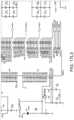
- FIG. 1A more detailed example 20 is shown in FIG. 1 .
- One remote 31with its own unique button layout, is used to control a television 21 .
- Another remote 32is used to control an audiovisual receiver 22 .
- Another remote 34is used to control a game console 24 , and another remote 36 is used to control a cable box 26 .
- another remote 38is used to control a DVD player 28 .
- Each remotehas its own unique button layout, as illustrated schematically in FIG. 1 .
- the system of the preferred embodimenteliminates the need to use multiple remote control devices on a regular basis.
- a single browser devicefor example, a cellular telephone having a display
- the browser devicecan illustrate all of the various remotes currently used by the consumer, only one at a time.
- the illustrated remoteseach function in the same manner as the original remotes.
- the browser devicecommunicates via Wi-Fi with a central function device.
- the function devicehas information regarding all the various remote controls needed by the consumer.
- the function devicecommunicates wirelessly with the browser device and in turn then operates all of the consumer's electronic devices.
- the single-line HDMI-CEC (High Definition Multimedia Interface-Consumer Electronic Control) bus or protocolis used to identify an IR codeset for an electronic consumer device (ECD) from a database of IR codesets.
- ECDelectronic consumer device
- the systemautomatically queries the new ECD using the single-wire HDMI-CEC bus to identify itself.
- the ECDautomatically responds by sending back information across the HDMI-CEC bus. This information is usable to identify the ECD.
- the returned informationincludes a brand name in ACSII format of the ECD, a device type in ASCII format of the ECD, and a model number in ASCII format of the ECD.
- the systemuses the returned information to identify a particular IR codeset in the database that is usable to control the ECD.
- the systemthen enables an IR remote control device to use the identified codeset to send IR remote control operational signals to the ECD device so that the IR remote control device can control the ECD.
- the use of HDMI-CEC to identify a codesetis not, however, limited to IR applications but rather also applies to codesets used to generate and detect other wireless remote control operational signals such as, for example, RF remote control operational signals for remote control devices that transmit RF signals.
- illustrationsfor example, digital pictures
- a portable display deviceuses the portable display device to select one of the illustrations that looks like a remote control device that the user is trying to imitate.
- the systemuses the user selection to identify an IR codeset for the associated ECD from many IR codesets in a database of IR codesets.
- a portable display devicesuch as a PDA, or cellular telephone, or Apple iPhone having a browser communicates with an AV system.
- the AV systemserves the illustrations of the remote control devices, and the portable display device and associated browser displays the illustrations to the user.
- the portable display devicedisplays illustrations or pictures of ECDs that the user might want to control.
- the useruses the portable display device to select the picture of the ECD that the user wishes to control.
- the portable display devicecommunicates the user selection information back to the system.
- the systemuses the information to identify the IR codeset in the database that controls the ECD (the ECD controlled by the remote control device).
- the systemthen enables the portable display device to use the identified codeset to send IR remote control operational signals to the ECD device so that the portable display device can operate as (imitate) the original remote control device picture selected by the user.
- the systemis usable to emulate a remote control device that the user has lost.
- pictures of a plurality of remote control devicesare displayed to a user on a portable display device.
- the usercan use the portable display device to select icons or buttons on the pictures, and to cause functionality of the selected icons or buttons to be associated with another rendering of a remote control device.
- the usercan copy (for example, by “dragging and dropping”) a selected icon or key or button from the pictured remote control device to a template of a remote control device illustrated elsewhere on the portable display device. Both the pictured remote control device and the template remote control device are displayed on the portable display device.
- the userdrags and drops” icons or keys or buttons, the icons or keys or buttons are added to and appear on the template.
- icons or keys or buttons from multiple different pictured remote control devicescan be dragged and dropped onto the same template, and the functionalities associated with the original icons, key and buttons in the pictured remote control devices are automatically assumed by the associated new icons or keys or buttons on the template.
- the userbuilds a new custom hybrid remote control device, a rendering of which can be displayed on the portable display device.
- the portable display deviceperforms the function that the original pictured remote control device that had the same key would have performed.
- the usertakes a digital picture of a remote control device to be imitated, and this picture is communicated to a system.
- the systemperforms optical recognition on the digital picture.
- a userhas a portable display device such as a PDA, or cellular telephone, or Apple iPhone that has camera functionality.
- the useruses the portable display device to take a digital picture of an IR remote control device.
- the display devicethen communicates the digital picture (for example, in the form of a JPEG file) to the system.
- the systemperforms optical object recognition on the digital picture and identifies which one of a plurality of codesets in a database of codeset is the codeset for the remote control device in the digital picture.
- the databasemay, for example, contain information on what the various remote control devices look like so that the optical recognition results will be usable to identify the pictured remote control device. This information may include information on the shape of the contour of the remote control device, the number of keys and placement of keys on the remote control device, and text that is printed on the remote control device.
- the internet-accessible computer systemreceives from a user a digital image of an electrical device via the internet.
- the electrical devicemay, for example, be a remote control device or an electronic consumer device (ECD) that is controlled by a remote control device.
- ECDelectronic consumer device
- the internet-accessible computer systemthen automatically performs optical object recognition on the digital image, and charges the user a fee to return information obtained from the optical recognition.
- the returned informationmay, for example, be codeset information.
- FIG. 1is a diagram of a collection of various electronic consumer devices, including various means of communication.
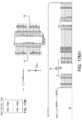
- FIG. 2is a schematic illustration of a system for communicating with electronic consumer devices.
- FIG. 2 Ais a schematic illustration of a system for communicating with electronic consumer devices, where a device includes among other parts: the functionality of the function device of FIG. 2 , the records database of FIG. 2 , a speaker, a display output, and a signal output 125 .
- FIG. 3is a schematic illustration of a database including a plurality of records regarding various remote controls, including a schematic illustration of some of the detail included in each of the records.
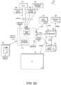
- FIG. 4 A- 4 Dare illustrations of various control devices used for controlling electronic consumer devices.
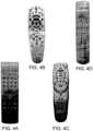
- FIG. 5 A- 5 Care illustrations of other control devices for controlling electronic consumer devices including a device for controlling lights that may be turned on or off or dimmed or brightened.
- FIG. 6is a schematic illustration of a display device illustrating a picture of a remote control with a user's finger on one of the illustrated buttons.
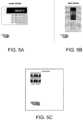
- FIG. 7is an illustration of a display device including buttons that cause a collection of changes in the function of electronic consumer devices, based on the different interests or moods of the user.
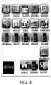
- FIG. 8is a diagram of a display with an illustration of a possible main menu that permits a user to select various functions.
- FIG. 9is an illustration of a method of how a consumer can set up the system to control electronic consumer devices.
- FIG. 10is a schematic illustration of how possible choices available to a user can be limited.
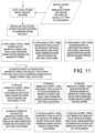
- FIG. 11is an illustration of a method of using a digital image to narrow down the possible choices of which particular device for consumers interested in.
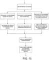
- FIG. 12is a flowchart showing how a consumer can obtain a digital image of a particular device, and then use that image to identify a specific database record referencing that particular control device.
- FIG. 13illustrates how a custom device screen can be created.
- FIG. 14illustrates a resulting smaller custom device screen.
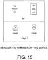
- FIG. 15illustrates a possible device button layout that can be programmed for a particular control device of interest.
- FIG. 16is an illustration of a template custom control device with existing buttons, where the user then assigns a button function to each of the buttons on the template.
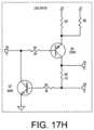
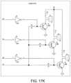
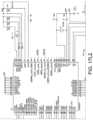
- FIG. 17illustrates a block diagram of the components that make up the function device.
- FIGS. 17 A- 17 K , 17 L 1 - 17 L 4 , 17 M 1 , and 17 M 2illustrate the details of the components that make up the function device shown in FIG. 17 .
- Household ECDscan be anything that can be controlled by a remote control device or a keypad or some other control device, such as a DVD, a television, an audiovisual receiver, a sprinkler system, a light switch, an alarm panel, a game console, a computer, and so on.
- FIG. 2is one embodiment of a system 100 for controlling electronic consumer devices (ECDs).
- System 100includes a function device 101 , a display 102 , a plurality of ECDs 103 - 111 , a database 112 and a memory 113 .
- Database 112 and memory 113are accessible via a network connection 131 to a network such as the internet 115 .
- the ECDs 103 - 111include, in this example, a light switch 103 , a heating ventilation and air conditioning (HVAC) controller 104 , sprinkler system controller 105 , an alarm system controller 106 , a DVD player 107 , a set-top box 108 , an audio-visual receiver 104 (sometimes also referred to as an “audio-video receiver” or “AV receiver”), a game console 110 , and a television 111 .
- HVACheating ventilation and air conditioning
- AV receiveraudio-visual receiver
- Database 112is a database of codesets. For details on an example of a codeset and what a codeset entails and how a codeset is used, see: U.S. Pat. No. 7,259,696, the subject matter of which is incorporated herein by reference.
- Database 112includes information on the identities of many different types of ECDs, and information on the functions of each ECD. These functions may, for example, be volume up or down, channel up or down, turn on sprinkler, etc., which can be controlled by a remote control device. The ECD manufacturer usually supplies such a remote control device at the time the ECD is originally sold to consumers. How to generate the various signals needed to be received by the ECD in order to make the ECD perform a desired function is set forth in database 112 .
- database 112is or includes a pictorial record database of illustrations of remotes or control devices with buttons that are used to control the ECD functions.
- illustrationas it is used here includes both digital photographs and schematic renderings.
- control deviceas it is used herein encompasses, but is not limited to, a remote control device.
- database 112includes extracted graphical information on each control device.
- extracted graphical informationmay, for example, include information on the shape of the control device, the buttons (keys) on the control device, the number of buttons and the locations of the buttons, and characters or other printing that appears on the control device.
- the databasealso includes the ECD function information (keycodes and other codeset information) associated with each button.
- Central function device 101communicates with the database 112 to obtain the control device's information, such as the devices shape, devices button labels, button shapes, and the button locations i.e., the button layout.
- Function device 101also includes a display output 116 that outputs a signal to a display device 102 .
- Display device 102displays an input screen that illustrates the control device's information, such as the device's shape, button labels, button shapes and button locations or layout.
- function device 101database 112 , memory 113 and display device 102 are illustrated in FIG. 2 as separate devices or functionalities, in another embodiment (see FIG. 2 A ) some or all of these system elements can be combined into a single device.
- the function device 101is functionality that is physically incorporated (not shown) into one of the ECDs, such as the cable set-top box 108 .
- a processorcan provide some or all of the function device's functionality.
- the term “processor” as the term is used hereinis a digital processing unit such as a microcontroller or microprocessor, along with its associated functional hardware and software. The term includes a microprocessor such as is normally found in a personal computer, and its functional software.
- a consumerpurchases a new ECD.
- the consumertakes the new ECD home, and plugs it into an existing home entertainment/ECD system.
- the ECDwere a set-top box, such as a cable box
- a consumercan connect a cable wire to the box, and then connect the box to an audio-visual system.
- the systemincludes an AV receiver
- the consumermight use a high-definition media interface (HDMI) cable to connect the cable box to the AV receiver, as further explained below.
- HDMIhigh-definition media interface
- the cable boxincludes a novel function device. The function device within the cable box begins to recognize the various ECDs in the consumer's home system.
- the function devicecan determine. the manufacturer, type, and particular model of the AV receiver using the CEC protocol over the HDMI cable. Once the identity of the AV receiver is determined, the function device then communicates with the database 112 that includes information about the various control devices. By communicating to database 112 the particular identity of the AV receiver, the database can use the identity information to identify information associated with the particular control device normally supplied to the consumer when the AV receiver is sold. Using the ECD identity information, database 112 returns to the function device in the cable box that particular ECD function information. In some embodiments, it also returns an illustration of the control device supplied by the ECD device manufacturer at the time the ECD is sold to consumers.
- ECDshave the ability to communicate via HDMI with the function device.
- the consumermay identify the ECD for the function device. Using a setup procedure, as further explained below, the consumer identifies the other ECDs in the consumer's home entertainment/ECD system.
- the consumercan then use a single display device (for example, display 102 ) with two-way communication to the function device to control all of the ECDs, as further explained below.
- a single display devicefor example, display 102
- display 102is a mobile communication device that has a touch screen 114 .
- Display 102can respond to a user interacting with the input screen 114 .
- the screen 114displays a button 130
- the usercan interact with the button 130 .
- the display 102can react to a user touching the button 130 on the screen 114 .
- a usermay use a keyboard (not shown) to tab between buttons and touch a key in order to interact with the button, or the user can use a mouse (not shown) to mouse over each button and click to interact with the button.
- a keyboardnot shown
- mousenot shown
- the user inputis communicated to function device 101 , and function device 101 takes the information from the button function information database 112 and uses it to create a signal with the control devices button function information.
- This signalis then output through a signal output to the ECD to be controlled.
- the signal outputis an IR transmitter, and the signal is an infrared transmission.
- the signal outputis an HDMI port, and the signal is an HDMI communication that is communicated to the ECD to be controlled by an HDMI cable.
- the function device 101can communicate with the display 102 in many ways. For example, if display 102 is physically located (not shown) in the same device housing as functional device 101 , then a data bus can communicate between the display and the function device 101 . If the display is physically located in a separate device in a separate housing, as shown in FIG. 2 , other means for communicating between the display and the function device 101 are required. In one example (not shown), the display is hard wired to the function device 101 . In another example, as shown in FIG. 2 , the display communicates wirelessly with the function device 101 . While all methods of wireless communication can be used, a preferred method of communication is to use Wi-Fi.
- a cellular networkcan be used for communication between the function device 101 and the display 102 .
- Other methods of communicationcan include using coaxial cable, like an RF signal, and an HDMI cable, including using consumer electronic communication (CEC).
- the communication between the display device 102 and the function device 101can be one-way or two-way communication.
- the function device 101can output the input screen information to the display device, and the display device can return to the function device 101 information about user interaction.
- the display devicecan take many forms. It could be a television, a personal computer, or a smart phone or smart device such as an Apple Inc. iPhone or iPod Touch, both of which have Wi-Fi communication capabilities. With Wi-Fi communication capabilities, the display device can interact using Wi-Fi with the function device 101 .
- Function device 101communicates with the button function information database and the database with pictorial records of other devices. These databases can be stored in a database server within the function device 101 , or the database can be located remote from function device 101 . For example, if the database is on the Internet, then communication with the Internet can permit the function device 101 to communicate with the database. Such communication could be over each Ethernet cable through a modem to a remotely located database server.
- the function device 101will include some form of memory.
- the memorymay be physically within the same device housing as the function device 101 , or it may be located remotely from the function device 101 . If located remotely, then some form of communication will need to occur between the function device 101 and the remote memory in order to retrieve the user interaction information.
- the communication between the memory and the function device 101can be over a data bus, if located in the same physical housing, or can be over network communication, if located remote from the function device 101 . If located remotely, then any of the previously described methods of communication can be used.
- function device 101creates an input screen output.
- the input screenis a page in a plurality of linked pages.
- the function deviceserves the pages using HTML.
- other methodssuch as by using a stand-alone application to create the input screen can be used.
- a browser executing in display device 102is used to render the input screen on the display of display device 102 . Since the user will interact repeatedly with the input screen, it is beneficial if the web browser on the display device supports HTML and user interaction with the HTML.
- the web browsershould support JavaScript to permit user interaction with a button without having to refresh the entire user input screen, or some other form of AJAX (Asynchronous JavaScript and XML) process.
- the display deviceshould support enlargement of any illustration on the display, as shown in FIG. 6 .
- the page servercan be either software processed by the same function device 101 referred to above, or the web server can be located remotely from the function device 101 .
- the web servercan be on a network web server, and the function device 101 can communicate with the networked web server.
- the term “web server” as it is used hereis not limited to use on the World Wide Web, but rather is a page server of linked pages, regardless of whether the pages are part of the World Wide Web or whether the pages are only locally accessible.
- function device 101communicates with various ECDs.
- the communicationcan use any of the above-described methods of communicating a signal, such as using infrared Wi-Fi, HDMI, CEC and/or RF.
- Another form of communication between the function device and the ECDsmay be a Wave, or Zigbee, which is a known method of communication between household ECDs such as light switches and devices for its controlling the light switch.
- the communicationwill be one way.
- the function device 101can cause a television to turn on.
- function device 101can tell the television volume to increase.
- two-way communicationcan occur between function device 101 and the ECD.
- a signal to turn oncan be communicated to a light switch, and some sort of response indicating the light did in fact turn on can be returned to function device 101 , so that the user can confirm that the light was turned on.
- the existence of a particular ECDmay be communicated to function device 101 through such two-way communication.
- Other methods of communicationcan also include X10 and RS-485, as illustrated in FIG. 17 .
- the systemcan also handle more complicated actions. For example, a combination of many button functions can occur in response to the user interaction with one particular button. For example, a user can in the morning turn on various ECDs. Lights can be turned on, and a coffee pot started.
- one button labeled MORNINGas illustrated in FIG. 7 , can be used on the display device to cause these various different ECD function commands to be output by the function device 101 , in response to the user interacting with the MORNING button on the display device.
- Database 120includes records 124 for different control devices, and each record 124 includes information on the control device's shape, the button layout of the control device, and the button labels and other text that can appear on the control device. Each record 124 also includes the code 126 or signals associated with each button 128 on the control device 124 . These codes may, for example, be referred to as keycodes.
- FIG. 4illustrates a sample selection of device shapes and button layouts.
- Various pieces of textsuch as the ECD manufacturer, as best seen in FIG. 14
- various symbolsalso appear on each device, either on the buttons or otherwise.
- the pictorial databaseincludes this information regarding the symbols, the buttons, the shapes of the buttons, the button locations, and the shape of the overall control device. In other less preferred embodiments, a subset of this information can be used.
- the pictorial databaseincludes information on many different kinds of other devices.
- FIGS. 5 A and 5 Billustrating various sample control devices used for control of ECDs, such as a DVD, cable box, a DVD player, and a television.
- ECDsinclude, for example, referring to the Figure illustrating other control devices, an alarm system, and HVAC control, as well as a light switch wall plate.
- buttonscan be turned on or off or dimmed or brightened.
- the buttonscan also change color or otherwise respond to user interaction. For example, if a light is turned on, a button on display device 102 can change color to indicate that the light is on.
- the main input screen shown on the display devicecan permit a user to select generally the category of user desired ECD interaction.
- An example of a main input screenis shown in FIG. 8 .
- the usercan select which type of ECD to use.
- the usercan select various custom control devices, created as explained below.
- the usercan choose to build a new custom control device, to teach the device to learn how to behave like an existing control device, or to set up the function device 101 , as explained below.
- the systemcan also learn a particular control device's button function information. This can be done using an IR learning process, as commonly known in the art.
- FIG. 10An important aspect of the system of FIG. 2 is the ability of the system to permit easy setup of the system.
- Setupas used herein means the selection of the choice of control devices to be imitated.
- An example of a setup procedure, as illustrated in FIG. 10is as follows.
- Function device 101outputs a user input screen to display device 102 .
- the input screenas rendered on the display of display device 102 , presents the user with a choice of a one of the following criteria: a control device's shape, a control device manufacturer, a control device type of ECD to be controlled, and a selection of other device button layouts.
- the userinteracts with the input screen to select one of the criteria.
- Display device 102then communicates with function device 101 , and the function device 101 communicates with the device pictorial database to reduce the number of other devices of interest to the user. For example, if the user selects the manufacturer “Sony” from a list of ECD manufacturers presented to the user, then only Sony devices would be available to the user for further selection. More particularly, as illustrated in FIG. 11 , the second criterion will depend on the first criterion selected by the user. For example, if ECD type, such as DVD or television or receiver, was selected as the first criterion, than a second choice presented to the user may be a list of ECD manufacturers. Another option would be to show a selection of button layouts for other devices, or to show the shapes of other devices.
- ECD typesuch as DVD or television or receiver
- the display device 102When the second criterion is then selected, the display device 102 will communicate again with function device 101 , which in turn will communicate with the device database. As a result of the narrower criterion, the set of possible choices presented to the user will be further narrowed. The set of possible choices is then returned to the function device 101 , and the function device 101 creates an input display screen with a more limited selection choices. The user interacts with the user input screen to select a particular device of interest to the user. If, in the first instance, the user selected device manufacturer, then the second criterion may be to show the types of ECDs made by that manufacturer. In the alternative, after selecting a device manufacturer, the second criteria may be button layouts of devices made by that manufacturer, or the shapes of such devices. Likewise, if device shape is the first criterion, then the second criterion can be either a button layout or the device manufacturer or the type of ECD.
- button function databasereferred to here is sometimes referred to as a codeset database.
- the button information databasecan be the same database as the pictorial database, or it may be another database.
- an illustration of the control deviceis output, via the page server, to the display device along with codeset information and/or other information usable to imitate the original control device.
- the illustrationappears on the user input screen that is displayed on the display device. The user then can interact with the buttons on the user input screen to select various device functions of the control device.
- Another method of obtaining information about what ECDs the user wants to controlinvolves having function device 101 output a communication query signal across the HDMI-CEC bus to any newly connected ECDs, as shown in FIG. 9 .
- the newly connected ECDautomatically responds by communicating back ECD identification information across the CEC bus.
- This ECD identification informationmay include a brand name in ASCII characters, a device type in ASCII characters, and a model number in ASCII characters.
- Function device 101parses and interprets this returning ECD identification information, and then forwards some or all of it, or a determination based on it, to the control device pictorial database.
- the pictorial databasereturns an illustration of the associated control device, which is forwarded to display device 102 so an image of the control device is displayed to the user on display device 102 .
- FIGS. 11 and 12Another method of obtaining information from a user regarding a particular control device to be imitated by the system, is to begin with a digital photograph of the control device to be imitated, as illustrated in FIGS. 11 and 12 .
- the usercan obtain this digital photograph (image) using a digital camera.
- the Apple iPhonehas a digital camera built into the smart phone. Once the digital camera captures an image of the control device to be imitated (for example, as a JPEG file), the image is communicated to the function device 101 using any suitable method of communication. With an Apple iPhone, the image could be transferred via Wi-Fi to the function device 101 .
- display deviceis a cellular telephone having camera functionality, and the cellular telephone is used to capture a digital image and to transmit the digital photograph to function device 101 .
- Function device 101then analyzes the digital photograph (image) or communicates with another function device 101 that analyzes the digital photograph or image.
- the analyzing function devicetypically uses optical recognition techniques to analyze one or more of the following characteristics of the image: the shape of the outer contour of the pictured control device, the location and number of buttons on the pictured control device, the characters or text appearing on the buttons, and any characters or text of other printing that appears on the control device. Any one or all of the above pieces of extracted graphical information can be extracted from the raw digital photograph. This information can be obtained from the digital image using known optical recognition approaches, or by using techniques used with facial recognition, for example. Once the graphical information has been extracted using optical recognition, the extracted information is communicated to a database that includes similar types of previously extracted graphical information about other control devices.
- a particular control device in the databaseis selected as the best match. After the particular control device has been selected, information particular to the particular control device is communicated back to the function device 101 . Function device 101 may forward the information to display device 102 .
- FIG. 4illustrating a sample selection of control device shapes and button layouts
- control device in FIG. 40has a relatively straight sided shape with parallel sides, but with rounded ends.
- the device in FIG. 4 Ahas straight parallel sides and relatively straight parallel ends, while the device in FIG. 4 C has a rounded contour in the middle of the device, which makes it readily distinguishable from the control devices.
- This device shape informationcan be used by the optical recognition software executing in function device 101 to identify a particular control device.
- the charactersidentify the device manufacturer. This information can be used to select or narrow down the particular devices of interest.
- the button layout, and the Symbols on the buttons, as illustrated in this figurecan also be used.
- an illustration of the identified control deviceis made to be displayed on display device 102 and the user can interact with the control device illustration to select a control device button to create a signal to control an ECD function.
- the usercan then interact with the illustrations of the control devices to imitate the operation of the control devices.
- the display devicecommunicates with the function device 101 , telling the function device 101 what button was selected.
- the function device 101then outputs a signal to a signal output, which, for example, can be an IR emitter, that then emits the appropriate IR code for that function for that particular ECD, so that the particular ECD can respond to that command.
- a signal outputis a hardwired bus port such as, for example, an HDMI port into which an HDMI cable is plugged.
- the system of FIG. 2offers the creation of a custom control device.
- a custom control deviceis one that realized a selection of button functions from multiple different control devices.
- the function device 101outputs at least one collection of button information from one of the control devices of interest to the user.
- the original button layoutincluding the shape of the control device, is displayed on the user input screen, as illustrated in FIG. 14 .
- the userthen interacts with the buttons on the user input screen, by either selecting a button, choosing a menu option or other control that says use such button, or, in the preferred embodiment, by dragging and dropping the illustrated button to another location on the input screen.
- the custom control deviceincludes a collection of buttons and button functions from the depicted other control devices of interest to the user.
- a done or finish button 142is selected by the user, and this user input is communicated to the function device 101 .
- the function device 101then creates the custom control device illustration.
- the custom control device illustrationis then output to the display device.
- the custom control device buttons used to control a televisioncan be the buttons used to control the television in a custom control device area labeled TV.
- the buttons used to control a cable set-top boxcould be gathered in a custom control device location entitled Cable.
- the userdrags and drops selected buttons from the illustrations appearing to the right in FIG. 14 . These selected buttons are dropped in the area illustrated to the left in FIG. 14 .
- the custom control deviceoffers a simpler device for control of ECDs.
- the custom control deviceends up with an illustration of buttons, as shown in FIG. 15 , which is much more compact in size than the original shape of the various other devices of interest to the user. This permits the button sizes to be larger, making it easier for user interaction. This also simplifies the amount of information the user has to deal with in order to interact with the various ECDs.
- FIG. 16another approach to custom control device creation is illustrated.
- the user input screenbegins with a template custom control device with existing buttons.
- the userassigns various button functions to each of the buttons on the template custom control device. This is done in a fashion similar to the description of selection of buttons referred to earlier.
- the control device of interest to the useris illustrated, and the user drags and drops buttons of interest from the illustrated control device to the template custom control device, thereby assigning functions of the selected buttons to the buttons on the custom control device.
- the resulting custom control device input screensare much simpler than the original, relatively busy, control devices.
- the function device 101can include various components. These components may be housed in one housing, or in separate housings with communication between the various housings.
- the function device 101includes a power source, a fan control, a RS-232 port, and a general-purpose processor board.
- the function device 101also includes flash memory, z-Wave, X10 and RS-485 wireless communication, and IR learning.
- the function device 101also includes IR outputs, HDMI ports, and a level shifter.
- the function device 101also includes Wi-Fi inputs and outputs, SRAM, RS485, an Ethernet router, and an X10 TW523. The particulars regarding these various components are illustrated in FIGS. 17 A through 17 M .
- HDMI-CEC communicationto identify a remote control device usable to control an ECD, or to identify a codeset usable to control an ECD
- a digital photograph of a remote control deviceand/or of an ECD controllable by the remote control device
- identify information about the remote control deviceand/or about the ECD
- a web-based servicecan receive a digital photograph via the internet, can perform optical recognition on the digital photograph and use the results of the optical recognition to identify information in a database about the remote control device and/or an ECD controllable by the remote control device.
- the identified informationcan be returned to the user via the internet and the user can be billed for the service. Accordingly, the lookup function performed by function device 101 and database 112 need not be localized to a user's home.
- the storage of digital images of remote control devices in a codeset databasehas general applicability, as does the storage of extracted graphical information about remote control devices in the codeset database. Accordingly, various modifications, adaptations, and combinations of various features of the described embodiments can be practiced without departing from the scope of the invention as set forth in the claims.
Landscapes
- Engineering & Computer Science (AREA)
- Multimedia (AREA)
- Signal Processing (AREA)
- Human Computer Interaction (AREA)
- General Engineering & Computer Science (AREA)
- Theoretical Computer Science (AREA)
- Physics & Mathematics (AREA)
- General Physics & Mathematics (AREA)
- Selective Calling Equipment (AREA)
Abstract
Description
Claims (5)
Priority Applications (3)
| Application Number | Priority Date | Filing Date | Title |
|---|---|---|---|
| US18/100,737US11868588B2 (en) | 2008-04-18 | 2023-01-24 | Selecting a picture of a device to identify an associated codeset |
| US18/373,927US12189922B2 (en) | 2008-04-18 | 2023-09-27 | Selecting a picture of a device to identify an associated codeset |
| US18/987,179US20250117113A1 (en) | 2008-04-18 | 2024-12-19 | Selecting a picture of a device to identify an associated codeset |
Applications Claiming Priority (4)
| Application Number | Priority Date | Filing Date | Title |
|---|---|---|---|
| US12/148,420US9870123B1 (en) | 2008-04-18 | 2008-04-18 | Selecting a picture of a device to identify an associated codeset |
| US15/835,804US10514828B2 (en) | 2008-04-18 | 2017-12-08 | Selecting a picture of a device to identify an associated codeset |
| US16/596,458US11592961B2 (en) | 2008-04-18 | 2019-10-08 | Selecting a picture of a device to identify an associated codeset |
| US18/100,737US11868588B2 (en) | 2008-04-18 | 2023-01-24 | Selecting a picture of a device to identify an associated codeset |
Related Parent Applications (1)
| Application Number | Title | Priority Date | Filing Date |
|---|---|---|---|
| US16/596,458ContinuationUS11592961B2 (en) | 2008-04-18 | 2019-10-08 | Selecting a picture of a device to identify an associated codeset |
Related Child Applications (1)
| Application Number | Title | Priority Date | Filing Date |
|---|---|---|---|
| US18/373,927ContinuationUS12189922B2 (en) | 2008-04-18 | 2023-09-27 | Selecting a picture of a device to identify an associated codeset |
Publications (2)
| Publication Number | Publication Date |
|---|---|
| US20230161454A1 US20230161454A1 (en) | 2023-05-25 |
| US11868588B2true US11868588B2 (en) | 2024-01-09 |
Family
ID=60934983
Family Applications (8)
| Application Number | Title | Priority Date | Filing Date |
|---|---|---|---|
| US12/148,420Active2031-09-29US9870123B1 (en) | 2008-04-18 | 2008-04-18 | Selecting a picture of a device to identify an associated codeset |
| US15/835,804Active2028-07-03US10514828B2 (en) | 2008-04-18 | 2017-12-08 | Selecting a picture of a device to identify an associated codeset |
| US16/596,458Active2030-01-27US11592961B2 (en) | 2008-04-18 | 2019-10-08 | Selecting a picture of a device to identify an associated codeset |
| US16/596,438ActiveUS10949064B2 (en) | 2008-04-18 | 2019-10-08 | Selecting a picture of a device to identify an associated codeset |
| US17/168,729ActiveUS11520462B2 (en) | 2008-04-18 | 2021-02-05 | Selecting a picture of a device to identify an associated codeset |
| US18/100,737ActiveUS11868588B2 (en) | 2008-04-18 | 2023-01-24 | Selecting a picture of a device to identify an associated codeset |
| US18/373,927ActiveUS12189922B2 (en) | 2008-04-18 | 2023-09-27 | Selecting a picture of a device to identify an associated codeset |
| US18/987,179PendingUS20250117113A1 (en) | 2008-04-18 | 2024-12-19 | Selecting a picture of a device to identify an associated codeset |
Family Applications Before (5)
| Application Number | Title | Priority Date | Filing Date |
|---|---|---|---|
| US12/148,420Active2031-09-29US9870123B1 (en) | 2008-04-18 | 2008-04-18 | Selecting a picture of a device to identify an associated codeset |
| US15/835,804Active2028-07-03US10514828B2 (en) | 2008-04-18 | 2017-12-08 | Selecting a picture of a device to identify an associated codeset |
| US16/596,458Active2030-01-27US11592961B2 (en) | 2008-04-18 | 2019-10-08 | Selecting a picture of a device to identify an associated codeset |
| US16/596,438ActiveUS10949064B2 (en) | 2008-04-18 | 2019-10-08 | Selecting a picture of a device to identify an associated codeset |
| US17/168,729ActiveUS11520462B2 (en) | 2008-04-18 | 2021-02-05 | Selecting a picture of a device to identify an associated codeset |
Family Applications After (2)
| Application Number | Title | Priority Date | Filing Date |
|---|---|---|---|
| US18/373,927ActiveUS12189922B2 (en) | 2008-04-18 | 2023-09-27 | Selecting a picture of a device to identify an associated codeset |
| US18/987,179PendingUS20250117113A1 (en) | 2008-04-18 | 2024-12-19 | Selecting a picture of a device to identify an associated codeset |
Country Status (1)
| Country | Link |
|---|---|
| US (8) | US9870123B1 (en) |
Families Citing this family (10)
| Publication number | Priority date | Publication date | Assignee | Title |
|---|---|---|---|---|
| EP2118208B1 (en) | 2007-02-01 | 2019-10-09 | Sol-Gel Technologies Ltd. | Method for preparing particles comprising metal oxide coating |
| EP2307129A2 (en) | 2008-07-31 | 2011-04-13 | Sol-Gel Technologies Ltd. | Microcapsules comprising active ingredients and a metal oxide shell, a method for their preparation and uses thereof |
| EP2726067B1 (en) | 2011-06-29 | 2020-02-19 | Sol-Gel Technologies Ltd. | Stabilized topical formulations containing core-shell microcapsules |
| KR102354763B1 (en)* | 2014-11-17 | 2022-01-25 | 삼성전자주식회사 | Electronic device for identifying peripheral apparatus and method thereof |
| KR102655584B1 (en)* | 2017-01-02 | 2024-04-08 | 삼성전자주식회사 | Display apparatus and controlling method thereof |
| JP2020527140A (en) | 2017-07-12 | 2020-09-03 | ソル − ゲル テクノロジーズ リミテッド | Compositions Containing Encapsulated Tretinoin |
| US11113040B2 (en)* | 2018-07-18 | 2021-09-07 | Verizon Patent And Licensing Inc. | Systems and methods for orchestration and automated input handling of interactions received via a user interface |
| WO2020241459A1 (en)* | 2019-05-30 | 2020-12-03 | ソニー株式会社 | Information processing device, operation terminal, and information processing method |
| US11445107B2 (en)* | 2019-08-08 | 2022-09-13 | Qorvo Us, Inc. | Supervised setup for control device with imager |
| US12148291B2 (en)* | 2021-02-16 | 2024-11-19 | Arris Enterprises Llc | System to control multiple devices with a remote control device |
Citations (69)
| Publication number | Priority date | Publication date | Assignee | Title |
|---|---|---|---|---|
| US4623887A (en) | 1984-05-15 | 1986-11-18 | General Electric Company | Reconfigurable remote control |
| US4774511A (en) | 1985-05-30 | 1988-09-27 | Nap Consumer Electronics Corp. | Universal remote control unit |
| US4959810A (en) | 1987-10-14 | 1990-09-25 | Universal Electronics, Inc. | Universal remote control device |
| US5263098A (en) | 1990-07-06 | 1993-11-16 | Matsushita Electric Industrial Co., Ltd. | Object recognition method and apparatus for determining the presence and shape of an object |
| US5481256A (en) | 1987-10-14 | 1996-01-02 | Universal Electronics Inc. | Direct entry remote control with channel scan |
| US5515052A (en) | 1987-10-14 | 1996-05-07 | Universal Electronics Inc. | Universal remote control with function synthesis |
| US5886697A (en) | 1993-05-24 | 1999-03-23 | Sun Microsystems, Inc. | Method and apparatus for improved graphical user interface having anthropomorphic characters |
| US6014092A (en) | 1987-10-14 | 2000-01-11 | Universal Electronics Inc. | Key mover |
| US6115495A (en) | 1993-12-10 | 2000-09-05 | Ricoh Company, Ltd. | Image extraction method and apparatus, and image recognition method and apparatus for extracting/recognizing specific images from input image signals |
| US6127941A (en) | 1998-02-03 | 2000-10-03 | Sony Corporation | Remote control device with a graphical user interface |
| US6133847A (en) | 1997-10-09 | 2000-10-17 | At&T Corp. | Configurable remote control device |
| US6157319A (en) | 1998-07-23 | 2000-12-05 | Universal Electronics Inc. | Universal remote control system with device activated setup |
| US6160491A (en) | 1994-11-10 | 2000-12-12 | Matsushita Electric Industrial Co., Ltd. | Remote controller, remote control interface, and remote control system including a remote controller and a remote control interface |
| US6211856B1 (en) | 1998-04-17 | 2001-04-03 | Sung M. Choi | Graphical user interface touch screen with an auto zoom feature |
| US6211870B1 (en) | 1997-07-07 | 2001-04-03 | Combi/Mote Corp. | Computer programmable remote control |
| US6225938B1 (en) | 1999-01-14 | 2001-05-01 | Universal Electronics Inc. | Universal remote control system with bar code setup |
| US20010017615A1 (en) | 1999-12-10 | 2001-08-30 | Chih-Shu Lin | Intelligent touch-type universal remote control |
| US20010043145A1 (en) | 1997-10-10 | 2001-11-22 | James E. Jacobson | Addressable distributed wireless remote control system |
| US20010045819A1 (en) | 2000-03-15 | 2001-11-29 | Harris Glen Mclean | State-based remote control system |
| US20010053274A1 (en) | 2000-06-20 | 2001-12-20 | Koninklijke Philips Electronics N.V. | System and method for remote control of consumer electronics over data network with visual feedback |
| US20020059617A1 (en) | 2000-06-30 | 2002-05-16 | Tomoko Terakado | Control system |
| US20020080163A1 (en)* | 1998-02-23 | 2002-06-27 | Morey Dale D. | Information retrieval system |
| US20020143805A1 (en) | 2001-01-29 | 2002-10-03 | Hayes Patrick H. | Hand held device having a browser application |
| US20020171624A1 (en) | 2001-05-03 | 2002-11-21 | Mitsubishi Digital Electronics America, Inc. | Control system and user interface for network of input devices |
| US20030025840A1 (en) | 2001-08-03 | 2003-02-06 | Arling Paul D. | Control device with easy lock feature |
| US20030095156A1 (en) | 2001-11-20 | 2003-05-22 | Universal Electronics Inc. | Hand held remote control device having an improved user interface |
| US20030095211A1 (en) | 2001-11-21 | 2003-05-22 | Satoshi Nakajima | Field extensible controllee sourced universal remote control method and apparatus |
| US20030103088A1 (en) | 2001-11-20 | 2003-06-05 | Universal Electronics Inc. | User interface for a remote control application |
| US20030141987A1 (en)* | 1999-06-16 | 2003-07-31 | Hayes Patrick H. | System and method for automatically setting up a universal remote control |
| US20030189509A1 (en) | 1998-07-23 | 2003-10-09 | Universal Electronics Inc. | System and method for automatically setting up a universal remote control |
| US20040003001A1 (en) | 2002-04-03 | 2004-01-01 | Fuji Photo Film Co., Ltd. | Similar image search system |
| US20040070491A1 (en) | 1998-07-23 | 2004-04-15 | Universal Electronics Inc. | System and method for setting up a universal remote control |
| US20040090464A1 (en) | 2002-11-01 | 2004-05-13 | Shake Francis David | Method for automatically determining equipment control code sets from a database and presenting information to a user interface |
| US6763148B1 (en) | 2000-11-13 | 2004-07-13 | Visual Key, Inc. | Image recognition methods |
| US20040215816A1 (en) | 2002-12-16 | 2004-10-28 | Hayes Stephen T | Apparatus and methods for communication among devices |
| US20040257259A1 (en) | 2003-06-20 | 2004-12-23 | Lucent Technologies Inc. | Universal soft remote control |
| US20050054289A1 (en) | 2003-09-05 | 2005-03-10 | Innovative Intelcom Industries | Communications, command, and control system with plug-and-play connectivity |
| US20050096753A1 (en) | 2003-11-04 | 2005-05-05 | Universal Electronics Inc. | Home appliance control system and methods in a networked environment |
| WO2005043484A1 (en) | 2003-11-04 | 2005-05-12 | Koninklijke Philips Electronics N.V. | Universal remote control device with touch screen |
| US20050151727A1 (en) | 2004-01-08 | 2005-07-14 | Intel Corporation | Wireless enabled touch pad pointing device with integrated remote control function |
| EP1578016A1 (en) | 2004-03-15 | 2005-09-21 | Ruwido Austria Gesellschaft M.B.H. | Programmable remote control, in particular infrared remote control and programming device for programming the remote control |
| US6952496B2 (en) | 1999-11-23 | 2005-10-04 | Microsoft Corporation | Object recognition system and process for identifying people and objects in an image of a scene |
| US20060041655A1 (en)* | 2004-05-06 | 2006-02-23 | Marty Holloway | Bi-directional remote control for remotely controllable apparatus |
| US20060050142A1 (en) | 2004-09-08 | 2006-03-09 | Universal Electronics Inc. | Configurable controlling device having an associated editing program |
| US20060168618A1 (en) | 2003-04-01 | 2006-07-27 | Dong-Wook Choi | System and method for home automation using wireless control rf remocon module based on network |
| US20060227997A1 (en) | 2005-03-31 | 2006-10-12 | Honeywell International Inc. | Methods for defining, detecting, analyzing, indexing and retrieving events using video image processing |
| US20070096283A1 (en) | 2005-10-27 | 2007-05-03 | Peter Ljung | Configuration of an electronic device |
| US20070217650A1 (en) | 2006-03-20 | 2007-09-20 | Fujifilm Corporation | Remote controller, remote control system, and method for displaying detailed information |
| US20070271267A1 (en) | 2006-05-19 | 2007-11-22 | Universal Electronics Inc. | System and method for using image data in connection with configuring a universal controlling device |
| US20080126965A1 (en) | 2005-03-17 | 2008-05-29 | Masafumi Shimotashiro | Electronic Device System |
| US20080136972A1 (en)* | 2006-12-12 | 2008-06-12 | Blankenburg Carl J | Control system and user interface for network of input devices |
| US20080166105A1 (en) | 2007-01-05 | 2008-07-10 | Verizon Services Corp. | Apparatus for remotely controlling set-top boxes and an associated method and computer program product |
| US20080231762A1 (en) | 2007-03-22 | 2008-09-25 | Sony Corporation | System and method for application dependent universal remote control |
| US20090079869A1 (en) | 2007-09-21 | 2009-03-26 | Samsung Electronics Co., Ltd. | Image apparatuses capable of intercommunicating and control method thereof |
| US20090094645A1 (en) | 2004-06-28 | 2009-04-09 | Yi-Liang Ting | Method of controlling remote-controlled electronic device using universal remote controller and universal remote controller thereof |
| US20090154933A1 (en)* | 2007-12-17 | 2009-06-18 | Peter Mortensen | Control system for network of input devices with automatic device configuration |
| US7589642B1 (en) | 2003-12-16 | 2009-09-15 | Uei Cayman Inc. | Relaying key code signals through a remote control device |
| US20090254500A1 (en)* | 2008-04-08 | 2009-10-08 | Polly Stecyk | Control system for network of input devices with automatic audio/video receiver detection and control configuration |
| US20090327910A1 (en) | 2008-06-27 | 2009-12-31 | Universal Electronics Inc. | System and method for ubiquitous appliance control |
| US20100008636A1 (en) | 2008-07-11 | 2010-01-14 | Kabushiki Kaisha Toshiba | Video display device, video playback device, video playback display system and control method thereof |
| US7685341B2 (en)* | 2005-05-06 | 2010-03-23 | Fotonation Vision Limited | Remote control apparatus for consumer electronic appliances |
| US20120005337A1 (en) | 2010-06-30 | 2012-01-05 | Sony Corporation | Remote control device, remote control setting method, and program |
| US20120071989A1 (en) | 2008-04-18 | 2012-03-22 | Uei Cayman Inc. | Using hdmi-cec to identify a codeset |
| US20120098771A1 (en) | 2010-10-22 | 2012-04-26 | Sony Corporation | Operational terminal device, display control device, method of operating terminal device, method of operating display control device, and system |
| US20120287023A1 (en)* | 2000-06-15 | 2012-11-15 | Benjamin Slotznick | Portable device that is adapted to remotely control content on a nearby display screen |
| US20140184395A1 (en) | 2012-12-28 | 2014-07-03 | Kabushiki Kaisha Toshiba | Communication device and communication system |
| US20140222862A1 (en) | 2006-09-05 | 2014-08-07 | Universal Electronics Inc. | System and method for configuring the remote control functionality of a portable device |
| US20170048577A1 (en) | 2015-08-14 | 2017-02-16 | Jet Optoelectronics Co., Ltd. | Remote control method related to hdmi-cec specification and system thereof |
| US20210021904A1 (en) | 2018-03-19 | 2021-01-21 | Samsung Electronics Co., Ltd. | Image display apparatus and method for operating same |
Family Cites Families (3)
| Publication number | Priority date | Publication date | Assignee | Title |
|---|---|---|---|---|
| US6104334A (en)* | 1997-12-31 | 2000-08-15 | Eremote, Inc. | Portable internet-enabled controller and information browser for consumer devices |
| US7889112B1 (en)* | 2007-01-19 | 2011-02-15 | Uei Cayman Inc. | Dynamic linking of codesets in universal remote control devices |
| US20100028010A1 (en)* | 2008-04-11 | 2010-02-04 | The Directv Group, Inc. | Method and system for updating a control device database via flashing light |
- 2008
- 2008-04-18USUS12/148,420patent/US9870123B1/enactiveActive
- 2017
- 2017-12-08USUS15/835,804patent/US10514828B2/enactiveActive
- 2019
- 2019-10-08USUS16/596,458patent/US11592961B2/enactiveActive
- 2019-10-08USUS16/596,438patent/US10949064B2/enactiveActive
- 2021
- 2021-02-05USUS17/168,729patent/US11520462B2/enactiveActive
- 2023
- 2023-01-24USUS18/100,737patent/US11868588B2/enactiveActive
- 2023-09-27USUS18/373,927patent/US12189922B2/enactiveActive
- 2024
- 2024-12-19USUS18/987,179patent/US20250117113A1/enactivePending
Patent Citations (75)
| Publication number | Priority date | Publication date | Assignee | Title |
|---|---|---|---|---|
| US4623887A (en) | 1984-05-15 | 1986-11-18 | General Electric Company | Reconfigurable remote control |
| US4774511A (en) | 1985-05-30 | 1988-09-27 | Nap Consumer Electronics Corp. | Universal remote control unit |
| US5481256A (en) | 1987-10-14 | 1996-01-02 | Universal Electronics Inc. | Direct entry remote control with channel scan |
| US6014092A (en) | 1987-10-14 | 2000-01-11 | Universal Electronics Inc. | Key mover |
| US4959810A (en) | 1987-10-14 | 1990-09-25 | Universal Electronics, Inc. | Universal remote control device |
| US5515052A (en) | 1987-10-14 | 1996-05-07 | Universal Electronics Inc. | Universal remote control with function synthesis |
| US5959751A (en) | 1987-10-14 | 1999-09-28 | Universal Electronics Inc. | Universal remote control device |
| US5263098A (en) | 1990-07-06 | 1993-11-16 | Matsushita Electric Industrial Co., Ltd. | Object recognition method and apparatus for determining the presence and shape of an object |
| US5886697A (en) | 1993-05-24 | 1999-03-23 | Sun Microsystems, Inc. | Method and apparatus for improved graphical user interface having anthropomorphic characters |
| US6115495A (en) | 1993-12-10 | 2000-09-05 | Ricoh Company, Ltd. | Image extraction method and apparatus, and image recognition method and apparatus for extracting/recognizing specific images from input image signals |
| US6160491A (en) | 1994-11-10 | 2000-12-12 | Matsushita Electric Industrial Co., Ltd. | Remote controller, remote control interface, and remote control system including a remote controller and a remote control interface |
| US6211870B1 (en) | 1997-07-07 | 2001-04-03 | Combi/Mote Corp. | Computer programmable remote control |
| US6133847A (en) | 1997-10-09 | 2000-10-17 | At&T Corp. | Configurable remote control device |
| US20010043145A1 (en) | 1997-10-10 | 2001-11-22 | James E. Jacobson | Addressable distributed wireless remote control system |
| US6127941A (en) | 1998-02-03 | 2000-10-03 | Sony Corporation | Remote control device with a graphical user interface |
| US20020080163A1 (en)* | 1998-02-23 | 2002-06-27 | Morey Dale D. | Information retrieval system |
| US6211856B1 (en) | 1998-04-17 | 2001-04-03 | Sung M. Choi | Graphical user interface touch screen with an auto zoom feature |
| US20030189509A1 (en) | 1998-07-23 | 2003-10-09 | Universal Electronics Inc. | System and method for automatically setting up a universal remote control |
| US6157319A (en) | 1998-07-23 | 2000-12-05 | Universal Electronics Inc. | Universal remote control system with device activated setup |
| US20040070491A1 (en) | 1998-07-23 | 2004-04-15 | Universal Electronics Inc. | System and method for setting up a universal remote control |
| US20070296552A1 (en) | 1998-07-23 | 2007-12-27 | Universal Electronics Inc. | System and method for setting up a universal remote control |
| US6225938B1 (en) | 1999-01-14 | 2001-05-01 | Universal Electronics Inc. | Universal remote control system with bar code setup |
| US7046161B2 (en) | 1999-06-16 | 2006-05-16 | Universal Electronics Inc. | System and method for automatically setting up a universal remote control |
| US20030141987A1 (en)* | 1999-06-16 | 2003-07-31 | Hayes Patrick H. | System and method for automatically setting up a universal remote control |
| US6952496B2 (en) | 1999-11-23 | 2005-10-04 | Microsoft Corporation | Object recognition system and process for identifying people and objects in an image of a scene |
| US20010017615A1 (en) | 1999-12-10 | 2001-08-30 | Chih-Shu Lin | Intelligent touch-type universal remote control |
| US20010045819A1 (en) | 2000-03-15 | 2001-11-29 | Harris Glen Mclean | State-based remote control system |
| US20120287023A1 (en)* | 2000-06-15 | 2012-11-15 | Benjamin Slotznick | Portable device that is adapted to remotely control content on a nearby display screen |
| US20010053274A1 (en) | 2000-06-20 | 2001-12-20 | Koninklijke Philips Electronics N.V. | System and method for remote control of consumer electronics over data network with visual feedback |
| US20020059617A1 (en) | 2000-06-30 | 2002-05-16 | Tomoko Terakado | Control system |
| US6763148B1 (en) | 2000-11-13 | 2004-07-13 | Visual Key, Inc. | Image recognition methods |
| US20020143805A1 (en) | 2001-01-29 | 2002-10-03 | Hayes Patrick H. | Hand held device having a browser application |
| US20020171624A1 (en) | 2001-05-03 | 2002-11-21 | Mitsubishi Digital Electronics America, Inc. | Control system and user interface for network of input devices |
| US20030025840A1 (en) | 2001-08-03 | 2003-02-06 | Arling Paul D. | Control device with easy lock feature |
| US20030103088A1 (en) | 2001-11-20 | 2003-06-05 | Universal Electronics Inc. | User interface for a remote control application |
| US20030095156A1 (en) | 2001-11-20 | 2003-05-22 | Universal Electronics Inc. | Hand held remote control device having an improved user interface |
| US20030095211A1 (en) | 2001-11-21 | 2003-05-22 | Satoshi Nakajima | Field extensible controllee sourced universal remote control method and apparatus |
| US20040003001A1 (en) | 2002-04-03 | 2004-01-01 | Fuji Photo Film Co., Ltd. | Similar image search system |
| US20040090464A1 (en) | 2002-11-01 | 2004-05-13 | Shake Francis David | Method for automatically determining equipment control code sets from a database and presenting information to a user interface |
| US20040215816A1 (en) | 2002-12-16 | 2004-10-28 | Hayes Stephen T | Apparatus and methods for communication among devices |
| US20060168618A1 (en) | 2003-04-01 | 2006-07-27 | Dong-Wook Choi | System and method for home automation using wireless control rf remocon module based on network |
| US20040257259A1 (en) | 2003-06-20 | 2004-12-23 | Lucent Technologies Inc. | Universal soft remote control |
| US7132973B2 (en) | 2003-06-20 | 2006-11-07 | Lucent Technologies Inc. | Universal soft remote control |
| US20050054289A1 (en) | 2003-09-05 | 2005-03-10 | Innovative Intelcom Industries | Communications, command, and control system with plug-and-play connectivity |
| US20050096753A1 (en) | 2003-11-04 | 2005-05-05 | Universal Electronics Inc. | Home appliance control system and methods in a networked environment |
| WO2005043484A1 (en) | 2003-11-04 | 2005-05-12 | Koninklijke Philips Electronics N.V. | Universal remote control device with touch screen |
| US20070080845A1 (en) | 2003-11-04 | 2007-04-12 | Koninklijke Philips Electronics N.V. | Universal remote control device with touch screen |
| US7589642B1 (en) | 2003-12-16 | 2009-09-15 | Uei Cayman Inc. | Relaying key code signals through a remote control device |
| US20050151727A1 (en) | 2004-01-08 | 2005-07-14 | Intel Corporation | Wireless enabled touch pad pointing device with integrated remote control function |
| EP1578016A1 (en) | 2004-03-15 | 2005-09-21 | Ruwido Austria Gesellschaft M.B.H. | Programmable remote control, in particular infrared remote control and programming device for programming the remote control |
| US20060041655A1 (en)* | 2004-05-06 | 2006-02-23 | Marty Holloway | Bi-directional remote control for remotely controllable apparatus |
| US20090094645A1 (en) | 2004-06-28 | 2009-04-09 | Yi-Liang Ting | Method of controlling remote-controlled electronic device using universal remote controller and universal remote controller thereof |
| US20060050142A1 (en) | 2004-09-08 | 2006-03-09 | Universal Electronics Inc. | Configurable controlling device having an associated editing program |
| US20080126965A1 (en) | 2005-03-17 | 2008-05-29 | Masafumi Shimotashiro | Electronic Device System |
| US20060227997A1 (en) | 2005-03-31 | 2006-10-12 | Honeywell International Inc. | Methods for defining, detecting, analyzing, indexing and retrieving events using video image processing |
| US7685341B2 (en)* | 2005-05-06 | 2010-03-23 | Fotonation Vision Limited | Remote control apparatus for consumer electronic appliances |
| US20070096283A1 (en) | 2005-10-27 | 2007-05-03 | Peter Ljung | Configuration of an electronic device |
| US20070217650A1 (en) | 2006-03-20 | 2007-09-20 | Fujifilm Corporation | Remote controller, remote control system, and method for displaying detailed information |
| US7783676B2 (en) | 2006-05-19 | 2010-08-24 | Universal Electronics Inc. | System and method for using image data in connection with configuring a universal controlling device |
| US20070271267A1 (en) | 2006-05-19 | 2007-11-22 | Universal Electronics Inc. | System and method for using image data in connection with configuring a universal controlling device |
| US20140222862A1 (en) | 2006-09-05 | 2014-08-07 | Universal Electronics Inc. | System and method for configuring the remote control functionality of a portable device |
| US20080136972A1 (en)* | 2006-12-12 | 2008-06-12 | Blankenburg Carl J | Control system and user interface for network of input devices |
| US20080166105A1 (en) | 2007-01-05 | 2008-07-10 | Verizon Services Corp. | Apparatus for remotely controlling set-top boxes and an associated method and computer program product |
| US20080231762A1 (en) | 2007-03-22 | 2008-09-25 | Sony Corporation | System and method for application dependent universal remote control |
| US20090079869A1 (en) | 2007-09-21 | 2009-03-26 | Samsung Electronics Co., Ltd. | Image apparatuses capable of intercommunicating and control method thereof |
| US20090154933A1 (en)* | 2007-12-17 | 2009-06-18 | Peter Mortensen | Control system for network of input devices with automatic device configuration |
| US20090254500A1 (en)* | 2008-04-08 | 2009-10-08 | Polly Stecyk | Control system for network of input devices with automatic audio/video receiver detection and control configuration |
| US20120071989A1 (en) | 2008-04-18 | 2012-03-22 | Uei Cayman Inc. | Using hdmi-cec to identify a codeset |
| US20090327910A1 (en) | 2008-06-27 | 2009-12-31 | Universal Electronics Inc. | System and method for ubiquitous appliance control |
| US20100008636A1 (en) | 2008-07-11 | 2010-01-14 | Kabushiki Kaisha Toshiba | Video display device, video playback device, video playback display system and control method thereof |
| US20120005337A1 (en) | 2010-06-30 | 2012-01-05 | Sony Corporation | Remote control device, remote control setting method, and program |
| US20120098771A1 (en) | 2010-10-22 | 2012-04-26 | Sony Corporation | Operational terminal device, display control device, method of operating terminal device, method of operating display control device, and system |
| US20140184395A1 (en) | 2012-12-28 | 2014-07-03 | Kabushiki Kaisha Toshiba | Communication device and communication system |
| US20170048577A1 (en) | 2015-08-14 | 2017-02-16 | Jet Optoelectronics Co., Ltd. | Remote control method related to hdmi-cec specification and system thereof |
| US20210021904A1 (en) | 2018-03-19 | 2021-01-21 | Samsung Electronics Co., Ltd. | Image display apparatus and method for operating same |
Non-Patent Citations (2)
| Title |
|---|
| United States Patent and Trademark Office, Non-Final Office Action issued in U.S. Appl. No. 16/596,438, dated Jun. 25, 2020, 8 pgs. |
| United States Patent and Trademark Office, Non-Final Office Action issued in U.S. Appl. No. 17/168,729, dated Jan. 21, 2022, 16 pgs. |
Also Published As
| Publication number | Publication date |
|---|---|
| US20250117113A1 (en) | 2025-04-10 |
| US9870123B1 (en) | 2018-01-16 |
| US20240028181A1 (en) | 2024-01-25 |
| US20230161454A1 (en) | 2023-05-25 |
| US12189922B2 (en) | 2025-01-07 |
| US11520462B2 (en) | 2022-12-06 |
| US20180101284A1 (en) | 2018-04-12 |
| US10949064B2 (en) | 2021-03-16 |
| US20210165539A1 (en) | 2021-06-03 |
| US10514828B2 (en) | 2019-12-24 |
| US20200097145A1 (en) | 2020-03-26 |
| US11592961B2 (en) | 2023-02-28 |
| US20200097144A1 (en) | 2020-03-26 |
Similar Documents
| Publication | Publication Date | Title |
|---|---|---|
| US9350850B2 (en) | Using HDMI-CEC to identify a codeset | |
| US11868588B2 (en) | Selecting a picture of a device to identify an associated codeset | |
| US8094875B1 (en) | Performing optical recognition on a picture of a remote to identify an associated codeset | |
| US8151211B1 (en) | Copying keys to create a custom remote | |
| US11144274B2 (en) | Methods, systems, and media for providing a remote control interface | |
| US8683086B2 (en) | Universal remote control with automated setup | |
| EP2223194B1 (en) | Touch sensitive wireless navigation device for remote control | |
| WO2009032280A2 (en) | Web browser based remote control for programmable multimedia controller | |
| CN107580248B (en) | Setting method, remote controller, television system and computer readable storage medium | |
| CN113347482B (en) | Method for playing data and display device | |
| CN101937612B (en) | Real image network control device and related method | |
| CN117807307A (en) | Information recommendation method, device, electronic equipment and computer readable storage medium | |
| JP2001274818A (en) | Network equipment |
Legal Events
| Date | Code | Title | Description |
|---|---|---|---|
| AS | Assignment | Owner name:UEI CAYMAN INC., CALIFORNIA Free format text:ASSIGNMENT OF ASSIGNORS INTEREST;ASSIGNOR:ZILOG, INC.;REEL/FRAME:062469/0380 Effective date:20090707 Owner name:UNIVERSAL ELECTRONICS INC., ARIZONA Free format text:ASSIGNMENT OF ASSIGNORS INTEREST;ASSIGNORS:C.G. DEVELOPMENT LIMITED;UEI CAYMAN INC.;REEL/FRAME:062469/0881 Effective date:20160427 Owner name:C.G. DEVELOPMENT LIMITED, HONG KONG Free format text:ASSIGNMENT OF ASSIGNORS INTEREST;ASSIGNOR:UEI CAYMAN INC.;REEL/FRAME:062469/0585 Effective date:20110930 Owner name:ZILOG, INC., CALIFORNIA Free format text:ASSIGNMENT OF ASSIGNORS INTEREST;ASSIGNORS:POPE, STEVEN M.;CHOCK, RAYMOND O.;SHERIDAN, NORMAN G.;REEL/FRAME:062469/0075 Effective date:20080415 | |
| FEPP | Fee payment procedure | Free format text:ENTITY STATUS SET TO UNDISCOUNTED (ORIGINAL EVENT CODE: BIG.); ENTITY STATUS OF PATENT OWNER: LARGE ENTITY | |
| STPP | Information on status: patent application and granting procedure in general | Free format text:DOCKETED NEW CASE - READY FOR EXAMINATION | |
| STPP | Information on status: patent application and granting procedure in general | Free format text:NOTICE OF ALLOWANCE MAILED -- APPLICATION RECEIVED IN OFFICE OF PUBLICATIONS | |
| STPP | Information on status: patent application and granting procedure in general | Free format text:PUBLICATIONS -- ISSUE FEE PAYMENT VERIFIED | |
| STCF | Information on status: patent grant | Free format text:PATENTED CASE | |
| AS | Assignment | Owner name:U.S. BANK NATIONAL ASSOCIATION, CALIFORNIA Free format text:SECURITY INTEREST;ASSIGNOR:UNIVERSAL ELECTRONICS INC.;REEL/FRAME:067417/0402 Effective date:20120914 |