US11867962B2 - Cable fixation assembly with strength member anchor adapter - Google Patents
Cable fixation assembly with strength member anchor adapterDownload PDFInfo
- Publication number
- US11867962B2 US11867962B2US17/761,105US202017761105AUS11867962B2US 11867962 B2US11867962 B2US 11867962B2US 202017761105 AUS202017761105 AUS 202017761105AUS 11867962 B2US11867962 B2US 11867962B2
- Authority
- US
- United States
- Prior art keywords
- cable
- strength member
- support body
- fixation assembly
- type
- Prior art date
- Legal status (The legal status is an assumption and is not a legal conclusion. Google has not performed a legal analysis and makes no representation as to the accuracy of the status listed.)
- Active
Links
Images


Classifications
- G—PHYSICS
- G02—OPTICS
- G02B—OPTICAL ELEMENTS, SYSTEMS OR APPARATUS
- G02B6/00—Light guides; Structural details of arrangements comprising light guides and other optical elements, e.g. couplings
- G02B6/44—Mechanical structures for providing tensile strength and external protection for fibres, e.g. optical transmission cables
- G02B6/4439—Auxiliary devices
- G02B6/4471—Terminating devices ; Cable clamps
- G02B6/4477—Terminating devices ; Cable clamps with means for strain-relieving to interior strengths element
- G—PHYSICS
- G02—OPTICS
- G02B—OPTICAL ELEMENTS, SYSTEMS OR APPARATUS
- G02B6/00—Light guides; Structural details of arrangements comprising light guides and other optical elements, e.g. couplings
- G02B6/44—Mechanical structures for providing tensile strength and external protection for fibres, e.g. optical transmission cables
- G02B6/4439—Auxiliary devices
- G02B6/4471—Terminating devices ; Cable clamps
- G02B6/44765—Terminating devices ; Cable clamps with means for strain-relieving to exterior cable layers
- G—PHYSICS
- G02—OPTICS
- G02B—OPTICAL ELEMENTS, SYSTEMS OR APPARATUS
- G02B6/00—Light guides; Structural details of arrangements comprising light guides and other optical elements, e.g. couplings
- G02B6/24—Coupling light guides
- G02B6/36—Mechanical coupling means
- G02B6/3616—Holders, macro size fixtures for mechanically holding or positioning fibres, e.g. on an optical bench
- G—PHYSICS
- G02—OPTICS
- G02B—OPTICAL ELEMENTS, SYSTEMS OR APPARATUS
- G02B6/00—Light guides; Structural details of arrangements comprising light guides and other optical elements, e.g. couplings
- G02B6/44—Mechanical structures for providing tensile strength and external protection for fibres, e.g. optical transmission cables
- G02B6/4439—Auxiliary devices
- G02B6/444—Systems or boxes with surplus lengths
- G02B6/4441—Boxes
- G02B6/4442—Cap coupling boxes
- G02B6/4444—Seals
- G—PHYSICS
- G02—OPTICS
- G02B—OPTICAL ELEMENTS, SYSTEMS OR APPARATUS
- G02B6/00—Light guides; Structural details of arrangements comprising light guides and other optical elements, e.g. couplings
- G02B6/44—Mechanical structures for providing tensile strength and external protection for fibres, e.g. optical transmission cables
- G02B6/4439—Auxiliary devices
- G02B6/444—Systems or boxes with surplus lengths
- G02B6/4453—Cassettes
- G02B6/4454—Cassettes with splices
Definitions
- the present disclosurerelates to fixing a portion of a telecommunications cable.
- the telecommunications cableis fixed within an interior volume of a telecommunications closure.
- Telecommunications systemstypically employ a network of telecommunications cables capable of transmitting large volumes of data and voice signals over relatively long distances.
- Telecommunications cablescan include fiber optic cables, electrical cables, or combinations of electrical and fiber optic cables.
- a typical telecommunications networkalso includes a plurality of telecommunications enclosures integrated throughout the network of telecommunications cables.
- the telecommunications enclosures or “closures”are adapted to house and protect telecommunications components such as splices, termination panels, power splitters, wave division multiplexers, fiber management trays, cable organizing and routing components, etc.
- the enclosure/housingis water and contaminant (e.g., dust) proof or water-resistant.
- contaminante.g., dust
- enclosurescan include a seal (e.g., a gel seal) around the perimeter of the enclosure or portions of the perimeter of the enclosure.
- a seale.g., a gel seal
- sealing members positioned at the port locations of the enclosurecan define cable passages such that the sealing blocks form seals around the cables.
- cables entering telecommunications enclosuresmust be fixed in place inside the enclosure.
- protective components of the cablesuch as a jacket, a buffer tube, strength members, etc., are stripped, truncated, or removed, allowing the optical fibers held by the cable to be managed within the closure.
- One or more of these cable componentsmay be fixed in place using a cable fixation assembly.
- Fixing cables in telecommunications closurescan be important to minimize damage to, or over-bending of, the exposed fibers within the closure.
- the present disclosureis directed to improvements in the fixation relative to a telecommunications closure or other structure of a cable strength member, such as aramid yarn, or a rigid rod.
- Some telecommunications cablesinclude one or more optical fibers held within a protective buffer tube.
- Cables of relatively thin diameter and relatively lower rigiditycan include a yarn strength member, e.g., aramid yarn positioned around the buffer tube in between the buffer tube and an outer protective jacket of the cable.
- Thicker, more rigid cablescan include one or more rigid rods that provide strength to the cable and thereby act as strength members.
- the rigid rodcan be centered at the cable axis, or two rods can be spaced apart offset from each other along a transverse diameter of the cable.
- the rigid rod(s)can be made from a rigid material, such as fiberglass or metal.
- the cablecan be electrically grounded by connecting the one or more metal strength member rods to an electrical ground.
- fixation principles of the present disclosurecan apply to cables of different configurations, e.g., cables with or without buffer tubes, and cables with or without additional components, such as conductive shields.
- the cable to be fixedhas simply an outer jacket housing, one or more signal conductors (e.g., optical fibers and/or or electrical conductors) and a fibrous or yarn-like material within the outer jacket.
- signal conductorse.g., optical fibers and/or or electrical conductors
- fibrous or yarn-like materialwithin the outer jacket.
- Such fibrous materialis often incorporated into cables to add strength to the cable (e.g., resistance to lateral loads) while still permitting flexing or bending of the cable.
- the fibrous materialis, or includes, aramid yarn.
- Anchoring the strength member materialcan, e.g., minimize undesirable stresses on or shifting of the exposed optical fiber(s) (or other signal conduits).
- the exposed optical fibersare delicate and are often managed in ways (e.g., splicing, splitting) that are sensitive to external loads. For example, external forces on the optical fibers can cause breakage or bending of an optical fiber beyond its minimum bend radius, which can result in deterioration of signal transmission.
- a strength member rodcan detrimentally creep or shift, potentially damaging an exposed optical fiber, while the threads of a fibrous strength member material can have a tendency to separate and spread out, which can interfere with adjacent cables and fixation assemblies. For example, stray strength member threads from one cable can become undesirably attached to an adjacent cable or cable fixation assembly.
- aspects of the present disclosureprovide for cable fixation assemblies that accommodate fixation of multiple strength member types, e.g., both rigid strength rods and yarn (e.g., aramid yarn).
- multiple strength member typese.g., both rigid strength rods and yarn (e.g., aramid yarn).
- a typical telecommunications closureincludes one or more ports through which cables enter the interior volume of the closure.
- optical fibers from the cableare managed, e.g., spliced, split, indexed, stored, connected via connectors to fibers of other cables entering the closure, etc.
- the portsinclude seals that seal around the cable.
- the same closurecan support multiple cables of different diameters and different types. It can be advantageous to provide cable fixation assemblies for the closures that are suited to fix multiple different types of cables, such as both cables that include rigid rod strength members and cables that include yarn strength members.
- a cable fixation assemblywill include an anchor for one type of strength member, e.g., a fibrous or yarn strength member, but not another type of strength member (e.g., a rigid rod), and a cable support body of a given cable fixation assembly is dedicated to one or the other type of cable strength member.
- a strength membere.g., a fibrous or yarn strength member
- another type of strength membere.g., a rigid rod
- a cable fixation assemblyhaving a cable support body that includes a first type of strength member anchor and being adaptable to anchor a second type of strength member by coupling a strength member anchor adapter to the cable support body.
- a rigid strength rod anchor of a cable fixation assemblyincludes a press screw, and a bracket having a press plate, the bracket having a bracket height generally corresponding to a thickness of a bracket mount of the rigid strength rod anchor such that the press plate sits above the rigid strength rod, and wherein the press screw and the press plate are adapted to cooperate to bend the press plate away from the bracket mount and press against the rigid strength rod.
- verticalAs used herein, terms such as “vertical,” “horizontal,” “vertically,” “horizontally,” “up,” “down,” “top,” “bottom,” “upper,” “lower,” “front,” “back,” “rear,” “proximal,” “distal,” etc., are used only for ease of description in relating the position or orientation of one component relative to another and regardless of how the overall apparatus (e.g., the closure) may be used, positioned, or oriented in practice.
- vertically spaced apart components as described hereinmay be horizontally or otherwise spaced apart in practice depending on how the telecommunications closure is oriented in the field or while it is being serviced.
- a cable fixation assemblycomprises: a cable support body extending between a proximal end and an opposite distal end along a longitudinal axis of the cable support body, the cable support body including: a seat for seating a telecommunications cable; a strength member anchoring arrangement adapted to anchor a cable strength member of a first type; and a first coupler; and a strength member anchor adapter adapted to lockingly couple to the first coupler and further adapted to anchor a cable strength member of a second type, the second type being different from the first type.
- a cable fixation assemblycomprises a cable support body extending between a proximal end and an opposite distal end along a longitudinal axis of the cable support body, the cable support body including a seat for seating a telecommunications cable, the seat including a horizontal cable support surface facing vertically upwards; and a strength member anchor including: a main body; a bracket; and a press screw, the main body including a passage wall that defines a strength rod passage, the passage wall including a through hole for receiving the press screw; wherein the bracket includes a press plate, an upper plate having a through hole, and a connector connecting the press plate and the upper plate; wherein the bracket is configured to straddle the passage wall such that the press plate is within the strength rod passage and the upper plate is outside of the strength rod passage, and such that the press plate is engageable by the press screw extending through the through hole of the upper plate and through the through hole of the strength rod passage wall to bend the press plate at a downward incline away from the horizontal.
- a telecommunications closurecomprises first and second housing pieces configured to cooperate to define a sealable interior volume, and a cable fixation assembly according to the present disclosure mounted to the first or second housing piece within the interior volume.
- a method of fixing a portion of a telecommunications cablecomprises: providing a cable support body extending between a proximal end and an opposite distal end along a longitudinal axis of the cable support body, the cable support body including: a seat for seating a telecommunications cable; a strength member anchoring arrangement adapted to anchor a cable strength member of a first type; and a first coupler; providing a strength member anchor adapter adapted to anchor a cable strength member of a second type, the second type being different from the first type; and at least one of: i) lockingly coupling the strength member anchor adapter to the first coupler and anchoring a cable strength member of the second type to the strength member anchor adapter; and ii) decoupling the strength member anchor adapter from the first coupler and anchoring a cable strength member of the first type to the strength member anchoring arrangement.
- a method of fixing a portion of a telecommunications cablecomprises: providing a cable support body extending between a proximal end and an opposite distal end along a longitudinal axis of the cable support body, the cable support body including a seat for seating a telecommunications cable, the seat including a horizontal cable support surface facing vertically upwards; providing a strength member anchor including a main body, a bracket, and a press screw, the main body including a passage wall that defines a strength rod passage, the passage wall including a through hole for receiving the press screw, the bracket includes a press plate, an upper plate having a through hole, and a connector connecting the press plate and the upper plate; positioning the bracket to straddle the passage wall such that the press plate is within the strength rod passage and the upper plate is outside of the strength rod passage; inserting the press screw through the through hole of the upper plate and through the through hole of the strength rod passage wall; and rotating the press screw such that a tip of a shaft of the press screw bend
- inventive aspectscan relate to individual features and to combinations of features. It is to be understood that both the foregoing general description and the following detailed description are exemplary and explanatory only and are not restrictive of the broad inventive concepts upon which the embodiments disclosed herein are based.
- FIG. 1is a perspective view of an example telecommunications system including a telecommunications closure and a cable in accordance with the present disclosure, the closure being in a closed configuration.
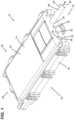
- FIG. 2is a perspective view of a cable having a rigid rod strength member and a portion of the closure of FIG. 1 , the closure being in an open configuration, and showing an example of a cable fixation assembly in accordance with the present disclosure.
- FIG. 3is a perspective view of a portion of the cable fixation assembly of FIG. 2 and a cable having a yarn strength member.
- FIG. 4is a perspective view of a portion of the cable fixation assembly and cable of FIG. 2 .
- FIG. 5is a perspective partial cross-sectional view of a portion of the cable fixation assembly and cable of FIG. 2 .
- FIG. 6is a partially exploded view of a portion of the cable fixation assembly of FIG. 2 .
- FIG. 7is a perspective view of the strength member anchor adapter of the cable fixation assembly of FIG. 2 .
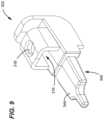
- FIG. 8is a further perspective view of the strength member anchor adapter of FIG. 6 .
- FIG. 9is a further perspective view of the strength member anchor adapter of FIG. 6 .
- FIG. 10is a further perspective view of the strength member anchor adapter of FIG. 6 .
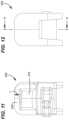
- FIG. 11is a proximal end view of the strength member anchor adapter of FIG. 6 .
- FIG. 12is a distal end view of the strength member anchor adapter of FIG. 6 .
- FIG. 13is a cross-sectional view of the strength member anchor adapter of FIG. 6 along the line A-A in FIG. 11 .
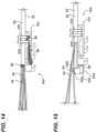
- FIG. 14is a view of an example cable fixation assembly in accordance with the present disclosure to which is secured a cable having a yarn strength member.
- FIG. 15is a view of the cable fixation assembly of FIG. 14 to which is secured a cable having a rigid rod strength member, the assembly also including an example strength member anchor adapter in accordance with the present disclosure.
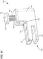
- FIG. 16is a perspective view of a further example cable fixation assembly in accordance the present disclosure.
- FIG. 17is a further perspective view of the cable fixation assembly of FIG. 16 .
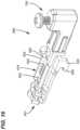
- FIG. 18is an exploded view of the cable fixation assembly of FIG. 16 .
- FIG. 19is a perspective view of a portion of the cable fixation assembly of FIG. 16 .
- FIG. 20is a further perspective view of the portion of the cable fixation assembly of FIG. 19 .
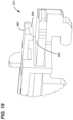
- FIG. 21is a perspective view of the strength member anchor adapter of the cable fixation assembly of FIG. 16 .
- FIG. 22is a perspective, cross-sectional view of the strength member anchor adapter of the cable fixation assembly of FIG. 16 .
- a telecommunications system 10includes a closure 12 having a first housing piece 14 and a second housing piece 16 configured to cooperate with each other to form the closure 12 that is re-enterable and re-closable. Sealing members are disposed to form a seal between the housing pieces when the closure 12 is closed, thereby minimizing ingress of contaminants (e.g., moisture, dust, etc.) into the interior volume 40 of the closure 12 .
- the closureextends from a proximal end 18 to a distal end 20 , and has a top 22 , and a bottom 24 .
- An example telecommunications cable 26enters the interior volume 40 of the closure 12 through a port 30 defined by the housing pieces 14 and 16 .
- the cable 26is defined by a longitudinal cable axis 38 and includes an outer jacket 28 that radially surrounds the cable axis 38 and protects and provides structural support to the cable, and particularly to the one or more optical fibers carried by the cable.
- the housing piecesdefine a plurality of ports 30 , 32 through which cables can enter the closure.
- the outer ports 30are configured to receive relatively large cables, such as feeder cables, while the inner ports 32 are configured to receive relatively small cables, such as drop cables or distribution cables.
- Positioned at the ports and between the housing pieces 14 and 16are cable port seal blocks 34 , 36 that can seal around the cables as they enter the closure and/or seal off the ports where no cable is present.
- the interior volume 40includes a fiber management area 42 that includes fiber management devices and structures such as fiber retainers 44 , splice holders 46 and splitter holders 48 .
- Optical fiberssuch as the optical fiber 64 entering the interior volume 40 via a cable 80 (having a longitudinal cable axis 81 , an outer jacket 82 , and a rigid rod strength member 84 ) are routed to the fiber management area 42 where they are managed, e.g., by storing them in loops, splicing them to other fibers, splitting them with splitters, etc.
- the fiberscan be individual fibers or groups of fibers. Groups of fibers can be loosely bundled, e.g., in protection tubes, or connected, such as in the case of ribbon fibers.
- the base plate 50Connected to the housing piece 16 and within the interior volume 40 is a base plate 50 .
- the base plate 50includes a plurality of elongate slots 52 elongated in the proximal to distal direction and extending between a proximal slot end 56 and a distal slot end 54 of the slot 52 .
- the slots 52extend through a thickness of the base plate 50 , extending between the top surface 58 and an opposite bottom surface of the base plate 50 .
- the cable fixation assembly 100includes a cable support body 102 supporting a cable 80 .
- the cable 80is secured to cable support body 102 with tie wraps 200 .
- the cable support body 102is elongate along a longitudinal axis 104 .
- the cable support body 102extends vertically from a top 114 of the cable support body 102 to a bottom 116 of the cable support body 102 .
- the cable support body 102is a unitary molded polymer structure. In some examples, the cable support body 102 includes metal.
- the cable support body 102defines a seat 118 having a horizontal cable support surface 120 facing vertically upwards and opposing walls 122 on opposite sides of the horizontal cable support surface 120 .
- the seat 118is seating the outer jacket 92 of a telecommunications cable 90 .
- the cable 90has a longitudinal axis 91 , carries one or more optical fibers 94 and a yarn strength member 96 (schematically represented).
- the outer jacket 92 of the cable 90is secured to the cable support body 102 with tie wraps 200 that are fed through tie wrap passages defined by the cable support body 102 and around the cable 90 .
- the cable support body 102includes a strength member anchoring arrangement including a radial channel 130 and a longitudinal channel 133 .
- the yarn strength member 96is placed in the radial channel 130 and the longitudinal channel 133 , and a free end portion of the yarn strength member 96 is then folded over the more proximal tie wrap 200 and tightened under the more distal tie wrap 200 to secure the strength member 96 to the cable support body 102 .
- the cable support bodyalso includes a coupler 131 for lockingly engaging a strength member anchor adapter for anchoring a rigid strength rod of a telecommunications cable.
- the cable support body 102includes legs 124 with feet 126 extending from the legs.
- the legs 124 and feet 126are configured to engage the slots 52 of the base plate 50 ( FIG. 2 ) to mount the cable support body 102 to the base plate 50 ( FIG. 2 ).
- a slot-engageable locking memberis positioned proximally to one of the feet 126 and configured to enter the same slot as the corresponding foot to minimize or prevent undesired proximally directed shifting of the cable support body 102 once it is mounted to the base plate 50 .
- the cable support body 102includes a coupler 131 to which the strength member anchor adapter 300 can be lockingly coupled and unlocked to be decoupled from the cable support body 102 .
- the strength member anchor adapter 300is adapted to anchor a rod strength remember, e.g., a rigid metal or fiberglass rod strength member. Coupling the adapter 300 to the cable support body 102 and decoupling the adapter 300 from the cable support body 102 allows the cable fixation assembly 100 to be easily converted between one that accommodates fixation of a cable having a rod strength member (and, optionally, also a yarn strength member) and a cable fixation assembly 100 that accommodates fixation of a cable having only a yarn strength member.
- the tie wrapssecure the outer jacket 82 of the cable 80 to the cable support body 102 .
- the tie wraps 200are zip ties.
- the tie wrapscan be, e.g., any form of tightenable strip, e.g., a twist tie, a hose clamp, etc.
- the strength member anchor adapter 300includes a main body 302 , a press screw 304 and a bracket 306 .
- the press screw 304includes a screw head 310 , and a threaded shaft 308 extending from the head 310 to a tip 312 of the shaft 308 .
- One or more of these components of the strength member anchor adaptercan be metallic or non-metallic (e.g., made from a polymeric material).
- the main body 302 of the strength member anchor adapter 300includes a passage wall 314 that defines a strength rod passage 316 , the passage wall 314 including a through hole 318 for receiving the press screw 304 .
- the bracket 306includes a press plate 320 , an upper plate 322 having a through hole 324 , and a connector 326 connecting the press plate 320 and the upper plate 322 .
- the bracket 306is configured to straddle an upper portion 328 of the passage wall 314 such that the press plate 320 is within the strength rod passage 316 and the upper plate 322 is outside of the strength rod passage and above the upper portion 328 of the passage wall 314 .
- the press plate 320is engageable by the tip 312 of the press screw 304 extending through the through hole 324 of the upper plate 322 and through the through hole 318 of the passage wall 314 to bend the press plate 320 at an obtuse angle ⁇ away from the vertical, which includes a nonzero acute angle relative to the horizontal ( FIG. 5 ), such that the press plate 320 is distally inclined downward as it extends away from the connector 326 .
- the main body 302 of the strength member anchor adapter 300includes a ramp 330 at a bottom of the strength rod passage 316 , the ramp 330 being distally inclined (i.e., as the ramp extends in the distal direction) upward relative to the horizontal.
- the inclines of the bent press plate 320 and the ramp 330approach each other in the distal direction.
- the strength rod 84 of the cable 80is squeezed between the ramp 330 and the bent press plate 320 to secure the strength rod 84 in a generally vertical central position of the strength rod passage 316 .
- the bent press plate 320engages the strength rod 84 distally of the shaft 308 of the press screw 304 .
- the vertical height H of the connector 326is generally equal to the vertical thickness T of the upper portion 328 of the passage wall 314 .
- the bracket 306is configured to frictionally hold itself to the upper portion 328 of the passage wall 314 against, e.g., a force of gravity. This self-retention feature of the bracket 306 facilitates handling of the strength member anchor adapter 300 and of securing a strength rod therein in that that there are fewer moving parts when properly placing the strength rod 84 , the bracket 306 and the press screw 304 for tightening the press screw 304 .
- the press plate 320cannot contact the strength rod 84 prior to bending the press plate 320 with the press screw 304 .
- the coupler 131includes a cavity 160 defined by the cable support body 102 and a resilient latch arm 162 extending distally away from the cavity 160 , the latch arm including a catch 164 .
- the main body 302 of the strength member anchor adapter 300includes a second coupler 340 having a shoulder 342 and a plug 344 extending proximally away from the shoulder 342 .
- the plug 344is adapted to be received in the cavity 160
- the shoulder 342is adapted to engage the catch 164 to lockingly couple the strength member anchor adapter 300 to the cable support body 102 .
- the latch arm 162can be flexed downward to disengage the catch 164 from the shoulder 342 , such that the plug 344 can then be removed from the cavity 160 .
- the plug 344 and the cavity 160are complementarily keyed to each other to permit receiving of the plug 344 by the cavity 160 in only one orientation.
- a transverse cross-section of the plug 344(transverse to the proximal to distal direction) is asymmetrical.
- the asymmetry of the plugcan provide for greater robustness of the plug at the side of the fixation assembly where the longitudinal channel of the strength member arrangement is disposed. The radial channel can reduce the robustness of the overall cable fixation assembly, while the complementary larger side of the plug 344 can the improve the overall robustness of the cable fixation assembly.
- the main body 302 of the strength member anchor adapter 300includes a distal stop 370 positioned distally of the strength rod passage 316 .
- the distal stop 370is a wall configured to stop creeping of the strength rod 84 distally beyond the distal stop 370 . Such creeping can occur when securing the cable 80 and/or when environmental conditions change, and is undesirable, as it can damage delicate optical fibers in the vicinity.
- FIG. 14shows an example cable fixation assembly 400 in accordance with the present disclosure to which is secured a cable 90 having an outer jacket 92 , optical fibers 94 , and a yarn strength member 96 .
- the outer jacket 92is secured to the cable support body 102 with a pair of tie wraps 200 .
- the yarn strength member 96is secured to the cable support body using the radial and longitudinal channels of the strength member anchor arrangement of the cable support body 102 , and including the tie wraps 200 .
- the cable fixation assembly 400does not include a strength rod anchor adapter. However, the cable support body 102 is adapted to couple a strength rod anchor adapter.
- FIG. 15is a view of the cable fixation assembly 500 to which is secured a cable 80 having an outer jacket 82 , optical fibers 64 , and a rod strength member 86 .
- a strength member anchor adapter 502is lockingly coupled to the cable support body 102 and includes a main body 504 and a press screw 506 .
- the rod strength member 86is anchored between a press plate of a bracket 508 of the adapter 502 and a bottom surface of a strength member passage defined by the main body 504 .
- the assembly 400can be converted to the assembly 500 by introducing and coupling the adapter 502 to the cable support body 102 .
- the assembly 500can be converted to the assembly 400 by decoupling the adapter 502 from the cable support body 102 and removing the adapter 502 .
- the assembly 600includes a cable support body 602 that is elongate along a longitudinal axis 604 between a proximal end 601 and a distal end 603 .
- the cable support body 602extends vertically from a top 614 of the cable support body 602 to a bottom 616 of the cable support body 602 .
- the cable support body 602is a unitary molded polymer structure. In some examples, the cable support body 602 includes metal.
- the cable support body 602defines a seat 618 having a horizontal cable support surface 620 facing vertically upwards and opposing walls 622 on opposite sides of the horizontal cable support surface 620 .
- the cable support body 602includes tie wrap passages that receive tie wrap passages for securing the cable to the cable support body 602 .
- the cable support body 602includes a strength member anchoring arrangement including a radial channel 630 and a longitudinal channel 633 .
- a yarn strength member 96can be placed in the radial channel 630 and the longitudinal channel 633 and secured with tie wraps as described above.
- the cable support body 602includes legs 624 with feet 626 extending from the legs.
- the legs 624 and feet 626are configured to engage the slots 52 of the base plate 50 ( FIG. 2 ) to mount the cable support body 102 to the base plate 50 ( FIG. 2 ).
- a slot-engageable locking memberis positioned proximally to one of the feet 626 and configured to enter the same slot as the corresponding foot to minimize or prevent undesired proximally directed shifting of the cable support body 602 once it is mounted to the base plate 50 .
- the cable support body 602includes a coupler 131 to which the strength member anchor adapter 700 can be lockingly coupled and unlocked to be decoupled from the cable support body 602 .
- the strength member anchor adapter 700is adapted to anchor a rod strength remember, e.g., a rigid metal or fiberglass rod strength member. Coupling the adapter 700 to the cable support body 602 and decoupling the adapter 700 from the cable support body 602 allows the cable fixation assembly 600 to be easily converted between one that accommodates fixation of a cable having a rod strength member (and, optionally, also a yarn strength member) and a cable fixation assembly 600 that accommodates fixation of a cable having only a yarn strength member.
- the strength member anchor adapter 700includes a main body 702 , a press screw 704 and a bracket 706 .
- the press screw 704includes a screw head 710 , and a threaded shaft 708 extending from the head 710 to a tip 712 of the shaft 708 .
- One or more of these components of the strength member anchor adaptercan be metallic or non-metallic (e.g., made from a polymeric material).
- the main body 702 of the strength member anchor adapter 700includes a passage wall 714 that defines a strength rod passage 716 , the passage wall 714 including a through hole 718 for receiving the press screw 704 .
- the bracket 706includes a press plate 720 , an upper plate 722 having a through hole 724 , a connector 726 connecting the press plate 720 and the upper plate 722 , and a retainer finger 727 opposite the connector 726 and adapted to engage the main body 702 to better stabilize the bracket 706 relative to the main body 702 .
- the bracket 706is configured to straddle an upper portion 728 of the passage wall 714 such that the press plate 720 is within the strength rod passage 716 and the upper plate 722 is outside of the strength rod passage and above the upper portion 728 of the passage wall 714 .
- the press plate 720is engageable by the tip 712 of the press screw 704 extending through the through hole 724 of the upper plate 722 and through the through hole 718 of the passage wall 714 to bend the press plate 720 at an obtuse angle ⁇ away from the vertical, which includes a nonzero acute angle relative to the horizontal, such that the press plate 720 is distally inclined downward as it extends away from the connector 726 .
- the main body 702 of the strength member anchor adapter 700includes a rod engagement surface 730 (in this example, the surface 730 is, but need not be, horizontal) at a bottom of the strength rod passage 716 .
- a strength rodcan be squeezed between the rod engagement surface 730 and the bent press plate 720 to secure the strength rod in the strength rod passage 716 .
- the vertical height H 2 of the connector 726is generally equal to the vertical thickness T 2 of the upper portion 728 of the passage wall 714 .
- the bracket 706is configured to frictionally hold itself to the upper portion 728 of the passage wall 714 against, e.g., a force of gravity. This self-retention feature of the bracket 706 facilitates handling of the strength member anchor adapter 700 and of securing a strength rod therein in that that there are fewer moving parts when properly placing the strength rod, the bracket 706 , and the press screw 704 for tightening the press screw 704 .
- the coupler 631includes an upper latch arm 660 and a lower support surface 662 .
- the latch arm 660includes a catch 664 .
- the main body 702 of the strength member anchor adapter 700includes a second coupler 740 having an upper latch engagement arm 743 defining an opening 742 for receiving the catch 664 , and a lower support arm 744 that slots between the latch arm 660 and the lower support surface 662 for a robust coupling of the adapter 700 and the cable support body 600 .
- the latch arm 660can be flexed upward to disengage the catch 664 from the opening 742 , such that the adapter 700 can then be removed from the assembly 600 .
- the main body 702 of the strength member anchor adapter 700includes a distal stop 770 positioned at the distal end of the strength rod passage 716 .
- the distal stop 770is a wall configured to stop creeping of a strength rod distally beyond the distal stop 770 . Such creeping can occur when securing the cable 80 and/or when environmental conditions change, and is undesirable, as it can damage delicate optical fibers in the vicinity.
Landscapes
- Physics & Mathematics (AREA)
- General Physics & Mathematics (AREA)
- Optics & Photonics (AREA)
- Cable Accessories (AREA)
Abstract
Description
Claims (17)
Priority Applications (1)
| Application Number | Priority Date | Filing Date | Title |
|---|---|---|---|
| US17/761,105US11867962B2 (en) | 2019-09-16 | 2020-09-15 | Cable fixation assembly with strength member anchor adapter |
Applications Claiming Priority (3)
| Application Number | Priority Date | Filing Date | Title |
|---|---|---|---|
| US201962900841P | 2019-09-16 | 2019-09-16 | |
| US17/761,105US11867962B2 (en) | 2019-09-16 | 2020-09-15 | Cable fixation assembly with strength member anchor adapter |
| PCT/US2020/050876WO2021055356A1 (en) | 2019-09-16 | 2020-09-15 | Cable fixation assembly with strength member anchor adapter |
Publications (2)
| Publication Number | Publication Date |
|---|---|
| US20220334319A1 US20220334319A1 (en) | 2022-10-20 |
| US11867962B2true US11867962B2 (en) | 2024-01-09 |
Family
ID=74883671
Family Applications (1)
| Application Number | Title | Priority Date | Filing Date |
|---|---|---|---|
| US17/761,105ActiveUS11867962B2 (en) | 2019-09-16 | 2020-09-15 | Cable fixation assembly with strength member anchor adapter |
Country Status (5)
| Country | Link |
|---|---|
| US (1) | US11867962B2 (en) |
| EP (1) | EP4031918A4 (en) |
| AU (1) | AU2020348681B2 (en) |
| MX (1) | MX2022002955A (en) |
| WO (1) | WO2021055356A1 (en) |
Families Citing this family (6)
| Publication number | Priority date | Publication date | Assignee | Title |
|---|---|---|---|---|
| AU2020210734B2 (en) | 2019-01-22 | 2025-02-20 | Commscope Technologies Llc | Cable fixation assemblies for telecommunications enclosures |
| WO2020219571A1 (en) | 2019-04-22 | 2020-10-29 | Commscope Technologies Llc | Cable fixation assembly with improved strength member yarn anchoring and method of anchoring cable strength member yarn |
| US11867872B2 (en) | 2020-02-11 | 2024-01-09 | Commscope Technologies Llc | Cable fixation devices and arrangements with improved installation and space utilization at telecommunications enclosures |
| EP4341737A1 (en)* | 2021-05-19 | 2024-03-27 | Preformed Line Products Co. | Cable restraints for splice enclosures and splice enclosures including cable restraints |
| EP4396620A4 (en)* | 2021-08-31 | 2025-07-09 | Commscope Technologies Llc | ADJUSTABLE MOUNTING DEVICE ARRANGEMENT FOR FASTENING DIFFERENT NUMBERS OF CABLES TO A TELECOMMUNICATIONS ENCLOSURE |
| CN114640078B (en)* | 2022-04-11 | 2023-05-30 | 山东省煤田地质局物探测量队 | Multichannel cable transfer box for electrical prospecting based on electromagnetic method |
Citations (74)
| Publication number | Priority date | Publication date | Assignee | Title |
|---|---|---|---|---|
| US3552696A (en) | 1969-05-29 | 1971-01-05 | Emil H Orenick | Cable retainer |
| US4279466A (en)* | 1978-02-21 | 1981-07-21 | Bunker Ramo Corporation | Hermaphroditic fiber optic connector |
| US4552998A (en) | 1983-05-16 | 1985-11-12 | Ziegler Hans J | Apparatus for alternatively and selectively connecting telephone cable shield ground straps to a ground rod and including a ground bracket |
| DE3726718A1 (en) | 1986-04-07 | 1989-02-23 | Siemens Ag | DEVICE FOR ATTACHING A MECHANICAL CONNECTION TO THE CABLE SHEATH OF AN OPTICAL CABLE |
| US4986761A (en) | 1989-05-26 | 1991-01-22 | Gladden Jr Robert H | Cable connecting device |
| US4991928A (en)* | 1990-02-20 | 1991-02-12 | Siecor Corporation | Movable clamp for fiber optic enclosures |
| US5097529A (en)* | 1991-03-22 | 1992-03-17 | At&T Bell Laboratories | Space-saving optical fiber cable closure |
| US5121458A (en) | 1991-04-05 | 1992-06-09 | Alcatel Na Cable Systems, Inc. | Preterminated fiber optic cable |
| US5440666A (en) | 1994-06-22 | 1995-08-08 | At&T Corp. | Splice closure and grip block |
| US5455391A (en) | 1991-06-06 | 1995-10-03 | N.V. Raychem S.A. | Cable sealing |
| US5491766A (en) | 1993-04-16 | 1996-02-13 | Raychem Corporation | Bonding assembly for fiber optic cable and associated method |
| US5502282A (en) | 1993-08-11 | 1996-03-26 | Siemens Aktiengesellschaft | Sleeve head for a cable sleeve having a seal insert composed of elastic material |
| WO1996024185A1 (en) | 1995-02-02 | 1996-08-08 | N.V. Raychem S.A. | Cable splice closure |
| GB2298053A (en) | 1995-02-07 | 1996-08-21 | Manorbeach Ltd | An optical fibre management system |
| EP0646294B1 (en) | 1992-06-15 | 1996-11-06 | N.V. Raychem S.A. | Cable sealing and/or feedthrough device |
| EP0646295B1 (en) | 1992-06-15 | 1996-12-27 | N.V. Raychem S.A. | Cable sealing device |
| WO1997012268A1 (en) | 1995-09-29 | 1997-04-03 | Psi Telecommunications, Inc. | Fiber optic cable splice closure |
| US5696351A (en) | 1995-03-10 | 1997-12-09 | Ericsson Raynet | Cable retention and sealing device |
| US5775702A (en) | 1994-03-07 | 1998-07-07 | N.V. Raychem S.A. | Sealing arrangement |
| US5793921A (en)* | 1995-03-20 | 1998-08-11 | Psi Telecommunications, Inc. | Kit and method for converting a conductive cable closure to a fiber optic cable closure |
| US5814770A (en) | 1993-11-08 | 1998-09-29 | Raychem Corporation | Cable closure |
| US5824961A (en) | 1997-04-30 | 1998-10-20 | Lucent Technologies Inc. | Central strength member anchor for optical fiber cables |
| US5883333A (en) | 1994-09-21 | 1999-03-16 | N.V. Raychem S.A. | Cable splice closure |
| US6051792A (en) | 1994-09-21 | 2000-04-18 | N.V. Raychem S.A. | Retention strip |
| US6150608A (en) | 1996-05-02 | 2000-11-21 | N.V. Raychem S.A. | Seal for sealing an aperture |
| US6269214B1 (en)* | 1998-08-04 | 2001-07-31 | Pouyet, S.A. | Device for interconnecting optical fiber cables |
| US6322378B1 (en) | 1999-12-14 | 2001-11-27 | Electric Motion Company, Inc. | Conductor protector for ground clamp |
| WO2002073281A1 (en) | 2001-03-14 | 2002-09-19 | Tyco Electronics Raychem Nv | Cable termination device |
| US20040226734A1 (en) | 2000-09-01 | 2004-11-18 | Senior Industries, Inc. | Universal ground strap assembly |
| WO2005020400A1 (en) | 2003-08-20 | 2005-03-03 | Ccs Technology, Inc. | Clamping device for optical cables, and cable joint |
| US6933442B2 (en) | 2003-02-12 | 2005-08-23 | Senior Industries, Inc. | Methods and apparatus to secure a ground strap assembly to an electrically conductive member |
| WO2006009671A2 (en) | 2004-06-17 | 2006-01-26 | Mustafa Celik | Defining statistical sensitivity for timing optimization of logic circuits with large-scale process and environmental variations |
| US20060150483A1 (en) | 2005-01-05 | 2006-07-13 | Esmail Zayer | Tree support assembly |
| US20060275006A1 (en) | 2005-06-03 | 2006-12-07 | Telect, Inc. | Fiber breakout system |
| US20060283619A1 (en) | 2005-06-21 | 2006-12-21 | Adc Telecommunications, Inc. | Grounding device for armored cable |
| US20070235422A1 (en) | 2006-04-04 | 2007-10-11 | Bornemann Brian J | Cable management system for plasma cutter |
| WO2009040566A1 (en) | 2007-09-24 | 2009-04-02 | Tyco Electronics Raychem Nv | Cable termination clamp with inclined gripping means |
| US20100054688A1 (en) | 2008-09-03 | 2010-03-04 | Julian Mullaney | Cable strain relief clamping devices and methods for using the same |
| US20100061692A1 (en) | 2007-03-01 | 2010-03-11 | Adc Gmbh | Multifiber loose buffer receiving element for a distributing device for optical waveguides |
| US20100092147A1 (en)* | 2006-10-16 | 2010-04-15 | Christophe Desard | Optical fiber cable retention device |
| US20110075974A1 (en)* | 2009-09-30 | 2011-03-31 | Japan Aviation Electronics Industry, Limited | Optical connector and optical connector cable |
| US20120177334A1 (en) | 2010-10-26 | 2012-07-12 | Matthew Holmberg | System and method for anchoring fiber optic cables to provide strain relief |
| JP2012154419A (en) | 2011-01-26 | 2012-08-16 | Hitachi Systems Ltd | Cable bundling device |
| US20120230646A1 (en) | 2011-03-07 | 2012-09-13 | Roy Keller Thompson | Cable Strain Relief Clamping Devices and Methods for Using the Same |
| EP2551708A1 (en) | 2011-07-26 | 2013-01-30 | Tyco Electronics Raychem BVBA | Clamp terminal comprising adaptor and kit for assembling clamp terminal comprising adaptor |
| US20130058616A1 (en) | 2011-09-02 | 2013-03-07 | Monique Lise Cote | Removable strain relief brackets for securing fiber optic cables and/or optical fibers to fiber optic equipment, and related assemblies and methods |
| WO2013037746A1 (en) | 2011-09-16 | 2013-03-21 | Tyco Electronics Raychem Bvba | Holding fixture for holding at least one cable with an affixing member and a clamping member |
| WO2013092220A2 (en) | 2011-12-19 | 2013-06-27 | Tyco Electronics Raychem Bvba | Strain relief device for a fiber optic cable |
| US20130243386A1 (en)* | 2010-12-01 | 2013-09-19 | 3M Innovative Properties Company | Fiber organizer and distribution box |
| WO2013149922A1 (en) | 2012-04-03 | 2013-10-10 | Tyco Electronics Raychem Bvba | Cable fixation bracket |
| WO2013149846A1 (en) | 2012-04-03 | 2013-10-10 | Tyco Electronics Raychem Bvba | Telecommunications enclosure and organizer |
| US20130315551A1 (en)* | 2012-05-25 | 2013-11-28 | Tyco Electronics Raychem Bvba | Filler rod for cable seal and method |
| EP2647095B1 (en) | 2010-11-29 | 2014-08-27 | 3M Innovative Properties Company | Strain relief device |
| US20140241674A1 (en)* | 2011-11-09 | 2014-08-28 | Corning Optical Communications LLC | Cable assembly with cable attach structure having off-axis fiber routing |
| US20140270677A1 (en) | 2013-03-13 | 2014-09-18 | Adc Telecommunications, Inc. | Anchoring cables to rack with self-locking cable clamp arrangements |
| US20150093090A1 (en) | 2012-04-03 | 2015-04-02 | Tyco Electronics Raychem Bvba | Cable clamp and telecommunications enclosure |
| US20160077300A1 (en) | 2013-04-24 | 2016-03-17 | Tomas FUCSEK | Optical fiber distribution system |
| KR101606203B1 (en) | 2015-08-10 | 2016-03-25 | 폴그린테크(주) | Intrusion detection device for structure blocked |
| WO2017114936A1 (en) | 2015-12-31 | 2017-07-06 | CommScope Connectivity Belgium BVBA | Cable fixation devices and methods |
| US9753239B2 (en) | 2014-06-26 | 2017-09-05 | Commscope Technologies Llc | Fiber optic cable retention |
| US20180157002A1 (en)* | 2015-06-19 | 2018-06-07 | Commscope Technologies Llc | Optical termination enclosure |
| WO2018154125A1 (en) | 2017-02-27 | 2018-08-30 | CommScope Connectivity Belgium BVBA | Fiber optic cable fixation device and fiber optic cable mounting system comprising same |
| US20180261986A1 (en) | 2017-03-07 | 2018-09-13 | CommScope Connectivity Belgium BVBA | Cable grounding assembly for telecommunications enclosure |
| WO2018208518A1 (en) | 2017-05-08 | 2018-11-15 | Commscope Technologies Llc | Fiber-optic breakout transition assembly |
| WO2019034613A1 (en) | 2017-08-15 | 2019-02-21 | CommScope Connectivity Belgium BVBA | Cable fixation assembly for a cable having a strength member |
| WO2019072852A1 (en) | 2017-10-09 | 2019-04-18 | CommScope Connectivity Belgium BVBA | Cable fixation devices and methods |
| WO2019072782A1 (en) | 2017-10-09 | 2019-04-18 | CommScope Connectivity Belgium BVBA | Cable fixation devices and methods |
| US10495838B2 (en) | 2014-03-25 | 2019-12-03 | CommScope Connectivity Belgium BVBA | Adapter tube for a cable fixation and sealing system |
| WO2019241502A1 (en) | 2018-06-15 | 2019-12-19 | Commscope Technologies Llc | Methods, kits, and systems incorporating a self-amalgamating tape for clamping fiber optic cable |
| WO2020104395A1 (en) | 2018-11-19 | 2020-05-28 | CommScope Connectivity Belgium BVBA | Modularized cable termination apparatus |
| WO2020154418A1 (en) | 2019-01-22 | 2020-07-30 | Commscope Technologies Llc | Cable fixation assemblies for telecommunications enclosures |
| WO2020212365A1 (en) | 2019-04-15 | 2020-10-22 | CommScope Connectivity Belgium BVBA | Cable seal and attachment assembly |
| WO2020219571A1 (en) | 2019-04-22 | 2020-10-29 | Commscope Technologies Llc | Cable fixation assembly with improved strength member yarn anchoring and method of anchoring cable strength member yarn |
| US20230129717A1 (en)* | 2020-02-11 | 2023-04-27 | Commscope Technologies Llc | Cable fixation devices and arrangements with improved installation and space utilization at telecommunications enclosures |
- 2020
- 2020-09-15USUS17/761,105patent/US11867962B2/enactiveActive
- 2020-09-15AUAU2020348681Apatent/AU2020348681B2/enactiveActive
- 2020-09-15WOPCT/US2020/050876patent/WO2021055356A1/ennot_activeCeased
- 2020-09-15EPEP20866524.0Apatent/EP4031918A4/enactivePending
- 2020-09-15MXMX2022002955Apatent/MX2022002955A/enunknown
Patent Citations (80)
| Publication number | Priority date | Publication date | Assignee | Title |
|---|---|---|---|---|
| US3552696A (en) | 1969-05-29 | 1971-01-05 | Emil H Orenick | Cable retainer |
| US4279466A (en)* | 1978-02-21 | 1981-07-21 | Bunker Ramo Corporation | Hermaphroditic fiber optic connector |
| US4552998A (en) | 1983-05-16 | 1985-11-12 | Ziegler Hans J | Apparatus for alternatively and selectively connecting telephone cable shield ground straps to a ground rod and including a ground bracket |
| DE3726718A1 (en) | 1986-04-07 | 1989-02-23 | Siemens Ag | DEVICE FOR ATTACHING A MECHANICAL CONNECTION TO THE CABLE SHEATH OF AN OPTICAL CABLE |
| US4986761A (en) | 1989-05-26 | 1991-01-22 | Gladden Jr Robert H | Cable connecting device |
| US4991928A (en)* | 1990-02-20 | 1991-02-12 | Siecor Corporation | Movable clamp for fiber optic enclosures |
| US5097529A (en)* | 1991-03-22 | 1992-03-17 | At&T Bell Laboratories | Space-saving optical fiber cable closure |
| US5121458A (en) | 1991-04-05 | 1992-06-09 | Alcatel Na Cable Systems, Inc. | Preterminated fiber optic cable |
| US5455391A (en) | 1991-06-06 | 1995-10-03 | N.V. Raychem S.A. | Cable sealing |
| EP0646294B1 (en) | 1992-06-15 | 1996-11-06 | N.V. Raychem S.A. | Cable sealing and/or feedthrough device |
| EP0646295B1 (en) | 1992-06-15 | 1996-12-27 | N.V. Raychem S.A. | Cable sealing device |
| US5491766A (en) | 1993-04-16 | 1996-02-13 | Raychem Corporation | Bonding assembly for fiber optic cable and associated method |
| US5502282A (en) | 1993-08-11 | 1996-03-26 | Siemens Aktiengesellschaft | Sleeve head for a cable sleeve having a seal insert composed of elastic material |
| US5814770A (en) | 1993-11-08 | 1998-09-29 | Raychem Corporation | Cable closure |
| US5775702A (en) | 1994-03-07 | 1998-07-07 | N.V. Raychem S.A. | Sealing arrangement |
| US5440666A (en) | 1994-06-22 | 1995-08-08 | At&T Corp. | Splice closure and grip block |
| US5883333A (en) | 1994-09-21 | 1999-03-16 | N.V. Raychem S.A. | Cable splice closure |
| US6051792A (en) | 1994-09-21 | 2000-04-18 | N.V. Raychem S.A. | Retention strip |
| WO1996024185A1 (en) | 1995-02-02 | 1996-08-08 | N.V. Raychem S.A. | Cable splice closure |
| GB2298053A (en) | 1995-02-07 | 1996-08-21 | Manorbeach Ltd | An optical fibre management system |
| US5696351A (en) | 1995-03-10 | 1997-12-09 | Ericsson Raynet | Cable retention and sealing device |
| US5793921A (en)* | 1995-03-20 | 1998-08-11 | Psi Telecommunications, Inc. | Kit and method for converting a conductive cable closure to a fiber optic cable closure |
| WO1997012268A1 (en) | 1995-09-29 | 1997-04-03 | Psi Telecommunications, Inc. | Fiber optic cable splice closure |
| US6150608A (en) | 1996-05-02 | 2000-11-21 | N.V. Raychem S.A. | Seal for sealing an aperture |
| US5824961A (en) | 1997-04-30 | 1998-10-20 | Lucent Technologies Inc. | Central strength member anchor for optical fiber cables |
| US6269214B1 (en)* | 1998-08-04 | 2001-07-31 | Pouyet, S.A. | Device for interconnecting optical fiber cables |
| US6322378B1 (en) | 1999-12-14 | 2001-11-27 | Electric Motion Company, Inc. | Conductor protector for ground clamp |
| US20040226734A1 (en) | 2000-09-01 | 2004-11-18 | Senior Industries, Inc. | Universal ground strap assembly |
| WO2002073281A1 (en) | 2001-03-14 | 2002-09-19 | Tyco Electronics Raychem Nv | Cable termination device |
| US6933442B2 (en) | 2003-02-12 | 2005-08-23 | Senior Industries, Inc. | Methods and apparatus to secure a ground strap assembly to an electrically conductive member |
| WO2005020400A1 (en) | 2003-08-20 | 2005-03-03 | Ccs Technology, Inc. | Clamping device for optical cables, and cable joint |
| WO2006009671A2 (en) | 2004-06-17 | 2006-01-26 | Mustafa Celik | Defining statistical sensitivity for timing optimization of logic circuits with large-scale process and environmental variations |
| US20060150483A1 (en) | 2005-01-05 | 2006-07-13 | Esmail Zayer | Tree support assembly |
| US20060275006A1 (en) | 2005-06-03 | 2006-12-07 | Telect, Inc. | Fiber breakout system |
| US7254307B2 (en) | 2005-06-03 | 2007-08-07 | Telect Inc. | Fiber breakout system |
| US20060283619A1 (en) | 2005-06-21 | 2006-12-21 | Adc Telecommunications, Inc. | Grounding device for armored cable |
| US20070235422A1 (en) | 2006-04-04 | 2007-10-11 | Bornemann Brian J | Cable management system for plasma cutter |
| US20100092147A1 (en)* | 2006-10-16 | 2010-04-15 | Christophe Desard | Optical fiber cable retention device |
| US20100061692A1 (en) | 2007-03-01 | 2010-03-11 | Adc Gmbh | Multifiber loose buffer receiving element for a distributing device for optical waveguides |
| WO2009040566A1 (en) | 2007-09-24 | 2009-04-02 | Tyco Electronics Raychem Nv | Cable termination clamp with inclined gripping means |
| US20100054688A1 (en) | 2008-09-03 | 2010-03-04 | Julian Mullaney | Cable strain relief clamping devices and methods for using the same |
| US20110075974A1 (en)* | 2009-09-30 | 2011-03-31 | Japan Aviation Electronics Industry, Limited | Optical connector and optical connector cable |
| US20120177334A1 (en) | 2010-10-26 | 2012-07-12 | Matthew Holmberg | System and method for anchoring fiber optic cables to provide strain relief |
| EP2647095B1 (en) | 2010-11-29 | 2014-08-27 | 3M Innovative Properties Company | Strain relief device |
| US20130243386A1 (en)* | 2010-12-01 | 2013-09-19 | 3M Innovative Properties Company | Fiber organizer and distribution box |
| JP2012154419A (en) | 2011-01-26 | 2012-08-16 | Hitachi Systems Ltd | Cable bundling device |
| WO2012121955A1 (en) | 2011-03-07 | 2012-09-13 | Tyco Electronics Corporation | Cable strain relief clamping devices and methods for using the same |
| US20120230646A1 (en) | 2011-03-07 | 2012-09-13 | Roy Keller Thompson | Cable Strain Relief Clamping Devices and Methods for Using the Same |
| US8903216B2 (en) | 2011-03-07 | 2014-12-02 | Tyco Electronics Corporation | Cable strain relief clamping devices and methods for using the same |
| EP2551708A1 (en) | 2011-07-26 | 2013-01-30 | Tyco Electronics Raychem BVBA | Clamp terminal comprising adaptor and kit for assembling clamp terminal comprising adaptor |
| US20130058616A1 (en) | 2011-09-02 | 2013-03-07 | Monique Lise Cote | Removable strain relief brackets for securing fiber optic cables and/or optical fibers to fiber optic equipment, and related assemblies and methods |
| WO2013037746A1 (en) | 2011-09-16 | 2013-03-21 | Tyco Electronics Raychem Bvba | Holding fixture for holding at least one cable with an affixing member and a clamping member |
| US20140241674A1 (en)* | 2011-11-09 | 2014-08-28 | Corning Optical Communications LLC | Cable assembly with cable attach structure having off-axis fiber routing |
| WO2013092220A2 (en) | 2011-12-19 | 2013-06-27 | Tyco Electronics Raychem Bvba | Strain relief device for a fiber optic cable |
| US20140314388A1 (en) | 2011-12-19 | 2014-10-23 | Tyco Electronics Raychem Bvba | Strain relief device for a fiber optic cable |
| US20150093090A1 (en) | 2012-04-03 | 2015-04-02 | Tyco Electronics Raychem Bvba | Cable clamp and telecommunications enclosure |
| WO2013149846A1 (en) | 2012-04-03 | 2013-10-10 | Tyco Electronics Raychem Bvba | Telecommunications enclosure and organizer |
| WO2013149922A1 (en) | 2012-04-03 | 2013-10-10 | Tyco Electronics Raychem Bvba | Cable fixation bracket |
| US20150168663A1 (en) | 2012-04-03 | 2015-06-18 | Tyco Electronics Raychem Bvba | Telecommunications enclosure organizer |
| US20130315551A1 (en)* | 2012-05-25 | 2013-11-28 | Tyco Electronics Raychem Bvba | Filler rod for cable seal and method |
| US20140270677A1 (en) | 2013-03-13 | 2014-09-18 | Adc Telecommunications, Inc. | Anchoring cables to rack with self-locking cable clamp arrangements |
| US20160077300A1 (en) | 2013-04-24 | 2016-03-17 | Tomas FUCSEK | Optical fiber distribution system |
| US10495838B2 (en) | 2014-03-25 | 2019-12-03 | CommScope Connectivity Belgium BVBA | Adapter tube for a cable fixation and sealing system |
| US9753239B2 (en) | 2014-06-26 | 2017-09-05 | Commscope Technologies Llc | Fiber optic cable retention |
| US20180157002A1 (en)* | 2015-06-19 | 2018-06-07 | Commscope Technologies Llc | Optical termination enclosure |
| US10209473B2 (en) | 2015-06-19 | 2019-02-19 | Commscope Technologies Llc | Optical termination enclosure |
| KR101606203B1 (en) | 2015-08-10 | 2016-03-25 | 폴그린테크(주) | Intrusion detection device for structure blocked |
| WO2017114936A1 (en) | 2015-12-31 | 2017-07-06 | CommScope Connectivity Belgium BVBA | Cable fixation devices and methods |
| WO2018154125A1 (en) | 2017-02-27 | 2018-08-30 | CommScope Connectivity Belgium BVBA | Fiber optic cable fixation device and fiber optic cable mounting system comprising same |
| US20180261986A1 (en) | 2017-03-07 | 2018-09-13 | CommScope Connectivity Belgium BVBA | Cable grounding assembly for telecommunications enclosure |
| WO2018208518A1 (en) | 2017-05-08 | 2018-11-15 | Commscope Technologies Llc | Fiber-optic breakout transition assembly |
| WO2019034613A1 (en) | 2017-08-15 | 2019-02-21 | CommScope Connectivity Belgium BVBA | Cable fixation assembly for a cable having a strength member |
| WO2019072852A1 (en) | 2017-10-09 | 2019-04-18 | CommScope Connectivity Belgium BVBA | Cable fixation devices and methods |
| WO2019072782A1 (en) | 2017-10-09 | 2019-04-18 | CommScope Connectivity Belgium BVBA | Cable fixation devices and methods |
| WO2019241502A1 (en) | 2018-06-15 | 2019-12-19 | Commscope Technologies Llc | Methods, kits, and systems incorporating a self-amalgamating tape for clamping fiber optic cable |
| WO2020104395A1 (en) | 2018-11-19 | 2020-05-28 | CommScope Connectivity Belgium BVBA | Modularized cable termination apparatus |
| WO2020154418A1 (en) | 2019-01-22 | 2020-07-30 | Commscope Technologies Llc | Cable fixation assemblies for telecommunications enclosures |
| WO2020212365A1 (en) | 2019-04-15 | 2020-10-22 | CommScope Connectivity Belgium BVBA | Cable seal and attachment assembly |
| WO2020219571A1 (en) | 2019-04-22 | 2020-10-29 | Commscope Technologies Llc | Cable fixation assembly with improved strength member yarn anchoring and method of anchoring cable strength member yarn |
| US20230129717A1 (en)* | 2020-02-11 | 2023-04-27 | Commscope Technologies Llc | Cable fixation devices and arrangements with improved installation and space utilization at telecommunications enclosures |
Non-Patent Citations (2)
| Title |
|---|
| European Extended Search Report for PCT/US2020/050876 dated Aug. 21, 2023 (6 pages). |
| International Search Report and Written Opinion of the International Searching Authority for International Patent Application No. PCT/US2020/050876 dated Dec. 24, 2020, 11 pages. |
Also Published As
| Publication number | Publication date |
|---|---|
| WO2021055356A1 (en) | 2021-03-25 |
| US20220334319A1 (en) | 2022-10-20 |
| AU2020348681B2 (en) | 2025-10-02 |
| AU2020348681A1 (en) | 2022-04-28 |
| EP4031918A1 (en) | 2022-07-27 |
| EP4031918A4 (en) | 2023-09-20 |
| MX2022002955A (en) | 2022-05-10 |
Similar Documents
| Publication | Publication Date | Title |
|---|---|---|
| US11867962B2 (en) | Cable fixation assembly with strength member anchor adapter | |
| US10473873B2 (en) | Fiber optic enclosure with cable management drawer | |
| US10509191B2 (en) | Optical termination enclosure | |
| US20250085500A1 (en) | Cable fixation assemblies for telecommunications enclosures | |
| US20250264683A1 (en) | Cable fixation devices and arrangements with improved installation and space utilization at telecommunications enclosures | |
| US11841543B2 (en) | Cable fixation assembly with improved strength member yarn anchoring and method of anchoring cable strength member yarn | |
| US8620128B2 (en) | System and method for anchoring fiber optic cables to provide strain relief | |
| US11860437B2 (en) | Cable fixation assembly with tie wrap passage having preferred insertion direction | |
| WO2021011386A1 (en) | Cable fixation assembly and method with floating cable support | |
| US12160056B2 (en) | Easy mounting cable grounding assemblies for telecommunications enclosures | |
| US10054741B2 (en) | Fiber optic enclosure assembly | |
| US20230314728A1 (en) | Fiber optic enclosure with a side cable entrance | |
| US20250116836A1 (en) | Cable fixation devices and arrangements with improved fixation features for telecommunications enclosures | |
| US20100104247A1 (en) | Optical access network system |
Legal Events
| Date | Code | Title | Description |
|---|---|---|---|
| AS | Assignment | Owner name:COMMSCOPE TECHNOLOGIES LLC, NORTH CAROLINA Free format text:ASSIGNMENT OF ASSIGNORS INTEREST;ASSIGNORS:CAMS, EDDY LUC;GEENS, JOHAN;SIGNING DATES FROM 20210527 TO 20210708;REEL/FRAME:059286/0503 | |
| FEPP | Fee payment procedure | Free format text:ENTITY STATUS SET TO UNDISCOUNTED (ORIGINAL EVENT CODE: BIG.); ENTITY STATUS OF PATENT OWNER: LARGE ENTITY | |
| STPP | Information on status: patent application and granting procedure in general | Free format text:DOCKETED NEW CASE - READY FOR EXAMINATION | |
| STPP | Information on status: patent application and granting procedure in general | Free format text:RESPONSE TO NON-FINAL OFFICE ACTION ENTERED AND FORWARDED TO EXAMINER | |
| STPP | Information on status: patent application and granting procedure in general | Free format text:EX PARTE QUAYLE ACTION MAILED | |
| STPP | Information on status: patent application and granting procedure in general | Free format text:RESPONSE TO EX PARTE QUAYLE ACTION ENTERED AND FORWARDED TO EXAMINER | |
| STPP | Information on status: patent application and granting procedure in general | Free format text:NOTICE OF ALLOWANCE MAILED -- APPLICATION RECEIVED IN OFFICE OF PUBLICATIONS | |
| STPP | Information on status: patent application and granting procedure in general | Free format text:PUBLICATIONS -- ISSUE FEE PAYMENT VERIFIED | |
| STCF | Information on status: patent grant | Free format text:PATENTED CASE | |
| AS | Assignment | Owner name:JPMORGAN CHASE BANK, N.A., AS COLLATERAL AGENT, NEW YORK Free format text:PATENT SECURITY AGREEMENT (ABL);ASSIGNORS:ARRIS ENTERPRISES LLC;COMMSCOPE TECHNOLOGIES LLC;COMMSCOPE, INC. OF NORTH CAROLINA;REEL/FRAME:067252/0657 Effective date:20240425 Owner name:JPMORGAN CHASE BANK, N.A., AS COLLATERAL AGENT, NEW YORK Free format text:PATENT SECURITY AGREEMENT (TERM);ASSIGNORS:ARRIS ENTERPRISES LLC;COMMSCOPE TECHNOLOGIES LLC;COMMSCOPE, INC. OF NORTH CAROLINA;REEL/FRAME:067259/0697 Effective date:20240425 | |
| AS | Assignment | Owner name:APOLLO ADMINISTRATIVE AGENCY LLC, NEW YORK Free format text:SECURITY INTEREST;ASSIGNORS:ARRIS ENTERPRISES LLC;COMMSCOPE TECHNOLOGIES LLC;COMMSCOPE INC., OF NORTH CAROLINA;AND OTHERS;REEL/FRAME:069889/0114 Effective date:20241217 | |
| AS | Assignment | Owner name:COMMSCOPE TECHNOLOGIES LLC, NORTH CAROLINA Free format text:RELEASE OF SECURITY INTEREST AT REEL/FRAME 067259/0697;ASSIGNOR:JPMORGAN CHASE BANK, N.A., AS COLLATERAL AGENT;REEL/FRAME:069790/0575 Effective date:20241217 Owner name:COMMSCOPE, INC. OF NORTH CAROLINA, NORTH CAROLINA Free format text:RELEASE OF SECURITY INTEREST AT REEL/FRAME 067259/0697;ASSIGNOR:JPMORGAN CHASE BANK, N.A., AS COLLATERAL AGENT;REEL/FRAME:069790/0575 Effective date:20241217 Owner name:ARRIS ENTERPRISES LLC (F/K/A ARRIS ENTERPRISES, INC.), NORTH CAROLINA Free format text:RELEASE OF SECURITY INTEREST AT REEL/FRAME 067259/0697;ASSIGNOR:JPMORGAN CHASE BANK, N.A., AS COLLATERAL AGENT;REEL/FRAME:069790/0575 Effective date:20241217 |