US11866063B2 - Communication system and method - Google Patents
Communication system and methodDownload PDFInfo
- Publication number
- US11866063B2 US11866063B2US17/146,071US202117146071AUS11866063B2US 11866063 B2US11866063 B2US 11866063B2US 202117146071 AUS202117146071 AUS 202117146071AUS 11866063 B2US11866063 B2US 11866063B2
- Authority
- US
- United States
- Prior art keywords
- autonomous vehicle
- rider
- information
- verbal
- interior
- Prior art date
- Legal status (The legal status is an assumption and is not a legal conclusion. Google has not performed a legal analysis and makes no representation as to the accuracy of the status listed.)
- Active, expires
Links
- 238000000034methodMethods0.000titleclaimsabstractdescription32
- 230000006854communicationEffects0.000titledescription31
- 238000004891communicationMethods0.000titledescription10
- 230000004044responseEffects0.000claimsabstractdescription82
- 238000012544monitoring processMethods0.000claimsabstractdescription40
- 238000012545processingMethods0.000claimsabstractdescription30
- 238000004590computer programMethods0.000claimsabstractdescription22
- 230000001755vocal effectEffects0.000claimsdescription91
- 230000008569processEffects0.000description14
- 238000010586diagramMethods0.000description10
- 230000006870functionEffects0.000description10
- 238000003860storageMethods0.000description8
- 230000001960triggered effectEffects0.000description7
- 230000003287optical effectEffects0.000description4
- 230000008447perceptionEffects0.000description4
- 230000000007visual effectEffects0.000description4
- 238000013461designMethods0.000description3
- 238000012986modificationMethods0.000description3
- 230000004048modificationEffects0.000description3
- 230000002085persistent effectEffects0.000description3
- 230000008901benefitEffects0.000description2
- 230000005540biological transmissionEffects0.000description2
- 230000008859changeEffects0.000description2
- 239000000463materialSubstances0.000description2
- 238000003058natural language processingMethods0.000description2
- 239000013307optical fiberSubstances0.000description2
- 238000010408sweepingMethods0.000description2
- 238000013473artificial intelligenceMethods0.000description1
- 230000006399behaviorEffects0.000description1
- 230000004397blinkingEffects0.000description1
- 238000005516engineering processMethods0.000description1
- 230000007613environmental effectEffects0.000description1
- 230000003993interactionEffects0.000description1
- 238000004519manufacturing processMethods0.000description1
- 230000005055memory storageEffects0.000description1
- 238000003825pressingMethods0.000description1
- 230000000644propagated effectEffects0.000description1
- 230000001172regenerating effectEffects0.000description1
- 239000004065semiconductorSubstances0.000description1
- 230000007704transitionEffects0.000description1
Images


Classifications
- B—PERFORMING OPERATIONS; TRANSPORTING
- B60—VEHICLES IN GENERAL
- B60W—CONJOINT CONTROL OF VEHICLE SUB-UNITS OF DIFFERENT TYPE OR DIFFERENT FUNCTION; CONTROL SYSTEMS SPECIALLY ADAPTED FOR HYBRID VEHICLES; ROAD VEHICLE DRIVE CONTROL SYSTEMS FOR PURPOSES NOT RELATED TO THE CONTROL OF A PARTICULAR SUB-UNIT
- B60W50/00—Details of control systems for road vehicle drive control not related to the control of a particular sub-unit, e.g. process diagnostic or vehicle driver interfaces
- B60W50/08—Interaction between the driver and the control system
- B60W50/10—Interpretation of driver requests or demands
- B—PERFORMING OPERATIONS; TRANSPORTING
- B60—VEHICLES IN GENERAL
- B60W—CONJOINT CONTROL OF VEHICLE SUB-UNITS OF DIFFERENT TYPE OR DIFFERENT FUNCTION; CONTROL SYSTEMS SPECIALLY ADAPTED FOR HYBRID VEHICLES; ROAD VEHICLE DRIVE CONTROL SYSTEMS FOR PURPOSES NOT RELATED TO THE CONTROL OF A PARTICULAR SUB-UNIT
- B60W60/00—Drive control systems specially adapted for autonomous road vehicles
- B60W60/001—Planning or execution of driving tasks
- B—PERFORMING OPERATIONS; TRANSPORTING
- B60—VEHICLES IN GENERAL
- B60W—CONJOINT CONTROL OF VEHICLE SUB-UNITS OF DIFFERENT TYPE OR DIFFERENT FUNCTION; CONTROL SYSTEMS SPECIALLY ADAPTED FOR HYBRID VEHICLES; ROAD VEHICLE DRIVE CONTROL SYSTEMS FOR PURPOSES NOT RELATED TO THE CONTROL OF A PARTICULAR SUB-UNIT
- B60W50/00—Details of control systems for road vehicle drive control not related to the control of a particular sub-unit, e.g. process diagnostic or vehicle driver interfaces
- B60W50/08—Interaction between the driver and the control system
- B60W50/14—Means for informing the driver, warning the driver or prompting a driver intervention
- G—PHYSICS
- G01—MEASURING; TESTING
- G01C—MEASURING DISTANCES, LEVELS OR BEARINGS; SURVEYING; NAVIGATION; GYROSCOPIC INSTRUMENTS; PHOTOGRAMMETRY OR VIDEOGRAMMETRY
- G01C21/00—Navigation; Navigational instruments not provided for in groups G01C1/00 - G01C19/00
- G01C21/26—Navigation; Navigational instruments not provided for in groups G01C1/00 - G01C19/00 specially adapted for navigation in a road network
- G01C21/34—Route searching; Route guidance
- G01C21/3407—Route searching; Route guidance specially adapted for specific applications
- G01C21/3438—Rendezvous; Ride sharing
- G—PHYSICS
- G10—MUSICAL INSTRUMENTS; ACOUSTICS
- G10L—SPEECH ANALYSIS TECHNIQUES OR SPEECH SYNTHESIS; SPEECH RECOGNITION; SPEECH OR VOICE PROCESSING TECHNIQUES; SPEECH OR AUDIO CODING OR DECODING
- G10L15/00—Speech recognition
- G10L15/22—Procedures used during a speech recognition process, e.g. man-machine dialogue
- B—PERFORMING OPERATIONS; TRANSPORTING
- B60—VEHICLES IN GENERAL
- B60W—CONJOINT CONTROL OF VEHICLE SUB-UNITS OF DIFFERENT TYPE OR DIFFERENT FUNCTION; CONTROL SYSTEMS SPECIALLY ADAPTED FOR HYBRID VEHICLES; ROAD VEHICLE DRIVE CONTROL SYSTEMS FOR PURPOSES NOT RELATED TO THE CONTROL OF A PARTICULAR SUB-UNIT
- B60W2540/00—Input parameters relating to occupants
- B60W2540/21—Voice
- G—PHYSICS
- G10—MUSICAL INSTRUMENTS; ACOUSTICS
- G10L—SPEECH ANALYSIS TECHNIQUES OR SPEECH SYNTHESIS; SPEECH RECOGNITION; SPEECH OR VOICE PROCESSING TECHNIQUES; SPEECH OR AUDIO CODING OR DECODING
- G10L15/00—Speech recognition
- G10L15/22—Procedures used during a speech recognition process, e.g. man-machine dialogue
- G10L2015/221—Announcement of recognition results
- G—PHYSICS
- G10—MUSICAL INSTRUMENTS; ACOUSTICS
- G10L—SPEECH ANALYSIS TECHNIQUES OR SPEECH SYNTHESIS; SPEECH RECOGNITION; SPEECH OR VOICE PROCESSING TECHNIQUES; SPEECH OR AUDIO CODING OR DECODING
- G10L15/00—Speech recognition
- G10L15/22—Procedures used during a speech recognition process, e.g. man-machine dialogue
- G10L2015/223—Execution procedure of a spoken command
- G—PHYSICS
- G10—MUSICAL INSTRUMENTS; ACOUSTICS
- G10L—SPEECH ANALYSIS TECHNIQUES OR SPEECH SYNTHESIS; SPEECH RECOGNITION; SPEECH OR VOICE PROCESSING TECHNIQUES; SPEECH OR AUDIO CODING OR DECODING
- G10L15/00—Speech recognition
- G10L15/22—Procedures used during a speech recognition process, e.g. man-machine dialogue
- G10L2015/226—Procedures used during a speech recognition process, e.g. man-machine dialogue using non-speech characteristics
- G10L2015/228—Procedures used during a speech recognition process, e.g. man-machine dialogue using non-speech characteristics of application context
Definitions
- hired vehiclessuch hired vehicles are driven by a driver to which riders in the vehicle may speak. Accordingly, the rider in the vehicle may ask the driver questions, change their destination, ask the driver to make an unexpected stop midpoint in a trip, etc.
- autonomous vehiclessuch discussions are difficult to have, being there is no human being with whom the rider make speak.
- a computer-implemented methodis executed on a computing device and includes: monitoring the interior of an autonomous vehicle for information being provided by a rider of the autonomous vehicle to the autonomous vehicle; and processing the information provided by the rider of the autonomous vehicle to the autonomous vehicle to generate a response based, at least in part, upon the information provided by the rider of the autonomous vehicle.
- Monitoring the interior of an autonomous vehicle for information being provided by a rider of the autonomous vehicle to the autonomous vehiclemay include: monitoring the interior of the autonomous vehicle for verbal information being provided by the rider of the autonomous vehicle to the autonomous vehicle; wherein the interior of the autonomous vehicle includes a microphone assembly for obtaining the verbal information provided by the rider of the autonomous vehicle.
- Monitoring the interior of an autonomous vehicle for information being provided by a rider of the autonomous vehicle to the autonomous vehiclemay include: monitoring the interior of the autonomous vehicle for non-verbal information being provided by the rider of the autonomous vehicle to the autonomous vehicle; wherein the interior of the autonomous vehicle includes an input device for obtaining the non-verbal information provided by the rider of the autonomous vehicle.
- the non-verbal informationmay include one or more of: text-based information; and encoded information.
- the responsemay be provided to the rider of the autonomous vehicle.
- Providing the response to the rider of the autonomous vehiclemay include: providing a verbal response to the rider of the autonomous vehicle; wherein the interior of the autonomous vehicle includes a speaker assembly for providing the verbal response to the rider of the autonomous vehicle.
- Providing the response to the rider of the autonomous vehiclemay include: providing a non-verbal response to the rider of the autonomous vehicle; wherein the interior of the autonomous vehicle includes an output assembly for providing the non-verbal response to the rider of the autonomous vehicle.
- the non-verbal informationmay include one or more of: a text-based response; and a light-based response.
- NLUNatural Language Understanding
- a computer program productresides on a computer readable medium and has a plurality of instructions stored on it. When executed by a processor, the instructions cause the processor to perform operations including: monitoring the interior of an autonomous vehicle for information being provided by a rider of the autonomous vehicle to the autonomous vehicle; and processing the information provided by the rider of the autonomous vehicle to the autonomous vehicle to generate a response based, at least in part, upon the information provided by the rider of the autonomous vehicle.
- Monitoring the interior of an autonomous vehicle for information being provided by a rider of the autonomous vehicle to the autonomous vehiclemay include: monitoring the interior of the autonomous vehicle for verbal information being provided by the rider of the autonomous vehicle to the autonomous vehicle; wherein the interior of the autonomous vehicle includes a microphone assembly for obtaining the verbal information provided by the rider of the autonomous vehicle.
- Monitoring the interior of an autonomous vehicle for information being provided by a rider of the autonomous vehicle to the autonomous vehiclemay include: monitoring the interior of the autonomous vehicle for non-verbal information being provided by the rider of the autonomous vehicle to the autonomous vehicle; wherein the interior of the autonomous vehicle includes an input device for obtaining the non-verbal information provided by the rider of the autonomous vehicle.
- the non-verbal informationmay include one or more of: text-based information; and encoded information.
- the responsemay be provided to the rider of the autonomous vehicle.
- Providing the response to the rider of the autonomous vehiclemay include: providing a verbal response to the rider of the autonomous vehicle; wherein the interior of the autonomous vehicle includes a speaker assembly for providing the verbal response to the rider of the autonomous vehicle.
- Providing the response to the rider of the autonomous vehiclemay include: providing a non-verbal response to the rider of the autonomous vehicle; wherein the interior of the autonomous vehicle includes an output assembly for providing the non-verbal response to the rider of the autonomous vehicle.
- the non-verbal informationmay include one or more of: a text-based response; and a light-based response.
- NLUNatural Language Understanding
- a computing systemincludes a processor and memory is configured to perform operations including: monitoring the interior of an autonomous vehicle for information being provided by a rider of the autonomous vehicle to the autonomous vehicle; and processing the information provided by the rider of the autonomous vehicle to the autonomous vehicle to generate a response based, at least in part, upon the information provided by the rider of the autonomous vehicle.
- Monitoring the interior of an autonomous vehicle for information being provided by a rider of the autonomous vehicle to the autonomous vehiclemay include: monitoring the interior of the autonomous vehicle for verbal information being provided by the rider of the autonomous vehicle to the autonomous vehicle; wherein the interior of the autonomous vehicle includes a microphone assembly for obtaining the verbal information provided by the rider of the autonomous vehicle.
- Monitoring the interior of an autonomous vehicle for information being provided by a rider of the autonomous vehicle to the autonomous vehiclemay include: monitoring the interior of the autonomous vehicle for non-verbal information being provided by the rider of the autonomous vehicle to the autonomous vehicle; wherein the interior of the autonomous vehicle includes an input device for obtaining the non-verbal information provided by the rider of the autonomous vehicle.
- the non-verbal informationmay include one or more of: text-based information; and encoded information.
- the responsemay be provided to the rider of the autonomous vehicle.
- Providing the response to the rider of the autonomous vehiclemay include: providing a verbal response to the rider of the autonomous vehicle; wherein the interior of the autonomous vehicle includes a speaker assembly for providing the verbal response to the rider of the autonomous vehicle.
- Providing the response to the rider of the autonomous vehiclemay include: providing a non-verbal response to the rider of the autonomous vehicle; wherein the interior of the autonomous vehicle includes an output assembly for providing the non-verbal response to the rider of the autonomous vehicle.
- the non-verbal informationmay include one or more of: a text-based response; and a light-based response.
- NLUNatural Language Understanding
- FIG. 1is a diagrammatic view of an autonomous vehicle according to an embodiment of the present disclosure
- FIG. 2 Ais a diagrammatic view of one embodiment of the various systems included within the autonomous vehicle of FIG. 1 according to an embodiment of the present disclosure
- FIG. 2 Bis a diagrammatic view of another embodiment of the various systems included within the autonomous vehicle of FIG. 1 according to an embodiment of the present disclosure
- FIG. 3is a diagrammatic view of another embodiment of the various systems included within the autonomous vehicle of FIG. 1 according to an embodiment of the present disclosure
- FIG. 4is an interior view of autonomous vehicle of FIG. 1 according to an embodiment of the present disclosure.
- FIG. 5is a flowchart of a communication process executed on one or more systems of the autonomous vehicle of FIG. 1 according to an embodiment of the present disclosure.
- autonomous vehicle 10As is known in the art, an autonomous vehicle (e.g. autonomous vehicle 10 ) is a vehicle that is capable of sensing its environment and moving with little or no human input. Autonomous vehicles (e.g. autonomous vehicle 10 ) may combine a variety of sensor systems to perceive their surroundings, examples of which may include but are not limited to radar, computer vision, LIDAR, GPS, odometry, temperature and inertia, wherein such sensor systems may be configured to interpret lanes and markings on a roadway, street signs, stoplights, pedestrians, other vehicles, roadside objects, hazards, etc.
- sensor systemsmay be configured to interpret lanes and markings on a roadway, street signs, stoplights, pedestrians, other vehicles, roadside objects, hazards, etc.
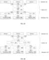
- Autonomous vehicle 10may include a plurality of sensors (e.g. sensors 12 ), a plurality of electronic control units (e.g. ECUs 14 ) and a plurality of actuators (e.g. actuators 16 ). Accordingly, sensors 12 within autonomous vehicle 10 may monitor the environment in which autonomous vehicle 10 is operating, wherein sensors 12 may provide sensor data 18 to ECUs 14 . ECUs 14 may process sensor data 18 to determine the manner in which autonomous vehicle 10 should move. ECUs 14 may then provide control data 20 to actuators 16 so that autonomous vehicle 10 may move in the manner decided by ECUs 14 .
- sensors 12 within autonomous vehicle 10may monitor the environment in which autonomous vehicle 10 is operating, wherein sensors 12 may provide sensor data 18 to ECUs 14 .
- ECUs 14may process sensor data 18 to determine the manner in which autonomous vehicle 10 should move.
- ECUs 14may then provide control data 20 to actuators 16 so that autonomous vehicle 10 may move in the manner decided by ECUs 14 .
- a machine vision sensor included within sensors 12may “read” a speed limit sign stating that the speed limit on the road on which autonomous vehicle 10 is traveling is now 35 miles an hour. This machine vision sensor included within sensors 12 may provide sensor data 18 to ECUs 14 indicating that the speed on the road on which autonomous vehicle 10 is traveling is now 35 mph. Upon receiving sensor data 18 , ECUs 14 may process sensor data 18 and may determine that autonomous vehicle 10 (which is currently traveling at 45 mph) is traveling too fast and needs to slow down. Accordingly, ECUs 14 may provide control data 20 to actuators 16 , wherein control data 20 may e.g. apply the brakes of autonomous vehicle 10 or eliminate any actuation signal currently being applied to the accelerator (thus allowing autonomous vehicle 10 to coast until the speed of autonomous vehicle 10 is reduced to 35 mph).
- autonomous vehicle 10is being controlled by the various electronic systems included therein (e.g. sensors 12 , ECUs 14 and actuators 16 ), the potential failure of one or more of these systems should be considered when designing autonomous vehicle 10 and appropriate contingency plans may be employed.
- the various ECUse.g., ECUs 14
- the various ECUsthat are included within autonomous vehicle 10 may be compartmentalized so that the responsibilities of the various ECUs (e.g., ECUs 14 ) may be logically grouped.
- ECUs 14may include autonomy control unit 50 that may receive sensor data 18 from sensors 12 .
- Autonomy control unit 50may be configured to perform various functions. For example, autonomy control unit 50 may receive and process exteroceptive sensor data (e.g., sensor data 18 ), may estimate the position of autonomous vehicle 10 within its operating environment, may calculate a representation of the surroundings of autonomous vehicle 10 , may compute safe trajectories for autonomous vehicle 10 , and may command the other ECUs (in particular, a vehicle control unit) to cause autonomous vehicle 10 to execute a desired maneuver. Autonomy control unit 50 may include substantial compute power, persistent storage, and memory.
- exteroceptive sensor datae.g., sensor data 18
- autonomy control unit 50may process sensor data 18 to determine the manner in which autonomous vehicle 10 should be operating. Autonomy control unit 50 may then provide vehicle control data 52 to vehicle control unit 54 , wherein vehicle control unit 54 may then process vehicle control data 52 to determine the manner in which the individual control systems (e.g. powertrain system 56 , braking system 58 and steering system 60 ) should respond in order to achieve the trajectory defined by autonomous control unit 50 within vehicle control data 52 .
- vehicle control unit 54may then process vehicle control data 52 to determine the manner in which the individual control systems (e.g. powertrain system 56 , braking system 58 and steering system 60 ) should respond in order to achieve the trajectory defined by autonomous control unit 50 within vehicle control data 52 .
- Vehicle control unit 54may be configured to control other ECUs included within autonomous vehicle 10 .
- vehicle control unit 54may control the steering, powertrain, and brake controller units.
- vehicle control unit 54may provide: powertrain control signal 62 to powertrain control unit 64 ; braking control signal 66 to braking control unit 68 ; and steering control signal 70 to steering control unit 72 .
- Powertrain control unit 64may process powertrain control signal 62 so that the appropriate control data (commonly represented by control data 20 ) may be provided to powertrain system 56 .
- braking control unit 68may process braking control signal 66 so that the appropriate control data (commonly represented by control data 20 ) may be provided to braking system 58 .
- steering control unit 72may process steering control signal 70 so that the appropriate control data (commonly represented by control data 20 ) may be provided to steering system 60 .
- Powertrain control unit 64may be configured to control the transmission (not shown) and engine/traction motor (not shown) within autonomous vehicle 10 ; while brake control unit 68 may be configured to control the mechanical/regenerative braking system (not shown) within autonomous vehicle 10 ; and steering control unit 72 may be configured to control the steering column/steering rack (not shown) within autonomous vehicle 10 .
- Autonomy control unit 50may be a highly complex computing system that may provide extensive processing capabilities (e.g., a workstation-class computing system with multi-core processors, discrete co-processing units, gigabytes of memory, and persistent storage).
- vehicle control unit 54may be a much simpler device that may provide processing power equivalent to the other ECUs included within autonomous vehicle 10 (e.g., a computing system having a modest microprocessor (with a CPU frequency of less than 200 megahertz), less than 1 megabyte of system memory, and no persistent storage). Due to these simpler designs, vehicle control unit 54 may have greater reliability and durability than autonomy control unit 50 .
- the two vehicle control unitsmay be configured in various ways.
- the two vehicle control unitse.g. vehicle control units 54 , 74
- the two vehicle control unitsmay be configured in an active—passive configuration, wherein e.g. vehicle control unit 54 performs the active role of processing vehicle control data 52 while vehicle control unit 74 assumes a passive role and is essentially in standby mode.
- vehicle control unit 74may transition from a passive role to an active role and assume the role of processing vehicle control data 52 .
- the two vehicle control unitse.g. vehicle control units 54 , 74
- both vehicle control unit 52 and vehicle control unit 74perform the active role of processing vehicle control data 54 (e.g. divvying up the workload), wherein in the event of a failure of either vehicle control unit 54 or vehicle control unit 74 , the surviving vehicle control unit may process all of vehicle control data 52 .
- FIG. 2 Billustrates one example of the manner in which the various ECUs (e.g. ECUs 14 ) included within autonomous vehicle 10 may be configured in a redundant fashion
- autonomous control unit 50may be configured in a redundant fashion, wherein a second autonomous control unit (not shown) is included within autonomous vehicle 10 and is configured in an active—passive or active—active fashion.
- a second autonomous control unitnot shown
- one or more of the sensorse.g., sensors 12
- the actuatorse.g. actuators 16
- the level of redundancy achievable with respect to autonomous vehicle 10may only be limited by the design criteria and budget constraints of autonomous vehicle 10 .
- the various ECUs of autonomous vehicle 10may be grouped/arranged/configured to effectuate various functionalities.
- one or more of ECUs 14may be configured to effectuate/form perception subsystem 100 , wherein perception subsystem 100 may be configured to process data from onboard sensors (e.g., sensor data 18 ) to calculate concise representations of objects of interest near autonomous vehicle 10 (examples of which may include but are not limited to other vehicles, pedestrians, traffic signals, traffic signs, road markers, hazards, etc.) and to identify environmental features that may assist in determining the location of autonomous vehicle 10 .
- onboard sensorse.g., sensor data 18
- concise representations of objects of interest near autonomous vehicle 10examples of which may include but are not limited to other vehicles, pedestrians, traffic signals, traffic signs, road markers, hazards, etc.
- environmental featuresmay assist in determining the location of autonomous vehicle 10 .
- one or more of ECUs 14may be configured to effectuate/form state estimation subsystem 102 , wherein state estimation subsystem 102 may be configured to process data from onboard sensors (e.g., sensor data 18 ) to estimate the position, orientation, and velocity of autonomous vehicle 10 within its operating environment. Additionally, one or more of ECUs 14 may be configured to effectuate/form planning subsystem 104 , wherein planning subsystem 104 may be configured to calculate a desired vehicle trajectory (using perception output 106 and state estimation output 108 ).
- one or more of ECUs 14may be configured to effectuate/form trajectory control subsystem 110 , wherein trajectory control subsystem 110 uses planning output 112 and state estimation output 108 (in conjunction with feedback and/or feedforward control techniques) to calculate actuator commands (e.g., control data 20 ) that may cause autonomous vehicle 10 to execute its intended trajectory within it operating environment.
- trajectory control subsystem 110uses planning output 112 and state estimation output 108 (in conjunction with feedback and/or feedforward control techniques) to calculate actuator commands (e.g., control data 20 ) that may cause autonomous vehicle 10 to execute its intended trajectory within it operating environment.
- the above-described subsystemsmay be distributed across various devices (e.g., autonomy control unit 50 and vehicle control units 54 , 74 ). Additionally/alternatively and due to the increased computational requirements, perception subsystem 100 and planning subsystem 104 may be located almost entirely within autonomy control unit 50 , which (as discussed above) has much more computational horsepower than vehicle control units 54 , 74 . Conversely and due to their lower computational requirements, state estimation subsystem 102 and trajectory control subsystem 110 may be: located entirely on vehicle control units 54 , 74 if vehicle control units 54 , 74 have the requisite computational capacity; and/or located partially on vehicle control units 54 , 74 and partially on autonomy control unit 50 . However, the location of state estimation subsystem 102 and trajectory control subsystem 110 may be of critical importance in the design of any contingency planning architecture, as the location of these subsystems may determine how contingency plans are calculated, transmitted, and/or executed.
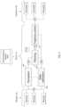
- autonomous vehicle 10may include various systems/devices that enable a rider (e.g., rider 200 ) to communicate with autonomous vehicle 10 .
- autonomous vehicle 10may include contextual display assembly 202 , light display assembly 204 , speaker assembly 206 , microphone assembly 208 , scanner assembly 210 and keyboard assembly 212 .
- one or more of ECUs 14may execute communication process 250 .
- Communication process 250may be executed on a single ECU or may be executed collaboratively across multiple ECUs.
- communication process 250may be executed solely by autonomy control unit 50 , vehicle control unit 54 or vehicle control unit 74 .
- communication process 250may be executed collaboratively across the combination of autonomy control unit 50 , vehicle control unit 54 and vehicle control unit 74 . Accordingly and in the latter configuration, in the event of a failure of one of autonomy control unit 50 , vehicle control unit 54 or vehicle control unit 74 , the surviving control unit(s) may continue to execute communication process 250 .
- the instruction sets and subroutines of communication process 250may be stored on storage device 114 (see FIG. 3 ) coupled to ECUs 14 , may be executed by one or more processors (not shown) and one or more memory architectures (not shown) included within ECUs 14 .
- Examples of storage device 114may include but are not limited to: a hard disk drive; a RAID device; a random-access memory (RAM); a read-only memory (ROM); and all forms of flash memory storage devices.
- these various systems/devicesmay be configured to provide different types of functionality, as discussed below.
- a ridermay sign in to a mobile or web application (not shown) wherein the rider (e.g., rider 200 ) may have a stored user profile that contains their contact information.
- the ridere.g., rider 200
- an autonomous vehiclee.g., autonomous vehicle 10
- detailssuch as the desired pick-up date and time, the pickup and drop off locations, and the number of seats required may be specified.
- ride detailsmay be encoded into a digital ticket (e.g., digital ticket 214 ) that may be stored in a mobile application (e.g., a smartphone application) for future use.
- a digital tickete.g., digital ticket 214
- a mobile applicatione.g., a smartphone application
- the ride requestmay be sent to a dispatch system (not shown).
- This dispatch systemmay select an autonomous vehicle (e.g., autonomous vehicle 10 ) and (via a telecommunications link) may remotely command an autonomous vehicle (e.g., autonomous vehicle 10 ) to drive to the appropriate pickup location.
- a human operatormay optionally be involved in the autonomous vehicle's dispatch, either by simply authorizing the pre-selected dispatch or by manually performing other computations/decisions/commands required to dispatch the autonomous vehicle (e.g., autonomous vehicle 10 ).
- the ridere.g., rider 200
- the ridermay be prompted (e.g., via verbal prompting or text-based prompting) to produce their digital ticket (e.g., digital ticket 214 ) in order to begin their ride.
- the digital tickete.g., digital ticket 214
- the digital ticketmay be required to enter autonomous vehicle 10 , whereby the vehicle doors are unlocked only when a valid digital ticket (e.g., digital ticket 214 ) is presented.
- a valid digital ticket(e.g., digital ticket 214 ) may be required after the rider (e.g., rider 200 ) has entered the autonomous vehicle (e.g., autonomous vehicle 10 ) in order to begin the trip.
- Ride detailsmay be encoded in the digital ticket (e.g., digital ticket 214 ) and may be sent to the autonomous vehicle (e.g., autonomous vehicle 10 ) at the time of the ride via a visual code (e.g., QR code or other 1D or 2D barcode) scannable via scanner assembly 210 (e.g., an optical scanner assembly, near-field communication (NFC), radio-frequency identification (RFID), wi-fi, Bluetooth, or other short-range communication technologies).
- the dispatch systemmay then utilize the information contained in the digital ticket (e.g., digital ticket 214 ) in order to fulfill the trip.
- One or more display screensmay be mounted inside the autonomous vehicle (e.g., autonomous vehicle 10 ), wherein these display screens (e.g., contextual display assembly 202 ) may be configured to provide simple, contextually relevant information/prompts to the rider (e.g., rider 200 ) throughout the course of the trip, wherein such information may include text, graphics, animations and/or sounds.
- Messages shown on the display screensmay be triggered by various systems including communication process 250 , a remote monitoring system and/or a dispatch system. Additionally, such messages shown on the display screens (e.g., contextual display assembly 202 ) may be triggered by rider actions, remote monitor actions, trip events, system status and/or other events. For example:
- Communication process 250may determine which message is appropriate to display at any given time based on a number of factors, including trip status. For example, different messages may be displayed in response to a seatbelt being unbuckled depending on whether the trip has not yet started, is in progress, or has been completed. For example:
- messagesmay be assigned a priority, whereby if multiple messages are triggered, only the highest priority message may be displayed at a given time.
- a prioritywhereby if multiple messages are triggered, only the highest priority message may be displayed at a given time.
- the display screen(e.g., contextual display assembly 202 ) may also include a default (or main) screen (e.g., a map showing the location of autonomous vehicle 10 ) that is the lowest priority and is only displayed when no other messages have been triggered. Any suppressed messages may either be stored in a queue for later display or not shown at all if they are no longer relevant.
- a default (or main) screene.g., a map showing the location of autonomous vehicle 10
- Communication process 250may render unique light codes that vary by intensity, duration, frequency, color, animation pattern, and light display location. These unique light codes may be rendered on light display assembly 204 and may be assigned to each type of message as a secondary method of conveying information to the rider (e.g., rider 200 ). Messages shown on the display screen (e.g., contextual display assembly 202 ) may be accompanied by their uniquely assigned light code rendered on light display assembly 204 in order to subtly inform the rider or to generally enhance the vehicle appearance and setting. For example, light display assembly 204 may include animated strip lighting near the top of the windshield that may be used to indicate that autonomous vehicle 10 is turning (much like a turn signal indicator). Light display assembly 204 may also be configured to accompany messages shown on the display screen (e.g., contextual display assembly 202 ), such as rapidly blinking lights to remind passengers to buckle their seatbelts.
- Communication process 250may be configured to interface with one or more physical buttons (e.g., physical button 216 ) inside autonomous vehicle 10 and may be used by the rider (e.g., rider 200 ) during the trip to trigger a response from autonomous vehicle 10 (or a remote monitoring system). Further, multiple sets of buttons may be positioned within autonomous vehicle 10 so that passengers throughout autonomous vehicle 10 may have access to a physical button (e.g., physical button 216 ). For example, if a rider (e.g., rider 200 ) wishes to stop autonomous vehicle 10 in the middle of a ride, rider 200 may press a physical button (e.g., physical button 216 ) within autonomous vehicle 10 . In response to pressing physical button 216 , communication process 250 may send a signal to either autonomous vehicle 10 or to a remote monitoring system (not shown) requesting that autonomous vehicle 10 pull over.
- one or more physical buttonse.g., physical button 216
- rider 200may press a physical button (e.g., physical button 216 )
- physical button 216 located in autonomous vehicle 10may enable a rider to request support. Accordingly, when a rider (e.g., rider 200 ) presses physical button 216 , communication process 250 may send a signal to the remote monitoring system (not shown) requesting support, wherein the remote monitor responsible for monitoring autonomous vehicle 10 may respond by opening an audio call with rider (e.g., rider 200 ).
- ridere.g., rider 200
- audio and visual communication equipmentmay be present in autonomous vehicle 10 , examples of which may include cameras, speakers, and microphones. At any time before, during, or after a trip, such audio and visual communication equipment may be used for communication between the rider (e.g., rider 200 ) and the remote monitor (e.g., in the case of the support request described above).
- ridere.g., rider 200
- remote monitore.g., in the case of the support request described above.
- Ridersmay also use a mobile application (not shown) on their smartphone (not shown) to interact with autonomous vehicle 10 and/or the remote monitor before, during, and after their trip.
- a mobile application(not shown) on their smartphone (not shown) to interact with autonomous vehicle 10 and/or the remote monitor before, during, and after their trip.
- the current location of autonomous vehicle 10may be displayed visually on a map within the mobile application (not shown) on their smartphone (not shown).
- a ridere.g., rider 200
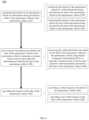
- communication process 250may monitor 252 the interior of the autonomous vehicle (e.g., autonomous vehicle 10 ) for information (e.g., information 218 ) being provided by the rider (e.g., rider 200 ) of the autonomous vehicle (e.g., autonomous vehicle 10 ) to the autonomous vehicle (e.g., autonomous vehicle 10 ).
- informatione.g., information 218
- ridere.g., rider 200
- autonomous vehiclee.g., autonomous vehicle 10
- autonomous vehicle 10e.g., autonomous vehicle 10
- communication process 250may monitor 254 the interior of the autonomous vehicle (e.g., autonomous vehicle 10 ) for verbal information (e.g., information 218 ) being provided by the rider (e.g., rider 200 ) of the autonomous vehicle (e.g., autonomous vehicle 10 ) to the autonomous vehicle (e.g., autonomous vehicle 10 ).
- the interior of the autonomous vehiclemay include a microphone assembly (e.g., microphone assembly 208 ) for obtaining the verbal information (e.g., information 218 ) provided by the rider (e.g., rider 200 ) of the autonomous vehicle (e.g., autonomous vehicle 10 ).
- a microphone assemblye.g., microphone assembly 208
- the verbal informatione.g., information 218
- the ridere.g., rider 200
- microphone assembly 208may be configured to enable rider 200 to provide verbal feedback to autonomous vehicle 10 (or to a person remotely-monitoring the operation of autonomous vehicle 10 ).
- communication process 250may monitor 256 the interior of the autonomous vehicle (e.g., autonomous vehicle 10 ) for non-verbal information (e.g., information 218 ) being provided by the rider (e.g., rider 200 ) of the autonomous vehicle (e.g., autonomous vehicle 10 ) to the autonomous vehicle (e.g., autonomous vehicle 10 ).
- non-verbal informatione.g., information 218
- the interior of the autonomous vehiclemay include an input device for obtaining the non-verbal information (e.g., information 218 ) provided by the rider (e.g., rider 200 ) of the autonomous vehicle (e.g., autonomous vehicle 10 ).
- the interior of autonomous vehicle 10may include one or more of scanner assembly 210 and keyboard assembly 212 .
- examples of this non-verbal informationmay include but are not limited to one or more of: text-based information that is provided to keyboard assembly 212 and encoded information (e.g., QR code information, creditcard information, ApplePayTM information, GooglePayTM information or SamsungPayTM information) that is provided to scanner assembly 210 .
- encoded informatione.g., QR code information, creditcard information, ApplePayTM information, GooglePayTM information or SamsungPayTM information
- communication process 250may process 258 the information (e.g., information 218 ) provided by the rider (e.g., rider 200 ) of the autonomous vehicle (e.g., autonomous vehicle 10 ) to the autonomous vehicle (e.g., autonomous vehicle 10 ) to generate a response (e.g., response 220 ) based, at least in part, upon the information (e.g., information 218 ) provided by the rider (e.g., rider 200 ) of the autonomous vehicle (e.g., autonomous vehicle 10 ).
- a responsee.g., response 220
- the information provided by the rider (e.g., rider 200 ) of the autonomous vehicle (e.g., autonomous vehicle 10 )may be verbal information (e.g., information 218 ).
- the verbal informatione.
- NLUNatural language Understanding
- AIartificial intelligence
- NLUmay directly enable human-computer interaction (HCl), wherein the understanding of natural human language enables computers to understand human-provided commands (without the formalized syntax of computer languages) while enabling these computers to respond to the human in their own language.
- HClhuman-computer interaction
- the field of NLUis an important and challenging subset of natural language processing (NLP). While both understand human language, NLU is tasked with communicating with untrained individuals and understanding their intent, meaning that NLU goes beyond understanding words and actually interprets the meaning of such words.
- NLUmay use algorithms to reduce human speech into a structured ontology, fleshing out such things as intent, timing, locations and sentiments.
- communication process 250may provide 262 the response (e.g., response 220 ) to the rider (e.g., rider 200 ) of the autonomous vehicle (e.g., autonomous vehicle 10 ).
- communication process 250may provide 264 a verbal response (e.g., response 220 ) to the rider (e.g., rider 200 ) of the autonomous vehicle (e.g., autonomous vehicle 10 ).
- the interior of the autonomous vehiclemay include a speaker assembly (e.g., speaker assembly 206 ) for providing the verbal response to the rider (e.g., rider 200 ) of the autonomous vehicle (e.g., autonomous vehicle 10 ).
- speaker assembly 206may be configured to render an audio-based message that says “Welcome aboard. Please buckle your seatbelt so we can depart.”
- communication process 250may provide 266 a non-verbal response (e.g., response 220 ) to the rider (e.g., rider 200 ) of the autonomous vehicle (e.g., autonomous vehicle 10 ).
- the interior of the autonomous vehicleincludes an output assembly (e.g., contextual display assembly 202 and/or light display assembly 204 ) for providing the non-verbal response to the rider (e.g., rider 200 ) of the autonomous vehicle (e.g., autonomous vehicle 10 ).
- an output assemblye.g., contextual display assembly 202 and/or light display assembly 204
- contextual display assembly 202may be configured to render a text-based message for rider 200 that says “Arriving at your destination.
- light display assembly 204may be configured to render a right-sweeping image to indicate that the autonomous vehicle (e.g., autonomous vehicle 10 ) will be turning right.
- the present disclosuremay be embodied as a method, a system, or a computer program product. Accordingly, the present disclosure may take the form of an entirely hardware embodiment, an entirely software embodiment (including firmware, resident software, micro-code, etc.) or an embodiment combining software and hardware aspects that may all generally be referred to herein as a “circuit,” “module” or “system.” Furthermore, the present disclosure may take the form of a computer program product on a computer-usable storage medium having computer-usable program code embodied in the medium.
- the computer-usable or computer-readable mediummay be, for example but not limited to, an electronic, magnetic, optical, electromagnetic, infrared, or semiconductor system, apparatus, device, or propagation medium. More specific examples (a non-exhaustive list) of the computer-readable medium may include the following: an electrical connection having one or more wires, a portable computer diskette, a hard disk, a random access memory (RAM), a read-only memory (ROM), an erasable programmable read-only memory (EPROM or Flash memory), an optical fiber, a portable compact disc read-only memory (CD-ROM), an optical storage device, a transmission media such as those supporting the Internet or an intranet, or a magnetic storage device.
- the computer-usable or computer-readable mediummay also be paper or another suitable medium upon which the program is printed, as the program can be electronically captured, via, for instance, optical scanning of the paper or other medium, then compiled, interpreted, or otherwise processed in a suitable manner, if necessary, and then stored in a computer memory.
- a computer-usable or computer-readable mediummay be any medium that can contain, store, communicate, propagate, or transport the program for use by or in connection with the instruction execution system, apparatus, or device.
- the computer-usable mediummay include a propagated data signal with the computer-usable program code embodied therewith, either in baseband or as part of a carrier wave.
- the computer usable program codemay be transmitted using any appropriate medium, including but not limited to the Internet, wireline, optical fiber cable, RF, etc.
- Computer program code for carrying out operations of the present disclosuremay be written in an object oriented programming language such as Java, Smalltalk, C++ or the like. However, the computer program code for carrying out operations of the present disclosure may also be written in conventional procedural programming languages, such as the “C” programming language or similar programming languages.
- the program codemay execute entirely on the user's computer, partly on the user's computer, as a stand-alone software package, partly on the user's computer and partly on a remote computer or entirely on the remote computer or server. In the latter scenario, the remote computer may be connected to the user's computer through a local area network/a wide area network/the Internet (e.g., network 14 ).
- These computer program instructionsmay also be stored in a computer-readable memory that may direct a computer or other programmable data processing apparatus to function in a particular manner, such that the instructions stored in the computer-readable memory produce an article of manufacture including instruction means which implement the function/act specified in the flowchart and/or block diagram block or blocks.
- the computer program instructionsmay also be loaded onto a computer or other programmable data processing apparatus to cause a series of operational steps to be performed on the computer or other programmable apparatus to produce a computer-implemented process such that the instructions which execute on the computer or other programmable apparatus provide steps for implementing the functions/acts specified in the flowchart and/or block diagram block or blocks.
- each block in the flowchart or block diagramsmay represent a module, segment, or portion of code, which comprises one or more executable instructions for implementing the specified logical function(s).
- the functions noted in the blockmay occur out of the order noted in the figures. For example, two blocks shown in succession may, in fact, be executed substantially concurrently, or the blocks may sometimes be executed in the reverse order, depending upon the functionality involved.
Landscapes
- Engineering & Computer Science (AREA)
- Automation & Control Theory (AREA)
- Human Computer Interaction (AREA)
- Radar, Positioning & Navigation (AREA)
- Remote Sensing (AREA)
- Transportation (AREA)
- Mechanical Engineering (AREA)
- Physics & Mathematics (AREA)
- General Physics & Mathematics (AREA)
- Computational Linguistics (AREA)
- Health & Medical Sciences (AREA)
- Audiology, Speech & Language Pathology (AREA)
- Acoustics & Sound (AREA)
- Multimedia (AREA)
- Traffic Control Systems (AREA)
Abstract
Description
Contextual Display Assembly 202 may be configured to enableautonomous vehicle 10 to provide text-based information to a rider (e.g., rider200) ofautonomous vehicle 10. For example, ifautonomous vehicle 10 is approaching its intended destination,contextual display assembly 202 may be configured to render a text-based message forrider 200 that says “Arriving at your destination. Please exit from the right-side of the vehicle.”Light Display Assembly 204 may be configured to enableautonomous vehicle 10 to provide image-based information to a rider (e.g., rider200) ofautonomous vehicle 10. For example, ifautonomous vehicle 10 is going to be turning right at an intersection,light display assembly 204 may be configured to render a right-sweeping image to indicate thatautonomous vehicle 10 will be turning right.Speaker Assembly 206 may be configured to enableautonomous vehicle 10 to provide audio-based information to a rider (e.g., rider200) ofautonomous vehicle 10. For example, ifautonomous vehicle 10 just picked up a rider and is getting ready to depart,speaker assembly 206 may be configured to render an audio-based message that says “Welcome aboard. Please buckle your seatbelt so we can depart.”Microphone Assembly 208 may be configured to enable a rider (e.g., rider200) ofautonomous vehicle 10 to provide audio-based information toautonomous vehicle 10. For example, if a rider (e.g., rider200) ofautonomous vehicle 10 is displeased with the condition ofautonomous vehicle 10,microphone assembly 208 may be configured to enablerider 200 to provide verbal feedback to autonomous vehicle10 (or to a person remotely-monitoring the operation of autonomous vehicle10).Scanner Assembly 210 may be configured to enable a rider (e.g., rider200) ofautonomous vehicle 10 to provide encoded information toautonomous vehicle 10. For example, if a rider (e.g., rider200) enteredautonomous vehicle 10 after hailingautonomous vehicle 10 using a remote application,scanner assembly 210 may be configured to scan a QR code rendered on a handheld device (e.g., a smartphone) ofrider 200 to authenticaterider 200. Additionally/alternatively,scanner assembly 210 may be configured to enablerider 200 to pay for their trip withinautonomous vehicle 10 by e.g., scanning a credit card or paying via ApplePay™, GooglePay™ or SamsungPay™.Keyboard Assembly 212 may be configured to enable a rider (e.g., rider200) ofautonomous vehicle 10 to provide text-based information toautonomous vehicle 10. For example, if a rider (e.g., rider200) enteredautonomous vehicle 10 without a destination being predefined,keyboard assembly 212 may be configured to enablerider 200 to type in an intended destination.
- Assume that the autonomous vehicle (e.g., autonomous vehicle10) has arrived to pick up the rider (e.g., rider200) and the rider must present a valid digital ticket (e.g., digital ticket214) in order to begin the trip. Accordingly, the display screen (e.g., contextual display assembly202) may display a message such as: “Welcome, [Rider Name], please scan your digital ticket to begin.” If the rider does not present their digital ticket (e.g., digital ticket214) after some period of time, a reminder sound may play.
- Assume that the autonomous vehicle (e.g., autonomous vehicle10) is yielding at an intersection for an unusually long amount of time. The display screen (e.g., contextual display assembly202) may display a message such as “Waiting for path to clear” in order to inform the rider (e.g., rider200) of the situation and reassure the rider (e.g., rider200) that nothing is wrong.
- Assume that while the autonomous vehicle (e.g., autonomous vehicle10) is en-route, it is detected that a seatbelt has been unbuckled in an occupied seat. The display screen (e.g., contextual display assembly202) may display visual and audible warnings to the rider (e.g., rider200) such as “Please buckle your seatbelt”, accompanied by a graphic indicating which seatbelt is unbuckled.” If the seatbelt is not re-engaged, the message displayed may escalate to “The vehicle will pull over in [time remaining] seconds” if seat belt is not buckled.
- Assume that prior to beginning a trip, if it is detected that a door is open. Accordingly, the display screen (e.g., contextual display assembly202) may display a message requesting that the rider close the door such as “Please close door to begin your trip.” This message may also be accompanied by sounds, graphics, and/or animations.
Message Selection
- During Pickup: If a seatbelt is unbuckled in an occupied seat when the trip status is “Picking-Up,” then a message such as “Please buckle your seatbelt so we can start our trip” may be displayed, accompanied by a graphic showing which seatbelt is unbuckled.
- While En-Route: If a seatbelt becomes unbuckled in an occupied seat when the trip status is “En-Route,” then a more urgent message such as “Please buckle your seatbelt or the vehicle will pull-over” may be displayed, accompanied by a sound to get the attention of the rider (e.g., rider200).
- During Dropoff: If a seatbelt is unbuckled in an occupied seat when the trip status is “Dropping-Off,” then this is a desired behavior so there may be no message displayed regarding the seatbelt.
Claims (30)
Priority Applications (1)
| Application Number | Priority Date | Filing Date | Title |
|---|---|---|---|
| US17/146,071US11866063B2 (en) | 2020-01-10 | 2021-01-11 | Communication system and method |
Applications Claiming Priority (2)
| Application Number | Priority Date | Filing Date | Title |
|---|---|---|---|
| US202062959400P | 2020-01-10 | 2020-01-10 | |
| US17/146,071US11866063B2 (en) | 2020-01-10 | 2021-01-11 | Communication system and method |
Publications (2)
| Publication Number | Publication Date |
|---|---|
| US20210213970A1 US20210213970A1 (en) | 2021-07-15 |
| US11866063B2true US11866063B2 (en) | 2024-01-09 |
Family
ID=76764086
Family Applications (1)
| Application Number | Title | Priority Date | Filing Date |
|---|---|---|---|
| US17/146,071Active2041-11-11US11866063B2 (en) | 2020-01-10 | 2021-01-11 | Communication system and method |
Country Status (4)
| Country | Link |
|---|---|
| US (1) | US11866063B2 (en) |
| CN (1) | CN115066662A (en) |
| DE (1) | DE112021000497T5 (en) |
| WO (1) | WO2021142442A1 (en) |
Cited By (2)
| Publication number | Priority date | Publication date | Assignee | Title |
|---|---|---|---|---|
| US20240034257A1 (en)* | 2022-07-28 | 2024-02-01 | Kubota Corporation | Audio signaling system and method for autonomous vehicles |
| US20240227845A1 (en)* | 2023-01-05 | 2024-07-11 | GM Global Technology Operations LLC | System for motion planning with natural language command interpretation |
Families Citing this family (1)
| Publication number | Priority date | Publication date | Assignee | Title |
|---|---|---|---|---|
| DE102020205674A1 (en)* | 2020-05-05 | 2021-11-11 | Volkswagen Aktiengesellschaft | Method, computer program and device for reproducing notifications in a vehicle |
Citations (241)
| Publication number | Priority date | Publication date | Assignee | Title |
|---|---|---|---|---|
| US3997868A (en) | 1973-02-20 | 1976-12-14 | Ribnick Gerson D | Emergency vehicle warning system |
| US4930742A (en) | 1988-03-25 | 1990-06-05 | Donnelly Corporation | Rearview mirror and accessory mount for vehicles |
| US4956866A (en) | 1989-06-30 | 1990-09-11 | Sy/Lert System Ltd. | Emergency signal warning system |
| US4959865A (en) | 1987-12-21 | 1990-09-25 | The Dsp Group, Inc. | A method for indicating the presence of speech in an audio signal |
| US4975966A (en) | 1989-08-24 | 1990-12-04 | Bose Corporation | Reducing microphone puff noise |
| US5287411A (en) | 1990-07-27 | 1994-02-15 | Hill James L | System for detecting the siren of an approaching emergency vehicle |
| US5329593A (en) | 1993-05-10 | 1994-07-12 | Lazzeroni John J | Noise cancelling microphone |
| US5495242A (en) | 1993-08-16 | 1996-02-27 | C.A.P.S., Inc. | System and method for detection of aural signals |
| US5550677A (en) | 1993-02-26 | 1996-08-27 | Donnelly Corporation | Automatic rearview mirror system using a photosensor array |
| US5670935A (en) | 1993-02-26 | 1997-09-23 | Donnelly Corporation | Rearview vision system for vehicle including panoramic view |
| US5671996A (en) | 1994-12-30 | 1997-09-30 | Donnelly Corporation | Vehicle instrumentation/console lighting |
| US5703957A (en) | 1995-06-30 | 1997-12-30 | Lucent Technologies Inc. | Directional microphone assembly |
| WO1998017046A1 (en) | 1996-10-17 | 1998-04-23 | Andrea Electronics Corporation | Noise cancelling acoustical improvement to wireless telephone or cellular phone |
| US5820245A (en) | 1995-12-11 | 1998-10-13 | Donnelly Corporation | Rearview mirror assembly |
| US5828012A (en) | 1996-05-31 | 1998-10-27 | W. L. Gore & Associates, Inc. | Protective cover assembly having enhanced acoustical characteristics |
| US5850016A (en) | 1996-03-20 | 1998-12-15 | Pioneer Hi-Bred International, Inc. | Alteration of amino acid compositions in seeds |
| US5877897A (en) | 1993-02-26 | 1999-03-02 | Donnelly Corporation | Automatic rearview mirror, vehicle lighting control and vehicle interior monitoring system using a photosensor array |
| US5878147A (en) | 1996-12-31 | 1999-03-02 | Etymotic Research, Inc. | Directional microphone assembly |
| US5894279A (en) | 1997-08-22 | 1999-04-13 | Rose; Chino R. | Emergency vehicle detection system |
| US5979586A (en) | 1997-02-05 | 1999-11-09 | Automotive Systems Laboratory, Inc. | Vehicle collision warning system |
| US6166625A (en) | 1996-09-26 | 2000-12-26 | Donnelly Corporation | Pyroelectric intrusion detection in motor vehicles |
| WO2001037519A2 (en) | 1999-11-19 | 2001-05-25 | Gentex Corporation | Vehicle accessory microphone |
| US6243003B1 (en) | 1999-08-25 | 2001-06-05 | Donnelly Corporation | Accessory module for vehicle |
| US6278377B1 (en) | 1999-08-25 | 2001-08-21 | Donnelly Corporation | Indicator for vehicle accessory |
| US6326613B1 (en) | 1998-01-07 | 2001-12-04 | Donnelly Corporation | Vehicle interior mirror assembly adapted for containing a rain sensor |
| US6329925B1 (en) | 1999-11-24 | 2001-12-11 | Donnelly Corporation | Rearview mirror assembly with added feature modular display |
| US20020032510A1 (en) | 2000-04-06 | 2002-03-14 | Turnbull Robert R. | Vehicle rearview mirror assembly incorporating a communication system |
| US6363156B1 (en) | 1998-11-18 | 2002-03-26 | Lear Automotive Dearborn, Inc. | Integrated communication system for a vehicle |
| US6362749B1 (en) | 2001-06-18 | 2002-03-26 | William E. Brill | Emergency vehicle detection system |
| US6366213B2 (en) | 1998-02-18 | 2002-04-02 | Donnelly Corporation | Rearview mirror assembly incorporating electrical accessories |
| US6420975B1 (en) | 1999-08-25 | 2002-07-16 | Donnelly Corporation | Interior rearview mirror sound processing system |
| US6428172B1 (en) | 1999-11-24 | 2002-08-06 | Donnelly Corporation | Rearview mirror assembly with utility functions |
| US20020110255A1 (en) | 2000-10-05 | 2002-08-15 | Killion Mead C. | Directional microphone assembly |
| US20020110256A1 (en) | 2001-02-14 | 2002-08-15 | Watson Alan R. | Vehicle accessory microphone |
| US6485081B1 (en) | 1999-03-24 | 2002-11-26 | Donnelly Corporation | Safety system for a closed compartment of a vehicle |
| US6570992B1 (en) | 2000-10-11 | 2003-05-27 | Molex, Incorporated | Microphone holder |
| US6587186B2 (en) | 2000-06-06 | 2003-07-01 | Canesta, Inc. | CMOS-compatible three-dimensional image sensing using reduced peak energy |
| WO2003091066A2 (en) | 2002-04-24 | 2003-11-06 | Salvatore Buscemi | System to warn of an approaching emergency vehicle |
| US6648477B2 (en) | 2000-07-06 | 2003-11-18 | Donnelly Corporation | Rearview mirror assembly with information display |
| US6678039B2 (en) | 2001-05-23 | 2004-01-13 | Canesta, Inc. | Method and system to enhance dynamic range conversion useable with CMOS three-dimensional imaging |
| US6690268B2 (en) | 2000-03-02 | 2004-02-10 | Donnelly Corporation | Video mirror systems incorporating an accessory module |
| US6690354B2 (en) | 2000-11-19 | 2004-02-10 | Canesta, Inc. | Method for enhancing performance in a system utilizing an array of sensors that sense at least two-dimensions |
| US6693517B2 (en) | 2000-04-21 | 2004-02-17 | Donnelly Corporation | Vehicle mirror assembly communicating wirelessly with vehicle accessories and occupants |
| US6710770B2 (en) | 2000-02-11 | 2004-03-23 | Canesta, Inc. | Quasi-three-dimensional method and apparatus to detect and localize interaction of user-object and virtual transfer device |
| US20040155795A1 (en) | 2002-12-30 | 2004-08-12 | Quintana Nina Mariah C. | Systems and methods for motor vehicle-based emergency/hazard detection |
| US20040170286A1 (en) | 2003-02-27 | 2004-09-02 | Bayerische Motoren Werke Aktiengesellschaft | Method for controlling an acoustic system in a vehicle |
| US20040258252A1 (en) | 2003-06-17 | 2004-12-23 | Honda Motor Co., Ltd. | Active vibratory noise control apparatus |
| US6876775B2 (en) | 2001-02-16 | 2005-04-05 | Canesta, Inc. | Technique for removing blurring from a captured image |
| US20050074131A1 (en) | 2003-10-06 | 2005-04-07 | Mc Call Clark E. | Vehicular sound processing system |
| US6906793B2 (en) | 2000-12-11 | 2005-06-14 | Canesta, Inc. | Methods and devices for charge management for three-dimensional sensing |
| US6919549B2 (en) | 2003-04-11 | 2005-07-19 | Canesta, Inc. | Method and system to differentially enhance sensor dynamic range |
| US6958707B1 (en) | 2001-06-18 | 2005-10-25 | Michael Aaron Siegel | Emergency vehicle alert system |
| US6980663B1 (en) | 1999-08-16 | 2005-12-27 | Daimlerchrysler Ag | Process and device for compensating for signal loss |
| US20060023892A1 (en) | 2002-04-18 | 2006-02-02 | Juergen Schultz | Communications device for transmitting acoustic signals in a motor vehicle |
| US20060055630A1 (en) | 2004-09-15 | 2006-03-16 | Cheang Tak M | Chromatically enhanced display |
| US7038577B2 (en) | 2002-05-03 | 2006-05-02 | Donnelly Corporation | Object detection system for vehicle |
| US7053357B2 (en) | 1996-09-05 | 2006-05-30 | Rudolf Schwarte | Method and apparatus for determining the phase and/or amplitude information of an electromagnetic wave for photomixing |
| US7061402B1 (en) | 2003-10-09 | 2006-06-13 | Robert Lawson | Emergency vehicle warning system |
| US7157685B2 (en) | 2004-04-12 | 2007-01-02 | Canesta, Inc. | Method and system to enhance differential dynamic range and signal/noise in CMOS range finding systems using differential sensors |
| US20070008175A1 (en) | 2005-07-06 | 2007-01-11 | Duane Johnson | Siren detection notification alarm |
| US7176438B2 (en) | 2003-04-11 | 2007-02-13 | Canesta, Inc. | Method and system to differentially enhance sensor dynamic range using enhanced common mode reset |
| US7203356B2 (en) | 2002-04-11 | 2007-04-10 | Canesta, Inc. | Subject segmentation and tracking using 3D sensing technology for video compression in multimedia applications |
| US7212663B2 (en) | 2002-06-19 | 2007-05-01 | Canesta, Inc. | Coded-array technique for obtaining depth and other position information of an observed object |
| US20070146127A1 (en) | 2004-03-09 | 2007-06-28 | Stilp Louis A | System, method and device for detecting a siren |
| US7245232B1 (en) | 2005-08-09 | 2007-07-17 | Caouette Sr James | Emergency vehicle alert system |
| US20070216539A1 (en) | 2005-10-12 | 2007-09-20 | D Antoni Jennifer | System to warn of an approaching emergency vehicle |
| US7283213B2 (en) | 2005-02-08 | 2007-10-16 | Canesta, Inc. | Method and system to correct motion blur and reduce signal transients in time-of-flight sensor systems |
| US7308341B2 (en) | 2003-10-14 | 2007-12-11 | Donnelly Corporation | Vehicle communication system |
| US7310431B2 (en) | 2002-04-10 | 2007-12-18 | Canesta, Inc. | Optical methods for remotely measuring objects |
| US7321111B2 (en) | 2004-04-12 | 2008-01-22 | Canesta, Inc. | Method and system to enhance differential dynamic range and signal/noise in CMOS range finding systems using differential sensors |
| US7340077B2 (en) | 2002-02-15 | 2008-03-04 | Canesta, Inc. | Gesture recognition system using depth perceptive sensors |
| US20080068187A1 (en) | 2006-09-12 | 2008-03-20 | Zachary Thomas Bonefas | Method and system for detecting operator alertness |
| US7352454B2 (en) | 2000-11-09 | 2008-04-01 | Canesta, Inc. | Methods and devices for improved charge management for three-dimensional and color sensing |
| US7375803B1 (en) | 2006-05-18 | 2008-05-20 | Canesta, Inc. | RGBZ (red, green, blue, z-depth) filter system usable with sensor systems, including sensor systems with synthetic mirror enhanced three-dimensional imaging |
| US7379163B2 (en) | 2005-02-08 | 2008-05-27 | Canesta, Inc. | Method and system for automatic gain control of sensors in time-of-flight systems |
| US7379100B2 (en) | 2004-02-12 | 2008-05-27 | Canesta, Inc. | Method and system to increase dynamic range of time-of-flight (TOF) and/or imaging sensors |
| US20080150786A1 (en) | 1997-10-22 | 2008-06-26 | Intelligent Technologies International, Inc. | Combined Imaging and Distance Monitoring for Vehicular Applications |
| US7405812B1 (en) | 2006-05-18 | 2008-07-29 | Canesta, Inc. | Method and system to avoid inter-system interference for phase-based time-of-flight systems |
| US7408627B2 (en) | 2005-02-08 | 2008-08-05 | Canesta, Inc. | Methods and system to quantify depth data accuracy in three-dimensional sensors using single frame capture |
| US7415116B1 (en) | 1999-11-29 | 2008-08-19 | Deutsche Telekom Ag | Method and system for improving communication in a vehicle |
| US20090028425A1 (en) | 2007-07-27 | 2009-01-29 | Sportvision, Inc. | Identifying an object in an image using color profiles |
| US20090097674A1 (en) | 1999-11-19 | 2009-04-16 | Watson Alan R | Vehicle accessory microphone |
| US20090125311A1 (en) | 2006-10-02 | 2009-05-14 | Tim Haulick | Vehicular voice control system |
| US20090179774A1 (en) | 2008-01-15 | 2009-07-16 | Qnx Software Systems (Wavemakers), Inc. | Dynamic siren detection and notification system |
| US7580795B2 (en) | 1999-11-24 | 2009-08-25 | Donnelly Corporation | Vehicular navigation system |
| US20090322559A1 (en) | 2006-09-08 | 2009-12-31 | Panasonic Corporation | Warning sound direction detecting apparatus |
| US7657052B2 (en) | 2002-10-01 | 2010-02-02 | Donnelly Corporation | Microphone system for vehicle |
| US7675431B1 (en) | 2009-03-13 | 2010-03-09 | Caouette Sr James | Emergency vehicle alert system |
| US20100100284A1 (en) | 2008-10-22 | 2010-04-22 | Fuji Jukogyo Kabushiki Kaisha | Steering assist apparatus |
| US7720580B2 (en) | 2004-12-23 | 2010-05-18 | Donnelly Corporation | Object detection system for vehicle |
| US20100231436A1 (en) | 2007-08-02 | 2010-09-16 | Thomas Focke | Radar sensor for motor vehicles |
| US20100245066A1 (en) | 2007-10-23 | 2010-09-30 | Sarioglu Guner R | Automotive Ultrasonic Sensor System with Independent Wire Harness |
| US7855755B2 (en) | 2005-11-01 | 2010-12-21 | Donnelly Corporation | Interior rearview mirror assembly with display |
| US20110199230A1 (en) | 2007-08-29 | 2011-08-18 | Continental Teves Ag & Co. Ohg | Information device for the adapted presentation of information in a vehicle |
| US8013780B2 (en) | 2007-01-25 | 2011-09-06 | Magna Electronics Inc. | Radar sensing system for vehicle |
| US8027029B2 (en) | 2007-11-07 | 2011-09-27 | Magna Electronics Inc. | Object detection and tracking system |
| US20110296794A1 (en) | 2010-06-07 | 2011-12-08 | Georgia-Pacific Gypsum Llc | Acoustical sound proofing materials and methods of making the same |
| US8094040B1 (en) | 2005-11-02 | 2012-01-10 | Cornett Robertt H | Methods and apparatus for electronically detecting siren sounds for controlling traffic control lights for signalling the right of way to emergency vehicles at intersections or to warn motor vehicle operators of an approaching emergency vehicle |
| US20120062743A1 (en) | 2009-02-27 | 2012-03-15 | Magna Electronics Inc. | Alert system for vehicle |
| US20120072051A1 (en) | 2010-09-22 | 2012-03-22 | Koon Phillip L | Trackless Transit System with Adaptive Vehicles |
| US20120121113A1 (en) | 2010-11-16 | 2012-05-17 | National Semiconductor Corporation | Directional control of sound in a vehicle |
| US20120136559A1 (en) | 2010-11-29 | 2012-05-31 | Reagan Inventions, Llc | Device and system for identifying emergency vehicles and broadcasting the information |
| US20120218412A1 (en) | 2009-06-12 | 2012-08-30 | Magna Electronics Inc. | Scalable integrated electronic control unit for vehicle |
| US8258932B2 (en) | 2004-11-22 | 2012-09-04 | Donnelly Corporation | Occupant detection system for vehicle |
| US20120230504A1 (en) | 2009-09-10 | 2012-09-13 | Pioneer Corporation | Noise-reduction device |
| US8275145B2 (en) | 2006-04-25 | 2012-09-25 | Harman International Industries, Incorporated | Vehicle communication system |
| US8319620B2 (en) | 2008-06-19 | 2012-11-27 | Personics Holdings Inc. | Ambient situation awareness system and method for vehicles |
| US20130049985A1 (en) | 2011-08-24 | 2013-02-28 | Henry Eisenson | Device and system to alert vehicles and pedestrians of approaching emergency vehicles and emergency situations |
| US8392064B2 (en) | 2008-05-27 | 2013-03-05 | The Board Of Trustees Of The Leland Stanford Junior University | Systems, methods and devices for adaptive steering control of automotive vehicles |
| US20130124038A1 (en) | 2001-10-24 | 2013-05-16 | Mouhamad Ahmad Naboulsi | Safety Control System for Vehicles |
| US20130222592A1 (en) | 2012-02-24 | 2013-08-29 | Magna Electronics Inc. | Vehicle top clearance alert system |
| US20130223643A1 (en) | 2012-02-29 | 2013-08-29 | Murakami Corporation | System for introducing sound outside vehicle |
| DE102013004271A1 (en) | 2013-03-13 | 2013-09-19 | Daimler Ag | Method for assisting driver during driving vehicle on highway, involves detecting and classifying optical and acoustic environment information, and adjusting variably vehicle parameter adjusted based on classification results |
| US20130261871A1 (en) | 2012-04-02 | 2013-10-03 | Google Inc. | Gesture-Based Automotive Controls |
| US8676427B1 (en) | 2012-10-11 | 2014-03-18 | Google Inc. | Controlling autonomous vehicle using audio data |
| US20140078291A1 (en) | 2011-05-10 | 2014-03-20 | Autoliv Development Ab | Driver Assisting System and Method for a Motor Vehicle |
| US20140218529A1 (en) | 2013-02-04 | 2014-08-07 | Magna Electronics Inc. | Vehicle data recording system |
| US8824697B2 (en) | 2009-01-23 | 2014-09-02 | Harman Becker Automotive Systems Gmbh | Passenger compartment communication system |
| US20140266853A1 (en) | 2013-03-12 | 2014-09-18 | Escort Inc. | Radar False Alert Reduction |
| US8849557B1 (en) | 2012-11-15 | 2014-09-30 | Google Inc. | Leveraging of behavior of vehicles to detect likely presence of an emergency vehicle |
| US20140309878A1 (en) | 2013-04-15 | 2014-10-16 | Flextronics Ap, Llc | Providing gesture control of associated vehicle functions across vehicle zones |
| WO2014172334A1 (en) | 2013-04-15 | 2014-10-23 | Flextronics Ap, Llc | User gesture control of vehicle features |
| US20140336876A1 (en) | 2013-05-10 | 2014-11-13 | Magna Electronics Inc. | Vehicle vision system |
| US20140350927A1 (en) | 2012-02-20 | 2014-11-27 | JVC Kenwood Corporation | Device and method for suppressing noise signal, device and method for detecting special signal, and device and method for detecting notification sound |
| WO2014204794A1 (en) | 2013-06-21 | 2014-12-24 | Magna Electronics Inc. | Vehicle vision system |
| US20140375476A1 (en) | 2013-06-24 | 2014-12-25 | Magna Electronics Inc. | Vehicle alert system |
| US20150009010A1 (en) | 2013-07-03 | 2015-01-08 | Magna Electronics Inc. | Vehicle vision system with driver detection |
| US20150015710A1 (en) | 2013-07-09 | 2015-01-15 | Magna Electronics Inc. | Vehicle vision system |
| US20150025709A1 (en) | 2013-07-22 | 2015-01-22 | Osram Sylvania Inc. | Spatially and/or distance defined light-based communications in a vehicle/roadway environment |
| US20150022664A1 (en) | 2012-01-20 | 2015-01-22 | Magna Electronics Inc. | Vehicle vision system with positionable virtual viewpoint |
| US20150065060A1 (en) | 2012-04-11 | 2015-03-05 | Continental Automotive Gmbh | Communication device for a vehicle |
| US20150061895A1 (en) | 2012-03-14 | 2015-03-05 | Flextronics Ap, Llc | Radar sensing and emergency response vehicle detection |
| US20150066284A1 (en) | 2013-09-05 | 2015-03-05 | Ford Global Technologies, Llc | Autonomous vehicle control for impaired driver |
| US20150092042A1 (en) | 2013-09-19 | 2015-04-02 | Magna Electronics Inc. | Vehicle vision system with virtual retinal display |
| US20150137998A1 (en) | 2013-11-21 | 2015-05-21 | Harman International Industries, Incorporated | Using external sounds to alert vehicle occupants of external events and mask in-car conversations |
| US20150142244A1 (en) | 2013-07-09 | 2015-05-21 | Hyundai Motor Company | Apparatus and method for managiing failure in autonomous navigation system |
| US20150161458A1 (en) | 2013-12-11 | 2015-06-11 | Continental Automotive Systems, Inc. | Emergency vehicle detection with digital image sensor |
| US20150181175A1 (en) | 2004-09-30 | 2015-06-25 | Donnelly Corporation | Driver assistance system for vehicle |
| US20150232030A1 (en) | 2014-02-19 | 2015-08-20 | Magna Electronics Inc. | Vehicle vision system with display |
| US9146898B2 (en) | 2011-10-27 | 2015-09-29 | Magna Electronics Inc. | Driver assist system with algorithm switching |
| US20150296135A1 (en) | 2014-04-10 | 2015-10-15 | Magna Electronics Inc. | Vehicle vision system with driver monitoring |
| US20150294169A1 (en) | 2014-04-10 | 2015-10-15 | Magna Electronics Inc. | Vehicle vision system with driver monitoring |
| US20150332425A1 (en)* | 2014-05-16 | 2015-11-19 | Uber Technologies, Inc. | User-configurable indication device for use with an on-demand service |
| US20150348580A1 (en) | 2014-05-29 | 2015-12-03 | Jaunt Inc. | Camera array including camera modules |
| US20150352953A1 (en) | 2014-06-04 | 2015-12-10 | Magna Electronics Inc. | Vehicle control system with mobile device interface |
| US9224294B1 (en) | 2013-04-09 | 2015-12-29 | Phyllis St. John | Automobile emergency vehicle warning display system |
| US20150382102A1 (en) | 2014-06-27 | 2015-12-31 | Kabushiki Kaisha Audio-Technica | Dynamic microphone and method of forming back-side air chamber |
| KR101588184B1 (en) | 2014-10-22 | 2016-01-25 | 현대자동차주식회사 | Control apparatus for vechicle, vehicle, and controlling method for vehicle |
| US20160029111A1 (en) | 2014-07-24 | 2016-01-28 | Magna Electronics Inc. | Vehicle in cabin sound processing system |
| US9275136B1 (en) | 2013-12-03 | 2016-03-01 | Google Inc. | Method for siren detection based on audio samples |
| US9278689B1 (en) | 2014-11-13 | 2016-03-08 | Toyota Motor Engineering & Manufacturing North America, Inc. | Autonomous vehicle detection of and response to emergency vehicles |
| US20160094911A1 (en) | 2014-09-29 | 2016-03-31 | Keith Kropf | Underwater Communication Systems, Underwater Speakers, Underwater Microphone Assemblies and Methods |
| US20160191815A1 (en) | 2014-07-25 | 2016-06-30 | Jaunt Inc. | Camera array removing lens distortion |
| US9397630B2 (en) | 2012-04-09 | 2016-07-19 | Dts, Inc. | Directional based audio response to an external environment emergency signal |
| US20160209647A1 (en) | 2015-01-19 | 2016-07-21 | Magna Electronics Inc. | Vehicle vision system with light field monitor |
| US9405120B2 (en) | 2014-11-19 | 2016-08-02 | Magna Electronics Solutions Gmbh | Head-up display and vehicle using the same |
| US9417838B2 (en) | 2012-09-10 | 2016-08-16 | Harman International Industries, Incorporated | Vehicle safety system using audio/visual cues |
| US20160252905A1 (en) | 2014-08-28 | 2016-09-01 | Google Inc. | Real-time active emergency vehicle detection |
| KR101654694B1 (en) | 2015-03-31 | 2016-09-06 | 주식회사 퓨전소프트 | Electronics apparatus control method for automobile using hand gesture and motion detection device implementing the same |
| US20160259037A1 (en) | 2015-03-03 | 2016-09-08 | Nvidia Corporation | Radar based user interface |
| US9470033B1 (en) | 2015-06-09 | 2016-10-18 | Ford Global Technologies, Llc | System and method for controlling vehicle access component |
| US20160355125A1 (en) | 2015-06-02 | 2016-12-08 | Karma Automotive, Llc | Systems and Methods for Use in a Vehicle for Detecting External Events |
| US20160355124A1 (en) | 2015-06-04 | 2016-12-08 | Ford Global Technologies, Llc | Molded electroluminescent automotive interior components |
| US9575560B2 (en) | 2014-06-03 | 2017-02-21 | Google Inc. | Radar-based gesture-recognition through a wearable device |
| US9575160B1 (en) | 2016-04-25 | 2017-02-21 | Uhnder, Inc. | Vehicular radar sensing system utilizing high rate true random number generator |
| US9599702B1 (en) | 2016-04-25 | 2017-03-21 | Uhnder, Inc. | On-demand multi-scan micro doppler for vehicle |
| US20170109947A1 (en)* | 2015-10-19 | 2017-04-20 | Toyota Motor Engineering & Manufacturing North America, Inc. | Vehicle operational data acquisition responsive to vehicle occupant voice inputs |
| US9689967B1 (en) | 2016-04-07 | 2017-06-27 | Uhnder, Inc. | Adaptive transmission and interference cancellation for MIMO radar |
| US20170222311A1 (en) | 2016-02-01 | 2017-08-03 | Magna Electronics Inc. | Vehicle sensing system with radar antenna radome |
| US20170217445A1 (en)* | 2016-01-29 | 2017-08-03 | GM Global Technology Operations LLC | System for intelligent passenger-vehicle interactions |
| US9753121B1 (en) | 2016-06-20 | 2017-09-05 | Uhnder, Inc. | Power control for improved near-far performance of radar systems |
| US20170254873A1 (en) | 2016-03-04 | 2017-09-07 | Magna Electronics Inc. | Vehicle trailer angle detection system using short range communication devices |
| US20170267169A1 (en) | 2016-03-21 | 2017-09-21 | Valeo Vision | Device for controlling the interior lighting of a motor vehicle |
| US20170274906A1 (en) | 2016-03-23 | 2017-09-28 | Magna Electronics Inc. | Vehicle driver monitoring system |
| US20170276788A1 (en) | 2016-03-25 | 2017-09-28 | Magna Electronics Inc. | Vehicle short range sensing system using rf sensors |
| US20170315231A1 (en) | 2016-05-02 | 2017-11-02 | Magna Electronics Inc. | Mounting system for vehicle short range sensors |
| US9811164B2 (en) | 2014-08-07 | 2017-11-07 | Google Inc. | Radar-based gesture sensing and data transmission |
| US20170323540A1 (en) | 2016-05-09 | 2017-11-09 | Coban Technologies, Inc. | Systems, apparatuses and methods for triggering actions based on data capture and characterization |
| US9817109B2 (en) | 2015-02-27 | 2017-11-14 | Texas Instruments Incorporated | Gesture recognition using frequency modulated continuous wave (FMCW) radar with low angle resolution |
| US9818246B2 (en) | 2015-07-29 | 2017-11-14 | Ford Global Technologies, Llc | System and method for gesture-based control of a vehicle door |
| US20170356994A1 (en) | 2016-06-14 | 2017-12-14 | Magna Electronics Inc. | Vehicle sensing system with 360 degree near range sensing |
| US20180015875A1 (en) | 2016-07-13 | 2018-01-18 | Magna Electronics Inc. | Vehicle sensing system using daisy chain of sensors |
| US20180046255A1 (en) | 2016-08-09 | 2018-02-15 | Google Inc. | Radar-based gestural interface |
| US20180045812A1 (en) | 2016-08-15 | 2018-02-15 | Magna Electronics Inc. | Vehicle radar system with shaped radar antennas |
| US20180050698A1 (en) | 2016-08-17 | 2018-02-22 | Allstate Insurance Company | Driving Cues and Coaching |
| US20180079427A1 (en)* | 2016-09-21 | 2018-03-22 | Apple Inc. | Gesture based control of autonomous vehicles |
| US20180137756A1 (en) | 2016-11-17 | 2018-05-17 | Ford Global Technologies, Llc | Detecting and responding to emergency vehicles in a roadway |
| US9982474B2 (en) | 2013-05-15 | 2018-05-29 | Magna Closures Inc. | Method and system for operating a closure panel of a vehicle |
| US20180170309A1 (en) | 2016-09-08 | 2018-06-21 | Magna Closures Inc. | User notification of powered system activation during non-contact human activation |
| US20180196501A1 (en) | 2017-01-09 | 2018-07-12 | Infineon Technologies Ag | System and Method of Gesture Detection for a Remote Device |
| US20180194366A1 (en) | 2017-01-10 | 2018-07-12 | Ford Global Technologies, Llc | Autonomous-Vehicle-Control System And Method Incorporating Occupant Preferences |
| US20180202822A1 (en)* | 2017-01-19 | 2018-07-19 | Andrew DeLizio | Managing autonomous vehicles |
| US20180222414A1 (en) | 2017-02-06 | 2018-08-09 | Magna Electronics Inc. | Vehicle cabin monitoring system and temperature control |
| US20180231635A1 (en) | 2017-02-16 | 2018-08-16 | Magna Electronics Inc. | Vehicle radar system with copper pcb |
| US20180238099A1 (en) | 2017-02-17 | 2018-08-23 | Magna Closures Inc. | Power swing door with virtual handle gesture control |
| US20180251122A1 (en)* | 2017-03-01 | 2018-09-06 | Qualcomm Incorporated | Systems and methods for operating a vehicle based on sensor data |
| US20180261237A1 (en) | 2017-03-01 | 2018-09-13 | Soltare Inc. | Systems and methods for detection of a target sound |
| US20180284772A1 (en)* | 2017-04-03 | 2018-10-04 | nuTonomy Inc. | Processing a request signal regarding operation of an autonomous vehicle |
| JP2018163668A (en) | 2018-05-14 | 2018-10-18 | 株式会社ユピテル | Electronic information system and program thereof |
| US10137777B2 (en) | 2015-11-03 | 2018-11-27 | GM Global Technology Operations LLC | Systems and methods for vehicle system control based on physiological traits |
| US20180350391A1 (en) | 2017-05-03 | 2018-12-06 | Soltare Inc. | Audio processing for vehicle sensory systems |
| US20180364704A1 (en)* | 2017-06-16 | 2018-12-20 | nuTonomy Inc. | Intervention in operation of a vehicle having autonomous driving capabilities |
| US20190018364A1 (en) | 2016-07-09 | 2019-01-17 | Doubleme, Inc | Vehicle Onboard Holographic Communication System |
| US20190051302A1 (en)* | 2018-09-24 | 2019-02-14 | Intel Corporation | Technologies for contextual natural language generation in a vehicle |
| US10246009B2 (en) | 2016-09-08 | 2019-04-02 | Magna Colsures Inc. | User notification of powered system activation during non-contact human activation |
| US20190122056A1 (en) | 2017-10-24 | 2019-04-25 | Magna Closures Inc. | Ultrasonic object detection system for motor vehicles and method of operation thereof |
| US20190153770A1 (en) | 2017-11-22 | 2019-05-23 | Magna Closures Inc. | Radar beam forming shield for motor vehicle |
| US20190162010A1 (en) | 2016-09-08 | 2019-05-30 | Magna Closures Inc. | Radar detection system for non-contact human activation of powered closure member |
| US20190162822A1 (en) | 2016-09-08 | 2019-05-30 | Magna Closures Inc. | Radar detection system for non-contact human activation of powered closure member |
| US20190162821A1 (en) | 2016-09-08 | 2019-05-30 | Magna Closures Inc. | Radar detection system for non-contact human activation of powered closure member |
| US10346888B2 (en)* | 2017-06-16 | 2019-07-09 | Uber Technologies, Inc. | Systems and methods to obtain passenger feedback in response to autonomous vehicle driving events |
| US20190220010A1 (en)* | 2018-01-12 | 2019-07-18 | Toyota Research Institute, Inc. | Systems and methods for incentivizing user-aided improvement of autonomous vehicle control systems and methods of operating a vehicle using the same |
| US20190227553A1 (en)* | 2015-11-04 | 2019-07-25 | Zoox, Inc. | Interactive autonomous vehicle command controller |
| US10372130B1 (en)* | 2017-05-19 | 2019-08-06 | Zoox, Inc. | Communicating reasons for vehicle actions |
| US20190309564A1 (en) | 2018-04-06 | 2019-10-10 | Magna Closures Inc. | Vehicle latch with integrated radar module |
| US10443292B2 (en) | 2016-04-25 | 2019-10-15 | Magna Closures, Inc. | Non-contact obstacle detection system for motor vehicles |
| US10459080B1 (en) | 2015-10-06 | 2019-10-29 | Google Llc | Radar-based object detection for vehicles |
| US20190337532A1 (en) | 2017-01-26 | 2019-11-07 | Ford Global Technologies, Llc | Autonomous vehicle providing driver education |
| US20190339382A1 (en) | 2016-07-08 | 2019-11-07 | Magna Electronics Inc. | 2d mimo radar system for vehicle |
| US10476500B2 (en) | 2015-03-18 | 2019-11-12 | Jaguar Land Rover Limited | Reducing erroneous detection of input command gestures |
| US20190371297A1 (en) | 2019-07-22 | 2019-12-05 | Lg Electronics Inc. | Artificial intelligence apparatus and method for recognizing speech of user in consideration of user's application usage log |
| US20200018111A1 (en) | 2016-04-25 | 2020-01-16 | Magna Closures Inc. | System and method for detecting vehicular door movement due to non-contact using obstacle detection |
| US10589716B2 (en) | 2014-03-26 | 2020-03-17 | Magna Mirrors Of America, Inc. | Vehicle function control system using sensing and icon display module |
| US10598504B2 (en)* | 2017-09-25 | 2020-03-24 | Lg Electronics Inc. | Vehicle control device and vehicle comprising the same |
| US10609148B1 (en) | 2019-09-17 | 2020-03-31 | Ha Q Tran | Smart vehicle |
| US20200143560A1 (en) | 2018-11-01 | 2020-05-07 | Magna Electronics Inc. | Vehicular driver monitoring system |
| US20200157873A1 (en) | 2018-11-15 | 2020-05-21 | Magna Closures, Inc. | Side door non-contact obstacle detection system and method |
| US20200191589A1 (en)* | 2018-12-13 | 2020-06-18 | GM Global Technology Operations LLC | Vehicle route control based on user-provided trip constraints |
| US20200202151A1 (en) | 2018-12-19 | 2020-06-25 | Magna Electronics Inc. | Vehicle driver monitoring system for determining driver workload |
| US20200216086A1 (en)* | 2019-01-04 | 2020-07-09 | Cerence Operating Company | Methods and systems for increasing autonomous vehicle safety and flexibility using voice interaction |
| US10766412B1 (en)* | 2019-09-12 | 2020-09-08 | Toyota Motor Engineering & Manufacturing North America, Inc. | Systems and methods for notifying other road users of a change in vehicle speed |
| US10789840B2 (en) | 2016-05-09 | 2020-09-29 | Coban Technologies, Inc. | Systems, apparatuses and methods for detecting driving behavior and triggering actions based on detected driving behavior |
| US20200320320A1 (en) | 2019-04-02 | 2020-10-08 | Magna Electronics Inc. | Vehicular driver monitoring system |
| US20200353862A1 (en)* | 2017-11-15 | 2020-11-12 | Pedestrian Safety Solutions, Llc | Vehicle front alert system |
| US10914110B2 (en) | 2017-11-02 | 2021-02-09 | Magna Closures Inc. | Multifunction radar based detection system for a vehicle liftgate |
| US20210174590A1 (en)* | 2019-12-09 | 2021-06-10 | At&T Intellectual Property I, L.P. | Cognitive stimulation in vehicles |
| US20210262274A1 (en) | 2020-02-26 | 2021-08-26 | Magna Electronics Inc. | Radar scanning system for static obstacle detection for power door movement |
| US20210291739A1 (en) | 2020-03-19 | 2021-09-23 | Magna Electronics Inc. | Multi-camera vision system integrated into interior rearview mirror |
| US20210323473A1 (en) | 2020-04-17 | 2021-10-21 | Magna Mirrors Of America, Inc. | Interior rearview mirror assembly with driver monitoring system |
| US11167771B2 (en) | 2018-01-05 | 2021-11-09 | Magna Mirrors Of America, Inc. | Vehicular gesture monitoring system |
| US11244564B2 (en) | 2017-01-26 | 2022-02-08 | Magna Electronics Inc. | Vehicle acoustic-based emergency vehicle detection |
Family Cites Families (1)
| Publication number | Priority date | Publication date | Assignee | Title |
|---|---|---|---|---|
| US20170327082A1 (en)* | 2016-05-12 | 2017-11-16 | GM Global Technology Operations LLC | End-to-end accommodation functionality for passengers of fully autonomous shared or taxi-service vehicles |
- 2021
- 2021-01-11DEDE112021000497.2Tpatent/DE112021000497T5/enactivePending
- 2021-01-11WOPCT/US2021/012958patent/WO2021142442A1/ennot_activeCeased
- 2021-01-11CNCN202180013574.0Apatent/CN115066662A/enactivePending
- 2021-01-11USUS17/146,071patent/US11866063B2/enactiveActive
Patent Citations (263)
| Publication number | Priority date | Publication date | Assignee | Title |
|---|---|---|---|---|
| US3997868A (en) | 1973-02-20 | 1976-12-14 | Ribnick Gerson D | Emergency vehicle warning system |
| US4959865A (en) | 1987-12-21 | 1990-09-25 | The Dsp Group, Inc. | A method for indicating the presence of speech in an audio signal |
| US4930742A (en) | 1988-03-25 | 1990-06-05 | Donnelly Corporation | Rearview mirror and accessory mount for vehicles |
| US4956866A (en) | 1989-06-30 | 1990-09-11 | Sy/Lert System Ltd. | Emergency signal warning system |
| US4975966A (en) | 1989-08-24 | 1990-12-04 | Bose Corporation | Reducing microphone puff noise |
| US5287411A (en) | 1990-07-27 | 1994-02-15 | Hill James L | System for detecting the siren of an approaching emergency vehicle |
| US5877897A (en) | 1993-02-26 | 1999-03-02 | Donnelly Corporation | Automatic rearview mirror, vehicle lighting control and vehicle interior monitoring system using a photosensor array |
| US5550677A (en) | 1993-02-26 | 1996-08-27 | Donnelly Corporation | Automatic rearview mirror system using a photosensor array |
| US5670935A (en) | 1993-02-26 | 1997-09-23 | Donnelly Corporation | Rearview vision system for vehicle including panoramic view |
| US5949331A (en) | 1993-02-26 | 1999-09-07 | Donnelly Corporation | Display enhancements for vehicle vision system |
| US5329593A (en) | 1993-05-10 | 1994-07-12 | Lazzeroni John J | Noise cancelling microphone |
| US5495242A (en) | 1993-08-16 | 1996-02-27 | C.A.P.S., Inc. | System and method for detection of aural signals |
| US5671996A (en) | 1994-12-30 | 1997-09-30 | Donnelly Corporation | Vehicle instrumentation/console lighting |
| US5703957A (en) | 1995-06-30 | 1997-12-30 | Lucent Technologies Inc. | Directional microphone assembly |
| US5820245A (en) | 1995-12-11 | 1998-10-13 | Donnelly Corporation | Rearview mirror assembly |
| US5850016A (en) | 1996-03-20 | 1998-12-15 | Pioneer Hi-Bred International, Inc. | Alteration of amino acid compositions in seeds |
| US5828012A (en) | 1996-05-31 | 1998-10-27 | W. L. Gore & Associates, Inc. | Protective cover assembly having enhanced acoustical characteristics |
| US7053357B2 (en) | 1996-09-05 | 2006-05-30 | Rudolf Schwarte | Method and apparatus for determining the phase and/or amplitude information of an electromagnetic wave for photomixing |
| US6166625A (en) | 1996-09-26 | 2000-12-26 | Donnelly Corporation | Pyroelectric intrusion detection in motor vehicles |
| WO1998017046A1 (en) | 1996-10-17 | 1998-04-23 | Andrea Electronics Corporation | Noise cancelling acoustical improvement to wireless telephone or cellular phone |
| US5878147A (en) | 1996-12-31 | 1999-03-02 | Etymotic Research, Inc. | Directional microphone assembly |
| US5979586A (en) | 1997-02-05 | 1999-11-09 | Automotive Systems Laboratory, Inc. | Vehicle collision warning system |
| US5894279A (en) | 1997-08-22 | 1999-04-13 | Rose; Chino R. | Emergency vehicle detection system |
| US20080150786A1 (en) | 1997-10-22 | 2008-06-26 | Intelligent Technologies International, Inc. | Combined Imaging and Distance Monitoring for Vehicular Applications |
| US6326613B1 (en) | 1998-01-07 | 2001-12-04 | Donnelly Corporation | Vehicle interior mirror assembly adapted for containing a rain sensor |
| US6774356B2 (en) | 1998-01-07 | 2004-08-10 | Donnelly Corporation | Vehicle interior mirror system including a housing containing electrical components/accessories |
| US6366213B2 (en) | 1998-02-18 | 2002-04-02 | Donnelly Corporation | Rearview mirror assembly incorporating electrical accessories |
| US6906632B2 (en) | 1998-04-08 | 2005-06-14 | Donnelly Corporation | Vehicular sound-processing system incorporating an interior mirror user-interaction site for a restricted-range wireless communication system |
| US6363156B1 (en) | 1998-11-18 | 2002-03-26 | Lear Automotive Dearborn, Inc. | Integrated communication system for a vehicle |
| US6485081B1 (en) | 1999-03-24 | 2002-11-26 | Donnelly Corporation | Safety system for a closed compartment of a vehicle |
| US6980663B1 (en) | 1999-08-16 | 2005-12-27 | Daimlerchrysler Ag | Process and device for compensating for signal loss |
| US6243003B1 (en) | 1999-08-25 | 2001-06-05 | Donnelly Corporation | Accessory module for vehicle |
| US6278377B1 (en) | 1999-08-25 | 2001-08-21 | Donnelly Corporation | Indicator for vehicle accessory |
| US6420975B1 (en) | 1999-08-25 | 2002-07-16 | Donnelly Corporation | Interior rearview mirror sound processing system |
| US6717524B2 (en) | 1999-08-25 | 2004-04-06 | Donnelly Corporation | Voice acquisition system for a vehicle |
| US6433676B2 (en) | 1999-08-25 | 2002-08-13 | Donnelly Corporation | Mirror-based audio system for a vehicle |
| WO2001037519A2 (en) | 1999-11-19 | 2001-05-25 | Gentex Corporation | Vehicle accessory microphone |
| US20090097674A1 (en) | 1999-11-19 | 2009-04-16 | Watson Alan R | Vehicle accessory microphone |
| US6614911B1 (en) | 1999-11-19 | 2003-09-02 | Gentex Corporation | Microphone assembly having a windscreen of high acoustic resistivity and/or hydrophobic material |
| US7580795B2 (en) | 1999-11-24 | 2009-08-25 | Donnelly Corporation | Vehicular navigation system |
| US6501387B2 (en) | 1999-11-24 | 2002-12-31 | Donnelly Corporation | Rearview mirror assembly with added feature modular display |
| US6428172B1 (en) | 1999-11-24 | 2002-08-06 | Donnelly Corporation | Rearview mirror assembly with utility functions |
| US20020080021A1 (en) | 1999-11-24 | 2002-06-27 | Donnelly Corporation, Corporation Of The State Of Michigan | Rearview mirror assembly with added feature modular display |
| US6329925B1 (en) | 1999-11-24 | 2001-12-11 | Donnelly Corporation | Rearview mirror assembly with added feature modular display |
| US7415116B1 (en) | 1999-11-29 | 2008-08-19 | Deutsche Telekom Ag | Method and system for improving communication in a vehicle |
| US6710770B2 (en) | 2000-02-11 | 2004-03-23 | Canesta, Inc. | Quasi-three-dimensional method and apparatus to detect and localize interaction of user-object and virtual transfer device |
| US6690268B2 (en) | 2000-03-02 | 2004-02-10 | Donnelly Corporation | Video mirror systems incorporating an accessory module |
| US6980092B2 (en) | 2000-04-06 | 2005-12-27 | Gentex Corporation | Vehicle rearview mirror assembly incorporating a communication system |
| US20020032510A1 (en) | 2000-04-06 | 2002-03-14 | Turnbull Robert R. | Vehicle rearview mirror assembly incorporating a communication system |
| US6693517B2 (en) | 2000-04-21 | 2004-02-17 | Donnelly Corporation | Vehicle mirror assembly communicating wirelessly with vehicle accessories and occupants |
| US6587186B2 (en) | 2000-06-06 | 2003-07-01 | Canesta, Inc. | CMOS-compatible three-dimensional image sensing using reduced peak energy |
| US6648477B2 (en) | 2000-07-06 | 2003-11-18 | Donnelly Corporation | Rearview mirror assembly with information display |
| US6798890B2 (en) | 2000-10-05 | 2004-09-28 | Etymotic Research, Inc. | Directional microphone assembly |
| US20020110255A1 (en) | 2000-10-05 | 2002-08-15 | Killion Mead C. | Directional microphone assembly |
| US6570992B1 (en) | 2000-10-11 | 2003-05-27 | Molex, Incorporated | Microphone holder |
| US7352454B2 (en) | 2000-11-09 | 2008-04-01 | Canesta, Inc. | Methods and devices for improved charge management for three-dimensional and color sensing |
| US6690354B2 (en) | 2000-11-19 | 2004-02-10 | Canesta, Inc. | Method for enhancing performance in a system utilizing an array of sensors that sense at least two-dimensions |
| US6906793B2 (en) | 2000-12-11 | 2005-06-14 | Canesta, Inc. | Methods and devices for charge management for three-dimensional sensing |
| US6882734B2 (en) | 2001-02-14 | 2005-04-19 | Gentex Corporation | Vehicle accessory microphone |
| US20020110256A1 (en) | 2001-02-14 | 2002-08-15 | Watson Alan R. | Vehicle accessory microphone |
| US6876775B2 (en) | 2001-02-16 | 2005-04-05 | Canesta, Inc. | Technique for removing blurring from a captured image |
| US6678039B2 (en) | 2001-05-23 | 2004-01-13 | Canesta, Inc. | Method and system to enhance dynamic range conversion useable with CMOS three-dimensional imaging |
| US6958707B1 (en) | 2001-06-18 | 2005-10-25 | Michael Aaron Siegel | Emergency vehicle alert system |
| US6362749B1 (en) | 2001-06-18 | 2002-03-26 | William E. Brill | Emergency vehicle detection system |
| US20130124038A1 (en) | 2001-10-24 | 2013-05-16 | Mouhamad Ahmad Naboulsi | Safety Control System for Vehicles |
| US7340077B2 (en) | 2002-02-15 | 2008-03-04 | Canesta, Inc. | Gesture recognition system using depth perceptive sensors |
| US7310431B2 (en) | 2002-04-10 | 2007-12-18 | Canesta, Inc. | Optical methods for remotely measuring objects |
| US7203356B2 (en) | 2002-04-11 | 2007-04-10 | Canesta, Inc. | Subject segmentation and tracking using 3D sensing technology for video compression in multimedia applications |
| US20060023892A1 (en) | 2002-04-18 | 2006-02-02 | Juergen Schultz | Communications device for transmitting acoustic signals in a motor vehicle |
| WO2003091066A2 (en) | 2002-04-24 | 2003-11-06 | Salvatore Buscemi | System to warn of an approaching emergency vehicle |
| US7038577B2 (en) | 2002-05-03 | 2006-05-02 | Donnelly Corporation | Object detection system for vehicle |
| US7212663B2 (en) | 2002-06-19 | 2007-05-01 | Canesta, Inc. | Coded-array technique for obtaining depth and other position information of an observed object |
| US8355521B2 (en) | 2002-10-01 | 2013-01-15 | Donnelly Corporation | Microphone system for vehicle |
| US7657052B2 (en) | 2002-10-01 | 2010-02-02 | Donnelly Corporation | Microphone system for vehicle |
| US20040155795A1 (en) | 2002-12-30 | 2004-08-12 | Quintana Nina Mariah C. | Systems and methods for motor vehicle-based emergency/hazard detection |
| US20040170286A1 (en) | 2003-02-27 | 2004-09-02 | Bayerische Motoren Werke Aktiengesellschaft | Method for controlling an acoustic system in a vehicle |
| US7176438B2 (en) | 2003-04-11 | 2007-02-13 | Canesta, Inc. | Method and system to differentially enhance sensor dynamic range using enhanced common mode reset |
| US6919549B2 (en) | 2003-04-11 | 2005-07-19 | Canesta, Inc. | Method and system to differentially enhance sensor dynamic range |
| US20040258252A1 (en) | 2003-06-17 | 2004-12-23 | Honda Motor Co., Ltd. | Active vibratory noise control apparatus |
| US20050074131A1 (en) | 2003-10-06 | 2005-04-07 | Mc Call Clark E. | Vehicular sound processing system |
| US7061402B1 (en) | 2003-10-09 | 2006-06-13 | Robert Lawson | Emergency vehicle warning system |
| US7308341B2 (en) | 2003-10-14 | 2007-12-11 | Donnelly Corporation | Vehicle communication system |
| US7379100B2 (en) | 2004-02-12 | 2008-05-27 | Canesta, Inc. | Method and system to increase dynamic range of time-of-flight (TOF) and/or imaging sensors |
| US20070146127A1 (en) | 2004-03-09 | 2007-06-28 | Stilp Louis A | System, method and device for detecting a siren |
| US7157685B2 (en) | 2004-04-12 | 2007-01-02 | Canesta, Inc. | Method and system to enhance differential dynamic range and signal/noise in CMOS range finding systems using differential sensors |
| US7321111B2 (en) | 2004-04-12 | 2008-01-22 | Canesta, Inc. | Method and system to enhance differential dynamic range and signal/noise in CMOS range finding systems using differential sensors |
| US20060055630A1 (en) | 2004-09-15 | 2006-03-16 | Cheang Tak M | Chromatically enhanced display |
| US20150181175A1 (en) | 2004-09-30 | 2015-06-25 | Donnelly Corporation | Driver assistance system for vehicle |
| US8258932B2 (en) | 2004-11-22 | 2012-09-04 | Donnelly Corporation | Occupant detection system for vehicle |
| US7720580B2 (en) | 2004-12-23 | 2010-05-18 | Donnelly Corporation | Object detection system for vehicle |
| US7379163B2 (en) | 2005-02-08 | 2008-05-27 | Canesta, Inc. | Method and system for automatic gain control of sensors in time-of-flight systems |
| US7283213B2 (en) | 2005-02-08 | 2007-10-16 | Canesta, Inc. | Method and system to correct motion blur and reduce signal transients in time-of-flight sensor systems |
| US7408627B2 (en) | 2005-02-08 | 2008-08-05 | Canesta, Inc. | Methods and system to quantify depth data accuracy in three-dimensional sensors using single frame capture |
| US20070008175A1 (en) | 2005-07-06 | 2007-01-11 | Duane Johnson | Siren detection notification alarm |
| US7245232B1 (en) | 2005-08-09 | 2007-07-17 | Caouette Sr James | Emergency vehicle alert system |
| US20070216539A1 (en) | 2005-10-12 | 2007-09-20 | D Antoni Jennifer | System to warn of an approaching emergency vehicle |
| US7855755B2 (en) | 2005-11-01 | 2010-12-21 | Donnelly Corporation | Interior rearview mirror assembly with display |
| US8094040B1 (en) | 2005-11-02 | 2012-01-10 | Cornett Robertt H | Methods and apparatus for electronically detecting siren sounds for controlling traffic control lights for signalling the right of way to emergency vehicles at intersections or to warn motor vehicle operators of an approaching emergency vehicle |
| US8275145B2 (en) | 2006-04-25 | 2012-09-25 | Harman International Industries, Incorporated | Vehicle communication system |
| US7405812B1 (en) | 2006-05-18 | 2008-07-29 | Canesta, Inc. | Method and system to avoid inter-system interference for phase-based time-of-flight systems |
| US7375803B1 (en) | 2006-05-18 | 2008-05-20 | Canesta, Inc. | RGBZ (red, green, blue, z-depth) filter system usable with sensor systems, including sensor systems with synthetic mirror enhanced three-dimensional imaging |
| US20090322559A1 (en) | 2006-09-08 | 2009-12-31 | Panasonic Corporation | Warning sound direction detecting apparatus |
| US20080068187A1 (en) | 2006-09-12 | 2008-03-20 | Zachary Thomas Bonefas | Method and system for detecting operator alertness |
| US20090125311A1 (en) | 2006-10-02 | 2009-05-14 | Tim Haulick | Vehicular voice control system |
| US8013780B2 (en) | 2007-01-25 | 2011-09-06 | Magna Electronics Inc. | Radar sensing system for vehicle |
| US20090028425A1 (en) | 2007-07-27 | 2009-01-29 | Sportvision, Inc. | Identifying an object in an image using color profiles |
| US20100231436A1 (en) | 2007-08-02 | 2010-09-16 | Thomas Focke | Radar sensor for motor vehicles |
| US20110199230A1 (en) | 2007-08-29 | 2011-08-18 | Continental Teves Ag & Co. Ohg | Information device for the adapted presentation of information in a vehicle |
| US20100245066A1 (en) | 2007-10-23 | 2010-09-30 | Sarioglu Guner R | Automotive Ultrasonic Sensor System with Independent Wire Harness |
| US8027029B2 (en) | 2007-11-07 | 2011-09-27 | Magna Electronics Inc. | Object detection and tracking system |
| US20090179774A1 (en) | 2008-01-15 | 2009-07-16 | Qnx Software Systems (Wavemakers), Inc. | Dynamic siren detection and notification system |
| US7791499B2 (en) | 2008-01-15 | 2010-09-07 | Qnx Software Systems Co. | Dynamic siren detection and notification system |
| US8392064B2 (en) | 2008-05-27 | 2013-03-05 | The Board Of Trustees Of The Leland Stanford Junior University | Systems, methods and devices for adaptive steering control of automotive vehicles |
| US8319620B2 (en) | 2008-06-19 | 2012-11-27 | Personics Holdings Inc. | Ambient situation awareness system and method for vehicles |
| US20100100284A1 (en) | 2008-10-22 | 2010-04-22 | Fuji Jukogyo Kabushiki Kaisha | Steering assist apparatus |
| US8824697B2 (en) | 2009-01-23 | 2014-09-02 | Harman Becker Automotive Systems Gmbh | Passenger compartment communication system |
| US20120062743A1 (en) | 2009-02-27 | 2012-03-15 | Magna Electronics Inc. | Alert system for vehicle |
| US7675431B1 (en) | 2009-03-13 | 2010-03-09 | Caouette Sr James | Emergency vehicle alert system |
| US9036026B2 (en) | 2009-06-12 | 2015-05-19 | Magna Electronics | Scalable integrated electronic control unit for vehicle |
| US20120218412A1 (en) | 2009-06-12 | 2012-08-30 | Magna Electronics Inc. | Scalable integrated electronic control unit for vehicle |
| US20120230504A1 (en) | 2009-09-10 | 2012-09-13 | Pioneer Corporation | Noise-reduction device |
| US20110296794A1 (en) | 2010-06-07 | 2011-12-08 | Georgia-Pacific Gypsum Llc | Acoustical sound proofing materials and methods of making the same |
| US20120072051A1 (en) | 2010-09-22 | 2012-03-22 | Koon Phillip L | Trackless Transit System with Adaptive Vehicles |
| US20120121113A1 (en) | 2010-11-16 | 2012-05-17 | National Semiconductor Corporation | Directional control of sound in a vehicle |
| US20120136559A1 (en) | 2010-11-29 | 2012-05-31 | Reagan Inventions, Llc | Device and system for identifying emergency vehicles and broadcasting the information |
| US20140078291A1 (en) | 2011-05-10 | 2014-03-20 | Autoliv Development Ab | Driver Assisting System and Method for a Motor Vehicle |
| US20130049985A1 (en) | 2011-08-24 | 2013-02-28 | Henry Eisenson | Device and system to alert vehicles and pedestrians of approaching emergency vehicles and emergency situations |
| US9146898B2 (en) | 2011-10-27 | 2015-09-29 | Magna Electronics Inc. | Driver assist system with algorithm switching |
| US20150022664A1 (en) | 2012-01-20 | 2015-01-22 | Magna Electronics Inc. | Vehicle vision system with positionable virtual viewpoint |
| US20140350927A1 (en) | 2012-02-20 | 2014-11-27 | JVC Kenwood Corporation | Device and method for suppressing noise signal, device and method for detecting special signal, and device and method for detecting notification sound |
| US20130222592A1 (en) | 2012-02-24 | 2013-08-29 | Magna Electronics Inc. | Vehicle top clearance alert system |
| US20130223643A1 (en) | 2012-02-29 | 2013-08-29 | Murakami Corporation | System for introducing sound outside vehicle |
| US9412273B2 (en) | 2012-03-14 | 2016-08-09 | Autoconnect Holdings Llc | Radar sensing and emergency response vehicle detection |
| US20150061895A1 (en) | 2012-03-14 | 2015-03-05 | Flextronics Ap, Llc | Radar sensing and emergency response vehicle detection |
| US20130261871A1 (en) | 2012-04-02 | 2013-10-03 | Google Inc. | Gesture-Based Automotive Controls |
| US9397630B2 (en) | 2012-04-09 | 2016-07-19 | Dts, Inc. | Directional based audio response to an external environment emergency signal |
| US20150065060A1 (en) | 2012-04-11 | 2015-03-05 | Continental Automotive Gmbh | Communication device for a vehicle |
| US9417838B2 (en) | 2012-09-10 | 2016-08-16 | Harman International Industries, Incorporated | Vehicle safety system using audio/visual cues |
| US8676427B1 (en) | 2012-10-11 | 2014-03-18 | Google Inc. | Controlling autonomous vehicle using audio data |
| US8849557B1 (en) | 2012-11-15 | 2014-09-30 | Google Inc. | Leveraging of behavior of vehicles to detect likely presence of an emergency vehicle |
| US20140218529A1 (en) | 2013-02-04 | 2014-08-07 | Magna Electronics Inc. | Vehicle data recording system |
| US20140266853A1 (en) | 2013-03-12 | 2014-09-18 | Escort Inc. | Radar False Alert Reduction |
| DE102013004271A1 (en) | 2013-03-13 | 2013-09-19 | Daimler Ag | Method for assisting driver during driving vehicle on highway, involves detecting and classifying optical and acoustic environment information, and adjusting variably vehicle parameter adjusted based on classification results |
| US9224294B1 (en) | 2013-04-09 | 2015-12-29 | Phyllis St. John | Automobile emergency vehicle warning display system |
| WO2014172334A1 (en) | 2013-04-15 | 2014-10-23 | Flextronics Ap, Llc | User gesture control of vehicle features |
| US20140309878A1 (en) | 2013-04-15 | 2014-10-16 | Flextronics Ap, Llc | Providing gesture control of associated vehicle functions across vehicle zones |
| US9280202B2 (en) | 2013-05-10 | 2016-03-08 | Magna Electronics Inc. | Vehicle vision system |
| US20140336876A1 (en) | 2013-05-10 | 2014-11-13 | Magna Electronics Inc. | Vehicle vision system |
| US9982474B2 (en) | 2013-05-15 | 2018-05-29 | Magna Closures Inc. | Method and system for operating a closure panel of a vehicle |
| WO2014204794A1 (en) | 2013-06-21 | 2014-12-24 | Magna Electronics Inc. | Vehicle vision system |
| US20160137126A1 (en) | 2013-06-21 | 2016-05-19 | Magna Electronics Inc. | Vehicle vision system |
| US20140375476A1 (en) | 2013-06-24 | 2014-12-25 | Magna Electronics Inc. | Vehicle alert system |
| US20150009010A1 (en) | 2013-07-03 | 2015-01-08 | Magna Electronics Inc. | Vehicle vision system with driver detection |
| US20150142244A1 (en) | 2013-07-09 | 2015-05-21 | Hyundai Motor Company | Apparatus and method for managiing failure in autonomous navigation system |
| US20150015710A1 (en) | 2013-07-09 | 2015-01-15 | Magna Electronics Inc. | Vehicle vision system |
| US9701258B2 (en) | 2013-07-09 | 2017-07-11 | Magna Electronics Inc. | Vehicle vision system |
| US20150025709A1 (en) | 2013-07-22 | 2015-01-22 | Osram Sylvania Inc. | Spatially and/or distance defined light-based communications in a vehicle/roadway environment |
| US20150066284A1 (en) | 2013-09-05 | 2015-03-05 | Ford Global Technologies, Llc | Autonomous vehicle control for impaired driver |
| US20150092042A1 (en) | 2013-09-19 | 2015-04-02 | Magna Electronics Inc. | Vehicle vision system with virtual retinal display |
| US20150137998A1 (en) | 2013-11-21 | 2015-05-21 | Harman International Industries, Incorporated | Using external sounds to alert vehicle occupants of external events and mask in-car conversations |
| US9275136B1 (en) | 2013-12-03 | 2016-03-01 | Google Inc. | Method for siren detection based on audio samples |
| US20150161458A1 (en) | 2013-12-11 | 2015-06-11 | Continental Automotive Systems, Inc. | Emergency vehicle detection with digital image sensor |
| US9576208B2 (en) | 2013-12-11 | 2017-02-21 | Continental Automotive Systems, Inc. | Emergency vehicle detection with digital image sensor |
| US20150232030A1 (en) | 2014-02-19 | 2015-08-20 | Magna Electronics Inc. | Vehicle vision system with display |
| US10589716B2 (en) | 2014-03-26 | 2020-03-17 | Magna Mirrors Of America, Inc. | Vehicle function control system using sensing and icon display module |
| US20150294169A1 (en) | 2014-04-10 | 2015-10-15 | Magna Electronics Inc. | Vehicle vision system with driver monitoring |
| US20150296135A1 (en) | 2014-04-10 | 2015-10-15 | Magna Electronics Inc. | Vehicle vision system with driver monitoring |
| US20150332425A1 (en)* | 2014-05-16 | 2015-11-19 | Uber Technologies, Inc. | User-configurable indication device for use with an on-demand service |
| US20150348580A1 (en) | 2014-05-29 | 2015-12-03 | Jaunt Inc. | Camera array including camera modules |
| US9575560B2 (en) | 2014-06-03 | 2017-02-21 | Google Inc. | Radar-based gesture-recognition through a wearable device |
| US20150352953A1 (en) | 2014-06-04 | 2015-12-10 | Magna Electronics Inc. | Vehicle control system with mobile device interface |
| US20150382102A1 (en) | 2014-06-27 | 2015-12-31 | Kabushiki Kaisha Audio-Technica | Dynamic microphone and method of forming back-side air chamber |
| US20180077506A1 (en) | 2014-07-24 | 2018-03-15 | Magna Electronics Inc. | Vehicle sound processing system |
| US9800983B2 (en) | 2014-07-24 | 2017-10-24 | Magna Electronics Inc. | Vehicle in cabin sound processing system |
| US20160029111A1 (en) | 2014-07-24 | 2016-01-28 | Magna Electronics Inc. | Vehicle in cabin sound processing system |
| US20160191815A1 (en) | 2014-07-25 | 2016-06-30 | Jaunt Inc. | Camera array removing lens distortion |
| US9811164B2 (en) | 2014-08-07 | 2017-11-07 | Google Inc. | Radar-based gesture sensing and data transmission |
| US20160252905A1 (en) | 2014-08-28 | 2016-09-01 | Google Inc. | Real-time active emergency vehicle detection |
| US20160094911A1 (en) | 2014-09-29 | 2016-03-31 | Keith Kropf | Underwater Communication Systems, Underwater Speakers, Underwater Microphone Assemblies and Methods |
| KR101588184B1 (en) | 2014-10-22 | 2016-01-25 | 현대자동차주식회사 | Control apparatus for vechicle, vehicle, and controlling method for vehicle |
| US9278689B1 (en) | 2014-11-13 | 2016-03-08 | Toyota Motor Engineering & Manufacturing North America, Inc. | Autonomous vehicle detection of and response to emergency vehicles |
| US9405120B2 (en) | 2014-11-19 | 2016-08-02 | Magna Electronics Solutions Gmbh | Head-up display and vehicle using the same |
| US20160209647A1 (en) | 2015-01-19 | 2016-07-21 | Magna Electronics Inc. | Vehicle vision system with light field monitor |
| US9817109B2 (en) | 2015-02-27 | 2017-11-14 | Texas Instruments Incorporated | Gesture recognition using frequency modulated continuous wave (FMCW) radar with low angle resolution |
| US20160259037A1 (en) | 2015-03-03 | 2016-09-08 | Nvidia Corporation | Radar based user interface |
| US10476500B2 (en) | 2015-03-18 | 2019-11-12 | Jaguar Land Rover Limited | Reducing erroneous detection of input command gestures |
| KR101654694B1 (en) | 2015-03-31 | 2016-09-06 | 주식회사 퓨전소프트 | Electronics apparatus control method for automobile using hand gesture and motion detection device implementing the same |
| US20160355125A1 (en) | 2015-06-02 | 2016-12-08 | Karma Automotive, Llc | Systems and Methods for Use in a Vehicle for Detecting External Events |
| US20160355124A1 (en) | 2015-06-04 | 2016-12-08 | Ford Global Technologies, Llc | Molded electroluminescent automotive interior components |
| US9470033B1 (en) | 2015-06-09 | 2016-10-18 | Ford Global Technologies, Llc | System and method for controlling vehicle access component |
| US9818246B2 (en) | 2015-07-29 | 2017-11-14 | Ford Global Technologies, Llc | System and method for gesture-based control of a vehicle door |
| US10459080B1 (en) | 2015-10-06 | 2019-10-29 | Google Llc | Radar-based object detection for vehicles |
| US20170109947A1 (en)* | 2015-10-19 | 2017-04-20 | Toyota Motor Engineering & Manufacturing North America, Inc. | Vehicle operational data acquisition responsive to vehicle occupant voice inputs |
| US10137777B2 (en) | 2015-11-03 | 2018-11-27 | GM Global Technology Operations LLC | Systems and methods for vehicle system control based on physiological traits |
| US20190227553A1 (en)* | 2015-11-04 | 2019-07-25 | Zoox, Inc. | Interactive autonomous vehicle command controller |
| US20170217445A1 (en)* | 2016-01-29 | 2017-08-03 | GM Global Technology Operations LLC | System for intelligent passenger-vehicle interactions |
| US20170222311A1 (en) | 2016-02-01 | 2017-08-03 | Magna Electronics Inc. | Vehicle sensing system with radar antenna radome |
| US20170254873A1 (en) | 2016-03-04 | 2017-09-07 | Magna Electronics Inc. | Vehicle trailer angle detection system using short range communication devices |
| US20170267169A1 (en) | 2016-03-21 | 2017-09-21 | Valeo Vision | Device for controlling the interior lighting of a motor vehicle |
| US20170274906A1 (en) | 2016-03-23 | 2017-09-28 | Magna Electronics Inc. | Vehicle driver monitoring system |
| US20170276788A1 (en) | 2016-03-25 | 2017-09-28 | Magna Electronics Inc. | Vehicle short range sensing system using rf sensors |
| US9689967B1 (en) | 2016-04-07 | 2017-06-27 | Uhnder, Inc. | Adaptive transmission and interference cancellation for MIMO radar |
| US20200018111A1 (en) | 2016-04-25 | 2020-01-16 | Magna Closures Inc. | System and method for detecting vehicular door movement due to non-contact using obstacle detection |
| US9599702B1 (en) | 2016-04-25 | 2017-03-21 | Uhnder, Inc. | On-demand multi-scan micro doppler for vehicle |
| US10443292B2 (en) | 2016-04-25 | 2019-10-15 | Magna Closures, Inc. | Non-contact obstacle detection system for motor vehicles |
| US9575160B1 (en) | 2016-04-25 | 2017-02-21 | Uhnder, Inc. | Vehicular radar sensing system utilizing high rate true random number generator |
| US20170315231A1 (en) | 2016-05-02 | 2017-11-02 | Magna Electronics Inc. | Mounting system for vehicle short range sensors |
| US10789840B2 (en) | 2016-05-09 | 2020-09-29 | Coban Technologies, Inc. | Systems, apparatuses and methods for detecting driving behavior and triggering actions based on detected driving behavior |
| US20170323540A1 (en) | 2016-05-09 | 2017-11-09 | Coban Technologies, Inc. | Systems, apparatuses and methods for triggering actions based on data capture and characterization |
| US20170356994A1 (en) | 2016-06-14 | 2017-12-14 | Magna Electronics Inc. | Vehicle sensing system with 360 degree near range sensing |
| US9753121B1 (en) | 2016-06-20 | 2017-09-05 | Uhnder, Inc. | Power control for improved near-far performance of radar systems |
| US20190339382A1 (en) | 2016-07-08 | 2019-11-07 | Magna Electronics Inc. | 2d mimo radar system for vehicle |
| US20190018364A1 (en) | 2016-07-09 | 2019-01-17 | Doubleme, Inc | Vehicle Onboard Holographic Communication System |
| US20180015875A1 (en) | 2016-07-13 | 2018-01-18 | Magna Electronics Inc. | Vehicle sensing system using daisy chain of sensors |
| US20180046255A1 (en) | 2016-08-09 | 2018-02-15 | Google Inc. | Radar-based gestural interface |
| US20180045812A1 (en) | 2016-08-15 | 2018-02-15 | Magna Electronics Inc. | Vehicle radar system with shaped radar antennas |
| US20180050698A1 (en) | 2016-08-17 | 2018-02-22 | Allstate Insurance Company | Driving Cues and Coaching |
| US10246009B2 (en) | 2016-09-08 | 2019-04-02 | Magna Colsures Inc. | User notification of powered system activation during non-contact human activation |
| US20180170309A1 (en) | 2016-09-08 | 2018-06-21 | Magna Closures Inc. | User notification of powered system activation during non-contact human activation |
| US20190162821A1 (en) | 2016-09-08 | 2019-05-30 | Magna Closures Inc. | Radar detection system for non-contact human activation of powered closure member |
| US20190162822A1 (en) | 2016-09-08 | 2019-05-30 | Magna Closures Inc. | Radar detection system for non-contact human activation of powered closure member |
| US20190162010A1 (en) | 2016-09-08 | 2019-05-30 | Magna Closures Inc. | Radar detection system for non-contact human activation of powered closure member |
| US20180079427A1 (en)* | 2016-09-21 | 2018-03-22 | Apple Inc. | Gesture based control of autonomous vehicles |
| US20180137756A1 (en) | 2016-11-17 | 2018-05-17 | Ford Global Technologies, Llc | Detecting and responding to emergency vehicles in a roadway |
| US20180196501A1 (en) | 2017-01-09 | 2018-07-12 | Infineon Technologies Ag | System and Method of Gesture Detection for a Remote Device |
| US10266182B2 (en)* | 2017-01-10 | 2019-04-23 | Ford Global Technologies, Llc | Autonomous-vehicle-control system and method incorporating occupant preferences |
| US20180194366A1 (en) | 2017-01-10 | 2018-07-12 | Ford Global Technologies, Llc | Autonomous-Vehicle-Control System And Method Incorporating Occupant Preferences |
| US20180202822A1 (en)* | 2017-01-19 | 2018-07-19 | Andrew DeLizio | Managing autonomous vehicles |
| US11244564B2 (en) | 2017-01-26 | 2022-02-08 | Magna Electronics Inc. | Vehicle acoustic-based emergency vehicle detection |
| US20190337532A1 (en) | 2017-01-26 | 2019-11-07 | Ford Global Technologies, Llc | Autonomous vehicle providing driver education |
| US20180222414A1 (en) | 2017-02-06 | 2018-08-09 | Magna Electronics Inc. | Vehicle cabin monitoring system and temperature control |
| US20180231635A1 (en) | 2017-02-16 | 2018-08-16 | Magna Electronics Inc. | Vehicle radar system with copper pcb |
| US20180238099A1 (en) | 2017-02-17 | 2018-08-23 | Magna Closures Inc. | Power swing door with virtual handle gesture control |
| US20180251122A1 (en)* | 2017-03-01 | 2018-09-06 | Qualcomm Incorporated | Systems and methods for operating a vehicle based on sensor data |
| US20180261237A1 (en) | 2017-03-01 | 2018-09-13 | Soltare Inc. | Systems and methods for detection of a target sound |
| US20180284772A1 (en)* | 2017-04-03 | 2018-10-04 | nuTonomy Inc. | Processing a request signal regarding operation of an autonomous vehicle |
| US20180350391A1 (en) | 2017-05-03 | 2018-12-06 | Soltare Inc. | Audio processing for vehicle sensory systems |
| US10372130B1 (en)* | 2017-05-19 | 2019-08-06 | Zoox, Inc. | Communicating reasons for vehicle actions |
| US10346888B2 (en)* | 2017-06-16 | 2019-07-09 | Uber Technologies, Inc. | Systems and methods to obtain passenger feedback in response to autonomous vehicle driving events |
| US20180364704A1 (en)* | 2017-06-16 | 2018-12-20 | nuTonomy Inc. | Intervention in operation of a vehicle having autonomous driving capabilities |
| US10598504B2 (en)* | 2017-09-25 | 2020-03-24 | Lg Electronics Inc. | Vehicle control device and vehicle comprising the same |
| US20190122056A1 (en) | 2017-10-24 | 2019-04-25 | Magna Closures Inc. | Ultrasonic object detection system for motor vehicles and method of operation thereof |
| US10914110B2 (en) | 2017-11-02 | 2021-02-09 | Magna Closures Inc. | Multifunction radar based detection system for a vehicle liftgate |
| US20200353862A1 (en)* | 2017-11-15 | 2020-11-12 | Pedestrian Safety Solutions, Llc | Vehicle front alert system |
| US20190153770A1 (en) | 2017-11-22 | 2019-05-23 | Magna Closures Inc. | Radar beam forming shield for motor vehicle |
| US11167771B2 (en) | 2018-01-05 | 2021-11-09 | Magna Mirrors Of America, Inc. | Vehicular gesture monitoring system |
| US20190220010A1 (en)* | 2018-01-12 | 2019-07-18 | Toyota Research Institute, Inc. | Systems and methods for incentivizing user-aided improvement of autonomous vehicle control systems and methods of operating a vehicle using the same |
| US20190309564A1 (en) | 2018-04-06 | 2019-10-10 | Magna Closures Inc. | Vehicle latch with integrated radar module |
| JP2018163668A (en) | 2018-05-14 | 2018-10-18 | 株式会社ユピテル | Electronic information system and program thereof |
| US20190051302A1 (en)* | 2018-09-24 | 2019-02-14 | Intel Corporation | Technologies for contextual natural language generation in a vehicle |
| US20200143560A1 (en) | 2018-11-01 | 2020-05-07 | Magna Electronics Inc. | Vehicular driver monitoring system |
| US20200157873A1 (en) | 2018-11-15 | 2020-05-21 | Magna Closures, Inc. | Side door non-contact obstacle detection system and method |
| US20200191589A1 (en)* | 2018-12-13 | 2020-06-18 | GM Global Technology Operations LLC | Vehicle route control based on user-provided trip constraints |
| US20200202151A1 (en) | 2018-12-19 | 2020-06-25 | Magna Electronics Inc. | Vehicle driver monitoring system for determining driver workload |
| US20200216086A1 (en)* | 2019-01-04 | 2020-07-09 | Cerence Operating Company | Methods and systems for increasing autonomous vehicle safety and flexibility using voice interaction |
| US20200320320A1 (en) | 2019-04-02 | 2020-10-08 | Magna Electronics Inc. | Vehicular driver monitoring system |
| US20190371297A1 (en) | 2019-07-22 | 2019-12-05 | Lg Electronics Inc. | Artificial intelligence apparatus and method for recognizing speech of user in consideration of user's application usage log |
| US10766412B1 (en)* | 2019-09-12 | 2020-09-08 | Toyota Motor Engineering & Manufacturing North America, Inc. | Systems and methods for notifying other road users of a change in vehicle speed |
| US10609148B1 (en) | 2019-09-17 | 2020-03-31 | Ha Q Tran | Smart vehicle |
| US20210174590A1 (en)* | 2019-12-09 | 2021-06-10 | At&T Intellectual Property I, L.P. | Cognitive stimulation in vehicles |
| US20210262274A1 (en) | 2020-02-26 | 2021-08-26 | Magna Electronics Inc. | Radar scanning system for static obstacle detection for power door movement |
| US20210291739A1 (en) | 2020-03-19 | 2021-09-23 | Magna Electronics Inc. | Multi-camera vision system integrated into interior rearview mirror |
| US20210323473A1 (en) | 2020-04-17 | 2021-10-21 | Magna Mirrors Of America, Inc. | Interior rearview mirror assembly with driver monitoring system |
Non-Patent Citations (11)
| Title |
|---|
| Bendler et al., "Emergency Vehicle Detector," ECE4007 Senior Design Project, Sep. 15, 2008. |
| Fazenda et al., "Acoustic based safety emergency vehicle detection for intelligent transport systems," IEEE ICCAS-SICE Sep. 2009. |
| Fragoulis et al., "A Siren Detection System Based on Mechanical Resonant Filter5b4s," Sensors 2001, vol. 1, pp. 121-137, ISSN 1424-8220, MDPI, 2001. |
| International Search Report and Written Opinion dated Apr. 14, 2021 for corresponding PCT Application No. PCT/US2021/012958. |
| International Search Report and Written Opinion dated Aug. 3, 2020 from corresponding PCT Application No. PCT/CA2020/050673 and filed May 19, 2020. |
| Park et al., "Automatic Detection of Emergency Vehicles for Hearing Impaired Drivers," Texas A&M University—Kingsville, EE/CS Department, 2000. |
| Real F.D., Berry F. (2009) Smart Cameras: Technologies and Applications. In: Belbachir A. (eds) Smart Cameras. Springer, Boston , MA. 2009 (Year: 2009). |
| Schroder et al., "Automatic Acoustic Siren Detection in Traffic Noise By Part-Based Models," University of Oldenburg, Germany, May 2013. |
| Schwander et al., "Effect of two-microphone noise reduction on speech recognition by normal-hearing listeners" Veterans Administration, Journal of Rehabilitation Research and Development, vol. 24, No. 4, pp. 87-92, Fall 1987. |
| Simmer et al., "Adaptive Microphone Arrays for Noise Suppression in the Frequency Domain" Second Cost 229 Workshop on Adaptive Algorithms in Communications, Bordeaux, 30.92.10.1992. |
| Zhang et al., "High-speed Noise Cancellation with Microphone Array" Technology Reports, NTT DoCoMo Technical Journal vol. 9, No. 4. |
Cited By (3)
| Publication number | Priority date | Publication date | Assignee | Title |
|---|---|---|---|---|
| US20240034257A1 (en)* | 2022-07-28 | 2024-02-01 | Kubota Corporation | Audio signaling system and method for autonomous vehicles |
| US20240227845A1 (en)* | 2023-01-05 | 2024-07-11 | GM Global Technology Operations LLC | System for motion planning with natural language command interpretation |
| US12221130B2 (en)* | 2023-01-05 | 2025-02-11 | GM Global Technology Operations LLC | System for motion planning with natural language command interpretation |
Also Published As
| Publication number | Publication date |
|---|---|
| US20210213970A1 (en) | 2021-07-15 |
| CN115066662A (en) | 2022-09-16 |
| WO2021142442A1 (en) | 2021-07-15 |
| DE112021000497T5 (en) | 2022-11-24 |
Similar Documents
| Publication | Publication Date | Title |
|---|---|---|
| US11866063B2 (en) | Communication system and method | |
| US11577742B2 (en) | Methods and systems for increasing autonomous vehicle safety and flexibility using voice interaction | |
| CN109334566B (en) | Method, device, equipment and storage medium for providing feedback outside vehicle | |
| US20200231182A1 (en) | Vehicle control device and vehicle control method | |
| CN109455180B (en) | Method and device for controlling unmanned vehicle | |
| JP6733293B2 (en) | Information processing equipment | |
| JP2024111090A (en) | Information processing device, information processing method, program, and vehicle | |
| CN112823372A (en) | Queuing up to get on and off | |
| CN112298024B (en) | Avoidance reminding system and method, vehicle and computer storage medium | |
| WO2017130482A1 (en) | Alert control apparatus and alert control method | |
| CN109109857A (en) | A kind of unmanned vendors' cart and its parking method and device | |
| CN112469610A (en) | Method and device for supporting driver attention and/or driving readiness during automated driving of a vehicle | |
| CN117087697A (en) | Automatic driving control device, automatic driving control method, and program | |
| CN112298022A (en) | Welcome system, method, vehicle and computer storage medium | |
| KR20240026212A (en) | Information processing systems and information processing devices | |
| US20240317304A1 (en) | Information processing device and information processing system | |
| CN112298016A (en) | High beam warning system, method, vehicle and computer storage medium | |
| CN112298021A (en) | Environment interaction system, method, vehicle and computer storage medium | |
| CN117809482A (en) | Traffic safety assistance system and storage medium | |
| CN112298020A (en) | Vehicle information display system, method, vehicle and computer storage medium | |
| CN112298017A (en) | Interactive system, method and computer storage medium | |
| US20250042428A1 (en) | Processing system and information presentation device | |
| US11231713B2 (en) | Method for providing vehicle information, device and storage medium | |
| CN112365729A (en) | Road condition reminding system, method, vehicle and computer storage medium | |
| CN112298023A (en) | Vehicle distance reminding system and method, vehicle and computer storage medium |
Legal Events
| Date | Code | Title | Description |
|---|---|---|---|
| FEPP | Fee payment procedure | Free format text:ENTITY STATUS SET TO UNDISCOUNTED (ORIGINAL EVENT CODE: BIG.); ENTITY STATUS OF PATENT OWNER: LARGE ENTITY | |
| FEPP | Fee payment procedure | Free format text:ENTITY STATUS SET TO SMALL (ORIGINAL EVENT CODE: SMAL); ENTITY STATUS OF PATENT OWNER: LARGE ENTITY | |
| STPP | Information on status: patent application and granting procedure in general | Free format text:APPLICATION DISPATCHED FROM PREEXAM, NOT YET DOCKETED | |
| STPP | Information on status: patent application and granting procedure in general | Free format text:DOCKETED NEW CASE - READY FOR EXAMINATION | |
| AS | Assignment | Owner name:OPTIMUS RIDE, INC., MASSACHUSETTS Free format text:ASSIGNMENT OF ASSIGNORS INTEREST;ASSIGNORS:KLOTZ, ALEXANDRA;KIRSANOV, DANA;SULE, DISHA;AND OTHERS;SIGNING DATES FROM 20200121 TO 20200129;REEL/FRAME:059054/0371 | |
| AS | Assignment | Owner name:MAGNA ELECTRONICS INC., MICHIGAN Free format text:ASSIGNMENT OF ASSIGNORS INTEREST;ASSIGNOR:OPTIMUS RIDE INC.;REEL/FRAME:059088/0385 Effective date:20211231 | |
| FEPP | Fee payment procedure | Free format text:ENTITY STATUS SET TO UNDISCOUNTED (ORIGINAL EVENT CODE: BIG.); ENTITY STATUS OF PATENT OWNER: LARGE ENTITY | |
| STPP | Information on status: patent application and granting procedure in general | Free format text:FINAL REJECTION MAILED | |
| STPP | Information on status: patent application and granting procedure in general | Free format text:DOCKETED NEW CASE - READY FOR EXAMINATION | |
| STPP | Information on status: patent application and granting procedure in general | Free format text:NOTICE OF ALLOWANCE MAILED -- APPLICATION RECEIVED IN OFFICE OF PUBLICATIONS | |
| STPP | Information on status: patent application and granting procedure in general | Free format text:PUBLICATIONS -- ISSUE FEE PAYMENT RECEIVED | |
| STPP | Information on status: patent application and granting procedure in general | Free format text:PUBLICATIONS -- ISSUE FEE PAYMENT VERIFIED | |
| STCF | Information on status: patent grant | Free format text:PATENTED CASE |