US11864824B2 - Electrosurgical cutting instrument - Google Patents
Electrosurgical cutting instrumentDownload PDFInfo
- Publication number
- US11864824B2 US11864824B2US17/066,831US202017066831AUS11864824B2US 11864824 B2US11864824 B2US 11864824B2US 202017066831 AUS202017066831 AUS 202017066831AUS 11864824 B2US11864824 B2US 11864824B2
- Authority
- US
- United States
- Prior art keywords
- inner shaft
- outer shaft
- shaft
- fluid
- electrode
- Prior art date
- Legal status (The legal status is an assumption and is not a legal conclusion. Google has not performed a legal analysis and makes no representation as to the accuracy of the status listed.)
- Active, expires
Links
Images


Classifications
- A—HUMAN NECESSITIES
- A61—MEDICAL OR VETERINARY SCIENCE; HYGIENE
- A61B—DIAGNOSIS; SURGERY; IDENTIFICATION
- A61B18/00—Surgical instruments, devices or methods for transferring non-mechanical forms of energy to or from the body
- A61B18/04—Surgical instruments, devices or methods for transferring non-mechanical forms of energy to or from the body by heating
- A61B18/12—Surgical instruments, devices or methods for transferring non-mechanical forms of energy to or from the body by heating by passing a current through the tissue to be heated, e.g. high-frequency current
- A61B18/14—Probes or electrodes therefor
- A61B18/1485—Probes or electrodes therefor having a short rigid shaft for accessing the inner body through natural openings
- A—HUMAN NECESSITIES
- A61—MEDICAL OR VETERINARY SCIENCE; HYGIENE
- A61B—DIAGNOSIS; SURGERY; IDENTIFICATION
- A61B18/00—Surgical instruments, devices or methods for transferring non-mechanical forms of energy to or from the body
- A61B18/04—Surgical instruments, devices or methods for transferring non-mechanical forms of energy to or from the body by heating
- A61B18/12—Surgical instruments, devices or methods for transferring non-mechanical forms of energy to or from the body by heating by passing a current through the tissue to be heated, e.g. high-frequency current
- A61B18/14—Probes or electrodes therefor
- A61B18/148—Probes or electrodes therefor having a short, rigid shaft for accessing the inner body transcutaneously, e.g. for neurosurgery or arthroscopy
- A—HUMAN NECESSITIES
- A61—MEDICAL OR VETERINARY SCIENCE; HYGIENE
- A61B—DIAGNOSIS; SURGERY; IDENTIFICATION
- A61B18/00—Surgical instruments, devices or methods for transferring non-mechanical forms of energy to or from the body
- A61B2018/00053—Mechanical features of the instrument of device
- A61B2018/00184—Moving parts
- A61B2018/00202—Moving parts rotating
- A61B2018/00208—Moving parts rotating actively driven, e.g. by a motor
- A—HUMAN NECESSITIES
- A61—MEDICAL OR VETERINARY SCIENCE; HYGIENE
- A61B—DIAGNOSIS; SURGERY; IDENTIFICATION
- A61B18/00—Surgical instruments, devices or methods for transferring non-mechanical forms of energy to or from the body
- A61B2018/00315—Surgical instruments, devices or methods for transferring non-mechanical forms of energy to or from the body for treatment of particular body parts
- A61B2018/00321—Head or parts thereof
- A61B2018/00327—Ear, nose or throat
- A—HUMAN NECESSITIES
- A61—MEDICAL OR VETERINARY SCIENCE; HYGIENE
- A61B—DIAGNOSIS; SURGERY; IDENTIFICATION
- A61B18/00—Surgical instruments, devices or methods for transferring non-mechanical forms of energy to or from the body
- A61B2018/00315—Surgical instruments, devices or methods for transferring non-mechanical forms of energy to or from the body for treatment of particular body parts
- A61B2018/00565—Bone
- A—HUMAN NECESSITIES
- A61—MEDICAL OR VETERINARY SCIENCE; HYGIENE
- A61B—DIAGNOSIS; SURGERY; IDENTIFICATION
- A61B18/00—Surgical instruments, devices or methods for transferring non-mechanical forms of energy to or from the body
- A61B2018/00571—Surgical instruments, devices or methods for transferring non-mechanical forms of energy to or from the body for achieving a particular surgical effect
- A61B2018/00595—Cauterization
- A—HUMAN NECESSITIES
- A61—MEDICAL OR VETERINARY SCIENCE; HYGIENE
- A61B—DIAGNOSIS; SURGERY; IDENTIFICATION
- A61B18/00—Surgical instruments, devices or methods for transferring non-mechanical forms of energy to or from the body
- A61B2018/00571—Surgical instruments, devices or methods for transferring non-mechanical forms of energy to or from the body for achieving a particular surgical effect
- A61B2018/00601—Cutting
- A—HUMAN NECESSITIES
- A61—MEDICAL OR VETERINARY SCIENCE; HYGIENE
- A61B—DIAGNOSIS; SURGERY; IDENTIFICATION
- A61B18/00—Surgical instruments, devices or methods for transferring non-mechanical forms of energy to or from the body
- A61B2018/00571—Surgical instruments, devices or methods for transferring non-mechanical forms of energy to or from the body for achieving a particular surgical effect
- A61B2018/00607—Coagulation and cutting with the same instrument
- A—HUMAN NECESSITIES
- A61—MEDICAL OR VETERINARY SCIENCE; HYGIENE
- A61B—DIAGNOSIS; SURGERY; IDENTIFICATION
- A61B18/00—Surgical instruments, devices or methods for transferring non-mechanical forms of energy to or from the body
- A61B2018/00571—Surgical instruments, devices or methods for transferring non-mechanical forms of energy to or from the body for achieving a particular surgical effect
- A61B2018/0063—Sealing
- A—HUMAN NECESSITIES
- A61—MEDICAL OR VETERINARY SCIENCE; HYGIENE
- A61B—DIAGNOSIS; SURGERY; IDENTIFICATION
- A61B2218/00—Details of surgical instruments, devices or methods for transferring non-mechanical forms of energy to or from the body
- A61B2218/001—Details of surgical instruments, devices or methods for transferring non-mechanical forms of energy to or from the body having means for irrigation and/or aspiration of substances to and/or from the surgical site
- A61B2218/002—Irrigation
- A—HUMAN NECESSITIES
- A61—MEDICAL OR VETERINARY SCIENCE; HYGIENE
- A61B—DIAGNOSIS; SURGERY; IDENTIFICATION
- A61B2218/00—Details of surgical instruments, devices or methods for transferring non-mechanical forms of energy to or from the body
- A61B2218/001—Details of surgical instruments, devices or methods for transferring non-mechanical forms of energy to or from the body having means for irrigation and/or aspiration of substances to and/or from the surgical site
- A61B2218/007—Aspiration
Definitions
- the disclosurerelates to instruments or tools used in performing surgery on a patient. More particularly, the disclosure relates to cutting instruments using electrodes to seal or cauterize tissue.
- Cliniciansuse surgical instruments, including debriders such as microdebriders, to shave, cut, resect, abrade, or remove tissue, bone, or other body materials from a surgical site during surgery including endoscopic surgery.
- An example of such an instrumentincludes a rotating cutting blade on an elongated tube.
- the elongated tubeis fit within an elongated outer tube having a cutting window exposing the cutting blade.
- the cutting bladeis rotated within and with respect to the outer tube.
- the outer tube and inner tubeare coupled to a handpiece.
- the handpiecetypically includes a motor coupled to inner tube to rotate the cutting blade with respect to the handpiece.
- an actuator on the handpiececontrols the rotation of the motor.
- a clinicianis thus able to manipulate the location and rotation of the cutting blade to remove material from the surgical site.
- a vacuumis applied through the inner tube to remove material that is cut with the blade.
- Many instrumentsalso supply an irrigation fluid to the surgical site. The surgical instruments provide precise mechanical cutting at a surgical site through a low or minimally invasive incision or entry point in the patient.
- Electrosurgical instrumentsare often used to control bleeding in such circumstances. Electrosurgical instruments can be used to cauterize, coagulate/desiccate or simply reduce blood flow by controlling electrosurgical energy applied to the tissue. Small blood vessels, e.g., those having a diameter of less than about two millimeters, can be coapted through coagulation, i.e., the process of desiccating tissue where the tissue cells are ruptured and dried.
- a second surgical deviceis used to control bleeding either before or after body material is cut.
- Some electrosurgical cutting instrumentsinclude the ability to cut body material and control bleeding with the same device.
- Surgical instrumentssuch as debriders are suitable for a variety of surgical applications including ear, nose, and throat (ENT) procedures.
- Sinus proceduresare challenging due to the proximal location of sensitive organs such as the eyes and brain and due to the small size of the surgical site.
- the disclosureis directed to debriders that provide both cutting or debridement and sealing energy through energized electrodes and fluids.
- the debridersconduct sealing energy to the electrode via conductive shafts selectively coated with an insulating material.
- the conductive shaftsprovide for robust electrodes as well as reduced costs and a more streamlined assembly.
- the disclosureis directed to an electrosurgical device having a tubular outer shaft and an inner shaft.
- the tubular outer shaftincludes an axis and a distal end region.
- the distal end regionincludes a distal-most tip and a cutting edge defining a window in the outer shaft proximal along the axis to the distal-most tip.
- the inner shaft inner shaftis coaxially maintained within the outer shaft such that the inner shaft is movable about the axis with respect to the outer shaft and wherein a portion of the inner shaft is exposed in the window of the outer shaft.
- the inner shaftincludes an outer surface and an inner surface forming an axial lumen.
- the inner surface of the inner shaftis exposed in the window while in an open configuration and the outer surface of the inner shaft is exposed in the window while in a closed configuration.
- a first electrodeis disposed on the outer shaft in a region proximal along the axis to the window.
- a second electrodeelectrically isolated from the first electrode and disposed on the outer surface of the inner shaft. The second electrode is exposed in the window of the outer shaft in the closed configuration, and the inner surface in the portion exposed by the window in the open configuration is covered in an electrically isolating material.
- the disclosureis directed to an electrosurgical device having a tubular outer shaft and a tubular inner shaft.
- the tubular outer shaftincludes an axis and a distal end region.
- the distal end regionincludes a distal-most tip and a cutting edge defining an outer shaft window proximal along the axis to the distal-most tip.
- the tubular inner shaftis coaxially maintained within the outer shaft such that the inner shaft is movable about the axis with respect to the outer shaft.
- the inner shaftincludes an outer surface having a toothed edge defining an opening. The opening exposes an inner surface of the inner shaft in the window of the outer shaft when the opening is aligned with the window.
- a first electrodeis disposed on the outer shaft in a region proximal along the axis to the window.
- a fluid distribution pointis disposed on the outer shaft in a region proximal along the axis to the first electrode.
- the fluid distribution pointemits fluid across the first electrode and toward the distal-most end.
- a second electrodeelectrically is isolated from the first electrode.
- the second electrodeis disposed on the outer surface of the inner shaft and exposed in the window of the outer shaft.
- the second electrodeincludes a first portion disposed on the outer surface of the inner shaft.
- the inner surface of the inner shaftis covered in an electrically isolating material.
- the disclosureis directed to an electrosurgical system having a tubular outer shaft and a tubular inner shaft.
- the outer shaftincludes an elongate portion and a distal end region.
- the distal end regionincludes a distal-most tip defining a window in the outer shaft proximal along the axis to the distal-most tip.
- the elongate portionincludes a conductive shaft covered with an electrically isolating material.
- the distal end regionis configured from an insulator.
- the inner shaftis coaxially maintained within the outer shaft such that the inner shaft is movable about the axis with respect to the outer shaft. A portion of the inner shaft is exposed in the window of the outer shaft, and the inner shaft is electrically isolated from the conductive shaft.
- the inner shaftincludes an outer surface and an inner surface forming an axial lumen.
- the inner surface of the inner shaftis exposed in the window while in an open configuration, and the outer surface of the inner shaft is exposed in the window while in a closed configuration.
- a first electrodedisposed on the outer shaft in a region proximal along the axis to the window and on the insulator of the distal end region. The first electrode is electrically coupled to the conductive shaft.
- a second electrodeis disposed on the inner shaft and electrically isolated from the first electrode. The second electrode is exposed in the window of the outer shaft at least in one of the open configuration and the closed configuration.
- FIG. 1is a schematic perspective view illustrating an example electrosurgical cutting instrument constructed in accordance with the present disclosure.
- FIG. 2is a schematic perspective view illustrating an example distal portion of the electrosurgical cutting instrument of FIG. 1 in a first configuration.
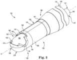
- FIG. 3is a schematic perspective view illustrating an example distal portion of the electrosurgical cutting instrument of FIG. 1 in a second configuration that is different than the first configuration.
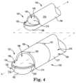
- FIG. 4is schematic exploded view illustrating features of components of the electrosurgical cutting instrument of FIG. 1 .
- FIG. 5is a schematic view illustrating another feature a component of the electrosurgical cutting instrument of FIG. 1 .
- FIG. 6is a schematic perspective view illustrating an example distal portion of an electrosurgical cutting instrument having an alternatively designed outer shaft in combination with the inner shaft in the second configuration.
- FIG. 7is a schematic perspective view illustrating a feature of the alternately designed outer shaft of the electrosurgical cutting instrument of FIG. 6 .
- FIG. 1illustrates a system 100 that includes an electrosurgical device 102 having a proximal end region 110 and a distal end region 120 .
- the device 102includes tubular, or hollow, outer shaft 130 and a tubular, or hollow, inner shaft 140 coaxially maintained within the outer shaft 130 .
- the distal end region 120is configured to engage the surgical site.
- a portion of the inner shaft 140is exposed at distal end region 120 .
- the distal end region 120includes a mechanical cutting element, such as a blade, and a bipolar electrode to provide for coapting blood vessels during hemostasis.
- at least the exposed portion of the inner shaft 140is movable with respect to the outer shaft 130 to effect mechanical cutting at the surgical site.
- the distal end region 120typically includes a low profile as it is often inserted through an incision in the patient.
- proximal end region 110includes a handle or handpiece 175 and an actuator 200 remote from the distal end 120 and thus remote from the surgical site such as outside of the patient.
- a cliniciancan grasp the handpiece 175 and can control the system 100 or operate the device 102 at least in part through the actuator.
- the actuator 200includes a button 202 carried on a housing 204 .
- the handpiece 175 and the actuator housing 204are coupled together and affixed to the outer shaft 130 such that the outer shaft does not move with respect to the handpiece 175 and actuator housing 204 . Examples are contemplated, however, where the outer shaft 130 can rotate with respect to the housing 204 and inner shaft 140 .
- the proximal end region 110also includes a hub 177 coupled to inner shaft 140 .
- the hub 175is disposed within the handpiece 175 and is configured to move the inner shaft 140 with respect to the outer shaft 130 .
- the device 102may be coupled to an driving mechanism or motor, which may be included as part of an integrated power console, or IPC, 179 for driving the hub 177 and specifically for controlling rotation or oscillation of inner shaft 140 with respect to the handpiece 175 .
- Proximal end region 110also includes a fluid source connector 150 for connection to a fluid source 152 .
- the fluid source 152can include a bag of fluid coupled to flexible delivery tubing to carry the fluid to connector 150 .
- the fluidis conveyed along the shafts 130 , 140 and is emitted from an opening at the distal end region 120 .
- the hub 177may be made isolated from the fluid source connector through the application of a silicon O-ring disposed around the inner shaft 140 proximal to the fluid source connector 150 and distal to the hub 177 or by other mechanisms.
- the fluidincludes saline and can include physiologic saline such as sodium chloride (NaCl) 0.9% solution. Saline is an electrically conductive fluid, and other suitable electrically conductive fluids can be used.
- the fluidmay include a nonconductive fluid, such as deionized water, which may still provide advantages over using no fluid.
- a pumpcan be used to convey fluid to the electrosurgical device 102 and control fluid flow.
- delivery tubingis passed through pump.
- Pumpin one example is a peristaltic pump such as a rotary peristaltic pump or a linear peristaltic pump.
- Pumpcan convey the fluid through the delivery tubing by way of intermittent forces placed on the external surface of the delivery tubing.
- Peristaltic pumpsare often preferred because the mechanical elements of the pump places forces are placed on the external surface of the delivery tubing and do not come into direct contact with the fluid, which can reduce the likelihood of fluid contamination.
- Other examples of system 100might not include a pump, and fluid can be is provided to the electrosurgical device 102 via gravity.
- Proximal end region 110also includes a power source connector 154 for connection to a source of electrical energy indicated as power source 156 .
- Power source 156provides electrical energy, such as radio-frequency (RF) energy via insulated wires to the power source connector 154 .
- the power source connector 154is in electrical communication with conductors along the elongated portions of the shafts 130 , 140 to bipolar electrodes at the distal end region 120 .
- the conductive outer shaft 130is configured to carry RF energy to an electrode at a first pole and the conductive inner shaft 140 is configured to carry RF energy to an electrode.
- the first and second polesare opposite from each other, such as the first pole is active and the second pole is passive, and the outer shaft 130 and inner shaft 140 are electrically isolated from each other.
- the elongated portions of the outer and inner shafts 130 , 140are conductive themselves and carry the RF energy from the power source 156 to electrodes at the distal end region 120 .
- the conductive portion of the outer shaft 130is covered with an elongate insulator 131 that extends from at least the proximal end region 110 to at least the distal end region 120 . Accordingly, the elongated portion of outer shaft 130 conveys RF energy from the power source connector 154 to the distal end region 120 , but is insulated from any articles that may come into contact with the elongated portion of the outer shaft 130 .
- power source 156includes a generator configured for use with one or more electrosurgical devices.
- An example generatoris available under the trade designation Aquamantys and provides a type of RF sealing energy technology available under the trade designation Transcollation from Medtronic Advanced Energy of Portsmouth, N.H., United States. Examples of suitable generators and flow rate controllers are described in U.S. Pat. No. 7,815,634, and published U.S. Pat. Application Nos. 2001-0032002; 2006-0149225 and 2005-0090816, which are incorporated by reference into this disclosure.
- Proximal end regioncan also include a suction source connector 158 for connection to a suction source 159 .
- the suction connector 158is in fluid communication with an opening in the distal end region 120 . Fragments of body materials cut with the device 102 and fluids can be removed from the surgical site through the opening in the distal end region via the suction source 159 .
- FIGS. 2 and 3illustrate schematic perspective views of outer shaft 130 and inner shaft 140 of device 102 in different configurations.
- FIG. 2illustrates the device 102 with inner shaft 140 in a first configuration with respect to outer shaft 130 .
- FIG. 3illustrates the device 102 with inner shaft 140 in a second configuration with respect to outer shaft 140 .
- FIGS. 2 and 3illustrate elongated inner shaft 140 coaxially maintained within elongated outer shaft 130 along axis A.
- the outer shaft 130includes an elongated portion that extends from a proximal end 131 , which can be connected to housing 204 , to a distal end 132 that includes an opening such as window 133 and a distal-most tip 136 .
- An outer shaft cutting edge 134defines window 133 .
- the outer shaft cutting edge 134includes cutting teeth 135 .
- the outer shaft 130may be rigid, malleable, or include combinations including a rigid portion and a malleable portion.
- the inner shaft 140includes an elongated portion that extends from a proximal end 141 , which can be connected to hub 177 , to a distal end 142 . A portion of the distal end 142 is exposed to the surgical site through window 133 of outer shaft 130 .
- a lumen 137 formed between the outer shaft 130 and the inner shaft 140is configured to carry fluid between an outer surface of the inner shaft 140 and an inner surface of the outer shaft 130 . Fluid is emitted from the distal end region 120 at distribution point 160 .
- the outer shaft 130includes more than one distribution points, such as proximal distribution point 161 and distal distribution point 162 that are spaced-apart from each other.
- distribution points 161 and 162are aligned along longitudinal axis A on the outer surface 180 of the outer shaft 130 . Fluid from distribution point 161 , as well as distribution point 162 , generally flows axially along the outer surface 180 towards window 133 of the outer shaft 130 .
- One or more outer shaft electrodes 190can be disposed along the outer surface 180 of the outer shaft 130 in the distal end region 120 .
- an electrode 191is exposed on the outer surface 180 of the outer shaft 130 between fluid distribution point 161 and the window 133 of the outer shaft 130 in the path of fluid flow. More particularly, the electrode 191 can be exposed on the outer surface 180 between proximate fluid distribution point 161 and distal distribution point 162 .
- the remaining portions of the outer surface 180 in the distal end regioncan be covered with an insulator or electrically isolating material 216 .
- the electrode 191can be formed as a patch of a conductive element in electrical communication with the power source connector 154 partially extending around the outer surface 180 or, as illustrated, a conductive element along the entire circumference of the outer surface 180 between the distribution point 161 and window 133 .
- electrode 191can be an exposed portion of the conductive portion of the outer shaft 130 , i.e., a portion of the outer shaft 130 without an electrically isolating coating 216 , rather than a separate conductor affixed to the outer shaft 130 . Electrode 191 is thus in electrical communication with the power source connector 154 .
- FIG. 2also illustrates inner shaft 140 in a first configuration, or open position, with respect to outer shaft 130 such that an inner shaft cutting edge or inner cutter 143 is exposed to window 133 .
- Inner cutter 143includes cutting teeth 144 and defines an inner shaft window or opening 145 .
- An inner surface 182 of the inner shaft 140is exposed to the surgical site in the open position.
- the inner surface 182defines a lumen 149 axially extending along the elongated inner shaft 140 . Fluid from distribution point 161 and distribution point 162 can collect on the inner surface 182 of the inner shaft 140 within lumen 149 .
- the device 102can be used to remove body matter and fluids from the surgical site while the outer and inner shaft cutters 134 and 143 are the open position.
- the inner shaft and outer shaft cutters 134 , 143may move relative to one another in oscillation, rotation, or both, via the hub 177 to mechanically cut body matter.
- outer shaft cutter 134may remain stationary relative to the handpiece 175 and actuator housing 204 while the inner shaft cutter 143 rotates about longitudinal axis A of the device to cut body matter.
- the outer shaft 130 and the inner shaft 140can be locked in the open position.
- the cliniciancan also manipulate the device 102 so that the distal end region moves along the longitudinal axis A, rotates about the longitudinal axis A, or otherwise to cut body matter with teeth 144 without rotating the inner shaft 140 with respect to the outer shaft 130 .
- the inner shaft opening 145is fluidly connected to an inner shaft lumen 149 that extends from the inner shaft opening 145 to the proximal end 141 of inner shaft 140 and may be fluidly connected with the suction source 159 through suction source connection 158 .
- body matter cut via inner and outer shaft cutters 143 , 134 and fluid, such as fluid emitted from distribution points 161 and 162is aspirated into the inner shaft lumen 149 through the inner shaft opening 145 upon application of suction source 159 to remove body material and fluid from the surgical site.
- the inner surface 182 of the inner shaftis covered in an insulator 210 to electrically isolate the electrode 191 from the conductive portions of the inner shaft 140 .
- the inner shaftdoes not include an electrode and the distal end region 120 does not deliver RF energy to the tissues when the inner shaft 140 is in the open configuration relative to the outer shaft 130 .
- the inner surface 182 of the inner shaft 140can include one or more inner surface electrodes in the distal end region 120 .
- an inner surface electrodecan be formed with the conductive portion of the inner shaft 140 is exposed on the inner surface 182 in a region axially distal to the distal fluid distribution point 162 on the outer surface 180 of the outer shaft 130 .
- an inner surface electrodecan be formed with conductive portion of the inner shaft 140 exposed on inner surface 182 of the inner shaft 140 in the region at least distal to the proximal-most inner shaft edge 143 or proximal-most portion of the inner shaft window 145 .
- An inner surface electrodewould be electrically isolated from the outer shaft electrode 191 .
- an inner surface electrodeis in electrical communication with the power source connector 154 and forms an electrode pole opposite the pole of the outer surface electrode 191 .
- an inner surface electrodeis the return electrode in the bipolar configuration.
- FIG. 3illustrates the inner shaft 140 in a second configuration, or closed position, with respect to the outer shaft 130 .
- An outer surface 184 of the inner shaft 140is exposed in outer shaft window 133 of the outer shaft 130 .
- Inner shaft 140is rotated about longitudinal axis A within the outer shaft 130 such that the inner shaft cutter 143 is completely shielded from exposure.
- the inner shaft in the closed positioncan be rotated 180 degrees with respect to inner shaft relative to the outer shaft in the open position.
- the inner shaft cutter 143in one example, is facing the interior of the outer shaft 130 opposite from the outer shaft window 133 and an outer surface 184 of the inner shaft 140 is exposed in the window 133 .
- the longitudinal edges of window 133do not extend 180 degrees radially around the circumference of the outer shaft 130 .
- the inner shaft 140can be rotated less than 180 degrees from the open position to be in the closed position. In one example, the inner shaft 140 can be locked in the closed position.
- Electrodescan be disposed on the outer surface 184 of the inner shaft 140 .
- electrode 196is exposed in the window 133 while the inner shaft 140 is in the closed position.
- electrode 196is exposed on the outer surface 184 of inner shaft 140 in the region axially distal to the distal fluid distribution point 162 on the outer surface 180 of the outer shaft 130 .
- the electrode 196is exposed on outer surface 184 of the inner shaft 140 in the region at least longitudinally distal to the proximal-most inner shaft edge 143 or proximal-most portion of the inner shaft window 145 .
- the outer surface 184 of the inner shaft 140is an electrically isolating material 212 covering the conductive portion.
- electrode 196can be an exposed portion of the conductive portion of the inner shaft 140 , i.e., a portion of the inner shaft 140 without an electrically isolating coating, rather than a separate conductor affixed to the inner shaft 140 . Electrode 196 is thus in electrical communication with the power source connector 154 .
- Electrode 196is electrically isolated from the outer shaft electrode 190 , such as electrode 191 . Electrode 196 forms an electrode pole opposite the pole of the outer surface electrode 190 . For example, if the outer surface electrode 190 on the outer shaft 130 is the active electrode then the electrode 196 on the inner shaft 140 is the return electrode in the bipolar configuration.
- the electrode 196 on the outer surface 184can be made to be in electrical communication with the electrode on the inner surface 182 of the inner shaft 140 .
- Energized electrodes 191 and 196 along with fluid dispersed from distribution points 161 and 162combine to form a field of RF energy to coapt blood vessels during hemostasis.
- RF energyis delivered to tissue through electrodes 191 , 196 while the inner shaft 140 is in the closed position without attendant risk that the cutting teeth 144 of the inner shaft 140 will diminish the efforts to achieve hemostasis.
- Device 102may thus comprise two modes: a cutting or debridement mode and a sealing or hemostasis mode and the two modes may be mutually exclusive.
- hemostasisis achieved via RF energy delivered to tissue while cutters 134 , 143 are not active or cutting.
- RF energymay be advantageously delivered simultaneously with the fluid such as saline to achieve an optimal tissue effect by delivering controlled thermal energy to tissue.
- RF energymay be delivered to electrodes during cutting mode while the cutters 134 , 143 are actively cutting so that cutting or debridement mode is not exclusive of sealing or hemostasis mode.
- the inner shaft 140may be locked in an open position during sealing or hemostasis mode in order for fluid to collect and be suctioned from lumen 149 in case the inner surface 182 includes an electrode.
- FIG. 4schematically illustrates outer shaft 130 and inner shaft 140 in the design illustrated in FIGS. 2 and 3 .
- Inner shaft 140includes inner cutter 143 defining inner shaft opening 145 , as illustrated schematically.
- Inner shaft 140also includes inner surface 182 forming lumen 149 and outer surface 184 .
- the inner shaft 140is formed from a conducting material that is covered with an electrically isolating coating, or insulator.
- the inner surface 182is covered in the insulator 210 at least at the distal tip region 120 .
- the insulator 212 on the outer surface 184 of the inner shaft 140is formed to expose outer surface electrode 196 .
- Outer shaft 130includes distal-most tip 136 and cutting edge 134 to define window 133 , also as illustrated schematically. Outer shaft 130 also includes outer surface 180 and, as illustrated, inner surface 186 forming lumen 139 .
- the outer shaft 130is formed from a conductive material that is covered with an electrically isolating coating, or insulator 216 on the outer surface 180 .
- the inner surface 186is covered in the insulator 214 at least at the distal tip region 120 .
- the insulator 216 on the outer surface 180 of the outer shaft 130is formed to expose outer surface electrode 191 .
- Inner and outer shafts 130 and 140are preferably constructed from a metal such as titanium, copper, tantalum, molybdenum, tungsten, or stainless steel, or another conductive material that can withstand forces used to cut body materials and repeated sterilizations in high temperature autoclaves or other suitable medical-grade materials. If the shafts 130 , 140 are intended for single use, shafts 130 , 140 can be constructed from a conductive medical-grade material that can withstand forces used to cut body materials and temperatures used in hemostasis.
- the inner shaft 140is electrically isolated from the outer shaft 130 . This can include forming an insulator on the entire outer surface 184 of the inner shaft 140 (except for the exposed portion for electrode 196 ), the entire inner surface 186 of the outer shaft 130 , both the inner surface 186 of the outer shaft 130 and the outer surface 184 of the inner shaft 140 (except for the exposed portion for electrode 196 ), or some other suitable combination.
- Insulators 210 and 212selectively cover the inner and outer surfaces 182 , 184 of the inner shaft 140 , respectively, except for the exposed portion for electrode 196 .
- An insulator 214selectively covers the inner surface 186 of the outer shaft 130 .
- Insulator 216selectively covers the outer surface 180 of the outer shaft 130 .
- insulator 216can include insulators 217 and 218 selectively to cover separate regions of the outer surface 180 of the outer shaft 130 .
- insulator 217covers the elongate portion of the outer surface 180 of the outer shaft 130
- insulator 218covers the distal tip 136 of the outer shaft 130 .
- Insulators 210 , 212 , 214 , 216can be one or more medical-grade insulating polymer formed from fluorinated ethylene propylene (FEP), polytetrafluoroethylene (PTFE), parylene or any other material suitable as a non-conductive or electrically insulative material.
- the coatingincludes polyaryletherketones (PAEK) polymer thermoplastic such as polyetheretherketone (PEEK) polymer thermoplastic.
- PAEKpolyaryletherketones
- PEEKpolyetherketone
- One particularly suitable and medical-grade PEEK polymer thermoplastic coatingis available under the trade designation Vicote from Victrex Manufacturing Ltd. of Thorton Cleveleys, Lancashire, United Kingdom.
- the polymer thermoplasticcan be dispersed on the conductors of portions of shafts 130 and as either a powder or aqueous solution to form coatings for surfaces 180 , 182 , 184 , and 186 .
- the insulatoris capable of withstanding use and cleaning conditions.
- Electrodessuch as electrodes 191 and 196 , are formed on the outer and inner shafts 130 , 140 .
- the conductive portions of shafts 130 , 140are masked while the insulators are being coated on the shafts, the the masks are later removed to expose uncoated regions of the shafts 130 , 140 configured to act as electrodes 191 and 196 .
- the shafts 130 , 140are coated, and the coating is later removed from shafts 130 , 140 to exposed the regions configured to act as electrodes. Still further, some combination of masking and coating removal is used to form the not coated regions configured to act as electrodes.
- FIG. 5shows another schematic view of an example of the inner shaft 140 .
- the inner shaft 130 of the exampleincludes an insulated elongated portion 220 and an exposed and not coated inner cutter 143 .
- the elongated portion 220includes at least one fluid distribution flute 222 formed in the outer surface 184 .
- the exampleshows a plurality of fluid distribution flutes 222 a , 222 b , . . . 222 n formed into the inner shaft 140 and spaced-apart from each other around the circumference of the outer surface 184 .
- At least one reservoir 224is formed into outer surface 184 the inner shaft 140 and connected to the fluid distribution flutes 222 a , 222 b , . . . 222 n as illustrated. In the example, reservoir 224 extends along the circumference of the outer surface 184 .
- Fluid collected from the reservoircan be dispersed from distribution points 161 and 162 on the outer shaft 130 .
- the inner surface 186 of outer shaft 130combine with distribution flutes 222 a , 222 b , . . . 222 n and reservoir to form lumen 137 described above with respect to FIGS. 2 and 3 .
- detentscan be formed in the inner surface 186 of outer shaft 130 in addition to or instead of distribution flutes 222 and reservoir 224 to form lumen 137 . If detents are formed into the inner surface 186 of outer shaft 130 , the outer surface 184 of inner shaft 140 can optionally be made smooth.
- FIG. 6shows an alternative design of surgical device 102 , i.e., surgical device 300 .
- Device 300includes an outer shaft 230 , which is an alternate design of the outer shaft 130 of FIGS. 2 - 3 .
- the remaining portions of device 300can be similar to the device illustrated in FIG. 1 , and like parts are labeled with like reference numerals.
- Device 300includes elongated inner shaft 140 , which can be the same as illustrated above, coaxially maintained within elongated outer shaft 230 along axis B.
- the outer shaft 230includes an elongated portion 231 that extends from a proximal end, not shown, which can be connected to housing 204 , and a distal end 232 that includes an opening such as window 233 and a distal-most tip 236 .
- An outer shaft cutting edge 234defines window 233 .
- the outer shaft cutting edge 234includes cutting teeth 235 .
- the outer shaft 230may be rigid, malleable, or include combinations including a rigid portion and a malleable portion.
- the outer surface 280 of elongated portion 231 of the outer shaft 230can be covered in an electrically isolating material 316 .
- a lumen 237 formed between the outer shaft 230 and the inner shaft 140is configured to carry fluid between an outer surface of the inner shaft 140 and an inner surface of the outer shaft 230 . Fluid is emitted from the distal end region at distribution point 260 .
- the outer shaft 230includes more than one distribution points, such as proximal distribution point 261 and distal distribution point 262 that are spaced-apart from each other.
- distribution points 261 and 262are aligned along longitudinal axis B on the outer surface 280 of the outer shaft 230 . Fluid from distribution point 261 , as well as distribution point 262 , generally flows axially along the outer surface 280 towards window 233 of the outer shaft 230 .
- the outer surface 280 of distal end 232can include an electrically isolating over-mold portion 320 .
- the over-mold portion 320forms the shaft 230 at the distal end 232 .
- the over-mold portion 320takes the place of the insulator-covered conductor at the tip in of outer shaft 130 in FIG. 4 .
- the conductive elongate portion of outer shaft 230is attached to an electrically isolating over-mold 320 to form the distal end 232 .
- This designelectrically isolates the distal end 232 from the inner shaft 140 .
- the electrically isolating material used to form the over-mold portion 320can include one or more medical grade polymers, such as the medical grade polymers described above used to form insulators 210 , 212 , 214 , 216 .
- the over mold portion 320is constructed from medical-grade PEEK polymer thermoplastic coating is available under the trade designation Vicote from Victrex, as described above.
- Outer shaft 230also includes an electrode 290 disposed on the electrically isolating over-mold portion 320 .
- the electrode 290can be formed as a sleeve prior to coupling to the outer shaft 230 .
- the electrode 290can be attached to the conductive portion of the shaft 230 to be in electrical communication with the power source connection 154 .
- the electrode 290 sleevecan be attached over the over-mold portion 320 .
- the electrode 290can be attached directly to the conductive portion of the shaft 230 or to the conductive portion via an electrical conductor such as a wire or trace (not shown).
- Electrode 290is preferably constructed from a metal such as titanium, copper, tantalum, molybdenum, tungsten, or stainless steel, or another conductive material that can withstand forces used to cut body materials and repeated sterilizations in high temperature autoclaves or other suitable medical-grade materials. If the debrider 300 is intended for single use, electrode 290 can be constructed from a conductive medical-grade material that can withstand forces used to cut body materials and temperatures used in hemostasis.
- the electrode 290can receive RF energy and function in the same manner as electrode 190 in FIG. 2 .
- the electrode 290can be energized along with electrode 196 of the inner shaft 140 , and fluid can be dispersed from fluid distribution points 261 and 262 , to provide hemostasis at the distal end 232 as described above with respect to the design shown in FIGS. 2 and 3 .
- FIG. 7illustrates the electrode 290 in greater detail.
- the electrode 290can be wire cut to form the outer shaft cutting edge 234 including cutting teeth 235 and a distal lateral band 296 .
- Electrode 290can also include a distal circumferential band 297 that can extend all or partially around the circumference of the outer shaft 230 proximal to fluid distribution point 262 .
- the distal circumferential band 297 in the exampleis coupled to a proximal circumferential band 298 via one or more longitudinal strips 299 configured to run axially along the over-mold portion 320 .
- the exampleillustrates two longitudinal strips 299 on opposite sides of the over-mold portion 320 and, in the example, spaced-apart from the fluid distribution points 262 .
- the proximal circumferential band 298is configured to interface with the elongate portion of the outer shaft 230 .
- the proximal circumferential band 298 in the exampleencircles the over-mold portion 320 and is configured to be distal to fluid distribution point 261 .
- Fluid from distribution point 261generally flows axially along the outer surface 280 towards window 233 and distal tip 236 of the outer shaft 230 .
- the fluidflows across the proximal circumferential band 298 and the distal circumferential band 296 , such as fluid from distribution point 261 .
- fluid from distribution points 261 , 262can flow across the distal lateral band 296 .
- the fluidis energized when the electrodes 290 and 194 are activated with RF sealing energy to create an RF field in the area near the distal region 232 .
Landscapes
- Health & Medical Sciences (AREA)
- Surgery (AREA)
- Engineering & Computer Science (AREA)
- Life Sciences & Earth Sciences (AREA)
- Heart & Thoracic Surgery (AREA)
- Animal Behavior & Ethology (AREA)
- Nuclear Medicine, Radiotherapy & Molecular Imaging (AREA)
- Otolaryngology (AREA)
- Veterinary Medicine (AREA)
- Public Health (AREA)
- Physics & Mathematics (AREA)
- Biomedical Technology (AREA)
- Medical Informatics (AREA)
- Molecular Biology (AREA)
- Plasma & Fusion (AREA)
- General Health & Medical Sciences (AREA)
- Neurosurgery (AREA)
- Neurology (AREA)
- Surgical Instruments (AREA)
Abstract
Description
This application is a continuation of U.S. patent application Ser. No. 14/632,460, filed Feb. 26, 2015, and entitled “ELECTROSURGICAL CUTTING INSTRUMENT, which claims the benefit of the filing date of U.S. Provisional Patent Application Ser. No. 61/944,863, filed Feb. 26, 2014, and entitled “ELECTROSURGICAL CUTTING INSTRUMENT,” the entire teachings of each of which are incorporated herein by reference.
The disclosure relates to instruments or tools used in performing surgery on a patient. More particularly, the disclosure relates to cutting instruments using electrodes to seal or cauterize tissue.
Clinicians use surgical instruments, including debriders such as microdebriders, to shave, cut, resect, abrade, or remove tissue, bone, or other body materials from a surgical site during surgery including endoscopic surgery. An example of such an instrument includes a rotating cutting blade on an elongated tube. The elongated tube is fit within an elongated outer tube having a cutting window exposing the cutting blade. The cutting blade is rotated within and with respect to the outer tube. The outer tube and inner tube are coupled to a handpiece. The handpiece typically includes a motor coupled to inner tube to rotate the cutting blade with respect to the handpiece. Typically, an actuator on the handpiece controls the rotation of the motor. A clinician is thus able to manipulate the location and rotation of the cutting blade to remove material from the surgical site. In some examples, a vacuum is applied through the inner tube to remove material that is cut with the blade. Many instruments also supply an irrigation fluid to the surgical site. The surgical instruments provide precise mechanical cutting at a surgical site through a low or minimally invasive incision or entry point in the patient.
An issue typically presented with surgical cutting instruments such as debriders involves the ability to control bleeding. If bleeding is not controlled, blood can obscure the view of the surgical site, adversely affect the precision of the cutting or severing tissue, and prolong the surgery. Too much blood loss can cause trauma to the patient that may require a blood transfusion. Electrosurgical instruments are often used to control bleeding in such circumstances. Electrosurgical instruments can be used to cauterize, coagulate/desiccate or simply reduce blood flow by controlling electrosurgical energy applied to the tissue. Small blood vessels, e.g., those having a diameter of less than about two millimeters, can be coapted through coagulation, i.e., the process of desiccating tissue where the tissue cells are ruptured and dried. Larger blood vessels may be coapted through sealing, i.e., the process of liquefying the collagen in the tissue so that it reforms into a fused mass. In some instances, a second surgical device is used to control bleeding either before or after body material is cut. Some electrosurgical cutting instruments include the ability to cut body material and control bleeding with the same device.
This summary is provided to introduce a selection of concepts in a simplified form that are further described below in the Detailed Description. This summary is not intended to identify key features or essential features of the claimed subject matter, nor is it intended to be used to limit the scope of the claimed subject matter.
Surgical instruments such as debriders are suitable for a variety of surgical applications including ear, nose, and throat (ENT) procedures. Sinus procedures are challenging due to the proximal location of sensitive organs such as the eyes and brain and due to the small size of the surgical site.
The disclosure is directed to debriders that provide both cutting or debridement and sealing energy through energized electrodes and fluids. The debriders conduct sealing energy to the electrode via conductive shafts selectively coated with an insulating material. The conductive shafts provide for robust electrodes as well as reduced costs and a more streamlined assembly.
In one aspect, the disclosure is directed to an electrosurgical device having a tubular outer shaft and an inner shaft. The tubular outer shaft includes an axis and a distal end region. The distal end region includes a distal-most tip and a cutting edge defining a window in the outer shaft proximal along the axis to the distal-most tip. The inner shaft inner shaft is coaxially maintained within the outer shaft such that the inner shaft is movable about the axis with respect to the outer shaft and wherein a portion of the inner shaft is exposed in the window of the outer shaft. The inner shaft includes an outer surface and an inner surface forming an axial lumen. The inner surface of the inner shaft is exposed in the window while in an open configuration and the outer surface of the inner shaft is exposed in the window while in a closed configuration. A first electrode is disposed on the outer shaft in a region proximal along the axis to the window. A second electrode electrically isolated from the first electrode and disposed on the outer surface of the inner shaft. The second electrode is exposed in the window of the outer shaft in the closed configuration, and the inner surface in the portion exposed by the window in the open configuration is covered in an electrically isolating material.
In another aspect, the disclosure is directed to an electrosurgical device having a tubular outer shaft and a tubular inner shaft. The tubular outer shaft includes an axis and a distal end region. The distal end region includes a distal-most tip and a cutting edge defining an outer shaft window proximal along the axis to the distal-most tip. The tubular inner shaft is coaxially maintained within the outer shaft such that the inner shaft is movable about the axis with respect to the outer shaft. The inner shaft includes an outer surface having a toothed edge defining an opening. The opening exposes an inner surface of the inner shaft in the window of the outer shaft when the opening is aligned with the window. A first electrode is disposed on the outer shaft in a region proximal along the axis to the window. A fluid distribution point is disposed on the outer shaft in a region proximal along the axis to the first electrode.
The fluid distribution point emits fluid across the first electrode and toward the distal-most end. A second electrode electrically is isolated from the first electrode. The second electrode is disposed on the outer surface of the inner shaft and exposed in the window of the outer shaft. The second electrode includes a first portion disposed on the outer surface of the inner shaft. The inner surface of the inner shaft is covered in an electrically isolating material.
In still another aspect, the disclosure is directed to an electrosurgical system having a tubular outer shaft and a tubular inner shaft. The outer shaft includes an elongate portion and a distal end region. The distal end region includes a distal-most tip defining a window in the outer shaft proximal along the axis to the distal-most tip. The elongate portion includes a conductive shaft covered with an electrically isolating material. The distal end region is configured from an insulator. The inner shaft is coaxially maintained within the outer shaft such that the inner shaft is movable about the axis with respect to the outer shaft. A portion of the inner shaft is exposed in the window of the outer shaft, and the inner shaft is electrically isolated from the conductive shaft. The inner shaft includes an outer surface and an inner surface forming an axial lumen. The inner surface of the inner shaft is exposed in the window while in an open configuration, and the outer surface of the inner shaft is exposed in the window while in a closed configuration. A first electrode disposed on the outer shaft in a region proximal along the axis to the window and on the insulator of the distal end region. The first electrode is electrically coupled to the conductive shaft. A second electrode is disposed on the inner shaft and electrically isolated from the first electrode. The second electrode is exposed in the window of the outer shaft at least in one of the open configuration and the closed configuration.
The accompanying drawings are included to provide a further understanding of embodiments and are incorporated in and constitute a part of this specification. The drawings illustrate embodiments and together with the description serve to explain principles of embodiments. Other embodiments and many of the intended advantages of embodiments will be readily appreciated, as they become better understood by reference to the following detailed description. The elements of the drawings are not necessarily to scale relative to each other. Like reference numerals designate corresponding similar parts.
In the following Detailed Description, reference is made to the accompanying drawings, which form a part hereof, and in which is shown by way of illustration specific embodiments or examples in which the invention may be practiced. It is to be understood that other examples may be utilized and structural or logical changes may be made without departing from the scope of the present disclosure. The following detailed description, therefore, is not to be taken in a limiting sense, and the scope of the present invention is defined by the appended claims. It is to be understood that features of the various exemplary embodiments described herein may be combined with each other, unless specifically noted otherwise.
In the example,proximal end region 110 includes a handle orhandpiece 175 and anactuator 200 remote from thedistal end 120 and thus remote from the surgical site such as outside of the patient. A clinician can grasp thehandpiece 175 and can control thesystem 100 or operate thedevice 102 at least in part through the actuator. Theactuator 200 includes abutton 202 carried on ahousing 204. In the example, thehandpiece 175 and theactuator housing 204 are coupled together and affixed to theouter shaft 130 such that the outer shaft does not move with respect to thehandpiece 175 andactuator housing 204. Examples are contemplated, however, where theouter shaft 130 can rotate with respect to thehousing 204 andinner shaft 140.
Theproximal end region 110 also includes ahub 177 coupled toinner shaft 140. In the example, thehub 175 is disposed within thehandpiece 175 and is configured to move theinner shaft 140 with respect to theouter shaft 130. Thedevice 102 may be coupled to an driving mechanism or motor, which may be included as part of an integrated power console, or IPC,179 for driving thehub 177 and specifically for controlling rotation or oscillation ofinner shaft 140 with respect to thehandpiece 175.
A pump can be used to convey fluid to theelectrosurgical device 102 and control fluid flow. In one example, delivery tubing is passed through pump. Pump in one example is a peristaltic pump such as a rotary peristaltic pump or a linear peristaltic pump. Pump can convey the fluid through the delivery tubing by way of intermittent forces placed on the external surface of the delivery tubing. Peristaltic pumps are often preferred because the mechanical elements of the pump places forces are placed on the external surface of the delivery tubing and do not come into direct contact with the fluid, which can reduce the likelihood of fluid contamination. Other examples ofsystem 100 might not include a pump, and fluid can be is provided to theelectrosurgical device 102 via gravity.
In one example, the elongated portions of the outer andinner shafts power source 156 to electrodes at thedistal end region 120. In the example shown, the conductive portion of theouter shaft 130 is covered with anelongate insulator 131 that extends from at least theproximal end region 110 to at least thedistal end region 120. Accordingly, the elongated portion ofouter shaft 130 conveys RF energy from thepower source connector 154 to thedistal end region 120, but is insulated from any articles that may come into contact with the elongated portion of theouter shaft 130.
In one example ofpower source 156 includes a generator configured for use with one or more electrosurgical devices. An example generator is available under the trade designation Aquamantys and provides a type of RF sealing energy technology available under the trade designation Transcollation from Medtronic Advanced Energy of Portsmouth, N.H., United States. Examples of suitable generators and flow rate controllers are described in U.S. Pat. No. 7,815,634, and published U.S. Pat. Application Nos. 2001-0032002; 2006-0149225 and 2005-0090816, which are incorporated by reference into this disclosure.
Proximal end region can also include asuction source connector 158 for connection to a suction source159. Thesuction connector 158 is in fluid communication with an opening in thedistal end region 120. Fragments of body materials cut with thedevice 102 and fluids can be removed from the surgical site through the opening in the distal end region via the suction source159.
Alumen 137 formed between theouter shaft 130 and theinner shaft 140 is configured to carry fluid between an outer surface of theinner shaft 140 and an inner surface of theouter shaft 130. Fluid is emitted from thedistal end region 120 atdistribution point 160. In one example, theouter shaft 130 includes more than one distribution points, such asproximal distribution point 161 anddistal distribution point 162 that are spaced-apart from each other. In the example, distribution points161 and162 are aligned along longitudinal axis A on theouter surface 180 of theouter shaft 130. Fluid fromdistribution point 161, as well asdistribution point 162, generally flows axially along theouter surface 180 towardswindow 133 of theouter shaft 130.
One or moreouter shaft electrodes 190 can be disposed along theouter surface 180 of theouter shaft 130 in thedistal end region 120. In the example design illustrated inFIG.2 , anelectrode 191 is exposed on theouter surface 180 of theouter shaft 130 betweenfluid distribution point 161 and thewindow 133 of theouter shaft 130 in the path of fluid flow. More particularly, theelectrode 191 can be exposed on theouter surface 180 between proximatefluid distribution point 161 anddistal distribution point 162. The remaining portions of theouter surface 180 in the distal end region can be covered with an insulator or electrically isolatingmaterial 216. Theelectrode 191 can be formed as a patch of a conductive element in electrical communication with thepower source connector 154 partially extending around theouter surface 180 or, as illustrated, a conductive element along the entire circumference of theouter surface 180 between thedistribution point 161 andwindow 133.
In one example,electrode 191 can be an exposed portion of the conductive portion of theouter shaft 130, i.e., a portion of theouter shaft 130 without an electrically isolatingcoating 216, rather than a separate conductor affixed to theouter shaft 130.Electrode 191 is thus in electrical communication with thepower source connector 154.
Thedevice 102 can be used to remove body matter and fluids from the surgical site while the outer andinner shaft cutters outer shaft cutters hub 177 to mechanically cut body matter. In one example,outer shaft cutter 134 may remain stationary relative to thehandpiece 175 andactuator housing 204 while theinner shaft cutter 143 rotates about longitudinal axis A of the device to cut body matter. Also, theouter shaft 130 and theinner shaft 140 can be locked in the open position. The clinician can also manipulate thedevice 102 so that the distal end region moves along the longitudinal axis A, rotates about the longitudinal axis A, or otherwise to cut body matter withteeth 144 without rotating theinner shaft 140 with respect to theouter shaft 130.
Theinner shaft opening 145 is fluidly connected to aninner shaft lumen 149 that extends from theinner shaft opening 145 to theproximal end 141 ofinner shaft 140 and may be fluidly connected with the suction source159 throughsuction source connection 158. When theinner shaft 130 is in the open position, body matter cut via inner andouter shaft cutters distribution points inner shaft lumen 149 through the inner shaft opening145 upon application of suction source159 to remove body material and fluid from the surgical site.
In the illustrated example ofFIG.2 , theinner surface 182 of the inner shaft is covered in aninsulator 210 to electrically isolate theelectrode 191 from the conductive portions of theinner shaft 140. In this example, the inner shaft does not include an electrode and thedistal end region 120 does not deliver RF energy to the tissues when theinner shaft 140 is in the open configuration relative to theouter shaft 130.
In other examples, theinner surface 182 of theinner shaft 140 can include one or more inner surface electrodes in thedistal end region 120. For example, an inner surface electrode can be formed with the conductive portion of theinner shaft 140 is exposed on theinner surface 182 in a region axially distal to the distalfluid distribution point 162 on theouter surface 180 of theouter shaft 130. In another example, an inner surface electrode can be formed with conductive portion of theinner shaft 140 exposed oninner surface 182 of theinner shaft 140 in the region at least distal to the proximal-mostinner shaft edge 143 or proximal-most portion of theinner shaft window 145. An inner surface electrode would be electrically isolated from theouter shaft electrode 191. In this example, an inner surface electrode is in electrical communication with thepower source connector 154 and forms an electrode pole opposite the pole of theouter surface electrode 191. For example, if theouter surface electrode 191 is the active electrode then an inner surface electrode is the return electrode in the bipolar configuration.
One or more electrodes, such aselectrode 196, can be disposed on theouter surface 184 of theinner shaft 140. In the example,electrode 196 is exposed in thewindow 133 while theinner shaft 140 is in the closed position. In the example,electrode 196 is exposed on theouter surface 184 ofinner shaft 140 in the region axially distal to the distalfluid distribution point 162 on theouter surface 180 of theouter shaft 130. In another example, theelectrode 196 is exposed onouter surface 184 of theinner shaft 140 in the region at least longitudinally distal to the proximal-mostinner shaft edge 143 or proximal-most portion of theinner shaft window 145.
In one example, theouter surface 184 of theinner shaft 140 is an electrically isolatingmaterial 212 covering the conductive portion. In this example,electrode 196 can be an exposed portion of the conductive portion of theinner shaft 140, i.e., a portion of theinner shaft 140 without an electrically isolating coating, rather than a separate conductor affixed to theinner shaft 140.Electrode 196 is thus in electrical communication with thepower source connector 154.
If theinner shaft 140 also includes an inner surface electrode, theelectrode 196 on theouter surface 184 can be made to be in electrical communication with the electrode on theinner surface 182 of theinner shaft 140.
In other examples, RF energy may be delivered to electrodes during cutting mode while thecutters inner shaft 140 may be locked in an open position during sealing or hemostasis mode in order for fluid to collect and be suctioned fromlumen 149 in case theinner surface 182 includes an electrode.
Inner andouter shafts shafts shafts
Theinner shaft 140 is electrically isolated from theouter shaft 130. This can include forming an insulator on the entireouter surface 184 of the inner shaft140 (except for the exposed portion for electrode196), the entireinner surface 186 of theouter shaft 130, both theinner surface 186 of theouter shaft 130 and theouter surface 184 of the inner shaft140 (except for the exposed portion for electrode196), or some other suitable combination.
Electrodes, such aselectrodes inner shafts shafts shafts electrodes shafts shafts
Fluid collected from the reservoir can be dispersed fromdistribution points outer shaft 130. When theinner shaft 140 is disposed withinouter shaft 130, theinner surface 186 ofouter shaft 130 combine withdistribution flutes FIGS.2 and3 . In another example, detents can be formed in theinner surface 186 ofouter shaft 130 in addition to or instead ofdistribution flutes 222 andreservoir 224 to formlumen 137. If detents are formed into theinner surface 186 ofouter shaft 130, theouter surface 184 ofinner shaft 140 can optionally be made smooth.
Alumen 237 formed between theouter shaft 230 and theinner shaft 140 is configured to carry fluid between an outer surface of theinner shaft 140 and an inner surface of theouter shaft 230. Fluid is emitted from the distal end region atdistribution point 260. In one example, theouter shaft 230 includes more than one distribution points, such asproximal distribution point 261 anddistal distribution point 262 that are spaced-apart from each other. In the example, distribution points261 and262 are aligned along longitudinal axis B on theouter surface 280 of theouter shaft 230. Fluid fromdistribution point 261, as well asdistribution point 262, generally flows axially along theouter surface 280 towardswindow 233 of theouter shaft 230.
Theouter surface 280 ofdistal end 232 can include an electrically isolatingover-mold portion 320. In one example, theover-mold portion 320 forms theshaft 230 at thedistal end 232. In particular, theover-mold portion 320 takes the place of the insulator-covered conductor at the tip in ofouter shaft 130 inFIG.4 . Accordingly, the conductive elongate portion ofouter shaft 230 is attached to an electrically isolatingover-mold 320 to form thedistal end 232. This design electrically isolates thedistal end 232 from theinner shaft 140.
The electrically isolating material used to form theover-mold portion 320 can include one or more medical grade polymers, such as the medical grade polymers described above used to forminsulators mold portion 320 is constructed from medical-grade PEEK polymer thermoplastic coating is available under the trade designation Vicote from Victrex, as described above.
Theelectrode 290 can receive RF energy and function in the same manner aselectrode 190 inFIG.2 . Theelectrode 290 can be energized along withelectrode 196 of theinner shaft 140, and fluid can be dispersed from fluid distribution points261 and262, to provide hemostasis at thedistal end 232 as described above with respect to the design shown inFIGS.2 and3 .
Fluid fromdistribution point 261, as well asdistribution point 262, generally flows axially along theouter surface 280 towardswindow 233 anddistal tip 236 of theouter shaft 230. The fluid flows across the proximalcircumferential band 298 and the distalcircumferential band 296, such as fluid fromdistribution point 261. Additionally, fluid fromdistribution points lateral band 296. The fluid is energized when theelectrodes distal region 232.
Although the present disclosure has been described with reference to preferred embodiments, workers skilled in the art will recognize that changes can be made in form and detail without departing from the spirit and scope of the present disclosure.
Claims (20)
1. A method of surgically cutting and sealing tissue comprising:
positioning a distal end region of an electrosurgical device at an operative site within a patient, the electrosurgical device including:
an outer shaft comprising a lumen and a distal end comprising a cutting edge forming an outer shaft window,
an inner shaft rotatably disposed within the lumen of the outer shaft, the inner shaft having a distal portion comprising an inner shaft cutter forming an inner shaft window,
the outer shaft and the inner shaft forming a fluid passage therebetween, the fluid passage being open to a first fluid distribution point located proximal the outer shaft window, and
first and second electrodes that are electrically isolated from one another and positioned at the distal end region;
cutting tissue at the operative site with the inner shaft cutter and the outer shaft cutting edge by moving the inner shaft relative to the outer shaft;
arranging the electrosurgical device in a closed position in which the inner shaft cutter is shielded;
supplying RF energy to the first and second electrodes while the electrosurgical device is in the closed position to apply the RF energy to tissue of the operative site; and
dispensing, during the step of supplying, fluid from the first fluid distribution point and across at least one of the first and second electrodes.
2. The method ofclaim 1 , wherein the step of supplying includes effecting hemostasis at the operative site.
3. The method ofclaim 1 , wherein in the step of dispensing includes operatively coupling the fluid to the first and second electrodes.
4. The method ofclaim 1 , wherein the inner shaft cutter includes cutting teeth formed about the inner shaft window, and further wherein the closed position includes the cutting teeth disposed within the lumen of the outer shaft.
5. The method ofclaim 1 , wherein at least a portion of the first electrode is located between the outer shaft window and the first fluid distribution point, and further wherein the step of dispensing includes dispensing the fluid across the portion.
6. The method ofclaim 5 , wherein the portion of the first electrode is carried by the outer shaft.
7. The method ofclaim 6 , wherein the portion of the first electrode is formed by an exposed surface of the outer shaft.
8. The method ofclaim 5 , wherein the fluid passage is further open to a second fluid distribution point located between the outer shaft window and the portion of the first electrode, the method further comprising:
during the step of supplying, dispensing fluid from the second fluid distribution point and across at least one of the first and second electrodes.
9. The method ofclaim 8 , wherein the first and second fluid distribution points are aligned with one another along a longitudinal axis of the outer shaft.
10. The method ofclaim 1 , further comprising:
during the step of cutting, dispensing the fluid from the first fluid distribution point.
11. The method ofclaim 10 , further comprising:
during the step of cutting, supplying the RF energy to the first and second electrodes.
12. The method ofclaim 1 , wherein the first electrode is carried by the outer shaft, and the second electrode is carried by the inner shaft.
13. The method ofclaim 12 , wherein the second electrode is formed by an exposed surface of the inner shaft.
14. The method ofclaim 1 , further comprising:
locking the electrosurgical device in an open position in which the inner shaft window is open to the outer shaft window; and
aspirating fluid into the inner shaft window while the electrosurgical device is in the open position.
15. The method ofclaim 14 , further comprising:
during the step of aspirating, supplying the RF energy to the first electrode and a third electrode carried by an inner surface of the inner shaft.
16. A method of surgically treating tissue comprising:
positioning a distal end region of an electrosurgical device at an operative site within a patient, the electrosurgical device including:
an outer shaft comprising a lumen and a distal end comprising a cutting edge forming an outer shaft window,
an inner shaft rotatably disposed within the lumen of the outer shaft, the inner shaft having a distal portion comprising an inner shaft cutter forming an inner shaft window,
a fluid passage defined between the outer shaft and the inner shaft, the fluid passage being open to first and second fluid distribution points each located proximal the outer shaft window, the first fluid distribution point being proximal the second fluid distribution point, and
first and second electrodes that are electrically isolated from one another and positioned at the distal end region;
arranging the electrosurgical device in a closed position in which the inner shaft cutter is shielded;
supplying RF energy to the first and second electrodes while the electrosurgical device is in the closed position to apply the RF energy to tissue of the operative site; and
dispensing, during the step of supplying, fluid from the first and second fluid distribution points to operatively couple the fluid to the first and second electrodes.
17. The method ofclaim 16 , wherein the step of supplying includes effecting hemostasis at the operative site.
18. The method ofclaim 17 , further comprising:
locking the electrosurgical device in an open position in which the inner shaft window is open to the outer shaft window; and
aspirating fluid into the inner shaft window while the electrosurgical device is in the open position.
19. The method ofclaim 18 , wherein the second electrode is covered and not exposed in the open position.
20. An electrosurgical device for surgically cutting and sealing tissue comprising:
an outer shaft comprising a lumen and a distal end comprising a cutting edge forming an outer shaft window;
an inner shaft rotatably disposed within the lumen of the outer shaft, the inner shaft having a distal portion comprising an inner shaft cutter forming an inner shaft window;
a fluid passage defined between the outer shaft and the inner shaft, the fluid passage being open to a fluid distribution point located proximal the outer shaft window; and
first and second electrodes that are electrically isolated from one another and positioned at a distal end region of the electrosurgical device;
wherein the electrosurgical device is configured to provide:
a cutting state that cuts tissue at an operative site with the inner shaft cutter and the outer shaft cutting edge by moving the inner shaft relative to the outer shaft, and
a hemostasis state that achieves hemostasis at the operative site by arranging the electrosurgical device in a closed position in which the inner shaft cutter is shielded, RF energy is supplied to the first and second electrodes while the electrosurgical device is in the closed position to apply RF energy to tissue of the operative site, and fluid is dispensed from the fluid distribution point and across at least one of the first and second electrodes,
wherein the second electrode is exposed in the window of the outer shaft in the closed position, and
wherein the electrosurgical device is configured such that the second electrode is covered and not exposed in an open position.
Priority Applications (2)
| Application Number | Priority Date | Filing Date | Title |
|---|---|---|---|
| US17/066,831US11864824B2 (en) | 2014-02-26 | 2020-10-09 | Electrosurgical cutting instrument |
| US18/495,559US12343070B2 (en) | 2014-02-26 | 2023-10-26 | Electrosurgical cutting instrument |
Applications Claiming Priority (3)
| Application Number | Priority Date | Filing Date | Title |
|---|---|---|---|
| US201461944863P | 2014-02-26 | 2014-02-26 | |
| US14/632,460US10813686B2 (en) | 2014-02-26 | 2015-02-26 | Electrosurgical cutting instrument |
| US17/066,831US11864824B2 (en) | 2014-02-26 | 2020-10-09 | Electrosurgical cutting instrument |
Related Parent Applications (1)
| Application Number | Title | Priority Date | Filing Date |
|---|---|---|---|
| US14/632,460ContinuationUS10813686B2 (en) | 2014-02-26 | 2015-02-26 | Electrosurgical cutting instrument |
Related Child Applications (1)
| Application Number | Title | Priority Date | Filing Date |
|---|---|---|---|
| US18/495,559ContinuationUS12343070B2 (en) | 2014-02-26 | 2023-10-26 | Electrosurgical cutting instrument |
Publications (2)
| Publication Number | Publication Date |
|---|---|
| US20210022801A1 US20210022801A1 (en) | 2021-01-28 |
| US11864824B2true US11864824B2 (en) | 2024-01-09 |
Family
ID=54140971
Family Applications (3)
| Application Number | Title | Priority Date | Filing Date |
|---|---|---|---|
| US14/632,460Active2036-07-27US10813686B2 (en) | 2014-02-26 | 2015-02-26 | Electrosurgical cutting instrument |
| US17/066,831Active2036-08-19US11864824B2 (en) | 2014-02-26 | 2020-10-09 | Electrosurgical cutting instrument |
| US18/495,559ActiveUS12343070B2 (en) | 2014-02-26 | 2023-10-26 | Electrosurgical cutting instrument |
Family Applications Before (1)
| Application Number | Title | Priority Date | Filing Date |
|---|---|---|---|
| US14/632,460Active2036-07-27US10813686B2 (en) | 2014-02-26 | 2015-02-26 | Electrosurgical cutting instrument |
Family Applications After (1)
| Application Number | Title | Priority Date | Filing Date |
|---|---|---|---|
| US18/495,559ActiveUS12343070B2 (en) | 2014-02-26 | 2023-10-26 | Electrosurgical cutting instrument |
Country Status (1)
| Country | Link |
|---|---|
| US (3) | US10813686B2 (en) |
Cited By (1)
| Publication number | Priority date | Publication date | Assignee | Title |
|---|---|---|---|---|
| US20240050149A1 (en)* | 2014-02-26 | 2024-02-15 | Medtronic Advanced Energy Llc | Electrosurgical cutting instrument |
Families Citing this family (24)
| Publication number | Priority date | Publication date | Assignee | Title |
|---|---|---|---|---|
| US9226792B2 (en) | 2012-06-12 | 2016-01-05 | Medtronic Advanced Energy Llc | Debridement device and method |
| US10314647B2 (en) | 2013-12-23 | 2019-06-11 | Medtronic Advanced Energy Llc | Electrosurgical cutting instrument |
| US10188456B2 (en) | 2015-02-18 | 2019-01-29 | Medtronic Xomed, Inc. | Electrode assembly for RF energy enabled tissue debridement device |
| US10376302B2 (en) | 2015-02-18 | 2019-08-13 | Medtronic Xomed, Inc. | Rotating electrical connector for RF energy enabled tissue debridement device |
| AU2016219980B2 (en)* | 2015-02-18 | 2020-09-03 | Medtronic Xomed, Inc. | RF energy enabled tissue debridement device |
| US9585675B1 (en) | 2015-10-23 | 2017-03-07 | RELIGN Corporation | Arthroscopic devices and methods |
| US9603656B1 (en) | 2015-10-23 | 2017-03-28 | RELIGN Corporation | Arthroscopic devices and methods |
| US10022140B2 (en) | 2016-02-04 | 2018-07-17 | RELIGN Corporation | Arthroscopic devices and methods |
| GB2549992B (en)* | 2016-05-06 | 2022-08-10 | Gyrus Medical Ltd | Electrosurgical instrument |
| US11426231B2 (en) | 2017-01-11 | 2022-08-30 | RELIGN Corporation | Arthroscopic devices and methods |
| US11065023B2 (en)* | 2017-03-17 | 2021-07-20 | RELIGN Corporation | Arthroscopic devices and methods |
| WO2019133542A1 (en)* | 2017-12-27 | 2019-07-04 | Aaron Germain | Arthroscopic devices and methods |
| US11382684B2 (en)* | 2018-03-27 | 2022-07-12 | Gyrus Acmi, Inc. | Electrode blade for shavers |
| WO2019209749A1 (en)* | 2018-04-23 | 2019-10-31 | Aaron Germain | Arthroscopic devices and methods |
| US11672593B2 (en)* | 2018-04-23 | 2023-06-13 | RELIGN Corporation | Arthroscopic devices and methods |
| US12137966B2 (en)* | 2018-06-12 | 2024-11-12 | RELIGN Corporation | Arthroscopic devices and methods |
| EP3927265A1 (en) | 2019-02-22 | 2021-12-29 | Smith&Nephew, Inc. | Combination electrosurgical and mechanical resection device |
| US20210093371A1 (en)* | 2019-09-30 | 2021-04-01 | RELIGN Corporation | Medical devices and method |
| US11497551B2 (en)* | 2019-11-26 | 2022-11-15 | RELIGN Corporation | Arthroscopic devices and methods |
| US20210353356A1 (en)* | 2020-05-14 | 2021-11-18 | Singlepass Transsepat, Inc. | Tubular large bore transseptal crossing sheath |
| GB2598332B (en)* | 2020-08-26 | 2024-07-24 | Gyrus Medical Ltd | Electrosurgical instrument |
| GB2610599B (en)* | 2021-09-08 | 2023-08-30 | Gyrus Medical Ltd | Shaver arrangement for a surgical instrument |
| GB2623118B (en)* | 2022-10-06 | 2024-11-20 | Gyrus Medical Ltd | RF shaver auxiliary suction |
| CN117731386B (en)* | 2024-02-08 | 2024-06-11 | 诺美伊创医疗科技(成都)有限公司 | Inner cutter head assembly, inner cutter assembly and plane cutter |
Citations (263)
| Publication number | Priority date | Publication date | Assignee | Title |
|---|---|---|---|---|
| US2888928A (en) | 1957-04-15 | 1959-06-02 | Seiger Harry Wright | Coagulating surgical instrument |
| US3682130A (en) | 1965-03-19 | 1972-08-08 | Jeffers & Bailey Inc | Fusible temperature responsive trigger device |
| US3750650A (en) | 1970-12-15 | 1973-08-07 | Hewlett Packard Gmbh | Double spiral electrode for intra-cavity attachment |
| US4060088A (en) | 1976-01-16 | 1977-11-29 | Valleylab, Inc. | Electrosurgical method and apparatus for establishing an electrical discharge in an inert gas flow |
| US4195637A (en) | 1977-10-21 | 1980-04-01 | Schneider Medintag Ag | Catheter arrangement, method of catheterization, and method of manufacturing a dilatation element |
| US4207897A (en) | 1976-07-21 | 1980-06-17 | Spembly Limited | Cryosurgical probe |
| US4248224A (en) | 1978-08-01 | 1981-02-03 | Jones James W | Double venous cannula |
| US4932952A (en) | 1988-12-20 | 1990-06-12 | Alto Development Corporation | Antishock, anticlog suction coagulator |
| US4943290A (en) | 1987-06-23 | 1990-07-24 | Concept Inc. | Electrolyte purging electrode tip |
| US4950232A (en) | 1987-08-11 | 1990-08-21 | Surelab Superior Research Laboratories | Cerebrospinal fluid shunt system |
| US4985030A (en) | 1989-05-27 | 1991-01-15 | Richard Wolf Gmbh | Bipolar coagulation instrument |
| US4998933A (en) | 1988-06-10 | 1991-03-12 | Advanced Angioplasty Products, Inc. | Thermal angioplasty catheter and method |
| US5190541A (en) | 1990-10-17 | 1993-03-02 | Boston Scientific Corporation | Surgical instrument and method |
| US5195959A (en) | 1991-05-31 | 1993-03-23 | Paul C. Smith | Electrosurgical device with suction and irrigation |
| US5234428A (en) | 1991-06-11 | 1993-08-10 | Kaufman David I | Disposable electrocautery/cutting instrument with integral continuous smoke evacuation |
| US5254117A (en) | 1992-03-17 | 1993-10-19 | Alton Dean Medical | Multi-functional endoscopic probe apparatus |
| US5281215A (en) | 1992-04-16 | 1994-01-25 | Implemed, Inc. | Cryogenic catheter |
| US5330521A (en) | 1992-06-29 | 1994-07-19 | Cohen Donald M | Low resistance implantable electrical leads |
| US5334181A (en) | 1990-09-26 | 1994-08-02 | Cryomedical Sciences, Inc. | Cryosurgical system for destroying tumors by freezing |
| US5336220A (en) | 1992-10-09 | 1994-08-09 | Symbiosis Corporation | Tubing for endoscopic electrosurgical suction-irrigation instrument |
| US5364395A (en) | 1993-05-14 | 1994-11-15 | West Jr Hugh S | Arthroscopic surgical instrument with cauterizing capability |
| US5383874A (en) | 1991-11-08 | 1995-01-24 | Ep Technologies, Inc. | Systems for identifying catheters and monitoring their use |
| US5385148A (en) | 1993-07-30 | 1995-01-31 | The Regents Of The University Of California | Cardiac imaging and ablation catheter |
| US5395312A (en) | 1991-10-18 | 1995-03-07 | Desai; Ashvin | Surgical tool |
| US5401272A (en) | 1992-09-25 | 1995-03-28 | Envision Surgical Systems, Inc. | Multimodality probe with extendable bipolar electrodes |
| US5405376A (en) | 1993-08-27 | 1995-04-11 | Medtronic, Inc. | Method and apparatus for ablation |
| US5417709A (en) | 1994-04-12 | 1995-05-23 | Symbiosis Corporation | Endoscopic instrument with end effectors forming suction and/or irrigation lumens |
| US5431649A (en) | 1993-08-27 | 1995-07-11 | Medtronic, Inc. | Method and apparatus for R-F ablation |
| US5431168A (en) | 1993-08-23 | 1995-07-11 | Cordis-Webster, Inc. | Steerable open-lumen catheter |
| US5441503A (en) | 1988-09-24 | 1995-08-15 | Considine; John | Apparatus for removing tumors from hollow organs of the body |
| US5443463A (en) | 1992-05-01 | 1995-08-22 | Vesta Medical, Inc. | Coagulating forceps |
| US5445638A (en) | 1993-03-08 | 1995-08-29 | Everest Medical Corporation | Bipolar coagulation and cutting forceps |
| US5460629A (en) | 1991-02-06 | 1995-10-24 | Advanced Surgical, Inc. | Electrosurgical device and method |
| US5490819A (en) | 1991-08-05 | 1996-02-13 | United States Surgical Corporation | Articulating endoscopic surgical apparatus |
| US5492527A (en) | 1994-09-09 | 1996-02-20 | Linvatec Corporation | Arthroscopic shaver with rotatable collet and slide aspiration control valve |
| US5496271A (en) | 1990-09-14 | 1996-03-05 | American Medical Systems, Inc. | Combined hyperthermia and dilation catheter |
| US5505700A (en) | 1994-06-14 | 1996-04-09 | Cordis Corporation | Electro-osmotic infusion catheter |
| US5521576A (en) | 1993-10-06 | 1996-05-28 | Collins; Franklyn M. | Fine-line thick film resistors and resistor networks and method of making same |
| US5540562A (en) | 1994-04-28 | 1996-07-30 | Ashirus Technologies, Inc. | Single-piston, multi-mode fluid displacement pump |
| US5542945A (en) | 1993-10-05 | 1996-08-06 | Delma Elektro-U. Medizinische Apparatebau Gesellschaft Mbh | Electro-surgical radio-frequency instrument |
| US5542196A (en) | 1994-04-15 | 1996-08-06 | Donna Karan Shoe Company | Insole |
| US5556397A (en) | 1994-10-26 | 1996-09-17 | Laser Centers Of America | Coaxial electrosurgical instrument |
| US5562702A (en) | 1994-02-18 | 1996-10-08 | Ethicon Endo-Surgery, Inc. | Cable-actuated jaw assembly for surgical instruments |
| US5569243A (en) | 1993-07-13 | 1996-10-29 | Symbiosis Corporation | Double acting endoscopic scissors with bipolar cautery capability |
| US5573424A (en) | 1995-02-09 | 1996-11-12 | Everest Medical Corporation | Apparatus for interfacing a bipolar electrosurgical instrument to a monopolar generator |
| US5595183A (en) | 1995-02-17 | 1997-01-21 | Ep Technologies, Inc. | Systems and methods for examining heart tissue employing multiple electrode structures and roving electrodes |
| US5599346A (en) | 1993-11-08 | 1997-02-04 | Zomed International, Inc. | RF treatment system |
| US5605539A (en) | 1992-09-11 | 1997-02-25 | Urohealth Systems, Inc. | Self-introducing infusion catheter |
| US5647869A (en) | 1994-06-29 | 1997-07-15 | Gyrus Medical Limited | Electrosurgical apparatus |
| US5685838A (en) | 1995-04-17 | 1997-11-11 | Xomed-Treace, Inc. | Sinus debrider apparatus |
| US5688267A (en) | 1995-05-01 | 1997-11-18 | Ep Technologies, Inc. | Systems and methods for sensing multiple temperature conditions during tissue ablation |
| US5697536A (en) | 1992-01-07 | 1997-12-16 | Arthrocare Corporation | System and method for electrosurgical cutting and ablation |
| US5713942A (en) | 1992-05-01 | 1998-02-03 | Vesta Medical, Inc. | Body cavity ablation apparatus and model |
| US5733280A (en) | 1995-11-15 | 1998-03-31 | Avitall; Boaz | Cryogenic epicardial mapping and ablation |
| US5743903A (en) | 1991-11-08 | 1998-04-28 | Ep Technologies, Inc. | Cardiac ablation systems and methods using tissue temperature monitoring and control |
| US5766167A (en) | 1993-12-17 | 1998-06-16 | United States Surgical Corporation | Monopolar electrosurgical Instruments |
| WO1998034550A1 (en) | 1997-02-10 | 1998-08-13 | West Hugh S Jr | Mechanical and electrical endoscopic surgical instrument |
| US5797960A (en) | 1993-02-22 | 1998-08-25 | Stevens; John H. | Method and apparatus for thoracoscopic intracardiac procedures |
| US5797905A (en) | 1994-08-08 | 1998-08-25 | E. P. Technologies Inc. | Flexible tissue ablation elements for making long lesions |
| US5810802A (en) | 1994-08-08 | 1998-09-22 | E.P. Technologies, Inc. | Systems and methods for controlling tissue ablation using multiple temperature sensing elements |
| US5810764A (en) | 1992-01-07 | 1998-09-22 | Arthrocare Corporation | Resecting loop electrode and method for electrosurgical cutting and ablation |
| US5827216A (en) | 1995-06-07 | 1998-10-27 | Cormedics Corp. | Method and apparatus for accessing the pericardial space |
| US5836947A (en) | 1994-10-07 | 1998-11-17 | Ep Technologies, Inc. | Flexible structures having movable splines for supporting electrode elements |
| US5840030A (en) | 1993-12-22 | 1998-11-24 | Sulzer Osypka Gmbh | Ultrasonic marked cardiac ablation catheter |
| US5843021A (en) | 1994-05-09 | 1998-12-01 | Somnus Medical Technologies, Inc. | Cell necrosis apparatus |
| US5843152A (en) | 1997-06-02 | 1998-12-01 | Irvine Biomedical, Inc. | Catheter system having a ball electrode |
| US5891142A (en) | 1996-12-06 | 1999-04-06 | Eggers & Associates, Inc. | Electrosurgical forceps |
| US5895355A (en) | 1995-05-23 | 1999-04-20 | Cardima, Inc. | Over-the-wire EP catheter |
| US5897553A (en) | 1995-11-02 | 1999-04-27 | Medtronic, Inc. | Ball point fluid-assisted electrocautery device |
| US5913854A (en) | 1997-02-04 | 1999-06-22 | Medtronic, Inc. | Fluid cooled ablation catheter and method for making |
| US5916213A (en) | 1997-02-04 | 1999-06-29 | Medtronic, Inc. | Systems and methods for tissue mapping and ablation |
| US5921982A (en) | 1993-07-30 | 1999-07-13 | Lesh; Michael D. | Systems and methods for ablating body tissue |
| US5925045A (en) | 1993-11-10 | 1999-07-20 | Mentor Corporation | Bipolar electrosurgical instrument |
| US5928191A (en) | 1993-07-30 | 1999-07-27 | E.P. Technologies, Inc. | Variable curve electrophysiology catheter |
| US5927284A (en) | 1995-09-20 | 1999-07-27 | Medtronic, Inc | Method and apparatus for temporarily immobilizing a local area of tissue |
| US5944715A (en) | 1996-06-20 | 1999-08-31 | Gyrus Medical Limited | Electrosurgical instrument |
| US5971980A (en) | 1995-05-02 | 1999-10-26 | Heart Rhythm Technologies, Inc. | System for controlling the energy delivered to a patient for ablation |
| US5971983A (en) | 1997-05-09 | 1999-10-26 | The Regents Of The University Of California | Tissue ablation device and method of use |
| US5975919A (en) | 1997-08-26 | 1999-11-02 | Lucent Technologies Inc. | Terminal housing and wire board arrangement with solderless mountable insulation displacement connector terminals |
| US5980516A (en) | 1993-08-27 | 1999-11-09 | Medtronic, Inc. | Method and apparatus for R-F ablation |
| US5991650A (en) | 1993-10-15 | 1999-11-23 | Ep Technologies, Inc. | Surface coatings for catheters, direct contacting diagnostic and therapeutic devices |
| US5989248A (en) | 1998-04-07 | 1999-11-23 | Tu; Hosheng | Medical device and methods for treating tissues |
| US5993412A (en) | 1997-05-19 | 1999-11-30 | Bioject, Inc. | Injection apparatus |
| US6004319A (en) | 1995-06-23 | 1999-12-21 | Gyrus Medical Limited | Electrosurgical instrument |
| US6004316A (en) | 1996-10-30 | 1999-12-21 | Hearten Medical, Inc. | Method for the treatment of patent ductus arteriosus |
| US6010500A (en) | 1997-07-21 | 2000-01-04 | Cardiac Pathways Corporation | Telescoping apparatus and method for linear lesion ablation |
| US6012457A (en) | 1997-07-08 | 2000-01-11 | The Regents Of The University Of California | Device and method for forming a circumferential conduction block in a pulmonary vein |
| US6015391A (en) | 1998-10-06 | 2000-01-18 | Medsol, Corp. | Biopsy needle structure |
| US6024733A (en) | 1995-06-07 | 2000-02-15 | Arthrocare Corporation | System and method for epidermal tissue ablation |
| US6042556A (en) | 1998-09-04 | 2000-03-28 | University Of Washington | Method for determining phase advancement of transducer elements in high intensity focused ultrasound |
| US6063081A (en) | 1995-02-22 | 2000-05-16 | Medtronic, Inc. | Fluid-assisted electrocautery device |
| US6071279A (en) | 1996-12-19 | 2000-06-06 | Ep Technologies, Inc. | Branched structures for supporting multiple electrode elements |
| US6088894A (en) | 1997-02-11 | 2000-07-18 | Tetrad Corporation | Methods of making composite ultrasonic transducers |
| US6096037A (en) | 1997-07-29 | 2000-08-01 | Medtronic, Inc. | Tissue sealing electrosurgery device and methods of sealing tissue |
| US6117101A (en) | 1997-07-08 | 2000-09-12 | The Regents Of The University Of California | Circumferential ablation device assembly |
| US6142994A (en) | 1994-10-07 | 2000-11-07 | Ep Technologies, Inc. | Surgical method and apparatus for positioning a diagnostic a therapeutic element within the body |
| US6142993A (en) | 1998-02-27 | 2000-11-07 | Ep Technologies, Inc. | Collapsible spline structure using a balloon as an expanding actuator |
| US6152920A (en) | 1997-10-10 | 2000-11-28 | Ep Technologies, Inc. | Surgical method and apparatus for positioning a diagnostic or therapeutic element within the body |
| US6161543A (en) | 1993-02-22 | 2000-12-19 | Epicor, Inc. | Methods of epicardial ablation for creating a lesion around the pulmonary veins |
| US6165174A (en) | 1996-05-03 | 2000-12-26 | Clemens Josephus Jacobs | Instrument for interrupting conduction paths within the heart |
| US6193715B1 (en) | 1999-03-19 | 2001-02-27 | Medical Scientific, Inc. | Device for converting a mechanical cutting device to an electrosurgical cutting device |
| US6217576B1 (en) | 1997-05-19 | 2001-04-17 | Irvine Biomedical Inc. | Catheter probe for treating focal atrial fibrillation in pulmonary veins |
| US6217528B1 (en) | 1999-02-11 | 2001-04-17 | Scimed Life Systems, Inc. | Loop structure having improved tissue contact capability |
| US6221088B1 (en) | 1996-09-24 | 2001-04-24 | Xomed Surgical Products, Inc. | Powered handpiece and surgical blades and methods thereof |
| US6224592B1 (en) | 1992-01-07 | 2001-05-01 | Arthrocare Corporation | Systems and methods for electrosurgical tissue treatment in conductive fluid |
| US6231518B1 (en) | 1998-05-26 | 2001-05-15 | Comedicus Incorporated | Intrapericardial electrophysiological procedures |
| US6235024B1 (en) | 1999-06-21 | 2001-05-22 | Hosheng Tu | Catheters system having dual ablation capability |
| US6237605B1 (en) | 1996-10-22 | 2001-05-29 | Epicor, Inc. | Methods of epicardial ablation |
| US6238393B1 (en) | 1998-07-07 | 2001-05-29 | Medtronic, Inc. | Method and apparatus for creating a bi-polar virtual electrode used for the ablation of tissue |
| US6238347B1 (en) | 1994-03-11 | 2001-05-29 | Intravascular Research Limited | Ultrasonic transducer array and method of manufacturing the same |
| US6245061B1 (en) | 1995-06-07 | 2001-06-12 | Ep Technologies, Inc. | Tissue heating and ablation systems and methods using self-heated electrodes |
| US6245064B1 (en) | 1997-07-08 | 2001-06-12 | Atrionix, Inc. | Circumferential ablation device assembly |
| US6245065B1 (en) | 1998-09-10 | 2001-06-12 | Scimed Life Systems, Inc. | Systems and methods for controlling power in an electrosurgical probe |
| US6251128B1 (en) | 1998-09-01 | 2001-06-26 | Fidus Medical Technology Corporation | Microwave ablation catheter with loop configuration |
| US6251092B1 (en) | 1997-12-30 | 2001-06-26 | Medtronic, Inc. | Deflectable guiding catheter |
| US20010007938A1 (en) | 1999-06-29 | 2001-07-12 | Long Gary L. | Method and aparatus for automated biopsy and collection of soft tissue |
| US6270471B1 (en) | 1997-12-23 | 2001-08-07 | Misonix Incorporated | Ultrasonic probe with isolated outer cannula |
| US6293952B1 (en) | 1997-07-31 | 2001-09-25 | Circon Corporation | Medical instrument system for piercing through tissue |
| US6293943B1 (en) | 1995-06-07 | 2001-09-25 | Ep Technologies, Inc. | Tissue heating and ablation systems and methods which predict maximum tissue temperature |
| US6325797B1 (en) | 1999-04-05 | 2001-12-04 | Medtronic, Inc. | Ablation catheter and method for isolating a pulmonary vein |
| US6332881B1 (en) | 1999-09-01 | 2001-12-25 | Cardima, Inc. | Surgical ablation tool |
| US6361531B1 (en) | 2000-01-21 | 2002-03-26 | Medtronic Xomed, Inc. | Focused ultrasound ablation devices having malleable handle shafts and methods of using the same |
| US20020038122A1 (en) | 2000-09-24 | 2002-03-28 | Medtronic, Inc. | Surgical micro-resecting instrument with electrocautery feature |
| US6364876B1 (en) | 1998-10-23 | 2002-04-02 | Afx, Inc. | Vacuum-assisted securing apparatus for a microwave ablation instrument |
| US6368275B1 (en) | 1999-10-07 | 2002-04-09 | Acuson Corporation | Method and apparatus for diagnostic medical information gathering, hyperthermia treatment, or directed gene therapy |
| US20020049483A1 (en) | 1996-01-05 | 2002-04-25 | Knowlton Edward W. | Fluid delivery apparatus |
| US6385472B1 (en) | 1999-09-10 | 2002-05-07 | Stereotaxis, Inc. | Magnetically navigable telescoping catheter and method of navigating telescoping catheter |
| US20020062131A1 (en) | 1999-09-03 | 2002-05-23 | Conmed Corporation | Electrosurgical coagulating and cutting instrument |
| US6398792B1 (en) | 1999-06-21 | 2002-06-04 | O'connor Lawrence | Angioplasty catheter with transducer using balloon for focusing of ultrasonic energy and method for use |
| US6409722B1 (en) | 1998-07-07 | 2002-06-25 | Medtronic, Inc. | Apparatus and method for creating, maintaining, and controlling a virtual electrode used for the ablation of tissue |
| US20020082643A1 (en) | 2000-12-26 | 2002-06-27 | Milla Juan G. | Implantable medical electronics using high voltage flip chip components |
| US6413254B1 (en) | 2000-01-19 | 2002-07-02 | Medtronic Xomed, Inc. | Method of tongue reduction by thermal ablation using high intensity focused ultrasound |
| US6419648B1 (en) | 2000-04-21 | 2002-07-16 | Insightec-Txsonics Ltd. | Systems and methods for reducing secondary hot spots in a phased array focused ultrasound system |
| US6425867B1 (en) | 1998-09-18 | 2002-07-30 | University Of Washington | Noise-free real time ultrasonic imaging of a treatment site undergoing high intensity focused ultrasound therapy |
| US6430426B2 (en) | 1993-12-03 | 2002-08-06 | Boaz Avitall | Mapping and ablation catheter system |
| US6461357B1 (en) | 1997-02-12 | 2002-10-08 | Oratec Interventions, Inc. | Electrode for electrosurgical ablation of tissue |
| US6468272B1 (en) | 1997-10-10 | 2002-10-22 | Scimed Life Systems, Inc. | Surgical probe for supporting diagnostic and therapeutic elements in contact with tissue in or around body orifices |
| US6471698B1 (en) | 1993-11-08 | 2002-10-29 | Rita Medical Systems, Inc. | Multiple electrode ablation apparatus |
| US6477396B1 (en) | 2000-07-07 | 2002-11-05 | Biosense Webster, Inc. | Mapping and ablation catheter |
| US6474340B1 (en) | 1996-10-22 | 2002-11-05 | Epicor, Inc. | Apparatus and method for diagnosis and therapy of electrophysiological disease |
| US6488680B1 (en) | 2000-04-27 | 2002-12-03 | Medtronic, Inc. | Variable length electrodes for delivery of irrigated ablation |
| US6488678B2 (en) | 1998-05-05 | 2002-12-03 | Cardiac Pacemakers, Inc. | RF ablation apparatus and method using unipolar and bipolar techniques |
| US6503263B2 (en) | 2000-09-24 | 2003-01-07 | Medtronic, Inc. | Surgical micro-shaving instrument with elevator tip |
| US6514250B1 (en) | 2000-04-27 | 2003-02-04 | Medtronic, Inc. | Suction stabilized epicardial ablation devices |
| US20030032954A1 (en) | 1997-02-12 | 2003-02-13 | Carranza J. Remberto | Electrosurgical instrument having a chamber to volatize a liquid |
| US6527767B2 (en) | 1998-05-20 | 2003-03-04 | New England Medical Center | Cardiac ablation system and method for treatment of cardiac arrhythmias and transmyocardial revascularization |
| US6537248B2 (en) | 1998-07-07 | 2003-03-25 | Medtronic, Inc. | Helical needle apparatus for creating a virtual electrode used for the ablation of tissue |
| US6537272B2 (en) | 1998-07-07 | 2003-03-25 | Medtronic, Inc. | Apparatus and method for creating, maintaining, and controlling a virtual electrode used for the ablation of tissue |
| US20030060862A1 (en) | 2001-09-21 | 2003-03-27 | Gyrus Medical Limited | Surgical system and method |
| US20030073993A1 (en) | 2001-10-09 | 2003-04-17 | Scott Ciarrocca | Self-wetting, dry-field bipolar electrodes for endoscopic surgery |
| US6558382B2 (en) | 2000-04-27 | 2003-05-06 | Medtronic, Inc. | Suction stabilized epicardial ablation devices |
| US6558385B1 (en) | 2000-09-22 | 2003-05-06 | Tissuelink Medical, Inc. | Fluid-assisted medical device |
| US6565561B1 (en) | 1996-06-20 | 2003-05-20 | Cyrus Medical Limited | Electrosurgical instrument |
| US6584360B2 (en) | 2000-04-27 | 2003-06-24 | Medtronic Inc. | System and method for assessing transmurality of ablation lesions |
| US20030144656A1 (en) | 2002-01-25 | 2003-07-31 | Medtronic, Inc | Fluid-assisted electrosurgical instrument with shapeable electrode |
| US6605084B2 (en) | 2000-03-24 | 2003-08-12 | Transurgical, Inc. | Apparatus and methods for intrabody thermal treatment |
| US6610055B1 (en) | 1997-10-10 | 2003-08-26 | Scimed Life Systems, Inc. | Surgical method for positioning a diagnostic or therapeutic element on the epicardium or other organ surface |
| WO2003079911A1 (en) | 2002-03-22 | 2003-10-02 | Gyrus Ent L.L.C. | Powered surgical apparatus, method of manufacturing powered surgical apparatus, and method of using powered surgical apparatus |
| US20030204185A1 (en) | 2002-04-26 | 2003-10-30 | Sherman Marshall L. | System and method for monitoring use of disposable catheters |
| US6645199B1 (en) | 1999-11-22 | 2003-11-11 | Scimed Life Systems, Inc. | Loop structures for supporting diagnostic and therapeutic elements contact with body tissue and expandable push devices for use with same |
| US6648883B2 (en) | 2001-04-26 | 2003-11-18 | Medtronic, Inc. | Ablation system and method of use |
| US20030216725A1 (en)* | 1993-05-10 | 2003-11-20 | Arthrocare Corporation | Electrosurgical apparatus and methods for laparoscopy |
| US20030216724A1 (en) | 2002-05-16 | 2003-11-20 | Jahns Scott E. | Device and method for needle-less interstitial injection of fluid for ablation of cardiac tissue |
| US6656175B2 (en) | 2001-12-11 | 2003-12-02 | Medtronic, Inc. | Method and system for treatment of atrial tachyarrhythmias |
| US6663627B2 (en) | 2001-04-26 | 2003-12-16 | Medtronic, Inc. | Ablation system and method of use |
| US20040015106A1 (en) | 2000-01-19 | 2004-01-22 | Coleman R. Glen | Focused ultrasound ablation devices having selectively actuatable emitting elements and methods of using the same |
| US20040015219A1 (en) | 2002-05-16 | 2004-01-22 | Francischelli David E. | Device and method for ablation of cardiac tissue |
| US20040024395A1 (en) | 2001-09-13 | 2004-02-05 | Ellman Alan G. | Intelligent selection system for electrosurgical instrument |
| US6689131B2 (en) | 2001-03-08 | 2004-02-10 | Tissuelink Medical, Inc. | Electrosurgical device having a tissue reduction sensor |
| US6699240B2 (en) | 2001-04-26 | 2004-03-02 | Medtronic, Inc. | Method and apparatus for tissue ablation |
| US6702811B2 (en) | 1999-04-05 | 2004-03-09 | Medtronic, Inc. | Ablation catheter assembly with radially decreasing helix and method of use |
| US6702810B2 (en) | 2000-03-06 | 2004-03-09 | Tissuelink Medical Inc. | Fluid delivery system and controller for electrosurgical devices |
| US6706039B2 (en) | 1998-07-07 | 2004-03-16 | Medtronic, Inc. | Method and apparatus for creating a bi-polar virtual electrode used for the ablation of tissue |
| US20040082948A1 (en) | 1999-04-05 | 2004-04-29 | Medtronic, Inc. | Ablation catheter assembly and method for isolating a pulmonary vein |
| US20040087940A1 (en) | 2002-10-30 | 2004-05-06 | Jahns Scott E. | Electrosurgical hemostat |
| US20040111137A1 (en) | 1996-08-13 | 2004-06-10 | Oratec Interventions, Inc., A Delaware Corporation | Method of treating intervertebral disc |
| US20040116923A1 (en) | 2000-05-26 | 2004-06-17 | Kai Desinger | Electrode arrangement for surgical instrument |
| US20040138621A1 (en) | 2003-01-14 | 2004-07-15 | Jahns Scott E. | Devices and methods for interstitial injection of biologic agents into tissue |
| US6780180B1 (en) | 1995-06-23 | 2004-08-24 | Gyrus Medical Limited | Electrosurgical instrument |
| US20040186465A1 (en) | 2000-04-27 | 2004-09-23 | Francischelli David E | Vibration sensitive ablation device and method |
| US6807968B2 (en) | 2001-04-26 | 2004-10-26 | Medtronic, Inc. | Method and system for treatment of atrial tachyarrhythmias |
| US20040220560A1 (en) | 2003-04-29 | 2004-11-04 | Briscoe Roderick E. | Endocardial dispersive electrode for use with a monopolar RF ablation pen |
| US6827715B2 (en) | 2002-01-25 | 2004-12-07 | Medtronic, Inc. | System and method of performing an electrosurgical procedure |
| US20050010095A1 (en) | 1999-04-05 | 2005-01-13 | Medtronic, Inc. | Multi-purpose catheter apparatus and method of use |
| US20050070892A1 (en) | 2003-09-30 | 2005-03-31 | Scott Ciarrocca | Bipolar tissue morcellator |
| US20050090815A1 (en) | 2001-04-26 | 2005-04-28 | Francischelli David E. | Ablation system and method of use |
| US20050090816A1 (en) | 2000-03-06 | 2005-04-28 | Mcclurken Michael E. | Fluid-assisted medical devices, systems and methods |
| US6896674B1 (en) | 1993-05-10 | 2005-05-24 | Arthrocare Corporation | Electrosurgical apparatus having digestion electrode and methods related thereto |
| US20050171525A1 (en) | 2004-02-02 | 2005-08-04 | Rioux Robert J. | System and method for performing ablation using a balloon |
| US6936046B2 (en) | 2000-01-19 | 2005-08-30 | Medtronic, Inc. | Methods of using high intensity focused ultrasound to form an ablated tissue area containing a plurality of lesions |
| US20050209564A1 (en) | 2001-01-13 | 2005-09-22 | Medtronic, Inc. | Devices and methods for interstitial injection of biologic agents into tissue |
| US6953461B2 (en) | 2002-05-16 | 2005-10-11 | Tissuelink Medical, Inc. | Fluid-assisted medical devices, systems and methods |
| US6979332B2 (en) | 2003-11-04 | 2005-12-27 | Medtronic, Inc. | Surgical micro-resecting instrument with electrocautery and continuous aspiration features |
| US20060009759A1 (en) | 2004-06-02 | 2006-01-12 | Chrisitian Steven C | Loop ablation apparatus and method |
| US20060009756A1 (en) | 2004-05-14 | 2006-01-12 | Francischelli David E | Method and devices for treating atrial fibrillation by mass ablation |
| US20060064085A1 (en) | 2004-09-21 | 2006-03-23 | Schechter David A | Articulating bipolar electrosurgical instrument |
| US20060106375A1 (en) | 2004-11-15 | 2006-05-18 | Werneth Randell L | Ablation system with feedback |
| US20060178670A1 (en) | 2003-07-16 | 2006-08-10 | Arthro Care Corporation | Rotary electrosurgical apparatus and methods thereof |
| US20060200123A1 (en) | 2005-03-04 | 2006-09-07 | Gyrus Ent, L.L.C. | Surgical instrument and method |
| US7150747B1 (en)* | 2003-01-22 | 2006-12-19 | Smith & Nephew, Inc. | Electrosurgical cutter |
| US7166103B2 (en) | 2001-10-01 | 2007-01-23 | Electrosurgery Associates, Llc | High efficiency electrosurgical ablator with electrode subjected to oscillatory or other repetitive motion |
| US7229437B2 (en) | 2003-09-22 | 2007-06-12 | St. Jude Medical, Atrial Fibrillation Division, Inc. | Medical device having integral traces and formed electrodes |
| US7232440B2 (en) | 2003-11-17 | 2007-06-19 | Sherwood Services Ag | Bipolar forceps having monopolar extension |
| US20070149965A1 (en) | 2005-12-13 | 2007-06-28 | Arthrex, Inc. | Aspirating electrosurgical probe with aspiration through electrode face |
| US20070156131A1 (en)* | 2005-12-30 | 2007-07-05 | Keshava Datta | Ablation catheter with improved tip cooling |
| US20070179495A1 (en) | 2006-01-27 | 2007-08-02 | Mitchell Mathew E | Combination electrosurgery |
| US7278994B2 (en) | 1997-07-18 | 2007-10-09 | Gyrus Medical Limited | Electrosurgical instrument |
| US7311708B2 (en) | 2001-12-12 | 2007-12-25 | Tissuelink Medical, Inc. | Fluid-assisted medical devices, systems and methods |
| US7322974B2 (en) | 2004-08-10 | 2008-01-29 | Medtronic, Inc. | TUNA device with integrated saline reservoir |
| US20080058796A1 (en) | 2000-03-06 | 2008-03-06 | Tissuelink Medical, Inc. | Fluid-assisted medical devices, systems and methods |
| US20080071270A1 (en) | 2004-07-07 | 2008-03-20 | Kai Desinger | Bipolare Koagulationselektrode |
| US7361175B2 (en) | 2002-10-04 | 2008-04-22 | Plasma Surgical Investments Limited | Plasma surgical device |
| US20080207208A1 (en) | 2003-02-06 | 2008-08-28 | Research In Motion Limited | Apparatus, and associated method, for transposing short codes used to direct a call to a service center during operation of a mobile communication |
| US20080262489A1 (en) | 2007-04-23 | 2008-10-23 | Minnow Medical, Llc | Thrombus removal |
| US20090118729A1 (en) | 2007-11-07 | 2009-05-07 | Mirabilis Medica Inc. | Hemostatic spark erosion tissue tunnel generator with integral treatment providing variable volumetric necrotization of tissue |
| US7608072B2 (en) | 2003-12-02 | 2009-10-27 | Boston Scientific Scimed, Inc. | Surgical methods and apparatus for maintaining contact between tissue and electrophysiology elements and confirming whether a therapeutic lesion has been formed |
| US20090306655A1 (en) | 2008-06-09 | 2009-12-10 | Stangenes Todd R | Catheter assembly with front-loaded tip and multi-contact connector |
| US7691050B2 (en) | 1997-02-13 | 2010-04-06 | Boston Scientific Scimed, Inc. | Devices for minimally invasive pelvic surgery |
| US20100087812A1 (en) | 2006-01-06 | 2010-04-08 | Arthrocare Corporation | Electrosurgical system and method for sterilizing chronic wound tissue |
| US7736361B2 (en) | 2003-02-14 | 2010-06-15 | The Board Of Trustees Of The Leland Stamford Junior University | Electrosurgical system with uniformly enhanced electric field and minimal collateral damage |
| US20100160906A1 (en) | 2008-12-23 | 2010-06-24 | Asthmatx, Inc. | Expandable energy delivery devices having flexible conductive elements and associated systems and methods |
| US7785337B2 (en) | 2003-09-09 | 2010-08-31 | Medtronic Xomed, Inc. | Surgical micro-burring instrument and method of performing sinus surgery |
| US20100241178A1 (en) | 2008-06-02 | 2010-09-23 | Loma Vista Medical, Inc. | Inflatable medical devices |
| US7811282B2 (en) | 2000-03-06 | 2010-10-12 | Salient Surgical Technologies, Inc. | Fluid-assisted electrosurgical devices, electrosurgical unit with pump and methods of use thereof |
| US20110064978A1 (en) | 2009-09-14 | 2011-03-17 | Warsaw Orthopedic, Inc. | Surgical tool |
| US7909820B2 (en) | 2003-03-06 | 2011-03-22 | Salient Surgical Technologies, Inc. | Electrosurgical generator and bipolar electrosurgical device adaptors |
| US7942872B2 (en) | 2006-02-27 | 2011-05-17 | Moshe Ein-Gal | Blended monopolar and bipolar application of RF energy |
| US20110137298A1 (en) | 2001-10-11 | 2011-06-09 | St. Jude Medical, Inc. | Ultrasound ablation apparatus with discrete staggered ablation zones |
| US20110178515A1 (en) | 2010-01-15 | 2011-07-21 | Bloom Eliot F | Electrosurgical Devices, Electrosurgical Unit and Methods of Use Thereof |
| US7993337B2 (en) | 1997-05-09 | 2011-08-09 | The Regents Of The University Of California | Circumferential ablation device assembly |
| US20110196367A1 (en) | 2010-02-11 | 2011-08-11 | Arthrex, Inc. | Ablator with improved cutting tip |
| US7997278B2 (en) | 2005-11-23 | 2011-08-16 | Barrx Medical, Inc. | Precision ablating method |
| US8034071B2 (en) | 1997-08-15 | 2011-10-11 | Kyphon Sarl | Systems and methods for forming a cavity in cancellous bone |
| US20110295249A1 (en) | 2010-05-28 | 2011-12-01 | Salient Surgical Technologies, Inc. | Fluid-Assisted Electrosurgical Devices, and Methods of Manufacture Thereof |
| US20110319889A1 (en) | 2010-06-28 | 2011-12-29 | Salient Surgical Technologies, Inc. | Electrode Sheath For Electrosurgical Device |
| US20120004657A1 (en) | 2010-06-30 | 2012-01-05 | Salient Surgical Technologies, Inc. | Electrosurgical Devices with Wire Electrode And Methods of Use Thereof |
| US8105323B2 (en) | 1998-10-23 | 2012-01-31 | Covidien Ag | Method and system for controlling output of RF medical generator |
| US20120071712A1 (en) | 2009-04-17 | 2012-03-22 | Kim Manwaring | Heated balloon catheter |
| US8172828B2 (en) | 2004-04-21 | 2012-05-08 | Acclarent, Inc. | Apparatus and methods for dilating and modifying ostia of paranasal sinuses and other intranasal or paranasal structures |
| US20120116397A1 (en) | 2010-11-08 | 2012-05-10 | Bovie Medical Corporation | Electrosurgical apparatus with retractable blade |
| US8177783B2 (en) | 2006-11-02 | 2012-05-15 | Peak Surgical, Inc. | Electric plasma-mediated cutting and coagulation of tissue and surgical apparatus |
| US20120143293A1 (en) | 2010-10-25 | 2012-06-07 | Medtronic Ardian Luxembourg S.a.r.I. | Catheter apparatuses having multi-electrode arrays for renal neuromodulation and associated systems and methods |
| US20120151165A1 (en) | 2010-12-13 | 2012-06-14 | International Business Machines Corporation | Data protection technique that protects illicit copying of data Maintained in data storage |
| US20120157989A1 (en) | 2004-09-10 | 2012-06-21 | Vessix Vascular, Inc. | Tuned rf energy and electrical tissue characterization for selective treatment of target tissues |
| US20120165812A1 (en) | 2010-12-28 | 2012-06-28 | Christian Steven C | Multi-rate fluid flow and variable power deliverty for ablation electrode assemblies used in catheter ablation procedures |
| US20120172877A1 (en) | 2011-01-04 | 2012-07-05 | Gyrus Ent, L.L.C. | Surgical tool coupling |
| US8216233B2 (en) | 2007-03-23 | 2012-07-10 | Salient Surgical Technologies, Inc. | Surgical devices and methods of use thereof |
| US20120179158A1 (en) | 2011-01-06 | 2012-07-12 | Karen Stierman | Sinus Ablation Devices, Methods, And Systems |
| US20120191117A1 (en) | 2011-01-25 | 2012-07-26 | Gyrus Ent L.L.C. | Surgical cutting instrument with distal suction capability |
| US20120215245A1 (en) | 2011-02-17 | 2012-08-23 | Gyrus Ent, L.L.C. | Surgical instrument with distal suction capability |
| US8317786B2 (en) | 2009-09-25 | 2012-11-27 | AthroCare Corporation | System, method and apparatus for electrosurgical instrument with movable suction sheath |
| US8323276B2 (en) | 2007-04-06 | 2012-12-04 | The Board Of Trustees Of The Leland Stanford Junior University | Method for plasma-mediated thermo-electrical ablation with low temperature electrode |
| US8377086B2 (en) | 2011-01-25 | 2013-02-19 | Gyrus Ent L.L.C. | Surgical cutting instrument with distal suction passage forming member |
| US20130053830A1 (en) | 2011-08-24 | 2013-02-28 | Gyrus Ent, L.L.C. | Surgical instrument with malleable tubing |
| US8388642B2 (en) | 2005-01-18 | 2013-03-05 | Acclarent, Inc. | Implantable devices and methods for treating sinusitis and other disorders |
| US20130085498A1 (en) | 2011-10-03 | 2013-04-04 | Gyrus Ent L.L.C. | Apparatus for controlling position of rotary surgical instrument |
| US20130345704A1 (en) | 2012-06-20 | 2013-12-26 | Gyrus Ent, L.L.C. | Bipolar surgical instrument with two half tube electrodes |
| US8688237B2 (en) | 2009-10-02 | 2014-04-01 | Medtronic Xomed, Inc. | Endotracheal tube apparatus |
| US20150173827A1 (en) | 2013-12-23 | 2015-06-25 | Medtronic Advanced Energy Llc | Electrosurgical cutting instrument |
| US9289141B2 (en) | 2007-10-12 | 2016-03-22 | Micropen Technologies Corporation | Apparatus and methods for the measurement of cardiac output |
| US20160235474A1 (en) | 2015-02-18 | 2016-08-18 | Medtronic Xomed, Inc. | Electrode assembly for rf energy enabled tissue debridement device |
| US20160235469A1 (en) | 2015-02-18 | 2016-08-18 | Medtronic Xomed, Inc. | Rf energy enabled tissue debridement device |
| US20160235468A1 (en) | 2015-02-18 | 2016-08-18 | Medtronic Xomed, Inc. | Rotating electrical connector for rf energy enabled tissue debridement device |
Family Cites Families (6)
| Publication number | Priority date | Publication date | Assignee | Title |
|---|---|---|---|---|
| US5857048A (en) | 1996-09-11 | 1999-01-05 | Lucent Technologies, Inc. | Fourier-plane photonics package |
| US6503563B1 (en) | 2001-10-09 | 2003-01-07 | Komatsu Ltd. | Method of producing polycrystalline silicon for semiconductors from saline gas |
| KR20050032527A (en) | 2002-06-19 | 2005-04-07 | 메사추세츠 인스티튜트 오브 테크놀로지 | Ge photodetectors |
| CN101165566A (en) | 2006-10-20 | 2008-04-23 | 鸿富锦精密工业(深圳)有限公司 | Direct type backlight module group |
| US9850274B2 (en) | 2008-12-30 | 2017-12-26 | Gkl-Biotec Ag | Peptide combination |
| US10813686B2 (en)* | 2014-02-26 | 2020-10-27 | Medtronic Advanced Energy Llc | Electrosurgical cutting instrument |
- 2015
- 2015-02-26USUS14/632,460patent/US10813686B2/enactiveActive
- 2020
- 2020-10-09USUS17/066,831patent/US11864824B2/enactiveActive
- 2023
- 2023-10-26USUS18/495,559patent/US12343070B2/enactiveActive
Patent Citations (349)
| Publication number | Priority date | Publication date | Assignee | Title |
|---|---|---|---|---|
| US2888928A (en) | 1957-04-15 | 1959-06-02 | Seiger Harry Wright | Coagulating surgical instrument |
| US3682130A (en) | 1965-03-19 | 1972-08-08 | Jeffers & Bailey Inc | Fusible temperature responsive trigger device |
| US3750650A (en) | 1970-12-15 | 1973-08-07 | Hewlett Packard Gmbh | Double spiral electrode for intra-cavity attachment |
| US4060088A (en) | 1976-01-16 | 1977-11-29 | Valleylab, Inc. | Electrosurgical method and apparatus for establishing an electrical discharge in an inert gas flow |
| US4207897A (en) | 1976-07-21 | 1980-06-17 | Spembly Limited | Cryosurgical probe |
| US4195637A (en) | 1977-10-21 | 1980-04-01 | Schneider Medintag Ag | Catheter arrangement, method of catheterization, and method of manufacturing a dilatation element |
| US4248224A (en) | 1978-08-01 | 1981-02-03 | Jones James W | Double venous cannula |
| US4943290A (en) | 1987-06-23 | 1990-07-24 | Concept Inc. | Electrolyte purging electrode tip |
| US4950232A (en) | 1987-08-11 | 1990-08-21 | Surelab Superior Research Laboratories | Cerebrospinal fluid shunt system |
| US4998933A (en) | 1988-06-10 | 1991-03-12 | Advanced Angioplasty Products, Inc. | Thermal angioplasty catheter and method |
| US5441503A (en) | 1988-09-24 | 1995-08-15 | Considine; John | Apparatus for removing tumors from hollow organs of the body |
| US4932952A (en) | 1988-12-20 | 1990-06-12 | Alto Development Corporation | Antishock, anticlog suction coagulator |
| US4985030A (en) | 1989-05-27 | 1991-01-15 | Richard Wolf Gmbh | Bipolar coagulation instrument |
| US5496271A (en) | 1990-09-14 | 1996-03-05 | American Medical Systems, Inc. | Combined hyperthermia and dilation catheter |
| US5334181A (en) | 1990-09-26 | 1994-08-02 | Cryomedical Sciences, Inc. | Cryosurgical system for destroying tumors by freezing |
| US5190541A (en) | 1990-10-17 | 1993-03-02 | Boston Scientific Corporation | Surgical instrument and method |
| US5460629A (en) | 1991-02-06 | 1995-10-24 | Advanced Surgical, Inc. | Electrosurgical device and method |
| US5195959A (en) | 1991-05-31 | 1993-03-23 | Paul C. Smith | Electrosurgical device with suction and irrigation |
| US5234428A (en) | 1991-06-11 | 1993-08-10 | Kaufman David I | Disposable electrocautery/cutting instrument with integral continuous smoke evacuation |
| US5490819A (en) | 1991-08-05 | 1996-02-13 | United States Surgical Corporation | Articulating endoscopic surgical apparatus |
| US5395312A (en) | 1991-10-18 | 1995-03-07 | Desai; Ashvin | Surgical tool |
| US5383874A (en) | 1991-11-08 | 1995-01-24 | Ep Technologies, Inc. | Systems for identifying catheters and monitoring their use |
| US5743903A (en) | 1991-11-08 | 1998-04-28 | Ep Technologies, Inc. | Cardiac ablation systems and methods using tissue temperature monitoring and control |
| US5810764A (en) | 1992-01-07 | 1998-09-22 | Arthrocare Corporation | Resecting loop electrode and method for electrosurgical cutting and ablation |
| US5873855A (en) | 1992-01-07 | 1999-02-23 | Arthrocare Corporation | Systems and methods for electrosurgical myocardial revascularization |
| US6224592B1 (en) | 1992-01-07 | 2001-05-01 | Arthrocare Corporation | Systems and methods for electrosurgical tissue treatment in conductive fluid |
| US5697536A (en) | 1992-01-07 | 1997-12-16 | Arthrocare Corporation | System and method for electrosurgical cutting and ablation |
| US5254117A (en) | 1992-03-17 | 1993-10-19 | Alton Dean Medical | Multi-functional endoscopic probe apparatus |
| US5281215A (en) | 1992-04-16 | 1994-01-25 | Implemed, Inc. | Cryogenic catheter |
| US5713942A (en) | 1992-05-01 | 1998-02-03 | Vesta Medical, Inc. | Body cavity ablation apparatus and model |
| US5443463A (en) | 1992-05-01 | 1995-08-22 | Vesta Medical, Inc. | Coagulating forceps |
| US5330521A (en) | 1992-06-29 | 1994-07-19 | Cohen Donald M | Low resistance implantable electrical leads |
| US5605539A (en) | 1992-09-11 | 1997-02-25 | Urohealth Systems, Inc. | Self-introducing infusion catheter |
| US5401272A (en) | 1992-09-25 | 1995-03-28 | Envision Surgical Systems, Inc. | Multimodality probe with extendable bipolar electrodes |
| US5336220A (en) | 1992-10-09 | 1994-08-09 | Symbiosis Corporation | Tubing for endoscopic electrosurgical suction-irrigation instrument |
| US6161543A (en) | 1993-02-22 | 2000-12-19 | Epicor, Inc. | Methods of epicardial ablation for creating a lesion around the pulmonary veins |
| US5797960A (en) | 1993-02-22 | 1998-08-25 | Stevens; John H. | Method and apparatus for thoracoscopic intracardiac procedures |
| US5445638A (en) | 1993-03-08 | 1995-08-29 | Everest Medical Corporation | Bipolar coagulation and cutting forceps |
| US5445638B1 (en) | 1993-03-08 | 1998-05-05 | Everest Medical Corp | Bipolar coagulation and cutting forceps |
| US20030216725A1 (en)* | 1993-05-10 | 2003-11-20 | Arthrocare Corporation | Electrosurgical apparatus and methods for laparoscopy |
| US6896674B1 (en) | 1993-05-10 | 2005-05-24 | Arthrocare Corporation | Electrosurgical apparatus having digestion electrode and methods related thereto |
| US5364395A (en) | 1993-05-14 | 1994-11-15 | West Jr Hugh S | Arthroscopic surgical instrument with cauterizing capability |
| US5569243A (en) | 1993-07-13 | 1996-10-29 | Symbiosis Corporation | Double acting endoscopic scissors with bipolar cautery capability |
| US5921982A (en) | 1993-07-30 | 1999-07-13 | Lesh; Michael D. | Systems and methods for ablating body tissue |
| US5385148A (en) | 1993-07-30 | 1995-01-31 | The Regents Of The University Of California | Cardiac imaging and ablation catheter |
| US5928191A (en) | 1993-07-30 | 1999-07-27 | E.P. Technologies, Inc. | Variable curve electrophysiology catheter |
| US5431168A (en) | 1993-08-23 | 1995-07-11 | Cordis-Webster, Inc. | Steerable open-lumen catheter |
| US5405376A (en) | 1993-08-27 | 1995-04-11 | Medtronic, Inc. | Method and apparatus for ablation |
| US5980516A (en) | 1993-08-27 | 1999-11-09 | Medtronic, Inc. | Method and apparatus for R-F ablation |
| US5431649A (en) | 1993-08-27 | 1995-07-11 | Medtronic, Inc. | Method and apparatus for R-F ablation |
| US5542945A (en) | 1993-10-05 | 1996-08-06 | Delma Elektro-U. Medizinische Apparatebau Gesellschaft Mbh | Electro-surgical radio-frequency instrument |
| US5521576A (en) | 1993-10-06 | 1996-05-28 | Collins; Franklyn M. | Fine-line thick film resistors and resistor networks and method of making same |
| US5991650A (en) | 1993-10-15 | 1999-11-23 | Ep Technologies, Inc. | Surface coatings for catheters, direct contacting diagnostic and therapeutic devices |
| US6471698B1 (en) | 1993-11-08 | 2002-10-29 | Rita Medical Systems, Inc. | Multiple electrode ablation apparatus |
| US5935123A (en) | 1993-11-08 | 1999-08-10 | Rita Medical Systems, Inc. | RF treatment apparatus |
| US5599346A (en) | 1993-11-08 | 1997-02-04 | Zomed International, Inc. | RF treatment system |
| US5925045A (en) | 1993-11-10 | 1999-07-20 | Mentor Corporation | Bipolar electrosurgical instrument |
| US6430426B2 (en) | 1993-12-03 | 2002-08-06 | Boaz Avitall | Mapping and ablation catheter system |
| US5766167A (en) | 1993-12-17 | 1998-06-16 | United States Surgical Corporation | Monopolar electrosurgical Instruments |
| US5840030A (en) | 1993-12-22 | 1998-11-24 | Sulzer Osypka Gmbh | Ultrasonic marked cardiac ablation catheter |
| US5562702A (en) | 1994-02-18 | 1996-10-08 | Ethicon Endo-Surgery, Inc. | Cable-actuated jaw assembly for surgical instruments |
| US6238347B1 (en) | 1994-03-11 | 2001-05-29 | Intravascular Research Limited | Ultrasonic transducer array and method of manufacturing the same |
| US5417709A (en) | 1994-04-12 | 1995-05-23 | Symbiosis Corporation | Endoscopic instrument with end effectors forming suction and/or irrigation lumens |
| US5542196A (en) | 1994-04-15 | 1996-08-06 | Donna Karan Shoe Company | Insole |
| US5540562A (en) | 1994-04-28 | 1996-07-30 | Ashirus Technologies, Inc. | Single-piston, multi-mode fluid displacement pump |
| US5843021A (en) | 1994-05-09 | 1998-12-01 | Somnus Medical Technologies, Inc. | Cell necrosis apparatus |
| US5505700A (en) | 1994-06-14 | 1996-04-09 | Cordis Corporation | Electro-osmotic infusion catheter |
| US5647869A (en) | 1994-06-29 | 1997-07-15 | Gyrus Medical Limited | Electrosurgical apparatus |
| US5810802A (en) | 1994-08-08 | 1998-09-22 | E.P. Technologies, Inc. | Systems and methods for controlling tissue ablation using multiple temperature sensing elements |
| US5797905A (en) | 1994-08-08 | 1998-08-25 | E. P. Technologies Inc. | Flexible tissue ablation elements for making long lesions |
| US5492527A (en) | 1994-09-09 | 1996-02-20 | Linvatec Corporation | Arthroscopic shaver with rotatable collet and slide aspiration control valve |
| US6142994A (en) | 1994-10-07 | 2000-11-07 | Ep Technologies, Inc. | Surgical method and apparatus for positioning a diagnostic a therapeutic element within the body |
| US5836947A (en) | 1994-10-07 | 1998-11-17 | Ep Technologies, Inc. | Flexible structures having movable splines for supporting electrode elements |
| US5556397A (en) | 1994-10-26 | 1996-09-17 | Laser Centers Of America | Coaxial electrosurgical instrument |
| US5573424A (en) | 1995-02-09 | 1996-11-12 | Everest Medical Corporation | Apparatus for interfacing a bipolar electrosurgical instrument to a monopolar generator |
| US5595183A (en) | 1995-02-17 | 1997-01-21 | Ep Technologies, Inc. | Systems and methods for examining heart tissue employing multiple electrode structures and roving electrodes |
| US6949098B2 (en) | 1995-02-22 | 2005-09-27 | Medtronic, Inc. | Pen-type electrosurgical instrument |
| US6358248B1 (en) | 1995-02-22 | 2002-03-19 | Medtronic, Inc. | Ball point fluid-assisted electrocautery device |
| US6063081A (en) | 1995-02-22 | 2000-05-16 | Medtronic, Inc. | Fluid-assisted electrocautery device |
| US20080015563A1 (en) | 1995-02-22 | 2008-01-17 | Hoey Michael F | Apparatus and method for creating, maintaining, and controlling a virtual electrode used for the ablation of tissue |
| US6764487B2 (en) | 1995-02-22 | 2004-07-20 | Medtronic, Inc. | Fluid-assisted electrosurgical device |
| US6475216B2 (en) | 1995-02-22 | 2002-11-05 | Medtronic, Inc. | Fluid-assisted electrocautery method |
| US20070118114A1 (en) | 1995-02-22 | 2007-05-24 | Medtronic, Inc. | Pen-type electrosurgical instrument |
| US6585732B2 (en) | 1995-02-22 | 2003-07-01 | Medtronic, Inc. | Fluid-assisted electrosurgical device |
| US7364579B2 (en) | 1995-02-22 | 2008-04-29 | Medtronic, Inc. | Fluid-assisted electrosurgical device |
| US6716211B2 (en) | 1995-02-22 | 2004-04-06 | Medtronic, Inc. | Medical device with porous metal element |
| US7247155B2 (en) | 1995-02-22 | 2007-07-24 | Medtronic, Inc. | Apparatus and method for creating, maintaining, and controlling a virtual electrode used for the ablation of tissue |
| US20070208332A1 (en) | 1995-02-22 | 2007-09-06 | Mulier Peter M | Pen-type electrosurgical instrument |
| US6328736B1 (en) | 1995-02-22 | 2001-12-11 | Medtronic, Inc. | Fluid-assisted electrocautery device |
| US20040215183A1 (en) | 1995-02-22 | 2004-10-28 | Medtronic, Inc. | Apparatus and method for creating, maintaining, and controlling a virtual electrode used for the ablation of tissue |
| US6293957B1 (en) | 1995-04-17 | 2001-09-25 | Medtronic Xomed, Inc. | Method of performing sinus surgery utilizing & sinus debrider instrument |
| US5685838A (en) | 1995-04-17 | 1997-11-11 | Xomed-Treace, Inc. | Sinus debrider apparatus |
| US5688267A (en) | 1995-05-01 | 1997-11-18 | Ep Technologies, Inc. | Systems and methods for sensing multiple temperature conditions during tissue ablation |
| US5971980A (en) | 1995-05-02 | 1999-10-26 | Heart Rhythm Technologies, Inc. | System for controlling the energy delivered to a patient for ablation |
| US5895355A (en) | 1995-05-23 | 1999-04-20 | Cardima, Inc. | Over-the-wire EP catheter |
| US6245061B1 (en) | 1995-06-07 | 2001-06-12 | Ep Technologies, Inc. | Tissue heating and ablation systems and methods using self-heated electrodes |
| US6024733A (en) | 1995-06-07 | 2000-02-15 | Arthrocare Corporation | System and method for epidermal tissue ablation |
| US6293943B1 (en) | 1995-06-07 | 2001-09-25 | Ep Technologies, Inc. | Tissue heating and ablation systems and methods which predict maximum tissue temperature |
| US5827216A (en) | 1995-06-07 | 1998-10-27 | Cormedics Corp. | Method and apparatus for accessing the pericardial space |
| US6780180B1 (en) | 1995-06-23 | 2004-08-24 | Gyrus Medical Limited | Electrosurgical instrument |
| US6004319A (en) | 1995-06-23 | 1999-12-21 | Gyrus Medical Limited | Electrosurgical instrument |
| US5927284A (en) | 1995-09-20 | 1999-07-27 | Medtronic, Inc | Method and apparatus for temporarily immobilizing a local area of tissue |
| US5897553A (en) | 1995-11-02 | 1999-04-27 | Medtronic, Inc. | Ball point fluid-assisted electrocautery device |
| US5733280A (en) | 1995-11-15 | 1998-03-31 | Avitall; Boaz | Cryogenic epicardial mapping and ablation |
| US20020049483A1 (en) | 1996-01-05 | 2002-04-25 | Knowlton Edward W. | Fluid delivery apparatus |
| US20030191462A1 (en) | 1996-05-03 | 2003-10-09 | Jacobs Clemens J. | Method for interrupting conduction paths within the heart |
| US6502575B1 (en) | 1996-05-03 | 2003-01-07 | Clemens J. Jacobs | Instrument for interrupting conduction paths within the heart |
| US20030045872A1 (en) | 1996-05-03 | 2003-03-06 | Jacobs Clemens J. | Instrument for interrupting conduction paths within the heart |
| US6165174A (en) | 1996-05-03 | 2000-12-26 | Clemens Josephus Jacobs | Instrument for interrupting conduction paths within the heart |
| US5944715A (en) | 1996-06-20 | 1999-08-31 | Gyrus Medical Limited | Electrosurgical instrument |
| US6565561B1 (en) | 1996-06-20 | 2003-05-20 | Cyrus Medical Limited | Electrosurgical instrument |
| US20040111137A1 (en) | 1996-08-13 | 2004-06-10 | Oratec Interventions, Inc., A Delaware Corporation | Method of treating intervertebral disc |
| US20040111136A1 (en) | 1996-08-13 | 2004-06-10 | Oratec Interventions, Inc., A Delaware Corporation | Method for treating intervertebral discs |
| US6221088B1 (en) | 1996-09-24 | 2001-04-24 | Xomed Surgical Products, Inc. | Powered handpiece and surgical blades and methods thereof |
| US6484727B1 (en) | 1996-10-22 | 2002-11-26 | Epicor, Inc. | Apparatus and method for diagnosis and therapy of electrophysiological disease |
| US6474340B1 (en) | 1996-10-22 | 2002-11-05 | Epicor, Inc. | Apparatus and method for diagnosis and therapy of electrophysiological disease |
| US6237605B1 (en) | 1996-10-22 | 2001-05-29 | Epicor, Inc. | Methods of epicardial ablation |
| US6004316A (en) | 1996-10-30 | 1999-12-21 | Hearten Medical, Inc. | Method for the treatment of patent ductus arteriosus |
| US5891142A (en) | 1996-12-06 | 1999-04-06 | Eggers & Associates, Inc. | Electrosurgical forceps |
| US6071279A (en) | 1996-12-19 | 2000-06-06 | Ep Technologies, Inc. | Branched structures for supporting multiple electrode elements |
| US5916213A (en) | 1997-02-04 | 1999-06-29 | Medtronic, Inc. | Systems and methods for tissue mapping and ablation |
| US5913854A (en) | 1997-02-04 | 1999-06-22 | Medtronic, Inc. | Fluid cooled ablation catheter and method for making |
| US5904681A (en) | 1997-02-10 | 1999-05-18 | Hugh S. West, Jr. | Endoscopic surgical instrument with ability to selectively remove different tissue with mechanical and electrical energy |
| WO1998034550A1 (en) | 1997-02-10 | 1998-08-13 | West Hugh S Jr | Mechanical and electrical endoscopic surgical instrument |
| US6088894A (en) | 1997-02-11 | 2000-07-18 | Tetrad Corporation | Methods of making composite ultrasonic transducers |
| US20030032954A1 (en) | 1997-02-12 | 2003-02-13 | Carranza J. Remberto | Electrosurgical instrument having a chamber to volatize a liquid |
| US20030014050A1 (en) | 1997-02-12 | 2003-01-16 | Oratec Interventions, Inc., A California Corporation | Electrode for electrosurgical ablation of tissue |
| US6461357B1 (en) | 1997-02-12 | 2002-10-08 | Oratec Interventions, Inc. | Electrode for electrosurgical ablation of tissue |
| US7691050B2 (en) | 1997-02-13 | 2010-04-06 | Boston Scientific Scimed, Inc. | Devices for minimally invasive pelvic surgery |
| US6471697B1 (en) | 1997-05-09 | 2002-10-29 | The Regents Of The University Of California | Tissue ablation device and method |
| US5971983A (en) | 1997-05-09 | 1999-10-26 | The Regents Of The University Of California | Tissue ablation device and method of use |
| US7993337B2 (en) | 1997-05-09 | 2011-08-09 | The Regents Of The University Of California | Circumferential ablation device assembly |
| US6217576B1 (en) | 1997-05-19 | 2001-04-17 | Irvine Biomedical Inc. | Catheter probe for treating focal atrial fibrillation in pulmonary veins |
| US5993412A (en) | 1997-05-19 | 1999-11-30 | Bioject, Inc. | Injection apparatus |
| US5843152A (en) | 1997-06-02 | 1998-12-01 | Irvine Biomedical, Inc. | Catheter system having a ball electrode |
| US6383151B1 (en) | 1997-07-08 | 2002-05-07 | Chris J. Diederich | Circumferential ablation device assembly |
| US6245064B1 (en) | 1997-07-08 | 2001-06-12 | Atrionix, Inc. | Circumferential ablation device assembly |
| US6117101A (en) | 1997-07-08 | 2000-09-12 | The Regents Of The University Of California | Circumferential ablation device assembly |
| US6012457A (en) | 1997-07-08 | 2000-01-11 | The Regents Of The University Of California | Device and method for forming a circumferential conduction block in a pulmonary vein |
| US7278994B2 (en) | 1997-07-18 | 2007-10-09 | Gyrus Medical Limited | Electrosurgical instrument |
| US6776780B2 (en) | 1997-07-18 | 2004-08-17 | Medtronic, Inc. | Tissue sealing electrosurgery device and methods of sealing tissue |
| US20040236322A1 (en) | 1997-07-18 | 2004-11-25 | Mulier Peter M.J. | Device and method for ablating tissue |
| US6010500A (en) | 1997-07-21 | 2000-01-04 | Cardiac Pathways Corporation | Telescoping apparatus and method for linear lesion ablation |
| US6613048B2 (en) | 1997-07-29 | 2003-09-02 | Medtronic, Inc. | Tissue sealing electrosurgery device and methods of sealing tissue |
| US6610060B2 (en) | 1997-07-29 | 2003-08-26 | Medtronic, Inc. | Tissue sealing electrosurgery device and methods of sealing tissue |
| US6440130B1 (en) | 1997-07-29 | 2002-08-27 | Medtronic, Inc. | Tissue sealing electrosurgery device and methods of sealing tissue |
| US6443952B1 (en) | 1997-07-29 | 2002-09-03 | Medtronic, Inc. | Tissue sealing electrosurgery device and methods of sealing tissue |
| US6755827B2 (en) | 1997-07-29 | 2004-06-29 | Medtronic, Inc. | Tissue sealing electrosurgery device and methods of sealing tissue |
| US6858028B2 (en) | 1997-07-29 | 2005-02-22 | Medtronic, Inc. | Tissue sealing electrosurgery device and methods of sealing tissue |
| US6096037A (en) | 1997-07-29 | 2000-08-01 | Medtronic, Inc. | Tissue sealing electrosurgery device and methods of sealing tissue |
| US6293952B1 (en) | 1997-07-31 | 2001-09-25 | Circon Corporation | Medical instrument system for piercing through tissue |
| US8034071B2 (en) | 1997-08-15 | 2011-10-11 | Kyphon Sarl | Systems and methods for forming a cavity in cancellous bone |
| US5975919A (en) | 1997-08-26 | 1999-11-02 | Lucent Technologies Inc. | Terminal housing and wire board arrangement with solderless mountable insulation displacement connector terminals |
| US6468272B1 (en) | 1997-10-10 | 2002-10-22 | Scimed Life Systems, Inc. | Surgical probe for supporting diagnostic and therapeutic elements in contact with tissue in or around body orifices |
| US6152920A (en) | 1997-10-10 | 2000-11-28 | Ep Technologies, Inc. | Surgical method and apparatus for positioning a diagnostic or therapeutic element within the body |
| US6610055B1 (en) | 1997-10-10 | 2003-08-26 | Scimed Life Systems, Inc. | Surgical method for positioning a diagnostic or therapeutic element on the epicardium or other organ surface |
| US6270471B1 (en) | 1997-12-23 | 2001-08-07 | Misonix Incorporated | Ultrasonic probe with isolated outer cannula |
| US6251092B1 (en) | 1997-12-30 | 2001-06-26 | Medtronic, Inc. | Deflectable guiding catheter |
| US6142993A (en) | 1998-02-27 | 2000-11-07 | Ep Technologies, Inc. | Collapsible spline structure using a balloon as an expanding actuator |
| US5989248A (en) | 1998-04-07 | 1999-11-23 | Tu; Hosheng | Medical device and methods for treating tissues |
| US6488678B2 (en) | 1998-05-05 | 2002-12-03 | Cardiac Pacemakers, Inc. | RF ablation apparatus and method using unipolar and bipolar techniques |
| US6527767B2 (en) | 1998-05-20 | 2003-03-04 | New England Medical Center | Cardiac ablation system and method for treatment of cardiac arrhythmias and transmyocardial revascularization |
| US6231518B1 (en) | 1998-05-26 | 2001-05-15 | Comedicus Incorporated | Intrapericardial electrophysiological procedures |
| US7261711B2 (en) | 1998-07-07 | 2007-08-28 | Medtronic, Inc. | Electrosurgical instrument |
| US6736810B2 (en) | 1998-07-07 | 2004-05-18 | Medtronic, Inc. | Apparatus and method for creating, maintaining, and controlling a virtual electrode used for the ablation of tissue |
| US6537248B2 (en) | 1998-07-07 | 2003-03-25 | Medtronic, Inc. | Helical needle apparatus for creating a virtual electrode used for the ablation of tissue |
| US6849073B2 (en) | 1998-07-07 | 2005-02-01 | Medtronic, Inc. | Apparatus and method for creating, maintaining, and controlling a virtual electrode used for the ablation of tissue |
| US20070093808A1 (en) | 1998-07-07 | 2007-04-26 | Mulier Peter M J | Method and apparatus for creating a bi-polar virtual electrode used for the ablation of tissue |
| US6409722B1 (en) | 1998-07-07 | 2002-06-25 | Medtronic, Inc. | Apparatus and method for creating, maintaining, and controlling a virtual electrode used for the ablation of tissue |
| US20040092926A1 (en) | 1998-07-07 | 2004-05-13 | Medtronic, Inc. | Apparatus and method for creating, maintaining, and controlling a virtual electrode used for the ablation of tissue |
| US7309325B2 (en) | 1998-07-07 | 2007-12-18 | Medtronic, Inc. | Helical needle apparatus for creating a virtual electrode used for the ablation of tissue |
| US6962589B2 (en) | 1998-07-07 | 2005-11-08 | Medtronic, Inc. | Method and apparatus for creating a bi-polar virtual electrode used for the ablation of tissue |
| US6537272B2 (en) | 1998-07-07 | 2003-03-25 | Medtronic, Inc. | Apparatus and method for creating, maintaining, and controlling a virtual electrode used for the ablation of tissue |
| US6706039B2 (en) | 1998-07-07 | 2004-03-16 | Medtronic, Inc. | Method and apparatus for creating a bi-polar virtual electrode used for the ablation of tissue |
| US6238393B1 (en) | 1998-07-07 | 2001-05-29 | Medtronic, Inc. | Method and apparatus for creating a bi-polar virtual electrode used for the ablation of tissue |
| US6911019B2 (en) | 1998-07-07 | 2005-06-28 | Medtronic, Inc. | Helical needle apparatus for creating a virtual electrode used for the ablation of tissue |
| US6251128B1 (en) | 1998-09-01 | 2001-06-26 | Fidus Medical Technology Corporation | Microwave ablation catheter with loop configuration |
| US6042556A (en) | 1998-09-04 | 2000-03-28 | University Of Washington | Method for determining phase advancement of transducer elements in high intensity focused ultrasound |
| US6245065B1 (en) | 1998-09-10 | 2001-06-12 | Scimed Life Systems, Inc. | Systems and methods for controlling power in an electrosurgical probe |
| US6425867B1 (en) | 1998-09-18 | 2002-07-30 | University Of Washington | Noise-free real time ultrasonic imaging of a treatment site undergoing high intensity focused ultrasound therapy |
| US6015391A (en) | 1998-10-06 | 2000-01-18 | Medsol, Corp. | Biopsy needle structure |
| US8105323B2 (en) | 1998-10-23 | 2012-01-31 | Covidien Ag | Method and system for controlling output of RF medical generator |
| US6364876B1 (en) | 1998-10-23 | 2002-04-02 | Afx, Inc. | Vacuum-assisted securing apparatus for a microwave ablation instrument |
| US6217528B1 (en) | 1999-02-11 | 2001-04-17 | Scimed Life Systems, Inc. | Loop structure having improved tissue contact capability |
| US6193715B1 (en) | 1999-03-19 | 2001-02-27 | Medical Scientific, Inc. | Device for converting a mechanical cutting device to an electrosurgical cutting device |
| US6949097B2 (en) | 1999-04-05 | 2005-09-27 | Medtronic, Inc. | Ablation catheter and method for isolating a pulmonary vein |
| US6702811B2 (en) | 1999-04-05 | 2004-03-09 | Medtronic, Inc. | Ablation catheter assembly with radially decreasing helix and method of use |
| US20050010095A1 (en) | 1999-04-05 | 2005-01-13 | Medtronic, Inc. | Multi-purpose catheter apparatus and method of use |
| US6325797B1 (en) | 1999-04-05 | 2001-12-04 | Medtronic, Inc. | Ablation catheter and method for isolating a pulmonary vein |
| US6773433B2 (en) | 1999-04-05 | 2004-08-10 | Medtronic, Inc. | Ablation catheter and method for isolating a pulmonary vein |
| US20040082948A1 (en) | 1999-04-05 | 2004-04-29 | Medtronic, Inc. | Ablation catheter assembly and method for isolating a pulmonary vein |
| US6899711B2 (en) | 1999-04-05 | 2005-05-31 | Medtronic, Inc. | Ablation catheter and method for isolating a pulmonary vein |
| US6235024B1 (en) | 1999-06-21 | 2001-05-22 | Hosheng Tu | Catheters system having dual ablation capability |
| US6398792B1 (en) | 1999-06-21 | 2002-06-04 | O'connor Lawrence | Angioplasty catheter with transducer using balloon for focusing of ultrasonic energy and method for use |
| US20010007938A1 (en) | 1999-06-29 | 2001-07-12 | Long Gary L. | Method and aparatus for automated biopsy and collection of soft tissue |
| US6332881B1 (en) | 1999-09-01 | 2001-12-25 | Cardima, Inc. | Surgical ablation tool |
| US20020062131A1 (en) | 1999-09-03 | 2002-05-23 | Conmed Corporation | Electrosurgical coagulating and cutting instrument |
| US6385472B1 (en) | 1999-09-10 | 2002-05-07 | Stereotaxis, Inc. | Magnetically navigable telescoping catheter and method of navigating telescoping catheter |
| US6368275B1 (en) | 1999-10-07 | 2002-04-09 | Acuson Corporation | Method and apparatus for diagnostic medical information gathering, hyperthermia treatment, or directed gene therapy |
| US6645199B1 (en) | 1999-11-22 | 2003-11-11 | Scimed Life Systems, Inc. | Loop structures for supporting diagnostic and therapeutic elements contact with body tissue and expandable push devices for use with same |
| US6413254B1 (en) | 2000-01-19 | 2002-07-02 | Medtronic Xomed, Inc. | Method of tongue reduction by thermal ablation using high intensity focused ultrasound |
| US6936046B2 (en) | 2000-01-19 | 2005-08-30 | Medtronic, Inc. | Methods of using high intensity focused ultrasound to form an ablated tissue area containing a plurality of lesions |
| US20040015106A1 (en) | 2000-01-19 | 2004-01-22 | Coleman R. Glen | Focused ultrasound ablation devices having selectively actuatable emitting elements and methods of using the same |
| US20050267454A1 (en) | 2000-01-19 | 2005-12-01 | Medtronic, Inc. | Methods of using high intensity focused ultrasound to form an ablated tissue area containing a plurality of lesions |
| US6361531B1 (en) | 2000-01-21 | 2002-03-26 | Medtronic Xomed, Inc. | Focused ultrasound ablation devices having malleable handle shafts and methods of using the same |
| US20080058796A1 (en) | 2000-03-06 | 2008-03-06 | Tissuelink Medical, Inc. | Fluid-assisted medical devices, systems and methods |
| US20120101496A1 (en) | 2000-03-06 | 2012-04-26 | Salient Surgical Technologies, Inc. | Fluid-assisted medical devices, systems and methods |
| US7815634B2 (en) | 2000-03-06 | 2010-10-19 | Salient Surgical Technologies, Inc. | Fluid delivery system and controller for electrosurgical devices |
| US20110028965A1 (en) | 2000-03-06 | 2011-02-03 | Salient Surgical Technologies, Inc. | Fluid-Assisted Electrosurgical Devices, Electrosurgical Unit With Pump And Methods Of Use Thereof |
| US20070049920A1 (en) | 2000-03-06 | 2007-03-01 | Tissuelink Medical, Inc. | Fluid-Assisted Medical Devices, Fluid Delivery Systems and Controllers for Such Devices, and Methods |
| US8038670B2 (en) | 2000-03-06 | 2011-10-18 | Salient Surgical Technologies, Inc. | Fluid-assisted medical devices, systems and methods |
| US7811282B2 (en) | 2000-03-06 | 2010-10-12 | Salient Surgical Technologies, Inc. | Fluid-assisted electrosurgical devices, electrosurgical unit with pump and methods of use thereof |
| US20050090816A1 (en) | 2000-03-06 | 2005-04-28 | Mcclurken Michael E. | Fluid-assisted medical devices, systems and methods |
| US6702810B2 (en) | 2000-03-06 | 2004-03-09 | Tissuelink Medical Inc. | Fluid delivery system and controller for electrosurgical devices |
| US8083736B2 (en) | 2000-03-06 | 2011-12-27 | Salient Surgical Technologies, Inc. | Fluid-assisted medical devices, systems and methods |
| US8048070B2 (en) | 2000-03-06 | 2011-11-01 | Salient Surgical Technologies, Inc. | Fluid-assisted medical devices, systems and methods |
| US20090264879A1 (en) | 2000-03-06 | 2009-10-22 | Salient Surgical Technologies, Inc. | Fluid-Assisted Medical Devices, Systems and Methods |
| US8361068B2 (en) | 2000-03-06 | 2013-01-29 | Medtronic Advanced Energy Llc | Fluid-assisted electrosurgical devices, electrosurgical unit with pump and methods of use thereof |
| US7604635B2 (en) | 2000-03-06 | 2009-10-20 | Salient Surgical Technologies, Inc. | Fluid-assisted medical devices, systems and methods |
| US6605084B2 (en) | 2000-03-24 | 2003-08-12 | Transurgical, Inc. | Apparatus and methods for intrabody thermal treatment |
| US6419648B1 (en) | 2000-04-21 | 2002-07-16 | Insightec-Txsonics Ltd. | Systems and methods for reducing secondary hot spots in a phased array focused ultrasound system |
| US6960205B2 (en) | 2000-04-27 | 2005-11-01 | Medtronic, Inc. | Suction stabilized epicardial ablation devices |
| US6916318B2 (en) | 2000-04-27 | 2005-07-12 | Medtronic, Inc. | Variable length electrodes for delivery of irrigated ablation |
| US6584360B2 (en) | 2000-04-27 | 2003-06-24 | Medtronic Inc. | System and method for assessing transmurality of ablation lesions |
| US6558382B2 (en) | 2000-04-27 | 2003-05-06 | Medtronic, Inc. | Suction stabilized epicardial ablation devices |
| US20040186465A1 (en) | 2000-04-27 | 2004-09-23 | Francischelli David E | Vibration sensitive ablation device and method |
| US6706038B2 (en) | 2000-04-27 | 2004-03-16 | Medtronic, Inc. | System and method for assessing transmurality of ablation lesions |
| US20040138656A1 (en) | 2000-04-27 | 2004-07-15 | Francischelli David E. | System and method for assessing transmurality of ablation lesions |
| US6887238B2 (en) | 2000-04-27 | 2005-05-03 | Medtronic, Inc. | Suction stabilized epicardial ablation devices |
| US6514250B1 (en) | 2000-04-27 | 2003-02-04 | Medtronic, Inc. | Suction stabilized epicardial ablation devices |
| US6488680B1 (en) | 2000-04-27 | 2002-12-03 | Medtronic, Inc. | Variable length electrodes for delivery of irrigated ablation |
| US20050143729A1 (en) | 2000-04-27 | 2005-06-30 | Medtronic, Inc. | Method of irrigated ablation |
| US20040116923A1 (en) | 2000-05-26 | 2004-06-17 | Kai Desinger | Electrode arrangement for surgical instrument |
| US6477396B1 (en) | 2000-07-07 | 2002-11-05 | Biosense Webster, Inc. | Mapping and ablation catheter |
| US20100100095A1 (en) | 2000-09-22 | 2010-04-22 | Salient Surgical Technologies, Inc. | Fluid-assisted medical device |
| US7651494B2 (en) | 2000-09-22 | 2010-01-26 | Salient Surgical Technologies, Inc. | Fluid-assisted medical device |
| US6558385B1 (en) | 2000-09-22 | 2003-05-06 | Tissuelink Medical, Inc. | Fluid-assisted medical device |
| US7645277B2 (en) | 2000-09-22 | 2010-01-12 | Salient Surgical Technologies, Inc. | Fluid-assisted medical device |
| US6503263B2 (en) | 2000-09-24 | 2003-01-07 | Medtronic, Inc. | Surgical micro-shaving instrument with elevator tip |
| US6663628B2 (en) | 2000-09-24 | 2003-12-16 | Medtronic, Inc. | Surgical micro-resecting instrument with electrocautery feature |
| US20020038122A1 (en) | 2000-09-24 | 2002-03-28 | Medtronic, Inc. | Surgical micro-resecting instrument with electrocautery feature |
| US20020082643A1 (en) | 2000-12-26 | 2002-06-27 | Milla Juan G. | Implantable medical electronics using high voltage flip chip components |
| US20050209564A1 (en) | 2001-01-13 | 2005-09-22 | Medtronic, Inc. | Devices and methods for interstitial injection of biologic agents into tissue |
| US6689131B2 (en) | 2001-03-08 | 2004-02-10 | Tissuelink Medical, Inc. | Electrosurgical device having a tissue reduction sensor |
| US6663627B2 (en) | 2001-04-26 | 2003-12-16 | Medtronic, Inc. | Ablation system and method of use |
| US6807968B2 (en) | 2001-04-26 | 2004-10-26 | Medtronic, Inc. | Method and system for treatment of atrial tachyarrhythmias |
| US20040143260A1 (en) | 2001-04-26 | 2004-07-22 | Francischelli David E. | Method and apparatus for tissue ablation |
| US20050033280A1 (en) | 2001-04-26 | 2005-02-10 | Francischelli David E. | Method and system for treatment of atrial tachyarrhythmias |
| US20050090815A1 (en) | 2001-04-26 | 2005-04-28 | Francischelli David E. | Ablation system and method of use |
| US20040049179A1 (en) | 2001-04-26 | 2004-03-11 | Francischelli David E. | Ablation system |
| US6648883B2 (en) | 2001-04-26 | 2003-11-18 | Medtronic, Inc. | Ablation system and method of use |
| US6699240B2 (en) | 2001-04-26 | 2004-03-02 | Medtronic, Inc. | Method and apparatus for tissue ablation |
| US20040044340A1 (en) | 2001-04-26 | 2004-03-04 | Francischelli David E. | Ablation system and method of use |
| US20040024395A1 (en) | 2001-09-13 | 2004-02-05 | Ellman Alan G. | Intelligent selection system for electrosurgical instrument |
| US7052494B2 (en) | 2001-09-21 | 2006-05-30 | Gyrus Medical Limited | Surgical system and method |
| US20030060862A1 (en) | 2001-09-21 | 2003-03-27 | Gyrus Medical Limited | Surgical system and method |
| US7166103B2 (en) | 2001-10-01 | 2007-01-23 | Electrosurgery Associates, Llc | High efficiency electrosurgical ablator with electrode subjected to oscillatory or other repetitive motion |
| US20030073993A1 (en) | 2001-10-09 | 2003-04-17 | Scott Ciarrocca | Self-wetting, dry-field bipolar electrodes for endoscopic surgery |
| US20110137298A1 (en) | 2001-10-11 | 2011-06-09 | St. Jude Medical, Inc. | Ultrasound ablation apparatus with discrete staggered ablation zones |
| US20040078069A1 (en) | 2001-12-11 | 2004-04-22 | Francischelli David E. | Method and system for treatment of atrial tachyarrhythmias |
| US6656175B2 (en) | 2001-12-11 | 2003-12-02 | Medtronic, Inc. | Method and system for treatment of atrial tachyarrhythmias |
| US7537595B2 (en) | 2001-12-12 | 2009-05-26 | Tissuelink Medical, Inc. | Fluid-assisted medical devices, systems and methods |
| US7311708B2 (en) | 2001-12-12 | 2007-12-25 | Tissuelink Medical, Inc. | Fluid-assisted medical devices, systems and methods |
| US6827715B2 (en) | 2002-01-25 | 2004-12-07 | Medtronic, Inc. | System and method of performing an electrosurgical procedure |
| US20040267326A1 (en) | 2002-01-25 | 2004-12-30 | Ocel Jon M | Cardiac mapping instrument with shapeable electrode |
| US20030144656A1 (en) | 2002-01-25 | 2003-07-31 | Medtronic, Inc | Fluid-assisted electrosurgical instrument with shapeable electrode |
| US20050165392A1 (en) | 2002-01-25 | 2005-07-28 | Medtronic, Inc. | System and method of performing an electrosurgical procedure |
| US7998140B2 (en) | 2002-02-12 | 2011-08-16 | Salient Surgical Technologies, Inc. | Fluid-assisted medical devices, systems and methods |
| WO2003079911A1 (en) | 2002-03-22 | 2003-10-02 | Gyrus Ent L.L.C. | Powered surgical apparatus, method of manufacturing powered surgical apparatus, and method of using powered surgical apparatus |
| US20030204185A1 (en) | 2002-04-26 | 2003-10-30 | Sherman Marshall L. | System and method for monitoring use of disposable catheters |
| US7976544B2 (en) | 2002-05-16 | 2011-07-12 | Salient Surgical Technologies, Inc. | Fluid-assisted medical devices, systems and methods |
| US20030216724A1 (en) | 2002-05-16 | 2003-11-20 | Jahns Scott E. | Device and method for needle-less interstitial injection of fluid for ablation of cardiac tissue |
| US20040015219A1 (en) | 2002-05-16 | 2004-01-22 | Francischelli David E. | Device and method for ablation of cardiac tissue |
| US6953461B2 (en) | 2002-05-16 | 2005-10-11 | Tissuelink Medical, Inc. | Fluid-assisted medical devices, systems and methods |
| US7361175B2 (en) | 2002-10-04 | 2008-04-22 | Plasma Surgical Investments Limited | Plasma surgical device |
| US20040087940A1 (en) | 2002-10-30 | 2004-05-06 | Jahns Scott E. | Electrosurgical hemostat |
| US20040138621A1 (en) | 2003-01-14 | 2004-07-15 | Jahns Scott E. | Devices and methods for interstitial injection of biologic agents into tissue |
| US7150747B1 (en)* | 2003-01-22 | 2006-12-19 | Smith & Nephew, Inc. | Electrosurgical cutter |
| US20080207208A1 (en) | 2003-02-06 | 2008-08-28 | Research In Motion Limited | Apparatus, and associated method, for transposing short codes used to direct a call to a service center during operation of a mobile communication |
| US7736361B2 (en) | 2003-02-14 | 2010-06-15 | The Board Of Trustees Of The Leland Stamford Junior University | Electrosurgical system with uniformly enhanced electric field and minimal collateral damage |
| US7909820B2 (en) | 2003-03-06 | 2011-03-22 | Salient Surgical Technologies, Inc. | Electrosurgical generator and bipolar electrosurgical device adaptors |
| US20040220560A1 (en) | 2003-04-29 | 2004-11-04 | Briscoe Roderick E. | Endocardial dispersive electrode for use with a monopolar RF ablation pen |
| US20060178670A1 (en) | 2003-07-16 | 2006-08-10 | Arthro Care Corporation | Rotary electrosurgical apparatus and methods thereof |
| US8012153B2 (en) | 2003-07-16 | 2011-09-06 | Arthrocare Corporation | Rotary electrosurgical apparatus and methods thereof |
| US7785337B2 (en) | 2003-09-09 | 2010-08-31 | Medtronic Xomed, Inc. | Surgical micro-burring instrument and method of performing sinus surgery |
| US7229437B2 (en) | 2003-09-22 | 2007-06-12 | St. Jude Medical, Atrial Fibrillation Division, Inc. | Medical device having integral traces and formed electrodes |
| US20050070892A1 (en) | 2003-09-30 | 2005-03-31 | Scott Ciarrocca | Bipolar tissue morcellator |
| US7232439B2 (en) | 2003-09-30 | 2007-06-19 | Ethicon, Inc. | Bipolar tissue morcellator |
| US6979332B2 (en) | 2003-11-04 | 2005-12-27 | Medtronic, Inc. | Surgical micro-resecting instrument with electrocautery and continuous aspiration features |
| US7232440B2 (en) | 2003-11-17 | 2007-06-19 | Sherwood Services Ag | Bipolar forceps having monopolar extension |
| US7608072B2 (en) | 2003-12-02 | 2009-10-27 | Boston Scientific Scimed, Inc. | Surgical methods and apparatus for maintaining contact between tissue and electrophysiology elements and confirming whether a therapeutic lesion has been formed |
| US20050171525A1 (en) | 2004-02-02 | 2005-08-04 | Rioux Robert J. | System and method for performing ablation using a balloon |
| US8172828B2 (en) | 2004-04-21 | 2012-05-08 | Acclarent, Inc. | Apparatus and methods for dilating and modifying ostia of paranasal sinuses and other intranasal or paranasal structures |
| US20120184983A1 (en) | 2004-04-21 | 2012-07-19 | Acclarent, Inc. | Apparatus and Methods for Dilating and Modifying Ostia of Paranasal Sinuses and Other Intranasal or Paranasal Structures |
| US20060009756A1 (en) | 2004-05-14 | 2006-01-12 | Francischelli David E | Method and devices for treating atrial fibrillation by mass ablation |
| US20060009759A1 (en) | 2004-06-02 | 2006-01-12 | Chrisitian Steven C | Loop ablation apparatus and method |
| US20080071270A1 (en) | 2004-07-07 | 2008-03-20 | Kai Desinger | Bipolare Koagulationselektrode |
| US7322974B2 (en) | 2004-08-10 | 2008-01-29 | Medtronic, Inc. | TUNA device with integrated saline reservoir |
| US20120157989A1 (en) | 2004-09-10 | 2012-06-21 | Vessix Vascular, Inc. | Tuned rf energy and electrical tissue characterization for selective treatment of target tissues |
| US20060064085A1 (en) | 2004-09-21 | 2006-03-23 | Schechter David A | Articulating bipolar electrosurgical instrument |
| US20060106375A1 (en) | 2004-11-15 | 2006-05-18 | Werneth Randell L | Ablation system with feedback |
| US8388642B2 (en) | 2005-01-18 | 2013-03-05 | Acclarent, Inc. | Implantable devices and methods for treating sinusitis and other disorders |
| US7854736B2 (en) | 2005-03-04 | 2010-12-21 | Gyrus Ent, L.L.C. | Surgical instrument and method |
| US7674263B2 (en) | 2005-03-04 | 2010-03-09 | Gyrus Ent, L.L.C. | Surgical instrument and method |
| US20060200123A1 (en) | 2005-03-04 | 2006-09-07 | Gyrus Ent, L.L.C. | Surgical instrument and method |
| US7997278B2 (en) | 2005-11-23 | 2011-08-16 | Barrx Medical, Inc. | Precision ablating method |
| US20070149965A1 (en) | 2005-12-13 | 2007-06-28 | Arthrex, Inc. | Aspirating electrosurgical probe with aspiration through electrode face |
| US20070156131A1 (en)* | 2005-12-30 | 2007-07-05 | Keshava Datta | Ablation catheter with improved tip cooling |
| US20100087812A1 (en) | 2006-01-06 | 2010-04-08 | Arthrocare Corporation | Electrosurgical system and method for sterilizing chronic wound tissue |
| US20070179495A1 (en) | 2006-01-27 | 2007-08-02 | Mitchell Mathew E | Combination electrosurgery |
| US7942872B2 (en) | 2006-02-27 | 2011-05-17 | Moshe Ein-Gal | Blended monopolar and bipolar application of RF energy |
| US8177783B2 (en) | 2006-11-02 | 2012-05-15 | Peak Surgical, Inc. | Electric plasma-mediated cutting and coagulation of tissue and surgical apparatus |
| US8414572B2 (en) | 2006-11-02 | 2013-04-09 | Medtronic Advanced Energy Llc | Electrosurgery apparatus with partially insulated electrode and exposed edge |
| US20120191084A1 (en) | 2006-11-02 | 2012-07-26 | Davison Paul O | Electrosurgery apparatus with partially insulated electrode and exposed edge |
| US8348946B2 (en) | 2007-03-23 | 2013-01-08 | Medtronic Advanced Energy Llc | Surgical devices and methods of use thereof |
| US20120253343A1 (en) | 2007-03-23 | 2012-10-04 | Mcclurken Michael E | Surgical Devices And Methods of Use Thereof |
| US8216233B2 (en) | 2007-03-23 | 2012-07-10 | Salient Surgical Technologies, Inc. | Surgical devices and methods of use thereof |
| US8323276B2 (en) | 2007-04-06 | 2012-12-04 | The Board Of Trustees Of The Leland Stanford Junior University | Method for plasma-mediated thermo-electrical ablation with low temperature electrode |
| US20080262489A1 (en) | 2007-04-23 | 2008-10-23 | Minnow Medical, Llc | Thrombus removal |
| US9289141B2 (en) | 2007-10-12 | 2016-03-22 | Micropen Technologies Corporation | Apparatus and methods for the measurement of cardiac output |
| US20090118729A1 (en) | 2007-11-07 | 2009-05-07 | Mirabilis Medica Inc. | Hemostatic spark erosion tissue tunnel generator with integral treatment providing variable volumetric necrotization of tissue |
| US20100241178A1 (en) | 2008-06-02 | 2010-09-23 | Loma Vista Medical, Inc. | Inflatable medical devices |
| US20090306655A1 (en) | 2008-06-09 | 2009-12-10 | Stangenes Todd R | Catheter assembly with front-loaded tip and multi-contact connector |
| US20100160906A1 (en) | 2008-12-23 | 2010-06-24 | Asthmatx, Inc. | Expandable energy delivery devices having flexible conductive elements and associated systems and methods |
| US20120071712A1 (en) | 2009-04-17 | 2012-03-22 | Kim Manwaring | Heated balloon catheter |
| US20110064978A1 (en) | 2009-09-14 | 2011-03-17 | Warsaw Orthopedic, Inc. | Surgical tool |
| US8317786B2 (en) | 2009-09-25 | 2012-11-27 | AthroCare Corporation | System, method and apparatus for electrosurgical instrument with movable suction sheath |
| US8688237B2 (en) | 2009-10-02 | 2014-04-01 | Medtronic Xomed, Inc. | Endotracheal tube apparatus |
| US20110178515A1 (en) | 2010-01-15 | 2011-07-21 | Bloom Eliot F | Electrosurgical Devices, Electrosurgical Unit and Methods of Use Thereof |
| US20110196367A1 (en) | 2010-02-11 | 2011-08-11 | Arthrex, Inc. | Ablator with improved cutting tip |
| US20110295249A1 (en) | 2010-05-28 | 2011-12-01 | Salient Surgical Technologies, Inc. | Fluid-Assisted Electrosurgical Devices, and Methods of Manufacture Thereof |
| US20110319889A1 (en) | 2010-06-28 | 2011-12-29 | Salient Surgical Technologies, Inc. | Electrode Sheath For Electrosurgical Device |
| US20120004657A1 (en) | 2010-06-30 | 2012-01-05 | Salient Surgical Technologies, Inc. | Electrosurgical Devices with Wire Electrode And Methods of Use Thereof |
| US20120143293A1 (en) | 2010-10-25 | 2012-06-07 | Medtronic Ardian Luxembourg S.a.r.I. | Catheter apparatuses having multi-electrode arrays for renal neuromodulation and associated systems and methods |
| US20120116397A1 (en) | 2010-11-08 | 2012-05-10 | Bovie Medical Corporation | Electrosurgical apparatus with retractable blade |
| US20120151165A1 (en) | 2010-12-13 | 2012-06-14 | International Business Machines Corporation | Data protection technique that protects illicit copying of data Maintained in data storage |
| US20120165812A1 (en) | 2010-12-28 | 2012-06-28 | Christian Steven C | Multi-rate fluid flow and variable power deliverty for ablation electrode assemblies used in catheter ablation procedures |
| US20120172877A1 (en) | 2011-01-04 | 2012-07-05 | Gyrus Ent, L.L.C. | Surgical tool coupling |
| US20120179158A1 (en) | 2011-01-06 | 2012-07-12 | Karen Stierman | Sinus Ablation Devices, Methods, And Systems |
| US8377086B2 (en) | 2011-01-25 | 2013-02-19 | Gyrus Ent L.L.C. | Surgical cutting instrument with distal suction passage forming member |
| US20120191117A1 (en) | 2011-01-25 | 2012-07-26 | Gyrus Ent L.L.C. | Surgical cutting instrument with distal suction capability |
| US20120215245A1 (en) | 2011-02-17 | 2012-08-23 | Gyrus Ent, L.L.C. | Surgical instrument with distal suction capability |
| US20130053830A1 (en) | 2011-08-24 | 2013-02-28 | Gyrus Ent, L.L.C. | Surgical instrument with malleable tubing |
| US20130085498A1 (en) | 2011-10-03 | 2013-04-04 | Gyrus Ent L.L.C. | Apparatus for controlling position of rotary surgical instrument |
| US20130345704A1 (en) | 2012-06-20 | 2013-12-26 | Gyrus Ent, L.L.C. | Bipolar surgical instrument with two half tube electrodes |
| US20150173827A1 (en) | 2013-12-23 | 2015-06-25 | Medtronic Advanced Energy Llc | Electrosurgical cutting instrument |
| US20160235474A1 (en) | 2015-02-18 | 2016-08-18 | Medtronic Xomed, Inc. | Electrode assembly for rf energy enabled tissue debridement device |
| US20160235469A1 (en) | 2015-02-18 | 2016-08-18 | Medtronic Xomed, Inc. | Rf energy enabled tissue debridement device |
| US20160235468A1 (en) | 2015-02-18 | 2016-08-18 | Medtronic Xomed, Inc. | Rotating electrical connector for rf energy enabled tissue debridement device |
Non-Patent Citations (4)
| Title |
|---|
| Arthrocare PROcise EZ View Sinus Wand with integrated ablation, suction, and bipolar hemostasis. 2008 (1 pg.) admitted prior art document. |
| Berger et al., Histopathological Changes After Coblation Inferior Turbinate Reduction, Arch Otolaryngol Head Neck Surg. 2008;134(8):819-823. |
| Lee et al, Comparative Study on the Long-Term Effectiveness Between Coblation-and-Microdebrider-Assisted partial Turbinoplasty, Laryngoscope 116:May 2006 pp. 729-734. |
| Micropen Technologies, MicroPenning, MicroPen Technologies, Sep. 13, 2010, 3 pages. |
Cited By (2)
| Publication number | Priority date | Publication date | Assignee | Title |
|---|---|---|---|---|
| US20240050149A1 (en)* | 2014-02-26 | 2024-02-15 | Medtronic Advanced Energy Llc | Electrosurgical cutting instrument |
| US12343070B2 (en)* | 2014-02-26 | 2025-07-01 | Medtronic Advanced Energy Llc | Electrosurgical cutting instrument |
Also Published As
| Publication number | Publication date |
|---|---|
| US20210022801A1 (en) | 2021-01-28 |
| US10813686B2 (en) | 2020-10-27 |
| US12343070B2 (en) | 2025-07-01 |
| US20240050149A1 (en) | 2024-02-15 |
| US20150265337A1 (en) | 2015-09-24 |
Similar Documents
| Publication | Publication Date | Title |
|---|---|---|
| US12343070B2 (en) | Electrosurgical cutting instrument | |
| US10314647B2 (en) | Electrosurgical cutting instrument | |
| US12064165B2 (en) | Electrode assembly for RF energy enabled tissue debridement device | |
| EP2863822B1 (en) | Bipolar surgical instrument with two half tube electrodes | |
| US7699846B2 (en) | Surgical instrument and method | |
| JP6831847B2 (en) | Arthroscopic devices and methods | |
| US8702702B1 (en) | Surgical cutting instrument with electromechanical cutting | |
| US7854736B2 (en) | Surgical instrument and method | |
| EP3345557B1 (en) | Combined debrider and coagulator | |
| US10376302B2 (en) | Rotating electrical connector for RF energy enabled tissue debridement device | |
| US7232439B2 (en) | Bipolar tissue morcellator | |
| US20230389982A1 (en) | Medical device | |
| US20150173825A1 (en) | Debridement device having a split shaft with biopolar electrodes |
Legal Events
| Date | Code | Title | Description |
|---|---|---|---|
| FEPP | Fee payment procedure | Free format text:ENTITY STATUS SET TO UNDISCOUNTED (ORIGINAL EVENT CODE: BIG.); ENTITY STATUS OF PATENT OWNER: LARGE ENTITY | |
| STPP | Information on status: patent application and granting procedure in general | Free format text:APPLICATION DISPATCHED FROM PREEXAM, NOT YET DOCKETED | |
| AS | Assignment | Owner name:MEDTRONIC ADVANCED ENERGY LLC, MINNESOTA Free format text:ASSIGNMENT OF ASSIGNORS INTEREST;ASSIGNOR:BLOOM, ELIOT F.;REEL/FRAME:055210/0691 Effective date:20150227 | |
| STPP | Information on status: patent application and granting procedure in general | Free format text:DOCKETED NEW CASE - READY FOR EXAMINATION | |
| STPP | Information on status: patent application and granting procedure in general | Free format text:RESPONSE TO NON-FINAL OFFICE ACTION ENTERED AND FORWARDED TO EXAMINER | |
| STPP | Information on status: patent application and granting procedure in general | Free format text:NOTICE OF ALLOWANCE MAILED -- APPLICATION RECEIVED IN OFFICE OF PUBLICATIONS | |
| STPP | Information on status: patent application and granting procedure in general | Free format text:PUBLICATIONS -- ISSUE FEE PAYMENT VERIFIED | |
| STCF | Information on status: patent grant | Free format text:PATENTED CASE |