US11860666B2 - Matrix multiplication using optical processing - Google Patents
Matrix multiplication using optical processingDownload PDFInfo
- Publication number
- US11860666B2 US11860666B2US16/671,726US201916671726AUS11860666B2US 11860666 B2US11860666 B2US 11860666B2US 201916671726 AUS201916671726 AUS 201916671726AUS 11860666 B2US11860666 B2US 11860666B2
- Authority
- US
- United States
- Prior art keywords
- optical
- encoders
- value
- row
- column
- Prior art date
- Legal status (The legal status is an assumption and is not a legal conclusion. Google has not performed a legal analysis and makes no representation as to the accuracy of the status listed.)
- Active, expires
Links
Images


Classifications
- G—PHYSICS
- G06—COMPUTING OR CALCULATING; COUNTING
- G06E—OPTICAL COMPUTING DEVICES; COMPUTING DEVICES USING OTHER RADIATIONS WITH SIMILAR PROPERTIES
- G06E3/00—Devices not provided for in group G06E1/00, e.g. for processing analogue or hybrid data
- G06E3/001—Analogue devices in which mathematical operations are carried out with the aid of optical or electro-optical elements
- G06E3/005—Analogue devices in which mathematical operations are carried out with the aid of optical or electro-optical elements using electro-optical or opto-electronic means
- G—PHYSICS
- G02—OPTICS
- G02F—OPTICAL DEVICES OR ARRANGEMENTS FOR THE CONTROL OF LIGHT BY MODIFICATION OF THE OPTICAL PROPERTIES OF THE MEDIA OF THE ELEMENTS INVOLVED THEREIN; NON-LINEAR OPTICS; FREQUENCY-CHANGING OF LIGHT; OPTICAL LOGIC ELEMENTS; OPTICAL ANALOGUE/DIGITAL CONVERTERS
- G02F3/00—Optical logic elements; Optical bistable devices
- G—PHYSICS
- G06—COMPUTING OR CALCULATING; COUNTING
- G06E—OPTICAL COMPUTING DEVICES; COMPUTING DEVICES USING OTHER RADIATIONS WITH SIMILAR PROPERTIES
- G06E1/00—Devices for processing exclusively digital data
- G06E1/02—Devices for processing exclusively digital data operating upon the order or content of the data handled
- G06E1/04—Devices for processing exclusively digital data operating upon the order or content of the data handled for performing computations using exclusively denominational number representation, e.g. using binary, ternary, decimal representation
- G06E1/045—Matrix or vector computation
- G—PHYSICS
- G06—COMPUTING OR CALCULATING; COUNTING
- G06E—OPTICAL COMPUTING DEVICES; COMPUTING DEVICES USING OTHER RADIATIONS WITH SIMILAR PROPERTIES
- G06E3/00—Devices not provided for in group G06E1/00, e.g. for processing analogue or hybrid data
- G06E3/008—Matrix or vector computation
- G—PHYSICS
- G06—COMPUTING OR CALCULATING; COUNTING
- G06N—COMPUTING ARRANGEMENTS BASED ON SPECIFIC COMPUTATIONAL MODELS
- G06N3/00—Computing arrangements based on biological models
- G06N3/02—Neural networks
- G06N3/06—Physical realisation, i.e. hardware implementation of neural networks, neurons or parts of neurons
- G06N3/067—Physical realisation, i.e. hardware implementation of neural networks, neurons or parts of neurons using optical means
- G06N3/0675—Physical realisation, i.e. hardware implementation of neural networks, neurons or parts of neurons using optical means using electro-optical, acousto-optical or opto-electronic means
- G—PHYSICS
- G06—COMPUTING OR CALCULATING; COUNTING
- G06N—COMPUTING ARRANGEMENTS BASED ON SPECIFIC COMPUTATIONAL MODELS
- G06N3/00—Computing arrangements based on biological models
- G06N3/02—Neural networks
- G06N3/08—Learning methods
- G06N3/084—Backpropagation, e.g. using gradient descent
Definitions
- Matrices and tensorsare multidimensional arrays of numbers, symbols, and/or expressions.
- Linear operations that involve matrices and tensorsare fundamental in many computational algorithms, including deep learning and machine learning. Such linear operations often reuse the same input data multiple times and can be computationally intensive.
- the photonic processorcomprises a plurality of row encoders, each of the plurality of row encoders configured to encode a row value into an optical signal of a plurality of optical signals; a plurality of column encoders, each of the plurality of column encoders configured to encode a column value into a different optical signal of the plurality of optical signals; and a plurality of optical multiplication devices, each of the plurality of optical multiplication devices being coupled to a respective one of the plurality of row encoders and a respective one of the plurality of column encoders.
- Each of the plurality of optical multiplication devicesis configured to output an electrical signal proportional to a product of an encoded row value and an encoded column value.
- Some embodimentsare directed to a method of performing tensor multiplication using a plurality of optical multiplication devices.
- the methodcomprises encoding, using a plurality of row encoders, a row value of a first matrix into an optical signal of a plurality of optical signals; encoding, using a plurality of column encoders, a column value of a second matrix into a different optical signal of the plurality of optical signals; and outputting, from each optical multiplication device of the plurality of optical multiplication devices, an electrical signal that represents a product of the respective row value and the respective column value.
- Some embodimentsare directed to at least one non-transitory computer-readable medium comprising instructions, which, when executed by an at least one photonic processor, cause the photonic processor to perform a method.
- the methodcomprises encoding, using a plurality of row encoders, a row value of a first matrix into an optical signal of a plurality of optical signals; encoding, using a plurality of column encoders, a column value of a second matrix into a different optical signal of the plurality of optical signals; and outputting, from each optical multiplication device of the plurality of optical multiplication devices, an electrical signal that represents an outer product of the respective row value and the respective column value.
- Some embodimentsare directed to a method of manufacturing a photonic processor.
- the methodcomprises providing a plurality of row encoders, each of the plurality of row encoders configured to encode a row value into an optical signal of a plurality of optical signals; providing a plurality of column encoders, each of the plurality of column encoders configured to encode a column value into a different optical signal of the plurality of optical signals; and providing a plurality of optical multiplication devices, each of the plurality of optical multiplication devices being coupled to a respective one of the plurality of row encoders and a respective one of the plurality of column encoders.
- Each of the plurality of optical multiplication devicesis configured to output an electrical signal proportional to a product of an encoded row value and an encoded column value.
- the optical multiplication devicecomprises a first input waveguide configured to receive a first optical signal, the first optical signal comprising a first value; a second input waveguide configured to receive a second optical signal, the second optical signal comprising a second value; a coupler circuit coupled to the first input waveguide and the second input waveguide and configured to output a first mixed optical signal and a second mixed optical signal by mixing the first optical signal and the second optical signal; a first detector coupled to the coupler circuit and configured to output a first electrical signal based on the first mixed optical signal; a second detector coupled to the coupler circuit and configured to output a second electrical signal based on the second mixed optical signal; and a circuit coupled to the first detector and second detector and configured to output a current that is proportional to a product of the first value and the second value based on the first electrical signal and the second electrical signal.
- Some embodimentsare directed to a method of performing an outer product operation using a plurality of optical multiplication devices.
- the methodcomprises encoding, using a plurality of first encoders, values of a column vector into a first plurality of optical signals; encoding, using a plurality of second encoders, values of a row vector into a second plurality of optical signals; and outputting, from each of the plurality of optical multiplication devices coupled to the plurality of first encoders and the plurality of second encoders, an electrical signal that represents an outer product of the column vector and the row vector.
- Some embodimentsare directed to a method of performing matrix-matrix and/or tensor multiplication operations using a plurality of optical multiplication devices.
- the methodcomprises, for each clock cycle of a plurality of clock cycles: encoding, using a plurality of first encoders, a column of a first matrix into a first plurality of optical signals; encoding, using a plurality of second encoders, a row of a second matrix into a second plurality of optical signals; and outputting, from the plurality of optical multiplication devices coupled to the plurality of first encoders and the plurality of second encoders, electrical signals that represent a matrix comprising an outer product of the column and the row.
- the methodfurther comprises summing the output electrical signals to produce a result representing a multiplication of the first matrix and the second matrix; and outputting the result.
- FIG. 1is a schematic diagram illustrating an example of a photonic processing system, in accordance with some embodiments of the technology described herein;
- FIG. 2is a block diagram illustrating an example of a photonic processor, in accordance with some embodiments of the technology described herein;
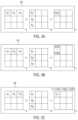
- FIGS. 3 A- 3 Care schematic diagrams illustrating a method of performing matrix multiplication in accordance with the method of FIG. 6 , in accordance with some of the embodiments of the technology described herein;
- FIG. 4is a circuit diagram illustrating an example of a differential optical receiver, in accordance with some embodiments of the technology described herein;
- FIG. 5is a schematic diagram illustrating a photonic circuit that may be coupled with the differential optical receiver of FIG. 3 , in accordance with some embodiments of the technology described herein;
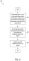
- FIG. 6is a flowchart illustrating a method of performing multiplication using the photonic circuit of FIGS. 4 and 5 , in accordance with some embodiments of the technology described herein;
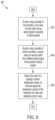
- FIG. 7is a flowchart illustrating a method of performing an outer-product using the photonic processor of FIG. 2 , in accordance with some embodiments of the technology described herein;
- FIG. 8is a flowchart illustrating a method of performing matrix multiplication using the photonic processor of FIG. 2 and using the method of FIG. 7 , in accordance with some embodiments of the technology described herein;
- FIG. 9is a flowchart illustrating a method of performing matrix multiplication using the photonic processor of FIG. 2 , in accordance with some embodiments of the technology described herein;
- FIG. 10is a schematic diagram of a generalized photonic processor, in accordance with some embodiments of the technology described herein;
- FIG. 11is a flowchart illustrating a method of manufacturing a photonic processor, in accordance with some embodiments of the technology described herein.
- tensor operationsmay be performed conventionally using, for example, a graphics processing unit (GPU) or a systolic array (e.g. Google Tensor Processing Unit or Cadence Tensilica).
- GPUgraphics processing unit
- systolic arraye.g. Google Tensor Processing Unit or Cadence Tensilica.
- a massive number of threadsare instantiated to perform a large number of multiply and accumulate operations.
- Each input data elementis copied several times and fed into different registers to speed up the process.
- the advantage of this highly large parallelismis apparent in computer graphical processing, where the value of each pixel is obtained by performing small matrix multiplications.
- systolic arraysmake use of a 2D array of electronic multiply-accumulators (MACs), where each MAC accumulates one element of the tensor multiplication. At each clock cycle, data from both matrices are input into the array. The partial products are accumulated at each processor and are also copied to the neighboring processors. Systolic arrays are suitable for large tensor multiplications. To multiply two N ⁇ N matrices, systolic arrays have a latency commensurate with one dimension of the systolic array (e.g., O(N)).
- Some optical matrix multiplication architectureshave been proposed that rely on free space optical systems. They typically spread the input data using imaging optics, e.g. a lens or a prism. The spread-out data are propagated through a 2-D array of electro-optic or acousto-optic cells (e.g. a spatial light modulator (SLM)) which multiply the data by the appropriate matrix values. The resulting transformed data are then focused into an image plane and are read using an array of detectors, where each detector corresponds to a single output element of the tensor operations. Each detector accumulates all light (and hence all multiplied data) arriving there.
- imaging opticse.g. a lens or a prism.
- the spread-out dataare propagated through a 2-D array of electro-optic or acousto-optic cells (e.g. a spatial light modulator (SLM)) which multiply the data by the appropriate matrix values.
- SLMspatial light modulator
- the resulting transformed dataare then focused into an
- optical tensor multiplicationmay be performed using a phase-stable chip-based architecture.
- Training deep neural networkstypically makes us of backpropagation algorithms which involve outer products between the input tensor and the back-propagated error tensors.
- the result of this outer productis the gradient of the loss/cost function with respect to the weight tensor which is used to update the weight tensor at the next iteration. Reducing the latency of outer product calculations can increase training efficiency of deep neural networks.
- FIG. 1is a schematic diagram of a photonic processing system implementing photonic processing techniques, according to some embodiments of the technology described herein.
- Photonic processing system 100includes a controller 102 , an optical source 108 , and a photonic processor 110 .
- the photonic processing system 100may receive, as an input from an external processor (e.g., a CPU, not shown), one or more input matrices represented by a group of input bit strings and may produce an output matrix represented by a group of output bit strings.
- an external processore.g., a CPU, not shown
- the input matrixmay be represented by N 2 separate bit strings, each bit string representing a respective component of the input matrix.
- the input bit stringmay be received as an electrical or optical signal from the external processor and the output bit string may be transmitted as an electrical optical signal to the external processor.
- the controller 102does not necessarily output an output bit string after every process iteration.
- the controller 100may use one or more output bit strings to determine a new input bit string to feed through the other components of the photonic processing system 100 .
- the output bit stringitself may be used as the input bit string for a subsequent iteration of the process implemented by the photonic processing system 100 .
- multiple output bit stringsmay be combined in various ways to determine a subsequent input bit string. For example, one or more output bit strings may be summed together as part of the determination of the subsequent input bit string.
- the controller 102includes a processor 104 and a memory 106 for controlling the optical source 108 and/or photonic processor 110 .
- the memory 106may be used to store input and output bit strings and/or results from the photonic processor 110 .
- the memory 106may also store executable instructions that, when executed by the processor 104 , control the optical source 108 and/or control components of the photonic processor 110 (e.g., encoders, phase shifters, and/or detectors).
- the memory 106may store executable instructions that cause the processor 104 to determine new input values to send to the photonic processor 110 based on the number of computational iterations that have occurred.
- the output matrix transmitted by the photonic processing system 100 to the external processormay be the result of multiple, accumulated multiplication operations, not simply a single multiplication operation.
- the result of the computation by the photonic processing system 100may be operated on digitally by the processor 104 before being stored in the memory 106 .
- the operations on the bit stringsmay not be simply linear, but may also be non-linear or, more generally, be Turing complete.
- the optical source 108may be configured to provide the photonic processor 110 with N optical signals, in accordance with some embodiments of the technology.
- Optical source 108may include, for example, one or more coherent light sources configured to produce the N optical signals.
- Optical light source 108may include a laser configured to emit light at a wavelength ⁇ 0 .
- the wavelength of emissionmay be in the visible, infrared (including near infrared, mid infrared and far infrared) or ultraviolet portion of the electromagnetic spectrum.
- ⁇ 0may be in the O-band, C-band or L-band.
- optical source 108may be coupled one-to-one to a single input of the photonic processor 110 , in accordance with some embodiments of the technology described herein.
- optical source 108may be disposed on the same substrate (e.g., a same chip) as the photonic processor 110 .
- the optical signalsmay be transmitted from the optical source 108 to the photonic processor 110 in waveguides (e.g., silicon photonic waveguides) disposed on the same substrate.
- the optical source 108may be disposed on a separate substrate from the photonic processor 110 .
- the optical signalsmay be transmitted from the optical source 108 to the photonic processor 110 through one or more optical fibers.
- the photonic processor 110performs tensor multiplication operations, in accordance with some embodiments of the technology described herein.
- the photonic processor 110includes three parts: encoders configured to encode elements of the input matrices in the amplitude and phase of the optical signals from optical source 108 (see e.g., row and column encoders 202 , 204 of FIG. 2 ), phase shifters configured to correct for phase shifts in the optical signals due to differences in path lengths and/or temperature variations (see e.g., phase shifter 208 of FIG.
- the photonic processor 110outputs these electrical signals to the controller 102 for further processing and/or output to the external processor.
- one or more of the input matrices or tensorsmay be too large to be encoded in the photonic processor using a single pass.
- one portion of the large matrixmay be encoded in the photonic processor and the multiplication process may be performed for that single portion of the large matrix and/or matrices.
- the results of that first operationmay be stored in memory 106 .
- a second portion of the large matrixmay be encoded in the photonic processor and a second multiplication process may be performed. This “chunking” of the large matrix may continue until the multiplication process has been performed on all portions of the large matrix.
- the results of the multiple multiplication processeswhich may be stored in memory 106 , may then be combined to form a final result of the tensor multiplication operation.
- FIG. 2is a schematic diagram of an example of a photonic processor 200 , in accordance with some embodiments of the technology described herein.
- Photonic processor 200may be implemented as photonic processor 110 in the photonic processing system 100 as described in connection with FIG. 1 .
- Photonic processor 200may include encoders 202 , 1-to-N splitters 204 , phase shifters 206 , and detectors 210 , in accordance with some embodiments described herein.
- Photonic processor 200may receive optical signals as input from an optical source (e.g., from optical source 108 as described in connection with FIG. 1 ) and output an electrical signal (e.g., to controller 102 as described in connection with FIG. 1 ).
- the optical signals from optical source 108may first be received by 2N encoders 202 (e.g., N row encoders and N column encoders), which are configured to encode elements from the input matrices into the amplitude and phase of the optical signals.
- 2N encoders 202e.g., N row encoders and N column encoders
- the elements from the input matricesmay be real numbers or complex numbers, in some embodiments.
- the real numbersmay be signed (e.g., may be positive or negative).
- the real numbermay represent a certain physical variable or parameter, such as an environmental condition (e.g., temperature, pressure, etc.), information associated with an object (e.g., position, motion, velocity, rate of rotation, acceleration, etc.), information associated with a multimedia file (e.g., acoustic intensity of audio files, pixel color and/or intensity of image or video files), information associated with a certain chemical/organic element or compound (e.g., concentration), information associated with financial assets (e.g., price of a certain security), or any other suitable type of information including information derived from the examples described above.
- the information represented by the signed, real numbermay be useful for a variety of reasons, including for example to train a machine learning algorithm, to perform forecasting, data analytics, troubleshooting, or simply to collect data for future use.
- Encoders 202may be implemented as optical modulators, in some embodiments.
- optical modulatorsthat may be used as encoders 202 include Mach Zehnder modulators, electro-optical modulators, ring or disk modulators or other types of resonant modulators, electro-absorption modulators, Frank-Keldysh modulators, acousto-optical modulators, Stark-effect modulators, magneto-optical modulators, thermos-optical modulators, liquid crystal modulators, quantum-confinement optical modulators, and/or photonic crystal modulators.
- encoders 202may be implemented as optical modulators such as those described in U.S.
- Encoders 202may encode the elements of the input matrices in the complex plane, in accordance with some embodiments of the technology described herein.
- a value representative of the element of an input matrixmay be encoded onto an optical field.
- encoding the value onto an optical fieldinvolves modulating the phase and the intensity of an optical field based on the value. As a result, the phase and the amplitude of the optical field reflect the encoded value.
- the phaseis chosen between 0, which corresponds to a positive value, and ⁇ , which corresponds to a negative value.
- modulating the phase and amplitude based on the valueinvolves driving a single encoder with a single electrical modulating signal.
- a single modulating signalmay modulate both the phase and the amplitude of an optical field.
- one phase modulator in combination with another amplitude modulatormay be needed to correctly encode the values.
- each encoder 202may encode a new value from its respective input matrix row or column.
- the row encoder A 1kmay encode, on the first clock cycle, value A 11 of input matrix A.
- encoder A 1kmay encode value A 12 of input matrix A.
- encoder A 1kmay encode value A 13 of input matrix A.
- the column encoder B k1may encode, on the first clock cycle, value B 11 of input matrix B.
- encoder B k1may encode value B 21 of input matrix B.
- encoder B k1may encode value B 31 of input matrix B.
- Output encoded optical signals from encoders 202may be received by optical 1-to-N splitters 204 , in accordance with some embodiments of the technology described herein.
- the 1-to-N splittersmay be manufactured from optical devices with fewer input and output ports (e.g., Y-junctions, directional couplers, multimode interferometers, tunable 1 ⁇ 2 interferometers, tunable 2 ⁇ 2 interferometers) by organizing the devices in a fanout network, e.g., in a binary tree network where the one input (the first level) may be split into two outputs using the aforementioned device, and each output may be further split into two at each level using the aforementioned device until the last level of the tree.
- a fanout networke.g., in a binary tree network where the one input (the first level) may be split into two outputs using the aforementioned device, and each output may be further split into two at each level using the aforementioned device until the last level of the tree.
- the 1-to-N splittersmay be manufactured with a single multimode 1-to-N multimode interferometer, which may be designed using numerical photonics inverse design methods.
- the 1-to-N splitters 204may take a single input optical signal and split the input optical signal into N output optical signals. In some embodiments, there may be 2N 1-to-N splitters 204 , each 1-to-N splitter 204 being coupled to a single encoder 202 .
- a number of output channels of the 1-to-N splitters 204may be determined based on a desired size of the input matrices.
- the outputs of the 1-to-N splitters 204may be coupled to phase shifters 206 and/or detectors 208 through waveguides (e.g., silicon photonic waveguides) or through fiber optics.
- output optical signals from the 1-to-N splitters 204may be coupled to one or more inputs of detectors 208 .
- Detectors 208may be photodetectors configured to receive two or more input optical signals and output an electrical signal (e.g., a photocurrent) proportional to an intensity of the input optical signals.
- Detectors 208may be, for example, homodyne detectors, heterodyne detectors, intradyne detectors, Dolinar detectors, and/or any suitable coherent detector.
- detectors 208may receive a first encoded optical signal corresponding to an encoded row value from a first encoder 202 and a second encoded optical signal corresponding to an encoded column value from a second encoder 202 .
- the output electrical signal at each detector 208may be proportional to a product of the encoded row value and the encoded column value.
- detectors 208are depicted as homodyne detectors. It should be appreciated that detectors 208 could alternatively be shown as heterodyne detectors, intradyne detectors, Dolinar detectors, and/or any other suitable coherent detector.
- each one of the detectors 208 responsible for producing an output element C ijmay receive an optical signal corresponding to element A ik (e.g., an optical field A ik ) at a top arm of the detector 208 and an optical signal corresponding to element B kj (e.g., an optical field B kj ) at a bottom arm of the detector 208 .
- the detector 208 responsible for producing output element C 11may receive an optical signal corresponding to element A 11 at a top arm of the detector 208 and an optical signal corresponding to element B 11 at the bottom arm of the detector 208 .
- the detectors 208 responsible for producing output element C 11may receive an optical signal corresponding to element A 12 at the top arm of the detector 208 and an optical signal corresponding to element B 21 at the bottom arm of the detector 208 .
- the detectors 208 responsible for producing output element C 11may receive an optical signal corresponding to element A 13 at the top arm of the detector 208 and an optical signal corresponding to element B 31 at the bottom arm of the detector 208 .
- the photonic processorproduces electrical signals in the array of detectors that are proportional to the outer-product between the column of the encoded row values (e.g., a row of matrix A) and the row of the encoded column values (e.g., a column of matrix B). Therefore, in some embodiments, the photonic processor may be purposed for computing the outer product between an input column vector and an input row vector that produces an output matrix.
- the detector 208may include a 50-50 directional coupler, as will be described in further detail in connection with FIGS. 4 and 5 , which is configured to transform the optical field at the top arm into (A ik iB kj )/ ⁇ square root over (2) ⁇ and (iA ik B kj )/ ⁇ square root over (2) ⁇ at the bottom arm.
- Each output of the top arm and the bottom arm of the 50-50 directional coupler of detector 208may be fed into a photodetector configured to generate an electrical signal (e.g., a photocurrent) that may be proportional to the intensity of the light received.
- the electrical signal generated from the top armmay be described by:
- i B ⁇ ⁇ iA ik + B kj 2 ⁇ 21 2 ⁇ ( ⁇ A ik ⁇ 2 + ⁇ B kj ⁇ 2 - iA ik * ⁇ B kj + iA ik ⁇ B kj * ) .
- the electronic circuitry of detectors 208may connect an anode of one photodetector with a cathode of another photodetector within each of the detectors 208 , as described in more detail in connection with FIGS. 4 and 5 herein.
- an output current from this circuitrymay be proportional to the difference between the two photocurrents, i T and i B .
- the output currentmay be described by: i Out ⁇ 2
- a new multiplication operationmay be performed in each detector 208 , and the results from the previous multiplication operation may be output by detectors 208 to an accumulator (not shown).
- the output photocurrent of each detector 208may be converted to a voltage using a transimpedance circuit (not shown) prior to the output being sent to the accumulator.
- the accumulationmay be performed by applying a low-pass filter at an output of the transimpedance circuit with a bandwidth proportional to clock-frequency/N (e.g., for the example of FIG. 2 , clock-frequency/3).
- an electrical storage devicemay accumulate the energy associated with the sum of three photocurrents, and a single number may be read out at every detector 208 after every N clock cycles (e.g., after every three clock cycles for the example of FIG. 2 ). The number read out may be proportional to the desired output matrix value C u .
- the detectors 208may be replaced with two photonic receivers, one for each arm of the detectors 208 , and the multiplication may be performed digitally.
- the configuration between the encoders and receiversmay enable broadcasting photonic signals from the encoders to the receivers to perform an outer product in a parallel manner.
- the advantage of these embodimentsis that the multiplication may be done at full precision using digital circuitry while maintaining efficient broadcasting operations using photonics.
- the optical signalsmay not necessarily encode the values in the analog domain, but the values may be encoded in the digital domain.
- the digital values broadcastedmay be in the integer number type format or they may be in the floating-point number type format, and/or in any other suitable digital number representations.
- the digital circuitry that performs the multiplicationmay perform the operations according to the number representation of the broadcasted digital values.
- the appropriate detectorse.g., direct detectors, homodyne detectors, heterodyne detectors, and/or any other suitable coherent detectors
- pipelining strategiesmay be implemented such that while the values are broadcasted, the multiplication operations occur simultaneously.
- the output optical signals from the 1-to-N splitters 204may be received by phase shifters 206 prior to being received by detectors 208 .
- phase shifters 206may be configured to correct for any possible phase errors that may occur between encoders 202 and detectors 208 .
- phase shifters 206may correct for static phase errors.
- phase shifters 206may correct for phase errors caused by differences in path lengths between different ones of the 1-to-N splitters 204 and detectors 208 .
- phase shifters 206may correct for dynamic phase errors.
- phase shifters 206may correct for phase errors caused by thermal fluctuations. It may be appreciated that, while the example of FIG. 2 shows phase shifters 206 coupled to one input of detectors 208 , in some embodiments phase shifters 206 may be coupled to all inputs of detectors 208 .
- FIGS. 3 A- 3 Cshow a schematic diagram of a method of performing tensor multiplication using a photonic processor (e.g., photonic processor 200 as described in connection with FIG. 2 ), in accordance with some embodiments described herein.
- the method of FIGS. 3 A- 3 Cmay be implemented by a single detector (e.g., a single detector 208 ) of a photonic processor and may output a single element of an output matrix. It may be appreciated that other detectors of the photonic processor may be simultaneously performing different multiplication operations to produce different elements of the output matrix.
- element A 11 of input matrix A and element B 11 of input matrix Bmay be loaded into the photonic processor.
- the photonic processormay encode element A 11 into an amplitude and a phase of an optical signal (e.g., using an encoder such as encoder 202 ) and may encode element B 11 into an amplitude and a phase of a different optical signal (e.g., using an encoder such as encoder 202 ).
- the encoded optical signalsmay be sent to a detector (e.g., detector 208 ) which may output an electrical signal (e.g., a photocurrent) proportional to a product of elements A 11 and B 11 .
- the electrical signalmay be accumulated by an accumulator represented by the matrix C in the examples of FIGS. 3 A- 3 C .
- element A 12 of input matrix A and element B 21 of input matrix Bmay be loaded into the photonic processor.
- the photonic processormay encode element A 12 into an amplitude and a phase of an optical signal (e.g., using an encoder such as encoder 202 ) and may encode element B 21 into an amplitude and a phase of a different optical signal (e.g., using an encoder such as encoder 202 ).
- the encoded optical signalsmay be sent to a detector (e.g., detector 208 ) which may output an electrical signal (e.g., a photocurrent) proportional to a product of elements A 12 and B 21 .
- the accumulatormay then “add” the electrical signal proportional to a product of elements A 12 and B 21 to the previous electrical signal accumulated during act 302 .
- element A 13 of input matrix A and element B 31 of input matrix Bmay be loaded into the photonic processor.
- the photonic processormay encode element A 13 into an amplitude and a phase of an optical signal (e.g., using an encoder such as encoder 202 ) and may encode element B 31 into an amplitude and a phase of a different optical signal (e.g., using an encoder such as encoder 202 ).
- the encoded optical signalsmay be sent to a detector (e.g., detector 208 ) which may output an electrical signal (e.g., a photocurrent) proportional to a product of elements A 13 and B 31 .
- the accumulatormay then “add” the electrical signal proportional to a product of elements A 13 and B 31 to the previous electrical signals accumulated during acts 302 and 304 to form a total accumulated signal proportional to the output matrix element C 11 .
- the accumulated signalmay then be read out from the photonic processor for use by, for example, controller 102 , processor 104 , memory 106 as described in connection with FIG. 1 and/or another external processor and/or memory.
- the inventorshave recognized and appreciated that performing such tensor multiplication operations as described in connection with FIGS. 2 and 3 may call for significant readout circuitry to read out the result at its full precision.
- the A ik row encoder systemincluding, e.g., a digital-to-analog converter (DAC) and encoder 202
- the B kj column encoder systemincluding e.g., a DAC and encoder 202
- the detector systemincluding e.g., analog-to-digital converter (ADC) readout circuitry
- ADCanalog-to-digital converter
- the values read by the ADCmay be rounded and/or truncated otherwise.
- readout circuitry with a precision of b row +b col +log 2 N bitsmay be difficult to manufacture if b row +b col +log 2 N is large.
- the inventorshave developed a method for reducing the needed complexity of the readout circuitry.
- the partial product values after every clock cyclemay be readout at a full precision of b row +b col .
- the accumulation operationsmay be performed by an external processor (e.g., processor 104 as described in connection with FIG. 1 ). While this method may reduce the readout bit precision required, it may also increase the readout circuitry bandwidth by a factor of N.
- both b row and b colmay be n-bit numbers such that b row ⁇ 0,1 ⁇ n and b col ⁇ 0,1 ⁇ n .
- this method of reducing the number of bits in a valuemay be extended to matrix multiplication operations and/or other linear tensor operations.
- y j⁇ j M ij x j , where each element of M ij ⁇ 0,1 ⁇ n and x j ⁇ 0,1 ⁇ n is an n-bit number
- the same partial-product techniquemay be applied to obtain a fully precise result y j , whose elements are 2n-bit numbers.
- each matrix and vectormay be divided into d divisions.
- the number of matrix-vector products that may be performedmay be d 2 .
- FIG. 4illustrates a non-limiting example of an optical receiver 400 (e.g., a portion of detector 208 of FIG. 2 ), in accordance with some non-limiting embodiments of the present application and as described in U.S. patent application Ser. No. 16/411,391 titled “Optical Differential Low-Noise Receivers and Related Methods” filed May 14, 2019, which is incorporated by reference herein in its entirety.
- optical receiver 400may include photodetectors 402 , 404 , 406 and 408 , though other implementations include more than four photodetectors.
- Photodetector 402may be connected to photodetector 404
- photodetector 406may be connected to photodetector 408 .
- the anode of photodetector 402may be connected to the cathode of photodetector 404 (e.g., at node 403 ), and the cathode of photodetector 406 may be connected to the anode of photodetector 408 (e.g., at node 405 ).
- the cathodes of photodetectors 402 and 408are connected to voltage supply V DD and the anodes of photodetectors 404 and 406 are connected to a reference potential (e.g., to ground).
- the reference potentialmay be at a potential equal to zero or having any suitable value, such as ⁇ V DD .
- V DDmay have any suitable value.
- Photodetectors 402 - 408may be implemented in any of numerous ways, including for example with pn-junction photodiodes, pin-junction photodiodes, avalanche photodiodes, phototransistors, and/or photoresistors.
- the photodetectorsmay include a material capable of absorbing light at the wavelength of interest.
- the photodetectorsmay have an absorption region made at least in part of germanium and/or indium gallium arsenide (InGaAs), by way of a non-limiting example.
- InGaAsindium gallium arsenide
- the photodetectorsmay have an absorption region made at least in part of silicon, by way of another non-limiting example.
- Photodetectors 402 - 408may be integrated components formed monolithically as part of the same substrate.
- the substratemay be a silicon substrate in some embodiments, such as a bulk silicon substrate or a silicon-on-insulator. Other types of substrates can also be used, including for example indium phosphide or any suitable semiconductor material.
- the photodetectorsmay be positioned in close proximity to one another. For example, the photodetectors may be positioned on a substrate within an area of 1 mm 2 or less, 0.1 mm 2 less or 0.01 mm 2 or less.
- photodetectors 402 - 408may be connected to a differential operational amplifier (DOA) 410 .
- DOAdifferential operational amplifier
- photodetectors 402 and 404may be connected to a non-inverting input (“+”) of DOA 410 and photodetectors 406 and 408 may be connected to an inverting input (“ ⁇ ”) of DOA 410 .
- DOA 410may have a pair of outputs. One output may be inverting and one output may be non-inverting.
- photodetectors 402 and 406may be arranged to receive the same optical signal, t, and photodetectors 404 and 408 may be arranged to receive the same optical signal, b.
- photodetectors 402 - 408may be designed to be substantially similar to each other.
- photodetectors 402 - 408may be formed using the same process steps and using the same photomask patterns.
- photodetectors 402 - 408may exhibit substantially the same characteristics, such as substantially the same responsivity (the ratio between the photocurrent and the received optical power) and/or substantially the same dark current (the current generated when no optical power is received).
- the photocurrents generated by photodetectors 402 and 406 responsive to reception of signal tmay be substantially equal to each other.
- Such photocurrentsare identified as i t in FIG. 4 .
- the photocurrents generated by photodetectors 402 and 406may be oriented in opposite directions. That is, the photocurrent of photodetector 402 may be directed towards node 403 and the photocurrent of photodetector 406 may be oriented away from node 405 .
- the photocurrents generated by photodetectors 404 and 408 responsive to reception of signal bmay be substantially equal to each other. Such photocurrents are identified as i b .
- the photocurrents generated by photodetectors 404 and 408may be oriented in opposite directions. That is, the photocurrent of photodetector 408 may be directed towards node 405 and the photocurrent of photodetector 404 may be oriented away from node 403 .
- a current with amplitude i t ⁇ i bemerges from node 403 and a current with amplitude i b ⁇ i t emerges from node 405 .
- the currentsmay have substantially the same amplitudes, but may have opposite signs.
- FIG. 5illustrates a photonic circuit 500 (e.g., a portion of detector 208 of FIG. 2 ) arranged for providing two optical signals to photodetectors 402 - 408 , in accordance with some non-limiting embodiments.
- Photonic circuit 500may comprise optical waveguides for routing the optical signals to the photodetectors.
- the optical waveguidesmay be made of a material that is transparent or at least partially transparent to light at the wavelength of interest.
- the optical waveguidesmay be made of silicon, silicon oxide, silicon nitride, indium phosphide, gallium arsenide, or any other suitable material.
- FIG. 5illustrates a photonic circuit 500 (e.g., a portion of detector 208 of FIG. 2 ) arranged for providing two optical signals to photodetectors 402 - 408 , in accordance with some non-limiting embodiments.
- Photonic circuit 500may comprise optical waveguides for routing the optical signals to the photodetectors.
- the optical waveguidesmay
- photonic circuit 500includes input optical waveguides 502 and 504 and couplers 512 , 514 and 516 . As further illustrated, the output optical waveguides of photonic circuit 500 may be coupled to photodetectors 402 - 408 .
- couplers 512 , 514 and 516comprise directional couplers, where evanescent coupling enables transfer of optical power between adjacent waveguides.
- couplersmay be implemented with a multi-mode interferometer (MMI).
- MMImulti-mode interferometer
- Couplers 512 , 514 and 516may be 3 dB couplers (with a 50%-50% coupling ratio) in some embodiments, though other ratios are also possible, such as 51%-49%, 55%-45% or 60%-40%. It should be appreciated that, due to fabrication tolerances, the actual coupling ratio may deviate slightly from the intended coupling ratio.
- Signal s 1may be provided at input optical waveguide 502 and signal s 2 may be provided at input optical waveguide 504 .
- Signals s 1 and s 2may be provided to the respective input optical waveguides using for example optical fibers.
- s 1represents a reference local oscillator signal, such as the signal generated by a reference laser
- s 2represents the signal to be detected.
- the optical receivermay be viewed as a homodyne optical receiver.
- s 1may be a continuous wave (CW) optical signal while s 2 may be modulated.
- both signalsare modulated or both signals are CW optical signals, as the application is not limited to any particular type of signal.
- Coupler 512combines signals s 1 and s 2 such that signals t and b emerge at respective outputs of coupler 212 .
- t and bmay be described by the following expression:
- T[A LO 2 +A S 2 +2 A LO A S sin( ⁇ )]
- B[A LO 2 +A S 2 ⁇ 2 A LO A S sin( ⁇ )]
- photodetectors 402 and 406may each receive a power given by T/2 and photodetectors 404 and 408 may each receive a power given by B/2.
- DOA 410may be arranged to amplify the differential signal received at the “+” and “ ⁇ ” inputs, and to produce an amplified differential output, represented in FIG. 4 by voltages V out,n and V out,p .
- DOA 410in combination with impedances z, may be viewed as a differential transimpedance amplifier, in that it produces a differential pair of voltage (V out,n , V out,p ) based on a differential pair of current (i b ⁇ i t , i t ⁇ i n ).
- This differential pair of voltagesmay be provided as input to any suitable electronic circuit, including but not limited to an analog-to-digital converter (not shown in FIG. 4 ).
- FIG. 6illustrates a method 600 of performing a multiplication operation using a homodyne detector (e.g., a detector comprising optical receiver 400 of FIG. 4 and photonic circuit 500 of FIG. 5 ), in accordance with some embodiments of the technology described herein.
- a homodyne detectore.g., a detector comprising optical receiver 400 of FIG. 4 and photonic circuit 500 of FIG. 5
- a first optical signal, r 1 , and a second optical signal, r 2may be mixed.
- the first optical signal and second optical signalmay be encoded optical signals.
- a first numerical value and a second numerical valuemay be encoded into an amplitude and a phase of the first optical signal and the second optical signal, respectively.
- Encoding of the first numerical value and the second numerical valuemay be performed by, for example, an encoder such as encoder 202 as described in connection with FIG. 2 , or any other suitable optical encoding device.
- Mixing of the first optical signal and the second optical signalmay comprise using an optical coupler, such as coupler 512 as described in connection with FIG. 5 , in accordance with some embodiments of the technology described herein.
- the first optical signal and the second optical signalmay be transformed into a first mixed optical signal and a second mixed optical signal.
- the first mixed optical signal and the second mixed optical signalmay have magnitudes of (r 1 +ir 2 )/ ⁇ square root over (2) ⁇ and (ir 1 +r 2 )/ ⁇ square root over (2) ⁇ , respectively, as described in connection with FIG. 2 .
- a first photocurrent and a second photocurrentmay be output, in accordance with some embodiments of the technology described herein.
- the first photocurrent and the second photocurrentmay be generated based on the first mixed optical signal and the second mixed optical signal.
- the first mixed optical signal and the second mixed optical signalmay be detected by photodetectors (e.g., photodetectors 402 - 408 as described in connection with FIG. 4 ) configured to output a photocurrent based on an intensity of a detected optical signal.
- the first photocurrentmay be subtracted from the second photocurrent, in accordance with some embodiments described herein.
- the first photocurrentmay be subtracted from the second photocurrent using, for example, a differential operational amplifier (e.g., differential operational amplifier 410 as described in connection with FIG. 4 ).
- the difference between the first photocurrent and the second photocurrentmay be output as an output photocurrent.
- the output photocurrentmay be proportional to a product of the first numerical value and the second numerical value.
- FIG. 7illustrates a method 700 of performing an outer product operation using a photonic processor (e.g., the photonic processor of FIG. 2 ), in accordance with some embodiments of the technology described herein.
- a photonic processore.g., the photonic processor of FIG. 2
- values of a column vectormay be encoded into a plurality of optical signals using a plurality of first encoders, in accordance with some embodiments described herein.
- Each value of the values of the column vectormay be encoded into a single optical signal of the plurality of optical signals.
- the valuemay be encoded into an amplitude and a phase of the single optical signal, as described herein.
- Each of the first encodersmay be, for example, an encoder such as encoder 202 as described in connection with FIG. 2 , or any other suitable optical encoding device.
- values of a row vectormay be encoded into another plurality of optical signals using a plurality of second encoders, in accordance with some embodiments described herein.
- Each value of the values of the row vectormay be encoded into a single optical signal of the another plurality of optical signals.
- the valuemay be encoded into an amplitude and a phase of the single optical signal, as described herein.
- Each of the second encodersmay be, for example, an encoder such as encoder 202 as described in connection with FIG. 2 , or any other suitable optical encoding device.
- the plurality of first encoders and the plurality of second encodersmay be coupled to a plurality of optical multiplication devices.
- the optical multiplication devicesmay be, for example, detectors 208 as described in connection with FIG. 2 , or any other suitable optical multiplication device.
- the couplingmay be arranged as described in connection with FIG. 2 , or any other suitable coupling arrangement configured to perform an outer product may be implemented.
- the pluralities of optical signalsmay be sent to the optical multiplication devices through any suitable optical coupling means (e.g., through a waveguide and/or fiber optical system as described herein).
- Each of the plurality of optical multiplication devicesmay output an electrical signal that represents a product of a value of the column vector and a value of the row vector, in accordance with some embodiments described herein.
- the plurality of optical multiplication devicesmay output a plurality of electrical signals, the plurality of electrical signals representing an outer product of the column vector and the row vector.
- FIG. 8illustrates a method 800 of performing matrix-matrix and/or tensor multiplication operations using a photonic processor (e.g., the photonic processor of FIG. 2 ) and a method of calculating outer products (e.g., method 700 of FIG. 7 ), in accordance with some embodiments of the technology described herein.
- a photonic processore.g., the photonic processor of FIG. 2
- a method of calculating outer productse.g., method 700 of FIG. 7
- a series of outer product operationsmay be performed, in accordance with some embodiments of the technology described herein.
- the operationsmay result in outputting, as a plurality of electrical signals, a matrix representing an outer product of a column vector and a row vector, the column vector and the row vector belonging to different matrices.
- the series of operationsmay be, for example, those performed in method 700 as described in connection with FIG. 7 . That is, in act 802 , a column of a first matrix A may be encoded in a plurality of optical signals using a first plurality of encoders, and a row of a second matrix B may be encoded in another plurality of optical signals using a second plurality of encoders.
- the encoded values of the column and row vectormay be multiplied using a plurality of optical multiplication devices (e.g., detectors 208 of FIG. 2 ) adapted to output a plurality of electrical signals proportional to a product of a value of the column vector and a value of the row vector.
- the plurality of electrical signalsmay be output from the optical multiplication devices and may form a matrix that represents an outer product of the column vector and the row vector.
- the output electrical signals from each clock cyclemay be stored in a plurality of electrical storage devices, in accordance with some embodiments of the technology described herein.
- the output electrical signalsmay be summed to produce a result representing a multiplication of matrix A and matrix B.
- the summationmay be performed by, for example, accumulating, after each clock cycle, electrical signals representing different outer products in the electrical storage devices.
- the summed electrical signals representing a multiplication of the matrix A and matrix Bmay be output from the electrical storage devices, in accordance with some embodiments described herein.
- the output electrical signalsmay be output to, for example, a controller (e.g., controller 102 as described in connection with FIG. 1 ) to be stored in computer memory (e.g., memory 106 ) or used for further computational steps (e.g., performed on processor 104 or photonic processor 110 ).
- the output electrical signalsmay be output (e.g., as a bit string) to an external processor and/or memory system for further storage and/or computational steps.
- FIG. 9illustrates a method 900 of performing tensor multiplication using a photonic processor (e.g., photonic processor 200 of FIG. 2 ), in accordance with some embodiments of the technology described herein.
- a photonic processore.g., photonic processor 200 of FIG. 2
- a row value of a first matrixmay be encoded into an optical signal of a plurality of optical signals, in accordance with some embodiments of the technology described herein.
- the row valuemay be encoded into the optical signal using, for example, an encoder such as encoder 202 as described in connection with FIG. 2 .
- the row valuemay be encoded into an amplitude and phase of the optical signal.
- a column value of a second matrixmay be encoded into a different optical signal of a plurality of optical signals, in accordance with some embodiments of the technology described herein.
- the column valuemay be encoded into the different optical signal using, for example, an encoder such as encoder 202 as described in connection with FIG. 2 .
- the column valuemay be encoded into an amplitude and phase of the optical signal.
- the encoded row value and column valuemay then be output to an optical multiplication device (e.g., detectors 208 as described in connection with FIG. 2 ).
- each optical multiplication devicemay output an electrical signal (e.g., a photocurrent) that represents a product of the respective row value and respective column value.
- the optical multiplication devicemay detect the optical signals from the row encoder and from the column encoder independently and may perform the multiplication using digital circuitry (e.g., one or more of an adder, a subtractor, a multiplier, and/or a divisor).
- digital circuitrye.g., one or more of an adder, a subtractor, a multiplier, and/or a divisor.
- the output electrical signalwill represent a product of the respective row value and respective column value in terms of a bit string.
- FIG. 10shows a schematic diagram of a generalized photonic processor 1000 , in accordance with some embodiments of the technology described herein.
- the 2N copies of the 1-to-N splitters 204 of FIG. 2may be replaced with two copies of an N-to-N 2 arbitrary unitary transformer 1004 .
- the N-to-N 2 arbitrary unitary transformers 1004may be built using, for example, an interconnected array of Mach-Zehnder interferometers.
- tensor multiplication operationsare not the only operations that may be performed.
- other mathematical operations that use data copying and multiplying-and-accumulating operationse.g., convolutions, outer products, and/or tensor multiplications
- a single 2N-to-2N 2 arbitrary unitary transformermay be used in place of N-to-N 2 arbitrary unitary transformer 1004 , in some embodiments.
- values from a first encodermay be multiplied with values from any other encoder, including values from the first encoder.
- FIG. 11illustrates a method 1100 of manufacturing a photonic processor (e.g., photonic processor 200 and/or generalized photonic processor 1000 ), in accordance with some embodiments of the technology described herein.
- a photonic processore.g., photonic processor 200 and/or generalized photonic processor 1000
- the method 1100begins with act 1102 , in which a plurality of encoders may be provided.
- the encodersmay be configured to encode a value into an optical signal, as discussed herein in connection with encoders 202 of FIG. 2 .
- the encodersmay be configured to encode the value into an amplitude and phase of the optical signal.
- the encodersmay include row encoders and column encoders arranged to perform tensor multiplication operations (e.g., as discussed in connection with photonic processor 200 of FIG. 2 ).
- the encodersmay not be configured so specifically (e.g., as discussed in connection with generalized photonic processor 1000 of FIG. 10 ).
- Act 1102may include providing the encoders on one or more semiconductor substrates (e.g., silicon substrates) using known semiconductor device fabrication techniques.
- the encodersmay be provided on a single substrate.
- the encodersmay be provided on two or more substrates.
- the substratesmay be connected using, for example, optical fiber techniques.
- a plurality of optical multiplication devicesmay be provided, in accordance with some embodiments of the technology described herein.
- the optical multiplication devicesmay be coupled to one or more of the encoders provided in act 1102 .
- Each optical multiplication devicemay output an electrical signal (e.g., a photocurrent) proportional to a product of the values received by the optical multiplication device from the one or more encoders.
- the provided optical multiplication devicesmay be configured as homodyne detectors and/or heterodyne detectors.
- the optical multiplication devicesmay be, for example, detectors 208 as described in connection with FIG. 2 .
- the optical multiplication devicesmay each be coupled to a row encoder and a column encoder so that the optical multiplication device may output.
- the optical multiplication devicesmay be, for example, detectors 1006 of photonic processor 1000 as described in connection with FIG. 10 .
- the provided optical multiplication devicesmay be coupled to any one or more of the encoders, including receiving multiple inputs from a single encoder.
- the optical multiplication devicesmay be provided on the same substrate as the encoders and the light sources.
- the optical multiplication devicesmay be coupled to the encoders through one or more waveguides (e.g., silicon waveguides).
- the waveguidesmay be single-mode waveguides, though it is to be appreciated that imperfections during fabrication may yield waveguides that are not perfectly single-mode in nature.
- the optical multiplication devicesmay be provided simultaneously or separately from the encoders (e.g., in a same or different fabrication step). It may further be appreciated that the optical multiplication devices may be provided in a same or different level of the substrate as the encoders.
- the optical multiplication devicesmay be provided on a different substrate from the encoders.
- the optical multiplication devicesmay be coupled to the encoders using, for example, fiber optical techniques.
- the separate substratesmay be mounted together into a single package using, for example, flip-chip bonding techniques or any other suitable packaging techniques.
- the light sourcesmay be located on the same substrate or a different substrate as the encoders. Similar packaging techniques, such as flip-chip bonding, edge coupling, or vertical coupling, may be used to package the substrates together.
- processorsmay be implemented as integrated circuits, with one or more processors in an integrated circuit component, including commercially available integrated circuit components known in the art by names such as CPU chips, GPU chips, microprocessor, microcontroller, or co-processor.
- processorsmay be implemented in custom circuitry, such as an ASIC, or semi-custom circuitry resulting from configuring a programmable logic device.
- a processormay be a portion of a larger circuit or semiconductor device, whether commercially available, semi-custom or custom.
- some commercially available microprocessorshave multiple cores such that one or a subset of those cores may constitute a processor.
- a processormay be implemented using circuitry in any suitable format.
- the various methods or processes outlined hereinmay be coded as software that is executable on one or more processors running any one of a variety of operating systems or platforms.
- Such softwaremay be written using any of a number of suitable programming languages and/or programming tools, including scripting languages and/or scripting tools.
- such softwaremay be compiled as executable machine language code or intermediate code that is executed on a framework or virtual machine. Additionally, or alternatively, such software may be interpreted.
- the techniques disclosed hereinmay be embodied as a non-transitory computer-readable medium (or multiple computer-readable media) (e.g., a computer memory, one or more floppy discs, compact discs, optical discs, magnetic tapes, flash memories, circuit configurations in Field Programmable Gate Arrays or other semiconductor devices, or other non-transitory, tangible computer storage medium) encoded with one or more programs that, when executed on one or more processors, perform methods that implement the various embodiments of the present disclosure described above.
- the computer-readable medium or mediamay be transportable, such that the program or programs stored thereon may be loaded onto one or more different computers or other processors to implement various aspects of the present disclosure as described above.
- a computing devicemay additionally have one or more components and peripherals, including input and output devices. These devices can be used, among other things, to present a user interface. Examples of output devices that can be used to provide a user interface include printers or display screens for visual presentation of output and speakers or other sound generating devices for audible presentation of output. Examples of input devices that can be used for a user interface include keyboards, and pointing devices, such as mice, touch pads, and digitizing tablets. As another example, a computing device may receive input information through speech recognition or in other audible format. As another example, a computing device may receive input from a camera, lidar, or other device that produces visual data.
- Embodiments of a computing devicemay also include a photonic processor, such as the one described herein.
- the processor of the computing devicemay send and receive information to the photonic processor via one or more interfaces.
- the information that is sent and receivedmay include settings of the detectors of the photonic processor and/or measurement results from the detectors of the photonic processor.
- programor “software” are used herein to refer to any type of computer code or set of computer-executable instructions that may be employed to program one or more processors to implement various aspects of the present disclosure as described above.
- programor “software” are used herein to refer to any type of computer code or set of computer-executable instructions that may be employed to program one or more processors to implement various aspects of the present disclosure as described above.
- one or more computer programs that, when executed, perform methods of the present disclosureneed not reside on a single computer or processor, but may be distributed in a modular fashion amongst a number of different computers or processors to implement various aspects of the present disclosure.
- Computer-executable instructionsmay be in many forms, such as program modules, executed by one or more computers or other devices.
- Program modulesmay include routines, programs, objects, components, data structures, etc. that perform particular tasks or implement particular abstract data types. Functionalities of the program modules may be combined or distributed as desired in various embodiments.
- data structuresmay be stored in computer-readable media in any suitable form.
- data structuresmay be shown to have fields that are related through location in the data structure. Such relationships may likewise be achieved by assigning storage for the fields to locations in a computer-readable medium that convey relationship between the fields.
- any suitable mechanismmay be used to establish a relationship between information in fields of a data structure, including through the use of pointers, tags, or other mechanisms that establish relationship between data elements.
- the technology described hereinmay be embodied as a method, examples of which are provided herein including with reference to FIGS. 6 and 7 .
- the acts performed as part of the methodmay be ordered in any suitable way. Accordingly, embodiments may be constructed in which acts are performed in an order different than illustrated, which may include performing some acts simultaneously, even though shown as sequential acts in illustrative embodiments.
- the terms “approximately” and “substantially”may be used to mean within ⁇ 20% of a target value in some embodiments, within ⁇ 10% of a target value in some embodiments, within ⁇ 5% of a target value in some embodiments, or within ⁇ 2% of a target value in some embodiments.
- the terms “approximately” and “substantially”may include the target value.
Landscapes
- Physics & Mathematics (AREA)
- Engineering & Computer Science (AREA)
- Theoretical Computer Science (AREA)
- General Physics & Mathematics (AREA)
- Optics & Photonics (AREA)
- Nonlinear Science (AREA)
- Mathematical Physics (AREA)
- Computing Systems (AREA)
- Algebra (AREA)
- Mathematical Analysis (AREA)
- Pure & Applied Mathematics (AREA)
- Optical Communication System (AREA)
- Optical Modulation, Optical Deflection, Nonlinear Optics, Optical Demodulation, Optical Logic Elements (AREA)
Abstract
Description
iOut∂2|Aik∥Bkj|cos(θ−ϕ)∂AikBkj,
brow=br0br1. . . br(d−1)=
bcol=bc0bc1. . . bc(d−1)=
brow×bcol=c=
Mij=M0ijM1ij. . . Md−1ij=
xj=x0jx1j. . . xd−1j=x0j2k(d−1)+x1j2k(d−2)+ . . . +xd−1j20.
yj=ΣjMijxj
yj=Σj(
yj=Σj(Σp=02(d−1)Σa,ba+b=pMaijxbj22k(d−1)−pk)
yj=Σp=02(d−1){(Σa,ba+b=pΣjMaijxbj)22k(d−1)−pk}
yj=Σp=02(d−1)ypi22k(d−1)−pk
T=[ALO2+AS2+2ALOASsin(θ−ϕ)]
B=[ALO2+AS2−2ALOASsin(θ−ϕ)]
it−ib=2ALOASsin(θ−ϕ)
ib−it=−2ALOASsin(θ−ϕ)
Vout,p=2z(it−ib)
Vout,n=2Z(ib−it)
Claims (40)
Priority Applications (3)
| Application Number | Priority Date | Filing Date | Title |
|---|---|---|---|
| US16/671,726US11860666B2 (en) | 2018-11-02 | 2019-11-01 | Matrix multiplication using optical processing |
| US18/505,602US12174656B2 (en) | 2018-11-02 | 2023-11-09 | Matrix multiplication using optical processing |
| US18/944,155US20250068206A1 (en) | 2018-11-02 | 2024-11-12 | Matrix multiplication using optical processing |
Applications Claiming Priority (2)
| Application Number | Priority Date | Filing Date | Title |
|---|---|---|---|
| US201862755381P | 2018-11-02 | 2018-11-02 | |
| US16/671,726US11860666B2 (en) | 2018-11-02 | 2019-11-01 | Matrix multiplication using optical processing |
Related Child Applications (1)
| Application Number | Title | Priority Date | Filing Date |
|---|---|---|---|
| US18/505,602ContinuationUS12174656B2 (en) | 2018-11-02 | 2023-11-09 | Matrix multiplication using optical processing |
Publications (2)
| Publication Number | Publication Date |
|---|---|
| US20200142441A1 US20200142441A1 (en) | 2020-05-07 |
| US11860666B2true US11860666B2 (en) | 2024-01-02 |
Family
ID=70459824
Family Applications (3)
| Application Number | Title | Priority Date | Filing Date |
|---|---|---|---|
| US16/671,726Active2042-08-03US11860666B2 (en) | 2018-11-02 | 2019-11-01 | Matrix multiplication using optical processing |
| US18/505,602ActiveUS12174656B2 (en) | 2018-11-02 | 2023-11-09 | Matrix multiplication using optical processing |
| US18/944,155PendingUS20250068206A1 (en) | 2018-11-02 | 2024-11-12 | Matrix multiplication using optical processing |
Family Applications After (2)
| Application Number | Title | Priority Date | Filing Date |
|---|---|---|---|
| US18/505,602ActiveUS12174656B2 (en) | 2018-11-02 | 2023-11-09 | Matrix multiplication using optical processing |
| US18/944,155PendingUS20250068206A1 (en) | 2018-11-02 | 2024-11-12 | Matrix multiplication using optical processing |
Country Status (3)
| Country | Link |
|---|---|
| US (3) | US11860666B2 (en) |
| TW (1) | TW202036134A (en) |
| WO (1) | WO2020092899A1 (en) |
Cited By (2)
| Publication number | Priority date | Publication date | Assignee | Title |
|---|---|---|---|---|
| US20250103934A1 (en)* | 2022-03-22 | 2025-03-27 | Forschungszentrum Jülich GmbH | Quantum circuit |
| US12393096B2 (en)* | 2023-06-02 | 2025-08-19 | Hewlett Packard Enterprise Development Lp | Tensorized integrated coherent Ising machine |
Families Citing this family (30)
| Publication number | Priority date | Publication date | Assignee | Title |
|---|---|---|---|---|
| US11507818B2 (en)* | 2018-06-05 | 2022-11-22 | Lightelligence PTE. Ltd. | Optoelectronic computing systems |
| EP3803710B1 (en) | 2018-06-05 | 2025-02-12 | Lightelligence PTE. Ltd. | Optoelectronic computing systems |
| US11604978B2 (en)* | 2018-11-12 | 2023-03-14 | Massachusetts Institute Of Technology | Large-scale artificial neural-network accelerators based on coherent detection and optical data fan-out |
| US11734556B2 (en) | 2019-01-14 | 2023-08-22 | Lightelligence PTE. Ltd. | Optoelectronic computing systems |
| US12045080B1 (en)* | 2020-02-07 | 2024-07-23 | Luminous Computing, Inc. | Optical computing system and method of use |
| WO2021211125A1 (en)* | 2020-04-16 | 2021-10-21 | The George Washington University | Photonic tensor core matrix vector multiplier |
| KR20230008142A (en)* | 2020-04-27 | 2023-01-13 | 라이트매터, 인크. | Photonics Processor Architecture |
| CN111680796B (en)* | 2020-06-29 | 2023-07-11 | 中国人民解放军国防科技大学 | On-chip photonic neural network device and chip based on cascade optical coupler and application method of device and chip |
| US12353988B2 (en) | 2020-07-09 | 2025-07-08 | Celestial Ai Inc. | Neuromorphic photonics with coherent linear neurons |
| JP2023536703A (en)* | 2020-07-24 | 2023-08-29 | ライトマター インコーポレイテッド | Systems and methods for exploiting photon degrees of freedom in photonic processors |
| US11817903B2 (en)* | 2020-08-06 | 2023-11-14 | Celestial Ai Inc. | Coherent photonic computing architectures |
| US11742450B2 (en)* | 2020-08-31 | 2023-08-29 | X Display Company Technology Limited | Hybrid electro-optically controlled matrix-addressed systems |
| EP4040258A1 (en)* | 2021-02-05 | 2022-08-10 | Microsoft Technology Licensing, LLC | Optical vector multiplier |
| CN113051523B (en)* | 2021-03-16 | 2023-02-24 | 深圳前海黑顿科技有限公司 | Optical device for fast calculating matrix multiplication |
| CN115310031A (en)* | 2021-05-07 | 2022-11-08 | 脸萌有限公司 | Matrix multiplication circuit module and method |
| CN115310030A (en)* | 2021-05-07 | 2022-11-08 | 脸萌有限公司 | Matrix multiplication circuit module and method |
| CN113325650B (en)* | 2021-05-28 | 2023-02-28 | 山东云海国创云计算装备产业创新中心有限公司 | Optical circuit, optical signal processing method, optical signal processing device and readable storage medium |
| US20220405566A1 (en) | 2021-06-18 | 2022-12-22 | Celestial Ai Inc. | Multi-chip electro-photonic network |
| CN113918120B (en)* | 2021-10-19 | 2025-01-03 | Oppo广东移动通信有限公司 | Computing device, neural network processing equipment, chip and method for processing data |
| CN116339444A (en)* | 2021-12-23 | 2023-06-27 | 华为技术有限公司 | Optical computing device, method and system |
| US11835777B2 (en) | 2022-03-18 | 2023-12-05 | Celestial Ai Inc. | Optical multi-die interconnect bridge (OMIB) |
| US12436346B2 (en) | 2022-03-18 | 2025-10-07 | Celestial Ai Inc. | Optically bridged multicomponent package with extended temperature range |
| WO2023177417A1 (en) | 2022-03-18 | 2023-09-21 | Celestial Ai Inc. | Photonic fabric with optical interface for connection to memory |
| US20230325252A1 (en)* | 2022-04-07 | 2023-10-12 | Micron Technology, Inc. | Non-uniform Splitting of a Tensor in Shuffled Secure Multiparty Computation |
| TWI828138B (en)* | 2022-05-04 | 2024-01-01 | 英屬開曼群島商臉萌有限公司 | Matrix multiplication circuit module and martrix mulitplication method |
| WO2023220834A1 (en)* | 2022-05-20 | 2023-11-23 | The Royal Institution For The Advancement Of Learning/Mcgill University | Multi-transverse-mode optical processor |
| US12191257B2 (en) | 2022-07-26 | 2025-01-07 | Celestial Ai Inc. | Electrical bridge package with integrated off-bridge photonic channel interface |
| US12283584B2 (en) | 2022-07-26 | 2025-04-22 | Celestial Ai Inc. | Electrical bridge package with integrated off-bridge photonic channel interface |
| US12217056B2 (en) | 2023-01-27 | 2025-02-04 | Celestial Ai Inc. | Load/store unit for a tensor engine and methods for loading or storing a tensor |
| CN116932459B (en)* | 2023-08-02 | 2025-09-26 | 光本位智能科技(上海)有限公司 | Optoelectronic hybrid computing method and array for on-chip large-scale matrix multiplication operations |
Citations (53)
| Publication number | Priority date | Publication date | Assignee | Title |
|---|---|---|---|---|
| US4567569A (en) | 1982-12-15 | 1986-01-28 | Battelle Development Corporation | Optical systolic array processing |
| US4603398A (en) | 1984-02-17 | 1986-07-29 | The United States Of America As Represented By The Secretary Of The Navy | Matrix-matrix multiplication using an electrooptical systolic/engagement array processing architecture |
| US4633428A (en) | 1984-02-25 | 1986-12-30 | Standard Telephones And Cables Public Limited Company | Optical matrix-vector multiplication |
| US5004309A (en) | 1988-08-18 | 1991-04-02 | Teledyne Brown Engineering | Neural processor with holographic optical paths and nonlinear operating means |
| US5077619A (en) | 1989-10-25 | 1991-12-31 | Tacan Corporation | High linearity optical transmitter |
| US5095459A (en) | 1988-07-05 | 1992-03-10 | Mitsubishi Denki Kabushiki Kaisha | Optical neural network |
| US5428711A (en) | 1991-01-09 | 1995-06-27 | Matsushita Electric Industrial Co., Ltd. | Spatial light modulator and neural network |
| US5699449A (en) | 1994-11-14 | 1997-12-16 | The University Of Connecticut | Method and apparatus for implementation of neural networks for face recognition |
| US6005998A (en) | 1998-02-20 | 1999-12-21 | Lucent Technologies Inc. | Strictly non-blocking scalable matrix optical switch |
| US6178020B1 (en) | 1999-09-30 | 2001-01-23 | Ut-Battelle, Llc | Modules and methods for all photonic computing |
| US20030086138A1 (en) | 2001-11-06 | 2003-05-08 | Pittman Todd B | Techniques for performing logic operations using quantum states of single photons |
| US20030235363A1 (en) | 2002-06-24 | 2003-12-25 | Alcatel | Device for a passive optical network |
| US20040243657A1 (en) | 2001-09-03 | 2004-12-02 | Avner Goren | Vector-matrix multiplication |
| WO2005029404A2 (en) | 2002-12-09 | 2005-03-31 | The Johns Hopkins University | Method and apparatus for single-photon source and quantum memory |
| WO2006023067A2 (en) | 2004-07-26 | 2006-03-02 | Hewlett-Packard Development Company, L.P. | Nonlinear electromagnetic quantum information processing |
| US7173272B2 (en) | 2001-08-24 | 2007-02-06 | The University Of Queensland | Quantum optical CNOT gate |
| US20070180586A1 (en) | 2006-01-27 | 2007-08-02 | Amin Mohammad H | Methods of adiabatic quantum computation |
| US20080031566A1 (en) | 2004-08-04 | 2008-02-07 | The Furukawa Electric Co., Ltd | Optical Circuit Device |
| WO2008069490A1 (en) | 2006-12-05 | 2008-06-12 | Electronics And Telecommunications Research Institute | Polarization-insensitive one-way quantum key distribution receiver, transmitter/receiver system |
| US20080212186A1 (en) | 2002-05-20 | 2008-09-04 | Peter Zoller | Long-distance quantum communication |
| US20080273835A1 (en) | 2007-05-04 | 2008-11-06 | Milos Popovic | Optical coupled resonator structures based on loop-coupled cavities and loop coupling phase |
| US20090028554A1 (en) | 2005-10-13 | 2009-01-29 | National Ict Australia Limited | Method and apparatus for sampled optical signal monitoring |
| CN101630178A (en) | 2008-07-16 | 2010-01-20 | 中国科学院半导体研究所 | Silicon-based integrated optical vector-matrix multiplier |
| US7660533B1 (en) | 2004-08-04 | 2010-02-09 | The United States Of America As Represented By The Secretary Of The Army | Quantum Fourier transform based information transmission system and method |
| US7876248B2 (en) | 2006-12-05 | 2011-01-25 | D-Wave Systems Inc. | Systems, methods and apparatus for local programming of quantum processor elements |
| US7985965B2 (en) | 2007-03-29 | 2011-07-26 | Raytheon Company | Quantum computing device and method including qubit arrays of entangled states using negative refractive index lenses |
| US8018244B2 (en) | 2007-04-25 | 2011-09-13 | D-Wave Systems Inc. | Architecture for local programming of quantum processor elements using latching qubits |
| US8023828B2 (en) | 2005-10-17 | 2011-09-20 | Hewlett-Packard Development Company, L.P. | Quantum information conversion between matter and light representations |
| US8027587B1 (en) | 2007-08-21 | 2011-09-27 | Sandia Corporation | Integrated optic vector-matrix multiplier |
| US8190553B2 (en) | 2007-12-20 | 2012-05-29 | Routt Thomas J | Methods and systems for quantum search, computation and memory |
| US8223414B2 (en) | 2008-02-21 | 2012-07-17 | Kabushiki Kaisha Toshiba | Quantum computing method and quantum computer |
| US20130011093A1 (en) | 2010-03-19 | 2013-01-10 | Nippon Telegraph And Telephone Corporation | Optical modulator |
| US8386899B2 (en) | 2009-03-27 | 2013-02-26 | Kabushiki Kaisha Toshiba | Quantum computing method and a quantum computer |
| US8560282B2 (en) | 2005-07-11 | 2013-10-15 | D-Wave Systems Inc. | Quantum processor-based systems, methods and apparatus for solving problems as logic circuits |
| US8620855B2 (en) | 2009-04-17 | 2013-12-31 | Microsoft Corporation | Use of topological charge measurements to change between different qubit encodings |
| US20140241657A1 (en) | 2013-02-26 | 2014-08-28 | Stmicroelectronics Sa | Optical modulator with automatic bias correction |
| US8837544B2 (en) | 2011-10-28 | 2014-09-16 | Hewlett-Packard Development Company, L.P. | Quantum optical device |
| US20140299743A1 (en) | 2012-11-27 | 2014-10-09 | The Board Of Trustees Of The Leland Stanford Junior University | Universal Linear Components |
| US20150116721A1 (en) | 2012-06-05 | 2015-04-30 | President And Fellows Of Harvard College | Ultra-thin optical coatings and devices and methods of using ultra-thin optical coatings |
| US20150354938A1 (en) | 2014-06-06 | 2015-12-10 | Jacob C. Mower | Methods, systems, and apparatus for programmable quantum photonic processing |
| US20150382089A1 (en) | 2006-12-06 | 2015-12-31 | Mohammad A. Mazed | Dynamic intelligent bidirectional optical access communication system with object/intelligent appliance-to-object/intelligent appliance interaction |
| US9250391B2 (en) | 2011-07-28 | 2016-02-02 | Lumentum Operations Llc | Multicast optical switch |
| US20160103281A1 (en) | 2013-04-24 | 2016-04-14 | Nec Corporation | Polarization beam splitter and optical device |
| US20160118106A1 (en) | 2013-05-31 | 2016-04-28 | Hitachi, Ltd. | Semiconductor device |
| US9330344B2 (en) | 2009-09-28 | 2016-05-03 | Qinetiq Limited | Photonic processor with pattern matching and image recognition |
| US20160162798A1 (en) | 2013-07-09 | 2016-06-09 | The Board Of Trustees Of The Leland Stanford Junior University | Computation using a network of optical parametric oscillators |
| US9467569B2 (en) | 2015-03-05 | 2016-10-11 | Raytheon Company | Methods and apparatus for reducing audio conference noise using voice quality measures |
| US20170031101A1 (en) | 2015-03-25 | 2017-02-02 | The Board Of Trustees Of The Leland Stanford Junior University | Field-Programmable Optical Component |
| US20170285373A1 (en) | 2016-03-31 | 2017-10-05 | Chunshu Zhang | Automatic Endless Polarization Controller For A Silicon-On-Insulator Platform |
| US20170351293A1 (en) | 2016-06-02 | 2017-12-07 | Jacques Johannes Carolan | Apparatus and Methods for Optical Neural Network |
| WO2018098230A1 (en) | 2016-11-22 | 2018-05-31 | Massachusetts Institute Of Technology | Systems and methods for training neural networks |
| US20180335574A1 (en) | 2017-05-17 | 2018-11-22 | Massachusetts Institute Of Technology | Apparatus, systems, and methods for nonblocking optical switching |
| WO2019217835A1 (en) | 2018-05-10 | 2019-11-14 | The Board Of Trustees Of The Leland Stanford Junior University | Training of photonic neural networks through in situ backpropagation |
Family Cites Families (1)
| Publication number | Priority date | Publication date | Assignee | Title |
|---|---|---|---|---|
| US5321639A (en)* | 1992-03-02 | 1994-06-14 | Regents Of The University Of California | Dual-scale topology optoelectronic matrix algebraic processing system |
- 2019
- 2019-11-01TWTW108139690Apatent/TW202036134A/enunknown
- 2019-11-01USUS16/671,726patent/US11860666B2/enactiveActive
- 2019-11-01WOPCT/US2019/059386patent/WO2020092899A1/ennot_activeCeased
- 2023
- 2023-11-09USUS18/505,602patent/US12174656B2/enactiveActive
- 2024
- 2024-11-12USUS18/944,155patent/US20250068206A1/enactivePending
Patent Citations (59)
| Publication number | Priority date | Publication date | Assignee | Title |
|---|---|---|---|---|
| US4567569A (en) | 1982-12-15 | 1986-01-28 | Battelle Development Corporation | Optical systolic array processing |
| US4603398A (en) | 1984-02-17 | 1986-07-29 | The United States Of America As Represented By The Secretary Of The Navy | Matrix-matrix multiplication using an electrooptical systolic/engagement array processing architecture |
| US4633428A (en) | 1984-02-25 | 1986-12-30 | Standard Telephones And Cables Public Limited Company | Optical matrix-vector multiplication |
| US5095459A (en) | 1988-07-05 | 1992-03-10 | Mitsubishi Denki Kabushiki Kaisha | Optical neural network |
| US5004309A (en) | 1988-08-18 | 1991-04-02 | Teledyne Brown Engineering | Neural processor with holographic optical paths and nonlinear operating means |
| US5077619A (en) | 1989-10-25 | 1991-12-31 | Tacan Corporation | High linearity optical transmitter |
| US5428711A (en) | 1991-01-09 | 1995-06-27 | Matsushita Electric Industrial Co., Ltd. | Spatial light modulator and neural network |
| US5699449A (en) | 1994-11-14 | 1997-12-16 | The University Of Connecticut | Method and apparatus for implementation of neural networks for face recognition |
| US6005998A (en) | 1998-02-20 | 1999-12-21 | Lucent Technologies Inc. | Strictly non-blocking scalable matrix optical switch |
| US6178020B1 (en) | 1999-09-30 | 2001-01-23 | Ut-Battelle, Llc | Modules and methods for all photonic computing |
| US7173272B2 (en) | 2001-08-24 | 2007-02-06 | The University Of Queensland | Quantum optical CNOT gate |
| US20040243657A1 (en) | 2001-09-03 | 2004-12-02 | Avner Goren | Vector-matrix multiplication |
| US20030086138A1 (en) | 2001-11-06 | 2003-05-08 | Pittman Todd B | Techniques for performing logic operations using quantum states of single photons |
| US20080212186A1 (en) | 2002-05-20 | 2008-09-04 | Peter Zoller | Long-distance quantum communication |
| US20030235363A1 (en) | 2002-06-24 | 2003-12-25 | Alcatel | Device for a passive optical network |
| WO2005029404A2 (en) | 2002-12-09 | 2005-03-31 | The Johns Hopkins University | Method and apparatus for single-photon source and quantum memory |
| WO2006023067A2 (en) | 2004-07-26 | 2006-03-02 | Hewlett-Packard Development Company, L.P. | Nonlinear electromagnetic quantum information processing |
| US7660533B1 (en) | 2004-08-04 | 2010-02-09 | The United States Of America As Represented By The Secretary Of The Army | Quantum Fourier transform based information transmission system and method |
| US20080031566A1 (en) | 2004-08-04 | 2008-02-07 | The Furukawa Electric Co., Ltd | Optical Circuit Device |
| US8560282B2 (en) | 2005-07-11 | 2013-10-15 | D-Wave Systems Inc. | Quantum processor-based systems, methods and apparatus for solving problems as logic circuits |
| US20090028554A1 (en) | 2005-10-13 | 2009-01-29 | National Ict Australia Limited | Method and apparatus for sampled optical signal monitoring |
| US8023828B2 (en) | 2005-10-17 | 2011-09-20 | Hewlett-Packard Development Company, L.P. | Quantum information conversion between matter and light representations |
| US20070180586A1 (en) | 2006-01-27 | 2007-08-02 | Amin Mohammad H | Methods of adiabatic quantum computation |
| US8035540B2 (en) | 2006-12-05 | 2011-10-11 | D-Wave Systems Inc. | Systems, methods and apparatus for local programming of quantum processor elements |
| US7876248B2 (en) | 2006-12-05 | 2011-01-25 | D-Wave Systems Inc. | Systems, methods and apparatus for local programming of quantum processor elements |
| WO2008069490A1 (en) | 2006-12-05 | 2008-06-12 | Electronics And Telecommunications Research Institute | Polarization-insensitive one-way quantum key distribution receiver, transmitter/receiver system |
| US8604944B2 (en) | 2006-12-05 | 2013-12-10 | D-Wave Systems Inc. | Systems, methods and apparatus for local programming of quantum processor elements |
| US20150382089A1 (en) | 2006-12-06 | 2015-12-31 | Mohammad A. Mazed | Dynamic intelligent bidirectional optical access communication system with object/intelligent appliance-to-object/intelligent appliance interaction |
| US7985965B2 (en) | 2007-03-29 | 2011-07-26 | Raytheon Company | Quantum computing device and method including qubit arrays of entangled states using negative refractive index lenses |
| US8018244B2 (en) | 2007-04-25 | 2011-09-13 | D-Wave Systems Inc. | Architecture for local programming of quantum processor elements using latching qubits |
| US20080273835A1 (en) | 2007-05-04 | 2008-11-06 | Milos Popovic | Optical coupled resonator structures based on loop-coupled cavities and loop coupling phase |
| US8027587B1 (en) | 2007-08-21 | 2011-09-27 | Sandia Corporation | Integrated optic vector-matrix multiplier |
| US8190553B2 (en) | 2007-12-20 | 2012-05-29 | Routt Thomas J | Methods and systems for quantum search, computation and memory |
| US8223414B2 (en) | 2008-02-21 | 2012-07-17 | Kabushiki Kaisha Toshiba | Quantum computing method and quantum computer |
| CN101630178A (en) | 2008-07-16 | 2010-01-20 | 中国科学院半导体研究所 | Silicon-based integrated optical vector-matrix multiplier |
| US8386899B2 (en) | 2009-03-27 | 2013-02-26 | Kabushiki Kaisha Toshiba | Quantum computing method and a quantum computer |
| US8620855B2 (en) | 2009-04-17 | 2013-12-31 | Microsoft Corporation | Use of topological charge measurements to change between different qubit encodings |
| US9330344B2 (en) | 2009-09-28 | 2016-05-03 | Qinetiq Limited | Photonic processor with pattern matching and image recognition |
| US20130011093A1 (en) | 2010-03-19 | 2013-01-10 | Nippon Telegraph And Telephone Corporation | Optical modulator |
| US9250391B2 (en) | 2011-07-28 | 2016-02-02 | Lumentum Operations Llc | Multicast optical switch |
| US8837544B2 (en) | 2011-10-28 | 2014-09-16 | Hewlett-Packard Development Company, L.P. | Quantum optical device |
| US20150116721A1 (en) | 2012-06-05 | 2015-04-30 | President And Fellows Of Harvard College | Ultra-thin optical coatings and devices and methods of using ultra-thin optical coatings |
| US20140299743A1 (en) | 2012-11-27 | 2014-10-09 | The Board Of Trustees Of The Leland Stanford Junior University | Universal Linear Components |
| US20140241657A1 (en) | 2013-02-26 | 2014-08-28 | Stmicroelectronics Sa | Optical modulator with automatic bias correction |
| US20160103281A1 (en) | 2013-04-24 | 2016-04-14 | Nec Corporation | Polarization beam splitter and optical device |
| US20160118106A1 (en) | 2013-05-31 | 2016-04-28 | Hitachi, Ltd. | Semiconductor device |
| US20160162798A1 (en) | 2013-07-09 | 2016-06-09 | The Board Of Trustees Of The Leland Stanford Junior University | Computation using a network of optical parametric oscillators |
| US20180274900A1 (en) | 2014-06-06 | 2018-09-27 | Massachusetts Institute Of Technology | Methods, systems, and apparatus for programmable quantum photonic processing |
| US9354039B2 (en) | 2014-06-06 | 2016-05-31 | Massachusetts Institute Of Technology | Methods, systems, and apparatus for programmable quantum photonic processing |
| US20150354938A1 (en) | 2014-06-06 | 2015-12-10 | Jacob C. Mower | Methods, systems, and apparatus for programmable quantum photonic processing |
| US10359272B2 (en) | 2014-06-06 | 2019-07-23 | Massachusetts Institute Of Technology | Programmable photonic processing |
| US9791258B2 (en) | 2014-06-06 | 2017-10-17 | Massachusetts Institute Of Technology | Methods, systems, and apparatus for programmable quantum photonic processing |
| US9467569B2 (en) | 2015-03-05 | 2016-10-11 | Raytheon Company | Methods and apparatus for reducing audio conference noise using voice quality measures |
| US20170031101A1 (en) | 2015-03-25 | 2017-02-02 | The Board Of Trustees Of The Leland Stanford Junior University | Field-Programmable Optical Component |
| US20170285373A1 (en) | 2016-03-31 | 2017-10-05 | Chunshu Zhang | Automatic Endless Polarization Controller For A Silicon-On-Insulator Platform |
| US20170351293A1 (en) | 2016-06-02 | 2017-12-07 | Jacques Johannes Carolan | Apparatus and Methods for Optical Neural Network |
| WO2018098230A1 (en) | 2016-11-22 | 2018-05-31 | Massachusetts Institute Of Technology | Systems and methods for training neural networks |
| US20180335574A1 (en) | 2017-05-17 | 2018-11-22 | Massachusetts Institute Of Technology | Apparatus, systems, and methods for nonblocking optical switching |
| WO2019217835A1 (en) | 2018-05-10 | 2019-11-14 | The Board Of Trustees Of The Leland Stanford Junior University | Training of photonic neural networks through in situ backpropagation |
Non-Patent Citations (218)
| Title |
|---|
| [No Author Listed], Systolic Architectures. Slides from Shaaban. 2003. 9 pages. |
| Aaronson et al., Computational complexity of linear optics. Proceedings of the 43rd Annual ACM Symposium on Theory of Computing. 2011. 101 pages. ISBN 978-1-4503-0691-1. |
| Abu-Mostafa et al., Optical neural computers. Scientific American 256.3 (1987):88-95. |
| Albert et al., Statistical mechanics of com-plex networks. Reviews of Modern Physics. 2002;(74):47-97. |
| Almeida et al., All-optical control of light on a silicon chip. Nature. 2004;431:1081-1084. |
| Amir et al., Classical diffusion of a quantum particle in a noisy environment. Physical Review E. 2009;79. 5 pages. DOI: 10.1103/PhysRevE.79.050105. |
| Amit et al., Spin-glass models of neural networks. Physical Review A. 1985;32(2):1007-1018. |
| Anitha et al., Comparative Study of High performance Braun's multiplier using FPGAs. IOSR Journal of Electrontrics and Communication Engineering (IOSRJECE). 2012;1:33-37. |
| Appeltant et al., Information processing using a single dynamical node as complex system. Nature Communications. 2011. 6 pages. DOI: 10.1038/ncomms1476. |
| Arjovsky et al., Unitary Evolution Recurrent Neural Networks. arXiv:1511.06464. 2016. 9 pages. |
| Aspuru-Guzik et al., Photonic quantum simulators. Nature Physics. 2012;8:285-291. DOI: 10.1038/NPHYS2253. |
| Aspuru-Guzik et al., Simulated Quantum Computation of Molecular Energies. Science. 2005;309:1704-7. |
| Atabaki et al., Integrating photonics with silicon nanoelectronics for the next generation of systems on a chip. Nature. 2018;556(7701):349-354. 10 pages. DOI: 10.1038/s41586-018-0028-z. |
| Baehr-Jones et al., A 25 GB/s Silicon Photonics Platform. arXiv:1203.0767. 2012. 11 pages. |
| Bao et al., Atomic-Layer Graphene as a Saturable Absorber for Ultrafast Pulsed Lasers. 24 pages. 2009. |
| Bao et al., Monolayer graphene as a saturable absorber in a mode-locked laser. Nano Research. 2011;4:297-307. DOI: 10.1007/s12274-010-0082-9. |
| Barahona, On the computational complexity of Ising spin glass models. Journal of Physics A: Mathematical and General. 1982;15:3241-3253. |
| Bertsimas et al., Robust optimization with simulated annealing. Journal of Global Optimization. 2010;48:323-334. DOI 10.1007/s10898-009-9496-x. |
| Bewick, Fast multiplication: algorithms and implementation. Ph.D. thesis, Stanford University. 1994.170 pages. |
| Bonneau et al., Quantum interference and manipulation of entanglement in silicon wire waveguide quantum circuits. New Journal of Physics. 2012;14:045003. 13 pages. DOI: 10.1088/1367-2630/14/4/045003. |
| Brilliantov, Effective magnetic Hamiltonian and Ginzburg criterion for fluids. Physical Review E. 1998;58:2628-2631. |
| Bromberg et al., Bloch oscillations of path-entangled photons. Physical Review Letters. 2010;105:263604-1-2633604-4. 4 pages. DOI: 10.1103/PhysRevLett.105.263604. |
| Bromberg et al., Quantum and Classical Correlations in Waveguide Lattices. Physical Review Letters. 2009;102:253904-1-253904-4. 4 pages. DOI: 10.1103/PhysRevLett.102.253904. |
| Broome et al., Photonic Boson Sampling in a Tunable Circuit. Science. 2012;339:794-8. |
| Bruck et al., on the power of neural networks for solving hard problems. American Institute of Physics. 1988. pp. 137-143. 7 pages. |
| Canziani et al., Evaluation of neural network architectures for embedded systems. Circuits and Systems (ISCAS). 2017 IEEE International Symposium. 4 pages. |
| Cardenas et al., Low loss etchless silicon photonic waveguides. Optics Express. 2009;17(6):4752-4757. |
| Carolan et al., Universal linear optics. Science. 2015;349:711-716. |
| Caulfield et al., Optical Implementation of Systolic Array Processing. Optics Communications. 1981;40(2):86-90. |
| Caves, Quantum-mechanical noise in an interferometer. Physical Review D. 1981;23(8):1693-1708. 16 pages. |
| Centeno et al., Optical bistability in finite-size nonlinear bidimensional photonic crystals doped by a microcavity. Physical Review B. 2000;62(12):R7683-R7686. |
| Chan, Optical flow switching networks. Proceedings of the IEEE. 2012;100(5):1079-1091. |
| Chen et al., Compact, low-loss and low-power 8×8 broadband silicon optical switch. Optics Express. 2012;20(17):18977-18985. |
| Chen et al., DianNao: a small-footprint high-throughput accelerator for ubiquitous machine-learning. ACM Sigplan Notices. 2014;49:269-283. |
| Chen et al., Efficient photon pair sources based on silicon-on-insulator microresonators. Proc. of SPIE. 2010;7815. 10 pages. |
| Chen et al., Frequency-bin entangled comb of photon pairs from a Silicon-on-Insulator micro-resonator. Optics Express. 2011;19(2):1470-1483. |
| Chen et al., Universal method for constructing N-port nonblocking optical router based on 2×2 optical switch for photonic networks-on-chip. Optics Express. 2014;22(10);12614-12627. DOI: 10.1364/OE.22.012614. |
| Cheng et al., In-Plane Optical Absorption and Free Carrier Absorption in Graphene-on-Silicon Waveguides. IEEE Journal of Selected Topics in Quantum Electronics. 2014;20(1). 6 pages. |
| Chetlur et al., cuDNN: Efficient primitives for deep learning. arXiv preprint arXiv:1410.0759. 2014. 9 pages. |
| Childs et al., Spatial search by quantum walk. Physical Review A. 2004;70(2):022314. 11 pages. |
| Chung et al., A monolithically integrated large-scale optical phased array in silicon-on-insulator cmos. IEEE Journal of Solid-State Circuits. 2018;53:275-296. |
| Cincotti, Prospects on planar quantum computing. Journal of Lightwave Technology. 2009;27(24):5755-5766. |
| Clements et al., Optimal design for universal multiport interferometers. Optica. 2016;3(12):1460-1465. |
| Crespi et al., Integrated multimode interferometers with arbitrary designs for photonic boson sampling. Nature Photonics. 2013;7:545-549. DOI: 10.1038/NPHOTON.2013.112. |
| Crespi, et al., Anderson localization of entangled photons in an integrated quantum walk. Nature Photonics. 2013;7:322-328. DOI: 10.1038/NPHOTON.2013.26. |
| Dai et al., Novel concept for ultracompact polarization splitter-rotator based on silicon nanowires. Optics Express. 2011;19(11):10940-9. |
| Di Giuseppe et al., Einstein-Podolsky-Rosen Spatial Entanglement in Ordered and Anderson Photonic Lattices. Physical Review Letters. 2013;110:150503-1-150503-5. DOI: 10.1103/PhysRevLett.110.150503. |
| Dunningham et al., Efficient comparison of path-lengths using Fourier multiport devices. Journal of Physics B: Atomic, Molecular and Optical Physics. 2006;39:1579-1586. DOI: 10.1088/0953-4075/39/7/002. |
| Esser et al., Convolutional networks for fast, energy-efficient neuromorphic computing. Proceedings of the National Academy of Sciences. 2016:113(41):11441-11446. |
| Farhat et al., Optical implementation of the Hopfield model. Applied Optics. 1985;24(10):1469-1475. |
| Feinberg et al., Making memristive neural network accelerators reliable. IEEE International Symposium on High Performance Computer Architecture (HPCA). 2018. pp. 52-65. DOI 10.1109/HPCA.2018.00015. |
| Fushman et al., Controlled Phase Shifts with a Single Quantum Dot. Science. 2008;320:769-772. DOI: 10.1126/science.1154643. |
| George et al., A programmable and configurable mixed-mode FPAA SoC. IEEE Transactions on Very Large Scale Integration (VLSI) Systems. 2016;24:2253-2261. |
| Gilmer et al., Neural message passing for quantum chemistry. arXiv preprint arXiv: 1704.01212. Jun. 2017. 14 pages. |
| Golub et al., Calculating the singular values and pseudo-inverse of a matrix. Journal of the Society for Industrial and Applied Mathematics Series B Numerical Analysis. 1965;2(2):205-224. |
| Graves et al., Hybrid computing using a neural network with dynamic external memory. Nature. 2016;538. 21 pages. DOI:10.1038/nature20101. |
| Grote et al., First long-term application of squeezed states of light in a gravitational-wave observatory. Physical Review Letter. 2013;110:181101. 5 pages. DOI: 10.1103/PhysRevLett.110.181101. |
| Gruber et al., Planar-integrated optical vector-matrix multiplier. Applied Optics. 2000;39(29):5367-5373. |
| Gullans et al., Single-Photon Nonlinear Optics with Graphene Plasmons. Physical Review Letter. 2013;111:247401-1-247401-5. DOI: 10.1103/PhysRevLett.111.247401. |
| Gunn, CMOS photonics for high-speed interconnects. IEEE Micro. 2006;26:58-66. |
| Haffner et al., Low-loss plasmon-assisted electro-optic modulator. Nature. 2018;556:483-486. 17 pages. DOI: 10.1038/s41586-018-0031-4. |
| Halasz et al., Phase diagram of QCD. Physical Review D. 1998;58:096007. 11 pages. |
| Hamerly et al., Scaling advantages of all-to-all connectivity in physical annealers: the Coherent Ising Machine vs. D-Wave 2000Q. arXiv preprints, May 2018. 17 pages. |
| Harris et al. Efficient, Compact and Low Loss Thermo-Optic Phase Shifter in Silicon. Optics Express. 2014;22(9);10487-93. DOI:10.1364/OE.22.010487. |
| Harris et al., Bosonic transport simulations in a large-scale programmable nanophotonic processor. arXiv:1507.03406. 2015. 8 pages. |
| Harris et al., Integrated source of spectrally filtered correlated photons for large-scale quantum photonic systems. Physical Review X. 2014;4:041047. 10 pages. DOI: 10.1103/PhysRevX.4.041047. |
| Harris et al., Quantum transport simulations in a programmable nanophotonic processor. Nature Photonics. 2017;11:447-452. DOI: 10.1038/NPHOTON.2017.95. |
| Hinton et al., Reducing the dimensionality of data with neural networks. Science. 2006;313:504-507. |
| Hochberg et al., Silicon Photonics: The Next Fabless Semiconductor Industry. IEEE Solid-State Circuits Magazine. 2013. pp. 48-58. DOI: 10.1109/MSSC.2012.2232791. |
| Honerkamp-Smith et al., An introduction to critical points for biophysicists; observations of compositional heterogeneity in lipid membranes. Biochimica et Biophysica Acta (BBA). 2009;1788:53-63. DOI: 10.1016/j.bbamem.2008.09.010. |
| Hong et al., Measurement of subpicosecond time intervals between two photons by interference. Physical Review Letters. 1987;59(18):2044-2046. |
| Hopfield et al., Neural computation of decisions in optimization problems. Biological Cybernetics. 1985;52;141-152. |
| Hopfield, Neural networks and physical systems with emergent collective computational abilities. PNAS. 1982;79:2554-2558. DOI: 10.1073/pnas.79.8.2554. |
| Horowitz, Computing's energy problem (and what we can do about it). Solid-State Circuits Conference Digest of Technical Papers (ISSCC), 2014 IEEE International. 5 pages. |
| Horst et al., Cascaded Mach-Zehnder wavelength filters in silicon photonics for low loss and flat pass-band WDM (de-)multiplexing. Optics Express. 2013;21(10):11652-8. DOI: 10.1364/OE.21.011652. |
| Humphreys et al., Linear Optical Quantum Computing in a Single Spatial Mode. Physical Review Letters. 2013;111:150501. 5 pages. DOI: 10.1103/PhysRevLett.111.150501. |
| Hwang et al., Optical multiplication and division using modified-signed-digit symbolic substitution. Optical Engineering. 1989;28(4):364-372. |
| Inagaki et al., Large-scale ising spin network based on degenerate optical parametric oscillators. Nature Photonics. 2016;10:415-419. 6 pages. DOI: 10.1038/NPHOTON.2016.68. |
| International Search Report and Written Opinion for International Application No. PCT/US19/59386 dated Mar. 3, 2020. |
| International Search Report and Written Opinion from International Application No. PCT/US2015/034500, dated Mar. 15, 2016, 7 pages. |
| Invitation to Pay Additional Fees for International Application No. PCT/US19/59386 dated Jan. 6, 2020. |
| Isichenko, Percolation, statistical topography, and trans-port in random media. Reviews of Modern Physics. 1992;64(4):961-1043. |
| Israel et al., Asynchronous integrated optical multiply accumulate with sideways summer. Applied Optics. 1986;25(14):2284-7. |
| Jaekel et al., Quantum limits in interferometric measurements. Europhysics Letters. 1990;13(4):301-306. |
| Jalali et al., Silicon Photonics. Journal of Lightwave Technology. 2006;24(12):4600-15. DOI: 10.1109/JLT.2006.885782. |
| Jia et al., Caffe: Convolutional architecture for fast feature embedding. Proceedings of the 22nd ACM International Conference on Multimedia. Nov. 2014. 4 pages. URL:http://doi.acm.org/10.1145/2647868.2654889. |
| Jiang et al., A planar ion trapping microdevice with integrated waveguides for optical detection. Optics Express. 2011;19(4):3037-43. |
| Jonsson, An empirical approach to finding energy efficient ADC architectures. 2011 International Workshop on ADC Modelling, Testing and Data Converter Analysis and Design and IEEE 2011 ADC Forum. 6 pages. |
| Jouppi et al. In-datacenter performance analysis of a tensor processing unit. Proceeding of Computer Architecture (ISCA). Jun. 2017. 12 pages. URL:https://doi.org/10.1145/3079856.3080246. |
| Kahn et al., Communications expands its space. Nature Photonics. 2017;11:5-8. |
| Kardar et al., Dynamic Scaling of Growing Interfaces. Physical Review Letters. 1986;56(9):889-892. |
| Karpathy, CS231n Convolutional Neural Networks for Visual Recognition. Class notes. 2019. URL:http://cs231n.github.io/ 2 pages. [last accessed Sep. 24, 2019]. |
| Keckler et al., GPUs and the future of parallel computing. IEEE Micro. 2011;31:7-17. DOI: 10.1109/MM.2011.89. |
| Kieling et al., On photonic Controlled Phase Gates. New Journal of Physics. 2010;12:0133003. 17 pages. DOI: 10.1088/1367-2630/12/1/013003. |
| Kilper et al., Optical networks come of age. Optics Photonics News. 2014;25:50-57. DOI: 10.1364/OPN.25.9.000050. |
| Kim et al., A functional hybrid memristor crossbar-array/cmos system for data storage and neuromorphic applications. Nano Letters. 2011;12:389-395. |
| Kirkpatrick et al., Optimization by simulated annealing. Science. 1983;220(4598):671-680. |
| Knill et al., A scheme for efficient quantum computation with linear optics. Nature. 2001;409(4652):46-52. |
| Knill et al., The Bayesian brain: the role of uncertainty in neural coding and computation. Trends in Neurosciences. 2004;27(12):712-719. |
| Knill, Quantum computing with realistically noisy devices. Nature. 2005;434:39-44. |
| Kok et al., Linear optical quantum computing with photonic qubits. Reviews of Modern Physics. 2007;79(1):135-174. |
| Koos et al., Silicon-organic hybrid (SOH) and plasmonic-organic hybrid (POH) integration. Journal of Lightwave Technology. 2016;34(2):256-268. |
| Krizhevsky et al., ImageNet classification with deep convolutional neural networks. Advances in Neural Information Processing Systems (NIPS). 2012. 9 pages. |
| Kucherenko et al., Application of Deterministic Low-Discrepancy Sequences in Global Optimization. Computational Optimization and Applications. 2005;30:297-318. |
| Kwack et al., Monolithic InP strictly non-blocking 8×8 switch for high-speed WDM optical interconnection. Optics Express. 2012;20(27):28734-41. |
| Lahini et al., Anderson Localization and Nonlinearity in One-Dimensional Disordered Photonic Lattices. Physical Review Letters. 2008;100:013906. 4 pages. DOI: 10.1103/PhysRevLett.100.013906. |
| Lahini et al., Quantum Correlations in Two-Particle Anderson Localization. Physical Review Letters. 2010;105:163905. 4 pages. DOI: 10.1103/PhysRevLett.105.163905. |
| Laing et al., High-fidelity operation of quantum photonic circuits. Applied Physics Letters. 2010;97:211109. 5 pages. DOI: 10.1063/1.3497087. |
| Landauer, Irreversibility and heat generation in the computing process. IBM Journal of Research and Development. 1961. pp. 183-191. |
| Lanyon et al., Towards quantum chemistry on a quantum computer. Nature Chemistry. 2010;2:106-10. DOI: 10.1038/NCHEM.483. |
| Lawson et al., Basic linear algebra subprograms for Fortran usage. ACM Transactions on Mathematical Software (TOMS). 1979;5(3):308-323. |
| Lecun et al., Deep learning. Nature. 2015;521:436-444. DOI:10.1038/nature14539. |
| Lecun et al., Gradient-based learning applied to document recognition. Proceedings of the IEEE. Nov. 1998. 46 pages. |
| Levi et al., Hyper-transport of light and stochastic acceleration by evolving disorder. Nature Physics. 2012;8:912-7. DOI: 10.1038/NPHYS2463. |
| Li et al., Efficient and self-adaptive in-situ learning in multilayer memristor neural networks. Nature Communications. 2018;9:2385. 8 pages. doi: 10.1038/s41467-018-04484-2. |
| Lin et al., All-optical machine learning using diffractive deep neural networks. Science. 2018;361:1004-1008. 6 pages. doi: 10.1126/science.aat8084. |
| Little, The existence of persistent states in the brain. Mathematical Biosciences. 1974;19:101-120. |
| Lu et al., 16×16 non-blocking silicon optical switch based on electro-optic Mach-Zehnder interferometers. Optics Express. 2016:24(9):9295-9307. doi: 10.1364/OE.24.009295. |
| Ma et al., Optical switching technology comparison: Optical mems vs. Other technologies. IEEE Optical Communications. 2003;41(11):S16-S23. |
| Macready et al., Criticality and Parallelism in Combinatorial Optimization. Science. 1996;271:56-59. |
| Marandi et al., Network of time-multiplexed optical parametric oscillators as a coherent Ising machine. Nature Photonics. 2014;8:937-942. doi: 10.1038/NPHOTON.2014.249. |
| Martin-Lopez et al., Experimental realization of Shor's quantum factoring algorithm using qubit recycling. Nature Photonics. 2012;6:773-6. DOI: 10.1038/NPHOTON.2012.259. |
| Mcmahon et al., A fully programmable 100-spin coherent Ising machine with all-to-all connections. Science. 2016;354(6312):614-7. DOI: 10.1126/science.aah5178. |
| Mead, Neuromorphic electronic systems. Proceedings of the IEEE. 1990;78(10):1629-1636. |
| Migdall et al., Tailoring single-photon and multiphoton probabilities of a single-photon on-demand source. Physical Review A. 2002;66:053805. 4 pages. DOI: 10.1103/PhysRevA.66.053805. |
| Mikkelsen et al., Dimensional variation tolerant silicon-on-insulator directional couplers. Optics Express. 2014;22(3):3145-50. DOI:10.1364/OE.22.003145. |
| Miller, Are optical transistors the logical next step? Nature Photonics. 2010;4:3-5. |
| Miller, Attojoule optoelectronics for low-energy information processing and communications. Journal of Lightwave Technology. 2017;35(3):346-96. DOI: 10.1109/JLT.2017.2647779. |
| Miller, Energy consumption in optical modulators for interconnects. Optics Express. 2012;20(S2):A293-A308. |
| Miller, Perfect optics with imperfect components. Optica. 2015;2(8):747-750. |
| Miller, Reconfigurable add-drop multiplexer for spatial modes. Optics Express. 2013;21(17):20220-9. DOI:10.1364/OE.21.020220. |
| Miller, Self-aligning universal beam coupler, Optics Express. 2013;21(5):6360-70. |
| Miller, Self-configuring universal linear optical component [Invited]. Photonics Research. 2013;1(1):1-15. URL:http://dx.doi.org/10.1364/PRJ.1.000001. |
| Misra et al., Artificial neural networks in hardware: A survey of two decades of progress. Neurocomputing. 2010;74:239-255. |
| Mohseni et al., Environment-assisted quantum walks in photosynthetic complexes. The Journal of Chemical Physics. 2008;129:174106. 10 pages. DOI: 10.1063/1.3002335. |
| Moore, Cramming more components onto integrated circuits. Proceeding of the IEEE. 1998;86(1):82-5. |
| Mower et al., Efficient generation of single and entangled photons on a silicon photonic integrated chip. Physical Review A. 2011;84:052326. 7 pages. DOI: 10.1103/PhysRevA.84.052326. |
| Mower et al., High-fidelity quantum state evolution in imperfect photonic integrated circuits. Physical Review A. 2015;92(3):032322. 7 pages. doi: 10.1103/PhysRevA.92.032322. |
| Nagamatsu et al., A 15 NS 32×32-bit CMOS multiplier with an improved parallel structure. IEEE Custom Integrated Circuits Conference. 1989. 4 pages. |
| Najafi et al., On-Chip Detection of Entangled Photons by Scalable Integration of Single-Photon Detectors. arXiv:1405.4244. May 16, 2014. 27 pages. |
| Najafi et al., On-Chip detection of non-classical light by scalable integration of single-photon detectors. Nature Communications. 2015;625873. 8 pages. DOI: 10.1038/ncomms6873. |
| Naruse, Nanophotonic Information Physics. Nanointelligence and Nanophotonic Computing. Springer. 2014. 261 pages. DOI 10.1007/978-3-642-40224-1. |
| Nozaki et al., Sub-femtojoule all-optical switching using a photonic-crystal nanocavity. Nature Photonics. 2010;4:477-483. doi: 10.1038/NPHOTON.2010.89. |
| O'Brien et al., Demonstration of an all-optical quantum controlled-NOT gate. Nature. 2003;426:264-7. |
| Onsager, Crystal Statistics. I. A Two-Dimensional Model with an Order-Disorder Transition. Physical Review. 1944;65(3,4):117-149. |
| Orcutt et al., Nanophotonic integration in state-of-the-art CMOS foundries. Optics Express. 2011;19(3):2335-46. |
| Pelissetto et al., Critical phenomena and renormalization-group theory. Physics Reports. Apr. 2002. 150 pages. |
| Peng, Implementation of AlexNet with Tensorflow. https://github.com/ykpengba/AlexNet-A-Practical-Implementation. 2018. 2 pages. [last accessed Sep. 24, 2019]. |
| Peretto, Collective properties of neural networks: A statistical physics approach. Biological Cybernetics. 1984;50:51-62. |
| Pernice et al., High-speed and high-efficiency travelling wave single-photon detectors embedded in nanophotonic circuits. Nature Communications 2012;3:1325. 10 pages. DOI: 10.1038/ncomms2307. |
| Peruzzo et al., Quantum walk of correlated photons. Science. 2010;329;1500-3. DOI: 10.1126/science.1193515. |
| Politi et al., Integrated Quantum Photonics, IEEE Journal of Selected Topics in Quantum Electronics, 2009;5(6):1-12. DOI: 10.1109/JSTQE.2009.2026060. |
| Politi et al., Silica-on-Silicon Waveguide Quantum Circuits. Science. 2008;320:646-9. DOI: 10.1126/science.1155441. |
| Poon et al., Neuromorphic silicon neurons and large-scale neural networks: challenges and opportunities. Frontiers in Neuroscience. 2011;5:1-3. doi: 10.3389/fnins.2011.00108. |
| Prucnal et al., Recent progress in semiconductor excitable lasers for photonic spike processing. Advances in Optics and Photonics. 2016;8(2):228-299. |
| Psaltis et al., Holography in artificial neural networks. Nature. 1990;343:325-330. |
| Qiao et al., 16×16 non-blocking silicon electro-optic switch based on mach zehnder interferometers. Optical Fiber Communication Conference. Optical Society of America. 2016. 3 pages. |
| Ralph et al., Linear optical controlled-NOT gate in the coincidence basis. Physical Review A. 2002;65:062324-1-062324-5. DOI: 10.1103/PhysRevA.65.062324. |
| Ramanitra et al., Scalable and multi-service passive optical access infrastructure using variable optical splitters. Optical Fiber Communication Conference. Optical Society of America. 2005. 3 pages. |
| Raussendorf et al., A one-way quantum computer. Physical Review Letter. 2001;86(22):5188-91. DOI: 10.1103/PhysRevLett.86.5188. |
| Rechtsman et al., Photonic floquet topological insulators. Nature. 2013;496:196-200. doi: 10.1038/nature12066. |
| Reck et al., Experimental realization of any discrete unitary operator. Physical review letters. 1994;73(1):58-61. 6 pages. |
| Reed et al., Silicon optical modulators. Nature Photonics. 2010;4:518-26. DOI: 10.1038/NPHOTON.2010.179. |
| Rendl et al., Solving Max-Cut to optimality by intersecting semidefinite and polyhedral relaxations. Mathematical Programming. 2010;121:307-335. doi: 10.1007/s10107-008-0235-8. |
| Rios et al., Integrated all-photonic non-volatile multilevel memory. Nature Photonics. 2015;9:725-732. doi: 10.1038/NPHOTON.2015.182. |
| Rogalski, Progress in focal plane array technologies. Progress in Quantum Electronics. 2012;36:342-473. |
| Rohit et al., 8×8 space and wavelength selective cross-connect for simultaneous dynamic multi-wavelength routing. Optical Fiber Communication Conference. OFC/NFOEC Technical Digest. 2013. 3 pages. |
| Rosenblatt, The perceptron: a probabilistic model for information storage and organization in the brain. Psychological Review. 1958;65(6):386-408. |
| Russakovsky et al., ImageNet Large Scale Visual Recognition Challenge. arXiv:1409.0575v3. Jan. 2015. 43 pages. |
| Saade et al., Random projections through multiple optical scattering: Approximating Kernels at the speed of light. arXiv:1510.06664v2. Oct. 25, 2015. 6 pages. |
| Salandrino et al., Analysis of a three-core adiabatic directional coupler. Optics Communications. 2009;282:4524-6. doi:10.1016/j.optcom.2009.08.025. |
| Schaeff et al., Scalable fiber integrated source for higher-dimensional path-entangled photonic quNits. Optics Express. 2012;20(15):16145-153. |
| Schirmer et al., Nonlinear mirror based on two-photon absorption. Journal of the Optical Society of America B. 1997;14(11):2865-8. |
| Schmidhuber, Deep learning in neural networks: An overview. Neural Networks. 2015;61:85-117. |
| Schreiber et al., Decoherence and Disorder in Quantum Walks: From Ballistic Spread to Localization. Physical Review Letters. 2011;106:180403. 4 pages. DOI: 10.1103/PhysRevLett.106.180403. |
| Schwartz et al., Transport and Anderson localization in disordered two-dimensional photonic lattices. Nature. 2007;446:52-5. doi: 10.1038/nature05623. |
| Selden, Pulse transmission through a saturable absorber. British Journal of Applied Physics. 1967;18:743-8. |
| Shafiee et al., ISAAC: A convolutional neural network accelerator with in-situ analog arithmetic in crossbars. ACM/IEEE 43rd Annual International Symposium on Computer Architecture. Oct. 2016. 13 pages. |
| Shen et al., Deep learning with coherent nanophotonic circuits. Nature Photonics. 2017;11:441-6. DOI: 10.1038/NPHOTON.2017.93. |
| Shoji et al., Low-crosstalk 2×2 thermo-optic switch with silicon wire waveguides. Optics Express.2010;18(9):9071-5. |
| Silver et al. Mastering chess and shogi by self-play with a general reinforcement learning algorithm. arXiv preprint arXiv:1712.01815. 19 pages. 2017. |
| Silver et al., Mastering the game of go with deep neural networks and tree search. Nature. 2016;529:484-9. 20 pages. doi: 10.1038/nature16961. |
| Silver et al., Mastering the game of Go without human knowledge. Nature. 2017;550:354-9. 18 pages. doi:10.1038/nature24270. |
| Silverstone et al., On-chip quantum interference between silicon photon-pair sources. Nature Photonics. 2014;8:104-8. DOI: 10.1038/NPHOTON.2013.339. |
| Smith et al., Phase-controlled integrated photonic quantum circuits. Optics Express. 2009;17(16):13516-25. |
| Soljacic et al., Optimal bistable switching in nonlinear photonic crystals. Physical Review E. vol. 66, p. 055601, Nov. 2002. 4 pages. |
| Solli et al., Analog optical computing. Nature Photonics. 2015;9:704-6. |
| Spring et al., Boson sampling on a photonic chip. Science. 2013;339:798-801. DOI: 10.1126/science.1231692. |
| Srinivasan et al., 56 GB/s germanium waveguide electro-absorption modulator. Journal of Lightwave Technology. 2016;34(2):419-24. DOI: 10.1109/JLT.2015.2478601. |
| Steinkraus et al., Using GPUs for machine learning algorithms. Proceedings of the 2005 Eight International Conference on Document Analysis and Recognition. 2005. 6 pages. |
| Suda et al., Quantum interference of photons in simple networks. Quantum Information Process. 2013;12:1915-45. DOI 10.1007/s11128-012-0479-3. |
| Sun et al., Large-scale nanophotonic phased array. Nature. 2013;493:195-9. doi:10.1038/nature11727. |
| Sun et al., Single-chip microprocessor that communicates directly using light. Nature. 2015;528:534-8. doi:10.1038/nature16454. |
| Suzuki et al., Ultra-compact 8×8 strictly-non-blocking Si-wire PILOSS switch. Optics Express. 2014;22(4):3887-94. DOI:10.1364/OE.22.003887. |
| Sze et al., Efficient processing of deep neural networks: A tutorial and survey. Proceedings of the IEEE. 2017;105(12):2295-2329. DOI: 10.1109/JPROC.2017.276174. |
| Tabia, Experimental scheme for qubit and qutrit symmetric informationally complete positive operator-valued measurements using multiport devices. Physical Review A. 2012;86:062107. 8 pages. DOI: 10.1103/PhysRevA.86.062107. |
| Tait et al., Broadcast and weight: An integrated network for scalable photonic spike processing. Journal of Lightwave Technology. 2014;32(21):3427-39. DOI: 10.1109/JLT.2014.2345652. |
| Tait et al., Chapter 8 Photonic Neuromorphic Signal Processing and Computing. Springer, Berlin, Heidelberg. 2014. pp. 183-222. |
| Tait et al., Neuromorphic photonic networks using silicon photonic weight banks. Scientific Reports. 2017;7:7430. 10 pages. |
| Tanabe et al., Fast bistable all-optical switch and memory on a silicon photonic crystal on-chip. Optics Letters. 2005;30(19):2575-7. |
| Tanizawa et al., Ultra-compact 32×32 strictly-non-blocking Si-wire optical switch with fan-out LGA interposer. Optics Express. 2015;23(13):17599-606. DOI:10.1364/OE.23.017599. |
| Thompson et al., Integrated waveguide circuits for optical quantum computing. IET Circuits, Devices, & Systems. 2011;5(2):94-102. doi: 10.1049/iet-cds.2010.0108. |
| Timurdogan et al., An ultralow power athermal silicon modulator. Nature Communications. 2014;5:4008. 11 pages. DOI: 10.1038/ncomms5008. |
| Vandoorne et al., Experimental demonstration of reservoir computing on a silicon photonics chip. Nature Communications. 2014;5:3541. 6 pages. DOI: 10.1038/ncomms4541. |
| Vazquez et al., Optical NP problem solver on laser-written waveguide plat-form. Optics Express. 2018;26(2):702-10. |
| Vivien et al., Zero-bias 40gbit/s germanium waveguide photodetector on silicon. Optics Express. 2012;20(2):1096-1101. |
| Wang et al., Coherent Ising machine based on degenerate optical parametric oscillators. Physical Review A. 2013;88:063853. 9 pages. DOI: 10.1103/PhysRevA.88.063853. |
| Wang et al., Deep learning for identifying metastatic breast cancer. arXiv preprint arXiv:1606.05718. Jun. 18, 2016. 6 pages. |
| Werbos, Beyond regression: New tools for prediction and analysis in the behavioral sciences. Ph.D. dissertation, Harvard University. Aug. 1974. 454 pages. |
| Whitfield et al., Simulation of electronic structure Hamiltonians using quantum computers. Molecular Physics. 2010;109(5,10):735-50. DOI: 10.1080/00268976.2011.552441. |
| Wu et al., An optical fiber network oracle for NP-complete problems. Light: Science & Applications. 2014;3: e147. 5 pages. doi:10.1038/lsa.2014.28. |
| Xia et al., Mode conversion losses in silicon-on-insulator photonic wire based racetrack resonators. Optics Express. 2006;14(9):3872-86. |
| Xu et al., Experimental observations of bistability and instability in a two-dimensional nonlinear optical superlattice. Physical Review Letters. 1993;71(24):3959-62. |
| Yang et al., Non-Blocking 4×4 Electro-Optic Silicon Switch for On-Chip Photonic Networks. Optics Express 2011;19(1):47-54. |
| Yang et al., On-chip optical matrix-vector multiplier for parallel computation. SPIE. 2013. 3 pages. DOI: 10.1117/2.1201306.004932. |
| Yao et al., Serial-parallel multipliers. Proceedings of 27th Asilomar Conference on Signals, Systems and Computers. 1993. pp. 359-363. |
| Young et al., Recent trends in deep learning based natural language processing. IEEE Computational Intelligence Magazine. arXiv:1708.02709v8. Nov. 2018. 32 pages. |
| Zhou et al., Calculating Unknown Eigenvalues with a Quantum Algorithm. Nature Photonics. 2013;7:223-8. DOI: 10.1038/NPHOTON.2012.360. |
Cited By (2)
| Publication number | Priority date | Publication date | Assignee | Title |
|---|---|---|---|---|
| US20250103934A1 (en)* | 2022-03-22 | 2025-03-27 | Forschungszentrum Jülich GmbH | Quantum circuit |
| US12393096B2 (en)* | 2023-06-02 | 2025-08-19 | Hewlett Packard Enterprise Development Lp | Tensorized integrated coherent Ising machine |
Also Published As
| Publication number | Publication date |
|---|---|
| TW202036134A (en) | 2020-10-01 |
| US20200142441A1 (en) | 2020-05-07 |
| US20250068206A1 (en) | 2025-02-27 |
| US20240353886A9 (en) | 2024-10-24 |
| US20240077904A1 (en) | 2024-03-07 |
| WO2020092899A1 (en) | 2020-05-07 |
| US12174656B2 (en) | 2024-12-24 |
Similar Documents
| Publication | Publication Date | Title |
|---|---|---|
| US12174656B2 (en) | Matrix multiplication using optical processing | |
| US12244354B2 (en) | Systems and methods for analog computing using a linear photonic processor | |
| US12073315B2 (en) | Optoelectronic computing systems | |
| US11853871B2 (en) | Optoelectronic computing systems | |
| Giamougiannis et al. | Analog nanophotonic computing going practical: silicon photonic deep learning engines for tiled optical matrix multiplication with dynamic precision | |
| EP3912096A1 (en) | Optoelectronic computing systems | |
| Zhu et al. | Silicon photonic neuromorphic accelerator using integrated coherent transmit-receive optical sub-assemblies | |
| Xu et al. | Photoelectric hybrid convolution neural network with coherent nanophotonic circuits | |
| Xu et al. | Convolutional neural networks with coherent nanophotonic circuits | |
| Li et al. | A wavelength-multiplexed photonic tensor processor based on Mach-Zehnder modulator | |
| Ma et al. | Photonic tensor core machine learning accelerator | |
| CN117671454A (en) | Photoelectric computing system and method integrating attention mechanism |
Legal Events
| Date | Code | Title | Description |
|---|---|---|---|
| FEPP | Fee payment procedure | Free format text:ENTITY STATUS SET TO UNDISCOUNTED (ORIGINAL EVENT CODE: BIG.); ENTITY STATUS OF PATENT OWNER: SMALL ENTITY | |
| FEPP | Fee payment procedure | Free format text:ENTITY STATUS SET TO SMALL (ORIGINAL EVENT CODE: SMAL); ENTITY STATUS OF PATENT OWNER: SMALL ENTITY | |
| AS | Assignment | Owner name:LIGHTMATTER, INC., MASSACHUSETTS Free format text:ASSIGNMENT OF ASSIGNORS INTEREST;ASSIGNORS:BUNANDAR, DARIUS;HARRIS, NICHOLAS C;KENNEY, TYLER;REEL/FRAME:051742/0444 Effective date:20190206 | |
| AS | Assignment | Owner name:EASTWARD FUND MANAGEMENT, LLC, MASSACHUSETTS Free format text:SECURITY INTEREST;ASSIGNOR:LIGHTMATTER, INC.;REEL/FRAME:062230/0361 Effective date:20221222 | |
| AS | Assignment | Owner name:LIGHTMATTER, INC., MASSACHUSETTS Free format text:RELEASE BY SECURED PARTY;ASSIGNOR:EASTWARD FUND MANAGEMENT, LLC;REEL/FRAME:063209/0966 Effective date:20230330 | |
| STPP | Information on status: patent application and granting procedure in general | Free format text:NON FINAL ACTION MAILED | |
| STPP | Information on status: patent application and granting procedure in general | Free format text:NOTICE OF ALLOWANCE MAILED -- APPLICATION RECEIVED IN OFFICE OF PUBLICATIONS | |
| STPP | Information on status: patent application and granting procedure in general | Free format text:PUBLICATIONS -- ISSUE FEE PAYMENT RECEIVED | |
| STPP | Information on status: patent application and granting procedure in general | Free format text:PUBLICATIONS -- ISSUE FEE PAYMENT RECEIVED | |
| STPP | Information on status: patent application and granting procedure in general | Free format text:PUBLICATIONS -- ISSUE FEE PAYMENT VERIFIED | |
| STCF | Information on status: patent grant | Free format text:PATENTED CASE | |
| AS | Assignment | Owner name:LIGHTMATTER, INC., CALIFORNIA Free format text:TERMINATION OF IP SECURITY AGREEMENT;ASSIGNOR:EASTWARD FUND MANAGEMENT, LLC;REEL/FRAME:069304/0700 Effective date:20240716 |