US11858099B2 - Clinch staple mechanism - Google Patents
Clinch staple mechanismDownload PDFInfo
- Publication number
- US11858099B2 US11858099B2US16/747,648US202016747648AUS11858099B2US 11858099 B2US11858099 B2US 11858099B2US 202016747648 AUS202016747648 AUS 202016747648AUS 11858099 B2US11858099 B2US 11858099B2
- Authority
- US
- United States
- Prior art keywords
- clinch
- staple
- rearward
- curved portion
- crown
- Prior art date
- Legal status (The legal status is an assumption and is not a legal conclusion. Google has not performed a legal analysis and makes no representation as to the accuracy of the status listed.)
- Active, expires
Links
- 230000007246mechanismEffects0.000titleclaimsabstractdescription21
- 239000002023woodSubstances0.000claimsdescription24
- 230000008901benefitEffects0.000description2
- 230000004048modificationEffects0.000description2
- 238000012986modificationMethods0.000description2
Images


Classifications
- B—PERFORMING OPERATIONS; TRANSPORTING
- B25—HAND TOOLS; PORTABLE POWER-DRIVEN TOOLS; MANIPULATORS
- B25C—HAND-HELD NAILING OR STAPLING TOOLS; MANUALLY OPERATED PORTABLE STAPLING TOOLS
- B25C5/00—Manually operated portable stapling tools; Hand-held power-operated stapling tools; Staple feeding devices therefor
- B25C5/02—Manually operated portable stapling tools; Hand-held power-operated stapling tools; Staple feeding devices therefor with provision for bending the ends of the staples on to the work
- B25C5/0207—Particular clinching mechanisms
- B—PERFORMING OPERATIONS; TRANSPORTING
- B25—HAND TOOLS; PORTABLE POWER-DRIVEN TOOLS; MANIPULATORS
- B25C—HAND-HELD NAILING OR STAPLING TOOLS; MANUALLY OPERATED PORTABLE STAPLING TOOLS
- B25C5/00—Manually operated portable stapling tools; Hand-held power-operated stapling tools; Staple feeding devices therefor
- B25C5/10—Driving means
- B25C5/13—Driving means operated by fluid pressure
Definitions
- Exemplary embodiments disclosed hereinrelate to clinch staple mechanisms.
- Clinch staplesare typically used to fasten two wood pieces together.
- a palletmay be formed from wood pieces such as deck boards and stringer boards fastened together by clinch staples where the deck boards and stringer boards intersect.
- Typical clinch staple mechanisms in the industryonly clinch in a direction parallel to the crown of the staple, or they are clinched in an uncontrolled manner.
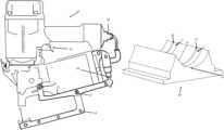
- FIG. 1is a perspective view of a clinch staple mechanism according to embodiments of the disclosure.
- FIG. 2 Ais a side view of a clinch staple mechanism according to embodiments of the disclosure shown without a pneumatic stapling tool.
- FIG. 2 Bis a side view of a clinch staple mechanism according to embodiments of the disclosure shown with a pneumatic stapling tool.
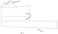
- FIG. 3is a partial side view of a clinch staple mechanism according to embodiments of the disclosure.
- FIG. 4is a perspective view of a clinch block according to embodiments of the disclosure.
- FIG. 5is a perspective view of a staple clinched by a clinch staple mechanism according to embodiments of the disclosure.
- FIG. 6is a perspective view of deck board and a stringer boards for use with a clinch staple mechanism according to embodiments of the disclosure.
- a clinch staple mechanism 10is a piece of equipment for attaching to pneumatic stapling tools 11 .
- Clinch staple mechanism 10includes a pivoting base 12 for the pneumatic stapling tool 11 to attach to, a clinch arm 14 that holds a clinch block 18 on a distal end 31 of clinch arm 14 .
- Pneumatic stapling tool 11is pivotally connected to pivoting base 12 at pivoting base pivot point 21 .
- Clinch arm 14is pivotally connected at a proximal end 33 thereof to pivoting base 12 at clinch arm pivot point 13 .
- Clinch block 18may be supported on clinch arm 14 by a clinch block base 16 .
- Clinch block 18has a pair of staple leg tracks 20 in the form of parallel grooves for the guiding of staples in a particular direction relevant to the orientation of the wood grain of the wood being clinched.
- Exemplary embodiments of this disclosureallow for the clinching of two pieces of wood such as a top deck board 32 and a stringer board 34 whose wood grain orientations are opposite or perpendicular to one another.
- a pallet 30may include top deck boards 32 and stringer boards 34 .
- Top deck boards 32may have a wood grain direction A which is perpendicular or opposite to a wood grain direction B of stringer boards 34 .
- the clinch staple mechanism 10is used by attaching a pneumatic stapling tool 11 to pivoting base 12 and to an air supply attachment 22 configured for receiving air from the pneumatic stapling tool 11 ( FIGS. 2 A and 2 B ).
- a pneumatic stapling tool 11is attached to pivoting base 12 , it is usable, for example, for clinching together wooden deck boards 32 and stringer boards 34 ( FIG. 6 ).
- the userinserts clinch arm 14 so that clinch block 18 is positioned beneath a top deck board 32 and touching near the underside of a stringer board 34 of a pallet 30 and pneumatic tool 11 is positioned above the top deck board 32 .
- Clinch block 18has a curved substantially U-shaped profile 19 configured to face the underside of the wood pieces being clinched such as the underside of stringer board 34 .
- Staple leg tracks 20follow curved profile 19 so that each staple leg track 20 has a bottom portion 23 , a forward curved portion 25 and a rearward curved portion 27 .
- staple legs 28After passing through top deck board 32 and stringer board 34 , staple legs 28 will reach the bottom portion 23 of staple leg tracks 20 . After the staple legs 28 reach bottom portion 23 , they are diverted and bent in the direction of staple leg tracks 20 following either forward curved portion 25 or rearward curved portion 27 of staple tracks 20 .
- staple legs 28bend either forward (away from proximal end 33 of clinch arm 14 ) or backward (towards proximal end 33 of clinch arm 14 ) following forward curved portion 25 or rearward curved portion 27 of staple tracks 20 until they curve upwardly and re-enter stringer boards 34 and top deck boards 32 from underneath such that staple legs 28 are not parallel with crown 29 .
- This forward or backward clinching directionadds far greater clinching strength to the deck boards, as it clinches in the direction of wood grain of the wood on both the top deck board and the stringer board underneath.
- Releasing trigger 15 of pneumatic stapling tool 11allows for clinch arm 14 to release the wood so the next clinch can be shot on.
- crown 29 of staple 26is disposed in crown direction C and perpendicularly traverses the direction A of the wood grain of top deck board 32 and extends in the direction of B of the wood grain of stringer board 34 underneath, and also staple legs 28 are bent in direction D perpendicular to crown direction C and perpendicularly traverse direction B of the wood grain of stringer board 34 underneath and are bent in the direction A of the wood grain of top deck board 32 .
- This clinching format of staple 26creates a clinch that does not pull back through the wood grain of the wood, but instead it captures both opposing directions of the wood grain in each board 32 , 34 .
Landscapes
- Engineering & Computer Science (AREA)
- Mechanical Engineering (AREA)
- Physics & Mathematics (AREA)
- Fluid Mechanics (AREA)
- Dovetailed Work, And Nailing Machines And Stapling Machines For Wood (AREA)
Abstract
Description
Claims (8)
Priority Applications (1)
| Application Number | Priority Date | Filing Date | Title |
|---|---|---|---|
| US16/747,648US11858099B2 (en) | 2019-01-18 | 2020-01-21 | Clinch staple mechanism |
Applications Claiming Priority (2)
| Application Number | Priority Date | Filing Date | Title |
|---|---|---|---|
| US201962794003P | 2019-01-18 | 2019-01-18 | |
| US16/747,648US11858099B2 (en) | 2019-01-18 | 2020-01-21 | Clinch staple mechanism |
Publications (2)
| Publication Number | Publication Date |
|---|---|
| US20200230792A1 US20200230792A1 (en) | 2020-07-23 |
| US11858099B2true US11858099B2 (en) | 2024-01-02 |
Family
ID=71609547
Family Applications (1)
| Application Number | Title | Priority Date | Filing Date |
|---|---|---|---|
| US16/747,648Active2040-04-18US11858099B2 (en) | 2019-01-18 | 2020-01-21 | Clinch staple mechanism |
Country Status (4)
| Country | Link |
|---|---|
| US (1) | US11858099B2 (en) |
| EP (1) | EP3911476A4 (en) |
| CA (1) | CA3125989A1 (en) |
| WO (1) | WO2020150724A1 (en) |
Families Citing this family (1)
| Publication number | Priority date | Publication date | Assignee | Title |
|---|---|---|---|---|
| US11660737B2 (en)* | 2019-09-10 | 2023-05-30 | Pneutools, Inc. | Directional clinching tool and nails |
Citations (35)
| Publication number | Priority date | Publication date | Assignee | Title |
|---|---|---|---|---|
| US212316A (en)* | 1879-02-18 | Improvement in devices for inserting metallic staples in papers | ||
| US985103A (en)* | 1910-03-28 | 1911-02-21 | Louis Baum | Device for bending ends of pins. |
| DE447735C (en)* | 1926-08-30 | 1927-07-27 | Skrebba Werk Metallwaren G M B | Multiple die stapler |
| US1956174A (en) | 1931-11-28 | 1934-04-24 | Boston Wire Stitcher Co | Stapling machine |
| US2046359A (en)* | 1934-12-11 | 1936-07-07 | Stapling Machines Co | Means and method of stapling box parts |
| US2687522A (en)* | 1953-03-30 | 1954-08-31 | Senco Products | Stapling machine |
| CH340043A (en)* | 1956-06-04 | 1959-07-31 | Vickers Armstrongs Ltd | Stapling machine |
| US2943327A (en) | 1957-03-08 | 1960-07-05 | Senco Products | Stapling plier |
| FR1397370A (en)* | 1964-03-17 | 1965-04-30 | Soc D Const D Outil Mecanique | Improvements to stapling by metal jumpers |
| US3734378A (en) | 1971-09-02 | 1973-05-22 | Textron Inc | Pneumatically actuated stapling plier |
| US3871227A (en)* | 1973-11-26 | 1975-03-18 | Jr Carl E Tidwell | Nail turning apparatus |
| US3900144A (en)* | 1972-05-22 | 1975-08-19 | Hambro Forest Products Inc | Fastening machine |
| US4011785A (en) | 1971-06-16 | 1977-03-15 | Bliss & Laughlin Ind., Inc. | Nail and powered nailer |
| US4340331A (en) | 1979-03-26 | 1982-07-20 | Savino Dominick J | Staple and anviless stapling apparatus therefor |
| SU1007980A1 (en)* | 1978-02-16 | 1983-03-30 | Kuznetsov Aleksej | Apparatus for folding braces |
| SU1418033A1 (en)* | 1987-01-23 | 1988-08-23 | Всесоюзный Научно-Исследовательский И Проектно-Конструкторский Институт Продуктов Детского Питания И Систем Управления Агропромышленными Комплексами Консервной Промышленности | Method of fastening pallet with staples |
| US5004142A (en) | 1989-01-23 | 1991-04-02 | Swingline Inc. | Guide anvil including movable clinching wings for stapler |
| US5350400A (en)* | 1991-10-30 | 1994-09-27 | American Cyanamid Company | Malleable, bioabsorbable, plastic staple; and method and apparatus for deforming such staple |
| US5360305A (en) | 1993-03-19 | 1994-11-01 | Duo-Fast Corporation | Clinch staples and method of manufacturing and applying clinch staples |
| US6056183A (en) | 1996-10-25 | 2000-05-02 | Max Co., Ltd. | Clinch mechanism in stapler |
| US6059504A (en) | 1997-07-03 | 2000-05-09 | Max Co., Ltd. | Binding device |
| US6237827B1 (en) | 1998-11-12 | 2001-05-29 | Senco Products, Inc. | Stapler and method for the attachment of steel framing |
| US6431428B1 (en) | 2000-10-16 | 2002-08-13 | Jui-Chin Chen | Pneumatic nail gun |
| US20040031839A1 (en) | 2002-08-16 | 2004-02-19 | Stanley Fastening Systems, L.P. | Clip applicator tool |
| US6877646B2 (en)* | 2000-02-24 | 2005-04-12 | National Innovation Centre (Australia) Pty Ltd. | Rivets and methods for their production and use |
| US20060071047A1 (en) | 2004-10-06 | 2006-04-06 | Stanley Fastening Systems, L.P. | Variable outward clinch stapler |
| US20090159633A1 (en) | 2007-12-21 | 2009-06-25 | Yi-Tsung Wu | Nail Gun Switch Mechanism |
| US7556183B1 (en) | 2008-02-04 | 2009-07-07 | De Poan Pneumatic Corp. | Control device for nail hitting of pneumatic nail guns |
| US20140076954A1 (en) | 2012-09-18 | 2014-03-20 | Stanley Fastening Systems, L.P. | Pallet nail clinching apparatus and methods |
| US20140209657A1 (en) | 2013-01-30 | 2014-07-31 | Chun-Ming Huang | Nail gun structure |
| US20170297188A1 (en)* | 2016-04-15 | 2017-10-19 | Everwin Pneumatic Corp. | Clamping device for a nail gun |
| US9993913B2 (en) | 2013-10-14 | 2018-06-12 | Senco Brands, Inc. | Clenching adapter for automatic nailers |
| US20180168598A1 (en)* | 2016-12-21 | 2018-06-21 | Ethicon Endo-Surgery, Llc | Staple forming pocket arrangements comprising zoned forming surface grooves |
| US20180354112A1 (en) | 2017-06-13 | 2018-12-13 | Everwin Pneumatic Corporation | Nail gun structure |
| US20190329391A1 (en)* | 2018-04-30 | 2019-10-31 | Everwin Pneumatic Corporation | Nail blocking member for nail gun |
- 2020
- 2020-01-21CACA3125989Apatent/CA3125989A1/enactivePending
- 2020-01-21USUS16/747,648patent/US11858099B2/enactiveActive
- 2020-01-21EPEP20741211.5Apatent/EP3911476A4/ennot_activeWithdrawn
- 2020-01-21WOPCT/US2020/014321patent/WO2020150724A1/ennot_activeCeased
Patent Citations (35)
| Publication number | Priority date | Publication date | Assignee | Title |
|---|---|---|---|---|
| US212316A (en)* | 1879-02-18 | Improvement in devices for inserting metallic staples in papers | ||
| US985103A (en)* | 1910-03-28 | 1911-02-21 | Louis Baum | Device for bending ends of pins. |
| DE447735C (en)* | 1926-08-30 | 1927-07-27 | Skrebba Werk Metallwaren G M B | Multiple die stapler |
| US1956174A (en) | 1931-11-28 | 1934-04-24 | Boston Wire Stitcher Co | Stapling machine |
| US2046359A (en)* | 1934-12-11 | 1936-07-07 | Stapling Machines Co | Means and method of stapling box parts |
| US2687522A (en)* | 1953-03-30 | 1954-08-31 | Senco Products | Stapling machine |
| CH340043A (en)* | 1956-06-04 | 1959-07-31 | Vickers Armstrongs Ltd | Stapling machine |
| US2943327A (en) | 1957-03-08 | 1960-07-05 | Senco Products | Stapling plier |
| FR1397370A (en)* | 1964-03-17 | 1965-04-30 | Soc D Const D Outil Mecanique | Improvements to stapling by metal jumpers |
| US4011785A (en) | 1971-06-16 | 1977-03-15 | Bliss & Laughlin Ind., Inc. | Nail and powered nailer |
| US3734378A (en) | 1971-09-02 | 1973-05-22 | Textron Inc | Pneumatically actuated stapling plier |
| US3900144A (en)* | 1972-05-22 | 1975-08-19 | Hambro Forest Products Inc | Fastening machine |
| US3871227A (en)* | 1973-11-26 | 1975-03-18 | Jr Carl E Tidwell | Nail turning apparatus |
| SU1007980A1 (en)* | 1978-02-16 | 1983-03-30 | Kuznetsov Aleksej | Apparatus for folding braces |
| US4340331A (en) | 1979-03-26 | 1982-07-20 | Savino Dominick J | Staple and anviless stapling apparatus therefor |
| SU1418033A1 (en)* | 1987-01-23 | 1988-08-23 | Всесоюзный Научно-Исследовательский И Проектно-Конструкторский Институт Продуктов Детского Питания И Систем Управления Агропромышленными Комплексами Консервной Промышленности | Method of fastening pallet with staples |
| US5004142A (en) | 1989-01-23 | 1991-04-02 | Swingline Inc. | Guide anvil including movable clinching wings for stapler |
| US5350400A (en)* | 1991-10-30 | 1994-09-27 | American Cyanamid Company | Malleable, bioabsorbable, plastic staple; and method and apparatus for deforming such staple |
| US5360305A (en) | 1993-03-19 | 1994-11-01 | Duo-Fast Corporation | Clinch staples and method of manufacturing and applying clinch staples |
| US6056183A (en) | 1996-10-25 | 2000-05-02 | Max Co., Ltd. | Clinch mechanism in stapler |
| US6059504A (en) | 1997-07-03 | 2000-05-09 | Max Co., Ltd. | Binding device |
| US6237827B1 (en) | 1998-11-12 | 2001-05-29 | Senco Products, Inc. | Stapler and method for the attachment of steel framing |
| US6877646B2 (en)* | 2000-02-24 | 2005-04-12 | National Innovation Centre (Australia) Pty Ltd. | Rivets and methods for their production and use |
| US6431428B1 (en) | 2000-10-16 | 2002-08-13 | Jui-Chin Chen | Pneumatic nail gun |
| US20040031839A1 (en) | 2002-08-16 | 2004-02-19 | Stanley Fastening Systems, L.P. | Clip applicator tool |
| US20060071047A1 (en) | 2004-10-06 | 2006-04-06 | Stanley Fastening Systems, L.P. | Variable outward clinch stapler |
| US20090159633A1 (en) | 2007-12-21 | 2009-06-25 | Yi-Tsung Wu | Nail Gun Switch Mechanism |
| US7556183B1 (en) | 2008-02-04 | 2009-07-07 | De Poan Pneumatic Corp. | Control device for nail hitting of pneumatic nail guns |
| US20140076954A1 (en) | 2012-09-18 | 2014-03-20 | Stanley Fastening Systems, L.P. | Pallet nail clinching apparatus and methods |
| US20140209657A1 (en) | 2013-01-30 | 2014-07-31 | Chun-Ming Huang | Nail gun structure |
| US9993913B2 (en) | 2013-10-14 | 2018-06-12 | Senco Brands, Inc. | Clenching adapter for automatic nailers |
| US20170297188A1 (en)* | 2016-04-15 | 2017-10-19 | Everwin Pneumatic Corp. | Clamping device for a nail gun |
| US20180168598A1 (en)* | 2016-12-21 | 2018-06-21 | Ethicon Endo-Surgery, Llc | Staple forming pocket arrangements comprising zoned forming surface grooves |
| US20180354112A1 (en) | 2017-06-13 | 2018-12-13 | Everwin Pneumatic Corporation | Nail gun structure |
| US20190329391A1 (en)* | 2018-04-30 | 2019-10-31 | Everwin Pneumatic Corporation | Nail blocking member for nail gun |
Non-Patent Citations (5)
| Title |
|---|
| "Polyamide Fibers (Nylon)" (Polymer Properties Database(online) (retrieved from the internet on Nov. 6, 2020: https://web.archive.org/web/20170311172258/https://polymerdatabase.com/Fibers/Nylon.html. Mar. 11, 2017; entire document, especially paragraph 3. |
| International Search Report and Written Opinion for corresponding International Application No. PCT/US20/27956 dated Jul. 24, 2020. |
| International Search Report and Written Opinion for International Application No. PCT/US20/20091 dated Nov. 27, 2020. |
| Search Report and Written Opinion for corresponding International Application No. PCT/US20/14321 dated Apr. 29, 2020. |
| Search Report and Written Opinion for European Application No. 20741211 dated Sep. 8, 2022. |
Also Published As
| Publication number | Publication date |
|---|---|
| EP3911476A4 (en) | 2022-10-19 |
| EP3911476A1 (en) | 2021-11-24 |
| US20200230792A1 (en) | 2020-07-23 |
| WO2020150724A1 (en) | 2020-07-23 |
| CA3125989A1 (en) | 2020-07-18 |
Similar Documents
| Publication | Publication Date | Title |
|---|---|---|
| US5588577A (en) | Magazine assembly for pneumatic staple guns | |
| US7882994B2 (en) | 45 degree adjustable adapter for flooring nailer | |
| US7311236B2 (en) | Electric stapler having two anvil plates and workpiece sensing controller | |
| US6244491B1 (en) | Hand held stapler | |
| US5163596A (en) | Portable pneumatic tool employing improved magazine feed, eject and jam-clearing technique | |
| US20110049213A1 (en) | Stapler | |
| EP2708338B1 (en) | Apparatus for clinching nails into workpieces | |
| US4878608A (en) | Hand stapler for use with a bar of ornamented staples | |
| US20070221699A1 (en) | Staplers with effort-saving arm assembly | |
| US7228999B2 (en) | Clincher for stapler | |
| US6237827B1 (en) | Stapler and method for the attachment of steel framing | |
| US11858099B2 (en) | Clinch staple mechanism | |
| US5692667A (en) | Document positioning member for a stapler | |
| US3900144A (en) | Fastening machine | |
| US4126258A (en) | Clamp nail driving tool | |
| CA1325573C (en) | Staple positioning tab | |
| US20030121949A1 (en) | Tacker for both nail and staples with a resilient guiding device for the nail at the launching position | |
| US2755474A (en) | Fastener applying device | |
| CN212240882U (en) | Nail pusher and stapler with same | |
| US8430290B2 (en) | System and method for driving a fastener | |
| US20030010804A1 (en) | Anti-reversing device in a staple magazine | |
| JP5050991B2 (en) | Stapler | |
| US20090308906A1 (en) | Cap feeder with grip finger | |
| DE19849093C2 (en) | Stapler | |
| JP5138415B2 (en) | Driving tool |
Legal Events
| Date | Code | Title | Description |
|---|---|---|---|
| FEPP | Fee payment procedure | Free format text:ENTITY STATUS SET TO UNDISCOUNTED (ORIGINAL EVENT CODE: BIG.); ENTITY STATUS OF PATENT OWNER: SMALL ENTITY | |
| FEPP | Fee payment procedure | Free format text:ENTITY STATUS SET TO SMALL (ORIGINAL EVENT CODE: SMAL); ENTITY STATUS OF PATENT OWNER: SMALL ENTITY | |
| STPP | Information on status: patent application and granting procedure in general | Free format text:DOCKETED NEW CASE - READY FOR EXAMINATION | |
| STPP | Information on status: patent application and granting procedure in general | Free format text:NON FINAL ACTION MAILED | |
| STPP | Information on status: patent application and granting procedure in general | Free format text:FINAL REJECTION MAILED | |
| STPP | Information on status: patent application and granting procedure in general | Free format text:DOCKETED NEW CASE - READY FOR EXAMINATION | |
| STPP | Information on status: patent application and granting procedure in general | Free format text:NON FINAL ACTION MAILED | |
| STPP | Information on status: patent application and granting procedure in general | Free format text:NON FINAL ACTION MAILED | |
| AS | Assignment | Owner name:PNEUTOOLS, INC., TENNESSEE Free format text:ASSIGNMENT OF ASSIGNORS INTEREST;ASSIGNOR:LAMB, FREDERICK WILLIAM;REEL/FRAME:062585/0651 Effective date:20230203 | |
| STPP | Information on status: patent application and granting procedure in general | Free format text:FINAL REJECTION MAILED | |
| STPP | Information on status: patent application and granting procedure in general | Free format text:NOTICE OF ALLOWANCE MAILED -- APPLICATION RECEIVED IN OFFICE OF PUBLICATIONS | |
| STPP | Information on status: patent application and granting procedure in general | Free format text:PUBLICATIONS -- ISSUE FEE PAYMENT RECEIVED | |
| STPP | Information on status: patent application and granting procedure in general | Free format text:PUBLICATIONS -- ISSUE FEE PAYMENT VERIFIED | |
| STCF | Information on status: patent grant | Free format text:PATENTED CASE |