US11857432B2 - Expandable implant assembly - Google Patents
Expandable implant assemblyDownload PDFInfo
- Publication number
- US11857432B2 US11857432B2US16/847,187US202016847187AUS11857432B2US 11857432 B2US11857432 B2US 11857432B2US 202016847187 AUS202016847187 AUS 202016847187AUS 11857432 B2US11857432 B2US 11857432B2
- Authority
- US
- United States
- Prior art keywords
- implant
- upper support
- support
- lower support
- receive
- Prior art date
- Legal status (The legal status is an assumption and is not a legal conclusion. Google has not performed a legal analysis and makes no representation as to the accuracy of the status listed.)
- Active
Links
Images


Classifications
- A—HUMAN NECESSITIES
- A61—MEDICAL OR VETERINARY SCIENCE; HYGIENE
- A61F—FILTERS IMPLANTABLE INTO BLOOD VESSELS; PROSTHESES; DEVICES PROVIDING PATENCY TO, OR PREVENTING COLLAPSING OF, TUBULAR STRUCTURES OF THE BODY, e.g. STENTS; ORTHOPAEDIC, NURSING OR CONTRACEPTIVE DEVICES; FOMENTATION; TREATMENT OR PROTECTION OF EYES OR EARS; BANDAGES, DRESSINGS OR ABSORBENT PADS; FIRST-AID KITS
- A61F2/00—Filters implantable into blood vessels; Prostheses, i.e. artificial substitutes or replacements for parts of the body; Appliances for connecting them with the body; Devices providing patency to, or preventing collapsing of, tubular structures of the body, e.g. stents
- A61F2/02—Prostheses implantable into the body
- A61F2/30—Joints
- A61F2/44—Joints for the spine, e.g. vertebrae, spinal discs
- A61F2/4455—Joints for the spine, e.g. vertebrae, spinal discs for the fusion of spinal bodies, e.g. intervertebral fusion of adjacent spinal bodies, e.g. fusion cages
- A—HUMAN NECESSITIES
- A61—MEDICAL OR VETERINARY SCIENCE; HYGIENE
- A61F—FILTERS IMPLANTABLE INTO BLOOD VESSELS; PROSTHESES; DEVICES PROVIDING PATENCY TO, OR PREVENTING COLLAPSING OF, TUBULAR STRUCTURES OF THE BODY, e.g. STENTS; ORTHOPAEDIC, NURSING OR CONTRACEPTIVE DEVICES; FOMENTATION; TREATMENT OR PROTECTION OF EYES OR EARS; BANDAGES, DRESSINGS OR ABSORBENT PADS; FIRST-AID KITS
- A61F2/00—Filters implantable into blood vessels; Prostheses, i.e. artificial substitutes or replacements for parts of the body; Appliances for connecting them with the body; Devices providing patency to, or preventing collapsing of, tubular structures of the body, e.g. stents
- A61F2/02—Prostheses implantable into the body
- A61F2/30—Joints
- A61F2/44—Joints for the spine, e.g. vertebrae, spinal discs
- A61F2/442—Intervertebral or spinal discs, e.g. resilient
- A61F2/4425—Intervertebral or spinal discs, e.g. resilient made of articulated components
- A—HUMAN NECESSITIES
- A61—MEDICAL OR VETERINARY SCIENCE; HYGIENE
- A61F—FILTERS IMPLANTABLE INTO BLOOD VESSELS; PROSTHESES; DEVICES PROVIDING PATENCY TO, OR PREVENTING COLLAPSING OF, TUBULAR STRUCTURES OF THE BODY, e.g. STENTS; ORTHOPAEDIC, NURSING OR CONTRACEPTIVE DEVICES; FOMENTATION; TREATMENT OR PROTECTION OF EYES OR EARS; BANDAGES, DRESSINGS OR ABSORBENT PADS; FIRST-AID KITS
- A61F2/00—Filters implantable into blood vessels; Prostheses, i.e. artificial substitutes or replacements for parts of the body; Appliances for connecting them with the body; Devices providing patency to, or preventing collapsing of, tubular structures of the body, e.g. stents
- A61F2/02—Prostheses implantable into the body
- A61F2/30—Joints
- A61F2/44—Joints for the spine, e.g. vertebrae, spinal discs
- A61F2/4455—Joints for the spine, e.g. vertebrae, spinal discs for the fusion of spinal bodies, e.g. intervertebral fusion of adjacent spinal bodies, e.g. fusion cages
- A61F2/447—Joints for the spine, e.g. vertebrae, spinal discs for the fusion of spinal bodies, e.g. intervertebral fusion of adjacent spinal bodies, e.g. fusion cages substantially parallelepipedal, e.g. having a rectangular or trapezoidal cross-section
- A—HUMAN NECESSITIES
- A61—MEDICAL OR VETERINARY SCIENCE; HYGIENE
- A61F—FILTERS IMPLANTABLE INTO BLOOD VESSELS; PROSTHESES; DEVICES PROVIDING PATENCY TO, OR PREVENTING COLLAPSING OF, TUBULAR STRUCTURES OF THE BODY, e.g. STENTS; ORTHOPAEDIC, NURSING OR CONTRACEPTIVE DEVICES; FOMENTATION; TREATMENT OR PROTECTION OF EYES OR EARS; BANDAGES, DRESSINGS OR ABSORBENT PADS; FIRST-AID KITS
- A61F2/00—Filters implantable into blood vessels; Prostheses, i.e. artificial substitutes or replacements for parts of the body; Appliances for connecting them with the body; Devices providing patency to, or preventing collapsing of, tubular structures of the body, e.g. stents
- A61F2/02—Prostheses implantable into the body
- A61F2/30—Joints
- A61F2002/30001—Additional features of subject-matter classified in A61F2/28, A61F2/30 and subgroups thereof
- A61F2002/30108—Shapes
- A61F2002/30199—Three-dimensional shapes
- A61F2002/30261—Three-dimensional shapes parallelepipedal
- A61F2002/30266—Three-dimensional shapes parallelepipedal wedge-shaped parallelepipeds
- A—HUMAN NECESSITIES
- A61—MEDICAL OR VETERINARY SCIENCE; HYGIENE
- A61F—FILTERS IMPLANTABLE INTO BLOOD VESSELS; PROSTHESES; DEVICES PROVIDING PATENCY TO, OR PREVENTING COLLAPSING OF, TUBULAR STRUCTURES OF THE BODY, e.g. STENTS; ORTHOPAEDIC, NURSING OR CONTRACEPTIVE DEVICES; FOMENTATION; TREATMENT OR PROTECTION OF EYES OR EARS; BANDAGES, DRESSINGS OR ABSORBENT PADS; FIRST-AID KITS
- A61F2/00—Filters implantable into blood vessels; Prostheses, i.e. artificial substitutes or replacements for parts of the body; Appliances for connecting them with the body; Devices providing patency to, or preventing collapsing of, tubular structures of the body, e.g. stents
- A61F2/02—Prostheses implantable into the body
- A61F2/30—Joints
- A61F2002/30001—Additional features of subject-matter classified in A61F2/28, A61F2/30 and subgroups thereof
- A61F2002/30316—The prosthesis having different structural features at different locations within the same prosthesis; Connections between prosthetic parts; Special structural features of bone or joint prostheses not otherwise provided for
- A61F2002/30329—Connections or couplings between prosthetic parts, e.g. between modular parts; Connecting elements
- A61F2002/30331—Connections or couplings between prosthetic parts, e.g. between modular parts; Connecting elements made by longitudinally pushing a protrusion into a complementarily-shaped recess, e.g. held by friction fit
- A61F2002/30362—Connections or couplings between prosthetic parts, e.g. between modular parts; Connecting elements made by longitudinally pushing a protrusion into a complementarily-shaped recess, e.g. held by friction fit with possibility of relative movement between the protrusion and the recess
- A61F2002/3037—Translation along the common longitudinal axis, e.g. piston
- A—HUMAN NECESSITIES
- A61—MEDICAL OR VETERINARY SCIENCE; HYGIENE
- A61F—FILTERS IMPLANTABLE INTO BLOOD VESSELS; PROSTHESES; DEVICES PROVIDING PATENCY TO, OR PREVENTING COLLAPSING OF, TUBULAR STRUCTURES OF THE BODY, e.g. STENTS; ORTHOPAEDIC, NURSING OR CONTRACEPTIVE DEVICES; FOMENTATION; TREATMENT OR PROTECTION OF EYES OR EARS; BANDAGES, DRESSINGS OR ABSORBENT PADS; FIRST-AID KITS
- A61F2/00—Filters implantable into blood vessels; Prostheses, i.e. artificial substitutes or replacements for parts of the body; Appliances for connecting them with the body; Devices providing patency to, or preventing collapsing of, tubular structures of the body, e.g. stents
- A61F2/02—Prostheses implantable into the body
- A61F2/30—Joints
- A61F2002/30001—Additional features of subject-matter classified in A61F2/28, A61F2/30 and subgroups thereof
- A61F2002/30316—The prosthesis having different structural features at different locations within the same prosthesis; Connections between prosthetic parts; Special structural features of bone or joint prostheses not otherwise provided for
- A61F2002/30329—Connections or couplings between prosthetic parts, e.g. between modular parts; Connecting elements
- A61F2002/30383—Connections or couplings between prosthetic parts, e.g. between modular parts; Connecting elements made by laterally inserting a protrusion, e.g. a rib into a complementarily-shaped groove
- A61F2002/30387—Dovetail connection
- A—HUMAN NECESSITIES
- A61—MEDICAL OR VETERINARY SCIENCE; HYGIENE
- A61F—FILTERS IMPLANTABLE INTO BLOOD VESSELS; PROSTHESES; DEVICES PROVIDING PATENCY TO, OR PREVENTING COLLAPSING OF, TUBULAR STRUCTURES OF THE BODY, e.g. STENTS; ORTHOPAEDIC, NURSING OR CONTRACEPTIVE DEVICES; FOMENTATION; TREATMENT OR PROTECTION OF EYES OR EARS; BANDAGES, DRESSINGS OR ABSORBENT PADS; FIRST-AID KITS
- A61F2/00—Filters implantable into blood vessels; Prostheses, i.e. artificial substitutes or replacements for parts of the body; Appliances for connecting them with the body; Devices providing patency to, or preventing collapsing of, tubular structures of the body, e.g. stents
- A61F2/02—Prostheses implantable into the body
- A61F2/30—Joints
- A61F2002/30001—Additional features of subject-matter classified in A61F2/28, A61F2/30 and subgroups thereof
- A61F2002/30316—The prosthesis having different structural features at different locations within the same prosthesis; Connections between prosthetic parts; Special structural features of bone or joint prostheses not otherwise provided for
- A61F2002/30329—Connections or couplings between prosthetic parts, e.g. between modular parts; Connecting elements
- A61F2002/30383—Connections or couplings between prosthetic parts, e.g. between modular parts; Connecting elements made by laterally inserting a protrusion, e.g. a rib into a complementarily-shaped groove
- A61F2002/3039—Connections or couplings between prosthetic parts, e.g. between modular parts; Connecting elements made by laterally inserting a protrusion, e.g. a rib into a complementarily-shaped groove with possibility of relative movement of the rib within the groove
- A61F2002/30398—Sliding
- A—HUMAN NECESSITIES
- A61—MEDICAL OR VETERINARY SCIENCE; HYGIENE
- A61F—FILTERS IMPLANTABLE INTO BLOOD VESSELS; PROSTHESES; DEVICES PROVIDING PATENCY TO, OR PREVENTING COLLAPSING OF, TUBULAR STRUCTURES OF THE BODY, e.g. STENTS; ORTHOPAEDIC, NURSING OR CONTRACEPTIVE DEVICES; FOMENTATION; TREATMENT OR PROTECTION OF EYES OR EARS; BANDAGES, DRESSINGS OR ABSORBENT PADS; FIRST-AID KITS
- A61F2/00—Filters implantable into blood vessels; Prostheses, i.e. artificial substitutes or replacements for parts of the body; Appliances for connecting them with the body; Devices providing patency to, or preventing collapsing of, tubular structures of the body, e.g. stents
- A61F2/02—Prostheses implantable into the body
- A61F2/30—Joints
- A61F2002/30001—Additional features of subject-matter classified in A61F2/28, A61F2/30 and subgroups thereof
- A61F2002/30316—The prosthesis having different structural features at different locations within the same prosthesis; Connections between prosthetic parts; Special structural features of bone or joint prostheses not otherwise provided for
- A61F2002/30329—Connections or couplings between prosthetic parts, e.g. between modular parts; Connecting elements
- A61F2002/30405—Connections or couplings between prosthetic parts, e.g. between modular parts; Connecting elements made by screwing complementary threads machined on the parts themselves
- A—HUMAN NECESSITIES
- A61—MEDICAL OR VETERINARY SCIENCE; HYGIENE
- A61F—FILTERS IMPLANTABLE INTO BLOOD VESSELS; PROSTHESES; DEVICES PROVIDING PATENCY TO, OR PREVENTING COLLAPSING OF, TUBULAR STRUCTURES OF THE BODY, e.g. STENTS; ORTHOPAEDIC, NURSING OR CONTRACEPTIVE DEVICES; FOMENTATION; TREATMENT OR PROTECTION OF EYES OR EARS; BANDAGES, DRESSINGS OR ABSORBENT PADS; FIRST-AID KITS
- A61F2/00—Filters implantable into blood vessels; Prostheses, i.e. artificial substitutes or replacements for parts of the body; Appliances for connecting them with the body; Devices providing patency to, or preventing collapsing of, tubular structures of the body, e.g. stents
- A61F2/02—Prostheses implantable into the body
- A61F2/30—Joints
- A61F2002/30001—Additional features of subject-matter classified in A61F2/28, A61F2/30 and subgroups thereof
- A61F2002/30316—The prosthesis having different structural features at different locations within the same prosthesis; Connections between prosthetic parts; Special structural features of bone or joint prostheses not otherwise provided for
- A61F2002/30329—Connections or couplings between prosthetic parts, e.g. between modular parts; Connecting elements
- A61F2002/30428—Connections or couplings between prosthetic parts, e.g. between modular parts; Connecting elements made by inserting a protrusion into a slot
- A—HUMAN NECESSITIES
- A61—MEDICAL OR VETERINARY SCIENCE; HYGIENE
- A61F—FILTERS IMPLANTABLE INTO BLOOD VESSELS; PROSTHESES; DEVICES PROVIDING PATENCY TO, OR PREVENTING COLLAPSING OF, TUBULAR STRUCTURES OF THE BODY, e.g. STENTS; ORTHOPAEDIC, NURSING OR CONTRACEPTIVE DEVICES; FOMENTATION; TREATMENT OR PROTECTION OF EYES OR EARS; BANDAGES, DRESSINGS OR ABSORBENT PADS; FIRST-AID KITS
- A61F2/00—Filters implantable into blood vessels; Prostheses, i.e. artificial substitutes or replacements for parts of the body; Appliances for connecting them with the body; Devices providing patency to, or preventing collapsing of, tubular structures of the body, e.g. stents
- A61F2/02—Prostheses implantable into the body
- A61F2/30—Joints
- A61F2002/30001—Additional features of subject-matter classified in A61F2/28, A61F2/30 and subgroups thereof
- A61F2002/30316—The prosthesis having different structural features at different locations within the same prosthesis; Connections between prosthetic parts; Special structural features of bone or joint prostheses not otherwise provided for
- A61F2002/30329—Connections or couplings between prosthetic parts, e.g. between modular parts; Connecting elements
- A61F2002/30476—Connections or couplings between prosthetic parts, e.g. between modular parts; Connecting elements locked by an additional locking mechanism
- A61F2002/30507—Connections or couplings between prosthetic parts, e.g. between modular parts; Connecting elements locked by an additional locking mechanism using a threaded locking member, e.g. a locking screw or a set screw
- A—HUMAN NECESSITIES
- A61—MEDICAL OR VETERINARY SCIENCE; HYGIENE
- A61F—FILTERS IMPLANTABLE INTO BLOOD VESSELS; PROSTHESES; DEVICES PROVIDING PATENCY TO, OR PREVENTING COLLAPSING OF, TUBULAR STRUCTURES OF THE BODY, e.g. STENTS; ORTHOPAEDIC, NURSING OR CONTRACEPTIVE DEVICES; FOMENTATION; TREATMENT OR PROTECTION OF EYES OR EARS; BANDAGES, DRESSINGS OR ABSORBENT PADS; FIRST-AID KITS
- A61F2/00—Filters implantable into blood vessels; Prostheses, i.e. artificial substitutes or replacements for parts of the body; Appliances for connecting them with the body; Devices providing patency to, or preventing collapsing of, tubular structures of the body, e.g. stents
- A61F2/02—Prostheses implantable into the body
- A61F2/30—Joints
- A61F2002/30001—Additional features of subject-matter classified in A61F2/28, A61F2/30 and subgroups thereof
- A61F2002/30316—The prosthesis having different structural features at different locations within the same prosthesis; Connections between prosthetic parts; Special structural features of bone or joint prostheses not otherwise provided for
- A61F2002/30329—Connections or couplings between prosthetic parts, e.g. between modular parts; Connecting elements
- A61F2002/30476—Connections or couplings between prosthetic parts, e.g. between modular parts; Connecting elements locked by an additional locking mechanism
- A61F2002/30515—Connections or couplings between prosthetic parts, e.g. between modular parts; Connecting elements locked by an additional locking mechanism using a locking wedge or block
- A—HUMAN NECESSITIES
- A61—MEDICAL OR VETERINARY SCIENCE; HYGIENE
- A61F—FILTERS IMPLANTABLE INTO BLOOD VESSELS; PROSTHESES; DEVICES PROVIDING PATENCY TO, OR PREVENTING COLLAPSING OF, TUBULAR STRUCTURES OF THE BODY, e.g. STENTS; ORTHOPAEDIC, NURSING OR CONTRACEPTIVE DEVICES; FOMENTATION; TREATMENT OR PROTECTION OF EYES OR EARS; BANDAGES, DRESSINGS OR ABSORBENT PADS; FIRST-AID KITS
- A61F2/00—Filters implantable into blood vessels; Prostheses, i.e. artificial substitutes or replacements for parts of the body; Appliances for connecting them with the body; Devices providing patency to, or preventing collapsing of, tubular structures of the body, e.g. stents
- A61F2/02—Prostheses implantable into the body
- A61F2/30—Joints
- A61F2002/30001—Additional features of subject-matter classified in A61F2/28, A61F2/30 and subgroups thereof
- A61F2002/30316—The prosthesis having different structural features at different locations within the same prosthesis; Connections between prosthetic parts; Special structural features of bone or joint prostheses not otherwise provided for
- A61F2002/30329—Connections or couplings between prosthetic parts, e.g. between modular parts; Connecting elements
- A61F2002/30518—Connections or couplings between prosthetic parts, e.g. between modular parts; Connecting elements with possibility of relative movement between the prosthetic parts
- A61F2002/30523—Connections or couplings between prosthetic parts, e.g. between modular parts; Connecting elements with possibility of relative movement between the prosthetic parts by means of meshing gear teeth
- A61F2002/30525—Worm gears
- A—HUMAN NECESSITIES
- A61—MEDICAL OR VETERINARY SCIENCE; HYGIENE
- A61F—FILTERS IMPLANTABLE INTO BLOOD VESSELS; PROSTHESES; DEVICES PROVIDING PATENCY TO, OR PREVENTING COLLAPSING OF, TUBULAR STRUCTURES OF THE BODY, e.g. STENTS; ORTHOPAEDIC, NURSING OR CONTRACEPTIVE DEVICES; FOMENTATION; TREATMENT OR PROTECTION OF EYES OR EARS; BANDAGES, DRESSINGS OR ABSORBENT PADS; FIRST-AID KITS
- A61F2/00—Filters implantable into blood vessels; Prostheses, i.e. artificial substitutes or replacements for parts of the body; Appliances for connecting them with the body; Devices providing patency to, or preventing collapsing of, tubular structures of the body, e.g. stents
- A61F2/02—Prostheses implantable into the body
- A61F2/30—Joints
- A61F2002/30001—Additional features of subject-matter classified in A61F2/28, A61F2/30 and subgroups thereof
- A61F2002/30316—The prosthesis having different structural features at different locations within the same prosthesis; Connections between prosthetic parts; Special structural features of bone or joint prostheses not otherwise provided for
- A61F2002/30535—Special structural features of bone or joint prostheses not otherwise provided for
- A61F2002/30537—Special structural features of bone or joint prostheses not otherwise provided for adjustable
- A61F2002/30538—Special structural features of bone or joint prostheses not otherwise provided for adjustable for adjusting angular orientation
- A—HUMAN NECESSITIES
- A61—MEDICAL OR VETERINARY SCIENCE; HYGIENE
- A61F—FILTERS IMPLANTABLE INTO BLOOD VESSELS; PROSTHESES; DEVICES PROVIDING PATENCY TO, OR PREVENTING COLLAPSING OF, TUBULAR STRUCTURES OF THE BODY, e.g. STENTS; ORTHOPAEDIC, NURSING OR CONTRACEPTIVE DEVICES; FOMENTATION; TREATMENT OR PROTECTION OF EYES OR EARS; BANDAGES, DRESSINGS OR ABSORBENT PADS; FIRST-AID KITS
- A61F2/00—Filters implantable into blood vessels; Prostheses, i.e. artificial substitutes or replacements for parts of the body; Appliances for connecting them with the body; Devices providing patency to, or preventing collapsing of, tubular structures of the body, e.g. stents
- A61F2/02—Prostheses implantable into the body
- A61F2/30—Joints
- A61F2002/30001—Additional features of subject-matter classified in A61F2/28, A61F2/30 and subgroups thereof
- A61F2002/30316—The prosthesis having different structural features at different locations within the same prosthesis; Connections between prosthetic parts; Special structural features of bone or joint prostheses not otherwise provided for
- A61F2002/30535—Special structural features of bone or joint prostheses not otherwise provided for
- A61F2002/30537—Special structural features of bone or joint prostheses not otherwise provided for adjustable
- A61F2002/30556—Special structural features of bone or joint prostheses not otherwise provided for adjustable for adjusting thickness
- A—HUMAN NECESSITIES
- A61—MEDICAL OR VETERINARY SCIENCE; HYGIENE
- A61F—FILTERS IMPLANTABLE INTO BLOOD VESSELS; PROSTHESES; DEVICES PROVIDING PATENCY TO, OR PREVENTING COLLAPSING OF, TUBULAR STRUCTURES OF THE BODY, e.g. STENTS; ORTHOPAEDIC, NURSING OR CONTRACEPTIVE DEVICES; FOMENTATION; TREATMENT OR PROTECTION OF EYES OR EARS; BANDAGES, DRESSINGS OR ABSORBENT PADS; FIRST-AID KITS
- A61F2/00—Filters implantable into blood vessels; Prostheses, i.e. artificial substitutes or replacements for parts of the body; Appliances for connecting them with the body; Devices providing patency to, or preventing collapsing of, tubular structures of the body, e.g. stents
- A61F2/02—Prostheses implantable into the body
- A61F2/30—Joints
- A61F2002/30001—Additional features of subject-matter classified in A61F2/28, A61F2/30 and subgroups thereof
- A61F2002/30316—The prosthesis having different structural features at different locations within the same prosthesis; Connections between prosthetic parts; Special structural features of bone or joint prostheses not otherwise provided for
- A61F2002/30535—Special structural features of bone or joint prostheses not otherwise provided for
- A61F2002/30576—Special structural features of bone or joint prostheses not otherwise provided for with extending fixation tabs
- A61F2002/30578—Special structural features of bone or joint prostheses not otherwise provided for with extending fixation tabs having apertures, e.g. for receiving fixation screws
- A—HUMAN NECESSITIES
- A61—MEDICAL OR VETERINARY SCIENCE; HYGIENE
- A61F—FILTERS IMPLANTABLE INTO BLOOD VESSELS; PROSTHESES; DEVICES PROVIDING PATENCY TO, OR PREVENTING COLLAPSING OF, TUBULAR STRUCTURES OF THE BODY, e.g. STENTS; ORTHOPAEDIC, NURSING OR CONTRACEPTIVE DEVICES; FOMENTATION; TREATMENT OR PROTECTION OF EYES OR EARS; BANDAGES, DRESSINGS OR ABSORBENT PADS; FIRST-AID KITS
- A61F2/00—Filters implantable into blood vessels; Prostheses, i.e. artificial substitutes or replacements for parts of the body; Appliances for connecting them with the body; Devices providing patency to, or preventing collapsing of, tubular structures of the body, e.g. stents
- A61F2/02—Prostheses implantable into the body
- A61F2/30—Joints
- A61F2002/30001—Additional features of subject-matter classified in A61F2/28, A61F2/30 and subgroups thereof
- A61F2002/30316—The prosthesis having different structural features at different locations within the same prosthesis; Connections between prosthetic parts; Special structural features of bone or joint prostheses not otherwise provided for
- A61F2002/30535—Special structural features of bone or joint prostheses not otherwise provided for
- A61F2002/30593—Special structural features of bone or joint prostheses not otherwise provided for hollow
- A—HUMAN NECESSITIES
- A61—MEDICAL OR VETERINARY SCIENCE; HYGIENE
- A61F—FILTERS IMPLANTABLE INTO BLOOD VESSELS; PROSTHESES; DEVICES PROVIDING PATENCY TO, OR PREVENTING COLLAPSING OF, TUBULAR STRUCTURES OF THE BODY, e.g. STENTS; ORTHOPAEDIC, NURSING OR CONTRACEPTIVE DEVICES; FOMENTATION; TREATMENT OR PROTECTION OF EYES OR EARS; BANDAGES, DRESSINGS OR ABSORBENT PADS; FIRST-AID KITS
- A61F2/00—Filters implantable into blood vessels; Prostheses, i.e. artificial substitutes or replacements for parts of the body; Appliances for connecting them with the body; Devices providing patency to, or preventing collapsing of, tubular structures of the body, e.g. stents
- A61F2/02—Prostheses implantable into the body
- A61F2/30—Joints
- A61F2/30767—Special external or bone-contacting surface, e.g. coating for improving bone ingrowth
- A61F2/30771—Special external or bone-contacting surface, e.g. coating for improving bone ingrowth applied in original prostheses, e.g. holes or grooves
- A61F2002/30772—Apertures or holes, e.g. of circular cross section
- A61F2002/30784—Plurality of holes
- A61F2002/30787—Plurality of holes inclined obliquely with respect to each other
- A—HUMAN NECESSITIES
- A61—MEDICAL OR VETERINARY SCIENCE; HYGIENE
- A61F—FILTERS IMPLANTABLE INTO BLOOD VESSELS; PROSTHESES; DEVICES PROVIDING PATENCY TO, OR PREVENTING COLLAPSING OF, TUBULAR STRUCTURES OF THE BODY, e.g. STENTS; ORTHOPAEDIC, NURSING OR CONTRACEPTIVE DEVICES; FOMENTATION; TREATMENT OR PROTECTION OF EYES OR EARS; BANDAGES, DRESSINGS OR ABSORBENT PADS; FIRST-AID KITS
- A61F2/00—Filters implantable into blood vessels; Prostheses, i.e. artificial substitutes or replacements for parts of the body; Appliances for connecting them with the body; Devices providing patency to, or preventing collapsing of, tubular structures of the body, e.g. stents
- A61F2/02—Prostheses implantable into the body
- A61F2/30—Joints
- A61F2/44—Joints for the spine, e.g. vertebrae, spinal discs
- A61F2/442—Intervertebral or spinal discs, e.g. resilient
- A61F2/4425—Intervertebral or spinal discs, e.g. resilient made of articulated components
- A61F2002/443—Intervertebral or spinal discs, e.g. resilient made of articulated components having two transversal endplates and at least one intermediate component
Definitions
- the present disclosuregenerally relates to implants. More specifically, the present application relates to expandable implants and devices, including spinal interbody and intravertebral body devices, and vertebral interbody and intravertebral devices that are expandable after spinal placement thereof.
- a spinal fusionuses an implant or device known as an interbody cage or spacer along with bone graft and/or bone graft substitute that is inserted into the disc space between adjacent vertebrae from one side of the spine.
- additional surgical hardwaresuch as pedicle screws and rods or plates are attached to the back of the vertebrae. As the bone graft heals, it fuses the adjacent vertebrae to form one long vertebra.
- Fusion cagesas well as other types of implants, bodies and/or devices, are frequently utilized in spinal surgery inside a vertebra (intravertebral) and/or between vertebrae of a patient (interbody), or adjacent other bone bodies.
- interbody devicesone or more such spinal bodies are placed between vertebrae to provide support and promote fusion between adjacent vertebrae where such is necessary due to disease, injury, general deterioration or congenital problem.
- intravertebral devicesone or more spinal bodies are placed within a vertebra.
- Spinal devicessuch as fusion cages and/or the like, are inserted into a spinal space either anteriorly, posteriorly, laterally or posterolaterally.
- an implantin some embodiments, includes an upper support that includes an upper plate configured to receive a first anchoring member and a lower support that includes a lower plate configured to receive a second anchoring member.
- the implantalso includes a control member that includes a head and a shaft and configured to control relative movement between the upper support and the lower support, a front portion configured engage the upper support and the lower support and further configured to receive the head of the control member, and a rear portion configured engage the upper support and the lower support and further configured to engage a portion of the shaft, wherein manipulation of the control member causes the front portion to move relative to the rear portion, such that the upper support moves relative to the lower support.
- a method of installing an implantincludes inserting the implant into a desired location.
- the implantincludes an upper support that includes an upper plate configured to receive a first anchoring member, a lower support that includes a lower plate configured to receive a second anchoring member, and a control assembly including a control member, a front member, and a rear member, wherein the control assembly is configured to control relative movement between the upper support and the lower support.
- the methodfurther includes manipulation the control member to cause relative sliding movement between the front member and both the upper support and the lower support, and the rear member and both the upper support and the lower support, to expand the implant to a desired height, and securing the first and second anchoring members into adjacent portions of bone to secure the implant into the desired location.
- an implantin some embodiments, includes an upper support configured to engage a first portion of bone.
- the upper supportincludes an upper plate at a first end of the upper support configured to secure the upper support to the first portion of bone.
- the implantalso includes a lower support configured to engage a second portion of bone.
- the lower supportincludes a lower plate at a first end of the lower support configured to secure the lower support to the second portion of bone.
- the implantincludes a control assembly configured to control relative movement between the upper support and the lower support.
- the control assemblyincludes a front portion configured to engage the upper support at the first end of the upper support, a rear portion configured to engage the upper support at a second end of the upper support, the second end being opposite the first end, and a control member adjustably engaging the front portion and the rear portion.
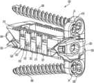
- FIG. 1is a perspective view of an implant in a collapsed position according to an example embodiment.
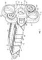
- FIG. 2is a front view of the implant of FIG. 1 in a collapsed position according to an example embodiment.
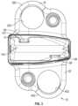
- FIG. 3is a rear view of the implant of FIG. 1 in a collapsed position according to an example embodiment.
- FIG. 4is a top view of the implant of FIG. 1 in a collapsed position according to an example embodiment.
- FIG. 5is a perspective view of the implant of FIG. 1 in an expanded position according to an example embodiment.
- FIG. 6is another perspective view of the implant of FIG. 1 in an expanded position according to an example embodiment.
- FIG. 7is another perspective view of the implant of FIG. 1 in an expanded position according to an example embodiment.
- FIG. 8is a front view of the implant of FIG. 1 in an expanded position according to an example embodiment.
- FIG. 9is a rear view of the implant of FIG. 1 in an expanded position according to an example embodiment.
- FIG. 10is a top view of the implant of FIG. 1 in an expanded position according to an example embodiment.
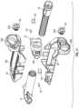
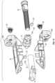
- FIG. 11is an exploded view of the implant of FIG. 1 according an example embodiment.
- FIG. 12is another exploded view of the implant of FIG. 1 according an example embodiment.
- FIG. 13is a perspective view of a front component of the implant of FIG. 1 according an example embodiment.
- FIG. 14is another perspective view of the front component of the implant of FIG. 1 according an example embodiment.
- FIG. 15is a perspective view of a rear component of the implant of FIG. 1 according an example embodiment.
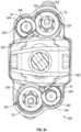
- FIG. 16is another perspective view of the rear component of the implant of FIG. 1 according an example embodiment.
- FIG. 17is another perspective view of the rear component of the implant of FIG. 1 according an example embodiment.
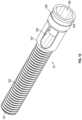
- FIG. 18is a perspective view of a control member of the implant of FIG. 1 according an example embodiment.
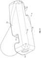
- FIG. 19is a perspective view of an upper support of the implant of FIG. 1 according an example embodiment.
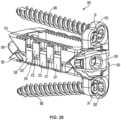
- FIG. 20is another perspective view of the upper support of the implant of FIG. 1 according an example embodiment.
- FIG. 21is a perspective view of a lower support of the implant of FIG. 1 according an example embodiment.
- FIG. 22is another perspective view of the lower support of the implant of FIG. 1 according an example embodiment.
- FIG. 23is a perspective view of the implant of FIG. 1 with a plurality of retention members according to another example embodiment.
- FIG. 24is a front view of the implant of FIG. 23 according to an example embodiment.
- FIG. 25is a perspective view of an implant according to another example embodiment.
- FIG. 26is a top view of the implant of FIG. 25 according to an example embodiment.
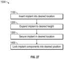
- FIG. 27is a flow chart for a method of installing an implant according to an example embodiment.
- the implantmay be an interbody (between adjacent vertebrae), intravertebral-body (inside the vertebrae) and/or spinal stabilization device that may or may not be used as an interbody fusion cage or device, interbody/intravertebral body stabilization device and/or the like (e.g., spinal device(s)) for providing support, stabilization and/or promoting bone growth between or inside vertebrae or other portions of bone that have been destabilized or otherwise due to injury, illness and/or the like.
- spinal device(s)for providing support, stabilization and/or promoting bone growth between or inside vertebrae or other portions of bone that have been destabilized or otherwise due to injury, illness and/or the like.
- the present disclosureprovides various versions of dynamic (expandable and/or expandable and retractable) interbody/intravertebral body devices that are usable in a spinal column or other areas of a human.
- the implantmay be implanted or inserted into a human spine adjacent upper and lower vertebrae of the spine.
- the components of the implants disclosed hereinmay be made of any suitable material(s), including a variety of metals, plastics, composites, or other suitable bio-compatible materials.
- one or more components of the implants disclosed hereinmay be made of the same material, while in other embodiments, different materials may be used for different components of the various implants.
- an expandable implant 10is shown according to an exemplary embodiment.
- the implant 10is usable, for example, between and/or within vertebral bodies of the spine. It should be understood that the implant 10 may in some embodiments be usable in other portions of the body in addition to the spine, and all such applications are to be understood to be within the scope of the present disclosure.
- the implant 10includes a first, or front component 12 (e.g., a first wedge member), a second, or rear component 14 (e.g., a second wedge member), and a third, intermediate, or control member 16 , which collectively form a control assembly that extends along a longitudinal axis of the implant 10 .
- a first, or upper support 18e.g., an upper plate, support member, assembly, etc.
- a second, or lower support 20e.g., a lower plate, support member, assembly
- the upper support 18may be identical to the lower support 20 , which may reduce manufacturing costs of the implant 10 .
- the upper and lower supports 18 , 20define a height of the implant 10 (e.g., a support height defined by the upper and lower grooved/toothed surfaces of the implant), wherein the height of the implant 10 is the vertical distance between an outer or top surface 48 of upper support 18 and outer or lower surface 76 of lower support 20 .
- the top surface 48 of the upper support 18is substantially parallel to the lower surface 76 of the lower support 20 .
- the height of the implant 10is substantially constant throughout the implant 10 .
- the top surface 48 of the upper support 18 and the lower surface 76 of the lower support 20are not parallel.
- the top surface 48 of the upper support 18 and the lower surface 76 of the lower support 20may form an angle, such that the height of the implant 10 is not consistent throughout, as will be discussed further herein.
- the front component 12includes a front portion 122 , a rear portion 123 opposite the front portion 122 , a first side portion 124 , and a second side portion 125 opposite the first side portion 124 .
- the front component 12also includes a first ramped surface 26 and a second ramped surface 27 proximate the first side portion 124 .
- the front component 12also includes a third ramped surface 28 and fourth ramped surface 29 proximate the second side portion 125 .
- the front component 12includes a first projection 30 proximate the first ramped surface 26 , a second projection 31 proximate the second ramped surface 27 , a third projection 32 proximate the third ramped surface 28 , and a fourth projection 33 proximate the fourth ramped surface 29 .
- the front portion 122 of the front component 12may have an angular profile as shown in FIG. 2 .
- the height of the front portion 122i.e., the distance between surface of the front portion 122 that engages the upper support 18 and the surface of the front portion 122 that engages the lower support 20
- the height of the front portion 122may be greater proximate the second side portion 125 (see FIG. 14 ) than the height of the front portion 122 proximate the first side portion 124 (see FIG. 13 ).
- first ramped surface 26 and the third ramped surface 28are angled in an upwards direction towards the top surface 48 of the upper support 18 .
- second ramped surface 27 and fourth ramped surface 29are angled in a downwards direction towards the lower surface 76 of the lower support 20 .
- the ramped surfaces 26 , 27 , 28 , 29 and the projections 30 , 31 , 32 , 33facilitate controlled sliding movement of the upper support 18 and the lower support 20 , as will be discussed further herein.
- the front component 12may include a control bore 34 configured to receive the control member 16 , such that the control bore 34 extends from the front portion 122 through the rear portion 123 .
- the control bore 34may be threaded. In other embodiments, such as the embodiment shown in FIGS. 13 and 14 , the control bore 34 may be unthreaded.
- the front component 12may include a first installation tool interface 35 proximate the first side portion 124 and a second installation tool interface 37 proximate the second side portion 125 . The first and second tool interface 35 , 37 may be utilized with an installation tool to assist a medical practitioner or other user in inserting the implant 10 into a patient, as will be discussed further herein.
- the front component 12may include a wedge slot 126 on the first side portion 124 and a wedge slot 126 on the second side portion 125 . As shown in FIGS. 12 and 13 , the wedge slots 126 may span from the first side portion 124 into the control bore 34 or from the second side portion 125 into the control bore 34 . The wedge slot 126 is configured to receive a portion of a retention wedge 127 (see FIG. 11 ).
- the rear component 14includes a rear nose 142 , a threaded bore 145 positioned opposite the rear nose 142 , a first side portion 143 , and a second side portion 144 opposite the first side portion 143 .
- the rear nose 142also includes an upper ramp 149 and a lower ramp 150 .
- the rear component 14includes a first guide groove 146 proximate the first side portion 143 and a second guide groove 147 proximate the second side portion 144 .
- the first guide groove 146is generally angled downwards towards the lower surface 76 of the lower support 20
- the second guide groove 147is generally angled upwards towards the top surface 48 of the upper support 18 .
- the first guide groove 146 and the second guide groove 147may facilitate controlled sliding movement of the upper support 18 and the lower support 20 , as will be discussed further herein.
- the rear nose 142 of the rear component 14may be generally wedge-shaped.
- the rear nose 142may also include a nose at either the first side portion 143 or second side portion 144 .
- the generally wedge-shaped rear nose 142 of the rear component 14also includes a nose proximate the first side portion 143 of the rear component 14 .
- having a nosesuch as the nose on the first proximate side 143 of the rear component 14 , may facilitate inserting the implant 10 into a patient, as will be discussed further herein.
- the rear component 14may have a through whole 148 extending from the first side portion 143 to the second side portion 144 .
- the control member 16includes a tip 161 at a first end and a head 164 at a second end, opposite the first end.
- the tip 161may be flat.
- the control member 16also includes a threaded shaft 162 extending from the tip 161 to a shoulder 167 .
- the control member 16may include a plurality of teeth or strips or other securing mechanisms that may be received by the rear component 14 , as will be discussed further herein.
- the control member 16also may include a through hole 168 that may facilitate implanting bone graft growth within the implant 10 .
- Through hole 168may be in communication with a tool port 166 to enable insertion of bone graft or other material into the interior of implant 10 via tool port 166 .
- through hole 168defines openings on opposing portions of control member 16 .
- the control member 16may also include a groove 169 near the head 164 .
- the groove 169may be configured to receive a portion of a retention wedge 127 in order to prevent back out of the control member 16 .
- the tool port 166is configured to receive a tool that may be used to manipulate the control member 16 .
- the tool port 166may be configured to receive a hex head driver. While this example embodiment shows the tool port 166 as being a hex head socket, it should be appreciated that the tool port 166 can be designed to receive several different types of hand tools, including a slotted screwdriver, a Phillips-head screwdriver, an Allen wrench screwdriver, a hexagonal drive, a torx drive, a Robertson drive, a tri-wing screwdriver, an Allen security driver, a torx security driver, a Pozidriv, a clutch drive, a spanner, a Schrader drive, a nut driver, a hex wrench, a node security driver, any combination of the listed driver interfaces, and any other type of driver interface.
- a slotted screwdrivera Phillips-head screwdriver
- an Allen wrench screwdrivera hexagonal drive
- a torx drive
- the upper support 18is shown according to an example embodiment.
- the upper support 18includes a top surface 48 , a front portion 49 , a rear portion 51 opposite the front portion 49 , a first side 50 , and a second side 52 opposite the first side 50 .
- the upper support 18further includes a plurality of ridges 54 on the top surface 48 .
- the series of ridges 54may create a surface roughness that provides additional stability of the implant 10 once installed.
- the upper support 18further includes a first ramp 55 , a second ramp 56 , a third ramp 57 , and a fourth ramp 58 .
- the first ramp 55 and the second ramp 56are proximate the front portion 49 , and are configured to engage the first ramped surface 26 and the third ramped surface 28 of the front component 12 .
- the first ramp 55will slide along the first ramped surface 26 of the front component 12 and the second ramp 56 will slide along the third ramped surface 28 of the front component 12 as the implant 10 expands from a first position to a second position.
- the upper support 18further includes a third ramp 57 and a fourth ramp 58 proximate the rear portion 51 of the upper support 18 .
- the third ramp 57 and the forth ramp 58are configured to engage the upper ramp 149 of the rear component 14 .
- the third ramp 57 and the fourth ramp 58will slide along the upper ramp 149 of the rear component 14 as the implant 10 expands from a first position to a second position.
- the upper support 18may further includes a guide rail 59 proximate the rear portion 51 .
- the guide rail 59is configured to be received by the second guide groove 147 of the rear component 14 .
- the guide rail 59will translate within the second guide groove 147 of the rear component as the implant 10 expands from a first position to a second position, as will be discussed further herein.
- the guide rail 59 and the guide groove 147may be dovetail shaped, as shown in FIG. 3 . The dovetail shape may help keep the various components of the implant from undesirably shifting relative to one another.
- the upper support 18may include a first side projection 61 , a first side slot 64 , and a second side slot 65 proximate the first side 50 .
- the upper support 18may also include a second side projection 62 , a third side projection 63 , and a third side slot 66 proximate the second side 52 .
- the upper support 18may include a pin aperture 68 proximate the second side 52 .
- the pin aperture 68may be configured to receive a pin 67 , as will be discussed further herein.
- the upper support 18further includes an upper mounting plate 300 proximate the front portion 49 .
- the upper mounting plate 300is integrated into the upper support 18 , such that the upper support 18 and upper mounting plate 300 are manufactured as one piece.
- the upper support 18 and upper mounting plate 300may be 3D printed as a single piece.
- the upper mounting plate 300may include an unthreaded bore 302 configured to receive a first portion of an anchoring member, such as a bone screw 22 (see FIG. 23 ), as will be discussed further herein.
- the upper mounting plate 300may include a threaded bore 304 configured to receive a retention member 24 (see FIG. 23 ), as will be discussed further herein.
- the lower support 20is shown according to an example embodiment.
- the lower support 20includes a lower surface 76 , a front portion 79 , a rear portion 81 opposite the front portion 79 , a first side 80 , and a second side 82 opposite the first side 80 .
- the lower support 20further includes a plurality of ridges 84 on the lower surface 76 .
- the series of ridges 84may create a surface roughness that provides additional stability of the implant 10 once installed.
- the lower support 20further includes a first ramp 85 , a second ramp 86 , a third ramp 87 , and a fourth ramp 88 .
- the first ramp 85 and the second ramp 86are proximate the front portion 79 , and are configured to engage the second ramped surface 27 and the fourth ramped surface 29 of the front component 12 .
- the first ramp 85will slide along the second ramped surface 27 and the second ramp 86 will slide along the fourth ramped surface 29 as the implant 10 expands from a first position to a second position, as will be discussed further herein.
- the lower support 20further includes a third ramp 87 and a fourth ramp 88 proximate the rear portion 81 of the lower support 20 .
- the third ramp 87 and the forth ramp 88are configured to engage the lower ramp 150 of the rear component 14 .
- the third ramp 87 and the fourth ramp 88will slide along the lower ramp 150 of the rear component 14 as the implant 10 expands from a first position to a second position, as will be discussed further herein.
- the lower support 20may further includes a guide rail 89 proximate the rear portion 51 .
- the guide rail 89is configured to be received by the first guide groove 146 of the rear component 14 .
- the guide rail 89will translate within the first guide groove 146 of the rear component 14 as the implant 10 expands from a first position to a second position, as will be discussed further herein.
- the lower support 20may include a first side projection 90 , a second side projection 91 , and a first side slot 93 proximate the first side 80 .
- the lower support 20may include a third side projection 92 , a second side slot 94 , and a third side slot 95 proximate the second side 82 .
- the lower support 20may include a pin aperture 97 configured to receive a pin 67 , as will be discussed further herein.
- the lower support 20further includes a lower mounting plate 400 proximate the front portion 79 .
- the lower mounting plate 400is integrated into the lower support 20 , such that the lower support 20 and lower mounting plate 400 are manufactured as one piece.
- the lower support 20 and lower mounting plate 400may be 3D printed as a single piece.
- the lower mounting plate 400may include an unthreaded bore 402 configured to receive an anchoring member, such as a bone screw 22 (see FIG. 23 ), as will be discussed further herein.
- the upper mounting plate 300may include a threaded bore 304 configured to receive a retention member 24 (see FIG. 23 ), as will be discussed further herein.
- the implant 10is shown with a plurality of anchoring members.
- the implant 10may contain at least one anchoring member used to secure the implant 10 inside a patient.
- the anchoring membermay be a bone screw 22 .
- the example embodiment shown in FIG. 23shows an implant 10 with two bone screws 22 used as anchoring members.
- each bone screw 22includes a linear, externally threaded shaft 222 , a head 224 at a first end, and a tip 226 at a second end opposite the first end.
- the tip 226is pointed.
- the diameter of the bone screw 22remains constant from the head 224 to the tip 226 .
- the head 224further includes a socket 228 that is configured to receive an installation tool. While this example embodiment has a torx drive socket 228 , it should be appreciated that the socket 158 can be designed to receive several different types of hand tools, including a slotted screwdriver, a Phillips-head screwdriver, an Allen wrench screwdriver, a hexagonal drive, a torx drive, a Robertson drive, a tri-wing screwdriver, an Allen security driver, a torx security driver, a Pozidriv, a clutch drive, a spanner, a Schrader drive, a nut driver, a hex wrench, a node security driver, any combination of the listed driver interfaces, and any other type of driver interface.
- a slotted screwdrivera Phillips-head screwdriver
- an Allen wrench screwdrivera hexagonal drive
- a torx drivea Robertson drive
- a tri-wing screwdriveran Allen security driver
- a torx security drivera
- a retention screw 24may be used to prevent a back out of the bone screw 22 .
- the retention screw 24may include a head 244 , a tool port 248 , and a threaded shaft 242 (see. FIG. 11 ).
- the threaded shaft 242may be screwed into either the threaded bore 304 of the upper mounting plate 300 and/or the threaded bore 404 of the lower mounting plate 400 , as shown in FIG. 24 .
- the head 244further includes a flat portion 240 and a rounded shoulder portion 249 .
- the retention screw 24when the flat portion 240 is proximate the head 244 of the bone screw 22 , the retention screw 24 is not in contact with the bone screw 22 . However, the retention screw 24 may be tightened into the threaded bore 304 of the upper mounting plate 300 and/or the threaded bore 404 of the lower mounting plate 400 , such that the rounded shoulder portion 249 is proximate to the bone screw 22 .
- the retention screw 24when the retention screw 24 is tightened into the threaded bore 304 of the upper mounting plate 300 or the threaded bore 404 of the lower mounting plate 400 , the underside of the rounded shoulder portion 249 is in contact with the head 224 of the bone screw 22 . In doing so, the retention screw 24 may be used to prevent back out of the bone screw 22 .
- the retention screw 24includes a tool port 248 configured to receive a hex head driver.
- the tool port 248can be designed to receive several different types of hand tools, including a slotted screwdriver, a Phillips-head screwdriver, an Allen wrench screwdriver, a hexagonal drive, a torx drive, a Robertson drive, a tri-wing screwdriver, an Allen security driver, a torx security driver, a Pozidriv, a clutch drive, a spanner, a Schrader drive, a nut driver, a hex wrench, a node security driver, any combination of the listed driver interfaces, and any other type of driver interface.
- an implant 500is shown according to an example embodiment.
- the implant 500is usable, for example, between and/or within vertebral bodies of the spine. It should be understood that the implant 500 may, in some embodiments, be usable in other portions of the body in addition to the spine, and all such applications are to be understood to be within the scope of the present disclosure.
- the implant 500includes a first, or front component 530 (e.g., a first wedge member), a second, or rear component 540 (e.g., a second wedge member), and a third, intermediate, or control member 550 , which collectively form a control assembly that extends along a longitudinal axis 582 of the implant 500 .
- a first, or upper support 510e.g., an upper plate, support member, assembly, etc.
- a second, or lower support 520e.g., a lower plate, support member, assembly
- the upper support 510may be identical to the lower support 520 , which may reduce manufacturing costs of the implant 500 .
- the control assemblycan be used to expand the implant 500 between at least a first, collapsed position and a second, expanded position, as shown in FIG. 25 .
- the control assemblyincluding the front component 530 , the rear component 540 , and the control member 540 , can be used to control the implant height (e.g., a support height defined by the upper and lower grooved/toothed surfaces of the implant), wherein the height of the implant 500 is the vertical distance between an outer or top surface of upper support 510 and outer or lower surface of lower support 520 .
- the control assemblyis configured to interface with the upper support 510 and the lower support 520 to control the height of the implant 500 in a similar manner as described above with respect to the implant 10 shown in FIGS. 1 - 10 .
- the upper supportincludes a first side projection 511 and a second side projection 512 on a first lateral side 518 of the upper support 510 .
- the upper support 510further includes a third side projection 513 , a fourth side projection 514 , and a fifth side projection 515 on a second lateral side 519 of the upper support 510 .
- the lower support 520includes a first side projection 521 , a second side projection 522 , and a third side projection 523 on a first lateral side 528 of the lower support 520 .
- the lower support 520further includes a fourth side projection 524 and a fifth side projection 525 on a second lateral side 529 of the lower support.
- the plurality of side projections 511 , 512 of the upper support 510slidably interface with the plurality of side projection 521 , 522 , 523 of the lower support 520 .
- the plurality of side projections 513 , 514 , 515 of the upper support 510slidably interface with the plurality of side projection 524 , 525 of the lower support 520 .
- the plurality of side projections 511 , 512 , 513 , 514 , 515 of the upper support 510 and the plurality of side projections 521 , 522 , 523 , 524 , 525 of the lower support 520may provide the implant 500 with additional mechanical stability by preventing the various components from shifting, including preventing lateral movement of the upper support 510 relative to the lower support 520 .
- the upper support 510may further include a mounting plate 516 configured to receive a retention member 24 and an anchoring member 560 , such as a bone screw.
- the lower support 520may also included a mounting plate 526 configured to receive a retention member 24 and an anchoring member 560 , such as a bone screw.
- the mounting plate 516 of the upper support 510 and the mounting plate 526 of the lower support 520may be angled, such that when the anchoring member 560 is inserted into the mounting plate 516 , 526 , a center-line trajectory 584 of the anchoring member 560 is not parallel with the longitudinal axis 582 of the implant 500 . For example, as shown in FIG.
- the center-line trajectory 584 and the longitudinal axis 582form a plate angle 580 .
- the plate angle 580may be 0 degrees.
- the plate angle 580may be around 20 to 30 degrees.
- the plate angle 580may be vary from 0 degrees to 90 degrees, depending on the application of implant 500 .
- the plate angle 580may vary based on the location an implant is being inserted into, and also based upon the insertion angle into the patient.
- the implant 500may be used in an Anterior to Psoas (ATP) Fusion surgery.
- ATPAnterior to Psoas
- FIG. 27a method of installing an implant 1000 is shown according to an example embodiment. If should be appreciated that the method shown is exemplary in nature, and should not be construed as limiting. Additional steps may be included in the method, and steps shown may be omitted and/or performed in any suitable order. While reference is made to specific implants, it should be appreciated that this method may apply to any suitable implant.
- Step 1100involves inserting an implant into a desired location.
- step 1100may involve inserting the implant 10 shown in FIG. 1 into a patient.
- step 1100involves inserting the implant 10 between two adjacent vertebrae in a patient's spinal column.
- the implant 10is inserted into a patient's spinal column through the lateral side of a patient.
- the implant 10may be used in a lateral lumbar interbody fusion (LLIF) surgery.
- LLIFlateral lumbar interbody fusion
- an incision in the lateral side of a patientmay be made, and the implant 10 may be inserted into the patient's spine.
- the rear nose 142 of the rear component 14may be inserted between two adjacent vertebrae in the patient's spinal column.
- a surgeon or other usermay use an installation tool to grip the installation tool interfaces 35 , 37 of the implant 10 , and the installation tool may then be used to insert the implant 10 into a desired location.
- the implant 10when the implant 10 is inserted, the implant 10 is in a first, collapsed position, as shown in FIGS. 1 - 4 .
- the control member 16when the implant 10 is in the first, collapsed position, the control member 16 is received by the control bore 34 of the front component 12 .
- the control member 16may be received by the control bore 34 prior to the implant 10 being inserted.
- the control member 16extends into a central cavity of the implant 10 , and the threaded shaft 162 of the control member 16 is received by the threaded bore 145 of the rear component 14 , as shown in FIG. 4 .
- the threaded shaft 162 of the control member 16 , and the threaded bore 145 of the rear component 14are threaded such that turning the control member 16 in a clockwise direction will cause the head 164 of the control member 16 to move in a direction towards the rear nose 142 of the rear component 14 .
- the threaded shaft 162 and threaded bore 145may be threaded such that turning the control member 16 in a counter-clockwise direction will cause the head 164 of the control member 16 to move in a direction towards the rear nose 142 of the rear component 14 .
- the rear component 14 and the control member 16may mechanically engage using other mechanisms, such as a zipper mechanism, a plurality of teeth on the shaft 162 and the bore 145 , etc. to allow an operator to manipulate the position of shaft 162 within the bore 145 .
- control member 16 and the rear component 14engage the upper support 18 and the lower support 20 in the first, collapsed position.
- the guide rail 59 of the upper support 18may be received by the second guide groove 147 of the rear component 14 .
- the guide rail 89 of the lower support 20may be received by the first guide groove 146 of the rear component 14 .
- the guide grooves 146 , 147may prevent the upper support 18 from expanding away from the lower support 20 when the implant 10 is in the first, collapsed position.
- the first ramped surface 26 and the first projection 30 of the front component 12may engage the first ramp 55 of the upper support 18 in the first, collapsed position.
- the third ramped surface 28 and the third projection 32 of the front component 12may engage the second ramp 56 of the upper support 18 in the first, collapsed position.
- the second ramped surface 27 and the second projection 31 of the front component 12may engage the first ramp 85 of the lower support 20 when the implant 10 is in the first, collapsed position.
- the fourth ramped surface 29 and the fourth projection 33may engage the second ramp 86 of the lower support 20 when the implant 10 is in the first, collapsed position.
- the projections 30 , 31 , 32 , 33may be dovetail shaped.
- the dovetail shapemay help keep the various components of the implant from undesirably shifting relative to one another.
- the upper support 18interfaces with the lower support 20 as shown in FIGS. 1 and 4 .
- the second side projection 62 of the upper support 18is positioned between the first side projection 90 and the second side projection 91 of the lower support 20 .
- the third side projection 92 of the lower support 20is positioned between the second side projection 62 and third side projection 63 of the upper support 18 in the first, collapsed position.
- Step 1200involves expanding an implant to a desired height.
- the implantmay be expanded.
- the implant 10may be expanded to a second, expanded position as shown in FIGS. 5 - 9 .
- a personmay expand the implant 10 from a first, collapsed position to a second, expanded position using the control member 16 .
- the personmay use an expansion tool that engages with the tool port 166 of the control member 16 .
- the expansion toolmay be a hex head screw driver. The person may then use the installation tool to turn the control member 16 , for example, in a clock-wise direction.
- the threaded shaft 162 of the control member 16 , and the threaded bore 145 of the rear component 14are threaded such that turning the control member 16 in a clockwise direction will cause the head 164 of the control member 16 to move in a direction towards the rear nose 142 of the rear component 14 .
- the threaded shaft 162will screw into the threaded bore 145 , until the threaded shaft 162 is completely within rear component 14 , as shown in FIG. 10 .
- other adjustment mechanismsmay be used (e.g., ratchet mechanisms, indents/detents, etc.).
- the control member 16may be manipulated (e.g., urged, turned, pushed, rotated, etc.) to control relative movement between the upper support 18 and the lower support 20 .
- the guide rail 59 of the upper support 18will slide within the second guide groove 147 of the rear component 14 .
- the guide rail 89 of the lower support 20will slide within the first guide groove 146 of the rear component 14 .
- the first ramp 55 of the upper support 18will slide along the first ramped surface 26 of the front component 12
- the second ramp 56will slide along the third ramped surface 28 of the front component 12 .
- the first ramp 85 of the lower support 20will slide along the second ramped surface 27 of the front component 12
- the second ramp 86 of the lower support 20will slide along the fourth ramped surface 29 of the front component 12 .
- the upper support 18 and the lower support 20will expand away from each other at least in part due to the ramped surfaces 26 , 27 , 28 , 29 on the front component 12 , the rear component 14 , the upper support 18 , and the lower support 20 .
- the expansion profile of an implantmay be customized in part by changing the angles of the various ramped surfaces.
- Using the implant in various locationsmay require a custom expansion profile.
- the implant expansion profilemay be customized to match the curvature of the patient's spine at the desired location that the implant is to be implanted into.
- the ramped surfaces 26 , 27 , 28 , 29 of the front component 12may have a much higher angle (i.e., the angle that upward angled surface and the downward angle surface form) than the ramped surfaces 26 , 27 , 28 , 29 of the rear component 14 .
- turning the control member 16will cause the implant 10 to expand more near the front component 12 than near the rear component 14 .
- the implant 10 heightwill be larger near the front component 12 than near the rear component 14 . It should be appreciated that further customization of the expansion profile of an implant 10 may be accomplished by adjusting the angle of ramped surfaces 26 , 27 , 28 , 29 on the front component 12 , the rear component 14 , the upper support 18 , and the lower support 20 .
- Step 1300involves securing the implant in a desired location within a patient.
- step 1300may involve securing the implant to the two adjacent vertebrae that the implant was inserted between.
- the implant 10as shown in FIG. 23 , may be secured to adjacent vertebrae using bone screws 22 .
- the implant 10may be inserted between two vertebrae, and expanded to a desired height.
- the top surface 48 of the upper support 18may engage the upper vertebrae and the lower surface 76 of the lower support 20 may engage the lower vertebrae.
- a first bone screw 22may be driven through the unthreaded bore 302 of the upper mounting plate 300 and into an adjacent vertebrae.
- a second bone screw 22may then be driven through the unthreaded bore 402 of the lower mounting plate 400 and into another adjacent vertebrae. It should be appreciated that the bone screws 22 may inserted into the unthreaded bore 402 of the lower mounting plate 400 , securing the implant 10 to the lower vertebrae before the first bone screw 22 is through the unthreaded bore 302 and into the upper vertebrae.
- step 1300may occur before, after, or in conjunction with step 1200 .
- the implant 10may be secured to two adjacent vertebrae while in a first, collapsed position, and then expanded to a desired height.
- the implant 10may be secured to one vertebrae while in a first, collapsed position, then expanded to a desired height, and then secured to a second vertebrae.
- the implant 10may be used without any anchoring members.
- Step 1400involves locking the implant components into a desired position.
- a plurality of retention wedges 127 and pins 67may be used to secure components in place.
- a first retention wedge 127 and a second retention wedge 127may be driven (e.g., pressure fit) into a first wedge slot 126 and a second wedge slot 126 on the front component 12 .
- the retention wedges 127are driven through the wedge slots 126 and into the groove 169 of the control member 16 . In doing so, the control member 16 will be prevented from backing out. Therefore, the retention wedges 127 will prevent the implant 10 from further expanding or collapsing.
- the implant 10may be locked into a desired position using retention pins 67 .
- a first retention pin 67may be driven (e.g., press fit) into the pin aperture 68 on the upper support 18 and a second retention pin 67 may be driven (e.g., press fit) into the pin aperture 96 of the lower support 20 .
- the retention pins 67may extend into the center cavity of the implant 10 , thereby preventing the front component 12 from moving closer to the rear component 14 , thereby preventing over expansion of the implant 10 .
- the retention pins 67may prevent the implant 10 from collapsing by preventing the lower support 20 and the upper support 18 from returning to the first, collapsed position.
- Step 1400may further include locking anchoring members into place.
- the bone screws 22 of the implant 10 shown in FIG. 24may be locked into place using the retention members 24 .
- a first retention member 24may be partially screwed into the threaded bore 304 of the upper mounting plate 300 and a second retention member 24 may be threaded into the threaded bore 404 of the lower mounting plate 400 .
- the first retention member 24may be screwed into the threaded bore 304 such that the flat portion 240 of the retention member 24 is proximate the unthreaded bore 302 .
- the second retention member 24may be screwed into the threaded bore 404 such that the flat portion 240 of the retention member 24 is proximate the unthreaded bore 402 .
- the bone screws 22may be inserted into the unthreaded bores 302 , 402 and driven into the adjacent vertebrae. Since the flat portion 240 of the retention members 24 is proximate the unthreaded bores 302 , 402 , the retention members 24 will not interfere with the bone screws 22 as the bone screws 22 are driven into the adjacent vertebrae.
- the retention members 24may be turned using a tool. For example, in the embodiment shown in FIG.
- the retention members 24may be turned using a hex head screw driver.
- the retention members 24may be turned such that the rounded should portion 249 is proximate the head 224 of the bone screw 22 . In doing so, the underside of the head 244 of the retention member 24 may be pressed up against the head 224 of the bone screw 22 , thereby preventing the bone screw 22 from backing out.
- the various embodiments disclosed hereinprovide expandable implants including a lower support and an upper support adjustably coupled to the lower support and movable between a first, collapsed position, and a second, expanded position. Further, a rear component and a control shaft rotatably received by the rear component is disclosed, where rotation of the control shaft causes relative movement of a front component relative to the rear component.
- the upper supportmoves in a linear fashion relative to the lower support. In other embodiments, the upper support may move in a non-linear fashion relative to the lower support.
- a single control member and control shaftare utilized. In other embodiments, multiple (e.g., 2) control members and control shafts are utilized.
- the multiple control channelsare parallel and straight. In other embodiments, the control channels are non-parallel and straight (e.g., angled toward each other). In further embodiments, the control channels are non-parallel and non-straight such that the adjustable member moves in a non-linear fashion relative to the base member.
- control shaftincludes a control thread corresponding to each control member.
- control shaftincludes a single control thread
- control shaftincludes multiple (e.g., first and second) control threads.
- the control threadsare like-threaded.
- the control threadshave different threads.
- a first control threadis opposite-handed from a second control thread.
- a first control threadhas a different pitch from a second control thread.
- a first control threadis different handed and has a different pitch from a second control thread.
- one or both of the lower support and the upper supportinclude projections/grooves to provide a gripping surface intended to facilitate gripping adjacent portions of bone.
- one or both of the lower support and the upper supportinclude one or more apertures and/or cavities configured to promote bone growth in and around the lower support and the upper support.
- the aperturesextend from a top, bottom, and/or side surface of the lower support and the upper support and to a central cavity of the implant.
- one or more bone screwsmay be included and positioned to extend through one or both of the lower support and the upper support and into adjacent portions of bone.
- multiple bone screwsare used.
- a first bone screwmay extend through the adjustable member and into a first portion of bone
- a second bone screwmay extend through the base member and into a second portion of bone.
- multiple bone screwsare accessible and manipulatable by way of the front face of the implant defined by one or both of the adjustable member and the base member.
- a head and tool port of the control shaftmay further be accessible by way of the front face of the implant.
- control shaft/control member(s)/control channel(s)any suitable configuration of the control shaft/control member(s)/control channel(s) may be utilized.
- an at least partially spherical control memberthreadingly engages a threaded control shaft and translates both along the control shaft and within the control channel.
- the control memberis non-spherical and is received at least partially on or in a control rail or control channel provided by the adjustable member, such that the control member translates along both the control shaft and the control channel or control rail.
- Coupledmeans the joining of two members directly or indirectly to one another. Such joining may be stationary (e.g., permanent) or moveable (e.g., removable or releasable). Such joining may be achieved with the two members or the two members and any additional intermediate members being integrally formed as a single unitary body with one another or with the two members or the two members and any additional intermediate members being attached to one another.
Landscapes
- Health & Medical Sciences (AREA)
- Engineering & Computer Science (AREA)
- Biomedical Technology (AREA)
- Neurology (AREA)
- Orthopedic Medicine & Surgery (AREA)
- Cardiology (AREA)
- Oral & Maxillofacial Surgery (AREA)
- Transplantation (AREA)
- Heart & Thoracic Surgery (AREA)
- Vascular Medicine (AREA)
- Life Sciences & Earth Sciences (AREA)
- Animal Behavior & Ethology (AREA)
- General Health & Medical Sciences (AREA)
- Public Health (AREA)
- Veterinary Medicine (AREA)
- Prostheses (AREA)
Abstract
Description
Claims (14)
Priority Applications (6)
| Application Number | Priority Date | Filing Date | Title |
|---|---|---|---|
| US16/847,187US11857432B2 (en) | 2020-04-13 | 2020-04-13 | Expandable implant assembly |
| PCT/US2021/026606WO2021211377A1 (en) | 2020-04-13 | 2021-04-09 | Expandable implant assembly |
| CN202180027292.6ACN115397368A (en) | 2020-04-13 | 2021-04-09 | Expandable implant assembly |
| EP21722081.3AEP4135629A1 (en) | 2020-04-13 | 2021-04-09 | Expandable implant assembly |
| KR1020227036933AKR20220167290A (en) | 2020-04-13 | 2021-04-09 | Expandable Implant Assembly |
| US18/400,214US20240130865A1 (en) | 2020-04-13 | 2023-12-29 | Expandable implant assembly |
Applications Claiming Priority (1)
| Application Number | Priority Date | Filing Date | Title |
|---|---|---|---|
| US16/847,187US11857432B2 (en) | 2020-04-13 | 2020-04-13 | Expandable implant assembly |
Related Child Applications (1)
| Application Number | Title | Priority Date | Filing Date |
|---|---|---|---|
| US18/400,214ContinuationUS20240130865A1 (en) | 2020-04-13 | 2023-12-29 | Expandable implant assembly |
Publications (2)
| Publication Number | Publication Date |
|---|---|
| US20210315707A1 US20210315707A1 (en) | 2021-10-14 |
| US11857432B2true US11857432B2 (en) | 2024-01-02 |
Family
ID=75690723
Family Applications (2)
| Application Number | Title | Priority Date | Filing Date |
|---|---|---|---|
| US16/847,187ActiveUS11857432B2 (en) | 2020-04-13 | 2020-04-13 | Expandable implant assembly |
| US18/400,214PendingUS20240130865A1 (en) | 2020-04-13 | 2023-12-29 | Expandable implant assembly |
Family Applications After (1)
| Application Number | Title | Priority Date | Filing Date |
|---|---|---|---|
| US18/400,214PendingUS20240130865A1 (en) | 2020-04-13 | 2023-12-29 | Expandable implant assembly |
Country Status (5)
| Country | Link |
|---|---|
| US (2) | US11857432B2 (en) |
| EP (1) | EP4135629A1 (en) |
| KR (1) | KR20220167290A (en) |
| CN (1) | CN115397368A (en) |
| WO (1) | WO2021211377A1 (en) |
Cited By (5)
| Publication number | Priority date | Publication date | Assignee | Title |
|---|---|---|---|---|
| US20220409392A1 (en)* | 2019-10-11 | 2022-12-29 | Endac Co., Ltd. | Variable vertebral cage |
| US20230181330A1 (en)* | 2020-04-16 | 2023-06-15 | Life Spine, Inc. | Expandable implant assembly |
| US20240024123A1 (en)* | 2019-10-07 | 2024-01-25 | L&K Biomed Co., Ltd. | Height-adjustable intervertebral fusion cage |
| US12336917B2 (en) | 2020-05-15 | 2025-06-24 | Life Spine, Inc. | Steerable implant assembly |
| US12427033B2 (en) | 2020-06-25 | 2025-09-30 | Life Spine, Inc. | Expandable implant assembly |
Families Citing this family (3)
| Publication number | Priority date | Publication date | Assignee | Title |
|---|---|---|---|---|
| KR102489197B1 (en)* | 2020-05-25 | 2023-01-17 | (주)엘앤케이바이오메드 | Expandable Spinal Fusuion Cage |
| US12268614B2 (en) | 2021-06-24 | 2025-04-08 | Warsaw Orthopedic, Inc. | Interbody implant with adjusting shims |
| US11850163B2 (en)* | 2022-02-01 | 2023-12-26 | Warsaw Orthopedic, Inc. | Interbody implant with adjusting shims |
Citations (386)
| Publication number | Priority date | Publication date | Assignee | Title |
|---|---|---|---|---|
| US904434A (en) | 1907-03-23 | 1908-11-17 | Packard Motor Car Co | Oil-pump. |
| GB284462A (en) | 1927-01-21 | 1928-02-02 | John Meredith Rubury | Improvements in and relating to universal joints and couplings |
| US1925385A (en) | 1932-11-08 | 1933-09-05 | Homer C Humes | Screw driver with screw holders |
| US3846846A (en) | 1972-09-28 | 1974-11-12 | Fischer Artur | Hip joint prosthesis |
| US4466426A (en) | 1981-06-29 | 1984-08-21 | Blackman Seymour N | Syringe with actinic ray blocking stripe |
| US4636217A (en) | 1985-04-23 | 1987-01-13 | Regents Of The University Of Minnesota | Anterior spinal implant |
| US4743256A (en) | 1985-10-04 | 1988-05-10 | Brantigan John W | Surgical prosthetic implant facilitating vertebral interbody fusion and method |
| US4863476A (en) | 1986-08-29 | 1989-09-05 | Shepperd John A N | Spinal implant |
| US5098435A (en) | 1990-11-21 | 1992-03-24 | Alphatec Manufacturing Inc. | Cannula |
| US5192327A (en) | 1991-03-22 | 1993-03-09 | Brantigan John W | Surgical prosthetic implant for vertebrae |
| US5236460A (en) | 1990-02-12 | 1993-08-17 | Midas Rex Pneumatic Tools, Inc. | Vertebral body prosthesis |
| DE9407806U1 (en) | 1994-05-11 | 1994-07-14 | Aesculap AG & Co. KG, 78532 Tuttlingen | Intervertebral implant |
| US5390683A (en) | 1991-02-22 | 1995-02-21 | Pisharodi; Madhavan | Spinal implantation methods utilizing a middle expandable implant |
| FR2717068A1 (en) | 1994-03-14 | 1995-09-15 | Biomat | Intersomatic cage insertable between two vertebral bodies |
| WO1995031158A1 (en) | 1994-05-11 | 1995-11-23 | Jean Taylor | Vertebral implant |
| US5522899A (en) | 1988-06-28 | 1996-06-04 | Sofamor Danek Properties, Inc. | Artificial spinal fusion implants |
| US5609635A (en) | 1988-06-28 | 1997-03-11 | Michelson; Gary K. | Lordotic interbody spinal fusion implants |
| FR2727003B1 (en) | 1994-11-18 | 1997-04-18 | Euros Sa | ANTERIOR STABILIZATION DEVICE OF THE LOMBO-SACRE SPINE |
| US5645599A (en) | 1994-07-26 | 1997-07-08 | Fixano | Interspinal vertebral implant |
| US5658335A (en) | 1995-03-09 | 1997-08-19 | Cohort Medical Products Group, Inc. | Spinal fixator |
| US5658337A (en) | 1994-05-23 | 1997-08-19 | Spine-Tech, Inc. | Intervertebral fusion implant |
| US5836948A (en) | 1997-01-02 | 1998-11-17 | Saint Francis Medical Technologies, Llc | Spine distraction implant and method |
| EP0880950A1 (en) | 1997-05-30 | 1998-12-02 | Biomat | Intervertebral cervical cage |
| US5860977A (en) | 1997-01-02 | 1999-01-19 | Saint Francis Medical Technologies, Llc | Spine distraction implant and method |
| WO1999026562A1 (en) | 1997-11-25 | 1999-06-03 | Jean Taylor | Vertebral implant adapted to be inserted from the rear in an intervertebral space |
| US6045579A (en) | 1997-05-01 | 2000-04-04 | Spinal Concepts, Inc. | Adjustable height fusion device |
| US6048342A (en) | 1997-01-02 | 2000-04-11 | St. Francis Medical Technologies, Inc. | Spine distraction implant |
| US6068630A (en) | 1997-01-02 | 2000-05-30 | St. Francis Medical Technologies, Inc. | Spine distraction implant |
| WO2000044319A1 (en) | 1999-01-27 | 2000-08-03 | Disc-O-Tech Medical Technologies, Ltd. | Expandable intervertebral spacer |
| US6113638A (en) | 1999-02-26 | 2000-09-05 | Williams; Lytton A. | Method and apparatus for intervertebral implant anchorage |
| US6126689A (en) | 1998-06-15 | 2000-10-03 | Expanding Concepts, L.L.C. | Collapsible and expandable interbody fusion device |
| US6129763A (en) | 1996-09-13 | 2000-10-10 | Chauvin; Jean-Luc | Expandable osteosynthesis cage |
| US6176882B1 (en) | 1998-02-20 | 2001-01-23 | Biedermann Motech Gmbh | Intervertebral implant |
| US6290724B1 (en) | 1998-05-27 | 2001-09-18 | Nuvasive, Inc. | Methods for separating and stabilizing adjacent vertebrae |
| US20020010472A1 (en) | 2000-06-30 | 2002-01-24 | Kuslich Stephen D. | Tool to direct bone replacement material |
| US20020029084A1 (en) | 1998-08-03 | 2002-03-07 | Paul David C. | Bone implants with central chambers |
| US6375682B1 (en) | 2001-08-06 | 2002-04-23 | Lewis W. Fleischmann | Collapsible, rotatable and expandable spinal hydraulic prosthetic device |
| WO2002044319A2 (en) | 2000-11-29 | 2002-06-06 | Picoliter Inc. | Spatially directed ejection of cells from a carrier fluid |
| US6443989B1 (en) | 2000-12-04 | 2002-09-03 | Roger P. Jackson | Posterior expandable fusion cage |
| US6443990B1 (en) | 1997-08-06 | 2002-09-03 | Synthes (U.S.A.) | Adjustable intervertebral implant |
| US20020128716A1 (en) | 1999-07-26 | 2002-09-12 | Howard Cohen | Spinal surgical prosthesis |
| US6451019B1 (en) | 1998-10-20 | 2002-09-17 | St. Francis Medical Technologies, Inc. | Supplemental spine fixation device and method |
| KR200290058Y1 (en) | 2002-05-11 | 2002-09-26 | 정연문 | Lumbar vertebra fixture |
| US20020143343A1 (en) | 2001-03-27 | 2002-10-03 | Surgical Dynamics, Inc. | Method and apparatus for spinal implant insertion |
| US20020143399A1 (en) | 2001-04-02 | 2002-10-03 | Ulrich Gmbh & Co. Kg | Anchorable vertebral implant |
| US20020147461A1 (en) | 2001-04-06 | 2002-10-10 | Aldrich William N. | Apparatus and methods for closing openings in spinal discs |
| US20020177897A1 (en) | 2001-02-04 | 2002-11-28 | Michelson Gary K. | Instrumentation and method for inserting and deploying and expandable interbody spinal fusion implant |
| US6491724B1 (en) | 1999-08-13 | 2002-12-10 | Bret Ferree | Spinal fusion cage with lordosis correction |
| US6494883B1 (en) | 2000-05-26 | 2002-12-17 | Bret A. Ferree | Bone reinforcers |
| US20030004576A1 (en) | 2001-06-28 | 2003-01-02 | Thalgott John S. | Modular anatomic fusion device |
| US20030040746A1 (en) | 2001-07-20 | 2003-02-27 | Mitchell Margaret E. | Spinal stabilization system and method |
| US20030040802A1 (en) | 2001-07-16 | 2003-02-27 | Errico Joseph P. | Artificial intervertebral disc having limited rotation using a captured ball and socket joint with a solid ball and compression locking post |
| US6537320B1 (en) | 1998-10-30 | 2003-03-25 | Gary K. Michelson | Self-broaching, rotatable, push-in interbody spinal fusion implant and method for deployment thereof |
| US6613091B1 (en) | 1995-03-27 | 2003-09-02 | Sdgi Holdings, Inc. | Spinal fusion implants and tools for insertion and revision |
| US20030176926A1 (en) | 2000-11-13 | 2003-09-18 | Boehm Frank H. | Device and method for lumbar interbody fusion |
| US6641614B1 (en) | 1997-05-01 | 2003-11-04 | Spinal Concepts, Inc. | Multi-variable-height fusion device |
| US6648917B2 (en) | 2001-10-17 | 2003-11-18 | Medicinelodge, Inc. | Adjustable bone fusion implant and method |
| DE20314708U1 (en) | 2003-09-16 | 2003-11-20 | Aesculap AG & Co. KG, 78532 Tuttlingen | spinal implant |
| US20030236520A1 (en) | 2002-06-25 | 2003-12-25 | Roy Lim | Minimally invasive expanding spacer and method |
| US6685742B1 (en) | 2002-11-12 | 2004-02-03 | Roger P. Jackson | Articulated anterior expandable spinal fusion cage system |
| US6695842B2 (en) | 1997-10-27 | 2004-02-24 | St. Francis Medical Technologies, Inc. | Interspinous process distraction system and method with positionable wing and method |
| US20040073213A1 (en) | 2002-10-09 | 2004-04-15 | Hassan Serhan | Device for distracting vertebrae and delivering a flowable material into a disc space |
| US6752832B2 (en) | 2000-12-27 | 2004-06-22 | Ulrich Gmbh & Co., Kg | Vertebral implant and setting tool therefor |
| WO2004052245A1 (en) | 2002-12-06 | 2004-06-24 | Synthes Ag Chur | Intervertebral implant |
| US6773460B2 (en) | 2000-12-05 | 2004-08-10 | Roger P. Jackson | Anterior variable expandable fusion cage |
| US6796983B1 (en) | 1997-01-02 | 2004-09-28 | St. Francis Medical Technologies, Inc. | Spine distraction implant and method |
| US20040204747A1 (en) | 2001-08-10 | 2004-10-14 | Lajos Kemeny | Phototherapeutical apparatus and method for the treatment and prevention of diseases of body cavities |
| US20040225292A1 (en) | 2003-05-05 | 2004-11-11 | Sasso Ricardo C. | Bone anchor and methods of using the same |
| US20040230309A1 (en) | 2003-02-14 | 2004-11-18 | Depuy Spine, Inc. | In-situ formed intervertebral fusion device and method |
| US6849093B2 (en) | 2001-03-09 | 2005-02-01 | Gary K. Michelson | Expansion constraining member adapted for use with an expandable interbody spinal fusion implant and method for use thereof |
| WO2005009299A1 (en) | 2003-07-25 | 2005-02-03 | Impliant Ltd. | Elastomeric spinal disc nucleus replacement |
| US20050033437A1 (en) | 2002-05-23 | 2005-02-10 | Pioneer Laboratories, Inc. | Artificial disc device |
| US20050070911A1 (en) | 2003-09-29 | 2005-03-31 | Scimed Life Systems, Inc. | Apparatus and methods for reducing compression bone fractures using high strength ribbed members |
| US20050107800A1 (en) | 2003-11-19 | 2005-05-19 | Frankel Bruce M. | Fenestrated bone tap and method |
| US20050119747A1 (en) | 2002-02-26 | 2005-06-02 | Sdgi Holdings, Inc. | Connectable interbody implant |
| US20050131536A1 (en) | 2003-12-11 | 2005-06-16 | Lukas Eisermann | Expandable intervertebral implant |
| US20050177236A1 (en) | 2002-02-19 | 2005-08-11 | Claude Mathieu | Intervertebral implant |
| US20050177235A1 (en) | 2004-02-10 | 2005-08-11 | Baynham Bret O. | Spinal fusion device |
| US20050222681A1 (en) | 2002-06-17 | 2005-10-06 | Richard Richley | Devices and methods for minimally invasive treatment of degenerated spinal discs |
| US20050228391A1 (en) | 2004-04-05 | 2005-10-13 | Levy Mark M | Expandable bone device |
| US20050261769A1 (en) | 2004-05-13 | 2005-11-24 | Moskowitz Nathan C | Artificial expansile total lumbar and thoracic discs for posterior placement without supplemental instrumentation and its adaptation for anterior placement of artificial cervical, thoracic and lumbar discs |
| US20050278036A1 (en) | 2004-06-09 | 2005-12-15 | Ceravic | Method for restoration of human or animal bone anatomy, and expansible prosthetic implant allowing implementation of this method |
| US20060030943A1 (en) | 2004-07-23 | 2006-02-09 | Marc Peterman | Expandable spinal implant having interlocking geometry for structural support |
| US20060036258A1 (en) | 2004-06-08 | 2006-02-16 | St. Francis Medical Technologies, Inc. | Sizing distractor and method for implanting an interspinous implant between adjacent spinous processes |
| US7001385B2 (en) | 1998-08-20 | 2006-02-21 | Bonutti Ip, Llc | Joint spacer with compartment for orthobiologic material |
| US20060084988A1 (en) | 2004-10-20 | 2006-04-20 | The Board Of Trustees Of The Leland Stanford Junior University | Systems and methods for posterior dynamic stabilization of the spine |
| US20060089718A1 (en) | 2003-05-22 | 2006-04-27 | St. Francis Medical Technologies, Inc. | Interspinous process implant and method of implantation |
| US20060089715A1 (en) | 2004-06-07 | 2006-04-27 | Csaba Truckai | Implants and methods for treating bone |
| US20060095136A1 (en) | 2004-11-03 | 2006-05-04 | Mcluen Design, Inc. | Bone fusion device |
| US7048736B2 (en) | 2002-05-17 | 2006-05-23 | Sdgi Holdings, Inc. | Device for fixation of spinous processes |
| US20060122701A1 (en) | 2004-11-23 | 2006-06-08 | Kiester P D | Posterior lumbar interbody fusion expandable cage with lordosis and method of deploying the same |
| US20060189999A1 (en) | 2005-02-24 | 2006-08-24 | Paul Zwirkoski | Linked slideable and interlockable rotatable components |
| US7101375B2 (en) | 1997-01-02 | 2006-09-05 | St. Francis Medical Technologies, Inc. | Spine distraction implant |
| WO2006102485A2 (en) | 2005-03-22 | 2006-09-28 | St. Francis Medical Technologies, Inc. | Interspinous process implant with slide-in distraction piece and method of implantation |
| WO2006105437A2 (en) | 2005-03-31 | 2006-10-05 | Life Spine, Inc. | Expandable spinal interbody and intravertebral body devices |
| US20060241601A1 (en) | 2005-04-08 | 2006-10-26 | Trautwein Frank T | Interspinous vertebral and lumbosacral stabilization devices and methods of use |
| US20060241621A1 (en) | 2005-04-12 | 2006-10-26 | Moskowitz Mosheh T | Bi-directional fixating transvertebral body screws, zero-profile horizontal intervertebral miniplates, expansile intervertebral body fusion devices, and posterior motion-calibrating interarticulating joint stapling device for spinal fusion |
| US20060264938A1 (en) | 2005-03-21 | 2006-11-23 | St. Francis Medical Technologies, Inc. | Interspinous process implant having deployable wing and method of implantation |
| US20060265077A1 (en) | 2005-02-23 | 2006-11-23 | Zwirkoski Paul A | Spinal repair |
| US20070072475A1 (en) | 2005-09-26 | 2007-03-29 | Justin Daniel F | Universal spinal disc implant system |
| US7214243B2 (en) | 2002-10-21 | 2007-05-08 | 3Hbfm, Llc | Intervertebral disk prosthesis |
| US7217291B2 (en) | 2003-12-08 | 2007-05-15 | St. Francis Medical Technologies, Inc. | System and method for replacing degenerated spinal disks |
| US7220280B2 (en) | 2002-10-16 | 2007-05-22 | Advanced Medical Technologies Ag | Spreader implant for placement between vertebrae |
| FR2894130A1 (en) | 2005-12-05 | 2007-06-08 | Spineart Sa Sa | CAGES OF CONTENTION AND INTERSOMATIC FUSION OF VERTEBRATES |
| US20070142915A1 (en) | 2004-10-20 | 2007-06-21 | Moti Altarac | Systems and methods for posterior dynamic stabilization of the spine |
| US7250055B1 (en) | 2003-08-26 | 2007-07-31 | Biomet Manufacturing Corp. | Method and apparatus for cement delivering buttress pin |
| US20070213739A1 (en) | 2001-03-01 | 2007-09-13 | Sdgi Holdings, Inc. | Method for using dynamic lordotic guard with movable extensions for creating an implantation space posteriorly in the lumbar spine |
| US20070244485A1 (en) | 2004-09-21 | 2007-10-18 | Greenhalgh E S | Expandable support device and method of use |
| US20070270968A1 (en) | 2004-02-10 | 2007-11-22 | Baynham Bret O | Plif opposing wedge ramp |
| US20080114456A1 (en) | 2006-11-15 | 2008-05-15 | Warsaw Orthopedic, Inc. | Spinal implant system |
| US20080114367A1 (en) | 2006-11-10 | 2008-05-15 | Syberspine Limited | Method and relaxable distracters for in-situ formation of intervertebral disc prosthesis |
| US20080114453A1 (en) | 2006-11-13 | 2008-05-15 | Warsaw Orthopedic, Inc. | Intervertebral prosthetic devices and surgical methods |
| US20080119853A1 (en) | 2006-11-21 | 2008-05-22 | Jeffrey Felt | Methods and apparatus for minimally invasive modular interbody fusion devices |
| US20080119945A1 (en) | 2005-03-24 | 2008-05-22 | Synthes (U.S.A.) | Device for the Cement Augmentation of Bone Implants |
| EP1925272A1 (en) | 2006-11-23 | 2008-05-28 | BIEDERMANN MOTECH GmbH | Expandable intervertebral implant |
| US20080140207A1 (en) | 2006-12-07 | 2008-06-12 | Interventional Spine, Inc. | Intervertebral implant |
| US20080140085A1 (en) | 2006-12-11 | 2008-06-12 | G&L Consulting, Llc | Steerable spine implant insertion device and method |
| US20080161818A1 (en) | 2005-02-08 | 2008-07-03 | Henning Kloss | Spinous Process Distractor |
| US20080177391A1 (en) | 2006-10-24 | 2008-07-24 | St. Francis Medical Technologies, Inc. | Systems and Methods for In Situ Assembly of an Interspinous Process Distraction Implant |
| US20080183211A1 (en) | 2007-01-11 | 2008-07-31 | Lanx, Llc | Spinous process implants and associated methods |
| US20080243251A1 (en) | 2007-03-30 | 2008-10-02 | Shawn Stad | Intervertebral Device Having Expandable Endplates |
| US20080288077A1 (en) | 2006-12-28 | 2008-11-20 | Spinal Kinetics, Inc. | Prosthetic Disc Assembly Having Natural Biomechanical Movement |
| US20080312741A1 (en) | 2007-04-10 | 2008-12-18 | David Lee | Adjustable spine distraction implant |
| US20090005872A1 (en) | 2007-06-26 | 2009-01-01 | Missoum Moumene | Intervertebral Motion Disc With Helical Shock Absorber |
| US7473276B2 (en) | 2002-12-17 | 2009-01-06 | Synthes (U.S.A.) | Intervertebral implant with joint parts mounted on roller bodies |
| US20090062833A1 (en) | 2007-08-27 | 2009-03-05 | Vermillion Technologies, Llc | Device and method for placement of interbody device |
| US20090062915A1 (en) | 2007-08-27 | 2009-03-05 | Andrew Kohm | Spinous-process implants and methods of using the same |
| US20090105832A1 (en) | 2007-06-08 | 2009-04-23 | Ldr Medical | Intersomatic cage, intervertebral prosthesis, anchoring device and implantation instruments |
| KR100905962B1 (en) | 2008-03-17 | 2009-07-06 | 조철민 | Intervertebral expansion cage device and mounting method |
| US20090192553A1 (en) | 2008-01-25 | 2009-07-30 | Depuy Spine, Inc. | Anti-backout mechanism |
| US20090198339A1 (en) | 2008-02-06 | 2009-08-06 | Nuvasive, Inc. | Systems and methods for spinal fusion |
| US20090198338A1 (en) | 2008-02-04 | 2009-08-06 | Phan Christopher U | Medical implants and methods |
| US20090222099A1 (en) | 2008-02-28 | 2009-09-03 | Warsaw Orthopedics, Inc. | Self Centering Nucleus Implant |
| WO2009124269A1 (en) | 2008-04-05 | 2009-10-08 | Synthes Usa, Llc | Expandable intervertebral implant |
| US7621950B1 (en) | 1999-01-27 | 2009-11-24 | Kyphon Sarl | Expandable intervertebral spacer |
| US20100082109A1 (en) | 2008-09-22 | 2010-04-01 | Stout Medical Group, L.P. | Expandable intervertebral implant |
| US7695513B2 (en) | 2003-05-22 | 2010-04-13 | Kyphon Sarl | Distractible interspinous process implant and method of implantation |
| US20100103344A1 (en) | 2008-10-23 | 2010-04-29 | Boe Technology Group Co., Ltd | Edge-lighting led backlight and lcd thereof |
| US7722674B1 (en) | 2005-08-12 | 2010-05-25 | Innvotec Surgical Inc. | Linearly expanding spine cage for enhanced spinal fusion |
| US20100179655A1 (en) | 2009-01-12 | 2010-07-15 | Noah Hansell | Expandable Vertebral Prosthesis |
| US20100191336A1 (en) | 2008-11-12 | 2010-07-29 | Stout Medical Group. L.P. | Fixation device and method |
| US20100204795A1 (en) | 2008-11-12 | 2010-08-12 | Stout Medical Group, L.P. | Fixation device and method |
| US20100211176A1 (en) | 2008-11-12 | 2010-08-19 | Stout Medical Group, L.P. | Fixation device and method |
| US20100234889A1 (en) | 2009-03-13 | 2010-09-16 | Harold Hess | Interspinous Process Implant and Fusion Cage Spacer |
| US20100241167A1 (en) | 2007-01-11 | 2010-09-23 | Lanx, Inc. | Spinous process implants and associated methods |
| US20100249937A1 (en) | 2009-03-27 | 2010-09-30 | Spinal Elements, Inc. | Flanged interbody fusion device |
| USD626233S1 (en) | 2008-02-28 | 2010-10-26 | Stryker Spine | Expandable intervertebral implant |
| US7824427B2 (en) | 2007-01-16 | 2010-11-02 | Perez-Cruet Miquelangelo J | Minimally invasive interbody device |
| US7828849B2 (en) | 2003-02-03 | 2010-11-09 | Warsaw Orthopedic, Inc. | Expanding interbody implant and articulating inserter and method |
| US20100286777A1 (en) | 2009-05-08 | 2010-11-11 | Stryker Spine | Stand alone anterior cage |
| US7846188B2 (en) | 2005-04-12 | 2010-12-07 | Moskowitz Nathan C | Bi-directional fixating transvertebral body screws, zero-profile horizontal intervertebral miniplates, total intervertebral body fusion devices, and posterior motion-calibrating interarticulating joint stapling device for spinal fusion |
| US7854766B2 (en) | 2004-05-13 | 2010-12-21 | Moskowitz Nathan C | Artificial total lumbar disc for unilateral safe and simple posterior placement in the lumbar spine, and removable bifunctional screw which drives vertical sliding expansile plate expansion, and interplate widening, and angled traction spikes |
| WO2010148112A1 (en) | 2009-06-16 | 2010-12-23 | Stout Medical Group, L.P. | Expandable support device and method of use |
| US7867277B1 (en) | 2005-07-15 | 2011-01-11 | Nuvasive Inc. | Spinal fusion implant and related methods |
| US20110022090A1 (en) | 2009-06-23 | 2011-01-27 | Osteomed, L.P. | Spinous process fusion implants |
| US7879098B1 (en) | 2005-10-19 | 2011-02-01 | Simmons Jr James W | Expandable lordosis stabilizing cage |
| US20110046682A1 (en) | 2009-07-06 | 2011-02-24 | Synthes Gmbh Or Synthes Usa, Llc | Expandable fixation assemblies |
| US20110054538A1 (en) | 2008-03-14 | 2011-03-03 | Eli Zehavi | Segmented insert for intervertebral support |
| US20110066186A1 (en) | 2009-09-11 | 2011-03-17 | Boyer Ii Michael Lee | Spinous Process Fusion Devices |
| US20110071635A1 (en) | 2009-09-23 | 2011-03-24 | Zimmer Spine, Inc. | Composite implant |
| US20110077738A1 (en) | 2009-09-28 | 2011-03-31 | Lfc Sp. Z.O.O. | Device for surgical displacement of vertebrae |
| US7942903B2 (en) | 2005-04-12 | 2011-05-17 | Moskowitz Ahmnon D | Bi-directional fixating transvertebral body screws and posterior cervical and lumbar interarticulating joint calibrated stapling devices for spinal fusion |
| US7959675B2 (en) | 2005-04-08 | 2011-06-14 | G&L Consulting, Llc | Spine implant insertion device and method |
| US20110144753A1 (en) | 2009-12-10 | 2011-06-16 | Connie Marchek | Bellows-Like Expandable Interbody Fusion Cage |
| US20110144692A1 (en) | 2008-08-13 | 2011-06-16 | Synthes Usa, Llc | Interspinous spacer assembly |
| US20110144755A1 (en) | 2004-02-10 | 2011-06-16 | Baynham Bret O | PLIF opposing wedge ramp |
| US7972363B2 (en) | 2005-04-12 | 2011-07-05 | Moskowitz Ahmnon D | Bi-directional fixating/locking transvertebral body screw/intervertebral cage stand-alone constructs and posterior cervical and lumbar interarticulating joint stapling guns and devices for spinal fusion |
| US20110172774A1 (en) | 2010-01-11 | 2011-07-14 | Armando Varela | Expandable intervertebral implant and associated surgical method |
| US20110172709A1 (en) | 2010-01-13 | 2011-07-14 | Kyphon Sarl | Dynamic interspinous process device |
| US20110172716A1 (en) | 2010-01-12 | 2011-07-14 | Chad Glerum | Expandable Spacer and Method For Use Thereof |
| US20110178599A1 (en) | 2009-09-17 | 2011-07-21 | Brett Darrell C | Intervertebral implant having extendable bone fixation members |
| US20110184468A1 (en) | 2010-01-28 | 2011-07-28 | Warsaw Orthopedic, Inc., An Indiana Corporation | Spinous process fusion plate with osteointegration insert |
| US20110190817A1 (en) | 2009-11-06 | 2011-08-04 | Synthes Usa, Llc | Minimally invasive interspinous process spacer implants and methods |
| US20110196494A1 (en) | 2009-12-04 | 2011-08-11 | Osteo Innovations Llc | Percutaneous interbody spine fusion devices, nuclear support device, spine fracture support device, delivery tools, percutaneous off-angle bone stapling/nailing fixation device and methods of use |
| US8016861B2 (en) | 2008-02-26 | 2011-09-13 | Spartek Medical, Inc. | Versatile polyaxial connector assembly and method for dynamic stabilization of the spine |
| US20110224731A1 (en) | 2010-03-12 | 2011-09-15 | Southern Spine, Llc | Interspinous Process Spacing Device |
| US20110282453A1 (en) | 2010-05-13 | 2011-11-17 | Stout Medical Group, L.P. | Fixation device and method |
| US8062375B2 (en) | 2009-10-15 | 2011-11-22 | Globus Medical, Inc. | Expandable fusion device and method of installation thereof |
| US8070817B2 (en) | 2006-06-28 | 2011-12-06 | M.O.R.E. Medical Solutions Gmbh | Vertebral implant |
| US8071007B1 (en) | 2000-09-20 | 2011-12-06 | Osteopore International Pte. Ltd. | Three-dimensional bioresorbable scaffolds for tissue engineering applications |
| US20110301711A1 (en) | 2010-06-02 | 2011-12-08 | Warsaw Orthopedic, Inc. | System and methods for a laterally expanding implant |
| US20110319997A1 (en) | 2010-06-25 | 2011-12-29 | Chad Glerum | Expandable Fusion Device and Method of Installation Thereof |
| US20120010717A1 (en) | 2008-12-26 | 2012-01-12 | Scott Spann | Spinal implant for use during retroperitoneal lateral insertion procedures |
| US20120016418A1 (en) | 2010-07-15 | 2012-01-19 | Spinefrontier Inc | Interspinous fixation implant |
| US20120022652A1 (en) | 2010-06-18 | 2012-01-26 | Roger Berger | Spine disc replacement with compliant articulating core |
| US20120046748A1 (en) | 2010-02-24 | 2012-02-23 | Mark Weiman | Expandable Intervertebral Spacer and Method of Posterior Insertion Thereof |
| US20120059474A1 (en) | 2010-09-03 | 2012-03-08 | Mark Weiman | Expandable Fusion Device and Method of Installation Thereof |
| US20120059472A1 (en) | 2010-09-03 | 2012-03-08 | Mark Weiman | Expandable Fusion Device and Method of Installation Thereof |
| US20120071978A1 (en) | 2010-06-29 | 2012-03-22 | Jann-Paul Suedkamp | Distractible intervertebral implant |
| CN102427769A (en) | 2009-03-12 | 2012-04-25 | 维克辛姆公司 | Apparatus for bone restoration of the spine and methods of use |
| US20120109203A1 (en) | 2010-11-01 | 2012-05-03 | Warsaw Orthopedic, Inc. | Spinous process implant with extended post |
| US20120185049A1 (en) | 2010-01-11 | 2012-07-19 | Innova Spinal Technologies, Llc | Expandable intervertebral implant and associated surgical method |
| US8241364B2 (en) | 2009-04-02 | 2012-08-14 | Globus Medical, Inc. | Method of installation of intervertebral spacers |
| US8252060B2 (en) | 2009-04-02 | 2012-08-28 | Globus Medical Inc. | Method of installation of intervertebral spacers |
| US20120221051A1 (en) | 2010-12-05 | 2012-08-30 | Robinson James C | Spinous process fixation apparatus |
| US8257370B2 (en) | 2005-04-12 | 2012-09-04 | Moskowitz Ahmnon D | Posterior cervical and lumbar interarticulating joint staples, stapling guns, and devices for spinal fusion |
| US20120226357A1 (en) | 2010-01-11 | 2012-09-06 | Innova Spinal Technologies, Llc | Expandable intervertebral implant and associated surgical method |
| WO2012121726A1 (en) | 2011-03-10 | 2012-09-13 | Synthes USA, LLC. | Awl screw fixation members and related systems |
| US8303663B2 (en) | 2009-07-22 | 2012-11-06 | Spinex Tec, Llc | Methods and apparatuses for vertebral body distraction and fusion employing a coaxial screw gear sleeve mechanism |
| US8308804B2 (en) | 2008-11-14 | 2012-11-13 | David Krueger | Spinal fusion device |
| US20120330422A1 (en) | 2010-09-03 | 2012-12-27 | Mark Weiman | Expandable Fusion Device and Method of Installation Thereof |
| US8343190B1 (en) | 2008-03-26 | 2013-01-01 | Nuvasive, Inc. | Systems and methods for spinous process fixation |
| US20130023994A1 (en) | 2009-10-15 | 2013-01-24 | Chad Glerum | Expandable Fusion Device and Method of Installation Thereof |
| US20130023993A1 (en) | 2010-09-03 | 2013-01-24 | Mark Weiman | Expandable Fusion Device and Method of Installation Thereof |
| US8382801B2 (en) | 2007-01-11 | 2013-02-26 | Lanx, Inc. | Spinous process implants, instruments, and methods |
| US8382842B2 (en) | 2009-05-14 | 2013-02-26 | Stout Medical Group, L.P. | Expandable support device and method of use |
| US8388686B2 (en) | 2002-12-17 | 2013-03-05 | Max Aebi | Intervertebral implant with tiltable joint parts |
| US8394129B2 (en) | 2011-03-10 | 2013-03-12 | Interventional Spine, Inc. | Method and apparatus for minimally invasive insertion of intervertebral implants |
| US8398713B2 (en) | 2010-09-03 | 2013-03-19 | Globus Medical, Inc. | Expandable fusion device and method of installation thereof |
| US20130085572A1 (en) | 2011-09-30 | 2013-04-04 | Chad Glerum | Expandable Fusion Device and Method of Installation Thereof |
| US8425607B2 (en) | 2007-04-03 | 2013-04-23 | Warsaw Orthopedic, Inc. | Anchor member locking features |
| US20130103156A1 (en) | 2011-10-19 | 2013-04-25 | Evan PACKER | Laterally expandable spinal prosthesis |
| US20130116793A1 (en) | 2010-07-23 | 2013-05-09 | Privelop-Spine Ag | Surgical implant |
| US8454706B2 (en) | 2009-02-25 | 2013-06-04 | Brian C. de Beaubien | Antibiotic delivery system and method for treating an infected synovial joint during re-implantation of an orthopedic prosthesis |
| US20130144391A1 (en) | 2010-07-15 | 2013-06-06 | Nlt Spine Ltd | Surgical systems and methods for implanting deflectable implants |
| US20130158668A1 (en) | 2011-12-14 | 2013-06-20 | Biospine, Llc | Unilateral moveable interbody fusion device and method of use |
| US20130158663A1 (en) | 2011-12-19 | 2013-06-20 | Warsaw Orthopedic, Inc | Expandable interbody implant and methods of use |
| US20130158669A1 (en) | 2012-02-13 | 2013-06-20 | Arno Sungarian | Expandable Self-Anchoring Interbody Cage for Orthopedic Applications |
| US20130158664A1 (en) | 2011-12-19 | 2013-06-20 | Warsaw Orthopedic, Inc. | Expandable interbody implant and methods of use |
| US20130197647A1 (en) | 2005-03-31 | 2013-08-01 | Life Spine, Inc. | Expandable spinal interbody and intravertebral body devices |
| US8506629B2 (en) | 2005-01-28 | 2013-08-13 | Advanced Medical Technologies Ag | Implant for transforaminal interbody fusion |
| US20130211526A1 (en) | 2011-08-16 | 2013-08-15 | Stryker Spine | Expandable implant |
| US8518120B2 (en) | 2009-10-15 | 2013-08-27 | Globus Medical, Inc. | Expandable fusion device and method of installation thereof |
| US8529628B2 (en) | 2009-06-17 | 2013-09-10 | Trinity Orthopedics, Llc | Expanding intervertebral device and methods of use |
| US8551173B2 (en) | 2008-01-17 | 2013-10-08 | DePuy Synthes Products, LLC | Expandable intervertebral implant and associated method of manufacturing the same |
| US8556979B2 (en) | 2009-10-15 | 2013-10-15 | Globus Medical, Inc. | Expandable fusion device and method of installation thereof |
| US8597360B2 (en) | 2004-11-03 | 2013-12-03 | Neuropro Technologies, Inc. | Bone fusion device |
| US8632595B2 (en) | 2010-09-03 | 2014-01-21 | Globus Medical, Inc. | Expandable fusion device and method of installation thereof |
| US8641766B2 (en) | 2009-04-15 | 2014-02-04 | DePuy Synthes Products, LLC | Arcuate fixation member |
| US8641764B2 (en) | 2006-10-11 | 2014-02-04 | G&L Consulting, Llc | Spine implant insertion device and method |
| US8663332B1 (en) | 2012-12-13 | 2014-03-04 | Ouroboros Medical, Inc. | Bone graft distribution system |
| US20140067071A1 (en) | 2010-09-03 | 2014-03-06 | Mark Weiman | Expandable Fusion Device and Method of Installation Thereof |
| US8690883B2 (en) | 2004-06-29 | 2014-04-08 | Spine Wave, Inc. | Articulating injection cannula and seal assembly |
| US20140148904A1 (en) | 2012-08-08 | 2014-05-29 | James C. Robinson | Expandable intervertebral cage assemblies and methods |
| US20140163683A1 (en) | 2012-12-11 | 2014-06-12 | Jody L. Seifert | Expandable Vertebral Implant |
| US20140188224A1 (en) | 2012-12-14 | 2014-07-03 | Facet-Link Inc. | Laterally expandable intervertebral fusion implant |
| US20140236296A1 (en) | 2013-02-20 | 2014-08-21 | Erik Wagner | Expandable fusion device for positioning between adjacent vertebral bodies |
| US8821506B2 (en) | 2006-05-11 | 2014-09-02 | Michael David Mitchell | Bone screw |
| US20140249629A1 (en) | 2005-04-12 | 2014-09-04 | Ahmnon D. Moskowitz | Zero-profile expandable intervertebral spacer devices for distraction and spinal fusion and a universal tool for their placement and expansion |
| WO2014134590A1 (en) | 2013-03-01 | 2014-09-04 | Globus Medical, Inc. | Articulating expandable intervertebral implant |
| EP2777633A2 (en) | 2013-03-15 | 2014-09-17 | Expanding Orthopedics, Inc. | Expandable orthopedic devices |
| US20140277461A1 (en) | 2013-03-15 | 2014-09-18 | Smed-Ta/Td, Llc | Porous tissue ingrowth structure |
| US20140277473A1 (en) | 2013-03-15 | 2014-09-18 | Pioneer Surgical Technology, Inc. | Systems and methods for inserting an expandable intervertebral device |
| US20140277500A1 (en) | 2013-03-15 | 2014-09-18 | Neuropro Technologies, INC | Bodiless bone fusion device, apparatus and method |
| US20140288653A1 (en) | 2013-03-20 | 2014-09-25 | Kuei Jung CHEN | Textured implant device having series extendible blades |
| US8845731B2 (en) | 2010-09-03 | 2014-09-30 | Globus Medical, Inc. | Expandable fusion device and method of installation thereof |
| US8845728B1 (en) | 2011-09-23 | 2014-09-30 | Samy Abdou | Spinal fixation devices and methods of use |
| US8845734B2 (en) | 2010-09-03 | 2014-09-30 | Globus Medical, Inc. | Expandable fusion device and method of installation thereof |
| WO2014165319A1 (en) | 2013-04-03 | 2014-10-09 | Globus Medical, Inc. | Expandable fusion device and method of installation thereof |
| US20140343678A1 (en) | 2013-05-20 | 2014-11-20 | K2M, Inc. | Adjustable Implant and Insertion Tool |
| US8906095B2 (en) | 2011-03-11 | 2014-12-09 | FBC Device ApS | Spinal implant, instrument for preparation and method of use |
| US20150012097A1 (en) | 2013-07-03 | 2015-01-08 | Spinefrontier Inc | System amd method for an expandable intervertebral implant |
| WO2015009793A1 (en) | 2013-07-17 | 2015-01-22 | Spinal Usa, Inc. | Modular intervertebral cage system |
| US8940052B2 (en) | 2012-07-26 | 2015-01-27 | DePuy Synthes Products, LLC | Expandable implant |
| US20150066145A1 (en) | 2013-08-29 | 2015-03-05 | Andrew Rogers | Expandable and adjustable lordosis interbody fusion system |
| US8974505B2 (en) | 2008-06-16 | 2015-03-10 | Anna G. U. Sawa | Venting/pressure adjustment to aid in delivery of material into an anatomic region via a cannula |
| US20150100130A1 (en) | 2013-10-08 | 2015-04-09 | Pioneer Surgical Technology, Inc. | Expandable intervertebral device, and systems and methods for inserting same |
| US20150100128A1 (en) | 2009-10-15 | 2015-04-09 | Globus Medical, Inc. | Expandable Fusion Device and Method of Installation Thereof |
| US20150112438A1 (en) | 2013-10-18 | 2015-04-23 | Spine Wave, Inc. | Method of expanding an intradiscal space and providing an osteoconductive path during expansion |
| WO2015063721A1 (en) | 2013-10-31 | 2015-05-07 | Nlt Spine Ltd. | Adjustable implant |
| US9034045B2 (en) | 2013-03-15 | 2015-05-19 | Globus Medical, Inc | Expandable intervertebral implant |
| US9044284B2 (en) | 2010-09-29 | 2015-06-02 | Spinal Generations, Llc | Intervertebral insert system |
| WO2015085111A1 (en) | 2013-12-05 | 2015-06-11 | Spinal Elements, Inc | Expandable interbody device |
| US9060876B1 (en) | 2015-01-20 | 2015-06-23 | Ouroboros Medical, Inc. | Stabilized intervertebral scaffolding systems |
| US20150173917A1 (en) | 2013-12-19 | 2015-06-25 | Amendia, Inc. | Expandable spinal implant |
| US9101487B2 (en) | 2012-08-27 | 2015-08-11 | Globus Medical, Inc. | Intevertebral implant |
| US9149367B2 (en) | 2013-03-15 | 2015-10-06 | Globus Medical Inc | Expandable intervertebral implant |
| US9186258B2 (en) | 2013-03-15 | 2015-11-17 | Globus Medical, Inc. | Expandable intervertebral implant |
| US9198772B2 (en) | 2013-03-01 | 2015-12-01 | Globus Medical, Inc. | Articulating expandable intervertebral implant |
| US9204922B2 (en) | 2010-12-01 | 2015-12-08 | Enable Urology, Llc | Method and apparatus for remodeling/profiling a tissue lumen, particularly in the urethral lumen in the prostate gland |
| US20150351928A1 (en) | 2007-03-29 | 2015-12-10 | Life Spine, Inc. | Radially expandable spinal interbody device and implantation tool |
| US9216095B2 (en) | 2009-10-15 | 2015-12-22 | Globus Medical, Inc. | Expandable fusion device and method of installation thereof |
| US9216098B2 (en) | 2006-08-10 | 2015-12-22 | Pioneer Surgical Technology, Inc. | Intervertebral disc space sizing tools and methods |
| US20150374507A1 (en) | 2005-03-31 | 2015-12-31 | Life Spine, Inc. | Expandable spinal interbody and intravertebral body devices |
| US9233009B2 (en) | 2013-03-15 | 2016-01-12 | Globus Medical, Inc. | Expandable intervertebral implant |
| US9278008B2 (en) | 2012-05-30 | 2016-03-08 | Globus Medical, Inc. | Expandable interbody spacer |
| US20160089247A1 (en) | 2013-05-13 | 2016-03-31 | Biomet Spine, Llc | Adjustable interbody fusion devices |
| WO2016051095A1 (en) | 2014-09-30 | 2016-04-07 | Yellowsteps | Interbody fusion cage with adjustable cover, and related manufacture method |
| US20160120660A1 (en) | 2014-11-04 | 2016-05-05 | Warsaw Orthopedic, Inc. | Expandable interbody implant |
| WO2016077610A1 (en) | 2014-11-12 | 2016-05-19 | Grotz Robert Thomas | Universally expanding cage |
| US9358123B2 (en) | 2011-08-09 | 2016-06-07 | Neuropro Spinal Jaxx, Inc. | Bone fusion device, apparatus and method |
| EP3031424A1 (en) | 2014-12-11 | 2016-06-15 | K2M, Inc. | Expandable spinal implants |
| US9402739B2 (en) | 2014-02-07 | 2016-08-02 | Globus Medical, Inc. | Variable lordosis spacer and related methods of use |
| US9402738B2 (en) | 2013-02-14 | 2016-08-02 | Globus Medical, Inc. | Devices and methods for correcting vertebral misalignment |
| WO2016127139A1 (en) | 2015-02-05 | 2016-08-11 | Spectrum Spine Ip Holdings, Llc | Expandable, adjustable inter-body fusion devices and methods |
| US9421111B2 (en) | 2013-03-15 | 2016-08-23 | Atlas Spine, Inc. | PLIF hinged spacer |
| US20160242927A1 (en) | 2012-12-11 | 2016-08-25 | Globus Medical, Inc. | Expandable vertebral implant |
| US9456906B2 (en) | 2013-03-15 | 2016-10-04 | Globus Medical, Inc. | Expandable intervertebral implant |
| US9474622B2 (en) | 2013-03-15 | 2016-10-25 | Globus Medical, Inc | Expandable intervertebral implant |
| US9492286B2 (en) | 2011-06-14 | 2016-11-15 | Biedermann Technologies Gmbh & Co. Kg | Intervertebral implant |
| US9517144B2 (en) | 2014-04-24 | 2016-12-13 | Exactech, Inc. | Limited profile intervertebral implant with incorporated fastening mechanism |
| US20160361177A1 (en) | 2015-06-10 | 2016-12-15 | Lutz Biedermann | Intervertebral implant and system of an intervertebral implant and an instrument for inserting the intervertebral implant |
| US20160367377A1 (en) | 2015-06-17 | 2016-12-22 | Globus Medical, Inc. | Variable lordotic interbody spacer |
| US9532821B2 (en) | 2005-04-12 | 2017-01-03 | Nathan C. Moskowitz | Bi-directional fixating/locking transvertebral body screw/intervertebral cage stand-alone constructs with vertical hemi-bracket screw locking mechanism |
| US9532883B2 (en) | 2012-04-13 | 2017-01-03 | Neuropro Technologies, Inc. | Bone fusion device |
| US9539103B2 (en) | 2013-03-15 | 2017-01-10 | Globus Medical, Inc. | Expandable intervertebral implant |
| CN205866898U (en) | 2016-05-27 | 2017-01-11 | 瞿玉兴 | Lumbar vertebrae interbody fusion cage can strut |
| US20170014244A1 (en) | 2015-07-17 | 2017-01-19 | Globus Medical, Inc. | Intervertebral spacer and plate |
| US9554918B2 (en) | 2013-03-01 | 2017-01-31 | Globus Medical, Inc. | Articulating expandable intervertebral implant |
| WO2017027277A1 (en) | 2015-08-12 | 2017-02-16 | Warsaw Orthopedic, Inc. | Expandable spinal implant and method of implanting same |
| WO2017027873A1 (en) | 2015-08-13 | 2017-02-16 | K2M, Inc. | Adjustable spinal implant |
| US9572677B2 (en) | 2013-03-15 | 2017-02-21 | Globus Medical, Inc. | Expandable intervertebral implant |
| US9579124B2 (en) | 2003-08-05 | 2017-02-28 | Flexuspine, Inc. | Expandable articulating intervertebral implant with limited articulation |
| US20170056197A1 (en) | 2015-09-02 | 2017-03-02 | Globus Medical, Inc. | Expandable intervertebral fusion devices and methods of installation thereof |
| US9585765B2 (en) | 2013-02-14 | 2017-03-07 | Globus Medical, Inc | Devices and methods for correcting vertebral misalignment |
| US9597200B2 (en) | 2010-06-25 | 2017-03-21 | Globus Medical, Inc | Expandable fusion device and method of installation thereof |
| US9610174B2 (en) | 2013-11-29 | 2017-04-04 | Metal Industries Research & Development Centre | Intervertebral implant |
| US9622879B2 (en) | 2011-10-21 | 2017-04-18 | Ebi, Llc | Curved spacer and inserter |
| WO2017066463A1 (en) | 2015-10-16 | 2017-04-20 | Warsaw Orthopedic, Inc. | Expandable spinal implant system and method |
| US9662224B2 (en) | 2014-02-07 | 2017-05-30 | Globus Medical, Inc. | Variable lordosis spacer and related methods of use |
| WO2017106614A1 (en) | 2015-12-16 | 2017-06-22 | Globus Medical, Inc. | Expandable intervertebral spacer |
| US20170216036A1 (en) | 2014-10-16 | 2017-08-03 | Additive Innovations, Llc | Additive manufactured titanium bone device |
| US20170224505A1 (en) | 2013-03-13 | 2017-08-10 | Life Spine, Inc. | Expandable spinal interbody assembly |
| US20170224504A1 (en)* | 2013-03-13 | 2017-08-10 | Life Spine, Inc. | Expandable spinal interbody assembly |
| US20170246006A1 (en) | 2016-02-26 | 2017-08-31 | K2M, Inc. | Insertion instrument for expandable spinal implants |
| US9770343B2 (en) | 2013-03-01 | 2017-09-26 | Globus Medical Inc. | Articulating expandable intervertebral implant |
| US9782265B2 (en) | 2013-02-15 | 2017-10-10 | Globus Medical, Inc | Articulating and expandable vertebral implant |
| US9814601B2 (en) | 2005-04-12 | 2017-11-14 | Nathan C. Moskowitz | Bi-directional fixating/locking transvertebral body screw/intervertebral cage stand-alone constructs |
| EP3245982A1 (en) | 2016-05-20 | 2017-11-22 | Howmedica Osteonics Corp. | Expandable interbody implant with lordosis correction |
| US20170333198A1 (en) | 2014-10-28 | 2017-11-23 | Spectrum Spine Ip Holdings, Llc | Expandable, adjustable inter-body fusion devices and methods |
| US20170333200A1 (en) | 2016-05-19 | 2017-11-23 | Apifix Ltd. | Adjustable spinal cage |
| US9839528B2 (en) | 2014-02-07 | 2017-12-12 | Globus Medical, Inc. | Variable lordosis spacer and related methods of use |
| US20170367842A1 (en) | 2013-03-13 | 2017-12-28 | Life Spine, Inc. | Expandable implant assembly |
| US9855151B2 (en) | 2010-09-03 | 2018-01-02 | Globus Medical, Inc | Expandable fusion device and method of installation thereof |
| US20180014947A1 (en) | 2014-06-03 | 2018-01-18 | Atlas Spine, Inc. | Spinal Implant Device |
| US20180042732A1 (en)* | 2015-07-17 | 2018-02-15 | Globus Medical, Inc. | Intervertebral spacer and plate |
| US9907673B2 (en) | 2010-09-03 | 2018-03-06 | Globus Medical, Inc. | Expandable fusion device and method of installation thereof |
| WO2018049227A1 (en) | 2016-09-08 | 2018-03-15 | Mayo Foundation For Medical Education And Research | Spinal fixation system |
| US9931226B2 (en) | 2014-11-11 | 2018-04-03 | Globus Medical, Inc. | Spinal implants and instruments |
| US9962272B1 (en)* | 2017-06-28 | 2018-05-08 | Amendia, Inc. | Intervertebral implant device with lordotic expansion |
| US9980822B2 (en) | 2012-05-30 | 2018-05-29 | Globus Medical, Inc. | Expandable interbody spacer |
| US9987143B2 (en) | 2013-03-15 | 2018-06-05 | Spectrum Spine Ip Holdings, Llc | Expandable inter-body fusion devices and methods |
| US10004607B2 (en) | 2013-03-01 | 2018-06-26 | Globus Medical, Inc. | Articulating expandable intervertebral implant |
| US20180185163A1 (en) | 2010-09-03 | 2018-07-05 | Globus Medical, Inc. | Expandable fusion device and method of installation thereof |
| US10028740B2 (en) | 2005-04-12 | 2018-07-24 | Moskowitz Family Llc | Spinal fusion implant with curvilinear nail-screws |
| US20180243107A1 (en) | 2017-02-24 | 2018-08-30 | Warsaw Orthopedic, Inc | Expanding interbody implant and articulating inserter and methods of use |
| US10076423B2 (en) | 2016-01-04 | 2018-09-18 | Warsaw Orthopedic, Inc. | Pivoting wedge expanding spinal implant and method of implanting same |
| US10085849B2 (en) | 2010-09-03 | 2018-10-02 | Globus Medical, Inc. | Expandable fusion device and method of installation thereof |
| US10098758B2 (en) | 2009-10-15 | 2018-10-16 | Globus Medical, Inc. | Expandable fusion device and method of installation thereof |
| US10105239B2 (en) | 2013-02-14 | 2018-10-23 | Globus Medical, Inc. | Devices and methods for correcting vertebral misalignment |
| US20180303621A1 (en) | 2015-05-12 | 2018-10-25 | Nuvasive, Inc. | Expandable Lordosis Intervertebral Implants |
| US10111760B2 (en) | 2017-01-18 | 2018-10-30 | Neuropro Technologies, Inc. | Bone fusion system, device and method including a measuring mechanism |
| WO2018200530A1 (en) | 2017-04-25 | 2018-11-01 | Life Spine, Inc. | Expandable spinal interbody assembly |
| WO2018200507A1 (en) | 2017-04-25 | 2018-11-01 | Life Spine, Inc. | Expandable spinal interbody assembly |
| US10117754B2 (en) | 2013-02-25 | 2018-11-06 | Globus Medical, Inc. | Expandable intervertebral implant |
| US20180318101A1 (en) | 2017-05-08 | 2018-11-08 | Medos International Sarl | Expandable cage |
| US10137007B2 (en) | 2016-05-05 | 2018-11-27 | Warsaw Orthopedic, Inc. | Geared cam expandable interbody implant and method of implanting same |
| US20180360616A1 (en) | 2017-06-14 | 2018-12-20 | DePuy Synthes Products, Inc. | Expandable Intervertebral Implant and Related Methods |
| US10159583B2 (en) | 2012-04-13 | 2018-12-25 | Neuropro Technologies, Inc. | Bone fusion device |
| WO2019014139A1 (en) | 2017-07-10 | 2019-01-17 | Life Spine, Inc. | Expandable implant assembly |
| US20190021871A1 (en) | 2014-06-03 | 2019-01-24 | Atlas Spine, Inc. | Spinal implant device |
| US10213321B2 (en) | 2017-01-18 | 2019-02-26 | Neuropro Technologies, Inc. | Bone fusion system, device and method including delivery apparatus |
| EP3479799A1 (en) | 2017-11-07 | 2019-05-08 | Globus Medical, Inc. | Expandable fusion device |
| US20190133779A1 (en)* | 2017-11-09 | 2019-05-09 | Globus Medical, Inc. | Expandable intervertebral implant |
| US20190133784A1 (en) | 2017-09-29 | 2019-05-09 | Mirus Llc | Expandable Interbody Devices |
| US10292830B2 (en) | 2011-08-09 | 2019-05-21 | Neuropro Technologies, Inc. | Bone fusion device, system and method |
| WO2019126213A1 (en) | 2017-12-18 | 2019-06-27 | Nuvasive, Inc. | Expandable implant device |
| US20190254836A1 (en) | 2018-02-22 | 2019-08-22 | Warsaw Orthopedic, Inc. | Expandable spinal implant system and method of using same |
| US20190254838A1 (en) | 2018-02-22 | 2019-08-22 | Warsaw Orthopedic, Inc. | Expandable spinal implant system and method of using same |
| US10420654B2 (en) | 2011-08-09 | 2019-09-24 | Neuropro Technologies, Inc. | Bone fusion device, system and method |
| US20190298524A1 (en) | 2018-03-31 | 2019-10-03 | Life Spine, Inc. | Expandable Wedge Implant for Osteotomies of the Extremities |
| US20190307577A1 (en) | 2017-07-10 | 2019-10-10 | Life Spine, Inc. | Expandable implant assembly |
| US20190328540A1 (en) | 2015-07-17 | 2019-10-31 | Globus Medical, Inc. | Intervertebral spacer and plate |
| US10470894B2 (en) | 2017-04-06 | 2019-11-12 | Warsaw Orthopedic, Inc. | Expanding interbody implant and articulating inserter and methods of use |
| WO2019241687A1 (en) | 2018-06-15 | 2019-12-19 | Life Spine, Inc. | Expandable spinal interbody assembly |
| US10512550B2 (en) | 2010-09-03 | 2019-12-24 | Globus Medical, Inc. | Expandable interspinous process fixation device |
| US20190388232A1 (en) | 2018-06-20 | 2019-12-26 | Astura Medical Inc. | Expandable cage |
| US10531895B2 (en) | 2013-11-14 | 2020-01-14 | Globus Medical, Inc. | Endoscopic fusion system and method with neuromonitoring |
| US20200054461A1 (en) | 2018-05-25 | 2020-02-20 | Mirus Llc | Multiple expansion stage interbody devices |
| US20200129307A1 (en) | 2018-10-25 | 2020-04-30 | Medos International Sarl | Expandable intervertebral implant, inserter instrument, and related methods |
| US10709571B2 (en) | 2009-10-15 | 2020-07-14 | Globus Medical, Inc. | Expandable vertebral implant |
| US10709569B2 (en) | 2017-11-09 | 2020-07-14 | Globus Medical, Inc. | Expandable intervertebral implant |
| US10709573B2 (en) | 2010-09-03 | 2020-07-14 | Globus Medical Inc. | Expandable fusion device and method of installation thereof |
| US10729560B2 (en) | 2017-01-18 | 2020-08-04 | Neuropro Technologies, Inc. | Bone fusion system, device and method including an insertion instrument |
| US10779957B2 (en) | 2010-09-03 | 2020-09-22 | Globus Medical, Inc. | Expandable fusion device and method of installation thereof |
| US10835387B2 (en) | 2010-09-03 | 2020-11-17 | Globus Medical Inc. | Expandable fusion device and method of installation thereof |
| US10842644B2 (en) | 2010-09-03 | 2020-11-24 | Globus Medical, Inc. | Expandable fusion device and method of installation thereof |
| US10869768B2 (en) | 2010-09-03 | 2020-12-22 | Globus Medical Inc. | Expandable fusion device and method of installation thereof |
| US20210015627A1 (en) | 2019-07-18 | 2021-01-21 | Globus Medical, Inc. | Expanding intervertebral implants |
| US20210045892A1 (en) | 2019-08-15 | 2021-02-18 | Spineex, Inc. | Dual-axis adjustable spinal systems and interbody fusion devices with fixation |
| US20210045891A1 (en) | 2019-08-15 | 2021-02-18 | Spineex, Inc. | Translating dual axis adjustable interbody fusion spinal system |
| US20210137699A1 (en) | 2019-11-08 | 2021-05-13 | Industrial Technology Research Institute | Spinal intervertebral body fusion device |
| US11065128B2 (en) | 2014-09-03 | 2021-07-20 | Globus Medical, Inc. | Intervertebral implants and related methods of use |
| US20210322181A1 (en) | 2020-04-16 | 2021-10-21 | Life Spine, Inc. | Expandable implant assembly |
| US20220304823A1 (en) | 2021-03-26 | 2022-09-29 | Medos International Sarl | Expandable lordotic intervertebral fusion cage |
| US20220387184A1 (en) | 2020-11-05 | 2022-12-08 | Warsaw Orthopedic, Inc. | Dual expandable inter-body device |
- 2020
- 2020-04-13USUS16/847,187patent/US11857432B2/enactiveActive
- 2021
- 2021-04-09KRKR1020227036933Apatent/KR20220167290A/enactivePending
- 2021-04-09EPEP21722081.3Apatent/EP4135629A1/enactivePending
- 2021-04-09CNCN202180027292.6Apatent/CN115397368A/enactivePending
- 2021-04-09WOPCT/US2021/026606patent/WO2021211377A1/ennot_activeCeased
- 2023
- 2023-12-29USUS18/400,214patent/US20240130865A1/enactivePending
Patent Citations (582)
| Publication number | Priority date | Publication date | Assignee | Title |
|---|---|---|---|---|
| US904434A (en) | 1907-03-23 | 1908-11-17 | Packard Motor Car Co | Oil-pump. |
| GB284462A (en) | 1927-01-21 | 1928-02-02 | John Meredith Rubury | Improvements in and relating to universal joints and couplings |
| US1925385A (en) | 1932-11-08 | 1933-09-05 | Homer C Humes | Screw driver with screw holders |
| US3846846A (en) | 1972-09-28 | 1974-11-12 | Fischer Artur | Hip joint prosthesis |
| US4466426A (en) | 1981-06-29 | 1984-08-21 | Blackman Seymour N | Syringe with actinic ray blocking stripe |
| US4636217A (en) | 1985-04-23 | 1987-01-13 | Regents Of The University Of Minnesota | Anterior spinal implant |
| US4743256A (en) | 1985-10-04 | 1988-05-10 | Brantigan John W | Surgical prosthetic implant facilitating vertebral interbody fusion and method |
| US4863476A (en) | 1986-08-29 | 1989-09-05 | Shepperd John A N | Spinal implant |
| US5776199A (en) | 1988-06-28 | 1998-07-07 | Sofamor Danek Properties | Artificial spinal fusion implants |
| US5522899A (en) | 1988-06-28 | 1996-06-04 | Sofamor Danek Properties, Inc. | Artificial spinal fusion implants |
| US5609635A (en) | 1988-06-28 | 1997-03-11 | Michelson; Gary K. | Lordotic interbody spinal fusion implants |
| US5236460A (en) | 1990-02-12 | 1993-08-17 | Midas Rex Pneumatic Tools, Inc. | Vertebral body prosthesis |
| US5098435A (en) | 1990-11-21 | 1992-03-24 | Alphatec Manufacturing Inc. | Cannula |
| US5390683A (en) | 1991-02-22 | 1995-02-21 | Pisharodi; Madhavan | Spinal implantation methods utilizing a middle expandable implant |
| US5192327A (en) | 1991-03-22 | 1993-03-09 | Brantigan John W | Surgical prosthetic implant for vertebrae |
| FR2717068A1 (en) | 1994-03-14 | 1995-09-15 | Biomat | Intersomatic cage insertable between two vertebral bodies |
| DE9407806U1 (en) | 1994-05-11 | 1994-07-14 | Aesculap AG & Co. KG, 78532 Tuttlingen | Intervertebral implant |
| WO1995031158A1 (en) | 1994-05-11 | 1995-11-23 | Jean Taylor | Vertebral implant |
| US5658337A (en) | 1994-05-23 | 1997-08-19 | Spine-Tech, Inc. | Intervertebral fusion implant |
| US5645599A (en) | 1994-07-26 | 1997-07-08 | Fixano | Interspinal vertebral implant |
| FR2727003B1 (en) | 1994-11-18 | 1997-04-18 | Euros Sa | ANTERIOR STABILIZATION DEVICE OF THE LOMBO-SACRE SPINE |
| US5658335A (en) | 1995-03-09 | 1997-08-19 | Cohort Medical Products Group, Inc. | Spinal fixator |
| US6613091B1 (en) | 1995-03-27 | 2003-09-02 | Sdgi Holdings, Inc. | Spinal fusion implants and tools for insertion and revision |
| US6447544B1 (en) | 1995-06-07 | 2002-09-10 | Gary Karlin Michelson | Lordotic interbody spinal fusion implants |
| US8858638B2 (en) | 1995-06-07 | 2014-10-14 | Warsaw Orthopedic, Inc. | Spinal implant |
| US7503933B2 (en) | 1995-06-07 | 2009-03-17 | Warsaw Orthopedic, Inc. | Lordotic interbody spinal fusion implants |
| US6302914B1 (en) | 1995-06-07 | 2001-10-16 | Gary Karlin Michelson | Lordotic interbody spinal fusion implants |
| US8444696B2 (en) | 1995-06-07 | 2013-05-21 | Warsaw Orthopedic, Inc. | Anatomic spinal implant having anatomic bearing surfaces |
| US7789914B2 (en) | 1995-06-07 | 2010-09-07 | Warsaw Orthopedic, Inc. | Implant having arcuate upper and lower bearing surfaces along a longitudinal axis |
| US8021430B2 (en) | 1995-06-07 | 2011-09-20 | Warsaw Orthopedic, Inc. | Anatomic spinal implant having anatomic bearing surfaces |
| US6129763A (en) | 1996-09-13 | 2000-10-10 | Chauvin; Jean-Luc | Expandable osteosynthesis cage |
| US5836948A (en) | 1997-01-02 | 1998-11-17 | Saint Francis Medical Technologies, Llc | Spine distraction implant and method |
| US6699247B2 (en) | 1997-01-02 | 2004-03-02 | St. Francis Medical Technologies, Inc. | Spine distraction implant |
| US6699246B2 (en) | 1997-01-02 | 2004-03-02 | St. Francis Medical Technologies, Inc. | Spine distraction implant |
| US6074390A (en) | 1997-01-02 | 2000-06-13 | St. Francis Medical Technologies, Inc. | Spine distraction implant and method |
| US6068630A (en) | 1997-01-02 | 2000-05-30 | St. Francis Medical Technologies, Inc. | Spine distraction implant |
| US6048342A (en) | 1997-01-02 | 2000-04-11 | St. Francis Medical Technologies, Inc. | Spine distraction implant |
| US6183471B1 (en) | 1997-01-02 | 2001-02-06 | St. Francis Medical Technologies, Inc. | Spine distraction implant and method |
| US6190387B1 (en) | 1997-01-02 | 2001-02-20 | St. Francis Medical Technologies, Inc. | Spine distraction implant |
| US6235030B1 (en) | 1997-01-02 | 2001-05-22 | St. Francis Medical Technologies, Inc. | Spine distraction implant |
| US6796983B1 (en) | 1997-01-02 | 2004-09-28 | St. Francis Medical Technologies, Inc. | Spine distraction implant and method |
| US5876404A (en) | 1997-01-02 | 1999-03-02 | St. Francis Medical Technologies, Llc | Spine distraction implant and method |
| US7101375B2 (en) | 1997-01-02 | 2006-09-05 | St. Francis Medical Technologies, Inc. | Spine distraction implant |
| US5860977A (en) | 1997-01-02 | 1999-01-19 | Saint Francis Medical Technologies, Llc | Spine distraction implant and method |
| US6576016B1 (en) | 1997-05-01 | 2003-06-10 | Spinal Concepts, Inc. | Adjustable height fusion device |
| US6045579A (en) | 1997-05-01 | 2000-04-04 | Spinal Concepts, Inc. | Adjustable height fusion device |
| US6706070B1 (en) | 1997-05-01 | 2004-03-16 | Spinal Concepts, Inc. | Multi-variable-height fusion device |
| US6641614B1 (en) | 1997-05-01 | 2003-11-04 | Spinal Concepts, Inc. | Multi-variable-height fusion device |
| US6080193A (en) | 1997-05-01 | 2000-06-27 | Spinal Concepts, Inc. | Adjustable height fusion device |
| EP0880950A1 (en) | 1997-05-30 | 1998-12-02 | Biomat | Intervertebral cervical cage |
| US6443990B1 (en) | 1997-08-06 | 2002-09-03 | Synthes (U.S.A.) | Adjustable intervertebral implant |
| US6695842B2 (en) | 1997-10-27 | 2004-02-24 | St. Francis Medical Technologies, Inc. | Interspinous process distraction system and method with positionable wing and method |
| WO1999026562A1 (en) | 1997-11-25 | 1999-06-03 | Jean Taylor | Vertebral implant adapted to be inserted from the rear in an intervertebral space |
| US6176882B1 (en) | 1998-02-20 | 2001-01-23 | Biedermann Motech Gmbh | Intervertebral implant |
| US6290724B1 (en) | 1998-05-27 | 2001-09-18 | Nuvasive, Inc. | Methods for separating and stabilizing adjacent vertebrae |
| US6126689A (en) | 1998-06-15 | 2000-10-03 | Expanding Concepts, L.L.C. | Collapsible and expandable interbody fusion device |
| US6409766B1 (en) | 1998-07-30 | 2002-06-25 | Expanding Concepts, Llc | Collapsible and expandable interbody fusion device |
| US20020029084A1 (en) | 1998-08-03 | 2002-03-07 | Paul David C. | Bone implants with central chambers |
| US7001385B2 (en) | 1998-08-20 | 2006-02-21 | Bonutti Ip, Llc | Joint spacer with compartment for orthobiologic material |
| US6451019B1 (en) | 1998-10-20 | 2002-09-17 | St. Francis Medical Technologies, Inc. | Supplemental spine fixation device and method |
| US6537320B1 (en) | 1998-10-30 | 2003-03-25 | Gary K. Michelson | Self-broaching, rotatable, push-in interbody spinal fusion implant and method for deployment thereof |
| US20050143827A1 (en) | 1999-01-27 | 2005-06-30 | Disco-O-Tech Medical Technologies Ltd. | Expandable intervertebral spacer |
| US20040167625A1 (en) | 1999-01-27 | 2004-08-26 | Disc-O-Tech Orthopedic Technologies Inc. | Spacer filler |
| US7621950B1 (en) | 1999-01-27 | 2009-11-24 | Kyphon Sarl | Expandable intervertebral spacer |
| WO2000044319A1 (en) | 1999-01-27 | 2000-08-03 | Disc-O-Tech Medical Technologies, Ltd. | Expandable intervertebral spacer |
| US6800092B1 (en) | 1999-02-26 | 2004-10-05 | Lytton A. Williams | Method and apparatus for intervertebral implant anchorage |
| US20050027362A1 (en) | 1999-02-26 | 2005-02-03 | Williams Lytton A. | Method and apparatus for intervertebral implant anchorage |
| US6113638A (en) | 1999-02-26 | 2000-09-05 | Williams; Lytton A. | Method and apparatus for intervertebral implant anchorage |
| US20020128716A1 (en) | 1999-07-26 | 2002-09-12 | Howard Cohen | Spinal surgical prosthesis |
| US20040153156A1 (en) | 1999-07-26 | 2004-08-05 | Howard Cohen | Artificial disc spinal surgical prosthesis |
| US6491724B1 (en) | 1999-08-13 | 2002-12-10 | Bret Ferree | Spinal fusion cage with lordosis correction |
| US6494883B1 (en) | 2000-05-26 | 2002-12-17 | Bret A. Ferree | Bone reinforcers |
| US20020010472A1 (en) | 2000-06-30 | 2002-01-24 | Kuslich Stephen D. | Tool to direct bone replacement material |
| US8071007B1 (en) | 2000-09-20 | 2011-12-06 | Osteopore International Pte. Ltd. | Three-dimensional bioresorbable scaffolds for tissue engineering applications |
| US20030176926A1 (en) | 2000-11-13 | 2003-09-18 | Boehm Frank H. | Device and method for lumbar interbody fusion |
| WO2002044319A2 (en) | 2000-11-29 | 2002-06-06 | Picoliter Inc. | Spatially directed ejection of cells from a carrier fluid |
| US6443989B1 (en) | 2000-12-04 | 2002-09-03 | Roger P. Jackson | Posterior expandable fusion cage |
| US6773460B2 (en) | 2000-12-05 | 2004-08-10 | Roger P. Jackson | Anterior variable expandable fusion cage |
| US6752832B2 (en) | 2000-12-27 | 2004-06-22 | Ulrich Gmbh & Co., Kg | Vertebral implant and setting tool therefor |
| US20020177897A1 (en) | 2001-02-04 | 2002-11-28 | Michelson Gary K. | Instrumentation and method for inserting and deploying and expandable interbody spinal fusion implant |
| US20070213739A1 (en) | 2001-03-01 | 2007-09-13 | Sdgi Holdings, Inc. | Method for using dynamic lordotic guard with movable extensions for creating an implantation space posteriorly in the lumbar spine |
| US6849093B2 (en) | 2001-03-09 | 2005-02-01 | Gary K. Michelson | Expansion constraining member adapted for use with an expandable interbody spinal fusion implant and method for use thereof |
| US20020143343A1 (en) | 2001-03-27 | 2002-10-03 | Surgical Dynamics, Inc. | Method and apparatus for spinal implant insertion |
| US20020143399A1 (en) | 2001-04-02 | 2002-10-03 | Ulrich Gmbh & Co. Kg | Anchorable vertebral implant |
| US20020147461A1 (en) | 2001-04-06 | 2002-10-10 | Aldrich William N. | Apparatus and methods for closing openings in spinal discs |
| US20030004576A1 (en) | 2001-06-28 | 2003-01-02 | Thalgott John S. | Modular anatomic fusion device |
| US20030040802A1 (en) | 2001-07-16 | 2003-02-27 | Errico Joseph P. | Artificial intervertebral disc having limited rotation using a captured ball and socket joint with a solid ball and compression locking post |
| US20030040746A1 (en) | 2001-07-20 | 2003-02-27 | Mitchell Margaret E. | Spinal stabilization system and method |
| US6375682B1 (en) | 2001-08-06 | 2002-04-23 | Lewis W. Fleischmann | Collapsible, rotatable and expandable spinal hydraulic prosthetic device |
| US20040204747A1 (en) | 2001-08-10 | 2004-10-14 | Lajos Kemeny | Phototherapeutical apparatus and method for the treatment and prevention of diseases of body cavities |
| US6648917B2 (en) | 2001-10-17 | 2003-11-18 | Medicinelodge, Inc. | Adjustable bone fusion implant and method |
| US20050177236A1 (en) | 2002-02-19 | 2005-08-11 | Claude Mathieu | Intervertebral implant |
| US20050119747A1 (en) | 2002-02-26 | 2005-06-02 | Sdgi Holdings, Inc. | Connectable interbody implant |
| KR200290058Y1 (en) | 2002-05-11 | 2002-09-26 | 정연문 | Lumbar vertebra fixture |
| US7048736B2 (en) | 2002-05-17 | 2006-05-23 | Sdgi Holdings, Inc. | Device for fixation of spinous processes |
| US20050033437A1 (en) | 2002-05-23 | 2005-02-10 | Pioneer Laboratories, Inc. | Artificial disc device |
| US20050222681A1 (en) | 2002-06-17 | 2005-10-06 | Richard Richley | Devices and methods for minimally invasive treatment of degenerated spinal discs |
| US7087055B2 (en) | 2002-06-25 | 2006-08-08 | Sdgi Holdings, Inc. | Minimally invasive expanding spacer and method |
| US20030236520A1 (en) | 2002-06-25 | 2003-12-25 | Roy Lim | Minimally invasive expanding spacer and method |
| US20040073213A1 (en) | 2002-10-09 | 2004-04-15 | Hassan Serhan | Device for distracting vertebrae and delivering a flowable material into a disc space |
| US7220280B2 (en) | 2002-10-16 | 2007-05-22 | Advanced Medical Technologies Ag | Spreader implant for placement between vertebrae |
| US7214243B2 (en) | 2002-10-21 | 2007-05-08 | 3Hbfm, Llc | Intervertebral disk prosthesis |
| US6685742B1 (en) | 2002-11-12 | 2004-02-03 | Roger P. Jackson | Articulated anterior expandable spinal fusion cage system |
| US20040254643A1 (en) | 2002-11-12 | 2004-12-16 | Jackson Roger P. | Articulated anterior expandable spinal fusion cage system |
| WO2004052245A1 (en) | 2002-12-06 | 2004-06-24 | Synthes Ag Chur | Intervertebral implant |
| US8388686B2 (en) | 2002-12-17 | 2013-03-05 | Max Aebi | Intervertebral implant with tiltable joint parts |
| US7473276B2 (en) | 2002-12-17 | 2009-01-06 | Synthes (U.S.A.) | Intervertebral implant with joint parts mounted on roller bodies |
| US7828849B2 (en) | 2003-02-03 | 2010-11-09 | Warsaw Orthopedic, Inc. | Expanding interbody implant and articulating inserter and method |
| US20040230309A1 (en) | 2003-02-14 | 2004-11-18 | Depuy Spine, Inc. | In-situ formed intervertebral fusion device and method |
| US20040225292A1 (en) | 2003-05-05 | 2004-11-11 | Sasso Ricardo C. | Bone anchor and methods of using the same |
| US8048117B2 (en) | 2003-05-22 | 2011-11-01 | Kyphon Sarl | Interspinous process implant and method of implantation |
| US20060089718A1 (en) | 2003-05-22 | 2006-04-27 | St. Francis Medical Technologies, Inc. | Interspinous process implant and method of implantation |
| US7695513B2 (en) | 2003-05-22 | 2010-04-13 | Kyphon Sarl | Distractible interspinous process implant and method of implantation |
| WO2005009299A1 (en) | 2003-07-25 | 2005-02-03 | Impliant Ltd. | Elastomeric spinal disc nucleus replacement |
| US9579124B2 (en) | 2003-08-05 | 2017-02-28 | Flexuspine, Inc. | Expandable articulating intervertebral implant with limited articulation |
| US7250055B1 (en) | 2003-08-26 | 2007-07-31 | Biomet Manufacturing Corp. | Method and apparatus for cement delivering buttress pin |
| DE20314708U1 (en) | 2003-09-16 | 2003-11-20 | Aesculap AG & Co. KG, 78532 Tuttlingen | spinal implant |
| US20050070911A1 (en) | 2003-09-29 | 2005-03-31 | Scimed Life Systems, Inc. | Apparatus and methods for reducing compression bone fractures using high strength ribbed members |
| US20050107800A1 (en) | 2003-11-19 | 2005-05-19 | Frankel Bruce M. | Fenestrated bone tap and method |
| US7837734B2 (en) | 2003-12-08 | 2010-11-23 | Warsaw Orthopedic, Inc. | System and method for replacing degenerated spinal disks |
| US7217291B2 (en) | 2003-12-08 | 2007-05-15 | St. Francis Medical Technologies, Inc. | System and method for replacing degenerated spinal disks |
| US20090312837A1 (en) | 2003-12-11 | 2009-12-17 | Warsaw Orthopedic Inc. | Expandable intervertebral implant |
| US20050131536A1 (en) | 2003-12-11 | 2005-06-16 | Lukas Eisermann | Expandable intervertebral implant |
| US20070270968A1 (en) | 2004-02-10 | 2007-11-22 | Baynham Bret O | Plif opposing wedge ramp |
| US20050177235A1 (en) | 2004-02-10 | 2005-08-11 | Baynham Bret O. | Spinal fusion device |
| US7850733B2 (en) | 2004-02-10 | 2010-12-14 | Atlas Spine, Inc. | PLIF opposing wedge ramp |
| US20110144755A1 (en) | 2004-02-10 | 2011-06-16 | Baynham Bret O | PLIF opposing wedge ramp |
| US20050228391A1 (en) | 2004-04-05 | 2005-10-13 | Levy Mark M | Expandable bone device |
| US7854766B2 (en) | 2004-05-13 | 2010-12-21 | Moskowitz Nathan C | Artificial total lumbar disc for unilateral safe and simple posterior placement in the lumbar spine, and removable bifunctional screw which drives vertical sliding expansile plate expansion, and interplate widening, and angled traction spikes |
| US20050261769A1 (en) | 2004-05-13 | 2005-11-24 | Moskowitz Nathan C | Artificial expansile total lumbar and thoracic discs for posterior placement without supplemental instrumentation and its adaptation for anterior placement of artificial cervical, thoracic and lumbar discs |
| US20060089715A1 (en) | 2004-06-07 | 2006-04-27 | Csaba Truckai | Implants and methods for treating bone |
| US20060036258A1 (en) | 2004-06-08 | 2006-02-16 | St. Francis Medical Technologies, Inc. | Sizing distractor and method for implanting an interspinous implant between adjacent spinous processes |
| US20050278036A1 (en) | 2004-06-09 | 2005-12-15 | Ceravic | Method for restoration of human or animal bone anatomy, and expansible prosthetic implant allowing implementation of this method |
| US8690883B2 (en) | 2004-06-29 | 2014-04-08 | Spine Wave, Inc. | Articulating injection cannula and seal assembly |
| US20060030943A1 (en) | 2004-07-23 | 2006-02-09 | Marc Peterman | Expandable spinal implant having interlocking geometry for structural support |
| US20070244485A1 (en) | 2004-09-21 | 2007-10-18 | Greenhalgh E S | Expandable support device and method of use |
| US20060084988A1 (en) | 2004-10-20 | 2006-04-20 | The Board Of Trustees Of The Leland Stanford Junior University | Systems and methods for posterior dynamic stabilization of the spine |
| US20070142915A1 (en) | 2004-10-20 | 2007-06-21 | Moti Altarac | Systems and methods for posterior dynamic stabilization of the spine |
| US8187332B2 (en) | 2004-11-03 | 2012-05-29 | Mcluen Design, Inc. | Bone fusion device |
| US9974665B2 (en) | 2004-11-03 | 2018-05-22 | Neuropro Technologies, Inc. | Bone fusion device |
| US7727280B2 (en) | 2004-11-03 | 2010-06-01 | Mcluen Design, Inc. | Bone fusion device |
| US8597360B2 (en) | 2004-11-03 | 2013-12-03 | Neuropro Technologies, Inc. | Bone fusion device |
| US20060253201A1 (en) | 2004-11-03 | 2006-11-09 | Mcluen Design, Inc. | Bone fusion device |
| US9186262B2 (en) | 2004-11-03 | 2015-11-17 | Neuropro Technologies, Inc. | Bone fusion device |
| US20060095136A1 (en) | 2004-11-03 | 2006-05-04 | Mcluen Design, Inc. | Bone fusion device |
| US10682240B2 (en) | 2004-11-03 | 2020-06-16 | Neuropro Technologies, Inc. | Bone fusion device |
| US20060122701A1 (en) | 2004-11-23 | 2006-06-08 | Kiester P D | Posterior lumbar interbody fusion expandable cage with lordosis and method of deploying the same |
| US8506629B2 (en) | 2005-01-28 | 2013-08-13 | Advanced Medical Technologies Ag | Implant for transforaminal interbody fusion |
| US20080161818A1 (en) | 2005-02-08 | 2008-07-03 | Henning Kloss | Spinous Process Distractor |
| US20060265077A1 (en) | 2005-02-23 | 2006-11-23 | Zwirkoski Paul A | Spinal repair |
| US20060189999A1 (en) | 2005-02-24 | 2006-08-24 | Paul Zwirkoski | Linked slideable and interlockable rotatable components |
| US20060264938A1 (en) | 2005-03-21 | 2006-11-23 | St. Francis Medical Technologies, Inc. | Interspinous process implant having deployable wing and method of implantation |
| WO2006102485A2 (en) | 2005-03-22 | 2006-09-28 | St. Francis Medical Technologies, Inc. | Interspinous process implant with slide-in distraction piece and method of implantation |
| US20080119945A1 (en) | 2005-03-24 | 2008-05-22 | Synthes (U.S.A.) | Device for the Cement Augmentation of Bone Implants |
| US7731751B2 (en) | 2005-03-31 | 2010-06-08 | Life Spine, Inc. | Expandable spinal devices and method of insertion |
| US9034041B2 (en)* | 2005-03-31 | 2015-05-19 | Life Spine, Inc. | Expandable spinal interbody and intravertebral body devices |
| WO2006105437A2 (en) | 2005-03-31 | 2006-10-05 | Life Spine, Inc. | Expandable spinal interbody and intravertebral body devices |
| US20150374507A1 (en) | 2005-03-31 | 2015-12-31 | Life Spine, Inc. | Expandable spinal interbody and intravertebral body devices |
| US9801733B2 (en) | 2005-03-31 | 2017-10-31 | Life Spine, Inc. | Expandable spinal interbody and intravertebral body devices |
| US20130197647A1 (en) | 2005-03-31 | 2013-08-01 | Life Spine, Inc. | Expandable spinal interbody and intravertebral body devices |
| US20060241601A1 (en) | 2005-04-08 | 2006-10-26 | Trautwein Frank T | Interspinous vertebral and lumbosacral stabilization devices and methods of use |
| US20110166654A1 (en) | 2005-04-08 | 2011-07-07 | G&L Consulting | Spine implant insertion device and method |
| US7959675B2 (en) | 2005-04-08 | 2011-06-14 | G&L Consulting, Llc | Spine implant insertion device and method |
| US9895238B2 (en) | 2005-04-12 | 2018-02-20 | Nathan C. Moskowitz | Bi-directional fixating transvertebral body screws and posterior cervical and lumbar interarticulating joint calibrated stapling devices for spinal fusion |
| US9005293B2 (en) | 2005-04-12 | 2015-04-14 | Ahmnon D. Moskowitz | Bi-directional fixating transvertebral body screws and posterior cervical and lumbar interarticulating joint calibrated stapling devices for spinal fusion |
| US10478319B2 (en) | 2005-04-12 | 2019-11-19 | Moskowitz Family Llc | System with tool assembly and expandable spinal implant |
| US20060241621A1 (en) | 2005-04-12 | 2006-10-26 | Moskowitz Mosheh T | Bi-directional fixating transvertebral body screws, zero-profile horizontal intervertebral miniplates, expansile intervertebral body fusion devices, and posterior motion-calibrating interarticulating joint stapling device for spinal fusion |
| US9622875B2 (en) | 2005-04-12 | 2017-04-18 | Nathan C. Moskowitz | Bi-directional fixating/locking transvertebral body screw/intervertebral cage stand-alone constructs having a central screw locking lever, and pliers and devices for spinal fusion |
| US10426633B2 (en) | 2005-04-12 | 2019-10-01 | Moskowitz Family Llc | Zero-profile expandable intervertebral spacer devices for distraction and spinal fusion and a universal tool for their placement and expansion |
| US10376386B2 (en) | 2005-04-12 | 2019-08-13 | Moskowitz Family Llc | Spinal staple |
| US9301854B2 (en) | 2005-04-12 | 2016-04-05 | Ahmnon D. Moskowitz | Bi-directional fixating transvertebral body screws and posterior cervical and lumbar interarticulating joint calibrated stapling devices for spinal fusion |
| US9814601B2 (en) | 2005-04-12 | 2017-11-14 | Nathan C. Moskowitz | Bi-directional fixating/locking transvertebral body screw/intervertebral cage stand-alone constructs |
| US9848993B2 (en) | 2005-04-12 | 2017-12-26 | Nathan C. Moskowitz | Zero-profile expandable intervertebral spacer devices for distraction and spinal fusion and a universal tool for their placement and expansion |
| US9603713B2 (en) | 2005-04-12 | 2017-03-28 | Nathan C. Moskowitz | Bi-directional fixating/locking transvertebral body screw/intervertebral cage stand-alone constructs and posterior cervical and lumbar interarticulating joint stapling guns and devices for spinal fusion |
| US9848998B2 (en) | 2005-04-12 | 2017-12-26 | Nathan C. Moskowitz | Bi-directional fixating transvertebral body screws and posterior cervical and lumbar interarticulating joint calibrated stapling devices for spinal fusion |
| US9867719B2 (en) | 2005-04-12 | 2018-01-16 | Nathan C. Moskowitz | Bi-directional fixating transvertebral body screws and posterior cervical and lumbar interarticulating joint calibrated stapling devices for spinal fusion |
| US10307268B2 (en) | 2005-04-12 | 2019-06-04 | Moskowitz Family Llc | Intervertebral expandable implant |
| US9889022B2 (en) | 2005-04-12 | 2018-02-13 | Nathan C. Moskowitz | Bi-directional fixating transvertebral body screws and posterior cervical and lumbar interarticulating joint calibrated stapling devices for spinal fusion |
| US10251643B2 (en) | 2005-04-12 | 2019-04-09 | Moskowitz Family Llc | Bi-directional fixating transvertebral body screws, zero-profile horizontal intervertebral miniplates, expansile intervertebral body fusion devices, and posterior motion-calibrating interarticulating joint stapling device for spinal fusion |
| US7846188B2 (en) | 2005-04-12 | 2010-12-07 | Moskowitz Nathan C | Bi-directional fixating transvertebral body screws, zero-profile horizontal intervertebral miniplates, total intervertebral body fusion devices, and posterior motion-calibrating interarticulating joint stapling device for spinal fusion |
| US8257370B2 (en) | 2005-04-12 | 2012-09-04 | Moskowitz Ahmnon D | Posterior cervical and lumbar interarticulating joint staples, stapling guns, and devices for spinal fusion |
| US8734516B2 (en) | 2005-04-12 | 2014-05-27 | Ahmnon D. Moskowitz | Bi-directional fixating/locking transvertebral body screw/intervertebral cage stand-alone constructs having a central screw locking lever, and pliers and devices for spinal fusion |
| US9532821B2 (en) | 2005-04-12 | 2017-01-03 | Nathan C. Moskowitz | Bi-directional fixating/locking transvertebral body screw/intervertebral cage stand-alone constructs with vertical hemi-bracket screw locking mechanism |
| US7972363B2 (en) | 2005-04-12 | 2011-07-05 | Moskowitz Ahmnon D | Bi-directional fixating/locking transvertebral body screw/intervertebral cage stand-alone constructs and posterior cervical and lumbar interarticulating joint stapling guns and devices for spinal fusion |
| US9907674B2 (en) | 2005-04-12 | 2018-03-06 | Nathan C. Moskowitz | Bi-directional fixating transvertebral body screws and posterior cervical and lumbar interarticulating joint calibrated stapling devices for spinal fusion |
| US10076367B2 (en) | 2005-04-12 | 2018-09-18 | Moskowitz Family Llc | Bi-directional fixating transvertebral body screws, zero-profile horizontal intervertebral miniplates, total intervertebral body fusion devices, and posterior motion-calibrating interarticulating joint stapling device for spinal fusion |
| US20140249629A1 (en) | 2005-04-12 | 2014-09-04 | Ahmnon D. Moskowitz | Zero-profile expandable intervertebral spacer devices for distraction and spinal fusion and a universal tool for their placement and expansion |
| US10028740B2 (en) | 2005-04-12 | 2018-07-24 | Moskowitz Family Llc | Spinal fusion implant with curvilinear nail-screws |
| US7942903B2 (en) | 2005-04-12 | 2011-05-17 | Moskowitz Ahmnon D | Bi-directional fixating transvertebral body screws and posterior cervical and lumbar interarticulating joint calibrated stapling devices for spinal fusion |
| US8353913B2 (en) | 2005-04-12 | 2013-01-15 | Moskowitz Ahmnon D | Bi-directional fixating transvertebral body screws and posterior cervical and lumbar interarticulating joint calibrated stapling devices for spinal fusion |
| US7867277B1 (en) | 2005-07-15 | 2011-01-11 | Nuvasive Inc. | Spinal fusion implant and related methods |
| US7722674B1 (en) | 2005-08-12 | 2010-05-25 | Innvotec Surgical Inc. | Linearly expanding spine cage for enhanced spinal fusion |
| US20070072475A1 (en) | 2005-09-26 | 2007-03-29 | Justin Daniel F | Universal spinal disc implant system |
| US7879098B1 (en) | 2005-10-19 | 2011-02-01 | Simmons Jr James W | Expandable lordosis stabilizing cage |
| FR2894130A1 (en) | 2005-12-05 | 2007-06-08 | Spineart Sa Sa | CAGES OF CONTENTION AND INTERSOMATIC FUSION OF VERTEBRATES |
| US8821506B2 (en) | 2006-05-11 | 2014-09-02 | Michael David Mitchell | Bone screw |
| US8070817B2 (en) | 2006-06-28 | 2011-12-06 | M.O.R.E. Medical Solutions Gmbh | Vertebral implant |
| US9216098B2 (en) | 2006-08-10 | 2015-12-22 | Pioneer Surgical Technology, Inc. | Intervertebral disc space sizing tools and methods |
| US8641764B2 (en) | 2006-10-11 | 2014-02-04 | G&L Consulting, Llc | Spine implant insertion device and method |
| US20080177391A1 (en) | 2006-10-24 | 2008-07-24 | St. Francis Medical Technologies, Inc. | Systems and Methods for In Situ Assembly of an Interspinous Process Distraction Implant |
| US20080114367A1 (en) | 2006-11-10 | 2008-05-15 | Syberspine Limited | Method and relaxable distracters for in-situ formation of intervertebral disc prosthesis |
| US20080114453A1 (en) | 2006-11-13 | 2008-05-15 | Warsaw Orthopedic, Inc. | Intervertebral prosthetic devices and surgical methods |
| US20080114456A1 (en) | 2006-11-15 | 2008-05-15 | Warsaw Orthopedic, Inc. | Spinal implant system |
| US20080119853A1 (en) | 2006-11-21 | 2008-05-22 | Jeffrey Felt | Methods and apparatus for minimally invasive modular interbody fusion devices |
| US20080147193A1 (en) | 2006-11-23 | 2008-06-19 | Wilfried Matthis | Expandable intervertebral implant |
| US9662223B2 (en) | 2006-11-23 | 2017-05-30 | Biedermann Technologies Gmbh & Co. Kg | Expandable intervertebral implant |
| US9980823B2 (en) | 2006-11-23 | 2018-05-29 | Biedermann Technologies Gmbh & Co. Kg | Expandable intervertebral implant |
| EP1925272A1 (en) | 2006-11-23 | 2008-05-28 | BIEDERMANN MOTECH GmbH | Expandable intervertebral implant |
| US8702798B2 (en) | 2006-11-23 | 2014-04-22 | Biedermann Technologies Gmbh & Co. Kg | Expandable intervertebral implant |
| US8366777B2 (en) | 2006-11-23 | 2013-02-05 | Biedermann Technologies Gmbh & Co. Kg | Expandable intervertebral implant |
| US8105382B2 (en) | 2006-12-07 | 2012-01-31 | Interventional Spine, Inc. | Intervertebral implant |
| US8568481B2 (en) | 2006-12-07 | 2013-10-29 | Interventional Spine, Inc. | Intervertebral implant |
| US20080140207A1 (en) | 2006-12-07 | 2008-06-12 | Interventional Spine, Inc. | Intervertebral implant |
| US20080140085A1 (en) | 2006-12-11 | 2008-06-12 | G&L Consulting, Llc | Steerable spine implant insertion device and method |
| US20080288077A1 (en) | 2006-12-28 | 2008-11-20 | Spinal Kinetics, Inc. | Prosthetic Disc Assembly Having Natural Biomechanical Movement |
| US20080183211A1 (en) | 2007-01-11 | 2008-07-31 | Lanx, Llc | Spinous process implants and associated methods |
| US8241330B2 (en) | 2007-01-11 | 2012-08-14 | Lanx, Inc. | Spinous process implants and associated methods |
| US8382801B2 (en) | 2007-01-11 | 2013-02-26 | Lanx, Inc. | Spinous process implants, instruments, and methods |
| US20100241167A1 (en) | 2007-01-11 | 2010-09-23 | Lanx, Inc. | Spinous process implants and associated methods |
| US7824427B2 (en) | 2007-01-16 | 2010-11-02 | Perez-Cruet Miquelangelo J | Minimally invasive interbody device |
| US20150351928A1 (en) | 2007-03-29 | 2015-12-10 | Life Spine, Inc. | Radially expandable spinal interbody device and implantation tool |
| US20080243251A1 (en) | 2007-03-30 | 2008-10-02 | Shawn Stad | Intervertebral Device Having Expandable Endplates |
| US8425607B2 (en) | 2007-04-03 | 2013-04-23 | Warsaw Orthopedic, Inc. | Anchor member locking features |
| US20080312741A1 (en) | 2007-04-10 | 2008-12-18 | David Lee | Adjustable spine distraction implant |
| US8231656B2 (en) | 2007-04-10 | 2012-07-31 | Life Spine, Inc. | Adjustable spine distraction implant |
| US20090105832A1 (en) | 2007-06-08 | 2009-04-23 | Ldr Medical | Intersomatic cage, intervertebral prosthesis, anchoring device and implantation instruments |
| US20090005872A1 (en) | 2007-06-26 | 2009-01-01 | Missoum Moumene | Intervertebral Motion Disc With Helical Shock Absorber |
| US20090062833A1 (en) | 2007-08-27 | 2009-03-05 | Vermillion Technologies, Llc | Device and method for placement of interbody device |
| US20090062915A1 (en) | 2007-08-27 | 2009-03-05 | Andrew Kohm | Spinous-process implants and methods of using the same |
| US9433510B2 (en) | 2008-01-17 | 2016-09-06 | DePuy Synthes Products, Inc. | Expandable intervertebral implant and associated method of manufacturing the same |
| US9597197B2 (en) | 2008-01-17 | 2017-03-21 | DePuy Synthes Products, Inc. | Expandable intervertebral implant and associated method of manufacturing the same |
| US10433977B2 (en) | 2008-01-17 | 2019-10-08 | DePuy Synthes Products, Inc. | Expandable intervertebral implant and associated method of manufacturing the same |
| US9295562B2 (en) | 2008-01-17 | 2016-03-29 | DePuy Synthes Products, Inc. | Expandable intervertebral implant and associated method of manufacturing the same |
| US20190388238A1 (en) | 2008-01-17 | 2019-12-26 | DePuy Synthes Products, Inc. | Expandable intervertebral implant and associated method of manufacturing the same |
| US10449058B2 (en) | 2008-01-17 | 2019-10-22 | DePuy Synthes Products, Inc. | Expandable intervertebral implant and associated method of manufacturing the same |
| US8551173B2 (en) | 2008-01-17 | 2013-10-08 | DePuy Synthes Products, LLC | Expandable intervertebral implant and associated method of manufacturing the same |
| US20090192553A1 (en) | 2008-01-25 | 2009-07-30 | Depuy Spine, Inc. | Anti-backout mechanism |
| US20090198338A1 (en) | 2008-02-04 | 2009-08-06 | Phan Christopher U | Medical implants and methods |
| US20090198339A1 (en) | 2008-02-06 | 2009-08-06 | Nuvasive, Inc. | Systems and methods for spinal fusion |
| US8016861B2 (en) | 2008-02-26 | 2011-09-13 | Spartek Medical, Inc. | Versatile polyaxial connector assembly and method for dynamic stabilization of the spine |
| US20090222099A1 (en) | 2008-02-28 | 2009-09-03 | Warsaw Orthopedics, Inc. | Self Centering Nucleus Implant |
| US8267939B2 (en) | 2008-02-28 | 2012-09-18 | Stryker Spine | Tool for implanting expandable intervertebral implant |
| USD626233S1 (en) | 2008-02-28 | 2010-10-26 | Stryker Spine | Expandable intervertebral implant |
| US20110054538A1 (en) | 2008-03-14 | 2011-03-03 | Eli Zehavi | Segmented insert for intervertebral support |
| KR100905962B1 (en) | 2008-03-17 | 2009-07-06 | 조철민 | Intervertebral expansion cage device and mounting method |
| US8343190B1 (en) | 2008-03-26 | 2013-01-01 | Nuvasive, Inc. | Systems and methods for spinous process fixation |
| US8936641B2 (en) | 2008-04-05 | 2015-01-20 | DePuy Synthes Products, LLC | Expandable intervertebral implant |
| WO2009124269A1 (en) | 2008-04-05 | 2009-10-08 | Synthes Usa, Llc | Expandable intervertebral implant |
| US8974505B2 (en) | 2008-06-16 | 2015-03-10 | Anna G. U. Sawa | Venting/pressure adjustment to aid in delivery of material into an anatomic region via a cannula |
| US20110144692A1 (en) | 2008-08-13 | 2011-06-16 | Synthes Usa, Llc | Interspinous spacer assembly |
| US20100082109A1 (en) | 2008-09-22 | 2010-04-01 | Stout Medical Group, L.P. | Expandable intervertebral implant |
| US20100103344A1 (en) | 2008-10-23 | 2010-04-29 | Boe Technology Group Co., Ltd | Edge-lighting led backlight and lcd thereof |
| US9408708B2 (en) | 2008-11-12 | 2016-08-09 | Stout Medical Group, L.P. | Fixation device and method |
| US20100191336A1 (en) | 2008-11-12 | 2010-07-29 | Stout Medical Group. L.P. | Fixation device and method |
| US20160310291A1 (en) | 2008-11-12 | 2016-10-27 | Stout Medical Group, L.P. | Fixation device and method |
| US20180256359A1 (en) | 2008-11-12 | 2018-09-13 | Stout Medical Group, L.P. | Fixation device and method |
| US10285820B2 (en) | 2008-11-12 | 2019-05-14 | Stout Medical Group, L.P. | Fixation device and method |
| US10285819B2 (en) | 2008-11-12 | 2019-05-14 | Stout Medical Group, L.P. | Fixation device and method |
| US10292828B2 (en) | 2008-11-12 | 2019-05-21 | Stout Medical Group, L.P. | Fixation device and method |
| US20100211176A1 (en) | 2008-11-12 | 2010-08-19 | Stout Medical Group, L.P. | Fixation device and method |
| US10940014B2 (en) | 2008-11-12 | 2021-03-09 | Stout Medical Group, L.P. | Fixation device and method |
| US20100204795A1 (en) | 2008-11-12 | 2010-08-12 | Stout Medical Group, L.P. | Fixation device and method |
| US20150230931A1 (en) | 2008-11-12 | 2015-08-20 | Stout Medical Group, L.P. | Fixation device and method |
| US8308804B2 (en) | 2008-11-14 | 2012-11-13 | David Krueger | Spinal fusion device |
| US20120035730A1 (en) | 2008-12-26 | 2012-02-09 | Scott Spann | Minimally-invasive retroperitoneal lateral approach for spinal surgery |
| US20120010717A1 (en) | 2008-12-26 | 2012-01-12 | Scott Spann | Spinal implant for use during retroperitoneal lateral insertion procedures |
| US20100179655A1 (en) | 2009-01-12 | 2010-07-15 | Noah Hansell | Expandable Vertebral Prosthesis |
| US8454706B2 (en) | 2009-02-25 | 2013-06-04 | Brian C. de Beaubien | Antibiotic delivery system and method for treating an infected synovial joint during re-implantation of an orthopedic prosthesis |
| CN102427769A (en) | 2009-03-12 | 2012-04-25 | 维克辛姆公司 | Apparatus for bone restoration of the spine and methods of use |
| US20100234889A1 (en) | 2009-03-13 | 2010-09-16 | Harold Hess | Interspinous Process Implant and Fusion Cage Spacer |
| US20100249937A1 (en) | 2009-03-27 | 2010-09-30 | Spinal Elements, Inc. | Flanged interbody fusion device |
| US8241364B2 (en) | 2009-04-02 | 2012-08-14 | Globus Medical, Inc. | Method of installation of intervertebral spacers |
| US8252060B2 (en) | 2009-04-02 | 2012-08-28 | Globus Medical Inc. | Method of installation of intervertebral spacers |
| US8641766B2 (en) | 2009-04-15 | 2014-02-04 | DePuy Synthes Products, LLC | Arcuate fixation member |
| US20100286777A1 (en) | 2009-05-08 | 2010-11-11 | Stryker Spine | Stand alone anterior cage |
| US9414932B2 (en) | 2009-05-08 | 2016-08-16 | Stryker European Holdings I, Llc | Stand alone anterior cage |
| US8382842B2 (en) | 2009-05-14 | 2013-02-26 | Stout Medical Group, L.P. | Expandable support device and method of use |
| WO2010148112A1 (en) | 2009-06-16 | 2010-12-23 | Stout Medical Group, L.P. | Expandable support device and method of use |
| US8529628B2 (en) | 2009-06-17 | 2013-09-10 | Trinity Orthopedics, Llc | Expanding intervertebral device and methods of use |
| US20110022090A1 (en) | 2009-06-23 | 2011-01-27 | Osteomed, L.P. | Spinous process fusion implants |
| US20110046682A1 (en) | 2009-07-06 | 2011-02-24 | Synthes Gmbh Or Synthes Usa, Llc | Expandable fixation assemblies |
| US8303663B2 (en) | 2009-07-22 | 2012-11-06 | Spinex Tec, Llc | Methods and apparatuses for vertebral body distraction and fusion employing a coaxial screw gear sleeve mechanism |
| US20110066186A1 (en) | 2009-09-11 | 2011-03-17 | Boyer Ii Michael Lee | Spinous Process Fusion Devices |
| US20110178599A1 (en) | 2009-09-17 | 2011-07-21 | Brett Darrell C | Intervertebral implant having extendable bone fixation members |
| US20110071635A1 (en) | 2009-09-23 | 2011-03-24 | Zimmer Spine, Inc. | Composite implant |
| US20110077738A1 (en) | 2009-09-28 | 2011-03-31 | Lfc Sp. Z.O.O. | Device for surgical displacement of vertebrae |
| US8556979B2 (en) | 2009-10-15 | 2013-10-15 | Globus Medical, Inc. | Expandable fusion device and method of installation thereof |
| US9119730B2 (en) | 2009-10-15 | 2015-09-01 | Globus Medical, Inc. | Expandable fusion device and method of installation thereof |
| US9510954B2 (en) | 2009-10-15 | 2016-12-06 | Globus Medical, Inc. | Expandable fusion device and method of installation thereof |
| US20170281432A1 (en) | 2009-10-15 | 2017-10-05 | Globus Medical, Inc. | Expandable fusion device and method of installation thereof |
| US8062375B2 (en) | 2009-10-15 | 2011-11-22 | Globus Medical, Inc. | Expandable fusion device and method of installation thereof |
| US10226359B2 (en) | 2009-10-15 | 2019-03-12 | Globus Medical, Inc. | Expandable fusion device and method of installation thereof |
| US10709571B2 (en) | 2009-10-15 | 2020-07-14 | Globus Medical, Inc. | Expandable vertebral implant |
| US9358126B2 (en) | 2009-10-15 | 2016-06-07 | Globus Medical, Inc. | Expandable fusion device and method of installation thereof |
| US9358128B2 (en) | 2009-10-15 | 2016-06-07 | Globus Medical, Inc. | Expandable fusion device and method of installation thereof |
| US9452063B2 (en) | 2009-10-15 | 2016-09-27 | Globus Medical, Inc. | Expandable fusion device and method of installation thereof |
| US10219913B2 (en) | 2009-10-15 | 2019-03-05 | Globus Medical, Inc. | Expandable fusion device and method of installation thereof |
| US9226836B2 (en) | 2009-10-15 | 2016-01-05 | Globus Medical, Inc. | Expandable fusion device and method of installation thereof |
| US20130023994A1 (en) | 2009-10-15 | 2013-01-24 | Chad Glerum | Expandable Fusion Device and Method of Installation Thereof |
| US10098758B2 (en) | 2009-10-15 | 2018-10-16 | Globus Medical, Inc. | Expandable fusion device and method of installation thereof |
| US9492287B2 (en) | 2009-10-15 | 2016-11-15 | Globus Medical, Inc. | Expandable fusion device and method of installation thereof |
| US9216095B2 (en) | 2009-10-15 | 2015-12-22 | Globus Medical, Inc. | Expandable fusion device and method of installation thereof |
| US8888853B2 (en) | 2009-10-15 | 2014-11-18 | Globus Medical Inc. | Expandable fusion device and method of installation thereof |
| US9204974B2 (en) | 2009-10-15 | 2015-12-08 | Globus Medical, Inc. | Expandable fusion device and method of installation thereof |
| US10617533B2 (en) | 2009-10-15 | 2020-04-14 | Globus Medical, Inc. | Expandable fusion device and method of installation thereof |
| US8518120B2 (en) | 2009-10-15 | 2013-08-27 | Globus Medical, Inc. | Expandable fusion device and method of installation thereof |
| US9211196B2 (en) | 2009-10-15 | 2015-12-15 | Globus Medical, Inc. | Expandable fusion device and method of installation thereof |
| US8888854B2 (en) | 2009-10-15 | 2014-11-18 | Globus Medical, Inc. | Expandable fusion device and method of installation thereof |
| US8709086B2 (en) | 2009-10-15 | 2014-04-29 | Globus Medical, Inc. | Expandable fusion device and method of installation thereof |
| US9655747B2 (en) | 2009-10-15 | 2017-05-23 | Globus Medical, Inc. | Expandable fusion device and method of installation thereof |
| US9039771B2 (en) | 2009-10-15 | 2015-05-26 | Globus Medical, Inc | Expandable fusion device and method of installation thereof |
| US20150100128A1 (en) | 2009-10-15 | 2015-04-09 | Globus Medical, Inc. | Expandable Fusion Device and Method of Installation Thereof |
| US8926704B2 (en) | 2009-10-15 | 2015-01-06 | Globus Medical, Inc. | Expandable fusion device and method of installation thereof |
| US20110190817A1 (en) | 2009-11-06 | 2011-08-04 | Synthes Usa, Llc | Minimally invasive interspinous process spacer implants and methods |
| US20110196494A1 (en) | 2009-12-04 | 2011-08-11 | Osteo Innovations Llc | Percutaneous interbody spine fusion devices, nuclear support device, spine fracture support device, delivery tools, percutaneous off-angle bone stapling/nailing fixation device and methods of use |
| US20110144753A1 (en) | 2009-12-10 | 2011-06-16 | Connie Marchek | Bellows-Like Expandable Interbody Fusion Cage |
| US8795366B2 (en) | 2010-01-11 | 2014-08-05 | Innova Spinal Technologies, Llc | Expandable intervertebral implant and associated surgical method |
| US8894711B2 (en) | 2010-01-11 | 2014-11-25 | Innova Spinal Technologies, Llc | Expandable intervertebral implant and associated surgical method |
| US20110172774A1 (en) | 2010-01-11 | 2011-07-14 | Armando Varela | Expandable intervertebral implant and associated surgical method |
| US20120226357A1 (en) | 2010-01-11 | 2012-09-06 | Innova Spinal Technologies, Llc | Expandable intervertebral implant and associated surgical method |
| US20120185049A1 (en) | 2010-01-11 | 2012-07-19 | Innova Spinal Technologies, Llc | Expandable intervertebral implant and associated surgical method |
| US8894712B2 (en) | 2010-01-11 | 2014-11-25 | Innova Spinal Technologies, Llc | Expandable intervertebral implant and associated surgical method |
| US8353963B2 (en) | 2010-01-12 | 2013-01-15 | Globus Medical | Expandable spacer and method for use thereof |
| US20110172716A1 (en) | 2010-01-12 | 2011-07-14 | Chad Glerum | Expandable Spacer and Method For Use Thereof |
| US20110172709A1 (en) | 2010-01-13 | 2011-07-14 | Kyphon Sarl | Dynamic interspinous process device |
| US20110184468A1 (en) | 2010-01-28 | 2011-07-28 | Warsaw Orthopedic, Inc., An Indiana Corporation | Spinous process fusion plate with osteointegration insert |
| US20120046748A1 (en) | 2010-02-24 | 2012-02-23 | Mark Weiman | Expandable Intervertebral Spacer and Method of Posterior Insertion Thereof |
| US20110224731A1 (en) | 2010-03-12 | 2011-09-15 | Southern Spine, Llc | Interspinous Process Spacing Device |
| US20110282453A1 (en) | 2010-05-13 | 2011-11-17 | Stout Medical Group, L.P. | Fixation device and method |
| US8535380B2 (en) | 2010-05-13 | 2013-09-17 | Stout Medical Group, L.P. | Fixation device and method |
| US20110301711A1 (en) | 2010-06-02 | 2011-12-08 | Warsaw Orthopedic, Inc. | System and methods for a laterally expanding implant |
| US20120022652A1 (en) | 2010-06-18 | 2012-01-26 | Roger Berger | Spine disc replacement with compliant articulating core |
| US10799368B2 (en) | 2010-06-25 | 2020-10-13 | Globus Medical, Inc. | Expandable fusion device and method of installation thereof |
| US9597200B2 (en) | 2010-06-25 | 2017-03-21 | Globus Medical, Inc | Expandable fusion device and method of installation thereof |
| US9456903B2 (en) | 2010-06-25 | 2016-10-04 | Globus Medical Inc. | Expandable fusion device and method of installation thereof |
| US10350085B2 (en) | 2010-06-25 | 2019-07-16 | Globus Medical, Inc | Expandable fusion device and method of installation thereof |
| US10052213B2 (en) | 2010-06-25 | 2018-08-21 | Globus Medical, Inc. | Expandable fusion device and method of installation thereof |
| US20220133495A1 (en) | 2010-06-25 | 2022-05-05 | Globus Medical, Inc. | Expandable fusion device and method of installation thereof |
| US8685098B2 (en) | 2010-06-25 | 2014-04-01 | Globus Medical, Inc. | Expandable fusion device and method of installation thereof |
| US9848997B2 (en) | 2010-06-25 | 2017-12-26 | Globus Medical, Inc. | Expandable fusion device and method of installation thereof |
| US8679183B2 (en) | 2010-06-25 | 2014-03-25 | Globus Medical | Expandable fusion device and method of installation thereof |
| US20110319997A1 (en) | 2010-06-25 | 2011-12-29 | Chad Glerum | Expandable Fusion Device and Method of Installation Thereof |
| US20120071978A1 (en) | 2010-06-29 | 2012-03-22 | Jann-Paul Suedkamp | Distractible intervertebral implant |
| US20120016418A1 (en) | 2010-07-15 | 2012-01-19 | Spinefrontier Inc | Interspinous fixation implant |
| US20130144391A1 (en) | 2010-07-15 | 2013-06-06 | Nlt Spine Ltd | Surgical systems and methods for implanting deflectable implants |
| US20130116793A1 (en) | 2010-07-23 | 2013-05-09 | Privelop-Spine Ag | Surgical implant |
| US9907673B2 (en) | 2010-09-03 | 2018-03-06 | Globus Medical, Inc. | Expandable fusion device and method of installation thereof |
| US8845731B2 (en) | 2010-09-03 | 2014-09-30 | Globus Medical, Inc. | Expandable fusion device and method of installation thereof |
| US8398713B2 (en) | 2010-09-03 | 2013-03-19 | Globus Medical, Inc. | Expandable fusion device and method of installation thereof |
| US10973649B2 (en) | 2010-09-03 | 2021-04-13 | Globus Medical, Inc. | Expandable fusion device and method of installation thereof |
| US8491659B2 (en) | 2010-09-03 | 2013-07-23 | Globus Medical, Inc. | Expandable fusion device and method of installation thereof |
| US9125757B2 (en) | 2010-09-03 | 2015-09-08 | Globus Medical, Inc. | Expandable fusion device and method of installation thereof |
| US10925752B2 (en) | 2010-09-03 | 2021-02-23 | Globus Medical, Inc. | Expandable fusion device and method of installation thereof |
| US8845734B2 (en) | 2010-09-03 | 2014-09-30 | Globus Medical, Inc. | Expandable fusion device and method of installation thereof |
| US10137001B2 (en) | 2010-09-03 | 2018-11-27 | Globus Medical, Inc. | Expandable fusion device and method of installation thereof |
| US10869768B2 (en) | 2010-09-03 | 2020-12-22 | Globus Medical Inc. | Expandable fusion device and method of installation thereof |
| US10842644B2 (en) | 2010-09-03 | 2020-11-24 | Globus Medical, Inc. | Expandable fusion device and method of installation thereof |
| US8632595B2 (en) | 2010-09-03 | 2014-01-21 | Globus Medical, Inc. | Expandable fusion device and method of installation thereof |
| US8435298B2 (en) | 2010-09-03 | 2013-05-07 | Globus Medical, Inc. | Expandable fusion device and method of installation thereof |
| US10835387B2 (en) | 2010-09-03 | 2020-11-17 | Globus Medical Inc. | Expandable fusion device and method of installation thereof |
| US9855151B2 (en) | 2010-09-03 | 2018-01-02 | Globus Medical, Inc | Expandable fusion device and method of installation thereof |
| US9358129B2 (en) | 2010-09-03 | 2016-06-07 | Globus Medical, Inc. | Expandable fusion device and method of installation thereof |
| US20120059472A1 (en) | 2010-09-03 | 2012-03-08 | Mark Weiman | Expandable Fusion Device and Method of Installation Thereof |
| US20130023993A1 (en) | 2010-09-03 | 2013-01-24 | Mark Weiman | Expandable Fusion Device and Method of Installation Thereof |
| US9370434B2 (en) | 2010-09-03 | 2016-06-21 | Globus Medical, Inc. | Expandable fusion device and method of installation thereof |
| US10779957B2 (en) | 2010-09-03 | 2020-09-22 | Globus Medical, Inc. | Expandable fusion device and method of installation thereof |
| US8852279B2 (en) | 2010-09-03 | 2014-10-07 | Globus Medical, Inc. | Expandable fusion device and method of installation thereof |
| US9561116B2 (en) | 2010-09-03 | 2017-02-07 | Globus Medical, Inc. | Expandable fusion device and method of installation thereof |
| US10098759B2 (en) | 2010-09-03 | 2018-10-16 | Globus Medical, Inc. | Expandable fusion device and method of installation thereof |
| US10758367B2 (en) | 2010-09-03 | 2020-09-01 | Globus Medical Inc. | Expandable fusion device and method of installation thereof |
| US20120059474A1 (en) | 2010-09-03 | 2012-03-08 | Mark Weiman | Expandable Fusion Device and Method of Installation Thereof |
| US10085849B2 (en) | 2010-09-03 | 2018-10-02 | Globus Medical, Inc. | Expandable fusion device and method of installation thereof |
| US20120330422A1 (en) | 2010-09-03 | 2012-12-27 | Mark Weiman | Expandable Fusion Device and Method of Installation Thereof |
| US20180185163A1 (en) | 2010-09-03 | 2018-07-05 | Globus Medical, Inc. | Expandable fusion device and method of installation thereof |
| US20140067071A1 (en) | 2010-09-03 | 2014-03-06 | Mark Weiman | Expandable Fusion Device and Method of Installation Thereof |
| US10512550B2 (en) | 2010-09-03 | 2019-12-24 | Globus Medical, Inc. | Expandable interspinous process fixation device |
| US8845732B2 (en) | 2010-09-03 | 2014-09-30 | Globus Medical, Inc. | Expandable fusion device and method of installation thereof |
| US10709573B2 (en) | 2010-09-03 | 2020-07-14 | Globus Medical Inc. | Expandable fusion device and method of installation thereof |
| US9044284B2 (en) | 2010-09-29 | 2015-06-02 | Spinal Generations, Llc | Intervertebral insert system |
| US20120109203A1 (en) | 2010-11-01 | 2012-05-03 | Warsaw Orthopedic, Inc. | Spinous process implant with extended post |
| US9204922B2 (en) | 2010-12-01 | 2015-12-08 | Enable Urology, Llc | Method and apparatus for remodeling/profiling a tissue lumen, particularly in the urethral lumen in the prostate gland |
| US20120221051A1 (en) | 2010-12-05 | 2012-08-30 | Robinson James C | Spinous process fixation apparatus |
| US8394129B2 (en) | 2011-03-10 | 2013-03-12 | Interventional Spine, Inc. | Method and apparatus for minimally invasive insertion of intervertebral implants |
| WO2012121726A1 (en) | 2011-03-10 | 2012-09-13 | Synthes USA, LLC. | Awl screw fixation members and related systems |
| US8906095B2 (en) | 2011-03-11 | 2014-12-09 | FBC Device ApS | Spinal implant, instrument for preparation and method of use |
| US9492286B2 (en) | 2011-06-14 | 2016-11-15 | Biedermann Technologies Gmbh & Co. Kg | Intervertebral implant |
| US9358123B2 (en) | 2011-08-09 | 2016-06-07 | Neuropro Spinal Jaxx, Inc. | Bone fusion device, apparatus and method |
| US10092422B2 (en) | 2011-08-09 | 2018-10-09 | Neuropro Spinal Jaxx, Inc. | Bone fusion device, apparatus and method |
| US10736754B2 (en) | 2011-08-09 | 2020-08-11 | Neuropro Spinal Jaxx, Inc. | Bone fusion device, apparatus and method |
| US10420654B2 (en) | 2011-08-09 | 2019-09-24 | Neuropro Technologies, Inc. | Bone fusion device, system and method |
| US10292830B2 (en) | 2011-08-09 | 2019-05-21 | Neuropro Technologies, Inc. | Bone fusion device, system and method |
| US20130211526A1 (en) | 2011-08-16 | 2013-08-15 | Stryker Spine | Expandable implant |
| US8845728B1 (en) | 2011-09-23 | 2014-09-30 | Samy Abdou | Spinal fixation devices and methods of use |
| US9539108B2 (en) | 2011-09-30 | 2017-01-10 | Globus Medical, Inc. | Expandable fusion device and method of installation thereof |
| US8864833B2 (en) | 2011-09-30 | 2014-10-21 | Globus Medical, Inc. | Expandable fusion device and method of installation thereof |
| US10034772B2 (en) | 2011-09-30 | 2018-07-31 | Globus Medical, Inc | Expandable fusion device and method of installation thereof |
| US20130085572A1 (en) | 2011-09-30 | 2013-04-04 | Chad Glerum | Expandable Fusion Device and Method of Installation Thereof |
| US20130103156A1 (en) | 2011-10-19 | 2013-04-25 | Evan PACKER | Laterally expandable spinal prosthesis |
| US9622879B2 (en) | 2011-10-21 | 2017-04-18 | Ebi, Llc | Curved spacer and inserter |
| US10064742B2 (en) | 2011-10-21 | 2018-09-04 | Zimmer Biomet Spine, Inc. | Curved spacer and inserter |
| US20130158668A1 (en) | 2011-12-14 | 2013-06-20 | Biospine, Llc | Unilateral moveable interbody fusion device and method of use |
| US8628578B2 (en) | 2011-12-19 | 2014-01-14 | Warsaw Orthopedic, Inc. | Expandable interbody implant and methods of use |
| US20130158664A1 (en) | 2011-12-19 | 2013-06-20 | Warsaw Orthopedic, Inc. | Expandable interbody implant and methods of use |
| US9445919B2 (en) | 2011-12-19 | 2016-09-20 | Warsaw Orthopedic, Inc. | Expandable interbody implant and methods of use |
| US20130158663A1 (en) | 2011-12-19 | 2013-06-20 | Warsaw Orthopedic, Inc | Expandable interbody implant and methods of use |
| US20130158669A1 (en) | 2012-02-13 | 2013-06-20 | Arno Sungarian | Expandable Self-Anchoring Interbody Cage for Orthopedic Applications |
| US10709574B2 (en) | 2012-04-13 | 2020-07-14 | Neuropro Technologies, Inc. | Bone fusion device |
| US10016283B2 (en) | 2012-04-13 | 2018-07-10 | Neuropro Technologies, Inc. | Bone fusion device |
| US9532883B2 (en) | 2012-04-13 | 2017-01-03 | Neuropro Technologies, Inc. | Bone fusion device |
| US10159583B2 (en) | 2012-04-13 | 2018-12-25 | Neuropro Technologies, Inc. | Bone fusion device |
| US9980822B2 (en) | 2012-05-30 | 2018-05-29 | Globus Medical, Inc. | Expandable interbody spacer |
| US9278008B2 (en) | 2012-05-30 | 2016-03-08 | Globus Medical, Inc. | Expandable interbody spacer |
| US10085844B2 (en) | 2012-05-30 | 2018-10-02 | Globus Medical, Inc. | Expandable interbody spacer |
| US9655737B2 (en) | 2012-05-30 | 2017-05-23 | Globus Medical, Inc. | Expandable interbody spacer |
| US9561117B2 (en) | 2012-07-26 | 2017-02-07 | DePuy Synthes Products, Inc. | Expandable implant |
| US10058433B2 (en) | 2012-07-26 | 2018-08-28 | DePuy Synthes Products, Inc. | Expandable implant |
| US8940052B2 (en) | 2012-07-26 | 2015-01-27 | DePuy Synthes Products, LLC | Expandable implant |
| US20140148904A1 (en) | 2012-08-08 | 2014-05-29 | James C. Robinson | Expandable intervertebral cage assemblies and methods |
| US9101487B2 (en) | 2012-08-27 | 2015-08-11 | Globus Medical, Inc. | Intevertebral implant |
| US9486326B2 (en) | 2012-08-27 | 2016-11-08 | Globus Medical, Inc. | Intervertebral implant |
| US20160242927A1 (en) | 2012-12-11 | 2016-08-25 | Globus Medical, Inc. | Expandable vertebral implant |
| US20140163683A1 (en) | 2012-12-11 | 2014-06-12 | Jody L. Seifert | Expandable Vertebral Implant |
| US10299934B2 (en) | 2012-12-11 | 2019-05-28 | Globus Medical, Inc | Expandable vertebral implant |
| US8663332B1 (en) | 2012-12-13 | 2014-03-04 | Ouroboros Medical, Inc. | Bone graft distribution system |
| US9333092B2 (en) | 2012-12-13 | 2016-05-10 | Ouroboros Medical, Inc. | Intervertebral scaffolding system |
| US20140188224A1 (en) | 2012-12-14 | 2014-07-03 | Facet-Link Inc. | Laterally expandable intervertebral fusion implant |
| US9402738B2 (en) | 2013-02-14 | 2016-08-02 | Globus Medical, Inc. | Devices and methods for correcting vertebral misalignment |
| US9585765B2 (en) | 2013-02-14 | 2017-03-07 | Globus Medical, Inc | Devices and methods for correcting vertebral misalignment |
| US10105239B2 (en) | 2013-02-14 | 2018-10-23 | Globus Medical, Inc. | Devices and methods for correcting vertebral misalignment |
| US10143500B2 (en) | 2013-02-14 | 2018-12-04 | Globus Medical, Inc. | Devices and methods for correcting vertebral misalignment |
| US20180049885A1 (en) | 2013-02-15 | 2018-02-22 | Globus Medical, Inc. | Articulating and expandable vertebral implant |
| US9782265B2 (en) | 2013-02-15 | 2017-10-10 | Globus Medical, Inc | Articulating and expandable vertebral implant |
| US20140236296A1 (en) | 2013-02-20 | 2014-08-21 | Erik Wagner | Expandable fusion device for positioning between adjacent vertebral bodies |
| US10117754B2 (en) | 2013-02-25 | 2018-11-06 | Globus Medical, Inc. | Expandable intervertebral implant |
| US10786364B2 (en) | 2013-02-25 | 2020-09-29 | Globus Medical, Inc. | Expandable intervertebral implant |
| US20180325693A1 (en) | 2013-03-01 | 2018-11-15 | Globus Medical, Inc. | Articulating expandable intervertebral implant |
| US20200360153A1 (en) | 2013-03-01 | 2020-11-19 | Globus Medical, Inc. | Articulating expandable intervertebral implant |
| US9204972B2 (en) | 2013-03-01 | 2015-12-08 | Globus Medical, Inc. | Articulating expandable intervertebral implant |
| US20170348116A1 (en) | 2013-03-01 | 2017-12-07 | Globus Medical, Inc. | Articulating expandable intervertebral implant |
| US9198772B2 (en) | 2013-03-01 | 2015-12-01 | Globus Medical, Inc. | Articulating expandable intervertebral implant |
| US10765528B2 (en) | 2013-03-01 | 2020-09-08 | Globus Medical Inc. | Articulating expandable intervertebral implant |
| WO2014134590A1 (en) | 2013-03-01 | 2014-09-04 | Globus Medical, Inc. | Articulating expandable intervertebral implant |
| US10004607B2 (en) | 2013-03-01 | 2018-06-26 | Globus Medical, Inc. | Articulating expandable intervertebral implant |
| US9554918B2 (en) | 2013-03-01 | 2017-01-31 | Globus Medical, Inc. | Articulating expandable intervertebral implant |
| US10874522B2 (en) | 2013-03-01 | 2020-12-29 | Globus Medical, Inc. | Articulating expandable intervertebral implant |
| US10874523B2 (en) | 2013-03-01 | 2020-12-29 | Globus Medical, Inc. | Articulating expandable intervertebral implant |
| US20160051377A1 (en) | 2013-03-01 | 2016-02-25 | Globus Medical, Inc. | Articulating expandable intervertebral implant |
| US9770343B2 (en) | 2013-03-01 | 2017-09-26 | Globus Medical Inc. | Articulating expandable intervertebral implant |
| US9968462B2 (en) | 2013-03-01 | 2018-05-15 | Globus Medical, Inc. | Articulating expandable intervertebral implant |
| US20210113349A1 (en) | 2013-03-01 | 2021-04-22 | Globus Medical, Inc. | Articulating expandable intervertebral implant |
| US10426632B2 (en) | 2013-03-13 | 2019-10-01 | Life Spine, Inc. | Expandable spinal interbody assembly |
| US20170367842A1 (en) | 2013-03-13 | 2017-12-28 | Life Spine, Inc. | Expandable implant assembly |
| US10383741B2 (en) | 2013-03-13 | 2019-08-20 | Life Spine, Inc. | Expandable spinal interbody assembly |
| US10154911B2 (en) | 2013-03-13 | 2018-12-18 | Life Spine, Inc. | Expandable implant assembly |
| US20190374348A1 (en) | 2013-03-13 | 2019-12-12 | Life Spine, Inc. | Expandable implant assembly |
| US20170224505A1 (en) | 2013-03-13 | 2017-08-10 | Life Spine, Inc. | Expandable spinal interbody assembly |
| US20170224504A1 (en)* | 2013-03-13 | 2017-08-10 | Life Spine, Inc. | Expandable spinal interbody assembly |
| US10080669B2 (en) | 2013-03-15 | 2018-09-25 | Globus Medical, Inc. | Expandable intervertebral implant |
| US10098757B2 (en) | 2013-03-15 | 2018-10-16 | Neuropro Technologies Inc. | Bodiless bone fusion device, apparatus and method |
| US20140277500A1 (en) | 2013-03-15 | 2014-09-18 | Neuropro Technologies, INC | Bodiless bone fusion device, apparatus and method |
| US9987143B2 (en) | 2013-03-15 | 2018-06-05 | Spectrum Spine Ip Holdings, Llc | Expandable inter-body fusion devices and methods |
| US9572677B2 (en) | 2013-03-15 | 2017-02-21 | Globus Medical, Inc. | Expandable intervertebral implant |
| US20140277473A1 (en) | 2013-03-15 | 2014-09-18 | Pioneer Surgical Technology, Inc. | Systems and methods for inserting an expandable intervertebral device |
| US9456906B2 (en) | 2013-03-15 | 2016-10-04 | Globus Medical, Inc. | Expandable intervertebral implant |
| US9833336B2 (en) | 2013-03-15 | 2017-12-05 | Globus Medical, Inc. | Expandable intervertebral implant |
| US10028842B2 (en) | 2013-03-15 | 2018-07-24 | Globus Medical, Inc. | Expandable intervertebral implant |
| US10034773B2 (en) | 2013-03-15 | 2018-07-31 | Globus Medical, Inc. | Expandable intervertebral implant |
| US9539103B2 (en) | 2013-03-15 | 2017-01-10 | Globus Medical, Inc. | Expandable intervertebral implant |
| US9186258B2 (en) | 2013-03-15 | 2015-11-17 | Globus Medical, Inc. | Expandable intervertebral implant |
| US20140277461A1 (en) | 2013-03-15 | 2014-09-18 | Smed-Ta/Td, Llc | Porous tissue ingrowth structure |
| EP2777633A2 (en) | 2013-03-15 | 2014-09-17 | Expanding Orthopedics, Inc. | Expandable orthopedic devices |
| US9943418B2 (en) | 2013-03-15 | 2018-04-17 | Globus Medical, Inc. | Expandable intervertebral implant |
| US10772737B2 (en) | 2013-03-15 | 2020-09-15 | Globus Medical, Inc. | Expandable intervertebral implant |
| US9421111B2 (en) | 2013-03-15 | 2016-08-23 | Atlas Spine, Inc. | PLIF hinged spacer |
| US9474622B2 (en) | 2013-03-15 | 2016-10-25 | Globus Medical, Inc | Expandable intervertebral implant |
| US9034045B2 (en) | 2013-03-15 | 2015-05-19 | Globus Medical, Inc | Expandable intervertebral implant |
| US20210259849A1 (en) | 2013-03-15 | 2021-08-26 | Spectrum Spine Ip Holdings, Llc | Expandable inter-body fusion devices and methods |
| US9480579B2 (en) | 2013-03-15 | 2016-11-01 | Globus Medical, Inc. | Expandable intervertebral implant |
| US9492289B2 (en) | 2013-03-15 | 2016-11-15 | Globus Medical, Inc. | Expandable intervertebral implant |
| US20180055652A1 (en)* | 2013-03-15 | 2018-03-01 | Globus Medical, Inc. | Expandable intervertebral implant |
| US9233009B2 (en) | 2013-03-15 | 2016-01-12 | Globus Medical, Inc. | Expandable intervertebral implant |
| US9149367B2 (en) | 2013-03-15 | 2015-10-06 | Globus Medical Inc | Expandable intervertebral implant |
| US11051951B2 (en) | 2013-03-15 | 2021-07-06 | Spectrum Spine Ip Holdings, Llc | Expandable inter-body fusion devices and methods |
| US10702393B2 (en) | 2013-03-15 | 2020-07-07 | Globus Medical Inc. | Expandable intervertebral implant |
| US9486325B2 (en) | 2013-03-15 | 2016-11-08 | Globus Medical, Inc. | Expandable intervertebral implant |
| US10624761B2 (en) | 2013-03-15 | 2020-04-21 | Globus Medical, Inc. | Expandable intervertebral implant |
| US9707092B2 (en) | 2013-03-15 | 2017-07-18 | Globus Medical, Inc. | Expandable intervertebral implant |
| US10575966B2 (en) | 2013-03-15 | 2020-03-03 | Neuropro Technologies, Inc. | Bodiless bone fusion device, apparatus and method |
| US20140288653A1 (en) | 2013-03-20 | 2014-09-25 | Kuei Jung CHEN | Textured implant device having series extendible blades |
| WO2014165319A1 (en) | 2013-04-03 | 2014-10-09 | Globus Medical, Inc. | Expandable fusion device and method of installation thereof |
| US20160089247A1 (en) | 2013-05-13 | 2016-03-31 | Biomet Spine, Llc | Adjustable interbody fusion devices |
| US20140343678A1 (en) | 2013-05-20 | 2014-11-20 | K2M, Inc. | Adjustable Implant and Insertion Tool |
| US20150012097A1 (en) | 2013-07-03 | 2015-01-08 | Spinefrontier Inc | System amd method for an expandable intervertebral implant |
| WO2015009793A1 (en) | 2013-07-17 | 2015-01-22 | Spinal Usa, Inc. | Modular intervertebral cage system |
| US20150066145A1 (en) | 2013-08-29 | 2015-03-05 | Andrew Rogers | Expandable and adjustable lordosis interbody fusion system |
| US20150100130A1 (en) | 2013-10-08 | 2015-04-09 | Pioneer Surgical Technology, Inc. | Expandable intervertebral device, and systems and methods for inserting same |
| US20150112438A1 (en) | 2013-10-18 | 2015-04-23 | Spine Wave, Inc. | Method of expanding an intradiscal space and providing an osteoconductive path during expansion |
| WO2015063721A1 (en) | 2013-10-31 | 2015-05-07 | Nlt Spine Ltd. | Adjustable implant |
| US10531895B2 (en) | 2013-11-14 | 2020-01-14 | Globus Medical, Inc. | Endoscopic fusion system and method with neuromonitoring |
| US9610174B2 (en) | 2013-11-29 | 2017-04-04 | Metal Industries Research & Development Centre | Intervertebral implant |
| WO2015085111A1 (en) | 2013-12-05 | 2015-06-11 | Spinal Elements, Inc | Expandable interbody device |
| US20170258605A1 (en) | 2013-12-05 | 2017-09-14 | Spinal Elements, Inc. | Expandable interbody device |
| US20150173917A1 (en) | 2013-12-19 | 2015-06-25 | Amendia, Inc. | Expandable spinal implant |
| US10143569B2 (en) | 2014-02-07 | 2018-12-04 | Globus Medical, Inc. | Variable lordosis spacer and related methods of use |
| US10092417B2 (en) | 2014-02-07 | 2018-10-09 | Globus Medical, Inc. | Variable lordosis spacer and related methods of use |
| US9662224B2 (en) | 2014-02-07 | 2017-05-30 | Globus Medical, Inc. | Variable lordosis spacer and related methods of use |
| US10639166B2 (en) | 2014-02-07 | 2020-05-05 | Globus Medical In. | Variable lordosis spacer and related methods of use |
| US9839528B2 (en) | 2014-02-07 | 2017-12-12 | Globus Medical, Inc. | Variable lordosis spacer and related methods of use |
| US9402739B2 (en) | 2014-02-07 | 2016-08-02 | Globus Medical, Inc. | Variable lordosis spacer and related methods of use |
| US9517144B2 (en) | 2014-04-24 | 2016-12-13 | Exactech, Inc. | Limited profile intervertebral implant with incorporated fastening mechanism |
| US20190021871A1 (en) | 2014-06-03 | 2019-01-24 | Atlas Spine, Inc. | Spinal implant device |
| US20180014947A1 (en) | 2014-06-03 | 2018-01-18 | Atlas Spine, Inc. | Spinal Implant Device |
| US11065128B2 (en) | 2014-09-03 | 2021-07-20 | Globus Medical, Inc. | Intervertebral implants and related methods of use |
| WO2016051095A1 (en) | 2014-09-30 | 2016-04-07 | Yellowsteps | Interbody fusion cage with adjustable cover, and related manufacture method |
| US20170296352A1 (en) | 2014-09-30 | 2017-10-19 | Yellowsteps | Interbody fusion cage with adjustable cover, and related manufacture method |
| US20170216036A1 (en) | 2014-10-16 | 2017-08-03 | Additive Innovations, Llc | Additive manufactured titanium bone device |
| US20170333198A1 (en) | 2014-10-28 | 2017-11-23 | Spectrum Spine Ip Holdings, Llc | Expandable, adjustable inter-body fusion devices and methods |
| US20160120660A1 (en) | 2014-11-04 | 2016-05-05 | Warsaw Orthopedic, Inc. | Expandable interbody implant |
| US9931226B2 (en) | 2014-11-11 | 2018-04-03 | Globus Medical, Inc. | Spinal implants and instruments |
| WO2016077610A1 (en) | 2014-11-12 | 2016-05-19 | Grotz Robert Thomas | Universally expanding cage |
| EP3031424A1 (en) | 2014-12-11 | 2016-06-15 | K2M, Inc. | Expandable spinal implants |
| US9402733B1 (en) | 2015-01-20 | 2016-08-02 | Integrity Implants, Inc | Stabilized, laterovertically-expanding fusion cage systems |
| US9060876B1 (en) | 2015-01-20 | 2015-06-23 | Ouroboros Medical, Inc. | Stabilized intervertebral scaffolding systems |
| WO2016127139A1 (en) | 2015-02-05 | 2016-08-11 | Spectrum Spine Ip Holdings, Llc | Expandable, adjustable inter-body fusion devices and methods |
| US20180303621A1 (en) | 2015-05-12 | 2018-10-25 | Nuvasive, Inc. | Expandable Lordosis Intervertebral Implants |
| US20160361177A1 (en) | 2015-06-10 | 2016-12-15 | Lutz Biedermann | Intervertebral implant and system of an intervertebral implant and an instrument for inserting the intervertebral implant |
| US20160367377A1 (en) | 2015-06-17 | 2016-12-22 | Globus Medical, Inc. | Variable lordotic interbody spacer |
| US20180042732A1 (en)* | 2015-07-17 | 2018-02-15 | Globus Medical, Inc. | Intervertebral spacer and plate |
| US9956087B2 (en) | 2015-07-17 | 2018-05-01 | Globus Medical, Inc | Intervertebral spacer and plate |
| US20170014244A1 (en) | 2015-07-17 | 2017-01-19 | Globus Medical, Inc. | Intervertebral spacer and plate |
| US20190328540A1 (en) | 2015-07-17 | 2019-10-31 | Globus Medical, Inc. | Intervertebral spacer and plate |
| WO2017027277A1 (en) | 2015-08-12 | 2017-02-16 | Warsaw Orthopedic, Inc. | Expandable spinal implant and method of implanting same |
| WO2017027873A1 (en) | 2015-08-13 | 2017-02-16 | K2M, Inc. | Adjustable spinal implant |
| US20170056197A1 (en) | 2015-09-02 | 2017-03-02 | Globus Medical, Inc. | Expandable intervertebral fusion devices and methods of installation thereof |
| WO2017066463A1 (en) | 2015-10-16 | 2017-04-20 | Warsaw Orthopedic, Inc. | Expandable spinal implant system and method |
| US20190314168A1 (en)* | 2015-12-16 | 2019-10-17 | Globus Medical, Inc. | Expandable intervertebral spacer |
| US20170172756A1 (en) | 2015-12-16 | 2017-06-22 | Globus Medical, Inc. | Expandable intervertebralspacer |
| WO2017106614A1 (en) | 2015-12-16 | 2017-06-22 | Globus Medical, Inc. | Expandable intervertebral spacer |
| US10076423B2 (en) | 2016-01-04 | 2018-09-18 | Warsaw Orthopedic, Inc. | Pivoting wedge expanding spinal implant and method of implanting same |
| US20170246006A1 (en) | 2016-02-26 | 2017-08-31 | K2M, Inc. | Insertion instrument for expandable spinal implants |
| US10137007B2 (en) | 2016-05-05 | 2018-11-27 | Warsaw Orthopedic, Inc. | Geared cam expandable interbody implant and method of implanting same |
| US20170333200A1 (en) | 2016-05-19 | 2017-11-23 | Apifix Ltd. | Adjustable spinal cage |
| EP3245982A1 (en) | 2016-05-20 | 2017-11-22 | Howmedica Osteonics Corp. | Expandable interbody implant with lordosis correction |
| US20170333199A1 (en) | 2016-05-20 | 2017-11-23 | Howmedica Osteonics Corp. | Expandable interbody implant with lordosis correction |
| CN205866898U (en) | 2016-05-27 | 2017-01-11 | 瞿玉兴 | Lumbar vertebrae interbody fusion cage can strut |
| WO2018049227A1 (en) | 2016-09-08 | 2018-03-15 | Mayo Foundation For Medical Education And Research | Spinal fixation system |
| US10111760B2 (en) | 2017-01-18 | 2018-10-30 | Neuropro Technologies, Inc. | Bone fusion system, device and method including a measuring mechanism |
| US10729560B2 (en) | 2017-01-18 | 2020-08-04 | Neuropro Technologies, Inc. | Bone fusion system, device and method including an insertion instrument |
| US10213321B2 (en) | 2017-01-18 | 2019-02-26 | Neuropro Technologies, Inc. | Bone fusion system, device and method including delivery apparatus |
| US10729562B2 (en) | 2017-01-18 | 2020-08-04 | Neuropro Technologies, Inc. | Bone fusion system, device and method including a measuring mechanism |
| US20180243107A1 (en) | 2017-02-24 | 2018-08-30 | Warsaw Orthopedic, Inc | Expanding interbody implant and articulating inserter and methods of use |
| US10470894B2 (en) | 2017-04-06 | 2019-11-12 | Warsaw Orthopedic, Inc. | Expanding interbody implant and articulating inserter and methods of use |
| WO2018200530A1 (en) | 2017-04-25 | 2018-11-01 | Life Spine, Inc. | Expandable spinal interbody assembly |
| WO2018200507A1 (en) | 2017-04-25 | 2018-11-01 | Life Spine, Inc. | Expandable spinal interbody assembly |
| US20180318101A1 (en) | 2017-05-08 | 2018-11-08 | Medos International Sarl | Expandable cage |
| US20180360616A1 (en) | 2017-06-14 | 2018-12-20 | DePuy Synthes Products, Inc. | Expandable Intervertebral Implant and Related Methods |
| US9962272B1 (en)* | 2017-06-28 | 2018-05-08 | Amendia, Inc. | Intervertebral implant device with lordotic expansion |
| US20190307577A1 (en) | 2017-07-10 | 2019-10-10 | Life Spine, Inc. | Expandable implant assembly |
| WO2019014139A1 (en) | 2017-07-10 | 2019-01-17 | Life Spine, Inc. | Expandable implant assembly |
| US20190133784A1 (en) | 2017-09-29 | 2019-05-09 | Mirus Llc | Expandable Interbody Devices |
| EP3479799A1 (en) | 2017-11-07 | 2019-05-08 | Globus Medical, Inc. | Expandable fusion device |
| US10722379B2 (en) | 2017-11-09 | 2020-07-28 | Globus Medical, Inc. | Expandable intervertebral implant |
| US20190133779A1 (en)* | 2017-11-09 | 2019-05-09 | Globus Medical, Inc. | Expandable intervertebral implant |
| US10709569B2 (en) | 2017-11-09 | 2020-07-14 | Globus Medical, Inc. | Expandable intervertebral implant |
| WO2019126213A1 (en) | 2017-12-18 | 2019-06-27 | Nuvasive, Inc. | Expandable implant device |
| US20190201210A1 (en) | 2017-12-18 | 2019-07-04 | Nuvasive, Inc. | Expandable implant device |
| US11020239B2 (en) | 2018-02-22 | 2021-06-01 | Warsaw Orthopedic, Inc. | Expandable spinal implant system and method of using same |
| US20190254838A1 (en) | 2018-02-22 | 2019-08-22 | Warsaw Orthopedic, Inc. | Expandable spinal implant system and method of using same |
| US20190254836A1 (en) | 2018-02-22 | 2019-08-22 | Warsaw Orthopedic, Inc. | Expandable spinal implant system and method of using same |
| US20190298524A1 (en) | 2018-03-31 | 2019-10-03 | Life Spine, Inc. | Expandable Wedge Implant for Osteotomies of the Extremities |
| US20200054461A1 (en) | 2018-05-25 | 2020-02-20 | Mirus Llc | Multiple expansion stage interbody devices |
| WO2019241687A1 (en) | 2018-06-15 | 2019-12-19 | Life Spine, Inc. | Expandable spinal interbody assembly |
| US20190388232A1 (en) | 2018-06-20 | 2019-12-26 | Astura Medical Inc. | Expandable cage |
| US20200129307A1 (en) | 2018-10-25 | 2020-04-30 | Medos International Sarl | Expandable intervertebral implant, inserter instrument, and related methods |
| US20210015627A1 (en) | 2019-07-18 | 2021-01-21 | Globus Medical, Inc. | Expanding intervertebral implants |
| WO2021030645A1 (en) | 2019-08-15 | 2021-02-18 | Spineex, Inc. | Dual-axis adjustable spinal systems and interbody fusion devices with fixation |
| US20210045891A1 (en) | 2019-08-15 | 2021-02-18 | Spineex, Inc. | Translating dual axis adjustable interbody fusion spinal system |
| US20210045892A1 (en) | 2019-08-15 | 2021-02-18 | Spineex, Inc. | Dual-axis adjustable spinal systems and interbody fusion devices with fixation |
| US20210137699A1 (en) | 2019-11-08 | 2021-05-13 | Industrial Technology Research Institute | Spinal intervertebral body fusion device |
| US20210322181A1 (en) | 2020-04-16 | 2021-10-21 | Life Spine, Inc. | Expandable implant assembly |
| US20220387184A1 (en) | 2020-11-05 | 2022-12-08 | Warsaw Orthopedic, Inc. | Dual expandable inter-body device |
| US20220304823A1 (en) | 2021-03-26 | 2022-09-29 | Medos International Sarl | Expandable lordotic intervertebral fusion cage |
Non-Patent Citations (39)
| Title |
|---|
| "MectaLIF Oblique & Posterior Intervertebral Body Fusion Device." Brochure. 2004, Medacta International, San Pietro, Switzerland. |
| "Webster's II New College Dictionary." Excerpts. 2005, Houghton Mifflin Co., p. 992. |
| "Wedge." Encyclopedia Brittanica. Aug. 14, 2008. britannica.com/print/article/638734. |
| Bacfuse® Spinous Process Fusion Plate Surgical Technique, 2011, Pioneer Surgical, 12 pages. |
| Extended European Search Report for European Application No. 14159101.6, dated Jun. 18, 2014, 5 pages. |
| Extended European Search Report for European Application No. 16169890.7, dated Oct. 21, 2016, 7 pages. |
| Final Office Action on U.S. Appl. No. 16/009,616 dated Jul. 6, 2021. |
| Folman, et al., "Posterior Lumbar Interbody Fusion for Degenerative Disc Disease Using a Minimally Invasive B-Twin Expandable Spinal Spacer." Journal of Spinal Disorders & Techniques. 2003, vol. 16, No. 5, pp. 455-460. |
| Foreign Action other than Search Report on EP 06740268.5 dated Jan. 2, 2020, 4 pages. |
| Foreign Action other than Search Report on PCT PCT/US2018/029120 dated Nov. 7, 2019, 9 pages. |
| Foreign Action other than Search Report on PCT PCT/US2018/029149 dated Nov. 7, 2019, 8 pages. |
| Foreign Action other than Search Report on PCT PCT/US2018/041306 dated Jan. 23, 2020, 6 pages. |
| Foreign Search Report on PCT PCT/US2019/037275 dated Sep. 24, 2019, 12 pages. |
| Foreign Search Report on PCT PCT/US2021/026606 dated Jul. 15, 2021, 20 pages. |
| International Preliminary Report on Patentability for Application No. PCT/US06/12060 dated Sep. 30, 2007, 3 pages. |
| International Search Report and Written Opinion for International Application No. PCT/US2006/012060, dated Apr. 5, 2007, 4 pages. |
| International Search Report and Written Opinion for International Application No. PCT/US2012/057324, dated Dec. 20, 2012, 10 pages. |
| International Search Report and Written Opinion in PCT PCT/US2021/030261 dated Aug. 31, 2021 (18 pages). |
| International Search Report and Written Opinion in PCT/US2021/031596 dated Sep. 28, 2021 (12 pages). |
| International Search Report and Written Opinion in PCT/US2021/033832 dated Sep. 17, 2021. |
| International Search Report and Written Opinion in PCT/US2022/053230 dated May 3, 2023 (18 pages). |
| International Search Report and Written Opinion on PCT/US2020/036809 dated Sep. 14, 2020, 12 pages. |
| International Search Report and Written Opinion received for Life Spine, Inc., for PCT app. No. PCT/US2021026610 dated Jul. 20, 2021, 18 pages. |
| International Search Report for Application No. PCT/US06/12060, dated Apr. 5, 2007, 1 page. |
| International Search Report for International Application No. PCT/US2018/029120, dated Jun. 28, 2018, 17 pages. |
| International Search Report for International Application No. PCT/US2018/029149, dated Jun. 25, 2018, 13 pages. |
| International Search Report on PCT/US2020/037020, dated Sep. 29, 2020, 20 pages. |
| Kambin, P., et al., "Arthroscopic Discectomy of the Lumbar Spine." Clinical Orthopaedics and Related Research. Apr. 1997, No. 337, pp. 49-57. |
| Kim, D., et al. "Posterior Lumbar Interbody Fusion Using a Unilateral Single Cage and a Local Morselized Bone Graft in the Degenerative Lumbar Spine." Clinics in Orthopedic Surgery. 2009, vol. 1, No. 4, pp. 214-221. |
| Kim, Y, et al., "Clinical Applications of the Tubular Retractor on Spinal Disorders." Journal of Korean Neurosurgery, Nov. 2007, No. 42, pp. 244-250. |
| Moore, J., et al, "Mechanics Map—Wedges." Aug. 20, 2022, mechanicsmap.psu.edu/websites/7_friction/7-3_wedges/wedges. |
| Peltier, L. "Orthopedics: A History and Iconography" 1993, Norman Publishing, San Francisco, CA. |
| Sasso, R., et al., "Anterior Lumbar Interbody Fusion." Surgical Management of Low Back Pain. 2009, Chapter 10, pp. 87-95. |
| Schizas, C., "Spinal Fusion: Techniques Results and Limitations." European Cells and Materials. 2005, vol. 10, Suppl. 3, p. 1. |
| Search Report for International Application No. PCT/US2018/041306, dated Sep. 28, 2018, 12 pages. |
| Tsuang, Y., et al., "Comparison of cage application modality in posterior lumbar interbody fusion with posterior instrumentation—A finite element study." Medical Engineering & Physics 31. 2009, pp. 565-570. |
| Virk, S., et al. "History of Spinal Fusion: Where We Came from and Where We Are Going." Current Concepts in Spinal Fusion. HSS Journal, 2020, No. 16, pp. 137-142. |
| Written Opinion of the International Searching Authority for Application No. PCT/US06/12060, dated Apr. 5, 2007, 3 pages. |
| Xiao, Y, et al., "Unilateral Transforaminal Lumbar Interbody Fusion: a Review of the Technique, Indications and Graft Materials." The Journal of International Medical Research. 2009, No. 37, pp. 908-917. |
Cited By (8)
| Publication number | Priority date | Publication date | Assignee | Title |
|---|---|---|---|---|
| US20240024123A1 (en)* | 2019-10-07 | 2024-01-25 | L&K Biomed Co., Ltd. | Height-adjustable intervertebral fusion cage |
| US12318305B2 (en)* | 2019-10-07 | 2025-06-03 | L&K Biomed Co., Ltd. | Height-adjustable intervertebral fusion cage |
| US20220409392A1 (en)* | 2019-10-11 | 2022-12-29 | Endac Co., Ltd. | Variable vertebral cage |
| US12433760B2 (en)* | 2019-10-11 | 2025-10-07 | Endac co., Ltd | Variable vertebral cage |
| US20230181330A1 (en)* | 2020-04-16 | 2023-06-15 | Life Spine, Inc. | Expandable implant assembly |
| US12138178B2 (en)* | 2020-04-16 | 2024-11-12 | Life Spine, Inc. | Expandable implant assembly |
| US12336917B2 (en) | 2020-05-15 | 2025-06-24 | Life Spine, Inc. | Steerable implant assembly |
| US12427033B2 (en) | 2020-06-25 | 2025-09-30 | Life Spine, Inc. | Expandable implant assembly |
Also Published As
| Publication number | Publication date |
|---|---|
| WO2021211377A1 (en) | 2021-10-21 |
| KR20220167290A (en) | 2022-12-20 |
| CN115397368A (en) | 2022-11-25 |
| US20240130865A1 (en) | 2024-04-25 |
| EP4135629A1 (en) | 2023-02-22 |
| US20210315707A1 (en) | 2021-10-14 |
Similar Documents
| Publication | Publication Date | Title |
|---|---|---|
| US11857432B2 (en) | Expandable implant assembly | |
| US12138178B2 (en) | Expandable implant assembly | |
| US12427033B2 (en) | Expandable implant assembly | |
| US12138179B2 (en) | Expandable implant assembly with compression features | |
| US11253372B2 (en) | Universally expanding cages | |
| US12414860B2 (en) | Implant with bone screw retention | |
| US9775652B2 (en) | Lateral plate | |
| US11896494B2 (en) | Expandable implant assembly | |
| US8348982B2 (en) | Bone fixation plate | |
| US12193948B2 (en) | Expandable implant assembly | |
| US20240325164A1 (en) | Expandable implant assembly | |
| US20220104951A1 (en) | Implant assembly with expandable implant and plate | |
| US20240341971A1 (en) | Implant with bone screw retention | |
| WO2021257191A1 (en) | Expandable implant assembly | |
| EP4447832A1 (en) | Implant assembly with expandable implant and plate | |
| US8062335B1 (en) | Plate systems and methods of use | |
| CN117460482A (en) | Expandable interbody implants and corresponding surgical tools |
Legal Events
| Date | Code | Title | Description |
|---|---|---|---|
| FEPP | Fee payment procedure | Free format text:ENTITY STATUS SET TO UNDISCOUNTED (ORIGINAL EVENT CODE: BIG.); ENTITY STATUS OF PATENT OWNER: SMALL ENTITY | |
| FEPP | Fee payment procedure | Free format text:ENTITY STATUS SET TO SMALL (ORIGINAL EVENT CODE: SMAL); ENTITY STATUS OF PATENT OWNER: SMALL ENTITY | |
| AS | Assignment | Owner name:LIFE SPINE, INC., ILLINOIS Free format text:ASSIGNMENT OF ASSIGNORS INTEREST;ASSIGNORS:KELLER, KATRINA ROBIN;WOLTERS, MADELINE;REEL/FRAME:052614/0146 Effective date:20200505 | |
| STPP | Information on status: patent application and granting procedure in general | Free format text:NON FINAL ACTION MAILED | |
| STPP | Information on status: patent application and granting procedure in general | Free format text:RESPONSE TO NON-FINAL OFFICE ACTION ENTERED AND FORWARDED TO EXAMINER | |
| STPP | Information on status: patent application and granting procedure in general | Free format text:FINAL REJECTION MAILED | |
| STPP | Information on status: patent application and granting procedure in general | Free format text:ADVISORY ACTION MAILED | |
| STPP | Information on status: patent application and granting procedure in general | Free format text:DOCKETED NEW CASE - READY FOR EXAMINATION | |
| STPP | Information on status: patent application and granting procedure in general | Free format text:NON FINAL ACTION MAILED | |
| STPP | Information on status: patent application and granting procedure in general | Free format text:RESPONSE TO NON-FINAL OFFICE ACTION ENTERED AND FORWARDED TO EXAMINER | |
| STPP | Information on status: patent application and granting procedure in general | Free format text:FINAL REJECTION MAILED | |
| STPP | Information on status: patent application and granting procedure in general | Free format text:RESPONSE TO NON-FINAL OFFICE ACTION ENTERED AND FORWARDED TO EXAMINER | |
| STPP | Information on status: patent application and granting procedure in general | Free format text:NOTICE OF ALLOWANCE MAILED -- APPLICATION RECEIVED IN OFFICE OF PUBLICATIONS | |
| AS | Assignment | Owner name:ST. CLOUD CAPITAL PARTNERS III SBIC, LP, CALIFORNIA Free format text:SECURITY INTEREST;ASSIGNORS:LIFE SPINE, INC.;GIZMO MEDICAL, LLC;REEL/FRAME:064865/0151 Effective date:20230816 | |
| STPP | Information on status: patent application and granting procedure in general | Free format text:PUBLICATIONS -- ISSUE FEE PAYMENT VERIFIED | |
| STCF | Information on status: patent grant | Free format text:PATENTED CASE | |
| AS | Assignment | Owner name:ST. CLOUD CAPITAL PARTNERS III SBIC, LP, CALIFORNIA Free format text:SECURITY INTEREST;ASSIGNORS:LIFE SPINE, INC.;GIZMO MEDICAL, LLC;REEL/FRAME:066133/0614 Effective date:20240105 |