US11857231B2 - Bone compression device and method - Google Patents
Bone compression device and methodDownload PDFInfo
- Publication number
- US11857231B2 US11857231B2US17/158,628US202117158628AUS11857231B2US 11857231 B2US11857231 B2US 11857231B2US 202117158628 AUS202117158628 AUS 202117158628AUS 11857231 B2US11857231 B2US 11857231B2
- Authority
- US
- United States
- Prior art keywords
- bone plate
- lobes
- bone
- intermediate portion
- configuration
- Prior art date
- Legal status (The legal status is an assumption and is not a legal conclusion. Google has not performed a legal analysis and makes no representation as to the accuracy of the status listed.)
- Active, expires
Links
Images


Classifications
- A—HUMAN NECESSITIES
- A61—MEDICAL OR VETERINARY SCIENCE; HYGIENE
- A61B—DIAGNOSIS; SURGERY; IDENTIFICATION
- A61B17/00—Surgical instruments, devices or methods
- A61B17/56—Surgical instruments or methods for treatment of bones or joints; Devices specially adapted therefor
- A61B17/58—Surgical instruments or methods for treatment of bones or joints; Devices specially adapted therefor for osteosynthesis, e.g. bone plates, screws or setting implements
- A61B17/68—Internal fixation devices, including fasteners and spinal fixators, even if a part thereof projects from the skin
- A61B17/80—Cortical plates, i.e. bone plates; Instruments for holding or positioning cortical plates, or for compressing bones attached to cortical plates
- A61B17/808—Instruments for holding or positioning bone plates, or for adjusting screw-to-plate locking mechanisms
- A—HUMAN NECESSITIES
- A61—MEDICAL OR VETERINARY SCIENCE; HYGIENE
- A61B—DIAGNOSIS; SURGERY; IDENTIFICATION
- A61B17/00—Surgical instruments, devices or methods
- A61B17/16—Instruments for performing osteoclasis; Drills or chisels for bones; Trepans
- A61B17/17—Guides or aligning means for drills, mills, pins or wires
- A61B17/1728—Guides or aligning means for drills, mills, pins or wires for holes for bone plates or plate screws
- A—HUMAN NECESSITIES
- A61—MEDICAL OR VETERINARY SCIENCE; HYGIENE
- A61B—DIAGNOSIS; SURGERY; IDENTIFICATION
- A61B17/00—Surgical instruments, devices or methods
- A61B17/56—Surgical instruments or methods for treatment of bones or joints; Devices specially adapted therefor
- A61B17/58—Surgical instruments or methods for treatment of bones or joints; Devices specially adapted therefor for osteosynthesis, e.g. bone plates, screws or setting implements
- A61B17/68—Internal fixation devices, including fasteners and spinal fixators, even if a part thereof projects from the skin
- A61B17/80—Cortical plates, i.e. bone plates; Instruments for holding or positioning cortical plates, or for compressing bones attached to cortical plates
- A61B17/8004—Cortical plates, i.e. bone plates; Instruments for holding or positioning cortical plates, or for compressing bones attached to cortical plates with means for distracting or compressing the bone or bones
- A—HUMAN NECESSITIES
- A61—MEDICAL OR VETERINARY SCIENCE; HYGIENE
- A61B—DIAGNOSIS; SURGERY; IDENTIFICATION
- A61B17/00—Surgical instruments, devices or methods
- A61B17/56—Surgical instruments or methods for treatment of bones or joints; Devices specially adapted therefor
- A61B17/58—Surgical instruments or methods for treatment of bones or joints; Devices specially adapted therefor for osteosynthesis, e.g. bone plates, screws or setting implements
- A61B17/68—Internal fixation devices, including fasteners and spinal fixators, even if a part thereof projects from the skin
- A61B17/80—Cortical plates, i.e. bone plates; Instruments for holding or positioning cortical plates, or for compressing bones attached to cortical plates
- A61B17/8085—Cortical plates, i.e. bone plates; Instruments for holding or positioning cortical plates, or for compressing bones attached to cortical plates with pliable or malleable elements or having a mesh-like structure, e.g. small strips
- A—HUMAN NECESSITIES
- A61—MEDICAL OR VETERINARY SCIENCE; HYGIENE
- A61B—DIAGNOSIS; SURGERY; IDENTIFICATION
- A61B17/00—Surgical instruments, devices or methods
- A61B17/56—Surgical instruments or methods for treatment of bones or joints; Devices specially adapted therefor
- A61B17/58—Surgical instruments or methods for treatment of bones or joints; Devices specially adapted therefor for osteosynthesis, e.g. bone plates, screws or setting implements
- A61B17/68—Internal fixation devices, including fasteners and spinal fixators, even if a part thereof projects from the skin
- A61B17/84—Fasteners therefor or fasteners being internal fixation devices
- A61B17/86—Pins or screws or threaded wires; nuts therefor
- A61B17/8645—Headless screws, e.g. ligament interference screws
- A—HUMAN NECESSITIES
- A61—MEDICAL OR VETERINARY SCIENCE; HYGIENE
- A61B—DIAGNOSIS; SURGERY; IDENTIFICATION
- A61B17/00—Surgical instruments, devices or methods
- A61B17/56—Surgical instruments or methods for treatment of bones or joints; Devices specially adapted therefor
- A61B17/58—Surgical instruments or methods for treatment of bones or joints; Devices specially adapted therefor for osteosynthesis, e.g. bone plates, screws or setting implements
- A61B17/88—Osteosynthesis instruments; Methods or means for implanting or extracting internal or external fixation devices
- A61B17/8863—Apparatus for shaping or cutting osteosynthesis equipment by medical personnel
- A—HUMAN NECESSITIES
- A61—MEDICAL OR VETERINARY SCIENCE; HYGIENE
- A61B—DIAGNOSIS; SURGERY; IDENTIFICATION
- A61B17/00—Surgical instruments, devices or methods
- A61B17/064—Surgical staples, i.e. penetrating the tissue
- A61B17/0642—Surgical staples, i.e. penetrating the tissue for bones, e.g. for osteosynthesis or connecting tendon to bone
- A—HUMAN NECESSITIES
- A61—MEDICAL OR VETERINARY SCIENCE; HYGIENE
- A61B—DIAGNOSIS; SURGERY; IDENTIFICATION
- A61B17/00—Surgical instruments, devices or methods
- A61B2017/00831—Material properties
- A61B2017/00867—Material properties shape memory effect
Definitions
- the inventionrelates to the stabilization of bones and, more particularly, to devices for compressing bones together to encourage bone growth.
- Nitinol staplesare often used to stabilize bones in orthopedic podiatry, hand, and wrist surgeries.
- the term “bone”is intended to refer to whole bones, bone fragments, and other portions of the skeleton.
- Nitinol staplesmay be used to compress a pair of bones separated by a cut or break to encourage healing.
- Nitinol staplesmay also be used to compress a pair of bones on opposite sides of an implant to encourage fusion of the bones and implant construct.
- a nitinol staplemay be implanted by first drilling holes for legs of the staple in the bones sought to be stabilized.
- the legs of the stapleare splayed apart, which elastically deforms the staple, and are inserted into the holes.
- the resilient properties of the nitinol stapletend to draw the legs back together which compresses the bones.
- the compressive force applied by the stapleencourages bone growth between the bones.
- a nitinol stapleprovides a limited amount of compression which is in acceptable in some applications. In other applications, however, a greater amount of compression or increased stability is desired such that two staples are implanted in the bones. Specifically, one staple is implanted in one side of the bones and the other staple is implanted in an opposite side of the bones. Implanting two staples on opposite sides of the bones may complicate the surgical procedure. Further, in some applications, a greater amount of compression and/or increased stability is desired but the surrounding anatomy may inhibit the use of two staples on opposite sides of the bones.
- a surgical kitmay include staples having different staple bridge lengths to position the legs of the staples different distances apart. For each staple bridge length, the surgical kit would also include staples with different leg lengths. Providing both a range of staple bridge lengths and staple leg lengths significantly increases the number of staples required in the kit.
- FIG. 2is a side elevational view of the bone plate of FIG. 1 showing the bone plate in an initial, unflexed configuration with an intermediate portion of the bone plate having a curved shape;
- FIG. 3is a bottom perspective view of the bone plate of FIG. 1 showing lobes of the bone plate at opposite ends of the intermediate portion and an outer lip of one of the lobes;
- FIG. 4is a perspective view of one of a pair of manipulators for implanting the bone plate of FIG. 1 ;
- FIG. 5is an enlarged perspective view of a distal end portion of the manipulator of FIG. 4 showing an opening sized to receive one of the lobes of the bone plate of FIG. 1 ;
- FIG. 6is a bottom plan view of the distal end portion of the manipulator of FIG. 4 showing a central cannula of the manipulator;
- FIG. 7is a schematic view showing the manipulators positioned above the lobes of the bone plate of FIG. 1 for connection therewith;
- FIG. 8is a cross-sectional view of the bone plate and manipulators of FIG. 7 showing one of the manipulators connected to the associated bone plate lobe;
- FIG. 9is a bottom plan view of the manipulator of FIG. 8 connected to the bone plate lobe showing a mating fit of the bone plate lobe and the manipulator;
- FIG. 10is a bottom perspective view showing both of the manipulators of FIG. 7 connected to the lobes of the bone plate;
- FIG. 11is a side elevational view of the manipulators and bone plate of FIG. 10 showing center lines of the manipulator cannulas oriented at an angle relative to one each other;
- FIG. 12is a view similar to FIG. 11 showing the manipulators pivoted toward one another to an insertion orientation which bends the intermediate portion of the bone plate and reconfigures the bone plate into a flexed configuration;
- FIG. 13is a bottom perspective view of the manipulators and bone plate of FIG. 12 showing centerlines of the manipulators aligned with through bores of the bone plate lobes;
- FIG. 14is a perspective view of the manipulators and bone plate of FIG. 12 showing a restraint being advanced onto the manipulators to secure the manipulators in the insertion orientation;
- FIG. 15is a side view similar to FIG. 14 showing the restraint resisting pivoting of the manipulators away from the insertion orientation thereof;
- FIG. 16is a top plan view of the restraint, manipulators, and bone plate of FIG. 15 showing cannulas of the manipulators aligned with the through bores of the bone plate lobes;
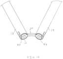
- FIG. 17is a side elevational view of the restraint and manipulators of FIG. 15 being used to position the bone plate in the flexed configuration against bones;
- FIG. 18is an enlarged perspective view showing the manipulators of FIG. 17 maintaining the bone plate in the flexed configuration against the bones;
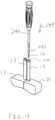
- FIG. 19is a schematic view of a screw driver positioned to advance a bone screw through a cannula of one of the manipulators;
- FIG. 20is a perspective view similar to FIG. 18 showing a shank portion of the bone screw being driven into the through bore of one of the bone plate lobes;
- FIG. 21is a view similar to FIG. 20 showing the screw driver driving a head portion of the bone screw into the lobe through bore;
- FIG. 22is a schematic view showing the bone plate in the flexed configuration having been secured to the bone by the bone screws and the manipulators having been disconnected from the bone plate lobes;
- FIG. 23is a side elevational view of the bone plate of FIG. 22 secured to the bones in the flexed configuration with dashed lines showing the bone plate shifting toward the unflexed configuration thereof and compressing the bones together;
- FIG. 24is a perspective view of a bone compression device including a bone plate and manipulators that are releasably connectable to the bone plate;
- FIG. 25is a top plan view of the bone plate of FIG. 24 showing the bone plate in an unflexed configuration with an intermediate portion of the bone plate curved;
- FIG. 26is a top plan view similar to FIG. 25 showing the manipulators squeezed together which flexes the bone plate and straightens the intermediate portion of the bone plate;
- FIGS. 27 and 28are perspective views of the bone plate and manipulators of FIG. 26 showing a bone screw being driven into a through bore of the bone plate while the manipulators hold the bone plate in the flexed configuration;
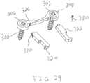
- FIG. 29is a perspective view similar to FIGS. 27 and 28 showing the manipulators disconnected from the bone plate after the bone plate has been implanted in the flexed configuration thereof;
- FIG. 30is a perspective view of a bone compression device including a bone plate having integrated manipulators
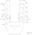
- FIG. 31is an enlarged, top plan view of the bone plate of FIG. 30 showing a connection between a body of the bone plate and the manipulator;
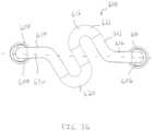
- FIG. 32is a perspective view of another bone compression device having a resilient body and bone screws
- FIG. 33is a top plan view of the resilient body of FIG. 32 in an unflexed configuration
- FIG. 34is a view similar to FIG. 33 showing end portions of the resilient body moved apart from one another to reconfigure the resilient body to a flexed configuration;
- FIG. 35is a cross-sectional view taken across line 35 - 35 in FIG. 32 showing a retention mechanism for keeping the end portion of the resilient body secured to the bone screw;
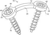
- a bone compression device 10having a bone plate 12 with a body 14 for being secured to bones with bone anchors, such as bone screws 16 .
- the bone plate 12is made entirely or partially of a shape-retentive material that permits elastic deformation of the bone plate 12 and resiliently biases the bone screws 16 and bones connected thereto together once the bone plate 12 has been implanted on the bones.
- the bone plate 12is made of nitinol having superelastic properties that permits the bone plate 12 to deform elastically as the bone plate 12 is flexed during implantation of the bone plate 12 , as discussed in greater detail below.
- the bone plate 12acts as a spring and applies constant compression to the bones until the elastically deformed bone plate 12 returns toward its initial, unflexed configuration.
- Thisis an improvement over some prior compression bone plates that are plastically deformed to compress bones.
- theremay be spring back within the bone plate after implantation of the bone plate which reduces the compression applied to the bones.
- the bone plate 12may be made from a shape memory material, such as shape memory nitinol, which would compress the bones by changing shape in situ from a flexed configuration to an unflexed configuration in response to the internal temperature of the patient.
- the bone plate 12has an initial, unflexed configuration where an intermediate portion 20 of the bone plate 12 is curved or bent, as shown in FIG. 2 .
- the bone plate 12may be flexed using an instrument 15 that includes a pair of manipulators 17 , 19 .
- the manipulators 17 , 19are connected to the bone plate 12 and squeezed together toward an installation orientation as shown in FIG. 12 , which bends the bone plate 12 to the flexed configuration wherein the intermediate portion 20 is substantially straight. This loads the intermediate portion 20 and stores potential energy in the bone plate 12 in a manner similar to compressing a spring.
- a restraint 190may be connected to the manipulators 17 , 19 to hold the manipulators 17 , 19 in the installation orientation which, in turn, maintains the bone plate 12 in the flexed configuration.
- the assembled manipulators 17 , 19 and restraint 190are manipulated to position the bone plate 12 in the flexed configuration thereof against bones 13 , 15 , as shown in FIG. 17 .
- the bone screws 16are advanced through the manipulators 17 , 19 and driven into throughbores 22 , 24 of the bone plate 12 to secure the bone plate 12 to the bones 13 , 15 .
- the bone plate 12With the bone plate 12 secured to the bones 13 , 15 in the flexed configuration, the bone plate 12 resiliently biases against the bone screws 12 as the bone plate 12 rebounds or returns toward its unflexed configuration and the intermediate portion 20 returns in direction 30 toward its curved, unflexed shape 32 , as shown by dashed lines in FIG. 23 .
- the bone plate 12urges the bone screws 16 together as the bone plate 12 rebounds toward its unflexed configuration which compresses the bones 13 , 15 together to heal a cut or break 280 .
- the length of the bone plate 12may be selected so that the bone plate 12 does not completely return to its unflexed configuration after being secured to the bones 13 , 15 so that the bone plate 12 continues to continuously apply compression to the bones 13 , 15 .
- the intermediate portion 20may flex as needed to accommodate subsidence or movement of the bones 13 , 15 post-surgery while continuing to compress the bones 13 , 15 together.
- the bone plate 12has bone anchor receiving portions, such as lobes 40 , 42 , which include the through bores 22 , 24 .
- the bone compression device 10includes retention mechanisms 44 to resist back-out of head portions 46 of bone screws 16 from the lobes 40 , 42 .
- the screw retention mechanisms 44may also fix the bone screw head portions 46 to the bone plate lobes 40 , 42 .
- the screw retention mechanisms 44includes cooperating threads on the bone screw head portion 46 and the lobes 40 , 42 .
- the screw retention mechanisms 44may include an expandable bone screw head portion 46 and an actuator for expanding the head portion 46 into engagement with the surfaces of the through bores 22 , 24 , for example.
- the kit of bone compression devices 10would include a plurality of bone plates 12 having different lengths, a plurality of bone screws 16 having different lengths, the manipulators 17 , 19 , and the restraint 190 .
- the kit of bone compression devices 10could have fewer components than the nitinol staple kit because the different length screws 16 in the kit could be used with any of the lengths of bone plate 12 in the kit.
- the kit of bone compression devices 10would include one set of bone screws 16 of different lengths, rather than a set of bone screws 16 of different lengths for each bone plate 12 .
- the surgical kitmay be provided with one length of manipulators 17 , 19 that can be used with the bonne plates 12 of different lengths or may provided with a plurality of pairs of manipulators 17 , 19 having different lengths. Further, the surgical kit may be provided with one or more of the restraints 190 . If one restraint 190 is provided, the restraint 190 may be adjustable to fix the manipulators 17 , 19 at different distances apart.
- the bone plate 12is shown in an initial, unflexed configuration with the intermediate portion 20 having a non-linear, curved shape.
- the curved shape of the intermediate portion 20orients center lines 50 , 52 of the through bores 22 , 24 to extend at an angle 53 relative to each other.
- the lobes 40 , 42each have an instrument receiving portion 54 including a notched profile 56 with a lip 58 and a depending flat 60 .
- the lip 58has a lower surface 62 that is lifted upward by a lip engaging portion 66 (see FIG. 5 ) of the associated manipulator 17 , 19 , as discussed in greater detail below.
- the lobes 40 , 42 of the bone plateare each configured to form a mating, non-rotatable fit with a distal lobe engaging portion 72 of one of the manipulators 17 , 19 .
- the lobe 42has a rounded outer surface 80 that fits within a rounded inner surface 82 of the lobe engaging portion 72 of the manipulator 19 .
- the lobes 40 , 42are sized to fit within openings 74 of the manipulators 17 , 19 and the flats 60 of the lobes 40 , 42 each abut a flat 76 of the associated manipulator 17 , 19 .
- the abutting flats 60 , 76 of the lobes 40 , 42 and manipulators 17 , 19resist turning of the lobes 40 , 42 within the lobe engaging portions 72 as shown in FIG. 9 .
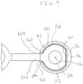
- the manipulator 19has a notch 84 sized to receive a section of the intermediate portion 20 of the bone plate 12 as the manipulator 19 is advanced onto the lobe 42 .
- the manipulator 19has a fulcrum 88 for engaging the bone plate 12 as the manipulator 19 is pivoted toward the manipulator 17 to bend the bone plate 12 as discussed in greater detail below.
- the fulcrum 88includes a surface 90 that rests upon an upper surface 92 of the bone plate 12 , as shown in FIG. 8 .
- the notch 84includes walls 160 , 162 arranged to abut sides 164 , 166 of the intermediate portion 20 and resist rotational movement between the lobe 24 and the manipulator 19 .
- the manipulator 19has an aperture 100 sized to receive the lip 58 of the lobe 42 .
- the aperture 100has a width 102 larger than a width 104 (see FIG. 3 ) of the lip 58 .
- the lip 58 of the lobe 42extends over and is supported on an upper surface 150 of the lip engaging portion 66 with the lip 58 positioned in the aperture 100 such that pivoting of the manipulator 19 in direction 132 tightly engages the lip lower surface 62 and the upper surface 150 (see FIG. 8 ).
- the manipulator 19has a cannula 110 with a center 112 and a wall 114 extending about the cannula 110 .
- the lip engaging portion 66 of the manipulator 19engages the lip lower surface 62 of the lobe 42 and the surface 90 of the manipulator 19 seats on the upper surface 92 of the bone plate 12 with the manipulator 19 connected to the lobe 42 .
- the manipulators 17 , 19have a distance 116 between the lip engaging portion 66 and the surface 90 of each manipulators 17 , 19 . In this manner, pivoting the manipulators 17 , 19 in directions 130 , 132 as shown in FIGS.
- the manipulators 17 , 19have a length 136 that provides additional leverage for bending the bone plate 12 as shown in FIG. 4 .
- FIGS. 7 - 23a method of applying compression to the bones 13 , 15 using the bone plate 12 is shown.
- the lobe engaging portions 72 of the manipulators 17 , 19are connected to the lobes 40 , 42 of the bone plate 12 .
- the manipulator 19is maneuvered in direction 140 to position the lip engaging portion 66 in the notched profile 56 of the lobe 42 below the lip 58 .
- the manipulator 19is then pivoted in direction 142 which shifts the notch 84 downward onto the intermediate portion 20 of the bone plate 12 and seats the lobe engaging portion 72 on the lobe 42 .
- the manipulator 19is shown after pivoting in direction 142 such that the upper surface 150 of the lip engaging portion 66 is engaged with the lower surface 62 of the lip 58 , the flat 76 of the manipulator 19 is engaged with the flat 60 of the lobe 42 , and the surface 90 of the manipulator 19 is engaged with the upper surface 92 of the bone plate 12 .
- the lip engaging portion 66engages the bone plate 12 at one side of the lobe 42 and the notch 84 engages the intermediate portion 20 at the opposite side of the lobe 42 . This engagement resists lateral movement between the lobe 42 and the manipulator 19 in directions 152 , 154 even as the manipulator 19 is pivoted to bend the bone plate 12 .
- this engagementmaintains a coaxial alignment of a center line of the lobe through bore 24 and a center line of the manipulator cannula 110 .
- the aligned center lines of the through bore 24 and cannula 110will be referred to with combined reference numeral 156 .
- the manipulator 17is then connected to the lobe 40 in a similar manner and establishes a coaxially aligned center line 158 of the through bore 22 of the lobe 40 and the cannula 110 of the manipulator 17 .
- the manipulators 17 , 19are shown connected to the lobes 40 , 42 of the bone plate 12 .
- the bone plate 12is in the initial, unflexed configuration and the intermediate portion 20 of the bone plate 12 has a curved shape.
- the center lines 156 , 158are oriented at an angle 170 that may be the same or substantially the same as the angle 53 between the centerlines 50 , 52 of the bone plate throughbores 22 , 24 with the bone plate 12 in the unflexed configuration (see FIG. 2 ).
- the manipulators 17 , 19are pivoted toward each other in directions 130 , 132 such as by a user squeezing the manipulators 17 , 19 together, into an installation orientation as shown in FIG. 12 .
- the centerlines 156 , 158may be substantially parallel to each other, as shown in FIG. 12 .
- pivoting the manipulators 17 , 19 toward each otherflexes the bone plate 12 and bends the intermediate portion 20 into a straight configuration.
- the bone plate 12is generally planar which is in contrast to the bent configuration of the bone plate 12 shown in FIG. 2 .
- the bone plate 12may have a flexed configuration for some procedures where the bone plate 12 is partially flexed and the intermediate portion 20 is only partially straightened. Even when the intermediate portion 20 is only partially straightened, the elastic properties of the bone plate 12 will still apply a constant, compressive force against the bones 13 , 15 once the bone plate 12 has been secured to the bones 13 , 15 .
- a restraint 190may be connected to proximal end portions 192 , 194 of the manipulators 17 , 19 .
- the restraint 190has collars 198 , 200 and a link portion 210 connecting the collars 198 , 200 .
- the restraint 190is connected to the manipulators 17 , 19 by advancing the restraint 190 in direction 210 so that the collars 198 , 200 fit over necks 206 , 208 of the manipulators 17 , 19 and rest against shoulders 212 , 214 of the manipulators 17 , 19 .
- the restraint 190resists pivoting of the manipulators 17 , 19 in directions 220 , 222 away from the installation orientation, as shown in FIG. 15 .
- the manipulators 17 , 19 and restraint 190may be made materials, such as metals or polymers, sufficiently rigid to resist the resilient bending of the bone plate 12 back toward its initial, unflexed configuration.
- the manipulators 17 , 19may be made of stainless steel and the restraint 190 may be made from carbon fiber polyether ether ketone (PEEK).
- PEEKcarbon fiber polyether ether ketone
- the manipulators 17 , 19 and restraint 190may be disposable or reusable.
- the collars 198 , 200may fit around the exteriors of the necks 206 , 208 of the manipulators 17 , 19 which permits the cannulas 110 of the manipulators 17 , 19 to be unobstructed with the restraint 190 connected to the manipulators 17 , 19 .
- the unobstructed cannulas 110permit access to the through bores 22 , 24 of the lobes 40 , 42 through the cannulas 110 .
- the restraint 190maintains the manipulators 17 , 19 and bone plate 12 in an assembled configuration and permits one-handed handling of the assembly of the bone plate 12 , manipulators 17 , 19 , and restraint 190 .
- This assembly of the restraint 190 , manipulators 17 , 19 and bone plate 12can be readily maneuvered in direction 230 into position on the bones 13 , 15 .
- the intermediate portion 20 of the bone plate 12is in its generally straight or flat configuration due to the restraint 190 continuing to resist pivoting of the manipulators 17 , 19 away from their installation orientation.
- the manipulators 17 , 19have been used to position the bone plate 12 on the bones 13 , 15 such that the through bores 22 , 24 are each positioned over one of the bones 13 , 15 . Due to the elastic properties of the bone plate 12 , the intermediate portion 20 biases the lobes 40 , 42 back toward their unflexed orientations (see FIG. 2 ).
- an instrumentsuch as a screw driver 240
- a screw driver 240has a shaft 242 with a bone screw 16 connected thereto.
- the screw driver 240 and bone screw 16are advanced in direction 244 into the cannula 110 of manipulator 19 to advance a shank portion 246 of the bone screw 16 into the through bore 24 of the lobe 42 and drive the shank portion 246 into the bone 15 .
- the screw driver 240continues to drive the bone screw 16 into the bone 15 until the head portion 46 of the bone screw 16 seats within the through bore 24 of the lobe 42 , as shown in FIG. 21 .
- This processis repeated to drive the other bone screw 16 into the through bore 22 of the lobe 40 so that both lobes 40 , 42 are secured to the bones 13 , 15 as shown in FIG. 22 .
- the restraint 190is removed in direction 271 to draw the collars 198 , 200 off of the necks 206 , 208 as shown in FIG. 22 .
- the bone plate engaging members 17 , 19are pivoted in directions 270 , 272 to lift the notches 84 of the manipulators 17 , 19 off of the intermediate portion 20 of the bone plate 12 .
- the manipulatorsare shifted outwardly in directions 274 , 276 in order to unhook the lip engaging portions 66 from below the lips 58 of the lobes 40 , 42 .
- the bone plate 12 in the flexed configurationis shown secured to the bones 13 , 15 .
- the bone screws 16have been driven into the bones 13 , 15 to secure the lobes 40 , 42 against the bones 13 , 15 .
- the intermediate portion 20returns toward its unflexed configuration 32 .
- the bone plate 12applies tension to the bone screws 16 and compresses the bones 13 , 15 together.
- the bone plate 12may be made of a shape memory nitinol that shifts in situ from a flexed, installation configuration to an unflexed, compression configuration in response to the temperature of the patient.
- the bone plate 12may be chilled, such as in a saline solution, mechanically forced into a straightened configuration, and implanted in the straightened configuration. As the temperature of the bone plate 12 raises to the internal temperature of the patient, the bone plate 12 will return to its original shape and compress the bones 13 , 15 .
- a bone compression device 300having a bone plate 302 that flexes within the thickness of the bone plate 302 to apply compression to bones.
- the bone plate 302has a body 304 with lobes 306 , 308 and an intermediate portion 310 connecting the lobes 306 , 308 .
- the intermediate portion 310is curved or bent and extends between planes defined by upper and lower surfaces 311 , 313 of the lobes 306 , 308 .
- an instrument 319including manipulators 320 , 322 that each have a releasable connection 324 to the bone plate 302 .
- the releasable connection 324includes a recess 326 of the bone plate 302 and a complimentary projection 330 of the associated manipulator 320 , 322 configured to form an interlocking, rigid engagement with the recesses 326 .
- the bone plateis shown in the initial, unflexed configuration.
- longitudinal axis 340 , 342 of the manipulators 320 , 322extend an angle 344 to one another.
- handle portions 350 , 352 of the manipulators 320 , 322are grasped and pressed toward one another in directions 354 , 356 from an initial orientation to an installation orientation. Because the manipulators 320 , 322 are connected to the lobes 306 , 308 , pressing the manipulator handle portions 350 , 352 together deflects the intermediate portion 310 from the initial, curved configuration as shown in FIG. 24 to a flexed, straightened configuration as shown in FIG. 26 . As the bone plate 302 flexes between the unflexed and flexed configurations, the intermediate portion 310 remains between the planes defined by the upper and lower surfaces 311 , 313 of the lobes 306 , 308 .
- a usermay hold the manipulators 320 , 322 in the installation orientation and keep the bone plate 302 in the flexed configuration with one hand, e.g., between a thumb and an index finger.
- the flexed bone plate 302has been positioned on bones (not shown) and bone screws 360 are advanced in direction 362 into through bores 364 of the lobes 306 , 308 .
- the lobes 306 , 308may turn slightly about a bone screw head portion 364 as the intermediate portion 310 bends back toward its curved, unflexed configuration and compresses the bones together via the bone screws 360 .
- the head portions 360may have a non-threaded outer surface 370 .
- screw retention mechanismsmay be provided to resist backout of the bone screws 360 from the through bores 364 while permitting this turning of the lobes 306 , 308 about the head portion 364 .
- the lobes 306 , 308may each have a lip extending about the through bore 364 that deflects out of the way of the bone screw 306 as the bone screw 306 is advanced into the through bore 364 and then snaps back over the head portion 364 once the head portion 364 is seated within the through bore 364 .
- the manipulators 320 , 322may be disconnected from the bone plate 302 .
- the projections 330may be slid in direction 380 out of the recesses 326 .
- the flexed intermediate portion 310biases against the bone screws 360 and compresses the bone screws 360 and bones connected thereto together as the intermediate portion returns toward its initial, unflexed configuration.
- the intermediate portion 310shifts from its straightened toward its curved configuration, the intermediate portion 310 travels along the outer surfaces of the bones rather than away from the outer surfaces of the bones as does the intermediate portion 20 of the bone plate 12 (see FIG. 23 ).
- a bone compression device 400having a bone plate 402 that is similar in many respects to the bone plate 302 as discussed above.
- the bone plate 402has an integrated installation instrument 403 with manipulators 404 , 406 that may be used to flex the bone plate 402 and then be removed from the bone plate 402 after installation of the bone plate 402 onto bones.
- the manipulators 404 , 406are integrally formed with a body 408 of the bone plate 402 .
- the term “integral”is intended to refer to being formed as one piece with another part.
- the manipulator 404is connected to the body 408 at a frangible portion 410 .
- a usergrasps handle portions 412 of the manipulators 404 , 406 and squeezes the handle portions 412 together generally in direction 414 .
- Thispivots the manipulator 404 about the frangible portion 410 in direction 420 and brings a surface 422 of the manipulator 404 into contact with a surface 424 of the body 408 .
- pivoting the manipulator 404 in direction 420closes a gap 426 between the surfaces 422 , 424 with a distance 428 between the surfaces 422 , 424 , decreasing as the manipulator 404 pivots in direction 420 .
- the surfaces 422 , 424abutting, continued squeezing of the handle portions 412 together moves the lobes 408 in directions 430 and straightens an intermediate portion 432 .
- a usermay bend, cut, or otherwise separate the manipulators 404 , 406 from the bone plate body 408 at the frangible portions 410 .
- a bone compression device 500having a resilient body 502 connecting bone screws 504 , 506 .
- the resilient body 502includes end portions 508 , 510 secured to the bone screws 504 , 506 and an intermediate spring portion 512 configured to apply a compressive force to the bones connected to the bone screws 504 , 506 .
- the bone screws 504 , 506have blind bores 530 that receive the end portions 508 , 510 of the resilient body 502 .
- the bores 530each have an upper portion with a hex drive configuration to accommodate a hex driver for driving the bone screws into 504 , 506 into bone.
- a top plan view of the body 502is provided showing the body 502 in an unflexed configuration.
- the body 502has straight portions 516 , 518 , 520 and curved portions 522 , 524 connecting the straight portions 516 , 518 , 520 .
- the end portions 508 , 510are moved apart from each other in directions 521 , 523 . This causes the elbow portions 522 , 524 to elastically flex to a more open configuration as shown in FIG. 34 .
- one or more of the straight portions 516 , 518 , 520may elastically deform in the lengthwise direction.
- the bone screws 504 , 506are driven into the bones and the end portions 508 , 510 of the body 502 are moved apart from each other to shift the body 502 to the flexed configuration thereof as shown in FIG. 34 .
- the end portions 508 , 510are held in their spaced orientation to keep the body 502 flexed and the end portions 508 , 510 are then advanced into the bores 530 of the bone screws 504 , 506 previously driven into the bones.
- the resilient body 502biases against the bone screws 504 , 506 in directions 534 , 536 as the body 502 returns toward its unflexed configuration and compresses the bones.
- the bone compression device 500includes a retention mechanism 550 for maintaining the end portions 508 , 510 in the bores 530 of the bone screws 504 , 506 .
- the retention mechanism 550includes a leading end portion 552 of the resilient body end portion 508 .
- the leading end portion 552has a cam surface 554 and an enlarged portion 556 that snaps past a retention portion 558 of the bone screw 504 .
- the retention portion 558includes an annular collar 564 having an upper surface 560 and a lower surface 562 . Advancing the leading end portion 552 in direction 570 into the bore 530 engages the cam surface 554 with the upper surface 560 of the collar 564 .
- the leading end portion 508has a smooth, volcano-shaped neck portion 580 spaced from the collar 564 with the leading end portion 552 captured in the bore 530 by the collar 564 .
- the neck portion 580permits the end portion 508 to turn within the bore 530 after installation of the bone compression device 500 which accommodates turning of the straight portion 520 in direction 582 (see FIG.
- the resilient body end portion 508 and bone screw 504thereby form a pivot connection therebetween that permits reconfiguring of the resilient body 502 back toward its unflexed configuration while maintaining the end portion 508 securely connected to the bone screw 5034 .
- a bone compression device 600is provided that is similar in many respects to the bone compression device 500 .
- the bone compression device 600includes a resilient body 602 having end portions 604 , 606 that are configured to be secured to bone screws 608 , 610 and a spring portion 612 intermediate the end portions 604 , 606 .
- One difference between the resilient body 602 and the resilient body 502is that the resilient body 602 has straight legs 614 , 616 connecting the end portions 604 , 606 , and the spring portion 612 .
- the straight legs 614 , 616reduce turning of the end portions 604 , 606 relative to the bone screws 608 , 610 as the resilient body 602 returns toward its unflexed configuration.
- the straight legs 614 , 616reduce turning of the end portions 604 , 606 relative to the bone screws 608 , 610 because elbow portions 620 , 622 of the spring portion 612 can flex and open as the resilient body 602 shifts toward its flexed configuration while the straight legs 614 , 616 remain generally aligned along an axis 630 .
- the bone compression device 600may have retention mechanisms that rigidly fix the resilient body 602 to the bone screws 608 , 610 since the end portions 608 , 610 generally do not turn relative to the bone screws 608 , 610 as the resilient body 602 returns toward its unflexed configuration.
- the bone compression devices discussed abovemay be used in a variety of applications, such as hand and foot bone fragment and osteotomy fixation and joint arthrodesis, fixation of proximal tibial metaphysis osteotomy, and adjunctive fixation of small bone fragments.
- the bone compression devicesmay be used with bones such as the femur, humerus, clavicle, sternum, ribs, and pelvis.
Landscapes
- Health & Medical Sciences (AREA)
- Orthopedic Medicine & Surgery (AREA)
- Surgery (AREA)
- Life Sciences & Earth Sciences (AREA)
- Heart & Thoracic Surgery (AREA)
- Veterinary Medicine (AREA)
- Engineering & Computer Science (AREA)
- Biomedical Technology (AREA)
- Nuclear Medicine, Radiotherapy & Molecular Imaging (AREA)
- Medical Informatics (AREA)
- Molecular Biology (AREA)
- Animal Behavior & Ethology (AREA)
- General Health & Medical Sciences (AREA)
- Public Health (AREA)
- Neurology (AREA)
- Dentistry (AREA)
- Oral & Maxillofacial Surgery (AREA)
- Surgical Instruments (AREA)
Abstract
Description
Claims (25)
Priority Applications (1)
| Application Number | Priority Date | Filing Date | Title |
|---|---|---|---|
| US17/158,628US11857231B2 (en) | 2015-03-03 | 2021-01-26 | Bone compression device and method |
Applications Claiming Priority (4)
| Application Number | Priority Date | Filing Date | Title |
|---|---|---|---|
| US201562127609P | 2015-03-03 | 2015-03-03 | |
| US15/058,695US10123831B2 (en) | 2015-03-03 | 2016-03-02 | Bone compression device and method |
| US16/164,899US10932833B2 (en) | 2015-03-03 | 2018-10-19 | Bone compression device and method |
| US17/158,628US11857231B2 (en) | 2015-03-03 | 2021-01-26 | Bone compression device and method |
Related Parent Applications (1)
| Application Number | Title | Priority Date | Filing Date |
|---|---|---|---|
| US16/164,899ContinuationUS10932833B2 (en) | 2015-03-03 | 2018-10-19 | Bone compression device and method |
Publications (2)
| Publication Number | Publication Date |
|---|---|
| US20210220029A1 US20210220029A1 (en) | 2021-07-22 |
| US11857231B2true US11857231B2 (en) | 2024-01-02 |
Family
ID=56849406
Family Applications (3)
| Application Number | Title | Priority Date | Filing Date |
|---|---|---|---|
| US15/058,695Active2036-10-21US10123831B2 (en) | 2015-03-03 | 2016-03-02 | Bone compression device and method |
| US16/164,899Active2036-09-04US10932833B2 (en) | 2015-03-03 | 2018-10-19 | Bone compression device and method |
| US17/158,628Active2037-02-05US11857231B2 (en) | 2015-03-03 | 2021-01-26 | Bone compression device and method |
Family Applications Before (2)
| Application Number | Title | Priority Date | Filing Date |
|---|---|---|---|
| US15/058,695Active2036-10-21US10123831B2 (en) | 2015-03-03 | 2016-03-02 | Bone compression device and method |
| US16/164,899Active2036-09-04US10932833B2 (en) | 2015-03-03 | 2018-10-19 | Bone compression device and method |
Country Status (1)
| Country | Link |
|---|---|
| US (3) | US10123831B2 (en) |
Families Citing this family (11)
| Publication number | Priority date | Publication date | Assignee | Title |
|---|---|---|---|---|
| US10123831B2 (en) | 2015-03-03 | 2018-11-13 | Pioneer Surgical Technology, Inc. | Bone compression device and method |
| CN112367937A (en)* | 2018-06-29 | 2021-02-12 | 先锋外科技术公司 | Bone plating system |
| US20200038076A1 (en)* | 2018-08-02 | 2020-02-06 | DePuy Synthes Products, Inc. | Method and apparatus for a continuous compression implant |
| US11877779B2 (en) | 2020-03-26 | 2024-01-23 | Xtant Medical Holdings, Inc. | Bone plate system |
| EP4161415A4 (en)* | 2020-06-08 | 2024-07-10 | In2Bones USA, LLC | ARCHED PLATE FOR FIXING OSTEOTOMIES AND ARTICLE ARTHRODESES |
| US11806059B2 (en) | 2020-07-14 | 2023-11-07 | DePuy Synthes Products, Inc. | Shape memory implants and methods and apparatus for the loading and implanting thereof |
| US12161371B2 (en) | 2021-01-18 | 2024-12-10 | Treace Medical Concepts, Inc. | Contoured bone plate with locking screw for bone compression, particularly across a tarsometatarsal joint |
| US11944352B2 (en) | 2021-05-28 | 2024-04-02 | William Casey Fox | Extracorporeal bone compressing link and apparatus and method using same |
| WO2023064785A1 (en)* | 2021-10-12 | 2023-04-20 | Lee Randall F | System and method for a medical implant with integrated propulsors |
| US11931084B2 (en) | 2021-12-07 | 2024-03-19 | DePuy Synthes Products, Inc. | Method and apparatus for an orthopedic fixation system |
| WO2024108120A1 (en) | 2022-11-18 | 2024-05-23 | William Casey Fox | Extracorporeal bone compressing link and apparatus |
Citations (86)
| Publication number | Priority date | Publication date | Assignee | Title |
|---|---|---|---|---|
| US2580821A (en) | 1950-10-21 | 1952-01-01 | Nicola Toufick | Spring impactor bone plate |
| US3710789A (en) | 1970-12-04 | 1973-01-16 | Univ Minnesota | Method of repairing bone fractures with expanded metal |
| US3900025A (en) | 1974-04-24 | 1975-08-19 | Jr Walter P Barnes | Apparatus for distracting or compressing longitudinal bone segments |
| US3939828A (en) | 1974-09-09 | 1976-02-24 | Mohr Robert N | Method and clasp for internal osseous fixation |
| US4364382A (en) | 1979-08-23 | 1982-12-21 | Ulrich Mennen | Internal fixation device for bone fractures |
| DE3808937A1 (en) | 1988-03-17 | 1989-10-05 | Fischer Artur Werke Gmbh | Connecting element for connecting and stabilising a bone in the region of a fracture |
| US5026390A (en) | 1989-10-26 | 1991-06-25 | Brown Alan W | Surgical staple |
| US5281226A (en) | 1989-03-31 | 1994-01-25 | Davydov Anatoly B | Missing portion of a tubular bone |
| US5423816A (en) | 1993-07-29 | 1995-06-13 | Lin; Chih I. | Intervertebral locking device |
| US5423826A (en)* | 1993-02-05 | 1995-06-13 | Danek Medical, Inc. | Anterior cervical plate holder/drill guide and method of use |
| US5458642A (en) | 1994-01-18 | 1995-10-17 | Beer; John C. | Synthetic intervertebral disc |
| US5620443A (en) | 1995-01-25 | 1997-04-15 | Danek Medical, Inc. | Anterior screw-rod connector |
| US5713900A (en) | 1996-05-31 | 1998-02-03 | Acromed Corporation | Apparatus for retaining bone portions in a desired spatial relationship |
| US5735853A (en) | 1994-06-17 | 1998-04-07 | Olerud; Sven | Bone screw for osteosynthesis |
| US5766218A (en) | 1996-10-01 | 1998-06-16 | Metamorphic Surgical Devices, Inc. | Surgical binding device and method of using same |
| US5785713A (en) | 1995-04-25 | 1998-07-28 | Jobe; Richard P. | Surgical fixation apparatus |
| US6117135A (en) | 1996-07-09 | 2000-09-12 | Synthes (U.S.A.) | Device for bone surgery |
| US6136002A (en) | 1999-02-05 | 2000-10-24 | Industrial Technology Research Institute | Anterior spinal fixation system |
| WO2000062693A1 (en) | 1999-04-21 | 2000-10-26 | Eaves Felmont F Iii | Bone fracture fixation clip |
| US6342055B1 (en) | 1999-04-29 | 2002-01-29 | Theken Surgical Llc | Bone fixation system |
| US6645207B2 (en) | 2000-05-08 | 2003-11-11 | Robert A. Dixon | Method and apparatus for dynamized spinal stabilization |
| US6695846B2 (en) | 2002-03-12 | 2004-02-24 | Spinal Innovations, Llc | Bone plate and screw retaining mechanism |
| US20040039388A1 (en) | 2001-10-23 | 2004-02-26 | Lutz Biedermann | Bone fixation device and screw therefor |
| US6719793B2 (en) | 1995-07-18 | 2004-04-13 | Iowa State University Research Foundation, Inc. | Method of restructuring bone |
| US20040087955A1 (en) | 2001-03-09 | 2004-05-06 | Alessandro Bordi | Tubular internal fixation for bone fractures and prostheses |
| US20040116931A1 (en) | 2002-12-17 | 2004-06-17 | Carlson Gregory D. | Vertebrae fixation device and method of use |
| US20040147928A1 (en) | 2002-10-30 | 2004-07-29 | Landry Michael E. | Spinal stabilization system using flexible members |
| US6783531B2 (en) | 1999-04-26 | 2004-08-31 | Drew Allen, DPM | Compression bone staple, apparatus and method |
| US20050004573A1 (en) | 2003-04-18 | 2005-01-06 | M. Samy Abdou | Bone fixation system and method of implantation |
| US20050043732A1 (en) | 2003-08-18 | 2005-02-24 | Dalton Brian E. | Cervical compression plate assembly |
| US20050203513A1 (en) | 2003-09-24 | 2005-09-15 | Tae-Ahn Jahng | Spinal stabilization device |
| US6986771B2 (en) | 2003-05-23 | 2006-01-17 | Globus Medical, Inc. | Spine stabilization system |
| US7008427B2 (en) | 2000-05-25 | 2006-03-07 | Orthoplex, Llc | Inter-vertebral disc prosthesis for rachis through anterior surgery thereof |
| US20060167457A1 (en) | 2005-01-21 | 2006-07-27 | Loubert Suddaby | Orthopedic fusion plate having both active and passive subsidence controlling features |
| US7115129B2 (en)* | 2001-10-19 | 2006-10-03 | Baylor College Of Medicine | Bone compression devices and systems and methods of contouring and using same |
| US20070055251A1 (en) | 2005-07-13 | 2007-03-08 | Huebner Randall J | Bone plates with movable locking elements |
| US20070213727A1 (en) | 2006-02-09 | 2007-09-13 | Apex Abc, Llc | Method and apparatus for bone fracture fixation |
| US20080147124A1 (en) | 2006-10-31 | 2008-06-19 | Haidukewych George J | Bone plate system with slidable compression holes |
| US20080269753A1 (en) | 2007-04-26 | 2008-10-30 | Blue Fury Consulting, Llc | Dynamic cervical plate |
| US20090069812A1 (en) | 2007-06-15 | 2009-03-12 | Acumed Llc | Rib fixation with an intramedullary nail |
| US20100036430A1 (en) | 2004-09-14 | 2010-02-11 | Wright Medical Technology, Inc. | Compression brace |
| US20100063505A1 (en) | 2007-03-22 | 2010-03-11 | Robert Frigg | Bone plate |
| US7749256B2 (en) | 2005-04-05 | 2010-07-06 | Warsaw Orthopedic, Inc. | Ratcheting fixation plate |
| US7833256B2 (en) | 2004-04-16 | 2010-11-16 | Biedermann Motech Gmbh | Elastic element for the use in a stabilization device for bones and vertebrae and method for the manufacture of such elastic element |
| US7914561B2 (en) | 2002-12-31 | 2011-03-29 | Depuy Spine, Inc. | Resilient bone plate and screw system allowing bi-directional assembly |
| US20110106182A1 (en) | 2008-06-12 | 2011-05-05 | Medxpert Gmbh | Device for osteosynthesis and for immobilization and stabilisation of tubular bones |
| US7993380B2 (en) | 2005-03-31 | 2011-08-09 | Alphatel Spine, Inc. | Active compression orthopedic plate system and method for using the same |
| US8043346B2 (en) | 2007-05-18 | 2011-10-25 | Custom Spine, Inc. | Anterior cervical plate with independent spring-loaded locking slides for each screw |
| US20110295324A1 (en) | 2010-03-19 | 2011-12-01 | Brian Donley | Tabbed compression plate and method of use |
| US8226693B2 (en) | 2006-06-16 | 2012-07-24 | Reimels William J | Bone bridge providing dynamic compression on bone fractures |
| US8257404B2 (en) | 2006-06-16 | 2012-09-04 | Hack Bradford H | Bone plate with dynamic compression |
| US8262711B2 (en) | 2009-03-13 | 2012-09-11 | Spinal Simplicity Llc | Dynamic vertebral column plate system |
| US20120296440A1 (en) | 2010-01-26 | 2012-11-22 | Univeriste Jean Monnet | Device for osteosynthesis of the thoracic wall |
| WO2012162733A1 (en) | 2011-06-01 | 2012-12-06 | Alfred Health | Bone splint |
| US20130090695A1 (en) | 2011-09-30 | 2013-04-11 | Acute Innovations, Llc | Bone fixation system with opposed mounting portions |
| US20130190762A1 (en) | 2008-03-24 | 2013-07-25 | Mark Frankle | Method and system for the intramedullary fixation of a fractured bone |
| US8574270B2 (en) | 2009-03-13 | 2013-11-05 | Spinal Simplicity Llc | Bone plate assembly with bone screw retention features |
| US8585742B2 (en) | 2008-08-15 | 2013-11-19 | Ao Technology Ag | Bone fixation device |
| US8623019B2 (en) | 2007-07-03 | 2014-01-07 | Pioneer Surgical Technology, Inc. | Bone plate system |
| US20140039630A1 (en) | 2007-03-20 | 2014-02-06 | Memometal Technologies | Osteosynthesis device |
| US8728127B2 (en) | 2011-01-18 | 2014-05-20 | Spineworks, Llc | Bone plate incorporating a compression mechanism and associated surgical methods |
| US8758347B2 (en) | 2010-03-19 | 2014-06-24 | Nextremity Solutions, Inc. | Dynamic bone plate |
| US20140188178A1 (en) | 2012-10-22 | 2014-07-03 | Brad Juchno | Posterior Lumbar Plate |
| US8790379B2 (en) | 2010-06-23 | 2014-07-29 | Zimmer, Inc. | Flexible plate fixation of bone fractures |
| US8882815B2 (en) | 2010-06-23 | 2014-11-11 | Zimmer, Inc. | Flexible plate fixation of bone fractures |
| US8974504B2 (en) | 2012-05-10 | 2015-03-10 | Spinal Simplicity Llc | Dynamic bone fracture plates |
| US9005257B2 (en) | 2010-11-28 | 2015-04-14 | Dexiu Sun | Universal locking and compression device for bone plate |
| US9005255B2 (en) | 2011-02-15 | 2015-04-14 | Orthohelix Surgical Designs, Inc. | Orthopedic compression plate |
| US9033988B2 (en) | 2005-02-23 | 2015-05-19 | Pioneer Surgical Technology, Inc. | Minimally invasive surgical system |
| US20150157374A1 (en) | 2013-12-05 | 2015-06-11 | Pioneer Surgical Technology, Inc. | Bone plate system and method |
| US20150230843A1 (en) | 2011-09-22 | 2015-08-20 | Mx Orthopedics, Corp. | Controlling the unloading stress of nitinol devices and/or other shape memory material devices |
| US20150238238A1 (en) | 2014-02-27 | 2015-08-27 | Biomedical Enterprises, Inc. | Method and apparatus for use of a compressing plate |
| US20150289918A1 (en) | 2012-11-12 | 2015-10-15 | Flower Orthopedic Corporation | Sterile-Packaged Disposable Contouring Tool Systems for Medical Implants and Methods for Contouring Medical Implants |
| US20150313656A1 (en) | 2014-04-30 | 2015-11-05 | DePuy Synthes Products, Inc. | Tensioning instrument and related bone fixation systems and methods |
| US9198769B2 (en) | 2011-12-23 | 2015-12-01 | Pioneer Surgical Technology, Inc. | Bone anchor assembly, bone plate system, and method |
| US20160074082A1 (en) | 2011-10-20 | 2016-03-17 | Stryker Trauma Sa | Flexible locked plate fixation |
| US9295503B2 (en) | 2005-11-16 | 2016-03-29 | DePuy Synthes Products, Inc. | Device for bone fixation with at least one through hole |
| US9295508B2 (en) | 2012-02-03 | 2016-03-29 | Zimmer, Inc. | Bone plate for elastic osteosynthesis |
| US20160256203A1 (en) | 2015-03-03 | 2016-09-08 | Pioneer Surgical Technology, Inc. | Bone compression device and method |
| US9498259B2 (en) | 2011-06-29 | 2016-11-22 | Albany Medical College | Dynamic spinal plating system |
| US9579135B2 (en) | 2011-12-22 | 2017-02-28 | Fellowship of Orthopaedic Researchers, LLC | Plate and screw apparatus and methods thereof |
| US9788863B2 (en) | 2012-10-22 | 2017-10-17 | Globus Medical, Inc. | Posterior lumbar plate |
| US20170360487A1 (en) | 2012-05-10 | 2017-12-21 | Spinal Simplicity, Llc | Locking fastener for use with dynamic bone fracture plates |
| US9855082B2 (en) | 2009-05-12 | 2018-01-02 | DePuy Synthes Products, Inc. | Readjustable locking plate hole |
| US9883897B2 (en) | 2014-09-25 | 2018-02-06 | Biomedical Enterprises, Inc. | Method and apparatus for a compressing plate |
| US20200000501A1 (en) | 2018-06-29 | 2020-01-02 | Pioneer Surgical Technology, Inc. | Bone plate system |
- 2016
- 2016-03-02USUS15/058,695patent/US10123831B2/enactiveActive
- 2018
- 2018-10-19USUS16/164,899patent/US10932833B2/enactiveActive
- 2021
- 2021-01-26USUS17/158,628patent/US11857231B2/enactiveActive
Patent Citations (122)
| Publication number | Priority date | Publication date | Assignee | Title |
|---|---|---|---|---|
| US2580821A (en) | 1950-10-21 | 1952-01-01 | Nicola Toufick | Spring impactor bone plate |
| US3710789A (en) | 1970-12-04 | 1973-01-16 | Univ Minnesota | Method of repairing bone fractures with expanded metal |
| US3900025A (en) | 1974-04-24 | 1975-08-19 | Jr Walter P Barnes | Apparatus for distracting or compressing longitudinal bone segments |
| US3939828A (en) | 1974-09-09 | 1976-02-24 | Mohr Robert N | Method and clasp for internal osseous fixation |
| US4364382A (en) | 1979-08-23 | 1982-12-21 | Ulrich Mennen | Internal fixation device for bone fractures |
| DE3808937A1 (en) | 1988-03-17 | 1989-10-05 | Fischer Artur Werke Gmbh | Connecting element for connecting and stabilising a bone in the region of a fracture |
| US5281226A (en) | 1989-03-31 | 1994-01-25 | Davydov Anatoly B | Missing portion of a tubular bone |
| US5026390A (en) | 1989-10-26 | 1991-06-25 | Brown Alan W | Surgical staple |
| US5423826A (en)* | 1993-02-05 | 1995-06-13 | Danek Medical, Inc. | Anterior cervical plate holder/drill guide and method of use |
| US5423816A (en) | 1993-07-29 | 1995-06-13 | Lin; Chih I. | Intervertebral locking device |
| US5458642A (en) | 1994-01-18 | 1995-10-17 | Beer; John C. | Synthetic intervertebral disc |
| US5735853A (en) | 1994-06-17 | 1998-04-07 | Olerud; Sven | Bone screw for osteosynthesis |
| US5620443A (en) | 1995-01-25 | 1997-04-15 | Danek Medical, Inc. | Anterior screw-rod connector |
| US5785713A (en) | 1995-04-25 | 1998-07-28 | Jobe; Richard P. | Surgical fixation apparatus |
| US6719793B2 (en) | 1995-07-18 | 2004-04-13 | Iowa State University Research Foundation, Inc. | Method of restructuring bone |
| US5713900A (en) | 1996-05-31 | 1998-02-03 | Acromed Corporation | Apparatus for retaining bone portions in a desired spatial relationship |
| US6117135A (en) | 1996-07-09 | 2000-09-12 | Synthes (U.S.A.) | Device for bone surgery |
| US5766218A (en) | 1996-10-01 | 1998-06-16 | Metamorphic Surgical Devices, Inc. | Surgical binding device and method of using same |
| US6136002A (en) | 1999-02-05 | 2000-10-24 | Industrial Technology Research Institute | Anterior spinal fixation system |
| WO2000062693A1 (en) | 1999-04-21 | 2000-10-26 | Eaves Felmont F Iii | Bone fracture fixation clip |
| US6783531B2 (en) | 1999-04-26 | 2004-08-31 | Drew Allen, DPM | Compression bone staple, apparatus and method |
| US6342055B1 (en) | 1999-04-29 | 2002-01-29 | Theken Surgical Llc | Bone fixation system |
| US6645207B2 (en) | 2000-05-08 | 2003-11-11 | Robert A. Dixon | Method and apparatus for dynamized spinal stabilization |
| US7008427B2 (en) | 2000-05-25 | 2006-03-07 | Orthoplex, Llc | Inter-vertebral disc prosthesis for rachis through anterior surgery thereof |
| US20040087955A1 (en) | 2001-03-09 | 2004-05-06 | Alessandro Bordi | Tubular internal fixation for bone fractures and prostheses |
| US7931679B2 (en) | 2001-10-19 | 2011-04-26 | Baylor College Of Medicine | Bone compression device |
| US7115129B2 (en)* | 2001-10-19 | 2006-10-03 | Baylor College Of Medicine | Bone compression devices and systems and methods of contouring and using same |
| US20040039388A1 (en) | 2001-10-23 | 2004-02-26 | Lutz Biedermann | Bone fixation device and screw therefor |
| US8500737B2 (en) | 2002-03-12 | 2013-08-06 | Aesculap Implant Systems, Llc | Bone plate and screw retaining mechanism |
| US6695846B2 (en) | 2002-03-12 | 2004-02-24 | Spinal Innovations, Llc | Bone plate and screw retaining mechanism |
| US7972366B2 (en) | 2002-03-12 | 2011-07-05 | Aesculap Implant Systems, Llc | Bone plate and screw retaining mechanism |
| US20040147928A1 (en) | 2002-10-30 | 2004-07-29 | Landry Michael E. | Spinal stabilization system using flexible members |
| US20040116931A1 (en) | 2002-12-17 | 2004-06-17 | Carlson Gregory D. | Vertebrae fixation device and method of use |
| US8747441B2 (en) | 2002-12-31 | 2014-06-10 | Depuy Spine, Inc. | Resilient bone plate and screw system allowing bi-directional assembly |
| US7914561B2 (en) | 2002-12-31 | 2011-03-29 | Depuy Spine, Inc. | Resilient bone plate and screw system allowing bi-directional assembly |
| US9351774B2 (en) | 2002-12-31 | 2016-05-31 | DePuy Synthes Products, Inc. | Resilient bone plate and screw system allowing bi-directional assembly |
| US20050004573A1 (en) | 2003-04-18 | 2005-01-06 | M. Samy Abdou | Bone fixation system and method of implantation |
| US6986771B2 (en) | 2003-05-23 | 2006-01-17 | Globus Medical, Inc. | Spine stabilization system |
| US20050043732A1 (en) | 2003-08-18 | 2005-02-24 | Dalton Brian E. | Cervical compression plate assembly |
| US7763056B2 (en) | 2003-08-18 | 2010-07-27 | Dalton Brian E | Cervical compression plate assembly |
| US20050203513A1 (en) | 2003-09-24 | 2005-09-15 | Tae-Ahn Jahng | Spinal stabilization device |
| US7833256B2 (en) | 2004-04-16 | 2010-11-16 | Biedermann Motech Gmbh | Elastic element for the use in a stabilization device for bones and vertebrae and method for the manufacture of such elastic element |
| US20100036430A1 (en) | 2004-09-14 | 2010-02-11 | Wright Medical Technology, Inc. | Compression brace |
| US7591840B2 (en) | 2005-01-21 | 2009-09-22 | Loubert Suddaby | Orthopedic fusion plate having both active and passive subsidence controlling features |
| US20060167457A1 (en) | 2005-01-21 | 2006-07-27 | Loubert Suddaby | Orthopedic fusion plate having both active and passive subsidence controlling features |
| US9033988B2 (en) | 2005-02-23 | 2015-05-19 | Pioneer Surgical Technology, Inc. | Minimally invasive surgical system |
| US7993380B2 (en) | 2005-03-31 | 2011-08-09 | Alphatel Spine, Inc. | Active compression orthopedic plate system and method for using the same |
| US7749256B2 (en) | 2005-04-05 | 2010-07-06 | Warsaw Orthopedic, Inc. | Ratcheting fixation plate |
| US7857836B2 (en) | 2005-07-13 | 2010-12-28 | Acumed Llc | Bone plates with movable locking elements |
| US20070055251A1 (en) | 2005-07-13 | 2007-03-08 | Huebner Randall J | Bone plates with movable locking elements |
| US9295503B2 (en) | 2005-11-16 | 2016-03-29 | DePuy Synthes Products, Inc. | Device for bone fixation with at least one through hole |
| US20070213727A1 (en) | 2006-02-09 | 2007-09-13 | Apex Abc, Llc | Method and apparatus for bone fracture fixation |
| US8226693B2 (en) | 2006-06-16 | 2012-07-24 | Reimels William J | Bone bridge providing dynamic compression on bone fractures |
| US8257404B2 (en) | 2006-06-16 | 2012-09-04 | Hack Bradford H | Bone plate with dynamic compression |
| US20080147124A1 (en) | 2006-10-31 | 2008-06-19 | Haidukewych George J | Bone plate system with slidable compression holes |
| US20140039630A1 (en) | 2007-03-20 | 2014-02-06 | Memometal Technologies | Osteosynthesis device |
| US20100063505A1 (en) | 2007-03-22 | 2010-03-11 | Robert Frigg | Bone plate |
| US20080269753A1 (en) | 2007-04-26 | 2008-10-30 | Blue Fury Consulting, Llc | Dynamic cervical plate |
| US8216285B2 (en) | 2007-05-18 | 2012-07-10 | Custom Spine, Inc. | Anterior cervical plate with independent spring-loaded locking slides for each screw |
| US8043346B2 (en) | 2007-05-18 | 2011-10-25 | Custom Spine, Inc. | Anterior cervical plate with independent spring-loaded locking slides for each screw |
| US20090069812A1 (en) | 2007-06-15 | 2009-03-12 | Acumed Llc | Rib fixation with an intramedullary nail |
| US20160270831A1 (en) | 2007-07-03 | 2016-09-22 | Pioneer Surgical Technology, Inc. | Bone Plate System |
| US9381046B2 (en) | 2007-07-03 | 2016-07-05 | Pioneer Surgical Technology, Inc. | Bone plate system |
| US10226291B2 (en) | 2007-07-03 | 2019-03-12 | Pioneer Surgical Technology, Inc. | Bone plate system |
| US20190175234A1 (en) | 2007-07-03 | 2019-06-13 | Pioneer Surgical Technology, Inc. | Bone Plate System |
| US8623019B2 (en) | 2007-07-03 | 2014-01-07 | Pioneer Surgical Technology, Inc. | Bone plate system |
| US20130190762A1 (en) | 2008-03-24 | 2013-07-25 | Mark Frankle | Method and system for the intramedullary fixation of a fractured bone |
| US20110106182A1 (en) | 2008-06-12 | 2011-05-05 | Medxpert Gmbh | Device for osteosynthesis and for immobilization and stabilisation of tubular bones |
| US8585742B2 (en) | 2008-08-15 | 2013-11-19 | Ao Technology Ag | Bone fixation device |
| US8262711B2 (en) | 2009-03-13 | 2012-09-11 | Spinal Simplicity Llc | Dynamic vertebral column plate system |
| US8574270B2 (en) | 2009-03-13 | 2013-11-05 | Spinal Simplicity Llc | Bone plate assembly with bone screw retention features |
| US8814915B2 (en) | 2009-03-13 | 2014-08-26 | Spinal Simplicity Llc | Dynamic vertebral column plate system |
| US8882812B2 (en) | 2009-03-13 | 2014-11-11 | Spinal Simplicity Llc | Bone plate assembly with plates that ratchet together |
| US9095388B2 (en) | 2009-03-13 | 2015-08-04 | Spinal Simplicity Llc | Bone plate assembly with plates that ratchet together |
| US9855082B2 (en) | 2009-05-12 | 2018-01-02 | DePuy Synthes Products, Inc. | Readjustable locking plate hole |
| US20180078296A1 (en) | 2009-05-12 | 2018-03-22 | DePuy Synthes Products, Inc. | Readjustable Locking Plate Hole |
| US20120296440A1 (en) | 2010-01-26 | 2012-11-22 | Univeriste Jean Monnet | Device for osteosynthesis of the thoracic wall |
| US20110295324A1 (en) | 2010-03-19 | 2011-12-01 | Brian Donley | Tabbed compression plate and method of use |
| US8758347B2 (en) | 2010-03-19 | 2014-06-24 | Nextremity Solutions, Inc. | Dynamic bone plate |
| US20180070997A1 (en) | 2010-06-23 | 2018-03-15 | Zimmer, Inc. | Flexible plate fixation of bone fractures |
| US8992583B2 (en) | 2010-06-23 | 2015-03-31 | Zimmer, Inc. | Flexible plate fixation of bone fractures |
| US20180036048A1 (en) | 2010-06-23 | 2018-02-08 | Zimmer, Inc. | Flexible plate fixation of bone fractures |
| US8882815B2 (en) | 2010-06-23 | 2014-11-11 | Zimmer, Inc. | Flexible plate fixation of bone fractures |
| US9788873B2 (en) | 2010-06-23 | 2017-10-17 | Zimmer, Inc. | Flexible plate fixation of bone fractures |
| US9763713B2 (en) | 2010-06-23 | 2017-09-19 | Zimmer, Inc. | Flexible plate fixation of bone fractures |
| US9510879B2 (en) | 2010-06-23 | 2016-12-06 | Zimmer, Inc. | Flexible plate fixation of bone fractures |
| US8790379B2 (en) | 2010-06-23 | 2014-07-29 | Zimmer, Inc. | Flexible plate fixation of bone fractures |
| US9005257B2 (en) | 2010-11-28 | 2015-04-14 | Dexiu Sun | Universal locking and compression device for bone plate |
| US8728127B2 (en) | 2011-01-18 | 2014-05-20 | Spineworks, Llc | Bone plate incorporating a compression mechanism and associated surgical methods |
| US9005255B2 (en) | 2011-02-15 | 2015-04-14 | Orthohelix Surgical Designs, Inc. | Orthopedic compression plate |
| WO2012162733A1 (en) | 2011-06-01 | 2012-12-06 | Alfred Health | Bone splint |
| US9498259B2 (en) | 2011-06-29 | 2016-11-22 | Albany Medical College | Dynamic spinal plating system |
| US20150230843A1 (en) | 2011-09-22 | 2015-08-20 | Mx Orthopedics, Corp. | Controlling the unloading stress of nitinol devices and/or other shape memory material devices |
| US20130090695A1 (en) | 2011-09-30 | 2013-04-11 | Acute Innovations, Llc | Bone fixation system with opposed mounting portions |
| US20160157905A1 (en) | 2011-10-20 | 2016-06-09 | Stryker European Holdings I, Llc | Flexible locked plate fixation |
| US20160074082A1 (en) | 2011-10-20 | 2016-03-17 | Stryker Trauma Sa | Flexible locked plate fixation |
| US9579135B2 (en) | 2011-12-22 | 2017-02-28 | Fellowship of Orthopaedic Researchers, LLC | Plate and screw apparatus and methods thereof |
| US10159514B2 (en) | 2011-12-23 | 2018-12-25 | Pioneer Surgical Technology, Inc. | Method of implanting a bone plate |
| US9198769B2 (en) | 2011-12-23 | 2015-12-01 | Pioneer Surgical Technology, Inc. | Bone anchor assembly, bone plate system, and method |
| US10022168B2 (en) | 2012-02-03 | 2018-07-17 | Zimmer, Inc. | Bone plate for elastic osteosynthesis |
| US10070905B2 (en) | 2012-02-03 | 2018-09-11 | Zimmer, Inc. | Flexible plate fixation of bone fractures |
| US9700361B2 (en) | 2012-02-03 | 2017-07-11 | Zimmer, Inc. | Bone plate for elastic osteosynthesis |
| US9295508B2 (en) | 2012-02-03 | 2016-03-29 | Zimmer, Inc. | Bone plate for elastic osteosynthesis |
| US20170360487A1 (en) | 2012-05-10 | 2017-12-21 | Spinal Simplicity, Llc | Locking fastener for use with dynamic bone fracture plates |
| US8974504B2 (en) | 2012-05-10 | 2015-03-10 | Spinal Simplicity Llc | Dynamic bone fracture plates |
| US10092336B2 (en) | 2012-05-10 | 2018-10-09 | Spinal Simplicity, Llc | Dynamic bone fracture plates |
| US20160166296A9 (en) | 2012-10-22 | 2016-06-16 | Globus Medical, Inc. | Posterior Lumbar Plate |
| US9788863B2 (en) | 2012-10-22 | 2017-10-17 | Globus Medical, Inc. | Posterior lumbar plate |
| US20180000520A1 (en) | 2012-10-22 | 2018-01-04 | Globus Medical, Inc. | Posterior lumbar plate |
| US20140188178A1 (en) | 2012-10-22 | 2014-07-03 | Brad Juchno | Posterior Lumbar Plate |
| US20150289918A1 (en) | 2012-11-12 | 2015-10-15 | Flower Orthopedic Corporation | Sterile-Packaged Disposable Contouring Tool Systems for Medical Implants and Methods for Contouring Medical Implants |
| US20150157374A1 (en) | 2013-12-05 | 2015-06-11 | Pioneer Surgical Technology, Inc. | Bone plate system and method |
| US20150238238A1 (en) | 2014-02-27 | 2015-08-27 | Biomedical Enterprises, Inc. | Method and apparatus for use of a compressing plate |
| US9408647B2 (en)* | 2014-02-27 | 2016-08-09 | Biomedical Enterprises, Inc. | Method and apparatus for use of a compressing plate |
| US9924987B2 (en) | 2014-02-27 | 2018-03-27 | Biomedical Enterprises, Inc. | Method and apparatus for use of a compressing plate |
| US20150313656A1 (en) | 2014-04-30 | 2015-11-05 | DePuy Synthes Products, Inc. | Tensioning instrument and related bone fixation systems and methods |
| US9883897B2 (en) | 2014-09-25 | 2018-02-06 | Biomedical Enterprises, Inc. | Method and apparatus for a compressing plate |
| US10123831B2 (en) | 2015-03-03 | 2018-11-13 | Pioneer Surgical Technology, Inc. | Bone compression device and method |
| US20160256203A1 (en) | 2015-03-03 | 2016-09-08 | Pioneer Surgical Technology, Inc. | Bone compression device and method |
| US20190046247A1 (en) | 2015-03-03 | 2019-02-14 | Pioneer Surgical Technology, Inc. | Bone compression device and method |
| US10932833B2 (en) | 2015-03-03 | 2021-03-02 | Pioneer Surgical Technology, Inc. | Bone compression device and method |
| US20200000501A1 (en) | 2018-06-29 | 2020-01-02 | Pioneer Surgical Technology, Inc. | Bone plate system |
Non-Patent Citations (5)
| Title |
|---|
| Charlotte Claw Compression Plate, Wright Medical Technology, Inc., 2 pages, 2015. |
| F. Paris, V. Tarazona, E. Blasco, A. Canto, M. Casillas, J. Pastor, M. Paris, and R. Montero, Surgical stabilization of traumatic flail chest, Thorax (1975), 30, pp. 521-527. |
| Johnson Matthey Medical Components, How Does Nitinol Work? All About Nitinol Shape Memory and Superelasticity, retrieved on Jun. 21, 2018; http://jmmedical.com/resources/122/How-Does-Nitinol-Work%3F-All-About-Nitinol-Shape-Memory-and-Superelasticity.html; 2 pages. |
| U.S. Appl. No. 17/211,489, filed Mar. 24, 2021 (43 pages). |
| U.S. Appl. No. 62/692,464, filed Jun. 29, 2018, Gephart Matthew P. |
Also Published As
| Publication number | Publication date |
|---|---|
| US20160256203A1 (en) | 2016-09-08 |
| US20190046247A1 (en) | 2019-02-14 |
| US20210220029A1 (en) | 2021-07-22 |
| US10123831B2 (en) | 2018-11-13 |
| US10932833B2 (en) | 2021-03-02 |
Similar Documents
| Publication | Publication Date | Title |
|---|---|---|
| US11857231B2 (en) | Bone compression device and method | |
| US11871899B2 (en) | Bone plates with dynamic elements | |
| AU2021277682B2 (en) | Bone plates with dynamic elements | |
| EP3426166B1 (en) | Devices for generating and applying compression within a body | |
| US8740915B2 (en) | Bone fixation systems and methods of use | |
| US20110264100A1 (en) | Bone Plate Bender System | |
| US20090281577A1 (en) | Bone plate with reduction aids and methods of use thereof | |
| US10159517B2 (en) | Bone plate with attachable wedge | |
| AU2019280104B2 (en) | Compression force magnifier | |
| HK40016321A (en) | Bone plates with dynamic elements | |
| HK40006277B (en) | Bone plates with dynamic elements | |
| HK40006277A (en) | Bone plates with dynamic elements | |
| HK40016321B (en) | Bone plates with dynamic elements |
Legal Events
| Date | Code | Title | Description |
|---|---|---|---|
| FEPP | Fee payment procedure | Free format text:ENTITY STATUS SET TO UNDISCOUNTED (ORIGINAL EVENT CODE: BIG.); ENTITY STATUS OF PATENT OWNER: LARGE ENTITY | |
| AS | Assignment | Owner name:PIONEER SURGICAL TECHNOLOGY, INC., FLORIDA Free format text:CHANGE OF NAME;ASSIGNOR:RTI SURGICAL, LLC;REEL/FRAME:055137/0129 Effective date:20200717 Owner name:RTI SURGICAL, LLC, FLORIDA Free format text:ASSIGNMENT OF ASSIGNORS INTEREST;ASSIGNOR:PIONEER SURGICAL TECHNOLOGY, INC.;REEL/FRAME:055048/0399 Effective date:20200708 Owner name:PIONEER SURGICAL TECHNOLOGY, INC., MICHIGAN Free format text:ASSIGNMENT OF ASSIGNORS INTEREST;ASSIGNOR:GEPHART, MATTHEW P.;REEL/FRAME:055048/0361 Effective date:20160302 | |
| STPP | Information on status: patent application and granting procedure in general | Free format text:DOCKETED NEW CASE - READY FOR EXAMINATION | |
| STPP | Information on status: patent application and granting procedure in general | Free format text:RESPONSE TO NON-FINAL OFFICE ACTION ENTERED AND FORWARDED TO EXAMINER | |
| STPP | Information on status: patent application and granting procedure in general | Free format text:NOTICE OF ALLOWANCE MAILED -- APPLICATION RECEIVED IN OFFICE OF PUBLICATIONS | |
| STPP | Information on status: patent application and granting procedure in general | Free format text:PUBLICATIONS -- ISSUE FEE PAYMENT RECEIVED | |
| STPP | Information on status: patent application and granting procedure in general | Free format text:PUBLICATIONS -- ISSUE FEE PAYMENT VERIFIED | |
| STCF | Information on status: patent grant | Free format text:PATENTED CASE | |
| AS | Assignment | Owner name:PIONEER SURGICAL TECHNOLOGY, INC., MICHIGAN Free format text:PARTIAL TERMINATION AND RELEASE OF SECURITY INTEREST IN PATENTS;ASSIGNOR:ARES CAPITAL CORPORATION;REEL/FRAME:070705/0094 Effective date:20250401 | |
| AS | Assignment | Owner name:PARAGON 28, INC., COLORADO Free format text:ASSIGNMENT OF ASSIGNORS INTEREST;ASSIGNOR:PIONEER SURGICAL TECHNOLOGY, INC. D/B/A RESOLVE SURGICAL TECHNOLOGIES;REEL/FRAME:071195/0786 Effective date:20250512 | |
| AS | Assignment | Owner name:OHA AGENCY LLC, AS COLLATERAL AGENT, NEW YORK Free format text:SECURITY INTEREST;ASSIGNORS:PIONEER SURGICAL TECHNOLOGY, INC.;TYBER MEDICAL LLC;SMADE SAS;AND OTHERS;REEL/FRAME:071575/0563 Effective date:20250612 |