US11855959B2 - Implementing logical DHCP servers in logical networks - Google Patents
Implementing logical DHCP servers in logical networksDownload PDFInfo
- Publication number
- US11855959B2 US11855959B2US17/079,461US202017079461AUS11855959B2US 11855959 B2US11855959 B2US 11855959B2US 202017079461 AUS202017079461 AUS 202017079461AUS 11855959 B2US11855959 B2US 11855959B2
- Authority
- US
- United States
- Prior art keywords
- logical
- dhcp
- logical network
- network
- address
- Prior art date
- Legal status (The legal status is an assumption and is not a legal conclusion. Google has not performed a legal analysis and makes no representation as to the accuracy of the status listed.)
- Active
Links
- 238000000034methodMethods0.000claimsabstractdescription82
- 238000012545processingMethods0.000claimsabstractdescription34
- VOWAEIGWURALJQ-UHFFFAOYSA-NDicyclohexyl phthalateChemical compoundC=1C=CC=C(C(=O)OC2CCCCC2)C=1C(=O)OC1CCCCC1VOWAEIGWURALJQ-UHFFFAOYSA-N0.000claimsdescription2
- 238000000194supercritical-fluid extractionMethods0.000claims1
- 238000007726management methodMethods0.000description51
- 230000015654memoryEffects0.000description20
- 238000003860storageMethods0.000description20
- 239000003795chemical substances by applicationSubstances0.000description12
- 101100513146Dictyostelium discoideum mfeB geneProteins0.000description8
- 101100443148Drosophila melanogaster Mfe2 geneProteins0.000description8
- 230000003068static effectEffects0.000description8
- 230000027455bindingEffects0.000description7
- 238000009739bindingMethods0.000description7
- 238000013500data storageMethods0.000description7
- 238000013507mappingMethods0.000description6
- 230000006870functionEffects0.000description5
- 230000014759maintenance of locationEffects0.000description4
- 238000004891communicationMethods0.000description3
- 238000004590computer programMethods0.000description3
- 230000003287optical effectEffects0.000description3
- 238000005204segregationMethods0.000description3
- 1087000208313-Hydroxyacyl-CoA DehydrogenaseProteins0.000description2
- 1021000218343-hydroxyacyl-CoA dehydrogenaseHuman genes0.000description2
- 101100513145Dictyostelium discoideum mfeA geneProteins0.000description2
- 101100064649Rattus norvegicus Ehhadh geneProteins0.000description2
- 238000010586diagramMethods0.000description2
- 238000013519translationMethods0.000description2
- 230000005641tunnelingEffects0.000description2
- 238000003491arrayMethods0.000description1
- 238000013461designMethods0.000description1
- 239000002355dual-layerSubstances0.000description1
- 239000004973liquid crystal related substanceSubstances0.000description1
- 238000012544monitoring processMethods0.000description1
- 230000002093peripheral effectEffects0.000description1
- 238000012552reviewMethods0.000description1
- 239000007787solidSubstances0.000description1
- 238000013024troubleshootingMethods0.000description1
Images


Classifications
- H—ELECTRICITY
- H04—ELECTRIC COMMUNICATION TECHNIQUE
- H04L—TRANSMISSION OF DIGITAL INFORMATION, e.g. TELEGRAPHIC COMMUNICATION
- H04L12/00—Data switching networks
- H04L12/28—Data switching networks characterised by path configuration, e.g. LAN [Local Area Networks] or WAN [Wide Area Networks]
- H04L12/46—Interconnection of networks
- H04L12/4633—Interconnection of networks using encapsulation techniques, e.g. tunneling
- H—ELECTRICITY
- H04—ELECTRIC COMMUNICATION TECHNIQUE
- H04L—TRANSMISSION OF DIGITAL INFORMATION, e.g. TELEGRAPHIC COMMUNICATION
- H04L41/00—Arrangements for maintenance, administration or management of data switching networks, e.g. of packet switching networks
- H04L41/12—Discovery or management of network topologies
- H04L41/122—Discovery or management of network topologies of virtualised topologies, e.g. software-defined networks [SDN] or network function virtualisation [NFV]
- H—ELECTRICITY
- H04—ELECTRIC COMMUNICATION TECHNIQUE
- H04L—TRANSMISSION OF DIGITAL INFORMATION, e.g. TELEGRAPHIC COMMUNICATION
- H04L61/00—Network arrangements, protocols or services for addressing or naming
- H04L61/50—Address allocation
- H04L61/5007—Internet protocol [IP] addresses
- H04L61/5014—Internet protocol [IP] addresses using dynamic host configuration protocol [DHCP] or bootstrap protocol [BOOTP]
- H—ELECTRICITY
- H04—ELECTRIC COMMUNICATION TECHNIQUE
- H04L—TRANSMISSION OF DIGITAL INFORMATION, e.g. TELEGRAPHIC COMMUNICATION
- H04L61/00—Network arrangements, protocols or services for addressing or naming
- H04L61/50—Address allocation
- H04L61/5061—Pools of addresses
- H—ELECTRICITY
- H04—ELECTRIC COMMUNICATION TECHNIQUE
- H04L—TRANSMISSION OF DIGITAL INFORMATION, e.g. TELEGRAPHIC COMMUNICATION
- H04L2101/00—Indexing scheme associated with group H04L61/00
- H04L2101/60—Types of network addresses
- H04L2101/668—Internet protocol [IP] address subnets
Definitions
- Typical physical networksoften use dynamic host configuration protocol (DHCP) to assign IP addresses to physical machines.
- DHCPdynamic host configuration protocol
- VMsvirtual machines
- each tenant's network topologymay include several different subnets with different IP address ranges assigned to the subnets. As such, two or more subnets (belonging to different tenants) may share the same or overlapping IP address ranges.
- a networkhas to deploy multiple DHCP servers that are isolated from each other. As such, a large network that implements thousands of logical networks would require thousands of isolated DHCP servers.
- Some embodimentsprovide a method for providing dynamic host configuration protocol (DHCP) services to different data compute nodes (e.g., virtual machines) that belong to different logical networks (e.g., for different tenants in a datacenter).
- the methodinserts a logical network's identification data to the DHCP packet and forwards the packet to a DHCP server module for processing the DHCP request.
- the logical network's identification datamay include a logical network identifier (LNI), a logical switch identifier (LSI), or a combination of both.
- LNIlogical network identifier
- LSIlogical switch identifier
- the DHCP serverthen provides the requested DHCP service (e.g., assigning an IP address to a data compute node that has originated the DHCP packet, assigning a domain name, etc.) according to a DHCP service configuration for the identified logical network.
- a DHCP servercan assign IP addresses to data compute nodes that are on different subnets of logical networks even when these subnets have overlapping IP address ranges.
- a managed forwarding element (MFE) in a set of MFEs that implements the different logical networks (i.e., different logical forwarding elements of the logical networks) on a physical nodeinserts the logical network ID to the DHCP packets that are received from different data compute nodes of different logical networks.
- the managed forwarding elementinserts the logical network ID to a particular sub-option field (e.g., Circuit ID sub-option, Remote ID sub-option, etc.) of a particular DHCP option (e.g., DHCP option 82 ) of a DHCP packet in some embodiments.
- the particular DHCP optionin some embodiments, is part of a payload of a DHCP packet (e.g., a DHCP server discovery packet, a DHCP request packet, etc.).
- Some embodimentsinsert a unique LSI value in a particular sub-option field of the DHCP packet. This way, the DHCP server module can identify the particular logical switch that has requested the service.
- Some embodimentsadd a universally unique identifier (UUID) that is associated with only one logical switch of a logical network to the DHCP packet.
- UUIDuniversally unique identifier
- some other embodimentsinsert an LNI in one sub-option field (e.g., Circuit ID sub-option) and an LSI in another sub-option field (e.g., Remote ID sub-option) of the DHCP packet.
- the DHCP server modulethen matches the inserted data in the packet against a local table in order to identify a particular DHCP database (or a particular table in a DHCP database) that contains the DHCP configuration data for that particular logical switch or logical network.
- the MFE that adds the network identification information to the DHCP packetsoften executes on an edge node of a physical network infrastructure (e.g., a datacenter) on which the logical networks are implemented.
- the MFEfunctions as a virtual tunnel endpoint (VTEP) which exchanges network data with other MFEs that execute on other host machines and/or edge nodes (e.g., one particular port of each MFE that has a unique IP address functions as a VTEP).
- VTEPvirtual tunnel endpoint
- the edge nodee.g., a gateway machine
- the edge nodeis one of several edge nodes of an edge cluster that handles north-south traffic for a logical network (e.g., connects the logical network to other logical networks implemented by the same physical network, or to other (logical and/or physical) external networks).
- Some embodimentsimplement the DHCP server module on the same edge node on which the MFE executes.
- the physical DHCP server moduleis implemented on the same edge node where the service routing component of a logical router is implemented.
- the DHCP moduleis part of a service routing component (module) of a logical router that provides DHCP services along with other forwarding services (e.g., network address translation, stateful firewall, load balancing, etc.).
- the DHCP moduleexecutes on a separate physical computing machine (e.g., on a host machine of a hosting system instead of the edge node) that is dedicated to providing DHCP services.
- a userspecifies a logical network topology by defining different logical elements of the logical network (e.g., switches, routers, DHCP servers, etc.) for a management plane (e.g., a manager computer of a management cluster) of the network.
- the userdefines the logical network elements through a set of application programming interface (API) calls.
- the management planebased on the received logical network definition, generates the necessary configuration data for the logical elements and pushes this configuration data to one or more controllers in a central control plane (CCP) cluster of the network. Based on the generated configuration data, the control plane configures the logical elements on a set of physical nodes (e.g., host machines, gateway machines, etc.) that implements the logical network.
- a set of physical nodese.g., host machines, gateway machines, etc.
- a logical DHCP serverthat provides DHCP services for a set of data compute nodes connected to a logical forwarding element (e.g., a logical switch).
- a logical forwarding elemente.g., a logical switch.
- the management planeautomatically generates a logical DHCP port on the logical switch for the logical DHCP server.
- the management planethen assigns unique MAC and IP addresses to the logical port in order to couple the logical port to a physical (e.g., software) DHCP server module that executes on an edge node (or to an interface of a service router that implements the DHCP module).
- each set of defined logical DHCP serversgets mapped to a physical DHCP server operating in an edge node of an edge cluster in order to enable scalability.
- the userbefore a user defines a logical DHCP server, the user creates a DHCP profile.
- the defined DHCP profilecaptures DHCP configurations that can be shared by multiple logical DHCP servers, such as a default gateway for a subnet, the specification of edge cluster (e.g., the active and standby edge nodes' identification), commonly used DHCP parameters (e.g., domain name, lease period, etc.), static bindings, and IP pools.
- edge clustere.g., the active and standby edge nodes' identification
- commonly used DHCP parameterse.g., domain name, lease period, etc.
- IP poolsIP pools.
- the DHCP services of the logical DHCP server(some of which are specified in the DHCP profile) will be available to the logical switch (i.e., to the DCNs that are logically coupled to the logical switch).
- a DHCP packetis a broadcast packet
- a data compute nodee.g., a virtual machine, a container, a namespace, etc.
- the logical switch to which the DCN is coupledforwards the packet to all destinations on the logical switch.
- the real forwarding operation for the logical switchis performed by an MFE that (1) executes on the same host machine as the DCN, and (2) implements a logical port of the logical switch to which the DCN is logically coupled.
- One of the logical switch ports that receives the broadcast DHCP packetis the logical DHCP port, the MAC address of which is associated with the DHCP server module's interface. As such, the DHCP packet is forwarded to the DHCP server module to receive the IP address.
- a logical routermay act as a relay agent for a logical switch that is not bound to a logical DHCP server. That is, a logical router may provide the DHCP services of a logical DHCP server that is connected to a first logical switch, to a set of data compute nodes that are coupled to a second logical switch (e.g., when the second logical switch is not bound to any logical DHCP server).
- An edge MFEthat implements such a logical router does not have to convert a broadcast DHCP packet to a unicast packet before sending the packet to the DHCP server module (in the same way that a relay agent in a physical network does).
- a logical routeracts as a relay agent between two logical switches of the same logical network
- some embodimentsrequire the two logical switches to be on two different subnets of the logical network (i.e., two subnets that do not have overlapping IP address ranges).
- the management planeselects two edge nodes from the edge cluster (or two host machines from the physical nodes of the network) to implement the DHCP server module.
- the first edge nodeimplements a master (or active) DHCP server and the second edge node implements a backup (or standby) DHCP server.
- a particular one of the DHCP server modulesis an active DHCP server that implements a particular set of logical DHCP servers, while the other DHCP server module is a standby DHCP server that implements the same particular set of logical DHCP servers in case a failover process is activated.
- the managed forwarding element at the DCN's host machinesends the DHCP packet to only the active implementation (e.g., via a tunnel between the host and the edge node) in some embodiments.
- a userspecifies, through the management plane, which edge nodes of the edge cluster should implement a pair of DHCP server modules (i.e., the active and standby modules).
- the management plane of the networkautomatically creates the DHCP module on a pair of available edge nodes in the edge cluster.
- the management planeautomatically assigns the edge nodes upon receiving a definition of a new logical DHCP server that has to be implemented by a DHCP server module.
- the management planeassigns the edge nodes each time the edge cluster starts up.
- a usermay query the management plane for the status of a logical DHCP server in a logical network or the status of a physical DHCP server module that implements one or more logical DHCP servers.
- the queried statusmay include the IP pools' status, the lease information, etc., of one or more logical DHCP servers implemented by the DHCP server module.
- the DHCP related states of the logical DHCP serversare reported to the user (through the management plane) upon occurrence of a particular event.
- the DHCP states of the logical DHCP serversare reported to one or more users each time a new logical router is added to a logical network.
- the statusis reported each time an edge node that implements a DHCP server module fails. Some other embodiments generate status reports periodically.
- FIG. 1illustrates an example of inserting a logical network identifier (LNI) to a DHCP packet that is initiated by a data compute node to receive a DHCP service from a DHCP server.
- LNIlogical network identifier
- FIG. 2conceptually illustrates a physical network topology that connects one or more logical networks implemented on the physical nodes of the network to one or more external networks.
- FIG. 3illustrates implementation of different logical DHCP servers by an active DHCP server module and a standby DHCP server module executing on two different edge nodes of an edge cluster.
- FIG. 4illustrates an example flow of a DHCP packet that is generated and sent from a data compute node to request a particular DHCP service such as requesting an IP address after the data compute node starts.
- FIG. 5conceptually illustrates a process of some embodiments for defining a DHCP profile and a logical DHCP server that uses this profile in order to provide DHCP services to one or more subnets of a logical network.
- FIG. 6conceptually illustrates an example block diagram of an edge node (e.g., a gateway machine) that implements a DHCP server module.
- edge nodee.g., a gateway machine
- FIG. 7illustrates a logical router that acts as a DHCP relay agent to provide DHCP services to a logical switch that is not bound to any logical DHCP server.
- FIG. 8conceptually illustrates a process of some embodiments that receives a DHCP packet from a data compute node and processes the packet.
- FIG. 9conceptually illustrates an electronic system with which some embodiments of the invention are implemented.
- Some embodimentsprovide a method for providing dynamic host configuration protocol (DHCP) services to different data compute nodes (e.g., virtual machines) that belong to different logical networks (e.g., for different tenants in a datacenter).
- the methodinserts a logical network identifier (LNI) to the DHCP packet and forwards the packet to a DHCP server module for processing the DHCP request.
- LNIlogical network identifier
- the DHCP serverBased on the LNI value, the DHCP server of some embodiments identifies the logical network from which the DHCP packet is received.
- the DHCP serverthen provides the requested DHCP service (e.g., assigning an IP address to a data compute node that has originated the DHCP packet, assigning a domain name, etc.) according to a DHCP service configuration for the identified logical network.
- DHCP servicee.g., assigning an IP address to a data compute node that has originated the DHCP packet, assigning a domain name, etc.
- FIG. 1illustrates an example of inserting a logical network identifier to a DHCP packet that is initiated by a data compute node to receive a DHCP service from a DHCP server. More specifically, FIG. 1 illustrates, in three different stages 105 - 115 , which represent three different points of time T 1 -T 3 , how an LNI is added to a DHCP packet request (e.g., for an IP address) that is originated by a virtual machine (VM) logically connected to a particular logical network. The request is for providing a DHCP service that is configured for the particular logical network.
- the figureincludes a VM 120 , a logical network 130 , a DHCP server module 140 , and three different database storages 150 - 170 .
- the VM 120is a virtual machine that executes on a host machine (e.g., of a hosting system such as a datacenter).
- the VMis logically coupled to a logical network 130 that connects the VM to other VMs of a tenant of the hosting system.
- the other VMsmay execute on the same host machine as the VM, or other host machines of the hosting system.
- the logical networkalso connects the VMs of the tenant to other logical networks that are implemented on the physical nodes of the hosting system, or other physical and/or logical networks outside the hosting system (i.e., external networks).
- the DHCP server module 140is a physical (software) module that operates on an edge node or a host machine of the hosting system in some embodiments.
- the DHCP server module of some embodimentsis part of a service router of a logical router that operates on an edge node and provides different types of services such as stateful firewall and NAT services to to one or more logical networks of one or more tenants.
- the DHCP moduleis an independent module that provides DHCP services to the logical networks.
- Each of the database storages 150 - 170includes DHCP related data for a particular logical network. This data is received from a user (e.g., tenant) as part of the DHCP configuration data for the logical network and can be updated at runtime.
- a usere.g., tenant
- the usershould create a DHCP profile.
- the DHCP profilecaptures DHCP configurations that can be shared by multiple logical DHCP servers, such as a default gateway, specification of the edge cluster (e.g., the active and standby edge nodes' identification), commonly used DHCP parameters (e.g., domain name, lease period, etc.), static bindings, and IP pools.
- the logical DHCP servermay be bound to a logical switch to make the DHCP services specified in the DHCP profile available for the logical switch.
- a DHCP packetis a broadcast packet
- a data compute nodee.g., a virtual machine, a container, a namespace, etc.
- a DHCP packete.g., discovery packet
- the logical switch to which the DCN is coupledforwards the packet to all destinations on the logical switch.
- the database storages 150 - 170can be included in a single database storage that stores the DHCP profiles for logical DHCP servers of all of the logical networks in some embodiments.
- the first stage 105illustrates that at time T 1 , the VM 120 has generated and forwarded a DHCP packet 180 towards the DHCP server module 140 through the logical network 130 .
- the DCNrequests for an IP address assigned to it.
- the DCNgenerates a broadcast DHCP discovery packet and forwards the packet to a logical switch (in the logical network) to which the DCN is coupled.
- the logical switchis one of the logical forwarding elements (e.g., logical switches, logical routers, etc.) in the logical network 130 that is dedicated to a tenant of the hosting system.
- the logical network 130is one of the logical networks that are implemented across the physical nodes of the hosting system.
- One of the logical ports of the logical switch that receives the packetis coupled to a logical DHCP server 135 , which is another logical network element in the logical network 130 .
- the broadcast DHCP packet 180is forwarded to the logical DHCP server 135 .
- the logical switch and DHCP serverare implemented by a set of managed forwarding elements that executes on a host machine that hosts the DCN 120 .
- the set of managed forwarding elementsexecutes a pipeline for each of these logical elements in order to implement them.
- the logical DHCP server 135manages static IP addresses, as well as a pool of IP addresses and contains information about client configuration parameters such as default gateway, domain name, the name servers, and time servers for the DCNs that are connected to the logical switch.
- the logical DHCP servermay respond with specific information for each DCN (e.g., as previously configured by an administrator), or with a specific address and any other information valid for the entire logical network and for the time period for which the allocation of service (e.g., a lease) is valid.
- a DCNtypically queries for this information immediately after booting (i.e., executing on the host machine), and periodically thereafter before the expiration of the information.
- a DCN refreshes an assignmentit initially requests the same parameter values, but the logical DHCP server may assign a new address based on the assignment policies in the DHCP profile (e.g., that is set by a network administrator, by a tenant, etc.).
- some embodimentsimplement a DHCP server module 140 on a physical node (e.g., an edge node, a host machine, etc.) of the hosting system.
- the DHCP server module 140executes on a physical node and implements one or more logical DHCP servers, each of which is bound to a logical switch.
- the DHCP server module 140is also connected to one or more local databases that each stores the required DHCP data for a logical network (or a logical switch of the logical network).
- the DHCP server module 140should be able to recognize the logical switch and network from which the DHCP request is received in order to provide corresponding DHCP services that have been defined and configured only for that logical switch and network.
- the second stage 110illustrates that at time T 2 , the DHCP packet 185 is sent from the logical network 130 towards the DHCP server module 140 .
- the DHCP packet 185is the same DHCP packet 180 which was sent out from the VM 120 at stage 105 .
- the packet 185contains additional data that one or more managed forwarding elements that implement the logical network have added to the packet (e.g., to the payload of the packet).
- Some embodimentsadd the logical switch and/or logical network identification information to each DHCP packet in order to enable the DHCP server module 140 to identify which logical switch or network has sent the request and to provide the requested service accordingly.
- a set of managed forwarding elements that implements the different logical networksinserts the LNIs to the DHCP request packets that are received from different data compute nodes of different logical networks.
- Implementation of logical networks by managed forwarding elementsis discussed in more detail below by reference to FIGS. 3 and 4 . These figures show how the MFEs of different physical nodes that implement a logical network exchange the DHCP packets (as well as other network data) between each other.
- the set of MFEinserts the LNI (or a logical switch identifier) to a particular sub-option field (e.g., Circuit ID sub-option, Remote ID sub-option, etc.) of a particular DHCP option (e.g., DHCP option 82 ) of the DHCP packet in some embodiments.
- the particular DHCP optionin some embodiments, is part of a payload of the DHCP packet (e.g., payload of a DHCP discovery packet or a DHCP request).
- the set of MFEsinserts a logical network identifier to the DHCP packet (“N1” is added to “DP” in the example), the MFEs of different embodiments add other types of identifiers to the DHCP packet before sending the packet to a DHCP server module.
- some embodimentsinsert a unique logical forwarding element identifier (e.g., an identifier value for a logical switch) in a particular sub-option field of the DHCP packet.
- a unique logical forwarding element identifiere.g., an identifier value for a logical switch
- the DHCP identifiercan identify the particular logical forwarding element that has requested the service. For example, if a user assign one logical DHCP server to a first logical switch of a logical network and a different logical DHCP server to a second logical switch of the same logical network, the DHCP server module will be able to distinguish between the services for each logical switch even though they both belong to the same network.
- Some embodimentsadd a universally unique identifier (UUID) that is associated with only one logical forwarding element and network to the DHCP packet. Yet, some other embodiments insert an LNI in one sub-option field and a logical forwarding element identifier in another sub-option field of the DHCP packet.
- UUIDuniversally unique identifier
- the third stage 115shows that the DHCP server module 140 , after receiving the packet 185 , matches the inserted data in the packet 185 against a local table 190 to identify the DHCP services that are configured for the logical network 130 and provide the required service.
- the DHCP server module 140reads the identification value (e.g., in the circuit ID sub-option field of the packet) and compares this value against the local table 190 .
- the modulemaps the network ID (or switch ID) stored in the packet to the corresponding DHCP database locator. This way, the module realizes which database contains the required DHCP configuration data for the logical network from which the request packet is received.
- the DHCP server modulesince the circuit ID value of the DHCP packet is “N1” the DHCP server module realizes that the the packet is received from the logical network N 1 . As such, the DHCP server module looks up the requested DHCP service in the related database DHCP 1 which is specified in the table 190 .
- the DHCP server module 140starts retrieving the required data from this database in order to provide the requested service. For example, if the requested service is assignment of a new IP address, the DHCP server module retrieves a new IP address from the IP pool stored in the database and sends the IP address to the DCN 120 (e.g., through a DHCP IP lease offer packet).
- the management planereceives the logical network topology (definition) from a user (e.g., a tenant in a datacenter).
- the userprovides the logical network definition (e.g., logical network topology) to the management plane through a set of application programming interface (API) calls in some embodiments.
- the management planebased on the received logical network definition, generates the necessary configuration data for the logical forwarding elements (e.g., logical switches, logical routers, logical DHCP servers, etc.) and pushes this configuration data to a control plane (one or more controllers of a central control plane (CCP) cluster) of the network.
- the management and control planesconfigure the logical network elements on a set of physical nodes (e.g., host machines, gateway machines, etc.) that implements the logical network.
- the control planemodifies the configuration of the logical forwarding elements (LFEs) on the physical nodes that implement the LFEs at runtime. That is, based on the generated configuration data that the control plane receives from the management plane and the runtime data that the control plane receives from the physical nodes, the control plane modifies the configuration of the LFEs on the physical nodes at runtime.
- the management and control planesconfigure the LFEs on a physical node by configuring a managed forwarding element (MFE) that executes on the physical node (e.g., in the virtualization software of the physical node) to implement the LFEs of the logical network.
- MFEmanaged forwarding element
- a logical network topologyincludes a set of logical network entities that are placed on different logical paths of the network.
- logical network entities in a logical networkinclude logical forwarding elements (e.g., logical L2 and L3 switches, logical routers), logical middleboxes (e.g., logical firewalls, logical load balancers, etc.), logical DHCP servers, and other logical network elements such as a source or destination data compute node (DCN) and a tunnel endpoint (e.g., implemented by an MFE).
- logical forwarding elementse.g., logical L2 and L3 switches, logical routers
- logical middleboxese.g., logical firewalls, logical load balancers, etc.
- logical DHCP serverse.g., logical DHCP servers
- DCNsource or destination data compute node
- tunnel endpointe.g., implemented by an MFE
- a logical forwarding element or logical middleboxspans several different MFEs (e.g., software and/or hardware MFEs) that operate on different machines (e.g., a host machine, a top of rack hardware switch, etc.).
- the logical forwarding elements of a logical networklogically connect several different DCNs (e.g., VMs, containers, physical machines, etc.) that run on different host machines, to each other and to other logical and/or physical networks.
- DCNse.g., VMs, containers, physical machines, etc.
- different subsets of DCNsreside on different host machines that also execute the MFEs.
- Each set of MFEsexecutes on a physical node (e.g., a host machine) and implements the LFEs of the logical network to which a subset of DCNs that runs on the host machine is logically connected.
- One of the logical elements that a user may define for the logical network topologyis a logical DHCP server that provides DHCP services for a set of data compute nodes connected to a logical forwarding element (e.g., a logical switch).
- a logical forwarding elemente.g., a logical switch.
- the management planeautomatically generates a logical DHCP port on the logical switch for the logical DHCP server.
- the management planethen assigns a unique MAC address to the logical port in order to couple the logical port to a physical DHCP server module executing on an edge node (e.g., a DHCP module in a service router that executes on the edge node).
- each set of defined logical DHCP serversgets mapped to a physical DHCP server operating in an edge node of an edge cluster in order to enable scalability. That is, for example, different logical DHCP servers of a first set of logical networks may be mapped to a first DHCP server module that executes on a first edge node (in a first edge cluster), while the logical DHCP servers of a second set of logical networks are mapped to a second DHCP server module that executes on a second edge node (e.g., in the same first edge cluster or a different, second edge cluster).
- An MFEin some embodiments, is an application and/or process that executes in a virtualization software (e.g., a hypervisor) of a physical node that implements one or more logical network elements of one or more logical networks.
- a virtualization softwaree.g., a hypervisor
- implementing the LFEs of a logical network on a host machineincludes performing network traffic forwarding processing for the packets that are originated from and/or destined for a set of DCNs that resides on the host machine on which the MFE operates.
- the MFEs running on the host machinemay implement different sets of LFEs that belong to different logical networks.
- a set of MFEs(e.g., a particular MFE in the set) that executes on a particular machine on which a DHCP server module also executes, inserts the network identification information to the DHCP packets received from other sets MFEs.
- the set of MFEsexecutes on an edge node of a physical network infrastructure (e.g., a datacenter) over which the logical networks are implemented.
- An MFE in the setimplements a virtual tunnel endpoint (VTEP) which exchanges network data with other MFEs that execute on other host machines and/or edge nodes.
- VTEPvirtual tunnel endpoint
- the edge nodee.g., a gateway machine
- the edge nodeis one of several edge nodes of an edge cluster that connects a logical network to other logical networks and/or to external networks (e.g., external logical and/or physical networks).
- the physical DHCP server moduleis implemented on the same edge node where the service routing component of a logical router is implemented.
- a logical router and its different componentsare described in more detail below by reference to FIG. 8 .
- the DHCP moduleis a part of the service routing component (module), which provides DHCP services along with other forwarding services (e.g., network address translation, stateful firewall, load balancing, etc.).
- the DHCP moduleexecutes on a separate physical computing machine (e.g., on a host machine) that is dedicated to DHCP service providing.
- FIG. 2conceptually illustrates a physical network topology 200 that connects one or more logical networks implemented on the physical nodes of the network to one or more external networks. More specifically, this figure shows different physical nodes such as host machines, gateway machines, managers, and controllers of a physical network (e.g., a datacenter) that implement logical network entities of different logical networks.
- FIG. 2includes a manager 203 , a controller cluster 205 , an edge cluster 210 , an external network 270 , and two host machines 235 and 240 .
- Each of the host machines shown in the figureincludes a set of managed forwarding elements 245 , a local controller 260 , and a set of data compute nodes 250 (VM 1 -VM 4 ).
- the MFEs 245are implemented in the virtualization software (e.g., hypervisor) of the host machines 235 and 240 (the hypervisors are not shown in the figure for simplicity of description).
- the controller cluster 205includes a set of controllers 220 that control the data exchange between the logical forwarding elements.
- the edge cluster 210includes a set of edge nodes (e.g., gateway machines) 225 that connect one or more logical networks implemented on the physical nodes to the external network 270 .
- a logical networkwhich logically connects the VMs executing on the host machine 235 to the VMs that execute on the host machine 240 , can be connected to the external network 270 through one or more gateway machines 225 of the edge cluster 210 .
- the external network 270may then connect the VMs 250 running on the host machines to other logical networks that are implemented on other host machines (in the same hosting system).
- the external network 270may also connect the VMs to other physical and/or logical networks (e.g., external physical networks or logical networks that are not implemented by the hosting system).
- the logical network(e.g., a set of logical switches, logical routers, logical DHCP servers, logical load balancers, etc.) is configured and managed by the manager 203 and CCP cluster 205 .
- the logical networki.e., the different forwarding elements of the logical network
- the MFEs 245that run on the host machines and other MFEs (not shown in this figure) that run on the edge nodes of the edge cluster 270 .
- the dashed lines that connect the management and control plane to the edge cluster and host machinesrepresent the management and control plane data exchange while the solid lines represent the data plane network data exchange between the host machines and edge cluster.
- the manager 203can be a manager of a management cluster that includes several other managers each of which manages one or more logical networks in some embodiments.
- Each of the managers and controllerscan be a physical computing device (e.g., a server, a computer, etc.), a data compute node (DCN) such as a virtual machine (VM), a container, etc., or a software instance (or a process) operating on a physical computing device or DCN.
- a managerincludes different user interface applications for administration, configuration, monitoring, and troubleshooting one or more logical networks in the physical network infrastructure (e.g., a hosting system network). These applications, in some embodiments, include a particular DHCP module 215 through which a user can define different DHCP profiles, logical DHCP servers, etc., and assign different logical DHCP servers to different logical switches.
- the CCP clustercontrols the network data communication between the different DCNs of a logical network (e.g., between the VMs 250 in the illustrated example) by controlling the data communications between the MFEs 245 .
- the CCP clustercommunicates with the MFEs 245 in order to control the data exchange between the MFEs since the MFEs also implement virtual tunnel endpoints (VTEPs) that ultimately exchange the logical network data between the DCNs.
- VTEPsvirtual tunnel endpoints
- the CCP cluster of some embodimentsreceives runtime data for the logical network entities (e.g., VMs 250 , updated forwarding data for LFEs, etc.) from each of the MFEs.
- the CCP cluster 220also receives configuration data for logical network elements from the management cluster (e.g., the manager 203 ) and uses this data along with the runtime data in order to control the data communications of the logical network.
- some embodimentsimplement a DHCP module within the CCP cluster that is responsible for configuring the DHCP server module 230 on one or more edge nodes of the edge cluster 210 .
- the CCP cluster modulereceives the DHCP configuration data (e.g., logical DHCP server definitions, DHCP profiles, etc.) from the management plane (e.g., from the DHCP module 215 ) and configures the DHCP server module on the edge nodes based on the defined configuration, as well as runtime updates (e.g., to logical DHCP servers) received from the MFEs. For example, when a DHCP server binding is moved from one edge node to another, the CCP cluster module removes the DHCP server module from the first edge node and adds/updates the DHCP server module on the other edge node.
- the DHCP configuration datae.g., logical DHCP server definitions, DHCP profiles, etc.
- runtime updatese.g., to logical
- a local controller 260which also executes in a hypervisor of each host machine in some embodiments, receives logical network data from a controller 220 of the CCP cluster 205 .
- the local controller 260then converts and customizes the received logical network data for the local set of MFE 245 that operates on the same machine on which the local controller operates.
- the local controllerthen delivers the converted and customized data to the local set of MFEs 245 on each host machine.
- the set of MFEs on each host machineimplements the logical network based on the forwarding data that the MFEs receive from their corresponding local controller.
- one MFEimplements every logical network element (e.g., logical switches, routers, etc.), while in other embodiments each MFE in the set of MFEs implements a number of the logical network elements.
- the connections of the end machines to an LFEare defined using logical ports of the LFE, which are mapped to the physical ports of the MFEs (e.g., a first logical port of a logical switch is mapped to a physical port of an MFE that is coupled to VM 1 running on the host machine 235 , and a second logical port of the logical switch is mapped to a physical port of an MFE that is connected to VM 3 running on the host machine 240 ).
- an MFEWhen an MFE receives a packet from a DCN (e.g., VM 1 ) that couples to a first port of a logical switch, the MFE performs the network forwarding processing for the logical switch, to which the DCN is logically coupled.
- the same MFE, or another MFE in the set of MFEsalso performs the forwarding processing for any additional LFE (e.g., logical router processing if the packet is sent to an external network (e.g., external network 270 ), logical router processing and processing for another logical switch in the network if the packet is sent to a DCN coupled to the other logical switch, etc.).
- additional LFEe.g., logical router processing if the packet is sent to an external network (e.g., external network 270 ), logical router processing and processing for another logical switch in the network if the packet is sent to a DCN coupled to the other logical switch, etc.
- the set of MFEscan decide where to send the received packet. For example, if the set of MFEs running on the host machine 235 decides to send a packet from VM 1 to VM 3 , which is coupled to a second port of a logical switch that is implemented by a particular MFE on host machine 240 , the set of MFEs sends the packet to the particular MFE (through a tunnel that is established between the sets of MFEs running on the host machines), to be delivered to VM 3 .
- a logical network for a tenant of a hosting systemmay span a multitude of host machines (and third-party hardware switches), and logically connect a large number of DCNs to each other (and to several other physical devices that are connected to the hardware switches).
- DCNsdata compute nodes
- FIG. 1it should be understood that other types of data compute nodes (e.g., namespaces, containers, etc.) may connect to logical forwarding elements in some embodiments.
- the management planeselects two edge nodes from the edge cluster (or two host machines from the physical nodes of the network) to implement the DHCP server module.
- the first edge nodeimplements a master (or active) DHCP server and the second edge node implements a backup (or standby) DHCP server.
- a particular one of the DHCP server modulesis an active DHCP server that implements a particular set of logical DHCP servers, while the other DHCP server module is a standby DHCP server that implements the same particular set of logical DHCP servers.
- each logical DHCP server in the setis logically connected to one or more logical switches of a logical network.
- the set of managed forwarding elements at the DCN's host machinesends the DHCP packet to only the active implementation (e.g., via a tunnel between the host and the edge node) in some embodiments.
- the DHCP server modulereceives the packet and provides the required DHCP service according to a DHCP configuration that is defined for the logical network from which the DHCP packet is originated.
- a userspecifies, through the management plane, which edge nodes of the edge cluster should implement the DHCP server modules (i.e., the active and standby modules).
- the management planeautomatically creates the DHCP module on a pair of available edge nodes in the edge cluster.
- the management planeautomatically generates the DHCP server modules upon receiving a definition of a new logical DHCP server that has to be implemented by a DHCP server module.
- the management planegenerates the DHCP server modules at boot time of the edge cluster.
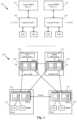
- FIG. 3illustrates implementation of different logical DHCP servers by an active DHCP server module and a standby DHCP server module executing on two different edge nodes of an edge cluster. This figure further shows how the physical nodes of the physical network implement the logical forwarding elements and logical DHCP servers of the logical network.
- the top half of the figureillustrates a logical network architecture 301 that includes two logical switches and two logical DHCP servers.
- the two logical switches 305 and 310logically connect four DCNs VM 1 -V 4 to two different logical networks.
- the logical switch 305is also connected to logical DHCP server 315 which provides DHCP services to DCNs VM 1 and VM 2
- the logical switch 310is connected to logical DHCP server 320 which provides DHCP services to DCNs VM 3 and VM 4 .
- the virtual machines VM 1 and VM 2are logically connected to each other (and other machines) in a first logical network
- the virtual machines VM 3 and VM 4are logically connected to each other (and other machines) in a second logical network.
- the first logical switchhas a first subnet address (i.e., 1.1.1.0/24) specified by a user.
- a first tenanthas specified that any DCN that is coupled to the first logical switch has to be assigned an IP address that falls under the first subnet address range and provided by the first logical DHCP server 315 .
- the second logical switchhas a same subnet address (i.e., 1.1.1.0/24) assigned to it.
- a second tenant of the datacenterhas specified that any DCN that is coupled to the second logical switch has to be assigned an IP address (by the second logical DHCP server) that falls under the second subnet address range, which is the same range as the first subnet address range.
- a central DHCP server modulethat implements both logical DHCP servers 315 and 320 receives a request to assign an IP address to one of the VMs, the module should be able to identify from which logical switch and network the request is received and provide the IP address according to the requirements (i.e., DHCP configuration) of that logical switch and network.
- the bottom half of the figureillustrates the physical network architecture 302 that implements the logical network 301 .
- the physical nodes shown in bottom half of the figureinclude two gateway machines 325 and 330 as the edge nodes, and two host machines 335 and 340 which host virtual machines of different logical networks.
- Each of the illustrated physical nodesincludes a set of MFEs 350 (e.g., operating in the virtualization software of the physical nodes in some embodiments).
- the host machine 335hosts the virtual machines VM 1 and VM 3 along a set of other data compute nodes, while the host machine 340 hosts the virtual machines VM 2 and VM 4 along a set of other data compute nodes.
- the gateway machine 325implements (i.e., executes) an active DHCP server module 360
- the gateway machine 330implements a standby DHCP server module 370 .
- the two active and standby edge nodes 325 and 330can be selected from the edge cluster manually (e.g., by a network administrator), or alternatively they can be selected automatically by the management plane. Having an active-standby design for DHCP server modules enables the network to implement a failover process and to provide continuity in providing DHCP services.
- the forwarding addresses of the standby edge node 330e.g., the MAC/VTEP mapping of the logical switch ports
- the host machineslearn the IP address of the standby edge node during the failover process.
- a standby DHCP server module running on a standby edge nodetakes over the responsibilities of an active DHCP server module running on an active edge node, it sends messages to all of the host machines (i.e., the MFEs running on the host machines) that implement the corresponding logical DHCP servers to force the host machines to learn the new location of the DHCP server module (e.g., the IP address of MFE 4 ).
- the standby DHCP server moduleWhen a failover process is activated and the standby edge node takes over a DHCP server module from an active edge node, the standby DHCP server module has to know about the existing leases handed out by the previously active edge node. Some embodiments periodically sync the leases (and other DHCP options and parameters) between the active and standby edge nodes. In some such embodiments, the sync process on the active edge node monitors the DHCP databases(s) (e.g., a lease table in the database) on the active edge node and sends any new changes to the standby edge node to update its corresponding databases.
- DHCP databases(s)e.g., a lease table in the database
- the lease sync processalso syncs the DHCP parameters with the other edge node.
- the CCP clusterkeeps track of the different active-standby edge nodes in the edge cluster that are assigned by the user or the management plane.
- Each set of MFEs 350implements the logical forwarding elements (LFEs) of the logical network by performing the forwarding processing of the LFEs for the packets that are received from or sent to the corresponding VMs that are connected to the MFEs.
- LFEslogical forwarding elements
- the number of MFEs in a set of MFEs that implement the logical elementsmay vary.
- each MFE in the setmay implement a certain number of logical elements, a certain type of logical elements, or a combination of both.
- MFEslogical forwarding elements
- a first logical port of the logical switch 305is mapped to a physical port of MFE 1 that is coupled to VM 1 executing on the first host machine 335 .
- a second logical port of the logical switch 305is mapped to a physical port of MFE 2 that is coupled to VM 2 executing on the second host machine 340 .
- a first logical port of the logical switch 310is mapped to another physical port of MFE 1 that is coupled to VM 3 executing on the first host machine 335
- a second logical port of the logical switch 310is mapped to anther physical port of MFE 2 that is coupled to VM 2 executing on the second host machine 340 .
- a third set of MFEs that operates on the gateway machine 325also implements the same first and second logical switches 305 and 310 . However, as shown in the figure, this set of MFEs implements the logical ports of these logical switches that are connected to the logical DHCP servers 315 and 320 . More specifically, a DHCP logical port of the logical switch 305 is mapped to a physical port of MFE 3 that is coupled to the active DHCP server module 360 . Additionally, a DHCP logical port of the logical switch 510 is also mapped to the same physical port of MFE 3 that is coupled to the MDP server module 360 . The fourth set of MFEs which operates on the standby edge node 330 functions the same as described for the third set of MFEs operating on the active edge node 325 .
- each of the gateway machines 325 and 330also executes a service router (e.g., a service routing instance or application) that implements the corresponding DHCP server module shown in the figure.
- the MFEsare also connected to each other through the illustrated tunnels in order to exchange network data after performing the forwarding functionalities of the logical forwarding elements.
- two end machines that are connected to the same logical switchare hosted by two different host machines (e.g., VM 1 and VM 2 that are connected to the same logical switch, execute on two different host machines Host 1 and Host 2 ), two or more end machines that are connected to a same logical switch may operate on the same host machine.
- the virtual machines VM 1 and VM 3communicate (e.g., exchange network data) with each other, with the virtual machines VM 2 and VM 4 , and with the external networks via the managed forwarding elements that implement the logical entities of the logical network 301 .
- the MFEs 350 operating on the host machinesare physical software switches provided by the hypervisors or other virtualization software of the host machines. These MFEs perform the entire first-hop forwarding processing for the logical switches 305 and 310 on packets that are received from the virtual machines VM 1 -VM 4 of the logical network 301 .
- the MFEs residing on the host machines Host 1 and Host 2may also implement logical switches (and distributed logical routers) for other logical networks if the other logical networks have VMs that reside on the host machines Host 1 and Host 2 as well.
- each set of MFEs 350may perform first hop processing, each set of MFEs implements all of the logical forwarding elements including the logical switches 305 and 310 , as well as the logical DHCP servers 315 and 320 that are connected to these logical switches.
- the MFEsmay be flow-based forwarding elements (e.g., Open vSwitches) or code-based forwarding elements (e.g., ESX software switches), or a combination of the two, in various different embodiments. These different types of forwarding elements implement the various logical forwarding elements differently, but in each case they execute a pipeline for each logical forwarding element that may be required to process a packet.
- an MFEwhen an MFE receives a packet from a VM that is coupled to the MFE, it performs the forwarding processing for the logical switch to which that VM logically couples.
- the MFEalso performs the forwarding processing for any additional logical forwarding elements (e.g., logical router processing if the packet is sent to an external network, logical router processing and processing for the other logical switch in the network if the packet is sent to an end machine coupled to the other logical switch, etc.).
- additional logical forwarding elementse.g., logical router processing if the packet is sent to an external network, logical router processing and processing for the other logical switch in the network if the packet is sent to an end machine coupled to the other logical switch, etc.
- the management and control planesdistribute the management and forwarding data of the L2 logical switches 305 and 310 , and the logical DHCP servers 315 and 320 to the MFEs 350 in order for the MFEs to implement these logical forwarding elements and servers. Additionally, the management and control plane distribute the management and forwarding data of the physical DHCP server modules 315 and 320 to the gateway machines 325 and 330 to implement the logical DHCP servers (i.e., one as an active server module and the other one as a standby server module) and provide the requested DHCP services to the DCNs.
- the logical DHCP serversi.e., one as an active server module and the other one as a standby server module
- FIG. 4illustrates an example flow of a DHCP packet that is generated and sent from a DCN to request a particular DHCP service (e.g., request an IP address after the DCN starts). More specifically, this figure shows, through four different stages 405 - 420 , how a packet is forwarded through the physical network elements that implement the logical network 301 shown in FIG. 3 . This figure also shows how an MFE (in a set of MFEs) that executes on an edge node adds additional logical network information to the DHCP packet so that the DHCP server module can recognize which DHCP database (or which DHCP table in a single database) should be used to provide the requested DHCP service to the requesting DCN.
- MFEin a set of MFEs
- the first stage 305shows that VM 2 , which runs on the host machine 340 , has generated and forwarded a broadcast DHCP packet 430 (e.g., a discovery packet) to the managed forwarding element MFE 2 that also operates on the host machine 340 .
- the packetis being forwarded to MFE 2 because this managed forwarding element implements the logical port of the logical switch to which VM 2 is logically connected (as shown in the logical network 301 of FIG. 3 ). Since packet 430 is a broadcast packet and one of the logical ports of the logical switch 305 is connected to the logical DHCP server 315 , the MFE starts processing the pipeline of logical DHCP server 315 .
- the datapath on MFE 2initially runs the logical switch 305 pipeline (e.g., based on the ingress port through which the packet is received, the source MAC address, etc.).
- This pipelinespecifies to forward the packet to the logical DHCP port of the logical switch (e.g., since the packet is a broadcast packet and this port is one of the ports on the logical switch).
- the pipelinethen identifies MFE 3 that executes on the edge node 325 as the MFE that performs the forwarding processing for the logical DHCP port of the logical switch (i.e., LDS 1 port implemented on MFE shown in FIG. 3 ).
- the second stage 410shows that MFE 2 has identified the gateway machine 325 as the machine that hosts MFE 3 which implements the logical DHCP port of the logical switch.
- MFE 2encapsulates the packet 435 with the required data to send the packet to MFE 3 that runs on the identified gateway machine 325 (e.g., MFE 2 adds its own IP address to the outer packet header as the source VTEP and the IP address of MFE 3 as the destination VTEP).
- the configuration data that the management planee.g., a manager in the management cluster
- distributes to the MFEsincludes forwarding data that defines how to set up tunnels between the MFEs.
- the configuration dataspecifies the location (e.g., IP address) of each MFE as a virtual tunnel endpoint (VTEP).
- the different MFEsreceive the tunnel endpoint addresses of the other MFEs that implement the logical forwarding elements from the CCP cluster and store these addresses in the MFEs' corresponding VTEP tables. The MFEs then use these VTEP tables to establish tunnels between each other.
- each source VTEPuses its corresponding VTEP table data to encapsulate the packets received form a source VM.
- the source VTEPencapsulates the packets using a particular tunnel protocol (e.g., VXLAN protocol), and forwards the packets towards the destination VTEP.
- the destination VTEPthen decapsulates the packets using the same particular tunnel protocol and forwards the packets towards a destination VM.
- the third stage 415shows that MFE 3 on the gateway machine 325 receives the packet 435 , decapsulates it (i.e., removes the tunneling data in the outer header of the packet), and identifies the DHCP server module 315 based on the logical context information in the packet as well as the destination MAC address that corresponds to the DHCP server module 315 .
- MFE 3adds logical network data to the packet.
- the managed forwarding element MFE 3since the managed forwarding element MFE 3 knows that the packet is received from a logical port of the logical switch 305 that belongs to a particular logical network (e.g., with a LNI value of LNI-1), the MFE 3 inserts the logical network identifier to the packet. As shown in this stage, the packet 440 now includes additional identification information (e.g., in the payload of the packet) to identify the logical switch and network from which the packet is received.
- additional identification informatione.g., in the payload of the packet
- the MFE 3inserts the logical network identifier (LNI) to a particular sub-option field (e.g., Circuit ID sub-option, Remote ID sub-option, etc.) of a particular DHCP option (e.g., DHCP option 82 ) of the DHCP packet 440 in some embodiments.
- the MFE 3inserts the LNI in one sub-option field (e.g., Circuit ID) and an identifier value for the logical switch 305 in another sub-option field (e.g., Remote ID sub-option).
- This stagealso shows that the DHCP server module 360 is connected to two databases 450 and 460 .
- the first database 450stores the DHCP configuration data for the first logical network that includes the logical switch 305
- the second database 460stores the DHCP configuration data for the second logical network that includes the logical switch 310 .
- the fourth stage 420illustrates that after the DHCP server module receives the packet 440 , the module starts analyzing the packet to identify the DHCP database that should be used to retrieve the requested data.
- the DHCP server module 360reads the inserted data in the packet and matches the data against a local table that includes all of the logical switches and networks identification information. This table is described in more detail below by reference to FIG. 6 . After finding a match, the module retrieves the required data from a DHCP database that is in the matched record of the table.
- the DHCP server modulehas identified the DHCP database 450 , which is highlighted in the figure, as the database that includes the required data for providing the requested DHCP service. For example, the module retrieves an IP address from an IP pool stored in this database for VM 2 which requested an IP address. The module may also retrieve a static IP address from the database, e.g., when the MAC address of the requesting DCN dictates assignment of a static IP address. The DHCP server module ultimately sends the retrieved IP address to the requesting DCN.
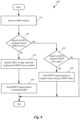
- FIG. 5conceptually illustrates a process 500 of some embodiments for generating a DHCP profile and a logical DHCP server that uses this profile in order to provide DHCP services to one or more subnets of a logical network.
- the process 500is performed by a management plane (e.g., a manager machine, a manager process, etc.) in some embodiments. In some other embodiments, the process is performed by a combination of management and control planes of a hosting system.
- a management planee.g., a manager machine, a manager process, etc.
- the processstarts by receiving (at 510 ) a definition of a logical switch.
- a usermay define any new logical element such as a logical switch through API calls to the management plane.
- the processreceives (at 520 ) a definition of a logic DHCP server to which the logical switch is bound. That is, the user specifies the logical DHCP server, from which, the DCNs that are logically connected to the logical switch receive DHCP services.
- the process of some embodimentsconfigures (at 530 ) the DHCP server module to implement the logical DHCP server.
- the userfirst defines a DHCP profile the attributes of which can be shared by multiple logical DHCP servers.
- the DHCP profile attributesinclude, but are not limited to, a default gateway for the subnet, specification of the edge cluster (e.g., MAC/VTEP mappings of active and standby edge nodes in the edge cluster), commonly used DHCP parameters (e.g., domain name, lease period, etc.), static bindings, IP pools, etc.
- the userthen defines a new logical DHCP server by specifying the DHCP profile from which, the logical DHCP server inherits its attributes.
- the usermay create, modify, or delete a logical DHCP server, the DHCP options for an IP pool that the logical DHCP server uses (if dynamic range is configured) or a particular DCN for the logical DHCP (if static binding is used), etc.
- a DHCP parametere.g., an IP pool
- a general parameterthat is defined for the associated DHCP profile. For example, if the user defines a particular lease time (for IP address) for a logical DHCP server, when the DHCP server module specifies the lease time for a DCN's IP address, the module uses the particular lease time specified in the logical server definition and not the general lease time that is specified in the DHCP profile based on which the logical DHCP server is defined.
- the management planegenerates one or more DHCP configuration databases (e.g., stored in one or more edge nodes that implement the DHCP server modules) that keep the DHCP profile's data and logical servers' data for each logical network.
- the processAfter configuring the logical DHCP server, the process generates (at 540 ) a new logical DHCP server port on the logical switch and assigns MAC and IP addresses to the generated logical port. That is, the process assigns a unique MAC and IP addresses to the logical DHCP port of the logical switch in order to couple the logical port to a physical DHCP server module executing on an edge node (e.g., a DHCP module in a service router that executes on the edge node).
- This unique MAC and OP addressesare associated with a DHCP server module that runs on an edge node or a host and will be shared by every logical DHCP server in some embodiments.
- the MFE that implements the logical switch's pipelinelooks for the IP address of the DHCP port of the logical switch (e.g., kept in forwarding tables of the MFE). From the forwarding data, the MFE identifies the other MFE that implements the DHCP port of the logical switch (which executes on the edge node that implements the HDCP server module). As such, the packet will be forwarded (by the MFE that implements the logical switch on the host machine) to the proper DHCP server module. The process then ends.
- the specific operations of the process 500may not be performed in the exact order shown and described.
- the specific operationsmay not be performed in one continuous series of operations, and different specific operations may be performed in different embodiments.
- some embodimentsfirst receive a logical DHCP server definition and configure the logical DHCP server on a physical DHCP server module. These embodiments then receive the logical switch's definition and assign the configured logical DHCP server to the logical switch.
- the process 500could be implemented using several sub-processes, or as part of a larger macro process.
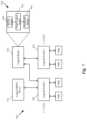
- FIG. 6conceptually illustrates an example block diagram of an edge node (e.g., a gateway machine) that implements a DHCP server module.
- the figureshows a gateway machine 610 that includes a DHCP server module 620 , a local controller 630 , an MFE 640 , a DHCP configuration data storage 650 , and a DHCP map data storage 660 that includes a map table 670 .
- the local controller 630receives a logical DHCP server's configuration data (from the CCP cluster) and stores this data (e.g., the IP pool of the DHCP server, the binding logical switch, the lease periods, etc.) in the DHCP configuration data storage 650 .
- the local controller 630adds and/or updates the data in the mapping table 670 based on the forwarding and management data that the local controller receives from the controller cluster.
- the DHCP server module 620receives the required configuration data for each logical network from the data storage 650 .
- the DHCP server module 620also updates the data in the data storage 650 based on the requests that it receives and the services that it provides. For example, when a lease is handed out or renewed, the DHCP server module writes the lease information to a table of the data storage 650 .
- the DHCP server modulealso updates the mapping data in the mapping table 670 at runtime.
- the MFE 640 on the edge nodereceives a DHCP packet, based on the logical switch from which the broadcast packet is received, inserts a unique identifier value to the packet (e.g., to a sub-option field of option 82 ).
- the identifier valueis a universally unique identifier (UUID) that is global for all of the logical switches of the logical networks.
- the inserted identifieris an identification value of the logical switch itself that is a global value as well.
- the inserted identifieris the logical network identifier that as unique between all logical networks.
- the MFEinserts both of the identification values of the logical switch and the logical network to the received DHCP packet.
- the MFE 640then sends the packet to the DHCP server module 620 .
- the DHCP server modulebased on the inserted identification value in the packet, identifies the logical DHCP server and logical switch from which the packet is received.
- the DHCP server module 620reads the identification value, e.g., that is stored in the circuit ID sub-option field in the packet, and compares this value against the mapping table 670 . For instance, in the illustrated example, if the circuit ID value of the DHCP packet is “12cj14g,” the DHCP server module realizes that the the packet is received from the logical switch LS 2 in logical network 20 .
- the DHCP server modulelooks up the requested DHCP service in the related section of the data storage 650 . For example, if a DCN that is connected the logical switch LS 2 has sent an IP address request, the DHCP server module 620 looks up in the LS 2 section's records (or the logical network 20 section) in the database, and pulls an IP address from the IP pool that is stored in that section.
- the DHCP server moduleAfter retrieving the service that was requested, the DHCP server module sends a DHCP service packet back to the requesting DCN (or relay agent), through the MFE of the edge node. That is, the module requesting DCN's MAC address as the destination MAC address to the packet and sends the packet to the edge node's MFE.
- the MFEin turn identifies the host machine that implements the logical switch and forwards (i.e., tunnels) the packet to the MFE of the host machine, which in turn forwards the packet with the new IP address to the DCN.
- some embodimentsassign a DHCP server module (and a standby module) to implement a set of logical DHCP servers that belongs to one or more logical networks. For example, when the number of logical switches in one logical network grows, or the number of logical networks surpasses a threshold, some embodiments add another DHCP module to handle the logical DHCP servers for the additional logical switches and/or networks.
- a usermay query the management plane for the status of a logical DHCP server in a logical network or the status of a physical DHCP server module that implements one or more logical DHCP servers.
- the queried statusmay include the IP pools' status, the lease information, etc., of one or more logical DHCP servers implemented by the DHCP server module.
- the DHCP related states of the logical DHCP serversare reported to the user (through the management plane) upon occurrence of a particular event.
- the DHCP states of the logical DHCP serversare reported to one or more users each time a new logical router is added to a logical network.
- the statusis reported each time an edge node that implements a DHCP server module fails. Some other embodiments generate status reports periodically.
- a logical routerthat acts as a relay agent couples to a logical switch that is connected to a logical DHCP server and receives DHCP services.
- the logical routercan be configured to act as a relay agent and provide the DHCP services of the logical DHCP server to a set of DCNs connected to the other logical switch (i.e., the logical switch to which no logical DHCP server is coupled).
- a logical routerWhen a logical router functions as a relay agent between two logical switches of the same logical network, some embodiments require the two logical switches to be on two different subnets of the logical network (i.e., two subnets that do not have overlapping IP address ranges).
- FIG. 7illustrates a logical router that acts as a DHCP relay agent to provide DHCP services to a logical switch that is not bound to any logical DHCP server. More specifically, this figure shows a logical network 700 that includes two logical switches 705 and 710 of a logical network that logically connect four DCNs VM 1 -V 4 to each other (and to other DCNs). The logical switch 705 is also connected to a logical DHCP server 715 which provides DHCP services to DCNs VM 1 and VM 2 . However, the logical switch 710 is not connected to any logical DHCP server and instead is logically coupled to the logical router 720 .
- the logical router 720is also couple to a logical port of the first logical switch 705 .
- the logical routercan act as a DHCP relay agent that relays the DHCP requests coming from the second logical switch 710 to the logical DHCP server 715 and also relays the DHCP services of the logical DHCP server to the DCNs that are coupled to logical switch 710 (i.e., VM 3 and VM 4 ).
- the first logical switchhas a first subnet address (i.e., 1.1.1.0/24) assigned to it, while the second logical switch has a second, different subnet address (i.e., 1.1.2.0/24) assigned to it.
- a relay agenti.e., logical router
- a userdefines a logical router for the logical network through the management plane. That is, the user makes one or more API calls to a manager of the network to define the logical router.
- the management planethen generates and pushes the configuration data for the defined logical router to the control plane.
- the control planeafter receiving the configuration data of the logical router, creates a single distributed routing component (also referred to as a distributed router (DR)) and one or more service routing components (also referred to as service routers (SRs)).
- DRdistributed router
- SRsservice routers
- the DRin some embodiments, spans managed forwarding elements (MFEs) that couple directly with virtual machines (VMs) or other data compute nodes that are logically connected, directly or indirectly, to the logical router.
- MFEsmanaged forwarding elements
- the DR of some embodimentsalso spans the gateways to which the logical router is bound.
- the DR of some embodimentsis responsible for first-hop distributed routing between logical switches and/or other logical routers that are logically connected to the logical router.
- the service routers (SRs) of some embodimentsare responsible for delivering services that are not implemented in a distributed fashion (e.g., some stateful services) as well as connecting the logical network to external network(s).
- some embodimentsimplement the DHCP server module as part of the service router of the logical router.
- a distributed logical routerwill have SRs if either (i) the logical router is a provider logical router (PLR), and therefore connects to external physical networks or (ii) the logical router has services configured that do not have a distributed implementation (e.g., NAT, load balancing, DHCP in some embodiments). Even if there are no stateful services configured on a PLR, some embodiments use SRs for failure handling and for ECMP.
- PLRprovider logical router
- Logical routersin some embodiments, can be viewed from three different perspectives.
- the first of these viewsis the API view, or configuration view, which is how the user (e.g., a datacenter provider or tenant) views and defines the logical router.
- the logical router 720is how the user views the logical router in the logical network.
- the second viewis the control plane or management plane view, which is how the controller computer internally defines the logical router.
- the third viewis the physical realization, or implementation of the logical router, which is how the logical router is actually implemented in the physical network.
- the control/management plane view 730 of the logical router 720shows that the control plane has generated a service router 740 , a transit logical switch 750 , and a distributed router 760 for the logical router.
- the transit logical switch 210has different logical ports for each of the created routers, and each of the routing components 740 and 760 has an interface to logically connect to the transit logical switch 750 .
- the service router 740is implemented on a gateway machine, while the transit logical switch 750 and the distributed router 760 are implemented across all of the host machines and gateway machines of the logical network.
- the MFE of the host machine that implements the logical port of the logical switch 710which is coupled to the DR 760 , catches the packet. Since the packet is a DHCP broadcast packet, the DR 760 pipeline realizes that the packet should be sent to the logical switch 705 which is connected to the logical DHCP server.
- the MFEforwards (i.e., tunnels) the packet to the MFE that implements the port of logical switch 710 that is coupled to the logical DHCP server 715 .
- the DHCP packetthen is forwarded to a gateway machine that implements the corresponding DHCP server module (e.g., that is implemented by the SR 740 , or another SR of another logical router).
- FIG. 8conceptually illustrates a process 800 of some embodiments that receives a DHCP packet from a data compute node and processes the packet.
- the processis performed by a managed forwarding element.
- the managed forwarding elementexecutes on an edge node in some embodiments. In some other embodiments the managed forwarding element executes on a host machine.
- the processstarts by receiving (at 810 ) a DHCP packet from a data compute node (e.g., a virtual machine that runs on a host machine).
- a data compute nodee.g., a virtual machine that runs on a host machine
- the packetcan be a DHCP discovery request (e.g., when the virtual machine starts operating on the host machine) or any other DHCP service request (e.g., a lease renewal request).
- the broadcast packetas described above, is received at a logical port of a logical switch that is coupled to the requesting DCN.
- the processdetermines (at 820 ) whether the logical switch that receives the DHCP packet is bound to a logical DHCP server or not. In other words, the process determines whether a user has defined a logical DHCP server associated with the logical switch or not. The process of some embodiments makes such a determination by determining whether a logical DHCP server port is defined and created for the logical switch.
- the processdetermines that the logical switch is bound to a logical DHCP server, the process identifies (at 830 ) the tunnel endpoint to which the DHCP packet should be forwarded.
- the processidentifies the tunnel endpoint by identifying the IP address that is assigned to the logical DHCP server. This IP address is in fact the IP address of a managed forwarding element that runs on the same gateway machine on which the DHCP server module executes.
- the process of some embodimentssends (at 840 ) the DHCP packet to the identified MFE. As described above, the process encapsulates the packet with the required tunneling data and tunnels the packet to the edge node MFE. The process then ends. However, if the process determines that the logical switch is not bound to any logical DHCP server, the process determines (at 850 ) whether the logical switch is bound to a DHCP relay logical router. When the process determines that the logical switch is not coupled to such a logical router, in some embodiments, the process returns an error. In some other embodiments, the process drops the DHCP packet. The process then ends.
- forwarding the packet to the logical routerincludes sending the packet from the logical switch's pipeline to the DR's pipeline both of which execute on the same managed forwarding element that is connected to the requesting DCN.
- forwarding the packet to the logical routerincludes sending the packet from the logical switch's pipeline to the DR's pipeline both of which execute on the same managed forwarding element that is connected to the requesting DCN.
- process 800may not be performed in the exact order shown and described. The specific operations may not be performed in one continuous series of operations, and different specific operations may be performed in different embodiments. Additionally, one of ordinary skill in the art would realize that the process 800 could be implemented using several sub-processes, or as part of a larger macro process.
- Computer readable storage mediumalso referred to as computer readable medium.
- these instructionsare executed by one or more computational or processing unit(s) (e.g., one or more processors, cores of processors, or other processing units), they cause the processing unit(s) to perform the actions indicated in the instructions.
- computational or processing unit(s)e.g., one or more processors, cores of processors, or other processing units
- Examples of computer readable mediainclude, but are not limited to, CD-ROMs, flash drives, random access memory (RAM) chips, hard drives, erasable programmable read-only memories (EPROMs), electrically erasable programmable read-only memories (EEPROMs), etc.
- the computer readable mediadoes not include carrier waves and electronic signals passing wirelessly or over wired connections.
- the term “software”is meant to include firmware residing in read-only memory or applications stored in magnetic storage, which can be read into memory for processing by a processor.
- multiple software inventionscan be implemented as sub-parts of a larger program while remaining distinct software inventions.
- multiple software inventionscan also be implemented as separate programs.
- any combination of separate programs that together implement a software invention described hereis within the scope of the invention.
- the software programswhen installed to operate on one or more electronic systems, define one or more specific machine implementations that execute and perform the operations of the software programs.
- FIG. 9conceptually illustrates an electronic system 900 with which some embodiments of the invention are implemented.
- the electronic system 900may be a computer (e.g., a desktop computer, personal computer, tablet computer, etc.), server, dedicated switch, phone, PDA, or any other sort of electronic or computing device.
- Such an electronic systemincludes various types of computer readable media and interfaces for various other types of computer readable media.
- Electronic system 900includes a bus 905 , processing unit(s) 910 , a system memory 925 , a read-only memory 930 , a permanent storage device 935 , input devices 940 , and output devices 945 .
- the bus 905collectively represents all system, peripheral, and chipset buses that communicatively connect the numerous internal devices of the electronic system 900 .
- the bus 905communicatively connects the processing unit(s) 910 with the read-only memory 930 , the system memory 925 , and the permanent storage device 935 .
- the processing unit(s) 910retrieves instructions to execute and data to process in order to execute the processes of the invention.
- the processing unit(s)may be a single processor or a multi-core processor in different embodiments.
- the read-only-memory (ROM) 930stores static data and instructions that are needed by the processing unit(s) 910 and other modules of the electronic system.
- the permanent storage device 935is a read-and-write memory device. This device is a non-volatile memory unit that stores instructions and data even when the electronic system 900 is off. Some embodiments of the invention use a mass-storage device (such as a magnetic or optical disk and its corresponding disk drive) as the permanent storage device 935 .
- the system memory 925is a read-and-write memory device. However, unlike storage device 935 , the system memory 925 is a volatile read-and-write memory, such a random access memory.
- the system memory 925stores some of the instructions and data that the processor needs at runtime.
- the invention's processesare stored in the system memory 925 , the permanent storage device 935 , and/or the read-only memory 930 . From these various memory units, the processing unit(s) 910 retrieves instructions to execute and data to process in order to execute the processes of some embodiments.
- the bus 905also connects to the input and output devices 940 and 945 .
- the input devices 940enable the user to communicate information and select commands to the electronic system.
- the input devices 940include alphanumeric keyboards and pointing devices (also called “cursor control devices”), cameras (e.g., webcams), microphones or similar devices for receiving voice commands, etc.
- the output devices 945display images generated by the electronic system or otherwise output data.
- the output devices 945include printers and display devices, such as cathode ray tubes (CRT) or liquid crystal displays (LCD), as well as speakers or similar audio output devices. Some embodiments include devices such as a touchscreen that function as both input and output devices.
- CTRcathode ray tubes
- LCDliquid crystal displays
- bus 905also couples electronic system 900 to a network 965 through a network adapter (not shown).
- the computercan be a part of a network of computers (such as a local area network (“LAN”), a wide area network (“WAN”), or an Intranet, or a network of networks, such as the Internet. Any or all components of electronic system 900 may be used in conjunction with the invention.
- Some embodimentsinclude electronic components, such as microprocessors, storage and memory that store computer program instructions in a machine-readable or computer-readable medium (alternatively referred to as computer-readable storage media, machine-readable media, or machine-readable storage media).
- computer-readable mediainclude RAM, ROM, read-only compact discs (CD-ROM), recordable compact discs (CD-R), rewritable compact discs (CD-RW), read-only digital versatile discs (e.g., DVD-ROM, dual-layer DVD-ROM), a variety of recordable/rewritable DVDs (e.g., DVD-RAM, DVD-RW, DVD+RW, etc.), flash memory (e.g., SD cards, mini-SD cards, micro-SD cards, etc.), magnetic and/or solid state hard drives, read-only and recordable Blu-Ray® discs, ultra density optical discs, any other optical or magnetic media, and floppy disks.
- CD-ROMcompact discs
- CD-Rrecordable compact discs
- the computer-readable mediamay store a computer program that is executable by at least one processing unit and includes sets of instructions for performing various operations.
- Examples of computer programs or computer codeinclude machine code, such as is produced by a compiler, and files including higher-level code that are executed by a computer, an electronic component, or a microprocessor using an interpreter.
- ASICsapplication specific integrated circuits
- FPGAsfield programmable gate arrays
- PLDsprogrammable logic devices
- ROMread only memory
- RAMrandom access memory
- the terms “computer”, “server”, “processor”, and “memory”all refer to electronic or other technological devices. These terms exclude people or groups of people.
- display or displayingmeans displaying on an electronic device.
- the terms “computer readable medium,” “computer readable media,” and “machine readable medium”are entirely restricted to tangible, physical objects that store information in a form that is readable by a computer. These terms exclude any wireless signals, wired download signals, and any other ephemeral signals.
- DCNsdata compute nodes
- addressable nodesmay include non-virtualized physical hosts, virtual machines, containers that run on top of a host operating system without the need for a hypervisor or separate operating system, and hypervisor kernel network interface modules.
- VMsin some embodiments, operate with their own guest operating systems on a host using resources of the host virtualized by virtualization software (e.g., a hypervisor, virtual machine monitor, etc.).
- the tenanti.e., the owner of the VM
- Some containersare constructs that run on top of a host operating system without the need for a hypervisor or separate guest operating system.
- the host operating systemuses name spaces to isolate the containers from each other and therefore provides operating-system level segregation of the different groups of applications that operate within different containers.
- This segregationis akin to the VM segregation that is offered in hypervisor-virtualized environments that virtualize system hardware, and thus can be viewed as a form of virtualization that isolates different groups of applications that operate in different containers.
- Such containersare more lightweight than VMs.
- Hypervisor kernel network interface modulesin some embodiments, is a non-VM DCN that includes a network stack with a hypervisor kernel network interface and receive/transmit threads.
- a hypervisor kernel network interface moduleis the vmknic module that is part of the ESXiTM hypervisor of VMware, Inc.
- VMsvirtual machines
- examples givencould be any type of DCNs, including physical hosts, VMs, non-VM containers, and hypervisor kernel network interface modules.
- the example networkscould include combinations of different types of DCNs in some embodiments.
- packetis used throughout this application to refer to a collection of bits in a particular format sent across a network. It should be understood that the term “packet” may be used herein to refer to various formatted collections of bits that may be sent across a network. A few examples of such formatted collections of bits are Ethernet frames, TCP segments, UDP datagrams, IP packets, etc.
- FIGS. 5 and 8conceptually illustrate processes. The specific operations of these processes may not be performed in the exact order shown and described. The specific operations may not be performed in one continuous series of operations, and different specific operations may be performed in different embodiments. Furthermore, the process could be implemented using several sub-processes, or as part of a larger macro process. Thus, one of ordinary skill in the art would understand that the invention is not to be limited by the foregoing illustrative details, but rather is to be defined by the appended claims.
Landscapes
- Engineering & Computer Science (AREA)
- Computer Networks & Wireless Communication (AREA)
- Signal Processing (AREA)
- Data Exchanges In Wide-Area Networks (AREA)
Abstract
Description
Claims (22)
Priority Applications (1)
| Application Number | Priority Date | Filing Date | Title |
|---|---|---|---|
| US17/079,461US11855959B2 (en) | 2016-04-29 | 2020-10-24 | Implementing logical DHCP servers in logical networks |
Applications Claiming Priority (3)
| Application Number | Priority Date | Filing Date | Title |
|---|---|---|---|
| US201662329958P | 2016-04-29 | 2016-04-29 | |
| US15/420,070US10841273B2 (en) | 2016-04-29 | 2017-01-30 | Implementing logical DHCP servers in logical networks |
| US17/079,461US11855959B2 (en) | 2016-04-29 | 2020-10-24 | Implementing logical DHCP servers in logical networks |
Related Parent Applications (1)
| Application Number | Title | Priority Date | Filing Date |
|---|---|---|---|
| US15/420,070ContinuationUS10841273B2 (en) | 2016-04-29 | 2017-01-30 | Implementing logical DHCP servers in logical networks |
Publications (2)
| Publication Number | Publication Date |
|---|---|
| US20210058365A1 US20210058365A1 (en) | 2021-02-25 |
| US11855959B2true US11855959B2 (en) | 2023-12-26 |
Family
ID=60159160
Family Applications (2)
| Application Number | Title | Priority Date | Filing Date |
|---|---|---|---|
| US15/420,070Active2037-03-31US10841273B2 (en) | 2016-04-29 | 2017-01-30 | Implementing logical DHCP servers in logical networks |
| US17/079,461ActiveUS11855959B2 (en) | 2016-04-29 | 2020-10-24 | Implementing logical DHCP servers in logical networks |
Family Applications Before (1)
| Application Number | Title | Priority Date | Filing Date |
|---|---|---|---|
| US15/420,070Active2037-03-31US10841273B2 (en) | 2016-04-29 | 2017-01-30 | Implementing logical DHCP servers in logical networks |
Country Status (1)
| Country | Link |
|---|---|
| US (2) | US10841273B2 (en) |
Families Citing this family (83)
| Publication number | Priority date | Publication date | Assignee | Title |
|---|---|---|---|---|
| US9225638B2 (en) | 2013-05-09 | 2015-12-29 | Vmware, Inc. | Method and system for service switching using service tags |
| US10749711B2 (en) | 2013-07-10 | 2020-08-18 | Nicira, Inc. | Network-link method useful for a last-mile connectivity in an edge-gateway multipath system |
| US10454714B2 (en) | 2013-07-10 | 2019-10-22 | Nicira, Inc. | Method and system of overlay flow control |
| US9887960B2 (en) | 2013-08-14 | 2018-02-06 | Nicira, Inc. | Providing services for logical networks |
| US9774537B2 (en) | 2014-09-30 | 2017-09-26 | Nicira, Inc. | Dynamically adjusting load balancing |
| US9755898B2 (en) | 2014-09-30 | 2017-09-05 | Nicira, Inc. | Elastically managing a service node group |
| US10135789B2 (en) | 2015-04-13 | 2018-11-20 | Nicira, Inc. | Method and system of establishing a virtual private network in a cloud service for branch networking |
| US10498652B2 (en) | 2015-04-13 | 2019-12-03 | Nicira, Inc. | Method and system of application-aware routing with crowdsourcing |
| US9825851B2 (en) | 2015-06-27 | 2017-11-21 | Nicira, Inc. | Distributing routing information in a multi-datacenter environment |
| US10484515B2 (en) | 2016-04-29 | 2019-11-19 | Nicira, Inc. | Implementing logical metadata proxy servers in logical networks |
| US10841273B2 (en) | 2016-04-29 | 2020-11-17 | Nicira, Inc. | Implementing logical DHCP servers in logical networks |
| US11394685B2 (en)* | 2016-05-27 | 2022-07-19 | Walmart Apollo, Llc | Systems and methods of database instance container deployment |
| US20200036624A1 (en) | 2017-01-31 | 2020-01-30 | The Mode Group | High performance software-defined core network |
| US20180219765A1 (en) | 2017-01-31 | 2018-08-02 | Waltz Networks | Method and Apparatus for Network Traffic Control Optimization |
| US10992568B2 (en) | 2017-01-31 | 2021-04-27 | Vmware, Inc. | High performance software-defined core network |
| US11706127B2 (en) | 2017-01-31 | 2023-07-18 | Vmware, Inc. | High performance software-defined core network |
| US10778528B2 (en) | 2017-02-11 | 2020-09-15 | Nicira, Inc. | Method and system of connecting to a multipath hub in a cluster |
| US10523539B2 (en) | 2017-06-22 | 2019-12-31 | Nicira, Inc. | Method and system of resiliency in cloud-delivered SD-WAN |
| US11558364B2 (en)* | 2017-07-18 | 2023-01-17 | Nicira, Inc. | Authentication offload in virtualized computing environments |
| US10999100B2 (en) | 2017-10-02 | 2021-05-04 | Vmware, Inc. | Identifying multiple nodes in a virtual network defined over a set of public clouds to connect to an external SAAS provider |
| US10841131B2 (en) | 2017-10-02 | 2020-11-17 | Vmware, Inc. | Distributed WAN security gateway |
| US11115480B2 (en) | 2017-10-02 | 2021-09-07 | Vmware, Inc. | Layer four optimization for a virtual network defined over public cloud |
| US10805181B2 (en) | 2017-10-29 | 2020-10-13 | Nicira, Inc. | Service operation chaining |
| US11223514B2 (en) | 2017-11-09 | 2022-01-11 | Nicira, Inc. | Method and system of a dynamic high-availability mode based on current wide area network connectivity |
| US10805192B2 (en) | 2018-03-27 | 2020-10-13 | Nicira, Inc. | Detecting failure of layer 2 service using broadcast messages |
| US10477382B1 (en)* | 2018-04-18 | 2019-11-12 | Adobe Inc. | Attributing online activities to internet protocol addresses of routers for customizing content to different networks |
| US11595250B2 (en) | 2018-09-02 | 2023-02-28 | Vmware, Inc. | Service insertion at logical network gateway |
| CN116319541B (en)* | 2018-09-02 | 2024-12-13 | 威睿有限责任公司 | Service insertion method, device and system at a logical gateway |
| CN109150638A (en)* | 2018-11-01 | 2019-01-04 | 郑州云海信息技术有限公司 | A kind of route management method and device |
| US11321113B2 (en) | 2019-02-22 | 2022-05-03 | Vmware, Inc. | Creating and distributing service chain descriptions |
| US11171885B2 (en) | 2019-08-27 | 2021-11-09 | Vmware, Inc. | Providing recommendations for implementing virtual networks |
| US11611507B2 (en) | 2019-10-28 | 2023-03-21 | Vmware, Inc. | Managing forwarding elements at edge nodes connected to a virtual network |
| US11140218B2 (en) | 2019-10-30 | 2021-10-05 | Vmware, Inc. | Distributed service chain across multiple clouds |
| US11489783B2 (en) | 2019-12-12 | 2022-11-01 | Vmware, Inc. | Performing deep packet inspection in a software defined wide area network |
| US11394640B2 (en) | 2019-12-12 | 2022-07-19 | Vmware, Inc. | Collecting and analyzing data regarding flows associated with DPI parameters |
| US11223494B2 (en) | 2020-01-13 | 2022-01-11 | Vmware, Inc. | Service insertion for multicast traffic at boundary |
| US11411777B2 (en) | 2020-01-14 | 2022-08-09 | Vmware, Inc. | Port mapping for bonded interfaces of ECMP group |
| WO2021145939A1 (en)* | 2020-01-14 | 2021-07-22 | Vmware, Inc. | Transparent demilitarized zone providing stateful service between physical and logical networks |
| US11418997B2 (en) | 2020-01-24 | 2022-08-16 | Vmware, Inc. | Using heart beats to monitor operational state of service classes of a QoS aware network link |
| US11777899B1 (en)* | 2020-01-24 | 2023-10-03 | Equinix, Inc. | Hierarchical distributed dynamic host configuration protocol system |
| US11792112B2 (en) | 2020-04-06 | 2023-10-17 | Vmware, Inc. | Using service planes to perform services at the edge of a network |
| US11088902B1 (en) | 2020-04-06 | 2021-08-10 | Vmware, Inc. | Synchronization of logical network state between global and local managers |
| US11374817B2 (en) | 2020-04-06 | 2022-06-28 | Vmware, Inc. | Determining span of logical network element |
| US11258668B2 (en) | 2020-04-06 | 2022-02-22 | Vmware, Inc. | Network controller for multi-site logical network |
| US11777793B2 (en) | 2020-04-06 | 2023-10-03 | Vmware, Inc. | Location criteria for security groups |
| US11374850B2 (en)* | 2020-04-06 | 2022-06-28 | Vmware, Inc. | Tunnel endpoint group records |
| US11245641B2 (en) | 2020-07-02 | 2022-02-08 | Vmware, Inc. | Methods and apparatus for application aware hub clustering techniques for a hyper scale SD-WAN |
| US11363124B2 (en) | 2020-07-30 | 2022-06-14 | Vmware, Inc. | Zero copy socket splicing |
| US11757940B2 (en) | 2020-09-28 | 2023-09-12 | Vmware, Inc. | Firewall rules for application connectivity |
| US11425044B2 (en)* | 2020-10-15 | 2022-08-23 | Cisco Technology, Inc. | DHCP layer 2 relay in VXLAN overlay fabric |
| US11444865B2 (en) | 2020-11-17 | 2022-09-13 | Vmware, Inc. | Autonomous distributed forwarding plane traceability based anomaly detection in application traffic for hyper-scale SD-WAN |
| US11575600B2 (en) | 2020-11-24 | 2023-02-07 | Vmware, Inc. | Tunnel-less SD-WAN |
| US11734043B2 (en) | 2020-12-15 | 2023-08-22 | Vmware, Inc. | Providing stateful services in a scalable manner for machines executing on host computers |
| US11929903B2 (en) | 2020-12-29 | 2024-03-12 | VMware LLC | Emulating packet flows to assess network links for SD-WAN |
| US12218845B2 (en) | 2021-01-18 | 2025-02-04 | VMware LLC | Network-aware load balancing |
| CN116783874A (en) | 2021-01-18 | 2023-09-19 | Vm维尔股份有限公司 | Network aware load balancing |
| US11463312B2 (en)* | 2021-01-21 | 2022-10-04 | Cisco Technology, Inc. | Secure onboarding of network devices |
| US11979325B2 (en) | 2021-01-28 | 2024-05-07 | VMware LLC | Dynamic SD-WAN hub cluster scaling with machine learning |
| US12368676B2 (en) | 2021-04-29 | 2025-07-22 | VMware LLC | Methods for micro-segmentation in SD-WAN for virtual networks |
| US12009987B2 (en) | 2021-05-03 | 2024-06-11 | VMware LLC | Methods to support dynamic transit paths through hub clustering across branches in SD-WAN |
| US11637768B2 (en) | 2021-05-03 | 2023-04-25 | Vmware, Inc. | On demand routing mesh for routing packets through SD-WAN edge forwarding nodes in an SD-WAN |
| US11729065B2 (en) | 2021-05-06 | 2023-08-15 | Vmware, Inc. | Methods for application defined virtual network service among multiple transport in SD-WAN |
| US12250114B2 (en) | 2021-06-18 | 2025-03-11 | VMware LLC | Method and apparatus for deploying tenant deployable elements across public clouds based on harvested performance metrics of sub-types of resource elements in the public clouds |
| US11489720B1 (en) | 2021-06-18 | 2022-11-01 | Vmware, Inc. | Method and apparatus to evaluate resource elements and public clouds for deploying tenant deployable elements based on harvested performance metrics |
| US12015536B2 (en) | 2021-06-18 | 2024-06-18 | VMware LLC | Method and apparatus for deploying tenant deployable elements across public clouds based on harvested performance metrics of types of resource elements in the public clouds |
| US12047282B2 (en) | 2021-07-22 | 2024-07-23 | VMware LLC | Methods for smart bandwidth aggregation based dynamic overlay selection among preferred exits in SD-WAN |
| US11375005B1 (en)* | 2021-07-24 | 2022-06-28 | Vmware, Inc. | High availability solutions for a secure access service edge application |
| US12267364B2 (en) | 2021-07-24 | 2025-04-01 | VMware LLC | Network management services in a virtual network |
| US11943146B2 (en) | 2021-10-01 | 2024-03-26 | VMware LLC | Traffic prioritization in SD-WAN |
| US20230179985A1 (en)* | 2021-12-08 | 2023-06-08 | Palo Alto Networks, Inc. | Targeted pdu capture by a network device for roaming detection in wireless networks |
| US12184557B2 (en) | 2022-01-04 | 2024-12-31 | VMware LLC | Explicit congestion notification in a virtual environment |
| US12425395B2 (en) | 2022-01-15 | 2025-09-23 | VMware LLC | Method and system of securely adding an edge device operating in a public network to an SD-WAN |
| CN114584555B (en)* | 2022-03-08 | 2024-06-14 | 浪潮云信息技术股份公司 | Global event distribution method and system in distributed cloud scene |
| US11909815B2 (en) | 2022-06-06 | 2024-02-20 | VMware LLC | Routing based on geolocation costs |
| US12166661B2 (en) | 2022-07-18 | 2024-12-10 | VMware LLC | DNS-based GSLB-aware SD-WAN for low latency SaaS applications |
| US12316524B2 (en) | 2022-07-20 | 2025-05-27 | VMware LLC | Modifying an SD-wan based on flow metrics |
| US12107722B2 (en) | 2022-07-20 | 2024-10-01 | VMware LLC | Sharing network manager between multiple tenants |
| US12184521B2 (en) | 2023-02-23 | 2024-12-31 | VMware LLC | Framework for providing health status data |
| US12034587B1 (en) | 2023-03-27 | 2024-07-09 | VMware LLC | Identifying and remediating anomalies in a self-healing network |
| US12425332B2 (en) | 2023-03-27 | 2025-09-23 | VMware LLC | Remediating anomalies in a self-healing network |
| US12057993B1 (en) | 2023-03-27 | 2024-08-06 | VMware LLC | Identifying and remediating anomalies in a self-healing network |
| US12261777B2 (en) | 2023-08-16 | 2025-03-25 | VMware LLC | Forwarding packets in multi-regional large scale deployments with distributed gateways |
| US12355655B2 (en) | 2023-08-16 | 2025-07-08 | VMware LLC | Forwarding packets in multi-regional large scale deployments with distributed gateways |
Citations (289)
| Publication number | Priority date | Publication date | Assignee | Title |
|---|---|---|---|---|
| US5504921A (en) | 1990-09-17 | 1996-04-02 | Cabletron Systems, Inc. | Network management system using model-based intelligence |
| US5550816A (en) | 1994-12-29 | 1996-08-27 | Storage Technology Corporation | Method and apparatus for virtual switching |
| US5751967A (en) | 1994-07-25 | 1998-05-12 | Bay Networks Group, Inc. | Method and apparatus for automatically configuring a network device to support a virtual network |
| US6006275A (en) | 1992-05-12 | 1999-12-21 | Compaq Computer Corporation | Network connector operable in bridge mode and bypass mode |
| US6104699A (en) | 1994-06-13 | 2000-08-15 | Telefonaktiebolget Lm Ericsson | Method and device for partitioning physical network resources |
| US6205118B1 (en) | 1995-12-28 | 2001-03-20 | Lucent Technologies Inc. | Adaptive time slot scheduling apparatus and method for end-points in an ATM network |
| US6219699B1 (en) | 1996-01-02 | 2001-04-17 | Cisco Technologies, Inc. | Multiple VLAN Architecture system |
| US20010043614A1 (en) | 1998-07-17 | 2001-11-22 | Krishna Viswanadham | Multi-layer switching apparatus and method |
| US20020029287A1 (en)* | 2000-02-02 | 2002-03-07 | Yechiam Yemini | Method and apparatus for dynamically addressing a circuits based network |
| US6359909B1 (en) | 1996-05-09 | 2002-03-19 | Fujitsu Limited | Switch device for relayin G cells or packets on demand |
| US20020093952A1 (en) | 2000-06-30 | 2002-07-18 | Gonda Rumi Sheryar | Method for managing circuits in a multistage cross connect |
| US6456624B1 (en) | 1997-10-29 | 2002-09-24 | Enterasys Networks, Inc. | Network address resolve blocker |
| US20020194369A1 (en) | 2001-03-20 | 2002-12-19 | Worldcom, Inc. | Policy-based synchronization of per-class resources between routers in a data network |
| US6512745B1 (en) | 1996-03-08 | 2003-01-28 | Hitachi, Ltd. | Packet switching network, packet switching equipment, and network management equipment |
| US20030041170A1 (en) | 2001-08-23 | 2003-02-27 | Hiroyuki Suzuki | System providing a virtual private network service |
| US6539432B1 (en) | 1998-05-19 | 2003-03-25 | Hitachi, Ltd. | Network manager, nodes and network management system |
| US20030058850A1 (en) | 2001-07-05 | 2003-03-27 | Anand Rangarajan | Routing packets across multiple forwarding elements |
| US20030069972A1 (en) | 2001-10-10 | 2003-04-10 | Yutaka Yoshimura | Computer resource allocating method |
| US20030093481A1 (en) | 2001-11-09 | 2003-05-15 | Julian Mitchell | Middlebox control |
| US20030163341A1 (en) | 2002-02-26 | 2003-08-28 | International Business Machines Corporation | Apparatus and method of dynamically updating dynamic host configuration protocol (DHCP) options |
| JP2003318949A (en) | 2002-04-19 | 2003-11-07 | Nippon Telegr & Teleph Corp <Ntt> | Vpn system and router |
| US6680934B1 (en) | 1999-12-02 | 2004-01-20 | Nortel Networks Limited | System, device and method for expediting control flow in a communication system |
| US20040021678A1 (en) | 2002-07-31 | 2004-02-05 | Ullah Syed S. | Method and graphical user interface for creating a configuration file used to allocate computer system resources among workloads |
| US20040073659A1 (en) | 2002-10-15 | 2004-04-15 | Carl Rajsic | Method and apparatus for managing nodes in a network |
| US20040078419A1 (en) | 2001-11-02 | 2004-04-22 | Stephen Ferrari | Switching system |
| US20040098505A1 (en) | 2002-11-20 | 2004-05-20 | Clemmensen Daniel G. | Forwarding system with multiple logical sub-system functionality |
| US6785843B1 (en) | 2001-02-23 | 2004-08-31 | Mcrae Andrew | Data plane restart without state change in a control plane of an intermediate network node |
| US20040267866A1 (en) | 2003-06-24 | 2004-12-30 | International Business Machines Corporation | Virtual machine connection to a tangible network |
| US20050018669A1 (en) | 2003-07-25 | 2005-01-27 | International Business Machines Corporation | Infiniband subnet management queue pair emulation for multiple logical ports on a single physical port |
| US20050027881A1 (en) | 2003-07-30 | 2005-02-03 | Nortel Networks Limited | Method and apparatus for direct frame switching using frame contained destination information |
| US20050041596A1 (en)* | 2003-07-07 | 2005-02-24 | Matsushita Electric Industrial Co., Ltd. | Relay device and server, and port forward setting method |
| US20050053079A1 (en) | 2003-09-06 | 2005-03-10 | Havala Paul F. | Virtual private network (VPN) with channelized ethernet over sonet (EoS) interface and method |
| US20050080891A1 (en) | 2003-08-28 | 2005-04-14 | Cauthron David M. | Maintenance unit architecture for a scalable internet engine |
| US20050083953A1 (en) | 2003-10-17 | 2005-04-21 | Ip Infusion Inc., A Delaware Corporation | System and method for providing redundant routing capabilities for a network node |
| US20050120160A1 (en) | 2003-08-20 | 2005-06-02 | Jerry Plouffe | System and method for managing virtual servers |
| US20050132044A1 (en) | 2003-12-12 | 2005-06-16 | Alcatel | Distributed architecture for real-time flow measurement at the network domain level |
| US20050188063A1 (en) | 2004-02-19 | 2005-08-25 | International Business Machines Corporation | Modifying a DHCP configuration for one system according to a request from another system |
| US6941487B1 (en) | 2002-03-07 | 2005-09-06 | Riverstone Networks, Inc. | Method, system, and computer program product for providing failure protection in a network node |
| US6950428B1 (en) | 1998-12-30 | 2005-09-27 | Hewlett-Packard Development Company, L.P. | System and method for configuring adaptive sets of links between routers in a system area network (SAN) |
| US6963585B1 (en) | 1999-10-21 | 2005-11-08 | International Business Machines Corporation | Method and system for establishing a virtual path capability in a frame relay network |
| US20050251856A1 (en) | 2004-03-11 | 2005-11-10 | Aep Networks | Network access using multiple authentication realms |
| WO2005112390A1 (en) | 2004-05-12 | 2005-11-24 | Alcatel | Automated containment of network intruder |
| US20050264420A1 (en)* | 2004-05-13 | 2005-12-01 | Cisco Technology, Inc. A Corporation Of California | Automated configuration of network device ports |
| US20060002370A1 (en) | 2004-07-02 | 2006-01-05 | Nortel Networks Limited | VLAN support of differentiated services |
| US20060018253A1 (en) | 2004-07-23 | 2006-01-26 | Windisch Kurt J | System and method for preserving multicast data forwarding during control failures in a router |
| US20060026225A1 (en) | 2004-08-02 | 2006-02-02 | Alcatel | Shared resources in a multi manager environment |
| US20060029056A1 (en) | 2003-10-14 | 2006-02-09 | Raptor Networks Technology, Inc. | Virtual machine task management system |
| US6999454B1 (en) | 2001-02-09 | 2006-02-14 | Nortel Networks Limited | Information routing system and apparatus |
| US20060056412A1 (en) | 2004-09-14 | 2006-03-16 | Gregory Page | Optimization of routing forwarding database in a network processor |
| EP1653688A1 (en) | 2004-11-01 | 2006-05-03 | Lucent Technologies Inc. | Softrouter protocol disaggregation |
| US20060092976A1 (en) | 2004-11-01 | 2006-05-04 | Lucent Technologies Inc. | Softrouter separate control network |
| US20060161663A1 (en) | 2005-01-17 | 2006-07-20 | Palm Stephen R | Network user priority assignment system |
| US20060174087A1 (en) | 2005-01-28 | 2006-08-03 | Hitachi, Ltd. | Computer system, computer, storage system, and control terminal |
| US20060187908A1 (en) | 2003-06-18 | 2006-08-24 | Hitachi, Ltd. | Network system and its switches |
| US20060193266A1 (en) | 2005-02-25 | 2006-08-31 | Ip Infusion, Inc. A Delaware Corporation | Hardware abstraction layer |
| US7152117B1 (en)* | 2001-10-04 | 2006-12-19 | Cisco Technology, Inc. | Techniques for dynamic host configuration using overlapping network |
| US20060291388A1 (en) | 2001-05-24 | 2006-12-28 | F5 Networks, Inc. | Method and system for scaling network traffic managers |
| US20070043860A1 (en) | 2005-08-15 | 2007-02-22 | Vipul Pabari | Virtual systems management |
| US20070061492A1 (en) | 2005-08-05 | 2007-03-15 | Red Hat, Inc. | Zero-copy network i/o for virtual hosts |
| US20070064673A1 (en) | 2005-03-10 | 2007-03-22 | Nehru Bhandaru | Flexible, scalable, wireless data forwarding and mobility for secure wireless networks |
| US7197572B2 (en) | 2002-05-06 | 2007-03-27 | Qlogic, Corporation | System and method for implementing logical switches in a network system |
| US7200144B2 (en) | 2001-10-18 | 2007-04-03 | Qlogic, Corp. | Router and methods using network addresses for virtualization |
| US7209439B2 (en) | 2001-03-20 | 2007-04-24 | Mci, Llc | Pool-based resource management in a data network |
| US7231660B1 (en) | 1999-11-25 | 2007-06-12 | International Business Machines Corporation | Method and system for preventing unauthorized server interference in an internet protocol network |
| US20070140128A1 (en) | 2001-11-02 | 2007-06-21 | Eric Klinker | System and method to provide routing control of information over networks |
| US20070156919A1 (en) | 2005-06-21 | 2007-07-05 | Sunil Potti | Enforcing network service level agreements in a network element |
| US7260648B2 (en) | 2001-01-25 | 2007-08-21 | Ericsson, Inc. | Extension of address resolution protocol (ARP) for internet protocol (IP) virtual networks |
| US20070201357A1 (en) | 2002-11-27 | 2007-08-30 | Smethurst Adrian C | Control plane security and traffic flow management |
| US7283473B2 (en) | 2003-04-10 | 2007-10-16 | International Business Machines Corporation | Apparatus, system and method for providing multiple logical channel adapters within a single physical channel adapter in a system area network |
| US20070286209A1 (en) | 2006-06-12 | 2007-12-13 | Research In Motion Limited | System and method for handling address resolution protocol requests |
| US20070297428A1 (en) | 2006-06-26 | 2007-12-27 | Patrick Glen Bose | Port pooling |
| US20080002579A1 (en) | 2004-12-21 | 2008-01-03 | Fredrik Lindholm | Arrangement and a Method Relating to Flow of Packets in Communication Systems |
| US20080002683A1 (en) | 2006-06-30 | 2008-01-03 | Sun Microsystems, Inc. | Virtual switch |
| US20080013474A1 (en) | 2006-07-14 | 2008-01-17 | Symbol Technologies, Inc. | Wireless switch network architecture implementing layer 3 mobility domains |
| US20080049646A1 (en) | 1998-12-21 | 2008-02-28 | Xiaolin Lu | Communication network apparatus and method |
| US20080049621A1 (en) | 2004-12-31 | 2008-02-28 | Mcguire Alan | Connection-Oriented Communications Scheme For Connection-Less Communications Traffic |
| US20080059556A1 (en) | 2006-08-31 | 2008-03-06 | Egenera, Inc. | Providing virtual machine technology as an embedded layer within a processing platform |
| US7342916B2 (en) | 2003-09-10 | 2008-03-11 | Intel Corporation | Method, apparatus and system for optimizing routing of mobile IP packets |
| US20080072305A1 (en) | 2006-09-14 | 2008-03-20 | Ouova, Inc. | System and method of middlebox detection and characterization |
| US20080071900A1 (en) | 2005-03-16 | 2008-03-20 | Wavestorm | Device and a method for communicating in a network |
| US20080086726A1 (en) | 2006-10-10 | 2008-04-10 | International Business Machines Corporation | System, method and program for managing communication with multiple configurations for virtual machine |
| US7391771B2 (en) | 2004-01-23 | 2008-06-24 | Metro Packet Systems Inc. | Method of sending information through a tree and ring topology of a network system |
| US20080151893A1 (en) | 2006-12-20 | 2008-06-26 | Sun Microsystems, Inc. | Method and system for virtual routing using containers |
| US20080159301A1 (en) | 2006-12-29 | 2008-07-03 | De Heer Arjan Arie | Enabling virtual private local area network services |
| US20080189769A1 (en) | 2007-02-01 | 2008-08-07 | Martin Casado | Secure network switching infrastructure |
| US20080225853A1 (en) | 2007-02-14 | 2008-09-18 | Melman David | Logical bridging system and method |
| US20080240122A1 (en) | 2007-03-27 | 2008-10-02 | Richardson David R | Configuring intercommunications between computing nodes |
| US20080253366A1 (en) | 2007-04-11 | 2008-10-16 | Palo Alto Networks, Inc. | L2/l3 multi-mode switch including policy processing |
| US7450598B2 (en) | 2003-12-15 | 2008-11-11 | At&T Intellectual Property I, L.P. | System and method to provision MPLS/VPN network |
| US20080291910A1 (en) | 2007-05-24 | 2008-11-27 | World Wide Packets, Inc. | Transitioning a Virtual Interface from One Tunnel to Another Tunnel |
| US7463579B2 (en) | 2003-07-11 | 2008-12-09 | Nortel Networks Limited | Routed split multilink trunking |
| US7478173B1 (en) | 2003-12-18 | 2009-01-13 | Wmware, Inc. | Method and system for sharing a network connection in a virtual computer system |
| US20090019536A1 (en) | 2006-01-27 | 2009-01-15 | Camrivox Ltd. | Automatic ip network determination and configuration for edge devices |
| US7483411B2 (en) | 2001-06-04 | 2009-01-27 | Nec Corporation | Apparatus for public access mobility LAN and method of operation thereof |
| US20090043823A1 (en) | 2007-04-12 | 2009-02-12 | Liviu Iftode | System and method for controlling a file system |
| US20090083445A1 (en) | 2007-09-24 | 2009-03-26 | Ganga Ilango S | Method and system for virtual port communications |
| US20090092137A1 (en) | 2007-10-03 | 2009-04-09 | Virtela Communications, Inc. | Virtualized application acceleration infrastructure |
| US20090122710A1 (en) | 2007-11-08 | 2009-05-14 | Chen Bar-Tor | Event correlation using network data flow simulation over unmanaged network segments |
| US20090129271A1 (en) | 2007-11-19 | 2009-05-21 | Rajesh Ramankutty | Providing services to packet flows in a network |
| US20090132696A1 (en) | 2007-11-20 | 2009-05-21 | Alcatel Lucent | Facilitating DHCP diagnostics in telecommunication networks |
| US7542468B1 (en) | 2005-10-18 | 2009-06-02 | Intuit Inc. | Dynamic host configuration protocol with security |
| US20090150527A1 (en) | 2007-12-10 | 2009-06-11 | Sun Microsystems, Inc. | Method and system for reconfiguring a virtual network path |
| US20090161547A1 (en) | 2007-12-20 | 2009-06-25 | Packeteer, Inc. | Compression Mechanisms for Control Plane-Data Plane Processing Architectures |
| US7555002B2 (en) | 2003-11-06 | 2009-06-30 | International Business Machines Corporation | Infiniband general services queue pair virtualization for multiple logical ports on a single physical port |
| US20090177953A1 (en) | 2006-03-31 | 2009-07-09 | Cau Stephane | Method and system for updating topology changes of a computer network |
| US20090193103A1 (en)* | 2008-01-29 | 2009-07-30 | Small Keith M | Method of and System for Support of User Devices Roaming Between Routing Realms by a Single Network Server |
| US20090235325A1 (en) | 2006-03-02 | 2009-09-17 | Theo Dimitrakos | Message processing methods and systems |
| US20090249473A1 (en) | 2008-03-31 | 2009-10-01 | Cohn Daniel T | Authorizing communications between computing nodes |
| US20090249470A1 (en) | 2008-03-27 | 2009-10-01 | Moshe Litvin | Combined firewalls |
| US7606260B2 (en) | 2003-03-31 | 2009-10-20 | Fujitsu Limited | Virtual path configuration apparatus, virtual path configuration method, and computer product |
| US20090279536A1 (en) | 2007-12-31 | 2009-11-12 | Nortel Networks Limited | IP forwarding across a link state protocol controlled ethernet network |
| US20090282471A1 (en) | 2008-05-07 | 2009-11-12 | Secure Computing Corporation | Named sockets in a firewall |
| US20090292858A1 (en) | 2008-05-23 | 2009-11-26 | Vmware, Inc. | Distributed Virtual Switch for Virtualized Computer Systems |
| US20090300210A1 (en) | 2008-05-28 | 2009-12-03 | James Michael Ferris | Methods and systems for load balancing in cloud-based networks |
| US20090303880A1 (en) | 2008-06-09 | 2009-12-10 | Microsoft Corporation | Data center interconnect and traffic engineering |
| US20090327471A1 (en) | 2008-05-02 | 2009-12-31 | Skytap | Multitenant hosted virtual machine infrastructure |
| US7643488B2 (en) | 2006-09-29 | 2010-01-05 | Nortel Networks Limited | Method and apparatus for supporting multiple customer provisioned IPSec VPNs |
| US20100002722A1 (en) | 2008-06-03 | 2010-01-07 | Porat Hayim | Automatic signaling method and device for telecommunication services |
| US7649851B2 (en) | 2005-11-11 | 2010-01-19 | Hitachi, Ltd. | Virtual network management method, virtual network management program, virtual network management system, and virtual network means |
| US20100046531A1 (en) | 2007-02-02 | 2010-02-25 | Groupe Des Ecoles Des Telecommunications (Get) Institut National Des Telecommunications (Int) | Autonomic network node system |
| CN101677291A (en) | 2008-09-18 | 2010-03-24 | 华为技术有限公司 | Method, device and system for automatically configuring network element equipment |
| US20100107162A1 (en) | 2008-03-07 | 2010-04-29 | Aled Edwards | Routing across a virtual network |
| US7710874B2 (en) | 2003-06-04 | 2010-05-04 | International Business Machines Corporation | System and method for automatic management of many computer data processing system pipes |
| US20100115101A1 (en) | 2008-03-07 | 2010-05-06 | Antonio Lain | Distributed network connection policy management |
| US20100131636A1 (en) | 2008-11-24 | 2010-05-27 | Vmware, Inc. | Application delivery control module for virtual network switch |
| US20100153554A1 (en) | 2008-12-15 | 2010-06-17 | Thomas Anschutz | Method and apparatus for providing network virtualization |
| US20100153701A1 (en) | 2008-12-17 | 2010-06-17 | Cisco Technology, Inc. | Layer two encryption for data center interconnectivity |
| US20100162036A1 (en) | 2008-12-19 | 2010-06-24 | Watchguard Technologies, Inc. | Self-Monitoring Cluster of Network Security Devices |
| US20100165877A1 (en) | 2008-12-30 | 2010-07-01 | Amit Shukla | Methods and apparatus for distributed dynamic network provisioning |
| US20100169467A1 (en) | 2008-12-30 | 2010-07-01 | Amit Shukla | Method and apparatus for determining a network topology during network provisioning |
| US7764599B2 (en) | 2006-06-01 | 2010-07-27 | Alaxala Networks Corporation | Network routing device and network routing method |
| US20100192225A1 (en) | 2009-01-28 | 2010-07-29 | Juniper Networks, Inc. | Efficient application identification with network devices |
| US20100205479A1 (en) | 2006-10-30 | 2010-08-12 | Hiroaki Akutsu | Information system, data transfer method and data protection method |
| US20100214949A1 (en) | 2009-02-23 | 2010-08-26 | Cisco Technology, Inc. | Distributed data center access switch |
| US7792987B1 (en) | 2003-04-21 | 2010-09-07 | Juniper Networks, Inc. | Supporting virtual private networks using a first network topology for forwarding and a subset of the first network topology or a smaller topology for signaling |
| JP2010226665A (en) | 2009-03-25 | 2010-10-07 | Nec Corp | Load distribution system, apparatus and method |
| US7814541B1 (en) | 2006-05-19 | 2010-10-12 | Array Networks, Inc. | Virtual routing for virtual local area networks having overlapping IP addresses |
| US7818452B2 (en) | 2000-09-13 | 2010-10-19 | Fortinet, Inc. | Distributed virtual system to support managed, network-based services |
| US20100275199A1 (en) | 2009-04-28 | 2010-10-28 | Cisco Technology, Inc. | Traffic forwarding for virtual machines |
| US7826482B1 (en) | 2006-11-17 | 2010-11-02 | Juniper Networks, Inc. | Service-specific forwarding in an LDP-RSVP hybrid network |
| US20100290485A1 (en) | 2009-05-18 | 2010-11-18 | Luca Martini | Regulation of network traffic in virtual private networks |
| US7839847B2 (en) | 2006-05-08 | 2010-11-23 | Cisco Technology, Inc. | Methods and apparatus providing VPN traffic matrix construction |
| US20100299419A1 (en) | 2009-05-15 | 2010-11-25 | Cisco Technology, Inc. | System and method for a self organizing network |
| US20100318609A1 (en) | 2009-06-15 | 2010-12-16 | Microsoft Corporation | Bridging enterprise networks into cloud |
| US20100322255A1 (en) | 2009-06-22 | 2010-12-23 | Alcatel-Lucent Usa Inc. | Providing cloud-based services using dynamic network virtualization |
| US20110016215A1 (en) | 2002-03-01 | 2011-01-20 | Verizon Business Global Llc | Resource allocation in virtual routers |
| US20110022695A1 (en) | 2009-07-27 | 2011-01-27 | Vmware, Inc. | Management and Implementation of Enclosed Local Networks in a Virtual Lab |
| US20110022694A1 (en) | 2009-07-27 | 2011-01-27 | Vmware, Inc. | Automated Network Configuration of Virtual Machines in a Virtual Lab Environment |
| US7882169B1 (en) | 2003-02-13 | 2011-02-01 | Cisco Technology, Inc. | Method and apparatus for configuring relay processes used for dynamically configuring hosts in network communications |
| US20110030032A1 (en)* | 2009-07-30 | 2011-02-03 | Calix Networks, Inc. | Secure dhcp processing for layer two access networks |
| US20110026537A1 (en) | 2008-03-20 | 2011-02-03 | Telefonaktiebolaget Lm Ericsson (Publ) | Method and Apparatus for Communication of Data Packets between Local Networks |
| US7885276B1 (en) | 2008-09-30 | 2011-02-08 | Emc Corporation | Isolating network traffic in multi-tenant virtualization environments |
| US20110032830A1 (en) | 2009-08-06 | 2011-02-10 | Jacobus Van Der Merwe | Live Router Migration |
| US7890689B2 (en) | 2003-12-08 | 2011-02-15 | The Board Of Trustees Of The Leland Stanford Junior University | Virtual appliance management |
| US20110075674A1 (en) | 2009-09-30 | 2011-03-31 | Alcatel-Lucent Usa Inc. | Scalable architecture for enterprise extension in a cloud topology |
| US20110075664A1 (en) | 2009-09-30 | 2011-03-31 | Vmware, Inc. | Private Allocated Networks Over Shared Communications Infrastructure |
| US20110082879A1 (en) | 2009-10-07 | 2011-04-07 | International Business Machines Corporation | Proxy Support For Special Subtree Entries In A Directory Information Tree Using Attribute Rules |
| US20110085557A1 (en) | 2009-10-08 | 2011-04-14 | Brocade Communications Systems, Inc. | Partitioning of Switches and Fabrics into Logical Switches and Fabrics |
| US20110085559A1 (en) | 2009-10-08 | 2011-04-14 | Brocade Communications Systems, Inc. | Transit Switches in a Network of Logical Switches |
| US7937438B1 (en) | 2009-12-07 | 2011-05-03 | Amazon Technologies, Inc. | Using virtual networking devices to manage external connections |
| US7936770B1 (en) | 2005-03-08 | 2011-05-03 | Enterasys Networks, Inc. | Method and apparatus of virtual class of service and logical queue representation through network traffic distribution over multiple port interfaces |
| US20110119382A1 (en) | 2009-11-17 | 2011-05-19 | Iron Mountain, Incorporated | Techniques for deploying virtual machines using a dhcp server to assign reserved ip addresses |
| US20110119748A1 (en) | 2004-10-29 | 2011-05-19 | Hewlett-Packard Development Company, L.P. | Virtual computing infrastructure |
| US7948986B1 (en) | 2009-02-02 | 2011-05-24 | Juniper Networks, Inc. | Applying services within MPLS networks |
| US7953865B1 (en) | 2009-12-28 | 2011-05-31 | Amazon Technologies, Inc. | Using virtual networking devices to manage routing communications between connected computer networks |
| US20110134931A1 (en) | 2009-12-08 | 2011-06-09 | Jacobus Van Der Merwe | Virtual router migration |
| US20110142053A1 (en) | 2009-12-15 | 2011-06-16 | Jacobus Van Der Merwe | Methods and apparatus to communicatively couple virtual private networks to virtual machines within distributive computing networks |
| US7991859B1 (en) | 2009-12-28 | 2011-08-02 | Amazon Technologies, Inc. | Using virtual networking devices to connect managed computer networks |
| US7995483B1 (en) | 2009-01-20 | 2011-08-09 | Juniper Networks, Inc. | Simultaneously testing connectivity to multiple remote maintenance endpoints of the same maintenance association |
| US20110194567A1 (en) | 2002-07-20 | 2011-08-11 | Naiming Shen | Method and apparatus for routing and forwarding between virtual routers within a single network element |
| US8027354B1 (en) | 2009-04-29 | 2011-09-27 | Cisco Technology, Inc. | Network consolidation for virtualized servers |
| US8031633B2 (en) | 2007-08-13 | 2011-10-04 | Honeywell International Inc. | Virtual network architecture for space data processing |
| US20110261825A1 (en) | 2009-03-09 | 2011-10-27 | Nec Corporation | OpenFlow COMMUNICATION SYSTEM AND OpenFlow COMMUNICATION METHOD |
| US8054832B1 (en) | 2008-12-30 | 2011-11-08 | Juniper Networks, Inc. | Methods and apparatus for routing between virtual resources based on a routing location policy |
| US8060875B1 (en) | 2006-05-26 | 2011-11-15 | Vmware, Inc. | System and method for multiple virtual teams |
| US20110283017A1 (en) | 2010-05-14 | 2011-11-17 | Microsoft Corporation | Interconnecting Members of a Virtual Network |
| US20110299534A1 (en) | 2010-06-08 | 2011-12-08 | Brocade Communications Systems, Inc. | Virtual port grouping for virtual cluster switching |
| US20110307548A1 (en)* | 2001-02-09 | 2011-12-15 | Quadriga Technology Limited | Data distribution |
| US20110310899A1 (en) | 2010-06-22 | 2011-12-22 | Microsoft Corporation | Distributed Virtual Network Gateways |
| US20110317703A1 (en) | 2010-06-29 | 2011-12-29 | Futurewei Technologies, Inc. | Asymmetric Network Address Encapsulation |
| US20120014387A1 (en) | 2010-05-28 | 2012-01-19 | Futurewei Technologies, Inc. | Virtual Layer 2 and Mechanism to Make it Scalable |
| US20120014386A1 (en) | 2010-06-29 | 2012-01-19 | Futurewei Technologies, Inc. | Delegate Gateways and Proxy for Target Hosts in Large Layer 2 and Address Resolution with Duplicated Internet Protocol Addresses |
| US20120027008A1 (en) | 2001-10-12 | 2012-02-02 | Spice I2I Limited | Addressing Techniques For Voice Over Internet Protocol Router |
| US8149737B2 (en) | 2005-08-09 | 2012-04-03 | Motorola Solutions, Inc. | Method and system for data transmission in a wireless network |
| US8155028B2 (en) | 2008-03-17 | 2012-04-10 | Alcatel Lucent | Method and apparatus for providing full logical connectivity in MPLS networks |
| US8176094B2 (en) | 2008-05-30 | 2012-05-08 | Novell, Inc. | System and method for efficiently building virtual appliances in a hosted environment |
| US20120131662A1 (en) | 2010-11-23 | 2012-05-24 | Cisco Technology, Inc. | Virtual local area networks in a virtual machine environment |
| US20120131643A1 (en) | 2003-11-19 | 2012-05-24 | Cisco Technology, Inc. | Tunneled Security Groups |
| US8190767B1 (en) | 2003-06-24 | 2012-05-29 | Nvidia Corporation | Data structures and state tracking for network protocol processing |
| US8194674B1 (en) | 2007-12-20 | 2012-06-05 | Quest Software, Inc. | System and method for aggregating communications and for translating between overlapping internal network addresses and unique external network addresses |
| US8199750B1 (en) | 2007-12-18 | 2012-06-12 | World Wide Packets, Inc. | Communicating with a control plane using a forwarding information format and control plane processing of packets devoid of a virtual switch identifier |
| US8224931B1 (en) | 2010-03-31 | 2012-07-17 | Amazon Technologies, Inc. | Managing use of intermediate destination computing nodes for provided computer networks |
| US8223668B2 (en) | 2006-12-14 | 2012-07-17 | Rockstar Bidco Lp | Method and apparatus for exchanging routing information and the establishment of connectivity across multiple network areas |
| US8224971B1 (en) | 2009-12-28 | 2012-07-17 | Amazon Technologies, Inc. | Using virtual networking devices and routing information to initiate external actions |
| US20120182992A1 (en) | 2011-01-14 | 2012-07-19 | International Business Machines Corporation | Hypervisor routing between networks in a virtual networking environment |
| US20120197973A1 (en) | 2011-01-27 | 2012-08-02 | Wyse Technology Inc. | Transferring configuration data from a public cloud server and applying onto a mobile client |
| US8239572B1 (en) | 2010-06-30 | 2012-08-07 | Amazon Technologies, Inc. | Custom routing decisions |
| US8239549B2 (en) | 2007-09-12 | 2012-08-07 | Microsoft Corporation | Dynamic host configuration protocol |
| US8259571B1 (en) | 2010-03-26 | 2012-09-04 | Zscaler, Inc. | Handling overlapping IP addresses in multi-tenant architecture |
| US8265075B2 (en) | 2009-03-16 | 2012-09-11 | International Business Machines Corporation | Method and apparatus for managing, configuring, and controlling an I/O virtualization device through a network switch |
| US20120236734A1 (en) | 2011-03-16 | 2012-09-20 | Juniper Networks, Inc. | Packet loss measurement at service endpoints of a virtual private lan service |
| US20120246282A1 (en) | 2011-03-22 | 2012-09-27 | Fujitsu Limited | Communication setting method, server, relay device, communication system, and information processing device |
| US8281067B2 (en) | 2003-04-21 | 2012-10-02 | Nvidia Corporation | Disk array controller with reconfigurable data path |
| CN102710814A (en) | 2012-06-21 | 2012-10-03 | 奇智软件(北京)有限公司 | Method and device for controlling Internet protocol (IP) address of virtual machine |
| US20120281711A1 (en) | 2009-07-24 | 2012-11-08 | Broadcom Corporation | Method And System For Network Aware Virtual Machines |
| US8339959B1 (en) | 2008-05-20 | 2012-12-25 | Juniper Networks, Inc. | Streamlined packet forwarding using dynamic filters for routing and security in a shared forwarding plane |
| US8339994B2 (en) | 2009-08-27 | 2012-12-25 | Brocade Communications Systems, Inc. | Defining an optimal topology for a group of logical switches |
| US8345650B2 (en) | 2009-04-17 | 2013-01-01 | Viasat, Inc. | Access node/gateway to access node/gateway layer-2 connectivity (end-to-end) |
| US20130007740A1 (en) | 2011-06-29 | 2013-01-03 | Fujitsu Limited | Apparatus and method for monitoring communication performed by a virtual machine |
| US8351418B2 (en) | 2009-02-19 | 2013-01-08 | Futurewei Technologies, Inc. | System and method for point to multipoint inter-domain multiprotocol label switching traffic engineering path calculation |
| US20130041987A1 (en) | 2011-08-11 | 2013-02-14 | Computer Associates Think, Inc. | System and Method for Deploying a Dynamic Virtual Network Address Translation Appliance |
| US20130044636A1 (en)* | 2011-08-17 | 2013-02-21 | Teemu Koponen | Distributed logical l3 routing |
| US20130044641A1 (en) | 2011-08-17 | 2013-02-21 | Teemu Koponen | Federating interconnection switching element network to two or more levels |
| US20130054773A1 (en) | 2011-08-30 | 2013-02-28 | Fujitsu Limited | Communication method, communication device, and computer product |
| US20130058229A1 (en) | 2010-07-06 | 2013-03-07 | Martin Casado | Method and apparatus for robust packet distribution among hierarchical managed switching elements |
| US20130058346A1 (en) | 2011-09-07 | 2013-03-07 | Microsoft Corporation | Distributed Routing Domains in Multi-Tenant Datacenter Virtual Networks |
| US20130058351A1 (en) | 2010-07-06 | 2013-03-07 | Martin Casado | Use of tunnels to hide network addresses |
| US20130073743A1 (en) | 2011-09-19 | 2013-03-21 | Cisco Technology, Inc. | Services controlled session based flow interceptor |
| US20130103836A1 (en)* | 2011-10-21 | 2013-04-25 | Joseph Garcia Baniqued | Centralized Configuration with Dynamic Distributed Address Management |
| US20130125124A1 (en)* | 2011-09-30 | 2013-05-16 | Telefonaktiebolaget L M Ericsson (Publ) | Apparatus and method for segregating tenant specific data when using mpls in openflow-enabled cloud computing |
| US20130128891A1 (en) | 2011-11-15 | 2013-05-23 | Nicira, Inc. | Connection identifier assignment and source network address translation |
| US8456984B2 (en) | 2010-07-19 | 2013-06-04 | Ciena Corporation | Virtualized shared protection capacity |
| US20130166754A1 (en) | 2011-12-22 | 2013-06-27 | International Business Machines Corporation | Client-driven load balancing of dynamic ip address allocation |
| US20130166707A1 (en) | 2011-12-22 | 2013-06-27 | International Business Machines Corporation | Extending a dhcp relay to backup a dhcp server |
| US8478902B1 (en) | 2012-02-06 | 2013-07-02 | Skytap | Virtual gateway router |
| US20130182712A1 (en)* | 2012-01-13 | 2013-07-18 | Dan Aguayo | System and method for managing site-to-site vpns of a cloud managed network |
| US8504718B2 (en) | 2010-04-28 | 2013-08-06 | Futurewei Technologies, Inc. | System and method for a context layer switch |
| US20130227550A1 (en) | 2012-02-27 | 2013-08-29 | Computer Associates Think, Inc. | System and method for isolated virtual image and appliance communication within a cloud environment |
| US20130268799A1 (en) | 2012-04-04 | 2013-10-10 | Cisco Technology, Inc. | Automatically Scaled Network Overlay with Heuristic Monitoring in a Hybrid Cloud Environment |
| US20130266015A1 (en) | 2012-04-09 | 2013-10-10 | Futurewei Technologies, Inc. | L3 Gateway for VXLAN |
| US8565108B1 (en) | 2010-09-28 | 2013-10-22 | Amazon Technologies, Inc. | Network data transmission analysis |
| US20130294230A1 (en) | 2012-05-03 | 2013-11-07 | Itron, Inc. | Efficient device handover/migration in mesh networks |
| US20130305320A1 (en)* | 2012-05-08 | 2013-11-14 | Guest Tek Interactive Entertainment Ltd. | Automatic service activation for user device upon detecting its device identifier on network of hospitality establishment |
| US20130332602A1 (en)* | 2012-06-06 | 2013-12-12 | Juniper Networks, Inc. | Physical path determination for virtual network packet flows |
| US20130332577A1 (en)* | 2012-06-06 | 2013-12-12 | Juniper Networks, Inc. | Multitenant server for virtual networks within datacenter |
| US20130332983A1 (en) | 2012-06-12 | 2013-12-12 | TELEFONAKTIEBOLAGET L M ERRICSSON (publ) | Elastic Enforcement Layer for Cloud Security Using SDN |
| US8611351B2 (en) | 2007-04-19 | 2013-12-17 | Hewlett-Packard Development Company, L.P. | Marked packet forwarding |
| US8612627B1 (en) | 2010-03-03 | 2013-12-17 | Amazon Technologies, Inc. | Managing encoded multi-part communications for provided computer networks |
| US20130339544A1 (en) | 2012-06-15 | 2013-12-19 | Sharvari Mithyantha | Systems and methods for using ecmp routes for traffic distribution |
| US20140003434A1 (en) | 2012-06-29 | 2014-01-02 | Avaya, Inc. | Method for Mapping Packets to Network Virtualization Instances |
| US8625616B2 (en) | 2010-05-11 | 2014-01-07 | Brocade Communications Systems, Inc. | Converged network extension |
| US8625603B1 (en) | 2006-05-16 | 2014-01-07 | Cisco Technology, Inc. | Systems and methods for multicast switching in a private VLAN |
| US8627313B2 (en) | 2008-03-07 | 2014-01-07 | Hewlett-Packard Development Company, L.P. | Virtual machine liveness determination |
| US8625594B2 (en) | 2009-11-02 | 2014-01-07 | Marvell World Trade Ltd. | Switching apparatus and method based on virtual interfaces |
| US20140016501A1 (en) | 2012-07-16 | 2014-01-16 | International Business Machines Corporation | Flow based overlay network |
| US8644188B1 (en) | 2009-06-25 | 2014-02-04 | Amazon Technologies, Inc. | Providing virtual networking functionality for managed computer networks |
| US20140047081A1 (en)* | 2010-09-30 | 2014-02-13 | William Scott Edwards | Cloud-based virtual machines and offices |
| US8660129B1 (en) | 2012-02-02 | 2014-02-25 | Cisco Technology, Inc. | Fully distributed routing over a user-configured on-demand virtual network for infrastructure-as-a-service (IaaS) on hybrid cloud networks |
| US20140068602A1 (en) | 2012-09-04 | 2014-03-06 | Aaron Robert Gember | Cloud-Based Middlebox Management System |
| US20140075013A1 (en) | 2012-09-07 | 2014-03-13 | International Business Machines Corporation | Method for virtual machine monitoring in cloud infrastructures |
| US20140089503A1 (en)* | 2011-04-29 | 2014-03-27 | Telefonaktiebolaget L M Ericsson (Publ) | Automatic Connection Selection |
| US20140115578A1 (en) | 2012-10-21 | 2014-04-24 | Geoffrey Howard Cooper | Providing a virtual security appliance architecture to a virtual cloud infrastructure |
| US20140129700A1 (en)* | 2012-11-02 | 2014-05-08 | Juniper Networks, Inc. | Creating searchable and global database of user visible process traces |
| US8725852B1 (en)* | 2011-09-30 | 2014-05-13 | Infoblox Inc. | Dynamic network action based on DHCP notification |
| US20140181274A1 (en)* | 2012-12-10 | 2014-06-26 | Guillaume Yves Bernard BAZIN | System and method for ip network semantic label storage and management |
| US20140189081A1 (en)* | 2012-12-27 | 2014-07-03 | Deep River Ventures, Llc | Methods, Systems, and Computer Program Products for Assigning an Interface Identifier to a Network Interface |
| US20140195666A1 (en) | 2011-08-04 | 2014-07-10 | Midokura Sarl | System and method for implementing and managing virtual networks |
| US20140281029A1 (en) | 2013-03-14 | 2014-09-18 | Time Warner Cable Enterprises Llc | System and method for automatic routing of dynamic host configuration protocol (dhcp) traffic |
| US20140313933A1 (en)* | 2011-12-12 | 2014-10-23 | Huawei Technologies Co., Ltd. | Method, apparatus, and system for layer 2 interworking based on ipv6 |
| US20140325040A1 (en)* | 2013-04-24 | 2014-10-30 | Ciena Corporation | Network-based dhcp server recovery |
| US20150016469A1 (en) | 2013-07-12 | 2015-01-15 | Nicira, Inc. | Maintaining Data Stored with a Packet |
| US20150052262A1 (en)* | 2013-08-14 | 2015-02-19 | Nicira, Inc. | Providing Services for Logical Networks |
| US20150052522A1 (en)* | 2013-08-14 | 2015-02-19 | Nicira, Inc. | Generation of DHCP Configuration Files |
| US20150058968A1 (en)* | 2013-08-26 | 2015-02-26 | Vmware, Inc. | Proxy methods for suppressing broadcast traffic in a network |
| US20150058467A1 (en)* | 2012-06-15 | 2015-02-26 | Digital River, Inc. | Fast provisioning of platform-as-a-service system and method |
| US20150095472A1 (en) | 2010-04-23 | 2015-04-02 | International Business Machines Corporation | Resource Affinity Via Dynamic Reconfiguration for Multi-Queue Network Adapters |
| US20150103838A1 (en) | 2013-10-13 | 2015-04-16 | Nicira, Inc. | Asymmetric connection with external networks |
| US20150117445A1 (en) | 2011-08-17 | 2015-04-30 | Nicira, Inc. | Packet Conflict Resolution |
| US20150124823A1 (en) | 2013-11-05 | 2015-05-07 | Cisco Technology, Inc. | Tenant dhcp in an overlay network |
| US9043463B1 (en) | 2009-03-30 | 2015-05-26 | Amazon Technologies, Inc. | Providing extendible network capabilities for managed computer networks |
| US20150163196A1 (en) | 2013-12-05 | 2015-06-11 | Vmware, Inc. | System and method for dynamically configuring a dhcp server in a virtual network environment |
| US20150244617A1 (en)* | 2012-06-06 | 2015-08-27 | Juniper Networks, Inc. | Physical path determination for virtual network packet flows |
| US20150263899A1 (en)* | 2014-03-14 | 2015-09-17 | Nicira, Inc. | Managed gateways peering with external router to attract ingress packets |
| US20150281947A1 (en)* | 2014-03-26 | 2015-10-01 | Qualcomm Incorporated | Method and apparatus for fast ip address assignment |
| US20150288443A1 (en)* | 2009-04-17 | 2015-10-08 | Viasat, Inc. | Layer-2 connectivity from switch to access node/gateway |
| US20150334696A1 (en)* | 2013-08-15 | 2015-11-19 | Huawei Technologies Co., Ltd. | Resource provisioning method |
| US20150363221A1 (en)* | 2013-02-25 | 2015-12-17 | Hitachi Ltd. | Method of managing tenant network configuration in environment where virtual server and non-virtual server coexist |
| US20150381478A1 (en) | 2014-06-27 | 2015-12-31 | Futurewei Technologies, Inc. | Proxy for port to service instance mapping |
| US9286047B1 (en) | 2013-02-13 | 2016-03-15 | Cisco Technology, Inc. | Deployment and upgrade of network devices in a network environment |
| US9300581B1 (en)* | 2015-02-03 | 2016-03-29 | Google Inc. | Mesh network addressing |
| US20160112452A1 (en)* | 2014-10-15 | 2016-04-21 | Adtran, Inc. | Network access control using subnet addressing |
| US20160119054A1 (en)* | 2009-04-17 | 2016-04-28 | Viasat, Inc. | Layer-2 connectivity from switch to access node/gateway |
| US20160156718A1 (en)* | 2014-12-01 | 2016-06-02 | Telefonaktiebolaget L M Ericsson (Publ) | Enf selection for nfvi |
| US20160248729A1 (en) | 2013-10-02 | 2016-08-25 | Telefonaktiebolaget L M Ericsson(Publ) | A movable gateway, a dhcp server and respective methods performed thereby for enabling the gateway to move from a first access point to a second access point |
| US20160352867A1 (en) | 2015-05-27 | 2016-12-01 | Elastic Beam, Inc. | Systems and methods for api routing and security |
| US20170034012A1 (en)* | 2012-06-15 | 2017-02-02 | Digital River, Inc. | Fast Provisioning Service for Cloud Computing |
| US20170317974A1 (en) | 2016-04-29 | 2017-11-02 | Nicira, Inc. | Implementing logical metadata proxy servers in logical networks |
| US20170317969A1 (en) | 2016-04-29 | 2017-11-02 | Nicira, Inc. | Implementing logical dhcp servers in logical networks |
| US10862791B1 (en)* | 2012-12-27 | 2020-12-08 | Sitting Man, Llc | DNS methods, systems, and computer program products |
- 2017
- 2017-01-30USUS15/420,070patent/US10841273B2/enactiveActive
- 2020
- 2020-10-24USUS17/079,461patent/US11855959B2/enactiveActive
Patent Citations (323)
| Publication number | Priority date | Publication date | Assignee | Title |
|---|---|---|---|---|
| US5504921A (en) | 1990-09-17 | 1996-04-02 | Cabletron Systems, Inc. | Network management system using model-based intelligence |
| US6006275A (en) | 1992-05-12 | 1999-12-21 | Compaq Computer Corporation | Network connector operable in bridge mode and bypass mode |
| US6104699A (en) | 1994-06-13 | 2000-08-15 | Telefonaktiebolget Lm Ericsson | Method and device for partitioning physical network resources |
| US5751967A (en) | 1994-07-25 | 1998-05-12 | Bay Networks Group, Inc. | Method and apparatus for automatically configuring a network device to support a virtual network |
| US5550816A (en) | 1994-12-29 | 1996-08-27 | Storage Technology Corporation | Method and apparatus for virtual switching |
| US6205118B1 (en) | 1995-12-28 | 2001-03-20 | Lucent Technologies Inc. | Adaptive time slot scheduling apparatus and method for end-points in an ATM network |
| US6219699B1 (en) | 1996-01-02 | 2001-04-17 | Cisco Technologies, Inc. | Multiple VLAN Architecture system |
| US6512745B1 (en) | 1996-03-08 | 2003-01-28 | Hitachi, Ltd. | Packet switching network, packet switching equipment, and network management equipment |
| US7046630B2 (en) | 1996-03-08 | 2006-05-16 | Hitachi, Ltd. | Packet switching network, packet switching equipment and network management equipment |
| US6359909B1 (en) | 1996-05-09 | 2002-03-19 | Fujitsu Limited | Switch device for relayin G cells or packets on demand |
| US6456624B1 (en) | 1997-10-29 | 2002-09-24 | Enterasys Networks, Inc. | Network address resolve blocker |
| US6539432B1 (en) | 1998-05-19 | 2003-03-25 | Hitachi, Ltd. | Network manager, nodes and network management system |
| US20010043614A1 (en) | 1998-07-17 | 2001-11-22 | Krishna Viswanadham | Multi-layer switching apparatus and method |
| US20080049646A1 (en) | 1998-12-21 | 2008-02-28 | Xiaolin Lu | Communication network apparatus and method |
| US6950428B1 (en) | 1998-12-30 | 2005-09-27 | Hewlett-Packard Development Company, L.P. | System and method for configuring adaptive sets of links between routers in a system area network (SAN) |
| US6963585B1 (en) | 1999-10-21 | 2005-11-08 | International Business Machines Corporation | Method and system for establishing a virtual path capability in a frame relay network |
| US7231660B1 (en) | 1999-11-25 | 2007-06-12 | International Business Machines Corporation | Method and system for preventing unauthorized server interference in an internet protocol network |
| US6680934B1 (en) | 1999-12-02 | 2004-01-20 | Nortel Networks Limited | System, device and method for expediting control flow in a communication system |
| US20020029287A1 (en)* | 2000-02-02 | 2002-03-07 | Yechiam Yemini | Method and apparatus for dynamically addressing a circuits based network |
| US20020093952A1 (en) | 2000-06-30 | 2002-07-18 | Gonda Rumi Sheryar | Method for managing circuits in a multistage cross connect |
| US7818452B2 (en) | 2000-09-13 | 2010-10-19 | Fortinet, Inc. | Distributed virtual system to support managed, network-based services |
| US7260648B2 (en) | 2001-01-25 | 2007-08-21 | Ericsson, Inc. | Extension of address resolution protocol (ARP) for internet protocol (IP) virtual networks |
| US6999454B1 (en) | 2001-02-09 | 2006-02-14 | Nortel Networks Limited | Information routing system and apparatus |
| US20110307548A1 (en)* | 2001-02-09 | 2011-12-15 | Quadriga Technology Limited | Data distribution |
| US6785843B1 (en) | 2001-02-23 | 2004-08-31 | Mcrae Andrew | Data plane restart without state change in a control plane of an intermediate network node |
| US20020194369A1 (en) | 2001-03-20 | 2002-12-19 | Worldcom, Inc. | Policy-based synchronization of per-class resources between routers in a data network |
| US7209439B2 (en) | 2001-03-20 | 2007-04-24 | Mci, Llc | Pool-based resource management in a data network |
| US20060291388A1 (en) | 2001-05-24 | 2006-12-28 | F5 Networks, Inc. | Method and system for scaling network traffic managers |
| US7483411B2 (en) | 2001-06-04 | 2009-01-27 | Nec Corporation | Apparatus for public access mobility LAN and method of operation thereof |
| US20030058850A1 (en) | 2001-07-05 | 2003-03-27 | Anand Rangarajan | Routing packets across multiple forwarding elements |
| JP2003069609A (en) | 2001-08-23 | 2003-03-07 | Fujitsu Ltd | A system that provides virtual private network services |
| US20030041170A1 (en) | 2001-08-23 | 2003-02-27 | Hiroyuki Suzuki | System providing a virtual private network service |
| US7152117B1 (en)* | 2001-10-04 | 2006-12-19 | Cisco Technology, Inc. | Techniques for dynamic host configuration using overlapping network |
| US20030069972A1 (en) | 2001-10-10 | 2003-04-10 | Yutaka Yoshimura | Computer resource allocating method |
| JP2003124976A (en) | 2001-10-10 | 2003-04-25 | Hitachi Ltd | Computer resource allocation method |
| US20120027008A1 (en) | 2001-10-12 | 2012-02-02 | Spice I2I Limited | Addressing Techniques For Voice Over Internet Protocol Router |
| US7200144B2 (en) | 2001-10-18 | 2007-04-03 | Qlogic, Corp. | Router and methods using network addresses for virtualization |
| US20040078419A1 (en) | 2001-11-02 | 2004-04-22 | Stephen Ferrari | Switching system |
| US20070140128A1 (en) | 2001-11-02 | 2007-06-21 | Eric Klinker | System and method to provide routing control of information over networks |
| US20030093481A1 (en) | 2001-11-09 | 2003-05-15 | Julian Mitchell | Middlebox control |
| US20030163341A1 (en) | 2002-02-26 | 2003-08-28 | International Business Machines Corporation | Apparatus and method of dynamically updating dynamic host configuration protocol (DHCP) options |
| US20110016215A1 (en) | 2002-03-01 | 2011-01-20 | Verizon Business Global Llc | Resource allocation in virtual routers |
| US6941487B1 (en) | 2002-03-07 | 2005-09-06 | Riverstone Networks, Inc. | Method, system, and computer program product for providing failure protection in a network node |
| JP2003318949A (en) | 2002-04-19 | 2003-11-07 | Nippon Telegr & Teleph Corp <Ntt> | Vpn system and router |
| US7197572B2 (en) | 2002-05-06 | 2007-03-27 | Qlogic, Corporation | System and method for implementing logical switches in a network system |
| US20110194567A1 (en) | 2002-07-20 | 2011-08-11 | Naiming Shen | Method and apparatus for routing and forwarding between virtual routers within a single network element |
| US20040021678A1 (en) | 2002-07-31 | 2004-02-05 | Ullah Syed S. | Method and graphical user interface for creating a configuration file used to allocate computer system resources among workloads |
| US20040073659A1 (en) | 2002-10-15 | 2004-04-15 | Carl Rajsic | Method and apparatus for managing nodes in a network |
| US20090031041A1 (en) | 2002-11-20 | 2009-01-29 | 4198638 Canada Inc. | Forwarding system with multiple logical sub-system functionality |
| US20040098505A1 (en) | 2002-11-20 | 2004-05-20 | Clemmensen Daniel G. | Forwarding system with multiple logical sub-system functionality |
| US20070201357A1 (en) | 2002-11-27 | 2007-08-30 | Smethurst Adrian C | Control plane security and traffic flow management |
| US7882169B1 (en) | 2003-02-13 | 2011-02-01 | Cisco Technology, Inc. | Method and apparatus for configuring relay processes used for dynamically configuring hosts in network communications |
| US7606260B2 (en) | 2003-03-31 | 2009-10-20 | Fujitsu Limited | Virtual path configuration apparatus, virtual path configuration method, and computer product |
| US7283473B2 (en) | 2003-04-10 | 2007-10-16 | International Business Machines Corporation | Apparatus, system and method for providing multiple logical channel adapters within a single physical channel adapter in a system area network |
| US7792987B1 (en) | 2003-04-21 | 2010-09-07 | Juniper Networks, Inc. | Supporting virtual private networks using a first network topology for forwarding and a subset of the first network topology or a smaller topology for signaling |
| US8281067B2 (en) | 2003-04-21 | 2012-10-02 | Nvidia Corporation | Disk array controller with reconfigurable data path |
| US7710874B2 (en) | 2003-06-04 | 2010-05-04 | International Business Machines Corporation | System and method for automatic management of many computer data processing system pipes |
| US20060187908A1 (en) | 2003-06-18 | 2006-08-24 | Hitachi, Ltd. | Network system and its switches |
| US8190767B1 (en) | 2003-06-24 | 2012-05-29 | Nvidia Corporation | Data structures and state tracking for network protocol processing |
| US20040267866A1 (en) | 2003-06-24 | 2004-12-30 | International Business Machines Corporation | Virtual machine connection to a tangible network |
| US20050041596A1 (en)* | 2003-07-07 | 2005-02-24 | Matsushita Electric Industrial Co., Ltd. | Relay device and server, and port forward setting method |
| US7463579B2 (en) | 2003-07-11 | 2008-12-09 | Nortel Networks Limited | Routed split multilink trunking |
| US20050018669A1 (en) | 2003-07-25 | 2005-01-27 | International Business Machines Corporation | Infiniband subnet management queue pair emulation for multiple logical ports on a single physical port |
| US20050027881A1 (en) | 2003-07-30 | 2005-02-03 | Nortel Networks Limited | Method and apparatus for direct frame switching using frame contained destination information |
| US20050120160A1 (en) | 2003-08-20 | 2005-06-02 | Jerry Plouffe | System and method for managing virtual servers |
| US20050080891A1 (en) | 2003-08-28 | 2005-04-14 | Cauthron David M. | Maintenance unit architecture for a scalable internet engine |
| US20050053079A1 (en) | 2003-09-06 | 2005-03-10 | Havala Paul F. | Virtual private network (VPN) with channelized ethernet over sonet (EoS) interface and method |
| US7342916B2 (en) | 2003-09-10 | 2008-03-11 | Intel Corporation | Method, apparatus and system for optimizing routing of mobile IP packets |
| US20060029056A1 (en) | 2003-10-14 | 2006-02-09 | Raptor Networks Technology, Inc. | Virtual machine task management system |
| US20050083953A1 (en) | 2003-10-17 | 2005-04-21 | Ip Infusion Inc., A Delaware Corporation | System and method for providing redundant routing capabilities for a network node |
| US7555002B2 (en) | 2003-11-06 | 2009-06-30 | International Business Machines Corporation | Infiniband general services queue pair virtualization for multiple logical ports on a single physical port |
| US20120131643A1 (en) | 2003-11-19 | 2012-05-24 | Cisco Technology, Inc. | Tunneled Security Groups |
| US7890689B2 (en) | 2003-12-08 | 2011-02-15 | The Board Of Trustees Of The Leland Stanford Junior University | Virtual appliance management |
| US20050132044A1 (en) | 2003-12-12 | 2005-06-16 | Alcatel | Distributed architecture for real-time flow measurement at the network domain level |
| US7450598B2 (en) | 2003-12-15 | 2008-11-11 | At&T Intellectual Property I, L.P. | System and method to provision MPLS/VPN network |
| US7478173B1 (en) | 2003-12-18 | 2009-01-13 | Wmware, Inc. | Method and system for sharing a network connection in a virtual computer system |
| US7391771B2 (en) | 2004-01-23 | 2008-06-24 | Metro Packet Systems Inc. | Method of sending information through a tree and ring topology of a network system |
| US20050188063A1 (en) | 2004-02-19 | 2005-08-25 | International Business Machines Corporation | Modifying a DHCP configuration for one system according to a request from another system |
| US20050251856A1 (en) | 2004-03-11 | 2005-11-10 | Aep Networks | Network access using multiple authentication realms |
| WO2005112390A1 (en) | 2004-05-12 | 2005-11-24 | Alcatel | Automated containment of network intruder |
| US20050264420A1 (en)* | 2004-05-13 | 2005-12-01 | Cisco Technology, Inc. A Corporation Of California | Automated configuration of network device ports |
| US20060002370A1 (en) | 2004-07-02 | 2006-01-05 | Nortel Networks Limited | VLAN support of differentiated services |
| US20060018253A1 (en) | 2004-07-23 | 2006-01-26 | Windisch Kurt J | System and method for preserving multicast data forwarding during control failures in a router |
| US20060026225A1 (en) | 2004-08-02 | 2006-02-02 | Alcatel | Shared resources in a multi manager environment |
| US20060056412A1 (en) | 2004-09-14 | 2006-03-16 | Gregory Page | Optimization of routing forwarding database in a network processor |
| US20110119748A1 (en) | 2004-10-29 | 2011-05-19 | Hewlett-Packard Development Company, L.P. | Virtual computing infrastructure |
| US20060092976A1 (en) | 2004-11-01 | 2006-05-04 | Lucent Technologies Inc. | Softrouter separate control network |
| EP1653688A1 (en) | 2004-11-01 | 2006-05-03 | Lucent Technologies Inc. | Softrouter protocol disaggregation |
| US20060092940A1 (en) | 2004-11-01 | 2006-05-04 | Ansari Furquan A | Softrouter protocol disaggregation |
| US20080002579A1 (en) | 2004-12-21 | 2008-01-03 | Fredrik Lindholm | Arrangement and a Method Relating to Flow of Packets in Communication Systems |
| US20080049621A1 (en) | 2004-12-31 | 2008-02-28 | Mcguire Alan | Connection-Oriented Communications Scheme For Connection-Less Communications Traffic |
| US20060161663A1 (en) | 2005-01-17 | 2006-07-20 | Palm Stephen R | Network user priority assignment system |
| US20060174087A1 (en) | 2005-01-28 | 2006-08-03 | Hitachi, Ltd. | Computer system, computer, storage system, and control terminal |
| US20060193266A1 (en) | 2005-02-25 | 2006-08-31 | Ip Infusion, Inc. A Delaware Corporation | Hardware abstraction layer |
| US7936770B1 (en) | 2005-03-08 | 2011-05-03 | Enterasys Networks, Inc. | Method and apparatus of virtual class of service and logical queue representation through network traffic distribution over multiple port interfaces |
| US20070064673A1 (en) | 2005-03-10 | 2007-03-22 | Nehru Bhandaru | Flexible, scalable, wireless data forwarding and mobility for secure wireless networks |
| US20080071900A1 (en) | 2005-03-16 | 2008-03-20 | Wavestorm | Device and a method for communicating in a network |
| US20070156919A1 (en) | 2005-06-21 | 2007-07-05 | Sunil Potti | Enforcing network service level agreements in a network element |
| US20070061492A1 (en) | 2005-08-05 | 2007-03-15 | Red Hat, Inc. | Zero-copy network i/o for virtual hosts |
| US8149737B2 (en) | 2005-08-09 | 2012-04-03 | Motorola Solutions, Inc. | Method and system for data transmission in a wireless network |
| US20070043860A1 (en) | 2005-08-15 | 2007-02-22 | Vipul Pabari | Virtual systems management |
| US7542468B1 (en) | 2005-10-18 | 2009-06-02 | Intuit Inc. | Dynamic host configuration protocol with security |
| US7649851B2 (en) | 2005-11-11 | 2010-01-19 | Hitachi, Ltd. | Virtual network management method, virtual network management program, virtual network management system, and virtual network means |
| US20090019536A1 (en) | 2006-01-27 | 2009-01-15 | Camrivox Ltd. | Automatic ip network determination and configuration for edge devices |
| US20090235325A1 (en) | 2006-03-02 | 2009-09-17 | Theo Dimitrakos | Message processing methods and systems |
| US20090177953A1 (en) | 2006-03-31 | 2009-07-09 | Cau Stephane | Method and system for updating topology changes of a computer network |
| US7839847B2 (en) | 2006-05-08 | 2010-11-23 | Cisco Technology, Inc. | Methods and apparatus providing VPN traffic matrix construction |
| US8625603B1 (en) | 2006-05-16 | 2014-01-07 | Cisco Technology, Inc. | Systems and methods for multicast switching in a private VLAN |
| US7814541B1 (en) | 2006-05-19 | 2010-10-12 | Array Networks, Inc. | Virtual routing for virtual local area networks having overlapping IP addresses |
| US8060875B1 (en) | 2006-05-26 | 2011-11-15 | Vmware, Inc. | System and method for multiple virtual teams |
| US7764599B2 (en) | 2006-06-01 | 2010-07-27 | Alaxala Networks Corporation | Network routing device and network routing method |
| US20070286209A1 (en) | 2006-06-12 | 2007-12-13 | Research In Motion Limited | System and method for handling address resolution protocol requests |
| US20070297428A1 (en) | 2006-06-26 | 2007-12-27 | Patrick Glen Bose | Port pooling |
| US20080002683A1 (en) | 2006-06-30 | 2008-01-03 | Sun Microsystems, Inc. | Virtual switch |
| US20080013474A1 (en) | 2006-07-14 | 2008-01-17 | Symbol Technologies, Inc. | Wireless switch network architecture implementing layer 3 mobility domains |
| US20080059556A1 (en) | 2006-08-31 | 2008-03-06 | Egenera, Inc. | Providing virtual machine technology as an embedded layer within a processing platform |
| US20080072305A1 (en) | 2006-09-14 | 2008-03-20 | Ouova, Inc. | System and method of middlebox detection and characterization |
| US7643488B2 (en) | 2006-09-29 | 2010-01-05 | Nortel Networks Limited | Method and apparatus for supporting multiple customer provisioned IPSec VPNs |
| US20080086726A1 (en) | 2006-10-10 | 2008-04-10 | International Business Machines Corporation | System, method and program for managing communication with multiple configurations for virtual machine |
| US20100205479A1 (en) | 2006-10-30 | 2010-08-12 | Hiroaki Akutsu | Information system, data transfer method and data protection method |
| US7826482B1 (en) | 2006-11-17 | 2010-11-02 | Juniper Networks, Inc. | Service-specific forwarding in an LDP-RSVP hybrid network |
| US8223668B2 (en) | 2006-12-14 | 2012-07-17 | Rockstar Bidco Lp | Method and apparatus for exchanging routing information and the establishment of connectivity across multiple network areas |
| US20080151893A1 (en) | 2006-12-20 | 2008-06-26 | Sun Microsystems, Inc. | Method and system for virtual routing using containers |
| US20080159301A1 (en) | 2006-12-29 | 2008-07-03 | De Heer Arjan Arie | Enabling virtual private local area network services |
| US20080189769A1 (en) | 2007-02-01 | 2008-08-07 | Martin Casado | Secure network switching infrastructure |
| WO2008095010A1 (en) | 2007-02-01 | 2008-08-07 | The Board Of Trustees Of The Leland Stanford Jr. University | Secure network switching infrastructure |
| US20100046531A1 (en) | 2007-02-02 | 2010-02-25 | Groupe Des Ecoles Des Telecommunications (Get) Institut National Des Telecommunications (Int) | Autonomic network node system |
| US20080225853A1 (en) | 2007-02-14 | 2008-09-18 | Melman David | Logical bridging system and method |
| US20080240122A1 (en) | 2007-03-27 | 2008-10-02 | Richardson David R | Configuring intercommunications between computing nodes |
| US8166201B2 (en) | 2007-03-27 | 2012-04-24 | Amazon Technologies, Inc. | Configuring intercommunications between computing nodes |
| US8055789B2 (en) | 2007-03-27 | 2011-11-08 | Amazon Technologies, Inc. | Configuring intercommunications between computing nodes |
| US20080253366A1 (en) | 2007-04-11 | 2008-10-16 | Palo Alto Networks, Inc. | L2/l3 multi-mode switch including policy processing |
| US20090043823A1 (en) | 2007-04-12 | 2009-02-12 | Liviu Iftode | System and method for controlling a file system |
| US8611351B2 (en) | 2007-04-19 | 2013-12-17 | Hewlett-Packard Development Company, L.P. | Marked packet forwarding |
| US20080291910A1 (en) | 2007-05-24 | 2008-11-27 | World Wide Packets, Inc. | Transitioning a Virtual Interface from One Tunnel to Another Tunnel |
| US8031633B2 (en) | 2007-08-13 | 2011-10-04 | Honeywell International Inc. | Virtual network architecture for space data processing |
| US8239549B2 (en) | 2007-09-12 | 2012-08-07 | Microsoft Corporation | Dynamic host configuration protocol |
| US20090083445A1 (en) | 2007-09-24 | 2009-03-26 | Ganga Ilango S | Method and system for virtual port communications |
| US20090092137A1 (en) | 2007-10-03 | 2009-04-09 | Virtela Communications, Inc. | Virtualized application acceleration infrastructure |
| US20090122710A1 (en) | 2007-11-08 | 2009-05-14 | Chen Bar-Tor | Event correlation using network data flow simulation over unmanaged network segments |
| US20090129271A1 (en) | 2007-11-19 | 2009-05-21 | Rajesh Ramankutty | Providing services to packet flows in a network |
| US20090132696A1 (en) | 2007-11-20 | 2009-05-21 | Alcatel Lucent | Facilitating DHCP diagnostics in telecommunication networks |
| US20090150527A1 (en) | 2007-12-10 | 2009-06-11 | Sun Microsystems, Inc. | Method and system for reconfiguring a virtual network path |
| US8199750B1 (en) | 2007-12-18 | 2012-06-12 | World Wide Packets, Inc. | Communicating with a control plane using a forwarding information format and control plane processing of packets devoid of a virtual switch identifier |
| US20090161547A1 (en) | 2007-12-20 | 2009-06-25 | Packeteer, Inc. | Compression Mechanisms for Control Plane-Data Plane Processing Architectures |
| US8194674B1 (en) | 2007-12-20 | 2012-06-05 | Quest Software, Inc. | System and method for aggregating communications and for translating between overlapping internal network addresses and unique external network addresses |
| US20090279536A1 (en) | 2007-12-31 | 2009-11-12 | Nortel Networks Limited | IP forwarding across a link state protocol controlled ethernet network |
| US20090193103A1 (en)* | 2008-01-29 | 2009-07-30 | Small Keith M | Method of and System for Support of User Devices Roaming Between Routing Realms by a Single Network Server |
| US8627313B2 (en) | 2008-03-07 | 2014-01-07 | Hewlett-Packard Development Company, L.P. | Virtual machine liveness determination |
| US20100107162A1 (en) | 2008-03-07 | 2010-04-29 | Aled Edwards | Routing across a virtual network |
| US8370834B2 (en) | 2008-03-07 | 2013-02-05 | Hewlett-Packard Development Company, L.P. | Routing across a virtual network |
| US20100115101A1 (en) | 2008-03-07 | 2010-05-06 | Antonio Lain | Distributed network connection policy management |
| US8155028B2 (en) | 2008-03-17 | 2012-04-10 | Alcatel Lucent | Method and apparatus for providing full logical connectivity in MPLS networks |
| US20110026537A1 (en) | 2008-03-20 | 2011-02-03 | Telefonaktiebolaget Lm Ericsson (Publ) | Method and Apparatus for Communication of Data Packets between Local Networks |
| US20090249470A1 (en) | 2008-03-27 | 2009-10-01 | Moshe Litvin | Combined firewalls |
| US20090249473A1 (en) | 2008-03-31 | 2009-10-01 | Cohn Daniel T | Authorizing communications between computing nodes |
| US20090327471A1 (en) | 2008-05-02 | 2009-12-31 | Skytap | Multitenant hosted virtual machine infrastructure |
| US20090282471A1 (en) | 2008-05-07 | 2009-11-12 | Secure Computing Corporation | Named sockets in a firewall |
| US8339959B1 (en) | 2008-05-20 | 2012-12-25 | Juniper Networks, Inc. | Streamlined packet forwarding using dynamic filters for routing and security in a shared forwarding plane |
| US20090292858A1 (en) | 2008-05-23 | 2009-11-26 | Vmware, Inc. | Distributed Virtual Switch for Virtualized Computer Systems |
| US20090300210A1 (en) | 2008-05-28 | 2009-12-03 | James Michael Ferris | Methods and systems for load balancing in cloud-based networks |
| US8176094B2 (en) | 2008-05-30 | 2012-05-08 | Novell, Inc. | System and method for efficiently building virtual appliances in a hosted environment |
| US20100002722A1 (en) | 2008-06-03 | 2010-01-07 | Porat Hayim | Automatic signaling method and device for telecommunication services |
| US20090303880A1 (en) | 2008-06-09 | 2009-12-10 | Microsoft Corporation | Data center interconnect and traffic engineering |
| CN101677291A (en) | 2008-09-18 | 2010-03-24 | 华为技术有限公司 | Method, device and system for automatically configuring network element equipment |
| US7885276B1 (en) | 2008-09-30 | 2011-02-08 | Emc Corporation | Isolating network traffic in multi-tenant virtualization environments |
| US20100131636A1 (en) | 2008-11-24 | 2010-05-27 | Vmware, Inc. | Application delivery control module for virtual network switch |
| US20100153554A1 (en) | 2008-12-15 | 2010-06-17 | Thomas Anschutz | Method and apparatus for providing network virtualization |
| US20100153701A1 (en) | 2008-12-17 | 2010-06-17 | Cisco Technology, Inc. | Layer two encryption for data center interconnectivity |
| US20100162036A1 (en) | 2008-12-19 | 2010-06-24 | Watchguard Technologies, Inc. | Self-Monitoring Cluster of Network Security Devices |
| US20100169467A1 (en) | 2008-12-30 | 2010-07-01 | Amit Shukla | Method and apparatus for determining a network topology during network provisioning |
| US20100165877A1 (en) | 2008-12-30 | 2010-07-01 | Amit Shukla | Methods and apparatus for distributed dynamic network provisioning |
| US8054832B1 (en) | 2008-12-30 | 2011-11-08 | Juniper Networks, Inc. | Methods and apparatus for routing between virtual resources based on a routing location policy |
| US7995483B1 (en) | 2009-01-20 | 2011-08-09 | Juniper Networks, Inc. | Simultaneously testing connectivity to multiple remote maintenance endpoints of the same maintenance association |
| US20100192225A1 (en) | 2009-01-28 | 2010-07-29 | Juniper Networks, Inc. | Efficient application identification with network devices |
| US7948986B1 (en) | 2009-02-02 | 2011-05-24 | Juniper Networks, Inc. | Applying services within MPLS networks |
| US8351418B2 (en) | 2009-02-19 | 2013-01-08 | Futurewei Technologies, Inc. | System and method for point to multipoint inter-domain multiprotocol label switching traffic engineering path calculation |
| US20100214949A1 (en) | 2009-02-23 | 2010-08-26 | Cisco Technology, Inc. | Distributed data center access switch |
| US20110261825A1 (en) | 2009-03-09 | 2011-10-27 | Nec Corporation | OpenFlow COMMUNICATION SYSTEM AND OpenFlow COMMUNICATION METHOD |
| US8265075B2 (en) | 2009-03-16 | 2012-09-11 | International Business Machines Corporation | Method and apparatus for managing, configuring, and controlling an I/O virtualization device through a network switch |
| JP2010226665A (en) | 2009-03-25 | 2010-10-07 | Nec Corp | Load distribution system, apparatus and method |
| US9043463B1 (en) | 2009-03-30 | 2015-05-26 | Amazon Technologies, Inc. | Providing extendible network capabilities for managed computer networks |
| US20160119054A1 (en)* | 2009-04-17 | 2016-04-28 | Viasat, Inc. | Layer-2 connectivity from switch to access node/gateway |
| US8345650B2 (en) | 2009-04-17 | 2013-01-01 | Viasat, Inc. | Access node/gateway to access node/gateway layer-2 connectivity (end-to-end) |
| US20150288443A1 (en)* | 2009-04-17 | 2015-10-08 | Viasat, Inc. | Layer-2 connectivity from switch to access node/gateway |
| US20100275199A1 (en) | 2009-04-28 | 2010-10-28 | Cisco Technology, Inc. | Traffic forwarding for virtual machines |
| US8027354B1 (en) | 2009-04-29 | 2011-09-27 | Cisco Technology, Inc. | Network consolidation for virtualized servers |
| US20100299419A1 (en) | 2009-05-15 | 2010-11-25 | Cisco Technology, Inc. | System and method for a self organizing network |
| US20100290485A1 (en) | 2009-05-18 | 2010-11-18 | Luca Martini | Regulation of network traffic in virtual private networks |
| US20100318609A1 (en) | 2009-06-15 | 2010-12-16 | Microsoft Corporation | Bridging enterprise networks into cloud |
| US20100322255A1 (en) | 2009-06-22 | 2010-12-23 | Alcatel-Lucent Usa Inc. | Providing cloud-based services using dynamic network virtualization |
| US8644188B1 (en) | 2009-06-25 | 2014-02-04 | Amazon Technologies, Inc. | Providing virtual networking functionality for managed computer networks |
| US20120281711A1 (en) | 2009-07-24 | 2012-11-08 | Broadcom Corporation | Method And System For Network Aware Virtual Machines |
| US20110022694A1 (en) | 2009-07-27 | 2011-01-27 | Vmware, Inc. | Automated Network Configuration of Virtual Machines in a Virtual Lab Environment |
| US20110022695A1 (en) | 2009-07-27 | 2011-01-27 | Vmware, Inc. | Management and Implementation of Enclosed Local Networks in a Virtual Lab |
| US20110030032A1 (en)* | 2009-07-30 | 2011-02-03 | Calix Networks, Inc. | Secure dhcp processing for layer two access networks |
| US20110032830A1 (en) | 2009-08-06 | 2011-02-10 | Jacobus Van Der Merwe | Live Router Migration |
| US8339994B2 (en) | 2009-08-27 | 2012-12-25 | Brocade Communications Systems, Inc. | Defining an optimal topology for a group of logical switches |
| US20110075674A1 (en) | 2009-09-30 | 2011-03-31 | Alcatel-Lucent Usa Inc. | Scalable architecture for enterprise extension in a cloud topology |
| US20110075664A1 (en) | 2009-09-30 | 2011-03-31 | Vmware, Inc. | Private Allocated Networks Over Shared Communications Infrastructure |
| US20110082879A1 (en) | 2009-10-07 | 2011-04-07 | International Business Machines Corporation | Proxy Support For Special Subtree Entries In A Directory Information Tree Using Attribute Rules |
| US20110085557A1 (en) | 2009-10-08 | 2011-04-14 | Brocade Communications Systems, Inc. | Partitioning of Switches and Fabrics into Logical Switches and Fabrics |
| US20110085559A1 (en) | 2009-10-08 | 2011-04-14 | Brocade Communications Systems, Inc. | Transit Switches in a Network of Logical Switches |
| US8625594B2 (en) | 2009-11-02 | 2014-01-07 | Marvell World Trade Ltd. | Switching apparatus and method based on virtual interfaces |
| US20110119382A1 (en) | 2009-11-17 | 2011-05-19 | Iron Mountain, Incorporated | Techniques for deploying virtual machines using a dhcp server to assign reserved ip addresses |
| US8046456B1 (en) | 2009-12-07 | 2011-10-25 | Amazon Technologies, Inc. | Using virtual networking devices to manage external connections |
| US7937438B1 (en) | 2009-12-07 | 2011-05-03 | Amazon Technologies, Inc. | Using virtual networking devices to manage external connections |
| US20110134931A1 (en) | 2009-12-08 | 2011-06-09 | Jacobus Van Der Merwe | Virtual router migration |
| US20110142053A1 (en) | 2009-12-15 | 2011-06-16 | Jacobus Van Der Merwe | Methods and apparatus to communicatively couple virtual private networks to virtual machines within distributive computing networks |
| US8705513B2 (en) | 2009-12-15 | 2014-04-22 | At&T Intellectual Property I, L.P. | Methods and apparatus to communicatively couple virtual private networks to virtual machines within distributive computing networks |
| US7953865B1 (en) | 2009-12-28 | 2011-05-31 | Amazon Technologies, Inc. | Using virtual networking devices to manage routing communications between connected computer networks |
| US8224971B1 (en) | 2009-12-28 | 2012-07-17 | Amazon Technologies, Inc. | Using virtual networking devices and routing information to initiate external actions |
| US8312129B1 (en) | 2009-12-28 | 2012-11-13 | Amazon Technologies, Inc. | Using virtual networking devices to connect managed computer networks |
| US7991859B1 (en) | 2009-12-28 | 2011-08-02 | Amazon Technologies, Inc. | Using virtual networking devices to connect managed computer networks |
| US8131852B1 (en) | 2009-12-28 | 2012-03-06 | Amazon Technologies, Inc. | Using virtual networking devices to manage routing communications between connected computer networks |
| US8612627B1 (en) | 2010-03-03 | 2013-12-17 | Amazon Technologies, Inc. | Managing encoded multi-part communications for provided computer networks |
| US8259571B1 (en) | 2010-03-26 | 2012-09-04 | Zscaler, Inc. | Handling overlapping IP addresses in multi-tenant architecture |
| US8224931B1 (en) | 2010-03-31 | 2012-07-17 | Amazon Technologies, Inc. | Managing use of intermediate destination computing nodes for provided computer networks |
| US20150095472A1 (en) | 2010-04-23 | 2015-04-02 | International Business Machines Corporation | Resource Affinity Via Dynamic Reconfiguration for Multi-Queue Network Adapters |
| US8504718B2 (en) | 2010-04-28 | 2013-08-06 | Futurewei Technologies, Inc. | System and method for a context layer switch |
| US8625616B2 (en) | 2010-05-11 | 2014-01-07 | Brocade Communications Systems, Inc. | Converged network extension |
| US20110283017A1 (en) | 2010-05-14 | 2011-11-17 | Microsoft Corporation | Interconnecting Members of a Virtual Network |
| US20120014387A1 (en) | 2010-05-28 | 2012-01-19 | Futurewei Technologies, Inc. | Virtual Layer 2 and Mechanism to Make it Scalable |
| US20110299534A1 (en) | 2010-06-08 | 2011-12-08 | Brocade Communications Systems, Inc. | Virtual port grouping for virtual cluster switching |
| US20110310899A1 (en) | 2010-06-22 | 2011-12-22 | Microsoft Corporation | Distributed Virtual Network Gateways |
| US20120014386A1 (en) | 2010-06-29 | 2012-01-19 | Futurewei Technologies, Inc. | Delegate Gateways and Proxy for Target Hosts in Large Layer 2 and Address Resolution with Duplicated Internet Protocol Addresses |
| US20110317703A1 (en) | 2010-06-29 | 2011-12-29 | Futurewei Technologies, Inc. | Asymmetric Network Address Encapsulation |
| US8239572B1 (en) | 2010-06-30 | 2012-08-07 | Amazon Technologies, Inc. | Custom routing decisions |
| US20130058229A1 (en) | 2010-07-06 | 2013-03-07 | Martin Casado | Method and apparatus for robust packet distribution among hierarchical managed switching elements |
| US20130058351A1 (en) | 2010-07-06 | 2013-03-07 | Martin Casado | Use of tunnels to hide network addresses |
| US8456984B2 (en) | 2010-07-19 | 2013-06-04 | Ciena Corporation | Virtualized shared protection capacity |
| US8565108B1 (en) | 2010-09-28 | 2013-10-22 | Amazon Technologies, Inc. | Network data transmission analysis |
| US20140047081A1 (en)* | 2010-09-30 | 2014-02-13 | William Scott Edwards | Cloud-based virtual machines and offices |
| US20120131662A1 (en) | 2010-11-23 | 2012-05-24 | Cisco Technology, Inc. | Virtual local area networks in a virtual machine environment |
| US20120182992A1 (en) | 2011-01-14 | 2012-07-19 | International Business Machines Corporation | Hypervisor routing between networks in a virtual networking environment |
| US20120197973A1 (en) | 2011-01-27 | 2012-08-02 | Wyse Technology Inc. | Transferring configuration data from a public cloud server and applying onto a mobile client |
| US20120236734A1 (en) | 2011-03-16 | 2012-09-20 | Juniper Networks, Inc. | Packet loss measurement at service endpoints of a virtual private lan service |
| US20120246282A1 (en) | 2011-03-22 | 2012-09-27 | Fujitsu Limited | Communication setting method, server, relay device, communication system, and information processing device |
| US20140089503A1 (en)* | 2011-04-29 | 2014-03-27 | Telefonaktiebolaget L M Ericsson (Publ) | Automatic Connection Selection |
| US20130007740A1 (en) | 2011-06-29 | 2013-01-03 | Fujitsu Limited | Apparatus and method for monitoring communication performed by a virtual machine |
| US20140195666A1 (en) | 2011-08-04 | 2014-07-10 | Midokura Sarl | System and method for implementing and managing virtual networks |
| US20130041987A1 (en) | 2011-08-11 | 2013-02-14 | Computer Associates Think, Inc. | System and Method for Deploying a Dynamic Virtual Network Address Translation Appliance |
| US20130151661A1 (en) | 2011-08-17 | 2013-06-13 | Nicira, Inc. | Handling nat migration in logical l3 routing |
| US20130148542A1 (en) | 2011-08-17 | 2013-06-13 | Nicira, Inc. | Handling nat in logical l3 routing |
| US8958298B2 (en) | 2011-08-17 | 2015-02-17 | Nicira, Inc. | Centralized logical L3 routing |
| US20130044641A1 (en) | 2011-08-17 | 2013-02-21 | Teemu Koponen | Federating interconnection switching element network to two or more levels |
| US20130044636A1 (en)* | 2011-08-17 | 2013-02-21 | Teemu Koponen | Distributed logical l3 routing |
| US20130142048A1 (en) | 2011-08-17 | 2013-06-06 | Nicira, Inc. | Flow templating in logical l3 routing |
| US9059999B2 (en) | 2011-08-17 | 2015-06-16 | Nicira, Inc. | Load balancing in a logical pipeline |
| US20150117445A1 (en) | 2011-08-17 | 2015-04-30 | Nicira, Inc. | Packet Conflict Resolution |
| US20130148543A1 (en) | 2011-08-17 | 2013-06-13 | Nicira, Inc. | Handling reverse nat in logical l3 routing |
| US20130148505A1 (en) | 2011-08-17 | 2013-06-13 | Nicira, Inc. | Load balancing in a logical pipeline |
| US20130148541A1 (en) | 2011-08-17 | 2013-06-13 | Nicira, Inc. | Distributed logical l3 routing |
| US20130151676A1 (en) | 2011-08-17 | 2013-06-13 | Nicira, Inc. | Logical l3 routing with dhcp |
| US20130148656A1 (en) | 2011-08-17 | 2013-06-13 | Nicira, Inc. | Logical L3 Daemon |
| US20130054773A1 (en) | 2011-08-30 | 2013-02-28 | Fujitsu Limited | Communication method, communication device, and computer product |
| US20130058346A1 (en) | 2011-09-07 | 2013-03-07 | Microsoft Corporation | Distributed Routing Domains in Multi-Tenant Datacenter Virtual Networks |
| US20130073743A1 (en) | 2011-09-19 | 2013-03-21 | Cisco Technology, Inc. | Services controlled session based flow interceptor |
| US20130125124A1 (en)* | 2011-09-30 | 2013-05-16 | Telefonaktiebolaget L M Ericsson (Publ) | Apparatus and method for segregating tenant specific data when using mpls in openflow-enabled cloud computing |
| US8725852B1 (en)* | 2011-09-30 | 2014-05-13 | Infoblox Inc. | Dynamic network action based on DHCP notification |
| US20130103836A1 (en)* | 2011-10-21 | 2013-04-25 | Joseph Garcia Baniqued | Centralized Configuration with Dynamic Distributed Address Management |
| US20150237002A1 (en)* | 2011-10-21 | 2015-08-20 | Aruba Networks, Inc. | Centralized Configuration with Dynamic Distributed Address Management |
| US20130128891A1 (en) | 2011-11-15 | 2013-05-23 | Nicira, Inc. | Connection identifier assignment and source network address translation |
| US20140313933A1 (en)* | 2011-12-12 | 2014-10-23 | Huawei Technologies Co., Ltd. | Method, apparatus, and system for layer 2 interworking based on ipv6 |
| US20130166754A1 (en) | 2011-12-22 | 2013-06-27 | International Business Machines Corporation | Client-driven load balancing of dynamic ip address allocation |
| US20130166707A1 (en) | 2011-12-22 | 2013-06-27 | International Business Machines Corporation | Extending a dhcp relay to backup a dhcp server |
| US20130182712A1 (en)* | 2012-01-13 | 2013-07-18 | Dan Aguayo | System and method for managing site-to-site vpns of a cloud managed network |
| US8660129B1 (en) | 2012-02-02 | 2014-02-25 | Cisco Technology, Inc. | Fully distributed routing over a user-configured on-demand virtual network for infrastructure-as-a-service (IaaS) on hybrid cloud networks |
| US8478902B1 (en) | 2012-02-06 | 2013-07-02 | Skytap | Virtual gateway router |
| US20130227550A1 (en) | 2012-02-27 | 2013-08-29 | Computer Associates Think, Inc. | System and method for isolated virtual image and appliance communication within a cloud environment |
| US20130268799A1 (en) | 2012-04-04 | 2013-10-10 | Cisco Technology, Inc. | Automatically Scaled Network Overlay with Heuristic Monitoring in a Hybrid Cloud Environment |
| US20130266015A1 (en) | 2012-04-09 | 2013-10-10 | Futurewei Technologies, Inc. | L3 Gateway for VXLAN |
| US20130266019A1 (en) | 2012-04-09 | 2013-10-10 | Futurewei Technologies, Inc. | L3 Gateway for VXLAN |
| US20130294230A1 (en) | 2012-05-03 | 2013-11-07 | Itron, Inc. | Efficient device handover/migration in mesh networks |
| US20130305320A1 (en)* | 2012-05-08 | 2013-11-14 | Guest Tek Interactive Entertainment Ltd. | Automatic service activation for user device upon detecting its device identifier on network of hospitality establishment |
| US20150244617A1 (en)* | 2012-06-06 | 2015-08-27 | Juniper Networks, Inc. | Physical path determination for virtual network packet flows |
| US20130332602A1 (en)* | 2012-06-06 | 2013-12-12 | Juniper Networks, Inc. | Physical path determination for virtual network packet flows |
| US20130332577A1 (en)* | 2012-06-06 | 2013-12-12 | Juniper Networks, Inc. | Multitenant server for virtual networks within datacenter |
| US20130329548A1 (en) | 2012-06-06 | 2013-12-12 | Harshad Bhaskar Nakil | Re-routing network traffic after link failure |
| US20130332983A1 (en) | 2012-06-12 | 2013-12-12 | TELEFONAKTIEBOLAGET L M ERRICSSON (publ) | Elastic Enforcement Layer for Cloud Security Using SDN |
| US20130339544A1 (en) | 2012-06-15 | 2013-12-19 | Sharvari Mithyantha | Systems and methods for using ecmp routes for traffic distribution |
| US20170034012A1 (en)* | 2012-06-15 | 2017-02-02 | Digital River, Inc. | Fast Provisioning Service for Cloud Computing |
| US20150058467A1 (en)* | 2012-06-15 | 2015-02-26 | Digital River, Inc. | Fast provisioning of platform-as-a-service system and method |
| CN102710814A (en) | 2012-06-21 | 2012-10-03 | 奇智软件(北京)有限公司 | Method and device for controlling Internet protocol (IP) address of virtual machine |
| US20140003434A1 (en) | 2012-06-29 | 2014-01-02 | Avaya, Inc. | Method for Mapping Packets to Network Virtualization Instances |
| US20140016501A1 (en) | 2012-07-16 | 2014-01-16 | International Business Machines Corporation | Flow based overlay network |
| US20140068602A1 (en) | 2012-09-04 | 2014-03-06 | Aaron Robert Gember | Cloud-Based Middlebox Management System |
| US20140075013A1 (en) | 2012-09-07 | 2014-03-13 | International Business Machines Corporation | Method for virtual machine monitoring in cloud infrastructures |
| US20140115578A1 (en) | 2012-10-21 | 2014-04-24 | Geoffrey Howard Cooper | Providing a virtual security appliance architecture to a virtual cloud infrastructure |
| US20140129700A1 (en)* | 2012-11-02 | 2014-05-08 | Juniper Networks, Inc. | Creating searchable and global database of user visible process traces |
| US20140181274A1 (en)* | 2012-12-10 | 2014-06-26 | Guillaume Yves Bernard BAZIN | System and method for ip network semantic label storage and management |
| US20140189081A1 (en)* | 2012-12-27 | 2014-07-03 | Deep River Ventures, Llc | Methods, Systems, and Computer Program Products for Assigning an Interface Identifier to a Network Interface |
| US10862791B1 (en)* | 2012-12-27 | 2020-12-08 | Sitting Man, Llc | DNS methods, systems, and computer program products |
| US9286047B1 (en) | 2013-02-13 | 2016-03-15 | Cisco Technology, Inc. | Deployment and upgrade of network devices in a network environment |
| US20150363221A1 (en)* | 2013-02-25 | 2015-12-17 | Hitachi Ltd. | Method of managing tenant network configuration in environment where virtual server and non-virtual server coexist |
| US20140281029A1 (en) | 2013-03-14 | 2014-09-18 | Time Warner Cable Enterprises Llc | System and method for automatic routing of dynamic host configuration protocol (dhcp) traffic |
| US20140325040A1 (en)* | 2013-04-24 | 2014-10-30 | Ciena Corporation | Network-based dhcp server recovery |
| US20150016469A1 (en) | 2013-07-12 | 2015-01-15 | Nicira, Inc. | Maintaining Data Stored with a Packet |
| US20150052522A1 (en)* | 2013-08-14 | 2015-02-19 | Nicira, Inc. | Generation of DHCP Configuration Files |
| US20180159821A1 (en) | 2013-08-14 | 2018-06-07 | Nicira, Inc. | Providing services for logical networks |
| US20150052262A1 (en)* | 2013-08-14 | 2015-02-19 | Nicira, Inc. | Providing Services for Logical Networks |
| US9952885B2 (en) | 2013-08-14 | 2018-04-24 | Nicira, Inc. | Generation of configuration files for a DHCP module executing within a virtualized container |
| US9887960B2 (en) | 2013-08-14 | 2018-02-06 | Nicira, Inc. | Providing services for logical networks |
| US10764238B2 (en) | 2013-08-14 | 2020-09-01 | Nicira, Inc. | Providing services for logical networks |
| US20200366640A1 (en) | 2013-08-14 | 2020-11-19 | Nicira, Inc. | Providing services for logical networks |
| US20150334696A1 (en)* | 2013-08-15 | 2015-11-19 | Huawei Technologies Co., Ltd. | Resource provisioning method |
| US9999030B2 (en) | 2013-08-15 | 2018-06-12 | Huawei Technologies Co., Ltd. | Resource provisioning method |
| US20150058968A1 (en)* | 2013-08-26 | 2015-02-26 | Vmware, Inc. | Proxy methods for suppressing broadcast traffic in a network |
| US20160248729A1 (en) | 2013-10-02 | 2016-08-25 | Telefonaktiebolaget L M Ericsson(Publ) | A movable gateway, a dhcp server and respective methods performed thereby for enabling the gateway to move from a first access point to a second access point |
| US20150103838A1 (en) | 2013-10-13 | 2015-04-16 | Nicira, Inc. | Asymmetric connection with external networks |
| US20150124644A1 (en)* | 2013-11-05 | 2015-05-07 | Cisco Technology, Inc. | Stage upgrade of image versions on devices in a cluster |
| US20150124823A1 (en) | 2013-11-05 | 2015-05-07 | Cisco Technology, Inc. | Tenant dhcp in an overlay network |
| US20150163196A1 (en) | 2013-12-05 | 2015-06-11 | Vmware, Inc. | System and method for dynamically configuring a dhcp server in a virtual network environment |
| US20150263899A1 (en)* | 2014-03-14 | 2015-09-17 | Nicira, Inc. | Managed gateways peering with external router to attract ingress packets |
| US20150281947A1 (en)* | 2014-03-26 | 2015-10-01 | Qualcomm Incorporated | Method and apparatus for fast ip address assignment |
| US20150381478A1 (en) | 2014-06-27 | 2015-12-31 | Futurewei Technologies, Inc. | Proxy for port to service instance mapping |
| US20160112452A1 (en)* | 2014-10-15 | 2016-04-21 | Adtran, Inc. | Network access control using subnet addressing |
| US20160156718A1 (en)* | 2014-12-01 | 2016-06-02 | Telefonaktiebolaget L M Ericsson (Publ) | Enf selection for nfvi |
| US9300581B1 (en)* | 2015-02-03 | 2016-03-29 | Google Inc. | Mesh network addressing |
| US20160352867A1 (en) | 2015-05-27 | 2016-12-01 | Elastic Beam, Inc. | Systems and methods for api routing and security |
| US10484515B2 (en) | 2016-04-29 | 2019-11-19 | Nicira, Inc. | Implementing logical metadata proxy servers in logical networks |
| US20170317969A1 (en) | 2016-04-29 | 2017-11-02 | Nicira, Inc. | Implementing logical dhcp servers in logical networks |
| US20170317974A1 (en) | 2016-04-29 | 2017-11-02 | Nicira, Inc. | Implementing logical metadata proxy servers in logical networks |
Non-Patent Citations (8)
| Title |
|---|
| Author Unknown, "What is a Logical Network?," Feb. 2010, 3 pages, retrieved from https://searchnetworking.techtarget.com/definition/logical-network. |
| Cain, Nigel, "System Center: Virtual Machine Manager Engineering Blog. Networking in VMM 2012 SP1-Logical Networks (Part I)," Feb. 14, 2013, 24 pages, Retrieved from: https://blogs.technet.microsoft.com/scvmm/2013/02/14/networking-in-vmm-2012-sp1-logical-networks-part-i/. |
| Dixon, Colin, et al., "An End to the Middle," Proceedings of the 12th Conference on Hot Topics in Operating Systems, May 2009, 5 pages, USENIX Association, Berkeley, CA, USA. |
| Dumitriu, Dan Mihai, et al., (U.S. Appl. No. 61/514,990), filed Aug. 4, 2011, 31 pages. |
| Greenberg, Albert, et al., "VL2: A Scalable and Flexible Data Center Network," SIGCOMM '09, Aug. 17-21, 2009, 12 pages, ACM, Barcelona, Spain. |
| Guichard, J., et al., "Network Service Chaining Problem Statement," Network Working Group, Jun. 13, 2013, 14 pages, Cisco Systems, Inc. |
| Kim, Changhoon, et al., "Floodless in Seattle: A Scalable Ethernet Architecture for Large Enterprises," SIGCOMM'08, Aug. 17-22, 2008, 12 pages, ACM, Seattle, Washington, USA. |
| Non-Published Commonly Owned U.S. Appl. No. 16/945,541, filed Jul. 31, 2020, 73 pages, Nicira, Inc. |
Also Published As
| Publication number | Publication date |
|---|---|
| US20170317969A1 (en) | 2017-11-02 |
| US10841273B2 (en) | 2020-11-17 |
| US20210058365A1 (en) | 2021-02-25 |
Similar Documents
| Publication | Publication Date | Title |
|---|---|---|
| US11855959B2 (en) | Implementing logical DHCP servers in logical networks | |
| US10484515B2 (en) | Implementing logical metadata proxy servers in logical networks | |
| US11502958B2 (en) | Automatic configuration of logical routers on edge nodes | |
| US10880170B2 (en) | Method and tool for diagnosing logical networks | |
| US11895023B2 (en) | Enabling hardware switches to perform logical routing functionalities | |
| US11863352B2 (en) | Hierarchical networking for nested container clusters | |
| US11502898B2 (en) | Logical L3 processing for L2 hardware switches | |
| US11196682B2 (en) | IP aliases in logical networks with hardware switches | |
| US10320665B2 (en) | Configuration of a logical router for dynamic routing | |
| US10659431B2 (en) | Implementing logical network security on a hardware switch | |
| US11451413B2 (en) | Method for advertising availability of distributed gateway service and machines at host computer | |
| US11736391B2 (en) | Defining routing domain for distributed packet processing | |
| US10637800B2 (en) | Replacement of logical network addresses with physical network addresses | |
| US9847938B2 (en) | Configuring logical routers on hardware switches | |
| US9819581B2 (en) | Configuring a hardware switch as an edge node for a logical router | |
| US20220038310A1 (en) | Method for providing distributed gateway service at host computer | |
| US20200169496A1 (en) | Using route type to determine routing protocol behavior | |
| US10681000B2 (en) | Assignment of unique physical network addresses for logical network addresses | |
| US10999196B2 (en) | Global replication mode for overlay runtime state migration |
Legal Events
| Date | Code | Title | Description |
|---|---|---|---|
| FEPP | Fee payment procedure | Free format text:ENTITY STATUS SET TO UNDISCOUNTED (ORIGINAL EVENT CODE: BIG.); ENTITY STATUS OF PATENT OWNER: LARGE ENTITY | |
| STPP | Information on status: patent application and granting procedure in general | Free format text:APPLICATION DISPATCHED FROM PREEXAM, NOT YET DOCKETED | |
| STPP | Information on status: patent application and granting procedure in general | Free format text:DOCKETED NEW CASE - READY FOR EXAMINATION | |
| STPP | Information on status: patent application and granting procedure in general | Free format text:NON FINAL ACTION MAILED | |
| STPP | Information on status: patent application and granting procedure in general | Free format text:RESPONSE TO NON-FINAL OFFICE ACTION ENTERED AND FORWARDED TO EXAMINER | |
| STPP | Information on status: patent application and granting procedure in general | Free format text:FINAL REJECTION MAILED | |
| STPP | Information on status: patent application and granting procedure in general | Free format text:DOCKETED NEW CASE - READY FOR EXAMINATION | |
| STPP | Information on status: patent application and granting procedure in general | Free format text:NON FINAL ACTION MAILED | |
| STCV | Information on status: appeal procedure | Free format text:NOTICE OF APPEAL FILED | |
| STPP | Information on status: patent application and granting procedure in general | Free format text:NOTICE OF ALLOWANCE MAILED -- APPLICATION RECEIVED IN OFFICE OF PUBLICATIONS | |
| STPP | Information on status: patent application and granting procedure in general | Free format text:AWAITING TC RESP, ISSUE FEE PAYMENT VERIFIED | |
| STPP | Information on status: patent application and granting procedure in general | Free format text:PUBLICATIONS -- ISSUE FEE PAYMENT VERIFIED | |
| STCF | Information on status: patent grant | Free format text:PATENTED CASE | |
| AS | Assignment | Owner name:VMWARE LLC, CALIFORNIA Free format text:MERGER;ASSIGNOR:NICIRA, INC.;REEL/FRAME:070187/0487 Effective date:20240820 |