US11849993B2 - Electrosurgical device with vacuum port having multiple swivel connections - Google Patents
Electrosurgical device with vacuum port having multiple swivel connectionsDownload PDFInfo
- Publication number
- US11849993B2 US11849993B2US15/665,859US201715665859AUS11849993B2US 11849993 B2US11849993 B2US 11849993B2US 201715665859 AUS201715665859 AUS 201715665859AUS 11849993 B2US11849993 B2US 11849993B2
- Authority
- US
- United States
- Prior art keywords
- swivel
- longitudinal axis
- operable
- degrees
- swivel element
- Prior art date
- Legal status (The legal status is an assumption and is not a legal conclusion. Google has not performed a legal analysis and makes no representation as to the accuracy of the status listed.)
- Active, expires
Links
Images


Classifications
- A—HUMAN NECESSITIES
- A61—MEDICAL OR VETERINARY SCIENCE; HYGIENE
- A61B—DIAGNOSIS; SURGERY; IDENTIFICATION
- A61B18/00—Surgical instruments, devices or methods for transferring non-mechanical forms of energy to or from the body
- A61B18/04—Surgical instruments, devices or methods for transferring non-mechanical forms of energy to or from the body by heating
- A61B18/12—Surgical instruments, devices or methods for transferring non-mechanical forms of energy to or from the body by heating by passing a current through the tissue to be heated, e.g. high-frequency current
- A61B18/14—Probes or electrodes therefor
- A61B18/1402—Probes for open surgery
- A—HUMAN NECESSITIES
- A61—MEDICAL OR VETERINARY SCIENCE; HYGIENE
- A61B—DIAGNOSIS; SURGERY; IDENTIFICATION
- A61B18/00—Surgical instruments, devices or methods for transferring non-mechanical forms of energy to or from the body
- A61B2018/00053—Mechanical features of the instrument of device
- A61B2018/00172—Connectors and adapters therefor
- A—HUMAN NECESSITIES
- A61—MEDICAL OR VETERINARY SCIENCE; HYGIENE
- A61B—DIAGNOSIS; SURGERY; IDENTIFICATION
- A61B18/00—Surgical instruments, devices or methods for transferring non-mechanical forms of energy to or from the body
- A61B2018/00053—Mechanical features of the instrument of device
- A61B2018/00184—Moving parts
- A61B2018/00202—Moving parts rotating
- A—HUMAN NECESSITIES
- A61—MEDICAL OR VETERINARY SCIENCE; HYGIENE
- A61B—DIAGNOSIS; SURGERY; IDENTIFICATION
- A61B18/00—Surgical instruments, devices or methods for transferring non-mechanical forms of energy to or from the body
- A61B2018/00571—Surgical instruments, devices or methods for transferring non-mechanical forms of energy to or from the body for achieving a particular surgical effect
- A61B2018/00607—Coagulation and cutting with the same instrument
- A—HUMAN NECESSITIES
- A61—MEDICAL OR VETERINARY SCIENCE; HYGIENE
- A61B—DIAGNOSIS; SURGERY; IDENTIFICATION
- A61B18/00—Surgical instruments, devices or methods for transferring non-mechanical forms of energy to or from the body
- A61B2018/00571—Surgical instruments, devices or methods for transferring non-mechanical forms of energy to or from the body for achieving a particular surgical effect
- A61B2018/00625—Vaporization
- A—HUMAN NECESSITIES
- A61—MEDICAL OR VETERINARY SCIENCE; HYGIENE
- A61B—DIAGNOSIS; SURGERY; IDENTIFICATION
- A61B18/00—Surgical instruments, devices or methods for transferring non-mechanical forms of energy to or from the body
- A61B2018/00636—Sensing and controlling the application of energy
- A61B2018/00696—Controlled or regulated parameters
- A—HUMAN NECESSITIES
- A61—MEDICAL OR VETERINARY SCIENCE; HYGIENE
- A61B—DIAGNOSIS; SURGERY; IDENTIFICATION
- A61B18/00—Surgical instruments, devices or methods for transferring non-mechanical forms of energy to or from the body
- A61B18/04—Surgical instruments, devices or methods for transferring non-mechanical forms of energy to or from the body by heating
- A61B18/12—Surgical instruments, devices or methods for transferring non-mechanical forms of energy to or from the body by heating by passing a current through the tissue to be heated, e.g. high-frequency current
- A61B18/14—Probes or electrodes therefor
- A61B2018/1405—Electrodes having a specific shape
- A61B2018/1412—Blade
- A—HUMAN NECESSITIES
- A61—MEDICAL OR VETERINARY SCIENCE; HYGIENE
- A61B—DIAGNOSIS; SURGERY; IDENTIFICATION
- A61B2218/00—Details of surgical instruments, devices or methods for transferring non-mechanical forms of energy to or from the body
- A61B2218/001—Details of surgical instruments, devices or methods for transferring non-mechanical forms of energy to or from the body having means for irrigation and/or aspiration of substances to and/or from the surgical site
- A61B2218/007—Aspiration
- A61B2218/008—Aspiration for smoke evacuation
Definitions
- the present inventionrelates generally to smoke evacuation and more specifically to an electrosurgical device with smoke evacuation during medical procedures.
- Surgical smoke and aerosol, or plumeis created in connection with surgery.
- heatis created. This heat vaporizes the intracellular fluid, which increases the pressure inside the cell and eventually causes the cell membrane to burst.
- a plume of smoke containing water vaporis released into the atmosphere of the operating room or doctor's office.
- the heat createdmay char the protein and other organic matter within the cell, and may cause thermal necrosis in adjacent cells.
- the charring of cellsmay also release other harmful contaminants, such as carbonized cell fragments and gaseous hydrocarbons.
- a first exemplary embodiment of the present disclosureprovides an apparatus for surgical procedures.
- the apparatusincludes a body having a longitudinal axis, the body including a hollow passageway extending through the longitudinal axis from an inlet to a port.
- the apparatusfurther includes a swivel portion moveably coupled to the port, the swivel portion having a second hollow passageway fluidly coupled to the hollow passageway extending from the port to an outlet, wherein the swivel portion is operable to rotate around the longitudinal axis relative to the body, and wherein the swivel portion comprises a hollow socket and a hollow ball, the hollow ball operable to rotate within the socket relative to the socket.
- a second exemplary embodiment of the present disclosureprovides electrosurgical device.
- the electrosurgical deviceincludes a body having a longitudinal axis, the body comprising a hollow passageway extending through the longitudinal axis from an inlet at a distal end to a port at a proximal end, and an electrode extending from the distal end of the body adjacent to the inlet.
- the electrosurgical devicefurther includes a swivel portion moveably coupled to the port, the swivel portion having a second hollow passageway fluidly coupled to the hollow passageway extending from the port to an outlet, wherein the swivel portion comprises a first swivel element operable to rotate around the longitudinal axis relative to the body, and wherein the swivel portion comprises a second swivel element operable to rotate relative to the first swivel element and the body.
- a third exemplary embodiment of the present disclosureprovides a method.
- the methodincludes providing a body having a longitudinal axis, the body comprising a hollow passageway extending through the longitudinal axis from an inlet at a distal end to a port at a proximal end, and providing an electrode extending from the distal end of the body adjacent to the inlet.
- the methodfurther includes providing a swivel portion moveably coupled to the port, the swivel portion having a second hollow passageway fluidly coupled to the hollow passageway extending from the port to an outlet, wherein the swivel portion comprises a first swivel element operable to rotate around the longitudinal axis relative to the body, and wherein the swivel portion comprises a second swivel element operable to rotate relative to the first swivel element and the body.
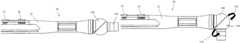
- FIG. 1is a side elevation view of a device suitable for use in practicing exemplary embodiments of this disclosure.
- FIG. 2is a perspective view of a device suitable for use in practicing exemplary embodiments of this disclosure.
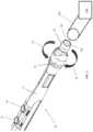
- FIG. 3is a partial perspective cross-sectional view of a device suitable for use in practicing exemplary embodiments of this disclosure.
- FIG. 4 Ais a partial side cross-sectional view of a device suitable for use in practicing exemplary embodiments of this disclosure.
- FIG. 4 Bis a partial side cross-sectional view of an alternative embodiment of a device suitable for use in practicing exemplary embodiments of this disclosure.
- FIG. 5is a perspective view of a second embodiment of a device suitable for use in practicing exemplary embodiments of this disclosure.
- FIG. 6is a perspective cross-sectional view of a second embodiment of a device suitable for use in practicing exemplary embodiments of this disclosure.
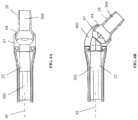
- FIG. 7 Ais a side elevation view of a third embodiment of a device suitable for use in practicing exemplary embodiments of this disclosure.
- FIG. 8is a perspective view of the third embodiment of a device suitable for use in practicing exemplary embodiments of this disclosure.
- FIG. 9is a partial cross-sectional view of a portion of the third embodiment of a device suitable for use in practicing exemplary embodiments of this disclosure.
- FIG. 11is a perspective view of an electrosurgical device suitable for use in practicing exemplary embodiments of this disclosure.
- the terms “horizontal”, “vertical”, “left”, “right”, “up” and “down”, as well as adjectival and adverbial derivatives thereof,simply refer to the orientation of the illustrated structure as the particular drawing figure faces the reader.
- the terms “inwardly” and “outwardly”generally refer to the orientation of a surface relative to its axis of elongation, or of rotation, as appropriate.
- FIG. 1Shown in FIG. 1 is the proximal end of an electrosurgical device 20 having a longitudinal axis 45 .
- the electrosurgical device 20includes a hollow body 22 enclosing a passageway 302 (shown in FIG. 3 ) extending through the longitudinal axis 45 from a distal end 1104 (shown in FIG. 11 ) holding an electrode 1100 to a proximal end 39 having a port 306 .
- the proximal end 39 and port 306 of the body 22is disposed adjacent to a swivel portion 42 having a barbed fitting 28 for attachment to a conduit such as a vacuum tube 202 or plastic hose leading to the vacuum power unit 204 (shown in FIG. 2 ).
- Port 306 , passageway 302 , outlet 104 , and passageway 304are fluidly connected.
- a conduit 202(shown in FIG. 2 ) may extend from a vacuum power unit 204 to the barbed fitting 28 at the end of the electrosurgical device 20 operable for removing the surgical smoke through the body 22 and passageway 302 of the electrosurgical device 20 and through vacuum tube 202 .
- the distal end 1104 of the electrosurgical device 20(shown in FIG. 11 ) may be provided with an inlet 1102 to passageway 302 .
- the smoke generated by the electrosurgical device 20enters the inlet 1102 which is in fluid communication with a passageway 302 through the body 22 of the electrosurgical device 20 .
- the passageway 302is disposed in fluid communication with swivel portion 42 having a hollow passageway 304 and an outlet 104 of the electrosurgical device 22 where the barbed fitting 28 is located. Accordingly, smoke and debris from the procedure may be conveyed from the inlet 1102 through the electrosurgical device 20 and hollow passageway 304 of swivel portion 42 to the outlet 104 of the electrosurgical device 20 surrounded by the barbed fitting 28 . From the outlet 104 , the smoke and debris is conveyed through a conduit 202 toward the vacuum source 204 .
- barbed fitting 28does not have to be a barbed fitting 28 , and that any male or female connection can be substituted. For example, a female connector may be used in place of barbed fitting 28 so as to keep the inner diameter of the fitting, and hence the passageway 304 (see FIG. 3 ), as large as possible.
- the electrosurgical device 20may be provided with a cut button 33 and a coagulate button 36 that provide different levels of current to the electrode 1100 at the distal end 1104 of the electrosurgical device 20 .
- the cut button 33is operable to activate the electrode 1100 at a first power level
- coagulate button 36is operable to activate the electrode 1100 at a second power level.
- the first power levelin embodiments is different from the second power level.
- the proximal end 39 of the body 22is disposed adjacent to a swivel portion 42 .
- the swivel portion 42is connected to the body 22 but is configured and arranged to rotate about the longitudinal axis 45 of the electrosurgical device 20 .
- FIG. 3The rotatable connection between the swivel portion 42 and the body 22 is shown in FIG. 3 .
- the barbed fitting 28may be pivotally attached to the swivel portion 42 such that the barbed fitting may rotate relative to the swivel portion 42 which in turn may rotate relative to the body 22 . Accordingly, the system provides significant flexibility with regard to the positioning of the conduit 202 leading to the vacuum unit 204 . As indicated by arrows 48 and 51 , the barbed fitting 28 can be rotated upward or downward with respect to the orientation shown in FIG. 1 .
- the barbed fitting 28includes passageway 304 to provide an air pathway to the conduit 202 that is attached to the outlet 104 .
- the barbed fitting 28is connected to a ball 64 that fits inside a socket 67 formed in the end of the swivel portion 42 . Accordingly, the barbed fitting 28 may be pivoted and rotated in many different directions in the ball and socket configuration.
- the hose connector 80may also be angled at approximately ninety degrees between a first end 82 and a second end 84 . Embodiments include the hose connector 80 being angled anywhere between approximately 0 degrees to 90 degrees. The first end 82 of the hose connector 80 is capable of rotating relative to the second end 78 of the swivel portion 70 in the direction of arrow 85 .
Landscapes
- Health & Medical Sciences (AREA)
- Surgery (AREA)
- Engineering & Computer Science (AREA)
- Life Sciences & Earth Sciences (AREA)
- Biomedical Technology (AREA)
- Otolaryngology (AREA)
- Nuclear Medicine, Radiotherapy & Molecular Imaging (AREA)
- Plasma & Fusion (AREA)
- Physics & Mathematics (AREA)
- Heart & Thoracic Surgery (AREA)
- Medical Informatics (AREA)
- Molecular Biology (AREA)
- Animal Behavior & Ethology (AREA)
- General Health & Medical Sciences (AREA)
- Public Health (AREA)
- Veterinary Medicine (AREA)
- Surgical Instruments (AREA)
Abstract
Description
Claims (12)
Priority Applications (2)
| Application Number | Priority Date | Filing Date | Title |
|---|---|---|---|
| US15/665,859US11849993B2 (en) | 2016-08-01 | 2017-08-01 | Electrosurgical device with vacuum port having multiple swivel connections |
| US18/526,635US20240099762A1 (en) | 2016-08-01 | 2023-12-01 | Electrosurgical device with vacuum port having multiple swivel connections |
Applications Claiming Priority (2)
| Application Number | Priority Date | Filing Date | Title |
|---|---|---|---|
| US201662369625P | 2016-08-01 | 2016-08-01 | |
| US15/665,859US11849993B2 (en) | 2016-08-01 | 2017-08-01 | Electrosurgical device with vacuum port having multiple swivel connections |
Related Child Applications (1)
| Application Number | Title | Priority Date | Filing Date |
|---|---|---|---|
| US18/526,635ContinuationUS20240099762A1 (en) | 2016-08-01 | 2023-12-01 | Electrosurgical device with vacuum port having multiple swivel connections |
Publications (2)
| Publication Number | Publication Date |
|---|---|
| US20180028255A1 US20180028255A1 (en) | 2018-02-01 |
| US11849993B2true US11849993B2 (en) | 2023-12-26 |
Family
ID=61011789
Family Applications (2)
| Application Number | Title | Priority Date | Filing Date |
|---|---|---|---|
| US15/665,859Active2038-11-06US11849993B2 (en) | 2016-08-01 | 2017-08-01 | Electrosurgical device with vacuum port having multiple swivel connections |
| US18/526,635PendingUS20240099762A1 (en) | 2016-08-01 | 2023-12-01 | Electrosurgical device with vacuum port having multiple swivel connections |
Family Applications After (1)
| Application Number | Title | Priority Date | Filing Date |
|---|---|---|---|
| US18/526,635PendingUS20240099762A1 (en) | 2016-08-01 | 2023-12-01 | Electrosurgical device with vacuum port having multiple swivel connections |
Country Status (5)
| Country | Link |
|---|---|
| US (2) | US11849993B2 (en) |
| EP (1) | EP3490477B1 (en) |
| AU (1) | AU2017305300B2 (en) |
| CA (2) | CA3032419C (en) |
| WO (1) | WO2018026832A1 (en) |
Families Citing this family (6)
| Publication number | Priority date | Publication date | Assignee | Title |
|---|---|---|---|---|
| US20180333195A1 (en)* | 2017-05-18 | 2018-11-22 | Megadyne Medical Products, Inc. | Hand-held instrument with body-swivel |
| US11617611B2 (en)* | 2016-06-17 | 2023-04-04 | Megadayne Medical Products, Inc. | Hand-held instrument with dual zone fluid removal |
| US11266384B2 (en)* | 2018-04-20 | 2022-03-08 | Johnson & Johnson Surgical Vision, Inc. | Ergonomic handpiece |
| US11547463B2 (en)* | 2018-09-21 | 2023-01-10 | Covidien Lp | Smoke evacuation electrosurgical pencil with adjustable electrode and vent tube |
| JP7194190B2 (en)* | 2018-10-26 | 2022-12-21 | バッファロー フィルター エルエルシー | Filtering system, apparatus and method |
| GB2621613B (en)* | 2022-08-16 | 2025-04-23 | Gyrus Medical Ltd | Surgical device |
Citations (12)
| Publication number | Priority date | Publication date | Assignee | Title |
|---|---|---|---|---|
| US4911159A (en)* | 1988-11-21 | 1990-03-27 | Johnson Jeffrey W | Electrosurgical instrument with electrical contacts between the probe and the probe holder |
| US5674219A (en) | 1994-10-06 | 1997-10-07 | Donaldson Company, Inc. | Electrosurgical smoke evacuator |
| US20010051804A1 (en) | 1995-02-22 | 2001-12-13 | Medtronic, Inc. | Fluid-assisted electrocautery device |
| US20020019631A1 (en) | 2000-02-28 | 2002-02-14 | John Kidder | Electro-surgical pencil with smoke evacuation |
| US20050107782A1 (en) | 2003-11-19 | 2005-05-19 | Reschke Arlan J. | Pistol grip electrosurgical pencil with manual aspirator/irrigator and methods of using the same |
| US20090018539A1 (en)* | 2005-12-02 | 2009-01-15 | Ioan Cosmescu | Swivel Device for Electrosurgery Pencil and Surgical Smoke Evacuation |
| US20110190768A1 (en) | 2010-02-04 | 2011-08-04 | Medtek Devices, Inc. | Electrosurgical device with vacuum port |
| US20120310229A1 (en) | 2011-05-31 | 2012-12-06 | Tyco Healthcare Group Lp | Surgical Device with DC Power Connection |
| US20150209100A1 (en) | 2012-08-28 | 2015-07-30 | Instruventional Inc. | Adjustable electrosurgical pencil with slidable vent tube |
| US20150306348A1 (en) | 2004-10-15 | 2015-10-29 | Amendia, Inc. | Devices and methods for treating tissue |
| US20160175033A1 (en) | 2014-12-23 | 2016-06-23 | Applied Medical Resources Corporation | Bipolar electrosurgical sealer and divider |
| US20170014559A1 (en)* | 2015-07-13 | 2017-01-19 | Integrated Surgical LLC | Surgical suction device that uses positive pressure gas |
- 2017
- 2017-08-01WOPCT/US2017/044927patent/WO2018026832A1/ennot_activeCeased
- 2017-08-01CACA3032419Apatent/CA3032419C/enactiveActive
- 2017-08-01USUS15/665,859patent/US11849993B2/enactiveActive
- 2017-08-01AUAU2017305300Apatent/AU2017305300B2/enactiveActive
- 2017-08-01EPEP17837551.5Apatent/EP3490477B1/enactiveActive
- 2017-08-01CACA3079331Apatent/CA3079331C/enactiveActive
- 2023
- 2023-12-01USUS18/526,635patent/US20240099762A1/enactivePending
Patent Citations (14)
| Publication number | Priority date | Publication date | Assignee | Title |
|---|---|---|---|---|
| US4911159A (en)* | 1988-11-21 | 1990-03-27 | Johnson Jeffrey W | Electrosurgical instrument with electrical contacts between the probe and the probe holder |
| US5674219A (en) | 1994-10-06 | 1997-10-07 | Donaldson Company, Inc. | Electrosurgical smoke evacuator |
| US20010051804A1 (en) | 1995-02-22 | 2001-12-13 | Medtronic, Inc. | Fluid-assisted electrocautery device |
| US20020019631A1 (en) | 2000-02-28 | 2002-02-14 | John Kidder | Electro-surgical pencil with smoke evacuation |
| US20050107782A1 (en) | 2003-11-19 | 2005-05-19 | Reschke Arlan J. | Pistol grip electrosurgical pencil with manual aspirator/irrigator and methods of using the same |
| US20150306348A1 (en) | 2004-10-15 | 2015-10-29 | Amendia, Inc. | Devices and methods for treating tissue |
| US8414576B2 (en) | 2005-12-02 | 2013-04-09 | Ioan Cosmescu | Swivel device for electrosurgery pencil and surgical smoke evacuation |
| US20090018539A1 (en)* | 2005-12-02 | 2009-01-15 | Ioan Cosmescu | Swivel Device for Electrosurgery Pencil and Surgical Smoke Evacuation |
| US20110190768A1 (en) | 2010-02-04 | 2011-08-04 | Medtek Devices, Inc. | Electrosurgical device with vacuum port |
| US20120310229A1 (en) | 2011-05-31 | 2012-12-06 | Tyco Healthcare Group Lp | Surgical Device with DC Power Connection |
| US20150209100A1 (en) | 2012-08-28 | 2015-07-30 | Instruventional Inc. | Adjustable electrosurgical pencil with slidable vent tube |
| US20150257816A1 (en) | 2012-08-28 | 2015-09-17 | Leonard Ineson | Adjustable electrosurgical pencil |
| US20160175033A1 (en) | 2014-12-23 | 2016-06-23 | Applied Medical Resources Corporation | Bipolar electrosurgical sealer and divider |
| US20170014559A1 (en)* | 2015-07-13 | 2017-01-19 | Integrated Surgical LLC | Surgical suction device that uses positive pressure gas |
Non-Patent Citations (1)
| Title |
|---|
| International Search Report for corresponding PCT Application PCT/US2017/044927 dated Oct. 6, 2017, dated Sep. 22, 2017. |
Also Published As
| Publication number | Publication date |
|---|---|
| CA3032419C (en) | 2021-11-30 |
| CA3079331C (en) | 2022-11-15 |
| CA3079331A1 (en) | 2018-02-08 |
| CA3032419A1 (en) | 2018-02-08 |
| US20180028255A1 (en) | 2018-02-01 |
| AU2017305300A1 (en) | 2019-02-07 |
| EP3490477A1 (en) | 2019-06-05 |
| EP3490477B1 (en) | 2025-04-23 |
| WO2018026832A1 (en) | 2018-02-08 |
| AU2017305300B2 (en) | 2020-05-21 |
| EP3490477A4 (en) | 2020-05-06 |
| US20240099762A1 (en) | 2024-03-28 |
Similar Documents
| Publication | Publication Date | Title |
|---|---|---|
| US20240099762A1 (en) | Electrosurgical device with vacuum port having multiple swivel connections | |
| AU2022204356B2 (en) | Method and apparatus for attachment and evacuation | |
| EP2285303B1 (en) | Electrosurgical pencil with a swivel device | |
| US12070262B2 (en) | Electrosurgical device with vacuum port | |
| US20230082376A1 (en) | Directed gas flow accessory for providing gases to and venting gases from a patient | |
| US20050245898A1 (en) | Surgical handpiece with quick-connection for irrigation and aspiration tubes | |
| CN117297749A (en) | Smoke discharging pen | |
| JP2017531508A (en) | Variable suction control | |
| AU2019384814B2 (en) | Method and apparatus for flow |
Legal Events
| Date | Code | Title | Description |
|---|---|---|---|
| STPP | Information on status: patent application and granting procedure in general | Free format text:DOCKETED NEW CASE - READY FOR EXAMINATION | |
| AS | Assignment | Owner name:BUFFALO FILTER LLC, NEW YORK Free format text:ASSIGNMENT OF ASSIGNORS INTEREST;ASSIGNORS:MILLER, MICHAEL;HERSEY, TIMOTHY;BONANO, SAMANTHA;AND OTHERS;SIGNING DATES FROM 20170901 TO 20190128;REEL/FRAME:048273/0517 | |
| AS | Assignment | Owner name:JPMORGAN CHASE BANK, N.A., AS ADMINISTRATIVE AGENT Free format text:GRANT OF SECURITY INTEREST IN PATENT RIGHTS;ASSIGNOR:BUFFALO FILTER LLC;REEL/FRAME:048413/0947 Effective date:20190211 Owner name:JPMORGAN CHASE BANK, N.A., AS ADMINISTRATIVE AGENT, ILLINOIS Free format text:GRANT OF SECURITY INTEREST IN PATENT RIGHTS;ASSIGNOR:BUFFALO FILTER LLC;REEL/FRAME:048413/0947 Effective date:20190211 | |
| STPP | Information on status: patent application and granting procedure in general | Free format text:NON FINAL ACTION MAILED | |
| STPP | Information on status: patent application and granting procedure in general | Free format text:RESPONSE TO NON-FINAL OFFICE ACTION ENTERED AND FORWARDED TO EXAMINER | |
| STPP | Information on status: patent application and granting procedure in general | Free format text:ADVISORY ACTION MAILED | |
| STPP | Information on status: patent application and granting procedure in general | Free format text:DOCKETED NEW CASE - READY FOR EXAMINATION | |
| STPP | Information on status: patent application and granting procedure in general | Free format text:NON FINAL ACTION MAILED | |
| STPP | Information on status: patent application and granting procedure in general | Free format text:RESPONSE TO NON-FINAL OFFICE ACTION ENTERED AND FORWARDED TO EXAMINER | |
| STPP | Information on status: patent application and granting procedure in general | Free format text:FINAL REJECTION MAILED | |
| STPP | Information on status: patent application and granting procedure in general | Free format text:DOCKETED NEW CASE - READY FOR EXAMINATION | |
| STPP | Information on status: patent application and granting procedure in general | Free format text:AWAITING TC RESP., ISSUE FEE NOT PAID | |
| STPP | Information on status: patent application and granting procedure in general | Free format text:NOTICE OF ALLOWANCE MAILED -- APPLICATION RECEIVED IN OFFICE OF PUBLICATIONS | |
| STPP | Information on status: patent application and granting procedure in general | Free format text:PUBLICATIONS -- ISSUE FEE PAYMENT RECEIVED | |
| STPP | Information on status: patent application and granting procedure in general | Free format text:PUBLICATIONS -- ISSUE FEE PAYMENT VERIFIED | |
| STCF | Information on status: patent grant | Free format text:PATENTED CASE | |
| AS | Assignment | Owner name:JPMORGAN CHASE BANK, N.A., AS ADMINISTRATIVE AGENT, ILLINOIS Free format text:SECURITY INTEREST;ASSIGNORS:CONMED CORPORATION;BIOREZ, INC.;BUFFALO FILTER LLC;AND OTHERS;REEL/FRAME:072097/0762 Effective date:20250610 |