US11849978B2 - Constrained motion bone screw assembly - Google Patents
Constrained motion bone screw assemblyDownload PDFInfo
- Publication number
- US11849978B2 US11849978B2US17/232,836US202117232836AUS11849978B2US 11849978 B2US11849978 B2US 11849978B2US 202117232836 AUS202117232836 AUS 202117232836AUS 11849978 B2US11849978 B2US 11849978B2
- Authority
- US
- United States
- Prior art keywords
- cap
- bone anchor
- anchor
- bone
- rod
- Prior art date
- Legal status (The legal status is an assumption and is not a legal conclusion. Google has not performed a legal analysis and makes no representation as to the accuracy of the status listed.)
- Expired - Lifetime, expires
Links
Images


Classifications
- A—HUMAN NECESSITIES
- A61—MEDICAL OR VETERINARY SCIENCE; HYGIENE
- A61B—DIAGNOSIS; SURGERY; IDENTIFICATION
- A61B17/00—Surgical instruments, devices or methods
- A61B17/56—Surgical instruments or methods for treatment of bones or joints; Devices specially adapted therefor
- A61B17/58—Surgical instruments or methods for treatment of bones or joints; Devices specially adapted therefor for osteosynthesis, e.g. bone plates, screws or setting implements
- A61B17/68—Internal fixation devices, including fasteners and spinal fixators, even if a part thereof projects from the skin
- A61B17/70—Spinal positioners or stabilisers, e.g. stabilisers comprising fluid filler in an implant
- A61B17/7001—Screws or hooks combined with longitudinal elements which do not contact vertebrae
- A61B17/7035—Screws or hooks, wherein a rod-clamping part and a bone-anchoring part can pivot relative to each other
- A61B17/7037—Screws or hooks, wherein a rod-clamping part and a bone-anchoring part can pivot relative to each other wherein pivoting is blocked when the rod is clamped
- A—HUMAN NECESSITIES
- A61—MEDICAL OR VETERINARY SCIENCE; HYGIENE
- A61B—DIAGNOSIS; SURGERY; IDENTIFICATION
- A61B17/00—Surgical instruments, devices or methods
- A61B17/56—Surgical instruments or methods for treatment of bones or joints; Devices specially adapted therefor
- A61B17/58—Surgical instruments or methods for treatment of bones or joints; Devices specially adapted therefor for osteosynthesis, e.g. bone plates, screws or setting implements
- A61B17/68—Internal fixation devices, including fasteners and spinal fixators, even if a part thereof projects from the skin
- A61B17/70—Spinal positioners or stabilisers, e.g. stabilisers comprising fluid filler in an implant
- A61B17/7001—Screws or hooks combined with longitudinal elements which do not contact vertebrae
- A61B17/7035—Screws or hooks, wherein a rod-clamping part and a bone-anchoring part can pivot relative to each other
- A61B17/7038—Screws or hooks, wherein a rod-clamping part and a bone-anchoring part can pivot relative to each other to a different extent in different directions, e.g. within one plane only
- A—HUMAN NECESSITIES
- A61—MEDICAL OR VETERINARY SCIENCE; HYGIENE
- A61B—DIAGNOSIS; SURGERY; IDENTIFICATION
- A61B17/00—Surgical instruments, devices or methods
- A61B17/56—Surgical instruments or methods for treatment of bones or joints; Devices specially adapted therefor
- A61B17/58—Surgical instruments or methods for treatment of bones or joints; Devices specially adapted therefor for osteosynthesis, e.g. bone plates, screws or setting implements
- A61B17/68—Internal fixation devices, including fasteners and spinal fixators, even if a part thereof projects from the skin
- A61B17/70—Spinal positioners or stabilisers, e.g. stabilisers comprising fluid filler in an implant
- A61B17/7001—Screws or hooks combined with longitudinal elements which do not contact vertebrae
- A61B17/7035—Screws or hooks, wherein a rod-clamping part and a bone-anchoring part can pivot relative to each other
- A61B17/704—Screws or hooks, wherein a rod-clamping part and a bone-anchoring part can pivot relative to each other the longitudinal element passing through a ball-joint in the screw head
- A—HUMAN NECESSITIES
- A61—MEDICAL OR VETERINARY SCIENCE; HYGIENE
- A61B—DIAGNOSIS; SURGERY; IDENTIFICATION
- A61B17/00—Surgical instruments, devices or methods
- A61B17/56—Surgical instruments or methods for treatment of bones or joints; Devices specially adapted therefor
- A61B17/58—Surgical instruments or methods for treatment of bones or joints; Devices specially adapted therefor for osteosynthesis, e.g. bone plates, screws or setting implements
- A61B17/68—Internal fixation devices, including fasteners and spinal fixators, even if a part thereof projects from the skin
- A61B17/70—Spinal positioners or stabilisers, e.g. stabilisers comprising fluid filler in an implant
- A61B17/7001—Screws or hooks combined with longitudinal elements which do not contact vertebrae
- A61B17/7041—Screws or hooks combined with longitudinal elements which do not contact vertebrae with single longitudinal rod offset laterally from single row of screws or hooks
- A—HUMAN NECESSITIES
- A61—MEDICAL OR VETERINARY SCIENCE; HYGIENE
- A61B—DIAGNOSIS; SURGERY; IDENTIFICATION
- A61B17/00—Surgical instruments, devices or methods
- A61B17/56—Surgical instruments or methods for treatment of bones or joints; Devices specially adapted therefor
- A61B17/58—Surgical instruments or methods for treatment of bones or joints; Devices specially adapted therefor for osteosynthesis, e.g. bone plates, screws or setting implements
- A61B17/68—Internal fixation devices, including fasteners and spinal fixators, even if a part thereof projects from the skin
- A61B17/70—Spinal positioners or stabilisers, e.g. stabilisers comprising fluid filler in an implant
- A61B17/7001—Screws or hooks combined with longitudinal elements which do not contact vertebrae
- A61B17/7032—Screws or hooks with U-shaped head or back through which longitudinal rods pass
Definitions
- Spinal fixation systemsmay be used in surgery to align, adjust and/or fix portions of the spinal column, i.e., vertebrae, in a desired spatial relationship relative to each other.
- Many spinal fixation systemsemploy a spinal rod for supporting the spine and for properly positioning components of the spine for various treatment purposes.
- Vertebral anchorscomprising pins, bolts, screws, and hooks, engage the vertebrae and connect the supporting rod to different vertebrae.
- the size, length and shape of the cylindrical roddepend on the size, number and position of the vertebrae to be held in a desired spatial relationship relative to each other by the apparatus.
- Spinal fixation elementscan be anchored to specific portions of the vertebra. Since each vertebra varies in shape and size, a variety of anchoring devices have been developed to facilitate engagement of a particular portion of the bone.
- Pedicle screw assembliesfor example, have a shape and size that is configured to engage pedicle bone. Such screws typically include a threaded shank that is adapted to be threaded into a vertebra, and a head portion having a spinal fixation element-receiving element, which, in spinal rod applications, is usually in the form of a U-shaped slot formed in the head portion for receiving the rod. A set-screw, plug, cap or similar type of closure mechanism is used to lock the rod into the rod-receiving portion of the pedicle screw.
- Monoaxial screwsare a type of screw in which the longitudinal axis of the threaded shank is fixed relative to the head portion, or rod slot.
- the longitudinal axis of the threaded shankmay be aligned with the longitudinal axis of the head portion, and/or the threaded shank extends at a fixed angle relative to the head.
- the threaded shankis rigidly connected to or integrally formed with the head such that the orientation of the threaded shank is fixed with respect to the head.
- Polyaxial pedicle screwshave been designed to allow angulation of one portion of the screw relative to another portion of the screw and the spinal fixation element coupled to one portion of the screw.
- polyaxial pedicle screwsallow for a shaft portion to pivot relative to a rod-receiving portion in all directions about a 360° are around the rod-receiving portion.
- Polyaxial screwsmay be useful for positioning bone anchors on adjacent vertebrae, when the close proximity of adjacent vertebrae can result in interference between the bone anchors.
- Polyaxial screwsallow for pivoting of the screws in any direction out of alignment with each other to avoid such interference.
- Polyaxial and multi-axial screwswhich allow the screw shank to pivot in all directions about the head portion, can be difficult to control and often result in movement of the screw shank in planes in which movement is not desirable. For example, during vertebral body rotation maneuvers, which require application of force to the screw head, it is not desirable for the screw shank to move relative to the screw head.
- the present inventionprovides a bone screw assembly that provides for controlled movement between an anchor portion and a rod-receiving portion of the bone screw assembly.
- the bone screw assemblyallows the anchor portion to pivot about the rod-receiving portion and/or a spinal fixation element received in the rod-receiving portion in one or more directions, while limiting the movement in other selected directions.
- the anchor portioncan pivot about a first axis that passes through the head of the anchor portion and is perpendicular to a longitudinal axis of a rod received in the rod-receiving portion, so that the anchor portion aligns with the rod in a selected plane, while being restricted from rotation about one or more other axes of the head.
- the anchor portionWhen assembled in a patient, the anchor portion may be moveable in at least one plane, such as the coronal plane, to allow for movement of vertebral bodies coupled to the rod by the bone screw assembly in one or more selected directions, while fixed in at least one plane, such as the sagittal plane, to prevent movement in one or more other directions.
- at least one planesuch as the coronal plane
- a bone anchor assemblycomprises a bone anchor having a proximal head and a distal shaft extending along a longitudinal axis configured to engage bone, a receiving member for receiving a spinal fixation element and for engaging the proximal head of the bone anchor and a restriction member inserted in the receiving member.
- the restriction memberallows the bone anchor to pivot relative to the receiving member about a first axis of the proximal head in at least a first direction and restricts the bone anchor from pivoting about a second axis of the bone anchor in a second direction.
- the proximal headmay be received in a cavity of the receiving portion.
- the first axisis perpendicular to a longitudinal axis of the spinal fixation element.
- the second axismay be parallel to a longitudinal axis of the spinal fixation element.
- the proximal headmay have a first curved side surface to facilitate pivoting of the bone anchor in the first direction.
- the proximal headincludes two opposed side surfaces that are curved.
- One or more of the curved side surfacesmay be curved in three dimensions.
- the proximal headmay have at least one flat side surface to prevent pivoting of the bone anchor in the second direction.
- a bone anchor assemblycomprises a bone anchor having a distal shaft extending along a longitudinal axis configured to engage bone and a substantially spherical proximal head having at least one flat side surface extending substantially parallel to the longitudinal axis.
- a receiving memberreceives a spinal fixation element and movably engages the spherical proximal head.
- a restriction memberis inserted in the receiving member for mating with the flat side surface of the anchor head to prevent rotation of the bone anchor relative to the receiving member in a direction that is perpendicular to the flat side surface.
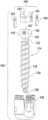
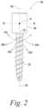
- FIG. 2illustrates a constrained motion bone screw assembly according to an embodiment of the invention.
- FIG. 3is a top view illustrating the area in which the anchor portion of the bone screw of FIG. 2 is movable relative to the head portion according to one aspect of the invention.
- FIG. 4is a top view illustrating the area in which the anchor portion of the bone screw of FIG. 2 is movable relative to the head portion according to another aspect of the invention.
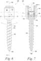
- FIG. 5illustrates an embodiment of a constrained motion bone screw according to an illustrative embodiment of the invention.
- FIG. 6is a side view of the assembled bone screw of FIG. 5 .
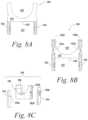
- FIG. 8 A- 8 Cillustrate in detail the compression and restriction member of the bone screw assembly of FIG. 5 .
- FIG. 9 A- 9 Care detailed views of the constrained motion bone screw assembly of FIG. 5 in the vicinity of the receiving member.
- FIG. 11illustrates a constrained motion bone screw according to another embodiment of the invention.
- FIG. 12illustrates a constrained motion bone screw according to another embodiment of the invention.
- FIGS. 13 A- 13 Cillustrate a constrained motion bone screw according to still another embodiment of the invention.
- FIGS. 14 A- 14 Billustrate different views of a rod seat for the constrained motion bone screw of FIGS. 13 A- 13 C .
- the present inventionprovides an improved bone screw assembly in a spinal fixation system.
- the inventionis not limited to use in bone or in spinal surgery, and that the instrument and methods described herein can be adapted for use with any suitable surgical device to be moved into a selected position in a variety of medical procedures.
- the present inventionwill be described below relative to certain exemplary embodiments to provide an overall understanding of the principles of the structure, function, manufacture, and use of the instruments disclosed herein. Those skilled in the art will appreciate that the present invention may be implemented in a number of different applications and embodiments and is not specifically limited in its application to the particular embodiments depicted herein.
- the controlled movement bone screw assemblypermits rotation of the anchor portion about an axis perpendicular to a rod coupled to the bone screw assembly, while preventing, blocking, prohibiting or otherwise constraining rotation of the anchor portion about an axis extending parallel to the rod.
- the controlled movement bone screw assembly of the present inventionmay allow a surgeon to rotate vertebral bodies and facilitates rod placement into the rod-receiving portion.
- the exemplary bone screw assemblies of the illustrative embodiments of the inventionmay be employed to engage one or more spinal fixation elements to bone.
- a bone screw assemblymay be employed to fix a spinal plate, rod, and/or cable to a vertebra of the spine.
- the exemplary bone screw assemblies described beloware designed primarily for use in spinal applications, and specifically the pedicle region of a vertebra, one skilled in the art will appreciate that the structure, features and principles of the exemplary bone screw assemblies, as well as the other exemplary embodiments described below, may be employed to couple any type of orthopedic implant to any type of bone or tissue.
- the bone screw assembly described hereinfacilitates the correction of the position, for example, the angular orientation, of the vertebra in which the bone screw is implanted.
- the bone screw assemblymay be configured to provide stability in one plane, for example, the transverse plane, by restricting pivoting of the receiver member of the bone screw assembly in the selected plane.
- the stability of the bone screw assembly in the selected planefacilitates movement of the bone screw assembly and associated vertebra in the selected plane. e.g., facilitates rotation of the bone anchor assembly and the vertebra about an axis that intersects the plane.
- Exemplary instruments and methods for manipulating a bone anchor assembly connected to a vertebraare described in detail in U.S.
- FIG. 1is a diagram of the human body, and illustrates the three planes used to help describe anatomy.
- the sagittal plane 20splits the body from head to toe, from the back or posterior to the front or anterior.
- the coronal plane 24splits the body from head to toe, side to side.
- the transverse plane 26slices through the body yielding cross-sectional views.
- a constrained motion bone screw assembly 30shown in FIG.
- an anchor portion 32that is controllably pivotable in selected directions about one or more axes passing through a pivot point P with respect to a head portion 34 , which may be a receiving portion, such as a rod-receiving portion, for receiving a spinal rod or other spinal fixation element.
- the constrained motion bone screw assembly 30 of the present inventionfurther selectively constrains the movement of the anchor portion 32 relative to the head portion 34 and/or a spinal fixation element received in the head portion 34 in one or more selected directions.
- the anchor portion 32relative to the head portion 34 in several directions about pivot point P, as indicated by arrows 35 a - 35 e .
- the illustrative anchor portion 32is prevented from pivoting about axis R-R, which extends through the pivot point P in a direction that is perpendicular to the longitudinal axis of 22 of the shaft.
- the anchor portion 32is thus restricted from rotating about the head portion 34 in a direction that is perpendicular to the axis R-R.
- the anchor portion 32may be adjusted such that the longitudinal axis 22 of the bone anchor portion 32 extends at an angle of between 0° and 90° in the selected direction relative to the longitudinal axis 42 of the head portion 34 .
- a rod seat within the head portion 34may be selectively movable to allow for relative movement between a spinal fixation element, such as a spinal rod, received in the head portion 34 and the bone anchor.
- FIG. 3is a top view illustrating the range of motion of the anchor portion 32 relative to the head portion 34 of a bone screw assembly 30 and a rod 12 received by the head portion 34 according to one embodiment of the invention.
- the path of the anchor portion in the region surrounding the head portionmay be limited in the sagittal plane, but movable in all other planes around the head portion, including the coronal plane.
- the anchor portionis pivotable not only about axis T-T, which is perpendicular to the longitudinal axis of the rod 12 received by the head portion 34 , but also around several intermediate axes I 1 -I 4 extending between the perpendicular axis T-T and the axis R-R to allow movement in the shaded region 40 surrounding the head portion 34 .
- the anchor portion 32is fixed from rotating about axis R-R, to prevent movement of the anchor portion in perpendicular region 44 extending perpendicular to the longitudinal axis 42 of the head portion.
- the anchor portion 32may be fixed in all planes except for one selected plane, such as the coronal plane, to allow for movement of the anchor portion along a selected path in a single plane, such as the sagittal plane, while preventing movement of the anchor portion out of the single plane in all other directions relative to the head portion.
- the anchor portionis only pivotable about axis T-T, so that the range of motion of the anchor portion relative to the head portion is limited to the region 40 ′ that is parallel to and aligned with the rod 12 . Because the anchor cannot pivot about other axes, the anchor portion cannot move into the region 44 ′ and is fixed in the plane defined by region 40 ′.
- the region 40 ′may encompass the sagittal plane when the screw assembly is inserted in a patient.
- ranges of motion between those illustrated in FIGS. 3 and 4are also contemplated by the present invention.
- the bone anchor 114comprises a joint portion, illustrated as a proximal anchor head 116 , for coupling the bone anchor 114 to the rod-receiving portion 140 , and an anchoring portion, illustrated as a distal shaft 118 configured to engage bone.
- the distal shaft 118 of the bone anchor 114has a shaft diameter 120 and a longitudinal axis 122 .
- the distal shaft 118may include one or more bone engagement mechanisms to facilitate gripping engagement of the bone anchor to bone.
- the distal shaft 118includes an external thread 124 extending along at least a portion of the shaft for engaging bone.
- the external thread 124is a single lead thread that extends from a distal tip 126 of the shaft to the anchor head 116 , though one skilled in the art will recognize that the external thread may extend along any selected portion of the shaft and have any suitable number of leads.
- Other suitable bone engagement mechanismsinclude, but are not limited to, one or more annular ridges, multiple threads, dual lead threads, variable pitched threads and/or any conventional bone engagement mechanism.
- the rod-receiving member 140receives the proximal head 116 of the bone anchor to couple the bone anchor 114 thereto, thereby coupling the bone to a rod or other element received in the rod-receiving member 140 .
- the illustrative rod-receiving member 140may be substantially similar to a head portion of a polyaxial screw assembly of the prior art. In a rest position, the longitudinal axis 122 of the bone anchor aligns with a longitudinal axis 142 extending through the rod-receiving member 140 .
- the distal shaft 118is pivotable relative to the rod-receiving member 140 about the proximal head 116 in one or more selected directions to angulate the longitudinal axis 122 relative to the longitudinal axis 142 .
- the screw assembly 100further includes one or more components, illustrated as the compression and restriction member 180 , for preventing a pivoting movement of the distal shaft 118 in one or more directions, so that the distal shaft 118 cannot pivot in all 360 degrees around the rod-receiving member 140 , thereby increasing the stability of the screw assembly in one or more planes, as described in detail below.
- the shaftis pivotable about axis T-T, but constrained from pivoting about axis R-R.
- Axis R-Ris aligned with and parallel to the longitudinal axis r-r of the rod 12 in a selected plane and perpendicular to axis T-T, intersecting T-T at pivot point P, and may be substantially parallel to the longitudinal axis r-r of a rod to be received in the receiving portion 140 .
- the anchor head 116 of the bone anchor 114may be configured to facilitate controlled adjustment of the bone anchor 114 relative to the receiving member 140 of the bone screw assembly.
- the illustrative anchor head 116may be substantially spherical and include curved side surfaces 161 , 162 that are shaped to permit pivoting of the bone anchor 114 relative to the receiving member 140 in one or more selected directions.
- the curved side surfaces 161 , 162are preferably curved in three-dimensions to facilitate rotation of the anchor portion 114 relative to the receiving member 140 .
- the illustrative anchor head 116further includes two opposed flat side surfaces 163 , 165 for constraining the pivoting movement to the one or more selected directions.
- the flat surfaces 163 , 165preferably extend substantially parallel to the longitudinal axis 122 of the shaft 118 . While the illustrative embodiment shows two opposed flat side surfaces 163 , 165 , one skilled in the art will recognize that the head can have any suitable number of flat surfaces or other selected feature for limiting the path of the shaft 118 relative to the receiving portion 140 about any selected axis or axes.
- the top surface 167 of the anchor head 116may be a generally planar surface to facilitate seating of the anchor within the rod-receiving portion 140 of the screw assembly.
- the anchor head 116may also have surface texturing, knurling and/or ridges.
- the illustrative bone screw assembly 100further includes a compression and restriction member 180 for seating the anchor head 116 within the rod-receiving portion 140 of the screw 100 and for cooperating with the flat surfaces 163 , 165 to constrain the movement of the anchor portion relative to the rod-receiving portion 140 and/or a rod received therein.
- the compression and restriction member 180preferably forms a proximal rod seat 182 for seating a rod or other spinal fixation element and an opposed distal anchor seat 197 for engaging the anchor head 116 .
- FIGS. 8 A- 8 Cillustrate an embodiment of the compression and restriction member 180 in detail, though one skilled in the art will recognize that the invention is not limited to the illustrative embodiment.
- the illustrative compression and restriction member 180includes a cap 181 and restricting protrusions 192 , 194 that extend from a lower surface 184 of the cap 181 .
- the restricting protrusions 192 , 194form a track-like region 197 for receiving the anchor head 116 therebetween.
- the restricting protrusions 192 , 194are configured to mate with the flat surfaces 163 , 165 of the anchor head 116 when the bone screw assembly 100 is assembled to guide and constrain the pivoting movement of the anchor head 116 relative to the receiving member 140 .
- the illustrative restricting protrusions 192 , 194restrict movement of the anchor head 116 about axis T-T through a plane that is parallel to the flat faces 163 , 165 of the proximal head 116 and the protrusions 192 , 194 .
- the plane through which the anchor portion 114 pivotsis preferably defined by the longitudinal axis r-r of a rod inserted in the rod-receiving member 140 when the screw assembly 100 is assembled and the longitudinal axis 142 of the receiving member 140 , similar to the assembly of FIG. 4 B .
- the screw assembly 100 of FIGS. 5 - 8 Cmay also be made to pivot in one or more other directions relative to the rod-receiving member 140 .
- each restricting projectionWhen coupled, each restricting projection extends past the bottom surface 184 of the cap 181 to cover and abut the flat surfaces 163 , 165 of the anchor head 116 when the screw is assembled to control the movement of the anchor 114 relative to the rod-receiving member 140 .
- any suitable means for coupling the restricting protrusions to the cap 181may be used.
- one or more of the restricting protrusions 192 or 194may be integrally formed with the cap 181 .
- the restriction and compression member 180is positioned within the receiving member 140 between the spinal rod 12 and the anchor head 116 when the bone screw assembly is assembled.
- the restriction and compression member 180preferably engages the spinal rod 12 and the anchor head 116 to facilitate assembly of the constrained motion bone screw assembly 100 .
- the restricting protrusionsmay include projections configured to be received in the recesses formed in the side surfaces 163 , 165 to facilitate coupling of a compression and restriction member to the proximal head that selectively limits rotation of the anchor in one or more directions while facilitating rotation in one or more other directions.
- a spinal fixation elementmay be coupled to the bone anchor by alternative coupling mechanisms in place of a recess, including, for example, an offset coupling mechanism, such as a band clamp, sacral extender, or a lateral off-set connector.
- an offset coupling mechanismsuch as a band clamp, sacral extender, or a lateral off-set connector.
- the illustrative second surface 184has a hemispherical shape to approximate the curvature of the anchor head 116 .
- a bore 186may extend through the cap 181 to allow for advancement of an instrument to the bone anchor 116 during assembly of the bone screw assembly.
- the compression and restricting member 180 or other suitable restriction membermay also be configured to allow some rotation of the anchor portion about the longitudinal axis 122 , or allow pivoting in an intermediate direction about an intermediate axis I-I between axes T-T and R-R, while restricting the anchor from being able to move in any direction in the full 360 degree around the rod-receiving member 140 , as shown in FIG. 3 .
- the proximal head 116 ′ of the anchor portion 114 ′ of a constrained motion bone screw assembly 100 ′is substantially spherical and curved on all side surfaces.
- the proximal head 116includes a cavity 1162 formed in the top surface for receiving a ball end 1165 of a receiving member 140 ′.
- a retention ring 1164 inserted in the cavity 1162secures the ball end 1165 within the cavity to couple the anchor portion 114 ′ to the receiving member 140 ′.
- a support collar 1168extends from the receiving member 140 over a portion of the proximal head 116 ′ to maintain the position of the anchor portion and the receiving member.
- the ball end 1165 of the receiving membermay include one or more flat surfaces that abut flat surfaces on the retention ring 1164 to constrict rotation of the anchor portion relative to the ball end in one or more selected directions.
- the illustrative embodimentis a top-loading screw
- the present inventionencompasses a bottom-loading screw as well.
- the first opening 160 of the receiving membermay be larger than the head 116 to allow the head to pass through the opening 160 during assembly of the screw.
- the anchor headwould then be inserted through a bottom opening of the receiving member and retained therein by a securing means, i.e., the anchor head is smaller in diameter than the bottom opening of the receiving member.
- the anchor head of a top-loading screwis smaller than the bottom opening of the receiving member.
- a top-loading screwis assembled by inserting the shaft through the bottom opening, so that the anchor head is retained within a cavity in the receiving member.
- a bottom-loading screwis assembled by inserting the anchor head through the bottom opening, and inserting and activating the securing means to prevent the anchor head from passing through the opening.
- the spherical shape of the side surfaces of the anchor head adjacent to the flat surfacesallows for rotation of the anchor about the axis T-T.
- a closure mechanismmay be inserted to lock the rod in the receiving member and/or lock the orientation of the anchor.
- the closure mechanismpresses down on the compression and restriction member 180 ′′ and locks the bone anchor between the compression and restriction member 180 ′′ and the retaining member 190 .
- FIGS. 13 A-Cillustrate another embodiment of a constrained motion bone screw assembly 1000 according to an alternate embodiment of the invention.
- the constrained motion bone screw assembly 1000 of FIGS. 13 A- 13 Callows for pivoting of a spinal rod received in the constrained motion bone screw assembly 1000 in at least one direction relative to the bone screw assembly 1000 , while movement in other directions is restricted.
- the illustrative constrained motion bone screw assembly 1000includes a bone anchor portion 1140 , a rod-receiving portion 1400 and a movable rod seat 1800 housed by the rod-receiving portion 1400 .
- the illustrative rod seat 1800includes a lower rod seat 1800 a and an upper rod seat 1800 b .
- the lower rod seat 1800 a and the upper rod seat 1800 bcooperate to define the rod seat 1800 for receiving the rod therebetween.
- the rod seat 1800is configured to move in one or more selected directions relative to the bone anchor portion 1140 and the rod-receiving portion 1400 to guide movement of the spinal rod 12 relative to the bone screw assembly 1000 . In this manner, both the bone anchor portion 1140 and the rod-receiving portion can move relative to the spinal rod.
- the bone anchor portion 1140includes a shaft 1180 and a joint portion 1160 .
- the joint portion 1160includes a recess 1162 formed in a top surface thereof for receiving the lower rod seat 1800 a .
- the recess 1162preferably has a concave, spherical shape to allow pivoting of the lower rod seat 1800 a within the recess 1162 .
- the illustrative lower rod seat 1800 ashown in detail in FIGS. 14 A- 14 B , is substantially rectangular, with a spherical bottom surface 1802 configured to mate with a concave surface 1164 of the recess 1162 .
- the lower rod seat 1800 aincludes a flat top surface 1804 for seating the rod 12 .
- the lower rod seat 1800 amay include retention recesses 1807 a , 1807 b on opposing side surfaces 1805 , 1806 , respectively, for receiving corresponding protrusions (not shown) on the rod-receiving portion 1400 to thereby couple the rod-receiving portion to the lower rod seat 1800 a , while allowing selective relative movement between the rod seat and other components of the bone screw assembly 1000 .
- the rod receiving portion 1400includes a body 1402 , which may comprise one or more components coupled together, and the upper rod seat 1800 b pivotably mounted to the body 1402 .
- the upper rod seat 1800 bincludes a pivot point 1810 received in a recess 1403 of the body 1402 and a rod seat member 1812 connected to the pivot point 1810 via a connecting member 1814 .
- the recess 1403 and pivot point 1810cooperate to allow for pivoting of the upper rod seat 1800 b in one or more selected directions only, while restricting pivoting in other directions.
- the illustrative constrained motion bone screw assembly 1000allows for pivoting of the rod seat 1800 relative to the bone anchor portion 1140 and/or the rod-receiving portion 1400 .
- the lower rod seat and upper rod seatdefining therebetween a movable channel for receiving the spinal rod 12 and for allowing for relative movement between the bone anchor portion 1140 and the spinal rod 12 , as well as between the rod-receiving portion 1400 and the spinal rod 12 .
- the upper rod seat 1800 bpivots in a selected direction, and the lower rod seat 1800 a rotates in the recess 1162 to guide the rod's movement, while retaining the rod therebetween.
- the coupling between the lower rod seat 1800 a and the rod-receiving portion 1140prevent movement in other directions. In this manner, the relative angle between the rod and both the bone anchor portion 1140 and the rod-receiving portion 1400 can be selectively varied in a first direction, while movement in other directions is prevented.
- the components of the constrained motion bone anchor assembly of the illustrative embodiments of the inventionmay be manufactured from any suitable biocompatible material, including, but not limited to, metals and metal alloys such as titanium and stainless steel, polymers and/or ceramics.
- the componentsmay be manufactured from the same or different materials though manufacturing processes known in the art.
Landscapes
- Health & Medical Sciences (AREA)
- Orthopedic Medicine & Surgery (AREA)
- Life Sciences & Earth Sciences (AREA)
- Neurology (AREA)
- Surgery (AREA)
- Heart & Thoracic Surgery (AREA)
- Engineering & Computer Science (AREA)
- Biomedical Technology (AREA)
- Nuclear Medicine, Radiotherapy & Molecular Imaging (AREA)
- Medical Informatics (AREA)
- Molecular Biology (AREA)
- Animal Behavior & Ethology (AREA)
- General Health & Medical Sciences (AREA)
- Public Health (AREA)
- Veterinary Medicine (AREA)
- Surgical Instruments (AREA)
Abstract
Description
The present application is a continuation application of U.S. application Ser. No. 16/217,329 filed on Dec. 12, 2018, entitled “Constrained Motion Bone Screw Assembly,” which is a continuation to U.S. application Ser. No. 15/711,380 (now U.S. Pat. No. 10,172,648) filed on Sep. 21, 2017, entitled “Constrained Motion Bone Screw Assembly,” which is a continuation to U.S. application Ser. No. 14/754,259 (now U.S. Pat. No. 9,795,416), filed on Jun. 29, 2015, entitled “Constrained Motion Bone Screw Assembly,” which is a continuation to U.S. application Ser. No. 11/073,325 (now U.S. Pat. No. 7,951,172) filed on Mar. 4, 2005, entitled “Constrained Motion Bone Screw Assembly,” the contents of which are hereby incorporated herein by reference in their entireties.
The present invention relates to spinal fixation devices used in orthopedic surgery. More particularly, the present invention relates to a bone screw for coupling a spinal rod to a bone, such as the pedicle.
Spinal fixation systems may be used in surgery to align, adjust and/or fix portions of the spinal column, i.e., vertebrae, in a desired spatial relationship relative to each other. Many spinal fixation systems employ a spinal rod for supporting the spine and for properly positioning components of the spine for various treatment purposes. Vertebral anchors, comprising pins, bolts, screws, and hooks, engage the vertebrae and connect the supporting rod to different vertebrae. The size, length and shape of the cylindrical rod depend on the size, number and position of the vertebrae to be held in a desired spatial relationship relative to each other by the apparatus.
Spinal fixation elements can be anchored to specific portions of the vertebra. Since each vertebra varies in shape and size, a variety of anchoring devices have been developed to facilitate engagement of a particular portion of the bone. Pedicle screw assemblies, for example, have a shape and size that is configured to engage pedicle bone. Such screws typically include a threaded shank that is adapted to be threaded into a vertebra, and a head portion having a spinal fixation element-receiving element, which, in spinal rod applications, is usually in the form of a U-shaped slot formed in the head portion for receiving the rod. A set-screw, plug, cap or similar type of closure mechanism is used to lock the rod into the rod-receiving portion of the pedicle screw. In use, the shank portion of each screw is then threaded into a vertebra, and once properly positioned, a fixation rod is seated through the rod-receiving portion of each screw. The rod is locked into place by tightening a cap or similar type of closure mechanism to securely interconnect each screw and the fixation rod. Other anchoring devices also include hooks and other types of bone screws.
Monoaxial screws are a type of screw in which the longitudinal axis of the threaded shank is fixed relative to the head portion, or rod slot. The longitudinal axis of the threaded shank may be aligned with the longitudinal axis of the head portion, and/or the threaded shank extends at a fixed angle relative to the head. In fixed pedicle screws, which are used in the pedicle region of the vertebra, the threaded shank is rigidly connected to or integrally formed with the head such that the orientation of the threaded shank is fixed with respect to the head.
Polyaxial pedicle screws have been designed to allow angulation of one portion of the screw relative to another portion of the screw and the spinal fixation element coupled to one portion of the screw. For example, polyaxial pedicle screws allow for a shaft portion to pivot relative to a rod-receiving portion in all directions about a 360° are around the rod-receiving portion. Polyaxial screws may be useful for positioning bone anchors on adjacent vertebrae, when the close proximity of adjacent vertebrae can result in interference between the bone anchors. Polyaxial screws allow for pivoting of the screws in any direction out of alignment with each other to avoid such interference.
An example of such a polyaxial pedicle screw assembly is described in detail in U.S. Patent Application Publication Number US 2004/0186473 entitled “Spinal Fixation Devices of Improved Strength and Rigidity”, U.S. Patent Application Publication Number US 2004/0181224 entitled “Anchoring Element for Use in Spine or Bone Surgery, Methods for Use and Production Thereof” and U.S. Patent Application Publication Number US 2003/0100896, entitled “Element With a Shank and a Holding Element Connected to It for Connecting to a Rod”, the contents of which are herein incorporated by reference.
Polyaxial and multi-axial screws, which allow the screw shank to pivot in all directions about the head portion, can be difficult to control and often result in movement of the screw shank in planes in which movement is not desirable. For example, during vertebral body rotation maneuvers, which require application of force to the screw head, it is not desirable for the screw shank to move relative to the screw head.
The present invention provides a bone screw assembly that provides for controlled movement between an anchor portion and a rod-receiving portion of the bone screw assembly. The bone screw assembly allows the anchor portion to pivot about the rod-receiving portion and/or a spinal fixation element received in the rod-receiving portion in one or more directions, while limiting the movement in other selected directions. For example, the anchor portion can pivot about a first axis that passes through the head of the anchor portion and is perpendicular to a longitudinal axis of a rod received in the rod-receiving portion, so that the anchor portion aligns with the rod in a selected plane, while being restricted from rotation about one or more other axes of the head. When assembled in a patient, the anchor portion may be moveable in at least one plane, such as the coronal plane, to allow for movement of vertebral bodies coupled to the rod by the bone screw assembly in one or more selected directions, while fixed in at least one plane, such as the sagittal plane, to prevent movement in one or more other directions.
According to a first aspect of the invention, a bone anchor assembly comprises a bone anchor having a proximal head and a distal shaft extending along a longitudinal axis configured to engage bone, a receiving member for receiving a spinal fixation element and for engaging the proximal head of the bone anchor and a restriction member inserted in the receiving member. The restriction member allows the bone anchor to pivot relative to the receiving member about a first axis of the proximal head in at least a first direction and restricts the bone anchor from pivoting about a second axis of the bone anchor in a second direction. The proximal head may be received in a cavity of the receiving portion.
In one embodiment, the first axis is perpendicular to a longitudinal axis of the spinal fixation element. The second axis may be parallel to a longitudinal axis of the spinal fixation element.
The proximal head may have a first curved side surface to facilitate pivoting of the bone anchor in the first direction. In one embodiment, the proximal head includes two opposed side surfaces that are curved. One or more of the curved side surfaces may be curved in three dimensions.
The proximal head may have at least one flat side surface to prevent pivoting of the bone anchor in the second direction.
According to one embodiment, the bone anchor is pivotable in a coronal plane when inserted in a patient. According to one embodiment, the bone anchor is fixed from moving in a sagittal plane when inserted in a patient.
The restriction member in the bone anchor assembly according to the first aspect of the invention may comprise a cap for seating the proximal head within a cavity of the receiving member. In one embodiment, the cap includes a seat for receiving the spinal fixation element. The cap may also include a first protrusion for guiding the movement of the bone anchor, which may be coupled to or integrally formed with the cap. The proximal head may include a projection or other suitable mating means for mating with a recess on the protrusion. A second protrusion may extend from the cap, with each protrusion configured to abut a side surface of the proximal head. One or both of the protrusions may have a flat surface configured to abut a corresponding flat surface of proximal head.
The anchor portion may be restricted to pivoting about a single axis only relative to the rod-receiving portion, or may pivot about multiple axes relative to the rod-receiving portion.
According to another aspect, a bone anchor assembly comprises a bone anchor having a distal shaft extending along a longitudinal axis configured to engage bone and a proximal head having at least one flat side surface extending substantially parallel to the longitudinal axis and a restriction member. The restriction member receives the proximal head on a first side and configured to mate with a first flat side surface of the proximal head to prevent pivoting of the distal shaft about a first axis of the proximal head that is parallel to the first flat side surface.
According to another aspect of the invention, a bone anchor assembly comprises a bone anchor having a distal shaft extending along a longitudinal axis configured to engage bone and a substantially spherical proximal head having at least one flat side surface extending substantially parallel to the longitudinal axis. A receiving member receives a spinal fixation element and movably engages the spherical proximal head. A restriction member is inserted in the receiving member for mating with the flat side surface of the anchor head to prevent rotation of the bone anchor relative to the receiving member in a direction that is perpendicular to the flat side surface.
The restriction member in the bone anchor assembly may comprise a cap disposed over a top surface of the proximal head and a first protrusion extending from the cap over the flat side surface of the proximal head, and the first protrusion may be integrally formed with or coupled to the cap. In one embodiment, the first protrusion has a flat surface configured to abut the flat surface of proximal head. The restricting member may further comprise a second protrusion opposed to the first protrusion for mating with a second flat surface on the proximal head.
According to still another aspect of the invention, a bone anchor assembly comprises a bone anchor having a distal shaft extending along a longitudinal axis configured to engage bone and a proximal head having at least one flat side surface extending substantially parallel to the longitudinal axis and a capping member configured to engage the proximal head on a first side and a spinal rod on a second side, the capping member including a first protrusion extending over and abutting a first flat side surface to prevent rotation of the distal shaft about a first axis of the proximal head that is parallel to the first flat side surface. The capping member may prevent the anchor portion from pivoting out of a plane aligned with the rod. The proximal head may be substantially spherical in shape.
The first flat side surface on the proximal head may include a projection for engaging a recess in the protrusion to mate the first flat side surface to the protrusion.
The capping member may include a rod seat for receiving the rod on the second side. The rod seat may have a longitudinal axis that is perpendicular to the first axis of the proximal head about which the shaft pivots.
According to another aspect of the invention, a bone anchor assembly includes a bone anchor having a distal shaft extending along a longitudinal axis configured to engage bone and a proximal head and a rod seat coupled to the bone anchor for seating a spinal rod. The rod seat allows for a relative pivoting movement between the bone anchor and a spinal rod inserted in the rod seat in at least a first direction, while restricting relative pivoting movement between the bone anchor and the spinal rod in a second direction. The rod seat may pivot relative to the bone anchor to facilitate pivoting of the bone anchor relative to the spinal rod. The bone anchor assembly may further comprise a receiving member coupled to the bone anchor for housing the rod seat. The rod seat may comprise a lower rod seat coupled to the receiving member and having a substantially spherical surface configured to slidably mate with a recess in the proximal head of the bone anchor and an upper rod seat pivotably connected to the receiving member, so that the lower rod seat and upper rod seat define therebetween a movable channel for receiving the spinal rod and for allowing relative movement between the bone anchor and the spinal rod.
The foregoing and other objects, features and advantages of the invention will be apparent from the following description and apparent from the accompanying drawings, in which like reference characters refer to the same parts throughout the different views. The drawings illustrate principles of the invention and, although not to scale, show relative dimensions.
The present invention provides an improved bone screw assembly in a spinal fixation system. One skilled in the art will recognize that the invention is not limited to use in bone or in spinal surgery, and that the instrument and methods described herein can be adapted for use with any suitable surgical device to be moved into a selected position in a variety of medical procedures. The present invention will be described below relative to certain exemplary embodiments to provide an overall understanding of the principles of the structure, function, manufacture, and use of the instruments disclosed herein. Those skilled in the art will appreciate that the present invention may be implemented in a number of different applications and embodiments and is not specifically limited in its application to the particular embodiments depicted herein.
During spinal deformity surgeries, it may be necessary to de-rotate the vertebral bodies to normalize the spine. Due to varying patient anatomy, insertion of fixed angle screws, where the anchor portion of the screw extends at a fixed angle relative to the rod-receiving portion of the screw can be difficult. Polyaxial and multi-axial screws, which allow the screw shank to pivot in all directions about the head portion, can be difficult to control and often result in undesirable movement in certain planes. A constrained motion bone screw assembly, different embodiments of which are illustrated inFIGS.3-13C , allows for angulation of the anchor portion relative to a head portion in at least one plane, such as the coronal plane of the human body, but prevents angulation in another plane, such as the sagittal plane of the human body. For a bone screw assembly used to couple a spinal rod to bone, such as the pedicle bone, to prevent angulation in the sagittal plane, the controlled movement bone screw assembly permits rotation of the anchor portion about an axis perpendicular to a rod coupled to the bone screw assembly, while preventing, blocking, prohibiting or otherwise constraining rotation of the anchor portion about an axis extending parallel to the rod. The controlled movement bone screw assembly of the present invention may allow a surgeon to rotate vertebral bodies and facilitates rod placement into the rod-receiving portion.
The exemplary bone screw assemblies of the illustrative embodiments of the invention may be employed to engage one or more spinal fixation elements to bone. For example, a bone screw assembly may be employed to fix a spinal plate, rod, and/or cable to a vertebra of the spine. Although the exemplary bone screw assemblies described below are designed primarily for use in spinal applications, and specifically the pedicle region of a vertebra, one skilled in the art will appreciate that the structure, features and principles of the exemplary bone screw assemblies, as well as the other exemplary embodiments described below, may be employed to couple any type of orthopedic implant to any type of bone or tissue.
The bone screw assembly described herein facilitates the correction of the position, for example, the angular orientation, of the vertebra in which the bone screw is implanted. For example, the bone screw assembly may be configured to provide stability in one plane, for example, the transverse plane, by restricting pivoting of the receiver member of the bone screw assembly in the selected plane. The stability of the bone screw assembly in the selected plane facilitates movement of the bone screw assembly and associated vertebra in the selected plane. e.g., facilitates rotation of the bone anchor assembly and the vertebra about an axis that intersects the plane. Exemplary instruments and methods for manipulating a bone anchor assembly connected to a vertebra are described in detail in U.S. patent application Ser. No. 11/073,352, filed concurrently herewith, entitled Instruments and Methods for Manipulating a Vertebra, incorporated herein by reference.
The constrained motionbone screw assembly 30 of the present invention further selectively constrains the movement of theanchor portion 32 relative to thehead portion 34 and/or a spinal fixation element received in thehead portion 34 in one or more selected directions. As shown inFIG.2 , theanchor portion 32 relative to thehead portion 34 in several directions about pivot point P, as indicated by arrows35a-35e. Theillustrative anchor portion 32 is prevented from pivoting about axis R-R, which extends through the pivot point P in a direction that is perpendicular to the longitudinal axis of22 of the shaft. Theanchor portion 32 is thus restricted from rotating about thehead portion 34 in a direction that is perpendicular to the axis R-R. Preferably, theanchor portion 32 may be adjusted such that thelongitudinal axis 22 of thebone anchor portion 32 extends at an angle of between 0° and 90° in the selected direction relative to thelongitudinal axis 42 of thehead portion 34.
In an alternate embodiment, a rod seat within thehead portion 34 may be selectively movable to allow for relative movement between a spinal fixation element, such as a spinal rod, received in thehead portion 34 and the bone anchor.
As shown inFIG.4 , according to another embodiment of the invention, theanchor portion 32 may be fixed in all planes except for one selected plane, such as the coronal plane, to allow for movement of the anchor portion along a selected path in a single plane, such as the sagittal plane, while preventing movement of the anchor portion out of the single plane in all other directions relative to the head portion. In the embodiment ofFIG.4 , the anchor portion is only pivotable about axis T-T, so that the range of motion of the anchor portion relative to the head portion is limited to theregion 40′ that is parallel to and aligned with therod 12. Because the anchor cannot pivot about other axes, the anchor portion cannot move into theregion 44′ and is fixed in the plane defined byregion 40′. Theregion 40′ may encompass the sagittal plane when the screw assembly is inserted in a patient. One skilled in the art will recognize that ranges of motion between those illustrated inFIGS.3 and4 are also contemplated by the present invention.
Thebone anchor 114 comprises a joint portion, illustrated as aproximal anchor head 116, for coupling thebone anchor 114 to the rod-receivingportion 140, and an anchoring portion, illustrated as adistal shaft 118 configured to engage bone. Thedistal shaft 118 of thebone anchor 114 has ashaft diameter 120 and alongitudinal axis 122. Thedistal shaft 118 may include one or more bone engagement mechanisms to facilitate gripping engagement of the bone anchor to bone. In the illustrated embodiment, thedistal shaft 118 includes anexternal thread 124 extending along at least a portion of the shaft for engaging bone. In the illustrated embodiment, theexternal thread 124 is a single lead thread that extends from adistal tip 126 of the shaft to theanchor head 116, though one skilled in the art will recognize that the external thread may extend along any selected portion of the shaft and have any suitable number of leads. Other suitable bone engagement mechanisms include, but are not limited to, one or more annular ridges, multiple threads, dual lead threads, variable pitched threads and/or any conventional bone engagement mechanism.
The rod-receivingmember 140 receives theproximal head 116 of the bone anchor to couple thebone anchor 114 thereto, thereby coupling the bone to a rod or other element received in the rod-receivingmember 140. The illustrative rod-receivingmember 140 may be substantially similar to a head portion of a polyaxial screw assembly of the prior art. In a rest position, thelongitudinal axis 122 of the bone anchor aligns with alongitudinal axis 142 extending through the rod-receivingmember 140. Thedistal shaft 118 is pivotable relative to the rod-receivingmember 140 about theproximal head 116 in one or more selected directions to angulate thelongitudinal axis 122 relative to thelongitudinal axis 142. Thescrew assembly 100 further includes one or more components, illustrated as the compression andrestriction member 180, for preventing a pivoting movement of thedistal shaft 118 in one or more directions, so that thedistal shaft 118 cannot pivot in all 360 degrees around the rod-receivingmember 140, thereby increasing the stability of the screw assembly in one or more planes, as described in detail below. For example, referring toFIGS.6 and7 , the shaft is pivotable about axis T-T, but constrained from pivoting about axis R-R. Axis R-R is aligned with and parallel to the longitudinal axis r-r of therod 12 in a selected plane and perpendicular to axis T-T, intersecting T-T at pivot point P, and may be substantially parallel to the longitudinal axis r-r of a rod to be received in the receivingportion 140.
Theanchor head 116 of thebone anchor 114 may be configured to facilitate controlled adjustment of thebone anchor 114 relative to the receivingmember 140 of the bone screw assembly. For example, theillustrative anchor head 116 may be substantially spherical and include curved side surfaces161,162 that are shaped to permit pivoting of thebone anchor 114 relative to the receivingmember 140 in one or more selected directions. The curved side surfaces161,162 are preferably curved in three-dimensions to facilitate rotation of theanchor portion 114 relative to the receivingmember 140. Theillustrative anchor head 116 further includes two opposed flat side surfaces163,165 for constraining the pivoting movement to the one or more selected directions. Theflat surfaces longitudinal axis 122 of theshaft 118. While the illustrative embodiment shows two opposed flat side surfaces163,165, one skilled in the art will recognize that the head can have any suitable number of flat surfaces or other selected feature for limiting the path of theshaft 118 relative to the receivingportion 140 about any selected axis or axes. Thetop surface 167 of theanchor head 116 may be a generally planar surface to facilitate seating of the anchor within the rod-receivingportion 140 of the screw assembly. Theanchor head 116 may also have surface texturing, knurling and/or ridges.
The illustrativebone screw assembly 100 further includes a compression andrestriction member 180 for seating theanchor head 116 within the rod-receivingportion 140 of thescrew 100 and for cooperating with theflat surfaces portion 140 and/or a rod received therein. The compression andrestriction member 180 preferably forms aproximal rod seat 182 for seating a rod or other spinal fixation element and an opposeddistal anchor seat 197 for engaging theanchor head 116.FIGS.8A-8C illustrate an embodiment of the compression andrestriction member 180 in detail, though one skilled in the art will recognize that the invention is not limited to the illustrative embodiment. The illustrative compression andrestriction member 180 includes acap 181 and restrictingprotrusions lower surface 184 of thecap 181. The restrictingprotrusions like region 197 for receiving theanchor head 116 therebetween. The restrictingprotrusions flat surfaces anchor head 116 when thebone screw assembly 100 is assembled to guide and constrain the pivoting movement of theanchor head 116 relative to the receivingmember 140. The illustrative restrictingprotrusions anchor head 116 about axis T-T through a plane that is parallel to the flat faces163,165 of theproximal head 116 and theprotrusions
In illustrative embodiment ofFIGS.5 -SC, the plane through which theanchor portion 114 pivots is preferably defined by the longitudinal axis r-r of a rod inserted in the rod-receivingmember 140 when thescrew assembly 100 is assembled and thelongitudinal axis 142 of the receivingmember 140, similar to the assembly ofFIG.4B . However, one skilled in the art will recognize that thescrew assembly 100 ofFIGS.5-8C may also be made to pivot in one or more other directions relative to the rod-receivingmember 140.
In the embodiment shown inFIGS.8A-8C , the restrictingprotrusions cap 181. For example, theillustrative cap 181 includes side recesses182a,182b, each sized and configured to receive a top end of a restrictingprotrusion coupling projection 183a.183bconfigured to mate with a hole or recess195a,195b, in an associated restrictingprojection bottom surface 184 of thecap 181 to cover and abut theflat surfaces anchor head 116 when the screw is assembled to control the movement of theanchor 114 relative to the rod-receivingmember 140.
One skilled in the art will recognize that any suitable means for coupling the restricting protrusions to thecap 181 may be used. Alternatively, one or more of the restrictingprotrusions cap 181.
The restriction andcompression member 180 is positioned within the receivingmember 140 between thespinal rod 12 and theanchor head 116 when the bone screw assembly is assembled. The restriction andcompression member 180 preferably engages thespinal rod 12 and theanchor head 116 to facilitate assembly of the constrained motionbone screw assembly 100.
According to another embodiment of the invention, a restriction member is provided for restricting pivoting of the bone anchor relative to the receiving member that does not necessarily serve as a compression member and/or a rod seat for seating the spinal rod or other spinal fixation element coupled to the bone anchor assembly.
In the illustrative embodiment, the restrictingprotrusions flat surfaces anchor head 116 and the restrictingprotrusions
The invention is not limited to the illustrated mechanism for constraining the motion of the shaft relative to the rod-receiving portion. For example, as shown inFIG.10 , theanchor head 116 may includeprojections recesses protrusions anchor 114 can rotate. Alternatively, the restricting protrusions may include projections configured to be received in the recesses formed in the side surfaces163,165 to facilitate coupling of a compression and restriction member to the proximal head that selectively limits rotation of the anchor in one or more directions while facilitating rotation in one or more other directions.
In addition, while the illustrative protrusions include flat surfaces configured to abut flat surfaces on theproximal head 116 to restrict rotation along a single axis, the restricting protrusions can alternatively be designed to allow for rotation about one or more of the intermediate axes I1-I4 shown inFIG.3 .
According to an illustrative embodiment of the invention, the receivingmember 140 of the constrained motion bone screw assembly defines arecess 148. Therecess 148 may be sized and shaped to receive aspinal rod 12 that extends along axis r-r or another suitable spinal fixation element. The exemplaryspinal rod 12 may be seated within therecess 148 by aligning thespinal rod 12 and therecess 148 and advancing the spinal rod through a top bore hole into therecess 148. The configuration of therecess 148 may be varied to accommodate any suitable spinal fixation element. A suitable configuration for the receivingmember 140 is described in the U.S. Patent Application Publication Numbers US 2004/0186473, US 2004/0181224 and US 2003/0100896, the contents of which are herein incorporated by reference.
In other embodiments, a spinal fixation element may be coupled to the bone anchor by alternative coupling mechanisms in place of a recess, including, for example, an offset coupling mechanism, such as a band clamp, sacral extender, or a lateral off-set connector.
The receivingmember 140 may couple the spinal fixation element seated therein to thebone anchor 116 through any suitable means. For example, in the illustrative embodiment, the distal end of the receiving member includes anopening 160 through which at least a portion of thebone anchor 114 may extend. The distal opening is preferably smaller in size and shape than theanchor bead 116 so as to engage thehead 116 of thebone anchor 114. Thedistal opening 160 may define aseat 169 to allow thebone anchor 114 to selectively pivot relative to the receiving member. The screw is assembled by inserting the shaft through thefirst opening 160 until thehead 116 is received in and constrained by thecavity 169.
The illustrative compression andrestriction member cap 181 may be generally disc-shaped having a circular cross-section or other cross section preferably corresponding to afirst bore 144 of the receivingmember 140. A first surface of the compression andrestriction member 180 may be configured to seat the spinal fixation element. In the illustrative embodiment, theseat 182 formed in the first surface has a generally arcuate cross-section having a curvature that may approximate the curvature of the exemplary spinal rod to be received therein. Thesecond surface 184 may be configured to engage theanchor head 116. For example thesecond surface 184 may have a generally concave spherical shape or a tapered shape to engage the head of the bone anchor. The illustrativesecond surface 184 has a hemispherical shape to approximate the curvature of theanchor head 116. Abore 186 may extend through thecap 181 to allow for advancement of an instrument to thebone anchor 116 during assembly of the bone screw assembly.
After pivoting thebone anchor portion 116 about a selected axis in a selected direction relative to the receivingportion 140 by a selected degree, preferably between 0° and 90°, a user can lock the orientation of the anchor portion relative to the rod-receiving portion by inserting a closure mechanism, such as a set screw. The closure mechanism secures aspinal rod 12 or other suitably configured spinal fixation element within therecess 148 of the receivingmember 140 and locks theanchor head 116 in the selected orientation within and relative to the receivingmember 140. In the illustrative embodiment, distal advancement of the closure mechanism into engagement with thespinal rod 12 in therecess 148 seats the spinal rod in theseat 182 of the compression andrestriction member 180. The compression andrestriction member 180 or other suitable restriction member may compress against theanchor head 116 to lock anchor in the selected orientation. Other suitable closure mechanisms may be employed to secure the spinal fixation element to the assembly and/or to lock the orientation of the bone anchor relative to the receiving portion.
While the illustrative restrictingprotrusions member 180 or other suitable restriction member may also be configured to allow some rotation of the anchor portion about thelongitudinal axis 122, or allow pivoting in an intermediate direction about an intermediate axis I-I between axes T-T and R-R, while restricting the anchor from being able to move in any direction in the full 360 degree around the rod-receivingmember 140, as shown inFIG.3 .
The receivingmember 140, in certain exemplary embodiments, may be configured to receive a spinal fixation element, such as a rod, and couple the spinal fixation element to thebone screw assembly 100. As shown, therecess 148 is sized and shaped to receive a spinal rod, though one skilled in the art will recognize that the receivingmember 140 may be configured to accommodate any suitable spinal fixation element.
In another embodiment of the invention, shown inFIG.11 , theproximal head 116′ of theanchor portion 114′ of a constrained motionbone screw assembly 100′ is substantially spherical and curved on all side surfaces. Theproximal head 116 includes acavity 1162 formed in the top surface for receiving aball end 1165 of a receivingmember 140′. Aretention ring 1164 inserted in thecavity 1162 secures theball end 1165 within the cavity to couple theanchor portion 114′ to the receivingmember 140′. Asupport collar 1168 extends from the receivingmember 140 over a portion of theproximal head 116′ to maintain the position of the anchor portion and the receiving member. Theball end 1165 of the receiving member may include one or more flat surfaces that abut flat surfaces on theretention ring 1164 to constrict rotation of the anchor portion relative to the ball end in one or more selected directions.
Alternatively, thecollar portion 1168 and the outer surface of the substantially sphericalproximal head 116′ may be configured so as to selectively prohibit rotation of the anchor portion relative to the receiving member in one or more selected directions while allowing rotation in one or more different directions.
Other details of the bottom-loading screw assembly shown inFIG.11 are described in U.S. Pat. No. 6,623,485 which is incorporated herein by reference.
While the illustrative embodiment is a top-loading screw, one skilled in the art will recognize that the present invention encompasses a bottom-loading screw as well. For example, thefirst opening 160 of the receiving member may be larger than thehead 116 to allow the head to pass through theopening 160 during assembly of the screw. The anchor head would then be inserted through a bottom opening of the receiving member and retained therein by a securing means, i.e., the anchor head is smaller in diameter than the bottom opening of the receiving member. In contrast, the anchor head of a top-loading screw is smaller than the bottom opening of the receiving member. A top-loading screw is assembled by inserting the shaft through the bottom opening, so that the anchor head is retained within a cavity in the receiving member. A bottom-loading screw is assembled by inserting the anchor head through the bottom opening, and inserting and activating the securing means to prevent the anchor head from passing through the opening.
Other details of the bottom-loading screw assembly 100″ shown inFIG.12 are described in U.S. Pat. No. 6,280,442, which is incorporated herein by reference.
As shown, thebone anchor portion 1140 includes ashaft 1180 and ajoint portion 1160. Thejoint portion 1160 includes arecess 1162 formed in a top surface thereof for receiving thelower rod seat 1800a. Therecess 1162 preferably has a concave, spherical shape to allow pivoting of thelower rod seat 1800awithin therecess 1162.
The illustrativelower rod seat 1800a, shown in detail inFIGS.14A-14B , is substantially rectangular, with aspherical bottom surface 1802 configured to mate with aconcave surface 1164 of therecess 1162. Thelower rod seat 1800aincludes a flattop surface 1804 for seating therod 12. Thelower rod seat 1800amay includeretention recesses side surfaces portion 1400 to thereby couple the rod-receiving portion to thelower rod seat 1800a, while allowing selective relative movement between the rod seat and other components of thebone screw assembly 1000.
Therod receiving portion 1400 includes abody 1402, which may comprise one or more components coupled together, and theupper rod seat 1800bpivotably mounted to thebody 1402. Theupper rod seat 1800bincludes apivot point 1810 received in arecess 1403 of thebody 1402 and arod seat member 1812 connected to thepivot point 1810 via a connectingmember 1814. Therecess 1403 andpivot point 1810 cooperate to allow for pivoting of theupper rod seat 1800bin one or more selected directions only, while restricting pivoting in other directions.
As shown inFIG.13C , the illustrative constrained motionbone screw assembly 1000 allows for pivoting of therod seat 1800 relative to thebone anchor portion 1140 and/or the rod-receivingportion 1400. The selective pivoting of therod seat 1800 in one or more selected directions to allow bending of thespinal rod 12 received therein relative to thebone anchor portion 1140 and the rod-receivingportion 1400. The lower rod seat and upper rod seat defining therebetween a movable channel for receiving thespinal rod 12 and for allowing for relative movement between thebone anchor portion 1140 and thespinal rod 12, as well as between the rod-receivingportion 1400 and thespinal rod 12. Theupper rod seat 1800bpivots in a selected direction, and thelower rod seat 1800arotates in therecess 1162 to guide the rod's movement, while retaining the rod therebetween. The coupling between thelower rod seat 1800aand the rod-receivingportion 1140 prevent movement in other directions. In this manner, the relative angle between the rod and both thebone anchor portion 1140 and the rod-receivingportion 1400 can be selectively varied in a first direction, while movement in other directions is prevented.
The components of the constrained motion bone anchor assembly of the illustrative embodiments of the invention may be manufactured from any suitable biocompatible material, including, but not limited to, metals and metal alloys such as titanium and stainless steel, polymers and/or ceramics. The components may be manufactured from the same or different materials though manufacturing processes known in the art.
The present invention has been described relative to an illustrative embodiment. Since certain changes may be made in the above constructions without departing from the scope of the invention, it is intended that all matter contained in the above description or shown in the accompanying drawings be interpreted as illustrative and not in a limiting sense.
It is also to be understood that the following claims are to cover all generic and specific features of the invention described herein, and all statements of the scope of the invention which, as a matter of language, might be said to fall therebetween.
Claims (18)
1. A spinal system, comprising:
at least a first bone anchor having a proximal head and a distal shaft configured to engage bone, the proximal head having a spherical shape with opposed first and second non-spherical side portions;
at least a first receiving member being configured to receive the first bone anchor and having a proximal end and a distal end, the proximal end of the first receiving member having two spaced apart upright arms defining a recess for receiving a spinal rod therebetween, the distal end of the at least a first receiving member having a bore therethrough; and
at least a first cap being configured to be seated within the first receiving member and having a proximal portion configured to seat the spinal rod, the at least a first cap configured to extend around opposed sides of the spinal rod and above a center thereof, the at least a first cap having a cavity formed in a distal portion thereof configured to at least partially receive the proximal head of the first bone anchor,
first and second restrictor elements each having a first end configured to be removably attached to the at least a first cap and a second end that extends distally beyond the at least a first cap, and that are complementary to and configured to receive the first and second non-spherical side portions of the at least a first bone anchor;
wherein when the first bone anchor is received in the cavity of the at least a first cap, the first and second restrictor elements engage with at least a portion of the first and second non-spherical side portions of the proximal head to restrict movement of the first bone anchor relative to the at least a first cap in a direction toward and away from the side portions of the at least a first cap.
2. The spinal system ofclaim 1 , wherein at least a portion of each of the first and second restrictor elements are tapered.
3. The spinal system ofclaim 1 , wherein at least a portion of each of the first and second non-spherical side portions of the proximal head of the first bone anchor are opposed flat surfaces.
4. The spinal system ofclaim 3 , wherein the first and second restrictor elements are configured to prevent the first bone anchor from rotating about an axis extending along the distal shaft of the first bone anchor.
5. The spinal system ofclaim 3 , wherein first and second inner surfaces of the first and second restrictor elements are engageable with at least a portion of the first and second non-spherical side portions of the proximal head of the at least a first bone anchor such that the distal shaft of the bone anchor is prevented from moving about an axis that is aligned with and parallel to a longitudinal axis of a spinal rod seated within the first receiving member.
6. The spinal system ofclaim 1 , wherein a first portion of each of the first and second non-spherical side portions of the proximal head of the first bone anchor are opposed flat surfaces, and the cavity of the at least a first cap has a tapered shape to engage the opposed flat surfaces.
7. The spinal system ofclaim 1 , further comprising a second bone anchor having a proximal head and a distal shaft corresponding to the at least a first anchor and a second cap corresponding to the at least a first cap.
8. The spinal system ofclaim 1 , wherein the at least a first cap has a proximal portion with a U-shaped profile.
9. The spinal system ofclaim 1 , further comprising a first closure mechanism being configured to engage with inner surfaces of the arms of the first receiving member to secure the spinal rod within the recess thereof.
10. A spinal system, comprising:
a plurality of bone anchors, each of the plurality of bone anchors having a distal shaft configured to engage bone and a proximal portion engageable with a spinal rod, at least one of the plurality of bone anchors having a restrictive proximal head having a generally spherical outer surface with two opposed restrictive side portions interrupting the generally spherical outer surface;
at least one restrictive cap having a proximal portion configured to receive the spinal rod therein, the at least one restrictive cap having first and second grooves in an exterior thereof, and
first and second protrusions extending distally from the first and second grooves of the restrictive cap, the first and second protrusions being configured to receive the two opposed restrictive side portions of the restrictive proximal head such that rotation of the corresponding bone anchor relative to the restrictive cap is restricted in at least one dimension.
11. The spinal system ofclaim 10 , wherein the restrictive cap has opposed first and second at least partially curved side portions configured to seat a portion of the restrictive proximal head that has the generally spherical outer surface.
12. The spinal system ofclaim 11 , wherein the opposed first and second curved side portions of the restrictive cap terminate at the two opposed restrictive side portions of the restrictive proximal head.
13. The spinal system ofclaim 11 , wherein the first and second protrusions extend distally between the opposed first and second curved side portions of the restrictive cap.
14. The spinal system ofclaim 11 , wherein distal ends of the first and second protrusions are at least partially tapered.
15. The spinal system ofclaim 11 , further comprising a plurality of receiving members, each of the plurality of receiving members being configured to receive a corresponding one of the plurality of bone anchors therein and having two upright arms defining a recess therebetween for receiving the spinal rod therein, at least one of the plurality of receiving members being configured to seat the restrictive cap therein.
16. A surgical method, comprising:
advancing a distal shaft of at least a first bone anchor into a first vertebra, the first bone anchor having a proximal head disposed in a first receiving member, the first receiving member having two spaced apart upright arms defining a recess for receiving a spinal rod therebetween, and having a bore through a distal end thereof through which the distal shaft of the corresponding first bone anchor extends;
seating a first cap within the corresponding first receiving member, the first cap having side portions extending proximally on opposed sides of a received spinal rod above a center thereof; and
attaching first and second restrictor elements to the first cap, each of the first and second restrictor elements extending distally along the proximal head of the first bone anchor such that flat inner surfaces of the first and second restrictor elements engage with flat side portions of the proximal head of the first bone anchor.
17. The surgical method ofclaim 16 , further comprising placing the spinal rod into the recess of the first receiving member to contact the first cap and to connect the first bone anchor with a second bone anchor to span vertebrae.
18. The surgical method ofclaim 17 , further comprising engaging a first closure mechanism with the upright arms of the first receiving member to secure the spinal rod therein such that the side portions of the first cap are secured into restrictive engagement with the proximal head of the first bone anchor to restrict movement of the distal shaft of the first bone anchor relative to the first cap in at least a first direction and to allow movement in at least a second direction.
Priority Applications (1)
| Application Number | Priority Date | Filing Date | Title |
|---|---|---|---|
| US17/232,836US11849978B2 (en) | 2005-03-04 | 2021-04-16 | Constrained motion bone screw assembly |
Applications Claiming Priority (5)
| Application Number | Priority Date | Filing Date | Title |
|---|---|---|---|
| US11/073,325US7951172B2 (en) | 2005-03-04 | 2005-03-04 | Constrained motion bone screw assembly |
| US14/754,259US9795416B2 (en) | 2005-03-04 | 2015-06-29 | Constrained motion bone screw assembly |
| US15/711,380US10172648B2 (en) | 2005-03-04 | 2017-09-21 | Constrained motion bone screw assembly |
| US16/217,329US11000315B2 (en) | 2005-03-04 | 2018-12-12 | Constrained motion bone screw assembly |
| US17/232,836US11849978B2 (en) | 2005-03-04 | 2021-04-16 | Constrained motion bone screw assembly |
Related Parent Applications (1)
| Application Number | Title | Priority Date | Filing Date |
|---|---|---|---|
| US16/217,329ContinuationUS11000315B2 (en) | 2005-03-04 | 2018-12-12 | Constrained motion bone screw assembly |
Publications (2)
| Publication Number | Publication Date |
|---|---|
| US20210282818A1 US20210282818A1 (en) | 2021-09-16 |
| US11849978B2true US11849978B2 (en) | 2023-12-26 |
Family
ID=36945059
Family Applications (6)
| Application Number | Title | Priority Date | Filing Date |
|---|---|---|---|
| US11/073,325Expired - LifetimeUS7951172B2 (en) | 2005-03-04 | 2005-03-04 | Constrained motion bone screw assembly |
| US13/087,777Active2025-12-12US9095379B2 (en) | 2005-03-04 | 2011-04-15 | Constrained motion bone screw assembly |
| US14/754,259Expired - LifetimeUS9795416B2 (en) | 2005-03-04 | 2015-06-29 | Constrained motion bone screw assembly |
| US15/711,380Expired - LifetimeUS10172648B2 (en) | 2005-03-04 | 2017-09-21 | Constrained motion bone screw assembly |
| US16/217,329Expired - Fee RelatedUS11000315B2 (en) | 2005-03-04 | 2018-12-12 | Constrained motion bone screw assembly |
| US17/232,836Expired - LifetimeUS11849978B2 (en) | 2005-03-04 | 2021-04-16 | Constrained motion bone screw assembly |
Family Applications Before (5)
| Application Number | Title | Priority Date | Filing Date |
|---|---|---|---|
| US11/073,325Expired - LifetimeUS7951172B2 (en) | 2005-03-04 | 2005-03-04 | Constrained motion bone screw assembly |
| US13/087,777Active2025-12-12US9095379B2 (en) | 2005-03-04 | 2011-04-15 | Constrained motion bone screw assembly |
| US14/754,259Expired - LifetimeUS9795416B2 (en) | 2005-03-04 | 2015-06-29 | Constrained motion bone screw assembly |
| US15/711,380Expired - LifetimeUS10172648B2 (en) | 2005-03-04 | 2017-09-21 | Constrained motion bone screw assembly |
| US16/217,329Expired - Fee RelatedUS11000315B2 (en) | 2005-03-04 | 2018-12-12 | Constrained motion bone screw assembly |
Country Status (3)
| Country | Link |
|---|---|
| US (6) | US7951172B2 (en) |
| EP (1) | EP1853200B1 (en) |
| WO (1) | WO2006096306A2 (en) |
Families Citing this family (209)
| Publication number | Priority date | Publication date | Assignee | Title |
|---|---|---|---|---|
| US7833250B2 (en) | 2004-11-10 | 2010-11-16 | Jackson Roger P | Polyaxial bone screw with helically wound capture connection |
| US8353932B2 (en)* | 2005-09-30 | 2013-01-15 | Jackson Roger P | Polyaxial bone anchor assembly with one-piece closure, pressure insert and plastic elongate member |
| US10729469B2 (en) | 2006-01-09 | 2020-08-04 | Roger P. Jackson | Flexible spinal stabilization assembly with spacer having off-axis core member |
| US7862587B2 (en) | 2004-02-27 | 2011-01-04 | Jackson Roger P | Dynamic stabilization assemblies, tool set and method |
| US10258382B2 (en) | 2007-01-18 | 2019-04-16 | Roger P. Jackson | Rod-cord dynamic connection assemblies with slidable bone anchor attachment members along the cord |
| US8292926B2 (en) | 2005-09-30 | 2012-10-23 | Jackson Roger P | Dynamic stabilization connecting member with elastic core and outer sleeve |
| US6740086B2 (en) | 2002-04-18 | 2004-05-25 | Spinal Innovations, Llc | Screw and rod fixation assembly and device |
| WO2006052796A2 (en) | 2004-11-10 | 2006-05-18 | Jackson Roger P | Helical guide and advancement flange with break-off extensions |
| US8876868B2 (en) | 2002-09-06 | 2014-11-04 | Roger P. Jackson | Helical guide and advancement flange with radially loaded lip |
| US7887539B2 (en) | 2003-01-24 | 2011-02-15 | Depuy Spine, Inc. | Spinal rod approximators |
| US6716214B1 (en) | 2003-06-18 | 2004-04-06 | Roger P. Jackson | Polyaxial bone screw with spline capture connection |
| US7621918B2 (en) | 2004-11-23 | 2009-11-24 | Jackson Roger P | Spinal fixation tool set and method |
| US7377923B2 (en) | 2003-05-22 | 2008-05-27 | Alphatec Spine, Inc. | Variable angle spinal screw assembly |
| US8377102B2 (en) | 2003-06-18 | 2013-02-19 | Roger P. Jackson | Polyaxial bone anchor with spline capture connection and lower pressure insert |
| US7967850B2 (en) | 2003-06-18 | 2011-06-28 | Jackson Roger P | Polyaxial bone anchor with helical capture connection, insert and dual locking assembly |
| US8926670B2 (en) | 2003-06-18 | 2015-01-06 | Roger P. Jackson | Polyaxial bone screw assembly |
| US7776067B2 (en) | 2005-05-27 | 2010-08-17 | Jackson Roger P | Polyaxial bone screw with shank articulation pressure insert and method |
| US8257398B2 (en) | 2003-06-18 | 2012-09-04 | Jackson Roger P | Polyaxial bone screw with cam capture |
| US8137386B2 (en) | 2003-08-28 | 2012-03-20 | Jackson Roger P | Polyaxial bone screw apparatus |
| US7766915B2 (en) | 2004-02-27 | 2010-08-03 | Jackson Roger P | Dynamic fixation assemblies with inner core and outer coil-like member |
| US8398682B2 (en) | 2003-06-18 | 2013-03-19 | Roger P. Jackson | Polyaxial bone screw assembly |
| US8366753B2 (en) | 2003-06-18 | 2013-02-05 | Jackson Roger P | Polyaxial bone screw assembly with fixed retaining structure |
| US7179261B2 (en) | 2003-12-16 | 2007-02-20 | Depuy Spine, Inc. | Percutaneous access devices and bone anchor assemblies |
| US11419642B2 (en) | 2003-12-16 | 2022-08-23 | Medos International Sarl | Percutaneous access devices and bone anchor assemblies |
| US7527638B2 (en) | 2003-12-16 | 2009-05-05 | Depuy Spine, Inc. | Methods and devices for minimally invasive spinal fixation element placement |
| JP2007525274A (en) | 2004-02-27 | 2007-09-06 | ロジャー・ピー・ジャクソン | Orthopedic implant rod reduction instrument set and method |
| US7160300B2 (en) | 2004-02-27 | 2007-01-09 | Jackson Roger P | Orthopedic implant rod reduction tool set and method |
| US8152810B2 (en) | 2004-11-23 | 2012-04-10 | Jackson Roger P | Spinal fixation tool set and method |
| US11241261B2 (en)* | 2005-09-30 | 2022-02-08 | Roger P Jackson | Apparatus and method for soft spinal stabilization using a tensionable cord and releasable end structure |
| US7901435B2 (en)* | 2004-05-28 | 2011-03-08 | Depuy Spine, Inc. | Anchoring systems and methods for correcting spinal deformities |
| US7651502B2 (en) | 2004-09-24 | 2010-01-26 | Jackson Roger P | Spinal fixation tool set and method for rod reduction and fastener insertion |
| US8926672B2 (en) | 2004-11-10 | 2015-01-06 | Roger P. Jackson | Splay control closure for open bone anchor |
| WO2006057837A1 (en) | 2004-11-23 | 2006-06-01 | Jackson Roger P | Spinal fixation tool attachment structure |
| US8308782B2 (en) | 2004-11-23 | 2012-11-13 | Jackson Roger P | Bone anchors with longitudinal connecting member engaging inserts and closures for fixation and optional angulation |
| US7875065B2 (en)* | 2004-11-23 | 2011-01-25 | Jackson Roger P | Polyaxial bone screw with multi-part shank retainer and pressure insert |
| US9168069B2 (en) | 2009-06-15 | 2015-10-27 | Roger P. Jackson | Polyaxial bone anchor with pop-on shank and winged insert with lower skirt for engaging a friction fit retainer |
| US8444681B2 (en) | 2009-06-15 | 2013-05-21 | Roger P. Jackson | Polyaxial bone anchor with pop-on shank, friction fit retainer and winged insert |
| US9216041B2 (en) | 2009-06-15 | 2015-12-22 | Roger P. Jackson | Spinal connecting members with tensioned cords and rigid sleeves for engaging compression inserts |
| US9980753B2 (en) | 2009-06-15 | 2018-05-29 | Roger P Jackson | pivotal anchor with snap-in-place insert having rotation blocking extensions |
| WO2006058221A2 (en) | 2004-11-24 | 2006-06-01 | Abdou Samy M | Devices and methods for inter-vertebral orthopedic device placement |
| US7901437B2 (en) | 2007-01-26 | 2011-03-08 | Jackson Roger P | Dynamic stabilization member with molded connection |
| US10076361B2 (en) | 2005-02-22 | 2018-09-18 | Roger P. Jackson | Polyaxial bone screw with spherical capture, compression and alignment and retention structures |
| US7951175B2 (en) | 2005-03-04 | 2011-05-31 | Depuy Spine, Inc. | Instruments and methods for manipulating a vertebra |
| US7951172B2 (en) | 2005-03-04 | 2011-05-31 | Depuy Spine Sarl | Constrained motion bone screw assembly |
| CA2614898C (en) | 2005-04-27 | 2014-04-22 | Trinity Orthopedics, Llc | Mono-planar pedilcle screw method, system, and kit |
| WO2008137933A1 (en)* | 2005-05-25 | 2008-11-13 | Alpinespine Llc | Low rider pedicle screw system |
| WO2006127992A2 (en)* | 2005-05-25 | 2006-11-30 | Alphaspine, Inc. | Low profile pedicle screw and rod assembly |
| JP5084195B2 (en)* | 2005-08-03 | 2012-11-28 | ビーダーマン・モテーク・ゲゼルシャフト・ミット・ベシュレンクタ・ハフツング | Bone anchoring device |
| US8105368B2 (en) | 2005-09-30 | 2012-01-31 | Jackson Roger P | Dynamic stabilization connecting member with slitted core and outer sleeve |
| US12357348B2 (en) | 2005-09-30 | 2025-07-15 | Roger P. Jackson | Method of assembling a pivotal bone anchor assembly with press-in-place insert |
| ES2313182T3 (en)* | 2005-10-12 | 2009-03-01 | Biedermann Motech Gmbh | PIVOTABLE POLIAXIAL STORM IN A SINGLE FLAT. |
| US8075599B2 (en)* | 2005-10-18 | 2011-12-13 | Warsaw Orthopedic, Inc. | Adjustable bone anchor assembly |
| US7722651B2 (en) | 2005-10-21 | 2010-05-25 | Depuy Spine, Inc. | Adjustable bone screw assembly |
| GB0521582D0 (en) | 2005-10-22 | 2005-11-30 | Depuy Int Ltd | An implant for supporting a spinal column |
| US8100946B2 (en)* | 2005-11-21 | 2012-01-24 | Synthes Usa, Llc | Polyaxial bone anchors with increased angulation |
| US7704271B2 (en) | 2005-12-19 | 2010-04-27 | Abdou M Samy | Devices and methods for inter-vertebral orthopedic device placement |
| GB0600662D0 (en) | 2006-01-13 | 2006-02-22 | Depuy Int Ltd | Spinal support rod kit |
| US8348952B2 (en) | 2006-01-26 | 2013-01-08 | Depuy International Ltd. | System and method for cooling a spinal correction device comprising a shape memory material for corrective spinal surgery |
| US7833252B2 (en) | 2006-01-27 | 2010-11-16 | Warsaw Orthopedic, Inc. | Pivoting joints for spinal implants including designed resistance to motion and methods of use |
| US8057519B2 (en) | 2006-01-27 | 2011-11-15 | Warsaw Orthopedic, Inc. | Multi-axial screw assembly |
| US7722652B2 (en) | 2006-01-27 | 2010-05-25 | Warsaw Orthopedic, Inc. | Pivoting joints for spinal implants including designed resistance to motion and methods of use |
| US20080058808A1 (en) | 2006-06-14 | 2008-03-06 | Spartek Medical, Inc. | Implant system and method to treat degenerative disorders of the spine |
| US8066744B2 (en)* | 2006-11-10 | 2011-11-29 | Warsaw Orthopedic, Inc. | Keyed crown orientation for multi-axial screws |
| ES2334811T3 (en)* | 2006-11-17 | 2010-03-16 | Biedermann Motech Gmbh | OSEO ANCHORAGE DEVICE. |
| CA2670988C (en) | 2006-12-08 | 2014-03-25 | Roger P. Jackson | Tool system for dynamic spinal implants |
| AU2008206396A1 (en)* | 2007-01-12 | 2008-07-24 | Lanx, Inc. | Bone fastener assembly |
| US8475498B2 (en) | 2007-01-18 | 2013-07-02 | Roger P. Jackson | Dynamic stabilization connecting member with cord connection |
| US8366745B2 (en) | 2007-05-01 | 2013-02-05 | Jackson Roger P | Dynamic stabilization assembly having pre-compressed spacers with differential displacements |
| US10792074B2 (en) | 2007-01-22 | 2020-10-06 | Roger P. Jackson | Pivotal bone anchor assemly with twist-in-place friction fit insert |
| US8979904B2 (en) | 2007-05-01 | 2015-03-17 | Roger P Jackson | Connecting member with tensioned cord, low profile rigid sleeve and spacer with torsion control |
| US10383660B2 (en) | 2007-05-01 | 2019-08-20 | Roger P. Jackson | Soft stabilization assemblies with pretensioned cords |
| US8109970B2 (en) | 2007-06-05 | 2012-02-07 | Spartek Medical, Inc. | Deflection rod system with a deflection contouring shield for a spine implant and method |
| US8052722B2 (en) | 2007-06-05 | 2011-11-08 | Spartek Medical, Inc. | Dual deflection rod system for a dynamic stabilization and motion preservation spinal implantation system and method |
| US8048128B2 (en) | 2007-06-05 | 2011-11-01 | Spartek Medical, Inc. | Revision system and method for a dynamic stabilization and motion preservation spinal implantation system and method |
| US8021396B2 (en) | 2007-06-05 | 2011-09-20 | Spartek Medical, Inc. | Configurable dynamic spinal rod and method for dynamic stabilization of the spine |
| US8048115B2 (en) | 2007-06-05 | 2011-11-01 | Spartek Medical, Inc. | Surgical tool and method for implantation of a dynamic bone anchor |
| US8048123B2 (en) | 2007-06-05 | 2011-11-01 | Spartek Medical, Inc. | Spine implant with a deflection rod system and connecting linkages and method |
| US8092501B2 (en) | 2007-06-05 | 2012-01-10 | Spartek Medical, Inc. | Dynamic spinal rod and method for dynamic stabilization of the spine |
| US8114134B2 (en) | 2007-06-05 | 2012-02-14 | Spartek Medical, Inc. | Spinal prosthesis having a three bar linkage for motion preservation and dynamic stabilization of the spine |
| US8083772B2 (en) | 2007-06-05 | 2011-12-27 | Spartek Medical, Inc. | Dynamic spinal rod assembly and method for dynamic stabilization of the spine |
| US9439681B2 (en) | 2007-07-20 | 2016-09-13 | DePuy Synthes Products, Inc. | Polyaxial bone fixation element |
| WO2009029928A1 (en)* | 2007-08-31 | 2009-03-05 | University Of South Florida | Translational manipulation polyaxial screw head |
| GB0720762D0 (en) | 2007-10-24 | 2007-12-05 | Depuy Spine Sorl | Assembly for orthopaedic surgery |
| US8007522B2 (en)* | 2008-02-04 | 2011-08-30 | Depuy Spine, Inc. | Methods for correction of spinal deformities |
| US8337536B2 (en) | 2008-02-26 | 2012-12-25 | Spartek Medical, Inc. | Load-sharing bone anchor having a deflectable post with a compliant ring and method for stabilization of the spine |
| US8333792B2 (en) | 2008-02-26 | 2012-12-18 | Spartek Medical, Inc. | Load-sharing bone anchor having a deflectable post and method for dynamic stabilization of the spine |
| US8097024B2 (en) | 2008-02-26 | 2012-01-17 | Spartek Medical, Inc. | Load-sharing bone anchor having a deflectable post and method for stabilization of the spine |
| US8007518B2 (en) | 2008-02-26 | 2011-08-30 | Spartek Medical, Inc. | Load-sharing component having a deflectable post and method for dynamic stabilization of the spine |
| US8048125B2 (en) | 2008-02-26 | 2011-11-01 | Spartek Medical, Inc. | Versatile offset polyaxial connector and method for dynamic stabilization of the spine |
| US8057517B2 (en) | 2008-02-26 | 2011-11-15 | Spartek Medical, Inc. | Load-sharing component having a deflectable post and centering spring and method for dynamic stabilization of the spine |
| US8211155B2 (en) | 2008-02-26 | 2012-07-03 | Spartek Medical, Inc. | Load-sharing bone anchor having a durable compliant member and method for dynamic stabilization of the spine |
| US8083775B2 (en) | 2008-02-26 | 2011-12-27 | Spartek Medical, Inc. | Load-sharing bone anchor having a natural center of rotation and method for dynamic stabilization of the spine |
| US8267979B2 (en) | 2008-02-26 | 2012-09-18 | Spartek Medical, Inc. | Load-sharing bone anchor having a deflectable post and axial spring and method for dynamic stabilization of the spine |
| US8709015B2 (en)* | 2008-03-10 | 2014-04-29 | DePuy Synthes Products, LLC | Bilateral vertebral body derotation system |
| US8608746B2 (en) | 2008-03-10 | 2013-12-17 | DePuy Synthes Products, LLC | Derotation instrument with reduction functionality |
| US10973556B2 (en) | 2008-06-17 | 2021-04-13 | DePuy Synthes Products, Inc. | Adjustable implant assembly |
| TR201103565T2 (en)* | 2008-07-25 | 2011-08-22 | Hays Sa�Lik �R�Nler� �� Ve Di� T�Caret Hayvancilik Ltd.�T�. | Posterior dynamic screw. |
| AU2010260521C1 (en) | 2008-08-01 | 2013-08-01 | Roger P. Jackson | Longitudinal connecting member with sleeved tensioned cords |
| JP5815407B2 (en) | 2008-09-12 | 2015-11-17 | ジンテス ゲゼルシャフト ミット ベシュレンクテル ハフツング | Spinal stabilization and guided fixation system |
| KR20110081208A (en) | 2008-09-29 | 2011-07-13 | 신세스 게엠바하 | Multi-Axis Bottom-Loading Screw and Rod Assemblies |
| US20100087873A1 (en)* | 2008-10-06 | 2010-04-08 | Warsaw Orthopedics, Inc. | Surgical Connectors for Attaching an Elongated Member to a Bone |
| CA2742399A1 (en)* | 2008-11-03 | 2010-06-03 | Dustin M. Harvey | Uni-planar bone fixation assembly |
| US9247967B2 (en)* | 2008-12-03 | 2016-02-02 | Warsaw Orthopedic, Inc. | Rod and anchor system and method for using |
| US8603145B2 (en)* | 2008-12-16 | 2013-12-10 | Zimmer Spine, Inc. | Coaxially lockable poly-axial bone fastener assemblies |
| KR20120013312A (en) | 2009-04-15 | 2012-02-14 | 신세스 게엠바하 | Orthodontic Connectors for Spinal Structures |
| US8382805B2 (en)* | 2009-06-02 | 2013-02-26 | Alphatec Spine, Inc. | Bone screw assembly for limited angulation |
| US8998959B2 (en) | 2009-06-15 | 2015-04-07 | Roger P Jackson | Polyaxial bone anchors with pop-on shank, fully constrained friction fit retainer and lock and release insert |
| US11464549B2 (en) | 2009-06-15 | 2022-10-11 | Roger P. Jackson | Pivotal bone anchor assembly with horizontal tool engagement grooves and insert with upright arms having flared outer portions |
| CN103826560A (en) | 2009-06-15 | 2014-05-28 | 罗杰.P.杰克逊 | Polyaxial Bone Anchor with Socket Stem and Winged Inserts with Friction Fit Compression Collars |
| US9668771B2 (en) | 2009-06-15 | 2017-06-06 | Roger P Jackson | Soft stabilization assemblies with off-set connector |
| US11229457B2 (en) | 2009-06-15 | 2022-01-25 | Roger P. Jackson | Pivotal bone anchor assembly with insert tool deployment |
| CA2764841A1 (en) | 2009-06-17 | 2010-12-23 | Synthes Usa, Llc | Revision connector for spinal constructs |
| WO2011037969A1 (en) | 2009-09-23 | 2011-03-31 | Depuy Spine, Inc. | Methods and devices for manipulating a vertebra |
| EP2485654B1 (en) | 2009-10-05 | 2021-05-05 | Jackson P. Roger | Polyaxial bone anchor with non-pivotable retainer and pop-on shank, some with friction fit |
| US8986349B1 (en) | 2009-11-11 | 2015-03-24 | Nuvasive, Inc. | Systems and methods for correcting spinal deformities |
| US20110202094A1 (en)* | 2009-11-11 | 2011-08-18 | Pereira Mario L | Trans-polyaxial screw |
| CN102695465A (en) | 2009-12-02 | 2012-09-26 | 斯帕泰克医疗股份有限公司 | Low profile spinal prosthesis incorporating a bone anchor having a deflectable post and a compound spinal rod |
| US8764806B2 (en) | 2009-12-07 | 2014-07-01 | Samy Abdou | Devices and methods for minimally invasive spinal stabilization and instrumentation |
| US8647370B2 (en)* | 2010-01-15 | 2014-02-11 | Ebi, Llc | Uniplanar bone anchor system |
| US8419778B2 (en)* | 2010-01-15 | 2013-04-16 | Ebi, Llc | Uniplanar bone anchor system |
| US20110196430A1 (en)* | 2010-02-10 | 2011-08-11 | Walsh David A | Spinal fixation assembly with intermediate element |
| WO2011106339A1 (en) | 2010-02-23 | 2011-09-01 | K2M, Inc. | Polyaxial bone screw assembly |
| WO2011127065A1 (en) | 2010-04-06 | 2011-10-13 | Seaspine, Inc. | System and methods for correcting spinal deformities |
| DE102010028423B4 (en)* | 2010-04-30 | 2016-04-14 | Kilian Kraus | Pedicle screw and device for stabilizing the spine |
| US12383311B2 (en) | 2010-05-14 | 2025-08-12 | Roger P. Jackson | Pivotal bone anchor assembly and method for use thereof |
| US20110307015A1 (en) | 2010-06-10 | 2011-12-15 | Spartek Medical, Inc. | Adaptive spinal rod and methods for stabilization of the spine |
| US9084634B1 (en)* | 2010-07-09 | 2015-07-21 | Theken Spine, Llc | Uniplanar screw |
| US10603083B1 (en) | 2010-07-09 | 2020-03-31 | Theken Spine, Llc | Apparatus and method for limiting a range of angular positions of a screw |
| AU2014200455B2 (en)* | 2010-08-20 | 2014-12-18 | K2M, Inc. | Spinal Fixation System |
| US9393049B2 (en) | 2010-08-20 | 2016-07-19 | K2M, Inc. | Spinal fixation system |
| US8882817B2 (en) | 2010-08-20 | 2014-11-11 | K2M, Inc. | Spinal fixation system |
| AU2011299558A1 (en) | 2010-09-08 | 2013-05-02 | Roger P. Jackson | Dynamic stabilization members with elastic and inelastic sections |
| AU2011324058A1 (en) | 2010-11-02 | 2013-06-20 | Roger P. Jackson | Polyaxial bone anchor with pop-on shank and pivotable retainer |
| US20140018867A1 (en)* | 2011-02-04 | 2014-01-16 | Stefan Freudiger | Precaution against jamming on open bone screws |
| JP5865479B2 (en) | 2011-03-24 | 2016-02-17 | ロジャー・ピー・ジャクソン | Multiaxial bone anchor with compound joint and pop-mounted shank |
| CN103687560B (en) | 2011-05-26 | 2016-08-24 | 艾泽特奇有限责任公司 | Bone screw system with connecting portion |
| US11103286B2 (en)* | 2011-07-15 | 2021-08-31 | Globus Medical, Inc. | Orthopedic fixation devices and methods of installation thereof |
| US9295501B2 (en) | 2011-08-02 | 2016-03-29 | Blackstone Medical, Inc. | Bayonet counter-torque wrench |
| US9060818B2 (en) | 2011-09-01 | 2015-06-23 | DePuy Synthes Products, Inc. | Bone implants |
| US8845728B1 (en) | 2011-09-23 | 2014-09-30 | Samy Abdou | Spinal fixation devices and methods of use |
| EP2747670A4 (en) | 2011-10-05 | 2015-06-24 | Mark A Dodson | Modular retractor and related method |
| EP2604204B1 (en) | 2011-12-13 | 2014-10-01 | Biedermann Technologies GmbH & Co. KG | Monoplanar bone anchoring device with selectable pivot plane |
| EP2606841B1 (en)* | 2011-12-23 | 2016-03-09 | Biedermann Technologies GmbH & Co. KG | Polyaxial bone anchoring device |
| US8911479B2 (en) | 2012-01-10 | 2014-12-16 | Roger P. Jackson | Multi-start closures for open implants |
| US8430916B1 (en) | 2012-02-07 | 2013-04-30 | Spartek Medical, Inc. | Spinal rod connectors, methods of use, and spinal prosthesis incorporating spinal rod connectors |
| US20130226240A1 (en) | 2012-02-22 | 2013-08-29 | Samy Abdou | Spinous process fixation devices and methods of use |
| US9271759B2 (en) | 2012-03-09 | 2016-03-01 | Institute Of Musculoskeletal Science And Education, Ltd. | Pedicle screw assembly with locking cap |
| EP2674123B1 (en) | 2012-06-11 | 2018-03-21 | Biedermann Technologies GmbH & Co. KG | Polyaxial bone anchoring device |
| EP2687171B1 (en) | 2012-07-18 | 2015-04-22 | Biedermann Technologies GmbH & Co. KG | Polyaxial bone anchoring device |
| US9198767B2 (en) | 2012-08-28 | 2015-12-01 | Samy Abdou | Devices and methods for spinal stabilization and instrumentation |
| US9101426B2 (en) | 2012-10-11 | 2015-08-11 | Stryker Trauma Sa | Cable plug |
| US9320617B2 (en) | 2012-10-22 | 2016-04-26 | Cogent Spine, LLC | Devices and methods for spinal stabilization and instrumentation |
| US9763702B2 (en)* | 2012-11-16 | 2017-09-19 | DePuy Synthes Products, Inc. | Bone fixation assembly |
| US8911478B2 (en) | 2012-11-21 | 2014-12-16 | Roger P. Jackson | Splay control closure for open bone anchor |
| US10058354B2 (en) | 2013-01-28 | 2018-08-28 | Roger P. Jackson | Pivotal bone anchor assembly with frictional shank head seating surfaces |
| US8852239B2 (en) | 2013-02-15 | 2014-10-07 | Roger P Jackson | Sagittal angle screw with integral shank and receiver |
| US10342582B2 (en) | 2013-03-14 | 2019-07-09 | DePuy Synthes Products, Inc. | Bone anchor assemblies and methods with improved locking |
| US9259247B2 (en) | 2013-03-14 | 2016-02-16 | Medos International Sarl | Locking compression members for use with bone anchor assemblies and methods |
| WO2014169189A1 (en) | 2013-04-12 | 2014-10-16 | Alphatec Spine, Inc. | Uniplanar screw assembly and methods of use |
| CN114983546A (en) | 2013-05-13 | 2022-09-02 | 尼奥医疗公司 | Orthopedic implant kit |
| US9358060B2 (en) | 2013-07-25 | 2016-06-07 | Zimmer Spine, Inc. | Self-retaining driver for a bone screw |
| US9526529B2 (en)* | 2013-09-25 | 2016-12-27 | Blackstone Medical, Inc. | Bone screw systems with pressure caps having biasing members |
| US9480501B2 (en) | 2013-10-21 | 2016-11-01 | Blackstone Medical, Inc. | Modular pedicle screw |
| US9566092B2 (en) | 2013-10-29 | 2017-02-14 | Roger P. Jackson | Cervical bone anchor with collet retainer and outer locking sleeve |
| US9980758B2 (en) | 2013-11-27 | 2018-05-29 | Blackstone Medical, Inc. | Minimally invasive counter-torque wrench system |
| US9717533B2 (en) | 2013-12-12 | 2017-08-01 | Roger P. Jackson | Bone anchor closure pivot-splay control flange form guide and advancement structure |
| US9451993B2 (en) | 2014-01-09 | 2016-09-27 | Roger P. Jackson | Bi-radial pop-on cervical bone anchor |
| US9549765B2 (en) | 2014-04-03 | 2017-01-24 | Zimmer Spine, Inc. | Uniplanar bone screw |
| US10064658B2 (en) | 2014-06-04 | 2018-09-04 | Roger P. Jackson | Polyaxial bone anchor with insert guides |
| US9597119B2 (en) | 2014-06-04 | 2017-03-21 | Roger P. Jackson | Polyaxial bone anchor with polymer sleeve |
| US10499968B2 (en) | 2014-08-08 | 2019-12-10 | Stryker European Holdings I, Llc | Cable plugs for bone plates |
| US11219471B2 (en) | 2014-10-21 | 2022-01-11 | Roger P. Jackson | Pivotal bone anchor receiver having an insert with post-placement tool deployment |
| US10543021B2 (en) | 2014-10-21 | 2020-01-28 | Roger P. Jackson | Pivotal bone anchor assembly having an open ring positioner for a retainer |
| US9924975B2 (en) | 2014-10-21 | 2018-03-27 | Roger P. Jackson | Bone anchor having a snap-fit assembly |
| DE102014117175A1 (en)* | 2014-11-24 | 2016-05-25 | Aesculap Ag | Pedicle screw system and spine stabilization system |
| DE102014117176A1 (en) | 2014-11-24 | 2016-05-25 | Aesculap Ag | Pedicle screw system and spine stabilization system |
| US10149702B2 (en) | 2015-01-12 | 2018-12-11 | Imds Llc | Polyaxial screw and rod system |
| US9833263B2 (en)* | 2015-04-13 | 2017-12-05 | Medos International Sarl | Bone anchor assemblies with orientation indicator |
| DE102015109481A1 (en)* | 2015-06-15 | 2016-12-15 | Aesculap Ag | Pedicle screw with radially offset guide |
| JP6643364B2 (en) | 2015-06-25 | 2020-02-12 | インスティテュート フォー マスキュロスケレタル サイエンス アンド エジュケイション,リミテッド | Interbody fusion device and system for implantation |
| US9968378B1 (en) | 2015-07-22 | 2018-05-15 | University Of South Florida | Adaptation sphere saddle |
| US9956003B2 (en)* | 2015-09-18 | 2018-05-01 | Warsaw Orthopedic, Inc | Spinal implant system and methods of use |
| WO2017059941A1 (en) | 2015-10-06 | 2017-04-13 | Joimax Gmbh | Device for securing a rod to a bone |
| DE102015012909A1 (en)* | 2015-10-06 | 2017-04-06 | Joimax Gmbh | Device for attaching a rod to a bone |
| US10857003B1 (en) | 2015-10-14 | 2020-12-08 | Samy Abdou | Devices and methods for vertebral stabilization |
| US20170290608A1 (en)* | 2016-01-22 | 2017-10-12 | Spinal Usa, Inc. | Spinal fixation systems and methods |
| US10888357B2 (en)* | 2016-02-29 | 2021-01-12 | Warsaw Orthopedic, Inc. | Spinal implant system and method |
| US10307265B2 (en) | 2016-10-18 | 2019-06-04 | Institute for Musculoskeletal Science and Education, Ltd. | Implant with deployable blades |
| US10405992B2 (en) | 2016-10-25 | 2019-09-10 | Institute for Musculoskeletal Science and Education, Ltd. | Spinal fusion implant |
| US10973648B1 (en) | 2016-10-25 | 2021-04-13 | Samy Abdou | Devices and methods for vertebral bone realignment |
| US10744000B1 (en) | 2016-10-25 | 2020-08-18 | Samy Abdou | Devices and methods for vertebral bone realignment |
| US10610265B1 (en) | 2017-07-31 | 2020-04-07 | K2M, Inc. | Polyaxial bone screw with increased angulation |
| US10507043B1 (en) | 2017-10-11 | 2019-12-17 | Seaspine Orthopedics Corporation | Collet for a polyaxial screw assembly |
| US11596449B2 (en) | 2018-09-13 | 2023-03-07 | Roger P. Jackson | Pivotal bone anchor assembly with modular receiver and universal shank head |
| US11179248B2 (en) | 2018-10-02 | 2021-11-23 | Samy Abdou | Devices and methods for spinal implantation |
| WO2020097691A1 (en)* | 2018-11-16 | 2020-05-22 | Southern Cross Patents Pty Ltd | Pedicle screws |
| US11849981B2 (en) | 2019-01-30 | 2023-12-26 | Medos International Sarl | Systems and methods for en bloc derotation of a spinal column |
| US12082848B2 (en) | 2019-02-27 | 2024-09-10 | Orthopediatrics Corp. | Bone anchors with cord retention features |
| CN113795211B (en) | 2019-03-26 | 2024-11-29 | 尼奥医疗公司 | System for tightening an orthopedic set screw at two different torque levels |
| DE102019116374A1 (en)* | 2019-06-17 | 2020-12-17 | Aesculap Ag | Partially blocked pedicle screw II |
| ES2988747T3 (en) | 2019-07-02 | 2024-11-21 | Neo Medical Sa | System to prevent lateral tension on bone structures resulting from off-axis forces caused by the screwdriver and screw extender |
| US20210186565A1 (en)* | 2019-12-20 | 2021-06-24 | Warsaw Orthopedic, Inc. | Anti-Splay Head and Set Screw for Spinal Fixation |
| WO2021263088A1 (en) | 2020-06-26 | 2021-12-30 | K2M, Inc. | Modular head assembly |
| US11311316B2 (en)* | 2020-09-04 | 2022-04-26 | Warsaw Orthopedic, Inc. | Spinal implant system and methods of use |
| WO2022108875A1 (en)* | 2020-11-19 | 2022-05-27 | K2M, Inc. | Modular head assembly for spinal fixation |
| WO2022184797A1 (en) | 2021-03-05 | 2022-09-09 | Medos International Sarl | Selectively locking polyaxial screw |
| US11751915B2 (en) | 2021-07-09 | 2023-09-12 | Roger P. Jackson | Modular spinal fixation system with bottom-loaded universal shank heads |
| US12053209B2 (en) | 2022-01-18 | 2024-08-06 | Roger P. Jackson | Spinal fixation systems with modular receiver and ring retainer sub-assemblies for connecting with universal shank heads |
| US12414801B2 (en) | 2022-11-03 | 2025-09-16 | Roger P. Jackson | Spinal fixation system with modular receiver sub-assemblies for connecting with bi-spherical universal shank heads |
Citations (360)
| Publication number | Priority date | Publication date | Assignee | Title |
|---|---|---|---|---|
| US410780A (en) | 1889-09-10 | Maurice cah | ||
| US445513A (en) | 1891-01-27 | powell | ||
| US1116532A (en) | 1912-03-14 | 1914-11-10 | Ralph A Armstrong | Screw-driver attachment. |
| US1470313A (en) | 1922-09-19 | 1923-10-09 | L M Tryer | Piston-ring squeezer |
| DE417480C (en) | 1924-11-18 | 1925-08-11 | Philipp Boehm | Elastic door buffer connected to the door handle |
| US1628144A (en) | 1924-05-16 | 1927-05-10 | Herrmann William | Screw driver |
| US1709766A (en) | 1926-09-16 | 1929-04-16 | Shawmut Eng Co | Yarn carrier |
| US1889330A (en) | 1932-02-23 | 1932-11-29 | Homer C Humes | Screw holding attachment for screw drivers |
| US1925385A (en) | 1932-11-08 | 1933-09-05 | Homer C Humes | Screw driver with screw holders |
| US2113246A (en) | 1937-05-17 | 1938-04-05 | Wappler Frederick Charles | Endoscopic forceps |
| US2248054A (en) | 1939-06-07 | 1941-07-08 | Becker Joseph | Screw driver |
| US2248057A (en) | 1939-01-25 | 1941-07-08 | Bell Telephone Labor Inc | Electrical cutting device |
| US2291413A (en) | 1941-06-13 | 1942-07-28 | John R Siebrandt | Bone clamping and wire adjusting means |
| US2370407A (en) | 1944-01-05 | 1945-02-27 | Zimmer Mfg Company | Screw driver |
| US2669896A (en) | 1951-01-19 | 1954-02-23 | Robert S Clough | Retractable jaw wrench having parallel resilient jaws |
| US2800820A (en) | 1954-06-04 | 1957-07-30 | Groov Pin Corp | Driver tool for self tapping inserts, struds, screw bolts, and the like |
| US2952285A (en) | 1958-12-09 | 1960-09-13 | Gramiger A G Geb | Screwdrivers |
| US3604487A (en) | 1969-03-10 | 1971-09-14 | Richard S Gilbert | Orthopedic screw driving means |
| US3960147A (en) | 1975-03-10 | 1976-06-01 | Murray William M | Compression bone staples and methods of compressing bone segments |
| US4019755A (en) | 1974-05-28 | 1977-04-26 | Alloway Manufacturing, Inc. | Hitch assembly for mounting a transverse beam on a three-point hitch |
| US4237875A (en) | 1979-02-23 | 1980-12-09 | Towmotor Corporation | Dynamic intramedullary compression nailing |
| US4271836A (en) | 1976-06-28 | 1981-06-09 | Wyzsza Szkola Inzynierska Im. Jurija Gagarina | Appliance for correction of spinal curvatures |
| US4363250A (en) | 1980-04-04 | 1982-12-14 | Asakichi Suga | Device for driving screw, pin, rivet or the like |
| US4411259A (en) | 1980-02-04 | 1983-10-25 | Drummond Denis S | Apparatus for engaging a hook assembly to a spinal column |
| US4445513A (en) | 1981-05-29 | 1984-05-01 | Max Bernhard Ulrich | Device for straightening spinal column |
| US4655223A (en) | 1985-08-05 | 1987-04-07 | Kim Daniel S Y | Frenotomy method and apparatus |
| US4733657A (en) | 1984-04-16 | 1988-03-29 | Patrick Kluger | Apparatus for aligning a spinal column having damaged vertebrae |
| US4743260A (en) | 1985-06-10 | 1988-05-10 | Burton Charles V | Method for a flexible stabilization system for a vertebral column |
| US4809695A (en) | 1981-10-21 | 1989-03-07 | Owen M. Gwathmey | Suturing assembly and method |
| US4887596A (en) | 1988-03-02 | 1989-12-19 | Synthes (U.S.A.) | Open backed pedicle screw |
| US4896661A (en) | 1988-02-05 | 1990-01-30 | Pfizer, Inc. | Multi purpose orthopedic ratcheting forceps |
| WO1990002527A1 (en) | 1988-09-09 | 1990-03-22 | Australian Defence Industries Pty. Limited | Spinal distractor |
| US4950269A (en) | 1988-06-13 | 1990-08-21 | Acromed Corporation | Spinal column fixation device |
| US4957495A (en) | 1987-04-01 | 1990-09-18 | Patrick Kluger | Device for setting the spinal column |
| US4987892A (en) | 1989-04-04 | 1991-01-29 | Krag Martin H | Spinal fixation device |
| DE3923996A1 (en) | 1989-07-20 | 1991-01-31 | Lutz Biedermann | RECORDING PART FOR JOINTLY CONNECTING TO A SCREW FOR MAKING A PEDICLE SCREW |
| US5005562A (en) | 1988-06-24 | 1991-04-09 | Societe De Fabrication De Material Orthopedique | Implant for spinal osteosynthesis device, in particular in traumatology |
| US5014407A (en) | 1989-09-28 | 1991-05-14 | Boughten Larry R | Tube expanding device |
| US5020519A (en) | 1990-12-07 | 1991-06-04 | Zimmer, Inc. | Sagittal approximator |
| US5067955A (en) | 1989-04-13 | 1991-11-26 | Societe De Fabrication De Material Orthopedique | Vertebral implant for osteosynthesis device |
| DE9110203U1 (en) | 1991-08-17 | 1991-11-28 | Aesculap AG, 7200 Tuttlingen | Internal fixator for repositioning a lumbar spondylolisthesis |
| US5092866A (en) | 1989-02-03 | 1992-03-03 | Breard Francis H | Flexible inter-vertebral stabilizer as well as process and apparatus for determining or verifying its tension before installation on the spinal column |
| EP0487895A1 (en) | 1990-11-26 | 1992-06-03 | Synthes AG, Chur | Anchoring device |
| US5120171A (en) | 1990-11-27 | 1992-06-09 | Stuart Surgical | Bone screw with improved threads |
| DE4107480A1 (en) | 1991-03-08 | 1992-09-10 | Heinrich Ulrich | Screw for fixing appliance for correcting spinal column - has specially shaped head to receive appliance rod |
| FR2677242A1 (en) | 1991-06-05 | 1992-12-11 | Jeanson Jean Francois | Push-bar device for spinal support |
| US5176680A (en) | 1990-02-08 | 1993-01-05 | Vignaud Jean Louis | Device for the adjustable fixing of spinal osteosynthesis rods |
| US5176678A (en) | 1991-03-14 | 1993-01-05 | Tsou Paul M | Orthopaedic device with angularly adjustable anchor attachments to the vertebrae |
| US5181917A (en) | 1990-06-19 | 1993-01-26 | Chaim Rogozinski | System and method for instrumentation of the spine in the treatment of spinal deformities |
| US5181971A (en) | 1986-05-20 | 1993-01-26 | Canon Kabushiki Kaisha | Magnet and method of manufacturing the same |
| FR2680314A1 (en) | 1991-08-16 | 1993-02-19 | Lebosse Guy | Straight or curved coeliosurgery scissors with electrocoagulating fields in bipolar mode |
| US5219349A (en) | 1991-02-15 | 1993-06-15 | Howmedica, Inc. | Spinal fixator reduction frame |
| US5226766A (en) | 1990-11-27 | 1993-07-13 | Stuart Surgical | Bone screw with improved threads |
| EP0558883A1 (en) | 1992-03-02 | 1993-09-08 | Howmedica GmbH | Apparatus for bracing a plurality of vertebras of the human spine |
| US5261913A (en) | 1989-07-26 | 1993-11-16 | J.B.S. Limited Company | Device for straightening, securing, compressing and elongating the spinal column |
| US5263939A (en) | 1992-10-09 | 1993-11-23 | Surgin Surgical Instrumentation, Inc. | Retainer for laparoscopic cannula |
| US5282801A (en) | 1993-02-17 | 1994-02-01 | Danek Medical, Inc. | Top tightening clamp assembly for a spinal fixation system |
| EP0592266A1 (en) | 1992-10-07 | 1994-04-13 | Jean-Claude Bouvet | Rod locking device, especially for osteosynthesis or arthrodesis |
| USD346217S (en) | 1992-07-13 | 1994-04-19 | Acromed Corporation | Combined hook holder and rod mover for spinal surgery |
| US5306248A (en) | 1992-04-07 | 1994-04-26 | C. R. Bard, Inc. | Selectively controllable inflation-deflation device adapted for use in angioplasty procedures |
| DE4238339A1 (en) | 1992-11-13 | 1994-05-19 | Peter Brehm | Fastening screw for spinal column support rod - has hollow slotted head with female thread to accommodate grub-screw to firmly clamp rod in place |
| EP0328883B1 (en) | 1988-02-18 | 1994-07-06 | Howmedica GmbH | Supporting device for the human spinal column |
| US5330474A (en) | 1991-09-23 | 1994-07-19 | Lin Chih I | Vertebral locking and retrieving system |
| US5334203A (en) | 1992-09-30 | 1994-08-02 | Amei Technologies Inc. | Spinal fixation system and methods |
| US5360431A (en) | 1990-04-26 | 1994-11-01 | Cross Medical Products | Transpedicular screw system and method of use |
| US5364397A (en) | 1993-06-01 | 1994-11-15 | Zimmer, Inc. | Spinal coupler seater with dual jaws and an independent plunger |
| US5385565A (en) | 1992-09-21 | 1995-01-31 | Danek Medical, Inc. | Tool and method for derotating scoliotic spine |
| US5387213A (en) | 1991-02-05 | 1995-02-07 | Safir S.A.R.L. | Osseous surgical implant particularly for an intervertebral stabilizer |
| US5391170A (en) | 1991-12-13 | 1995-02-21 | David A. McGuire | Angled surgical screw driver and methods of arthroscopic ligament reconstruction |
| US5415661A (en) | 1993-03-24 | 1995-05-16 | University Of Miami | Implantable spinal assist device |
| US5429641A (en) | 1993-03-28 | 1995-07-04 | Gotfried; Yechiel | Surgical device for connection of fractured bones |
| US5431658A (en) | 1994-02-14 | 1995-07-11 | Moskovich; Ronald | Facilitator for vertebrae grafts and prostheses |
| US5468241A (en) | 1988-02-18 | 1995-11-21 | Howmedica Gmbh | Support device for the human vertebral column |
| US5478340A (en) | 1992-01-31 | 1995-12-26 | Kluger; Patrick | Vertebral column implant and repositioning instrument |
| US5484440A (en) | 1992-11-03 | 1996-01-16 | Zimmer, Inc. | Bone screw and screwdriver |
| US5487744A (en) | 1993-04-08 | 1996-01-30 | Advanced Spine Fixation Systems, Inc. | Closed connector for spinal fixation systems |
| EP0572790B1 (en) | 1992-06-04 | 1996-02-14 | Synthes AG, Chur | Osteosynthesis anchoring element |
| US5499983A (en) | 1994-02-23 | 1996-03-19 | Smith & Nephew Richards, Inc. | Variable angle spinal screw |
| US5501684A (en) | 1992-06-25 | 1996-03-26 | Synthes (U.S.A.) | Osteosynthetic fixation device |
| US5522816A (en) | 1994-03-09 | 1996-06-04 | Acromed Corporation | Transverse connection for spinal column corrective devices |
| US5536127A (en) | 1994-10-13 | 1996-07-16 | Pennig; Dietmar | Headed screw construction for use in fixing the position of an intramedullary nail |
| US5536268A (en) | 1992-12-23 | 1996-07-16 | Plus Endoprothetik Ag | System for osteosynthesis at the vertebral column, connecting element for such a system and tool for its placement and removal |
| WO1996021396A1 (en) | 1995-01-12 | 1996-07-18 | Euros | Spinal fixator |
| US5540688A (en) | 1991-05-30 | 1996-07-30 | Societe "Psi" | Intervertebral stabilization device incorporating dampers |
| US5545165A (en) | 1992-10-09 | 1996-08-13 | Biedermann Motech Gmbh | Anchoring member |
| US5549608A (en) | 1995-07-13 | 1996-08-27 | Fastenetix, L.L.C. | Advanced polyaxial locking screw and coupling element device for use with rod fixation apparatus |
| US5551320A (en) | 1994-05-13 | 1996-09-03 | Horobec; Bill R. | System for the removing of threaded fasteners |
| US5591166A (en) | 1995-03-27 | 1997-01-07 | Smith & Nephew Richards, Inc. | Multi angle bone bolt |
| US5591235A (en) | 1995-03-15 | 1997-01-07 | Kuslich; Stephen D. | Spinal fixation device |
| US5616143A (en) | 1995-02-06 | 1997-04-01 | Schlapfer; Johannes F. | Surgical forceps |
| US5649931A (en) | 1996-01-16 | 1997-07-22 | Zimmer, Inc. | Orthopaedic apparatus for driving and/or removing a bone screw |
| US5667513A (en) | 1995-06-07 | 1997-09-16 | Smith & Nephew Dyonics Inc. | Soft tissue anchor delivery apparatus |
| US5672175A (en) | 1993-08-27 | 1997-09-30 | Martin; Jean Raymond | Dynamic implanted spinal orthosis and operative procedure for fitting |
| US5672176A (en) | 1995-03-15 | 1997-09-30 | Biedermann; Lutz | Anchoring member |
| US5683399A (en) | 1995-12-01 | 1997-11-04 | Stelkast Incorporated | Acetabular cup insertion tool |
| US5697933A (en) | 1995-12-18 | 1997-12-16 | Medicinelodge, Inc. | Bone-tendon-bone drill guide |
| US5702393A (en) | 1995-12-07 | 1997-12-30 | Groupe Lepine | Assembly device for elongate components of osteosynthesis, especially spinal, equipment |
| US5707371A (en) | 1992-02-28 | 1998-01-13 | Howmedica Gmbh | Repositioning tool |
| US5720751A (en) | 1996-11-27 | 1998-02-24 | Jackson; Roger P. | Tools for use in seating spinal rods in open ended implants |
| US5725532A (en) | 1996-09-10 | 1998-03-10 | Shoemaker; Steven | Integrated surgical reduction clamp and drill guide |
| US5746757A (en) | 1996-01-17 | 1998-05-05 | Mcguire; David A. | Suturing jig and method for using same |
| WO1998022033A1 (en) | 1996-11-15 | 1998-05-28 | Stryker France S.A. | Osteosynthesis system with elastic deformation for spinal column |
| WO1998025534A1 (en) | 1996-12-12 | 1998-06-18 | Synthes Ag Chur | Device for connecting a longitudinal support to a pedicle screw |
| DE29806563U1 (en) | 1998-04-09 | 1998-06-18 | Howmedica GmbH, 24232 Schönkirchen | Pedicle screw and assembly aid for it |
| US5782831A (en) | 1996-11-06 | 1998-07-21 | Sdgi Holdings, Inc. | Method an device for spinal deformity reduction using a cable and a cable tensioning system |
| US5797911A (en) | 1996-09-24 | 1998-08-25 | Sdgi Holdings, Inc. | Multi-axial bone screw assembly |
| US5797910A (en) | 1993-08-27 | 1998-08-25 | Paulette Fairant | Operative equipment for correcting a spinal deformity |
| US5810878A (en) | 1997-02-12 | 1998-09-22 | Sdgi Holdings, Inc. | Rod introducer forceps |
| US5814046A (en) | 1992-11-13 | 1998-09-29 | Sofamor S.N.C. | Pedicular screw and posterior spinal instrumentation |
| EP0885598A2 (en) | 1997-06-16 | 1998-12-23 | Howmedica GmbH | A receiving part for a retaining component of a vertebral column implant |
| US5879350A (en) | 1996-09-24 | 1999-03-09 | Sdgi Holdings, Inc. | Multi-axial bone screw assembly |
| US5882350A (en) | 1995-04-13 | 1999-03-16 | Fastenetix, Llc | Polyaxial pedicle screw having a threaded and tapered compression locking mechanism |
| US5885285A (en) | 1995-08-14 | 1999-03-23 | Simonson; Peter Melott | Spinal implant connection assembly |
| USRE36211E (en) | 1989-07-21 | 1999-05-18 | Brother Kogyo Kabushiki Kaisha | Communication managing data processing device in facsimile machine |
| EP0669109B1 (en) | 1994-02-28 | 1999-05-26 | Sulzer Orthopädie AG | Stabilizer for adjacent vertebrae |
| USRE36221E (en) | 1989-02-03 | 1999-06-01 | Breard; Francis Henri | Flexible inter-vertebral stabilizer as well as process and apparatus for determining or verifying its tension before installation on the spinal column |
| US5910141A (en) | 1997-02-12 | 1999-06-08 | Sdgi Holdings, Inc. | Rod introduction apparatus |
| US5938663A (en) | 1995-03-06 | 1999-08-17 | Stryker France, S.A. | Spinal instruments, particularly for a rod |
| US5941885A (en) | 1996-10-08 | 1999-08-24 | Jackson; Roger P. | Tools for use in installing osteosynthesis apparatus utilizing set screw with break-off head |
| WO1999044527A1 (en) | 1998-03-04 | 1999-09-10 | Dimso (Distribution Medicale Du Sud-Ouest) | Backbone osteosynthesis system with ligament |
| US5951579A (en) | 1997-10-06 | 1999-09-14 | Dykes; Ronald E. | Incision guide for intra-ocular surgery |
| US5951564A (en) | 1996-12-18 | 1999-09-14 | Bristol-Myers Squibb Company | Orthopaedic positioning apparatus |
| US5951555A (en) | 1996-03-27 | 1999-09-14 | Rehak; Lubos | Device for the correction of spinal deformities |
| US5964760A (en) | 1996-10-18 | 1999-10-12 | Spinal Innovations | Spinal implant fixation assembly |
| US5976133A (en) | 1997-04-23 | 1999-11-02 | Trustees Of Tufts College | External fixator clamp and system |
| US5989250A (en) | 1996-10-24 | 1999-11-23 | Spinal Concepts, Inc. | Method and apparatus for spinal fixation |
| US5989254A (en) | 1997-05-20 | 1999-11-23 | Katz; Akiva Raphael | Pedicle screw assembly |
| US6010509A (en) | 1998-07-01 | 2000-01-04 | The Dana Center For Orthopaedic Implants | Patella resection drill and prosthesis implantation device |
| US6050997A (en) | 1999-01-25 | 2000-04-18 | Mullane; Thomas S. | Spinal fixation system |
| US6090113A (en) | 1996-12-27 | 2000-07-18 | Stryker France S.A. | Adjustable osteosynthesis system of the rachis |
| EP1023873A2 (en) | 1999-01-30 | 2000-08-02 | Ja-Kyo Gu | Spinal fixation system |
| US6099528A (en) | 1997-05-29 | 2000-08-08 | Sofamor S.N.C. | Vertebral rod for spinal osteosynthesis instrumentation and osteosynthesis instrumentation, including said rod |
| US6123707A (en) | 1999-01-13 | 2000-09-26 | Spinal Concepts, Inc. | Reduction instrument |
| US6139549A (en) | 1996-04-09 | 2000-10-31 | Waldemar Link (Gmbh & Co.) | Spinal fixing device |
| US6146383A (en) | 1998-02-02 | 2000-11-14 | Sulzer Orthopadie Ag | Pivotal securing system at a bone screw |
| US6189422B1 (en) | 1998-07-17 | 2001-02-20 | Karl Storz Gmbh & Co. Kg | Screwdriver |
| US6204060B1 (en) | 1995-07-24 | 2001-03-20 | Transgene S.A. | Viral vectors and line for gene therapy |
| US6210330B1 (en) | 1999-08-04 | 2001-04-03 | Rontech Medical Ltd. | Apparatus, system and method for real-time endovaginal sonography guidance of intra-uterine, cervical and tubal procedures |
| EP1090595A2 (en) | 1999-10-07 | 2001-04-11 | Stryker Spine SA | Slotted head pedicle screw assembly |
| US6235028B1 (en) | 2000-02-14 | 2001-05-22 | Sdgi Holdings, Inc. | Surgical guide rod |
| US6251112B1 (en) | 2000-04-18 | 2001-06-26 | Roger P. Jackson | Thin profile closure cap for open ended medical implant |
| WO2001045576A1 (en) | 1999-12-20 | 2001-06-28 | Synthes Ag Chur | Device for the stabilisation of two adjacent verterbral bodies of the spine |
| US6254602B1 (en) | 1999-05-28 | 2001-07-03 | Sdgi Holdings, Inc. | Advanced coupling device using shape-memory technology |
| US6258090B1 (en) | 2000-04-28 | 2001-07-10 | Roger P. Jackson | Closure for open ended medical implant and removal tool |
| DE10005385A1 (en) | 2000-02-07 | 2001-08-09 | Ulrich Gmbh & Co Kg | Pedicle screw |
| DE10005386A1 (en) | 2000-02-07 | 2001-08-09 | Ulrich Gmbh & Co Kg | Pedicle screw for spinal implants takes round bar whose longitudinally rotating shoe notchably accepts notch-legged clip for bar. |
| US6280442B1 (en) | 1999-09-01 | 2001-08-28 | Sdgi Holdings, Inc. | Multi-axial bone screw assembly |
| US6287309B1 (en) | 1997-09-23 | 2001-09-11 | Dimso (Distribution Medicale Du Sudouest) | Screw and plate system for backbone osteosynthesis |
| US6299616B1 (en) | 1998-11-07 | 2001-10-09 | Aesculap Ag & Co. Kg | Endoscopic insertion apparatus |
| US20010029376A1 (en) | 1998-05-12 | 2001-10-11 | Sater Ghaleb A. | Manual bone anchor placement devices |
| US6302888B1 (en) | 1999-03-19 | 2001-10-16 | Interpore Cross International | Locking dovetail and self-limiting set screw assembly for a spinal stabilization member |
| US6309389B1 (en) | 1997-02-26 | 2001-10-30 | Stryker France, S.A. | Ring for an angulation osteosynthesis device and osteosynthesis device incorporating same |
| WO2002007622A1 (en) | 2000-07-25 | 2002-01-31 | Spine Next | Flexible linking piece for stabilising the spine |
| US20020035366A1 (en) | 2000-09-18 | 2002-03-21 | Reto Walder | Pedicle screw for intervertebral support elements |
| US6368321B1 (en) | 2000-12-04 | 2002-04-09 | Roger P. Jackson | Lockable swivel head bone screw |
| US6371973B1 (en) | 1999-08-04 | 2002-04-16 | Ron-Tech Medical Ltd. | Forceps useful for intrabody guiding and/or positioning of a medical instrument |
| US6379357B1 (en) | 1994-10-25 | 2002-04-30 | Sdgi Holdings, Inc. | Modular spinal system |
| US20020072752A1 (en) | 1998-10-20 | 2002-06-13 | Zucherman James F. | Interspinous process implant sizer and distractor with a split head and size indicator and method |
| US20020082599A1 (en) | 2000-03-15 | 2002-06-27 | Dennis Crandall | Multidirectional pivoting bone screw and fixation system |
| US20020095153A1 (en) | 2001-09-12 | 2002-07-18 | Jones Robert J. | Spinal rod translation instrument |
| US6423065B2 (en) | 2000-02-25 | 2002-07-23 | Bret A. Ferree | Cross-coupled vertebral stabilizers including cam-operated cable connectors |
| US6440133B1 (en) | 2001-07-03 | 2002-08-27 | Sdgi Holdings, Inc. | Rod reducer instruments and methods |
| US6440137B1 (en) | 2000-04-18 | 2002-08-27 | Andres A. Horvath | Medical fastener cap system |
| US6440144B1 (en) | 2000-04-19 | 2002-08-27 | Karl Storz Gmbh & Co. Kg | Medical instrument having a lockable force transmitting element |
| US6440142B1 (en) | 2001-04-27 | 2002-08-27 | Third Millennium Engineering, Llc | Femoral ring loader |
| US6443953B1 (en) | 2000-02-08 | 2002-09-03 | Cross Medical Products, Inc. | Self-aligning cap nut for use with a spinal rod anchor |
| US20020133155A1 (en) | 2000-02-25 | 2002-09-19 | Ferree Bret A. | Cross-coupled vertebral stabilizers incorporating spinal motion restriction |
| US20020143341A1 (en)* | 2001-03-27 | 2002-10-03 | Lutz Biedermann | Anchoring element |
| DE20207851U1 (en) | 2002-05-21 | 2002-10-10 | Metz-Stavenhagen, Peter, Dr.med., 34537 Bad Wildungen | Anchoring element for fastening a rod of a device for setting up a human or animal spine to a vertebral bone |
| US20020151900A1 (en) | 2001-01-12 | 2002-10-17 | Craig Glascott | Polyaxial screw with improved locking |
| US6478798B1 (en) | 2001-05-17 | 2002-11-12 | Robert S. Howland | Spinal fixation apparatus and methods for use |
| WO2002102259A2 (en) | 2001-06-16 | 2002-12-27 | Dilip Kumar Sengupta | An assembly for the stabilisation of vertebral bodies of the spine |
| US6511484B2 (en) | 2001-06-29 | 2003-01-28 | Depuy Acromed, Inc. | Tool and system for aligning and applying fastener to implanted anchor |
| WO2003007828A1 (en) | 2001-07-18 | 2003-01-30 | Frederic Fortin | Flexible vertebral linking device |
| US20030028195A1 (en) | 2001-07-25 | 2003-02-06 | Stephane Bette | Ancillary for spinal osteosynthesis system and process for implanting a spinal osteosynthesis system using the said ancillary |
| US20030045875A1 (en) | 2001-09-04 | 2003-03-06 | Bertranou Patrick P. | Spinal assembly plate |
| US6530929B1 (en) | 1999-10-20 | 2003-03-11 | Sdgi Holdings, Inc. | Instruments for stabilization of bony structures |
| EP1295566A1 (en) | 1999-06-30 | 2003-03-26 | Surgival Co., S.A. | Polyaxial vertebral fixing system |
| US6540748B2 (en) | 1999-09-27 | 2003-04-01 | Blackstone Medical, Inc. | Surgical screw system and method of use |
| US20030073995A1 (en) | 2001-10-15 | 2003-04-17 | Reed Gary Jack | Orthopedic stabilization device and method |
| WO2003032863A2 (en) | 2001-10-15 | 2003-04-24 | Reed Gary J | Orthopedic stabilization device and method |
| US6554831B1 (en) | 2000-09-01 | 2003-04-29 | Hopital Sainte-Justine | Mobile dynamic system for treating spinal disorder |
| US20030083747A1 (en) | 2001-10-30 | 2003-05-01 | Osteotech, Inc. | Bone implant and isertion tools |
| US20030083657A1 (en) | 2001-10-30 | 2003-05-01 | Drewry Troy D. | Flexible spinal stabilization system and method |
| US20030088248A1 (en) | 2001-11-07 | 2003-05-08 | Reed Gary Jack | Orthopedic stabilization device and method |
| US6565567B1 (en) | 1996-12-20 | 2003-05-20 | Thomas T. Haider | Pedicle screw for osteosynthesis |
| US20030100896A1 (en) | 2001-11-27 | 2003-05-29 | Lutz Biedermann | Element with a shank and a holding element connected to it for connecting to a rod |
| US20030105460A1 (en) | 2000-03-15 | 2003-06-05 | Dennis Crandall | Multidirectional pivoting bone screw and fixation system |
| US20030109880A1 (en) | 2001-08-01 | 2003-06-12 | Showa Ika Kohgyo Co., Ltd. | Bone connector |
| US20030114852A1 (en) | 2001-01-12 | 2003-06-19 | Lutz Biedermann | Connector element for bone rods or spinal rods |
| WO2003049629A1 (en) | 2001-12-12 | 2003-06-19 | Ldr Medical | Implant for osseous anchoring with polyaxial head |
| US20030125750A1 (en) | 2001-11-05 | 2003-07-03 | Zwirnmann Ralph Fritz | Spring loaded fixation element insertion device |
| US6597279B1 (en) | 1998-03-06 | 2003-07-22 | Sony Corporation | Portable information terminal and method of setting the same |
| US20030149438A1 (en) | 2001-04-30 | 2003-08-07 | Howmedica Osteonics Corp. | Insertion instrument |
| US20030171756A1 (en) | 2002-02-12 | 2003-09-11 | Fallin T. Wade | Surgical milling instrument for shaping a bone cavity |
| US20030171749A1 (en) | 2000-07-25 | 2003-09-11 | Regis Le Couedic | Semirigid linking piece for stabilizing the spine |
| US20030176861A1 (en) | 2002-03-15 | 2003-09-18 | Reed Gary J. | Orthopedic stabilization device and method |
| US6623485B2 (en) | 2001-10-17 | 2003-09-23 | Hammill Manufacturing Company | Split ring bone screw for a spinal fixation system |
| US20030191370A1 (en) | 2002-04-05 | 2003-10-09 | Phillips Burns P. | Side loading surgical retractor |
| US20030191470A1 (en) | 2002-04-05 | 2003-10-09 | Stephen Ritland | Dynamic fixation device and method of use |
| US20030199872A1 (en) | 2002-04-17 | 2003-10-23 | Stryker Spine | Rod persuader |
| US6648888B1 (en) | 2002-09-06 | 2003-11-18 | Endius Incorporated | Surgical instrument for moving a vertebra |
| US6652523B1 (en) | 1998-12-29 | 2003-11-25 | Delegation General Pour L'armement | Monolateral orthopedic device with external fixing for immobilizing a fractured bone |
| US20030220642A1 (en) | 2002-05-21 | 2003-11-27 | Stefan Freudiger | Elastic stabilization system for vertebral columns |
| US20030220643A1 (en) | 2002-05-24 | 2003-11-27 | Ferree Bret A. | Devices to prevent spinal extension |
| US20030225408A1 (en) | 2002-06-04 | 2003-12-04 | Howmedica Osteonics Corp. | Apparatus for securing a spinal rod system |
| US20040002708A1 (en) | 2002-05-08 | 2004-01-01 | Stephen Ritland | Dynamic fixation device and method of use |
| WO2004004549A2 (en) | 2002-07-10 | 2004-01-15 | Joseph Aferzon | Spinal support coupling device |
| US6689137B2 (en) | 2001-10-15 | 2004-02-10 | Gary Jack Reed | Orthopedic fastener and method |
| US6695843B2 (en) | 2000-12-22 | 2004-02-24 | Biedermann Motech Gmbh | Fixing element |
| US20040036254A1 (en) | 2002-08-21 | 2004-02-26 | Patton Prudence R. | System and method for costuming and decorating a wheelchair |
| US20040049190A1 (en) | 2002-08-09 | 2004-03-11 | Biedermann Motech Gmbh | Dynamic stabilization device for bones, in particular for vertebrae |
| WO2004019755A2 (en) | 2002-08-28 | 2004-03-11 | Ashman Richard B | Variable angle spinal implant connection assembly |
| US6716214B1 (en) | 2003-06-18 | 2004-04-06 | Roger P. Jackson | Polyaxial bone screw with spline capture connection |
| US20040073215A1 (en) | 2002-10-14 | 2004-04-15 | Scient ' X | Dynamic intervertebral connection device with controlled multidirectional deflection |
| US6733502B2 (en) | 2002-05-15 | 2004-05-11 | Cross Medical Products, Inc. | Variable locking spinal screw having a knurled collar |
| US20040092931A1 (en) | 2000-11-07 | 2004-05-13 | Jean Taylor | Vertebral arthrodesis equipment |
| US20040102789A1 (en) | 2002-11-22 | 2004-05-27 | Scimed Life Systems, Inc. | Selectively locking device |
| US6743231B1 (en) | 2000-10-02 | 2004-06-01 | Sulzer Spine-Tech Inc. | Temporary spinal fixation apparatuses and methods |
| US6749613B1 (en) | 1999-02-18 | 2004-06-15 | Stryker Spine | Distraction/contraction device for spinal osteosynthesis system |
| US6752832B2 (en) | 2000-12-27 | 2004-06-22 | Ulrich Gmbh & Co., Kg | Vertebral implant and setting tool therefor |
| US6755829B1 (en) | 2000-09-22 | 2004-06-29 | Depuy Acromed, Inc. | Lock cap anchor assembly for orthopaedic fixation |
| US20040147937A1 (en) | 2003-01-24 | 2004-07-29 | Depuy Spine, Inc. | Spinal rod approximators |
| US20040147936A1 (en) | 2003-01-28 | 2004-07-29 | Rosenberg William S. | Spinal rod approximator |
| US20040158257A1 (en) | 2003-02-12 | 2004-08-12 | Bonati Alfred O. | Extractor tube for removing orthopaedic hardware |
| US20040158258A1 (en) | 2003-02-12 | 2004-08-12 | Bonati Alfred O. | Method for removing orthopaedic hardware |
| US20040172057A1 (en) | 2003-02-27 | 2004-09-02 | Guillebon Henri De | Super atraumatic grasper apparatus |
| US20040176779A1 (en) | 2003-02-03 | 2004-09-09 | Guido Casutt | Targeting aid |
| US6790208B2 (en) | 2000-03-28 | 2004-09-14 | Showa Ika Kohgyo Co., Ltd. | Rod gripper |
| US20040181224A1 (en) | 2003-03-11 | 2004-09-16 | Biedermann Motech Gmbh | Anchoring element for use in spine or bone surgery, methods for use and production thereof |
| US20040186473A1 (en) | 2003-03-21 | 2004-09-23 | Cournoyer John R. | Spinal fixation devices of improved strength and rigidity |
| US20040204711A1 (en) | 2003-04-09 | 2004-10-14 | Jackson Roger P. | Polyaxial bone screw locking mechanism |
| US20040220567A1 (en) | 2003-02-12 | 2004-11-04 | Sdgi Holdings, Inc. | Instruments and methods for aligning implants for insertion |
| US20040225289A1 (en) | 2003-05-07 | 2004-11-11 | Biedermann Motech Gmbh | Dynamic anchoring device and dynamic stabilization device for bones, in particular for vertebrae, with such an anchoring device |
| US20040243139A1 (en) | 2003-04-28 | 2004-12-02 | Lewis Derek S. | Multiple screw delivery apparatus |
| US6827722B1 (en) | 2001-12-11 | 2004-12-07 | Biomet, Inc. | Method and apparatus for use of a guide wire capturing surgical instrument |
| US20040254576A1 (en) | 2003-06-16 | 2004-12-16 | Depuy Acromed, Inc. | Rod reduction nut and driver tool |
| US20040267264A1 (en) | 2003-06-27 | 2004-12-30 | Konieczynski David D. | Polyaxial bone screw |
| US20040267260A1 (en) | 2003-06-16 | 2004-12-30 | Thomas Mack | Implant for correction and stabilization of the spinal column |
| US20040267275A1 (en) | 2003-06-26 | 2004-12-30 | Cournoyer John R. | Spinal implant holder and rod reduction systems and methods |
| US6837889B2 (en) | 2002-03-01 | 2005-01-04 | Endius Incorporated | Apparatus for connecting a longitudinal member to a bone portion |
| US20050015095A1 (en) | 2003-07-15 | 2005-01-20 | Cervitech, Inc. | Insertion instrument for cervical prostheses |
| US20050015094A1 (en) | 2003-07-15 | 2005-01-20 | Cervitech, Inc. | Arrangement of a cervical prosthesis and insertion instrument |
| WO2005006948A2 (en) | 2003-07-03 | 2005-01-27 | Hfsc Company | Top loading spinal fixation device and instruments for loading and handling the same |
| US20050033295A1 (en) | 2003-08-08 | 2005-02-10 | Paul Wisnewski | Implants formed of shape memory polymeric material for spinal fixation |
| US20050033291A1 (en) | 2003-05-22 | 2005-02-10 | Sohei Ebara | Surgical device for correction of spinal deformity and method for using same |
| US20050055031A1 (en) | 2003-09-10 | 2005-03-10 | Roy Lim | Devices and methods for inserting spinal implants |
| US20050059969A1 (en) | 2003-09-17 | 2005-03-17 | Depuy Acromed, Inc. | Rod approximator |
| US20050065514A1 (en) | 2001-12-07 | 2005-03-24 | Armin Studer | Damping element |
| US20050065515A1 (en) | 2003-09-24 | 2005-03-24 | Tae-Ahn Jahng | Marking and guidance method and system for flexible fixation of a spine |
| US20050065517A1 (en) | 2003-09-24 | 2005-03-24 | Chin Kingsley Richard | Methods and devices for improving percutaneous access in minimally invasive surgeries |
| US20050070917A1 (en) | 2003-09-29 | 2005-03-31 | Justis Jeff R. | Instruments and methods for securing a connecting element along a bony segment |
| WO2005030065A1 (en) | 2003-09-26 | 2005-04-07 | Synthes Gmbh | Device for connecting a longitudinal carrier to a bone |
| US20050079909A1 (en) | 2003-10-14 | 2005-04-14 | Lertyos Singhaseni | Method for player-influenced random distribution of game tokens |
| US20050085813A1 (en) | 2003-10-21 | 2005-04-21 | Innovative Spinal Technologies | System and method for stabilizing of internal structures |
| US20050085815A1 (en) | 2003-10-17 | 2005-04-21 | Biedermann Motech Gmbh | Rod-shaped implant element for application in spine surgery or trauma surgery, stabilization apparatus comprising said rod-shaped implant element, and production method for the rod-shaped implant element |
| US20050090824A1 (en) | 2003-10-22 | 2005-04-28 | Endius Incorporated | Method and surgical tool for inserting a longitudinal member |
| WO2005044123A1 (en) | 2003-11-07 | 2005-05-19 | Biedermann Motech Gmbh | Bone fixing element and stabilising device comprising one such bone fixing element |
| WO2005044117A2 (en) | 2003-11-07 | 2005-05-19 | Biedermann Motech Gmbh | Spring element for a bone stabilizing device, and method for the production of said spring element |
| US20050131421A1 (en) | 2003-12-16 | 2005-06-16 | Anderson David G. | Methods and devices for minimally invasive spinal fixation element placement |
| US20050131420A1 (en) | 2003-12-16 | 2005-06-16 | Techiera Richard C. | Pivoting implant holder |
| US20050131408A1 (en) | 2003-12-16 | 2005-06-16 | Sicvol Christopher W. | Percutaneous access devices and bone anchor assemblies |
| US20050131422A1 (en) | 2003-12-16 | 2005-06-16 | Anderson David G. | Methods and devices for spinal fixation element placement |
| US20050143737A1 (en) | 2003-12-31 | 2005-06-30 | John Pafford | Dynamic spinal stabilization system |
| US20050143749A1 (en) | 2003-12-31 | 2005-06-30 | Depuy Spine, Inc. | Inserter instrument and implant clip |
| US20050149053A1 (en) | 2003-12-17 | 2005-07-07 | Varieur Michael S. | Instruments and methods for bone anchor engagement and spinal rod reduction |
| US20050149048A1 (en) | 2003-12-23 | 2005-07-07 | Eurosurgical Sa | Surgical instrument of the releaser type for a spinal implant |
| US20050159650A1 (en) | 2003-12-18 | 2005-07-21 | Depuy Spine, Inc. | Surgical methods and surgical kits |
| US20050177163A1 (en) | 2003-12-29 | 2005-08-11 | Abdou M. S. | Plating system for bone fixation and method of implantation |
| US20050192573A1 (en) | 2004-02-27 | 2005-09-01 | Custom Spine, Inc. | Biased angle polyaxial pedicle screw assembly |
| US20050192570A1 (en) | 2004-02-27 | 2005-09-01 | Jackson Roger P. | Orthopedic implant rod reduction tool set and method |
| US20050192589A1 (en) | 2004-02-06 | 2005-09-01 | Douglas Raymond | Devices and methods for inserting a spinal fixation element |
| US20050192579A1 (en) | 2004-02-27 | 2005-09-01 | Jackson Roger P. | Orthopedic implant rod reduction tool set and method |
| EP1574175A1 (en) | 2004-03-09 | 2005-09-14 | Showa IKA Kohgyo Co., Ltd. | Auxiliary instrument for fixing rod |
| US20050228392A1 (en) | 2004-04-12 | 2005-10-13 | Keyer Thomas R | Rod persuader |
| US20050228400A1 (en) | 2004-03-31 | 2005-10-13 | Chao Nam T | Instrument for inserting, adjusting and removing pedicle screws and other orthopedic implants |
| US20050228380A1 (en) | 2004-04-09 | 2005-10-13 | Depuy Spine Inc. | Instruments and methods for minimally invasive spine surgery |
| US20050228376A1 (en) | 2004-03-31 | 2005-10-13 | Boomer Mark C | Adjustable-angle spinal fixation element |
| US20050245928A1 (en) | 2004-05-03 | 2005-11-03 | Innovative Spinal Technologies | System and method for displacement of bony structures |
| US20050261687A1 (en)* | 2004-04-20 | 2005-11-24 | Laszlo Garamszegi | Pedicle screw assembly |
| US20050283244A1 (en) | 2003-08-05 | 2005-12-22 | Gordon Charles R | Method of insertion of an expandable intervertebral implant |
| US20050288668A1 (en) | 2002-06-24 | 2005-12-29 | Bernhard Brinkhaus | Spinal column support system |
| US20060009775A1 (en) | 2004-07-06 | 2006-01-12 | Brian Dec | Spinal rod insertion instrument |
| US20060036254A1 (en) | 2004-08-10 | 2006-02-16 | Roy Lim | Reducing instrument for spinal surgery |
| US20060036260A1 (en) | 2004-08-06 | 2006-02-16 | Runco Thomas J | Instrument for guiding a rod into an implant in a spinal fixation system |
| US20060036255A1 (en) | 2004-08-13 | 2006-02-16 | Pond John D Jr | System and method for positioning a connecting member adjacent the spinal column in minimally invasive procedures |
| US20060069391A1 (en) | 2004-02-27 | 2006-03-30 | Jackson Roger P | Spinal fixation tool attachment structure |
| US20060074418A1 (en) | 2004-09-24 | 2006-04-06 | Jackson Roger P | Spinal fixation tool set and method for rod reduction and fastener insertion |
| US20060079909A1 (en) | 2003-12-17 | 2006-04-13 | Runco Thomas J | Instruments and methods for bone anchor engagement and spinal rod reduction |
| US20060089651A1 (en) | 2004-10-26 | 2006-04-27 | Trudeau Jeffrey L | Apparatus and method for anchoring a surgical rod |
| US20060095035A1 (en) | 2004-11-03 | 2006-05-04 | Jones Robert J | Instruments and methods for reduction of vertebral bodies |
| US20060111712A1 (en) | 2004-11-23 | 2006-05-25 | Jackson Roger P | Spinal fixation tool set and method |
| US20060111730A1 (en) | 2004-11-23 | 2006-05-25 | Medical Innovators, Inc. | Deformity reduction instrument and method |
| US20060111713A1 (en) | 2004-11-23 | 2006-05-25 | Jackson Roger P | Spinal fixation tool set and method |
| US20060149236A1 (en) | 2004-12-30 | 2006-07-06 | Barry Mark A | System and method for aligning vertebrae in the amelioration of aberrant spinal column deviation conditions |
| US20060166534A1 (en) | 2005-01-26 | 2006-07-27 | Brumfield David L | Reducing instrument for spinal surgery |
| US7083621B2 (en) | 2003-04-25 | 2006-08-01 | Sdgi Holdings, Inc. | Articulating spinal fixation rod and system |
| US20060173454A1 (en) | 2003-10-21 | 2006-08-03 | Innovative Spinal Technologies | Internal structure stabilization system for spanning three or more structures |
| WO2006084443A1 (en) | 2005-02-08 | 2006-08-17 | Henning Kloss | Spinal fixing device |
| US20060195092A1 (en) | 2004-12-30 | 2006-08-31 | Barry Mark A | System and method for aligning vertebrae in the amelioration of aberrant spinal column deviation conditions |
| US20060200131A1 (en) | 2005-03-04 | 2006-09-07 | Depuy Spine Sarl | Constrained motion bone screw assembly |
| US20060200132A1 (en) | 2005-03-04 | 2006-09-07 | Chao Nam T | Instruments and methods for manipulating a vertebra |
| US20060217735A1 (en) | 2005-03-11 | 2006-09-28 | Macdonald Joel | Bone repair device and method |
| US20060229605A1 (en) | 2005-03-18 | 2006-10-12 | Olsen Ron A | Adjustable splint for osteosynthesis with incrementing assembly for adjustment in predetermined increments |
| US20060247630A1 (en) | 2005-04-27 | 2006-11-02 | Andrew Iott | Percutaneous vertebral stabilization system |
| US20060264934A1 (en) | 2005-05-18 | 2006-11-23 | Medicinelodge, Inc. | System and method for orthopedic implant configuration |
| US20060271050A1 (en) | 2005-03-30 | 2006-11-30 | Gabriel Piza Vallespir | Instrumentation and methods for reducing spinal deformities |
| US20060282073A1 (en) | 2003-04-03 | 2006-12-14 | Naum Simanovsky | Implant for treating idiopathic scoliosis and a method for using the same |
| US20060293690A1 (en) | 2005-05-23 | 2006-12-28 | Custom Spine, Inc. | Rod reducer |
| US20060293692A1 (en) | 2005-06-02 | 2006-12-28 | Whipple Dale E | Instruments and methods for manipulating a spinal fixation element |
| US7179254B2 (en) | 2004-03-09 | 2007-02-20 | Ethicon, Inc. | High intensity ablation device |
| US20070078460A1 (en) | 2005-08-25 | 2007-04-05 | Robert Frigg | Methods of spinal fixation and instrumentation |
| US20070093849A1 (en) | 2005-09-29 | 2007-04-26 | Jones Scott A | Single action anti-torque rod reducer |
| US20070100347A1 (en) | 2005-10-31 | 2007-05-03 | Stad Shawn D | Arthroplasty revision device and method |
| US20070118118A1 (en) | 2005-10-21 | 2007-05-24 | Depuy Spine, Inc. | Adjustable bone screw assembly |
| US20070161998A1 (en) | 2005-10-28 | 2007-07-12 | Dale Whipple | Instruments and Methods For Manipulating A Spinal Rod |
| US20070161994A1 (en) | 2005-09-30 | 2007-07-12 | Lowery Gary L | Hinged Polyaxial Screw and methods of use |
| US20070173831A1 (en) | 2005-11-14 | 2007-07-26 | Abdou M S | Device and method for the placement of spinal fixators |
| US7250052B2 (en) | 2002-10-30 | 2007-07-31 | Abbott Spine Inc. | Spinal stabilization systems and methods |
| US20070185375A1 (en) | 2006-02-06 | 2007-08-09 | Depuy Spine, Inc. | Medical device installation tool |
| WO2007092870A2 (en) | 2006-02-07 | 2007-08-16 | Warsaw Orthopedic, Inc. | Surgical instruments and techniques for percutaneous placement of spinal stabilization elements |
| WO2007092797A2 (en) | 2006-02-09 | 2007-08-16 | Warsaw Orthopedic, Inc | Spinal derotation instruments and methods |
| US20070191836A1 (en) | 2006-01-27 | 2007-08-16 | Sdgi Holdings, Inc. | Methods and devices for a minimally invasive placement of a rod within a patient |
| WO2007092876A2 (en) | 2006-02-09 | 2007-08-16 | Warsaw Orthopedic, Inc. | Methods and instruments for spinal derotation |
| JP2007525274A (en) | 2004-02-27 | 2007-09-06 | ロジャー・ピー・ジャクソン | Orthopedic implant rod reduction instrument set and method |
| US20070213722A1 (en) | 2006-03-09 | 2007-09-13 | Jones Scott A | Dual action rod reducing and locking device and method |
| US20070233079A1 (en) | 2006-02-06 | 2007-10-04 | Stryker Spine | Rod contouring apparatus and method for percutaneous pedicle screw extension |
| US20070231059A1 (en) | 2006-02-22 | 2007-10-04 | Mullaney Michael W | Articulation apparatus for external fixation device |
| US20070270880A1 (en) | 2006-04-28 | 2007-11-22 | Lindemann Gary S | Bone screw revision tools and methods of use |
| US20070282337A1 (en) | 2006-05-18 | 2007-12-06 | Laszlo Garamszegi | Rod reducer |
| WO2007149426A2 (en) | 2006-06-16 | 2007-12-27 | Alphatec Spine, Inc. | Systems and methods for manipulating and/or installing a pedicle screw |
| US20080045956A1 (en) | 2005-02-23 | 2008-02-21 | Pioneer Laboratories, Inc. | Minimally invasive surcigal system |
| WO2008024937A2 (en) | 2006-08-23 | 2008-02-28 | Pioneer Surgical Technology, Inc. | Minimally invasive surgical system |
| US20080077135A1 (en) | 2006-09-26 | 2008-03-27 | Depuy Spine, Inc. | Minimally invasive bone anchor extensions |
| US20080086130A1 (en) | 2006-10-06 | 2008-04-10 | Depuy Spine, Inc. | Torsionally stable fixation |
| US20080161853A1 (en) | 2006-12-28 | 2008-07-03 | Depuy Spine, Inc. | Spine stabilization system with dynamic screw |
| US20080172062A1 (en) | 2007-01-12 | 2008-07-17 | Depuy Spine, Inc. | Bone anchor manipulation device |
| US20080243190A1 (en) | 2007-03-29 | 2008-10-02 | Depuy Spine, Inc. | In-line rod reduction device and methods |
| US20080255574A1 (en) | 2007-04-13 | 2008-10-16 | Zimmer Technology, Inc. | Instrument for insertion of prosthetic components |
| US20090005815A1 (en) | 2007-06-28 | 2009-01-01 | Scott Ely | Dynamic stabilization system |
| US20090018541A1 (en) | 2007-06-27 | 2009-01-15 | Abraham Lavi | Multi-angle clamp |
| US20090030419A1 (en) | 2007-07-26 | 2009-01-29 | Depuy Spine, Inc. | Spinal rod reduction instruments and methods for use |
| US7485120B2 (en) | 2003-12-31 | 2009-02-03 | Ray Charles D | Tapered bone fusion cages or blocks, implantation means and method |
| US7491208B2 (en) | 2005-04-28 | 2009-02-17 | Warsaw Orthopedic, Inc. | Instrument and method for guiding surgical implants and instruments during surgery |
| US20090054902A1 (en) | 2007-08-21 | 2009-02-26 | Depuy Spine, Inc. | Tether tensioning instrument |
| US20090062857A1 (en) | 2007-08-31 | 2009-03-05 | Ramsay Christopher L | Minimally invasive guide system |
| US20090082811A1 (en) | 2007-09-26 | 2009-03-26 | Depuy Spine, Inc. | Devices and methods for positioning a spinal fixation element |
| US20090088764A1 (en) | 2007-09-28 | 2009-04-02 | Depuy Spine, Inc. | Dual pivot instrument for reduction of a fixation element and method of use |
| US20090143828A1 (en) | 2007-10-04 | 2009-06-04 | Shawn Stad | Methods and Devices For Minimally Invasive Spinal Connection Element Delivery |
| US20090228051A1 (en) | 2008-03-10 | 2009-09-10 | Eric Kolb | Bilateral vertebral body derotation system |
| US20090228053A1 (en) | 2008-03-10 | 2009-09-10 | Eric Kolb | Derotation instrument with reduction functionality |
| US7588585B2 (en) | 2002-03-26 | 2009-09-15 | Novare Surgical Systems, Inc. | Handleless clamping device |
| US7591836B2 (en) | 2004-07-30 | 2009-09-22 | Zimmer Spine, Inc. | Surgical devices and methods for vertebral shifting utilizing spinal fixation systems |
| US20090281579A1 (en) | 2008-05-08 | 2009-11-12 | Aesculap Implant Systems, Inc. | Minimally invasive spinal stabilization system |
| US7666189B2 (en) | 2004-09-29 | 2010-02-23 | Synthes Usa, Llc | Less invasive surgical system and methods |
| US20100045155A1 (en) | 2006-12-01 | 2010-02-25 | World Properties, Inc. | EL Panel with Thermally Rear Electrode |
| US20100063544A1 (en) | 2008-09-10 | 2010-03-11 | Butler Michael S | Spinal Rod |
| US20110077689A1 (en) | 2009-09-23 | 2011-03-31 | Depuy Spine, Inc. | Methods and Devices for Manipulating a Vertebra |
| US7981172B2 (en) | 2002-04-14 | 2011-07-19 | Idatech, Llc | Steam reforming fuel processor, burner assembly, and methods of operating the same |
| US20140277198A1 (en) | 2013-03-14 | 2014-09-18 | DePuy Synthes Products, LLC | Methods and devices for polyaxial screw alignment |
Family Cites Families (7)
| Publication number | Priority date | Publication date | Assignee | Title |
|---|---|---|---|---|
| US4135517A (en)* | 1977-07-21 | 1979-01-23 | Minnesota Mining And Manufacturing Company | Femoral prosthesis trial fitting device |
| DE19605640C2 (en) | 1996-02-15 | 2002-08-14 | Peter Griss | Osteosynthetic fastener |
| US7713306B2 (en)* | 2001-02-23 | 2010-05-11 | Biomet Manufacturing Corp. | Method and apparatus for acetabular reconstruction |
| US7165306B2 (en)* | 2003-10-15 | 2007-01-23 | Frito-Lay North America, Inc. | Overcap having improved fit |
| US8175683B2 (en)* | 2003-12-30 | 2012-05-08 | Depuy Products, Inc. | System and method of designing and manufacturing customized instrumentation for accurate implantation of prosthesis by utilizing computed tomography data |
| US7727282B2 (en)* | 2006-03-17 | 2010-06-01 | Biomet Manufacturing Corp. | Method and apparatus for implanting a prosthesis |
| US8172851B2 (en)* | 2008-04-21 | 2012-05-08 | Zimmer, Inc. | Cement shroud for use with cemented prosthetic implant |
- 2005
- 2005-03-04USUS11/073,325patent/US7951172B2/ennot_activeExpired - Lifetime
- 2006
- 2006-02-17EPEP06735464.7Apatent/EP1853200B1/enactiveActive
- 2006-02-17WOPCT/US2006/005811patent/WO2006096306A2/enactiveApplication Filing
- 2011
- 2011-04-15USUS13/087,777patent/US9095379B2/enactiveActive
- 2015
- 2015-06-29USUS14/754,259patent/US9795416B2/ennot_activeExpired - Lifetime
- 2017
- 2017-09-21USUS15/711,380patent/US10172648B2/ennot_activeExpired - Lifetime
- 2018
- 2018-12-12USUS16/217,329patent/US11000315B2/ennot_activeExpired - Fee Related
- 2021
- 2021-04-16USUS17/232,836patent/US11849978B2/ennot_activeExpired - Lifetime
Patent Citations (492)
| Publication number | Priority date | Publication date | Assignee | Title |
|---|---|---|---|---|
| US410780A (en) | 1889-09-10 | Maurice cah | ||
| US445513A (en) | 1891-01-27 | powell | ||
| US1116532A (en) | 1912-03-14 | 1914-11-10 | Ralph A Armstrong | Screw-driver attachment. |
| US1470313A (en) | 1922-09-19 | 1923-10-09 | L M Tryer | Piston-ring squeezer |
| US1628144A (en) | 1924-05-16 | 1927-05-10 | Herrmann William | Screw driver |
| DE417480C (en) | 1924-11-18 | 1925-08-11 | Philipp Boehm | Elastic door buffer connected to the door handle |
| US1709766A (en) | 1926-09-16 | 1929-04-16 | Shawmut Eng Co | Yarn carrier |
| US1889330A (en) | 1932-02-23 | 1932-11-29 | Homer C Humes | Screw holding attachment for screw drivers |
| US1925385A (en) | 1932-11-08 | 1933-09-05 | Homer C Humes | Screw driver with screw holders |
| US2113246A (en) | 1937-05-17 | 1938-04-05 | Wappler Frederick Charles | Endoscopic forceps |
| US2248057A (en) | 1939-01-25 | 1941-07-08 | Bell Telephone Labor Inc | Electrical cutting device |
| US2248054A (en) | 1939-06-07 | 1941-07-08 | Becker Joseph | Screw driver |
| US2291413A (en) | 1941-06-13 | 1942-07-28 | John R Siebrandt | Bone clamping and wire adjusting means |
| US2370407A (en) | 1944-01-05 | 1945-02-27 | Zimmer Mfg Company | Screw driver |
| US2669896A (en) | 1951-01-19 | 1954-02-23 | Robert S Clough | Retractable jaw wrench having parallel resilient jaws |
| US2800820A (en) | 1954-06-04 | 1957-07-30 | Groov Pin Corp | Driver tool for self tapping inserts, struds, screw bolts, and the like |
| US2952285A (en) | 1958-12-09 | 1960-09-13 | Gramiger A G Geb | Screwdrivers |
| US3604487A (en) | 1969-03-10 | 1971-09-14 | Richard S Gilbert | Orthopedic screw driving means |
| US4019755A (en) | 1974-05-28 | 1977-04-26 | Alloway Manufacturing, Inc. | Hitch assembly for mounting a transverse beam on a three-point hitch |
| US3960147A (en) | 1975-03-10 | 1976-06-01 | Murray William M | Compression bone staples and methods of compressing bone segments |
| US4271836A (en) | 1976-06-28 | 1981-06-09 | Wyzsza Szkola Inzynierska Im. Jurija Gagarina | Appliance for correction of spinal curvatures |
| US4237875A (en) | 1979-02-23 | 1980-12-09 | Towmotor Corporation | Dynamic intramedullary compression nailing |
| US4411259A (en) | 1980-02-04 | 1983-10-25 | Drummond Denis S | Apparatus for engaging a hook assembly to a spinal column |
| US4363250A (en) | 1980-04-04 | 1982-12-14 | Asakichi Suga | Device for driving screw, pin, rivet or the like |
| US4445513A (en) | 1981-05-29 | 1984-05-01 | Max Bernhard Ulrich | Device for straightening spinal column |
| US4809695A (en) | 1981-10-21 | 1989-03-07 | Owen M. Gwathmey | Suturing assembly and method |
| US4733657A (en) | 1984-04-16 | 1988-03-29 | Patrick Kluger | Apparatus for aligning a spinal column having damaged vertebrae |
| US4743260A (en) | 1985-06-10 | 1988-05-10 | Burton Charles V | Method for a flexible stabilization system for a vertebral column |
| US5282863A (en) | 1985-06-10 | 1994-02-01 | Charles V. Burton | Flexible stabilization system for a vertebral column |
| US4655223A (en) | 1985-08-05 | 1987-04-07 | Kim Daniel S Y | Frenotomy method and apparatus |
| US5181971A (en) | 1986-05-20 | 1993-01-26 | Canon Kabushiki Kaisha | Magnet and method of manufacturing the same |
| US4957495A (en) | 1987-04-01 | 1990-09-18 | Patrick Kluger | Device for setting the spinal column |
| US4896661A (en) | 1988-02-05 | 1990-01-30 | Pfizer, Inc. | Multi purpose orthopedic ratcheting forceps |
| EP0328883B1 (en) | 1988-02-18 | 1994-07-06 | Howmedica GmbH | Supporting device for the human spinal column |
| US5468241A (en) | 1988-02-18 | 1995-11-21 | Howmedica Gmbh | Support device for the human vertebral column |
| US4887596A (en) | 1988-03-02 | 1989-12-19 | Synthes (U.S.A.) | Open backed pedicle screw |
| US4950269A (en) | 1988-06-13 | 1990-08-21 | Acromed Corporation | Spinal column fixation device |
| US5005562A (en) | 1988-06-24 | 1991-04-09 | Societe De Fabrication De Material Orthopedique | Implant for spinal osteosynthesis device, in particular in traumatology |
| WO1990002527A1 (en) | 1988-09-09 | 1990-03-22 | Australian Defence Industries Pty. Limited | Spinal distractor |
| EP0381588B2 (en) | 1989-02-03 | 2000-05-03 | Francis Henri Bréard | Intervertebral flexible stabilizer |
| US5092866A (en) | 1989-02-03 | 1992-03-03 | Breard Francis H | Flexible inter-vertebral stabilizer as well as process and apparatus for determining or verifying its tension before installation on the spinal column |
| USRE36221E (en) | 1989-02-03 | 1999-06-01 | Breard; Francis Henri | Flexible inter-vertebral stabilizer as well as process and apparatus for determining or verifying its tension before installation on the spinal column |
| US4987892A (en) | 1989-04-04 | 1991-01-29 | Krag Martin H | Spinal fixation device |
| US5067955A (en) | 1989-04-13 | 1991-11-26 | Societe De Fabrication De Material Orthopedique | Vertebral implant for osteosynthesis device |
| DE3923996A1 (en) | 1989-07-20 | 1991-01-31 | Lutz Biedermann | RECORDING PART FOR JOINTLY CONNECTING TO A SCREW FOR MAKING A PEDICLE SCREW |
| USRE36211E (en) | 1989-07-21 | 1999-05-18 | Brother Kogyo Kabushiki Kaisha | Communication managing data processing device in facsimile machine |
| US5261913A (en) | 1989-07-26 | 1993-11-16 | J.B.S. Limited Company | Device for straightening, securing, compressing and elongating the spinal column |
| US5014407A (en) | 1989-09-28 | 1991-05-14 | Boughten Larry R | Tube expanding device |
| US5176680A (en) | 1990-02-08 | 1993-01-05 | Vignaud Jean Louis | Device for the adjustable fixing of spinal osteosynthesis rods |
| EP0441729B1 (en) | 1990-02-08 | 1994-01-12 | STRYKER CORPORATION (a Michigan corporation) | Swivelling fastening device for spinal osteosynthesis rods |
| US5360431A (en) | 1990-04-26 | 1994-11-01 | Cross Medical Products | Transpedicular screw system and method of use |
| US5181917A (en) | 1990-06-19 | 1993-01-26 | Chaim Rogozinski | System and method for instrumentation of the spine in the treatment of spinal deformities |
| EP0487895A1 (en) | 1990-11-26 | 1992-06-03 | Synthes AG, Chur | Anchoring device |
| US5190543A (en) | 1990-11-26 | 1993-03-02 | Synthes (U.S.A.) | Anchoring device |
| US5120171A (en) | 1990-11-27 | 1992-06-09 | Stuart Surgical | Bone screw with improved threads |
| US5226766A (en) | 1990-11-27 | 1993-07-13 | Stuart Surgical | Bone screw with improved threads |
| US5020519A (en) | 1990-12-07 | 1991-06-04 | Zimmer, Inc. | Sagittal approximator |
| US5387213A (en) | 1991-02-05 | 1995-02-07 | Safir S.A.R.L. | Osseous surgical implant particularly for an intervertebral stabilizer |
| US5219349A (en) | 1991-02-15 | 1993-06-15 | Howmedica, Inc. | Spinal fixator reduction frame |
| DE4107480A1 (en) | 1991-03-08 | 1992-09-10 | Heinrich Ulrich | Screw for fixing appliance for correcting spinal column - has specially shaped head to receive appliance rod |
| US5176678A (en) | 1991-03-14 | 1993-01-05 | Tsou Paul M | Orthopaedic device with angularly adjustable anchor attachments to the vertebrae |
| US5540688A (en) | 1991-05-30 | 1996-07-30 | Societe "Psi" | Intervertebral stabilization device incorporating dampers |
| FR2677242A1 (en) | 1991-06-05 | 1992-12-11 | Jeanson Jean Francois | Push-bar device for spinal support |
| FR2680314A1 (en) | 1991-08-16 | 1993-02-19 | Lebosse Guy | Straight or curved coeliosurgery scissors with electrocoagulating fields in bipolar mode |
| DE9110203U1 (en) | 1991-08-17 | 1991-11-28 | Aesculap AG, 7200 Tuttlingen | Internal fixator for repositioning a lumbar spondylolisthesis |
| US5330474A (en) | 1991-09-23 | 1994-07-19 | Lin Chih I | Vertebral locking and retrieving system |
| US5391170A (en) | 1991-12-13 | 1995-02-21 | David A. McGuire | Angled surgical screw driver and methods of arthroscopic ligament reconstruction |
| US5478340A (en) | 1992-01-31 | 1995-12-26 | Kluger; Patrick | Vertebral column implant and repositioning instrument |
| US5707371A (en) | 1992-02-28 | 1998-01-13 | Howmedica Gmbh | Repositioning tool |
| US20010020169A1 (en) | 1992-03-02 | 2001-09-06 | Peter Metz-Stavenhagen | Apparatus for bracing vertebrae |
| US6261287B1 (en) | 1992-03-02 | 2001-07-17 | Stryker Trauma Gmbh | Apparatus for bracing vertebrae |
| US6537276B2 (en) | 1992-03-02 | 2003-03-25 | Stryker Trauma Gmbh | Apparatus for bracing vertebrae |
| US6090110A (en) | 1992-03-02 | 2000-07-18 | Howmedica Gmbh | Apparatus for bracing vertebrae |
| EP0558883A1 (en) | 1992-03-02 | 1993-09-08 | Howmedica GmbH | Apparatus for bracing a plurality of vertebras of the human spine |
| US5306248A (en) | 1992-04-07 | 1994-04-26 | C. R. Bard, Inc. | Selectively controllable inflation-deflation device adapted for use in angioplasty procedures |
| US5520689A (en) | 1992-06-04 | 1996-05-28 | Synthes (U.S.A.) | Osteosynthetic fastening device |
| EP0572790B1 (en) | 1992-06-04 | 1996-02-14 | Synthes AG, Chur | Osteosynthesis anchoring element |
| US5501684A (en) | 1992-06-25 | 1996-03-26 | Synthes (U.S.A.) | Osteosynthetic fixation device |
| USD346217S (en) | 1992-07-13 | 1994-04-19 | Acromed Corporation | Combined hook holder and rod mover for spinal surgery |
| US5385565A (en) | 1992-09-21 | 1995-01-31 | Danek Medical, Inc. | Tool and method for derotating scoliotic spine |
| US5334203A (en) | 1992-09-30 | 1994-08-02 | Amei Technologies Inc. | Spinal fixation system and methods |
| EP0592266A1 (en) | 1992-10-07 | 1994-04-13 | Jean-Claude Bouvet | Rod locking device, especially for osteosynthesis or arthrodesis |
| US5263939A (en) | 1992-10-09 | 1993-11-23 | Surgin Surgical Instrumentation, Inc. | Retainer for laparoscopic cannula |
| US5545165A (en) | 1992-10-09 | 1996-08-13 | Biedermann Motech Gmbh | Anchoring member |
| US5484440A (en) | 1992-11-03 | 1996-01-16 | Zimmer, Inc. | Bone screw and screwdriver |
| US5814046A (en) | 1992-11-13 | 1998-09-29 | Sofamor S.N.C. | Pedicular screw and posterior spinal instrumentation |
| DE4238339A1 (en) | 1992-11-13 | 1994-05-19 | Peter Brehm | Fastening screw for spinal column support rod - has hollow slotted head with female thread to accommodate grub-screw to firmly clamp rod in place |
| US5536268A (en) | 1992-12-23 | 1996-07-16 | Plus Endoprothetik Ag | System for osteosynthesis at the vertebral column, connecting element for such a system and tool for its placement and removal |
| US5282801A (en) | 1993-02-17 | 1994-02-01 | Danek Medical, Inc. | Top tightening clamp assembly for a spinal fixation system |
| US5415661A (en) | 1993-03-24 | 1995-05-16 | University Of Miami | Implantable spinal assist device |
| US5429641A (en) | 1993-03-28 | 1995-07-04 | Gotfried; Yechiel | Surgical device for connection of fractured bones |
| US5487744A (en) | 1993-04-08 | 1996-01-30 | Advanced Spine Fixation Systems, Inc. | Closed connector for spinal fixation systems |
| US5364397A (en) | 1993-06-01 | 1994-11-15 | Zimmer, Inc. | Spinal coupler seater with dual jaws and an independent plunger |
| US5797910A (en) | 1993-08-27 | 1998-08-25 | Paulette Fairant | Operative equipment for correcting a spinal deformity |
| US5672175A (en) | 1993-08-27 | 1997-09-30 | Martin; Jean Raymond | Dynamic implanted spinal orthosis and operative procedure for fitting |
| US5431658A (en) | 1994-02-14 | 1995-07-11 | Moskovich; Ronald | Facilitator for vertebrae grafts and prostheses |
| US5499983A (en) | 1994-02-23 | 1996-03-19 | Smith & Nephew Richards, Inc. | Variable angle spinal screw |
| EP0669109B1 (en) | 1994-02-28 | 1999-05-26 | Sulzer Orthopädie AG | Stabilizer for adjacent vertebrae |
| US5522816A (en) | 1994-03-09 | 1996-06-04 | Acromed Corporation | Transverse connection for spinal column corrective devices |
| US5551320A (en) | 1994-05-13 | 1996-09-03 | Horobec; Bill R. | System for the removing of threaded fasteners |
| US5536127A (en) | 1994-10-13 | 1996-07-16 | Pennig; Dietmar | Headed screw construction for use in fixing the position of an intramedullary nail |
| US6379357B1 (en) | 1994-10-25 | 2002-04-30 | Sdgi Holdings, Inc. | Modular spinal system |
| WO1996021396A1 (en) | 1995-01-12 | 1996-07-18 | Euros | Spinal fixator |
| FR2729291A1 (en) | 1995-01-12 | 1996-07-19 | Euros Sa | RACHIDIAN IMPLANT |
| US5616143A (en) | 1995-02-06 | 1997-04-01 | Schlapfer; Johannes F. | Surgical forceps |
| US5938663A (en) | 1995-03-06 | 1999-08-17 | Stryker France, S.A. | Spinal instruments, particularly for a rod |
| US5672176A (en) | 1995-03-15 | 1997-09-30 | Biedermann; Lutz | Anchoring member |
| US5591235A (en) | 1995-03-15 | 1997-01-07 | Kuslich; Stephen D. | Spinal fixation device |
| US5591166A (en) | 1995-03-27 | 1997-01-07 | Smith & Nephew Richards, Inc. | Multi angle bone bolt |
| US5882350A (en) | 1995-04-13 | 1999-03-16 | Fastenetix, Llc | Polyaxial pedicle screw having a threaded and tapered compression locking mechanism |
| US5667513A (en) | 1995-06-07 | 1997-09-16 | Smith & Nephew Dyonics Inc. | Soft tissue anchor delivery apparatus |
| US5549608A (en) | 1995-07-13 | 1996-08-27 | Fastenetix, L.L.C. | Advanced polyaxial locking screw and coupling element device for use with rod fixation apparatus |
| US20030203488A1 (en) | 1995-07-24 | 2003-10-30 | Majid Mehtali | Viral vectors and line for gene therapy |
| US6204060B1 (en) | 1995-07-24 | 2001-03-20 | Transgene S.A. | Viral vectors and line for gene therapy |
| EP0784693B1 (en) | 1995-07-24 | 2001-10-04 | Transgene S.A. | Viral vectors for gene therapy |
| US5885285A (en) | 1995-08-14 | 1999-03-23 | Simonson; Peter Melott | Spinal implant connection assembly |
| US5683399A (en) | 1995-12-01 | 1997-11-04 | Stelkast Incorporated | Acetabular cup insertion tool |
| US5702393A (en) | 1995-12-07 | 1997-12-30 | Groupe Lepine | Assembly device for elongate components of osteosynthesis, especially spinal, equipment |
| US5697933A (en) | 1995-12-18 | 1997-12-16 | Medicinelodge, Inc. | Bone-tendon-bone drill guide |
| US5649931A (en) | 1996-01-16 | 1997-07-22 | Zimmer, Inc. | Orthopaedic apparatus for driving and/or removing a bone screw |
| US5746757A (en) | 1996-01-17 | 1998-05-05 | Mcguire; David A. | Suturing jig and method for using same |
| US5951555A (en) | 1996-03-27 | 1999-09-14 | Rehak; Lubos | Device for the correction of spinal deformities |
| US6139549A (en) | 1996-04-09 | 2000-10-31 | Waldemar Link (Gmbh & Co.) | Spinal fixing device |
| US5725532A (en) | 1996-09-10 | 1998-03-10 | Shoemaker; Steven | Integrated surgical reduction clamp and drill guide |
| US5879350A (en) | 1996-09-24 | 1999-03-09 | Sdgi Holdings, Inc. | Multi-axial bone screw assembly |
| US5797911A (en) | 1996-09-24 | 1998-08-25 | Sdgi Holdings, Inc. | Multi-axial bone screw assembly |
| US5941885A (en) | 1996-10-08 | 1999-08-24 | Jackson; Roger P. | Tools for use in installing osteosynthesis apparatus utilizing set screw with break-off head |
| US5964760A (en) | 1996-10-18 | 1999-10-12 | Spinal Innovations | Spinal implant fixation assembly |
| US5989250A (en) | 1996-10-24 | 1999-11-23 | Spinal Concepts, Inc. | Method and apparatus for spinal fixation |
| US5782831A (en) | 1996-11-06 | 1998-07-21 | Sdgi Holdings, Inc. | Method an device for spinal deformity reduction using a cable and a cable tensioning system |
| WO1998022033A1 (en) | 1996-11-15 | 1998-05-28 | Stryker France S.A. | Osteosynthesis system with elastic deformation for spinal column |
| US5720751A (en) | 1996-11-27 | 1998-02-24 | Jackson; Roger P. | Tools for use in seating spinal rods in open ended implants |
| WO1998025534A1 (en) | 1996-12-12 | 1998-06-18 | Synthes Ag Chur | Device for connecting a longitudinal support to a pedicle screw |
| US6063090A (en) | 1996-12-12 | 2000-05-16 | Synthes (U.S.A.) | Device for connecting a longitudinal support to a pedicle screw |
| US5951564A (en) | 1996-12-18 | 1999-09-14 | Bristol-Myers Squibb Company | Orthopaedic positioning apparatus |
| US6565567B1 (en) | 1996-12-20 | 2003-05-20 | Thomas T. Haider | Pedicle screw for osteosynthesis |
| US6090113A (en) | 1996-12-27 | 2000-07-18 | Stryker France S.A. | Adjustable osteosynthesis system of the rachis |
| US5810878A (en) | 1997-02-12 | 1998-09-22 | Sdgi Holdings, Inc. | Rod introducer forceps |
| US5910141A (en) | 1997-02-12 | 1999-06-08 | Sdgi Holdings, Inc. | Rod introduction apparatus |
| US6036692A (en) | 1997-02-12 | 2000-03-14 | Sdgi Holdings, Inc. | Rod introducer forceps |
| US6309389B1 (en) | 1997-02-26 | 2001-10-30 | Stryker France, S.A. | Ring for an angulation osteosynthesis device and osteosynthesis device incorporating same |
| US5976133A (en) | 1997-04-23 | 1999-11-02 | Trustees Of Tufts College | External fixator clamp and system |
| US5989254A (en) | 1997-05-20 | 1999-11-23 | Katz; Akiva Raphael | Pedicle screw assembly |
| US6099528A (en) | 1997-05-29 | 2000-08-08 | Sofamor S.N.C. | Vertebral rod for spinal osteosynthesis instrumentation and osteosynthesis instrumentation, including said rod |
| EP0885598A2 (en) | 1997-06-16 | 1998-12-23 | Howmedica GmbH | A receiving part for a retaining component of a vertebral column implant |
| US6074391A (en) | 1997-06-16 | 2000-06-13 | Howmedica Gmbh | Receiving part for a retaining component of a vertebral column implant |
| US6287309B1 (en) | 1997-09-23 | 2001-09-11 | Dimso (Distribution Medicale Du Sudouest) | Screw and plate system for backbone osteosynthesis |
| US5951579A (en) | 1997-10-06 | 1999-09-14 | Dykes; Ronald E. | Incision guide for intra-ocular surgery |
| US6146383A (en) | 1998-02-02 | 2000-11-14 | Sulzer Orthopadie Ag | Pivotal securing system at a bone screw |
| WO1999044527A1 (en) | 1998-03-04 | 1999-09-10 | Dimso (Distribution Medicale Du Sud-Ouest) | Backbone osteosynthesis system with ligament |
| US6597279B1 (en) | 1998-03-06 | 2003-07-22 | Sony Corporation | Portable information terminal and method of setting the same |
| US6183472B1 (en) | 1998-04-09 | 2001-02-06 | Howmedica Gmbh | Pedicle screw and an assembly aid therefor |
| EP0948939A2 (en) | 1998-04-09 | 1999-10-13 | Howmedica GmbH | Pedicle screw and mounting tool |
| DE29806563U1 (en) | 1998-04-09 | 1998-06-18 | Howmedica GmbH, 24232 Schönkirchen | Pedicle screw and assembly aid for it |
| US20010029376A1 (en) | 1998-05-12 | 2001-10-11 | Sater Ghaleb A. | Manual bone anchor placement devices |
| US6589249B2 (en) | 1998-05-12 | 2003-07-08 | Scimed Life Systems, Inc. | Manual bone anchor placement devices |
| US6010509A (en) | 1998-07-01 | 2000-01-04 | The Dana Center For Orthopaedic Implants | Patella resection drill and prosthesis implantation device |
| US6189422B1 (en) | 1998-07-17 | 2001-02-20 | Karl Storz Gmbh & Co. Kg | Screwdriver |
| US7189234B2 (en) | 1998-10-20 | 2007-03-13 | St. Francis Medical Technologies, Inc. | Interspinous process implant sizer and distractor with a split head and size indicator and method |
| US20020072752A1 (en) | 1998-10-20 | 2002-06-13 | Zucherman James F. | Interspinous process implant sizer and distractor with a split head and size indicator and method |
| US6299616B1 (en) | 1998-11-07 | 2001-10-09 | Aesculap Ag & Co. Kg | Endoscopic insertion apparatus |
| US6652523B1 (en) | 1998-12-29 | 2003-11-25 | Delegation General Pour L'armement | Monolateral orthopedic device with external fixing for immobilizing a fractured bone |
| US6123707A (en) | 1999-01-13 | 2000-09-26 | Spinal Concepts, Inc. | Reduction instrument |
| US6050997A (en) | 1999-01-25 | 2000-04-18 | Mullane; Thomas S. | Spinal fixation system |
| US6280443B1 (en) | 1999-01-30 | 2001-08-28 | Ja-Kyo Gu | Spinal fixation system |
| EP1023873A2 (en) | 1999-01-30 | 2000-08-02 | Ja-Kyo Gu | Spinal fixation system |
| US6749613B1 (en) | 1999-02-18 | 2004-06-15 | Stryker Spine | Distraction/contraction device for spinal osteosynthesis system |
| US6302888B1 (en) | 1999-03-19 | 2001-10-16 | Interpore Cross International | Locking dovetail and self-limiting set screw assembly for a spinal stabilization member |
| US6254602B1 (en) | 1999-05-28 | 2001-07-03 | Sdgi Holdings, Inc. | Advanced coupling device using shape-memory technology |
| EP1295566A1 (en) | 1999-06-30 | 2003-03-26 | Surgival Co., S.A. | Polyaxial vertebral fixing system |
| US6371973B1 (en) | 1999-08-04 | 2002-04-16 | Ron-Tech Medical Ltd. | Forceps useful for intrabody guiding and/or positioning of a medical instrument |
| US6210330B1 (en) | 1999-08-04 | 2001-04-03 | Rontech Medical Ltd. | Apparatus, system and method for real-time endovaginal sonography guidance of intra-uterine, cervical and tubal procedures |
| US6280442B1 (en) | 1999-09-01 | 2001-08-28 | Sdgi Holdings, Inc. | Multi-axial bone screw assembly |
| US6540748B2 (en) | 1999-09-27 | 2003-04-01 | Blackstone Medical, Inc. | Surgical screw system and method of use |
| EP1090595A2 (en) | 1999-10-07 | 2001-04-11 | Stryker Spine SA | Slotted head pedicle screw assembly |
| US6530929B1 (en) | 1999-10-20 | 2003-03-11 | Sdgi Holdings, Inc. | Instruments for stabilization of bony structures |
| US20060229614A1 (en) | 1999-10-20 | 2006-10-12 | Foley Kevin T | Instruments and methods for stabilization of bony structures |
| US20050021031A1 (en) | 1999-10-20 | 2005-01-27 | Foley Kevin T. | Instruments and methods for stabilization of bony structures |
| WO2001045576A1 (en) | 1999-12-20 | 2001-06-28 | Synthes Ag Chur | Device for the stabilisation of two adjacent verterbral bodies of the spine |
| DE10005385A1 (en) | 2000-02-07 | 2001-08-09 | Ulrich Gmbh & Co Kg | Pedicle screw |
| US6402752B2 (en) | 2000-02-07 | 2002-06-11 | Ulrich Gmbh & Co. Kg | Polyaxial pedicle-screw |
| DE10005386A1 (en) | 2000-02-07 | 2001-08-09 | Ulrich Gmbh & Co Kg | Pedicle screw for spinal implants takes round bar whose longitudinally rotating shoe notchably accepts notch-legged clip for bar. |
| US6443953B1 (en) | 2000-02-08 | 2002-09-03 | Cross Medical Products, Inc. | Self-aligning cap nut for use with a spinal rod anchor |
| US6235028B1 (en) | 2000-02-14 | 2001-05-22 | Sdgi Holdings, Inc. | Surgical guide rod |
| US6423065B2 (en) | 2000-02-25 | 2002-07-23 | Bret A. Ferree | Cross-coupled vertebral stabilizers including cam-operated cable connectors |
| US20020133155A1 (en) | 2000-02-25 | 2002-09-19 | Ferree Bret A. | Cross-coupled vertebral stabilizers incorporating spinal motion restriction |
| US20020082599A1 (en) | 2000-03-15 | 2002-06-27 | Dennis Crandall | Multidirectional pivoting bone screw and fixation system |
| US20030105460A1 (en) | 2000-03-15 | 2003-06-05 | Dennis Crandall | Multidirectional pivoting bone screw and fixation system |
| US7322979B2 (en) | 2000-03-15 | 2008-01-29 | Warsaw Orthopedic, Inc. | Multidirectional pivoting bone screw and fixation system |
| US6790208B2 (en) | 2000-03-28 | 2004-09-14 | Showa Ika Kohgyo Co., Ltd. | Rod gripper |
| US6440137B1 (en) | 2000-04-18 | 2002-08-27 | Andres A. Horvath | Medical fastener cap system |
| US6251112B1 (en) | 2000-04-18 | 2001-06-26 | Roger P. Jackson | Thin profile closure cap for open ended medical implant |
| US6440144B1 (en) | 2000-04-19 | 2002-08-27 | Karl Storz Gmbh & Co. Kg | Medical instrument having a lockable force transmitting element |
| US6258090B1 (en) | 2000-04-28 | 2001-07-10 | Roger P. Jackson | Closure for open ended medical implant and removal tool |
| US20030171749A1 (en) | 2000-07-25 | 2003-09-11 | Regis Le Couedic | Semirigid linking piece for stabilizing the spine |
| US20040049189A1 (en) | 2000-07-25 | 2004-03-11 | Regis Le Couedic | Flexible linking piece for stabilising the spine |
| WO2002007622A1 (en) | 2000-07-25 | 2002-01-31 | Spine Next | Flexible linking piece for stabilising the spine |
| US6554831B1 (en) | 2000-09-01 | 2003-04-29 | Hopital Sainte-Justine | Mobile dynamic system for treating spinal disorder |
| US20020035366A1 (en) | 2000-09-18 | 2002-03-21 | Reto Walder | Pedicle screw for intervertebral support elements |
| US6755829B1 (en) | 2000-09-22 | 2004-06-29 | Depuy Acromed, Inc. | Lock cap anchor assembly for orthopaedic fixation |
| US7081117B2 (en) | 2000-09-22 | 2006-07-25 | Depuy Acromed, Inc. | Locking cap assembly for spinal fixation instrumentation |
| US6743231B1 (en) | 2000-10-02 | 2004-06-01 | Sulzer Spine-Tech Inc. | Temporary spinal fixation apparatuses and methods |
| US20050137593A1 (en) | 2000-10-02 | 2005-06-23 | Sulzer Spine-Tech Inc. | Temporary spinal fixation apparatuses and methods |
| US20040092931A1 (en) | 2000-11-07 | 2004-05-13 | Jean Taylor | Vertebral arthrodesis equipment |
| US6368321B1 (en) | 2000-12-04 | 2002-04-09 | Roger P. Jackson | Lockable swivel head bone screw |
| US6695843B2 (en) | 2000-12-22 | 2004-02-24 | Biedermann Motech Gmbh | Fixing element |
| US6752832B2 (en) | 2000-12-27 | 2004-06-22 | Ulrich Gmbh & Co., Kg | Vertebral implant and setting tool therefor |
| US20030114852A1 (en) | 2001-01-12 | 2003-06-19 | Lutz Biedermann | Connector element for bone rods or spinal rods |
| US20020151900A1 (en) | 2001-01-12 | 2002-10-17 | Craig Glascott | Polyaxial screw with improved locking |
| US20020143341A1 (en)* | 2001-03-27 | 2002-10-03 | Lutz Biedermann | Anchoring element |
| US6440142B1 (en) | 2001-04-27 | 2002-08-27 | Third Millennium Engineering, Llc | Femoral ring loader |
| US20030149438A1 (en) | 2001-04-30 | 2003-08-07 | Howmedica Osteonics Corp. | Insertion instrument |
| US6478798B1 (en) | 2001-05-17 | 2002-11-12 | Robert S. Howland | Spinal fixation apparatus and methods for use |
| US20020173789A1 (en) | 2001-05-17 | 2002-11-21 | Howland Robert S. | Spinal fixation apparatus and methods for use |
| WO2002102259A2 (en) | 2001-06-16 | 2002-12-27 | Dilip Kumar Sengupta | An assembly for the stabilisation of vertebral bodies of the spine |
| US6511484B2 (en) | 2001-06-29 | 2003-01-28 | Depuy Acromed, Inc. | Tool and system for aligning and applying fastener to implanted anchor |
| JP2003052708A (en) | 2001-06-29 | 2003-02-25 | Depuy Acromed Inc | Tool for aligning and applying fastener to implanted anchor |
| US20030009168A1 (en) | 2001-07-03 | 2003-01-09 | Beale Jeffrey W. | Rod reducer instruments and methods |
| US6790209B2 (en) | 2001-07-03 | 2004-09-14 | Sdgi Holdings, Inc. | Rod reducer instruments and methods |
| US6440133B1 (en) | 2001-07-03 | 2002-08-27 | Sdgi Holdings, Inc. | Rod reducer instruments and methods |
| WO2003007828A1 (en) | 2001-07-18 | 2003-01-30 | Frederic Fortin | Flexible vertebral linking device |
| US20030028195A1 (en) | 2001-07-25 | 2003-02-06 | Stephane Bette | Ancillary for spinal osteosynthesis system and process for implanting a spinal osteosynthesis system using the said ancillary |
| US6726692B2 (en) | 2001-07-25 | 2004-04-27 | Spinevision | Ancillary for spinal osteosynthesis system and process for implanting a spinal osteosynthesis system using the said ancillary |
| US20030109880A1 (en) | 2001-08-01 | 2003-06-12 | Showa Ika Kohgyo Co., Ltd. | Bone connector |
| US20030045875A1 (en) | 2001-09-04 | 2003-03-06 | Bertranou Patrick P. | Spinal assembly plate |
| US6746449B2 (en) | 2001-09-12 | 2004-06-08 | Spinal Concepts, Inc. | Spinal rod translation instrument |
| US20020095153A1 (en) | 2001-09-12 | 2002-07-18 | Jones Robert J. | Spinal rod translation instrument |
| US6689137B2 (en) | 2001-10-15 | 2004-02-10 | Gary Jack Reed | Orthopedic fastener and method |
| US20030073995A1 (en) | 2001-10-15 | 2003-04-17 | Reed Gary Jack | Orthopedic stabilization device and method |
| US6692500B2 (en) | 2001-10-15 | 2004-02-17 | Gary Jack Reed | Orthopedic stabilization device and method |
| WO2003032863A2 (en) | 2001-10-15 | 2003-04-24 | Reed Gary J | Orthopedic stabilization device and method |
| US6623485B2 (en) | 2001-10-17 | 2003-09-23 | Hammill Manufacturing Company | Split ring bone screw for a spinal fixation system |
| US20030083657A1 (en) | 2001-10-30 | 2003-05-01 | Drewry Troy D. | Flexible spinal stabilization system and method |
| US20040172025A1 (en) | 2001-10-30 | 2004-09-02 | Drewry Troy D. | Flexible spinal stabilization system and method |
| US6783527B2 (en) | 2001-10-30 | 2004-08-31 | Sdgi Holdings, Inc. | Flexible spinal stabilization system and method |
| US20030083747A1 (en) | 2001-10-30 | 2003-05-01 | Osteotech, Inc. | Bone implant and isertion tools |
| US20030125750A1 (en) | 2001-11-05 | 2003-07-03 | Zwirnmann Ralph Fritz | Spring loaded fixation element insertion device |
| US6800078B2 (en) | 2001-11-07 | 2004-10-05 | Lock-N-Stitch, Inc. | Orthopedic stabilization device and method |
| US20030088248A1 (en) | 2001-11-07 | 2003-05-08 | Reed Gary Jack | Orthopedic stabilization device and method |
| US20030100896A1 (en) | 2001-11-27 | 2003-05-29 | Lutz Biedermann | Element with a shank and a holding element connected to it for connecting to a rod |
| US20050065514A1 (en) | 2001-12-07 | 2005-03-24 | Armin Studer | Damping element |
| US6827722B1 (en) | 2001-12-11 | 2004-12-07 | Biomet, Inc. | Method and apparatus for use of a guide wire capturing surgical instrument |
| WO2003049629A1 (en) | 2001-12-12 | 2003-06-19 | Ldr Medical | Implant for osseous anchoring with polyaxial head |
| US20030171756A1 (en) | 2002-02-12 | 2003-09-11 | Fallin T. Wade | Surgical milling instrument for shaping a bone cavity |
| US7090677B2 (en) | 2002-02-12 | 2006-08-15 | Medicine Lodge, Inc. | Surgical milling instrument for shaping a bone cavity |
| US6837889B2 (en) | 2002-03-01 | 2005-01-04 | Endius Incorporated | Apparatus for connecting a longitudinal member to a bone portion |
| US6800079B2 (en) | 2002-03-15 | 2004-10-05 | Lock-N-Stitch, Inc. | Orthopedic stabilization device and method |
| US20030176861A1 (en) | 2002-03-15 | 2003-09-18 | Reed Gary J. | Orthopedic stabilization device and method |
| US20060155277A1 (en) | 2002-03-21 | 2006-07-13 | Peter Metz-Stavenhagen | Anchoring element for securing a rod of a device for adjusting a human or animal vertrebal column on a vertreba |
| US7588585B2 (en) | 2002-03-26 | 2009-09-15 | Novare Surgical Systems, Inc. | Handleless clamping device |
| US20030191370A1 (en) | 2002-04-05 | 2003-10-09 | Phillips Burns P. | Side loading surgical retractor |
| US20030191470A1 (en) | 2002-04-05 | 2003-10-09 | Stephen Ritland | Dynamic fixation device and method of use |
| US7981172B2 (en) | 2002-04-14 | 2011-07-19 | Idatech, Llc | Steam reforming fuel processor, burner assembly, and methods of operating the same |
| US20040049191A1 (en) | 2002-04-17 | 2004-03-11 | Stryker Spine | System for use in spinal stabilization |
| US20030199872A1 (en) | 2002-04-17 | 2003-10-23 | Stryker Spine | Rod persuader |
| US6660006B2 (en) | 2002-04-17 | 2003-12-09 | Stryker Spine | Rod persuader |
| US20040002708A1 (en) | 2002-05-08 | 2004-01-01 | Stephen Ritland | Dynamic fixation device and method of use |
| US6733502B2 (en) | 2002-05-15 | 2004-05-11 | Cross Medical Products, Inc. | Variable locking spinal screw having a knurled collar |
| DE20207851U1 (en) | 2002-05-21 | 2002-10-10 | Metz-Stavenhagen, Peter, Dr.med., 34537 Bad Wildungen | Anchoring element for fastening a rod of a device for setting up a human or animal spine to a vertebral bone |
| US20030220642A1 (en) | 2002-05-21 | 2003-11-27 | Stefan Freudiger | Elastic stabilization system for vertebral columns |
| EP1364622B1 (en) | 2002-05-21 | 2005-07-20 | Spinelab GmbH | Elastical system for stabilising the spine |
| US7766944B2 (en) | 2002-05-21 | 2010-08-03 | Peter Metz-Stavenhagen | Anchoring element for fastening a rod of a device for adjusting a human or animal vertebral column on a vertebra |
| WO2003096915A1 (en) | 2002-05-21 | 2003-11-27 | Peter Metz-Stavenhagen | Anchoring element for securing a rod of a device for adjusting a human or animal vertebral column on a vertebra |
| US20030220643A1 (en) | 2002-05-24 | 2003-11-27 | Ferree Bret A. | Devices to prevent spinal extension |
| US7278995B2 (en) | 2002-06-04 | 2007-10-09 | Howmedica Osteonics Corp. | Apparatus for securing a spinal rod system |
| US20030225408A1 (en) | 2002-06-04 | 2003-12-04 | Howmedica Osteonics Corp. | Apparatus for securing a spinal rod system |
| US20050288668A1 (en) | 2002-06-24 | 2005-12-29 | Bernhard Brinkhaus | Spinal column support system |
| US20050234449A1 (en) | 2002-07-10 | 2005-10-20 | Joseph Aferzon | Spinal support coupling device |
| WO2004004549A2 (en) | 2002-07-10 | 2004-01-15 | Joseph Aferzon | Spinal support coupling device |
| US20040049190A1 (en) | 2002-08-09 | 2004-03-11 | Biedermann Motech Gmbh | Dynamic stabilization device for bones, in particular for vertebrae |
| US20040036254A1 (en) | 2002-08-21 | 2004-02-26 | Patton Prudence R. | System and method for costuming and decorating a wheelchair |
| WO2004019755A2 (en) | 2002-08-28 | 2004-03-11 | Ashman Richard B | Variable angle spinal implant connection assembly |
| US6648888B1 (en) | 2002-09-06 | 2003-11-18 | Endius Incorporated | Surgical instrument for moving a vertebra |
| US20050033299A1 (en) | 2002-09-06 | 2005-02-10 | Shluzas Alan E. | Surgical instrument for moving a vertebra |
| WO2004034916A1 (en) | 2002-10-14 | 2004-04-29 | Scient'x | Dynamic device for intervertebral linkage with multidirectional controlled displacement |
| US20040073215A1 (en) | 2002-10-14 | 2004-04-15 | Scient ' X | Dynamic intervertebral connection device with controlled multidirectional deflection |
| US7491218B2 (en) | 2002-10-30 | 2009-02-17 | Abbott Spine, Inc. | Spinal stabilization systems and methods using minimally invasive surgical procedures |
| US7250052B2 (en) | 2002-10-30 | 2007-07-31 | Abbott Spine Inc. | Spinal stabilization systems and methods |
| US20040102789A1 (en) | 2002-11-22 | 2004-05-27 | Scimed Life Systems, Inc. | Selectively locking device |
| US20040147937A1 (en) | 2003-01-24 | 2004-07-29 | Depuy Spine, Inc. | Spinal rod approximators |
| US7887539B2 (en) | 2003-01-24 | 2011-02-15 | Depuy Spine, Inc. | Spinal rod approximators |
| US20110034962A1 (en) | 2003-01-24 | 2011-02-10 | Dunbar Jr William L | Spinal Rod Approximator |
| US7988698B2 (en) | 2003-01-28 | 2011-08-02 | Depuy Spine, Inc. | Spinal rod approximator |
| US20040147936A1 (en) | 2003-01-28 | 2004-07-29 | Rosenberg William S. | Spinal rod approximator |
| US20110144695A1 (en) | 2003-01-28 | 2011-06-16 | Depuy Spine, Inc. | Spinal rod approximator |
| US20040176779A1 (en) | 2003-02-03 | 2004-09-09 | Guido Casutt | Targeting aid |
| US20040158257A1 (en) | 2003-02-12 | 2004-08-12 | Bonati Alfred O. | Extractor tube for removing orthopaedic hardware |
| US20040220567A1 (en) | 2003-02-12 | 2004-11-04 | Sdgi Holdings, Inc. | Instruments and methods for aligning implants for insertion |
| US20040158258A1 (en) | 2003-02-12 | 2004-08-12 | Bonati Alfred O. | Method for removing orthopaedic hardware |
| US20040172057A1 (en) | 2003-02-27 | 2004-09-02 | Guillebon Henri De | Super atraumatic grasper apparatus |
| US20040181224A1 (en) | 2003-03-11 | 2004-09-16 | Biedermann Motech Gmbh | Anchoring element for use in spine or bone surgery, methods for use and production thereof |
| US20040186473A1 (en) | 2003-03-21 | 2004-09-23 | Cournoyer John R. | Spinal fixation devices of improved strength and rigidity |
| US20060282073A1 (en) | 2003-04-03 | 2006-12-14 | Naum Simanovsky | Implant for treating idiopathic scoliosis and a method for using the same |
| US6964666B2 (en) | 2003-04-09 | 2005-11-15 | Jackson Roger P | Polyaxial bone screw locking mechanism |
| US20040204711A1 (en) | 2003-04-09 | 2004-10-14 | Jackson Roger P. | Polyaxial bone screw locking mechanism |
| US7083621B2 (en) | 2003-04-25 | 2006-08-01 | Sdgi Holdings, Inc. | Articulating spinal fixation rod and system |
| US20040243139A1 (en) | 2003-04-28 | 2004-12-02 | Lewis Derek S. | Multiple screw delivery apparatus |
| US20040225289A1 (en) | 2003-05-07 | 2004-11-11 | Biedermann Motech Gmbh | Dynamic anchoring device and dynamic stabilization device for bones, in particular for vertebrae, with such an anchoring device |
| US20050033291A1 (en) | 2003-05-22 | 2005-02-10 | Sohei Ebara | Surgical device for correction of spinal deformity and method for using same |
| US20040254576A1 (en) | 2003-06-16 | 2004-12-16 | Depuy Acromed, Inc. | Rod reduction nut and driver tool |
| US7156849B2 (en) | 2003-06-16 | 2007-01-02 | Depuy Spine, Inc. | Rod reduction nut and driver tool |
| US20040267260A1 (en) | 2003-06-16 | 2004-12-30 | Thomas Mack | Implant for correction and stabilization of the spinal column |
| US20050222570A1 (en) | 2003-06-18 | 2005-10-06 | Jackson Roger P | Upload shank swivel head bone screw spinal implant |
| US6716214B1 (en) | 2003-06-18 | 2004-04-06 | Roger P. Jackson | Polyaxial bone screw with spline capture connection |
| US20040267275A1 (en) | 2003-06-26 | 2004-12-30 | Cournoyer John R. | Spinal implant holder and rod reduction systems and methods |
| US20040267264A1 (en) | 2003-06-27 | 2004-12-30 | Konieczynski David D. | Polyaxial bone screw |
| US20060025768A1 (en) | 2003-07-03 | 2006-02-02 | Andy Iott | Top loading spinal fixation device and instruments for loading and handling the same |
| WO2005006948A2 (en) | 2003-07-03 | 2005-01-27 | Hfsc Company | Top loading spinal fixation device and instruments for loading and handling the same |
| US7320689B2 (en) | 2003-07-15 | 2008-01-22 | Cervitech, Inc. | Multi-part cervical endoprosthesis with insertion instrument |
| US20050015095A1 (en) | 2003-07-15 | 2005-01-20 | Cervitech, Inc. | Insertion instrument for cervical prostheses |
| US20050015094A1 (en) | 2003-07-15 | 2005-01-20 | Cervitech, Inc. | Arrangement of a cervical prosthesis and insertion instrument |
| US20050283244A1 (en) | 2003-08-05 | 2005-12-22 | Gordon Charles R | Method of insertion of an expandable intervertebral implant |
| US20050033295A1 (en) | 2003-08-08 | 2005-02-10 | Paul Wisnewski | Implants formed of shape memory polymeric material for spinal fixation |
| WO2005013839A2 (en) | 2003-08-08 | 2005-02-17 | Sdgi Holdings, Inc. | Implants formed of shape memory polymeric material for spinal fixation |
| US20050055031A1 (en) | 2003-09-10 | 2005-03-10 | Roy Lim | Devices and methods for inserting spinal implants |
| US20050059969A1 (en) | 2003-09-17 | 2005-03-17 | Depuy Acromed, Inc. | Rod approximator |
| US20050065516A1 (en) | 2003-09-24 | 2005-03-24 | Tae-Ahn Jahng | Method and apparatus for flexible fixation of a spine |
| US20050065515A1 (en) | 2003-09-24 | 2005-03-24 | Tae-Ahn Jahng | Marking and guidance method and system for flexible fixation of a spine |
| US20050065517A1 (en) | 2003-09-24 | 2005-03-24 | Chin Kingsley Richard | Methods and devices for improving percutaneous access in minimally invasive surgeries |
| WO2005030065A1 (en) | 2003-09-26 | 2005-04-07 | Synthes Gmbh | Device for connecting a longitudinal carrier to a bone |
| US20050070917A1 (en) | 2003-09-29 | 2005-03-31 | Justis Jeff R. | Instruments and methods for securing a connecting element along a bony segment |
| US7455685B2 (en) | 2003-09-29 | 2008-11-25 | Warsaw Orthopedic, Inc. | Instruments and methods for securing a connecting element along a bony segment |
| US20050079909A1 (en) | 2003-10-14 | 2005-04-14 | Lertyos Singhaseni | Method for player-influenced random distribution of game tokens |
| US20050085815A1 (en) | 2003-10-17 | 2005-04-21 | Biedermann Motech Gmbh | Rod-shaped implant element for application in spine surgery or trauma surgery, stabilization apparatus comprising said rod-shaped implant element, and production method for the rod-shaped implant element |
| US20060173454A1 (en) | 2003-10-21 | 2006-08-03 | Innovative Spinal Technologies | Internal structure stabilization system for spanning three or more structures |
| US20050085813A1 (en) | 2003-10-21 | 2005-04-21 | Innovative Spinal Technologies | System and method for stabilizing of internal structures |
| US20050090824A1 (en) | 2003-10-22 | 2005-04-28 | Endius Incorporated | Method and surgical tool for inserting a longitudinal member |
| WO2005044123A1 (en) | 2003-11-07 | 2005-05-19 | Biedermann Motech Gmbh | Bone fixing element and stabilising device comprising one such bone fixing element |
| WO2005044117A2 (en) | 2003-11-07 | 2005-05-19 | Biedermann Motech Gmbh | Spring element for a bone stabilizing device, and method for the production of said spring element |
| WO2005072081A2 (en) | 2003-11-08 | 2005-08-11 | Stryker Spine | Methods and devices for improving percutaneous access in minimally invasive surgeries |
| US7708763B2 (en) | 2003-12-16 | 2010-05-04 | Depuy Spine, Inc. | Methods and devices for minimally invasive spinal fixation element placement |
| US20070167954A1 (en) | 2003-12-16 | 2007-07-19 | Christopher Sicvol | Percutaneous Access Devices And Bone Anchor Assemblies |
| US20050131421A1 (en) | 2003-12-16 | 2005-06-16 | Anderson David G. | Methods and devices for minimally invasive spinal fixation element placement |
| US20050131420A1 (en) | 2003-12-16 | 2005-06-16 | Techiera Richard C. | Pivoting implant holder |
| US7666188B2 (en) | 2003-12-16 | 2010-02-23 | Depuy Spine, Inc. | Methods and devices for spinal fixation element placement |
| US7179261B2 (en) | 2003-12-16 | 2007-02-20 | Depuy Spine, Inc. | Percutaneous access devices and bone anchor assemblies |
| US20090138056A1 (en) | 2003-12-16 | 2009-05-28 | Depuy Spine, Inc. | Methods and devices for minimally invasive spinal fixation element placement |
| US7527638B2 (en) | 2003-12-16 | 2009-05-05 | Depuy Spine, Inc. | Methods and devices for minimally invasive spinal fixation element placement |
| US20050131408A1 (en) | 2003-12-16 | 2005-06-16 | Sicvol Christopher W. | Percutaneous access devices and bone anchor assemblies |
| US20070129731A1 (en) | 2003-12-16 | 2007-06-07 | Christopher Sicvol | Percutaneous Access Devices And Bone Anchor Assemblies |
| US20050131422A1 (en) | 2003-12-16 | 2005-06-16 | Anderson David G. | Methods and devices for spinal fixation element placement |
| US20100137915A1 (en) | 2003-12-16 | 2010-06-03 | Depuy Spine, Inc. | Methods and devices for spinal fixation element placement |
| US20070233097A1 (en) | 2003-12-16 | 2007-10-04 | Depuy Spine, Inc. | Methods and devices for spinal fixation element placement |
| US20050154389A1 (en) | 2003-12-16 | 2005-07-14 | Depuy Spine, Inc. | Methods and devices for minimally invasive spinal fixation element placement |
| US20060079909A1 (en) | 2003-12-17 | 2006-04-13 | Runco Thomas J | Instruments and methods for bone anchor engagement and spinal rod reduction |
| US7824411B2 (en) | 2003-12-17 | 2010-11-02 | Depuy Spine, Inc. | Instruments and methods for bone anchor engagement and spinal rod reduction |
| US7824413B2 (en) | 2003-12-17 | 2010-11-02 | Depuy Spine, Inc. | Instruments and methods for bone anchor engagement and spinal rod reduction |
| US20050149036A1 (en) | 2003-12-17 | 2005-07-07 | Varieur Michael S. | Instruments and methods for bone anchor engagement and spinal rod reduction |
| US20050149053A1 (en) | 2003-12-17 | 2005-07-07 | Varieur Michael S. | Instruments and methods for bone anchor engagement and spinal rod reduction |
| US7842044B2 (en) | 2003-12-17 | 2010-11-30 | Depuy Spine, Inc. | Instruments and methods for bone anchor engagement and spinal rod reduction |
| US20110093022A1 (en) | 2003-12-17 | 2011-04-21 | Runco Thomas J | Instruments and Methods for Bone Anchor Engagement and Spinal Rod Reduction |
| US20050159650A1 (en) | 2003-12-18 | 2005-07-21 | Depuy Spine, Inc. | Surgical methods and surgical kits |
| US20050149048A1 (en) | 2003-12-23 | 2005-07-07 | Eurosurgical Sa | Surgical instrument of the releaser type for a spinal implant |
| US20050177163A1 (en) | 2003-12-29 | 2005-08-11 | Abdou M. S. | Plating system for bone fixation and method of implantation |
| US20050143749A1 (en) | 2003-12-31 | 2005-06-30 | Depuy Spine, Inc. | Inserter instrument and implant clip |
| US7485120B2 (en) | 2003-12-31 | 2009-02-03 | Ray Charles D | Tapered bone fusion cages or blocks, implantation means and method |
| US20050143737A1 (en) | 2003-12-31 | 2005-06-30 | John Pafford | Dynamic spinal stabilization system |
| US20050192589A1 (en) | 2004-02-06 | 2005-09-01 | Douglas Raymond | Devices and methods for inserting a spinal fixation element |
| US20050192570A1 (en) | 2004-02-27 | 2005-09-01 | Jackson Roger P. | Orthopedic implant rod reduction tool set and method |
| US20050192573A1 (en) | 2004-02-27 | 2005-09-01 | Custom Spine, Inc. | Biased angle polyaxial pedicle screw assembly |
| US20060069391A1 (en) | 2004-02-27 | 2006-03-30 | Jackson Roger P | Spinal fixation tool attachment structure |
| US20080288005A1 (en) | 2004-02-27 | 2008-11-20 | Jackson Roger P | Orthopedic implant rod reduction tool set and method |
| US7470279B2 (en) | 2004-02-27 | 2008-12-30 | Jackson Roger P | Orthopedic implant rod reduction tool set and method |
| US20050192579A1 (en) | 2004-02-27 | 2005-09-01 | Jackson Roger P. | Orthopedic implant rod reduction tool set and method |
| JP2007525274A (en) | 2004-02-27 | 2007-09-06 | ロジャー・ピー・ジャクソン | Orthopedic implant rod reduction instrument set and method |
| US7160300B2 (en) | 2004-02-27 | 2007-01-09 | Jackson Roger P | Orthopedic implant rod reduction tool set and method |
| EP1574175A1 (en) | 2004-03-09 | 2005-09-14 | Showa IKA Kohgyo Co., Ltd. | Auxiliary instrument for fixing rod |
| US7179254B2 (en) | 2004-03-09 | 2007-02-20 | Ethicon, Inc. | High intensity ablation device |
| US20050261702A1 (en) | 2004-03-09 | 2005-11-24 | Showa Ika Kohgyo Co., Ltd. | Auxiliary instrument for fixing rod |
| US20050228400A1 (en) | 2004-03-31 | 2005-10-13 | Chao Nam T | Instrument for inserting, adjusting and removing pedicle screws and other orthopedic implants |
| US20050228376A1 (en) | 2004-03-31 | 2005-10-13 | Boomer Mark C | Adjustable-angle spinal fixation element |
| US20050228380A1 (en) | 2004-04-09 | 2005-10-13 | Depuy Spine Inc. | Instruments and methods for minimally invasive spine surgery |
| US7491207B2 (en) | 2004-04-12 | 2009-02-17 | Synthes Usa, Llc | Rod persuader |
| US20050228392A1 (en) | 2004-04-12 | 2005-10-13 | Keyer Thomas R | Rod persuader |
| US20050261687A1 (en)* | 2004-04-20 | 2005-11-24 | Laszlo Garamszegi | Pedicle screw assembly |
| US20050245928A1 (en) | 2004-05-03 | 2005-11-03 | Innovative Spinal Technologies | System and method for displacement of bony structures |
| US20060009775A1 (en) | 2004-07-06 | 2006-01-12 | Brian Dec | Spinal rod insertion instrument |
| US7371239B2 (en) | 2004-07-06 | 2008-05-13 | Synthes (U.S.A.) | Spinal rod insertion instrument |
| US7591836B2 (en) | 2004-07-30 | 2009-09-22 | Zimmer Spine, Inc. | Surgical devices and methods for vertebral shifting utilizing spinal fixation systems |
| US20060036260A1 (en) | 2004-08-06 | 2006-02-16 | Runco Thomas J | Instrument for guiding a rod into an implant in a spinal fixation system |
| US7572281B2 (en) | 2004-08-06 | 2009-08-11 | Depuy Spine, Inc. | Instrument for guiding a rod into an implant in a spinal fixation system |
| WO2006020443A1 (en) | 2004-08-10 | 2006-02-23 | Sdgi Holdings, Inc. | Reducing instrument for spinal surgery |
| US7462182B2 (en) | 2004-08-10 | 2008-12-09 | Warsaw Orthopedic, Inc. | Reducing instrument for spinal surgery |
| US20060036254A1 (en) | 2004-08-10 | 2006-02-16 | Roy Lim | Reducing instrument for spinal surgery |
| US20060036255A1 (en) | 2004-08-13 | 2006-02-16 | Pond John D Jr | System and method for positioning a connecting member adjacent the spinal column in minimally invasive procedures |
| US7465306B2 (en) | 2004-08-13 | 2008-12-16 | Warsaw Orthopedic, Inc. | System and method for positioning a connecting member adjacent the spinal column in minimally invasive procedures |
| US7651502B2 (en) | 2004-09-24 | 2010-01-26 | Jackson Roger P | Spinal fixation tool set and method for rod reduction and fastener insertion |
| US20060074418A1 (en) | 2004-09-24 | 2006-04-06 | Jackson Roger P | Spinal fixation tool set and method for rod reduction and fastener insertion |
| US7666189B2 (en) | 2004-09-29 | 2010-02-23 | Synthes Usa, Llc | Less invasive surgical system and methods |
| US20060089651A1 (en) | 2004-10-26 | 2006-04-27 | Trudeau Jeffrey L | Apparatus and method for anchoring a surgical rod |
| US20060095035A1 (en) | 2004-11-03 | 2006-05-04 | Jones Robert J | Instruments and methods for reduction of vertebral bodies |
| US7621918B2 (en) | 2004-11-23 | 2009-11-24 | Jackson Roger P | Spinal fixation tool set and method |
| US20060111712A1 (en) | 2004-11-23 | 2006-05-25 | Jackson Roger P | Spinal fixation tool set and method |
| US20060111730A1 (en) | 2004-11-23 | 2006-05-25 | Medical Innovators, Inc. | Deformity reduction instrument and method |
| US20060111713A1 (en) | 2004-11-23 | 2006-05-25 | Jackson Roger P | Spinal fixation tool set and method |
| US20060149236A1 (en) | 2004-12-30 | 2006-07-06 | Barry Mark A | System and method for aligning vertebrae in the amelioration of aberrant spinal column deviation conditions |
| US20060195092A1 (en) | 2004-12-30 | 2006-08-31 | Barry Mark A | System and method for aligning vertebrae in the amelioration of aberrant spinal column deviation conditions |
| US20060166534A1 (en) | 2005-01-26 | 2006-07-27 | Brumfield David L | Reducing instrument for spinal surgery |
| US20060166535A1 (en) | 2005-01-26 | 2006-07-27 | Brumfield David L | Reducing instrument for spinal surgery |
| US20080195159A1 (en) | 2005-02-08 | 2008-08-14 | Henning Kloss | Spine Fixator |
| WO2006084443A1 (en) | 2005-02-08 | 2006-08-17 | Henning Kloss | Spinal fixing device |
| US20080045956A1 (en) | 2005-02-23 | 2008-02-21 | Pioneer Laboratories, Inc. | Minimally invasive surcigal system |
| US8007516B2 (en) | 2005-03-04 | 2011-08-30 | Depuy Spine, Inc. | Instruments and methods for manipulating vertebra |
| US8709044B2 (en) | 2005-03-04 | 2014-04-29 | DePuy Synthes Products, LLC | Instruments and methods for manipulating vertebra |
| US20180008319A1 (en) | 2005-03-04 | 2018-01-11 | Medos International Sarl | Constrained Motion Bone Screw Assembly |
| US9795416B2 (en) | 2005-03-04 | 2017-10-24 | Medos International Sárl | Constrained motion bone screw assembly |
| US20170156765A1 (en) | 2005-03-04 | 2017-06-08 | DePuy Synthes Products, Inc. | Instruments and methods for manipulating vertebra |
| US10314624B2 (en) | 2005-03-04 | 2019-06-11 | DePuy Synthes Products, Inc. | Instruments and methods for manipulating vertebra |
| US20150297268A1 (en) | 2005-03-04 | 2015-10-22 | Medos International Sarl | Constrained Motion Bone Screw Assembly |
| US9095379B2 (en) | 2005-03-04 | 2015-08-04 | Medos International Sarl | Constrained motion bone screw assembly |
| US7951175B2 (en) | 2005-03-04 | 2011-05-31 | Depuy Spine, Inc. | Instruments and methods for manipulating a vertebra |
| US20190216509A1 (en) | 2005-03-04 | 2019-07-18 | Medos International Sarl | Constrained Motion Bone Screw Assembly |
| US20140188182A1 (en) | 2005-03-04 | 2014-07-03 | DePuy Synthes Products, LLC | Instruments and methods for manipulating vertebra |
| US20110196431A1 (en) | 2005-03-04 | 2011-08-11 | Depuy Spine Sarl | Constrained motion bone screw assembly |
| US20190307492A1 (en) | 2005-03-04 | 2019-10-10 | DePuy Synthes Products, Inc. | Instruments and methods for manipulating vertebra |
| US20060200132A1 (en) | 2005-03-04 | 2006-09-07 | Chao Nam T | Instruments and methods for manipulating a vertebra |
| US10172648B2 (en) | 2005-03-04 | 2019-01-08 | Medos International Sarl | Constrained motion bone screw assembly |
| US20060200131A1 (en) | 2005-03-04 | 2006-09-07 | Depuy Spine Sarl | Constrained motion bone screw assembly |
| US11000315B2 (en) | 2005-03-04 | 2021-05-11 | Medos International Sarl | Constrained motion bone screw assembly |
| US20070162009A1 (en) | 2005-03-04 | 2007-07-12 | Chao Nam T | Instruments and methods for manipulating vertebra |
| US7951168B2 (en) | 2005-03-04 | 2011-05-31 | Depuy Spine, Inc. | Instruments and methods for manipulating vertebra |
| US20070162010A1 (en) | 2005-03-04 | 2007-07-12 | Chao Nam T | Instruments and methods for manipulating vertebra |
| US20110282402A1 (en) | 2005-03-04 | 2011-11-17 | Depuy Spine, Inc. | Instruments and methods for manipulating vertebra |
| US7951172B2 (en) | 2005-03-04 | 2011-05-31 | Depuy Spine Sarl | Constrained motion bone screw assembly |
| US20060217735A1 (en) | 2005-03-11 | 2006-09-28 | Macdonald Joel | Bone repair device and method |
| US20060229605A1 (en) | 2005-03-18 | 2006-10-12 | Olsen Ron A | Adjustable splint for osteosynthesis with incrementing assembly for adjustment in predetermined increments |
| US20060271050A1 (en) | 2005-03-30 | 2006-11-30 | Gabriel Piza Vallespir | Instrumentation and methods for reducing spinal deformities |
| US20060247630A1 (en) | 2005-04-27 | 2006-11-02 | Andrew Iott | Percutaneous vertebral stabilization system |
| US7491208B2 (en) | 2005-04-28 | 2009-02-17 | Warsaw Orthopedic, Inc. | Instrument and method for guiding surgical implants and instruments during surgery |
| US20060264934A1 (en) | 2005-05-18 | 2006-11-23 | Medicinelodge, Inc. | System and method for orthopedic implant configuration |
| US20060293690A1 (en) | 2005-05-23 | 2006-12-28 | Custom Spine, Inc. | Rod reducer |
| US20060293692A1 (en) | 2005-06-02 | 2006-12-28 | Whipple Dale E | Instruments and methods for manipulating a spinal fixation element |
| US20070260261A1 (en) | 2005-06-02 | 2007-11-08 | Depuy Spine, Inc. | Instruments and methods for manipulating a spinal fixation element |
| US8216241B2 (en) | 2005-06-02 | 2012-07-10 | Depuy Spine, Inc. | Instruments and methods for manipulating a spinal fixation element |
| US20120253413A1 (en) | 2005-06-02 | 2012-10-04 | Depuy Spine, Inc | Instruments and methods for manipulating a spinal fixation element |
| US8647347B2 (en) | 2005-06-02 | 2014-02-11 | DePuy Synthes Products, LLC | Instruments and methods for manipulating a spinal fixation element |
| US20070078460A1 (en) | 2005-08-25 | 2007-04-05 | Robert Frigg | Methods of spinal fixation and instrumentation |
| US20070093849A1 (en) | 2005-09-29 | 2007-04-26 | Jones Scott A | Single action anti-torque rod reducer |
| US20070161994A1 (en) | 2005-09-30 | 2007-07-12 | Lowery Gary L | Hinged Polyaxial Screw and methods of use |
| US8845700B2 (en) | 2005-10-21 | 2014-09-30 | DePuy Synthes Products, LLC. | Adjustable bone screw assembly |
| US20070118118A1 (en) | 2005-10-21 | 2007-05-24 | Depuy Spine, Inc. | Adjustable bone screw assembly |
| US20070161998A1 (en) | 2005-10-28 | 2007-07-12 | Dale Whipple | Instruments and Methods For Manipulating A Spinal Rod |
| US20070100347A1 (en) | 2005-10-31 | 2007-05-03 | Stad Shawn D | Arthroplasty revision device and method |
| US7867237B2 (en) | 2005-10-31 | 2011-01-11 | Depuy Spine, Inc. | Arthroplasty revision device and method |
| US20070173831A1 (en) | 2005-11-14 | 2007-07-26 | Abdou M S | Device and method for the placement of spinal fixators |
| US20070191836A1 (en) | 2006-01-27 | 2007-08-16 | Sdgi Holdings, Inc. | Methods and devices for a minimally invasive placement of a rod within a patient |
| US20070185375A1 (en) | 2006-02-06 | 2007-08-09 | Depuy Spine, Inc. | Medical device installation tool |
| US20070233079A1 (en) | 2006-02-06 | 2007-10-04 | Stryker Spine | Rod contouring apparatus and method for percutaneous pedicle screw extension |
| WO2007092870A2 (en) | 2006-02-07 | 2007-08-16 | Warsaw Orthopedic, Inc. | Surgical instruments and techniques for percutaneous placement of spinal stabilization elements |
| US20070213716A1 (en) | 2006-02-09 | 2007-09-13 | Sdgi Holdings, Inc. | Methods and instruments for spinal derotation |
| US20070213715A1 (en) | 2006-02-09 | 2007-09-13 | Sdgi Holdings, Inc. | Spinal derotation instruments and methods |
| WO2007092876A2 (en) | 2006-02-09 | 2007-08-16 | Warsaw Orthopedic, Inc. | Methods and instruments for spinal derotation |
| US7794464B2 (en) | 2006-02-09 | 2010-09-14 | Warsaw Orthopedic, Inc. | Spinal derotation instruments and methods |
| WO2007092797A2 (en) | 2006-02-09 | 2007-08-16 | Warsaw Orthopedic, Inc | Spinal derotation instruments and methods |
| US20070231059A1 (en) | 2006-02-22 | 2007-10-04 | Mullaney Michael W | Articulation apparatus for external fixation device |
| US8888777B2 (en) | 2006-02-22 | 2014-11-18 | Zimmer, Inc. | Articulation apparatus for external fixation device |
| US7708736B2 (en) | 2006-02-22 | 2010-05-04 | Extraortho, Inc. | Articulation apparatus for external fixation device |
| US20070213722A1 (en) | 2006-03-09 | 2007-09-13 | Jones Scott A | Dual action rod reducing and locking device and method |
| US20070270880A1 (en) | 2006-04-28 | 2007-11-22 | Lindemann Gary S | Bone screw revision tools and methods of use |
| US20070282337A1 (en) | 2006-05-18 | 2007-12-06 | Laszlo Garamszegi | Rod reducer |
| US8192438B2 (en) | 2006-05-18 | 2012-06-05 | Phygen, LLC. | Rod reducer |
| WO2007149426A2 (en) | 2006-06-16 | 2007-12-27 | Alphatec Spine, Inc. | Systems and methods for manipulating and/or installing a pedicle screw |
| WO2008024937A2 (en) | 2006-08-23 | 2008-02-28 | Pioneer Surgical Technology, Inc. | Minimally invasive surgical system |
| US20080077135A1 (en) | 2006-09-26 | 2008-03-27 | Depuy Spine, Inc. | Minimally invasive bone anchor extensions |
| US20080077134A1 (en) | 2006-09-26 | 2008-03-27 | Depuy Spine, Inc. | Minimally invasive bone anchor extensions |
| US20080086130A1 (en) | 2006-10-06 | 2008-04-10 | Depuy Spine, Inc. | Torsionally stable fixation |
| US20100045155A1 (en) | 2006-12-01 | 2010-02-25 | World Properties, Inc. | EL Panel with Thermally Rear Electrode |
| US20080161853A1 (en) | 2006-12-28 | 2008-07-03 | Depuy Spine, Inc. | Spine stabilization system with dynamic screw |
| US20080161863A1 (en) | 2006-12-28 | 2008-07-03 | Depuy Spine, Inc. | Spinal anchoring screw |
| US20080172062A1 (en) | 2007-01-12 | 2008-07-17 | Depuy Spine, Inc. | Bone anchor manipulation device |
| US8172847B2 (en) | 2007-03-29 | 2012-05-08 | Depuy Spine, Inc. | In-line rod reduction device and methods |
| US20080243190A1 (en) | 2007-03-29 | 2008-10-02 | Depuy Spine, Inc. | In-line rod reduction device and methods |
| US20080255574A1 (en) | 2007-04-13 | 2008-10-16 | Zimmer Technology, Inc. | Instrument for insertion of prosthetic components |
| US20090018541A1 (en) | 2007-06-27 | 2009-01-15 | Abraham Lavi | Multi-angle clamp |
| US20090005815A1 (en) | 2007-06-28 | 2009-01-01 | Scott Ely | Dynamic stabilization system |
| US20110034961A1 (en) | 2007-07-26 | 2011-02-10 | Depuy Spine, Inc. | Spinal rod reduction instruments and methods for use |
| US20090030419A1 (en) | 2007-07-26 | 2009-01-29 | Depuy Spine, Inc. | Spinal rod reduction instruments and methods for use |
| US7887541B2 (en) | 2007-07-26 | 2011-02-15 | Depuy Spine, Inc. | Spinal rod reduction instruments and methods for use |
| US20090030420A1 (en) | 2007-07-26 | 2009-01-29 | Depuy Spine, Inc. | Spinal rod reduction instruments and methods for use |
| US20090054902A1 (en) | 2007-08-21 | 2009-02-26 | Depuy Spine, Inc. | Tether tensioning instrument |
| US20090062857A1 (en) | 2007-08-31 | 2009-03-05 | Ramsay Christopher L | Minimally invasive guide system |
| US20090082811A1 (en) | 2007-09-26 | 2009-03-26 | Depuy Spine, Inc. | Devices and methods for positioning a spinal fixation element |
| US20090088764A1 (en) | 2007-09-28 | 2009-04-02 | Depuy Spine, Inc. | Dual pivot instrument for reduction of a fixation element and method of use |
| US20090143828A1 (en) | 2007-10-04 | 2009-06-04 | Shawn Stad | Methods and Devices For Minimally Invasive Spinal Connection Element Delivery |
| US20090228051A1 (en) | 2008-03-10 | 2009-09-10 | Eric Kolb | Bilateral vertebral body derotation system |
| US9326798B2 (en) | 2008-03-10 | 2016-05-03 | DePuy Synthes Products, Inc. | Derotation instrument with reduction functionality |
| US8608746B2 (en) | 2008-03-10 | 2013-12-17 | DePuy Synthes Products, LLC | Derotation instrument with reduction functionality |
| US20090228053A1 (en) | 2008-03-10 | 2009-09-10 | Eric Kolb | Derotation instrument with reduction functionality |
| US20090281579A1 (en) | 2008-05-08 | 2009-11-12 | Aesculap Implant Systems, Inc. | Minimally invasive spinal stabilization system |
| US20100063544A1 (en) | 2008-09-10 | 2010-03-11 | Butler Michael S | Spinal Rod |
| US20110077689A1 (en) | 2009-09-23 | 2011-03-31 | Depuy Spine, Inc. | Methods and Devices for Manipulating a Vertebra |
| US20140277198A1 (en) | 2013-03-14 | 2014-09-18 | DePuy Synthes Products, LLC | Methods and devices for polyaxial screw alignment |
Non-Patent Citations (11)
| Title |
|---|
| European Office Action for Application No. 06735464.7, dated Apr. 14, 2010. |
| European Office Action for Application No. 06735464.7, dated Feb. 10, 2012, 1-4. |
| European Office Action for Application No. 06736870, dated Dec. 18, 2009. |
| International Preliminary Report on Patentability issued in International Patent Application No. PCT/US2006/005811, dated Oct. 9, 2007, 8 pages. |
| International Search Report and Written Opinion for Application No. PCT/US06/40621, dated May 18, 2007. |
| International Search Report and Written Opinion issued in International Application No. PCT/US06/07619, dated Apr. 16, 2007, 3 pages. |
| International Search Report and Written Opinion issued in International Application No. PCT/US2006/005811, dated Sep. 13, 2007, 10 pages. |
| International Search Report issued in International Application No. PCT/US2008/068515, dated Jan. 2, 2009. |
| Sofamor Introducteur Contreur De Tige, Jun. 1994. |
| Supplementary European Search Report issued in European Application No. 06735464.7, dated Apr. 14, 2010, 10 pages. |
| Wiltse et al., 1992, "History of Pedicle Screw Fixation of the Spine", Spine, State of the Art Reviews, 6(1):1-10. |
Also Published As
| Publication number | Publication date |
|---|---|
| WO2006096306A3 (en) | 2007-12-06 |
| US10172648B2 (en) | 2019-01-08 |
| US20110196431A1 (en) | 2011-08-11 |
| US7951172B2 (en) | 2011-05-31 |
| US20060200131A1 (en) | 2006-09-07 |
| EP1853200A2 (en) | 2007-11-14 |
| US20210282818A1 (en) | 2021-09-16 |
| US20190216509A1 (en) | 2019-07-18 |
| EP1853200B1 (en) | 2014-08-20 |
| US9095379B2 (en) | 2015-08-04 |
| US9795416B2 (en) | 2017-10-24 |
| EP1853200A4 (en) | 2010-05-12 |
| US20180008319A1 (en) | 2018-01-11 |
| US20150297268A1 (en) | 2015-10-22 |
| WO2006096306A2 (en) | 2006-09-14 |
| WO2006096306A8 (en) | 2007-03-22 |
| US11000315B2 (en) | 2021-05-11 |
Similar Documents
| Publication | Publication Date | Title |
|---|---|---|
| US11849978B2 (en) | Constrained motion bone screw assembly | |
| US11992245B2 (en) | Adjustable implant assembly | |
| US10758277B2 (en) | Bone fixation assembly | |
| US10314624B2 (en) | Instruments and methods for manipulating vertebra | |
| US8845700B2 (en) | Adjustable bone screw assembly | |
| JP2007516811A (en) | Bone anchor assembly and method for manufacturing bone anchor assembly | |
| AU2004311447A1 (en) | Bone anchor assemblies | |
| US20240180594A1 (en) | Monoaxial - uniplanar hybrid screw |
Legal Events
| Date | Code | Title | Description |
|---|---|---|---|
| FEPP | Fee payment procedure | Free format text:ENTITY STATUS SET TO UNDISCOUNTED (ORIGINAL EVENT CODE: BIG.); ENTITY STATUS OF PATENT OWNER: LARGE ENTITY | |
| STPP | Information on status: patent application and granting procedure in general | Free format text:DOCKETED NEW CASE - READY FOR EXAMINATION | |
| STPP | Information on status: patent application and granting procedure in general | Free format text:NON FINAL ACTION MAILED | |
| STPP | Information on status: patent application and granting procedure in general | Free format text:NON FINAL ACTION MAILED | |
| STPP | Information on status: patent application and granting procedure in general | Free format text:NOTICE OF ALLOWANCE MAILED -- APPLICATION RECEIVED IN OFFICE OF PUBLICATIONS | |
| STPP | Information on status: patent application and granting procedure in general | Free format text:PUBLICATIONS -- ISSUE FEE PAYMENT VERIFIED | |
| STCF | Information on status: patent grant | Free format text:PATENTED CASE |