US11849657B2 - Methods and apparatus for aerating turf - Google Patents
Methods and apparatus for aerating turfDownload PDFInfo
- Publication number
- US11849657B2 US11849657B2US16/592,960US201916592960AUS11849657B2US 11849657 B2US11849657 B2US 11849657B2US 201916592960 AUS201916592960 AUS 201916592960AUS 11849657 B2US11849657 B2US 11849657B2
- Authority
- US
- United States
- Prior art keywords
- chassis
- hitch
- receiver
- front plate
- slot
- Prior art date
- Legal status (The legal status is an assumption and is not a legal conclusion. Google has not performed a legal analysis and makes no representation as to the accuracy of the status listed.)
- Active, expires
Links
Images


Classifications
- A—HUMAN NECESSITIES
- A01—AGRICULTURE; FORESTRY; ANIMAL HUSBANDRY; HUNTING; TRAPPING; FISHING
- A01B—SOIL WORKING IN AGRICULTURE OR FORESTRY; PARTS, DETAILS, OR ACCESSORIES OF AGRICULTURAL MACHINES OR IMPLEMENTS, IN GENERAL
- A01B49/00—Combined machines
- A01B49/04—Combinations of soil-working tools with non-soil-working tools, e.g. planting tools
- A01B49/06—Combinations of soil-working tools with non-soil-working tools, e.g. planting tools for sowing or fertilising
- A01B49/065—Combinations of soil-working tools with non-soil-working tools, e.g. planting tools for sowing or fertilising the soil-working tools being actively driven
- A—HUMAN NECESSITIES
- A01—AGRICULTURE; FORESTRY; ANIMAL HUSBANDRY; HUNTING; TRAPPING; FISHING
- A01B—SOIL WORKING IN AGRICULTURE OR FORESTRY; PARTS, DETAILS, OR ACCESSORIES OF AGRICULTURAL MACHINES OR IMPLEMENTS, IN GENERAL
- A01B45/00—Machines for treating meadows or lawns, e.g. for sports grounds
- A01B45/02—Machines for treating meadows or lawns, e.g. for sports grounds for aerating
- A—HUMAN NECESSITIES
- A01—AGRICULTURE; FORESTRY; ANIMAL HUSBANDRY; HUNTING; TRAPPING; FISHING
- A01C—PLANTING; SOWING; FERTILISING
- A01C7/00—Sowing
- A01C7/08—Broadcast seeders; Seeders depositing seeds in rows
- A—HUMAN NECESSITIES
- A01—AGRICULTURE; FORESTRY; ANIMAL HUSBANDRY; HUNTING; TRAPPING; FISHING
- A01G—HORTICULTURE; CULTIVATION OF VEGETABLES, FLOWERS, RICE, FRUIT, VINES, HOPS OR SEAWEED; FORESTRY; WATERING
- A01G20/00—Cultivation of turf, lawn or the like; Apparatus or methods therefor
- A01G20/30—Apparatus for treating the lawn or grass surface
- A—HUMAN NECESSITIES
- A01—AGRICULTURE; FORESTRY; ANIMAL HUSBANDRY; HUNTING; TRAPPING; FISHING
- A01M—CATCHING, TRAPPING OR SCARING OF ANIMALS; APPARATUS FOR THE DESTRUCTION OF NOXIOUS ANIMALS OR NOXIOUS PLANTS
- A01M7/00—Special adaptations or arrangements of liquid-spraying apparatus for purposes covered by this subclass
Definitions
- outer tine assemblieswere rotatably mounted at the two end portions of a single driven shaft including inner tine assemblies secured to the single driven shaft intermediate the outer tine assemblies.
- this alternate approachdid not have the turning ability achieved by the turf aerator of U.S. Pat. No. 6,708,773.
- U.S. Pat. No. 9,474,196reflects another major innovation in the turf field, with U.S. Pat. No. 9,474,196 also being incorporated herein by reference.
- Rolling tine aeratorsaerate to a given depth based on the down pressure placed on the tines.
- Current riding aerating machinescontrol depth by setting a fixed hydraulic pressure to produce a given down pressure.
- the useris constantly having to adjust hydraulic pressure to compensate for those changes in conditions on a lawn to get the proper down pressure and corresponding depth desired. Consistent depth is desired, so if the down pressure is too light on harder soil conditions, the tines will not penetrate to the desired depth, and if the down pressure is too heavy on softer soil conditions, the tines will penetrate past the desired depth, possibly hitting things such as tree roots, irrigation systems, etc. that are buried.
- Broadcast seeder attachmentscurrently exist to put on the front of riding aerators.
- a problem with a broadcast seederis it spreads 2-4 times the aeration width of the riding aerator. The user can do this two ways—1) the user has to go back over the lawn to seed after it has been aerated, which is hard to see where you have already seeded, or 2) the user seeds while aerating, but has to remember to turn on the broadcast seeder every other pass for example.
- Another issue with the broadcast seederis it is easy to accidentally throw seed in areas that aren't desired, such as a flower bed, requiring the user to clean seed out of the flower bed.
- liquidssuch as herbicides, insecticides, or the like be applied to the area being aerated. This was conventionally performed by separate operation of a spray applicator.
- a turf aeratoris configured with components that provide a user with the ability to control and accordingly set a desired level of depth for tine penetration into the ground, which thereby automatically adjusts the necessary hydraulic pressure to reach the set level of depth.
- the usercan use a depth control lever on the turf aerator in order to set the desired level of depth.
- the depth control levermay be operatively connected to an adjustable switch for which the user can adjust the positioning.
- a fixed switchmay be positioned above the adjustable switch when the turf aerator is upright. The fixed switch can define the raised position of the hydraulic cylinder and the adjustable switch can control the lowered position of the hydraulic cylinder.
- the retraction and elongation of the hydraulic cylinderis determined by the bounds between the adjusted switch and the fixed switch.
- a tripmay be positioned between the fixed switch and the adjustable switch, and the trip's position corresponds to the retraction and elongation of the hydraulic cylinder.
- the fixed switchdefines the maximum retraction of the hydraulic cylinder
- the adjustable switchdefines the maximum elongation of the hydraulic cylinder.
- the tinesmay still penetrate to the set depth without the user having to specifically adjust hydraulic pressure. This way, consistent depth is reached regardless of the turf's density.
- the turf aeratorfurther employs drive chains that are utilized for gearing the tine assemblies and wheels for movement, in which the drive chains are positioned on an exterior of a tine housing in order to protect the drive chains from dirt and debris during the turf aeration. Positioning the drive chains such that they are protected from the turf aeration allows for an increased life of the drive chains, which thereby reduces cost for repairs and saves time for users.
- the turf aeratorincludes a drop seeder removably attached to a chassis.
- a valve plateis moved by a linear electric actuator to align or mis-align valve openings with lower openings of a hopper.
- a leverwhich is pivotably mounted to a housing in turn removably fixed to the chassis, is pivoted to actuate the linear electric actuator and to actuate a switch controlling an agitator inside of the hopper.
- the turf aeratorincludes a spray unit having a tank removably attached to a chassis.
- a valveis in fluid communication with a pump in fluid communication with the tank and driven by an electric motor.
- the valveis alternately in fluid communication with a spray nozzle mounted relative to the tank and a spray wand moveable relative to the tank and slideably received in a tube mounted to the chassis.
- a switchis mounted to the chassis and electrically connected to the electric motor.
- a first plateextends generally perpendicular to a receiver extending in a longitudinal direction.
- a hitchis configured to be slideably received in the receiver.
- a lockis pivotably mounted relative to the hitch between locked and unlocked positions. In the locked position, the lower edge of the front plate is received in slots of the lock.
- the hitchis pinned in the receiver, and a rod extending through the lock is movable relative to the hitch to pivot the lock.
- FIG. 1shows an exploded, rear perspective view of an illustrative embodiment of an apparatus for aerating turf.
- FIG. 2shows a perspective view of some of the components of the aerating apparatus of FIG. 1 , with portions broken away to show internal details.
- FIG. 3shows an exploded perspective view of various components of the aerating apparatus of FIG. 2 .
- FIG. 4shows a perspective view of other components of the aerating apparatus of FIG. 1 .
- FIG. 5shows a perspective view of the aerating apparatus of FIG. 1 including an attachment driven with the tine assembly and drive wheel.
- FIG. 6shows a perspective view of the aerating apparatus of FIG. 1 including an attachment driven by a motor.
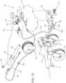
- FIG. 7shows an exploded, bottom perspective view of the attachment of FIG. 6 and the aerating apparatus of FIG. 1 , with portions broken away.
- FIG. 8shows a perspective view of a portion of the attachment of FIG. 6 .
- FIGS. 9 and 10show partial cross sectional views of the attachment of FIG. 6 and the aerating apparatus of FIG. 1 .
- FIG. 11shows a bottom perspective view of an attachment including a linear electric actuator.
- FIG. 12shows a perspective view of the aerating apparatus of FIG. 1 including an attachment driven by a motor.
- FIG. 13shows an exploded, perspective view of the attachment of FIG. 12 and the aerating apparatus of FIG. 1 , with portions broken away.
- turf aerator 10includes a chassis 12 including first and second side plates 14 , front and back plates 24 and 26 , respectively, extending between side plates 14 , and a top plate 28 extending between side plates 14 and from front plate 24 towards, but spaced from, back plate 26 .
- top plate 28is generally an isosceles trapezoid.
- Chassis 12is moveably supported on turf adjacent to front plate 24 by caster wheels 30 , with caster wheels 30 located outwardly of side plates 14 . The wheels may protrude from each side which thereby provides additional stability to the turf aerator.
- a motor 38is mounted to top plate 28 adjacent to front plate 24 .
- Motor 38is in driving connection to hydraulic pumps.
- tine assemblies 100are driven at their outer ends by a sprocket 18 in gearing relation to a drive chain 20 .
- tine assemblies 100are each of the type shown and described in U.S. patent application Ser. No. 13/282,095 (U.S. Pat. No. 9,474,196), which is hereby incorporated herein by reference. All bearings on the tine shafts, wheels, casters, and jackshafts are sealed bearings and may not need to be greased by the user at given intervals. This saves the user time in maintenance, and also reduces the possibility that maintenance is forgotten which thereby leads to bearing failures and costly repairs for the user.
- chassis 12 of turf aerator 10includes a rectangular opening 40 in top plate 28 between side plates 14 and spaced from front plate 24 and generally located over tine assemblies 100 .
- a tine housing 50is pivotably secured to chassis 12 and extends within opening 40 in chassis 12 .
- Tine housing 50includes first and second side sheets 52 located inwardly of side plates 14 of chassis 12 . Further, front and back sheets 56 and 58 of tine housing 50 extend between side sheets 52 intermediate the front and back ends and at the back ends thereof respectively.
- Tine housing 50further includes a top sheet 60 extending between front and back sheets 56 and 58 and extending between side sheets 52 . Top sheet 60 and front and back sheets 56 and 58 extend generally perpendicular to side sheets 52 .
- Tine assemblies 100are rotatably mounted relative to chassis 12 about an axis parallel to the turf, with tine assemblies 100 including a plurality of tines extending circumferentially and perpendicularly from the axis of tine assemblies 100 . Particularly, tine assemblies are rotatably mounted to tine housing 50 between side sheets 52 and front and back sheets 56 and 58 and under top sheet 60 , with the outer ends and sprockets 18 of tine assemblies 100 located outside of side sheets 52 .
- the word sheetsare used to describe various components such as the top sheet 60 and side sheets 52 , it should be understood that these components can likewise be considered support members in general or frames that form the overall shape of the components, and may not necessarily be manufactured as sheets of material.
- the chassis 12can also include a front attachment receiver 27 which can be used to secure the attachment 110 thereto.
- the attachment receiver 27forms a U-shaped channel extending in a longitudinal direction and which is or can be square or rectangle.
- Front plate 24extends from both sides of front attachment receiver 27 generally perpendicular to the longitudinal direction of front attachment receiver 27 .
- Chassis 12also includes holes 29 , in this example shaped as a tear-drop for improved ease of use and functionality, which can be used for one or both purposes of securing the aerator turf machine for transport or for securing the attachment 110 thereto.
- holes 31 on side fenders 33can be used to better secure the turf aerator during transport.
- the holes 31can be referred to as tie-down holes in which a user can use to better secure the turf aerator during transportation.
- the attachment receiver 27is shown at least partially on front plate 24 and top plate 28 , however, the attachment receiver can additionally or alternatively be positioned on one or the other as well. Additional U-shaped channels can also be used for additional support.
- FIG. 3depicts the holes 29 positioned on front plate 24 , alternatively or additional holes can be positioned on top plate 28 .
- Turf aerator 10further includes a pair of hydraulic motors 34 mounted to chassis 12 between opening 40 and front plate 24 and having output shafts 32 aligned with each other and extending generally perpendicular to side plates 14 .
- Tine housing 50is pivotably connected to chassis 12 by having the front ends of side sheets 52 rotatably coupled to output shafts 32 which are parallel to, but spaced from, the rotation axis of tine assemblies 100 .
- Each output shaft 32includes a sprocket 36 a in gearing relation to drive chain 20 for driving the corresponding tine assembly 100 .
- Each output shaft 32further includes a sprocket 36 b in gearing relation to drive chain 42 .
- Drive chain 42is in gearing relation to a sprocket 44 on a stub axle 46 of drive wheel 48 , with stub axle 46 rotatably mounted to the corresponding side plate 14 of chassis 12 adjacent to back plate 26 . It should then be appreciated that drive chains 20 and 42 are located intermediate side sheets 52 and side plates 14 , and particularly are located exteriorly of tine housing 50 .
- Other manners for operating the tine assembly in addition to or as an alternative to the drive chainscan include a hydraulic motor that is coupled directly or indirectly to the tine assembly, such that the hydraulic motor itself powers the tine assembly.
- Other manners for operating the tine assemblycan include a belt, such as a v-belt, in place of the drive chains, in which case pulleys can be used in place of the sprockets.
- the componentsmay likewise be positioned where the drive chains are located, that is, exterior to the tine housing 50 , so that each of the components can likewise be protected from the tine assemblies in operation.
- first and second drivescan be in fixed timing with each other such that the wheels and tine assemblies operate in tandem.
- the second drivecan be positioned such that the second side support member is at least partially positioned between the tine assembly and the second drive.
- the tine housing 50may alternatively be a single component with the chassis 12 .
- the tine assemblies 100may be rotatably mounted to the chassis 12 itself.
- the tine housing 50can be formed as part of the chassis 12 , any discussion of components with respect to the tine housing can be formed as the chassis as well, including the front and back sheets 56 and 58 and the side sheets 52 .
- the chassiscan be formed of a pivoting portion which is mounted to the tine assemblies and a fixed portion.
- the chassisitself may include the pivot in which case the tine assemblies and the pivoting portion of the chassis connected to the tine assemblies can pivot relative to the remainder of the chassis (e.g., the fixed portion) in accordance with the elongation and retraction of the hydraulic cylinder.
- Any discussion of tine housing 50can alternatively be considered as being a discussion with respect to the chassis 12 itself, such as the pivoting portion of the chassis.
- Chassis 12further includes a console 16 shown as including a pair of side portions 62 secured to side plates 14 and upstanding therefrom.
- a top portion 64extends between and is secured to the upper ends of side portions 62 .
- a support shaft 66extends between side portions 62 parallel to and spaced from top plate 28 and intermediate top portion 64 and tine housing 50 .
- a hydraulic cylinder 68is pivotably connected to support shaft 66 .
- the lower end of the hydraulic cylinder 68is pivotably connected to a U-shaped bracket 70 secured to top sheet 60 of tine housing 50 .
- tine housing 50 and tine assemblies 100 thereinare pivoted relative to chassis 12 .
- the chassisforms the components of the tine housing such that it is all a fluid piece or connection, then that portion of the chassis can move, or pivot, relative to the remainder of the fixed portion of the chassis based on the elongation and retraction of the hydraulic cylinder.
- a bracket 72is pivotably secured to support shaft 66 such as by extending support shaft 66 through a pair of ears 74 extending generally perpendicular to bracket 72 and located on opposite sides of the upper end of hydraulic cylinder 68 .
- a trip 76is movably mounted relative to a bracket 72 in a direction perpendicular to support shaft 66 and parallel to hydraulic cylinder 68 , such as by having fasteners of trip 76 extend through an elongated slot 72 a .
- the positions of trip 76 relative to bracket 72correspond to the elongation or retraction of hydraulic cylinder 68 , such as by a rod 78 having its upper end pivotably connected to trip 76 and its lower end pivotably connected to U-shaped bracket 70 and extending generally parallel to hydraulic cylinder 68 .
- a first switch 80is suitably secured to an upper end of bracket 72 , which is engageable by trip 76 to define the maximum retraction of hydraulic cylinder 68 .
- a second switch 82is mounted to bracket 72 for movement parallel to the movement of trip 76 relative to bracket 72 , which is engageable by trip 76 to define the maximum elongation of hydraulic cylinder 68 .
- switch 82is mounted to a bracket 84 having fasteners extending through an elongated slot 72 b which is parallel to and spaced from slot 72 a .
- a J-shaped crank arm 86is pivotably mounted to one ear 74 at its first end.
- a slide rod 88has its first end pivotably connected to a first end of crank arm 86 intermediate its ends and a second end pivotably connected to bracket 84 .
- a handle rod 90has a first end pivotably connected to a second end of crank arm 86 and a second end pivotably connected to a depth control lever 92 pivotably mounted in console 16 and extending outwardly of top portion 64 .
- a switch 94controls the retraction and elongation of hydraulic cylinder 68 between the extents defined by switches 80 and 82 .
- switch 94is located on an operator platform 96 mounted to chassis 12 .
- operator platform 96uses the rubber isolator mounting system disclosed in U.S. Pat. No. 8,632,018, which is hereby incorporated herein by reference.
- operator platform 96has a rubber mat 104 with holes in it to help with operator fatigue. Mat 104 can be flipped up for ease of cleaning dirt and debris that can accumulate while aerating.
- Operator platform 96also has a lock 102 to keep it from accidentally flipping up with the user still on operator platform 96 .
- the lock 102can engage with a corresponding bore in the operator platform 96 which thereby prohibits the operator platform from moving. For example, when the operator platform is in use, that is, it extends parallel to the ground, the lock prohibits the operator platform from moving upwards in a closed position. Likewise, when the operator platform is positioned upward, or perpendicular to the ground, the lock can prohibit the operator platform from falling downward. Thus, the lock 102 can be disengaged to rotate operator platform 96 up and then, once the operator platform is in the up position, re-locked to hold it up. This aids in providing access to the user to the tine assemblies 100 in order to clean them.
- switches and tripsare shown in the figures and described, other electronic or mechanical mechanisms can also be implemented to serve a similar such purpose.
- the switchmay be considered a variable position mechanism or device and the trip may be considered a triggering mechanism.
- a magnetic pick-up sensorcan be used to identify the presence of a magnet which may replace the trip.
- Other sensory devicescan also be utilized such as a proximity sensory, and the like which can detect the approach of an object such as the trip.
- sensorsare utilized in which signals, such as digital signals, are ultimately transmitted to one or more processors (e.g., CPU), or otherwise a controller, micro-controller, etc., which can thereby control the operation of the hydraulic cylinder.
- the turf aeratorcan include other components typically associated with computing devices in addition to the sensors and processors mentioned, such as memory configured to install data and instructions executable by the one or more processors, a display screen as an output mechanism, and an input mechanism for the user to control the turf aerator.
- Attachmentssuch as drop seeder, drop spreader, or broadcast spreader can be installed on the front of the machine.
- an attachment 110is suitably secured to front plate 24 and is powered by at least one hydraulic motor 34 with its corresponding tine assembly 100 and drive wheel 48 .
- Attachment 110is shown as being a drop seeder, but attachment 110 could be of other forms and types useful in turf management and, especially, in cooperation with aeration, including, but not limited to, a broadcast spreader, a drop spreader, or the like.
- FIG. 5shows a drop seeder 112 that is powered by a v-belt 120 that is connected to hydraulic motor 34 by pulley 112 .
- the agitator 116 in the seeder 112runs proportionate to ground speed as the hydraulic motor also runs the wheels of the turf aerator.
- attachment 110includes a seeder 112 for holding seeds for dispensing out of an adjustable lower opening 114 .
- controls for adjusting lower opening 114could be routed up to console 16 which the operator could easily reach during operation.
- the agitator 116is provided inside of seeder 112 having a pulley 118 exterior of seeder 112 .
- Pulley 118 and agitator 116are shown as being powered by the belt 120 , which in this example is a v-belt, extending between pulley 118 and a pulley 122 provided on output shaft 32 outwardly of side plate 14 .
- attachment 110could also be powered by the other hydraulic motor 34 with the other drive wheel 48 and the other tine assembly 100 .
- an attachment 210is suitably secured to front plate 24 and is powered by at least one electric motor 232 .
- Attachment 210is shown as being a drop seeder, but attachment 210 could be of other forms and types useful in turf management and, especially, in cooperation with aeration, including, but not limited to, a broadcast spreader or the like.
- FIG. 6shows a hopper 212 for holding seeds for dispensing out of a plurality of spaced lower openings 214 .
- An agitator 216is provided inside of hopper 212 having a sprocket 218 exterior of hopper 212 .
- Sprocket 218 and agitator 216are shown as being powered by a continuous drive member 220 , which in this example is a roller chain, extending between sprocket 218 and a sprocket 222 provided on electric motor 232 mounted outside of hopper 212 .
- Motor 232runs at a constant speed, and there is no variation with ground speed. Agitator 216 does not meter the seed and only keeps it flowing.
- a valve plate 240is slideably mounted to the bottom of hopper 212 and extends over lower openings 214 , such as by fasteners extending through elongated slots. Valve plate 240 also includes a plurality of spaced valve openings 242 of a size and spacing corresponding to lower openings 214 . Valve plate 240 is biased to an open position, such as by a spring 244 , with valve openings 242 aligned with lower openings 214 .
- a lever 246is pivotable relative to chassis 12 by being pivotably mounted to a housing 248 removably fixed to one side portion 62 of console 16 .
- a cable 247extends from lever 246 to a tab 249 on valve plate 240 .
- Lever 246is pivoted between a closed position to an open position with cable 247 moving valve plate 240 .
- spring 244closes valve plate 240 (i.e. valve openings 242 aligning with lower openings 214 ) when lever 246 is pivoted past over center.
- Lever 246engages with a switch 250 mounted in housing 248 in the closed position, with switch 250 controlling electric motor 232 to drive agitator 216 when lever 246 is in the open position and to not drive agitator 216 in the closed position.
- switch 250is activated with lever 246 which opens or closes valve plate 240 , the user does not have to remember to turn electric motor 232 on or off.
- Housing 248is removably mounted to console 16 , without the use of tools, such as by wing nuts 252 threaded on bolts 254 extending from side portion 62 and through housing 248 .
- a cam 260is rotatably mounted on the bottom of hopper 212 for abutting with a follower tab 262 extending from valve plate 240 .
- Cam 260is adjustably fixed to hopper 212 such as by a wing nut 264 . By loosening wing nut 264 , the degree to which valve openings 242 align with lower openings 214 can be adjusted.
- valve plate 240is moved by a linear electric actuator 270 .
- actuator 270is pivotably connected to an end of a pivot arm 272 pivotably mounted intermediate its ends about an axis 274 fixed to hopper 212 .
- the opposite end of pivot arm 272is connected by a spring 276 in turn connected to valve plate 240 .
- Switch 94 controlling linear electric actuator 270 and electric motor 232is suitably mounted on turf aerator 10 to be conveniently operated by the user, such as mounted on operator platform 96 .
- switch 94controls hydraulic cylinder 68 as well as linear electric actuator 270 , so attachment 210 is actuated once tine assemblies 100 are engaged and is automatically stopped when tine assemblies 100 are disengaged.
- attachment 210is mounted to a hitch 280 mounted to hopper 212 by brackets 282 .
- Hitch 280is slideably received in receiver 27 and is removably fixed therein by a pin 284 .
- a lock 286is pivotably mounted to brackets 282 .
- lock 286includes first and second side plates 286 a located on opposite sides of the longitudinal direction of hitch 280 , a bottom plate 286 b extending between side plate 286 a , and a rear plate 286 c extending upward generally perpendicular to bottom plate 286 b and located intermediate and spaced from side plates 286 a .
- Side plates 286 aare pivotably mounted to brackets 282 about an axis 288 extending parallel to and spaced from rear plate 286 c .
- Side plates 286 ainclude downwardly extending slots 290 for slideably receiving the lower edge of first plate 24 .
- Lock 286is pivotable between a locked position with the lower edge of first plate 24 received in slots 290 on opposite sides of receiver 27 and rear plate 286 c abutting with receiver 27 and an unlocked position with slots 290 and lock 286 spaced from front plate 24 and receiver 27 .
- any slop between hitch 280 and receiver 27is removed, removing vibration caused from the slop.
- pin 284is only necessary as a redundancy for safety.
- Lock 286is suitably pivotably moved between the locked and unlocked positions by any suitable provisions.
- an L-shaped rod 290extends in a plane extending in the longitudinal direction away from hitch 280 and along an axis perpendicular to axis 288 through a slot 292 in bottom plate 286 b and is threaded into hitch 280 .
- bottom plate 286 bBy threading L-shaped rod 290 into hitch 280 , bottom plate 286 b and thus lock 286 is moved from the unlocked position to the locked position, and vice versa.
- pivoting of lock 286can be accomplished in other manners including, but not limited to, using straps, abutment bolts, or the like.
- Attachments 110 and 210allow the user to seed while aerating, seeding every pass.
- the userengages lever 246 on console 16 at the beginning of each pass and disengages at the end of each pass.
- Attachments 110 and 210spread seed the same width as the aeration width. There is no danger of accidentally spreading seed into flower beds. Attachments 110 and 210 can be installed or removed without tools, allowing the user to easily take it off if they are only doing aerations without seeding for the day.
- Housing 248 mounted on console 16comes off with just two wing nuts 252 .
- the power cord for electric motor 232has a connector up by housing 248 that gets disconnected. This plus the locking system do not require any tools to take attachment 210 off and on turf aerator 10 , allowing the user the ease of not having attachment 210 on turf aerator 10 if they have a day where they are only aerating and not seeding. Seeding is more commonly done in the fall, so many times during spring aeration they will not need attachment 210 installed.
- an attachment 310is suitably secured to front plate 24 and is powered by at least one electric motor 332 .
- Attachment 310is shown as being a sprayer unit, but attachment 310 could be of other forms and types useful in turf management and, especially, in cooperation with aeration, including, but not limited to, a broadcast spreader or the like.
- FIG. 12shows a tank 312 for holding a liquid such as herbicides, insecticides, or the like.
- a pump 314 driven by electric motor 332includes an inlet hose 316 extending into and in communication with the liquid held in tank 312 .
- Pump 314is in fluid communication with a manually operated valve 318 after a pressure regulator and gauge 320 .
- Valve 318is positionable to be in fluid communication with a first hose 322 terminating in a wide angle spray nozzle 324 and with a second hose 326 terminating in a manually operated spray wand 328 .
- Hitch 280is mounted to tank 312 by a mount bracket 330 . With hitch 280 slideably received in receiver 27 , mount bracket 330 and tank 312 are held generally horizontally and parallel to the ground. Nozzle 324 is mounted to mount bracket 330 in the arrangement as disclosed in U.S. Pat. Nos. 8,056,828; 8,632,018; and 10,194,582. Hose 326 is wound around a reel 336 which is mounted to top plate 28 of chassis 12 adjacent motor 38 . Hose 326 extends from reel 336 through a direction loop 338 secured to one of the pair of side portions 62 . Wand 328 is removably positioned in a tube 340 fixed to the one of the pair of side plates 62 by a mounting bracket 342 above direction loop 338 .
- Attachment 310allows the user to apply a liquid while aerating.
- valve 318positioned to communicate with hose 322 , the user activates a switch 346 on console 16 to activate or deactivate motor 332 and pump 314 , such as at the beginning or ending of each pass.
- spray nozzle 324sprays liquid the same width as the aeration width. There is no danger of accidentally spraying liquid into flower beds.
- valve 318 positioned to communicate with hose 326the user can remove wand 328 from tube 340 and point it at areas desired to be sprayed within or outside the aeration width.
- switch 346 on console 16the application of liquid can be completed using wand 328 .
- Attachment 310can be installed or removed without tools, allowing the user to take it off if they are only doing aeration without liquid application for the day.
- Reel 336 , direction loop 338 and mounting bracket 342are permanently mounted on chassis 16 , but hose 326 comes off valve 318 utilizing a coupler.
- the power cord for electric motor 332has a connector that gets disconnected. This plus the locking system do not require any tools to take attachment 310 off and on turf aerator 10 , allowing the user the ease of not having attachment 310 on turf aerator, if they have a day where only aerating and not liquid application is desired.
- Turf aerator 10eliminates the need for the user to have to adjust hydraulic pressure, by instead having the user set a desired depth and automatically adjusting hydraulic pressure to produce the correct down pressure.
- the depthwill stay consistent and does not require constant adjustment by the user.
- the only condition where the depth will be less than setis when the soil is too hard and the down pressure required for that depth is more than the maximum created by the weight of turf aerator 10 .
- tine assemblies 100will not penetrate to the depth selected. This is the same as conventional machines when they are at their maximum hydraulic pressure.
- To engage tine assemblies 100 in the groundthe user steps on switch 94 on operator platform 96 and keeps switch 94 down.
- To disengage tine assemblies 100the user steps off switch 94 .
- Turf aerator 10allows the user to set a fixed depth by having depth control lever 92 that is infinitely variable to set depth. That is, infinitely variable may be defined between the two points in which the depth control lever can extend. Thus, the user can adjust the depth control lever at any location between which the lever operates, such as may be defined by the top portion 64 .
- There are two switches 80 and 82one for the raised position (remains fixed) and one for the lowered position (variable and is attached by linkage to depth control lever 92 ).
- As depth control lever 92is moved forward or backward, it increases or decreases the tine depth by moving switch 82 down or up.
- Trip 76is moveably attached to tine housing 50 , which trips either raised position switch 80 or lowered position switch 82 .
- both the first and second switchescan be variable, that is, adjustable by the user using depth control levers or other adjustable mechanisms.
- turf aerator 10has tine housing 50 shielding tine assemblies 100 attached to the tine shaft, so the whole assembly raises and lowers. Since it is all independent of chassis 12 , turf aerator 10 allows drive chains 20 and 42 to be on the outside of tine housing 50 , which shields drive chains 20 and 42 from the dirt and debris of aerating. This improves chain life and creates less down time for the user. Turf aerator 10 also minimizes the number of chains and belts, with only one belt to run the hydraulic pumps and four drive chains 20 and 42 running off hydraulic motors 34 to run each wheel 48 and each tine assembly 100 . Also, the belt has a spring tensioner to help take up slack in the belt as it stretches with wear.
Landscapes
- Life Sciences & Earth Sciences (AREA)
- Environmental Sciences (AREA)
- Soil Sciences (AREA)
- Engineering & Computer Science (AREA)
- Mechanical Engineering (AREA)
- Insects & Arthropods (AREA)
- Pest Control & Pesticides (AREA)
- Wood Science & Technology (AREA)
- Zoology (AREA)
- Soil Working Implements (AREA)
Abstract
Description
Claims (9)
Priority Applications (2)
| Application Number | Priority Date | Filing Date | Title |
|---|---|---|---|
| US16/592,960US11849657B2 (en) | 2018-10-15 | 2019-10-04 | Methods and apparatus for aerating turf |
| US18/510,618US20240081164A1 (en) | 2018-10-15 | 2023-11-15 | Methods and Apparatus for Aerating Turf |
Applications Claiming Priority (3)
| Application Number | Priority Date | Filing Date | Title |
|---|---|---|---|
| US201862745557P | 2018-10-15 | 2018-10-15 | |
| US201962800584P | 2019-02-04 | 2019-02-04 | |
| US16/592,960US11849657B2 (en) | 2018-10-15 | 2019-10-04 | Methods and apparatus for aerating turf |
Related Child Applications (1)
| Application Number | Title | Priority Date | Filing Date |
|---|---|---|---|
| US18/510,618DivisionUS20240081164A1 (en) | 2018-10-15 | 2023-11-15 | Methods and Apparatus for Aerating Turf |
Publications (2)
| Publication Number | Publication Date |
|---|---|
| US20200113114A1 US20200113114A1 (en) | 2020-04-16 |
| US11849657B2true US11849657B2 (en) | 2023-12-26 |
Family
ID=70162166
Family Applications (2)
| Application Number | Title | Priority Date | Filing Date |
|---|---|---|---|
| US16/592,960Active2042-07-08US11849657B2 (en) | 2018-10-15 | 2019-10-04 | Methods and apparatus for aerating turf |
| US18/510,618PendingUS20240081164A1 (en) | 2018-10-15 | 2023-11-15 | Methods and Apparatus for Aerating Turf |
Family Applications After (1)
| Application Number | Title | Priority Date | Filing Date |
|---|---|---|---|
| US18/510,618PendingUS20240081164A1 (en) | 2018-10-15 | 2023-11-15 | Methods and Apparatus for Aerating Turf |
Country Status (1)
| Country | Link |
|---|---|
| US (2) | US11849657B2 (en) |
Families Citing this family (9)
| Publication number | Priority date | Publication date | Assignee | Title |
|---|---|---|---|---|
| US9474196B2 (en) | 2010-10-27 | 2016-10-25 | Turfco Manufacturing, Inc. | Apparatus for aerating turf including positionable transport wheels |
| US10849262B2 (en) | 2016-10-19 | 2020-12-01 | Turfco Manufacturing, Inc. | Methods and apparatus for aerating turf |
| US10918003B2 (en)* | 2018-04-03 | 2021-02-16 | Briggs & Stratton, Llc | Turf aerators and assemblies for same |
| US11849657B2 (en)* | 2018-10-15 | 2023-12-26 | Turfco Manufacturing, Inc | Methods and apparatus for aerating turf |
| WO2022040814A1 (en)* | 2020-08-28 | 2022-03-03 | Ecolawn Aerator Incorporated | Lawn aerator apparatus |
| US20220104425A1 (en)* | 2020-10-06 | 2022-04-07 | Stinger Equipment, Inc. | Seeding Attachment for Riding Aerator |
| CN115250838B (en)* | 2022-09-01 | 2023-09-29 | 上海市园林设计研究总院有限公司 | Park green land transformation auxiliary device |
| WO2024263914A1 (en)* | 2023-06-21 | 2024-12-26 | Doosan Bobcat North America, Inc. | Hydrostatic aerator |
| CN118985228B (en)* | 2024-10-23 | 2025-01-17 | 中国农业科学院草原研究所 | Adjustable automatic oat seeding device |
Citations (134)
| Publication number | Priority date | Publication date | Assignee | Title |
|---|---|---|---|---|
| US1157670A (en) | 1915-02-10 | 1915-10-26 | Henson R Roswell | Tractor-plow. |
| US1778334A (en) | 1927-08-04 | 1930-10-14 | Pedersen Dines Christian | Engine-driven rotary cultivator |
| US1807182A (en) | 1930-09-18 | 1931-05-26 | Frank H Stoner | Disk cultivator |
| GB472443A (en) | 1936-08-15 | 1937-09-23 | Johan Alfred Lassas | A new or improved motor-driven land-working machine or tractor |
| US2205997A (en) | 1939-07-13 | 1940-06-25 | Tabor Mfg Co | Dibbling machine |
| US2229497A (en) | 1939-06-05 | 1941-01-21 | Dontje Emanuel Charles | Spiking apparatus |
| US2234534A (en) | 1939-11-27 | 1941-03-11 | Lavere E Reno | Palmetto cutting and root exterminating machine |
| US2244099A (en) | 1940-06-29 | 1941-06-03 | Fmc Corp | Rotary cutter |
| US2260110A (en) | 1939-06-05 | 1941-10-21 | Sophus T Blohm | Device for lawn development |
| US2400204A (en) | 1944-03-13 | 1946-05-14 | Segfrid J Lindskog | Lawn renovating machine |
| US2649061A (en) | 1947-11-24 | 1953-08-18 | Hawkins | Soil treating device |
| US2675750A (en) | 1954-04-20 | Boyer | ||
| US2750859A (en) | 1952-01-08 | 1956-06-19 | George E Smithburn | Rotary tiller |
| US2778291A (en) | 1954-10-19 | 1957-01-22 | James F Kerns | Rotary renovator |
| US2823597A (en) | 1953-09-03 | 1958-02-18 | Cadwallader W Kelsey | Rotary soil working device |
| US2835182A (en) | 1954-04-28 | 1958-05-20 | George E Smithburn | Garden cultivator |
| US2888994A (en) | 1955-10-06 | 1959-06-02 | Hoffco Inc | Cultivating implement |
| AU256472B2 (en) | 1960-05-09 | 1963-05-23 | David Swinerton Kaye Ronald | Soil aerating machine |
| US3148737A (en) | 1963-09-13 | 1964-09-15 | Grant Roy | Aerator |
| US3171498A (en) | 1963-12-27 | 1965-03-02 | Frederick B Logan | Aerating apparatus |
| US3429378A (en) | 1965-05-18 | 1969-02-25 | Thomas C Mascaro | Turf-aerating apparatus |
| US3462173A (en)* | 1967-07-31 | 1969-08-19 | August M Bock | Draw bar for towing vehicles |
| US3504748A (en) | 1969-01-02 | 1970-04-07 | Paul H Croft | Drag wheel for a garden tiller |
| US3534818A (en) | 1968-10-24 | 1970-10-20 | Kearney National Inc | Turf cultivating spoon mounting arrangement |
| US3566973A (en) | 1968-08-05 | 1971-03-02 | Walter Bradley | Lawn-aerating machine |
| US3675724A (en) | 1969-06-11 | 1972-07-11 | Arthur F Schneider | Self propelled land clearing and plowing apparatus |
| US3792734A (en) | 1972-01-10 | 1974-02-19 | Atlas Tool Mfg Co | Self-propelled tiller |
| US3851894A (en)* | 1973-05-30 | 1974-12-03 | H Pierre | Connector |
| US3853255A (en)* | 1973-08-01 | 1974-12-10 | J Spencer | Motorcycle carrier |
| US4089387A (en) | 1977-03-23 | 1978-05-16 | Edko Manufacturing Company | Adjustable ratcheting wheel hub |
| US4127951A (en)* | 1977-06-30 | 1978-12-05 | Hatch Richard W | Automatic coupling mechanism for snow-plows and the like |
| GB1558467A (en) | 1976-09-13 | 1980-01-03 | Wilkinson Sword Ltd | Tools for turf treatment or for other prposes |
| US4289224A (en) | 1979-09-04 | 1981-09-15 | Deere & Company | Independent wheel drive |
| US4336760A (en) | 1981-03-13 | 1982-06-29 | Improved Lawn Equipment Corporation | Earth working apparatus including aerators and material dispensers |
| US4438873A (en) | 1981-10-28 | 1984-03-27 | Turfco Manufacturing, Inc. | Ground driven top dresser utilizing special clutch mechanism |
| US4476938A (en) | 1979-10-24 | 1984-10-16 | Mckay Leon A | Aerating means |
| US4550783A (en) | 1978-02-01 | 1985-11-05 | Outboard Marine Corporation | Self-propelled aerating device |
| US4601163A (en) | 1984-04-10 | 1986-07-22 | Black & Decker Inc. | Garden tool |
| US4645012A (en) | 1985-01-16 | 1987-02-24 | Outboard Marine Corporation | Turf aerating apparatus |
| EP0140989B1 (en) | 1983-11-04 | 1987-06-03 | Winfried Schäfer | Soil working implement |
| US4750565A (en) | 1985-01-16 | 1988-06-14 | Outboard Marine Corporation | Turf aerating apparatus |
| US4753298A (en) | 1985-01-16 | 1988-06-28 | Outboard Marine Corporation | Turf aerating apparatus |
| US4773486A (en) | 1986-08-19 | 1988-09-27 | Outboard Marine Corporation | Driven tine wheel type aerator having improved tine geometry |
| US4776404A (en) | 1986-11-28 | 1988-10-11 | Olathe Manufacturing, Inc. | Multiple unit turf aerator |
| US4826195A (en)* | 1988-03-28 | 1989-05-02 | Cardinal Industries, Inc. | Auxiliary towing apparatus for tractor trucks and the like |
| US4830145A (en) | 1987-12-08 | 1989-05-16 | Outboard Marine Corporation | Lubricating arrangement for slide assembly |
| US4867244A (en) | 1987-11-16 | 1989-09-19 | Outboard Marine Corporation | Turf aerating apparatus |
| US4881602A (en) | 1988-08-05 | 1989-11-21 | Outboard Marine Corporation | Turf aerating tine |
| US4962599A (en)* | 1990-04-12 | 1990-10-16 | Dsp, Inc. | Quick connect-disconnect coupling for snow plow |
| US5009270A (en) | 1990-02-15 | 1991-04-23 | Turfco Manufacturing, Incorporated | Earthworking machine with single handle for adjusting and locking blade depth |
| US5029652A (en) | 1990-03-05 | 1991-07-09 | Whitfield Carroll J | Turf aerator with lateral tine movement |
| US5031927A (en)* | 1989-07-14 | 1991-07-16 | Frenette Albert E | Semi-automatic attach device for mounting snowplows |
| US5036608A (en)* | 1990-02-26 | 1991-08-06 | The Louis Berkman Company | Snowplow quick mount lift assembly |
| US5036655A (en) | 1990-04-30 | 1991-08-06 | Holloway E Ray | Replacement roller and turf groomer |
| US5119880A (en) | 1991-01-22 | 1992-06-09 | Bluebird International, Inc. | Aerating apparatus |
| US5142852A (en) | 1988-12-23 | 1992-09-01 | Nelson Danny L | Dethatching apparatus |
| US5207278A (en) | 1992-04-13 | 1993-05-04 | Textron Inc. | Turf aerator |
| US5209306A (en) | 1992-04-06 | 1993-05-11 | Whitfield Carroll J | Turf aerator with improved bearings for lateral tine movement |
| US5307965A (en) | 1992-11-30 | 1994-05-03 | Turfco Manufacturing, Incorporated | Ground-driven top dresser utilizing easily actuated clutch mechanism |
| US5307952A (en) | 1991-02-06 | 1994-05-03 | Turfco Manufacturing Incorporated | Top dresser |
| US5398767A (en) | 1988-06-22 | 1995-03-21 | Warke; William L. | Ground treatment apparatus |
| US5454433A (en) | 1992-07-31 | 1995-10-03 | Turfco Manufacturing, Incorporated | High frequency, low amplitude, sod harvesting apparatus |
| US5460229A (en) | 1994-03-25 | 1995-10-24 | Mattis; Henry J. | Field aerator apparatus |
| US5586604A (en) | 1994-06-02 | 1996-12-24 | Postema; Leonard F. | Aerator |
| US5673756A (en) | 1995-11-13 | 1997-10-07 | Classen Enterprises, Inc. | Turf aerator drive assembly |
| US5680903A (en) | 1997-02-11 | 1997-10-28 | Bluebird International, Inc. | Lawn aerator having tine assemblies spaced along a shaft |
| US5794708A (en) | 1996-04-19 | 1998-08-18 | Turfco Manufacturing, Incorporated | Triangular cross section trenching apparatus for edging |
| US5802994A (en) | 1996-07-03 | 1998-09-08 | Turfco Manufacturing Incorporated | Seeder apparatus for dispensing seed with or without top dressing |
| US5823269A (en) | 1996-03-27 | 1998-10-20 | Leclerc; Francois | Turf aerator attachment for tractor |
| US6024033A (en) | 1996-07-03 | 2000-02-15 | Turfco Manufacturing, Inc. | Seeder apparatus for dispensing seed with or without top dressing |
| US6041869A (en) | 1998-02-23 | 2000-03-28 | Textron Inc. | Turf aerator with constantly vertical tines |
| US6102129A (en) | 1999-05-27 | 2000-08-15 | Classen Enterprises, Inc. | Aerator |
| US6149079A (en) | 1998-09-03 | 2000-11-21 | Turfco Manufacturing, Incorporated | Broadcast spreading top dresser |
| US6151811A (en) | 1998-11-03 | 2000-11-28 | Barreto; Greg | Retractable assembly for trenchers and walk-behind power units |
| US6179061B1 (en) | 2000-03-13 | 2001-01-30 | Michael John Fiore | Seat operable lawn treatment device |
| US6200066B1 (en) | 1998-02-05 | 2001-03-13 | John L. Humphrey | Self-propelled vibratory greensroller |
| US6209231B1 (en)* | 1998-08-14 | 2001-04-03 | Curtis International, Inc. | Vehicle hitch mount assembly for a snow plow |
| US6241025B1 (en) | 1999-08-31 | 2001-06-05 | Jrco, Incorporated | Aerator |
| US6273197B1 (en) | 1999-07-27 | 2001-08-14 | Audie Marlow | Method and apparatus for a self-propelled ground aerator |
| US20010033068A1 (en)* | 2000-04-21 | 2001-10-25 | Melesko Steven David | Self centering trailer hitch |
| US20010045720A1 (en)* | 2000-01-27 | 2001-11-29 | Schlicht Willian S. | Folding step for trailer hitch |
| US6336600B1 (en)* | 1999-11-10 | 2002-01-08 | Thomas F. Jessen | Self-propelled material spreader |
| US6381880B1 (en)* | 1998-08-14 | 2002-05-07 | Curtis International, Inc. | Vehicle hitch mount assembly for a snow plow |
| US20020084082A1 (en) | 2000-12-28 | 2002-07-04 | Hill John W. | Plug aerator |
| US6443474B1 (en)* | 1999-06-09 | 2002-09-03 | Jack Kay | High strength extended length trailer hitch |
| US20030127813A1 (en)* | 2002-01-07 | 2003-07-10 | Lenkman Thomas E. | Utility transport system |
| US20030178207A1 (en) | 2002-03-25 | 2003-09-25 | Lauer G. Kent | Aerator device |
| US20030201106A1 (en)* | 2002-04-24 | 2003-10-30 | Thomas Jessen | Aerator sulky |
| US6684960B1 (en) | 2002-01-28 | 2004-02-03 | Cheong-Yeow Ng | Turf aerator |
| US6708773B1 (en) | 2002-11-12 | 2004-03-23 | Turfco Manufacturing, Inc. | Method and apparatus for an aerator with differential, steering assist and power lifting |
| US6742799B1 (en)* | 2003-01-06 | 2004-06-01 | Richard C. Hansen | Hitch adapter |
| US20050000706A1 (en) | 2001-03-29 | 2005-01-06 | Maas David R. | Arcuate aeration tine |
| US20050006110A1 (en) | 2003-06-25 | 2005-01-13 | Industrial Machine Specialties, Inc. | Turf aerator with unibody construction and reciprocating tines |
| US20050076543A1 (en)* | 2002-09-20 | 2005-04-14 | Curtis Marc D. | Jack for a working implement and method |
| US20050173134A1 (en) | 2004-02-10 | 2005-08-11 | Maas David R. | Aerating a ground surface |
| US20050241553A1 (en)* | 2004-05-03 | 2005-11-03 | Michael Dika | Seeding apparatus |
| US20060048952A1 (en) | 2004-09-09 | 2006-03-09 | Larry Classen | Turf aerator |
| US20060055150A1 (en)* | 2003-09-29 | 2006-03-16 | Ltt Biio-Phara Co., Ltd | Vehicle mount assembly for a utilitarian accessory |
| US20060070750A1 (en) | 2004-09-09 | 2006-04-06 | Schiller-Pfieffer, Inc. | Turf aerator |
| US20070222183A1 (en)* | 2006-03-24 | 2007-09-27 | Nissan Technical Center North America, Inc. | Power retractable trailer hitch |
| US20080023940A1 (en)* | 2006-07-11 | 2008-01-31 | Eley Coy Warford | Unitary trailer hitch safety device |
| US20080029278A1 (en) | 2006-08-04 | 2008-02-07 | Ross Wynings | Hydraulic drive aerator |
| US7334357B1 (en)* | 2004-10-27 | 2008-02-26 | Altheide Charles E | Snowplow impact reduction system |
| US20080101899A1 (en)* | 2006-10-27 | 2008-05-01 | Stacy Evan Slonecker | Refuse or recycling cart lifting and transporting device |
| US7543842B1 (en)* | 2008-02-22 | 2009-06-09 | Raymond Fiorini | Portable and adjustable trailer assembly and method of use thereof |
| US20100201102A1 (en)* | 2009-01-30 | 2010-08-12 | Weaver Danny C | Pin-engaging drawbar and lock plate assembly |
| US7779929B2 (en) | 2004-02-10 | 2010-08-24 | Planetair Turf Products, Llc | Soil aerator assembly |
| US20110079659A1 (en)* | 2009-10-01 | 2011-04-07 | Fimco Industries | Sprayer system |
| US7992327B2 (en)* | 2008-06-17 | 2011-08-09 | Sno-Way International, Inc. | Snow plow rebound apparatus |
| US20110203816A1 (en) | 2010-02-19 | 2011-08-25 | Carl Bottom | Aerator for zero turn lawn equipment |
| US8056828B1 (en) | 2008-01-07 | 2011-11-15 | Turfco Manufacturing, Inc. | Methods and apparatus for applying product |
| US20120006571A1 (en) | 2010-07-12 | 2012-01-12 | Ryan Sprouse Dart | Lawn mower mounted plug aerator |
| US8235410B2 (en)* | 2010-02-15 | 2012-08-07 | Richard Weber | Trailer and towing related technologies |
| US8291991B1 (en) | 2009-12-22 | 2012-10-23 | The Toro Company | Walk-behind soil aerator |
| US20130014965A1 (en) | 2009-09-14 | 2013-01-17 | Barger K Kent | Soil aerator |
| US20130076008A1 (en)* | 2011-09-23 | 2013-03-28 | Austin Su | Locking assembly for towing hitch |
| US20130292145A1 (en)* | 2012-03-08 | 2013-11-07 | Shane Pastour | Sleeve hitch mount core aerator |
| US8590632B2 (en) | 2011-02-07 | 2013-11-26 | Landoll Corporation | Single pass ground driven tiller and seeder apparatus |
| US8733477B1 (en) | 2009-12-22 | 2014-05-27 | The Toro Company | Speed control system for earth working apparatus |
| US20140224512A1 (en) | 2013-02-13 | 2014-08-14 | Enduratech Manufacturing, LLC | Aeration tines and methods of making aeration tines |
| US8832974B2 (en)* | 2008-06-17 | 2014-09-16 | Sno-Way International, Inc. | V-plow |
| US8967654B1 (en)* | 2013-10-01 | 2015-03-03 | Gary Riibe | Trailer hitch |
| US20150107863A1 (en) | 2013-10-17 | 2015-04-23 | Exmark Mfg. Co., Inc. | Walk aerator |
| US20150217703A1 (en)* | 2014-02-04 | 2015-08-06 | DD Custom Industries, LLC | Trailer hitch receiver mounted collapsible workbench |
| US20150271983A1 (en) | 2012-11-06 | 2015-10-01 | Redexim Handel-En Exploitatie Mij. B.V. | Aerating Device |
| US20160138233A1 (en)* | 2014-11-13 | 2016-05-19 | Douglas Dynamics, L.L.C. | Snow plow and mount assembly |
| US9474196B2 (en) | 2010-10-27 | 2016-10-25 | Turfco Manufacturing, Inc. | Apparatus for aerating turf including positionable transport wheels |
| KR20160144130A (en) | 2015-06-08 | 2016-12-16 | 김신 | Turf punch for perforation working of grassplot |
| US20170113501A1 (en)* | 2015-10-23 | 2017-04-27 | Robert Reynolds | Trailer hitch attachment device |
| US20170217267A1 (en)* | 2015-02-04 | 2017-08-03 | Jimmie D. Vetkos | Trailer Hitch Apparatus with Obtuse-Angled Elongate Winch Support Providing Improved Vehicle-End Profile and Hinged Door or Tailgate Clearance |
| US20180103571A1 (en) | 2016-10-19 | 2018-04-19 | Turfco Manufacturing, Inc. | Methods and Apparatus for Aerating Turf |
| US20200086701A1 (en)* | 2015-07-08 | 2020-03-19 | Pullium Enterprises, Inc. | Ball Hitch Fifth Wheel |
| US20200113114A1 (en)* | 2018-10-15 | 2020-04-16 | Turfco Manufacturing, Inc. | Methods and Apparatus for Aerating Turf |
| US10766319B2 (en)* | 2017-03-10 | 2020-09-08 | Gr Innovations Llc | Chain holder |
- 2019
- 2019-10-04USUS16/592,960patent/US11849657B2/enactiveActive
- 2023
- 2023-11-15USUS18/510,618patent/US20240081164A1/enactivePending
Patent Citations (153)
| Publication number | Priority date | Publication date | Assignee | Title |
|---|---|---|---|---|
| US2675750A (en) | 1954-04-20 | Boyer | ||
| US1157670A (en) | 1915-02-10 | 1915-10-26 | Henson R Roswell | Tractor-plow. |
| US1778334A (en) | 1927-08-04 | 1930-10-14 | Pedersen Dines Christian | Engine-driven rotary cultivator |
| US1807182A (en) | 1930-09-18 | 1931-05-26 | Frank H Stoner | Disk cultivator |
| GB472443A (en) | 1936-08-15 | 1937-09-23 | Johan Alfred Lassas | A new or improved motor-driven land-working machine or tractor |
| US2260110A (en) | 1939-06-05 | 1941-10-21 | Sophus T Blohm | Device for lawn development |
| US2229497A (en) | 1939-06-05 | 1941-01-21 | Dontje Emanuel Charles | Spiking apparatus |
| US2205997A (en) | 1939-07-13 | 1940-06-25 | Tabor Mfg Co | Dibbling machine |
| US2234534A (en) | 1939-11-27 | 1941-03-11 | Lavere E Reno | Palmetto cutting and root exterminating machine |
| US2244099A (en) | 1940-06-29 | 1941-06-03 | Fmc Corp | Rotary cutter |
| US2400204A (en) | 1944-03-13 | 1946-05-14 | Segfrid J Lindskog | Lawn renovating machine |
| US2649061A (en) | 1947-11-24 | 1953-08-18 | Hawkins | Soil treating device |
| US2750859A (en) | 1952-01-08 | 1956-06-19 | George E Smithburn | Rotary tiller |
| US2823597A (en) | 1953-09-03 | 1958-02-18 | Cadwallader W Kelsey | Rotary soil working device |
| US2835182A (en) | 1954-04-28 | 1958-05-20 | George E Smithburn | Garden cultivator |
| US2778291A (en) | 1954-10-19 | 1957-01-22 | James F Kerns | Rotary renovator |
| US2888994A (en) | 1955-10-06 | 1959-06-02 | Hoffco Inc | Cultivating implement |
| AU256472B2 (en) | 1960-05-09 | 1963-05-23 | David Swinerton Kaye Ronald | Soil aerating machine |
| US3148737A (en) | 1963-09-13 | 1964-09-15 | Grant Roy | Aerator |
| US3171498A (en) | 1963-12-27 | 1965-03-02 | Frederick B Logan | Aerating apparatus |
| US3429378A (en) | 1965-05-18 | 1969-02-25 | Thomas C Mascaro | Turf-aerating apparatus |
| US3462173A (en)* | 1967-07-31 | 1969-08-19 | August M Bock | Draw bar for towing vehicles |
| US3566973A (en) | 1968-08-05 | 1971-03-02 | Walter Bradley | Lawn-aerating machine |
| US3534818A (en) | 1968-10-24 | 1970-10-20 | Kearney National Inc | Turf cultivating spoon mounting arrangement |
| US3504748A (en) | 1969-01-02 | 1970-04-07 | Paul H Croft | Drag wheel for a garden tiller |
| US3675724A (en) | 1969-06-11 | 1972-07-11 | Arthur F Schneider | Self propelled land clearing and plowing apparatus |
| US3792734A (en) | 1972-01-10 | 1974-02-19 | Atlas Tool Mfg Co | Self-propelled tiller |
| US3851894A (en)* | 1973-05-30 | 1974-12-03 | H Pierre | Connector |
| US3853255A (en)* | 1973-08-01 | 1974-12-10 | J Spencer | Motorcycle carrier |
| GB1558467A (en) | 1976-09-13 | 1980-01-03 | Wilkinson Sword Ltd | Tools for turf treatment or for other prposes |
| US4089387A (en) | 1977-03-23 | 1978-05-16 | Edko Manufacturing Company | Adjustable ratcheting wheel hub |
| US4127951A (en)* | 1977-06-30 | 1978-12-05 | Hatch Richard W | Automatic coupling mechanism for snow-plows and the like |
| US4550783A (en) | 1978-02-01 | 1985-11-05 | Outboard Marine Corporation | Self-propelled aerating device |
| US4289224A (en) | 1979-09-04 | 1981-09-15 | Deere & Company | Independent wheel drive |
| US4476938A (en) | 1979-10-24 | 1984-10-16 | Mckay Leon A | Aerating means |
| US4336760A (en) | 1981-03-13 | 1982-06-29 | Improved Lawn Equipment Corporation | Earth working apparatus including aerators and material dispensers |
| US4438873A (en) | 1981-10-28 | 1984-03-27 | Turfco Manufacturing, Inc. | Ground driven top dresser utilizing special clutch mechanism |
| EP0140989B1 (en) | 1983-11-04 | 1987-06-03 | Winfried Schäfer | Soil working implement |
| US4601163A (en) | 1984-04-10 | 1986-07-22 | Black & Decker Inc. | Garden tool |
| US4750565A (en) | 1985-01-16 | 1988-06-14 | Outboard Marine Corporation | Turf aerating apparatus |
| US4753298A (en) | 1985-01-16 | 1988-06-28 | Outboard Marine Corporation | Turf aerating apparatus |
| US4645012A (en) | 1985-01-16 | 1987-02-24 | Outboard Marine Corporation | Turf aerating apparatus |
| US4773486A (en) | 1986-08-19 | 1988-09-27 | Outboard Marine Corporation | Driven tine wheel type aerator having improved tine geometry |
| US4776404A (en) | 1986-11-28 | 1988-10-11 | Olathe Manufacturing, Inc. | Multiple unit turf aerator |
| US4867244A (en) | 1987-11-16 | 1989-09-19 | Outboard Marine Corporation | Turf aerating apparatus |
| US4830145A (en) | 1987-12-08 | 1989-05-16 | Outboard Marine Corporation | Lubricating arrangement for slide assembly |
| US4826195A (en)* | 1988-03-28 | 1989-05-02 | Cardinal Industries, Inc. | Auxiliary towing apparatus for tractor trucks and the like |
| US5398767A (en) | 1988-06-22 | 1995-03-21 | Warke; William L. | Ground treatment apparatus |
| US4881602A (en) | 1988-08-05 | 1989-11-21 | Outboard Marine Corporation | Turf aerating tine |
| US5142852A (en) | 1988-12-23 | 1992-09-01 | Nelson Danny L | Dethatching apparatus |
| US5031927A (en)* | 1989-07-14 | 1991-07-16 | Frenette Albert E | Semi-automatic attach device for mounting snowplows |
| US5009270A (en) | 1990-02-15 | 1991-04-23 | Turfco Manufacturing, Incorporated | Earthworking machine with single handle for adjusting and locking blade depth |
| US5036608A (en)* | 1990-02-26 | 1991-08-06 | The Louis Berkman Company | Snowplow quick mount lift assembly |
| US5029652A (en) | 1990-03-05 | 1991-07-09 | Whitfield Carroll J | Turf aerator with lateral tine movement |
| US4962599A (en)* | 1990-04-12 | 1990-10-16 | Dsp, Inc. | Quick connect-disconnect coupling for snow plow |
| US5036655A (en) | 1990-04-30 | 1991-08-06 | Holloway E Ray | Replacement roller and turf groomer |
| US5119880A (en) | 1991-01-22 | 1992-06-09 | Bluebird International, Inc. | Aerating apparatus |
| US5478104A (en) | 1991-02-06 | 1995-12-26 | Turfco Manufacturing, Incorporated | Cantilevered leaf spring assembly |
| US5307952A (en) | 1991-02-06 | 1994-05-03 | Turfco Manufacturing Incorporated | Top dresser |
| US5209306A (en) | 1992-04-06 | 1993-05-11 | Whitfield Carroll J | Turf aerator with improved bearings for lateral tine movement |
| US5207278A (en) | 1992-04-13 | 1993-05-04 | Textron Inc. | Turf aerator |
| US5454433A (en) | 1992-07-31 | 1995-10-03 | Turfco Manufacturing, Incorporated | High frequency, low amplitude, sod harvesting apparatus |
| US5571252A (en) | 1992-07-31 | 1996-11-05 | Turfco Manufacturing, Incorporated | High frequency, low amplitude, sod harvesting apparatus |
| US5307965A (en) | 1992-11-30 | 1994-05-03 | Turfco Manufacturing, Incorporated | Ground-driven top dresser utilizing easily actuated clutch mechanism |
| US5460229A (en) | 1994-03-25 | 1995-10-24 | Mattis; Henry J. | Field aerator apparatus |
| US5586604A (en) | 1994-06-02 | 1996-12-24 | Postema; Leonard F. | Aerator |
| US5673756A (en) | 1995-11-13 | 1997-10-07 | Classen Enterprises, Inc. | Turf aerator drive assembly |
| US5823269A (en) | 1996-03-27 | 1998-10-20 | Leclerc; Francois | Turf aerator attachment for tractor |
| US5794708A (en) | 1996-04-19 | 1998-08-18 | Turfco Manufacturing, Incorporated | Triangular cross section trenching apparatus for edging |
| US5802994A (en) | 1996-07-03 | 1998-09-08 | Turfco Manufacturing Incorporated | Seeder apparatus for dispensing seed with or without top dressing |
| US6024033A (en) | 1996-07-03 | 2000-02-15 | Turfco Manufacturing, Inc. | Seeder apparatus for dispensing seed with or without top dressing |
| US6058860A (en) | 1996-07-03 | 2000-05-09 | Turfco Manufacturing Incorporated | Seeder apparatus for dispensing seed with or without top dressing |
| US5680903A (en) | 1997-02-11 | 1997-10-28 | Bluebird International, Inc. | Lawn aerator having tine assemblies spaced along a shaft |
| US6200066B1 (en) | 1998-02-05 | 2001-03-13 | John L. Humphrey | Self-propelled vibratory greensroller |
| US6041869A (en) | 1998-02-23 | 2000-03-28 | Textron Inc. | Turf aerator with constantly vertical tines |
| US6381880B1 (en)* | 1998-08-14 | 2002-05-07 | Curtis International, Inc. | Vehicle hitch mount assembly for a snow plow |
| US6209231B1 (en)* | 1998-08-14 | 2001-04-03 | Curtis International, Inc. | Vehicle hitch mount assembly for a snow plow |
| US6149079A (en) | 1998-09-03 | 2000-11-21 | Turfco Manufacturing, Incorporated | Broadcast spreading top dresser |
| US6151811A (en) | 1998-11-03 | 2000-11-28 | Barreto; Greg | Retractable assembly for trenchers and walk-behind power units |
| GB2347400B (en) | 1999-02-04 | 2002-09-18 | John Lionel Humphrey | Self-propelled vibratory greensroller |
| US6102129A (en) | 1999-05-27 | 2000-08-15 | Classen Enterprises, Inc. | Aerator |
| US6443474B1 (en)* | 1999-06-09 | 2002-09-03 | Jack Kay | High strength extended length trailer hitch |
| US6273197B1 (en) | 1999-07-27 | 2001-08-14 | Audie Marlow | Method and apparatus for a self-propelled ground aerator |
| US6241025B1 (en) | 1999-08-31 | 2001-06-05 | Jrco, Incorporated | Aerator |
| US6415872B2 (en) | 1999-08-31 | 2002-07-09 | Jrco, Incorporated | Aerator |
| US6336600B1 (en)* | 1999-11-10 | 2002-01-08 | Thomas F. Jessen | Self-propelled material spreader |
| US20010045720A1 (en)* | 2000-01-27 | 2001-11-29 | Schlicht Willian S. | Folding step for trailer hitch |
| US6179061B1 (en) | 2000-03-13 | 2001-01-30 | Michael John Fiore | Seat operable lawn treatment device |
| US20010033068A1 (en)* | 2000-04-21 | 2001-10-25 | Melesko Steven David | Self centering trailer hitch |
| US6675905B2 (en) | 2000-12-28 | 2004-01-13 | Ohio Steel Industries, Inc. | Plug aerator |
| US20020084082A1 (en) | 2000-12-28 | 2002-07-04 | Hill John W. | Plug aerator |
| US20050000706A1 (en) | 2001-03-29 | 2005-01-06 | Maas David R. | Arcuate aeration tine |
| US20030127813A1 (en)* | 2002-01-07 | 2003-07-10 | Lenkman Thomas E. | Utility transport system |
| US6684960B1 (en) | 2002-01-28 | 2004-02-03 | Cheong-Yeow Ng | Turf aerator |
| US20030178207A1 (en) | 2002-03-25 | 2003-09-25 | Lauer G. Kent | Aerator device |
| US6758283B2 (en) | 2002-03-25 | 2004-07-06 | Billy Goat Industries, Inc. | Aerator device |
| US20030201106A1 (en)* | 2002-04-24 | 2003-10-30 | Thomas Jessen | Aerator sulky |
| US20050076543A1 (en)* | 2002-09-20 | 2005-04-14 | Curtis Marc D. | Jack for a working implement and method |
| US6708773B1 (en) | 2002-11-12 | 2004-03-23 | Turfco Manufacturing, Inc. | Method and apparatus for an aerator with differential, steering assist and power lifting |
| US20040154811A1 (en) | 2002-11-12 | 2004-08-12 | Kinkead John B. | Method and apparatus for an aerator with differential, steering assist and power lifting |
| US6742799B1 (en)* | 2003-01-06 | 2004-06-01 | Richard C. Hansen | Hitch adapter |
| US20050006110A1 (en) | 2003-06-25 | 2005-01-13 | Industrial Machine Specialties, Inc. | Turf aerator with unibody construction and reciprocating tines |
| US6892821B2 (en) | 2003-06-25 | 2005-05-17 | Sourceone, Inc. | Turf aerator with unibody construction and reciprocating tines |
| US20060055150A1 (en)* | 2003-09-29 | 2006-03-16 | Ltt Biio-Phara Co., Ltd | Vehicle mount assembly for a utilitarian accessory |
| US20050173134A1 (en) | 2004-02-10 | 2005-08-11 | Maas David R. | Aerating a ground surface |
| US7779929B2 (en) | 2004-02-10 | 2010-08-24 | Planetair Turf Products, Llc | Soil aerator assembly |
| US8079422B2 (en) | 2004-02-10 | 2011-12-20 | Planetair Turf Products, Llc | Soil aerator assembly |
| US20050241553A1 (en)* | 2004-05-03 | 2005-11-03 | Michael Dika | Seeding apparatus |
| US7341114B2 (en) | 2004-09-09 | 2008-03-11 | Schiller-Pfeiffer, Inc. | Turf aerator |
| US7100702B2 (en) | 2004-09-09 | 2006-09-05 | Schiller-Pfeiffer, Inc. | Turf aerator |
| US20060070750A1 (en) | 2004-09-09 | 2006-04-06 | Schiller-Pfieffer, Inc. | Turf aerator |
| US20060048952A1 (en) | 2004-09-09 | 2006-03-09 | Larry Classen | Turf aerator |
| US7334357B1 (en)* | 2004-10-27 | 2008-02-26 | Altheide Charles E | Snowplow impact reduction system |
| US20070222183A1 (en)* | 2006-03-24 | 2007-09-27 | Nissan Technical Center North America, Inc. | Power retractable trailer hitch |
| US20080023940A1 (en)* | 2006-07-11 | 2008-01-31 | Eley Coy Warford | Unitary trailer hitch safety device |
| US20080029278A1 (en) | 2006-08-04 | 2008-02-07 | Ross Wynings | Hydraulic drive aerator |
| US20080101899A1 (en)* | 2006-10-27 | 2008-05-01 | Stacy Evan Slonecker | Refuse or recycling cart lifting and transporting device |
| US10194582B2 (en) | 2008-01-07 | 2019-02-05 | Turfco Manufacturing, Inc. | Methods and apparatus for applying product |
| US8632018B2 (en) | 2008-01-07 | 2014-01-21 | Turfco Manufacturing, Inc. | Methods and apparatus for applying product |
| US8056828B1 (en) | 2008-01-07 | 2011-11-15 | Turfco Manufacturing, Inc. | Methods and apparatus for applying product |
| US7543842B1 (en)* | 2008-02-22 | 2009-06-09 | Raymond Fiorini | Portable and adjustable trailer assembly and method of use thereof |
| US7992327B2 (en)* | 2008-06-17 | 2011-08-09 | Sno-Way International, Inc. | Snow plow rebound apparatus |
| US8832974B2 (en)* | 2008-06-17 | 2014-09-16 | Sno-Way International, Inc. | V-plow |
| US20100201102A1 (en)* | 2009-01-30 | 2010-08-12 | Weaver Danny C | Pin-engaging drawbar and lock plate assembly |
| US20130014965A1 (en) | 2009-09-14 | 2013-01-17 | Barger K Kent | Soil aerator |
| US20110079659A1 (en)* | 2009-10-01 | 2011-04-07 | Fimco Industries | Sprayer system |
| US8291991B1 (en) | 2009-12-22 | 2012-10-23 | The Toro Company | Walk-behind soil aerator |
| US8733477B1 (en) | 2009-12-22 | 2014-05-27 | The Toro Company | Speed control system for earth working apparatus |
| US8235410B2 (en)* | 2010-02-15 | 2012-08-07 | Richard Weber | Trailer and towing related technologies |
| US20110203816A1 (en) | 2010-02-19 | 2011-08-25 | Carl Bottom | Aerator for zero turn lawn equipment |
| US20120006571A1 (en) | 2010-07-12 | 2012-01-12 | Ryan Sprouse Dart | Lawn mower mounted plug aerator |
| US20190183028A1 (en) | 2010-10-27 | 2019-06-20 | Turfco Manufacturing, Inc. | Turf Aerator Having Removable Cover Over Rotatable Tines |
| US10212872B2 (en) | 2010-10-27 | 2019-02-26 | Turfco Manufacturing, Inc. | Turf aerator having removable cover over rotatable tines |
| US9474196B2 (en) | 2010-10-27 | 2016-10-25 | Turfco Manufacturing, Inc. | Apparatus for aerating turf including positionable transport wheels |
| US8590632B2 (en) | 2011-02-07 | 2013-11-26 | Landoll Corporation | Single pass ground driven tiller and seeder apparatus |
| US20130076008A1 (en)* | 2011-09-23 | 2013-03-28 | Austin Su | Locking assembly for towing hitch |
| US20130292145A1 (en)* | 2012-03-08 | 2013-11-07 | Shane Pastour | Sleeve hitch mount core aerator |
| US20150271983A1 (en) | 2012-11-06 | 2015-10-01 | Redexim Handel-En Exploitatie Mij. B.V. | Aerating Device |
| US9622397B2 (en) | 2012-11-06 | 2017-04-18 | Redexim Handel-en Exploitatie Mij. BV | Aerating device |
| US20140224512A1 (en) | 2013-02-13 | 2014-08-14 | Enduratech Manufacturing, LLC | Aeration tines and methods of making aeration tines |
| US8967654B1 (en)* | 2013-10-01 | 2015-03-03 | Gary Riibe | Trailer hitch |
| US20150107863A1 (en) | 2013-10-17 | 2015-04-23 | Exmark Mfg. Co., Inc. | Walk aerator |
| US9241437B2 (en) | 2013-10-17 | 2016-01-26 | Exmark Mfg. Co., Inc. | Walk aerator |
| US20150217703A1 (en)* | 2014-02-04 | 2015-08-06 | DD Custom Industries, LLC | Trailer hitch receiver mounted collapsible workbench |
| US20160138233A1 (en)* | 2014-11-13 | 2016-05-19 | Douglas Dynamics, L.L.C. | Snow plow and mount assembly |
| US20170217267A1 (en)* | 2015-02-04 | 2017-08-03 | Jimmie D. Vetkos | Trailer Hitch Apparatus with Obtuse-Angled Elongate Winch Support Providing Improved Vehicle-End Profile and Hinged Door or Tailgate Clearance |
| KR20160144130A (en) | 2015-06-08 | 2016-12-16 | 김신 | Turf punch for perforation working of grassplot |
| US20200086701A1 (en)* | 2015-07-08 | 2020-03-19 | Pullium Enterprises, Inc. | Ball Hitch Fifth Wheel |
| US20170113501A1 (en)* | 2015-10-23 | 2017-04-27 | Robert Reynolds | Trailer hitch attachment device |
| US20180103571A1 (en) | 2016-10-19 | 2018-04-19 | Turfco Manufacturing, Inc. | Methods and Apparatus for Aerating Turf |
| US10849262B2 (en)* | 2016-10-19 | 2020-12-01 | Turfco Manufacturing, Inc. | Methods and apparatus for aerating turf |
| US10766319B2 (en)* | 2017-03-10 | 2020-09-08 | Gr Innovations Llc | Chain holder |
| US20200113114A1 (en)* | 2018-10-15 | 2020-04-16 | Turfco Manufacturing, Inc. | Methods and Apparatus for Aerating Turf |
Non-Patent Citations (5)
| Title |
|---|
| Billy Goat Industries—EZair Aerators, web page (2 pgs.)—no date—. |
| BlueBird Internation Products-Turf Care-424, web page (2 pgs.)—no date—. |
| BlueBird International Products-Turf Care, web page (1 pg.)—no date—. |
| Classen Manufacturing, Inc., web page (2 pgs.)—no date—. |
| Plagr Walk Behind Power Aerators, web page, (5 pgs.)—no date—. |
Also Published As
| Publication number | Publication date |
|---|---|
| US20200113114A1 (en) | 2020-04-16 |
| US20240081164A1 (en) | 2024-03-14 |
Similar Documents
| Publication | Publication Date | Title |
|---|---|---|
| US20240081164A1 (en) | Methods and Apparatus for Aerating Turf | |
| US12114585B2 (en) | Methods and apparatus for aerating turf | |
| US4145980A (en) | Seeder for planting seeds at precise intervals | |
| US5477927A (en) | Turf maintenance and brushing machine | |
| US8028506B1 (en) | Adjustable row unit structure | |
| US7730960B1 (en) | Turf aeration device | |
| US6644416B2 (en) | Tiller | |
| JP4769282B2 (en) | Rice transplanter | |
| JP4537921B2 (en) | Rice transplanter | |
| US5347939A (en) | Agricultural apparatus | |
| US4493272A (en) | Agricultural planter with sled frame, vacuum dispensing and ground drive | |
| CA2707876C (en) | Turfplaner | |
| US4223478A (en) | Agricultural chemical applicator | |
| US5038868A (en) | Ground cultivator | |
| US5287685A (en) | Seed harvester | |
| FR2499817A1 (en) | Tractor mounted seed-sower - is connected to tractor by double acting hydraulic ram and curved pivoted arms | |
| US4286671A (en) | Kit for converting a rotary tiller into a plow | |
| US4875421A (en) | Seeding implement with a combination transport-drive wheel | |
| KR20090099802A (en) | Agricultural Vinyl Coating Machine | |
| KR102791948B1 (en) | Tracted type ridge making machine | |
| JP4484754B2 (en) | Rice transplanter | |
| CA1270153A (en) | Seed planter | |
| JP2003061427A (en) | Application device of tiller | |
| USRE32467E (en) | Plow attachment for converting a rotary tiller into a plow | |
| KR102663328B1 (en) | Covering machine for agriculture |
Legal Events
| Date | Code | Title | Description |
|---|---|---|---|
| AS | Assignment | Owner name:TURFCO MANUFACTURING, INC., MINNESOTA Free format text:ASSIGNMENT OF ASSIGNORS INTEREST;ASSIGNORS:KINKEAD, GEORGE B.;OEDING, NICHOLAS;REEL/FRAME:050636/0486 Effective date:20190828 | |
| FEPP | Fee payment procedure | Free format text:ENTITY STATUS SET TO UNDISCOUNTED (ORIGINAL EVENT CODE: BIG.); ENTITY STATUS OF PATENT OWNER: SMALL ENTITY | |
| FEPP | Fee payment procedure | Free format text:ENTITY STATUS SET TO SMALL (ORIGINAL EVENT CODE: SMAL); ENTITY STATUS OF PATENT OWNER: SMALL ENTITY | |
| STPP | Information on status: patent application and granting procedure in general | Free format text:NON FINAL ACTION MAILED | |
| STPP | Information on status: patent application and granting procedure in general | Free format text:RESPONSE TO NON-FINAL OFFICE ACTION ENTERED AND FORWARDED TO EXAMINER | |
| STPP | Information on status: patent application and granting procedure in general | Free format text:NON FINAL ACTION MAILED | |
| STPP | Information on status: patent application and granting procedure in general | Free format text:FINAL REJECTION MAILED | |
| STPP | Information on status: patent application and granting procedure in general | Free format text:NOTICE OF ALLOWANCE MAILED -- APPLICATION RECEIVED IN OFFICE OF PUBLICATIONS | |
| STPP | Information on status: patent application and granting procedure in general | Free format text:PUBLICATIONS -- ISSUE FEE PAYMENT VERIFIED | |
| STCF | Information on status: patent grant | Free format text:PATENTED CASE | |
| AS | Assignment | Owner name:TURFCO MFG., INC., MINNESOTA Free format text:CORRECTIVE ASSIGNMENT TO CORRECT THE ASSIGNEE NAME PREVIOUSLY RECORDED AT REEL: 50636 FRAME: 486. ASSIGNOR(S) HEREBY CONFIRMS THE ASSIGNMENT OF ASSIGNORS INTEREST;ASSIGNORS:KINKEAD, GEORGE B.;OEDING, NICHOLAS;REEL/FRAME:072354/0309 Effective date:20190828 |