US11846811B2 - Tuned fiber optic connector - Google Patents
Tuned fiber optic connectorDownload PDFInfo
- Publication number
- US11846811B2 US11846811B2US17/627,579US202017627579AUS11846811B2US 11846811 B2US11846811 B2US 11846811B2US 202017627579 AUS202017627579 AUS 202017627579AUS 11846811 B2US11846811 B2US 11846811B2
- Authority
- US
- United States
- Prior art keywords
- hub
- boot
- fiber optic
- housing
- optic connector
- Prior art date
- Legal status (The legal status is an assumption and is not a legal conclusion. Google has not performed a legal analysis and makes no representation as to the accuracy of the status listed.)
- Active
Links
- 239000000835fiberSubstances0.000titleclaimsabstractdescription51
- 239000013307optical fiberSubstances0.000claimsdescription8
- 238000000034methodMethods0.000claimsdescription7
- 230000000295complement effectEffects0.000claimsdescription2
- 230000008878couplingEffects0.000claims7
- 238000010168coupling processMethods0.000claims7
- 238000005859coupling reactionMethods0.000claims7
- 230000008901benefitEffects0.000description2
- 238000004519manufacturing processMethods0.000description2
- 230000013011matingEffects0.000description2
- 230000003287optical effectEffects0.000description2
- 230000003014reinforcing effectEffects0.000description2
- 239000000853adhesiveSubstances0.000description1
- 230000001070adhesive effectEffects0.000description1
- 230000005540biological transmissionEffects0.000description1
- 238000012986modificationMethods0.000description1
- 230000004048modificationEffects0.000description1
- 230000000704physical effectEffects0.000description1
- 230000001681protective effectEffects0.000description1
- 230000008054signal transmissionEffects0.000description1
Images


Classifications
- G—PHYSICS
- G02—OPTICS
- G02B—OPTICAL ELEMENTS, SYSTEMS OR APPARATUS
- G02B6/00—Light guides; Structural details of arrangements comprising light guides and other optical elements, e.g. couplings
- G02B6/24—Coupling light guides
- G02B6/36—Mechanical coupling means
- G02B6/38—Mechanical coupling means having fibre to fibre mating means
- G02B6/3807—Dismountable connectors, i.e. comprising plugs
- G02B6/3869—Mounting ferrules to connector body, i.e. plugs
- G02B6/3871—Ferrule rotatable with respect to plug body, e.g. for setting rotational position ; Fixation of ferrules after rotation
- G—PHYSICS
- G02—OPTICS
- G02B—OPTICAL ELEMENTS, SYSTEMS OR APPARATUS
- G02B6/00—Light guides; Structural details of arrangements comprising light guides and other optical elements, e.g. couplings
- G02B6/24—Coupling light guides
- G02B6/36—Mechanical coupling means
- G02B6/38—Mechanical coupling means having fibre to fibre mating means
- G02B6/3807—Dismountable connectors, i.e. comprising plugs
- G02B6/389—Dismountable connectors, i.e. comprising plugs characterised by the method of fastening connecting plugs and sockets, e.g. screw- or nut-lock, snap-in, bayonet type
- G02B6/3893—Push-pull type, e.g. snap-in, push-on
Definitions
- Fiber optic cablesare used in the telecommunication industry to transmit light signals in high-speed data and communication systems.
- a standard fiber optic cableincludes a fiber with an inner light transmitting optical core. Surrounding the fiber is an outer protective casing.
- a fiberterminates at a fiber optic connector.
- Connectorsare frequently used to non-permanently connect and disconnect optical elements in a fiber optic transmission system.
- Other types of connectorsinclude ST and D4-type connectors.
- a typical SC fiber optic connectorincludes a housing having a front end positioned opposite from a rear end.
- the front end of the SC connector housingis commonly configured to be inserted within an adapter.
- An example adapteris shown in U.S. Pat. No. 5,317,663, assigned to ADC Telecommunications, Inc.
- the SC connectortypically further includes a ferrule that is positioned within the front and rear ends of the housing, and adjacent the front end. The ferrule is axially moveable relative to the housing, and is spring biased toward the front of the connector.
- the fiber optic cablehas an end that is stripped. The stripped end includes a bare fiber that extends into the connector and through the ferrule.
- a connectorsuch as the connector described above, is mated to another connector within an adapter like the adapter of U.S. Pat. No. 5,317,663.
- a first connectoris received within the front portion of the adapter, and a second fiber is received within the rear portion of the adapter.
- the ferrulesand hence the fibers internal to the ferrule contact or are in close proximity to each other to provide for signal transmission between the fibers.
- Another connector and mating adapteris shown in U.S. Pat. No. 6,142,676, assigned to ADC Telecommunications, Inc.
- Signal losses within a systemoften occur within the connection between two optical fiber cores. Due to manufacturing tolerances of the ferrule outer diameter to inner diameter concentricity, ferrule inner diameter hole size and fiber outer diameter, and fiber core to fiber outer diameter concentricity, when the fiber is inserted into the ferrule the core of a fiber may not and typically does not end up perfectly centered relative to the ferrule outer diameter. If one or both of the fibers are off center, when they are connected within an adapter, the fibers will not be aligned and thus there will be a signal loss when the signal is transmitted between the two fibers. It is therefore desirable to tune a connector to minimize this signal loss. Tuning can be accomplished by measuring signal characteristics through the connector and/or examining physical properties of the connector, and then determining the optimal position of the ferrule and fiber in the connector.
- a fiber optic connector with a hub extensionpositioned on the hub of the connector.
- the hub and ferrule assemblyPrior to assembly of the connector with the rear boot, the hub and ferrule assembly can be pushed backward within the front and rear housings to clear an anti-rotation portion of the front housing and turned for tuning. After complete assembly of the rear boot, the hub extension bottoms out against the boot prior to the hub and ferrule assembly disengaging the anti-rotation portion of the front housing, thereby maintaining the tuned position.
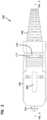
- FIG. 1is an exploded view of an example embodiment of a fiber optic connector made in accordance with the present disclosure.
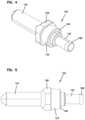
- FIG. 2is a side view of the connector of FIG. 1 in a fully assembled state.
- FIG. 3is a cross-sectional view of the connector shown in FIG. 2 .
- FIG. 4is a perspective view of an example hub/ferrule assembly of the connector shown in FIG. 1 .
- FIG. 5is a side view of the hub/ferrule assembly shown in FIG. 4 .
- FIG. 6is perspective view of an example rear housing of the connector shown in FIG. 1 .
- FIG. 7is a side view of the rear housing shown in FIG. 6 .
- FIG. 8is perspective view of an example front housing of the connector shown in FIG. 1 .
- FIG. 9is a side view of the front housing shown in FIG. 8 .
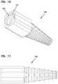
- FIG. 10is perspective view of an example boot of the connector shown in FIG. 1 .
- FIG. 11is a side view of the boot shown in FIG. 10 .
- FIG. 12is perspective view of a hub extension member of the connector shown in FIG. 1 .
- FIG. 13is another perspective view of the hub extension member shown in FIG. 12 .
- FIG. 14is a side view of the hub extension member shown in FIG. 12 .
- FIG. 15is a cross-sectional view of the connector shown in FIG. 1 with the hub/ferrule assembly pressed rearwardly.
- FIG. 16is a cross-sectional view of the front and rear housings of the connector shown in FIG. 1 in a semi-assembled state.
- FIG. 17is another cross-sectional view of the front and rear housings shown in FIG. 16 with the hub/ferrule assembly pressed rearwardly.
- the present disclosureis directed to systems and methods for manufacturing and tuning fiber optic connectors.
- FIG. 1is an exploded view of an example connector 100 illustrating components made in accordance with the present disclosure.
- the connector 100includes an outer key member 104 , a front housing 110 , a rear housing 140 , and a boot 150 with a bore 152 . Also included is a hub/ferrule assembly 120 with a hub 122 and a ferrule 124 .
- the hub 122includes an anti-rotation portion 128 and a cylindrical rear portion 123 .
- the hub 122is connected to the ferrule 124 , such as with adhesive or with an interference fit.
- a spring 130is also provided.
- a fiber optic cable 101is shown including a fiber 102 and a jacket 103 .
- the cable 101is of the type without reinforcing strength members.
- a hub extension member 160that is coupled to the hub 122 and extends rearwardly towards the boot 150 . As described further below, the hub extension member 160 maintains the connector 100 in a tuned state upon full assembly of the connector 100 .
- the key member 104includes a key 202 that defines the tuned position for the connector 100 .
- the front housing 110 of the connector 100extends along a longitudinal axis 200 and defines an anti-rotation seat 112 and a cavity 114 .
- the ferrule 124extends through a front bore 116 of the front housing 110 and includes a passage 167 .
- the anti-rotation portion 128 of the hub 122is slidingly engaged along the longitudinal axis 200 in the anti-rotation seat 112 .
- the anti-rotation portion 128is shaped in an octagonal configuration (see FIGS. 4 - 5 ) and the anti-rotation seat 112 defines a seat of a complementary geometry.
- the anti-rotation portion 128 and the anti-rotation seat 112allow for sliding along the longitudinal axis 200 , but prevent relative rotation.
- Other mating shapes and configurationsare also possible.
- the elongated cylindrical rear portion 123 of the hub 122extends into the cavity 114 of the front housing 110 .
- the hub 122includes a passage 119 extending along the longitudinal axis 200 .
- the spring 130surrounds the hub 122 .
- the spring 130is captured between a surface 148 of the anti-rotation portion 128 and a surface 146 of the rear housing 140 .
- the spring 130functions to bias the anti-rotation portion 128 of the hub 122 into the anti-rotation seat 112 of the front housing 110 . Because the ferrule 124 is connected to the hub 122 , the spring 130 also functions to bias the ferrule 124 in a forward direction through the front bore 116 .
- Outer protrusions 143 of the rear housing 140are held engagingly in openings 117 formed by the front housing 110 . See FIGS. 6 - 9 .
- the rear housing 140includes a passage 147 .
- a rear portion 145 of the rear housing 140extends along the longitudinal axis 200 into the bore 152 of the boot 150 . See FIGS. 10 - 11 .
- An arm 151 of the boot 150extend over tabs 144 formed by the rear portion 145 to hold the rear housing 140 to the boot 150 .
- a passage 153 extending through the boot 150is coaxially aligned with passage 147 of the rear housing 140 and passage 119 of the hub 122 .
- the passage 119is coaxially aligned with the passage 167 of the ferrule 124 and is sized to receive a bare fiber of a fiber optic cable.
- An enlarged front portion 165 of the hub extension member 160(see FIGS. 12 - 14 ) includes an arm 166 to engage tabs 168 of the hub 122 to couple the hub extension member 160 to the hub 122 .
- the hub extension member 160extends rearwardly into the passage 153 formed by the boot 150 .
- An end 170 of the hub extension member 160is positioned relative to a surface 172 of the boot 150 so that, in the fully assembled state as depicted, the end 170 contacts the surface 172 of the boot 150 and limits further rearward travel of the hub 122 before the anti-rotation portion 128 clears the anti-rotation seat 112 , so that the connector 100 cannot become un-tuned.
- a distance 180 from the end 170 to the surface 172is smaller than the distance 182 required to remove the anti-rotation portion 128 from the anti-rotation seat 112 . See FIGS. 1 and 15 .
- the cable 101is extended through the passages 153 and 147 , and the fiber 102 is extended through passages 119 and 167 and is glued to the ferrule 124 .
- the jacket 103extends through passage 119 and can abut the ferrule 124 .
- the jacket 103is glued to the hub 122 .
- the connector 100can be assembled and tuned as follows.
- the hub 122 and ferrule 124are inserted into the front housing 110 so that the anti-rotation portion 128 of the hub 122 sits in the anti-rotation seat 112 of the front housing 110 .
- the rear housing 140is then slid into the front housing 110 until the outer protrusions 143 of the rear housing 140 are held engagingly in openings 117 formed by the front housing 110 to form an integral unit.
- the front and rear housings 110 , 140are fully connected to each other.
- the front and rear housings 110 and 140can be pressed together in any convenient manner, such as with a press or clamping tool. This forms a semi-assembled state without the boot 150 .
- the ferrule 124 and the hub 122can be pushed back against the biasing force of the spring 130 along the longitudinal axis 200 towards the rear housing 140 so that the anti-rotation portion 128 of the hub 122 enters the cavity 114 and completely clears the anti-rotation seat 112 .
- Thiscan be accomplished because the boot 150 has not yet been coupled to the rear housing 140 .
- the ferrule 124 and the hub 122can be rotated about the longitudinal axis 200 to tune the connector 100 as desired. See FIG. 17 .
- Tuningcan thereupon be performed to determine the desired tuned position. Tuning can be by any method useful to determine the desired orientation of the ferrule 124 in the connector 100 .
- the hub/ferrule assembly 120is released so that the anti-rotation portion 128 of the hub 122 again sits in the anti-rotation seat 112 of the front housing 110 to limit rotation of the hub/ferrule assembly 120 and thereby maintain the tuned position.
- the boot 150is moved longitudinally along the axis 200 so that rear housing 140 is received in the bore 152 and extends into the passage 153 .
- the arms 151 of the boot 150extend over tabs 144 formed by the rear portion 145 to couple the rear housing 140 to the boot 150 .
- the outer key member 104Prior to or after tuning, the outer key member 104 is oriented relative to the front housing 110 , and the outer key member 104 is slid onto the front housing 110 until a tab 302 is received in an opening 304 of the outer key member 104 . See FIGS. 1 and 8 - 9 .
- the key 202indicates the tuned position when the connector 100 is coupled to another connector.
- the longitudinal distance 182 along the longitudinal axis 200 between the anti-rotation seat 112 and the rear surface 146 of the rear housing 140is greater than the distance 180 between the end 170 of the hub extension member 160 to the surface 172 of the boot 150 .
- the advantages embodied in connectors made in accordance to the inventionare applicable to a variety of fiber optic cable and connector types.
- the inventionis particularly convenient for smaller cables, such as, for example, 0.900-millimeter cable, which does not include strength reinforcing members. Pulling rearwardly on the cable may pull the ferrule rearwardly, against the spring, but the hub will not disengage from the housing, thereby maintaining the tuned state of the connector.
- the hub extension member 160is illustrated as being separate from the hub 122 , in alternative embodiments the hub can be elongated to form an integral extension (see U.S. Pat. No. 6,629,782 as an example, the entirety of which is hereby incorporated by reference) that extends towards the boot 150 .
- Other configurationsare possible.
Landscapes
- Physics & Mathematics (AREA)
- General Physics & Mathematics (AREA)
- Optics & Photonics (AREA)
- Mechanical Coupling Of Light Guides (AREA)
Abstract
Description
Claims (12)
Priority Applications (1)
| Application Number | Priority Date | Filing Date | Title |
|---|---|---|---|
| US17/627,579US11846811B2 (en) | 2019-07-17 | 2020-07-15 | Tuned fiber optic connector |
Applications Claiming Priority (3)
| Application Number | Priority Date | Filing Date | Title |
|---|---|---|---|
| US201962875348P | 2019-07-17 | 2019-07-17 | |
| US17/627,579US11846811B2 (en) | 2019-07-17 | 2020-07-15 | Tuned fiber optic connector |
| PCT/US2020/042152WO2021011666A1 (en) | 2019-07-17 | 2020-07-15 | Tuned fiber optic connector |
Publications (2)
| Publication Number | Publication Date |
|---|---|
| US20220357523A1 US20220357523A1 (en) | 2022-11-10 |
| US11846811B2true US11846811B2 (en) | 2023-12-19 |
Family
ID=74211329
Family Applications (1)
| Application Number | Title | Priority Date | Filing Date |
|---|---|---|---|
| US17/627,579ActiveUS11846811B2 (en) | 2019-07-17 | 2020-07-15 | Tuned fiber optic connector |
Country Status (2)
| Country | Link |
|---|---|
| US (1) | US11846811B2 (en) |
| WO (1) | WO2021011666A1 (en) |
Families Citing this family (2)
| Publication number | Priority date | Publication date | Assignee | Title |
|---|---|---|---|---|
| WO2021011794A1 (en) | 2019-07-17 | 2021-01-21 | Commscope Technologies Llc | Fiber optic connector with anti-wicking epoxy tube |
| EP3999889A1 (en) | 2019-07-17 | 2022-05-25 | CommScope Technologies LLC | Fiber optic connector with epoxy tube with axial float |
Citations (31)
| Publication number | Priority date | Publication date | Assignee | Title |
|---|---|---|---|---|
| US5096276A (en) | 1988-02-23 | 1992-03-17 | Amp Incorporated | Sheath connector for an optical cable |
| US5181267A (en) | 1988-02-23 | 1993-01-19 | Amp Incorporated | Sheath connector for an optical cable |
| US5317663A (en) | 1993-05-20 | 1994-05-31 | Adc Telecommunications, Inc. | One-piece SC adapter |
| US5375183A (en) | 1993-05-25 | 1994-12-20 | The Whitaker Corporation | Overmolded alignment ferrule |
| US5428703A (en) | 1994-02-18 | 1995-06-27 | Augat Inc. | One-piece SC fiber optic connector |
| US5778126A (en) | 1995-05-31 | 1998-07-07 | Kyocera Corporation | Ferrule for optical fiber and optical connector using a ferrule |
| US6142676A (en) | 1997-05-20 | 2000-11-07 | Adc Telecommunications, Inc. | Fiber connector and adaptor |
| US6155146A (en)* | 1999-07-28 | 2000-12-05 | Lucent Technologies Inc. | Optical fiber connector tuning wrench |
| US20020081077A1 (en) | 2000-12-27 | 2002-06-27 | Nault Patrick Jude | Tunable fiber optic connector and method for assembling |
| US20030147598A1 (en) | 2002-02-04 | 2003-08-07 | Mcphee Robert J. | Tuned fiber optic connector and method |
| US20040151437A1 (en) | 2003-01-30 | 2004-08-05 | Marrs Samuel M. | Tunable fiber optic connector |
| US20050232553A1 (en) | 2004-04-14 | 2005-10-20 | Holmquist Marlon E | Fiber optic connector and method |
| US20050232554A1 (en) | 2002-01-30 | 2005-10-20 | Adc Telecommunications, Inc. | Fiber optic connector and method |
| US20060115219A1 (en) | 2004-11-29 | 2006-06-01 | Mudd Ronald L | Optical fiber connector |
| CN101091131A (en) | 2004-11-10 | 2007-12-19 | 康宁光缆系统有限责任公司 | Field installable optical fiber connector |
| US20090214164A1 (en) | 2008-02-21 | 2009-08-27 | Suncall Corporation | Optical Fiber Connector |
| US20110008003A1 (en) | 2008-02-29 | 2011-01-13 | Sumitomo Electric Industries Ltd | Optical connector |
| US20110075972A1 (en) | 2009-09-30 | 2011-03-31 | Parkman Iii Louis E | Fiber Optic Connectors and Methods for Making the Same |
| US20130089294A1 (en) | 2006-08-01 | 2013-04-11 | Steven C. Zimmel | Dual inner diameter ferrule device with smooth internal contours and method |
| US8496386B2 (en) | 2009-12-30 | 2013-07-30 | Corning Cable Systems Llc | Ferrules having an anti-rotation feature and fiber optic connectors using the same |
| US20130315541A1 (en) | 2012-05-03 | 2013-11-28 | Adc Telecommunications, Inc. | Fiber Optic Connector |
| US20130322826A1 (en) | 2012-06-05 | 2013-12-05 | Charles T. Henke | Ferrule holders with an integral lead-in tube employed in fiber optic connector assemblies, and related components, connectors, and methods |
| WO2014031556A1 (en) | 2012-08-22 | 2014-02-27 | Corning Cable Systems Llc | Ferrule holder having increased adhesive region |
| CN104169764A (en) | 2010-03-16 | 2014-11-26 | Ofs菲特尔有限责任公司 | Simplex connectors for multicore optical fiber cables |
| US9057849B2 (en) | 2010-07-08 | 2015-06-16 | Ilsin Ots Co., Ltd. | Optical fiber connector and an assembly method for the same |
| US20180059334A1 (en) | 2013-07-22 | 2018-03-01 | Commscope Technologies Llc | Expanded beam fiber optic connector, and cable assembly, and methods for manufacturing |
| US20180224608A1 (en) | 2014-02-14 | 2018-08-09 | Adc Telecommunications (Shanghai) Distribution Co., Ltd. | Fiber optic connector and method of assembling the same |
| CN109716194A (en) | 2016-10-13 | 2019-05-03 | 康普技术有限责任公司 | Fiber optic tap transitioning component comprising epoxy plugs and cable strain relief member |
| US11150412B2 (en)* | 2018-01-31 | 2021-10-19 | Commscope Technologies Llc | Tunable fiber optic connectors |
| US20220260788A1 (en) | 2019-07-17 | 2022-08-18 | Commscope Technologies Llc | Fiber optic connector with epoxy tube with axial float |
| US20220269014A1 (en) | 2019-07-17 | 2022-08-25 | Commscope Technologies Llc | Fiber optic connector with overmold lead-in tube |
- 2020
- 2020-07-15WOPCT/US2020/042152patent/WO2021011666A1/ennot_activeCeased
- 2020-07-15USUS17/627,579patent/US11846811B2/enactiveActive
Patent Citations (36)
| Publication number | Priority date | Publication date | Assignee | Title |
|---|---|---|---|---|
| US5096276A (en) | 1988-02-23 | 1992-03-17 | Amp Incorporated | Sheath connector for an optical cable |
| US5181267A (en) | 1988-02-23 | 1993-01-19 | Amp Incorporated | Sheath connector for an optical cable |
| US5317663A (en) | 1993-05-20 | 1994-05-31 | Adc Telecommunications, Inc. | One-piece SC adapter |
| US5375183A (en) | 1993-05-25 | 1994-12-20 | The Whitaker Corporation | Overmolded alignment ferrule |
| US5428703A (en) | 1994-02-18 | 1995-06-27 | Augat Inc. | One-piece SC fiber optic connector |
| US5778126A (en) | 1995-05-31 | 1998-07-07 | Kyocera Corporation | Ferrule for optical fiber and optical connector using a ferrule |
| US6142676A (en) | 1997-05-20 | 2000-11-07 | Adc Telecommunications, Inc. | Fiber connector and adaptor |
| US6155146A (en)* | 1999-07-28 | 2000-12-05 | Lucent Technologies Inc. | Optical fiber connector tuning wrench |
| US20020081077A1 (en) | 2000-12-27 | 2002-06-27 | Nault Patrick Jude | Tunable fiber optic connector and method for assembling |
| US20050232554A1 (en) | 2002-01-30 | 2005-10-20 | Adc Telecommunications, Inc. | Fiber optic connector and method |
| US20030147598A1 (en) | 2002-02-04 | 2003-08-07 | Mcphee Robert J. | Tuned fiber optic connector and method |
| US6629782B2 (en) | 2002-02-04 | 2003-10-07 | Adc Telecommunications, Inc. | Tuned fiber optic connector and method |
| US20040151437A1 (en) | 2003-01-30 | 2004-08-05 | Marrs Samuel M. | Tunable fiber optic connector |
| US20050232553A1 (en) | 2004-04-14 | 2005-10-20 | Holmquist Marlon E | Fiber optic connector and method |
| US20070183721A1 (en) | 2004-04-14 | 2007-08-09 | Adc Telecommunications, Inc. | Fiber Optic Connector and Method |
| CN101091131A (en) | 2004-11-10 | 2007-12-19 | 康宁光缆系统有限责任公司 | Field installable optical fiber connector |
| US20060115219A1 (en) | 2004-11-29 | 2006-06-01 | Mudd Ronald L | Optical fiber connector |
| US7281859B2 (en) | 2004-11-29 | 2007-10-16 | Corning Cable Systems Llc | Optical fiber connector and method of assembly |
| US20130089294A1 (en) | 2006-08-01 | 2013-04-11 | Steven C. Zimmel | Dual inner diameter ferrule device with smooth internal contours and method |
| US20090214164A1 (en) | 2008-02-21 | 2009-08-27 | Suncall Corporation | Optical Fiber Connector |
| US7997806B2 (en) | 2008-02-21 | 2011-08-16 | Suncall Corporation | Optical fiber connector |
| US20110008003A1 (en) | 2008-02-29 | 2011-01-13 | Sumitomo Electric Industries Ltd | Optical connector |
| US20110075972A1 (en) | 2009-09-30 | 2011-03-31 | Parkman Iii Louis E | Fiber Optic Connectors and Methods for Making the Same |
| US8496386B2 (en) | 2009-12-30 | 2013-07-30 | Corning Cable Systems Llc | Ferrules having an anti-rotation feature and fiber optic connectors using the same |
| CN104169764A (en) | 2010-03-16 | 2014-11-26 | Ofs菲特尔有限责任公司 | Simplex connectors for multicore optical fiber cables |
| US9057849B2 (en) | 2010-07-08 | 2015-06-16 | Ilsin Ots Co., Ltd. | Optical fiber connector and an assembly method for the same |
| US20130315541A1 (en) | 2012-05-03 | 2013-11-28 | Adc Telecommunications, Inc. | Fiber Optic Connector |
| US8858090B2 (en) | 2012-06-05 | 2014-10-14 | Corning Cable Systems Llc | Ferrule holders with an integral lead-in tube employed in fiber optic connector assemblies, and related components, connectors, and methods |
| US20130322826A1 (en) | 2012-06-05 | 2013-12-05 | Charles T. Henke | Ferrule holders with an integral lead-in tube employed in fiber optic connector assemblies, and related components, connectors, and methods |
| WO2014031556A1 (en) | 2012-08-22 | 2014-02-27 | Corning Cable Systems Llc | Ferrule holder having increased adhesive region |
| US20180059334A1 (en) | 2013-07-22 | 2018-03-01 | Commscope Technologies Llc | Expanded beam fiber optic connector, and cable assembly, and methods for manufacturing |
| US20180224608A1 (en) | 2014-02-14 | 2018-08-09 | Adc Telecommunications (Shanghai) Distribution Co., Ltd. | Fiber optic connector and method of assembling the same |
| CN109716194A (en) | 2016-10-13 | 2019-05-03 | 康普技术有限责任公司 | Fiber optic tap transitioning component comprising epoxy plugs and cable strain relief member |
| US11150412B2 (en)* | 2018-01-31 | 2021-10-19 | Commscope Technologies Llc | Tunable fiber optic connectors |
| US20220260788A1 (en) | 2019-07-17 | 2022-08-18 | Commscope Technologies Llc | Fiber optic connector with epoxy tube with axial float |
| US20220269014A1 (en) | 2019-07-17 | 2022-08-25 | Commscope Technologies Llc | Fiber optic connector with overmold lead-in tube |
Non-Patent Citations (6)
| Title |
|---|
| Extended European Search Report for Application No. 20841353.4 dated Jul. 14, 2023. |
| International International Search Report and Written Opinion of the International Searching Authority for International Patent Application No. PCT/US2020/042135 dated Nov. 5, 2020, 9 pages. |
| International International Search Report and Written Opinion of the International Searching Authority for International Patent Application No. PCT/US2020/042368 dated Nov. 5, 2020, 10 pages. |
| International International Search Report and Written Opinion of the International Searching Authority for International Patent Application No. PCT/US2020/42152 dated Nov. 6, 2020, 9 pages. |
| International Search Report and Written Opinion of the International Searching Authority for International Patent Application No. PCT/US2020/041955 dated Nov. 5, 2020, 14 pages. |
| Partial Supplementary European Search Report for Application No. 20840593.6 dated Jul. 4, 2023. |
Also Published As
| Publication number | Publication date |
|---|---|
| WO2021011666A1 (en) | 2021-01-21 |
| US20220357523A1 (en) | 2022-11-10 |
Similar Documents
| Publication | Publication Date | Title |
|---|---|---|
| US6629782B2 (en) | Tuned fiber optic connector and method | |
| US10663675B2 (en) | Tuned fiber optic connectors | |
| US6916120B2 (en) | Fiber optic connector and method | |
| US12140805B2 (en) | Optical fiber connector with articulated relative movement | |
| US8342755B2 (en) | Fiber optic connector and method for assembling | |
| US11150412B2 (en) | Tunable fiber optic connectors | |
| US20150286011A1 (en) | Fiber optic connectors | |
| US20250130378A1 (en) | Fiber optic connector with epoxy tube with axial float | |
| US20230194793A1 (en) | Pushable optical connector with connector-integrated articulation | |
| US11846811B2 (en) | Tuned fiber optic connector | |
| US12422625B2 (en) | Optical fiber connector for minimizing signal transmission losses | |
| JP4804448B2 (en) | Connection structure between optical fiber cable connector and receptacle |
Legal Events
| Date | Code | Title | Description |
|---|---|---|---|
| AS | Assignment | Owner name:COMMSCOPE TECHNOLOGIES LLC, NORTH CAROLINA Free format text:ASSIGNMENT OF ASSIGNORS INTEREST;ASSIGNORS:ZIMMEL, STEVEN CONRAD;SCHAIBLE, GREGORY J.;SIGNING DATES FROM 20210506 TO 20210507;REEL/FRAME:058664/0720 | |
| FEPP | Fee payment procedure | Free format text:ENTITY STATUS SET TO UNDISCOUNTED (ORIGINAL EVENT CODE: BIG.); ENTITY STATUS OF PATENT OWNER: LARGE ENTITY | |
| AS | Assignment | Owner name:V TECHNOLOGY CO., LTD., JAPAN Free format text:ASSIGNMENT OF ASSIGNORS INTEREST;ASSIGNOR:MIZUMURA, MICHINOBU;REEL/FRAME:058765/0922 Effective date:20211202 | |
| AS | Assignment | Owner name:JPMORGAN CHASE BANK, N.A., NEW YORK Free format text:ABL SECURITY AGREEMENT;ASSIGNORS:ARRIS ENTERPRISES LLC;COMMSCOPE TECHNOLOGIES LLC;COMMSCOPE, INC. OF NORTH CAROLINA;REEL/FRAME:059350/0743 Effective date:20220307 Owner name:JPMORGAN CHASE BANK, N.A., NEW YORK Free format text:TERM LOAN SECURITY AGREEMENT;ASSIGNORS:ARRIS ENTERPRISES LLC;COMMSCOPE TECHNOLOGIES LLC;COMMSCOPE, INC. OF NORTH CAROLINA;REEL/FRAME:059350/0921 Effective date:20220307 | |
| AS | Assignment | Owner name:WILMINGTON TRUST, DELAWARE Free format text:SECURITY INTEREST;ASSIGNORS:ARRIS ENTERPRISES LLC;COMMSCOPE TECHNOLOGIES LLC;COMMSCOPE, INC. OF NORTH CAROLINA;REEL/FRAME:059710/0506 Effective date:20220307 | |
| STPP | Information on status: patent application and granting procedure in general | Free format text:DOCKETED NEW CASE - READY FOR EXAMINATION | |
| STPP | Information on status: patent application and granting procedure in general | Free format text:NOTICE OF ALLOWANCE MAILED -- APPLICATION RECEIVED IN OFFICE OF PUBLICATIONS | |
| STPP | Information on status: patent application and granting procedure in general | Free format text:NOTICE OF ALLOWANCE MAILED -- APPLICATION RECEIVED IN OFFICE OF PUBLICATIONS | |
| STPP | Information on status: patent application and granting procedure in general | Free format text:AWAITING TC RESP., ISSUE FEE NOT PAID Free format text:NOTICE OF ALLOWANCE MAILED -- APPLICATION RECEIVED IN OFFICE OF PUBLICATIONS | |
| STPP | Information on status: patent application and granting procedure in general | Free format text:PUBLICATIONS -- ISSUE FEE PAYMENT VERIFIED | |
| STCF | Information on status: patent grant | Free format text:PATENTED CASE | |
| AS | Assignment | Owner name:APOLLO ADMINISTRATIVE AGENCY LLC, NEW YORK Free format text:SECURITY INTEREST;ASSIGNORS:ARRIS ENTERPRISES LLC;COMMSCOPE TECHNOLOGIES LLC;COMMSCOPE INC., OF NORTH CAROLINA;AND OTHERS;REEL/FRAME:069889/0114 Effective date:20241217 | |
| AS | Assignment | Owner name:COMMSCOPE TECHNOLOGIES LLC, NORTH CAROLINA Free format text:RELEASE OF SECURITY INTEREST AT REEL/FRAME 059350/0921;ASSIGNOR:JPMORGAN CHASE BANK, N.A., AS COLLATERAL AGENT;REEL/FRAME:069743/0704 Effective date:20241217 Owner name:COMMSCOPE, INC. OF NORTH CAROLINA, NORTH CAROLINA Free format text:RELEASE OF SECURITY INTEREST AT REEL/FRAME 059350/0921;ASSIGNOR:JPMORGAN CHASE BANK, N.A., AS COLLATERAL AGENT;REEL/FRAME:069743/0704 Effective date:20241217 Owner name:ARRIS ENTERPRISES LLC (F/K/A ARRIS ENTERPRISES, INC.), NORTH CAROLINA Free format text:RELEASE OF SECURITY INTEREST AT REEL/FRAME 059350/0921;ASSIGNOR:JPMORGAN CHASE BANK, N.A., AS COLLATERAL AGENT;REEL/FRAME:069743/0704 Effective date:20241217 |