US11842138B2 - Integrated routing assembly and system using same - Google Patents
Integrated routing assembly and system using sameDownload PDFInfo
- Publication number
- US11842138B2 US11842138B2US17/477,542US202117477542AUS11842138B2US 11842138 B2US11842138 B2US 11842138B2US 202117477542 AUS202117477542 AUS 202117477542AUS 11842138 B2US11842138 B2US 11842138B2
- Authority
- US
- United States
- Prior art keywords
- connectors
- cables
- substrate
- terminals
- chip package
- Prior art date
- Legal status (The legal status is an assumption and is not a legal conclusion. Google has not performed a legal analysis and makes no representation as to the accuracy of the status listed.)
- Active, expires
Links
Images


Classifications
- H—ELECTRICITY
- H04—ELECTRIC COMMUNICATION TECHNIQUE
- H04Q—SELECTING
- H04Q1/00—Details of selecting apparatus or arrangements
- H04Q1/02—Constructional details
- H04Q1/13—Patch panels for monitoring, interconnecting or testing circuits, e.g. patch bay, patch field or jack field; Patching modules
- G—PHYSICS
- G06—COMPUTING OR CALCULATING; COUNTING
- G06F—ELECTRIC DIGITAL DATA PROCESSING
- G06F30/00—Computer-aided design [CAD]
- G06F30/30—Circuit design
- G06F30/39—Circuit design at the physical level
- G06F30/398—Design verification or optimisation, e.g. using design rule check [DRC], layout versus schematics [LVS] or finite element methods [FEM]
- G—PHYSICS
- G06—COMPUTING OR CALCULATING; COUNTING
- G06F—ELECTRIC DIGITAL DATA PROCESSING
- G06F30/00—Computer-aided design [CAD]
- G06F30/30—Circuit design
- G06F30/32—Circuit design at the digital level
- G06F30/33—Design verification, e.g. functional simulation or model checking
- G06F30/3308—Design verification, e.g. functional simulation or model checking using simulation
- G06F30/331—Design verification, e.g. functional simulation or model checking using simulation with hardware acceleration, e.g. by using field programmable gate array [FPGA] or emulation
- G—PHYSICS
- G06—COMPUTING OR CALCULATING; COUNTING
- G06F—ELECTRIC DIGITAL DATA PROCESSING
- G06F30/00—Computer-aided design [CAD]
- G06F30/30—Circuit design
- G06F30/36—Circuit design at the analogue level
- G06F30/367—Design verification, e.g. using simulation, simulation program with integrated circuit emphasis [SPICE], direct methods or relaxation methods
- G—PHYSICS
- G06—COMPUTING OR CALCULATING; COUNTING
- G06F—ELECTRIC DIGITAL DATA PROCESSING
- G06F30/00—Computer-aided design [CAD]
- G06F30/30—Circuit design
- G06F30/36—Circuit design at the analogue level
- G06F30/373—Design optimisation
- H—ELECTRICITY
- H04—ELECTRIC COMMUNICATION TECHNIQUE
- H04Q—SELECTING
- H04Q1/00—Details of selecting apparatus or arrangements
- H—ELECTRICITY
- H01—ELECTRIC ELEMENTS
- H01R—ELECTRICALLY-CONDUCTIVE CONNECTIONS; STRUCTURAL ASSOCIATIONS OF A PLURALITY OF MUTUALLY-INSULATED ELECTRICAL CONNECTING ELEMENTS; COUPLING DEVICES; CURRENT COLLECTORS
- H01R12/00—Structural associations of a plurality of mutually-insulated electrical connecting elements, specially adapted for printed circuits, e.g. printed circuit boards [PCB], flat or ribbon cables, or like generally planar structures, e.g. terminal strips, terminal blocks; Coupling devices specially adapted for printed circuits, flat or ribbon cables, or like generally planar structures; Terminals specially adapted for contact with, or insertion into, printed circuits, flat or ribbon cables, or like generally planar structures
- H01R12/70—Coupling devices
- H01R12/71—Coupling devices for rigid printing circuits or like structures
- H01R12/712—Coupling devices for rigid printing circuits or like structures co-operating with the surface of the printed circuit or with a coupling device exclusively provided on the surface of the printed circuit
- H01R12/716—Coupling device provided on the PCB
- H01R12/718—Contact members provided on the PCB without an insulating housing
- H—ELECTRICITY
- H01—ELECTRIC ELEMENTS
- H01R—ELECTRICALLY-CONDUCTIVE CONNECTIONS; STRUCTURAL ASSOCIATIONS OF A PLURALITY OF MUTUALLY-INSULATED ELECTRICAL CONNECTING ELEMENTS; COUPLING DEVICES; CURRENT COLLECTORS
- H01R13/00—Details of coupling devices of the kinds covered by groups H01R12/70 or H01R24/00 - H01R33/00
- H01R13/648—Protective earth or shield arrangements on coupling devices, e.g. anti-static shielding
- H01R13/658—High frequency shielding arrangements, e.g. against EMI [Electro-Magnetic Interference] or EMP [Electro-Magnetic Pulse]
- H01R13/6591—Specific features or arrangements of connection of shield to conductive members
- H01R13/65912—Specific features or arrangements of connection of shield to conductive members for shielded multiconductor cable
- H01R13/65914—Connection of shield to additional grounding conductors
Definitions
- the Present Disclosurerelates generally to high speed data transmission systems suitable for use in transmitting high speed signals at low losses from chips or processors of a chip package to backplanes and devices, and more particularly to connectors suitable for use in integrated connector interface-chip package routing assemblies and direct connections to a chip or chip package.
- Electronic devicessuch as routers, servers, switches and the like need to operate at high data transmission speeds in order to serve the rising need for bandwidth and delivery of streaming audio and video in many end user devices.
- These devicesuse signal transmission lines that extend between a primary chip member mounted on a printed circuit board (mother board) of the device, such as an ASIC, FPGA, etc. and connectors mounted to the circuit board.
- These transmission linesare conductive traces that are formed as part of the mother board and extend between the chip member and connectors to provide that provides a connection between one or more external plug connectors and the chip member.
- Circuit boardsare usually formed from a material known as FR4, which is inexpensive.
- FR4is known to promote losses in high speed signal transmission lines (e.g., traces) at signaling frequency rates of about 6 GHz and greater. These losses increase as the frequency increases and therefore make FR4 material undesirable for the high speed data transfer applications of about 10 GHz and greater.
- FR4 materialwhich has the advantage of being a lost cost material
- a designermay have to utilize various active components such as amplifiers and equalizers and may need to use additional layers. While losses can sometimes be corrected by the use of amplifiers, repeaters and equalizers, thus allowing the use of FR4 material, the active elements increase the cost of manufacturing the circuit board, which increases the final cost of the device. The use of active components also complicates the design as additional board space is needed to accommodate the active components.
- the routing of the signal traces using active componentsmay require multiple turns and transitions. These turns and the transitions tend to decrease the signal to noise ratio, thus negatively impacting the signal integrity of the system.
- circuit boardsbeing lossy, it can be difficult to route transmission line traces in a manner to achieve a consistent impedance and a low signal loss therethrough.
- a designerin order to control the impedance in high-speed trace routing design, a designer must utilize extras layers of up to between about 8 to about 16 extra layers to the circuit board. This increases the manufacturing cost of circuit boards and increases the design time required to develop such circuit boards.
- existing circuit boardshave physical limitations that are becoming more difficult to design around.
- Chipsare the heart of these routers, switches and other devices.
- Chipstypically include a processor, such as an application specific integrated circuit (ASIC) and/or a field programmable gate array (FPGA), as well as other circuitry and can be connected to a substrate by way of conductive solder bumps or other convenient connection.
- ASICapplication specific integrated circuit
- FPGAfield programmable gate array
- the combination of the chip and substrateform a chip package.
- the substratemay include micro-vias or plated through holes that are connected to solder balls. If used, the solder balls can provide a ball grid array (BGA) structure by which the chip package can be attached to a motherboard.
- BGAball grid array
- the motherboardincludes numerous traces formed in it that define transmission lines and the transmission lines can include differential signal pairs for the transmission of signals at high data rates, ground paths associated with the differential signal pairs, and a variety of low data-rate transmission lines for power, clock and logic signals as well as other components.
- These tracescan be routed from the chip package to the I/O connectors of the device into which external connectors are connected and can also be routed from the chip package to a backplane connector that allows the device to be connected to an overall system such as a network server or the like.
- Chip capabilitieshave increased to the point where it is possible to support data rates of 25 Gbps and greater. This results in signaling frequencies that can be greater than 12 GHz. It therefore becomes difficult to adequately design signal transmission lines in circuit boards and backplanes to meet the crosstalk and loss requirements needed for high speed applications, especially while trying to maintain reasonable cost. As a results, certain individuals would appreciate further improvements in the system design of routers, switches and other devices.
- the present disclosureis therefore directed to a routing assembly that fits within the housing of an electronic device as a single element and provides multiple data transmission channels that lead directly from a chip package.
- the transmission channelstake the form of cables supported by a routing substrate and the cables can be terminated at their proximal ends to wire-to-board style connectors in a manner that emulates the ordered geometry of the cables.
- the routing assemblycan have an L-shaped configuration that includes a tray that extends horizontally and further includes a pair of side supports that can support an array of connector ports along a mating face of a host device. These connector ports may include cable direct connectors held within housings that define the connector ports. The connector ports receive opposing, mating connectors associated with other devices and which are intended to be connected to the host device.
- the connectors, connector ports, cables and/or chip packagecan be integrated into the routing assembly as a single piece so that the routing assembly can readily inserted into the electronic device as an integrate unit.
- the traymay be positioned either above or below the motherboard of the host device.
- the traycan be formed from a dielectric material and may support the cables in a manner to preferably position the proximal ends of the cables in opposition to the chip package.
- the cables, once connected to the chip packagedefine high speed signal transmission channels between the chip package and the external connector interfaces, eliminating the need to route the transmission channels on the circuit board reducing the loss problems inherent in circuit board routing.
- the traycan support the chip package as part of the overall assembly, or it may support only the cables, with board connectors at their proximal ends for connecting to contacts of the chip package.
- the trayincludes a package opening, which can be positioned in opposition to a chip package on the motherboard. In this manner, the package opening surrounds and receives the chip package.
- the chip packagemay include a plurality of contacts, such as in the form of a BGA (ball grid array) arrayed along edges of the chip/chip package and aligned with the chip-receiving opening.
- BGAball grid array
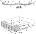
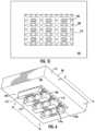
- FIG. 1is a perspective view of the interior of a conventional electronic device with a chip package in place upon a motherboard;
- FIG. 1 Ais a schematic sectional view of the electronic device of FIG. 1 illustrating how the circuit board is used for routing signal transmission channels between the chip package and the external connector interfaces of the device;
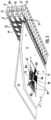
- FIG. 2is a perspective view of a routing assembly of the present disclosure in place underneath a motherboard and in which the chip package has a heat sink in place thereon;
- FIG. 2 Ais the same view as FIG. 2 , but taken from the rear;
- FIG. 2 Bis a schematic sectional view of the routing assembly of FIG. 2 illustrating how the cables are embedded within the routing substrate for routing signal transmission channels between a chip package substrate and the external connector interfaces of the assembly;
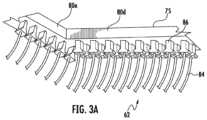
- FIG. 3is a perspective view of the routing assembly in place underneath a host device motherboard and contacting the chip package from below;
- FIG. 3 Ais an enlarged diagrammatic view of a portion of the routing assembly of FIG. 3 , illustrating a series of wire-to-board connectors of the present disclosure with their corresponding receptacles removed for clarity and which connect the cables to the chip package of the host device;
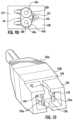
- FIG. 4is a perspective view of a wire-to-board connector assembly of the present disclosure which mates nine cables to the underside of a chip package or a chip package substrate;
- FIG. 4 Ais an elevational view of the connector assembly of FIG. 4 , taken along lines A-A thereof;
- FIG. 5is an exploded view of the connector assembly of FIG. 4 ;
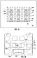
- FIG. 5 Ais a plan view of the bottom of the receptacle connector portion terminals in place upon a surface of the chip package substrate, taken along lines A-A of FIG. 5 ;
- FIG. 5 Bis an enlarged detail view of one set of terminals in place with contacts of the chip package substrate
- FIG. 5 Cis the same view as FIG. 5 A , but with the terminals removed to illustrate the contacts of the chip package substrate;
- FIG. 6is a perspective view of the receptacle portion of the connector assembly of FIG. 4 in place on the chip package substrate;
- FIG. 6 Ais a side elevational view of the connector assembly of FIG. 6 , taken along line A-A thereof;
- FIG. 6 Bis a plan view of the connector assembly receptacle portion of FIG. 6 , taken along lines B-B thereof;
- FIG. 6 Cis an enlarged detail view of one differential signal transmission channel of the connector assembly receptacle portion of FIG. 6 ;
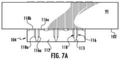
- FIG. 7is the same view as FIG. 6 , but with a near end wall thereof removed for clarity;
- FIG. 7 Ais an elevational view of the receptacle portion of the connector assembly of FIG. 7 , taken along lines A-A thereof;
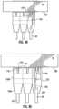
- FIG. 8is the same view of the connector assembly of FIG. 4 , but with one of the plug connector sectioned to illustrate the connection between the cable signal conductors and the connector assembly plug portion signal terminals;
- FIG. 8 Ais a similar view to FIG. 8 , but sectioned differently to illustrate the connection between the cable ground conductor and the ground terminals of the connector assembly plug portion;
- FIG. 8 Bis an enlarged detail view of a portion of FIG. 8 ;
- FIG. 8 Cis an enlarged detail view of a portion of FIG. 8 A ;
- FIG. 8 Dis a side elevational view of the connector assembly of FIG. 8 ;
- FIG. 8 Eis a side elevational view of the connector assembly of FIG. 8 A ;
- FIG. 9is a perspective view of the conductors of a cable terminated to the conductors of a plug portion of the connector assembly of FIG. 4 :
- FIG. 9 Ais an elevational view of FIG. 9 , but with the connector assembly plug portion signal and ground terminals held in positioning blocks;
- FIG. 9 Bis an elevational view of the assembly of FIG. 9 A , but aligned with its plug portion housing members;
- FIG. 9 Cis a perspective view of FIG. 9 B , taken from above;
- FIG. 9 Dis a plan view of the assembly of FIG. 9 C , taken along lines D-D thereof;
- FIG. 10is a perspective view of the mating face of the connector assembly plug portion of FIG.
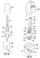
- FIG. 11is an enlarged sectional view of one of the connector assembly plug portions connected to a corresponding receptacle connector portion
- FIG. 11 Ais an elevational, diagrammatic view of the connector assembly of FIG. 4 , illustrating the preferred manner of connection between the plug and receptacle portions;
- FIG. 11 Bis the same view as FIG. 11 A , but taken along lines B-B thereof;
- FIG. 11 Cis a perspective view of the terminals of the mated pair of FIG. 11 ;
- FIG. 12is a perspective diagrammatic view of a housing that holds a series of connectors of FIG. 4 ;
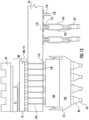
- FIG. 13is a diagram of a connector assembly of the present disclosure connected to a motherboard that supports a chip package.
- the routing assemblycan use twin-ax cables as its cables for transmitting differential signals from the chip package to the connector interfaces and vice-versa.
- the cableshave a reduced size and may be either free in their extent between the host device external connector interfaces and chip/chip package contacts, or they may be secured to or integrated with the routing assembly.
- Each such cablecontains two signal conductors and can contain one or more ground conductor that extend in an ordered orientation throughout their length.
- the proximal ends of the cablesextend into the chip-receiving opening and have package connectors configured to terminate the package connectors to corresponding contacts of the chip package.
- the cablesmaybe embedded in the tray so that they are protected from damage during assembly.
- the trayfits over the motherboard and the package opening fits over the chip package of the motherboard.
- the package connectorscan be flexibly supported by the tray so that they may be manipulated into engagement with opposing connectors on the chip package. With such a structure, the chip package and connector structure may be tested after assembly and prior to shipping to a client or insertion into a device.
- the routing assemblyallows for the removal high speed circuit traces on the motherboard and opens up space on the motherboard for additional low speed signal traces and components while avoiding the need for more expensive circuit board materials.
- the connectorstake the form of “chiclets” which are terminated to proximal ends of single cables.
- the connectorshave a structure that emulates the ordered geometry of the cable and has a contact structure that reliably mates with surface contacts such as one signal channel of a ball grid array. In this manner, each such signal channel may be at least partially housed within a single receptacle supported on the chip package in a manner that retains a low profile and with better impedance and signal integrity control.
- the depicted connectorsinclude interengaging first and second portions.
- One portionis configured as a plug connector that is terminated to the free ends of the cable signal and ground conductors.
- the other portionis configured as a receptacle connector and is terminated to the chip package ball grid array (BGA).
- BGAchip package ball grid array
- the plug connectorincludes elongated, conductive terminals that have tail portions to which the free ends of the cable signal and ground conductors are terminated.
- the terminalshave corresponding contact portions which are spaced apart from each other and which may be oriented at the apices of an imaginary triangle
- Each receptacle connectorincludes a pair of right angle contacts with tail portions which contact corresponding contacts of the chip package BGA.
- a pair of signal contact portionsextend upright from the tail portions into a designated receptacle.
- a right-angle configured ground terminalis provided and has a tail portion that contacts the ground contacts of the chip package BGA.
- the ground terminal contact portionextends up from the tail portion and is spaced apart from the signal terminal contact portions. It preferably has a width in opposition to the signal terminal contact portions.
- the receptacle connectorhas a dielectric housing that has a plurality of walls that define individual receptacles for each of the cables.
- the housingmay include a wall that extends between and separates the receptacle signal and ground terminals from each other and the dielectric constant of the housing material may be tailored to affect the broadside coupling that occurs between the signal and ground terminal contact portions.
- Such a structureis advantageous in that the connectors of the present disclosure are may be made with low profile on the order of about 10 mm so that they may be received within openings of routing assembly openings.
- the connectors of the present disclosuremay also be used to connector chip packages to chip packages and circuit boards together.
- FIG. 1illustrates a conventional electronic device 30 , such as a router, switch, etc. that has a sheet metal housing 31 with a front wall 32 and an opposing rear wall 34 .
- the device 30supports within the housing, a motherboard 36 that includes various electronic components such as a chip package 38 with an associated processor 40 , a power supply 42 and additional integrated circuits, connectors, capacitors, resistors, etc.
- the front wall 32has a series of openings 33 that are aligned with first connectors 43 to define connector ports for the device 30 .
- first connectors 43to define connector ports for the device 30 .
- an array of first connectors 43are mounted to the motherboard 36 at the front end thereof and enclosed within metal shielding cages 44 , or adapter frames, that are placed over the connectors 43 and onto the motherboard 36 .
- a series of second connectors 46are mounted along the rear edge of the motherboard 36 and aligned with openings in the rear wall of the housing 31 .
- These second connectors 43may be of the backplane style which permit the device 30 to be connected to a backplane.
- the first connectorswill be referred to as “entry” connectors and the second connectors will be referred to as “exit” connectors for the reasons set forth in the “Summary” section above.
- the chip package 38is connected to the first and second connectors by way of lengthy conductive traces 47 that extend from the chip package contacts through the motherboard 36 to the connectors 43 , 46 . Pairs of conductive traces 47 are required to define each differential signal transmission line and a third conductive trace will provide an associated ground that follows the path of the signal transmission line. Each such signal transmission line is routed through or on the motherboard and such routing has certain disadvantages.
- FR4is the material that is commonly used for circuit boards, and unfortunately, it becomes undesirably lossy at frequencies above 10 Ghz. Turns, bends and crossovers of these signal transmission line traces 47 are usually required to route the transmission line on the motherboard from the chip package contacts to the connectors.
- an integrated routing assembly 50that incorporates the external connector interfaces, cables and support into a single assembly for use in the host device 51 .
- the routing assemblyprovides a support for high speed differential pair signal transmission lines by way of elongated cables 62 that extend between the connector interfaces and the chip package 88 , thereby eliminating the need for high speed routing traces on the motherboard 53 .
- Such an assemblyis illustrated at 50 in FIG. 2 .
- the assembly 50includes a front portion that accommodates a plurality of external connector interfaces in the form of first connectors 55 , 57 and their associated housings 60 . These are arranged in preselected arrays, which are illustrated as four horizontal rows of connector housings 60 stacked vertically upon each other.
- the connector housings 60selectively contain the first connectors 55 , 57 and these cooperatively define the external connector interfaces for the device 50 .
- These connector interfacesare connector ports 54 , 56 and each such connector housing 60 contains one of the first connector 55 , 57 , which are preferably in a receptacle style with a card slot (such as is used with QSFP style connectors) and the connector ports 54 , 56 can be arranged in an N by M array where both N and M are equal to or greater than two.
- the first connectors 55 , 57are shown positioned on a front side of a system but could also be positioned elsewhere, depending on system designs. Consequentially, the present disclosure is not to be considered as limited to certain connectors at certain locations.
- the first connectors 55 , 57can be arranged in horizontal rows in an integrated fashion as in FIGS. 2 & 3 , where the connector housings 60 and associated connector heat sinks 61 are held in their horizontal extent and vertical alignment between support boards 67 , by way of fasteners, such as screws, that extend through bosses 60 a formed on the exterior of the connector housings 60 .
- Such an arrangementcan easily accommodate a face plate 70 , or panel, ( FIG. 3 ) that extends widthwise between two side supports 68 to form a frame 66 of the assembly 50 .
- the side supports 68have rearwardly extending channels 72 a, b that cooperatively define a plane in which a routing substrate 75 extends, which, in combination with the connector housings, define a tray-like system with a general L-shaped configuration that is readily insertable into a host device housing.
- the routing substrate 75can be planar and has a predetermined thickness.
- the depicted routing substrate 75has an opening 76 formed therein, which is shown in the Figures as located within a perimeter of the routing substrate 75 , so as to provide access to a chip package 88 .
- the opening 76is shown as having a central portion 78 that may have four edges 80 a - d that define the opening 76 .
- the routing substrate 75can simply end (e.g., have a rear edge) prior to the chip package 88 .
- the opening 76can extend around the chip package 88 .
- cablescan extend toward out of the routing substrate 75 and toward the chip package 88 in at least two directions (as depicted, from four directions).
- the first connectors 55 , 57 that form the array of connector ports 54 , 56have signal and ground terminals arranged in transmit and receive channel configurations to mate with opposing connectors having a plug style.
- Cables 62which preferably are in a twin-ax configuration, are directly terminated at their first ends 82 to the connector terminals of each connector 55 , 57 and are seen in FIG. 3 to flank low speed wires 64 (which can be used for power, logic, clock and other circuits). As illustrated in FIG.
- each cable 62includes a pair of signal conductors 62 a surrounded by a dielectric covering 62 b and may include an associated drain wire 62 c , all of which are enclosed in an insulative outer jacket 62 d .
- the cables 62maintain the ordered geometry of the signal conductors 62 a throughout their lengths as they traverse from the chip package 88 to the entry and exit connectors 54 , 56 . Because this geometry remains ordered through their length, the cables 62 may easily be turned or bent or crossed in their paths without introducing problematic signal reflection or impedance discontinuities into the transmission lines.
- Both the cables 62 and low speed wires 64are terminated directly at their first ends to the connector terminals. This allows the first connectors 55 , 57 to avoid being mated to a motherboard 53 and eliminates the impedance discontinuities which normally occur at a connector-circuit board mounting interface.
- the depicted cables 62are illustrated as arranged in vertical rows at the rear of the connector housings 60 , with the cables 62 and wires 64 of the lower connector housing rows arranged inwardly of the topmost connector housing row. This promotes orderly arrangement of the cables 62 in their extent from the connectors 55 , 57 to the routing substrate 75 .
- the cables 62 associated with the top three rows of connectors 55 , 57are seen to have a general S-shaped configuration extending downward to the level of the routing substrate 75 and into the substrate at the front end thereof, while the cables in the bottommost row extend almost horizontally into the routing substrate 75 .
- the cables 62lead from the rear of the connectors to the front edge of the routing substrate 75 where they enter the body of the routing substrate 75 .
- the second ends 84 of the cables 62extend into the opening 76 as illustrated where they are terminated to second connectors 86 that will mate with the chip package 88 .
- the second connectors 86can be a wire-to-board style so that the signal conductors and drain wires of the cables 62 can be easily connected to contacts on the substrate 91 .
- the second ends 84 of the cables 62exit the routing substrate to enter the opening 76 .
- the chip package 88is disposed on the device motherboard 53 , and the chip package 88 includes a plurality of contacts that can mate with the second connectors 86 and can preferably be arranged around the perimeter thereof and aligned with the opening 76 so as to align with the second connectors 86 .
- the chip package 88may be included as part of the overall routing assembly 74 .
- the area above the host device motherboard 53is free to accommodate thermal transfer members 93 , such as heat spreaders and/or heat sinks having perimeters larger than that of the processor 90 . This is because the integration of the cables 62 into the routing substrate 75 frees up most, if not all, of the space above the routing substrate 75 for other uses.
- the cables 62may be positioned as part of the routing substrate 75 in a variety of ways that suitably holds them in place from where they enter the routing substrate 75 , such as along the leading edge 83 of the routing substrate 75 to where they exit the routing substrate 75 and enter the opening 76 .
- the cables 62can be securely embedded in the routing substrate 75 by the use of adhesives or other known fastening techniques that positions them securely in position.
- the body portions of the cables 62are preferably completely surrounded by the routing substrate 75 so that the two are integrally formed as a single part that can be inserted into the routing assembly 74 as a tray portion.
- One routing pattern of the cables 62is illustrated in FIG. 5 , which has the upper portion of the routing substrate 75 removed for clarity to show the paths in which the cables 62 are laid. It can be appreciated that the routing substrate 75 can be formed of insulative or conductive materials, depending on the shielding needs of the system.
- the cables 62are terminated at their second ends 84 to the second connectors 86 either before or after the forming of the routing substrate 75 .
- the second connectors 86permit the cables 62 to be directly connected to the chip package 88 , thereby substantially or completely bypassing the motherboard 53 as a signal routing medium.
- the routing assembly 74may be mated to the motherboard before the routing assembly 74 and the motherboard 53 are inserted into the host device housing, where the routing assembly 74 may be spaced apart from the motherboard by standoffs 92 or the like.
- FIG. 3 & 3 Aillustrate the second connectors 86 and their associated housings 87 and mating faces 89 facing upwardly in the opening 76 so as to provide a connection to the chip package 88 .
- the second connectors 86are illustrated in the form of chiclets, each of which houses a single signal transmission channel which includes the twin-ax cable pair of signal conductors and an associated drain wire.
- the second connectors 86easily mate with small-sized receptacle connectors mounted on the substrate 91 or a motherboard 53 .
- the second connectors 86 and their mating receptacle connector portionsmay be made small in dimension so as to fit within the opening 76 and not unduly project outside of the opening 76 .
- FIGS. 4 - 5illustrate a connector assembly 100 that connects the conductors of a cable to circuits on a circuit board or similar substrate.
- the connector assembly 100includes the second connector and a third connector and is particularly suitable for use with the bypass routing assemblies described above.
- the connector assembly 100is shown connecting to a surface 102 of a substrate 91 .
- the surface 102which could be a top surface or a bottom surface, has a plurality of contacts, shown in FIGS.
- BGAball-grid array
- the third connector 104has a dielectric housing that may also be considered as having a grid configuration that is formed by main walls 112 and secondary walls 113 that intersect each other to form one or more individual receptacles 114 , each of which receives one of the second connectors 86 therein.
- the secondary walls 113 of the housingseen to have a height that is less than that of the main walls 112 .
- the third connector 104includes conductive terminals 116 , 118 arranged in individual sets of three terminals. Each such set of terminals includes two signal terminals 116 and an associated ground terminal 118 are housed in a single receptacle 114 to form a connection between a single set of terminals and a respective circuit on the chip package 88 .
- the receptacle terminals 116 , 118mate with corresponding terminals of a second connector 86 connected to the conductors 62 a , 62 c of a corresponding cable 62 .
- the receptacle terminals 116 , 118may be considered as arranged in a triangular pattern, with imaginary lines extending from the center point of each terminal contact portion defining an imaginary triangle. ( FIG. 5 B .)
- the top edges 116 c , 118 c of the signal terminals 116 and ground terminals 118are shown extending along parallel, spaced-apart paths separated by an intervening space 120 .
- the secondary walls 113are shown to extend within and fill these intervening spaces 120 .
- the signal terminals 116have tail portions 116 b that extend horizontally and which are contacted to the opposing corresponding signal contacts 106 on the BGA.
- the ground terminals 118also have a tail portions 118 b .
- the signal and ground terminals 116 , 118have contact portions 116 a , 118 a that extend vertically from the chip package surface 102 within the receptacles 114 .
- the rear surfaces of the signal and ground terminal contact portions 116 a , 118 apreferably abut the opposing surfaces of the intervening secondary walls 113 .
- the secondary walls 113reinforce the terminal contact portions 116 a , 118 a to resist deflection (in at least the horizontal direction) which may occur in response to insertion forces applied to them during the mating of the two connector portions 86 , 104 .
- the depicted designthus allow for the use of insertion normal forces of about 40 grams.
- the right angle nature of the terminals 116 , 118can meet small BGA spacing, such as about 1 mm.
- the signal terminals 116are arranged in rows. The rows of signal terminals are separated by intervening rows of ground terminals 118 . Adjacent pairs of signal terminals are separated from each other by the main walls 112 of the connector 104 .
- FIGS. 8 - 10illustrate the structure of the second connector 86 configured as a male plug.
- the connector 86includes a pair of signal terminals 124 which are spaced apart from each other. Preferably the spacing of the signal terminals 124 is the same spacing as the cable signal conductors 62 a , which are terminated to tail portions 124 b , 125 b .
- the second connector 86also includes a conductive ground terminal 125 which is terminated to the ground conductor 62 c of the cable 62 .
- the depicted ground terminal 125has a width that is larger than the signal terminals 124 and the signal and ground terminals face each other to encourage broadside coupling between the signal terminals 124 and their associated ground terminal 125 throughout the length of the connector 86 .
- the terminals 124 , 125are held in place by respective insulative fitting blocks 127 , 128 .
- the body portions of the terminals 124 , 125preferably include outward bends to define a final intervening space 130 located between the contact portions 124 a , 125 a at the mating end of the connector.
- the second connector portion 86has two hollow housing portions 132 a , 132 b that fit together around a fitting blocks 127 , 128 .
- One portion 132 ais in the nature of a hollow cap and fits over the termination area of the cable conductors 62 a , 62 c and engages top portions of the two fitting blocks.
- the other portion 132 bis in the nature of a hollow skirt portion that extends as a wall 136 around the terminal contact portions 124 a , 125 a to enclose them as shown.
- the wall 136is recessed in its outer profile to define a pair of shoulders 138 that engage opposing stop surfaces surrounding the receptacles 114 which cooperate to prevent over insertion of the plug connector in its corresponding receptacle 114 .
- the signal and ground terminal contact portions 124 a , 125 aextend in a cantilevered fashion from the fitting blocks 132 a , 132 b as shown.
- the contact portions 124 a , 125 aare separated by the intervening space that is larger than the intervening space between the receptacle connector terminal contact portions. With the depicted structure the contact portions 124 a , 125 a are able to flex outwardly and ride over the secondary wall 113 to engage the contact portions 116 a , 118 a in the receptacle 114 , but exert a contact force on the opposing terminals.
- the connector housing bottom portion 132 bfurther includes a slot 137 extending transversely in alignment with the intervening space 130 .
- the slot 137can be tapered and bifurcated in a manner complementary to the profile of the secondary wall 113 so that when the second connector 86 is mated to the third connector 104 the slot 137 is aligned with and positioned on the secondary wall 113 , thus helping to provide a reliable engagement between the second connector 86 and the third connector 104 .
- FIG. 13is a sectional view of one manner of use of the connector assembly 100 , where a heat sink 93 is attached to a chip package 88 (which can include a processor 90 ).
- the processor 90is mounted to a substrate 91 that is mated to a motherboard 53 .
- the depicted motherboard 53uses solder balls to mate with the substrate 91 and a series of vias 153 extending vertically through the motherboard 53 to contacts on the underside of the motherboard 53 .
- the third connector 104is mounted to the motherboard 53 and the second connectors 86 are supported in a carrier 150 that is configured to align each of the second connectors 86 with a corresponding receptacle 114 and the carrier 150 is retained by way of clips 151 .
- the third connectors 104are mounted adjacent to and are in communication with the chip package 88 .
- the vias 153can be optimized for high-speed signal transmission without incurring impedance problems that are inherent with the use of circuit board traces and can help eliminate from 6 to 18 layers of circuit board.
- a simplified version of the connector assembly 100is shown on the right side of FIG. 13 .
- the connectors assembly 100may be made in a low profile, including the inline configuration shown and right angle second connectors, with heights above the mounting point being around 10 mm, including any bend in the associated cable. Such low heights permit the third connectors to be located on the substrate or a supporting motherboard within the perimeter of the opening 76 without unduly increasing the height of the routing assembly. Overall footprints of individual plug connectors of about 4 millimeters squared are contemplated. The triangular arrangement of the signal and ground conductors of each signal transmission channel can be maintained through the cable and the connector assembly. The use of individual second connectors 86 also permits effective heat dissipation through the use of air flow over the heat sink 93 and because of the structure, the heat sink 93 has more room and thus can be made larger.
- the depicted configurationallows for significantly lower loss than would result if the system where using FR4 circuit board material to transmit the signals from the (less than half the insertion loss) at signal frequency rates of 12-25 GHz.
- the signal frequency rangecan provide data rates of up to 100 Gbps (using PAM4 encoding).
Landscapes
- Engineering & Computer Science (AREA)
- Computer Hardware Design (AREA)
- Physics & Mathematics (AREA)
- Theoretical Computer Science (AREA)
- General Physics & Mathematics (AREA)
- General Engineering & Computer Science (AREA)
- Geometry (AREA)
- Evolutionary Computation (AREA)
- Computer Networks & Wireless Communication (AREA)
- Microelectronics & Electronic Packaging (AREA)
- Details Of Connecting Devices For Male And Female Coupling (AREA)
- Connector Housings Or Holding Contact Members (AREA)
- Shielding Devices Or Components To Electric Or Magnetic Fields (AREA)
Abstract
Description
Claims (12)
Priority Applications (2)
| Application Number | Priority Date | Filing Date | Title |
|---|---|---|---|
| US17/477,542US11842138B2 (en) | 2016-01-19 | 2021-09-17 | Integrated routing assembly and system using same |
| US18/385,406US20240061988A1 (en) | 2016-01-19 | 2023-10-31 | Integrated routing assembly and system using same |
Applications Claiming Priority (4)
| Application Number | Priority Date | Filing Date | Title |
|---|---|---|---|
| US201662280411P | 2016-01-19 | 2016-01-19 | |
| PCT/US2017/014089WO2017127513A1 (en) | 2016-01-19 | 2017-01-19 | Integrated routing assembly and system using same |
| US201816070636A | 2018-07-17 | 2018-07-17 | |
| US17/477,542US11842138B2 (en) | 2016-01-19 | 2021-09-17 | Integrated routing assembly and system using same |
Related Parent Applications (2)
| Application Number | Title | Priority Date | Filing Date |
|---|---|---|---|
| US16/070,636ContinuationUS11151300B2 (en) | 2016-01-19 | 2017-01-19 | Integrated routing assembly and system using same |
| PCT/US2017/014089ContinuationWO2017127513A1 (en) | 2016-01-19 | 2017-01-19 | Integrated routing assembly and system using same |
Related Child Applications (1)
| Application Number | Title | Priority Date | Filing Date |
|---|---|---|---|
| US18/385,406DivisionUS20240061988A1 (en) | 2016-01-19 | 2023-10-31 | Integrated routing assembly and system using same |
Publications (2)
| Publication Number | Publication Date |
|---|---|
| US20220004692A1 US20220004692A1 (en) | 2022-01-06 |
| US11842138B2true US11842138B2 (en) | 2023-12-12 |
Family
ID=59362757
Family Applications (3)
| Application Number | Title | Priority Date | Filing Date |
|---|---|---|---|
| US16/070,636Active2039-01-01US11151300B2 (en) | 2016-01-19 | 2017-01-19 | Integrated routing assembly and system using same |
| US17/477,542Active2037-02-10US11842138B2 (en) | 2016-01-19 | 2021-09-17 | Integrated routing assembly and system using same |
| US18/385,406PendingUS20240061988A1 (en) | 2016-01-19 | 2023-10-31 | Integrated routing assembly and system using same |
Family Applications Before (1)
| Application Number | Title | Priority Date | Filing Date |
|---|---|---|---|
| US16/070,636Active2039-01-01US11151300B2 (en) | 2016-01-19 | 2017-01-19 | Integrated routing assembly and system using same |
Family Applications After (1)
| Application Number | Title | Priority Date | Filing Date |
|---|---|---|---|
| US18/385,406PendingUS20240061988A1 (en) | 2016-01-19 | 2023-10-31 | Integrated routing assembly and system using same |
Country Status (5)
| Country | Link |
|---|---|
| US (3) | US11151300B2 (en) |
| JP (2) | JP6626213B2 (en) |
| CN (2) | CN110839182B (en) |
| TW (1) | TWI597896B (en) |
| WO (1) | WO2017127513A1 (en) |
Families Citing this family (13)
| Publication number | Priority date | Publication date | Assignee | Title |
|---|---|---|---|---|
| KR102120813B1 (en) | 2015-01-11 | 2020-06-17 | 몰렉스 엘엘씨 | Circuit board bypass assembly and components therefor |
| US10424856B2 (en) | 2016-01-11 | 2019-09-24 | Molex, Llc | Routing assembly and system using same |
| TWI597896B (en) | 2016-01-19 | 2017-09-01 | Molex Llc | Integrated routing components |
| KR102397282B1 (en)* | 2017-09-15 | 2022-05-13 | 몰렉스 엘엘씨 | Grid Array Connector System |
| US11205867B2 (en) | 2017-09-15 | 2021-12-21 | Molex, Llc | Grid array connector system |
| WO2020014449A1 (en) | 2018-07-12 | 2020-01-16 | Samtec, Inc. | Cable connector system |
| US11588262B2 (en) | 2018-10-09 | 2023-02-21 | Samtec, Inc. | Cable connector systems |
| TWI819598B (en)* | 2020-02-07 | 2023-10-21 | 美商莫仕有限公司 | computing system |
| CN113395819A (en)* | 2020-03-13 | 2021-09-14 | 华为技术有限公司 | Cable assembly, signal transmission structure and electronic equipment |
| CN111525347B (en)* | 2020-04-20 | 2021-06-18 | 番禺得意精密电子工业有限公司 | Electric connector and connector combination |
| US11943886B2 (en)* | 2020-11-11 | 2024-03-26 | Te Connectivity Solutions Gmbh | Electronic assembly including a compression assembly for cable connector modules |
| US11894296B2 (en) | 2021-05-07 | 2024-02-06 | Cisco Technology, Inc. | Integrated circuit package with heatsink |
| TWI807918B (en)* | 2022-07-14 | 2023-07-01 | 中華精測科技股份有限公司 | Chip testing socket having common ground configuration |
Citations (408)
| Publication number | Priority date | Publication date | Assignee | Title |
|---|---|---|---|---|
| US3007131A (en) | 1957-08-29 | 1961-10-31 | Sanders Associates Inc | Electrical connector for flexible layer cable |
| US3594613A (en) | 1969-04-15 | 1971-07-20 | Woodward Schumacher Electric C | Transformer connection |
| US3633152A (en) | 1968-12-21 | 1972-01-04 | Amp Inc | Box edge electrical connector |
| JPS5059761U (en) | 1973-09-29 | 1975-06-03 | ||
| US3963319A (en) | 1974-12-12 | 1976-06-15 | Amp Incorporated | Coaxial ribbon cable terminator |
| US4009921A (en) | 1975-07-31 | 1977-03-01 | Thomas & Betts Corporation | Electrical contact and support means therefor |
| US4025141A (en) | 1976-01-28 | 1977-05-24 | E. I. Du Pont De Nemours And Company | Electrical connector block |
| US4060295A (en) | 1976-03-15 | 1977-11-29 | Molex Incorporated | Zero insertion force printed circuit board edge connector assembly |
| US4072387A (en) | 1976-02-20 | 1978-02-07 | Spectra-Strip Corporation | Multiple conductor connector unit and cable assembly |
| US4083615A (en) | 1977-01-27 | 1978-04-11 | Amp Incorporated | Connector for terminating a flat multi-wire cable |
| US4157612A (en) | 1977-12-27 | 1979-06-12 | Bell Telephone Laboratories, Incorporated | Method for improving the transmission properties of a connectorized flat cable interconnection assembly |
| US4290664A (en) | 1979-09-28 | 1981-09-22 | Communications Systems, Inc. | Multiple outlet telephone line adapter |
| US4307926A (en) | 1979-04-20 | 1981-12-29 | Amp Inc. | Triaxial connector assembly |
| US4346355A (en) | 1980-11-17 | 1982-08-24 | Raytheon Company | Radio frequency energy launcher |
| US4417779A (en) | 1981-03-26 | 1983-11-29 | Thomas & Betts Corporation | PCB-Mountable connector for terminating flat cable |
| US4508403A (en) | 1983-11-21 | 1985-04-02 | O.K. Industries Inc. | Low profile IC test clip |
| DE3447556A1 (en) | 1984-12-21 | 1986-07-10 | Heinrich-Hertz-Institut für Nachrichtentechnik Berlin GmbH, 1000 Berlin | Multilayer conductor connection |
| US4611186A (en) | 1983-09-08 | 1986-09-09 | Motorola, Inc. | Noncontacting MIC ground plane coupling using a broadband virtual short circuit gap |
| US4615578A (en) | 1984-12-05 | 1986-10-07 | Raychem Corporation | Mass termination device and connection assembly |
| US4639054A (en) | 1985-04-08 | 1987-01-27 | Intelligent Storage Inc. | Cable terminal connector |
| US4656441A (en) | 1983-08-01 | 1987-04-07 | Matsushita Electric Industrial Co., Ltd. | Coaxial line-to-microstrip line transition device |
| US4657329A (en) | 1985-03-05 | 1987-04-14 | Molex Incorporated | Board mounted cable connector |
| US4679321A (en) | 1985-10-18 | 1987-07-14 | Kollmorgen Technologies Corporation | Method for making coaxial interconnection boards |
| US4697862A (en) | 1985-05-29 | 1987-10-06 | E. I. Du Pont De Nemours And Company | Insulation displacement coaxial cable termination and method |
| US4724409A (en) | 1986-07-31 | 1988-02-09 | Raytheon Company | Microwave circuit package connector |
| US4889500A (en) | 1988-05-23 | 1989-12-26 | Burndy Corporation | Controlled impedance connector assembly |
| US4924179A (en) | 1977-12-12 | 1990-05-08 | Sherman Leslie H | Method and apparatus for testing electronic devices |
| JPH0279571U (en) | 1988-12-06 | 1990-06-19 | ||
| US4948379A (en) | 1989-03-17 | 1990-08-14 | E. I. Du Pont De Nemours And Company | Separable, surface-mating electrical connector and assembly |
| US4984992A (en) | 1989-11-01 | 1991-01-15 | Amp Incorporated | Cable connector with a low inductance path |
| US4991001A (en) | 1988-03-31 | 1991-02-05 | Kabushiki Kaisha Toshiba | IC packing device with impedance adjusting insulative layer |
| JPH0414372U (en) | 1990-05-28 | 1992-02-05 | ||
| US5112251A (en) | 1989-06-15 | 1992-05-12 | Bull S.A. | Electrical connector for connecting a shielded multiconductor cable to an electrical assembly located inside a chassis |
| US5197893A (en) | 1990-03-14 | 1993-03-30 | Burndy Corporation | Connector assembly for printed circuit boards |
| US5332979A (en) | 1991-02-11 | 1994-07-26 | Janusz Roskewitsch | Compact radio-frequency power-generator system |
| US5387130A (en) | 1994-03-29 | 1995-02-07 | The Whitaker Corporation | Shielded electrical cable assembly with shielding back shell |
| US5402088A (en) | 1992-12-03 | 1995-03-28 | Ail Systems, Inc. | Apparatus for the interconnection of radio frequency (RF) monolithic microwave integrated circuits |
| US5435757A (en) | 1993-07-27 | 1995-07-25 | The Whitaker Corporation | Contact and alignment feature |
| US5441424A (en) | 1993-04-15 | 1995-08-15 | Framatome Connectors International | Connector for coaxial and/or twinaxial cables |
| US5479110A (en) | 1994-01-13 | 1995-12-26 | Advanpro Corporation | Printed flexible circuit terminations and method of manufacture |
| US5487673A (en) | 1993-12-13 | 1996-01-30 | Rockwell International Corporation | Package, socket, and connector for integrated circuit |
| US5509827A (en) | 1994-11-21 | 1996-04-23 | Cray Computer Corporation | High density, high bandwidth, coaxial cable, flexible circuit and circuit board connection assembly |
| US5554038A (en) | 1993-11-19 | 1996-09-10 | Framatome Connectors International | Connector for shielded cables |
| US5598627A (en) | 1991-10-29 | 1997-02-04 | Sumitomo Wiring Systems, Ltd. | Method of making a wire harness |
| US5632634A (en) | 1992-08-18 | 1997-05-27 | The Whitaker Corporation | High frequency cable connector |
| US5691506A (en) | 1994-09-27 | 1997-11-25 | Sumitomo Wiring Systems Ltd. | Ground structure for shield wire and method for grounding wire |
| JPH10145767A (en) | 1996-11-05 | 1998-05-29 | Matsushita Electric Ind Co Ltd | Set top box |
| US5781759A (en) | 1995-01-31 | 1998-07-14 | Mitsubishi Denki Kabushiki Kaisha | Emulator probe mountable to a target board at different orientation angles |
| US5784644A (en) | 1995-02-02 | 1998-07-21 | Larabell; Henri J. | Carrier for connecting device using electrical display device for indicating SCSI ID and controller ID of the attached device on the carriers facial assembly |
| US5813243A (en) | 1997-04-04 | 1998-09-29 | Micron Electronics, Inc. | Chambered forced cooling system |
| US5842873A (en) | 1996-05-17 | 1998-12-01 | Radiall | Device for connecting a coaxial cable to a printed circuit card |
| US5876239A (en) | 1996-08-30 | 1999-03-02 | The Whitaker Corporation | Electrical connector having a light indicator |
| US6004139A (en) | 1997-06-24 | 1999-12-21 | International Business Machines Corporation | Memory module interface card adapter |
| US6053770A (en) | 1998-07-13 | 2000-04-25 | The Whitaker Corporation | Cable assembly adapted with a circuit board |
| US6067226A (en) | 1997-09-30 | 2000-05-23 | Compaq Computer Corporation | Apparatus for increasing the number of input/output ports while maintaining the form factor of an associated computer chassis |
| CN2379933Y (en) | 1999-04-13 | 2000-05-24 | 富士康(昆山)电脑接插件有限公司 | Connecting means for socket |
| US6083046A (en) | 1998-12-31 | 2000-07-04 | Hon Hai Precision Ind. Co., Ltd. | Receptacle connector |
| US6095872A (en) | 1998-10-21 | 2000-08-01 | Molex Incorporated | Connector having terminals with improved soldier tails |
| US6098127A (en) | 1998-06-26 | 2000-08-01 | Kwang; Yun-Ming | Interface socket for transmitting both signal transmission and power supply from motherboard to external peripheral |
| US6139372A (en) | 1998-12-09 | 2000-10-31 | All Best Electronics Co., Ltd. | Electrical connector |
| US6144559A (en) | 1999-04-08 | 2000-11-07 | Agilent Technologies | Process for assembling an interposer to probe dense pad arrays |
| US6156981A (en) | 1999-08-06 | 2000-12-05 | Thomas & Betts International, Inc. | Switch for data connector jack |
| CN2415473Y (en) | 1999-08-12 | 2001-01-17 | 富士康(昆山)电脑接插件有限公司 | Connector unit |
| US6195263B1 (en) | 1998-03-20 | 2001-02-27 | Aisin Aw Co., Ltd. | Electronic control unit |
| US6203376B1 (en) | 1999-12-15 | 2001-03-20 | Molex Incorporated | Cable wafer connector with integrated strain relief |
| US6216184B1 (en) | 1997-09-11 | 2001-04-10 | Intel Corporation | Extended riser for implementing a cableless front panel input/output |
| US6238219B1 (en) | 1998-11-17 | 2001-05-29 | Hon Hai Precision Ind. Co., Ltd. | Electrical connection method |
| US6255741B1 (en) | 1998-03-17 | 2001-07-03 | Denso Corporation | Semiconductor device with a protective sheet to affix a semiconductor chip |
| US6266712B1 (en) | 1999-03-27 | 2001-07-24 | Joseph Reid Henrichs | Optical data storage fixed hard disk drive using stationary magneto-optical microhead array chips in place of flying-heads and rotary voice-coil actuators |
| US6273758B1 (en) | 2000-05-19 | 2001-08-14 | Molex Incorporated | Wafer connector with improved grounding shield |
| US6273753B1 (en) | 2000-10-19 | 2001-08-14 | Hon Hai Precision Ind. Co., Ltd. | Twinax coaxial flat cable connector assembly |
| US20010016438A1 (en) | 1999-10-08 | 2001-08-23 | Bruce Reed | Cable structure with improved grounding termination in the connector |
| JP2001244661A (en) | 2000-02-25 | 2001-09-07 | Canon Inc | Electronic exchange device and computer device |
| CN1316802A (en) | 2000-03-31 | 2001-10-10 | 安普泰科电子有限公司 | Electric connector assembly |
| JP2001313109A (en) | 2000-04-27 | 2001-11-09 | Jst Mfg Co Ltd | Connection module for integrated circuit device and integrated circuit device suitable for the same |
| US20010042913A1 (en) | 2000-05-17 | 2001-11-22 | Kabushiki Kaisha Toshiba | Semiconductor device, method of manufacturing semiconductor device, resin molding die, and semiconductor manufacturing system |
| CN1336095A (en) | 1999-11-05 | 2002-02-13 | 罗伯特·博施有限公司 | Electronic control device |
| US6366471B1 (en) | 2000-06-30 | 2002-04-02 | Cisco Technology, Inc. | Holder for closely-positioned multiple GBIC connectors |
| US6368120B1 (en) | 2000-05-05 | 2002-04-09 | 3M Innovative Properties Company | High speed connector and circuit board interconnect |
| US6371788B1 (en) | 2000-05-19 | 2002-04-16 | Molex Incorporated | Wafer connection latching assembly |
| US20020111067A1 (en) | 1999-04-01 | 2002-08-15 | Fujitsu Takamisawa Component Limited | Cable connecting structure |
| US6452789B1 (en) | 2000-04-29 | 2002-09-17 | Hewlett-Packard Company | Packaging architecture for 32 processor server |
| US6454605B1 (en) | 1999-07-16 | 2002-09-24 | Molex Incorporated | Impedance-tuned termination assembly and connectors incorporating same |
| US20020157865A1 (en) | 2001-04-26 | 2002-10-31 | Atsuhito Noda | Flexible flat circuitry with improved shielding |
| US6489563B1 (en) | 2001-10-02 | 2002-12-03 | Hon Hai Precision Ind. Co., Ltd. | Electrical cable with grounding sleeve |
| US20020180554A1 (en) | 2001-05-31 | 2002-12-05 | Harris Corporation | Interconnect structure for interconnecting electronic modules |
| US6535367B1 (en) | 2000-06-13 | 2003-03-18 | Bittree Incorporated | Electrical patching system |
| US6538903B1 (en) | 2001-12-14 | 2003-03-25 | Sun Microsystems, Inc. | Method and apparatus for reducing electromagnetic radiation from a computer enclosure |
| US20030064616A1 (en) | 1999-10-08 | 2003-04-03 | Bruce Reed | Cable structure with improved grounding termination in the connector |
| US20030073331A1 (en) | 2001-10-17 | 2003-04-17 | Peloza Kirk B. | Connector with improved grounding means |
| US6574115B2 (en) | 2000-10-26 | 2003-06-03 | International Business Machines Corporation | Computer system, electronic circuit board, and card |
| US6575772B1 (en) | 2002-04-09 | 2003-06-10 | The Ludlow Company Lp | Shielded cable terminal with contact pins mounted to printed circuit board |
| US6592401B1 (en) | 2002-02-22 | 2003-07-15 | Molex Incorporated | Combination connector |
| US20030180006A1 (en) | 2002-03-22 | 2003-09-25 | Ban-Poh Loh | Waveguide based optical coupling of a fiber optic cable and an optoelectronic device |
| US6652296B2 (en) | 2001-08-24 | 2003-11-25 | J.S.T. Mfg. Co., Ltd. | Electric connector for shielded cable, a connector body thereof and a method of producing the electric connector |
| US6652318B1 (en) | 2002-05-24 | 2003-11-25 | Fci Americas Technology, Inc. | Cross-talk canceling technique for high speed electrical connectors |
| US20030222282A1 (en) | 2002-04-29 | 2003-12-04 | Fjelstad Joseph C. | Direct-connect signaling system |
| US6667891B2 (en) | 2000-02-18 | 2003-12-23 | Rackable Systems, Inc. | Computer chassis for dual offset opposing main boards |
| US6685501B1 (en) | 2002-10-03 | 2004-02-03 | Hon Hai Precision Ind. Co., Ltd. | Cable connector having improved cross-talk suppressing feature |
| US6692262B1 (en) | 2002-08-12 | 2004-02-17 | Huber & Suhner, Inc. | Connector assembly for coupling a plurality of coaxial cables to a substrate while maintaining high signal throughput and providing long-term serviceability |
| US6705893B1 (en) | 2002-09-04 | 2004-03-16 | Hon Hai Precision Ind. Co., Ltd. | Low profile cable connector assembly with multi-pitch contacts |
| US20040094328A1 (en) | 2002-11-16 | 2004-05-20 | Fjelstad Joseph C. | Cabled signaling system and components thereof |
| US20040121633A1 (en) | 2002-09-25 | 2004-06-24 | David Brunker L. | Impedance-tuned terminal contact arrangement and connectors incorporating same |
| CN2624465Y (en) | 2003-01-28 | 2004-07-07 | 富士康(昆山)电脑接插件有限公司 | Cable connector assembly |
| US6764342B2 (en) | 2002-06-28 | 2004-07-20 | Japan Aviation Electronics Industry, Limited | Electrical connector for balanced transmission cables with module for positioning cables |
| US20040155328A1 (en) | 2000-07-31 | 2004-08-12 | Kline Jerry D. | Wafer-interposer assembly |
| US20040155734A1 (en) | 2002-03-07 | 2004-08-12 | Takahiko Kosemura | High frequency module |
| US6780069B2 (en) | 2002-12-12 | 2004-08-24 | 3M Innovative Properties Company | Connector assembly |
| US6797891B1 (en) | 2002-03-18 | 2004-09-28 | Applied Micro Circuits Corporation | Flexible interconnect cable with high frequency electrical transmission line |
| US6812560B2 (en) | 2001-07-21 | 2004-11-02 | International Business Machines Corporation | Press-fit chip package |
| US20040229510A1 (en) | 2002-12-30 | 2004-11-18 | Lloyd Brian Keith | Cable connector with shielded termination area |
| US6824426B1 (en) | 2004-02-10 | 2004-11-30 | Hon Hai Precision Ind. Co., Ltd. | High speed electrical cable assembly |
| US20040264894A1 (en) | 2003-06-28 | 2004-12-30 | Cooke Donald A. | Bypass cable assembly for use in optical fiber hydrophone array |
| US20050006126A1 (en) | 2001-02-15 | 2005-01-13 | Integral Technologies, Inc. | Low cost shielded cable manufactured from conductive loaded resin-based materials |
| US6843657B2 (en) | 2001-01-12 | 2005-01-18 | Litton Systems Inc. | High speed, high density interconnect system for differential and single-ended transmission applications |
| US6859854B2 (en) | 2001-07-25 | 2005-02-22 | Bill Kwong | Universal storage interface bus |
| US20050051810A1 (en) | 2001-03-30 | 2005-03-10 | Kabushiki Kaisha Toshiba | Semiconductor package and method of manufacturing the same |
| CN1604398A (en) | 2003-10-02 | 2005-04-06 | 日本航空电子工业株式会社 | Card connector with thermal components that do not impede card insertion and removal |
| US6878012B2 (en) | 2000-12-06 | 2005-04-12 | Pulse Engineering, Inc. | Shielded microelectronic connector assembly and method of manufacturing |
| US6882241B2 (en) | 2001-09-27 | 2005-04-19 | Elpida Memory, Inc. | Method, memory system and memory module board for avoiding local incoordination of impedance around memory chips on the memory system |
| US20050093127A1 (en) | 2003-09-24 | 2005-05-05 | Fjelstad Joseph C. | Multi-surface IC packaging structures and methods for their manufacture |
| US6903934B2 (en) | 2002-09-06 | 2005-06-07 | Stratos International, Inc. | Circuit board construction for use in small form factor fiber optic communication system transponders |
| US20050130490A1 (en) | 2003-12-16 | 2005-06-16 | Samtec, Inc. | High speed cable assembly including finger grips |
| US6910914B1 (en) | 2004-08-11 | 2005-06-28 | Hon Hai Precision Ind. Co., Ltd. | Shielded cable end connector assembly |
| US20050142944A1 (en) | 2003-12-30 | 2005-06-30 | Yun Ling | High speed shielded internal cable/connector |
| US6916183B2 (en) | 2003-03-04 | 2005-07-12 | Intel Corporation | Array socket with a dedicated power/ground conductor bus |
| CN1647323A (en) | 2002-03-26 | 2005-07-27 | 莫莱克斯公司 | High-speed cable connector with stacking structure |
| CN1647599A (en) | 2002-03-06 | 2005-07-27 | 蒂科电子公司 | Pluggable electronic module and receptacle with heat sink |
| JP2005222537A (en) | 2004-01-23 | 2005-08-18 | Yamaichi Electronics Usa Inc | Heat sink and connector for electronic apparatus |
| US20050239339A1 (en) | 2004-04-27 | 2005-10-27 | Pepe Paul J | Interface adapter module |
| US6969280B2 (en) | 2003-07-11 | 2005-11-29 | Hon Hai Precision Ind. Co., Ltd. | Electrical connector with double mating interfaces for electronic components |
| US6969270B2 (en) | 2003-06-26 | 2005-11-29 | Intel Corporation | Integrated socket and cable connector |
| US6971887B1 (en) | 2004-06-24 | 2005-12-06 | Intel Corporation | Multi-portion socket and related apparatuses |
| US20060001163A1 (en) | 2004-06-30 | 2006-01-05 | Mohammad Kolbehdari | Groundless flex circuit cable interconnect |
| US20060035523A1 (en) | 2004-08-11 | 2006-02-16 | J.S.T. Mfg. Co., Ltd. | Connector and cable retainer |
| US20060038287A1 (en) | 2004-08-17 | 2006-02-23 | Hiroshi Hamasaki | LSI package equipped with interface module, interface module and connection holding mechanism |
| US7004767B2 (en) | 2002-03-26 | 2006-02-28 | Molex Incorporated | High-speed cable connector with improved grounding |
| US7004765B2 (en) | 2003-10-06 | 2006-02-28 | Delta Electronics, Inc. | Network connector module |
| US7004793B2 (en) | 2004-04-28 | 2006-02-28 | 3M Innovative Properties Company | Low inductance shielded connector |
| US7008234B1 (en) | 2002-06-27 | 2006-03-07 | Interactive Media Corporation | Data bank providing connectivity among multiple mass storage media devices using daisy chained universal bus interface |
| US20060050493A1 (en) | 2004-08-17 | 2006-03-09 | Hiroshi Hamasaki | LSI package with interface module, transmission line package, and ribbon optical transmission line |
| US20060079102A1 (en) | 2004-10-13 | 2006-04-13 | The Ludlow Company Lp | Cable terminal with flexible contacts |
| US20060079119A1 (en) | 2004-10-12 | 2006-04-13 | Hon Hai Precision Ind. Co., Ltd. | Serial ATA interface connector with low profiled cable connector |
| US20060088254A1 (en) | 2004-10-22 | 2006-04-27 | Mohammed Edris M | Surface mount (SMT) connector for VCSEL and photodiode arrays |
| US20060091507A1 (en) | 2002-04-29 | 2006-05-04 | Fjelstad Joseph C | IC package structures having separate circuit interconnection structures and assemblies constructed thereof |
| US7040918B2 (en) | 2004-03-16 | 2006-05-09 | Fujitsu Component Limited | Cable connector for differential transmission |
| US7044772B2 (en) | 2004-06-01 | 2006-05-16 | Molex Incorporated | Electrical connector and cable assembly |
| US7052292B2 (en) | 2004-02-11 | 2006-05-30 | Comax Technology Inc. | Grounding structure of an electrical connector |
| US20060114016A1 (en) | 2002-10-10 | 2006-06-01 | Yasuyuki Suzuki | Semiconductor device |
| US7066756B2 (en) | 2003-11-27 | 2006-06-27 | Weidmüller Interface GmbH & Co. KG | Apparatus for contacting a conductive surface by means of a pin connector |
| US7070446B2 (en) | 2003-08-27 | 2006-07-04 | Tyco Electronics Corporation | Stacked SFP connector and cage assembly |
| US20060160399A1 (en) | 2004-12-17 | 2006-07-20 | Dawiedczyk Daniel L | Connector guide with latch and connectors therefor |
| CN1266813C (en) | 2002-12-11 | 2006-07-26 | 富士康(昆山)电脑接插件有限公司 | Wire and cable connector assembly and its making process |
| US7086888B2 (en) | 2004-08-03 | 2006-08-08 | Hon Hai Precision Ind. Co., Ltd. | Serial ATA cable assembly with small size |
| US20060189212A1 (en) | 2005-02-22 | 2006-08-24 | Avery Hazelton P | Differential signal connector with wafer-style construction |
| US20060194475A1 (en) | 2005-02-28 | 2006-08-31 | Tatsuya Miyazaki | Minaturization facilitating plug connectors |
| US7108522B2 (en) | 2002-03-05 | 2006-09-19 | Fci | Connector assembling with side grounding pin |
| US20060216969A1 (en) | 2005-03-28 | 2006-09-28 | Tyco Electronics Corporation | Electrical connector |
| US20060228922A1 (en) | 2005-03-30 | 2006-10-12 | Morriss Jeff C | Flexible PCB connector |
| US20060234556A1 (en) | 2005-04-19 | 2006-10-19 | Hon Hai Precision Ind. Co., Ltd. | Connector assembly |
| US20060238991A1 (en) | 2005-04-21 | 2006-10-26 | Drako Dean M | Low profile expansion card for a system |
| US7148428B2 (en) | 2004-09-27 | 2006-12-12 | Intel Corporation | Flexible cable for high-speed interconnect |
| US20060282724A1 (en) | 2005-06-14 | 2006-12-14 | Microsoft Corporation | Programmatically switched hot-plug PCI slots |
| US20060292898A1 (en) | 2005-06-23 | 2006-12-28 | 3M Innovative Properties Company | Electrical interconnection system |
| US7163421B1 (en) | 2005-06-30 | 2007-01-16 | Amphenol Corporation | High speed high density electrical connector |
| US7168961B2 (en) | 2004-08-07 | 2007-01-30 | Hon Hai Precision Industry Co., Ltd. | Expansible interface for modularized printed circuit boards |
| US20070032104A1 (en) | 2005-08-08 | 2007-02-08 | Ddk Ltd. | Electrical connector |
| US7192300B2 (en) | 2004-06-07 | 2007-03-20 | Japan Aviation Electronics Industry, Limited | Cable with a meandering portion and a ground portion sandwiched between retaining elements |
| US7214097B1 (en) | 2004-03-16 | 2007-05-08 | Comax Technology Inc. | Electrical connector with grounding effect |
| US7223915B2 (en) | 2004-12-20 | 2007-05-29 | Tyco Electronics Corporation | Cable assembly with opposed inverse wire management configurations |
| US20070141871A1 (en) | 2005-12-19 | 2007-06-21 | 3M Innovative Properties Company | Boardmount header to cable connector assembly |
| US7234944B2 (en) | 2005-08-26 | 2007-06-26 | Panduit Corp. | Patch field documentation and revision systems |
| US7280372B2 (en) | 2003-11-13 | 2007-10-09 | Silicon Pipe | Stair step printed circuit board structures for high speed signal transmissions |
| US20070243741A1 (en) | 2006-04-18 | 2007-10-18 | Haven Yang | Plug/unplug moudle base |
| JP2007287380A (en) | 2006-04-13 | 2007-11-01 | Fujikura Ltd | Double-sided FPC / FFC connector |
| US20080024999A1 (en) | 2006-07-26 | 2008-01-31 | Aopen Inc. | Housing for an electronic device |
| US7331816B2 (en) | 2006-03-09 | 2008-02-19 | Vitesse Semiconductor Corporation | High-speed data interface for connecting network devices |
| JP2008041285A (en) | 2006-08-01 | 2008-02-21 | Fujikura Ltd | Coaxial cable shield processing structure and coaxial cable connector |
| JP2008059857A (en) | 2006-08-30 | 2008-03-13 | Toshiba Corp | Wiring connection device |
| CN101155037A (en) | 2006-09-30 | 2008-04-02 | 台达电子工业股份有限公司 | Signal exchange system and transformation connector thereof |
| US20080131997A1 (en) | 2004-03-05 | 2008-06-05 | Joong-Ho Kim | Integrated circuit package with chip-side signal connections |
| US7384275B2 (en) | 2004-08-13 | 2008-06-10 | Fci Americas Technology, Inc. | High speed, high signal integrity electrical connectors |
| WO2008072322A1 (en) | 2006-12-13 | 2008-06-19 | Advantest Corporation | Coaxial cable unit and test device |
| US7394665B2 (en) | 2003-02-18 | 2008-07-01 | Kabushiki Kaisha Toshiba | LSI package provided with interface module and method of mounting the same |
| US20080171476A1 (en) | 2007-01-17 | 2008-07-17 | Hon Hai Precision Ind. Co., Ltd. | Cable connector assembly with wire management member |
| US7402048B2 (en) | 2006-03-30 | 2008-07-22 | Intel Corporation | Technique for blind-mating daughtercard to mainboard |
| US20080186666A1 (en) | 2007-02-05 | 2008-08-07 | Dfi, Inc. | Motherboard and desktop host using the same |
| US20080242127A1 (en) | 2007-03-27 | 2008-10-02 | Tyco Electronics Corporation | Transceiver receptacle assembly |
| US7431608B2 (en) | 2006-02-20 | 2008-10-07 | Yazaki Corporation | Shielded cable connecting structure |
| US7445471B1 (en) | 2007-07-13 | 2008-11-04 | 3M Innovative Properties Company | Electrical connector assembly with carrier |
| US20080297988A1 (en) | 2007-05-31 | 2008-12-04 | Tyco Electronics Corporation | Interconnect module with integrated signal and power delivery |
| US7462924B2 (en) | 2006-06-27 | 2008-12-09 | Fci Americas Technology, Inc. | Electrical connector with elongated ground contacts |
| US20080305689A1 (en) | 2007-06-07 | 2008-12-11 | Hon Hai Precision Ind. Co., Ltd. | High speed electrical connector assembly with shieldding system |
| US20090023330A1 (en) | 2007-07-17 | 2009-01-22 | Fci America's Technology Inc. | Systems For Electrically Connecting Processing Devices Such As Central Processing Units And Chipsets |
| JP2009043590A (en) | 2007-08-09 | 2009-02-26 | I-Pex Co Ltd | Electrical connector and manufacturing method thereof |
| JP2009094842A (en) | 2007-10-10 | 2009-04-30 | Sony Corp | Receiver, receiving method, information processor, information processing method, and program |
| US7535090B2 (en) | 2003-12-26 | 2009-05-19 | Kabuhsiki Kaisha Toshiba | LSI package provided with interface module |
| US7540773B2 (en) | 2007-06-08 | 2009-06-02 | Hon Hai Precision Ind. Co., Ltd. | Connector assembly with improved strain relief structure |
| TWM359141U (en) | 2009-02-13 | 2009-06-11 | All Best Electronics Co Ltd | Connector assembly |
| US20090153169A1 (en) | 2007-01-29 | 2009-06-18 | Samtec Inc. | Probe having a field-replaceable tip |
| US7549897B2 (en) | 2006-08-02 | 2009-06-23 | Tyco Electronics Corporation | Electrical connector having improved terminal configuration |
| US20090166082A1 (en) | 2007-12-27 | 2009-07-02 | Da-Yu Liu | Anti-electromagnetic-interference signal transmission flat cable |
| US20090174991A1 (en) | 2008-01-05 | 2009-07-09 | Mohhamad Mahdavi | Generation Power Cable for Computers |
| US20090215309A1 (en) | 2008-02-22 | 2009-08-27 | Samtec, Inc. | Direct attach electrical connector |
| US7621779B2 (en) | 2005-03-31 | 2009-11-24 | Molex Incorporated | High-density, robust connector for stacking applications |
| WO2009147791A1 (en) | 2008-06-04 | 2009-12-10 | ホシデン株式会社 | Electric connector |
| US7637767B2 (en) | 2008-01-04 | 2009-12-29 | Tyco Electronics Corporation | Cable connector assembly |
| JP2010017388A (en) | 2008-07-11 | 2010-01-28 | Nintendo Co Ltd | Operating system |
| US7654831B1 (en) | 2008-07-18 | 2010-02-02 | Hon Hai Precision Ind. Co., Ltd. | Cable assembly having improved configuration for suppressing cross-talk |
| US7658654B2 (en) | 2007-12-05 | 2010-02-09 | Yazaki Corporation | Female terminal fitting |
| US20100042770A1 (en) | 2007-11-30 | 2010-02-18 | Chuang Yi-Fang | Expansion interface module having protection circuit |
| US7667982B2 (en) | 2007-08-10 | 2010-02-23 | Kabushiki Kaisha Toshiba | LSI package with interface module and interface module |
| CN101656384A (en) | 2008-08-19 | 2010-02-24 | 富士康(昆山)电脑接插件有限公司 | Electrical connector |
| US20100068944A1 (en) | 2008-09-18 | 2010-03-18 | 3M Innovative Properties Company | Electrical connector and circuit board interconnect |
| US7690930B2 (en) | 2007-10-17 | 2010-04-06 | Hubert Chen | Electrical connection between cable and printed circuit board for high data speed and high signal frequency |
| US20100112850A1 (en) | 2008-11-05 | 2010-05-06 | Sun Microsystems, Inc. | SAS PANEL MOUNT CONNECTOR CABLE ASSEMBLY WITH LEDs AND A SYSTEM INCLUDING THE SAME |
| US7719843B2 (en) | 2007-07-17 | 2010-05-18 | Lsi Corporation | Multiple drive plug-in cable |
| JP2010112789A (en) | 2008-11-05 | 2010-05-20 | Yamaha Fine Technologies Co Ltd | Electrical inspection apparatus |
| JP2010123274A (en) | 2008-11-17 | 2010-06-03 | Kyocera Elco Corp | Connector and manufacturing method of connector |
| US7737360B2 (en) | 2005-05-24 | 2010-06-15 | Panduit Corp. | Enclosure apparatus, system and method |
| US20100159829A1 (en) | 2008-12-23 | 2010-06-24 | Mccormack Gary D | Tightly-coupled near-field communication-link connector-replacement chips |
| US7744385B2 (en) | 2007-10-19 | 2010-06-29 | 3M Innovative Properties Company | High speed cable termination electrical connector assembly |
| US7744403B2 (en) | 2006-11-29 | 2010-06-29 | 3M Innovative Properties Company | Connector for electrical cables |
| US7744414B2 (en) | 2008-07-08 | 2010-06-29 | 3M Innovative Properties Company | Carrier assembly and system configured to commonly ground a header |
| US7748988B2 (en) | 2008-01-25 | 2010-07-06 | Denso Corporation | Card edge connector and method of manufacturing the same |
| US20100177489A1 (en) | 2009-01-15 | 2010-07-15 | Fujitsu Limited | Substrate for high frequency and package using this substrate |
| US20100190373A1 (en) | 2008-01-22 | 2010-07-29 | Shih-Kun Yeh | Flat cable connector |
| US7771207B2 (en) | 2008-09-29 | 2010-08-10 | Tyco Electronics Corporation | Assembly for interconnecting circuit boards |
| US20100203768A1 (en) | 2009-02-09 | 2010-08-12 | Hosiden Corporation | Connector |
| US7789529B2 (en) | 2005-11-18 | 2010-09-07 | Cree, Inc. | LED lighting units and assemblies with edge connectors |
| US7813146B1 (en) | 2006-09-26 | 2010-10-12 | Super Micro Computer, Inc. | Method and system for powering multiple computer platforms |
| US7819675B2 (en) | 2008-02-01 | 2010-10-26 | Hon Hai Precision Ind. Co., Ltd. | Grounding member for cable assembly |
| US7824197B1 (en) | 2009-10-09 | 2010-11-02 | Tyco Electronics Corporation | Modular connector system |
| US7857629B2 (en) | 2007-09-03 | 2010-12-28 | Asustek Computer Inc. | Dual in-line connector |
| US7857630B2 (en) | 2006-04-21 | 2010-12-28 | Axon'cable | Printed circuit board mounted connector housing shielded cables |
| US7862344B2 (en) | 2008-08-08 | 2011-01-04 | Tyco Electronics Corporation | Electrical connector having reversed differential pairs |
| CN101944697A (en) | 2008-06-30 | 2011-01-12 | 英特尔公司 | Modification of connections between a die package and a system board |
| JP2011018673A (en) | 2009-07-07 | 2011-01-27 | Hitachi Ltd | Lsi package, printed board and electronic apparatus |
| US20110043371A1 (en) | 2009-08-21 | 2011-02-24 | Michael German | Systems, Equipment and Methods for Automatically Tracking Cable Connections and for Identifying Work Area Devices and Related Methods of Operating Communications Networks |
| US7906730B2 (en) | 2008-09-29 | 2011-03-15 | Amphenol Corporation | Ground sleeve having improved impedance control and high frequency performance |
| US20110074213A1 (en) | 2008-07-01 | 2011-03-31 | Schaffer Christopher P | Power-enabled connector assembly and method of manufacturing |
| US20110080719A1 (en) | 2007-04-30 | 2011-04-07 | Huawei Technologies Co., Ltd. | Circuit board interconnection system, connector assembly, circuit board and method for manufacturing a circuit board |
| US7931502B2 (en) | 2009-07-24 | 2011-04-26 | Denso Corporation | Card edge connector and method for assembling the same |
| CN102074825A (en) | 2009-10-22 | 2011-05-25 | 日本麦可罗尼克斯股份有限公司 | Electrical connecting apparatus and testing system using the same |
| JP2011103442A (en) | 2009-08-31 | 2011-05-26 | Avago Technologies Fiber Ip (Singapore) Pte Ltd | Cage having heat sink device fixed by floating mechanism capable of maintaining continuous connection between the heat sink device and parallel optical communication device |
| US20110136387A1 (en) | 2008-06-09 | 2011-06-09 | Molex Incorporated | Card edge connector |
| US20110177699A1 (en) | 2010-01-20 | 2011-07-21 | Crofoot Larry M | Backplane cable interconnection |
| US7985097B2 (en) | 2006-12-20 | 2011-07-26 | Amphenol Corporation | Electrical connector assembly |
| TWM408835U (en) | 2011-03-09 | 2011-08-01 | Bing Xu Prec Co Ltd | Connector and connector assembly |
| US7997933B2 (en) | 2009-08-10 | 2011-08-16 | 3M Innovative Properties Company | Electrical connector system |
| US8002583B2 (en) | 2008-03-14 | 2011-08-23 | Fci | Electrical connector system having electromagnetic interference shield and latching features |
| US20110212633A1 (en) | 2008-09-09 | 2011-09-01 | Molex Incorporated | Connector with impedance tuned terminal arrangement |
| US8036500B2 (en) | 2009-05-29 | 2011-10-11 | Avago Technologies Fiber Ip (Singapore) Pte. Ltd | Mid-plane mounted optical communications system and method for providing high-density mid-plane mounting of parallel optical communications modules |
| US20110263156A1 (en) | 2010-04-21 | 2011-10-27 | Advanced Connectek Inc. | Receptacle connector for a cable |
| US20110300757A1 (en) | 2008-12-12 | 2011-12-08 | Molex Incorporated | Resonance modifying connector |
| US20110304966A1 (en) | 2010-06-09 | 2011-12-15 | Schrempp Michael W | Power Routing Device For Expansion Slot Of Computer System |
| US8089779B2 (en) | 2008-07-25 | 2012-01-03 | Fujitsu Technology Solutions Intellectual Property Gmbh | Data processing system |
| US20120003848A1 (en) | 2009-03-25 | 2012-01-05 | Molex Incorporated | High data rate connector system |
| US8096813B2 (en) | 2009-07-02 | 2012-01-17 | Michael M. Biggs | Method, kit, and an associated adaptor, usable with a hospital bed |
| US20120033370A1 (en) | 2010-08-06 | 2012-02-09 | Ocz Technology Group Inc. | PCIe BUS EXTENSION SYSTEM, METHOD AND INTERFACES THEREFOR |
| US20120034820A1 (en) | 2009-02-18 | 2012-02-09 | Molex Incorporated | Vertical connector for a printed circuit board |
| CN102365907A (en) | 2009-01-30 | 2012-02-29 | 莫列斯公司 | High speed interconnect cable assembly |
| US8157573B2 (en) | 2008-01-29 | 2012-04-17 | Japan Aviation Electronics Industry Limited | Connector |
| CN102468561A (en) | 2010-11-05 | 2012-05-23 | 富士康(昆山)电脑接插件有限公司 | Cable connector assembly |
| US8187038B2 (en) | 2009-07-24 | 2012-05-29 | Denso Corporation | Card edge connector and method of manufacturing the same |
| US8188594B2 (en) | 2008-09-29 | 2012-05-29 | Intel Corporation | Input/output package architectures |
| US8192222B2 (en) | 2008-07-22 | 2012-06-05 | Yazaki Corporation | Electrical connector with an electrical wire holding member |
| WO2012078434A2 (en) | 2010-12-07 | 2012-06-14 | 3M Innovative Properties Company | Electrical cable connector and assembly |
| TW201225455A (en) | 2010-12-15 | 2012-06-16 | Hon Hai Prec Ind Co Ltd | Cable, heat-shrinkable tube with a shielding layer and method of manufacturing the cable |
| CN102522645A (en) | 2011-12-15 | 2012-06-27 | 深圳格力浦电子有限公司 | Near-end crosstalk improvement method for backplane connector |
| US20120225585A1 (en) | 2011-03-04 | 2012-09-06 | Concraft Holding Co., Ltd. | Electrical connector with equal width connection part |
| US20120243837A1 (en) | 2009-09-18 | 2012-09-27 | Jamyuen Ko | Combined Optical and Electrical Interface |
| US20120246373A1 (en) | 2011-03-22 | 2012-09-27 | Nai-Chien Chang | Pci-e bus based connector expansion module |
| US20120251116A1 (en) | 2011-03-28 | 2012-10-04 | Altera Corporation | Integrated optical-electronic interface in programmable integrated circuit device |
| US8308491B2 (en) | 2011-04-06 | 2012-11-13 | Tyco Electronics Corporation | Connector assembly having a cable |
| US8337243B2 (en) | 2009-02-18 | 2012-12-25 | Cinch Connectors, Inc. | Cable assembly with a material at an edge of a substrate |
| US8338713B2 (en) | 2002-11-16 | 2012-12-25 | Samsung Electronics Co., Ltd. | Cabled signaling system and components thereof |
| US20130005178A1 (en) | 2010-04-07 | 2013-01-03 | Panduit Corp. | High Data Rate Electrical Connector and Cable Asssembly |
| US20130012038A1 (en) | 2009-11-13 | 2013-01-10 | Amphenol Corporation | High performance, small form factor connector |
| WO2013006592A2 (en) | 2011-07-07 | 2013-01-10 | Molex Incorporated | High performance cable with faraday ground sleeve |
| WO2013006499A2 (en) | 2011-07-01 | 2013-01-10 | Samtec, Inc. | Transceiver and interface for ic package |
| US20130017715A1 (en) | 2011-07-11 | 2013-01-17 | Toine Van Laarhoven | Visual Indicator Device and Heat Sink For Input/Output Connectors |
| JP2013016394A (en) | 2011-07-05 | 2013-01-24 | Nec Network Products Ltd | Electronic component, connector and contact pin |
| US8374470B2 (en) | 2007-06-22 | 2013-02-12 | Hitachi, Ltd. | Structure comprising opto-electric hybrid board and opto-electric package |
| US20130040482A1 (en) | 2011-08-12 | 2013-02-14 | Hung Viet Ngo | Electrical connector with side-mounted latch |
| US8398433B1 (en) | 2011-09-13 | 2013-03-19 | All Best Electronics Co., Ltd. | Connector structure |
| CN102986316A (en) | 2010-07-12 | 2013-03-20 | 大陆汽车有限责任公司 | Housing for the electronic circuit of the fuel pump |
| US8419472B1 (en) | 2012-01-30 | 2013-04-16 | Tyco Electronics Corporation | Grounding structures for header and receptacle assemblies |
| US20130092429A1 (en) | 2009-02-26 | 2013-04-18 | Jason John Ellison | Cross talk reduction for high-speed electrical connectors |
| US8435074B1 (en) | 2011-11-14 | 2013-05-07 | Airborn, Inc. | Low-profile right-angle electrical connector assembly |
| US8449330B1 (en) | 2011-12-08 | 2013-05-28 | Tyco Electronics Corporation | Cable header connector |
| US20130148321A1 (en) | 2011-12-08 | 2013-06-13 | Hon Hai Precision Industry Co., Ltd. | Expansion slot and motherboard having the expansion slot |
| JP2013524443A (en) | 2010-03-29 | 2013-06-17 | モレックス インコーポレイテド | Electrical connector |
| US8480413B2 (en) | 2010-09-27 | 2013-07-09 | Fci Americas Technology Llc | Electrical connector having commoned ground shields |
| US8517765B2 (en) | 2011-12-08 | 2013-08-27 | Tyco Electronics Corporation | Cable header connector |
| US8535069B2 (en) | 2012-01-04 | 2013-09-17 | Hon Hai Precision Industry Co., Ltd. | Shielded electrical connector with ground pins embeded in contact wafers |
| US8553102B2 (en) | 2009-02-10 | 2013-10-08 | Canon Kabushiki Kaisha | Electronic apparatus including multiple differential signal lines |
| US8575529B2 (en) | 2006-08-10 | 2013-11-05 | Panasonic Corporation | Photoelectric converter providing a waveguide along the surface of the mount substrate |
| US8575491B2 (en) | 2010-08-31 | 2013-11-05 | 3M Innovative Properties Company | Electrical cable with shielding film with gradual reduced transition area |
| US8585442B2 (en) | 2009-04-23 | 2013-11-19 | Hewlett-Packard Development Company, L.P. | Expansion card adapter |
| US20140041937A1 (en) | 2009-01-30 | 2014-02-13 | Brian Keith Lloyd | High Speed Bypass Cable Assembly |
| US8651890B2 (en) | 2010-08-04 | 2014-02-18 | Tyco Electronics Amp Italia S.R.L. | Electrical connector having spring clip assist contact |
| US20140073174A1 (en) | 2012-09-07 | 2014-03-13 | All Best Electronics Co., Ltd. | Electrical connector |
| US20140073173A1 (en) | 2012-09-07 | 2014-03-13 | All Best Electronics Co., Ltd. | Electrical connector |
| JP2014045080A (en) | 2012-08-27 | 2014-03-13 | Renesas Electronics Corp | Semiconductor device manufacturing method |
| US20140073181A1 (en) | 2012-09-07 | 2014-03-13 | All Best Electronics Co., Ltd. | Ground unit and electrical connector using same |
| US8672707B2 (en) | 2012-02-22 | 2014-03-18 | Tyco Electronics Corporation | Connector assembly configured to align communication connectors during a mating operation |
| US8687350B2 (en) | 2011-05-11 | 2014-04-01 | Ez-Tech Corp | Motherboard and case with hidden internal connectors |
| US8690604B2 (en) | 2011-10-19 | 2014-04-08 | Tyco Electronics Corporation | Receptacle assembly |
| US20140111293A1 (en) | 2011-07-04 | 2014-04-24 | Huawei Technologies Co., Ltd. | Coupling arrangement |
| US8715003B2 (en) | 2009-12-30 | 2014-05-06 | Fci Americas Technology Llc | Electrical connector having impedance tuning ribs |
| US8721361B2 (en) | 2010-04-19 | 2014-05-13 | Hon Hai Precision Industry Co., Ltd. | Low profile cable connector assembly |
| US20140141643A1 (en) | 2011-03-24 | 2014-05-22 | Molex Incorporated | Patch panel assembly adapter for use with data networks |
| US20140148048A1 (en) | 2012-11-26 | 2014-05-29 | Panasonic Corporation | Display device |
| US8740644B2 (en) | 2004-05-14 | 2014-06-03 | Molex Incorporated | Dual stacked connector |
| US8747158B2 (en) | 2012-06-19 | 2014-06-10 | Tyco Electronics Corporation | Electrical connector having grounding material |
| US8758051B2 (en) | 2010-11-05 | 2014-06-24 | Hitachi Metals, Ltd. | Connection structure and a connection method for connecting a differential signal transmission cable to a circuit board |
| US8764483B2 (en) | 2011-05-26 | 2014-07-01 | Fci Americas Technology Llc | Electrical connector |
| US8784122B2 (en) | 2011-11-14 | 2014-07-22 | Airborn, Inc. | Low-profile right-angle electrical connector assembly |
| US8794991B2 (en) | 2011-08-12 | 2014-08-05 | Fci Americas Technology Llc | Electrical connector including guidance and latch assembly |
| US20140217571A1 (en) | 2011-12-20 | 2014-08-07 | Intel Corporation | Low profile zero/low insertion force package top side flex cable connector architecture |
| US8804342B2 (en) | 2012-02-22 | 2014-08-12 | Tyco Electronics Corporation | Communication modules having connectors on a leading end and systems including the same |
| US8814595B2 (en) | 2011-02-18 | 2014-08-26 | Amphenol Corporation | High speed, high density electrical connector |
| US20140242844A1 (en) | 2013-02-27 | 2014-08-28 | Molex Incorporated | High Speed Bypass Cable For Use With Backplanes |
| US8834190B2 (en) | 2011-08-12 | 2014-09-16 | Fci Americas Technology Llc | Electrical connector with latch |
| US20140273551A1 (en) | 2013-03-14 | 2014-09-18 | Molex Incorporated | Cable module connector assembly suitable for use in blind-mate applications |
| US20140273594A1 (en) | 2013-03-14 | 2014-09-18 | Delphi Technologies, Inc. | Shielded cable assembly |
| CN203871546U (en) | 2014-03-12 | 2014-10-08 | 番禺得意精密电子工业有限公司 | Adapter connector and electrical connection system |
| US8864521B2 (en) | 2005-06-30 | 2014-10-21 | Amphenol Corporation | High frequency electrical connector |
| JP2014204057A (en) | 2013-04-09 | 2014-10-27 | ルネサスエレクトロニクス株式会社 | Semiconductor device and wiring board |
| US8888533B2 (en) | 2012-08-15 | 2014-11-18 | Tyco Electronics Corporation | Cable header connector |
| JP2014531723A (en) | 2011-09-28 | 2014-11-27 | スリーエム イノベイティブ プロパティズ カンパニー | Electrical contacts and connectors |
| US8905767B2 (en) | 2013-02-07 | 2014-12-09 | Tyco Electronics Corporation | Cable assembly and connector module having a drain wire and a ground ferrule that are laser-welded together |
| US8911255B2 (en) | 2010-10-13 | 2014-12-16 | 3M Innovative Properties Company | Electrical connector assembly and system |
| US8926342B2 (en) | 2011-10-24 | 2015-01-06 | Ardent Concepts, Inc. | Controlled-impedance cable termination using compliant interconnect elements |
| US20150013936A1 (en) | 2013-07-11 | 2015-01-15 | Ciena Corporation | Method of cooling stacked, pluggable optical transceivers |
| US20150079845A1 (en) | 2013-02-27 | 2015-03-19 | Molex Incorporated | High Speed Bypass Cable For Use With Backplanes |
| US8992236B2 (en) | 2011-03-03 | 2015-03-31 | Würth Elektronik Ics Gmbh & Co Kg | Tandem multi-fork push-in pin |
| US8992258B2 (en) | 2013-04-26 | 2015-03-31 | Delphi Technologies, Inc. | Electrical cable connector shield with positive retention locking feature |
| US20150090491A1 (en) | 2013-10-02 | 2015-04-02 | Tyco Electronics Corporation | Electrical cable assembly having an electrical shield |
| US9035183B2 (en) | 2011-12-27 | 2015-05-19 | Hitachi Metals, Ltd. | Connection structure, connection method and differential signal transmission cable |
| US9040824B2 (en) | 2012-05-24 | 2015-05-26 | Samtec, Inc. | Twinaxial cable and twinaxial cable ribbon |
| US9054432B2 (en) | 2013-10-02 | 2015-06-09 | All Best Precision Technology Co., Ltd. | Terminal plate set and electric connector including the same |
| US20150180578A1 (en) | 2012-04-30 | 2015-06-25 | Kevin B. Leigh | Transceiver module |
| US9071001B2 (en) | 2010-02-01 | 2015-06-30 | 3M Innovative Properties Company | Electrical connector and assembly |
| US20150207247A1 (en) | 2011-08-08 | 2015-07-23 | Molex Incorporated | Connector with tuned channel |
| US20150212961A1 (en) | 2014-01-29 | 2015-07-30 | Ioi Technology Corporation | Usb server |
| US9118151B2 (en) | 2013-04-25 | 2015-08-25 | Intel Corporation | Interconnect cable with edge finger connector |
| US9119292B2 (en) | 2010-08-31 | 2015-08-25 | 3M Innovative Properties Company | Shielded electrical cable in twinaxial configuration |
| US9136652B2 (en) | 2012-02-07 | 2015-09-15 | Fci Americas Technology Llc | Electrical connector assembly |
| US9155214B2 (en) | 2013-08-01 | 2015-10-06 | Tyco Electronics Corporation | Spacer assemblies for a cable backplane system |
| US9161463B2 (en) | 2010-04-14 | 2015-10-13 | Yazaki Corporation | Electronic component |
| US9160123B1 (en) | 2014-07-21 | 2015-10-13 | Topconn Electronic (Kunshan) Co., Ltd. | Communication connector and transmission wafer thereof |
| US9166320B1 (en) | 2014-06-25 | 2015-10-20 | Tyco Electronics Corporation | Cable connector assembly |
| US9196983B2 (en) | 2011-04-06 | 2015-11-24 | Robert Bosch Gmbh | Plug connector for direct contacting on a circuit board |
| US9203171B2 (en) | 2013-08-01 | 2015-12-01 | Hon Hai Precision Industry Co., Ltd. | Cable connector assembly having simple wiring arrangement between two end connectors |
| US9209539B2 (en) | 2014-01-09 | 2015-12-08 | Tyco Electronics Corporation | Backplane or midplane communication system and connector |
| US9214756B2 (en) | 2011-06-03 | 2015-12-15 | Autonetworks Technologies, Ltd. | Connector, connector manufacturing method, and method for connecting wire harness and wiring materials to member to be connected |
| US9214768B2 (en) | 2013-12-17 | 2015-12-15 | Topconn Electronic (Kunshan) Co., Ltd. | Communication connector and transmission module thereof |
| US9232676B2 (en) | 2013-06-06 | 2016-01-05 | Tyco Electronics Corporation | Spacers for a cable backplane system |
| US20160013596A1 (en) | 2013-02-27 | 2016-01-14 | Molex, Llc | Compact connector system |
| US9246251B2 (en) | 2012-05-03 | 2016-01-26 | Molex, Llc | High density connector |
| US20160064119A1 (en) | 2014-09-03 | 2016-03-03 | Tyco Electronics Corporation | Communication cable including a helically-wrapped shielding tape |
| US9292055B2 (en) | 2013-06-26 | 2016-03-22 | Ioi Technology Corporation | Peripheral component interconnect express slot expansion system |
| US20160104956A1 (en) | 2014-10-10 | 2016-04-14 | Samtec, Inc. | Cable assembly |
| US9331432B1 (en) | 2014-10-21 | 2016-05-03 | Tyco Electronics Corporation | Electrical connector having bussed ground contacts |
| US9356366B2 (en) | 2014-04-24 | 2016-05-31 | Tyco Electronics Corporation | Cable connector assembly for a communication system |
| US20160181713A1 (en) | 2013-08-07 | 2016-06-23 | Molex, Llc | Connector |
| US20160190720A1 (en) | 2013-09-13 | 2016-06-30 | HARTING Electronics GmbH | Connector |
| US20160197423A1 (en) | 2013-09-04 | 2016-07-07 | Molex Llc | Connector system with cable by-pass |
| US9391407B1 (en) | 2015-06-12 | 2016-07-12 | Tyco Electronics Corporation | Electrical connector assembly having stepped surface |
| WO2016112379A1 (en) | 2015-01-11 | 2016-07-14 | Molex, Llc | Circuit board bypass assemblies and components therefor |
| US9401563B2 (en) | 2014-01-16 | 2016-07-26 | Tyco Electronics Corporation | Cable header connector |
| US20160218455A1 (en) | 2015-01-26 | 2016-07-28 | Samtec, Inc. | Hybrid electrical connector for high-frequency signals |
| US9413090B2 (en) | 2012-05-25 | 2016-08-09 | J.S.T. Mfg. Co., Ltd. | Female connector and card edge connector |
| US9413097B2 (en) | 2014-12-22 | 2016-08-09 | Intel Corporation | High density cabled midplanes and backplanes |
| US9413112B2 (en) | 2014-08-07 | 2016-08-09 | Tyco Electronics Corporation | Electrical connector having contact modules |
| US20160233598A1 (en) | 2013-09-13 | 2016-08-11 | Würth Elektronik Ics Gmbh & Co. Kg | Direct plug device with pre-adjusting device and a locking device displaceable relative thereto |
| US20160233615A1 (en) | 2013-09-18 | 2016-08-11 | Fci Americas Technology Llc | Electrical connector assembly including polarization member |
| US9431773B2 (en) | 2015-01-06 | 2016-08-30 | Bellwether Electronic Corp. | Probe-type connector |
| US9437981B2 (en) | 2014-01-17 | 2016-09-06 | Foxconn Interconnect Technology Limited | Cable connector assembly with improved grounding structure |
| US9455538B2 (en) | 2012-12-28 | 2016-09-27 | Autonetworks Technologies, Ltd. | Card edge connector |
| US9484673B1 (en) | 2015-08-17 | 2016-11-01 | All Best Precision Technology Co., Ltd. | Signal terminal of vertical bilayer electrical connector |
| US9484671B2 (en) | 2012-08-07 | 2016-11-01 | Tyco Electronics (Shanghai) Co., Ltd. | Electrical connector and conductive terminal assembly thereof |
| US9490587B1 (en) | 2015-12-14 | 2016-11-08 | Tyco Electronics Corporation | Communication connector having a contact module stack |
| US9496655B1 (en) | 2015-05-15 | 2016-11-15 | Speed Tech Corp. | High-frequency electronic connector |
| US20160336692A1 (en) | 2015-05-14 | 2016-11-17 | Tyco Electronics Corporation | Electrical connector having resonance controlled ground conductors |
| US9515429B2 (en) | 2012-08-27 | 2016-12-06 | FCI Asia Pte. Ltd. | High speed electrical connector |
| US20160380383A1 (en) | 2013-11-27 | 2016-12-29 | Fci Americas Technology Llc | Electrical connector including guide member |
| US9543688B2 (en) | 2015-06-01 | 2017-01-10 | Chief Land Electronic Co., Ltd. | Electrical connector having terminals embedded in a packaging body |
| US9559465B2 (en) | 2014-07-29 | 2017-01-31 | Tyco Electronics Corporation | High speed signal-isolating electrical connector assembly |
| US20170033509A1 (en) | 2015-07-31 | 2017-02-02 | Foxconn Interconnect Technology Limited | Electrical connector |
| US20170033482A1 (en) | 2015-07-31 | 2017-02-02 | Foxconn Interconnect Technology Limited | Cable connector |
| US9565780B2 (en) | 2011-10-05 | 2017-02-07 | Autonetworks Technologies, Ltd. | Electronic circuit unit capable of external connection |
| US20170077621A1 (en) | 2015-09-15 | 2017-03-16 | Foxconn Interconnect Technology Limited | Electrical connector |
| US9608590B2 (en) | 2014-11-18 | 2017-03-28 | Te Connectivity Corporation | Cable assembly having a signal-control component |
| US9608388B2 (en) | 2015-03-03 | 2017-03-28 | Fujitsu Component Limited | Connector |
| US9627818B1 (en) | 2015-11-12 | 2017-04-18 | Speed Tech Corp. | Electrical connector fixed to circuit board |
| US20170110222A1 (en) | 2013-12-10 | 2017-04-20 | Delphi Technologies, Inc. | Shielded cable assembly |
| US9660364B2 (en) | 2012-10-17 | 2017-05-23 | Intel Corporation | System interconnect for integrated circuits |
| US9666998B1 (en) | 2016-02-25 | 2017-05-30 | Te Connectivity Corporation | Ground contact module for a contact module stack |
| US9673570B2 (en) | 2015-09-22 | 2017-06-06 | Te Connectivity Corporation | Stacked cage having different size ports |
| US9705258B2 (en) | 2015-08-06 | 2017-07-11 | Te Connectivity Corporation | Feed-through adapter assembly for an electrical connector system |
| WO2017123574A1 (en) | 2016-01-11 | 2017-07-20 | Molex, Llc | Routing assembly and system using same |
| WO2017127513A1 (en) | 2016-01-19 | 2017-07-27 | Molex, Llc | Integrated routing assembly and system using same |
| US20180034175A1 (en) | 2015-01-11 | 2018-02-01 | Molex, Llc | Wire to board connectors suitable for use in bypass routing assemblies |
| US20190027870A1 (en) | 2016-01-11 | 2019-01-24 | Molex, Llc | Cable connector assembly |
| US20190148858A1 (en) | 2017-11-13 | 2019-05-16 | Te Connectivity Corporation | Cable socket connector assembly for an electronic package |
Family Cites Families (1)
| Publication number | Priority date | Publication date | Assignee | Title |
|---|---|---|---|---|
| JPH0559761U (en) | 1992-01-16 | 1993-08-06 | 国際電気株式会社 | Cable connection device |
- 2017
- 2017-01-19TWTW106101831Apatent/TWI597896B/enactive
- 2017-01-19WOPCT/US2017/014089patent/WO2017127513A1/ennot_activeCeased
- 2017-01-19CNCN201911129759.9Apatent/CN110839182B/enactiveActive
- 2017-01-19JPJP2018536113Apatent/JP6626213B2/enactiveActive
- 2017-01-19USUS16/070,636patent/US11151300B2/enactiveActive
- 2017-01-19CNCN201780007317.XApatent/CN108475870B/enactiveActive
- 2019
- 2019-11-28JPJP2019215357Apatent/JP6889766B2/enactiveActive
- 2021
- 2021-09-17USUS17/477,542patent/US11842138B2/enactiveActive
- 2023
- 2023-10-31USUS18/385,406patent/US20240061988A1/enactivePending
Patent Citations (454)
| Publication number | Priority date | Publication date | Assignee | Title |
|---|---|---|---|---|
| US3007131A (en) | 1957-08-29 | 1961-10-31 | Sanders Associates Inc | Electrical connector for flexible layer cable |
| US3633152A (en) | 1968-12-21 | 1972-01-04 | Amp Inc | Box edge electrical connector |
| US3594613A (en) | 1969-04-15 | 1971-07-20 | Woodward Schumacher Electric C | Transformer connection |
| JPS5059761U (en) | 1973-09-29 | 1975-06-03 | ||
| US3963319A (en) | 1974-12-12 | 1976-06-15 | Amp Incorporated | Coaxial ribbon cable terminator |
| US4009921A (en) | 1975-07-31 | 1977-03-01 | Thomas & Betts Corporation | Electrical contact and support means therefor |
| US4025141A (en) | 1976-01-28 | 1977-05-24 | E. I. Du Pont De Nemours And Company | Electrical connector block |
| US4072387A (en) | 1976-02-20 | 1978-02-07 | Spectra-Strip Corporation | Multiple conductor connector unit and cable assembly |
| US4060295A (en) | 1976-03-15 | 1977-11-29 | Molex Incorporated | Zero insertion force printed circuit board edge connector assembly |
| US4083615A (en) | 1977-01-27 | 1978-04-11 | Amp Incorporated | Connector for terminating a flat multi-wire cable |
| US4924179A (en) | 1977-12-12 | 1990-05-08 | Sherman Leslie H | Method and apparatus for testing electronic devices |
| US4157612A (en) | 1977-12-27 | 1979-06-12 | Bell Telephone Laboratories, Incorporated | Method for improving the transmission properties of a connectorized flat cable interconnection assembly |
| US4307926A (en) | 1979-04-20 | 1981-12-29 | Amp Inc. | Triaxial connector assembly |
| US4290664A (en) | 1979-09-28 | 1981-09-22 | Communications Systems, Inc. | Multiple outlet telephone line adapter |
| US4346355A (en) | 1980-11-17 | 1982-08-24 | Raytheon Company | Radio frequency energy launcher |
| US4417779A (en) | 1981-03-26 | 1983-11-29 | Thomas & Betts Corporation | PCB-Mountable connector for terminating flat cable |
| US4656441A (en) | 1983-08-01 | 1987-04-07 | Matsushita Electric Industrial Co., Ltd. | Coaxial line-to-microstrip line transition device |
| US4611186A (en) | 1983-09-08 | 1986-09-09 | Motorola, Inc. | Noncontacting MIC ground plane coupling using a broadband virtual short circuit gap |
| US4508403A (en) | 1983-11-21 | 1985-04-02 | O.K. Industries Inc. | Low profile IC test clip |
| US4615578A (en) | 1984-12-05 | 1986-10-07 | Raychem Corporation | Mass termination device and connection assembly |
| DE3447556A1 (en) | 1984-12-21 | 1986-07-10 | Heinrich-Hertz-Institut für Nachrichtentechnik Berlin GmbH, 1000 Berlin | Multilayer conductor connection |
| US4657329A (en) | 1985-03-05 | 1987-04-14 | Molex Incorporated | Board mounted cable connector |
| US4639054A (en) | 1985-04-08 | 1987-01-27 | Intelligent Storage Inc. | Cable terminal connector |
| US4697862A (en) | 1985-05-29 | 1987-10-06 | E. I. Du Pont De Nemours And Company | Insulation displacement coaxial cable termination and method |
| US4679321A (en) | 1985-10-18 | 1987-07-14 | Kollmorgen Technologies Corporation | Method for making coaxial interconnection boards |
| US4724409A (en) | 1986-07-31 | 1988-02-09 | Raytheon Company | Microwave circuit package connector |
| US4991001A (en) | 1988-03-31 | 1991-02-05 | Kabushiki Kaisha Toshiba | IC packing device with impedance adjusting insulative layer |
| US4889500A (en) | 1988-05-23 | 1989-12-26 | Burndy Corporation | Controlled impedance connector assembly |
| JPH0279571U (en) | 1988-12-06 | 1990-06-19 | ||
| US4948379A (en) | 1989-03-17 | 1990-08-14 | E. I. Du Pont De Nemours And Company | Separable, surface-mating electrical connector and assembly |
| US5112251A (en) | 1989-06-15 | 1992-05-12 | Bull S.A. | Electrical connector for connecting a shielded multiconductor cable to an electrical assembly located inside a chassis |
| US4984992A (en) | 1989-11-01 | 1991-01-15 | Amp Incorporated | Cable connector with a low inductance path |
| US5197893A (en) | 1990-03-14 | 1993-03-30 | Burndy Corporation | Connector assembly for printed circuit boards |
| JPH0414372U (en) | 1990-05-28 | 1992-02-05 | ||
| US5332979A (en) | 1991-02-11 | 1994-07-26 | Janusz Roskewitsch | Compact radio-frequency power-generator system |
| US5598627A (en) | 1991-10-29 | 1997-02-04 | Sumitomo Wiring Systems, Ltd. | Method of making a wire harness |
| US5632634A (en) | 1992-08-18 | 1997-05-27 | The Whitaker Corporation | High frequency cable connector |
| US5402088A (en) | 1992-12-03 | 1995-03-28 | Ail Systems, Inc. | Apparatus for the interconnection of radio frequency (RF) monolithic microwave integrated circuits |
| US5441424A (en) | 1993-04-15 | 1995-08-15 | Framatome Connectors International | Connector for coaxial and/or twinaxial cables |
| US5435757A (en) | 1993-07-27 | 1995-07-25 | The Whitaker Corporation | Contact and alignment feature |
| US5554038A (en) | 1993-11-19 | 1996-09-10 | Framatome Connectors International | Connector for shielded cables |
| US5487673A (en) | 1993-12-13 | 1996-01-30 | Rockwell International Corporation | Package, socket, and connector for integrated circuit |
| US5479110A (en) | 1994-01-13 | 1995-12-26 | Advanpro Corporation | Printed flexible circuit terminations and method of manufacture |
| US5387130A (en) | 1994-03-29 | 1995-02-07 | The Whitaker Corporation | Shielded electrical cable assembly with shielding back shell |
| US5691506A (en) | 1994-09-27 | 1997-11-25 | Sumitomo Wiring Systems Ltd. | Ground structure for shield wire and method for grounding wire |
| US5509827A (en) | 1994-11-21 | 1996-04-23 | Cray Computer Corporation | High density, high bandwidth, coaxial cable, flexible circuit and circuit board connection assembly |
| US5781759A (en) | 1995-01-31 | 1998-07-14 | Mitsubishi Denki Kabushiki Kaisha | Emulator probe mountable to a target board at different orientation angles |
| US5784644A (en) | 1995-02-02 | 1998-07-21 | Larabell; Henri J. | Carrier for connecting device using electrical display device for indicating SCSI ID and controller ID of the attached device on the carriers facial assembly |
| US5842873A (en) | 1996-05-17 | 1998-12-01 | Radiall | Device for connecting a coaxial cable to a printed circuit card |
| US5876239A (en) | 1996-08-30 | 1999-03-02 | The Whitaker Corporation | Electrical connector having a light indicator |
| JPH10145767A (en) | 1996-11-05 | 1998-05-29 | Matsushita Electric Ind Co Ltd | Set top box |
| US5813243A (en) | 1997-04-04 | 1998-09-29 | Micron Electronics, Inc. | Chambered forced cooling system |
| US6004139A (en) | 1997-06-24 | 1999-12-21 | International Business Machines Corporation | Memory module interface card adapter |
| US6216184B1 (en) | 1997-09-11 | 2001-04-10 | Intel Corporation | Extended riser for implementing a cableless front panel input/output |
| US6067226A (en) | 1997-09-30 | 2000-05-23 | Compaq Computer Corporation | Apparatus for increasing the number of input/output ports while maintaining the form factor of an associated computer chassis |
| US6255741B1 (en) | 1998-03-17 | 2001-07-03 | Denso Corporation | Semiconductor device with a protective sheet to affix a semiconductor chip |
| US6195263B1 (en) | 1998-03-20 | 2001-02-27 | Aisin Aw Co., Ltd. | Electronic control unit |
| US6098127A (en) | 1998-06-26 | 2000-08-01 | Kwang; Yun-Ming | Interface socket for transmitting both signal transmission and power supply from motherboard to external peripheral |
| US6053770A (en) | 1998-07-13 | 2000-04-25 | The Whitaker Corporation | Cable assembly adapted with a circuit board |
| US6095872A (en) | 1998-10-21 | 2000-08-01 | Molex Incorporated | Connector having terminals with improved soldier tails |
| US6238219B1 (en) | 1998-11-17 | 2001-05-29 | Hon Hai Precision Ind. Co., Ltd. | Electrical connection method |
| US6139372A (en) | 1998-12-09 | 2000-10-31 | All Best Electronics Co., Ltd. | Electrical connector |
| US6083046A (en) | 1998-12-31 | 2000-07-04 | Hon Hai Precision Ind. Co., Ltd. | Receptacle connector |
| US6266712B1 (en) | 1999-03-27 | 2001-07-24 | Joseph Reid Henrichs | Optical data storage fixed hard disk drive using stationary magneto-optical microhead array chips in place of flying-heads and rotary voice-coil actuators |
| US20020111067A1 (en) | 1999-04-01 | 2002-08-15 | Fujitsu Takamisawa Component Limited | Cable connecting structure |
| US6144559A (en) | 1999-04-08 | 2000-11-07 | Agilent Technologies | Process for assembling an interposer to probe dense pad arrays |
| CN2379933Y (en) | 1999-04-13 | 2000-05-24 | 富士康(昆山)电脑接插件有限公司 | Connecting means for socket |
| US6454605B1 (en) | 1999-07-16 | 2002-09-24 | Molex Incorporated | Impedance-tuned termination assembly and connectors incorporating same |
| US6156981A (en) | 1999-08-06 | 2000-12-05 | Thomas & Betts International, Inc. | Switch for data connector jack |
| CN2415473Y (en) | 1999-08-12 | 2001-01-17 | 富士康(昆山)电脑接插件有限公司 | Connector unit |
| US20030064616A1 (en) | 1999-10-08 | 2003-04-03 | Bruce Reed | Cable structure with improved grounding termination in the connector |
| US20010016438A1 (en) | 1999-10-08 | 2001-08-23 | Bruce Reed | Cable structure with improved grounding termination in the connector |
| CN1336095A (en) | 1999-11-05 | 2002-02-13 | 罗伯特·博施有限公司 | Electronic control device |
| US6203376B1 (en) | 1999-12-15 | 2001-03-20 | Molex Incorporated | Cable wafer connector with integrated strain relief |
| US6667891B2 (en) | 2000-02-18 | 2003-12-23 | Rackable Systems, Inc. | Computer chassis for dual offset opposing main boards |
| JP2001244661A (en) | 2000-02-25 | 2001-09-07 | Canon Inc | Electronic exchange device and computer device |
| CN1316802A (en) | 2000-03-31 | 2001-10-10 | 安普泰科电子有限公司 | Electric connector assembly |
| JP2001313109A (en) | 2000-04-27 | 2001-11-09 | Jst Mfg Co Ltd | Connection module for integrated circuit device and integrated circuit device suitable for the same |
| US6452789B1 (en) | 2000-04-29 | 2002-09-17 | Hewlett-Packard Company | Packaging architecture for 32 processor server |
| US6368120B1 (en) | 2000-05-05 | 2002-04-09 | 3M Innovative Properties Company | High speed connector and circuit board interconnect |
| US20010042913A1 (en) | 2000-05-17 | 2001-11-22 | Kabushiki Kaisha Toshiba | Semiconductor device, method of manufacturing semiconductor device, resin molding die, and semiconductor manufacturing system |
| US6273758B1 (en) | 2000-05-19 | 2001-08-14 | Molex Incorporated | Wafer connector with improved grounding shield |
| US6371788B1 (en) | 2000-05-19 | 2002-04-16 | Molex Incorporated | Wafer connection latching assembly |
| US6535367B1 (en) | 2000-06-13 | 2003-03-18 | Bittree Incorporated | Electrical patching system |
| US6366471B1 (en) | 2000-06-30 | 2002-04-02 | Cisco Technology, Inc. | Holder for closely-positioned multiple GBIC connectors |
| US20040155328A1 (en) | 2000-07-31 | 2004-08-12 | Kline Jerry D. | Wafer-interposer assembly |
| US6273753B1 (en) | 2000-10-19 | 2001-08-14 | Hon Hai Precision Ind. Co., Ltd. | Twinax coaxial flat cable connector assembly |
| US6574115B2 (en) | 2000-10-26 | 2003-06-03 | International Business Machines Corporation | Computer system, electronic circuit board, and card |
| US6878012B2 (en) | 2000-12-06 | 2005-04-12 | Pulse Engineering, Inc. | Shielded microelectronic connector assembly and method of manufacturing |
| US6843657B2 (en) | 2001-01-12 | 2005-01-18 | Litton Systems Inc. | High speed, high density interconnect system for differential and single-ended transmission applications |
| US7056128B2 (en) | 2001-01-12 | 2006-06-06 | Litton Systems, Inc. | High speed, high density interconnect system for differential and single-ended transmission systems |
| US20050006126A1 (en) | 2001-02-15 | 2005-01-13 | Integral Technologies, Inc. | Low cost shielded cable manufactured from conductive loaded resin-based materials |
| US20050051810A1 (en) | 2001-03-30 | 2005-03-10 | Kabushiki Kaisha Toshiba | Semiconductor package and method of manufacturing the same |
| US20020157865A1 (en) | 2001-04-26 | 2002-10-31 | Atsuhito Noda | Flexible flat circuitry with improved shielding |
| US20020180554A1 (en) | 2001-05-31 | 2002-12-05 | Harris Corporation | Interconnect structure for interconnecting electronic modules |
| US6812560B2 (en) | 2001-07-21 | 2004-11-02 | International Business Machines Corporation | Press-fit chip package |
| US6859854B2 (en) | 2001-07-25 | 2005-02-22 | Bill Kwong | Universal storage interface bus |
| US6652296B2 (en) | 2001-08-24 | 2003-11-25 | J.S.T. Mfg. Co., Ltd. | Electric connector for shielded cable, a connector body thereof and a method of producing the electric connector |
| US6882241B2 (en) | 2001-09-27 | 2005-04-19 | Elpida Memory, Inc. | Method, memory system and memory module board for avoiding local incoordination of impedance around memory chips on the memory system |
| US6489563B1 (en) | 2001-10-02 | 2002-12-03 | Hon Hai Precision Ind. Co., Ltd. | Electrical cable with grounding sleeve |
| US20030073331A1 (en) | 2001-10-17 | 2003-04-17 | Peloza Kirk B. | Connector with improved grounding means |
| US6538903B1 (en) | 2001-12-14 | 2003-03-25 | Sun Microsystems, Inc. | Method and apparatus for reducing electromagnetic radiation from a computer enclosure |
| US6592401B1 (en) | 2002-02-22 | 2003-07-15 | Molex Incorporated | Combination connector |
| US7108522B2 (en) | 2002-03-05 | 2006-09-19 | Fci | Connector assembling with side grounding pin |
| CN1647599A (en) | 2002-03-06 | 2005-07-27 | 蒂科电子公司 | Pluggable electronic module and receptacle with heat sink |
| US20040155734A1 (en) | 2002-03-07 | 2004-08-12 | Takahiko Kosemura | High frequency module |
| US6797891B1 (en) | 2002-03-18 | 2004-09-28 | Applied Micro Circuits Corporation | Flexible interconnect cable with high frequency electrical transmission line |
| US20030180006A1 (en) | 2002-03-22 | 2003-09-25 | Ban-Poh Loh | Waveguide based optical coupling of a fiber optic cable and an optoelectronic device |
| US7004767B2 (en) | 2002-03-26 | 2006-02-28 | Molex Incorporated | High-speed cable connector with improved grounding |
| CN1647323A (en) | 2002-03-26 | 2005-07-27 | 莫莱克斯公司 | High-speed cable connector with stacking structure |
| US6575772B1 (en) | 2002-04-09 | 2003-06-10 | The Ludlow Company Lp | Shielded cable terminal with contact pins mounted to printed circuit board |
| US7307293B2 (en) | 2002-04-29 | 2007-12-11 | Silicon Pipe, Inc. | Direct-connect integrated circuit signaling system for bypassing intra-substrate printed circuit signal paths |
| US20060091507A1 (en) | 2002-04-29 | 2006-05-04 | Fjelstad Joseph C | IC package structures having separate circuit interconnection structures and assemblies constructed thereof |
| US20030222282A1 (en) | 2002-04-29 | 2003-12-04 | Fjelstad Joseph C. | Direct-connect signaling system |
| US6652318B1 (en) | 2002-05-24 | 2003-11-25 | Fci Americas Technology, Inc. | Cross-talk canceling technique for high speed electrical connectors |
| US7008234B1 (en) | 2002-06-27 | 2006-03-07 | Interactive Media Corporation | Data bank providing connectivity among multiple mass storage media devices using daisy chained universal bus interface |
| US6764342B2 (en) | 2002-06-28 | 2004-07-20 | Japan Aviation Electronics Industry, Limited | Electrical connector for balanced transmission cables with module for positioning cables |
| US6692262B1 (en) | 2002-08-12 | 2004-02-17 | Huber & Suhner, Inc. | Connector assembly for coupling a plurality of coaxial cables to a substrate while maintaining high signal throughput and providing long-term serviceability |
| US6705893B1 (en) | 2002-09-04 | 2004-03-16 | Hon Hai Precision Ind. Co., Ltd. | Low profile cable connector assembly with multi-pitch contacts |
| US6903934B2 (en) | 2002-09-06 | 2005-06-07 | Stratos International, Inc. | Circuit board construction for use in small form factor fiber optic communication system transponders |
| US20040121633A1 (en) | 2002-09-25 | 2004-06-24 | David Brunker L. | Impedance-tuned terminal contact arrangement and connectors incorporating same |
| US6685501B1 (en) | 2002-10-03 | 2004-02-03 | Hon Hai Precision Ind. Co., Ltd. | Cable connector having improved cross-talk suppressing feature |
| US20060114016A1 (en) | 2002-10-10 | 2006-06-01 | Yasuyuki Suzuki | Semiconductor device |
| US20040094328A1 (en) | 2002-11-16 | 2004-05-20 | Fjelstad Joseph C. | Cabled signaling system and components thereof |
| US8338713B2 (en) | 2002-11-16 | 2012-12-25 | Samsung Electronics Co., Ltd. | Cabled signaling system and components thereof |
| CN1266813C (en) | 2002-12-11 | 2006-07-26 | 富士康(昆山)电脑接插件有限公司 | Wire and cable connector assembly and its making process |
| US6780069B2 (en) | 2002-12-12 | 2004-08-24 | 3M Innovative Properties Company | Connector assembly |
| US20040229510A1 (en) | 2002-12-30 | 2004-11-18 | Lloyd Brian Keith | Cable connector with shielded termination area |
| US6955565B2 (en) | 2002-12-30 | 2005-10-18 | Molex Incorporated | Cable connector with shielded termination area |
| CN2624465Y (en) | 2003-01-28 | 2004-07-07 | 富士康(昆山)电脑接插件有限公司 | Cable connector assembly |
| US7394665B2 (en) | 2003-02-18 | 2008-07-01 | Kabushiki Kaisha Toshiba | LSI package provided with interface module and method of mounting the same |
| US6916183B2 (en) | 2003-03-04 | 2005-07-12 | Intel Corporation | Array socket with a dedicated power/ground conductor bus |
| US6969270B2 (en) | 2003-06-26 | 2005-11-29 | Intel Corporation | Integrated socket and cable connector |
| US7244137B2 (en) | 2003-06-26 | 2007-07-17 | Intel Corporation | Integrated socket and cable connector |
| US20040264894A1 (en) | 2003-06-28 | 2004-12-30 | Cooke Donald A. | Bypass cable assembly for use in optical fiber hydrophone array |
| US6969280B2 (en) | 2003-07-11 | 2005-11-29 | Hon Hai Precision Ind. Co., Ltd. | Electrical connector with double mating interfaces for electronic components |
| US7070446B2 (en) | 2003-08-27 | 2006-07-04 | Tyco Electronics Corporation | Stacked SFP connector and cage assembly |
| US20050093127A1 (en) | 2003-09-24 | 2005-05-05 | Fjelstad Joseph C. | Multi-surface IC packaging structures and methods for their manufacture |
| CN1604398A (en) | 2003-10-02 | 2005-04-06 | 日本航空电子工业株式会社 | Card connector with thermal components that do not impede card insertion and removal |
| US7004765B2 (en) | 2003-10-06 | 2006-02-28 | Delta Electronics, Inc. | Network connector module |
| US7280372B2 (en) | 2003-11-13 | 2007-10-09 | Silicon Pipe | Stair step printed circuit board structures for high speed signal transmissions |
| US7066756B2 (en) | 2003-11-27 | 2006-06-27 | Weidmüller Interface GmbH & Co. KG | Apparatus for contacting a conductive surface by means of a pin connector |
| US20050130490A1 (en) | 2003-12-16 | 2005-06-16 | Samtec, Inc. | High speed cable assembly including finger grips |
| US7535090B2 (en) | 2003-12-26 | 2009-05-19 | Kabuhsiki Kaisha Toshiba | LSI package provided with interface module |
| US20050142944A1 (en) | 2003-12-30 | 2005-06-30 | Yun Ling | High speed shielded internal cable/connector |
| JP2005222537A (en) | 2004-01-23 | 2005-08-18 | Yamaichi Electronics Usa Inc | Heat sink and connector for electronic apparatus |
| US6824426B1 (en) | 2004-02-10 | 2004-11-30 | Hon Hai Precision Ind. Co., Ltd. | High speed electrical cable assembly |
| US7052292B2 (en) | 2004-02-11 | 2006-05-30 | Comax Technology Inc. | Grounding structure of an electrical connector |
| US20080131997A1 (en) | 2004-03-05 | 2008-06-05 | Joong-Ho Kim | Integrated circuit package with chip-side signal connections |
| US7214097B1 (en) | 2004-03-16 | 2007-05-08 | Comax Technology Inc. | Electrical connector with grounding effect |
| US7040918B2 (en) | 2004-03-16 | 2006-05-09 | Fujitsu Component Limited | Cable connector for differential transmission |
| US20050239339A1 (en) | 2004-04-27 | 2005-10-27 | Pepe Paul J | Interface adapter module |
| US7004793B2 (en) | 2004-04-28 | 2006-02-28 | 3M Innovative Properties Company | Low inductance shielded connector |
| US9350108B2 (en) | 2004-05-14 | 2016-05-24 | Molex, Llc | Connector with frames |
| US8740644B2 (en) | 2004-05-14 | 2014-06-03 | Molex Incorporated | Dual stacked connector |
| US7044772B2 (en) | 2004-06-01 | 2006-05-16 | Molex Incorporated | Electrical connector and cable assembly |
| US7192300B2 (en) | 2004-06-07 | 2007-03-20 | Japan Aviation Electronics Industry, Limited | Cable with a meandering portion and a ground portion sandwiched between retaining elements |
| US6971887B1 (en) | 2004-06-24 | 2005-12-06 | Intel Corporation | Multi-portion socket and related apparatuses |
| US20060001163A1 (en) | 2004-06-30 | 2006-01-05 | Mohammad Kolbehdari | Groundless flex circuit cable interconnect |
| US7086888B2 (en) | 2004-08-03 | 2006-08-08 | Hon Hai Precision Ind. Co., Ltd. | Serial ATA cable assembly with small size |
| US7168961B2 (en) | 2004-08-07 | 2007-01-30 | Hon Hai Precision Industry Co., Ltd. | Expansible interface for modularized printed circuit boards |
| US20060035523A1 (en) | 2004-08-11 | 2006-02-16 | J.S.T. Mfg. Co., Ltd. | Connector and cable retainer |
| US6910914B1 (en) | 2004-08-11 | 2005-06-28 | Hon Hai Precision Ind. Co., Ltd. | Shielded cable end connector assembly |
| US7384275B2 (en) | 2004-08-13 | 2008-06-10 | Fci Americas Technology, Inc. | High speed, high signal integrity electrical connectors |
| US20060038287A1 (en) | 2004-08-17 | 2006-02-23 | Hiroshi Hamasaki | LSI package equipped with interface module, interface module and connection holding mechanism |
| US20060050493A1 (en) | 2004-08-17 | 2006-03-09 | Hiroshi Hamasaki | LSI package with interface module, transmission line package, and ribbon optical transmission line |
| US7489514B2 (en) | 2004-08-17 | 2009-02-10 | Kabushiki Kaisha Toshiba | LSI package equipped with interface module, interface module and connection holding mechanism |
| US7148428B2 (en) | 2004-09-27 | 2006-12-12 | Intel Corporation | Flexible cable for high-speed interconnect |
| US20060079119A1 (en) | 2004-10-12 | 2006-04-13 | Hon Hai Precision Ind. Co., Ltd. | Serial ATA interface connector with low profiled cable connector |
| US20060079102A1 (en) | 2004-10-13 | 2006-04-13 | The Ludlow Company Lp | Cable terminal with flexible contacts |
| US20060088254A1 (en) | 2004-10-22 | 2006-04-27 | Mohammed Edris M | Surface mount (SMT) connector for VCSEL and photodiode arrays |
| US20060160399A1 (en) | 2004-12-17 | 2006-07-20 | Dawiedczyk Daniel L | Connector guide with latch and connectors therefor |
| US7223915B2 (en) | 2004-12-20 | 2007-05-29 | Tyco Electronics Corporation | Cable assembly with opposed inverse wire management configurations |
| US20060189212A1 (en) | 2005-02-22 | 2006-08-24 | Avery Hazelton P | Differential signal connector with wafer-style construction |
| US7534142B2 (en) | 2005-02-22 | 2009-05-19 | Molex Incorporated | Differential signal connector with wafer-style construction |
| US20060194475A1 (en) | 2005-02-28 | 2006-08-31 | Tatsuya Miyazaki | Minaturization facilitating plug connectors |
| US7175446B2 (en) | 2005-03-28 | 2007-02-13 | Tyco Electronics Corporation | Electrical connector |
| US20060216969A1 (en) | 2005-03-28 | 2006-09-28 | Tyco Electronics Corporation | Electrical connector |
| US20060228922A1 (en) | 2005-03-30 | 2006-10-12 | Morriss Jeff C | Flexible PCB connector |
| US7621779B2 (en) | 2005-03-31 | 2009-11-24 | Molex Incorporated | High-density, robust connector for stacking applications |
| US20060234556A1 (en) | 2005-04-19 | 2006-10-19 | Hon Hai Precision Ind. Co., Ltd. | Connector assembly |
| US20060238991A1 (en) | 2005-04-21 | 2006-10-26 | Drako Dean M | Low profile expansion card for a system |
| US7737360B2 (en) | 2005-05-24 | 2010-06-15 | Panduit Corp. | Enclosure apparatus, system and method |
| US20060282724A1 (en) | 2005-06-14 | 2006-12-14 | Microsoft Corporation | Programmatically switched hot-plug PCI slots |
| US20060292898A1 (en) | 2005-06-23 | 2006-12-28 | 3M Innovative Properties Company | Electrical interconnection system |
| US8864521B2 (en) | 2005-06-30 | 2014-10-21 | Amphenol Corporation | High frequency electrical connector |
| US7163421B1 (en) | 2005-06-30 | 2007-01-16 | Amphenol Corporation | High speed high density electrical connector |
| US20070032104A1 (en) | 2005-08-08 | 2007-02-08 | Ddk Ltd. | Electrical connector |
| US7234944B2 (en) | 2005-08-26 | 2007-06-26 | Panduit Corp. | Patch field documentation and revision systems |
| US7789529B2 (en) | 2005-11-18 | 2010-09-07 | Cree, Inc. | LED lighting units and assemblies with edge connectors |
| US20070141871A1 (en) | 2005-12-19 | 2007-06-21 | 3M Innovative Properties Company | Boardmount header to cable connector assembly |
| US7431608B2 (en) | 2006-02-20 | 2008-10-07 | Yazaki Corporation | Shielded cable connecting structure |
| US7331816B2 (en) | 2006-03-09 | 2008-02-19 | Vitesse Semiconductor Corporation | High-speed data interface for connecting network devices |
| US7402048B2 (en) | 2006-03-30 | 2008-07-22 | Intel Corporation | Technique for blind-mating daughtercard to mainboard |
| JP2007287380A (en) | 2006-04-13 | 2007-11-01 | Fujikura Ltd | Double-sided FPC / FFC connector |
| US20070243741A1 (en) | 2006-04-18 | 2007-10-18 | Haven Yang | Plug/unplug moudle base |
| US7857630B2 (en) | 2006-04-21 | 2010-12-28 | Axon'cable | Printed circuit board mounted connector housing shielded cables |
| US7462924B2 (en) | 2006-06-27 | 2008-12-09 | Fci Americas Technology, Inc. | Electrical connector with elongated ground contacts |
| US20080024999A1 (en) | 2006-07-26 | 2008-01-31 | Aopen Inc. | Housing for an electronic device |
| JP2008041285A (en) | 2006-08-01 | 2008-02-21 | Fujikura Ltd | Coaxial cable shield processing structure and coaxial cable connector |
| US7549897B2 (en) | 2006-08-02 | 2009-06-23 | Tyco Electronics Corporation | Electrical connector having improved terminal configuration |
| US8575529B2 (en) | 2006-08-10 | 2013-11-05 | Panasonic Corporation | Photoelectric converter providing a waveguide along the surface of the mount substrate |
| JP2008059857A (en) | 2006-08-30 | 2008-03-13 | Toshiba Corp | Wiring connection device |
| US7813146B1 (en) | 2006-09-26 | 2010-10-12 | Super Micro Computer, Inc. | Method and system for powering multiple computer platforms |
| CN101155037A (en) | 2006-09-30 | 2008-04-02 | 台达电子工业股份有限公司 | Signal exchange system and transformation connector thereof |
| US7744403B2 (en) | 2006-11-29 | 2010-06-29 | 3M Innovative Properties Company | Connector for electrical cables |
| WO2008072322A1 (en) | 2006-12-13 | 2008-06-19 | Advantest Corporation | Coaxial cable unit and test device |
| US7985097B2 (en) | 2006-12-20 | 2011-07-26 | Amphenol Corporation | Electrical connector assembly |
| US20080171476A1 (en) | 2007-01-17 | 2008-07-17 | Hon Hai Precision Ind. Co., Ltd. | Cable connector assembly with wire management member |
| US20090153169A1 (en) | 2007-01-29 | 2009-06-18 | Samtec Inc. | Probe having a field-replaceable tip |
| US20080186666A1 (en) | 2007-02-05 | 2008-08-07 | Dfi, Inc. | Motherboard and desktop host using the same |
| US20080242127A1 (en) | 2007-03-27 | 2008-10-02 | Tyco Electronics Corporation | Transceiver receptacle assembly |
| US20110080719A1 (en) | 2007-04-30 | 2011-04-07 | Huawei Technologies Co., Ltd. | Circuit board interconnection system, connector assembly, circuit board and method for manufacturing a circuit board |
| US8018733B2 (en) | 2007-04-30 | 2011-09-13 | Huawei Technologies Co., Ltd. | Circuit board interconnection system, connector assembly, circuit board and method for manufacturing a circuit board |
| US20080297988A1 (en) | 2007-05-31 | 2008-12-04 | Tyco Electronics Corporation | Interconnect module with integrated signal and power delivery |
| US20080305689A1 (en) | 2007-06-07 | 2008-12-11 | Hon Hai Precision Ind. Co., Ltd. | High speed electrical connector assembly with shieldding system |
| US7540773B2 (en) | 2007-06-08 | 2009-06-02 | Hon Hai Precision Ind. Co., Ltd. | Connector assembly with improved strain relief structure |
| US8374470B2 (en) | 2007-06-22 | 2013-02-12 | Hitachi, Ltd. | Structure comprising opto-electric hybrid board and opto-electric package |
| US7445471B1 (en) | 2007-07-13 | 2008-11-04 | 3M Innovative Properties Company | Electrical connector assembly with carrier |
| US20090023330A1 (en) | 2007-07-17 | 2009-01-22 | Fci America's Technology Inc. | Systems For Electrically Connecting Processing Devices Such As Central Processing Units And Chipsets |
| US7719843B2 (en) | 2007-07-17 | 2010-05-18 | Lsi Corporation | Multiple drive plug-in cable |
| JP2009043590A (en) | 2007-08-09 | 2009-02-26 | I-Pex Co Ltd | Electrical connector and manufacturing method thereof |
| US7667982B2 (en) | 2007-08-10 | 2010-02-23 | Kabushiki Kaisha Toshiba | LSI package with interface module and interface module |
| US7857629B2 (en) | 2007-09-03 | 2010-12-28 | Asustek Computer Inc. | Dual in-line connector |
| JP2009094842A (en) | 2007-10-10 | 2009-04-30 | Sony Corp | Receiver, receiving method, information processor, information processing method, and program |
| US7904763B2 (en) | 2007-10-10 | 2011-03-08 | Sony Corporation | Reception device, reception method, information processing device, information processing method, and program |
| US7690930B2 (en) | 2007-10-17 | 2010-04-06 | Hubert Chen | Electrical connection between cable and printed circuit board for high data speed and high signal frequency |
| US7744385B2 (en) | 2007-10-19 | 2010-06-29 | 3M Innovative Properties Company | High speed cable termination electrical connector assembly |
| US20100042770A1 (en) | 2007-11-30 | 2010-02-18 | Chuang Yi-Fang | Expansion interface module having protection circuit |
| US7658654B2 (en) | 2007-12-05 | 2010-02-09 | Yazaki Corporation | Female terminal fitting |
| US20090166082A1 (en) | 2007-12-27 | 2009-07-02 | Da-Yu Liu | Anti-electromagnetic-interference signal transmission flat cable |
| US7637767B2 (en) | 2008-01-04 | 2009-12-29 | Tyco Electronics Corporation | Cable connector assembly |
| US20090174991A1 (en) | 2008-01-05 | 2009-07-09 | Mohhamad Mahdavi | Generation Power Cable for Computers |
| US20100190373A1 (en) | 2008-01-22 | 2010-07-29 | Shih-Kun Yeh | Flat cable connector |
| US7748988B2 (en) | 2008-01-25 | 2010-07-06 | Denso Corporation | Card edge connector and method of manufacturing the same |
| US8157573B2 (en) | 2008-01-29 | 2012-04-17 | Japan Aviation Electronics Industry Limited | Connector |
| US7819675B2 (en) | 2008-02-01 | 2010-10-26 | Hon Hai Precision Ind. Co., Ltd. | Grounding member for cable assembly |
| US20090215309A1 (en) | 2008-02-22 | 2009-08-27 | Samtec, Inc. | Direct attach electrical connector |
| US8002583B2 (en) | 2008-03-14 | 2011-08-23 | Fci | Electrical connector system having electromagnetic interference shield and latching features |
| WO2009147791A1 (en) | 2008-06-04 | 2009-12-10 | ホシデン株式会社 | Electric connector |
| US20110136387A1 (en) | 2008-06-09 | 2011-06-09 | Molex Incorporated | Card edge connector |
| CN101944697A (en) | 2008-06-30 | 2011-01-12 | 英特尔公司 | Modification of connections between a die package and a system board |
| US20110074213A1 (en) | 2008-07-01 | 2011-03-31 | Schaffer Christopher P | Power-enabled connector assembly and method of manufacturing |
| US7744414B2 (en) | 2008-07-08 | 2010-06-29 | 3M Innovative Properties Company | Carrier assembly and system configured to commonly ground a header |
| JP2010017388A (en) | 2008-07-11 | 2010-01-28 | Nintendo Co Ltd | Operating system |
| US7654831B1 (en) | 2008-07-18 | 2010-02-02 | Hon Hai Precision Ind. Co., Ltd. | Cable assembly having improved configuration for suppressing cross-talk |
| US8192222B2 (en) | 2008-07-22 | 2012-06-05 | Yazaki Corporation | Electrical connector with an electrical wire holding member |
| US8089779B2 (en) | 2008-07-25 | 2012-01-03 | Fujitsu Technology Solutions Intellectual Property Gmbh | Data processing system |
| US7862344B2 (en) | 2008-08-08 | 2011-01-04 | Tyco Electronics Corporation | Electrical connector having reversed differential pairs |
| CN101656384A (en) | 2008-08-19 | 2010-02-24 | 富士康(昆山)电脑接插件有限公司 | Electrical connector |
| US20110230104A1 (en) | 2008-09-09 | 2011-09-22 | Molex Incorporated | Flexible use connector |
| US20140335736A1 (en) | 2008-09-09 | 2014-11-13 | Molex Incorporated | Horizontally configured connector |
| US8465302B2 (en) | 2008-09-09 | 2013-06-18 | Molex Incorporated | Connector with impedance tuned terminal arrangement |
| US8449312B2 (en) | 2008-09-09 | 2013-05-28 | Molex Incorporated | Housing with a plurality of wafers and having a nose portion with engagement members |
| US8439704B2 (en) | 2008-09-09 | 2013-05-14 | Molex Incorporated | Horizontally configured connector with edge card mounting structure |
| US8753145B2 (en) | 2008-09-09 | 2014-06-17 | Molex Incorporated | Guide frame with two columns connected by cross pieces defining an opening with retention members |
| US8162675B2 (en) | 2008-09-09 | 2012-04-24 | Molex Incorporated | Connector shield with integrated fastening arrangement |
| US8226441B2 (en) | 2008-09-09 | 2012-07-24 | Molex Incorporated | Connector with improved manufacturability |
| US8597055B2 (en) | 2008-09-09 | 2013-12-03 | Molex Incorporated | Electrical connector |
| US20110212633A1 (en) | 2008-09-09 | 2011-09-01 | Molex Incorporated | Connector with impedance tuned terminal arrangement |
| US20100068944A1 (en) | 2008-09-18 | 2010-03-18 | 3M Innovative Properties Company | Electrical connector and circuit board interconnect |
| US7771207B2 (en) | 2008-09-29 | 2010-08-10 | Tyco Electronics Corporation | Assembly for interconnecting circuit boards |
| US7906730B2 (en) | 2008-09-29 | 2011-03-15 | Amphenol Corporation | Ground sleeve having improved impedance control and high frequency performance |
| US8188594B2 (en) | 2008-09-29 | 2012-05-29 | Intel Corporation | Input/output package architectures |
| US20100112850A1 (en) | 2008-11-05 | 2010-05-06 | Sun Microsystems, Inc. | SAS PANEL MOUNT CONNECTOR CABLE ASSEMBLY WITH LEDs AND A SYSTEM INCLUDING THE SAME |
| JP2010112789A (en) | 2008-11-05 | 2010-05-20 | Yamaha Fine Technologies Co Ltd | Electrical inspection apparatus |
| US7892019B2 (en) | 2008-11-05 | 2011-02-22 | Oracle America, Inc. | SAS panel mount connector cable assembly with LEDs and a system including the same |
| JP2010123274A (en) | 2008-11-17 | 2010-06-03 | Kyocera Elco Corp | Connector and manufacturing method of connector |
| US20130340251A1 (en) | 2008-12-12 | 2013-12-26 | Molex Incorporated | Resonance modifying connector |
| US20110300757A1 (en) | 2008-12-12 | 2011-12-08 | Molex Incorporated | Resonance modifying connector |
| US8540525B2 (en) | 2008-12-12 | 2013-09-24 | Molex Incorporated | Resonance modifying connector |
| US8992237B2 (en) | 2008-12-12 | 2015-03-31 | Molex Incorporated | Resonance modifying connector |
| US20100159829A1 (en) | 2008-12-23 | 2010-06-24 | Mccormack Gary D | Tightly-coupled near-field communication-link connector-replacement chips |
| US20100177489A1 (en) | 2009-01-15 | 2010-07-15 | Fujitsu Limited | Substrate for high frequency and package using this substrate |
| US9011177B2 (en)* | 2009-01-30 | 2015-04-21 | Molex Incorporated | High speed bypass cable assembly |
| CN102365907A (en) | 2009-01-30 | 2012-02-29 | 莫列斯公司 | High speed interconnect cable assembly |
| US20140041937A1 (en) | 2009-01-30 | 2014-02-13 | Brian Keith Lloyd | High Speed Bypass Cable Assembly |
| US20100203768A1 (en) | 2009-02-09 | 2010-08-12 | Hosiden Corporation | Connector |
| US8553102B2 (en) | 2009-02-10 | 2013-10-08 | Canon Kabushiki Kaisha | Electronic apparatus including multiple differential signal lines |
| TWM359141U (en) | 2009-02-13 | 2009-06-11 | All Best Electronics Co Ltd | Connector assembly |
| US8337243B2 (en) | 2009-02-18 | 2012-12-25 | Cinch Connectors, Inc. | Cable assembly with a material at an edge of a substrate |
| US20120034820A1 (en) | 2009-02-18 | 2012-02-09 | Molex Incorporated | Vertical connector for a printed circuit board |
| US20130092429A1 (en) | 2009-02-26 | 2013-04-18 | Jason John Ellison | Cross talk reduction for high-speed electrical connectors |
| US9277649B2 (en) | 2009-02-26 | 2016-03-01 | Fci Americas Technology Llc | Cross talk reduction for high-speed electrical connectors |
| US20120003848A1 (en) | 2009-03-25 | 2012-01-05 | Molex Incorporated | High data rate connector system |
| US8585442B2 (en) | 2009-04-23 | 2013-11-19 | Hewlett-Packard Development Company, L.P. | Expansion card adapter |
| US8036500B2 (en) | 2009-05-29 | 2011-10-11 | Avago Technologies Fiber Ip (Singapore) Pte. Ltd | Mid-plane mounted optical communications system and method for providing high-density mid-plane mounting of parallel optical communications modules |
| US8096813B2 (en) | 2009-07-02 | 2012-01-17 | Michael M. Biggs | Method, kit, and an associated adaptor, usable with a hospital bed |
| JP2011018673A (en) | 2009-07-07 | 2011-01-27 | Hitachi Ltd | Lsi package, printed board and electronic apparatus |
| US8187038B2 (en) | 2009-07-24 | 2012-05-29 | Denso Corporation | Card edge connector and method of manufacturing the same |
| US7931502B2 (en) | 2009-07-24 | 2011-04-26 | Denso Corporation | Card edge connector and method for assembling the same |
| US7997933B2 (en) | 2009-08-10 | 2011-08-16 | 3M Innovative Properties Company | Electrical connector system |
| US20110043371A1 (en) | 2009-08-21 | 2011-02-24 | Michael German | Systems, Equipment and Methods for Automatically Tracking Cable Connections and for Identifying Work Area Devices and Related Methods of Operating Communications Networks |
| JP2011103442A (en) | 2009-08-31 | 2011-05-26 | Avago Technologies Fiber Ip (Singapore) Pte Ltd | Cage having heat sink device fixed by floating mechanism capable of maintaining continuous connection between the heat sink device and parallel optical communication device |
| US8035973B2 (en) | 2009-08-31 | 2011-10-11 | Avago Technologies Fiber Ip (Singapore) Pte. Ltd. | Cage having a heat sink device secured thereto in a floating arrangement that ensures that continuous contact is maintained between the heat sink device and a parallel optical communications device secured to the cage |
| US20120243837A1 (en) | 2009-09-18 | 2012-09-27 | Jamyuen Ko | Combined Optical and Electrical Interface |
| US7824197B1 (en) | 2009-10-09 | 2010-11-02 | Tyco Electronics Corporation | Modular connector system |
| CN102074825A (en) | 2009-10-22 | 2011-05-25 | 日本麦可罗尼克斯股份有限公司 | Electrical connecting apparatus and testing system using the same |
| US9028281B2 (en) | 2009-11-13 | 2015-05-12 | Amphenol Corporation | High performance, small form factor connector |
| US8926377B2 (en) | 2009-11-13 | 2015-01-06 | Amphenol Corporation | High performance, small form factor connector with common mode impedance control |
| US20130012038A1 (en) | 2009-11-13 | 2013-01-10 | Amphenol Corporation | High performance, small form factor connector |
| US8715003B2 (en) | 2009-12-30 | 2014-05-06 | Fci Americas Technology Llc | Electrical connector having impedance tuning ribs |
| US20110177699A1 (en) | 2010-01-20 | 2011-07-21 | Crofoot Larry M | Backplane cable interconnection |
| US9071001B2 (en) | 2010-02-01 | 2015-06-30 | 3M Innovative Properties Company | Electrical connector and assembly |
| JP2013524443A (en) | 2010-03-29 | 2013-06-17 | モレックス インコーポレイテド | Electrical connector |
| US20130005178A1 (en) | 2010-04-07 | 2013-01-03 | Panduit Corp. | High Data Rate Electrical Connector and Cable Asssembly |
| US9161463B2 (en) | 2010-04-14 | 2015-10-13 | Yazaki Corporation | Electronic component |
| US8721361B2 (en) | 2010-04-19 | 2014-05-13 | Hon Hai Precision Industry Co., Ltd. | Low profile cable connector assembly |
| US20110263156A1 (en) | 2010-04-21 | 2011-10-27 | Advanced Connectek Inc. | Receptacle connector for a cable |
| US20110304966A1 (en) | 2010-06-09 | 2011-12-15 | Schrempp Michael W | Power Routing Device For Expansion Slot Of Computer System |
| CN102986316A (en) | 2010-07-12 | 2013-03-20 | 大陆汽车有限责任公司 | Housing for the electronic circuit of the fuel pump |
| US8651890B2 (en) | 2010-08-04 | 2014-02-18 | Tyco Electronics Amp Italia S.R.L. | Electrical connector having spring clip assist contact |
| US20120033370A1 (en) | 2010-08-06 | 2012-02-09 | Ocz Technology Group Inc. | PCIe BUS EXTENSION SYSTEM, METHOD AND INTERFACES THEREFOR |
| US9119292B2 (en) | 2010-08-31 | 2015-08-25 | 3M Innovative Properties Company | Shielded electrical cable in twinaxial configuration |
| US8575491B2 (en) | 2010-08-31 | 2013-11-05 | 3M Innovative Properties Company | Electrical cable with shielding film with gradual reduced transition area |
| US8480413B2 (en) | 2010-09-27 | 2013-07-09 | Fci Americas Technology Llc | Electrical connector having commoned ground shields |
| US8911255B2 (en) | 2010-10-13 | 2014-12-16 | 3M Innovative Properties Company | Electrical connector assembly and system |
| CN102468561A (en) | 2010-11-05 | 2012-05-23 | 富士康(昆山)电脑接插件有限公司 | Cable connector assembly |
| US8758051B2 (en) | 2010-11-05 | 2014-06-24 | Hitachi Metals, Ltd. | Connection structure and a connection method for connecting a differential signal transmission cable to a circuit board |
| WO2012078434A2 (en) | 2010-12-07 | 2012-06-14 | 3M Innovative Properties Company | Electrical cable connector and assembly |
| TW201225455A (en) | 2010-12-15 | 2012-06-16 | Hon Hai Prec Ind Co Ltd | Cable, heat-shrinkable tube with a shielding layer and method of manufacturing the cable |
| US8814595B2 (en) | 2011-02-18 | 2014-08-26 | Amphenol Corporation | High speed, high density electrical connector |
| US8992236B2 (en) | 2011-03-03 | 2015-03-31 | Würth Elektronik Ics Gmbh & Co Kg | Tandem multi-fork push-in pin |
| US20120225585A1 (en) | 2011-03-04 | 2012-09-06 | Concraft Holding Co., Ltd. | Electrical connector with equal width connection part |
| TWM408835U (en) | 2011-03-09 | 2011-08-01 | Bing Xu Prec Co Ltd | Connector and connector assembly |
| US20120246373A1 (en) | 2011-03-22 | 2012-09-27 | Nai-Chien Chang | Pci-e bus based connector expansion module |
| US20140141643A1 (en) | 2011-03-24 | 2014-05-22 | Molex Incorporated | Patch panel assembly adapter for use with data networks |
| US20120251116A1 (en) | 2011-03-28 | 2012-10-04 | Altera Corporation | Integrated optical-electronic interface in programmable integrated circuit device |
| US9196983B2 (en) | 2011-04-06 | 2015-11-24 | Robert Bosch Gmbh | Plug connector for direct contacting on a circuit board |
| US8308491B2 (en) | 2011-04-06 | 2012-11-13 | Tyco Electronics Corporation | Connector assembly having a cable |
| US8687350B2 (en) | 2011-05-11 | 2014-04-01 | Ez-Tech Corp | Motherboard and case with hidden internal connectors |
| US8764483B2 (en) | 2011-05-26 | 2014-07-01 | Fci Americas Technology Llc | Electrical connector |
| US9214756B2 (en) | 2011-06-03 | 2015-12-15 | Autonetworks Technologies, Ltd. | Connector, connector manufacturing method, and method for connecting wire harness and wiring materials to member to be connected |
| US8787711B2 (en) | 2011-07-01 | 2014-07-22 | Samtec, Inc. | Transceiver and interface for IC package |
| WO2013006499A2 (en) | 2011-07-01 | 2013-01-10 | Samtec, Inc. | Transceiver and interface for ic package |
| US8588561B2 (en) | 2011-07-01 | 2013-11-19 | Samtec, Inc. | Transceiver and interface for IC package |
| US20140111293A1 (en) | 2011-07-04 | 2014-04-24 | Huawei Technologies Co., Ltd. | Coupling arrangement |
| JP2013016394A (en) | 2011-07-05 | 2013-01-24 | Nec Network Products Ltd | Electronic component, connector and contact pin |
| WO2013006592A2 (en) | 2011-07-07 | 2013-01-10 | Molex Incorporated | High performance cable with faraday ground sleeve |
| US20130017715A1 (en) | 2011-07-11 | 2013-01-17 | Toine Van Laarhoven | Visual Indicator Device and Heat Sink For Input/Output Connectors |
| US9312618B2 (en) | 2011-08-08 | 2016-04-12 | Molex, Llc | Connector with tuned channel |
| US20150207247A1 (en) | 2011-08-08 | 2015-07-23 | Molex Incorporated | Connector with tuned channel |
| US20160190747A1 (en) | 2011-08-08 | 2016-06-30 | Molex, Llc | Connector with tuned channel |
| US20170302036A1 (en) | 2011-08-08 | 2017-10-19 | Molex, Llc | Connector with tuned channel |
| US8794991B2 (en) | 2011-08-12 | 2014-08-05 | Fci Americas Technology Llc | Electrical connector including guidance and latch assembly |
| US20130040482A1 (en) | 2011-08-12 | 2013-02-14 | Hung Viet Ngo | Electrical connector with side-mounted latch |
| US8834190B2 (en) | 2011-08-12 | 2014-09-16 | Fci Americas Technology Llc | Electrical connector with latch |
| US8398433B1 (en) | 2011-09-13 | 2013-03-19 | All Best Electronics Co., Ltd. | Connector structure |
| JP2014531723A (en) | 2011-09-28 | 2014-11-27 | スリーエム イノベイティブ プロパティズ カンパニー | Electrical contacts and connectors |
| US9565780B2 (en) | 2011-10-05 | 2017-02-07 | Autonetworks Technologies, Ltd. | Electronic circuit unit capable of external connection |
| US8690604B2 (en) | 2011-10-19 | 2014-04-08 | Tyco Electronics Corporation | Receptacle assembly |
| US8926342B2 (en) | 2011-10-24 | 2015-01-06 | Ardent Concepts, Inc. | Controlled-impedance cable termination using compliant interconnect elements |
| US9160151B2 (en) | 2011-10-24 | 2015-10-13 | Ardent Concepts, Inc. | Controlled-impedance cable termination using compliant interconnect elements |
| US8784122B2 (en) | 2011-11-14 | 2014-07-22 | Airborn, Inc. | Low-profile right-angle electrical connector assembly |
| US8435074B1 (en) | 2011-11-14 | 2013-05-07 | Airborn, Inc. | Low-profile right-angle electrical connector assembly |
| US8449330B1 (en) | 2011-12-08 | 2013-05-28 | Tyco Electronics Corporation | Cable header connector |
| US8517765B2 (en) | 2011-12-08 | 2013-08-27 | Tyco Electronics Corporation | Cable header connector |
| US20130148321A1 (en) | 2011-12-08 | 2013-06-13 | Hon Hai Precision Industry Co., Ltd. | Expansion slot and motherboard having the expansion slot |
| CN102522645A (en) | 2011-12-15 | 2012-06-27 | 深圳格力浦电子有限公司 | Near-end crosstalk improvement method for backplane connector |
| US20140217571A1 (en) | 2011-12-20 | 2014-08-07 | Intel Corporation | Low profile zero/low insertion force package top side flex cable connector architecture |
| US9035183B2 (en) | 2011-12-27 | 2015-05-19 | Hitachi Metals, Ltd. | Connection structure, connection method and differential signal transmission cable |
| US8535069B2 (en) | 2012-01-04 | 2013-09-17 | Hon Hai Precision Industry Co., Ltd. | Shielded electrical connector with ground pins embeded in contact wafers |
| US8419472B1 (en) | 2012-01-30 | 2013-04-16 | Tyco Electronics Corporation | Grounding structures for header and receptacle assemblies |
| US9136652B2 (en) | 2012-02-07 | 2015-09-15 | Fci Americas Technology Llc | Electrical connector assembly |
| US8804342B2 (en) | 2012-02-22 | 2014-08-12 | Tyco Electronics Corporation | Communication modules having connectors on a leading end and systems including the same |
| US8672707B2 (en) | 2012-02-22 | 2014-03-18 | Tyco Electronics Corporation | Connector assembly configured to align communication connectors during a mating operation |
| US20150180578A1 (en) | 2012-04-30 | 2015-06-25 | Kevin B. Leigh | Transceiver module |
| US9246251B2 (en) | 2012-05-03 | 2016-01-26 | Molex, Llc | High density connector |
| US9385455B2 (en) | 2012-05-03 | 2016-07-05 | Molex, Llc | High density connector |
| US9525245B2 (en) | 2012-05-03 | 2016-12-20 | Molex, Llc | High density connector |
| US9040824B2 (en) | 2012-05-24 | 2015-05-26 | Samtec, Inc. | Twinaxial cable and twinaxial cable ribbon |
| US9413090B2 (en) | 2012-05-25 | 2016-08-09 | J.S.T. Mfg. Co., Ltd. | Female connector and card edge connector |
| US8747158B2 (en) | 2012-06-19 | 2014-06-10 | Tyco Electronics Corporation | Electrical connector having grounding material |
| US9484671B2 (en) | 2012-08-07 | 2016-11-01 | Tyco Electronics (Shanghai) Co., Ltd. | Electrical connector and conductive terminal assembly thereof |
| US8888533B2 (en) | 2012-08-15 | 2014-11-18 | Tyco Electronics Corporation | Cable header connector |
| US9515429B2 (en) | 2012-08-27 | 2016-12-06 | FCI Asia Pte. Ltd. | High speed electrical connector |
| JP2014045080A (en) | 2012-08-27 | 2014-03-13 | Renesas Electronics Corp | Semiconductor device manufacturing method |
| US20140073181A1 (en) | 2012-09-07 | 2014-03-13 | All Best Electronics Co., Ltd. | Ground unit and electrical connector using same |
| US20140073173A1 (en) | 2012-09-07 | 2014-03-13 | All Best Electronics Co., Ltd. | Electrical connector |
| US20140073174A1 (en) | 2012-09-07 | 2014-03-13 | All Best Electronics Co., Ltd. | Electrical connector |
| US9660364B2 (en) | 2012-10-17 | 2017-05-23 | Intel Corporation | System interconnect for integrated circuits |
| US20140148048A1 (en) | 2012-11-26 | 2014-05-29 | Panasonic Corporation | Display device |
| US9455538B2 (en) | 2012-12-28 | 2016-09-27 | Autonetworks Technologies, Ltd. | Card edge connector |
| US8905767B2 (en) | 2013-02-07 | 2014-12-09 | Tyco Electronics Corporation | Cable assembly and connector module having a drain wire and a ground ferrule that are laser-welded together |
| US20150079845A1 (en) | 2013-02-27 | 2015-03-19 | Molex Incorporated | High Speed Bypass Cable For Use With Backplanes |
| US9985367B2 (en) | 2013-02-27 | 2018-05-29 | Molex, Llc | High speed bypass cable for use with backplanes |
| US20160013596A1 (en) | 2013-02-27 | 2016-01-14 | Molex, Llc | Compact connector system |
| US20140242844A1 (en) | 2013-02-27 | 2014-08-28 | Molex Incorporated | High Speed Bypass Cable For Use With Backplanes |
| US9142921B2 (en) | 2013-02-27 | 2015-09-22 | Molex Incorporated | High speed bypass cable for use with backplanes |
| US20170162960A1 (en) | 2013-02-27 | 2017-06-08 | Molex, Llc | High speed bypass cable for use with backplanes |
| US20140273551A1 (en) | 2013-03-14 | 2014-09-18 | Molex Incorporated | Cable module connector assembly suitable for use in blind-mate applications |
| US20140273594A1 (en) | 2013-03-14 | 2014-09-18 | Delphi Technologies, Inc. | Shielded cable assembly |
| JP2014204057A (en) | 2013-04-09 | 2014-10-27 | ルネサスエレクトロニクス株式会社 | Semiconductor device and wiring board |
| US9118151B2 (en) | 2013-04-25 | 2015-08-25 | Intel Corporation | Interconnect cable with edge finger connector |
| US8992258B2 (en) | 2013-04-26 | 2015-03-31 | Delphi Technologies, Inc. | Electrical cable connector shield with positive retention locking feature |
| US9232676B2 (en) | 2013-06-06 | 2016-01-05 | Tyco Electronics Corporation | Spacers for a cable backplane system |
| US9292055B2 (en) | 2013-06-26 | 2016-03-22 | Ioi Technology Corporation | Peripheral component interconnect express slot expansion system |
| US9846287B2 (en) | 2013-07-11 | 2017-12-19 | Ciena Corporation | Method of cooling stacked, pluggable optical transceivers |
| US20150013936A1 (en) | 2013-07-11 | 2015-01-15 | Ciena Corporation | Method of cooling stacked, pluggable optical transceivers |
| US9203171B2 (en) | 2013-08-01 | 2015-12-01 | Hon Hai Precision Industry Co., Ltd. | Cable connector assembly having simple wiring arrangement between two end connectors |
| US9155214B2 (en) | 2013-08-01 | 2015-10-06 | Tyco Electronics Corporation | Spacer assemblies for a cable backplane system |
| US20160181713A1 (en) | 2013-08-07 | 2016-06-23 | Molex, Llc | Connector |
| US20170098901A1 (en) | 2013-09-04 | 2017-04-06 | Molex, Llc | Connector system with cable by-pass |
| US20160197423A1 (en) | 2013-09-04 | 2016-07-07 | Molex Llc | Connector system with cable by-pass |
| US9553381B2 (en) | 2013-09-04 | 2017-01-24 | Molex, Llc | Connector system with cable by-pass |
| US20170365942A1 (en) | 2013-09-04 | 2017-12-21 | Molex, Llc | Connector system with cable by-pass |
| US9812799B2 (en) | 2013-09-13 | 2017-11-07 | Wurth Elektronik ICS GmbH & Co. KG | Printed circuit board plug device having a pre-adjusting device which serves as a locking device |
| US20160190720A1 (en) | 2013-09-13 | 2016-06-30 | HARTING Electronics GmbH | Connector |
| US20160233598A1 (en) | 2013-09-13 | 2016-08-11 | Würth Elektronik Ics Gmbh & Co. Kg | Direct plug device with pre-adjusting device and a locking device displaceable relative thereto |
| US20160233615A1 (en) | 2013-09-18 | 2016-08-11 | Fci Americas Technology Llc | Electrical connector assembly including polarization member |
| US9054432B2 (en) | 2013-10-02 | 2015-06-09 | All Best Precision Technology Co., Ltd. | Terminal plate set and electric connector including the same |
| US20150090491A1 (en) | 2013-10-02 | 2015-04-02 | Tyco Electronics Corporation | Electrical cable assembly having an electrical shield |
| US20160380383A1 (en) | 2013-11-27 | 2016-12-29 | Fci Americas Technology Llc | Electrical connector including guide member |
| US20170110222A1 (en) | 2013-12-10 | 2017-04-20 | Delphi Technologies, Inc. | Shielded cable assembly |
| US9214768B2 (en) | 2013-12-17 | 2015-12-15 | Topconn Electronic (Kunshan) Co., Ltd. | Communication connector and transmission module thereof |
| US9209539B2 (en) | 2014-01-09 | 2015-12-08 | Tyco Electronics Corporation | Backplane or midplane communication system and connector |
| US9401563B2 (en) | 2014-01-16 | 2016-07-26 | Tyco Electronics Corporation | Cable header connector |
| US9437981B2 (en) | 2014-01-17 | 2016-09-06 | Foxconn Interconnect Technology Limited | Cable connector assembly with improved grounding structure |
| US20150212961A1 (en) | 2014-01-29 | 2015-07-30 | Ioi Technology Corporation | Usb server |
| CN203871546U (en) | 2014-03-12 | 2014-10-08 | 番禺得意精密电子工业有限公司 | Adapter connector and electrical connection system |
| US9356366B2 (en) | 2014-04-24 | 2016-05-31 | Tyco Electronics Corporation | Cable connector assembly for a communication system |
| US9166320B1 (en) | 2014-06-25 | 2015-10-20 | Tyco Electronics Corporation | Cable connector assembly |
| US9160123B1 (en) | 2014-07-21 | 2015-10-13 | Topconn Electronic (Kunshan) Co., Ltd. | Communication connector and transmission wafer thereof |
| US9559465B2 (en) | 2014-07-29 | 2017-01-31 | Tyco Electronics Corporation | High speed signal-isolating electrical connector assembly |
| US9413112B2 (en) | 2014-08-07 | 2016-08-09 | Tyco Electronics Corporation | Electrical connector having contact modules |
| US20160064119A1 (en) | 2014-09-03 | 2016-03-03 | Tyco Electronics Corporation | Communication cable including a helically-wrapped shielding tape |
| US20160104956A1 (en) | 2014-10-10 | 2016-04-14 | Samtec, Inc. | Cable assembly |
| US9331432B1 (en) | 2014-10-21 | 2016-05-03 | Tyco Electronics Corporation | Electrical connector having bussed ground contacts |
| US9608590B2 (en) | 2014-11-18 | 2017-03-28 | Te Connectivity Corporation | Cable assembly having a signal-control component |
| US9413097B2 (en) | 2014-12-22 | 2016-08-09 | Intel Corporation | High density cabled midplanes and backplanes |
| US9431773B2 (en) | 2015-01-06 | 2016-08-30 | Bellwether Electronic Corp. | Probe-type connector |
| WO2016112379A1 (en) | 2015-01-11 | 2016-07-14 | Molex, Llc | Circuit board bypass assemblies and components therefor |
| US20180034175A1 (en) | 2015-01-11 | 2018-02-01 | Molex, Llc | Wire to board connectors suitable for use in bypass routing assemblies |
| US20160218455A1 (en) | 2015-01-26 | 2016-07-28 | Samtec, Inc. | Hybrid electrical connector for high-frequency signals |
| US9608388B2 (en) | 2015-03-03 | 2017-03-28 | Fujitsu Component Limited | Connector |
| US20160336692A1 (en) | 2015-05-14 | 2016-11-17 | Tyco Electronics Corporation | Electrical connector having resonance controlled ground conductors |
| US9496655B1 (en) | 2015-05-15 | 2016-11-15 | Speed Tech Corp. | High-frequency electronic connector |
| US9543688B2 (en) | 2015-06-01 | 2017-01-10 | Chief Land Electronic Co., Ltd. | Electrical connector having terminals embedded in a packaging body |
| US9391407B1 (en) | 2015-06-12 | 2016-07-12 | Tyco Electronics Corporation | Electrical connector assembly having stepped surface |
| US20170033482A1 (en) | 2015-07-31 | 2017-02-02 | Foxconn Interconnect Technology Limited | Cable connector |
| US20170033509A1 (en) | 2015-07-31 | 2017-02-02 | Foxconn Interconnect Technology Limited | Electrical connector |
| US9705258B2 (en) | 2015-08-06 | 2017-07-11 | Te Connectivity Corporation | Feed-through adapter assembly for an electrical connector system |
| US9484673B1 (en) | 2015-08-17 | 2016-11-01 | All Best Precision Technology Co., Ltd. | Signal terminal of vertical bilayer electrical connector |
| US20170077621A1 (en) | 2015-09-15 | 2017-03-16 | Foxconn Interconnect Technology Limited | Electrical connector |
| US9673570B2 (en) | 2015-09-22 | 2017-06-06 | Te Connectivity Corporation | Stacked cage having different size ports |
| US9627818B1 (en) | 2015-11-12 | 2017-04-18 | Speed Tech Corp. | Electrical connector fixed to circuit board |
| US9490587B1 (en) | 2015-12-14 | 2016-11-08 | Tyco Electronics Corporation | Communication connector having a contact module stack |
| WO2017123574A1 (en) | 2016-01-11 | 2017-07-20 | Molex, Llc | Routing assembly and system using same |
| US20190027870A1 (en) | 2016-01-11 | 2019-01-24 | Molex, Llc | Cable connector assembly |
| US10424856B2 (en) | 2016-01-11 | 2019-09-24 | Molex, Llc | Routing assembly and system using same |
| US20190319380A1 (en) | 2016-01-11 | 2019-10-17 | Molex, Llc | Routing assembly and system using same |
| WO2017127513A1 (en) | 2016-01-19 | 2017-07-27 | Molex, Llc | Integrated routing assembly and system using same |
| US9666998B1 (en) | 2016-02-25 | 2017-05-30 | Te Connectivity Corporation | Ground contact module for a contact module stack |
| US20190148858A1 (en) | 2017-11-13 | 2019-05-16 | Te Connectivity Corporation | Cable socket connector assembly for an electronic package |
Non-Patent Citations (24)
| Title |
|---|
| "File:Wrt54gl-layout.jpg-Embedded Xinu", Internet Citation, Sep. 8, 2006. Retrieved from the Internet:URL:http://xinu.mscs.edu/File:Wrt54gl-layout.jpg [retrieved on Sep. 23, 2014]. |
| Agilent, "Designing Scalable 1 OG Backplane Interconnect SystemsUtilizing Advanced Verification Methodologies," White Paper, Published May 5, 2012, USA. |
| Amphenol Aerospace, "Size 8 High Speed Quadrax andDifferential Twinax Contacts for Use in MIL-DTL-38999 Special Subminiature Cylindrical and ARING 600 Rectangular Connectors",published May 2008. Retrieved fromwww.peigenesis.com/images/contenUnews/amphenol quadrax.pdf. |
| Amphenol TCS, "Amphenol TCS expands the XCede Platform with 85 Ohm Connectors and High-Speed Cable Solutions," Press Release, Published Feb. 25, 2009,http://www.amphenol.com/abouUnews_archive/2009/58. |
| Decision to Grant received for Japanese Application No. 2018-536097, dated May 28, 2019, 5 pages. (2 pagesof English translation and 3 pages of Official copy). |
| Decision to Grant received for Japanese Patent Application No. 2017-557303, dated Jul. 16, 2019, 5 pages. (2 pages of English Translation and 3 pages of Official notification). |
| First Office Action received for related CN application No. 201910933045.7, dated Jun. 12, 2020, 22 pages. (11 pages of English translation and 11 pages of Official notification). |
| Hitachi Cable America Inc., "Direct Attach Cables: OMNIBIT supports 25 Gbit/s interconnections". Retrieved Aug. 10, 2017 fromwww.hca.hitachi-cable.com/products/hca/catalog/pdfs/direct-attachcable-assemblies.pdf. |
| International Preliminary Report on Patentability received for PCT Application No. PCT/US2016/012848, dated Jul. 20, 2017, 10 pages. |
| International Preliminary Report on Patentability received for PCT Application No. PCT/US2017/014089, dated Aug. 2, 2018, 6 pages. |
| International Search Report and Written Opinion received for PCT application No. PCT/US2016/012848, dated Apr. 25, 2016, 11 pages. |
| International Search Report and Written Opinion received for PCT application No. PCT/US2017/014089, dated Apr. 20, 2017, 8 pages. |
| Non Final Office Action received for U.S. Appl. No. 16/386,294, dated Jul. 3, 2019, 13 Pages. |
| Non Final Office Action received for U.S. Appl. No. 16/454,080, dated Oct. 22, 2019, 6 Pages. |
| Non Final Office Action received for U.S. Appl. No. 17/012,079, dated Feb. 10, 2021, 7 Pages. |
| Non-Final Rejection received for U.S. Appl. No. 15/561,100, dated Oct. 31, 2018,10 Pages. |
| Non-Final Rejection received for U.S. Appl. No. 16/110,727, dated Jun. 7, 2019, 22 Pages. |
| Notice of Allowance received for U.S. Appl. No. 16/069,058, dated May 15, 2019, 8 Pages. |
| Office Action received for CN Application No. 201911129759.9, dated Jun. 1, 2021, 12 Pages (06 Pages of English Translation and 06 Pages of Official notification). |
| Office Action received for Japanese application No. 2018-536113, dated Jul. 9, 2019, 6 pages. (3 pages of English translation and 3 pages of official copy). |
| Office Action received for Japanese Patent Application No. 2017-557303, dated Nov. 6, 2018, 10 pages. (5 pages of English Translation and 5 pages of Official Copy). |
| Office Action received for JP Application No. 2018-170271 dated Oct. 15, 2019, 10 pages.(5 pages of English translation and 5 pages of official notification). |
| Office Action received for JP Application No. 2019-149015, dated Oct. 6, 2020, 4 Pages. (2 pages of English translation and 2 pages of official notification). |
| Wig et al., U.S. Appl. No. 61/714,871, filed Oct. 17, 2012, 46 pages. |
Also Published As
| Publication number | Publication date |
|---|---|
| JP2020061166A (en) | 2020-04-16 |
| WO2017127513A1 (en) | 2017-07-27 |
| TWI597896B (en) | 2017-09-01 |
| US20220004692A1 (en) | 2022-01-06 |
| US20240061988A1 (en) | 2024-02-22 |
| JP2019505043A (en) | 2019-02-21 |
| JP6889766B2 (en) | 2021-06-18 |
| US20210209285A1 (en) | 2021-07-08 |
| CN108475870B (en) | 2019-10-18 |
| TW201733214A (en) | 2017-09-16 |
| CN108475870A (en) | 2018-08-31 |
| CN110839182B (en) | 2021-11-05 |
| CN110839182A (en) | 2020-02-25 |
| US11151300B2 (en) | 2021-10-19 |
| JP6626213B2 (en) | 2019-12-25 |
Similar Documents
| Publication | Publication Date | Title |
|---|---|---|
| US11842138B2 (en) | Integrated routing assembly and system using same | |
| US11688960B2 (en) | Routing assembly and system using same | |
| US10784603B2 (en) | Wire to board connectors suitable for use in bypass routing assemblies | |
| US10424878B2 (en) | Cable connector assembly | |
| US10637200B2 (en) | Circuit board bypass assemblies and components therefor | |
| US20180120906A1 (en) | Computing device using bypass assembly |
Legal Events
| Date | Code | Title | Description |
|---|---|---|---|
| AS | Assignment | Owner name:MOLEX, LLC, ILLINOIS Free format text:ASSIGNMENT OF ASSIGNORS INTEREST;ASSIGNORS:LLOYD, BRIAN KEITH;WALZ, GREGORY;ISAAC, AYMAN;AND OTHERS;SIGNING DATES FROM 20170119 TO 20170203;REEL/FRAME:057509/0248 | |
| FEPP | Fee payment procedure | Free format text:ENTITY STATUS SET TO UNDISCOUNTED (ORIGINAL EVENT CODE: BIG.); ENTITY STATUS OF PATENT OWNER: LARGE ENTITY | |
| STPP | Information on status: patent application and granting procedure in general | Free format text:DOCKETED NEW CASE - READY FOR EXAMINATION | |
| STPP | Information on status: patent application and granting procedure in general | Free format text:NON FINAL ACTION MAILED | |
| STPP | Information on status: patent application and granting procedure in general | Free format text:EX PARTE QUAYLE ACTION MAILED | |
| STPP | Information on status: patent application and granting procedure in general | Free format text:RESPONSE TO EX PARTE QUAYLE ACTION ENTERED AND FORWARDED TO EXAMINER | |
| STPP | Information on status: patent application and granting procedure in general | Free format text:NOTICE OF ALLOWANCE MAILED -- APPLICATION RECEIVED IN OFFICE OF PUBLICATIONS | |
| STPP | Information on status: patent application and granting procedure in general | Free format text:PUBLICATIONS -- ISSUE FEE PAYMENT RECEIVED | |
| STPP | Information on status: patent application and granting procedure in general | Free format text:PUBLICATIONS -- ISSUE FEE PAYMENT VERIFIED | |
| STCF | Information on status: patent grant | Free format text:PATENTED CASE |