US11834743B2 - Segmented showerhead for uniform delivery of multiple precursors - Google Patents
Segmented showerhead for uniform delivery of multiple precursorsDownload PDFInfo
- Publication number
- US11834743B2 US11834743B2US16/570,317US201916570317AUS11834743B2US 11834743 B2US11834743 B2US 11834743B2US 201916570317 AUS201916570317 AUS 201916570317AUS 11834743 B2US11834743 B2US 11834743B2
- Authority
- US
- United States
- Prior art keywords
- gas delivery
- delivery portion
- showerhead
- showerhead assembly
- assembly
- Prior art date
- Legal status (The legal status is an assumption and is not a legal conclusion. Google has not performed a legal analysis and makes no representation as to the accuracy of the status listed.)
- Active, expires
Links
- 239000002243precursorSubstances0.000titledescription11
- 239000000463materialSubstances0.000claimsabstractdescription67
- 238000000151depositionMethods0.000claimsabstractdescription41
- 239000000758substrateSubstances0.000claimsabstractdescription23
- 238000010438heat treatmentMethods0.000claimsdescription39
- 238000006243chemical reactionMethods0.000abstractdescription4
- 239000000376reactantSubstances0.000abstractdescription2
- 239000007789gasSubstances0.000description127
- 238000000034methodMethods0.000description63
- 230000008021depositionEffects0.000description32
- 239000012530fluidSubstances0.000description6
- 238000004891communicationMethods0.000description3
- 238000002955isolationMethods0.000description3
- RTAQQCXQSZGOHL-UHFFFAOYSA-NTitaniumChemical compound[Ti]RTAQQCXQSZGOHL-UHFFFAOYSA-N0.000description2
- 229910052782aluminiumInorganic materials0.000description2
- XAGFODPZIPBFFR-UHFFFAOYSA-NaluminiumChemical compound[Al]XAGFODPZIPBFFR-UHFFFAOYSA-N0.000description2
- 238000000231atomic layer depositionMethods0.000description2
- 238000009529body temperature measurementMethods0.000description2
- 238000005137deposition processMethods0.000description2
- 239000010410layerSubstances0.000description2
- 239000004065semiconductorSubstances0.000description2
- 238000005507sprayingMethods0.000description2
- 239000010935stainless steelSubstances0.000description2
- 229910001220stainless steelInorganic materials0.000description2
- 239000010936titaniumSubstances0.000description2
- 229910052719titaniumInorganic materials0.000description2
- PZNSFCLAULLKQX-UHFFFAOYSA-NBoron nitrideChemical compoundN#BPZNSFCLAULLKQX-UHFFFAOYSA-N0.000description1
- XMWRBQBLMFGWIX-UHFFFAOYSA-NC60 fullereneChemical compoundC12=C3C(C4=C56)=C7C8=C5C5=C9C%10=C6C6=C4C1=C1C4=C6C6=C%10C%10=C9C9=C%11C5=C8C5=C8C7=C3C3=C7C2=C1C1=C2C4=C6C4=C%10C6=C9C9=C%11C5=C5C8=C3C3=C7C1=C1C2=C4C6=C2C9=C5C3=C12XMWRBQBLMFGWIX-UHFFFAOYSA-N0.000description1
- OKTJSMMVPCPJKN-UHFFFAOYSA-NCarbonChemical compound[C]OKTJSMMVPCPJKN-UHFFFAOYSA-N0.000description1
- 229910000831SteelInorganic materials0.000description1
- 229910001069Ti alloyInorganic materials0.000description1
- NRTOMJZYCJJWKI-UHFFFAOYSA-NTitanium nitrideChemical compound[Ti]#NNRTOMJZYCJJWKI-UHFFFAOYSA-N0.000description1
- 239000007983Tris bufferSubstances0.000description1
- WYEMLYFITZORAB-UHFFFAOYSA-NboscalidChemical compoundC1=CC(Cl)=CC=C1C1=CC=CC=C1NC(=O)C1=CC=CN=C1ClWYEMLYFITZORAB-UHFFFAOYSA-N0.000description1
- 239000012159carrier gasSubstances0.000description1
- 230000000295complement effectEffects0.000description1
- 238000009833condensationMethods0.000description1
- 230000005494condensationEffects0.000description1
- 238000011109contaminationMethods0.000description1
- 239000002826coolantSubstances0.000description1
- 239000010432diamondSubstances0.000description1
- 230000000694effectsEffects0.000description1
- 239000010408filmSubstances0.000description1
- 229910002804graphiteInorganic materials0.000description1
- 239000010439graphiteSubstances0.000description1
- 230000013011matingEffects0.000description1
- 229910044991metal oxideInorganic materials0.000description1
- 150000004706metal oxidesChemical class0.000description1
- 238000002156mixingMethods0.000description1
- 230000003287optical effectEffects0.000description1
- 239000012044organic layerSubstances0.000description1
- 239000011368organic materialSubstances0.000description1
- 238000004886process controlMethods0.000description1
- 239000007787solidSubstances0.000description1
- 239000007921spraySubstances0.000description1
- 239000010959steelSubstances0.000description1
- 238000000859sublimationMethods0.000description1
- 230000008022sublimationEffects0.000description1
- 239000010409thin filmSubstances0.000description1
- TVIVIEFSHFOWTE-UHFFFAOYSA-Ktri(quinolin-8-yloxy)alumaneChemical compound[Al+3].C1=CN=C2C([O-])=CC=CC2=C1.C1=CN=C2C([O-])=CC=CC2=C1.C1=CN=C2C([O-])=CC=CC2=C1TVIVIEFSHFOWTE-UHFFFAOYSA-K0.000description1
- 238000007740vapor depositionMethods0.000description1
- XLYOFNOQVPJJNP-UHFFFAOYSA-NwaterSubstancesOXLYOFNOQVPJJNP-UHFFFAOYSA-N0.000description1
Images


Classifications
- H—ELECTRICITY
- H01—ELECTRIC ELEMENTS
- H01L—SEMICONDUCTOR DEVICES NOT COVERED BY CLASS H10
- H01L21/00—Processes or apparatus adapted for the manufacture or treatment of semiconductor or solid state devices or of parts thereof
- H01L21/67—Apparatus specially adapted for handling semiconductor or electric solid state devices during manufacture or treatment thereof; Apparatus specially adapted for handling wafers during manufacture or treatment of semiconductor or electric solid state devices or components ; Apparatus not specifically provided for elsewhere
- H01L21/67005—Apparatus not specifically provided for elsewhere
- H01L21/67011—Apparatus for manufacture or treatment
- H01L21/67017—Apparatus for fluid treatment
- C—CHEMISTRY; METALLURGY
- C23—COATING METALLIC MATERIAL; COATING MATERIAL WITH METALLIC MATERIAL; CHEMICAL SURFACE TREATMENT; DIFFUSION TREATMENT OF METALLIC MATERIAL; COATING BY VACUUM EVAPORATION, BY SPUTTERING, BY ION IMPLANTATION OR BY CHEMICAL VAPOUR DEPOSITION, IN GENERAL; INHIBITING CORROSION OF METALLIC MATERIAL OR INCRUSTATION IN GENERAL
- C23C—COATING METALLIC MATERIAL; COATING MATERIAL WITH METALLIC MATERIAL; SURFACE TREATMENT OF METALLIC MATERIAL BY DIFFUSION INTO THE SURFACE, BY CHEMICAL CONVERSION OR SUBSTITUTION; COATING BY VACUUM EVAPORATION, BY SPUTTERING, BY ION IMPLANTATION OR BY CHEMICAL VAPOUR DEPOSITION, IN GENERAL
- C23C16/00—Chemical coating by decomposition of gaseous compounds, without leaving reaction products of surface material in the coating, i.e. chemical vapour deposition [CVD] processes
- C23C16/44—Chemical coating by decomposition of gaseous compounds, without leaving reaction products of surface material in the coating, i.e. chemical vapour deposition [CVD] processes characterised by the method of coating
- C23C16/455—Chemical coating by decomposition of gaseous compounds, without leaving reaction products of surface material in the coating, i.e. chemical vapour deposition [CVD] processes characterised by the method of coating characterised by the method used for introducing gases into reaction chamber or for modifying gas flows in reaction chamber
- C23C16/45563—Gas nozzles
- C23C16/45565—Shower nozzles
- C—CHEMISTRY; METALLURGY
- C23—COATING METALLIC MATERIAL; COATING MATERIAL WITH METALLIC MATERIAL; CHEMICAL SURFACE TREATMENT; DIFFUSION TREATMENT OF METALLIC MATERIAL; COATING BY VACUUM EVAPORATION, BY SPUTTERING, BY ION IMPLANTATION OR BY CHEMICAL VAPOUR DEPOSITION, IN GENERAL; INHIBITING CORROSION OF METALLIC MATERIAL OR INCRUSTATION IN GENERAL
- C23C—COATING METALLIC MATERIAL; COATING MATERIAL WITH METALLIC MATERIAL; SURFACE TREATMENT OF METALLIC MATERIAL BY DIFFUSION INTO THE SURFACE, BY CHEMICAL CONVERSION OR SUBSTITUTION; COATING BY VACUUM EVAPORATION, BY SPUTTERING, BY ION IMPLANTATION OR BY CHEMICAL VAPOUR DEPOSITION, IN GENERAL
- C23C16/00—Chemical coating by decomposition of gaseous compounds, without leaving reaction products of surface material in the coating, i.e. chemical vapour deposition [CVD] processes
- C23C16/44—Chemical coating by decomposition of gaseous compounds, without leaving reaction products of surface material in the coating, i.e. chemical vapour deposition [CVD] processes characterised by the method of coating
- C23C16/455—Chemical coating by decomposition of gaseous compounds, without leaving reaction products of surface material in the coating, i.e. chemical vapour deposition [CVD] processes characterised by the method of coating characterised by the method used for introducing gases into reaction chamber or for modifying gas flows in reaction chamber
- C23C16/45523—Pulsed gas flow or change of composition over time
- C23C16/45525—Atomic layer deposition [ALD]
- C—CHEMISTRY; METALLURGY
- C23—COATING METALLIC MATERIAL; COATING MATERIAL WITH METALLIC MATERIAL; CHEMICAL SURFACE TREATMENT; DIFFUSION TREATMENT OF METALLIC MATERIAL; COATING BY VACUUM EVAPORATION, BY SPUTTERING, BY ION IMPLANTATION OR BY CHEMICAL VAPOUR DEPOSITION, IN GENERAL; INHIBITING CORROSION OF METALLIC MATERIAL OR INCRUSTATION IN GENERAL
- C23C—COATING METALLIC MATERIAL; COATING MATERIAL WITH METALLIC MATERIAL; SURFACE TREATMENT OF METALLIC MATERIAL BY DIFFUSION INTO THE SURFACE, BY CHEMICAL CONVERSION OR SUBSTITUTION; COATING BY VACUUM EVAPORATION, BY SPUTTERING, BY ION IMPLANTATION OR BY CHEMICAL VAPOUR DEPOSITION, IN GENERAL
- C23C16/00—Chemical coating by decomposition of gaseous compounds, without leaving reaction products of surface material in the coating, i.e. chemical vapour deposition [CVD] processes
- C23C16/44—Chemical coating by decomposition of gaseous compounds, without leaving reaction products of surface material in the coating, i.e. chemical vapour deposition [CVD] processes characterised by the method of coating
- C23C16/455—Chemical coating by decomposition of gaseous compounds, without leaving reaction products of surface material in the coating, i.e. chemical vapour deposition [CVD] processes characterised by the method of coating characterised by the method used for introducing gases into reaction chamber or for modifying gas flows in reaction chamber
- C23C16/45563—Gas nozzles
- C23C16/4557—Heated nozzles
- C—CHEMISTRY; METALLURGY
- C23—COATING METALLIC MATERIAL; COATING MATERIAL WITH METALLIC MATERIAL; CHEMICAL SURFACE TREATMENT; DIFFUSION TREATMENT OF METALLIC MATERIAL; COATING BY VACUUM EVAPORATION, BY SPUTTERING, BY ION IMPLANTATION OR BY CHEMICAL VAPOUR DEPOSITION, IN GENERAL; INHIBITING CORROSION OF METALLIC MATERIAL OR INCRUSTATION IN GENERAL
- C23C—COATING METALLIC MATERIAL; COATING MATERIAL WITH METALLIC MATERIAL; SURFACE TREATMENT OF METALLIC MATERIAL BY DIFFUSION INTO THE SURFACE, BY CHEMICAL CONVERSION OR SUBSTITUTION; COATING BY VACUUM EVAPORATION, BY SPUTTERING, BY ION IMPLANTATION OR BY CHEMICAL VAPOUR DEPOSITION, IN GENERAL
- C23C16/00—Chemical coating by decomposition of gaseous compounds, without leaving reaction products of surface material in the coating, i.e. chemical vapour deposition [CVD] processes
- C23C16/44—Chemical coating by decomposition of gaseous compounds, without leaving reaction products of surface material in the coating, i.e. chemical vapour deposition [CVD] processes characterised by the method of coating
- C23C16/455—Chemical coating by decomposition of gaseous compounds, without leaving reaction products of surface material in the coating, i.e. chemical vapour deposition [CVD] processes characterised by the method of coating characterised by the method used for introducing gases into reaction chamber or for modifying gas flows in reaction chamber
- C23C16/45563—Gas nozzles
- C23C16/45574—Nozzles for more than one gas
- H—ELECTRICITY
- H01—ELECTRIC ELEMENTS
- H01L—SEMICONDUCTOR DEVICES NOT COVERED BY CLASS H10
- H01L21/00—Processes or apparatus adapted for the manufacture or treatment of semiconductor or solid state devices or of parts thereof
- H01L21/02—Manufacture or treatment of semiconductor devices or of parts thereof
- H01L21/02104—Forming layers
- H01L21/02107—Forming insulating materials on a substrate
- H01L21/02109—Forming insulating materials on a substrate characterised by the type of layer, e.g. type of material, porous/non-porous, pre-cursors, mixtures or laminates
- H01L21/02205—Forming insulating materials on a substrate characterised by the type of layer, e.g. type of material, porous/non-porous, pre-cursors, mixtures or laminates the layer being characterised by the precursor material for deposition
- H—ELECTRICITY
- H01—ELECTRIC ELEMENTS
- H01L—SEMICONDUCTOR DEVICES NOT COVERED BY CLASS H10
- H01L21/00—Processes or apparatus adapted for the manufacture or treatment of semiconductor or solid state devices or of parts thereof
- H01L21/02—Manufacture or treatment of semiconductor devices or of parts thereof
- H01L21/02104—Forming layers
- H01L21/02107—Forming insulating materials on a substrate
- H01L21/02225—Forming insulating materials on a substrate characterised by the process for the formation of the insulating layer
- H01L21/0226—Forming insulating materials on a substrate characterised by the process for the formation of the insulating layer formation by a deposition process
- H01L21/02263—Forming insulating materials on a substrate characterised by the process for the formation of the insulating layer formation by a deposition process deposition from the gas or vapour phase
- H01L21/02271—Forming insulating materials on a substrate characterised by the process for the formation of the insulating layer formation by a deposition process deposition from the gas or vapour phase deposition by decomposition or reaction of gaseous or vapour phase compounds, i.e. chemical vapour deposition
- H—ELECTRICITY
- H01—ELECTRIC ELEMENTS
- H01L—SEMICONDUCTOR DEVICES NOT COVERED BY CLASS H10
- H01L21/00—Processes or apparatus adapted for the manufacture or treatment of semiconductor or solid state devices or of parts thereof
- H01L21/02—Manufacture or treatment of semiconductor devices or of parts thereof
- H01L21/04—Manufacture or treatment of semiconductor devices or of parts thereof the devices having potential barriers, e.g. a PN junction, depletion layer or carrier concentration layer
- H01L21/18—Manufacture or treatment of semiconductor devices or of parts thereof the devices having potential barriers, e.g. a PN junction, depletion layer or carrier concentration layer the devices having semiconductor bodies comprising elements of Group IV of the Periodic Table or AIIIBV compounds with or without impurities, e.g. doping materials
- H01L21/30—Treatment of semiconductor bodies using processes or apparatus not provided for in groups H01L21/20 - H01L21/26
- H01L21/324—Thermal treatment for modifying the properties of semiconductor bodies, e.g. annealing, sintering
- H—ELECTRICITY
- H01—ELECTRIC ELEMENTS
- H01L—SEMICONDUCTOR DEVICES NOT COVERED BY CLASS H10
- H01L21/00—Processes or apparatus adapted for the manufacture or treatment of semiconductor or solid state devices or of parts thereof
- H01L21/67—Apparatus specially adapted for handling semiconductor or electric solid state devices during manufacture or treatment thereof; Apparatus specially adapted for handling wafers during manufacture or treatment of semiconductor or electric solid state devices or components ; Apparatus not specifically provided for elsewhere
- H01L21/67005—Apparatus not specifically provided for elsewhere
- H01L21/67011—Apparatus for manufacture or treatment
- H01L21/67098—Apparatus for thermal treatment
Definitions
- Embodiments of the present disclosuregenerally relate to substrate processing equipment and techniques, and more particularly, to an apparatus for supplying gases to a reaction chamber.
- CMOScomplementary metal oxide semiconductor
- CIScomplementary metal oxide semiconductor
- the inventorshave observed that depositing organic material on a workpiece in a deposition process is problematic due to purity and/or contamination concerns that, among other things, prevent the use of a carrier gas.
- the inventorshave provided an improved apparatus for depositing multiple materials onto a substrate.
- a showerhead assembly for depositing multiple materials on a substrateincludes a plurality of gas delivery portions, each gas delivery portion having an inlet, a wedge shaped body that defines a plenum, and a plurality of openings disposed on a bottom surface of the gas delivery portion, wherein each of the plenums are fluidly isolated from each other.
- a showerhead assemblyincludes a first gas delivery portion defining a first plenum, a second gas delivery portion defining a second plenum, a third gas delivery portion defining a third plenum, and a fourth gas delivery portion defining a fourth plenum, wherein each of the first, second, third, and fourth gas delivery portions include an inlet and a plurality of openings, and wherein each of the first, second, third, and fourth plenums are fluidly isolated from each other.
- a method of introducing precursors through a segmented showerhead having a plurality of gas delivery portions that are fluidly isolatedincludes heating a first gas delivery portion to a first temperature; and simultaneously heating a second gas delivery portion to a second temperature different than the first temperature, wherein each of the first and second gas delivery portions (i) have a wedge shaped body that defines a plenum, (ii) are coplanar, and (iii) together form a showerhead having a circular shape.
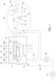
- FIG. 1shows a schematic side view of a deposition system having a showerhead assembly in accordance with some embodiments of the present disclosure.
- FIG. 2shows a top isometric view of a showerhead and lid assembly in accordance with some embodiments of the present disclosure.
- FIG. 3shows a top isometric cross-sectional view of a showerhead and lid assembly in accordance with some embodiments of the present disclosure.
- FIG. 4shows a top isometric view of a gas delivery portion of a showerhead in accordance with some embodiments of the present disclosure.
- FIG. 5shows a partial sectional view of a gas delivery portion of a showerhead in accordance with some embodiments of the present disclosure.
- Embodiments of apparatus for processing a substrate and/or providing multiple process materials to a deposition chamberare provided herein.
- the apparatus of the present disclosureincludes a showerhead assembly and/or delivery system configured to advantageously prevent thermal cross-talk between two or more adjacent process materials before exiting the delivery system.
- two or more species or samples of process materialmay be individually processed through the apparatus in thermal isolation, or relative thermal isolation, at the same or different temperatures prior to exiting a showerhead assembly and depositing on a substrate.
- the apparatus of the present disclosureadvantageously reduces a pressure drop across a showerhead assembly.
- process of the present disclosuremay be applied to any substrate process that requires delivery of multiple process materials, and in particular, in such processes where the multiple process materials are beneficially isolated from each other in accordance with the teachings provided herein.
- FIG. 1shows a schematic side view of a deposition system 100 in accordance with some embodiments of the present disclosure.
- the deposition system 100includes a deposition chamber 110 defined, at least in part, by one or more sides 111 , a floor 128 , and a lid 130 .
- the deposition system 100is configured to process a substrate, such as substrate 116 , in the deposition chamber 110 .
- the substrateis supported by a substrate support 114 disposed in the deposition chamber 110 .
- the deposition chamber 110may be a CVD chamber configured to perform process material deposition such as organic precursor deposition in accordance with the present disclosure.
- One non-limiting system suitable for use or that can be adapted for use in accordance with the present disclosureis the ENDURA® line of processing systems available from Applied Materials, Inc. of Santa Clara, Calif. Other processing systems, including those available from other manufacturers, can also be modified in accordance with the teachings provided herein.
- the apparatus in accordance with the present disclosuremay be utilized in a chamber configured to perform atomic layer deposition (ALD).
- ALDatomic layer deposition
- an organic layer(not shown), or derivatives thereof may be formed, condensed, or deposited by a deposition process on substrate 116 .
- the layermay be formed of multiple process materials that would otherwise undesirably react with each other within a conventional showerhead.
- the layermay be formed of multiple process materials that have difference process requirements, such as flow rate, temperature, or the like.
- suitable process materials for use in the apparatus of the present disclosureinclude any material suitable for sublimation and condensation on a substrate, for example tris (8-hydroxyquinolinato) aluminum (Alq3) or buckminsterfullerene (C 60 ).
- Other process gasesmay also suitably be used, in particular but not limited to, process gases that require one or more of different flow rates, different temperatures, or different gas distribution systems to prevent reactions between the respective process gases within the gas distribution system.
- the deposition system 100includes the deposition chamber 110 and a precursor delivery system 120 .
- the precursor delivery system 120may include one or more heating systems 142 (two shown in FIG. 1 ).
- the precursor delivery system 120may include one or more gas delivery systems 150 (two shown in FIG. 1 ).
- the components of the deposition system 100are connected and in communication such that processing material in the one or more heating systems 142 may be sublimated and subsequently passed through gas delivery system 150 into deposition chamber 110 .
- the one or more heating systems 142 , the gas delivery system 150 , and the deposition chamber 110may be in fluid communication.
- the precursor delivery system 120is configured to deliver the multiple process materials to a showerhead assembly 112 and substrate 116 in fluid communication with the showerhead assembly 112 .
- the showerhead assembly 112includes a plurality of gas delivery portions.
- the plurality of gas delivery portionsare coplanar and together form a showerhead assembly 112 having a circular shape.
- the plurality of gas delivery portionsare fluidly isolated from each other (e.g., material in each gas delivery portion cannot intermix with or contact the materials in other gas delivery portions within the showerhead assembly 112 ).
- the precursor delivery system 120is capable of delivering a first process material to one or more of the gas delivery portions at a first temperature. In some embodiments, the first temperature is about 200 degrees to about 350 degrees Celsius.
- the precursor delivery system 120is capable of delivering a second process material to one or more of the gas delivery portions at a second temperature different than the first temperature.
- the second temperatureis about 450 degrees to about 600 degrees Celsius.
- the precursor delivery system 120is capable of delivering a third process material to one or more of the gas delivery portions at the first temperature, the second temperature, or a third temperature different than the first temperature and the second temperature.
- the precursor delivery system 120is capable of delivering a fourth process material to one or more of the gas delivery portions at the first temperature, the second temperature, the third temperature, or a fourth temperature different than the first temperature, the second temperature, and the third temperature.
- the substrate support 114is capable of rotating the substrate 116 such that process materials from the plurality of gas delivery portions are uniformly deposited onto the substrate 116 .
- the plurality of gas delivery sectionsare further configured to reduce or prevent thermal cross-talk between each gas delivery section prior to exiting into the deposition chamber 110 , as described in further detail below.
- the temperature of the first process materialwill not affect, or will have a lessened effect on, the temperature of the second process material within the showerhead assembly 112 .
- a temperature difference between the first process material and the second process materialis between about 200 to about 400 degrees Celsius.
- the showerhead assembly 112is configured to deliver process material to the deposition chamber 110 without condensing the one or more process material(s) therein.
- the deposition system 100may include components used to execute and monitor pre-determined processes (e.g., depositing films) in the deposition system 100 .
- Such componentsgenerally include various sub-systems (e.g., vacuum and exhaust sub-systems, and the like) and devices (e.g., power supplies, process control instruments, and the like) of the deposition system 100 .
- the deposition system 100includes a first pump 180 , a second pump 181 , a throttle valve 184 , and a pressure valve 183 to control the pressure of the system and bring or maintain the deposition system 100 at vacuum conditions.
- the pressure valve 183may be included to remove vacuum conditions.
- FIG. 2shows a top isometric view of a showerhead and lid assembly in accordance with some embodiments of the present disclosure.
- the showerhead and lid assembly 200comprises a plurality of gas delivery portions including a first gas delivery portion 220 , a second gas delivery portion 230 , a third gas delivery portion 240 , and a fourth gas delivery portion 250 .
- the plurality of gas delivery portions 220 , 230 , 240 , 250are coplanar and together form a showerhead assembly 112 having a circular shape.
- the showerhead diameteris about 300 mm to about 500 mm.
- the showerhead diametercorresponds with a diameter of the substrate 116 .
- the plurality of gas delivery portioncan include three gas delivery portions.
- the plurality of gas delivery portionscan include six gas delivery portions.
- the plurality of gas delivery portions 220 , 230 , 240 , 250are arranged such that there is a gap 246 between each gas delivery portion.
- the spaced relation between the gas delivery portions 220 , 230 , 240 , 250advantageously reduces or prevents thermal cross-talk between each gas delivery portion prior to exiting into the deposition chamber 110 .
- a first heating assembly 125is configured to apply heat to the first gas delivery portion 220 .
- the first heating assembly 125may comprise one or more heating elements configured to maintain the first gas delivery portion at a substantially uniform temperature.
- the first heating assembly 125includes a heating element, such as a resistive heater, in at least one of the top wall and the bottom wall of the first gas delivery portion 220 (discussed below).
- the first heating assembly 125is configured to apply heat to a first process material passing through the first gas delivery portion 220 at a predetermined temperature, such as the first temperature, as the first process material moves into the deposition chamber 110 .
- a one or more first temperature sensor 141 and a first temperature controller 124are coupled to the first gas delivery portion 220 .
- the one or more first temperature sensor 141is configured to obtain thermal information from the first gas delivery portion 220 .
- the first temperature controller 124is configured to receive input from the one or more first temperature sensor 141 to control, adjust, or set a temperature of the first heating assembly 125 .
- the first temperature sensor 141can be a thermocouple, a pyrometer, or the like.
- a second heating assembly 127is configured to apply heat to the second gas delivery portion 230 .
- the second heating assembly 127may comprise one or more heating elements configured to maintain the second gas delivery portion 230 at a substantially uniform temperature.
- the first heating assembly 125includes a heating element, such as a resistive heater, in at least one of the top wall and the bottom wall of the second gas delivery portion 230 .
- the second heating assembly 127is configured to apply heat to a second process material passing through the second gas delivery portion 230 at a predetermined temperature, such as the second temperature, as the second process material moves into the deposition chamber 110 .
- a one or more second temperature sensor 143 and a second temperature controller 126are coupled to the second gas delivery portion 230 .
- the one or more second temperature sensor 143is configured to obtain thermal information from the second gas delivery portion 230 .
- the second temperature controller 126is configured to receive input from the one or more second temperature sensor 143 to control, adjust, or set a temperature of the second heating assembly 127 .
- the one or more second temperature sensor 143can be a thermocouple, a pyrometer, or the like.
- a third heating assembly 155is configured to apply heat to the third gas delivery portion 240 .
- the third heating assembly 155may comprise one or more heating elements configured to maintain the third gas delivery portion 240 at a substantially uniform temperature.
- the third heating assembly 155includes a heating element, such as a resistive heater, in at least one of the top wall and the bottom wall of the third gas delivery portion 240 .
- the third heating assembly 155is configured to apply heat to a process material passing through the third gas delivery portion 240 at a predetermined temperature, such as the first temperature, the second temperature, or a third temperature, as the process material moves into the deposition chamber 110 .
- the process materialmay be the first process material, the second process material, or a third process material.
- a temperature difference between the first temperature and the second temperatureis between about 200 to about 400 degrees Celsius.
- a one or more third temperature sensor and a third temperature controller 163are coupled to the third gas delivery portion 240 .
- the one or more third temperature sensor 145is configured to obtain thermal information from the third gas delivery portion 240 .
- the third temperature controller 163is configured to receive input from the one or more third temperature sensor 145 to control, adjust, or set a temperature of the third heating assembly 155 .
- the one or more third temperature sensor 145can be a thermocouple, a pyrometer, or the like.
- a fourth heating assembly 159is configured to apply heat to the fourth gas delivery portion 250 .
- the fourth heating assembly 159may comprise one or more heating elements configured to maintain the fourth gas delivery portion 250 at a substantially uniform temperature.
- the fourth heating assembly 159includes a heating element, such as a resistive heater, in at least one of the top wall and the bottom wall of the fourth gas delivery portion 250 .
- the fourth heating assembly 159is configured to apply heat to a process material passing through the fourth gas delivery portion 250 at a predetermined temperature, such as the first temperature, the second temperature, the third temperature, or a fourth temperature, as the process material moves into the deposition chamber 110 .
- the process materialmay be the first process material, the second process material, the third process material, or a fourth process material.
- a one or more fourth temperature sensor 147 and a fourth temperature controller 165are coupled to the fourth gas delivery portion 250 .
- the one or more fourth temperature sensor 147is configured to obtain thermal information from the fourth gas delivery portion 250 .
- the fourth temperature controller 165is configured to receive input from the one or more fourth temperature sensor 147 to control, adjust, or set a temperature of the fourth heating assembly 159 .
- the one or more fourth temperature sensor 147can be a thermocouple, a pyrometer, or the like.
- the showerhead and lid assembly 200includes a showerhead assembly 112 mounted to a lid plate 210 .
- the lid plate 210has a plurality of mounts 204 extending from a bottom surface 202 of the lid plate 210 .
- Each of the gas delivery portions 220 , 230 , 240 , 250 of the showerhead assembly 112include one or more mounts 216 that are capable of mating with corresponding mounts 204 of the lid plate 210 to couple the showerhead assembly 201 to the lid plate 210 .
- the one or more mounts 216extend from a radially outer surface of the showerhead assembly 112 .
- the mounts 204 , 216are made of an insulative material.
- the plurality of gas delivery portions 220 , 230 , 240 , 250are similar in size. In some embodiments, the plurality of gas delivery portions may be different sizes.
- the showerhead assembly 112is capable of flowing two process gases. For example, the first gas delivery portion 220 and the third gas delivery portion 240 are coupled to a first gas source and the second gas delivery portion 230 and the fourth gas delivery portion 250 are coupled to a second gas source. In some embodiments, the showerhead assembly 112 is capable of flowing three process gases.
- the first and third gas delivery portions 220 , 240coupled to a first gas source
- the second gas delivery portion 230coupled to a second gas source
- the fourth gas delivery portion 250coupled to a third gas source.
- the showerhead assembly 112is capable of flowing four process gases.
- the first gas delivery portion 220includes a wedge shaped body that defines a first plenum 318 .
- the first gas delivery portion 220includes a first inlet 208 extending from the wedge shaped body and through an opening in the lid plate 210 .
- the second gas delivery portion 230 , the third gas delivery portion 240 , and the fourth gas delivery portion 250include a second inlet 212 , a third inlet 214 , and a fourth inlet 224 , extending from their respective wedge shaped bodies through an opening in the lid plate 210 .
- each inlet 208 , 212 , 214 , 224is disposed adjacent a respective outer portion of each gas delivery portion 220 , 230 , 240 , 250 .
- the first gas delivery portion 220includes a plurality of openings 226 extending from a bottom surface 236 of the wedge shaped body to the first plenum 318 .
- the plurality of openings 226are configured to deliver a process gas into the deposition chamber 110 .
- the gas delivery portions 230 , 240 , 250include a plurality of openings 228 , 232 , 234 , respectively, extending from their respective bottom surfaces 238 , 242 , 244 .
- the plurality of openings 228 , 232 , 234are configured to deliver a process gas from each of the gas delivery portions 230 , 240 , 250 into the deposition chamber 110 .
- the plurality of openings 226 , 228 , 232 , 243may be arranged in any pattern suitable for uniformly depositing process materials onto the substrate 116 .
- the plurality of openings 226 , 228 , 232 , 243have a diameter of about 0.1 mm to about 3 mm.
- the showerhead and lid assembly 200includes a plurality of feedthrough plates 218 .
- the plurality of feedthrough plates 218are configured to allow wires to pass from the showerhead assembly 112 through the lid plate 210 .
- the wirescan be heater wires, sensor wires, or the like.
- the each of the plurality of feedthrough plates 218include a plurality of openings 222 .
- a feedthrough plate 218is disposed next to each of the plurality of gas delivery portions 220 , 230 , 240 , 250 .
- one or more heater wires 206are configured to pass through one of the feedthrough plates 218 and into the first gas delivery portion 220 .
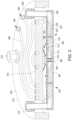
- FIG. 3shows a top isometric cross-sectional view of a showerhead and lid assembly in accordance with some embodiments of the present disclosure.
- the lid plate 210has a top surface 302 opposite the bottom surface 202 .
- the lid plate 210includes channels 310 extending from the top surface 302 towards the bottom surface 202 .
- the channels 310are configured to flow fluid to cool the lid plate 210 .
- the channels 310may be partially filled with plugs 308 to seal the channels 310 .
- the top surface 302includes a first port 304 and a second port 306 .
- the first port 304 and the second port 306are configured to flow fluid into and out of the channels 310 .
- the fluidcan be coolant, water, or the like.
- the first gas delivery portion 220includes a top wall 332 , a bottom wall 334 , and sidewalls 336 to define a first plenum 318 .
- top walls, bottom walls, and sidewalls of the second, third, and fourth gas delivery portions 230 , 240 , 250define a second plenum (inner volume of 230 ), a third plenum 320 , and a fourth plenum (inner volume of 250 ), respectively.
- the showerhead assembly 112may be coupled to the lid plate via the one or more mounts 216 that extend from a radially outer surface of the showerhead assembly 112 .
- the gas delivery portions 220 , 230 , 240 , 250 of the showerhead assembly 112may be coupled to each other at a central portion of the showerhead assembly 112 with a plug 324 while maintaining the gap 246 therebetween.
- the plug 324may have a central opening 326 that is capable of receiving a male portion of a fastener.
- a heat sink 330is disposed in the gap 246 between adjacent gas delivery portions.
- the heat sink 330has a conductivity of about 150 W/m-K or greater.
- the heat sink 330is configured to reduce or prevent heat from a gas delivery portion 220 , 230 , 240 , 250 from radiating to the gas delivery portion 220 , 230 , 240 , 250 that is cooler (i.e., thermal cross-talk).
- the heat sink 330comprises a thermally anisotropic material.
- a thermally anisotropic materialis a material that advantageously has an in-plane thermal conductivity (conductivity in the basal plane) much greater than a transverse thermal conductivity of the material, thus allowing for increased temperature uniformity in the direction of the plane.
- Thermal Pyrolytic Graphite®TPG is an example of a thermally anisotropic material having an in-plane thermal conductivity of about 1,500 W/m-K and a transverse thermal conductivity of about 10 W/m-K.
- suitable anisotropic materialsinclude pyrolytic boron nitride, synthetic diamonds, or the like.
- the plurality of gas delivery portions 220 , 230 , 240 , 250are similar (i.e., identical). The following discussion will be with respect to the first gas delivery portion 220 . However, the same discussion is applicable to the second, third, and fourth gas delivery portions 230 , 240 , 250 .
- the top wall 332 of the first gas delivery portion 220includes channels capable of carrying wires 312 of a resistive heater.
- the bottom wall 334 of the first gas delivery portion 220includes channels 314 capable of carrying wires of a resistive heater.
- the first gas delivery portion 220includes wires 312 in the top wall 332 and wires (e.g.
- a post 322is disposed through the top wall 332 and at least partially through the bottom wall 334 .
- the post 322is configured to facilitate measuring a temperature of a bottom end of the post 322 disposed in the bottom wall 334 to provide a temperature measurement of the bottom wall 334 .
- a post 328is disposed at least partially through the top wall 332 .
- the post 328is configured to facilitate measuring a temperature of a bottom end of the post 328 disposed in the top wall 332 to provide a temperature measurement of the top wall 322 .
- the post 322 and the post 328are tubes with an upper portion having a central opening and a bottom portion that is solid.
- the central openings of the post 322 and the post 328are configured to accommodate respective thermocouples.
- at least one of the post 322 and the post 328are coupled to the one or more first temperature sensors 141 .
- FIG. 4shows a top isometric view of a gas delivery portion in accordance with some embodiments of the present disclosure.
- the first gas delivery portion 220includes a wedge shaped body 408 and a curved portion 410 that curves radially outwards from an outer surface 412 of the wedge shaped body 408 .
- the first inlet 208may be disposed adjacent the curved portion 410 .
- the first gas delivery portion 220includes a heat shield 402 that substantially covers (i.e., envelopes) the wedge shaped body 408 .
- the heat shield 402includes a plurality of openings that correspond with the plurality of openings 226 of the first gas delivery portion 220 .
- the heat shield 402includes an opening 406 for post 328 .
- the heat shield 402includes an opening 414 for post 322 .
- the heat shield 402includes one or more openings 404 for one or more mounts 216 .
- the heat shield 402is configured to reduce or prevent heat from radiating from the first gas delivery portion 220 to adjacent gas delivery portions (i.e., thermal cross-talk).
- the heat shield 402is formed of stainless steel, aluminum, or the like.
- the wedge shaped body 408is formed of a high purity and high thermal resistance material, such as stainless steel, titanium, or the like.
- FIG. 5shows a partial sectional view of a gas delivery portion in accordance with some embodiments of the present disclosure.
- a nozzle 316may be placed in each hole of the plurality of openings 226 .
- the nozzle 316can have an inner diameter of about 0.1 mm to about 3 mm.
- the nozzle 316comprises titanium, titanium alloy, or titanium nitride coated steel.
- the nozzle 316can be configured to control speed, direction, and flow of process material.
- the nozzle 316is configured to spray process material passing from the first plenum 318 into the deposition chamber 110 . Spraying of the process material can advantageously increases the uniformity of deposition of the process material onto the substrate 116 .
- Spraying of the process materialalso advantageously increases the uniformity of mixing of the multiple process materials onto the substrate 116 .
- wires 506are disposed in the channels 314 in the bottom wall 334 to heat the first gas delivery portion 220 .
Landscapes
- Chemical & Material Sciences (AREA)
- Engineering & Computer Science (AREA)
- Chemical Kinetics & Catalysis (AREA)
- General Chemical & Material Sciences (AREA)
- Materials Engineering (AREA)
- Mechanical Engineering (AREA)
- Metallurgy (AREA)
- Organic Chemistry (AREA)
- Physics & Mathematics (AREA)
- Condensed Matter Physics & Semiconductors (AREA)
- General Physics & Mathematics (AREA)
- Manufacturing & Machinery (AREA)
- Computer Hardware Design (AREA)
- Microelectronics & Electronic Packaging (AREA)
- Power Engineering (AREA)
- Chemical Vapour Deposition (AREA)
Abstract
Description
Claims (16)
Priority Applications (7)
| Application Number | Priority Date | Filing Date | Title |
|---|---|---|---|
| US16/570,317US11834743B2 (en) | 2018-09-14 | 2019-09-13 | Segmented showerhead for uniform delivery of multiple precursors |
| PCT/US2019/051307WO2020056413A1 (en) | 2018-09-14 | 2019-09-16 | Segmented showerhead for uniform delivery of multiple precursors |
| JP2021513814AJP7208363B2 (en) | 2018-09-14 | 2019-09-16 | Segmented showerhead for uniform delivery of multiple precursors |
| TW108133201ATWI825173B (en) | 2018-09-14 | 2019-09-16 | A showerhead assembly and a method of introducing precursors through a segmented showerhead |
| CN201980058944.5ACN112740386A (en) | 2018-09-14 | 2019-09-16 | Segmented Sprinklers for Uniform Delivery of Multiple Precursors |
| KR1020217010762AKR102600505B1 (en) | 2018-09-14 | 2019-09-16 | Split showerhead for uniform delivery of multiple precursors |
| US18/072,711US12043895B2 (en) | 2018-09-14 | 2022-12-01 | Methods of using a segmented showerhead for uniform delivery of multiple pre-cursors |
Applications Claiming Priority (2)
| Application Number | Priority Date | Filing Date | Title |
|---|---|---|---|
| US201862731799P | 2018-09-14 | 2018-09-14 | |
| US16/570,317US11834743B2 (en) | 2018-09-14 | 2019-09-13 | Segmented showerhead for uniform delivery of multiple precursors |
Related Child Applications (1)
| Application Number | Title | Priority Date | Filing Date |
|---|---|---|---|
| US18/072,711DivisionUS12043895B2 (en) | 2018-09-14 | 2022-12-01 | Methods of using a segmented showerhead for uniform delivery of multiple pre-cursors |
Publications (2)
| Publication Number | Publication Date |
|---|---|
| US20200087790A1 US20200087790A1 (en) | 2020-03-19 |
| US11834743B2true US11834743B2 (en) | 2023-12-05 |
Family
ID=69773783
Family Applications (2)
| Application Number | Title | Priority Date | Filing Date |
|---|---|---|---|
| US16/570,317Active2039-11-21US11834743B2 (en) | 2018-09-14 | 2019-09-13 | Segmented showerhead for uniform delivery of multiple precursors |
| US18/072,711ActiveUS12043895B2 (en) | 2018-09-14 | 2022-12-01 | Methods of using a segmented showerhead for uniform delivery of multiple pre-cursors |
Family Applications After (1)
| Application Number | Title | Priority Date | Filing Date |
|---|---|---|---|
| US18/072,711ActiveUS12043895B2 (en) | 2018-09-14 | 2022-12-01 | Methods of using a segmented showerhead for uniform delivery of multiple pre-cursors |
Country Status (6)
| Country | Link |
|---|---|
| US (2) | US11834743B2 (en) |
| JP (1) | JP7208363B2 (en) |
| KR (1) | KR102600505B1 (en) |
| CN (1) | CN112740386A (en) |
| TW (1) | TWI825173B (en) |
| WO (1) | WO2020056413A1 (en) |
Families Citing this family (6)
| Publication number | Priority date | Publication date | Assignee | Title |
|---|---|---|---|---|
| US11393703B2 (en) | 2018-06-18 | 2022-07-19 | Applied Materials, Inc. | Apparatus and method for controlling a flow process material to a deposition chamber |
| KR102732061B1 (en)* | 2019-05-31 | 2024-11-18 | 어플라이드 머티어리얼스, 인코포레이티드 | Methods and systems for forming films on substrates |
| CN114144540B (en) | 2019-07-26 | 2024-06-11 | 应用材料公司 | Evaporator chamber for forming film on substrate |
| TWI875986B (en)* | 2020-03-21 | 2025-03-11 | 美商應用材料股份有限公司 | Pedestal geometry for fast gas exchange |
| KR102656121B1 (en)* | 2021-12-24 | 2024-04-12 | (주)보부하이테크 | Heater structure with improved welding defect and crack |
| CN115058702A (en)* | 2022-07-27 | 2022-09-16 | 拓荆科技(上海)有限公司 | Spray header and vacuum treatment equipment |
Citations (47)
| Publication number | Priority date | Publication date | Assignee | Title |
|---|---|---|---|---|
| US5653806A (en)* | 1995-03-10 | 1997-08-05 | Advanced Technology Materials, Inc. | Showerhead-type discharge assembly for delivery of source reagent vapor to a substrate, and CVD process utilizing same |
| US5958510A (en)* | 1996-01-08 | 1999-09-28 | Applied Materials, Inc. | Method and apparatus for forming a thin polymer layer on an integrated circuit structure |
| US6050506A (en)* | 1998-02-13 | 2000-04-18 | Applied Materials, Inc. | Pattern of apertures in a showerhead for chemical vapor deposition |
| US6533867B2 (en)* | 2000-11-20 | 2003-03-18 | Applied Epi Inc | Surface sealing showerhead for vapor deposition reactor having integrated flow diverters |
| US20040082251A1 (en)* | 2002-10-29 | 2004-04-29 | Applied Materials, Inc. | Apparatus for adjustable gas distribution for semiconductor substrate processing |
| US20040099213A1 (en)* | 2000-07-24 | 2004-05-27 | Adomaitis Raymond A | Spatially programmable microelectronics process equipment using segmented gas injection showerhead with exhaust gas recirculation |
| US6888733B2 (en)* | 2002-07-09 | 2005-05-03 | Samsung Electronics Co., Ltd. | Multiple chip system including a plurality of non-volatile semiconductor memory devices |
| US20060191637A1 (en)* | 2001-06-21 | 2006-08-31 | John Zajac | Etching Apparatus and Process with Thickness and Uniformity Control |
| US20060219362A1 (en) | 2005-04-01 | 2006-10-05 | Geun-Jo Han | Gas injector and apparatus including the same |
| US20080092812A1 (en)* | 2004-06-10 | 2008-04-24 | Mcdiarmid James | Methods and Apparatuses for Depositing Uniform Layers |
| US20080092815A1 (en) | 2006-10-18 | 2008-04-24 | Advanced Micro-Fabrication Equipment, Inc. Asia | Gas distribution assembly for use in a semiconductor work piece processing reactor |
| US20080236495A1 (en)* | 2007-03-27 | 2008-10-02 | Structured Materials Inc. | Showerhead for chemical vapor deposition (CVD) apparatus |
| US20090061646A1 (en)* | 2007-09-05 | 2009-03-05 | Chiang Tony P | Vapor based combinatorial processing |
| US20090095222A1 (en)* | 2007-10-16 | 2009-04-16 | Alexander Tam | Multi-gas spiral channel showerhead |
| US20090260571A1 (en)* | 2008-04-16 | 2009-10-22 | Novellus Systems, Inc. | Showerhead for chemical vapor deposition |
| KR20090131384A (en) | 2008-06-18 | 2009-12-29 | 주식회사 아이피에스 | Gas injection assembly and thin film deposition apparatus using the same |
| US7871470B2 (en)* | 2003-03-12 | 2011-01-18 | Applied Materials, Inc. | Substrate support lift mechanism |
| US7976631B2 (en)* | 2007-10-16 | 2011-07-12 | Applied Materials, Inc. | Multi-gas straight channel showerhead |
| US20110239940A1 (en)* | 2008-10-08 | 2011-10-06 | Giacomo Benvenuti | Vapor phase deposition system |
| KR20110133169A (en) | 2010-06-04 | 2011-12-12 | 주성엔지니어링(주) | Raw material supply apparatus and substrate processing apparatus having the same |
| WO2012027009A2 (en)* | 2010-08-27 | 2012-03-01 | Applied Materials, Inc. | Gas distribution showerhead with high emissivity surface |
| US20120064698A1 (en)* | 2010-09-13 | 2012-03-15 | Applied Materials, Inc. | Multiple section showerhead assembly |
| US8187679B2 (en)* | 2006-07-29 | 2012-05-29 | Lotus Applied Technology, Llc | Radical-enhanced atomic layer deposition system and method |
| US8216640B2 (en)* | 2009-09-25 | 2012-07-10 | Hermes-Epitek Corporation | Method of making showerhead for semiconductor processing apparatus |
| US8293013B2 (en)* | 2008-12-30 | 2012-10-23 | Intermolecular, Inc. | Dual path gas distribution device |
| US20120318457A1 (en)* | 2011-06-17 | 2012-12-20 | Son Nguyen | Materials and coatings for a showerhead in a processing system |
| US20130042811A1 (en)* | 2008-05-02 | 2013-02-21 | Intermolecular, Inc. | Combinatorial Plasma Enhanced Deposition Techniques |
| US20130052804A1 (en)* | 2009-10-09 | 2013-02-28 | Applied Materials, Imn, | Multi-gas centrally cooled showerhead design |
| US20130087093A1 (en)* | 2011-10-10 | 2013-04-11 | Applied Materials, Inc. | Apparatus and method for hvpe processing using a plasma |
| US20130220222A1 (en)* | 2012-02-23 | 2013-08-29 | Hermes-Epitek Corporation | Gas Distribution Apparatus with Heat Exchanging Channels |
| KR20130139651A (en) | 2012-06-13 | 2013-12-23 | 주식회사 원익아이피에스 | Manufacturing method for thin film and substrate process apparatus |
| US20130341433A1 (en)* | 2012-06-22 | 2013-12-26 | Shambhu N. Roy | Dual plenum, axi-symmetric showerhead with edge-to-center gas delivery |
| US20140166616A1 (en)* | 2012-12-17 | 2014-06-19 | Intermolecular, Inc. | Combinatorial Processing Using a Remote Plasma Source |
| KR20140101049A (en) | 2013-02-07 | 2014-08-19 | 주식회사 원익아이피에스 | Substrate Processing Apparatus |
| KR20140103080A (en)* | 2013-02-15 | 2014-08-25 | 노벨러스 시스템즈, 인코포레이티드 | Multi-plenum showerhead with temperature control |
| US8980379B2 (en)* | 2009-08-27 | 2015-03-17 | Applied Materials, Inc. | Gas distribution showerhead and method of cleaning |
| US20160240405A1 (en)* | 2015-02-12 | 2016-08-18 | Applied Materials, Inc. | Stand alone anneal system for semiconductor wafers |
| US20160340782A1 (en)* | 2015-05-22 | 2016-11-24 | Lam Research Corporation | Low volume showerhead with faceplate holes for improved flow uniformity |
| CN104278254B (en)* | 2013-07-03 | 2017-04-12 | 诺发系统公司 | Multi-plenum, dual-temperature showerhead |
| US20170191159A1 (en)* | 2016-01-01 | 2017-07-06 | Applied Materials, Inc. | Non-Metallic Thermal CVD/ALD Gas Injector And Purge System |
| US9728380B2 (en)* | 2012-08-31 | 2017-08-08 | Novellus Systems, Inc. | Dual-plenum showerhead with interleaved plenum sub-volumes |
| US20190351433A1 (en) | 2018-05-18 | 2019-11-21 | Applied Materials, Inc. | Multi-zone showerhead |
| US10533252B2 (en)* | 2016-03-31 | 2020-01-14 | Taiwan Semiconductor Manufacturing Co., Ltd. | Showerhead, semicondcutor processing apparatus having the same and semiconductor process |
| US20200034739A1 (en)* | 2018-07-25 | 2020-01-30 | Samsung Electronics Co., Ltd. | Method and device for estimating user's physical condition |
| US20200048767A1 (en)* | 2018-08-10 | 2020-02-13 | Applied Materials, Inc. | Showerhead for providing multiple materials to a process chamber |
| WO2020159799A1 (en)* | 2019-02-01 | 2020-08-06 | Lam Research Corporation | Showerhead for deposition tools having multiple plenums and gas distribution chambers |
| US11189502B2 (en)* | 2018-04-08 | 2021-11-30 | Applied Materials, Inc. | Showerhead with interlaced gas feed and removal and methods of use |
Family Cites Families (20)
| Publication number | Priority date | Publication date | Assignee | Title |
|---|---|---|---|---|
| KR100492258B1 (en)* | 1996-10-11 | 2005-09-02 | 가부시키가이샤 에바라 세이사꾸쇼 | Reaction gas ejection head |
| JP4815724B2 (en)* | 2000-09-08 | 2011-11-16 | 東京エレクトロン株式会社 | Shower head structure and film forming apparatus |
| KR100550342B1 (en)* | 2004-02-24 | 2006-02-08 | 삼성전자주식회사 | A semiconductor substrate processing apparatus comprising a gas spreading method and a shower head and a shower head |
| JP2007191792A (en)* | 2006-01-19 | 2007-08-02 | Atto Co Ltd | Gas separation type showerhead |
| US20100116788A1 (en)* | 2008-11-12 | 2010-05-13 | Lam Research Corporation | Substrate temperature control by using liquid controlled multizone substrate support |
| JP2010245323A (en)* | 2009-04-07 | 2010-10-28 | Seiko Epson Corp | Coil unit and electronic equipment |
| JP2012222024A (en)* | 2011-04-05 | 2012-11-12 | Hitachi Kokusai Electric Inc | Substrate processing device and semiconductor device manufacturing method |
| US8960235B2 (en)* | 2011-10-28 | 2015-02-24 | Applied Materials, Inc. | Gas dispersion apparatus |
| US10486183B2 (en)* | 2012-07-27 | 2019-11-26 | Applied Materials, Inc. | Methods and apparatus for delivering process gases to a substrate |
| US20140209242A1 (en)* | 2013-01-25 | 2014-07-31 | Applied Materials, Inc. | Substrate processing chamber components incorporating anisotropic materials |
| JP6054213B2 (en) | 2013-03-11 | 2016-12-27 | 東京エレクトロン株式会社 | Support member and semiconductor manufacturing apparatus |
| US9666466B2 (en)* | 2013-05-07 | 2017-05-30 | Applied Materials, Inc. | Electrostatic chuck having thermally isolated zones with minimal crosstalk |
| JP2015076495A (en)* | 2013-10-09 | 2015-04-20 | 日本電気株式会社 | System and method for power transmission |
| US9353440B2 (en) | 2013-12-20 | 2016-05-31 | Applied Materials, Inc. | Dual-direction chemical delivery system for ALD/CVD chambers |
| FR3018526B1 (en)* | 2014-03-14 | 2021-06-11 | Herakles | CVI DENSIFICATION INSTALLATION INCLUDING A HIGH-CAPACITY PREHEATING ZONE |
| US10079165B2 (en)* | 2014-05-20 | 2018-09-18 | Applied Materials, Inc. | Electrostatic chuck with independent zone cooling and reduced crosstalk |
| US10431435B2 (en)* | 2014-08-01 | 2019-10-01 | Applied Materials, Inc. | Wafer carrier with independent isolated heater zones |
| US10358722B2 (en)* | 2015-12-14 | 2019-07-23 | Lam Research Corporation | Showerhead assembly |
| US10403476B2 (en)* | 2016-11-09 | 2019-09-03 | Lam Research Corporation | Active showerhead |
| US10607817B2 (en)* | 2016-11-18 | 2020-03-31 | Applied Materials, Inc. | Thermal repeatability and in-situ showerhead temperature monitoring |
- 2019
- 2019-09-13USUS16/570,317patent/US11834743B2/enactiveActive
- 2019-09-16JPJP2021513814Apatent/JP7208363B2/enactiveActive
- 2019-09-16WOPCT/US2019/051307patent/WO2020056413A1/ennot_activeCeased
- 2019-09-16KRKR1020217010762Apatent/KR102600505B1/enactiveActive
- 2019-09-16CNCN201980058944.5Apatent/CN112740386A/enactivePending
- 2019-09-16TWTW108133201Apatent/TWI825173B/enactive
- 2022
- 2022-12-01USUS18/072,711patent/US12043895B2/enactiveActive
Patent Citations (55)
| Publication number | Priority date | Publication date | Assignee | Title |
|---|---|---|---|---|
| US5653806A (en)* | 1995-03-10 | 1997-08-05 | Advanced Technology Materials, Inc. | Showerhead-type discharge assembly for delivery of source reagent vapor to a substrate, and CVD process utilizing same |
| US5958510A (en)* | 1996-01-08 | 1999-09-28 | Applied Materials, Inc. | Method and apparatus for forming a thin polymer layer on an integrated circuit structure |
| US6050506A (en)* | 1998-02-13 | 2000-04-18 | Applied Materials, Inc. | Pattern of apertures in a showerhead for chemical vapor deposition |
| US20040099213A1 (en)* | 2000-07-24 | 2004-05-27 | Adomaitis Raymond A | Spatially programmable microelectronics process equipment using segmented gas injection showerhead with exhaust gas recirculation |
| US6821910B2 (en)* | 2000-07-24 | 2004-11-23 | University Of Maryland, College Park | Spatially programmable microelectronics process equipment using segmented gas injection showerhead with exhaust gas recirculation |
| US6533867B2 (en)* | 2000-11-20 | 2003-03-18 | Applied Epi Inc | Surface sealing showerhead for vapor deposition reactor having integrated flow diverters |
| US20060191637A1 (en)* | 2001-06-21 | 2006-08-31 | John Zajac | Etching Apparatus and Process with Thickness and Uniformity Control |
| US6888733B2 (en)* | 2002-07-09 | 2005-05-03 | Samsung Electronics Co., Ltd. | Multiple chip system including a plurality of non-volatile semiconductor memory devices |
| US20040082251A1 (en)* | 2002-10-29 | 2004-04-29 | Applied Materials, Inc. | Apparatus for adjustable gas distribution for semiconductor substrate processing |
| US7871470B2 (en)* | 2003-03-12 | 2011-01-18 | Applied Materials, Inc. | Substrate support lift mechanism |
| US20080092812A1 (en)* | 2004-06-10 | 2008-04-24 | Mcdiarmid James | Methods and Apparatuses for Depositing Uniform Layers |
| US20060219362A1 (en) | 2005-04-01 | 2006-10-05 | Geun-Jo Han | Gas injector and apparatus including the same |
| US8187679B2 (en)* | 2006-07-29 | 2012-05-29 | Lotus Applied Technology, Llc | Radical-enhanced atomic layer deposition system and method |
| US20080092815A1 (en) | 2006-10-18 | 2008-04-24 | Advanced Micro-Fabrication Equipment, Inc. Asia | Gas distribution assembly for use in a semiconductor work piece processing reactor |
| US20080236495A1 (en)* | 2007-03-27 | 2008-10-02 | Structured Materials Inc. | Showerhead for chemical vapor deposition (CVD) apparatus |
| WO2008118483A1 (en)* | 2007-03-27 | 2008-10-02 | Structured Materials Inc. | Showerhead for chemical vapor deposition (cvd) apparatus |
| US20090061646A1 (en)* | 2007-09-05 | 2009-03-05 | Chiang Tony P | Vapor based combinatorial processing |
| US8409354B2 (en) | 2007-09-05 | 2013-04-02 | Intermolecular, Inc. | Vapor based combinatorial processing |
| US8440259B2 (en) | 2007-09-05 | 2013-05-14 | Intermolecular, Inc. | Vapor based combinatorial processing |
| US7976631B2 (en)* | 2007-10-16 | 2011-07-12 | Applied Materials, Inc. | Multi-gas straight channel showerhead |
| US9644267B2 (en)* | 2007-10-16 | 2017-05-09 | Applied Materials, Inc. | Multi-gas straight channel showerhead |
| US8481118B2 (en)* | 2007-10-16 | 2013-07-09 | Applied Materials, Inc. | Multi-gas straight channel showerhead |
| US20090095222A1 (en)* | 2007-10-16 | 2009-04-16 | Alexander Tam | Multi-gas spiral channel showerhead |
| US20090260571A1 (en)* | 2008-04-16 | 2009-10-22 | Novellus Systems, Inc. | Showerhead for chemical vapor deposition |
| US20130042811A1 (en)* | 2008-05-02 | 2013-02-21 | Intermolecular, Inc. | Combinatorial Plasma Enhanced Deposition Techniques |
| KR20090131384A (en) | 2008-06-18 | 2009-12-29 | 주식회사 아이피에스 | Gas injection assembly and thin film deposition apparatus using the same |
| US20110239940A1 (en)* | 2008-10-08 | 2011-10-06 | Giacomo Benvenuti | Vapor phase deposition system |
| US8293013B2 (en)* | 2008-12-30 | 2012-10-23 | Intermolecular, Inc. | Dual path gas distribution device |
| US8980379B2 (en)* | 2009-08-27 | 2015-03-17 | Applied Materials, Inc. | Gas distribution showerhead and method of cleaning |
| US8216640B2 (en)* | 2009-09-25 | 2012-07-10 | Hermes-Epitek Corporation | Method of making showerhead for semiconductor processing apparatus |
| US20130052804A1 (en)* | 2009-10-09 | 2013-02-28 | Applied Materials, Imn, | Multi-gas centrally cooled showerhead design |
| KR20110133169A (en) | 2010-06-04 | 2011-12-12 | 주성엔지니어링(주) | Raw material supply apparatus and substrate processing apparatus having the same |
| WO2012027009A2 (en)* | 2010-08-27 | 2012-03-01 | Applied Materials, Inc. | Gas distribution showerhead with high emissivity surface |
| US20120064698A1 (en)* | 2010-09-13 | 2012-03-15 | Applied Materials, Inc. | Multiple section showerhead assembly |
| US20120318457A1 (en)* | 2011-06-17 | 2012-12-20 | Son Nguyen | Materials and coatings for a showerhead in a processing system |
| US20130087093A1 (en)* | 2011-10-10 | 2013-04-11 | Applied Materials, Inc. | Apparatus and method for hvpe processing using a plasma |
| US20130220222A1 (en)* | 2012-02-23 | 2013-08-29 | Hermes-Epitek Corporation | Gas Distribution Apparatus with Heat Exchanging Channels |
| KR20130139651A (en) | 2012-06-13 | 2013-12-23 | 주식회사 원익아이피에스 | Manufacturing method for thin film and substrate process apparatus |
| US9447499B2 (en)* | 2012-06-22 | 2016-09-20 | Novellus Systems, Inc. | Dual plenum, axi-symmetric showerhead with edge-to-center gas delivery |
| US20130341433A1 (en)* | 2012-06-22 | 2013-12-26 | Shambhu N. Roy | Dual plenum, axi-symmetric showerhead with edge-to-center gas delivery |
| US9728380B2 (en)* | 2012-08-31 | 2017-08-08 | Novellus Systems, Inc. | Dual-plenum showerhead with interleaved plenum sub-volumes |
| US20140166616A1 (en)* | 2012-12-17 | 2014-06-19 | Intermolecular, Inc. | Combinatorial Processing Using a Remote Plasma Source |
| KR20140101049A (en) | 2013-02-07 | 2014-08-19 | 주식회사 원익아이피에스 | Substrate Processing Apparatus |
| KR20140103080A (en)* | 2013-02-15 | 2014-08-25 | 노벨러스 시스템즈, 인코포레이티드 | Multi-plenum showerhead with temperature control |
| CN104278254B (en)* | 2013-07-03 | 2017-04-12 | 诺发系统公司 | Multi-plenum, dual-temperature showerhead |
| US9677176B2 (en) | 2013-07-03 | 2017-06-13 | Novellus Systems, Inc. | Multi-plenum, dual-temperature showerhead |
| US20160240405A1 (en)* | 2015-02-12 | 2016-08-18 | Applied Materials, Inc. | Stand alone anneal system for semiconductor wafers |
| US20160340782A1 (en)* | 2015-05-22 | 2016-11-24 | Lam Research Corporation | Low volume showerhead with faceplate holes for improved flow uniformity |
| US20170191159A1 (en)* | 2016-01-01 | 2017-07-06 | Applied Materials, Inc. | Non-Metallic Thermal CVD/ALD Gas Injector And Purge System |
| US10533252B2 (en)* | 2016-03-31 | 2020-01-14 | Taiwan Semiconductor Manufacturing Co., Ltd. | Showerhead, semicondcutor processing apparatus having the same and semiconductor process |
| US11189502B2 (en)* | 2018-04-08 | 2021-11-30 | Applied Materials, Inc. | Showerhead with interlaced gas feed and removal and methods of use |
| US20190351433A1 (en) | 2018-05-18 | 2019-11-21 | Applied Materials, Inc. | Multi-zone showerhead |
| US20200034739A1 (en)* | 2018-07-25 | 2020-01-30 | Samsung Electronics Co., Ltd. | Method and device for estimating user's physical condition |
| US20200048767A1 (en)* | 2018-08-10 | 2020-02-13 | Applied Materials, Inc. | Showerhead for providing multiple materials to a process chamber |
| WO2020159799A1 (en)* | 2019-02-01 | 2020-08-06 | Lam Research Corporation | Showerhead for deposition tools having multiple plenums and gas distribution chambers |
Non-Patent Citations (7)
Also Published As
| Publication number | Publication date |
|---|---|
| WO2020056413A1 (en) | 2020-03-19 |
| US20200087790A1 (en) | 2020-03-19 |
| JP2021536531A (en) | 2021-12-27 |
| CN112740386A (en) | 2021-04-30 |
| KR20210043732A (en) | 2021-04-21 |
| US20230092987A1 (en) | 2023-03-23 |
| KR102600505B1 (en) | 2023-11-08 |
| JP7208363B2 (en) | 2023-01-18 |
| TWI825173B (en) | 2023-12-11 |
| US12043895B2 (en) | 2024-07-23 |
| TW202012048A (en) | 2020-04-01 |
Similar Documents
| Publication | Publication Date | Title |
|---|---|---|
| US12043895B2 (en) | Methods of using a segmented showerhead for uniform delivery of multiple pre-cursors | |
| US11970775B2 (en) | Showerhead for providing multiple materials to a process chamber | |
| US12163225B2 (en) | Temperature-controlled chemical delivery system and reactor system including same | |
| US12438011B2 (en) | Apparatus and method for controlling a flow process material to a deposition chamber | |
| US7674352B2 (en) | System and method for depositing a gaseous mixture onto a substrate surface using a showerhead apparatus | |
| TWI570258B (en) | Gas distribution showerhead with high emissivity surface | |
| US6632325B2 (en) | Article for use in a semiconductor processing chamber and method of fabricating same | |
| US20090004405A1 (en) | Thermal Batch Reactor with Removable Susceptors | |
| US20080092812A1 (en) | Methods and Apparatuses for Depositing Uniform Layers | |
| US20150267295A1 (en) | Removable substrate tray and assembly and reactor including same | |
| CN101328579A (en) | HVPE nozzle design | |
| KR102634223B1 (en) | Liner for epi chamber | |
| US20120108081A1 (en) | Apparatus having improved substrate temperature uniformity using direct heating methods | |
| EP1505173A1 (en) | Shower head, device and method for manufacturing thin films | |
| JP2023501304A (en) | Processing kit to improve substrate edge thickness uniformity | |
| US11866821B2 (en) | Substrate support cover for high-temperature corrosive environment | |
| US20130220222A1 (en) | Gas Distribution Apparatus with Heat Exchanging Channels | |
| CN101418465A (en) | Hvpe showerhead design | |
| JP2012216744A (en) | Vapor growth device and vapor growth method |
Legal Events
| Date | Code | Title | Description |
|---|---|---|---|
| FEPP | Fee payment procedure | Free format text:ENTITY STATUS SET TO UNDISCOUNTED (ORIGINAL EVENT CODE: BIG.); ENTITY STATUS OF PATENT OWNER: LARGE ENTITY | |
| AS | Assignment | Owner name:APPLIED MATERIALS, INC., CALIFORNIA Free format text:ASSIGNMENT OF ASSIGNORS INTEREST;ASSIGNORS:LERNER, ALEXANDER;KOTHNUR, PRASHANTH;SHAVIV, ROEY;AND OTHERS;SIGNING DATES FROM 20190920 TO 20191216;REEL/FRAME:051356/0126 | |
| STPP | Information on status: patent application and granting procedure in general | Free format text:NON FINAL ACTION MAILED | |
| STPP | Information on status: patent application and granting procedure in general | Free format text:RESPONSE TO NON-FINAL OFFICE ACTION ENTERED AND FORWARDED TO EXAMINER | |
| STPP | Information on status: patent application and granting procedure in general | Free format text:EX PARTE QUAYLE ACTION MAILED | |
| STPP | Information on status: patent application and granting procedure in general | Free format text:NOTICE OF ALLOWANCE MAILED -- APPLICATION RECEIVED IN OFFICE OF PUBLICATIONS | |
| STPP | Information on status: patent application and granting procedure in general | Free format text:DOCKETED NEW CASE - READY FOR EXAMINATION | |
| STPP | Information on status: patent application and granting procedure in general | Free format text:NOTICE OF ALLOWANCE MAILED -- APPLICATION RECEIVED IN OFFICE OF PUBLICATIONS | |
| STPP | Information on status: patent application and granting procedure in general | Free format text:PUBLICATIONS -- ISSUE FEE PAYMENT VERIFIED | |
| STPP | Information on status: patent application and granting procedure in general | Free format text:WITHDRAW FROM ISSUE AWAITING ACTION | |
| STPP | Information on status: patent application and granting procedure in general | Free format text:RESPONSE TO NON-FINAL OFFICE ACTION ENTERED AND FORWARDED TO EXAMINER | |
| STPP | Information on status: patent application and granting procedure in general | Free format text:ALLOWED -- NOTICE OF ALLOWANCE NOT YET MAILED | |
| STPP | Information on status: patent application and granting procedure in general | Free format text:PUBLICATIONS -- ISSUE FEE PAYMENT RECEIVED | |
| STPP | Information on status: patent application and granting procedure in general | Free format text:PUBLICATIONS -- ISSUE FEE PAYMENT VERIFIED | |
| STCF | Information on status: patent grant | Free format text:PATENTED CASE |