US11832874B2 - Tissue extraction devices and methods - Google Patents
Tissue extraction devices and methodsDownload PDFInfo
- Publication number
- US11832874B2 US11832874B2US15/801,687US201715801687AUS11832874B2US 11832874 B2US11832874 B2US 11832874B2US 201715801687 AUS201715801687 AUS 201715801687AUS 11832874 B2US11832874 B2US 11832874B2
- Authority
- US
- United States
- Prior art keywords
- tissue
- sleeve
- extraction system
- outer sleeve
- lumen
- Prior art date
- Legal status (The legal status is an assumption and is not a legal conclusion. Google has not performed a legal analysis and makes no representation as to the accuracy of the status listed.)
- Active, expires
Links
- 238000000605extractionMethods0.000titleclaimsdescription54
- 238000000034methodMethods0.000titledescription12
- 239000012530fluidSubstances0.000claimsdescription60
- 238000002271resectionMethods0.000claimsdescription13
- 239000000919ceramicSubstances0.000claimsdescription12
- 239000003989dielectric materialSubstances0.000abstractdescription4
- 201000010260leiomyomaDiseases0.000description12
- 230000004323axial lengthEffects0.000description10
- 239000000463materialSubstances0.000description10
- 230000033001locomotionEffects0.000description8
- 230000007246mechanismEffects0.000description8
- 238000005086pumpingMethods0.000description8
- 206010046798Uterine leiomyomaDiseases0.000description7
- 239000000523sampleSubstances0.000description7
- 210000004291uterusAnatomy0.000description7
- 229910001220stainless steelInorganic materials0.000description6
- 239000010935stainless steelSubstances0.000description6
- 238000006073displacement reactionMethods0.000description4
- 230000000694effectsEffects0.000description4
- FAPWRFPIFSIZLT-UHFFFAOYSA-MSodium chlorideChemical compound[Na+].[Cl-]FAPWRFPIFSIZLT-UHFFFAOYSA-M0.000description3
- 239000007864aqueous solutionSubstances0.000description3
- 230000001419dependent effectEffects0.000description3
- 239000002184metalSubstances0.000description3
- 229910052751metalInorganic materials0.000description3
- 238000009834vaporizationMethods0.000description3
- 230000008016vaporizationEffects0.000description3
- 206010000060Abdominal distensionDiseases0.000description2
- 239000004812Fluorinated ethylene propyleneSubstances0.000description2
- 230000002159abnormal effectEffects0.000description2
- 230000008859changeEffects0.000description2
- 230000008878couplingEffects0.000description2
- 238000010168coupling processMethods0.000description2
- 238000005859coupling reactionMethods0.000description2
- 230000010339dilationEffects0.000description2
- 238000003780insertionMethods0.000description2
- 230000037431insertionEffects0.000description2
- 238000009413insulationMethods0.000description2
- 239000007788liquidSubstances0.000description2
- 230000010355oscillationEffects0.000description2
- 229920009441perflouroethylene propylenePolymers0.000description2
- 229920011301perfluoro alkoxyl alkanePolymers0.000description2
- -1polyethylenePolymers0.000description2
- 229920001343polytetrafluoroethylenePolymers0.000description2
- 239000011780sodium chlorideSubstances0.000description2
- 230000007704transitionEffects0.000description2
- 206010002091AnaesthesiaDiseases0.000description1
- 229920001780ECTFEPolymers0.000description1
- 206010028980NeoplasmDiseases0.000description1
- 239000002033PVDF binderSubstances0.000description1
- 239000004952PolyamideSubstances0.000description1
- 239000004698PolyethyleneSubstances0.000description1
- 229920006362Teflon®Polymers0.000description1
- 238000002679ablationMethods0.000description1
- 230000037005anaesthesiaEffects0.000description1
- 230000008901benefitEffects0.000description1
- 239000000560biocompatible materialSubstances0.000description1
- 230000015572biosynthetic processEffects0.000description1
- 210000004204blood vesselAnatomy0.000description1
- 229910010293ceramic materialInorganic materials0.000description1
- 210000003679cervix uteriAnatomy0.000description1
- 238000006243chemical reactionMethods0.000description1
- 239000011248coating agentSubstances0.000description1
- 238000000576coating methodMethods0.000description1
- 230000004064dysfunctionEffects0.000description1
- 230000005684electric fieldEffects0.000description1
- 229920000840ethylene tetrafluoroethylene copolymerPolymers0.000description1
- 230000005660hydrophilic surfaceEffects0.000description1
- 230000002209hydrophobic effectEffects0.000description1
- 230000005661hydrophobic surfaceEffects0.000description1
- 208000007106menorrhagiaDiseases0.000description1
- 230000036407painEffects0.000description1
- 239000004033plasticSubstances0.000description1
- 229920003023plasticPolymers0.000description1
- 229920002647polyamidePolymers0.000description1
- 229920000573polyethylenePolymers0.000description1
- 229920000642polymerPolymers0.000description1
- 229920001296polysiloxanePolymers0.000description1
- 229920000915polyvinyl chloridePolymers0.000description1
- 239000004800polyvinyl chlorideSubstances0.000description1
- 229920002981polyvinylidene fluoridePolymers0.000description1
- 230000001850reproductive effectEffects0.000description1
- 238000007789sealingMethods0.000description1
- 208000024891symptomDiseases0.000description1
- WFKWXMTUELFFGS-UHFFFAOYSA-NtungstenChemical compound[W]WFKWXMTUELFFGS-UHFFFAOYSA-N0.000description1
- 229910052721tungstenInorganic materials0.000description1
- 239000010937tungstenSubstances0.000description1
- 208000010579uterine corpus leiomyomaDiseases0.000description1
- 201000007954uterine fibroidDiseases0.000description1
Images


Classifications
- A—HUMAN NECESSITIES
- A61—MEDICAL OR VETERINARY SCIENCE; HYGIENE
- A61B—DIAGNOSIS; SURGERY; IDENTIFICATION
- A61B18/00—Surgical instruments, devices or methods for transferring non-mechanical forms of energy to or from the body
- A61B18/04—Surgical instruments, devices or methods for transferring non-mechanical forms of energy to or from the body by heating
- A61B18/12—Surgical instruments, devices or methods for transferring non-mechanical forms of energy to or from the body by heating by passing a current through the tissue to be heated, e.g. high-frequency current
- A61B18/14—Probes or electrodes therefor
- A61B18/1482—Probes or electrodes therefor having a long rigid shaft for accessing the inner body transcutaneously in minimal invasive surgery, e.g. laparoscopy
- A—HUMAN NECESSITIES
- A61—MEDICAL OR VETERINARY SCIENCE; HYGIENE
- A61B—DIAGNOSIS; SURGERY; IDENTIFICATION
- A61B17/00—Surgical instruments, devices or methods
- A61B17/32—Surgical cutting instruments
- A61B17/320016—Endoscopic cutting instruments, e.g. arthroscopes, resectoscopes
- A—HUMAN NECESSITIES
- A61—MEDICAL OR VETERINARY SCIENCE; HYGIENE
- A61B—DIAGNOSIS; SURGERY; IDENTIFICATION
- A61B17/00—Surgical instruments, devices or methods
- A61B17/32—Surgical cutting instruments
- A61B17/320016—Endoscopic cutting instruments, e.g. arthroscopes, resectoscopes
- A61B17/32002—Endoscopic cutting instruments, e.g. arthroscopes, resectoscopes with continuously rotating, oscillating or reciprocating cutting instruments
- A—HUMAN NECESSITIES
- A61—MEDICAL OR VETERINARY SCIENCE; HYGIENE
- A61B—DIAGNOSIS; SURGERY; IDENTIFICATION
- A61B17/00—Surgical instruments, devices or methods
- A61B17/32—Surgical cutting instruments
- A61B17/3205—Excision instruments
- A—HUMAN NECESSITIES
- A61—MEDICAL OR VETERINARY SCIENCE; HYGIENE
- A61B—DIAGNOSIS; SURGERY; IDENTIFICATION
- A61B18/00—Surgical instruments, devices or methods for transferring non-mechanical forms of energy to or from the body
- A61B18/04—Surgical instruments, devices or methods for transferring non-mechanical forms of energy to or from the body by heating
- A61B18/12—Surgical instruments, devices or methods for transferring non-mechanical forms of energy to or from the body by heating by passing a current through the tissue to be heated, e.g. high-frequency current
- A61B18/14—Probes or electrodes therefor
- A61B18/1485—Probes or electrodes therefor having a short rigid shaft for accessing the inner body through natural openings
- A—HUMAN NECESSITIES
- A61—MEDICAL OR VETERINARY SCIENCE; HYGIENE
- A61B—DIAGNOSIS; SURGERY; IDENTIFICATION
- A61B18/00—Surgical instruments, devices or methods for transferring non-mechanical forms of energy to or from the body
- A61B18/18—Surgical instruments, devices or methods for transferring non-mechanical forms of energy to or from the body by applying electromagnetic radiation, e.g. microwaves
- A—HUMAN NECESSITIES
- A61—MEDICAL OR VETERINARY SCIENCE; HYGIENE
- A61B—DIAGNOSIS; SURGERY; IDENTIFICATION
- A61B18/00—Surgical instruments, devices or methods for transferring non-mechanical forms of energy to or from the body
- A61B18/04—Surgical instruments, devices or methods for transferring non-mechanical forms of energy to or from the body by heating
- A61B18/042—Surgical instruments, devices or methods for transferring non-mechanical forms of energy to or from the body by heating using additional gas becoming plasma
- A—HUMAN NECESSITIES
- A61—MEDICAL OR VETERINARY SCIENCE; HYGIENE
- A61B—DIAGNOSIS; SURGERY; IDENTIFICATION
- A61B18/00—Surgical instruments, devices or methods for transferring non-mechanical forms of energy to or from the body
- A61B18/04—Surgical instruments, devices or methods for transferring non-mechanical forms of energy to or from the body by heating
- A61B18/12—Surgical instruments, devices or methods for transferring non-mechanical forms of energy to or from the body by heating by passing a current through the tissue to be heated, e.g. high-frequency current
- A61B18/14—Probes or electrodes therefor
- A—HUMAN NECESSITIES
- A61—MEDICAL OR VETERINARY SCIENCE; HYGIENE
- A61B—DIAGNOSIS; SURGERY; IDENTIFICATION
- A61B17/00—Surgical instruments, devices or methods
- A61B17/00234—Surgical instruments, devices or methods for minimally invasive surgery
- A61B2017/00238—Type of minimally invasive operation
- A61B2017/00269—Type of minimally invasive operation endoscopic mucosal resection EMR
- A—HUMAN NECESSITIES
- A61—MEDICAL OR VETERINARY SCIENCE; HYGIENE
- A61B—DIAGNOSIS; SURGERY; IDENTIFICATION
- A61B17/00—Surgical instruments, devices or methods
- A61B17/32—Surgical cutting instruments
- A61B17/320016—Endoscopic cutting instruments, e.g. arthroscopes, resectoscopes
- A61B17/32002—Endoscopic cutting instruments, e.g. arthroscopes, resectoscopes with continuously rotating, oscillating or reciprocating cutting instruments
- A61B2017/320028—Endoscopic cutting instruments, e.g. arthroscopes, resectoscopes with continuously rotating, oscillating or reciprocating cutting instruments with reciprocating movements
- A—HUMAN NECESSITIES
- A61—MEDICAL OR VETERINARY SCIENCE; HYGIENE
- A61B—DIAGNOSIS; SURGERY; IDENTIFICATION
- A61B17/00—Surgical instruments, devices or methods
- A61B17/32—Surgical cutting instruments
- A61B17/320016—Endoscopic cutting instruments, e.g. arthroscopes, resectoscopes
- A61B2017/32004—Endoscopic cutting instruments, e.g. arthroscopes, resectoscopes having a laterally movable cutting member at its most distal end which remains within the contours of said end
- A—HUMAN NECESSITIES
- A61—MEDICAL OR VETERINARY SCIENCE; HYGIENE
- A61B—DIAGNOSIS; SURGERY; IDENTIFICATION
- A61B17/00—Surgical instruments, devices or methods
- A61B17/32—Surgical cutting instruments
- A61B2017/320064—Surgical cutting instruments with tissue or sample retaining means
- A—HUMAN NECESSITIES
- A61—MEDICAL OR VETERINARY SCIENCE; HYGIENE
- A61B—DIAGNOSIS; SURGERY; IDENTIFICATION
- A61B18/00—Surgical instruments, devices or methods for transferring non-mechanical forms of energy to or from the body
- A61B2018/00053—Mechanical features of the instrument of device
- A61B2018/00059—Material properties
- A61B2018/00071—Electrical conductivity
- A61B2018/00083—Electrical conductivity low, i.e. electrically insulating
- A—HUMAN NECESSITIES
- A61—MEDICAL OR VETERINARY SCIENCE; HYGIENE
- A61B—DIAGNOSIS; SURGERY; IDENTIFICATION
- A61B18/00—Surgical instruments, devices or methods for transferring non-mechanical forms of energy to or from the body
- A61B2018/00053—Mechanical features of the instrument of device
- A61B2018/00184—Moving parts
- A61B2018/00196—Moving parts reciprocating lengthwise
- A—HUMAN NECESSITIES
- A61—MEDICAL OR VETERINARY SCIENCE; HYGIENE
- A61B—DIAGNOSIS; SURGERY; IDENTIFICATION
- A61B18/00—Surgical instruments, devices or methods for transferring non-mechanical forms of energy to or from the body
- A61B2018/00315—Surgical instruments, devices or methods for transferring non-mechanical forms of energy to or from the body for treatment of particular body parts
- A61B2018/00559—Female reproductive organs
- A—HUMAN NECESSITIES
- A61—MEDICAL OR VETERINARY SCIENCE; HYGIENE
- A61B—DIAGNOSIS; SURGERY; IDENTIFICATION
- A61B18/00—Surgical instruments, devices or methods for transferring non-mechanical forms of energy to or from the body
- A61B2018/00571—Surgical instruments, devices or methods for transferring non-mechanical forms of energy to or from the body for achieving a particular surgical effect
- A61B2018/00595—Cauterization
- A—HUMAN NECESSITIES
- A61—MEDICAL OR VETERINARY SCIENCE; HYGIENE
- A61B—DIAGNOSIS; SURGERY; IDENTIFICATION
- A61B18/00—Surgical instruments, devices or methods for transferring non-mechanical forms of energy to or from the body
- A61B2018/00571—Surgical instruments, devices or methods for transferring non-mechanical forms of energy to or from the body for achieving a particular surgical effect
- A61B2018/00601—Cutting
- A—HUMAN NECESSITIES
- A61—MEDICAL OR VETERINARY SCIENCE; HYGIENE
- A61B—DIAGNOSIS; SURGERY; IDENTIFICATION
- A61B18/00—Surgical instruments, devices or methods for transferring non-mechanical forms of energy to or from the body
- A61B2018/00636—Sensing and controlling the application of energy
- A61B2018/00696—Controlled or regulated parameters
- A61B2018/0072—Current
- A—HUMAN NECESSITIES
- A61—MEDICAL OR VETERINARY SCIENCE; HYGIENE
- A61B—DIAGNOSIS; SURGERY; IDENTIFICATION
- A61B18/00—Surgical instruments, devices or methods for transferring non-mechanical forms of energy to or from the body
- A61B18/04—Surgical instruments, devices or methods for transferring non-mechanical forms of energy to or from the body by heating
- A61B18/12—Surgical instruments, devices or methods for transferring non-mechanical forms of energy to or from the body by heating by passing a current through the tissue to be heated, e.g. high-frequency current
- A61B18/1206—Generators therefor
- A61B2018/1213—Generators therefor creating an arc
- A—HUMAN NECESSITIES
- A61—MEDICAL OR VETERINARY SCIENCE; HYGIENE
- A61B—DIAGNOSIS; SURGERY; IDENTIFICATION
- A61B18/00—Surgical instruments, devices or methods for transferring non-mechanical forms of energy to or from the body
- A61B18/04—Surgical instruments, devices or methods for transferring non-mechanical forms of energy to or from the body by heating
- A61B18/12—Surgical instruments, devices or methods for transferring non-mechanical forms of energy to or from the body by heating by passing a current through the tissue to be heated, e.g. high-frequency current
- A61B18/1206—Generators therefor
- A61B2018/122—Generators therefor ionizing, with corona
- A—HUMAN NECESSITIES
- A61—MEDICAL OR VETERINARY SCIENCE; HYGIENE
- A61B—DIAGNOSIS; SURGERY; IDENTIFICATION
- A61B18/00—Surgical instruments, devices or methods for transferring non-mechanical forms of energy to or from the body
- A61B18/04—Surgical instruments, devices or methods for transferring non-mechanical forms of energy to or from the body by heating
- A61B18/12—Surgical instruments, devices or methods for transferring non-mechanical forms of energy to or from the body by heating by passing a current through the tissue to be heated, e.g. high-frequency current
- A61B18/14—Probes or electrodes therefor
- A61B2018/1405—Electrodes having a specific shape
- A61B2018/1412—Blade
- A—HUMAN NECESSITIES
- A61—MEDICAL OR VETERINARY SCIENCE; HYGIENE
- A61B—DIAGNOSIS; SURGERY; IDENTIFICATION
- A61B18/00—Surgical instruments, devices or methods for transferring non-mechanical forms of energy to or from the body
- A61B18/04—Surgical instruments, devices or methods for transferring non-mechanical forms of energy to or from the body by heating
- A61B18/12—Surgical instruments, devices or methods for transferring non-mechanical forms of energy to or from the body by heating by passing a current through the tissue to be heated, e.g. high-frequency current
- A61B18/14—Probes or electrodes therefor
- A61B2018/1405—Electrodes having a specific shape
- A61B2018/142—Electrodes having a specific shape at least partly surrounding the target, e.g. concave, curved or in the form of a cave
- A—HUMAN NECESSITIES
- A61—MEDICAL OR VETERINARY SCIENCE; HYGIENE
- A61B—DIAGNOSIS; SURGERY; IDENTIFICATION
- A61B18/00—Surgical instruments, devices or methods for transferring non-mechanical forms of energy to or from the body
- A61B18/04—Surgical instruments, devices or methods for transferring non-mechanical forms of energy to or from the body by heating
- A61B18/12—Surgical instruments, devices or methods for transferring non-mechanical forms of energy to or from the body by heating by passing a current through the tissue to be heated, e.g. high-frequency current
- A61B18/14—Probes or electrodes therefor
- A61B2018/1475—Electrodes retractable in or deployable from a housing
- A—HUMAN NECESSITIES
- A61—MEDICAL OR VETERINARY SCIENCE; HYGIENE
- A61B—DIAGNOSIS; SURGERY; IDENTIFICATION
- A61B2217/00—General characteristics of surgical instruments
- A61B2217/002—Auxiliary appliance
- A61B2217/005—Auxiliary appliance with suction drainage system
- A—HUMAN NECESSITIES
- A61—MEDICAL OR VETERINARY SCIENCE; HYGIENE
- A61B—DIAGNOSIS; SURGERY; IDENTIFICATION
- A61B2218/00—Details of surgical instruments, devices or methods for transferring non-mechanical forms of energy to or from the body
- A61B2218/001—Details of surgical instruments, devices or methods for transferring non-mechanical forms of energy to or from the body having means for irrigation and/or aspiration of substances to and/or from the surgical site
- A61B2218/007—Aspiration
- A—HUMAN NECESSITIES
- A61—MEDICAL OR VETERINARY SCIENCE; HYGIENE
- A61B—DIAGNOSIS; SURGERY; IDENTIFICATION
- A61B50/00—Containers, covers, furniture or holders specially adapted for surgical or diagnostic appliances or instruments, e.g. sterile covers
- A61B50/10—Furniture specially adapted for surgical or diagnostic appliances or instruments
Definitions
- the present inventionrelates systems and methods for the cutting and extraction of uterine fibroid tissue, polyps and other abnormal uterine tissue.
- Uterine fibroidsare non-cancerous tumors that develop in the wall of uterus. Such fibroids occur in a large percentage of the female population, with some studies indicating up to 40 percent of all women have fibroids. Uterine fibroids can grow over time to be several centimeters in diameter and symptoms can include menorrhagia, reproductive dysfunction, pelvic pressure and pain.
- One current treatment of fibroidsis hysteroscopic resection or myomectomy which involves transcervical access to the uterus with a hysteroscope together with insertion of a cutting instrument through a working channel in the hysteroscope.
- the cutting instrumentmay be a mechanical tissue cutter or an electrosurgical resection device such as a cutting loop.
- Mechanical cutting devicesare disclosed in U.S. Pat. Nos. 7,226,459; 6,032,673 and 5,730,752 and U.S. Published Patent Appl. 2009/0270898.
- An electrosurgical cutting deviceis disclosed in U.S. Pat. No. 5,906,615.
- the initial step of the procedureincludes distention of the uterine cavity to create a working space for assisting viewing through the hysteroscope.
- the uterine cavitycollapses with the uterine walls in contact with one another.
- a fluid management systemis used to distend the uterus to provide a working space wherein a fluid is administered through a passageway in the hysteroscope under sufficient pressure to expand or distend the uterine cavity.
- the fluids used to distend the uterusare typically liquid aqueous solutions such as a saline solution or a sugar-based aqueous solution.
- the distending fluidis a non-conductive aqueous solution to limit RF current conduction.
- fluid management systemstypically administer the fluid under a pressure of up to 100 mm Hg or more which results in a significant risk that the distending fluid may be taken up by a cut blood vessel exposed in the uterine cavity.
- Such unwanted fluid uptakeis known as intravasation, which can lead to serious complications and even death.
- fluid management systemshave been developed to monitor the patient's fluid uptake on a continuous basis during a procedure, typically using complicated systems that capture, collect and weigh distending fluids that flow through the uterine cavity.
- hysteroscopic resectioncan be effective in removing uterine fibroids
- many commercially available instrumentare too large in diameter and thus require anesthesia in an operating room environment.
- Conventional resectoscopesrequire cervical dilation to about 9 mm. What is needed is a system that can effectively cut and remove fibroid tissue through a small diameter hysteroscope.
- the present inventioncomprises a tissue cutting device including an elongated structure where the elongated structure comprises an outer sleeve and an inner cutting sleeve.
- the elongated structurewill typically be attached at a proximal end to a hub, handle, or other component to allow manipulation of the device.
- the elongated structurewill be in the form of a shaft suitable for introduction to a body cavity, for example for transcervical introduction to a uterus.
- a cutting windowwill be formed through a wall at a distal end of the sleeve, and the inner sleeve will be configured to move between a proximal position and a distal position relative to the cutting window.
- the inner cutting sleevewill typically have a distal cutting edge, such as a sharpened edge, an electrosurgical edge, or the like, which allows the inner sleeve to be advanced past the cutting window in the outer sleeve in order to cut, sever, or otherwise remove tissue which intrudes inwardly through the window.
- the inner sleevewill have an interior lumen extending at least partly therethrough to allow tissue to be extracted after it has been severed.
- the tissue-extracting lumen of the inner cutting sleevehas a distal luminal portion having a first diameter and a proximal luminal portion having a second diameter.
- the first distal diameterwill usually be less than the second proximal diameter so that the cross-sectional area of the distal portion is less than that of the proximal portion of the lumen.
- the distal lumen portionwill have a length which is only a small fraction of the length of the total tissue-extracting lumen.
- the total length of the tissue-extracting lumen for a device configured for transcervical introduction into a uterus, including both the distal and proximal luminal portionswill typically be in the range from 450 mm to 550 mm, with the distal luminal portion with usually extending at least 1 mm from a distal end of the inner cutting sleeve, often extending at least 2 mm from the distal end of the inner cutting sleeve.
- the distal luminal portionwill usually have a maximum length no greater than 15 mm, more usually being no greater than 10 mm.
- the distal lumen portionwill usually have a length and range from 1 mm to 15 mm, often being in the range from 2 mm to 10 mm.
- the inner cutting sleeve and the outer sleevewill typically both be cylindrical at at least their distal ends in order to permit relative rotation and optionally rotational oscillation. In other instances, however, the sleeves or some portion thereof could have non-circular cross-sectional areas where the diameter ranges set forth above will be equivalent to an average width of the lumen in any point.
- the cross-sectional area of the distal luminal portionwill typically be less than 95% of the cross-sectional area of the proximal luminal portion, more usually being less than 90% of the cross-sectional area of the proximal luminal portion.
- the cross-sectional area of the distal luminal portionwill be less than 95% of the cross-sectional area of the proximal luminal portion, more usually being less than 90% of the cross-sectional area of the proximal luminal portion.
- the cross-sectional area of the distal luminal portion relative to the proximal luminal portionwill typically be in the range from 80% to 95%, more usually in the range from 90% to 95%.
- a perimeter of the distal or cutting window in the outer sleevewill comprise a dielectric material, such as a ceramic material, a polymeric material, or the like.
- the dielectric material about the window perimeterfunctions to provide spacing between the opposing polarity electrode surfaces of the inner cutting sleeve and the outer sleeve.
- the inner sleeve of the tissue cutting devicehas a distal tissue-contacting edge that is displaced radially inwardly from an outer diameter of said inner sleeve, where the displaced edge typically comprises an electrode.
- a dielectric layerwill usually be formed on or over an interior of the outer sleeve.
- a ratio of the diameter of at least a proximal portion of the tissue-extraction lumen to the outer diameter of the outer sleevewill be at least 0.65 to 1, usually being at least 0.70 to 1.
- the tissue cutting systemwill further comprise a hysteroscope, and a ratio of the diameter of the tissue-extraction lumen to an outer diameter of the hysteroscope will be at least 0.35 to 1, preferably being at least 0.4 to 1.
- a tissue cutting probecomprises first and second concentric sleeves having a common axis, where the sleeves are configured for relative axial movement between a window-open position for receiving tissue therethrough and a range of window-closing positions in which the second sleeve is adapted to cut tissue which is received through the window in the first sleeve.
- the probefurther comprises a motor to provide relative movement of the sleeves, including rotation, rotational oscillation, and/or axial translation) to effect cutting, and each of the sleeves comprises a tissue-contacting edge, where the contacting edge of one sleeves comprises an electrode and the contacting edge of the other sleeve comprises a dielectric.
- the dielectricmaybe on at least one interfacing surface of the first and second sleeves, and often will be on the surfaces of both the first and second sleeves.
- the first and second sleevescomprise opposing polarity electrodes which maybe coupled to a radiofrequency source.
- FIG. 1is a plan view of an assembly including a hysteroscope and a tissue-cutting device corresponding to the invention that is inserted through the working channel of the hysteroscope.
- FIG. 2is a schematic perspective view of a fluid management system used for distending the uterus and for assisting in electrosurgical tissue cutting and extraction.
- FIG. 3is a cross-sectional view of the shaft of the hysteroscope of FIG. 1 showing various channels therein.
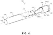
- FIG. 4is a schematic view of the working end of the electrosurgical tissue-cutting device of FIG. 1 showing an outer sleeve with a reciprocating inner cutting sleeve in a partially advanced position.
- FIG. 5is a schematic perspective view of the working end of the inner sleeve of FIG. 4 showing its electrode edge.
- FIG. 6 Ais a schematic cut-away view of a portion of outer sleeve, inner RF cutting sleeve and a tissue-receiving window of the outer sleeve.
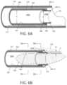
- FIG. 6 Bis a schematic view of a distal end portion another embodiment of inner RF cutting sleeve.
- FIG. 7 Ais a cross sectional view of the inner RF cutting sleeve of FIG. 6 B taken along line 7 A- 7 A of FIG. 6 B .
- FIG. 7 Bis another cross sectional view of the inner RF cutting sleeve of FIG. 6 B taken along line 7 B- 7 B of FIG. 6 B .
- FIG. 8is a schematic view of a distal end portion of another embodiment of inner RF cutting sleeve.
- FIG. 9 Ais a cross sectional view of the RF cutting sleeve of FIG. 8 taken along line 9 A- 9 A of FIG. 8 .
- FIG. 9 Bis a cross sectional view of the RF cutting sleeve of FIG. 8 taken along line 9 B- 9 B of FIG. 8 .
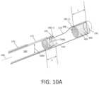
- FIG. 10 Ais an enlarged sectional view of a working end with an RF cutting sleeve in a partially advanced position illustrating fluid volumes that comprise a fluidic pumping mechanism corresponding to the invention for displacement of captured tissue.
- FIG. 10 Bis another enlarged sectional view similar to FIG. 10 A with the RF cutting sleeve in a further advanced position showing how a captured fluid volumes applies fluidic or hydraulic pressure to captured tissue.
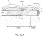
- FIG. 11 Ais a longitudinal sectional view a working end illustrating an electrode edge cutting tissue.
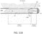
- FIG. 11 Bis a longitudinal sectional view similar to FIG. 11 A illustrating the pumping function of the working end.
- FIG. 12 Ais a cross-section of a sleeve assembly showing a fluid inflow lumen.
- FIG. 12 Bis a cross-section of a sleeve assembly showing an alternative fluid inflow lumen.
- FIG. 12 Cis a cross-section of a sleeve assembly showing an alternative fluid inflow lumen.
- FIG. 13is a sectional view of a variation of cutting sleeve with an inwardly displaced electrode edge.
- FIG. 14is a perspective view of another variation with an exterior sleeve with a distal dielectric body portion.
- FIG. 1illustrates an assembly that comprises an endoscope 50 used for hysteroscopy together with a tissue-extraction device 100 extending through a working channel 102 of the endoscope.
- the endoscope or hysteroscope 50has a handle 104 coupled to an elongated shaft 105 having a diameter of 5 mm to 7 mm.
- the working channel 102 thereinmay be round, D-shaped or any other suitable shape.
- the endoscope shaft 105is further configured with an optics channel 106 and one or more fluid inflow/outflow channels 108 a , 108 b ( FIG.
- the fluid inflow source 120is a component of a fluid management system 126 as is known in the art ( FIG. 2 ) which comprises a fluid container 128 and pump mechanism 130 which pumps fluid through the hysteroscope 50 into the uterine cavity.
- the fluid management system 126further includes the negative pressure source 125 (which can comprise an operating room wall suction source) coupled to the tissue-cutting device 100 .
- the handle 104 of the endoscopeincludes the angled extension portion 132 with optics to which a videoscopic camera 135 can be operatively coupled.
- a light source 136also is coupled to light coupling 138 on the handle of the hysteroscope 50 .
- the working channel 102 of the hysteroscopeis configured for insertion and manipulation of the tissue-cutting and extracting device 100 , for example to treat and remove fibroid tissue.
- the hysteroscope shaft 105has an axial length of 21 cm, and can comprise a 0° scope, or 15° to 30° scope.
- the tissue-cutting device 100has a highly elongated shaft assembly 140 configured to extend through the working channel 102 in the hysteroscope.
- a handle 142 of the tissue-cutting device 100is adapted for manipulating the electrosurgical working end 145 of the device. In use, the handle 142 can be manipulated both rotationally and axially, for example, to orient the working end 145 to cut targeted fibroid tissue.
- the tissue-cutting device 100has subsystems coupled to its handle 142 to enable electrosurgical cutting of targeted tissue.
- a radio frequency generator or RF source 150 and controller 155are coupled to at least one RF electrode carried by the working end 145 as will be described in detail below. In one embodiment shown in FIG.
- an electrical cable 156 and negative pressure source 125are operatively coupled to a connector 158 in handle 142 .
- the electrical cablecouples the RF source 150 to the electrosurgical working end 145 .
- the negative pressure source 125communicates with a tissue-extraction channel 160 in the shaft assembly 140 of the tissue extraction device 100 ( FIG. 4 ).
- FIG. 1further illustrates a seal housing 162 that carries a flexible seal 164 carried by the hysteroscope handle 104 for sealing the shaft 140 of the tissue-cutting device 100 in the working channel 102 to prevent distending fluid from escaping from a uterine cavity.
- the handle 142 of tissue-cutting device 100includes a motor drive 165 for reciprocating or otherwise moving a cutting component of the electrosurgical working end 145 as will be described below.
- the handle 142optionally includes one or more actuator buttons 166 for actuating the device.
- a footswitchcan be used to operate the device.
- the systemincludes a switch or control mechanism to provide a plurality of reciprocation speeds, for example 1 Hz, 2 Hz, 3 Hz, 4 Hz and up to 8 Hz.
- the systemcan include a mechanism for moving and locking the reciprocating cutting sleeve in a non-extended position and in an extended position.
- the systemcan include a mechanism for actuating a single reciprocating stroke.
- an electrosurgical tissue-cutting devicehas an elongate shaft assembly 140 extending about longitudinal axis 168 comprising an exterior or first outer sleeve 170 with passageway or lumen 172 therein that accommodates a second or inner sleeve 175 that can reciprocate (and optionally rotate or oscillate) in lumen 172 to cut tissue as is known in that art of such tubular cutters.
- the tissue-receiving window 176 in the outer sleeve 170has an axial length ranging between 10 mm and 30 mm and extends in a radial angle about outer sleeve 170 from about 45° to 210° relative to axis 168 of the sleeve.
- the windowextends in a radial angle of to 180°—that is, the window cut is one-half of the tube.
- the outer and inner sleeves 170 and 175can comprise a thin-wall stainless steel material and function as opposing polarity electrodes as will be described in detail below.
- FIGS. 6 A- 8illustrate insulative or dielectric layers carried by the outer and inner sleeves 170 and 175 to limit, control and/or prevent unwanted electrical current flows between certain portions of the sleeve.
- a stainless steel outer sleeve 170has an O.D. of 0.143′′ with an I.D. of 0.133′′ and with an inner insulative layer (described below) the sleeve has a nominal I.D. of 0.125′′.
- the stainless steel inner sleeve 175has an O.D. of 0.112′′ with an I.D. of 0.106′′.
- the inner sleeve 175 with an outer insulative layer 202has a nominal O.D. of about 0.120 to reciprocate in lumen 172 .
- outer and or inner sleevescan be fabricated of metal, plastic, ceramic of a combination thereof.
- the cross-section of the sleevescan be round, oval or any other suitable shape.
- the outer sleeveis 17-7 PH stainless steel has an O.D. of 0.140 to 0.143′′ with a wall thickness of 0.005′′ to 0.007′′ and the inner sleeve also is 17-7.
- O.D.0.140 to 0.143′′ with a wall thickness of 0.005′′ to 0.007′′
- the inner sleevealso is 17-7.
- the maximum scope diametershould be about 6.5 mm (0.256′′) which generally may allow for a maximum working channel of about 0.150′′.
- the thin wall tubing and insulation layershave been developed to provide an optimized tissue extraction lumen diameter (given the above scope dimensions and limitations above) that is greater than 0.090′′ or greater than 0.100′′—all accommodated in hysteroscope having a O.D. of 6.5 mm.
- a tissue cutting devicecorresponding to the invention comprises an elongated assembly comprising concentric outer and inner sleeves extending along an axis, a tissue-receiving window in the outer sleeve and a reciprocating inner sleeve having a extraction lumen 160 therein ( FIG. 5 ), and wherein the ratio of the diameter of the extraction lumen 160 to the outer diameter of the outer sleeve is at least 0.65:1 or at least 0.70:1.
- the tissue cutting device and hysteroscope together corresponding to the inventioncomprises an assembly or combination wherein the ratio of the diameter of the extraction lumen 160 to the outer diameter of the hysteroscope to at least 0.35:1 or at least 0.40:1.
- the distal end 177 of inner sleeve 175comprises a first polarity electrode with distal cutting electrode edge 180 about which plasma can be generated.
- the electrode edge 180also can be described as an active electrode during tissue cutting since the electrode edge 180 then has a substantially smaller surface area than the opposing polarity or return electrode.
- the exposed surfaces of outer sleeve 170comprises the second polarity electrode 185 , which thus can be described as the return electrode since during use such an electrode surface has a substantially larger surface area compared to the functionally exposed surface area of the active electrode edge 180 .
- the inner sleeve or cutting sleeve 175has an interior tissue extraction lumen 160 with first and second interior diameters that are adapted to electrosurgically cut tissue volumes rapidly—and thereafter consistently extract the cut tissue strips through the highly elongated lumen 160 without clogging.
- the inner sleeve 175has a first diameter portion 190 A that extends from the handle 142 ( FIG. 1 ) to a distal region 192 of the sleeve 175 wherein the tissue extraction lumen transitions to a smaller second diameter lumen 190 B with a reduced diameter indicated at B which is defined by the electrode sleeve element 195 that provides cutting electrode edge 180 .
- the axial length C of the reduced cross-section lumen 190 Bcan range from about 1 mm to 15 mm.
- the first diameter Ais 0.106′′ and the second reduced diameter B is 0.095′′ and has an axial length of 2 mm.
- the cross-sectional area of the distal lumen portionis less than 95% of cross-sectional area of the proximal lumen portion, or less than 90% of the cross-sectional area of the proximal lumen portion.
- the inner sleeve 175can be an electrically conductive stainless steel and the reduced diameter electrode portion also can comprise a stainless steel electrode sleeve element 195 that is welded in place by weld 196 ( FIG. 6 A ).
- the electrode and reduced diameter electrode sleeve element 195comprises a tungsten tube that can be press fit into the distal end 198 of inner sleeve 175 .
- FIGS. 5 and 6 Afurther illustrates the interfacing insulation layers 202 and 204 carried by the first and second sleeves 170 , 175 , respectively.
- the outer sleeve 170is lined with a thin-wall insulative material 200 , such as PFA, or another material described below.
- the inner sleeve 175has an exterior insulative layer 202 . These coating materials can be lubricious as well as electrically insulative to reduce friction during reciprocation of the inner sleeve 175 .
- the insulative layers 200 and 202 described abovecan comprise a lubricious, hydrophobic or hydrophilic polymeric material.
- the materialcan comprise a bio-compatible material such as PFA, TEFLON®, polytetrafluroethylene (PTFE), FEP (Fluorinated ethylenepropylene), polyethylene, polyamide, ECTFE (Ethylenechlorotrifluoro-ethylene), ETFE, PVDF, polyvinyl chloride or silicone.
- FIG. 6 Banother variation of inner sleeve 175 is illustrated in a schematic view together with a tissue volume being resected with the plasma electrode edge 180 .
- the RF sourceoperates at selected operational parameters to create a plasma around the electrode edge 180 of electrode sleeve 195 as is known in the art.
- the plasma generated at electrode edge 180can cut and ablate a path P in the tissue 220 , and is suited for cutting fibroid tissue and other abnormal uterine tissue.
- the distal portion of the cutting sleeve 175includes a ceramic collar 222 which is adjacent the distal edge 180 of the electrode sleeve 195 .
- the ceramic 222 collarfunctions to confine plasma formation about the distal electrode edge 180 and functions further to prevent plasma from contacting and damaging the polymer insulative layer 202 on the cutting sleeve 175 during operation.
- the path P cut in the tissue 220 with the plasma at electrode edge 180provides a path P having an ablated width indicated at W, wherein such path width W is substantially wide due to tissue vaporization.
- This removal and vaporization of tissue in path Pis substantially different than the effect of cutting similar tissue with a sharp blade edge, as in various prior art devices.
- a sharp blade edgecan divide tissue (without cauterization) but applies mechanical force to the tissue and may prevent a large cross section slug of tissue from being cut.
- the plasma at the electrode edge 180can vaporize a path P in tissue without applying any substantial force on the tissue to thus cut larger cross-sections of strips of tissue.
- the plasma cutting effectreduces the cross section of tissue strip 225 received in the tissue-extraction lumen 190 B.
- FIG. 6 Bdepicts a tissue strip to 225 entering lumen 190 B which has such a smaller cross-section than the lumen due to the vaporization of tissue.
- the cross section of tissue 225 as it enters the larger cross-section lumen 190 Aresults in even greater free space 196 around the tissue strip 225 .
- the resection of tissue with the plasma electrode edge 180together with the lumen transition from the smaller cross-section ( 190 B) to the larger cross-section ( 190 A) of the tissue-extraction lumen 160 can significantly reduce or eliminate the potential for successive resected tissue strips 225 to clog the lumen.
- Prior art resection devices with such small diameter tissue-extraction lumentypically have problems with tissue clogging.
- the negative pressure source 225 coupled to the proximal end of tissue-extraction lumen 160also assists in aspirating and moving tissue strips 225 in the proximal direction to a collection reservoir (not shown) outside the handle 142 of the device.
- FIGS. 7 A- 7 Billustrate the change in lumen diameter of cutting sleeve 175 of FIG. 6 B .
- FIG. 8illustrates the distal end of a variation of cutting sleeve 175 ′ which is configured with an electrode cutting element 195 ′ that is partially tubular in contrast to the previously described tubular electrode element 195 ( FIGS. 5 and 6 A ).
- FIGS. 9 A- 9 Bagain illustrate the change in cross-section of the tissue-extraction lumen between reduced cross-section region 190 B′ and the increased cross-section region 190 A′ of the cutting sleeve 175 ′ of FIG. 8 .
- the functionalityremains the same whether the cutting electrode element 195 ′ is tubular or partly tubular.
- FIG. 8illustrates the distal end of a variation of cutting sleeve 175 ′ which is configured with an electrode cutting element 195 ′ that is partially tubular in contrast to the previously described tubular electrode element 195 ( FIGS. 5 and 6 A ).
- the ceramic collar 222 ′is shown, in one variation, as extending only partially around sleeve 175 to cooperate with the radial angle of cutting electrode element 195 ′. Further, the variation of FIG. 8 illustrates that the ceramic collar 222 ′ has a larger outside diameter than insulative layer 202 . Thus, friction may be reduced since the short axial length of the ceramic collar 222 ′ interfaces and slides against the interfacing insulative layer 200 about the inner surface of lumen 172 of outer sleeve 170 .
- one aspect of the inventioncomprises a tissue cutting and extracting device ( FIGS. 4 A- 4 B ) that includes first and second concentric sleeves having an axis and wherein the second (inner) sleeve 175 has an axially-extending tissue-extraction lumen therein, and wherein the second sleeve 175 is moveable between axially non-extended and extended positions relative to a tissue-receiving window 176 in first sleeve 170 to resect tissue, and wherein the tissue extraction lumen 160 has first and second cross-sections.
- the second sleeve 175has a distal end configured as a plasma electrode edge 180 to resect tissue disposed in tissue-receiving window 176 of the first sleeve 170 . Further, the distal end of the second sleeve, and more particularly, the electrode edge 180 is configured for plasma ablation of a substantially wide path in the tissue.
- the tissue-extraction deviceis configured with a tissue extraction lumen 160 having a distal end portion with a reduced cross-section that is smaller than a cross-section of medial and proximal portions of the lumen 160 .
- the tissue-extraction lumen 160has a reduced cross-sectional area in lumen region 190 A proximate the plasma cutting tip or electrode edge 180 wherein said reduced cross section is less that 95%, 90%, 85% or 80% than the cross sectional area of medial and proximal portions 190 B of the tissue-extraction lumen, and wherein the axial length of the tissue-extraction lumen is from 450 mm to 550 mm for access to a uterine cavity.
- the shaft assembly 140 of the tissue-cutting deviceis 35 cm in length. Devices used for other procedures can have tissue-extraction lumen that are at least 10 cm, 20 cm, 30 cm or 40 cm in length.
- one aspect of the inventioncomprises a “tissue displacement” or pump means that is configured to displace and move tissue strips 225 (see FIGS. 11 A- 11 B ) in the proximal direction in lumen 160 of cutting sleeve 175 to thus ensure that tissue does not clog the lumen of the inner sleeve 175 .
- the pump means as a tissue displacement mechanismcomprises a volume of captured fluid indicated at 400 (phantom outline in FIG. 4 ) that is captured in a terminal chamber 405 of the assembly that is defined by the lumen 172 of outer sleeve and the distal tip or body 232 that is fixedly attached to outer sleeve 170 .
- a tissue cutting devicecomprises an elongated assembly comprising concentric outer and inner sleeves extending along an axis, a tissue-receiving window in the outer sleeve open to an interior lumen that extends to a terminal chamber that is distal to the window, wherein the terminal chamber defines a fluid volume of at least 0.01 mL, at least 0.02 mL or at least 0.04 mL.
- the terminal chamberis cylindrical and has a length to diameter ratio of at least 1:1, or at least 1.5:1.
- the fluid in chamber 405functions as a fluid piston to pump fluid or tissue in cylindrical chamber 410 defined by the electrode sleeve 195 and the adjoining extraction lumen 160 .
- the captured fluid 400can function as a pump and can push a captured tissue strip 225 in the proximal direction from the small cross-section lumen 190 B in electrode sleeve 155 as the cutting or inner sleeve 175 moves to its fully advanced or extended position (see. FIG. 10 B ).
- the above described length L of the terminal chamber 405is at least as great as the axial length E of the small cross-section lumen 190 B in the cutting sleeve 175 .
- the pumping stroke Y of the cutting sleeve 175extends at least about 3 mm, 4 mm or 5 mm distally beyond the distal edge of the window 290 .
- the stroke Y of the cutting sleeve 175is at least 5% or 10% of the total stroke of the cutting sleeve (stroke X+stroke Y in FIG. 11 A ).
- a method of cutting tissue corresponding to the inventioncomprises cutting tissue with a reciprocating cutting sleeve having an extending stroke and a retracting stroke within an outer sleeve, wherein the extending stroke cuts and captures tissue received by a tissue-receiving window in the outer sleeve; and moving the captured tissue proximally in the cutting sleeve with fluidic pressure.
- the fluidic pressureis provided by the captured fluid volume 400 in chamber 405 in reaction to the relative motion of the fluid volume 400 and the cutting sleeve 175 within which a tissue strip 225 is disposed.
- the fluidic pressureis substantially applied when the extending stroke of the sleeve 175 is distal of the window.
- the fluidic pressureis applied by a volume of distending fluid from the fluid-immersed working space that is captured in the closed-end terminal chamber 405 of outer sleeve 170 .
- the methodincludes cutting tissue with an RF plasma at a distal electrode edge 180 of the electrode sleeve 195 .
- the fluidcould be entirely or a partially supplied by a pressurized fluid inflow from a remote source through a flow passageway 415 in outer sleeve 170 as depicted in FIG.
- FIG. 12 Aa flow passageway 416 in inner sleeve 175 as depicted in FIG. 12 B , or a flow passageway 420 formed intermediate the walls of the outer and inner sleeves 170 , 175 as depicted in FIG. 12 C .
- the fluid in chamber 405functions as a fluid piston to pump fluid or tissue in cylindrical chamber 410 defined by the electrode sleeve 195 and the adjoining extraction lumen 160 .
- the captured fluid 400can function as a pump and can push a captured tissue strip 225 in the proximal direction from the small cross-section lumen 190 B in electrode sleeve 155 as the cutting or inner sleeve 175 moves to its fully advanced or extended position (see. FIG. 10 B ).
- the above described length L of the terminal chamber 405is at least as great as the axial length E of the small cross-section lumen 190 B in the cutting sleeve 170 .
- the stroke Y of the cutting sleeve 175extends at least about 3 mm, 4 mm or 5 mm distally beyond the distal edge of the window 290 .
- the stroke Y of the cutting sleeve 175is at least 5% or 10% of the total stroke of the cutting sleeve (stroke X+stroke Y in FIG. 11 A ).
- a method of cutting tissuecomprising cutting tissue with a reciprocating cutting sleeve having an extending stroke and a retracting stroke within an outer sleeve, wherein the extending stroke cuts and captures tissue received by a tissue-receiving window in the outer sleeve, and pushing the captured tissue in the proximal direction in the cutting sleeve with fluidic pressure provided by the captured fluid volume 400 in chamber 405 .
- the fluidic pressure and pump or displacement mechanismis configured to push the captured tissue at least in part from a first smaller cross-section lumen 190 B to a second larger cross-section lumen 190 A in the cutting sleeve 175 . Thereafter, the negative pressure source can more effectively extract and aspirate the tissue from the lumen.
- tissueis cut and extracted by (i) interfacing a probe working end with targeted tissue wherein the working end comprises an elongated outer sleeve with a window exposed to a reciprocating inner sleeve, (ii) extending the inner sleeve in a first cutting stroke distally across the window thereby cutting tissue disposed within the window and (iii) extending the inner sleeve in a second pumping stroke distally beyond the window thereby causing fluidic pressure to pump the tissue proximally in a lumen of the inner sleeve.
- the sequencecan be repeated with the first cutting stroke, the second pumping stroke and the retracting stroke having a rate of at least 1 Hz, 2 Hz or 3 Hz.
- the tissuecan be cut with an electrode edge or a blade edge.
- the terminal chamber 405is configured to capture a fluid volume sufficient to fill said inner sleeve lumen 160 over a length of at least 3 mm, 4 mm or 5 mm.
- the cutting stepcan include applying RF current to generate plasma at an electrode edge 180 on inner sleeve 175 and further comprising the step of terminating RF current at the end of the first cutting stroke.
- the system and controller 155can terminate RF current during the second cutting stroke.
- the controller 155can terminate RF current during the retracting stroke.
- the controllercan apply RF current to the electrodes during at least a portion of the retracting stroke to thereby cauterize adjacent tissue.
- the cautery effectcan be provided during the retracting stroke at the same operational parameters as used during the first cutting stroke, or at different operational RF parameters than used during the first cutting stroke.
- FIGS. 11 A- 11 Billustrate in more detail the functional pump aspects of the invention.
- the reciprocating cutting sleeve 175is shown in a medial position advancing distally wherein plasma at the cutting electrode edge 180 is cutting a tissue strip 225 that is disposed within lumen 160 of the cutting sleeve 175 .
- the distending fluid (saline) 244 from the working spacemigrates through window 176 into terminal chamber 405 to provide the fluid volume that will be captured upon advancement of the cutting sleeve saline.
- FIG. 11 Ait can be seen that the system operates in first electrosurgical mode corresponding to the reciprocation and axial range of motion of cutting sleeve 175 relative to the tissue-receiving window 176 .
- the electrical fields EF of the first modeare indicated in FIG. 11 A .
- the first RF modecan be used over an axial length of travel of inner cutting sleeve 175 as it crosses the tissue-receiving window 176 , or the over both the cutting and pumping strokes, and also optionally the retraction stroke.
- FIG. 11 Billustrates the fluid volume 400 in chamber 405 functioning as a fluid piston and pumping fluid and thus hydraulic or fluidic pressure again tissue strip 225 and moving the tissue proximally relative to the chamber defined by electrode sleeve 195 and the adjoining extraction lumen 160 (cf. FIG. 10 B )
- the working endcomprises first and second converging tissue-contacting edges, 180 and 440 , for cutting tissue engaged by or proximate to such edges.
- a first edgecomprises the electrode edge 180 described previously.
- the second first edge 440comprises an edge of the window 176 that comprises a dielectric or insulative material such as a ceramic of polymeric material.
- the tissue cutting probecomprises first and second concentric sleeves having and axis and configured for relative axial movement between a window-open position for receiving tissue therein and a range of window-closing positions in which the second sleeve cuts tissue in a window in the first sleeve, a motor for providing relative movement of the sleeves, wherein each of said sleeves comprising a tissue-contacting edge for contacting tissue, and wherein the contacting edge of one sleeve comprising an electrode and the contacting edge of the other sleeve comprising a dielectric.
- the tissue cutting probeincludes an electrically insulative layer disposed on at least one interfacing surface of the first and second sleeves. In another variation, the tissue cutting probe has an electrically insulative layer disposed the interfacing surfaces of both the first and second sleeves.
- the interface between the first and second sleevesprovides hydraulic resistance to substantially prevent liquid flow therethrough.
- the electrically insulative layer of one or both sleeves at the interfacecomprises a hydrophilic surface.
- an electrically insulative layercomprises a hydrophobic surface or an ultrahydrophobic surface.
- the electrode-sleevehas a displaced tissue-contacting edge 445 that is displaced dimension DD radially inward from an outer diameter of said second or cutting sleeve 175 .
- the tissue cutting probecomprises first and second concentric sleeves having and axis and configured for relative axial movement between a window-open position for receiving tissue therein and a range of window-closing positions in which the second sleeve cuts tissue in a tissue-receiving window in the first sleeve, a mechanism for providing relative movement of the sleeves, and wherein the second sleeve has a displaced tissue-contacting edge that is displaced selected dimension radially inward from a outer diameter of said second sleeve.
- the edge 444is displaced a dimension DD radially inward of at least 0.003′′.
- the inwardly spaced edgefurther can be configured with a ceramic collar fixed about the exterior of the sleeve proximate to the displaced edge ( FIG. 13 ).
- the working end 145 ′can comprise and outer metal sleeve 170 that is coupled to a dielectric body 450 of a ceramic or polymeric material that comprises a thin-wall structure bonded to sleeve 170 and extends substantially around the perimeter of window 176 and provides the interior terminal fluid chamber described above.
- the dielectric materialprovides further spacing between the first polarity electrode surface of the inner cutting sleeve (see. FIG. 4 ) and the second polarity electrode of the outer sleeve 170 (see FIGS. 4 and 14 ).
- a lower portion 455 of the metal sleevecan remain in place to add strength to the structure.
- At least one aperture 460is provided close to an axially-transverse plane at the distal edge of window 176 . Such an aperture can provide for rapid flow of distention fluid into the terminal chamber. Such at least one aperture will be blocked by sleeve 175 during the pumping stroke (see FIG. 11 B ).
Landscapes
- Health & Medical Sciences (AREA)
- Surgery (AREA)
- Life Sciences & Earth Sciences (AREA)
- Engineering & Computer Science (AREA)
- Biomedical Technology (AREA)
- Public Health (AREA)
- Nuclear Medicine, Radiotherapy & Molecular Imaging (AREA)
- Veterinary Medicine (AREA)
- General Health & Medical Sciences (AREA)
- Heart & Thoracic Surgery (AREA)
- Medical Informatics (AREA)
- Molecular Biology (AREA)
- Animal Behavior & Ethology (AREA)
- Physics & Mathematics (AREA)
- Otolaryngology (AREA)
- Plasma & Fusion (AREA)
- Orthopedic Medicine & Surgery (AREA)
- Electromagnetism (AREA)
- Surgical Instruments (AREA)
Abstract
Description
Claims (20)
Priority Applications (3)
| Application Number | Priority Date | Filing Date | Title |
|---|---|---|---|
| US15/801,687US11832874B2 (en) | 2011-04-11 | 2017-11-02 | Tissue extraction devices and methods |
| US18/496,478US12310649B2 (en) | 2011-04-11 | 2023-10-27 | Tissue extraction devices and methods |
| US19/205,182US20250275806A1 (en) | 2011-04-11 | 2025-05-12 | Tissue extraction devices and methods |
Applications Claiming Priority (5)
| Application Number | Priority Date | Filing Date | Title |
|---|---|---|---|
| US201161474164P | 2011-04-11 | 2011-04-11 | |
| US201161501438P | 2011-06-27 | 2011-06-27 | |
| US13/442,686US9254142B2 (en) | 2011-04-11 | 2012-04-09 | Tissue extraction devices and methods |
| US14/982,593US9827037B2 (en) | 2011-04-11 | 2015-12-29 | Tissue extraction devices and methods |
| US15/801,687US11832874B2 (en) | 2011-04-11 | 2017-11-02 | Tissue extraction devices and methods |
Related Parent Applications (1)
| Application Number | Title | Priority Date | Filing Date |
|---|---|---|---|
| US14/982,593ContinuationUS9827037B2 (en) | 2011-04-11 | 2015-12-29 | Tissue extraction devices and methods |
Related Child Applications (1)
| Application Number | Title | Priority Date | Filing Date |
|---|---|---|---|
| US18/496,478ContinuationUS12310649B2 (en) | 2011-04-11 | 2023-10-27 | Tissue extraction devices and methods |
Publications (2)
| Publication Number | Publication Date |
|---|---|
| US20180132930A1 US20180132930A1 (en) | 2018-05-17 |
| US11832874B2true US11832874B2 (en) | 2023-12-05 |
Family
ID=48136563
Family Applications (5)
| Application Number | Title | Priority Date | Filing Date |
|---|---|---|---|
| US13/442,686Active2034-02-14US9254142B2 (en) | 2011-04-11 | 2012-04-09 | Tissue extraction devices and methods |
| US14/982,593ActiveUS9827037B2 (en) | 2011-04-11 | 2015-12-29 | Tissue extraction devices and methods |
| US15/801,687Active2033-12-16US11832874B2 (en) | 2011-04-11 | 2017-11-02 | Tissue extraction devices and methods |
| US18/496,478ActiveUS12310649B2 (en) | 2011-04-11 | 2023-10-27 | Tissue extraction devices and methods |
| US19/205,182PendingUS20250275806A1 (en) | 2011-04-11 | 2025-05-12 | Tissue extraction devices and methods |
Family Applications Before (2)
| Application Number | Title | Priority Date | Filing Date |
|---|---|---|---|
| US13/442,686Active2034-02-14US9254142B2 (en) | 2011-04-11 | 2012-04-09 | Tissue extraction devices and methods |
| US14/982,593ActiveUS9827037B2 (en) | 2011-04-11 | 2015-12-29 | Tissue extraction devices and methods |
Family Applications After (2)
| Application Number | Title | Priority Date | Filing Date |
|---|---|---|---|
| US18/496,478ActiveUS12310649B2 (en) | 2011-04-11 | 2023-10-27 | Tissue extraction devices and methods |
| US19/205,182PendingUS20250275806A1 (en) | 2011-04-11 | 2025-05-12 | Tissue extraction devices and methods |
Country Status (1)
| Country | Link |
|---|---|
| US (5) | US9254142B2 (en) |
Families Citing this family (43)
| Publication number | Priority date | Publication date | Assignee | Title |
|---|---|---|---|---|
| US9662163B2 (en) | 2008-10-21 | 2017-05-30 | Hermes Innovations Llc | Endometrial ablation devices and systems |
| US8821486B2 (en) | 2009-11-13 | 2014-09-02 | Hermes Innovations, LLC | Tissue ablation systems and methods |
| US8540708B2 (en) | 2008-10-21 | 2013-09-24 | Hermes Innovations Llc | Endometrial ablation method |
| US11896282B2 (en) | 2009-11-13 | 2024-02-13 | Hermes Innovations Llc | Tissue ablation systems and method |
| US8512326B2 (en) | 2011-06-24 | 2013-08-20 | Arqos Surgical, Inc. | Tissue extraction devices and methods |
| US9254142B2 (en)* | 2011-04-11 | 2016-02-09 | Iogyn, Inc. | Tissue extraction devices and methods |
| WO2012178119A2 (en)* | 2011-06-24 | 2012-12-27 | Arqos Surgical, Inc. | Tissue extraction devices and methods |
| US9233193B2 (en) | 2011-06-29 | 2016-01-12 | Iogyn, Inc. | Surgical fluid management systems and methods |
| US9737362B2 (en) | 2011-07-06 | 2017-08-22 | Boston Scientific Scimed, Inc. | Tissue cutting systems and methods |
| US11291351B2 (en)* | 2011-08-19 | 2022-04-05 | Harold I. Daily | Hysteroscopes with curved tips |
| US9439720B2 (en)* | 2011-09-01 | 2016-09-13 | Iogyn, Inc. | Tissue extraction devices and methods |
| US9084847B2 (en) | 2011-09-22 | 2015-07-21 | Iogyn, Inc. | Surgical fluid management systems and methods |
| US9597149B2 (en) | 2011-11-04 | 2017-03-21 | Iogyn, Inc. | Tissue extraction devices and methods |
| US9439677B2 (en) | 2012-01-20 | 2016-09-13 | Iogyn, Inc. | Medical device and methods |
| US9526570B2 (en)* | 2012-10-04 | 2016-12-27 | Cook Medical Technologies Llc | Tissue cutting cap |
| US9498244B2 (en) | 2012-10-19 | 2016-11-22 | Iogyn, Inc. | Medical systems and methods |
| WO2014168985A1 (en) | 2013-04-08 | 2014-10-16 | Iogyn, Inc | Medical systems and methods |
| US9486233B2 (en) | 2013-04-26 | 2016-11-08 | Iogyn, Inc. | Tissue resecting systems and methods |
| CN103271757B (en)* | 2013-06-19 | 2015-02-25 | 中国人民解放军第三军医大学第三附属医院 | Cervix conization device |
| US9649125B2 (en) | 2013-10-15 | 2017-05-16 | Hermes Innovations Llc | Laparoscopic device |
| US9943639B2 (en) | 2013-10-28 | 2018-04-17 | Boston Scientific Scimed, Inc. | Fluid management system and methods |
| US10398461B2 (en)* | 2013-11-08 | 2019-09-03 | The Cleveland Clinic Foundation | Excising endocap |
| US20160095615A1 (en)* | 2014-10-01 | 2016-04-07 | Hermes Innovations, LLC | Surgical device and method of use |
| CN107405077B (en)* | 2015-02-18 | 2023-10-20 | 莱彻韦斯科勒公司 | Radiofrequency guidewire with controlled plasma generation and method of use thereof |
| JP6706611B2 (en)* | 2015-03-20 | 2020-06-10 | テルモ株式会社 | Catheter system and treatment method |
| CN107708591B (en) | 2015-04-29 | 2020-09-29 | 席勒斯科技有限公司 | Medical ablation device and method of use |
| US10178942B2 (en) | 2015-08-27 | 2019-01-15 | Boston Scientific Scimed, Inc. | Fluid management systems and methods |
| WO2017035205A1 (en) | 2015-08-27 | 2017-03-02 | Boston Scientific Scimed, Inc. | Tissue resecting device |
| EP3340852A2 (en) | 2015-08-27 | 2018-07-04 | Boston Scientific Scimed Inc. | Medical devices and methods |
| GB201600202D0 (en)* | 2016-01-06 | 2016-02-17 | Gyrus Medical Ltd | Electrosurgical apparatus |
| US10052149B2 (en) | 2016-01-20 | 2018-08-21 | RELIGN Corporation | Arthroscopic devices and methods |
| CN109561899A (en) | 2016-04-22 | 2019-04-02 | 锐凌公司 | Arthroscope device and method |
| US10405875B2 (en) | 2016-05-05 | 2019-09-10 | Misonix, Incorporated | Ultrasonic surgical instrument and method for manufacturing same |
| CN109661209A (en) | 2016-07-01 | 2019-04-19 | 锐凌公司 | Arthroscope device and method |
| US11622786B2 (en) | 2019-03-27 | 2023-04-11 | Gyrus Acmi, Inc. | Planar alignment for asymmetric cutting members |
| US11554214B2 (en) | 2019-06-26 | 2023-01-17 | Meditrina, Inc. | Fluid management system |
| EP3989795A1 (en) | 2019-06-27 | 2022-05-04 | Boston Scientific Scimed, Inc. | Detection of an endoscope to a fluid management system |
| JP7519447B2 (en) | 2020-01-30 | 2024-07-19 | ボストン サイエンティフィック サイムド,インコーポレイテッド | Fluid management system and method for controlling intraluminal pressure - Patents.com |
| US12279787B2 (en) | 2020-02-27 | 2025-04-22 | Misonix, Llc | Spinal surgery method |
| US12161389B2 (en)* | 2020-07-15 | 2024-12-10 | RELIGN Corporation | Arthroscopic devices and methods |
| CA3195337A1 (en)* | 2020-10-25 | 2022-04-28 | Dan Voic | Spinal surgery apparatus |
| US20220409268A1 (en)* | 2021-06-25 | 2022-12-29 | Medtronic Advanced Energy Llc | Monopolar plasma curette electrosurgical device |
| US12402905B2 (en) | 2021-08-13 | 2025-09-02 | Misonix, Llc | Serrated ultrasonic cutting blade with varied tooth pitch |
Citations (65)
| Publication number | Priority date | Publication date | Assignee | Title |
|---|---|---|---|---|
| US3850162A (en) | 1972-07-03 | 1974-11-26 | J Iglesias | Endoscope with continuous irrigation |
| US3945375A (en) | 1972-04-04 | 1976-03-23 | Surgical Design Corporation | Rotatable surgical instrument |
| US4203444A (en) | 1977-11-07 | 1980-05-20 | Dyonics, Inc. | Surgical instrument suitable for closed surgery such as of the knee |
| US4369768A (en) | 1980-07-30 | 1983-01-25 | Marko Vukovic | Arthroscope |
| US4606330A (en) | 1983-08-09 | 1986-08-19 | Richard Wolf Gmbh | Device for disintegrating stones in bodily cavities or ducts |
| US4955882A (en) | 1988-03-30 | 1990-09-11 | Hakky Said I | Laser resectoscope with mechanical and laser cutting means |
| US4998527A (en) | 1989-07-27 | 1991-03-12 | Percutaneous Technologies Inc. | Endoscopic abdominal, urological, and gynecological tissue removing device |
| US5009656A (en) | 1989-08-17 | 1991-04-23 | Mentor O&O Inc. | Bipolar electrosurgical instrument |
| US5080660A (en) | 1990-05-11 | 1992-01-14 | Applied Urology, Inc. | Electrosurgical electrode |
| US5106364A (en) | 1989-07-07 | 1992-04-21 | Kabushiki Kaisha Topcon | Surgical cutter |
| US5169397A (en) | 1990-02-08 | 1992-12-08 | Olympus Optical Co., Ltd. | Medical instrument |
| US5195541A (en) | 1991-10-18 | 1993-03-23 | Obenchain Theodore G | Method of performing laparoscopic lumbar discectomy |
| US5217479A (en) | 1991-02-14 | 1993-06-08 | Linvatec Corporation | Surgical cutting instrument |
| US5312399A (en) | 1992-09-29 | 1994-05-17 | Hakky Said I | Laser resectoscope with mechanical cutting means and laser coagulating means |
| US5320091A (en) | 1992-04-27 | 1994-06-14 | Circon Corporation | Continuous flow hysteroscope |
| US5456689A (en) | 1993-10-13 | 1995-10-10 | Arnold J. Kresch | Method and device for tissue resection |
| US5697281A (en) | 1991-10-09 | 1997-12-16 | Arthrocare Corporation | System and method for electrosurgical cutting and ablation |
| US5730752A (en) | 1996-10-29 | 1998-03-24 | Femrx, Inc. | Tubular surgical cutters having aspiration flow control ports |
| US5759185A (en) | 1994-10-24 | 1998-06-02 | Smith & Nephew, Inc. | Surgical instrument |
| US5873886A (en) | 1995-04-04 | 1999-02-23 | United States Surgical Corporation | Surgical cutting apparatus |
| US5885277A (en) | 1994-07-15 | 1999-03-23 | Olympus Winter & Ibe Gmbh | High-frequency surgical instrument for minimally invasive surgery |
| US5906615A (en) | 1997-03-31 | 1999-05-25 | Femrx, Inc. | Serpentine ablation/coagulation electrode |
| US5919181A (en)* | 1994-07-18 | 1999-07-06 | The Procter & Gamble Company | Pre-folded absorbent articles having improved fit |
| US5941876A (en) | 1996-03-11 | 1999-08-24 | Medical Scientific, Inc. | Electrosurgical rotating cutting device |
| US5997534A (en) | 1998-06-08 | 1999-12-07 | Tu; Hosheng | Medical ablation device and methods thereof |
| US6004319A (en) | 1995-06-23 | 1999-12-21 | Gyrus Medical Limited | Electrosurgical instrument |
| US6024751A (en) | 1997-04-11 | 2000-02-15 | Coherent Inc. | Method and apparatus for transurethral resection of the prostate |
| US6032673A (en) | 1994-10-13 | 2000-03-07 | Femrx, Inc. | Methods and devices for tissue removal |
| US6090106A (en) | 1996-01-09 | 2000-07-18 | Gyrus Medical Limited | Electrosurgical instrument |
| US6113594A (en) | 1996-07-02 | 2000-09-05 | Ethicon, Inc. | Systems, methods and apparatus for performing resection/ablation in a conductive medium |
| US6149620A (en) | 1995-11-22 | 2000-11-21 | Arthrocare Corporation | System and methods for electrosurgical tissue treatment in the presence of electrically conductive fluid |
| US6159160A (en) | 1998-03-26 | 2000-12-12 | Ethicon, Inc. | System and method for controlled infusion and pressure monitoring |
| US6245084B1 (en) | 1998-10-20 | 2001-06-12 | Promex, Inc. | System for controlling a motor driven surgical cutting instrument |
| US6293942B1 (en) | 1995-06-23 | 2001-09-25 | Gyrus Medical Limited | Electrosurgical generator method |
| US6494881B1 (en)* | 1997-09-30 | 2002-12-17 | Scimed Life Systems, Inc. | Apparatus and method for electrode-surgical tissue removal having a selectively insulated electrode |
| US20040230190A1 (en) | 1998-08-11 | 2004-11-18 | Arthrocare Corporation | Electrosurgical apparatus and methods for tissue treatment and removal |
| US6832996B2 (en) | 1995-06-07 | 2004-12-21 | Arthrocare Corporation | Electrosurgical systems and methods for treating tissue |
| US6979332B2 (en) | 2003-11-04 | 2005-12-27 | Medtronic, Inc. | Surgical micro-resecting instrument with electrocautery and continuous aspiration features |
| US20060047240A1 (en) | 2004-08-27 | 2006-03-02 | Atul Kumar | Controlled tissue cavity distending system with minimal turbulence |
| US20060122557A1 (en) | 2004-08-27 | 2006-06-08 | Atul Kumar | Tissue cavity distending system with low turbulence |
| US20060122556A1 (en) | 2004-08-27 | 2006-06-08 | Atul Kumar | Low turbulence fluid management system for endoscopic procedures |
| US20070021713A1 (en) | 2004-01-19 | 2007-01-25 | Atul Kumar | System for distending body tissue cavities by continuous flow irrigation |
| US7226459B2 (en) | 2001-10-26 | 2007-06-05 | Smith & Nephew, Inc. | Reciprocating rotary arthroscopic surgical instrument |
| US7244256B2 (en) | 2004-06-10 | 2007-07-17 | Linvatec Corporation | Electrosurgical device with adhesive-free insulating piece and method of making same |
| US7249602B1 (en) | 1997-09-04 | 2007-07-31 | Smith & Nephew, Inc. | Surgical endoscopic cutting device and method for its use |
| US20080021447A1 (en) | 1998-08-11 | 2008-01-24 | Arthrocare Corporation | Instrument for electrosurgical tissue treatment |
| US20080051708A1 (en) | 2006-08-24 | 2008-02-28 | Alka Kumar | Surgical aspiration system and method of surgical aspiration |
| US20080091071A1 (en) | 2006-10-11 | 2008-04-17 | Alka Kumar | System for evacuating detached tissue in continuous flow irrigation endoscopic procedures |
| US20080091074A1 (en) | 2006-10-11 | 2008-04-17 | Alka Kumar | Efficient continuous flow irrigation endoscope |
| US20080097468A1 (en) | 2006-10-18 | 2008-04-24 | Adams Ronald D | Systems for performing gynecological procedures with closed visualization lumen |
| US20080249366A1 (en) | 2007-04-06 | 2008-10-09 | William Harwick Gruber | System for use in performing a medical procedure and introducer device suitable for use in said system |
| US20080249553A1 (en) | 2007-04-06 | 2008-10-09 | William Harwick Gruber | Method, system and device for tissue removal |
| US20090270896A1 (en) | 2007-04-06 | 2009-10-29 | Interlace Medical, Inc. | Tissue cutter with differential hardness |
| US20090270812A1 (en) | 2007-04-06 | 2009-10-29 | Interlace Medical , Inc. | Access device with enhanced working channel |
| US7678070B2 (en) | 2004-11-30 | 2010-03-16 | Atul Kumar | System of dampening pressure pulsations caused by a positive displacement pump in endoscopic surgery |
| US7901403B2 (en) | 2006-03-02 | 2011-03-08 | Arthrocare Corporation | Internally located return electrode electrosurgical apparatus, system and method |
| US20120010464A1 (en) | 2009-11-13 | 2012-01-12 | Hologic, Inc. | Access system with removable outflow channel |
| US20120172889A1 (en) | 2011-01-05 | 2012-07-05 | Hologic, Inc. | Tissue removal system |
| US20120172888A1 (en) | 2010-12-30 | 2012-07-05 | Hologic, Inc. | Hysteroscopic tissue removal system with improved fluid management and/or monitoring capabilities |
| US8226549B2 (en) | 2006-10-11 | 2012-07-24 | Alka Kumar | Efficient continuous flow irrigation system |
| US8267934B2 (en) | 2005-04-13 | 2012-09-18 | Stryker Corporation | Electrosurgical tool |
| US8308726B2 (en) | 2004-09-03 | 2012-11-13 | Atul Kumar | Electromagnetically controlled tissue cavity distending system |
| US20130046316A1 (en) | 2011-08-18 | 2013-02-21 | Hologic, Inc. | Tissue removal system |
| US8460178B2 (en) | 2004-11-30 | 2013-06-11 | Atul Kumar | Method and system for minimizing leakage of a distending medium during endoscopic procedures |
| US9254142B2 (en)* | 2011-04-11 | 2016-02-09 | Iogyn, Inc. | Tissue extraction devices and methods |
- 2012
- 2012-04-09USUS13/442,686patent/US9254142B2/enactiveActive
- 2015
- 2015-12-29USUS14/982,593patent/US9827037B2/enactiveActive
- 2017
- 2017-11-02USUS15/801,687patent/US11832874B2/enactiveActive
- 2023
- 2023-10-27USUS18/496,478patent/US12310649B2/enactiveActive
- 2025
- 2025-05-12USUS19/205,182patent/US20250275806A1/enactivePending
Patent Citations (94)
| Publication number | Priority date | Publication date | Assignee | Title |
|---|---|---|---|---|
| US3945375A (en) | 1972-04-04 | 1976-03-23 | Surgical Design Corporation | Rotatable surgical instrument |
| US3850162A (en) | 1972-07-03 | 1974-11-26 | J Iglesias | Endoscope with continuous irrigation |
| US4203444A (en) | 1977-11-07 | 1980-05-20 | Dyonics, Inc. | Surgical instrument suitable for closed surgery such as of the knee |
| US4203444B1 (en) | 1977-11-07 | 1987-07-21 | ||
| US4369768A (en) | 1980-07-30 | 1983-01-25 | Marko Vukovic | Arthroscope |
| US4606330A (en) | 1983-08-09 | 1986-08-19 | Richard Wolf Gmbh | Device for disintegrating stones in bodily cavities or ducts |
| US4955882A (en) | 1988-03-30 | 1990-09-11 | Hakky Said I | Laser resectoscope with mechanical and laser cutting means |
| US5106364A (en) | 1989-07-07 | 1992-04-21 | Kabushiki Kaisha Topcon | Surgical cutter |
| US4998527A (en) | 1989-07-27 | 1991-03-12 | Percutaneous Technologies Inc. | Endoscopic abdominal, urological, and gynecological tissue removing device |
| US5009656A (en) | 1989-08-17 | 1991-04-23 | Mentor O&O Inc. | Bipolar electrosurgical instrument |
| US5169397A (en) | 1990-02-08 | 1992-12-08 | Olympus Optical Co., Ltd. | Medical instrument |
| US5080660A (en) | 1990-05-11 | 1992-01-14 | Applied Urology, Inc. | Electrosurgical electrode |
| US5217479A (en) | 1991-02-14 | 1993-06-08 | Linvatec Corporation | Surgical cutting instrument |
| US5697281A (en) | 1991-10-09 | 1997-12-16 | Arthrocare Corporation | System and method for electrosurgical cutting and ablation |
| US5195541A (en) | 1991-10-18 | 1993-03-23 | Obenchain Theodore G | Method of performing laparoscopic lumbar discectomy |
| US5320091A (en) | 1992-04-27 | 1994-06-14 | Circon Corporation | Continuous flow hysteroscope |
| US5312399A (en) | 1992-09-29 | 1994-05-17 | Hakky Said I | Laser resectoscope with mechanical cutting means and laser coagulating means |
| US5456689A (en) | 1993-10-13 | 1995-10-10 | Arnold J. Kresch | Method and device for tissue resection |
| US5527331A (en) | 1993-10-13 | 1996-06-18 | Femrx | Method for prostatic tissue resection |
| US5885277A (en) | 1994-07-15 | 1999-03-23 | Olympus Winter & Ibe Gmbh | High-frequency surgical instrument for minimally invasive surgery |
| US5919181A (en)* | 1994-07-18 | 1999-07-06 | The Procter & Gamble Company | Pre-folded absorbent articles having improved fit |
| US6032673A (en) | 1994-10-13 | 2000-03-07 | Femrx, Inc. | Methods and devices for tissue removal |
| US5759185A (en) | 1994-10-24 | 1998-06-02 | Smith & Nephew, Inc. | Surgical instrument |
| US5873886A (en) | 1995-04-04 | 1999-02-23 | United States Surgical Corporation | Surgical cutting apparatus |
| US6832996B2 (en) | 1995-06-07 | 2004-12-21 | Arthrocare Corporation | Electrosurgical systems and methods for treating tissue |
| US6293942B1 (en) | 1995-06-23 | 2001-09-25 | Gyrus Medical Limited | Electrosurgical generator method |
| US6004319A (en) | 1995-06-23 | 1999-12-21 | Gyrus Medical Limited | Electrosurgical instrument |
| US6056746A (en) | 1995-06-23 | 2000-05-02 | Gyrus Medical Limited | Electrosurgical instrument |
| US6149620A (en) | 1995-11-22 | 2000-11-21 | Arthrocare Corporation | System and methods for electrosurgical tissue treatment in the presence of electrically conductive fluid |
| US6090106A (en) | 1996-01-09 | 2000-07-18 | Gyrus Medical Limited | Electrosurgical instrument |
| US5941876A (en) | 1996-03-11 | 1999-08-24 | Medical Scientific, Inc. | Electrosurgical rotating cutting device |
| US6113594A (en) | 1996-07-02 | 2000-09-05 | Ethicon, Inc. | Systems, methods and apparatus for performing resection/ablation in a conductive medium |
| US5730752A (en) | 1996-10-29 | 1998-03-24 | Femrx, Inc. | Tubular surgical cutters having aspiration flow control ports |
| US5906615A (en) | 1997-03-31 | 1999-05-25 | Femrx, Inc. | Serpentine ablation/coagulation electrode |
| US6024751A (en) | 1997-04-11 | 2000-02-15 | Coherent Inc. | Method and apparatus for transurethral resection of the prostate |
| US8061359B2 (en) | 1997-09-04 | 2011-11-22 | Smith & Nephew, Inc. | Surgical endoscopic cutting device and method for its use |
| US20140074136A1 (en) | 1997-09-04 | 2014-03-13 | Smith & Nephew, Inc. | Surgical cutting device and method for its use |
| US20120197280A1 (en) | 1997-09-04 | 2012-08-02 | Smith & Nephew, Inc. | Surgical endoscopic cutting device and method for its use |
| US7249602B1 (en) | 1997-09-04 | 2007-07-31 | Smith & Nephew, Inc. | Surgical endoscopic cutting device and method for its use |
| US20080058588A1 (en) | 1997-09-04 | 2008-03-06 | Smith & Nephew, Inc. | Surgical endoscopic cutting device and method for its use |
| US20080058842A1 (en) | 1997-09-04 | 2008-03-06 | Smith & Nephew, Inc. | Surgical endoscopic cutting device and method for its use |
| US20150012023A1 (en) | 1997-09-04 | 2015-01-08 | Smith & Nephew, Inc. | Surgical endoscopic cutting device and method for its use |
| US8893722B2 (en) | 1997-09-04 | 2014-11-25 | Smith & Nephew, Inc. | Surgical endoscopic cutting device and method for its use |
| US6494881B1 (en)* | 1997-09-30 | 2002-12-17 | Scimed Life Systems, Inc. | Apparatus and method for electrode-surgical tissue removal having a selectively insulated electrode |
| US6159160A (en) | 1998-03-26 | 2000-12-12 | Ethicon, Inc. | System and method for controlled infusion and pressure monitoring |
| US5997534A (en) | 1998-06-08 | 1999-12-07 | Tu; Hosheng | Medical ablation device and methods thereof |
| US8663216B2 (en) | 1998-08-11 | 2014-03-04 | Paul O. Davison | Instrument for electrosurgical tissue treatment |
| US20040230190A1 (en) | 1998-08-11 | 2004-11-18 | Arthrocare Corporation | Electrosurgical apparatus and methods for tissue treatment and removal |
| US20080021447A1 (en) | 1998-08-11 | 2008-01-24 | Arthrocare Corporation | Instrument for electrosurgical tissue treatment |
| US6245084B1 (en) | 1998-10-20 | 2001-06-12 | Promex, Inc. | System for controlling a motor driven surgical cutting instrument |
| US6358263B2 (en) | 1998-10-20 | 2002-03-19 | Promex, Inc. | System for controlling a motor driven surgical cutting instrument |
| US7226459B2 (en) | 2001-10-26 | 2007-06-05 | Smith & Nephew, Inc. | Reciprocating rotary arthroscopic surgical instrument |
| US6979332B2 (en) | 2003-11-04 | 2005-12-27 | Medtronic, Inc. | Surgical micro-resecting instrument with electrocautery and continuous aspiration features |
| US20070021713A1 (en) | 2004-01-19 | 2007-01-25 | Atul Kumar | System for distending body tissue cavities by continuous flow irrigation |
| US8652089B2 (en) | 2004-01-19 | 2014-02-18 | Arthrex, Inc. | System for distending body tissue cavities by continuous flow irrigation |
| US7244256B2 (en) | 2004-06-10 | 2007-07-17 | Linvatec Corporation | Electrosurgical device with adhesive-free insulating piece and method of making same |
| US20060047240A1 (en) | 2004-08-27 | 2006-03-02 | Atul Kumar | Controlled tissue cavity distending system with minimal turbulence |
| US20060122557A1 (en) | 2004-08-27 | 2006-06-08 | Atul Kumar | Tissue cavity distending system with low turbulence |
| US20060122556A1 (en) | 2004-08-27 | 2006-06-08 | Atul Kumar | Low turbulence fluid management system for endoscopic procedures |
| US8591464B2 (en) | 2004-08-27 | 2013-11-26 | Atul Kumar | Low turbulence fluid management system for endoscopic procedures |
| US8512283B2 (en) | 2004-08-27 | 2013-08-20 | Atul Kumar | Tissue cavity distending system with low turbulence |
| US8388570B2 (en) | 2004-08-27 | 2013-03-05 | Atul Kumar | Controlled tissue cavity distending system with minimal turbulence |
| US8308726B2 (en) | 2004-09-03 | 2012-11-13 | Atul Kumar | Electromagnetically controlled tissue cavity distending system |
| US7678070B2 (en) | 2004-11-30 | 2010-03-16 | Atul Kumar | System of dampening pressure pulsations caused by a positive displacement pump in endoscopic surgery |
| US8460178B2 (en) | 2004-11-30 | 2013-06-11 | Atul Kumar | Method and system for minimizing leakage of a distending medium during endoscopic procedures |
| US8267934B2 (en) | 2005-04-13 | 2012-09-18 | Stryker Corporation | Electrosurgical tool |
| US7901403B2 (en) | 2006-03-02 | 2011-03-08 | Arthrocare Corporation | Internally located return electrode electrosurgical apparatus, system and method |
| US20080051708A1 (en) | 2006-08-24 | 2008-02-28 | Alka Kumar | Surgical aspiration system and method of surgical aspiration |
| US7918822B2 (en) | 2006-08-24 | 2011-04-05 | Alka Kumar | Surgical aspiration system and method of surgical aspiration |
| US20080091071A1 (en) | 2006-10-11 | 2008-04-17 | Alka Kumar | System for evacuating detached tissue in continuous flow irrigation endoscopic procedures |
| US8226549B2 (en) | 2006-10-11 | 2012-07-24 | Alka Kumar | Efficient continuous flow irrigation system |
| US20120271110A1 (en) | 2006-10-11 | 2012-10-25 | Alka Kumar | Efficient continuous flow irrigation system |
| US20080091074A1 (en) | 2006-10-11 | 2008-04-17 | Alka Kumar | Efficient continuous flow irrigation endoscope |
| US20080097471A1 (en) | 2006-10-18 | 2008-04-24 | Adams Ronald D | Systems for performing gynecological procedures with simultaneous tissue cutting and removal |
| US8840625B2 (en) | 2006-10-18 | 2014-09-23 | Hologic, Inc. | Systems for performing gynecological procedures with closed visualization lumen |
| US8840626B2 (en) | 2006-10-18 | 2014-09-23 | Hologic, Inc. | Systems for performing gynecological procedures with simultaneous tissue cutting and removal |
| US20080097468A1 (en) | 2006-10-18 | 2008-04-24 | Adams Ronald D | Systems for performing gynecological procedures with closed visualization lumen |
| US20080249553A1 (en) | 2007-04-06 | 2008-10-09 | William Harwick Gruber | Method, system and device for tissue removal |
| US20080249366A1 (en) | 2007-04-06 | 2008-10-09 | William Harwick Gruber | System for use in performing a medical procedure and introducer device suitable for use in said system |
| US8951274B2 (en) | 2007-04-06 | 2015-02-10 | Hologic, Inc. | Methods of high rate, low profile tissue removal |
| US20090270898A1 (en) | 2007-04-06 | 2009-10-29 | Interlace Medical, Inc. | Tissue removal device with high reciprocation rate |
| WO2010127174A1 (en) | 2007-04-06 | 2010-11-04 | Interlace Medical, Inc. | Tissue removal device with high reciprocation rate |
| US8574253B2 (en) | 2007-04-06 | 2013-11-05 | Hologic, Inc. | Method, system and device for tissue removal |
| US20090270812A1 (en) | 2007-04-06 | 2009-10-29 | Interlace Medical , Inc. | Access device with enhanced working channel |
| US20090270896A1 (en) | 2007-04-06 | 2009-10-29 | Interlace Medical, Inc. | Tissue cutter with differential hardness |
| US20090270897A1 (en)* | 2007-04-06 | 2009-10-29 | Interlace Medical, Inc. | Methods of high rate, low profile tissue removal |
| US20090270895A1 (en) | 2007-04-06 | 2009-10-29 | Interlace Medical, Inc. | Low advance ratio, high reciprocation rate tissue removal device |
| US20120010464A1 (en) | 2009-11-13 | 2012-01-12 | Hologic, Inc. | Access system with removable outflow channel |
| US20120172888A1 (en) | 2010-12-30 | 2012-07-05 | Hologic, Inc. | Hysteroscopic tissue removal system with improved fluid management and/or monitoring capabilities |
| US8568424B2 (en) | 2010-12-30 | 2013-10-29 | Hologic, Inc. | Hysteroscopic tissue removal system with improved fluid management and/or monitoring capabilities |
| US20120172889A1 (en) | 2011-01-05 | 2012-07-05 | Hologic, Inc. | Tissue removal system |
| US9254142B2 (en)* | 2011-04-11 | 2016-02-09 | Iogyn, Inc. | Tissue extraction devices and methods |
| US9827037B2 (en)* | 2011-04-11 | 2017-11-28 | Boston Scientific Scimed, Inc. | Tissue extraction devices and methods |
| US20130046316A1 (en) | 2011-08-18 | 2013-02-21 | Hologic, Inc. | Tissue removal system |
Also Published As
| Publication number | Publication date |
|---|---|
| US20240130779A1 (en) | 2024-04-25 |
| US20160106497A1 (en) | 2016-04-21 |
| US20250275806A1 (en) | 2025-09-04 |
| US20130103021A1 (en) | 2013-04-25 |
| US20180132930A1 (en) | 2018-05-17 |
| US9827037B2 (en) | 2017-11-28 |
| US9254142B2 (en) | 2016-02-09 |
| US12310649B2 (en) | 2025-05-27 |
| US20240225720A9 (en) | 2024-07-11 |
Similar Documents
| Publication | Publication Date | Title |
|---|---|---|
| US12310649B2 (en) | Tissue extraction devices and methods | |
| US12419682B2 (en) | Tissue extraction devices and methods | |
| US11350985B2 (en) | Medical device and methods | |
| US12402939B2 (en) | Tissue resecting device and methods |
Legal Events
| Date | Code | Title | Description |
|---|---|---|---|
| FEPP | Fee payment procedure | Free format text:ENTITY STATUS SET TO UNDISCOUNTED (ORIGINAL EVENT CODE: BIG.); ENTITY STATUS OF PATENT OWNER: LARGE ENTITY | |
| STPP | Information on status: patent application and granting procedure in general | Free format text:DOCKETED NEW CASE - READY FOR EXAMINATION | |
| STPP | Information on status: patent application and granting procedure in general | Free format text:NON FINAL ACTION MAILED | |
| STPP | Information on status: patent application and granting procedure in general | Free format text:RESPONSE TO NON-FINAL OFFICE ACTION ENTERED AND FORWARDED TO EXAMINER | |
| AS | Assignment | Owner name:MINERVA SURGICAL, INC., CALIFORNIA Free format text:ASSIGNMENT OF ASSIGNORS INTEREST;ASSIGNOR:BOSTON SCIENTIFIC SCIMED, INC.;REEL/FRAME:053265/0675 Effective date:20200429 | |
| STPP | Information on status: patent application and granting procedure in general | Free format text:RESPONSE AFTER FINAL ACTION FORWARDED TO EXAMINER | |
| STPP | Information on status: patent application and granting procedure in general | Free format text:DOCKETED NEW CASE - READY FOR EXAMINATION | |
| STPP | Information on status: patent application and granting procedure in general | Free format text:NON FINAL ACTION MAILED | |
| AS | Assignment | Owner name:CANADIAN IMPERIAL BANK OF COMMERCE, CANADA Free format text:SECURITY INTEREST;ASSIGNOR:MINERVA SURGICAL, INC.;REEL/FRAME:057758/0137 Effective date:20211008 | |
| STPP | Information on status: patent application and granting procedure in general | Free format text:RESPONSE TO NON-FINAL OFFICE ACTION ENTERED AND FORWARDED TO EXAMINER | |
| STPP | Information on status: patent application and granting procedure in general | Free format text:FINAL REJECTION MAILED | |
| STPP | Information on status: patent application and granting procedure in general | Free format text:RESPONSE AFTER FINAL ACTION FORWARDED TO EXAMINER | |
| STPP | Information on status: patent application and granting procedure in general | Free format text:ADVISORY ACTION MAILED | |
| STPP | Information on status: patent application and granting procedure in general | Free format text:RESPONSE TO NON-FINAL OFFICE ACTION ENTERED AND FORWARDED TO EXAMINER | |
| STPP | Information on status: patent application and granting procedure in general | Free format text:NON FINAL ACTION MAILED | |
| STPP | Information on status: patent application and granting procedure in general | Free format text:FINAL REJECTION MAILED | |
| STPP | Information on status: patent application and granting procedure in general | Free format text:NOTICE OF ALLOWANCE MAILED -- APPLICATION RECEIVED IN OFFICE OF PUBLICATIONS | |
| STPP | Information on status: patent application and granting procedure in general | Free format text:PUBLICATIONS -- ISSUE FEE PAYMENT VERIFIED | |
| STCF | Information on status: patent grant | Free format text:PATENTED CASE |