US11832873B2 - Cannulas for radio frequency ablation - Google Patents
Cannulas for radio frequency ablationDownload PDFInfo
- Publication number
- US11832873B2 US11832873B2US16/896,340US202016896340AUS11832873B2US 11832873 B2US11832873 B2US 11832873B2US 202016896340 AUS202016896340 AUS 202016896340AUS 11832873 B2US11832873 B2US 11832873B2
- Authority
- US
- United States
- Prior art keywords
- tip
- cannula
- distal end
- approximately
- ablation
- Prior art date
- Legal status (The legal status is an assumption and is not a legal conclusion. Google has not performed a legal analysis and makes no representation as to the accuracy of the status listed.)
- Active, expires
Links
- 241001631457CannulaSpecies0.000titledescription7
- 238000007674radiofrequency ablationMethods0.000titledescription5
- 238000002679ablationMethods0.000claimsabstractdescription27
- 239000003814drugSubstances0.000claimsabstractdescription14
- 229940079593drugDrugs0.000claimsabstractdescription13
- 239000000463materialSubstances0.000claimsabstractdescription12
- 239000012530fluidSubstances0.000claimsabstractdescription10
- 238000003780insertionMethods0.000claimsabstractdescription5
- 230000037431insertionEffects0.000claimsabstractdescription5
- 230000003902lesionEffects0.000claimsdescription6
- 229910052710siliconInorganic materials0.000claimsdescription4
- 239000010703siliconSubstances0.000claimsdescription4
- 239000002184metalSubstances0.000claims1
- 210000003462veinAnatomy0.000abstractdescription4
- 238000009413insulationMethods0.000description6
- 230000003444anaesthetic effectEffects0.000description2
- 150000003431steroidsChemical class0.000description2
- 210000004204blood vesselAnatomy0.000description1
- 238000000034methodMethods0.000description1
- 210000005036nerveAnatomy0.000description1
- 229910001000nickel titaniumInorganic materials0.000description1
- 230000001902propagating effectEffects0.000description1
- 239000010935stainless steelSubstances0.000description1
- 229910001220stainless steelInorganic materials0.000description1
Images


Classifications
- A—HUMAN NECESSITIES
- A61—MEDICAL OR VETERINARY SCIENCE; HYGIENE
- A61B—DIAGNOSIS; SURGERY; IDENTIFICATION
- A61B18/00—Surgical instruments, devices or methods for transferring non-mechanical forms of energy to or from the body
- A61B18/04—Surgical instruments, devices or methods for transferring non-mechanical forms of energy to or from the body by heating
- A61B18/12—Surgical instruments, devices or methods for transferring non-mechanical forms of energy to or from the body by heating by passing a current through the tissue to be heated, e.g. high-frequency current
- A61B18/14—Probes or electrodes therefor
- A61B18/1477—Needle-like probes
- A—HUMAN NECESSITIES
- A61—MEDICAL OR VETERINARY SCIENCE; HYGIENE
- A61B—DIAGNOSIS; SURGERY; IDENTIFICATION
- A61B18/00—Surgical instruments, devices or methods for transferring non-mechanical forms of energy to or from the body
- A61B2018/00053—Mechanical features of the instrument of device
- A61B2018/00059—Material properties
- A61B2018/00071—Electrical conductivity
- A61B2018/00083—Electrical conductivity low, i.e. electrically insulating
- A—HUMAN NECESSITIES
- A61—MEDICAL OR VETERINARY SCIENCE; HYGIENE
- A61B—DIAGNOSIS; SURGERY; IDENTIFICATION
- A61B18/00—Surgical instruments, devices or methods for transferring non-mechanical forms of energy to or from the body
- A61B2018/00053—Mechanical features of the instrument of device
- A61B2018/00107—Coatings on the energy applicator
- A61B2018/00154—Coatings on the energy applicator containing and delivering drugs
- A—HUMAN NECESSITIES
- A61—MEDICAL OR VETERINARY SCIENCE; HYGIENE
- A61B—DIAGNOSIS; SURGERY; IDENTIFICATION
- A61B18/00—Surgical instruments, devices or methods for transferring non-mechanical forms of energy to or from the body
- A61B2018/00571—Surgical instruments, devices or methods for transferring non-mechanical forms of energy to or from the body for achieving a particular surgical effect
- A61B2018/00577—Ablation
- A—HUMAN NECESSITIES
- A61—MEDICAL OR VETERINARY SCIENCE; HYGIENE
- A61B—DIAGNOSIS; SURGERY; IDENTIFICATION
- A61B18/00—Surgical instruments, devices or methods for transferring non-mechanical forms of energy to or from the body
- A61B18/04—Surgical instruments, devices or methods for transferring non-mechanical forms of energy to or from the body by heating
- A61B18/12—Surgical instruments, devices or methods for transferring non-mechanical forms of energy to or from the body by heating by passing a current through the tissue to be heated, e.g. high-frequency current
- A61B18/14—Probes or electrodes therefor
- A61B2018/1405—Electrodes having a specific shape
- A—HUMAN NECESSITIES
- A61—MEDICAL OR VETERINARY SCIENCE; HYGIENE
- A61B—DIAGNOSIS; SURGERY; IDENTIFICATION
- A61B18/00—Surgical instruments, devices or methods for transferring non-mechanical forms of energy to or from the body
- A61B18/04—Surgical instruments, devices or methods for transferring non-mechanical forms of energy to or from the body by heating
- A61B18/12—Surgical instruments, devices or methods for transferring non-mechanical forms of energy to or from the body by heating by passing a current through the tissue to be heated, e.g. high-frequency current
- A61B18/14—Probes or electrodes therefor
- A61B2018/1497—Electrodes covering only part of the probe circumference
- A—HUMAN NECESSITIES
- A61—MEDICAL OR VETERINARY SCIENCE; HYGIENE
- A61B—DIAGNOSIS; SURGERY; IDENTIFICATION
- A61B2218/00—Details of surgical instruments, devices or methods for transferring non-mechanical forms of energy to or from the body
- A61B2218/001—Details of surgical instruments, devices or methods for transferring non-mechanical forms of energy to or from the body having means for irrigation and/or aspiration of substances to and/or from the surgical site
- A61B2218/002—Irrigation
Definitions
- the present inventionrelates to the field of cannulas, and in particular, cannulas adapted for use in radio frequency ablation.
- a cannulais a thin tube inserted into a vein or body cavity to administer medicine, drain a fluid, or insert a surgical instrument.
- the tip or end of a cannulais usually adapted to perform a specific task.
- the tip of a cannula designed to administer a medicationwill have an opening at the tip from which the medication exits.
- Cannulas adapted for other functions, for example, ablation of lesions through the application of radio frequency (RF) energyprovide for the insertion of an RF transducer into the tip of the cannula to ablate a lesion at or near the tip.
- RFradio frequency
- Such cannulasmay be closed at the tip, or may have an opening at the tip to administer a steroid or anesthetic before or during an ablation procedure. It has been found, however, that such RF ablation cannulas have not been able to adequately administer medication, such as a steroid or anesthetic, since a subject nerve, for example, is usually located to the side of the cannula, not at the distal end of the tip. Another shortcoming of such RF ablation cannulas has been the inability to direct the RF energy toward a particular location, to cause ablation on one side of the cannula, but prevent ablation of tissue in other directions.
- an ablation cannulacomprises a tubular body, a tip at an end of the tubular body adapted to facilitate the insertion of the cannula into a vein or body cavity, the tip having a distal end, a transducer disposed within the tip, and at least one bore hole in the tip through which a medication or other fluid may be administered, wherein the at least one borehole is separated from the distal end of the tip by a first distance.
- the first distancemay be approximately 2.5 millimeters.
- the tipmay contain at least three boreholes substantially equally spaced around the circumference of the tip.
- the boreholesmay have a diameter of approximately 0.21-0.51 millimeters. Additional configurations are described herein.
- the transduceris preferably a radio frequency transducer, and an insulative material may be disposed on a selected portion of the tip to attenuate energy emitted from the radio frequency transducer through the insulative material.
- the insulative materialmay be comprised of silicon.
- an ablation cannulacomprises a tubular body, a tip at an end of the tubular body adapted to facilitate the insertion of the cannula into a vein or body cavity, a transducer disposed within the tip, and an insulative material disposed on a selected portion of the tip to attenuate energy emitted from the transducer through the insulative material.
- the transduceris preferably a radio frequency transducer and the insulative material is preferably comprised of silicon.
- the cannulamay also include at least one bore hole in the tip through which a medication or other fluid may be administered, and preferably, the at least one borehole is separated from the distal end of the tip.
- FIG. 1is an illustration of an ablation cannula
- FIGS. 2 A- 2 Cillustrate cannula tips in accordance with one aspect of the present invention
- FIG. 3is an axial cross-sectional view of the cannula tips of FIGS. 2 A- 2 C ; and FIGS. 4 A- 4 B illustrate cannula tips in accordance with another aspect of the present invention.
- an ablation cannula 10is adapted to be inserted into a blood vessel or body cavity of a patient to ablate a lesion.
- the cannulais comprised of a tip 12 and a tubular body 14 , usually made of stainless steel or a nickel-titanium alloy.
- a power source and controls 16are also provided for an RF transducer, which is inserted into the cannula and disposed within the tip 12 .
- the cannulawill be of 16, 18, 20 or 22 gauge, and can be straight or curved, but other configurations will be apparent to those skilled in the art, in view of the present description.
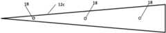
- FIGS. 2 A- 2 Cthree examples of active tips 12 are shown in FIGS. 2 A- 2 C .
- a cannula tip 12 ahas a length of approximately 5 mm and is provided with three bore holes 18 (only one of which is shown in FIG. 2 A ) located approximately 2.5 mm from the tip, through which a medication can be dispensed.
- FIG. 3is an axial cross-sectional view of the cannula tip 12 and illustrates the positions of the three boreholes 18 which are equally spaced around the periphery of the tip at approximately 12 o'clock, 4 o'clock and 8 o'clock positions.
- FIG. 2 Billustrates a cannula tip 12 b that has a length of approximately 10 mm and is provided with three bore holes 18 located approximately 2.5 mm from the tip and another three boreholes located approximately at 7.5 mm from the tip.
- the boreholesare equally spaced around the periphery of the tip, as explained with reference to FIG. 3 .
- FIG. 2 Cillustrates a cannula tip 12 c that has a length of approximately 15 mm and is provided with three bore holes 18 located approximately 2.5 mm from the tip, another three boreholes located approximately at 7.5 mm from the tip, and another three boreholes located approximately at 12.5 mm from the tip. Again, the boreholes are equally spaced around the periphery of the tip, as explained with reference to FIG. 3 .
- the cannula tip 12is closed. This configuration facilitates the application of a medication precisely to the desired location relative to the lesion.
- insulation effective to prevent RF energy from propagating therethroughis provided around selected portions of the tip, to directionally ablate—or not—in a particular direction, as desired.
- insulation 20 ais provided around approximately 180° about the periphery of the tip 12 , such that the RF energy is applied in the direction of the arrows, but not elsewhere.
- insulation 20 bis provided around approximately 90° about the periphery of the tip 12 , such that the RF energy is applied in the direction of the arrows, but not elsewhere.
- the insulationcan be formed of silicon, although other materials may be used if desired.
- the cannula in accordance with this aspect of the inventionmay provide selective ablation of a lesion without ablating surrounding tissue.
- boreholes 18are employed along with the insulation, only two boreholes may be used, although the third borehole may be provided through the insulation if desired.
Landscapes
- Health & Medical Sciences (AREA)
- Surgery (AREA)
- Engineering & Computer Science (AREA)
- Life Sciences & Earth Sciences (AREA)
- Biomedical Technology (AREA)
- Otolaryngology (AREA)
- Nuclear Medicine, Radiotherapy & Molecular Imaging (AREA)
- Plasma & Fusion (AREA)
- Physics & Mathematics (AREA)
- Heart & Thoracic Surgery (AREA)
- Medical Informatics (AREA)
- Molecular Biology (AREA)
- Animal Behavior & Ethology (AREA)
- General Health & Medical Sciences (AREA)
- Public Health (AREA)
- Veterinary Medicine (AREA)
- Surgical Instruments (AREA)
Abstract
Description
Claims (16)
Priority Applications (1)
| Application Number | Priority Date | Filing Date | Title |
|---|---|---|---|
| US16/896,340US11832873B2 (en) | 2019-06-14 | 2020-06-09 | Cannulas for radio frequency ablation |
Applications Claiming Priority (2)
| Application Number | Priority Date | Filing Date | Title |
|---|---|---|---|
| US201962861819P | 2019-06-14 | 2019-06-14 | |
| US16/896,340US11832873B2 (en) | 2019-06-14 | 2020-06-09 | Cannulas for radio frequency ablation |
Publications (2)
| Publication Number | Publication Date |
|---|---|
| US20200390491A1 US20200390491A1 (en) | 2020-12-17 |
| US11832873B2true US11832873B2 (en) | 2023-12-05 |
Family
ID=73746423
Family Applications (1)
| Application Number | Title | Priority Date | Filing Date |
|---|---|---|---|
| US16/896,340Active2041-04-20US11832873B2 (en) | 2019-06-14 | 2020-06-09 | Cannulas for radio frequency ablation |
Country Status (1)
| Country | Link |
|---|---|
| US (1) | US11832873B2 (en) |
Citations (14)
| Publication number | Priority date | Publication date | Assignee | Title |
|---|---|---|---|---|
| US5458597A (en)* | 1993-11-08 | 1995-10-17 | Zomed International | Device for treating cancer and non-malignant tumors and methods |
| US5792140A (en)* | 1997-05-15 | 1998-08-11 | Irvine Biomedical, Inc. | Catheter having cooled multiple-needle electrode |
| US5919188A (en)* | 1997-02-04 | 1999-07-06 | Medtronic, Inc. | Linear ablation catheter |
| US6015407A (en)* | 1996-03-06 | 2000-01-18 | Cardiac Pathways Corporation | Combination linear ablation and cooled tip RF catheters |
| US6514261B1 (en)* | 1998-09-30 | 2003-02-04 | Impra, Inc. | Delivery mechanism for implantable stent |
| US6712812B2 (en)* | 1999-08-05 | 2004-03-30 | Broncus Technologies, Inc. | Devices for creating collateral channels |
| US6770070B1 (en)* | 2000-03-17 | 2004-08-03 | Rita Medical Systems, Inc. | Lung treatment apparatus and method |
| US20060122593A1 (en)* | 2003-04-24 | 2006-06-08 | Myong-Ki Jun | Electrode for radiofrequency tissue ablation |
| US7311708B2 (en)* | 2001-12-12 | 2007-12-25 | Tissuelink Medical, Inc. | Fluid-assisted medical devices, systems and methods |
| US20090326439A1 (en)* | 2006-01-17 | 2009-12-31 | Cabochon Aesthetics, Inc. | High pressure pre-burst for improved fluid delivery |
| US8128620B2 (en)* | 2007-11-13 | 2012-03-06 | St. Jude Medical, Atrial Fibrillation Division, Inc. | Irrigated ablation electrode having proximal direction flow |
| US8273082B2 (en)* | 2007-12-21 | 2012-09-25 | St. Jude Medical, Atrial Fibrillation Division, Inc. | Irrigated ablation catheter assembly having a flow member to create parallel external flow |
| US8535306B2 (en)* | 2007-11-05 | 2013-09-17 | Angiodynamics, Inc. | Ablation devices and methods of using the same |
| US8702697B2 (en)* | 2011-04-12 | 2014-04-22 | Thermedical, Inc. | Devices and methods for shaping therapy in fluid enhanced ablation |
- 2020
- 2020-06-09USUS16/896,340patent/US11832873B2/enactiveActive
Patent Citations (14)
| Publication number | Priority date | Publication date | Assignee | Title |
|---|---|---|---|---|
| US5458597A (en)* | 1993-11-08 | 1995-10-17 | Zomed International | Device for treating cancer and non-malignant tumors and methods |
| US6015407A (en)* | 1996-03-06 | 2000-01-18 | Cardiac Pathways Corporation | Combination linear ablation and cooled tip RF catheters |
| US5919188A (en)* | 1997-02-04 | 1999-07-06 | Medtronic, Inc. | Linear ablation catheter |
| US5792140A (en)* | 1997-05-15 | 1998-08-11 | Irvine Biomedical, Inc. | Catheter having cooled multiple-needle electrode |
| US6514261B1 (en)* | 1998-09-30 | 2003-02-04 | Impra, Inc. | Delivery mechanism for implantable stent |
| US6712812B2 (en)* | 1999-08-05 | 2004-03-30 | Broncus Technologies, Inc. | Devices for creating collateral channels |
| US6770070B1 (en)* | 2000-03-17 | 2004-08-03 | Rita Medical Systems, Inc. | Lung treatment apparatus and method |
| US7311708B2 (en)* | 2001-12-12 | 2007-12-25 | Tissuelink Medical, Inc. | Fluid-assisted medical devices, systems and methods |
| US20060122593A1 (en)* | 2003-04-24 | 2006-06-08 | Myong-Ki Jun | Electrode for radiofrequency tissue ablation |
| US20090326439A1 (en)* | 2006-01-17 | 2009-12-31 | Cabochon Aesthetics, Inc. | High pressure pre-burst for improved fluid delivery |
| US8535306B2 (en)* | 2007-11-05 | 2013-09-17 | Angiodynamics, Inc. | Ablation devices and methods of using the same |
| US8128620B2 (en)* | 2007-11-13 | 2012-03-06 | St. Jude Medical, Atrial Fibrillation Division, Inc. | Irrigated ablation electrode having proximal direction flow |
| US8273082B2 (en)* | 2007-12-21 | 2012-09-25 | St. Jude Medical, Atrial Fibrillation Division, Inc. | Irrigated ablation catheter assembly having a flow member to create parallel external flow |
| US8702697B2 (en)* | 2011-04-12 | 2014-04-22 | Thermedical, Inc. | Devices and methods for shaping therapy in fluid enhanced ablation |
Also Published As
| Publication number | Publication date |
|---|---|
| US20200390491A1 (en) | 2020-12-17 |
Similar Documents
| Publication | Publication Date | Title |
|---|---|---|
| US20190217058A1 (en) | Endoluminal fluid delivery device and method | |
| US11110003B2 (en) | Gland or duct diagnostic and treatment methods and related apparatus | |
| EP0667126B1 (en) | Steerable medical probe with stylets | |
| US20190110828A1 (en) | Fluid detection assembly for a medical device | |
| US8103356B2 (en) | High frequency epidural neuromodulation catheter without needle for effectuating RF treatment | |
| US10159599B2 (en) | Meibomian gland intraductal diagnostic and treatment methods | |
| AU2021215216B2 (en) | Epicardial Access System and Methods | |
| JP6456401B2 (en) | Medical device for fluid communication | |
| US20170105792A1 (en) | Methods and systems for reducing ultrasound artifacts | |
| US20080208194A1 (en) | Double cut shaver | |
| US20070106219A1 (en) | Cleveland round tip (CRT) needle | |
| JP5105939B2 (en) | Medical insertion guide device | |
| BR112014011289B1 (en) | balloon dilation catheter | |
| US6293944B1 (en) | Combined syringe and electrosurgical electrode for sclerotherapy | |
| CN110169814B (en) | Positioning needle, positioning device, positioning equipment and positioning method | |
| JP5394951B2 (en) | Puncture needle guide device | |
| US11832873B2 (en) | Cannulas for radio frequency ablation | |
| US20200000516A1 (en) | Sterile disposable bipolar ablation needle, associated system, and method of use | |
| KR102744705B1 (en) | Endoscopic catheter device | |
| JP4383908B2 (en) | Epidural needle | |
| CN215228332U (en) | A puncture depth control device | |
| US20190038340A1 (en) | Radiofrequency cannula with fenestrated active tip | |
| JPH0542166A (en) | Electrode catherter for high-frequency abrasion | |
| US20240206944A1 (en) | Open lumen radiofrequency needle | |
| US20250000570A1 (en) | Radiofrequency Cannula for Thermal Ablation |
Legal Events
| Date | Code | Title | Description |
|---|---|---|---|
| FEPP | Fee payment procedure | Free format text:ENTITY STATUS SET TO UNDISCOUNTED (ORIGINAL EVENT CODE: BIG.); ENTITY STATUS OF PATENT OWNER: SMALL ENTITY | |
| FEPP | Fee payment procedure | Free format text:ENTITY STATUS SET TO SMALL (ORIGINAL EVENT CODE: SMAL); ENTITY STATUS OF PATENT OWNER: SMALL ENTITY | |
| STPP | Information on status: patent application and granting procedure in general | Free format text:APPLICATION DISPATCHED FROM PREEXAM, NOT YET DOCKETED | |
| STPP | Information on status: patent application and granting procedure in general | Free format text:DOCKETED NEW CASE - READY FOR EXAMINATION | |
| STPP | Information on status: patent application and granting procedure in general | Free format text:NON FINAL ACTION MAILED | |
| STPP | Information on status: patent application and granting procedure in general | Free format text:RESPONSE TO NON-FINAL OFFICE ACTION ENTERED AND FORWARDED TO EXAMINER | |
| STPP | Information on status: patent application and granting procedure in general | Free format text:FINAL REJECTION MAILED | |
| STPP | Information on status: patent application and granting procedure in general | Free format text:NON FINAL ACTION MAILED | |
| STPP | Information on status: patent application and granting procedure in general | Free format text:RESPONSE TO NON-FINAL OFFICE ACTION ENTERED AND FORWARDED TO EXAMINER | |
| STPP | Information on status: patent application and granting procedure in general | Free format text:NOTICE OF ALLOWANCE MAILED -- APPLICATION RECEIVED IN OFFICE OF PUBLICATIONS | |
| STPP | Information on status: patent application and granting procedure in general | Free format text:PUBLICATIONS -- ISSUE FEE PAYMENT VERIFIED | |
| STCF | Information on status: patent grant | Free format text:PATENTED CASE |