US11832367B2 - Dimming systems - Google Patents
Dimming systemsDownload PDFInfo
- Publication number
- US11832367B2 US11832367B2US16/977,028US201916977028AUS11832367B2US 11832367 B2US11832367 B2US 11832367B2US 201916977028 AUS201916977028 AUS 201916977028AUS 11832367 B2US11832367 B2US 11832367B2
- Authority
- US
- United States
- Prior art keywords
- control device
- led
- board
- dob
- dimming
- Prior art date
- Legal status (The legal status is an assumption and is not a legal conclusion. Google has not performed a legal analysis and makes no representation as to the accuracy of the status listed.)
- Active
Links
Images


Classifications
- F—MECHANICAL ENGINEERING; LIGHTING; HEATING; WEAPONS; BLASTING
- F21—LIGHTING
- F21K—NON-ELECTRIC LIGHT SOURCES USING LUMINESCENCE; LIGHT SOURCES USING ELECTROCHEMILUMINESCENCE; LIGHT SOURCES USING CHARGES OF COMBUSTIBLE MATERIAL; LIGHT SOURCES USING SEMICONDUCTOR DEVICES AS LIGHT-GENERATING ELEMENTS; LIGHT SOURCES NOT OTHERWISE PROVIDED FOR
- F21K9/00—Light sources using semiconductor devices as light-generating elements, e.g. using light-emitting diodes [LED] or lasers
- F21K9/20—Light sources comprising attachment means
- F21K9/23—Retrofit light sources for lighting devices with a single fitting for each light source, e.g. for substitution of incandescent lamps with bayonet or threaded fittings
- F21K9/238—Arrangement or mounting of circuit elements integrated in the light source
- F—MECHANICAL ENGINEERING; LIGHTING; HEATING; WEAPONS; BLASTING
- F21—LIGHTING
- F21S—NON-PORTABLE LIGHTING DEVICES; SYSTEMS THEREOF; VEHICLE LIGHTING DEVICES SPECIALLY ADAPTED FOR VEHICLE EXTERIORS
- F21S9/00—Lighting devices with a built-in power supply; Systems employing lighting devices with a built-in power supply
- F21S9/02—Lighting devices with a built-in power supply; Systems employing lighting devices with a built-in power supply the power supply being a battery or accumulator
- F21S9/03—Lighting devices with a built-in power supply; Systems employing lighting devices with a built-in power supply the power supply being a battery or accumulator rechargeable by exposure to light
- F21S9/037—Lighting devices with a built-in power supply; Systems employing lighting devices with a built-in power supply the power supply being a battery or accumulator rechargeable by exposure to light the solar unit and the lighting unit being located within or on the same housing
- F—MECHANICAL ENGINEERING; LIGHTING; HEATING; WEAPONS; BLASTING
- F21—LIGHTING
- F21V—FUNCTIONAL FEATURES OR DETAILS OF LIGHTING DEVICES OR SYSTEMS THEREOF; STRUCTURAL COMBINATIONS OF LIGHTING DEVICES WITH OTHER ARTICLES, NOT OTHERWISE PROVIDED FOR
- F21V23/00—Arrangement of electric circuit elements in or on lighting devices
- F21V23/003—Arrangement of electric circuit elements in or on lighting devices the elements being electronics drivers or controllers for operating the light source, e.g. for a LED array
- F21V23/004—Arrangement of electric circuit elements in or on lighting devices the elements being electronics drivers or controllers for operating the light source, e.g. for a LED array arranged on a substrate, e.g. a printed circuit board
- F21V23/006—Arrangement of electric circuit elements in or on lighting devices the elements being electronics drivers or controllers for operating the light source, e.g. for a LED array arranged on a substrate, e.g. a printed circuit board the substrate being distinct from the light source holder
- H—ELECTRICITY
- H05—ELECTRIC TECHNIQUES NOT OTHERWISE PROVIDED FOR
- H05B—ELECTRIC HEATING; ELECTRIC LIGHT SOURCES NOT OTHERWISE PROVIDED FOR; CIRCUIT ARRANGEMENTS FOR ELECTRIC LIGHT SOURCES, IN GENERAL
- H05B45/00—Circuit arrangements for operating light-emitting diodes [LED]
- H05B45/30—Driver circuits
- H05B45/37—Converter circuits
- H05B45/3725—Switched mode power supply [SMPS]
- H05B45/38—Switched mode power supply [SMPS] using boost topology
- H—ELECTRICITY
- H05—ELECTRIC TECHNIQUES NOT OTHERWISE PROVIDED FOR
- H05B—ELECTRIC HEATING; ELECTRIC LIGHT SOURCES NOT OTHERWISE PROVIDED FOR; CIRCUIT ARRANGEMENTS FOR ELECTRIC LIGHT SOURCES, IN GENERAL
- H05B47/00—Circuit arrangements for operating light sources in general, i.e. where the type of light source is not relevant
- H05B47/10—Controlling the light source
- H05B47/175—Controlling the light source by remote control
- H05B47/19—Controlling the light source by remote control via wireless transmission
- F—MECHANICAL ENGINEERING; LIGHTING; HEATING; WEAPONS; BLASTING
- F21—LIGHTING
- F21Y—INDEXING SCHEME ASSOCIATED WITH SUBCLASSES F21K, F21L, F21S and F21V, RELATING TO THE FORM OR THE KIND OF THE LIGHT SOURCES OR OF THE COLOUR OF THE LIGHT EMITTED
- F21Y2115/00—Light-generating elements of semiconductor light sources
- F21Y2115/10—Light-emitting diodes [LED]
- H—ELECTRICITY
- H05—ELECTRIC TECHNIQUES NOT OTHERWISE PROVIDED FOR
- H05B—ELECTRIC HEATING; ELECTRIC LIGHT SOURCES NOT OTHERWISE PROVIDED FOR; CIRCUIT ARRANGEMENTS FOR ELECTRIC LIGHT SOURCES, IN GENERAL
- H05B45/00—Circuit arrangements for operating light-emitting diodes [LED]
- H05B45/30—Driver circuits
- H05B45/32—Pulse-control circuits
- H05B45/325—Pulse-width modulation [PWM]
Definitions
- aspects of the inventionrelate to dimming systems. More particularly, aspects of the invention relate to universal control systems for dimmable light-emitting diode lamps.
- LED lightshave been used for years in applications requiring relatively-low energy lamps. LEDs are efficient, long-lasting, cost-effective and environmentally friendly. As LED lights are increasingly and more widely used in daily life, the demand for dimmable lights has also increased.
- a problem with existing dimmable LEDsis that the electronics required to control the dimming of the light are relatively large.
- Embodiments of the present inventionseek to overcome the above-mentioned problems, amongst others.
- a control device for dimming a LED light sourcecomprising a LED control circuit for dimming the LED light source, wherein the LED control circuit is powered independently to the LED light source.
- the LED control circuitis powered exclusively by the power source. That is, the LED control circuit does not draw power from the mains which power the LED source. This has a number of advantages, including:
- control devicemay comprise a power source electrically connected to the LED control circuit, wherein the LED control circuit is powered exclusively by the power source.
- the power sourcemay be internal or external to the control device. Examples of external power sources include a USB device, a transformer or an adaptor.
- the LED control circuithas a maximum load of 128 W.
- the power sourceprovides a current in the range 20-25 mAh.
- the power sourcefurther comprises a rechargeable battery.
- the rechargeable batterymay be connected to a PV cell that harvests light for example, emitted by the LED. This provides enough power to top up the battery extending battery life.
- the PV cellmay comprise PV tape.
- control devicefurther comprises a network communications board for remotely controlling one or more LED light sources. Further, this enables the device to be remotely controlled, for example via a mobile phone application.
- the network communications boardhas Bluetooth and/or DALI compatibility.
- the network communications boardmay comprise the LED control circuit.
- the network communications and LED control circuitsmay be on separate boards. Separating or de-coupling the communications board from the dimming board has a number of advantages over an integrated board, particularly within control devices as described above.
- the power sourcemay be located between the network communications and LED control circuit boards.
- the batteryis ‘sandwiched’ between the two boards. This sequence or configuration minimises space for fitting in a typical lamp for example, at the same time enabling a robust and remotely controllable dimming.
- a dimmable light-emitting lampcomprising:
- the control electronicsare housed within the housing.
- the housinghas a diameter of less than 26 mm.
- a control device for dimming a LED light sourcecomprising a LED control circuit for dimming the LED light source, wherein the LED control circuit is powered independently to the LED light source
- said control devicecomprises a housing with a circumferential wall having at its distal extremity a rim; a first board being exposed for receiving wireless communications through the space defined by said rim; and a second board located behind said first board and incorporating said LED control circuitry for dimming said LED light source; both said first and second board being located within said circumferential wall.
- a universal dimmercomprising a control device as described above.
- the universal dimmeris compatible with a plurality of LED light sources known in the art.
- FIG. 1schematically shows a light source
- FIG. 2shows a space model for “dimmer on board”, DoB, electronics within a E27 light bulb base;
- FIG. 3shows a perspective view from above of the space model of FIG. 2 ;
- FIG. 4shows a space model for printed circuit boards (PCB).
- FIGS. 5 A to 5 Cshow further models of a space model for DoB electronics within a light bulb base
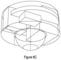
- FIGS. 6 A to 6 Cshow views of a space model of DoB circuitry and battery inside a E27 light bulb base
- FIG. 7shows schematically DoB circuitry
- FIG. 8shows schematically a Bluetooth circuit for the DoB
- FIG. 9shows schematically a microcontroller (MCU) circuit for the DoB
- FIGS. 10 A and 10 Brespectively show top and bottom views of a DoB PCB layout
- FIG. 11shows examples of pulse-width modulated (PWM) signals by DC electronics for driving the dimming of a LED
- FIG. 12shows a linear drive output from the DoB
- FIGS. 13 and 14show test results for European (230V) and US (110V) drive voltages
- FIG. 15is a schematic circuit diagram for a driver
- FIG. 16is a table showing test results for the driver
- FIG. 17shows an example driver board output
- FIG. 18shows a PV charging circuitry example
- FIG. 19shows an example circuit using PV cell and DoB (“Boost Integrated Circuit, IC”); The title of this figure may be: LTC3105 400 mA Step-Up DC/DC Converter with Maximum Power Point Control and 250 mV Start-Up.
- FIG. 20shows an example Boost Integrated Circuit (IC) simulated schematic
- FIG. 21shows a circuit for powering the DoB with an inductorless switching regulator;
- the title of this figuremay be: SR086/SR087 Adjustable Offline Inductorless Switching Regulators.
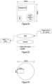
- FIG. 22shows example board sizes
- FIG. 23shows elements of a universal dimming interface
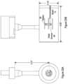
- FIG. 24shows example DoB measurements
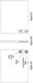
- FIGS. 25 A and 25 Brespectively show frontal and side views of a track light which includes a control device as described herewith;
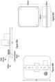
- FIGS. 26 A to 26 Cshow an example wherein the control device is provided on a panel
- FIGS. 27 A to 27 Crespectively show top, side and bottom views of a panel including the control device, in an alternative, side-by-side arrangement of a dimming board (dimmer), battery and communications board;
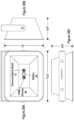
- FIGS. 28 A to 28 Cshow views of a flood light which includes the side-by-side arrangement
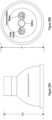
- FIGS. 29 A and 29 Brespectively show side and frontal views of a down light which includes the side-by-side arrangement
- FIGS. 30 A and 30 Brespectively show frontal and side views of a light emitting lamp with a circular panel including the side-by-side arrangement.
- the primary embodiment of the inventionconcerns a dimmable lamp which comprises a housing with the same characteristics in terms of shape and configuration as the base assembly of the bulb referenced below.
- the housing of the embodiment of a lampis provided to house the control electronic which may be of the same kind as those presented in combination with the bulb's base assembly.
- the skilled personwill readily understand how the advantages outlined in the context of a bulb may also apply to a lamp.
- FIG. 1shows schematically a LED lamp 10 for replacing an incandescent bulb in a common household light bulb socket.
- the lamp 10has a base assembly 20 having a hollow cylindrical portion, a bulb assembly 30 and a LED source 40 .
- the LEDis powered from the mains via the base assembly 20 .
- the bulb assembly 30is preferably made from a transparent material such as glass.
- the base assembly 20is made from a suitable metallic material and is configured to fit an E26 or E27 light bulb socket.
- the base assemblymay be adapted to form a housing which would be readily fit into a lamp.
- the light bulb sockethas threads which correspond to threads 21 on lamp 10 .
- the base assembly 20preferably looks the same as a “screw” or “bayonet” portion of a typical light bulb.
- the tip 22 of the base assembly 20touches a contact in the bottom of the light bulb socket when lamp 10 is fully screwed into the socket to power the LED from the mains.
- the base assembly 20houses the electronics of the lamp, including a “dimmer on board” DoB in space 50 , so that the LED 40 is exposed as much as possible.
- the dimmer usedis a 4 W 2-step dim PCB (printed circuit board).
- the space 50 made available inside the base assembly 20houses DoB electronics including a varistor component of the 2-step dim PCB.
- Space 50therefore represents a “keep-out” region for dimmer electronics and extends more roughly to the base of the usable space.
- the small dome 60 shown at the bottom of the rim portion (or base) of the base assembly 20is shown for completeness but is not envisaged to house electronics due to the relatively small volume and a requirement for electrical connection through the centre of the dome and through tip 22 .
- FIG. 3is a perspective aerial view of the base assembly 20 of FIG. 2 .
- Indicated in FIG. 4is a PCB area 55 . Between 1 to 3 PCBs may advantageously fit in the proposed PCB area 55 .
- the components on this version of the 2-step dim PCBare mounted on the underside, with the top side left clear This could be inverted using a 4 W or else an additional clearance will be required from the 2-step dim circular board face; 1.2 mm for one half of the 2-step dim PCB and 2.8 mm on the other half.
- the dimming of the LEDsis driven by DC electronics using a pulse-width modulated (PWM) signal.
- PWMpulse-width modulated
- the level of dimming at any particular timeis defined by the duty-cycle of the PWM signal, which is simply the amount of time in a period that the signal is “on” for.
- An example of PWM signalis shown in FIG. 11 .
- the PWM signalis used to “chop” the AC signal feeding the LED driving circuitry, thus dimming them.
- the PWM signalis produced by a timer in a microcontroller (MCU), which is itself software controlled.
- MCUmicrocontroller
- Bluetoothis preferable to connect to a mobile device such as mobile phone for example.
- Bluetoothtraditionally, is a paired technology whereby two devices must be connected to each other (and no one else) in order to communicate data.
- Bluetooth 5 mesh-networkingallows a Bluetooth device to communicate with more than one other device in a wider network. Accordingly, the mesh capability of Bluetooth 5 enables grouping and control of multiple lighting devices.
- Pulse-width modulated (PWM) dimming with a co-processor modelis preferred, whereby a “Blue Gecko” solution from Silicon Labs is used as a traditional model alongside a microcontroller (MCU).
- Bluetooth 5offers an alternative to traditional network communications systems such as DALI and is of particular interest due to the availability of Bluetooth on mobile phones.
- DALI compatibilityis envisaged in order to allow control at least partially via mains power.
- itis a wireless network control but DALI compatibility means being able to integrate as at least part of a primarily wired controlled system. This might be to allow signals via the wires to a wireless repeater which can “speak” the DALI language which can then be understood by the lamp. In that sense, the lamp is able to understand the language but cannot itself be directly controlled via a mains contact point.
- the MCU devicemay comprise a DALI stack.
- a Bluetooth modulemay optionally connect to an external antenna. This overcomes any poor RF performance due to a “Faraday cage” effect of the metallic base assembly of the lamp.
- an internal antennamay be used to reduce cost and complexity of manufacturing.
- Dimmersmay include a Triac or MOSFET for example.
- Heat protectionmay be included such as a thermistor for shutting off operation if the device were to overheat.
- a heat pipe optionis also envisaged, to spread head from the DoB to the LED/filaments or vice versa.
- Bluetooth connectionis set up between a mobile phone application (App) and a Bluetooth communication adapter board. With this set up, 4 W and 10 W LED bulbs may be respectively dimmed and brightened remotely via the App.
- the PWM frequencyis preferably 900 Hz, up to 1 kHz.
- the bulbsmay be dimmed and brightened by the DoB smoothly and without a flicker.
- the drive outputwas measured in terms of volts against a dimmer setting 10-100 in steps of 10. As shown in FIG. 12 , the drive output from the DoB is output linearly, in proportion across the range.
- the DoBmay be powered by both UK and US voltage supply for example.
- the DOBmay be powered via a variac set to 110V.
- Example results for testing the drive at both 230V and 110Vare shown in the table of FIG. 13 , plotted in FIG. 14 . As can be seen from FIG. 14 , both 110V and 230V drive voltages produced linear results.
- a 4 W driverwas used, with a filament wiring of 4 ⁇ 40 mm and a ST64-4S-E27-1800K bulb.
- the internal filament wiringis schematically shown in FIG. 15 .
- the LED filaments 110are all wired in series from one point (A) of the DoB to another (B), point B representing the anode of the first LED.
- Each LED 110 in the diagramrepresents a LED filament.
- Connecting the multimeter 220 in series in this configurationallows for measuring the voltage and the current flowing through the bulb filaments supplied by the driver. In a measurement, there was a 40V voltage across each of the filaments, resulting in 160V overall.
- FIG. 17shows a near linear current draw, with points 10 to 100 being represented on the graph.
- the dimming circuitryis powered independently to the LED. That is, the dimmer does not draw power from the grid, but from a separate source.
- the electronic controlcan draw power from the LED but not from the mains.
- a solution for harvesting from the 2-step dimming circuitwould be a preferred option (requiring minimal components). It is envisaged that the 230V is stepped down by the dimming circuit, the LEDs themselves providing a step down and rectification function.
- re-chargeable batteriesa charge circuit and a source of energy.
- One option for the energy sourceis the 2-step dimming board, however this would couple the solution to the dimming board (i.e. not universal).
- a further, preferred, optionis to use a flexible solar cell located within the base assembly 20 (within the diameter of the threaded portion) and facing the filament.
- the solar cellcould be made from a photovoltaic (PV) tape for example that could harvest energy from the light emitted from the LED, providing enough power to top up a battery to control the electronics.
- PVphotovoltaic
- both the communications board and the control boardare on the same board.
- FIGS. 6 A to 6 Cshow views of a space model of DoB circuitry and battery inside a E27 light bulb base, wherein the communications board 70 and the circular dimming board 90 are separate, located either side of battery 80 .
- the communications board 7may be a Bluetooth device.
- FIG. 8shows schematically a Bluetooth circuit for the DoB.
- the MCU 95is located in space 50 .
- FIG. 9shows schematically a microcontroller (MCU) circuit for the DoB.
- a DoB PCB layoutis shown in FIGS. 10 A and 10 B .
- Power harvesting for trickle charging a batteryuses a rechargeable battery, a charging circuit, and a source of energy.
- a Photovoltaic cellPV
- the typical hardware blocks required for charging battery from a PVare shown in FIG. 18 : light source, PV, Boost IC, rechargeable battery and load (DoB and Communication electronics).
- the Photovoltaic Celldraws power from a light source such as the LED lamp according to aspects of the invention.
- Power from the PVis fed into input of Boost IC for converting to usable form (e.g. 4.2V).
- the output of Boost ICis used to charge a battery.
- the battery and Boost ICis used to power load (e.g. DoB and Communications electronics).
- the PV cell componentis preferably a PV solar tape.
- PV tapemay be provided in rolls, preferably separated in 10 cm sections.
- PV solar tapeis a flexible organic solar cell foil with optional semi-transparent lined adhesive on the front or backside and functions as a “solar sticker”.
- FIG. 19shows a typical application of Boost IC, containing the following hardware blocks: a PV cell 130 and battery.
- the loadDoB and Communication electronics
- the loadwould be connected to the point Vout in FIG. 19 .
- Power from a USB socket and cablecould be used to provide power to the DoB and Communications electronics. This may be achieved for example by wiring a micro socket to the V_IN and GND 1 test points on the DoB electronics. An off the shelf adapter board such as the one below or custom PCB would need to be developed and added to the DoB electronic design. A standard micro USB cable could then be connected between this socket and a standard USB adapter to provide power to the DoB and communications electronics.
- Powering via a transformeris an alternative solution akin to having a combination of an external unit and the lamps.
- an AC/DC Convertercould be used to power the DoB and communications electronics directly from mains (230V).
- the external unitin effect houses the step down power circuitry. It has the advantage over the provision of a step down power circuit as it does not impact the goal of dimming electronics in the board, but does mean that wiring the lamps and siting the transformer would not make the offering easily installable and retrofittable.
- a more generic optionwould be to use an off the shelf power adaptor and barrel connector wired to the DoB and communications electronics.
- All these three power optionsmake use of a transformer to convert for example 230V to 5V. Powering using a transformer advantageously removes the need for any connectors as it can be wired directly to the DoB and communication electronics. An advantage is that it can be wired directly into an existing lighting circuit, therefore the DoB electronics can be powered in parallel to the light sources that they are controlling.
- the DoB and communications boardmay be powered from driver circuitry elements either internally or externally from the board. Taking power from inside the lamp means access to neutral and both sides of the mains which makes the stepping down from mains power to the 3V power easier to achieve. The essence for this requirement is similar to that given above for the solar charging input in that the charge could be held in a capacitor or battery. The level and amount of the charge would change and may in some instances be negligible (e.g. if it were possible to utilise the power directly with minimal step down).
- Powering the DoB and Communications boardmay be powered from an IC without using a transformer or inductor, which are typically physically large components.
- a transformeris typically the standard method used when stepping down from 230 VAC to a smaller DC voltage.
- ICsthat make use of alternative methods to step down voltage.
- One such componentis the SR086.
- FIG. 21A typical application circuit is shown in FIG. 21 , comprising 4 resistors, 4 capacitors, 1 bridge rectifier, a fuse, a visitor, a transistor and the IC (SR086) itself. Applying this to the DoB, the bridge rectifier and fuse can be ignored as they are already included as part of the DoB schematic. Using a value of 82K for R 1 , this would set the value of Vout to 9.2V. Vout is internally used in the SR086 to power a 3V3 linear regulator which has a 60 mA output current. This would provide more than enough headroom to power the DoB circuitry. Further details with regard to FIG. 21 may be obtained from the following website: http://ww1.microchip.com/downloads/en/DeviceDoc/20005544A.pdf
- the largest components in this circuitwould be the regulator itself (5 mm ⁇ 6.2 mm), the transistor (11.5 mm ⁇ 6.7 mm) and the 470 uF capacitor which has a 10 mm diameter.
- the other components in the typical applicationneed to be carefully selected in order to have the right power ratings for the application but would be physically smaller than these three main parts.
- the 470 uFcould also be reduced; this value was chosen to accommodate a load of 100 mA on Vout, whereas in practice the DoB represents a maximum load of 25 mA.
- FIG. 22indicates an estimate of the required board size (square with 25 mm sides) for accommodating this solution. Accordingly, the components could fit on a board size of 625 mm 2 (just under 1 square inch). The usable surface area of a board this size would in fact be 1250 mm 2 as both sides of the board can be used to fit components.
- the size of the board required to support this solutionis a lot smaller than a similar transformer based circuit. Furthermore, although the component count is similar, the physical sizes of each component allow for greater flexibility in how the board is designed at the layout stage.
- a universal dimmer interfaceincludes dimming, communication, and power source elements. Each dimmer/communications combination would require powering from one power source.
- FIG. 23shows the components of a universal dimming interface: a DoB, a power source (e.g. 20-25 ma) and a load (e.g. 40V), and a communications board/electronics.
- the power source which drives the electronicsis independent from the electronics.
- the DoBis load in this example is set at 128 W limited by a bridge rectifier.
- the design of the DoBwas described above.
- Combinations of the communications optionsare envisaged to provide generality. For example, a wired DALI connected solution could then be coupled with a Bluetooth wireless solution. Each could use the same dimmer board.
- the power sourcepreferably provides a voltage of 4.2V and current: 20-25 mAh.
- a means of supplying power from a constant rechargeable sourceis required. Essentially this will require a capacitor to store change and a rechargeable battery has been used in the demonstrator.
- the battery in this examplehas a capacitance of 75 mAh and therefore in parallel with charging circuitry will provide 3 hours of headroom and on a constant charge will power the DoB and Communications electronics. This is sufficient to provide the constant power to the battery over a battery life which could then power the bulb for a typical life-time.
- a number of methodshave been investigated for the provision of this constant changing, one using a solar source as described above. The inventors found that a load of 64 W (8 bulbs attached) can be fully dimmed and brightened, with a projected capability of 128 W.
- FIG. 24shows example DoB measurements.
- the usable surface area of both sides of the boardis approximately 680.2 mm 2 . Given that the board is densely populated, this can be taken as the minimum surface area required to house the components that make up the DoB. This would mean that components could be placed on a board that contains an equivalent surface area.
- the DoB prototypehas been designed for fitting into a lamp.
- the size of the housingmay have an external diameter of 26 mm.
- the DoBis designed to fit inside the holder.
- the inside measurementmay be 26 mm but could be 25 mm dependent on the housing.
- the DoB with a diameter of 22 mmtheoretically fits.
- the shape and dimensions of the boardcan be varied, and, in addition, boards can be stacked within a space. It is therefore sensible to consider the finite limit on the board area, or real estate, required for components to fit. EMC, antenna, rf and safety considerations also need to be taken into account. Each implementation can be customised. As a starting point, the basic real-estate required for the DoB electronics as a minimum is set as that designed for a E27 bulb at 680.2 mm 2 —this would allow the housing to fit a wide variety of lamps.
- the light emitting lampis a track light, that is, a lamp which is fitted on tracks to allow variable positioning.
- FIGS. 25 A and 25 Brespectively show frontal and side views of a track light.
- a circular communications board 70 and a circular dimming board 90e.g. a PWM dimmer are located either side of a circular battery 80 , in a ‘sandwich’ type arrangement.
- the sandwich’ type arrangementis provided on a panel, being ‘stacked’ on the panel.
- the communications board 70sits on the panel, with the battery 80 above it, and the dimming board on top.
- This arrangementadvantageously fits inside a housing with 250 mm ⁇ 250 mm ⁇ 88 mm in dimension.
- the communications board 70 , battery 80 and dimming board 90are arranged side by side, instead of being stacked.
- FIGS. 27 A to 27 Crespectively show top, side and bottom views of a square panel which comprises the communications board 70 , battery 80 and dimming board 90 arranged side by side. It will be appreciated that the shape of the panel may differ depending on the light emitting lamp.
- FIGS. 30 A and 30 Crespectively show frontal and side views of a light emitting lamp with a circular panel including the side-by-side arrangement.
- the light emitting lampis a flood light.
- FIGS. 28 A to 28 Cshow views of a flood light which includes the side-by-side arrangement of the communications board 70 , battery 80 and dimming board 90 .
- the side-by-side arrangementis provided within a panel inside the flood light.
- the light emitting lampis a down light.
- FIGS. 29 A and 29 Brespectively show side and frontal views of a down light which includes the side-by-side arrangement of the communications board 70 , battery 80 and dimming board 90 .
- the side-by-side arrangementis provided within a panel inside the downlight.
Landscapes
- Engineering & Computer Science (AREA)
- General Engineering & Computer Science (AREA)
- Microelectronics & Electronic Packaging (AREA)
- Computer Networks & Wireless Communication (AREA)
- Life Sciences & Earth Sciences (AREA)
- Sustainable Development (AREA)
- Physics & Mathematics (AREA)
- Optics & Photonics (AREA)
- Circuit Arrangement For Electric Light Sources In General (AREA)
- Arrangement Of Elements, Cooling, Sealing, Or The Like Of Lighting Devices (AREA)
- Fastening Of Light Sources Or Lamp Holders (AREA)
- Non-Portable Lighting Devices Or Systems Thereof (AREA)
Abstract
Description
- The device can be more easily configured to provide the power required.
- A clean isolation barrier is provided between low voltage and mains voltage.
- a LED light source;
- a control device; and
- a housing for housing said control device.
- It can easily be configured to provide the power required (power requirements could change if other communications systems such as WiFi are incorporated at a later date).
- It enables more options to fit all of the electronics to fit within a lamp.
- The DoB is decoupled from the 2-step dimming board meaning that the technology is more portable.
- A clean isolation barrier is provided between low voltage and mains voltage.
- The PCB design is more robust and provides options if required to alleviate EMC or electrical disturbance.
- Additional space on the PCB provides options for design and manufacture testing which otherwise would not be possible to incorporate.
- Bluetooth mesh—the Bluetooth module trialled is mesh capable.
- Space for alternative or additional mesh networks has been allowed on the communications board.
2) Wired communications option - The requirement for integration of DALI, DMX has been considered.
- These options would require power to be supplied through to the DoB. External power options have been considered and recommended and these could be used to facilitate this functionality.
- The MCU has been chosen so that it could accommodate a DALI stack and the option of adding in the software required for DALI and DMX control.
Claims (15)
Applications Claiming Priority (10)
| Application Number | Priority Date | Filing Date | Title |
|---|---|---|---|
| GB1803354 | 2018-03-01 | ||
| GB1803352 | 2018-03-01 | ||
| GB1803352.2 | 2018-03-01 | ||
| GB1803352.2AGB2563475B (en) | 2018-03-01 | 2018-03-01 | Dimmable light source |
| GB1803354.8 | 2018-03-01 | ||
| GB1803354.8AGB2570163B (en) | 2018-03-01 | 2018-03-01 | Dimming systems |
| GBGB1804162.4AGB201804162D0 (en) | 2018-03-15 | 2018-03-15 | Dimmable light source |
| GB1804162 | 2018-03-15 | ||
| GB1804162.4 | 2018-03-15 | ||
| PCT/GB2019/050554WO2019166808A1 (en) | 2018-03-01 | 2019-02-28 | Dimming systems |
Publications (2)
| Publication Number | Publication Date |
|---|---|
| US20210045203A1 US20210045203A1 (en) | 2021-02-11 |
| US11832367B2true US11832367B2 (en) | 2023-11-28 |
Family
ID=66001247
Family Applications (2)
| Application Number | Title | Priority Date | Filing Date |
|---|---|---|---|
| US16/977,032ActiveUS11134557B2 (en) | 2018-03-01 | 2019-02-28 | Dimmable light source |
| US16/977,028ActiveUS11832367B2 (en) | 2018-03-01 | 2019-02-28 | Dimming systems |
Family Applications Before (1)
| Application Number | Title | Priority Date | Filing Date |
|---|---|---|---|
| US16/977,032ActiveUS11134557B2 (en) | 2018-03-01 | 2019-02-28 | Dimmable light source |
Country Status (12)
| Country | Link |
|---|---|
| US (2) | US11134557B2 (en) |
| EP (2) | EP3760003A1 (en) |
| JP (2) | JP7424642B2 (en) |
| CN (2) | CN112056008A (en) |
| AU (2) | AU2019226708A1 (en) |
| CA (2) | CA3131650A1 (en) |
| DK (1) | DK3760004T3 (en) |
| ES (1) | ES2927415T3 (en) |
| HU (1) | HUE059801T2 (en) |
| PL (1) | PL3760004T3 (en) |
| PT (1) | PT3760004T (en) |
| WO (2) | WO2019166808A1 (en) |
Families Citing this family (3)
| Publication number | Priority date | Publication date | Assignee | Title |
|---|---|---|---|---|
| ES2927415T3 (en)* | 2018-03-01 | 2022-11-07 | Broseley Ltd | dimmable light source |
| IT201900021603A1 (en)* | 2019-11-19 | 2021-05-19 | C Led Srl | LED DRIVER FOR LOW VOLTAGE LIGHTING TRACKS |
| US12253221B2 (en)* | 2023-09-19 | 2025-03-18 | Dongguan Renzheng lighting electric Appliance Co., LTD | Multifunctional and variable lamp sheet and lamp |
Citations (42)
| Publication number | Priority date | Publication date | Assignee | Title |
|---|---|---|---|---|
| JP2000197281A (en) | 1998-12-25 | 2000-07-14 | Kyocera Corp | Battery type power supply and self-luminous device |
| JP2002289378A (en) | 2001-03-27 | 2002-10-04 | Matsushita Electric Works Ltd | Lighting control device |
| US20050237005A1 (en) | 2004-04-23 | 2005-10-27 | Lighting Science Group Corporation | Electronic light generating element light bulb |
| JP2006338982A (en) | 2005-06-01 | 2006-12-14 | Kawamura Electric Inc | Light control device |
| US20080180036A1 (en)* | 2007-01-31 | 2008-07-31 | Lighting Science Group Corporation | Method and apparatus for operating a light emitting diode with a dimmer |
| US20080304299A1 (en) | 2006-09-11 | 2008-12-11 | Bormann Ronald M | Low voltage LED drive from 120VAC line |
| US20080304249A1 (en) | 2007-06-08 | 2008-12-11 | A66, Incorporated | Durable super-cooled intelligent light bulb |
| CN101858535A (en) | 2003-07-02 | 2010-10-13 | S·C·约翰松及索恩公司 | Lamps and bulbs for lighting and ambient lighting |
| CN101877926A (en) | 2010-07-08 | 2010-11-03 | 张家炎 | Automatic light-regulating control system |
| CN201639821U (en) | 2010-02-01 | 2010-11-17 | 佛山市伊戈尔电业制造股份有限公司 | Dimming control circuit of LED lamp |
| US20100328946A1 (en) | 2009-06-26 | 2010-12-30 | Borkar Shekhar Y | Light devices having controllable light emitting elements |
| US20110025205A1 (en) | 2004-09-29 | 2011-02-03 | Koninklijke Philips Electronics N.V. | Lighting device |
| JP2011192481A (en) | 2010-03-12 | 2011-09-29 | Toshiba Lighting & Technology Corp | Dimmer and lighting system |
| US20120043889A1 (en) | 2006-03-28 | 2012-02-23 | Wireless Environment, Llc. | Off-Grid LED Power Failure Lights |
| WO2012052893A1 (en) | 2010-10-19 | 2012-04-26 | Koninklijke Philips Electronics N.V. | Led circuit arrangement |
| US20120262093A1 (en) | 2011-04-15 | 2012-10-18 | Recker Michael V | Lighting device capable of maintaining light intensity in demand response applications |
| WO2013108187A2 (en) | 2012-01-18 | 2013-07-25 | Koninklijke Philips N.V. | Ultra low standby power system for electronic devices |
| CN103267954A (en) | 2013-04-19 | 2013-08-28 | 深圳莱特光电有限公司 | Feed and detection method of LED luminous energy and illuminating system |
| WO2013155867A1 (en) | 2012-04-18 | 2013-10-24 | Zhang Jiayan | Automatic dimming constant-light control system |
| US20140056001A1 (en)* | 2012-08-24 | 2014-02-27 | Industrial Technology Research Institute | Led light bulb module |
| CN103621180A (en) | 2011-03-31 | 2014-03-05 | 丽托尼克斯有限公司 | Lighting device |
| US20140070703A1 (en)* | 2012-09-07 | 2014-03-13 | Phihong Technology Co., Ltd. | Wirelessly Controllable LED Bulb and Wireless Control Method thereof |
| CN103874294A (en) | 2014-03-13 | 2014-06-18 | 新杰克缝纫机股份有限公司 | Light control illumination device for sewing machine |
| WO2014134637A2 (en) | 2013-02-28 | 2014-09-04 | Azoteq (Pty) Ltd | Intelligent lighting apparatus |
| US20140265836A1 (en)* | 2013-03-14 | 2014-09-18 | Bby Solutions, Inc. | Modular led bulb with user replaceable components |
| CN104078998A (en) | 2014-07-04 | 2014-10-01 | 陕西日升源创能科技有限公司 | Energy feedback method for LED lamps |
| US8994276B2 (en) | 2006-03-28 | 2015-03-31 | Wireless Environment, Llc | Grid shifting system for a lighting circuit |
| CN104834117A (en) | 2015-06-01 | 2015-08-12 | 京东方科技集团股份有限公司 | Colored film substrate, display device and manufacturing method of colored film substrate |
| CN104869716A (en) | 2015-05-28 | 2015-08-26 | 宁夏科楠电工科技有限公司 | Wireless touch dimming switch with energy collection function |
| JP2015170061A (en) | 2014-03-06 | 2015-09-28 | 株式会社クボタ | Automatic dispenser |
| EP2958402A1 (en) | 2014-06-19 | 2015-12-23 | Nxp B.V. | Dimmable LED lighting circuit |
| US20160088693A1 (en) | 2013-04-08 | 2016-03-24 | Yijun Zhao | Lamp cap integrated with led drive power supply |
| DE202016104063U1 (en) | 2016-06-17 | 2016-08-09 | Hangzhou Zhonggan Electronic Technology Co.,Ltd. | Inductor, LED driver and LED light |
| KR101653134B1 (en) | 2016-05-09 | 2016-09-01 | 강규리 | Driving device for led lighting lamp |
| CN205560353U (en) | 2016-01-21 | 2016-09-07 | 广东昭信照明科技有限公司 | LED ball bubble lamp of built -in speaker |
| CN205961497U (en) | 2016-05-30 | 2017-02-15 | 深圳市蚂蚁雄兵物联技术有限公司 | Bluetooth ball bubble lamp |
| US20170102112A1 (en) | 2008-01-10 | 2017-04-13 | Feit Electric Company, Inc. | Led lamp |
| US9657928B1 (en) | 2015-12-15 | 2017-05-23 | Crestron Electronics, Inc. | Wireless replacement LED bulb with one or more accompanying control switches |
| JP2017098144A (en) | 2015-11-26 | 2017-06-01 | アール・ビー・コントロールズ株式会社 | Led illumination device and led illumination control device |
| WO2017127836A1 (en) | 2016-01-23 | 2017-07-27 | Innosys, Inc. | Continuously powered load switch lock |
| US20190320515A1 (en)* | 2018-04-15 | 2019-10-17 | Laurence P. Sadwick | Solid State Lighting Systems |
| US20210227661A1 (en)* | 2016-04-25 | 2021-07-22 | Osram Sylvania Inc. | Tuneable lighting systems and methods |
Family Cites Families (25)
| Publication number | Priority date | Publication date | Assignee | Title |
|---|---|---|---|---|
| US8444299B2 (en)* | 2007-09-25 | 2013-05-21 | Enertron, Inc. | Dimmable LED bulb with heatsink having perforated ridges |
| JP5463447B2 (en)* | 2008-01-18 | 2014-04-09 | 三洋電機株式会社 | Light emitting device and lamp provided with the same |
| US9326346B2 (en)* | 2009-01-13 | 2016-04-26 | Terralux, Inc. | Method and device for remote sensing and control of LED lights |
| US20100277067A1 (en)* | 2009-04-30 | 2010-11-04 | Lighting Science Group Corporation | Dimmable led luminaire |
| US20130193879A1 (en)* | 2010-05-10 | 2013-08-01 | Innosys, Inc. | Universal Dimmer |
| US9732930B2 (en)* | 2010-07-20 | 2017-08-15 | Panasonic Intellectual Property Management Co., Ltd. | Light bulb shaped lamp |
| CN202195288U (en)* | 2011-04-29 | 2012-04-18 | 泉州市金太阳电子科技有限公司 | Remote control light-emitting diode (LED) lamp |
| JP5129413B1 (en)* | 2011-07-22 | 2013-01-30 | パナソニック株式会社 | Illumination light source and illumination device |
| EP2837057B1 (en)* | 2012-04-12 | 2016-06-08 | Koninklijke Philips N.V. | Controllable lighting assembly |
| JP2013225450A (en)* | 2012-04-23 | 2013-10-31 | Sharp Corp | Lighting device |
| JP6042637B2 (en) | 2012-05-29 | 2016-12-14 | 株式会社東横イン電建 | LED lighting system |
| US20170105265A1 (en)* | 2014-05-27 | 2017-04-13 | Laurence P. Sadwick | Lighting Systems |
| JP6678466B2 (en) | 2015-02-09 | 2020-04-08 | 株式会社小糸製作所 | Vehicle lighting |
| CA2979409C (en)* | 2015-03-12 | 2023-09-26 | GE Lighting Solutions, LLC | Led lamp with internal mirror |
| US9420644B1 (en)* | 2015-03-31 | 2016-08-16 | Frank Shum | LED lighting |
| CN106151934A (en)* | 2015-04-20 | 2016-11-23 | 葛兰菲照明有限公司 | Integrating illumination and the LED bulb of night-light function |
| CN104791627B (en)* | 2015-04-21 | 2018-10-12 | 贵州光浦森光电有限公司 | A kind of construction method and LED filament lamp of LED filament lamp |
| CN105042366A (en)* | 2015-07-10 | 2015-11-11 | 黄新 | Three-dimensional power source of bulb lamp and LED filament bulb lamp |
| CN105402617A (en)* | 2015-11-20 | 2016-03-16 | 宁波多力浦工贸有限公司 | Improved bulb light |
| CN107654857B (en)* | 2016-07-26 | 2024-04-05 | 上海莱托思电子科技有限公司 | An integrated filament lamp |
| CN206409920U (en)* | 2017-01-09 | 2017-08-15 | 杭州时代照明电器有限公司 | One kind is without stroboscopic Dimmable LED bulb |
| CN206904630U (en)* | 2017-05-03 | 2018-01-19 | 江门市卡迪光电科技有限公司 | A kind of modularized limit emitting diode (LED) bulb lamp |
| US10260683B2 (en)* | 2017-05-10 | 2019-04-16 | Cree, Inc. | Solid-state lamp with LED filaments having different CCT's |
| CN107612461A (en)* | 2017-09-27 | 2018-01-19 | 上海剑桥科技股份有限公司 | Full isolation electric supply conversion equipment |
| ES2927415T3 (en)* | 2018-03-01 | 2022-11-07 | Broseley Ltd | dimmable light source |
- 2019
- 2019-02-28ESES19715187Tpatent/ES2927415T3/enactiveActive
- 2019-02-28CNCN201980029038.2Apatent/CN112056008A/enactivePending
- 2019-02-28CACA3131650Apatent/CA3131650A1/enactivePending
- 2019-02-28HUHUE19715187Apatent/HUE059801T2/enunknown
- 2019-02-28AUAU2019226708Apatent/AU2019226708A1/ennot_activeAbandoned
- 2019-02-28JPJP2020568854Apatent/JP7424642B2/enactiveActive
- 2019-02-28USUS16/977,032patent/US11134557B2/enactiveActive
- 2019-02-28EPEP19715186.3Apatent/EP3760003A1/ennot_activeWithdrawn
- 2019-02-28DKDK19715187.1Tpatent/DK3760004T3/enactive
- 2019-02-28WOPCT/GB2019/050554patent/WO2019166808A1/ennot_activeCeased
- 2019-02-28PTPT197151871Tpatent/PT3760004T/enunknown
- 2019-02-28CNCN201980029034.4Apatent/CN112056007B/enactiveActive
- 2019-02-28EPEP19715187.1Apatent/EP3760004B1/enactiveActive
- 2019-02-28JPJP2020568855Apatent/JP7406258B2/enactiveActive
- 2019-02-28CACA3131649Apatent/CA3131649A1/enactivePending
- 2019-02-28AUAU2019226704Apatent/AU2019226704A1/ennot_activeAbandoned
- 2019-02-28PLPL19715187.1Tpatent/PL3760004T3/enunknown
- 2019-02-28WOPCT/GB2019/050558patent/WO2019166812A1/ennot_activeCeased
- 2019-02-28USUS16/977,028patent/US11832367B2/enactiveActive
Patent Citations (42)
| Publication number | Priority date | Publication date | Assignee | Title |
|---|---|---|---|---|
| JP2000197281A (en) | 1998-12-25 | 2000-07-14 | Kyocera Corp | Battery type power supply and self-luminous device |
| JP2002289378A (en) | 2001-03-27 | 2002-10-04 | Matsushita Electric Works Ltd | Lighting control device |
| CN101858535A (en) | 2003-07-02 | 2010-10-13 | S·C·约翰松及索恩公司 | Lamps and bulbs for lighting and ambient lighting |
| US20050237005A1 (en) | 2004-04-23 | 2005-10-27 | Lighting Science Group Corporation | Electronic light generating element light bulb |
| US20110025205A1 (en) | 2004-09-29 | 2011-02-03 | Koninklijke Philips Electronics N.V. | Lighting device |
| JP2006338982A (en) | 2005-06-01 | 2006-12-14 | Kawamura Electric Inc | Light control device |
| US20120043889A1 (en) | 2006-03-28 | 2012-02-23 | Wireless Environment, Llc. | Off-Grid LED Power Failure Lights |
| US8994276B2 (en) | 2006-03-28 | 2015-03-31 | Wireless Environment, Llc | Grid shifting system for a lighting circuit |
| US20080304299A1 (en) | 2006-09-11 | 2008-12-11 | Bormann Ronald M | Low voltage LED drive from 120VAC line |
| US20080180036A1 (en)* | 2007-01-31 | 2008-07-31 | Lighting Science Group Corporation | Method and apparatus for operating a light emitting diode with a dimmer |
| US20080304249A1 (en) | 2007-06-08 | 2008-12-11 | A66, Incorporated | Durable super-cooled intelligent light bulb |
| US20170102112A1 (en) | 2008-01-10 | 2017-04-13 | Feit Electric Company, Inc. | Led lamp |
| US20100328946A1 (en) | 2009-06-26 | 2010-12-30 | Borkar Shekhar Y | Light devices having controllable light emitting elements |
| CN201639821U (en) | 2010-02-01 | 2010-11-17 | 佛山市伊戈尔电业制造股份有限公司 | Dimming control circuit of LED lamp |
| JP2011192481A (en) | 2010-03-12 | 2011-09-29 | Toshiba Lighting & Technology Corp | Dimmer and lighting system |
| CN101877926A (en) | 2010-07-08 | 2010-11-03 | 张家炎 | Automatic light-regulating control system |
| WO2012052893A1 (en) | 2010-10-19 | 2012-04-26 | Koninklijke Philips Electronics N.V. | Led circuit arrangement |
| CN103621180A (en) | 2011-03-31 | 2014-03-05 | 丽托尼克斯有限公司 | Lighting device |
| US20120262093A1 (en) | 2011-04-15 | 2012-10-18 | Recker Michael V | Lighting device capable of maintaining light intensity in demand response applications |
| WO2013108187A2 (en) | 2012-01-18 | 2013-07-25 | Koninklijke Philips N.V. | Ultra low standby power system for electronic devices |
| WO2013155867A1 (en) | 2012-04-18 | 2013-10-24 | Zhang Jiayan | Automatic dimming constant-light control system |
| US20140056001A1 (en)* | 2012-08-24 | 2014-02-27 | Industrial Technology Research Institute | Led light bulb module |
| US20140070703A1 (en)* | 2012-09-07 | 2014-03-13 | Phihong Technology Co., Ltd. | Wirelessly Controllable LED Bulb and Wireless Control Method thereof |
| WO2014134637A2 (en) | 2013-02-28 | 2014-09-04 | Azoteq (Pty) Ltd | Intelligent lighting apparatus |
| US20140265836A1 (en)* | 2013-03-14 | 2014-09-18 | Bby Solutions, Inc. | Modular led bulb with user replaceable components |
| US20160088693A1 (en) | 2013-04-08 | 2016-03-24 | Yijun Zhao | Lamp cap integrated with led drive power supply |
| CN103267954A (en) | 2013-04-19 | 2013-08-28 | 深圳莱特光电有限公司 | Feed and detection method of LED luminous energy and illuminating system |
| JP2015170061A (en) | 2014-03-06 | 2015-09-28 | 株式会社クボタ | Automatic dispenser |
| CN103874294A (en) | 2014-03-13 | 2014-06-18 | 新杰克缝纫机股份有限公司 | Light control illumination device for sewing machine |
| EP2958402A1 (en) | 2014-06-19 | 2015-12-23 | Nxp B.V. | Dimmable LED lighting circuit |
| CN104078998A (en) | 2014-07-04 | 2014-10-01 | 陕西日升源创能科技有限公司 | Energy feedback method for LED lamps |
| CN104869716A (en) | 2015-05-28 | 2015-08-26 | 宁夏科楠电工科技有限公司 | Wireless touch dimming switch with energy collection function |
| CN104834117A (en) | 2015-06-01 | 2015-08-12 | 京东方科技集团股份有限公司 | Colored film substrate, display device and manufacturing method of colored film substrate |
| JP2017098144A (en) | 2015-11-26 | 2017-06-01 | アール・ビー・コントロールズ株式会社 | Led illumination device and led illumination control device |
| US9657928B1 (en) | 2015-12-15 | 2017-05-23 | Crestron Electronics, Inc. | Wireless replacement LED bulb with one or more accompanying control switches |
| CN205560353U (en) | 2016-01-21 | 2016-09-07 | 广东昭信照明科技有限公司 | LED ball bubble lamp of built -in speaker |
| WO2017127836A1 (en) | 2016-01-23 | 2017-07-27 | Innosys, Inc. | Continuously powered load switch lock |
| US20210227661A1 (en)* | 2016-04-25 | 2021-07-22 | Osram Sylvania Inc. | Tuneable lighting systems and methods |
| KR101653134B1 (en) | 2016-05-09 | 2016-09-01 | 강규리 | Driving device for led lighting lamp |
| CN205961497U (en) | 2016-05-30 | 2017-02-15 | 深圳市蚂蚁雄兵物联技术有限公司 | Bluetooth ball bubble lamp |
| DE202016104063U1 (en) | 2016-06-17 | 2016-08-09 | Hangzhou Zhonggan Electronic Technology Co.,Ltd. | Inductor, LED driver and LED light |
| US20190320515A1 (en)* | 2018-04-15 | 2019-10-17 | Laurence P. Sadwick | Solid State Lighting Systems |
Non-Patent Citations (4)
| Title |
|---|
| China Patent Office, Office Action, dated Jul. 26, 2023. |
| International Search Report and Written Opinion for Application No. PCT/GB2019/050554 dated May 27, 2019. |
| United Kingdom Examination and Search Report for Application No. GB1803352.2 dated May 9, 2018. |
| United Kingdom Examination and Search Report for Application No. GB1803354.8 dated Jul. 24, 2018. |
Also Published As
| Publication number | Publication date |
|---|---|
| EP3760004A1 (en) | 2021-01-06 |
| DK3760004T3 (en) | 2022-09-19 |
| US11134557B2 (en) | 2021-09-28 |
| EP3760003A1 (en) | 2021-01-06 |
| CN112056007A (en) | 2020-12-08 |
| WO2019166808A1 (en) | 2019-09-06 |
| EP3760004B1 (en) | 2022-06-22 |
| CN112056008A (en) | 2020-12-08 |
| US20200408365A1 (en) | 2020-12-31 |
| PL3760004T3 (en) | 2022-10-17 |
| CA3131649A1 (en) | 2019-09-06 |
| AU2019226708A1 (en) | 2020-10-15 |
| ES2927415T3 (en) | 2022-11-07 |
| JP2021515380A (en) | 2021-06-17 |
| WO2019166812A1 (en) | 2019-09-06 |
| CA3131650A1 (en) | 2019-09-06 |
| AU2019226704A1 (en) | 2020-10-15 |
| US20210045203A1 (en) | 2021-02-11 |
| HUE059801T2 (en) | 2022-12-28 |
| CN112056007B (en) | 2023-06-09 |
| JP7406258B2 (en) | 2023-12-27 |
| PT3760004T (en) | 2022-09-22 |
| JP2021521615A (en) | 2021-08-26 |
| JP7424642B2 (en) | 2024-01-30 |
Similar Documents
| Publication | Publication Date | Title |
|---|---|---|
| KR100759054B1 (en) | Lighting device using light emitting diode | |
| US11832367B2 (en) | Dimming systems | |
| JP6444991B2 (en) | Integrated micro light-emitting diode module with built-in programmability | |
| CN102474958B (en) | Led turn-on circuit, lamp, and illumination apparatus | |
| US7221105B2 (en) | Electromagnetic radiation emitting bulb and method using same in a portable device | |
| CN104206019A (en) | Lamp comprising high-efficiency light devices | |
| CN103155710A (en) | Power supply device and lighting device | |
| US20150009657A1 (en) | Light Apparatus | |
| US9920916B2 (en) | Card type LED driver and transportation means with card type driver | |
| US8777436B2 (en) | Battery powered lamp socket that supplies energy for LED or CFL light bulbs | |
| CN208222107U (en) | A kind of illumination panel and illuminator | |
| CN105873263A (en) | Lighting device and lighting tool | |
| JP6665460B2 (en) | Lighting equipment and lighting equipment | |
| US9215764B1 (en) | High-temperature ultra-low ripple multi-stage LED driver and LED control circuits | |
| GB2570163A (en) | Dimming system | |
| HK40044146A (en) | Dimmable light source | |
| HK40044146B (en) | Dimmable light source | |
| GB2563475A (en) | Dimmable light source | |
| JP6986208B2 (en) | lighting equipment | |
| US11835210B1 (en) | Flashlight element | |
| CN104125681A (en) | Regulating and control system of LED lamp |
Legal Events
| Date | Code | Title | Description |
|---|---|---|---|
| FEPP | Fee payment procedure | Free format text:ENTITY STATUS SET TO UNDISCOUNTED (ORIGINAL EVENT CODE: BIG.); ENTITY STATUS OF PATENT OWNER: SMALL ENTITY | |
| AS | Assignment | Owner name:BROSELEY LIMITED, UNITED KINGDOM Free format text:ASSIGNMENT OF ASSIGNORS INTEREST;ASSIGNOR:BAYES, KEVIN PAUL;REEL/FRAME:053666/0902 Effective date:20200828 | |
| FEPP | Fee payment procedure | Free format text:ENTITY STATUS SET TO SMALL (ORIGINAL EVENT CODE: SMAL); ENTITY STATUS OF PATENT OWNER: SMALL ENTITY | |
| STPP | Information on status: patent application and granting procedure in general | Free format text:DOCKETED NEW CASE - READY FOR EXAMINATION | |
| STPP | Information on status: patent application and granting procedure in general | Free format text:NON FINAL ACTION MAILED | |
| STPP | Information on status: patent application and granting procedure in general | Free format text:NON FINAL ACTION MAILED | |
| STPP | Information on status: patent application and granting procedure in general | Free format text:NOTICE OF ALLOWANCE MAILED -- APPLICATION RECEIVED IN OFFICE OF PUBLICATIONS | |
| STPP | Information on status: patent application and granting procedure in general | Free format text:PUBLICATIONS -- ISSUE FEE PAYMENT VERIFIED | |
| STCB | Information on status: application discontinuation | Free format text:ABANDONMENT FOR FAILURE TO CORRECT DRAWINGS/OATH/NONPUB REQUEST | |
| STPP | Information on status: patent application and granting procedure in general | Free format text:DOCKETED NEW CASE - READY FOR EXAMINATION | |
| STPP | Information on status: patent application and granting procedure in general | Free format text:NOTICE OF ALLOWANCE MAILED -- APPLICATION RECEIVED IN OFFICE OF PUBLICATIONS | |
| STPP | Information on status: patent application and granting procedure in general | Free format text:WITHDRAW FROM ISSUE AWAITING ACTION | |
| STPP | Information on status: patent application and granting procedure in general | Free format text:AWAITING TC RESP., ISSUE FEE NOT PAID | |
| STPP | Information on status: patent application and granting procedure in general | Free format text:PUBLICATIONS -- ISSUE FEE PAYMENT VERIFIED | |
| STCF | Information on status: patent grant | Free format text:PATENTED CASE |