US11831155B2 - E-cigarette and re-charging pack - Google Patents
E-cigarette and re-charging packDownload PDFInfo
- Publication number
- US11831155B2 US11831155B2US16/281,332US201916281332AUS11831155B2US 11831155 B2US11831155 B2US 11831155B2US 201916281332 AUS201916281332 AUS 201916281332AUS 11831155 B2US11831155 B2US 11831155B2
- Authority
- US
- United States
- Prior art keywords
- battery
- cigarette
- pack
- current
- connector
- Prior art date
- Legal status (The legal status is an assumption and is not a legal conclusion. Google has not performed a legal analysis and makes no representation as to the accuracy of the status listed.)
- Active, expires
Links
Images


Classifications
- A—HUMAN NECESSITIES
- A61—MEDICAL OR VETERINARY SCIENCE; HYGIENE
- A61M—DEVICES FOR INTRODUCING MEDIA INTO, OR ONTO, THE BODY; DEVICES FOR TRANSDUCING BODY MEDIA OR FOR TAKING MEDIA FROM THE BODY; DEVICES FOR PRODUCING OR ENDING SLEEP OR STUPOR
- A61M15/00—Inhalators
- A61M15/06—Inhaling appliances shaped like cigars, cigarettes or pipes
- H—ELECTRICITY
- H01—ELECTRIC ELEMENTS
- H01M—PROCESSES OR MEANS, e.g. BATTERIES, FOR THE DIRECT CONVERSION OF CHEMICAL ENERGY INTO ELECTRICAL ENERGY
- H01M10/00—Secondary cells; Manufacture thereof
- H01M10/42—Methods or arrangements for servicing or maintenance of secondary cells or secondary half-cells
- H01M10/44—Methods for charging or discharging
- H—ELECTRICITY
- H02—GENERATION; CONVERSION OR DISTRIBUTION OF ELECTRIC POWER
- H02J—CIRCUIT ARRANGEMENTS OR SYSTEMS FOR SUPPLYING OR DISTRIBUTING ELECTRIC POWER; SYSTEMS FOR STORING ELECTRIC ENERGY
- H02J7/00—Circuit arrangements for charging or depolarising batteries or for supplying loads from batteries
- H02J7/007—Regulation of charging or discharging current or voltage
- H02J7/00712—Regulation of charging or discharging current or voltage the cycle being controlled or terminated in response to electric parameters
- H—ELECTRICITY
- H02—GENERATION; CONVERSION OR DISTRIBUTION OF ELECTRIC POWER
- H02J—CIRCUIT ARRANGEMENTS OR SYSTEMS FOR SUPPLYING OR DISTRIBUTING ELECTRIC POWER; SYSTEMS FOR STORING ELECTRIC ENERGY
- H02J7/00—Circuit arrangements for charging or depolarising batteries or for supplying loads from batteries
- H02J7/0029—Circuit arrangements for charging or depolarising batteries or for supplying loads from batteries with safety or protection devices or circuits
- H02J7/0031—Circuit arrangements for charging or depolarising batteries or for supplying loads from batteries with safety or protection devices or circuits using battery or load disconnect circuits
- A—HUMAN NECESSITIES
- A24—TOBACCO; CIGARS; CIGARETTES; SIMULATED SMOKING DEVICES; SMOKERS' REQUISITES
- A24F—SMOKERS' REQUISITES; MATCH BOXES; SIMULATED SMOKING DEVICES
- A24F40/00—Electrically operated smoking devices; Component parts thereof; Manufacture thereof; Maintenance or testing thereof; Charging means specially adapted therefor
- A24F40/40—Constructional details, e.g. connection of cartridges and battery parts
- A—HUMAN NECESSITIES
- A24—TOBACCO; CIGARS; CIGARETTES; SIMULATED SMOKING DEVICES; SMOKERS' REQUISITES
- A24F—SMOKERS' REQUISITES; MATCH BOXES; SIMULATED SMOKING DEVICES
- A24F40/00—Electrically operated smoking devices; Component parts thereof; Manufacture thereof; Maintenance or testing thereof; Charging means specially adapted therefor
- A24F40/50—Control or monitoring
- A24F40/53—Monitoring, e.g. fault detection
- A—HUMAN NECESSITIES
- A24—TOBACCO; CIGARS; CIGARETTES; SIMULATED SMOKING DEVICES; SMOKERS' REQUISITES
- A24F—SMOKERS' REQUISITES; MATCH BOXES; SIMULATED SMOKING DEVICES
- A24F40/00—Electrically operated smoking devices; Component parts thereof; Manufacture thereof; Maintenance or testing thereof; Charging means specially adapted therefor
- A24F40/90—Arrangements or methods specially adapted for charging batteries thereof
- A24F40/95—Arrangements or methods specially adapted for charging batteries thereof structurally associated with cases
- B—PERFORMING OPERATIONS; TRANSPORTING
- B65—CONVEYING; PACKING; STORING; HANDLING THIN OR FILAMENTARY MATERIAL
- B65D—CONTAINERS FOR STORAGE OR TRANSPORT OF ARTICLES OR MATERIALS, e.g. BAGS, BARRELS, BOTTLES, BOXES, CANS, CARTONS, CRATES, DRUMS, JARS, TANKS, HOPPERS, FORWARDING CONTAINERS; ACCESSORIES, CLOSURES, OR FITTINGS THEREFOR; PACKAGING ELEMENTS; PACKAGES
- B65D85/00—Containers, packaging elements or packages, specially adapted for particular articles or materials
- B65D85/07—Containers, packaging elements or packages, specially adapted for particular articles or materials for compressible or flexible articles
- B65D85/08—Containers, packaging elements or packages, specially adapted for particular articles or materials for compressible or flexible articles rod-shaped or tubular
- B65D85/10—Containers, packaging elements or packages, specially adapted for particular articles or materials for compressible or flexible articles rod-shaped or tubular for cigarettes
- H—ELECTRICITY
- H01—ELECTRIC ELEMENTS
- H01M—PROCESSES OR MEANS, e.g. BATTERIES, FOR THE DIRECT CONVERSION OF CHEMICAL ENERGY INTO ELECTRICAL ENERGY
- H01M10/00—Secondary cells; Manufacture thereof
- H01M10/42—Methods or arrangements for servicing or maintenance of secondary cells or secondary half-cells
- H01M10/425—Structural combination with electronic components, e.g. electronic circuits integrated to the outside of the casing
- H—ELECTRICITY
- H01—ELECTRIC ELEMENTS
- H01M—PROCESSES OR MEANS, e.g. BATTERIES, FOR THE DIRECT CONVERSION OF CHEMICAL ENERGY INTO ELECTRICAL ENERGY
- H01M10/00—Secondary cells; Manufacture thereof
- H01M10/42—Methods or arrangements for servicing or maintenance of secondary cells or secondary half-cells
- H01M10/44—Methods for charging or discharging
- H01M10/443—Methods for charging or discharging in response to temperature
- H—ELECTRICITY
- H01—ELECTRIC ELEMENTS
- H01M—PROCESSES OR MEANS, e.g. BATTERIES, FOR THE DIRECT CONVERSION OF CHEMICAL ENERGY INTO ELECTRICAL ENERGY
- H01M10/00—Secondary cells; Manufacture thereof
- H01M10/42—Methods or arrangements for servicing or maintenance of secondary cells or secondary half-cells
- H01M10/46—Accumulators structurally combined with charging apparatus
- H—ELECTRICITY
- H01—ELECTRIC ELEMENTS
- H01M—PROCESSES OR MEANS, e.g. BATTERIES, FOR THE DIRECT CONVERSION OF CHEMICAL ENERGY INTO ELECTRICAL ENERGY
- H01M10/00—Secondary cells; Manufacture thereof
- H01M10/42—Methods or arrangements for servicing or maintenance of secondary cells or secondary half-cells
- H01M10/48—Accumulators combined with arrangements for measuring, testing or indicating the condition of cells, e.g. the level or density of the electrolyte
- H01M10/486—Accumulators combined with arrangements for measuring, testing or indicating the condition of cells, e.g. the level or density of the electrolyte for measuring temperature
- H—ELECTRICITY
- H02—GENERATION; CONVERSION OR DISTRIBUTION OF ELECTRIC POWER
- H02H—EMERGENCY PROTECTIVE CIRCUIT ARRANGEMENTS
- H02H3/00—Emergency protective circuit arrangements for automatic disconnection directly responsive to an undesired change from normal electric working condition with or without subsequent reconnection ; integrated protection
- H02H3/08—Emergency protective circuit arrangements for automatic disconnection directly responsive to an undesired change from normal electric working condition with or without subsequent reconnection ; integrated protection responsive to excess current
- H—ELECTRICITY
- H02—GENERATION; CONVERSION OR DISTRIBUTION OF ELECTRIC POWER
- H02H—EMERGENCY PROTECTIVE CIRCUIT ARRANGEMENTS
- H02H3/00—Emergency protective circuit arrangements for automatic disconnection directly responsive to an undesired change from normal electric working condition with or without subsequent reconnection ; integrated protection
- H02H3/20—Emergency protective circuit arrangements for automatic disconnection directly responsive to an undesired change from normal electric working condition with or without subsequent reconnection ; integrated protection responsive to excess voltage
- H—ELECTRICITY
- H02—GENERATION; CONVERSION OR DISTRIBUTION OF ELECTRIC POWER
- H02J—CIRCUIT ARRANGEMENTS OR SYSTEMS FOR SUPPLYING OR DISTRIBUTING ELECTRIC POWER; SYSTEMS FOR STORING ELECTRIC ENERGY
- H02J7/00—Circuit arrangements for charging or depolarising batteries or for supplying loads from batteries
- H02J7/0029—Circuit arrangements for charging or depolarising batteries or for supplying loads from batteries with safety or protection devices or circuits
- H02J7/00304—Overcurrent protection
- H—ELECTRICITY
- H02—GENERATION; CONVERSION OR DISTRIBUTION OF ELECTRIC POWER
- H02J—CIRCUIT ARRANGEMENTS OR SYSTEMS FOR SUPPLYING OR DISTRIBUTING ELECTRIC POWER; SYSTEMS FOR STORING ELECTRIC ENERGY
- H02J7/00—Circuit arrangements for charging or depolarising batteries or for supplying loads from batteries
- H02J7/0029—Circuit arrangements for charging or depolarising batteries or for supplying loads from batteries with safety or protection devices or circuits
- H02J7/00308—Overvoltage protection
- H—ELECTRICITY
- H02—GENERATION; CONVERSION OR DISTRIBUTION OF ELECTRIC POWER
- H02J—CIRCUIT ARRANGEMENTS OR SYSTEMS FOR SUPPLYING OR DISTRIBUTING ELECTRIC POWER; SYSTEMS FOR STORING ELECTRIC ENERGY
- H02J7/00—Circuit arrangements for charging or depolarising batteries or for supplying loads from batteries
- H02J7/0029—Circuit arrangements for charging or depolarising batteries or for supplying loads from batteries with safety or protection devices or circuits
- H02J7/0036—Circuit arrangements for charging or depolarising batteries or for supplying loads from batteries with safety or protection devices or circuits using connection detecting circuits
- H—ELECTRICITY
- H02—GENERATION; CONVERSION OR DISTRIBUTION OF ELECTRIC POWER
- H02J—CIRCUIT ARRANGEMENTS OR SYSTEMS FOR SUPPLYING OR DISTRIBUTING ELECTRIC POWER; SYSTEMS FOR STORING ELECTRIC ENERGY
- H02J7/00—Circuit arrangements for charging or depolarising batteries or for supplying loads from batteries
- H02J7/007—Regulation of charging or discharging current or voltage
- H02J7/007188—Regulation of charging or discharging current or voltage the charge cycle being controlled or terminated in response to non-electric parameters
- H02J7/007192—Regulation of charging or discharging current or voltage the charge cycle being controlled or terminated in response to non-electric parameters in response to temperature
- H02J7/007194—Regulation of charging or discharging current or voltage the charge cycle being controlled or terminated in response to non-electric parameters in response to temperature of the battery
- H—ELECTRICITY
- H02—GENERATION; CONVERSION OR DISTRIBUTION OF ELECTRIC POWER
- H02J—CIRCUIT ARRANGEMENTS OR SYSTEMS FOR SUPPLYING OR DISTRIBUTING ELECTRIC POWER; SYSTEMS FOR STORING ELECTRIC ENERGY
- H02J7/00—Circuit arrangements for charging or depolarising batteries or for supplying loads from batteries
- H02J7/34—Parallel operation in networks using both storage and other DC sources, e.g. providing buffering
- H02J7/342—The other DC source being a battery actively interacting with the first one, i.e. battery to battery charging
- A—HUMAN NECESSITIES
- A24—TOBACCO; CIGARS; CIGARETTES; SIMULATED SMOKING DEVICES; SMOKERS' REQUISITES
- A24F—SMOKERS' REQUISITES; MATCH BOXES; SIMULATED SMOKING DEVICES
- A24F40/00—Electrically operated smoking devices; Component parts thereof; Manufacture thereof; Maintenance or testing thereof; Charging means specially adapted therefor
- A24F40/10—Devices using liquid inhalable precursors
- H—ELECTRICITY
- H01—ELECTRIC ELEMENTS
- H01M—PROCESSES OR MEANS, e.g. BATTERIES, FOR THE DIRECT CONVERSION OF CHEMICAL ENERGY INTO ELECTRICAL ENERGY
- H01M10/00—Secondary cells; Manufacture thereof
- H01M10/42—Methods or arrangements for servicing or maintenance of secondary cells or secondary half-cells
- H01M10/425—Structural combination with electronic components, e.g. electronic circuits integrated to the outside of the casing
- H01M2010/4271—Battery management systems including electronic circuits, e.g. control of current or voltage to keep battery in healthy state, cell balancing
- H—ELECTRICITY
- H01—ELECTRIC ELEMENTS
- H01M—PROCESSES OR MEANS, e.g. BATTERIES, FOR THE DIRECT CONVERSION OF CHEMICAL ENERGY INTO ELECTRICAL ENERGY
- H01M2220/00—Batteries for particular applications
- H01M2220/30—Batteries in portable systems, e.g. mobile phone, laptop
- H—ELECTRICITY
- H01—ELECTRIC ELEMENTS
- H01M—PROCESSES OR MEANS, e.g. BATTERIES, FOR THE DIRECT CONVERSION OF CHEMICAL ENERGY INTO ELECTRICAL ENERGY
- H01M50/00—Constructional details or processes of manufacture of the non-active parts of electrochemical cells other than fuel cells, e.g. hybrid cells
- H01M50/20—Mountings; Secondary casings or frames; Racks, modules or packs; Suspension devices; Shock absorbers; Transport or carrying devices; Holders
- H—ELECTRICITY
- H02—GENERATION; CONVERSION OR DISTRIBUTION OF ELECTRIC POWER
- H02J—CIRCUIT ARRANGEMENTS OR SYSTEMS FOR SUPPLYING OR DISTRIBUTING ELECTRIC POWER; SYSTEMS FOR STORING ELECTRIC ENERGY
- H02J7/00—Circuit arrangements for charging or depolarising batteries or for supplying loads from batteries
- H02J7/0029—Circuit arrangements for charging or depolarising batteries or for supplying loads from batteries with safety or protection devices or circuits
- H02J7/00302—Overcharge protection
- H—ELECTRICITY
- H02—GENERATION; CONVERSION OR DISTRIBUTION OF ELECTRIC POWER
- H02J—CIRCUIT ARRANGEMENTS OR SYSTEMS FOR SUPPLYING OR DISTRIBUTING ELECTRIC POWER; SYSTEMS FOR STORING ELECTRIC ENERGY
- H02J7/00—Circuit arrangements for charging or depolarising batteries or for supplying loads from batteries
- H02J7/0029—Circuit arrangements for charging or depolarising batteries or for supplying loads from batteries with safety or protection devices or circuits
- H02J7/00309—Overheat or overtemperature protection
- Y—GENERAL TAGGING OF NEW TECHNOLOGICAL DEVELOPMENTS; GENERAL TAGGING OF CROSS-SECTIONAL TECHNOLOGIES SPANNING OVER SEVERAL SECTIONS OF THE IPC; TECHNICAL SUBJECTS COVERED BY FORMER USPC CROSS-REFERENCE ART COLLECTIONS [XRACs] AND DIGESTS
- Y02—TECHNOLOGIES OR APPLICATIONS FOR MITIGATION OR ADAPTATION AGAINST CLIMATE CHANGE
- Y02E—REDUCTION OF GREENHOUSE GAS [GHG] EMISSIONS, RELATED TO ENERGY GENERATION, TRANSMISSION OR DISTRIBUTION
- Y02E60/00—Enabling technologies; Technologies with a potential or indirect contribution to GHG emissions mitigation
- Y02E60/10—Energy storage using batteries
Definitions
- the present applicationrelates to an e-cigarette, such as an electronic vapor provision system or an electronic nicotine delivery system, and a re-charging pack for the e-cigarette.
- Most e-cigarettesinclude a re-chargeable battery for supplying electrical power to the heater and other electrical/electronic components, such as a sensor to detect inhalation.
- Some e-cigaretteshave a cartridge section. After the nicotine or other liquid in this cartridge has been exhausted, the empty cartridge can be removed or separated from the e-cigarette and replaced with a new cartridge containing further nicotine.
- E-cigarettesare often supplied in packs for protection and easy portability. Such packs may accommodate multiple e-cigarettes and/or replacement cartridges, thereby offering a backup facility if one e-cigarette (or its cartridge) is exhausted.
- An e-cigarette packmay also have the ability to re-charge an e-cigarette, again helping to ensure good operating availability of the e-cigarette for a user.
- a packis provided with a cylindrical hole for receiving an e-cigarette for recharging, the hole generally reflecting the elongated, cylindrical shape of an e-cigarette.
- the batterycan be re-charged by a suitable wired or wireless connection (a wireless connection may rely upon induction charging).
- the cylindrical holemay receive the entire e-cigarette for re-charging, while in other packs only a portion of the e-cigarette may be received into the hole.
- the packmust be connected to a power supply, e.g. a mains outlet or USB connection, during re-charging of the e-cigarette battery.
- a power supplye.g. a mains outlet or USB connection
- the packis typically acting as a convenient device for holding and interfacing to the e-cigarette during re-charging.
- the packitself is provided with a battery (or other charge storage facility). The pack battery allows the e-cigarette to be re-charged from the pack without the need for the pack to be connected to an external power supply during the re-charging, thereby providing greater convenience for a user.
- the pack batterywill be depleted in due course, and so is generally provided with its own re-charging facility—typically again reliant upon some form of mains or USB connection.
- the packsince the pack is larger than an e-cigarette, it can accommodate a larger battery and therefore the pack does not have to be re-charged as frequently as an e-cigarette.
- the charge capacity of a typical e-cigarette batterymay be approximately 60 mAh, whereas the charge capacity of a typical pack battery might be in the region of 800 mAh. Accordingly, the pack battery is capable of re-charging the e-cigarette a few times at least before the pack battery itself needs to be re-charged.
- Such a multiple or hierarchical arrangement of separately chargeable systemsnamely firstly an e-cigarette and secondly a pack for the e-cigarette, is relatively rare.
- most re-chargeable devicese.g. mobile (cell) phones, are usually connected directly to a mains-powered charging supply (or else to an in-car charging supply).
- a packfor containing and recharging an e-cigarette.
- the packcomprises: a re-chargeable pack battery; a first connector which is electrically connectable to an external power source; a first recharging mechanism for re-charging the pack battery using the external power source when the first connector is electrically connected to the external power source; a second connector which is electrically connectable to an e-cigarette contained within the pack; and a second recharging mechanism for re-charging the e-cigarette when the e-cigarette is electrically connected to the second connector.
- the first recharging mechanismcomprises a first protection circuit module for preventing electrical power flow from the external power source to the pack battery when the current supplied to the pack battery exceeds a first predetermined current threshold or the voltage supplied to the pack battery exceeds a first predetermined voltage threshold.
- the second re-charging mechanismcomprises a second protection circuit module for preventing electrical power flow from the pack battery to the e-cigarette when the current supplied by the pack battery exceeds a second predetermined current threshold or the voltage supplied by the pack battery exceeds a second predetermined voltage threshold.
- a rechargeable e-cigarettecomprising: a battery; a connector which is electrically connectable to an external battery pack; and a recharging mechanism for re-charging the battery using the external battery pack when the connector is electrically connected to the external battery pack.
- the recharging mechanismcomprises a charge controller for controlling electrical power flow from the external battery pack to the battery; a temperature sensor which is response to the temperature of the battery; and a timer.
- the charging controlleris configured to prevent electrical power flow from the external battery pack to the battery when the temperature of the battery is determined to lie outside a range defined between a lower temperature threshold and an upper temperature threshold.
- the timeris configured to start timing when electrical power starts flowing from the external battery pack to the battery and to prevent electrical power flow from the external battery pack to the battery after a predetermined time period has elapsed.
- FIG. 1is a schematic (exploded) diagram of an e-cigarette in accordance with some embodiments of the disclosure.
- FIG. 2is a schematic (simplified) diagram of a body of the e-cigarette of FIG. 1 in accordance with some embodiments of the disclosure.
- FIG. 3is a schematic diagram of a cartomizer of the e-cigarette of FIG. 1 in accordance with some embodiments of the disclosure.
- FIG. 4is a schematic diagram of certain details of a connector at one end of the body of the e-cigarette of FIG. 1 in accordance with some embodiments of the disclosure.
- FIG. 5illustrates a cap with a connector at another end of the body of the e-cigarette of FIG. 1 in accordance with some embodiments of the disclosure.
- FIG. 6is a schematic diagram of the main functional components of the body of the e-cigarette of FIG. 1 in accordance with some embodiments of the disclosure.
- FIG. 7illustrates a pack for receiving and accommodating an e-cigarette in accordance with some embodiments of the disclosure.
- FIG. 8illustrates the main components that are housed within the body of the pack of FIG. 7 in accordance with some embodiments of the disclosure.
- FIGS. 9 A and 9 Billustrate (in an exploded view) an e-cigarette connection assembly 700 of the pack of FIG. 7 in accordance with some embodiments of the disclosure.
- FIG. 10is a schematic diagram of safety components of the e-cigarette of FIG. 1 in accordance with some embodiments of the disclosure.
- FIG. 11is a schematic diagram of safety components of the pack of FIG. 7 in accordance with some embodiments of the disclosure.
- FIG. 1is a schematic diagram of an electronic vapor provision system such as an e-cigarette 10 in accordance with some embodiments of the disclosure (not to scale).
- the e-cigarette 10has a generally cylindrical shape, extending along a longitudinal axis indicated by dashed line LA, and comprises two main components, namely a body 20 and a cartomizer 30 .
- the cartomizer 30includes an internal chamber containing a reservoir of nicotine, a vaporizer (such as a heater), and a mouthpiece 35 .
- the reservoirmay be a foam matrix or any other structure for retaining the nicotine until such time that it is required to be delivered to the vaporizer.
- the cartomizer 30also includes a heater for vaporizing the nicotine and may further include a wick or similar facility to transport a small amount of nicotine from the reservoir to a heating location on or adjacent the heater.
- the body 20includes a re-chargeable cell or battery to provide power to the e-cigarette 10 and a circuit board for generally controlling the e-cigarette 10 .
- the heaterreceives power from the battery, as controlled by the circuit board, the heater vaporizes the nicotine and this vapor is then inhaled by a user through the mouthpiece.
- the body 20 and cartomizer 30are detachable from one another by separating in a direction parallel to the longitudinal axis LA, as shown in FIG. 1 , but are joined together when the device 10 is in use by a connection, indicated schematically in FIG. 1 as 25 A and 25 B, to provide mechanical and electrical connectivity between the body 20 and the cartomizer 30 .
- the electrical connector on the body 20 that is used to connect to the cartomizer 30also serves as a socket for connecting a charging device (not shown) when the body 20 is detached from the cartomizer 30 .
- the other end of the charging devicecan be plugged into a USB socket to re-charge the cell in the body of the e-cigarette 10 .
- a cablemay be provided for direct connection between the electrical connector on the body 20 and a USB socket.
- the e-cigarette 10is provided with one or more holes (not shown in FIG. 1 ) for air inlet. These holes connect to an air passage through the e-cigarette 10 to the mouthpiece 35 .
- air inlet holeswhich are suitably located on the outside of the e-cigarette 10 .
- This airflow(or the resulting change in pressure) is detected by a pressure sensor that in turn activates the heater to vaporize the nicotine from the cartridge.
- the airflowpasses through, and combines with, the nicotine vapor, and this combination of airflow and nicotine vapor then passes out of the mouthpiece 35 to be inhaled by a user.
- the cartomizer 30may be detached from the body 20 and disposed of when the supply of nicotine is exhausted (and replaced with another cartomizer 30 if so desired).
- the e-cigarette 10 shown in FIG. 1is presented by way of example, and various other implementations can be adopted.
- the cartomizer 30is provided as two separable components, namely a cartridge comprising the nicotine reservoir and mouthpiece (which can be replaced when the nicotine from the reservoir is exhausted), and a vaporizer comprising a heater (which is generally retained).
- the e-cigarette 10 , the body 20 and the cartomizer 30may be joined together permanently, so in effect they are just a single component.
- Some such unitary (one-piece) e-cigarettesmay allow replenishing of a nicotine reservoir when exhausted using some suitable (re)supply mechanism; other one-piece e-cigarettes may be disposed of once the nicotine reservoir has been exhausted. Note that this latter type of device still generally supports re-charging because the battery will normally become depleted more quickly than the nicotine reservoir.
- resuitable supply mechanism
- FIG. 2is a schematic (simplified) diagram of the body 20 of the e-cigarette 10 of FIG. 1 in accordance with some embodiments of the disclosure.
- FIG. 2can generally be regarded as a cross-section in a plane through the longitudinal axis LA of the e-cigarette 10 .
- various components and details of the body 20e.g. such as wiring and more complex shaping, have been omitted from FIG. 2 for reasons of clarity.
- the body 20includes a battery or cell 210 for powering the e-cigarette 10 , as well as a chip, such as an application specific integrated circuit (ASIC) or microcontroller for controlling the e-cigarette 10 .
- the ASICmay be positioned alongside or at one end of the battery 210 .
- the ASICis attached to a sensor unit 215 to detect an inhalation on mouthpiece 35 (or alternatively the sensor unit 215 may be provided on the ASIC itself). In response to such a detection, the ASIC provides power from the battery or cell 210 to a heater in the cartomizer to vaporize nicotine into the airflow which is inhaled by a user.
- the body 20further includes a cap 225 to seal and protect the far (distal) end of the e-cigarette 10 .
- a cap 225to seal and protect the far (distal) end of the e-cigarette 10 .
- the cap 225may also comprise a pair of electrical contacts which allow the e-cigarette 10 to be charged using these electrical contacts (in addition to, or instead of, USB charging or the like using the connector 25 B). This is explained in more detail below.
- the connector 25 Bfor joining the body 20 to the cartomizer 30 .
- the connector 25 Bprovides mechanical and electrical connectivity between the body 20 and the cartomizer 30 .
- the connector 25 Bincludes a body connector 240 , which is metallic (silver-plated in some embodiments) to serve as one terminal for electrical connection (positive or negative) to the cartomizer 30 .
- the connector 25 Bfurther includes an electrical contact 250 to provide a second terminal for electrical connection to the cartomizer 30 of opposite polarity to the first terminal, namely body connector 240 .
- the electrical contact 250is mounted on a coil spring 255 .
- the connector 25 A on the cartomizer 30pushes against the electrical contact 250 in such a manner as to compress the coil spring in an axial direction, i.e. in a direction parallel to (co-aligned with) the longitudinal axis LA.
- this compressionbiases the spring 255 to expand, which has the effect of pushing the electrical contact 250 firmly against connector 25 A, thereby helping to ensure good electrical connectivity between the body 20 and the cartomizer 30 .
- the body connector 240 and the electrical contact 250are separated by a trestle 260 , which is made of a non-conductor (such as plastic) to provide good insulation between the two electrical terminals.
- the trestle 260is shaped to assist with the mutual mechanical engagement of connectors 25 A and 25 B.
- FIG. 3is a schematic diagram of the cartomizer 30 of the e-cigarette 10 of FIG. 1 in accordance with some embodiments of the disclosure.
- FIG. 3can generally be regarded as a cross-section in a plane through the longitudinal axis LA of the e-cigarette 10 .
- various components and details of the body 20e.g. such as wiring and more complex shaping, have been omitted from FIG. 3 for reasons of clarity.
- the cartomizer 30includes an air passage 355 extending along the central (longitudinal) axis of the cartomizer 30 from the mouthpiece 35 to the connector 25 A for joining the cartomizer 30 to the body 20 .
- a reservoir of nicotine 360is provided around the air passage 335 . This reservoir 360 may be implemented, for example, by providing cotton or foam soaked in nicotine.
- the cartomizer 30also includes a heater 365 for heating nicotine from reservoir 360 to generate nicotine vapor to flow through air passage 355 and out through mouthpiece 35 in response to a user inhaling on the e-cigarette 10 .
- the heater 365is powered through lines 366 and 367 , which are in turn connected to opposing polarities (positive and negative, or vice versa) of the battery 210 via connector 25 A (the details of the wiring between the power lines 366 and 367 and connector 25 A are omitted from FIG. 3 ).
- the connector 25 Aincludes an inner electrode 375 , which may be silver-plated or made of some other suitable metal.
- the inner electrode 375contacts the electrical contact 250 of the body 20 to provide a first electrical path between the cartomizer 30 and the body 20 .
- the inner electrode 375pushes against the electrical contact 250 so as to compress the coil spring 255 , thereby helping to ensure good electrical contact between the inner electrode 375 and the electrical contact 250 .
- the inner electrode 375is surrounded by an insulating ring 372 , which may be made of plastic, rubber, silicone, or any other suitable material.
- the insulating ringis surrounded by the cartomizer connector 370 , which may be silver-plated or made of some other suitable metal or conducting material.
- the inner electrode 375 and the cartomizer connector 370serve as positive and negative terminals (or vice versa) for supplying power from the battery 210 in the body 20 to the heater 365 in the cartomizer 30 via supply lines 366 and 367 as appropriate.
- the cartomizer connector 370is provided with two lugs or tabs 380 A, 380 B, which extend in opposite directions away from the longitudinal axis of the e-cigarette 10 . These tabs are used to provide a bayonet fitting in conjunction with the body connector 240 for connecting the cartomizer 30 to the body 20 .
- This bayonet fittingprovides a secure and robust connection between the cartomizer 30 and the body 20 , so that the cartomizer 30 and body 20 are held in a fixed position relative to one another, without wobble or flexing, and the likelihood of any accidental disconnection is very small.
- the bayonet fittingprovides simple and rapid connection and disconnection by an insertion followed by a rotation for connection, and a rotation (in the reverse direction) followed by withdrawal for disconnection.
- a different form of connection between the body 20 and the cartomizer 30such as a snap fit or a screw connection.
- FIG. 4is a schematic diagram of certain details of the connector 25 B at the end of the body 20 in accordance with some embodiments of the disclosure (but omitting for clarity most of the internal structure of the connector as shown in FIG. 2 , such as trestle 260 ).
- FIG. 4shows the external housing 201 of the body 20 , which generally has the form of a cylindrical tube.
- This external housing 201may comprise, for example, an inner tube of metal with an outer covering of paper or similar.
- the body connector 240extends from this external housing 201 of the body 20 .
- the body connector 240 as shown in FIG. 4comprises two main portions, a shaft portion 241 in the shape of a hollow cylindrical tube, which is sized to fit just inside the external housing 201 of the body 20 , and a lip portion 242 which is directed in a radially outward direction, away from the main longitudinal axis (LA) of the e-cigarette 10 .
- a collar or sleeve 290Surrounding the shaft portion 241 of the body connector 240 , where the shaft portion 241 does not overlap with the external housing 201 , is a collar or sleeve 290 , which is again in a shape of a cylindrical tube.
- the collar 290is retained between the lip portion 242 of the body connector 240 and the external housing 201 of the body 20 , which together prevent movement of the collar 290 in an axial direction (i.e. parallel to axis LA). However, collar 290 may be free to rotate around the shaft portion 241 (and hence also axis LA).
- the cap 225is provided with an air inlet hole to allow air to flow past sensor 215 when a user inhales on the mouthpiece 35 .
- the majority of air that enters the device when a user inhalesflows through collar 290 and body connector 240 as indicated by the two arrows in FIG. 4 .
- the collar 290 and the body connector 240are provided with holes, not shown in FIG. 4 , to support such airflow.
- FIG. 5shows the cap or tip 225 of the body 20 of the e-cigarette 10 in accordance with some embodiments of the disclosure.
- the cap 225comprises a connector 900 comprising two electrical contacts 900 A, 900 B.
- the electrical contact 900 Bis a circular point-type contact located at the center of the cap 225 .
- the electrical contact 900 Ais a circular ring which is concentric with the contact 900 A and provided around the outside or rim of the cap 225 . It will, however, be appreciated that any other shape configuration of the electrical contacts could be used.
- the electrical contacts 900 A, 900 Bare typically made of metal and are connectable to positive and negative electrical terminals of a recharging e-cigarette pack so as to (re)charge the e-cigarette 10 (as explained in more detail later on).
- the tip of the e-cigarette 10in particular connector 900 , may be covered by a user-removable protective tab or similar while shipping or before use to protect against the battery 210 accidentally discharging prior to first use by a consumer. This helps to ensure that the battery 210 is delivered in an acceptable state to the consumer, and also that damage which might be caused by heating due to unexpected current flows from the battery 210 is avoided.
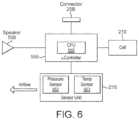
- FIG. 6is a schematic diagram of the main functional components of the body 20 of the e-cigarette 10 of FIG. 1 in accordance with some embodiments of the disclosure. These components may be mounted on the circuit board provided within the body 20 , although depending on the particular configuration, in some embodiments, one or more of the components may instead be accommodated in the body 20 to operate in conjunction with the circuit board, but is/are not physically mounted on the circuit board itself.
- the body 20includes the sensor unit 215 located in or adjacent to the air path through the body 20 from the air inlet to the air outlet (to the vaporizer).
- the sensor unit 215includes a pressure drop sensor 562 and temperature sensor 563 (also in or adjacent to this air path).
- the body 20further includes a small speaker 558 and an electrical socket or connector 25 B for connecting to the cartomizer 30 or to a USB charging device. (The body may also be provided with a tip connector 900 , such as discussed above in relation to FIG. 5 .)
- the microcontroller (e.g. an ASIC) 555includes a CPU 550 .
- the operations of the CPU 550 and other electronic components, such as the pressure sensor 562are generally controlled at least in part by software programs running on the CPU 550 (or other component).
- software programsmay be stored in non-volatile memory, such as ROM, which can be integrated into the microcontroller 555 itself, or provided as a separate component.
- the CPU 550may access the ROM to load and execute individual software programs as and when required.
- the microcontroller 555also contains appropriate communications interfaces (and control software) for communicating as appropriate with other devices in the body 10 , such as the pressure sensor 562 .
- the CPU 550controls the speaker 558 to produce audio output to reflect conditions or states within the e-cigarette 10 , such as a low battery warning.
- Different signals for signaling different states or conditionsmay be provided by utilizing tones or beeps of different pitch and/or duration, and/or by providing multiple such beeps or tones.
- the e-cigarette 10may also be provided with an LED indicator (instead of or as well as speaker 558 ) to provide visual output to a user, such as a warning of low battery charge.
- the e-cigarette 10provides an air path from the air inlet through the e-cigarette 10 , past the pressure drop sensor 562 and the heater (in the vaporizer or cartomizer 30 ), to the mouthpiece 35 .
- the CPU 550detects such inhalation based on information from the pressure drop sensor.
- the CPU 550supplies power from the battery or cell 210 to the heater, which thereby heats and vaporizes the nicotine from the wick for inhalation by the user.
- the level of power supplied to the heatermay be controlled on the basis of information from the pressure sensor and/or the temperature sensor 563 , for example, to help regulate the nicotine delivery to the user according to the current ambient air pressure and temperature.
- FIG. 7illustrates a pack 100 for receiving and accommodating an e-cigarette 10 in accordance with some embodiments of the disclosure.
- the pack 100comprises a body 120 which is provided with a hinged lid 140 that can open and close.
- the body 120comprises an outer case or housing 125 which is fitted with an insert 130 . More particularly, the outer case 125 has an opening at the top, i.e. the end at which the lid is located, and the insert 130 is fitted into, and generally closes, this opening.
- the insert 130itself is provided with two openings or holes that extend down into the body 120 of the pack 100 .
- the first opening 132comprises a substantially circular hole (in terms of cross-sectional shape). The first opening 132 is surrounded by an annular light element 133 .
- the second opening 131 in the insertcomprises a pair of linked holes (only one of which is easily visible in FIG. 7 ).
- the openings 132 and 131(and more particularly, each of the pair of holes formed by opening 131 ) can be used to receive an appropriately shaped object, such as an e-cigarette, a spare or used cartridge, etc.
- the dimensions of pack 100are generally arranged so that an e-cigarette accommodated within openings 132 or 131 protrudes slightly out of this opening. This allows a user to readily discern the contents of pack 100 (as also helped by making lid 140 transparent), and also facilitates removal by a user of an e-cigarette located within one of these openings.
- the pack 100is further provided with a set of LED lights 128 . These are shown separated from the casing 125 in FIG. 7 in an exploded view, but in the assembled pack 100 are integrated into the body 120 so as to lie flush with the outer casing 125 . These LED lights 128 can be used to indicate the charging state of the pack 100 , for example, whether it is fully charged, partly charged, or fully discharged. The LED lights 128 may also be used to indicate whether or not the pack 100 is currently charging (being charged). Such charging may be accomplished via a (mini or micro) USB link using a (mini or micro) USB connector located on the underside of the pack 100 (not visible in FIG. 7 ).
- FIG. 8illustrates the main components that are housed within the body 120 of the pack 100 , more particularly, within housing 125 , in accordance with some embodiments of the disclosure (some minor components, such as internal wiring, are omitted for reasons of clarity).
- the bodyincludes a battery unit 150 comprising a battery 151 , a printed circuit board (PCB) 154 , and a switch 152 .
- the body 120can be seen to include a hinge or axle 134 , which provides a pivot about which the lid 140 is able to open and shut.
- the battery unit 150including the switch 152 , is located substantially below the hinge 134 .
- the switch 152is activated as the lid 140 is opened or closed, and this activation of the switch 152 then, in turn, is able to trigger activation of the LED lights, etc.
- the insert 130extends substantially to the bottom of the outer casing 125 .
- the insertdefines a substantially cylindrical tube 132 A extending down from opening 132 (see FIG. 7 ), which is able to receive and hold an e-cigarette.
- the insertfurther includes two further substantially cylindrical tubes 131 A, 131 B, which overlap one another, extending down from opening 131 (see FIG. 7 ) with a “figure-of-8” cross-section.
- tubes 131 A and 131 Bmay be closed by the insert 130 itself, or may be open, but abutting against the bottom of the outer casing 125 , which would then have the effect of again closing the bottom of the tubes 131 A and 131 B in order to retain an e-cigarette (or other item, such as a spare cartridge, therein).
- the configuration of the bottom of the tube 132 Ais explained in more detail later on.
- the battery 151is relatively large—comparable in size, for example, with the opening 132 and associated tube 132 A for receiving an e-cigarette. Consequently the battery 151 of the pack 100 will usually have significantly greater electrical storage capacity than a battery provided in an e-cigarette which may be accommodated within the pack 100 . This allows the battery in the e-cigarette to be re-charged, typically several times, using the battery unit 150 of pack 100 , without the need for any additional, external power supply (such as a mains connection). This can be very convenient for a user, who may be in a location or situation which does not provide a ready connection to the mains power supply.
- the bottom portion of the tube 132 Ais located within an e-cigarette connection assembly 700 .
- the e-cigarette connection assembly 700allows an electrical connection to be made between the pack 100 and the electrical contacts 900 A, 900 B on the cap 225 of the e-cigarette 10 when the e-cigarette 10 is inserted into the tube 132 A, thus allowing the e-cigarette battery 210 to be charged using the pack battery 151 . This is explained in more detail below.
- the insert 130is provided with printed circuit boards (PCBs) 135 and 160 .
- the PCB 160provides the main control functionality of the pack 100 and is attached to tubes 131 A, 131 B by screws 136 A, 136 B, thereby retaining the PCB 160 in the appropriate position relative to the tubes 131 A, 131 B.
- a mini-USB (or micro-USB) connector 164is provided at the bottom of the PCB 160 , and is accessible through a corresponding aperture in the underside of the housing 125 of the pack body 120 . This USB connector 164 can be used to connect an external power supply to the pack 100 for re-charging the battery 151 (and also any e-cigarette located in tube 132 A).
- the USB connector 164may also be used, if so desired, for communications with the electronics of the pack 100 and/or e-cigarette 10 , for example to update software on the PCB 160 and/or to download usage data from the e-cigarette 10 , etc.
- the PCB 160is further provided with a set of physical and mechanical connectors 161 for retaining and operating the LED lighting 128 .
- the PCB 160controls the LED lighting element 128 to provide an indication to a user about the current charging situation of the pack 100 , plus any other suitable information.
- the PCB 135is located on the outside of re-charging tube 132 A, relatively near the top, i.e. closer to the hole or opening 132 for receiving an e-cigarette for re-charging.
- This PCB 135incorporates at least one light emitting diode (LED), which is used to illuminate the annular light element 133 .
- the PCB 135 , LED and annular light element 133are used to provide an indication to a user about the current charging situation of an e-cigarette located within tube 132 A pack 100 , plus any other suitable information.
- FIGS. 9 A and 9 Bshow (in an exploded view) the e-cigarette connection assembly 700 in more detail in accordance with some embodiments of the disclosure.
- the e-cigarette connection assembly 700comprises a base 702 , which is located on the base of the pack 100 , and a connector 703 , which has two electrical contacts 704 A, 704 B for making an electrical connection with the electrical contacts 900 A, 900 B on the cap 225 of the e-cigarette 10 when the e-cigarette 10 is inserted into the tube 132 A.
- the outer electrical contact 704 Amakes an electrical connection with electrical contact 900 A on the e-cigarette 10
- the inner electrical contact 704 Bmakes an electrical connection with the electrical contact 900 B on the e-cigarette 10 .
- the electrical contacts 704 A, 704 Bare connected to the PCB 160 via wires 708 A, 708 B and, under the control of the PCB 160 , act as positive and negative electrodes for charging the e-cigarette 10 with power supplied from the battery 151 .
- the electrical contacts 704 A, 704 Bare spring-mounted on the base 702 so as to ensure good electrical connection with the electrical contacts 900 A, 900 B on the cap 225 of the e-cigarette 10 .
- Electrical conductors connecting the electrical contacts 704 A, 704 B and the wires 708 A, 708 Bmay extend along the surface of the base 702 or may extend through a bore through the base 702 , for example.
- the e-cigarette connection assembly 700further comprises a cylindrical tube 706 which is fixed to the base 702 .
- a portion of the cylindrical tube 706is configured to receive an end portion of the tube 132 A.
- the inner diameter of the portion of the cylindrical tube 706 which receives the end portion of the tube 132 Ais set such that the outer surface of the end portion of the tube 132 A frictionally engages with the inner surface of the cylindrical tube 706 .
- the inner surface of the cylindrical tube 706further comprises a rib 714 which abuts the end of the tube 132 A and ensures that only an end portion of the tube 132 A having a predetermined length is able to enter the cylindrical tube 706 .
- the cylindrical tube 706further comprises a groove 710 on its outer surface which engages with a rib 712 on the PCB 160 .
- the base 702abuts the bottom inner surface of the outer case 125 .
- the insert 130 and e-cigarette connection assembly 700are held in place within the outer case 125 (and also in relation to one another).
- the configuration and arrangement of the pack 100 and insert 130 shown in FIGS. 7 , 8 and 9are provided by way of example, and the skilled person will be aware of many potential variations—e.g. the number, position, size and/or shape of holes 131 , 132 may vary from one embodiment to another, likewise the associated tubes 131 A, 131 B, 132 A. Similarly, the details of the positioning, shape and size of the battery unit 150 , PCB 160 , and other components will generally vary from one embodiment to another, depending upon the particular circumstances and requirements of any given implementation. It is also noted that the shape and positioning of the electrical contacts 704 A, 704 B will be adapted according to different shape and positional configurations of electrical contacts 900 A, 900 B on the e-cigarette 10 .
- FIGS. 10 and 11schematically show some components of the e-cigarette 10 and pack 100 , respectively, in accordance with some embodiments of the disclosure. These components help to improve the safety and reliability of the various charging mechanisms provided for the e-cigarette 10 and pack 100 .
- FIG. 10schematically depicts some electrical components of the e-cigarette 10 .
- FIG. 10also shows a tip charge PCB 1002 , a temperature sensor 1006 , and an over-current protection PCB 1000 . It is noted that for the sake of clarity, not all electrical components of the e-cigarette 10 are included in FIG. 10 e.g. some of the components already shown in FIG. 6 have been omitted.
- the over-current protection PCB 1000monitors the current flowing through the connector 25 B during operation of the e-cigarette 10 . It is recalled that, during use of the e-cigarette 10 , the CPU 550 detects when a user is drawing air through the e-cigarette 10 using information from the sensor unit 215 and causes current to flow to the heater 365 in the cartomizer 30 via the connector 25 B. If there is a short circuit at the heater 365 , for example, there will be a sudden increase in current flowing through the heater 365 and connector 25 B. The short circuit might occur for reasons such as an electrical fault at the heater 365 , the heating circuit having been tampered with, excessive moisture making contact with the heater 365 , etc. A short circuit of the heater 365 may risk damage occurring to the e-cigarette device or, worse, injury to the user.
- the over-current protection PCB 1000upon detection of a current through the connector 25 B which is deemed too high (that is, above a certain predetermined threshold), causes the supply of current from the battery 210 to the connector 25 B to be cut. This reduces the chance of damage to the e-cigarette 10 and of injury to the user due to such a short circuit.
- the predetermined current thresholdis set such that dangerously high currents indicative of a short circuit are cut off, but normal, non-dangerous variations in the current are not cut off (thus avoiding unnecessary inconvenience to the user).
- the threshold for the current supply from the battery 210 to the heater 365may be set somewhere in the range 40-250 milliAmps, or more precisely, in the range 60-120 milliAmps, such that any current greater than this threshold amount triggers a circuit cut off.
- the PCB 1000may also cut-off if the voltage of the battery 210 is too low, for example, below about 3.1 or 3.2V. This generally indicates that the battery 210 is in a state of low charge, and this could potentially prevent correct (or satisfactory) operation of the heater coil.
- the over-current protection PCB 1000may also monitor current flowing through the connector 25 B, and/or voltage applied at connector 25 B, during re-charging of the e-cigarette 10 via USB connector 25 B.
- the expected voltage applied by a USB charger to the USB connector 25 Bmay be 5V, so that the over-voltage cut-off might be set, by way of illustration, at 6V.
- the over-current protection PCB 1000therefore provides protection for the e-cigarette 10 both during re-charging (against excessive re-charging voltage), and also during normal operation (against excessive current draw).
- the tip charge PCB 1002acts as a controller for monitoring and controlling power flow from the pack 100 to the e-cigarette battery 210 during re-charging. For example, the tip charge PCB may cut off the power flow from the pack 100 to the battery 210 if the voltage and/or current received via connector 900 is too high—e.g. exceeds a predetermined threshold for voltage or current.
- the thresholdscan be set to tolerate the full range of normal operating conditions, but to trigger (cut off) before a level that might start to cause damage to the e-cigarette 10 .
- the tip charge PCB 1002is connected to the temperature sensor 1006 .
- the temperature sensor 1006is in thermal contact with the battery 210 so as to be responsive to the temperature of the battery 210 .
- Thius temperature sensor 1006is normally an additional device to temperature sensor 563 shown in FIG. 6 , since the former is positioned to measure the temperature of the battery 210 , while the latter is positioned to measure the temperature of the airflow into the e-cigarette 10 .
- the battery 210As the battery 210 is (re)charged using the connector 900 (that is, when the e-cigarette 10 is inserted into the tube 132 A of the pack 100 so that the connector 900 makes electrical contact with the connector 703 of the pack), the battery 210 will normally heat up. However, if the battery 210 gets too hot (perhaps due to a fault in the battery 210 or because the ambient temperature is very warm), this may cause damage to the e-cigarette 10 , to the pack 100 or, worse, injury to the user. Also, if the battery 210 is very cold (perhaps due to the ambient temperature being very cold), then attempting to charge the battery 210 may cause damage to it. Thus, the tip charge PCB 1002 monitors the temperature of the battery 210 using information generated by the temperature sensor 1006 .
- the tip charge PCB 1002cuts off the current supply to the battery 210 from the connector 900 . This reduces the chance of damage to the e-cigarette 10 or pack 100 or of injury to the user due to the battery 210 overheating, as well as reducing the chance of damage to the battery 210 by charging it when it is too cold.
- the predetermined upper temperature thresholdis set such that high temperatures indicative of potential battery overheating result in current to the battery 210 being cut off, whereas lower increases in battery temperature do not result in the current to the battery 210 being cut off.
- the predetermined lower temperature thresholdis set such that low temperatures which could damage the battery 210 result in current to the battery 210 being cut off, whereas smaller reductions in battery temperature do not result in current to the battery 210 being cut off.
- the upper and lower temperature thresholdsare about 60° C. and about 0° C., or about 45° C. and about 10° C., respectively.
- the tip charging PCB 1002also ensures that current is only supplied to the battery 210 for a predetermined time period before it is cut off. This ensures that the battery 210 is not subjected to overcharging, in which the battery 210 is continuously charged even though it is at full capacity (which might damage the battery 210 ).
- the predetermined time periodis set so that the battery 210 can be charged to its full capacity (maximizing the length of time that the user can use the e-cigarette 10 without having to recharge it), but also avoiding overcharging of the battery 210 .
- the predetermined time periodmay be set somewhere in the range 1 to 4 hours, such as between 1 and 2 hours.
- over-current protection PCB 1000 and/or the tip charging PCB 1002provide protection based on the parameters or dimensions set out below.
- the re-charge(or operation of the device as appropriate) can be terminated by activating a suitable cut-off.
- protection for each of the above four parameters or dimensionsmay generally be implemented as appropriate in the over-current protection PCB 1000 and/or in the tip charge PCB 1002 , where the former relates to the re-charge or normal operation through connector 25 B, while the latter relates to re-charge through connector 900 .
- the functionality shown in FIG. 10may be implemented using separate components.
- the tip charge PCB 1002may be implemented as a separate component such as a BQ24040 PCB from Texas Instruments (this can help support the use of off-the-shelf components).
- the tip charge and over-current protection PCBs 1002 , 1000may be integrated as part of the microcontroller 555 (see FIG. 6 ).
- the tip charge and over-current protection PCBs 1002 , 1000are integrated together into a single device which is separate from the microcontroller 555 .
- the e-cigarette 10is provided with two contacts that can be used for re-charging, namely connector 900 (for charging via pack 100 ), and also connector 25 B, which can be used for charging via a (micro) USB connector when the e-cigarette 10 is in a disassembled state (the body 20 and cartomizer 30 separated).
- Connector 25 Bcan also be used for supplying power from the body to the cartomizer when the e-cigarette 10 is in an assembled state.
- the tip charge PCB 1002provides protection and control in relation to charging the e-cigarette via connector 900 .
- the over-current protection PCB 1000provides protection and control in relation to supplying power from the body 20 to the cartomizer 30 .
- the over-current protection PCB 1000may also provide protection and control in relation to charging the e-cigarette 10 from an external power supply via connector 25 B, analogous to the protection provided by tip charge PCB 1002 when re-charging via connector 900 .
- this protection and controlmay involve monitoring the current and/or voltage supplied from connector 25 B, and cutting off the power supply to the battery 210 if the current or voltage exceeds a respective limit.
- the over-current protection PCBmay cut off power if the duration (time) of charging exceeds some threshold level, or if the temperature of the e-cigarette 10 is too hot or too cold.
- over-current protection PCB 1000may have access to temperature sensor 1006 for making this latter determination, or may be provided with its own, additional temperature sensor (not shown in FIG. 10 ).
- FIG. 11schematically shows some electrical components of the recharge pack 100 in accordance with some embodiments of the disclosure.
- FIG. 11also shows an over-current cut-off unit 1100 , an over-voltage cut-off unit 1102 , a multipoint control unit (MCU) 1104 , a regulator PCB 1106 , a temperature sensor 1108 and a protection circuit module (PCM) 1110 . Similar to FIG. 10 , certain components of the pack 100 have been omitted from FIG. 11 for the sake of clarity.
- MCUmultipoint control unit
- PCBprotection circuit module
- the pack 100supports three main charging operations (modes). (1) When the connector 164 is electrically connected to a power source (such as a USB charging device), power flows from the power source via the connector 164 to the battery 151 . This allows the battery 151 to be charged. (2) When the connector 164 is electrically connected to a power source (such as a USB charging device), power also flows from the power source via the connectors 164 and 703 to an e-cigarette 10 (if present). This allows the battery 210 of the e-cigarette 10 to be charged (simultaneously with the pack battery 151 ).
- a power sourcesuch as a USB charging device
- the regulating PCB 1106is the principal controller of power for charging the battery 151 in that it regulates the current and voltage supplied to the battery 151 during charging.
- the regulating PCB 1106is implemented using a MicrOne ME4057 device; however, other implementations may use different devices (or may integrate the functionality of the regulating PCB 1106 into other components).
- the current and voltageare regulated by PCB 1106 such that they remain substantially constant at predetermined values, which are selected to provide efficient, timely and safe charging of the battery 151 and to help enhance or at least maintain the battery's long-term lifespan (the long-time lifespan being related to the total number of times a rechargeable battery can be charged and recharged before it starts permanently losing its capacity).
- the predetermined values of the current and voltagemay be about 400-500 mA and about 4.2V respectively during charging.
- the predetermined valuesmay also change over the course of a single battery charge. For example, when the battery 151 is first charged, the predetermined value of the current may be lower. Then, at a later time, when the battery 151 has stored a certain amount of charge, the predetermined value of the current may be stepped up to about 400-500 mA as above. This prevents the battery 151 from being subjected to a relatively large current when it is completely discharged (or close to being completely discharged), which might otherwise cause damage to the battery 151 and reduce its long-term lifespan.
- Other implementationsmay have a different maximum current supply or voltage supply, such as somewhere in the region 250-600 mA and somewhere in the region 3-6V (respectively).
- the regulating PCB 1106is also connected to the temperature sensor 1108 .
- the temperature sensor 1108is in thermal contact with the battery 151 so as to be responsive to the temperature of the battery 151 .
- the battery 151will normally heat up. However, if the battery 151 gets too hot (perhaps due to a fault in the battery 151 or because the ambient temperature is very warm), this may cause damage to the battery 151 or pack 100 or, worse, injury to the user. Also, if the battery 151 is very cold (perhaps due to the ambient temperature being very cold), then attempting to charge the battery 151 may also cause damage to the battery 151 .
- the regulating PCB 1106monitors the temperature of the battery 151 using information provided by the temperature sensor 1108 . If the temperature gets too hot (that is, above a certain predetermined upper threshold) or too cold (that is, below a predetermined lower threshold), then the regulating PCB 1106 cuts off the current supply to the battery 210 . This reduces the chance of damage to the battery 151 or pack 100 and of injury to the user due the battery 151 overheating, and reduces the chance of damage to the battery 151 by charging it when it is too cold.
- the predetermined upper temperature thresholdis set such that high temperatures indicative of battery overheating result in current to the battery 151 being cut off, but normal (routine) increases in battery temperature, which do not risk damage, do not result in current to the battery 151 being cut off.
- the predetermined lower temperature thresholdis set such that for low temperatures, which might result in damage to the battery 151 , the current to the battery 151 is cut off. However, falls in battery temperature that remain within the specified normal operating limits do not result in current to the battery 151 being cut off.
- the upper and lower temperature thresholdsare about 45° C. and about ⁇ 5° C., respectively. However, for some batteries, the upper temperature threshold may be up to about 60° C. and the lower temperature threshold may be down to about ⁇ 20° C. Typically the upper threshold is in the range 45 to 60° C., while the lower threshold is in the range 0 to ⁇ 20° C.
- the pack 100may be provided with a temperature sensor that measures ambient temperature within the pack 100 (typically close to the location of any re-charging e-cigarette inside the pack 100 ). Again, this sensor may trigger a power cut-off if the temperature is found to rise above a certain threshold, such as 50° C. Note that such a temperature sensor may be provided in addition to or instead of temperature sensor 1108 as shown in FIG. 11 (which is intended to measure primarily the temperature of the battery 151 ).
- pack 100is provided with further safeguards against excessive voltages or currents that are too high and which may therefore cause damage to the battery 151 or other components of the pack 100 (or injury to the user).
- pack 100also includes the over-current cut-off unit 1100 and the over-voltage cut-off unit 1102 .
- the over-current cut-off unit 1100cuts off the power supplied from the connector 164 to the other components of the pack 100 (including the regulating PCB 1106 ) when it detects that the current exceeds a predetermined threshold. Even though the current supplied to the battery 151 is regulated by the regulating PCB 1106 (as already described), the over-current cut-off unit 1100 provides an extra layer of protection to the battery 151 and other pack components. For example, the over-current cut-off unit 1100 helps to reduce the risk of damage to the components of the pack in the case that too much current is supplied via the connector 164 (this could happen, for example, if an unsuitable charging device which supplies too much current is connected to the connector 164 , or if one of the components of the pack short circuits).
- the over-current cut-off unit 1100may be implemented, for example, using a thermal resettable fuse, which trips out by entering a high impedance state when the current exceeds the predetermined threshold. At a later time, when the temperature cools down, the thermal resettable fuse re-enters a low impedance state again, thereby allowing current to flow again (so that use of the pack 100 may be resumed).
- the predetermined current thresholdis set such that a high current which might cause damage is cut off, but such that variations in the current within normal and acceptable operating parameters do not produce a cut-off.
- the predetermined current thresholdmay be set at about 1 amp.
- the over-voltage cut-off unit 1102cuts off the power supplied from the connector 164 to the other components of the pack 100 (including the regulating PCB 1106 ) if it detects that the supply voltage has exceeded a predetermined threshold. Even though the voltage supplied to the battery 151 is regulated by the regulating PCB 1106 (as described above), the over-voltage cut-off unit 1100 provides an extra layer of protection for the battery 151 and other pack components, thus reducing the risk of damage to the components in the pack 100 (or potential injury to the user) in the case that too high a voltage is supplied via the connector 164 . Such a high voltage might occur, for example, if an unsuitable charging device that supplies too high a voltage were to be connected to the connector 164 .
- the predetermined voltage thresholdis set such that a dangerously high voltage is cut off (i.e. one that might damage the device, or possibly cause injury to a user), but variations of the voltage within the normal (non-dangerous) operating range are not cut off.
- the predetermined voltage thresholdmay be set at about 6V, thereby ensuring that a 5V USB charging device will not trigger the over-voltage cut-off unit 1102 , but that higher voltages will trigger the over-voltage cut-off unit 1102 .
- the PCM 1110which sits between the regulating PCB and the battery 151 , monitors the current and voltage between the battery 151 and other components of the pack (including the regulating PCB 1106 ) and trips the electrical connection between the battery 151 and the other pack components in the case that the current or voltage moves outside a predetermined current or voltage range (respectively). This monitoring is performed both for charging the battery 151 (from an external power supply via connector 164 ), and also for discharging the battery 151 (to supply power to battery 210 in the e-cigarette 10 via connector 703 , as well as to other components in the pack 100 , such as lighting 128 ).
- the electrical connection between the battery 151 and other pack componentsis tripped (cut off), i.e. the flow of power between the battery 151 and the other pack components is prevented or at least seriously impeded.
- the threshold for the over-voltagemay be set, for example, at about 4.3V, while the threshold for the over-current may be set, for example, in the range 1.5-2.5 amps, e.g. at about 1.8 amps.
- the electrical connection between the battery 151 and the other pack components, such as connector 703is cut off. This helps to prevent damage to the battery 151 that might otherwise occur due the continued drawing of current from the battery 151 when it has a low remaining capacity and is outputting a low voltage (this can happen with certain rechargeable batteries such as Li-ion batteries).
- the PCM 1110may comprise a separate PCB or may (for example) be integrated as part of the battery 151 . Due to the position of the PCM 1110 within the electrical circuit (that is, between the battery 151 and other pack components), the PCM 1110 is able to detect voltage/current abnormalities which may not be detectable by the other voltage/current-controlling pack components (such as the regulator PCB 1106 , over-current cut-off unit 1100 and over-voltage cut-off unit 1102 ). The PCM 1110 thus adds an extra layer of protection against the risk of damage to the battery 151 or any of the other pack components (or e-cigarette 10 ), and against potential injury to the user caused by abnormal current or voltage values.
- the PCM 1110may comprise any standard PCB suitable for detecting whether or not an applied voltage and/or current is within certain predetermined limits. Furthermore, the PCM 1110 may comprise a metal-oxide-semiconductor field-effect transistor (MOSFET) for detecting when the current exceeds the predetermined current threshold.
- MOSFETmetal-oxide-semiconductor field-effect transistor
- the MCU 1104ensures that current is only supplied to the battery 151 during charging for a predetermined time period before it is cut off. This helps to ensure that the battery 151 is not subjected to overcharging, in which the battery 151 is continuously charged even though it is at full capacity (this may damage the battery 151 ).
- the predetermined time periodis set to allow the battery to be charged to its full capacity (thereby maximizing the length of time between charges for which the user can use the pack 100 , such as to recharge the e-cigarette 10 ), but also avoiding overcharging of the battery 151 .
- the predetermined time periodmay be set somewhere in the range 2 to 8 hours, such as between 4 and 6 hours.
- the cut-off of the current supply to the battery 151 after the predetermined time period has elapsedmay also help reduce the chance of the battery 151 becoming too hot or too cold. Although this is managed by the temperature-monitoring function of the regulating PCB 1106 (as already described), if, for any reason, the temperature-monitoring function does not work correctly, then, because current is only supplied to the battery 151 for the predetermined time period (rather than indefinitely), the above-discussed problems associated with continuously supplying current to the battery 151 when it is too hot may at least be alleviated.
- the MCU 1104also ensures that current is only supplied from the battery 151 during charging of an e-cigarette 10 via the connector 703 for a predetermined time before it is cut off. This provides an extra layer of protection to help prevent overcharging of the battery 210 of the e-cigarette 10 (in addition to the timed current cut-off function of the tip charge PCB 1002 of the e-cigarette 10 itself, as described above).
- the predetermined time periodmay be set somewhere in the range 2 to 6 hours, such as between 3 and 5 hours. Note that this cut-off applies irrespective of whether the current is being supplied to the e-cigarette 10 via the external power source and connector 164 or from the pack battery 151 .
- the overcharging of the e-cigarette battery 210may be avoided primarily by the predetermined e-cigarette charge time of the tip charge PCB 1002 , with the predetermined e-cigarette charge time of the MCU 1104 then being set at the same or a somewhat larger value so as to act as a back-up in the event that the timer of the MCU 1104 experiences a fault and fails to cut off the current at the appropriate time.
- overcharging of the e-cigarette 10can be avoided even if there is a failure in the timer function of the e-cigarette 10 .
- the pack 100 of FIG. 11may implement a large number of protection features such as: protection against high voltage and/or high current received from connector 164 , and/or from power being supplied from connector 164 for too long; protection against the pack 100 and/or battery 151 having too high (or too low) a temperature (this protection is relevant for all 3 of the charging modes defined above); protection against high voltage and/or high current being supplied to an e-cigarette 10 via connector 703 , and/or from power being supplied to the e-cigarette 10 via connector 703 for too long (this current/voltage and timing protection can apply irrespective of whether the e-cigarette 10 is being re-charged by an external power supply or by pack battery 151 .
- PCB 1106There may also be a cut-off implemented by PCB 1106 if the voltage of pack battery 151 exceeds a predetermined level while the pack battery 151 is re-charging (typically somewhere in the range 4.2-4.5V), or if the voltage of the pack battery 151 falls below a predetermined level while the pack battery 151 is discharging (to the e-cigarette or other components of pack).
- This lower voltagemay be set, for example, in the range 2-3V, such as approximately 2.5V.
- One or more of the components of FIG. 11may be integrated as part of the PCBs 160 , 135 or 154 shown in FIG. 8 . Alternatively, one or more of them may be separate components. In addition, the functionality may be distributed differently between the different components.
- the connector 703 of the pack 100 and the connector 900 of the e-cigarette 10there are numerous potential variations for the connector 703 of the pack 100 and the connector 900 of the e-cigarette 10 .
- the connectors 703 , 900may vary in position, size, shape, etc., so long as the connectors 703 and 900 are able to provide an electrical connection with each other to allow current to flow from the battery 151 of the pack 100 to the battery 210 of the e-cigarette 10 .
Landscapes
- Engineering & Computer Science (AREA)
- Power Engineering (AREA)
- Manufacturing & Machinery (AREA)
- Chemical & Material Sciences (AREA)
- Chemical Kinetics & Catalysis (AREA)
- Electrochemistry (AREA)
- General Chemical & Material Sciences (AREA)
- Health & Medical Sciences (AREA)
- Microelectronics & Electronic Packaging (AREA)
- Anesthesiology (AREA)
- Life Sciences & Earth Sciences (AREA)
- Pulmonology (AREA)
- Mechanical Engineering (AREA)
- Biomedical Technology (AREA)
- Heart & Thoracic Surgery (AREA)
- Hematology (AREA)
- Bioinformatics & Cheminformatics (AREA)
- Animal Behavior & Ethology (AREA)
- General Health & Medical Sciences (AREA)
- Public Health (AREA)
- Veterinary Medicine (AREA)
- Charge And Discharge Circuits For Batteries Or The Like (AREA)
- Battery Mounting, Suspending (AREA)
- Secondary Cells (AREA)
Abstract
Description
- time—there is a threshold for a maximum re-charge duration.
- temperature—there are upper and lower thresholds for a maximum and minimum battery temperature respectively. These thresholds are applied in particular when
battery 210 is being re-charged, but may also be applied during normal operation of the device—i.e. when the user is inhaling throughe-cigarette 10 to activateheater 365 and produce vapor output. - voltage—there is a threshold for a maximum voltage applied during re-charge.
- current—there is a threshold for a maximum current flowing during re-charge and/or for a maximum current flowing from the
body 20 to thecartomizer 30 during normal operation of the e-cigarette.
- a) monitoring and regulating across multiple parameters or dimensions, in particular, using time, temperature, voltage and current. Not only do these different dimensions can help to detect different fault conditions, but they also help to provide redundant (backup) protection against certain fault conditions, should one of the monitoring and regulating systems itself fail;
- b) monitoring and regulating at various locations within both the
e-cigarette 10 and also in thepack 100. Monitoring and regulation at multiple locations within one device (i.e. thepack 100 or the e-cigarette10), potentially for the same parameter (current, voltage, etc), again can help to detect different fault conditions, as well as helping to provide redundant (backup) protection against certain fault conditions, should one of the monitoring and regulating systems itself fail. In addition, providing corresponding monitoring and regulation functionality both in the e-cigarette10 itself, and also in the chargingpack 100, further helps to provide some protection should a user try to use a different charging pack100 (i.e. one without the safety components described above) for re-charging thee-cigarette 10, or to use the chargingpack 100 to re-charge a different e-cigarette (i.e. one without the safety components described above).
Claims (8)
Priority Applications (2)
| Application Number | Priority Date | Filing Date | Title |
|---|---|---|---|
| US18/498,252US20240063648A1 (en) | 2014-07-29 | 2023-10-31 | E-cigarette and re-charging pack |
| US19/029,559US20250167323A1 (en) | 2014-07-29 | 2025-01-17 | E-cigarette and re-charging pack |
Applications Claiming Priority (3)
| Application Number | Priority Date | Filing Date | Title |
|---|---|---|---|
| GB1413432 | 2014-07-29 | ||
| GB1413432.4AGB2528711B (en) | 2014-07-29 | 2014-07-29 | E-cigarette and re-charging pack |
| PCT/GB2015/052152WO2016016620A1 (en) | 2014-07-29 | 2015-07-24 | E-cigarette and re-charging pack |
Related Parent Applications (3)
| Application Number | Title | Priority Date | Filing Date |
|---|---|---|---|
| US15/326,592ContinuationUS10276898B2 (en) | 2014-07-29 | 2015-07-24 | E-cigarette and re-charging pack |
| PCT/GB2015/052152ContinuationWO2016016620A1 (en) | 2014-07-29 | 2015-07-24 | E-cigarette and re-charging pack |
| US201715326592AContinuation | 2014-07-29 | 2017-01-16 |
Related Child Applications (1)
| Application Number | Title | Priority Date | Filing Date |
|---|---|---|---|
| US18/498,252ContinuationUS20240063648A1 (en) | 2014-07-29 | 2023-10-31 | E-cigarette and re-charging pack |
Publications (2)
| Publication Number | Publication Date |
|---|---|
| US20190190088A1 US20190190088A1 (en) | 2019-06-20 |
| US11831155B2true US11831155B2 (en) | 2023-11-28 |
Family
ID=51587415
Family Applications (4)
| Application Number | Title | Priority Date | Filing Date |
|---|---|---|---|
| US15/326,592ActiveUS10276898B2 (en) | 2014-07-29 | 2015-07-24 | E-cigarette and re-charging pack |
| US16/281,332Active2035-07-28US11831155B2 (en) | 2014-07-29 | 2019-02-21 | E-cigarette and re-charging pack |
| US18/498,252PendingUS20240063648A1 (en) | 2014-07-29 | 2023-10-31 | E-cigarette and re-charging pack |
| US19/029,559PendingUS20250167323A1 (en) | 2014-07-29 | 2025-01-17 | E-cigarette and re-charging pack |
Family Applications Before (1)
| Application Number | Title | Priority Date | Filing Date |
|---|---|---|---|
| US15/326,592ActiveUS10276898B2 (en) | 2014-07-29 | 2015-07-24 | E-cigarette and re-charging pack |
Family Applications After (2)
| Application Number | Title | Priority Date | Filing Date |
|---|---|---|---|
| US18/498,252PendingUS20240063648A1 (en) | 2014-07-29 | 2023-10-31 | E-cigarette and re-charging pack |
| US19/029,559PendingUS20250167323A1 (en) | 2014-07-29 | 2025-01-17 | E-cigarette and re-charging pack |
Country Status (8)
| Country | Link |
|---|---|
| US (4) | US10276898B2 (en) |
| EP (3) | EP3745524B1 (en) |
| CN (3) | CN113498886A (en) |
| ES (2) | ES2828450T3 (en) |
| GB (1) | GB2528711B (en) |
| PL (2) | PL3175507T3 (en) |
| RU (1) | RU2682333C2 (en) |
| WO (1) | WO2016016620A1 (en) |
Families Citing this family (88)
| Publication number | Priority date | Publication date | Assignee | Title |
|---|---|---|---|---|
| US20160345631A1 (en) | 2005-07-19 | 2016-12-01 | James Monsees | Portable devices for generating an inhalable vapor |
| US10279934B2 (en) | 2013-03-15 | 2019-05-07 | Juul Labs, Inc. | Fillable vaporizer cartridge and method of filling |
| WO2015026948A1 (en)* | 2013-08-20 | 2015-02-26 | VMR Products, LLC | Vaporizer |
| US10039321B2 (en) | 2013-11-12 | 2018-08-07 | Vmr Products Llc | Vaporizer |
| USD825102S1 (en) | 2016-07-28 | 2018-08-07 | Juul Labs, Inc. | Vaporizer device with cartridge |
| US10058129B2 (en) | 2013-12-23 | 2018-08-28 | Juul Labs, Inc. | Vaporization device systems and methods |
| USD842536S1 (en) | 2016-07-28 | 2019-03-05 | Juul Labs, Inc. | Vaporizer cartridge |
| DE202014011260U1 (en) | 2013-12-23 | 2018-11-13 | Juul Labs Uk Holdco Limited | Systems for an evaporation device |
| US10159282B2 (en) | 2013-12-23 | 2018-12-25 | Juul Labs, Inc. | Cartridge for use with a vaporizer device |
| US20160366947A1 (en) | 2013-12-23 | 2016-12-22 | James Monsees | Vaporizer apparatus |
| US10076139B2 (en) | 2013-12-23 | 2018-09-18 | Juul Labs, Inc. | Vaporizer apparatus |
| GB2524736B (en) | 2014-03-31 | 2021-02-24 | Nicoventures Holdings Ltd | Re-charging pack for an e-cigarette |
| WO2016012795A1 (en) | 2014-07-24 | 2016-01-28 | Nicoventures Holdings Limited | Re-charging pack for an e-cigarette |
| GB2524735B (en) | 2014-03-31 | 2017-10-25 | Nicoventures Holdings Ltd | Re-charging pack for an e-cigarette |
| GB2528711B (en)* | 2014-07-29 | 2019-02-20 | Nicoventures Holdings Ltd | E-cigarette and re-charging pack |
| GB2528712B (en) | 2014-07-29 | 2019-03-27 | Nicoventures Holdings Ltd | E-cigarette and re-charging pack |
| MX394125B (en) | 2014-12-05 | 2025-03-24 | Juul Labs Inc | CALIBRATED DOSE CONTROL |
| US10874139B2 (en)* | 2015-07-07 | 2020-12-29 | Altria Client Services Llc | E-vapor device including capsule containing pre-vapor formulation |
| EA036828B1 (en)* | 2015-12-22 | 2020-12-24 | Джапан Тобакко Инк. | Power supply assembly, non-combustion-type flavor inhaler and non-combustion-type flavor inhalation system |
| US12356507B2 (en)* | 2016-02-01 | 2025-07-08 | Altria Client Services Llc | Aerosol-generating device having multiple power supplies |
| EP3413960B1 (en) | 2016-02-11 | 2021-03-31 | Juul Labs, Inc. | Fillable vaporizer cartridge and method of filling |
| CO2018009342A2 (en) | 2016-02-11 | 2018-09-20 | Juul Labs Inc | Secure fixing cartridges for vaporizing devices |
| US9936733B2 (en) | 2016-03-09 | 2018-04-10 | Rai Strategic Holdings, Inc. | Accessory configured to charge an aerosol delivery device and related method |
| US10405582B2 (en) | 2016-03-10 | 2019-09-10 | Pax Labs, Inc. | Vaporization device with lip sensing |
| USD849996S1 (en) | 2016-06-16 | 2019-05-28 | Pax Labs, Inc. | Vaporizer cartridge |
| USD851830S1 (en) | 2016-06-23 | 2019-06-18 | Pax Labs, Inc. | Combined vaporizer tamp and pick tool |
| USD836541S1 (en) | 2016-06-23 | 2018-12-25 | Pax Labs, Inc. | Charging device |
| WO2018001746A1 (en)* | 2016-06-29 | 2018-01-04 | Philip Morris Products S.A. | Battery powered aerosol-generating device comprising a temperature dependent battery pre-heating |
| US10729177B2 (en)* | 2016-07-31 | 2020-08-04 | Altria Client Services Llc | Electronic vaping device, battery section, and charger |
| CN120531201A (en)* | 2016-08-05 | 2025-08-26 | 尤尔实验室有限公司 | Evaporator air speed auxiliary control |
| CA3054273C (en)* | 2017-03-06 | 2022-01-11 | Japan Tobacco Inc. | Battery unit, flavor inhaler, method for controlling battery unit, and program |
| EA201992106A1 (en)* | 2017-03-06 | 2020-02-03 | Джапан Тобакко Инк. | BATTERY UNIT, INHALATOR FOR TASTE AROMATIC MATERIAL, METHOD FOR MANAGING THE BATTERY UNIT AND PROGRAM |
| CA3043272A1 (en) | 2017-03-14 | 2018-09-20 | Philip Morris Products S.A. | Power management method and system for a battery powered aerosol-generating device |
| GB201707194D0 (en) | 2017-05-05 | 2017-06-21 | Nicoventures Holdings Ltd | Electronic aerosol provision system |
| CN107280072A (en) | 2017-06-19 | 2017-10-24 | 深圳市合元科技有限公司 | Electronic cigarette and its control method |
| GB201709982D0 (en)* | 2017-06-22 | 2017-08-09 | Nicoventures Holdings Ltd | Electronic vapour provision system |
| USD887632S1 (en) | 2017-09-14 | 2020-06-16 | Pax Labs, Inc. | Vaporizer cartridge |
| US10505383B2 (en)* | 2017-09-19 | 2019-12-10 | Rai Strategic Holdings, Inc. | Intelligent charger for an aerosol delivery device |
| JP6860687B2 (en)* | 2017-10-18 | 2021-04-21 | 日本たばこ産業株式会社 | Battery unit, flavor aspirator, method of controlling the battery unit, and program |
| CN111225574B (en)* | 2017-10-18 | 2023-07-07 | 日本烟草产业株式会社 | Battery unit, fragrance inhaler, charger, method of controlling battery unit, and computer-readable recording medium |
| CN111511229B (en)* | 2017-10-24 | 2024-01-12 | 日本烟草产业株式会社 | Aerosol generating device, method for operating it, and storage medium |
| USD893412S1 (en)* | 2017-11-06 | 2020-08-18 | William Lee Steadman | Battery |
| USD889739S1 (en) | 2018-07-12 | 2020-07-07 | Juul Labs, Inc. | Case |
| USD889035S1 (en) | 2018-01-26 | 2020-06-30 | Juul Labs, Inc. | Case |
| EP3743977A1 (en) | 2018-01-26 | 2020-12-02 | Juul Labs, Inc. | Charging case assembly |
| PL3738454T3 (en)* | 2018-02-02 | 2024-05-20 | Japan Tobacco Inc. | Power source unit for inhalation component generation device |
| JP1638846S (en) | 2018-02-28 | 2019-08-13 | ||
| USD860523S1 (en) | 2018-02-28 | 2019-09-17 | Juul Labs, Inc. | Case |
| KR102142635B1 (en)* | 2018-03-06 | 2020-08-07 | 주식회사 케이티앤지 | Method and device for supplying power |
| CN112203532A (en) | 2018-05-31 | 2021-01-08 | 日本烟草产业株式会社 | Fragrance generating device |
| CN108631416A (en)* | 2018-07-17 | 2018-10-09 | 绿烟实业(深圳)有限公司 | Wireless charging type electronic cigarette packet and heated type non-combustion system |
| KR102832535B1 (en)* | 2018-07-31 | 2025-07-11 | 니뽄 다바코 산교 가부시키가이샤 | Charging device and information processing system |
| EP3838034B1 (en) | 2018-08-13 | 2023-08-09 | Japan Tobacco Inc. | Flavor generation system, method, and program |
| WO2020051385A1 (en)* | 2018-09-06 | 2020-03-12 | Bergstrom Sam | Vaporizer apparatuses and vaporizing methods |
| US11103013B2 (en) | 2018-09-07 | 2021-08-31 | Fontem Holdings 1 B.V. | Pivotable charging case for electronic smoking device |
| JP6577113B1 (en) | 2018-10-03 | 2019-09-18 | 日本たばこ産業株式会社 | Aerosol generating device, control unit, method and program for aerosol generating device |
| JP2020058236A (en)* | 2018-10-04 | 2020-04-16 | 日本たばこ産業株式会社 | Suction component generation device, control circuit, control method and control program for suction component generation device |
| US11089820B2 (en)* | 2018-10-12 | 2021-08-17 | Tuanfang Liu | Electronic cigarette comprising sealed atomizing assembly |
| WO2020082040A1 (en) | 2018-10-19 | 2020-04-23 | Juul Labs, Inc. | Charging adapter for vaporizer device |
| US11882438B2 (en)* | 2018-10-29 | 2024-01-23 | Zorday IP, LLC | Network-enabled electronic cigarette |
| WO2020090374A1 (en)* | 2018-10-30 | 2020-05-07 | 日本たばこ産業株式会社 | Power supply unit of aerosol generation device, control method of power supply unit of aerosol generation device, and program for power supply unit of aerosol generation device |
| JP6557393B1 (en) | 2018-10-31 | 2019-08-07 | 日本たばこ産業株式会社 | Power supply unit for aerosol inhaler, its control method and control program |
| JP6564922B1 (en)* | 2018-10-31 | 2019-08-21 | 日本たばこ産業株式会社 | Power supply unit for aerosol inhaler, its control method and control program |
| US11592793B2 (en)* | 2018-11-19 | 2023-02-28 | Rai Strategic Holdings, Inc. | Power control for an aerosol delivery device |
| CN113939203A (en) | 2019-01-15 | 2022-01-14 | 尤尔实验室有限公司 | Evaporator device |
| JP6608082B1 (en)* | 2019-01-17 | 2019-11-20 | 日本たばこ産業株式会社 | Power supply unit for aerosol inhaler |
| WO2020182739A1 (en)* | 2019-03-11 | 2020-09-17 | Nicoventures Trading Limited | Aerosol provision device |
| GB201915511D0 (en) | 2019-10-25 | 2019-12-11 | Nicoventures Trading Ltd | Battery charging |
| KR102864765B1 (en)* | 2020-04-13 | 2025-09-24 | 삼성에스디아이 주식회사 | Rechargeable battery |
| WO2021213848A1 (en)* | 2020-04-22 | 2021-10-28 | Jt International Sa | Electrical system for an aerosol generating device |
| US20230225418A1 (en)* | 2020-06-25 | 2023-07-20 | Philip Morris Products S.A. | Aerosol-generating device with visual feedback means |
| JP6864769B1 (en)* | 2020-07-09 | 2021-04-28 | 日本たばこ産業株式会社 | Aerosol aspirator power supply unit |
| JP6864140B1 (en) | 2020-07-09 | 2021-04-28 | 日本たばこ産業株式会社 | Power supply unit of aerosol generator |
| EP3937337B1 (en) | 2020-07-09 | 2022-11-09 | Japan Tobacco Inc. | Power supply unit for aerosol inhaler comprising a temperature sensor |
| US20220015441A1 (en)* | 2020-07-15 | 2022-01-20 | Altria Client Services Llc | Non-nicotine electronic vaping devices having auto shutdown |
| US20220015436A1 (en)* | 2020-07-15 | 2022-01-20 | Altria Client Services Llc | Nicotine electronic vaping devices having auto shutdown |
| JP6856811B1 (en) | 2020-09-07 | 2021-04-14 | 日本たばこ産業株式会社 | Power supply unit of aerosol generator |
| JP6856810B1 (en)* | 2020-09-07 | 2021-04-14 | 日本たばこ産業株式会社 | Power supply unit of aerosol generator |
| JP6905134B1 (en) | 2020-09-07 | 2021-07-21 | 日本たばこ産業株式会社 | Power supply unit of aerosol generator |
| WO2022050812A1 (en) | 2020-09-07 | 2022-03-10 | Kt&G Corporation | Aerosol generating device and method for controlling power mode thereof |
| KR102525015B1 (en)* | 2020-11-11 | 2023-04-24 | 주식회사 케이티앤지 | Protection circuit module and aerosol generating device including the same |
| GB202019031D0 (en)* | 2020-12-02 | 2021-01-13 | Nicoventures Trading Ltd | Aerosol provision |
| EP4312636A1 (en) | 2021-03-29 | 2024-02-07 | JT International SA | Combination of a vaporizer and a charger and a method of outputting information related to a combination of a vaporizer and a charger |
| CN113100505B (en)* | 2021-04-02 | 2024-02-02 | 北京航天雷特机电工程有限公司 | Split type electronic heating smoking set and charging method thereof |
| KR20230163495A (en)* | 2021-05-10 | 2023-11-30 | 니뽄 다바코 산교 가부시키가이샤 | Power unit of aerosol generating device |
| US12088029B2 (en)* | 2021-07-20 | 2024-09-10 | Dell Products L.P. | Cable termination for information handling systems |
| CN114287679A (en)* | 2021-12-30 | 2022-04-08 | 苏州米力特智能科技有限公司 | Miniature electronic atomization system capable of being accurately controlled and control method |
| EP4580436A1 (en)* | 2022-08-31 | 2025-07-09 | Imperial Tobacco Limited | Aerosol generating apparatus |
Citations (65)
| Publication number | Priority date | Publication date | Assignee | Title |
|---|---|---|---|---|
| US5391974A (en) | 1990-10-15 | 1995-02-21 | Toshiba Battery Co., Ltd. | Secondary battery charging circuit |
| WO1997041744A1 (en) | 1996-05-02 | 1997-11-13 | 1149235 Ontario Inc. | Hand-held smoker's device for sidestream smoke control |
| US5723971A (en) | 1995-07-20 | 1998-03-03 | Nippon Soken, Inc. | Apparatus for charging a battery for a charge time determined based on the depth of discharge |
| US5864224A (en) | 1994-12-26 | 1999-01-26 | Yamaha Hatsudoki Kabushiki Kaisha | Method for charging secondary battery and charger therefor |
| WO1999017418A1 (en) | 1997-09-30 | 1999-04-08 | Chartec Laboratories A/S | Method and apparatus for charging a rechargeable battery |
| US20030117112A1 (en)* | 2001-12-24 | 2003-06-26 | Huei-Chiu Chen | Method and apparatus for implementing smart management of a rechargeable battery |
| RU2210841C2 (en) | 2001-04-02 | 2003-08-20 | Открытое акционерное общество "Всероссийский научно-исследовательский и проектно-конструкторский институт электровозостроения" | Method for charging nickel-cadmium storage battery |
| US20030218446A1 (en) | 2000-11-30 | 2003-11-27 | Rolf Beerwerth | Circuit for charging rechargeable batteries |
| US20040150367A1 (en) | 2003-01-31 | 2004-08-05 | James Cornett | Method of terminating charge for a battery |
| US20080238362A1 (en)* | 2007-03-26 | 2008-10-02 | The Gillette Company | Fast Battery Charger Device and Method |
| US20080258688A1 (en) | 2007-04-19 | 2008-10-23 | Summit Microelectronics, Inc. | Battery Charging Systems and Methods with Adjustable Current Limit |
| EP2079142A1 (en) | 2008-01-10 | 2009-07-15 | Research In Motion Limited | Rechargeable battery pack |
| CN201370098Y (en) | 2009-02-04 | 2009-12-30 | 万佳通达科技(北京)有限公司 | Electronic cigarette |
| CN201374580Y (en) | 2009-02-04 | 2009-12-30 | 万佳通达科技(北京)有限公司 | Charging unit of electronic cigarette case |
| CN201370099Y (en) | 2009-02-04 | 2009-12-30 | 万佳通达科技(北京)有限公司 | Electronic cigarette case |
| US20100141215A1 (en)* | 2008-12-04 | 2010-06-10 | Mitsumi Electric Co., Ltd. | Rechargeable battery protection integrated circuit device, rechargeable battery protection module using the rechargeable battery protection integrated circuit device, and battery pack |
| CN101789531A (en) | 2010-01-29 | 2010-07-28 | 上海广为电器工具有限公司 | Original charging device of protection device |
| CN201571500U (en) | 2009-11-12 | 2010-09-08 | 深圳市博格科技有限公司 | Portable traveling charging cigarette case for electronic cigarettes |
| US20100277128A1 (en) | 2009-05-04 | 2010-11-04 | Apple Inc. | Portable electronic device having automatic low temperature battery charging capability |
| US20110036346A1 (en) | 2009-04-21 | 2011-02-17 | A. J. Marketing Llc | Personal inhalation devices |
| US20110226236A1 (en) | 2008-10-23 | 2011-09-22 | Helmut Buchberger | Inhaler |
| US20110265806A1 (en) | 2010-04-30 | 2011-11-03 | Ramon Alarcon | Electronic smoking device |
| RU114228U1 (en) | 2011-10-19 | 2012-03-10 | Федеральное государственное унитарное предприятие "18 Центральный научно-исследовательский институт" Министерства обороны Российской Федерации | BATTERY CHARGING DEVICE WITH RESTRICTION AND SIGNALING OF ITS CURRENT OVERLOADS |
| US20120127619A1 (en) | 2010-11-23 | 2012-05-24 | Adrian Mikolajczak | Input power port protection component |
| US20120227753A1 (en)* | 2010-12-06 | 2012-09-13 | Newton Kyle D | Charger Package for Electronic Cigarette Components |
| JP2012228142A (en) | 2011-04-22 | 2012-11-15 | Sanyo Electric Co Ltd | Charging finished time definition method, charging finished time definition device, and pack battery |
| CN102916461A (en) | 2012-09-06 | 2013-02-06 | 深圳市合元科技有限公司 | Intelligent charge-discharge control circuit of battery |
| US20130038275A1 (en) | 2009-10-28 | 2013-02-14 | Superior Communications, Inc. | Method and apparatus for recharging batteries in a more efficient manner |
| CN202819631U (en) | 2012-09-29 | 2013-03-27 | 吴昌明 | Electronic smoking device |
| CN103124097A (en) | 2013-03-27 | 2013-05-29 | 南通林诺电子科技有限公司 | Intelligent lithium ion charger |
| WO2013093695A1 (en) | 2011-12-18 | 2013-06-27 | Sis Resources Ltd. | Charging electronic cigarette |
| US20130192615A1 (en) | 2012-01-31 | 2013-08-01 | Altria Client Services Inc. | Electronic cigarette |
| CN203166461U (en) | 2013-03-05 | 2013-08-28 | 向智勇 | Control device used for overcurrent or short-circuit protection of electronic cigarette |
| CN203166467U (en) | 2013-03-20 | 2013-08-28 | 向智勇 | Overvoltage protection circuit |
| CN203166473U (en) | 2013-03-20 | 2013-08-28 | 向智勇 | Overheating protective device for electronic cigarette or cartridge |
| CN203166462U (en) | 2013-03-05 | 2013-08-28 | 向智勇 | Protective device for preventing dropping of power supply voltage of microcontroller in electronic cigarette |
| JP2013168285A (en) | 2012-02-15 | 2013-08-29 | Toyota Motor Corp | Battery system and method for controlling charge/discharge of nonaqueous secondary battery |
| RU2492558C1 (en) | 2012-03-29 | 2013-09-10 | Открытое Акционерное Общество "Научно-Исследовательский Институт Железнодорожного Транспорта" | Method of determining frequency of maintenance of accumulator battery |
| US20130241500A1 (en) | 2012-03-13 | 2013-09-19 | Hon Hai Precision Industry Co., Ltd. | Charge control circuit |
| US20130293186A1 (en) | 2012-05-02 | 2013-11-07 | Wistron Corp. | Battery charging circuit |
| CN203326671U (en) | 2013-07-10 | 2013-12-04 | 向智勇 | Control circuit for electronic cigarette case |
| CN203337806U (en) | 2013-08-01 | 2013-12-11 | 向智勇 | Power Inquiry Device |
| CN203339772U (en) | 2013-07-23 | 2013-12-11 | 向智勇 | An electronic cigarette USB charger |
| US20130336358A1 (en) | 2012-06-16 | 2013-12-19 | Qiuming Liu | Electronic Cigarette Case and Electronic Cigarette Device |
| CN203368107U (en) | 2013-08-09 | 2013-12-25 | 向智勇 | Charger with overvoltage and overcurrent protection |
| CN203387219U (en) | 2013-05-28 | 2014-01-08 | 向智勇 | Electronic cigarette high-efficiency charging device |
| CN203398771U (en) | 2013-07-31 | 2014-01-15 | 向智勇 | An overcurrent and overvoltage protection circuit for electronic cigarettes |
| CN203434223U (en) | 2013-08-16 | 2014-02-12 | 刘秋明 | Electronic cigarette package, electronic cigarette as well as battery assembly thereof |
| CN203482903U (en) | 2013-10-17 | 2014-03-19 | 向智勇 | Touch control circuit and cigarette case circuit |
| CN203504217U (en) | 2013-09-10 | 2014-03-26 | 向智勇 | electronic cigarette case |
| WO2014047953A1 (en) | 2012-09-29 | 2014-04-03 | Wu Changming | Electronic smoking device |
| CN203537022U (en) | 2013-10-31 | 2014-04-09 | 刘秋明 | An electronic cigarette charging device |
| US20140117784A1 (en)* | 2012-10-31 | 2014-05-01 | Motorola Solutions, Inc. | Portable rechargeable battery pack and external adapter for same |
| WO2014075369A1 (en) | 2012-11-13 | 2014-05-22 | 卓尔悦(常州)电子科技有限公司 | Intelligent controller and method for electronic cigarette |
| CN203660013U (en) | 2013-09-29 | 2014-06-18 | 刘秋明 | Battery pack of electronic cigarette, atomization component and electronic cigarette |
| US20140278250A1 (en)* | 2013-03-15 | 2014-09-18 | Altria Client Services Inc. | System and method of obtaining smoking topography data |
| EP2782201A1 (en)* | 2011-11-16 | 2014-09-24 | Panasonic Corporation | Storage battery unit |
| US20140291179A1 (en)* | 2013-04-01 | 2014-10-02 | Zhiyong Xiang | Electronic cigarette case with sterilization function |
| WO2014163664A1 (en) | 2013-04-05 | 2014-10-09 | Johnson Creek Enterprises, LLC | Method and apparatus for controlling electronic cigarette |
| US20150181942A1 (en)* | 2012-08-24 | 2015-07-02 | Philips Morris Products S.A. | Portable electronic system including charging device and method of charging a secondary battery |
| WO2015165813A1 (en) | 2014-04-30 | 2015-11-05 | Philip Morris Products S.A. | An electrically heated aerosol-generating system |
| US20170207499A1 (en)* | 2014-07-29 | 2017-07-20 | Nicoventures Holdings Limited | E-cigarette and re-charging pack |
| US10218193B2 (en) | 2014-07-29 | 2019-02-26 | Nicoventures Holdings Limited | E-cigarette and re-charging pack |
| US10236708B2 (en) | 2014-07-24 | 2019-03-19 | Nicoventures Holdings Limited | Re-charging pack for an e-cigarette |
| US10433584B2 (en) | 2014-07-24 | 2019-10-08 | Nicoventures Holdings Limited | Re-charging pack for an E-cigarette |
Family Cites Families (12)
| Publication number | Priority date | Publication date | Assignee | Title |
|---|---|---|---|---|
| CN1305145C (en)* | 2000-10-20 | 2007-03-14 | 瑞约伐克股份有限公司 | Method and apparatus for regulating charging of electrochemical cells |
| JP2006115654A (en)* | 2004-10-18 | 2006-04-27 | Nec Corp | Charging control circuit, electronic apparatus therewith and charging control method |
| CN101647177A (en)* | 2007-03-26 | 2010-02-10 | 吉列公司 | Fast battery charger device and method |
| KR100929036B1 (en) | 2007-09-27 | 2009-11-30 | 삼성에스디아이 주식회사 | Protection circuit of battery pack, battery pack having same and operation method thereof |
| JP5098912B2 (en)* | 2008-07-11 | 2012-12-12 | ソニー株式会社 | Battery pack and charge control system |
| US20100102781A1 (en)* | 2008-10-24 | 2010-04-29 | Sony Ericsson Mobile Communications Ab | Apparatus and method for charging a battery |
| FR2940950B1 (en)* | 2009-01-12 | 2011-02-11 | Renault Sas | METHOD FOR ANTICIPATING RETROGRADING AND CONTROLLING AN AUTOMATIC TRANSMISSION |
| DE102011005418A1 (en) | 2011-03-11 | 2012-09-13 | Robert Bosch Gmbh | Security charger |
| US9312712B2 (en)* | 2012-07-26 | 2016-04-12 | Samsung Sdi Co., Ltd. | Method and system for controlling charging parameters of a battery using a plurality of temperature ranges and counters and parameter sets |
| AU2012388105B2 (en) | 2012-08-24 | 2017-01-12 | Huizhou Kimree Technology Co., Ltd. | Electronic cigarette apparatus |
| CN203262281U (en) | 2013-04-15 | 2013-11-06 | 向智勇 | Electronic cigarette case |
| CN203662028U (en) | 2014-01-24 | 2014-06-25 | 惠州市吉瑞科技有限公司 | Electronic cigarette case |
- 2014
- 2014-07-29GBGB1413432.4Apatent/GB2528711B/enactiveActive
- 2015
- 2015-07-24PLPL15744313Tpatent/PL3175507T3/enunknown
- 2015-07-24CNCN202110938107.0Apatent/CN113498886A/enactivePending
- 2015-07-24RURU2017102636Apatent/RU2682333C2/enactive
- 2015-07-24USUS15/326,592patent/US10276898B2/enactiveActive
- 2015-07-24CNCN201580041644.8Apatent/CN106575877B/enactiveActive
- 2015-07-24EPEP20185949.3Apatent/EP3745524B1/enactiveActive
- 2015-07-24CNCN202110938114.0Apatent/CN113498887A/enactivePending
- 2015-07-24WOPCT/GB2015/052152patent/WO2016016620A1/enactiveApplication Filing
- 2015-07-24EPEP15744313.6Apatent/EP3175507B1/ennot_activeRevoked
- 2015-07-24ESES15744313Tpatent/ES2828450T3/enactiveActive
- 2015-07-24EPEP24152925.4Apatent/EP4340170A3/enactivePending
- 2015-07-24ESES20185949Tpatent/ES2976589T3/enactiveActive
- 2015-07-24PLPL20185949.3Tpatent/PL3745524T3/enunknown
- 2019
- 2019-02-21USUS16/281,332patent/US11831155B2/enactiveActive
- 2023
- 2023-10-31USUS18/498,252patent/US20240063648A1/enactivePending
- 2025
- 2025-01-17USUS19/029,559patent/US20250167323A1/enactivePending
Patent Citations (80)
| Publication number | Priority date | Publication date | Assignee | Title |
|---|---|---|---|---|
| US5391974A (en) | 1990-10-15 | 1995-02-21 | Toshiba Battery Co., Ltd. | Secondary battery charging circuit |
| US5864224A (en) | 1994-12-26 | 1999-01-26 | Yamaha Hatsudoki Kabushiki Kaisha | Method for charging secondary battery and charger therefor |
| US5723971A (en) | 1995-07-20 | 1998-03-03 | Nippon Soken, Inc. | Apparatus for charging a battery for a charge time determined based on the depth of discharge |
| WO1997041744A1 (en) | 1996-05-02 | 1997-11-13 | 1149235 Ontario Inc. | Hand-held smoker's device for sidestream smoke control |
| WO1999017418A1 (en) | 1997-09-30 | 1999-04-08 | Chartec Laboratories A/S | Method and apparatus for charging a rechargeable battery |
| EP1040547A1 (en) | 1997-09-30 | 2000-10-04 | Chartec Laboratories A/S | Method and apparatus for charging a rechargeable battery |
| US20030218446A1 (en) | 2000-11-30 | 2003-11-27 | Rolf Beerwerth | Circuit for charging rechargeable batteries |
| RU2210841C2 (en) | 2001-04-02 | 2003-08-20 | Открытое акционерное общество "Всероссийский научно-исследовательский и проектно-конструкторский институт электровозостроения" | Method for charging nickel-cadmium storage battery |
| US20030117112A1 (en)* | 2001-12-24 | 2003-06-26 | Huei-Chiu Chen | Method and apparatus for implementing smart management of a rechargeable battery |
| US20040150367A1 (en) | 2003-01-31 | 2004-08-05 | James Cornett | Method of terminating charge for a battery |
| US20080238362A1 (en)* | 2007-03-26 | 2008-10-02 | The Gillette Company | Fast Battery Charger Device and Method |
| CN101675570A (en) | 2007-04-19 | 2010-03-17 | 舒米特微电子公司 | Batter-charghing system and method with adjustable current restriction |
| US20080258688A1 (en) | 2007-04-19 | 2008-10-23 | Summit Microelectronics, Inc. | Battery Charging Systems and Methods with Adjustable Current Limit |
| EP2079142A1 (en) | 2008-01-10 | 2009-07-15 | Research In Motion Limited | Rechargeable battery pack |
| US20090179618A1 (en) | 2008-01-10 | 2009-07-16 | Siong Litingtun | Rechargeable battery pack |
| US20110226236A1 (en) | 2008-10-23 | 2011-09-22 | Helmut Buchberger | Inhaler |
| US20100141215A1 (en)* | 2008-12-04 | 2010-06-10 | Mitsumi Electric Co., Ltd. | Rechargeable battery protection integrated circuit device, rechargeable battery protection module using the rechargeable battery protection integrated circuit device, and battery pack |
| CN201370099Y (en) | 2009-02-04 | 2009-12-30 | 万佳通达科技(北京)有限公司 | Electronic cigarette case |
| CN201370098Y (en) | 2009-02-04 | 2009-12-30 | 万佳通达科技(北京)有限公司 | Electronic cigarette |
| CN201374580Y (en) | 2009-02-04 | 2009-12-30 | 万佳通达科技(北京)有限公司 | Charging unit of electronic cigarette case |
| US20110036346A1 (en) | 2009-04-21 | 2011-02-17 | A. J. Marketing Llc | Personal inhalation devices |
| US20100277128A1 (en) | 2009-05-04 | 2010-11-04 | Apple Inc. | Portable electronic device having automatic low temperature battery charging capability |
| US20130038275A1 (en) | 2009-10-28 | 2013-02-14 | Superior Communications, Inc. | Method and apparatus for recharging batteries in a more efficient manner |
| CN201571500U (en) | 2009-11-12 | 2010-09-08 | 深圳市博格科技有限公司 | Portable traveling charging cigarette case for electronic cigarettes |
| CN101789531A (en) | 2010-01-29 | 2010-07-28 | 上海广为电器工具有限公司 | Original charging device of protection device |
| US20110265806A1 (en) | 2010-04-30 | 2011-11-03 | Ramon Alarcon | Electronic smoking device |
| US20120127619A1 (en) | 2010-11-23 | 2012-05-24 | Adrian Mikolajczak | Input power port protection component |
| US20120227753A1 (en)* | 2010-12-06 | 2012-09-13 | Newton Kyle D | Charger Package for Electronic Cigarette Components |
| JP2012228142A (en) | 2011-04-22 | 2012-11-15 | Sanyo Electric Co Ltd | Charging finished time definition method, charging finished time definition device, and pack battery |
| RU114228U1 (en) | 2011-10-19 | 2012-03-10 | Федеральное государственное унитарное предприятие "18 Центральный научно-исследовательский институт" Министерства обороны Российской Федерации | BATTERY CHARGING DEVICE WITH RESTRICTION AND SIGNALING OF ITS CURRENT OVERLOADS |
| EP2782201A1 (en)* | 2011-11-16 | 2014-09-24 | Panasonic Corporation | Storage battery unit |
| US20150020831A1 (en)* | 2011-12-18 | 2015-01-22 | Sis Resources Ltd. | Charging electronic cigarette |
| WO2013093695A1 (en) | 2011-12-18 | 2013-06-27 | Sis Resources Ltd. | Charging electronic cigarette |
| US20130192615A1 (en) | 2012-01-31 | 2013-08-01 | Altria Client Services Inc. | Electronic cigarette |
| JP2013168285A (en) | 2012-02-15 | 2013-08-29 | Toyota Motor Corp | Battery system and method for controlling charge/discharge of nonaqueous secondary battery |
| US20130241500A1 (en) | 2012-03-13 | 2013-09-19 | Hon Hai Precision Industry Co., Ltd. | Charge control circuit |
| RU2492558C1 (en) | 2012-03-29 | 2013-09-10 | Открытое Акционерное Общество "Научно-Исследовательский Институт Железнодорожного Транспорта" | Method of determining frequency of maintenance of accumulator battery |
| US20130293186A1 (en) | 2012-05-02 | 2013-11-07 | Wistron Corp. | Battery charging circuit |
| US20130336358A1 (en) | 2012-06-16 | 2013-12-19 | Qiuming Liu | Electronic Cigarette Case and Electronic Cigarette Device |
| US20150181942A1 (en)* | 2012-08-24 | 2015-07-02 | Philips Morris Products S.A. | Portable electronic system including charging device and method of charging a secondary battery |
| CN102916461A (en) | 2012-09-06 | 2013-02-06 | 深圳市合元科技有限公司 | Intelligent charge-discharge control circuit of battery |
| CN202819631U (en) | 2012-09-29 | 2013-03-27 | 吴昌明 | Electronic smoking device |
| US20150189916A1 (en) | 2012-09-29 | 2015-07-09 | Ahmad Thaer | Electronic smoking device |
| WO2014047953A1 (en) | 2012-09-29 | 2014-04-03 | Wu Changming | Electronic smoking device |
| US20140117784A1 (en)* | 2012-10-31 | 2014-05-01 | Motorola Solutions, Inc. | Portable rechargeable battery pack and external adapter for same |
| EP2921064A1 (en) | 2012-11-13 | 2015-09-23 | Joyetech (Changzhou) Electronics Co., Ltd. | Intelligent controller and method for electronic cigarette |
| WO2014075369A1 (en) | 2012-11-13 | 2014-05-22 | 卓尔悦(常州)电子科技有限公司 | Intelligent controller and method for electronic cigarette |
| CN203166461U (en) | 2013-03-05 | 2013-08-28 | 向智勇 | Control device used for overcurrent or short-circuit protection of electronic cigarette |
| CN203166462U (en) | 2013-03-05 | 2013-08-28 | 向智勇 | Protective device for preventing dropping of power supply voltage of microcontroller in electronic cigarette |
| US20140278250A1 (en)* | 2013-03-15 | 2014-09-18 | Altria Client Services Inc. | System and method of obtaining smoking topography data |
| US20140285937A1 (en) | 2013-03-20 | 2014-09-25 | Zhiyong Xiang | Circuit and method of over-voltage protection |
| CN203166473U (en) | 2013-03-20 | 2013-08-28 | 向智勇 | Overheating protective device for electronic cigarette or cartridge |
| CN203166467U (en) | 2013-03-20 | 2013-08-28 | 向智勇 | Overvoltage protection circuit |
| CN103124097A (en) | 2013-03-27 | 2013-05-29 | 南通林诺电子科技有限公司 | Intelligent lithium ion charger |
| US20140291179A1 (en)* | 2013-04-01 | 2014-10-02 | Zhiyong Xiang | Electronic cigarette case with sterilization function |
| WO2014163664A1 (en) | 2013-04-05 | 2014-10-09 | Johnson Creek Enterprises, LLC | Method and apparatus for controlling electronic cigarette |
| CN203387219U (en) | 2013-05-28 | 2014-01-08 | 向智勇 | Electronic cigarette high-efficiency charging device |
| US20150015187A1 (en) | 2013-07-10 | 2015-01-15 | Zhiyong Xiang | Control circuit and method for electronic cigarette box |
| CN203326671U (en) | 2013-07-10 | 2013-12-04 | 向智勇 | Control circuit for electronic cigarette case |
| CN203339772U (en) | 2013-07-23 | 2013-12-11 | 向智勇 | An electronic cigarette USB charger |
| CN203398771U (en) | 2013-07-31 | 2014-01-15 | 向智勇 | An overcurrent and overvoltage protection circuit for electronic cigarettes |
| CN203337806U (en) | 2013-08-01 | 2013-12-11 | 向智勇 | Power Inquiry Device |
| CN203368107U (en) | 2013-08-09 | 2013-12-25 | 向智勇 | Charger with overvoltage and overcurrent protection |
| US20150043117A1 (en) | 2013-08-09 | 2015-02-12 | Zhiyong Xiang | Charger with over-voltage and over-current protection and method for using the same |
| CN203434223U (en) | 2013-08-16 | 2014-02-12 | 刘秋明 | Electronic cigarette package, electronic cigarette as well as battery assembly thereof |
| US20160226286A1 (en) | 2013-09-10 | 2016-08-04 | Kimree Hi-Tech Inc. | Electronic cigarette case and method for detecting battery rod insertion into or removal from electronic cigarette case |
| CN203504217U (en) | 2013-09-10 | 2014-03-26 | 向智勇 | electronic cigarette case |
| CN203660013U (en) | 2013-09-29 | 2014-06-18 | 刘秋明 | Battery pack of electronic cigarette, atomization component and electronic cigarette |
| CN203482903U (en) | 2013-10-17 | 2014-03-19 | 向智勇 | Touch control circuit and cigarette case circuit |
| WO2015054961A1 (en) | 2013-10-17 | 2015-04-23 | 吉瑞高新科技股份有限公司 | Touch control circuit, cigarette case circuit, and control method for touch electronic cigarette case |
| CN203537022U (en) | 2013-10-31 | 2014-04-09 | 刘秋明 | An electronic cigarette charging device |
| EP3136889A1 (en) | 2014-04-30 | 2017-03-08 | Philip Morris Products S.A. | An electrically heated aerosol-generating system |
| WO2015165813A1 (en) | 2014-04-30 | 2015-11-05 | Philip Morris Products S.A. | An electrically heated aerosol-generating system |
| US10236708B2 (en) | 2014-07-24 | 2019-03-19 | Nicoventures Holdings Limited | Re-charging pack for an e-cigarette |
| US20190181675A1 (en) | 2014-07-24 | 2019-06-13 | Nicoventures Holdings Limited | Re-charging pack for an e-cigarette |
| US10433584B2 (en) | 2014-07-24 | 2019-10-08 | Nicoventures Holdings Limited | Re-charging pack for an E-cigarette |
| US20170207499A1 (en)* | 2014-07-29 | 2017-07-20 | Nicoventures Holdings Limited | E-cigarette and re-charging pack |
| US10218193B2 (en) | 2014-07-29 | 2019-02-26 | Nicoventures Holdings Limited | E-cigarette and re-charging pack |
| US10276898B2 (en)* | 2014-07-29 | 2019-04-30 | Nicoventures Holdings Limited | E-cigarette and re-charging pack |
| US20190157887A1 (en) | 2014-07-29 | 2019-05-23 | Nicoventures Holdings Limited | E-cigarette and re-charging pack |
Non-Patent Citations (78)
| Title |
|---|
| "Battery charging, gauging and protection presentation," Jun. 29, 2010, 22 pages. |
| "Expert opinion of Mr Wei Wei", Jan. 12, 2023. |
| "JEITA-Compliant, Li+ Charger with Smart Power Selector, Automatic Detection, and USB Enumeration", datasheet for MAX77301, Maxim Intergrated, 2012, 70 pages. |
| "Oral proceedings by Hoffmann Eitle for European Patent Application No. 3175507, mailed on Jan. 27, 2023", Jan. 27, 2023, 19 pages. |
| "Oral proceedings by Weickmann for European Patent Application No. 3175507, mailed on Jan. 10, 2023", Jan. 10, 2023, 16 pages. |
| Analog Devices; Compact, 1.5 A Linear Charger for Single-Cell Li+ Battery; ADP2291; 2005; Available from https://www.analog.com/media/en/technical-documentation/data-sheets/adp2291.pdf. |
| Archive version of corresponding product page of bq24190 dated Jan. 4, 2013 as retrieved via https ://archive. org/web/, Retrieved from the Internet: https://www.ti.com/product/BQ24190, 5 pages. |
| Archive Version of Corresponding product page of bq24295 dated Jan. 5, 2014 as retrieved via https ://archive.org/web/, Retrieved from the Internet: https://www.ti.com/product/BQ24295, 2 pages. |
| Archive Version of Corresponding Product Page of bq28550 dated Dec. 7, 2011 as retrieved via https://archive.org/web/, Retrieved from the Internet: https://www.ti.com/product/bq28550, 2 pages. |
| Barsukov Y., et al., "Battery Power Management for Portable Devices," Artech House Power Engineering, May 1, 2013, ISBN-13 978-1608074914, 56 pages. |
| Battery University: "All About Chargers," Mar. 7, 2011, 4 Pages. |
| Battery University: "Charging Lithium Ion", Jun. 25, 2014, Retrieved from the Internet: https://web.archive.org/web/20140625074339/https://batteryuniversity.com/learn/article/charging_lithium_ion_batteries, 3 pages. |
| Battery University: "Safety Circuits for Modern Batteries," Jun. 26, 2014, Internet Archive—http://web.archive.org/web/20140626163028/https://batteryuniversity.com/learn/article/safety_circuits_for_modern_batteries, 3 pages. |
| Beale J., "Transcript of Battery charging, gauging and protection," Jun. 29, 2010, Retrieved from the Internet: https://training.ti.com/battery-charging-gauging-and-protection, 18 pages. |
| Bourns Incorporated: "Internet Archive Wayback Machine capture of MF-PSMF Series—PTC Resettable Fuses," Feb. 13, 2014, 3 pages. |
| Bourns, "Preventing Component Circuit Damage from Above Range Current with Reliable Overcurrent Protection," 2009, 8 pages. |
| Brown D., "Battery Charging Options for Portable Products," 2006, 9 pages. |
| Chinese Office Action, Application No. 201580041644.8, dated Apr. 24, 2020, 18 pages. |
| Chinese Office Action, Application No. 201580041644.8, dated Oct. 8, 2018, 7 pages. |
| Datasheet for Charge Control Chip NE57610, Nov. 5, 2002, 16 pages. |
| Datasheet for MAX8600A, Maxim Integrated Products, 2009, 12 pages. |
| Doughty D.H., et al., "A General Discussion of Li Ion Battery Safety," 2012, The Electrochemical Society Interface, 9 pages. |
| Extended European Search for EP Application No. 20185949.3, dated Oct. 29, 2020, 10 pages. |
| GB Search Report, Application No. GB1413432.4, dated Mar. 31, 2015, 3 pages. |
| GB Search Report, Application No. GB1413432.4, dated Mar. 31, 2015, 9 pages. |
| Great Britain Examination Report, Application No. GB1413432.4, dated Aug. 18, 2017, 7 pages. |
| Great Britain Examination Report, Application No. GB1413432.4, dated Feb. 2, 2018, 5 pages. |
| Great Britain Examination Report, Application No. GB1413432.4, dated Sep. 4, 2018, 5 pages. |
| Great Britain Search Report, Application No. GB1821030.2, dated Jan. 22, 2019, 6 pages. |
| Great Britain Search Report, Application No. GB1821032.8, dated Jan. 22, 2019, 8 pages. |
| Great Britain Search Report, Application No. GB1821033.6, dated Jan. 18, 2019, 7 pages. |
| Great Britain Search Report, Application No. GB1821033.6, dated May 8, 2019, 7 pages. |
| Gunderson D., "Li-ion battery temperature trends during charge and discharge," Sep. 5, 2012, 4 pages. |
| IEC 62133 Edition 2.0, "Secondary cells and batteries containing alkaline or other non-acid electrolytes Safety requirements for portable sealed secondary cells, and for batteries made from them, for use in portable application," 2012, 118 pages. |
| IEEE Standard for Rechargeable Batteries for Cellular Telephones, IEEE Std 1725, 2006, 82 Pages. |
| International Preliminary Report on Patentability, International Application No. PCT/GB2015/052152, dated Feb. 21, 2016, 17 pages. |
| International Search Report and Written Opinion, International Application No. PCT/GB2015/052152, dated Oct. 8, 2015, 13 pages. |
| Jackson B., "Battery Circuit Architecture," Texas Instruments Incorporated, 2004, 9 pages. |
| Japan Electronics and Information "A guide to the safe use of secondary lithium ion batteries in 038notebook-type personal computers," Apr. 20, 2007, 18 pages. |
| Linear Technology Corporation: Datasheet for Battery Charger Chip LTC4057, 2003, 12 pages. |
| Linear Technology; "LTC3204-3.3/LTC3204-5/LTC3204B-3.3/LTC3204B-5 Low Noise Regulated Charge Pump in 2×2 DFN"; 2004; Available from https://www.analog.com/media/en/technicaldocumentation/data-sheets/3204 fa.pdf [Accessed Feb. 16, 2019]. |
| Linear Technology; "LTC4095 Standalone USB Li-Ion/Polymer Battery Charger in 2mm×2mm DFN"; 2007; Available from https://www.analog.com/media/en/technical-documentation/ datasheets/4095fa.pdf [ Accessed Jan. 16, 2019]. |
| Littlefuse Incorporated: "Protecting the Universal Serial Bus from Over Voltage and Overcurrent Threats," Application Notes, Mar. 2001, 4 pages. |
| Mamyrbayeva Y.Y., "Charge and Discharge Behaviour of Li-Ion Batteries at Various Temperatures Containing LiCo02 Nanostructured Cathode Produced by CCSO," 2013, 6 pages. |
| Nilsson J.F., "Low Temperature Li-ion Battery Ageing," Sep. 2014, 57 pages. |
| Notice of Opposition—JT International S.A, for European Application No. 15744313.6, dated Jun. 2, 2021, 36 pages. |
| Notice of Opposition—Philip Morris for European Application No. 15744313.6, dated Jun. 1, 2021, 73 pages. |
| Notice of Opposition—Weickmann & Weickmann for European Application No. 15744313.6, dated Jun. 2, 2021, 23 pages. |
| Office Action dated Apr. 14, 2022 for Russian Application No. 2019106530, 15 pages. |
| Panasonic Corporation , "Lithium Ion Batteries Technical Handbook", 2007, 38 pages. |
| Panasonic: "Li-ion batteries," brochure, 2007, 17 pages. |
| Pistoia G., "Batteries for portable devices," Elsevier, 2005, 4 pages. |
| Qian J., " Improving battery safety, charging, and fuel gauging in portable media applications," 2009, 8 pages. |
| Qian, Jinrong, "Li-ion battery-charger solutions for JEITA compliance", Analog Applications Journal, 2010, 6 pages http://www.ti.com/cn/lit/an/slyt365.pdf. |
| Richtek, "Understanding the Characteristics of Li-Ion batteries and Richtek power management solutions", Richtek Technology Corporation , Jan. 2014, https://www.richtek.com/en/Design%2520Support/Technical%2520Document/˜/media/AN%2520PDF/AN023_EN.ashx, 22 pages. |
| Richtek: "Easy to Use Power Bank Solution (EZPBS™) Integrated Chip with Two Ports Output," Dec. 2014, 16 pages. |
| Russian Office Action, Application No. 2017102636, dated Apr. 20, 2018, 11 pages (18 pages with translation). |
| Samsung SDI Co., Ltd., "Specification of Production for Lithium-ion Rechargeable Cell Model: ICR18650-30A", Nov. 2007, 14 pages. |
| Scott Dearbom, Microchip Technology; Power Management in Portable Applications: Charging Lithium-Ion/Lithium-Polymer Batteries ; AN947; Dec. 7, 2004; Available from http://wwl.microchip.com/downloads/en/appnotes/00947a.pdf. |
| Seiko Instruments Inc: "Datasheet for S-8241 Battery Protection IC for 1-Cell Pack," 2013, 39 pages. |
| Selected screen captures of Battery charging, gauging and protection, Jun. 29, 2010, 7 pages. |
| Shearer F., "Power Management in Mobile Devices," Elsevier, ISBN: 978-0-7506-7958-9, 2008, 7 pages. |
| Shenzhen Huatai; "Switchmode Li-Ion Charge Controller HB6293"; Nov. 28, 2011; Available from http://www.huatai-ic.com/adminasd/uppic/201112795406.pdf [Accessed Feb. 16, 2019]. |
| Simpson, Chester, "LM2576, LM3420, LP2951, LP2952 Battery Charging", Texas Instruments, 2011 www.ti.com/lit/an/snva557/snva557.pdf, 19 pages. |
| Texas Instruments, "Datasheet for BQ24040," Sep. 2009—Revised Feb. 2013, 33 pages. |
| Texas Instruments, "Datasheet for bq2406x," Jun. 2006—Revised Oct. 2006, 36 pages. |
| Texas Instruments: "bq2407x Single-Chip Li-ion Charge and System Power-Path Management IC," published Mar. 2006, Revised Dec. 2014, 34 pages. |
| Texas Instruments: Datasheet bq24190, Oct. 2012, 38 pages. |
| Texas Instruments: Datasheet bq24295, Sep. 2013, 38 pages. |
| Texas Instruments: Datasheet bq28550, Sep. 2011, 28 pages. |
| Texas Instruments; "BQ2404x 1A, Single-Input, Single Cell Li-Ion and Li-Pol Battery Charger with Auto Start"; Feb. 2014; Available from https://web.archive.org/web/20140522213712/http://www.ti.com/lit/ds/symlink/bq24040.pdf [Accessed May 13, 2019]. |
| Tyco Electronics Corporation: "Circuit protection considerations for USB 3.0," Application Note, 2009, 4 pages. |
| Tyco Electronics Corporation: "Poly Zen Protection Device for USB Applications," Datasheet, 2010, 2 pages. |
| Tyco Electronics Corporation: "Usb 2.0 and USB 3.0 Circuit Protection considerations for Hard Disc Drives," Application Note, 2011, 5 pages. |
| Ultra Life Corporation: "Lithium-Ion & Lithium Polymer Cells and Batteries—Safety Precautions," 2010, 4 pages. |
| Westcott, Richard, BBC Transport Correspondent, Batteries on planes pose ‘increased fire risk’, dated Feb. 4, 2014, 3 pages. |
| Woodbank Communications: 2012, Electropaedia, Battery Protection Methods, Available from https://www.mpoweruk.com/protection.htm, dated Sep. 9, 2018. |
| Woodbank Communications; 2012; Electropaedia, Battery Chargers and Charging Methods, Available from: https://www.mpoweruk.com/charger.htm, dated Sep. 9, 2018. |
Also Published As
| Publication number | Publication date |
|---|---|
| RU2019106530A3 (en) | 2022-04-14 |
| CN113498887A (en) | 2021-10-15 |
| EP4340170A2 (en) | 2024-03-20 |
| US20190190088A1 (en) | 2019-06-20 |
| GB201413432D0 (en) | 2014-09-10 |
| CN106575877A (en) | 2017-04-19 |
| EP3745524A1 (en) | 2020-12-02 |
| WO2016016620A1 (en) | 2016-02-04 |
| PL3175507T3 (en) | 2021-04-06 |
| EP3745524B1 (en) | 2024-01-24 |
| EP3175507B1 (en) | 2020-09-02 |
| RU2682333C2 (en) | 2019-03-19 |
| CN113498886A (en) | 2021-10-15 |
| GB2528711B (en) | 2019-02-20 |
| US10276898B2 (en) | 2019-04-30 |
| RU2019106530A (en) | 2019-03-22 |
| CN106575877B (en) | 2021-09-03 |
| US20240063648A1 (en) | 2024-02-22 |
| PL3745524T3 (en) | 2024-06-10 |
| US20250167323A1 (en) | 2025-05-22 |
| RU2017102636A3 (en) | 2018-07-31 |
| EP4340170A3 (en) | 2024-04-17 |
| ES2828450T3 (en) | 2021-05-26 |
| RU2017102636A (en) | 2018-07-31 |
| GB2528711A (en) | 2016-02-03 |
| US20170207499A1 (en) | 2017-07-20 |
| ES2976589T3 (en) | 2024-08-05 |
| EP3175507A1 (en) | 2017-06-07 |
Similar Documents
| Publication | Publication Date | Title |
|---|---|---|
| US20250167323A1 (en) | E-cigarette and re-charging pack | |
| US12095052B2 (en) | E-cigarette and re-charging pack | |
| GB2566857B (en) | E-cigarette and re-charging pack | |
| GB2566856B (en) | E-cigarette and re-charging pack | |
| GB2566858A (en) | E-cigarette and re-charging pack | |
| RU2796391C2 (en) | Electronic cigarette and rechargeable cigarette packaging | |
| HK1237127B (en) | E-cigarette and re-charging pack | |
| HK1237127A1 (en) | E-cigarette and re-charging pack |
Legal Events
| Date | Code | Title | Description |
|---|---|---|---|
| FEPP | Fee payment procedure | Free format text:ENTITY STATUS SET TO UNDISCOUNTED (ORIGINAL EVENT CODE: BIG.); ENTITY STATUS OF PATENT OWNER: LARGE ENTITY | |
| AS | Assignment | Owner name:NICOVENTURES HOLDINGS LIMITED, UNITED KINGDOM Free format text:ASSIGNMENT OF ASSIGNORS INTEREST;ASSIGNOR:LEADLEY, DAVID;REEL/FRAME:049092/0177 Effective date:20140703 | |
| STPP | Information on status: patent application and granting procedure in general | Free format text:NON FINAL ACTION MAILED | |
| STPP | Information on status: patent application and granting procedure in general | Free format text:RESPONSE TO NON-FINAL OFFICE ACTION ENTERED AND FORWARDED TO EXAMINER | |
| STPP | Information on status: patent application and granting procedure in general | Free format text:FINAL REJECTION MAILED | |
| STPP | Information on status: patent application and granting procedure in general | Free format text:ADVISORY ACTION MAILED | |
| STPP | Information on status: patent application and granting procedure in general | Free format text:DOCKETED NEW CASE - READY FOR EXAMINATION | |
| STPP | Information on status: patent application and granting procedure in general | Free format text:RESPONSE TO NON-FINAL OFFICE ACTION ENTERED AND FORWARDED TO EXAMINER | |
| STPP | Information on status: patent application and granting procedure in general | Free format text:FINAL REJECTION MAILED | |
| STPP | Information on status: patent application and granting procedure in general | Free format text:RESPONSE AFTER FINAL ACTION FORWARDED TO EXAMINER | |
| STPP | Information on status: patent application and granting procedure in general | Free format text:ADVISORY ACTION MAILED | |
| AS | Assignment | Owner name:NICOVENTURES TRADING LIMITED, UNITED KINGDOM Free format text:ASSIGNMENT OF ASSIGNORS INTEREST;ASSIGNOR:NICOVENTURES HOLDINGS LIMITED;REEL/FRAME:055424/0056 Effective date:20200305 | |
| STPP | Information on status: patent application and granting procedure in general | Free format text:DOCKETED NEW CASE - READY FOR EXAMINATION | |
| STPP | Information on status: patent application and granting procedure in general | Free format text:NON FINAL ACTION MAILED | |
| STPP | Information on status: patent application and granting procedure in general | Free format text:RESPONSE TO NON-FINAL OFFICE ACTION ENTERED AND FORWARDED TO EXAMINER | |
| STPP | Information on status: patent application and granting procedure in general | Free format text:NOTICE OF ALLOWANCE MAILED -- APPLICATION RECEIVED IN OFFICE OF PUBLICATIONS | |
| STPP | Information on status: patent application and granting procedure in general | Free format text:DOCKETED NEW CASE - READY FOR EXAMINATION | |
| STPP | Information on status: patent application and granting procedure in general | Free format text:NOTICE OF ALLOWANCE MAILED -- APPLICATION RECEIVED IN OFFICE OF PUBLICATIONS | |
| STPP | Information on status: patent application and granting procedure in general | Free format text:PUBLICATIONS -- ISSUE FEE PAYMENT VERIFIED | |
| STCF | Information on status: patent grant | Free format text:PATENTED CASE |