US11826953B2 - Surrogate supports in additive manufacturing - Google Patents
Surrogate supports in additive manufacturingDownload PDFInfo
- Publication number
- US11826953B2 US11826953B2US16/568,188US201916568188AUS11826953B2US 11826953 B2US11826953 B2US 11826953B2US 201916568188 AUS201916568188 AUS 201916568188AUS 11826953 B2US11826953 B2US 11826953B2
- Authority
- US
- United States
- Prior art keywords
- surrogate
- supports
- build
- support
- build piece
- Prior art date
- Legal status (The legal status is an assumption and is not a legal conclusion. Google has not performed a legal analysis and makes no representation as to the accuracy of the status listed.)
- Active, expires
Links
Images


Classifications
- B—PERFORMING OPERATIONS; TRANSPORTING
- B29—WORKING OF PLASTICS; WORKING OF SUBSTANCES IN A PLASTIC STATE IN GENERAL
- B29C—SHAPING OR JOINING OF PLASTICS; SHAPING OF MATERIAL IN A PLASTIC STATE, NOT OTHERWISE PROVIDED FOR; AFTER-TREATMENT OF THE SHAPED PRODUCTS, e.g. REPAIRING
- B29C64/00—Additive manufacturing, i.e. manufacturing of three-dimensional [3D] objects by additive deposition, additive agglomeration or additive layering, e.g. by 3D printing, stereolithography or selective laser sintering
- B29C64/10—Processes of additive manufacturing
- B29C64/141—Processes of additive manufacturing using only solid materials
- B29C64/153—Processes of additive manufacturing using only solid materials using layers of powder being selectively joined, e.g. by selective laser sintering or melting
- B—PERFORMING OPERATIONS; TRANSPORTING
- B22—CASTING; POWDER METALLURGY
- B22F—WORKING METALLIC POWDER; MANUFACTURE OF ARTICLES FROM METALLIC POWDER; MAKING METALLIC POWDER; APPARATUS OR DEVICES SPECIALLY ADAPTED FOR METALLIC POWDER
- B22F10/00—Additive manufacturing of workpieces or articles from metallic powder
- B22F10/20—Direct sintering or melting
- B22F10/28—Powder bed fusion, e.g. selective laser melting [SLM] or electron beam melting [EBM]
- B—PERFORMING OPERATIONS; TRANSPORTING
- B22—CASTING; POWDER METALLURGY
- B22F—WORKING METALLIC POWDER; MANUFACTURE OF ARTICLES FROM METALLIC POWDER; MAKING METALLIC POWDER; APPARATUS OR DEVICES SPECIALLY ADAPTED FOR METALLIC POWDER
- B22F10/00—Additive manufacturing of workpieces or articles from metallic powder
- B22F10/40—Structures for supporting workpieces or articles during manufacture and removed afterwards
- B22F10/47—Structures for supporting workpieces or articles during manufacture and removed afterwards characterised by structural features
- B—PERFORMING OPERATIONS; TRANSPORTING
- B29—WORKING OF PLASTICS; WORKING OF SUBSTANCES IN A PLASTIC STATE IN GENERAL
- B29C—SHAPING OR JOINING OF PLASTICS; SHAPING OF MATERIAL IN A PLASTIC STATE, NOT OTHERWISE PROVIDED FOR; AFTER-TREATMENT OF THE SHAPED PRODUCTS, e.g. REPAIRING
- B29C64/00—Additive manufacturing, i.e. manufacturing of three-dimensional [3D] objects by additive deposition, additive agglomeration or additive layering, e.g. by 3D printing, stereolithography or selective laser sintering
- B29C64/20—Apparatus for additive manufacturing; Details thereof or accessories therefor
- B29C64/205—Means for applying layers
- B—PERFORMING OPERATIONS; TRANSPORTING
- B29—WORKING OF PLASTICS; WORKING OF SUBSTANCES IN A PLASTIC STATE IN GENERAL
- B29C—SHAPING OR JOINING OF PLASTICS; SHAPING OF MATERIAL IN A PLASTIC STATE, NOT OTHERWISE PROVIDED FOR; AFTER-TREATMENT OF THE SHAPED PRODUCTS, e.g. REPAIRING
- B29C64/00—Additive manufacturing, i.e. manufacturing of three-dimensional [3D] objects by additive deposition, additive agglomeration or additive layering, e.g. by 3D printing, stereolithography or selective laser sintering
- B29C64/20—Apparatus for additive manufacturing; Details thereof or accessories therefor
- B29C64/245—Platforms or substrates
- B—PERFORMING OPERATIONS; TRANSPORTING
- B29—WORKING OF PLASTICS; WORKING OF SUBSTANCES IN A PLASTIC STATE IN GENERAL
- B29C—SHAPING OR JOINING OF PLASTICS; SHAPING OF MATERIAL IN A PLASTIC STATE, NOT OTHERWISE PROVIDED FOR; AFTER-TREATMENT OF THE SHAPED PRODUCTS, e.g. REPAIRING
- B29C64/00—Additive manufacturing, i.e. manufacturing of three-dimensional [3D] objects by additive deposition, additive agglomeration or additive layering, e.g. by 3D printing, stereolithography or selective laser sintering
- B29C64/20—Apparatus for additive manufacturing; Details thereof or accessories therefor
- B29C64/255—Enclosures for the building material, e.g. powder containers
- B—PERFORMING OPERATIONS; TRANSPORTING
- B29—WORKING OF PLASTICS; WORKING OF SUBSTANCES IN A PLASTIC STATE IN GENERAL
- B29C—SHAPING OR JOINING OF PLASTICS; SHAPING OF MATERIAL IN A PLASTIC STATE, NOT OTHERWISE PROVIDED FOR; AFTER-TREATMENT OF THE SHAPED PRODUCTS, e.g. REPAIRING
- B29C64/00—Additive manufacturing, i.e. manufacturing of three-dimensional [3D] objects by additive deposition, additive agglomeration or additive layering, e.g. by 3D printing, stereolithography or selective laser sintering
- B29C64/20—Apparatus for additive manufacturing; Details thereof or accessories therefor
- B29C64/264—Arrangements for irradiation
- B29C64/268—Arrangements for irradiation using laser beams; using electron beams [EB]
- B—PERFORMING OPERATIONS; TRANSPORTING
- B29—WORKING OF PLASTICS; WORKING OF SUBSTANCES IN A PLASTIC STATE IN GENERAL
- B29C—SHAPING OR JOINING OF PLASTICS; SHAPING OF MATERIAL IN A PLASTIC STATE, NOT OTHERWISE PROVIDED FOR; AFTER-TREATMENT OF THE SHAPED PRODUCTS, e.g. REPAIRING
- B29C64/00—Additive manufacturing, i.e. manufacturing of three-dimensional [3D] objects by additive deposition, additive agglomeration or additive layering, e.g. by 3D printing, stereolithography or selective laser sintering
- B29C64/30—Auxiliary operations or equipment
- B29C64/307—Handling of material to be used in additive manufacturing
- B29C64/321—Feeding
- B29C64/329—Feeding using hoppers
- B—PERFORMING OPERATIONS; TRANSPORTING
- B29—WORKING OF PLASTICS; WORKING OF SUBSTANCES IN A PLASTIC STATE IN GENERAL
- B29C—SHAPING OR JOINING OF PLASTICS; SHAPING OF MATERIAL IN A PLASTIC STATE, NOT OTHERWISE PROVIDED FOR; AFTER-TREATMENT OF THE SHAPED PRODUCTS, e.g. REPAIRING
- B29C64/00—Additive manufacturing, i.e. manufacturing of three-dimensional [3D] objects by additive deposition, additive agglomeration or additive layering, e.g. by 3D printing, stereolithography or selective laser sintering
- B29C64/40—Structures for supporting 3D objects during manufacture and intended to be sacrificed after completion thereof
- B—PERFORMING OPERATIONS; TRANSPORTING
- B33—ADDITIVE MANUFACTURING TECHNOLOGY
- B33Y—ADDITIVE MANUFACTURING, i.e. MANUFACTURING OF THREE-DIMENSIONAL [3-D] OBJECTS BY ADDITIVE DEPOSITION, ADDITIVE AGGLOMERATION OR ADDITIVE LAYERING, e.g. BY 3-D PRINTING, STEREOLITHOGRAPHY OR SELECTIVE LASER SINTERING
- B33Y80/00—Products made by additive manufacturing
- B—PERFORMING OPERATIONS; TRANSPORTING
- B22—CASTING; POWDER METALLURGY
- B22F—WORKING METALLIC POWDER; MANUFACTURE OF ARTICLES FROM METALLIC POWDER; MAKING METALLIC POWDER; APPARATUS OR DEVICES SPECIALLY ADAPTED FOR METALLIC POWDER
- B22F10/00—Additive manufacturing of workpieces or articles from metallic powder
- B22F10/40—Structures for supporting workpieces or articles during manufacture and removed afterwards
- B—PERFORMING OPERATIONS; TRANSPORTING
- B22—CASTING; POWDER METALLURGY
- B22F—WORKING METALLIC POWDER; MANUFACTURE OF ARTICLES FROM METALLIC POWDER; MAKING METALLIC POWDER; APPARATUS OR DEVICES SPECIALLY ADAPTED FOR METALLIC POWDER
- B22F10/00—Additive manufacturing of workpieces or articles from metallic powder
- B22F10/60—Treatment of workpieces or articles after build-up
- B22F10/66—Treatment of workpieces or articles after build-up by mechanical means
- B—PERFORMING OPERATIONS; TRANSPORTING
- B22—CASTING; POWDER METALLURGY
- B22F—WORKING METALLIC POWDER; MANUFACTURE OF ARTICLES FROM METALLIC POWDER; MAKING METALLIC POWDER; APPARATUS OR DEVICES SPECIALLY ADAPTED FOR METALLIC POWDER
- B22F10/00—Additive manufacturing of workpieces or articles from metallic powder
- B22F10/60—Treatment of workpieces or articles after build-up
- B22F10/68—Cleaning or washing
- B—PERFORMING OPERATIONS; TRANSPORTING
- B22—CASTING; POWDER METALLURGY
- B22F—WORKING METALLIC POWDER; MANUFACTURE OF ARTICLES FROM METALLIC POWDER; MAKING METALLIC POWDER; APPARATUS OR DEVICES SPECIALLY ADAPTED FOR METALLIC POWDER
- B22F12/00—Apparatus or devices specially adapted for additive manufacturing; Auxiliary means for additive manufacturing; Combinations of additive manufacturing apparatus or devices with other processing apparatus or devices
- B22F12/50—Means for feeding of material, e.g. heads
- B22F12/52—Hoppers
- B—PERFORMING OPERATIONS; TRANSPORTING
- B22—CASTING; POWDER METALLURGY
- B22F—WORKING METALLIC POWDER; MANUFACTURE OF ARTICLES FROM METALLIC POWDER; MAKING METALLIC POWDER; APPARATUS OR DEVICES SPECIALLY ADAPTED FOR METALLIC POWDER
- B22F12/00—Apparatus or devices specially adapted for additive manufacturing; Auxiliary means for additive manufacturing; Combinations of additive manufacturing apparatus or devices with other processing apparatus or devices
- B22F12/60—Planarisation devices; Compression devices
- B22F12/67—Blades
- B—PERFORMING OPERATIONS; TRANSPORTING
- B22—CASTING; POWDER METALLURGY
- B22F—WORKING METALLIC POWDER; MANUFACTURE OF ARTICLES FROM METALLIC POWDER; MAKING METALLIC POWDER; APPARATUS OR DEVICES SPECIALLY ADAPTED FOR METALLIC POWDER
- B22F3/00—Manufacture of workpieces or articles from metallic powder characterised by the manner of compacting or sintering; Apparatus specially adapted therefor ; Presses and furnaces
- B22F3/24—After-treatment of workpieces or articles
- B22F2003/247—Removing material: carving, cleaning, grinding, hobbing, honing, lapping, polishing, milling, shaving, skiving, turning the surface
- B—PERFORMING OPERATIONS; TRANSPORTING
- B22—CASTING; POWDER METALLURGY
- B22F—WORKING METALLIC POWDER; MANUFACTURE OF ARTICLES FROM METALLIC POWDER; MAKING METALLIC POWDER; APPARATUS OR DEVICES SPECIALLY ADAPTED FOR METALLIC POWDER
- B22F2999/00—Aspects linked to processes or compositions used in powder metallurgy
- B—PERFORMING OPERATIONS; TRANSPORTING
- B22—CASTING; POWDER METALLURGY
- B22F—WORKING METALLIC POWDER; MANUFACTURE OF ARTICLES FROM METALLIC POWDER; MAKING METALLIC POWDER; APPARATUS OR DEVICES SPECIALLY ADAPTED FOR METALLIC POWDER
- B22F3/00—Manufacture of workpieces or articles from metallic powder characterised by the manner of compacting or sintering; Apparatus specially adapted therefor ; Presses and furnaces
- B22F3/10—Sintering only
- B22F3/11—Making porous workpieces or articles
- B22F3/1103—Making porous workpieces or articles with particular physical characteristics
- B22F3/1115—Making porous workpieces or articles with particular physical characteristics comprising complex forms, e.g. honeycombs
- B—PERFORMING OPERATIONS; TRANSPORTING
- B33—ADDITIVE MANUFACTURING TECHNOLOGY
- B33Y—ADDITIVE MANUFACTURING, i.e. MANUFACTURING OF THREE-DIMENSIONAL [3-D] OBJECTS BY ADDITIVE DEPOSITION, ADDITIVE AGGLOMERATION OR ADDITIVE LAYERING, e.g. BY 3-D PRINTING, STEREOLITHOGRAPHY OR SELECTIVE LASER SINTERING
- B33Y10/00—Processes of additive manufacturing
- B—PERFORMING OPERATIONS; TRANSPORTING
- B33—ADDITIVE MANUFACTURING TECHNOLOGY
- B33Y—ADDITIVE MANUFACTURING, i.e. MANUFACTURING OF THREE-DIMENSIONAL [3-D] OBJECTS BY ADDITIVE DEPOSITION, ADDITIVE AGGLOMERATION OR ADDITIVE LAYERING, e.g. BY 3-D PRINTING, STEREOLITHOGRAPHY OR SELECTIVE LASER SINTERING
- B33Y30/00—Apparatus for additive manufacturing; Details thereof or accessories therefor
- B—PERFORMING OPERATIONS; TRANSPORTING
- B33—ADDITIVE MANUFACTURING TECHNOLOGY
- B33Y—ADDITIVE MANUFACTURING, i.e. MANUFACTURING OF THREE-DIMENSIONAL [3-D] OBJECTS BY ADDITIVE DEPOSITION, ADDITIVE AGGLOMERATION OR ADDITIVE LAYERING, e.g. BY 3-D PRINTING, STEREOLITHOGRAPHY OR SELECTIVE LASER SINTERING
- B33Y40/00—Auxiliary operations or equipment, e.g. for material handling
- B33Y40/20—Post-treatment, e.g. curing, coating or polishing
- Y—GENERAL TAGGING OF NEW TECHNOLOGICAL DEVELOPMENTS; GENERAL TAGGING OF CROSS-SECTIONAL TECHNOLOGIES SPANNING OVER SEVERAL SECTIONS OF THE IPC; TECHNICAL SUBJECTS COVERED BY FORMER USPC CROSS-REFERENCE ART COLLECTIONS [XRACs] AND DIGESTS
- Y02—TECHNOLOGIES OR APPLICATIONS FOR MITIGATION OR ADAPTATION AGAINST CLIMATE CHANGE
- Y02P—CLIMATE CHANGE MITIGATION TECHNOLOGIES IN THE PRODUCTION OR PROCESSING OF GOODS
- Y02P10/00—Technologies related to metal processing
- Y02P10/25—Process efficiency
Definitions
- the present disclosurerelates generally to additive manufacturing (AM), and more particularly, to techniques for preventing deformation and sag in build pieces.
- AMadditive manufacturing
- AM parts, or “build pieces” constructed via a three-dimensional (3-D) printerare conventionally printed on a horizontally-disposed substrate.
- powder bed fusion (PBF) AM systemscreate build pieces layer-by-layer within a powder bed having a build plate at its base. PBF systems sequentially deposit layers of powder and selectively expose portions of the powder in each deposited layer to an energy beam. The exposed portion of the powder layer solidifies into a layer of the build piece. The cyclic depositing and melting of layers continues until the part is complete.
- the non-design specific nature of AMadvantageously allows build pieces to be geometrically diverse, meaning they can be printed using curved, inclined, or overhanging shapes. Prior to solidifying, however, these shapes can sag or deform due to the influences of gravity and thermal effects. To counter these negative effects, manufacturers conventionally insert support structures (“supports”) underneath the affected regions during AM. These supports allow 3-D printing of build pieces by connecting overhanging or curved structures via the supports to the build plate during solidification, thereby preventing unwanted part deflection and deformation.
- a build jobincludes one or more vulnerable regions requiring support during a 3-D print, and at least one surrogate support in a first material configuration and offset from the vulnerable regions by a gap, wherein the gap comprises a second material configuration.
- a three-dimensional (3-D) print apparatusin another aspect of the disclosure, includes a leveler for depositing layers in a powder bed, an energy beam source arranged above the powder bed for selectively fusing powder in each deposited layer to form a build piece, and a controller configured to cause the energy beam source to generate at least one surrogate support in a first material configuration offset from vulnerable regions in the build piece by a gap, wherein the gap comprises a second material configuration.
- a method for additive manufacturingincludes receiving instructions identifying a build piece to be printed, the build piece comprising at least one vulnerable region requiring support during 3-D printing, and 3-D printing the build piece to include a surrogate support in at least one material configuration underneath the at least one vulnerable region, wherein the surrogate support is offset by a gap from the at least one vulnerable region, and wherein the gap comprises a second material configuration.
- FIG. 1 Ais a cross-sectional diagram of an exemplary PBF 3-D printer using surrogate supports with reference to an embodiment.
- FIG. 1 Bis a conceptual diagram of a portion of a build piece of FIG. 1 B showing the surrogate support structures.
- FIG. 2depicts a cross-sectional view of a build piece and corresponding tiered surrogate supports.
- FIG. 3illustrates a cross-sectional view of a set of build pieces and different configurations of the surrogate supports for each build piece.
- FIG. 4illustrates a cross-sectional view of build pieces that use different types of supports in the respective gaps between the surrogate supports and the build pieces.
- FIG. 5depicts a partial flow diagram demonstrating two exemplary surrogate modeling embodiments prior to printing the build piece to address minimizing distortion.
- FIG. 6illustrates an exemplary flow diagram of a 3-D printer printing a build piece and one or more surrogate supports.
- vulnerable regionsconstitute structural features of a 3-D printed build piece including but not limited to concave and convex curves, inclines having a threshold angle, overhangs, and other structural shapes for which support is required during a 3-D print to prevent sag, deformation, and deflection.
- the support requirementsmay sometimes differ based on a category of relevant printing technologies (e.g., PBF) and structure types that are often artifacts of different commercial markets.
- PBFrelevant printing technologies
- structure typesthat are often artifacts of different commercial markets.
- PBFrelevant printing technologies
- 3-D printing technologiesexpand along with technologies in general, the 3-D printed parts are becoming more complex, thereby introducing more or new vulnerable regions on average per part.
- High grade components generated using many if not most types of 3-D print technologiesoften have structural vulnerabilities that require compensation using physical support during the print stage.
- a maximum angle of inclinatione.g., 45 degrees, although the actual numbers can vary widely depending on the model
- Curvatures and other geometriesmay have their own set of criteria for identifying threshold requirements for some type of support.
- AMinvolves the use of a stored 3-D geometrical model for accumulating layered materials on a build plate to produce a three-dimensional (3-D) build piece having features defined by the model.
- AM techniquesare capable of printing complex components using a wide variety of materials.
- a 3-D objectmay be fabricated based on a computer aided design (CAD) model.
- the CAD modelcan be used to generate a set of instructions or commands that are compatible with a particular 3-D printer.
- the AM processcan create a solid 3-D object using the CAD model and print instructions.
- the print cycleconventionally begins with a designer that renders a three-dimensional computer-aided design (CAD) file of the build piece.
- CADcomputer-aided design
- manufacturersordinarily acquire one of several commercially-available or proprietary CAD software applications or application suites.
- This phaseoften involves a rigorous 3-D software design of the component that may be specialized for subsequent use in a vehicle or otherwise as a stand-alone component after being 3-D printed.
- the componentis created as a 3-D software design representation such that all features of the model are available to the viewer in three dimensions.
- the CAD stageis conventionally followed by a computer-aided manufacturing (CAM) stage.
- This stageoften includes support generation.
- the support structures deemed needed for portions of the build piece identified to harbor certain vulnerabilities as discussed abovemay be generated at this stage.
- CAD and CAM filesmay be integrated to enable automated support insertion to occur in conjunction with the print during or near real time (or with some 3-D print technologies, manually at the necessary time in the right places).
- the supportsare 3-D printed just like the build piece, but get separated from the build piece using a cutting tool during post-processing steps. Ordinarily, the supports are permanently connected (e.g., fused) to the vulnerable regions of the build piece.
- the fusingprevents, curves, inclines and similar geometries from moving (e.g., sliding or sagging) relative to the support.
- each of the slicesmay generally correspond to an analogous layer of powder that is initially deposited as a generally flat region on a build plate or substrate of the printer. Each ensuing layer or slice is sequentially deposited over the preceding layer.
- each such layerthere may be a print cycle where selective portions of the layer corresponding to the original CAD program at the vertical location represented by the layer (or, more simply, corresponding to the powder slice at issue) are sintered or melted by an energy beam source to become a solidified part of the build piece. This process is explained further below.
- the solid state processing system or controller of the PBF systemcan 3-D print one or more supports on the powder bed of the printer in anticipation of an upcoming vulnerable region.
- a CAD modelhas been designed such that there is a physical overhang somewhere in the middle of the CAD representation
- support materialmay be 3-D printed (or inserted) prior to deposition of that lowest layer of powder to ensure the overhang, when melted by the energy beam during the print cycle, stays in position relative to the remainder of the build piece.
- each layeris formed by depositing a layer of powder and exposing, per controller instructions, designated portions of the powder to an energy beam such as a laser, electron beam, etc.
- the energy beamis applied via a deflector to melt areas of the powder layer that coincide with the cross-section of the build piece in the layer. The melted powder cools and fuses to form a slice of the build piece.
- the processcan be repeated to form the next slice of the build piece, and the next, and so on until the build piece is complete.
- Each powder layeris deposited on top of the previous layer.
- the resulting structureis a build piece assembled slice-by-slice from the ground up.
- the present disclosuremay use PBF-based 3-D printing in an exemplary implementation, but the present disclosure is not limited to this application, and in fact can extend to any 3-D printer system which requires supports to ameliorate the problems in the art discussed above.
- a re-coatermay acquire powder from a hopper or other storage mechanism and mobilize to deposit individual layers of powder in a powder bed, as more clearly illustrated with reference to FIG. 1 A , below.
- Many different re-coaters and levelersexist.
- the re-coatermay include apertures or small slits for controllably dispensing powder layers onto the powder bed, and a leveler, or one or more specialized blades or a roller for smoothing and straightening the deposited powder layer.
- the re-coatercan deposit a layer in both directions (i.e., left-to-right and right-to-left).
- the re-coatermay “re-park” itself underneath the hopper to acquire more powder.
- the 3-D printermay instead use a powder reservoir to the left of the powder bed.
- a leveler or rollerpushes and smooths out layers of powder from the reservoir on the left and onto the powder bed.
- the reservoirmay include a piston at the bottom that slowly but progressively moves up more powder in sync with the pace of the deposition cycles. The piston moves in a start-stop motion until the powder begins to protrude from the reservoir. The protruding powder makes it easy for the leveler or re-coater to push the next deposition layer onto the powder bed on the right and smoothen it into the next layer.
- each deposition cycle providing a new layer of unfused powdermay thereupon be followed by a print cycle, wherein a laser, electron beam or other energy source relies on a deflector, which can be likened to a mirror or metal-based reflector of light and/or particle-based energy, to mobilize the beam to selected areas around the surface of the layer and, per controller instruction, selectively melts the deposited powder in the layer.
- the melted layersbegin as a weld pool and rapidly solidify to form a hardened part of the build piece.
- Deposition and print cyclestypically occur in an alternating sequence. This process may be interrupted when a support is required to be inserted, unless the support is also being 3-D printed, as is often the case, and fused into a posterior vulnerable region of the build piece until post-processing steps are employed to sever the connection.
- Vulnerable portionsare any portion, part, structure, feature, or piece of the build piece that requires support during at least a part of the printing process. Vulnerable portions may vary based on the print model and materials used in the print. Vulnerable materials often include curvatures with a threshold measure of convexity or concavity, inclines above a designated angle, overhangs, and other areas that would be prone to sag, deflect, deform, or lose shape during any part of the print process.
- This process of inserting supportsmay involve the 3-D printer rendering the support areas based on identified support points, so that the support areas are part of the build piece but need to be removed in post-processing steps.
- the integration of supportsmay in some implementations be driven automatically by programmed software, in which the printer or an automated constructor such as a robot, or dedicated hardware element in the printer itself, inserts the supports and may bond them using the thermal bonding inherent in the PBF process, or in other technologies via an adhesive mix, underneath the applicable portions of the layers that require them.
- the support processcan be facilitated manually at least in part.
- An automated sequence of support insertion events using supports generated during the CAM processmay be ideal to maximize precise placement of the supports.
- Thermal stressmay also be a cause for supports. Large or unevenly distributed heat loads may be routinely applied during the print cycles. These stresses can cause warping on the part or can produce cracks. Supports can be used to anchor vulnerable features to the build plate. These solutions can therefore act as both a structural support and a heat sink. Generally, the requirement of supports costs extra money to build individual parts, since more material is being used per build piece.
- each of the post-processing stepsmay contribute to a slower overall pace when producing one or more build pieces in a powder bed of a printer.
- Post-processing involving print removalis typically a significant, time consuming step.
- each build piecemay go through further processes of powder removal as well as support removal from the build piece and the build plate. Both of these procedures are conventionally necessary to liberate the build piece from its underlying AM process.
- the support structuresmust be separated from the build piece. Removal of fused supports is a delicate process, and is almost akin to a surgical procedure for particularly small or vulnerable regions of the build piece from the adjacent supporting material. In addition to the risks identified above, this process can be time consuming, and necessitates delicate handling of the printed component to avoid cracking of the build piece or imprecise separation of the support material.
- the increasingly complex parts and progressively larger print beds in modern AM systemsoften means that more supports are used per print job. This phenomenon may not only compromise the part integrity, but also may serve to increase the time for a technician or autonomous device to physically remove the supports without destroying the build piece. Where a larger number of smaller supports are used to support different types of vulnerabilities on a given build piece, a removal priority strategy may first have to be developed to minimize the potential for harm to the build piece. In short, the removal of supports can be a time-consuming part of the overall post-processing step. The time is only made longer as more and more build pieces are produced, possibly from a plurality of 3-D printers.
- a separate but related challengeinvolves the continued need to adequately accommodate the increasingly complex nature of build piece geometries available in modern manufacturing processes.
- the number of supportsmay be commensurate with the complexity of the part. The requirements to manufacture and position these supports are time consuming.
- surrogate supportsare implemented in an AM system.
- Surrogate supportsalso called “surrogates” are sacrificial parts that occupy the negative space of a given feature of a build piece being printed.
- Surrogate supports, and their role as a beneficial advance in AM,are introduced initially with reference to FIG. 1 A .
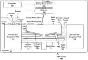
- FIG. 1 Ais a cross-sectional diagram of an exemplary powder based fusion (PBF) 3-D printing system 100 using surrogate supports with reference to an embodiment.
- PBF system 100includes controller 129 , which may include one or more processors such as microprocessors, digital signal processors (DSP), and various other analog and digital circuits configured to receive signals and transmit instructions to the different regions of the 3-D printer and the actuators and control inputs included in a given region.
- Controller 129may be partially or fully integrated within system 100 , or it may be part of a dedicated or generic computing device coupled to system 100 , depending on the print model and/or the manufacturer's configuration.
- Controller 129may also include different kinds of memory (volatile, non-volatile, read only memory, random access only (RAM), programmable read only memory, erasable-programmable read only memory, static RAM, dynamic RAM, etc.) to store data files, programs, dynamic link libraries, configuration parameters, and the like.
- memoryvolatile, non-volatile, read only memory, random access only (RAM), programmable read only memory, erasable-programmable read only memory, static RAM, dynamic RAM, etc.
- the controller 129may also store instructions to generate not only the build piece, but also the supports and constituent material configurations for the build piece 109 that are described in greater detail below.
- the controllermay include this information and these instructions in preexisting algorithms that can be selectively accessed as necessary to generate the appropriate support structures.
- the support structures and related configurationsmay have been developed and matured by a designer in connection with the CAD program.
- instructions and algorithms for rendering the support structures as described in detail hereinmay be stored in the memory and subsequently executed by the controller 129 to render the build piece with a base of support as part of the overall build job.
- the build jobmay include not only the build piece 109 , but also part or all of the different types of surrogate structures (see below) and other material configurations that collectively effect at least some, if not all, principles of the disclosure.
- System 100further includes one or more energy beam sources 103 for generating one or more respective energy beams 127 (such as, for example a laser or electron beam source in the case of PBF printer).
- System 100may further include one or more deflectors 105 .
- the illustrated deflector 105receives a beam from source 103 and alters the beam's reflection angle responsive to controller 129 to selectively direct the energy beam 127 to fuse powder 139 in powder bed 121 during a print cycle.
- the deflector 105is channeling the energy beam source 103 to fuse the build piece at the top layer of powder region 139 , which becomes fused powder and part of a build piece 109 .
- Printer 100may be housed in a closed chamber 113 such that one or more energy beam sources 103 are arranged sequentially or otherwise in a pattern on an upper wall of the chamber 113 (only one such connection 103 a is shown for simplicity).
- the chamber 113may also include powder bed receptacle walls 112 which define the powder bed 121 .
- the build plate 107may be supported by a build floor 111 , the latter of which may be configured to move vertically downward responsive to controller 129 instructions as the build piece increases in size and the 3-D print progresses.
- Printer 100may further include a hopper 115 for storing powder 117 .
- the hopper 115is a larger bin configured to be fixed to a side of chamber 113 above a powder bed receptacle wall 112 .
- the hopper's functionis to store the majority of powder to be used in a single rendering of a build piece or group thereof.
- a re-coater 111Directly underneath hopper 115 is a re-coater 111 .
- the re-coater 111may also be referenced as a depositor.
- the re-coater 111obtains powder from the hopper 115 via an aperture 141 (shown currently as closed to indicate that the re-coater 111 is full) disposed in the middle of the triangular-shaped elements.
- the re-coatermay, in an embodiment, extend into the illustration such that it has a width (not apparent from the cross-sectional view) sufficient to deposit layers of the powder 117 across the entire width of the powder bed 121 (i.e., the dimension running into and out of the drawing).
- the re-coater 111is a dynamic structure that is configured to move along with the leveler 119 from one end of the powder bed 121 to the other for purposes of depositing a layer of powder during a re-coat cycle (in preparation for the next print cycle).
- the direction of motion of the re-coater 111is shown by the bi-directional arrow immediately to the right of the 111 reference number.
- the leveler or leveling member 119 in this embodimentis a structural part of the re-coater 111 .
- the leveler 119may be used to straighten and level each deposited powder layer.
- the re-coater 111may be re-positioned on the left side of the PBF system 100 , e.g., above the left powder bed receptacle wall 112 and again beneath the hopper 115 .
- the re-coater 111determines whether it has enough powder to traverse the powder bed 121 and populate it with another layer of powder. If not, the controller can open aperture 141 and cause powder from the hopper 117 to enter the re-coater 111 until a sufficient amount is filled. Otherwise, during the next re-coat cycle, the re-coater 111 may separate from the hopper 115 to deposit another layer on the powder bed.
- the re-coater 111usually includes one or more slits (obscured from view) that pour out the raw powder in generally even amounts as the re-coater 111 is propelled across the surface of the powder bed 121 .
- the depositing slitsare adjacent the leveler 119 , which may be a structure permanently attached to the hopper 115 .
- the hopper 115is part and parcel of the re-coater 111 and moves along with the re-coater 111 during deposition cycles.
- the leveler 119may also extend across a width of the powder bed 121 and may serve to even or smooth out the new layer of unfused powder that is being ejected by the re-coater 111 .
- the leveler 119may include more than one blade.
- the leveler 119is capable of traversing left-to-right to deposit one layer, and thereafter right to left to deposit another layer after the first layer is selectively fused.
- the leveler 119 or the re-coater 111may take the form of a cylindrical shaped roller that is configured to smooth out the deposited powder by gently rolling it straight.
- the rollermay smooth out a powder ejected from a re-coater 119 , or the re-coater 111 may not be needed and the roller may store and eject the unfused powder.
- the rollermay be adopted using different powder ejection mechanisms that remain within the scope of the disclosure.
- the controller 129may be responsible for directing the re-coater 111 to deposit layers of powder 117 .
- the controller 129may use the print instructions to selectively fuse the necessary regions of the recently-deposited powder layer into solid form.
- the selectively fused regionscorrespond to the build piece 109 , which may be based on a data model from a computer aided design or modeling (CAD/CAM) application suite, one or both of which may be supplied to a slicer algorithm that is ultimately used to compile the necessary print instructions used by controller 129 .
- CAD/CAMcomputer aided design or modeling
- the controller 129may specifically direct the deflector 105 to fuse identified areas, where the powder melts and solidifies. Portions of the layer that are not fused, such as the unfused powder 131 , remain in powder form and do not become part of the build piece 109 .
- the PBF system 100 of FIG. 1 A and the present disclosurehas also recognized the need under different sets of circumstances for supports to preserve the integrity of the build piece 109 while contemporaneously avoiding, or substantially mitigating, the problems widely apparent in the art based on the use of such supports.
- surrogate supports 161 and support structure 133are introduced in areas where specifications indicate that support is needed, such as in the case of certain incline thresholds and overhangs.
- surrogate supportsare designed to be partially or completely contact-free from the build piece, such that the surrogate support is offset from the vulnerable region by a gap, such as a gap 128 between the surrogate support 161 and the build piece 109 as described below.
- the gapis populated with unfused powder that is obtained, for example, from the hopper 115 via the leveler 117 during the deposition cycle, although in other embodiments the gap may include other elements.
- the gapmay include partially or fully sintered powder at localized offsets to provide support and a conductive path for thermal management during printing.
- the gapmay be configured to include partially sintered powder, or fully sintered thin segments or other contacts present in the gaps.
- the build pieceis supported by the loose powder or alternative material present in gap 128 , by surrogate supports 161 and support structure 133 , if necessary to more securely fix the surrogate supports 161 .
- Surrogate supports 161 , gap 128 , and support structure 133may provide a collective base of support for the vulnerable regions of the build piece 109 .
- Surrogate supports 161may be composed of different material configurations.
- surrogate supports 161 and support structure 133may be co-printed using fused powder.
- support structure 133may be co-printed or otherwise provided in a material configuration that comprises a lattice structure to support and stabilize surrogate supports 161 .
- Support structure 133is described above in FIG. 1 A as having a lattice-based material configuration.
- support structure 133may alternatively be designed to include, in part or in whole, partially sintered material, loose powder with manual ties or other structures, or other material configurations (e.g., honeycomb-based structures, solid fused powder, etc.).
- the latticescan be 3-D printed during the formation of the build piece 109 .
- the lattices or honeycomb configurationscan, in turn, be coupled to the surrogate supports 161 to provide a base of support from below.
- lattice or honeycomb configurationsmay be composed of a very thin profile as desired, e.g., just strong enough to sustain the necessary support for the build piece 109 via surrogate support 161 and the gap 128 of loose powder.
- the lattice support structures 133may be stronger for greater support, yet may require less mass.
- post-processing separation of the build piece 109does not involve any separation force other than removing the build piece 109 from the unfused powder in gap 128 .
- the inclined and overhanging areas of build piece 109are also supported indirectly (in addition to the powder in the gaps 128 ) by the rigid material configurations of surrogate supports structures 161 .
- This supportin turn prevents inclined, curved and overhanging areas from deforming.
- the gap 128does not generally include a rigid support attached to the build piece 109 , there are no deflection forces that might otherwise cause cracks.
- the surrogate supports 161are shown in FIG. 1 A —namely, the two surrogate supports 161 that support the respective inclines via gap 128 of loose powder, and the surrogate support 161 that supports the overhang on the right of the drawing.
- the support structure 133(which may be lattice or patterned material configurations, among other possibilities) is also coupled to the surrogate supports 161 to provide a broader base of support for the surrogate supports 161 .
- the surrogate supports 161may include solid fused sections of metal created during the print cycle, or another rigid material configuration (e.g., partially hollow supports) that is disposed in areas where the build piece 109 would otherwise need support.
- the surrogates support structures 161can be defined as offset by a gap 128 from an undersurface of the build piece 109 .
- the gap 128need not be, and typically is not, empty space.
- Below and supporting the surrogate supports 161includes a support structure 133 , which in the case of FIG. 1 A is separated by a middle portion of build piece 109 .
- Support structure 133extends from surrogate supports 161 to the build plate to create a solid path.
- support structure 133has a fused powder configuration (whether solid or patterned) to reinforce the supports 161 .
- the surrogate supports 161are separated by the gap 128 from the build piece 109 .
- the gap 128resides between the surrogate supports 161 and the undersurface of the build piece 109 .
- the gap 128includes unfused powder.
- the controller 129does not cause the energy beam 127 to fuse areas corresponding to the gap 128 .
- the build piece 109is entirely separated from the surrogate 161 via the gap 128 , the sole exception being the small vertical column in the middle part of build piece 109 that is contacting the build plate 107 .
- the build piece 109 , surrogate supports 161 and corresponding support structure 133are initially formed by the printer adding sequential layers of powder in the power bed 121 .
- one or more energy beams 127are used to melt or fuse selected regions of the layer representative of either the support structure 133 or of the build piece 109 .
- the regions in build piece 109may be solidified.
- the material configuration in support structure 133may also be partially or fully solidified (e.g., it can be selectively fused in the relevant cross-sectional regions of each layer) to provide support, but they are also not part of the build piece 109 .
- the portion of the part or build piece 109 that represents a single vertical column that ultimately contacts the build plate 107 in this examplerepresents a region of the initial layers that was fused by the energy beam source 103 (in some embodiments along with fusing support structure 133 ), and thus solidified to form the lower part of the build piece 109 .
- the remaining portion of the build piece 109 above the vertical columnstarted out as a layer of powder deposited into the print bed, and then at a border prescribed by the design model the inclined layer was fused in those regions to become part of the build piece 109 .
- Inclined sliceswere partially fused to include only the inclined portion, with the loose powder remaining where the gap 128 currently resides. It should be noted that while a PBF 3-D printer is used in this example, the principles of the present disclosure are not so limited and may be provided to a wide variety of 3-D printer types.
- the gap 128 between the surrogate support 161 and the build piece 109may include material configurations other than or in addition to loose powder, such as a plurality of thin ties ( 413 ) that extend from the features of the build piece 109 to the surrogate supports.
- the objective of these alternative embodimentsis twofold. First, the use of some minimal structure (the ties, partially sintered material, thin branches of solid material ( 413 ), etc.) enables greater precision support of particularly vulnerable features in the face of thermal expansion or other issues that may be present during the AM process, but without the disadvantages inherent in a wholesale fusing of the build piece 109 to the supports, as in many conventional embodiments. Second, the use of these partial material configurations makes it as easy as possible to separate the vulnerable features from the surrogate supports without damaging the build piece 109 .
- the loose powder in the gap 128(often together with the lower support structure 133 ) is sufficient to support the vulnerable features of the build piece 109 and accordingly, the powder in the gap 128 need not be sintered or fused. Removal of the surrogate supports 161 in this latter case is a simple matter, as the loose powder is simply removed after the AM process is complete.
- the loose powder that resides in gap 128supports the vulnerable portions of the build piece 109 .
- the loose powderis on top of, and shaped by, the corresponding surrogate support 161 .
- the surrogates supports 161are offset from the build piece 109 by the gap 128 .
- the surrogates 161may further be coupled to partially solid or rigid support structures 133 that may extend from the base of the build plate 107 to each surrogate support 161 .
- the gap 128 between the surrogate support 161 and the build piece 109can be at a uniform or non-uniform distance across the geometry at a given surrogate support 161 . That is to say, the gap 128 may be of uniform thickness or variable thickness.
- the surrogate supports 161 with their corresponding gapsobviate the need for cutting conventionally fused supports from the build piece (a potentially dangerous undertaking to avoid damaging a fragile build piece) as is conventionally performed, and can be used to largely limit or eliminate the amount of post-processing work to remove the surrogate supports 161 from the build pieces 109 . By eliminating these conventional post-processing steps, the surrogate supports 161 improve productivity and throughput of the build pieces 109 . The cost of manufacturing the build pieces can therefore be reduced.
- surrogate supports 161can also eliminate surface roughness problems in complex build features attendant with the use of conventional supports. More specifically, the risk of cracking the build piece 109 or causing rough edges by splitting the supports from the build piece, as is done conventionally, is essentially eliminated. With but a few exceptions for thin strips of material and partially sintered material configurations corresponding to certain alternate embodiments, no removal of support material that otherwise contributes to the surface roughness problem of the build pieces is necessary. In these alternative embodiments where the gap includes material configurations such as partially sintered powder or manual support ties, minimal force is generally needed to remove the surrogate supports 161 , which preserves the structural and positional integrity of the features to which the surrogate supports 161 are connected.
- the surrogate supports 161 and associated gaps 128also reduce the amount of working mass applied to these smaller and more complex features requiring support on the build piece 109 .
- Thisis in contrast to conventional supports, which are often initially 3-D printed and attached to these complex features across their entire surfaces.
- the attachment and subsequent uncoupling of the conventional supportsmay inherently cause damage and unintended distortion (reshaping) of the smaller and hence more delicate features of the build piece.
- the surrogate supports 161can therefore remove these compromises to quality and reduction of tolerance in the AM process itself and all the post-processing efforts.
- the surrogate supports 161 proximal to the critical features of the build piece 109can act as a heat sink for thermal management, which keeps the nominal shape of the features closer to their original design intent. Further distortion control can be achieved by using the energy supplied to melt the surrogates to balance the influx of energy into the system over time, so that no specific layer receives significantly more or significantly less energy than its predecessor layer.
- FIG. 1 Bshows a close-up of the combined build-piece/surrogate/support structure of FIG. 1 A , but without the details of the printer.
- the loose powder in gap 128is omitted in this view; however, as in FIG. 1 A , the vulnerable regions of build piece 109 rest on the loose powder that fills gaps 128 .
- the surrogate supports 161 as shown in FIGS. 1 A-Brepresent typically solid, three-dimensional structures that are offset from the build piece 109 (or portion thereof), the latter representing the vulnerable surface to be supported.
- the gap 128exists in the regions between the build piece 109 and the surrogate supports 161 , and in an embodiment, includes loose powder to support the build piece 109 as described above, but without a permanent connection that can cause surface roughness and other damage upon post-processing separation.
- the gap 128 in the region between the build piece 109 and the surrogate support 161can simply take advantage of the 3-D printer capabilities to include unmelted powder that was previously deposited by the printer in the course of depositing the various layers of powder.
- the print instructions provided by a print controller 129include information defining the one or more offsets in a 3-D print job that define the gap 128 and surrogate supports 161 .
- the build piece in FIG. 1 A-Bincludes significant areas of overhang that are not being supported by the vertical column of the build piece 109 in the center, and thus would ordinarily require supports.
- a surrogate 161the overhanging portions of the build piece are supported instead by the powder residing in the gap 128 defined by the surrogate, with the surrogate 161 extending across the overhanging portions.
- the surrogate 161may be a fused area offset from the build piece 109 by the gap and supported by a further support structure 133 , which may also be formed from layers of powder that had been deposited and melted in early layers.
- the support structure 133need only include a matrix of material sufficient to support the build piece 109 and remaining surrogate pieces 161 . Because the gap 128 is typically filled with unfused powder between the build piece 109 and the support structures 161 , post-processing steps are reduced. The vulnerable regions of the build piece are not connected to the support structures and need not be removed in a post-AM process.
- the surrogate supports 161may be perfectly contoured to reflect the corresponding feature(s) on the build piece 109 .
- the surrogate supports 161may be drastically different, depending on factors including the support needs. For example, the presence of intricate or complex geometrical features on a part may require the use of perfectly contoured surrogates to provide maximum support and accuracy. Conversely, simpler or larger features may be able to use more generalized and less precise surrogate features, which in the latter case may avail a faster, more efficient 3-D print rendering.
- the entire build piece 109may be supported by a relatively flat surrogate underneath the overhanging sections of the part, thereby eliminating the build piece's connection to the build plate. This latter configuration may be achieved by using multiple tiers of surrogates, described further below.
- Another significant advantage of the approach described hereinis the flexibility accorded the designer in positioning the critical features. For example, if the left side of the build piece 109 in FIG. 1 A included a significant number of sophisticated geometrical features, then to reduce the extensive and compromising use of prior art-based supports, the designer may be required to orient those features in an upward direction (i.e., to eliminate vulnerable regions at the expense of the creative design of the part). By contrast, using the concept of surrogate supports, the designer need not be so restricted and the detailed overhanging features can instead be directed downward as desired, along with a contoured surrogate to accommodate support of the features without significant (if any) post-processing. This flexibility in turn enables design space to be freed-up, as the upper portion of the build piece here can be used for additional or different purposes. Moreover, this flexibility means that the build piece can potentially be designed globally in a manner that minimizes the overall use of support structures.
- FIG. 2depicts a cross-sectional view of a build piece 209 and corresponding tiered surrogate supports. For clarity, the 3-D printer is omitted.
- the feature-based surrogate supports 261are similar to the surrogate supports 161 of FIG. 1 A and, like in the earlier drawings, function to provide support without contact to the substantial overhanging portions of the build piece.
- a similar gap 228may be populated with loose powder, e.g., formed during deposition cycles in the print.
- a solidified support structure 233is provided below the feature-based surrogate supports 128 , but is not part of the build piece 209 . Unlike FIG.
- a global surrogate support 255is printed or provided.
- Global surrogate support 255may be composed of any suitable structure (such as a simple pattern to a solid rectangular structure) sufficient to sustain the weight and support of the elements above it.
- the purpose of the global surrogate structure 255 in this embodimentis to segregate the entire build piece 209 from the build plate 207 .
- Additional solidified support structure 233is present between the global surrogate support 255 and the feature-base surrogate supports 261 in order to further support the identified vulnerable areas on the build piece 209 .
- feature-based surrogaterefers to specific surrogate supports corresponding to specific vulnerable regions in the build piece 209 .
- another gap (not shown) of unfused powdermay be present between the lower vertical column of the build piece 209 and the global surrogate 255 , to effectively provide support to the support structure 233 and build piece 209 from the global surrogate 255 without specifically connecting the build piece 209 or support structure 233 to the global surrogate 255 .
- a gap 250 of loose powdermay separate the build plate 207 from the remaining structures.
- the build pieceis already divorced from the build plate 207 via the global surrogate 255 , and in some embodiments, powder-filled gap 250 . Post-processing separation of the build piece 209 and build plate 207 in either embodiment is eliminated.
- the build piece 209need not be cut or otherwise post-processed. Rather, the build piece 209 can simply be removed off of the global surrogate. The remaining supporting structures can be cleared from the build plate 207 .
- the process of FIG. 2is exemplary in nature, and a number of other tiers may be possible depending on the nature of the build piece 209 and the objectives involved.
- FIG. 2Another inherent advantage of the use of multiple tiers as shown in FIG. 2 is the ability to reuse the build plate in a subsequent build job.
- the build platemay require some simple machining or clean-up, e.g., to remove the global surrogate (i.e., where no gap 250 is present).
- the build plate preparation processwill be easier and faster than if build piece removal were required, rendering multiple print jobs more straightforward.
- FIG. 3illustrates a set of nine exemplary build pieces and different configurations of the surrogate supports for each build piece.
- the nine build piecesare represented by the reference numerals 308 a - i .
- the corresponding surrogate supportis labeled 310 a - i.
- the surrogatescan be thin or thick solid bodies, or can be composed of a more porous or lattice design, for example, to save powder costs.
- build pieces 308 a and 308 cinclude, respectively, a simple surrogate support 310 a that corresponds to build piece 308 a , and a thin surrogate support 310 c having a width less than that of the gap between the build piece 308 c and the support 310 c . It is noted that, for the purpose of most of these examples, the vulnerable regions of the build pieces are omitted for clarity and simplicity of illustration.
- surrogate support 310 dcoupled to build piece 308 a , represents a thick piece for accommodating heavier parts, such that the support 310 d is bigger than the gap.
- the surrogatemay, in alternative embodiments such as surrogate 310 b corresponding to build piece 308 b , be contoured to a portion of a critical feature (i.e., the inverse curvature) or expand away from the critical feature itself to improve its removability.
- a critical featurei.e., the inverse curvature
- supportsmay be offset from the build piece on both the top and bottom surfaces using surrogates at both ends of the build piece via an orifice, thereby improving the ease of removal and eliminating an unintended load path.
- top and bottom surfaces of support 310 hmay be visible at a portion of the top of the build piece 308 h and a portion of the bottom of the build piece 308 h . Between the top and bottom may be unfused powder, or in other examples, a lightweight support structure used for handling the build piece 308 h without placing undue pressure on other, more delicate regions of the build piece 308 h .
- Referring to build piece 308 iis a novel configuration where the surrogate support 310 i is part of a lattice or segmented part internal to build piece 308 i .
- accesse.g., an aperture
- the internal structure 310 ican be beneficial for moving the build piece 308 i without disrupting other delicate portions of the part.
- the surrogates 310may also be decomposed into disjointed segments that are all connected to one another and may also be used as the supports themselves, such as in build piece 308 g and corresponding segmented surrogate support 310 g . Tabs, grooves or any other variations may be added to further improve the removability. This strategy can be applied to PBF, vat polymerization, material extrusion and any other AM technology. They can also be leveraged for all materials, including multi-material solutions. In build piece 308 e , a lattice surrogate support 310 e has been constructed to provide the part with the necessary support while saving powder by using a lattice structure and reducing mass.
- the gapsare assumed to include unfused powder; in other embodiments, however, structure may be strategically placed in the gap area to provide for increases in support where needed without using wholesale supports covering and fusing the entire surface of the feature with a hard material, as is conventionally done.
- a gapmay be provided between the surrogate supports and the features.
- the gapmay include powder that is partially sintered or fully sintered at localized offsets to provide the requisite support and conductive path for thermal management during printing.
- the gapmay be configured to include partially sintered powder or fully sintered thin segments that are sufficient to retain support for the features during all stages of the 3-D print, but that make it easy to separate the features with very small forces after the print. Additional support may be desirable in cases where the features are sophisticated or very small.
- the surface area of the features that include contacts (present in the gap)is comparatively small, thereby minimizing the negative effect on the build pieces during support removal.
- Partial sintering embodimentsmay be effected through uniform exposure to the energy beam that may be lower than that used for printing the actual part and/or the surrogate. This partial sintering may be printed by targeting local regions within the gap, as opposed to globally across it.
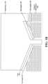
- FIG. 4illustrates a cross-sectional view of build pieces that use different types of supports in the gap between the surrogate support and the build pieces 408 a - d .
- the gapmay include unfused power (no sintering).
- manual support tiessuch as segments, or some level of solid structure (e.g., structures based on algorithmic parameters) may be used.
- any build piececan use surrogates offset by a spectrum of optimal features in the gap, from unfused powder on one end to solid material on the other end. In whatever case, it is generally desirable to maintain a balance of objectives that, while addressing thermal or other parameters and providing additional support for critical features, the amount and impact of AM post-processing steps are minimized, as discussed above.
- build piece 408 aIn the example of build piece 408 a , no sintering occurs and the gap between the build piece 408 a may include loose or unfused powder.
- Build piece 408 bdepicts segmented surrogate supports, with one such support used to support the curved feature 409 a , and the remaining supports in line with the middle support. Instead of unfused powder, the powder in the gap has been partially sintered to create a strong load path and to manage the conduction of heat during 3-D printing, but to maintain a relative weak separation at post-processing.
- the disjointed nature of the supports and the partial nature of the sinteringmay make support removal easier, and may represent a design balance between adequately supporting delicate features while facilitating the ease of the removal process.
- build piece 408 cis coupled to its requisite surrogate support by using manual support ties 413 .
- the support tiesare manually inserted between the gap.
- the surrogate supportitself also may include segments 420 , which may be sintered powder. Both the support ties and segments are ideally strong enough to support the build piece 408 c but easy to remove during the support removal process. Like the partially sintered powder, the support ties and segments represent a balance between providing support via the gap and facilitating heat transfer and support removal.
- Build piece 408 dhas been designed to include a solid body in the gap.
- the solid bodymay be constructed from the print material or from a different (e.g., softer) print material.
- the solid body construction in the gaplikely balances the support requirement and thermal conduction factors over the importance of post-processing support removal.
- the algorithmic parametersmay be selected such that the solid body of material is dramatically different in composition than the fused powder, and consequently easy to remove from the build piece without risk of the attendant cracks and other problems that may result.
- the surrogatesmay include solid material in the gap that is soft enough to be quickly and easily removed from the build piece 408 d.
- Partial sinteringcan be achieved using explicit modeling of features or more subtle methods.
- the partial sintering regionsi.e., the gaps
- the gapscan be modeled as solids between the surrogate and the part.
- the modeled gapsmay have unique parameters that may, for example, behave as supports with respect to layer height, spacing, power, speed, offsets, focus, etc. This type of modeling may advantageously reduce the time spent in CAM operations prior to releasing parts for print and may allow for faster iteration and parametric studies.
- surrogate supportscan be added to a model prior to thermal compensation, thereby receiving the compensation themselves.
- the gapcan be modeled as a solid body with contact but no overlap interference, such that the gap between the part and the surrogate is preserved after compensation.
- Surrogatescan also be modeled after thermal compensation to provide a more accurate but undistorted geometry.
- FIG. 5depicts a partial flow diagram demonstrating various surrogate modeling embodiments prior to printing the build piece to address distortion.
- Distortion analysisis often conducted using lightweight CAD representations. It is therefore challenging and time-consuming to add a feature to the model after it has been converted to its lightweight representation. That being said, a surrogate can still be modeled at a prescribed offset after the distortion analysis and compensation are completed.
- Another approachis to model the surrogates along with the build piece prior to the analysis.
- the current challenge with the majority of distortion analysis softwareis that multiple solid bodies (in the case of this disclosure, the build piece and the novel surrogates as presented herein) would be treated as separate entities. In some cases, the distortion analysis may have them distort in relatively similar manners but in other cases, they may distort very differently from one another. As such, there is no guarantee that the gap between the build piece and surrogates will be maintained at the desired distance.
- this disclosureincludes a method for circumventing that challenge by modeling an additional body for the gap and running that body through the distortion analysis as well.
- the build pieceis nominally in contact with the gap which is nominally in contact with the surrogate. This contact relationship will inherently be preserved due to the continuity of solid material (primarily due to the voxelization in the distortion analysis).
- the model of the gapmay be removed, ultimately preserving the original distance between the build piece and the surrogates.
- a first approach 508initially only build piece 508 a is modeled.
- the modelcan be used to evaluate, via one or more algorithmic simulations, the amount of anticipated distortion or similar force-inducing damage to which the vulnerable features requiring support (see portion 508 b ) may be subject. Compensation for the distortion can then be calculated by identifying a desired surrogate spacing and offsetting the surrogate accordingly, as shown in configuration 508 c.
- the part, gap and surrogatemay be initially modelled.
- the amount of expected distortion to the vulnerable featuresmay be evaluated ( 509 b ).
- the material in the gapmay be removed ( 509 c ) if necessary to preserve the integrity of the features.
- surrogate tiessuch as small structural threads extending across the gap, may be assigned based on the identified parameters. The surrogate ties may provide support for the features, e.g., during the AM phase. After AM is complete, the ties can be easily removed without distorting the features to which the ties are coupled.
- FIG. 6illustrates an exemplary flow diagram of a 3-D printer printing a build piece and one or more surrogate supports.
- the 3-D printerreceives instructions to print a build piece that includes at least one vulnerable region requiring support.
- the build pieceis 3-D printed to include surrogate supports.
- the surrogate supportsare co-printed with the build piece (step 604 ).
- the surrogate supportis also offset from the build piece by a gap that includes separate material (step 603 ).
- Separate materialdoes not necessarily mean that the material be separate from the printed material at an atomic level, but just that its properties are different in this embodiment because algorithmic parameters are used to idealize the material's characteristics as discussed in the embodiment of FIG. 4 , build piece 408 D.
- Separate material in this contextcan also mean the material(s) used in the 3-D printer at issue, but being partially sintered, for example, or being threaded contacts as described above.
Landscapes
- Engineering & Computer Science (AREA)
- Chemical & Material Sciences (AREA)
- Materials Engineering (AREA)
- Manufacturing & Machinery (AREA)
- Physics & Mathematics (AREA)
- Optics & Photonics (AREA)
- Mechanical Engineering (AREA)
- Plasma & Fusion (AREA)
- Health & Medical Sciences (AREA)
- Toxicology (AREA)
- Powder Metallurgy (AREA)
Abstract
Description
Claims (7)
Priority Applications (5)
| Application Number | Priority Date | Filing Date | Title |
|---|---|---|---|
| US16/568,188US11826953B2 (en) | 2018-09-12 | 2019-09-11 | Surrogate supports in additive manufacturing |
| PCT/US2019/050803WO2020056129A1 (en) | 2018-09-12 | 2019-09-12 | Surrogate supports in additive manufacturing |
| CN201921523446.7UCN211276515U (en) | 2018-09-12 | 2019-09-12 | Apparatus for replacement support in additive manufacturing |
| CN201910866425.3ACN110893464A (en) | 2018-09-12 | 2019-09-12 | Alternative support in additive manufacturing |
| EP19860908.3AEP3849786A4 (en) | 2018-09-12 | 2019-09-12 | Surrogate supports in additive manufacturing |
Applications Claiming Priority (2)
| Application Number | Priority Date | Filing Date | Title |
|---|---|---|---|
| US201862730505P | 2018-09-12 | 2018-09-12 | |
| US16/568,188US11826953B2 (en) | 2018-09-12 | 2019-09-11 | Surrogate supports in additive manufacturing |
Publications (2)
| Publication Number | Publication Date |
|---|---|
| US20200079028A1 US20200079028A1 (en) | 2020-03-12 |
| US11826953B2true US11826953B2 (en) | 2023-11-28 |
Family
ID=69719016
Family Applications (1)
| Application Number | Title | Priority Date | Filing Date |
|---|---|---|---|
| US16/568,188Active2041-07-17US11826953B2 (en) | 2018-09-12 | 2019-09-11 | Surrogate supports in additive manufacturing |
Country Status (4)
| Country | Link |
|---|---|
| US (1) | US11826953B2 (en) |
| EP (1) | EP3849786A4 (en) |
| CN (2) | CN211276515U (en) |
| WO (1) | WO2020056129A1 (en) |
Families Citing this family (21)
| Publication number | Priority date | Publication date | Assignee | Title |
|---|---|---|---|---|
| DE102020104541A1 (en)* | 2020-02-20 | 2021-08-26 | Brose Fahrzeugteile SE & Co. Kommanditgesellschaft, Würzburg | Method for manufacturing several components as part of an additive manufacturing process |
| JP7325607B2 (en)* | 2020-03-19 | 2023-08-14 | 三菱電機株式会社 | Laminate manufacturing path generation device, laminate manufacturing path generation method, and machine learning device |
| CN111483138B (en)* | 2020-04-16 | 2021-10-29 | 杭州喜马拉雅信息科技有限公司 | Printing platform for reducing 3D printing support |
| US11766832B2 (en)* | 2020-05-13 | 2023-09-26 | The Boeing Company | System and method for additively manufacturing an object |
| EP3943219A1 (en)* | 2020-07-24 | 2022-01-26 | Aixway3D GmbH | Device and method for improved powder application in an additive manufacturing method |
| US12226824B2 (en)* | 2020-12-22 | 2025-02-18 | Divergent Technologies, Inc. | Three dimensional printer with configurable build plate for rapid powder removal |
| CN112873850B (en)* | 2021-01-11 | 2022-10-18 | 清锋(北京)科技有限公司 | Mould and method for removing support structure on printing piece |
| CN112793164A (en)* | 2021-01-11 | 2021-05-14 | 西安赛隆金属材料有限责任公司 | Additive Manufacturing Support Structure and Design Method |
| CN112548106B (en)* | 2021-02-26 | 2021-05-18 | 中国航发上海商用航空发动机制造有限责任公司 | A method for additive manufacturing repair of ultra-thin structures |
| CN117545616A (en) | 2021-04-23 | 2024-02-09 | 戴弗根特技术有限公司 | Removing supports and other materials from surfaces and hollow 3D printed parts |
| JP7537359B2 (en)* | 2021-05-14 | 2024-08-21 | トヨタ自動車株式会社 | Manufacturing method of layered object |
| US12162072B2 (en)* | 2021-06-29 | 2024-12-10 | Howmedica Osteonics Corp. | Supports for cantilevered elements during additive manufacturing and methods of forming such supports |
| CN113798509A (en)* | 2021-09-10 | 2021-12-17 | 武汉易制科技有限公司 | Method for providing easily separable sintering support for 3DP formed metal workpiece |
| CN114274505B (en)* | 2021-12-23 | 2022-08-30 | 山东大学 | Sandwich plate fused deposition printing support structure generation method and system |
| WO2023130059A1 (en) | 2021-12-30 | 2023-07-06 | Saint-Gobain Abrasives, Inc. | Abrasive articles and methods for forming same |
| EP4457058A1 (en)* | 2021-12-30 | 2024-11-06 | Saint-gobain Abrasives, Inc | Abrasive articles and methods for forming same |
| US12036736B2 (en) | 2022-01-19 | 2024-07-16 | Ford Global Technologies, Llc | Three-dimensional printing assembly |
| CN116673577A (en)* | 2023-06-12 | 2023-09-01 | 南京理工大学 | An Arc Additive Method Applicable to Inclined Structural Parts |
| US20250121436A1 (en)* | 2023-10-12 | 2025-04-17 | General Electric Company | Additive manufacturing process |
| CN117358945A (en)* | 2023-10-23 | 2024-01-09 | 云耀深维(江苏)科技有限公司 | 3D printing method and device for constructing easily-separated three-dimensional structure and three-dimensional structure |
| US20250135550A1 (en)* | 2023-10-26 | 2025-05-01 | Rtx Corporation | Method for additively manufactured process-equivalent test specimens |
Citations (314)
| Publication number | Priority date | Publication date | Assignee | Title |
|---|---|---|---|---|
| US5203226A (en) | 1990-04-17 | 1993-04-20 | Toyoda Gosei Co., Ltd. | Steering wheel provided with luminous display device |
| WO1996036525A1 (en) | 1995-05-19 | 1996-11-21 | Edag Engineering + Design Ag | Process for automatically fitting a motor vehicle body component |
| WO1996036455A1 (en) | 1995-05-16 | 1996-11-21 | Edag Engineering + Design Ag | Device for feeding welding bolts to a welding gun |
| WO1996038260A1 (en) | 1995-05-30 | 1996-12-05 | Edag Engineering + Design Ag | Container changer |
| US5742385A (en) | 1996-07-16 | 1998-04-21 | The Boeing Company | Method of airplane interiors assembly using automated rotating laser technology |
| US5990444A (en) | 1995-10-30 | 1999-11-23 | Costin; Darryl J. | Laser method and system of scribing graphics |
| US6010155A (en) | 1996-12-31 | 2000-01-04 | Dana Corporation | Vehicle frame assembly and method for manufacturing same |
| US6096249A (en) | 1996-12-05 | 2000-08-01 | Teijin Limited | Method for molding fiber aggregate |
| US6140602A (en) | 1997-04-29 | 2000-10-31 | Technolines Llc | Marking of fabrics and other materials using a laser |
| US6250533B1 (en) | 1999-02-18 | 2001-06-26 | Edag Engineering & Design Ag | Clamping device for use in motor vehicle production lines and production line having such a clamping device |
| US6252196B1 (en) | 1996-10-11 | 2001-06-26 | Technolines Llc | Laser method of scribing graphics |
| US6318642B1 (en) | 1999-12-22 | 2001-11-20 | Visteon Global Tech., Inc | Nozzle assembly |
| US6365057B1 (en) | 1999-11-01 | 2002-04-02 | Bmc Industries, Inc. | Circuit manufacturing using etched tri-metal media |
| US6391251B1 (en) | 1999-07-07 | 2002-05-21 | Optomec Design Company | Forming structures from CAD solid models |
| US6409930B1 (en) | 1999-11-01 | 2002-06-25 | Bmc Industries, Inc. | Lamination of circuit sub-elements while assuring registration |
| US6468439B1 (en) | 1999-11-01 | 2002-10-22 | Bmc Industries, Inc. | Etching of metallic composite articles |
| WO2003024641A1 (en) | 2001-08-31 | 2003-03-27 | Edag Engineering + Design Aktiengesellschaft | Roller folding head and method for folding a flange |
| US6554345B2 (en) | 1997-10-23 | 2003-04-29 | Ssab Hardtech Ab | Lightweight beam |
| US6585151B1 (en) | 2000-05-23 | 2003-07-01 | The Regents Of The University Of Michigan | Method for producing microporous objects with fiber, wire or foil core and microporous cellular objects |
| US6644721B1 (en) | 2002-08-30 | 2003-11-11 | Ford Global Technologies, Llc | Vehicle bed assembly |
| US6811744B2 (en) | 1999-07-07 | 2004-11-02 | Optomec Design Company | Forming structures from CAD solid models |
| WO2004108343A1 (en) | 2003-06-05 | 2004-12-16 | Erwin Martin Heberer | Device for shielding coherent electromagnetic radiation and laser booth provided with such a device |
| US6866497B2 (en) | 2001-06-13 | 2005-03-15 | Kabushiki Kaisha Tokai Rika Denki Seisakusho | Molding apparatus having a projecting bulge located in a die half |
| US6919035B1 (en) | 2001-05-18 | 2005-07-19 | Ensci Inc. | Metal oxide coated polymer substrates |
| US6926970B2 (en) | 2001-11-02 | 2005-08-09 | The Boeing Company | Apparatus and method for forming weld joints having compressive residual stress patterns |
| WO2005093773A1 (en) | 2004-03-25 | 2005-10-06 | Audi Ag | System comprising an automotive fuse and an a/d converter |
| US20060108783A1 (en) | 2004-11-24 | 2006-05-25 | Chi-Mou Ni | Structural assembly for vehicles and method of making same |
| WO2007003375A1 (en) | 2005-06-30 | 2007-01-11 | Edag Engineering + Design Ag | Method and device for joining joining structures, particularly during the assembly of vehicle components |
| WO2007110236A1 (en) | 2006-03-28 | 2007-10-04 | Edag Gmbh & Co. Kgaa | Clamping device for holding and clamping components |
| WO2007110235A1 (en) | 2006-03-28 | 2007-10-04 | Edag Gmbh & Co. Kgaa | Clamping device for holding and clamping components |
| WO2007128586A2 (en) | 2006-05-10 | 2007-11-15 | Edag Gmbh & Co. Kgaa | Energy beam brazing or welding of components |
| WO2008019847A1 (en) | 2006-08-18 | 2008-02-21 | Fft Edag Produktionssysteme Gmbh & Co. Kg | Monitoring device for a laser machining device |
| US7344186B1 (en) | 2007-01-08 | 2008-03-18 | Ford Global Technologies, Llc | A-pillar structure for an automotive vehicle |
| WO2008068314A2 (en) | 2006-12-08 | 2008-06-12 | Edag Gmbh & Co. Kgaa | Flanging hand tool |
| WO2008087024A1 (en) | 2007-01-18 | 2008-07-24 | Toyota Motor Corporation | Composite of sheet metal parts |
| WO2008086994A1 (en) | 2007-01-15 | 2008-07-24 | Edag Gmbh & Co. Kgaa | Sheet-metal composite, method for joining sheets and joining device |
| WO2008107130A1 (en) | 2007-03-02 | 2008-09-12 | Edag Gmbh & Co. Kgaa | Automobile with facilitated passenger exit |
| WO2008138503A1 (en) | 2007-05-11 | 2008-11-20 | Edag Gmbh & Co. Kgaa | Crimping components in series production having short cycle times |
| WO2008145396A1 (en) | 2007-06-01 | 2008-12-04 | Edag Gmbh & Co. Kgaa | Edge curling tool |
| US20090039570A1 (en) | 2007-08-10 | 2009-02-12 | Rolls-Royce Plc | Support architecture |
| US7500373B2 (en) | 2004-09-24 | 2009-03-10 | Edag Gmbh & Co. Kgaa | Flanging device and flanging method with component protection |
| WO2009083609A2 (en) | 2008-01-03 | 2009-07-09 | Edag Gmbh & Co. Kgaa | Method for bending a workpiece |
| WO2009098285A1 (en) | 2008-02-07 | 2009-08-13 | Edag Gmbh & Co. Kgaa | Rotating table |
| WO2009112520A1 (en) | 2008-03-11 | 2009-09-17 | Edag Gmbh & Co. Kgaa | Tool, system and method for the manufacture of a cable harness |
| WO2009135938A1 (en) | 2008-05-09 | 2009-11-12 | Edag Gmbh & Co. Kgaa | Method and tool for producing a fixed connection to components joined in a form-fitted manner |
| WO2009140977A1 (en) | 2008-05-21 | 2009-11-26 | Edag Gmbh & Co. Kgaa | Clamping frame-less joining of components |
| US7637134B2 (en) | 2005-01-31 | 2009-12-29 | Edag Gmbh & Co. Kgaa | Flanging with a leading and following flanging die |
| US7710347B2 (en) | 2007-03-13 | 2010-05-04 | Raytheon Company | Methods and apparatus for high performance structures |
| US7716802B2 (en) | 2006-01-03 | 2010-05-18 | The Boeing Company | Method for machining using sacrificial supports |
| US7745293B2 (en) | 2004-06-14 | 2010-06-29 | Semiconductor Energy Laboratory Co., Ltd | Method for manufacturing a thin film transistor including forming impurity regions by diagonal doping |
| US7766123B2 (en) | 2006-03-29 | 2010-08-03 | Yamaha Hatsudoki Kabushiki Kaisha | Vehicle exhaust system |
| WO2010125058A1 (en) | 2009-04-27 | 2010-11-04 | Edag Gmbh & Co. Kgaa | Clamping device, system, and method for processing changing component types |
| WO2010125057A2 (en) | 2009-04-27 | 2010-11-04 | Edag Gmbh & Co. Kgaa | Robot support |
| US7852388B2 (en) | 2006-05-23 | 2010-12-14 | Panasonic Corporation | Imaging device |
| WO2010142703A2 (en) | 2009-06-09 | 2010-12-16 | Edag Gmbh & Co. Kgaa | Method and tool for edging a workpiece |
| US7908922B2 (en) | 2008-01-24 | 2011-03-22 | Delphi Technologies, Inc. | Silicon integrated angular rate sensor |
| WO2011032533A1 (en) | 2009-09-15 | 2011-03-24 | Edag Gmbh & Co. Kgaa | Vehicle body component composed of an exterior element and a fibre-reinforced plastic structural component connected to the rear side of said exterior element |
| US7951324B2 (en) | 2006-09-14 | 2011-05-31 | Ibiden Co., Ltd. | Method for manufacturing honeycomb structure |
| US8163077B2 (en) | 2005-09-28 | 2012-04-24 | Yissum Research Development Company Of The Hebrew University Of Jerusalem | Ink providing etch-like effect for printing on ceramic surfaces |
| WO2012131481A1 (en) | 2011-03-29 | 2012-10-04 | Inspire Ag, Irpd | Part structure built by metal powder based added manufacturing |
| US8286236B2 (en) | 2007-12-21 | 2012-10-09 | The Invention Science Fund I, Llc | Manufacturing control system |
| US8289352B2 (en) | 2010-07-15 | 2012-10-16 | HJ Laboratories, LLC | Providing erasable printing with nanoparticles |
| US8297096B2 (en) | 2007-07-20 | 2012-10-30 | Nippon Steel Corporation | Method for hydroforming and hydroformed product |
| US8354170B1 (en) | 2009-10-06 | 2013-01-15 | Hrl Laboratories, Llc | Elastomeric matrix composites |
| US8383028B2 (en) | 2008-11-13 | 2013-02-26 | The Boeing Company | Method of manufacturing co-molded inserts |
| US8429754B2 (en) | 2007-12-21 | 2013-04-23 | The Invention Science Fund I, Llc | Control technique for object production rights |
| US8437513B1 (en) | 2012-08-10 | 2013-05-07 | EyeVerify LLC | Spoof detection for biometric authentication |
| US8444903B2 (en) | 2007-07-13 | 2013-05-21 | The Boeing Company | Method of fabricating three dimensional printed part |
| US8452073B2 (en) | 2009-04-08 | 2013-05-28 | The United States Of America As Represented By The Administrator Of The National Aeronautics And Space Administration | Closed-loop process control for electron beam freeform fabrication and deposition processes |
| US8599301B2 (en) | 2006-04-17 | 2013-12-03 | Omnivision Technologies, Inc. | Arrayed imaging systems having improved alignment and associated methods |
| US8606540B2 (en) | 2009-11-10 | 2013-12-10 | Projectionworks, Inc. | Hole measurement apparatuses |
| US8610761B2 (en) | 2009-11-09 | 2013-12-17 | Prohectionworks, Inc. | Systems and methods for optically projecting three-dimensional text, images and/or symbols onto three-dimensional objects |
| WO2014016437A1 (en) | 2012-07-27 | 2014-01-30 | Fft Edag Produktionssysteme Gmbh & Co. Kg | Hemming press |
| US8678060B2 (en) | 2011-03-04 | 2014-03-25 | Fft Edag Produktionssysteme Gmbh & Co. Kg | Joining surface treatment device and method |
| US8686997B2 (en) | 2009-12-18 | 2014-04-01 | Sassault Systemes | Method and system for composing an assembly |
| US8694284B2 (en) | 2010-04-02 | 2014-04-08 | Dassault Systemes | Part modeled by parallel geodesic curves |
| US8752166B2 (en) | 2007-12-21 | 2014-06-10 | The Invention Science Fund I, Llc | Security-activated operational components |
| US8755923B2 (en) | 2009-12-07 | 2014-06-17 | Engineering Technology Associates, Inc. | Optimization system |
| US8818771B2 (en) | 2010-06-21 | 2014-08-26 | Johan Gielis | Computer implemented tool box systems and methods |
| US20140277669A1 (en) | 2013-03-15 | 2014-09-18 | Sikorsky Aircraft Corporation | Additive topology optimized manufacturing for multi-functional components |
| US20140291886A1 (en) | 2013-03-22 | 2014-10-02 | Gregory Thomas Mark | Three dimensional printing |
| US8873238B2 (en) | 2012-06-11 | 2014-10-28 | The Boeing Company | Chassis system and method for holding and protecting electronic modules |
| WO2014187720A1 (en) | 2013-05-22 | 2014-11-27 | Fft Edag Produktionssysteme Gmbh & Co. Kg | Joining a workpiece with a concealed joint seam |
| WO2014195340A1 (en) | 2013-06-07 | 2014-12-11 | Fft Produktionssyteme Gmbh & Co. Kg | Device for use in the handling of a load and method for producing such a device |
| US8978535B2 (en) | 2010-08-11 | 2015-03-17 | Massachusetts Institute Of Technology | Articulating protective system for resisting mechanical loads |
| DE102013218760A1 (en) | 2013-09-19 | 2015-03-19 | Bayerische Motoren Werke Aktiengesellschaft | Method for producing a component in layers |
| US20150080495A1 (en)* | 2013-07-11 | 2015-03-19 | Kurt E. Heikkila | Surface modified particulate and sintered or injection molded products |
| US9071436B2 (en) | 2007-12-21 | 2015-06-30 | The Invention Science Fund I, Llc | Security-activated robotic system |
| US9101979B2 (en) | 2011-10-31 | 2015-08-11 | California Institute Of Technology | Methods for fabricating gradient alloy articles with multi-functional properties |
| US9126365B1 (en) | 2013-03-22 | 2015-09-08 | Markforged, Inc. | Methods for composite filament fabrication in three dimensional printing |
| US9128476B2 (en) | 2007-12-21 | 2015-09-08 | The Invention Science Fund I, Llc | Secure robotic operational system |
| US9138924B2 (en) | 2014-01-06 | 2015-09-22 | Prior Company Limited | Manufacturing method of decorated molding article and manufacturing method of decorated film |
| US9149988B2 (en) | 2013-03-22 | 2015-10-06 | Markforged, Inc. | Three dimensional printing |
| US9156205B2 (en) | 2013-03-22 | 2015-10-13 | Markforged, Inc. | Three dimensional printer with composite filament fabrication |
| US9183325B2 (en) | 2013-04-05 | 2015-11-10 | Formlabs, Inc. | Additive fabrication support structures |
| US9186848B2 (en) | 2013-03-22 | 2015-11-17 | Markforged, Inc. | Three dimensional printing of composite reinforced structures |
| WO2015193331A1 (en) | 2014-06-17 | 2015-12-23 | Fft Produktionssysteme Gmbh & Co. Kg | Segmented retaining plate for a workpiece |
| US9244986B2 (en) | 2013-01-11 | 2016-01-26 | Buckyball Mobile, Inc. | Method and system for interactive geometric representations, configuration and control of data |
| US9248611B2 (en) | 2013-10-07 | 2016-02-02 | David A. Divine | 3-D printed packaging |
| US9254535B2 (en) | 2014-06-20 | 2016-02-09 | Velo3D, Inc. | Apparatuses, systems and methods for three-dimensional printing |
| US9266566B2 (en) | 2014-04-09 | 2016-02-23 | Hyundai Motor Company | Front body member for vehicle |
| US9269022B2 (en) | 2013-04-11 | 2016-02-23 | Digimarc Corporation | Methods for object recognition and related arrangements |
| US9329020B1 (en) | 2013-01-02 | 2016-05-03 | Lockheed Martin Corporation | System, method, and computer program product to provide wireless sensing based on an aggregate magnetic field reading |
| US20160144428A1 (en) | 2013-04-19 | 2016-05-26 | United Technologies Corporation | Build plate and apparatus for additive manufacturing |
| US20160175932A1 (en) | 2013-08-05 | 2016-06-23 | Renishaw Plc | Additive manufacturing method and apparatus |
| US9389315B2 (en) | 2012-12-19 | 2016-07-12 | Basf Se | Detector comprising a transversal optical sensor for detecting a transversal position of a light beam from an object and a longitudinal optical sensor sensing a beam cross-section of the light beam in a sensor region |
| WO2016116414A1 (en) | 2015-01-19 | 2016-07-28 | Fft Produktionssysteme Gmbh & Co. Kg | Flanging system, flanging unit and flanging method for autonomous flanging |
| US20160221264A1 (en) | 2015-02-02 | 2016-08-04 | United Technologies Corporation | Method and system for providing thermal support in an additive manufacturing process |
| US9457514B2 (en) | 2012-03-08 | 2016-10-04 | Klaus Schwärzler | Method and device for layered buildup of a shaped element |
| US9469057B2 (en) | 2012-05-18 | 2016-10-18 | 3D Systems, Inc. | Support structures and deposition techniques for 3D printing |
| US9481402B1 (en) | 2015-05-26 | 2016-11-01 | Honda Motor Co., Ltd. | Methods and apparatus for supporting vehicle components |
| US9486960B2 (en) | 2014-12-19 | 2016-11-08 | Palo Alto Research Center Incorporated | System for digital fabrication of graded, hierarchical material structures |
| US9502993B2 (en) | 2011-02-07 | 2016-11-22 | Ion Geophysical Corporation | Method and apparatus for sensing signals |
| US9525262B2 (en) | 2011-08-04 | 2016-12-20 | Martin A. Stuart | Slab laser and amplifier and method of use |
| US9533526B1 (en) | 2012-06-15 | 2017-01-03 | Joel Nevins | Game object advances for the 3D printing entertainment industry |
| US9555315B2 (en) | 2013-12-05 | 2017-01-31 | Aaron Benjamin Aders | Technologies for transportation |
| US9557856B2 (en) | 2013-08-19 | 2017-01-31 | Basf Se | Optical detector |
| US9555580B1 (en) | 2013-03-21 | 2017-01-31 | Temper Ip, Llc. | Friction stir welding fastener |
| US9566742B2 (en) | 2012-04-03 | 2017-02-14 | Massachusetts Institute Of Technology | Methods and apparatus for computer-assisted spray foam fabrication |
| US9566758B2 (en) | 2010-10-19 | 2017-02-14 | Massachusetts Institute Of Technology | Digital flexural materials |
| WO2017036461A1 (en) | 2015-09-04 | 2017-03-09 | Edag Engineering Gmbh | Mobile communication device and software code, and traffic entity |
| US9595795B2 (en) | 2014-12-09 | 2017-03-14 | Te Connectivity Corporation | Header assembly |
| US9600929B1 (en) | 2014-12-01 | 2017-03-21 | Ngrain (Canada) Corporation | System, computer-readable medium and method for 3D-differencing of 3D voxel models |
| US9597843B2 (en) | 2014-05-15 | 2017-03-21 | The Boeing Company | Method and apparatus for layup tooling |
| US9609755B2 (en) | 2013-01-17 | 2017-03-28 | Hewlett-Packard Development Company, L.P. | Nanosized particles deposited on shaped surface geometries |
| US9610737B2 (en) | 2015-03-04 | 2017-04-04 | Ebert Composites Corporation | 3D thermoplastic composite pultrusion system and method |
| US9611667B2 (en) | 2015-05-05 | 2017-04-04 | West Virginia University | Durable, fire resistant, energy absorbing and cost-effective strengthening systems for structural joints and members |
| US9626489B2 (en) | 2013-03-13 | 2017-04-18 | Intertrust Technologies Corporation | Object rendering systems and methods |
| US9626487B2 (en) | 2007-12-21 | 2017-04-18 | Invention Science Fund I, Llc | Security-activated production device |
| US20170111148A1 (en)* | 2015-10-19 | 2017-04-20 | Lg Electronics Inc. | Method and apparatus for transmitting feedback frame in wireless local area network system |
| US20170113344A1 (en) | 2015-10-21 | 2017-04-27 | Fft Produktionssysteme Gmbh & Co. Kg | Absolute Robot-Assisted Positioning Method |
| US9643361B2 (en) | 2014-05-27 | 2017-05-09 | Jian Liu | Method and apparatus for three-dimensional additive manufacturing with a high energy high power ultrafast laser |
| US20170136539A1 (en)* | 2015-11-13 | 2017-05-18 | The Board Of Trustees Of The University Of Alabama | Systems and methods for designing and fabricating support structures for overhang geometries of parts in additive manufacturing |
| US9665182B2 (en) | 2013-08-19 | 2017-05-30 | Basf Se | Detector for determining a position of at least one object |
| US9662840B1 (en) | 2015-11-06 | 2017-05-30 | Velo3D, Inc. | Adept three-dimensional printing |
| US9672389B1 (en) | 2012-06-26 | 2017-06-06 | The Mathworks, Inc. | Generic human machine interface for a graphical model |
| US9672550B2 (en) | 2010-09-24 | 2017-06-06 | Amazon Technologies, Inc. | Fulfillment of orders for items using 3D manufacturing on demand |
| US20170165792A1 (en)* | 2015-12-10 | 2017-06-15 | Velo3D, Inc. | Skillful Three-Dimensional Printing |
| US9684919B2 (en) | 2010-09-24 | 2017-06-20 | Amazon Technologies, Inc. | Item delivery using 3D manufacturing on demand |
| US9690286B2 (en) | 2012-06-21 | 2017-06-27 | Massachusetts Institute Of Technology | Methods and apparatus for digital material skins |
| US9688032B2 (en) | 2013-07-01 | 2017-06-27 | GM Global Technology Operations LLC | Thermoplastic component repair |
| US9703896B2 (en) | 2014-03-11 | 2017-07-11 | Microsoft Technology Licensing, Llc | Generation of custom modular objects |
| US9718302B2 (en) | 2015-09-22 | 2017-08-01 | The Boeing Company | Decorative laminate with non-visible light activated material and system and method for using the same |
| US9718434B2 (en) | 2015-01-21 | 2017-08-01 | GM Global Technology Operations LLC | Tunable energy absorbers |
| US9725178B2 (en) | 2015-05-08 | 2017-08-08 | Raymond R M Wang | Airflow modification apparatus and method |
| US9724877B2 (en) | 2013-06-23 | 2017-08-08 | Robert A. Flitsch | Methods and apparatus for mobile additive manufacturing of advanced structures and roadways |
| US9731773B2 (en) | 2015-03-11 | 2017-08-15 | Caterpillar Inc. | Node for a space frame |
| US9731730B2 (en) | 2014-09-24 | 2017-08-15 | Holland Lp | Grating connector and spacer apparatus, system, and methods of using the same |
| US20170232672A1 (en) | 2016-02-11 | 2017-08-17 | General Electric Company | Methods and keyway supports for additive manufacturing |
| US9741954B2 (en) | 2013-06-13 | 2017-08-22 | Basf Se | Optical detector and method for manufacturing the same |
| US20170239721A1 (en)* | 2016-02-18 | 2017-08-24 | Velo3D, Inc. | Accurate three-dimensional printing |
| US9764415B2 (en) | 2013-03-15 | 2017-09-19 | The United States Of America As Represented By The Administrator Of Nasa | Height control and deposition measurement for the electron beam free form fabrication (EBF3) process |
| US9765226B2 (en) | 2014-03-27 | 2017-09-19 | Disney Enterprises, Inc. | Ultraviolet printing with luminosity control |
| US9767224B2 (en) | 2013-05-13 | 2017-09-19 | The Board Of Trustees Of The University Of Alabama | Systems and methods for designing and fabricating contact-free support structures for overhang geometries of parts in powder-bed metal additive manufacturing |
| US9773393B2 (en) | 2015-10-07 | 2017-09-26 | Michael D. Velez | Flow alarm |
| US9782936B2 (en) | 2014-03-01 | 2017-10-10 | Anguleris Technologies, Llc | Method and system for creating composite 3D models for building information modeling (BIM) |
| US9783324B2 (en) | 2014-08-26 | 2017-10-10 | The Boeing Company | Vessel insulation assembly |
| US9783977B2 (en) | 2015-11-20 | 2017-10-10 | University Of South Florida | Shape-morphing space frame apparatus using unit cell bistable elements |
| US9789922B2 (en) | 2014-12-18 | 2017-10-17 | The Braun Corporation | Modified door opening of a motorized vehicle for accommodating a ramp system and method thereof |
| US9789548B2 (en) | 2015-08-31 | 2017-10-17 | The Boeing Company | Geodesic structure forming systems and methods |
| US20170297103A1 (en) | 2016-04-14 | 2017-10-19 | Desktop Metal, Inc. | Sinterable article with removable support structures |
| US9796137B2 (en) | 2015-06-08 | 2017-10-24 | The Boeing Company | Additive manufacturing methods |
| US20170304944A1 (en)* | 2016-04-26 | 2017-10-26 | Velo3D, Inc. | Three dimensional objects comprising robust alloys |
| CN107303728A (en) | 2016-04-15 | 2017-10-31 | 物化股份有限公司 | Use the 3 D-printing of the optimization of the supporter made |
| US9802108B2 (en) | 2013-12-05 | 2017-10-31 | Aaron Benjamin Aders | Technologies for transportation |
| US9809977B2 (en) | 2015-05-07 | 2017-11-07 | Massachusetts Institute Of Technology | Digital material assembly by passive means and modular isotropic lattice extruder system |
| US9818071B2 (en) | 2007-12-21 | 2017-11-14 | Invention Science Fund I, Llc | Authorization rights for operational components |
| US9817922B2 (en) | 2014-03-01 | 2017-11-14 | Anguleris Technologies, Llc | Method and system for creating 3D models from 2D data for building information modeling (BIM) |
| US9821339B2 (en) | 2014-12-19 | 2017-11-21 | Palo Alto Research Center Incorporated | System and method for digital fabrication of graded, hierarchical material structures |
| US9823143B2 (en) | 2013-10-07 | 2017-11-21 | United Technologies Corporation | Additively grown enhanced impact resistance features for improved structure and joint protection |
| US9829564B2 (en) | 2013-06-13 | 2017-11-28 | Basf Se | Detector for optically detecting at least one longitudinal coordinate of one object by determining a number of illuminated pixels |
| US20170343984A1 (en) | 2016-05-24 | 2017-11-30 | Divergent Technologies, Inc. | Systems and methods for additive manufacturing of transport structures |
| US20170341309A1 (en) | 2016-05-24 | 2017-11-30 | Airbus Operations Gmbh | System and method for handling a component |
| US9846933B2 (en) | 2015-11-16 | 2017-12-19 | General Electric Company | Systems and methods for monitoring components |
| US20170365484A1 (en) | 2015-01-19 | 2017-12-21 | Orbotech Ltd. | Printing of three-dimensional metal structures with a sacrificial support |
| US9854828B2 (en) | 2014-09-29 | 2018-01-02 | William Langeland | Method, system and apparatus for creating 3D-printed edible objects |
| US9858604B2 (en) | 2010-09-24 | 2018-01-02 | Amazon Technologies, Inc. | Vendor interface for item delivery via 3D manufacturing on demand |
| US9863885B2 (en) | 2015-10-07 | 2018-01-09 | The Regents Of The University Of Californa | Graphene-based multi-modal sensors |
| US9862834B2 (en) | 2014-09-09 | 2018-01-09 | Graphene Platform Corporation | Composite reinforcing material and molding material |
| US9870629B2 (en) | 2008-06-20 | 2018-01-16 | New Bis Safe Luxco S.À R.L | Methods, apparatus and systems for data visualization and related applications |
| US9879981B1 (en) | 2016-12-02 | 2018-01-30 | General Electric Company | Systems and methods for evaluating component strain |
| US9884663B2 (en) | 2014-05-16 | 2018-02-06 | Divergent Technologies, Inc. | Modular formed nodes for vehicle chassis and their methods of use |
| US9898776B2 (en) | 2010-09-24 | 2018-02-20 | Amazon Technologies, Inc. | Providing services related to item delivery via 3D manufacturing on demand |
| US9914150B2 (en) | 2010-09-22 | 2018-03-13 | Hexagon Technology Center Gmbh | Graphical application system |
| US9933092B2 (en) | 2016-08-18 | 2018-04-03 | Deflecto, LLC | Tubular structures and knurling systems and methods of manufacture and use thereof |
| US9933031B2 (en) | 2015-11-21 | 2018-04-03 | Ats Mer, Llc | Systems and methods for forming a layer onto a surface of a solid substrate and products formed thereby |
| US9957031B2 (en) | 2015-08-31 | 2018-05-01 | The Boeing Company | Systems and methods for manufacturing a tubular structure |
| US9963978B2 (en) | 2015-06-09 | 2018-05-08 | Ebert Composites Corporation | 3D thermoplastic composite pultrusion system and method |
| US9976063B2 (en) | 2016-03-11 | 2018-05-22 | The Boeing Company | Polyarylether ketone imide sulfone adhesives |
| US9988136B2 (en) | 2014-11-06 | 2018-06-05 | Airbus Operations Gmbh | Structural component and method for producing a structural component |
| US9996945B1 (en) | 2016-12-12 | 2018-06-12 | Fyusion, Inc. | Live augmented reality guides |
| US9996890B1 (en) | 2017-07-14 | 2018-06-12 | Synapse Technology Corporation | Detection of items |
| US20180169757A1 (en) | 2016-12-16 | 2018-06-21 | Canon Kabushiki Kaisha | Additive manufacturing apparatus and method of producing three-dimensionally shaped object |
| US10006156B2 (en) | 2014-03-21 | 2018-06-26 | Goodrich Corporation | Systems and methods for calculated tow fiber angle |
| US10011089B2 (en) | 2011-12-31 | 2018-07-03 | The Boeing Company | Method of reinforcement for additive manufacturing |
| US10015908B2 (en) | 2016-12-07 | 2018-07-03 | The Boeing Company | System and method for cryogenic cooling of electromagnetic induction filter |
| US10011685B2 (en) | 2016-03-11 | 2018-07-03 | The Boeing Company | Polyarylether ketone imide adhesives |
| US10013777B2 (en) | 2013-11-25 | 2018-07-03 | 7D Surgical Inc. | System and method for generating partial surface from volumetric data for registration to surface topology image data |
| US10018576B2 (en) | 2014-04-09 | 2018-07-10 | Texas Instruments Incorporated | Material detection and analysis using a dielectric waveguide |
| US10016852B2 (en) | 2014-11-13 | 2018-07-10 | The Boeing Company | Apparatuses and methods for additive manufacturing |
| US10017384B1 (en) | 2017-01-06 | 2018-07-10 | Nanoclear Technologies Inc. | Property control of multifunctional surfaces |
| US10022912B2 (en) | 2015-11-13 | 2018-07-17 | GM Global Technology Operations LLC | Additive manufacturing of a unibody vehicle |
| US10022792B2 (en) | 2014-11-13 | 2018-07-17 | The Indian Institute of Technology | Process of dough forming of polymer-metal blend suitable for shape forming |
| US10027376B2 (en) | 2015-09-11 | 2018-07-17 | Texas Instruments Incorporated | Guided near field communication for short range data communication |
| US10029415B2 (en) | 2012-08-16 | 2018-07-24 | Stratasys, Inc. | Print head nozzle for use with additive manufacturing system |
| US10040239B2 (en) | 2015-03-20 | 2018-08-07 | Chevron Phillips Chemical Company Lp | System and method for writing an article of manufacture into bulk material |
| US20180221958A1 (en)* | 2017-02-07 | 2018-08-09 | General Electric Company | Parts and methods for producing parts using hybrid additive manufacturing techniques |
| US10048769B2 (en) | 2015-11-18 | 2018-08-14 | Ted Selker | Three-dimensional computer-aided-design system user interface |
| US10046412B2 (en) | 2013-08-02 | 2018-08-14 | Rolls-Royce Plc | Method of manufacturing a component |
| US10055536B2 (en) | 2012-07-30 | 2018-08-21 | Materialise, Nv | Systems and methods for forming and utilizing bending maps for object design |
| US10052820B2 (en) | 2013-09-13 | 2018-08-21 | Made In Space, Inc. | Additive manufacturing of extended structures |
| US10052712B2 (en) | 2013-08-02 | 2018-08-21 | Rolls-Royce Plc | Method of manufacturing a component |
| US10068316B1 (en) | 2017-03-03 | 2018-09-04 | Fyusion, Inc. | Tilts as a measure of user engagement for multiview digital media representations |
| US10065361B2 (en) | 2017-02-07 | 2018-09-04 | Thermwood Corporation | Apparatus and method for printing long composite thermoplastic parts on a dual gantry machine during additive manufacturing |
| US10065367B2 (en) | 2015-03-20 | 2018-09-04 | Chevron Phillips Chemical Company Lp | Phonon generation in bulk material for manufacturing |
| US10074128B2 (en) | 2014-06-08 | 2018-09-11 | Shay C. Colson | Pre-purchase mechanism for autonomous vehicles |
| US10072179B2 (en) | 2013-04-26 | 2018-09-11 | Dsm Ip Assets B.V. | Vinyl functionalized urethane resins for powder coating compositions |
| US10081431B2 (en) | 2013-12-20 | 2018-09-25 | Airbus Operations Gmbh | Load bearing element and a method for manufacturing a load bearing element |
| US10081140B2 (en) | 2014-10-29 | 2018-09-25 | The Boeing Company | Apparatus for and method of compaction of a prepreg |
| US10086568B2 (en) | 2013-10-21 | 2018-10-02 | Made In Space, Inc. | Seamless scanning and production devices and methods |
| US10087320B2 (en) | 2017-02-17 | 2018-10-02 | Polydrop, Llc | Conductive polymer-matrix compositions and uses thereof |
| US10087556B2 (en) | 2013-11-21 | 2018-10-02 | Sabic Global Technologies B.V. | Reduced density article |
| US10108766B2 (en) | 2014-11-05 | 2018-10-23 | The Boeing Company | Methods and apparatus for analyzing fatigue of a structure and optimizing a characteristic of the structure based on the fatigue analysis |
| US10118579B2 (en) | 2015-01-28 | 2018-11-06 | Jaguar Land Rover Limited | Impact energy absorbing device for a vehicle |
| US10124570B2 (en) | 2015-07-31 | 2018-11-13 | The Boeing Company | Methods for additively manufacturing composite parts |
| US10124546B2 (en) | 2015-03-04 | 2018-11-13 | Ebert Composites Corporation | 3D thermoplastic composite pultrusion system and method |
| US10137500B2 (en) | 2013-08-02 | 2018-11-27 | Rolls-Royce Plc | Method of manufacturing a component |
| US10138354B2 (en) | 2014-12-10 | 2018-11-27 | Fraunhofer-Gesellschaft zur Förderung der angewandten Forschung e.V. | Polymer composition having delayed crystallization behavior, additive composition that influences the crystallization behavior, method for reducing the crystallization point and/or the crystallization speed, and use of an additive composition |
| US10144126B2 (en) | 2015-08-26 | 2018-12-04 | Airbus Operations Gmbh | Robot system and method of operating a robot system |
| US10152661B2 (en) | 2014-08-11 | 2018-12-11 | Brian Kieser | Structurally encoded component and method of manufacturing structurally encoded component |
| US10161021B2 (en) | 2016-04-20 | 2018-12-25 | Arconic Inc. | FCC materials of aluminum, cobalt and nickel, and products made therefrom |
| US10160278B2 (en) | 2014-12-16 | 2018-12-25 | Aktv8 LLC | System and method for vehicle stabilization |
| US10171578B1 (en) | 2017-06-29 | 2019-01-01 | Texas Instruments Incorporated | Tapered coax launch structure for a near field communication system |
| US10173255B2 (en) | 2016-06-09 | 2019-01-08 | Divergent Technologies, Inc. | Systems and methods for arc and node design and manufacture |
| US10178800B2 (en) | 2017-03-30 | 2019-01-08 | Honeywell International Inc. | Support structure for electronics having fluid passageway for convective heat transfer |
| US10179640B2 (en) | 2016-08-24 | 2019-01-15 | The Boeing Company | Wing and method of manufacturing |
| US10197338B2 (en) | 2013-08-22 | 2019-02-05 | Kevin Hans Melsheimer | Building system for cascading flows of matter and energy |
| US10196539B2 (en) | 2013-11-21 | 2019-02-05 | Dsm Ip Assets B.V. | Thermosetting powder coating compositions comprising methyl-substituted benzoyl peroxide |
| US10200677B2 (en) | 2017-05-22 | 2019-02-05 | Fyusion, Inc. | Inertial measurement unit progress estimation |
| US10204216B2 (en) | 2014-02-24 | 2019-02-12 | Singapore University Of Technology And Design | Verification methods and verification devices |
| US10201941B2 (en) | 2015-07-31 | 2019-02-12 | The Boeing Company | Systems for additively manufacturing composite parts |
| US10202673B2 (en) | 2016-04-20 | 2019-02-12 | Arconic Inc. | Fcc materials of aluminum, cobalt, iron and nickel, and products made therefrom |
| WO2019030248A1 (en) | 2017-08-09 | 2019-02-14 | Edag Engineering Gmbh | BEARING STORAGE FOR A VEHICLE |
| US10209065B2 (en) | 2014-11-17 | 2019-02-19 | The Boeing Company | Detachable protective coverings and protection methods |
| US10210662B2 (en) | 2016-12-09 | 2019-02-19 | Fyusion, Inc. | Live augmented reality using tracking |
| US10214248B2 (en) | 2016-11-14 | 2019-02-26 | Hall Labs Llc | Tripartite support mechanism for frame-mounted vehicle components |
| US10214252B2 (en) | 2014-11-13 | 2019-02-26 | Sabic Global Technologies B.V. | Drag reducing aerodynamic vehicle components and methods of making the same |
| US10213837B2 (en) | 2014-01-24 | 2019-02-26 | Hi-Lex Corporation | Titanium powder containing solid-soluted nitrogen, titanium material, and method for producing titanium powder containing solid-soluted nitrogen |
| US10214275B2 (en) | 2013-06-13 | 2019-02-26 | Airbus Operations Gmbh | Method of installing a fixture |
| US10221530B2 (en) | 2017-06-12 | 2019-03-05 | Driskell Holdings, LLC | Directional surface marking safety and guidance devices and systems |
| US10220575B2 (en) | 2011-06-02 | 2019-03-05 | A. Raymond Et Cie | Method of making nut fasteners |
| US10220881B2 (en) | 2016-08-26 | 2019-03-05 | Ford Global Technologies, Llc | Cellular structures with fourteen-cornered cells |
| WO2019042504A1 (en) | 2017-09-01 | 2019-03-07 | Fft Produktionssysteme Gmbh & Co. Kg | VEHICLE FOR CARRYING AND POSITIONING AN AIRCRAFT PARTS |
| WO2019048682A1 (en) | 2017-09-08 | 2019-03-14 | Edag Engineering Gmbh | GENERATED BATTERY MOUNT |
| WO2019048498A1 (en) | 2017-09-05 | 2019-03-14 | Edag Engineering Gmbh | SWIVEL JOINT WITH ADDITIONAL FREEDOM |
| WO2019048680A1 (en) | 2017-09-08 | 2019-03-14 | Edag Engineering Gmbh | MATERIAL-OPTIMIZED CONNECTION NODES |
| WO2019048010A1 (en) | 2017-09-05 | 2019-03-14 | Fft Produktionssysteme Gmbh & Co. Kg | FILLING DEVICE FOR FILLING AIR CONDITIONING WITH CO2 |
| US10232550B2 (en) | 2015-07-31 | 2019-03-19 | The Boeing Company | Systems for additively manufacturing composite parts |
| US10234342B2 (en) | 2016-04-04 | 2019-03-19 | Xerox Corporation | 3D printed conductive compositions anticipating or indicating structural compromise |
| US10237477B2 (en) | 2017-05-22 | 2019-03-19 | Fyusion, Inc. | Loop closure |
| US10252336B2 (en) | 2016-06-29 | 2019-04-09 | Velo3D, Inc. | Three-dimensional printing and three-dimensional printers |
| US10254499B1 (en) | 2016-08-05 | 2019-04-09 | Southern Methodist University | Additive manufacturing of active devices using dielectric, conductive and magnetic materials |
| US10257499B2 (en) | 2015-01-08 | 2019-04-09 | Kenneth J Hintz | Motion sensor |
| US10272860B2 (en) | 2014-07-25 | 2019-04-30 | Sabic Global Technologies B.V. | Crushable polymeric rail extension, systems, and methods of making and using the same |
| US10275564B2 (en) | 2016-06-17 | 2019-04-30 | The Boeing Company | System for analysis of a repair for a structure |
| US10272862B2 (en) | 2015-08-14 | 2019-04-30 | Scrape Armor, Inc. | Vehicle protection apparatus |
| US10285219B2 (en) | 2014-09-25 | 2019-05-07 | Aurora Flight Sciences Corporation | Electrical curing of composite structures |
| US10289263B2 (en) | 2016-01-08 | 2019-05-14 | The Boeing Company | Data acquisition and encoding process linking physical objects with virtual data for manufacturing, inspection, maintenance and repair |
| US10291193B2 (en) | 2016-09-02 | 2019-05-14 | Texas Instruments Incorporated | Combining power amplifiers at millimeter wave frequencies |
| US10289875B2 (en) | 2015-07-31 | 2019-05-14 | Portland State University | Embedding data on objects using surface modulation |
| US10286961B2 (en) | 2015-08-28 | 2019-05-14 | Edag Engineering Gmbh | Lightweight vehicle structure flexibly manufactured |
| US10294552B2 (en) | 2016-01-27 | 2019-05-21 | GM Global Technology Operations LLC | Rapidly solidified high-temperature aluminum iron silicon alloys |
| US10294982B2 (en) | 2014-03-28 | 2019-05-21 | The Boeing Company | Systems, methods, and apparatus for supported shafts |
| US10307824B2 (en) | 2014-01-10 | 2019-06-04 | Katsuyoshi Kondoh | Titanium powder, titanium material, and method for producing titanium powder containing solid-soluted oxygen |
| US10310197B1 (en) | 2018-09-17 | 2019-06-04 | Waymo Llc | Transmitter devices having bridge structures |
| US10313651B2 (en) | 2017-05-22 | 2019-06-04 | Fyusion, Inc. | Snapshots at predefined intervals or angles |
| US10315252B2 (en) | 2017-03-02 | 2019-06-11 | Velo3D, Inc. | Three-dimensional printing of three-dimensional objects |
| US10336050B2 (en) | 2016-03-07 | 2019-07-02 | Thermwood Corporation | Apparatus and methods for fabricating components |
| US10337542B2 (en) | 2017-02-28 | 2019-07-02 | The Boeing Company | Curtain retention bracket |
| US10337952B2 (en) | 2014-09-16 | 2019-07-02 | The Boeing Company | Systems and methods for icing flight tests |
| US10339266B2 (en) | 2016-02-16 | 2019-07-02 | Board Of Regents Of The University Of Texas Systems | Mechanisms for constructing spline surfaces to provide inter-surface continuity |
| US20190202127A1 (en)* | 2017-12-28 | 2019-07-04 | Applied Materials, Inc. | Additive manufacturing with powder dispensing |
| US10343725B2 (en) | 2017-03-03 | 2019-07-09 | GM Global Technology Operations LLC | Automotive structural component and method of manufacture |
| US10343355B2 (en) | 2015-07-31 | 2019-07-09 | The Boeing Company | Systems for additively manufacturing composite parts |
| US10343724B2 (en) | 2017-06-02 | 2019-07-09 | Gm Global Technology Operations Llc. | System and method for fabricating structures |
| US10343330B2 (en) | 2015-07-31 | 2019-07-09 | The Boeing Company | Systems for additively manufacturing composite parts |
| US10343331B2 (en) | 2015-12-22 | 2019-07-09 | Carbon, Inc. | Wash liquids for use in additive manufacturing with dual cure resins |
| US10350823B2 (en) | 2015-12-22 | 2019-07-16 | Carbon, Inc. | Dual precursor resin systems for additive manufacturing with dual cure resins |
| US10356395B2 (en) | 2017-03-03 | 2019-07-16 | Fyusion, Inc. | Tilts as a measure of user engagement for multiview digital media representations |
| US10356341B2 (en) | 2017-10-13 | 2019-07-16 | Fyusion, Inc. | Skeleton-based effects and background replacement |
| US10359756B2 (en) | 2016-08-23 | 2019-07-23 | Echostar Technologies Llc | Dynamic 3D object recognition and printing |
| US10382739B1 (en) | 2018-04-26 | 2019-08-13 | Fyusion, Inc. | Visual annotation using tagging sessions |
| US10384393B2 (en) | 2016-05-27 | 2019-08-20 | Florida State University Research Foundation, Inc. | Polymeric ceramic precursors, apparatuses, systems, and methods |
| US10389410B2 (en) | 2017-06-29 | 2019-08-20 | Texas Instruments Incorporated | Integrated artificial magnetic launch surface for near field communication system |
| US10392097B2 (en) | 2017-02-16 | 2019-08-27 | The Boeing Company | Efficient sub-structures |
| US10392131B2 (en) | 2016-08-26 | 2019-08-27 | The Boeing Company | Additive manufactured tool assembly |
| US10391710B2 (en) | 2017-06-27 | 2019-08-27 | Arevo, Inc. | Deposition of non-uniform non-overlapping curvilinear segments of anisotropic filament to form non-uniform layers |
| US10393315B2 (en) | 2016-04-26 | 2019-08-27 | Ford Global Technologies, Llc | Cellular structures with twelve-cornered cells |
| US10400080B2 (en) | 2015-03-16 | 2019-09-03 | Sabic Global Technologies B.V. | Fibrillated polymer compositions and methods of their manufacture |
| US10401832B2 (en) | 2013-10-21 | 2019-09-03 | Made In Space, Inc. | Terrestrial and space-based manufacturing systems |
| US10406750B2 (en) | 2016-08-04 | 2019-09-10 | The Regents Of The University Of Michigan | Fiber-reinforced 3D printing |
| US10412283B2 (en) | 2015-09-14 | 2019-09-10 | Trinamix Gmbh | Dual aperture 3D camera and method using differing aperture areas |
| US10425793B2 (en) | 2017-06-29 | 2019-09-24 | Texas Instruments Incorporated | Staggered back-to-back launch topology with diagonal waveguides for field confined near field communication system |
| US10422478B2 (en) | 2014-08-04 | 2019-09-24 | Washington State University | Vapor cooled shielding liner for cryogenic storage in composite pressure vessels |
| US10421496B2 (en) | 2017-09-15 | 2019-09-24 | Honda Motor Co., Ltd. | Panoramic roof stiffener reinforcement |
| US10427364B2 (en) | 2017-01-09 | 2019-10-01 | Ford Global Technologies, Llc | Smoothing of a surface of an article formed from a plastic |
| US10429006B2 (en) | 2016-10-12 | 2019-10-01 | Ford Global Technologies, Llc | Cellular structures with twelve-cornered cells |
| US10440351B2 (en) | 2017-03-03 | 2019-10-08 | Fyusion, Inc. | Tilts as a measure of user engagement for multiview interactive digital media representations |
| US10438407B2 (en) | 2017-04-05 | 2019-10-08 | Aerion Intellectual Property Management Corporation | Solid modeler that provides spatial gradients of 3D CAD models of solid objects |
| US10436038B2 (en) | 2015-12-07 | 2019-10-08 | General Electric Company | Turbine engine with an airfoil having a tip shelf outlet |
| US10442002B2 (en) | 2014-11-19 | 2019-10-15 | Airbus Operations Gmbh | Manufacturing of components of a vehicle using additive layer manufacturing |
| US10449696B2 (en) | 2017-03-28 | 2019-10-22 | Velo3D, Inc. | Material manipulation in three-dimensional printing |
| US10449737B2 (en) | 2015-03-04 | 2019-10-22 | Ebert Composites Corporation | 3D thermoplastic composite pultrusion system and method |
| US10461810B2 (en) | 2017-06-29 | 2019-10-29 | Texas Instruments Incorporated | Launch topology for field confined near field communication system |
- 2019
- 2019-09-11USUS16/568,188patent/US11826953B2/enactiveActive
- 2019-09-12CNCN201921523446.7Upatent/CN211276515U/enactiveActive
- 2019-09-12CNCN201910866425.3Apatent/CN110893464A/enactivePending
- 2019-09-12EPEP19860908.3Apatent/EP3849786A4/enactivePending
- 2019-09-12WOPCT/US2019/050803patent/WO2020056129A1/ennot_activeCeased
Patent Citations (420)
| Publication number | Priority date | Publication date | Assignee | Title |
|---|---|---|---|---|
| US5203226A (en) | 1990-04-17 | 1993-04-20 | Toyoda Gosei Co., Ltd. | Steering wheel provided with luminous display device |
| WO1996036455A1 (en) | 1995-05-16 | 1996-11-21 | Edag Engineering + Design Ag | Device for feeding welding bolts to a welding gun |
| WO1996036525A1 (en) | 1995-05-19 | 1996-11-21 | Edag Engineering + Design Ag | Process for automatically fitting a motor vehicle body component |
| WO1996038260A1 (en) | 1995-05-30 | 1996-12-05 | Edag Engineering + Design Ag | Container changer |
| US5990444A (en) | 1995-10-30 | 1999-11-23 | Costin; Darryl J. | Laser method and system of scribing graphics |
| US5742385A (en) | 1996-07-16 | 1998-04-21 | The Boeing Company | Method of airplane interiors assembly using automated rotating laser technology |
| US6252196B1 (en) | 1996-10-11 | 2001-06-26 | Technolines Llc | Laser method of scribing graphics |
| US6096249A (en) | 1996-12-05 | 2000-08-01 | Teijin Limited | Method for molding fiber aggregate |
| US6010155A (en) | 1996-12-31 | 2000-01-04 | Dana Corporation | Vehicle frame assembly and method for manufacturing same |
| US6140602A (en) | 1997-04-29 | 2000-10-31 | Technolines Llc | Marking of fabrics and other materials using a laser |
| US6554345B2 (en) | 1997-10-23 | 2003-04-29 | Ssab Hardtech Ab | Lightweight beam |
| US6250533B1 (en) | 1999-02-18 | 2001-06-26 | Edag Engineering & Design Ag | Clamping device for use in motor vehicle production lines and production line having such a clamping device |
| US6811744B2 (en) | 1999-07-07 | 2004-11-02 | Optomec Design Company | Forming structures from CAD solid models |
| US6391251B1 (en) | 1999-07-07 | 2002-05-21 | Optomec Design Company | Forming structures from CAD solid models |
| US6365057B1 (en) | 1999-11-01 | 2002-04-02 | Bmc Industries, Inc. | Circuit manufacturing using etched tri-metal media |
| US6468439B1 (en) | 1999-11-01 | 2002-10-22 | Bmc Industries, Inc. | Etching of metallic composite articles |
| US6409930B1 (en) | 1999-11-01 | 2002-06-25 | Bmc Industries, Inc. | Lamination of circuit sub-elements while assuring registration |
| US6318642B1 (en) | 1999-12-22 | 2001-11-20 | Visteon Global Tech., Inc | Nozzle assembly |
| US6585151B1 (en) | 2000-05-23 | 2003-07-01 | The Regents Of The University Of Michigan | Method for producing microporous objects with fiber, wire or foil core and microporous cellular objects |
| US6919035B1 (en) | 2001-05-18 | 2005-07-19 | Ensci Inc. | Metal oxide coated polymer substrates |
| US6866497B2 (en) | 2001-06-13 | 2005-03-15 | Kabushiki Kaisha Tokai Rika Denki Seisakusho | Molding apparatus having a projecting bulge located in a die half |
| WO2003024641A1 (en) | 2001-08-31 | 2003-03-27 | Edag Engineering + Design Aktiengesellschaft | Roller folding head and method for folding a flange |
| US7152292B2 (en) | 2001-08-31 | 2006-12-26 | Edag Engineering + Design Ag | Roller folding head |
| US6926970B2 (en) | 2001-11-02 | 2005-08-09 | The Boeing Company | Apparatus and method for forming weld joints having compressive residual stress patterns |
| US6644721B1 (en) | 2002-08-30 | 2003-11-11 | Ford Global Technologies, Llc | Vehicle bed assembly |
| US7586062B2 (en) | 2003-06-05 | 2009-09-08 | Fft Edag Produktionssysteme Gmbh & Co. Kg | Laser booth with device for shielding coherent electromagnetic radiation |
| WO2004108343A1 (en) | 2003-06-05 | 2004-12-16 | Erwin Martin Heberer | Device for shielding coherent electromagnetic radiation and laser booth provided with such a device |
| WO2005093773A1 (en) | 2004-03-25 | 2005-10-06 | Audi Ag | System comprising an automotive fuse and an a/d converter |
| US7745293B2 (en) | 2004-06-14 | 2010-06-29 | Semiconductor Energy Laboratory Co., Ltd | Method for manufacturing a thin film transistor including forming impurity regions by diagonal doping |
| US7500373B2 (en) | 2004-09-24 | 2009-03-10 | Edag Gmbh & Co. Kgaa | Flanging device and flanging method with component protection |
| US20060108783A1 (en) | 2004-11-24 | 2006-05-25 | Chi-Mou Ni | Structural assembly for vehicles and method of making same |
| US7637134B2 (en) | 2005-01-31 | 2009-12-29 | Edag Gmbh & Co. Kgaa | Flanging with a leading and following flanging die |
| WO2007003375A1 (en) | 2005-06-30 | 2007-01-11 | Edag Engineering + Design Ag | Method and device for joining joining structures, particularly during the assembly of vehicle components |
| US8163077B2 (en) | 2005-09-28 | 2012-04-24 | Yissum Research Development Company Of The Hebrew University Of Jerusalem | Ink providing etch-like effect for printing on ceramic surfaces |
| US7716802B2 (en) | 2006-01-03 | 2010-05-18 | The Boeing Company | Method for machining using sacrificial supports |
| WO2007110235A1 (en) | 2006-03-28 | 2007-10-04 | Edag Gmbh & Co. Kgaa | Clamping device for holding and clamping components |
| US8720876B2 (en) | 2006-03-28 | 2014-05-13 | Edag Gmbh & Co. Kgaa | Clamping device for holding and clamping components |
| WO2007110236A1 (en) | 2006-03-28 | 2007-10-04 | Edag Gmbh & Co. Kgaa | Clamping device for holding and clamping components |
| US7766123B2 (en) | 2006-03-29 | 2010-08-03 | Yamaha Hatsudoki Kabushiki Kaisha | Vehicle exhaust system |
| US8599301B2 (en) | 2006-04-17 | 2013-12-03 | Omnivision Technologies, Inc. | Arrayed imaging systems having improved alignment and associated methods |
| US9418193B2 (en) | 2006-04-17 | 2016-08-16 | Omnivision Technologies, Inc. | Arrayed imaging systems having improved alignment and associated methods |
| US10002215B2 (en) | 2006-04-17 | 2018-06-19 | Omnivision Technologies, Inc. | Arrayed imaging systems having improved alignment and associated methods |
| WO2007128586A2 (en) | 2006-05-10 | 2007-11-15 | Edag Gmbh & Co. Kgaa | Energy beam brazing or welding of components |
| WO2007128586A3 (en) | 2006-05-10 | 2008-06-05 | Edag Gmbh & Co Kgaa | Energy beam brazing or welding of components |
| US8686314B2 (en) | 2006-05-10 | 2014-04-01 | Fft Edag Produktionssysteme Gmbh & Co. Kg | Method of soldering or welding components |
| US7852388B2 (en) | 2006-05-23 | 2010-12-14 | Panasonic Corporation | Imaging device |
| US8094036B2 (en) | 2006-08-18 | 2012-01-10 | Fft Edag Produktionssysteme Gmbh & Co. Kg | Monitoring device for a laser machining device |
| WO2008019847A1 (en) | 2006-08-18 | 2008-02-21 | Fft Edag Produktionssysteme Gmbh & Co. Kg | Monitoring device for a laser machining device |
| US7951324B2 (en) | 2006-09-14 | 2011-05-31 | Ibiden Co., Ltd. | Method for manufacturing honeycomb structure |
| WO2008068314A2 (en) | 2006-12-08 | 2008-06-12 | Edag Gmbh & Co. Kgaa | Flanging hand tool |
| US7344186B1 (en) | 2007-01-08 | 2008-03-18 | Ford Global Technologies, Llc | A-pillar structure for an automotive vehicle |
| US9006605B2 (en) | 2007-01-15 | 2015-04-14 | Fft Produktionssysteme Gmbh & Co. Kg | Sheet-metal composite, method for joining sheets and joining device |
| WO2008086994A1 (en) | 2007-01-15 | 2008-07-24 | Edag Gmbh & Co. Kgaa | Sheet-metal composite, method for joining sheets and joining device |
| WO2008087024A1 (en) | 2007-01-18 | 2008-07-24 | Toyota Motor Corporation | Composite of sheet metal parts |
| US8631996B2 (en) | 2007-01-18 | 2014-01-21 | Toyota Motor Corporation | Composite of sheet metal parts |
| WO2008107130A1 (en) | 2007-03-02 | 2008-09-12 | Edag Gmbh & Co. Kgaa | Automobile with facilitated passenger exit |
| US7710347B2 (en) | 2007-03-13 | 2010-05-04 | Raytheon Company | Methods and apparatus for high performance structures |
| WO2008138503A1 (en) | 2007-05-11 | 2008-11-20 | Edag Gmbh & Co. Kgaa | Crimping components in series production having short cycle times |
| US8408036B2 (en) | 2007-06-01 | 2013-04-02 | Fft Edag Produktionssysteme Gmbh & Co. Kg | Edge curling tool |
| WO2008145396A1 (en) | 2007-06-01 | 2008-12-04 | Edag Gmbh & Co. Kgaa | Edge curling tool |
| US8444903B2 (en) | 2007-07-13 | 2013-05-21 | The Boeing Company | Method of fabricating three dimensional printed part |
| US8297096B2 (en) | 2007-07-20 | 2012-10-30 | Nippon Steel Corporation | Method for hydroforming and hydroformed product |
| US20090039570A1 (en) | 2007-08-10 | 2009-02-12 | Rolls-Royce Plc | Support architecture |
| US8752166B2 (en) | 2007-12-21 | 2014-06-10 | The Invention Science Fund I, Llc | Security-activated operational components |
| US9071436B2 (en) | 2007-12-21 | 2015-06-30 | The Invention Science Fund I, Llc | Security-activated robotic system |
| US9626487B2 (en) | 2007-12-21 | 2017-04-18 | Invention Science Fund I, Llc | Security-activated production device |
| US9818071B2 (en) | 2007-12-21 | 2017-11-14 | Invention Science Fund I, Llc | Authorization rights for operational components |
| US8286236B2 (en) | 2007-12-21 | 2012-10-09 | The Invention Science Fund I, Llc | Manufacturing control system |
| US8429754B2 (en) | 2007-12-21 | 2013-04-23 | The Invention Science Fund I, Llc | Control technique for object production rights |
| US9128476B2 (en) | 2007-12-21 | 2015-09-08 | The Invention Science Fund I, Llc | Secure robotic operational system |
| WO2009083609A2 (en) | 2008-01-03 | 2009-07-09 | Edag Gmbh & Co. Kgaa | Method for bending a workpiece |
| US7908922B2 (en) | 2008-01-24 | 2011-03-22 | Delphi Technologies, Inc. | Silicon integrated angular rate sensor |
| WO2009098285A1 (en) | 2008-02-07 | 2009-08-13 | Edag Gmbh & Co. Kgaa | Rotating table |
| WO2009112520A1 (en) | 2008-03-11 | 2009-09-17 | Edag Gmbh & Co. Kgaa | Tool, system and method for the manufacture of a cable harness |
| WO2009135938A1 (en) | 2008-05-09 | 2009-11-12 | Edag Gmbh & Co. Kgaa | Method and tool for producing a fixed connection to components joined in a form-fitted manner |
| WO2009140977A1 (en) | 2008-05-21 | 2009-11-26 | Edag Gmbh & Co. Kgaa | Clamping frame-less joining of components |
| US9870629B2 (en) | 2008-06-20 | 2018-01-16 | New Bis Safe Luxco S.À R.L | Methods, apparatus and systems for data visualization and related applications |
| US8383028B2 (en) | 2008-11-13 | 2013-02-26 | The Boeing Company | Method of manufacturing co-molded inserts |
| US8452073B2 (en) | 2009-04-08 | 2013-05-28 | The United States Of America As Represented By The Administrator Of The National Aeronautics And Space Administration | Closed-loop process control for electron beam freeform fabrication and deposition processes |
| WO2010125057A2 (en) | 2009-04-27 | 2010-11-04 | Edag Gmbh & Co. Kgaa | Robot support |
| WO2010125058A1 (en) | 2009-04-27 | 2010-11-04 | Edag Gmbh & Co. Kgaa | Clamping device, system, and method for processing changing component types |
| WO2010142703A2 (en) | 2009-06-09 | 2010-12-16 | Edag Gmbh & Co. Kgaa | Method and tool for edging a workpiece |
| WO2011032533A1 (en) | 2009-09-15 | 2011-03-24 | Edag Gmbh & Co. Kgaa | Vehicle body component composed of an exterior element and a fibre-reinforced plastic structural component connected to the rear side of said exterior element |
| US8354170B1 (en) | 2009-10-06 | 2013-01-15 | Hrl Laboratories, Llc | Elastomeric matrix composites |
| US9332251B2 (en) | 2009-11-09 | 2016-05-03 | Delta Sigma Company | Systems and methods for optically projecting three-dimensional text, images and/or symbols onto three-dimensional objects |
| US8610761B2 (en) | 2009-11-09 | 2013-12-17 | Prohectionworks, Inc. | Systems and methods for optically projecting three-dimensional text, images and/or symbols onto three-dimensional objects |
| US8606540B2 (en) | 2009-11-10 | 2013-12-10 | Projectionworks, Inc. | Hole measurement apparatuses |
| US8755923B2 (en) | 2009-12-07 | 2014-06-17 | Engineering Technology Associates, Inc. | Optimization system |
| US8686997B2 (en) | 2009-12-18 | 2014-04-01 | Sassault Systemes | Method and system for composing an assembly |
| US8694284B2 (en) | 2010-04-02 | 2014-04-08 | Dassault Systemes | Part modeled by parallel geodesic curves |
| US8818771B2 (en) | 2010-06-21 | 2014-08-26 | Johan Gielis | Computer implemented tool box systems and methods |
| US8289352B2 (en) | 2010-07-15 | 2012-10-16 | HJ Laboratories, LLC | Providing erasable printing with nanoparticles |
| US8978535B2 (en) | 2010-08-11 | 2015-03-17 | Massachusetts Institute Of Technology | Articulating protective system for resisting mechanical loads |
| US9914150B2 (en) | 2010-09-22 | 2018-03-13 | Hexagon Technology Center Gmbh | Graphical application system |
| US9684919B2 (en) | 2010-09-24 | 2017-06-20 | Amazon Technologies, Inc. | Item delivery using 3D manufacturing on demand |
| US9858604B2 (en) | 2010-09-24 | 2018-01-02 | Amazon Technologies, Inc. | Vendor interface for item delivery via 3D manufacturing on demand |
| US9898776B2 (en) | 2010-09-24 | 2018-02-20 | Amazon Technologies, Inc. | Providing services related to item delivery via 3D manufacturing on demand |
| US9672550B2 (en) | 2010-09-24 | 2017-06-06 | Amazon Technologies, Inc. | Fulfillment of orders for items using 3D manufacturing on demand |
| US10384416B2 (en) | 2010-10-19 | 2019-08-20 | Massachusetts Institute Of Technology | Digital flexural materials |
| US9566758B2 (en) | 2010-10-19 | 2017-02-14 | Massachusetts Institute Of Technology | Digital flexural materials |
| US9502993B2 (en) | 2011-02-07 | 2016-11-22 | Ion Geophysical Corporation | Method and apparatus for sensing signals |
| US8678060B2 (en) | 2011-03-04 | 2014-03-25 | Fft Edag Produktionssysteme Gmbh & Co. Kg | Joining surface treatment device and method |
| WO2012131481A1 (en) | 2011-03-29 | 2012-10-04 | Inspire Ag, Irpd | Part structure built by metal powder based added manufacturing |
| US10220575B2 (en) | 2011-06-02 | 2019-03-05 | A. Raymond Et Cie | Method of making nut fasteners |
| US9525262B2 (en) | 2011-08-04 | 2016-12-20 | Martin A. Stuart | Slab laser and amplifier and method of use |
| US9101979B2 (en) | 2011-10-31 | 2015-08-11 | California Institute Of Technology | Methods for fabricating gradient alloy articles with multi-functional properties |
| US10011089B2 (en) | 2011-12-31 | 2018-07-03 | The Boeing Company | Method of reinforcement for additive manufacturing |
| US9457514B2 (en) | 2012-03-08 | 2016-10-04 | Klaus Schwärzler | Method and device for layered buildup of a shaped element |
| US9566742B2 (en) | 2012-04-03 | 2017-02-14 | Massachusetts Institute Of Technology | Methods and apparatus for computer-assisted spray foam fabrication |
| US10189187B2 (en) | 2012-04-03 | 2019-01-29 | Massachusetts Institute Of Technology | Methods and apparatus for computer-assisted spray foam fabrication |
| US9469057B2 (en) | 2012-05-18 | 2016-10-18 | 3D Systems, Inc. | Support structures and deposition techniques for 3D printing |
| US8873238B2 (en) | 2012-06-11 | 2014-10-28 | The Boeing Company | Chassis system and method for holding and protecting electronic modules |
| US10226900B1 (en) | 2012-06-15 | 2019-03-12 | Joel Nevins | Synchronizing instructional media with object builds to advance the 3D printing industry |
| US9533526B1 (en) | 2012-06-15 | 2017-01-03 | Joel Nevins | Game object advances for the 3D printing entertainment industry |
| US10295989B1 (en) | 2012-06-15 | 2019-05-21 | Joel Nevins | Surprise object advances for the 3D printing entertainment industry |
| US10268181B1 (en) | 2012-06-15 | 2019-04-23 | Joel Nevins | Advancing the 3D printing industry with temporarily-viewable content, including advertisements, sculptures, indicia, and dynamically-changing presentations |
| US9690286B2 (en) | 2012-06-21 | 2017-06-27 | Massachusetts Institute Of Technology | Methods and apparatus for digital material skins |
| US9672389B1 (en) | 2012-06-26 | 2017-06-06 | The Mathworks, Inc. | Generic human machine interface for a graphical model |
| US9776234B2 (en) | 2012-07-27 | 2017-10-03 | Fft Produktionssysteme Gmbh & Co. Kg | Flanging press |
| WO2014016437A1 (en) | 2012-07-27 | 2014-01-30 | Fft Edag Produktionssysteme Gmbh & Co. Kg | Hemming press |
| US10055536B2 (en) | 2012-07-30 | 2018-08-21 | Materialise, Nv | Systems and methods for forming and utilizing bending maps for object design |
| US9971920B2 (en) | 2012-08-10 | 2018-05-15 | EyeVerify LLC | Spoof detection for biometric authentication |
| US8675925B2 (en) | 2012-08-10 | 2014-03-18 | EyeVerify LLC | Spoof detection for biometric authentication |
| US8787628B1 (en) | 2012-08-10 | 2014-07-22 | EyeVerify LLC | Spoof detection for biometric authentication |
| US8437513B1 (en) | 2012-08-10 | 2013-05-07 | EyeVerify LLC | Spoof detection for biometric authentication |
| US9104921B2 (en) | 2012-08-10 | 2015-08-11 | EyeVerify, LLC. | Spoof detection for biometric authentication |
| US10029415B2 (en) | 2012-08-16 | 2018-07-24 | Stratasys, Inc. | Print head nozzle for use with additive manufacturing system |
| US9389315B2 (en) | 2012-12-19 | 2016-07-12 | Basf Se | Detector comprising a transversal optical sensor for detecting a transversal position of a light beam from an object and a longitudinal optical sensor sensing a beam cross-section of the light beam in a sensor region |
| US10120078B2 (en) | 2012-12-19 | 2018-11-06 | Basf Se | Detector having a transversal optical sensor and a longitudinal optical sensor |
| US9329020B1 (en) | 2013-01-02 | 2016-05-03 | Lockheed Martin Corporation | System, method, and computer program product to provide wireless sensing based on an aggregate magnetic field reading |
| US9747352B2 (en) | 2013-01-11 | 2017-08-29 | Sharada Kalanidhi Karmarkar | Method and system for interactive geometric representations, configuration and control of data |
| US9244986B2 (en) | 2013-01-11 | 2016-01-26 | Buckyball Mobile, Inc. | Method and system for interactive geometric representations, configuration and control of data |
| US9609755B2 (en) | 2013-01-17 | 2017-03-28 | Hewlett-Packard Development Company, L.P. | Nanosized particles deposited on shaped surface geometries |
| US10061906B2 (en) | 2013-03-13 | 2018-08-28 | Intertrust Technologies Corporation | Object rendering systems and methods |
| US9626489B2 (en) | 2013-03-13 | 2017-04-18 | Intertrust Technologies Corporation | Object rendering systems and methods |
| US9764415B2 (en) | 2013-03-15 | 2017-09-19 | The United States Of America As Represented By The Administrator Of Nasa | Height control and deposition measurement for the electron beam free form fabrication (EBF3) process |
| US20140277669A1 (en) | 2013-03-15 | 2014-09-18 | Sikorsky Aircraft Corporation | Additive topology optimized manufacturing for multi-functional components |
| US9555580B1 (en) | 2013-03-21 | 2017-01-31 | Temper Ip, Llc. | Friction stir welding fastener |
| US9186848B2 (en) | 2013-03-22 | 2015-11-17 | Markforged, Inc. | Three dimensional printing of composite reinforced structures |
| US9327452B2 (en) | 2013-03-22 | 2016-05-03 | Markforged, Inc. | Methods for composite filament fabrication in three dimensional printing |
| US10076875B2 (en) | 2013-03-22 | 2018-09-18 | Markforged, Inc. | Methods for composite filament fabrication in three dimensional printing |
| US10076876B2 (en) | 2013-03-22 | 2018-09-18 | Markforged, Inc. | Three dimensional printing |
| US9156205B2 (en) | 2013-03-22 | 2015-10-13 | Markforged, Inc. | Three dimensional printer with composite filament fabrication |
| US10016942B2 (en) | 2013-03-22 | 2018-07-10 | Markforged, Inc. | Three dimensional printing |
| US20140291886A1 (en) | 2013-03-22 | 2014-10-02 | Gregory Thomas Mark | Three dimensional printing |
| US10099427B2 (en) | 2013-03-22 | 2018-10-16 | Markforged, Inc. | Three dimensional printer with composite filament fabrication |
| US9126365B1 (en) | 2013-03-22 | 2015-09-08 | Markforged, Inc. | Methods for composite filament fabrication in three dimensional printing |
| US9149988B2 (en) | 2013-03-22 | 2015-10-06 | Markforged, Inc. | Three dimensional printing |
| US9183325B2 (en) | 2013-04-05 | 2015-11-10 | Formlabs, Inc. | Additive fabrication support structures |
| US9478063B2 (en) | 2013-04-11 | 2016-10-25 | Digimarc Corporation | Methods for object recognition and related arrangements |
| US9990565B2 (en) | 2013-04-11 | 2018-06-05 | Digimarc Corporation | Methods for object recognition and related arrangements |
| US9269022B2 (en) | 2013-04-11 | 2016-02-23 | Digimarc Corporation | Methods for object recognition and related arrangements |
| US20160144428A1 (en) | 2013-04-19 | 2016-05-26 | United Technologies Corporation | Build plate and apparatus for additive manufacturing |
| US10072179B2 (en) | 2013-04-26 | 2018-09-11 | Dsm Ip Assets B.V. | Vinyl functionalized urethane resins for powder coating compositions |
| US9767224B2 (en) | 2013-05-13 | 2017-09-19 | The Board Of Trustees Of The University Of Alabama | Systems and methods for designing and fabricating contact-free support structures for overhang geometries of parts in powder-bed metal additive manufacturing |
| WO2014187720A1 (en) | 2013-05-22 | 2014-11-27 | Fft Edag Produktionssysteme Gmbh & Co. Kg | Joining a workpiece with a concealed joint seam |
| US9700966B2 (en) | 2013-05-22 | 2017-07-11 | Fft Produktionssysteme Gmbh & Co. Kg | Joining a workpiece in a concealed joining seam |
| US10173327B2 (en) | 2013-06-07 | 2019-01-08 | Fft Produktionssysteme Gmbh & Co. Kg | Device for use in the handling of a load and method for producing such a device |
| WO2014195340A1 (en) | 2013-06-07 | 2014-12-11 | Fft Produktionssyteme Gmbh & Co. Kg | Device for use in the handling of a load and method for producing such a device |
| US9989623B2 (en) | 2013-06-13 | 2018-06-05 | Basf Se | Detector for determining a longitudinal coordinate of an object via an intensity distribution of illuminated pixels |
| US9829564B2 (en) | 2013-06-13 | 2017-11-28 | Basf Se | Detector for optically detecting at least one longitudinal coordinate of one object by determining a number of illuminated pixels |
| US9741954B2 (en) | 2013-06-13 | 2017-08-22 | Basf Se | Optical detector and method for manufacturing the same |
| US10214275B2 (en) | 2013-06-13 | 2019-02-26 | Airbus Operations Gmbh | Method of installing a fixture |
| US9987792B2 (en) | 2013-06-23 | 2018-06-05 | Robert A. Flitsch | Methods and apparatus for mobile additive manufacturing |
| US9724877B2 (en) | 2013-06-23 | 2017-08-08 | Robert A. Flitsch | Methods and apparatus for mobile additive manufacturing of advanced structures and roadways |
| US10201932B2 (en) | 2013-06-23 | 2019-02-12 | Robert A. Flitsch | Methods and apparatus for mobile additive manufacturing |
| US9688032B2 (en) | 2013-07-01 | 2017-06-27 | GM Global Technology Operations LLC | Thermoplastic component repair |
| US20150080495A1 (en)* | 2013-07-11 | 2015-03-19 | Kurt E. Heikkila | Surface modified particulate and sintered or injection molded products |
| US9512544B2 (en)* | 2013-07-11 | 2016-12-06 | Tundra Composites, LLC | Surface modified particulate and sintered or injection molded products |
| US20160256925A1 (en)* | 2013-07-11 | 2016-09-08 | Tundra Composites, LLC | Surface modified particulate and sintered or injection molded products |
| US10052691B2 (en)* | 2013-07-11 | 2018-08-21 | Tundra Composites, LLC | Surface modified particulate and sintered or injection molded products |
| US10137500B2 (en) | 2013-08-02 | 2018-11-27 | Rolls-Royce Plc | Method of manufacturing a component |
| US10046412B2 (en) | 2013-08-02 | 2018-08-14 | Rolls-Royce Plc | Method of manufacturing a component |
| US10052712B2 (en) | 2013-08-02 | 2018-08-21 | Rolls-Royce Plc | Method of manufacturing a component |
| US20160175932A1 (en) | 2013-08-05 | 2016-06-23 | Renishaw Plc | Additive manufacturing method and apparatus |
| US9557856B2 (en) | 2013-08-19 | 2017-01-31 | Basf Se | Optical detector |
| US10012532B2 (en) | 2013-08-19 | 2018-07-03 | Basf Se | Optical detector |
| US9958535B2 (en) | 2013-08-19 | 2018-05-01 | Basf Se | Detector for determining a position of at least one object |
| US9665182B2 (en) | 2013-08-19 | 2017-05-30 | Basf Se | Detector for determining a position of at least one object |
| US10197338B2 (en) | 2013-08-22 | 2019-02-05 | Kevin Hans Melsheimer | Building system for cascading flows of matter and energy |
| US10052820B2 (en) | 2013-09-13 | 2018-08-21 | Made In Space, Inc. | Additive manufacturing of extended structures |
| DE102013218760A1 (en) | 2013-09-19 | 2015-03-19 | Bayerische Motoren Werke Aktiengesellschaft | Method for producing a component in layers |
| US9823143B2 (en) | 2013-10-07 | 2017-11-21 | United Technologies Corporation | Additively grown enhanced impact resistance features for improved structure and joint protection |
| US10435185B2 (en) | 2013-10-07 | 2019-10-08 | David A. Divine | 3-D printed packaging |
| US9994339B2 (en) | 2013-10-07 | 2018-06-12 | Shay C. Colson | 3-D printed packaging |
| US9248611B2 (en) | 2013-10-07 | 2016-02-02 | David A. Divine | 3-D printed packaging |
| US10401832B2 (en) | 2013-10-21 | 2019-09-03 | Made In Space, Inc. | Terrestrial and space-based manufacturing systems |
| US10086568B2 (en) | 2013-10-21 | 2018-10-02 | Made In Space, Inc. | Seamless scanning and production devices and methods |
| US10196539B2 (en) | 2013-11-21 | 2019-02-05 | Dsm Ip Assets B.V. | Thermosetting powder coating compositions comprising methyl-substituted benzoyl peroxide |
| US10087556B2 (en) | 2013-11-21 | 2018-10-02 | Sabic Global Technologies B.V. | Reduced density article |
| US10403009B2 (en) | 2013-11-25 | 2019-09-03 | 7D Surgical Inc. | System and method for generating partial surface from volumetric data for registration to surface topology image data |
| US10013777B2 (en) | 2013-11-25 | 2018-07-03 | 7D Surgical Inc. | System and method for generating partial surface from volumetric data for registration to surface topology image data |
| US9555315B2 (en) | 2013-12-05 | 2017-01-31 | Aaron Benjamin Aders | Technologies for transportation |
| US9802108B2 (en) | 2013-12-05 | 2017-10-31 | Aaron Benjamin Aders | Technologies for transportation |
| US10058764B2 (en) | 2013-12-05 | 2018-08-28 | Aaron Benjamin Aders | Technologies for transportation |
| US10081431B2 (en) | 2013-12-20 | 2018-09-25 | Airbus Operations Gmbh | Load bearing element and a method for manufacturing a load bearing element |
| US9138924B2 (en) | 2014-01-06 | 2015-09-22 | Prior Company Limited | Manufacturing method of decorated molding article and manufacturing method of decorated film |
| US10307824B2 (en) | 2014-01-10 | 2019-06-04 | Katsuyoshi Kondoh | Titanium powder, titanium material, and method for producing titanium powder containing solid-soluted oxygen |
| US10213837B2 (en) | 2014-01-24 | 2019-02-26 | Hi-Lex Corporation | Titanium powder containing solid-soluted nitrogen, titanium material, and method for producing titanium powder containing solid-soluted nitrogen |
| US10204216B2 (en) | 2014-02-24 | 2019-02-12 | Singapore University Of Technology And Design | Verification methods and verification devices |
| US9817922B2 (en) | 2014-03-01 | 2017-11-14 | Anguleris Technologies, Llc | Method and system for creating 3D models from 2D data for building information modeling (BIM) |
| US9782936B2 (en) | 2014-03-01 | 2017-10-10 | Anguleris Technologies, Llc | Method and system for creating composite 3D models for building information modeling (BIM) |
| US9703896B2 (en) | 2014-03-11 | 2017-07-11 | Microsoft Technology Licensing, Llc | Generation of custom modular objects |
| US10006156B2 (en) | 2014-03-21 | 2018-06-26 | Goodrich Corporation | Systems and methods for calculated tow fiber angle |
| US9765226B2 (en) | 2014-03-27 | 2017-09-19 | Disney Enterprises, Inc. | Ultraviolet printing with luminosity control |
| US10294982B2 (en) | 2014-03-28 | 2019-05-21 | The Boeing Company | Systems, methods, and apparatus for supported shafts |
| US10018576B2 (en) | 2014-04-09 | 2018-07-10 | Texas Instruments Incorporated | Material detection and analysis using a dielectric waveguide |
| US9266566B2 (en) | 2014-04-09 | 2016-02-23 | Hyundai Motor Company | Front body member for vehicle |
| US10416095B2 (en) | 2014-04-09 | 2019-09-17 | Texas Instruments Incorporated | Material detection and analysis using a dielectric waveguide |
| US9597843B2 (en) | 2014-05-15 | 2017-03-21 | The Boeing Company | Method and apparatus for layup tooling |
| US10118347B2 (en) | 2014-05-15 | 2018-11-06 | The Boeing Company | Apparatuses for layup tooling |
| US9884663B2 (en) | 2014-05-16 | 2018-02-06 | Divergent Technologies, Inc. | Modular formed nodes for vehicle chassis and their methods of use |
| US9770760B2 (en) | 2014-05-27 | 2017-09-26 | Jian Liu | Method and apparatus for three-dimensional additive manufacturing with a high energy high power ultrafast laser |
| US9643361B2 (en) | 2014-05-27 | 2017-05-09 | Jian Liu | Method and apparatus for three-dimensional additive manufacturing with a high energy high power ultrafast laser |
| US10074128B2 (en) | 2014-06-08 | 2018-09-11 | Shay C. Colson | Pre-purchase mechanism for autonomous vehicles |
| WO2015193331A1 (en) | 2014-06-17 | 2015-12-23 | Fft Produktionssysteme Gmbh & Co. Kg | Segmented retaining plate for a workpiece |
| US9573225B2 (en)* | 2014-06-20 | 2017-02-21 | Velo3D, Inc. | Apparatuses, systems and methods for three-dimensional printing |
| US9486878B2 (en) | 2014-06-20 | 2016-11-08 | Velo3D, Inc. | Apparatuses, systems and methods for three-dimensional printing |
| US9403235B2 (en) | 2014-06-20 | 2016-08-02 | Velo3D, Inc. | Apparatuses, systems and methods for three-dimensional printing |
| US9586290B2 (en) | 2014-06-20 | 2017-03-07 | Velo3D, Inc. | Systems for three-dimensional printing |
| US20160297007A1 (en)* | 2014-06-20 | 2016-10-13 | Velo3D, Inc. | Apparatuses, systems and methods for three-dimensional printing |
| US9399256B2 (en) | 2014-06-20 | 2016-07-26 | Velo3D, Inc. | Apparatuses, systems and methods for three-dimensional printing |
| US9254535B2 (en) | 2014-06-20 | 2016-02-09 | Velo3D, Inc. | Apparatuses, systems and methods for three-dimensional printing |
| US9573193B2 (en) | 2014-06-20 | 2017-02-21 | Velo3D, Inc. | Apparatuses, systems and methods for three-dimensional printing |
| US9346127B2 (en) | 2014-06-20 | 2016-05-24 | Velo3D, Inc. | Apparatuses, systems and methods for three-dimensional printing |
| US9821411B2 (en) | 2014-06-20 | 2017-11-21 | Velo3D, Inc. | Apparatuses, systems and methods for three-dimensional printing |
| US20170144254A1 (en)* | 2014-06-20 | 2017-05-25 | Velo3D, Inc. | Apparatuses, systems and methods for three-dimensional printing |
| US10195693B2 (en)* | 2014-06-20 | 2019-02-05 | Vel03D, Inc. | Apparatuses, systems and methods for three-dimensional printing |
| US10272860B2 (en) | 2014-07-25 | 2019-04-30 | Sabic Global Technologies B.V. | Crushable polymeric rail extension, systems, and methods of making and using the same |
| US10422478B2 (en) | 2014-08-04 | 2019-09-24 | Washington State University | Vapor cooled shielding liner for cryogenic storage in composite pressure vessels |
| US10152661B2 (en) | 2014-08-11 | 2018-12-11 | Brian Kieser | Structurally encoded component and method of manufacturing structurally encoded component |
| US9783324B2 (en) | 2014-08-26 | 2017-10-10 | The Boeing Company | Vessel insulation assembly |
| US9862833B2 (en) | 2014-09-09 | 2018-01-09 | Graphene Platform Corporation | Composite reinforcing material and method of producing a composite reinforcing material |
| US9862834B2 (en) | 2014-09-09 | 2018-01-09 | Graphene Platform Corporation | Composite reinforcing material and molding material |
| US10421863B2 (en) | 2014-09-09 | 2019-09-24 | Graphene Platform Corporation | Composite reinforcing material and molding material |
| US10337952B2 (en) | 2014-09-16 | 2019-07-02 | The Boeing Company | Systems and methods for icing flight tests |
| US9731730B2 (en) | 2014-09-24 | 2017-08-15 | Holland Lp | Grating connector and spacer apparatus, system, and methods of using the same |
| US10285219B2 (en) | 2014-09-25 | 2019-05-07 | Aurora Flight Sciences Corporation | Electrical curing of composite structures |
| US9854828B2 (en) | 2014-09-29 | 2018-01-02 | William Langeland | Method, system and apparatus for creating 3D-printed edible objects |
| US10081140B2 (en) | 2014-10-29 | 2018-09-25 | The Boeing Company | Apparatus for and method of compaction of a prepreg |
| US10108766B2 (en) | 2014-11-05 | 2018-10-23 | The Boeing Company | Methods and apparatus for analyzing fatigue of a structure and optimizing a characteristic of the structure based on the fatigue analysis |
| US9988136B2 (en) | 2014-11-06 | 2018-06-05 | Airbus Operations Gmbh | Structural component and method for producing a structural component |
| US10214252B2 (en) | 2014-11-13 | 2019-02-26 | Sabic Global Technologies B.V. | Drag reducing aerodynamic vehicle components and methods of making the same |
| US10022792B2 (en) | 2014-11-13 | 2018-07-17 | The Indian Institute of Technology | Process of dough forming of polymer-metal blend suitable for shape forming |
| US10016852B2 (en) | 2014-11-13 | 2018-07-10 | The Boeing Company | Apparatuses and methods for additive manufacturing |
| US10209065B2 (en) | 2014-11-17 | 2019-02-19 | The Boeing Company | Detachable protective coverings and protection methods |
| US10442002B2 (en) | 2014-11-19 | 2019-10-15 | Airbus Operations Gmbh | Manufacturing of components of a vehicle using additive layer manufacturing |
| US9600929B1 (en) | 2014-12-01 | 2017-03-21 | Ngrain (Canada) Corporation | System, computer-readable medium and method for 3D-differencing of 3D voxel models |
| US9595795B2 (en) | 2014-12-09 | 2017-03-14 | Te Connectivity Corporation | Header assembly |
| US10138354B2 (en) | 2014-12-10 | 2018-11-27 | Fraunhofer-Gesellschaft zur Förderung der angewandten Forschung e.V. | Polymer composition having delayed crystallization behavior, additive composition that influences the crystallization behavior, method for reducing the crystallization point and/or the crystallization speed, and use of an additive composition |
| US10160278B2 (en) | 2014-12-16 | 2018-12-25 | Aktv8 LLC | System and method for vehicle stabilization |
| US9789922B2 (en) | 2014-12-18 | 2017-10-17 | The Braun Corporation | Modified door opening of a motorized vehicle for accommodating a ramp system and method thereof |
| US9486960B2 (en) | 2014-12-19 | 2016-11-08 | Palo Alto Research Center Incorporated | System for digital fabrication of graded, hierarchical material structures |
| US9713903B2 (en) | 2014-12-19 | 2017-07-25 | Palo Alto Research Center Incorporated | System for digital fabrication of graded, hierarchical material structures |
| US9821339B2 (en) | 2014-12-19 | 2017-11-21 | Palo Alto Research Center Incorporated | System and method for digital fabrication of graded, hierarchical material structures |
| US10257499B2 (en) | 2015-01-08 | 2019-04-09 | Kenneth J Hintz | Motion sensor |
| WO2016116414A1 (en) | 2015-01-19 | 2016-07-28 | Fft Produktionssysteme Gmbh & Co. Kg | Flanging system, flanging unit and flanging method for autonomous flanging |
| US20170365484A1 (en) | 2015-01-19 | 2017-12-21 | Orbotech Ltd. | Printing of three-dimensional metal structures with a sacrificial support |
| US9718434B2 (en) | 2015-01-21 | 2017-08-01 | GM Global Technology Operations LLC | Tunable energy absorbers |
| US10118579B2 (en) | 2015-01-28 | 2018-11-06 | Jaguar Land Rover Limited | Impact energy absorbing device for a vehicle |
| US20160221264A1 (en) | 2015-02-02 | 2016-08-04 | United Technologies Corporation | Method and system for providing thermal support in an additive manufacturing process |
| US10449737B2 (en) | 2015-03-04 | 2019-10-22 | Ebert Composites Corporation | 3D thermoplastic composite pultrusion system and method |
| US10124546B2 (en) | 2015-03-04 | 2018-11-13 | Ebert Composites Corporation | 3D thermoplastic composite pultrusion system and method |
| US9616623B2 (en) | 2015-03-04 | 2017-04-11 | Ebert Composites Corporation | 3D thermoplastic composite pultrusion system and method |
| US9610737B2 (en) | 2015-03-04 | 2017-04-04 | Ebert Composites Corporation | 3D thermoplastic composite pultrusion system and method |
| US9764520B2 (en) | 2015-03-04 | 2017-09-19 | Ebert Composites Corporation | 3D thermoplastic composite pultrusion system and method |
| US9724881B2 (en) | 2015-03-04 | 2017-08-08 | Ebert Composites Corporation | 3D thermoplastic composite pultrusion system and method |
| US9731773B2 (en) | 2015-03-11 | 2017-08-15 | Caterpillar Inc. | Node for a space frame |
| US10400080B2 (en) | 2015-03-16 | 2019-09-03 | Sabic Global Technologies B.V. | Fibrillated polymer compositions and methods of their manufacture |
| US10065367B2 (en) | 2015-03-20 | 2018-09-04 | Chevron Phillips Chemical Company Lp | Phonon generation in bulk material for manufacturing |
| US10040239B2 (en) | 2015-03-20 | 2018-08-07 | Chevron Phillips Chemical Company Lp | System and method for writing an article of manufacture into bulk material |
| US10100542B2 (en) | 2015-05-05 | 2018-10-16 | West Virginia University | Durable, fire resistant, energy absorbing and cost-effective strengthening systems for structural joints and members |
| US9611667B2 (en) | 2015-05-05 | 2017-04-04 | West Virginia University | Durable, fire resistant, energy absorbing and cost-effective strengthening systems for structural joints and members |
| US9809977B2 (en) | 2015-05-07 | 2017-11-07 | Massachusetts Institute Of Technology | Digital material assembly by passive means and modular isotropic lattice extruder system |
| US10145110B2 (en) | 2015-05-07 | 2018-12-04 | Massachusetts Institute Of Technology | Digital material assembly by passive means and modular isotropic lattice extruder system |
| US9725178B2 (en) | 2015-05-08 | 2017-08-08 | Raymond R M Wang | Airflow modification apparatus and method |
| US9481402B1 (en) | 2015-05-26 | 2016-11-01 | Honda Motor Co., Ltd. | Methods and apparatus for supporting vehicle components |
| US9796137B2 (en) | 2015-06-08 | 2017-10-24 | The Boeing Company | Additive manufacturing methods |
| US9963978B2 (en) | 2015-06-09 | 2018-05-08 | Ebert Composites Corporation | 3D thermoplastic composite pultrusion system and method |
| US10190424B2 (en) | 2015-06-09 | 2019-01-29 | Ebert Composites Corporation | 3D thermoplastic composite pultrusion system and method |
| US10189240B2 (en) | 2015-07-31 | 2019-01-29 | The Boeing Company | Methods for additively manufacturing composite parts |
| US10189242B2 (en) | 2015-07-31 | 2019-01-29 | The Boeing Company | Methods for additively manufacturing composite parts |
| US10166752B2 (en) | 2015-07-31 | 2019-01-01 | The Boeing Company | Methods for additively manufacturing composite parts |
| US10189241B2 (en) | 2015-07-31 | 2019-01-29 | The Boeing Company | Methods for additively manufacturing composite parts |
| US10343355B2 (en) | 2015-07-31 | 2019-07-09 | The Boeing Company | Systems for additively manufacturing composite parts |
| US10201941B2 (en) | 2015-07-31 | 2019-02-12 | The Boeing Company | Systems for additively manufacturing composite parts |
| US10279580B2 (en) | 2015-07-31 | 2019-05-07 | The Boeing Company | Method for additively manufacturing composite parts |
| US10289875B2 (en) | 2015-07-31 | 2019-05-14 | Portland State University | Embedding data on objects using surface modulation |
| US10232550B2 (en) | 2015-07-31 | 2019-03-19 | The Boeing Company | Systems for additively manufacturing composite parts |
| US10166753B2 (en) | 2015-07-31 | 2019-01-01 | The Boeing Company | Systems and methods for additively manufacturing composite parts |
| US10343330B2 (en) | 2015-07-31 | 2019-07-09 | The Boeing Company | Systems for additively manufacturing composite parts |
| US10183478B2 (en) | 2015-07-31 | 2019-01-22 | The Boeing Company | Methods for additively manufacturing composite parts |
| US10124570B2 (en) | 2015-07-31 | 2018-11-13 | The Boeing Company | Methods for additively manufacturing composite parts |
| US10272862B2 (en) | 2015-08-14 | 2019-04-30 | Scrape Armor, Inc. | Vehicle protection apparatus |
| US10144126B2 (en) | 2015-08-26 | 2018-12-04 | Airbus Operations Gmbh | Robot system and method of operating a robot system |
| US10286961B2 (en) | 2015-08-28 | 2019-05-14 | Edag Engineering Gmbh | Lightweight vehicle structure flexibly manufactured |
| US9789548B2 (en) | 2015-08-31 | 2017-10-17 | The Boeing Company | Geodesic structure forming systems and methods |
| US9957031B2 (en) | 2015-08-31 | 2018-05-01 | The Boeing Company | Systems and methods for manufacturing a tubular structure |
| WO2017036461A1 (en) | 2015-09-04 | 2017-03-09 | Edag Engineering Gmbh | Mobile communication device and software code, and traffic entity |
| US10027376B2 (en) | 2015-09-11 | 2018-07-17 | Texas Instruments Incorporated | Guided near field communication for short range data communication |
| US10412283B2 (en) | 2015-09-14 | 2019-09-10 | Trinamix Gmbh | Dual aperture 3D camera and method using differing aperture areas |
| US9718302B2 (en) | 2015-09-22 | 2017-08-01 | The Boeing Company | Decorative laminate with non-visible light activated material and system and method for using the same |
| US9773393B2 (en) | 2015-10-07 | 2017-09-26 | Michael D. Velez | Flow alarm |
| US9863885B2 (en) | 2015-10-07 | 2018-01-09 | The Regents Of The University Of Californa | Graphene-based multi-modal sensors |
| US10269225B2 (en) | 2015-10-07 | 2019-04-23 | Michael D. Velez | Flow alarm |
| US10153877B2 (en)* | 2015-10-19 | 2018-12-11 | Lg Electronics Inc. | Method and apparatus for transmitting feedback frame in wireless local area network system |
| US20170111148A1 (en)* | 2015-10-19 | 2017-04-20 | Lg Electronics Inc. | Method and apparatus for transmitting feedback frame in wireless local area network system |
| US20170113344A1 (en) | 2015-10-21 | 2017-04-27 | Fft Produktionssysteme Gmbh & Co. Kg | Absolute Robot-Assisted Positioning Method |
| US9676145B2 (en) | 2015-11-06 | 2017-06-13 | Velo3D, Inc. | Adept three-dimensional printing |
| US10357957B2 (en) | 2015-11-06 | 2019-07-23 | Velo3D, Inc. | Adept three-dimensional printing |
| US9662840B1 (en) | 2015-11-06 | 2017-05-30 | Velo3D, Inc. | Adept three-dimensional printing |
| US10065270B2 (en) | 2015-11-06 | 2018-09-04 | Velo3D, Inc. | Three-dimensional printing in real time |
| US10022912B2 (en) | 2015-11-13 | 2018-07-17 | GM Global Technology Operations LLC | Additive manufacturing of a unibody vehicle |
| US20170136539A1 (en)* | 2015-11-13 | 2017-05-18 | The Board Of Trustees Of The University Of Alabama | Systems and methods for designing and fabricating support structures for overhang geometries of parts in additive manufacturing |
| US9846933B2 (en) | 2015-11-16 | 2017-12-19 | General Electric Company | Systems and methods for monitoring components |
| US10048769B2 (en) | 2015-11-18 | 2018-08-14 | Ted Selker | Three-dimensional computer-aided-design system user interface |
| US9783977B2 (en) | 2015-11-20 | 2017-10-10 | University Of South Florida | Shape-morphing space frame apparatus using unit cell bistable elements |
| US10151363B2 (en) | 2015-11-21 | 2018-12-11 | Ats Mer, Llc | Systems and methods for forming a layer onto a surface of a solid substrate and products formed thereby |
| US10113600B2 (en) | 2015-11-21 | 2018-10-30 | Ats Mer, Llc | Systems and methods for forming a layer onto a surface of a solid substrate and products formed thereby |
| US10100890B2 (en) | 2015-11-21 | 2018-10-16 | Ats Mer, Llc | Systems and methods for forming a layer onto a surface of a solid substrate and products formed thereby |
| US9933031B2 (en) | 2015-11-21 | 2018-04-03 | Ats Mer, Llc | Systems and methods for forming a layer onto a surface of a solid substrate and products formed thereby |
| US10107344B2 (en) | 2015-11-21 | 2018-10-23 | Ats Mer, Llc | Systems and methods for forming a layer onto a surface of a solid substrate and products formed thereby |
| US10436038B2 (en) | 2015-12-07 | 2019-10-08 | General Electric Company | Turbine engine with an airfoil having a tip shelf outlet |
| US10207454B2 (en) | 2015-12-10 | 2019-02-19 | Velo3D, Inc. | Systems for three-dimensional printing |
| US20170165792A1 (en)* | 2015-12-10 | 2017-06-15 | Velo3D, Inc. | Skillful Three-Dimensional Printing |
| US10058920B2 (en) | 2015-12-10 | 2018-08-28 | Velo3D, Inc. | Skillful three-dimensional printing |
| US9962767B2 (en)* | 2015-12-10 | 2018-05-08 | Velo3D, Inc. | Apparatuses for three-dimensional printing |
| US10071422B2 (en) | 2015-12-10 | 2018-09-11 | Velo3D, Inc. | Skillful three-dimensional printing |
| US10286603B2 (en) | 2015-12-10 | 2019-05-14 | Velo3D, Inc. | Skillful three-dimensional printing |
| US10183330B2 (en) | 2015-12-10 | 2019-01-22 | Vel03D, Inc. | Skillful three-dimensional printing |
| US10343331B2 (en) | 2015-12-22 | 2019-07-09 | Carbon, Inc. | Wash liquids for use in additive manufacturing with dual cure resins |
| US10350823B2 (en) | 2015-12-22 | 2019-07-16 | Carbon, Inc. | Dual precursor resin systems for additive manufacturing with dual cure resins |
| US10289263B2 (en) | 2016-01-08 | 2019-05-14 | The Boeing Company | Data acquisition and encoding process linking physical objects with virtual data for manufacturing, inspection, maintenance and repair |
| US10435773B2 (en) | 2016-01-27 | 2019-10-08 | GM Global Technology Operations LLC | Rapidly solidified high-temperature aluminum iron silicon alloys |
| US10294552B2 (en) | 2016-01-27 | 2019-05-21 | GM Global Technology Operations LLC | Rapidly solidified high-temperature aluminum iron silicon alloys |
| US20170232672A1 (en) | 2016-02-11 | 2017-08-17 | General Electric Company | Methods and keyway supports for additive manufacturing |
| US10339266B2 (en) | 2016-02-16 | 2019-07-02 | Board Of Regents Of The University Of Texas Systems | Mechanisms for constructing spline surfaces to provide inter-surface continuity |
| US10434573B2 (en) | 2016-02-18 | 2019-10-08 | Velo3D, Inc. | Accurate three-dimensional printing |
| US10252335B2 (en) | 2016-02-18 | 2019-04-09 | Vel03D, Inc. | Accurate three-dimensional printing |
| US9931697B2 (en)* | 2016-02-18 | 2018-04-03 | Velo3D, Inc. | Accurate three-dimensional printing |
| US20170239720A1 (en)* | 2016-02-18 | 2017-08-24 | Velo3D, Inc. | Accurate three-dimensional printing |
| US9919360B2 (en)* | 2016-02-18 | 2018-03-20 | Velo3D, Inc. | Accurate three-dimensional printing |
| US20170239721A1 (en)* | 2016-02-18 | 2017-08-24 | Velo3D, Inc. | Accurate three-dimensional printing |
| US10336050B2 (en) | 2016-03-07 | 2019-07-02 | Thermwood Corporation | Apparatus and methods for fabricating components |
| US9976063B2 (en) | 2016-03-11 | 2018-05-22 | The Boeing Company | Polyarylether ketone imide sulfone adhesives |
| US10011685B2 (en) | 2016-03-11 | 2018-07-03 | The Boeing Company | Polyarylether ketone imide adhesives |
| US10234342B2 (en) | 2016-04-04 | 2019-03-19 | Xerox Corporation | 3D printed conductive compositions anticipating or indicating structural compromise |
| US20170297103A1 (en) | 2016-04-14 | 2017-10-19 | Desktop Metal, Inc. | Sinterable article with removable support structures |
| US20170297097A1 (en) | 2016-04-14 | 2017-10-19 | Desktop Metal, Inc. | Fabricating an interface layer for removable support |
| CN107303728A (en) | 2016-04-15 | 2017-10-31 | 物化股份有限公司 | Use the 3 D-printing of the optimization of the supporter made |
| US10161021B2 (en) | 2016-04-20 | 2018-12-25 | Arconic Inc. | FCC materials of aluminum, cobalt and nickel, and products made therefrom |
| US10202673B2 (en) | 2016-04-20 | 2019-02-12 | Arconic Inc. | Fcc materials of aluminum, cobalt, iron and nickel, and products made therefrom |
| US20170304944A1 (en)* | 2016-04-26 | 2017-10-26 | Velo3D, Inc. | Three dimensional objects comprising robust alloys |
| US10393315B2 (en) | 2016-04-26 | 2019-08-27 | Ford Global Technologies, Llc | Cellular structures with twelve-cornered cells |
| US20170343984A1 (en) | 2016-05-24 | 2017-11-30 | Divergent Technologies, Inc. | Systems and methods for additive manufacturing of transport structures |
| US20170341309A1 (en) | 2016-05-24 | 2017-11-30 | Airbus Operations Gmbh | System and method for handling a component |
| US10303159B2 (en) | 2016-05-24 | 2019-05-28 | Divergent Technologies, Inc. | Systems and methods for additive manufacturing of transport structures |
| US10384393B2 (en) | 2016-05-27 | 2019-08-20 | Florida State University Research Foundation, Inc. | Polymeric ceramic precursors, apparatuses, systems, and methods |
| US10173255B2 (en) | 2016-06-09 | 2019-01-08 | Divergent Technologies, Inc. | Systems and methods for arc and node design and manufacture |
| US10275564B2 (en) | 2016-06-17 | 2019-04-30 | The Boeing Company | System for analysis of a repair for a structure |
| US10286452B2 (en) | 2016-06-29 | 2019-05-14 | Velo3D, Inc. | Three-dimensional printing and three-dimensional printers |
| US10259044B2 (en) | 2016-06-29 | 2019-04-16 | Velo3D, Inc. | Three-dimensional printing and three-dimensional printers |
| US10252336B2 (en) | 2016-06-29 | 2019-04-09 | Velo3D, Inc. | Three-dimensional printing and three-dimensional printers |
| US10406750B2 (en) | 2016-08-04 | 2019-09-10 | The Regents Of The University Of Michigan | Fiber-reinforced 3D printing |
| US10254499B1 (en) | 2016-08-05 | 2019-04-09 | Southern Methodist University | Additive manufacturing of active devices using dielectric, conductive and magnetic materials |
| US9933092B2 (en) | 2016-08-18 | 2018-04-03 | Deflecto, LLC | Tubular structures and knurling systems and methods of manufacture and use thereof |
| US10359756B2 (en) | 2016-08-23 | 2019-07-23 | Echostar Technologies Llc | Dynamic 3D object recognition and printing |
| US10179640B2 (en) | 2016-08-24 | 2019-01-15 | The Boeing Company | Wing and method of manufacturing |
| US10220881B2 (en) | 2016-08-26 | 2019-03-05 | Ford Global Technologies, Llc | Cellular structures with fourteen-cornered cells |
| US10392131B2 (en) | 2016-08-26 | 2019-08-27 | The Boeing Company | Additive manufactured tool assembly |
| US10291193B2 (en) | 2016-09-02 | 2019-05-14 | Texas Instruments Incorporated | Combining power amplifiers at millimeter wave frequencies |
| US10429006B2 (en) | 2016-10-12 | 2019-10-01 | Ford Global Technologies, Llc | Cellular structures with twelve-cornered cells |
| US10214248B2 (en) | 2016-11-14 | 2019-02-26 | Hall Labs Llc | Tripartite support mechanism for frame-mounted vehicle components |
| US9879981B1 (en) | 2016-12-02 | 2018-01-30 | General Electric Company | Systems and methods for evaluating component strain |
| US10015908B2 (en) | 2016-12-07 | 2018-07-03 | The Boeing Company | System and method for cryogenic cooling of electromagnetic induction filter |
| US10210662B2 (en) | 2016-12-09 | 2019-02-19 | Fyusion, Inc. | Live augmented reality using tracking |
| US9996945B1 (en) | 2016-12-12 | 2018-06-12 | Fyusion, Inc. | Live augmented reality guides |
| US20180169757A1 (en) | 2016-12-16 | 2018-06-21 | Canon Kabushiki Kaisha | Additive manufacturing apparatus and method of producing three-dimensionally shaped object |
| US10017384B1 (en) | 2017-01-06 | 2018-07-10 | Nanoclear Technologies Inc. | Property control of multifunctional surfaces |
| US10427364B2 (en) | 2017-01-09 | 2019-10-01 | Ford Global Technologies, Llc | Smoothing of a surface of an article formed from a plastic |
| US10071525B2 (en) | 2017-02-07 | 2018-09-11 | Thermwood Corporation | Apparatus and method for printing long composite thermoplastic parts on a dual gantry machine during additive manufacturing |
| US10065361B2 (en) | 2017-02-07 | 2018-09-04 | Thermwood Corporation | Apparatus and method for printing long composite thermoplastic parts on a dual gantry machine during additive manufacturing |
| US20180221958A1 (en)* | 2017-02-07 | 2018-08-09 | General Electric Company | Parts and methods for producing parts using hybrid additive manufacturing techniques |
| US10392097B2 (en) | 2017-02-16 | 2019-08-27 | The Boeing Company | Efficient sub-structures |
| US10087320B2 (en) | 2017-02-17 | 2018-10-02 | Polydrop, Llc | Conductive polymer-matrix compositions and uses thereof |
| US10337542B2 (en) | 2017-02-28 | 2019-07-02 | The Boeing Company | Curtain retention bracket |
| US10315252B2 (en) | 2017-03-02 | 2019-06-11 | Velo3D, Inc. | Three-dimensional printing of three-dimensional objects |
| US10369629B2 (en) | 2017-03-02 | 2019-08-06 | Veo3D, Inc. | Three-dimensional printing of three-dimensional objects |
| US10357829B2 (en) | 2017-03-02 | 2019-07-23 | Velo3D, Inc. | Three-dimensional printing of three-dimensional objects |
| US10442003B2 (en) | 2017-03-02 | 2019-10-15 | Velo3D, Inc. | Three-dimensional printing of three-dimensional objects |
| US10440351B2 (en) | 2017-03-03 | 2019-10-08 | Fyusion, Inc. | Tilts as a measure of user engagement for multiview interactive digital media representations |
| US10068316B1 (en) | 2017-03-03 | 2018-09-04 | Fyusion, Inc. | Tilts as a measure of user engagement for multiview digital media representations |
| US10356395B2 (en) | 2017-03-03 | 2019-07-16 | Fyusion, Inc. | Tilts as a measure of user engagement for multiview digital media representations |
| US10343725B2 (en) | 2017-03-03 | 2019-07-09 | GM Global Technology Operations LLC | Automotive structural component and method of manufacture |
| US10449696B2 (en) | 2017-03-28 | 2019-10-22 | Velo3D, Inc. | Material manipulation in three-dimensional printing |
| US10178800B2 (en) | 2017-03-30 | 2019-01-08 | Honeywell International Inc. | Support structure for electronics having fluid passageway for convective heat transfer |
| US10438407B2 (en) | 2017-04-05 | 2019-10-08 | Aerion Intellectual Property Management Corporation | Solid modeler that provides spatial gradients of 3D CAD models of solid objects |
| US10237477B2 (en) | 2017-05-22 | 2019-03-19 | Fyusion, Inc. | Loop closure |
| US10200677B2 (en) | 2017-05-22 | 2019-02-05 | Fyusion, Inc. | Inertial measurement unit progress estimation |
| US10313651B2 (en) | 2017-05-22 | 2019-06-04 | Fyusion, Inc. | Snapshots at predefined intervals or angles |
| US10343724B2 (en) | 2017-06-02 | 2019-07-09 | Gm Global Technology Operations Llc. | System and method for fabricating structures |
| US10221530B2 (en) | 2017-06-12 | 2019-03-05 | Driskell Holdings, LLC | Directional surface marking safety and guidance devices and systems |
| US10391710B2 (en) | 2017-06-27 | 2019-08-27 | Arevo, Inc. | Deposition of non-uniform non-overlapping curvilinear segments of anisotropic filament to form non-uniform layers |
| US10425793B2 (en) | 2017-06-29 | 2019-09-24 | Texas Instruments Incorporated | Staggered back-to-back launch topology with diagonal waveguides for field confined near field communication system |
| US10389410B2 (en) | 2017-06-29 | 2019-08-20 | Texas Instruments Incorporated | Integrated artificial magnetic launch surface for near field communication system |
| US10461810B2 (en) | 2017-06-29 | 2019-10-29 | Texas Instruments Incorporated | Launch topology for field confined near field communication system |
| US10171578B1 (en) | 2017-06-29 | 2019-01-01 | Texas Instruments Incorporated | Tapered coax launch structure for a near field communication system |
| US9996890B1 (en) | 2017-07-14 | 2018-06-12 | Synapse Technology Corporation | Detection of items |
| WO2019030248A1 (en) | 2017-08-09 | 2019-02-14 | Edag Engineering Gmbh | BEARING STORAGE FOR A VEHICLE |
| WO2019042504A1 (en) | 2017-09-01 | 2019-03-07 | Fft Produktionssysteme Gmbh & Co. Kg | VEHICLE FOR CARRYING AND POSITIONING AN AIRCRAFT PARTS |
| WO2019048010A1 (en) | 2017-09-05 | 2019-03-14 | Fft Produktionssysteme Gmbh & Co. Kg | FILLING DEVICE FOR FILLING AIR CONDITIONING WITH CO2 |
| WO2019048498A1 (en) | 2017-09-05 | 2019-03-14 | Edag Engineering Gmbh | SWIVEL JOINT WITH ADDITIONAL FREEDOM |
| WO2019048682A1 (en) | 2017-09-08 | 2019-03-14 | Edag Engineering Gmbh | GENERATED BATTERY MOUNT |
| WO2019048680A1 (en) | 2017-09-08 | 2019-03-14 | Edag Engineering Gmbh | MATERIAL-OPTIMIZED CONNECTION NODES |
| US10421496B2 (en) | 2017-09-15 | 2019-09-24 | Honda Motor Co., Ltd. | Panoramic roof stiffener reinforcement |
| US10356341B2 (en) | 2017-10-13 | 2019-07-16 | Fyusion, Inc. | Skeleton-based effects and background replacement |
| US20190202127A1 (en)* | 2017-12-28 | 2019-07-04 | Applied Materials, Inc. | Additive manufacturing with powder dispensing |
| US11090724B2 (en)* | 2017-12-28 | 2021-08-17 | Applied Materials, Inc. | Additive manufacturing with powder dispensing |
| US10382739B1 (en) | 2018-04-26 | 2019-08-13 | Fyusion, Inc. | Visual annotation using tagging sessions |
| US10310197B1 (en) | 2018-09-17 | 2019-06-04 | Waymo Llc | Transmitter devices having bridge structures |
Non-Patent Citations (7)
| Title |
|---|
| English language translation of the Notification of the First Office Action issued in CN 201910866425.3, dated Sep. 2, 2022, 10 pages. |
| First Office Action in CN 201910866425.3, dated Sep. 2, 2022, 10 pages. |
| International Search Report & Written Opinion received in PCT/US2019/050803 dated Dec. 4, 2019. |
| Supplementary European Search Report received in European Patent Application No. 19860908.3, dated Apr. 25, 2022. |
| US 10,449,880 B2, 10/2019, Mizobata et al. (withdrawn) |
| US 9,202,136 B2, 12/2015, Schmidt et al. (withdrawn) |
| US 9,809,265 B2, 11/2017, Kinjo (withdrawn) |
Also Published As
| Publication number | Publication date |
|---|---|
| WO2020056129A1 (en) | 2020-03-19 |
| EP3849786A4 (en) | 2022-05-25 |
| CN211276515U (en) | 2020-08-18 |
| CN110893464A (en) | 2020-03-20 |
| EP3849786A1 (en) | 2021-07-21 |
| US20200079028A1 (en) | 2020-03-12 |
Similar Documents
| Publication | Publication Date | Title |
|---|---|---|
| US11826953B2 (en) | Surrogate supports in additive manufacturing | |
| US12429848B2 (en) | Method and system for automated toolpath generation | |
| EP2986406B1 (en) | Build platform, apparatus and method for additive manufacturing | |
| US10493532B2 (en) | Thermal expansion fit build plate for additive manufacturing | |
| US7917243B2 (en) | Method for building three-dimensional objects containing embedded inserts | |
| JP2010538882A (en) | Domain-based support for parts manufactured by solid freeform fabrication | |
| EP4112209A1 (en) | Supports for cantilevered elements during additive manufacturing and methods of forming such support | |
| CN110769953B (en) | Method of making aircraft turbine blades using additive manufacturing techniques | |
| JP2020143335A (en) | Method for producing metal article having three-dimensional structure | |
| Kalmanovich | " Curved-Layer" Laminated Object Manufacturing | |
| CN101674986B (en) | Method of manufacturing stiffeners | |
| CN114929414B (en) | Scanning strategies for volumetric supports in additive manufacturing | |
| US11766745B2 (en) | System and method of determining support locations for additively manufactured build parts | |
| US12314031B1 (en) | Incorporating complex geometric features in additively manufactured parts | |
| CN112334903B (en) | Improved method for manufacturing a workpiece by additive manufacturing | |
| US20240152665A1 (en) | Evaluating a three-dimensional model of a desired object |
Legal Events
| Date | Code | Title | Description |
|---|---|---|---|
| FEPP | Fee payment procedure | Free format text:ENTITY STATUS SET TO UNDISCOUNTED (ORIGINAL EVENT CODE: BIG.); ENTITY STATUS OF PATENT OWNER: SMALL ENTITY | |
| FEPP | Fee payment procedure | Free format text:ENTITY STATUS SET TO SMALL (ORIGINAL EVENT CODE: SMAL); ENTITY STATUS OF PATENT OWNER: SMALL ENTITY | |
| AS | Assignment | Owner name:DIVERGENT TECHNOLOGIES, INC., CALIFORNIA Free format text:ASSIGNMENT OF ASSIGNORS INTEREST;ASSIGNORS:MILLER, SAMUEL NOAH;KENWORTHY, MICHAEL THOMAS;MONTEITH, ERIC PAUL;AND OTHERS;SIGNING DATES FROM 20190912 TO 20191022;REEL/FRAME:050795/0477 | |
| STPP | Information on status: patent application and granting procedure in general | Free format text:DOCKETED NEW CASE - READY FOR EXAMINATION | |
| STPP | Information on status: patent application and granting procedure in general | Free format text:NON FINAL ACTION MAILED | |
| STPP | Information on status: patent application and granting procedure in general | Free format text:RESPONSE TO NON-FINAL OFFICE ACTION ENTERED AND FORWARDED TO EXAMINER | |
| STPP | Information on status: patent application and granting procedure in general | Free format text:NOTICE OF ALLOWANCE MAILED -- APPLICATION RECEIVED IN OFFICE OF PUBLICATIONS | |
| STPP | Information on status: patent application and granting procedure in general | Free format text:NOTICE OF ALLOWANCE MAILED -- APPLICATION RECEIVED IN OFFICE OF PUBLICATIONS | |
| STPP | Information on status: patent application and granting procedure in general | Free format text:RESPONSE TO NON-FINAL OFFICE ACTION ENTERED AND FORWARDED TO EXAMINER | |
| AS | Assignment | Owner name:WESTERN ALLIANCE BANK, ARIZONA Free format text:SECURITY INTEREST;ASSIGNOR:DIVERGENT TECHNOLOGIES, INC.;REEL/FRAME:062152/0613 Effective date:20220629 | |
| STPP | Information on status: patent application and granting procedure in general | Free format text:FINAL REJECTION MAILED | |
| STPP | Information on status: patent application and granting procedure in general | Free format text:DOCKETED NEW CASE - READY FOR EXAMINATION | |
| STPP | Information on status: patent application and granting procedure in general | Free format text:NOTICE OF ALLOWANCE MAILED -- APPLICATION RECEIVED IN OFFICE OF PUBLICATIONS | |
| STPP | Information on status: patent application and granting procedure in general | Free format text:PUBLICATIONS -- ISSUE FEE PAYMENT VERIFIED | |
| STCF | Information on status: patent grant | Free format text:PATENTED CASE | |
| AS | Assignment | Owner name:WESTERN ALLIANCE BANK, CALIFORNIA Free format text:SECURITY INTEREST;ASSIGNOR:DIVERGENT TECHNOLOGIES, INC.;REEL/FRAME:067569/0171 Effective date:20240529 | |
| AS | Assignment | Owner name:DIVERGENT TECHNOLOGIES, INC., DELAWARE Free format text:RELEASE BY SECURED PARTY;ASSIGNOR:WESTERN ALLIANCE BANK;REEL/FRAME:070048/0543 Effective date:20250128 |