US11822202B2 - Controlling transitions in optically switchable devices - Google Patents
Controlling transitions in optically switchable devicesDownload PDFInfo
- Publication number
- US11822202B2 US11822202B2US17/446,641US202117446641AUS11822202B2US 11822202 B2US11822202 B2US 11822202B2US 202117446641 AUS202117446641 AUS 202117446641AUS 11822202 B2US11822202 B2US 11822202B2
- Authority
- US
- United States
- Prior art keywords
- facility
- window
- electrochromic
- sensors
- tint
- Prior art date
- Legal status (The legal status is an assumption and is not a legal conclusion. Google has not performed a legal analysis and makes no representation as to the accuracy of the status listed.)
- Active, expires
Links
Images


Classifications
- G—PHYSICS
- G02—OPTICS
- G02F—OPTICAL DEVICES OR ARRANGEMENTS FOR THE CONTROL OF LIGHT BY MODIFICATION OF THE OPTICAL PROPERTIES OF THE MEDIA OF THE ELEMENTS INVOLVED THEREIN; NON-LINEAR OPTICS; FREQUENCY-CHANGING OF LIGHT; OPTICAL LOGIC ELEMENTS; OPTICAL ANALOGUE/DIGITAL CONVERTERS
- G02F1/00—Devices or arrangements for the control of the intensity, colour, phase, polarisation or direction of light arriving from an independent light source, e.g. switching, gating or modulating; Non-linear optics
- G02F1/01—Devices or arrangements for the control of the intensity, colour, phase, polarisation or direction of light arriving from an independent light source, e.g. switching, gating or modulating; Non-linear optics for the control of the intensity, phase, polarisation or colour
- G02F1/15—Devices or arrangements for the control of the intensity, colour, phase, polarisation or direction of light arriving from an independent light source, e.g. switching, gating or modulating; Non-linear optics for the control of the intensity, phase, polarisation or colour based on an electrochromic effect
- G02F1/163—Operation of electrochromic cells, e.g. electrodeposition cells; Circuit arrangements therefor
- E—FIXED CONSTRUCTIONS
- E06—DOORS, WINDOWS, SHUTTERS, OR ROLLER BLINDS IN GENERAL; LADDERS
- E06B—FIXED OR MOVABLE CLOSURES FOR OPENINGS IN BUILDINGS, VEHICLES, FENCES OR LIKE ENCLOSURES IN GENERAL, e.g. DOORS, WINDOWS, BLINDS, GATES
- E06B9/00—Screening or protective devices for wall or similar openings, with or without operating or securing mechanisms; Closures of similar construction
- E06B9/24—Screens or other constructions affording protection against light, especially against sunshine; Similar screens for privacy or appearance; Slat blinds
- G—PHYSICS
- G01—MEASURING; TESTING
- G01J—MEASUREMENT OF INTENSITY, VELOCITY, SPECTRAL CONTENT, POLARISATION, PHASE OR PULSE CHARACTERISTICS OF INFRARED, VISIBLE OR ULTRAVIOLET LIGHT; COLORIMETRY; RADIATION PYROMETRY
- G01J1/00—Photometry, e.g. photographic exposure meter
- G01J1/02—Details
- G01J1/0238—Details making use of sensor-related data, e.g. for identification of sensor or optical parts
- G—PHYSICS
- G01—MEASURING; TESTING
- G01J—MEASUREMENT OF INTENSITY, VELOCITY, SPECTRAL CONTENT, POLARISATION, PHASE OR PULSE CHARACTERISTICS OF INFRARED, VISIBLE OR ULTRAVIOLET LIGHT; COLORIMETRY; RADIATION PYROMETRY
- G01J1/00—Photometry, e.g. photographic exposure meter
- G01J1/42—Photometry, e.g. photographic exposure meter using electric radiation detectors
- G01J1/4204—Photometry, e.g. photographic exposure meter using electric radiation detectors with determination of ambient light
- G—PHYSICS
- G01—MEASURING; TESTING
- G01J—MEASUREMENT OF INTENSITY, VELOCITY, SPECTRAL CONTENT, POLARISATION, PHASE OR PULSE CHARACTERISTICS OF INFRARED, VISIBLE OR ULTRAVIOLET LIGHT; COLORIMETRY; RADIATION PYROMETRY
- G01J1/00—Photometry, e.g. photographic exposure meter
- G01J1/42—Photometry, e.g. photographic exposure meter using electric radiation detectors
- G01J1/4228—Photometry, e.g. photographic exposure meter using electric radiation detectors arrangements with two or more detectors, e.g. for sensitivity compensation
- G—PHYSICS
- G01—MEASURING; TESTING
- G01K—MEASURING TEMPERATURE; MEASURING QUANTITY OF HEAT; THERMALLY-SENSITIVE ELEMENTS NOT OTHERWISE PROVIDED FOR
- G01K13/00—Thermometers specially adapted for specific purposes
- G—PHYSICS
- G01—MEASURING; TESTING
- G01N—INVESTIGATING OR ANALYSING MATERIALS BY DETERMINING THEIR CHEMICAL OR PHYSICAL PROPERTIES
- G01N21/00—Investigating or analysing materials by the use of optical means, i.e. using sub-millimetre waves, infrared, visible or ultraviolet light
- G01N21/17—Systems in which incident light is modified in accordance with the properties of the material investigated
- G01N21/59—Transmissivity
- G—PHYSICS
- G02—OPTICS
- G02F—OPTICAL DEVICES OR ARRANGEMENTS FOR THE CONTROL OF LIGHT BY MODIFICATION OF THE OPTICAL PROPERTIES OF THE MEDIA OF THE ELEMENTS INVOLVED THEREIN; NON-LINEAR OPTICS; FREQUENCY-CHANGING OF LIGHT; OPTICAL LOGIC ELEMENTS; OPTICAL ANALOGUE/DIGITAL CONVERTERS
- G02F1/00—Devices or arrangements for the control of the intensity, colour, phase, polarisation or direction of light arriving from an independent light source, e.g. switching, gating or modulating; Non-linear optics
- G02F1/01—Devices or arrangements for the control of the intensity, colour, phase, polarisation or direction of light arriving from an independent light source, e.g. switching, gating or modulating; Non-linear optics for the control of the intensity, phase, polarisation or colour
- G02F1/13—Devices or arrangements for the control of the intensity, colour, phase, polarisation or direction of light arriving from an independent light source, e.g. switching, gating or modulating; Non-linear optics for the control of the intensity, phase, polarisation or colour based on liquid crystals, e.g. single liquid crystal display cells
- G02F1/133—Constructional arrangements; Operation of liquid crystal cells; Circuit arrangements
- G02F1/13306—Circuit arrangements or driving methods for the control of single liquid crystal cells
- G02F1/13318—Circuits comprising a photodetector
- E—FIXED CONSTRUCTIONS
- E06—DOORS, WINDOWS, SHUTTERS, OR ROLLER BLINDS IN GENERAL; LADDERS
- E06B—FIXED OR MOVABLE CLOSURES FOR OPENINGS IN BUILDINGS, VEHICLES, FENCES OR LIKE ENCLOSURES IN GENERAL, e.g. DOORS, WINDOWS, BLINDS, GATES
- E06B9/00—Screening or protective devices for wall or similar openings, with or without operating or securing mechanisms; Closures of similar construction
- E06B9/24—Screens or other constructions affording protection against light, especially against sunshine; Similar screens for privacy or appearance; Slat blinds
- E06B2009/2464—Screens or other constructions affording protection against light, especially against sunshine; Similar screens for privacy or appearance; Slat blinds featuring transparency control by applying voltage, e.g. LCD, electrochromic panels
- G—PHYSICS
- G01—MEASURING; TESTING
- G01J—MEASUREMENT OF INTENSITY, VELOCITY, SPECTRAL CONTENT, POLARISATION, PHASE OR PULSE CHARACTERISTICS OF INFRARED, VISIBLE OR ULTRAVIOLET LIGHT; COLORIMETRY; RADIATION PYROMETRY
- G01J1/00—Photometry, e.g. photographic exposure meter
- G01J1/02—Details
- G01J1/0219—Electrical interface; User interface
- G—PHYSICS
- G01—MEASURING; TESTING
- G01J—MEASUREMENT OF INTENSITY, VELOCITY, SPECTRAL CONTENT, POLARISATION, PHASE OR PULSE CHARACTERISTICS OF INFRARED, VISIBLE OR ULTRAVIOLET LIGHT; COLORIMETRY; RADIATION PYROMETRY
- G01J1/00—Photometry, e.g. photographic exposure meter
- G01J1/42—Photometry, e.g. photographic exposure meter using electric radiation detectors
- G01J2001/4266—Photometry, e.g. photographic exposure meter using electric radiation detectors for measuring solar light
- G—PHYSICS
- G02—OPTICS
- G02F—OPTICAL DEVICES OR ARRANGEMENTS FOR THE CONTROL OF LIGHT BY MODIFICATION OF THE OPTICAL PROPERTIES OF THE MEDIA OF THE ELEMENTS INVOLVED THEREIN; NON-LINEAR OPTICS; FREQUENCY-CHANGING OF LIGHT; OPTICAL LOGIC ELEMENTS; OPTICAL ANALOGUE/DIGITAL CONVERTERS
- G02F1/00—Devices or arrangements for the control of the intensity, colour, phase, polarisation or direction of light arriving from an independent light source, e.g. switching, gating or modulating; Non-linear optics
- G02F1/01—Devices or arrangements for the control of the intensity, colour, phase, polarisation or direction of light arriving from an independent light source, e.g. switching, gating or modulating; Non-linear optics for the control of the intensity, phase, polarisation or colour
- G02F1/15—Devices or arrangements for the control of the intensity, colour, phase, polarisation or direction of light arriving from an independent light source, e.g. switching, gating or modulating; Non-linear optics for the control of the intensity, phase, polarisation or colour based on an electrochromic effect
- G02F1/153—Constructional details
- G02F1/1533—Constructional details structural features not otherwise provided for
- Y—GENERAL TAGGING OF NEW TECHNOLOGICAL DEVELOPMENTS; GENERAL TAGGING OF CROSS-SECTIONAL TECHNOLOGIES SPANNING OVER SEVERAL SECTIONS OF THE IPC; TECHNICAL SUBJECTS COVERED BY FORMER USPC CROSS-REFERENCE ART COLLECTIONS [XRACs] AND DIGESTS
- Y02—TECHNOLOGIES OR APPLICATIONS FOR MITIGATION OR ADAPTATION AGAINST CLIMATE CHANGE
- Y02A—TECHNOLOGIES FOR ADAPTATION TO CLIMATE CHANGE
- Y02A30/00—Adapting or protecting infrastructure or their operation
- Y02A30/24—Structural elements or technologies for improving thermal insulation
- Y—GENERAL TAGGING OF NEW TECHNOLOGICAL DEVELOPMENTS; GENERAL TAGGING OF CROSS-SECTIONAL TECHNOLOGIES SPANNING OVER SEVERAL SECTIONS OF THE IPC; TECHNICAL SUBJECTS COVERED BY FORMER USPC CROSS-REFERENCE ART COLLECTIONS [XRACs] AND DIGESTS
- Y02—TECHNOLOGIES OR APPLICATIONS FOR MITIGATION OR ADAPTATION AGAINST CLIMATE CHANGE
- Y02B—CLIMATE CHANGE MITIGATION TECHNOLOGIES RELATED TO BUILDINGS, e.g. HOUSING, HOUSE APPLIANCES OR RELATED END-USER APPLICATIONS
- Y02B80/00—Architectural or constructional elements improving the thermal performance of buildings
Definitions
- electrochromic windowsalso referred to as smart windows
- the concepts disclosed hereinmay apply to other types of tintable windows.
- a window incorporating a liquid crystal device or a suspended particle deviceinstead of an electrochromic device, could be incorporated in any of the disclosed embodiments.
- electrochromic devicesIn order to orient the reader to the embodiments of systems, window controllers, and methods disclosed herein, a brief discussion of electrochromic devices is provided. This initial discussion of electrochromic devices is provided for context only, and the subsequently described embodiments of systems, window controllers, and methods are not limited to the specific features and fabrication processes of this initial discussion.
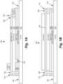
- FIG. 1 Ais a cross-sectional representation (see cut X-X′ of FIG. 1 C ) of an electrochromic lite, 100 , which is fabricated starting with a glass sheet, 105 .
- FIG. 1 Bshows an end view (see perspective Y-Y′ of FIG. 1 C ) of EC lite 100
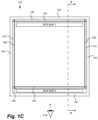
- FIG. 1 Cshows a top-down view of EC lite 100 .
- FIG. 1 Ashows the electrochromic lite after fabrication on glass sheet 105 , edge deleted to produce area, 140 , around the perimeter of the lite.
- FIG. 2 Ashows a cross-sectional schematic diagram of the electrochromic window as described in relation to FIGS. 1 A-C integrated into an IGU, 200 .
- a spacer, 205is used to separate the electrochromic lite from a second lite, 210 .
- Second lite 210 in IGU 200is a non-electrochromic lite, however, the embodiments disclosed herein are not so limited.
- metal oxides and doped metal oxidesexamples include indium oxide, indium tin oxide, doped indium oxide, tin oxide, doped tin oxide, zinc oxide, aluminum zinc oxide, doped zinc oxide, ruthenium oxide, doped ruthenium oxide and the like. Since oxides are often used for these layers, they are sometimes referred to as “transparent conductive oxide” (TCO) layers. Thin metallic coatings that are substantially transparent may also be used.
- a window controllercan power one or more electrochromic devices in an electrochromic window.
- this function of the window controlleris augmented with one or more other functions described in more detail below.
- Window controllers described hereinare not limited to those that have the function of powering an electrochromic device to which it is associated for the purposes of control. That is, the power source for the electrochromic window may be separate from the window controller, where the controller has its own power source and directs application of power from the window power source to the window. However, it is convenient to include a power source with the window controller and to configure the controller to power the window directly, because it obviates the need for separate wiring for powering the electrochromic window.
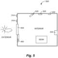
- FIG. 5depicts a schematic diagram of a room including an electrochromic window and a plurality of sensors.
- output from these sensorsmay be input to a signal conditioning module, 465 , of a window controller, 450 .
- output from these sensorsmay be input to a network including a building management system, as described further below in the Building Management System section.
- the various sensorsare depicted as being, e.g., on a vertical surface of the room, this is for the sake of simplicity, and any or all of the sensors may be on the ceiling or the floor as well.
- Exterior photosensor 510 and interior photosensor 520are devices that are able to detect the irradiance of light incident upon them.
- Light incident upon a photosensormay be light directly from a light source or light reflected from a surface to the photosensor.
- Exterior photosensor 510generally measures the direct or reflected sunlight incident upon the photosensor.
- a light level detected by exterior photosensor 510changes with the time of day and with the time of year as the angle at which sunlight strikes the earth changes.
- the light level detected by exterior photosensor 510also changes with the weather; e.g., on cloudy days, sunlight would be blocked by the clouds and the light level detected by exterior photosensor 510 would be lower than on cloudless days.
- window controller 450may perform a recalibration routine to determine the output range of interior photosensor 520 , which again depends on the object(s) in the field of view interior photosensor 520 .
- a recalibration routinemay be performed according to set schedule (e.g., once a week) or triggered by a person (e.g., a maintenance person who rearranges the furniture in room 500 ).
- output from exterior photosensor 510 , interior photosensor 520 , a temperature sensor, and a tint commandare input to signal conditioning module 465 .
- the temperature sensormay be an interior temperature sensor (not shown) or exterior temperature sensor 515 .
- the tint commandmay be a command from a person or occupant in room 500 as to the tint level desired by the person. For example, depending on electrochromic window 505 , the person may instruct the window to transition to a bleached state, a colored state, or an intermediate state. Such tint command instructions may be made, for example, with a wireless remote or with a panel associated with window controller 450 . If room 500 is a bedroom, for example, the person may want electrochromic window 505 to be in a colored state at night for privacy.
- window controller 450can instruct electrochromic window 505 to transition to a bleached state, and with an output value of 15, window controller 450 can instruct electrochromic window 505 to transition to a colored state.
- window controller 450can instruct electrochromic window 505 to transition to a bleached state, with an output value of 5 to 9, window controller 450 can instruct electrochromic window 505 to transition to a first intermediate state, with an output value of 10 to 14, window controller 450 can instruct electrochromic window 505 to transition to a second intermediate state, and with an output value of 15, window controller 450 can instruct electrochromic window 505 to transition to a colored state.
- window controller 450can instruct electrochromic window 505 to transition to a bleached state, with an output value of 15, window controller 450 can instruct electrochromic window 505 to transition to a colored state, and with an output value between 0 to 15, window controller 450 can instruct electrochromic window 505 to transition to a tint level corresponding to the output value.
- Weighting constants k 1 and k 2may be given values to keep the lighting in room 500 relatively constant.
- the weighting constantsmay be set to achieve any of a number of different responses for electrochromic window 505 .
- schedule 1may be a schedule for 10 pm to 6 am
- schedule 2may be a schedule for 10 am to 1 pm
- schedule 3may be a schedule for 1 pm to 10 pm.
- room 500is a room in a residential home
- schedule 1may color electrochromic window 505 for privacy
- schedules 2 and 3may balance the light in room 500 and the temperature.
- output indicating an energy or power consumption by a heating system, a cooling system, and/or lighting in the roomalso is received.
- devices that interface with the wires of the circuits providing power to the room including the tintable windowprovide the energy or power consumption output.
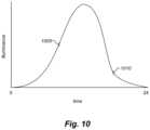
- the relationshipis an expression in which the level of tint is the dependent variable and the output signals are independent variables; an example of such a relationship is shown in FIG. 6 .
- the window controllerreceives the output signals and computes the level of tint based on the relationship and the output signals.
- the relationshipis a lookup table in which levels of tint are specified for various combinations of output signal values. Such a lookup table may be used, for example, when the tintable window is capable of achieving a finite number of states (e.g., two states, bleached and colored, or four states).
- instructionsare provided to change the tint of the tintable window to the level of tint determined in operation 810 .
- thisincludes a window controller applying voltage or current to the tintable window to drive the change in tint pursuant to the instructions.
- microcontroller 455provides instruction to PWM 460 to apply voltage and/or current to the tintable window.
- Method 800can be implemented in an iterative process, as described in operation 820 , a decision block.
- the tint level instructionsmay be generated based on a preset timing function, where after a preset time has elapsed, the controller samples output from the sensors in order to generate new instructions for the window. If the time period has not elapsed, then no further instructions are needed and the method ends. Once the time period has elapsed, then operations 805 through 815 are repeated.
- Decision block 820may also be based on any number of criteria, depending on the desired control level of the one or more windows. For example, decision block 820 may query whether there has been any change in the output from one or more sensors. If the answer is negative, then the method is complete; if the answer is affirmative, then operations 805 through 815 are repeated.
- operation 915instructions are provided to change the tint of the tintable window to the level of tint determined in operation 910 .
- operation 915is similar to operation 815 described with respect to FIG. 8 .
- FIGS. 8 and 9are two methods of controlling the tint state of a tintable window. Many other methods of controlling the tint state of a tintable window are possible, using different combinations of sensors and weighting the output of the different sensors using weighting functions.
- Each of controllers 1110can be in a separate location from the electrochromic window that it controls, or be integrated into the electrochromic window. For simplicity, only ten electrochromic windows of building 1101 are depicted as controlled by window controller 1102 . In a typical setting there may be a large number of electrochromic windows in a building controlled by window controller 1102 . Window controller 1102 need not be a distributed network of window controllers. For example, a single end controller which controls the functions of a single electrochromic window also falls within the scope of the embodiments disclosed herein, as described above. Advantages and features of incorporating electrochromic window controllers as described herein with BMS's are described below in more detail and in relation to FIG. 11 , where appropriate.
- a BMSmay not be present or a BMS may be present but may not communicate with a master network controller or communicate at a high level with a master network controller.
- a master network controllercan provide, for example, enhanced: 1) environmental control, 2) energy savings, 3) flexibility in control options, 4) improved reliability and usable life of other systems due to less reliance thereon and therefore less maintenance thereof, 5) information availability and diagnostics, 6) effective use of staff, and various combinations of these, because the electrochromic windows can be automatically controlled. In these embodiments, maintenance on the BMS would not interrupt control of the electrochromic windows.
- the systems of BMS 1100 or building network 1200may run according to daily, monthly, quarterly, or yearly schedules.
- the lighting control system, the window control system, the HVAC, and the security systemmay operate on a 24 hour schedule accounting for when people are in the building during the work day.
- the buildingmay enter an energy savings mode, and during the day, the systems may operate in a manner that minimizes the energy consumption of the building while providing for occupant comfort.
- the systemsmay shut down or enter an energy savings mode over a holiday period.
- the window controllers and the methods of controlling the tint state of a tintable window described hereinmay employ different sensors or combinations of sensors. Different sensors or combinations of sensors may be referred to as different “sensor setups” or “levels.” For example, use of an exterior photosensor may be referred to as “level 0,” use of an exterior photosensor and an interior photosensor may be referred to as “level 1,” use of an exterior photosensor, an interior photosensor, and an occupancy sensor may be referred to as “level 2,” and use of an exterior photosensor, an interior photosensor, an occupancy sensor, and a signal indicating energy or power consumption by a heating system, a cooling system, and/or lighting within the building (described below) may be referred to as “level 3.” Embodiments of each of these different levels are described further, below.
- the output signals receivedinclude a signal indicating energy or power consumption by a heating system, a cooling system, and/or lighting within the building.
- the energy or power consumption of the heating system, the cooling system, and/or the lighting of the buildingmay be monitored to provide the signal indicating energy or power consumption.
- Devicesmay be interfaced with or attached to the circuits and/or wiring of the building to enable this monitoring.
- the power systems in the buildingmay be installed such that the power consumed by the heating system, a cooling system, and/or lighting for an individual room within the building or a group of rooms within the building can be monitored.
- more than one mode of wireless communicationis used in the window controller distributed network.
- a master window controllermay communicate wirelessly to intermediate controllers via WiFi or Zigbee, while the intermediate controllers communicate with end controllers via Bluetooth, Zigbee, EnOcean, or other protocol.
- window controllershave redundant wireless communication systems for flexibility in end user choices for wireless communication.
Landscapes
- Physics & Mathematics (AREA)
- General Physics & Mathematics (AREA)
- Nonlinear Science (AREA)
- Engineering & Computer Science (AREA)
- Structural Engineering (AREA)
- Spectroscopy & Molecular Physics (AREA)
- Chemical & Material Sciences (AREA)
- Optics & Photonics (AREA)
- Life Sciences & Earth Sciences (AREA)
- Architecture (AREA)
- Civil Engineering (AREA)
- Sustainable Development (AREA)
- Health & Medical Sciences (AREA)
- Analytical Chemistry (AREA)
- Biochemistry (AREA)
- General Health & Medical Sciences (AREA)
- Immunology (AREA)
- Pathology (AREA)
- Mathematical Physics (AREA)
- Crystallography & Structural Chemistry (AREA)
- Electrochromic Elements, Electrophoresis, Or Variable Reflection Or Absorption Elements (AREA)
Abstract
Description
Claims (28)
Priority Applications (2)
| Application Number | Priority Date | Filing Date | Title |
|---|---|---|---|
| US17/446,641US11822202B2 (en) | 2011-03-16 | 2021-09-01 | Controlling transitions in optically switchable devices |
| US18/486,197US12298644B2 (en) | 2011-03-16 | 2023-10-13 | Controlling transitions in optically switchable devices |
Applications Claiming Priority (8)
| Application Number | Priority Date | Filing Date | Title |
|---|---|---|---|
| US13/049,756US9454055B2 (en) | 2011-03-16 | 2011-03-16 | Multipurpose controller for multistate windows |
| US13/449,235US8705162B2 (en) | 2012-04-17 | 2012-04-17 | Controlling transitions in optically switchable devices |
| US14/163,026US9423664B2 (en) | 2012-04-17 | 2014-01-24 | Controlling transitions in optically switchable devices |
| US14/932,474US9927674B2 (en) | 2011-03-16 | 2015-11-04 | Multipurpose controller for multistate windows |
| US14/993,822US10520784B2 (en) | 2012-04-17 | 2016-01-12 | Controlling transitions in optically switchable devices |
| US15/891,866US10908470B2 (en) | 2011-03-16 | 2018-02-08 | Multipurpose controller for multistate windows |
| US15/910,925US11137658B2 (en) | 2011-03-16 | 2018-03-02 | Controlling transitions in optically switchable devices |
| US17/446,641US11822202B2 (en) | 2011-03-16 | 2021-09-01 | Controlling transitions in optically switchable devices |
Related Parent Applications (1)
| Application Number | Title | Priority Date | Filing Date |
|---|---|---|---|
| US15/910,925ContinuationUS11137658B2 (en) | 2011-03-16 | 2018-03-02 | Controlling transitions in optically switchable devices |
Related Child Applications (1)
| Application Number | Title | Priority Date | Filing Date |
|---|---|---|---|
| US18/486,197ContinuationUS12298644B2 (en) | 2011-03-16 | 2023-10-13 | Controlling transitions in optically switchable devices |
Publications (2)
| Publication Number | Publication Date |
|---|---|
| US20210397060A1 US20210397060A1 (en) | 2021-12-23 |
| US11822202B2true US11822202B2 (en) | 2023-11-21 |
Family
ID=79023431
Family Applications (2)
| Application Number | Title | Priority Date | Filing Date |
|---|---|---|---|
| US17/446,641Active2031-08-13US11822202B2 (en) | 2011-03-16 | 2021-09-01 | Controlling transitions in optically switchable devices |
| US18/486,197ActiveUS12298644B2 (en) | 2011-03-16 | 2023-10-13 | Controlling transitions in optically switchable devices |
Family Applications After (1)
| Application Number | Title | Priority Date | Filing Date |
|---|---|---|---|
| US18/486,197ActiveUS12298644B2 (en) | 2011-03-16 | 2023-10-13 | Controlling transitions in optically switchable devices |
Country Status (1)
| Country | Link |
|---|---|
| US (2) | US11822202B2 (en) |
Families Citing this family (6)
| Publication number | Priority date | Publication date | Assignee | Title |
|---|---|---|---|---|
| US11703814B2 (en) | 2011-03-16 | 2023-07-18 | View, Inc. | Security event detection with smart windows |
| US11415949B2 (en) | 2011-03-16 | 2022-08-16 | View, Inc. | Security event detection with smart windows |
| US12429742B2 (en) | 2012-03-13 | 2025-09-30 | View Operating Corporation | Methods of controlling multi-zone tintable windows |
| US10048561B2 (en) | 2013-02-21 | 2018-08-14 | View, Inc. | Control method for tintable windows |
| US12372846B2 (en) | 2013-02-21 | 2025-07-29 | View Operating Corporation | Control methods and systems using external 3D modeling and schedule-based computing |
| US12422725B2 (en) | 2013-02-21 | 2025-09-23 | View Operating Corporation | Control methods and systems using outside temperature as a driver for changing window tint states |
Citations (77)
| Publication number | Priority date | Publication date | Assignee | Title |
|---|---|---|---|---|
| US2971186A (en) | 1959-06-30 | 1961-02-07 | Ripepi Tony | Central warning burglar alarm system |
| GB2169426A (en) | 1985-01-04 | 1986-07-09 | Hickman James A A | Glazing unit alarm systems |
| WO1989006302A1 (en) | 1987-12-29 | 1989-07-13 | Oscar Von Wedekind | Unit comprising two or more panes of glass permanently secured together |
| US5579149A (en) | 1993-09-13 | 1996-11-26 | Csem Centre Suisse D'electronique Et De Microtechnique Sa | Miniature network of light obturators |
| US5705983A (en) | 1996-01-22 | 1998-01-06 | Ford Motor Company | Glazing unit security system |
| US20020015214A1 (en) | 1999-02-18 | 2002-02-07 | Nippon Mitsubishi Oil Corporation | Electrochromic Device |
| US20020021481A1 (en) | 2000-12-15 | 2002-02-21 | Lin Chia Cheng | Electrochromic transparency incorporating security system |
| US6794882B2 (en) | 2002-07-30 | 2004-09-21 | Ppg Industries Ohio, Inc. | Rupture detector for windshield assembly |
| US20040215520A1 (en) | 2001-05-25 | 2004-10-28 | Andrew Butler | Remote monitoring system |
| US6829511B2 (en) | 2000-07-25 | 2004-12-07 | Gentex Corporation | System to control variable transmission windows having a security system interface |
| US20050046563A1 (en) | 2002-06-14 | 2005-03-03 | Paul Whitney | System and method for suppressing the spread of fire and various contaminants |
| US7133181B2 (en) | 2004-07-23 | 2006-11-07 | Sage Electrochromics, Inc. | Control system for electrochromic devices |
| US20060255922A1 (en) | 2005-05-11 | 2006-11-16 | Toyota Jidosha Kabushiki Kaisha | Function operation warning device |
| US7161483B2 (en) | 2003-02-26 | 2007-01-09 | Intexact Technologies Limited | Integrated programmable system for controlling the operation of electrical and/or electronic appliances of a premises |
| US20070053053A1 (en) | 2005-09-08 | 2007-03-08 | Spd Control Systems Corporation | Intelligent SPD control apparatus with scalable networking capabilities for window and multimedia applications |
| US20070086084A1 (en) | 2005-10-13 | 2007-04-19 | Toshihiro Mori | Optical device |
| US20080011864A1 (en) | 2004-03-02 | 2008-01-17 | Honeywell International Inc. | Wireless controller with gateway |
| US20080150555A1 (en) | 2006-12-20 | 2008-06-26 | 3M Innovative Properties Company | Detection system |
| US20080196331A1 (en) | 2007-02-16 | 2008-08-21 | Boyd Thomas J | Window frame with lip for covering windows |
| US20090020233A1 (en) | 2004-05-06 | 2009-01-22 | Mechoshade Systems, Inc. | Automated shade control method and system |
| WO2009087169A1 (en) | 2008-01-10 | 2009-07-16 | Robert Bosch Gmbh | Monitoring device for an alarm system, alarm system, and method for monitoring said alarm system |
| US20090324010A1 (en) | 2008-06-26 | 2009-12-31 | Billy Hou | Neural network-controlled automatic tracking and recognizing system and method |
| US7684105B2 (en) | 2005-02-24 | 2010-03-23 | National Research Council Of Canada | Microblinds and a method of fabrication thereof |
| WO2010079388A1 (en)* | 2009-01-07 | 2010-07-15 | Koninklijke Philips Electronics N.V. | Intelligent controllable lighting networks and schemata therefore |
| US20100243427A1 (en) | 2009-03-31 | 2010-09-30 | Soladigm, Inc. | Fabrication of low defectivity electrochromic devices |
| US20100265089A1 (en) | 2009-04-16 | 2010-10-21 | James Gregory | Emergency location finder |
| US20110087988A1 (en) | 2009-10-12 | 2011-04-14 | Johnson Controls Technology Company | Graphical control elements for building management systems |
| US20110267675A1 (en) | 2010-04-30 | 2011-11-03 | Soladigm, Inc. | Electrochromic devices |
| US20110267674A1 (en) | 2010-04-30 | 2011-11-03 | Soladigm, Inc. | Electrochromic devices |
| US20110266138A1 (en) | 2010-04-30 | 2011-11-03 | Soladigm, Inc. | Electrochromic devices |
| US20110266137A1 (en) | 2010-04-30 | 2011-11-03 | Soladigm, Inc. | Electrochromic devices |
| US20120033287A1 (en) | 2010-08-05 | 2012-02-09 | Soladigm, Inc. | Multi-pane electrochromic windows |
| US20120062975A1 (en) | 2011-03-16 | 2012-03-15 | Soladigm, Inc. | Controlling transitions in optically switchable devices |
| US20120080944A1 (en)* | 2006-03-28 | 2012-04-05 | Wireless Environment, Llc. | Grid Shifting System for a Lighting Circuit |
| US8213074B1 (en) | 2011-03-16 | 2012-07-03 | Soladigm, Inc. | Onboard controller for multistate windows |
| US20120188627A1 (en) | 2011-01-21 | 2012-07-26 | E Ink Holdings Inc. | Smart window and smart window system using the same |
| US20120229275A1 (en) | 2011-03-11 | 2012-09-13 | Mattern Jeremy Keith | System and Method for Providing Warning and Directives Based upon Gunfire Detection |
| US20120239209A1 (en) | 2011-03-16 | 2012-09-20 | Soladigm, Inc. | Multipurpose controller for multistate windows |
| US20120275008A1 (en) | 2010-04-30 | 2012-11-01 | Soladigm, Inc. | Electrochromic devices |
| US20130063065A1 (en) | 2004-05-06 | 2013-03-14 | Mechoshade Systems, Inc. | Automated shade control system utilizing brightness modeling |
| US20130271812A1 (en) | 2012-04-17 | 2013-10-17 | View, Inc. | Controlling transitions in optically switchable devices |
| US20130271815A1 (en) | 2012-04-17 | 2013-10-17 | View, Inc. | Driving thin film switchable optical devices |
| WO2013155467A1 (en) | 2012-04-13 | 2013-10-17 | View, Inc. | Applications for controlling optically switchable devices |
| US20130271813A1 (en) | 2012-04-17 | 2013-10-17 | View, Inc. | Controller for optically-switchable windows |
| US20130271814A1 (en) | 2012-04-17 | 2013-10-17 | View, Inc. | Controller for optically-switchable windows |
| WO2014082092A1 (en) | 2012-11-26 | 2014-05-30 | View, Inc. | Multi-pane windows including electrochromic devices and electromechanical systems devices |
| US20140313032A1 (en) | 2013-04-23 | 2014-10-23 | Canary Connect, Inc. | System and methods for notifying a community of security events |
| US20140368899A1 (en) | 2013-06-18 | 2014-12-18 | Sage Electrochromics, Inc. | Control system trunk line architecture |
| WO2014209812A1 (en) | 2013-06-28 | 2014-12-31 | View, Inc. | Controlling transitions in optically switchable devices |
| US9081246B2 (en) | 2009-12-22 | 2015-07-14 | View, Inc. | Wireless powered electrochromic windows |
| WO2016004109A1 (en) | 2014-06-30 | 2016-01-07 | View, Inc. | Control methods and systems for networks of optically switchable windows during reduced power availability |
| WO2016085964A1 (en) | 2014-11-25 | 2016-06-02 | View, Inc. | Window antennas |
| US20160154290A1 (en) | 2009-12-22 | 2016-06-02 | View, Inc. | Self-contained ec igu |
| US20160203403A1 (en) | 2015-01-12 | 2016-07-14 | Kinestral Technologies, Inc. | Install mode and cloud learning for smart windows |
| EP3104352A1 (en) | 2015-06-05 | 2016-12-14 | Penland, Rustin, B. | Security system for identifying disturbances in a building |
| US20170097553A1 (en) | 2013-06-28 | 2017-04-06 | View, Inc. | Controlling transitions in optically switchable devices |
| US20170097259A1 (en) | 2015-10-06 | 2017-04-06 | View, Inc. | Multi-sensor |
| WO2017075059A1 (en) | 2015-10-29 | 2017-05-04 | View, Inc. | Controllers for optically-switchable devices |
| US9677327B1 (en) | 2015-01-12 | 2017-06-13 | Kinestral Technologies, Inc. | Security focused system for smart windows |
| WO2017155833A1 (en) | 2016-03-09 | 2017-09-14 | View, Inc. | Method of commissioning electrochromic windows |
| WO2017189307A2 (en) | 2016-04-29 | 2017-11-02 | View, Inc. | Calibration of electrical parameters in optically switchable windows |
| WO2017192881A1 (en) | 2016-05-06 | 2017-11-09 | View. Inc. | Window antennas |
| US9885935B2 (en) | 2013-06-28 | 2018-02-06 | View, Inc. | Controlling transitions in optically switchable devices |
| US20180129172A1 (en) | 2012-04-13 | 2018-05-10 | View, Inc. | Monitoring sites containing switchable optical devices and controllers |
| WO2018098089A1 (en) | 2016-11-23 | 2018-05-31 | View, Inc. | Automated commissioning of controllers in a window network |
| WO2018112241A1 (en) | 2016-12-14 | 2018-06-21 | View, Inc. | Tester and electrical connectors for insulated glass units |
| US20180187478A1 (en) | 2014-06-30 | 2018-07-05 | View, Inc. | Power management for electrochromic window networks |
| US20180189117A1 (en) | 2014-12-08 | 2018-07-05 | View, Inc. | Multiple interacting systems at a site |
| US20180284555A1 (en) | 2012-03-13 | 2018-10-04 | View, Inc. | Methods of controlling multi-zone tintable windows |
| WO2018200740A2 (en) | 2017-04-26 | 2018-11-01 | View, Inc. | Tintable window system for building services |
| US10299101B1 (en) | 2017-12-27 | 2019-05-21 | Motorola Solutions, Inc. | Device, system and method for controlling quality of service of communication devices based on a predicted hazard path |
| US10329839B2 (en) | 2016-02-17 | 2019-06-25 | King Fahd University Of Petroleum And Minerals | Smart window control system |
| US20190317458A1 (en) | 2011-03-16 | 2019-10-17 | View, Inc. | Security event detection with smart windows |
| US20190391419A1 (en) | 2017-01-27 | 2019-12-26 | Merck Patent Gmbh | Method for detecting breakage of substrate of a switchable optical element and switchable optical device |
| CN111354169A (en) | 2020-03-12 | 2020-06-30 | 高永飞 | Building safety monitoring method based on Internet of things |
| US20200265089A1 (en) | 2018-05-30 | 2020-08-20 | Google Llc | Optimizing geographic region selection |
| US20220382224A1 (en) | 2011-03-16 | 2022-12-01 | View, Inc. | Security event detection with smart windows |
Family Cites Families (363)
| Publication number | Priority date | Publication date | Assignee | Title |
|---|---|---|---|---|
| US3963347A (en) | 1974-05-09 | 1976-06-15 | American Optical Corporation | Erbium laser ceilometer |
| US4355896A (en) | 1980-06-27 | 1982-10-26 | Nasa | Cloud cover sensor |
| US7663502B2 (en) | 1992-05-05 | 2010-02-16 | Intelligent Technologies International, Inc. | Asset system control arrangement and method |
| JPS6122897U (en) | 1984-07-17 | 1986-02-10 | 鹿島建設株式会社 | window solar shading device |
| JPS6282194A (en) | 1985-10-04 | 1987-04-15 | 日立照明株式会社 | Window light control system for visual sensation display apparatus work |
| JP2696827B2 (en) | 1987-02-25 | 1998-01-14 | 株式会社ニコン | Driving method of electrochromic device |
| JP2600862B2 (en) | 1988-11-14 | 1997-04-16 | 株式会社ニコン | Control circuit for electrochromic device |
| FR2649691B1 (en) | 1989-07-11 | 1992-10-30 | Saint Gobain Vitrage Int | ELECTROCHROME GLAZING |
| US5167993A (en) | 1990-03-03 | 1992-12-01 | Youhichiro Aoyagi | Color changing transparent plate device |
| JP2646287B2 (en) | 1990-05-29 | 1997-08-27 | 鹿島建設株式会社 | Solar control window |
| FR2666804B1 (en) | 1990-09-14 | 1993-05-28 | Saint Gobain Vitrage Int | ELECTROCHROME GLAZING. |
| US5220317A (en) | 1990-12-11 | 1993-06-15 | Donnelly Corporation | Electrochromic device capable of prolonged coloration |
| US5170108A (en) | 1991-01-31 | 1992-12-08 | Daylighting, Inc. | Motion control method and apparatus for motorized window blinds and and the like |
| US5379215A (en) | 1991-02-25 | 1995-01-03 | Douglas P. Kruhoeffer | Method for creating a 3-D image of terrain and associated weather |
| US5451822A (en) | 1991-03-15 | 1995-09-19 | Gentex Corporation | Electronic control system |
| JP2640997B2 (en) | 1991-06-11 | 1997-08-13 | 三井建設株式会社 | Blind opening and closing control device |
| FR2681444B1 (en) | 1991-09-16 | 1994-09-30 | Corning Inc | ELECTROCHROME DEVICE. |
| US5290986A (en) | 1991-10-22 | 1994-03-01 | International Business Machines Corporation | Thermally assisted shorts removal process for glass ceramic product using an RF field |
| US5204778A (en) | 1992-04-06 | 1993-04-20 | Gentex Corporation | Control system for automatic rearview mirrors |
| FR2690536B1 (en) | 1992-04-28 | 1994-06-17 | Saint Gobain Vitrage Int | ELECTROCHROME GLAZING. |
| FR2690763B1 (en) | 1992-04-30 | 1995-06-09 | Saint Gobain Vitrage Int | METHOD AND DEVICE FOR SUPPLYING AN ELECTROCHROMIC SYSTEM. |
| FR2694820B1 (en) | 1992-08-12 | 1994-09-16 | Saint Gobain Vitrage Int | Supply of an electrochromic cell. |
| US5673028A (en) | 1993-01-07 | 1997-09-30 | Levy; Henry A. | Electronic component failure indicator |
| EP0612826B1 (en) | 1993-02-26 | 2000-10-04 | Donnelly Corporation | Electrochromic polymeric solid films, manufacturing electrochromic devices using such solid films, and processing for making such solid films and devices |
| JPH06282194A (en) | 1993-03-25 | 1994-10-07 | Toshiba Corp | Fixing device |
| US9520827B2 (en) | 2006-08-05 | 2016-12-13 | Anlinx | Zilinx : the 11 less green technology for FPIC of smart window |
| US8089323B2 (en) | 2006-08-05 | 2012-01-03 | Min Ming Tarng | Green technology: green circuit and device designs of green chip |
| US8487653B2 (en) | 2006-08-05 | 2013-07-16 | Tang System | SDOC with FPHA and FPXC: system design on chip with field programmable hybrid array of FPAA, FPGA, FPLA, FPMA, FPRA, FPTA and frequency programmable xtaless clockchip with trimless/trimfree self-adaptive bandgap reference xtaless clockchip |
| US20140371931A1 (en) | 2013-06-16 | 2014-12-18 | Mei-Jech Lin | W5RS: Anlinx & Milinx & Zilinx - the 23Less Green Technology for FSOC of Scalable iPindow of iPhome & Scalable Smart Window of Smart Home with Wire/Wireless/Solar/Battery Communication, Power Supplies & Conversions |
| US5583972A (en) | 1993-08-02 | 1996-12-10 | Miller; Richard L. | 3-D weather display and weathercast system |
| US5900720A (en) | 1993-09-10 | 1999-05-04 | Kallman; William R. | Micro-electronic power supply for electrochromic eyewear |
| SG84490A1 (en) | 1994-04-29 | 2001-11-20 | Research Frontiers Inc | Optical cell control system |
| FR2719915B1 (en) | 1994-05-16 | 1996-06-14 | Saint Gobain Vitrage | Electrochromic system and its supply process. |
| JP2621796B2 (en) | 1994-05-30 | 1997-06-18 | 日本電気株式会社 | Interferometer |
| DE4438859C2 (en) | 1994-11-02 | 1996-12-12 | Siemens Ag | Process for analyzing process data of a technical system |
| FR2728696A1 (en) | 1994-12-23 | 1996-06-28 | Saint Gobain Vitrage | METHOD FOR ELECTRICALLY POWERING ELECTRO-CONTROLLABLE GLAZING |
| DE29506194U1 (en) | 1995-04-10 | 1995-06-08 | Wolters, Paolo, 12555 Berlin | Window element for shielding and illuminating interiors |
| US5686979A (en) | 1995-06-26 | 1997-11-11 | Minnesota Mining And Manufacturing Company | Optical panel capable of switching between reflective and transmissive states |
| US5760558A (en) | 1995-07-24 | 1998-06-02 | Popat; Pradeep P. | Solar-powered, wireless, retrofittable, automatic controller for venetian blinds and similar window converings |
| US5830336A (en) | 1995-12-05 | 1998-11-03 | Minnesota Mining And Manufacturing Company | Sputtering of lithium |
| US5663621A (en) | 1996-01-24 | 1997-09-02 | Popat; Pradeep P. | Autonomous, low-cost, automatic window covering system for daylighting applications |
| US5598000A (en) | 1996-02-22 | 1997-01-28 | Popat; Pradeep P. | Dual-mode automatic window covering system responsive to AC-induced flicker in ambient illumination |
| DE19622253A1 (en) | 1996-02-29 | 1997-09-04 | Zumtobel Licht | Method and device for controlling a dimming device |
| WO1998008137A1 (en) | 1996-08-20 | 1998-02-26 | Donnelly Corporation | Window assembly with controllable optical transmission |
| JPH1063216A (en) | 1996-08-23 | 1998-03-06 | Nikon Corp | Driving device for electrochromic device |
| AUPO303096A0 (en) | 1996-10-16 | 1996-11-14 | Sustainable Technologies Australia Limited | Control of electrochromic devices |
| JPH10159465A (en) | 1996-11-29 | 1998-06-16 | Toshiba Lighting & Technol Corp | Shading device and lighting control device |
| US6125327A (en) | 1997-01-15 | 2000-09-26 | Harris Corporation | System for identifying and generating geographic map display of aircraft icing conditions |
| JPH10249278A (en) | 1997-03-10 | 1998-09-22 | Mitsubishi Chem Corp | Electrostatic actuator device |
| US6089721A (en) | 1997-04-02 | 2000-07-18 | Donnelly Corporation | Digital electrochromic mirror system |
| US5956012A (en) | 1997-04-02 | 1999-09-21 | Gentex Corporation | Series drive circuit |
| US6130772A (en) | 1997-06-06 | 2000-10-10 | Cava; Frank James | Electrochromic device and method |
| US6247819B1 (en) | 1997-09-16 | 2001-06-19 | Gentex Corporation | Individual mirror control system |
| US6266063B1 (en) | 1997-10-20 | 2001-07-24 | Baron Services, Inc. | Real-time three-dimensional weather display method and weathercast system |
| JPH11154292A (en) | 1997-11-21 | 1999-06-08 | Kazuya Deguchi | Integrated warning system |
| US6084231A (en) | 1997-12-22 | 2000-07-04 | Popat; Pradeep P. | Closed-loop, daylight-sensing, automatic window-covering system insensitive to radiant spectrum produced by gaseous-discharge lamps |
| US6420975B1 (en) | 1999-08-25 | 2002-07-16 | Donnelly Corporation | Interior rearview mirror sound processing system |
| US6084700A (en) | 1998-04-29 | 2000-07-04 | Gentex Corporation | Reflectance control of an electrochromic element using a variable duty cycle drive |
| JP3871441B2 (en) | 1998-06-26 | 2007-01-24 | 旭化成ホームズ株式会社 | Residential sunshine simulation equipment |
| US6317248B1 (en) | 1998-07-02 | 2001-11-13 | Donnelly Corporation | Busbars for electrically powered cells |
| US6130448A (en) | 1998-08-21 | 2000-10-10 | Gentex Corporation | Optical sensor package and method of making same |
| US5973818A (en) | 1998-09-21 | 1999-10-26 | Ppg Industries Ohio, Inc. | Method and apparatus for controlling an electrochromic device |
| US5973819A (en) | 1998-09-21 | 1999-10-26 | Ppg Industries Ohio, Inc. | Method and apparatus for controlling an electrochromic device |
| US5978126A (en) | 1998-09-21 | 1999-11-02 | Ppg Industries Ohio, Inc. | Apparatus for controlling an electrochromic device |
| JP2000096956A (en) | 1998-09-22 | 2000-04-04 | Toso Co Ltd | Electric blind control device |
| US6163756A (en) | 1998-10-20 | 2000-12-19 | Baron Services, Inc. | System and method for detecting and displaying wind shear |
| US6375864B1 (en) | 1998-11-10 | 2002-04-23 | M.A. Hannacolor, A Division Of M.A. Hanna Company | Daylight/nightglow colored phosphorescent plastic compositions and articles |
| US6222177B1 (en) | 1999-01-19 | 2001-04-24 | Gentex Corporation | Electrochromic element driver with negative output resistance |
| US6398118B1 (en) | 1999-01-29 | 2002-06-04 | Howard B. Rosen | Thermostat incorporating thin film carbon dioxide sensor and environmental control system |
| US6055089A (en) | 1999-02-25 | 2000-04-25 | Minnesota Mining And Manufacturing Company | Photovoltaic powering and control system for electrochromic windows |
| CN1201181C (en) | 1999-04-06 | 2005-05-11 | 里维奥公司 | Electro-optical glazing structures having scatthering and transparent modes of operation |
| US6262831B1 (en) | 1999-10-22 | 2001-07-17 | Gentex Corporation | Power supply for electrochromic mirrors in high voltage automotive power systems |
| WO2001084230A1 (en) | 2000-05-04 | 2001-11-08 | Schott Donnelly Llc | Chromogenic glazing |
| EP1295169B1 (en) | 2000-05-24 | 2008-06-25 | Schott North America, Inc. | Electrode for electrochromic devices |
| US6407468B1 (en) | 2000-05-25 | 2002-06-18 | Gentex Corporation | Rearview mirror with buttons incorporating display |
| US6407847B1 (en) | 2000-07-25 | 2002-06-18 | Gentex Corporation | Electrochromic medium having a color stability |
| US6561460B2 (en) | 2000-08-03 | 2003-05-13 | Ppg Industries Ohio, Inc. | Switchable electrochromic devices for use in aircraft transparency windows |
| US6922701B1 (en) | 2000-08-03 | 2005-07-26 | John A. Ananian | Generating cad independent interactive physical description remodeling, building construction plan database profile |
| US6471360B2 (en) | 2000-08-03 | 2002-10-29 | Ppg Industries Ohio, Inc. | Switchable electrochromic devices with uniform switching and preferential area shading |
| US6614577B1 (en) | 2000-08-23 | 2003-09-02 | Ppg Industries Ohio, Inc. | Method and apparatus for controlling an electrochromic device |
| SE0003112D0 (en) | 2000-09-04 | 2000-09-04 | Granqvist Claes Goeran | Climate control system and method for controlling such |
| US20020075472A1 (en) | 2000-09-22 | 2002-06-20 | Holton Carvel E. | Optical fiber ceilometer for meteorological cloud altitude sensing |
| JP2002148573A (en) | 2000-11-15 | 2002-05-22 | Nissan Motor Co Ltd | Light control glass with solar cell |
| CA2432440C (en) | 2001-01-12 | 2007-03-27 | Novar Controls Corporation | Small building automation control system |
| US20020144831A1 (en) | 2001-02-28 | 2002-10-10 | Kalt Charles G. | Environmentally green shelter structure for commercial and residential use |
| CN1380482A (en) | 2001-04-06 | 2002-11-20 | 吴水森 | Light adjustable universal colour-changing glass door and window |
| DE10124673A1 (en) | 2001-05-18 | 2002-11-21 | Flabeg Gmbh & Co Kg | Varying at least one control variable influencing at least one optical property of switchable element involves limiting temperature gradient produced by absorption of electromagnetic radiation |
| US6819367B1 (en) | 2001-10-19 | 2004-11-16 | Frank James Cava | Shade-free light control system and method |
| US20030142140A1 (en) | 2002-01-28 | 2003-07-31 | International Business Machines Corporation | Adjusting the tint of a translucent window to convey status |
| US7832177B2 (en) | 2002-03-22 | 2010-11-16 | Electronics Packaging Solutions, Inc. | Insulated glazing units |
| RU29501U1 (en) | 2002-04-01 | 2003-05-20 | Общество с ограниченной ответстенностью "Интерфейс" | Light shields on vehicle windows |
| US6856444B2 (en) | 2002-05-10 | 2005-02-15 | Sage Electrochromics, Inc. | Inferential temperature measurement of an electrochromic device |
| US20030210355A1 (en) | 2002-05-13 | 2003-11-13 | Dao Hank Tien | Electronic adjustable window tinting system |
| JP3951950B2 (en) | 2002-05-31 | 2007-08-01 | ソニー株式会社 | Driving method of display device |
| US7215318B2 (en) | 2002-06-24 | 2007-05-08 | Gentex Corporation | Electrochromic element drive control circuit |
| US20040001056A1 (en) | 2002-06-28 | 2004-01-01 | Honeywell International Inc. | Electrochromic window driver |
| US9955551B2 (en) | 2002-07-12 | 2018-04-24 | Yechezkal Evan Spero | Detector controlled illuminating system |
| AU2003244954A1 (en) | 2002-07-26 | 2004-02-25 | Koninklijke Philips Electronics N.V. | Electrochromic color display having different electrochromic materials |
| US20090143141A1 (en) | 2002-08-06 | 2009-06-04 | Igt | Intelligent Multiplayer Gaming System With Multi-Touch Display |
| US6940627B2 (en) | 2002-10-30 | 2005-09-06 | Finisar Corporation | Control system for electrochromic devices |
| US6872901B2 (en) | 2002-11-21 | 2005-03-29 | Exon Science Inc. | Automatic actuation of device according to UV intensity |
| JP2004170350A (en) | 2002-11-22 | 2004-06-17 | Horiba Ltd | Observation device and observation method for cloud or the like |
| CN2590732Y (en) | 2002-12-31 | 2003-12-10 | 湖北省荆门市龙华实业有限公司 | Sandwich light modulating colour change glass |
| US20040135989A1 (en) | 2003-01-09 | 2004-07-15 | Klebe Dimitri I | Cloud sensor |
| FR2850469B1 (en) | 2003-01-24 | 2005-04-08 | Somfy Sas | METHOD FOR CONFIGURING AN INSTALLATION COMPRISING SOLAR PROTECTION AND / OR LIGHTING DEVICES |
| US7057512B2 (en) | 2003-02-03 | 2006-06-06 | Ingrid, Inc. | RFID reader for a security system |
| JP2004245985A (en) | 2003-02-13 | 2004-09-02 | Olympus Corp | Method for driving dimmer element, driving program, dimmer device, and camera using the dimmer device |
| US7111952B2 (en) | 2003-03-24 | 2006-09-26 | Lutron Electronics Co., Inc. | System to control daylight and artificial illumination and sun glare in a space |
| WO2004086195A2 (en) | 2003-03-24 | 2004-10-07 | Lutron Electronics Co., Inc. | System to control daylight and artificial illumination and sun glare in a space |
| FR2857617B1 (en) | 2003-07-16 | 2006-10-27 | Saint Gobain | FUNCTIONALIZED SAFETY GLAZING |
| JP2005054356A (en) | 2003-08-01 | 2005-03-03 | Cloud Nine:Kk | Electric blind remote control system |
| US8988757B2 (en) | 2004-03-12 | 2015-03-24 | The Boeing Company | Low vapor pressure solvent for electrochromic devices |
| KR100752041B1 (en) | 2004-03-16 | 2007-08-23 | 주식회사 엘지화학 | Drive circuit of electrochromic device |
| WO2005098811A1 (en) | 2004-03-17 | 2005-10-20 | Siemens Aktiengesellschaft | Control of electrochromic displays |
| US7548833B2 (en) | 2004-03-25 | 2009-06-16 | Siemens Building Technologies, Inc. | Method and apparatus for graphical display of a condition in a building system with a mobile display unit |
| US7610910B2 (en) | 2004-03-25 | 2009-11-03 | Siemens Building Technologies, Inc. | Method and apparatus for controlling building component characteristics |
| US7512450B2 (en) | 2004-03-25 | 2009-03-31 | Siemens Building Technologies, Inc. | Method and apparatus for generating a building system model |
| JP2005282106A (en) | 2004-03-29 | 2005-10-13 | Kyocera Corp | Dimmable glass window system |
| US6954299B1 (en) | 2004-03-31 | 2005-10-11 | Exon Science Incorporation | Controlling system with fixed frequency driver for controlling an electrochromic element and method for the same |
| FR2868850B1 (en) | 2004-04-09 | 2006-08-25 | Saint Gobain | METHOD FOR SUPPLYING AN ELECTROCOMMANDABLE DEVICE HAVING VARIABLE OPTICAL AND / OR ENERGY PROPERTIES |
| JP4455928B2 (en) | 2004-04-26 | 2010-04-21 | アイシン精機株式会社 | Natural light awakening device |
| US10253564B2 (en) | 2004-05-06 | 2019-04-09 | Mechoshade Systems, Llc | Sky camera system for intelligent building control |
| US10619415B2 (en) | 2004-05-06 | 2020-04-14 | Mechoshade Systems, Llc | Sky camera system utilizing circadian information for intelligent building control |
| US8120292B2 (en) | 2004-05-06 | 2012-02-21 | Mechoshade Systems, Inc. | Automated shade control reflectance module |
| GB2462755B (en) | 2004-05-06 | 2010-08-25 | Mechoshade Systems Inc | Automated shade control method and system |
| US7417397B2 (en) | 2004-05-06 | 2008-08-26 | Mechoshade Systems, Inc. | Automated shade control method and system |
| US8723467B2 (en) | 2004-05-06 | 2014-05-13 | Mechoshade Systems, Inc. | Automated shade control in connection with electrochromic glass |
| US8836263B2 (en) | 2004-05-06 | 2014-09-16 | Mechoshade Systems, Inc. | Automated shade control in connection with electrochromic glass |
| US8125172B2 (en) | 2004-05-06 | 2012-02-28 | Mechoshade Systems, Inc. | Automated shade control method and system |
| CN1704556A (en) | 2004-06-01 | 2005-12-07 | 乐金电子(沈阳)有限公司 | Adjustable staining device using liquid and control method thereof |
| US7706046B2 (en) | 2004-06-08 | 2010-04-27 | Gentex Corporation | Rearview mirror element having a circuit mounted to the rear surface of the element |
| US20060001683A1 (en) | 2004-06-10 | 2006-01-05 | Alexander May | Structure image generation |
| JP4327665B2 (en) | 2004-06-22 | 2009-09-09 | 株式会社ニチベイ | Electric blind control device |
| JP4410629B2 (en) | 2004-07-21 | 2010-02-03 | 株式会社ニチベイ | Electric blind slat angle control device |
| CN100557474C (en) | 2004-07-27 | 2009-11-04 | 伊英克公司 | Electro-optic display |
| JP4694816B2 (en) | 2004-09-17 | 2011-06-08 | 政安 宮崎 | Multi-layer high airtight insulation member |
| US7796322B2 (en) | 2004-10-08 | 2010-09-14 | Massachusetts Institute Of Technology | Programmable window: a device for controlling the opacity of small-scale areas within a large scale transparent membrane |
| EP1846936A4 (en) | 2005-01-24 | 2011-08-10 | Philips Solid State Lighting | Methods and apparatus for providing workspace lighting and facilitating workspace customization |
| US7389806B2 (en) | 2005-02-24 | 2008-06-24 | Lawrence Kates | Motorized window shade system |
| KR100733925B1 (en) | 2005-03-16 | 2007-07-02 | 주식회사 엘지화학 | ECD control apparatus |
| CN101322068B (en) | 2005-07-01 | 2010-09-22 | Ppg工业俄亥俄公司 | Transparent electrode for an electrochromic switchable cell |
| EP1742195A1 (en) | 2005-07-04 | 2007-01-10 | Seiko Epson Corporation | Electrochromic display and method of operation |
| US20080204850A1 (en) | 2005-07-29 | 2008-08-28 | Anoop Agrawal | Persistent Electro-Optic Devices and Processes for Optical Media |
| US8099178B2 (en) | 2005-08-22 | 2012-01-17 | Trane International Inc. | Building automation system facilitating user customization |
| DE102005039838B4 (en) | 2005-08-23 | 2008-03-13 | Airbus Deutschland Gmbh | Transmission-controlled window glazing |
| JP4799113B2 (en) | 2005-10-05 | 2011-10-26 | 株式会社村上開明堂 | Electrochromic device and driving method thereof |
| JP4867287B2 (en) | 2005-10-26 | 2012-02-01 | パナソニック電工株式会社 | Solar radiation shielding control device |
| US7873490B2 (en) | 2005-12-28 | 2011-01-18 | Solmetric Corporation | Solar access measurement device |
| US7567183B2 (en) | 2006-01-06 | 2009-07-28 | Exatec Llc | Printable sensors for plastic glazing |
| KR200412640Y1 (en) | 2006-01-16 | 2006-03-30 | 박기건 | Glass window with shading control |
| CN101395521B (en) | 2006-03-03 | 2010-09-29 | 金泰克斯公司 | Improved thin film coatings, photovoltaic elements and assemblies containing these elements |
| US8368992B2 (en) | 2006-03-03 | 2013-02-05 | Gentex Corporation | Electro-optical element including IMI coatings |
| JP2007308971A (en) | 2006-05-18 | 2007-11-29 | Panahome Corp | Structure of opening |
| GB0610634D0 (en) | 2006-05-30 | 2006-07-05 | Dow Corning | Insulating glass unit |
| KR101463801B1 (en) | 2006-06-09 | 2014-12-04 | 젠텍스 코포레이션 | Variable transmission window system |
| US7990603B2 (en) | 2006-06-09 | 2011-08-02 | Gentex Corporation | Variable transmission window system |
| US7518544B2 (en) | 2006-07-13 | 2009-04-14 | Colorado State University Research Foundation | Retrieval of parameters in networked radar environments |
| KR100931183B1 (en) | 2006-09-06 | 2009-12-10 | 주식회사 엘지화학 | Electrochromic device driving device and control method thereof |
| KR20090079237A (en) | 2006-10-12 | 2009-07-21 | 엔테라 인크 | Distributed display device |
| US8132938B2 (en) | 2006-10-17 | 2012-03-13 | Chromogenics Ab | Indoor light balancing |
| EP1935452A1 (en) | 2006-12-19 | 2008-06-25 | Koninklijke Philips Electronics N.V. | Electrochromic device and photodynamic treatment device comprising such an electrochromic device |
| CN101641618B (en) | 2007-01-24 | 2012-03-14 | 雷文布里克有限责任公司 | Thermally switched optical downconverting filter |
| US8292228B2 (en) | 2007-03-30 | 2012-10-23 | The Boeing Company | Control system for dimmable windows |
| US20080283621A1 (en) | 2007-05-16 | 2008-11-20 | Inncom International, Inc. | Occupant controlled energy management system and method for managing energy consumption in a multi-unit building |
| US7941245B1 (en) | 2007-05-22 | 2011-05-10 | Pradeep Pranjivan Popat | State-based system for automated shading |
| WO2008146219A1 (en) | 2007-05-31 | 2008-12-04 | Koninklijke Philips Electronics, N.V. | Method and system for providing illumination and physiological stimuli |
| KR20100017542A (en) | 2007-06-01 | 2010-02-16 | 크로모제닉스 에이비 | Control of Electrochromic Devices |
| CN201104273Y (en) | 2007-07-13 | 2008-08-20 | 中国人民解放军理工大学气象学院 | Cloud-detection sensor based on infrared |
| US8102586B2 (en) | 2007-07-23 | 2012-01-24 | Kuwait University | Electronic window shading system for houses, transport vehicles and the like |
| WO2009040724A2 (en) | 2007-09-26 | 2009-04-02 | Philips Intellectual Property & Standards Gmbh | Window system combining window and illumination functionalities |
| WO2009044330A1 (en) | 2007-10-02 | 2009-04-09 | Koninklijke Philips Electronics N.V. | Lighting system, and method and computer program for controlling the lighting system |
| EP2080648A1 (en) | 2008-01-21 | 2009-07-22 | Visiocorp Patents S.à.r.l. | Climate control system |
| US11159909B2 (en) | 2008-02-05 | 2021-10-26 | Victor Thomas Anderson | Wireless location establishing device |
| JP5072666B2 (en) | 2008-03-13 | 2012-11-14 | 株式会社東芝 | Facility equipment cooperation system, equipment control method, and agent device |
| WO2009124647A1 (en) | 2008-04-10 | 2009-10-15 | Saint-Gobain Glass France | Control device for at least one electrochromic window, control system for one or more electrochromic windows, means of transport with at least one electrochromic window and with at least one control device, and method of |
| JP2011520137A (en) | 2008-04-14 | 2011-07-14 | イー インク コーポレイション | Method for driving an electro-optic display |
| US7940457B2 (en) | 2008-05-30 | 2011-05-10 | The Board Of Trustees Of The University Of Illinois | Energy-efficient optoelectronic smart window |
| US8514476B2 (en) | 2008-06-25 | 2013-08-20 | View, Inc. | Multi-pane dynamic window and method for making same |
| FR2933504B1 (en) | 2008-07-04 | 2011-11-04 | Saint Gobain | METHOD FOR ELECTRICALLY SECURING AN ELECTRICAL POWER SUPPLY OF AN ELECTROCOMMANDABLE SYSTEM WITH VARIABLE OR LIGHTING OPTICAL PROPERTIES, USES OF THE ELECTRICALLY SECURED SYSTEM |
| US20110190911A1 (en) | 2008-07-15 | 2011-08-04 | Sharp Kabushiki Kaisha | Data transmitting apparatus, data transmitting method, audio-visual environment controlling apparatus, audio-visual environment controlling system, and audio-visual environment controlling method |
| ES2438570T3 (en) | 2008-09-04 | 2014-01-17 | Econtrol-Glas Gmbh & Co. Kg | Process and apparatus for switching large area electrochromic devices |
| US8248203B2 (en) | 2008-09-15 | 2012-08-21 | Martin James Hanwright | Remote monitor/control for billboard lighting or standby power system |
| KR20100034361A (en) | 2008-09-23 | 2010-04-01 | 이종오 | A automatic sunshine filter control unit for a glass door and method thereof |
| US8288981B2 (en) | 2008-09-25 | 2012-10-16 | Lutron Electronics Co., Inc. | Method of automatically controlling a motorized window treatment while minimizing occupant distractions |
| JP5452951B2 (en) | 2008-09-26 | 2014-03-26 | 積水化学工業株式会社 | Light control system |
| US20100235206A1 (en) | 2008-11-14 | 2010-09-16 | Project Frog, Inc. | Methods and Systems for Modular Buildings |
| DE102008061403B4 (en) | 2008-12-10 | 2012-02-09 | Saint-Gobain Sekurit Deutschland Gmbh & Co. Kg | Structure and method for adjusting the polarity of a power source to an electrochromic device |
| US7710671B1 (en) | 2008-12-12 | 2010-05-04 | Applied Materials, Inc. | Laminated electrically tintable windows |
| DE102008064357A1 (en) | 2008-12-20 | 2010-06-24 | Saint-Gobain Sekurit Deutschland Gmbh & Co. Kg | Optically active glazing with overvoltage protection |
| KR100904847B1 (en) | 2008-12-23 | 2009-06-25 | 박기건 | Shading Glass |
| AU2009208112C1 (en) | 2009-01-02 | 2014-04-24 | Econtrol-Glas Gmbh & Co. Kg | Process and apparatus for switching large-area electrochromic devices |
| US20090139669A1 (en) | 2009-02-05 | 2009-06-04 | Les Jardins | Shadeline personal shade |
| US7835060B2 (en) | 2009-03-30 | 2010-11-16 | Honda Motor Co., Ltd. | Variable attenuated transmittance device control system |
| US7817326B1 (en) | 2009-04-08 | 2010-10-19 | Stmicroelectronics Design And Application Gmbh | Electrochrome element driver |
| US8781633B2 (en) | 2009-04-15 | 2014-07-15 | Roberto Fata | Monitoring and control systems and methods |
| TWI385814B (en) | 2009-05-25 | 2013-02-11 | Ind Tech Res Inst | Photochromic element and manufacturing method thereof |
| EP2440967B1 (en) | 2009-06-11 | 2018-03-21 | Switch Materials, Inc. | Variable transmittance optical filter and uses thereof |
| US8325409B2 (en) | 2009-06-15 | 2012-12-04 | Qualcomm Mems Technologies, Inc. | Periscoping vanes for smart windows |
| TWM368189U (en) | 2009-06-30 | 2009-11-01 | Univ Minghsin Sci & Tech | Power saving intelligent board having solar cells |
| KR101252294B1 (en) | 2009-07-06 | 2013-04-05 | 한국전자통신연구원 | Transparent information window |
| US8456729B2 (en) | 2009-07-07 | 2013-06-04 | The State Of Oregon Acting By And Through The State Board Of Higher Education On Behalf Of The University Of Oregon | Weather-responsive shade control system |
| US8417388B2 (en) | 2009-07-30 | 2013-04-09 | Lutron Electronics Co., Inc. | Load control system having an energy savings mode |
| US8866343B2 (en) | 2009-07-30 | 2014-10-21 | Lutron Electronics Co., Inc. | Dynamic keypad for controlling energy-savings modes of a load control system |
| WO2011020478A1 (en) | 2009-08-17 | 2011-02-24 | Vkr Holding A/S | Method and apparatus for control of household devices |
| TWI395809B (en) | 2009-09-11 | 2013-05-11 | Ind Tech Res Inst | Multi-color solar photoelectric electrochromic device |
| US20110066302A1 (en) | 2009-09-16 | 2011-03-17 | Mcewan John Arthur | Intelligent energy-saving system and method |
| CN101762920A (en) | 2009-10-26 | 2010-06-30 | 杭州六易科技有限公司 | Controller of light-operated color-changing glass window |
| EP2357544B1 (en) | 2009-11-03 | 2014-10-22 | VKR Holding A/S | Shading means control |
| CN101702036B (en) | 2009-11-16 | 2010-12-08 | 中国科学院大气物理研究所 | Infrared celestial instrument |
| US11137659B2 (en) | 2009-12-22 | 2021-10-05 | View, Inc. | Automated commissioning of controllers in a window network |
| US10533892B2 (en) | 2015-10-06 | 2020-01-14 | View, Inc. | Multi-sensor device and system with a light diffusing element around a periphery of a ring of photosensors and an infrared sensor |
| WO2011087683A1 (en) | 2010-01-13 | 2011-07-21 | Masco Corporation | Low voltage control systems and associated methods |
| WO2011087684A1 (en) | 2010-01-13 | 2011-07-21 | Masco Corporation | Low voltage control systems and associated methods |
| KR20110094672A (en) | 2010-02-17 | 2011-08-24 | 박기건 | High thermal efficiency window system |
| WO2011127015A1 (en) | 2010-04-05 | 2011-10-13 | Alphamicron Incorporated | Electronically switchable optical device with a multi-functional optical control apparatus and methods for operating the same |
| WO2011124720A2 (en) | 2010-04-09 | 2011-10-13 | Siemens Concentrated Solar Power Ltd. | Clouds managing system for a solar field, method for operating the clouds management system and solar field with the clouds managing system |
| US8228587B2 (en) | 2010-04-22 | 2012-07-24 | Sage Electrochromics, Inc. | Series connected electrochromic devices |
| EP2560840A4 (en) | 2010-04-23 | 2017-11-29 | Magna Mirrors Of America, Inc. | Vehicle window with shade |
| US8450677B2 (en) | 2010-05-03 | 2013-05-28 | GM Global Technology Operations LLC | Methods and systems for controlling a reflectance of mirror in a vehicle |
| EP2577532A4 (en) | 2010-05-28 | 2016-04-06 | Geostellar Inc | System and method for geomatic modeling of a diverse resource base across broad landscapes |
| CA2801399C (en) | 2010-06-01 | 2016-03-29 | Ravenbrick, Llc | Multifunctional building component |
| DE102010026564B4 (en) | 2010-07-08 | 2024-08-29 | HELLA GmbH & Co. KGaA | Method for detecting visibility conditions outside a motor vehicle |
| FR2962682B1 (en) | 2010-07-16 | 2015-02-27 | Saint Gobain | ELECTROCHEMICAL WINDOW WITH ELECTRONICALLY CONTROLLED OPTICAL AND / OR ENERGY PROPERTIES |
| KR101146674B1 (en) | 2010-08-05 | 2012-05-23 | 삼성에스디아이 주식회사 | Window with Variable Light Transmittance |
| US8964278B2 (en) | 2010-08-09 | 2015-02-24 | Gentex Corporation | Electro-optic system configured to reduce a perceived color change |
| US8380393B1 (en) | 2010-09-03 | 2013-02-19 | The Boeing Company | Variably dimmable window system and method |
| CN101969207A (en) | 2010-09-16 | 2011-02-09 | 国网电力科学研究院 | Photovoltaic ultra-short term power predicting method based on satellite remote sensing and meteorology telemetry technology |
| JP5452433B2 (en) | 2010-09-17 | 2014-03-26 | アルプス電気株式会社 | Display device |
| KR101161380B1 (en) | 2010-11-01 | 2012-07-02 | 엘지전자 주식회사 | Smart window apparatus |
| US8164818B2 (en) | 2010-11-08 | 2012-04-24 | Soladigm, Inc. | Electrochromic window fabrication methods |
| US8462437B2 (en) | 2010-11-15 | 2013-06-11 | Massachusetts Institute Of Technology | Passive louver-based daylighting system |
| WO2012078634A2 (en) | 2010-12-08 | 2012-06-14 | Soladigm, Inc. | Improved spacers for insulated glass units |
| EP2652546A4 (en) | 2010-12-15 | 2014-09-10 | Switch Materials Inc | Variable transmittance optical devices |
| FR2969326B1 (en) | 2010-12-16 | 2012-12-28 | Saint Gobain | ACTIVE GLAZING CONTROL SYSTEM WITH BLEEDING SENSOR |
| FR2969325B1 (en) | 2010-12-16 | 2013-08-16 | Saint Gobain | SYSTEM FOR CONTROLLING ACTIVE GLAZING MANAGING THE COLOR OF LIGHT IN A BUILDING |
| FR2969204B1 (en) | 2010-12-16 | 2015-02-20 | Schneider Electric Ind Sas | METHOD FOR THE INDIVIDUALIZED AND AUTOMATED CONTROL OF THE OCCULTATION MEANS OF AT LEAST ONE WINDOW, CONTROL ARRANGEMENT FOR CARRYING OUT SAID METHOD, AND PARAMETERING TOOL FOR THE SAME |
| FR2969327B1 (en) | 2010-12-16 | 2012-12-28 | Saint Gobain | ACTIVE GLAZING CONTROL SYSTEM MANAGING TEMPERATURE AND BRIGHTNESS IN A BUILDING |
| US10359552B2 (en) | 2011-01-17 | 2019-07-23 | University Of Utah Research Foundation | Methods, systems, and apparatus for reducing the frequency and/or severity of photophobic responses or for modulating circadian cycles |
| CN103608719B (en) | 2011-01-24 | 2018-02-23 | Sage电致变色显示有限公司 | Control system for electrochromic device |
| WO2012109494A2 (en) | 2011-02-09 | 2012-08-16 | Kinestral Technologies, Inc. | Electrochromic multi-layer devices with spatially coordinated switching |
| CN102183237B (en) | 2011-03-04 | 2012-08-22 | 中国气象局气象探测中心 | Device and method for measuring two-waveband cloud height of foundation |
| CN103620150B (en) | 2011-03-11 | 2015-12-23 | 路创电子公司 | Electric Curtain Handling Device |
| US9645465B2 (en) | 2011-03-16 | 2017-05-09 | View, Inc. | Controlling transitions in optically switchable devices |
| US9778532B2 (en) | 2011-03-16 | 2017-10-03 | View, Inc. | Controlling transitions in optically switchable devices |
| KR101092643B1 (en) | 2011-04-06 | 2011-12-13 | 김세기 | Programmable logic controller for automatic driving safety distance control |
| US9078299B2 (en) | 2011-04-14 | 2015-07-07 | Suntracker Technologies Ltd | Predictive daylight harvesting system |
| US20120268803A1 (en) | 2011-04-20 | 2012-10-25 | Sage Electrochromics, Inc. | Electrochromic systems and controls comprising unique identifiers |
| TWI446131B (en) | 2011-05-04 | 2014-07-21 | Univ Nat Cheng Kung | Brightness adjustment system and method using photographing device |
| CN202110359U (en) | 2011-05-25 | 2012-01-11 | 王麒 | Intelligent nanometer glass |
| US20120323382A1 (en) | 2011-06-15 | 2012-12-20 | Expanergy, Llc | Systems and methods to assess and optimize energy usage for a facility |
| CN102330530B (en) | 2011-06-20 | 2013-10-30 | 何凯 | Energy saving method using window and energy-saving window |
| US20130011315A1 (en) | 2011-07-05 | 2013-01-10 | Osman Ahmed | Environmentally Responsive Building and Control System Therefor |
| KR20130018527A (en) | 2011-08-01 | 2013-02-25 | 주식회사 동진쎄미켐 | Window system and method with dye-sensitized solar cell manufacturing method thereof |
| US20130173926A1 (en) | 2011-08-03 | 2013-07-04 | Olea Systems, Inc. | Method, Apparatus and Applications for Biometric Identification, Authentication, Man-to-Machine Communications and Sensor Data Processing |
| CN202230346U (en) | 2011-08-16 | 2012-05-23 | 西安理工大学 | Rope-driving and air-actuating combinative control system used for shadow play performance |
| EP2566303B1 (en) | 2011-09-02 | 2018-02-28 | Nxp B.V. | Lighting system |
| US8755943B2 (en) | 2011-09-30 | 2014-06-17 | Johnson Controls Technology Company | Systems and methods for controlling energy use in a building management system using energy budgets |
| CN106930675B (en) | 2011-10-21 | 2019-05-28 | 唯景公司 | Mitigate the thermal shock in pigmentable window |
| RU2642502C2 (en) | 2011-10-25 | 2018-01-25 | Филипс Лайтинг Холдинг Б.В. | Method and device for lighting control in space inside of room |
| JP2013092707A (en) | 2011-10-27 | 2013-05-16 | Fujifilm Corp | Photochromic polarizing plate and shutter polarizing plate |
| FR2982390B1 (en) | 2011-11-07 | 2013-12-27 | Somfy Sas | METHOD FOR CONFIGURING AND OPERATING A SOLAR PROTECTION SYSTEM IN A BUILDING |
| BR112014010453A2 (en) | 2011-11-07 | 2017-06-13 | Somfy Sas | method for constituting a reference data structure, computer, joint actuator and control for building automation installation |
| US9222702B2 (en) | 2011-12-01 | 2015-12-29 | Brightsource Industries (Israel) Ltd. | Systems and methods for control and calibration of a solar power tower system |
| US8781676B2 (en) | 2011-12-16 | 2014-07-15 | Continental Automotive Systems, Inc. | Photo-electrochromic window tinter |
| WO2013102932A2 (en) | 2011-12-23 | 2013-07-11 | Mzaya Private Limited | System and method facilitating forecasting, optimization and visualization of energy data for an industry |
| WO2013105244A1 (en) | 2012-01-12 | 2013-07-18 | 株式会社日立製作所 | Shadow location predict system and shadow location predict method |
| US9281672B2 (en) | 2012-01-20 | 2016-03-08 | Sage Electrochromics, Inc. | Electrical connectivity within architectural glazing frame systems |
| US8976440B2 (en) | 2012-02-03 | 2015-03-10 | Itn Energy Systems, Inc. | Autonomous electrochromic assembly |
| US20130222878A1 (en) | 2012-02-28 | 2013-08-29 | Sage Electrochromics, Inc. | Multi-zone electrochromic devices |
| US11950340B2 (en) | 2012-03-13 | 2024-04-02 | View, Inc. | Adjusting interior lighting based on dynamic glass tinting |
| US9341912B2 (en) | 2012-03-13 | 2016-05-17 | View, Inc. | Multi-zone EC windows |
| US12429742B2 (en) | 2012-03-13 | 2025-09-30 | View Operating Corporation | Methods of controlling multi-zone tintable windows |
| US10048561B2 (en) | 2013-02-21 | 2018-08-14 | View, Inc. | Control method for tintable windows |
| US9638978B2 (en) | 2013-02-21 | 2017-05-02 | View, Inc. | Control method for tintable windows |
| US20220214592A1 (en) | 2012-04-13 | 2022-07-07 | View, Inc. | Control method for tintable windows |
| US11674843B2 (en) | 2015-10-06 | 2023-06-13 | View, Inc. | Infrared cloud detector systems and methods |
| DK177557B1 (en) | 2012-04-27 | 2013-10-14 | Sl Holding Kolding Aps | Intelligent temperature controlled window |
| EP2856844B1 (en) | 2012-05-24 | 2020-08-19 | Signify Holding B.V. | Lighting system, particularly for delirium reduction in intensive care units |
| EP2883108B1 (en) | 2012-08-08 | 2022-06-22 | Kinestral Technologies, Inc. | Electrochromic multi-layer devices with composite electrically conductive layers |
| EP2888427B1 (en) | 2012-08-23 | 2021-02-17 | View, Inc. | Photonic-powered electrochromic (ec) devices |
| EP2891019B1 (en) | 2012-08-28 | 2020-03-04 | Delos Living, LLC | Systems and methods for enhancing wellness associated with habitable environments |
| US9406028B2 (en) | 2012-08-31 | 2016-08-02 | Christian Humann | Expert system for prediction of changes to local environment |
| CN202794021U (en) | 2012-09-19 | 2013-03-13 | 上海新中佳精密仪器有限公司 | Spectroscopic analysis system of photochromic lens |
| CN104641304A (en) | 2012-09-21 | 2015-05-20 | 皇家飞利浦有限公司 | A unified controller for integrated lighting, shading and thermostat control |
| US20140083413A1 (en) | 2012-09-24 | 2014-03-27 | Brightsource Industries (Israel) Ltd. | Method and apparatus for mapping cloud shading on the ground in a large area |
| US8947759B2 (en) | 2012-10-12 | 2015-02-03 | Sage Electrochromics, Inc. | Partially tinted clear state for improved color and solar-heat gain control of electrochromic devices |
| US9574934B2 (en) | 2012-10-16 | 2017-02-21 | Philips Lighting Holding B.V. | Illumination sensor for distinguishing between different contributions to a sensed light level |
| EP3757672B1 (en) | 2012-11-13 | 2023-05-10 | View, Inc. | Electrochromic windows with a tint gradient zone |
| US9526216B2 (en) | 2012-11-26 | 2016-12-27 | Elwha Llc | System for facilitating cloud formation and cloud precipitation |
| KR102025585B1 (en) | 2012-12-12 | 2019-09-26 | 엘지디스플레이 주식회사 | Light controlling device and manufacturing method thereof |
| CN105164593A (en) | 2013-02-05 | 2015-12-16 | 西门子股份公司 | Method and device for controlling energy-generating system which can be operated with renewable energy source |
| ES2760698T3 (en) | 2013-02-06 | 2020-05-14 | Isoclima Spa | Window construction |
| US12372846B2 (en) | 2013-02-21 | 2025-07-29 | View Operating Corporation | Control methods and systems using external 3D modeling and schedule-based computing |
| US11966142B2 (en) | 2013-02-21 | 2024-04-23 | View, Inc. | Control methods and systems using outside temperature as a driver for changing window tint states |
| US11960190B2 (en) | 2013-02-21 | 2024-04-16 | View, Inc. | Control methods and systems using external 3D modeling and schedule-based computing |
| US12422725B2 (en) | 2013-02-21 | 2025-09-23 | View Operating Corporation | Control methods and systems using outside temperature as a driver for changing window tint states |
| US20230408883A1 (en) | 2013-02-21 | 2023-12-21 | View, Inc. | Control method for tintable windows |
| US11719990B2 (en) | 2013-02-21 | 2023-08-08 | View, Inc. | Control method for tintable windows |
| WO2014134451A2 (en) | 2013-03-01 | 2014-09-04 | New Energy Technologies, Inc. | Building intergrated photovoltaic devices as smart sensors for intelligent building energy management systems |
| CA2846049A1 (en) | 2013-03-15 | 2014-09-15 | Andersen Corporation | Glazing units with cartridge-based control units |
| US20140262057A1 (en) | 2013-03-15 | 2014-09-18 | Lutron Electronics Co., Inc. | Method of controlling a window treatment using a light sensor |
| TWI508627B (en) | 2013-03-22 | 2015-11-11 | Internat Mobile Iot Corp | Lighting control system |
| KR101906481B1 (en) | 2013-04-04 | 2018-10-11 | 설케디언 지클라이트 아이엔씨. | Lighting systems for protecting circadian neuroendocrine function |
| US20140303788A1 (en) | 2013-04-04 | 2014-10-09 | Lutron Electronics Co., Inc. | Dynamic façade system consisting of controllable windows, automated shades and dimmable electric lights |
| US9538603B2 (en) | 2013-04-19 | 2017-01-03 | Lutron Electronics Co., Inc. | Systems and methods for controlling color temperature |
| CN203271490U (en) | 2013-04-22 | 2013-11-06 | 浙江工业大学 | Adjustable solar smart window |
| KR20140139894A (en) | 2013-05-28 | 2014-12-08 | 이기익 | Thermal blocking fabric of film for roll-up blind, and roll-up blind having the same |
| US9850705B2 (en) | 2013-07-16 | 2017-12-26 | University Of Cincinnati | Energy efficient shading systems for windows |
| WO2015023843A1 (en) | 2013-08-14 | 2015-02-19 | Lutron Electronics Co., Inc. | Window treatment control using bright override |
| US10494580B2 (en) | 2013-08-15 | 2019-12-03 | Ethical Solutions, Llc | Viscosity reduction of heavy oils by cashew nut shell liquid formulations |
| WO2015041991A1 (en) | 2013-09-19 | 2015-03-26 | Polyceed Inc | Chromatic systems |
| US20150092259A1 (en) | 2013-10-01 | 2015-04-02 | Sage Electrochromics, Inc. | Control System For Color Rendering Of Optical Glazings |
| US8902486B1 (en) | 2013-11-20 | 2014-12-02 | Ashwin-Ushas Corporation, Inc. | Method and apparatus for control of electrochromic devices |
| US10221612B2 (en) | 2014-02-04 | 2019-03-05 | View, Inc. | Infill electrochromic windows |
| US9836557B2 (en) | 2014-02-18 | 2017-12-05 | Sefaira, Inc. | Real-time spatial daylighting analysis for a 3D geometric structure |
| EP3754588B1 (en) | 2014-02-28 | 2023-08-16 | Delos Living LLC | Systems, methods, and articles for enhancing wellness associated with habitable environments |
| CA2940418A1 (en) | 2014-02-28 | 2015-09-03 | Bombardier Inc. | Method, system, and executable program product for controlling lighting |
| US9540871B2 (en) | 2014-04-08 | 2017-01-10 | David R. Hall | Motorized gearbox assembly with through-channel design |
| CN203870367U (en) | 2014-05-04 | 2014-10-08 | 浙江省松阳县职业中等专业学校 | Solar photochromic glass |
| RU2019112834A (en) | 2014-05-09 | 2019-06-06 | Вью, Инк. | METHOD OF MANAGING TONORABLE WINDOWS |
| MX373904B (en) | 2014-06-23 | 2020-07-09 | Lutron Tech Co Llc | Controlling motorized window treatments in response to multipe sensors |
| WO2016022847A1 (en) | 2014-08-06 | 2016-02-11 | Lutron Electronics Co., Inc. | Motorized window treatment monitoring and control |
| CN104181612B (en) | 2014-08-13 | 2016-03-30 | 中国人民解放军理工大学 | A Ground-Based Cloud Observation Method Combining Infrared and Laser |
| US20160054023A1 (en) | 2014-08-22 | 2016-02-25 | Lutron Electronics Co., Inc. | Load control system responsive to sensors and mobile devices |
| WO2016029165A2 (en) | 2014-08-22 | 2016-02-25 | Lutron Electronics Co., Inc. | Load control system responsive to location of an occupant and mobile devices |
| US9951965B2 (en) | 2014-09-02 | 2018-04-24 | Vivint, Inc. | Smart HVAC |
| FR3026496B1 (en) | 2014-09-26 | 2016-12-02 | Reuniwatt | DETECTION ASSEMBLY AND METHOD FOR CLOUD IDENTIFICATION AND TRACKING IN AN AREA OF OBSERVED SKY |
| US10234596B2 (en) | 2014-09-29 | 2019-03-19 | View, Inc. | Sunlight intensity or cloud detection with variable distance sensing |
| US11566938B2 (en) | 2014-09-29 | 2023-01-31 | View, Inc. | Methods and systems for controlling tintable windows with cloud detection |
| TW202130977A (en) | 2014-09-29 | 2021-08-16 | 美商唯景公司 | Combi-sensor systems |
| DE102014220818A1 (en) | 2014-10-14 | 2016-04-14 | Signum Bildtechnik GmbH | Apparatus and method for reducing glare |
| CN107002957B (en) | 2014-12-16 | 2021-03-12 | 飞利浦灯具控股公司 | Lighting device, lighting system and use thereof |
| US10316581B1 (en) | 2015-01-12 | 2019-06-11 | Kinestral Technologies, Inc. | Building model generation and intelligent light control for smart windows |
| US9470947B2 (en) | 2015-01-12 | 2016-10-18 | Kinestral Technologies, Inc. | Distributed device network-based control system with decoupled intelligence for smart windows |
| US10174546B2 (en) | 2015-03-03 | 2019-01-08 | Mechoshade Systems, Llc | Shade adjustment notification system and method |
| US9951552B2 (en) | 2015-05-26 | 2018-04-24 | Guardian Glass, LLC | Glazing with heat flux sensor and/or methods of making the same |
| TWI746446B (en) | 2015-07-07 | 2021-11-21 | 美商唯景公司 | Viewcontrol methods for tintable windows |
| EP4220248A1 (en) | 2015-10-01 | 2023-08-02 | View, Inc. | Methods of controlling multi-zone tintable windows |
| US11255722B2 (en) | 2015-10-06 | 2022-02-22 | View, Inc. | Infrared cloud detector systems and methods |
| US20180301578A1 (en) | 2015-10-28 | 2018-10-18 | View, Inc. | Photovoltaic-electrochromic windows |
| KR101815919B1 (en) | 2015-11-30 | 2018-01-30 | 최은솔 | The Control method For Smart Glass And Home Appliances |
| CN109073950A (en) | 2016-02-22 | 2018-12-21 | 金泰克斯公司 | The electronic dimming window of performance improvement |
| CN105549293B (en) | 2016-03-08 | 2019-09-27 | 北京工业大学 | Design and construction method of an ergonomic intelligent window system |
| US10432705B2 (en) | 2016-03-23 | 2019-10-01 | Lutron Technology Company Llc | Configuring control devices operable for a load control environment |
| WO2017189437A1 (en) | 2016-04-28 | 2017-11-02 | The Regents Of The University Of California | A dynamic-shading system for a window/skylight |
| CN109416901A (en) | 2016-05-31 | 2019-03-01 | 唯景公司 | Realize the control method of the pigmentable window of semi-tone state |
| CN109565456B (en) | 2016-08-19 | 2022-02-08 | Pcms控股公司 | System and method for utilizing device independent scene in smart home environment |
| US20190229943A1 (en) | 2016-08-22 | 2019-07-25 | Pcms Holdings, Inc. | System and method for crowdsourcing generalized smart home automation scenes |
| EP3504942A4 (en) | 2016-08-24 | 2020-07-15 | Delos Living LLC | SYSTEMS, METHODS AND ARTICLES FOR IMPROVING WELL-BEING IN LIVABLE ENVIRONMENTS |
| TW202334672A (en) | 2016-10-06 | 2023-09-01 | 美商唯景公司 | Infrared cloud detector systems and methods |
| US10576809B2 (en) | 2016-11-22 | 2020-03-03 | Toyota Motor Engineering & Manufacturing North America, Inc. | Automatic window tinting systems and methods for a vehicle |
| US10500931B2 (en) | 2016-12-09 | 2019-12-10 | Gentex Corporation | Location based adjustable windows |
| CA3046635A1 (en) | 2016-12-09 | 2018-06-14 | Lutron Technology Company Llc | Load control system having a visible light sensor |
| CA3047093A1 (en) | 2016-12-15 | 2018-06-21 | View, Inc. | Control method for tintable windows |
| EP3577300A4 (en) | 2017-01-25 | 2020-06-24 | Sage Electrochromics, Inc. | Apparatus including a control device and a method of using the same |
| TWI765975B (en) | 2017-02-27 | 2022-06-01 | 美商唯景公司 | Adjusting interior lighting based on dynamic glass tinting |
| CN106971028B (en) | 2017-03-10 | 2020-07-31 | 福州众衡时代信息科技有限公司 | Method for applying virtual reality technology to assembly type building industry |
| DE102017114962B4 (en) | 2017-07-05 | 2019-08-29 | Dallmeier Electronic Gmbh & Co. Kg | Multi-sensor camera |
| CN112236576B (en) | 2018-03-21 | 2023-06-02 | 唯景公司 | Method and system for controlling tintable windows with cloud detection |
| EP4194657A1 (en) | 2018-03-21 | 2023-06-14 | View, Inc. | Control methods and systems using external 3d modeling and schedule-based computing |
| CA3208193A1 (en) | 2018-09-04 | 2020-03-12 | Lutron Technology Company Llc | Control of motorized window treatments and lighting color |
| US10921675B2 (en) | 2019-02-13 | 2021-02-16 | Kinestral Technologies, Inc. | Cloud-based system for controlling electrochromic devices |
| US20210054690A1 (en) | 2019-08-23 | 2021-02-25 | Victor Ramirez | Systems and methods for tintable car windows having display capabilities |
- 2021
- 2021-09-01USUS17/446,641patent/US11822202B2/enactiveActive
- 2023
- 2023-10-13USUS18/486,197patent/US12298644B2/enactiveActive
Patent Citations (99)
| Publication number | Priority date | Publication date | Assignee | Title |
|---|---|---|---|---|
| US2971186A (en) | 1959-06-30 | 1961-02-07 | Ripepi Tony | Central warning burglar alarm system |
| GB2169426A (en) | 1985-01-04 | 1986-07-09 | Hickman James A A | Glazing unit alarm systems |
| WO1989006302A1 (en) | 1987-12-29 | 1989-07-13 | Oscar Von Wedekind | Unit comprising two or more panes of glass permanently secured together |
| US5579149A (en) | 1993-09-13 | 1996-11-26 | Csem Centre Suisse D'electronique Et De Microtechnique Sa | Miniature network of light obturators |
| US5705983A (en) | 1996-01-22 | 1998-01-06 | Ford Motor Company | Glazing unit security system |
| US20020015214A1 (en) | 1999-02-18 | 2002-02-07 | Nippon Mitsubishi Oil Corporation | Electrochromic Device |
| US6829511B2 (en) | 2000-07-25 | 2004-12-07 | Gentex Corporation | System to control variable transmission windows having a security system interface |
| US8219217B2 (en) | 2000-07-25 | 2012-07-10 | Gentex Corporation | Variable transmission window constructions |
| US20020021481A1 (en) | 2000-12-15 | 2002-02-21 | Lin Chia Cheng | Electrochromic transparency incorporating security system |
| US20040215520A1 (en) | 2001-05-25 | 2004-10-28 | Andrew Butler | Remote monitoring system |
| US20050046563A1 (en) | 2002-06-14 | 2005-03-03 | Paul Whitney | System and method for suppressing the spread of fire and various contaminants |
| US6794882B2 (en) | 2002-07-30 | 2004-09-21 | Ppg Industries Ohio, Inc. | Rupture detector for windshield assembly |
| US7161483B2 (en) | 2003-02-26 | 2007-01-09 | Intexact Technologies Limited | Integrated programmable system for controlling the operation of electrical and/or electronic appliances of a premises |
| US20080011864A1 (en) | 2004-03-02 | 2008-01-17 | Honeywell International Inc. | Wireless controller with gateway |
| US20090020233A1 (en) | 2004-05-06 | 2009-01-22 | Mechoshade Systems, Inc. | Automated shade control method and system |
| US20130063065A1 (en) | 2004-05-06 | 2013-03-14 | Mechoshade Systems, Inc. | Automated shade control system utilizing brightness modeling |
| US7133181B2 (en) | 2004-07-23 | 2006-11-07 | Sage Electrochromics, Inc. | Control system for electrochromic devices |
| US7684105B2 (en) | 2005-02-24 | 2010-03-23 | National Research Council Of Canada | Microblinds and a method of fabrication thereof |
| US20060255922A1 (en) | 2005-05-11 | 2006-11-16 | Toyota Jidosha Kabushiki Kaisha | Function operation warning device |
| US20070053053A1 (en) | 2005-09-08 | 2007-03-08 | Spd Control Systems Corporation | Intelligent SPD control apparatus with scalable networking capabilities for window and multimedia applications |
| US20070086084A1 (en) | 2005-10-13 | 2007-04-19 | Toshihiro Mori | Optical device |
| US20120080944A1 (en)* | 2006-03-28 | 2012-04-05 | Wireless Environment, Llc. | Grid Shifting System for a Lighting Circuit |
| CN101553724A (en) | 2006-12-20 | 2009-10-07 | 3M创新有限公司 | Detection system |
| US20080150555A1 (en) | 2006-12-20 | 2008-06-26 | 3M Innovative Properties Company | Detection system |
| US20080196331A1 (en) | 2007-02-16 | 2008-08-21 | Boyd Thomas J | Window frame with lip for covering windows |
| WO2009087169A1 (en) | 2008-01-10 | 2009-07-16 | Robert Bosch Gmbh | Monitoring device for an alarm system, alarm system, and method for monitoring said alarm system |
| CN101911141A (en) | 2008-01-10 | 2010-12-08 | 罗伯特·博世有限公司 | Monitoring device for an alarm system, alarm system, and method for monitoring said alarm system |
| US20090324010A1 (en) | 2008-06-26 | 2009-12-31 | Billy Hou | Neural network-controlled automatic tracking and recognizing system and method |
| WO2010079388A1 (en)* | 2009-01-07 | 2010-07-15 | Koninklijke Philips Electronics N.V. | Intelligent controllable lighting networks and schemata therefore |
| US20100243427A1 (en) | 2009-03-31 | 2010-09-30 | Soladigm, Inc. | Fabrication of low defectivity electrochromic devices |
| US20100245973A1 (en) | 2009-03-31 | 2010-09-30 | Soladigm, Inc. | Electrochromic devices |
| US20100265089A1 (en) | 2009-04-16 | 2010-10-21 | James Gregory | Emergency location finder |
| US20110087988A1 (en) | 2009-10-12 | 2011-04-14 | Johnson Controls Technology Company | Graphical control elements for building management systems |
| US9081246B2 (en) | 2009-12-22 | 2015-07-14 | View, Inc. | Wireless powered electrochromic windows |
| US20160154290A1 (en) | 2009-12-22 | 2016-06-02 | View, Inc. | Self-contained ec igu |
| US20120275008A1 (en) | 2010-04-30 | 2012-11-01 | Soladigm, Inc. | Electrochromic devices |
| US20110266138A1 (en) | 2010-04-30 | 2011-11-03 | Soladigm, Inc. | Electrochromic devices |
| US20110266137A1 (en) | 2010-04-30 | 2011-11-03 | Soladigm, Inc. | Electrochromic devices |
| US20110267675A1 (en) | 2010-04-30 | 2011-11-03 | Soladigm, Inc. | Electrochromic devices |
| US8764950B2 (en) | 2010-04-30 | 2014-07-01 | View, Inc. | Electrochromic devices |
| US20110267674A1 (en) | 2010-04-30 | 2011-11-03 | Soladigm, Inc. | Electrochromic devices |
| US20120033287A1 (en) | 2010-08-05 | 2012-02-09 | Soladigm, Inc. | Multi-pane electrochromic windows |
| US20120188627A1 (en) | 2011-01-21 | 2012-07-26 | E Ink Holdings Inc. | Smart window and smart window system using the same |
| US20120229275A1 (en) | 2011-03-11 | 2012-09-13 | Mattern Jeremy Keith | System and Method for Providing Warning and Directives Based upon Gunfire Detection |
| US20220382224A1 (en) | 2011-03-16 | 2022-12-01 | View, Inc. | Security event detection with smart windows |
| US20180188628A1 (en) | 2011-03-16 | 2018-07-05 | View, Inc. | Controlling transitions in optically switchable devices |
| US20120236386A1 (en) | 2011-03-16 | 2012-09-20 | Soladigm, Inc. | Controlling transitions in optically switchable devices |
| US20120239209A1 (en) | 2011-03-16 | 2012-09-20 | Soladigm, Inc. | Multipurpose controller for multistate windows |
| US8213074B1 (en) | 2011-03-16 | 2012-07-03 | Soladigm, Inc. | Onboard controller for multistate windows |
| US11415949B2 (en) | 2011-03-16 | 2022-08-16 | View, Inc. | Security event detection with smart windows |
| US11137658B2 (en) | 2011-03-16 | 2021-10-05 | View, Inc. | Controlling transitions in optically switchable devices |
| US20190317458A1 (en) | 2011-03-16 | 2019-10-17 | View, Inc. | Security event detection with smart windows |
| US9454055B2 (en) | 2011-03-16 | 2016-09-27 | View, Inc. | Multipurpose controller for multistate windows |
| US8254013B2 (en) | 2011-03-16 | 2012-08-28 | Soladigm, Inc. | Controlling transitions in optically switchable devices |
| US20120062975A1 (en) | 2011-03-16 | 2012-03-15 | Soladigm, Inc. | Controlling transitions in optically switchable devices |
| US20180284555A1 (en) | 2012-03-13 | 2018-10-04 | View, Inc. | Methods of controlling multi-zone tintable windows |
| US20180129172A1 (en) | 2012-04-13 | 2018-05-10 | View, Inc. | Monitoring sites containing switchable optical devices and controllers |
| US20150116811A1 (en) | 2012-04-13 | 2015-04-30 | View, Inc. | Applications for controlling optically switchable devices |
| WO2013155467A1 (en) | 2012-04-13 | 2013-10-17 | View, Inc. | Applications for controlling optically switchable devices |
| US20130271815A1 (en) | 2012-04-17 | 2013-10-17 | View, Inc. | Driving thin film switchable optical devices |
| US20130271812A1 (en) | 2012-04-17 | 2013-10-17 | View, Inc. | Controlling transitions in optically switchable devices |
| US8705162B2 (en) | 2012-04-17 | 2014-04-22 | View, Inc. | Controlling transitions in optically switchable devices |
| US20130271814A1 (en) | 2012-04-17 | 2013-10-17 | View, Inc. | Controller for optically-switchable windows |
| US20130271813A1 (en) | 2012-04-17 | 2013-10-17 | View, Inc. | Controller for optically-switchable windows |
| US20150338713A1 (en) | 2012-11-26 | 2015-11-26 | View, Inc. | Multi-pane windows including electrochromic devices and electromechanical systems devices |
| WO2014082092A1 (en) | 2012-11-26 | 2014-05-30 | View, Inc. | Multi-pane windows including electrochromic devices and electromechanical systems devices |
| US20140313032A1 (en) | 2013-04-23 | 2014-10-23 | Canary Connect, Inc. | System and methods for notifying a community of security events |
| US20140368899A1 (en) | 2013-06-18 | 2014-12-18 | Sage Electrochromics, Inc. | Control system trunk line architecture |
| US20170097553A1 (en) | 2013-06-28 | 2017-04-06 | View, Inc. | Controlling transitions in optically switchable devices |
| WO2014209812A1 (en) | 2013-06-28 | 2014-12-31 | View, Inc. | Controlling transitions in optically switchable devices |
| US9885935B2 (en) | 2013-06-28 | 2018-02-06 | View, Inc. | Controlling transitions in optically switchable devices |
| WO2016004109A1 (en) | 2014-06-30 | 2016-01-07 | View, Inc. | Control methods and systems for networks of optically switchable windows during reduced power availability |
| US20180187478A1 (en) | 2014-06-30 | 2018-07-05 | View, Inc. | Power management for electrochromic window networks |
| US10942413B2 (en) | 2014-06-30 | 2021-03-09 | View, Inc. | Power management for electrochromic window networks |
| WO2016085964A1 (en) | 2014-11-25 | 2016-06-02 | View, Inc. | Window antennas |
| US10387221B2 (en) | 2014-12-08 | 2019-08-20 | View, Inc. | Multiple interacting systems at a site |
| US10949267B2 (en) | 2014-12-08 | 2021-03-16 | View, Inc. | Multiple interacting systems at a site |
| US20180189117A1 (en) | 2014-12-08 | 2018-07-05 | View, Inc. | Multiple interacting systems at a site |
| US20190384652A1 (en) | 2014-12-08 | 2019-12-19 | View, Inc. | Multiple interacting systems at a site |
| US20160203403A1 (en) | 2015-01-12 | 2016-07-14 | Kinestral Technologies, Inc. | Install mode and cloud learning for smart windows |
| US9677327B1 (en) | 2015-01-12 | 2017-06-13 | Kinestral Technologies, Inc. | Security focused system for smart windows |
| EP3104352A1 (en) | 2015-06-05 | 2016-12-14 | Penland, Rustin, B. | Security system for identifying disturbances in a building |
| WO2017062592A1 (en) | 2015-10-06 | 2017-04-13 | View, Inc. | Multi-sensor |
| US20170097259A1 (en) | 2015-10-06 | 2017-04-06 | View, Inc. | Multi-sensor |
| US20190011798A9 (en) | 2015-10-06 | 2019-01-10 | View, Inc. | Controllers for optically-switchable devices |
| US20190025661A9 (en) | 2015-10-06 | 2019-01-24 | View, Inc. | Controllers for optically-switchable devices |
| WO2017075059A1 (en) | 2015-10-29 | 2017-05-04 | View, Inc. | Controllers for optically-switchable devices |
| US10329839B2 (en) | 2016-02-17 | 2019-06-25 | King Fahd University Of Petroleum And Minerals | Smart window control system |
| WO2017155833A1 (en) | 2016-03-09 | 2017-09-14 | View, Inc. | Method of commissioning electrochromic windows |
| WO2017189307A2 (en) | 2016-04-29 | 2017-11-02 | View, Inc. | Calibration of electrical parameters in optically switchable windows |
| WO2017192881A1 (en) | 2016-05-06 | 2017-11-09 | View. Inc. | Window antennas |
| WO2018098089A1 (en) | 2016-11-23 | 2018-05-31 | View, Inc. | Automated commissioning of controllers in a window network |
| WO2018112241A1 (en) | 2016-12-14 | 2018-06-21 | View, Inc. | Tester and electrical connectors for insulated glass units |
| US20190391419A1 (en) | 2017-01-27 | 2019-12-26 | Merck Patent Gmbh | Method for detecting breakage of substrate of a switchable optical element and switchable optical device |
| WO2018200752A1 (en) | 2017-04-26 | 2018-11-01 | View, Inc. | Displays for tintable windows |
| WO2018200740A2 (en) | 2017-04-26 | 2018-11-01 | View, Inc. | Tintable window system for building services |
| US10299101B1 (en) | 2017-12-27 | 2019-05-21 | Motorola Solutions, Inc. | Device, system and method for controlling quality of service of communication devices based on a predicted hazard path |
| US20200265089A1 (en) | 2018-05-30 | 2020-08-20 | Google Llc | Optimizing geographic region selection |
| CN111354169A (en) | 2020-03-12 | 2020-06-30 | 高永飞 | Building safety monitoring method based on Internet of things |
Non-Patent Citations (29)
| Title |
|---|
| CN Office Action dated Dec. 31, 2021, in Application No. CN201980038031.7 with English translation. |
| CN Office Action dated Jun. 17, 2022, in Application No. CN201980038031.7 with English translation. |
| European Office Action dated Jan. 18, 2023 in Application No. EP19731576.5. |
| International Preliminary Report on Patentability dated Dec. 17, 2020 in PCT Application No. PCT/US2019/035544. |
| International Search Report and Written Opinion (ISA/EP) dated Nov. 5, 2019, in PCT Application No. PCT/US2019/035544. |
| TW Office Action dated Feb. 24, 2023, in Application No. TW20190119590 with English translation. |
| U.S. Advisory Action dated Jul. 17, 2020 in U.S. Appl. No. 15/910,931. |
| U.S. Appl. No. 16/555,377, filed Aug. 29, 2019, Shrivastava et al. |
| U.S. Appl. No. 18/202,859, inventors Shrivastava D, et al., filed May 26, 2023. |
| U.S. Final Office Action dated May 5, 2020 in U.S. Appl. No. 15/910,925. |
| U.S. Non-Final office Action dated Nov. 14, 2022 in U.S. Appl. No. 17/880,329. |
| U.S. Notice of Allowance dated Apr. 17, 2019 in U.S. Appl. No. 15/910,936. |
| U.S. Notice of Allowance dated Dec. 14, 2018 in U.S. Appl. No. 15/910,936. |
| U.S. Notice of Allowance dated Dec. 31, 2020 in U.S. Appl. No. 16/555,377. |
| U.S. Notice of Allowance dated Dec. 4, 2020 in U.S. Appl. No. 15/910,931. |
| U.S. Notice of Allowance dated Jul. 19, 2022, in U.S. Appl. No. 16/432,465. |
| U.S. Notice of Allowance dated Jun. 21, 2021 in U.S. Appl. No. 15/910,925. |
| U.S. Notice of Allowance dated Jun. 7, 2023 in U.S. Appl. No. 17/880,329. |
| U.S. Notice of Allowance dated Mar. 28, 2023 in U.S. Appl. No. 17/880,329. |
| U.S. Notice of Allowance dated Mar. 29, 2022 in U.S. Appl. No. 16/432,465. |
| U.S. Office Action dated Aug. 18, 2020 in U.S. Appl. No. 15/910,931. |
| U.S. Office Action dated Aug. 21, 2020 in U.S. Appl. No. 15/910,925. |
| U.S. Office Action dated Aug. 7, 2018 in U.S. Appl. No. 15/910,936. |
| U.S. Office Action dated Feb. 1, 2021 in U.S. Appl. No. 15/910,925. |
| U.S. Office Action dated Jul. 21, 2020 in U.S. Appl. No. 16/555,377. |
| U.S. Office Action dated Nov. 18, 2019 in U.S. Appl. No. 15/910,931. |
| U.S. Office Action dated Oct. 31, 2019 in U.S. Appl. No. 15/910,925. |
| U.S. Office Final Action dated Mar. 30, 2020 in U.S. Appl. No. 15/910,931. |
| US Final Office Action dated Dec. 2, 2020 in U.S. Appl. No. 15/910,925. |
Also Published As
| Publication number | Publication date |
|---|---|
| US20210397060A1 (en) | 2021-12-23 |
| US12298644B2 (en) | 2025-05-13 |
| US20240103332A1 (en) | 2024-03-28 |
Similar Documents
| Publication | Publication Date | Title |
|---|---|---|
| US11520207B2 (en) | Controlling transitions in optically switchable devices | |
| AU2020202011B2 (en) | Controlling transitions in optically switchable devices | |
| US11126057B2 (en) | Control method for tintable windows | |
| US20190171081A1 (en) | Control methods for tintable windows implementing intermediate tint states | |
| US11822202B2 (en) | Controlling transitions in optically switchable devices |
Legal Events
| Date | Code | Title | Description |
|---|---|---|---|
| FEPP | Fee payment procedure | Free format text:ENTITY STATUS SET TO UNDISCOUNTED (ORIGINAL EVENT CODE: BIG.); ENTITY STATUS OF PATENT OWNER: SMALL ENTITY | |
| AS | Assignment | Owner name:VIEW, INC., CALIFORNIA Free format text:CHANGE OF NAME;ASSIGNOR:SOLADIGM, INC.;REEL/FRAME:057432/0759 Effective date:20121108 Owner name:SOLADIGM, INC., CALIFORNIA Free format text:ASSIGNMENT OF ASSIGNORS INTEREST;ASSIGNORS:BROWN, STEPHEN C.;KHOWAL, DEEPIKA;VORA, NAMRATA;SIGNING DATES FROM 20120628 TO 20120629;REEL/FRAME:057373/0534 | |
| STPP | Information on status: patent application and granting procedure in general | Free format text:DOCKETED NEW CASE - READY FOR EXAMINATION | |
| STPP | Information on status: patent application and granting procedure in general | Free format text:RESPONSE TO NON-FINAL OFFICE ACTION ENTERED AND FORWARDED TO EXAMINER | |
| STPP | Information on status: patent application and granting procedure in general | Free format text:NOTICE OF ALLOWANCE MAILED -- APPLICATION RECEIVED IN OFFICE OF PUBLICATIONS | |
| STPP | Information on status: patent application and granting procedure in general | Free format text:PUBLICATIONS -- ISSUE FEE PAYMENT RECEIVED | |
| AS | Assignment | Owner name:CANTOR FITZGERALD SECURITIES, NEW YORK Free format text:SECURITY INTEREST;ASSIGNOR:VIEW, INC.;REEL/FRAME:065266/0810 Effective date:20231016 | |
| STPP | Information on status: patent application and granting procedure in general | Free format text:PUBLICATIONS -- ISSUE FEE PAYMENT VERIFIED | |
| STCF | Information on status: patent grant | Free format text:PATENTED CASE | |
| FEPP | Fee payment procedure | Free format text:ENTITY STATUS SET TO SMALL (ORIGINAL EVENT CODE: SMAL); ENTITY STATUS OF PATENT OWNER: SMALL ENTITY | |
| FEPP | Fee payment procedure | Free format text:ENTITY STATUS SET TO UNDISCOUNTED (ORIGINAL EVENT CODE: BIG.); ENTITY STATUS OF PATENT OWNER: LARGE ENTITY | |
| AS | Assignment | Owner name:VIEW OPERATING CORPORATION, CALIFORNIA Free format text:MERGER AND CHANGE OF NAME;ASSIGNORS:VIEW, INC.;PVMS MERGER SUB, INC.;VIEW OPERATING CORPORATION;REEL/FRAME:069743/0586 Effective date:20210308 |