US11822090B2 - Haptic systems for head-worn computers - Google Patents
Haptic systems for head-worn computersDownload PDFInfo
- Publication number
- US11822090B2 US11822090B2US16/741,672US202016741672AUS11822090B2US 11822090 B2US11822090 B2US 11822090B2US 202016741672 AUS202016741672 AUS 202016741672AUS 11822090 B2US11822090 B2US 11822090B2
- Authority
- US
- United States
- Prior art keywords
- user
- eye
- wearable head
- light
- head device
- Prior art date
- Legal status (The legal status is an assumption and is not a legal conclusion. Google has not performed a legal analysis and makes no representation as to the accuracy of the status listed.)
- Active, expires
Links
Images


Classifications
- G—PHYSICS
- G02—OPTICS
- G02B—OPTICAL ELEMENTS, SYSTEMS OR APPARATUS
- G02B27/00—Optical systems or apparatus not provided for by any of the groups G02B1/00 - G02B26/00, G02B30/00
- G02B27/01—Head-up displays
- G02B27/017—Head mounted
- G02B27/0176—Head mounted characterised by mechanical features
- G—PHYSICS
- G02—OPTICS
- G02B—OPTICAL ELEMENTS, SYSTEMS OR APPARATUS
- G02B26/00—Optical devices or arrangements for the control of light using movable or deformable optical elements
- G02B26/08—Optical devices or arrangements for the control of light using movable or deformable optical elements for controlling the direction of light
- G02B26/0816—Optical devices or arrangements for the control of light using movable or deformable optical elements for controlling the direction of light by means of one or more reflecting elements
- G02B26/0833—Optical devices or arrangements for the control of light using movable or deformable optical elements for controlling the direction of light by means of one or more reflecting elements the reflecting element being a micromechanical device, e.g. a MEMS mirror, DMD
- G—PHYSICS
- G02—OPTICS
- G02B—OPTICAL ELEMENTS, SYSTEMS OR APPARATUS
- G02B27/00—Optical systems or apparatus not provided for by any of the groups G02B1/00 - G02B26/00, G02B30/00
- G02B27/0093—Optical systems or apparatus not provided for by any of the groups G02B1/00 - G02B26/00, G02B30/00 with means for monitoring data relating to the user, e.g. head-tracking, eye-tracking
- G—PHYSICS
- G02—OPTICS
- G02B—OPTICAL ELEMENTS, SYSTEMS OR APPARATUS
- G02B27/00—Optical systems or apparatus not provided for by any of the groups G02B1/00 - G02B26/00, G02B30/00
- G02B27/01—Head-up displays
- G02B27/017—Head mounted
- G—PHYSICS
- G02—OPTICS
- G02B—OPTICAL ELEMENTS, SYSTEMS OR APPARATUS
- G02B27/00—Optical systems or apparatus not provided for by any of the groups G02B1/00 - G02B26/00, G02B30/00
- G02B27/01—Head-up displays
- G02B27/017—Head mounted
- G02B27/0172—Head mounted characterised by optical features
- G—PHYSICS
- G02—OPTICS
- G02B—OPTICAL ELEMENTS, SYSTEMS OR APPARATUS
- G02B27/00—Optical systems or apparatus not provided for by any of the groups G02B1/00 - G02B26/00, G02B30/00
- G02B27/10—Beam splitting or combining systems
- G02B27/1006—Beam splitting or combining systems for splitting or combining different wavelengths
- G02B27/102—Beam splitting or combining systems for splitting or combining different wavelengths for generating a colour image from monochromatic image signal sources
- G02B27/1026—Beam splitting or combining systems for splitting or combining different wavelengths for generating a colour image from monochromatic image signal sources for use with reflective spatial light modulators
- G02B27/1033—Beam splitting or combining systems for splitting or combining different wavelengths for generating a colour image from monochromatic image signal sources for use with reflective spatial light modulators having a single light modulator for all colour channels
- G—PHYSICS
- G02—OPTICS
- G02B—OPTICAL ELEMENTS, SYSTEMS OR APPARATUS
- G02B27/00—Optical systems or apparatus not provided for by any of the groups G02B1/00 - G02B26/00, G02B30/00
- G02B27/28—Optical systems or apparatus not provided for by any of the groups G02B1/00 - G02B26/00, G02B30/00 for polarising
- G02B27/283—Optical systems or apparatus not provided for by any of the groups G02B1/00 - G02B26/00, G02B30/00 for polarising used for beam splitting or combining
- G—PHYSICS
- G06—COMPUTING OR CALCULATING; COUNTING
- G06F—ELECTRIC DIGITAL DATA PROCESSING
- G06F1/00—Details not covered by groups G06F3/00 - G06F13/00 and G06F21/00
- G06F1/16—Constructional details or arrangements
- G06F1/1613—Constructional details or arrangements for portable computers
- G06F1/163—Wearable computers, e.g. on a belt
- G—PHYSICS
- G06—COMPUTING OR CALCULATING; COUNTING
- G06F—ELECTRIC DIGITAL DATA PROCESSING
- G06F1/00—Details not covered by groups G06F3/00 - G06F13/00 and G06F21/00
- G06F1/16—Constructional details or arrangements
- G06F1/1613—Constructional details or arrangements for portable computers
- G06F1/1633—Constructional details or arrangements of portable computers not specific to the type of enclosures covered by groups G06F1/1615 - G06F1/1626
- G06F1/1635—Details related to the integration of battery packs and other power supplies such as fuel cells or integrated AC adapter
- G—PHYSICS
- G06—COMPUTING OR CALCULATING; COUNTING
- G06F—ELECTRIC DIGITAL DATA PROCESSING
- G06F3/00—Input arrangements for transferring data to be processed into a form capable of being handled by the computer; Output arrangements for transferring data from processing unit to output unit, e.g. interface arrangements
- G06F3/002—Specific input/output arrangements not covered by G06F3/01 - G06F3/16
- G06F3/005—Input arrangements through a video camera
- G—PHYSICS
- G06—COMPUTING OR CALCULATING; COUNTING
- G06F—ELECTRIC DIGITAL DATA PROCESSING
- G06F3/00—Input arrangements for transferring data to be processed into a form capable of being handled by the computer; Output arrangements for transferring data from processing unit to output unit, e.g. interface arrangements
- G06F3/01—Input arrangements or combined input and output arrangements for interaction between user and computer
- G06F3/011—Arrangements for interaction with the human body, e.g. for user immersion in virtual reality
- G06F3/013—Eye tracking input arrangements
- G—PHYSICS
- G06—COMPUTING OR CALCULATING; COUNTING
- G06F—ELECTRIC DIGITAL DATA PROCESSING
- G06F3/00—Input arrangements for transferring data to be processed into a form capable of being handled by the computer; Output arrangements for transferring data from processing unit to output unit, e.g. interface arrangements
- G06F3/01—Input arrangements or combined input and output arrangements for interaction between user and computer
- G06F3/016—Input arrangements with force or tactile feedback as computer generated output to the user
- G—PHYSICS
- G06—COMPUTING OR CALCULATING; COUNTING
- G06F—ELECTRIC DIGITAL DATA PROCESSING
- G06F3/00—Input arrangements for transferring data to be processed into a form capable of being handled by the computer; Output arrangements for transferring data from processing unit to output unit, e.g. interface arrangements
- G06F3/01—Input arrangements or combined input and output arrangements for interaction between user and computer
- G06F3/017—Gesture based interaction, e.g. based on a set of recognized hand gestures
- G—PHYSICS
- G06—COMPUTING OR CALCULATING; COUNTING
- G06T—IMAGE DATA PROCESSING OR GENERATION, IN GENERAL
- G06T19/00—Manipulating 3D models or images for computer graphics
- G06T19/006—Mixed reality
- G—PHYSICS
- G02—OPTICS
- G02B—OPTICAL ELEMENTS, SYSTEMS OR APPARATUS
- G02B27/00—Optical systems or apparatus not provided for by any of the groups G02B1/00 - G02B26/00, G02B30/00
- G02B27/01—Head-up displays
- G02B27/0101—Head-up displays characterised by optical features
- G02B2027/0118—Head-up displays characterised by optical features comprising devices for improving the contrast of the display / brillance control visibility
- G—PHYSICS
- G02—OPTICS
- G02B—OPTICAL ELEMENTS, SYSTEMS OR APPARATUS
- G02B27/00—Optical systems or apparatus not provided for by any of the groups G02B1/00 - G02B26/00, G02B30/00
- G02B27/01—Head-up displays
- G02B27/0101—Head-up displays characterised by optical features
- G02B2027/0138—Head-up displays characterised by optical features comprising image capture systems, e.g. camera
- G—PHYSICS
- G02—OPTICS
- G02B—OPTICAL ELEMENTS, SYSTEMS OR APPARATUS
- G02B27/00—Optical systems or apparatus not provided for by any of the groups G02B1/00 - G02B26/00, G02B30/00
- G02B27/01—Head-up displays
- G02B27/017—Head mounted
- G02B2027/0178—Eyeglass type
- G—PHYSICS
- G02—OPTICS
- G02B—OPTICAL ELEMENTS, SYSTEMS OR APPARATUS
- G02B27/00—Optical systems or apparatus not provided for by any of the groups G02B1/00 - G02B26/00, G02B30/00
- G02B27/01—Head-up displays
- G02B27/0179—Display position adjusting means not related to the information to be displayed
- G02B2027/0187—Display position adjusting means not related to the information to be displayed slaved to motion of at least a part of the body of the user, e.g. head, eye
- G—PHYSICS
- G02—OPTICS
- G02B—OPTICAL ELEMENTS, SYSTEMS OR APPARATUS
- G02B27/00—Optical systems or apparatus not provided for by any of the groups G02B1/00 - G02B26/00, G02B30/00
- G02B27/01—Head-up displays
- G02B2027/0192—Supplementary details
- G02B2027/0194—Supplementary details with combiner of laminated type, for optical or mechanical aspects
Definitions
- This disclosurerelates to head-worn computer systems with haptic feedback systems.
- Head mounted displaysand particularly HMDs that provide a see-through view of the environment are valuable instruments.
- the presentation of content in the see-through displaycan be a complicated operation when attempting to ensure that the user experience is optimized. Improved systems and methods for presenting content in the see-through display are required to improve the user experience.
- aspects of the present disclosurerelate to methods and systems for providing haptic feedback in head-worn computer systems.
- a head-worn computermay include a frame adapted to hold a computer display in front of a user's eye, a processor adapted to present digital content in the computer display and to produce a haptic signal in coordination with the digital content display, and a haptic system comprising a plurality of haptic segments, wherein each of the haptic segments is individually controlled in coordination with the haptic signal.
- Each of the haptic segmentsmay include a piezo strip activated by the haptic signal to generate a vibration in the frame.
- An intensity of the haptic systemis increased by activating more than one of the plurality of haptic segments. The intensity may be further increased by activating more than two of the plurality of haptic segments.
- Each of the plurality of haptic segmentsmay include a different vibration capacity.
- An intensity of the haptic systemmay be regulated depending on which of the plurality of haptic segments is activated.
- Each of the plurality of haptic segmentsmay be mounted in a linear arrangement and the segments are arranged such that the higher capacity segments are at one end of the linear arrangement.
- the linear arrangementmay be from back to front on an arm of the head-worn computer, proximate a temple of the user, proximate an ear of the user, proximate a rear portion of the user's head, or from front to back on an arm of the head-worn computer.
- the head-worn computermay further include a vibration conduit, wherein the vibration conduit is mounted proximate the haptic system and adapted to touch the skin of the user's head to facilitate vibration sensations from the haptic system to the user's head.
- the vibration conduitmay be mounted on an arm of the head-worn computer.
- the vibration conduitmay touch the user's head proximate a temple of the user's head.
- the vibration conduitmay be made of a soft material that deforms to increase contact area with the user's head.
- FIG. 1illustrates a head worn computing system in accordance with the principles of the present disclosure.
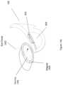
- FIG. 2illustrates a head worn computing system with optical system in accordance with the principles of the present disclosure.
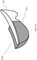
- FIG. 3illustrates upper and lower optical modules in accordance with the principles of the present disclosure.
- FIG. 4illustrates angles of combiner elements in accordance with the principles of the present disclosure.
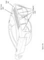
- FIG. 5illustrates upper and lower optical modules in accordance with the principles of the present disclosure.
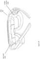
- FIG. 6illustrates upper and lower optical modules in accordance with the principles of the present disclosure.
- FIG. 7illustrates upper and lower optical modules in accordance with the principles of the present disclosure.
- FIG. 8illustrates upper and lower optical modules in accordance with the principles of the present disclosure.
- FIGS. 9 , 10 a , 10 b and 11illustrate light sources and filters in accordance with the principles of the present disclosure.
- FIGS. 12 a to 12 cillustrate light sources and quantum dot systems in accordance with the principles of the present disclosure.
- FIGS. 13 a to 13 cillustrate peripheral lighting systems in accordance with the principles of the present disclosure.
- FIGS. 14 a to 14 hillustrate light suppression systems in accordance with the principles of the present disclosure.
- FIG. 15illustrates an external user interface in accordance with the principles of the present disclosure.
- FIG. 16illustrates external user interfaces in accordance with the principles of the present disclosure.
- FIGS. 17 and 18illustrate structured eye lighting systems according to the principles of the present disclosure.
- FIG. 19illustrates eye glint in the prediction of eye direction analysis in accordance with the principles of the present disclosure.
- FIG. 20 aillustrates eye characteristics that may be used in personal identification through analysis of a system according to the principles of the present disclosure.
- FIG. 20 billustrates a digital content presentation reflection off of the wearer's eye that may be analyzed in accordance with the principles of the present disclosure.
- FIG. 21illustrates eye imaging along various virtual target lines and various focal planes in accordance with the principles of the present disclosure.
- FIG. 22illustrates content control with respect to eye movement based on eye imaging in accordance with the principles of the present disclosure.
- FIG. 23illustrates eye imaging and eye convergence in accordance with the principles of the present disclosure.
- FIG. 24illustrates light impinging an eye in accordance with the principles of the present disclosure.
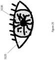
- FIG. 25illustrates a view of an eye in accordance with the principles of the present disclosure.
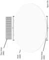
- FIGS. 26 a and 26 billustrate views of an eye with a structured light pattern in accordance with the principles of the present disclosure.
- FIG. 27illustrates a user interface in accordance with the principles of the present disclosure.
- FIG. 28illustrates a user interface in accordance with the principles of the present disclosure.
- FIGS. 29 and 29 aillustrate haptic systems in accordance with the principles of the present disclosure.
- HWChead-worn computing
- the glassesmay be a fully developed computing platform, such as including computer displays presented in each of the lenses of the glasses to the eyes of the user.
- the lenses and displaysmay be configured to allow a person wearing the glasses to see the environment through the lenses while also seeing, simultaneously, digital imagery, which forms an overlaid image that is perceived by the person as a digitally augmented image of the environment, or augmented reality (“AR”).
- ARaugmented reality
- HWChead-worn computing
- the systemmay need to be designed as a lightweight, compact and fully functional computer display, such as wherein the computer display includes a high resolution digital display that provides a high level of immersion comprised of the displayed digital content and the see-through view of the environmental surroundings.
- User interfaces and control systems suited to the HWC devicemay be required that are unlike those used for a more conventional computer such as a laptop.
- the glassesmay be equipped with sensors to determine environmental conditions, geographic location, relative positioning to other points of interest, objects identified by imaging and movement by the user or other users in a connected group, compass heading, head tilt, where the user is looking and the like.
- the HWCmay then change the mode of operation to match the conditions, location, positioning, movements, and the like, in a method generally referred to as a contextually aware HWC.
- the glassesalso may need to be connected, wirelessly or otherwise, to other systems either locally or through a network. Controlling the glasses may be achieved through the use of an external device, automatically through contextually gathered information, through user gestures captured by the glasses sensors, and the like. Each technique may be further refined depending on the software application being used in the glasses.
- the glassesmay further be used to control or coordinate with external devices that are associated with the glasses.
- the HWC system 100comprises a HWC 102 , which in this instance is configured as glasses to be worn on the head with sensors such that the HWC 102 is aware of the objects and conditions in the environment 114 .
- the HWC 102also receives and interprets control inputs such as gestures and movements 116 .
- the HWC 102may communicate with external user interfaces 104 .
- the external user interfaces 104may provide a physical user interface to take control instructions from a user of the HWC 102 and the external user interfaces 104 and the HWC 102 may communicate bi-directionally to affect the user's command and provide feedback to the external device 108 .
- the HWC 102may also communicate bi-directionally with externally controlled or coordinated local devices 108 .
- an external user interface 104may be used in connection with the HWC 102 to control an externally controlled or coordinated local device 108 .
- the externally controlled or coordinated local device 108may provide feedback to the HWC 102 and a customized GUI may be presented in the HWC 102 based on the type of device or specifically identified device 108 .
- the HWC 102may also interact with remote devices and information sources 112 through a network connection 110 .
- the external user interface 104may be used in connection with the HWC 102 to control or otherwise interact with any of the remote devices 108 and information sources 112 in a similar way as when the external user interfaces 104 are used to control or otherwise interact with the externally controlled or coordinated local devices 108 .
- HWC 102may interpret gestures 116 (e.g captured from forward, downward, upward, rearward facing sensors such as camera(s), range finders, IR sensors, etc.) or environmental conditions sensed in the environment 114 to control either local or remote devices 108 or 112 .
- the HWC 102is a computing platform intended to be worn on a person's head.
- the HWC 102may take many different forms to fit many different functional requirements.
- the HWC 102will be designed in the form of conventional glasses.
- the glassesmay or may not have active computer graphics displays.
- the displaysmay be configured as see-through displays such that the digital imagery can be overlaid with respect to the user's view of the environment 114 .
- see-through optical designsincluding ones that have a reflective display (e.g. LCoS, DLP), emissive displays (e.g. OLED, LED), hologram, TIR waveguides, and the like.
- lighting systems used in connection with the display opticsmay be solid state lighting systems, such as LED, OLED, quantum dot, quantum dot LED, etc.
- the optical configurationmay be monocular or binocular. It may also include vision corrective optical components.
- the opticsmay be packaged as contact lenses.
- the HWC 102may be in the form of a helmet with a see-through shield, sunglasses, safety glasses, goggles, a mask, fire helmet with see-through shield, police helmet with see through shield, military helmet with see-through shield, utility form customized to a certain work task (e.g. inventory control, logistics, repair, maintenance, etc.), and the like.
- the HWC 102may also have a number of integrated computing facilities, such as an integrated processor, integrated power management, communication structures (e.g. cell net, WiFi, Bluetooth, local area connections, mesh connections, remote connections (e.g. client server, etc.)), and the like.
- the HWC 102may also have a number of positional awareness sensors, such as GPS, electronic compass, altimeter, tilt sensor, IMU, and the like. It may also have other sensors such as a camera, rangefinder, hyper-spectral camera, Geiger counter, microphone, spectral illumination detector, temperature sensor, chemical sensor, biologic sensor, moisture sensor, ultrasonic sensor, and the like.
- the HWC 102may also have integrated control technologies.
- the integrated control technologiesmay be contextual based control, passive control, active control, user control, and the like.
- the HWC 102may have an integrated sensor (e.g. camera) that captures user hand or body gestures 116 such that the integrated processing system can interpret the gestures and generate control commands for the HWC 102 .
- the HWC 102may have sensors that detect movement (e.g. a nod, head shake, and the like) including accelerometers, gyros and other inertial measurements, where the integrated processor may interpret the movement and generate a control command in response.
- the HWC 102may also automatically control itself based on measured or perceived environmental conditions.
- the HWC 102may increase the brightness or contrast of the displayed image.
- the integrated control technologiesmay be mounted on the HWC 102 such that a user can interact with it directly.
- the HWC 102may have a button(s), touch capacitive interface, and the like.
- the HWC 102may be in communication with external user interfaces 104 .
- the external user interfacesmay come in many different forms.
- a cell phone screenmay be adapted to take user input for control of an aspect of the HWC 102 .
- the external user interfacemay be a dedicated UI (e.g. air mouse, finger mounted mouse), such as a keyboard, touch surface, button(s), joy stick, and the like.
- the external controllermay be integrated into another device such as a ring, watch, bike, car, and the like.
- the external user interface 104may include sensors (e.g. IMU, accelerometers, compass, altimeter, and the like) to provide additional input for controlling the HWD 104 .
- sensorse.g. IMU, accelerometers, compass, altimeter, and the like
- the HWC 102may control or coordinate with other local devices 108 .
- the external devices 108may be an audio device, visual device, vehicle, cell phone, computer, and the like.
- the local external device 108may be another HWC 102 , where information may then be exchanged between the separate HWCs 108 .
- the HWC 102may control or coordinate with remote devices 112 , such as the HWC 102 communicating with the remote devices 112 through a network 110 .
- the form of the remote device 112may have many forms. Included in these forms is another HWC 102 .
- each HWC 102may communicate its GPS position such that all the HWCs 102 know where all of HWC 102 are located.
- FIG. 2illustrates a HWC 102 with an optical system that includes an upper optical module 202 and a lower optical module 204 .
- the upper and lower optical modules 202 and 204will generally be described as separate modules, it should be understood that this is illustrative only and the present disclosure includes other physical configurations, such as that when the two modules are combined into a single module or where the elements making up the two modules are configured into more than two modules.
- the upper module 202includes a computer controlled display (e.g. LCoS, FLCoS, DLP, OLED, backlit LCD, etc.) and image light delivery optics.
- the lower moduleincludes eye delivery optics that are configured to receive the upper module's image light and deliver the image light to the eye of a wearer of the HWC.
- eye delivery opticsthat are configured to receive the upper module's image light and deliver the image light to the eye of a wearer of the HWC.
- FIG. 2it should be noted that while the upper and lower optical modules 202 and 204 are illustrated in one side of the HWC such that image light can be delivered to one eye of the wearer, that it is envisioned by the present disclosure that embodiments will contain two image light delivery systems, one for each eye.
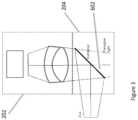
- FIG. 3illustrates a combination of an upper optical module 202 with a lower optical module 204 .
- the image light projected from the upper optical module 202may or may not be polarized.
- the image lightis reflected off a flat combiner element 602 such that it is directed towards the user's eye.
- the combiner element 602is a partial mirror that reflects image light while transmitting a substantial portion of light from the environment so the user can look through the combiner element and see the environment surrounding the HWC.
- the combiner 602may include a holographic pattern, to form a holographic mirror. If a monochrome image is desired, there may be a single wavelength reflection design for the holographic pattern on the surface of the combiner 602 . If the intention is to have multiple colors reflected from the surface of the combiner 602 , a multiple wavelength holographic mirror maybe included on the combiner surface. For example, in a three-color embodiment, where red, green and blue pixels are generated in the image light, the holographic mirror may be reflective to wavelengths substantially matching the wavelengths of the red, green and blue light provided in the image light. This configuration can be used as a wavelength specific mirror where pre-determined wavelengths of light from the image light are reflected to the user's eye.
- This configurationmay also be made such that substantially all other wavelengths in the visible pass through the combiner element 602 so the user has a substantially clear view of the environmental surroundings when looking through the combiner element 602 .
- the transparency between the user's eye and the surroundingmay be approximately 80% when using a combiner that is a holographic mirror.
- holographic mirrorscan be made using lasers to produce interference patterns in the holographic material of the combiner where the wavelengths of the lasers correspond to the wavelengths of light that are subsequently reflected by the holographic mirror.
- the combiner element 602may include a notch mirror comprised of a multilayer coated substrate wherein the coating is designed to substantially reflect the wavelengths of light provided in the image light by the light source and substantially transmit the remaining wavelengths in the visible spectrum.
- the notch mirroris a tristimulus notch mirror wherein the multilayer coating is designed to substantially reflect narrow bands of red, green and blue light that are matched to the what is provided by the light source and the remaining visible wavelengths are substantially transmitted through the coating to enable a view of the environment through the combiner.
- the notch mirroris designed to reflect a single narrow band of light that is matched to the wavelength range of the image light provided by the upper optics while transmitting the remaining visible wavelengths to enable a see-through view of the environment.
- the combiner 602 with the notch mirrorwould operate, from the user's perspective, in a manner similar to the combiner that includes a holographic pattern on the combiner element 602 .
- the combiner, with the tristimulus notch mirrorwould reflect image light associated with pixels, to the eye because of the match between the reflective wavelengths of the notch mirror and the wavelengths or color of the image light, and the wearer would simultaneously be able to see with high clarity the environmental surroundings.
- the transparency between the user's eye and the surroundingmay be approximately 80% when using the tristimulus notch mirror.
- the image provided with the notch mirror combinercan provide higher contrast images than the holographic mirror combiner because the notch mirror acts in a purely reflective manner compared to the holographic mirror which operates through diffraction, and as such the notch mirror is subject to less scattering of the imaging light by the combiner.
- the combiner element 602may include a simple partial mirror that reflects a portion (e.g. 50%) of all wavelengths of light in the visible.
- Image lightcan escape through the combiner 602 and may produce face glow from the optics shown in FIG. 3 , as the escaping image light is generally directed downward onto the cheek of the user.
- the escaping lightcan be trapped to avoid face glow.
- a linear polarizercan be laminated, or otherwise associated, to the combiner, with the transmission axis of the polarizer oriented relative to the polarized image light so that any escaping image light is absorbed by the polarizer.
- the image lightwould be polarized to provide S polarized light to the combiner for better reflection.
- the linear polarizer on the combinerwould be oriented to absorb S polarized light and pass P polarized light. This provides the preferred orientation of polarized sunglasses as well.
- a microlouvered filmsuch as a privacy filter can be used to absorb the escaping image light while providing the user with a see-through view of the environment.
- the absorbance or transmittance of the microlouvered filmis dependent on the angle of the light. Where steep angle light is absorbed and light at less of an angle is transmitted.
- the combiner with the microlouver filmis angled at greater than 45 degrees to the optical axis of the image light (e.g. the combiner can be oriented at 50 degrees so the image light from the file lens is incident on the combiner at an oblique angle.
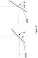
- FIG. 4illustrates an embodiment of a combiner element 602 at various angles when the combiner element 602 includes a holographic mirror.
- a mirrored surfacereflects light at an angle equal to the angle that the light is incident to the mirrored surface.
- the combiner elementbe at 45 degrees, 602 a , if the light is presented vertically to the combiner so the light can be reflected horizontally towards the wearer's eye.
- the incident lightcan be presented at angles other than vertical to enable the mirror surface to be oriented at other than 45 degrees, but in all cases wherein a mirrored surface is employed (including the tristimulus notch mirror described previously), the incident angle equals the reflected angle.
- a holographic mirror combinerincluded in embodiments, can be made such that light is reflected at a different angle from the angle that the light is incident onto the holographic mirrored surface. This allows freedom to select the angle of the combiner element 602 b independent of the angle of the incident image light and the angle of the light reflected into the wearer's eye.
- the angle of the combiner element 602 bis greater than 45 degrees (shown in FIG. 4 ) as this allows a more laterally compact HWC design.
- the increased angle of the combiner element 602 bdecreases the front to back width of the lower optical module 204 and may allow for a thinner HWC display (i.e. the furthest element from the wearer's eye can be closer to the wearer's face).
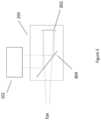
- FIG. 5illustrates another embodiment of a lower optical module 204 .
- polarized or unpolarized image lightprovided by the upper optical module 202 , is directed into the lower optical module 204 .
- the image lightreflects off a partial mirror 804 (e.g. polarized mirror, notch mirror, holographic mirror, etc.) and is directed toward a curved partially reflective mirror 802 .
- the curved partial mirror 802then reflects the image light back towards the user's eye, which passes through the partial mirror 804 .
- the usercan also see through the partial mirror 804 and the curved partial mirror 802 to see the surrounding environment. As a result, the user perceives a combined image comprised of the displayed image light overlaid onto the see-through view of the environment.
- the partial mirror 804 and the curved partial mirror 802are both non-polarizing so that the transmitted light from the surrounding environment is unpolarized so that rainbow interference patterns are eliminated when looking at polarized light in the environment such as provided by a computer monitor or in the reflected light from a lake.
- the image light production and management functions described in connection with the upper modulemay be arranged to direct light in other directions (e.g. upward, sideward, etc.).
- the lower optical moduleis generally configured to deliver the image light to the wearer's eye and allow the wearer to see through the lower optical module, which may be accomplished through a variety of optical components.
- FIG. 6illustrates an embodiment of the present disclosure where the upper optical module 202 is arranged to direct image light into a total internal reflection (TIR) waveguide 810 .
- the upper optical module 202is positioned above the wearer's eye 812 and the light is directed horizontally into the TIR waveguide 810 .
- the TIR waveguideis designed to internally reflect the image light in a series of downward TIR reflections until it reaches the portion in front of the wearer's eye, where the light passes out of the TIR waveguide 812 in a direction toward the wearer's eye.
- an outer shield 814may be positioned in front of the TIR waveguide 810 .
- FIG. 7illustrates an embodiment of the present disclosure where the upper optical module 202 is arranged to direct image light into a TIR waveguide 818 .
- the upper optical module 202is arranged on the side of the TIR waveguide 818 .
- the upper optical modulemay be positioned in the arm or near the arm of the HWC when configured as a pair of head worn glasses.
- the TIR waveguide 818is designed to internally reflect the image light in a series of TIR reflections until it reaches the portion in front of the wearer's eye, where the light passes out of the TIR waveguide 818 in a direction toward the wearer's eye 812 .
- FIG. 8illustrates yet further embodiments of the present disclosure where an upper optical module 202 directs polarized image light into an optical guide 828 where the image light passes through a polarized reflector 824 , changes polarization state upon reflection of the optical element 822 which includes a 1 ⁇ 4 wave film for example and then is reflected by the polarized reflector 824 towards the wearer's eye, due to the change in polarization of the image light.
- the upper optical module 202may be positioned behind the optical guide 828 wherein the image light is directed toward a mirror 820 that reflects the image light along the optical guide 828 and towards the polarized reflector 824 .
- the upper optical module 202may direct the image light directly along the optical guide 828 and towards the polarized reflector 824 . It should be understood that the present disclosure comprises other optical arrangements intended to direct image light into the wearer's eye.
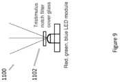
- FIG. 9illustrates a light source 1100 that may be used in association with the upper optics module 202 .
- the light source 1100may provide light to a backlighting optical system that is associated with the light source 1100 and which serves to homogenize the light and thereby provide uniform illuminating light to an image source in the upper optics.
- the light source 1100includes a tristimulus notch filter 1102 .
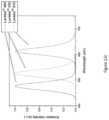
- the tristimulus notch filter 1102has narrow band pass filters for three wavelengths, as indicated in FIG. 10 b in a transmission graph 1108 .
- the graph shown in FIG. 10 a , as 1104illustrates an output of three different colored LEDs. One can see that the bandwidths of emission are narrow, but they have long tails.
- the tristimulus notch filter 1102can be used in connection with such LEDs to provide a light source 1100 that emits narrow filtered wavelengths of light as shown in FIG. 11 as the transmission graph 1110 . Wherein the clipping effects of the tristimulus notch filter 1102 can be seen to have cut the tails from the LED emission graph 1104 to provide narrower wavelength bands of light to the upper optical module 202 .
- the light source 1100can be used in connection with a matched combiner 602 that includes a holographic mirror or tristimulus notch mirror that substantially reflects the narrow bands of image light toward the wearer's eye with a reduced amount of image light that does not get reflected by the combiner, thereby improving efficiency of the head-worn computer (HWC) or head-mounted display (HMD) and reducing escaping light that can cause faceglow.
- HWChead-worn computer
- HMDhead-mounted display
- FIG. 12 aillustrates another light source 1200 that may be used in association with the upper optics module 202 .
- the light source 1200may provide light to a backlighting optical system that homogenizes the light prior to illuminating the image source in the upper optics as described previously herein.
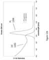
- the light source 1200includes a quantum dot cover glass 1202 . Where the quantum dots absorb light of a shorter wavelength and emit light of a longer wavelength ( FIG. 12 b shows an example wherein a UV spectrum 1202 applied to a quantum dot results in the quantum dot emitting a narrow band shown as a PL spectrum 1204 ) that is dependent on the material makeup and size of the quantum dot.
- quantum dots in the quantum dot cover glass 1202can be tailored to provide one or more bands of narrow bandwidth light (e.g. red, green and blue emissions dependent on the different quantum dots included as illustrated in the graph shown in FIG. 12 c where three different quantum dots are used.
- the LED driver lightemits UV light, deep blue or blue light.
- multiple light sources 1200would be used where each light source 1200 would include a quantum dot cover glass 1202 with at least one type of quantum dot selected to emit at one of each of the desired colors.
- the light source 1100can be used in connection with a combiner 602 with a holographic mirror or tristimulus notch mirror to provide narrow bands of image light that are reflected toward the wearer's eye with less wasted image light that does not get reflected.
- a solid state lighting systeme.g. LED, OLEO, etc.
- the solid state lighting systemmay be included inside the optical elements of an lower optical module 204 .
- the solid state lighting systemmay be arranged such that lighting effects outside of a field of view (FOV) associated with displayed digital content is presented to create an immersive effect for the person wearing the HWC.
- FOVfield of view
- the lighting effectsmay be presented to any portion of the HWC that is visible to the wearer.
- the solid state lighting systemmay be digitally controlled by an integrated processor on the HWC.
- the integrated processorwill control the lighting effects in coordination with digital content that is presented within the FOV of the HWC.
- a movie, picture, game, or other contentmay be displayed or playing within the FOV of the HWC.
- the contentmay show a bomb blast on the right side of the FOV and at the same moment, the solid state lighting system inside of the upper module optics may flash quickly in concert with the FOV image effect.
- the effectmay not be fast, it may be more persistent to indicate, for example, a general glow or color on one side of the user.
- the solid state lighting systemmay be color controlled, with red, green and blue LEDs, for example, such that color control can be coordinated with the digitally presented content within the field of view.
- FIG. 13 aillustrates optical components of a lower optical module 204 together with an outer lens 1302 .
- FIG. 13 aalso shows an embodiment including effects LEDs 1308 a and 1308 b .
- FIG. 13 aillustrates image light 1312 , as described herein elsewhere, directed into the upper optical module where it will reflect off of the combiner element 1304 , as described herein elsewhere.
- the combiner element 1304 in this embodimentis angled towards the wearer's eye at the top of the module and away from the wearer's eye at the bottom of the module, as also illustrated and described in connection with FIG. 8 (e.g. at a 45 degree angle).
- the image light 1312provided by an upper optical module 202 (not shown in FIG.
- the image light 1312then reflects and focuses off of the collimating mirror 1304 , passes back through the combiner element 1304 , and is directed into the wearer's eye.
- the wearercan also view the surrounding environment through the transparency of the combiner element 1304 , collimating mirror 1310 , and outer lens 1302 (if it is included).
- the image lightmay or may not be polarized and the see-through view of the surrounding environment is preferably non-polarized to provide a view of the surrounding environment that does not include rainbow interference patterns if the light from the surrounding environment is polarized such as from a computer monitor or reflections from a lake.
- the wearerwill generally perceive that the image light forms an image in the FOV 1305 .
- the outer lens 1302may be included.
- the outer lens 1302is an outer lens that may or may not be corrective and it may be designed to conceal the lower optical module components in an effort to make the HWC appear to be in a form similar to standard glasses or sunglasses.
- the effects LEDs 1308 a and 1308 bare positioned at the sides of the combiner element 1304 and the outer lens 1302 and/or the collimating mirror 1310 .
- the effects LEDs 1308 aare positioned within the confines defined by the combiner element 1304 and the outer lens 1302 and/or the collimating mirror.
- the effects LEDs 1308 a and 1308 bare also positioned outside of the FOV 1305 associated with the displayed digital content. In this arrangement, the effects LEDs 1308 a and 1308 b can provide lighting effects within the lower optical module outside of the FOV 1305 .
- the light emitted from the effects LEDs 1308 a and 1308 bmay be polarized and the outer lens 1302 may include a polarizer such that the light from the effects LEDs 1308 a and 1308 b will pass through the combiner element 1304 toward the wearer's eye and will be absorbed by the outer lens 1302 .
- This arrangementprovides peripheral lighting effects to the wearer in a more private setting by not transmitting the lighting effects through the front of the HWC into the surrounding environment.
- the effects LEDs 1308 a and 1308 bmay be non-polarized so the lighting effects provided are made to be purposefully viewable by others in the environment for entertainment such as giving the effect of the wearer's eye glowing in correspondence to the image content being viewed by the wearer.
- FIG. 13 billustrates a cross section of the embodiment described in connection with FIG. 13 a .
- the effects LED 1308 ais located in the upper-front area inside of the optical components of the lower optical module. It should be understood that the effects LED 1308 a position in the described embodiments is only illustrative and alternate placements are encompassed by the present disclosure. Additionally, in embodiments, there may be one or more effects LEDs 1308 a in each of the two sides of HWC to provide peripheral lighting effects near one or both eyes of the wearer.
- FIG. 13 cillustrates an embodiment where the combiner element 1304 is angled away from the eye at the top and towards the eye at the bottom (e.g. in accordance with the holographic or notch filter embodiments described herein).
- the effects LED 1308 amay be located on the outer lens 1302 side of the combiner element 1304 to provide a concealed appearance of the lighting effects.
- the effects LED 1308 a of FIG. 13 cmay include a polarizer such that the emitted light can pass through a polarized element associated with the combiner element 1304 and be blocked by a polarized element associated with the outer lens 1302 .
- the effects LED 13087 acan be configured such that at least a portion of the light is reflected away from the wearer's eye so that it is visible to people in the surrounding environment. This can be accomplished for example by using a combiner 1304 that is a simple partial mirror so that a portion of the image light 1312 is reflected toward the wearer's eye and a first portion of the light from the effects LED 13087 a is transmitted toward the wearer's eye and a second portion of the light from the effects LED 1308 a is reflected outward toward the surrounding environment.
- FIGS. 14 a , 14 b , 14 c and 14 dshow illustrations of a HWC that includes eye covers 1402 to restrict loss of image light to the surrounding environment and to restrict the ingress of stray light from the environment. Where the eye covers 1402 can be removably attached to the HWC with magnets 1404 . Another aspect of the present disclosure relates to automatically configuring the lighting system(s) used in the HWC 102 . In embodiments, the display lighting and/or effects lighting, as described herein, may be controlled in a manner suitable for when an eye cover 1402 is attached or removed from the HWC 102 .
- the lighting system(s) in the HWCmay go into a low light mode to further control any amounts of stray light escaping from the HWC and the areas around the HWC.
- Covert operations at night, while using night vision or standard vision,may require a solution which prevents as much escaping light as possible so a user may clip on the eye cover(s) 1402 and then the HWC may go into a low light mode.
- the low light modemay, in some embodiments, only go into a low light mode when the eye cover 1402 is attached if the HWC identifies that the environment is in low light conditions (e.g. through environment light level sensor detection).
- the low light levelmay be determined to be at an intermediate point between full and low light dependent on environmental conditions.
- Another aspect of the present disclosurerelates to automatically controlling the type of content displayed in the HWC when eye covers 1402 are attached or removed from the HWC.
- the displayed contentmay be restricted in amount or in color amounts.
- the display(s)may go into a simple content delivery mode to restrict the amount of information displayed. This may be done to reduce the amount of light produced by the display(s).
- the display(s)may change from color displays to monochrome displays to reduce the amount of light produced.
- the monochrome lightingmay be red to limit the impact on the wearer's eyes to maintain an ability to see better in the dark.
- the conversion systemmay include replaceable lenses, an eye cover, and optics adapted to provide user experiences in both modes.
- the outer lensesmay be ‘blacked-out’ with an opaque cover 1412 to provide an experience where all of the user's attention is dedicated to the digital content and then the outer lenses may be switched out for high see-through lenses so the digital content is augmenting the user's view of the surrounding environment.
- Another aspect of the disclosurerelates to low transmission outer lenses that permit the user to see through the outer lenses but remain dark enough to maintain most of the user's attention on the digital content. The slight see-through can provide the user with a visual connection to the surrounding environment and this can reduce or eliminate nausea and other problems associated with total removal of the surrounding view when viewing digital content.
- FIG. 14 dillustrates a head-worn computer system 102 with a see-through digital content display 204 adapted to include a removable outer lens 1414 and a removable eye cover 1402 .
- the eye cover 1402may be attached to the head-worn computer 102 with magnets 1404 or other attachment systems (e.g. mechanical attachments, a snug friction fit between the arms of the head-worn computer 102 , etc.).
- the eye cover 1402may be attached when the user wants to cut stray light from escaping the confines of the head-worn computer, create a more immersive experience by removing the otherwise viewable peripheral view of the surrounding environment, etc.
- the removable outer lens 1414may be of several varieties for various experiences.
- the outer lens 1414may be dark in a middle portion to provide a dark background for the digital content (i.e. dark backdrop behind the see-through field of view from the user's perspective) and a higher transmission area elsewhere.
- the outer lenses 1414may have a transmission in the range of 2 to 5%, 5 to 10%, 10 to 20% for the immersion effect and above 10% or 20% for the augmented reality effect, for example.
- the outer lenses 1414may also have an adjustable transmission to facilitate the change in system effect.
- the outer lenses 1414may be electronically adjustable tint lenses (e.g. liquid crystal or have crossed polarizers with an adjustment for the level of cross).
- the eye cover 1402may have areas of transparency or partial transparency to provide some visual connection with the user's surrounding environment. This may also reduce or eliminate nausea or other feelings associated with the complete removal of the view of the surrounding environment.
- FIG. 14 eillustrates a HWC 102 assembled with an eye cover 1402 without outer lenses in place.
- the outer lensesin embodiments, may be held in place with magnets 1418 for ease of removal and replacement. In embodiments, the outer lenses may be held in place with other systems, such as mechanical systems.
- an effects systemthat generates effects outside of the field of view in the see-through display of the head-worn computer.
- the effectsmay be, for example, lighting effects, sound effects, tactile effects (e.g. through vibration), air movement effects, etc.
- the effect generation systemis mounted on the eye cover 1402 .
- a lighting systeme.g. LED(s), OLEDs, etc.
- the contentmay be a movie or a game, for example, and an explosion may happen on the right side of the content, as scripted, and matching the content, a bright flash may be generated by the effects lighting system to create a stronger effect.
- the effects systemmay include a vibratory system mounted near the sides or temples, or otherwise, and when the same explosion occurs, the vibratory system may generate a vibration on the right side to increase the user experience indicating that the explosion had a real sound wave creating the vibration.
- the effects systemmay have an air system where the effect is a puff of air blown onto the user's face. This may create a feeling of closeness with some fast moving object in the content.
- the effects systemmay also have speakers directed towards the user's ears or an attachment for ear buds, etc.
- the effects generated by the effects systemmay be scripted by an author to coordinate with the content.
- sensorsmay be placed inside of the eye cover to monitor content effects (e.g. a light sensor to measure strong lighting effects or peripheral lighting effects) that would then cause an effect(s) to be generated.
- the effects system in the eye covermay be powered by an internal battery and the battery, in embodiments, may also provide additional power to the head-worn computer 102 as a back-up system. In embodiments, the effects system is powered by the batteries in the head-worn computer. Power may be delivered through the attachment system (e.g. magnets, mechanical system) or a dedicated power system.
- the effects systemmay receive data and/or commands from the head-worn computer through a data connection that is wired or wireless.
- the datamay come through the attachment system, a separate line, or through Bluetooth or other short range communication protocol, for example.
- the eye cover 1402is made of reticulated foam, which is very light and can contour to the user's face.
- the reticulated foamalso allows air to circulate because of the open-celled nature of the material, which can reduce user fatigue and increase user comfort.
- the eye cover 1402may be made of other materials, soft, stiff, pliable, etc. and may have another material on the periphery that contacts the face for comfort.
- the eye cover 1402may include a fan to exchange air between an external environment and an internal space, where the internal space is defined in part by the face of the user. The fan may operate very slowly and at low power to exchange the air to keep the face of the user cool.
- the fanmay have a variable speed controller and/or a temperature sensor may be positioned to measure temperature in the internal space to control the temperature in the internal space to a specified range, temperature, etc.
- the internal spaceis generally characterized by the confined space in front of the user's eyes and upper cheeks where the eye cover encloses the area.
- the audio headsetis mounted with a relatively rigid system that has flexible joint(s) (e.g. a rotational joint at the connection with the eye cover, a rotational joint in the middle of a rigid arm, etc.) and extension(s) (e.g. a telescopic arm) to provide the user with adjustability to allow for a comfortable fit over, in or around the user's ear.
- the audio headsetis mounted with a flexible system that is more flexible throughout, such as with a wire-based connection.
- FIG. 14 gillustrates a head-worn computer 102 with removable lenses 1414 along with a mounted eye cover 1402 .
- the head-worn computerin embodiments, includes a see-through display (as disclosed herein).
- the eye cover 1402also includes a mounted audio headset 1422 .
- the mounted audio headset 1422 in this embodimentis mounted to the eye cover 1402 and has audio wire connections (not shown).
- the audio wires' connectionsmay connect to an internal wireless communication system (e.g. Bluetooth, NFC, WiFi) to make connection to the processor in the head-worn computer.
- the audio wiresmay connect to a magnetic connector, mechanical connector or the like to make the connection.
- FIG. 14 hillustrates an unmounted eye cover 1402 with a mounted audio headset 1422 .
- the mechanical design of the eye coveris adapted to fit onto the head-worn computer to provide visual isolation or partial isolation and the audio headset.
- the eye cover 1402may be adapted to be removably mounted on a head-worn computer 102 with a see-through computer display.
- An audio headset 1422 with an adjustable mountmay be connected to the eye cover, wherein the adjustable mount may provide extension and rotation to provide a user of the head-worn computer with a mechanism to align the audio headset with an ear of the user.
- the audio headsetincludes an audio wire connected to a connector on the eye cover and the eye cover connector may be adapted to removably mate with a connector on the head-worn computer.
- the audio headsetmay be adapted to receive audio signals from the head-worn computer 102 through a wireless connection (e.g. Bluetooth, WiFi).
- the head-worn computer 102may have a removable and replaceable front lens 1414 .
- the eye cover 1402may include a battery to power systems internal to the eye cover 1402 .
- the eye cover 1402may have a battery to power systems internal to the head-worn computer 102 .
- the eye cover 1402may include a fan adapted to exchange air between an internal space, defined in part by the user's face, and an external environment to cool the air in the internal space and the user's face.
- the audio headset 1422may include a vibratory system (e.g. a vibration motor, piezo motor, etc. in the armature and/or in the section over the ear) adapted to provide the user with a haptic feedback coordinated with digital content presented in the see-through computer display.
- the head-worn computer 102includes a vibratory system adapted to provide the user with a haptic feedback coordinated with digital content presented in the see-through computer display.
- the eye cover 1402is adapted to be removably mounted on a head-worn computer with a see-through computer display.
- the eye cover 1402may also include a flexible audio headset mounted to the eye cover 1402 , wherein the flexibility provides the user of the head-worn computer 102 with a mechanism to align the audio headset with an ear of the user.
- the flexible audio headsetis mounted to the eye cover 1402 with a magnetic connection.
- the flexible audio headsetmay be mounted to the eye cover 1402 with a mechanical connection.
- the audio headset 1422may be spring or otherwise loaded such that the head set presses inward towards the user's ears for a more secure fit.
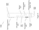
- the pen 1500is a specially designed external user interface 104 and can operate as a user interface, to many different styles of HWC 102 .
- the pen 1500generally follows the form of a conventional pen, which is a familiar user handled device and creates an intuitive physical interface for many of the operations to be carried out in the HWC system 100 .
- the pen 1500may be one of several user interfaces 104 used in connection with controlling operations within the HWC system 100 .
- the HWC 102may watch for and interpret hand gestures 116 as control signals, where the pen 1500 may also be used as a user interface with the same HWC 102 .
- a remote keyboardmay be used as an external user interface 104 in concert with the pen 1500 .
- the combination of user interfaces or the use of just one control systemgenerally depends on the operation(s) being executed in the HWC's system 100 .
- the pen 1500may follow the general form of a conventional pen, it contains numerous technologies that enable it to function as an external user interface 104 .
- FIG. 15illustrates technologies comprised in the pen 1500 .
- the pen 1500may include a camera 1508 , which is arranged to view through lens 1502 . The camera may then be focused, such as through lens 1502 , to image a surface upon which a user is writing or making other movements to interact with the HWC 102 .
- the pen 1500will also have an ink, graphite, or other system such that what is being written can be seen on the writing surface.
- the pen 1500does not have such a physical writing system so there is no deposit on the writing surface, where the pen would only be communicating data or commands to the HWC 102 .
- the lens 1502 configurationis described in greater detail herein.
- the function of the camera 1508is to capture information from an unstructured writing surface such that pen strokes can be interpreted as intended by the user.
- the pen 1500may include a sensor, such as an IMU 1512 .
- the IMUcould be included in the pen 1500 in its separate parts (e.g. gyro, accelerometer, etc.) or an IMU could be included as a single unit.
- the IMU 1512is used to measure and predict the motion of the pen 1500 .
- the integrated microprocessor 1510would take the IMU information and camera information as inputs and process the information to form a prediction of the pen tip movement.
- the pen 1500may also include a pressure monitoring system 1504 , such as to measure the pressure exerted on the lens 1502 .
- the pressure measurementcan be used to predict the user's intention for changing the weight of a line, type of a line, type of brush, click, double click, and the like.
- the pressure sensormay be constructed using any force or pressure measurement sensor located behind the lens 1502 , including for example, a resistive sensor, a current sensor, a capacitive sensor, a voltage sensor such as a piezoelectric sensor, and the like.
- the pen 1500may also include a communications module 1518 , such as for bi-directional communication with the HWC 102 .
- the communications module 1518may be a short distance communication module (e.g. Bluetooth).
- the communications module 1518may be security matched to the HWC 102 .
- the communications module 1518may be arranged to communicate data and commands to and from the microprocessor 1510 of the pen 1500 .
- the microprocessor 1510may be programmed to interpret data generated from the camera 1508 , IMU 1512 , and pressure sensor 1504 , and the like, and then pass a command onto the HWC 102 through the communications module 1518 , for example.
- the data collected from any of the input sourcese.g.
- the microprocessormay be communicated by the communication module 1518 to the HWC 102 , and the HWC 102 may perform data processing and prediction of the user's intention when using the pen 1500 .
- the datamay be further passed on through a network 110 to a remote device 112 , such as a server, for the data processing and prediction.
- the commandsmay then be communicated back to the HWC 102 for execution (e.g. display writing in the glasses display, make a selection within the UI of the glasses display, control a remote external device 112 , control a local external device 108 ), and the like.
- the penmay also include memory 1514 for long or short term uses.
- the pen 1500may also include a number of physical user interfaces, such as quick launch buttons 1522 , a touch sensor 1520 , and the like.
- the quick launch buttons 1522may be adapted to provide the user with a fast way of jumping to a software application in the HWC system 100 .
- the usermay be a frequent user of communication software packages (e.g. email, text, Twitter, Instagram, Facebook, Google+, and the like), and the user may program a quick launch button 1522 to command the HWC 102 to launch an application.
- the pen 1500may be provided with several quick launch buttons 1522 , which may be user programmable or factory programmable.
- the quick launch button 1522may be programmed to perform an operation.
- buttonsmay be programmed to clear the digital display of the HWC 102 . This would create a fast way for the user to clear the screens on the HWC 102 for any reason, such as for example to better view the environment.
- the quick launch button functionalitywill be discussed in further detail below.
- the touch sensor 1520may be used to take gesture style input from the user. For example, the user may be able to take a single finger and run it across the touch sensor 1520 to effect a page scroll.
- the pen 1500may also include a laser pointer 1524 .
- the laser pointer 1524may be coordinated with the IMU 1512 to coordinate gestures and laser pointing.
- a usermay use the laser 1524 in a presentation to help with guiding the audience with the interpretation of graphics and the IMU 1512 may, either simultaneously or when the laser 1524 is off, interpret the user's gestures as commands or data input.
- FIG. 16illustrates yet another embodiment of the present disclosure.
- FIG. 16illustrates a watchband clip-on controller 2000 .
- the watchband clip-on controllermay be a controller used to control the HWC 102 or devices in the HWC system 100 .
- the watchband clip-on controller 2000has a fastener 2018 (e.g. rotatable clip) that is mechanically adapted to attach to a watchband, as illustrated at 2004 .
- the watchband controller 2000may have quick launch interfaces 2008 (e.g. to launch applications and choosers as described herein), a touch pad 2014 (e.g. to be used as a touch style mouse for GUI control in a HWC 102 display) and a display 2012 .
- the clip 2018may be adapted to fit a wide range of watchbands so it can be used in connection with a watch that is independently selected for its function.
- the clipin embodiments, is rotatable such that a user can position it in a desirable manner.
- the clipmay be a flexible strap.
- the flexible strapmay be adapted to be stretched to attach to a hand, wrist, finger, device, weapon, and the like.
- the watchband controllermay be configured as a removable and replaceable watchband.
- the controllermay be incorporated into a band with a certain width, segment spacing, etc. such that the watchband, with its incorporated controller, can be attached to a watch body.
- the attachmentin embodiments, may be mechanically adapted to attach with a pin upon which the watchband rotates.
- the watchband controllermay be electrically connected to the watch and/or watch body such that the watch, watch body and/or the watchband controller can communicate data between them.
- the watchband controller 2000may have 3-axis motion monitoring (e.g. through an IMU, accelerometers, magnetometers, gyroscopes, etc.) to capture user motion. The user motion may then be interpreted for gesture control.
- 3-axis motion monitoringe.g. through an IMU, accelerometers, magnetometers, gyroscopes, etc.
- the watchband controller 2000may comprise fitness sensors and a fitness computer.
- the sensorsmay track heart rate, calories burned, strides, distance covered, and the like. The data may then be compared against performance goals and/or standards for user feedback.
- light to illuminate the wearer's eyecan be provided by several different sources including: light from the displayed image (i.e. image light); light from the environment that passes through the combiner or other optics; light provided by a dedicated eye light, etc.
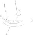
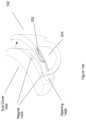
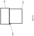
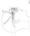
- FIGS. 17 and 18show illustrations of dedicated eye illumination lights 3420 .
- FIG. 17shows an illustration from a side view in which the dedicated illumination eye light 3420 is positioned at a corner of the combiner 3410 so that it doesn't interfere with the image light 3415 .
- the dedicated eye illumination light 3420is pointed so that the eye illumination light 3425 illuminates the eyebox 3427 where the eye 3430 is located when the wearer is viewing displayed images provided by the image light 3415 .
- FIG. 17shows an illustration from a side view in which the dedicated illumination eye light 3420 is positioned at a corner of the combiner 3410 so that it doesn't interfere with the image light 3415 .
- the dedicated eye illumination light 3420is pointed so that the eye illumination light 3425 illuminates the eyebox 3427 where the
- the dedicated eye illumination light 3420is shown at the upper left corner of the combiner 3410 , other positions along one of the edges of the combiner 3410 , or other optical or mechanical components, are possible as well. In other embodiments, more than one dedicated eye light 3420 with different positions can be used.
- the dedicated eye light 3420is an infrared light that is not visible by the wearer (e.g. 800 nm) so that the eye illumination light 3425 doesn't interfere with the displayed image perceived by the wearer.
- the eye imaging camerais inline with the image light optical path, or part of the image light optical path.
- the eye cameramay be positioned in the upper module to capture eye image light that reflects back through the optical system towards the image display.
- the eye image lightmay be captured after reflecting off of the image source (e.g. in a DLP configuration where the mirrors can be positioned to reflect the light towards the eye image light camera), a partially reflective surface may be placed along the image light optical path such that when the eye image light reflects back into the upper or lower module that it is reflected in a direction that the eye imaging camera can capture light eye image light.
- the eye image light camerais positioned outside of the image light optical path.
- the camera(s)may be positioned near the outer lens of the platform.
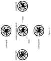
- FIG. 19shows a series of illustrations of captured eye images that show the eye glint (i.e. light that reflects off the front of the eye) produced by a dedicated eye light mounted adjacent to the combiner as previously described herein.
- captured images of the wearer's eyeare analyzed to determine the relative positions of the iris 3550 , pupil, or other portion of the eye, and the eye glint 3560 .
- the eye glintis a reflected image of the dedicated eye light 3420 when the dedicated light is used.
- FIG. 19illustrates the relative positions of the iris 3550 and the eye glint 3560 for a variety of eye positions.
- the eye glintprovides a fixed reference point against which the determined position of the iris can be compared to determine where the wearer is looking, either within the displayed image or within the see-through view of the surrounding environment.
- the dedicated eye light 3420By positioning the dedicated eye light 3420 at a corner of the combiner 3410 , the eye glint 3560 is formed away from the iris 3550 in the captured images. As a result, the positions of the iris and the eye glint can be determined more easily and more accurately during the analysis of the captured images, since they do not interfere with one another.
- the combinerincludes an associated cut filter that prevents infrared light from the environment from entering the HWC and the eye camera is an infrared camera, so that the eye glint 3560 is only provided by light from the dedicated eye light.
- the combinercan include a low pass filter that passes visible light while reflecting infrared light from the environment away from the eye camera, reflecting infrared light from the dedicated eye light toward the user's eye and the eye camera can include a high pass filter that absorbs visible light associated with the displayed image while passing infrared light associated with the eye image.
- the lens for the eye camerais designed to take into account the optics associated with the upper module 202 and the lower module 204 . This is accomplished by designing the eye camera to include the optics in the upper module 202 and optics in the lower module 204 , so that a high MTF image is produced, at the image sensor in the eye camera, of the wearer's eye.
- the eye camera lensis provided with a large depth of field to eliminate the need for focusing the eye camera to enable sharp images of the eye to be captured. Where a large depth of field is typically provided by a high f/# lens (e.g. f/#>5).
- the reduced light gathering associated with high f/# lensesis compensated by the inclusion of a dedicated eye light to enable a bright image of the eye to be captured.
- the brightness of the dedicated eye lightcan be modulated and synchronized with the capture of eye images so that the dedicated eye light has a reduced duty cycle and the brightness of infrared light on the wearer's eye is reduced.
- FIG. 20 ashows an illustration of an eye image that is used to identify the wearer of the HWC.
- an image of the wearer's eye 3611is captured and analyzed for patterns of identifiable features 3612 .
- the patternsare then compared to a database of eye images to determine the identity of the wearer.
- the operating mode of the HWC and the types of images, applications, and information to be displayedcan be adjusted and controlled in correspondence to the determined identity of the wearer. Examples of adjustments to the operating mode depending on who the wearer is determined to be or not be include: making different operating modes or feature sets available, shutting down or sending a message to an external network, allowing guest features and applications to run, etc.
- FIG. 20 bis an illustration of another embodiment using eye imaging, in which the sharpness of the displayed image is determined based on the eye glint produced by the reflection of the displayed image from the wearer's eye surface.
- an eye glint 3622which is a small version of the displayed image can be captured and analyzed for sharpness. If the displayed image is determined to not be sharp, then an automated adjustment to the focus of the HWC optics can be performed to improve the sharpness.
- This ability to perform a measurement of the sharpness of a displayed image at the surface of the wearer's eyecan provide a very accurate measurement of image quality.
- Having the ability to measure and automatically adjust the focus of displayed imagescan be very useful in augmented reality imaging where the focus distance of the displayed image can be varied in response to changes in the environment or changes in the method of use by the wearer.
- An aspect of the present disclosurerelates to controlling the HWC 102 through interpretations of eye imagery.
- eye imaging technologiessuch as those described herein, are used to capture an eye image or a series of eye images for processing.
- the image(s)may be processed to determine a user intended action, an HWC predetermined reaction, or other action.
- the imagerymay be interpreted as an affirmative user control action for an application on the HWC 102 .
- the imagerymay cause, for example, the HWC 102 to react in a pre-determined way such that the HWC 102 is operating safely, intuitively, etc.
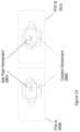
- FIG. 21illustrates an eye imagery process that involves imaging the HWC 102 wearer's eye(s) and processing the images (e.g. through eye imaging technologies described herein) to determine in what position 3702 the eye is relative to its neutral or forward looking position and/or the FOV 3708 .
- the processmay involve a calibration step where the user is instructed, through guidance provided in the FOV of the HWC 102 , to look in certain directions such that a more accurate prediction of the eye position relative to areas of the FOV can be made.
- the wearer's eyeis determined to be looking towards the right side of the FOV 3708 (as illustrated in FIG.
- a virtual target linemay be established to project what in the environment the wearer may be looking towards or at.
- the virtual target linemay be used in connection with an image captured by camera on the HWC 102 that images the surrounding environment in front of the wearer.
- the field of view of the camera capturing the surrounding environmentmatches, or can be matched (e.g. digitally), to the FOV 3708 such that making the comparison is made more clear.
- the virtual linecan be processed (e.g. in 2 d or 3 d , depending on the camera images capabilities and/or the processing of the images) by projecting what surrounding environment objects align with the virtual target line.
- focal planesmay be established corresponding to each of the objects such that digital content may be placed in an area in the FOV 3708 that aligns with the virtual target line and falls at a focal plane of an intersecting object. The user then may see the digital content when he focuses on the object in the environment, which is at the same focal plane.
- objects in line with the virtual target linemay be established by comparison to mapped information of the surroundings.
- the digital content that is in line with the virtual target linemay not be displayed in the FOV until the eye position is in the right position.
- Thismay be a predetermined process.
- the systemmay be set up such that a particular piece of digital content (e.g. an advertisement, guidance information, object information, etc.) will appear in the event that the wearer looks at a certain object(s) in the environment.
- a virtual target line(s)may be developed that virtually connects the wearer's eye with an object(s) in the environment (e.g. a building, portion of a building, mark on a building, GPS location, etc.) and the virtual target line may be continually updated depending on the position and viewing direction of the wearer (e.g.
- the digital contentmay be displayed in the FOV 3704 .
- the time spent looking along the virtual target line and/or a particular portion of the FOV 3708may indicate that the wearer is interested in an object in the environment and/or digital content being displayed.
- digital contentmay be presented in the area of the FOV 3708 .
- the time spent looking at an objectmay be interpreted as a command to display information about the object, for example.
- the contentmay not relate to the object and may be presented because of the indication that the person is relatively inactive.
- the digital contentmay be positioned in proximity to the virtual target line, but not in-line with it such that the wearer's view of the surroundings are not obstructed but information can augment the wearer's view of the surroundings.
- the time spent looking along a target line in the direction of displayed digital contentmay be an indication of interest in the digital content. This may be used as a conversion event in advertising. For example, an advertiser may pay more for an ad placement if the wearer of the HWC 102 looks at a displayed advertisement for a certain period of time. As such, in embodiments, the time spent looking at the advertisement, as assessed by comparing eye position with the content placement, target line or other appropriate position may be used to determine a rate of conversion or other compensation amount due for the presentation.
- FIG. 22illustrates a situation where eye imagery suggests that the eye has or is moving quickly so the digital content 3804 in the FOV 3808 is removed from the FOV 3808 .
- the wearermay be looking quickly to the side indicating that there is something on the side in the environment that has grabbed the wearer's attention.
- This eye movement 3802may be captured through eye imaging techniques (e.g. as described herein) and if the movement matches a predetermined movement (e.g. speed, rate, pattern, etc.) the content may be removed from view.
- the eye movementis used as one input and HWC movements indicated by other sensors (e.g. IMU in the HWC) may be used as another indication.
- sensorse.g. IMU in the HWC
- These various sensor movementsmay be used together to project an event that should cause a change in the content being displayed in the FOV.
- Another aspect of the present disclosurerelates to determining a focal plane based on the wearer's eye convergence. Eyes are generally converged slightly and converge more when the person focuses on something very close. This is generally referred to as convergence. In embodiments, convergence is calibrated for the wearer. That is, the wearer may be guided through certain focal plane exercises to determine how much the wearer's eyes converge at various focal planes and at various viewing angles. The convergence information may then be stored in a database for later reference. In embodiments, a general table may be used in the event there is no calibration step or the person skips the calibration step. The two eyes may then be imaged periodically to determine the convergence in an attempt to understand what focal plane the wearer is focused on. In embodiments, the eyes may be imaged to determine a virtual target line and then the eye's convergence may be determined to establish the wearer's focus, and the digital content may be displayed or altered based thereon.
- FIG. 23illustrates a situation where digital content is moved 3902 within one or both of the FOVs 3908 and 3910 to align with the convergence of the eyes as determined by the pupil movement 3904 .
- the digital contentBy moving the digital content to maintain alignment, in embodiments, the overlapping nature of the content is maintained so the object appears properly to the wearer. This can be important in situations where 3 D content is displayed.
- An aspect of the present disclosurerelates to controlling the HWC 102 based on events detected through eye imaging.
- a wearer winking, blinking, moving his eyes in a certain pattern, etc.may, for example, control an application of the HWC 102 .
- Eye imaginge.g. as described herein
- Eye imagingmay be used to monitor the eye(s) of the wearer and once a pre-determined pattern is detected an application control command may be initiated.
- An aspect of the disclosurerelates to monitoring the health of a person wearing a HWC 102 by monitoring the wearer's eye(s). Calibrations may be made such that the normal performance, under various conditions (e.g. lighting conditions, image light conditions, etc.) of a wearer's eyes may be documented. The wearer's eyes may then be monitored through eye imaging (e.g. as described herein) for changes in their performance. Changes in performance may be indicative of a health concern (e.g. concussion, brain injury, stroke, loss of blood, etc.). If detected the data indicative of the change or event may be communicated from the HWC 102 .
- a health concerne.g. concussion, brain injury, stroke, loss of blood, etc.
- aspects of the present disclosurerelate to security and access of computer assets (e.g. the HWC itself and related computer systems) as determined through eye image verification.
- eye imagerymay be compared to known person eye imagery to confirm a person's identity. Eye imagery may also be used to confirm the identity of people wearing the HWCs 102 before allowing them to link together or share files, streams, information, etc.
- An aspect of the present disclosurerelates to the timing of eye image capture.
- the timing of the capture of the eye image and the frequency of the capture of multiple images of the eyecan vary dependent on the use case for the information gathered from the eye image.
- capturing an eye image to identify the user of the HWCmay be required only when the HWC has been turned ON or when the HWC determines that the HWC has been put onto a wearer's head to control the security of the HWC and the associated information that is displayed to the user, wherein the orientation, movement pattern, stress or position of the earhorns (or other portions) of the HWC can be used to determine that a person has put the HWC onto their head with the intention to use the HWC.
- Those same parametersmay be monitored in an effort to understand when the HWC is dismounted from the user's head. This may enable a situation where the capture of an eye image for identifying the wearer may be completed only when a change in the wearing status is identified.
- capturing eye images to monitor the health of the wearermay require images to be captured periodically (e.g. every few seconds, minutes, hours, days, etc.). For example, the eye images may be taken in minute intervals when the images are being used to monitor the health of the wearer when detected movements indicate that the wearer is exercising. In a further contrasting example, capturing eye images to monitor the health of the wearer for long-term effects may only require that eye images be captured monthly.
- Embodiments of the disclosurerelate to selection of the timing and rate of capture of eye images to be in correspondence with the selected use scenario associated with the eye images. These selections may be done automatically, as with the exercise example above where movements indicate exercise, or these selections may be set manually.
- the selection of the timing and rate of eye image captureis adjusted automatically depending on the mode of operation of the HWC.
- the selection of the timing and rate of eye image capturecan further be selected in correspondence with input characteristics associated with the wearer including age and health status, or sensed physical conditions of the wearer including heart rate, chemical makeup of the blood and eye blink rate.
- FIG. 24illustrates a cross section of an eyeball of a wearer of an HWC with focus points that can be associated with the eye imaging system of the disclosure.
- the eyeball 5010includes an iris 5012 and a retina 5014 .
- the eye imaging system of the disclosureprovides coaxial eye imaging with a display system, images of the eye can be captured from a perspective directly in front of the eye and inline with where the wearer is looking.
- the eye imaging systemcan be focused at the iris 5012 and/or the retina 5014 of the wearer, to capture images of the external surface of the iris 5012 or the internal portions of the eye, which includes the retina 5014 .
- FIG. 24shows light rays 5020 and 5025 that are respectively associated with capturing images of the iris 5012 or the retina 5014 wherein the optics associated with the eye imaging system are respectively focused at the iris 5012 or the retina 5014 . Illuminating light can also be provided in the eye imaging system to illuminate the iris 5012 or the retina 5014 .
- FIG. 25shows an illustration of an eye including an iris 5130 and a sclera 5125 .
- the eye imaging systemcan be used to capture images that include the iris 5130 and portions of the sclera 5125 . The images can then be analyzed to determine color, shapes and patterns that are associated with the user.
- the focus of the eye imaging systemis adjusted to enable images to be captured of the iris 5012 or the retina 5014 .
- Illuminating lightcan also be adjusted to illuminate the iris 5012 or to pass through the pupil of the eye to illuminate the retina 5014 .
- the illuminating lightcan be visible light to enable capture of colors of the iris 5012 or the retina 5014 , or the illuminating light can be ultraviolet (e.g. 340 nm), near infrared (e.g. 850 nm) or mid-wave infrared (e.g. 5000 nm) light to enable capture of hyperspectral characteristics of the eye.
- FIGS. 26 a and 26 billustrate captured images of eyes where the eyes are illuminated with structured light patterns.
- an eye 5220is shown with a projected structured light pattern 5230 , where the light pattern is a grid of lines.
- a light pattern of such as 5230can be provided by the light source 5355 by including a diffractive or a refractive device to modify the light 5357 as are known by those skilled in the art.
- a visible light sourcecan also be included for the second camera, which can include a diffractive or refractive to modify the light 5467 to provide a light pattern.
- FIG. 26 billustrates how the structured light pattern of 5230 becomes distorted to 5235 when the user's eye 5225 looks to the side.
- This distortioncomes from the fact that the human eye is not completely spherical in shape, instead the iris sticks out slightly from the eyeball to form a bump in the area of the iris.
- the shape of the eye and the associated shape of the reflected structured light patternis different depending on which direction the eye is pointed, when images of the eye are captured from a fixed position. Changes in the structured light pattern can subsequently be analyzed in captured eye images to determine the direction that the eye is looking.
- the eye imaging systemcan also be used for the assessment of aspects of health of the user.
- information gained from analyzing captured images of the iris 5130 or sclera 5125are different from information gained from analyzing captured images of the retina 5014 .
- images of the retina 5014are captured using light that illuminates the inner portions of the eye including the retina 5014 .
- the lightcan be visible light, but in an embodiment, the light is infrared light (e.g. wavelength 1 to 5 microns) and the eye camera is an infrared light sensor (e.g. an InGaAs sensor) or a low resolution infrared image sensor that is used to determine the relative amount of light that is absorbed, reflected or scattered by the inner portions of the eye.
- the majority of the light that is absorbed, reflected or scatteredcan be attributed to materials in the inner portion of the eye including the retina where there are densely packed blood vessels with thin walls so that the absorption, reflection and scattering are caused by the material makeup of the blood.
- These measurementscan be conducted automatically when the user is wearing the HWC, either at regular intervals, after identified events or when prompted by an external communication.
- the illuminating lightis near infrared or mid infrared (e.g. 0.7 to 5 microns wavelength) to reduce the chance for thermal damage to the wearer's eye.
- the light source and the cameratogether comprise a spectrometer wherein the relative intensity of the light reflected by the eye is analyzed over a series of narrow wavelengths within the range of wavelengths provided by the light source to determine a characteristic spectrum of the light that is absorbed, reflected or scattered by the eye.
- the light sourcecan provide a broad range of infrared light to illuminate the eye and the camera can include: a grating to laterally disperse the reflected light from the eye into a series of narrow wavelength bands that are captured by a linear photodetector so that the relative intensity by wavelength can be measured and a characteristic absorbance spectrum for the eye can be determined over the broad range of infrared.
- the light sourcecan provide a series of narrow wavelengths of light (ultraviolet, visible or infrared) to sequentially illuminate the eye and camera includes a photodetector that is selected to measure the relative intensity of the series of narrow wavelengths in a series of sequential measurements that together can be used to determine a characteristic spectrum of the eye. The determined characteristic spectrum is then compared to known characteristic spectra for different materials to determine the material makeup of the eye.
- the illuminating lightis focused on the retina and a characteristic spectrum of the retina is determined and the spectrum is compared to known spectra for materials that may be present in the user's blood.
- 540 nmis useful for detecting hemoglobin and 660 nm is useful for differentiating oxygenated hemoglobin.
- 660 nmis useful for differentiating oxygenated hemoglobin.
- infrareda wide variety of materials can be identified as is known by those skilled in the art, including: glucose, urea, alcohol and controlled substances.
- the user interfaceincludes tactile feedback (otherwise referred to as haptic feedback) to the user to provide the user an indication of engagement and change.
- the user interfaceis a rotating element on a temple section of a glasses form factor of the HWC 102 .
- the rotating elementmay include segments such that it positively engages at certain predetermined angles. This facilitates a tactile feedback to the user.
- the rotating elementAs the user turns the rotating element it ‘clicks’ through its predetermined steps or angles and each step causes a displayed user interface content to be changed. For example, the user may cycle through a set of menu items or selectable applications.
- the rotating elementalso includes a selection element, such as a pressure-induced section where the user can push to make a selection.
- FIG. 27illustrates a human head wearing a head-worn computer in a glasses form factor.
- the glasseshave a temple section 11702 and a rotating user interface element 11704 .
- the usercan rotate the rotating element 11704 to cycle through options presented as content in the see-through display of the glasses.
- FIG. 28illustrates several examples of different rotating user interface elements 11704 a , 11704 b and 11704 c .
- Rotating element 11704 ais mounted at the front end of the temple and has significant side and top exposure for user interaction.
- Rotating element 11704 bis mounted further back and also has significant exposure (e.g. 270 degrees of touch).
- Rotating element 11704 chas less exposure and is exposed for interaction on the top of the temple.
- Other embodimentsmay have a side or bottom exposure.
- Another aspect of the present disclosurerelates to a haptic system in a head-worn computer.
- Creating visual, audio, and haptic sensations in coordinationcan increase the enjoyment or effectiveness of awareness in a number of situations. For example, when viewing a movie or playing a game while digital content is presented in a computer display of a head-worn computer, it is more immersive to include coordinated sound and haptic effects.
- the haptic sensationmay gently cause the user of the head-worn computer believe that there is some presence on the user's right side, but out of sight. It may be a very light haptic effect to cause the ‘tingling’ sensation of a presence of unknown origin.
- Haptic sensationscan be used to generate a perception in the user that objects and events are close by.
- digital contentmay be presented to the user in the computer displays and the digital content may appear to be within reach of the user. If the user reaches out his hand in an attempt to touch the digital object, which is not a real object, the haptic system may cause a sensation and the user may interpret the sensation as a touching sensation.
- the haptic systemmay generate slight vibrations near one or both temples for example and the user may infer from those vibrations that he has touched the digital object. This additional dimension in sensory feedback can be very useful and create a more intuitive and immersive user experience.
- the haptic systemincludes separate piezo strips such that each of the separate strips can be controlled separately.
- Each stripmay be controlled over a range of vibration levels and some of the separate strips may have a greater vibration capacity than others.
- a set of stripsmay be mounted in the arm of the head-worn computer (e.g. near the user's temple, ear, rear of the head, substantially along the length of the arm, etc.) and the further forward the strip the higher capacity the strip may have.
- the strips of varying capacitycould be arranged in any number of ways, including linear, curved, compound shape, two dimensional array, one dimensional array, three dimensional array, etc.).
- a processor in the head-worn computermay regulate the power applied to the strips individually, in sub-groups, as a whole, etc.
- separate strips or segments of varying capacityare individually controlled to generate a finely controlled multi-level vibration system.
- Patterns based on frequency, duration, intensity, segment type, and/or other control parameterscan be used to generate signature haptic feedback. For example, to simulate the haptic feedback of an explosion close to the user, a high intensity, low frequency, and moderate duration may be a pattern to use. A bullet whipping by the user may be simulated with a higher frequency and shorter duration. Following this disclosure, one can imagine various patterns for various simulation scenarios.
- Another aspect of the present disclosurerelates to making a physical connection between the haptic system and the user's head.
- the glassestouch the user's head in several places (e.g. ears, nose, forehead, etc.) and these areas may be satisfactory to generate the necessary haptic feedback.
- an additional mechanical elementmay be added to better translate the vibration from the haptic system to a desired location on the user's head.
- a vibration or signal conduitmay be added to the head-worn computer such that there is a vibration translation medium between the head-worn computers internal haptic system and the user's temple area.
- FIG. 29illustrates a head-worn computer 102 with a haptic system comprised of piezo strips 29002 .
- the piezo strips 29002are arranged linearly with strips of increasing vibration capacity from back to front of the arm 29004 .
- the increasing capacitymay be provided by different sized strips, for example.
- This arrangementcan cause a progressively increased vibration power 29003 from back to front.
- the head-worn computer 102may also have a vibration or signal conduit 29001 that facilitates the physical vibrations from the haptic system to the head of the user 29005 .
- the vibration conduitmay be malleable to form to the head of the user for a tighter or more appropriate fit.
- An aspect of the present inventionrelates to a head-worn computer, comprising: a frame adapted to hold a computer display in front of a user's eye; a processor adapted to present digital content in the computer display and to produce a haptic signal in coordination with the digital content display; and a haptic system comprised of a plurality of haptic segments, wherein each of the haptic segments is individually controlled in coordination with the haptic signal.
- the haptic segmentscomprise a piezo strip activated by the haptic signal to generate a vibration in the frame.
- the intensity of the haptic systemmay be increased by activating more than one of the plurality of haptic segments.
- the intensitymay be further increased by activating more than 2 of the plurality of haptic segments.
- each of the plurality of haptic segmentscomprises a different vibration capacity.
- the intensity of the haptic systemmay be regulated depending on which of the plurality of haptic segments is activated.
- each of the plurality of haptic segmentsare mounted in a linear arrangement and the segments are arranged such that the higher capacity segments are at one end of the linear arrangement.
- the linear arrangementis from back to front on an arm of the head-worn computer.
- the linear arrangementis proximate a temple of the user.
- the linear arrangementis proximate an ear of the user.
- the linear arrangementis proximate a rear portion of the user's head.
- the linear arrangementis from front to back on an arm of the head-worn computer, or otherwise arranged.
- An aspect of the present disclosureprovides a head-worn computer with a vibration conduit, wherein the vibration conduit is mounted proximate the haptic system and adapted to touch the skin of the user's head to facilitate vibration sensations from the haptic system to the user's head.
- the vibration conduitis mounted on an arm of the head-worn computer.
- the vibration conduittouches the user's head proximate a temple of the user's head.
- the vibration conduitis made of a soft material that deforms to increase contact area with the user's head.
- An aspect of the present disclosurerelates to a haptic array system in a head-worn computer.
- the haptic array(s)that can correlate vibratory sensations to indicate events, scenarios, etc. to the wearer.
- the vibrationsmay correlate or respond to auditory, visual, proximity to elements, etc. of a video game, movie, or relationships to elements in the real world as a means of augmenting the wearer's reality.
- physical proximity to objects in a wearer's environmentsudden changes in elevation in the path of the wearer (e.g. about to step off a curb), the explosions in a game or bullets passing by a wearer.
- Haptic effects from a piezo array(s) that make contact the side of the wearer's headmay be adapted to effect sensations that correlate to other events experienced by the wearer.
- FIG. 29 aillustrates a haptic system according to the principles of the present disclosure.
- the piezo stripsare mounted or deposited with varying width and thus varying force Piezo Elements on a rigid or flexible, non-conductive substrate attached, to or part of the temples of glasses, goggles, bands or other form factor.
- the non-conductive substratemay conform to the curvature of a head by being curved and it may be able to pivot (e.g. in and out, side to side, up and down, etc.) from a person's head.
- This arrangementmay be mounted to the inside of the temples of a pair of glasses.
- the vibration conduitdescribed herein elsewhere, may be mounted with a pivot.
- the piezo strips 29002may be mounted on a substrate and the substrate may be mounted to the inside of a glasses arm, strap, etc.
- the piezo strips in this embodimentincrease in vibration capacity as they move forward.
- the methods and systems described hereinmay be deployed in part or in whole through a machine that executes computer software, program codes, and/or instructions on a processor.
- the processormay be part of a server, cloud server, client, network infrastructure, mobile computing platform, stationary computing platform, or other computing platform.
- a processormay be any kind of computational or processing device capable of executing program instructions, codes, binary instructions and the like.
- the processormay be or include a signal processor, digital processor, embedded processor, microprocessor or any variant such as a co-processor (math co-processor, graphic co-processor, communication co-processor and the like) and the like that may directly or indirectly facilitate execution of program code or program instructions stored thereon.
- the processormay enable execution of multiple programs, threads, and codes.
- the threadsmay be executed simultaneously to enhance the performance of the processor and to facilitate simultaneous operations of the application.
- methods, program codes, program instructions and the like described hereinmay be implemented in one or more thread.
- the threadmay spawn other threads that may have assigned priorities associated with them; the processor may execute these threads based on priority or any other order based on instructions provided in the program code.
- the processormay include memory that stores methods, codes, instructions and programs as described herein and elsewhere.
- the processormay access a storage medium through an interface that may store methods, codes, and instructions as described herein and elsewhere.
- the storage medium associated with the processor for storing methods, programs, codes, program instructions or other type of instructions capable of being executed by the computing or processing devicemay include but may not be limited to one or more of a CD-ROM, DVD, memory, hard disk, flash drive, RAM, ROM, cache and the like.
- a processormay include one or more cores that may enhance speed and performance of a multiprocessor.
- the processmay be a dual core processor, quad core processors, other chip-level multiprocessor and the like that combine two or more independent cores (called a die).
- the methods and systems described hereinmay be deployed in part or in whole through a machine that executes computer software on a server, client, firewall, gateway, hub, router, or other such computer and/or networking hardware.
- the software programmay be associated with a server that may include a file server, print server, domain server, internet server, intranet server and other variants such as secondary server, host server, distributed server and the like.
- the servermay include one or more of memories, processors, computer readable transitory and/or non-transitory media, storage media, ports (physical and virtual), communication devices, and interfaces capable of accessing other servers, clients, machines, and devices through a wired or a wireless medium, and the like.
- the methods, programs or codes as described herein and elsewheremay be executed by the server.
- other devices required for execution of methods as described in this applicationmay be considered as a part of the infrastructure associated with the server.
- the servermay provide an interface to other devices including, without limitation, clients, other servers, printers, database servers, print servers, file servers, communication servers, distributed servers and the like. Additionally, this coupling and/or connection may facilitate remote execution of program across the network. The networking of some or all of these devices may facilitate parallel processing of a program or method at one or more location without deviating from the scope of the invention.
- all the devices attached to the server through an interfacemay include at least one storage medium capable of storing methods, programs, code and/or instructions.
- a central repositorymay provide program instructions to be executed on different devices. In this implementation, the remote repository may act as a storage medium for program code, instructions, and programs.
- the software programmay be associated with a client that may include a file client, print client, domain client, internet client, intranet client and other variants such as secondary client, host client, distributed client and the like.
- the clientmay include one or more of memories, processors, computer readable transitory and/or non-transitory media, storage media, ports (physical and virtual), communication devices, and interfaces capable of accessing other clients, servers, machines, and devices through a wired or a wireless medium, and the like.
- the methods, programs or codes as described herein and elsewheremay be executed by the client.
- other devices required for execution of methods as described in this applicationmay be considered as a part of the infrastructure associated with the client.
- the clientmay provide an interface to other devices including, without limitation, servers, other clients, printers, database servers, print servers, file servers, communication servers, distributed servers and the like. Additionally, this coupling and/or connection may facilitate remote execution of program across the network. The networking of some or all of these devices may facilitate parallel processing of a program or method at one or more location without deviating from the scope of the invention.
- all the devices attached to the client through an interfacemay include at least one storage medium capable of storing methods, programs, applications, code and/or instructions.
- a central repositorymay provide program instructions to be executed on different devices.
- the remote repositorymay act as a storage medium for program code, instructions, and programs.
- the methods and systems described hereinmay be deployed in part or in whole through network infrastructures.
- the network infrastructuremay include elements such as computing devices, servers, routers, hubs, firewalls, clients, personal computers, communication devices, routing devices and other active and passive devices, modules and/or components as known in the art.
- the computing and/or non-computing device(s) associated with the network infrastructuremay include, apart from other components, a storage medium such as flash memory, buffer, stack, RAM, ROM and the like.
- the processes, methods, program codes, instructions described herein and elsewheremay be executed by one or more of the network infrastructural elements.
- the methods, program codes, and instructions described herein and elsewheremay be implemented on a cellular network having multiple cells.
- the cellular networkmay either be frequency division multiple access (FDMA) network or code division multiple access (CDMA) network.
- FDMAfrequency division multiple access
- CDMAcode division multiple access
- the cellular networkmay include mobile devices, cell sites, base stations, repeaters, antennas, towers, and the like.
- the mobile devicesmay include navigation devices, cell phones, mobile phones, mobile personal digital assistants, laptops, palmtops, netbooks, pagers, electronic books readers, music players and the like. These devices may include, apart from other components, a storage medium such as a flash memory, buffer, RAM, ROM and one or more computing devices.
- the computing devices associated with mobile devicesmay be enabled to execute program codes, methods, and instructions stored thereon. Alternatively, the mobile devices may be configured to execute instructions in collaboration with other devices.
- the mobile devicesmay communicate with base stations interfaced with servers and configured to execute program codes.
- the mobile devicesmay communicate on a peer to peer network, mesh network, or other communications network.
- the program codemay be stored on the storage medium associated with the server and executed by a computing device embedded within the server.
- the base stationmay include a computing device and a storage medium.
- the storage devicemay store program codes and instructions executed by the computing devices associated with the base station.
- the computer software, program codes, and/or instructionsmay be stored and/or accessed on machine readable transitory and/or non-transitory media that may include: computer components, devices, and recording media that retain digital data used for computing for some interval of time; semiconductor storage known as random access memory (RAM); mass storage typically for more permanent storage, such as optical discs, forms of magnetic storage like hard disks, tapes, drums, cards and other types; processor registers, cache memory, volatile memory, non-volatile memory; optical storage such as CD, DVD; removable media such as flash memory (e.g.
- RAMrandom access memory
- mass storagetypically for more permanent storage, such as optical discs, forms of magnetic storage like hard disks, tapes, drums, cards and other types
- processor registerscache memory, volatile memory, non-volatile memory
- optical storagesuch as CD, DVD
- removable mediasuch as flash memory (e.g.
- USB sticks or keysfloppy disks, magnetic tape, paper tape, punch cards, standalone RAM disks, Zip drives, removable mass storage, off-line, and the like; other computer memory such as dynamic memory, static memory, read/write storage, mutable storage, read only, random access, sequential access, location addressable, file addressable, content addressable, network attached storage, storage area network, bar codes, magnetic ink, and the like.
- the methods and systems described hereinmay transform physical and/or intangible items from one state to another.
- the methods and systems described hereinmay also transform data representing physical and/or intangible items from one state to another, such as from usage data to a normalized usage dataset.
- machinesmay include, but may not be limited to, personal digital assistants, laptops, personal computers, mobile phones, other handheld computing devices, medical equipment, wired or wireless communication devices, transducers, chips, calculators, satellites, tablet PCs, electronic books, gadgets, electronic devices, devices having artificial intelligence, computing devices, networking equipment, servers, routers and the like.
- the elements depicted in the flow chart and block diagrams or any other logical componentmay be implemented on a machine capable of executing program instructions.
- the methods and/or processes described above, and steps thereof,may be realized in hardware, software or any combination of hardware and software suitable for a particular application.
- the hardwaremay include a dedicated computing device or specific computing device or particular aspect or component of a specific computing device.
- the processesmay be realized in one or more microprocessors, microcontrollers, embedded microcontrollers, programmable digital signal processors or other programmable device, along with internal and/or external memory.
- the processesmay also, or instead, be embodied in an application specific integrated circuit, a programmable gate array, programmable array logic, or any other device or combination of devices that may be configured to process electronic signals. It will further be appreciated that one or more of the processes may be realized as a computer executable code capable of being executed on a machine readable medium.
- the computer executable codemay be created using a structured programming language such as C, an object oriented programming language such as C++, or any other high-level or low-level programming language (including assembly languages, hardware description languages, and database programming languages and technologies) that may be stored, compiled or interpreted to run on one of the above devices, as well as heterogeneous combinations of processors, processor architectures, or combinations of different hardware and software, or any other machine capable of executing program instructions.
- a structured programming languagesuch as C
- an object oriented programming languagesuch as C++
- any other high-level or low-level programming languageincluding assembly languages, hardware description languages, and database programming languages and technologies
- each method described above and combinations thereofmay be embodied in computer executable code that, when executing on one or more computing devices, performs the steps thereof.
- the methodsmay be embodied in systems that perform the steps thereof, and may be distributed across devices in a number of ways, or all of the functionality may be integrated into a dedicated, standalone device or other hardware.
- the means for performing the steps associated with the processes described abovemay include any of the hardware and/or software described above. All such permutations and combinations are intended to fall within the scope of the present disclosure.
Landscapes
- Engineering & Computer Science (AREA)
- Physics & Mathematics (AREA)
- General Physics & Mathematics (AREA)
- Theoretical Computer Science (AREA)
- General Engineering & Computer Science (AREA)
- Optics & Photonics (AREA)
- Human Computer Interaction (AREA)
- Computer Hardware Design (AREA)
- Power Engineering (AREA)
- Computer Graphics (AREA)
- Software Systems (AREA)
- Multimedia (AREA)
Abstract
Description
Claims (14)
Priority Applications (3)
| Application Number | Priority Date | Filing Date | Title |
|---|---|---|---|
| US16/741,672US11822090B2 (en) | 2014-01-24 | 2020-01-13 | Haptic systems for head-worn computers |
| US18/486,963US12158592B2 (en) | 2014-01-24 | 2023-10-13 | Haptic systems for head-worn computers |
| US18/922,237US20250044601A1 (en) | 2014-01-24 | 2024-10-21 | Haptic systems for head-worn computers |
Applications Claiming Priority (7)
| Application Number | Priority Date | Filing Date | Title |
|---|---|---|---|
| US14/163,646US9400390B2 (en) | 2014-01-24 | 2014-01-24 | Peripheral lighting for head worn computing |
| US14/589,713US9529195B2 (en) | 2014-01-21 | 2015-01-05 | See-through computer display systems |
| US14/851,755US9651784B2 (en) | 2014-01-21 | 2015-09-11 | See-through computer display systems |
| US14/861,496US9753288B2 (en) | 2014-01-21 | 2015-09-22 | See-through computer display systems |
| US15/047,110US9846308B2 (en) | 2014-01-24 | 2016-02-18 | Haptic systems for head-worn computers |
| US15/683,343US10558050B2 (en) | 2014-01-24 | 2017-08-22 | Haptic systems for head-worn computers |
| US16/741,672US11822090B2 (en) | 2014-01-24 | 2020-01-13 | Haptic systems for head-worn computers |
Related Parent Applications (1)
| Application Number | Title | Priority Date | Filing Date |
|---|---|---|---|
| US15/683,343ContinuationUS10558050B2 (en) | 2014-01-24 | 2017-08-22 | Haptic systems for head-worn computers |
Related Child Applications (1)
| Application Number | Title | Priority Date | Filing Date |
|---|---|---|---|
| US18/486,963ContinuationUS12158592B2 (en) | 2014-01-24 | 2023-10-13 | Haptic systems for head-worn computers |
Publications (2)
| Publication Number | Publication Date |
|---|---|
| US20200257123A1 US20200257123A1 (en) | 2020-08-13 |
| US11822090B2true US11822090B2 (en) | 2023-11-21 |
Family
ID=56094197
Family Applications (5)
| Application Number | Title | Priority Date | Filing Date |
|---|---|---|---|
| US15/047,110ActiveUS9846308B2 (en) | 2014-01-24 | 2016-02-18 | Haptic systems for head-worn computers |
| US15/683,343ActiveUS10558050B2 (en) | 2014-01-24 | 2017-08-22 | Haptic systems for head-worn computers |
| US16/741,672Active2034-12-22US11822090B2 (en) | 2014-01-24 | 2020-01-13 | Haptic systems for head-worn computers |
| US18/486,963ActiveUS12158592B2 (en) | 2014-01-24 | 2023-10-13 | Haptic systems for head-worn computers |
| US18/922,237PendingUS20250044601A1 (en) | 2014-01-24 | 2024-10-21 | Haptic systems for head-worn computers |
Family Applications Before (2)
| Application Number | Title | Priority Date | Filing Date |
|---|---|---|---|
| US15/047,110ActiveUS9846308B2 (en) | 2014-01-24 | 2016-02-18 | Haptic systems for head-worn computers |
| US15/683,343ActiveUS10558050B2 (en) | 2014-01-24 | 2017-08-22 | Haptic systems for head-worn computers |
Family Applications After (2)
| Application Number | Title | Priority Date | Filing Date |
|---|---|---|---|
| US18/486,963ActiveUS12158592B2 (en) | 2014-01-24 | 2023-10-13 | Haptic systems for head-worn computers |
| US18/922,237PendingUS20250044601A1 (en) | 2014-01-24 | 2024-10-21 | Haptic systems for head-worn computers |
Country Status (1)
| Country | Link |
|---|---|
| US (5) | US9846308B2 (en) |
Cited By (1)
| Publication number | Priority date | Publication date | Assignee | Title |
|---|---|---|---|---|
| US12158592B2 (en) | 2014-01-24 | 2024-12-03 | Mentor Acquisition One, Llc | Haptic systems for head-worn computers |
Families Citing this family (75)
| Publication number | Priority date | Publication date | Assignee | Title |
|---|---|---|---|---|
| US9158116B1 (en) | 2014-04-25 | 2015-10-13 | Osterhout Group, Inc. | Temple and ear horn assembly for headworn computer |
| US9715112B2 (en) | 2014-01-21 | 2017-07-25 | Osterhout Group, Inc. | Suppression of stray light in head worn computing |
| US9952664B2 (en) | 2014-01-21 | 2018-04-24 | Osterhout Group, Inc. | Eye imaging in head worn computing |
| US9229233B2 (en) | 2014-02-11 | 2016-01-05 | Osterhout Group, Inc. | Micro Doppler presentations in head worn computing |
| US9965681B2 (en) | 2008-12-16 | 2018-05-08 | Osterhout Group, Inc. | Eye imaging in head worn computing |
| US9298007B2 (en) | 2014-01-21 | 2016-03-29 | Osterhout Group, Inc. | Eye imaging in head worn computing |
| US9400390B2 (en) | 2014-01-24 | 2016-07-26 | Osterhout Group, Inc. | Peripheral lighting for head worn computing |
| US9529195B2 (en) | 2014-01-21 | 2016-12-27 | Osterhout Group, Inc. | See-through computer display systems |
| US10191279B2 (en) | 2014-03-17 | 2019-01-29 | Osterhout Group, Inc. | Eye imaging in head worn computing |
| US11227294B2 (en) | 2014-04-03 | 2022-01-18 | Mentor Acquisition One, Llc | Sight information collection in head worn computing |
| US9829707B2 (en) | 2014-08-12 | 2017-11-28 | Osterhout Group, Inc. | Measuring content brightness in head worn computing |
| US10254856B2 (en) | 2014-01-17 | 2019-04-09 | Osterhout Group, Inc. | External user interface for head worn computing |
| US20160019715A1 (en) | 2014-07-15 | 2016-01-21 | Osterhout Group, Inc. | Content presentation in head worn computing |
| US9594246B2 (en) | 2014-01-21 | 2017-03-14 | Osterhout Group, Inc. | See-through computer display systems |
| US9299194B2 (en) | 2014-02-14 | 2016-03-29 | Osterhout Group, Inc. | Secure sharing in head worn computing |
| US9575321B2 (en) | 2014-06-09 | 2017-02-21 | Osterhout Group, Inc. | Content presentation in head worn computing |
| US11103122B2 (en) | 2014-07-15 | 2021-08-31 | Mentor Acquisition One, Llc | Content presentation in head worn computing |
| US9841599B2 (en) | 2014-06-05 | 2017-12-12 | Osterhout Group, Inc. | Optical configurations for head-worn see-through displays |
| US9746686B2 (en) | 2014-05-19 | 2017-08-29 | Osterhout Group, Inc. | Content position calibration in head worn computing |
| US9810906B2 (en) | 2014-06-17 | 2017-11-07 | Osterhout Group, Inc. | External user interface for head worn computing |
| US10684687B2 (en) | 2014-12-03 | 2020-06-16 | Mentor Acquisition One, Llc | See-through computer display systems |
| US9939934B2 (en) | 2014-01-17 | 2018-04-10 | Osterhout Group, Inc. | External user interface for head worn computing |
| US10649220B2 (en) | 2014-06-09 | 2020-05-12 | Mentor Acquisition One, Llc | Content presentation in head worn computing |
| US9753288B2 (en) | 2014-01-21 | 2017-09-05 | Osterhout Group, Inc. | See-through computer display systems |
| US9651784B2 (en) | 2014-01-21 | 2017-05-16 | Osterhout Group, Inc. | See-through computer display systems |
| US11892644B2 (en) | 2014-01-21 | 2024-02-06 | Mentor Acquisition One, Llc | See-through computer display systems |
| US9532715B2 (en) | 2014-01-21 | 2017-01-03 | Osterhout Group, Inc. | Eye imaging in head worn computing |
| US9740280B2 (en) | 2014-01-21 | 2017-08-22 | Osterhout Group, Inc. | Eye imaging in head worn computing |
| US12093453B2 (en) | 2014-01-21 | 2024-09-17 | Mentor Acquisition One, Llc | Eye glint imaging in see-through computer display systems |
| US9766463B2 (en) | 2014-01-21 | 2017-09-19 | Osterhout Group, Inc. | See-through computer display systems |
| US20150205135A1 (en) | 2014-01-21 | 2015-07-23 | Osterhout Group, Inc. | See-through computer display systems |
| US11669163B2 (en) | 2014-01-21 | 2023-06-06 | Mentor Acquisition One, Llc | Eye glint imaging in see-through computer display systems |
| US9494800B2 (en) | 2014-01-21 | 2016-11-15 | Osterhout Group, Inc. | See-through computer display systems |
| US9529199B2 (en) | 2014-01-21 | 2016-12-27 | Osterhout Group, Inc. | See-through computer display systems |
| US11487110B2 (en) | 2014-01-21 | 2022-11-01 | Mentor Acquisition One, Llc | Eye imaging in head worn computing |
| US9836122B2 (en) | 2014-01-21 | 2017-12-05 | Osterhout Group, Inc. | Eye glint imaging in see-through computer display systems |
| US11737666B2 (en) | 2014-01-21 | 2023-08-29 | Mentor Acquisition One, Llc | Eye imaging in head worn computing |
| US20150241964A1 (en) | 2014-02-11 | 2015-08-27 | Osterhout Group, Inc. | Eye imaging in head worn computing |
| US9401540B2 (en) | 2014-02-11 | 2016-07-26 | Osterhout Group, Inc. | Spatial location presentation in head worn computing |
| US20160187651A1 (en) | 2014-03-28 | 2016-06-30 | Osterhout Group, Inc. | Safety for a vehicle operator with an hmd |
| US9651787B2 (en) | 2014-04-25 | 2017-05-16 | Osterhout Group, Inc. | Speaker assembly for headworn computer |
| US9672210B2 (en) | 2014-04-25 | 2017-06-06 | Osterhout Group, Inc. | Language translation with head-worn computing |
| US9423842B2 (en) | 2014-09-18 | 2016-08-23 | Osterhout Group, Inc. | Thermal management for head-worn computer |
| US10853589B2 (en) | 2014-04-25 | 2020-12-01 | Mentor Acquisition One, Llc | Language translation with head-worn computing |
| US20150309534A1 (en) | 2014-04-25 | 2015-10-29 | Osterhout Group, Inc. | Ear horn assembly for headworn computer |
| US10663740B2 (en) | 2014-06-09 | 2020-05-26 | Mentor Acquisition One, Llc | Content presentation in head worn computing |
| US9879958B2 (en) | 2014-09-19 | 2018-01-30 | ARC Technology, LLC | Haptic feedback spark device for simulator |
| US9719759B2 (en)* | 2014-09-19 | 2017-08-01 | ARC Technology, LLC | Haptic feedback device for simulator |
| US9684172B2 (en) | 2014-12-03 | 2017-06-20 | Osterhout Group, Inc. | Head worn computer display systems |
| USD751552S1 (en) | 2014-12-31 | 2016-03-15 | Osterhout Group, Inc. | Computer glasses |
| USD753114S1 (en) | 2015-01-05 | 2016-04-05 | Osterhout Group, Inc. | Air mouse |
| US20160239985A1 (en) | 2015-02-17 | 2016-08-18 | Osterhout Group, Inc. | See-through computer display systems |
| US10139966B2 (en) | 2015-07-22 | 2018-11-27 | Osterhout Group, Inc. | External user interface for head worn computing |
| US11003246B2 (en) | 2015-07-22 | 2021-05-11 | Mentor Acquisition One, Llc | External user interface for head worn computing |
| US20170017323A1 (en)* | 2015-07-17 | 2017-01-19 | Osterhout Group, Inc. | External user interface for head worn computing |
| WO2017143128A1 (en)* | 2016-02-18 | 2017-08-24 | Osterhout Group, Inc. | Haptic systems for head-worn computers |
| US9826299B1 (en) | 2016-08-22 | 2017-11-21 | Osterhout Group, Inc. | Speaker systems for head-worn computer systems |
| US9880441B1 (en) | 2016-09-08 | 2018-01-30 | Osterhout Group, Inc. | Electrochromic systems for head-worn computer systems |
| US9761056B1 (en)* | 2016-03-10 | 2017-09-12 | Immersv, Inc. | Transitioning from a virtual reality application to an application install |
| US10824253B2 (en) | 2016-05-09 | 2020-11-03 | Mentor Acquisition One, Llc | User interface systems for head-worn computers |
| US10466491B2 (en) | 2016-06-01 | 2019-11-05 | Mentor Acquisition One, Llc | Modular systems for head-worn computers |
| US10684478B2 (en) | 2016-05-09 | 2020-06-16 | Mentor Acquisition One, Llc | User interface systems for head-worn computers |
| US10095311B2 (en)* | 2016-06-15 | 2018-10-09 | Immersion Corporation | Systems and methods for providing haptic feedback via a case |
| US10690936B2 (en) | 2016-08-29 | 2020-06-23 | Mentor Acquisition One, Llc | Adjustable nose bridge assembly for headworn computer |
| TWI746463B (en)* | 2016-10-04 | 2021-11-21 | 克米龍有限公司 | Virtual reality apparatus |
| USD840395S1 (en) | 2016-10-17 | 2019-02-12 | Osterhout Group, Inc. | Head-worn computer |
| KR20180052330A (en)* | 2016-11-10 | 2018-05-18 | 삼성전자주식회사 | Method for providing haptic effect and electronic device thereof |
| USD864959S1 (en) | 2017-01-04 | 2019-10-29 | Mentor Acquisition One, Llc | Computer glasses |
| US10152141B1 (en) | 2017-08-18 | 2018-12-11 | Osterhout Group, Inc. | Controller movement tracking with light emitters |
| EP3701316A4 (en) | 2017-12-20 | 2021-08-04 | Vuzix Corporation | DISPLAY SYSTEM FOR EXTENDED REALITY |
| EP3627194B1 (en)* | 2018-09-20 | 2025-09-17 | Essilor International | An optical device with reduced reflection in deep red, near infrared and visible ranges |
| TWI687745B (en)* | 2018-12-27 | 2020-03-11 | 國立交通大學 | Near-eye augmented reality device |
| US11836410B2 (en) | 2019-08-06 | 2023-12-05 | Universal City Studios Llc | Interactive headgear |
| US12314471B2 (en) | 2019-09-13 | 2025-05-27 | Apple Inc. | Head-mounted display with haptic output |
| US20240386819A1 (en)* | 2023-05-15 | 2024-11-21 | Apple Inc. | Head mountable display |
Citations (619)
| Publication number | Priority date | Publication date | Assignee | Title |
|---|---|---|---|---|
| US1897833A (en) | 1931-01-26 | 1933-02-14 | William G G Benway | Audiphone |
| US3305294A (en) | 1964-12-03 | 1967-02-21 | Optical Res & Dev Corp | Two-element variable-power spherical lens |
| US4034401A (en) | 1975-04-22 | 1977-07-05 | Smiths Industries Limited | Observer-identification of a target or other point of interest in a viewing field |
| US4668155A (en) | 1984-09-24 | 1987-05-26 | Asea Ab | Industrial robot |
| US4811739A (en) | 1982-09-03 | 1989-03-14 | Silver Robert H | Method and apparatus for the determination of substances in human fluids |
| US4852988A (en) | 1988-09-12 | 1989-08-01 | Applied Science Laboratories | Visor and camera providing a parallax-free field-of-view image for a head-mounted eye movement measurement system |
| US4928301A (en) | 1988-12-30 | 1990-05-22 | Bell Communications Research, Inc. | Teleconferencing terminal with camera behind display screen |
| EP0368898A1 (en) | 1987-06-12 | 1990-05-23 | Hughes Flight Dynamics, Inc. | Windshield display system for an automobile |
| USD327674S (en) | 1990-02-21 | 1992-07-07 | Primax Electronics Ltd. | Video display control or similar article |
| US5151722A (en) | 1990-11-05 | 1992-09-29 | The Johns Hopkins University | Video display on spectacle-like frame |
| US5257094A (en) | 1991-07-30 | 1993-10-26 | Larussa Joseph | Helmet mounted display system |
| USD352930S (en) | 1993-10-29 | 1994-11-29 | Hunter Fan Company | Remote control for a ceiling fan |
| JPH07110735A (en) | 1993-10-14 | 1995-04-25 | Nippon Telegr & Teleph Corp <Ntt> | Wearable pen input device |
| US5483307A (en) | 1994-09-29 | 1996-01-09 | Texas Instruments, Inc. | Wide field of view head-mounted display |
| USD376790S (en) | 1995-12-21 | 1996-12-24 | Goulet Matthew G | Computer hand controller |
| US5596451A (en) | 1995-01-30 | 1997-01-21 | Displaytech, Inc. | Miniature image generator including optics arrangement |
| US5621424A (en) | 1992-08-24 | 1997-04-15 | Olympus Optical Co., Ltd. | Head mount display apparatus allowing easy switching operation from electronic image to external field image |
| EP0777867A1 (en) | 1994-08-24 | 1997-06-11 | James L. Fergason | Head mounted display and viewing system using a remote retro-reflector and method of displaying and viewing an image |
| JPH09274144A (en)* | 1996-04-02 | 1997-10-21 | Canon Inc | Image display device |
| US5699194A (en) | 1996-02-13 | 1997-12-16 | Olympus Optical Co., Ltd. | Image display apparatus comprising an internally reflecting ocular optical system |
| US5699057A (en) | 1995-06-16 | 1997-12-16 | Fuji Jukogyo Kabushiki Kaisha | Warning system for vehicle |
| US5717422A (en) | 1994-01-25 | 1998-02-10 | Fergason; James L. | Variable intensity high contrast passive display |
| US5729242A (en) | 1996-05-08 | 1998-03-17 | Hughes Electronics | Dual PDLC-projection head-up display |
| USD392959S (en) | 1997-02-26 | 1998-03-31 | Kensington Microware Limited | Computer pointing device |
| US5767841A (en) | 1995-11-03 | 1998-06-16 | Hartman; William M. | Two-sided trackball |
| US5788195A (en) | 1993-08-09 | 1998-08-04 | Rice; Gregory H. | Ergonomic data entry device |
| US5808800A (en) | 1994-12-22 | 1998-09-15 | Displaytech, Inc. | Optics arrangements including light source arrangements for an active matrix liquid crystal image generator |
| USD410638S (en) | 1998-05-08 | 1999-06-08 | Logitech Incorporated | Optical trackball |
| US5914818A (en) | 1996-11-29 | 1999-06-22 | Texas Instruments Incorporated | Offset projection lens for use with reflective spatial light modulators |
| US5949583A (en) | 1992-02-07 | 1999-09-07 | I-O Display Systems Llc | Head-mounted display with image generator, fold mirror and mirror for transmission to the eye position of the user |
| US5991084A (en) | 1998-02-04 | 1999-11-23 | Inviso | Compact compound magnified virtual image display with a reflective/transmissive optic |
| US6028608A (en) | 1997-05-09 | 2000-02-22 | Jenkins; Barry | System and method of perception-based image generation and encoding |
| US6034653A (en) | 1997-08-01 | 2000-03-07 | Colorado Microdisplay, Inc. | Head-set display device |
| US6046712A (en) | 1996-07-23 | 2000-04-04 | Telxon Corporation | Head mounted communication system for providing interactive visual communications with a remote system |
| US6147805A (en) | 1994-08-24 | 2000-11-14 | Fergason; James L. | Head mounted display and viewing system using a remote retro-reflector and method of displaying and viewing an image |
| US6160666A (en) | 1994-02-07 | 2000-12-12 | I-O Display Systems Llc | Personal visual display system |
| US6160552A (en) | 1997-01-09 | 2000-12-12 | Sun Microsystems, Inc. | Method and apparatus for managing multiple hierarchical lists within a browser |
| JP2001002036A (en) | 1999-06-21 | 2001-01-09 | Toppan Label Kk | Label feeding-attaching device |
| CA2316473A1 (en) | 1999-07-28 | 2001-01-28 | Steve Mann | Covert headworn information display or data display or viewfinder |
| US6222677B1 (en) | 1999-04-12 | 2001-04-24 | International Business Machines Corporation | Compact optical system for use in virtual display applications |
| US20010019240A1 (en) | 1999-12-09 | 2001-09-06 | Kenji Takahashi | Display apparatus |
| US6297749B1 (en) | 1998-11-06 | 2001-10-02 | Eric S. Smith | Emergency operating system for piloting an aircraft in a smoke filled cockpit |
| USD451892S1 (en) | 1999-11-19 | 2001-12-11 | Tefal S.A. | Switch with a light |
| US20010050817A1 (en) | 2000-06-08 | 2001-12-13 | Paul Travers | Two stage optical magnification and image correction system |
| US20020005108A1 (en) | 1998-05-15 | 2002-01-17 | Ludwig Lester Frank | Tactile, visual, and array controllers for real-time control of music signal processing, mixing, video, and lighting |
| US6347764B1 (en) | 2000-11-13 | 2002-02-19 | The United States Of America As Represented By The Secretary Of The Army | Gun hardened, rotary winged, glide and descent device |
| US20020021498A1 (en) | 2000-04-28 | 2002-02-21 | Keiji Ohtaka | Image display apparatus and optical system |
| US6369952B1 (en) | 1995-07-14 | 2002-04-09 | I-O Display Systems Llc | Head-mounted personal visual display apparatus with image generator and holder |
| US6384982B1 (en) | 1996-10-08 | 2002-05-07 | The Microoptical Corporation | Compact image display system for eyeglasses or other head-borne frames |
| US6392656B1 (en) | 1998-05-20 | 2002-05-21 | Mitsubishi Denki Kabushiki Kaisha | Field-sequential color image display apparatus and method with reduced color breakup |
| USD460071S1 (en) | 2001-03-01 | 2002-07-09 | Logitech Europe S.A. | Mouse with side gap |
| US6433760B1 (en) | 1999-01-14 | 2002-08-13 | University Of Central Florida | Head mounted display with eyetracking capability |
| US20020109903A1 (en) | 2000-12-21 | 2002-08-15 | Toshiyuki Kaeriyama | Micro-electromechanical system |
| US20020148655A1 (en) | 2001-04-12 | 2002-10-17 | Samsung Electronics Co., Ltd. | Electronic pen input device and coordinate detecting method therefor |
| US20020149545A1 (en) | 1999-11-15 | 2002-10-17 | Ryotaro Hanayama | Head mounted display system |
| US20020183101A1 (en) | 2001-05-31 | 2002-12-05 | Oh Sang Hoon | Compact hands-free adapter for use with a cellular telephone |
| US6491391B1 (en) | 1999-07-02 | 2002-12-10 | E-Vision Llc | System, apparatus, and method for reducing birefringence |
| US20020191297A1 (en) | 2000-10-20 | 2002-12-19 | Gleckman Philip L. | Compact near-eye illumination system |
| CA2362895A1 (en) | 2001-06-26 | 2002-12-26 | Steve Mann | Smart sunglasses or computer information display built into eyewear having ordinary appearance, possibly with sight license |
| USD470144S1 (en) | 2002-04-18 | 2003-02-11 | Huixia Li | Computer mouse |
| US20030030597A1 (en) | 2001-08-13 | 2003-02-13 | Geist Richard Edwin | Virtual display apparatus for mobile activities |
| US20030030912A1 (en) | 2000-10-20 | 2003-02-13 | Gleckman Philip Landon | Compact wide field of view imaging system |
| USD473871S1 (en) | 2002-07-08 | 2003-04-29 | Mar Santos | Desktop/hand-held trackball |
| US6563626B1 (en) | 1999-02-25 | 2003-05-13 | Brother Kogyo Kabushiki Kaisha | Display device |
| USD478052S1 (en) | 2002-07-12 | 2003-08-05 | Hunter Fan Company | Ceiling fan remote control |
| US20030151834A1 (en) | 2001-12-31 | 2003-08-14 | Penn Steven M. | Prism for high contrast projection |
| US6642945B1 (en) | 2000-05-04 | 2003-11-04 | Microsoft Corporation | Method and system for optimizing a visual display for handheld computer systems |
| US20030209953A1 (en) | 2002-05-08 | 2003-11-13 | Pohang University Of Science And Technology Foundation | Multi-mode vibration damping device and method using negative capacitance shunt circuits |
| CA2388766A1 (en) | 2002-06-17 | 2003-12-17 | Steve Mann | Eyeglass frames based computer display or eyeglasses with operationally, actually, or computationally, transparent frames |
| US20030234823A1 (en) | 2002-05-17 | 2003-12-25 | Shigemi Sato | Image processing apparatus and image processing method, and image processing program and recording medium of the same |
| US20040024287A1 (en) | 2002-08-05 | 2004-02-05 | Eastman Kodak Company | System and method for conditioning the psychological state of a subject using an adaptive autostereoscopic display |
| US20040027312A1 (en) | 2002-03-27 | 2004-02-12 | Norio Owada | Portable information device |
| US20040032392A1 (en) | 2002-08-19 | 2004-02-19 | Topseed Technology Corp. | Mouse pen device having remote-control function |
| US20040066547A1 (en) | 2002-10-04 | 2004-04-08 | William Parker | Full color holographic image combiner system |
| US20040066363A1 (en) | 2000-09-26 | 2004-04-08 | Atsuhiro Yamano | Display unit and drive system thereof and an information display unit |
| US20040080541A1 (en) | 1998-03-20 | 2004-04-29 | Hisashi Saiga | Data displaying device |
| US6747611B1 (en) | 2000-07-27 | 2004-06-08 | International Business Machines Corporation | Compact optical system and packaging for head mounted display |
| US20040130522A1 (en) | 2003-01-08 | 2004-07-08 | Wen-Po Lin | System and method for presenting real handwriting trace |
| US6771294B1 (en) | 1999-12-29 | 2004-08-03 | Petri Pulli | User interface |
| US20040150631A1 (en) | 2003-01-31 | 2004-08-05 | David Fleck | Method of triggering functions in a computer application using a digitizer having a stylus and a digitizer system |
| US6795041B2 (en) | 2000-03-31 | 2004-09-21 | Hitachi Zosen Corporation | Mixed reality realizing system |
| US20040194880A1 (en) | 2001-07-02 | 2004-10-07 | Peiqi Jiang | Process for transferring a coating onto a surface of a lens blank |
| US20040227994A1 (en) | 2003-05-16 | 2004-11-18 | Jiaying Ma | Polarizing beam splitter and projection systems using the polarizing beam splitter |
| US20050010563A1 (en) | 2003-05-15 | 2005-01-13 | William Gross | Internet search application |
| US20050010091A1 (en) | 2003-06-10 | 2005-01-13 | Woods Joe W. | Non-invasive measurement of blood glucose using retinal imaging |
| US6847336B1 (en) | 1996-10-02 | 2005-01-25 | Jerome H. Lemelson | Selectively controllable heads-up display system |
| US20050041289A1 (en) | 2003-08-22 | 2005-02-24 | Arthur Berman | Advanced prism assemblies and prism assemblies using cholesteric reflectors |
| JP2005138755A (en) | 2003-11-07 | 2005-06-02 | Denso Corp | Virtual image display device and program |
| US20050156915A1 (en) | 2004-01-16 | 2005-07-21 | Fisher Edward N. | Handwritten character recording and recognition device |
| US6943754B2 (en) | 2002-09-27 | 2005-09-13 | The Boeing Company | Gaze tracking system, eye-tracking assembly and an associated method of calibration |
| US20050212980A1 (en) | 2004-03-23 | 2005-09-29 | Fuji Photo Film Co., Ltd. | Display and display method |
| USD512027S1 (en) | 2004-03-15 | 2005-11-29 | Nokia Corporation | Remote control |
| US6977776B2 (en) | 2001-07-06 | 2005-12-20 | Carl Zeiss Ag | Head-mounted optical direct visualization system |
| USD513233S1 (en) | 2004-02-28 | 2005-12-27 | Hunter Fan Company | Ceiling fan remote |
| US6987787B1 (en) | 2004-06-28 | 2006-01-17 | Rockwell Collins | LED brightness control system for a wide-range of luminance control |
| US20060023158A1 (en) | 2003-10-09 | 2006-02-02 | Howell Thomas A | Eyeglasses with electrical components |
| USD514525S1 (en) | 2004-02-28 | 2006-02-07 | Hunter Fan Company | Ceiling fan wall controller |
| US7003308B1 (en) | 2000-09-12 | 2006-02-21 | At&T Corp. | Method and system for handwritten electronic messaging |
| US20060047386A1 (en) | 2004-08-31 | 2006-03-02 | International Business Machines Corporation | Touch gesture based interface for motor vehicle |
| US20060050146A1 (en) | 1997-04-09 | 2006-03-09 | Richardson Technologies Inc. | Color translating UV microscope |
| US7016116B2 (en) | 1996-08-16 | 2006-03-21 | Eugene Dolgoff | Three-dimensional display system |
| US20060061542A1 (en) | 2004-09-23 | 2006-03-23 | Stokic Dragan Z | Dynamic character display input device |
| US7030925B1 (en) | 1978-04-23 | 2006-04-18 | Canon, Inc. | Camera system having converting means, recording means, reproduction means, plate-shaped display and protection means |
| US20060092131A1 (en) | 2004-10-28 | 2006-05-04 | Canon Kabushiki Kaisha | Image processing method and apparatus |
| US20060098293A1 (en) | 2004-09-08 | 2006-05-11 | John Garoutte | Wearable display system |
| USD521493S1 (en) | 2005-01-21 | 2006-05-23 | Koninklikjke Philips Electronics, N.V. | Gaming headphone |
| US20060119794A1 (en) | 2004-12-03 | 2006-06-08 | Hillis W D | Vision modification with reflected image |
| US20060132924A1 (en) | 2004-12-18 | 2006-06-22 | Emile Mimran | Portable adaptor and software for use with a heads-up display unit |
| US20060132457A1 (en) | 2004-12-21 | 2006-06-22 | Microsoft Corporation | Pressure sensitive controls |
| US20060152686A1 (en) | 2004-12-09 | 2006-07-13 | Serdar Yeralan | Short arc lamp light engine for video projection |
| US20060173351A1 (en) | 2005-01-03 | 2006-08-03 | Ronald Marcotte | System and method for inserting a needle into a blood vessel |
| US20060170652A1 (en) | 2005-01-31 | 2006-08-03 | Canon Kabushiki Kaisha | System, image processing apparatus, and information processing method |
| US7088234B2 (en) | 2001-11-27 | 2006-08-08 | Matsushita Electric Industrial Co., Ltd. | Wearing information notifying unit |
| US20060178827A1 (en) | 2005-02-10 | 2006-08-10 | Xanavi Informatics Corporation | Map display apparatus, map display method and navigation system |
| EP1326121B1 (en) | 1993-08-12 | 2006-09-13 | Seiko Epson Corporation | Head-mounted image display device and data processing apparatus including the same |
| US20060215111A1 (en) | 2003-03-31 | 2006-09-28 | Toshifumi Mihashi | Refraction measuring instrument |
| USD529467S1 (en) | 2005-06-01 | 2006-10-03 | Research In Motion Limited | Handset |
| US20060224238A1 (en) | 2005-04-04 | 2006-10-05 | Azar Dimitri T | Adaptively focusing extra-ocular vision prostheses |
| US7119971B2 (en) | 1997-11-17 | 2006-10-10 | Olympus Corporation | Optical prism, display element support and optical assembly using the same |
| US20060238550A1 (en) | 2005-03-17 | 2006-10-26 | Symagery Microsystems Inc. | Hands-free data acquisition system |
| US20060239629A1 (en) | 2005-04-20 | 2006-10-26 | Jun Qi | Elliptical diffusers used in displays |
| US20060250322A1 (en) | 2005-05-09 | 2006-11-09 | Optics 1, Inc. | Dynamic vergence and focus control for head-mounted displays |
| US20060288233A1 (en) | 2005-04-25 | 2006-12-21 | Douglas Kozlay | Attachable biometric authentication apparatus for watchbands and other personal items |
| US20060285315A1 (en) | 2005-06-20 | 2006-12-21 | Welch Allyn, Inc. | Hybrid surgical headlight |
| US20070004451A1 (en) | 2005-06-30 | 2007-01-04 | C Anderson Eric | Controlling functions of a handheld multifunction device |
| US20070003168A1 (en) | 2005-06-29 | 2007-01-04 | Microsoft Corporation | Computer input device |
| US20070024764A1 (en) | 2005-07-29 | 2007-02-01 | Optoma Technology, Inc. | Methods and systems that compensate for distortion introduced by anamorphic lenses in a video projector |
| US20070024820A1 (en) | 2005-07-29 | 2007-02-01 | Optoma Technology, Inc. | Methods and systems for calibrating rear projection video |
| US20070025273A1 (en) | 2005-07-29 | 2007-02-01 | Chung Yau W | Methods and systems for detecting video signals and sources |
| US20070024763A1 (en) | 2005-07-29 | 2007-02-01 | Chung Yau W | Methods and systems for displaying video on an adjustable screen |
| US20070024750A1 (en) | 2005-07-29 | 2007-02-01 | Yau Wing Chung | Methods and systems for displaying video in multiple aspect ratios |
| US20070024823A1 (en) | 2005-07-29 | 2007-02-01 | Optoma Technology, Inc. | Methods and systems for improving operation of a video projector |
| US20070030456A1 (en) | 2005-07-29 | 2007-02-08 | Duncan John E | Polarizing beam splitter |
| US20070030243A1 (en) | 2005-08-04 | 2007-02-08 | Seiko Epson Corporation | Display device and control method for the same |
| US20070038960A1 (en) | 1998-10-19 | 2007-02-15 | Sony Corporation | Information processing apparatus and method, information processing system, and providing medium |
| US20070035563A1 (en) | 2005-08-12 | 2007-02-15 | The Board Of Trustees Of Michigan State University | Augmented reality spatial interaction and navigational system |
| US20070058868A1 (en) | 2005-09-14 | 2007-03-15 | Kabushiki Kaisha Toshiba | Character reader, character reading method, and character reading program |
| US7206134B2 (en) | 2004-02-04 | 2007-04-17 | Displaytech, Inc. | Compact electronic viewfinder |
| USD541226S1 (en) | 2004-12-21 | 2007-04-24 | Kabushiki Kaisha Toshiba | Controller for forceps for medical robot |
| US20070100637A1 (en) | 2005-10-13 | 2007-05-03 | Integrated Wave Technology, Inc. | Autonomous integrated headset and sound processing system for tactical applications |
| US20070120806A1 (en) | 2005-11-28 | 2007-05-31 | Honeywell International, Inc. | Backlight variation compensated display |
| US20070120836A1 (en) | 2005-11-22 | 2007-05-31 | Sony Corporation | Inputting apparatus, inputting method and fabrication method for inputting apparatus |
| US20070132662A1 (en) | 2004-05-27 | 2007-06-14 | Canon Kabushiki Kaisha | Information processing method, information processing apparatus, and image sensing apparatus |
| US20070178950A1 (en) | 2006-01-19 | 2007-08-02 | International Business Machines Corporation | Wearable multimodal computing device with hands-free push to talk |
| US20070233376A1 (en) | 2006-04-04 | 2007-10-04 | Yariv Gershony | Device, system and method for displaying a cell phone control signal in front of a driver |
| US20070263174A1 (en) | 2006-05-09 | 2007-11-15 | Young Optics Inc. | Opitcal projection and image sensing apparatus |
| US20070273611A1 (en) | 2004-04-01 | 2007-11-29 | Torch William C | Biosensors, communicators, and controllers monitoring eye movement and methods for using them |
| US20070296684A1 (en) | 2006-06-21 | 2007-12-27 | Vishal Thomas | Power efficient screens through display size reduction |
| US20080005702A1 (en) | 2006-05-31 | 2008-01-03 | Abb Technology Ltd. | Virtual work place |
| USD559793S1 (en) | 2006-10-25 | 2008-01-15 | Hannspree, Inc. | Remote control |
| US20080066973A1 (en) | 2006-09-19 | 2008-03-20 | Fuji Xerox Co., Ltd. | Writing information processing system, writing information generating device and computer readable storage medium |
| US7347551B2 (en) | 2003-02-13 | 2008-03-25 | Fergason Patent Properties, Llc | Optical system for monitoring eye movement |
| US20080121441A1 (en) | 2006-05-12 | 2008-05-29 | Velosum, Inc. | Systems and methods for mutually exclusive options on a paper form for use with a digital pen |
| US20080143954A1 (en) | 2006-12-13 | 2008-06-19 | Marcio Mar Abreu | Biologically fit wearable electronics apparatus and methods |
| USD571816S1 (en) | 2006-06-19 | 2008-06-24 | Logitech Europe S.A. | Computer mouse topcase |
| US20080186255A1 (en) | 2006-12-07 | 2008-08-07 | Cohen Philip R | Systems and methods for data annotation, recordation, and communication |
| US20080191965A1 (en) | 2007-02-09 | 2008-08-14 | Raffaele Martini Pandozy | Apparatus and method for eye exercises |
| US7414791B2 (en) | 2004-10-08 | 2008-08-19 | Canon Kabushiki Kaisha | Eye detection apparatus and image display apparatus |
| US7417617B2 (en) | 1999-05-18 | 2008-08-26 | Dimension Technologies, Inc. | Enhanced resolution for image generation |
| US20080219025A1 (en) | 2007-03-07 | 2008-09-11 | Spitzer Mark B | Bi-directional backlight assembly |
| US20080266645A1 (en) | 2006-11-07 | 2008-10-30 | Agency For Science, Technology And Research | Device and method to realize a light processor |
| US7457040B2 (en) | 2002-03-21 | 2008-11-25 | Lumus Ltd. | Light guide optical device |
| US20080291277A1 (en) | 2007-01-12 | 2008-11-27 | Jacobsen Jeffrey J | Monocular display device |
| US20090015735A1 (en) | 2005-11-10 | 2009-01-15 | Michael David Simmonds | Display source |
| US20090040296A1 (en) | 2007-08-06 | 2009-02-12 | Moscato Jonathan D | Head mounted display assembly |
| US7522344B1 (en) | 2005-12-14 | 2009-04-21 | University Of Central Florida Research Foundation, Inc. | Projection-based head-mounted display with eye-tracking capabilities |
| US20090108837A1 (en) | 2007-10-31 | 2009-04-30 | Sony Ericsson Mobile Communications Ab | Magnetic audio volume control, connector system with magnetic audio volume control, and method |
| US20090110241A1 (en) | 2007-10-30 | 2009-04-30 | Canon Kabushiki Kaisha | Image processing apparatus and method for obtaining position and orientation of imaging apparatus |
| US7542210B2 (en) | 2006-06-29 | 2009-06-02 | Chirieleison Sr Anthony | Eye tracking head mounted display |
| US7543943B1 (en) | 2005-10-28 | 2009-06-09 | Hewlett-Packard Development Company, L.P. | Color permuting light projector |
| US20090147331A1 (en) | 2005-09-12 | 2009-06-11 | Elbit Systems Ltd | Near eye display system |
| US20090183929A1 (en) | 2005-06-08 | 2009-07-23 | Guanglie Zhang | Writing system with camera |
| JP2009171505A (en) | 2008-01-21 | 2009-07-30 | Nikon Corp | Head mounted display |
| US20090251441A1 (en) | 2008-04-03 | 2009-10-08 | Livescribe, Inc. | Multi-Modal Controller |
| US20090279180A1 (en) | 2004-06-17 | 2009-11-12 | Yaakov Amitai | High brightness optical device |
| US20100007852A1 (en) | 2008-07-11 | 2010-01-14 | Bietry Joseph R | Laser illuminated micro-mirror projector |
| US20100046075A1 (en) | 2008-08-19 | 2010-02-25 | Microvision, Inc. | Embedded relay lens for head-up displays or the like |
| US20100056274A1 (en) | 2008-08-28 | 2010-03-04 | Nokia Corporation | Visual cognition aware display and visual data transmission architecture |
| US20100060713A1 (en) | 2008-09-10 | 2010-03-11 | Eastman Kodak Company | System and Method for Enhancing Noverbal Aspects of Communication |
| US20100079733A1 (en) | 2008-09-27 | 2010-04-01 | Meistream International Optical Ltd. | Optical engine and wide angle projection lens module thereof |
| US20100079356A1 (en) | 2008-09-30 | 2010-04-01 | Apple Inc. | Head-mounted display apparatus for retaining a portable electronic device with display |
| US20100079508A1 (en) | 2008-09-30 | 2010-04-01 | Andrew Hodge | Electronic devices with gaze detection capabilities |
| US20100082368A1 (en) | 2008-09-29 | 2010-04-01 | Corquality Systems, Inc. | Wrong site surgery prevention system |
| US7690799B2 (en) | 2008-08-26 | 2010-04-06 | Microvision, Inc. | Optical relay for compact head up display |
| US20100085325A1 (en) | 2008-10-02 | 2010-04-08 | Wacom Co., Ltd. | Combination touch and transducer input system and method |
| US20100094161A1 (en) | 2008-10-09 | 2010-04-15 | Neuro Kinetics, Inc. | Quantitative, non-invasive, clinical diagnosis of traumatic brain injury using simulated distance visual stimulus device for neurologic testing |
| US20100097580A1 (en) | 2007-11-21 | 2010-04-22 | Panasonic Corporation | Display apparatus |
| US20100103075A1 (en) | 2008-10-24 | 2010-04-29 | Yahoo! Inc. | Reconfiguring reality using a reality overlay device |
| US20100130140A1 (en) | 2007-03-29 | 2010-05-27 | Kyocera Corporation | Portable wireless device |
| US7728799B2 (en) | 2001-06-15 | 2010-06-01 | Apple Inc. | Active enclosure for computing device |
| US20100149073A1 (en) | 2008-11-02 | 2010-06-17 | David Chaum | Near to Eye Display System and Appliance |
| EP2207164A2 (en) | 2007-07-31 | 2010-07-14 | Kopin Corporation | Mobile wireless display providing speech to speech translation and avatar simulating human attributes |
| US20100178101A1 (en) | 2009-01-10 | 2010-07-15 | Hon Hai Precision Industry Co., Ltd. | Joint mechanism for robot |
| US7758185B2 (en) | 2005-10-07 | 2010-07-20 | Lewis Scott W | Digital Eyewear |
| US20100194682A1 (en) | 2009-01-30 | 2010-08-05 | Research In Motion Limited | Method for tap detection and for interacting with a handheld electronic device, and a handheld electronic device configured therefor |
| US7777690B2 (en) | 2007-03-30 | 2010-08-17 | Itt Manufacturing Enterprises, Inc. | Radio frequency lens and method of suppressing side-lobes |
| US7777960B2 (en) | 2007-09-10 | 2010-08-17 | Microvision, Inc. | Wide field of view head-up display system |
| US7777723B2 (en) | 2006-06-28 | 2010-08-17 | Tosiki Namiki | Mouse |
| US20100240988A1 (en) | 2009-03-19 | 2010-09-23 | Kenneth Varga | Computer-aided system for 360 degree heads up display of safety/mission critical data |
| US20100241450A1 (en) | 2006-01-23 | 2010-09-23 | Gierhart Dennis L | Diagnostic, Prescriptive, and Data-Gathering System and Method For Macular Pigment Deficits and Other Eye Disorders |
| US20100254017A1 (en) | 2009-04-05 | 2010-10-07 | Miguel Marques Martins | Apparatus for head mounted image display |
| US7812842B2 (en) | 2003-03-13 | 2010-10-12 | Sony Corporation | Mobile motion capture cameras |
| US7813743B1 (en) | 2006-07-10 | 2010-10-12 | Loeb Enterprises Llc | Location dependent non-commercial messaging |
| US7830370B2 (en) | 2000-06-06 | 2010-11-09 | Semiconductor Energy Laboratory Co., Ltd. | Display device and method of manufacturing the same |
| US20100283774A1 (en) | 2008-01-11 | 2010-11-11 | Essilor International (Compagnie Generale D'optique) | Transparent component with switchable reflecting elements, and devices including such component |
| US20100290127A1 (en) | 2009-05-13 | 2010-11-18 | NVIS Inc. | Head-mounted optical apparatus using an oled display |
| US7850301B2 (en) | 2006-01-13 | 2010-12-14 | Liberty Sport, Inc. | Eyewear frames with magnetic lens attachements |
| US7855743B2 (en) | 2006-09-08 | 2010-12-21 | Sony Corporation | Image capturing and displaying apparatus and image capturing and displaying method |
| US20100329301A1 (en) | 2009-06-30 | 2010-12-30 | Yuk-Wa Pang | Remote temperature sensing device |
| US20110006982A1 (en) | 2009-07-07 | 2011-01-13 | Samsung Electronics Co., Ltd. | Pen type input device and input method using the same |
| US20110007081A1 (en) | 2003-03-13 | 2011-01-13 | Sony Corporation | Mobile motion capture cameras |
| US20110012874A1 (en) | 2008-04-30 | 2011-01-20 | Akira Kurozuka | Scanning image display apparatus, goggle-shaped head-mounted display, and automobile |
| USD631882S1 (en) | 2010-01-31 | 2011-02-01 | Swiftpoint Limited | Computer interface device |
| USD631881S1 (en) | 2006-03-28 | 2011-02-01 | Quinn Bryan C | Computer mouse |
| US7928926B2 (en) | 2006-06-27 | 2011-04-19 | Panasonic Corporation | Display apparatus and method for hands free operation that selects a function when window is within field of view |
| US20110089325A1 (en) | 2005-07-01 | 2011-04-21 | Ottney Joseph C | Fusion night vision system |
| US20110096100A1 (en) | 2008-09-04 | 2011-04-28 | Randall Sprague | System and apparatus for see-through display panels |
| US20110102234A1 (en) | 2009-11-03 | 2011-05-05 | Vawd Applied Science And Technology Corporation | Standoff range sense through obstruction radar system |
| US20110130958A1 (en) | 2009-11-30 | 2011-06-02 | Apple Inc. | Dynamic alerts for calendar events |
| US20110131495A1 (en) | 2007-09-06 | 2011-06-02 | Apple Inc. | Graphical representation of assets stored on a portable media device |
| US20110157236A1 (en) | 2009-12-24 | 2011-06-30 | Brother Kogyo Kabushiki Kaisha | Head-mounted display |
| US20110164163A1 (en) | 2010-01-05 | 2011-07-07 | Apple Inc. | Synchronized, interactive augmented reality displays for multifunction devices |
| US20110164221A1 (en) | 2010-01-04 | 2011-07-07 | Elbit Systems Of America, Llc | System and Method for Efficiently Delivering Rays from a Light Source to Create an Image |
| US20110164047A1 (en) | 2010-01-06 | 2011-07-07 | Apple Inc. | Transparent electronic device |
| US20110176106A1 (en) | 2006-05-01 | 2011-07-21 | Christopher Paul Lewkowski | Portable eye monitoring device and methods for using the same |
| US20110196610A1 (en) | 2010-02-05 | 2011-08-11 | Apple Inc. | Schematic maps |
| US20110201213A1 (en) | 2010-02-18 | 2011-08-18 | Apple Inc. | Low profile connector system |
| US20110202823A1 (en) | 2007-08-06 | 2011-08-18 | Apple Inc. | Pasting a set of cells |
| US20110199171A1 (en) | 2007-06-07 | 2011-08-18 | Apple Inc. | Multi-Position Magnetic Detents |
| US20110213664A1 (en) | 2010-02-28 | 2011-09-01 | Osterhout Group, Inc. | Local advertising content on an interactive head-mounted eyepiece |
| US20110211056A1 (en) | 2010-03-01 | 2011-09-01 | Eye-Com Corporation | Systems and methods for spatially controlled scene illumination |
| US8018579B1 (en) | 2005-10-21 | 2011-09-13 | Apple Inc. | Three-dimensional imaging and display system |
| US20110221896A1 (en) | 2010-02-28 | 2011-09-15 | Osterhout Group, Inc. | Displayed content digital stabilization |
| KR20110101944A (en) | 2010-03-10 | 2011-09-16 | 삼성전자주식회사 | 3D glasses, driving method of 3D glasses and 3D image providing system |
| US20110234631A1 (en) | 2010-03-25 | 2011-09-29 | Bizmodeline Co., Ltd. | Augmented reality systems |
| US20110248963A1 (en) | 2008-12-24 | 2011-10-13 | Lawrence Nicholas A | Touch Sensitive Image Display |
| WO2011143655A1 (en) | 2010-05-14 | 2011-11-17 | Advitech, Inc. | System and method for prevention and control of the effects of spatial disorientation |
| US20110285764A1 (en) | 2010-05-20 | 2011-11-24 | Hitachi Consumer Electronics Co., Ltd. | Video display device |
| US20110285638A1 (en) | 2010-05-21 | 2011-11-24 | Microsoft Corporation | Computing Device Notes |
| US8092007B2 (en) | 2006-01-13 | 2012-01-10 | Switch Vision, Llc | Eyewear frames with magnetic lens attachments |
| US20120021806A1 (en) | 2010-07-23 | 2012-01-26 | Maltz Gregory A | Unitized, Vision-Controlled, Wireless Eyeglass Transceiver |
| US20120026088A1 (en) | 2010-08-01 | 2012-02-02 | T-Mobile Usa, Inc. | Handheld device with projected user interface and interactive image |
| US20120035934A1 (en) | 2010-08-06 | 2012-02-09 | Dynavox Systems Llc | Speech generation device with a projected display and optical inputs |
| US20120050140A1 (en) | 2010-08-25 | 2012-03-01 | Border John N | Head-mounted display control |
| US20120050493A1 (en) | 2010-08-24 | 2012-03-01 | Siemens Corporation | Geometric calibration of head-worn multi-camera eye tracking system |
| US20120056093A1 (en) | 2006-06-29 | 2012-03-08 | Cdex, Inc | Substance detection, inspection and classification system using enhanced photoemission spectroscopy |
| US20120062444A1 (en) | 2010-09-09 | 2012-03-15 | Cok Ronald S | Switchable head-mounted display transition |
| US20120062850A1 (en) | 2010-09-15 | 2012-03-15 | Microsoft Corporation | Laser-scanning virtual image display |
| US20120062594A1 (en) | 2010-09-15 | 2012-03-15 | Richard John Campbell | Methods and Systems for Collaborative-Writing-Surface Image Formation |
| US20120062998A1 (en) | 2010-09-13 | 2012-03-15 | Vuzix Corporation | Prismatic multiple waveguide for near-eye display |
| US20120068913A1 (en) | 2010-09-21 | 2012-03-22 | Avi Bar-Zeev | Opacity filter for see-through head mounted display |
| US20120069413A1 (en) | 2010-09-22 | 2012-03-22 | Vuzix Corporation | Near-eye display with on-axis symmetry |
| US20120078628A1 (en) | 2010-09-28 | 2012-03-29 | Ghulman Mahmoud M | Head-mounted text display system and method for the hearing impaired |
| WO2012040030A2 (en) | 2010-09-20 | 2012-03-29 | Kopin Corporation | Bluetooth or other wireless interface with power management for head mounted display |
| US20120075168A1 (en) | 2010-09-14 | 2012-03-29 | Osterhout Group, Inc. | Eyepiece with uniformly illuminated reflective display |
| US20120081800A1 (en) | 2009-04-20 | 2012-04-05 | Dewen Cheng | Optical see-through free-form head-mounted display |
| US20120092328A1 (en) | 2010-10-15 | 2012-04-19 | Jason Flaks | Fusing virtual content into real content |
| US20120092329A1 (en) | 2010-10-13 | 2012-04-19 | Qualcomm Incorporated | Text-based 3d augmented reality |
| US20120096095A1 (en) | 2010-04-14 | 2012-04-19 | Adesh Bhargava | System and method for optimizing communication |
| US8166421B2 (en) | 2008-01-14 | 2012-04-24 | Primesense Ltd. | Three-dimensional user interface |
| WO2012058175A1 (en) | 2010-10-28 | 2012-05-03 | Eastman Kodak Company | Method of operating a head-mounted display for prevention of motion sickness |
| US20120113514A1 (en) | 2010-11-08 | 2012-05-10 | Polycom, Inc. | Picoprojector with Image Stabilization [Image-Stabilized Projector] |
| US20120120103A1 (en) | 2010-02-28 | 2012-05-17 | Osterhout Group, Inc. | Alignment control in an augmented reality headpiece |
| US20120119978A1 (en) | 2010-02-28 | 2012-05-17 | Osterhout Group, Inc. | Light control in head mounted displays |
| US20120120498A1 (en) | 2010-10-21 | 2012-05-17 | Lockheed Martin Corporation | Head-mounted display apparatus employing one or more fresnel lenses |
| WO2012064546A1 (en) | 2010-11-08 | 2012-05-18 | Microsoft Corporation | Automatic variable virtual focus for augmented reality displays |
| US20120127062A1 (en) | 2010-11-18 | 2012-05-24 | Avi Bar-Zeev | Automatic focus improvement for augmented reality displays |
| US20120127284A1 (en) | 2010-11-18 | 2012-05-24 | Avi Bar-Zeev | Head-mounted display device which provides surround video |
| US20120154920A1 (en) | 2010-12-16 | 2012-06-21 | Lockheed Martin Corporation | Collimating display with pixel lenses |
| WO2012082807A2 (en) | 2010-12-17 | 2012-06-21 | Microsoft Corporation | Optimized focal area for augmented reality displays |
| US20120162270A1 (en) | 2010-12-23 | 2012-06-28 | Microsoft Corporation | Mixed Sequential Color Display |
| US20120163013A1 (en) | 2010-12-22 | 2012-06-28 | Energy Focus, Inc. | Elongated LED Lighting Arrangement |
| US8212859B2 (en) | 2006-10-13 | 2012-07-03 | Apple Inc. | Peripheral treatment for head-mounted displays |
| US20120169608A1 (en) | 2010-12-29 | 2012-07-05 | Qualcomm Incorporated | Extending battery life of a portable electronic device |
| US20120176682A1 (en) | 2011-01-10 | 2012-07-12 | Microvision, Inc. | Substrate Guided Relay Having A Homogenizing Layer |
| US8228315B1 (en) | 2011-07-12 | 2012-07-24 | Google Inc. | Methods and systems for a virtual input device |
| US20120188245A1 (en) | 2011-01-20 | 2012-07-26 | Apple Inc. | Display resolution increase with mechanical actuation |
| US20120194550A1 (en) | 2010-02-28 | 2012-08-02 | Osterhout Group, Inc. | Sensor-based command and control of external devices with feedback from the external device to the ar glasses |
| US20120194553A1 (en) | 2010-02-28 | 2012-08-02 | Osterhout Group, Inc. | Ar glasses with sensor and user action based control of external devices with feedback |
| US20120194784A1 (en) | 2011-01-31 | 2012-08-02 | Shih Sheng-Wen | Iris image definition estimation system using the astigmatism of the corneal reflection of a non-coaxial light source |
| US8235529B1 (en) | 2011-11-30 | 2012-08-07 | Google Inc. | Unlocking a screen using eye tracking information |
| US20120200935A1 (en) | 2011-02-04 | 2012-08-09 | Seiko Epson Corporation | Virtual image display apparatus |
| EP2486450A1 (en) | 2008-11-02 | 2012-08-15 | David Chaum | Near to eye display system and appliance |
| US20120212499A1 (en) | 2010-02-28 | 2012-08-23 | Osterhout Group, Inc. | System and method for display content control during glasses movement |
| US20120212398A1 (en) | 2010-02-28 | 2012-08-23 | Osterhout Group, Inc. | See-through near-eye display glasses including a partially reflective, partially transmitting optical element |
| US20120212593A1 (en) | 2011-02-17 | 2012-08-23 | Orcam Technologies Ltd. | User wearable visual assistance system |
| US20120218301A1 (en) | 2010-02-28 | 2012-08-30 | Osterhout Group, Inc. | See-through display with an optical assembly including a wedge-shaped illumination system |
| US20120223885A1 (en) | 2011-03-02 | 2012-09-06 | Microsoft Corporation | Immersive display experience |
| WO2012118573A1 (en) | 2011-02-28 | 2012-09-07 | Osterhout Group, Inc. | Light control in head mounted displays |
| US20120229367A1 (en) | 2009-11-21 | 2012-09-13 | Douglas Peter Magyari | Head mounted display device |
| US20120233000A1 (en) | 2011-03-07 | 2012-09-13 | Jon Fisher | Systems and methods for analytic data gathering from image providers at an event or geographic location |
| US20120237085A1 (en) | 2009-10-19 | 2012-09-20 | Metaio Gmbh | Method for determining the pose of a camera and for recognizing an object of a real environment |
| US20120235885A1 (en) | 2010-02-28 | 2012-09-20 | Osterhout Group, Inc. | Grating in a light transmissive illumination system for see-through near-eye display glasses |
| EP2502410A1 (en) | 2009-11-19 | 2012-09-26 | eSight Corporation | Image magnification on a head mounted display |
| US20120242697A1 (en) | 2010-02-28 | 2012-09-27 | Osterhout Group, Inc. | See-through near-eye display glasses with the optical assembly including absorptive polarizers or anti-reflective coatings to reduce stray light |
| US20120242251A1 (en) | 2009-12-18 | 2012-09-27 | Koninklijke Philips Electronics N.V. | Ambience lighting system using global content characteristics |
| US20120249797A1 (en) | 2010-02-28 | 2012-10-04 | Osterhout Group, Inc. | Head-worn adaptive display |
| US20120250152A1 (en) | 2011-03-31 | 2012-10-04 | Honeywell International Inc. | Variable focus stereoscopic display system and method |
| US20120249741A1 (en) | 2011-03-29 | 2012-10-04 | Giuliano Maciocci | Anchoring virtual images to real world surfaces in augmented reality systems |
| USD669066S1 (en) | 2011-10-24 | 2012-10-16 | Google Inc. | Wearable display device |
| US20120264510A1 (en) | 2011-04-12 | 2012-10-18 | Microsoft Corporation | Integrated virtual environment |
| JP2012212990A (en) | 2011-03-30 | 2012-11-01 | Brother Ind Ltd | Head-mounted display |
| US20120287398A1 (en) | 2011-03-25 | 2012-11-15 | Carl Zeiss Meditec Ag | Heads-up vision analyzer |
| US20120294478A1 (en) | 2011-05-20 | 2012-11-22 | Eye-Com Corporation | Systems and methods for identifying gaze tracking scene reference locations |
| US20120293548A1 (en) | 2011-05-20 | 2012-11-22 | Microsoft Corporation | Event augmentation with real-time information |
| US20120306850A1 (en) | 2011-06-02 | 2012-12-06 | Microsoft Corporation | Distributed asynchronous localization and mapping for augmented reality |
| US20120327040A1 (en) | 2011-06-22 | 2012-12-27 | Simon David I | Identifiable stylus |
| US20120327116A1 (en) | 2011-06-23 | 2012-12-27 | Microsoft Corporation | Total field of view classification for head-mounted display |
| US20120326948A1 (en) | 2011-06-22 | 2012-12-27 | Microsoft Corporation | Environmental-light filter for see-through head-mounted display device |
| US20130009907A1 (en) | 2009-07-31 | 2013-01-10 | Rosenberg Ilya D | Magnetic Stylus |
| US20130009366A1 (en) | 2007-10-23 | 2013-01-10 | Weatherford/Lamb, Inc. | Low Profile Rotating Control Device |
| US20130044042A1 (en) | 2011-08-18 | 2013-02-21 | Google Inc. | Wearable device with input and output structures |
| US8384999B1 (en) | 2012-01-09 | 2013-02-26 | Cerr Limited | Optical modules |
| US20130069985A1 (en) | 2011-09-21 | 2013-03-21 | Google Inc. | Wearable Computer with Superimposed Controls and Instructions for External Device |
| US20130070344A1 (en) | 2011-09-15 | 2013-03-21 | Seiko Epson Corporation | Virtual image display device and manufacturing method of virtual image display device |
| US20130078628A1 (en) | 2010-02-22 | 2013-03-28 | Saleh Ibrahim | Single nucleotide polymorphisms of human chromosome 4 in the inositol polyphosphate-4-phosphatase type II gene (INPP4b gene) for the diagnosis or pre-diagnosis of multiple sclerosis |
| US20130077049A1 (en) | 2011-09-26 | 2013-03-28 | David D. Bohn | Integrated eye tracking and display system |
| US20130083009A1 (en) | 2011-09-30 | 2013-04-04 | Kevin A. Geisner | Exercising applications for personal audio/visual system |
| US20130083055A1 (en) | 2011-09-30 | 2013-04-04 | Apple Inc. | 3D Position Tracking for Panoramic Imagery Navigation |
| WO2013049248A2 (en) | 2011-09-26 | 2013-04-04 | Osterhout Group, Inc. | Video display modification based on sensor input for a see-through near-to-eye display |
| US20130088413A1 (en) | 2011-10-05 | 2013-04-11 | Google Inc. | Method to Autofocus on Near-Eye Display |
| WO2013050650A1 (en) | 2011-10-06 | 2013-04-11 | Nokia Corporation | Method and apparatus for controlling the visual representation of information upon a see-through display |
| USD680112S1 (en) | 2008-07-25 | 2013-04-16 | Michael J. Monahan | Movement filtered mouse |
| US8427396B1 (en) | 2012-07-16 | 2013-04-23 | Lg Electronics Inc. | Head mounted display and method of outputting a content using the same in which the same identical content is displayed |
| US20130100259A1 (en) | 2011-10-21 | 2013-04-25 | Arun Ramaswamy | Methods and apparatus to identify exposure to 3d media presentations |
| US20130106674A1 (en) | 2011-11-02 | 2013-05-02 | Google Inc. | Eye Gaze Detection to Determine Speed of Image Movement |
| US20130120224A1 (en) | 2011-11-11 | 2013-05-16 | Elmer S. Cajigas | Recalibration of a flexible mixed reality device |
| US20130120841A1 (en) | 2008-01-21 | 2013-05-16 | Primesense Ltd. | Optical pattern projection |
| US20130127980A1 (en) | 2010-02-28 | 2013-05-23 | Osterhout Group, Inc. | Video display modification based on sensor input for a see-through near-to-eye display |
| US20130127906A1 (en) | 2011-11-11 | 2013-05-23 | Kaoru Sugita | Information display apparatus, method thereof and program thereof |
| WO2013076079A1 (en) | 2011-11-22 | 2013-05-30 | Elmos Semiconductor Ag | Method and measuring system for measuring distance based on the transit time of compensated pulses |
| US20130141434A1 (en) | 2011-12-01 | 2013-06-06 | Ben Sugden | Virtual light in augmented reality |
| US20130154913A1 (en) | 2010-12-16 | 2013-06-20 | Siemens Corporation | Systems and methods for a gaze and gesture interface |
| USD685019S1 (en) | 2012-12-11 | 2013-06-25 | Weihua Li | Sunglasses camera |
| US20130162632A1 (en) | 2009-07-20 | 2013-06-27 | Real Time Companies, LLC | Computer-Aided System for 360º Heads Up Display of Safety/Mission Critical Data |
| WO2013103825A1 (en) | 2012-01-05 | 2013-07-11 | Google Inc. | Wearable device assembly with input and output structures |
| US20130176533A1 (en) | 2012-01-06 | 2013-07-11 | Hayes Solos Raffle | Structured Light for Eye-Tracking |
| US8487838B2 (en) | 2011-08-29 | 2013-07-16 | John R. Lewis | Gaze detection in a see-through, near-eye, mixed reality display |
| US8489326B1 (en) | 2010-02-09 | 2013-07-16 | Google Inc. | Placemarked based navigation and ad auction based on placemarks |
| US20130185052A1 (en) | 2007-03-29 | 2013-07-18 | Microsoft Corporation | Language translation of visual and audio input |
| US8494215B2 (en) | 2009-03-05 | 2013-07-23 | Microsoft Corporation | Augmenting a field of view in connection with vision-tracking |
| WO2013110846A1 (en) | 2012-01-26 | 2013-08-01 | Nokia Corporation | Capacitive eye tracking sensor |
| US20130196757A1 (en) | 2012-01-30 | 2013-08-01 | Microsoft Corporation | Multiplayer gaming with head-mounted display |
| US20130194389A1 (en) | 2012-01-31 | 2013-08-01 | Ben Vaught | Head-mounted display device to measure attentiveness |
| US20130201080A1 (en) | 2012-02-06 | 2013-08-08 | Allan T. Evans | Image Generation Systems And Image Generation Methods |
| US20130201081A1 (en) | 2012-02-06 | 2013-08-08 | Battelle Memorial Institute | Image generation systems and image generation methods |
| US8505430B2 (en) | 2009-09-09 | 2013-08-13 | Aerovironment, Inc. | Systems and devices for remotely operated unmanned aerial vehicle report-suppressing launcher with portable RF transparent launch tube |
| US20130207970A1 (en) | 2012-02-15 | 2013-08-15 | Primesense Ltd. | Scanning depth engine |
| US20130207887A1 (en) | 2012-02-15 | 2013-08-15 | Google Inc. | Heads-up display including eye tracking |
| US20130215149A1 (en) | 2010-09-30 | 2013-08-22 | Fujifilm Corporation | Information presentation device, digital camera, head mount display, projector, information presentation method and non-transitory computer readable medium |
| US20130222919A1 (en) | 2012-02-24 | 2013-08-29 | Seiko Epson Corporation | Virtual image display apparatus |
| US20130230215A1 (en) | 2010-05-31 | 2013-09-05 | Primesense Ltd. | Identifying components of a humanoid form in three-dimensional scenes |
| US8531394B2 (en) | 2010-07-23 | 2013-09-10 | Gregory A. Maltz | Unitized, vision-controlled, wireless eyeglasses transceiver |
| US20130234914A1 (en) | 2012-03-07 | 2013-09-12 | Seiko Epson Corporation | Head-mounted display device and control method for the head-mounted display device |
| US20130235331A1 (en) | 2012-03-07 | 2013-09-12 | Google Inc. | Eyeglass frame with input and output functionality |
| USD689862S1 (en) | 2012-08-15 | 2013-09-17 | Kye Systems Corp. | Ring mouse |
| US20130241805A1 (en) | 2012-03-15 | 2013-09-19 | Google Inc. | Using Convergence Angle to Select Among Different UI Elements |
| US20130241948A1 (en) | 2012-03-16 | 2013-09-19 | Seiko Epson Corporation | Head mounted display apparatus and method of controlling head mounted display apparatus |
| US20130242405A1 (en) | 2012-03-19 | 2013-09-19 | Google Inc. | Optical beam tilt for offset head mounted display |
| US20130249787A1 (en) | 2012-03-23 | 2013-09-26 | Sony Corporation | Head-mounted display |
| US20130250430A1 (en) | 2012-03-21 | 2013-09-26 | Steve Robbins | Increasing field of view of reflective waveguide |
| US20130250503A1 (en) | 2012-03-21 | 2013-09-26 | Google Inc. | Wearable computing device frame |
| US20130249778A1 (en) | 2012-03-22 | 2013-09-26 | Sony Corporation | Head-mounted display |
| US20130250207A1 (en) | 2012-03-21 | 2013-09-26 | David D. Bohn | Freeform-prism eyepiece with illumination waveguide |
| US20130248691A1 (en) | 2012-03-23 | 2013-09-26 | Google Inc. | Methods and Systems for Sensing Ambient Light |
| USD690684S1 (en) | 2012-05-30 | 2013-10-01 | Samsung Electronics Co., Ltd. | Remote controller |
| US20130257709A1 (en) | 2012-04-02 | 2013-10-03 | Google Inc. | Proximity Sensing for Wink Detection |
| US20130257622A1 (en) | 2012-03-30 | 2013-10-03 | Honeywell International Inc. | Personal protection equipment verification |
| US20130258111A1 (en) | 2009-03-02 | 2013-10-03 | Flir Systems, Inc. | Device attachment with infrared imaging sensor |
| US8553910B1 (en) | 2011-11-17 | 2013-10-08 | Jianchun Dong | Wearable computing device with behind-ear bone-conduction speaker |
| US20130265212A1 (en) | 2003-12-03 | 2013-10-10 | Nikon Corporation | Information display device and wireless remote controller |
| US20130265227A1 (en) | 2012-04-06 | 2013-10-10 | Apple Inc. | Systems and methods for counteracting a perceptual fading of a movable indicator |
| US8564883B2 (en) | 2011-02-04 | 2013-10-22 | Seiko Epson Corporation | Virtual image display device |
| US20130278631A1 (en) | 2010-02-28 | 2013-10-24 | Osterhout Group, Inc. | 3d positioning of augmented reality information |
| US8570273B1 (en) | 2010-05-20 | 2013-10-29 | Lockheed Martin Corporation | Input device configured to control a computing device |
| US8570656B1 (en) | 2009-04-06 | 2013-10-29 | Paul Weissman | See-through optical system |
| US8576491B2 (en) | 2011-02-04 | 2013-11-05 | Seiko Epson Corporation | Virtual image display device |
| US20130293530A1 (en) | 2012-05-04 | 2013-11-07 | Kathryn Stone Perez | Product augmentation and advertising in see through displays |
| US20130293580A1 (en) | 2012-05-01 | 2013-11-07 | Zambala Lllp | System and method for selecting targets in an augmented reality environment |
| US20130300637A1 (en) | 2010-10-04 | 2013-11-14 | G Dirk Smits | System and method for 3-d projection and enhancements for interactivity |
| WO2013170073A1 (en) | 2012-05-09 | 2013-11-14 | Nokia Corporation | Method and apparatus for determining representations of displayed information based on focus distance |
| US8587869B2 (en) | 2011-02-04 | 2013-11-19 | Seiko Epson Corporation | Virtual image display device |
| US8594467B2 (en) | 2008-12-19 | 2013-11-26 | Microsoft Corporation | Interactive virtual display system for ubiquitous devices |
| US8593795B1 (en) | 2011-08-09 | 2013-11-26 | Google Inc. | Weight distribution for wearable computing device |
| US20130321265A1 (en) | 2011-02-09 | 2013-12-05 | Primesense Ltd. | Gaze-Based Display Control |
| US20130321932A1 (en) | 2012-06-05 | 2013-12-05 | Largan Precision Co., Ltd. | Image capturing optical lens assembly |
| US8611015B2 (en) | 2011-11-22 | 2013-12-17 | Google Inc. | User interface |
| US20130335301A1 (en) | 2011-10-07 | 2013-12-19 | Google Inc. | Wearable Computer with Nearby Object Response |
| US20130336629A1 (en) | 2012-06-19 | 2013-12-19 | Qualcomm Incorporated | Reactive user interface for head-mounted display |
| US20130336528A1 (en) | 2012-05-25 | 2013-12-19 | Atheer, Inc. | Method and apparatus for identifying input features for later recognition |
| US20130335461A1 (en) | 2012-06-14 | 2013-12-19 | Sony Corporation | Control device, display device, control method, illumination control method, and program |
| US20130342564A1 (en) | 2012-06-25 | 2013-12-26 | Peter Tobias Kinnebrew | Configured virtual environments |
| US20130346245A1 (en) | 2012-06-26 | 2013-12-26 | Ebay, Inc. | System and Method for Conducting Delegated Payments |
| US20130342981A1 (en) | 2012-06-22 | 2013-12-26 | Cape Evolution Limited | Wearable electronic device |
| US20130342571A1 (en) | 2012-06-25 | 2013-12-26 | Peter Tobias Kinnebrew | Mixed reality system learned input and functions |
| USD696668S1 (en) | 2013-03-18 | 2013-12-31 | Asustek Computer Inc. | Input device |
| US8638498B2 (en) | 2012-01-04 | 2014-01-28 | David D. Bohn | Eyebox adjustment for interpupillary distance |
| US20140028704A1 (en) | 2012-07-30 | 2014-01-30 | Lenovo (Beijing) Co., Ltd. | Display Device |
| US20140043682A1 (en) | 2010-10-21 | 2014-02-13 | Patrick Hussey | Flip Up Interchangeable System |
| US8662686B2 (en) | 2010-09-03 | 2014-03-04 | Seiko Epson Corporation | Light guide plate and virtual image display apparatus having the same |
| US20140062854A1 (en) | 2012-08-31 | 2014-03-06 | Lg Electronics Inc. | Head mounted display and method of controlling digital device using the same |
| US20140063473A1 (en) | 2012-08-31 | 2014-03-06 | Stmicroelectronics S.R.L. | Stabilized pico-projector device and related image stabilization method |
| US20140063054A1 (en) | 2010-02-28 | 2014-03-06 | Osterhout Group, Inc. | Ar glasses specific control interface based on a connected external device type |
| US20140063055A1 (en) | 2010-02-28 | 2014-03-06 | Osterhout Group, Inc. | Ar glasses specific user interface and control interface based on a connected external device type |
| US8670183B2 (en) | 2011-03-07 | 2014-03-11 | Microsoft Corporation | Augmented view of advertisements |
| US20140078043A1 (en) | 2012-09-14 | 2014-03-20 | Lg Electronics Inc. | Apparatus and method of providing user interface on head mounted display and head mounted display thereof |
| US20140078282A1 (en) | 2012-09-14 | 2014-03-20 | Fujitsu Limited | Gaze point detection device and gaze point detection method |
| US8678581B2 (en) | 2010-04-13 | 2014-03-25 | Pixeloptics, Inc. | Attachable electro-active lens systems |
| US20140091984A1 (en) | 2012-09-28 | 2014-04-03 | Nokia Corporation | Method and apparatus for providing an indication regarding content presented to another user |
| US20140101608A1 (en) | 2012-10-05 | 2014-04-10 | Google Inc. | User Interfaces for Head-Mountable Devices |
| US8698157B2 (en) | 2011-10-03 | 2014-04-15 | Seiko Epson Corporation | Electro-optical apparatus and electronic apparatus |
| US8696113B2 (en) | 2005-10-07 | 2014-04-15 | Percept Technologies Inc. | Enhanced optical and perceptual digital eyewear |
| US20140104142A1 (en) | 2012-10-11 | 2014-04-17 | Sony Computer Entertainment Europe Limited | Head mountable display |
| US20140104692A1 (en) | 2012-10-11 | 2014-04-17 | Sony Computer Entertainment Europe Limited | Head mountable display |
| US20140129328A1 (en) | 2012-11-07 | 2014-05-08 | Microsoft Corporation | Providing augmented purchase schemes |
| US20140125785A1 (en) | 2012-11-08 | 2014-05-08 | Samsung Electronics Co., Ltd. | Head-mounted display apparatus and control method thereof |
| US8730129B2 (en) | 1990-12-07 | 2014-05-20 | Dennis J Solomon | Advanced immersive visual display system |
| US20140139655A1 (en) | 2009-09-20 | 2014-05-22 | Tibet MIMAR | Driver distraction and drowsiness warning and sleepiness reduction for accident avoidance |
| US20140147829A1 (en) | 2012-11-29 | 2014-05-29 | Robert Jerauld | Wearable food nutrition feedback system |
| US20140146394A1 (en) | 2012-11-28 | 2014-05-29 | Nigel David Tout | Peripheral display for a near-eye display device |
| US8743052B1 (en) | 2012-11-24 | 2014-06-03 | Eric Jeffrey Keller | Computing interface system |
| US8745058B1 (en) | 2012-02-21 | 2014-06-03 | Google Inc. | Dynamic data item searching |
| US20140152676A1 (en) | 2012-11-30 | 2014-06-05 | Dave Rohn | Low latency image display on multi-display device |
| US20140152530A1 (en) | 2012-12-03 | 2014-06-05 | Honeywell International Inc. | Multimedia near to eye display system |
| US20140152558A1 (en) | 2012-11-30 | 2014-06-05 | Tom Salter | Direct hologram manipulation using imu |
| US20140153173A1 (en) | 2012-04-25 | 2014-06-05 | Kopin Corporation | Spring-loaded supports for head set computer |
| US8750541B1 (en) | 2012-10-31 | 2014-06-10 | Google Inc. | Parametric array for a head-mountable device |
| US20140160170A1 (en) | 2012-12-06 | 2014-06-12 | Nokia Corporation | Provision of an Image Element on a Display Worn by a User |
| US20140160055A1 (en) | 2012-12-12 | 2014-06-12 | Jeffrey Margolis | Wearable multi-modal input device for augmented reality |
| US20140159995A1 (en) | 2012-12-12 | 2014-06-12 | Aditha May Adams | Head mounted display having temple arms to provide long axis compression |
| US20140160157A1 (en) | 2012-12-11 | 2014-06-12 | Adam G. Poulos | People-triggered holographic reminders |
| US20140160137A1 (en) | 2012-12-12 | 2014-06-12 | Qualcomm Mems Technologies, Inc. | Field-sequential color mode transitions |
| US8752963B2 (en) | 2011-11-04 | 2014-06-17 | Microsoft Corporation | See-through display brightness control |
| US20140168735A1 (en) | 2012-12-19 | 2014-06-19 | Sheng Yuan | Multiplexed hologram tiling in a waveguide display |
| US20140168716A1 (en) | 2004-04-19 | 2014-06-19 | Google Inc. | Handheld device for capturing text from both a document printed on paper and a document displayed on a dynamic display device |
| US20140168056A1 (en) | 2012-12-19 | 2014-06-19 | Qualcomm Incorporated | Enabling augmented reality using eye gaze tracking |
| US20140168266A1 (en) | 2012-12-13 | 2014-06-19 | Seiko Epson Corporation | Head-mounted display device, control method for head-mounted display device, and work supporting system |
| US20140177023A1 (en) | 2012-04-05 | 2014-06-26 | Augmented Vision Inc. | Apparatus for optical see-through head mounted display with mutual occlusion and opaqueness control capability |
| US20140176603A1 (en) | 2012-12-20 | 2014-06-26 | Sri International | Method and apparatus for mentoring via an augmented reality assistant |
| US20140176591A1 (en) | 2012-12-26 | 2014-06-26 | Georg Klein | Low-latency fusing of color image data |
| US8767306B1 (en) | 2011-09-22 | 2014-07-01 | Google Inc. | Display system |
| US20140183269A1 (en) | 2012-09-07 | 2014-07-03 | Lawrence F. Glaser | Communication device |
| US20140195918A1 (en) | 2013-01-07 | 2014-07-10 | Steven Friedlander | Eye tracking user interface |
| US8786686B1 (en) | 2011-09-16 | 2014-07-22 | Google Inc. | Head mounted display eyepiece with integrated depth sensing |
| US8787006B2 (en) | 2011-01-31 | 2014-07-22 | Apple Inc. | Wrist-worn electronic device and methods therefor |
| US8786675B2 (en) | 2008-01-23 | 2014-07-22 | Michael F. Deering | Systems using eye mounted displays |
| US20140222929A1 (en) | 2013-02-06 | 2014-08-07 | Brent Grossman | System, Method And Device For Creation And Notification Of Contextual Messages |
| US8803867B2 (en) | 2011-09-28 | 2014-08-12 | Seiko Epson Corporation | Electro-optical device and electronic apparatus |
| US20140225814A1 (en) | 2013-02-14 | 2014-08-14 | Apx Labs, Llc | Method and system for representing and interacting with geo-located markers |
| US20140232651A1 (en) | 2013-02-15 | 2014-08-21 | Google Inc. | Cascading optics in optical combiners of head mounted displays |
| US8823071B2 (en) | 2011-09-28 | 2014-09-02 | Seiko Epson Corporation | Electro-optical device and electronic apparatus |
| US8824779B1 (en) | 2011-12-20 | 2014-09-02 | Christopher Charles Smyth | Apparatus and method for determining eye gaze from stereo-optic views |
| US20140247286A1 (en) | 2012-02-20 | 2014-09-04 | Google Inc. | Active Stabilization for Heads-Up Displays |
| US8832557B2 (en) | 2007-05-04 | 2014-09-09 | Apple Inc. | Adjusting media display in a personal display system based on perspective |
| US20140253605A1 (en) | 2013-03-05 | 2014-09-11 | John N. Border | Controlling brightness of a displayed image |
| US20140253588A1 (en) | 2013-03-06 | 2014-09-11 | Qualcomm Incorporated | Disabling augmented reality (ar) devices at speed |
| US8836768B1 (en) | 2012-09-04 | 2014-09-16 | Aquifi, Inc. | Method and system enabling natural user interface gestures with user wearable glasses |
| US8837880B2 (en) | 2010-10-08 | 2014-09-16 | Seiko Epson Corporation | Virtual image display device |
| US20140267010A1 (en) | 2013-03-15 | 2014-09-18 | Research In Motion Limited | System and Method for Indicating a Presence of Supplemental Information in Augmented Reality |
| US20140285631A1 (en) | 2013-03-20 | 2014-09-25 | Trimble Navigation Limited | Indoor navigation via multi-beam laser projection |
| US8854433B1 (en) | 2012-02-03 | 2014-10-07 | Aquifi, Inc. | Method and system enabling natural user interface gestures with an electronic system |
| US20140306866A1 (en) | 2013-03-11 | 2014-10-16 | Magic Leap, Inc. | System and method for augmented and virtual reality |
| US20140310075A1 (en) | 2013-04-15 | 2014-10-16 | Flextronics Ap, Llc | Automatic Payment of Fees Based on Vehicle Location and User Detection |
| US8867139B2 (en) | 2012-11-30 | 2014-10-21 | Google Inc. | Dual axis internal optical beam tilt for eyepiece of an HMD |
| US8866849B1 (en) | 2013-08-28 | 2014-10-21 | Lg Electronics Inc. | Portable device supporting videotelephony of a head mounted display and method of controlling therefor |
| US8866702B1 (en) | 2012-03-13 | 2014-10-21 | Google Inc. | Use of optical display system as a visual indicator for a wearable computing device |
| US20140320389A1 (en) | 2013-04-29 | 2014-10-30 | Michael Scavezze | Mixed reality interactions |
| US20140320971A1 (en) | 2013-04-25 | 2014-10-30 | Google Inc. | Edge configurations for reducing artifacts in eyepieces |
| USD716813S1 (en) | 2014-07-28 | 2014-11-04 | Jianbo Deng | Computer mouse |
| USD716808S1 (en) | 2014-01-06 | 2014-11-04 | Lg Electronics Inc. | Head mounted display device |
| US20140341441A1 (en) | 2013-05-20 | 2014-11-20 | Motorola Mobility Llc | Wearable device user authentication |
| US20140361957A1 (en) | 2012-01-24 | 2014-12-11 | The Arizonia Board Of Regents On Behalf Of The University Of Arizonz | Compact eye-tracked head-mounted display |
| US20140363797A1 (en) | 2013-05-28 | 2014-12-11 | Lark Technologies, Inc. | Method for providing wellness-related directives to a user |
| USD719569S1 (en) | 2012-09-25 | 2014-12-16 | Google Inc. | Wearable display device |
| US20140372957A1 (en) | 2013-06-18 | 2014-12-18 | Brian E. Keane | Multi-step virtual object selection |
| US20140375683A1 (en) | 2013-06-25 | 2014-12-25 | Thomas George Salter | Indicating out-of-view augmented reality images |
| US20140375542A1 (en) | 2013-06-25 | 2014-12-25 | Steve Robbins | Adjusting a near-eye display device |
| US20140375545A1 (en) | 2013-06-25 | 2014-12-25 | Nathan Ackerman | Adaptive event recognition |
| US20150002371A1 (en) | 2013-07-01 | 2015-01-01 | Motorola Solutions, Inc | System and method for automatic aggregation of multiple physical display devices into a single logical display surface |
| US8929589B2 (en) | 2011-11-07 | 2015-01-06 | Eyefluence, Inc. | Systems and methods for high-resolution gaze tracking |
| US20150029088A1 (en) | 2013-07-25 | 2015-01-29 | Lg Electronics Inc. | Head mounted display and method of controlling therefor |
| US8947323B1 (en) | 2012-03-20 | 2015-02-03 | Hayes Solos Raffle | Content display methods |
| US20150042544A1 (en) | 2012-05-21 | 2015-02-12 | Olympus Corporation | Eyeglass-type wearable device, and front part and temple part of eyeglass-type wearable device |
| US8970495B1 (en) | 2012-03-09 | 2015-03-03 | Google Inc. | Image stabilization for color-sequential displays |
| USD724083S1 (en) | 2012-03-22 | 2015-03-10 | Google Inc. | Wearable display device |
| US20150097719A1 (en) | 2013-10-03 | 2015-04-09 | Sulon Technologies Inc. | System and method for active reference positioning in an augmented reality environment |
| USD728573S1 (en) | 2013-09-20 | 2015-05-05 | Jianbo Deng | Computer input device |
| US9033502B2 (en) | 2011-03-18 | 2015-05-19 | Sensomotoric Instruments Gesellschaft Fur Innovative Sensorik Mbh | Optical measuring device and method for capturing at least one parameter of at least one eye wherein an illumination characteristic is adjustable |
| US20150143297A1 (en) | 2011-11-22 | 2015-05-21 | Google Inc. | Input detection for a head mounted device |
| US20150146004A1 (en) | 2013-11-27 | 2015-05-28 | International Business Machines Corporation | Centralized video surveillance data in head mounted device |
| US20150145839A1 (en) | 2013-11-27 | 2015-05-28 | Universal Display Corporation | Ruggedized wearable display |
| US9046686B2 (en) | 2012-04-02 | 2015-06-02 | Seiko Epson Corporation | Head-mount type display device |
| US9046999B1 (en) | 2010-06-08 | 2015-06-02 | Google Inc. | Dynamic input at a touch-based interface based on pressure |
| US20150161913A1 (en) | 2013-12-10 | 2015-06-11 | At&T Mobility Ii Llc | Method, computer-readable storage device and apparatus for providing a recommendation in a vehicle |
| USD732025S1 (en) | 2012-09-25 | 2015-06-16 | Google Inc. | Wearable display device |
| US20150168731A1 (en) | 2012-06-04 | 2015-06-18 | Microsoft Technology Licensing, Llc | Multiple Waveguide Imaging Structure |
| US20150169953A1 (en) | 2008-12-16 | 2015-06-18 | Osterhout Group, Inc. | Eye imaging in head worn computing |
| US9063563B1 (en) | 2012-09-25 | 2015-06-23 | Amazon Technologies, Inc. | Gesture actions for interface elements |
| US20150181383A1 (en) | 2013-12-20 | 2015-06-25 | Egan Schulz | Location-based messages |
| US20150178932A1 (en) | 2013-12-20 | 2015-06-25 | Nvidia Corporation | Image analysis of display content for dynamic adjustment of a continuous scan display |
| USD733709S1 (en) | 2014-05-21 | 2015-07-07 | Kabushiki Kaisha Toshiba | Wearable image display apparatus |
| US20150198807A1 (en) | 2012-07-04 | 2015-07-16 | Sony Corporation | Head-mounted display device and optical unit |
| US20150205126A1 (en) | 2013-11-27 | 2015-07-23 | Magic Leap, Inc. | Virtual and augmented reality systems and methods |
| US20150201836A1 (en) | 2014-01-21 | 2015-07-23 | Osterhout Group, Inc. | Eye imaging in head worn computing |
| US20150205115A1 (en) | 2014-01-21 | 2015-07-23 | Osterhout Group, Inc. | Optical configurations for head worn computing |
| US20150205125A1 (en) | 2014-01-21 | 2015-07-23 | Osterhout Group, Inc. | Optical configurations for head worn computing |
| US20150205123A1 (en) | 2014-01-21 | 2015-07-23 | Osterhout Group, Inc. | Eye imaging in head worn computing |
| US20150205494A1 (en) | 2014-01-23 | 2015-07-23 | Jason Scott | Gaze swipe selection |
| US20150205035A1 (en) | 2014-01-21 | 2015-07-23 | Osterhout Group, Inc. | See-through computer display systems |
| US20150205349A1 (en) | 2014-01-21 | 2015-07-23 | Osterhout Group, Inc. | Eye imaging in head worn computing |
| US20150205130A1 (en) | 2014-01-21 | 2015-07-23 | Osterhout Group, Inc. | See-through computer display systems |
| US20150205566A1 (en) | 2014-01-17 | 2015-07-23 | Osterhout Group, Inc. | External user interface for head worn computing |
| US20150202962A1 (en) | 2014-01-21 | 2015-07-23 | Honda Motor Co., Ltd. | System and method for providing an augmented reality vehicle interface |
| WO2015109145A1 (en) | 2014-01-17 | 2015-07-23 | Osterhout Group, Inc. | See-through computer display systems |
| US20150205112A1 (en) | 2014-01-21 | 2015-07-23 | Osterhout Group, Inc. | Suppression of stray light in head worn computing |
| US20150205351A1 (en) | 2014-01-17 | 2015-07-23 | Osterhout Group, Inc. | External user interface for head worn computing |
| US20150205135A1 (en) | 2014-01-21 | 2015-07-23 | Osterhout Group, Inc. | See-through computer display systems |
| US20150205388A1 (en) | 2014-01-17 | 2015-07-23 | Osterhout Group, Inc. | External user interface for head worn computing |
| US20150212324A1 (en) | 2014-01-24 | 2015-07-30 | Osterhout Group, Inc. | Peripheral lighting for head worn computing |
| US20150213650A1 (en) | 2014-01-24 | 2015-07-30 | Avaya Inc. | Presentation of enhanced communication between remote participants using augmented and virtual reality |
| US20150213584A1 (en) | 2014-01-24 | 2015-07-30 | Ricoh Company, Ltd. | Projection system, image processing apparatus, and correction method |
| US9096920B1 (en) | 2012-03-22 | 2015-08-04 | Google Inc. | User interface method |
| US20150226966A1 (en) | 2014-02-11 | 2015-08-13 | Osterhout Group, Inc. | Micro doppler presentations in head worn computing |
| US20150226967A1 (en) | 2014-02-11 | 2015-08-13 | Osterhout Group, Inc. | Spatial location presentation in head worn computing |
| US20150228120A1 (en) | 2014-02-11 | 2015-08-13 | Osterhout Group, Inc. | Spatial location presentation in head worn computing |
| US20150229019A1 (en) | 2014-02-11 | 2015-08-13 | Osterhout Group, Inc. | Spatial location presentation in head worn computing |
| US9107622B2 (en) | 2011-03-18 | 2015-08-18 | Sensomotoric Instruments Gesellschaft Fur Innovative Sensorik Mbh | Optical measuring device and system |
| US20150235622A1 (en) | 2014-02-14 | 2015-08-20 | Osterhout Group, Inc. | Secure sharing in head worn computing |
| US20150234508A1 (en) | 2014-02-17 | 2015-08-20 | Lg Electronics Inc. | Display system for displaying augmented reality image and control method for the same |
| US9116337B1 (en) | 2012-03-21 | 2015-08-25 | Google Inc. | Increasing effective eyebox size of an HMD |
| US20150241966A1 (en) | 2014-01-21 | 2015-08-27 | Osterhout Group, Inc. | Eye imaging in head worn computing |
| US20150243039A1 (en) | 2012-01-17 | 2015-08-27 | Leap Motion, Inc. | Systems and Methods of Constructing Three-Dimensional (3D) Model of an Object Using Image Cross-Sections |
| US20150245131A1 (en) | 2014-02-21 | 2015-08-27 | Earlens Corporation | Contact hearing system with wearable communication apparatus |
| US9129157B2 (en) | 2013-04-30 | 2015-09-08 | Qualcomm Incorporated | Method for image-based status determination |
| USD738373S1 (en) | 2013-08-09 | 2015-09-08 | Kopin Corporation | Eyewear viewing device |
| US9129295B2 (en) | 2010-02-28 | 2015-09-08 | Microsoft Technology Licensing, Llc | See-through near-eye display glasses with a fast response photochromic film system for quick transition from dark to clear |
| US20150261015A1 (en) | 2014-03-14 | 2015-09-17 | Lg Electronics Inc. | Clip type display module and glass type terminal having the same |
| US20150260986A1 (en) | 2014-03-17 | 2015-09-17 | Osterhout Group, Inc. | Eye imaging in head worn computing |
| US9143693B1 (en) | 2014-06-10 | 2015-09-22 | Google Inc. | Systems and methods for push-button slow motion |
| US20150279104A1 (en) | 2014-03-28 | 2015-10-01 | Osterhout Group, Inc. | Sensor dependent content position in head worn computing |
| US20150277116A1 (en) | 2014-03-28 | 2015-10-01 | Google Inc. | Lightguide with multiple in-coupling holograms for head wearable display |
| US20150277559A1 (en) | 2014-04-01 | 2015-10-01 | Apple Inc. | Devices and Methods for a Ring Computing Device |
| US20150287048A1 (en) | 2014-04-03 | 2015-10-08 | Osterhout Group, Inc. | Sight information collection in head worn computing |
| US9158115B1 (en) | 2013-09-16 | 2015-10-13 | Amazon Technologies, Inc. | Touch control for immersion in a tablet goggles accessory |
| US9158116B1 (en) | 2014-04-25 | 2015-10-13 | Osterhout Group, Inc. | Temple and ear horn assembly for headworn computer |
| US20150294627A1 (en) | 2014-04-15 | 2015-10-15 | Samsung Electronics Co., Ltd. | Device and method for controlling display |
| US20150294156A1 (en) | 2014-04-14 | 2015-10-15 | Osterhout Group, Inc. | Sight information collection in head worn computing |
| US20150293587A1 (en) | 2014-04-10 | 2015-10-15 | Weerapan Wilairat | Non-visual feedback of visual change |
| US20150301593A1 (en) | 2014-01-21 | 2015-10-22 | Osterhout Group, Inc. | Eye imaging in head worn computing |
| US20150302647A1 (en) | 2014-02-11 | 2015-10-22 | Osterhout Group, Inc. | Spatial location presentation in head worn computing |
| US20150309995A1 (en) | 2014-04-25 | 2015-10-29 | Osterhout Group, Inc. | Language translation with head-worn computing |
| US20150309562A1 (en) | 2014-04-25 | 2015-10-29 | Osterhout Group, Inc. | In-vehicle use in head worn computing |
| US20150309534A1 (en) | 2014-04-25 | 2015-10-29 | Osterhout Group, Inc. | Ear horn assembly for headworn computer |
| US9176582B1 (en) | 2013-04-10 | 2015-11-03 | Google Inc. | Input system |
| US20150316766A1 (en) | 2012-03-23 | 2015-11-05 | Google Inc. | Enhancing Readability on Head-Mounted Display |
| WO2015175681A1 (en)* | 2014-05-15 | 2015-11-19 | Fenwal, Inc. | Head-mounted display device for use in a medical facility |
| US20150331241A1 (en) | 2014-05-19 | 2015-11-19 | Osterhout Group, Inc. | Content position calibration in head worn computing |
| USD743963S1 (en) | 2014-12-22 | 2015-11-24 | Osterhout Group, Inc. | Air mouse |
| WO2015179877A2 (en) | 2014-05-19 | 2015-11-26 | Osterhout Group, Inc. | External user interface for head worn computing |
| US9202233B1 (en) | 2010-09-30 | 2015-12-01 | Imdb.Com, Inc. | Event attendance determinations |
| US20150346496A1 (en) | 2014-04-25 | 2015-12-03 | Osterhout Group, Inc. | Speaker assembly for headworn computer |
| US20150347823A1 (en) | 2014-05-29 | 2015-12-03 | Comcast Cable Communications, Llc | Real-Time Image and Audio Replacement for Visual Aquisition Devices |
| USD745007S1 (en) | 2014-06-24 | 2015-12-08 | Google Inc. | Wearable hinged display device |
| US20150356778A1 (en) | 2014-06-09 | 2015-12-10 | Osterhout Group, Inc. | Content presentation in head worn computing |
| US20150355466A1 (en) | 2014-06-05 | 2015-12-10 | Osterhout Group, Inc. | Optical configurations for head-worn see-through displays |
| US20150356772A1 (en) | 2014-06-09 | 2015-12-10 | Osterhout Group, Inc. | Content presentation in head worn computing |
| US20150363975A1 (en) | 2014-06-17 | 2015-12-17 | Osterhout Group, Inc. | External user interface for head worn computing |
| WO2015195444A1 (en) | 2014-06-17 | 2015-12-23 | Osterhout Group, Inc. | External user interface for head worn computing |
| US9225934B2 (en) | 2012-12-28 | 2015-12-29 | Lg Electronics Inc. | Head mounted display and method of video communication using the same |
| US20150382305A1 (en) | 2014-06-27 | 2015-12-31 | Sony Corporation | Silent mode for submerged devices |
| US20160005003A1 (en) | 2013-02-19 | 2016-01-07 | Rubeyes Intangible Holdings, Llc | Continuous Proximity and Relational Analysis of User Devices in a Network |
| US20160011417A1 (en) | 2014-07-08 | 2016-01-14 | Osterhout Group, Inc. | Optical configurations for head-worn see-through displays |
| US20160018653A1 (en) | 2014-01-24 | 2016-01-21 | Osterhout Group, Inc. | See-through computer display systems |
| US20160018641A1 (en) | 2014-07-15 | 2016-01-21 | Osterhout Group, Inc. | Content presentation in head worn computing |
| US20160018648A1 (en) | 2014-01-21 | 2016-01-21 | Osterhout Group, Inc. | See-through computer display systems |
| US20160015470A1 (en) | 2014-07-15 | 2016-01-21 | Osterhout Group, Inc. | Content presentation in head worn computing |
| US20160025980A1 (en) | 2014-07-22 | 2016-01-28 | Osterhout Group, Inc. | External user interface for head worn computing |
| US20160025977A1 (en) | 2014-07-22 | 2016-01-28 | Osterhout Group, Inc. | External user interface for head worn computing |
| US20160025979A1 (en) | 2014-08-28 | 2016-01-28 | Osterhout Group, Inc. | External user interface for head worn computing |
| US20160048160A1 (en) | 2014-08-12 | 2016-02-18 | Osterhout Group, Inc. | Content presentation in head worn computing |
| US20160048021A1 (en) | 2014-08-12 | 2016-02-18 | Osterhout Group, Inc. | Measuring content brightness in head worn computing |
| US20160062118A1 (en) | 2014-07-22 | 2016-03-03 | Osterhout Group, Inc. | External user interface for head worn computing |
| US20160062121A1 (en) | 2014-01-21 | 2016-03-03 | Osterhout Group, Inc. | See-through computer display systems |
| USD751552S1 (en) | 2014-12-31 | 2016-03-15 | Osterhout Group, Inc. | Computer glasses |
| USD751551S1 (en) | 2014-06-06 | 2016-03-15 | Alpha Primitus, Inc. | Pair of temple arms for an eyeglass frame with mount |
| WO2016044035A1 (en) | 2014-09-17 | 2016-03-24 | Microsoft Technology Licensing, Llc | Smart ring |
| US20160085071A1 (en) | 2014-09-18 | 2016-03-24 | Osterhout Group, Inc. | See-through computer display systems |
| US20160085278A1 (en) | 2014-09-18 | 2016-03-24 | Osterhout Group, Inc. | Thermal management for head-worn computer |
| US20160091719A1 (en) | 2014-09-26 | 2016-03-31 | Osterhout Group, Inc. | See-through computer display systems |
| US20160091718A1 (en) | 2014-09-26 | 2016-03-31 | Osterhout Group, Inc. | See-through computer display systems |
| USD753114S1 (en) | 2015-01-05 | 2016-04-05 | Osterhout Group, Inc. | Air mouse |
| US20160109709A1 (en) | 2014-01-21 | 2016-04-21 | Osterhout Group, Inc. | See-through computer display systems |
| US20160116979A1 (en) | 2014-01-21 | 2016-04-28 | Osterhout Group, Inc. | Eye glint imaging in see-through computer display systems |
| US20160116745A1 (en) | 2014-01-21 | 2016-04-28 | Osterhout Group, Inc. | See-through computer display systems |
| US20160131904A1 (en) | 2014-11-07 | 2016-05-12 | Osterhout Group, Inc. | Power management for head worn computing |
| US20160131908A1 (en)* | 2014-11-07 | 2016-05-12 | Eye Labs, LLC | Visual stabilization system for head-mounted displays |
| US20160131912A1 (en) | 2014-01-21 | 2016-05-12 | Osterhout Group, Inc. | See-through computer display systems |
| USD756363S1 (en) | 2013-08-02 | 2016-05-17 | Sanofi-Aventis Deutschland Gmbh | Display for use with pen-type injection device |
| US20160137312A1 (en) | 2014-05-06 | 2016-05-19 | Osterhout Group, Inc. | Unmanned aerial vehicle launch system |
| US20160147070A1 (en) | 2014-11-26 | 2016-05-26 | Osterhout Group, Inc. | See-through computer display systems |
| US20160147063A1 (en) | 2014-11-26 | 2016-05-26 | Osterhout Group, Inc. | See-through computer display systems |
| US9354445B1 (en) | 2011-09-16 | 2016-05-31 | Google Inc. | Information processing on a head-mountable device |
| US20160161747A1 (en) | 2014-01-24 | 2016-06-09 | Osterhout Group, Inc. | Haptic systems for head-worn computers |
| US20160161743A1 (en) | 2014-12-03 | 2016-06-09 | Osterhout Group, Inc. | See-through computer display systems |
| US20160171846A1 (en) | 2014-12-11 | 2016-06-16 | Elwha Llc | Wearable haptic feedback devices and methods of fabricating wearable haptic feedback devices |
| US20160187651A1 (en) | 2014-03-28 | 2016-06-30 | Osterhout Group, Inc. | Safety for a vehicle operator with an hmd |
| US9449446B1 (en)* | 2012-05-27 | 2016-09-20 | Make Ideas, LLC | System employing a plurality of brain/body-generated inputs to control the multi-action operation of a controllable device |
| JP6017989B2 (en) | 2013-02-19 | 2016-11-02 | 株式会社三共 | Game machine |
| US9529195B2 (en) | 2014-01-21 | 2016-12-27 | Osterhout Group, Inc. | See-through computer display systems |
| US9568995B1 (en)* | 2015-12-30 | 2017-02-14 | Thunder Power Hong Kong Ltd. | Remote driving with a virtual reality system |
| US20170097753A1 (en)* | 2015-10-01 | 2017-04-06 | Thalmic Labs Inc. | Systems, devices, and methods for interacting with content displayed on head-mounted displays |
| US9658473B2 (en) | 2005-10-07 | 2017-05-23 | Percept Technologies Inc | Enhanced optical and perceptual digital eyewear |
| US9720505B2 (en) | 2013-01-03 | 2017-08-01 | Meta Company | Extramissive spatial imaging digital eye glass apparatuses, methods and systems for virtual or augmediated vision, manipulation, creation, or interaction with objects, materials, or other entities |
| WO2017143128A1 (en) | 2016-02-18 | 2017-08-24 | Osterhout Group, Inc. | Haptic systems for head-worn computers |
| US20170256029A1 (en) | 2016-03-02 | 2017-09-07 | Osterhout Group, Inc. | Optical systems for head-worn computers |
| US10013053B2 (en) | 2012-01-04 | 2018-07-03 | Tobii Ab | System for gaze interaction |
| US20180185665A1 (en) | 2016-12-30 | 2018-07-05 | Osterhout Group, Inc. | Head-worn therapy device |
| US10025379B2 (en) | 2012-12-06 | 2018-07-17 | Google Llc | Eye tracking wearable devices and methods for use |
| US10185147B2 (en) | 2005-10-07 | 2019-01-22 | Percept Technologies Inc | Enhanced optical and perceptual digital eyewear |
Family Cites Families (22)
| Publication number | Priority date | Publication date | Assignee | Title |
|---|---|---|---|---|
| USD375748S (en) | 1995-11-03 | 1996-11-19 | Hartman William M | Hand held remote |
| US5991064A (en) | 1996-06-29 | 1999-11-23 | Daewoo Electronics Co., Ltd. | Thin film actuated mirror array and a method for the manufacture thereof |
| JP2000199883A (en) | 1998-10-29 | 2000-07-18 | Fujitsu Ltd | Reflective projector |
| US6535182B2 (en) | 1998-12-07 | 2003-03-18 | Koninklijke Philips Electronics N.V. | Head-mounted projection display system |
| WO2001001195A1 (en) | 1999-06-29 | 2001-01-04 | U.S. Precision Lens Incorporated | Optical systems for projection displays |
| US6456438B1 (en) | 1999-08-12 | 2002-09-24 | Honeywell Inc. | Variable immersion vignetting display |
| US6480174B1 (en) | 1999-10-09 | 2002-11-12 | Optimize Incorporated | Eyeglass-mount display having personalized fit module |
| JP4481444B2 (en) | 2000-06-30 | 2010-06-16 | 株式会社東芝 | Image encoding device |
| JP4626019B2 (en) | 2000-07-05 | 2011-02-02 | 株式会社ニコン | Glasses frame |
| DE10325738B3 (en) | 2003-06-06 | 2004-12-02 | Atlas Elektronik Gmbh | Process for generating a three-dimensional terrain model |
| JP4373286B2 (en) | 2004-05-06 | 2009-11-25 | オリンパス株式会社 | Head-mounted display device |
| FR2924520A1 (en) | 2007-02-21 | 2009-06-05 | Nemoptic Sa | LIQUID CRYSTAL DISPLAY DEVICE COMPRISING ENHANCED SWITCHING MEANS. |
| US8623071B2 (en) | 2008-01-07 | 2014-01-07 | DePuy Synthes Products, LLC | Radiopaque super-elastic intravascular stent |
| US9176562B2 (en) | 2009-11-18 | 2015-11-03 | Aktiebolaget Skf | System and method for selecting and executing a task based upon a measured amount of energy |
| US8922530B2 (en) | 2010-01-06 | 2014-12-30 | Apple Inc. | Communicating stylus |
| US8558759B1 (en) | 2011-07-08 | 2013-10-15 | Google Inc. | Hand gestures to signify what is important |
| US9323325B2 (en) | 2011-08-30 | 2016-04-26 | Microsoft Technology Licensing, Llc | Enhancing an object of interest in a see-through, mixed reality display device |
| US8400212B1 (en) | 2011-09-22 | 2013-03-19 | Sandisk Technologies Inc. | High voltage charge pump regulation system with fine step adjustment |
| US20130077147A1 (en) | 2011-09-22 | 2013-03-28 | Los Alamos National Security, Llc | Method for producing a partially coherent beam with fast pattern update rates |
| US8982471B1 (en) | 2012-01-04 | 2015-03-17 | Google Inc. | HMD image source as dual-purpose projector/near-eye display |
| US8942419B1 (en) | 2012-01-06 | 2015-01-27 | Google Inc. | Position estimation using predetermined patterns of light sources |
| US10451874B2 (en)* | 2013-09-25 | 2019-10-22 | Seiko Epson Corporation | Image display device, method of controlling image display device, computer program, and image display system |
- 2016
- 2016-02-18USUS15/047,110patent/US9846308B2/enactiveActive
- 2017
- 2017-08-22USUS15/683,343patent/US10558050B2/enactiveActive
- 2020
- 2020-01-13USUS16/741,672patent/US11822090B2/enactiveActive
- 2023
- 2023-10-13USUS18/486,963patent/US12158592B2/enactiveActive
- 2024
- 2024-10-21USUS18/922,237patent/US20250044601A1/enactivePending
Patent Citations (801)
| Publication number | Priority date | Publication date | Assignee | Title |
|---|---|---|---|---|
| US1897833A (en) | 1931-01-26 | 1933-02-14 | William G G Benway | Audiphone |
| US3305294A (en) | 1964-12-03 | 1967-02-21 | Optical Res & Dev Corp | Two-element variable-power spherical lens |
| US4034401A (en) | 1975-04-22 | 1977-07-05 | Smiths Industries Limited | Observer-identification of a target or other point of interest in a viewing field |
| US7030925B1 (en) | 1978-04-23 | 2006-04-18 | Canon, Inc. | Camera system having converting means, recording means, reproduction means, plate-shaped display and protection means |
| US4811739A (en) | 1982-09-03 | 1989-03-14 | Silver Robert H | Method and apparatus for the determination of substances in human fluids |
| US4668155A (en) | 1984-09-24 | 1987-05-26 | Asea Ab | Industrial robot |
| EP0368898A1 (en) | 1987-06-12 | 1990-05-23 | Hughes Flight Dynamics, Inc. | Windshield display system for an automobile |
| US4852988A (en) | 1988-09-12 | 1989-08-01 | Applied Science Laboratories | Visor and camera providing a parallax-free field-of-view image for a head-mounted eye movement measurement system |
| US4928301A (en) | 1988-12-30 | 1990-05-22 | Bell Communications Research, Inc. | Teleconferencing terminal with camera behind display screen |
| USD327674S (en) | 1990-02-21 | 1992-07-07 | Primax Electronics Ltd. | Video display control or similar article |
| US5151722A (en) | 1990-11-05 | 1992-09-29 | The Johns Hopkins University | Video display on spectacle-like frame |
| US8730129B2 (en) | 1990-12-07 | 2014-05-20 | Dennis J Solomon | Advanced immersive visual display system |
| US5257094A (en) | 1991-07-30 | 1993-10-26 | Larussa Joseph | Helmet mounted display system |
| US5949583A (en) | 1992-02-07 | 1999-09-07 | I-O Display Systems Llc | Head-mounted display with image generator, fold mirror and mirror for transmission to the eye position of the user |
| US5621424A (en) | 1992-08-24 | 1997-04-15 | Olympus Optical Co., Ltd. | Head mount display apparatus allowing easy switching operation from electronic image to external field image |
| US5788195A (en) | 1993-08-09 | 1998-08-04 | Rice; Gregory H. | Ergonomic data entry device |
| EP1326121B1 (en) | 1993-08-12 | 2006-09-13 | Seiko Epson Corporation | Head-mounted image display device and data processing apparatus including the same |
| JPH07110735A (en) | 1993-10-14 | 1995-04-25 | Nippon Telegr & Teleph Corp <Ntt> | Wearable pen input device |
| USD352930S (en) | 1993-10-29 | 1994-11-29 | Hunter Fan Company | Remote control for a ceiling fan |
| US5717422A (en) | 1994-01-25 | 1998-02-10 | Fergason; James L. | Variable intensity high contrast passive display |
| US6160666A (en) | 1994-02-07 | 2000-12-12 | I-O Display Systems Llc | Personal visual display system |
| EP0777867A1 (en) | 1994-08-24 | 1997-06-11 | James L. Fergason | Head mounted display and viewing system using a remote retro-reflector and method of displaying and viewing an image |
| US6147805A (en) | 1994-08-24 | 2000-11-14 | Fergason; James L. | Head mounted display and viewing system using a remote retro-reflector and method of displaying and viewing an image |
| US5483307A (en) | 1994-09-29 | 1996-01-09 | Texas Instruments, Inc. | Wide field of view head-mounted display |
| US5808800A (en) | 1994-12-22 | 1998-09-15 | Displaytech, Inc. | Optics arrangements including light source arrangements for an active matrix liquid crystal image generator |
| US6195136B1 (en) | 1994-12-22 | 2001-02-27 | Displaytech, Inc | Optics arrangement including light source arrangement for an active matrix liquid crystal image generator |
| US6359723B1 (en) | 1994-12-22 | 2002-03-19 | Displaytech, Inc. | Optics arrangements including light source arrangements for an active matrix liquid crystal image generator |
| US5596451A (en) | 1995-01-30 | 1997-01-21 | Displaytech, Inc. | Miniature image generator including optics arrangement |
| US5699057A (en) | 1995-06-16 | 1997-12-16 | Fuji Jukogyo Kabushiki Kaisha | Warning system for vehicle |
| US6369952B1 (en) | 1995-07-14 | 2002-04-09 | I-O Display Systems Llc | Head-mounted personal visual display apparatus with image generator and holder |
| US5767841A (en) | 1995-11-03 | 1998-06-16 | Hartman; William M. | Two-sided trackball |
| USD376790S (en) | 1995-12-21 | 1996-12-24 | Goulet Matthew G | Computer hand controller |
| US5699194A (en) | 1996-02-13 | 1997-12-16 | Olympus Optical Co., Ltd. | Image display apparatus comprising an internally reflecting ocular optical system |
| JPH09274144A (en)* | 1996-04-02 | 1997-10-21 | Canon Inc | Image display device |
| US5729242A (en) | 1996-05-08 | 1998-03-17 | Hughes Electronics | Dual PDLC-projection head-up display |
| US6046712A (en) | 1996-07-23 | 2000-04-04 | Telxon Corporation | Head mounted communication system for providing interactive visual communications with a remote system |
| US7646540B2 (en) | 1996-08-16 | 2010-01-12 | Gene Dolgoff | Wide-angle glasses-free 3-D image display system without ghosting providing real depth and agreement between accommodation and convergence |
| US7016116B2 (en) | 1996-08-16 | 2006-03-21 | Eugene Dolgoff | Three-dimensional display system |
| US6847336B1 (en) | 1996-10-02 | 2005-01-25 | Jerome H. Lemelson | Selectively controllable heads-up display system |
| US6384982B1 (en) | 1996-10-08 | 2002-05-07 | The Microoptical Corporation | Compact image display system for eyeglasses or other head-borne frames |
| US5914818A (en) | 1996-11-29 | 1999-06-22 | Texas Instruments Incorporated | Offset projection lens for use with reflective spatial light modulators |
| US6160552A (en) | 1997-01-09 | 2000-12-12 | Sun Microsystems, Inc. | Method and apparatus for managing multiple hierarchical lists within a browser |
| USD392959S (en) | 1997-02-26 | 1998-03-31 | Kensington Microware Limited | Computer pointing device |
| US20060050146A1 (en) | 1997-04-09 | 2006-03-09 | Richardson Technologies Inc. | Color translating UV microscope |
| US6028608A (en) | 1997-05-09 | 2000-02-22 | Jenkins; Barry | System and method of perception-based image generation and encoding |
| US6034653A (en) | 1997-08-01 | 2000-03-07 | Colorado Microdisplay, Inc. | Head-set display device |
| US7119971B2 (en) | 1997-11-17 | 2006-10-10 | Olympus Corporation | Optical prism, display element support and optical assembly using the same |
| US5991084A (en) | 1998-02-04 | 1999-11-23 | Inviso | Compact compound magnified virtual image display with a reflective/transmissive optic |
| US20040080541A1 (en) | 1998-03-20 | 2004-04-29 | Hisashi Saiga | Data displaying device |
| USD410638S (en) | 1998-05-08 | 1999-06-08 | Logitech Incorporated | Optical trackball |
| US20020005108A1 (en) | 1998-05-15 | 2002-01-17 | Ludwig Lester Frank | Tactile, visual, and array controllers for real-time control of music signal processing, mixing, video, and lighting |
| US6392656B1 (en) | 1998-05-20 | 2002-05-21 | Mitsubishi Denki Kabushiki Kaisha | Field-sequential color image display apparatus and method with reduced color breakup |
| US20070038960A1 (en) | 1998-10-19 | 2007-02-15 | Sony Corporation | Information processing apparatus and method, information processing system, and providing medium |
| US6297749B1 (en) | 1998-11-06 | 2001-10-02 | Eric S. Smith | Emergency operating system for piloting an aircraft in a smoke filled cockpit |
| US6433760B1 (en) | 1999-01-14 | 2002-08-13 | University Of Central Florida | Head mounted display with eyetracking capability |
| US6563626B1 (en) | 1999-02-25 | 2003-05-13 | Brother Kogyo Kabushiki Kaisha | Display device |
| US6222677B1 (en) | 1999-04-12 | 2001-04-24 | International Business Machines Corporation | Compact optical system for use in virtual display applications |
| US7417617B2 (en) | 1999-05-18 | 2008-08-26 | Dimension Technologies, Inc. | Enhanced resolution for image generation |
| JP2001002036A (en) | 1999-06-21 | 2001-01-09 | Toppan Label Kk | Label feeding-attaching device |
| US6491391B1 (en) | 1999-07-02 | 2002-12-10 | E-Vision Llc | System, apparatus, and method for reducing birefringence |
| CA2316473A1 (en) | 1999-07-28 | 2001-01-28 | Steve Mann | Covert headworn information display or data display or viewfinder |
| US20020149545A1 (en) | 1999-11-15 | 2002-10-17 | Ryotaro Hanayama | Head mounted display system |
| USD451892S1 (en) | 1999-11-19 | 2001-12-11 | Tefal S.A. | Switch with a light |
| US20010019240A1 (en) | 1999-12-09 | 2001-09-06 | Kenji Takahashi | Display apparatus |
| US6771294B1 (en) | 1999-12-29 | 2004-08-03 | Petri Pulli | User interface |
| US6795041B2 (en) | 2000-03-31 | 2004-09-21 | Hitachi Zosen Corporation | Mixed reality realizing system |
| US20020021498A1 (en) | 2000-04-28 | 2002-02-21 | Keiji Ohtaka | Image display apparatus and optical system |
| US6642945B1 (en) | 2000-05-04 | 2003-11-04 | Microsoft Corporation | Method and system for optimizing a visual display for handheld computer systems |
| US7830370B2 (en) | 2000-06-06 | 2010-11-09 | Semiconductor Energy Laboratory Co., Ltd. | Display device and method of manufacturing the same |
| US20010050817A1 (en) | 2000-06-08 | 2001-12-13 | Paul Travers | Two stage optical magnification and image correction system |
| US6747611B1 (en) | 2000-07-27 | 2004-06-08 | International Business Machines Corporation | Compact optical system and packaging for head mounted display |
| US7003308B1 (en) | 2000-09-12 | 2006-02-21 | At&T Corp. | Method and system for handwritten electronic messaging |
| US20040066363A1 (en) | 2000-09-26 | 2004-04-08 | Atsuhiro Yamano | Display unit and drive system thereof and an information display unit |
| US20020191297A1 (en) | 2000-10-20 | 2002-12-19 | Gleckman Philip L. | Compact near-eye illumination system |
| US20030030912A1 (en) | 2000-10-20 | 2003-02-13 | Gleckman Philip Landon | Compact wide field of view imaging system |
| US6347764B1 (en) | 2000-11-13 | 2002-02-19 | The United States Of America As Represented By The Secretary Of The Army | Gun hardened, rotary winged, glide and descent device |
| US20020109903A1 (en) | 2000-12-21 | 2002-08-15 | Toshiyuki Kaeriyama | Micro-electromechanical system |
| USD460071S1 (en) | 2001-03-01 | 2002-07-09 | Logitech Europe S.A. | Mouse with side gap |
| US20020148655A1 (en) | 2001-04-12 | 2002-10-17 | Samsung Electronics Co., Ltd. | Electronic pen input device and coordinate detecting method therefor |
| US20020183101A1 (en) | 2001-05-31 | 2002-12-05 | Oh Sang Hoon | Compact hands-free adapter for use with a cellular telephone |
| US7728799B2 (en) | 2001-06-15 | 2010-06-01 | Apple Inc. | Active enclosure for computing device |
| CA2362895A1 (en) | 2001-06-26 | 2002-12-26 | Steve Mann | Smart sunglasses or computer information display built into eyewear having ordinary appearance, possibly with sight license |
| US20040194880A1 (en) | 2001-07-02 | 2004-10-07 | Peiqi Jiang | Process for transferring a coating onto a surface of a lens blank |
| US6977776B2 (en) | 2001-07-06 | 2005-12-20 | Carl Zeiss Ag | Head-mounted optical direct visualization system |
| US20030030597A1 (en) | 2001-08-13 | 2003-02-13 | Geist Richard Edwin | Virtual display apparatus for mobile activities |
| US7088234B2 (en) | 2001-11-27 | 2006-08-08 | Matsushita Electric Industrial Co., Ltd. | Wearing information notifying unit |
| US20030151834A1 (en) | 2001-12-31 | 2003-08-14 | Penn Steven M. | Prism for high contrast projection |
| US8004765B2 (en) | 2002-03-21 | 2011-08-23 | Lumus Ltd. | Light guide optical device |
| US7457040B2 (en) | 2002-03-21 | 2008-11-25 | Lumus Ltd. | Light guide optical device |
| US20040027312A1 (en) | 2002-03-27 | 2004-02-12 | Norio Owada | Portable information device |
| USD470144S1 (en) | 2002-04-18 | 2003-02-11 | Huixia Li | Computer mouse |
| US20030209953A1 (en) | 2002-05-08 | 2003-11-13 | Pohang University Of Science And Technology Foundation | Multi-mode vibration damping device and method using negative capacitance shunt circuits |
| US20030234823A1 (en) | 2002-05-17 | 2003-12-25 | Shigemi Sato | Image processing apparatus and image processing method, and image processing program and recording medium of the same |
| CA2388766A1 (en) | 2002-06-17 | 2003-12-17 | Steve Mann | Eyeglass frames based computer display or eyeglasses with operationally, actually, or computationally, transparent frames |
| USD473871S1 (en) | 2002-07-08 | 2003-04-29 | Mar Santos | Desktop/hand-held trackball |
| USD478052S1 (en) | 2002-07-12 | 2003-08-05 | Hunter Fan Company | Ceiling fan remote control |
| US20040024287A1 (en) | 2002-08-05 | 2004-02-05 | Eastman Kodak Company | System and method for conditioning the psychological state of a subject using an adaptive autostereoscopic display |
| US20040032392A1 (en) | 2002-08-19 | 2004-02-19 | Topseed Technology Corp. | Mouse pen device having remote-control function |
| US6943754B2 (en) | 2002-09-27 | 2005-09-13 | The Boeing Company | Gaze tracking system, eye-tracking assembly and an associated method of calibration |
| US20040066547A1 (en) | 2002-10-04 | 2004-04-08 | William Parker | Full color holographic image combiner system |
| US6906836B2 (en) | 2002-10-04 | 2005-06-14 | William Parker | Full color holographic image combiner system |
| US20040130522A1 (en) | 2003-01-08 | 2004-07-08 | Wen-Po Lin | System and method for presenting real handwriting trace |
| US20040150631A1 (en) | 2003-01-31 | 2004-08-05 | David Fleck | Method of triggering functions in a computer application using a digitizer having a stylus and a digitizer system |
| US7347551B2 (en) | 2003-02-13 | 2008-03-25 | Fergason Patent Properties, Llc | Optical system for monitoring eye movement |
| US20110007081A1 (en) | 2003-03-13 | 2011-01-13 | Sony Corporation | Mobile motion capture cameras |
| US7812842B2 (en) | 2003-03-13 | 2010-10-12 | Sony Corporation | Mobile motion capture cameras |
| US20060215111A1 (en) | 2003-03-31 | 2006-09-28 | Toshifumi Mihashi | Refraction measuring instrument |
| US20050010563A1 (en) | 2003-05-15 | 2005-01-13 | William Gross | Internet search application |
| US20040227994A1 (en) | 2003-05-16 | 2004-11-18 | Jiaying Ma | Polarizing beam splitter and projection systems using the polarizing beam splitter |
| US20050010091A1 (en) | 2003-06-10 | 2005-01-13 | Woods Joe W. | Non-invasive measurement of blood glucose using retinal imaging |
| US20050041289A1 (en) | 2003-08-22 | 2005-02-24 | Arthur Berman | Advanced prism assemblies and prism assemblies using cholesteric reflectors |
| US20060023158A1 (en) | 2003-10-09 | 2006-02-02 | Howell Thomas A | Eyeglasses with electrical components |
| JP2005138755A (en) | 2003-11-07 | 2005-06-02 | Denso Corp | Virtual image display device and program |
| US20130265212A1 (en) | 2003-12-03 | 2013-10-10 | Nikon Corporation | Information display device and wireless remote controller |
| US20050156915A1 (en) | 2004-01-16 | 2005-07-21 | Fisher Edward N. | Handwritten character recording and recognition device |
| US7206134B2 (en) | 2004-02-04 | 2007-04-17 | Displaytech, Inc. | Compact electronic viewfinder |
| USD514525S1 (en) | 2004-02-28 | 2006-02-07 | Hunter Fan Company | Ceiling fan wall controller |
| USD513233S1 (en) | 2004-02-28 | 2005-12-27 | Hunter Fan Company | Ceiling fan remote |
| USD512027S1 (en) | 2004-03-15 | 2005-11-29 | Nokia Corporation | Remote control |
| US20050212980A1 (en) | 2004-03-23 | 2005-09-29 | Fuji Photo Film Co., Ltd. | Display and display method |
| US7488294B2 (en) | 2004-04-01 | 2009-02-10 | Torch William C | Biosensors, communicators, and controllers monitoring eye movement and methods for using them |
| US20070273611A1 (en) | 2004-04-01 | 2007-11-29 | Torch William C | Biosensors, communicators, and controllers monitoring eye movement and methods for using them |
| US20140168716A1 (en) | 2004-04-19 | 2014-06-19 | Google Inc. | Handheld device for capturing text from both a document printed on paper and a document displayed on a dynamic display device |
| US20070132662A1 (en) | 2004-05-27 | 2007-06-14 | Canon Kabushiki Kaisha | Information processing method, information processing apparatus, and image sensing apparatus |
| US20090279180A1 (en) | 2004-06-17 | 2009-11-12 | Yaakov Amitai | High brightness optical device |
| US6987787B1 (en) | 2004-06-28 | 2006-01-17 | Rockwell Collins | LED brightness control system for a wide-range of luminance control |
| US20060047386A1 (en) | 2004-08-31 | 2006-03-02 | International Business Machines Corporation | Touch gesture based interface for motor vehicle |
| US20060098293A1 (en) | 2004-09-08 | 2006-05-11 | John Garoutte | Wearable display system |
| US20060061542A1 (en) | 2004-09-23 | 2006-03-23 | Stokic Dragan Z | Dynamic character display input device |
| US7414791B2 (en) | 2004-10-08 | 2008-08-19 | Canon Kabushiki Kaisha | Eye detection apparatus and image display apparatus |
| US20060092131A1 (en) | 2004-10-28 | 2006-05-04 | Canon Kabushiki Kaisha | Image processing method and apparatus |
| US20060119794A1 (en) | 2004-12-03 | 2006-06-08 | Hillis W D | Vision modification with reflected image |
| US20060152686A1 (en) | 2004-12-09 | 2006-07-13 | Serdar Yeralan | Short arc lamp light engine for video projection |
| US20060132924A1 (en) | 2004-12-18 | 2006-06-22 | Emile Mimran | Portable adaptor and software for use with a heads-up display unit |
| USD541226S1 (en) | 2004-12-21 | 2007-04-24 | Kabushiki Kaisha Toshiba | Controller for forceps for medical robot |
| US20060132457A1 (en) | 2004-12-21 | 2006-06-22 | Microsoft Corporation | Pressure sensitive controls |
| US20060173351A1 (en) | 2005-01-03 | 2006-08-03 | Ronald Marcotte | System and method for inserting a needle into a blood vessel |
| USD521493S1 (en) | 2005-01-21 | 2006-05-23 | Koninklikjke Philips Electronics, N.V. | Gaming headphone |
| US20060170652A1 (en) | 2005-01-31 | 2006-08-03 | Canon Kabushiki Kaisha | System, image processing apparatus, and information processing method |
| US20060178827A1 (en) | 2005-02-10 | 2006-08-10 | Xanavi Informatics Corporation | Map display apparatus, map display method and navigation system |
| US20060238550A1 (en) | 2005-03-17 | 2006-10-26 | Symagery Microsystems Inc. | Hands-free data acquisition system |
| US20060224238A1 (en) | 2005-04-04 | 2006-10-05 | Azar Dimitri T | Adaptively focusing extra-ocular vision prostheses |
| US20060239629A1 (en) | 2005-04-20 | 2006-10-26 | Jun Qi | Elliptical diffusers used in displays |
| US20060288233A1 (en) | 2005-04-25 | 2006-12-21 | Douglas Kozlay | Attachable biometric authentication apparatus for watchbands and other personal items |
| US20060250322A1 (en) | 2005-05-09 | 2006-11-09 | Optics 1, Inc. | Dynamic vergence and focus control for head-mounted displays |
| USD529467S1 (en) | 2005-06-01 | 2006-10-03 | Research In Motion Limited | Handset |
| US20090183929A1 (en) | 2005-06-08 | 2009-07-23 | Guanglie Zhang | Writing system with camera |
| US20060285315A1 (en) | 2005-06-20 | 2006-12-21 | Welch Allyn, Inc. | Hybrid surgical headlight |
| US20070003168A1 (en) | 2005-06-29 | 2007-01-04 | Microsoft Corporation | Computer input device |
| US20070004451A1 (en) | 2005-06-30 | 2007-01-04 | C Anderson Eric | Controlling functions of a handheld multifunction device |
| US20110089325A1 (en) | 2005-07-01 | 2011-04-21 | Ottney Joseph C | Fusion night vision system |
| US20070024823A1 (en) | 2005-07-29 | 2007-02-01 | Optoma Technology, Inc. | Methods and systems for improving operation of a video projector |
| US20070030456A1 (en) | 2005-07-29 | 2007-02-08 | Duncan John E | Polarizing beam splitter |
| US20070024750A1 (en) | 2005-07-29 | 2007-02-01 | Yau Wing Chung | Methods and systems for displaying video in multiple aspect ratios |
| US20070024763A1 (en) | 2005-07-29 | 2007-02-01 | Chung Yau W | Methods and systems for displaying video on an adjustable screen |
| US20070025273A1 (en) | 2005-07-29 | 2007-02-01 | Chung Yau W | Methods and systems for detecting video signals and sources |
| US20070024820A1 (en) | 2005-07-29 | 2007-02-01 | Optoma Technology, Inc. | Methods and systems for calibrating rear projection video |
| US20070024764A1 (en) | 2005-07-29 | 2007-02-01 | Optoma Technology, Inc. | Methods and systems that compensate for distortion introduced by anamorphic lenses in a video projector |
| US20070030243A1 (en) | 2005-08-04 | 2007-02-08 | Seiko Epson Corporation | Display device and control method for the same |
| US20070035563A1 (en) | 2005-08-12 | 2007-02-15 | The Board Of Trustees Of Michigan State University | Augmented reality spatial interaction and navigational system |
| US8079713B2 (en) | 2005-09-12 | 2011-12-20 | Elbit Systems Ltd. | Near eye display system |
| US20090147331A1 (en) | 2005-09-12 | 2009-06-11 | Elbit Systems Ltd | Near eye display system |
| US20070058868A1 (en) | 2005-09-14 | 2007-03-15 | Kabushiki Kaisha Toshiba | Character reader, character reading method, and character reading program |
| US8696113B2 (en) | 2005-10-07 | 2014-04-15 | Percept Technologies Inc. | Enhanced optical and perceptual digital eyewear |
| US7758185B2 (en) | 2005-10-07 | 2010-07-20 | Lewis Scott W | Digital Eyewear |
| US9239473B2 (en) | 2005-10-07 | 2016-01-19 | Percept Technologies Inc. | Digital eyewear |
| US10185147B2 (en) | 2005-10-07 | 2019-01-22 | Percept Technologies Inc | Enhanced optical and perceptual digital eyewear |
| US9244293B2 (en) | 2005-10-07 | 2016-01-26 | Percept Technologies Inc. | Digital eyewear |
| US9235064B2 (en) | 2005-10-07 | 2016-01-12 | Percept Technologies Inc. | Digital eyewear |
| US8733927B1 (en) | 2005-10-07 | 2014-05-27 | Percept Technologies Inc. | Enhanced optical and perceptual digital eyewear |
| US9010929B2 (en) | 2005-10-07 | 2015-04-21 | Percept Technologies Inc. | Digital eyewear |
| US9658473B2 (en) | 2005-10-07 | 2017-05-23 | Percept Technologies Inc | Enhanced optical and perceptual digital eyewear |
| US8353594B2 (en) | 2005-10-07 | 2013-01-15 | Lewis Scott W | Digital eyewear |
| US8733928B1 (en) | 2005-10-07 | 2014-05-27 | Percept Technologies Inc. | Enhanced optical and perceptual digital eyewear |
| US10151937B2 (en) | 2005-10-07 | 2018-12-11 | Percept Technologies Inc | Digital eyewear |
| US20070100637A1 (en) | 2005-10-13 | 2007-05-03 | Integrated Wave Technology, Inc. | Autonomous integrated headset and sound processing system for tactical applications |
| US8018579B1 (en) | 2005-10-21 | 2011-09-13 | Apple Inc. | Three-dimensional imaging and display system |
| US7543943B1 (en) | 2005-10-28 | 2009-06-09 | Hewlett-Packard Development Company, L.P. | Color permuting light projector |
| US20090015735A1 (en) | 2005-11-10 | 2009-01-15 | Michael David Simmonds | Display source |
| US20070120836A1 (en) | 2005-11-22 | 2007-05-31 | Sony Corporation | Inputting apparatus, inputting method and fabrication method for inputting apparatus |
| US20070120806A1 (en) | 2005-11-28 | 2007-05-31 | Honeywell International, Inc. | Backlight variation compensated display |
| US7522344B1 (en) | 2005-12-14 | 2009-04-21 | University Of Central Florida Research Foundation, Inc. | Projection-based head-mounted display with eye-tracking capabilities |
| US7850301B2 (en) | 2006-01-13 | 2010-12-14 | Liberty Sport, Inc. | Eyewear frames with magnetic lens attachements |
| US8092007B2 (en) | 2006-01-13 | 2012-01-10 | Switch Vision, Llc | Eyewear frames with magnetic lens attachments |
| US20070178950A1 (en) | 2006-01-19 | 2007-08-02 | International Business Machines Corporation | Wearable multimodal computing device with hands-free push to talk |
| US20100241450A1 (en) | 2006-01-23 | 2010-09-23 | Gierhart Dennis L | Diagnostic, Prescriptive, and Data-Gathering System and Method For Macular Pigment Deficits and Other Eye Disorders |
| USD631881S1 (en) | 2006-03-28 | 2011-02-01 | Quinn Bryan C | Computer mouse |
| US20070233376A1 (en) | 2006-04-04 | 2007-10-04 | Yariv Gershony | Device, system and method for displaying a cell phone control signal in front of a driver |
| US20110176106A1 (en) | 2006-05-01 | 2011-07-21 | Christopher Paul Lewkowski | Portable eye monitoring device and methods for using the same |
| US20070263174A1 (en) | 2006-05-09 | 2007-11-15 | Young Optics Inc. | Opitcal projection and image sensing apparatus |
| US20080121441A1 (en) | 2006-05-12 | 2008-05-29 | Velosum, Inc. | Systems and methods for mutually exclusive options on a paper form for use with a digital pen |
| US20080005702A1 (en) | 2006-05-31 | 2008-01-03 | Abb Technology Ltd. | Virtual work place |
| USD571816S1 (en) | 2006-06-19 | 2008-06-24 | Logitech Europe S.A. | Computer mouse topcase |
| US20070296684A1 (en) | 2006-06-21 | 2007-12-27 | Vishal Thomas | Power efficient screens through display size reduction |
| US7928926B2 (en) | 2006-06-27 | 2011-04-19 | Panasonic Corporation | Display apparatus and method for hands free operation that selects a function when window is within field of view |
| US7777723B2 (en) | 2006-06-28 | 2010-08-17 | Tosiki Namiki | Mouse |
| US20120056093A1 (en) | 2006-06-29 | 2012-03-08 | Cdex, Inc | Substance detection, inspection and classification system using enhanced photoemission spectroscopy |
| US7542210B2 (en) | 2006-06-29 | 2009-06-02 | Chirieleison Sr Anthony | Eye tracking head mounted display |
| US7813743B1 (en) | 2006-07-10 | 2010-10-12 | Loeb Enterprises Llc | Location dependent non-commercial messaging |
| US7855743B2 (en) | 2006-09-08 | 2010-12-21 | Sony Corporation | Image capturing and displaying apparatus and image capturing and displaying method |
| US20080066973A1 (en) | 2006-09-19 | 2008-03-20 | Fuji Xerox Co., Ltd. | Writing information processing system, writing information generating device and computer readable storage medium |
| US8212859B2 (en) | 2006-10-13 | 2012-07-03 | Apple Inc. | Peripheral treatment for head-mounted displays |
| USD559793S1 (en) | 2006-10-25 | 2008-01-15 | Hannspree, Inc. | Remote control |
| US20080266645A1 (en) | 2006-11-07 | 2008-10-30 | Agency For Science, Technology And Research | Device and method to realize a light processor |
| US20080186255A1 (en) | 2006-12-07 | 2008-08-07 | Cohen Philip R | Systems and methods for data annotation, recordation, and communication |
| US20080143954A1 (en) | 2006-12-13 | 2008-06-19 | Marcio Mar Abreu | Biologically fit wearable electronics apparatus and methods |
| US8378924B2 (en) | 2007-01-12 | 2013-02-19 | Kopin Corporation | Monocular display device |
| US20080291277A1 (en) | 2007-01-12 | 2008-11-27 | Jacobsen Jeffrey J | Monocular display device |
| US20080191965A1 (en) | 2007-02-09 | 2008-08-14 | Raffaele Martini Pandozy | Apparatus and method for eye exercises |
| US20080219025A1 (en) | 2007-03-07 | 2008-09-11 | Spitzer Mark B | Bi-directional backlight assembly |
| US20130185052A1 (en) | 2007-03-29 | 2013-07-18 | Microsoft Corporation | Language translation of visual and audio input |
| US20100130140A1 (en) | 2007-03-29 | 2010-05-27 | Kyocera Corporation | Portable wireless device |
| US7777690B2 (en) | 2007-03-30 | 2010-08-17 | Itt Manufacturing Enterprises, Inc. | Radio frequency lens and method of suppressing side-lobes |
| US8832557B2 (en) | 2007-05-04 | 2014-09-09 | Apple Inc. | Adjusting media display in a personal display system based on perspective |
| US20110199171A1 (en) | 2007-06-07 | 2011-08-18 | Apple Inc. | Multi-Position Magnetic Detents |
| EP2207164A2 (en) | 2007-07-31 | 2010-07-14 | Kopin Corporation | Mobile wireless display providing speech to speech translation and avatar simulating human attributes |
| US20090040296A1 (en) | 2007-08-06 | 2009-02-12 | Moscato Jonathan D | Head mounted display assembly |
| US20110202823A1 (en) | 2007-08-06 | 2011-08-18 | Apple Inc. | Pasting a set of cells |
| US20110131495A1 (en) | 2007-09-06 | 2011-06-02 | Apple Inc. | Graphical representation of assets stored on a portable media device |
| US7777960B2 (en) | 2007-09-10 | 2010-08-17 | Microvision, Inc. | Wide field of view head-up display system |
| US20130009366A1 (en) | 2007-10-23 | 2013-01-10 | Weatherford/Lamb, Inc. | Low Profile Rotating Control Device |
| US20090110241A1 (en) | 2007-10-30 | 2009-04-30 | Canon Kabushiki Kaisha | Image processing apparatus and method for obtaining position and orientation of imaging apparatus |
| US20090108837A1 (en) | 2007-10-31 | 2009-04-30 | Sony Ericsson Mobile Communications Ab | Magnetic audio volume control, connector system with magnetic audio volume control, and method |
| US20100097580A1 (en) | 2007-11-21 | 2010-04-22 | Panasonic Corporation | Display apparatus |
| US8246170B2 (en) | 2007-11-21 | 2012-08-21 | Panasonic Corporation | Display apparatus |
| US20100283774A1 (en) | 2008-01-11 | 2010-11-11 | Essilor International (Compagnie Generale D'optique) | Transparent component with switchable reflecting elements, and devices including such component |
| US8166421B2 (en) | 2008-01-14 | 2012-04-24 | Primesense Ltd. | Three-dimensional user interface |
| JP2009171505A (en) | 2008-01-21 | 2009-07-30 | Nikon Corp | Head mounted display |
| US20130120841A1 (en) | 2008-01-21 | 2013-05-16 | Primesense Ltd. | Optical pattern projection |
| US8786675B2 (en) | 2008-01-23 | 2014-07-22 | Michael F. Deering | Systems using eye mounted displays |
| US20090251441A1 (en) | 2008-04-03 | 2009-10-08 | Livescribe, Inc. | Multi-Modal Controller |
| US20110012874A1 (en) | 2008-04-30 | 2011-01-20 | Akira Kurozuka | Scanning image display apparatus, goggle-shaped head-mounted display, and automobile |
| US20100007852A1 (en) | 2008-07-11 | 2010-01-14 | Bietry Joseph R | Laser illuminated micro-mirror projector |
| USD680112S1 (en) | 2008-07-25 | 2013-04-16 | Michael J. Monahan | Movement filtered mouse |
| US20100046075A1 (en) | 2008-08-19 | 2010-02-25 | Microvision, Inc. | Embedded relay lens for head-up displays or the like |
| US7690799B2 (en) | 2008-08-26 | 2010-04-06 | Microvision, Inc. | Optical relay for compact head up display |
| US20100056274A1 (en) | 2008-08-28 | 2010-03-04 | Nokia Corporation | Visual cognition aware display and visual data transmission architecture |
| US20110096100A1 (en) | 2008-09-04 | 2011-04-28 | Randall Sprague | System and apparatus for see-through display panels |
| US20100060713A1 (en) | 2008-09-10 | 2010-03-11 | Eastman Kodak Company | System and Method for Enhancing Noverbal Aspects of Communication |
| US20100079733A1 (en) | 2008-09-27 | 2010-04-01 | Meistream International Optical Ltd. | Optical engine and wide angle projection lens module thereof |
| US20100082368A1 (en) | 2008-09-29 | 2010-04-01 | Corquality Systems, Inc. | Wrong site surgery prevention system |
| US20130135198A1 (en) | 2008-09-30 | 2013-05-30 | Apple Inc. | Electronic Devices With Gaze Detection Capabilities |
| US20100079508A1 (en) | 2008-09-30 | 2010-04-01 | Andrew Hodge | Electronic devices with gaze detection capabilities |
| US20100079356A1 (en) | 2008-09-30 | 2010-04-01 | Apple Inc. | Head-mounted display apparatus for retaining a portable electronic device with display |
| US20100085325A1 (en) | 2008-10-02 | 2010-04-08 | Wacom Co., Ltd. | Combination touch and transducer input system and method |
| US20100094161A1 (en) | 2008-10-09 | 2010-04-15 | Neuro Kinetics, Inc. | Quantitative, non-invasive, clinical diagnosis of traumatic brain injury using simulated distance visual stimulus device for neurologic testing |
| US20100103075A1 (en) | 2008-10-24 | 2010-04-29 | Yahoo! Inc. | Reconfiguring reality using a reality overlay device |
| US20100149073A1 (en) | 2008-11-02 | 2010-06-17 | David Chaum | Near to Eye Display System and Appliance |
| EP2486450A1 (en) | 2008-11-02 | 2012-08-15 | David Chaum | Near to eye display system and appliance |
| US20150169953A1 (en) | 2008-12-16 | 2015-06-18 | Osterhout Group, Inc. | Eye imaging in head worn computing |
| US8594467B2 (en) | 2008-12-19 | 2013-11-26 | Microsoft Corporation | Interactive virtual display system for ubiquitous devices |
| US20110248963A1 (en) | 2008-12-24 | 2011-10-13 | Lawrence Nicholas A | Touch Sensitive Image Display |
| US20100178101A1 (en) | 2009-01-10 | 2010-07-15 | Hon Hai Precision Industry Co., Ltd. | Joint mechanism for robot |
| US20100194682A1 (en) | 2009-01-30 | 2010-08-05 | Research In Motion Limited | Method for tap detection and for interacting with a handheld electronic device, and a handheld electronic device configured therefor |
| US20130258111A1 (en) | 2009-03-02 | 2013-10-03 | Flir Systems, Inc. | Device attachment with infrared imaging sensor |
| US8494215B2 (en) | 2009-03-05 | 2013-07-23 | Microsoft Corporation | Augmenting a field of view in connection with vision-tracking |
| US20100240988A1 (en) | 2009-03-19 | 2010-09-23 | Kenneth Varga | Computer-aided system for 360 degree heads up display of safety/mission critical data |
| US20100254017A1 (en) | 2009-04-05 | 2010-10-07 | Miguel Marques Martins | Apparatus for head mounted image display |
| US8570656B1 (en) | 2009-04-06 | 2013-10-29 | Paul Weissman | See-through optical system |
| US20120081800A1 (en) | 2009-04-20 | 2012-04-05 | Dewen Cheng | Optical see-through free-form head-mounted display |
| US20100290127A1 (en) | 2009-05-13 | 2010-11-18 | NVIS Inc. | Head-mounted optical apparatus using an oled display |
| US20100329301A1 (en) | 2009-06-30 | 2010-12-30 | Yuk-Wa Pang | Remote temperature sensing device |
| US20110006982A1 (en) | 2009-07-07 | 2011-01-13 | Samsung Electronics Co., Ltd. | Pen type input device and input method using the same |
| US20130162632A1 (en) | 2009-07-20 | 2013-06-27 | Real Time Companies, LLC | Computer-Aided System for 360º Heads Up Display of Safety/Mission Critical Data |
| US20130009907A1 (en) | 2009-07-31 | 2013-01-10 | Rosenberg Ilya D | Magnetic Stylus |
| US8505430B2 (en) | 2009-09-09 | 2013-08-13 | Aerovironment, Inc. | Systems and devices for remotely operated unmanned aerial vehicle report-suppressing launcher with portable RF transparent launch tube |
| US20140139655A1 (en) | 2009-09-20 | 2014-05-22 | Tibet MIMAR | Driver distraction and drowsiness warning and sleepiness reduction for accident avoidance |
| US20120237085A1 (en) | 2009-10-19 | 2012-09-20 | Metaio Gmbh | Method for determining the pose of a camera and for recognizing an object of a real environment |
| US20110102234A1 (en) | 2009-11-03 | 2011-05-05 | Vawd Applied Science And Technology Corporation | Standoff range sense through obstruction radar system |
| EP2502410A1 (en) | 2009-11-19 | 2012-09-26 | eSight Corporation | Image magnification on a head mounted display |
| US20120229367A1 (en) | 2009-11-21 | 2012-09-13 | Douglas Peter Magyari | Head mounted display device |
| US20110130958A1 (en) | 2009-11-30 | 2011-06-02 | Apple Inc. | Dynamic alerts for calendar events |
| US20120242251A1 (en) | 2009-12-18 | 2012-09-27 | Koninklijke Philips Electronics N.V. | Ambience lighting system using global content characteristics |
| US20110157236A1 (en) | 2009-12-24 | 2011-06-30 | Brother Kogyo Kabushiki Kaisha | Head-mounted display |
| US20110164221A1 (en) | 2010-01-04 | 2011-07-07 | Elbit Systems Of America, Llc | System and Method for Efficiently Delivering Rays from a Light Source to Create an Image |
| US20110164163A1 (en) | 2010-01-05 | 2011-07-07 | Apple Inc. | Synchronized, interactive augmented reality displays for multifunction devices |
| US20110164047A1 (en) | 2010-01-06 | 2011-07-07 | Apple Inc. | Transparent electronic device |
| USD631882S1 (en) | 2010-01-31 | 2011-02-01 | Swiftpoint Limited | Computer interface device |
| US20110196610A1 (en) | 2010-02-05 | 2011-08-11 | Apple Inc. | Schematic maps |
| US8489326B1 (en) | 2010-02-09 | 2013-07-16 | Google Inc. | Placemarked based navigation and ad auction based on placemarks |
| US20110201213A1 (en) | 2010-02-18 | 2011-08-18 | Apple Inc. | Low profile connector system |
| US20130078628A1 (en) | 2010-02-22 | 2013-03-28 | Saleh Ibrahim | Single nucleotide polymorphisms of human chromosome 4 in the inositol polyphosphate-4-phosphatase type II gene (INPP4b gene) for the diagnosis or pre-diagnosis of multiple sclerosis |
| US20110221672A1 (en) | 2010-02-28 | 2011-09-15 | Osterhout Group, Inc. | Hand-worn control device in an augmented reality eyepiece |
| US20120235885A1 (en) | 2010-02-28 | 2012-09-20 | Osterhout Group, Inc. | Grating in a light transmissive illumination system for see-through near-eye display glasses |
| US20110213664A1 (en) | 2010-02-28 | 2011-09-01 | Osterhout Group, Inc. | Local advertising content on an interactive head-mounted eyepiece |
| US20140063055A1 (en) | 2010-02-28 | 2014-03-06 | Osterhout Group, Inc. | Ar glasses specific user interface and control interface based on a connected external device type |
| US20120194550A1 (en) | 2010-02-28 | 2012-08-02 | Osterhout Group, Inc. | Sensor-based command and control of external devices with feedback from the external device to the ar glasses |
| US20120194553A1 (en) | 2010-02-28 | 2012-08-02 | Osterhout Group, Inc. | Ar glasses with sensor and user action based control of external devices with feedback |
| US20110221896A1 (en) | 2010-02-28 | 2011-09-15 | Osterhout Group, Inc. | Displayed content digital stabilization |
| US20140063054A1 (en) | 2010-02-28 | 2014-03-06 | Osterhout Group, Inc. | Ar glasses specific control interface based on a connected external device type |
| US8814691B2 (en) | 2010-02-28 | 2014-08-26 | Microsoft Corporation | System and method for social networking gaming with an augmented reality |
| US9129295B2 (en) | 2010-02-28 | 2015-09-08 | Microsoft Technology Licensing, Llc | See-through near-eye display glasses with a fast response photochromic film system for quick transition from dark to clear |
| US20110227820A1 (en) | 2010-02-28 | 2011-09-22 | Osterhout Group, Inc. | Lock virtual keyboard position in an augmented reality eyepiece |
| US20120212499A1 (en) | 2010-02-28 | 2012-08-23 | Osterhout Group, Inc. | System and method for display content control during glasses movement |
| US20120212398A1 (en) | 2010-02-28 | 2012-08-23 | Osterhout Group, Inc. | See-through near-eye display glasses including a partially reflective, partially transmitting optical element |
| US20120249797A1 (en) | 2010-02-28 | 2012-10-04 | Osterhout Group, Inc. | Head-worn adaptive display |
| US20120218301A1 (en) | 2010-02-28 | 2012-08-30 | Osterhout Group, Inc. | See-through display with an optical assembly including a wedge-shaped illumination system |
| US20120242697A1 (en) | 2010-02-28 | 2012-09-27 | Osterhout Group, Inc. | See-through near-eye display glasses with the optical assembly including absorptive polarizers or anti-reflective coatings to reduce stray light |
| US20130127980A1 (en) | 2010-02-28 | 2013-05-23 | Osterhout Group, Inc. | Video display modification based on sensor input for a see-through near-to-eye display |
| US20120120103A1 (en) | 2010-02-28 | 2012-05-17 | Osterhout Group, Inc. | Alignment control in an augmented reality headpiece |
| US20130278631A1 (en) | 2010-02-28 | 2013-10-24 | Osterhout Group, Inc. | 3d positioning of augmented reality information |
| US20120119978A1 (en) | 2010-02-28 | 2012-05-17 | Osterhout Group, Inc. | Light control in head mounted displays |
| US20110211056A1 (en) | 2010-03-01 | 2011-09-01 | Eye-Com Corporation | Systems and methods for spatially controlled scene illumination |
| KR20110101944A (en) | 2010-03-10 | 2011-09-16 | 삼성전자주식회사 | 3D glasses, driving method of 3D glasses and 3D image providing system |
| US20110234631A1 (en) | 2010-03-25 | 2011-09-29 | Bizmodeline Co., Ltd. | Augmented reality systems |
| US8678581B2 (en) | 2010-04-13 | 2014-03-25 | Pixeloptics, Inc. | Attachable electro-active lens systems |
| US20120096095A1 (en) | 2010-04-14 | 2012-04-19 | Adesh Bhargava | System and method for optimizing communication |
| WO2011143655A1 (en) | 2010-05-14 | 2011-11-17 | Advitech, Inc. | System and method for prevention and control of the effects of spatial disorientation |
| US20110285764A1 (en) | 2010-05-20 | 2011-11-24 | Hitachi Consumer Electronics Co., Ltd. | Video display device |
| US8570273B1 (en) | 2010-05-20 | 2013-10-29 | Lockheed Martin Corporation | Input device configured to control a computing device |
| US20110285638A1 (en) | 2010-05-21 | 2011-11-24 | Microsoft Corporation | Computing Device Notes |
| US20130230215A1 (en) | 2010-05-31 | 2013-09-05 | Primesense Ltd. | Identifying components of a humanoid form in three-dimensional scenes |
| US9046999B1 (en) | 2010-06-08 | 2015-06-02 | Google Inc. | Dynamic input at a touch-based interface based on pressure |
| US8531394B2 (en) | 2010-07-23 | 2013-09-10 | Gregory A. Maltz | Unitized, vision-controlled, wireless eyeglasses transceiver |
| US20120021806A1 (en) | 2010-07-23 | 2012-01-26 | Maltz Gregory A | Unitized, Vision-Controlled, Wireless Eyeglass Transceiver |
| US20120026088A1 (en) | 2010-08-01 | 2012-02-02 | T-Mobile Usa, Inc. | Handheld device with projected user interface and interactive image |
| US20120035934A1 (en) | 2010-08-06 | 2012-02-09 | Dynavox Systems Llc | Speech generation device with a projected display and optical inputs |
| US20120050493A1 (en) | 2010-08-24 | 2012-03-01 | Siemens Corporation | Geometric calibration of head-worn multi-camera eye tracking system |
| US20120050140A1 (en) | 2010-08-25 | 2012-03-01 | Border John N | Head-mounted display control |
| US8662686B2 (en) | 2010-09-03 | 2014-03-04 | Seiko Epson Corporation | Light guide plate and virtual image display apparatus having the same |
| US20120062444A1 (en) | 2010-09-09 | 2012-03-15 | Cok Ronald S | Switchable head-mounted display transition |
| US20120062998A1 (en) | 2010-09-13 | 2012-03-15 | Vuzix Corporation | Prismatic multiple waveguide for near-eye display |
| US20120075168A1 (en) | 2010-09-14 | 2012-03-29 | Osterhout Group, Inc. | Eyepiece with uniformly illuminated reflective display |
| US9128281B2 (en) | 2010-09-14 | 2015-09-08 | Microsoft Technology Licensing, Llc | Eyepiece with uniformly illuminated reflective display |
| US20120062850A1 (en) | 2010-09-15 | 2012-03-15 | Microsoft Corporation | Laser-scanning virtual image display |
| US20120062594A1 (en) | 2010-09-15 | 2012-03-15 | Richard John Campbell | Methods and Systems for Collaborative-Writing-Surface Image Formation |
| WO2012040030A2 (en) | 2010-09-20 | 2012-03-29 | Kopin Corporation | Bluetooth or other wireless interface with power management for head mounted display |
| US20120068913A1 (en) | 2010-09-21 | 2012-03-22 | Avi Bar-Zeev | Opacity filter for see-through head mounted display |
| US20120069413A1 (en) | 2010-09-22 | 2012-03-22 | Vuzix Corporation | Near-eye display with on-axis symmetry |
| US8376548B2 (en) | 2010-09-22 | 2013-02-19 | Vuzix Corporation | Near-eye display with on-axis symmetry |
| US20120078628A1 (en) | 2010-09-28 | 2012-03-29 | Ghulman Mahmoud M | Head-mounted text display system and method for the hearing impaired |
| US20130215149A1 (en) | 2010-09-30 | 2013-08-22 | Fujifilm Corporation | Information presentation device, digital camera, head mount display, projector, information presentation method and non-transitory computer readable medium |
| US9202233B1 (en) | 2010-09-30 | 2015-12-01 | Imdb.Com, Inc. | Event attendance determinations |
| US20130300637A1 (en) | 2010-10-04 | 2013-11-14 | G Dirk Smits | System and method for 3-d projection and enhancements for interactivity |
| US8837880B2 (en) | 2010-10-08 | 2014-09-16 | Seiko Epson Corporation | Virtual image display device |
| US20120092329A1 (en) | 2010-10-13 | 2012-04-19 | Qualcomm Incorporated | Text-based 3d augmented reality |
| US20120092328A1 (en) | 2010-10-15 | 2012-04-19 | Jason Flaks | Fusing virtual content into real content |
| US20140043682A1 (en) | 2010-10-21 | 2014-02-13 | Patrick Hussey | Flip Up Interchangeable System |
| US20120120498A1 (en) | 2010-10-21 | 2012-05-17 | Lockheed Martin Corporation | Head-mounted display apparatus employing one or more fresnel lenses |
| WO2012058175A1 (en) | 2010-10-28 | 2012-05-03 | Eastman Kodak Company | Method of operating a head-mounted display for prevention of motion sickness |
| US9292973B2 (en) | 2010-11-08 | 2016-03-22 | Microsoft Technology Licensing, Llc | Automatic variable virtual focus for augmented reality displays |
| US20120113514A1 (en) | 2010-11-08 | 2012-05-10 | Polycom, Inc. | Picoprojector with Image Stabilization [Image-Stabilized Projector] |
| WO2012064546A1 (en) | 2010-11-08 | 2012-05-18 | Microsoft Corporation | Automatic variable virtual focus for augmented reality displays |
| US8576276B2 (en) | 2010-11-18 | 2013-11-05 | Microsoft Corporation | Head-mounted display device which provides surround video |
| US20120127062A1 (en) | 2010-11-18 | 2012-05-24 | Avi Bar-Zeev | Automatic focus improvement for augmented reality displays |
| US20120127284A1 (en) | 2010-11-18 | 2012-05-24 | Avi Bar-Zeev | Head-mounted display device which provides surround video |
| US20120154920A1 (en) | 2010-12-16 | 2012-06-21 | Lockheed Martin Corporation | Collimating display with pixel lenses |
| US20130154913A1 (en) | 2010-12-16 | 2013-06-20 | Siemens Corporation | Systems and methods for a gaze and gesture interface |
| WO2012082807A2 (en) | 2010-12-17 | 2012-06-21 | Microsoft Corporation | Optimized focal area for augmented reality displays |
| US20120163013A1 (en) | 2010-12-22 | 2012-06-28 | Energy Focus, Inc. | Elongated LED Lighting Arrangement |
| US20120162270A1 (en) | 2010-12-23 | 2012-06-28 | Microsoft Corporation | Mixed Sequential Color Display |
| US20120169608A1 (en) | 2010-12-29 | 2012-07-05 | Qualcomm Incorporated | Extending battery life of a portable electronic device |
| US20120176682A1 (en) | 2011-01-10 | 2012-07-12 | Microvision, Inc. | Substrate Guided Relay Having A Homogenizing Layer |
| US20120188245A1 (en) | 2011-01-20 | 2012-07-26 | Apple Inc. | Display resolution increase with mechanical actuation |
| US8787006B2 (en) | 2011-01-31 | 2014-07-22 | Apple Inc. | Wrist-worn electronic device and methods therefor |
| US20120194784A1 (en) | 2011-01-31 | 2012-08-02 | Shih Sheng-Wen | Iris image definition estimation system using the astigmatism of the corneal reflection of a non-coaxial light source |
| US8587869B2 (en) | 2011-02-04 | 2013-11-19 | Seiko Epson Corporation | Virtual image display device |
| US20120200935A1 (en) | 2011-02-04 | 2012-08-09 | Seiko Epson Corporation | Virtual image display apparatus |
| US8576491B2 (en) | 2011-02-04 | 2013-11-05 | Seiko Epson Corporation | Virtual image display device |
| US8564883B2 (en) | 2011-02-04 | 2013-10-22 | Seiko Epson Corporation | Virtual image display device |
| US20130321265A1 (en) | 2011-02-09 | 2013-12-05 | Primesense Ltd. | Gaze-Based Display Control |
| US20130321271A1 (en) | 2011-02-09 | 2013-12-05 | Primesense Ltd | Pointing-based display interaction |
| US20120212593A1 (en) | 2011-02-17 | 2012-08-23 | Orcam Technologies Ltd. | User wearable visual assistance system |
| WO2012118575A2 (en) | 2011-02-28 | 2012-09-07 | Osterhout Group, Inc. | Alignment control in an augmented reality headpiece |
| WO2012118573A1 (en) | 2011-02-28 | 2012-09-07 | Osterhout Group, Inc. | Light control in head mounted displays |
| US20120223885A1 (en) | 2011-03-02 | 2012-09-06 | Microsoft Corporation | Immersive display experience |
| US9020832B2 (en) | 2011-03-07 | 2015-04-28 | KBA2 Inc. | Systems and methods for analytic data gathering from image providers at an event or geographic location |
| US8670183B2 (en) | 2011-03-07 | 2014-03-11 | Microsoft Corporation | Augmented view of advertisements |
| US20120233000A1 (en) | 2011-03-07 | 2012-09-13 | Jon Fisher | Systems and methods for analytic data gathering from image providers at an event or geographic location |
| US9033502B2 (en) | 2011-03-18 | 2015-05-19 | Sensomotoric Instruments Gesellschaft Fur Innovative Sensorik Mbh | Optical measuring device and method for capturing at least one parameter of at least one eye wherein an illumination characteristic is adjustable |
| US9107622B2 (en) | 2011-03-18 | 2015-08-18 | Sensomotoric Instruments Gesellschaft Fur Innovative Sensorik Mbh | Optical measuring device and system |
| US20120287398A1 (en) | 2011-03-25 | 2012-11-15 | Carl Zeiss Meditec Ag | Heads-up vision analyzer |
| US20120249741A1 (en) | 2011-03-29 | 2012-10-04 | Giuliano Maciocci | Anchoring virtual images to real world surfaces in augmented reality systems |
| JP2012212990A (en) | 2011-03-30 | 2012-11-01 | Brother Ind Ltd | Head-mounted display |
| US20120250152A1 (en) | 2011-03-31 | 2012-10-04 | Honeywell International Inc. | Variable focus stereoscopic display system and method |
| US20120264510A1 (en) | 2011-04-12 | 2012-10-18 | Microsoft Corporation | Integrated virtual environment |
| US20120294478A1 (en) | 2011-05-20 | 2012-11-22 | Eye-Com Corporation | Systems and methods for identifying gaze tracking scene reference locations |
| US20120293548A1 (en) | 2011-05-20 | 2012-11-22 | Microsoft Corporation | Event augmentation with real-time information |
| US20120306850A1 (en) | 2011-06-02 | 2012-12-06 | Microsoft Corporation | Distributed asynchronous localization and mapping for augmented reality |
| US20120326948A1 (en) | 2011-06-22 | 2012-12-27 | Microsoft Corporation | Environmental-light filter for see-through head-mounted display device |
| US20120327040A1 (en) | 2011-06-22 | 2012-12-27 | Simon David I | Identifiable stylus |
| US20120327116A1 (en) | 2011-06-23 | 2012-12-27 | Microsoft Corporation | Total field of view classification for head-mounted display |
| US8228315B1 (en) | 2011-07-12 | 2012-07-24 | Google Inc. | Methods and systems for a virtual input device |
| US8593795B1 (en) | 2011-08-09 | 2013-11-26 | Google Inc. | Weight distribution for wearable computing device |
| US20130044042A1 (en) | 2011-08-18 | 2013-02-21 | Google Inc. | Wearable device with input and output structures |
| US8487838B2 (en) | 2011-08-29 | 2013-07-16 | John R. Lewis | Gaze detection in a see-through, near-eye, mixed reality display |
| US8711487B2 (en) | 2011-09-15 | 2014-04-29 | Seiko Epson Corporation | Virtual image display device and manufacturing method of virtual image display device |
| US20130070344A1 (en) | 2011-09-15 | 2013-03-21 | Seiko Epson Corporation | Virtual image display device and manufacturing method of virtual image display device |
| US8786686B1 (en) | 2011-09-16 | 2014-07-22 | Google Inc. | Head mounted display eyepiece with integrated depth sensing |
| US9354445B1 (en) | 2011-09-16 | 2016-05-31 | Google Inc. | Information processing on a head-mountable device |
| WO2013043288A2 (en) | 2011-09-21 | 2013-03-28 | Google Inc. | Wearable computer with superimposed controls and instructions for external device |
| US20130069985A1 (en) | 2011-09-21 | 2013-03-21 | Google Inc. | Wearable Computer with Superimposed Controls and Instructions for External Device |
| US8767306B1 (en) | 2011-09-22 | 2014-07-01 | Google Inc. | Display system |
| US20130077049A1 (en) | 2011-09-26 | 2013-03-28 | David D. Bohn | Integrated eye tracking and display system |
| WO2013049248A2 (en) | 2011-09-26 | 2013-04-04 | Osterhout Group, Inc. | Video display modification based on sensor input for a see-through near-to-eye display |
| US8803867B2 (en) | 2011-09-28 | 2014-08-12 | Seiko Epson Corporation | Electro-optical device and electronic apparatus |
| US8823071B2 (en) | 2011-09-28 | 2014-09-02 | Seiko Epson Corporation | Electro-optical device and electronic apparatus |
| US20130083009A1 (en) | 2011-09-30 | 2013-04-04 | Kevin A. Geisner | Exercising applications for personal audio/visual system |
| US20130083055A1 (en) | 2011-09-30 | 2013-04-04 | Apple Inc. | 3D Position Tracking for Panoramic Imagery Navigation |
| US8698157B2 (en) | 2011-10-03 | 2014-04-15 | Seiko Epson Corporation | Electro-optical apparatus and electronic apparatus |
| US20130088413A1 (en) | 2011-10-05 | 2013-04-11 | Google Inc. | Method to Autofocus on Near-Eye Display |
| WO2013050650A1 (en) | 2011-10-06 | 2013-04-11 | Nokia Corporation | Method and apparatus for controlling the visual representation of information upon a see-through display |
| US20130335301A1 (en) | 2011-10-07 | 2013-12-19 | Google Inc. | Wearable Computer with Nearby Object Response |
| US20130100259A1 (en) | 2011-10-21 | 2013-04-25 | Arun Ramaswamy | Methods and apparatus to identify exposure to 3d media presentations |
| USD680152S1 (en) | 2011-10-24 | 2013-04-16 | Google Inc. | Wearable display device |
| USD669066S1 (en) | 2011-10-24 | 2012-10-16 | Google Inc. | Wearable display device |
| USD727317S1 (en) | 2011-10-24 | 2015-04-21 | Google Inc. | Wearable display device |
| US20130106674A1 (en) | 2011-11-02 | 2013-05-02 | Google Inc. | Eye Gaze Detection to Determine Speed of Image Movement |
| US8752963B2 (en) | 2011-11-04 | 2014-06-17 | Microsoft Corporation | See-through display brightness control |
| US8929589B2 (en) | 2011-11-07 | 2015-01-06 | Eyefluence, Inc. | Systems and methods for high-resolution gaze tracking |
| US20130127906A1 (en) | 2011-11-11 | 2013-05-23 | Kaoru Sugita | Information display apparatus, method thereof and program thereof |
| US20130120224A1 (en) | 2011-11-11 | 2013-05-16 | Elmer S. Cajigas | Recalibration of a flexible mixed reality device |
| US8553910B1 (en) | 2011-11-17 | 2013-10-08 | Jianchun Dong | Wearable computing device with behind-ear bone-conduction speaker |
| US20150143297A1 (en) | 2011-11-22 | 2015-05-21 | Google Inc. | Input detection for a head mounted device |
| WO2013076079A1 (en) | 2011-11-22 | 2013-05-30 | Elmos Semiconductor Ag | Method and measuring system for measuring distance based on the transit time of compensated pulses |
| US8611015B2 (en) | 2011-11-22 | 2013-12-17 | Google Inc. | User interface |
| US20130300652A1 (en) | 2011-11-30 | 2013-11-14 | Google, Inc. | Unlocking a Screen Using Eye Tracking Information |
| US8235529B1 (en) | 2011-11-30 | 2012-08-07 | Google Inc. | Unlocking a screen using eye tracking information |
| US20130141434A1 (en) | 2011-12-01 | 2013-06-06 | Ben Sugden | Virtual light in augmented reality |
| US8824779B1 (en) | 2011-12-20 | 2014-09-02 | Christopher Charles Smyth | Apparatus and method for determining eye gaze from stereo-optic views |
| US10013053B2 (en) | 2012-01-04 | 2018-07-03 | Tobii Ab | System for gaze interaction |
| US8638498B2 (en) | 2012-01-04 | 2014-01-28 | David D. Bohn | Eyebox adjustment for interpupillary distance |
| WO2013103825A1 (en) | 2012-01-05 | 2013-07-11 | Google Inc. | Wearable device assembly with input and output structures |
| US20130176533A1 (en) | 2012-01-06 | 2013-07-11 | Hayes Solos Raffle | Structured Light for Eye-Tracking |
| US8384999B1 (en) | 2012-01-09 | 2013-02-26 | Cerr Limited | Optical modules |
| US20150243039A1 (en) | 2012-01-17 | 2015-08-27 | Leap Motion, Inc. | Systems and Methods of Constructing Three-Dimensional (3D) Model of an Object Using Image Cross-Sections |
| US20140361957A1 (en) | 2012-01-24 | 2014-12-11 | The Arizonia Board Of Regents On Behalf Of The University Of Arizonz | Compact eye-tracked head-mounted display |
| WO2013110846A1 (en) | 2012-01-26 | 2013-08-01 | Nokia Corporation | Capacitive eye tracking sensor |
| US20130196757A1 (en) | 2012-01-30 | 2013-08-01 | Microsoft Corporation | Multiplayer gaming with head-mounted display |
| US20130194389A1 (en) | 2012-01-31 | 2013-08-01 | Ben Vaught | Head-mounted display device to measure attentiveness |
| US8854433B1 (en) | 2012-02-03 | 2014-10-07 | Aquifi, Inc. | Method and system enabling natural user interface gestures with an electronic system |
| US9076368B2 (en) | 2012-02-06 | 2015-07-07 | Battelle Memorial Institute | Image generation systems and image generation methods |
| US20130201080A1 (en) | 2012-02-06 | 2013-08-08 | Allan T. Evans | Image Generation Systems And Image Generation Methods |
| US8982014B2 (en) | 2012-02-06 | 2015-03-17 | Battelle Memorial Institute | Image generation systems and image generation methods |
| US20130201081A1 (en) | 2012-02-06 | 2013-08-08 | Battelle Memorial Institute | Image generation systems and image generation methods |
| US20130207887A1 (en) | 2012-02-15 | 2013-08-15 | Google Inc. | Heads-up display including eye tracking |
| US20130207970A1 (en) | 2012-02-15 | 2013-08-15 | Primesense Ltd. | Scanning depth engine |
| US20140247286A1 (en) | 2012-02-20 | 2014-09-04 | Google Inc. | Active Stabilization for Heads-Up Displays |
| US8745058B1 (en) | 2012-02-21 | 2014-06-03 | Google Inc. | Dynamic data item searching |
| US20130222919A1 (en) | 2012-02-24 | 2013-08-29 | Seiko Epson Corporation | Virtual image display apparatus |
| US20130234914A1 (en) | 2012-03-07 | 2013-09-12 | Seiko Epson Corporation | Head-mounted display device and control method for the head-mounted display device |
| US20130235331A1 (en) | 2012-03-07 | 2013-09-12 | Google Inc. | Eyeglass frame with input and output functionality |
| US8970495B1 (en) | 2012-03-09 | 2015-03-03 | Google Inc. | Image stabilization for color-sequential displays |
| US8866702B1 (en) | 2012-03-13 | 2014-10-21 | Google Inc. | Use of optical display system as a visual indicator for a wearable computing device |
| US20130241805A1 (en) | 2012-03-15 | 2013-09-19 | Google Inc. | Using Convergence Angle to Select Among Different UI Elements |
| US20130241948A1 (en) | 2012-03-16 | 2013-09-19 | Seiko Epson Corporation | Head mounted display apparatus and method of controlling head mounted display apparatus |
| US20130242405A1 (en) | 2012-03-19 | 2013-09-19 | Google Inc. | Optical beam tilt for offset head mounted display |
| US8760765B2 (en) | 2012-03-19 | 2014-06-24 | Google Inc. | Optical beam tilt for offset head mounted display |
| US8947323B1 (en) | 2012-03-20 | 2015-02-03 | Hayes Solos Raffle | Content display methods |
| US9274338B2 (en) | 2012-03-21 | 2016-03-01 | Microsoft Technology Licensing, Llc | Increasing field of view of reflective waveguide |
| US20130250430A1 (en) | 2012-03-21 | 2013-09-26 | Steve Robbins | Increasing field of view of reflective waveguide |
| US8971023B2 (en) | 2012-03-21 | 2015-03-03 | Google Inc. | Wearable computing device frame |
| US9116337B1 (en) | 2012-03-21 | 2015-08-25 | Google Inc. | Increasing effective eyebox size of an HMD |
| US20130250207A1 (en) | 2012-03-21 | 2013-09-26 | David D. Bohn | Freeform-prism eyepiece with illumination waveguide |
| US20130250503A1 (en) | 2012-03-21 | 2013-09-26 | Google Inc. | Wearable computing device frame |
| USD724083S1 (en) | 2012-03-22 | 2015-03-10 | Google Inc. | Wearable display device |
| US9096920B1 (en) | 2012-03-22 | 2015-08-04 | Google Inc. | User interface method |
| US20130249778A1 (en) | 2012-03-22 | 2013-09-26 | Sony Corporation | Head-mounted display |
| US20150316766A1 (en) | 2012-03-23 | 2015-11-05 | Google Inc. | Enhancing Readability on Head-Mounted Display |
| US20130249787A1 (en) | 2012-03-23 | 2013-09-26 | Sony Corporation | Head-mounted display |
| US20130248691A1 (en) | 2012-03-23 | 2013-09-26 | Google Inc. | Methods and Systems for Sensing Ambient Light |
| US20130257622A1 (en) | 2012-03-30 | 2013-10-03 | Honeywell International Inc. | Personal protection equipment verification |
| US9269193B2 (en) | 2012-04-02 | 2016-02-23 | Seiko Epson Corporation | Head-mount type display device |
| US20130257709A1 (en) | 2012-04-02 | 2013-10-03 | Google Inc. | Proximity Sensing for Wink Detection |
| US9046686B2 (en) | 2012-04-02 | 2015-06-02 | Seiko Epson Corporation | Head-mount type display device |
| US20140177023A1 (en) | 2012-04-05 | 2014-06-26 | Augmented Vision Inc. | Apparatus for optical see-through head mounted display with mutual occlusion and opaqueness control capability |
| US20130265227A1 (en) | 2012-04-06 | 2013-10-10 | Apple Inc. | Systems and methods for counteracting a perceptual fading of a movable indicator |
| US20140153173A1 (en) | 2012-04-25 | 2014-06-05 | Kopin Corporation | Spring-loaded supports for head set computer |
| US20130293580A1 (en) | 2012-05-01 | 2013-11-07 | Zambala Lllp | System and method for selecting targets in an augmented reality environment |
| US20130293530A1 (en) | 2012-05-04 | 2013-11-07 | Kathryn Stone Perez | Product augmentation and advertising in see through displays |
| WO2013170073A1 (en) | 2012-05-09 | 2013-11-14 | Nokia Corporation | Method and apparatus for determining representations of displayed information based on focus distance |
| US20150042544A1 (en) | 2012-05-21 | 2015-02-12 | Olympus Corporation | Eyeglass-type wearable device, and front part and temple part of eyeglass-type wearable device |
| US20130336528A1 (en) | 2012-05-25 | 2013-12-19 | Atheer, Inc. | Method and apparatus for identifying input features for later recognition |
| US9449446B1 (en)* | 2012-05-27 | 2016-09-20 | Make Ideas, LLC | System employing a plurality of brain/body-generated inputs to control the multi-action operation of a controllable device |
| USD690684S1 (en) | 2012-05-30 | 2013-10-01 | Samsung Electronics Co., Ltd. | Remote controller |
| US20150168731A1 (en) | 2012-06-04 | 2015-06-18 | Microsoft Technology Licensing, Llc | Multiple Waveguide Imaging Structure |
| US20130321932A1 (en) | 2012-06-05 | 2013-12-05 | Largan Precision Co., Ltd. | Image capturing optical lens assembly |
| US20130335461A1 (en) | 2012-06-14 | 2013-12-19 | Sony Corporation | Control device, display device, control method, illumination control method, and program |
| US20130336629A1 (en) | 2012-06-19 | 2013-12-19 | Qualcomm Incorporated | Reactive user interface for head-mounted display |
| US20130342981A1 (en) | 2012-06-22 | 2013-12-26 | Cape Evolution Limited | Wearable electronic device |
| US20130342571A1 (en) | 2012-06-25 | 2013-12-26 | Peter Tobias Kinnebrew | Mixed reality system learned input and functions |
| US20130342564A1 (en) | 2012-06-25 | 2013-12-26 | Peter Tobias Kinnebrew | Configured virtual environments |
| US20130346245A1 (en) | 2012-06-26 | 2013-12-26 | Ebay, Inc. | System and Method for Conducting Delegated Payments |
| US20150198807A1 (en) | 2012-07-04 | 2015-07-16 | Sony Corporation | Head-mounted display device and optical unit |
| US8427396B1 (en) | 2012-07-16 | 2013-04-23 | Lg Electronics Inc. | Head mounted display and method of outputting a content using the same in which the same identical content is displayed |
| US20140028704A1 (en) | 2012-07-30 | 2014-01-30 | Lenovo (Beijing) Co., Ltd. | Display Device |
| USD689862S1 (en) | 2012-08-15 | 2013-09-17 | Kye Systems Corp. | Ring mouse |
| US20140063473A1 (en) | 2012-08-31 | 2014-03-06 | Stmicroelectronics S.R.L. | Stabilized pico-projector device and related image stabilization method |
| US20140062854A1 (en) | 2012-08-31 | 2014-03-06 | Lg Electronics Inc. | Head mounted display and method of controlling digital device using the same |
| US8836768B1 (en) | 2012-09-04 | 2014-09-16 | Aquifi, Inc. | Method and system enabling natural user interface gestures with user wearable glasses |
| US20140183269A1 (en) | 2012-09-07 | 2014-07-03 | Lawrence F. Glaser | Communication device |
| US20140078043A1 (en) | 2012-09-14 | 2014-03-20 | Lg Electronics Inc. | Apparatus and method of providing user interface on head mounted display and head mounted display thereof |
| US20140078282A1 (en) | 2012-09-14 | 2014-03-20 | Fujitsu Limited | Gaze point detection device and gaze point detection method |
| US9063563B1 (en) | 2012-09-25 | 2015-06-23 | Amazon Technologies, Inc. | Gesture actions for interface elements |
| USD719568S1 (en) | 2012-09-25 | 2014-12-16 | Google Inc. | Wearable display device |
| USD732025S1 (en) | 2012-09-25 | 2015-06-16 | Google Inc. | Wearable display device |
| USD719570S1 (en) | 2012-09-25 | 2014-12-16 | Google Inc. | Wearable display device |
| USD719569S1 (en) | 2012-09-25 | 2014-12-16 | Google Inc. | Wearable display device |
| US20140091984A1 (en) | 2012-09-28 | 2014-04-03 | Nokia Corporation | Method and apparatus for providing an indication regarding content presented to another user |
| US20140101608A1 (en) | 2012-10-05 | 2014-04-10 | Google Inc. | User Interfaces for Head-Mountable Devices |
| US20140104142A1 (en) | 2012-10-11 | 2014-04-17 | Sony Computer Entertainment Europe Limited | Head mountable display |
| US20140104692A1 (en) | 2012-10-11 | 2014-04-17 | Sony Computer Entertainment Europe Limited | Head mountable display |
| US8750541B1 (en) | 2012-10-31 | 2014-06-10 | Google Inc. | Parametric array for a head-mountable device |
| US20140129328A1 (en) | 2012-11-07 | 2014-05-08 | Microsoft Corporation | Providing augmented purchase schemes |
| US20140125785A1 (en) | 2012-11-08 | 2014-05-08 | Samsung Electronics Co., Ltd. | Head-mounted display apparatus and control method thereof |
| US8743052B1 (en) | 2012-11-24 | 2014-06-03 | Eric Jeffrey Keller | Computing interface system |
| US20140146394A1 (en) | 2012-11-28 | 2014-05-29 | Nigel David Tout | Peripheral display for a near-eye display device |
| US20140147829A1 (en) | 2012-11-29 | 2014-05-29 | Robert Jerauld | Wearable food nutrition feedback system |
| US20140152558A1 (en) | 2012-11-30 | 2014-06-05 | Tom Salter | Direct hologram manipulation using imu |
| US20140152676A1 (en) | 2012-11-30 | 2014-06-05 | Dave Rohn | Low latency image display on multi-display device |
| US8867139B2 (en) | 2012-11-30 | 2014-10-21 | Google Inc. | Dual axis internal optical beam tilt for eyepiece of an HMD |
| US20140152530A1 (en) | 2012-12-03 | 2014-06-05 | Honeywell International Inc. | Multimedia near to eye display system |
| US10025379B2 (en) | 2012-12-06 | 2018-07-17 | Google Llc | Eye tracking wearable devices and methods for use |
| US20140160170A1 (en) | 2012-12-06 | 2014-06-12 | Nokia Corporation | Provision of an Image Element on a Display Worn by a User |
| USD685019S1 (en) | 2012-12-11 | 2013-06-25 | Weihua Li | Sunglasses camera |
| US20140160157A1 (en) | 2012-12-11 | 2014-06-12 | Adam G. Poulos | People-triggered holographic reminders |
| US20140160055A1 (en) | 2012-12-12 | 2014-06-12 | Jeffrey Margolis | Wearable multi-modal input device for augmented reality |
| US20140160137A1 (en) | 2012-12-12 | 2014-06-12 | Qualcomm Mems Technologies, Inc. | Field-sequential color mode transitions |
| US20140159995A1 (en) | 2012-12-12 | 2014-06-12 | Aditha May Adams | Head mounted display having temple arms to provide long axis compression |
| US20140168266A1 (en) | 2012-12-13 | 2014-06-19 | Seiko Epson Corporation | Head-mounted display device, control method for head-mounted display device, and work supporting system |
| US20140168735A1 (en) | 2012-12-19 | 2014-06-19 | Sheng Yuan | Multiplexed hologram tiling in a waveguide display |
| US20140168056A1 (en) | 2012-12-19 | 2014-06-19 | Qualcomm Incorporated | Enabling augmented reality using eye gaze tracking |
| US20140176603A1 (en) | 2012-12-20 | 2014-06-26 | Sri International | Method and apparatus for mentoring via an augmented reality assistant |
| US20140176591A1 (en) | 2012-12-26 | 2014-06-26 | Georg Klein | Low-latency fusing of color image data |
| US9225934B2 (en) | 2012-12-28 | 2015-12-29 | Lg Electronics Inc. | Head mounted display and method of video communication using the same |
| US9720505B2 (en) | 2013-01-03 | 2017-08-01 | Meta Company | Extramissive spatial imaging digital eye glass apparatuses, methods and systems for virtual or augmediated vision, manipulation, creation, or interaction with objects, materials, or other entities |
| US20140195918A1 (en) | 2013-01-07 | 2014-07-10 | Steven Friedlander | Eye tracking user interface |
| US20140222929A1 (en) | 2013-02-06 | 2014-08-07 | Brent Grossman | System, Method And Device For Creation And Notification Of Contextual Messages |
| US20140225814A1 (en) | 2013-02-14 | 2014-08-14 | Apx Labs, Llc | Method and system for representing and interacting with geo-located markers |
| US20140232651A1 (en) | 2013-02-15 | 2014-08-21 | Google Inc. | Cascading optics in optical combiners of head mounted displays |
| JP6017989B2 (en) | 2013-02-19 | 2016-11-02 | 株式会社三共 | Game machine |
| US20160005003A1 (en) | 2013-02-19 | 2016-01-07 | Rubeyes Intangible Holdings, Llc | Continuous Proximity and Relational Analysis of User Devices in a Network |
| US20140253605A1 (en) | 2013-03-05 | 2014-09-11 | John N. Border | Controlling brightness of a displayed image |
| US20140253588A1 (en) | 2013-03-06 | 2014-09-11 | Qualcomm Incorporated | Disabling augmented reality (ar) devices at speed |
| US20140306866A1 (en) | 2013-03-11 | 2014-10-16 | Magic Leap, Inc. | System and method for augmented and virtual reality |
| US20150235429A1 (en) | 2013-03-11 | 2015-08-20 | Magic Leap, Inc. | Selective light transmission for augmented or virtual reality |
| US20140267010A1 (en) | 2013-03-15 | 2014-09-18 | Research In Motion Limited | System and Method for Indicating a Presence of Supplemental Information in Augmented Reality |
| USD696668S1 (en) | 2013-03-18 | 2013-12-31 | Asustek Computer Inc. | Input device |
| US20140285631A1 (en) | 2013-03-20 | 2014-09-25 | Trimble Navigation Limited | Indoor navigation via multi-beam laser projection |
| US9176582B1 (en) | 2013-04-10 | 2015-11-03 | Google Inc. | Input system |
| US20140310075A1 (en) | 2013-04-15 | 2014-10-16 | Flextronics Ap, Llc | Automatic Payment of Fees Based on Vehicle Location and User Detection |
| US20140320971A1 (en) | 2013-04-25 | 2014-10-30 | Google Inc. | Edge configurations for reducing artifacts in eyepieces |
| US20140320389A1 (en) | 2013-04-29 | 2014-10-30 | Michael Scavezze | Mixed reality interactions |
| US9129157B2 (en) | 2013-04-30 | 2015-09-08 | Qualcomm Incorporated | Method for image-based status determination |
| US20140341441A1 (en) | 2013-05-20 | 2014-11-20 | Motorola Mobility Llc | Wearable device user authentication |
| US20140363797A1 (en) | 2013-05-28 | 2014-12-11 | Lark Technologies, Inc. | Method for providing wellness-related directives to a user |
| US20140372957A1 (en) | 2013-06-18 | 2014-12-18 | Brian E. Keane | Multi-step virtual object selection |
| US20140375545A1 (en) | 2013-06-25 | 2014-12-25 | Nathan Ackerman | Adaptive event recognition |
| US20140375683A1 (en) | 2013-06-25 | 2014-12-25 | Thomas George Salter | Indicating out-of-view augmented reality images |
| US20140375542A1 (en) | 2013-06-25 | 2014-12-25 | Steve Robbins | Adjusting a near-eye display device |
| US20150002371A1 (en) | 2013-07-01 | 2015-01-01 | Motorola Solutions, Inc | System and method for automatic aggregation of multiple physical display devices into a single logical display surface |
| US20150029088A1 (en) | 2013-07-25 | 2015-01-29 | Lg Electronics Inc. | Head mounted display and method of controlling therefor |
| USD756363S1 (en) | 2013-08-02 | 2016-05-17 | Sanofi-Aventis Deutschland Gmbh | Display for use with pen-type injection device |
| USD738373S1 (en) | 2013-08-09 | 2015-09-08 | Kopin Corporation | Eyewear viewing device |
| US8866849B1 (en) | 2013-08-28 | 2014-10-21 | Lg Electronics Inc. | Portable device supporting videotelephony of a head mounted display and method of controlling therefor |
| US9158115B1 (en) | 2013-09-16 | 2015-10-13 | Amazon Technologies, Inc. | Touch control for immersion in a tablet goggles accessory |
| USD728573S1 (en) | 2013-09-20 | 2015-05-05 | Jianbo Deng | Computer input device |
| US20150097719A1 (en) | 2013-10-03 | 2015-04-09 | Sulon Technologies Inc. | System and method for active reference positioning in an augmented reality environment |
| US20150205126A1 (en) | 2013-11-27 | 2015-07-23 | Magic Leap, Inc. | Virtual and augmented reality systems and methods |
| US20150146004A1 (en) | 2013-11-27 | 2015-05-28 | International Business Machines Corporation | Centralized video surveillance data in head mounted device |
| US20150145839A1 (en) | 2013-11-27 | 2015-05-28 | Universal Display Corporation | Ruggedized wearable display |
| US20150161913A1 (en) | 2013-12-10 | 2015-06-11 | At&T Mobility Ii Llc | Method, computer-readable storage device and apparatus for providing a recommendation in a vehicle |
| US20150178932A1 (en) | 2013-12-20 | 2015-06-25 | Nvidia Corporation | Image analysis of display content for dynamic adjustment of a continuous scan display |
| US20150181383A1 (en) | 2013-12-20 | 2015-06-25 | Egan Schulz | Location-based messages |
| USD716808S1 (en) | 2014-01-06 | 2014-11-04 | Lg Electronics Inc. | Head mounted display device |
| US20150205351A1 (en) | 2014-01-17 | 2015-07-23 | Osterhout Group, Inc. | External user interface for head worn computing |
| US20150205401A1 (en) | 2014-01-17 | 2015-07-23 | Osterhout Group, Inc. | External user interface for head worn computing |
| US20150205387A1 (en) | 2014-01-17 | 2015-07-23 | Osterhout Group, Inc. | External user interface for head worn computing |
| US20150205566A1 (en) | 2014-01-17 | 2015-07-23 | Osterhout Group, Inc. | External user interface for head worn computing |
| US20150205385A1 (en) | 2014-01-17 | 2015-07-23 | Osterhout Design Group, Inc. | External user interface for head worn computing |
| US20150205384A1 (en) | 2014-01-17 | 2015-07-23 | Osterhout Group, Inc. | External user interface for head worn computing |
| WO2015109145A1 (en) | 2014-01-17 | 2015-07-23 | Osterhout Group, Inc. | See-through computer display systems |
| US20150205378A1 (en) | 2014-01-17 | 2015-07-23 | Osterhout Group, Inc. | External user interface for head worn computing |
| US20150205388A1 (en) | 2014-01-17 | 2015-07-23 | Osterhout Group, Inc. | External user interface for head worn computing |
| US20150205402A1 (en) | 2014-01-17 | 2015-07-23 | Osterhout Group, Inc. | External user interface for head worn computing |
| US20150205373A1 (en) | 2014-01-17 | 2015-07-23 | Osterhout Group, Inc. | External user interface for head worn computing |
| US20150277120A1 (en) | 2014-01-21 | 2015-10-01 | Osterhout Group, Inc. | Optical configurations for head worn computing |
| US9329387B2 (en) | 2014-01-21 | 2016-05-03 | Osterhout Group, Inc. | See-through computer display systems |
| US20150205104A1 (en) | 2014-01-21 | 2015-07-23 | Osterhout Group, Inc. | Eye imaging in head worn computing |
| US20150205100A1 (en) | 2014-01-21 | 2015-07-23 | Osterhout Group, Inc. | Eye imaging in head worn computing |
| US20150205105A1 (en) | 2014-01-21 | 2015-07-23 | Osterhout Group, Inc. | Eye imaging in head worn computing |
| US20150205107A1 (en) | 2014-01-21 | 2015-07-23 | Osterhout Group, Inc. | See-through computer display systems |
| US20150205108A1 (en) | 2014-01-21 | 2015-07-23 | Osterhout Group, Inc. | Optical configurations for head worn computing |
| US20150205135A1 (en) | 2014-01-21 | 2015-07-23 | Osterhout Group, Inc. | See-through computer display systems |
| US20150201834A1 (en) | 2014-01-21 | 2015-07-23 | Osterhout Group, Inc. | Eye imaging in head worn computing |
| US20150205111A1 (en) | 2014-01-21 | 2015-07-23 | Osterhout Group, Inc. | Optical configurations for head worn computing |
| US20150205124A1 (en) | 2014-01-21 | 2015-07-23 | Osterhout Group, Inc. | Eye imaging in head worn computing |
| US20150205120A1 (en) | 2014-01-21 | 2015-07-23 | Osterhout Group, Inc. | Optical configurations for head worn computing |
| US20160109713A1 (en) | 2014-01-21 | 2016-04-21 | Osterhout Group, Inc. | See-through computer display systems |
| US20150205128A1 (en) | 2014-01-21 | 2015-07-23 | Osterhout Group, Inc. | See-through computer display systems |
| US20160116979A1 (en) | 2014-01-21 | 2016-04-28 | Osterhout Group, Inc. | Eye glint imaging in see-through computer display systems |
| US20150205346A1 (en) | 2014-01-21 | 2015-07-23 | Osterhout Group, Inc. | Eye imaging in head worn computing |
| US20150205127A1 (en) | 2014-01-21 | 2015-07-23 | Osterhout Group, Inc. | See-through computer display systems |
| US20150205035A1 (en) | 2014-01-21 | 2015-07-23 | Osterhout Group, Inc. | See-through computer display systems |
| US20160062121A1 (en) | 2014-01-21 | 2016-03-03 | Osterhout Group, Inc. | See-through computer display systems |
| US20150205130A1 (en) | 2014-01-21 | 2015-07-23 | Osterhout Group, Inc. | See-through computer display systems |
| US20160109709A1 (en) | 2014-01-21 | 2016-04-21 | Osterhout Group, Inc. | See-through computer display systems |
| US9298001B2 (en) | 2014-01-21 | 2016-03-29 | Osterhout Group, Inc. | Optical configurations for head worn computing |
| US20150205349A1 (en) | 2014-01-21 | 2015-07-23 | Osterhout Group, Inc. | Eye imaging in head worn computing |
| US20150206008A1 (en) | 2014-01-21 | 2015-07-23 | Osterhout Group, Inc. | Eye imaging in head worn computing |
| US20150205348A1 (en) | 2014-01-21 | 2015-07-23 | Osterhout Group, Inc. | Eye imaging in head worn computing |
| US20160018647A1 (en) | 2014-01-21 | 2016-01-21 | Osterhout Group, Inc. | See-through computer display systems |
| US9298002B2 (en) | 2014-01-21 | 2016-03-29 | Osterhout Group, Inc. | Optical configurations for head worn computing |
| US9316833B2 (en) | 2014-01-21 | 2016-04-19 | Osterhout Group, Inc. | Optical configurations for head worn computing |
| US20150205103A1 (en) | 2014-01-21 | 2015-07-23 | Osterhout Group, Inc. | Eye imaging in head worn computing |
| US20150241966A1 (en) | 2014-01-21 | 2015-08-27 | Osterhout Group, Inc. | Eye imaging in head worn computing |
| US20160116738A1 (en) | 2014-01-21 | 2016-04-28 | Osterhout Group, Inc. | See-through computer display systems |
| US20150205131A1 (en) | 2014-01-21 | 2015-07-23 | Osterhout Group, Inc. | See-through computer display systems |
| US20150205347A1 (en) | 2014-01-21 | 2015-07-23 | Osterhout Group, Inc. | Eye imaging in head worn computing |
| US20160018649A1 (en) | 2014-01-21 | 2016-01-21 | Osterhout Group, Inc. | See-through computer display systems |
| US20150241965A1 (en) | 2014-01-21 | 2015-08-27 | Osterhout Group, Inc. | Eye imaging in head worn computing |
| US20160116745A1 (en) | 2014-01-21 | 2016-04-28 | Osterhout Group, Inc. | See-through computer display systems |
| US20150206173A1 (en) | 2014-01-21 | 2015-07-23 | Osterhout Group, Inc. | Eye imaging in head worn computing |
| US20150202962A1 (en) | 2014-01-21 | 2015-07-23 | Honda Motor Co., Ltd. | System and method for providing an augmented reality vehicle interface |
| US20150205112A1 (en) | 2014-01-21 | 2015-07-23 | Osterhout Group, Inc. | Suppression of stray light in head worn computing |
| US20150205116A1 (en) | 2014-01-21 | 2015-07-23 | Osterhout Group, Inc. | Optical configurations for head worn computing |
| US20160018646A1 (en) | 2014-01-21 | 2016-01-21 | Osterhout Group, Inc. | See-through computer display systems |
| US20150205113A1 (en) | 2014-01-21 | 2015-07-23 | Osterhout Group, Inc. | Optical configurations for head worn computing |
| US20150205114A1 (en) | 2014-01-21 | 2015-07-23 | Osterhout Group, Inc. | Optical configurations for head worn computing |
| US10073266B2 (en) | 2014-01-21 | 2018-09-11 | Osterhout Group, Inc. | See-through computer display systems |
| US20150201836A1 (en) | 2014-01-21 | 2015-07-23 | Osterhout Group, Inc. | Eye imaging in head worn computing |
| US20150205115A1 (en) | 2014-01-21 | 2015-07-23 | Osterhout Group, Inc. | Optical configurations for head worn computing |
| US20160131912A1 (en) | 2014-01-21 | 2016-05-12 | Osterhout Group, Inc. | See-through computer display systems |
| US20180045967A1 (en) | 2014-01-21 | 2018-02-15 | Osterhout Group, Inc. | See-through computer display systems |
| US20150205121A1 (en) | 2014-01-21 | 2015-07-23 | Osterhout Group, Inc. | Optical configurations for head worn computing |
| US20150205117A1 (en) | 2014-01-21 | 2015-07-23 | Osterhout Group, Inc. | Optical configurations for head worn computing |
| US9753288B2 (en) | 2014-01-21 | 2017-09-05 | Osterhout Group, Inc. | See-through computer display systems |
| US9746676B2 (en) | 2014-01-21 | 2017-08-29 | Osterhout Group, Inc. | See-through computer display systems |
| US20150205129A1 (en) | 2014-01-21 | 2015-07-23 | Osterhout Group, Inc. | See-through computer display systems |
| US20170220865A1 (en) | 2014-01-21 | 2017-08-03 | Osterhout Group, Inc. | See-through computer display systems |
| US9298007B2 (en) | 2014-01-21 | 2016-03-29 | Osterhout Group, Inc. | Eye imaging in head worn computing |
| US20150205125A1 (en) | 2014-01-21 | 2015-07-23 | Osterhout Group, Inc. | Optical configurations for head worn computing |
| US9651784B2 (en) | 2014-01-21 | 2017-05-16 | Osterhout Group, Inc. | See-through computer display systems |
| US20170123213A1 (en) | 2014-01-21 | 2017-05-04 | Osterhout Group, Inc. | Suppression of stray light in head worn computing |
| US9529195B2 (en) | 2014-01-21 | 2016-12-27 | Osterhout Group, Inc. | See-through computer display systems |
| US20150205102A1 (en) | 2014-01-21 | 2015-07-23 | Osterhout Group, Inc. | Eye imaging in head worn computing |
| US20150301593A1 (en) | 2014-01-21 | 2015-10-22 | Osterhout Group, Inc. | Eye imaging in head worn computing |
| US20160018648A1 (en) | 2014-01-21 | 2016-01-21 | Osterhout Group, Inc. | See-through computer display systems |
| US20150205119A1 (en) | 2014-01-21 | 2015-07-23 | Osterhout Group, Inc. | Optical configurations for head worn computing |
| US20150309314A1 (en) | 2014-01-21 | 2015-10-29 | Osterhout Group, Inc. | See-through computer display systems |
| US20150201835A1 (en) | 2014-01-21 | 2015-07-23 | Osterhout Group, Inc. | Eye imaging in head worn computing |
| US20160231571A1 (en) | 2014-01-21 | 2016-08-11 | Osterhout Group, Inc. | See-through computer display systems |
| US20150309313A1 (en) | 2014-01-21 | 2015-10-29 | Osterhout Group, Inc. | See-through computer display systems |
| US20160216516A1 (en) | 2014-01-21 | 2016-07-28 | Osterhout Group, Inc. | Compact optical system with improved contrast uniformity |
| US20160216517A1 (en) | 2014-01-21 | 2016-07-28 | Osterhout Group, Inc. | Compact optical system with improved illumination |
| US20150205122A1 (en) | 2014-01-21 | 2015-07-23 | Osterhout Group, Inc. | Optical configurations for head worn computing |
| US20150316771A1 (en) | 2014-01-21 | 2015-11-05 | Osterhout Group, Inc. | See-through computer display systems |
| US20150205101A1 (en) | 2014-01-21 | 2015-07-23 | Osterhout Group, Inc. | Eye imaging in head worn computing |
| US20150316772A1 (en) | 2014-01-21 | 2015-11-05 | Osterhout Group, Inc. | See-through computer display systems |
| US20150316770A1 (en) | 2014-01-21 | 2015-11-05 | Osterhout Group, Inc. | See-through computer display systems |
| US20150316769A1 (en) | 2014-01-21 | 2015-11-05 | Osterhout Group, Inc. | See-through computer display systems |
| US20150205123A1 (en) | 2014-01-21 | 2015-07-23 | Osterhout Group, Inc. | Eye imaging in head worn computing |
| US20160154242A1 (en) | 2014-01-21 | 2016-06-02 | Osterhout Group, Inc. | See-through computer display systems |
| US20160018644A1 (en) | 2014-01-21 | 2016-01-21 | Osterhout Group, Inc. | See-through computer display systems |
| US20160154244A1 (en) | 2014-01-21 | 2016-06-02 | Osterhout Group, Inc. | Compact optical system for head-worn computer |
| US20160187658A1 (en) | 2014-01-21 | 2016-06-30 | Osterhout Group, Inc. | See-through computer display systems |
| US20150205118A1 (en) | 2014-01-21 | 2015-07-23 | Osterhout Group, Inc. | Optical configurations for head worn computing |
| US9377625B2 (en) | 2014-01-21 | 2016-06-28 | Osterhout Group, Inc. | Optical configurations for head worn computing |
| US20160170209A1 (en) | 2014-01-21 | 2016-06-16 | Osterhout Group, Inc. | See-through computer display systems |
| US9310610B2 (en) | 2014-01-21 | 2016-04-12 | Osterhout Group, Inc. | See-through computer display systems |
| US20160170208A1 (en) | 2014-01-21 | 2016-06-16 | Osterhout Group, Inc. | See-through computer display systems |
| US20150205494A1 (en) | 2014-01-23 | 2015-07-23 | Jason Scott | Gaze swipe selection |
| US20160018654A1 (en) | 2014-01-24 | 2016-01-21 | Osterhout Group, Inc. | See-through computer display systems |
| US9122054B2 (en) | 2014-01-24 | 2015-09-01 | Osterhout Group, Inc. | Stray light suppression for head worn computing |
| US20150338661A1 (en) | 2014-01-24 | 2015-11-26 | Osterhout Group, Inc. | Stray light suppression for head worn computing |
| US20160018652A1 (en) | 2014-01-24 | 2016-01-21 | Osterhout Group, Inc. | See-through computer display systems |
| US20160018650A1 (en) | 2014-01-24 | 2016-01-21 | Osterhout Group, Inc. | See-through computer display systems |
| US9846308B2 (en) | 2014-01-24 | 2017-12-19 | Osterhout Group, Inc. | Haptic systems for head-worn computers |
| US20160018645A1 (en) | 2014-01-24 | 2016-01-21 | Osterhout Group, Inc. | See-through computer display systems |
| US10558050B2 (en) | 2014-01-24 | 2020-02-11 | Mentor Acquisition One, Llc | Haptic systems for head-worn computers |
| US20160161747A1 (en) | 2014-01-24 | 2016-06-09 | Osterhout Group, Inc. | Haptic systems for head-worn computers |
| US20160170207A1 (en) | 2014-01-24 | 2016-06-16 | Osterhout Group, Inc. | See-through computer display systems |
| US9400390B2 (en) | 2014-01-24 | 2016-07-26 | Osterhout Group, Inc. | Peripheral lighting for head worn computing |
| US20160018651A1 (en) | 2014-01-24 | 2016-01-21 | Osterhout Group, Inc. | See-through computer display systems |
| US20160085072A1 (en) | 2014-01-24 | 2016-03-24 | Osterhout Group, Inc. | See-through computer display systems |
| US20160171769A1 (en) | 2014-01-24 | 2016-06-16 | Osterhout Group, Inc. | See-through computer display systems |
| US20150213584A1 (en) | 2014-01-24 | 2015-07-30 | Ricoh Company, Ltd. | Projection system, image processing apparatus, and correction method |
| US20150213650A1 (en) | 2014-01-24 | 2015-07-30 | Avaya Inc. | Presentation of enhanced communication between remote participants using augmented and virtual reality |
| US20150212327A1 (en) | 2014-01-24 | 2015-07-30 | Osterhout Group, Inc. | Stray light suppression for head worn computing |
| US20160018653A1 (en) | 2014-01-24 | 2016-01-21 | Osterhout Group, Inc. | See-through computer display systems |
| US20150212324A1 (en) | 2014-01-24 | 2015-07-30 | Osterhout Group, Inc. | Peripheral lighting for head worn computing |
| US20150302646A1 (en) | 2014-02-11 | 2015-10-22 | Osterhout Group, Inc. | Spatial location presentation in head worn computing |
| US20150241963A1 (en) | 2014-02-11 | 2015-08-27 | Osterhout Group, Inc. | Eye imaging in head worn computing |
| US9229233B2 (en) | 2014-02-11 | 2016-01-05 | Osterhout Group, Inc. | Micro Doppler presentations in head worn computing |
| US20160054566A1 (en) | 2014-02-11 | 2016-02-25 | Osterhout Group, Inc. | Micro doppler presentations in head worn computing |
| US20160202946A1 (en) | 2014-02-11 | 2016-07-14 | Osterhout Group, Inc. | Spatial location presentation in head worn computing |
| US9401540B2 (en) | 2014-02-11 | 2016-07-26 | Osterhout Group, Inc. | Spatial location presentation in head worn computing |
| US20150302647A1 (en) | 2014-02-11 | 2015-10-22 | Osterhout Group, Inc. | Spatial location presentation in head worn computing |
| US20150226966A1 (en) | 2014-02-11 | 2015-08-13 | Osterhout Group, Inc. | Micro doppler presentations in head worn computing |
| US20150226967A1 (en) | 2014-02-11 | 2015-08-13 | Osterhout Group, Inc. | Spatial location presentation in head worn computing |
| US20150228099A1 (en) | 2014-02-11 | 2015-08-13 | Osterhout Group, Inc. | Micro doppler presentations in head worn computing |
| US9286728B2 (en) | 2014-02-11 | 2016-03-15 | Osterhout Group, Inc. | Spatial location presentation in head worn computing |
| US20150241964A1 (en) | 2014-02-11 | 2015-08-27 | Osterhout Group, Inc. | Eye imaging in head worn computing |
| US20160077342A1 (en) | 2014-02-11 | 2016-03-17 | Osterhout Group, Inc. | Micro doppler presentations in head worn computing |
| US9229234B2 (en) | 2014-02-11 | 2016-01-05 | Osterhout Group, Inc. | Micro doppler presentations in head worn computing |
| US20150228120A1 (en) | 2014-02-11 | 2015-08-13 | Osterhout Group, Inc. | Spatial location presentation in head worn computing |
| US20150228119A1 (en) | 2014-02-11 | 2015-08-13 | Osterhout Group, Inc. | Spatial location presentation in head worn computing |
| US20150229019A1 (en) | 2014-02-11 | 2015-08-13 | Osterhout Group, Inc. | Spatial location presentation in head worn computing |
| US20150235422A1 (en) | 2014-02-14 | 2015-08-20 | Osterhout Group, Inc. | Object shadowing in head worn computing |
| US20150235622A1 (en) | 2014-02-14 | 2015-08-20 | Osterhout Group, Inc. | Secure sharing in head worn computing |
| US9299194B2 (en) | 2014-02-14 | 2016-03-29 | Osterhout Group, Inc. | Secure sharing in head worn computing |
| US20160170699A1 (en) | 2014-02-14 | 2016-06-16 | Osterhout Group, Inc. | Object shadowing in head worn computing |
| US20150234508A1 (en) | 2014-02-17 | 2015-08-20 | Lg Electronics Inc. | Display system for displaying augmented reality image and control method for the same |
| US20150245131A1 (en) | 2014-02-21 | 2015-08-27 | Earlens Corporation | Contact hearing system with wearable communication apparatus |
| US20150261015A1 (en) | 2014-03-14 | 2015-09-17 | Lg Electronics Inc. | Clip type display module and glass type terminal having the same |
| US20150260986A1 (en) | 2014-03-17 | 2015-09-17 | Osterhout Group, Inc. | Eye imaging in head worn computing |
| US20150279107A1 (en) | 2014-03-28 | 2015-10-01 | Osterhout Group, Inc. | Sensor dependent content position in head worn computing |
| US20160207457A1 (en) | 2014-03-28 | 2016-07-21 | Osterhout Group, Inc. | System for assisted operator safety using an hmd |
| US20150277549A1 (en) | 2014-03-28 | 2015-10-01 | Osterhout Group, Inc. | Sensor dependent content position in head worn computing |
| US20150277116A1 (en) | 2014-03-28 | 2015-10-01 | Google Inc. | Lightguide with multiple in-coupling holograms for head wearable display |
| US20150279108A1 (en) | 2014-03-28 | 2015-10-01 | Osterhout Group, Inc. | Sensor dependent content position in head worn computing |
| US20150277113A1 (en) | 2014-03-28 | 2015-10-01 | Osterhout Group, Inc. | Sensor dependent content position in head worn computing |
| US20150277122A1 (en) | 2014-03-28 | 2015-10-01 | Osterhout Group, Inc. | Sensor dependent content position in head worn computing |
| US20160187651A1 (en) | 2014-03-28 | 2016-06-30 | Osterhout Group, Inc. | Safety for a vehicle operator with an hmd |
| US20150279104A1 (en) | 2014-03-28 | 2015-10-01 | Osterhout Group, Inc. | Sensor dependent content position in head worn computing |
| US20150277118A1 (en) | 2014-03-28 | 2015-10-01 | Osterhout Group, Inc. | Sensor dependent content position in head worn computing |
| US20150277559A1 (en) | 2014-04-01 | 2015-10-01 | Apple Inc. | Devices and Methods for a Ring Computing Device |
| US20150287048A1 (en) | 2014-04-03 | 2015-10-08 | Osterhout Group, Inc. | Sight information collection in head worn computing |
| US20150293587A1 (en) | 2014-04-10 | 2015-10-15 | Weerapan Wilairat | Non-visual feedback of visual change |
| US20150294156A1 (en) | 2014-04-14 | 2015-10-15 | Osterhout Group, Inc. | Sight information collection in head worn computing |
| US20150294627A1 (en) | 2014-04-15 | 2015-10-15 | Samsung Electronics Co., Ltd. | Device and method for controlling display |
| US20150309317A1 (en) | 2014-04-25 | 2015-10-29 | Osterhout Group, Inc. | Temple and ear horn assembly for headworn computer |
| WO2015164276A1 (en) | 2014-04-25 | 2015-10-29 | Osterhout Group, Inc. | Head-worn computing systems |
| US20150309995A1 (en) | 2014-04-25 | 2015-10-29 | Osterhout Group, Inc. | Language translation with head-worn computing |
| US9158116B1 (en) | 2014-04-25 | 2015-10-13 | Osterhout Group, Inc. | Temple and ear horn assembly for headworn computer |
| US20150346496A1 (en) | 2014-04-25 | 2015-12-03 | Osterhout Group, Inc. | Speaker assembly for headworn computer |
| US20150346511A1 (en) | 2014-04-25 | 2015-12-03 | Osterhout Group, Inc. | Temple and ear horn assembly for headworn computer |
| US20150309562A1 (en) | 2014-04-25 | 2015-10-29 | Osterhout Group, Inc. | In-vehicle use in head worn computing |
| US20150309534A1 (en) | 2014-04-25 | 2015-10-29 | Osterhout Group, Inc. | Ear horn assembly for headworn computer |
| US20160137312A1 (en) | 2014-05-06 | 2016-05-19 | Osterhout Group, Inc. | Unmanned aerial vehicle launch system |
| WO2015175681A1 (en)* | 2014-05-15 | 2015-11-19 | Fenwal, Inc. | Head-mounted display device for use in a medical facility |
| US20150331241A1 (en) | 2014-05-19 | 2015-11-19 | Osterhout Group, Inc. | Content position calibration in head worn computing |
| WO2015179877A2 (en) | 2014-05-19 | 2015-11-26 | Osterhout Group, Inc. | External user interface for head worn computing |
| USD733709S1 (en) | 2014-05-21 | 2015-07-07 | Kabushiki Kaisha Toshiba | Wearable image display apparatus |
| US20150347823A1 (en) | 2014-05-29 | 2015-12-03 | Comcast Cable Communications, Llc | Real-Time Image and Audio Replacement for Visual Aquisition Devices |
| US20150355466A1 (en) | 2014-06-05 | 2015-12-10 | Osterhout Group, Inc. | Optical configurations for head-worn see-through displays |
| US20160109711A1 (en) | 2014-06-05 | 2016-04-21 | Osterhout Group, Inc. | Optical configurations for head-worn see-through displays |
| US20160062122A1 (en) | 2014-06-05 | 2016-03-03 | Osterhout Group, Inc. | Optical configurations for head-worn see-through displays |
| USD751551S1 (en) | 2014-06-06 | 2016-03-15 | Alpha Primitus, Inc. | Pair of temple arms for an eyeglass frame with mount |
| US20150356779A1 (en) | 2014-06-09 | 2015-12-10 | Osterhout Group, Inc. | Content presentation in head worn computing |
| US20150356778A1 (en) | 2014-06-09 | 2015-12-10 | Osterhout Group, Inc. | Content presentation in head worn computing |
| US20150356775A1 (en) | 2014-06-09 | 2015-12-10 | Osterhout Group, Inc. | Content presentation in head worn computing |
| US20150356777A1 (en) | 2014-06-09 | 2015-12-10 | Osterhout Group, Inc. | Content presentation in head worn computing |
| US20150356772A1 (en) | 2014-06-09 | 2015-12-10 | Osterhout Group, Inc. | Content presentation in head worn computing |
| US20150355468A1 (en) | 2014-06-09 | 2015-12-10 | Osterhout Group, Inc. | Content presentation in head worn computing |
| US20150356776A1 (en) | 2014-06-09 | 2015-12-10 | Osterhout Group, Inc. | Content presentation in head worn computing |
| US9143693B1 (en) | 2014-06-10 | 2015-09-22 | Google Inc. | Systems and methods for push-button slow motion |
| US20150363975A1 (en) | 2014-06-17 | 2015-12-17 | Osterhout Group, Inc. | External user interface for head worn computing |
| WO2015195444A1 (en) | 2014-06-17 | 2015-12-23 | Osterhout Group, Inc. | External user interface for head worn computing |
| USD745007S1 (en) | 2014-06-24 | 2015-12-08 | Google Inc. | Wearable hinged display device |
| USD757006S1 (en) | 2014-06-24 | 2016-05-24 | Google Inc. | Wearable hinged display device |
| US20150382305A1 (en) | 2014-06-27 | 2015-12-31 | Sony Corporation | Silent mode for submerged devices |
| US9366867B2 (en) | 2014-07-08 | 2016-06-14 | Osterhout Group, Inc. | Optical systems for see-through displays |
| US20160011417A1 (en) | 2014-07-08 | 2016-01-14 | Osterhout Group, Inc. | Optical configurations for head-worn see-through displays |
| US20160021304A1 (en) | 2014-07-15 | 2016-01-21 | Osterhout Group, Inc. | Content presentation in head worn computing |
| US20160019719A1 (en) | 2014-07-15 | 2016-01-21 | Osterhout Group, Inc. | Content presentation in head worn computing |
| US20160018642A1 (en) | 2014-07-15 | 2016-01-21 | Osterhout Group, Inc. | Content presentation in head worn computing |
| US20160019715A1 (en) | 2014-07-15 | 2016-01-21 | Osterhout Group, Inc. | Content presentation in head worn computing |
| US20160015470A1 (en) | 2014-07-15 | 2016-01-21 | Osterhout Group, Inc. | Content presentation in head worn computing |
| US20160018640A1 (en) | 2014-07-15 | 2016-01-21 | Osterhout Group, Inc. | Content presentation in head worn computing |
| US20160018641A1 (en) | 2014-07-15 | 2016-01-21 | Osterhout Group, Inc. | Content presentation in head worn computing |
| US20160062118A1 (en) | 2014-07-22 | 2016-03-03 | Osterhout Group, Inc. | External user interface for head worn computing |
| US20160025980A1 (en) | 2014-07-22 | 2016-01-28 | Osterhout Group, Inc. | External user interface for head worn computing |
| US20160027414A1 (en) | 2014-07-22 | 2016-01-28 | Osterhout Group, Inc. | External user interface for head worn computing |
| US20160025977A1 (en) | 2014-07-22 | 2016-01-28 | Osterhout Group, Inc. | External user interface for head worn computing |
| US20160025974A1 (en) | 2014-07-22 | 2016-01-28 | Osterhout Group, Inc. | External user interface for head worn computing |
| US20160027211A1 (en) | 2014-07-22 | 2016-01-28 | Osterhout Group, Inc. | External user interface for head worn computing |
| USD716813S1 (en) | 2014-07-28 | 2014-11-04 | Jianbo Deng | Computer mouse |
| US20160049008A1 (en) | 2014-08-12 | 2016-02-18 | Osterhout Group, Inc. | Content presentation in head worn computing |
| US20160048160A1 (en) | 2014-08-12 | 2016-02-18 | Osterhout Group, Inc. | Content presentation in head worn computing |
| US20160048019A1 (en) | 2014-08-12 | 2016-02-18 | Osterhout Group, Inc. | Content presentation in head worn computing |
| US20160048021A1 (en) | 2014-08-12 | 2016-02-18 | Osterhout Group, Inc. | Measuring content brightness in head worn computing |
| US20160048023A1 (en) | 2014-08-12 | 2016-02-18 | Osterhout Group, Inc. | Content presentation in head worn computing |
| US20160026239A1 (en) | 2014-08-28 | 2016-01-28 | Osterhout Group, Inc. | External user interface for head worn computing |
| US20160025979A1 (en) | 2014-08-28 | 2016-01-28 | Osterhout Group, Inc. | External user interface for head worn computing |
| WO2016044035A1 (en) | 2014-09-17 | 2016-03-24 | Microsoft Technology Licensing, Llc | Smart ring |
| US20160085071A1 (en) | 2014-09-18 | 2016-03-24 | Osterhout Group, Inc. | See-through computer display systems |
| US20160085278A1 (en) | 2014-09-18 | 2016-03-24 | Osterhout Group, Inc. | Thermal management for head-worn computer |
| US20160091718A1 (en) | 2014-09-26 | 2016-03-31 | Osterhout Group, Inc. | See-through computer display systems |
| US20160091719A1 (en) | 2014-09-26 | 2016-03-31 | Osterhout Group, Inc. | See-through computer display systems |
| US9366868B2 (en) | 2014-09-26 | 2016-06-14 | Osterhout Group, Inc. | See-through computer display systems |
| US20160131911A1 (en) | 2014-11-07 | 2016-05-12 | Osterhout Group, Inc. | Power management for head worn computing |
| US20160131904A1 (en) | 2014-11-07 | 2016-05-12 | Osterhout Group, Inc. | Power management for head worn computing |
| US20160132082A1 (en) | 2014-11-07 | 2016-05-12 | Osterhout Group, Inc. | Power management for head worn computing |
| US20160131908A1 (en)* | 2014-11-07 | 2016-05-12 | Eye Labs, LLC | Visual stabilization system for head-mounted displays |
| US20160133201A1 (en) | 2014-11-07 | 2016-05-12 | Osterhout Group, Inc. | Power management for head worn computing |
| WO2016073734A1 (en) | 2014-11-07 | 2016-05-12 | Osterhout Group, Inc. | Power management for head worn computing |
| US20160147070A1 (en) | 2014-11-26 | 2016-05-26 | Osterhout Group, Inc. | See-through computer display systems |
| US20160147063A1 (en) | 2014-11-26 | 2016-05-26 | Osterhout Group, Inc. | See-through computer display systems |
| US20160147064A1 (en) | 2014-11-26 | 2016-05-26 | Osterhout Group, Inc. | See-through computer display systems |
| US20160147065A1 (en) | 2014-11-26 | 2016-05-26 | Osterhout Group, Inc. | See-through computer display systems |
| US20160161743A1 (en) | 2014-12-03 | 2016-06-09 | Osterhout Group, Inc. | See-through computer display systems |
| US20160171846A1 (en) | 2014-12-11 | 2016-06-16 | Elwha Llc | Wearable haptic feedback devices and methods of fabricating wearable haptic feedback devices |
| USD743963S1 (en) | 2014-12-22 | 2015-11-24 | Osterhout Group, Inc. | Air mouse |
| USD751552S1 (en) | 2014-12-31 | 2016-03-15 | Osterhout Group, Inc. | Computer glasses |
| USD753114S1 (en) | 2015-01-05 | 2016-04-05 | Osterhout Group, Inc. | Air mouse |
| US20170097753A1 (en)* | 2015-10-01 | 2017-04-06 | Thalmic Labs Inc. | Systems, devices, and methods for interacting with content displayed on head-mounted displays |
| US9568995B1 (en)* | 2015-12-30 | 2017-02-14 | Thunder Power Hong Kong Ltd. | Remote driving with a virtual reality system |
| WO2017143128A1 (en) | 2016-02-18 | 2017-08-24 | Osterhout Group, Inc. | Haptic systems for head-worn computers |
| US20170256029A1 (en) | 2016-03-02 | 2017-09-07 | Osterhout Group, Inc. | Optical systems for head-worn computers |
| US20180185665A1 (en) | 2016-12-30 | 2018-07-05 | Osterhout Group, Inc. | Head-worn therapy device |
Non-Patent Citations (37)
| Title |
|---|
| "Audio Spotlight," by Holosonics, http://www.holosonics.com, accessed Jul. 3, 2014, three pages. |
| "Genius Ring Mice," http://www.geniusnet.com/Genius/wSite/productCompare/compare.jsp, Dec. 23, 2014, one page. |
| "Help Requested! Comments and input needed for new coaxial UAS-DIY Drones," http://diydrones.com/profiles/blogs/help-requested-comments-and-input-needed-for-new-coaxial-uas, Mar. 5, 2015, 1-3. |
| "How Ascent AeroSystems is looking to add to your outdoor adventure," http://droneblog.com/2015/03/23/how-ascent-aerosystems-is-looking-to-add-to-your-outdoor-adventure/#!prettyPhoto, Mar. 23, 2015, 1-10. |
| "Lightberry," https://web.archive.org/web/20131201194408/http:1/lightberry.eu/, Dec. 1, 2013, eleven pages. |
| "Meet Nod, the Bluetooth Ring That Wants to Replace your Mouse," http://www.pcmag.com/article2/0.2817.2457238.00.asp, Apr. 29, 2014, six pages. |
| "Sound from Ultrasound," Wikipedia entry, http://en.m.wikipedia.org/wiki/Sound_from_ultrasound, accessed Jul. 3, 2014, 13 pages. |
| Allison, R S. et al. "Tolerance of Temporal Delay in Virtual Environments," VR '01 Proceedings of the Virtual Reality 2001 Conference (VR'01), Centre for Vision Research and Departments of Computer Science and Psychology, Mar. 2001, 2-8. |
| Azuma, Ronald T. (Aug. 1997). "A Survey of Augmented Reality," In Presence: Teleoperators and Virtual Environments 6, 4, Hughes Research Laboratories, Malibu, CA, located at: https://web.archive.org/web/20010604100006/http://www.cs.unc.edu/˜azuma/ARpresence.pdf , retrieved on Oct. 26, 2020. |
| Bezryadin, et al. "Brightness Calculation in Digital Image Processing," Technologies for Digital Fulfillment 2007, Las Vegas, NV, 2007, pp. 1-6. |
| Bimber, Oliver et al. (2005). "Spatial Augmented Reality: Merging Real and Virtual Worlds," A. K. Peters, Ltd., Wellesley, MA. |
| Clements-Cortes, et al. "Short-Term Effects of Rhythmic Sensory Stimulation in Alzheimer's Disease: An Exploratory Pilot Study," Journal of Alzheimer's Disease 52 (2016), IOS Press Feb. 9, 2016, pp. 651-660. |
| Huang, "Image Completion Using Planar Structure Guidelines," ACM Transactions on Graphics, 33(4):129, Jul. 14, 2011, 1-10. |
| Jacob, R. "Eye Tracking in Advanced Interface Design", Virtual Environments and Advanced Interface Design, Oxford University Press, Inc. (Jun. 1995). |
| Janin, Adam L. et al., "Calibration of Head-Mounted Displays for Augmented Reality Applications", Research and Technology Boeing Computer Services MS ?L-48 P.O. Box 24346 Seattle, WA 98124-0346 Virtual Reality Annual International Symposium, 1993., 1993 IEEE,, 1993, 10 Pages. |
| Lang, Manuel et al. "Nonlinear Disparity Mapping for Stereoscopic 3D", Jul. 2010, pp. 1-10. |
| Logbar Inc., "Ring: Shortcut Everything", https://www.kickstarter.com/projects/1761670738/ring-shrotcut-everything, Dec. 2014, 22 pages. |
| Mastandrea. "Mycestro, The Next Generation 3D Mouse," https://www.kickstarter.com/projects/mycestro/mycestrotm-the-next-generation-3d-mouse. Dec. 2014, 22 pages. |
| Non-Final Office Action dated Apr. 2, 2019, for U.S. Appl. No. 15/683,343, filed Aug. 22, 2017, six pages. |
| Non-Final Office Action dated Oct. 5, 2018, for U.S. Appl. No. 15/683,343, filed Aug. 22, 2017, six pages. |
| Notice of Allowance dated Sep. 25, 2019, for U.S. Appl. No. 15/683,343, filed Aug. 22, 2017, nine pages. |
| Pamplona, Vitor R. et al., "Photorealistic Models for Pupil Light Reflex and Iridal Pattern Deformation", ACM Transactions on Graphics, vol. 28, No. 4, Article 106, Publication date: Aug. 2009, pp. 1-12. |
| PCT/US2015/011697, "International Application Serial No. PCT/US2015/011697, International Preliminary Report on Patentability and Written Opinion dated Jul. 28, 2016," Osterhout Group, Inc., 10 pages. |
| PCT/US2015/011697, "International Application Serial No. PCT/US2015/011697, International Search Report and Written Opinion dated Apr. 13, 2015," Osterhout Group, Inc., 14 pages. |
| PCT/US2015/026704, "International Search Report and Written Opinions," dated Aug. 21, 2015, 15 pages. |
| PCT/US2015/035192, "International Applications Serial No. PCT/US2015/035192, International Search Report and Written Opinion dated Sep. 3, 2015," Osterhout Group, Inc., 11 pages. |
| PCT/US2015/059264, "International Application Serial No. PCT/US2015/059264, Inernational Search Report and Written Opinion dated Feb. 19, 2016," Osterhout Group, Inc., 11 pages. |
| PCT/US2015033379, International Application Serial No. PCT/US2015033379, International Search Report and Written Opinion, dated Nov. 30, 2015, Osterhout Group, Inc. 12 pages. |
| PCT/US2016/018040, "International Application Serial No. PCT/US2016/018040, International Search Report and Written Opinion dated Jul. 6, 2016," Osterhout Group, Inc. 10 pages. |
| Plainis et al. "The Physiologic Mechanism of Accommodation," Cataract & Refractive Surgery Today Europe, Apr. 2014, pp. 23-29. |
| Rolland, J et al., "High-resolution inset head-mounted display", Optical Society of America, vol. 37, No. 19, Applied Optics, (Jul. 1, 1998). |
| Schedwill, "Bidirectional OLED Microdisplay", Fraunhofer Research Institution for Organics, Materials and Electronic Device COMEDD, Apr. 11, 2014, two pages. |
| Tanriverdi, V. et al. (Apr. 2000). "Interacting With Eye Movements in Virtual Environments," Department of Electrical Engineering and Computer Science, Tufts University, Medford, MA 02155, USA, Proceedings of the SIGCHI conference on Human Factors in Computing Systems, eight pages. |
| Vogel, et al., Data glasses controlled by eye movements, Information and communication, Fraunhofer-Gesellschaft, Sep. 22, 2013, two pages. |
| Walton, Z. "Wear This Smartphone Controller on Your Finger," http://www.webpronews.com/wear-this-smartphone-controller-on-your-finger-2012-06-24, five pages. |
| Ye, Hui et al., "High Quality Voice Morphing", Cambridge University Engineering Department Trumpington Street, Cambridge, England, CB2 1PZ, 2004, I-9-I-12. |
| Yoshida, A. et al., "Design and Applications of a High Resolution Insert Head Mounted Display", (Jun. 1994). |
Cited By (1)
| Publication number | Priority date | Publication date | Assignee | Title |
|---|---|---|---|---|
| US12158592B2 (en) | 2014-01-24 | 2024-12-03 | Mentor Acquisition One, Llc | Haptic systems for head-worn computers |
Also Published As
| Publication number | Publication date |
|---|---|
| US12158592B2 (en) | 2024-12-03 |
| US10558050B2 (en) | 2020-02-11 |
| US20160161747A1 (en) | 2016-06-09 |
| US20250044601A1 (en) | 2025-02-06 |
| US20180003988A1 (en) | 2018-01-04 |
| US9846308B2 (en) | 2017-12-19 |
| US20240061262A1 (en) | 2024-02-22 |
| US20200257123A1 (en) | 2020-08-13 |
Similar Documents
| Publication | Publication Date | Title |
|---|---|---|
| US12158592B2 (en) | Haptic systems for head-worn computers | |
| US12174393B2 (en) | Modular systems for head-worn computers | |
| US12320982B2 (en) | User interface systems for head-worn computers | |
| US20220249316A1 (en) | Providing enhanced images for navigation | |
| US11226691B2 (en) | User interface systems for head-worn computers | |
| US20170329138A1 (en) | Eye imaging systems for head-worn computers | |
| US20170343815A1 (en) | Corrective optic mounting system | |
| US20170243561A1 (en) | Method for improving color rendition in a head-worn computer | |
| US20180113504A1 (en) | User interface systems for head-worn computers | |
| US20180253159A1 (en) | User interface systems for head-worn computers |
Legal Events
| Date | Code | Title | Description |
|---|---|---|---|
| FEPP | Fee payment procedure | Free format text:ENTITY STATUS SET TO UNDISCOUNTED (ORIGINAL EVENT CODE: BIG.); ENTITY STATUS OF PATENT OWNER: LARGE ENTITY | |
| STPP | Information on status: patent application and granting procedure in general | Free format text:APPLICATION DISPATCHED FROM PREEXAM, NOT YET DOCKETED | |
| STPP | Information on status: patent application and granting procedure in general | Free format text:DOCKETED NEW CASE - READY FOR EXAMINATION | |
| STPP | Information on status: patent application and granting procedure in general | Free format text:NON FINAL ACTION MAILED | |
| STPP | Information on status: patent application and granting procedure in general | Free format text:RESPONSE TO NON-FINAL OFFICE ACTION ENTERED AND FORWARDED TO EXAMINER | |
| STPP | Information on status: patent application and granting procedure in general | Free format text:NON FINAL ACTION MAILED | |
| AS | Assignment | Owner name:CITIBANK, N.A., AS COLLATERAL AGENT, NEW YORK Free format text:SECURITY INTEREST;ASSIGNORS:MOLECULAR IMPRINTS, INC.;MENTOR ACQUISITION ONE, LLC;MAGIC LEAP, INC.;REEL/FRAME:060338/0665 Effective date:20220504 | |
| STPP | Information on status: patent application and granting procedure in general | Free format text:NON FINAL ACTION MAILED | |
| STPP | Information on status: patent application and granting procedure in general | Free format text:RESPONSE TO NON-FINAL OFFICE ACTION ENTERED AND FORWARDED TO EXAMINER | |
| STPP | Information on status: patent application and granting procedure in general | Free format text:FINAL REJECTION MAILED | |
| STPP | Information on status: patent application and granting procedure in general | Free format text:ADVISORY ACTION MAILED | |
| STPP | Information on status: patent application and granting procedure in general | Free format text:FINAL REJECTION MAILED | |
| STPP | Information on status: patent application and granting procedure in general | Free format text:RESPONSE AFTER FINAL ACTION FORWARDED TO EXAMINER | |
| STPP | Information on status: patent application and granting procedure in general | Free format text:NOTICE OF ALLOWANCE MAILED -- APPLICATION RECEIVED IN OFFICE OF PUBLICATIONS | |
| STPP | Information on status: patent application and granting procedure in general | Free format text:PUBLICATIONS -- ISSUE FEE PAYMENT RECEIVED | |
| STPP | Information on status: patent application and granting procedure in general | Free format text:PUBLICATIONS -- ISSUE FEE PAYMENT VERIFIED | |
| STCF | Information on status: patent grant | Free format text:PATENTED CASE |