US11821417B2 - Fluid handling assembly and related tube set and method for use in surgical procedures - Google Patents
Fluid handling assembly and related tube set and method for use in surgical proceduresDownload PDFInfo
- Publication number
- US11821417B2 US11821417B2US17/235,308US202117235308AUS11821417B2US 11821417 B2US11821417 B2US 11821417B2US 202117235308 AUS202117235308 AUS 202117235308AUS 11821417 B2US11821417 B2US 11821417B2
- Authority
- US
- United States
- Prior art keywords
- panel
- seat
- console
- tube
- disk
- Prior art date
- Legal status (The legal status is an assumption and is not a legal conclusion. Google has not performed a legal analysis and makes no representation as to the accuracy of the status listed.)
- Active, expires
Links
Images


Classifications
- F—MECHANICAL ENGINEERING; LIGHTING; HEATING; WEAPONS; BLASTING
- F04—POSITIVE - DISPLACEMENT MACHINES FOR LIQUIDS; PUMPS FOR LIQUIDS OR ELASTIC FLUIDS
- F04B—POSITIVE-DISPLACEMENT MACHINES FOR LIQUIDS; PUMPS
- F04B43/00—Machines, pumps, or pumping installations having flexible working members
- F04B43/12—Machines, pumps, or pumping installations having flexible working members having peristaltic action
- F04B43/1253—Machines, pumps, or pumping installations having flexible working members having peristaltic action by using two or more rollers as squeezing elements, the rollers moving on an arc of a circle during squeezing
- F04B43/1292—Pumps specially adapted for several tubular flexible members
- A—HUMAN NECESSITIES
- A61—MEDICAL OR VETERINARY SCIENCE; HYGIENE
- A61M—DEVICES FOR INTRODUCING MEDIA INTO, OR ONTO, THE BODY; DEVICES FOR TRANSDUCING BODY MEDIA OR FOR TAKING MEDIA FROM THE BODY; DEVICES FOR PRODUCING OR ENDING SLEEP OR STUPOR
- A61M1/00—Suction or pumping devices for medical purposes; Devices for carrying-off, for treatment of, or for carrying-over, body-liquids; Drainage systems
- A61M1/71—Suction drainage systems
- A61M1/77—Suction-irrigation systems
- A—HUMAN NECESSITIES
- A61—MEDICAL OR VETERINARY SCIENCE; HYGIENE
- A61M—DEVICES FOR INTRODUCING MEDIA INTO, OR ONTO, THE BODY; DEVICES FOR TRANSDUCING BODY MEDIA OR FOR TAKING MEDIA FROM THE BODY; DEVICES FOR PRODUCING OR ENDING SLEEP OR STUPOR
- A61M1/00—Suction or pumping devices for medical purposes; Devices for carrying-off, for treatment of, or for carrying-over, body-liquids; Drainage systems
- A61M1/80—Suction pumps
- A—HUMAN NECESSITIES
- A61—MEDICAL OR VETERINARY SCIENCE; HYGIENE
- A61M—DEVICES FOR INTRODUCING MEDIA INTO, OR ONTO, THE BODY; DEVICES FOR TRANSDUCING BODY MEDIA OR FOR TAKING MEDIA FROM THE BODY; DEVICES FOR PRODUCING OR ENDING SLEEP OR STUPOR
- A61M3/00—Medical syringes, e.g. enemata; Irrigators
- A61M3/02—Enemata; Irrigators
- A61M3/0233—Enemata; Irrigators characterised by liquid supply means, e.g. from pressurised reservoirs
- A61M3/0254—Enemata; Irrigators characterised by liquid supply means, e.g. from pressurised reservoirs the liquid being pumped
- A61M3/0258—Enemata; Irrigators characterised by liquid supply means, e.g. from pressurised reservoirs the liquid being pumped by means of electric pumps
- A—HUMAN NECESSITIES
- A61—MEDICAL OR VETERINARY SCIENCE; HYGIENE
- A61M—DEVICES FOR INTRODUCING MEDIA INTO, OR ONTO, THE BODY; DEVICES FOR TRANSDUCING BODY MEDIA OR FOR TAKING MEDIA FROM THE BODY; DEVICES FOR PRODUCING OR ENDING SLEEP OR STUPOR
- A61M39/00—Tubes, tube connectors, tube couplings, valves, access sites or the like, specially adapted for medical use
- A61M39/22—Valves or arrangement of valves
- A61M39/28—Clamping means for squeezing flexible tubes, e.g. roller clamps
- A61M39/281—Automatic tube cut-off devices, e.g. squeezing tube on detection of air
- A—HUMAN NECESSITIES
- A61—MEDICAL OR VETERINARY SCIENCE; HYGIENE
- A61M—DEVICES FOR INTRODUCING MEDIA INTO, OR ONTO, THE BODY; DEVICES FOR TRANSDUCING BODY MEDIA OR FOR TAKING MEDIA FROM THE BODY; DEVICES FOR PRODUCING OR ENDING SLEEP OR STUPOR
- A61M5/00—Devices for bringing media into the body in a subcutaneous, intra-vascular or intramuscular way; Accessories therefor, e.g. filling or cleaning devices, arm-rests
- A61M5/14—Infusion devices, e.g. infusing by gravity; Blood infusion; Accessories therefor
- A61M5/142—Pressure infusion, e.g. using pumps
- A61M5/14212—Pumping with an aspiration and an expulsion action
- A61M5/14228—Pumping with an aspiration and an expulsion action with linear peristaltic action, i.e. comprising at least three pressurising members or a helical member
- A—HUMAN NECESSITIES
- A61—MEDICAL OR VETERINARY SCIENCE; HYGIENE
- A61B—DIAGNOSIS; SURGERY; IDENTIFICATION
- A61B1/00—Instruments for performing medical examinations of the interior of cavities or tubes of the body by visual or photographical inspection, e.g. endoscopes; Illuminating arrangements therefor
- A61B1/12—Instruments for performing medical examinations of the interior of cavities or tubes of the body by visual or photographical inspection, e.g. endoscopes; Illuminating arrangements therefor with cooling or rinsing arrangements
- A61B1/121—Instruments for performing medical examinations of the interior of cavities or tubes of the body by visual or photographical inspection, e.g. endoscopes; Illuminating arrangements therefor with cooling or rinsing arrangements provided with means for cleaning post-use
- A61B1/125—Instruments for performing medical examinations of the interior of cavities or tubes of the body by visual or photographical inspection, e.g. endoscopes; Illuminating arrangements therefor with cooling or rinsing arrangements provided with means for cleaning post-use using fluid circuits
- A—HUMAN NECESSITIES
- A61—MEDICAL OR VETERINARY SCIENCE; HYGIENE
- A61B—DIAGNOSIS; SURGERY; IDENTIFICATION
- A61B18/00—Surgical instruments, devices or methods for transferring non-mechanical forms of energy to or from the body
- A61B2018/00005—Cooling or heating of the probe or tissue immediately surrounding the probe
- A61B2018/00011—Cooling or heating of the probe or tissue immediately surrounding the probe with fluids
- A—HUMAN NECESSITIES
- A61—MEDICAL OR VETERINARY SCIENCE; HYGIENE
- A61B—DIAGNOSIS; SURGERY; IDENTIFICATION
- A61B2218/00—Details of surgical instruments, devices or methods for transferring non-mechanical forms of energy to or from the body
- A61B2218/001—Details of surgical instruments, devices or methods for transferring non-mechanical forms of energy to or from the body having means for irrigation and/or aspiration of substances to and/or from the surgical site
- A—HUMAN NECESSITIES
- A61—MEDICAL OR VETERINARY SCIENCE; HYGIENE
- A61M—DEVICES FOR INTRODUCING MEDIA INTO, OR ONTO, THE BODY; DEVICES FOR TRANSDUCING BODY MEDIA OR FOR TAKING MEDIA FROM THE BODY; DEVICES FOR PRODUCING OR ENDING SLEEP OR STUPOR
- A61M2205/00—General characteristics of the apparatus
- A61M2205/33—Controlling, regulating or measuring
- A61M2205/3331—Pressure; Flow
Definitions
- the present inventionrelates to moving fluids in surgical procedures. More particularly, this invention relates to a fluid handling assembly including a console and a disposable tubing set. This invention also relates to the tubing set for use with the console. The invention also pertains to a method including the disposition of tubing in association with a pump and a pinch valve. The method is of particular use in ultrasonic surgical procedures, for irrigating and removing debris from a surgical site.
- the head of an ultrasonically vibrating probeis placed into pressure-wave transmitting contact with tissue of a patient.
- the probemay be an ablating device, a debriding instrument, or a suction instrument, among others.
- Using an ultrasonic proberequires the delivery of an irrigant to the instrument and to the tissue in order to prevent temperature elevation to a degree that would cause necrosis.
- the cooling liquidmust naturally be removed from the site into order to make way for further coolant. The removal entails suction that also removes entrained tissue particles.
- Surgical equipmentincludes irrigation tubing and suction tubing as well as a pump mechanism for moving the irrigant to the surgical site, for instance, via the ultrasonic probe or a sheath surrounding the probe, and an aspiration or vacuum source connected to the suction tubing.
- a techniciangenerally sets up the fluid handling circuits prior to the surgical procedure. On occasion, there are errors such as mixing the irrigation tubing and the suction tubing, which prevents proper operation of the assembly.
- the present inventionaims to provide a tubing set and associated console that facilitate the preparation of a fluids handling system prior to surgery.
- the present inventionfurther aims to provide such a tubing set and associated console that significantly reduce, if not eliminate, errors in setting up a surgical fluids handling assembly.
- the present inventionalso contemplates an associated method of setting up a fluids handling assembly or system.
- a fluid handling system for a surgical treatmentcomprises, in accordance with the present invention, a console and a tubing set.
- the consoleincludes a housing having a panel, a peristaltic pump, a pinch valve, and a first seat and a second seat on the housing panel.
- the peristaltic pumpis mounted to the housing and extends outwardly from the panel. More specifically, the pump includes a roller set and an anvil that are movably attached to a pump casing, the roller set being rotatable about an axis perpendicular to the housing panel and the anvil being movable from a neutral position to a closed position for clamping a tube between the roller set and a curved inside surface of the anvil.
- the pinch valveis mounted to the housing panel and has a slot or gap between two jaws movable relative to one another to selectively restrict flow through a tube inserted into the slot.
- the peristaltic pump and the pinch valveare spaced from one another along a line.
- the seatsare disposed on the housing panel on opposite sides of the line.
- the tubing setwhich is intended to be disposable rather than reusable, includes an irrigation tube, an aspiration tube, a first attachment element, and a second attachment element.
- the irrigation tube and the aspiration tubeare each coupled to both the first attachment element and the second attachment element.
- the first attachment elementis seatable in the first seat on the console housing panel while the second attachment element is seatable in the second seat.
- the irrigation tube and the aspiration tubeare coupled to the first attachment element and the second attachment element so that the irrigation tube and the aspiration tube extend in spaced relation to one another between the first attachment element and the second attachment element, at least when the attachment elements are spaced from one another by a distance approximately equal to the distance between the first seat and the second seat on the console panel.
- the irrigation tubeis positionable in operative engagement with the roller set and the anvil while the aspiration tube is insertable into the slot of the pinch valve upon seating of the first attachment element in the first seat and seating of the second attachment element in the second seat.
- the consolepreferably further comprises first coupling elements at the first seat and the second seat, while the first attachment element and the second attachment element include second coupling elements that cooperate with respective ones of the first coupling elements to releasably fasten the first attachment element and the second attachment element to the housing panel at the first seat and the second seat, respectively.
- the coupling elementsmay include magnets.
- Other, alternative, coupling elementsmay take the form of snap-lock fasteners, adhesive layers, hook-and-loop fasteners, etc.
- the seatsare recesses of different geometries in the console housing panel.
- the first attachment element and the second attachment elementhave geometries corresponding to the geometries of respective ones of the recesses.
- at least one of the attachment elements, said the second elementis disposable only in the second seat and cannot be seated in the first seat owing to a mismatch in size or shape.
- the first attachment element and the second attachment elementare disks of different sizes, the first seat and the second seat having different sizes congruent with respective ones of the disks.
- the disksmay be provided on one side (an outer side) with finger grips for facilitate manipulation of the tubing set during assembly of the fluid handling system.
- the consolemay further include a plurality of indicators such as LED lights that signal successful seating of the first attachment element and the second attachment element in the first seat and the second seat, respectively, and successful placement of the irrigation tube between the roller set and the anvil of the peristaltic pump.
- a plurality of indicatorssuch as LED lights that signal successful seating of the first attachment element and the second attachment element in the first seat and the second seat, respectively, and successful placement of the irrigation tube between the roller set and the anvil of the peristaltic pump.
- the consolemay also include an air bubble detector at the second seat.
- the air bubble detectoris so located to be juxtaposed to the irrigation tube upon seating of the second attachment element in the second seat. More particularly, the air bubble detector may be housed in a projection on the second seat that is inserted into a hole in the rear or inner side of the second attachment element. The irrigation tube extends across the hole so as to automatically insert into a slot in the projection upon the seating of the second attachment element in the second seat on the housing panel of the console.
- the air bubble detectormay take the form of an ultrasound sensor.
- the panelis preferably a side panel of the housing, and the peristaltic pump and the pinch valve are preferably located vertically one above the other.
- the present inventionis directed in part to a fluid handling tubing set for use in surgical interventions.
- the tubing setdescribed above, is utilizable with a console as described above.
- the present inventioncontemplates a console as described above.
- a surgical method in accordance with the present inventioncomprises providing a tubing set for carrying fluids, the tubing set including a first tube, a second tube, a first attachment element, and a second attachment element, the first tube and the second tube each being coupled to both the first attachment element and the second attachment element.
- the first attachment element and the second attachment elementhave different geometries.
- the methodincludes seating the first attachment element in a first seat on a panel of a console and seating the second attachment element in a second seat on the panel of the console so that the first tube and the second tube extend in spaced relation to one another between the first attachment element and the second attachment element.
- the first tubeis manipulated so as to dispose a portion of the first tube in operative engagement with a roller set and an anvil of the console projecting from the panel
- the second tubeis manipulated so as to insert the second tube into a slot or gap of a pinch valve of the console projecting from the panel.
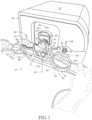
- FIG. 1is a perspective view of a fluid handling system particularly including a tubing set and a console, showing the tubing set spaced from an d in position for attachment to the console, in accordance with the present invention.
- FIG. 2is a perspective view of the system of FIG. 1 , showing the tubing system positioned on the console, with an irrigation tube between an anvil and a roller set of a peristaltic pump.
- FIG. 3is a perspective view similar to FIG. 2 , showing a cover of the peristaltic pump closed over the irrigation tube and further showing an aspiration tube inserted between jaws (or an anvil and jaw) of a pinch solenoid on the console.
- a fluid handling system 10 for use in a surgical treatment procedureincludes a console 12 and a tubing set 14 .
- Console 12includes a housing 16 with a side panel 18 .
- a peristaltic pump 20is mounted to housing 16 on side panel 18 and includes a roller set 22 and an anvil 24 , as well as a cover 26 .
- Roller set 22is held at an outer end by a bracket 28 for rotation about an axis 30 oriented perpendicular to panel 18 .
- Cover 26is hingedly mounted to a pump casing (not separately designated) and, when rotated downwardly from a neutral position shown in FIG. 1 to a closed position shown in FIG. 3 , moves anvil 24 toward roller set 22 , so that a curved surface or face 30 of the anvil is placed adjacent to rollers 32 of roller set 22 .
- Console 12further includes a solenoid-operated pinch valve 34 that comprises two relatively movable jaws (not separately designated) disposed inside a sleeve 36 mounted to panel 18 and formed with a transverse slot 38 .
- Pinch valve 34is spaced from peristaltic pump 20 , including roller set 22 and anvil 24 , in a plane or direction parallel to panel 18 .
- Console 12further includes, molded into side panel 18 , a first seat 40 and a second seat 42 in the form of circular or oval recesses of different geometries. More specifically, seats 40 and 42 may be of different shapes and/or different sizes. In the embodiment illustrated in the drawings, seat 42 is larger than seat 40 .
- Peristaltic pump 20 and solenoid pinch valve 34are disposed one above the other and thereby define a vertical line or plane 44 .
- Seats 40 and 42are disposed on side panel 18 on opposite sides of line or plane 44 .
- Tubing set 14includes an irrigation tube 46 , an aspiration tube 48 , a first attachment disk 50 , and a second attachment disk 52 .
- Irrigation tube 46 and aspiration tube 48are each coupled to both first attachment disk 50 and second attachment disk 52 .
- Disks 50 and 52may be formed by bonding two half disks to one another, sandwiching tubes 46 and 48 between the half disks in each case.
- Disks 50 and 52are each provided on major outer side or face (not designated) with a respective finger grip 54 and 56 in the form of a ring or flange projecting orthogonally to the respective major outer side or face for facilitating manipulation of the disks during an assembly procedure.
- a technician grasping finger grips 54 and 56will place disks 50 and 52 in recesses or seats 40 and 42 with major outer sides or faces of the disks in the seats so that the disks extend in parallel relation to each other and panel 18 .
- Attachmentis of a quick-release type owing to magnets 58 and 60 (or magnets and metal elements) positioned in housing 16 adjacent seats 40 and 42 and magnetic counterparts 62 and 64 attached to disks 50 and 52 .
- Alternative coupling elementssuch as snap-lock fasteners, adhesive layers, hook-and-loop fasteners, etc., may be used instead of magnets.
- Disks 50 and 52have different geometries, that is, different sizes and/or shapes, that are respectively congruent with the geometries of seats 40 and 42 so that disks 50 and 52 are seatable only in seats 40 and 42 , respectively. This ensures that irrigation tube 46 is located above aspiration tube 48 once attachment disks 50 and 52 are seated on panel 18 . Irrigation tube 46 and aspiration tube 48 are coupled to attachment disks 50 and 52 so that tubes 46 and 48 extend in spaced relation to one another between the disks and in a plane parallel to panel 18 , when the disks are placed into seats 40 and 42 .
- Disks 50 and 52are spaced from one another by lengths of tubes 46 and 48 that are approximately equal (and slightly greater) to the distance between seats 40 and 42 . Disks 50 and 52 are held and manipulated via flanges or finger grips 54 and 56 , to engage housing side panel 18 in recesses or seats 40 and 42 .
- irrigation tube 46is placed over roller set 22 in a gap between anvil 24 and bracket 28 , as shown in FIG. 2 .
- One then rotates the cover 26which is pivotably mounted to housing 16 via anvil 24 , thereby moving the anvil towards roller set 22 and clamping tube 46 between anvil surface 30 and the rollers 32 , as illustrated in FIG. 3 .
- aspiration tube 48is inserted into slot 38 of pinch valve 34 .
- Console 12exhibits indicators lights 66 , 68 , 70 that turn from one color, such as red or blue to another color such as green upon a successful seating of disks 50 and 52 in seats 40 and 42 and a successful or effective disposition of tube 46 between pump set 22 and surface 30 of anvil 24 .
- Console 12may also include an air bubble detector 72 within seat 42 .
- Bubble detector 72preferably takes the form of an ultrasonic sensor with transmitter and receiver elements (not separately depicted) disposed in respective halves 74 and 76 of a slotted projection.
- the detector 72is inserted into a hole 80 in the rear or inner side of attachment disk 52 .
- Irrigation tube 46extends across the hole 80 so as to automatically insert into a slot (not designated) defined between receiver halves 74 and 76 in the detector 72 upon the seating of attachment disk 52 in seat 42 .
- Panel 18is preferably a side panel of housing 16 , and peristaltic pump 20 and pinch valve 34 are preferably located vertically one above the other.
- peristaltic pump 20 and pinch valve 34are preferably located vertically one above the other.
- the essential featureis that the shapes and or sizes of disks 50 and 52 , as well as seats 40 and 42 , preclude an incorrect positioning of tubes 46 and 48 .
- tubing set 14Prior to an ultrasonic surgical procedure, wherein liquid irrigant or coolant is furnished to an ultrasonic instrument via tube 46 and removed from the surgical site via tube 48 , tubing set 14 is manipulated as described above so as to dispose a portion of tube 46 in operative engagement with roller set 22 and anvil 24 , and a portion of tube 48 is inserted into slot or gap 38 of pinch valve 34 .
- tubing set 14includes irrigant tube 46 and suction or aspiration tube 48 connected in parallel to one another via a pair of spaced fasteners, that is, disks 50 and 52 .
- Fasteners or attachment disks 50 and 52include magnetic elements and have with planar projections 54 and 56 that serve as grips for grasping between the forefingers and thumbs by a technician.
- Disks 50 and 52are juxtaposed to delineated positions (recesses or seats 40 and 42 ) on side panel 18 of console 16 where the disks are secured to the console in a quick-release mode of attachment, owing to magnetic attraction.
- Console panel 18features well-known prior-art peristaltic pump 20 and a well-known pinch solenoid 34 that are spaced from one another. Disks 50 and 52 are attached to console 16 on opposite sides of an imaginary line 44 or plane extending defined by the locations of peristaltic pump 22 and pinch solenoid 34 , preferably one located above the other.
- irrigation tube 46is inserted over the rollers 32 of pump 20 and a cover- or lid-type anvil 24 is pivoted into place so that irrigation tube 46 is pressed between the pump rollers 32 and a curved inner surface 30 of the anvil.
- Aspiration tube 48is placed in a gap 38 defined between jaws (not visible owing to sleeve 36 ) of pinch solenoid 34 .
- Tubing set 14simplifies the process of tube placement, making it impossible to insert the aspiration tube 48 into peristaltic pump 20 .
- Disk 50 or 52may be provided with an RFID tag or chip (not shown) that may be set by a transmitter in housing 16 to prevent re-use of the tubing set 14 , primarily for ensuring sterility.
Landscapes
- Health & Medical Sciences (AREA)
- Engineering & Computer Science (AREA)
- Heart & Thoracic Surgery (AREA)
- Animal Behavior & Ethology (AREA)
- Public Health (AREA)
- Biomedical Technology (AREA)
- Hematology (AREA)
- Life Sciences & Earth Sciences (AREA)
- Veterinary Medicine (AREA)
- General Health & Medical Sciences (AREA)
- Anesthesiology (AREA)
- Vascular Medicine (AREA)
- Pulmonology (AREA)
- Mechanical Engineering (AREA)
- General Engineering & Computer Science (AREA)
- Infusion, Injection, And Reservoir Apparatuses (AREA)
- External Artificial Organs (AREA)
Abstract
Description
Claims (16)
Priority Applications (2)
| Application Number | Priority Date | Filing Date | Title |
|---|---|---|---|
| US17/235,308US11821417B2 (en) | 2018-10-24 | 2021-04-20 | Fluid handling assembly and related tube set and method for use in surgical procedures |
| US18/389,084US20240410355A1 (en) | 2018-10-24 | 2023-11-13 | Fluid handling assembly and related tube set and method for use in surgical procedures |
Applications Claiming Priority (2)
| Application Number | Priority Date | Filing Date | Title |
|---|---|---|---|
| US16/169,569US11007308B2 (en) | 2018-10-24 | 2018-10-24 | Fluid handling assembly and related tube set and method for use in surgical procedures |
| US17/235,308US11821417B2 (en) | 2018-10-24 | 2021-04-20 | Fluid handling assembly and related tube set and method for use in surgical procedures |
Related Parent Applications (1)
| Application Number | Title | Priority Date | Filing Date |
|---|---|---|---|
| US16/169,569ContinuationUS11007308B2 (en) | 2018-10-24 | 2018-10-24 | Fluid handling assembly and related tube set and method for use in surgical procedures |
Related Child Applications (1)
| Application Number | Title | Priority Date | Filing Date |
|---|---|---|---|
| US18/389,084ContinuationUS20240410355A1 (en) | 2018-10-24 | 2023-11-13 | Fluid handling assembly and related tube set and method for use in surgical procedures |
Publications (2)
| Publication Number | Publication Date |
|---|---|
| US20210299345A1 US20210299345A1 (en) | 2021-09-30 |
| US11821417B2true US11821417B2 (en) | 2023-11-21 |
Family
ID=70326450
Family Applications (3)
| Application Number | Title | Priority Date | Filing Date |
|---|---|---|---|
| US16/169,569Active2039-03-28US11007308B2 (en) | 2018-10-24 | 2018-10-24 | Fluid handling assembly and related tube set and method for use in surgical procedures |
| US17/235,308Active2039-07-25US11821417B2 (en) | 2018-10-24 | 2021-04-20 | Fluid handling assembly and related tube set and method for use in surgical procedures |
| US18/389,084PendingUS20240410355A1 (en) | 2018-10-24 | 2023-11-13 | Fluid handling assembly and related tube set and method for use in surgical procedures |
Family Applications Before (1)
| Application Number | Title | Priority Date | Filing Date |
|---|---|---|---|
| US16/169,569Active2039-03-28US11007308B2 (en) | 2018-10-24 | 2018-10-24 | Fluid handling assembly and related tube set and method for use in surgical procedures |
Family Applications After (1)
| Application Number | Title | Priority Date | Filing Date |
|---|---|---|---|
| US18/389,084PendingUS20240410355A1 (en) | 2018-10-24 | 2023-11-13 | Fluid handling assembly and related tube set and method for use in surgical procedures |
Country Status (1)
| Country | Link |
|---|---|
| US (3) | US11007308B2 (en) |
Cited By (1)
| Publication number | Priority date | Publication date | Assignee | Title |
|---|---|---|---|---|
| US20240410355A1 (en)* | 2018-10-24 | 2024-12-12 | Misonix, Llc | Fluid handling assembly and related tube set and method for use in surgical procedures |
Families Citing this family (4)
| Publication number | Priority date | Publication date | Assignee | Title |
|---|---|---|---|---|
| US10405875B2 (en) | 2016-05-05 | 2019-09-10 | Misonix, Incorporated | Ultrasonic surgical instrument and method for manufacturing same |
| US12279787B2 (en) | 2020-02-27 | 2025-04-22 | Misonix, Llc | Spinal surgery method |
| US12029879B2 (en)* | 2020-11-05 | 2024-07-09 | Carefusion 303, Inc. | Controllable pumping tubing |
| US12402905B2 (en) | 2021-08-13 | 2025-09-02 | Misonix, Llc | Serrated ultrasonic cutting blade with varied tooth pitch |
Citations (17)
| Publication number | Priority date | Publication date | Assignee | Title |
|---|---|---|---|---|
| US4155362A (en) | 1976-01-26 | 1979-05-22 | Baxter Travenol Laboratories, Inc. | Method and apparatus for metered infusion of fluids |
| US5213483A (en)* | 1991-06-19 | 1993-05-25 | Strato Medical Corporation | Peristaltic infusion pump with removable cassette and mechanically keyed tube set |
| US5403277A (en) | 1993-01-12 | 1995-04-04 | Minnesota Mining And Manufacturing Company | Irrigation system with tubing cassette |
| US5460490A (en) | 1994-05-19 | 1995-10-24 | Linvatec Corporation | Multi-purpose irrigation/aspiration pump system |
| US6319223B1 (en) | 1997-03-24 | 2001-11-20 | Alcon Universal Ltd. | Compact cassette for ophthalmic surgery |
| US7273359B2 (en) | 2003-11-05 | 2007-09-25 | Linvatec Corporation | Peristaltic irrigation pump system |
| US20080154095A1 (en) | 2006-12-20 | 2008-06-26 | Eric Stubkjaer | Dual pump arthroscopic irrigation/aspiration system with outflow control |
| US20080214994A1 (en) | 2005-06-09 | 2008-09-04 | Mireille Guignard | Device for Irrigating and Pressurizing a Cavity |
| US20090043252A1 (en) | 2004-07-16 | 2009-02-12 | Alaris Medical U.K. Limited | Infusion apparatus |
| US7556481B2 (en) | 2005-08-26 | 2009-07-07 | Baxter International Inc. | Rotary axial peristaltic pumps and related methods |
| US20110300010A1 (en) | 2009-08-12 | 2011-12-08 | Pathway Medical Technologies, Inc. | Peristaltic pump assemblies, tubing cassettes, and systems incorporating such pump assemblies |
| US20120065482A1 (en) | 2005-04-08 | 2012-03-15 | Mark Ries Robinson | Determination of blood pump system performance and sample dilution using a property of fluid being transported |
| US20130131585A1 (en) | 2009-08-12 | 2013-05-23 | Medrad, Inc. | Interventional catheter assemblies, control consoles and adaptive tubing cassettes |
| US9200628B2 (en) | 2010-03-01 | 2015-12-01 | Ulrich Gmbh & Co. Kg | Peristaltic pump with adjusting ring |
| US20160287779A1 (en) | 2015-04-03 | 2016-10-06 | Cirrus Technologies Ltd. | Surgical fluid management system |
| WO2017083733A1 (en) | 2012-03-17 | 2017-05-18 | Abbott Medical Optics Inc. | Valve system of surgical cassette manifold, system, and methods thereof |
| US11007308B2 (en)* | 2018-10-24 | 2021-05-18 | Misonix, Incorporated | Fluid handling assembly and related tube set and method for use in surgical procedures |
Family Cites Families (1)
| Publication number | Priority date | Publication date | Assignee | Title |
|---|---|---|---|---|
| US7018182B2 (en)* | 2003-03-13 | 2006-03-28 | Chf Solutions, Inc. | Self-loading peristaltic pump for extracorporeal blood circuit |
- 2018
- 2018-10-24USUS16/169,569patent/US11007308B2/enactiveActive
- 2021
- 2021-04-20USUS17/235,308patent/US11821417B2/enactiveActive
- 2023
- 2023-11-13USUS18/389,084patent/US20240410355A1/enactivePending
Patent Citations (18)
| Publication number | Priority date | Publication date | Assignee | Title |
|---|---|---|---|---|
| US4155362A (en) | 1976-01-26 | 1979-05-22 | Baxter Travenol Laboratories, Inc. | Method and apparatus for metered infusion of fluids |
| US5213483A (en)* | 1991-06-19 | 1993-05-25 | Strato Medical Corporation | Peristaltic infusion pump with removable cassette and mechanically keyed tube set |
| US5403277A (en) | 1993-01-12 | 1995-04-04 | Minnesota Mining And Manufacturing Company | Irrigation system with tubing cassette |
| US5460490A (en) | 1994-05-19 | 1995-10-24 | Linvatec Corporation | Multi-purpose irrigation/aspiration pump system |
| US6319223B1 (en) | 1997-03-24 | 2001-11-20 | Alcon Universal Ltd. | Compact cassette for ophthalmic surgery |
| US7273359B2 (en) | 2003-11-05 | 2007-09-25 | Linvatec Corporation | Peristaltic irrigation pump system |
| US20090043252A1 (en) | 2004-07-16 | 2009-02-12 | Alaris Medical U.K. Limited | Infusion apparatus |
| US20120065482A1 (en) | 2005-04-08 | 2012-03-15 | Mark Ries Robinson | Determination of blood pump system performance and sample dilution using a property of fluid being transported |
| US20080214994A1 (en) | 2005-06-09 | 2008-09-04 | Mireille Guignard | Device for Irrigating and Pressurizing a Cavity |
| US7883489B2 (en)* | 2005-06-09 | 2011-02-08 | Mireille Guignard | Device for irrigating and pressurizing a cavity |
| US7556481B2 (en) | 2005-08-26 | 2009-07-07 | Baxter International Inc. | Rotary axial peristaltic pumps and related methods |
| US20080154095A1 (en) | 2006-12-20 | 2008-06-26 | Eric Stubkjaer | Dual pump arthroscopic irrigation/aspiration system with outflow control |
| US20110300010A1 (en) | 2009-08-12 | 2011-12-08 | Pathway Medical Technologies, Inc. | Peristaltic pump assemblies, tubing cassettes, and systems incorporating such pump assemblies |
| US20130131585A1 (en) | 2009-08-12 | 2013-05-23 | Medrad, Inc. | Interventional catheter assemblies, control consoles and adaptive tubing cassettes |
| US9200628B2 (en) | 2010-03-01 | 2015-12-01 | Ulrich Gmbh & Co. Kg | Peristaltic pump with adjusting ring |
| WO2017083733A1 (en) | 2012-03-17 | 2017-05-18 | Abbott Medical Optics Inc. | Valve system of surgical cassette manifold, system, and methods thereof |
| US20160287779A1 (en) | 2015-04-03 | 2016-10-06 | Cirrus Technologies Ltd. | Surgical fluid management system |
| US11007308B2 (en)* | 2018-10-24 | 2021-05-18 | Misonix, Incorporated | Fluid handling assembly and related tube set and method for use in surgical procedures |
Cited By (1)
| Publication number | Priority date | Publication date | Assignee | Title |
|---|---|---|---|---|
| US20240410355A1 (en)* | 2018-10-24 | 2024-12-12 | Misonix, Llc | Fluid handling assembly and related tube set and method for use in surgical procedures |
Also Published As
| Publication number | Publication date |
|---|---|
| US11007308B2 (en) | 2021-05-18 |
| US20240410355A1 (en) | 2024-12-12 |
| US20210299345A1 (en) | 2021-09-30 |
| US20200129677A1 (en) | 2020-04-30 |
Similar Documents
| Publication | Publication Date | Title |
|---|---|---|
| US11821417B2 (en) | Fluid handling assembly and related tube set and method for use in surgical procedures | |
| AU2014256933B2 (en) | Endoscope lens cleaning device | |
| US20190307607A1 (en) | Pre-alignment surgical cassette interface | |
| US5324180A (en) | Surgical instrument with drawer loading cassette system | |
| US4737148A (en) | Filtered T coupling | |
| US5120304A (en) | Surgical flushing and aspiration device | |
| JP3204344U (en) | Suitable for application of methods for keeping the reflective surface of a mirror with a handle for medical or dental testing clean during use by an manipulated air flow, improved to a more easily sterilizable of the handle mirror Configuration | |
| CN113520611B (en) | Sterile isolation mechanism, mirror holding arm and mirror holding robot | |
| CA2136092A1 (en) | Tubing management system | |
| JP6984007B2 (en) | MRI Guided Biopsy Device with Rotating Depth Stop Device | |
| JP2009540939A (en) | Surgical cassette with improved air filtration | |
| US6925917B2 (en) | Tool provided with irrigation for transection of a band, ring or the like and method of use | |
| JPH01502721A (en) | surgical suction cannula | |
| CN109475360A (en) | Ultrasonic surgery probe, component and correlation technique | |
| JP2017503630A (en) | Surgical drive | |
| CN103027653B (en) | Key and endoscope | |
| WO2020086063A1 (en) | Fluid handling assembly and related tube set and method for use in surgical procedures | |
| HK40052634A (en) | Fluid handling assembly and related tube set and method for use in surgical procedures | |
| US11661929B1 (en) | Suction valve apparatus and method of using same | |
| WO2018119022A1 (en) | Aspiration irrigation device for laparoscopic surgery | |
| JPWO2020086063A5 (en) | ||
| JP2024085540A (en) | Suction equipment | |
| JP2025529166A (en) | Surgical fluid delivery system and components thereof | |
| JPH07106206B2 (en) | Ultrasonic surgery equipment | |
| JOACHIMI OERTEL et al. | Ultrasonic aspiration in neuroendoscopy: first results |
Legal Events
| Date | Code | Title | Description |
|---|---|---|---|
| FEPP | Fee payment procedure | Free format text:ENTITY STATUS SET TO UNDISCOUNTED (ORIGINAL EVENT CODE: BIG.); ENTITY STATUS OF PATENT OWNER: LARGE ENTITY | |
| FEPP | Fee payment procedure | Free format text:ENTITY STATUS SET TO SMALL (ORIGINAL EVENT CODE: SMAL); ENTITY STATUS OF PATENT OWNER: LARGE ENTITY | |
| STPP | Information on status: patent application and granting procedure in general | Free format text:DOCKETED NEW CASE - READY FOR EXAMINATION | |
| AS | Assignment | Owner name:WELLS FARGO BANK, NATIONAL ASSOCIATION, AS COLLATERAL AGENT, VIRGINIA Free format text:SECURITY INTEREST;ASSIGNOR:MISONIX OPCO, LLC;REEL/FRAME:058809/0950 Effective date:20211105 | |
| AS | Assignment | Owner name:MISONIX OPCO, LLC, NEW YORK Free format text:MERGER AND CHANGE OF NAME;ASSIGNORS:OYSTER OPCO MERGER SUB, LLC;MISONIX OPCO, INC.;REEL/FRAME:061433/0736 Effective date:20211103 | |
| STPP | Information on status: patent application and granting procedure in general | Free format text:NON FINAL ACTION MAILED | |
| AS | Assignment | Owner name:MISONIX, LLC, NEW YORK Free format text:MERGER;ASSIGNOR:MISONIX, INC.;REEL/FRAME:064027/0523 Effective date:20211029 | |
| STPP | Information on status: patent application and granting procedure in general | Free format text:NOTICE OF ALLOWANCE MAILED -- APPLICATION RECEIVED IN OFFICE OF PUBLICATIONS | |
| FEPP | Fee payment procedure | Free format text:ENTITY STATUS SET TO UNDISCOUNTED (ORIGINAL EVENT CODE: BIG.); ENTITY STATUS OF PATENT OWNER: LARGE ENTITY | |
| STPP | Information on status: patent application and granting procedure in general | Free format text:PUBLICATIONS -- ISSUE FEE PAYMENT RECEIVED | |
| STPP | Information on status: patent application and granting procedure in general | Free format text:PUBLICATIONS -- ISSUE FEE PAYMENT VERIFIED | |
| STCF | Information on status: patent grant | Free format text:PATENTED CASE | |
| AS | Assignment | Owner name:WELLS FARGO BANK, NATIONAL ASSOCIATION, AS ADMINISTRATIVE AGENT, TEXAS Free format text:SECURITY INTEREST;ASSIGNOR:MISONIX, LLC;REEL/FRAME:072298/0866 Effective date:20250731 | |
| AS | Assignment | Owner name:MISONIX OPCO, LLC, NEW YORK Free format text:RELEASE BY SECURED PARTY;ASSIGNOR:WELLS FARGO BANK, NATIONAL ASSOCIATION, AS COLLATERAL AGENT;REEL/FRAME:072338/0395 Effective date:20250731 |