US11819259B2 - Methods and apparatus for controlled RF treatments and RF generator system - Google Patents
Methods and apparatus for controlled RF treatments and RF generator systemDownload PDFInfo
- Publication number
- US11819259B2 US11819259B2US16/269,314US201916269314AUS11819259B2US 11819259 B2US11819259 B2US 11819259B2US 201916269314 AUS201916269314 AUS 201916269314AUS 11819259 B2US11819259 B2US 11819259B2
- Authority
- US
- United States
- Prior art keywords
- temperature sensor
- electrosurgical
- patient
- electrode
- temperature
- Prior art date
- Legal status (The legal status is an assumption and is not a legal conclusion. Google has not performed a legal analysis and makes no representation as to the accuracy of the status listed.)
- Active, expires
Links
Images


Classifications
- A—HUMAN NECESSITIES
- A61—MEDICAL OR VETERINARY SCIENCE; HYGIENE
- A61B—DIAGNOSIS; SURGERY; IDENTIFICATION
- A61B18/00—Surgical instruments, devices or methods for transferring non-mechanical forms of energy to or from the body
- A—HUMAN NECESSITIES
- A61—MEDICAL OR VETERINARY SCIENCE; HYGIENE
- A61B—DIAGNOSIS; SURGERY; IDENTIFICATION
- A61B18/00—Surgical instruments, devices or methods for transferring non-mechanical forms of energy to or from the body
- A61B18/04—Surgical instruments, devices or methods for transferring non-mechanical forms of energy to or from the body by heating
- A61B18/12—Surgical instruments, devices or methods for transferring non-mechanical forms of energy to or from the body by heating by passing a current through the tissue to be heated, e.g. high-frequency current
- A61B18/1206—Generators therefor
- A61B18/1233—Generators therefor with circuits for assuring patient safety
- A—HUMAN NECESSITIES
- A61—MEDICAL OR VETERINARY SCIENCE; HYGIENE
- A61B—DIAGNOSIS; SURGERY; IDENTIFICATION
- A61B18/00—Surgical instruments, devices or methods for transferring non-mechanical forms of energy to or from the body
- A61B18/04—Surgical instruments, devices or methods for transferring non-mechanical forms of energy to or from the body by heating
- A61B18/08—Surgical instruments, devices or methods for transferring non-mechanical forms of energy to or from the body by heating by means of electrically-heated probes
- A61B18/082—Probes or electrodes therefor
- A—HUMAN NECESSITIES
- A61—MEDICAL OR VETERINARY SCIENCE; HYGIENE
- A61B—DIAGNOSIS; SURGERY; IDENTIFICATION
- A61B18/00—Surgical instruments, devices or methods for transferring non-mechanical forms of energy to or from the body
- A61B18/04—Surgical instruments, devices or methods for transferring non-mechanical forms of energy to or from the body by heating
- A61B18/12—Surgical instruments, devices or methods for transferring non-mechanical forms of energy to or from the body by heating by passing a current through the tissue to be heated, e.g. high-frequency current
- A61B18/1206—Generators therefor
- A—HUMAN NECESSITIES
- A61—MEDICAL OR VETERINARY SCIENCE; HYGIENE
- A61B—DIAGNOSIS; SURGERY; IDENTIFICATION
- A61B18/00—Surgical instruments, devices or methods for transferring non-mechanical forms of energy to or from the body
- A61B18/04—Surgical instruments, devices or methods for transferring non-mechanical forms of energy to or from the body by heating
- A61B18/12—Surgical instruments, devices or methods for transferring non-mechanical forms of energy to or from the body by heating by passing a current through the tissue to be heated, e.g. high-frequency current
- A61B18/14—Probes or electrodes therefor
- A—HUMAN NECESSITIES
- A61—MEDICAL OR VETERINARY SCIENCE; HYGIENE
- A61B—DIAGNOSIS; SURGERY; IDENTIFICATION
- A61B18/00—Surgical instruments, devices or methods for transferring non-mechanical forms of energy to or from the body
- A61B2018/00005—Cooling or heating of the probe or tissue immediately surrounding the probe
- A—HUMAN NECESSITIES
- A61—MEDICAL OR VETERINARY SCIENCE; HYGIENE
- A61B—DIAGNOSIS; SURGERY; IDENTIFICATION
- A61B18/00—Surgical instruments, devices or methods for transferring non-mechanical forms of energy to or from the body
- A61B2018/00053—Mechanical features of the instrument of device
- A61B2018/00059—Material properties
- A61B2018/00071—Electrical conductivity
- A61B2018/00083—Electrical conductivity low, i.e. electrically insulating
- A—HUMAN NECESSITIES
- A61—MEDICAL OR VETERINARY SCIENCE; HYGIENE
- A61B—DIAGNOSIS; SURGERY; IDENTIFICATION
- A61B18/00—Surgical instruments, devices or methods for transferring non-mechanical forms of energy to or from the body
- A61B2018/00053—Mechanical features of the instrument of device
- A61B2018/00059—Material properties
- A61B2018/00089—Thermal conductivity
- A61B2018/00095—Thermal conductivity high, i.e. heat conducting
- A—HUMAN NECESSITIES
- A61—MEDICAL OR VETERINARY SCIENCE; HYGIENE
- A61B—DIAGNOSIS; SURGERY; IDENTIFICATION
- A61B18/00—Surgical instruments, devices or methods for transferring non-mechanical forms of energy to or from the body
- A61B2018/00053—Mechanical features of the instrument of device
- A61B2018/00059—Material properties
- A61B2018/00089—Thermal conductivity
- A61B2018/00101—Thermal conductivity low, i.e. thermally insulating
- A—HUMAN NECESSITIES
- A61—MEDICAL OR VETERINARY SCIENCE; HYGIENE
- A61B—DIAGNOSIS; SURGERY; IDENTIFICATION
- A61B18/00—Surgical instruments, devices or methods for transferring non-mechanical forms of energy to or from the body
- A61B2018/00315—Surgical instruments, devices or methods for transferring non-mechanical forms of energy to or from the body for treatment of particular body parts
- A61B2018/00452—Skin
- A—HUMAN NECESSITIES
- A61—MEDICAL OR VETERINARY SCIENCE; HYGIENE
- A61B—DIAGNOSIS; SURGERY; IDENTIFICATION
- A61B18/00—Surgical instruments, devices or methods for transferring non-mechanical forms of energy to or from the body
- A61B2018/00636—Sensing and controlling the application of energy
- A61B2018/00666—Sensing and controlling the application of energy using a threshold value
- A61B2018/00678—Sensing and controlling the application of energy using a threshold value upper
- A—HUMAN NECESSITIES
- A61—MEDICAL OR VETERINARY SCIENCE; HYGIENE
- A61B—DIAGNOSIS; SURGERY; IDENTIFICATION
- A61B18/00—Surgical instruments, devices or methods for transferring non-mechanical forms of energy to or from the body
- A61B2018/00636—Sensing and controlling the application of energy
- A61B2018/00696—Controlled or regulated parameters
- A61B2018/00702—Power or energy
- A—HUMAN NECESSITIES
- A61—MEDICAL OR VETERINARY SCIENCE; HYGIENE
- A61B—DIAGNOSIS; SURGERY; IDENTIFICATION
- A61B18/00—Surgical instruments, devices or methods for transferring non-mechanical forms of energy to or from the body
- A61B2018/00636—Sensing and controlling the application of energy
- A61B2018/00696—Controlled or regulated parameters
- A61B2018/00714—Temperature
- A—HUMAN NECESSITIES
- A61—MEDICAL OR VETERINARY SCIENCE; HYGIENE
- A61B—DIAGNOSIS; SURGERY; IDENTIFICATION
- A61B18/00—Surgical instruments, devices or methods for transferring non-mechanical forms of energy to or from the body
- A61B2018/00636—Sensing and controlling the application of energy
- A61B2018/00696—Controlled or regulated parameters
- A61B2018/00726—Duty cycle
- A—HUMAN NECESSITIES
- A61—MEDICAL OR VETERINARY SCIENCE; HYGIENE
- A61B—DIAGNOSIS; SURGERY; IDENTIFICATION
- A61B18/00—Surgical instruments, devices or methods for transferring non-mechanical forms of energy to or from the body
- A61B2018/00636—Sensing and controlling the application of energy
- A61B2018/00696—Controlled or regulated parameters
- A61B2018/00732—Frequency
- A—HUMAN NECESSITIES
- A61—MEDICAL OR VETERINARY SCIENCE; HYGIENE
- A61B—DIAGNOSIS; SURGERY; IDENTIFICATION
- A61B18/00—Surgical instruments, devices or methods for transferring non-mechanical forms of energy to or from the body
- A61B2018/00636—Sensing and controlling the application of energy
- A61B2018/00696—Controlled or regulated parameters
- A61B2018/00761—Duration
- A—HUMAN NECESSITIES
- A61—MEDICAL OR VETERINARY SCIENCE; HYGIENE
- A61B—DIAGNOSIS; SURGERY; IDENTIFICATION
- A61B18/00—Surgical instruments, devices or methods for transferring non-mechanical forms of energy to or from the body
- A61B2018/00636—Sensing and controlling the application of energy
- A61B2018/00773—Sensed parameters
- A61B2018/00791—Temperature
- A61B2018/00815—Temperature measured by a thermistor
- A—HUMAN NECESSITIES
- A61—MEDICAL OR VETERINARY SCIENCE; HYGIENE
- A61B—DIAGNOSIS; SURGERY; IDENTIFICATION
- A61B18/00—Surgical instruments, devices or methods for transferring non-mechanical forms of energy to or from the body
- A61B2018/00636—Sensing and controlling the application of energy
- A61B2018/00773—Sensed parameters
- A61B2018/00791—Temperature
- A61B2018/00821—Temperature measured by a thermocouple
- A—HUMAN NECESSITIES
- A61—MEDICAL OR VETERINARY SCIENCE; HYGIENE
- A61B—DIAGNOSIS; SURGERY; IDENTIFICATION
- A61B18/00—Surgical instruments, devices or methods for transferring non-mechanical forms of energy to or from the body
- A61B18/04—Surgical instruments, devices or methods for transferring non-mechanical forms of energy to or from the body by heating
- A61B18/12—Surgical instruments, devices or methods for transferring non-mechanical forms of energy to or from the body by heating by passing a current through the tissue to be heated, e.g. high-frequency current
- A61B18/1206—Generators therefor
- A61B2018/128—Generators therefor generating two or more frequencies
- A—HUMAN NECESSITIES
- A61—MEDICAL OR VETERINARY SCIENCE; HYGIENE
- A61B—DIAGNOSIS; SURGERY; IDENTIFICATION
- A61B18/00—Surgical instruments, devices or methods for transferring non-mechanical forms of energy to or from the body
- A61B18/04—Surgical instruments, devices or methods for transferring non-mechanical forms of energy to or from the body by heating
- A61B18/12—Surgical instruments, devices or methods for transferring non-mechanical forms of energy to or from the body by heating by passing a current through the tissue to be heated, e.g. high-frequency current
- A61B18/14—Probes or electrodes therefor
- A61B2018/147—Electrodes transferring energy by capacitive coupling, i.e. with a dielectricum between electrode and target tissue
Definitions
- the subject matter disclosed hereingenerally pertains to electrosurgical systems, such as, for example, electrosurgical devices and related electrical circuitry and methods. More particularly, but not exclusively, this disclosure relates, in part, to electrosurgical systems and components thereof configured to deliver radio-frequency (RF) energy to a target site of a human or other animal patient with selectable RF energy delivery profiles, temperature sensors and controls, and/or electrodes configured to more uniformly or effectively deliver energy to target tissue. In some respects, this disclosure pertains to electrosurgical methods and systems for providing electrosurgical treatments.
- RFradio-frequency
- the electrosurgical systemincludes a control unit 34 and an electrosurgical device 10 .
- the electrosurgical device 10(sometimes referred to as a “handpiece”) includes a housing 12 , e.g., for containing circuitry, and an energizable electrode 18 configured to treat a target site on or in a patient's body.
- the housing 12can be configured as a graspable component of the handpiece, as shown for example in FIG. 34 . In other instances, the graspable portion of the handpiece may be spaced from a circuit-containing housing.
- the control unit 34is configured to provide power to the electrosurgical device 10 for energizing the electrode.
- the control unit 34can be configured to provide energy having a selected combination of waveform and frequency. Some control units 34 are configured to provide RF energy to the electrosurgical device 10 .
- a cable 32can extend between an electrical connector 33 on the control unit 34 and an electrical connector 31 on the electrosurgical device to electrically couple one or more conductive elements on or within the device 10 to one or more corresponding conductive elements of the controller 34 .
- Some known control unitsprovide three output terminals, with one of the terminals being an energizable terminal for conveying therapeutic energy, e.g., RF energy, to an energizable element of a handpiece.
- Such a control unit 34is usually configured to energize the energizable terminal when a circuit between the two remaining output terminals is completed, as through the closing of a user actuatable switch 14 .
- control unitssuch as control units are described, for example, in U.S. Pat. No. 6,652,514, which is hereby incorporated by reference herein by reference in its entirety, provides a three-wire output connector for powering and controlling electrosurgical handpieces.
- Conventional control unitscan generate, for example, one or more radio-frequency (RF) modulated waveforms, including, for one non-limiting example, at a frequency of about 4 mega-Hertz (MHz), which can be delivered to a target site by way of an electrosurgical handpiece having an energizable electrode defining an active surface.
- RFradio-frequency
- the active surface of an electrosurgical systemcan be configured for ablative and/or non-ablative electrosurgery, depending on the physical configuration of the active surface and applied-power parameters.
- an ablative procedureis one where the electrode and power settings result in cutting, coagulation, vaporization or other such traumatic disruption to the integrity of treated tissue
- a non-ablative procedureis one where such cutting, coagulation, vaporization or other such traumatic disruption to the integrity of treated tissue does not result.
- Certain embodiments of the inventive subject matterare directed to two or more adjustable power sources each having independent switches to independently feed into an RF amplifier. Where solely cut mode is desired, only one of the power sources is employed. Where solely coagulation mode is desired, only the other of the power sources is employed. Where a blend of cut and coagulation is desired, both of the two adjustable power sources having independent switches are employed.
- This conceptadvantageously enables excellent control over the wave form achieved in each mode, especially where blend is employed.
- Thisprovides excellent control of the hemostatic effect on the tissue such that a small amount of coagulative effect might be desired on a surface and a larger amount of coagulative effect might be desired on internal organs/tissues.
- the reduction of coagulative effectis useful on the surface tissue because it provides less thermal damage adjacent to the cut and in this way, there can be balance between bleeding and undesirable scarring related to coagulative effects on tissue caused by excessive coagulation.
- This conceptadvantageously enables the ability to control and to transition from cut to blend to coagulation and enables, in some embodiments, a single electrosurgical tip to be employed to make the initial cut through the skin surface in cut mode and to cut internal tissue layers with some coagulation to prevent unnecessary bleeding (in blend mode) and/or to solely coagulate tissue in coagulation mode.
- a single electrosurgical tipmay be employed during a procedure.
- a Conductive Containere.g., Mushroom Cap and Stem
- the inventive subject matterare directed to a temperature sensor assembly wherein the temperature measurement response time is fast, e.g., less than 1 second ⁇ .
- the assemblyincludes encasement of a temperature sensor in a highly thermally conductive container that has minimal thermal mass, and where the majority of the surface area of the temperature sensor that is encased is in good thermal contact with the conductive material.
- a tip portion of the containercontacts the surface of a patient's tissue to enable the temperature sensor to measure the surface temperature of the tissue via its good thermal contact with the conductive encasement.
- This conceptadvantageously enables the conductive container and temperature sensor assembly to be thermally isolated from adjacent material having a thermal mass. In this way, cross talk is avoided, the fidelity of the temperature feedback signal is ensured, and a response time of the temperature sensor is reduced.
- This conceptadvantageously enables the portion of the conductive container in contact with the surface of the tissue to be exaggerated such that it has a larger surface area than the surface area of the tip of the temperature sensor.
- This conceptadvantageously enables the portion of the conductive container in contact with the surface of the tissue to be tailored (e.g., smoothed such that what contacts the tissue surface lacks sharp edges) to comfortably contact the patient's tissue surface when the device is moved across the subject's tissue surface (e.g., skin surface).
- Certain embodiments of the inventive subject matterare directed to capacitive electrode configurations, where high frequency RF (e.g., 3-30 MHz, or 4 MHz) is emitted, that reduce dielectric losses within a capacitive electrode.
- the reduced dielectric lossesaccordingly reduce electrode heating and associated power loss to the electrode, which allows more energy to penetrate into the patient.
- a metal or otherwise conductive inner probe bodyhas an exterior surface covered with a dielectric coating.
- the dielectric coatingis employed to enable the treatment current to be delivered homogenously over the entire area of the electrode, where the dielectric coated surface of the electrode is in contact with the subject's skin or other target tissue surface.
- This conceptadvantageously enables a larger volume of tissue to be heated at a depth, because power is not lost in the electrode. This can be seen in the slower cool down time of the tissue surface post treatment with the application of high frequency RF (e.g., 3-30 MHz, or 4 MHz) with the capacitive probe.
- high frequency RFe.g., 3-30 MHz, or 4 MHz
- concepts disclosed heregenerally concern electrosurgical handpieces having a housing for a temperature sensor.
- the housingdefines a first patient-contact surface, an inner surface positioned opposite the first patient-contact surface, and an outer wall extending transversely relative to the first patient-contact surface.
- a temperature sensoris thermally coupled with the inner surface of the housing.
- An energizable electrodedefines a second patient-contact surface extending outward of the outer wall of the housing.
- An insulatoris positioned between the energizable electrode and the housing for the temperature sensor and inhibits thermal conduction between the energizable electrode and the housing for the temperature sensor.
- a shaftcan extend proximally from the energizable electrode and define an internal bore extending longitudinally of the shaft.
- the insulatorcan extend from a distal end positioned adjacent the first patient-contact surface and the second patient-contact surface to a proximal end positioned within the internal bore.
- the internal borecan define a first thread and the insulator can define a second thread. The first and second threads can be complementary and matingly engageable with each other.
- the electrosurgical handpiececan further have an electrical conductor extending proximally within the handpiece from the temperature sensor.
- the first patient-contact surface and the second patient-contact surfacecan be co-centrically aligned with each other.
- the temperature sensorcan be one or more of a thermocouple, a resistance-temperature detector, a thermistor, and a diode.
- the housing for the temperature sensorcan be a material having a thermal conductivity equal to or greater than about 200 W/mK.
- the electrodecan include a dielectric coating defining the second patient contact surface.
- the dielectric materialcan have a dielectric constant of between about 4 to about 12 at an operating frequency of the energizable electrode.
- the operating frequency of the energizable electrodecan be between about 3-30 MHz.
- the dielectric material coating camhave a substantially even thickness of about 0.004 to about 0.020 inches.
- the electrosurgical handpiececan further include a communication component configured to receive a temperature measured by the temperature sensor and to communicate the received temperature to a control system.
- the electrosurgical handpiececan be coupled to an electrosurgical generator comprising the control system.
- the control systemcan be configured to receive a temperature measurement from the temperature sensor via the communication component, compare the received temperature to a threshold temperature, and to modify the output RF waveform in response to the comparison.
- the first patient-contact surfacecan have a larger surface area than a surface area of the temperature sensor that is coupled to the housing.
- the energizeable electrodecan be capacitively coupled.
- the electrosurgical handpiececan be configured to output a radio frequency (RF) waveform received from an electrosurgical generator.
- RFradio frequency
- the electrosurgical handpiececan be coupled to an electrosurgical generator that includes a generator configured to combine a first current waveform having a corresponding first frequency, a first amplitude, and a first pulse-width with a second current waveform having a corresponding second frequency, a second amplitude, and a second pulse-width to define a blended waveform output; and a control system configured to control one or more of the first frequency, the first amplitude, the first pulse-width, the second frequency, the second amplitude and the second pulse-width responsive to a temperature received from the temperature sensor; where the energizable electrode is configured to output the blended waveform output received from the electrosurgical generator.
- the electrosurgical generatorcan include a first power source configured to generate the first current waveform; a second power source configured to generate the second current waveform; and a radio-frequency amplifier configured to blend the first and second current waveforms to define a blended waveform and to output the blended waveform to the electrosurgical handpiece.
- an electrosurgical handpiecehas an energizable electrode comprising a metal foil enclosing a volume and defining a patient-contact surface and a temperature sensor disposed in the volume and thermally coupled with the patient contact surface.
- the volumecan contain a gas or a low thermal mass solid.
- the low thermal mass solidcan including one or more of a solid plastic, and/or a fiber insulation.
- an electrosurgical systemhas a generator configured to combine a first current waveform having a corresponding first frequency, a first amplitude, and a first pulse-width with a second current waveform having a corresponding second frequency, a second amplitude, and a second pulse-width to define a blended waveform output.
- the electrosurgical systemhas a control system configured to control one or more of the first frequency, the first amplitude, the first pulse-width, the second frequency, the second amplitude and the second pulse-width responsive to a received temperature.
- One or more of the first frequency, the first amplitude, the first pulse-width, the second frequency, the second amplitude and the second pulse-widthcan be user selectable.
- the electrosurgical systemcan have a handpiece having an energizable electrode to deliver energy corresponding to the blended waveform output to a patient-treatment site.
- the handpiececan have a temperature sensor configured to output a temperature of the patient-treatment site. The received temperature can correspond to an output from the temperature sensor.
- the handpiececan include a temperature sensor and an associated first patient-contact surface.
- the energizable electrodecan define a second patient-contact surface positioned outward of the first patient-contact surface, wherein the second patient-contact surface can be configured to deliver the blended waveform output to a treatment site.
- the handpiececan include a housing for the temperature sensor.
- the housingcan define the first patient contact surface positioned relative to the second patient contact surface to observe a temperature of the treatment site.
- An insulatorcan be positioned between the energizable electrode and the housing for the temperature sensor to inhibit thermal conduction between the energizable electrode and the housing for the temperature sensor.
- the first patient contact surfacecan be positioned relative to the second patient contact surface to observe a temperature of the treatment site.
- the electrosurgical systemcan further have a first adjustable power source configured to generate the first current waveform, a second adjustable power source configured to generate the second current waveform, and a radio-frequency amplifier configured to blend the first and second current waveforms.
- the first adjustable power sourcecan be a first adjustable buck and a first power switch.
- the second adjustable power sourcecan be a second adjustable buck and a second power switch.
- Each adjustable buckcan set an output voltage level for its respective adjustable power source.
- the first current waveformcan cause the energizeable electrode to deliver energy to cut tissue at a treatment site and the second current waveform can cause the energizeable electrode to deliver energy to coagulate tissue at a treatment site.
- the blended waveformcan cause the energizeable electrode to deliver energy to combine cutting and coagulation at the treatment site.
- an electrosurgical systemincludes an electrosurgical generator configured to output a radio-frequency (RF) waveform and an electrosurgical handpiece.
- the electrosurgical handpiececan include a temperature sensor and an associated a first patient-contact surface.
- the electrosurgical handpiececan also include an energizable electrode defining a second patient-contact surface positioned outward of the first patient-contact surface and configured to output the RF waveform received from the electrosurgical generator.
- the electrosurgical generatorcan further include a control system configured to receive a temperature measurement from the temperature sensor, compare the received temperature to a threshold temperature, and to modify the output waveform in response to the comparison.
- the electrosurgical generatorcan further include a generator configured to combine a first current waveform having a corresponding first frequency, a first amplitude, and a first pulse-width with a second current waveform having a corresponding second frequency, a second amplitude, and a second pulse-width to define a blended waveform output.
- the electrosurgical generatorcan also include a control system configured to control one or more of the first frequency, the first amplitude, the first pulse-width, the second frequency, the second amplitude and the second pulse-width responsive to a temperature received from the temperature sensor.
- the electrosurgical generatorcan include a first power source configured to generate the first current waveform, a second power source configured to generate the second current waveform, and a radio-frequency amplifier configured to blend the first and second current waveforms to define a blended waveform and to output the blended waveform to the electrosurgical handpiece.
- the electrosurgical handpiececan include an insulator positioned between the energizable electrode and the temperature sensor to inhibit thermal conduction between the energizable electrode and the temperature sensor.
- a method of treatmentincludes placing an electrosurgical handpiece in contact with a treatment surface, causing the electrosurgical handpiece to emit a radio-frequency (RF) signal for a selected duration, and wherein the treatment surface is heated in correspondence with the RF signal and the selected duration.
- the methodcan include measuring, with the electrosurgical handpiece, a temperature of the treatment surface, communicating the measured temperature to a control system, and receiving, from the control system, a control signal responsive to the measured temperature.
- RFradio-frequency
- the methodcan further include moving the electrosurgical handpiece over the treatment surface to contact different regions of the treatment surface, and in some cases, moving the electrosurgical handpiece over the treatment surface continuously for the selected duration.
- the methodincludes applying a topical solution (e.g., ultrasound gel) to the treatment surface before placing the electrosurgical handpiece in contact with the treatment surface.
- a topical solutione.g., ultrasound gel
- the surface treated by the methodcan, for example, be human skin.
- One or more of a dermal layer, an epidermal layer, or a deep tissue layer or human skinis heated in accordance with the method.
- the treatment surfacecan be heated to a range of about 39 C-46 C.
- the treatment time periodcan be between about 5 minutes to about 50 minutes.
- control signal received from the control systemcan cause a termination of the RF signal.
- control signal received from the control systemcan cause a re-engagement of the RF signal.
- the methodcan further include causing the electrosurgical handpiece to emit a sinusoidal RF energy.
- a methodincludes causing an electrosurgical handpiece to emit a radio-frequency (RF) signal for a selected duration, receiving from the electrosurgical handpiece a temperature of a treatment surface in contact with the electrosurgical handpiece, comparing the received temperature to a threshold temperature, terminating the RF signal when the received temperature is equal to or higher than the threshold temperature, and re-engaging or continuing the RF signal emission when the received temperature is lower than the threshold temperature.
- RFradio-frequency
- the methodcan further include receiving a user selection of a value for one or more of a first frequency, a first amplitude, a first pulse-width, a second frequency, a second amplitude, and a second pulse-width and causing the electrosurgical handpiece to emit a RF signal comprising a waveform blended from a first current waveform having the first frequency, the first amplitude, and the first pulse-width and a second current waveform having the second frequency, the second amplitude, and the second pulse-width.
- a methodincludes placing an electrosurgical handpiece in contact with a treatment surface, receiving a user selection of a value for one or more of a first frequency, a first amplitude, a first pulse-width, a second frequency, a second amplitude, and a second pulse-width, and causing the electrosurgical handpiece to emit a radio-frequency (RF) signal including a waveform blended from a first current waveform having the first frequency, the first amplitude, and the first pulse-width and a second current waveform having the second frequency, the second amplitude, and the second pulse-width.
- RFradio-frequency
- the first current waveformcan be configured to cause the electrosurgical handpiece to cut the treatment surface and the second current waveform can be configured to cause the electrosurgical handpiece to coagulate the treatment surface.
- the blended waveformcan be configured to cause the electrosurgical handpiece to combine cutting and coagulation on the treatment surface.
- the methodcan further include receiving, at the electrosurgical handpiece, the blended waveform from an electrosurgical generator.
- the methodcan further include measuring a temperature of the treatment surface with the electrosurgical handpiece and controlling one or more of the first frequency, the first amplitude, the first pulse-width, the second frequency, the second amplitude, and the second pulse-width responsive to the measured temperature.
- FIGS. 1 through 5show examples of waveforms corresponding to different treatment modes available from an exemplary RF generator system.
- FIG. 6schematically illustrates several RF-treatment implements and corresponding examples of therapeutic effects of each on a treatment site.
- FIG. 7shows working embodiments of two handpieces having RF-treatment electrodes.
- FIGS. 8 - 12show surface and cross-section views of pork cutlet tissue treated with different waveforms to demonstrate corresponding therapeutic effects of the different waveforms.
- FIG. 13schematically illustrates a circuit topology for a power switch that can produce a variety of blend output waveforms.
- FIG. 14schematically illustrates a “two-tiered,” blended waveform output.
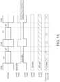
- FIG. 15schematically illustrates another “two-tiered,” blended waveform output.
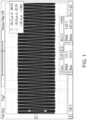
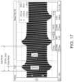
- FIGS. 16 and 17show additional examples of output blended waveforms according to embodiments.
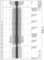
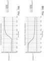
- FIGS. 18 A and 18 Billustrate transient temperature responses of a thermistor assembly to a step-increase in power and a step decrease in power, respectively.
- FIG. 19schematically illustrates a block diagram of a temperature-controllable circuit topology for an electrosurgical system.
- FIG. 20shows a temperature sensor assembly incorporated in an electrosurgical handpiece of the type shown in FIG. 23 .
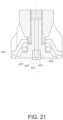
- FIG. 21shows another temperature sensor assembly incorporated in an electrosurgical handpiece of the type shown in FIG. 23 .
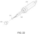
- FIG. 22shows an exploded view of a temperature sensor assembly incorporating a thermistor.
- FIG. 23shows a cross-sectional view of a portion of an electrosurgical handpiece that includes a temperature sensing assembly.
- FIG. 24shows a working example of an energizable electrode having a dielectric coating.
- FIG. 25shows a working example of an electrosurgical handpiece having an energizable electrode as in FIG. 24 .
- FIG. 26shows surface temperatures of a treatment site based on an infrared (IR) scan of the treatment site.
- IRinfrared
- FIG. 27schematically illustrates differences in tissue heating among different combinations of fundamental frequency and electrode configurations.
- FIG. 28A schematically illustrates representative dimensions of a portion of an energizable electrode having a temperature-sensor assembly incorporating a thermistor.
- FIG. 28 Bschematically illustrates representative dimensions of a portion of an energizable electrode having a temperature-sensor assembly incorporating a thermocouple.
- FIG. 29schematically illustrates representative dimensions of an energizable electrode incorporating a temperature-sensor assembly.
- FIG. 31schematically illustrates transient temperature response of a treatment site exposed to different electrosurgical waveforms.
- FIG. 32A schematically illustrates a typical, annular heated region of a treatment site arising from a direct-coupled electrode in contact with a patient's skin surface.
- FIG. 33schematically illustrates an example of a computing environment suitable for implementing one or more disclosed technologies.
- FIG. 34schematically illustrates an electrosurgical handpiece.
- a handpiececan constitute an electrosurgical instrument or device having an energizable electrode configured to treat or otherwise manipulate a target site on or in a patient's body, as well as associated power and temperature components. Accordingly, the inventive subject matter may be directed to overall systems, isolated components, alone or in various combinations.
- some disclosed electrosurgical devicesare configured to deliver energy to a patient's skin without the need for anesthetizing the patient.
- an energy flux of 4,000 Watts per square centimeter (W/cm 2 ) for about one second (1 s)probably would not ablate skin tissue, but might cause necrosis of some tissue.
- an energy flux of about 2,000 W/cm 2 applied for between about 2 seconds (s) and about 3 se.g., between about 1.9 s and about 3.1 s, such as, for example, between about 2.1 s and about 2.9 s
- Lower flux levelscan be applied for longer times, and higher flux levels might be applied for shorter times, without damaging tissues.
- a radio frequency (RF) generator systemcan include a circuit topology to provide a variety of output waveforms suitable for use in electro-surgical therapies.
- the output waveformscan arise from a combination of a plurality, e.g., two, constituent waveforms.
- one or more parameters of each constituent waveformcan be user selectable or controllable.
- an RF generatorcan operate on a fundamental frequency of about 4 MHz, or from about 400 kHz to about 13.56 MHz, or from about 500 kHz to about 8 MHz, or from about 3 MHz to about 5 MHz.
- An RF generator system disclosed hereintypically can operate on a fundamental frequency of about 4 MHz.
- Output waveforms produced by a monopolar outputcan include, for example, a continuous output and a variety of pulsed waveforms with, for example, the fundamental frequency of about 4 MHz.
- One or more of an amplitude, frequency, duty-cycle and pulse width of the output waveformcan be user controllable or selectable, and can arise from a combination of constituent waveforms.
- a continuous sine wave outputproduces a cutting tissue effect with little or minimized heating coagulation effect to the tissue adjacent the cut.
- a pulsed waveform with, for example, the fundamental frequency of about 4 MHz outputproduces a coagulation effect.
- FIGS. 1 through 5show different waveforms that may correspond to different treatment modes available from an exemplary RF generator system. These different treatment modes may result in various tissue treatment effects and may be categorized, for example, as:
- FIG. 6shows examples of various RF treatment implements including an RF powered scalpel ( 110 A- 110 D) and an RF powered ball ( 110 E).
- FIG. 6shows the surface of skin tissue 200 that was treated with RF powered treatment implements 110 A- 110 E and also shows a cross section of tissue 200 A after treatment with the RF powered treatment implements 110 A- 110 E.
- the continuous sine wave output as is shown in FIG. 1cuts tissue 200 with little coagulation effect to tissue adjacent to the cut.
- the tissue effect of the continuous sine wave output shown in FIG. 1 with scalpel 110 Ais shown in the treatment region labeled 210 A.
- the cross section of the tissue 200 A about the tissue 210 A that was cut by scalpel 110 Ashows that the cut is clean with a small amount of coagulation that results from RF energy applied to cut the tissue.
- the solely pulsed output shown in FIG. 5is designed to give a coagulation tissue effect and to not produce continuous plasma for cutting.
- the RF powered ball 110 Eis repeatedly pressed on the surface of the tissue 200 and coagulates the tissue in contact with the RF powered ball 110 E with each press of the RF powered ball 110 E on the tissue surface.
- the tissue effect of the pulsed output shown in FIG. 5 with ball 110 Eis shown in the treatment region labeled 210 E.
- the cross section of the tissue 200 A about the tissue 210 E that was treated by ball 110 Eshows that the ball made an impression of coagulation in the tissue 200 surface and as seen in the cross section 200 A.
- the combination of the two waveformsenable a combined cut and coagulation tissue effect to be produced.
- Such a combination of continuous sine waveform and the pulsed waveformis referred to as the blend mode, because the cut and coagulation tissue effects are “blended.”
- FIGS. 2 to 4show three such blend mode waveforms.
- FIG. 2depicts a continuous waveform with lots of cut and little coagulation.
- FIG. 3depicts a discontinuous waveform with a middle amount of cut and a middle amount of coagulation.
- FIG. 4depicts a discontinuous waveform with a lot of coagulation and small amount of cut.
- FIG. 2provides a waveform that produces a continuous cutting effect with increased side heating, which generates a hemostasis effect on the sides of the incision.
- Other waveformscan be produced giving more or less hemostasis and more or less of an aggressive cutting effect, as shown in FIGS. 2 - 4 .
- a blended effectis achieved with the continuous waveform shown in FIG. 2 , which has lots of cut and little coagulation, and which cuts tissue 200 with a small amount of coagulation effect to the tissue adjacent the cut.
- the tissue effect of the continuous waveform shown in FIG. 2 with scalpel 110 Bis shown in the treatment region labeled 210 B.
- the cross section of the tissue 200 A about the tissue region 210 B that was cut by scalpel 110 Bshows that the cut has a small amount of coagulation.
- a blended effectis also achieved with the discontinuous waveform shown in FIG. 3 , which has a middle amount of cut and a middle amount of coagulation, and which cuts tissue 200 with a middle amount of coagulation effect to the tissue adjacent the cut.
- the tissue effect of the discontinuous waveform shown in FIG. 3 with scalpel 110 Cis shown in the treatment region labeled 210 C.
- the cross section of the tissue 200 A about the tissue region 210 C that was cut by scalpel 110 Cshows that the cut has a middle amount of coagulation.
- FIG. 6shows another blended effect that is achieved with the discontinuous waveform shown in FIG. 4 , which has a lot of coagulation and small amount of cut, and which cuts tissue 200 with a small amount of cut and a lot of coagulation effect on the tissue adjacent to the cut.
- the tissue effect of the discontinuous waveform shown in FIG. 4 with scalpel 110 Dis shown in the treatment region labeled 210 D.
- the cross section of the tissue 200 A about the tissue region 210 D that was cut by scalpel 110 Dshows that the cut has a large amount of coagulation.
- the amount of coagulation in region 210 Dis comparable to the coagulation effect in the tissue region 210 E that was treated by a pulsed output shown in FIG. 5 .
- FIG. 7shows an image of a scalpel electrode on the left (e.g., a scalpel electrode having a shaft diameter of 1/16′′) and a ball electrode on the right (e.g., a 5 mm ball with a 1/16′′ shaft diameter) that were each used to cut a pork cutlet measuring 7/16 inches thick (e.g., 11 mm thick) and discussed in association with FIGS. 8 - 12 .
- a scalpel electrode on the lefte.g., a scalpel electrode having a shaft diameter of 1/16′′
- a ball electrode on the righte.g., a 5 mm ball with a 1/16′′ shaft diameter
- FIG. 8shows a surface view pork cutlet tissue that was treated on the left in cut mode with a scalpel electrode using a waveform similar to that shown in association with FIG. 1 at a device output of 20 (on a scale from 0-100), in the center in cut mode with a scalpel electrode using a waveform similar to that shown in association with FIG. 1 at a device output of 60 (on a scale from 0-100), and on the right in coagulation mode with a ball electrode using a waveform similar to that shown in association with FIG. 5 at a device coagulation output of 100 (on a scale from 0-100).
- FIG. 9shows another view of the pork cutlet tissue described in association with FIG. 8 .
- FIG. 10shows a view of the cross section of the pork cutlet tissue described in association with FIG. 8 , this cross-sectional view shows the depth of the tissue treated in cut mode on the left side, in cut mode in the middle, and in coagulation mode on the right-hand side.
- FIG. 11shows a surface view (above) and a top view (below) of pork cutlet tissue that was treated: on the left in cut mode with a scalpel electrode using a waveform similar to that shown in association with FIG. 1 at a device output of 20 (on a scale from 0-100), in the center in blend mode with a scalpel electrode using a waveform similar to that shown in association with FIG. 3 at a device output of 60 (on a scale from 0-100), and on the right in coagulation mode with a ball electrode using a waveform similar to that shown in association with FIG. 5 at a device coagulation output of 100 (on a scale from 0-100).
- FIG. 12shows a surface view (above) and a cross sectional view (below) of pork cutlet tissue that was treated: on the left in cut mode with a scalpel electrode using a waveform similar to that shown in association with FIG. 1 at a device output of 20 (on a scale from 0-100), in the center in blend mode with a scalpel electrode using a waveform similar to that shown in association with FIG. 3 at a device output of 60 (on a scale from 0-100), and on the right in coagulation mode with a ball electrode using a waveform similar to that shown in association with FIG. 5 at a device coagulation output of 100 (on a scale from 0-100).
- the cross-sectional viewshows the depth of the tissue treated in cut mode on the left side, in blend mode in the middle, and in coagulation mode on the right-hand side.
- FIG. 13shows one embodiment of power switch circuit topology that allows the above described variety of blend output waveforms to be produced.
- the circuitmay have two independently controllable DC circuits along with one monopolar RF circuit running at the fundamental frequency of about 4 MHz.
- the monopolar RF circuitcontinues to run at 4 MHz and two independent DC bucks are provided that controllably lessen the DC voltage that is supplied to two independent Power Switches (PSW).
- PSWPower Switches
- the two Power Switchesare switched/connected to the output independently at a rate of approximately 30 kHz. This creates the “two-tiered” output waveform as shown in FIG. 14 .
- the output voltages of the cut portion of the blend waveform and the coagulation portion of the blend waveformcan be independently adjusted, with the choice and/or pattern of adjustment giving different tissue effects.
- the power switch circuitcan be operated such that a dead time (e.g., off interval) between 30 kHz cycles may be selected.
- the dead timeis present after the cut and prior to the next cycle coagulation.
- This dead time or off period durationcan be adjusted to ensure the plasma from the previous “cut” period has time to fully extinguish before initiating the next cycle. This way, no undesired cutting between cycles occurs, and tissue only coagulates during the coagulation portion of the cycle.
- the blend waveformis pulsed at 30 kHz (33 ⁇ s).
- Buck 1sets the voltage level of a first function, e.g., a coagulation portion, of the output
- Buck 2sets the voltage level of a second function, e.g., a cut portion, of the output.
- Buck 1may be set at a higher voltage than Buck 2.
- Buck 1is set at 70 percent of its maximum voltage
- Buck 2is set at 35 percent of its maximum voltage, which is 50% of the voltage of Buck 1.
- the Pulsesets the duration of the coagulation portion for the output for one 30 kHz pulse, here the pulse is set at 100 percent.
- the Gatesets the overall duration of the output waveform for each 30 kHz pulse. For example, if the Gate is set to 100 then the composite pulse is on for the entire 30 kHz period (33 ⁇ s). If, as is shown in FIGS. 16 and 17 , the Gate is set at 50 percent, then the composite pulse of the RF emission will have a duration of 50 percent of the period (16.5 ⁇ s). And here, because the Pulse is set at 100, the output pulse will be on for the entire 16.5 ⁇ s that the RF emission is on. Accordingly, by adjustably controlling the foregoing parameters, desired blended waveform profiles may be achieved.
- one or more of a waveform's frequency, amplitude, and pulse-widthmay be user-selectable, for example, via a user interface element 202 displayed by a software control application, or by physical switches or controls on an electrosurgical generator.
- the cut on the left sideis accomplished by setting Buck 1 at 20 and there is no setting of Buck 2, Pulse, or Gate, because these are not applicable in Cut mode.
- the cut in the middleis accomplished by setting Buck 1 at 60 and there is no setting for Buck 2, Pulse, or Gate, because these are not applicable in Cut mode.
- the coagulation on the right-hand sideis accomplished by setting Buck 1 at 100 and the Pulse at 100, there is no setting for Buck 2 or Gate, because these are not applicable in coagulation mode.
- the cut on the left sideis accomplished by setting Buck 1 at 20 and there is no setting of Buck 2, Pulse, or Gate, because these are not applicable in Cut mode.
- the blend of cut and coagulation in the middleis accomplished by setting Buck 1 at 60, Buck 2 at 54, Pulse at 100, or Gate at 100.
- the coagulation on the right-hand sideis accomplished by setting Buck 1 at 100 and the Pulse at 100, there is no setting for Buck 2 or Gate, because these are not applicable in coagulation mode.
- the RF generator systemmay include an improved response time temperature sensor that is well-suited for use in non-invasive aesthetic treatments employing an RF generator system.
- the improved response time temperature sensorresponds more quickly than other temperature sensors and includes a temperature sensor/electrode assembly.
- the RF generator systemprovides RF energy (e.g., 4 MHz sinusoidal RF energy) that is applied to the tissue surface of a treatment subject (e.g., a patient) to cause heating of the subject's dermal, epidermal and/or deeper tissue layers.
- a topical solutionsuch as gel (e.g., ultrasound gel), lotion, or another substance may be applied to the surface of the subject's tissue (e.g., skin) prior to non-invasive RF energy treatment in order to reduce friction between the electrode and the surface, and/or to improve thermal or electrical conductivity from the patient-contact surface to the tissue surface of the treatment site.
- the RF electrodeis placed on a tissue surface (e.g., skin surface) of the treatment subject to which the topical solution has already been applied.
- the RF generatorinitiates an RF emission from an electrosurgical handpiece, and more particularly from the energizable electrode contacting the treatment site.
- the clinicianmoves the electrode tip of the electrosurgical handpiece in contact with the subject's tissue surface over a treatment area of the subject's tissue surface (e.g., skin surface). In some embodiments, the clinician moves the electrode tip over the subject's tissue surface continuously and without pausing or stopping.
- This treatmentresults in an area of elevated temperature, preferably a substantially uniform area of elevated temperature, with an elevated temperature that preferably measures around 42 C+/ ⁇ 1 C which is maintained for a given treatment time of from about 5 minutes to about 25 minutes, such as, for example, from about 7 minutes to about 10 minutes.
- the RF generatorcan achieve an elevated temperature range of from about 39 C to about 46 C, as from about 41 C to about 44 C.
- the temperature elevation that is targetedmay vary from patient to patient depending on the size of the treatment area, the sensitivity of the treatment area, and the tolerance of the patient amongst other factors.
- the selected duration of the treatment timemay vary depending on the size of the treatment area, the targeted depth of the treatment area, etc. Depending on such factors, suitable treatment times may range from about 5 minutes to about 50 minutes, or about 30 minutes.
- an improved response time temperature feedback sensoris required.
- the disclosed embodimentsadvantageously provide such an improved sensor.
- the improved response time temperature feedback sensorhas a response time constant of about 1 second or less.
- FIGS. 18 A and 18 Bdepict transient temperature responses to step changes in power for a working embodiment of a thermal sensor (e.g., a thermistor) in a 25 mm TempsureTM electrode assembly, available from Cynosure, Inc, Westford, Mass.
- a thermal sensore.g., a thermistor
- FIG. 18 Ashows the transient response to an increase in temperature.
- FIG. 18 Bshows the thermistor assembly response time to a decrease in temperature.
- the temperature sensor as assembled in the Tempsure electrodesshows a measurement response time of 2 to 3 seconds when warming from skin temperature (35° C.) to a target treatment temperature 42° C., to within 1° C.
- Temperature reference cold and warm platesmay be held constant with a heat exchanger to less than 0.5° C. of target temperatures
- Thermal time constant ⁇ of this 25 mm temperature sensing electrodeis defined mathematically as the time it takes the temperature sensing electrode to reach 63.2% of the target temperature from its initial temperature, a difference of 7° C. 63.2% of 7° C. is 4.42° C.
- the thermal time constant of the assembled temperature sensoris therefore approximately 1 second for both graphs (add or subtract 4.42° C. from start of measurement on the curve and find elapsed time).
- the “Thermal Time Constant”, under zero conditions,is the time it takes a temperature sensor, e.g. a thermistor, to change 63.2% of the total difference between the initial and the final body temperature, when subjected to a step function change in temperature. In simple terms, it represents in time, how long it takes a temperature sensor to recover up to 50% of its initial resistance.
- a temperature changeneeds to be applied. However, if that change is too slow, the measuring would be of the ambient rate of change; not the temperature sensor's response to the change. Therefore, it is preferable to use a temperature change as close to instantaneous as possible.
- the temperature sensor assembly's temperature sensor feedbackis measured by a control system communicatively coupled to the RF amplifier.
- the control systemcompares the measured temperature of the temperature sensor to a user selected temperature.
- the control systeminterrupts (e.g., diminishes or altogether stops) the RF emission.
- a duty cycle of the RF emissioncan be adjusted (e.g., decreased) to maintain a temperature of a patient treatment site at or below an upper threshold temperature.
- the electrode assemblymoves to a cooler zone in the treatment area, the temperature sensor in the electrode assembly can detect a temperature below a user-selected temperature.
- the control systemcan re-engage or increase the RF emission from the electrode assembly. This process continues throughout a treatment session to maintain the desired temperature e.g., the user selected temperature, throughout the treatment area.
- FIG. 19is a block diagram that shows the control system interacting with the temperature sensor feedback around the treatment of a subject.
- AC poweris converted to DC voltage in the AC to DC converter.
- the DC voltagetravels through the DC Buck Converter, which controllably lessens the supplied DC voltage.
- the supplied DC voltageis delivered to the RF Power Amplifier and then travels to patient isolation (e.g., a transformer). From patient isolation, the RF power is then delivered to the Patient.
- the Patient's skin surfaceis measured by the Temperature Measurement step, which utilizes a temperature sensor in the handpiece.
- the handpiece communicationcommunicates the patient skin surface temperature measurement to the control system. In some embodiments, the handpiece communication optically communicates the temperature measurement to the control system.
- the control systemcompares the patient skin surface temperature to the desired patient skin surface temperature.
- the desired patient skin surface temperaturemay be defined as a threshold temperature and/or a threshold temperature within a range of temperatures, e.g. +/ ⁇ 2 C from the threshold.
- the control systemenables and controls the DC Buck Converter and the RF Power Amplifier based on the how the patient skin surface measurement compares to the temperature threshold.
- the measured skin surface temperaturemeasures at or higher than the temperature threshold or the top of the threshold range.
- the control system's enable and controlshuts off the DC Buck Converter supply of DC voltage to the Amplifier, thereby disabling the RF power previously being delivered to the Patient.
- the temperature measurement feedback loopmay optionally continue measuring the patient skin surface temperature in the Temperature Measurement step.
- the control system's enable and controlwill enable the DC Buck converter and the RF Amplifier to resume the supply of DC voltage, thereby enabling delivery of the RF power again. In this way, the temperature of the patient's skin surface temperature is closely monitored and controlled.
- the measured skin surface temperaturemeasures at or higher than the temperature threshold or the top of the threshold range.
- the control system's enable and controlinhibits or lessens the DC Buck Converter supply of DC voltage to the Amplifier, thereby lessening the RF power previously being delivered to the Patient.
- the temperature measurement feedback loopwill continue measuring the patient skin surface temperature in the Temperature Measurement step.
- the control system's enable and controlwill enable the DC Buck converter supply of DC voltage to the Amplifier to increase the supply of DC voltage thereby enabling delivery of more RF power. In this way, the temperature of the patient's skin surface is closely monitored and controlled.
- the improved response time temperature feedback sensor assemblyhas several notable requirements.
- the thermal conduction between the subject's tissue surface (e.g., skin surface) and the temperature sensorshould be maximized. Or, stated differently, the thermal resistance between the patient and the temperature sensor should be minimized. Additionally, the temperature sensor thermal mass should be minimized to allow for detection of fast changes in temperature of the subject's tissue surface. Conversely, thermal conduction between the thermal mass of the electrode emitting the RF signal and the temperature sensor should be minimized. Or, stated differently, the thermal resistance should be maximized.
- the thermal conduction between the electrode thermal mass and the temperature sensoris minimized by using a thermally insulated material that thermally insulates the temperature sensor assembly from the electrode assembly. Suitable thermally insulated materials include machinable plastic such as ULTEMTM available from SABIC (Riyadh, Saudi Arabia). Any of a number of thermally insulative materials are known and may be employed.
- a goal of some electrosurgical treatmentis to drive electricity into the tissue and uniformly heat the tissue under the electrode surface.
- high frequencye.g., 4 MHz
- the desired tissue depthmay be achieved with surface uniformity.
- Lower frequency transmissionsmay dissipate too much energy in the dielectric material and can provide poor energy coupling between the energizable electrode and a treatment site.
- capacitive coupling of electrodeshelps achieve uniform distribution of electricity. With the disclosed, capacitively coupled approach, there is less thermal loss into the dielectric and relatively less power is lost. Therefore, more power is delivered into the tissue, compared with other devices that use a direct coupled approach and concomitantly cause electrode heating (akin to a hot rock).
- a capacitive probe according to the embodimentscan help fulfill these goals. If a selected electrode is purely resistive (as opposed to capacitive) then this limits the ability to achieve uniformity and opposes the goal of a higher amount of power delivered to tissue depth as uniformly as practicable.
- the electrodeis made from an electrically conductive material (e.g., gold plated brass). Generally, materials employed to make electrodes may also be very thermally conductive (e.g., aluminum, gold, brass, etc.). In addition, most electrode constructions have a relatively large thermal mass. In an embodiment, the electrode has much more thermal mass than the temperature sensor (e.g., >100:1). One goal is to measure the subject's tissue surface temperature, rather than the temperature of the electrode itself, because a primary objective is to reach and maintain a target temperature of the subject's tissue surface (e.g., skin surface) throughout the treatment area.
- an electrically conductive materiale.g., gold plated brass
- materials employed to make electrodesmay also be very thermally conductive (e.g., aluminum, gold, brass, etc.).
- most electrode constructionshave a relatively large thermal mass. In an embodiment, the electrode has much more thermal mass than the temperature sensor (e.g., >100:1).
- One goalis to measure the subject's tissue surface temperature,
- the electrodemay have a large thermal mass, and may be at a different temperature than the subject's tissue surface (e.g., skin surface), therefore thermal conduction from the electrode to the temperature sensor risks causing a skew in the resulting temperature feedback.
- the large thermal mass of the room temperature electrodemay saturate the temperature sensor with about 25° C. thermal conduction thus obscuring the subject's higher tissue surface temperature.
- the temperature sensorwould indicate a subject's tissue surface temperature lower than it is, which is a potential safety problem.
- the temperature sensor thermal massmay be minimized to enable an improved speed of detection of changes in tissue surface temperature. Minimization may be achieved by controlling the amount of material (thermal mass) in contact with the temperature sensor (e.g., a thermistor). For example, the amount of material in contact with the temperature sensor may be minimized. Additionally, thermal conduction between the subject's tissue surface and the temperature sensor should be maximized (e.g., the thermal resistance between the tissue surface and the temperature sensor, R ⁇ , should be minimized).
- FIGS. 4 - 7illustrate aspects of an electrosurgical handpiece including a temperature sensor assembly.
- the temperature sensor assemblyincludes a temperature sensor and housing to protect the temperature sensor.
- the housingcan define a patient contact surface.
- a patient contact surface of a temperature sensor assemblymay be defined by a cylinder that surrounds all or a portion of the temperature sensor.
- the patient contact surfacemay extend longitudinally past (e.g., may be slightly “proud” relative to) a patient contact surface defined by the energizable electrode to ensure thermal contact between the housing and a treatment site.
- the temperature sensormay be surrounded by a thermally conductive housing.
- a thermally conductive epoxy, paste, or other material suitable for reducing thermal contact resistance between the temperature sensor and the housingcan enhance thermal contact between the temperature sensor and the housing. Such thermal contact can ensure that a temperature of the temperature sensor and a temperature of the housing remain approximately the same.
- combining a low-mass housing and a low-mass temperature sensorcan provide a rapid thermal response (e.g., a low thermal time constant) for the temperature sensor assembly.
- FIGS. 20 - 21show cross-sections of a temperature sensor assembly 402 that may be used in an electrosurgical handpiece.
- a temperature sensor 410may be disposed inside a thermally conductive housing 420 (e.g., a thermally conductive cylinder, a thermally conductive sheath, a thermally conductive envelope).
- the temperature sensor 410may be thermally coupled to the housing 420 such that the entire surface area of the temperature sensor 410 is in direct contact with the thermally conductive housing 420 and/or with a thermal epoxy or other coupling that is also in contact with the housing 420 .
- the thermal fluxcan be maximized, which can be conducted into the temperature sensor 410 .
- the thermally conductive housing 420may include a first patient contact surface 422 , an inner surface 424 that is positioned opposite the first patient contact surface 422 , and an outer wall 426 that extends transversely relative to the first patient contact surface 422 .
- the thermally conductive housing 420may be made from a relatively small amount of material (e.g., as small an amount of material as is possible) to limit the thermal mass and thereby improve the response time (e.g., quicken the response time).
- the housing 420may be made from a thermally conductive material, e.g., having a thermal conductivity of about 200 Watts/meter-Kelvin (W/m-k), or about 400 W/m ⁇ K.
- a thermally conductive and electrically non-conductive materialsuch as, for example, AlN (aluminum nitride) or other ceramic material, may be desirable.
- the portion of the temperature sensor assembly in contact with the patient or subjectmay be exaggerated to increase surface area in contact with the patient (or subject) and to increase thermal conduction to the temperature sensor 410 therethrough.
- the portion of the temperature sensor assembly 402 in contact with the patienthas a larger surface area than the portion of the temperature sensor 410 that it contacts.
- the exaggerated surface area of the point of contact of the temperature sensor assembly with the tissue surfaceis desirable because the tissue is a relatively poor thermal conductor and exaggerating the area in contact with the tissue, compensates for the relatively poor conductivity of the tissue relative material in contact therewith (e.g., metal point of contact of the temperature sensor assembly).
- any number of shapes of the portion of the temperature sensor assembly in contact with the tissuemay be selected, for example, a disk (e.g., like a hockey puck), a rectangle, a sphere, or a mushroom cap shape.
- the first patient contact surface 422may flare out radially from a shaft or body of the sensor.
- the flared portionmay have a radial extension that is a multiple of the general diameter of the shaft or body of a temperature sensor.
- the diameter of a mushroom or disk tissue contacting portionmay be at least 2, 3, 4 5, 6, 7, 8, 9, 10, 15, 25, 30, or more times the diameter of the temperature sensor body, as the mushroom contact portion and associated temperature sensor are oriented in FIG. 20 , for example.
- the first patient contact surface 422may be tailored (e.g., smoothed such that what contacts the tissue surface lacks sharp or pronounced edges) to comfortably contact the patient's tissue surface when the device is moved across the subject's tissue surface (e.g., skin surface).
- the temperature sensor assembly 402may also include an insulator 430 .
- the insulator 430may be outside of the housing 420 and between the housing 420 and an energizable electrode 450 (of which only a portion is depicted), and may span a gap between the outer wall of the housing 420 and the electrode 450 .
- the insulator 430may completely fill the gap in an embodiment.
- the insulator 430may only partly fill the gap while the remaining volume in the gap is filled with a gas and/or another dielectric material.
- the insulator 430may minimize the thermal conduction between the thermal mass of the electrode 450 and housing 420 (and the temperature sensor 410 ).
- the insulator 430may be or use a material that thermally insulates the temperature sensor assembly 402 from the electrode assembly.
- Suitable thermally insulated materialsinclude machinable plastic such as ULTEMTM available from SABIC (Riyadh, Saudi Arabia). Any of a number of thermally insulative materials are known and may be employed.
- the edges of the temperature sensor assembly portion in contact with the patiente.g. the first patient contact surface 440 , are rounded off such that it is mushroom shaped, which provides patient comfort as the sensor assembly is swept along the patient's skin surface.
- This mushroom tip surface and the adjacent cylinder, e.g. housing 420act as a housing around the temperature sensor 410 , making the assembly well suited for fast response temperature feedback.
- the mushroom shapemay protrude in part past a surface of the electrode, and may provide a larger surface area compared to a flat tip for greater contact with the treatment surface.
- a temperature sensor assembly that uses a thermocouple instead of a thermistormay be similar to the assembly shown in FIG. 22 , albeit with a thermocouple instead of a thermistor.
- the housing used for a thermocouplemay have a shorter outer wall compared to the outer wall of the housing 520 , as described, for example, with respect to FIGS. 28 A-B . That reduction in material used for the housing can reduce the mass of the housing, and thus a thermal time constant for the temperature sensor assembly.
- a thermocouplemay have less mass than a thermistor, which can further enhance transient response times.
- these advantagesmay not outweigh disadvantages of many thermocouples, including inaccuracy arising from, for example, calibration drift, signal cross-talk with other electrical circuits, etc.
- FIG. 23depicts an example of a portion of an electrosurgical handpiece 604 in cross-section that includes a temperature sensing assembly.
- the temperature sensing assemblymay be the same or similar to the temperature sensing assembly 402 or 502 .
- the housing 620 and the insulator 630may be analogous to housing 420 , 520 and to insulator 430 , 530 , respectively.
- the portion of the figure within the dotted line boxmay represent the view as shown in FIG. 21 .
- the handpiece 604may include an energizable electrode 640 defining a second patient-contact surface 642 extending outward of the outer wall of the housing 620 .
- a low thermal mass materiale.g., a material having a lower thermal mass that the tissue being contacted, may be used for the electrode 640 to offer further improvement in temperature measurement accuracy of the temperature sensor, because it avoids cross talk between a thermal mass of the electrode 640 and the temperature sensor in the temperature sensing assembly.
- an electrode that has a low thermal time constantcan readily change temperature with its environment, improving a temporal response of the temperature sensing assembly relative to an electrode/temperature sensing assembly in which the electrode as a relatively higher thermal time constant.
- the temperature of the subject's skin surfaceis measured rather than the temperature of the electrode 640 itself.
- the thermal mass of the electrode 640 surrounding the temperature sensoris as close to zero as is possible. In this way, interference of any thermal mass of the electrode might be avoided.
- the electrode 640may be a metal foil that surrounds a void and has a temperature sensor disposed inside the void and in contact with the subject's tissue surface.
- any gassuch as air in the void acts as the insulator and has minimized mass to cross talk with the temperature sensor.
- the electrode 640may be a metal foil that surrounds a low thermal mass solid such as fiber insulation (e.g., plastic, pulp, paper, glass, etc.) or solid plastic and has a temperature sensor disposed inside the metal foil and in contact with the subject's tissue surface and likewise this low thermal mass material minimizes cross talk with the temperature sensor thereby improving accuracy of the temperature sensing of the subject's skin surface.
- the electrosurgical handpiece 604may be used as a capacitive heating probe to provide a tuned uniform deep tissue heating system.
- a metal inner probe bodye.g., the energizable electrode 640
- has an exterior surfacee.g., second patient contact surface 642 , that may be covered with a dielectric coating 644 . Absent the dielectric coating 644 , the second patient contact surface 642 may be the surface of the electrode itself. When present, the dielectric coating 644 becomes the second patient contact surface 642 , as it, and not the electrode, will come in contact with the treatment surface.
- the dielectric coating 644may be employed to enable the treatment current to be delivered homogenously over the entire area where the dielectric coated surface of the electrode is in contact with the subject's skin surface.
- the constraints on the dielectricmay include: the material property, thickness of coating, and applied voltage.
- HFhigh frequency energy source
- ITUInternational Telecommunications Union
- the coating 644may have a high dielectric constant, e.g., between about 4 to about 8, e.g., between about 5 and about 7, at the operating frequency, e.g., at 4 MHz.
- Dielectric constants of about 2, e.g., between about 1.9 and about 2.1may be considered low in this context.
- dielectric coatings that may be employeddesirably have properties that include the ability to be applied with a controllably even thickness, e.g., at a uniform thickness over the second patient contact surface.
- the dielectric coatingmay desirably be rugged enough for multiple uses and may be resistant to chipping and cracking.
- the dielectric coatingmay be biocompatible with human tissue; impervious to fluids; and non-absorptive to moisture.
- the dielectric coatingmay also have a low coefficient of friction against human tissue.
- the dielectric coatingmay have a relatively high loss tangent for a polymer at 4 MHz, e.g. a loss tangent of at or above 0.5. Low loss tangents, e.g., for other materials, may be in the range of 0.0004 to 0.001.
- the high dielectric constant, relatively low thickness (e.g. about 0.01 inches) of the dielectric applied to the surface, and the frequency range of the RF disclosed hereincan work in combination to inhibit or prevent arcing to the tissue.
- the tissuemay be protected from arcing damage due to the system design that controls voltage, dielectric material thickness, frequency, and material dielectric constant.
- Previous capacitive tissue heating systemshave used medium frequency energy sources (“MF” defined by the ITU as 300 kHz-3 MHz), which are not as effective at driving deep Joule tissue heating with capacitive probes due to dielectric losses and corresponding reduction of current to deep tissue.
- MFmedium frequency energy sources
- the RF energy sourceoperates at 4 MHz and conveys a waveform to the electrode having a frequency of 4 MHz, i.e. the operating frequency.
- the capacitive energy probemay have a diameter that is greater than 40 mm.
- the dielectric coatinghas less impedance to high frequencies and the 4 MHz system is a relatively high frequency system and therefore presents lower dielectric loss.
- a 400 kHz systemis capable of delivering substantially less current to deep tissue than the 4 MHz system when using a capacitive heating probe as described.
- the handpiece 604may further include a shaft 650 extending proximally from the energizable electrode 640 and defining a first internal bore 652 extending longitudinally of the shaft 650 .
- the insulator 630may extend through an opening (see opening 744 in FIG. 24 ) in the energizeable electrode 640 and into the first internal bore 652 of the shaft 650 .
- the shaft 650may be in contact with the energizeable electrode 640 at a shoulder 646 of the electrode.
- the energizeable electrode 640is energized by an RF generator (not shown).
- the insulator 630may extend from a distal end positioned adjacent the first patient-contact surface of the housing 620 , and the second patient-contact surface 642 to a proximal end positioned within the first internal bore 652 .
- the insulator 630may have a second internal bore 656 .
- the internal bore 652may have one or more first threads 654 a
- the insulator 630may have one or more second threads 654 b .
- the first and second threads 654may be complementary and matingly engageable with each other. When mated together, via the threads 654 or by other coupling means, the shaft 650 and the insulator 630 may capture the energizeable electrode 640 between them.
- the energizeable electrode 640When captured, the energizeable electrode 640 may be generally fixed such that it cannot move longitudinally with respect to the shaft 650 or the insulator 630 . In some embodiments, the energizeable electrode 640 may be free to rotate about the longitudinal axis 660 , and in other embodiments, the energizeable electrode 640 may be rotationally fixed. The energizeable electrode 640 may, in some embodiments, be able to pivot with respect to the shaft such that the axis of the shaft is at an angle to the longitudinal axis 660 to allow the energizeable electrode 640 to follow contours on the treatment surface and provide greater comfort for the human operator.
- the handpiece 604may further include an electrical conductor 628 extending proximally within the handpiece 604 from the temperature sensor in the housing 620 and through the second internal bore 656 .
- the electrical conductor 628may conduct a signal from the temperature sensor to a control system, or to a communication component (not shown) in the handpiece that can transmit the temperature sensor signal to a control system wirelessly or via a wire.
- the first patient-contact surface and the second patient-contact surface 642may be co-centrically aligned with each other.
- co-centrically alignedmeans each respective centroid in a plurality of centroids overlaps with or is coextensive with one of the other centroids, or a line joining two of the centroids is substantially parallel with a longitudinal axis of related structure.
- the centroids of the first and the second patient-contact surfacesmay be spaced apart from each other, but they are aligned substantially axially relative to a longitudinal axis 660 of the housing and/or the electrode.
- FIGS. 24 and 25show examples of electrodes and capacitive probes according to various embodiments.
- FIG. 24shows a proximal view (right) and a distal view (left) of an embodiment of an energizable electrode 740 .
- the second patient contact surface 742is visible on the electrode on the left.
- the electrode 740may be coated with a dielectric material.
- the energizeable electrode 740defines an opening 744 in which a temperature sensing assembly may be positioned.
- a shoulder 746may surround the opening 744 and extend distally.
- FIG. 25shows an embodiment of an electrosurgical handpiece 704 , that may be used, for example, as a capacitive probe.
- the electrosurgical handpiece 704may be an embodiment of the handpiece 604 , and may use the energizeable electrode 740 , or an energizeable electrode 740 ′ that may be similar to the energizeable electrode 740 .
- the electrosurgical handpiece 704as shown, has a temperature sensing assembly positioned at its center such that the first patient contact surface 722 is visible on the distal side. Also visible is a shaft 750 which may be graspable by a human or robotic operator of the handpiece 704 .
- FIG. 26shows treatment results using probes such as those shown in FIGS. 24 and 25 .
- the treatment resultsdemonstrate uniform tissue heating or substantially uniform tissue heating on the body of a subject as measured by skin surface temperature using an IR camera.
- the probes shown in FIGS. 24 and 25were attached to an RF generator providing continuous sinusoidal RF energy at a fundamental frequency of about 4 MHz.
- the probewas applied to the surface of a subject's skin and was moved by the clinician over the subject's skin surface to provide an increase in temperature with a treatment temperature measured at the skin surface of 34.7 C.
- the temperature sensorwas set to a temperature of 34.7 C and the sensed temperature sensor feedback is measured by the control system for the RF amplifier (discussed above).
- the control system for the RF amplifiercompares the temperature measured by the temperature sensor to the user selected temperature and when the measured temperature feedback from the temperature sensor equals or exceeds the user selected temperature, the control system interrupts the RF emission.
- the control systemre-enables the RF amplifier and the RF emission resumes.
- the probemust be moved over the surface of the skin substantially continuously so that the temperature sensor functions without interruption. This avoids over- and under-treatment.
- the described probeshould not be used in stamping mode, because there would be interruption in RF energy due to exceeding the user selected temperature.
- FIG. 27is a depiction of the differences in surface heating of the skin that occur with three different embodiments of probes.
- the left side in FIG. 27shows a direct coupled probe having dimensions similar to the probe shown in FIGS. 24 and 25 .
- the middle of FIG. 27shows a capacitively coupled probe having dimensions similar to the probe shown in FIGS. 24 and 25 , but operating at an RF frequency of 500 kHz and with a dielectric.
- the right side in FIG. 27shows a capacitively coupled probe operating at an RF frequency of 4 MHz and with a dielectric similar to the probe shown and described in association with FIGS. 24 and 25 .
- the directly coupled probe and the probe operating at an RF frequency of 4 MHzprovide relatively deep heating of tissue.
- the probe operating at an RF frequency of 500 kHzprovides relatively shallow heating of tissue due to power losses in the electrode dielectric coating and subsequent electrode heating.
- FIGS. 28 A-B , 29 and 30illustrate various possible dimensions that be used in embodiments of the temperature sensing assembly and the electrosurgical handpiece.
- the housingmay have a width w at the first patient contact surface that may be less than or equal to about 5 mm.
- the insulator 2830may have a diameter d (or width, if not circular) that may be between about 10 mm and about 90 mm.
- the height of the outer wall of the housingmay extend upward to a height H in order to maintain a thermally isolated and insulated space around the entire temperature-sensitive body of the thermistor.
- the outer wallmay only extend to a shorter height H′, because only the tip end of the thermocouple is temperature-sensitive.
- the conductive annulus of the electrode 2950may have a width greater than or equal to about 5 mm, as defined between an outer diameter of the electrode that is proximal to the perimeter of the handpiece and an inner diameter of the electrode that is proximal to an outer diameter of the insulator 2930 .
- the handpiecemay have an overall diameter (or width) phi, for example, of about 100 mm.
- the insulatormay have a diameter d that is large, relative to the width of the electrode annulus, e.g., d between about 34 and 90 mm.
- the insulatormay have a diameter d that is smaller than the width of the electrode annulus, e.g., d between about 10 and about 33 mm.
- a larger and/or more thermally resistant insulatormay be desirable to minimize or reduce effects of a heated electrode on the thermal sensor.
- Thermal resistance of an insulatorcan be based on a combination of material and thickness along heat-transfer direction. For example, an insulator with a high thermal resistance placed between the electrode and the housing can inhibit heat-transfer between the two and improve measurement accuracy relative to skin temperature.
- a larger electrode relative to the insulatormay be desirable to provide a larger treatment surface.
- the first patient contact surface of the housingmay generally be in the same plane as the surface of the electrode, or may protrude past the surface of the electrode, for example, in a rounded manner as shown in FIGS. 28 A , B.
- the protruding embodimentmay increase the surface area and therefore the thermal contact area of the first patient contact surface relative to a non-protruding embodiment, and may therefore provide a more accurate or stable temperature measurement.
- FIG. 30shows two possible embodiments having different diameters d of the insulator.
- the insulator 3030 ahas a large diameter relative to the width of the electrode 3050 a , and reduces the overall surface area of the electrode.
- the insulator 3030 bhas a small diameter relative to the width of the electrode 3050 b , such that the electrode has a relatively larger surface area.
- Other possible embodiments with different relative widths of the insulatormay be used without departing from the disclosed concepts.
- FIG. 31is a graph of skin surface temperature vs. time for a probe, as described in association with FIG. 27 and FIGS. 24 and 25 , operating at 500 kHz, and a probe operating at 4 MHz.
- a probeoperating at 500 kHz
- a probeoperating at 4 MHz.
- two capacitive treatmentsare given to the same subject and the same anatomical area for the same amount of time using two different energy sources with different frequencies.
- Surface temperatureis measured using an infrared (IR) camera.
- IRinfrared
- the MF 500 kHz energy sourceheats the surface of the tissue for about 8 minutes (here heating is judged to begin when the surface temperature reaches 39° C.) at the desired temperature, but when the energy is removed, at about the time of 10.5 minutes on the X-axis, the surface of the skin quickly cools down, which is indicative of skin and shallow tissue heating only (the deeper tissues have not been heated).
- the skin temperatureremains significantly higher for a longer period, which is indicative of deeper tissue heating with the 4 MHz device than with the 500 kHz device.
- FIG. 32 Ashows a direct-coupled electrode 3202 having a relatively small surface area in contact with a patient's skin surface.
- exemplary direct coupled electrodesinclude the Glidesafe 15 mm electrode sold with the Penevé® Wrinkle Reduction System, which is available from Cynosure, Inc.
- the active area of the directly coupled electrode and the skin effectlimits the depth of the electrical current that travels from the direct coupled electrode to the patient's tissue.
- the current path 3206travels only on the surface of the electrode 3202 until it encounters resistance, e.g. the skin surface 3204 .
- the path of the electrical dischargeresults in a ring of current 3208 being delivered to the subject's surface tissue.
- FIG. 32 Bshows a capacitively coupled electrode 3212 according to various embodiments having a relatively large surface area (e.g., at 60 mm) having a dielectric coating 3220 in contact with the patient's skin surface.
- the electrode 3212may be similar to the electrode described in association with FIGS. 24 and 25 .
- the electrode 3212is in contact with the patient's skin surface 3214 via the dielectric coating 3220 .
- the current path 3216provides a uniform and homogenous discharge of electrical current over the entire surface of the coated electrode.
- the path of the capacitively coupled electrical current dischargeresults in a uniform/homogeneous region of treatment 3218 .
- this homogenous region of treated tissueis like a cylinder of tissue in which the interior of the sphere of tissue was uniformly or homogenously treated with electrical current. More specifically, the surface of the treated tissue is like a circle 3218 having uniform treatment at and inside the circumference of the circle.
- the tissue beneath uniformly treated circleis treated to a depth, but, due to anatomical variation in the tissue, the shape of the treated area at depth may vary. However, in an ideal case of uniform tissue from surface to depth, the treated area at the depth is in the shape of a uniformly treated cylinder.
- the capacitively coupled probe discussed hereis circular, but such a probe may have any number of shapes suited to use on tissue, such as square, rectangular, rhombus, or another ellipse, etc.
- FIG. 33illustrates a generalized example of a suitable computing environment 1400 in which described methods, embodiments, techniques, and technologies relating, for example, to the control systems of electrosurgical generators discussed herein may be implemented.
- a control system of an electrosurgical generatormay be implemented by a computing system.
- the computing environment 1400is not intended to suggest any limitation as to scope of use or functionality of the technologies disclosed herein, as each technology may be implemented in diverse general-purpose or special-purpose computing environments.
- each disclosed technologymay be implemented with other computer system configurations, including wearable and handheld devices, multiprocessor systems, microprocessor-based or programmable consumer electronics, embedded platforms, network computers, minicomputers, mainframe computers, smartphones, tablet computers, data centers, audio devices, and the like.
- Each disclosed technologymay also be practiced in distributed computing environments where tasks are performed by remote processing devices that are linked through a communications connection or network.
- program modulesmay be located in both local and remote memory storage devices.
- a computing environmentmay have additional features.
- the computing environment 1400includes storage 1404 , one or more input devices 1405 , one or more output devices 1406 , and one or more communication connections 1407 .
- An interconnection mechanismsuch as a bus, a controller, or a network, interconnects the components of the computing environment 1400 .
- operating system softwareprovides an operating environment for other software executing in the computing environment 1400 , and coordinates activities of the components of the computing environment 1400 .
- the store 1404may be removable or non-removable, and can include selected forms of machine-readable media.
- machine-readable mediaincludes magnetic disks, magnetic tapes or cassettes, non-volatile solid-state memory, CD-ROMs, CD-RWs, DVDs, magnetic tape, optical data storage devices, and carrier waves, or any other machine-readable medium which can be used to store information, and which can be accessed within the computing environment 1400 .
- the storage 1404stores instructions for the software 1408 , which can implement technologies described herein.
- the store 1404can also be distributed over a network so that software instructions are stored and executed in a distributed fashion. In other embodiments, some of these operations might be performed by specific hardware components that contain hardwired logic. Those operations might alternatively be performed by any combination of programmed data processing components and fixed hardwired circuit components.
- the input device(s) 1405may be a touch input device, such as a keyboard, keypad, mouse, pen, touchscreen, touch pad, or trackball, a voice input device, a scanning device, or another device, that provides input to the computing environment 1400 .
- the input device(s) 1405may include a microphone or other transducer (e.g., a sound card or similar device that accepts audio input in analog or digital form), or a computer-readable media reader that provides audio samples to the computing environment 1400 .
- the output device(s) 1406may be a display, printer, speaker transducer, DVD-writer, or another device that provides output from the computing environment 1400 .
- the communication connection(s) 1407enable communication over a communication medium (e.g., a connecting network) to another computing entity.
- the communication mediumconveys information such as computer-executable instructions, compressed graphics information, processed signal information (including processed audio signals), or other data in a modulated data signal.
- Machine-readable mediaare any available media that can be accessed within a computing environment 1400 .
- machine-readable mediainclude memory 1402 , storage 1404 , communication media (not shown), and combinations of any of the above.
- Tangible machine-readable (or computer-readable) mediaexclude transitory signals.
- some disclosed principlescan be embodied in a tangible, non-transitory machine-readable medium (such as microelectronic memory) having stored thereon instructions, which program one or more data processing components (generically referred to here as a “processor”) to perform the digital signal processing operations described above including estimating, computing, calculating, measuring, adjusting, sensing, measuring, filtering, addition, subtraction, inversion, comparisons, and decision making.
- a processordata processing components
- some of these operationsmight be performed by specific electronic hardware components that contain hardwired logic. Those operations might alternatively be performed by any combination of programmed data processing components and fixed hardwired circuit components.
- One or more of the principles of the disclosed embodimentscan be incorporated in various system configurations to achieve any of a variety of system characteristics.
- Systems described in relation to particular applications, or uses,are merely examples of systems incorporating the principles disclosed herein and are used to illustrate one or more aspects of the disclosed principles. Accordingly, electrosurgical systems having attributes that are different from those specific examples discussed herein can embody one or more of the principles, and/or can be used in applications not described herein in detail, for example in ablative surgical applications. Accordingly, such alternative embodiments also fall within the scope of this disclosure.
Landscapes
- Health & Medical Sciences (AREA)
- Surgery (AREA)
- Life Sciences & Earth Sciences (AREA)
- Engineering & Computer Science (AREA)
- Biomedical Technology (AREA)
- Otolaryngology (AREA)
- Nuclear Medicine, Radiotherapy & Molecular Imaging (AREA)
- Heart & Thoracic Surgery (AREA)
- Medical Informatics (AREA)
- Molecular Biology (AREA)
- Animal Behavior & Ethology (AREA)
- General Health & Medical Sciences (AREA)
- Public Health (AREA)
- Veterinary Medicine (AREA)
- Plasma & Fusion (AREA)
- Physics & Mathematics (AREA)
- Surgical Instruments (AREA)
Abstract
Description
- Cut only (CONTINUOUS WAVEFORM) shown in
FIG.1 . - Lots of cut with little coagulation (CONTINUOUS WAVEFORM) shown in
FIG.2 . - Moderate cut with moderate coagulation (DISCONTINUOUS WAVEFORM) shown in
FIG.3 . - Lots of coagulation with little cut (DISCONTINUOUS WAVEFORM) shown in
FIG.4 . - Coagulation only (DISCONTINUOUS WAVEFORM) shown in
FIG.5 .
- Cut only (CONTINUOUS WAVEFORM) shown in
Claims (26)
Priority Applications (3)
| Application Number | Priority Date | Filing Date | Title |
|---|---|---|---|
| US16/269,314US11819259B2 (en) | 2018-02-07 | 2019-02-06 | Methods and apparatus for controlled RF treatments and RF generator system |
| US18/220,767US20230380883A1 (en) | 2018-02-07 | 2023-07-11 | Methods and apparatus for controlled rf treatments and rf generator system |
| US18/825,731US20240423695A1 (en) | 2018-02-07 | 2024-09-05 | Methods and apparatus for controlled rf treatments and rf generator system |
Applications Claiming Priority (3)
| Application Number | Priority Date | Filing Date | Title |
|---|---|---|---|
| US201862627611P | 2018-02-07 | 2018-02-07 | |
| US201862771294P | 2018-11-26 | 2018-11-26 | |
| US16/269,314US11819259B2 (en) | 2018-02-07 | 2019-02-06 | Methods and apparatus for controlled RF treatments and RF generator system |
Related Child Applications (1)
| Application Number | Title | Priority Date | Filing Date |
|---|---|---|---|
| US18/220,767DivisionUS20230380883A1 (en) | 2018-02-07 | 2023-07-11 | Methods and apparatus for controlled rf treatments and rf generator system |
Publications (2)
| Publication Number | Publication Date |
|---|---|
| US20190239939A1 US20190239939A1 (en) | 2019-08-08 |
| US11819259B2true US11819259B2 (en) | 2023-11-21 |
Family
ID=67476224
Family Applications (3)
| Application Number | Title | Priority Date | Filing Date |
|---|---|---|---|
| US16/269,314Active2040-07-17US11819259B2 (en) | 2018-02-07 | 2019-02-06 | Methods and apparatus for controlled RF treatments and RF generator system |
| US18/220,767PendingUS20230380883A1 (en) | 2018-02-07 | 2023-07-11 | Methods and apparatus for controlled rf treatments and rf generator system |
| US18/825,731PendingUS20240423695A1 (en) | 2018-02-07 | 2024-09-05 | Methods and apparatus for controlled rf treatments and rf generator system |
Family Applications After (2)
| Application Number | Title | Priority Date | Filing Date |
|---|---|---|---|
| US18/220,767PendingUS20230380883A1 (en) | 2018-02-07 | 2023-07-11 | Methods and apparatus for controlled rf treatments and rf generator system |
| US18/825,731PendingUS20240423695A1 (en) | 2018-02-07 | 2024-09-05 | Methods and apparatus for controlled rf treatments and rf generator system |
Country Status (8)
| Country | Link |
|---|---|
| US (3) | US11819259B2 (en) |
| EP (1) | EP3749241A4 (en) |
| KR (2) | KR102726940B1 (en) |
| CN (2) | CN111712208A (en) |
| AU (2) | AU2019217623B2 (en) |
| CA (2) | CA3234911A1 (en) |
| SG (1) | SG11202007028XA (en) |
| WO (1) | WO2019157076A1 (en) |
Families Citing this family (13)
| Publication number | Priority date | Publication date | Assignee | Title |
|---|---|---|---|---|
| US8048089B2 (en) | 2005-12-30 | 2011-11-01 | Edge Systems Corporation | Apparatus and methods for treating the skin |
| KR20100129269A (en) | 2008-01-04 | 2010-12-08 | 엣지 시스템즈 코포레이션 | Skin treatment device and method |
| US9056193B2 (en) | 2008-01-29 | 2015-06-16 | Edge Systems Llc | Apparatus and method for treating the skin |
| EP3437575B1 (en) | 2013-03-15 | 2021-04-21 | Edge Systems LLC | Devices and systems for treating the skin |
| EP4324414A3 (en) | 2014-12-23 | 2024-05-01 | HydraFacial LLC | Devices and methods for treating the skin using a rollerball or a wicking member |
| US11291474B2 (en) | 2020-01-06 | 2022-04-05 | Ed F. Nicolas | Skin treatment tool applicator tip |
| KR20230005947A (en) | 2020-05-05 | 2023-01-10 | 싸이노슈어, 엘엘씨 | Needle Array Devices and Related Methods |
| JP2023526314A (en) | 2020-05-13 | 2023-06-21 | サイノシュア,エルエルシー | Systems and methods for skin rejuvenation using impedance monitoring |
| USD1065551S1 (en) | 2021-09-10 | 2025-03-04 | Hydrafacial Llc | Skin treatment device |
| USD1016615S1 (en) | 2021-09-10 | 2024-03-05 | Hydrafacial Llc | Container for a skin treatment device |
| USD1042807S1 (en) | 2021-10-11 | 2024-09-17 | Hydrafacial Llc | Skin treatment tip |
| USD1084369S1 (en) | 2023-02-10 | 2025-07-15 | Hydrafacial Llc | Skin treatment tip |
| WO2025006638A1 (en)* | 2023-06-26 | 2025-01-02 | Cynosure, Llc | Systems and methods for rf-assisted liposuction |
Citations (528)
| Publication number | Priority date | Publication date | Assignee | Title |
|---|---|---|---|---|
| US236203A (en) | 1881-01-04 | Apparatus for extinguishing fires in oil-tanks | ||
| GB154881A (en) | 1919-12-04 | 1921-12-22 | Charles Henry | Improvements in and relating to the treatment of organic tissues and substances generally |
| US1881250A (en) | 1929-06-20 | 1932-10-04 | Tomlinson George Milton | Electrosurgical instrument |
| US1916722A (en) | 1931-06-15 | 1933-07-04 | Frank M Ende | Diathermy |
| US1942543A (en) | 1932-10-29 | 1934-01-09 | Nat Pneumatic Co | Pneumatic engine |
| US1943543A (en) | 1932-06-21 | 1934-01-16 | William J Mcfadden | Surgical instrument |
| US1945327A (en) | 1932-06-30 | 1934-01-30 | Willis B Morse | Combined tongue depressor and electrode for electrocoagulation of tonsils |
| US1983669A (en) | 1933-04-19 | 1934-12-11 | Gen Electric X Ray Corp | Electrode |
| US2102270A (en) | 1935-11-29 | 1937-12-14 | Mortimer N Hyams | Electrosurgical device |
| GB490788A (en) | 1937-05-31 | 1938-08-22 | Marthinus Cornelius Van Schoor | An improved container for the dispensing of predetermined quantities of powdered or granulated materials therefrom |
| US2888928A (en) | 1957-04-15 | 1959-06-02 | Seiger Harry Wright | Coagulating surgical instrument |
| US3058470A (en) | 1956-04-26 | 1962-10-16 | Siemens Reiniger Werke Ag | Apparatus for electrical highfrequency surgery |
| US3532095A (en) | 1968-06-21 | 1970-10-06 | Weck & Co Inc Edward | Electrosurgical instrument |
| DE2011035A1 (en) | 1969-03-10 | 1970-10-29 | Max Langensiepen Kg, 7830 Emmendingen | Connection element, in particular for furniture parts |
| US3730188A (en) | 1971-03-24 | 1973-05-01 | I Ellman | Electrosurgical apparatus for dental use |
| US3799168A (en) | 1972-02-28 | 1974-03-26 | R Peters | Electro-surgical handle |
| US3825044A (en) | 1972-05-30 | 1974-07-23 | Hc Ind | Drive apparatus for metering apparatus |
| US3825004A (en) | 1972-09-13 | 1974-07-23 | Durden Enterprises Ltd | Disposable electrosurgical cautery |
| US3858586A (en) | 1971-03-11 | 1975-01-07 | Martin Lessen | Surgical method and electrode therefor |
| US3879947A (en) | 1973-12-19 | 1975-04-29 | Bendix Corp | Master cylinder reservoir |
| US3916909A (en) | 1973-08-01 | 1975-11-04 | Bio Medicus Inc | Suction surgical instrument of the forceps type |
| US3920022A (en) | 1974-04-19 | 1975-11-18 | Macey A Pastor | Surgical instrument |
| US4051855A (en) | 1976-02-06 | 1977-10-04 | Ipco Hospital Supply Corporation, Whaledent International Division | Electrosurgical unit |
| USD246053S (en) | 1976-02-23 | 1977-10-11 | Concept, Inc. | Monopolar electrosurgical device with hand switch |
| US4071028A (en) | 1976-02-17 | 1978-01-31 | Perkins George C | Radio frequency cautery instrument and control unit therefor |
| US4103688A (en) | 1976-04-29 | 1978-08-01 | John Edwards | Method and apparatus for sterilization |
| US4108182A (en) | 1977-02-16 | 1978-08-22 | Concept Inc. | Reciprocation vitreous suction cutter head |
| US4123673A (en) | 1977-03-14 | 1978-10-31 | Dentsply Research And Development Corporation | Control circuit for an electrical device |
| US4137919A (en) | 1976-09-04 | 1979-02-06 | Erbe Elektromedizin Kg | Electromedical clip structure |
| US4148321A (en) | 1973-11-26 | 1979-04-10 | Wyss Oscar A M | Apparatuses and methods for therapeutic treatment and active massages of muscles |
| US4148324A (en) | 1976-07-10 | 1979-04-10 | Imperial Group Limited | Perforating device |
| US4171700A (en) | 1976-10-13 | 1979-10-23 | Erbe Elektromedizin Gmbh & Co. Kg | High-frequency surgical apparatus |
| US4185927A (en) | 1978-10-23 | 1980-01-29 | Karma Division Of Brandt, Inc. | Mixer for reconstituting dehydrated mashed potatoes |
| US4188927A (en) | 1978-01-12 | 1980-02-19 | Valleylab, Inc. | Multiple source electrosurgical generator |
| US4221222A (en) | 1978-06-12 | 1980-09-09 | Detsch Steven G | Medical cutting instrument |
| US4246902A (en) | 1978-03-10 | 1981-01-27 | Miguel Martinez | Surgical cutting instrument |
| US4269174A (en) | 1979-08-06 | 1981-05-26 | Medical Dynamics, Inc. | Transcutaneous vasectomy apparatus and method |
| US4271837A (en) | 1978-01-17 | 1981-06-09 | Aesculap-Werke Aktiengesellschaft Vormals Jetter & Scheerer | Electrosurgical apparatus |
| US4271891A (en) | 1978-03-10 | 1981-06-09 | Compagnie Generale Des Etablissements Michelin | Radial carcass tire employing carcass expansion limiting block |
| US4289132A (en) | 1979-06-25 | 1981-09-15 | Rieman Robert D | Surgical instrument and method of using the same |
| US4312364A (en) | 1977-04-08 | 1982-01-26 | C.G.R. Mev | Apparatus for localized heating of a living tissue, using electromagnetic waves of ultra high frequency, for medical applications |
| US4314560A (en) | 1979-11-28 | 1982-02-09 | Helfgott Maxwell A | Powered handpiece for endophthalmic surgery |
| USD263872S (en) | 1979-04-30 | 1982-04-13 | North American Philips Corp. | Housing for a massager/vibrator |
| US4334539A (en) | 1980-04-28 | 1982-06-15 | Cimarron Instruments, Inc. | Electrosurgical generator control apparatus |
| US4346416A (en) | 1980-02-29 | 1982-08-24 | Digital Equipment Corporation | Rotary actuator assembly for disk drive head positioner |
| US4378801A (en) | 1979-12-17 | 1983-04-05 | Medical Research Associates Ltd. #2 | Electrosurgical generator |
| US4438766A (en) | 1981-09-03 | 1984-03-27 | C. R. Bard, Inc. | Electrosurgical generator |
| US4463759A (en) | 1982-01-13 | 1984-08-07 | Garito Jon C | Universal finger/foot switch adaptor for tube-type electrosurgical instrument |
| US4473075A (en) | 1982-12-08 | 1984-09-25 | Medical Research Associates, Ltd. | Electrosurgical generator with improved rapid start capability |
| US4476862A (en) | 1980-12-08 | 1984-10-16 | Pao David S C | Method of scleral marking |
| US4492231A (en) | 1982-09-17 | 1985-01-08 | Auth David C | Non-sticking electrocautery system and forceps |
| US4517975A (en) | 1983-06-06 | 1985-05-21 | Garito Jon C | Electrosurgical electrode for matrisectomy |
| JPS60180394A (en) | 1984-02-28 | 1985-09-14 | Sony Corp | White balance adjuster |
| US4541440A (en) | 1984-11-14 | 1985-09-17 | Cordis Corporation | Bipolar epicardial temporary pacing lead |
| US4548207A (en) | 1982-11-17 | 1985-10-22 | Mentor O & O, Inc. | Disposable coagulator |
| US4550727A (en) | 1982-12-08 | 1985-11-05 | Medical Research Associates, Ltd. #2 | Electrosurgical generator |
| USD281721S (en) | 1983-01-14 | 1985-12-10 | Scanlan International, Inc. | Surgical punch |
| US4557272A (en) | 1980-03-31 | 1985-12-10 | Microwave Associates, Inc. | Microwave endoscope detection and treatment system |
| US4565200A (en) | 1980-09-24 | 1986-01-21 | Cosman Eric R | Universal lesion and recording electrode system |
| US4658820A (en) | 1985-02-22 | 1987-04-21 | Valleylab, Inc. | Electrosurgical generator with improved circuitry for generating RF drive pulse trains |
| US4658819A (en) | 1983-09-13 | 1987-04-21 | Valleylab, Inc. | Electrosurgical generator |
| US4658815A (en) | 1982-07-28 | 1987-04-21 | Erbe Elektromedizin Gmbh | High-frequency electrosurgical unit with timed safety shut down interlock |
| US4688569A (en) | 1986-06-09 | 1987-08-25 | Medi-Tech, Inc. | Finger actuated surgical electrode holder |
| US4701193A (en) | 1985-09-11 | 1987-10-20 | Xanar, Inc. | Smoke evacuator system for use in laser surgery |
| US4706667A (en) | 1984-06-25 | 1987-11-17 | Berchtold Medizin-Elektronik Gmbh & Co. | Electro surgical high frequency cutting instrument |
| US4711239A (en) | 1985-01-25 | 1987-12-08 | Sorochenko Oleg A | Electrosurgical instrument |
| US4712544A (en) | 1986-02-12 | 1987-12-15 | Castle Company | Electrosurgical generator |
| US4716897A (en) | 1985-07-15 | 1988-01-05 | Olympus Optical Co., Ltd. | Electrosurgical apparatus |
| DE3627221A1 (en) | 1986-01-15 | 1988-02-18 | Siemens Ag | HF SURGERY DEVICE WITH POWER CONTROL FROM THE SURGICAL HANDLE |
| US4754754A (en) | 1984-08-20 | 1988-07-05 | Garito Jon C | Electrosurgical handpiece for blades and needles |
| JPS63317073A (en) | 1987-06-20 | 1988-12-26 | Japan Spectroscopic Co | Electrical device for cytoclasis |
| US4821717A (en) | 1988-03-28 | 1989-04-18 | Wehrli Janet M M | Barbed electrolysis and thermolysis needle |
| US4827927A (en) | 1984-12-26 | 1989-05-09 | Valleylab, Inc. | Apparatus for changing the output power level of an electrosurgical generator while remaining in the sterile field of a surgical procedure |
| US4834095A (en) | 1988-02-16 | 1989-05-30 | Ipco Corporation | Probe unit for electro-surgical device |
| EP0332308A2 (en) | 1988-03-07 | 1989-09-13 | Bristol-Myers Company | Waveform generator for electrosurgical apparatus |
| US4886060A (en) | 1987-03-20 | 1989-12-12 | Swedemed Ab | Equipment for use in surgical operations to remove tissue |
| US4892105A (en) | 1986-03-28 | 1990-01-09 | The Cleveland Clinic Foundation | Electrical stimulus probe |
| EP0368532A2 (en) | 1988-11-10 | 1990-05-16 | Smiths Industries Public Limited Company | Electrical power control apparatus and methods |
| US4931047A (en) | 1987-09-30 | 1990-06-05 | Cavitron, Inc. | Method and apparatus for providing enhanced tissue fragmentation and/or hemostasis |
| US4936281A (en) | 1989-04-13 | 1990-06-26 | Everest Medical Corporation | Ultrasonically enhanced RF ablation catheter |
| US4962766A (en) | 1989-07-19 | 1990-10-16 | Herzon Garrett D | Nerve locator and stimulator |
| US4986839A (en) | 1988-11-10 | 1991-01-22 | Surgical Laser Products, Inc. | Self-contained air enhancement and laser plume evacuation system |
| EP0423757A1 (en) | 1989-10-18 | 1991-04-24 | Aloka Co. Ltd. | Electrosurgical unit |
| DE9102778U1 (en) | 1991-03-08 | 1991-05-29 | Olympus Winter & Ibe GmbH, 2000 Hamburg | Medical electrode |
| US5035695A (en) | 1987-11-30 | 1991-07-30 | Jaroy Weber, Jr. | Extendable electrocautery surgery apparatus and method |
| US5047029A (en) | 1988-06-10 | 1991-09-10 | Synthes (U.S.A.) | Clamp and system for internal fixation |
| US5047026A (en) | 1989-09-29 | 1991-09-10 | Everest Medical Corporation | Electrosurgical implement for tunneling through tissue |
| USD320271S (en) | 1987-11-14 | 1991-09-24 | E. A. Ellison & Co. Ltd. | Electrolysis pen |
| USD320856S (en) | 1989-01-04 | 1991-10-15 | Surgical Technologies Inc. | Bipolar pen coagulator |
| USD321056S (en) | 1989-04-10 | 1991-10-22 | Chambers John M | Infrared heating unit for rain relief |
| US5067953A (en) | 1989-05-19 | 1991-11-26 | Siemens Aktiengesellschaft | Circuit for controlling an electro-therapy device |
| USD322483S (en) | 1989-06-20 | 1991-12-17 | Shunichi Kishimoto | Vacuum skin cleaner |
| USD322676S (en) | 1989-05-22 | 1991-12-24 | Chambers John M | Infrared heating unit |
| US5078716A (en) | 1990-05-11 | 1992-01-07 | Doll Larry F | Electrosurgical apparatus for resecting abnormal protruding growth |
| US5098430A (en) | 1990-03-16 | 1992-03-24 | Beacon Laboratories, Inc. | Dual mode electrosurgical pencil |
| EP0480639A2 (en) | 1990-10-09 | 1992-04-15 | Shiro Yamada | Electrode assembly for high-frequency heating and coagulating apparatus |
| US5125058A (en) | 1990-07-11 | 1992-06-23 | Radi Medical Systems Ab | Fiber optic connection and method of measuring intravascular pressure using same |
| US5127460A (en) | 1990-11-29 | 1992-07-07 | Global Equipment Company | Environmental strip curtain system |
| USD329718S (en) | 1990-06-22 | 1992-09-22 | Remington Products, Inc. | Nail polish remover |
| US5160334A (en) | 1991-04-30 | 1992-11-03 | Utah Medical Products, Inc. | Electrosurgical generator and suction apparatus |
| US5186714A (en) | 1992-05-18 | 1993-02-16 | Yab Revo-Tech Inc. | Multifunctional surgical instrument |
| US5196007A (en) | 1991-06-07 | 1993-03-23 | Alan Ellman | Electrosurgical handpiece with activator |
| US5195959A (en) | 1991-05-31 | 1993-03-23 | Paul C. Smith | Electrosurgical device with suction and irrigation |
| US5217458A (en) | 1992-04-09 | 1993-06-08 | Everest Medical Corporation | Bipolar biopsy device utilizing a rotatable, single-hinged moving element |
| US5224947A (en) | 1991-10-21 | 1993-07-06 | Cooper Richard N | Soft, readily expandable vacuum bell assembly |
| US5226939A (en) | 1991-10-22 | 1993-07-13 | Stackhouse, Inc. | Surgical smoke evacuation system |
| US5243812A (en) | 1989-05-05 | 1993-09-14 | Schubert & Salzer Maschinenfabrik Ag | Device for the piecing of a yarn in a open-end spinning machine operating with a spinning rotor |
| US5246440A (en) | 1990-09-13 | 1993-09-21 | Noord Andrew J Van | Electrosurgical knife |
| US5261905A (en) | 1992-09-04 | 1993-11-16 | Doresey Iii James H | Spatula-hook instrument for laparoscopic cholecystectomy |
| US5267998A (en) | 1991-11-19 | 1993-12-07 | Delma Elektro-Und Medizinische Apparatebau Gesellschaft Mbh | Medical high frequency coagulation cutting instrument |
| US5267994A (en) | 1992-02-10 | 1993-12-07 | Conmed Corporation | Electrosurgical probe |
| US5275151A (en) | 1991-12-11 | 1994-01-04 | Clarus Medical Systems, Inc. | Handle for deflectable catheter |
| US5281218A (en) | 1992-06-05 | 1994-01-25 | Cardiac Pathways Corporation | Catheter having needle electrode for radiofrequency ablation |
| US5290283A (en) | 1990-01-31 | 1994-03-01 | Kabushiki Kaisha Toshiba | Power supply apparatus for electrosurgical unit including electrosurgical-current waveform data storage |
| US5304183A (en) | 1992-03-23 | 1994-04-19 | Laparomed Corporation | Tethered clamp retractor |
| USD346866S (en) | 1993-01-22 | 1994-05-10 | Lotuaco Baltazara G | Acupressure pole |
| US5318563A (en) | 1992-06-04 | 1994-06-07 | Valley Forge Scientific Corporation | Bipolar RF generator |
| US5324288A (en) | 1991-04-30 | 1994-06-28 | Utah Medical Products, Inc. | Electrosurgical loop with a depth gauge |
| US5325288A (en) | 1992-07-16 | 1994-06-28 | Sato Nobuyasu | Automatic PID controller in which the ratio of the control target value to the control signal is used to optimize performance |
| US5336218A (en) | 1993-06-15 | 1994-08-09 | Laser Engineering, Inc. | Surgical smoke evacuator synchronizing system |
| US5342349A (en) | 1993-08-18 | 1994-08-30 | Sorenson Laboratories, Inc. | Apparatus and system for coordinating a surgical plume evacuator and power generator |
| US5342356A (en) | 1992-12-02 | 1994-08-30 | Ellman Alan G | Electrical coupling unit for electrosurgery |
| USD351227S (en) | 1993-02-09 | 1994-10-04 | Alcon Laboratories, Inc. | Surgical handpiece shell |
| US5360428A (en) | 1992-07-22 | 1994-11-01 | Hutchinson Jr William B | Laparoscopic instrument with electrical cutting wires |
| USD352350S (en) | 1993-05-19 | 1994-11-08 | Medical Development Systems, Inc. | Apparatus for removing smoke and liquid from a surgical site in a hospital operating room |
| US5364393A (en) | 1990-07-02 | 1994-11-15 | Heart Technology, Inc. | Tissue dissipative recanalization catheter |
| WO1994026228A1 (en) | 1993-05-10 | 1994-11-24 | Thapliyal And Eggers Partners | Methods and apparatus for surgical cutting |
| US5368560A (en) | 1993-03-29 | 1994-11-29 | Medical Development Systems, Inc. | Suction nozzle |
| US5371188A (en) | 1988-03-18 | 1994-12-06 | The Salk Institute For Biological Studies | Neuronal nicotinic acetylcholine receptor compositions |
| US5374188A (en) | 1993-07-19 | 1994-12-20 | Bei Medical Systems, Inc. | Electro-surgical instrument and method for use with dental implantations |
| US5380245A (en) | 1992-05-24 | 1995-01-10 | Stackhouse, Inc. | Suction delivery system |
| US5383923A (en) | 1990-10-20 | 1995-01-24 | Webster Laboratories, Inc. | Steerable catheter having puller wire with shape memory |
| US5396893A (en) | 1990-02-16 | 1995-03-14 | Oberg; Ake P. | Method and apparatus for analyzing heart and respiratory frequencies photoplethysmographically |
| US5403311A (en) | 1993-03-29 | 1995-04-04 | Boston Scientific Corporation | Electro-coagulation and ablation and other electrotherapeutic treatments of body tissue |
| JPH0795985A (en) | 1993-09-29 | 1995-04-11 | Sumitomo Bakelite Co Ltd | Handpiece for surgical operation |
| US5413574A (en) | 1992-09-04 | 1995-05-09 | Fugo; Richard J. | Method of radiosurgery of the eye |
| JPH07124101A (en) | 1993-11-08 | 1995-05-16 | Olympus Optical Co Ltd | High-frequency cauterization device |
| US5423779A (en) | 1993-11-02 | 1995-06-13 | Yeh; Charles R. | High efficiency filtration particulate and smoke evacuator system |
| US5437664A (en) | 1994-01-18 | 1995-08-01 | Endovascular, Inc. | Apparatus and method for venous ligation |
| DE4423216A1 (en) | 1994-02-02 | 1995-08-03 | Vidamed Inc | Trans-urethral needle ablation surgical instrument |
| US5441499A (en) | 1993-07-14 | 1995-08-15 | Dekna Elektro-U. Medizinische Apparatebau Gesellschaft Mbh | Bipolar radio-frequency surgical instrument |
| US5456248A (en) | 1992-10-14 | 1995-10-10 | Stackhouse, Inc. | Surgical smoke evacuator |
| US5456683A (en) | 1993-07-14 | 1995-10-10 | Delma Elektro- Und Medizinisch Apparatebau Gesellschaft Mbh | Dismantalable medical instrument |
| US5458597A (en) | 1993-11-08 | 1995-10-17 | Zomed International | Device for treating cancer and non-malignant tumors and methods |
| US5465248A (en) | 1992-12-22 | 1995-11-07 | Sharp Kabushiki Kaisha | Deflecting a light beam in the same direction and speed of a recording medium by a rotating polygon or a holographic disk |
| US5478303A (en) | 1992-09-18 | 1995-12-26 | Foley-Nolan; Darragh | Electromagnetic apparatus for use in therapy |
| US5505728A (en) | 1994-01-31 | 1996-04-09 | Ellman; Alan G. | Electrosurgical stripping electrode for palatopharynx tissue |
| US5514131A (en) | 1992-08-12 | 1996-05-07 | Stuart D. Edwards | Method for the ablation treatment of the uvula |
| JPH08168495A (en) | 1994-12-19 | 1996-07-02 | Olympus Optical Co Ltd | Electrode knife |
| WO1996022742A1 (en) | 1995-01-25 | 1996-08-01 | Vidamed, Inc. | Transurethral needle ablation device and method for the treatment of the prostate |
| US5562503A (en) | 1994-12-05 | 1996-10-08 | Ellman; Alan G. | Bipolar adaptor for electrosurgical instrument |
| US5571101A (en) | 1995-05-25 | 1996-11-05 | Ellman; Alan G. | Electrosurgical electrode for DCR surgical procedure |
| WO1996034569A1 (en) | 1995-05-01 | 1996-11-07 | Ep Technologies, Inc. | Systems and methods for ablating body tissue using predicted maximum tissue temperature |
| USD376423S (en) | 1995-02-10 | 1996-12-10 | Therapeutic electrical stimulator | |
| WO1996039088A1 (en) | 1995-06-06 | 1996-12-12 | Valleylab Inc. | Digital waveform generation for electrosurgical generators |
| US5594686A (en) | 1995-12-29 | 1997-01-14 | Intel Corporation | Method and apparatus for protecting data stored in flash memory |
| US5599347A (en) | 1991-02-13 | 1997-02-04 | Applied Medical Resources Corporation | Surgical trocar with cutoff circuit |
| US5613966A (en) | 1994-12-21 | 1997-03-25 | Valleylab Inc | System and method for accessory rate control |
| US5620441A (en) | 1994-06-15 | 1997-04-15 | Stackhouse, Inc. | Smoke evacuator remote on/off switch apparatus and method |
| WO1997015238A1 (en) | 1995-10-24 | 1997-05-01 | Oratec Interventions, Inc. | Rf method and apparatus for controlled depth ablation of soft tissue, such as collagen |
| US5636733A (en) | 1995-09-06 | 1997-06-10 | Travel Caddy, Inc. | Luggage with retractable hook |
| USD382342S (en) | 1995-09-28 | 1997-08-12 | Meyer Robert Rosen | Reflex-correspondence tool |
| US5662680A (en) | 1991-10-18 | 1997-09-02 | Desai; Ashvin H. | Endoscopic surgical instrument |
| US5679401A (en) | 1995-12-06 | 1997-10-21 | Bawden; Dean T. | Medical marking device and its use |
| US5683387A (en) | 1996-01-29 | 1997-11-04 | Garito; Jon C. | Electrosurgical electrode for skin grafting |
| US5685878A (en) | 1995-11-13 | 1997-11-11 | C.R. Bard, Inc. | Snap fit distal assembly for an ablation catheter |
| USD388170S (en) | 1995-10-31 | 1997-12-23 | Smith & Nephew Endoscopy, Inc. | Surgical handpiece |
| US5709675A (en) | 1996-04-24 | 1998-01-20 | Medtronic, Inc. | Smoke reducing device for minimally invasive surgery |
| US5713942A (en) | 1992-05-01 | 1998-02-03 | Vesta Medical, Inc. | Body cavity ablation apparatus and model |
| USD393067S (en) | 1996-08-27 | 1998-03-31 | Valleylab Inc. | Electrosurgical pencil |
| US5741250A (en) | 1996-01-29 | 1998-04-21 | Garito; Jon C. | Electrosurgical instrument for ear surgery |
| USD393715S (en) | 1996-09-13 | 1998-04-21 | Hgm, Inc. | Optical fiber handpiece |
| WO1998016162A1 (en) | 1996-10-11 | 1998-04-23 | University Of Massachusetts | Hook/spatula electrosurgery device and methods of forming and of using the same for tissue dissection |
| US5746746A (en) | 1996-08-30 | 1998-05-05 | Garito; Jon C. | Electrosurgical electrode and method for skin resurfacing |
| US5755716A (en) | 1996-08-30 | 1998-05-26 | Garito; Jon C. | Method for using an electrosurgical electrode for treating glaucoma |
| US5766171A (en) | 1994-02-09 | 1998-06-16 | Keravision, Inc. | Electrosurgical procedure for the treatment of the cornea |
| US5769702A (en) | 1996-02-01 | 1998-06-23 | Sorenson Critical Care, Inc. | Variable positioning gaseous conduit orifice and method of use |
| WO1998038932A1 (en) | 1997-03-07 | 1998-09-11 | Advanced Closure Systems, Inc. | Resectoscope electrode assembly with simultaneous cutting and coagulation |
| US5807392A (en) | 1995-03-02 | 1998-09-15 | Eggers; Philip E. | Resistively heated cutting and coagulating surgical instrument |
| US5814044A (en) | 1995-02-10 | 1998-09-29 | Enable Medical Corporation | Apparatus and method for morselating and removing tissue from a patient |
| US5833689A (en) | 1994-10-26 | 1998-11-10 | Snj Company, Inc. | Versatile electrosurgical instrument capable of multiple surgical functions |
| US5836897A (en) | 1990-02-02 | 1998-11-17 | Olympus Optical Co., Ltd. | Ultrasonic treatment apparatus |
| USD402030S (en) | 1997-10-29 | 1998-12-01 | Megadyne Medical Products, Inc. | Electrosurgical pencil with push button actuators |
| US5871524A (en) | 1995-05-05 | 1999-02-16 | Thermage, Inc. | Apparatus for controlled contraction of collagen tissue |
| US5891142A (en) | 1996-12-06 | 1999-04-06 | Eggers & Associates, Inc. | Electrosurgical forceps |
| USD409335S (en) | 1997-09-18 | 1999-05-04 | Ana Lucia Slater | Portable mortorized manicuring apparatus |
| WO1999026546A1 (en) | 1997-11-25 | 1999-06-03 | Arthrocare Corporation | Systems and methods for electrosurgical treatment of the skin |
| US5916158A (en) | 1995-10-06 | 1999-06-29 | Cordis Webster, Inc. | Split tip electrode catheter |
| US5925039A (en) | 1996-06-12 | 1999-07-20 | Iti Medical Technologies, Inc. | Electrosurgical instrument with conductive ceramic or cermet and method of making same |
| US5924206A (en) | 1997-09-30 | 1999-07-20 | Becton, Dickinson And Company | Reusable device handle |
| US5948009A (en) | 1998-03-06 | 1999-09-07 | Tu; Hosheng | Apparatus and methods for medical ablation use |
| US5954686A (en) | 1998-02-02 | 1999-09-21 | Garito; Jon C | Dual-frequency electrosurgical instrument |
| US5984918A (en) | 1997-12-22 | 1999-11-16 | Garito; Jon C. | Electrosurgical handpiece with multiple electrode collet |
| US5991650A (en)* | 1993-10-15 | 1999-11-23 | Ep Technologies, Inc. | Surface coatings for catheters, direct contacting diagnostic and therapeutic devices |
| US5993447A (en) | 1996-08-16 | 1999-11-30 | United States Surgical | Apparatus for thermal treatment of tissue |
| US5997533A (en) | 1998-01-30 | 1999-12-07 | Ethicon Endo-Surgery, Inc. | RF pressure activated instrument |
| USD417371S (en) | 1997-05-30 | 1999-12-07 | Mcculloch Corporation | Combined lower housing and shield of a powered lawn and garden implement |
| US5997733A (en) | 1998-03-17 | 1999-12-07 | American Immuno Tech, Llc | Surgical waste liquid and smoke disposal system |
| US6001077A (en) | 1998-05-26 | 1999-12-14 | Ellman; Alan G. | Vacuum wand for surgical smoke plume evacuation system |
| US6006755A (en) | 1994-06-24 | 1999-12-28 | Edwards; Stuart D. | Method to detect and treat aberrant myoelectric activity |
| US6010500A (en) | 1997-07-21 | 2000-01-04 | Cardiac Pathways Corporation | Telescoping apparatus and method for linear lesion ablation |
| US6039734A (en) | 1995-10-24 | 2000-03-21 | Gyrus Medical Limited | Electrosurgical hand-held battery-operated instrument |
| USD422024S (en) | 1999-07-29 | 2000-03-28 | Parker Pen Products | Writing instrument |
| US6044846A (en) | 1994-06-24 | 2000-04-04 | Edwards; Stuart D. | Method to treat esophageal sphincters |
| US6050993A (en) | 1998-07-27 | 2000-04-18 | Quantum Therapeutics Corp. | Medical device and methods for treating hemorrhoids |
| US6059734A (en) | 1995-01-06 | 2000-05-09 | Yoon; Inbae | Methods of collecting tissue at obstructed anatomical sites |
| US6063085A (en) | 1992-04-23 | 2000-05-16 | Scimed Life Systems, Inc. | Apparatus and method for sealing vascular punctures |
| US6068628A (en) | 1996-08-20 | 2000-05-30 | Oratec Interventions, Inc. | Apparatus for treating chondromalacia |
| US6080152A (en) | 1998-06-05 | 2000-06-27 | Medical Scientific, Inc. | Electrosurgical instrument |
| USD428146S (en) | 1997-06-30 | 2000-07-11 | Amdent Ab | Dental instrument handle |
| US6093186A (en) | 1996-12-20 | 2000-07-25 | Gyrus Medical Limited | Electrosurgical generator and system |
| US6102046A (en) | 1995-11-22 | 2000-08-15 | Arthrocare Corporation | Systems and methods for electrosurgical tissue revascularization |
| US6113596A (en) | 1996-12-30 | 2000-09-05 | Enable Medical Corporation | Combination monopolar-bipolar electrosurgical instrument system, instrument and cable |
| US6123702A (en)* | 1998-09-10 | 2000-09-26 | Scimed Life Systems, Inc. | Systems and methods for controlling power in an electrosurgical probe |
| USD431972S (en) | 1999-01-05 | 2000-10-17 | Hp Intellectual Corp. | Handle for a small appliance |
| US6156032A (en) | 1998-09-30 | 2000-12-05 | Scimed Life Systems, Inc. | Method for causing a stricture of a body passageway |
| US6159194A (en) | 1992-01-07 | 2000-12-12 | Arthrocare Corporation | System and method for electrosurgical tissue contraction |
| DE19850663A1 (en) | 1998-11-03 | 2001-03-15 | Erbe Elektromedizin | Instrument for high frequency surgery |
| US6203762B1 (en) | 1992-03-16 | 2001-03-20 | Envirosurgical, Inc. | Surgery plume filter device and method of filtering |
| US6206842B1 (en) | 1998-08-03 | 2001-03-27 | Lily Chen Tu | Ultrasonic operation device |
| US6214003B1 (en) | 1999-05-11 | 2001-04-10 | Stryker Corporation | Electrosurgical tool |
| USD441007S1 (en) | 1999-01-26 | 2001-04-24 | Latin Percussion, Inc. | Handle for a musical instrument |
| US6228084B1 (en) | 1999-04-06 | 2001-05-08 | Kirwan Surgical Products, Inc. | Electro-surgical forceps having recessed irrigation channel |
| US6228078B1 (en) | 1995-11-22 | 2001-05-08 | Arthrocare Corporation | Methods for electrosurgical dermatological treatment |
| US6231571B1 (en) | 1999-05-03 | 2001-05-15 | Alan G. Ellman | Electrosurgical handpiece for treating tissue |
| US6235027B1 (en) | 1999-01-21 | 2001-05-22 | Garrett D. Herzon | Thermal cautery surgical forceps |
| US6238394B1 (en) | 1999-05-03 | 2001-05-29 | Jon C. Garito | Electrosurgical handle for bipolar/unipolar electrodes |
| US6238388B1 (en) | 1999-09-10 | 2001-05-29 | Alan G. Ellman | Low-voltage electrosurgical apparatus |
| US6245068B1 (en) | 1994-08-08 | 2001-06-12 | Scimed Life Systems, Inc. | Resilient radiopaque electrophysiology electrodes and probes including the same |
| US6251110B1 (en) | 1999-03-31 | 2001-06-26 | Ethicon Endo-Surgery, Inc. | Combined radio frequency and ultrasonic surgical device |
| US6280441B1 (en) | 1997-12-15 | 2001-08-28 | Sherwood Services Ag | Apparatus and method for RF lesioning |
| US20010018606A1 (en) | 1997-08-13 | 2001-08-30 | Surx, Inc. | Noninvasive devices, methods, and systems for shrinking of tissues |
| US6296637B1 (en) | 1997-05-29 | 2001-10-02 | Link Technology, Inc. | Electrosurgical electrode and methods for its use |
| US6312428B1 (en) | 1995-03-03 | 2001-11-06 | Neothermia Corporation | Methods and apparatus for therapeutic cauterization of predetermined volumes of biological tissue |
| USD453222S1 (en) | 2001-04-30 | 2002-01-29 | Jon C. Garito | Electrosurgical handpiece |
| US6348051B1 (en) | 1997-07-14 | 2002-02-19 | Erbe Elektromedizin Gmbh | Preparation instruments |
| US20020029036A1 (en) | 1995-06-23 | 2002-03-07 | Gyrus Medical Limited | Electrosurgical generator and system |
| US6355032B1 (en) | 1995-06-07 | 2002-03-12 | Arthrocare Corporation | Systems and methods for selective electrosurgical treatment of body structures |
| US20020032439A1 (en) | 1998-11-27 | 2002-03-14 | Olympus Optical Co., Ltd. | Electrosurgical apparatus with stable coagulation |
| US6368324B1 (en) | 1999-09-24 | 2002-04-09 | Medtronic Xomed, Inc. | Powered surgical handpiece assemblies and handpiece adapter assemblies |
| US6387092B1 (en) | 1999-09-07 | 2002-05-14 | Scimed Life Systems, Inc. | Systems and methods to identify and disable re-used single use devices based on time elapsed from first therapeutic use |
| US6387093B1 (en) | 1999-05-03 | 2002-05-14 | Alan G. Ellman | Radio frequency tongue base electrode |
| US6395001B1 (en) | 2000-04-10 | 2002-05-28 | Health Care Technologies, Llc | Electrosurgical electrode for wedge resection |
| US6402742B1 (en) | 1997-04-11 | 2002-06-11 | United States Surgical Corporation | Controller for thermal treatment of tissue |
| US20020077626A1 (en) | 2000-12-04 | 2002-06-20 | Ellman Alan G. | Bipolar electrosurgical handpiece for treating tissue |
| US6409726B1 (en) | 1999-11-08 | 2002-06-25 | Alan G. Ellman | Electrosurgical instrument for ear surgery |
| US6413255B1 (en)* | 1999-03-09 | 2002-07-02 | Thermage, Inc. | Apparatus and method for treatment of tissue |
| US6417532B2 (en) | 2000-01-28 | 2002-07-09 | Kabushiki Kaisha Toshiba | Power semiconductor module for use in power conversion units with downsizing requirements |
| US6416512B1 (en) | 1999-11-08 | 2002-07-09 | Health Care Technologies, Llc. | Electrosurgical instrument for ear surgery |
| US20020115991A1 (en) | 1994-06-24 | 2002-08-22 | Curon Medical, Inc. | Gerd treatment apparatus and method |
| US6447509B1 (en) | 1999-08-05 | 2002-09-10 | Richard Wolf Gmbh | Transurethral dissection electrode |
| US20020133149A1 (en) | 2001-03-17 | 2002-09-19 | Arthrocare Corporation | Electrosurgical systems and methods for hair transplantation and epilation |
| US6461352B2 (en) | 1999-05-11 | 2002-10-08 | Stryker Corporation | Surgical handpiece with self-sealing switch assembly |
| US20020188284A1 (en) | 2001-06-06 | 2002-12-12 | Kevin To | Intervertebral disc device employing looped probe |
| DE10138235C1 (en) | 2001-08-03 | 2003-01-02 | Aesculap Ag & Co Kg | Surgical scraping knife e.g. for tonsillectomy, has metallic blade acting simultaneously as cauterization electrode |
| US20030009165A1 (en) | 1998-01-14 | 2003-01-09 | Curon Medical, Inc. | GERD treatment apparatus and method |
| US6506267B1 (en) | 1998-11-04 | 2003-01-14 | Nippon Germanium Laboratory Co., Ltd. | Personal ornament and silver alloy for personal ornament |
| US6517532B1 (en) | 1997-05-15 | 2003-02-11 | Palomar Medical Technologies, Inc. | Light energy delivery head |
| US6530924B1 (en) | 2000-11-03 | 2003-03-11 | Alan G. Ellman | Electrosurgical tonsilar and adenoid electrode |
| US20030050634A1 (en) | 2001-09-13 | 2003-03-13 | Ellman Alan G. | RF probe for electrosurgical instrument |
| US6540745B1 (en) | 2001-05-01 | 2003-04-01 | Aeromet Technologies, Inc. | Coated medical devices |
| US6544210B1 (en) | 1998-10-22 | 2003-04-08 | Gregory J. Trudel | Disposable laparoscopic smoke evacuation system |
| US6546935B2 (en) | 2000-04-27 | 2003-04-15 | Atricure, Inc. | Method for transmural ablation |
| US6562036B1 (en) | 2001-12-10 | 2003-05-13 | Ellman Alan G | Electrosurgical electrode for rhinoplasty |
| US6562032B1 (en) | 2001-03-26 | 2003-05-13 | Ellman Alan G | Electrosurgical instrument with vibration |
| US6565561B1 (en) | 1996-06-20 | 2003-05-20 | Cyrus Medical Limited | Electrosurgical instrument |
| US6572613B1 (en) | 2001-01-16 | 2003-06-03 | Alan G. Ellman | RF tissue penetrating probe |
| US20030112204A1 (en) | 2001-11-14 | 2003-06-19 | Polydisplay Asa | Cascading of multi-or bi-stable liquid crystal display elements in large self-organizing scalable low frame rate display boards |
| US6582427B1 (en) | 1999-03-05 | 2003-06-24 | Gyrus Medical Limited | Electrosurgery system |
| US6585791B1 (en) | 2002-01-29 | 2003-07-01 | Jon C. Garito | Smoke plume evacuation filtration system |
| US20030130711A1 (en) | 2001-09-28 | 2003-07-10 | Pearson Robert M. | Impedance controlled tissue ablation apparatus and method |
| US20030130653A1 (en)* | 1997-09-30 | 2003-07-10 | Scimed Life Systems, Inc. | Electrosurgical tissue removal with a selectively insulated electrode |
| US6592580B1 (en) | 1997-08-08 | 2003-07-15 | Stockert Gmbh | Apparatus for the high-frequency treatment of body tissue |
| US20030139753A1 (en) | 1992-08-10 | 2003-07-24 | Yulun Wang | Method and apparatus for performing minimally invasive cardiac procedures |
| US20030139741A1 (en) | 2000-10-31 | 2003-07-24 | Gyrus Medical Limited | Surgical instrument |
| US6605080B1 (en) | 1998-03-27 | 2003-08-12 | The General Hospital Corporation | Method and apparatus for the selective targeting of lipid-rich tissues |
| US20030153906A1 (en) | 2002-02-08 | 2003-08-14 | Sharkey Hugh R. | Electrosurgical instrument having a predetermined heat profile |
| US6607528B1 (en) | 1999-06-22 | 2003-08-19 | Senorx, Inc. | Shapeable electrosurgical scalpel |
| US20030158545A1 (en) | 2000-09-28 | 2003-08-21 | Arthrocare Corporation | Methods and apparatus for treating back pain |
| US20030159700A1 (en) | 1997-04-07 | 2003-08-28 | Laufer Michael D. | Method of increasing gas exchange of a lung |
| US20030163178A1 (en) | 1997-10-02 | 2003-08-28 | Arthrocare Corporation | Systems and methods for electrosurgical tissue contraction |
| US6613048B2 (en) | 1997-07-29 | 2003-09-02 | Medtronic, Inc. | Tissue sealing electrosurgery device and methods of sealing tissue |
| US6613047B2 (en) | 1994-06-24 | 2003-09-02 | Curon Medical, Inc. | Apparatus to treat esophageal sphincters |
| USD481841S1 (en) | 2002-08-06 | 2003-11-04 | Ching-Feng Hsu | Vacuum |
| US20030216727A1 (en) | 2001-03-30 | 2003-11-20 | Long Gary L. | Medical device with improved wall construction |
| US20030216728A1 (en) | 1996-01-05 | 2003-11-20 | Stern Roger A. | RF electrode assembly for handpiece |
| US20030216725A1 (en) | 1993-05-10 | 2003-11-20 | Arthrocare Corporation | Electrosurgical apparatus and methods for laparoscopy |
| WO2003103522A1 (en) | 2002-06-10 | 2003-12-18 | Map Technologies Llc | Methods and devices for electrosurgical electrolysis |
| US20030233037A1 (en)* | 2002-06-14 | 2003-12-18 | Scimed Life Systems, Inc. | Medical probe with variable tip length and shape |
| US20030236487A1 (en) | 2002-04-29 | 2003-12-25 | Knowlton Edward W. | Method for treatment of tissue with feedback |
| US20040002705A1 (en) | 1996-01-05 | 2004-01-01 | Knowlton Edward W. | Methods for creating tissue effect utilizing electromagnetic energy and a reverse thermal gradient |
| US20040006339A1 (en) | 1995-06-07 | 2004-01-08 | Arthrocare Corporation | Method for treating obstructive sleep disorder includes removing tissue from the base of tongue |
| US6679881B1 (en) | 2000-10-06 | 2004-01-20 | David Byrum Bybee | Bipolar tool for surgical use |
| US20040024433A1 (en) | 2002-08-01 | 2004-02-05 | Surx, Inc. | Needle deployment for temperature sensing from an electrode |
| US6689071B2 (en) | 1998-03-03 | 2004-02-10 | Senorx, Inc. | Electrosurgical biopsy device and method |
| US20040030329A1 (en) | 2000-08-08 | 2004-02-12 | Martin Hagg | High-frequency generator for performing high-frequency surgery having adjustable power limitation, and method for controlling the power limitation |
| US6694707B2 (en) | 2000-08-04 | 2004-02-24 | Infineon Technologies Ag | Apparatus and method for populating transport tapes |
| US20040049251A1 (en) | 2002-07-14 | 2004-03-11 | Knowlton Edward W. | Method and apparatus for surgical dissection |
| US20040054365A1 (en) | 2002-09-18 | 2004-03-18 | Gyrus Medical Limited | Electrosurgical system |
| US20040064175A1 (en) | 2002-09-30 | 2004-04-01 | Lessar Joseph F. | Implantable medical device lead conductor having integral biostable in-situ grown oxide insulation and process for forming |
| US6730323B1 (en) | 1996-12-18 | 2004-05-04 | Care Teck Laboratories, Inc. | Microclysmic gel for treatment of tissue trauma and burns |
| US20040111087A1 (en) | 1999-03-09 | 2004-06-10 | Stern Roger A. | Handpiece for treatment of tissue |
| US6749608B2 (en) | 2002-08-05 | 2004-06-15 | Jon C. Garito | Adenoid curette electrosurgical probe |
| US20040116979A1 (en) | 2002-10-01 | 2004-06-17 | Surgrx | Electrosurgical instrument and method of use |
| US6759624B2 (en) | 2002-05-07 | 2004-07-06 | Ananda H. Kumar | Method and apparatus for heating a semiconductor wafer plasma reactor vacuum chamber |
| US6766202B2 (en) | 1999-08-30 | 2004-07-20 | Arthrocare Corp. | Systems and methods for intradermal collagen stimulation |
| US6767348B2 (en) | 2000-10-05 | 2004-07-27 | Olympus Corporation | High-frequency treatment device |
| USD494270S1 (en) | 2003-02-04 | 2004-08-10 | Sherwood Services Ag | Electrosurgical pencil with multiple scallops |
| US20040167516A1 (en) | 1990-12-14 | 2004-08-26 | Cucin Robert L. | Electro-cauterizing cannula assembly for use with power-assisted liposuction instruments |
| US20040181213A1 (en) | 2003-03-11 | 2004-09-16 | Masakatsu Gondo | Electrode rod for treating biological tissue |
| US20040186535A1 (en) | 1999-06-30 | 2004-09-23 | Knowlton Edward W. | Fluid delivery apparatus |
| US20040210214A1 (en) | 2003-03-31 | 2004-10-21 | Knowlton Edward Wells | Method for treatment of tissue |
| WO2004090939A2 (en) | 2003-03-31 | 2004-10-21 | Thermage, Inc. | Handpiece with rf electrode and non-volatile memory |
| US20040236203A1 (en) | 2003-05-19 | 2004-11-25 | Francesco Di Salvo | Silver alloys for use in medical, surgical and microsurgical instruments and process for producing the alloys |
| US6830569B2 (en) | 2002-11-19 | 2004-12-14 | Conmed Corporation | Electrosurgical generator and method for detecting output power delivery malfunction |
| USD500168S1 (en) | 2004-03-08 | 2004-12-21 | Genetech Industrial Limited | Hair remover |
| US6837884B2 (en) | 2001-06-18 | 2005-01-04 | Arthrocare Corporation | Electrosurgical apparatus having compound return electrode |
| US20050004564A1 (en) | 2003-05-01 | 2005-01-06 | Wham Robert H. | Method and system for programming and controlling an electrosurgical generator system |
| USD500854S1 (en) | 2003-06-11 | 2005-01-11 | Pei Eichel | Skin cleansing tool |
| US20050027235A1 (en) | 2002-02-12 | 2005-02-03 | Knudsen Katherine A. | Radiofrequency arthrosopic ablation device |
| US20050059889A1 (en) | 1996-10-16 | 2005-03-17 | Schneider (Usa) Inc., A Minnesota Corporation | Clad composite stent |
| US20050090816A1 (en) | 2000-03-06 | 2005-04-28 | Mcclurken Michael E. | Fluid-assisted medical devices, systems and methods |
| US6892580B2 (en) | 2003-07-21 | 2005-05-17 | Agc America, Inc. | Method for determining a rate of rain |
| US20050137662A1 (en) | 2001-02-28 | 2005-06-23 | Rita Medical Systems, Inc. | Tissue surface treatment apparatus and method |
| US20050154385A1 (en) | 2003-11-10 | 2005-07-14 | Heim Warren P. | Electrosurgical instrument |
| US6920883B2 (en) | 2001-11-08 | 2005-07-26 | Arthrocare Corporation | Methods and apparatus for skin treatment |
| US6926717B1 (en) | 2003-01-14 | 2005-08-09 | Jon C. Garito | Electrosurgical breast electrode |
| USD510158S1 (en) | 2003-10-28 | 2005-09-27 | Janford Development Limited | Electric pedi-care machine |
| USD510138S1 (en) | 2003-10-03 | 2005-09-27 | Conair Corporation | Hair remover |
| US20050256524A1 (en) | 2004-05-14 | 2005-11-17 | Long Gary L | RF ablation device and method of use |
| US20050267465A1 (en) | 2004-05-26 | 2005-12-01 | Baylis Medical Company Inc. | Multifunctional electrosurgical apparatus |
| US20060009763A1 (en) | 2000-02-22 | 2006-01-12 | Rhytech Limited | Tissue treatment system |
| US20060009757A1 (en) | 2004-07-09 | 2006-01-12 | Long Gary L | Ablation device with clear probe |
| US20060052847A1 (en) | 2003-08-25 | 2006-03-09 | Davenport Scott A | Method and system for treatment of post-partum abdominal skin redundancy or laxity |
| US7070604B1 (en) | 2002-10-07 | 2006-07-04 | Garito Jon C | RF electrosurgically-activated cutter |
| US20060173518A1 (en) | 2005-01-28 | 2006-08-03 | Syneron Medical Ltd. | Device and method for treating skin |
| US7090649B2 (en) | 2002-02-23 | 2006-08-15 | Hwajin Cosmetics Co., Ltd. | Total skin management system and total skin management method using the same |
| US7094231B1 (en) | 2004-01-22 | 2006-08-22 | Ellman Alan G | Dual-mode electrosurgical instrument |
| EP1707147A1 (en) | 2005-03-28 | 2006-10-04 | Jon C. Garito | Electrosurgical instrument |
| US20060259102A1 (en) | 2001-12-10 | 2006-11-16 | Michael Slatkine | Method and apparatus for vacuum-assisted light-based treatments of the skin |
| US7147634B2 (en) | 2005-05-12 | 2006-12-12 | Orion Industries, Ltd. | Electrosurgical electrode and method of manufacturing same |
| USD533943S1 (en) | 2004-04-26 | 2006-12-19 | Markwins International Corporation | Portable skin care implement |
| US7156844B2 (en) | 2003-11-20 | 2007-01-02 | Sherwood Services Ag | Electrosurgical pencil with improved controls |
| US20070005053A1 (en) | 2005-06-30 | 2007-01-04 | Dando Jeremy D | Ablation catheter with contoured openings in insulated electrodes |
| US7160295B1 (en) | 2003-12-22 | 2007-01-09 | Garito Jon C | Flexible electrosurgical electrode for treating tissue |
| USD535397S1 (en) | 2004-04-26 | 2007-01-16 | Markwins International Corporation | Portable skin care implement and charger |
| US7163336B2 (en) | 2003-08-04 | 2007-01-16 | Extech Instruments Corporation | Instrument for non-contact infrared temperature measurement having current clamp meter functions |
| US20070055226A1 (en) | 2005-07-14 | 2007-03-08 | Garito Jon C | Electrosurgical electrode with silver |
| USD538936S1 (en) | 2003-07-29 | 2007-03-20 | Kaltenbach Voigt Gmbh & Co. Kg | Probe |
| US20070083247A1 (en) | 2005-10-11 | 2007-04-12 | Thermage, Inc. | Electrode assembly and handpiece with adjustable system impedance, and methods of operating an energy-based medical system to treat tissue |
| US20070088413A1 (en) | 2005-10-19 | 2007-04-19 | Thermage, Inc. | Treatment apparatus and methods for delivering energy at multiple selectable depths in tissue |
| US20070093805A1 (en) | 2005-10-17 | 2007-04-26 | Coaptus Medical Corporation | Systems and methods for securing cardiovascular tissue, including via asymmetric electrodes |
| US20070106349A1 (en) | 2005-01-18 | 2007-05-10 | Ziv Karni | System and method for heating biological tissue via rf energy |
| US20070112342A1 (en) | 2001-05-10 | 2007-05-17 | Rita Medical Systems, Inc. | Tissue ablation apparatus and method |
| US20070161981A1 (en) | 2006-01-06 | 2007-07-12 | Arthrocare Corporation | Electrosurgical method and systems for treating glaucoma |
| USD548843S1 (en) | 2006-01-30 | 2007-08-14 | Kertz M Glen | Skin cleaner |
| US20070213700A1 (en) | 2006-01-06 | 2007-09-13 | Arthrocare Corporation | Electrosurgical method and system for treating foot ulcer |
| US20070213792A1 (en) | 2002-10-07 | 2007-09-13 | Palomar Medical Technologies, Inc. | Treatment Of Tissue Volume With Radiant Energy |
| US7276058B2 (en) | 2002-06-19 | 2007-10-02 | Palomar Medical Technologies, Inc. | Method and apparatus for treatment of cutaneous and subcutaneous conditions |
| US20070233191A1 (en) | 2006-02-07 | 2007-10-04 | Parmer Jonathan B | Vaginal remodeling device and methods |
| USD555803S1 (en) | 2004-12-03 | 2007-11-20 | Garito Jon C | Smoke evacuation system |
| US20070282318A1 (en) | 2006-05-16 | 2007-12-06 | Spooner Gregory J | Subcutaneous thermolipolysis using radiofrequency energy |
| US20080004678A1 (en) | 2005-01-28 | 2008-01-03 | Michael Kreindel | Device and method for treating skin with temperature control |
| US20080009849A1 (en)* | 2001-08-27 | 2008-01-10 | Gyrus Medical Limited | Electrosurgical generator and system |
| WO2008012827A2 (en) | 2006-07-27 | 2008-01-31 | Pollogen Ltd | Apparatus and method for non-invasive treatment of skin tissue |
| US20080051777A1 (en) | 2006-08-28 | 2008-02-28 | Dieter Haemmerich | Radiofrequency ablation device for reducing the incidence of skin burns |
| US20080058796A1 (en) | 2000-03-06 | 2008-03-06 | Tissuelink Medical, Inc. | Fluid-assisted medical devices, systems and methods |
| US7351252B2 (en) | 2002-06-19 | 2008-04-01 | Palomar Medical Technologies, Inc. | Method and apparatus for photothermal treatment of tissue at depth |
| US20080091184A1 (en) | 2006-10-16 | 2008-04-17 | Primaeva Medical, Inc. | Methods and devices for treating tissue |
| US20080091185A1 (en) | 2006-10-16 | 2008-04-17 | Primaeva Medical, Inc. | Methods and devices for treating tissue |
| US20080119846A1 (en) | 2006-10-11 | 2008-05-22 | Rioux Robert F | Methods and apparatus for percutaneous patient access and subcutaneous tissue tunneling |
| US20080125775A1 (en) | 2001-02-28 | 2008-05-29 | Morris David L | Hemostasis and/or coagulation of tissue |
| WO2008112931A2 (en) | 2007-03-13 | 2008-09-18 | Halt Medical, Inc. | Apparatus and method for moderating return electrode temperature |
| US7427289B2 (en) | 2005-01-14 | 2008-09-23 | Cynosure, Inc. | Multiple wavelength laser workstation |
| US20080262490A1 (en) | 2005-03-04 | 2008-10-23 | Williams Donald V | Minimal Device and Method for Effecting Hyperthermia Derived Anesthesia |
| US20080312651A1 (en) | 2007-06-15 | 2008-12-18 | Karl Pope | Apparatus and methods for selective heating of tissue |
| US20090012511A1 (en) | 2007-06-08 | 2009-01-08 | Cynosure, Inc. | Surgical waveguide |
| US20090024192A1 (en)* | 2007-07-16 | 2009-01-22 | Spamedica International Srl | Method and device for minimally invasive skin and fat treatment |
| US20090036958A1 (en) | 2007-08-01 | 2009-02-05 | Primaeva Medical, Inc. | Methods and devices for treating tissue |
| US20090062786A1 (en) | 2007-08-30 | 2009-03-05 | Garito Jon C | Tri-frequency electrosurgical instrument |
| WO2009031995A1 (en) | 2007-09-06 | 2009-03-12 | Lbhk, Llc | Electrocautery system, provided with safe lighting during operational use |
| US7507232B1 (en) | 2004-08-09 | 2009-03-24 | Elliquence, Llc | Flexible electrosurgical electrode with manipulator |
| US20090093864A1 (en) | 2007-10-08 | 2009-04-09 | Anderson Robert S | Methods and devices for applying energy to tissue |
| USD591365S1 (en) | 2007-01-31 | 2009-04-28 | Mattel, Inc. | Remote controller |
| US20090112205A1 (en) | 2007-10-31 | 2009-04-30 | Primaeva Medical, Inc. | Cartridge electrode device |
| WO2009053117A2 (en) | 2007-10-24 | 2009-04-30 | Celon Ag Medical Instruments | Hf-surgery device and method for an hf-surgery device |
| US20090112204A1 (en) | 2007-10-26 | 2009-04-30 | Encision, Inc. | Multiple Parameter Fault Detection in Electrosurgical Instrument Shields |
| US20090138011A1 (en) | 2007-03-13 | 2009-05-28 | Gordon Epstein | Intermittent ablation rf driving for moderating return electrode temperature |
| US20090171341A1 (en) | 2007-12-28 | 2009-07-02 | Karl Pope | Dispersive return electrode and methods |
| US7572251B1 (en) | 1995-06-07 | 2009-08-11 | Arthrocare Corporation | Systems and methods for electrosurgical tissue treatment |
| US20090248004A1 (en) | 2008-02-28 | 2009-10-01 | Palomar Medical Technologies, Inc. | Systems and methods for treatment of soft tissue |
| US20090248022A1 (en) | 2008-03-31 | 2009-10-01 | Applied Medical Resources Corporation | Electrosurgical system |
| USD601803S1 (en) | 2009-04-24 | 2009-10-13 | Pacific Biosciences Laboratories, Inc. | Electric skin brush applicator |
| US20090306648A1 (en) | 2008-06-10 | 2009-12-10 | Podhajsky Ronald J | System and Method for Output Control of Electrosurgical Generator |
| US20090306647A1 (en) | 2008-06-05 | 2009-12-10 | Greg Leyh | Dynamically controllable multi-electrode apparatus & methods |
| US20100023008A1 (en) | 2008-07-24 | 2010-01-28 | Heard David N | Suction Coagulator |
| US20100030212A1 (en) | 2008-05-13 | 2010-02-04 | Aramayo Thomas F | Methods, systems, and devices for performing electrosurgical procedures |
| US20100030107A1 (en) | 2006-10-10 | 2010-02-04 | Medical Device Innovations | Needle structure and method of performing needle biopsies |
| USD609817S1 (en) | 2007-09-28 | 2010-02-09 | Cypro-Ssage Pty Ltd | Hand held massager |
| US20100049178A1 (en) | 2007-04-19 | 2010-02-25 | Deem Mark E | Methods and apparatus for reducing sweat production |
| US20100045427A1 (en) | 2008-08-22 | 2010-02-25 | Emed, Inc. | Microdermabrasion System with Security Mechanism |
| USD612510S1 (en) | 2008-09-08 | 2010-03-23 | Brookstone Purchasing, Inc. | Light therapy wand |
| US20100114088A1 (en) | 2002-07-25 | 2010-05-06 | Buchman Ii Thomas L | Electrosurgical Pencil With Drag Sensing Capability |
| US7749218B2 (en) | 2002-09-30 | 2010-07-06 | Relievant Medsystems, Inc. | Method of straddling an intraosseous nerve |
| US20100211060A1 (en) | 2009-02-13 | 2010-08-19 | Cutera, Inc. | Radio frequency treatment of subcutaneous fat |
| US20100217254A1 (en) | 2009-02-25 | 2010-08-26 | Primaeva Medical, Inc. | Methods for applying energy to tissue using isolated energy sources |
| US20100228243A1 (en) | 2009-03-05 | 2010-09-09 | Primaeva Medical, Inc. | Devices and methods for percutaneous energy delivery |
| US20100228244A1 (en) | 2006-10-10 | 2010-09-09 | Microoncology Limited | Tissue measurement and ablation antenna |
| US20100241116A1 (en) | 2009-03-17 | 2010-09-23 | Benamou Steffan A | Method and system for adjusting source impedance and maximizing output by RF generator |
| US20100249772A1 (en) | 2009-03-26 | 2010-09-30 | Primaeva Medical, Inc. | Treatment of skin deformation |
| USD625412S1 (en) | 2007-05-04 | 2010-10-12 | Garito Jon C | Electrosurgical handpiece with dome |
| US20100262135A1 (en) | 2009-04-14 | 2010-10-14 | Primaeva Medical, Inc. | Controlled delivery of therapeutic energy to tissue |
| US7828794B2 (en) | 2005-08-25 | 2010-11-09 | Covidien Ag | Handheld electrosurgical apparatus for controlling operating room equipment |
| USD628304S1 (en) | 2009-07-31 | 2010-11-30 | Wahl Clipper Corporation | Massager |
| CN101905059A (en) | 2009-06-05 | 2010-12-08 | 爱尔曼国际有限公司 | Utilize the radio-frequency (RF) therapy of the epidermal tissue of shock-free handpiece |
| US7875026B1 (en) | 2007-02-23 | 2011-01-25 | Ellman International, Inc. | Finger-controllable electrosurgical handpiece |
| US7879032B1 (en) | 2007-04-16 | 2011-02-01 | Ellman International, Inc. | Disposable electrosurgical handpiece |
| US7879033B2 (en) | 2003-11-20 | 2011-02-01 | Covidien Ag | Electrosurgical pencil with advanced ES controls |
| US20110046523A1 (en) | 2009-07-23 | 2011-02-24 | Palomar Medical Technologies, Inc. | Method for improvement of cellulite appearance |
| US20110066145A1 (en)* | 2009-09-17 | 2011-03-17 | Ellman International, Inc. | RF cosmetic rejuvenation device and procedure |
| US20110087215A1 (en) | 2009-10-09 | 2011-04-14 | Ethicon Endo-Surgery, Inc. | Surgical generator for ultrasonic and electrosurgical devices |
| US7935110B1 (en) | 2007-06-25 | 2011-05-03 | Ellman International, Inc. | Eyelid RF surgery |
| US7947037B1 (en) | 2007-01-22 | 2011-05-24 | Ellman International, Inc. | Cosmetic RF surgery |
| US7955327B2 (en) | 2003-02-20 | 2011-06-07 | Covidien Ag | Motion detector for controlling electrosurgical output |
| US7959633B2 (en) | 2003-11-20 | 2011-06-14 | Covidien Ag | Electrosurgical pencil with improved controls |
| US20110144729A1 (en) | 1998-05-28 | 2011-06-16 | Paul Joseph Weber | Facial tissue strengthening and tightening device and methods |
| US7975702B2 (en) | 2005-04-05 | 2011-07-12 | El.En. S.P.A. | System and method for laser lipolysis |
| US20110178584A1 (en) | 2009-09-18 | 2011-07-21 | Parmer Jonathan B | Vaginal remodeling device and methods |
| US20110218464A1 (en) | 2010-03-01 | 2011-09-08 | Lumenis Ltd. | System, Device and Methods of Tissue Treatment for Achieving Tissue Specific Effects |
| US20110238056A1 (en) | 2010-03-26 | 2011-09-29 | Tim Koss | Impedance mediated control of power delivery for electrosurgery |
| USD646487S1 (en) | 2009-09-30 | 2011-10-11 | The Procter & Gamble Company | Motorized skin care device |
| US20110276046A1 (en) | 2010-05-05 | 2011-11-10 | Heimbecher Reed R | Monitoring, Managing and/or Protecting System and Method for Non-Targeted Tissue |
| US20120002512A1 (en) | 2010-07-05 | 2012-01-05 | Seiko Epson Corporation | Electronic Timepiece |
| USD652524S1 (en) | 2009-07-14 | 2012-01-17 | MerchSource, LLC | Massage apparatus |
| US8100898B2 (en) | 2007-08-01 | 2012-01-24 | Tyco Healthcare Group Lp | System and method for return electrode monitoring |
| US8100902B2 (en) | 2005-06-28 | 2012-01-24 | Covidien Ag | Electrode with rotatably deployable sheath |
| US20120022510A1 (en) | 2009-03-05 | 2012-01-26 | Cynosure, Inc. | Thermal surgery safety apparatus and method |
| US20120022504A1 (en) | 2008-09-11 | 2012-01-26 | Syneron Medical Ltd. | Device, apparatus, and method of adipose tissue treatment |
| US8128622B2 (en) | 2002-11-05 | 2012-03-06 | Covidien Ag | Electrosurgical pencil having a single button variable control |
| US20120095461A1 (en) | 2010-04-09 | 2012-04-19 | Minnow Medical, Inc. | Power generating and control apparatus for the treatment of tissue |
| US8162937B2 (en) | 2008-06-27 | 2012-04-24 | Tyco Healthcare Group Lp | High volume fluid seal for electrosurgical handpiece |
| WO2012052986A2 (en) | 2010-10-17 | 2012-04-26 | Syneron Medical Ltd. | A disposable patch for personal aesthetic skin treatment |
| US8172835B2 (en) | 2008-06-05 | 2012-05-08 | Cutera, Inc. | Subcutaneous electric field distribution system and methods |
| USD660448S1 (en) | 2011-03-21 | 2012-05-22 | Lda, Llc | Light emitting diode treatment device |
| US20120191072A1 (en) | 2009-10-02 | 2012-07-26 | Creo Medical Limited | Cosmetic surgery apparatus and method |
| US8231620B2 (en) | 2009-02-10 | 2012-07-31 | Tyco Healthcare Group Lp | Extension cutting blade |
| US8235987B2 (en) | 2007-12-05 | 2012-08-07 | Tyco Healthcare Group Lp | Thermal penetration and arc length controllable electrosurgical pencil |
| US8251989B1 (en) | 2006-06-13 | 2012-08-28 | Encision, Inc. | Combined bipolar and monopolar electrosurgical instrument and method |
| US20120265193A1 (en) | 2006-01-17 | 2012-10-18 | Daniel Lischinsky | Electrosurgical Methods and Devices Employing Phase-Controlled Radiofrequency Energy |
| US20120265196A1 (en) | 2009-10-09 | 2012-10-18 | Ethicon Endo-Surgery, Inc. | Surgical generator for ultrasonic and electrosurgical devices |
| US8321031B1 (en) | 2008-02-04 | 2012-11-27 | Ellman International, Inc | Radio-frequency treatment of skin tissue with temperature sensing |
| US8317782B1 (en) | 2006-10-13 | 2012-11-27 | Ellman International, Inc. | Non-ablative radio-frequency treatment of skin tissue |
| JP2012254312A (en) | 2007-02-06 | 2012-12-27 | Aragon Surgical Inc | Electrocautery method and apparatus |
| US20130006239A1 (en) | 2011-07-01 | 2013-01-03 | Ellman International, Inc. | Electrosurgical systems and methods |
| USD675829S1 (en) | 2010-10-18 | 2013-02-12 | Rafael Jakubow | Electric cosmetics brush handle |
| USD679502S1 (en) | 2011-09-30 | 2013-04-09 | L'oreal Sa | Electric skin brush |
| US8449540B2 (en) | 2003-11-20 | 2013-05-28 | Covidien Ag | Electrosurgical pencil with improved controls |
| WO2013090528A1 (en) | 2011-12-13 | 2013-06-20 | Lazure Scientific, Inc. | Control and delivery of electric fields via an electrode array |
| US8506565B2 (en) | 2007-08-23 | 2013-08-13 | Covidien Lp | Electrosurgical device with LED adapter |
| US20130245727A1 (en) | 2012-03-16 | 2013-09-19 | Cutera, Inc. | Systems and methods for thermolipolysis using rf energy |
| US20130245728A1 (en) | 2012-03-16 | 2013-09-19 | Viveve, Inc. | Vaginal remodeling device and method |
| US20130274841A1 (en) | 2010-12-03 | 2013-10-17 | Syneron Medical Ltd. | Method and apparatus for improving electrode-skin contact |
| US8591509B2 (en) | 2008-03-31 | 2013-11-26 | Covidien Lp | Electrosurgical pencil including improved controls |
| US8597292B2 (en) | 2008-03-31 | 2013-12-03 | Covidien Lp | Electrosurgical pencil including improved controls |
| US8608737B2 (en) | 2009-02-06 | 2013-12-17 | Syneron Medical Ltd. | Methods for applying energy to tissue using a graphical interface |
| US20140025033A1 (en) | 2010-12-03 | 2014-01-23 | Cynosure, Inc. | Non-Invasive Fat Reduction by Hyperthermic Treatment |
| US8636733B2 (en) | 2008-03-31 | 2014-01-28 | Covidien Lp | Electrosurgical pencil including improved controls |
| USD698921S1 (en) | 2011-12-29 | 2014-02-04 | Karl Storz Gmbh & Co. Kg | Handle for medical device |
| US8663216B2 (en) | 1998-08-11 | 2014-03-04 | Paul O. Davison | Instrument for electrosurgical tissue treatment |
| US8663128B2 (en) | 2006-11-14 | 2014-03-04 | Flowsense Ltd. | Diagnostic method and apparatus |
| US8668688B2 (en) | 2006-05-05 | 2014-03-11 | Covidien Ag | Soft tissue RF transection and resection device |
| EP2742891A1 (en) | 2012-12-17 | 2014-06-18 | Biosense Webster (Israel), Ltd. | Irrigated catheter tip with temperature sensor array |
| US20140182335A1 (en) | 2013-01-03 | 2014-07-03 | Samsung Corning Precision Materials Co., Ltd. | Method of cutting chemically toughened glass |
| USD713150S1 (en) | 2013-12-23 | 2014-09-16 | HCT Group Holdings Limited | Motorized cleansing brush |
| US20140276768A1 (en) | 2013-03-14 | 2014-09-18 | Ellman International, Inc. | Electrosurgical systems |
| WO2014145148A2 (en) | 2013-03-15 | 2014-09-18 | Ellman International, Inc. | Surgical instruments and systems with multimodes of treatments and electrosurgical operation |
| US20150005759A1 (en) | 2013-03-14 | 2015-01-01 | Cynosure, Inc. | Current Delivery Systems, Apparatuses and Methods |
| US20150025526A1 (en)* | 2012-03-23 | 2015-01-22 | Synaptic Medical (Beijing) Co. Ltd. | Ablation electrode and perfused electrode catheter using the electrode |
| US20150094914A1 (en) | 2004-02-26 | 2015-04-02 | Geelux Holding, Ltd. | Method and apparatus for biological evaluation |
| USD728242S1 (en) | 2013-10-18 | 2015-05-05 | Amorepacific Corporation | Skin care device |
| USD732164S1 (en) | 2014-02-25 | 2015-06-16 | ArthroCare Corporarion | Electrosurgical wand distal tip |
| USD733290S1 (en) | 2012-01-27 | 2015-06-30 | 3M Innovative Properties Company | Microneedle applicator |
| US20150196351A1 (en)* | 2011-08-08 | 2015-07-16 | Nelson Neal Stone | Method and apparatus for treating medical conditions |
| USD736462S1 (en) | 2014-03-11 | 2015-08-11 | Michael Todd Lp | Personal care device |
| US9132058B2 (en) | 2006-02-01 | 2015-09-15 | LELO Inc. | Rechargeable personal massager |
| US20150297908A1 (en) | 2014-04-22 | 2015-10-22 | ThermiGen, LLC | Methods and radiofrequency treatment probe for treating vaginal laxity |
| USD742647S1 (en) | 2013-08-28 | 2015-11-10 | L'oreal Usa Creative, Inc. | Powered brush handle |
| USD757953S1 (en) | 2015-01-13 | 2016-05-31 | Epicare, Ltd. | Skin care device |
| US20160263389A1 (en) | 2015-03-09 | 2016-09-15 | ThermiGen, LLC | Radiofrequency treatment probe for treating overactive bladders and associated systems and methods |
| US20160263387A1 (en) | 2014-04-22 | 2016-09-15 | ThermiGen, LLC | Radiofrequency treatment probe for treating vaginal laxity andassociated systems and methods |
| USD773676S1 (en) | 2015-06-05 | 2016-12-06 | alessandro International GmbH | Cosmetic skin treatment apparatus |
| US20170071651A1 (en) | 2015-09-16 | 2017-03-16 | Viveve Medical, Inc. | Methods and systems for treating urinary stress incontinence |
| KR20170035486A (en) | 2015-09-23 | 2017-03-31 | (주) 프라바이오 | Atmospheric Pressure Plasma Apparatus |
| KR101757131B1 (en) | 2016-12-30 | 2017-07-12 | 변광 | Medical Device |
| USD793186S1 (en) | 2014-12-23 | 2017-08-01 | Andreas Stihl Ag & Co. Kg | Operating handle |
| US20170333249A1 (en) | 2016-04-08 | 2017-11-23 | ThermiGen, LLC | Apparatus and method for treatment of dry eye using radio frequency heating |
| USD805781S1 (en) | 2016-12-20 | 2017-12-26 | Ideavillage Products Corporation | Facial brush |
| USD809139S1 (en) | 2015-10-09 | 2018-01-30 | Evalve, Inc. | Handle for a medical device |
| USD821759S1 (en) | 2016-12-20 | 2018-07-03 | Ideavillage Products Corp. | Facial brush |
| USD823478S1 (en) | 2016-08-18 | 2018-07-17 | Homelec Korea Co., Ltd | Portable massager |
| USD830700S1 (en) | 2017-09-14 | 2018-10-16 | Shenzhen Sikensanwei Technology Development Co., Ltd. | Oscillating facial cleansing brush |
| USD831905S1 (en) | 2017-05-24 | 2018-10-23 | Bissell Homecare, Inc. | Grooming tool |
| US10143831B2 (en) | 2013-03-14 | 2018-12-04 | Cynosure, Inc. | Electrosurgical systems and methods |
| USD835845S1 (en) | 2017-02-16 | 2018-12-11 | Donald Graves | Shaver handle |
| USD837395S1 (en) | 2017-01-20 | 2019-01-01 | Shenzhen Valuelink E-Commerce Co., Ltd. | Percussion action massager |
| USD839601S1 (en) | 2016-07-06 | 2019-02-05 | Shenzhen Cosbeauty Co., Ltd | Facial brush with brush head cover |
| USD840547S1 (en) | 2017-02-06 | 2019-02-12 | Fourth State Medicine Ltd | Skin treatment device |
| USD842491S1 (en) | 2018-03-05 | 2019-03-05 | Wahl Clipper Corporation | Massager housing lid |
| USD848677S1 (en) | 2016-08-11 | 2019-05-14 | Koninklijke Philips N.V. | Electric callus remover |
| USD860441S1 (en) | 2017-07-17 | 2019-09-17 | Karl Storz Se & Co. Kg | Multi-functional grip |
| USD863580S1 (en) | 2018-04-06 | 2019-10-15 | Jin Hee Lee | Skin care beauty device |
| USD863574S1 (en) | 2017-12-01 | 2019-10-15 | Guangdong Roman Technology Co., Ltd. | Skin care device |
| USD864407S1 (en) | 2017-12-07 | 2019-10-22 | Guanghua Zhou | Rechargeable handheld thump massager |
| USD870294S1 (en) | 2016-04-19 | 2019-12-17 | Vioptix, Inc. | Medical device |
| USD870304S1 (en) | 2018-01-04 | 2019-12-17 | Comper Chuangxiang (Beijing) Technology Co. | Beauty instrument |
| US10518097B2 (en) | 2013-12-30 | 2019-12-31 | L'oreal | Workpiece with integrated battery |
| USD873569S1 (en) | 2018-05-09 | 2020-01-28 | Thomas Nichols | Personal care device with camera |
| USD884203S1 (en) | 2018-11-27 | 2020-05-12 | Shay Segev | Skin care device |
| USD883675S1 (en) | 2018-05-03 | 2020-05-12 | L'Oréal USA Creative, Inc. | Powered brush handle |
| USD892322S1 (en) | 2017-02-28 | 2020-08-04 | Ninghai Koriya Electrical Co., Ltd | Beauty instrument |
| USD901034S1 (en) | 2016-08-22 | 2020-11-03 | Shenzhen Cosbeauty Technology Co., Ltd. | Radio frequency beauty instrument |
| USD905237S1 (en) | 2018-06-06 | 2020-12-15 | Welch Allyn, Inc. | Medical viewing device |
| USD905238S1 (en) | 2018-06-22 | 2020-12-15 | Welch Allyn, Inc. | Medical viewing device |
| USD913483S1 (en) | 2018-10-29 | 2021-03-16 | Mir Srl—Medical International Research | Medical instrument |
| USD919814S1 (en) | 2016-11-28 | 2021-05-18 | Caire Diagnostics Inc. | Handheld device for a respiratory monitor |
| USD969317S1 (en) | 2018-11-21 | 2022-11-08 | Ezisurg Medical Co., Ltd. | Handheld surgical instrument |
| USD975275S1 (en) | 2019-08-15 | 2023-01-10 | Auris Health, Inc. | Handle for a medical instrument |
| USD979751S1 (en) | 2019-06-17 | 2023-02-28 | My01 Ip Holdings Inc. | Implanting, sensing and reading device |
Family Cites Families (5)
| Publication number | Priority date | Publication date | Assignee | Title |
|---|---|---|---|---|
| CN2514847Y (en)* | 1999-09-28 | 2002-10-09 | 玉骑 | Composite pulse generator for electric pulse beautifying device |
| JP2007093235A (en)* | 2005-09-27 | 2007-04-12 | Kansai Electric Power Co Inc:The | Stereoscopic pyranometer |
| GB2514100B (en) | 2013-05-08 | 2020-04-01 | Creo Medical Ltd | Apparatus for Controlling Power Delivered by Electrosurgical Probe |
| CN103418087B (en)* | 2013-08-19 | 2015-04-22 | 廖植生 | Multifunctional radio frequency rehabilitation device |
| KR20160023319A (en)* | 2014-08-22 | 2016-03-03 | 주식회사 대호 | a welding machine torch for lighting |
- 2019
- 2019-02-06KRKR1020237007030Apatent/KR102726940B1/enactiveActive
- 2019-02-06KRKR1020207025344Apatent/KR102505869B1/enactiveActive
- 2019-02-06CNCN201980012536.6Apatent/CN111712208A/enactivePending
- 2019-02-06SGSG11202007028XApatent/SG11202007028XA/enunknown
- 2019-02-06CNCN202311202149.3Apatent/CN117137607A/enactivePending
- 2019-02-06WOPCT/US2019/016883patent/WO2019157076A1/ennot_activeCeased
- 2019-02-06USUS16/269,314patent/US11819259B2/enactiveActive
- 2019-02-06CACA3234911Apatent/CA3234911A1/enactivePending
- 2019-02-06EPEP19750304.8Apatent/EP3749241A4/enactivePending
- 2019-02-06AUAU2019217623Apatent/AU2019217623B2/enactiveActive
- 2019-02-06CACA3089137Apatent/CA3089137C/enactiveActive
- 2021
- 2021-10-11AUAU2021245265Apatent/AU2021245265B2/enactiveActive
- 2023
- 2023-07-11USUS18/220,767patent/US20230380883A1/enactivePending
- 2024
- 2024-09-05USUS18/825,731patent/US20240423695A1/enactivePending
Patent Citations (589)
| Publication number | Priority date | Publication date | Assignee | Title |
|---|---|---|---|---|
| US236203A (en) | 1881-01-04 | Apparatus for extinguishing fires in oil-tanks | ||
| GB154881A (en) | 1919-12-04 | 1921-12-22 | Charles Henry | Improvements in and relating to the treatment of organic tissues and substances generally |
| US1881250A (en) | 1929-06-20 | 1932-10-04 | Tomlinson George Milton | Electrosurgical instrument |
| US1916722A (en) | 1931-06-15 | 1933-07-04 | Frank M Ende | Diathermy |
| US1943543A (en) | 1932-06-21 | 1934-01-16 | William J Mcfadden | Surgical instrument |
| US1945327A (en) | 1932-06-30 | 1934-01-30 | Willis B Morse | Combined tongue depressor and electrode for electrocoagulation of tonsils |
| US1942543A (en) | 1932-10-29 | 1934-01-09 | Nat Pneumatic Co | Pneumatic engine |
| US1983669A (en) | 1933-04-19 | 1934-12-11 | Gen Electric X Ray Corp | Electrode |
| US2102270A (en) | 1935-11-29 | 1937-12-14 | Mortimer N Hyams | Electrosurgical device |
| GB490788A (en) | 1937-05-31 | 1938-08-22 | Marthinus Cornelius Van Schoor | An improved container for the dispensing of predetermined quantities of powdered or granulated materials therefrom |
| US3058470A (en) | 1956-04-26 | 1962-10-16 | Siemens Reiniger Werke Ag | Apparatus for electrical highfrequency surgery |
| US2888928A (en) | 1957-04-15 | 1959-06-02 | Seiger Harry Wright | Coagulating surgical instrument |
| US3532095A (en) | 1968-06-21 | 1970-10-06 | Weck & Co Inc Edward | Electrosurgical instrument |
| DE2011035A1 (en) | 1969-03-10 | 1970-10-29 | Max Langensiepen Kg, 7830 Emmendingen | Connection element, in particular for furniture parts |
| US3858586A (en) | 1971-03-11 | 1975-01-07 | Martin Lessen | Surgical method and electrode therefor |
| US3730188A (en) | 1971-03-24 | 1973-05-01 | I Ellman | Electrosurgical apparatus for dental use |
| US3799168A (en) | 1972-02-28 | 1974-03-26 | R Peters | Electro-surgical handle |
| US3825044A (en) | 1972-05-30 | 1974-07-23 | Hc Ind | Drive apparatus for metering apparatus |
| US3825004A (en) | 1972-09-13 | 1974-07-23 | Durden Enterprises Ltd | Disposable electrosurgical cautery |
| US3916909A (en) | 1973-08-01 | 1975-11-04 | Bio Medicus Inc | Suction surgical instrument of the forceps type |
| US4148321A (en) | 1973-11-26 | 1979-04-10 | Wyss Oscar A M | Apparatuses and methods for therapeutic treatment and active massages of muscles |
| US3879947A (en) | 1973-12-19 | 1975-04-29 | Bendix Corp | Master cylinder reservoir |
| US3920022A (en) | 1974-04-19 | 1975-11-18 | Macey A Pastor | Surgical instrument |
| US4051855A (en) | 1976-02-06 | 1977-10-04 | Ipco Hospital Supply Corporation, Whaledent International Division | Electrosurgical unit |
| US4071028A (en) | 1976-02-17 | 1978-01-31 | Perkins George C | Radio frequency cautery instrument and control unit therefor |
| USD246053S (en) | 1976-02-23 | 1977-10-11 | Concept, Inc. | Monopolar electrosurgical device with hand switch |
| US4103688A (en) | 1976-04-29 | 1978-08-01 | John Edwards | Method and apparatus for sterilization |
| US4148324A (en) | 1976-07-10 | 1979-04-10 | Imperial Group Limited | Perforating device |
| US4137919A (en) | 1976-09-04 | 1979-02-06 | Erbe Elektromedizin Kg | Electromedical clip structure |
| US4171700A (en) | 1976-10-13 | 1979-10-23 | Erbe Elektromedizin Gmbh & Co. Kg | High-frequency surgical apparatus |
| US4108182A (en) | 1977-02-16 | 1978-08-22 | Concept Inc. | Reciprocation vitreous suction cutter head |
| US4123673A (en) | 1977-03-14 | 1978-10-31 | Dentsply Research And Development Corporation | Control circuit for an electrical device |
| US4312364A (en) | 1977-04-08 | 1982-01-26 | C.G.R. Mev | Apparatus for localized heating of a living tissue, using electromagnetic waves of ultra high frequency, for medical applications |
| US4188927A (en) | 1978-01-12 | 1980-02-19 | Valleylab, Inc. | Multiple source electrosurgical generator |
| US4271837A (en) | 1978-01-17 | 1981-06-09 | Aesculap-Werke Aktiengesellschaft Vormals Jetter & Scheerer | Electrosurgical apparatus |
| US4246902A (en) | 1978-03-10 | 1981-01-27 | Miguel Martinez | Surgical cutting instrument |
| US4271891A (en) | 1978-03-10 | 1981-06-09 | Compagnie Generale Des Etablissements Michelin | Radial carcass tire employing carcass expansion limiting block |
| US4221222A (en) | 1978-06-12 | 1980-09-09 | Detsch Steven G | Medical cutting instrument |
| US4185927A (en) | 1978-10-23 | 1980-01-29 | Karma Division Of Brandt, Inc. | Mixer for reconstituting dehydrated mashed potatoes |
| USD263872S (en) | 1979-04-30 | 1982-04-13 | North American Philips Corp. | Housing for a massager/vibrator |
| US4289132A (en) | 1979-06-25 | 1981-09-15 | Rieman Robert D | Surgical instrument and method of using the same |
| US4269174A (en) | 1979-08-06 | 1981-05-26 | Medical Dynamics, Inc. | Transcutaneous vasectomy apparatus and method |
| US4314560A (en) | 1979-11-28 | 1982-02-09 | Helfgott Maxwell A | Powered handpiece for endophthalmic surgery |
| US4378801A (en) | 1979-12-17 | 1983-04-05 | Medical Research Associates Ltd. #2 | Electrosurgical generator |
| US4346416A (en) | 1980-02-29 | 1982-08-24 | Digital Equipment Corporation | Rotary actuator assembly for disk drive head positioner |
| US4557272A (en) | 1980-03-31 | 1985-12-10 | Microwave Associates, Inc. | Microwave endoscope detection and treatment system |
| US4334539A (en) | 1980-04-28 | 1982-06-15 | Cimarron Instruments, Inc. | Electrosurgical generator control apparatus |
| US4565200A (en) | 1980-09-24 | 1986-01-21 | Cosman Eric R | Universal lesion and recording electrode system |
| US4476862A (en) | 1980-12-08 | 1984-10-16 | Pao David S C | Method of scleral marking |
| US4438766A (en) | 1981-09-03 | 1984-03-27 | C. R. Bard, Inc. | Electrosurgical generator |
| US4463759A (en) | 1982-01-13 | 1984-08-07 | Garito Jon C | Universal finger/foot switch adaptor for tube-type electrosurgical instrument |
| US4658815A (en) | 1982-07-28 | 1987-04-21 | Erbe Elektromedizin Gmbh | High-frequency electrosurgical unit with timed safety shut down interlock |
| US4492231A (en) | 1982-09-17 | 1985-01-08 | Auth David C | Non-sticking electrocautery system and forceps |
| US4548207A (en) | 1982-11-17 | 1985-10-22 | Mentor O & O, Inc. | Disposable coagulator |
| US4550727A (en) | 1982-12-08 | 1985-11-05 | Medical Research Associates, Ltd. #2 | Electrosurgical generator |
| US4473075A (en) | 1982-12-08 | 1984-09-25 | Medical Research Associates, Ltd. | Electrosurgical generator with improved rapid start capability |
| USD281721S (en) | 1983-01-14 | 1985-12-10 | Scanlan International, Inc. | Surgical punch |
| US4517975A (en) | 1983-06-06 | 1985-05-21 | Garito Jon C | Electrosurgical electrode for matrisectomy |
| US4658819A (en) | 1983-09-13 | 1987-04-21 | Valleylab, Inc. | Electrosurgical generator |
| JPS60180394A (en) | 1984-02-28 | 1985-09-14 | Sony Corp | White balance adjuster |
| US4706667A (en) | 1984-06-25 | 1987-11-17 | Berchtold Medizin-Elektronik Gmbh & Co. | Electro surgical high frequency cutting instrument |
| US4754754A (en) | 1984-08-20 | 1988-07-05 | Garito Jon C | Electrosurgical handpiece for blades and needles |
| US4541440A (en) | 1984-11-14 | 1985-09-17 | Cordis Corporation | Bipolar epicardial temporary pacing lead |
| US4827927A (en) | 1984-12-26 | 1989-05-09 | Valleylab, Inc. | Apparatus for changing the output power level of an electrosurgical generator while remaining in the sterile field of a surgical procedure |
| US4711239A (en) | 1985-01-25 | 1987-12-08 | Sorochenko Oleg A | Electrosurgical instrument |
| US4658820A (en) | 1985-02-22 | 1987-04-21 | Valleylab, Inc. | Electrosurgical generator with improved circuitry for generating RF drive pulse trains |
| US4716897A (en) | 1985-07-15 | 1988-01-05 | Olympus Optical Co., Ltd. | Electrosurgical apparatus |
| US4701193A (en) | 1985-09-11 | 1987-10-20 | Xanar, Inc. | Smoke evacuator system for use in laser surgery |
| DE3627221A1 (en) | 1986-01-15 | 1988-02-18 | Siemens Ag | HF SURGERY DEVICE WITH POWER CONTROL FROM THE SURGICAL HANDLE |
| US4712544A (en) | 1986-02-12 | 1987-12-15 | Castle Company | Electrosurgical generator |
| US4892105A (en) | 1986-03-28 | 1990-01-09 | The Cleveland Clinic Foundation | Electrical stimulus probe |
| US4688569A (en) | 1986-06-09 | 1987-08-25 | Medi-Tech, Inc. | Finger actuated surgical electrode holder |
| US4886060A (en) | 1987-03-20 | 1989-12-12 | Swedemed Ab | Equipment for use in surgical operations to remove tissue |
| JPS63317073A (en) | 1987-06-20 | 1988-12-26 | Japan Spectroscopic Co | Electrical device for cytoclasis |
| US4931047A (en) | 1987-09-30 | 1990-06-05 | Cavitron, Inc. | Method and apparatus for providing enhanced tissue fragmentation and/or hemostasis |
| USD320271S (en) | 1987-11-14 | 1991-09-24 | E. A. Ellison & Co. Ltd. | Electrolysis pen |
| US5035695A (en) | 1987-11-30 | 1991-07-30 | Jaroy Weber, Jr. | Extendable electrocautery surgery apparatus and method |
| US4834095A (en) | 1988-02-16 | 1989-05-30 | Ipco Corporation | Probe unit for electro-surgical device |
| EP0332308A2 (en) | 1988-03-07 | 1989-09-13 | Bristol-Myers Company | Waveform generator for electrosurgical apparatus |
| US5371188A (en) | 1988-03-18 | 1994-12-06 | The Salk Institute For Biological Studies | Neuronal nicotinic acetylcholine receptor compositions |
| US4821717A (en) | 1988-03-28 | 1989-04-18 | Wehrli Janet M M | Barbed electrolysis and thermolysis needle |
| US5047029A (en) | 1988-06-10 | 1991-09-10 | Synthes (U.S.A.) | Clamp and system for internal fixation |
| EP0368532A2 (en) | 1988-11-10 | 1990-05-16 | Smiths Industries Public Limited Company | Electrical power control apparatus and methods |
| US4986839A (en) | 1988-11-10 | 1991-01-22 | Surgical Laser Products, Inc. | Self-contained air enhancement and laser plume evacuation system |
| USD320856S (en) | 1989-01-04 | 1991-10-15 | Surgical Technologies Inc. | Bipolar pen coagulator |
| USD321056S (en) | 1989-04-10 | 1991-10-22 | Chambers John M | Infrared heating unit for rain relief |
| US4936281A (en) | 1989-04-13 | 1990-06-26 | Everest Medical Corporation | Ultrasonically enhanced RF ablation catheter |
| US5243812A (en) | 1989-05-05 | 1993-09-14 | Schubert & Salzer Maschinenfabrik Ag | Device for the piecing of a yarn in a open-end spinning machine operating with a spinning rotor |
| US5067953A (en) | 1989-05-19 | 1991-11-26 | Siemens Aktiengesellschaft | Circuit for controlling an electro-therapy device |
| USD322676S (en) | 1989-05-22 | 1991-12-24 | Chambers John M | Infrared heating unit |
| USD322483S (en) | 1989-06-20 | 1991-12-17 | Shunichi Kishimoto | Vacuum skin cleaner |
| US4962766A (en) | 1989-07-19 | 1990-10-16 | Herzon Garrett D | Nerve locator and stimulator |
| US5047026A (en) | 1989-09-29 | 1991-09-10 | Everest Medical Corporation | Electrosurgical implement for tunneling through tissue |
| EP0423757A1 (en) | 1989-10-18 | 1991-04-24 | Aloka Co. Ltd. | Electrosurgical unit |
| US5290283A (en) | 1990-01-31 | 1994-03-01 | Kabushiki Kaisha Toshiba | Power supply apparatus for electrosurgical unit including electrosurgical-current waveform data storage |
| US5836897A (en) | 1990-02-02 | 1998-11-17 | Olympus Optical Co., Ltd. | Ultrasonic treatment apparatus |
| US5396893A (en) | 1990-02-16 | 1995-03-14 | Oberg; Ake P. | Method and apparatus for analyzing heart and respiratory frequencies photoplethysmographically |
| US5098430A (en) | 1990-03-16 | 1992-03-24 | Beacon Laboratories, Inc. | Dual mode electrosurgical pencil |
| US5078716A (en) | 1990-05-11 | 1992-01-07 | Doll Larry F | Electrosurgical apparatus for resecting abnormal protruding growth |
| USD329718S (en) | 1990-06-22 | 1992-09-22 | Remington Products, Inc. | Nail polish remover |
| US5364393A (en) | 1990-07-02 | 1994-11-15 | Heart Technology, Inc. | Tissue dissipative recanalization catheter |
| US5125058A (en) | 1990-07-11 | 1992-06-23 | Radi Medical Systems Ab | Fiber optic connection and method of measuring intravascular pressure using same |
| US5246440A (en) | 1990-09-13 | 1993-09-21 | Noord Andrew J Van | Electrosurgical knife |
| EP0480639A2 (en) | 1990-10-09 | 1992-04-15 | Shiro Yamada | Electrode assembly for high-frequency heating and coagulating apparatus |
| US5383923A (en) | 1990-10-20 | 1995-01-24 | Webster Laboratories, Inc. | Steerable catheter having puller wire with shape memory |
| US5127460A (en) | 1990-11-29 | 1992-07-07 | Global Equipment Company | Environmental strip curtain system |
| US20040167516A1 (en) | 1990-12-14 | 2004-08-26 | Cucin Robert L. | Electro-cauterizing cannula assembly for use with power-assisted liposuction instruments |
| US5599347A (en) | 1991-02-13 | 1997-02-04 | Applied Medical Resources Corporation | Surgical trocar with cutoff circuit |
| DE9102778U1 (en) | 1991-03-08 | 1991-05-29 | Olympus Winter & Ibe GmbH, 2000 Hamburg | Medical electrode |
| US5324288A (en) | 1991-04-30 | 1994-06-28 | Utah Medical Products, Inc. | Electrosurgical loop with a depth gauge |
| US5160334A (en) | 1991-04-30 | 1992-11-03 | Utah Medical Products, Inc. | Electrosurgical generator and suction apparatus |
| US5195959A (en) | 1991-05-31 | 1993-03-23 | Paul C. Smith | Electrosurgical device with suction and irrigation |
| US5196007A (en) | 1991-06-07 | 1993-03-23 | Alan Ellman | Electrosurgical handpiece with activator |
| US5662680A (en) | 1991-10-18 | 1997-09-02 | Desai; Ashvin H. | Endoscopic surgical instrument |
| US5224947A (en) | 1991-10-21 | 1993-07-06 | Cooper Richard N | Soft, readily expandable vacuum bell assembly |
| US5226939A (en) | 1991-10-22 | 1993-07-13 | Stackhouse, Inc. | Surgical smoke evacuation system |
| US5267998A (en) | 1991-11-19 | 1993-12-07 | Delma Elektro-Und Medizinische Apparatebau Gesellschaft Mbh | Medical high frequency coagulation cutting instrument |
| US5275151A (en) | 1991-12-11 | 1994-01-04 | Clarus Medical Systems, Inc. | Handle for deflectable catheter |
| US6159194A (en) | 1992-01-07 | 2000-12-12 | Arthrocare Corporation | System and method for electrosurgical tissue contraction |
| US5267994A (en) | 1992-02-10 | 1993-12-07 | Conmed Corporation | Electrosurgical probe |
| US6203762B1 (en) | 1992-03-16 | 2001-03-20 | Envirosurgical, Inc. | Surgery plume filter device and method of filtering |
| US5304183A (en) | 1992-03-23 | 1994-04-19 | Laparomed Corporation | Tethered clamp retractor |
| US5217458A (en) | 1992-04-09 | 1993-06-08 | Everest Medical Corporation | Bipolar biopsy device utilizing a rotatable, single-hinged moving element |
| US6063085A (en) | 1992-04-23 | 2000-05-16 | Scimed Life Systems, Inc. | Apparatus and method for sealing vascular punctures |
| US5713942A (en) | 1992-05-01 | 1998-02-03 | Vesta Medical, Inc. | Body cavity ablation apparatus and model |
| US5186714A (en) | 1992-05-18 | 1993-02-16 | Yab Revo-Tech Inc. | Multifunctional surgical instrument |
| US5380245A (en) | 1992-05-24 | 1995-01-10 | Stackhouse, Inc. | Suction delivery system |
| US5318563A (en) | 1992-06-04 | 1994-06-07 | Valley Forge Scientific Corporation | Bipolar RF generator |
| US5281218A (en) | 1992-06-05 | 1994-01-25 | Cardiac Pathways Corporation | Catheter having needle electrode for radiofrequency ablation |
| US5325288A (en) | 1992-07-16 | 1994-06-28 | Sato Nobuyasu | Automatic PID controller in which the ratio of the control target value to the control signal is used to optimize performance |
| US5360428A (en) | 1992-07-22 | 1994-11-01 | Hutchinson Jr William B | Laparoscopic instrument with electrical cutting wires |
| US20030139753A1 (en) | 1992-08-10 | 2003-07-24 | Yulun Wang | Method and apparatus for performing minimally invasive cardiac procedures |
| US5514131A (en) | 1992-08-12 | 1996-05-07 | Stuart D. Edwards | Method for the ablation treatment of the uvula |
| US5261905A (en) | 1992-09-04 | 1993-11-16 | Doresey Iii James H | Spatula-hook instrument for laparoscopic cholecystectomy |
| US5413574A (en) | 1992-09-04 | 1995-05-09 | Fugo; Richard J. | Method of radiosurgery of the eye |
| US5478303A (en) | 1992-09-18 | 1995-12-26 | Foley-Nolan; Darragh | Electromagnetic apparatus for use in therapy |
| US5456248A (en) | 1992-10-14 | 1995-10-10 | Stackhouse, Inc. | Surgical smoke evacuator |
| US5342356A (en) | 1992-12-02 | 1994-08-30 | Ellman Alan G | Electrical coupling unit for electrosurgery |
| US5465248A (en) | 1992-12-22 | 1995-11-07 | Sharp Kabushiki Kaisha | Deflecting a light beam in the same direction and speed of a recording medium by a rotating polygon or a holographic disk |
| USD346866S (en) | 1993-01-22 | 1994-05-10 | Lotuaco Baltazara G | Acupressure pole |
| USD351227S (en) | 1993-02-09 | 1994-10-04 | Alcon Laboratories, Inc. | Surgical handpiece shell |
| US5403311A (en) | 1993-03-29 | 1995-04-04 | Boston Scientific Corporation | Electro-coagulation and ablation and other electrotherapeutic treatments of body tissue |
| US5368560A (en) | 1993-03-29 | 1994-11-29 | Medical Development Systems, Inc. | Suction nozzle |
| US20030216725A1 (en) | 1993-05-10 | 2003-11-20 | Arthrocare Corporation | Electrosurgical apparatus and methods for laparoscopy |
| WO1994026228A1 (en) | 1993-05-10 | 1994-11-24 | Thapliyal And Eggers Partners | Methods and apparatus for surgical cutting |
| USD352350S (en) | 1993-05-19 | 1994-11-08 | Medical Development Systems, Inc. | Apparatus for removing smoke and liquid from a surgical site in a hospital operating room |
| US5336218A (en) | 1993-06-15 | 1994-08-09 | Laser Engineering, Inc. | Surgical smoke evacuator synchronizing system |
| US5456683A (en) | 1993-07-14 | 1995-10-10 | Delma Elektro- Und Medizinisch Apparatebau Gesellschaft Mbh | Dismantalable medical instrument |
| US5441499A (en) | 1993-07-14 | 1995-08-15 | Dekna Elektro-U. Medizinische Apparatebau Gesellschaft Mbh | Bipolar radio-frequency surgical instrument |
| US5374188A (en) | 1993-07-19 | 1994-12-20 | Bei Medical Systems, Inc. | Electro-surgical instrument and method for use with dental implantations |
| US5342349A (en) | 1993-08-18 | 1994-08-30 | Sorenson Laboratories, Inc. | Apparatus and system for coordinating a surgical plume evacuator and power generator |
| JPH0795985A (en) | 1993-09-29 | 1995-04-11 | Sumitomo Bakelite Co Ltd | Handpiece for surgical operation |
| US5991650A (en)* | 1993-10-15 | 1999-11-23 | Ep Technologies, Inc. | Surface coatings for catheters, direct contacting diagnostic and therapeutic devices |
| US5423779A (en) | 1993-11-02 | 1995-06-13 | Yeh; Charles R. | High efficiency filtration particulate and smoke evacuator system |
| JPH07124101A (en) | 1993-11-08 | 1995-05-16 | Olympus Optical Co Ltd | High-frequency cauterization device |
| US5458597A (en) | 1993-11-08 | 1995-10-17 | Zomed International | Device for treating cancer and non-malignant tumors and methods |
| US5437664A (en) | 1994-01-18 | 1995-08-01 | Endovascular, Inc. | Apparatus and method for venous ligation |
| US5505728A (en) | 1994-01-31 | 1996-04-09 | Ellman; Alan G. | Electrosurgical stripping electrode for palatopharynx tissue |
| DE4423216A1 (en) | 1994-02-02 | 1995-08-03 | Vidamed Inc | Trans-urethral needle ablation surgical instrument |
| US5766171A (en) | 1994-02-09 | 1998-06-16 | Keravision, Inc. | Electrosurgical procedure for the treatment of the cornea |
| US5620441A (en) | 1994-06-15 | 1997-04-15 | Stackhouse, Inc. | Smoke evacuator remote on/off switch apparatus and method |
| US20020115991A1 (en) | 1994-06-24 | 2002-08-22 | Curon Medical, Inc. | Gerd treatment apparatus and method |
| US6613047B2 (en) | 1994-06-24 | 2003-09-02 | Curon Medical, Inc. | Apparatus to treat esophageal sphincters |
| US6044846A (en) | 1994-06-24 | 2000-04-04 | Edwards; Stuart D. | Method to treat esophageal sphincters |
| US6006755A (en) | 1994-06-24 | 1999-12-28 | Edwards; Stuart D. | Method to detect and treat aberrant myoelectric activity |
| US5735846A (en)* | 1994-06-27 | 1998-04-07 | Ep Technologies, Inc. | Systems and methods for ablating body tissue using predicted maximum tissue temperature |
| US6245068B1 (en) | 1994-08-08 | 2001-06-12 | Scimed Life Systems, Inc. | Resilient radiopaque electrophysiology electrodes and probes including the same |
| US5833689A (en) | 1994-10-26 | 1998-11-10 | Snj Company, Inc. | Versatile electrosurgical instrument capable of multiple surgical functions |
| US5562503A (en) | 1994-12-05 | 1996-10-08 | Ellman; Alan G. | Bipolar adaptor for electrosurgical instrument |
| JPH08168495A (en) | 1994-12-19 | 1996-07-02 | Olympus Optical Co Ltd | Electrode knife |
| US5613966A (en) | 1994-12-21 | 1997-03-25 | Valleylab Inc | System and method for accessory rate control |
| US6059734A (en) | 1995-01-06 | 2000-05-09 | Yoon; Inbae | Methods of collecting tissue at obstructed anatomical sites |
| WO1996022742A1 (en) | 1995-01-25 | 1996-08-01 | Vidamed, Inc. | Transurethral needle ablation device and method for the treatment of the prostate |
| US5814044A (en) | 1995-02-10 | 1998-09-29 | Enable Medical Corporation | Apparatus and method for morselating and removing tissue from a patient |
| USD376423S (en) | 1995-02-10 | 1996-12-10 | Therapeutic electrical stimulator | |
| US5807392A (en) | 1995-03-02 | 1998-09-15 | Eggers; Philip E. | Resistively heated cutting and coagulating surgical instrument |
| US6312428B1 (en) | 1995-03-03 | 2001-11-06 | Neothermia Corporation | Methods and apparatus for therapeutic cauterization of predetermined volumes of biological tissue |
| WO1996034569A1 (en) | 1995-05-01 | 1996-11-07 | Ep Technologies, Inc. | Systems and methods for ablating body tissue using predicted maximum tissue temperature |
| US5871524A (en) | 1995-05-05 | 1999-02-16 | Thermage, Inc. | Apparatus for controlled contraction of collagen tissue |
| US5571101A (en) | 1995-05-25 | 1996-11-05 | Ellman; Alan G. | Electrosurgical electrode for DCR surgical procedure |
| US5733282A (en) | 1995-05-25 | 1998-03-31 | Ellman; Alan G. | Nasal surgical procedure using electrosurgical apparatus and novel electrode |
| WO1996039088A1 (en) | 1995-06-06 | 1996-12-12 | Valleylab Inc. | Digital waveform generation for electrosurgical generators |
| US6355032B1 (en) | 1995-06-07 | 2002-03-12 | Arthrocare Corporation | Systems and methods for selective electrosurgical treatment of body structures |
| US7572251B1 (en) | 1995-06-07 | 2009-08-11 | Arthrocare Corporation | Systems and methods for electrosurgical tissue treatment |
| US20040006339A1 (en) | 1995-06-07 | 2004-01-08 | Arthrocare Corporation | Method for treating obstructive sleep disorder includes removing tissue from the base of tongue |
| US20020029036A1 (en) | 1995-06-23 | 2002-03-07 | Gyrus Medical Limited | Electrosurgical generator and system |
| US5636733A (en) | 1995-09-06 | 1997-06-10 | Travel Caddy, Inc. | Luggage with retractable hook |
| USD382342S (en) | 1995-09-28 | 1997-08-12 | Meyer Robert Rosen | Reflex-correspondence tool |
| US5916158A (en) | 1995-10-06 | 1999-06-29 | Cordis Webster, Inc. | Split tip electrode catheter |
| WO1997015238A1 (en) | 1995-10-24 | 1997-05-01 | Oratec Interventions, Inc. | Rf method and apparatus for controlled depth ablation of soft tissue, such as collagen |
| US6039734A (en) | 1995-10-24 | 2000-03-21 | Gyrus Medical Limited | Electrosurgical hand-held battery-operated instrument |
| USD388170S (en) | 1995-10-31 | 1997-12-23 | Smith & Nephew Endoscopy, Inc. | Surgical handpiece |
| US5685878A (en) | 1995-11-13 | 1997-11-11 | C.R. Bard, Inc. | Snap fit distal assembly for an ablation catheter |
| US6228078B1 (en) | 1995-11-22 | 2001-05-08 | Arthrocare Corporation | Methods for electrosurgical dermatological treatment |
| US6102046A (en) | 1995-11-22 | 2000-08-15 | Arthrocare Corporation | Systems and methods for electrosurgical tissue revascularization |
| US5679401A (en) | 1995-12-06 | 1997-10-21 | Bawden; Dean T. | Medical marking device and its use |
| US5594686A (en) | 1995-12-29 | 1997-01-14 | Intel Corporation | Method and apparatus for protecting data stored in flash memory |
| US7473251B2 (en) | 1996-01-05 | 2009-01-06 | Thermage, Inc. | Methods for creating tissue effect utilizing electromagnetic energy and a reverse thermal gradient |
| US20030216728A1 (en) | 1996-01-05 | 2003-11-20 | Stern Roger A. | RF electrode assembly for handpiece |
| US20040002705A1 (en) | 1996-01-05 | 2004-01-01 | Knowlton Edward W. | Methods for creating tissue effect utilizing electromagnetic energy and a reverse thermal gradient |
| US5741250A (en) | 1996-01-29 | 1998-04-21 | Garito; Jon C. | Electrosurgical instrument for ear surgery |
| US5683387A (en) | 1996-01-29 | 1997-11-04 | Garito; Jon C. | Electrosurgical electrode for skin grafting |
| US5769702A (en) | 1996-02-01 | 1998-06-23 | Sorenson Critical Care, Inc. | Variable positioning gaseous conduit orifice and method of use |
| US5709675A (en) | 1996-04-24 | 1998-01-20 | Medtronic, Inc. | Smoke reducing device for minimally invasive surgery |
| US5925039A (en) | 1996-06-12 | 1999-07-20 | Iti Medical Technologies, Inc. | Electrosurgical instrument with conductive ceramic or cermet and method of making same |
| US6565561B1 (en) | 1996-06-20 | 2003-05-20 | Cyrus Medical Limited | Electrosurgical instrument |
| US5993447A (en) | 1996-08-16 | 1999-11-30 | United States Surgical | Apparatus for thermal treatment of tissue |
| US6068628A (en) | 1996-08-20 | 2000-05-30 | Oratec Interventions, Inc. | Apparatus for treating chondromalacia |
| USD393067S (en) | 1996-08-27 | 1998-03-31 | Valleylab Inc. | Electrosurgical pencil |
| US5755716A (en) | 1996-08-30 | 1998-05-26 | Garito; Jon C. | Method for using an electrosurgical electrode for treating glaucoma |
| US5746746A (en) | 1996-08-30 | 1998-05-05 | Garito; Jon C. | Electrosurgical electrode and method for skin resurfacing |
| USD393715S (en) | 1996-09-13 | 1998-04-21 | Hgm, Inc. | Optical fiber handpiece |
| WO1998016162A1 (en) | 1996-10-11 | 1998-04-23 | University Of Massachusetts | Hook/spatula electrosurgery device and methods of forming and of using the same for tissue dissection |
| US20050059889A1 (en) | 1996-10-16 | 2005-03-17 | Schneider (Usa) Inc., A Minnesota Corporation | Clad composite stent |
| US5891142A (en) | 1996-12-06 | 1999-04-06 | Eggers & Associates, Inc. | Electrosurgical forceps |
| US6730323B1 (en) | 1996-12-18 | 2004-05-04 | Care Teck Laboratories, Inc. | Microclysmic gel for treatment of tissue trauma and burns |
| US6093186A (en) | 1996-12-20 | 2000-07-25 | Gyrus Medical Limited | Electrosurgical generator and system |
| US6113596A (en) | 1996-12-30 | 2000-09-05 | Enable Medical Corporation | Combination monopolar-bipolar electrosurgical instrument system, instrument and cable |
| WO1998038932A1 (en) | 1997-03-07 | 1998-09-11 | Advanced Closure Systems, Inc. | Resectoscope electrode assembly with simultaneous cutting and coagulation |
| US20030159700A1 (en) | 1997-04-07 | 2003-08-28 | Laufer Michael D. | Method of increasing gas exchange of a lung |
| US6402742B1 (en) | 1997-04-11 | 2002-06-11 | United States Surgical Corporation | Controller for thermal treatment of tissue |
| US7763016B2 (en) | 1997-05-15 | 2010-07-27 | Palomar Medical Technologies, Inc. | Light energy delivery head |
| US6976985B2 (en) | 1997-05-15 | 2005-12-20 | Palomar Medical Technologies, Inc. | Light energy delivery head |
| US6663620B2 (en) | 1997-05-15 | 2003-12-16 | Palomar Medical Technologies, Inc. | Light energy delivery head |
| US6517532B1 (en) | 1997-05-15 | 2003-02-11 | Palomar Medical Technologies, Inc. | Light energy delivery head |
| US8002768B1 (en) | 1997-05-15 | 2011-08-23 | Palomar Medical Technologies, Inc. | Light energy delivery head |
| US6974451B2 (en) | 1997-05-15 | 2005-12-13 | Palomar Medical Technologies, Inc. | Light energy delivery head |
| US6296637B1 (en) | 1997-05-29 | 2001-10-02 | Link Technology, Inc. | Electrosurgical electrode and methods for its use |
| USD417371S (en) | 1997-05-30 | 1999-12-07 | Mcculloch Corporation | Combined lower housing and shield of a powered lawn and garden implement |
| USD428146S (en) | 1997-06-30 | 2000-07-11 | Amdent Ab | Dental instrument handle |
| US6348051B1 (en) | 1997-07-14 | 2002-02-19 | Erbe Elektromedizin Gmbh | Preparation instruments |
| US6010500A (en) | 1997-07-21 | 2000-01-04 | Cardiac Pathways Corporation | Telescoping apparatus and method for linear lesion ablation |
| US6613048B2 (en) | 1997-07-29 | 2003-09-02 | Medtronic, Inc. | Tissue sealing electrosurgery device and methods of sealing tissue |
| US6592580B1 (en) | 1997-08-08 | 2003-07-15 | Stockert Gmbh | Apparatus for the high-frequency treatment of body tissue |
| US20010018606A1 (en) | 1997-08-13 | 2001-08-30 | Surx, Inc. | Noninvasive devices, methods, and systems for shrinking of tissues |
| USD409335S (en) | 1997-09-18 | 1999-05-04 | Ana Lucia Slater | Portable mortorized manicuring apparatus |
| US5924206A (en) | 1997-09-30 | 1999-07-20 | Becton, Dickinson And Company | Reusable device handle |
| US20030130653A1 (en)* | 1997-09-30 | 2003-07-10 | Scimed Life Systems, Inc. | Electrosurgical tissue removal with a selectively insulated electrode |
| US20030163178A1 (en) | 1997-10-02 | 2003-08-28 | Arthrocare Corporation | Systems and methods for electrosurgical tissue contraction |
| USD402030S (en) | 1997-10-29 | 1998-12-01 | Megadyne Medical Products, Inc. | Electrosurgical pencil with push button actuators |
| JP2001523513A (en) | 1997-11-25 | 2001-11-27 | アースロケア コーポレイション | System and method for electrosurgical treatment of skin |
| WO1999026546A1 (en) | 1997-11-25 | 1999-06-03 | Arthrocare Corporation | Systems and methods for electrosurgical treatment of the skin |
| US6280441B1 (en) | 1997-12-15 | 2001-08-28 | Sherwood Services Ag | Apparatus and method for RF lesioning |
| US5984918A (en) | 1997-12-22 | 1999-11-16 | Garito; Jon C. | Electrosurgical handpiece with multiple electrode collet |
| US20030009165A1 (en) | 1998-01-14 | 2003-01-09 | Curon Medical, Inc. | GERD treatment apparatus and method |
| US5997533A (en) | 1998-01-30 | 1999-12-07 | Ethicon Endo-Surgery, Inc. | RF pressure activated instrument |
| US5954686A (en) | 1998-02-02 | 1999-09-21 | Garito; Jon C | Dual-frequency electrosurgical instrument |
| US6689071B2 (en) | 1998-03-03 | 2004-02-10 | Senorx, Inc. | Electrosurgical biopsy device and method |
| US5948009A (en) | 1998-03-06 | 1999-09-07 | Tu; Hosheng | Apparatus and methods for medical ablation use |
| US5997733A (en) | 1998-03-17 | 1999-12-07 | American Immuno Tech, Llc | Surgical waste liquid and smoke disposal system |
| US6605080B1 (en) | 1998-03-27 | 2003-08-12 | The General Hospital Corporation | Method and apparatus for the selective targeting of lipid-rich tissues |
| US6001077A (en) | 1998-05-26 | 1999-12-14 | Ellman; Alan G. | Vacuum wand for surgical smoke plume evacuation system |
| US20110144729A1 (en) | 1998-05-28 | 2011-06-16 | Paul Joseph Weber | Facial tissue strengthening and tightening device and methods |
| US6080152A (en) | 1998-06-05 | 2000-06-27 | Medical Scientific, Inc. | Electrosurgical instrument |
| US6050993A (en) | 1998-07-27 | 2000-04-18 | Quantum Therapeutics Corp. | Medical device and methods for treating hemorrhoids |
| US6206842B1 (en) | 1998-08-03 | 2001-03-27 | Lily Chen Tu | Ultrasonic operation device |
| US8663216B2 (en) | 1998-08-11 | 2014-03-04 | Paul O. Davison | Instrument for electrosurgical tissue treatment |
| US6123702A (en)* | 1998-09-10 | 2000-09-26 | Scimed Life Systems, Inc. | Systems and methods for controlling power in an electrosurgical probe |
| US6156032A (en) | 1998-09-30 | 2000-12-05 | Scimed Life Systems, Inc. | Method for causing a stricture of a body passageway |
| US6544210B1 (en) | 1998-10-22 | 2003-04-08 | Gregory J. Trudel | Disposable laparoscopic smoke evacuation system |
| DE19850663A1 (en) | 1998-11-03 | 2001-03-15 | Erbe Elektromedizin | Instrument for high frequency surgery |
| US6506267B1 (en) | 1998-11-04 | 2003-01-14 | Nippon Germanium Laboratory Co., Ltd. | Personal ornament and silver alloy for personal ornament |
| US20020032439A1 (en) | 1998-11-27 | 2002-03-14 | Olympus Optical Co., Ltd. | Electrosurgical apparatus with stable coagulation |
| USD431972S (en) | 1999-01-05 | 2000-10-17 | Hp Intellectual Corp. | Handle for a small appliance |
| US6235027B1 (en) | 1999-01-21 | 2001-05-22 | Garrett D. Herzon | Thermal cautery surgical forceps |
| USD441007S1 (en) | 1999-01-26 | 2001-04-24 | Latin Percussion, Inc. | Handle for a musical instrument |
| US6582427B1 (en) | 1999-03-05 | 2003-06-24 | Gyrus Medical Limited | Electrosurgery system |
| US20040111087A1 (en) | 1999-03-09 | 2004-06-10 | Stern Roger A. | Handpiece for treatment of tissue |
| US6413255B1 (en)* | 1999-03-09 | 2002-07-02 | Thermage, Inc. | Apparatus and method for treatment of tissue |
| US6251110B1 (en) | 1999-03-31 | 2001-06-26 | Ethicon Endo-Surgery, Inc. | Combined radio frequency and ultrasonic surgical device |
| US6228084B1 (en) | 1999-04-06 | 2001-05-08 | Kirwan Surgical Products, Inc. | Electro-surgical forceps having recessed irrigation channel |
| US6238394B1 (en) | 1999-05-03 | 2001-05-29 | Jon C. Garito | Electrosurgical handle for bipolar/unipolar electrodes |
| US6231571B1 (en) | 1999-05-03 | 2001-05-15 | Alan G. Ellman | Electrosurgical handpiece for treating tissue |
| US6387093B1 (en) | 1999-05-03 | 2002-05-14 | Alan G. Ellman | Radio frequency tongue base electrode |
| US6214003B1 (en) | 1999-05-11 | 2001-04-10 | Stryker Corporation | Electrosurgical tool |
| US6461352B2 (en) | 1999-05-11 | 2002-10-08 | Stryker Corporation | Surgical handpiece with self-sealing switch assembly |
| US6607528B1 (en) | 1999-06-22 | 2003-08-19 | Senorx, Inc. | Shapeable electrosurgical scalpel |
| US20040186535A1 (en) | 1999-06-30 | 2004-09-23 | Knowlton Edward W. | Fluid delivery apparatus |
| USD422024S (en) | 1999-07-29 | 2000-03-28 | Parker Pen Products | Writing instrument |
| US6447509B1 (en) | 1999-08-05 | 2002-09-10 | Richard Wolf Gmbh | Transurethral dissection electrode |
| US6766202B2 (en) | 1999-08-30 | 2004-07-20 | Arthrocare Corp. | Systems and methods for intradermal collagen stimulation |
| US6387092B1 (en) | 1999-09-07 | 2002-05-14 | Scimed Life Systems, Inc. | Systems and methods to identify and disable re-used single use devices based on time elapsed from first therapeutic use |
| US6238388B1 (en) | 1999-09-10 | 2001-05-29 | Alan G. Ellman | Low-voltage electrosurgical apparatus |
| US6368324B1 (en) | 1999-09-24 | 2002-04-09 | Medtronic Xomed, Inc. | Powered surgical handpiece assemblies and handpiece adapter assemblies |
| US6416512B1 (en) | 1999-11-08 | 2002-07-09 | Health Care Technologies, Llc. | Electrosurgical instrument for ear surgery |
| US6409726B1 (en) | 1999-11-08 | 2002-06-25 | Alan G. Ellman | Electrosurgical instrument for ear surgery |
| US6417532B2 (en) | 2000-01-28 | 2002-07-09 | Kabushiki Kaisha Toshiba | Power semiconductor module for use in power conversion units with downsizing requirements |
| US20060009763A1 (en) | 2000-02-22 | 2006-01-12 | Rhytech Limited | Tissue treatment system |
| US20080058796A1 (en) | 2000-03-06 | 2008-03-06 | Tissuelink Medical, Inc. | Fluid-assisted medical devices, systems and methods |
| US20050090816A1 (en) | 2000-03-06 | 2005-04-28 | Mcclurken Michael E. | Fluid-assisted medical devices, systems and methods |
| US6395001B1 (en) | 2000-04-10 | 2002-05-28 | Health Care Technologies, Llc | Electrosurgical electrode for wedge resection |
| US6546935B2 (en) | 2000-04-27 | 2003-04-15 | Atricure, Inc. | Method for transmural ablation |
| US6694707B2 (en) | 2000-08-04 | 2004-02-24 | Infineon Technologies Ag | Apparatus and method for populating transport tapes |
| US20040030329A1 (en) | 2000-08-08 | 2004-02-12 | Martin Hagg | High-frequency generator for performing high-frequency surgery having adjustable power limitation, and method for controlling the power limitation |
| US20030158545A1 (en) | 2000-09-28 | 2003-08-21 | Arthrocare Corporation | Methods and apparatus for treating back pain |
| US6767348B2 (en) | 2000-10-05 | 2004-07-27 | Olympus Corporation | High-frequency treatment device |
| US6679881B1 (en) | 2000-10-06 | 2004-01-20 | David Byrum Bybee | Bipolar tool for surgical use |
| US20030139741A1 (en) | 2000-10-31 | 2003-07-24 | Gyrus Medical Limited | Surgical instrument |
| US6530924B1 (en) | 2000-11-03 | 2003-03-11 | Alan G. Ellman | Electrosurgical tonsilar and adenoid electrode |
| US6802842B2 (en) | 2000-11-03 | 2004-10-12 | Alan G. Ellman | Electrosurgical tonsilar and adenoid electrode |
| US6432105B1 (en) | 2000-12-04 | 2002-08-13 | Alan G. Ellman | Bipolar electrosurgical handpiece for treating tissue |
| US20020077626A1 (en) | 2000-12-04 | 2002-06-20 | Ellman Alan G. | Bipolar electrosurgical handpiece for treating tissue |
| US6673072B1 (en) | 2001-01-16 | 2004-01-06 | Healthcare Technologies, Llc | RF electrosurgical probe electrode with added point |
| US6572613B1 (en) | 2001-01-16 | 2003-06-03 | Alan G. Ellman | RF tissue penetrating probe |
| US20050137662A1 (en) | 2001-02-28 | 2005-06-23 | Rita Medical Systems, Inc. | Tissue surface treatment apparatus and method |
| US20080125775A1 (en) | 2001-02-28 | 2008-05-29 | Morris David L | Hemostasis and/or coagulation of tissue |
| US7422586B2 (en) | 2001-02-28 | 2008-09-09 | Angiodynamics, Inc. | Tissue surface treatment apparatus and method |
| US20020133149A1 (en) | 2001-03-17 | 2002-09-19 | Arthrocare Corporation | Electrosurgical systems and methods for hair transplantation and epilation |
| US6562032B1 (en) | 2001-03-26 | 2003-05-13 | Ellman Alan G | Electrosurgical instrument with vibration |
| US20030216727A1 (en) | 2001-03-30 | 2003-11-20 | Long Gary L. | Medical device with improved wall construction |
| USD453222S1 (en) | 2001-04-30 | 2002-01-29 | Jon C. Garito | Electrosurgical handpiece |
| US6540745B1 (en) | 2001-05-01 | 2003-04-01 | Aeromet Technologies, Inc. | Coated medical devices |
| US20070112342A1 (en) | 2001-05-10 | 2007-05-17 | Rita Medical Systems, Inc. | Tissue ablation apparatus and method |
| US20020188284A1 (en) | 2001-06-06 | 2002-12-12 | Kevin To | Intervertebral disc device employing looped probe |
| US6837884B2 (en) | 2001-06-18 | 2005-01-04 | Arthrocare Corporation | Electrosurgical apparatus having compound return electrode |
| DE10138235C1 (en) | 2001-08-03 | 2003-01-02 | Aesculap Ag & Co Kg | Surgical scraping knife e.g. for tonsillectomy, has metallic blade acting simultaneously as cauterization electrode |
| US20080009849A1 (en)* | 2001-08-27 | 2008-01-10 | Gyrus Medical Limited | Electrosurgical generator and system |
| US20030050634A1 (en) | 2001-09-13 | 2003-03-13 | Ellman Alan G. | RF probe for electrosurgical instrument |
| US7479140B2 (en) | 2001-09-13 | 2009-01-20 | Ellman International, Inc. | Intelligent selection system for electrosurgical instrument |
| US6994707B2 (en) | 2001-09-13 | 2006-02-07 | Ellman Alan G | Intelligent selection system for electrosurgical instrument |
| US6652514B2 (en) | 2001-09-13 | 2003-11-25 | Alan G. Ellman | Intelligent selection system for electrosurgical instrument |
| US20030130711A1 (en) | 2001-09-28 | 2003-07-10 | Pearson Robert M. | Impedance controlled tissue ablation apparatus and method |
| US6920883B2 (en) | 2001-11-08 | 2005-07-26 | Arthrocare Corporation | Methods and apparatus for skin treatment |
| US20030112204A1 (en) | 2001-11-14 | 2003-06-19 | Polydisplay Asa | Cascading of multi-or bi-stable liquid crystal display elements in large self-organizing scalable low frame rate display boards |
| US6562036B1 (en) | 2001-12-10 | 2003-05-13 | Ellman Alan G | Electrosurgical electrode for rhinoplasty |
| US20060259102A1 (en) | 2001-12-10 | 2006-11-16 | Michael Slatkine | Method and apparatus for vacuum-assisted light-based treatments of the skin |
| US6585791B1 (en) | 2002-01-29 | 2003-07-01 | Jon C. Garito | Smoke plume evacuation filtration system |
| US20030153906A1 (en) | 2002-02-08 | 2003-08-14 | Sharkey Hugh R. | Electrosurgical instrument having a predetermined heat profile |
| US20050027235A1 (en) | 2002-02-12 | 2005-02-03 | Knudsen Katherine A. | Radiofrequency arthrosopic ablation device |
| US7090649B2 (en) | 2002-02-23 | 2006-08-15 | Hwajin Cosmetics Co., Ltd. | Total skin management system and total skin management method using the same |
| US20030236487A1 (en) | 2002-04-29 | 2003-12-25 | Knowlton Edward W. | Method for treatment of tissue with feedback |
| US6759624B2 (en) | 2002-05-07 | 2004-07-06 | Ananda H. Kumar | Method and apparatus for heating a semiconductor wafer plasma reactor vacuum chamber |
| WO2003103522A1 (en) | 2002-06-10 | 2003-12-18 | Map Technologies Llc | Methods and devices for electrosurgical electrolysis |
| US20030233037A1 (en)* | 2002-06-14 | 2003-12-18 | Scimed Life Systems, Inc. | Medical probe with variable tip length and shape |
| US7276058B2 (en) | 2002-06-19 | 2007-10-02 | Palomar Medical Technologies, Inc. | Method and apparatus for treatment of cutaneous and subcutaneous conditions |
| US8915948B2 (en) | 2002-06-19 | 2014-12-23 | Palomar Medical Technologies, Llc | Method and apparatus for photothermal treatment of tissue at depth |
| US20170182334A1 (en) | 2002-06-19 | 2017-06-29 | Palomar Medical Technologies, Llc | Method and apparatus for treatment of cutaneous and subcutaneous conditions |
| US7351252B2 (en) | 2002-06-19 | 2008-04-01 | Palomar Medical Technologies, Inc. | Method and apparatus for photothermal treatment of tissue at depth |
| US20170182335A1 (en) | 2002-06-19 | 2017-06-29 | Palomar Medical Technologies, Llc | Method and apparatus for treatment of cutaneous and subcutaneous conditions |
| US20040049251A1 (en) | 2002-07-14 | 2004-03-11 | Knowlton Edward W. | Method and apparatus for surgical dissection |
| US20100114088A1 (en) | 2002-07-25 | 2010-05-06 | Buchman Ii Thomas L | Electrosurgical Pencil With Drag Sensing Capability |
| US8016824B2 (en) | 2002-07-25 | 2011-09-13 | Covidien Ag | Electrosurgical pencil with drag sensing capability |
| US20040024433A1 (en) | 2002-08-01 | 2004-02-05 | Surx, Inc. | Needle deployment for temperature sensing from an electrode |
| US6749608B2 (en) | 2002-08-05 | 2004-06-15 | Jon C. Garito | Adenoid curette electrosurgical probe |
| USD481841S1 (en) | 2002-08-06 | 2003-11-04 | Ching-Feng Hsu | Vacuum |
| US20040054365A1 (en) | 2002-09-18 | 2004-03-18 | Gyrus Medical Limited | Electrosurgical system |
| US20040064175A1 (en) | 2002-09-30 | 2004-04-01 | Lessar Joseph F. | Implantable medical device lead conductor having integral biostable in-situ grown oxide insulation and process for forming |
| US7749218B2 (en) | 2002-09-30 | 2010-07-06 | Relievant Medsystems, Inc. | Method of straddling an intraosseous nerve |
| US20040116979A1 (en) | 2002-10-01 | 2004-06-17 | Surgrx | Electrosurgical instrument and method of use |
| US7070604B1 (en) | 2002-10-07 | 2006-07-04 | Garito Jon C | RF electrosurgically-activated cutter |
| US20070213792A1 (en) | 2002-10-07 | 2007-09-13 | Palomar Medical Technologies, Inc. | Treatment Of Tissue Volume With Radiant Energy |
| US8128622B2 (en) | 2002-11-05 | 2012-03-06 | Covidien Ag | Electrosurgical pencil having a single button variable control |
| US6830569B2 (en) | 2002-11-19 | 2004-12-14 | Conmed Corporation | Electrosurgical generator and method for detecting output power delivery malfunction |
| US6926717B1 (en) | 2003-01-14 | 2005-08-09 | Jon C. Garito | Electrosurgical breast electrode |
| USD494270S1 (en) | 2003-02-04 | 2004-08-10 | Sherwood Services Ag | Electrosurgical pencil with multiple scallops |
| US7955327B2 (en) | 2003-02-20 | 2011-06-07 | Covidien Ag | Motion detector for controlling electrosurgical output |
| US20040181213A1 (en) | 2003-03-11 | 2004-09-16 | Masakatsu Gondo | Electrode rod for treating biological tissue |
| CN1697631A (en) | 2003-03-31 | 2005-11-16 | 塞梅格公司 | Handpiece with RF electrode and non-volatile memory |
| US20040210214A1 (en) | 2003-03-31 | 2004-10-21 | Knowlton Edward Wells | Method for treatment of tissue |
| WO2004090939A2 (en) | 2003-03-31 | 2004-10-21 | Thermage, Inc. | Handpiece with rf electrode and non-volatile memory |
| US20050004564A1 (en) | 2003-05-01 | 2005-01-06 | Wham Robert H. | Method and system for programming and controlling an electrosurgical generator system |
| US20040236203A1 (en) | 2003-05-19 | 2004-11-25 | Francesco Di Salvo | Silver alloys for use in medical, surgical and microsurgical instruments and process for producing the alloys |
| US7258689B2 (en) | 2003-05-19 | 2007-08-21 | Matteo Tutino | Silver alloys for use in medical, surgical and microsurgical instruments and process for producing the alloys |
| USD500854S1 (en) | 2003-06-11 | 2005-01-11 | Pei Eichel | Skin cleansing tool |
| US6892580B2 (en) | 2003-07-21 | 2005-05-17 | Agc America, Inc. | Method for determining a rate of rain |
| USD538936S1 (en) | 2003-07-29 | 2007-03-20 | Kaltenbach Voigt Gmbh & Co. Kg | Probe |
| US7163336B2 (en) | 2003-08-04 | 2007-01-16 | Extech Instruments Corporation | Instrument for non-contact infrared temperature measurement having current clamp meter functions |
| US20060052847A1 (en) | 2003-08-25 | 2006-03-09 | Davenport Scott A | Method and system for treatment of post-partum abdominal skin redundancy or laxity |
| USD510138S1 (en) | 2003-10-03 | 2005-09-27 | Conair Corporation | Hair remover |
| USD510158S1 (en) | 2003-10-28 | 2005-09-27 | Janford Development Limited | Electric pedi-care machine |
| US20050154385A1 (en) | 2003-11-10 | 2005-07-14 | Heim Warren P. | Electrosurgical instrument |
| US7959633B2 (en) | 2003-11-20 | 2011-06-14 | Covidien Ag | Electrosurgical pencil with improved controls |
| US8449540B2 (en) | 2003-11-20 | 2013-05-28 | Covidien Ag | Electrosurgical pencil with improved controls |
| US7156844B2 (en) | 2003-11-20 | 2007-01-02 | Sherwood Services Ag | Electrosurgical pencil with improved controls |
| US7879033B2 (en) | 2003-11-20 | 2011-02-01 | Covidien Ag | Electrosurgical pencil with advanced ES controls |
| US7160295B1 (en) | 2003-12-22 | 2007-01-09 | Garito Jon C | Flexible electrosurgical electrode for treating tissue |
| US7094231B1 (en) | 2004-01-22 | 2006-08-22 | Ellman Alan G | Dual-mode electrosurgical instrument |
| US20150094914A1 (en) | 2004-02-26 | 2015-04-02 | Geelux Holding, Ltd. | Method and apparatus for biological evaluation |
| USD500168S1 (en) | 2004-03-08 | 2004-12-21 | Genetech Industrial Limited | Hair remover |
| USD533943S1 (en) | 2004-04-26 | 2006-12-19 | Markwins International Corporation | Portable skin care implement |
| USD535397S1 (en) | 2004-04-26 | 2007-01-16 | Markwins International Corporation | Portable skin care implement and charger |
| US20050256524A1 (en) | 2004-05-14 | 2005-11-17 | Long Gary L | RF ablation device and method of use |
| US20050267465A1 (en) | 2004-05-26 | 2005-12-01 | Baylis Medical Company Inc. | Multifunctional electrosurgical apparatus |
| US20060009757A1 (en) | 2004-07-09 | 2006-01-12 | Long Gary L | Ablation device with clear probe |
| US7507232B1 (en) | 2004-08-09 | 2009-03-24 | Elliquence, Llc | Flexible electrosurgical electrode with manipulator |
| USD555803S1 (en) | 2004-12-03 | 2007-11-20 | Garito Jon C | Smoke evacuation system |
| US20090054956A1 (en) | 2005-01-14 | 2009-02-26 | Cynosure, Inc. | Multiple wavelength laser workstation |
| US20130296835A1 (en) | 2005-01-14 | 2013-11-07 | Cynosure, Inc. | Multiple wavelength laser workstation |
| US7427289B2 (en) | 2005-01-14 | 2008-09-23 | Cynosure, Inc. | Multiple wavelength laser workstation |
| US20070106349A1 (en) | 2005-01-18 | 2007-05-10 | Ziv Karni | System and method for heating biological tissue via rf energy |
| US20060173518A1 (en) | 2005-01-28 | 2006-08-03 | Syneron Medical Ltd. | Device and method for treating skin |
| US20080004678A1 (en) | 2005-01-28 | 2008-01-03 | Michael Kreindel | Device and method for treating skin with temperature control |
| US20080262490A1 (en) | 2005-03-04 | 2008-10-23 | Williams Donald V | Minimal Device and Method for Effecting Hyperthermia Derived Anesthesia |
| JP2006271968A (en) | 2005-03-28 | 2006-10-12 | Jon C Garito | Electrical surgical instrument improved in capability |
| EP1707147A1 (en) | 2005-03-28 | 2006-10-04 | Jon C. Garito | Electrosurgical instrument |
| US7674261B2 (en) | 2005-03-28 | 2010-03-09 | Elliquence, Llc | Electrosurgical instrument with enhanced capability |
| US8113209B2 (en) | 2005-04-05 | 2012-02-14 | Cynosure, Inc. | Sub-dermal laser skin treatment |
| US7975702B2 (en) | 2005-04-05 | 2011-07-12 | El.En. S.P.A. | System and method for laser lipolysis |
| US7147634B2 (en) | 2005-05-12 | 2006-12-12 | Orion Industries, Ltd. | Electrosurgical electrode and method of manufacturing same |
| US8460289B2 (en) | 2005-06-28 | 2013-06-11 | Covidien Ag | Electrode with rotatably deployable sheath |
| US8100902B2 (en) | 2005-06-28 | 2012-01-24 | Covidien Ag | Electrode with rotatably deployable sheath |
| US20070005053A1 (en) | 2005-06-30 | 2007-01-04 | Dando Jeremy D | Ablation catheter with contoured openings in insulated electrodes |
| US20070055226A1 (en) | 2005-07-14 | 2007-03-08 | Garito Jon C | Electrosurgical electrode with silver |
| US7828794B2 (en) | 2005-08-25 | 2010-11-09 | Covidien Ag | Handheld electrosurgical apparatus for controlling operating room equipment |
| US20070083247A1 (en) | 2005-10-11 | 2007-04-12 | Thermage, Inc. | Electrode assembly and handpiece with adjustable system impedance, and methods of operating an energy-based medical system to treat tissue |
| US20070093805A1 (en) | 2005-10-17 | 2007-04-26 | Coaptus Medical Corporation | Systems and methods for securing cardiovascular tissue, including via asymmetric electrodes |
| US20070093804A1 (en) | 2005-10-17 | 2007-04-26 | Coaptus Medical Corporation | Control systems for patient devices, including devices for securing cardiovascular tissue, and associated methods |
| US20070088413A1 (en) | 2005-10-19 | 2007-04-19 | Thermage, Inc. | Treatment apparatus and methods for delivering energy at multiple selectable depths in tissue |
| US20070213700A1 (en) | 2006-01-06 | 2007-09-13 | Arthrocare Corporation | Electrosurgical method and system for treating foot ulcer |
| US20070161981A1 (en) | 2006-01-06 | 2007-07-12 | Arthrocare Corporation | Electrosurgical method and systems for treating glaucoma |
| US20120265193A1 (en) | 2006-01-17 | 2012-10-18 | Daniel Lischinsky | Electrosurgical Methods and Devices Employing Phase-Controlled Radiofrequency Energy |
| USD548843S1 (en) | 2006-01-30 | 2007-08-14 | Kertz M Glen | Skin cleaner |
| US9132058B2 (en) | 2006-02-01 | 2015-09-15 | LELO Inc. | Rechargeable personal massager |
| US8961511B2 (en) | 2006-02-07 | 2015-02-24 | Viveve, Inc. | Vaginal remodeling device and methods |
| US20160135876A1 (en) | 2006-02-07 | 2016-05-19 | Jonathan B. Parmer | Vaginal remodeling device and methods |
| US20070233191A1 (en) | 2006-02-07 | 2007-10-04 | Parmer Jonathan B | Vaginal remodeling device and methods |
| US20150327926A1 (en) | 2006-02-07 | 2015-11-19 | Viveve, Inc. | Vaginal remodeling device and methods |
| US8668688B2 (en) | 2006-05-05 | 2014-03-11 | Covidien Ag | Soft tissue RF transection and resection device |
| US20070282318A1 (en) | 2006-05-16 | 2007-12-06 | Spooner Gregory J | Subcutaneous thermolipolysis using radiofrequency energy |
| US8251989B1 (en) | 2006-06-13 | 2012-08-28 | Encision, Inc. | Combined bipolar and monopolar electrosurgical instrument and method |
| CN101610736A (en) | 2006-07-27 | 2009-12-23 | 波洛根有限公司 | The apparatus and method of non-invasive treatment of skin tissue |
| WO2008012827A2 (en) | 2006-07-27 | 2008-01-31 | Pollogen Ltd | Apparatus and method for non-invasive treatment of skin tissue |
| US20080183251A1 (en) | 2006-07-27 | 2008-07-31 | Zion Azar | Apparatus and method for non-invasive treatment of skin tissue |
| US20080051777A1 (en) | 2006-08-28 | 2008-02-28 | Dieter Haemmerich | Radiofrequency ablation device for reducing the incidence of skin burns |
| US20100030107A1 (en) | 2006-10-10 | 2010-02-04 | Medical Device Innovations | Needle structure and method of performing needle biopsies |
| US20100228244A1 (en) | 2006-10-10 | 2010-09-09 | Microoncology Limited | Tissue measurement and ablation antenna |
| US20080119846A1 (en) | 2006-10-11 | 2008-05-22 | Rioux Robert F | Methods and apparatus for percutaneous patient access and subcutaneous tissue tunneling |
| US8317782B1 (en) | 2006-10-13 | 2012-11-27 | Ellman International, Inc. | Non-ablative radio-frequency treatment of skin tissue |
| US20080091184A1 (en) | 2006-10-16 | 2008-04-17 | Primaeva Medical, Inc. | Methods and devices for treating tissue |
| US20080091185A1 (en) | 2006-10-16 | 2008-04-17 | Primaeva Medical, Inc. | Methods and devices for treating tissue |
| US8663128B2 (en) | 2006-11-14 | 2014-03-04 | Flowsense Ltd. | Diagnostic method and apparatus |
| US7947037B1 (en) | 2007-01-22 | 2011-05-24 | Ellman International, Inc. | Cosmetic RF surgery |
| USD591365S1 (en) | 2007-01-31 | 2009-04-28 | Mattel, Inc. | Remote controller |
| JP2012254312A (en) | 2007-02-06 | 2012-12-27 | Aragon Surgical Inc | Electrocautery method and apparatus |
| US7875026B1 (en) | 2007-02-23 | 2011-01-25 | Ellman International, Inc. | Finger-controllable electrosurgical handpiece |
| US20090138011A1 (en) | 2007-03-13 | 2009-05-28 | Gordon Epstein | Intermittent ablation rf driving for moderating return electrode temperature |
| WO2008112931A2 (en) | 2007-03-13 | 2008-09-18 | Halt Medical, Inc. | Apparatus and method for moderating return electrode temperature |
| US7879032B1 (en) | 2007-04-16 | 2011-02-01 | Ellman International, Inc. | Disposable electrosurgical handpiece |
| US20100049178A1 (en) | 2007-04-19 | 2010-02-25 | Deem Mark E | Methods and apparatus for reducing sweat production |
| USD625412S1 (en) | 2007-05-04 | 2010-10-12 | Garito Jon C | Electrosurgical handpiece with dome |
| US20090018531A1 (en) | 2007-06-08 | 2009-01-15 | Cynosure, Inc. | Coaxial suction system for laser lipolysis |
| US8190243B2 (en) | 2007-06-08 | 2012-05-29 | Cynosure, Inc. | Thermal surgical monitoring |
| US20090012511A1 (en) | 2007-06-08 | 2009-01-08 | Cynosure, Inc. | Surgical waveguide |
| US8845630B2 (en) | 2007-06-15 | 2014-09-30 | Syneron Medical Ltd | Devices and methods for percutaneous energy delivery |
| US20080312651A1 (en) | 2007-06-15 | 2008-12-18 | Karl Pope | Apparatus and methods for selective heating of tissue |
| US7935110B1 (en) | 2007-06-25 | 2011-05-03 | Ellman International, Inc. | Eyelid RF surgery |
| US20090024192A1 (en)* | 2007-07-16 | 2009-01-22 | Spamedica International Srl | Method and device for minimally invasive skin and fat treatment |
| US20090036958A1 (en) | 2007-08-01 | 2009-02-05 | Primaeva Medical, Inc. | Methods and devices for treating tissue |
| US8100898B2 (en) | 2007-08-01 | 2012-01-24 | Tyco Healthcare Group Lp | System and method for return electrode monitoring |
| US8506565B2 (en) | 2007-08-23 | 2013-08-13 | Covidien Lp | Electrosurgical device with LED adapter |
| US8998891B2 (en) | 2007-08-30 | 2015-04-07 | Ellman International, Inc. | Tri-frequency electrosurgical instrument |
| US20090062786A1 (en) | 2007-08-30 | 2009-03-05 | Garito Jon C | Tri-frequency electrosurgical instrument |
| WO2009031995A1 (en) | 2007-09-06 | 2009-03-12 | Lbhk, Llc | Electrocautery system, provided with safe lighting during operational use |
| USD609817S1 (en) | 2007-09-28 | 2010-02-09 | Cypro-Ssage Pty Ltd | Hand held massager |
| US20090093864A1 (en) | 2007-10-08 | 2009-04-09 | Anderson Robert S | Methods and devices for applying energy to tissue |
| WO2009053117A2 (en) | 2007-10-24 | 2009-04-30 | Celon Ag Medical Instruments | Hf-surgery device and method for an hf-surgery device |
| US20090112204A1 (en) | 2007-10-26 | 2009-04-30 | Encision, Inc. | Multiple Parameter Fault Detection in Electrosurgical Instrument Shields |
| US20090112205A1 (en) | 2007-10-31 | 2009-04-30 | Primaeva Medical, Inc. | Cartridge electrode device |
| US8235987B2 (en) | 2007-12-05 | 2012-08-07 | Tyco Healthcare Group Lp | Thermal penetration and arc length controllable electrosurgical pencil |
| US8945124B2 (en) | 2007-12-05 | 2015-02-03 | Covidien Lp | Thermal penetration and arc length controllable electrosurgical pencil |
| US20090171341A1 (en) | 2007-12-28 | 2009-07-02 | Karl Pope | Dispersive return electrode and methods |
| US8321031B1 (en) | 2008-02-04 | 2012-11-27 | Ellman International, Inc | Radio-frequency treatment of skin tissue with temperature sensing |
| US20090248004A1 (en) | 2008-02-28 | 2009-10-01 | Palomar Medical Technologies, Inc. | Systems and methods for treatment of soft tissue |
| US8591509B2 (en) | 2008-03-31 | 2013-11-26 | Covidien Lp | Electrosurgical pencil including improved controls |
| US8663218B2 (en) | 2008-03-31 | 2014-03-04 | Covidien Lp | Electrosurgical pencil including improved controls |
| US8663219B2 (en) | 2008-03-31 | 2014-03-04 | Covidien Lp | Electrosurgical pencil including improved controls |
| US8597292B2 (en) | 2008-03-31 | 2013-12-03 | Covidien Lp | Electrosurgical pencil including improved controls |
| US8632536B2 (en) | 2008-03-31 | 2014-01-21 | Covidien Lp | Electrosurgical pencil including improved controls |
| US8636733B2 (en) | 2008-03-31 | 2014-01-28 | Covidien Lp | Electrosurgical pencil including improved controls |
| US20090248022A1 (en) | 2008-03-31 | 2009-10-01 | Applied Medical Resources Corporation | Electrosurgical system |
| US20100030212A1 (en) | 2008-05-13 | 2010-02-04 | Aramayo Thomas F | Methods, systems, and devices for performing electrosurgical procedures |
| US20090306647A1 (en) | 2008-06-05 | 2009-12-10 | Greg Leyh | Dynamically controllable multi-electrode apparatus & methods |
| US8454591B2 (en) | 2008-06-05 | 2013-06-04 | Cutera, Inc. | Subcutaneous electric field distribution system and methods |
| US8172835B2 (en) | 2008-06-05 | 2012-05-08 | Cutera, Inc. | Subcutaneous electric field distribution system and methods |
| US20090306648A1 (en) | 2008-06-10 | 2009-12-10 | Podhajsky Ronald J | System and Method for Output Control of Electrosurgical Generator |
| US8162937B2 (en) | 2008-06-27 | 2012-04-24 | Tyco Healthcare Group Lp | High volume fluid seal for electrosurgical handpiece |
| US20100023008A1 (en) | 2008-07-24 | 2010-01-28 | Heard David N | Suction Coagulator |
| US20100045427A1 (en) | 2008-08-22 | 2010-02-25 | Emed, Inc. | Microdermabrasion System with Security Mechanism |
| USD612510S1 (en) | 2008-09-08 | 2010-03-23 | Brookstone Purchasing, Inc. | Light therapy wand |
| US20120022504A1 (en) | 2008-09-11 | 2012-01-26 | Syneron Medical Ltd. | Device, apparatus, and method of adipose tissue treatment |
| US8608737B2 (en) | 2009-02-06 | 2013-12-17 | Syneron Medical Ltd. | Methods for applying energy to tissue using a graphical interface |
| US8231620B2 (en) | 2009-02-10 | 2012-07-31 | Tyco Healthcare Group Lp | Extension cutting blade |
| US20100211060A1 (en) | 2009-02-13 | 2010-08-19 | Cutera, Inc. | Radio frequency treatment of subcutaneous fat |
| US20100217254A1 (en) | 2009-02-25 | 2010-08-26 | Primaeva Medical, Inc. | Methods for applying energy to tissue using isolated energy sources |
| US20100228243A1 (en) | 2009-03-05 | 2010-09-09 | Primaeva Medical, Inc. | Devices and methods for percutaneous energy delivery |
| US20120022510A1 (en) | 2009-03-05 | 2012-01-26 | Cynosure, Inc. | Thermal surgery safety apparatus and method |
| US8540705B2 (en) | 2009-03-05 | 2013-09-24 | Syneron Medical Ltd. | Devices and methods for percutaneous energy delivery |
| US20100241116A1 (en) | 2009-03-17 | 2010-09-23 | Benamou Steffan A | Method and system for adjusting source impedance and maximizing output by RF generator |
| US20100249772A1 (en) | 2009-03-26 | 2010-09-30 | Primaeva Medical, Inc. | Treatment of skin deformation |
| US20100262135A1 (en) | 2009-04-14 | 2010-10-14 | Primaeva Medical, Inc. | Controlled delivery of therapeutic energy to tissue |
| USD601803S1 (en) | 2009-04-24 | 2009-10-13 | Pacific Biosciences Laboratories, Inc. | Electric skin brush applicator |
| US9345531B2 (en) | 2009-06-05 | 2016-05-24 | Cynosure, Inc. | Radio-frequency treatment of skin tissue with shock-free handpiece |
| US20100312233A1 (en) | 2009-06-05 | 2010-12-09 | Ellman International, Inc. | Radio-frequency treatment of skin tissue with shock-free handpiece |
| EP2258296A1 (en) | 2009-06-05 | 2010-12-08 | Ellman International, Inc. | Radio-frequency treatment of skin tissue with shock-free handpiece |
| CN101905059A (en) | 2009-06-05 | 2010-12-08 | 爱尔曼国际有限公司 | Utilize the radio-frequency (RF) therapy of the epidermal tissue of shock-free handpiece |
| US20160256701A1 (en) | 2009-06-05 | 2016-09-08 | Cynosure, Inc. | Radio-frequency treatment of skin tissure with shock-free handpiece |
| USD652524S1 (en) | 2009-07-14 | 2012-01-17 | MerchSource, LLC | Massage apparatus |
| US20110046523A1 (en) | 2009-07-23 | 2011-02-24 | Palomar Medical Technologies, Inc. | Method for improvement of cellulite appearance |
| USD628304S1 (en) | 2009-07-31 | 2010-11-30 | Wahl Clipper Corporation | Massager |
| US20110066145A1 (en)* | 2009-09-17 | 2011-03-17 | Ellman International, Inc. | RF cosmetic rejuvenation device and procedure |
| US8359104B2 (en) | 2009-09-17 | 2013-01-22 | Ellman International Inc. | RF cosmetic rejuvenation device and procedure |
| US9271785B2 (en) | 2009-09-18 | 2016-03-01 | Viveve, Inc. | Vaginal remodeling device and methods |
| US20110178584A1 (en) | 2009-09-18 | 2011-07-21 | Parmer Jonathan B | Vaginal remodeling device and methods |
| USD646487S1 (en) | 2009-09-30 | 2011-10-11 | The Procter & Gamble Company | Motorized skin care device |
| US20120191072A1 (en) | 2009-10-02 | 2012-07-26 | Creo Medical Limited | Cosmetic surgery apparatus and method |
| US20120265196A1 (en) | 2009-10-09 | 2012-10-18 | Ethicon Endo-Surgery, Inc. | Surgical generator for ultrasonic and electrosurgical devices |
| US20110087215A1 (en) | 2009-10-09 | 2011-04-14 | Ethicon Endo-Surgery, Inc. | Surgical generator for ultrasonic and electrosurgical devices |
| US20110087216A1 (en) | 2009-10-09 | 2011-04-14 | Ethicon Endo-Surgery, Inc. | Surgical generator for ultrasonic and electrosurgical devices |
| US20110218464A1 (en) | 2010-03-01 | 2011-09-08 | Lumenis Ltd. | System, Device and Methods of Tissue Treatment for Achieving Tissue Specific Effects |
| US20110238056A1 (en) | 2010-03-26 | 2011-09-29 | Tim Koss | Impedance mediated control of power delivery for electrosurgery |
| US20120095461A1 (en) | 2010-04-09 | 2012-04-19 | Minnow Medical, Inc. | Power generating and control apparatus for the treatment of tissue |
| US20110276046A1 (en) | 2010-05-05 | 2011-11-10 | Heimbecher Reed R | Monitoring, Managing and/or Protecting System and Method for Non-Targeted Tissue |
| US20120002512A1 (en) | 2010-07-05 | 2012-01-05 | Seiko Epson Corporation | Electronic Timepiece |
| WO2012052986A2 (en) | 2010-10-17 | 2012-04-26 | Syneron Medical Ltd. | A disposable patch for personal aesthetic skin treatment |
| USD675829S1 (en) | 2010-10-18 | 2013-02-12 | Rafael Jakubow | Electric cosmetics brush handle |
| US20140025033A1 (en) | 2010-12-03 | 2014-01-23 | Cynosure, Inc. | Non-Invasive Fat Reduction by Hyperthermic Treatment |
| US20130274841A1 (en) | 2010-12-03 | 2013-10-17 | Syneron Medical Ltd. | Method and apparatus for improving electrode-skin contact |
| USD660448S1 (en) | 2011-03-21 | 2012-05-22 | Lda, Llc | Light emitting diode treatment device |
| US20130006239A1 (en) | 2011-07-01 | 2013-01-03 | Ellman International, Inc. | Electrosurgical systems and methods |
| US20150196351A1 (en)* | 2011-08-08 | 2015-07-16 | Nelson Neal Stone | Method and apparatus for treating medical conditions |
| USD679502S1 (en) | 2011-09-30 | 2013-04-09 | L'oreal Sa | Electric skin brush |
| EP2790603A1 (en) | 2011-12-13 | 2014-10-22 | LaZure Scientific, Inc. | Control and delivery of electric fields via an electrode array |
| WO2013090528A1 (en) | 2011-12-13 | 2013-06-20 | Lazure Scientific, Inc. | Control and delivery of electric fields via an electrode array |
| USD698921S1 (en) | 2011-12-29 | 2014-02-04 | Karl Storz Gmbh & Co. Kg | Handle for medical device |
| USD733290S1 (en) | 2012-01-27 | 2015-06-30 | 3M Innovative Properties Company | Microneedle applicator |
| US20160296278A1 (en) | 2012-03-16 | 2016-10-13 | Viveve, Inc. | Vaginal remodeling device and method |
| US20130245727A1 (en) | 2012-03-16 | 2013-09-19 | Cutera, Inc. | Systems and methods for thermolipolysis using rf energy |
| US9415235B2 (en) | 2012-03-16 | 2016-08-16 | Viveve, Inc. | Vaginal remodeling device and method |
| US20130245728A1 (en) | 2012-03-16 | 2013-09-19 | Viveve, Inc. | Vaginal remodeling device and method |
| US20150025526A1 (en)* | 2012-03-23 | 2015-01-22 | Synaptic Medical (Beijing) Co. Ltd. | Ablation electrode and perfused electrode catheter using the electrode |
| EP2742891A1 (en) | 2012-12-17 | 2014-06-18 | Biosense Webster (Israel), Ltd. | Irrigated catheter tip with temperature sensor array |
| US20140182335A1 (en) | 2013-01-03 | 2014-07-03 | Samsung Corning Precision Materials Co., Ltd. | Method of cutting chemically toughened glass |
| US20140276768A1 (en) | 2013-03-14 | 2014-09-18 | Ellman International, Inc. | Electrosurgical systems |
| US10143831B2 (en) | 2013-03-14 | 2018-12-04 | Cynosure, Inc. | Electrosurgical systems and methods |
| US20150005759A1 (en) | 2013-03-14 | 2015-01-01 | Cynosure, Inc. | Current Delivery Systems, Apparatuses and Methods |
| WO2014145148A2 (en) | 2013-03-15 | 2014-09-18 | Ellman International, Inc. | Surgical instruments and systems with multimodes of treatments and electrosurgical operation |
| EP2967711A2 (en) | 2013-03-15 | 2016-01-20 | Ellman International, Inc. | Electrosurgical instruments with multimodes of operation |
| US10492849B2 (en) | 2013-03-15 | 2019-12-03 | Cynosure, Llc | Surgical instruments and systems with multimodes of treatments and electrosurgical operation |
| USD742647S1 (en) | 2013-08-28 | 2015-11-10 | L'oreal Usa Creative, Inc. | Powered brush handle |
| USD767897S1 (en) | 2013-08-28 | 2016-10-04 | L'Oréal USA Creative, Inc. | Powered brush handle |
| USD728242S1 (en) | 2013-10-18 | 2015-05-05 | Amorepacific Corporation | Skin care device |
| USD713150S1 (en) | 2013-12-23 | 2014-09-16 | HCT Group Holdings Limited | Motorized cleansing brush |
| US10518097B2 (en) | 2013-12-30 | 2019-12-31 | L'oreal | Workpiece with integrated battery |
| USD732164S1 (en) | 2014-02-25 | 2015-06-16 | ArthroCare Corporarion | Electrosurgical wand distal tip |
| USD736462S1 (en) | 2014-03-11 | 2015-08-11 | Michael Todd Lp | Personal care device |
| US20150297908A1 (en) | 2014-04-22 | 2015-10-22 | ThermiGen, LLC | Methods and radiofrequency treatment probe for treating vaginal laxity |
| US20160263387A1 (en) | 2014-04-22 | 2016-09-15 | ThermiGen, LLC | Radiofrequency treatment probe for treating vaginal laxity andassociated systems and methods |
| US20180001103A9 (en) | 2014-04-22 | 2018-01-04 | ThermiGen, LLC | Radiofrequency treatment probe for treating vaginal laxity and associated systems and methods |
| USD793186S1 (en) | 2014-12-23 | 2017-08-01 | Andreas Stihl Ag & Co. Kg | Operating handle |
| USD757953S1 (en) | 2015-01-13 | 2016-05-31 | Epicare, Ltd. | Skin care device |
| US20160263388A1 (en) | 2015-03-09 | 2016-09-15 | ThermiGen, LLC | Radiofrequency treatment probe for treating fecal incontinence and associated systems and methods |
| US20160263389A1 (en) | 2015-03-09 | 2016-09-15 | ThermiGen, LLC | Radiofrequency treatment probe for treating overactive bladders and associated systems and methods |
| USD773676S1 (en) | 2015-06-05 | 2016-12-06 | alessandro International GmbH | Cosmetic skin treatment apparatus |
| US20170071651A1 (en) | 2015-09-16 | 2017-03-16 | Viveve Medical, Inc. | Methods and systems for treating urinary stress incontinence |
| KR20170035486A (en) | 2015-09-23 | 2017-03-31 | (주) 프라바이오 | Atmospheric Pressure Plasma Apparatus |
| USD809139S1 (en) | 2015-10-09 | 2018-01-30 | Evalve, Inc. | Handle for a medical device |
| USD902403S1 (en) | 2015-10-09 | 2020-11-17 | Evalve, Inc. | Handle for a medical device |
| US20170333249A1 (en) | 2016-04-08 | 2017-11-23 | ThermiGen, LLC | Apparatus and method for treatment of dry eye using radio frequency heating |
| USD870294S1 (en) | 2016-04-19 | 2019-12-17 | Vioptix, Inc. | Medical device |
| USD839601S1 (en) | 2016-07-06 | 2019-02-05 | Shenzhen Cosbeauty Co., Ltd | Facial brush with brush head cover |
| USD848677S1 (en) | 2016-08-11 | 2019-05-14 | Koninklijke Philips N.V. | Electric callus remover |
| USD823478S1 (en) | 2016-08-18 | 2018-07-17 | Homelec Korea Co., Ltd | Portable massager |
| USD901034S1 (en) | 2016-08-22 | 2020-11-03 | Shenzhen Cosbeauty Technology Co., Ltd. | Radio frequency beauty instrument |
| USD919814S1 (en) | 2016-11-28 | 2021-05-18 | Caire Diagnostics Inc. | Handheld device for a respiratory monitor |
| USD805781S1 (en) | 2016-12-20 | 2017-12-26 | Ideavillage Products Corporation | Facial brush |
| USD821759S1 (en) | 2016-12-20 | 2018-07-03 | Ideavillage Products Corp. | Facial brush |
| KR101757131B1 (en) | 2016-12-30 | 2017-07-12 | 변광 | Medical Device |
| USD837395S1 (en) | 2017-01-20 | 2019-01-01 | Shenzhen Valuelink E-Commerce Co., Ltd. | Percussion action massager |
| USD840547S1 (en) | 2017-02-06 | 2019-02-12 | Fourth State Medicine Ltd | Skin treatment device |
| USD835845S1 (en) | 2017-02-16 | 2018-12-11 | Donald Graves | Shaver handle |
| USD892322S1 (en) | 2017-02-28 | 2020-08-04 | Ninghai Koriya Electrical Co., Ltd | Beauty instrument |
| USD831905S1 (en) | 2017-05-24 | 2018-10-23 | Bissell Homecare, Inc. | Grooming tool |
| USD860441S1 (en) | 2017-07-17 | 2019-09-17 | Karl Storz Se & Co. Kg | Multi-functional grip |
| USD830700S1 (en) | 2017-09-14 | 2018-10-16 | Shenzhen Sikensanwei Technology Development Co., Ltd. | Oscillating facial cleansing brush |
| USD863574S1 (en) | 2017-12-01 | 2019-10-15 | Guangdong Roman Technology Co., Ltd. | Skin care device |
| USD864407S1 (en) | 2017-12-07 | 2019-10-22 | Guanghua Zhou | Rechargeable handheld thump massager |
| USD870304S1 (en) | 2018-01-04 | 2019-12-17 | Comper Chuangxiang (Beijing) Technology Co. | Beauty instrument |
| USD842491S1 (en) | 2018-03-05 | 2019-03-05 | Wahl Clipper Corporation | Massager housing lid |
| USD863580S1 (en) | 2018-04-06 | 2019-10-15 | Jin Hee Lee | Skin care beauty device |
| USD883675S1 (en) | 2018-05-03 | 2020-05-12 | L'Oréal USA Creative, Inc. | Powered brush handle |
| USD873569S1 (en) | 2018-05-09 | 2020-01-28 | Thomas Nichols | Personal care device with camera |
| USD905237S1 (en) | 2018-06-06 | 2020-12-15 | Welch Allyn, Inc. | Medical viewing device |
| USD905238S1 (en) | 2018-06-22 | 2020-12-15 | Welch Allyn, Inc. | Medical viewing device |
| USD905239S1 (en) | 2018-06-22 | 2020-12-15 | Welch Allyn, Inc. | Medical viewing device |
| USD913483S1 (en) | 2018-10-29 | 2021-03-16 | Mir Srl—Medical International Research | Medical instrument |
| USD969317S1 (en) | 2018-11-21 | 2022-11-08 | Ezisurg Medical Co., Ltd. | Handheld surgical instrument |
| USD884203S1 (en) | 2018-11-27 | 2020-05-12 | Shay Segev | Skin care device |
| USD979751S1 (en) | 2019-06-17 | 2023-02-28 | My01 Ip Holdings Inc. | Implanting, sensing and reading device |
| USD975275S1 (en) | 2019-08-15 | 2023-01-10 | Auris Health, Inc. | Handle for a medical instrument |
Non-Patent Citations (61)
| Title |
|---|
| Abraham, Manoj T., et al. "Monopolar Radiofrequency Skin Tightening," Facial Plastic Surgery Clinics of North America, 2007, pp. 169-177, vol. 15, Elsevier Inc. |
| Australian Office Action for Australian Application No. 2021245265, dated Mar. 28, 2023, 4 pages. |
| Brunelle et al., A Bipolar Electrode for Vascular Electrocoagulation with Alternating Current. Radiology, vol. 137, No. 1, pp. 239 240, Oct. 1980. |
| Chinese-language Office Action (with English-language translation provided) dated Jul. 12, 2012, issued by China's State Intellectual Property Office in Chinese Application No. 201010201340.2, 4 pages. |
| European Search Report dated Jan. 23, 2009 for European Patent application No. 08252879.5; 9 pages. |
| European Search Report for European Application No. 10176756.4, dated Dec. 28, 2010, 5 pages. |
| European Search Report for European U.S. Appl. No. 10/164,893, dated Oct. 11, 2010, 6 pages. |
| European Search Report for European U.S. Appl. No. 99303449, dated Oct. 6, 1999, 3 pages. |
| Ex parte Quayle Action for U.S. Appl. No. 29/698,791, dated Jun. 7, 2022, 7 pages. |
| Examination Report in Australian Application No. 2019217623, dated Mar. 10, 2021, 4 pages. |
| Examination Report in Australian Application No. 2019217623, dated Oct. 27, 2020, 5 pages. |
| Extended European Search Report dated Nov. 4, 2016 in European Application No. 14762910.9. |
| Extended European Search Report dated Nov. 8, 2016 in European Patent Application No. 14768330.4. |
| Extended European Search Report in European U.S. Appl. No. 19/750,304, dated Oct. 21, 2021, 6 pages. |
| Final Office Action for U.S. Appl. No. 14/214,627, dated Mar. 8, 2017, 21 pages. |
| Final Office Action for U.S. Appl. No. 14/214,627, dated Oct. 31, 2018, 26 pages. |
| Final Office Action for U.S. Appl. No. 14/214,627, dated Sep. 21, 2018, 24 pages. |
| First Examination Report in Australian Application No. 2021245265, dated Nov. 1, 2022, 4 pages. |
| Fritz, et al. (2004). ‘Radiofrequency treatment for middle and lower face laxity’. Arch Facial Plastic Surgery 2004; 6:370-373. (4 pages total). |
| Fritzpatrick, et al. (2003). ‘Multicenter study of noninvasive radiofrequency for periorbilal tissue tightening’. Lasers in Surgery and Medicine 2003; 33:232-242. (11 page total). |
| Gonzalez-Suarez, Ana, et al., "Thermal and Elastic Response of Subcutaneous Tissue With Different Fibrous Septa Architectures to RF Heating: Numerical Study," Lasers in Surgery and Medicine, Oct. 4, 2015, pp. 183-195, vol. 47, Wiley Periodicals, Inc., United States. |
| Hantash, Basil M., et al., "Bipolar Fractional Radiofrequency Treatment Induces Neoelastogenesis and Neocollagenesis," Lasers in Surgery and Medicine, 2009, pp. 1-9, vol. 41, Wiley-Liss, Inc., United States. |
| Hayashi, Kei, et al., "Effect of Nonablative Laser Energy on the Joint Capsule: An in Vivo Rabbit Study Using a Holmium: YAG Laser," Lasers in Surgery and Medicine, Feb. 21, 1997, pp. 164-171, vol. 20, Wiley-Liss, Inc., United States. |
| Hayashi, Kei, et al., "The Effect of Thermal Heating on the Length and Histologic Properties of the Glenohumeral Joint Capsule," The American Journal of Sports Medicine, 1997, pp. 107-112, vol. 25 No. 1, Sage Publications, United States. |
| International Search Report and Written Opinion for PCT Application No. PCT/US2014/029862, dated Oct. 23, 2014. |
| International Search Report and Written Opinion for PCT Application No. PCT/US2017/040585, dated Dec. 6, 2017, 24 pages. |
| International Search Report and Written Opinion in PCT Application No. PCT/US2019/016883, dated Jun. 24, 2019, 12 pages. |
| International Search Report and Written Opinion of the International Searching Authority in PCT/US14/29862 dated Oct. 23, 2014. |
| Invitation to Pay Additional Fees for PCT Application No. PCT/US2017/040585, dated Oct. 13, 2017, 23 pages. |
| Kist, David, et al., "Ultrastructural Evaluation of Multiple Pass Low Energy Versus Single Pass High Energy Radio-Frequency Treatment," Lasers in Surgery and Medicine, Jan. 5, 2006, pp. 150-154, vol. 38, Wiley-Liss, Inc., United States. |
| Kushikata, et al., (2005). ‘Is topical anesthesia useful in noninvasive skin tightening using radiofrequency?’ J. Dermatologic Surgery 2005; 31:526-533. (8 page total). |
| Lauback, Hans J., et al., "Intense Focused Ultrasound: Evaluation of a New Treatment Modality for Precise Microcoagulation within the Skin," American Society for Dermatologic Surgery, Inc., May 2008, pp. 727-734, vol. 34, Blackwell Publishing, United States. |
| Lin, Sung-Jan, et al., "Monitoring the Thermally Induced Structural Transitions of Collagen by Use of Second-Harmonic Generation Microscopy," Optics Letters, Mar. 15, 2005, pp. 622-624, vol. 30 No. 6, Optical Society of America. |
| Maximum Power Transfer Theorem in DC Theory, http://www.electronics-tutorials.ws/dccircuits/dcp_9.html. Accessed Oct. 31, 2019. |
| Maximum Power Transfer Theorem-Electronics Hub. http://www. electronicshub.org/maximum-power-transfer-therein/. Accessed Thu Oct. 26, 2017. |
| Non-Final Office Action for U.S. Appl. No. 14/205,021, dated Jul. 28, 2016. |
| Non-Final Office Action for U.S. Appl. No. 14/214,627, dated Apr. 10, 2019, 19 pages. |
| Non-Final Office Action for U.S. Appl. No. 14/214,627, dated Aug. 19, 2016, 16 pages. |
| Non-Final Office Action for U.S. Appl. No. 14/214,627, dated Jul. 14, 2017, 22 pages. |
| Non-Final Office Action for U.S. Appl. No. 14/214,627, dated May 25, 2018, 23 pages. |
| Non-Final Office Action in U.S. Appl. No. 16/684,937, dated Mar. 2, 2022, 8 pages. |
| Notice of Allowance in Korean Application No. 10-2020-7025344, dated Nov. 25, 2022, 5 pages. |
| Notice of Allowance in U.S. Appl. No. 16/684,937, dated May 20, 2022, 11 pages. |
| Notice of Reasons for Refusal for Japanese Application No. 2008-218931, dated Aug. 5, 2013, 6 pages. |
| Office Action for Japanese Application No. 2008-218931, dated Feb. 5, 2013, 4 pages. |
| Office Action in Canadian Application No. 3,089,137, dated Aug. 11, 2021, 3 pages. |
| Office Action in Canadian Application No. 3089137, dated Jun. 2, 2022, 4 pages. |
| Office Action in Canadian Application No. 3089137, dated Mar. 15, 2023, 3 pages. |
| Office Action in Chinese Application No. 2019800125366, dated Jan. 28, 2023, 6 pages. |
| Office Action in Korean Application No. 10-2020-7025344, dated Mar. 29, 2022, 10 pages. |
| Paul, Malcolm, et al., "Three-Dimensional Radiofrequency Tissue Tightening: A Proposed Mechanism and Applications for Body Contouring," Aesth Plastic Surgery, Jul. 6, 2010, pp. 87-95, vol. 35., Springer. |
| Restriction Requirement for U.S. Appl. No. 29/698,791, dated Mar. 29, 2022, 11 pages. |
| Sadick, Neil, "Tissue Tightening Technologies: Fact or Fiction," Aesthetic Surgery Journal, Dec. 11, 2007, pp. 180-188, vol. 28 No. 2, Sage Publications, United States. |
| The Effect of Heat on Collagen and Neocollagenesis, Ultherapy.com, Jul. 20, 2011, 78 pages, available from http://www.ultherapy.com/uploads/document/professional/Effects-of-Temperature-on-Collagen.pdf. (last accessed May 9, 2018). |
| Third Examination Report in Australian Application No. 2019217623, dated Sep. 21, 2021, 4 pages. |
| Third Examination Report in Australian Application No. 2021245265, dated Jun. 16, 2023, 5 pages. |
| Third Party Submission in PCT Application No. PCT/US2017/040585, filed Jan. 29, 2018, 30 pages. |
| Third Party Submission in U.S. Appl. No. 15/640,710, filed Feb. 7, 2018, 58 pages. |
| Vangsness Jr., C. Thomas, et al., "Collagen Shortening: An Experimental Approach with Heat," Clinical Orthopedics and Related Research, Mar. 24, 1997, pp. 267-271, vol. 337, Lippincott-Raven Publishers. |
| White, W. Matthew, et al., "Selective Transcutaneous Delivery of Energy to Porcine Soft Tissues Using Intense Ultrasound (IUS)," Lasers in Surgery and Medicine, Dec. 27, 2008, pp. 67-75, vol. 40, Wiley-Liss, Inc., United States. |
| Zelickson, Brian D., et al., "Histological and Ultrastructural Evaluation of the Effects of Radiofrequency-Based Nonablative Dermal Remodeling Device," Arch Dermatol, 2004, pp. 204-209, vol. 140, American Medical Association, United States. |
Also Published As
| Publication number | Publication date |
|---|---|
| KR20230035448A (en) | 2023-03-13 |
| KR102726940B1 (en) | 2024-11-05 |
| CN111712208A (en) | 2020-09-25 |
| CN117137607A (en) | 2023-12-01 |
| US20240423695A1 (en) | 2024-12-26 |
| KR102505869B1 (en) | 2023-03-07 |
| SG11202007028XA (en) | 2020-08-28 |
| US20230380883A1 (en) | 2023-11-30 |
| AU2019217623A1 (en) | 2020-08-06 |
| AU2019217623B2 (en) | 2021-10-28 |
| KR20200118115A (en) | 2020-10-14 |
| US20190239939A1 (en) | 2019-08-08 |
| CA3089137A1 (en) | 2019-08-15 |
| AU2021245265A1 (en) | 2021-11-04 |
| CA3234911A1 (en) | 2019-08-15 |
| AU2021245265B2 (en) | 2023-11-09 |
| EP3749241A4 (en) | 2021-11-24 |
| CA3089137C (en) | 2024-05-21 |
| WO2019157076A1 (en) | 2019-08-15 |
| EP3749241A1 (en) | 2020-12-16 |
Similar Documents
| Publication | Publication Date | Title |
|---|---|---|
| US20240423695A1 (en) | Methods and apparatus for controlled rf treatments and rf generator system | |
| US9993285B2 (en) | System for controlling tissue ablation using temperature sensors | |
| US11291499B2 (en) | Device and method for treatment of sleep disorders | |
| US8974450B2 (en) | System and method for ablation procedure monitoring using electrodes | |
| US8926605B2 (en) | Systems and methods for radiometrically measuring temperature during tissue ablation | |
| EP1862137B1 (en) | System for controlling tissue heating rate prior to cellular vaporization | |
| US7722603B2 (en) | Smart return electrode pad | |
| JP7296450B2 (en) | Microwave ablation probe with high frequency impedance sensing | |
| US9743975B2 (en) | Thermal ablation probe for a medical device | |
| JP2014004368A (en) | Irrigated electrode with enhanced heat conduction | |
| CA2845863A1 (en) | Catheter with spray irrigation | |
| US20240122638A1 (en) | Computer vision based control of an energy generator | |
| HK40034392A (en) | Methods and apparatus for controlled rf treatments and rf generator system | |
| TW202139937A (en) | Electrode assemblies with non-contact temperature sensing for thermal measursements | |
| HK40004729B (en) | Ultrasound transducer and system | |
| AU2014202924A1 (en) | Systems and methods for radiometrically measuring temperature and detecting tissue contact prior to and during tissue ablation |
Legal Events
| Date | Code | Title | Description |
|---|---|---|---|
| FEPP | Fee payment procedure | Free format text:ENTITY STATUS SET TO UNDISCOUNTED (ORIGINAL EVENT CODE: BIG.); ENTITY STATUS OF PATENT OWNER: LARGE ENTITY | |
| AS | Assignment | Owner name:CYNOSURE, LLC, MASSACHUSETTS Free format text:ASSIGNMENT OF ASSIGNORS INTEREST;ASSIGNORS:BOLL, JAMES;WELCHES, RICHARD SHAUN;MCCARTHY, ROBERT D.;AND OTHERS;SIGNING DATES FROM 20190403 TO 20190630;REEL/FRAME:049980/0207 Owner name:EMPHYSYS, INC., MASSACHUSETTS Free format text:ASSIGNMENT OF ASSIGNORS INTEREST;ASSIGNORS:MASSE, DAN;BRUCE, SAMUEL;SIMON, JEFFREY;AND OTHERS;SIGNING DATES FROM 20190418 TO 20190425;REEL/FRAME:049980/0252 Owner name:CYNOSURE, LLC, MASSACHUSETTS Free format text:ASSIGNMENT OF ASSIGNORS INTEREST;ASSIGNOR:EMPHYSYS, INC.;REEL/FRAME:049980/0289 Effective date:20190418 | |
| AS | Assignment | Owner name:BANK OF AMERICA, N.A., AS COLLATERAL AGENT, NORTH Free format text:SECURITY INTEREST;ASSIGNORS:HOLOGIC, INC.;CYNOSURE, LLC;CYTYC CORPORATION;AND OTHERS;REEL/FRAME:050719/0701 Effective date:20191011 Owner name:BANK OF AMERICA, N.A., AS COLLATERAL AGENT, NORTH CAROLINA Free format text:SECURITY INTEREST;ASSIGNORS:HOLOGIC, INC.;CYNOSURE, LLC;CYTYC CORPORATION;AND OTHERS;REEL/FRAME:050719/0701 Effective date:20191011 | |
| AS | Assignment | Owner name:CYNOSURE, LLC, MASSACHUSETTS Free format text:RELEASE OF SECURITY INTEREST IN PATENT RIGHTS;ASSIGNOR:BANK OF AMERICA, N.A.;REEL/FRAME:051447/0536 Effective date:20191230 | |
| AS | Assignment | Owner name:U.S. BANK NATIONAL ASSOCIATION, DELAWARE Free format text:NOTICE AND CONFIRMATION OF GRANT OF SECURITY INTEREST IN PATENTS;ASSIGNORS:CYNOSURE, LLC;PALOMAR MEDICAL TECHNOLOGIES, LLC;REEL/FRAME:051496/0579 Effective date:20191230 | |
| STPP | Information on status: patent application and granting procedure in general | Free format text:NON FINAL ACTION MAILED | |
| STPP | Information on status: patent application and granting procedure in general | Free format text:NON FINAL ACTION MAILED | |
| STPP | Information on status: patent application and granting procedure in general | Free format text:RESPONSE TO NON-FINAL OFFICE ACTION ENTERED AND FORWARDED TO EXAMINER | |
| STPP | Information on status: patent application and granting procedure in general | Free format text:FINAL REJECTION MAILED | |
| STPP | Information on status: patent application and granting procedure in general | Free format text:RESPONSE AFTER FINAL ACTION FORWARDED TO EXAMINER | |
| STPP | Information on status: patent application and granting procedure in general | Free format text:ADVISORY ACTION MAILED | |
| STPP | Information on status: patent application and granting procedure in general | Free format text:DOCKETED NEW CASE - READY FOR EXAMINATION | |
| STPP | Information on status: patent application and granting procedure in general | Free format text:NOTICE OF ALLOWANCE MAILED -- APPLICATION RECEIVED IN OFFICE OF PUBLICATIONS | |
| STPP | Information on status: patent application and granting procedure in general | Free format text:PUBLICATIONS -- ISSUE FEE PAYMENT VERIFIED | |
| STCF | Information on status: patent grant | Free format text:PATENTED CASE | |
| AS | Assignment | Owner name:UBS AG, STAMFORD BRANCH, AS COLLATERAL AGENT, CONNECTICUT Free format text:ABL NOTICE AND CONFIRMATION OF GRANT OFSECURITY INTEREST IN PATENTS;ASSIGNORS:CYNOSURE, LLC;PALOMAR MEDICAL TECHNOLOGIES, LLC;REEL/FRAME:066222/0937 Effective date:20191230 | |
| AS | Assignment | Owner name:CYNOSURE, LLC, MASSACHUSETTS Free format text:ASSIGNMENT OF ASSIGNORS INTEREST;ASSIGNOR:EMPHYSYS, INC.;REEL/FRAME:066471/0345 Effective date:20240129 | |
| AS | Assignment | Owner name:PALOMAR MEDICAL TECHNOLOGIES, LLC, MASSACHUSETTS Free format text:TERMINATION AND RELEASE OF PATENTS;ASSIGNOR:UBS AG, STAMFORD BRANCH, AS COLLATERAL AGENT;REEL/FRAME:066707/0957 Effective date:20240229 Owner name:CYNOSURE, LLC, MASSACHUSETTS Free format text:TERMINATION AND RELEASE OF PATENTS;ASSIGNOR:UBS AG, STAMFORD BRANCH, AS COLLATERAL AGENT;REEL/FRAME:066707/0957 Effective date:20240229 | |
| AS | Assignment | Owner name:PALOMAR MEDICAL TECHNOLOGIES, LLC, MASSACHUSETTS Free format text:RELEASE BY SECURED PARTY;ASSIGNOR:U.S. BANK TRUST COMPANY, NATIONAL ASSOCIATION;REEL/FRAME:066723/0227 Effective date:20240229 Owner name:CYNOSURE, LLC, MASSACHUSETTS Free format text:RELEASE BY SECURED PARTY;ASSIGNOR:U.S. BANK TRUST COMPANY, NATIONAL ASSOCIATION;REEL/FRAME:066723/0227 Effective date:20240229 |