US11812978B2 - Knee balancing system using patient specific instruments - Google Patents
Knee balancing system using patient specific instrumentsDownload PDFInfo
- Publication number
- US11812978B2 US11812978B2US17/069,781US202017069781AUS11812978B2US 11812978 B2US11812978 B2US 11812978B2US 202017069781 AUS202017069781 AUS 202017069781AUS 11812978 B2US11812978 B2US 11812978B2
- Authority
- US
- United States
- Prior art keywords
- femur
- knee joint
- shim
- leg
- insert
- Prior art date
- Legal status (The legal status is an assumption and is not a legal conclusion. Google has not performed a legal analysis and makes no representation as to the accuracy of the status listed.)
- Active, expires
Links
Images


Classifications
- A—HUMAN NECESSITIES
- A61—MEDICAL OR VETERINARY SCIENCE; HYGIENE
- A61B—DIAGNOSIS; SURGERY; IDENTIFICATION
- A61B17/00—Surgical instruments, devices or methods
- A61B17/14—Surgical saws
- A61B17/15—Guides therefor
- A61B17/154—Guides therefor for preparing bone for knee prosthesis
- A61B17/155—Cutting femur
- A—HUMAN NECESSITIES
- A61—MEDICAL OR VETERINARY SCIENCE; HYGIENE
- A61B—DIAGNOSIS; SURGERY; IDENTIFICATION
- A61B17/00—Surgical instruments, devices or methods
- A61B17/16—Instruments for performing osteoclasis; Drills or chisels for bones; Trepans
- A61B17/17—Guides or aligning means for drills, mills, pins or wires
- A61B17/1739—Guides or aligning means for drills, mills, pins or wires specially adapted for particular parts of the body
- A61B17/1764—Guides or aligning means for drills, mills, pins or wires specially adapted for particular parts of the body for the knee
- A—HUMAN NECESSITIES
- A61—MEDICAL OR VETERINARY SCIENCE; HYGIENE
- A61B—DIAGNOSIS; SURGERY; IDENTIFICATION
- A61B17/00—Surgical instruments, devices or methods
- A61B17/02—Surgical instruments, devices or methods for holding wounds open, e.g. retractors; Tractors
- A61B17/025—Joint distractors
- A—HUMAN NECESSITIES
- A61—MEDICAL OR VETERINARY SCIENCE; HYGIENE
- A61B—DIAGNOSIS; SURGERY; IDENTIFICATION
- A61B17/00—Surgical instruments, devices or methods
- A61B17/14—Surgical saws
- A61B17/15—Guides therefor
- A61B17/154—Guides therefor for preparing bone for knee prosthesis
- A61B17/157—Cutting tibia
- A—HUMAN NECESSITIES
- A61—MEDICAL OR VETERINARY SCIENCE; HYGIENE
- A61B—DIAGNOSIS; SURGERY; IDENTIFICATION
- A61B17/00—Surgical instruments, devices or methods
- A61B17/16—Instruments for performing osteoclasis; Drills or chisels for bones; Trepans
- A61B17/1613—Component parts
- A61B17/1622—Drill handpieces
- A61B17/1624—Drive mechanisms therefor
- A—HUMAN NECESSITIES
- A61—MEDICAL OR VETERINARY SCIENCE; HYGIENE
- A61B—DIAGNOSIS; SURGERY; IDENTIFICATION
- A61B17/00—Surgical instruments, devices or methods
- A61B17/16—Instruments for performing osteoclasis; Drills or chisels for bones; Trepans
- A61B17/1613—Component parts
- A61B17/1626—Control means; Display units
- A—HUMAN NECESSITIES
- A61—MEDICAL OR VETERINARY SCIENCE; HYGIENE
- A61B—DIAGNOSIS; SURGERY; IDENTIFICATION
- A61B17/00—Surgical instruments, devices or methods
- A61B17/16—Instruments for performing osteoclasis; Drills or chisels for bones; Trepans
- A61B17/17—Guides or aligning means for drills, mills, pins or wires
- A61B17/1703—Guides or aligning means for drills, mills, pins or wires using imaging means, e.g. by X-rays
- A—HUMAN NECESSITIES
- A61—MEDICAL OR VETERINARY SCIENCE; HYGIENE
- A61B—DIAGNOSIS; SURGERY; IDENTIFICATION
- A61B90/00—Instruments, implements or accessories specially adapted for surgery or diagnosis and not covered by any of the groups A61B1/00 - A61B50/00, e.g. for luxation treatment or for protecting wound edges
- A61B90/90—Identification means for patients or instruments, e.g. tags
- A61B90/94—Identification means for patients or instruments, e.g. tags coded with symbols, e.g. text
- A—HUMAN NECESSITIES
- A61—MEDICAL OR VETERINARY SCIENCE; HYGIENE
- A61B—DIAGNOSIS; SURGERY; IDENTIFICATION
- A61B90/00—Instruments, implements or accessories specially adapted for surgery or diagnosis and not covered by any of the groups A61B1/00 - A61B50/00, e.g. for luxation treatment or for protecting wound edges
- A61B90/90—Identification means for patients or instruments, e.g. tags
- A61B90/98—Identification means for patients or instruments, e.g. tags using electromagnetic means, e.g. transponders
- A—HUMAN NECESSITIES
- A61—MEDICAL OR VETERINARY SCIENCE; HYGIENE
- A61F—FILTERS IMPLANTABLE INTO BLOOD VESSELS; PROSTHESES; DEVICES PROVIDING PATENCY TO, OR PREVENTING COLLAPSING OF, TUBULAR STRUCTURES OF THE BODY, e.g. STENTS; ORTHOPAEDIC, NURSING OR CONTRACEPTIVE DEVICES; FOMENTATION; TREATMENT OR PROTECTION OF EYES OR EARS; BANDAGES, DRESSINGS OR ABSORBENT PADS; FIRST-AID KITS
- A61F2/00—Filters implantable into blood vessels; Prostheses, i.e. artificial substitutes or replacements for parts of the body; Appliances for connecting them with the body; Devices providing patency to, or preventing collapsing of, tubular structures of the body, e.g. stents
- A61F2/02—Prostheses implantable into the body
- A61F2/30—Joints
- A61F2/46—Special tools for implanting artificial joints
- A61F2/4657—Measuring instruments used for implanting artificial joints
- A—HUMAN NECESSITIES
- A61—MEDICAL OR VETERINARY SCIENCE; HYGIENE
- A61F—FILTERS IMPLANTABLE INTO BLOOD VESSELS; PROSTHESES; DEVICES PROVIDING PATENCY TO, OR PREVENTING COLLAPSING OF, TUBULAR STRUCTURES OF THE BODY, e.g. STENTS; ORTHOPAEDIC, NURSING OR CONTRACEPTIVE DEVICES; FOMENTATION; TREATMENT OR PROTECTION OF EYES OR EARS; BANDAGES, DRESSINGS OR ABSORBENT PADS; FIRST-AID KITS
- A61F2/00—Filters implantable into blood vessels; Prostheses, i.e. artificial substitutes or replacements for parts of the body; Appliances for connecting them with the body; Devices providing patency to, or preventing collapsing of, tubular structures of the body, e.g. stents
- A61F2/02—Prostheses implantable into the body
- A61F2/30—Joints
- A61F2/46—Special tools for implanting artificial joints
- A61F2/4684—Trial or dummy prostheses
- A—HUMAN NECESSITIES
- A61—MEDICAL OR VETERINARY SCIENCE; HYGIENE
- A61B—DIAGNOSIS; SURGERY; IDENTIFICATION
- A61B17/00—Surgical instruments, devices or methods
- A61B2017/00017—Electrical control of surgical instruments
- A61B2017/00199—Electrical control of surgical instruments with a console, e.g. a control panel with a display
- A—HUMAN NECESSITIES
- A61—MEDICAL OR VETERINARY SCIENCE; HYGIENE
- A61B—DIAGNOSIS; SURGERY; IDENTIFICATION
- A61B17/00—Surgical instruments, devices or methods
- A61B2017/00017—Electrical control of surgical instruments
- A61B2017/00221—Electrical control of surgical instruments with wireless transmission of data, e.g. by infrared radiation or radiowaves
- A—HUMAN NECESSITIES
- A61—MEDICAL OR VETERINARY SCIENCE; HYGIENE
- A61B—DIAGNOSIS; SURGERY; IDENTIFICATION
- A61B17/00—Surgical instruments, devices or methods
- A61B17/02—Surgical instruments, devices or methods for holding wounds open, e.g. retractors; Tractors
- A61B17/025—Joint distractors
- A61B2017/0268—Joint distractors for the knee
- A—HUMAN NECESSITIES
- A61—MEDICAL OR VETERINARY SCIENCE; HYGIENE
- A61B—DIAGNOSIS; SURGERY; IDENTIFICATION
- A61B90/00—Instruments, implements or accessories specially adapted for surgery or diagnosis and not covered by any of the groups A61B1/00 - A61B50/00, e.g. for luxation treatment or for protecting wound edges
- A61B90/06—Measuring instruments not otherwise provided for
- A61B2090/064—Measuring instruments not otherwise provided for for measuring force, pressure or mechanical tension
- A—HUMAN NECESSITIES
- A61—MEDICAL OR VETERINARY SCIENCE; HYGIENE
- A61B—DIAGNOSIS; SURGERY; IDENTIFICATION
- A61B90/00—Instruments, implements or accessories specially adapted for surgery or diagnosis and not covered by any of the groups A61B1/00 - A61B50/00, e.g. for luxation treatment or for protecting wound edges
- A61B90/06—Measuring instruments not otherwise provided for
- A61B2090/067—Measuring instruments not otherwise provided for for measuring angles
- A—HUMAN NECESSITIES
- A61—MEDICAL OR VETERINARY SCIENCE; HYGIENE
- A61F—FILTERS IMPLANTABLE INTO BLOOD VESSELS; PROSTHESES; DEVICES PROVIDING PATENCY TO, OR PREVENTING COLLAPSING OF, TUBULAR STRUCTURES OF THE BODY, e.g. STENTS; ORTHOPAEDIC, NURSING OR CONTRACEPTIVE DEVICES; FOMENTATION; TREATMENT OR PROTECTION OF EYES OR EARS; BANDAGES, DRESSINGS OR ABSORBENT PADS; FIRST-AID KITS
- A61F2/00—Filters implantable into blood vessels; Prostheses, i.e. artificial substitutes or replacements for parts of the body; Appliances for connecting them with the body; Devices providing patency to, or preventing collapsing of, tubular structures of the body, e.g. stents
- A61F2/02—Prostheses implantable into the body
- A61F2/30—Joints
- A61F2/46—Special tools for implanting artificial joints
- A61F2/4657—Measuring instruments used for implanting artificial joints
- A61F2002/4658—Measuring instruments used for implanting artificial joints for measuring dimensions, e.g. length
Definitions
- the present inventionpertains generally to measurement of physical parameters, and particularly to, but not exclusively, medical electronic devices for high precision sensing.
- the skeletal system of a mammalis subject to variations among species. Further changes can occur due to environmental factors, degradation through use, and aging.
- An orthopedic joint of the skeletal systemtypically comprises two or more bones that move in relation to one another. Movement is enabled by muscle tissue and tendons attached to the skeletal system of the joint. Ligaments hold and stabilize the one or more joint bones positionally.
- Cartilageis a wear surface that prevents bone-to-bone contact, distributes load, and lowers friction.
- FIGS. 1 A- 1 Cis an illustration of a system of patient specific instruments in accordance with an example embodiment
- FIG. 2 Ais an illustration of the tensor in accordance with an example embodiment
- FIG. 2 Bis a close-up view of a distraction gap display of the tensor of FIG. 2 A ;
- FIGS. 3 A- 3 Gis an illustration of a clinical workflow using patient specific instruments with the tensor in accordance with an example embodiment
- FIGS. 4 A- 4 Dare illustrations of different views of the tensor in accordance with an example embodiment
- FIG. 5illustrates a partial view of the tensor inserted in a joint
- FIGS. 6 A- 6 Cillustrates an insert in accordance with an example embodiment
- FIGS. 7 A- 7 Eillustrates the insert in accordance with an example embodiment
- FIGS. 8 A- 8 Dillustrate steps used to perform one or more bone cuts using the insert in a knee joint in accordance with an example embodiment
- Embodiments of the inventionare broadly directed to measurement of physical parameters, and more particularly, to fast-response circuitry that supports accurate measurement of small sensor changes in a surgical environment.
- the orientation of the x, y, and z-axes of rectangular Cartesian coordinatesis assumed to be such that the x and y axes define a plane at a given location, and the z-axis is normal to the x-y plane.
- the axes of rotations about the Cartesian axes of the deviceare defined as yaw, pitch and roll.
- the yaw axis of rotationis the z-axis through body of the device.
- Pitchchanges the orientation of a longitudinal axis of the device.
- Rollis rotation about the longitudinal axis of the device.
- the orientation in Cartesian coordinatesis selected to facilitate graphical display on computer screens or displays having the orientation that the user will be able to relate to most easily. Therefore the image of the device moves upward on the computer display whenever the device itself moves upward for example away from the surface of the earth. The same applies to movements to the left or right.
- inertial sensorsare provided as enabling examples in the description of embodiments, any tracking device (e.g., a GPS chip, acoustical ranging, accelerometer, magnetometer, gyroscope, inclinometers, MEMs devices) can be used within the scope of the embodiments described.
- a GPS chipe.g., a GPS chip, acoustical ranging, accelerometer, magnetometer, gyroscope, inclinometers, MEMs devices
- At least one embodimentis directed to a kinetic orthopedic measurement system to aid a surgeon in determining real time alignment, range of motion, loading, impingement, and contact point of orthopedic implants.
- systemis generic to any orthopedic surgery (e.g., spinal, shoulder, knee, hip, ankle, wrist, finger, toe, bone, musculoskeletal, etc.) the following examples deal with knee surgery as a non-limiting example of an embodiment of the invention.
- the non-limiting embodiment described hereinis related to quantitative measurement based orthopedic surgery and referred to herein as the kinetic system.
- the kinetic systemincludes a sensor system that provides quantitative measurement data and feedback that can be provided visually, audibly, or haptically to a surgeon or surgical team.
- the kinetic systemprovides the surgeon real-time dynamic data regarding force, pressure, or loading on the knee joint, contact and congruency through a full range of motion.
- kineticsis the study of the effect of forces upon the motion of a body or system of bodies.
- the kinetic systemcan be for the installation of prosthetic components or for monitoring and assessment of permanently installed components to the musculoskeletal system.
- installation of a prosthetic componentcan require one or more bone surface to be prepared to receive a device or component.
- the kinetic systemis designed to take quantitative measurements of at least the load, position of load, or alignment with the forces being applied to the joint similar to that of a final joint installation.
- the sensored measurement componentsare designed to allow ligaments, tissue, and bone to be in place while the quantitative measurement data is taken. This is significant because the bone cuts take into account the kinetic forces where a kinematic assessment and subsequent bone cuts could be substantial changed from an alignment, load, and position of load once the joint is reassembled.
- a prosthetic joint installationcan benefit from quantitative measurement data in conjunction with subjective feedback of the prosthetic joint to the surgeon.
- the quantitative measurementscan be used to determine adjustments to bone, prosthetic components, or tissue prior to final installation.
- Permanent sensorscan also be housed in final prosthetic components to provide periodic data related to the status of the implant. Data collected intra-operatively and long term can be used to determine parameter ranges for surgical installation and to improve future prosthetic components.
- the physical parameter or parameters of interestcan include, but are not limited to, measurement of alignment, load, force, pressure, position, displacement, density, viscosity, pH, spurious accelerations, color, movement, particulate matter, structural integrity, and localized temperature. Often, several measured parameters are used to make a quantitative assessment.
- a graphical user interfacecan support assimilation of measurement data.
- Parameterscan be evaluated relative to orientation, alignment, direction, displacement, or position as well as movement, rotation, or acceleration along an axis or combination of axes by wireless sensing modules or devices positioned on or within a body, instrument, appliance, vehicle, equipment, or other physical system.
- the example embodiments shown herein below of the measurement deviceare illustrative only and do not limit use for other parts of a body.
- the measurement devicecan be a tool, equipment, implant, or prosthesis that measures at least one parameter or supports installation of prosthetic components to the musculoskeletal system.
- the measurement devicecan be used on bone, the knee, hip, ankle, spine, shoulder, hand, wrist, foot, fingers, toes, and other areas of the musculoskeletal system.
- the principles disclosed hereinare meant to be adapted for use in all locations of the musculoskeletal system.
- At least one embodimentis directed to a system for distracting and balancing a knee joint in at least two positions to support bone cuts for installation of one or more prosthetic components.
- the systemfurther includes patient specific instruments that are customized for the specific patient.
- the patient specific instrumentscomprise one or more bone cutting guides to support one or more bone cuts.
- the systemhas at least one articular surface that supports movement when inserted in the joint.
- the systemfurther includes a plurality of load sensors coupled to the articular surface and a position measurement system configured to measure position, slope, rotation, or trajectory.
- the systemhas computer and display configured to wirelessly receive quantitative measurement data from the system inserted in the joint where the computer and display is configured to display the articular surface, to display position of applied load to the articular surface, contact point rotation relative to a reference position, load magnitude at the position of applied load (contact point), range of motion, and other sensor information.
- the systemprovides the information on the display in the operating room in real-time to support the installation process to optimize the surgery for performance, reduced rehabilitation, stability, and reliability.
- any specific materialssuch as temperatures, times, energies, and material properties for process steps or specific structure implementations should be interpreted to be illustrative only and non-limiting. Processes, techniques, apparatus, and materials as known by one of ordinary skill in the art may not be discussed in detail but are intended to be part of an enabling description where appropriate. It should also be noted that the word “coupled” used herein implies that elements may be directly coupled together or may be coupled through one or more intervening elements.
- the sizes of structures used in exemplary embodimentsare not limited by any discussion herein (e.g., the sizes of structures can be macro (centimeter, meter, and larger sizes), micro (micrometer), and nanometer size and smaller).
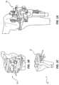
- FIGS. 1 A- 1 Cillustrate a system 100 of patient specific instruments in accordance with an example embodiment.
- Patient specific instrumentsare used in conjunction with a tensor 104 ( FIG. 1 A ) configured for patient specific balance prior to one or more bone cuts.
- patient specific instrumentsare configured to simplify and support the installation of one or more prosthetic components during implant surgery.
- a patient specific instrumentis a custom instrument designed specifically for a patient bone geometry and deformities to optimize a prosthetic component installation for performance and reliability whereas most prosthetic component installations are not optimized for a patient but to accommodate a wide range of people at the detriment of performance or reliability.
- a PSIis a cutting block customized for a bone structure of a patient.
- the PSI cutting blockis designed using images such as computed tomography (CT), X-rays, magnetic resonance imaging (MRI), ultrasonic imaging, other imaging techniques, or combinations of different images to render a 3D model of the musculoskeletal system.
- CTcomputed tomography
- MRImagnetic resonance imaging
- ultrasonic imagingother imaging techniques, or combinations of different images to render a 3D model of the musculoskeletal system.
- the PSI cutting blockcan take into account bone deformities as well as osteophytes.
- the 3D modelcan also be used in a preplan to facility or determine an implementation of a bone resection. Having modeled the musculoskeletal system during the preplanning stage, the PSI cutting block can be customized for different traumas that may have occurred to a bone or bones of the musculoskeletal system such as fractures or mal-alignment.
- the preplanningcan take into account the trauma or mal-alignment using the 3D model such that a workflow can be generated to bring the musculoskeletal system back into alignment as well as determining if problems can occur using standard prosthetic components.
- the 3D modelcan support a selection of implant size, position, and rotation thereby reducing surgical time in the operating room which is more efficient and saves costs.
- the PSIcan be manufactured using 3D printers to build the custom instrument using measurements from the 3D models of the musculoskeletal system.
- System 100comprises a bone cutting jig 102 configured to couple to a patient femur ( FIG. 1 B ), a bone cutting jig 106 configured to couple to the patient tibia ( FIG. 1 C ), and a tensor 104 configured to distract, load, balance, and support a bone cut.
- system 100supports one or more bone cuts to install a knee prosthetic joint that is loaded correctly, balanced, and aligned.
- a knee prosthetic componentis used in the example, system 100 can be adapted for use in hip, ankle, shoulder, spine, hand, wrist, and other parts of the musculoskeletal system requiring one or more bone cuts for installing a prosthetic component.
- bone cutting jig 106is a patient specific instrument configured to couple to the patient.
- System 100combines the advantages of pre-operative planning, generating a 3D model of a patient specific musculoskeletal system, and alignment capabilities of patient specific instruments with predictive implant balancing of tensor 104 .
- Tensor 104is configured to enable patient specific instrument guide placement for optimal femoral implant location.
- the workflow disclosed hereinsimplifies and differentiates from other instrument systems or procedures using existing technology.
- predictive balancing of the knee joint at the native femoral stepenables intraoperative efficiency by preventing the need for any re-cuts or adjustments.
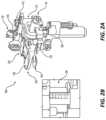
- FIG. 2 Ais an illustration of tensor 104 in accordance with an example embodiment.
- Tensor 104is modified to work with one or more patient specific instruments to support installation of one or more prosthetic components.
- tensor 104is configured to enable implant planning non-robotically by adding femoral drill guide 110 that corresponds to the patient specific instruments.
- Femoral drill guide 110relates to bone cutting jig 102 and bone cutting jig 106 shown in FIGS. 1 A- 1 C .
- Drill guide 110is configured to be utilized to set balanced extension and flexion femoral implant location.
- a modular drill guide attachment 116is configured to couple to tensor 104 .
- Modular drill guide attachment 116includes an anterior/posterior (A/P) adjustment 112 for femoral drill guide 110 and a rotation adjustment 114 for femoral drill guide 110 .
- A/Panterior/posterior
- Tensor 104comprises a tibial plate 128 , a femoral plate 130 , a distraction mechanism 118 , a tilt mechanism 132 , electronic circuitry, and one or more sensors.
- Tibial plate 128is configured to couple to a tibia
- femoral plate 130is configured to couple to a femur.
- femoral plate 130has a medial side and a lateral side configured to respectively couple to a medial femoral condyle and a lateral femoral condyle of the femur.
- a load plate 120 and a load plate 122couples to femoral plate 130 .
- the electronic circuitry and the one or more sensorsunderlie at least in part, load plates 120 and 122 .
- the one or more sensorscouple to the electronic circuitry.
- the electronic circuitrycontrols a measurement process and transmits measurement data to a computer in the operating room
- the computerincludes a display configured to display measurement from tensor 104 in real-time.
- Femoral platemoves 130 in relation to tibial plate 128 to distract a tibia from a femur by a predetermined distance.
- a surgeoncouples a device having a handle to distraction mechanism 118 . The device is used to rotate distraction mechanism to raise or lower femoral plate 130 relative to tibial plate 128 .
- a distraction gap display 126is provided on tensor 104 to quantify the distraction gap. An enlarged region of the distraction gap display 126 is also illustrated in FIG. 2 B showing hash marks indicated the amount of distraction.
- femoral plate 130includes load sensors for measuring load applied to tensor 104 . Loading applied to load plate 120 is measured independently from the loading applied to load plate 122 .
- three or more sensorsunderlie load plate 120 to support a load measurement.
- three or more load sensorsunderlie load plate 122 .
- the load sensorscan be used to determine a load magnitude at each sensor location.
- a load magnitude applied at a contact point on either load plate 120 or load plate 122can be calculated using the position of each sensor underlying the load plate and the load magnitude at the location.
- the point of contact to the load plate and the load magnitude at the point of contactcan be determined and displayed by the computer in real-time. Overall cut to cut gap is displayed allowing extension and flexion gap balancing.
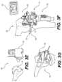
- FIGS. 3 A- 3 Gillustrate of a clinical workflow using patient specific instruments with tensor 104 in accordance with an example embodiment.
- the workflowcomprises one or more steps using one or more patient specific instruments and tensor 104 to support installation of one or more prosthetic components.
- the stepscan be performed in any order and no sequence is implied. Steps can be removed or replaced in the workflow depending on the application.
- FIG. 3 Ais an illustration of a pre-operative plan in accordance with an example embodiment.
- a displayshows a preoperative plan for the installation of one or more prosthetic components to a surgical team in an operating room. In general, a surgeon or surgical team goes through a standard pre-operative planning process prior to the surgery.
- the planningincludes optimization of tibial or femoral location.
- the PSIwill be manufactured for the patient during the pre-operative planning phase. In one embodiment, this will comprise one or more cutting blocks that are configured to couple to the patient based on a 3D model of the musculoskeletal system.
- the bone cuts and joint reconstructioncan be optimized for the specific patient using the 3D model and identified deformities, trauma, injury, bone growths, or other factors that could impact the surgery.
- the pre-operative plancan be displayed on the display of computer 146 shown in FIG. 3 C in the operating room to provide unique information related to the patient or changes to the workflow due to specifics of the patient.
- FIG. 3 Bis an illustration of a bone cutting jig 102 in accordance with an example embodiment.
- Bone cutting jig 102is a PSI built for the patient undergoing surgery using image data and a 3D model of the musculoskeletal system.
- bone cutting jig 102is used to resect a proximal tibia.
- Bone cutting jig 102is a patient specific instrument and a tibial resection guide.
- the bone cut to the tibiais performed to be in alignment with the mechanical axis of the leg.
- the bone cutcan take into account deformities in the leg to improve stability, performance, and reliability of the joint installation.
- FIG. 3 Cis an illustration of a tensor 104 inserted in a knee joint of the musculoskeletal system in accordance with an example embodiment.
- tensor 104is placed in at a minimum height.
- Tensor 104is placed in the knee joint such that tibial plate 128 couples to the prepared surface of the tibia and a medial side and a lateral side of femoral plate 130 respectively couples to a medial condyle and a lateral condyle of the femur.
- medial and lateral forcesare balanced in the knee joint.
- a balancing processuses distraction mechanism 118 and tilt mechanism 132 of tensor 104 .
- Distraction mechanism 118is rotated to increase or decrease the medial and lateral compartment heights.
- Tilt mechanism 132is rotated to tilt femoral plate 130 to further adjust the loading on the medial side and the lateral side of femoral plate 130 .
- Tilt mechanism 132will also change the medial and lateral compartment heights but can change them such that the compartment heights differ.
- the legis placed in flexion in a position greater than 5 degrees but less than 80 degrees. In one embodiment, the leg is positioned in approximately 10 degrees flexion with tensor 104 inserted in the knee joint. In one embodiment, the forces on the medial and lateral sides of the knee are balanced.
- Sensors on the medial and lateral side of femoral plate 130measure a load magnitude at the point of contact respectively of the medial condyle and the lateral condyle of the femur.
- the load measurements and contact point informationis displayed on computer 146 in real-time for a surgical team to view.
- balancedoes not mean making the loading applied by the musculoskeletal system to tensor 104 equal on the medial and lateral sides.
- balancecan be setting the loading on the medial side of tensor 104 to a first predetermined load magnitude and setting the loading on the lateral side of tensor 104 to a second predetermined load magnitude based on the pre-operative plan, the type of implant used, or what is determined during surgery.
- the knee joint or the legis moved and checked at full extension. Additional steps can be performed to optimize the knee if the knee joint hyperextends when placed in full extension or if the knee does not extend to full extension. For example, tissue tensioning, bone cuts, or compartment adjustments can be performed to increase or decrease knee joint movement to prevent hyperextension but allowing the leg to reach full extension.
- one or more sensors within tensor 104transmit measurement data to a computer 146 .
- computer 146receives, calculates, and processes the measurement data to provide an output in a visual, audible, or haptic form that supports rapid data assimilation of the information.
- Computer 146has a display in the operating room to provide the measurement data in real-time to the surgeon and surgical team. Computer 146 and the display can indicate issues or problems from the measurement data. Furthermore, computer 146 can suggest one or more workflow steps to address an issue or improve the installation.
- the distraction gap indicatoris referenced and one or more holes are drilled using femoral drill guide 110 when the knee joint is balanced and tested that the leg can move to full extension.
- femoral drill guide 110supports cutting the femur to allow equal compartment heights with the leg in full extension and in balance.
- the tensor 104is returned to the minimum height and removed from the knee joint.
- FIG. 3 Dis an illustration of PSI cutting block 106 coupled to the femur in accordance with an example embodiment.
- bone cutting jig 106is pinned to the femur using the one or more holes drilled using femoral drill guide 110 on tensor 104 as shown in FIG. 3 C .
- Bone cutting jig 106is a patient specific instrument that was manufactured using the 3D imaging of the musculoskeletal as described herein above. The femur is than resected using bone cutting jig 106 .
- FIG. 3 Eis an illustration of a coronal alignment check in accordance with an example embodiment.
- a coronal alignment checkcan be made before or after resection.
- a femoral PSI 152is coupled to the femur to support coronal alignment measurement.
- a tibial PSI 154is coupled to the tibia to support the coronal alignment measurement.
- FIG. 3 Fis an illustration of tensor 104 placed in the knee joint with the leg in flexion in accordance with an example embodiment.
- the legis balanced in flexion. In general, the leg is placed in flexion at greater than 80 degrees but less than 145 degrees. In one embodiment, the leg is flexed to approximately 90 degrees.
- Tensor 104is placed at minimum height and inserted into the knee joint in flexion.
- Distractor mechanism 118is used to set the compartment height.
- Tilt mechanism 132is used to tilt femoral plate 130 to achieve balance with the leg in flexion.
- the balance forcesare based on patient specific forces or determined when the leg was placed in extension in the prior balancing step (with the leg in extension).
- Measurement datais displayed on computer 146 in real-time.
- the distraction gap indicatoris referenced and one or more holes are drilled using femoral drill guide 110 to support pinning a desired thickness in flexion matching the extension target (i.e. 18, 19, 20 mm etc. . . . ).
- the medial and lateral compartment heights of the knee joint at 90 degrees flexioncan be made identical to the medial and lateral compartment height at full extension. Alternatively, they can be made having compartment heights that differ. The complexity can change significantly using PSI prosthetic components. Tensor 104 is removed from the knee joint after the balancing distraction gap is reduced.
- FIG. 3 Gis an illustration of bone cutting jig 160 coupled to the femur in accordance with an example embodiment.
- a bone cutting jig 160is pinned to the femur in flexion.
- Bone cutting jig 160is a patient specific instrument and is configured to remove posterior bone from a distal end of the femur. The resection depths are confirmed prior to a cut being made.
- Bone cutting jig 160is pinned to the femur using the one or more holes drilled using femoral drill guide 110 when the leg was placed at 90 degrees flexion.
- the femoral cutsare then performed to the femur in flexion thereby removing a portion of the posterior side of the distal end of the femur.
- the tibial prosthetic component, femoral prosthetic component, and the insertcan then be installed to complete the prosthetic knee surgery with the knee in balance based on quantitative measurement data from tensor 104 .
- Patient specific instrumentenable all implant and instrument sizing to be pre-determined, minimal reusables, patient kitted (one sensor) disposable system. Predictively balancing the joint at the native femoral step enables intraoperative efficiency by preventing the need for any re-cuts or adjustments.
- a patient specific instrumentation surgical plancould be displayed within a tablet or computer for reference throughout the surgery.
- the workflowis a significant advance compared to other patient specific instrument products.
- the systemenables intraoperative flexibility that is not possible with patient specific instrument products alone.
- the tensorcan be adapted for use with a surgical robot.
- FIG. 4 A- 4 Dillustrates different views of tensor 104 in accordance with an example embodiment.
- FIG. 4 Ais an illustration of an anterior view of tensor 104 in accordance with an example embodiment.
- tibial plate 128is configured to couple to femoral plate 130 when tensor 104 is in a minimum height position.
- tibial plate 128is smaller or comprises less area than femoral plate 130 .
- a bottom surface of femoral plate 130includes a cavity. Tibial plate 128 fits within the cavity of the bottom surface of femoral plate 130 to minimize the minimum height. Femoral plate 130 and tibial plate 128 are inserted within the knee joint.
- Femoral plate 130is a moving structure whereas tibial plate 128 is in a fixed position.
- Tibial plate 128couples to tube 170 .
- Tube 170is directed in a reference position of tensor 104 .
- tibial plate 128is affixed to tube 170 at a 90 degree angle relative to the direction of tube 170 .
- a bottom surface of tibial plate 128is planar to couple to a prepared bone surface of a tibia.
- An upper surface of tibial plate 128can include ribbing or other structures to increase a rigidity of tibial plate 128 .
- a toolis configured to couple to distraction mechanism 118 .
- the toolis inserted and aligned to distraction mechanism 118 to support rotating distraction mechanism 118 by a surgeon.
- femoral plate 130couples to cylindrical structure 174 and at least a portion of cylindrical structure 174 is inserted into tube 170 .
- distraction mechanism 118is a gear mechanism configured to raise and lower the cylindrical structure thereby raising and lowering femoral plate 130 .
- a side of the cylindrical structure 174can have gear teeth configured to couple to the gear mechanism of distraction mechanism 118 to support raising or lowering femoral plate 130 .
- the surgeon viewing the anterior view of tensor 104can see the distraction gap display 126 (shown in FIG. 2 A ).
- tensor 104can have a sensor system configured to measure and display the distraction gap or the compartment gaps on the medial and lateral sides of tensor 104 .
- the distraction gapwould be displayed on the display of computer 146 (as shown in FIG. 3 C ) in the operating room.
- the surgeon and surgical teamcan view the contact points, load magnitudes, distraction gap, and tilt of femoral plate 30 in real-time during the surgery.
- femoral plate 130couples to support structure 172 .
- Support structure 172couples to cylindrical structure 174 .
- Rotating distraction mechanism 118raises or lowers cylindrical structure 174 within tube 170 thereby raising or lowering support structure 172 and femoral plate 130 .
- Modular drill guide attachment 116is configured to couple to support structure 172 .
- support structure 172has one or more holes configured to receive one or more pegs from modular drill guide attachment 116 to retain and align femoral drill guide 110 to tensor 104 .
- Modular drill guide attachment 116places femoral drill guide 110 above femoral plate 130 .
- A-P adjustmentcouples to support structure 172 .
- A-P adjustmentis screw button that can be loosened allow femoral drill guide 110 to be moved in an anterior or posterior direction to place femoral drill guide 110 near the femur to support drilling one or more holes.
- the screw buttoncan be tightened when femoral drill guide 110 is in position to prevent movement during drilling.
- FIG. 4 Bis a top view of tensor 104 in accordance with an example embodiment.
- Femoral plate 130is shown extending outward from tensor 104 to support insertion into the knee joint.
- femoral plate 130is offset to support placing the patella to the side to insert tensor 104 and then re-placing the patella back onto the knee joint for a kinetic assessment of the knee joint.
- load plate 120overlies three sensors at predetermined positions.
- load plate 122overlies three sensors at predetermined positions.
- Electronic circuitry 176couples the sensors underlying load plates 120 and 122 to control a measurement process and transmit measurement data to a computer.
- the measurement datais used to calculate a position of applied load to load plate 120 or load plate 122 or a load magnitude at the position of applied load to load plate 120 or load plate 122 .
- the compartment heightis set by rotating distraction mechanism 118 while reviewing the loading applied to plates 120 and 122 .
- Tilt mechanism 132is rotated to tilt femoral plate 130 relative to tibial plate 128 (not shown).
- tilt mechanism 132is rotated to achieve balance in the knee joint.
- tilt mechanism 132is a gear mechanism configured to rotate femoral plate 130 .
- tilt mechanism 132is coupled between distraction mechanism 118 and femoral plate 130 .
- A-P adjustmentis loosened and femoral drill guide 110 is positioned near the femur to drill one or more holes.
- an equal compartment heightis maintained on the medial side and the lateral side the knee joint.
- rotation adjustment 114is used to rotate femoral drill guide 110 to compensate for the tilt introduced by tilt mechanism 132 .
- amount of rotation of femoral drill guide 110can be viewed on rotation adjustment 114 .
- one or more sensorscan be placed on tensor 104 to measure tilt of femoral plate 130 and femoral drill guide 110 . The tilt of femoral plate 130 and femoral drill guide 100 would be displayed on the computer to which the measurement data is sent in real-time for review by the surgical team.
- FIG. 4 Cis side view of tensor 104 in accordance with an example embodiment.
- Tensor 104is shown with femoral plate 130 raised above tibial plate 128 .
- a support structure 178is coupled between tube 170 and tibial plate 128 .
- Support structure 178extends horizontally away from tube 170 and vertically to position tibial plate 128 below femoral plate 130 .
- Support structure 178is in a fixed position aligned to tube 170 .
- Support structure 178is configured not to flex or bend under loading when distracting the knee joint.
- the proximal end of the tibiais cut using a PSI cutting jig 106 as shown in FIG. 1 C .
- tibial plate 128has a planar bottom surface configured to couple to the prepared surface of the tibia.
- Tilt mechanism 132is placed between femoral plate 130 and distraction mechanism 118 .
- tilt mechanism 132comprises a gear drive configured to rotate femoral plate 130 .
- Tilt mechanism 132is configured to tilt femoral plate 130 medially or laterally.
- Tilt mechanism 132 and femoral plate 130are raised and lowered together by distraction mechanism 118 .
- the gear drive in tilt mechanism 132will hold position when tilted under load.
- tilt mechanism 132can be used with a separate tilt lock to prevent movement of tilt mechanism 132 after being set.
- Femoral drill guide 110 , rotation adjustment, 114 , A-P adjustment 112 , and modular drill guide attachment 116is configured to be coupled to tensor 104 after the knee joint balance is achieved or it can be installed to tensor 104 during the balancing operation.
- FIG. 4 Dis a side view of tensor 104 in accordance with an example embodiment.
- Tensor 104is shown with femoral plate 130 being separated from tibial plate 130 .
- Tensor 104has compartment height corresponding to a distance between the upper surface of support structure 130 and the bottom surface of tibial plate 128 . In one embodiment, the compartment height would be measured from the surface of load plate 120 or load plate 122 as shown in FIG. 4 C to the bottom surface of tibial plate 128 .
- support structure 178 , tibial plate 128 , and tube 170are formed as a single structure.
- support structure 178 , tibial plate 128 , and tube 170can be milled from a block of metal such as aluminum or steel.
- support structure 178 , tibial plate 128 , and tube 170can be formed by other processes such as by mold or 3D printing.
- Support structure 178 , tibial plate 128 , and tube 170are aligned to one another in predetermined positions.
- Support structure 178extends tube 170 horizontally and then has a vertical component to position tibial plate 128 in a predetermined position relative to femoral plate 130 .
- Femoral plate 130couples to tilt mechanism 132 .
- Tilt mechanism 132couples to distraction mechanism 118 .
- Distraction mechanism 118 , tilt mechanism 132 , and femoral plate 130are aligned to tibial plate 128 by cylindrical structure 174 of distraction mechanism 118 .
- Cylindrical structure 174fits within tube 170 and is configured to move up or down within tube 170 under control of distraction mechanism 118 .
- Tilt mechanism 132is configured to tilt femoral plate 130 to balance the knee joint. In one embodiment, tilt mechanism 132 can be locked after a tilt has been established by tightening a nut that is part of tilt mechanism 118 to prevent rotation of the gear mechanism.
- Modular drill guide attachment 116is coupled to support structure 172 of distraction mechanism 118 .
- Pin 180 of modular drill guide attachment 116couples through an opening in support structure 172 .
- Modular drill guide 116places A-P adjustment 112 , rotation adjustment 114 , and femoral drill guide 110 above support structure 172 , tilt mechanism 132 , and femoral plate 130 .
- Femoral drill guide 110can be adjusted by A-P adjustment 112 and rotation adjustment 114 to drill one or more holes in the femur for pinning a femoral cutting block to cut the femur in balance at a predetermined compartment height as set by tensor 104 .
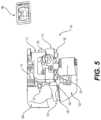
- FIG. 5is a partial view of tensor 104 inserted in a knee joint in accordance with an example embodiment.
- a proximal end of tibia 182is shown having a prepared bone surface from being cut using a PSI bone cutting guide.
- Tensor 104is placed in at a minimum height and inserted in the knee joint. The minimum height of tensor 104 occurs when femoral plate 130 couples to tibial plate 128 .
- a femur 184is at a 90 degree angle from tibia 182 .
- Tensor 104can have one or more sensors configured to measure the position of femur 184 relative to tibia 182 and display the angle on computer 146 in the operating room.
- tensor 104is distracted to a predetermined compartment height.
- the load magnitude and the position of applied load of a medial condyle and a lateral condyle coupling to femoral plate 130are measured by tensor 104 .
- the load magnitude and position of applied load one the medial and lateral sides of tensor 104are shown on computer 146 .
- the predetermined compartment heightcan be read from distraction gap display 126 or displayed on computer 146 .
- the predetermined compartment heightcorresponds to the installation of a tibial prosthetic component, a femoral prosthetic component, and an insert.
- the combined thickness of the tibial prosthetic component, the femoral prosthetic component, and the insertis related to the predetermined compartment height.
- Tilt mechanism 132is used to tilt femoral plate 130 to bring the knee joint in balance.
- the predetermined compartment heightis equal on the medial and lateral sides of tensor 104 .
- tilt mechanism 132brings the knee joint into balance but can make the medial compartment height differ from the lateral compartment height.
- Femoral drill guide 110is rotated to correspond to the tilt produced by tilt mechanism 132 to bring the knee joint in balance.
- One or more holesare drilled into femur 184 . The one or more holes are used to pin a PSI cutting block to femur 184 .
- the one or more holesare used to pin the PSI cutting block at an angle the produce equal compartment heights on the medial and lateral sides of the knee joint.
- the bone cut of femur 184will also maintain the balance measured by tensor 104 .
- two pins 180 of modular drill guide attachment 116are shown inserted into support structure 172 to retain and position femoral drill guide 110 relative to femoral plate 130 .
- the load magnitude and position of applied loading over a range of motion of the final installed prosthetic componentsshould be approximately equal to the measurement data generated by tensor 104 that support the bone cuts in balance.
- FIGS. 6 A- 6 Cillustrates an insert system 200 in accordance with an example embodiment.
- Insert system 200can be used in place of tensor 104 disclosed herein above to balance a knee joint and support one or more bone cuts to install one or more prosthetic components.
- Insert system 200can be used with patient specific instruments (PSI) that are constructed using one or more images to form a 3D model of a femur and a tibia of the patient.
- PSIpatient specific instruments
- insert system 200is used in conjunction with bone cutting jig 102 , bone cutting jig 106 , bone cutting jig 160 , femoral PSI 152 , or tibial PSI 154 shown in FIGS. 3 A- 3 G .
- Each of the patient specific instrumentsare configured to couple to the femur and the tibia of the patient to cut bone using pinning holes drilled using insert system 200 .
- femoral PSI 152is coupled to the femur to support a coronal alignment measurement.
- tibial PSI 154is coupled to the tibia to support the coronal alignment measurement during the balancing process using insert system 200 .
- insert system 200is a low cost system configured to be disposable after a single use.
- insert system 200can be patient specific instruments based on 3D models using one or more images of the patient femur and tibia. Insert system 200 can be designed using the 3D model of the femur and tibia.
- Insert system 200can be molded or manufactured using 3D print technology.
- insert system 200can be made of a polymer material such as polycarbonate, polyurethane, PEEK, UHMW polyurethane, or other biocompatible material. Insert system 200 can also be made from metal or metal alloy. In one embodiment, insert system 200 can be a reusable system configured to be sterilized after each use.
- FIG. 6 Ais an illustration of an insert 206 , a shim 202 , and a shim 204 in accordance with an example embodiment.
- Insert system 200comprises an insert 206 and a plurality of shims.
- the plurality of shimscomprises shims for a medial side and a lateral side of insert 206 .
- the medial side and the lateral side shimswill come in different heights corresponding to final insert heights used with a final femoral prosthetic component and a final tibial prosthetic component.
- insert system 200will have insert 206 and a plurality of shims for a right side knee joint and an insert 206 and a plurality of shims for a left side knee joint.
- the insert 206will differ for the left knee or the right knee based on the location of structure 208 extending from insert 206 .
- the offset location of structure 208supports the placement of a patella to the side while inserting insert system 200 or removing insert system 200 to change shims and replacing insert system 200 within the knee joint. The patella can then be placed back on the knee joint to load the knee joint over a range of motion.
- structure 208 of insert 206has an opening 222 and an opening 224 . Openings 222 and 224 are used to couple an instrument or device to structure 208 .
- opening 222is circular in shape.
- opening 224is square in shape.
- a toolcan be coupled to openings 222 and 224 having a handle to aid the surgeon in directing insert 206 , shim 202 , and shim 204 into the knee joint.
- a shim 202 and a shim 204are coupled to insert 206 .
- a surface of shim 202 and a surface of shim 204are non-planar.
- the non-planar surface of shim 202 or shim 204is an articular surface configured to support movement of the knee joint.
- shim 202 or shim 204can have a planar surface.
- Shim 202 and shim 204are configured to couple to insert 206 .
- insert 206has one or more grooves 210 formed in an upper surface of insert 206 . Grooves 210 are configured to support coupling shim 202 to insert 206 .
- insert 206has one or more grooves 210 configured to support coupling shim 204 to insert 206 .
- shim 202has corresponding tongues configured to fit within grooves 210 .
- the tongues of shim 202are aligned to grooves 210 such that shim 202 slides into insert 206 laterally.
- Shim 204has corresponding tongues configured to fit within grooves 210 formed on the surface of insert 206 .
- a structural feature within grooves 210 of insert 206will prevent further lateral movement of shim 202 . Shim 202 in contact with the structural feature will place 202 in alignment with insert 206 .
- shim 202 and insert 206are configured to retain shim 202 in place while supporting quick removal should a different size shim be required to achieve an appropriate balance.
- a structural featureis also in grooves 210 to prevent lateral movement of shim 204 .
- shim 202 and 204can only be inserted one way such that shims for the medial side can only be placed on the medial side of insert 206 and shims for the lateral side can only be placed on the lateral side of insert 206 .
- a shim 204 which is thicker than shim 202was used to achieve balance within the knee joint.
- insert system 200couples to a computer to receive measurement data from insert system 200 .
- Insert system 200includes one or more sensors coupled to electronic circuitry. The electronic circuitry controls a measurement process and transmits measurement data.
- the heights of shim 204 and shim 202can be entered in the computer during the surgery and the tilt can be calculated using the heights of shim 202 and 204 stored in the computer.
- FIG. 6 Bis a top view of insert system 200 in accordance with an example embodiment.
- Condyles of a femurcouple to shims 202 and 204 when inserted in the knee joint.
- Insert system 200includes a drill guide to support one or more bone cuts when the knee joint is in balance.
- the drill guideis similar to the drill guide disclosed for tensor 104 in FIGS. 1 A- 5 . Any disclosed feature or use of the drill guide for tensor 104 also applies to insert system 200 .
- Structure 208extends outward from insert 206 . Structure 208 does not reside within the knee joint and is accessible to the surgeon when insert 206 , shim 202 , and shim 204 are placed in the knee joint.
- Modular drill guide attachment 216is configured to couple to structure 208 thereby placing the drill guide in proximity to the knee joint.
- modular drill guide attachment 216has a cylindrical pin and a square pin that are configured to fit respectively within openings 222 and 224 of structure 208 .
- the cylindrical pin and the square pinretain modular drill guide attachment 216 to structure 208 to support drilling one or more holes in the femur.
- Loosening anterior-posterior (A-P) adjustmentallows femoral drill guide 220 to be moved in an anterior or posterior direction. In general, femoral drill guide 220 is moved to a location that supports drilling one or more holes in the femur.
- A-P adjustmentis then tightened to hold femoral drill guide 220 in place to prevent movement in the anterior or posterior direction.
- the femuris cut to have equal compartment heights.
- Femoral drill guide 220can be rotated using rotation adjustment 214 to angle the cut to compensate for different heights of shims 202 and 204 .
- rotation adjustment 214has a rotation display that is visible to the surgeon or surgical team that indicates the amount of rotation.
- One or more holesare drilled in the femur having a predetermined rotation.
- a cutting blockcan be coupled to the femur aligned to the one or more holes thereby cutting the femur having equal compartment heights and in balance.
- FIG. 6 Cis a side view of insert system 200 in accordance with an example embodiment.
- Structure 208extends from and is offset on insert 206 to support positioning a patella to allow insert 206 , shim 202 , and shim 204 to be inserted in a knee joint. The patella can then be placed back on the knee joint to load the knee joint after insert 206 , shim 202 , and shim 204 is inserted. Structure 208 is not in the knee joint.
- Modular drill guide attachment 216positions femoral drill guide 220 to be centered to the intercondylar notch. Modular drill guide attachment 216 places femoral drill guide 220 above shims 202 and 204 .
- A-P adjustment 212 and rotation adjustment 214are used to position femoral drill guide 220 to drill one or more holes for pinning a PSI cutting block to the femur to make a cut at a predetermined angle.
- femoral drill guide 220has openings for drilling holes in the medial condyle and the lateral condyle of the femur.
- the PSI cutting blockcan be attached to the femur in a manner that supports cutting femur at the predetermined angle.
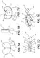
- FIG. 7 Ais a top view of insert system 200 in accordance with an example embodiment.
- Shim 202 and shim 204are coupled to a top surface of insert 206 .
- shim 202is one of a plurality of shims each having a different height.
- shim 204is one of a plurality of shims each having a different height.
- the plurality of shims corresponding to shim 202are configured to couple to a first predetermined side of insert 206 .
- the plurality of shims corresponding to shim 204are configured to couple to a second predetermined side of insert 206 .
- shim 202will not couple to the second predetermined side of insert 206 . In one embodiment, shim 204 will not couple to the first predetermined side of insert 206 .
- Structure 208is shown extending from insert 206 . In one embodiment, structure 208 has an opening 222 and an opening 224 . A tool, equipment, or device is configured to couple to openings 222 and 224 . Structure 208 is configured to support, retain, and position the tool, equipment, or device relative to insert 206 .
- FIG. 7 Bis a side view of insert system 200 in accordance with an example embodiment.
- the side viewillustrates shim 204 coupled to a top surface of insert 206 .
- Structure 208is shown extending from insert 206 .
- structure 208 and insert 206are part of the same structure.
- insert 208 and structure 208are molded as a single structure.
- a sensor system 230couples to a bottom surface of insert 206 .
- sensor system 230comprises at least one sensor, electronic circuitry, and a power source.
- Sensor system 230is configured to control a measurement process and transmit measurement data.
- a computerreceives the measurement data and displays the measurement data.
- the computercan include one or more software programs and is configured to process or convert the measurement data to visual, audible, or haptic forms for rapid assimilation.
- the computeris in the operating room for the surgeon or surgical staff to review the measurement data in real-time.
- FIG. 7 Cis an illustration of sensor system 230 coupled to a lower surface 232 of insert 206 in accordance with an example embodiment.
- Sensor system 230comprises sensors 236 , sensors 238 , and electronic circuitry 234 .
- sensors 236 , sensors 238 , and electronic circuitry 234couple to a printed circuit board. Portions of the printed circuit board can be flexible and other portions can be rigid.
- the printed circuit boardcan have more than one layer of interconnect to couple sensors 236 and 238 to electronic circuitry 234 .
- electronic circuitry 234includes a battery or batteries configured to power electronic circuitry 234 during the surgery.
- Sensor system 230couples to a lower surface 232 of insert 206 .
- Insert 206can have one or more retaining features to align sensors 236 , sensors 238 , and electronic circuitry 234 to lower surface 232 .
- sensors 236underlie shim 202 and sensors 238 underlie shim 204 .
- Electronic circuitry 234is placed in a location that is unloaded by the musculoskeletal system when insert system 200 is inserted in the knee joint.
- sensors 236have load sensors placed at vertexes of a polygon. In general, this defines an area of measurement. Measurement outside the polygon can be measured but can be less accurate as some of the sensors become unloaded.
- Sensors 238will have a similar arrangement as sensors 236 . The area of the polygon in sensors 236 can differ from the area of sensors 238 .
- the area of measurement on the medial side of insert 206can differ from the area of measure on the lateral side of insert 206 to support differences in contact point movement of the knee joint on the medial or lateral sides of insert 206 .
- loading applied by the musculoskeletal system to shim 202 or shim 204is respectively coupled through sensors 236 or sensors 238 .
- sensors 236 and sensors 238can provide accurate measurement of the load magnitude applied to the surface of shim 202 or shim 204 .
- the position of each sensor of sensors 236is known relative to the articular surface of shim 202 .
- the position of each sensor of sensors 238is known relative to the articular surface of shim 204 .
- the measurement data from insert system 200is transmitted to a computer.
- the computercan use the measurement data to calculate a load magnitude and a position wherein the load magnitude is applied to shim 202 or shim 204 .
- the measurement datais used to determine balance and contact point over a range of motion of the knee joint.
- the computercan further identify problems that require adjustments.
- the computercan further provide a work flow to make the adjustments to ensure the optimization of the knee joint for performance and reliability.
- FIG. 7 Dis an illustration of a side view of sensor system 200 in accordance with an example embodiment.
- Sensor system 230is shown coupled to a bottom surface of insert 206 .
- a bottom surface of sensor system 230extends beyond insert 206 such that the bottom surface of sensor system 230 couples to the prepared surface of the tibia when insert system 200 is inserted in the knee joint.
- Shim 202 and shim 204are coupled to and aligned to the upper surface of insert 206 .
- shim 202has a height less than shim 204 to achieve balance in the knee joint.
- the shim heights of shim 202 and shim 204are provided to the computer receiving information from insert system 200 .
- the computeris computer 146 shown in FIG. 3 C that is placed within the operating room for viewing by the surgeon or surgical team.
- Computer 146processes information received from insert system 200 similarly to how it processes information from tensor 104 during a surgical installation. Insert system 200 provides measurement data to computer 146 .
- Computer 146has an interface that supports data entry such as shim height.
- computer 146can have a scanner for scanning code on a shim that provides information such as the height of the shim.
- each shim of the plurality of shimscan have an RF ID tag that can provide shim information to computer 146 .
- computer 146calculates a tilt corresponding to the difference in height between shim 202 and 204 . The tilt information based on shim height is used with the femoral bone cutting jig to set the compartment heights for the balanced knee joint.
- the medial and lateral compartment heights of the knee jointare set to be equal.
- Tongues 240are formed in a bottom surface of insert 202 .
- Grooves 210are formed in the upper surface of insert 206 . Grooves 210 are aligned to and correspond to tongues 240 .
- tongues 244are formed in a bottom surface of insert 204 .
- Grooves 246are formed in the upper surface of insert 206 . Grooves 246 are aligned to and correspond to tongues 244 .
- a retaining feature 248is formed as part of insert 206 between shims 202 and 204 . Retaining feature 248 is configured to retain shim 202 or shim 204 to prevent shim 202 or shim 204 to disengage during a measurement process.
- retaining feature 248is configured to extend into a sidewall groove of shim 202 or 204 .
- shim 202 or shim 204can only be coupled to insert 206 by sliding shim 202 or shim 204 laterally into insert 206 .
- Retaining feature 248prevents shim 202 or 204 from being pressed vertically onto the top surface of insert 206 .
- Insert 206includes a stop that aligns shim 202 or shim 204 to insert 206 from being pushed further laterally than the stop.
- Removing shim 202 or shim 204is just a reverse process of sliding out shim 202 or 204 in an opposite direction from where it was initially engaged to insert 206 .
- shim 202 or shim 204cannot swap placement as only can be coupled to insert 206 as shown. In other words, shim 204 cannot replace shim 202 and vice versa.
- FIG. 7 Eis an illustration of an angled view of insert system 200 in accordance with an example embodiment.
- Shim 202 and shim 204are coupled to a top surface of insert 206 .
- shim 202 or shim 204are coupled to insert 206 from the anterior side of insert 206 .
- the tongues of a shimare coupled to the corresponding grooves in the top surface of insert 206 such that a bottom surface of the shim couples to the top surface of insert 206 .
- the bottom surface of the shimslides across the top surface of insert 206 until the shim is aligned to insert 206 .
- the retaining feature 248also couples to the shim during the sliding process.
- Structure 208is not inserted within the knee joint and extends outward from insert 206 which is inserted in the knee joint.
- a tool, device, or other equipmentis configured to couple to structure 208 such as a PSI bone cutting jig.
- insert system 200can be a patient specific instrument created from a 3D model of the patient's leg and knee joint.
- a bottom view of insert system 200illustrates sensor system 230 coupled to a lower surface 232 of insert 206 .
- Sensor system 230comprises sensors 236 , sensors 238 , and electronic circuitry 234 .
- Electronic circuitry 234is configured to control a measurement process and transmit measurement data to a computer such as computer 146 shown in FIG. 3 C .
- sensors 230extends below insert 206 such that sensors 230 couples to the prepared surface of the tibia and insert 206 does not.
- the musculoskeletal system loading shim 202 and shim 204transfers the load through insert 206 to sensors 236 and sensors 238 .
- sensors 236comprise three sensors placed at vertexes of a first triangle.
- sensors 238comprise three sensors placed at vertexes of a second triangle.
- the positions of each sensor of sensors 236 and 238is provided or known by computer 146 of FIG. 3 C .
- the first and second trianglescan differ in perimeter and area.
- the entire loading applied to shim 202is channeled thru the three sensors of sensors 236 .
- the entire loading applied to shim 204is channeled thru the three sensors of sensors 238 .
- the computer 146 of FIG. 3 Creceives the measurement data from sensors 236 and sensors 234 .
- Computer 146can calculate a position applied load to shim 202 and shim 204 and calculate the load magnitude applied at the position of applied load to shim 202 and shim 204 .
- the measurement datasupports determining a balanced condition for the knee joint.
- FIG. 8 Ais an illustration of insert system 200 in a knee joint in accordance with an example embodiment.
- the workflow disclosed herein belowcomprises one or more steps using one or more patient specific instruments and insert 206 to support installation of one or more prosthetic components. The steps can be performed in any order and no sequence is implied. Steps can be removed or replaced in the workflow depending on the application.
- a pre-operative plancan be put together as a guide to the surgery. The pre-operative plan can be viewed on display 146 in the operating room. In general, a surgeon or surgical team goes through a standard pre-operative planning process. In one embodiment, the pre-operative planning includes optimization of a tibial 252 or femoral location 250 .
- a PSI bone cutting jigis used to resect a proximal tibia.
- the bone cutting jigis a patient specific instrument PSI and a tibial resection guide.
- the PSIcan be designed from one or more images of the femur, knee joint, and tibia.
- a 3D model of the legcan generated from the one or more images of the femur, knee joint, and tibia.
- the 3D modelcan be used to create devices, tools, prosthesis, trialing devices, final devices or equipment designed specifically for the patient surgery.
- a 3D printercan be used to manufacture the devices, tools, prosthesis, trialing devices, final devices or equipment.
- a PSI bone cutting jigis coupled to tibia 252 .
- the PSI bone cutting jigis used to cut the proximal end of tibia 252 in a manner that supports alignment to the leg mechanical axis.
- a second stepmedial and lateral forces are balanced in the knee joint.
- the legis positioned in flexion greater than 5 degrees and less than 80 degrees. In one embodiment, the leg is positioned at approximately 10 degrees of flexion with insert system 200 inserted in the knee joint.
- Sensor system 230couples to the prepared surface of tibia 252 cut in the first step.
- Condyles of femur 250couple to shim 202 and shim 204 to support movement of the knee joint.
- the forces on the medial and lateral sides of the knee joint by the medial condyle and lateral condyle of femur 250are balanced by selecting different heights for shims 202 and 204 .
- the pre-planningmay include determining an approximate compartment height for the knee joint.
- the pre-planned compartment heightcan be trialed in the knee joint.
- Sensor system 200can be removed from the knee joint if the measured balanced as viewed on computer 146 is non-optimal.
- a shim or both shimsare removed and a new shim or shims can be installed on insert 206 to adjust the balance, load value, and contact points.
- a new shim having reduced thicknesswill lower the load magnitude applied by the corresponding condyle of the femur to insert system 200 .
- a new shim having increased thicknesswill increase the load magnitude applied by the corresponding condyle of the femur to insert system 200 .
- the load magnitude and the contact point location on the new shimcan be viewed in real-time on computer 146 .
- the surgeonhas the options of re-cutting the tibia or soft tissue tensioning to further optimize the balance of the knee joint or correct for defects not identified during pre-planning.
- a third stepthe heights of the medial shim and the lateral shim have been selected.
- the heights of the medial shim and the lateral shimare entered in computer 146 and computer 146 calculates the tilt.
- the knee jointis then moved from 10 degrees flexion to full limb extension. Ideally, the limb can be placed in full extension. Additional steps can be performed to optimize the knee if the knee joint hyperextends when placed in full extension or the knee does not extend to full extension.
- one or more sensors within insert 176transmit measurement data to a computer having a display.
- the computeris in the operating room providing the measurement data in real-time to the surgeon and surgical team for making adjustments or confirming that measurements are within specification.
- drill guide 116is coupled to insert 176 and one or more holes are drilled.
- a femoral bone cutting jigis pinned to the femur.
- the femoral bone cutting jigis a patient specific instrument.
- the femuris than resected using the femoral bone cutting jig.
- the legis balanced in flexion. In one embodiment, the leg is flexed to approximately 90 degrees with insert 176 in the knee joint. In one embodiment, the balance forces are based on patient specific forces determined when the leg was placed in extension in a prior step. Measurement data is displayed on the computer in real-time.
- drill guide 116is coupled to insert 176 .
- One or more holesare drilled with the femur in flexion using drill guide 116 .
- the drill guide 116is then removed from insert 176 .
- a femoral cutting jigis then pinned to the femur in flexion.
- the femoral cutting jigis a patient specific instrument. The resection depths can be confirmed prior to a cut being made.
- the femoral cutsare then performed to the femur in flexion.
- the tibial prosthetic component, femoral prosthetic component, and the insertcan then be installed to complete the prosthetic knee surgery.
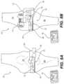
- FIG. 8 Bis an illustration of drilling one or more holes in femur 250 to support a bone cut to femur 250 in accordance with an example embodiment.
- Patient specific instrumentsenable all implant and instrument sizing to be pre-determined, minimizes reusables, and is a patient kitted disposable system. Predictively balancing the knee joint at the native femoral step enables intraoperative efficiency by preventing the need for any re-cuts or adjustments.
- a patient specific instrumentation surgical plancould be displayed on computer 146 for reference throughout the surgery.
- the workflowis a significant advance compared to other patient specific instrument products.
- the systemenables intraoperative flexibility that is not possible with patient specific instrument products alone.
- the system disclosed hereincan be adapted for use with a surgical robot.
- a drill guideis coupled to structure 208 extending from insert 208 .
- the drill guidecan be a patient specific instrument (PSI) manufactured specifically for drilling femur 250 of the patient based on one or more images of femur 250 , tibia 252 , and the knee joint.
- PSIpatient specific instrument
- a 3D model of the patient femur 250 , tibia 252 , and the knee jointis used to define the drill guide.
- the drill guidecomprises a modular drill guide attachment 216 , an anterior-posterior (A-P) adjustment 212 , a rotation adjustment 214 (not shown), and femoral drill guide 220 .
- A-Panterior-posterior
- modular drill guide attachment 216has two pegs configured to couple to two openings in structure 208 of insert 206 .
- Modular drill guide attachment 216is a support structure that is retained to insert 206 and positions femoral drill guide 220 in a location to drill one or more holes in an anterior portion of the condyles of femur 250 .
- structure 208is offset relative to femur 250
- modular drill guide attachment 216places femoral drill guide 220 centered to the intercondylar notch.
- femoral drill guide 220has a medial side and a lateral side template for drilling holes to the anterior side of the condyles of femur 250 .
- A-P adjustment 212can be used to position femoral drill guide 220 near femur 250 .
- A-P adjustment 212is tightened to hold the A-P position of femoral drill guide 220 .
- Femoral drill guide 220can be rotated to change where the holes are drilled on femur 250 on the medial and lateral condyle.
- the medial and lateral compartment heights of the knee jointare determined to be equal for the installation of the femoral prosthetic component. Note that shims 202 and 204 result in unequal heights (tilt) due to their height differences.
- Rotation adjustment 212is rotated to compensate for the tilt introduced by shims 202 and 204 such that the medial and lateral compartment heights of the knee joint are equal while maintain the balance as disclosed in steps 2 and 3.
- the tilt of the one or more holes drilled in femur 250will “tilt” the PSI cutting jig such that the bone cut yields equal compartment heights at the measured balance.
- adjustmentscan be made prior drilling one or more holes into the distal end of the femur.
- adjustmentssuch as a bone cut, soft tissue tensioning, or rotation of insert system 200 can be performed to change the balance, contact point location on shims 260 and 264 , or load magnitudes applied to shims 260 and 264 with the knee joint in flexion.
- Computer 146can display measurement data such as load magnitudes, position of applied load, or contact point rotation (of insert system 200 ) in real-time to support the adjustments in real-time. The adjustments are made to optimize, improve fit, reliability, and performance of the knee joint.
- insert system 200is removed from the knee joint after drilling one or more holes into the medial and lateral condyles of femur 250 .
- a PSI bone cutting jigis coupled to the distal end of femur 250 .
- the patient specific cutting jigis configured to fit femur 250 based on the 3D model disclosed herein above.
- pinsare used to hold the PSI cutting jig to femur 250 . The location of the pins will tilt the patient specific cutting jig when pinned to femur 250 .
- the PSI cutting jigwill have a slot for receiving a bone saw.
- the bone sawwill cut distal end of the femur corresponding to the tilt introduced in step 4 by rotation adjustment 212 to femoral drill guide 220 .
- the bone cut to the distal end of femuryields equal medial and lateral compartment heights in the knee joint at the balance measured by sensor system 230 .
- FIG. 8 Cillustrates the knee in flexion with insert system 200 within the knee joint in accordance with an example embodiment.
- the legcan be placed in flexion at greater than 45 degrees but less than 135 degrees.
- the legis placed in flexion at 90 degrees.
- the knee jointis balanced based on specific forces determined previously when the leg was in extension. In other words, the balance of the leg at 90 degrees in flexion is made to approximately the balance in extension.
- the compartment height of the knee joint with the leg at 90 degrees flexionis made to match the compartment height with the leg in extension. Shims 260 and 262 are installed to insert 206 to trial the knee joint at 90 degrees flexion.
- the selection of shims 260 and 262set the compartment height equal to the final compartment height with the knee joint in extension.
- Insert system 200is placed in the knee joint such that sensor system 230 couples to the prepared surface of tibia 252 .
- a posterior portion of the condyles of femur 250couple to shims 260 and 262 .
- the posterior portion of the condyles of femur 250 that couple to shims 260 and 262are uncut.
- the force or load applied by the condyles of femur 250 to insert system 200are monitored on computer 206 .
- the contact points of the medial and lateral condyles to shim 260 and 262are also displayed on computer 146 .
- the loading on shim 260 and 262are not in balance for the equal compartment heights. Ideally, the loading on at least one of shims 260 or 262 will be approximately equal to the loading when the leg is in extension or measures a higher loading.
- insert system 200is inserted in the knee joint with the leg in flexion at 90 degrees and the measurement data is viewed on computer 146 to determine what is required to balance the knee joint at 90 degrees flexion.
- the side measuring equal to or higher loading than what was measured when the knee joint was in extensionis identified.
- the loading on the remaining sidemeasures low compared to what was measured when the knee joint was in extension.
- Insert system 200is removed and a shim of increased height replaces the shim that measured low loading. Insert system 200 is then inserted in the knee joint at 90 degrees flexion. In one embodiment, both compartments measured with the knee joint at 90 degrees flexion now measure loading equal to or greater than the loading measured with the knee joint in extension.
- FIG. 8 Dis an illustration of drilling one or more holes in the condyles of femur when the knee joint is in flexion in accordance with an example embodiment.
- the knee jointis balanced in flexion.
- shim 260 and shim 264are selected to balance the knee joint when placed in flexion at 90 degrees.
- the compartment height within the knee joint at 90 degrees flexionis selected to be substantially equal to the compartment height selected when the knee joint was in in extension as disclosed in FIG. 8 A .
- 260 and shim 262is selected to have the same height as shim 202 .
- shim 260can be shim 202 that is reused when insert system 200 is inserted into the knee joint at 90 degrees flexion.
- shims 260 and 264were selected to balance the knee joint and determine the compartment height in the sixth step.
- shims 260 and 264have been selected to determine balance and compartment height of the knee joint in 90 degrees flexion.
- adjustmentscan be made prior drilling one or more holes into the distal end of the femur.
- Adjustmentssuch as a bone cut, soft tissue tensioning, or rotation of insert system 200 can be performed to optimize the balance, contact point location on shims 260 and 264 , or change load magnitudes applied to shims 260 and 264 with the knee joint in flexion.
- Computer 146can display measurement data such as load magnitudes, position of applied load, or contact point rotation (of insert system 200 ) in real-time to support the adjustments in real-time. The adjustments are made to optimize, improve fit, reliability, and performance of the knee joint.
- the drill guideis coupled to structure 208 extending from insert system 200 after the adjustments are made.
- the drill guidecan be a patient specific instrument (PSI) manufactured specifically for drilling femur 250 of the patient based on one or more images of femur 250 , tibia 252 , and the knee joint.
- PSIpatient specific instrument
- a 3D model of the patient femur 250 , tibia 252 , and the knee jointis used to define the drill guide.
- the drill guidecomprises a modular drill guide attachment 216 , an anterior-posterior (A-P) adjustment 212 , a rotation adjustment 214 (not shown), and femoral drill guide 220 .
- A-Panterior-posterior
- 214rotation adjustment 214
- the drill guidecan also be a PSI drill guide made specifically for drilling into the distal end of femur 250 .
- modular drill guide attachment 216has two pegs configured to couple to two openings in structure 208 of insert 206 .
- Modular drill guide attachment 216is a support structure that is retained to insert 206 and positions femoral drill guide 220 in a location to drill one or more holes in the prepared surface of femur 250 as disclosed in the fifth step on the medial condyle or the lateral condyle of femur 250 .
- structure 208is offset relative to femur 250
- modular drill guide attachment 216places femoral drill guide 220 centered to the intercondylar notch.
- femoral drill guide 220has a medial side and a lateral side template for drilling holes to a distal end of femur 250 on the medial condyle and the lateral condyle.
- A-P adjustment 212can be used to position femoral drill guide 220 near femur 250 .
- A-P adjustment 212is tightened to hold the A-P position of femoral drill guide 220 .
- Femoral drill guide 220can be rotated to change where the holes are drilled on femur 250 on the medial and lateral condyle.
- the medial and lateral compartment heights of the knee joint in 90 degrees flexionare determined to be equal for the installation of the femoral prosthetic component.
- the compartment height of the knee joint in 90 degrees flexionis made to be equal to the compartment height of the knee joint in extension as disclosed herein above.
- shims 260 and 264result in unequal heights (tilt) due to their height differences.
- Rotation adjustment 214is rotated to compensate for the tilt introduced by shims 260 and 264 such that the medial and lateral compartment heights of the knee joint are equal while maintain the balance as disclosed set with the knee joint in 90 degrees flexion.
- the tilt of the one or more holes drilled in femur 250will “tilt” the PSI bone cutting jig such that the bone cut yields equal compartment heights at the measured balance.
- insert system 200is removed from the knee joint.
- a PSI bone cutting jigis coupled to the femur.
- the PSI bone cutting jigis pinned to femur 250 using the one or more holes drilled in the seventh step to align the PSI bone cutting jig to cut the femur for equal compartment heights and in balance as set in the sixth step with the knee joint at 90 degrees flexion.
- the PSI bone cutting jigwill have a slot for receiving the bone saw.
- the bone sawwill a posterior portion of the condyles of femur 250 corresponding to the tilt introduced in step 7 by rotation adjustment 212 to femoral drill guide 220 .
- the bone cut to the distal end of femuryields equal medial and lateral compartment heights in the knee joint at the balance measured by sensor system 230 .
- the final femoral prosthetic componentis installed after a posterior portion of the condyles have been removed with the support of the PSI bone cutting jig.
- the final femoral componentis configured to couple to a distal end of femur 250 having the compartment heights disclosed herein above for the knee joint in extension and the knee joint in 90 degrees flexion.
- the final tibial prosthetic componentis coupled to the proximal end of tibia 252 .
- a final insertis then coupled to the final tibial prosthetic component and the wound due to the surgery is sealed.
- the surgical orthopedic systemis configured to support an installation of one or more prosthetic components in a manner that decreases surgical time while improving performance and reliability. Components from FIGS. 1 A- 8 D will be identified and described.
- the surgical orthopedic systemcomprises one or more patient specific instruments.
- a surgeon and surgical teamprepare a pre-operative plan for the patient.
- the pre-operative plancan include the design and manufacture of one or more patient specific instruments.
- the pre-operative plancan be provided to computer 146 and displayed on the display coupled to computer 146 in the operating room.
- the pre-operative plansupports the optimization of a tibial or femoral location.
- Patient specific instrumentsare designed specific to the patient taking into account the size and shape of the musculoskeletal system.
- the design of patient specific instrumentscan use one or more images of the musculoskeletal system.
- a 3D model of the musculoskeletal systemcan be created from the one or more images to support the design of a patient specific instrument.
- bone cutting jigs 102 , 106 , and 160are patient specific instruments configured to support one or more bone cuts of a patient's femur or tibia.
- insert system 200comprising insert 206 , shim 202 , shim 204 , and the drill guide can be patient specific instruments configured to couple to the patient's femur or tibia.
- a plurality of medial and lateral shimsare provided each having different heights for a medial side and a lateral side optimization of the balance to insert system 200 .
- Tensor 104comprises a distraction mechanism 118 and a tilting mechanism 132 .
- tensor 104has a moving structure that moves and tilts relative to a fixed structure.
- the fixed structurecomprises tibial plate 128 , support structure 178 , and tube 170 .
- the fixed structure of tensor 104does not move.
- Distraction mechanism 118moves femoral plate 130 relative to tibial plate 128 .
- distraction mechanism 118comprises a gear drive that when rotated will raise or lower femoral support 130 .
- distraction mechanism 118includes a cylindrical structure 174 that couples within tube 170 . Cylindrical structure 174 can have a side having gear teeth that couples to the gear drive of distraction mechanism 118 .
- raising and lowering of femoral plate 130is aligned to tube 170 via cylindrical structure 174 .
- Tilt mechanism 132couples between femoral plate 130 and distraction mechanism 118 .
- Tilt mechanisms 132is configured to tilt femoral plate 130 thereby changing a medial and lateral compartment height to support balancing the knee joint.
- tilt mechanism 132is a gear drive coupled to femoral plate 130 whereby rotating tilt mechanism 132 rotates femoral plate 130 .
- Tensor 104is inserted in the knee joint such that femoral plate 130 and tibial plate 128 respectively couple to the condyles of the femur and the proximal end of the tibia.
- Tensor 104is configured to support balancing the knee joint.
- the knee jointis balanced with the leg in flexion greater than 5 degrees and less than 80 degrees.
- a drill guideis configured to couple to tensor 104 to drill one or more holes in a bone to support attaching bone cutting jig for preparing a bone surface for a prosthetic component in balance.
- Load plates 120 and 122are configured to couple to condyles of the femur. Underlying load plates 120 and 122 are a sensor system. A plurality of sensors underlie plate 120 and a plurality of sensors underlie plate 122 . Electronic circuitry 176 couples to the plurality of sensors underlying plates 120 and 122 . The electronic circuitry 176 controls a measurement process and transmits measurement data to a computer 146 . The plurality of sensors underlying load plate 120 and 122 are at predetermined locations and are configured to measure the load applied to load plates 120 or 122 at the predetermined locations. Computer 146 receives the measurement data from electronic circuitry 176 and can calculate a position of applied load on load plate 120 or load plate 122 and the load magnitude at the position of applied load.
- Computer 146uses the predetermined locations and the measured load at the predetermined locations to calculate the load magnitude and position of applied load. Measurement data is displayed on a display of computer 146 in real-time within the operating room for the surgeon and surgical team to view.
- Sensor system 230 disclosed in FIGS. 7 A- 7 Ecorresponds to the sensor system used in tensor 104 to measure load and position of load. The description of sensor system 230 also applies to the sensor system in tensor 104 .
- a bone cutting jig 106is configured to couple to a bone of the patient.
- the bone cutting jigis a PSI tibial resection guide.
- cutting jig 106supports a resection of a proximal tibia of the patient's leg. After resection of the tibia the leg is placed in flexion. As mentioned previously, the leg is placed in flexion greater than 5 degrees but less than 80 degrees. In one embodiment, the leg is placed in flexion at approximately 10 degrees.
- Tensor 104is placed in the knee joint with the leg in flexion at 10 degrees. Tensor 104 is configured under surgeon control to balance the knee joint.
- the legis moved to extension after the surgeon sets the balance.
- the balance set by tensor 104 with the leg in extensionwill correspond to a compartment height.
- the measured compartment heightcorresponds to the combined thickness of the prosthetic components when placed in the knee joint.
- the prosthetic componentswill have the same balance as measured by tensor 104 when installed in the knee joint.
- the drill guideis coupled to tensor 104 .
- the drill guidecomprises modular drill guide attachment 116 , anterior-posterior (A-P) adjustment 112 , rotation adjustment 114 , and femoral drill guide 110 .
- drill guide 110is configured to drill one or more holes in a medial condyle and a lateral condyle of the femur.
- Modular drill guide attachment 116couples and positions A-P adjustment 112 , rotation adjustment 114 , and femoral drill guide 110 to the distal end of the femur.
- the A-P adjustment 112allows precise positioning of femoral drill guide 110 to the distal end of the femur.
- the one or more holes drilled into the femurare drilled in an anterior portion of the medial and lateral condyles.
- the compartment heights on the medial and lateral sides created by tensor 104will not be equal in height when the knee joint is set in balance.
- the prosthetic componentsare designed to have equal compartment heights on the medial and lateral sides.
- femoral drill guide 110is rotated using rotation adjustment 114 by an amount corresponding to the tilt of femoral plate 130 .
- the plurality of holesare drilled having the tilt introduced by rotation adjustment 114 .
- Tensor 104is removed from the knee joint.
- the one or more holes drilled in the femurare used to couple bone cutting jig 106 to the femur in alignment to have a bone cut with the leg in extension such that the knee joint has equal compartment heights in the balance set by tensor 104 .
- bone cutting jig 106is a PSI distal femoral guide.
- the PSI distal femoral guideis pinned to the femur having the tilt introduced by rotating femoral drill guide 110 .
- the PSI distal femoral guidehas a guide slot for a bone saw to resect the distal end of the femur having equal compartment height and in the balance set by tensor 104 .
- the legmay not be able to be moved to extension after the leg is placed in balance at 10 degrees flexion.
- the knee jointis assessed by the surgeon or surgical team and one or more adjustments are made to the knee joints.
- the one or more adjustmentscan be a bone cut, tissue tensioning, rotation of tensor 104 or other adjustment that increases the range of motion of the leg. The adjustment is deemed correct if the leg can be placed in extension.
- the knee jointis also assessed by the surgeon or surgical team if the knee joint hyperextends when placing the knee joint or leg in extension. One or more adjustments are made to prevent hyperextension.
- the one or more adjustment that decreases the range of motion of the legcan be a bone cut, tissue tensioning, rotation of tensor 104 or other adjustments that reduce the range of motion of the leg near extension.
- the adjustmentis deemed correct if the leg can be placed in extension and does not hyper extend.
- the legis placed in flexion at approximately 90 degrees after the resection of the distal end of the femur.
- Tensor 104is configured to be inserted back into the knee joint.
- Tensor 104is used to balance the knee joint with the leg in flexion at 90 degrees.
- the compartment height with the leg in flexion at 90 degreesis made to be equal to the compartment height with the leg in extension.
- the balance of the knee joint in flexion at 90 degreesis made to be equal to the balance of the knee joint in extension.
- the drill guideis coupled to tensor 104 and one or more holes are drilled into the femur.
- the one or more holesare drilled in the prepared surface of the distal end of the femur corresponding to the medial and lateral condyles.
- femoral plate 130will have a tilt when tensor 104 sets the knee joint in balance with the leg in flexion at 90 degrees.
- the compartment height set by tensor 104will also be set to same compartment height when the leg was in extension.
- Femoral drill guide 110is rotated using rotation adjustment 114 to a tilt corresponding to femoral plate 130 to yield equal compartment height at the balance set by tensor 104 .
- One or more holesare drilled in the prepared surface of the distal end of the femur with the leg position at 90 degrees flexion.
- a bone cutting jig 160is configured to couple to the femur.
- bone cutting jig 160is a PSI femoral resection guide that is pinned to the femur using the one or more holes that were drilled in the femur of the leg when placed in flexion at 90 degrees.
- the one or more holes used to couple the PSI femoral resection guideimpose a tilt on the PSI femoral resection guide to cut the posterior portion of the medial and lateral condyles to have equal compartment heights in the balance set by tensor 104 . In the example, the balance and the compartment height will be equal in 90 degrees flexion and in extension.
- the femuris resected using bone cutting jig 160 .
- Bone cutting jig 160is removed and the final tibial component, insert, and final femoral component are installed.
- the compartment height of final tibial component, insert, and final femoral component when installed in the knee jointwill be equal to the compartment height set by tensor 104 with the leg at 90 degrees flexion and in extension.
- a surgical insert system 200is disclosed herein to support the installation of one or more prosthetic components.
- surgical insert system 200is configured to support at least one bone cut of the musculoskeletal system.
- Surgical insert system 200 called herein after as insert system 200is used with a pre-operative plan.
- the pre-operative planis provided to computer 146 coupled to insert system 200 and displayed for viewing by the surgeon and surgical team.
- one or more imagesare taken of the musculoskeletal system during pre-operative planning.
- the one or more images of the musculoskeletal systemcan be used to form a 3D image or 3D model of joint or bone requiring surgery.
- the 3D image, or 3D modelis used to support a manufacture of one or more patient specific instruments (PSI) configured to be used in the surgery in support of the installation of one or more prosthetic components.
- PSIcan be bone cutting jigs to cut a femur or a tibia.
- the PSIcan be insert system 200 configured to fit the patient musculoskeletal system.
- surgical insert system 200is configured to be used in a knee joint.
- Surgical insert system 200can be adapted for use in different joints such as spine, hip, shoulder, elbow, wrist, ankle, fingers, toes, or the musculoskeletal system.
- the surgical insert system 200comprises one or more patient specific instruments ( 102 , 106 , 152 , 154 , and 160 ), an insert 206 , a plurality of medial shims, a plurality of lateral shims, and a sensor system 230 .
- Insert 206has an upper surface and a lower surface.
- a structure 208extends from insert 206 and is configured to position and retain at least one tool, equipment, device, or component.
- structure 208is offset to one side of insert 206 . The offset is configured to support placing a patella to the side, inserting insert system 200 in the knee joint, and replacing the patella back on the knee joint. The patella will load the knee joint thereby supporting a kinetic assessment of the knee joint.
- a drill guideis configured to couple to structure 208 .
- the drill guideis configured to support drilling one or more holes to align a bone cutting jig to a femur.
- a medial shim, a lateral shim, insert 206 , and the sensor systemare configured to be placed in the knee joint.
- structure 208extends outside the knee joint.
- a selected lateral shim 202 and a selected medial shim 204are respectively chosen from the plurality of lateral shims and the plurality of medial shims.
- Selected lateral shim 202 and selected medial shim 204will be called shim 202 and shim 204 or lateral shim 202 and medial shim 204 herein after.
- each shim of the plurality of medial shimshas a different height.
- each shim of the plurality of lateral shimshas a different height.
- lateral shim 202 and medial shim 204are selected based on the pre-operative plan and the one or more images.
- Lateral shim 202 and medial shim 204are configured to couple to an upper surface of insert 206 .
- the upper surface of insert 206includes retaining features to hold and align lateral shim 202 and medial shim 204 to insert 206 .
- a medial shimcan only be coupled to a medial side of the upper surface of insert 206 .
- a lateral shimcan only be couple to a lateral side of the upper surface of insert 206 .
- Sensor system 230is configured to couple to a lower surface of insert 206 .
- Sensor system 230includes one or more sensors configured to measure one or more parameters as disclosed herein above.
- sensor system 230comprises sensors 236 and sensors 238 respectively configured to measure loading applied to a medial side or a lateral side of insert system 200 by a medial condyle or a lateral condyle of the femur.
- Sensors 236 and sensors 238couple to electronic circuitry 234 .
- Electronic circuitry 234is configured to control a measurement process and transmit measurement data to computer 146 . The measurement data can be provided on the display of computer 146 in real-time.
- Sensor system 230can include one or more printed circuit boards that can be flexible or rigid to interconnect sensors 236 , sensors 238 , and components of electronic circuitry 234 to form sensor system 230 .
- sensors 236 , sensors 238 , and electronic circuitry 234are encapsulated to be hermetically sealed.
- sensors 236 or sensors 238comprise three sensors located at vertexes of a triangle at known predetermined locations. The known predetermined locations of sensors 236 or sensors 238 are provided to computer 146 to perform calculations related to position of applied load and load magnitude at the position of applied load. Measurement data from each of the three sensors of sensors 236 or the three sensors of sensors 238 are provided to computer 146 .
- loading applied by the medial condyle or the lateral condyle of the femur to shim 204 or shim 202is respectively coupled to the three sensors of sensors 238 or sensors 236 .
- sensor system 230couples to the lower surface 232 of insert 206 .
- Loading applied to shim 202 or shim 204 by the femurcouples through insert 206 to sensors 236 and 238 .
- a lower surface of sensors 236 and 238extends below insert 206 to couple to the prepared surface of the tibia when insert system 200 is inserted in the knee joint.
- Bone cutting jig 102is coupled to the tibia.
- bone cutting jig 102is a PSI tibial resection guide.
- the PSI tibial resection guideis coupled to the tibia according to the pre-operative plan.
- a bone sawis guided by PSI tibial resection guide to resect the proximal tibia.
- Insert system 200is inserted into the knee joint and enabled to start transmitting measurement data to computer 146 . In general, the leg is placed in flexion between 5 degrees and 80 degrees.
- the legis placed in flexion at 10 degrees.
- computer 146uses the predetermined locations of sensors 236 and 238 and the measurement data to calculate the position applied load to shim 202 or shim 204 and the load magnitude at the position of applied load to shim 202 or shim 204 in real-time.
- the display of computer 146can display the contact point to shim 202 or shim 204 and the corresponding load magnitude at the contact point on shim 202 or shim 204 .
- Computer 146will also calculate the tilt corresponding to a difference in height between shims 202 and 204 . The surgeon determines what the desired load magnitude is on the medial and lateral sides that achieve the balance for the knee joint.
- the load magnitudescan be determined during the pre-operative planning.
- the surgeoncan determine the appropriate load magnitudes on the medial and lateral sides of the knee joint by movement of the leg with insert system 200 installed. The surgeon then can use the quantitative measurement data on the display to determine if the knee joint is in balance and the tilt corresponding to the balance.
- Insert system 200can be removed from the knee joint if it is determined that the balance is incorrect or needs to be adjusted.
- Medial shim 204 , lateral shim 202 , or bothcan be replaced with another shim from the plurality of medial shims or the plurality of lateral shims. In one embodiment, only the plurality of medial shims will couple to the medial side of insert 206 .
- electronic circuitry 230includes a sensor configured to measure rotation of insert 206 from a reference position. The amount of rotation of insert 206 from the reference position is displayed on the display of computer 146 .
- femoral PSI 152is coupled to the femur to support a coronal alignment measurement.
- tibial PSI 154is coupled to the tibia to support the coronal alignment measurement during the balancing process using insert system 200 .
- the legis placed in extension after achieving the balance at 10 degrees flexion.
- the knee jointis configured to be reassessed and one or more adjustments made to increase a range of motion if the leg cannot be placed in extension.
- the adjustmentcan comprise a bone cut, soft tissue tensioning, rotating insert 206 , or other adjustment that increases a range of motion of the leg to extension.
- the knee jointis configured to be reassessed and one or more adjustments made to decrease a range of motion if the leg hyperextends when placed in extension.
- a drill guideis coupled to structure 208 .
- the drill guidecomprises a modular drill guide attachment 216 , an anterior-posterior (A-P) adjustment 212 , a rotation adjustment 214 , and femoral drill guide 110 .
- A-Panterior-posterior
- the drill guideis coupled to structure 208 of insert 206 .
- the knee jointis in balance and the leg is in extension.
- the measurement data from sensor system 230can include leg position sensing.
- the position(e.g. extension) can be displayed on the display of computer 146 .
- One or more drill holesare drilled in the femur of the leg using femoral drill guide 110 .
- Insert system 200is removed from the leg in extension after drilling the holes.
- the medial compartment heightis made to be equal to the lateral compartment height. Obviously, if shim 202 differs in height from shim 204 to achieve balance the compartment heights are different. The height difference between shim 202 and shim 204 corresponds to a tilt that is calculated on computer 146 .
- the tilt of shim 202 and 204can be negated by using rotation adjustment 214 to rotate femoral drill guide 220 to compensate for the tilt thereby yielding equal medial and lateral compartment heights after cutting the femur.
- the one or more drill holesare used to couple bone cutting jig 106 to the femur.
- pinsare inserted through bone cutting jig 106 into the one or more drill holes in the femur.
- bone cutting jig 106is a PSI distal femoral guide.
- the PSI distal femoral guideis configured to couple to the femur and support resection of the femur.
- Bone cutting jig 106is coupled to the femur having a tilt that produces a bone cut on the femur having equal compartment heights when the leg is in extension and in balance as previously measured by insert system 200 .
- Insert system 200is placed in the knee joint.
- the initial compartment height of insert system 200 with the leg in flexion at 90 degreesis made equal to the compartment height set with the leg in extension.
- lateral shim 260 and medial shim 264are selected to be used in insert system 200 with the leg in flexion at 90 degrees.
- the balance with the leg in flexion at 90 degreesis made to be the same when the balance was set with the leg in extension.
- insert system 200is removed from the leg in flexion at 90 degrees and reinserted with one or more different shims until the knee joint is in balance at the same compartment height set with the leg in extension.
- the surgeoncan further adjust the balance of the knee joint by a bone cut, soft tissue tensioning, insert rotation, or other method.
- the drill guideis then coupled to structure 208 of insert 206 with the leg in flexion at 90 degrees.
- One or more drill holesare drilled into the femur with the leg in flexion at 90 degrees.
- the medial shim and the lateral shimwill not be the same height.
- the selection and use of lateral shim 260 and medial shim 264results in insert system 200 being in balance with the leg in flexion at 90 degrees.
- the medial and lateral shim heights with the leg in balanceare provided to computer 146 .
- Computer 146displays the tilt corresponding to the medial and lateral shim heights with the leg in flexion at 90 degrees.
- the tilt of lateral shim 260 and medial shim 264can be negated by using rotation adjustment 214 to rotate femoral drill guide 220 to compensate for the tilt thereby yielding equal medial and lateral compartment heights with the leg in flexion at 90 degrees after cutting the femur.
- the medial and lateral compartment heights of the leg in flexion at 90 degreeswill equal the medial and lateral compartment heights with the leg in extension.
- the balance in flexion at 90 degreeswill be equal to the balance with the leg in extension. Insert system 200 is removed from the knee joint with the leg in flexion at 90 degrees.
- the one or more drill holes in the femur drilled when the leg was in flexion at 90 degreesare used to couple bone cutting jig 160 to the femur.
- pinsare inserted through bone cutting jig 160 into the one or more drill holes made in the femur with the leg in flexion at 90 degrees.
- bone cutting jig 160is a PSI femoral guide.
- the PSI femoral guideis configured to couple to the femur and support resection of the femur.
- Bone cutting jig 160is coupled to the femur having a tilt that produces a bone cut on the femur having equal compartment heights when the leg is in flexion at 90 degrees and in balance as previously measured by insert system 200 with the leg in flexion at 90 degrees.
- the femur with the leg in flexion at 90 degreesis resected.
- Bone cutting jig 160can be removed.
- the final tibial prosthetic component, an insert, and a final femoral prosthetic componentare installed in the knee joint. The result is a knee joint in balance with the compartment heights of the leg in extension equal to the compartment heights in flexion at 90 degrees.
- the measured datacan be collected to a database where it can be stored and analyzed. For example, once a relevant sample of the measured data is collected, it can be used to define optimal initial measured settings, geometries, and alignments for maximizing the life and usability of an implanted orthopedic device.
- the present inventionis applicable to a wide range of medical and nonmedical applications including, but not limited to, frequency compensation; control of, or alarms for, physical systems; or monitoring or measuring physical parameters of interest.
- the level of accuracy and repeatability attainable in a highly compact sensing module or devicemay be applicable to many medical applications monitoring or measuring physiological parameters throughout the human body including, not limited to, bone density, movement, viscosity, and pressure of various fluids, localized temperature, etc. with applications in the vascular, lymph, respiratory, digestive system, muscles, bones, and joints, other soft tissue areas, and interstitial fluids.
Landscapes
- Health & Medical Sciences (AREA)
- Life Sciences & Earth Sciences (AREA)
- Surgery (AREA)
- Nuclear Medicine, Radiotherapy & Molecular Imaging (AREA)
- Animal Behavior & Ethology (AREA)
- Veterinary Medicine (AREA)
- Public Health (AREA)
- General Health & Medical Sciences (AREA)
- Engineering & Computer Science (AREA)
- Biomedical Technology (AREA)
- Heart & Thoracic Surgery (AREA)
- Orthopedic Medicine & Surgery (AREA)
- Oral & Maxillofacial Surgery (AREA)
- Medical Informatics (AREA)
- Molecular Biology (AREA)
- Dentistry (AREA)
- Transplantation (AREA)
- Physical Education & Sports Medicine (AREA)
- Pathology (AREA)
- Cardiology (AREA)
- Vascular Medicine (AREA)
- Radiology & Medical Imaging (AREA)
- Physics & Mathematics (AREA)
- Biophysics (AREA)
- Electromagnetism (AREA)
- Prostheses (AREA)
- Surgical Instruments (AREA)
Abstract
Description
Claims (10)
Priority Applications (2)
| Application Number | Priority Date | Filing Date | Title |
|---|---|---|---|
| US17/069,781US11812978B2 (en) | 2019-10-15 | 2020-10-13 | Knee balancing system using patient specific instruments |
| US18/377,896US20240032946A1 (en) | 2019-10-15 | 2023-10-09 | Knee Balancing System Using Patient Specific Instrumentation |
Applications Claiming Priority (2)
| Application Number | Priority Date | Filing Date | Title |
|---|---|---|---|
| US201962915017P | 2019-10-15 | 2019-10-15 | |
| US17/069,781US11812978B2 (en) | 2019-10-15 | 2020-10-13 | Knee balancing system using patient specific instruments |
Related Child Applications (1)
| Application Number | Title | Priority Date | Filing Date |
|---|---|---|---|
| US18/377,896ContinuationUS20240032946A1 (en) | 2019-10-15 | 2023-10-09 | Knee Balancing System Using Patient Specific Instrumentation |
Publications (2)
| Publication Number | Publication Date |
|---|---|
| US20210259713A1 US20210259713A1 (en) | 2021-08-26 |
| US11812978B2true US11812978B2 (en) | 2023-11-14 |
Family
ID=77366865
Family Applications (2)
| Application Number | Title | Priority Date | Filing Date |
|---|---|---|---|
| US17/069,781Active2041-08-23US11812978B2 (en) | 2019-10-15 | 2020-10-13 | Knee balancing system using patient specific instruments |
| US18/377,896PendingUS20240032946A1 (en) | 2019-10-15 | 2023-10-09 | Knee Balancing System Using Patient Specific Instrumentation |
Family Applications After (1)
| Application Number | Title | Priority Date | Filing Date |
|---|---|---|---|
| US18/377,896PendingUS20240032946A1 (en) | 2019-10-15 | 2023-10-09 | Knee Balancing System Using Patient Specific Instrumentation |
Country Status (1)
| Country | Link |
|---|---|
| US (2) | US11812978B2 (en) |
Families Citing this family (5)
| Publication number | Priority date | Publication date | Assignee | Title |
|---|---|---|---|---|
| US11986251B2 (en) | 2019-09-13 | 2024-05-21 | Treace Medical Concepts, Inc. | Patient-specific osteotomy instrumentation |
| EP4027922A4 (en) | 2019-09-13 | 2023-10-04 | MIOS Marketing LLC, DBA RedPoint Medical 3D | Patient-specific surgical methods and instrumentation |
| US20210228377A1 (en) | 2020-01-29 | 2021-07-29 | Howmedica Osteonics Corp. | Load Sensor Balancer Instruments |
| US11786262B1 (en)* | 2023-03-28 | 2023-10-17 | Knimble Designs, Inc. | Methods and apparatus for mid-flexion balancing during knee arthroplasty |
| CN117481741B (en)* | 2023-12-29 | 2024-08-13 | 江西省人民医院 | Individualized tibia high-level osteotomy orthopedic guide plate |
Citations (214)
| Publication number | Priority date | Publication date | Assignee | Title |
|---|---|---|---|---|
| US3727616A (en) | 1971-06-15 | 1973-04-17 | Gen Dynamics Corp | Electronic system for the stimulation of biological systems |
| US4066082A (en) | 1975-04-24 | 1978-01-03 | Ramot University Authority For Applied Research And Industrial Development Ltd. | Force applicator including indicator |
| US4092597A (en) | 1976-08-10 | 1978-05-30 | International Telephone & Telegraph Corporation | Confirmation circuit for a two-way communication system |
| US4127110A (en) | 1976-05-24 | 1978-11-28 | Huntington Institute Of Applied Medical Research | Implantable pressure transducer |
| US4277758A (en) | 1979-08-09 | 1981-07-07 | Taga Electric Company, Limited | Ultrasonic wave generating apparatus with voltage-controlled filter |
| US4480485A (en) | 1982-10-01 | 1984-11-06 | Panametrics, Inc. | Acoustic flowmeter with envelope midpoint tracking |
| US4731762A (en) | 1984-07-17 | 1988-03-15 | Fisco Electronics | Distance sensing apparatus |
| US4764804A (en) | 1986-02-21 | 1988-08-16 | Hitachi, Ltd. | Semiconductor device and process for producing the same |
| US4857893A (en) | 1986-07-18 | 1989-08-15 | Bi Inc. | Single chip transponder device |
| US4899761A (en) | 1988-03-31 | 1990-02-13 | Brown Mark D | Apparatus and method for measuring spinal instability |
| US4902958A (en) | 1988-11-14 | 1990-02-20 | Progressive Dynamics, Inc. | Incandescent light regulation and intensity controller |
| US4920279A (en) | 1987-10-06 | 1990-04-24 | Sgs Thomson Microelectronics Sa | Method to expand an analog signal and device to implement the method |
| US4983533A (en) | 1987-10-28 | 1991-01-08 | Irvine Sensors Corporation | High-density electronic modules - process and product |
| US4986281A (en) | 1984-08-23 | 1991-01-22 | Starkey Laboratories, Inc. | Method for obtaining a signal for analyzing human and animal joint functions |
| US5042489A (en) | 1988-05-11 | 1991-08-27 | Lunar Corporation | Ultrasonic densitometer device and method |
| US5119676A (en) | 1991-09-03 | 1992-06-09 | The Babcock & Wilcox Company | Ultrasonic method and apparatus for determining water level in a closed vessel |
| US5456724A (en) | 1993-12-15 | 1995-10-10 | Industrial Technology Research Institute | Load sensor for bone graft |
| US5470354A (en) | 1991-11-12 | 1995-11-28 | Biomet Inc. | Force sensing apparatus and method for orthopaedic joint reconstruction |
| US5569260A (en) | 1994-12-01 | 1996-10-29 | Petersen; Thomas D. | Distal femoral resector guide |
| US5650571A (en) | 1995-03-13 | 1997-07-22 | Freud; Paul J. | Low power signal processing and measurement apparatus |
| US5669914A (en) | 1996-02-16 | 1997-09-23 | Board Of Regents Of The University Of Colorado | Rotation alignment instrument |
| US5683396A (en) | 1996-02-20 | 1997-11-04 | Smith & Nephew, Inc. | Orthopaedic cutting instrumentation with cam locking arrangement |
| US5688279A (en) | 1992-09-01 | 1997-11-18 | Depuy Orthopedics, Inc. | Alignment guide for a bone cutting block |
| US5733292A (en) | 1995-09-15 | 1998-03-31 | Midwest Orthopaedic Research Foundation | Arthroplasty trial prosthesis alignment devices and associated methods |
| US5871018A (en) | 1995-12-26 | 1999-02-16 | Delp; Scott L. | Computer-assisted surgical method |
| US5879298A (en) | 1996-06-19 | 1999-03-09 | Siemens Aktiengesellschaft | Control unit for a medical device |
| US5900592A (en) | 1997-08-29 | 1999-05-04 | Lockheed Martin Energy Research Corp. | Load sensing system |
| US6022377A (en) | 1998-01-20 | 2000-02-08 | Sulzer Orthopedics Inc. | Instrument for evaluating balance of knee joint |
| US6072784A (en) | 1997-07-25 | 2000-06-06 | At&T Corp. | CDMA mobile station wireless transmission power management with adaptive scheduling priorities based on battery power level |
| US6092530A (en) | 1999-03-24 | 2000-07-25 | The B.F. Goodrich Company | Remotely interrogated implant device with sensor for detecting accretion of biological matter |
| US6115636A (en) | 1998-12-22 | 2000-09-05 | Medtronic, Inc. | Telemetry for implantable devices using the body as an antenna |
| US6165142A (en) | 1998-09-21 | 2000-12-26 | Roho, Inc. | Biomedical apparatus |
| US6184651B1 (en) | 2000-03-20 | 2001-02-06 | Motorola, Inc. | Contactless battery charger with wireless control link |
| US6245109B1 (en) | 1999-11-18 | 2001-06-12 | Intellijoint Systems, Ltd. | Artificial joint system and method utilizing same for monitoring wear and displacement of artificial joint members |
| US20020029784A1 (en) | 1999-06-11 | 2002-03-14 | Izex Technologies, Inc. | Database management for an orthopedic treatment system |
| US20020049394A1 (en) | 2000-08-25 | 2002-04-25 | The Cleveland Clinic Foundation | Apparatus and method for assessing loads on adjacent bones |
| US6385475B1 (en) | 1997-03-11 | 2002-05-07 | Philippe Cinquin | Process and device for the preoperative determination of the positioning data of endoprosthetic parts |
| US20020087075A1 (en) | 1990-10-19 | 2002-07-04 | St. Louis University | System for indicating the position of a surgical probe within a head on an image of the head |
| US6425920B1 (en) | 1999-10-13 | 2002-07-30 | James S. Hamada | Spinal fusion implant |
| US6429585B1 (en) | 1999-02-12 | 2002-08-06 | Nec Corporation | Organic thin film EL panel and method of manufacturing the same |
| US6443891B1 (en) | 2000-09-20 | 2002-09-03 | Medtronic, Inc. | Telemetry modulation protocol system for medical devices |
| US6447448B1 (en) | 1998-12-31 | 2002-09-10 | Ball Semiconductor, Inc. | Miniature implanted orthopedic sensors |
| US20030004518A1 (en) | 1999-11-15 | 2003-01-02 | Stephan Perren | Method and device for the determination of reduction parameters for the subsequent reduction of a fractured bone |
| US20030036713A1 (en) | 2001-07-26 | 2003-02-20 | Chad Bouton | Detection of fluids in tissue |
| US20030069644A1 (en) | 2001-10-05 | 2003-04-10 | Nebojsa Kovacevic | Dual-tray teletibial implant |
| US6580947B1 (en) | 2000-03-10 | 2003-06-17 | Medtronic, Inc. | Magnetic field sensor for an implantable medical device |
| US20030114898A1 (en) | 2001-12-19 | 2003-06-19 | Von Arx Jeffrey A. | Telemetry duty cycle management system for an implantable medical device |
| US6583630B2 (en) | 1999-11-18 | 2003-06-24 | Intellijoint Systems Ltd. | Systems and methods for monitoring wear and/or displacement of artificial joint members, vertebrae, segments of fractured bones and dental implants |
| US6621278B2 (en) | 1999-04-28 | 2003-09-16 | Nexense Ltd. | High-precision measuring method and apparatus |
| US20030187351A1 (en) | 1998-04-21 | 2003-10-02 | Neutar L.L.C., A Maine Corporation | Instrument guidance system for spinal and other surgery |
| US20030187452A1 (en) | 2002-03-29 | 2003-10-02 | Smith Bryan J. | Instruments and methods for flexion gap adjustment |
| US20040011365A1 (en) | 2002-07-18 | 2004-01-22 | Assaf Govari | Medical sensor having power coil, sensing coil and control chip |
| US20040019382A1 (en) | 2002-03-19 | 2004-01-29 | Farid Amirouche | System and method for prosthetic fitting and balancing in joints |
| US20040064073A1 (en) | 2002-09-30 | 2004-04-01 | Heldreth Mark A. | Modified system and method for intraoperative tension assessment during joint arthroplasty |
| US6739068B1 (en) | 2003-01-06 | 2004-05-25 | Pilling Weck Incorporated | Pliers with jaw spacing and load measuring readings |
| US20040105086A1 (en) | 2002-12-02 | 2004-06-03 | Francois Leitner | Localization device display method and apparatus |
| US20040131013A1 (en) | 1997-10-23 | 2004-07-08 | Kabushiki Kaisha Toshiba | Communication resource management method and node control device using priority control and admission control |
| US6770078B2 (en) | 2000-01-14 | 2004-08-03 | Peter M. Bonutti | Movable knee implant and methods therefor |
| US20040152970A1 (en) | 2003-01-30 | 2004-08-05 | Mark Hunter | Six degree of freedom alignment display for medical procedures |
| US20040184351A1 (en) | 2002-11-27 | 2004-09-23 | Yasushi Nishimori | Ultrasonic transmitter, utrasonic transceiver and sonar apparatus |
| US6796988B2 (en) | 1997-12-12 | 2004-09-28 | Surgical Navigation Technologies, Inc. | Image guided spinal surgery guide, system, and method for use thereof |
| US20040215079A1 (en) | 2002-12-19 | 2004-10-28 | Olympus Corporation | Ultrasonic probe |
| US20050010302A1 (en) | 2003-07-11 | 2005-01-13 | Terry Dietz | Telemetric tibial tray |
| US20050010299A1 (en) | 2003-07-11 | 2005-01-13 | Disilvestro Mark R. | In vivo joint implant cycle counter |
| US20050020941A1 (en) | 2003-07-24 | 2005-01-27 | Samih Tarabichi | Dynamic spacer for total knee arthroplasty |
| US20050033383A1 (en) | 2003-08-04 | 2005-02-10 | Ibrahim Ibrahim | Medical device with magnetically-responsive control switch |
| US6859661B2 (en) | 2001-01-25 | 2005-02-22 | Finsbury (Development) Limited | Surgical system for use in the course of a knee replacement operation |
| US20050234555A1 (en) | 2004-04-16 | 2005-10-20 | Depuy Spine, Inc. | Intervertebral disc with monitoring and adjusting capabilities |
| US20050252294A1 (en) | 2004-05-11 | 2005-11-17 | Nexense Ltd. | Sensor system for high-precision measurements of temperature, composition, and/or pressure of a fluid |
| US20050267485A1 (en) | 2004-02-06 | 2005-12-01 | Synvasive Technology, Inc. | Dynamic knee balancer with opposing adjustment mechanism |
| US20050273170A1 (en) | 2004-06-08 | 2005-12-08 | Navarro Richard R | Prosthetic intervertebral spinal disc with integral microprocessor |
| US20060058798A1 (en) | 2004-08-24 | 2006-03-16 | Roman Shawn D | Bone distractor with ratchet mechanism |
| US20060069436A1 (en) | 2004-09-30 | 2006-03-30 | Depuy Spine, Inc. | Trial disk implant |
| US20060132120A1 (en) | 2004-12-17 | 2006-06-22 | Cherry Gmbh | Inductive sensor unit |
| US20060161051A1 (en) | 2005-01-18 | 2006-07-20 | Lauralan Terrill-Grisoni | Method of computer-assisted ligament balancing and component placement in total knee arthroplasty |
| US7080554B2 (en) | 1999-04-28 | 2006-07-25 | Nexense Ltd. | High-precision measuring method and apparatus |
| US20060173295A1 (en) | 2005-01-26 | 2006-08-03 | Zeijlemaker Volkert A | Apparatus for detecting strong magnetic fields for protection of medical devices |
| US20060184067A1 (en) | 2005-02-15 | 2006-08-17 | Clemson University | Contact sensors and methods for making same |
| US7097662B2 (en) | 2004-08-25 | 2006-08-29 | Ut-Battelle, Llc | In-vivo orthopedic implant diagnostic device for sensing load, wear, and infection |
| US20060195042A1 (en) | 2005-01-18 | 2006-08-31 | Flaherty J C | Biological interface system with thresholded configuration |
| US20060206014A1 (en) | 2005-03-13 | 2006-09-14 | Nexense Ltd. | Ear probe particularly for measuring various physiological conditions particularly blood pressure, temperature and/or respiration |
| US20060232408A1 (en) | 2005-04-18 | 2006-10-19 | Sdgi Holdings, Inc. | Method and apparatus for implant identification |
| US20060241569A1 (en) | 2005-03-31 | 2006-10-26 | Disilvestro Mark R | Method and apparatus for use in balancing ligaments of a knee |
| US20060241422A1 (en) | 2005-03-31 | 2006-10-26 | Given Imaging Ltd. | Antenna for in-vivo imaging system |
| US20060265026A1 (en) | 2003-01-29 | 2006-11-23 | David Madjar | Self powered osteogenesis and osseointegration promotion and maintenance device for endosseous implants |
| US7141020B2 (en) | 2002-02-20 | 2006-11-28 | Koninklijke Philips Electronics N.V. | Portable 3D ultrasound system |
| US20060271112A1 (en) | 2004-11-15 | 2006-11-30 | Martinson James B | Instrumented orthopedic and other medical implants |
| US7153281B2 (en) | 2002-10-30 | 2006-12-26 | Mekanika, Inc | Apparatus and method for measuring instability of a motion segment unit of a spine |
| US20070005145A1 (en) | 2005-06-30 | 2007-01-04 | University Of Florida Research Foundation, Inc. | Intraoperative joint force measuring device, system and method |
| US7173749B2 (en) | 2003-08-04 | 2007-02-06 | California Institute Of Technology | Opto-electronic feedback for stabilizing oscillators |
| US7195645B2 (en) | 2003-07-11 | 2007-03-27 | Depuy Products, Inc. | In vivo joint space measurement device and method |
| US7195654B2 (en) | 2001-03-29 | 2007-03-27 | The Lubrizol Corporation | Gasoline additive concentrate composition and fuel composition and method thereof |
| US20070089518A1 (en) | 2005-10-26 | 2007-04-26 | Ericson Milton N | Method and apparatus for orthopedic implant assessment |
| US20070129776A1 (en) | 2005-10-20 | 2007-06-07 | Light Sciences Llc | External wearable light therapy treatment systems |
| US20070173946A1 (en) | 2000-01-14 | 2007-07-26 | Bonutti Peter M | Inlaid articular implant |
| US7256695B2 (en) | 2002-09-23 | 2007-08-14 | Microstrain, Inc. | Remotely powered and remotely interrogated wireless digital sensor telemetry system |
| US20070219561A1 (en) | 2006-03-20 | 2007-09-20 | Perception Raisonnement Action En Medecine | Distractor system |
| US20070233065A1 (en) | 2006-02-17 | 2007-10-04 | Sdgi Holdings, Inc. | Dynamic treatment system and method of use |
| US20070233267A1 (en) | 2006-03-29 | 2007-10-04 | Farid Amirouche | Application of neural networks to prosthesis fitting and balancing in joints |
| US20070239282A1 (en) | 2006-04-07 | 2007-10-11 | Caylor Edward J Iii | System and method for transmitting orthopaedic implant data |
| US20070234819A1 (en) | 2006-03-29 | 2007-10-11 | Farid Amirouche | Force monitoring system |
| US20070239165A1 (en) | 2006-03-29 | 2007-10-11 | Farid Amirouche | Device and method of spacer and trial design during joint arthroplasty |
| US7283867B2 (en) | 2004-06-10 | 2007-10-16 | Ndi Medical, Llc | Implantable system and methods for acquisition and processing of electrical signals from muscles and/or nerves and/or central nervous system tissue |
| US20070242652A1 (en) | 2004-09-15 | 2007-10-18 | Telefonaktiebolaget Lm Ericsson (Publ) | Methods for Improving Uplink Communications in a Wideband Code Division Multiple Access (Wcdma) Communication System |
| US20070255088A1 (en) | 2006-04-11 | 2007-11-01 | Jacobson Andrew D | Implantable, magnetic actuator |
| US20070258674A1 (en) | 2004-03-01 | 2007-11-08 | Wei-Chih Wang | Polymer based distributive waveguide sensor for pressure and shear measurement |
| US20070276294A1 (en) | 2004-07-08 | 2007-11-29 | Munish Gupta | Strain monitoring system and apparatus |
| US20070272747A1 (en) | 2006-05-25 | 2007-11-29 | Woods Sherrod A | Method and system for managing inventories of orthopaedic implants |
| US20070282451A1 (en) | 2006-05-31 | 2007-12-06 | Biomet Manufacturing Corp. | Prosthesis and implementation system |
| US20080051908A1 (en) | 2006-08-22 | 2008-02-28 | Laurent Angibaud | System and method for adjusting the thickness of a prosthesis |
| US7344493B2 (en) | 2001-02-26 | 2008-03-18 | Medigus Ltd. | Endoscopic device having ultrasonic positioning |
| US7347817B2 (en) | 2001-08-02 | 2008-03-25 | Given Imaging Ltd. | Polarized in vivo imaging device, system and method |
| US20080082118A1 (en) | 2005-02-17 | 2008-04-03 | Edidin Avram A | Percutaneous spinal implants and methods |
| US7378916B2 (en) | 2004-02-20 | 2008-05-27 | Nihon Dempa Kogyo Co., Ltd. | Crystal oscillator device, oscillation method and heater |
| US20080129486A1 (en) | 2005-04-26 | 2008-06-05 | Joel Jeckelmann | Energy-Optimised Data Transmission for a Medical Appliance |
| US20080133016A1 (en) | 2006-11-30 | 2008-06-05 | Warsaw Orthopedic, Inc. | Spinal arthroplasty device compatible with neural integrity monitoring |
| US7384403B2 (en) | 2004-12-17 | 2008-06-10 | Depuy Products, Inc. | Wireless communication system for transmitting information from a medical device |
| US7396336B2 (en) | 2003-10-30 | 2008-07-08 | Sherwood Services Ag | Switched resonant ultrasonic power amplifier system |
| US20080191584A1 (en) | 2007-02-08 | 2008-08-14 | Malkin Matthew C | Spring disc energy harvester apparatus and method |
| US7412897B2 (en) | 2004-06-15 | 2008-08-19 | Synthes (U.S.A.) | Device for measuring tibio-femoral force amplitudes and force locations in total knee arthroplasty |
| US20080228195A1 (en) | 2007-03-15 | 2008-09-18 | General Electric Company | Instrument guide for use with a surgical navigation system |
| US20080228231A1 (en) | 2007-01-19 | 2008-09-18 | University Of Southern California | Acoustic Back-Scattering Sensing Screw for Preventing Spine Surgery Complications |
| US20080243266A1 (en) | 2005-06-10 | 2008-10-02 | The Ohio Willow Wood Company | Prosthetic device utilizing electric vacuum pump |
| US7432788B2 (en) | 2003-06-27 | 2008-10-07 | Memscap, Inc. | Microelectromechanical magnetic switches having rotors that rotate into a recess in a substrate |
| US7454972B2 (en) | 2005-09-07 | 2008-11-25 | Luna Innovations Incorporated | Method and apparatus for acoustically weighing moving loads |
| US20090005708A1 (en) | 2007-06-29 | 2009-01-01 | Johanson Norman A | Orthopaedic Implant Load Sensor And Method Of Interpreting The Same |
| US7477926B2 (en) | 2004-03-31 | 2009-01-13 | Smith & Nephew, Inc. | Methods and apparatuses for providing a reference array input device |
| US7481780B2 (en) | 2001-12-11 | 2009-01-27 | ECOLE DE TECHNOLOGIE SUPéRIEURE | Method of calibration for the representation of knee kinematics and harness for use therewith |
| US20090069803A1 (en) | 2007-09-10 | 2009-03-12 | Medtronic, Inc. | Selective depth electrode deployment for electrical stimulation |
| US7519422B2 (en) | 2004-04-14 | 2009-04-14 | Biotronik Crm Patent Ag | Electrotherapy device |
| US20090167719A1 (en) | 2007-11-02 | 2009-07-02 | Woolley Richard D | Gesture commands performed in proximity but without making physical contact with a touchpad |
| US7559951B2 (en) | 2004-09-30 | 2009-07-14 | Depuy Products, Inc. | Adjustable, remote-controllable orthopaedic prosthesis and associated method |
| US20090264894A1 (en) | 2008-04-21 | 2009-10-22 | Ray Wasielewski | Method of designing orthopedic implants using in vivo data |
| US7630774B2 (en) | 2005-01-18 | 2009-12-08 | Alma Lasers Ltd. | System and method for heating biological tissue via RF energy |
| US7639006B2 (en) | 2005-06-03 | 2009-12-29 | Deffeyes Kenneth S | Detector for magnetic hazards to implanted medical device |
| US7643862B2 (en) | 2005-09-15 | 2010-01-05 | Biomet Manufacturing Corporation | Virtual mouse for use in surgical navigation |
| US20100010494A1 (en) | 2008-07-11 | 2010-01-14 | Q-Spine, Llc | Spinal measuring device and distractor |
| US20100022874A1 (en) | 2008-07-25 | 2010-01-28 | Jaw-Lin Wang | Image Guided Navigation System and Method Thereof |
| US7668201B2 (en) | 2003-08-28 | 2010-02-23 | Symbol Technologies, Inc. | Bandwidth management in wireless networks |
| US7672726B2 (en) | 2003-06-30 | 2010-03-02 | Codman Neuro Sciences Sárl | System and method for controlling an implantable medical device subject to magnetic field or radio frequency exposure |
| US20100076505A1 (en) | 2008-09-10 | 2010-03-25 | OrthAlign, Inc. | Hip surgery systems and methods |
| US20100076563A1 (en) | 2008-09-19 | 2010-03-25 | Smith & Nephew, Inc. | Operatively tuning implants for increased performance |
| US20100100010A1 (en) | 2008-10-21 | 2010-04-22 | General Electric Company | Implantable device system |
| US20100100130A1 (en) | 2004-08-03 | 2010-04-22 | K Spine, Inc. | Device and method for correcting a spinal deformity |
| US7725288B2 (en) | 2005-11-28 | 2010-05-25 | Navisense | Method and system for object control |
| US20100151946A1 (en) | 2003-03-25 | 2010-06-17 | Wilson Andrew D | System and method for executing a game process |
| US20100191153A1 (en) | 2009-01-27 | 2010-07-29 | University Of Washington | Prosthetic limb monitoring system |
| US7769947B2 (en) | 2005-09-30 | 2010-08-03 | Intel Corporation | Management of data redundancy based on power availability in mobile computer systems |
| US20100198067A1 (en) | 2009-02-02 | 2010-08-05 | Mahfouz Mohamed M | Noninvasive Diagnostic System |
| US20100204575A1 (en) | 2005-11-29 | 2010-08-12 | Martin Roche | Method and system for enhancing accuracy in ultrasonic alignment |
| US20100204955A1 (en) | 2005-11-28 | 2010-08-12 | Martin Roche | Method and system for positional measurement using ultrasonic sensing |
| US20100249665A1 (en) | 2009-03-26 | 2010-09-30 | Martin Roche | System and method for orthopedic distraction and cutting block |
| US7819826B2 (en) | 2002-01-23 | 2010-10-26 | The Regents Of The University Of California | Implantable thermal treatment method and apparatus |
| US20100320973A1 (en) | 2007-09-06 | 2010-12-23 | Ricoh Company, Ltd. | Charge control circuit |
| US20100331734A1 (en) | 2009-06-30 | 2010-12-30 | Orthosensor | System and method for orthopedic load sensing insert device |
| US20100331738A1 (en) | 2009-06-30 | 2010-12-30 | Orthosensor | Integrated sensor and interconnect for measuring a parameter of the muscular-skeletal system |
| US20110004076A1 (en) | 2008-02-01 | 2011-01-06 | Smith & Nephew, Inc. | System and method for communicating with an implant |
| US20110029913A1 (en) | 2005-11-12 | 2011-02-03 | Marc Boillot | Navigation System and User Interface For Directing a Control Action |
| US20110032184A1 (en) | 2005-12-01 | 2011-02-10 | Martin Roche | Orthopedic method and system for mapping an anatomical pivot point |
| US20110060220A1 (en) | 2005-12-01 | 2011-03-10 | Martin Roche | Virtual mapping of an anatomical pivot point and alignment therewith |
| US7918887B2 (en) | 2005-03-29 | 2011-04-05 | Roche Martin W | Body parameter detecting sensor and method for detecting body parameters |
| US20110092972A1 (en) | 2009-10-21 | 2011-04-21 | Tyco Healthcare Group Lp | Methods for Ultrasonic Tissue Sensing and Feedback |
| US20110102455A1 (en) | 2009-11-05 | 2011-05-05 | Will John Temple | Scrolling and zooming of a portable device display with device motion |
| US20110107850A1 (en) | 2009-11-09 | 2011-05-12 | Korean Research Institute Of Standards And Science | 6-axis sensor structure using force sensor and method of measuring force and moment therewith |
| US20110160572A1 (en) | 2009-12-31 | 2011-06-30 | Orthosensor | Disposable wand and sensor for orthopedic alignment |
| US20110160616A1 (en) | 2009-06-30 | 2011-06-30 | Orthosensor | System and method for orthopedic load and location sensing |
| US20110257491A1 (en) | 2007-03-09 | 2011-10-20 | Timothy Robertson | In-body device having deployable antenna |
| US20110275957A1 (en) | 2010-05-06 | 2011-11-10 | Sachin Bhandari | Inertial Sensor Based Surgical Navigation System for Knee Replacement Surgery |
| US8099168B2 (en) | 2008-10-22 | 2012-01-17 | Martin William Roche | Post-operative pain inhibitor for joint replacement and method thereof |
| US20120016362A1 (en) | 2002-04-25 | 2012-01-19 | Tyco Healthcare Group Lp | Surgical Instrument Including MEMS Devices |
| US20120022667A1 (en) | 2010-07-20 | 2012-01-26 | 5280 Prosthetics Llc | Intelligent prosthetic socket system with active user feedback interface and real time prosthesis diagnostics |
| US20120035868A1 (en) | 2008-03-18 | 2012-02-09 | Orthosensor, Inc. | Method and System For Media Presentation During Operative Workflow |
| US8169185B2 (en) | 2006-01-31 | 2012-05-01 | Mojo Mobility, Inc. | System and method for inductive charging of portable devices |
| US8167823B2 (en) | 2009-03-24 | 2012-05-01 | Biomet Manufacturing Corp. | Method and apparatus for aligning and securing an implant relative to a patient |
| US8197489B2 (en) | 2008-06-27 | 2012-06-12 | Depuy Products, Inc. | Knee ligament balancer |
| US20120147887A1 (en) | 2009-08-24 | 2012-06-14 | Huawei Device Co., Ltd. | Method and device for delivering and receiving push message |
| US8211041B2 (en) | 2008-08-20 | 2012-07-03 | Synvasive Technology, Inc. | Sensing force during partial and total knee replacement surgery |
| US20120209117A1 (en) | 2006-03-08 | 2012-08-16 | Orthosensor, Inc. | Surgical Measurement Apparatus and System |
| US8295920B2 (en) | 2003-10-24 | 2012-10-23 | Medrad, Inc. | System for detecting fluid changes and sensoring devices therefor |
| US20120330367A1 (en) | 2011-06-20 | 2012-12-27 | Orthosensor, Inc. | Orthopedic Check and Balance System |
| US20130023794A1 (en) | 2010-03-26 | 2013-01-24 | Orthosensor Inc. | Distractor having a capacitive sensor array for measuring a force, pressure, or load applied by the muscular-skeletal system and method therefor |
| US20130079884A1 (en) | 2011-09-23 | 2013-03-28 | Orthosensor | Insert measuring system having a polymer articular surface |
| US20130079671A1 (en) | 2011-09-23 | 2013-03-28 | Orthosensor | Self-contained muscular-skeletal parameter measurement system having shims to adjust height |
| US20130079668A1 (en) | 2011-09-23 | 2013-03-28 | Orthosensor | Self-contained muscular-skeletal parameter measurement system having a first and second support structure |
| US20130079675A1 (en) | 2011-09-23 | 2013-03-28 | Orthosensor | Insert measuring system having an internal sensor assembly |
| US8421642B1 (en) | 2006-08-24 | 2013-04-16 | Navisense | System and method for sensorized user interface |
| US8427176B2 (en) | 2009-06-30 | 2013-04-23 | Orthosensor Inc | Pulsed waveguide sensing device and method for measuring a parameter |
| US8494805B2 (en) | 2005-11-28 | 2013-07-23 | Orthosensor | Method and system for assessing orthopedic alignment using tracking sensors |
| US8516884B2 (en) | 2010-06-29 | 2013-08-27 | Orthosensor Inc. | Shielded prosthetic component |
| US20130226036A1 (en) | 2012-02-27 | 2013-08-29 | Orthosensor Inc. | Measurement device for the muscular-skeletal system having an integrated sensor |
| US8659661B2 (en) | 2007-11-28 | 2014-02-25 | Flir Systems, Inc. | Infrared camera systems and methods for maritime applications |
| US8679186B2 (en) | 2010-06-29 | 2014-03-25 | Ortho Sensor Inc. | Hermetically sealed prosthetic component and method therefor |
| US20140094715A1 (en) | 2012-09-28 | 2014-04-03 | Orthosensor Inc. | Distractor for measuring load and position of load applied by the muscular-skeletal system and method therefor |
| US8696756B2 (en) | 2010-06-29 | 2014-04-15 | Orthosensor Inc. | Muscular-skeletal force, pressure, and load measurement system and method |
| US8701484B2 (en) | 2010-06-29 | 2014-04-22 | Orthosensor Inc. | Small form factor medical sensor structure and method therefor |
| US8707782B2 (en) | 2009-06-30 | 2014-04-29 | Orthosensor Inc | Prosthetic component for monitoring synovial fluid and method |
| US8720270B2 (en) | 2010-06-29 | 2014-05-13 | Ortho Sensor Inc. | Prosthetic component for monitoring joint health |
| US20140134586A1 (en) | 2012-11-09 | 2014-05-15 | Orthosensor Inc | Orthopedic tool position and trajectory gui |
| US20140135655A1 (en) | 2009-06-30 | 2014-05-15 | Orthsosensor Inc. | Prosthetic Component Having A Compliant Surface |
| US20140135773A1 (en) | 2012-11-09 | 2014-05-15 | Orthosensor Inc | Prosthetic hip installation system |
| US8746062B2 (en) | 2010-06-29 | 2014-06-10 | Orthosensor Inc. | Medical measurement system and method |
| US8826733B2 (en) | 2009-06-30 | 2014-09-09 | Orthosensor Inc | Sensored prosthetic component and method |
| US20140276886A1 (en) | 2013-03-18 | 2014-09-18 | Orthosensor Inc | Reference position tool for the muscular-skeletal system and method therefor |
| US20140288563A1 (en)* | 2011-07-19 | 2014-09-25 | Jody L. Claypool | Knee arthroplasty instrument |
| US8945133B2 (en) | 2011-09-23 | 2015-02-03 | Orthosensor Inc | Spinal distraction tool for load and position measurement |
| US8979758B2 (en) | 2010-06-29 | 2015-03-17 | Orthosensor Inc | Sensing module for orthopedic load sensing insert device |
| US9259179B2 (en) | 2012-02-27 | 2016-02-16 | Orthosensor Inc. | Prosthetic knee joint measurement system including energy harvesting and method therefor |
| US9271675B2 (en) | 2012-02-27 | 2016-03-01 | Orthosensor Inc. | Muscular-skeletal joint stability detection and method therefor |
| US9332943B2 (en) | 2011-09-23 | 2016-05-10 | Orthosensor Inc | Flexible surface parameter measurement system for the muscular-skeletal system |
| US9345492B2 (en) | 2009-06-30 | 2016-05-24 | Orthosensor Inc. | Shielded capacitor sensor system for medical applications and method |
| US9462964B2 (en) | 2011-09-23 | 2016-10-11 | Orthosensor Inc | Small form factor muscular-skeletal parameter measurement system |
| US9622701B2 (en) | 2012-02-27 | 2017-04-18 | Orthosensor Inc | Muscular-skeletal joint stability detection and method therefor |
| US9844335B2 (en) | 2012-02-27 | 2017-12-19 | Orthosensor Inc | Measurement device for the muscular-skeletal system having load distribution plates |
| US10004449B2 (en) | 2012-02-27 | 2018-06-26 | Orthosensor Inc. | Measurement device for the muscular-skeletal system having alignment features |
- 2020
- 2020-10-13USUS17/069,781patent/US11812978B2/enactiveActive
- 2023
- 2023-10-09USUS18/377,896patent/US20240032946A1/enactivePending
Patent Citations (290)
| Publication number | Priority date | Publication date | Assignee | Title |
|---|---|---|---|---|
| US3727616A (en) | 1971-06-15 | 1973-04-17 | Gen Dynamics Corp | Electronic system for the stimulation of biological systems |
| US4066082A (en) | 1975-04-24 | 1978-01-03 | Ramot University Authority For Applied Research And Industrial Development Ltd. | Force applicator including indicator |
| US4127110A (en) | 1976-05-24 | 1978-11-28 | Huntington Institute Of Applied Medical Research | Implantable pressure transducer |
| US4092597A (en) | 1976-08-10 | 1978-05-30 | International Telephone & Telegraph Corporation | Confirmation circuit for a two-way communication system |
| US4277758A (en) | 1979-08-09 | 1981-07-07 | Taga Electric Company, Limited | Ultrasonic wave generating apparatus with voltage-controlled filter |
| US4480485A (en) | 1982-10-01 | 1984-11-06 | Panametrics, Inc. | Acoustic flowmeter with envelope midpoint tracking |
| US4731762A (en) | 1984-07-17 | 1988-03-15 | Fisco Electronics | Distance sensing apparatus |
| US4986281A (en) | 1984-08-23 | 1991-01-22 | Starkey Laboratories, Inc. | Method for obtaining a signal for analyzing human and animal joint functions |
| US4764804A (en) | 1986-02-21 | 1988-08-16 | Hitachi, Ltd. | Semiconductor device and process for producing the same |
| US4857893A (en) | 1986-07-18 | 1989-08-15 | Bi Inc. | Single chip transponder device |
| US4920279A (en) | 1987-10-06 | 1990-04-24 | Sgs Thomson Microelectronics Sa | Method to expand an analog signal and device to implement the method |
| US4983533A (en) | 1987-10-28 | 1991-01-08 | Irvine Sensors Corporation | High-density electronic modules - process and product |
| US4899761A (en) | 1988-03-31 | 1990-02-13 | Brown Mark D | Apparatus and method for measuring spinal instability |
| US5042489A (en) | 1988-05-11 | 1991-08-27 | Lunar Corporation | Ultrasonic densitometer device and method |
| US4902958A (en) | 1988-11-14 | 1990-02-20 | Progressive Dynamics, Inc. | Incandescent light regulation and intensity controller |
| US20020087075A1 (en) | 1990-10-19 | 2002-07-04 | St. Louis University | System for indicating the position of a surgical probe within a head on an image of the head |
| US5119676A (en) | 1991-09-03 | 1992-06-09 | The Babcock & Wilcox Company | Ultrasonic method and apparatus for determining water level in a closed vessel |
| US5470354A (en) | 1991-11-12 | 1995-11-28 | Biomet Inc. | Force sensing apparatus and method for orthopaedic joint reconstruction |
| US5688279A (en) | 1992-09-01 | 1997-11-18 | Depuy Orthopedics, Inc. | Alignment guide for a bone cutting block |
| US5456724A (en) | 1993-12-15 | 1995-10-10 | Industrial Technology Research Institute | Load sensor for bone graft |
| US5569260A (en) | 1994-12-01 | 1996-10-29 | Petersen; Thomas D. | Distal femoral resector guide |
| US5650571A (en) | 1995-03-13 | 1997-07-22 | Freud; Paul J. | Low power signal processing and measurement apparatus |
| US5733292A (en) | 1995-09-15 | 1998-03-31 | Midwest Orthopaedic Research Foundation | Arthroplasty trial prosthesis alignment devices and associated methods |
| US5871018A (en) | 1995-12-26 | 1999-02-16 | Delp; Scott L. | Computer-assisted surgical method |
| US5669914A (en) | 1996-02-16 | 1997-09-23 | Board Of Regents Of The University Of Colorado | Rotation alignment instrument |
| US5683396A (en) | 1996-02-20 | 1997-11-04 | Smith & Nephew, Inc. | Orthopaedic cutting instrumentation with cam locking arrangement |
| US5879298A (en) | 1996-06-19 | 1999-03-09 | Siemens Aktiengesellschaft | Control unit for a medical device |
| US6385475B1 (en) | 1997-03-11 | 2002-05-07 | Philippe Cinquin | Process and device for the preoperative determination of the positioning data of endoprosthetic parts |
| US6072784A (en) | 1997-07-25 | 2000-06-06 | At&T Corp. | CDMA mobile station wireless transmission power management with adaptive scheduling priorities based on battery power level |
| US5900592A (en) | 1997-08-29 | 1999-05-04 | Lockheed Martin Energy Research Corp. | Load sensing system |
| US20040131013A1 (en) | 1997-10-23 | 2004-07-08 | Kabushiki Kaisha Toshiba | Communication resource management method and node control device using priority control and admission control |
| US6796988B2 (en) | 1997-12-12 | 2004-09-28 | Surgical Navigation Technologies, Inc. | Image guided spinal surgery guide, system, and method for use thereof |
| US6022377A (en) | 1998-01-20 | 2000-02-08 | Sulzer Orthopedics Inc. | Instrument for evaluating balance of knee joint |
| US20030187351A1 (en) | 1998-04-21 | 2003-10-02 | Neutar L.L.C., A Maine Corporation | Instrument guidance system for spinal and other surgery |
| US6165142A (en) | 1998-09-21 | 2000-12-26 | Roho, Inc. | Biomedical apparatus |
| US6115636A (en) | 1998-12-22 | 2000-09-05 | Medtronic, Inc. | Telemetry for implantable devices using the body as an antenna |
| US6447448B1 (en) | 1998-12-31 | 2002-09-10 | Ball Semiconductor, Inc. | Miniature implanted orthopedic sensors |
| US6429585B1 (en) | 1999-02-12 | 2002-08-06 | Nec Corporation | Organic thin film EL panel and method of manufacturing the same |
| US6092530A (en) | 1999-03-24 | 2000-07-25 | The B.F. Goodrich Company | Remotely interrogated implant device with sensor for detecting accretion of biological matter |
| US6856141B2 (en) | 1999-04-28 | 2005-02-15 | Nexense Ltd. | High-precision measuring method and apparatus |
| US6621278B2 (en) | 1999-04-28 | 2003-09-16 | Nexense Ltd. | High-precision measuring method and apparatus |
| US7080554B2 (en) | 1999-04-28 | 2006-07-25 | Nexense Ltd. | High-precision measuring method and apparatus |
| US20020029784A1 (en) | 1999-06-11 | 2002-03-14 | Izex Technologies, Inc. | Database management for an orthopedic treatment system |
| US6425920B1 (en) | 1999-10-13 | 2002-07-30 | James S. Hamada | Spinal fusion implant |
| US20030036764A1 (en) | 1999-10-13 | 2003-02-20 | Hamada James S. | Spinal fusion instrumentation, implant and method |
| US20030004518A1 (en) | 1999-11-15 | 2003-01-02 | Stephan Perren | Method and device for the determination of reduction parameters for the subsequent reduction of a fractured bone |
| US6245109B1 (en) | 1999-11-18 | 2001-06-12 | Intellijoint Systems, Ltd. | Artificial joint system and method utilizing same for monitoring wear and displacement of artificial joint members |
| US6583630B2 (en) | 1999-11-18 | 2003-06-24 | Intellijoint Systems Ltd. | Systems and methods for monitoring wear and/or displacement of artificial joint members, vertebrae, segments of fractured bones and dental implants |
| US6770078B2 (en) | 2000-01-14 | 2004-08-03 | Peter M. Bonutti | Movable knee implant and methods therefor |
| US20070173946A1 (en) | 2000-01-14 | 2007-07-26 | Bonutti Peter M | Inlaid articular implant |
| US6580947B1 (en) | 2000-03-10 | 2003-06-17 | Medtronic, Inc. | Magnetic field sensor for an implantable medical device |
| US6184651B1 (en) | 2000-03-20 | 2001-02-06 | Motorola, Inc. | Contactless battery charger with wireless control link |
| US20020049394A1 (en) | 2000-08-25 | 2002-04-25 | The Cleveland Clinic Foundation | Apparatus and method for assessing loads on adjacent bones |
| US6443891B1 (en) | 2000-09-20 | 2002-09-03 | Medtronic, Inc. | Telemetry modulation protocol system for medical devices |
| US6859661B2 (en) | 2001-01-25 | 2005-02-22 | Finsbury (Development) Limited | Surgical system for use in the course of a knee replacement operation |
| US7344493B2 (en) | 2001-02-26 | 2008-03-18 | Medigus Ltd. | Endoscopic device having ultrasonic positioning |
| US7195654B2 (en) | 2001-03-29 | 2007-03-27 | The Lubrizol Corporation | Gasoline additive concentrate composition and fuel composition and method thereof |
| US20030036713A1 (en) | 2001-07-26 | 2003-02-20 | Chad Bouton | Detection of fluids in tissue |
| US7347817B2 (en) | 2001-08-02 | 2008-03-25 | Given Imaging Ltd. | Polarized in vivo imaging device, system and method |
| US20030069644A1 (en) | 2001-10-05 | 2003-04-10 | Nebojsa Kovacevic | Dual-tray teletibial implant |
| US7481780B2 (en) | 2001-12-11 | 2009-01-27 | ECOLE DE TECHNOLOGIE SUPéRIEURE | Method of calibration for the representation of knee kinematics and harness for use therewith |
| US6993393B2 (en) | 2001-12-19 | 2006-01-31 | Cardiac Pacemakers, Inc. | Telemetry duty cycle management system for an implantable medical device |
| US20030114898A1 (en) | 2001-12-19 | 2003-06-19 | Von Arx Jeffrey A. | Telemetry duty cycle management system for an implantable medical device |
| US7819826B2 (en) | 2002-01-23 | 2010-10-26 | The Regents Of The University Of California | Implantable thermal treatment method and apparatus |
| US7141020B2 (en) | 2002-02-20 | 2006-11-28 | Koninklijke Philips Electronics N.V. | Portable 3D ultrasound system |
| US8197549B2 (en) | 2002-03-19 | 2012-06-12 | The Board Of Trustees Of The University Of Illinois | System and method for prosthetic fitting and balancing in joints |
| US20090299483A1 (en) | 2002-03-19 | 2009-12-03 | The Board Of Trustees Of The University Of Illinois | System and method for prosthetic fitting and balancing in joints |
| US20040019382A1 (en) | 2002-03-19 | 2004-01-29 | Farid Amirouche | System and method for prosthetic fitting and balancing in joints |
| US7575602B2 (en) | 2002-03-19 | 2009-08-18 | The Board Of Trustees Of The University Of Illinois | System and method for prosthetic fitting and balancing in joints |
| US6758850B2 (en) | 2002-03-29 | 2004-07-06 | Depuy Orthopaedics, Inc. | Instruments and methods for flexion gap adjustment |
| US20030187452A1 (en) | 2002-03-29 | 2003-10-02 | Smith Bryan J. | Instruments and methods for flexion gap adjustment |
| US20120016362A1 (en) | 2002-04-25 | 2012-01-19 | Tyco Healthcare Group Lp | Surgical Instrument Including MEMS Devices |
| US20040011365A1 (en) | 2002-07-18 | 2004-01-22 | Assaf Govari | Medical sensor having power coil, sensing coil and control chip |
| US7256695B2 (en) | 2002-09-23 | 2007-08-14 | Microstrain, Inc. | Remotely powered and remotely interrogated wireless digital sensor telemetry system |
| US7632283B2 (en) | 2002-09-30 | 2009-12-15 | Depuy Products, Inc. | Modified system and method for intraoperative tension assessment during joint arthroplasty |
| US20040064073A1 (en) | 2002-09-30 | 2004-04-01 | Heldreth Mark A. | Modified system and method for intraoperative tension assessment during joint arthroplasty |
| US7153281B2 (en) | 2002-10-30 | 2006-12-26 | Mekanika, Inc | Apparatus and method for measuring instability of a motion segment unit of a spine |
| US20040184351A1 (en) | 2002-11-27 | 2004-09-23 | Yasushi Nishimori | Ultrasonic transmitter, utrasonic transceiver and sonar apparatus |
| US7215599B2 (en) | 2002-11-27 | 2007-05-08 | Furuno Electric Co., Ltd. | Ultrasonic transmitter, ultrasonic transceiver and sonar apparatus |
| US20040105086A1 (en) | 2002-12-02 | 2004-06-03 | Francois Leitner | Localization device display method and apparatus |
| US20040215079A1 (en) | 2002-12-19 | 2004-10-28 | Olympus Corporation | Ultrasonic probe |
| US6739068B1 (en) | 2003-01-06 | 2004-05-25 | Pilling Weck Incorporated | Pliers with jaw spacing and load measuring readings |
| US20060265026A1 (en) | 2003-01-29 | 2006-11-23 | David Madjar | Self powered osteogenesis and osseointegration promotion and maintenance device for endosseous implants |
| US20040152970A1 (en) | 2003-01-30 | 2004-08-05 | Mark Hunter | Six degree of freedom alignment display for medical procedures |
| US20100151946A1 (en) | 2003-03-25 | 2010-06-17 | Wilson Andrew D | System and method for executing a game process |
| US7432788B2 (en) | 2003-06-27 | 2008-10-07 | Memscap, Inc. | Microelectromechanical magnetic switches having rotors that rotate into a recess in a substrate |
| US7672726B2 (en) | 2003-06-30 | 2010-03-02 | Codman Neuro Sciences Sárl | System and method for controlling an implantable medical device subject to magnetic field or radio frequency exposure |
| US20050010299A1 (en) | 2003-07-11 | 2005-01-13 | Disilvestro Mark R. | In vivo joint implant cycle counter |
| US20050010302A1 (en) | 2003-07-11 | 2005-01-13 | Terry Dietz | Telemetric tibial tray |
| US7195645B2 (en) | 2003-07-11 | 2007-03-27 | Depuy Products, Inc. | In vivo joint space measurement device and method |
| US20050020941A1 (en) | 2003-07-24 | 2005-01-27 | Samih Tarabichi | Dynamic spacer for total knee arthroplasty |
| US20050033383A1 (en) | 2003-08-04 | 2005-02-10 | Ibrahim Ibrahim | Medical device with magnetically-responsive control switch |
| US7173749B2 (en) | 2003-08-04 | 2007-02-06 | California Institute Of Technology | Opto-electronic feedback for stabilizing oscillators |
| US7668201B2 (en) | 2003-08-28 | 2010-02-23 | Symbol Technologies, Inc. | Bandwidth management in wireless networks |
| US8295920B2 (en) | 2003-10-24 | 2012-10-23 | Medrad, Inc. | System for detecting fluid changes and sensoring devices therefor |
| US7396336B2 (en) | 2003-10-30 | 2008-07-08 | Sherwood Services Ag | Switched resonant ultrasonic power amplifier system |
| US7578821B2 (en) | 2004-02-06 | 2009-08-25 | Synvasive Technology, Inc. | Dynamic knee balancer with pressure sensing |
| US7442196B2 (en) | 2004-02-06 | 2008-10-28 | Synvasive Technology, Inc. | Dynamic knee balancer |
| US8491589B2 (en) | 2004-02-06 | 2013-07-23 | Synvasive Technology, Inc. | Dynamic knee balancer with pressure sensing |
| US8715290B2 (en) | 2004-02-06 | 2014-05-06 | Synvasive Technology, Inc. | Dynamic knee balancer with pressure sensing |
| US20050267485A1 (en) | 2004-02-06 | 2005-12-01 | Synvasive Technology, Inc. | Dynamic knee balancer with opposing adjustment mechanism |
| US7378916B2 (en) | 2004-02-20 | 2008-05-27 | Nihon Dempa Kogyo Co., Ltd. | Crystal oscillator device, oscillation method and heater |
| US20070258674A1 (en) | 2004-03-01 | 2007-11-08 | Wei-Chih Wang | Polymer based distributive waveguide sensor for pressure and shear measurement |
| US7477926B2 (en) | 2004-03-31 | 2009-01-13 | Smith & Nephew, Inc. | Methods and apparatuses for providing a reference array input device |
| US7519422B2 (en) | 2004-04-14 | 2009-04-14 | Biotronik Crm Patent Ag | Electrotherapy device |
| US20050234555A1 (en) | 2004-04-16 | 2005-10-20 | Depuy Spine, Inc. | Intervertebral disc with monitoring and adjusting capabilities |
| US20050252294A1 (en) | 2004-05-11 | 2005-11-17 | Nexense Ltd. | Sensor system for high-precision measurements of temperature, composition, and/or pressure of a fluid |
| US7266989B2 (en) | 2004-05-11 | 2007-09-11 | Nexense Ltd. | Sensor system for high-precision measurements of temperature, composition, and/or pressure of a fluid |
| US20050273170A1 (en) | 2004-06-08 | 2005-12-08 | Navarro Richard R | Prosthetic intervertebral spinal disc with integral microprocessor |
| US7283867B2 (en) | 2004-06-10 | 2007-10-16 | Ndi Medical, Llc | Implantable system and methods for acquisition and processing of electrical signals from muscles and/or nerves and/or central nervous system tissue |
| US7412897B2 (en) | 2004-06-15 | 2008-08-19 | Synthes (U.S.A.) | Device for measuring tibio-femoral force amplitudes and force locations in total knee arthroplasty |
| US8070695B2 (en) | 2004-07-08 | 2011-12-06 | Deborah Schenberger | Strain monitoring system and apparatus |
| US20070276294A1 (en) | 2004-07-08 | 2007-11-29 | Munish Gupta | Strain monitoring system and apparatus |
| US20100100130A1 (en) | 2004-08-03 | 2010-04-22 | K Spine, Inc. | Device and method for correcting a spinal deformity |
| US20060058798A1 (en) | 2004-08-24 | 2006-03-16 | Roman Shawn D | Bone distractor with ratchet mechanism |
| US7097662B2 (en) | 2004-08-25 | 2006-08-29 | Ut-Battelle, Llc | In-vivo orthopedic implant diagnostic device for sensing load, wear, and infection |
| US20070242652A1 (en) | 2004-09-15 | 2007-10-18 | Telefonaktiebolaget Lm Ericsson (Publ) | Methods for Improving Uplink Communications in a Wideband Code Division Multiple Access (Wcdma) Communication System |
| US20060069436A1 (en) | 2004-09-30 | 2006-03-30 | Depuy Spine, Inc. | Trial disk implant |
| US7559951B2 (en) | 2004-09-30 | 2009-07-14 | Depuy Products, Inc. | Adjustable, remote-controllable orthopaedic prosthesis and associated method |
| US20060271112A1 (en) | 2004-11-15 | 2006-11-30 | Martinson James B | Instrumented orthopedic and other medical implants |
| US20060132120A1 (en) | 2004-12-17 | 2006-06-22 | Cherry Gmbh | Inductive sensor unit |
| US7384403B2 (en) | 2004-12-17 | 2008-06-10 | Depuy Products, Inc. | Wireless communication system for transmitting information from a medical device |
| US7630774B2 (en) | 2005-01-18 | 2009-12-08 | Alma Lasers Ltd. | System and method for heating biological tissue via RF energy |
| US20060195042A1 (en) | 2005-01-18 | 2006-08-31 | Flaherty J C | Biological interface system with thresholded configuration |
| US20060161051A1 (en) | 2005-01-18 | 2006-07-20 | Lauralan Terrill-Grisoni | Method of computer-assisted ligament balancing and component placement in total knee arthroplasty |
| US20060173295A1 (en) | 2005-01-26 | 2006-08-03 | Zeijlemaker Volkert A | Apparatus for detecting strong magnetic fields for protection of medical devices |
| US20060184067A1 (en) | 2005-02-15 | 2006-08-17 | Clemson University | Contact sensors and methods for making same |
| US20080082118A1 (en) | 2005-02-17 | 2008-04-03 | Edidin Avram A | Percutaneous spinal implants and methods |
| US20060206014A1 (en) | 2005-03-13 | 2006-09-14 | Nexense Ltd. | Ear probe particularly for measuring various physiological conditions particularly blood pressure, temperature and/or respiration |
| US8372147B2 (en) | 2005-03-29 | 2013-02-12 | Martin W. Roche | Method for detecting body parameters |
| US8444654B2 (en) | 2005-03-29 | 2013-05-21 | Martin W. Roche | Method for detecting body parameters |
| US7918887B2 (en) | 2005-03-29 | 2011-04-05 | Roche Martin W | Body parameter detecting sensor and method for detecting body parameters |
| US8372153B2 (en) | 2005-03-29 | 2013-02-12 | Martin W. Roche | Method for detecting body parameters |
| US8449556B2 (en) | 2005-03-29 | 2013-05-28 | Martin W. Roche | Method for detecting body parameters |
| US8394104B2 (en) | 2005-03-31 | 2013-03-12 | DePuy Synthes Products, LLC | Method and apparatus for use in balancing ligaments of a knee |
| US8734454B2 (en) | 2005-03-31 | 2014-05-27 | DePuy Synthes Products, LLC | Method and apparatus for use in balancing ligaments of a knee |
| US7615055B2 (en) | 2005-03-31 | 2009-11-10 | Depuy Products, Inc. | Method and apparatus for use in balancing ligaments of a knee |
| US20060241422A1 (en) | 2005-03-31 | 2006-10-26 | Given Imaging Ltd. | Antenna for in-vivo imaging system |
| US20060241569A1 (en) | 2005-03-31 | 2006-10-26 | Disilvestro Mark R | Method and apparatus for use in balancing ligaments of a knee |
| US20060232408A1 (en) | 2005-04-18 | 2006-10-19 | Sdgi Holdings, Inc. | Method and apparatus for implant identification |
| US20080129486A1 (en) | 2005-04-26 | 2008-06-05 | Joel Jeckelmann | Energy-Optimised Data Transmission for a Medical Appliance |
| US7639006B2 (en) | 2005-06-03 | 2009-12-29 | Deffeyes Kenneth S | Detector for magnetic hazards to implanted medical device |
| US20080243266A1 (en) | 2005-06-10 | 2008-10-02 | The Ohio Willow Wood Company | Prosthetic device utilizing electric vacuum pump |
| US20070005145A1 (en) | 2005-06-30 | 2007-01-04 | University Of Florida Research Foundation, Inc. | Intraoperative joint force measuring device, system and method |
| US7454972B2 (en) | 2005-09-07 | 2008-11-25 | Luna Innovations Incorporated | Method and apparatus for acoustically weighing moving loads |
| US7643862B2 (en) | 2005-09-15 | 2010-01-05 | Biomet Manufacturing Corporation | Virtual mouse for use in surgical navigation |
| US7769947B2 (en) | 2005-09-30 | 2010-08-03 | Intel Corporation | Management of data redundancy based on power availability in mobile computer systems |
| US20070129776A1 (en) | 2005-10-20 | 2007-06-07 | Light Sciences Llc | External wearable light therapy treatment systems |
| US20070089518A1 (en) | 2005-10-26 | 2007-04-26 | Ericson Milton N | Method and apparatus for orthopedic implant assessment |
| US20110029913A1 (en) | 2005-11-12 | 2011-02-03 | Marc Boillot | Navigation System and User Interface For Directing a Control Action |
| US8494805B2 (en) | 2005-11-28 | 2013-07-23 | Orthosensor | Method and system for assessing orthopedic alignment using tracking sensors |
| US20100204955A1 (en) | 2005-11-28 | 2010-08-12 | Martin Roche | Method and system for positional measurement using ultrasonic sensing |
| US7725288B2 (en) | 2005-11-28 | 2010-05-25 | Navisense | Method and system for object control |
| US8000926B2 (en) | 2005-11-28 | 2011-08-16 | Orthosensor | Method and system for positional measurement using ultrasonic sensing |
| US8270253B1 (en) | 2005-11-29 | 2012-09-18 | Orthosensor, Inc. | Method and system for ultrasonic measurement and alignment |
| US8098544B2 (en) | 2005-11-29 | 2012-01-17 | Orthosensor, Inc. | Method and system for enhancing accuracy in ultrasonic alignment |
| US20100204575A1 (en) | 2005-11-29 | 2010-08-12 | Martin Roche | Method and system for enhancing accuracy in ultrasonic alignment |
| US20110032184A1 (en) | 2005-12-01 | 2011-02-10 | Martin Roche | Orthopedic method and system for mapping an anatomical pivot point |
| US20110060220A1 (en) | 2005-12-01 | 2011-03-10 | Martin Roche | Virtual mapping of an anatomical pivot point and alignment therewith |
| US8169185B2 (en) | 2006-01-31 | 2012-05-01 | Mojo Mobility, Inc. | System and method for inductive charging of portable devices |
| US20070233065A1 (en) | 2006-02-17 | 2007-10-04 | Sdgi Holdings, Inc. | Dynamic treatment system and method of use |
| US20120209117A1 (en) | 2006-03-08 | 2012-08-16 | Orthosensor, Inc. | Surgical Measurement Apparatus and System |
| US20070219561A1 (en) | 2006-03-20 | 2007-09-20 | Perception Raisonnement Action En Medecine | Distractor system |
| US20070233267A1 (en) | 2006-03-29 | 2007-10-04 | Farid Amirouche | Application of neural networks to prosthesis fitting and balancing in joints |
| US20070234819A1 (en) | 2006-03-29 | 2007-10-11 | Farid Amirouche | Force monitoring system |
| US20070239165A1 (en) | 2006-03-29 | 2007-10-11 | Farid Amirouche | Device and method of spacer and trial design during joint arthroplasty |
| US8141437B2 (en) | 2006-03-29 | 2012-03-27 | Ortho Sensing Technologies, Llc | Force monitoring system |
| US20070239282A1 (en) | 2006-04-07 | 2007-10-11 | Caylor Edward J Iii | System and method for transmitting orthopaedic implant data |
| US20070255088A1 (en) | 2006-04-11 | 2007-11-01 | Jacobson Andrew D | Implantable, magnetic actuator |
| US20070272747A1 (en) | 2006-05-25 | 2007-11-29 | Woods Sherrod A | Method and system for managing inventories of orthopaedic implants |
| US20070282451A1 (en) | 2006-05-31 | 2007-12-06 | Biomet Manufacturing Corp. | Prosthesis and implementation system |
| US20080051908A1 (en) | 2006-08-22 | 2008-02-28 | Laurent Angibaud | System and method for adjusting the thickness of a prosthesis |
| US9642571B2 (en) | 2006-08-24 | 2017-05-09 | Orthosensor Inc | System and method for sensorized user interface |
| US8421642B1 (en) | 2006-08-24 | 2013-04-16 | Navisense | System and method for sensorized user interface |
| US9265462B2 (en) | 2006-08-24 | 2016-02-23 | Orthosensor Inc | System and method for sensorized user interface |
| US20130225982A1 (en) | 2006-08-24 | 2013-08-29 | Orthosensor Inc | System and method for sensorized user interface |
| US20080133016A1 (en) | 2006-11-30 | 2008-06-05 | Warsaw Orthopedic, Inc. | Spinal arthroplasty device compatible with neural integrity monitoring |
| US20080228231A1 (en) | 2007-01-19 | 2008-09-18 | University Of Southern California | Acoustic Back-Scattering Sensing Screw for Preventing Spine Surgery Complications |
| US20080191584A1 (en) | 2007-02-08 | 2008-08-14 | Malkin Matthew C | Spring disc energy harvester apparatus and method |
| US20110257491A1 (en) | 2007-03-09 | 2011-10-20 | Timothy Robertson | In-body device having deployable antenna |
| US20080228195A1 (en) | 2007-03-15 | 2008-09-18 | General Electric Company | Instrument guide for use with a surgical navigation system |
| US20090005708A1 (en) | 2007-06-29 | 2009-01-01 | Johanson Norman A | Orthopaedic Implant Load Sensor And Method Of Interpreting The Same |
| US20100320973A1 (en) | 2007-09-06 | 2010-12-23 | Ricoh Company, Ltd. | Charge control circuit |
| US20090069803A1 (en) | 2007-09-10 | 2009-03-12 | Medtronic, Inc. | Selective depth electrode deployment for electrical stimulation |
| US20090167719A1 (en) | 2007-11-02 | 2009-07-02 | Woolley Richard D | Gesture commands performed in proximity but without making physical contact with a touchpad |
| US8659661B2 (en) | 2007-11-28 | 2014-02-25 | Flir Systems, Inc. | Infrared camera systems and methods for maritime applications |
| US20110004076A1 (en) | 2008-02-01 | 2011-01-06 | Smith & Nephew, Inc. | System and method for communicating with an implant |
| US20120035868A1 (en) | 2008-03-18 | 2012-02-09 | Orthosensor, Inc. | Method and System For Media Presentation During Operative Workflow |
| US20090264894A1 (en) | 2008-04-21 | 2009-10-22 | Ray Wasielewski | Method of designing orthopedic implants using in vivo data |
| US8197489B2 (en) | 2008-06-27 | 2012-06-12 | Depuy Products, Inc. | Knee ligament balancer |
| US8562617B2 (en) | 2008-06-27 | 2013-10-22 | DePuy Synthes Products, LLC | Knee ligament balancer |
| US20100010494A1 (en) | 2008-07-11 | 2010-01-14 | Q-Spine, Llc | Spinal measuring device and distractor |
| US20100022874A1 (en) | 2008-07-25 | 2010-01-28 | Jaw-Lin Wang | Image Guided Navigation System and Method Thereof |
| US8211041B2 (en) | 2008-08-20 | 2012-07-03 | Synvasive Technology, Inc. | Sensing force during partial and total knee replacement surgery |
| US20100076505A1 (en) | 2008-09-10 | 2010-03-25 | OrthAlign, Inc. | Hip surgery systems and methods |
| US20100076563A1 (en) | 2008-09-19 | 2010-03-25 | Smith & Nephew, Inc. | Operatively tuning implants for increased performance |
| US20100100010A1 (en) | 2008-10-21 | 2010-04-22 | General Electric Company | Implantable device system |
| US8498711B2 (en) | 2008-10-22 | 2013-07-30 | Martin William Roche | Post-operative pain inhibitor for joint replacement and method thereof |
| US8099168B2 (en) | 2008-10-22 | 2012-01-17 | Martin William Roche | Post-operative pain inhibitor for joint replacement and method thereof |
| US20100191153A1 (en) | 2009-01-27 | 2010-07-29 | University Of Washington | Prosthetic limb monitoring system |
| US20100198067A1 (en) | 2009-02-02 | 2010-08-05 | Mahfouz Mohamed M | Noninvasive Diagnostic System |
| US8167823B2 (en) | 2009-03-24 | 2012-05-01 | Biomet Manufacturing Corp. | Method and apparatus for aligning and securing an implant relative to a patient |
| US20100249665A1 (en) | 2009-03-26 | 2010-09-30 | Martin Roche | System and method for orthopedic distraction and cutting block |
| US20100249787A1 (en) | 2009-03-26 | 2010-09-30 | Martin Roche | System and method for orthopedic dynamic distraction |
| US20100249790A1 (en) | 2009-03-26 | 2010-09-30 | Martin Roche | System and method for soft tissue tensioning in extension and flexion |
| US20100249791A1 (en) | 2009-03-26 | 2010-09-30 | Martin Roche | System and method for orthopedic measurement and alignment |
| US20100249788A1 (en) | 2009-03-26 | 2010-09-30 | Martin Roche | System and method for orthopedic distraction and stabilization |
| US9492119B2 (en) | 2009-06-30 | 2016-11-15 | Orthosensor Inc. | Sensing module for orthopedic load sensing insert device |
| US8668646B2 (en) | 2009-06-30 | 2014-03-11 | Orthoseusor Inc. | Integrated sensor for medical applications |
| US20100331738A1 (en) | 2009-06-30 | 2010-12-30 | Orthosensor | Integrated sensor and interconnect for measuring a parameter of the muscular-skeletal system |
| US8245583B2 (en) | 2009-06-30 | 2012-08-21 | Marc Stein | Sensing module having a piezo-resistive sensor for orthopedic load sensing insert device |
| US9226694B2 (en) | 2009-06-30 | 2016-01-05 | Orthosensor Inc | Small form factor medical sensor structure and method therefor |
| US9289163B2 (en) | 2009-06-30 | 2016-03-22 | Orthosensor Inc. | Prosthetic component for monitoring synovial fluid and method |
| US20100328098A1 (en) | 2009-06-30 | 2010-12-30 | Orthosensor | System and method for integrated antenna in a sensing module for measurement of the muscular-skeletal system |
| US20100331735A1 (en) | 2009-06-30 | 2010-12-30 | Orthosensor | Wireless power modulation telemetry for measuring a parameter of the muscular-skeletal system |
| US20100331633A1 (en) | 2009-06-30 | 2010-12-30 | Orthosensor | System and method for short range telemetry to measure a parameter of the muscular-skeletal system |
| US20100331736A1 (en) | 2009-06-30 | 2010-12-30 | Orthosensor | Wireless sensing module for sensing a parameter of the muscular-skeletal system |
| US9492116B2 (en) | 2009-06-30 | 2016-11-15 | Orthosensor Inc. | Prosthetic knee joint measurement system including energy harvesting and method therefor |
| US20140135624A1 (en) | 2009-06-30 | 2014-05-15 | Orthosensor Inc. | Integrated Sensor For Medical Applications |
| US9345449B2 (en) | 2009-06-30 | 2016-05-24 | Orthosensor Inc | Prosthetic component for monitoring joint health |
| US9492115B2 (en) | 2009-06-30 | 2016-11-15 | Orthosensor Inc. | Sensored prosthetic component and method |
| US20100331737A1 (en) | 2009-06-30 | 2010-12-30 | Orthosensor | Encapsulated force sensor for measuring a parameter of the muscular-skeletal system |
| US8421479B2 (en) | 2009-06-30 | 2013-04-16 | Navisense | Pulsed echo propagation device and method for measuring a parameter |
| US8427176B2 (en) | 2009-06-30 | 2013-04-23 | Orthosensor Inc | Pulsed waveguide sensing device and method for measuring a parameter |
| US20100331682A1 (en) | 2009-06-30 | 2010-12-30 | Orthosensor | Device and method for advanced low-power management of a sensor to measure a parameter of the muscular-skeletal system |
| US20100331734A1 (en) | 2009-06-30 | 2010-12-30 | Orthosensor | System and method for orthopedic load sensing insert device |
| US20140135655A1 (en) | 2009-06-30 | 2014-05-15 | Orthsosensor Inc. | Prosthetic Component Having A Compliant Surface |
| US9125627B2 (en) | 2009-06-30 | 2015-09-08 | Orthosensor Inc. | Wireless power modulation telemetry for measuring a parameter of the muscular-skeletal system |
| US8707782B2 (en) | 2009-06-30 | 2014-04-29 | Orthosensor Inc | Prosthetic component for monitoring synovial fluid and method |
| US9301720B2 (en) | 2009-06-30 | 2016-04-05 | Orthosensor Inc | Integrated position and parameter sensing for the muscular-skeletal system |
| US8516907B2 (en) | 2009-06-30 | 2013-08-27 | Orthosensor Inc. | Load sensing platform for measuring a parameter of the muscular-skeletal system |
| US9345492B2 (en) | 2009-06-30 | 2016-05-24 | Orthosensor Inc. | Shielded capacitor sensor system for medical applications and method |
| US9358136B2 (en) | 2009-06-30 | 2016-06-07 | Orthosensor Inc. | Shielded capacitor sensor system for medical applications and method |
| US9119733B2 (en) | 2009-06-30 | 2015-09-01 | Orthosensor Inc. | Shielded prosthetic component |
| US20110160616A1 (en) | 2009-06-30 | 2011-06-30 | Orthosensor | System and method for orthopedic load and location sensing |
| US20100331680A1 (en) | 2009-06-30 | 2010-12-30 | Orthosensor | High precision processing of measurement data for the muscular-skeletal system |
| US8826733B2 (en) | 2009-06-30 | 2014-09-09 | Orthosensor Inc | Sensored prosthetic component and method |
| US9357964B2 (en) | 2009-06-30 | 2016-06-07 | Orthosensor Inc. | Hermetically sealed prosthetic component and method therefor |
| US8689647B2 (en) | 2009-06-30 | 2014-04-08 | Orthosensor Inc. | Sensing module having a piezo-resistive sensor for orthopedic load sensing insert device |
| US20120147887A1 (en) | 2009-08-24 | 2012-06-14 | Huawei Device Co., Ltd. | Method and device for delivering and receiving push message |
| US20110092972A1 (en) | 2009-10-21 | 2011-04-21 | Tyco Healthcare Group Lp | Methods for Ultrasonic Tissue Sensing and Feedback |
| US20110102455A1 (en) | 2009-11-05 | 2011-05-05 | Will John Temple | Scrolling and zooming of a portable device display with device motion |
| US20110107850A1 (en) | 2009-11-09 | 2011-05-12 | Korean Research Institute Of Standards And Science | 6-axis sensor structure using force sensor and method of measuring force and moment therewith |
| US20110160738A1 (en) | 2009-12-31 | 2011-06-30 | Orthosensor | Operating room surgical field device and method therefore |
| US20110160572A1 (en) | 2009-12-31 | 2011-06-30 | Orthosensor | Disposable wand and sensor for orthopedic alignment |
| US20130023794A1 (en) | 2010-03-26 | 2013-01-24 | Orthosensor Inc. | Distractor having a capacitive sensor array for measuring a force, pressure, or load applied by the muscular-skeletal system and method therefor |
| US20130023795A1 (en) | 2010-03-26 | 2013-01-24 | Orthosensor Inc. | Distractor having an internal load measurment system for the muscular-skeletal system and method therefor |
| US20110275957A1 (en) | 2010-05-06 | 2011-11-10 | Sachin Bhandari | Inertial Sensor Based Surgical Navigation System for Knee Replacement Surgery |
| US8720270B2 (en) | 2010-06-29 | 2014-05-13 | Ortho Sensor Inc. | Prosthetic component for monitoring joint health |
| US8701484B2 (en) | 2010-06-29 | 2014-04-22 | Orthosensor Inc. | Small form factor medical sensor structure and method therefor |
| US8696756B2 (en) | 2010-06-29 | 2014-04-15 | Orthosensor Inc. | Muscular-skeletal force, pressure, and load measurement system and method |
| US8746062B2 (en) | 2010-06-29 | 2014-06-10 | Orthosensor Inc. | Medical measurement system and method |
| US8679186B2 (en) | 2010-06-29 | 2014-03-25 | Ortho Sensor Inc. | Hermetically sealed prosthetic component and method therefor |
| US8516884B2 (en) | 2010-06-29 | 2013-08-27 | Orthosensor Inc. | Shielded prosthetic component |
| US8979758B2 (en) | 2010-06-29 | 2015-03-17 | Orthosensor Inc | Sensing module for orthopedic load sensing insert device |
| US20120022667A1 (en) | 2010-07-20 | 2012-01-26 | 5280 Prosthetics Llc | Intelligent prosthetic socket system with active user feedback interface and real time prosthesis diagnostics |
| US20120330367A1 (en) | 2011-06-20 | 2012-12-27 | Orthosensor, Inc. | Orthopedic Check and Balance System |
| US20140288563A1 (en)* | 2011-07-19 | 2014-09-25 | Jody L. Claypool | Knee arthroplasty instrument |
| US20130079668A1 (en) | 2011-09-23 | 2013-03-28 | Orthosensor | Self-contained muscular-skeletal parameter measurement system having a first and second support structure |
| US20130079884A1 (en) | 2011-09-23 | 2013-03-28 | Orthosensor | Insert measuring system having a polymer articular surface |
| US9462964B2 (en) | 2011-09-23 | 2016-10-11 | Orthosensor Inc | Small form factor muscular-skeletal parameter measurement system |
| US20130079670A1 (en) | 2011-09-23 | 2013-03-28 | Orthosensor | Self-contained muscular-skeletal parameter measurement system having un-loaded or lightly loaded cavity |
| US8945133B2 (en) | 2011-09-23 | 2015-02-03 | Orthosensor Inc | Spinal distraction tool for load and position measurement |
| US20130079675A1 (en) | 2011-09-23 | 2013-03-28 | Orthosensor | Insert measuring system having an internal sensor assembly |
| US20130079671A1 (en) | 2011-09-23 | 2013-03-28 | Orthosensor | Self-contained muscular-skeletal parameter measurement system having shims to adjust height |
| US8926530B2 (en) | 2011-09-23 | 2015-01-06 | Orthosensor Inc | Orthopedic insert measuring system for having a sterilized cavity |
| US9161717B2 (en) | 2011-09-23 | 2015-10-20 | Orthosensor Inc. | Orthopedic insert measuring system having a sealed cavity |
| US9332943B2 (en) | 2011-09-23 | 2016-05-10 | Orthosensor Inc | Flexible surface parameter measurement system for the muscular-skeletal system |
| US9844335B2 (en) | 2012-02-27 | 2017-12-19 | Orthosensor Inc | Measurement device for the muscular-skeletal system having load distribution plates |
| US20130226036A1 (en) | 2012-02-27 | 2013-08-29 | Orthosensor Inc. | Measurement device for the muscular-skeletal system having an integrated sensor |
| US9622701B2 (en) | 2012-02-27 | 2017-04-18 | Orthosensor Inc | Muscular-skeletal joint stability detection and method therefor |
| US9271675B2 (en) | 2012-02-27 | 2016-03-01 | Orthosensor Inc. | Muscular-skeletal joint stability detection and method therefor |
| US10004449B2 (en) | 2012-02-27 | 2018-06-26 | Orthosensor Inc. | Measurement device for the muscular-skeletal system having alignment features |
| US9259179B2 (en) | 2012-02-27 | 2016-02-16 | Orthosensor Inc. | Prosthetic knee joint measurement system including energy harvesting and method therefor |
| US20140094715A1 (en) | 2012-09-28 | 2014-04-03 | Orthosensor Inc. | Distractor for measuring load and position of load applied by the muscular-skeletal system and method therefor |
| US20140135773A1 (en) | 2012-11-09 | 2014-05-15 | Orthosensor Inc | Prosthetic hip installation system |
| US20140134586A1 (en) | 2012-11-09 | 2014-05-15 | Orthosensor Inc | Orthopedic tool position and trajectory gui |
| US9351782B2 (en) | 2012-11-09 | 2016-05-31 | Orthosensor Inc. | Medical device motion and orientation tracking system |
| US20140276886A1 (en) | 2013-03-18 | 2014-09-18 | Orthosensor Inc | Reference position tool for the muscular-skeletal system and method therefor |
| US9456769B2 (en) | 2013-03-18 | 2016-10-04 | Orthosensor Inc. | Method to measure medial-lateral offset relative to a mechanical axis |
| US9492238B2 (en) | 2013-03-18 | 2016-11-15 | Orthosensor Inc | System and method for measuring muscular-skeletal alignment to a mechanical axis |
| US9408557B2 (en) | 2013-03-18 | 2016-08-09 | Orthosensor Inc. | System and method to change a contact point of the muscular-skeletal system |
| US9566020B2 (en) | 2013-03-18 | 2017-02-14 | Orthosensor Inc | System and method for assessing, measuring, and correcting an anterior-posterior bone cut |
| US9615887B2 (en) | 2013-03-18 | 2017-04-11 | Orthosensor Inc. | Bone cutting system for the leg and method therefor |
| US20160157940A1 (en) | 2013-03-18 | 2016-06-09 | Orthosensor Inc | System for surgical information and feedback display |
| US9642676B2 (en) | 2013-03-18 | 2017-05-09 | Orthosensor Inc | System and method for measuring slope or tilt of a bone cut on the muscular-skeletal system |
| US9339212B2 (en) | 2013-03-18 | 2016-05-17 | Orthosensor Inc | Bone cutting system for alignment relative to a mechanical axis |
| US9820678B2 (en) | 2013-03-18 | 2017-11-21 | Orthosensor Inc | Kinetic assessment and alignment of the muscular-skeletal system and method therefor |
| US9265447B2 (en) | 2013-03-18 | 2016-02-23 | Orthosensor Inc. | System for surgical information and feedback display |
| US9259172B2 (en) | 2013-03-18 | 2016-02-16 | Orthosensor Inc. | Method of providing feedback to an orthopedic alignment system |
Also Published As
| Publication number | Publication date |
|---|---|
| US20240032946A1 (en) | 2024-02-01 |
| US20210259713A1 (en) | 2021-08-26 |
Similar Documents
| Publication | Publication Date | Title |
|---|---|---|
| US11109777B2 (en) | Kinetic assessment and alignment of the muscular-skeletal system and method therefor | |
| US10939966B2 (en) | Methods and devices for knee surgery with inertial sensors | |
| US11812978B2 (en) | Knee balancing system using patient specific instruments | |
| AU2014318540B2 (en) | Kinetic assessment and alignment of the muscular-skeletal system and method therefor | |
| US20240065577A1 (en) | Kinetic assessment and alignment of the muscular-skeletal system and method therefor |
Legal Events
| Date | Code | Title | Description |
|---|---|---|---|
| AS | Assignment | Owner name:ORTHOSENSOR INC., FLORIDA Free format text:ASSIGNMENT OF ASSIGNORS INTEREST;ASSIGNORS:LIEFFORT, DANIEL;DELEVIC, IVAN;ROCHE, MARTIN;AND OTHERS;REEL/FRAME:054044/0268 Effective date:20200915 | |
| FEPP | Fee payment procedure | Free format text:ENTITY STATUS SET TO UNDISCOUNTED (ORIGINAL EVENT CODE: BIG.); ENTITY STATUS OF PATENT OWNER: LARGE ENTITY | |
| AS | Assignment | Owner name:ORTHOSENSOR INC., FLORIDA Free format text:ASSIGNMENT OF ASSIGNORS INTEREST;ASSIGNOR:COLLAZO, CARLOS E.;REEL/FRAME:056821/0670 Effective date:20210708 | |
| STPP | Information on status: patent application and granting procedure in general | Free format text:DOCKETED NEW CASE - READY FOR EXAMINATION | |
| STPP | Information on status: patent application and granting procedure in general | Free format text:NON FINAL ACTION MAILED | |
| STPP | Information on status: patent application and granting procedure in general | Free format text:RESPONSE TO NON-FINAL OFFICE ACTION ENTERED AND FORWARDED TO EXAMINER | |
| STPP | Information on status: patent application and granting procedure in general | Free format text:RESPONSE TO NON-FINAL OFFICE ACTION ENTERED AND FORWARDED TO EXAMINER | |
| STPP | Information on status: patent application and granting procedure in general | Free format text:NOTICE OF ALLOWANCE MAILED -- APPLICATION RECEIVED IN OFFICE OF PUBLICATIONS | |
| STPP | Information on status: patent application and granting procedure in general | Free format text:PUBLICATIONS -- ISSUE FEE PAYMENT VERIFIED | |
| STCF | Information on status: patent grant | Free format text:PATENTED CASE | |
| AS | Assignment | Owner name:HOWMEDICA OSTEONICS CORP., NEW JERSEY Free format text:ASSIGNMENT OF ASSIGNORS INTEREST;ASSIGNOR:ORTHOSENSOR, INC.;REEL/FRAME:065602/0965 Effective date:20231117 | |
| AS | Assignment | Owner name:HOWMEDICA OSTEONICS CORP., NEW JERSEY Free format text:CORRECTIVE ASSIGNMENT TO CORRECT THE EXHIBIT A PREVIOUSLY RECORDED AT REEL: 065602 FRAME: 0965. ASSIGNOR(S) HEREBY CONFIRMS THE ASSIGNMENT;ASSIGNOR:ORTHOSENSOR, INC.;REEL/FRAME:065776/0915 Effective date:20231117 |