US11808888B2 - Multi-wavelength pulse steering in LiDAR systems - Google Patents
Multi-wavelength pulse steering in LiDAR systemsDownload PDFInfo
- Publication number
- US11808888B2 US11808888B2US16/283,577US201916283577AUS11808888B2US 11808888 B2US11808888 B2US 11808888B2US 201916283577 AUS201916283577 AUS 201916283577AUS 11808888 B2US11808888 B2US 11808888B2
- Authority
- US
- United States
- Prior art keywords
- pulses
- pulse
- light source
- light
- pulse signal
- Prior art date
- Legal status (The legal status is an assumption and is not a legal conclusion. Google has not performed a legal analysis and makes no representation as to the accuracy of the status listed.)
- Active, expires
Links
Images


Classifications
- G—PHYSICS
- G01—MEASURING; TESTING
- G01S—RADIO DIRECTION-FINDING; RADIO NAVIGATION; DETERMINING DISTANCE OR VELOCITY BY USE OF RADIO WAVES; LOCATING OR PRESENCE-DETECTING BY USE OF THE REFLECTION OR RERADIATION OF RADIO WAVES; ANALOGOUS ARRANGEMENTS USING OTHER WAVES
- G01S7/00—Details of systems according to groups G01S13/00, G01S15/00, G01S17/00
- G01S7/48—Details of systems according to groups G01S13/00, G01S15/00, G01S17/00 of systems according to group G01S17/00
- G01S7/481—Constructional features, e.g. arrangements of optical elements
- G01S7/4817—Constructional features, e.g. arrangements of optical elements relating to scanning
- G—PHYSICS
- G01—MEASURING; TESTING
- G01S—RADIO DIRECTION-FINDING; RADIO NAVIGATION; DETERMINING DISTANCE OR VELOCITY BY USE OF RADIO WAVES; LOCATING OR PRESENCE-DETECTING BY USE OF THE REFLECTION OR RERADIATION OF RADIO WAVES; ANALOGOUS ARRANGEMENTS USING OTHER WAVES
- G01S17/00—Systems using the reflection or reradiation of electromagnetic waves other than radio waves, e.g. lidar systems
- G01S17/02—Systems using the reflection of electromagnetic waves other than radio waves
- G01S17/06—Systems determining position data of a target
- G01S17/08—Systems determining position data of a target for measuring distance only
- G01S17/10—Systems determining position data of a target for measuring distance only using transmission of interrupted, pulse-modulated waves
- G—PHYSICS
- G01—MEASURING; TESTING
- G01S—RADIO DIRECTION-FINDING; RADIO NAVIGATION; DETERMINING DISTANCE OR VELOCITY BY USE OF RADIO WAVES; LOCATING OR PRESENCE-DETECTING BY USE OF THE REFLECTION OR RERADIATION OF RADIO WAVES; ANALOGOUS ARRANGEMENTS USING OTHER WAVES
- G01S17/00—Systems using the reflection or reradiation of electromagnetic waves other than radio waves, e.g. lidar systems
- G01S17/02—Systems using the reflection of electromagnetic waves other than radio waves
- G01S17/06—Systems determining position data of a target
- G01S17/42—Simultaneous measurement of distance and other co-ordinates
- G—PHYSICS
- G01—MEASURING; TESTING
- G01S—RADIO DIRECTION-FINDING; RADIO NAVIGATION; DETERMINING DISTANCE OR VELOCITY BY USE OF RADIO WAVES; LOCATING OR PRESENCE-DETECTING BY USE OF THE REFLECTION OR RERADIATION OF RADIO WAVES; ANALOGOUS ARRANGEMENTS USING OTHER WAVES
- G01S7/00—Details of systems according to groups G01S13/00, G01S15/00, G01S17/00
- G01S7/48—Details of systems according to groups G01S13/00, G01S15/00, G01S17/00 of systems according to group G01S17/00
- G01S7/481—Constructional features, e.g. arrangements of optical elements
- G01S7/4814—Constructional features, e.g. arrangements of optical elements of transmitters alone
- G01S7/4815—Constructional features, e.g. arrangements of optical elements of transmitters alone using multiple transmitters
- G—PHYSICS
- G01—MEASURING; TESTING
- G01S—RADIO DIRECTION-FINDING; RADIO NAVIGATION; DETERMINING DISTANCE OR VELOCITY BY USE OF RADIO WAVES; LOCATING OR PRESENCE-DETECTING BY USE OF THE REFLECTION OR RERADIATION OF RADIO WAVES; ANALOGOUS ARRANGEMENTS USING OTHER WAVES
- G01S7/00—Details of systems according to groups G01S13/00, G01S15/00, G01S17/00
- G01S7/48—Details of systems according to groups G01S13/00, G01S15/00, G01S17/00 of systems according to group G01S17/00
- G01S7/481—Constructional features, e.g. arrangements of optical elements
- G01S7/4818—Constructional features, e.g. arrangements of optical elements using optical fibres
- G—PHYSICS
- G01—MEASURING; TESTING
- G01S—RADIO DIRECTION-FINDING; RADIO NAVIGATION; DETERMINING DISTANCE OR VELOCITY BY USE OF RADIO WAVES; LOCATING OR PRESENCE-DETECTING BY USE OF THE REFLECTION OR RERADIATION OF RADIO WAVES; ANALOGOUS ARRANGEMENTS USING OTHER WAVES
- G01S7/00—Details of systems according to groups G01S13/00, G01S15/00, G01S17/00
- G01S7/48—Details of systems according to groups G01S13/00, G01S15/00, G01S17/00 of systems according to group G01S17/00
- G01S7/483—Details of pulse systems
- G01S7/484—Transmitters
- G—PHYSICS
- G01—MEASURING; TESTING
- G01S—RADIO DIRECTION-FINDING; RADIO NAVIGATION; DETERMINING DISTANCE OR VELOCITY BY USE OF RADIO WAVES; LOCATING OR PRESENCE-DETECTING BY USE OF THE REFLECTION OR RERADIATION OF RADIO WAVES; ANALOGOUS ARRANGEMENTS USING OTHER WAVES
- G01S7/00—Details of systems according to groups G01S13/00, G01S15/00, G01S17/00
- G01S7/48—Details of systems according to groups G01S13/00, G01S15/00, G01S17/00 of systems according to group G01S17/00
- G01S7/483—Details of pulse systems
- G01S7/486—Receivers
- G01S7/4865—Time delay measurement, e.g. time-of-flight measurement, time of arrival measurement or determining the exact position of a peak
- G—PHYSICS
- G01—MEASURING; TESTING
- G01S—RADIO DIRECTION-FINDING; RADIO NAVIGATION; DETERMINING DISTANCE OR VELOCITY BY USE OF RADIO WAVES; LOCATING OR PRESENCE-DETECTING BY USE OF THE REFLECTION OR RERADIATION OF RADIO WAVES; ANALOGOUS ARRANGEMENTS USING OTHER WAVES
- G01S7/00—Details of systems according to groups G01S13/00, G01S15/00, G01S17/00
- G01S7/48—Details of systems according to groups G01S13/00, G01S15/00, G01S17/00 of systems according to group G01S17/00
- G01S7/483—Details of pulse systems
- G01S7/486—Receivers
- G01S7/487—Extracting wanted echo signals, e.g. pulse detection
- G—PHYSICS
- G01—MEASURING; TESTING
- G01S—RADIO DIRECTION-FINDING; RADIO NAVIGATION; DETERMINING DISTANCE OR VELOCITY BY USE OF RADIO WAVES; LOCATING OR PRESENCE-DETECTING BY USE OF THE REFLECTION OR RERADIATION OF RADIO WAVES; ANALOGOUS ARRANGEMENTS USING OTHER WAVES
- G01S17/00—Systems using the reflection or reradiation of electromagnetic waves other than radio waves, e.g. lidar systems
- G01S17/88—Lidar systems specially adapted for specific applications
- G01S17/89—Lidar systems specially adapted for specific applications for mapping or imaging
Definitions
- This disclosurerelates generally to laser scanning and, more particularly, to using steering pulses in laser scanning systems based on pulse wavelength.
- LiDARLight detection and ranging
- Some typical LiDAR systemsinclude a light source, a pulse steering system, and light detector.
- the light sourcegenerates light pulses that are directed by the pulse steering system in particular directions when being transmitted from the LiDAR system.
- a transmitted light pulseis scattered by an object, some of the scattered light is returned to the LiDAR system as a returned pulse.
- the light detectordetects the returned pulse. Using the time it took for the returned pulse to be detected after the light pulse was transmitted and the speed of light, the LiDAR system can determine the distance to the object along the path of the transmitted light pulse.
- the pulse steering systemcan direct light pulses along different paths to allow the LiDAR system to scan the surrounding environment and produce an image or point cloud.
- LiDAR systemscan also use techniques other than time-of-flight and scanning to measure the surrounding environment
- An embodiment of a LiDAR systemincludes a rotatable polygon having a plurality of reflective sides including a first reflective side.
- a first light sourceguides a first pulse signal of a first plurality of pulse signals to the first reflective side of the rotatable polygon.
- the first pulse signalhas a first incident angle on the first reflective side and having a first wavelength.
- a second light sourceguides a second pulse signal of a second plurality of pulse signals to the first reflective side of the rotatable polygon.
- the second pulse signalhas a second incident angle on the first reflective side and having a second wavelength.
- a LiDAR systemincludes a light source configure to produce first plurality of pulses including a first pulse and a second plurality of pulses including a second pulse.
- the first plurality of pulseshas a first wavelength and the second plurality of pulse has a second wavelength different than the first wavelength.
- a pulse steering systemincludes a dispersion optic configured to receive along a receive path the first pulse and the second pulse from the light source and to direct the first pulse along a first scan path and the second pulse along a second scan path different than the first scan path.
- FIGS. 1 - 3illustrate an exemplary LiDAR system using pulse signal to measure distances to points in the outside environment.
- FIG. 4depicts a logical block diagram of the exemplary LiDAR system.
- FIG. 5depicts a light source of the exemplary LiDAR system.
- FIG. 6depicts a light detector of the exemplary LiDAR system.
- FIGS. 7 A- 7 Edepict components for implementing an embodiment of a pulse steering system using light sources producing pulses of different wavelengths.
- FIG. 8depicts components for implementing an embodiment of a pulse steering system using a dispersion optic to scan pulses in a direction.
- FIG. 9depicts a portion of the scan pattern generated by the embodiment from FIG. 8 .
- FIG. 10depicts components for implementing another embodiment of a pulse steering system using a dispersion optic to scan pulses in a direction.
- FIG. 11depicts components for implementing another embodiment of a pulse steering system using a dispersion optic to receive pulses from various directions.
- LiDARlight detection and ranging
- some embodiments of the present technologyuse two light sources that produce pulses of different wavelengths. These light sources provide the pulses to a pulse steering system at different angles so that the scan area for each light source is different. This allows for tuning the light source to appropriate powers and the possibility of having overlapping scan areas that cover scans of different distances. Longer ranges can be scanned with pulses having higher power and/or slower repetition rate. Shorter ranges can be scanned with pulses having lower power and/or high repetition rate to increase point density.
- some embodiments of the present technologyuse pulse steering systems with one or more dispersion elements (e.g., gratings, optical combs, prisms, etc.) to direct pulses based on the wavelength of the pulse.
- a dispersion elementcan make fine adjustments to a pulse's optical path, which may be difficult or impossible with mechanical systems.
- using one or more dispersion elementsallows the pulse steering system to use few mechanical components to achieve the desired scanning capabilities. This results in a simpler, more efficient (e.g., lower power) design that is potentially more reliable (due to few moving components).
- an exemplary LiDAR system 100includes a laser light source (e.g., a fiber laser), a steering system (e.g., a system of one or more moving mirrors), and a light detector (e.g., a photon detector with one or more optics).
- a laser light sourcee.g., a fiber laser
- a steering systeme.g., a system of one or more moving mirrors
- a light detectore.g., a photon detector with one or more optics.
- LiDAR system 100transmits light pulse 102 along path 104 as determined by the steering system of LiDAR system 100 .
- light pulse 102which is generated by the laser light source, is a short pulse of laser light.
- the signal steering system of the LiDAR system 100is a pulse signal steering system.
- LiDAR systemscan operate by generating, transmitting, and detecting light signals that are not pulsed and/use derive ranges to object in the surrounding environment using techniques other than time-of-flight.
- some LiDAR systemsuse frequency modulated continuous waves (i.e., “FMCW”).
- FMCWfrequency modulated continuous waves
- any of the techniques described herein with respect to time-of-flight based systems that use pulsesalso may be applicable to LiDAR systems that do not use one or both of these techniques.
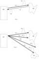
- LiDAR system 100scans the external environment (e.g., by directing light pulses 102 , 202 , 206 , 210 along paths 104 , 204 , 208 , 212 , respectively).
- LiDAR system 100receives returned light pulses 108 , 302 , 306 (which correspond to transmitted light pulses 102 , 202 , 210 , respectively) back after objects 106 and 214 scatter the transmitted light pulses and reflect pulses back along paths 110 , 304 , 308 , respectively.
- the surroundings within the detection rangee.g., the field of view between path 104 and 212 , inclusively
- the surroundings within the detection rangecan be precisely plotted (e.g., a point cloud or image can be created).
- a corresponding light pulseis not received for a particular transmitted light pulse, then it can be determined that there are no objects within a certain range of LiDAR system 100 (e.g., the max scanning distance of LiDAR system 100 ). For example, in FIG. 2 , light pulse 206 will not have a corresponding returned light pulse (as depicted in FIG. 3 ) because it did not produce a scattering event along its transmission path 208 within the predetermined detection range. LiDAR system 100 (or an external system communication with LiDAR system 100 ) can interpret this as no object being along path 208 within the detection range of LiDAR system 100 .
- transmitted light pulses 102 , 202 , 206 , 210can be transmitted in any order, serially, in parallel, or based on other timings with respect to each other.
- LiDAR system 100optionally also directs similar arrays of transmitted light pulses along other planes so that a 2-dimensional array of light pulses is transmitted.
- This 2-dimensional arraycan be transmitted point-by-point, line-by-line, all at once, or in some other manner.
- the point cloud or image from a 1-dimensional array(e.g., a single horizontal line) will produce 2-dimensional information (e.g., (1) the horizontal transmission direction and (2) the range to objects).
- the point cloud or image from a 2-dimensional arraywill have 3-dimensional information (e.g., (1) the horizontal transmission direction, (2) the vertical transmission direction, and (3) the range to objects).
- the density of points in point cloud or image from a LiDAR system 100is equal to the number of pulses divided by the field of view. Given that the field of view is fixed, to increase the density of points generated by one set of transmission-receiving optics, the LiDAR system should fire a pulse more frequently, in other words, a light source with a higher repetition rate is needed. However, by sending pulses more frequently the farthest distance that the LiDAR system can detect may be more limited. For example, if a returned signal from a distant object is received after the system transmits the next pulse, the return signals may be detected in a different order than the order in which the corresponding signals are transmitted, thereby causing ambiguity if the system cannot correctly correlate the returned signals with the transmitted signals.
- the farthest distance the LiDAR system can detectmay be 300 meters and 150 meters for 500 kHz and 1 MHz, respectively.
- the density of points of a LiDAR system with 500 kHz repetition rateis half of that with 1 MHz.
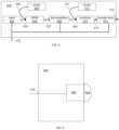
- FIG. 4depicts a logical block diagram of LiDAR system 100 , which includes light source 402 , signal steering system 404 , pulse detector 406 , and controller 408 . These components are coupled together using communications paths 410 , 412 , 414 , 416 , and 418 . These communications paths represent communication (bidirectional or unidirectional) among the various LiDAR system components but need not be physical components themselves. While the communications paths can be implemented by one or more electrical wires, busses, or optical fibers, the communication paths can also be wireless channels or open-air optical paths so that no physical communication medium is present.
- communication path 410is one or more optical fibers
- communication path 412represents an optical path
- communication paths 414 , 416 , 418 , and 420are all one or more electrical wires that carry electrical signals.
- the communications pathscan also include more than one of the above types of communication mediums (e.g., they can include an optical fiber and an optical path or one or more optical fibers and one or more electrical wires).
- LiDAR system 100can also include other components not depicted in FIG. 4 , such as power buses, power supplies, LED indicators, switches, etc. Additionally, other connections among components may be present, such as a direct connection between light source 402 and light detector 406 so that light detector 406 can accurately measure the time from when light source 402 transmits a light pulse until light detector 406 detects a returned light pulse.
- FIG. 5depicts a logical block diagram of one example of light source 402 that is based on a laser fiber, although any number of light sources with varying architecture could be used as part of the LiDAR system.
- Light source 402uses seed 502 to generate initial light pulses of one or more wavelengths (e.g., 1550 nm), which are provided to wavelength-division multiplexor (WDM) 504 via fiber 503 .
- WDMwavelength-division multiplexor
- Pump 506also provides laser power (of a different wavelength, such as 980 nm) to WDM 504 via fiber 505 .
- the output of WDM 504is provided to pre-amplifiers 508 (which includes one or more amplifiers) which provides its output to combiner 510 via fiber 509 .
- Combiner 510also takes laser power from pump 512 via fiber 511 and provides pulses via fiber 513 to booster amplifier 514 , which produces output light pulses on fiber 410 . The outputted light pulses are then fed to steering system 404 .
- light source 402can produce pulses of different amplitudes based on the fiber gain profile of the fiber used in the source.
- Communication path 416couples light source 402 to controller 408 ( FIG. 4 ) so that components of light source 402 can be controlled by or otherwise communicate with controller 408 .
- light source 402may include its own controller. Instead of controller 408 communicating directly with components of light source 402 , a dedicated light source controller communicates with controller 408 and controls and/or communicates with the components of light source 402 .
- Light source 402also includes other components not shown, such as one or more power connectors, power supplies, and/or power lines.
- Some other light sourcesinclude one or more laser diodes, short-cavity fiber lasers, solid-state lasers, and/or tunable external cavity diode lasers, configured to generate one or more light signals at various wavelengths.
- light sources use amplifierse.g., pre-amps or booster amps
- amplifiersinclude a doped optical fiber amplifier, a solid-state bulk amplifier, and/or a semiconductor optical amplifier, configured to receive and amplify light signals.
- signal steering system 404includes any number of components for steering light signals generated by light source 402 .
- signal steering system 404may include one or more optical redirection elements (e.g., mirrors or lens) that steer light pulses (e.g., by rotating, vibrating, or directing) along a transmit path to scan the external environment.
- these optical redirection elementsmay include MEMS mirrors, rotating polyhedron mirrors, or stationary mirrors to steer the transmitted pulse signals to different directions.
- Signal steering system 404optionally also includes other optical components, such as dispersion optics (e.g., diffuser lenses, prisms, or gratings) to further expand the coverage of the transmitted signal in order to increase the LiDAR system 100 's transmission area (i.e., field of view).
- dispersion opticse.g., diffuser lenses, prisms, or gratings
- An example signal steering systemis described in U.S. patent application Ser. No. 15/721,127 filed on Sep. 29, 2017, entitled “2D Scanning High Precision LiDAR Using Combination of Rotating Concave Mirror and Beam Steering Devices,” the content of which is incorporated by reference in its entirety herein for all purposes.
- signal steering system 404does not contain any active optical components (e.g., it does not contain any amplifiers).
- one or more of the components from light source 402such as a booster amplifier, may be included in signal steering system 404 .
- signal steering system 404can be considered a LiD
- Some implementations of signal steering systemsinclude one or more optical redirection elements (e.g., mirrors or lens) that steers returned light signals (e.g., by rotating, vibrating, or directing) along a receive path to direct the returned light signals to the light detector.
- the optical redirection elements that direct light signals along the transmit and receive pathsmay be the same components (e.g., shared), separate components (e.g., dedicated), and/or a combination of shared and separate components. This means that in some cases the transmit and receive paths are different although they may partially overlap (or in some cases, substantially overlap).
- FIG. 6depicts a logical block diagram of one possible arrangement of components in light detector 404 of LiDAR system 100 ( FIG. 4 ).
- Light detector 404includes optics 604 (e.g., a system of one or more optical lenses) and detector 602 (e.g., a charge coupled device (CCD), a photodiode, an avalanche photodiode, a photomultiplier vacuum tube, an image sensor, etc.) that is connected to controller 408 ( FIG. 4 ) via communication path 418 .
- the optics 604may include one or more photo lenses to receive, focus, and direct the returned signals.
- Light detector 404can include filters to selectively pass light of certain wavelengths.
- Light detector 404can also include a timing circuit that measures the time from when a pulse is transmitted to when a corresponding returned pulse is detected. This data can then be transmitted to controller 408 ( FIG. 4 ) or to other devices via communication line 418 . Light detector 404 can also receive information about when light source 402 transmitted a light pulse via communication line 418 or other communications lines that are not shown (e.g., an optical fiber from light source 402 that samples transmitted light pulses). Alternatively, light detector 404 can provide signals via communication line 418 that indicate when returned light pulses are detected. Other pulse data, such as power, pulse shape, and/or wavelength, can also be communicated.
- controller 408contains components for the control of LiDAR system 100 and communication with external devices that use the system.
- controller 408optionally includes one or more processors, memories, communication interfaces, sensors, storage devices, clocks, ASICs, FPGAs, and/or other devices that control light source 402 , signal steering system 404 , and/or light detector 406 .
- controller 408controls the power, rate, timing, and/or other properties of light signals generated by light source 402 ; controls the speed, transmit direction, and/or other parameters of light steering system 404 ; and/or controls the sensitivity and/or other parameters of light detector 406 .
- Controller 408optionally is also configured to process data received from these components. In some examples, controller determines the time it takes from transmitting a light pulse until a corresponding returned light pulse is received; determines when a returned light pulse is not received for a transmitted light pulse; determines the transmitted direction (e.g., horizontal and/or vertical information) for a transmitted/returned light pulse; determines the estimated range in a particular direction; and/or determines any other type of data relevant to LiDAR system 100 .
- controllerdetermines the time it takes from transmitting a light pulse until a corresponding returned light pulse is received; determines when a returned light pulse is not received for a transmitted light pulse; determines the transmitted direction (e.g., horizontal and/or vertical information) for a transmitted/returned light pulse; determines the estimated range in a particular direction; and/or determines any other type of data relevant to LiDAR system 100 .
- FIG. 7 Adepicts part of a pulse steering system (e.g., pulse steering system 404 of FIG. 4 ) according to some embodiments of the present technology.
- Polygon 702has ten reflective sides (sides 702 A- 702 E are visible in FIG. 7 A ) but can have any number of reflective sides.
- Polygon 702rotates about axis 703 based on a drive motor (not shown) to scan pulses from fiber 706 and 708 along a direction perpendicular to axis of rotation 703 (see FIGS. 7 C- 7 E ).
- Mirror 704is positioned next to polygon 702 so that pulses emitted from fiber 706 and 708 that are reflected off rotating polygon 702 are reflected again along a desired optical path. Mirror 704 tilts so as to scan pulses from fiber 706 and 708 in a direction different than the direction that polygon 702 scans pulses (e.g., edge 704 A tilts towards and away from polygon 702 so as to scan pulses along a path that is parallel to the axis of rotation of polygon 702 ).
- polygon 702is responsible for scanning pulses in the vertical direction of the LiDAR system and mirror 704 is responsible for scanning pulses in the horizontal direction. In some other examples, polygon 702 and mirror 704 are configured in the reverse manner.
- fiber 706 and fiber 708provide pulses of different wavelengths (e.g., fiber 706 only provides pulses of a wavelength that is different than the wavelength of pulses provided from fiber 708 ).
- the fibersmay be connected to different light sources that are designed/tuned to provide pulses of different wavelengths or the fibers may be connected to the same light source that is capable of producing pulses of different wavelengths).
- the power for pulses of each wavelengthare tuned based on the distances anticipated in the scan area covered by those pulses.
- fiber 706 and fiber 708provide light signals of the same wavelength (e.g., fiber 706 and fiber 708 are connected to the same light source that only provides one wavelength).
- Fiber 706 and fiber 708are positioned to provide their respective pulses to polygon 702 at different incident angles, which results in the pulses having different reflection angles from polygon 702 . This causes the scan area provided by the pulses from the two fibers to have different scan areas, as illustrated in the example of FIG. 7 B . Because fiber 706 and fiber 708 are positioned to provide pulses at different angle to polygon 702 , the scan areas (the scan area for fiber 706 is represented by the two dotted lines and the scan area for fiber 708 is represented by the two solid lines) are also different. In FIG. 7 B , the scan areas overlap. In some other embodiments, the scan areas do not overlap.
- FIGS. 7 C- 7 Efurther illustrate the different scan areas produced by fiber 706 versus fiber 708 .
- fiber 706 and 708are configured to provide pulses to polygon 702 at different incident angles.
- the rotation of polygon 702allows for the scanning of the pulses in a direction perpendicular to the axis of rotation (which is perpendicular to the page in FIGS. 7 C- 7 E ).
- pulses from fiber 706will be directed along optical path 707 A while pulses from fiber 708 will be directed along optical path 709 A.
- FIG. 7 CWhen polygon 702 is in the position depicted in FIG.
- pulses from fiber 706will be directed along optical path 707 B while pulses from fiber 708 will be directed along optical path 709 B.
- pulses from fiber 706will be directed along optical path 707 C while pulses from fiber 708 will be directed along optical path 709 C.
- pulses from fiber 706 and fiber 708have different wavelengths, they can be triggered without regard to each other (e.g., triggered at the same time, in close proximity to each other, at different rates, at the same rate, synchronously, asynchronously, etc.).
- the wavelength of a returned pulsewill indicate to the LiDAR system along which optical path the pulse traveled.
- the pulses of each fibercan have other different properties as well. For example, pulses from fiber 706 might have a slow repetition rate but have a higher power. These pulses, in some cases, are more suited for detecting ranges of far away objects but at a lower resolution (e.g., lower density of points). In this example, pulses form fiber 708 might have a high repetition rate but have lower power, and are more suited for detecting ranges to nearby objects with higher resolution (e.g., more points).
- FIGS. 7 A- 7 Euses two fibers providing pulses of two different wavelengths
- more fibers and/or wavelengthscan be used.
- a third scan areacan be added to the areas depicted in FIG. 704 . This scan area can overlap with completely, partly, or not at all with the scan areas produced by pulses form fibers 706 and 708 .
- FIG. 8depicts part of a pulse steering system (e.g., pulse steering system 404 of FIG. 4 ) according to some embodiments of the present technology.
- Polygon 802has ten reflective sides (sides 802 A- 802 E are visible in FIG. 8 ) but can have any number of reflective sides.
- Polygon 802rotates about axis 803 based on a drive motor (not shown) to scan pulses from fiber 806 along a direction perpendicular to axis of rotation 803 (similar to the scanning of polygon 702 in FIGS. 7 A- 7 E ).
- fiber 806provides pulses of different wavelengths along path 808 to a dispersion optic (prism 804 in FIG. 8 but other dispersion optics can be used, such as gratings).
- the dispersion opticdirects pulses along different optical paths (e.g., one of paths 810 , 812 , or 814 ) according to the wavelength of the pulse.
- the dispersion opticcan scan pulses along a direction (e.g., a direction parallel to axis of rotation 803 , which is also the direction of dispersion) without using any moving parts. Additional scanning components (e.g., a mirror similar to mirror 704 of FIGS.
- Prism 804(or other dispersion optics) allows for fine separation of pulses that can be used to decrease the speed of the rotating polygon 802 by allowing for more scan lines in the given amount of time.
- FIG. 9depicts an example scan pattern 900 that could be generated using the configuration depicted in FIG. 8 .
- Empty circlese.g., circle 902
- Solid circlese.g., circle 904
- Cross-hatched circlese.g., circle 906
- the horizontal separation of these three pulsesis due to the dispersion optic.
- the horizontal repetition of this pattern of three pulsesis due to additional scanning components in the pulse steering system (e.g., mirror 704 of FIG. 7 A- 7 E ).
- the vertical repetition of the patternis due rotating polygon 802 .
- a pulse steering systemcan realize several benefits.
- the dispersion elementcan provide for a higher density scan pattern that possible with mechanical-only scanning. It may also provide for the ability to scan the pattern faster than mechanical-only scanning can.
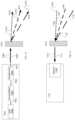
- FIGS. 10 and 11depict parts of a LiDAR system according to some embodiments of the present invention.
- light source 1001has laser seed 1002 connected to pre-amplifier 1004 via fiber 1003 .
- Pre-amplifier 1004is connected to amplifier 1006 via fiber 1005 .
- Output pulsesare provided on output 1007 , which can be any number of optical outputs, such as a fiber.
- Laser seed 1002is a tunable laser seed (such as external-cavity diode lasers and distributed Bragg reflector lasers). It can produce pulses with different wavelengths. In some examples, laser seed 1002 provides pulses with wavelengths ranging from 1510 nm to 1580 nm.
- the pulses of various wavelengths from light source 1001are provided along path 1009 to a dispersion element (in FIG. 10 , the dispersion optics is grating 1010 , but other dispersion optics can be used) that is part of a pulse steering system (which optically includes one or more additional optics).
- the dispersion opticBased on the wave length of the pulse, the dispersion optic directs the pulse along any number of paths. For example, because pulses 1011 , 1013 , and 1015 are each a different wavelength, the dispersion optic directs the pulses down a path associated with the wavelength, path 1012 , path 1014 , and 1016 , respectively.
- the dispersion opticperforms this function based on the wavelength dependence of its refractive index.
- a LiDAR systemcan scan pulses along a line using a dispersion optic. Additional components (e.g., moving mirrors and/or polygons described above) can be used to expand the scan pattern to two dimensions.
- FIG. 11depicts a portion of the receive path of the LiDAR system from FIG. 10 .
- return pulses 1105 , 1107 , and 1109 associated with pulses 1011 , 1013 , and 1015 ( FIG. 10 ), respectivelytravel along optical paths 1106 , 1108 , and 1110 , respectively, back to the dispersion optic.
- Optical paths 1106 , 1108 , and 1110are similar or the same as optical path 1012 , path 1014 , and 1016 , respectively.
- Dispersion opticredirects return pulses 1105 , 1107 , and 1109 along optical path 1111 (similar to return pulse 1112 ) so that detector 1102 of light detector 1101 can detect the return pulses and LiDAR system can calculate ranges associated with the pulses.
Landscapes
- Engineering & Computer Science (AREA)
- Physics & Mathematics (AREA)
- Computer Networks & Wireless Communication (AREA)
- General Physics & Mathematics (AREA)
- Radar, Positioning & Navigation (AREA)
- Remote Sensing (AREA)
- Electromagnetism (AREA)
- Optical Radar Systems And Details Thereof (AREA)
Abstract
Description
Claims (18)
Priority Applications (2)
| Application Number | Priority Date | Filing Date | Title |
|---|---|---|---|
| US16/283,577US11808888B2 (en) | 2018-02-23 | 2019-02-22 | Multi-wavelength pulse steering in LiDAR systems |
| US18/375,961US20240027588A1 (en) | 2018-02-23 | 2023-10-02 | Multi-wavelength pulse steering in lidar systems |
Applications Claiming Priority (2)
| Application Number | Priority Date | Filing Date | Title |
|---|---|---|---|
| US201862634665P | 2018-02-23 | 2018-02-23 | |
| US16/283,577US11808888B2 (en) | 2018-02-23 | 2019-02-22 | Multi-wavelength pulse steering in LiDAR systems |
Related Child Applications (1)
| Application Number | Title | Priority Date | Filing Date |
|---|---|---|---|
| US18/375,961DivisionUS20240027588A1 (en) | 2018-02-23 | 2023-10-02 | Multi-wavelength pulse steering in lidar systems |
Publications (2)
| Publication Number | Publication Date |
|---|---|
| US20190265337A1 US20190265337A1 (en) | 2019-08-29 |
| US11808888B2true US11808888B2 (en) | 2023-11-07 |
Family
ID=67685065
Family Applications (2)
| Application Number | Title | Priority Date | Filing Date |
|---|---|---|---|
| US16/283,577Active2042-03-16US11808888B2 (en) | 2018-02-23 | 2019-02-22 | Multi-wavelength pulse steering in LiDAR systems |
| US18/375,961PendingUS20240027588A1 (en) | 2018-02-23 | 2023-10-02 | Multi-wavelength pulse steering in lidar systems |
Family Applications After (1)
| Application Number | Title | Priority Date | Filing Date |
|---|---|---|---|
| US18/375,961PendingUS20240027588A1 (en) | 2018-02-23 | 2023-10-02 | Multi-wavelength pulse steering in lidar systems |
Country Status (2)
| Country | Link |
|---|---|
| US (2) | US11808888B2 (en) |
| WO (1) | WO2020013890A2 (en) |
Families Citing this family (47)
| Publication number | Priority date | Publication date | Assignee | Title |
|---|---|---|---|---|
| US11609336B1 (en) | 2018-08-21 | 2023-03-21 | Innovusion, Inc. | Refraction compensation for use in LiDAR systems |
| WO2018182812A2 (en) | 2016-12-30 | 2018-10-04 | Innovusion Ireland Limited | Multiwavelength lidar design |
| US10942257B2 (en) | 2016-12-31 | 2021-03-09 | Innovusion Ireland Limited | 2D scanning high precision LiDAR using combination of rotating concave mirror and beam steering devices |
| US11009605B2 (en) | 2017-01-05 | 2021-05-18 | Innovusion Ireland Limited | MEMS beam steering and fisheye receiving lens for LiDAR system |
| US11054508B2 (en) | 2017-01-05 | 2021-07-06 | Innovusion Ireland Limited | High resolution LiDAR using high frequency pulse firing |
| US10969475B2 (en) | 2017-01-05 | 2021-04-06 | Innovusion Ireland Limited | Method and system for encoding and decoding LiDAR |
| CN111542765B (en) | 2017-10-19 | 2024-08-02 | 图达通智能美国有限公司 | LIDAR with large dynamic range |
| US11493601B2 (en) | 2017-12-22 | 2022-11-08 | Innovusion, Inc. | High density LIDAR scanning |
| US11977184B2 (en) | 2018-01-09 | 2024-05-07 | Seyond, Inc. | LiDAR detection systems and methods that use multi-plane mirrors |
| US11675050B2 (en) | 2018-01-09 | 2023-06-13 | Innovusion, Inc. | LiDAR detection systems and methods |
| US11391823B2 (en) | 2018-02-21 | 2022-07-19 | Innovusion, Inc. | LiDAR detection systems and methods with high repetition rate to observe far objects |
| WO2019164961A1 (en) | 2018-02-21 | 2019-08-29 | Innovusion Ireland Limited | Lidar systems with fiber optic coupling |
| WO2019165289A1 (en) | 2018-02-22 | 2019-08-29 | Innovusion Ireland Limited | Receive path for lidar system |
| WO2019165294A1 (en) | 2018-02-23 | 2019-08-29 | Innovusion Ireland Limited | 2-dimensional steering system for lidar systems |
| US12085673B2 (en) | 2018-02-23 | 2024-09-10 | Seyond, Inc. | Distributed LiDAR systems |
| US11808888B2 (en) | 2018-02-23 | 2023-11-07 | Innovusion, Inc. | Multi-wavelength pulse steering in LiDAR systems |
| WO2019245614A2 (en) | 2018-03-09 | 2019-12-26 | Innovusion Ireland Limited | Lidar safety systems and methods |
| WO2019199775A1 (en) | 2018-04-09 | 2019-10-17 | Innovusion Ireland Limited | Lidar systems and methods for exercising precise control of a fiber laser |
| US11789132B2 (en) | 2018-04-09 | 2023-10-17 | Innovusion, Inc. | Compensation circuitry for lidar receiver systems and method of use thereof |
| CN112585492B (en) | 2018-06-15 | 2024-10-25 | 图达通智能美国有限公司 | LIDAR system and method for focusing a range of interest |
| US11860316B1 (en) | 2018-08-21 | 2024-01-02 | Innovusion, Inc. | Systems and method for debris and water obfuscation compensation for use in LiDAR systems |
| US11579300B1 (en) | 2018-08-21 | 2023-02-14 | Innovusion, Inc. | Dual lens receive path for LiDAR system |
| US11614526B1 (en) | 2018-08-24 | 2023-03-28 | Innovusion, Inc. | Virtual windows for LIDAR safety systems and methods |
| US11796645B1 (en) | 2018-08-24 | 2023-10-24 | Innovusion, Inc. | Systems and methods for tuning filters for use in lidar systems |
| US11579258B1 (en) | 2018-08-30 | 2023-02-14 | Innovusion, Inc. | Solid state pulse steering in lidar systems |
| US12313788B1 (en) | 2018-10-09 | 2025-05-27 | Seyond, Inc. | Ultrashort pulses in LiDAR systems |
| WO2020102406A1 (en) | 2018-11-14 | 2020-05-22 | Innovusion Ireland Limited | Lidar systems and methods that use a multi-facet mirror |
| US11675055B2 (en) | 2019-01-10 | 2023-06-13 | Innovusion, Inc. | LiDAR systems and methods with beam steering and wide angle signal detection |
| US11486970B1 (en) | 2019-02-11 | 2022-11-01 | Innovusion, Inc. | Multiple beam generation from a single source beam for use with a LiDAR system |
| US11977185B1 (en) | 2019-04-04 | 2024-05-07 | Seyond, Inc. | Variable angle polygon for use with a LiDAR system |
| WO2021210954A1 (en)* | 2020-04-16 | 2021-10-21 | 주식회사 만도 | Lidar device |
| JP7509578B2 (en)* | 2020-05-22 | 2024-07-02 | 株式会社Screenホールディングス | Optical scanning device, object recognition device, and optical scanning method |
| US12061289B2 (en) | 2021-02-16 | 2024-08-13 | Innovusion, Inc. | Attaching a glass mirror to a rotating metal motor frame |
| US11422267B1 (en) | 2021-02-18 | 2022-08-23 | Innovusion, Inc. | Dual shaft axial flux motor for optical scanners |
| US11789128B2 (en) | 2021-03-01 | 2023-10-17 | Innovusion, Inc. | Fiber-based transmitter and receiver channels of light detection and ranging systems |
| US11555895B2 (en) | 2021-04-20 | 2023-01-17 | Innovusion, Inc. | Dynamic compensation to polygon and motor tolerance using galvo control profile |
| US11614521B2 (en) | 2021-04-21 | 2023-03-28 | Innovusion, Inc. | LiDAR scanner with pivot prism and mirror |
| CN117178199A (en) | 2021-04-22 | 2023-12-05 | 图达通智能美国有限公司 | Compact light detection and ranging design with high resolution and ultra wide field of view |
| WO2022225859A1 (en) | 2021-04-22 | 2022-10-27 | Innovusion, Inc. | A compact lidar design with high resolution and ultra-wide field of view |
| EP4314885A1 (en) | 2021-05-12 | 2024-02-07 | Innovusion, Inc. | Systems and apparatuses for mitigating lidar noise, vibration, and harshness |
| EP4314884A1 (en) | 2021-05-21 | 2024-02-07 | Innovusion, Inc. | Movement profiles for smart scanning using galvonometer mirror inside lidar scanner |
| US11768294B2 (en) | 2021-07-09 | 2023-09-26 | Innovusion, Inc. | Compact lidar systems for vehicle contour fitting |
| CN216356147U (en) | 2021-11-24 | 2022-04-19 | 图达通智能科技(苏州)有限公司 | Vehicle-mounted laser radar motor, vehicle-mounted laser radar and vehicle |
| WO2023133122A2 (en)* | 2022-01-05 | 2023-07-13 | Luminar, Llc | Lidar system with detector array |
| US11871130B2 (en) | 2022-03-25 | 2024-01-09 | Innovusion, Inc. | Compact perception device |
| US12204033B2 (en) | 2022-03-25 | 2025-01-21 | Seyond, Inc. | Multimodal detection with integrated sensors |
| JP2025042122A (en)* | 2023-09-14 | 2025-03-27 | 株式会社小糸製作所 | Measurement device, measurement program, and computer-readable recording medium having computer program recorded thereon |
Citations (373)
| Publication number | Priority date | Publication date | Assignee | Title |
|---|---|---|---|---|
| US3122330A (en) | 1961-12-11 | 1964-02-25 | Ernest J Trentini | Arc reflectors |
| US3854821A (en) | 1971-10-29 | 1974-12-17 | Westinghouse Electric Corp | Optical system for wide band light energy |
| JPS5085346A (en) | 1973-11-27 | 1975-07-09 | ||
| US3897150A (en) | 1972-04-03 | 1975-07-29 | Hughes Aircraft Co | Scanned laser imaging and ranging system |
| GB1427164A (en) | 1972-02-19 | 1976-03-10 | Nippon Electric Co | Interference eliminating system for radars |
| GB2000411A (en) | 1977-06-15 | 1979-01-04 | Impulsphysik Gmbh | Ceilometric method and apparatus |
| US4412720A (en) | 1980-04-23 | 1983-11-01 | Cselt - Centro Studi E Laboratori Telecomunicazioni S.P.A. | Optical system coupling a rectangular light source to a circular light receiver |
| US4464048A (en) | 1981-03-25 | 1984-08-07 | Barr & Stroud Limited | Laser rangefinders |
| US4923263A (en) | 1988-09-22 | 1990-05-08 | The United States Of America As Represented By The Secretary Of The Army | Rotating mirror optical scanning device |
| US5006721A (en) | 1990-03-23 | 1991-04-09 | Perceptron, Inc. | Lidar scanning system |
| JPH04223422A (en) | 1990-12-26 | 1992-08-13 | Ricoh Co Ltd | Internal polygon mirror and its manufacturing method |
| US5157451A (en) | 1991-04-01 | 1992-10-20 | John Taboada | Laser imaging and ranging system using two cameras |
| WO1992022109A1 (en) | 1991-06-07 | 1992-12-10 | Advanced Laser Technologies, Inc. | Laser beam scanning apparatus and method |
| US5303084A (en) | 1991-08-27 | 1994-04-12 | Kaman Aerospace Corporation | Laser light beam homogenizer and imaging lidar system incorporating same |
| US5319434A (en) | 1992-12-30 | 1994-06-07 | Litton Systems, Inc. | Laser rangefinder apparatus with fiber optic interface |
| US5369661A (en) | 1991-02-07 | 1994-11-29 | Nippon Steel Corporation | Semiconductor laser-pumped solid state laser system and optical coupling system coupling semiconductor laser with optical fiber |
| US5442358A (en) | 1991-08-16 | 1995-08-15 | Kaman Aerospace Corporation | Imaging lidar transmitter downlink for command guidance of underwater vehicle |
| US5475207A (en) | 1992-07-14 | 1995-12-12 | Spectra-Physics Scanning Systems, Inc. | Multiple plane scanning system for data reading applications |
| US5510890A (en) | 1992-11-03 | 1996-04-23 | Gec-Marconi Limited | Laser radar with reference beam storage |
| US5546188A (en) | 1992-11-23 | 1996-08-13 | Schwartz Electro-Optics, Inc. | Intelligent vehicle highway system sensor and method |
| US5579153A (en) | 1992-04-27 | 1996-11-26 | Pirelli Cavi S.P.A. | Optical power limiting amplifier |
| US5600487A (en)* | 1994-04-14 | 1997-02-04 | Omron Corporation | Dichroic mirror for separating/synthesizing light with a plurality of wavelengths and optical apparatus and detecting method using the same |
| EP0757257A2 (en) | 1995-07-31 | 1997-02-05 | HE HOLDINGS, INC. dba HUGHES ELECTRONICS | Laser range finder receiver |
| US5614961A (en) | 1993-02-03 | 1997-03-25 | Nitor | Methods and apparatus for image projection |
| US5657077A (en) | 1993-02-18 | 1997-08-12 | Deangelis; Douglas J. | Event recording system with digital line camera |
| US5682225A (en) | 1996-06-07 | 1997-10-28 | Loral Vought Systems Corp. | Ladar intensity image correction for laser output variations |
| US5736958A (en) | 1990-10-29 | 1998-04-07 | Essex Corporation | Image synthesis using time sequential holography |
| US5793491A (en)* | 1992-12-30 | 1998-08-11 | Schwartz Electro-Optics, Inc. | Intelligent vehicle highway system multi-lane sensor and method |
| US5838239A (en) | 1992-10-20 | 1998-11-17 | Robotic Vision Systems, Inc. | System for detecting ice or snow on surface which specularly reflects light |
| US5864391A (en) | 1996-04-04 | 1999-01-26 | Denso Corporation | Radar apparatus and a vehicle safe distance control system using this radar apparatus |
| DE19757848A1 (en) | 1997-12-24 | 1999-07-08 | Johann Hipp | Optical detection apparatus |
| US5926259A (en) | 1995-05-04 | 1999-07-20 | Bushnell Corporation | Laser range finder with target quality display |
| US5936756A (en) | 1996-01-10 | 1999-08-10 | Ricoh Company Ltd. | Compact scanning optical system |
| US6163378A (en) | 1999-06-14 | 2000-12-19 | Khoury; Jehad | Spectroscopic time integrative correlation for rapid medical diagnostic and universal image analysis |
| US6175440B1 (en) | 1994-02-02 | 2001-01-16 | Advanced Laser Technologies, Inc. | Laser beam display |
| US6317202B1 (en) | 1998-11-12 | 2001-11-13 | Denso Corporation | Automotive radar detecting lane mark and frontal obstacle |
| US20010043717A1 (en) | 1998-10-23 | 2001-11-22 | Facet Technology Corporation | Method and apparatus for rapidly determining whether a digitized image frame contains an object of interest |
| US6361324B1 (en) | 2000-12-05 | 2002-03-26 | William Possidento | Tetrahedral twist: chemistry puzzle and teaching device |
| US6420698B1 (en) | 1997-04-24 | 2002-07-16 | Cyra Technologies, Inc. | Integrated system for quickly and accurately imaging and modeling three-dimensional objects |
| EP1237305A2 (en) | 2001-02-28 | 2002-09-04 | KiloLambda IP Limited | Multi-wavelength light source |
| US20020136251A1 (en) | 2001-01-25 | 2002-09-26 | Science And Technology Corporation | Automatic gain control system for use with multiple wavelength signal detector |
| US20020149761A1 (en) | 2001-02-07 | 2002-10-17 | Honeywell International Inc. | Scanner for airborne laser system |
| US20020149760A1 (en) | 2001-03-05 | 2002-10-17 | Sick Ag | Apparatus for determining a distance profile |
| US20030046025A1 (en) | 2001-09-04 | 2003-03-06 | Jamieson James R. | Wide field scanning laser obstacle awareness system |
| US20030066954A1 (en) | 2001-09-03 | 2003-04-10 | Sick Ag | Optoelectronic detection device |
| US20030080285A1 (en) | 2001-10-29 | 2003-05-01 | Sick Ag | Optoelectronic distance measuring device |
| US20030184835A1 (en)* | 2002-01-14 | 2003-10-02 | Boris Goldberg | Multi-beam polygon scanning system |
| US6650404B1 (en) | 2002-05-28 | 2003-11-18 | Analog Modules, Inc. | Laser rangefinder receiver |
| US20040135992A1 (en) | 2002-11-26 | 2004-07-15 | Munro James F. | Apparatus for high accuracy distance and velocity measurement and methods thereof |
| US6783074B1 (en) | 2002-11-07 | 2004-08-31 | Ncr Corporation | Methods and apparatus for efficient use of space in arranging and configuring optical components of bar code scanners |
| US20050033497A1 (en) | 2003-08-06 | 2005-02-10 | Stopczynski Lawrence Gerard | Method of controlling an external object sensor for an automotive vehicle |
| US20050034036A1 (en) | 2001-06-15 | 2005-02-10 | Ulrich Lages | Method for correcting data of several opto-electronic sensors |
| US6864498B2 (en) | 2001-05-11 | 2005-03-08 | Orbotech Ltd. | Optical inspection system employing a staring array scanner |
| US20050088641A1 (en) | 2003-10-23 | 2005-04-28 | Chih-Wei Hung | Testing method for rangefinders |
| US20050190424A1 (en) | 2004-02-27 | 2005-09-01 | Sick Ag | Method and device for optical scanning of objects |
| US20050195383A1 (en) | 1994-05-23 | 2005-09-08 | Breed David S. | Method for obtaining information about objects in a vehicular blind spot |
| CN1677050A (en) | 2004-03-31 | 2005-10-05 | 株式会社电装 | Object detector of vehicle |
| US20050218128A1 (en) | 2004-03-31 | 2005-10-06 | Han You-Hie | Laser processing apparatus with polygon mirror |
| US20060071846A1 (en) | 2003-05-30 | 2006-04-06 | Yakayuki Yanagisawa | Coherent laser radar |
| US20060132752A1 (en) | 2004-12-16 | 2006-06-22 | Kane David M | Micromechanical and related lidar apparatus and method, and fast light-routing components |
| US20060145062A1 (en) | 2002-09-25 | 2006-07-06 | Christian Boehlau | Optoelectronic detection device |
| US20060146377A1 (en) | 2003-03-07 | 2006-07-06 | Qinetiq Limited | Scanning apparatus and method |
| US20060227317A1 (en) | 2005-04-06 | 2006-10-12 | Henderson Sammy W | Efficient lidar with flexible target interrogation pattern |
| US7128267B2 (en) | 2003-07-11 | 2006-10-31 | Sick Ag | Device for optical scanning of objects, especially markings |
| US20070024840A1 (en) | 2005-07-14 | 2007-02-01 | Fetzer Gregory J | Ultraviolet, infrared, and near-infrared lidar system and method |
| US20070091948A1 (en) | 2005-07-29 | 2007-04-26 | Aculight Corporation | Multi-stage optical amplifier having photonic-crystal waveguides for generation of high-power pulsed radiation and associated method |
| JP2007144667A (en) | 2005-11-24 | 2007-06-14 | Fuji Xerox Co Ltd | Image forming apparatus and formed image correcting method |
| CN1322307C (en) | 2004-02-27 | 2007-06-20 | 欧姆龙株式会社 | Apparatus for surface inspection and method and apparatus for inspecting substrate |
| US20070181810A1 (en) | 2006-02-06 | 2007-08-09 | Tan Michael R T | Vertical cavity surface emitting laser (VCSEL) array laser scanner |
| WO2007095329A2 (en)* | 2006-02-15 | 2007-08-23 | Spudnik, Inc. | Servo-assisted scanning beam display systems using fluorescent screens |
| US20070216995A1 (en) | 2006-03-16 | 2007-09-20 | Bollond Paul G | Optical fiber laser having improved efficiency |
| US20070248136A1 (en) | 2006-04-19 | 2007-10-25 | Mobius Photonics, Inc. | Laser apparatus having multiple synchronous amplifiers tied to one master oscillator |
| JP2007301756A (en) | 2006-05-09 | 2007-11-22 | Brother Ind Ltd | Inkjet recording device |
| CN101093285A (en) | 2002-05-09 | 2007-12-26 | 精工爱普生株式会社 | Optical scanner, and mechanism for cleaning optical scanner cover glass |
| US7323987B2 (en) | 2004-06-28 | 2008-01-29 | Sigma Space Corporation | Compact single lens laser system for object/vehicle presence and speed determination |
| JP2008070159A (en) | 2006-09-12 | 2008-03-27 | Hokuyo Automatic Co | Scanning distance measuring device |
| EP1923721A1 (en) | 2005-08-15 | 2008-05-21 | Topcon Corporation | Measuring device |
| US20080123170A1 (en) | 2006-11-27 | 2008-05-29 | Riegl Laser Measurement Systems Gmbh | Scanning apparatus |
| US20080174762A1 (en) | 2006-08-29 | 2008-07-24 | Jony Jiang Liu | Micro-mirror optical tracking and ranging system |
| US7405676B2 (en) | 2004-09-10 | 2008-07-29 | Gatsometer B.V. | Method and system for detecting with laser the passage by a vehicle of a point for monitoring on a road |
| CN101231383A (en) | 2008-02-26 | 2008-07-30 | 上海激光等离子体研究所 | Light spectrum modulation reshaping device for chirp pulse amplified self-collimation recessed surface |
| CN101241182A (en) | 2007-02-06 | 2008-08-13 | 电装波动株式会社 | Laser radar apparatus for measuring direction and distance of object |
| US20080193135A1 (en) | 2007-02-14 | 2008-08-14 | Finisar Corporation | Collimated ball lenses for optical triplexers |
| CN101246216A (en) | 2007-02-14 | 2008-08-20 | 徕卡测量系统股份有限公司 | High-speed laser ranging system including a fiber laser |
| US20080210881A1 (en) | 2005-07-29 | 2008-09-04 | Qinetiq Limited | Laser Measurement Device and Method |
| US20080247425A1 (en) | 2007-04-03 | 2008-10-09 | David Welford | Q-switched microlaser apparatus and method for use |
| US20080264164A1 (en) | 2007-04-30 | 2008-10-30 | Hunter Solheim | Autonomous continuous atmospheric present weather, nowcasting, and forecasting system |
| JP2008298520A (en) | 2007-05-30 | 2008-12-11 | Nec Corp | Scanning distance measuring instrument |
| US20090002678A1 (en) | 2007-02-28 | 2009-01-01 | Denso Wave Incorporated | Laser radar apparatus for three-dimensional detection of objects |
| US20090010644A1 (en) | 2002-02-01 | 2009-01-08 | Cubic Corporation | Integrated optical communication and range finding system and applications thereof |
| US20090051926A1 (en) | 2007-04-13 | 2009-02-26 | United States Of America As Represented By The Administrator Of The National Aeronautics And Spac | Multiple frequency optical mixer and demultiplexer and apparatus for remote sensing |
| US20090059201A1 (en) | 2007-08-28 | 2009-03-05 | Science Applications International Corporation | Full-Field Light Detection and Ranging Imaging System |
| US20090067453A1 (en) | 2005-04-07 | 2009-03-12 | Matsushita Electric Industrial Co., Ltd. | Laser Light Source and Optical Device |
| US20090099813A1 (en) | 2007-09-20 | 2009-04-16 | Jerry Samuel Dimsdale | Time Delay Estimation |
| US20090102313A1 (en) | 2007-09-20 | 2009-04-23 | Joseph Newhall West | Transmission Lines Applied to Contact Free Slip Rings |
| US7541944B2 (en) | 2004-07-12 | 2009-06-02 | The Boeing Company | Systems and methods for collision avoidance |
| US7541943B2 (en) | 2006-05-05 | 2009-06-02 | Eis Electronic Integrated Systems Inc. | Traffic sensor incorporating a video camera and method of operating same |
| CN201251669Y (en) | 2008-07-30 | 2009-06-03 | 中国科学院上海光学精密机械研究所 | Near single photoperiod laser pulse generating device |
| JP2009121836A (en) | 2007-11-12 | 2009-06-04 | Denso Wave Inc | Laser radar equipment |
| US20090147239A1 (en) | 2005-09-02 | 2009-06-11 | Neptec | Apparatus and method for tracking an object |
| US20090245302A1 (en) | 2008-03-31 | 2009-10-01 | Electro Scientific Industries, Inc. | Methods and systems for dynamically generating tailored laser pulses |
| US20090252376A1 (en) | 2000-08-12 | 2009-10-08 | Retterath Jamie E | System for Road Sign Sheeting Classification |
| US20090262760A1 (en) | 2005-01-20 | 2009-10-22 | Vladimir Krupkin | Laser Obstacle Ranging and Display |
| CN101576620A (en) | 2009-06-08 | 2009-11-11 | 北京理工大学 | Large-caliber optical periscopic non-coaxial laser radar three-dimensional scanning device |
| US20090316134A1 (en) | 2004-07-08 | 2009-12-24 | Michael Christopher E | Fiber laser ladar |
| US20090324293A1 (en) | 2008-06-27 | 2009-12-31 | Canon Kabushiki Kaisha | Image forming apparatus |
| US20100006760A1 (en) | 2004-04-13 | 2010-01-14 | Science & Engineering Services, Inc. | Ultraviolet lidar for detection of biological warfare agents |
| US20100007870A1 (en) | 2008-07-09 | 2010-01-14 | Sick Ag | Apparatus for the recognition of the presence of an object in space |
| US20100020377A1 (en) | 2008-07-25 | 2010-01-28 | Spudnik, Inc. | Beam Scanning Based on Two-Dimensional Polygon Scanner for Display and Other Applications |
| US20100020306A1 (en) | 2006-07-13 | 2010-01-28 | Velodyne Acoustics, Inc. | High definition lidar system |
| CN101641613A (en) | 2007-03-02 | 2010-02-03 | 托波西斯地形系统数据有限公司 | Determine the equipment and the method for distance by light pulse |
| US20100025798A1 (en) | 2006-03-27 | 2010-02-04 | Princeton Lightwave, Inc. | Apparatus Comprising a Single Photon Photodetector Having Reduced Afterpulsing and Method Therefor |
| US20100027602A1 (en) | 2008-07-31 | 2010-02-04 | United States Of America As Represented By The Administrator Of The National Aeronautics And Spac | Time delay and distance measurement |
| JP2010035385A (en) | 2008-07-31 | 2010-02-12 | Kyocera Mita Corp | Motor drive controller |
| JP2010038859A (en) | 2008-08-08 | 2010-02-18 | Toyota Motor Corp | Three-dimensional laser range finder |
| EP2157445A2 (en) | 2008-08-19 | 2010-02-24 | Rosemount Aerospace Inc. | Lidar system using a pseudo-random pulse sequence |
| US20100053715A1 (en) | 2006-10-30 | 2010-03-04 | O'neill James | Scanning system for lidar |
| US7679798B2 (en) | 2002-05-09 | 2010-03-16 | Seiko Epson Corporation | Optical scanning device and cover glass cleaning mechanism for optical scanning device |
| JP2010060309A (en) | 2008-09-01 | 2010-03-18 | Ihi Corp | Laser radar and method of monitoring boundary by same |
| US20100097678A1 (en)* | 2007-06-27 | 2010-04-22 | Spudnik, Inc. | Servo Feedback Control Based on Designated Scanning Servo Beam in Scanning Beam Display Systems with Light-Emitting Screens |
| US20100114416A1 (en) | 2008-10-30 | 2010-05-06 | Honeywell International Inc. | System and method for navigating an autonomous vehicle using laser detection and ranging |
| US20100128109A1 (en) | 2008-11-25 | 2010-05-27 | Banks Paul S | Systems And Methods Of High Resolution Three-Dimensional Imaging |
| US20100128248A1 (en) | 2008-11-21 | 2010-05-27 | Sick Ag | Optoelectronic sensor and method for the measurement of distances in accordance with light transit time principle |
| US20100165082A1 (en) | 2008-12-23 | 2010-07-01 | Sick Ag | Detection apparatus |
| CN101813778A (en) | 2010-04-20 | 2010-08-25 | 长春艾克思科技有限责任公司 | Multi-line laser radar system for automobiles |
| US20100245849A1 (en) | 2009-03-31 | 2010-09-30 | Uwe Satzky | Optical sensor operating on the transit time principle |
| US20100271614A1 (en) | 2006-01-27 | 2010-10-28 | Vijay Albuquerque | LIDAR system utilizing SOI-based opto-electronic components |
| US20100302528A1 (en) | 2009-06-02 | 2010-12-02 | Velodyne Acoustics, Inc. | Color lidar scanner |
| US20110032508A1 (en) | 2009-08-06 | 2011-02-10 | Irvine Sensors Corporation | Phase sensing and scanning time of flight LADAR using atmospheric absorption bands |
| US20110085155A1 (en) | 2009-10-08 | 2011-04-14 | Barry Lee Stann | Ladar transmitting and receiving system and method |
| US20110102764A1 (en) | 2006-09-22 | 2011-05-05 | Leica Geosystems Ag | Lidar system |
| US20110122895A1 (en) | 2009-11-23 | 2011-05-26 | Lockheed Martin Corporation | Q-switched oscillator seed-source for mopa laser illuminator method and apparatus |
| CN102083359A (en) | 2008-07-11 | 2011-06-01 | 佳能株式会社 | Photoacoustic measuring device |
| US20110176146A1 (en) | 2008-09-02 | 2011-07-21 | Cristina Alvarez Diez | Device and method for measuring a surface |
| US20110181864A1 (en) | 2008-07-04 | 2011-07-28 | Eads Deutschland Gmbh | Lidar method for measuring speeds and lidar device with time-controlled detection |
| US20110216304A1 (en) | 2006-07-13 | 2011-09-08 | Velodyne Acoustics, Inc. | High definition lidar system |
| US20110235019A1 (en) | 2010-03-23 | 2011-09-29 | Kabushiki Kaisha Toyota Chuo Kenkyusho | Light scanning apparatus and separation distance measurement apparatus |
| EP2395368A1 (en) | 2010-06-11 | 2011-12-14 | Sick AG | Distance-measuring laser scanner for detecting objects in a surveillance range |
| JP2011257193A (en) | 2010-06-07 | 2011-12-22 | Ihi Corp | Object detector |
| US20120035788A1 (en) | 2006-03-16 | 2012-02-09 | Gray & Company, Inc. | Navigation and control system for autonomous vehicles |
| US8116968B2 (en) | 2008-12-23 | 2012-02-14 | National Chiao Tung University | Method for identification of traffic lane boundary |
| KR20120013515A (en) | 2010-08-05 | 2012-02-15 | (주)이오시스템 | Avalanche Photodiode Gain Compensation Device of Optical Measuring Equipment |
| US20120038903A1 (en) | 2010-08-16 | 2012-02-16 | Ball Aerospace & Technologies Corp. | Electronically steered flash lidar |
| WO2012051700A1 (en) | 2010-10-22 | 2012-04-26 | Neptec Design Group Ltd. | Wide angle bistatic scanning optical ranging sensor |
| US20120101680A1 (en) | 2008-10-24 | 2012-04-26 | The Gray Insurance Company | Control and systems for autonomously driven vehicles |
| US20120124113A1 (en) | 2010-11-05 | 2012-05-17 | University of Maribor | LIGHT DETECTION AND RANGING (LiDAR)DATA COMPRESSION AND DECOMPRESSION METHODS AND APPARATUS |
| US20120162373A1 (en) | 2010-12-23 | 2012-06-28 | Electronics And Telecommunications Research Institute | Dynamic range three-dimensional image system |
| GB2487518A (en) | 2009-11-20 | 2012-07-25 | Faro Tech Inc | Device for optically scanning and measuring an environment |
| US8248272B2 (en) | 2005-10-31 | 2012-08-21 | Wavetronix | Detecting targets in roadway intersections |
| US20120221142A1 (en) | 2011-02-24 | 2012-08-30 | Mss, Inc. | Sequential Scanning Of Multiple Wavelengths |
| US20120219020A1 (en) | 1993-12-20 | 2012-08-30 | Imra America, Inc. | Environmentally stable passively modelocked fiber laser pulse source |
| US20120249996A1 (en) | 2011-03-31 | 2012-10-04 | Denso Wave Incorporated | Laser radar for three-dimensional scanning |
| US8299957B2 (en) | 2010-03-19 | 2012-10-30 | Chien Cheng Technology Co., Ltd. | Method for detecting a vehicle type, a vehicle speed and width of a detecting area by a vehicle radar sensor |
| US20130050676A1 (en) | 2009-09-02 | 2013-02-28 | Trimble A.B. | Distance Measurement Methods and Apparatus |
| CN102971657A (en) | 2010-07-22 | 2013-03-13 | 瑞尼斯豪公司 | Laser scanning apparatus and method of use |
| US20130087689A1 (en) | 2011-10-05 | 2013-04-11 | Telcordia Technologies, Inc. | System and Method for Nonlinear Optical Devices |
| US20130107016A1 (en) | 2010-05-17 | 2013-05-02 | Iee International Electronics & Engineering S.A. | Scanning 3d imager |
| US20130116971A1 (en) | 2010-06-28 | 2013-05-09 | Fraunhofer-Gesellschaft Zur Foerderung Der Angewandten Forschung E.V. | Method for generating a signal for a distance measurement and method and system for distance measurement between a transmitter and a receiver |
| KR20130068224A (en) | 2011-12-15 | 2013-06-26 | 여우순엽 | The apparatus and method of monitoring with terrestrial lidar and reflectless totalstation |
| CN103293530A (en) | 2012-02-22 | 2013-09-11 | 株式会社理光 | Distance measuring device |
| US20130235366A1 (en) | 2012-03-07 | 2013-09-12 | Vectronix Ag | Distance measuring device |
| US20130241761A1 (en) | 2012-03-16 | 2013-09-19 | Nikon Corporation | Beam steering for laser radar and other uses |
| US20130293946A1 (en) | 2012-05-01 | 2013-11-07 | Imra America, Inc. | Optical frequency ruler |
| US20130293867A1 (en) | 2009-09-23 | 2013-11-07 | Pixart Imaging Inc. | Distance-measuring device of measuring distance according to variation of imaging location and calibrating method thereof |
| JP2013238440A (en) | 2012-05-14 | 2013-11-28 | Mitsubishi Electric Corp | Beam scan type object detector |
| US20130329279A1 (en) | 2004-03-31 | 2013-12-12 | Imra America, Inc. | Method and apparatus for controlling and protecting pulsed high power fiber amplifier systems |
| US20130342822A1 (en) | 2011-03-02 | 2013-12-26 | Toyota Jidosha Kabushiki Kaisha | Laser radar device |
| US8629977B2 (en) | 2010-04-14 | 2014-01-14 | Digital Ally, Inc. | Traffic scanning LIDAR |
| US20140027607A1 (en) | 2012-05-04 | 2014-01-30 | Princeton Lightwave, Inc. | High-Repetition-Rate Single-Photon Receiver and Method Therefor |
| US8659748B2 (en) | 2011-02-15 | 2014-02-25 | Optical Air Data Systems, Llc | Scanning non-scanning LIDAR |
| US8659643B2 (en) | 2011-01-18 | 2014-02-25 | Disney Enterprises, Inc. | Counting system for vehicle riders |
| US20140063489A1 (en) | 2012-09-06 | 2014-03-06 | Faro Technologies, Inc. | Laser Scanner |
| US20140063255A1 (en) | 1994-05-23 | 2014-03-06 | American Vehicular Sciences, LLC | Techniques for Improving Safe Operation of a Vehicle |
| US20140104594A1 (en) | 2009-07-28 | 2014-04-17 | Applied Concepts, Inc. | Lidar Measurement Device with Target Tracking and Method for Use of Same |
| JP2014071038A (en) | 2012-09-28 | 2014-04-21 | Denso Wave Inc | Laser radar device |
| US20140171523A1 (en) | 2012-11-23 | 2014-06-19 | Universitaet Duisburg Essen | Method for manufacture of pure, carbon free nanoparticles |
| CN103954971A (en) | 2014-05-22 | 2014-07-30 | 武汉大学 | On-board colorful three-dimensional scanning laser radar |
| US20140233942A1 (en) | 2012-02-16 | 2014-08-21 | Nucrypt Llc | System and method for measuring the phase of a modulated optical signal |
| US8842356B2 (en) | 2007-04-02 | 2014-09-23 | Fraunhofer-Gesellschaft Zur Foerderung Der Angewandten Forschung E.V. | Micromechanical device with temperature stabilization and method for adjusting a defined temperature or a defined temperature course on a micromechanical device |
| US20140300952A1 (en) | 2009-06-30 | 2014-10-09 | Trimble Ab | Optical pulse transmitter |
| US20140320845A1 (en) | 2011-12-23 | 2014-10-30 | Valeo Schalter Und Sensoren Gmbh | Optical measuring device and a method for producing a cover disc for a housing of an optical measuring device |
| US20140319638A1 (en) | 2011-10-20 | 2014-10-30 | Agency For Science, Technology And Research | Avalanche photodiode |
| US20140327945A1 (en) | 2004-11-15 | 2014-11-06 | Scaneva Ltd. | Method and device for scanning light |
| US20140332676A1 (en) | 2011-11-29 | 2014-11-13 | Valeo Schalter Und Sensoren Gmbh | Optical measuring device |
| US20140347650A1 (en) | 2011-12-23 | 2014-11-27 | Leica Geosystems Ag | Distance-measuring device alignment |
| US20140350836A1 (en) | 2013-05-24 | 2014-11-27 | Advance Scientific Concepts, Inc. | Automotive auxiliary ladar sensor |
| US8918270B2 (en) | 2010-10-28 | 2014-12-23 | Tongqing Wang | Wireless traffic sensor system |
| US20150015868A1 (en) | 2013-07-11 | 2015-01-15 | Sick Ag | Optoelectric Sensor and Method for the Detection and Distance Determination of Objects |
| US20150055117A1 (en) | 2013-08-20 | 2015-02-26 | Google Inc. | Devices and Methods for a Rotating LIDAR Platform with a Shared Transmit/Receive Path |
| US20150078123A1 (en) | 2013-09-16 | 2015-03-19 | Appareo Systems, Llc | Synthetic underwater visualization system |
| US20150084805A1 (en) | 2012-03-19 | 2015-03-26 | Qinetiq Limited | Detection Techniques |
| US20150109603A1 (en) | 2013-10-21 | 2015-04-23 | Electronics And Telecommunications Research Institute | Multi-wavelength image lidar sensor apparatus and signal processing method thereof |
| US20150116692A1 (en) | 2012-04-30 | 2015-04-30 | Michigan Aerospace Corporation | System and method for scan range gating |
| US20150124238A1 (en)* | 2013-11-05 | 2015-05-07 | Kohji Sakai | Object detecting apparatus |
| US20150131080A1 (en) | 2013-11-12 | 2015-05-14 | Facet Technology Corp. | Methods and Apparatus for Array Based Lidar Systems with Reduced Interference |
| US20150139259A1 (en) | 2013-11-21 | 2015-05-21 | Christie Digital Systems Canada Inc. | Method, system and apparatus for automatically determining operating conditions of a periodically poled lithium niobate crystal in a laser system |
| US20150158489A1 (en) | 2013-12-09 | 2015-06-11 | Hyundai Motor Company | Method for object processing and vehicle supporting the same |
| US9065243B2 (en) | 2011-01-20 | 2015-06-23 | Nippon Telegraph And Telephone Corporation | Optical amplifier |
| EP2889642A1 (en) | 2013-12-16 | 2015-07-01 | Riegl Laser Measurement Systems GmbH | Method for distance measurement |
| US9086273B1 (en) | 2013-03-08 | 2015-07-21 | Google Inc. | Microrod compression of laser beam in combination with transmit lens |
| CN104914448A (en) | 2015-06-16 | 2015-09-16 | 中国科学技术大学 | Range resolution active atmospheric turbulence laser radar system based on differential image motion method |
| US20150266472A1 (en) | 2012-09-05 | 2015-09-24 | Google Inc. | Construction Zone Object Detection Using Light Detection and Ranging |
| US20150293228A1 (en) | 2014-04-11 | 2015-10-15 | Facet Technology Corp. | Methods and apparatus for object detection and identification in a multiple detector lidar array |
| CN204758260U (en) | 2015-07-21 | 2015-11-11 | 北京杏林睿光科技有限公司 | Semiconductor laser structure of multitube core characteristic monitoring |
| US9188674B2 (en) | 2012-07-03 | 2015-11-17 | Ricoh Company, Ltd. | Laser radar device |
| US20150332102A1 (en) | 2007-11-07 | 2015-11-19 | Magna Electronics Inc. | Object detection system |
| US20150338270A1 (en) | 2012-05-10 | 2015-11-26 | Voxtel, Inc. | Discriminating photo counts and dark counts in an avalanche photodiode |
| CN105143820A (en) | 2013-03-15 | 2015-12-09 | 苹果公司 | Depth scanning with multiple emitters |
| US20150355327A1 (en) | 2012-11-21 | 2015-12-10 | Nikon Metrology Nv | Scan mirrors for laser radar |
| CN204885804U (en) | 2015-07-21 | 2015-12-16 | 北京杏林睿光科技有限公司 | A narrow linewidth beam combining module and a multi-wavelength Raman laser with the module |
| US20150378012A1 (en) | 2014-06-27 | 2015-12-31 | Hrl Laboratories Llc | Single chip scanning lidar and method of producing the same |
| WO2016002776A1 (en) | 2014-07-03 | 2016-01-07 | 三菱電機株式会社 | Monitoring apparatus |
| US20160003946A1 (en) | 2014-07-03 | 2016-01-07 | Advanced Scientific Concepts, Inc. | Ladar sensor for a dense environment |
| US9239959B1 (en) | 2013-04-08 | 2016-01-19 | Lockheed Martin Corporation | Multi-resolution, wide field-of-view, unmanned ground vehicle navigation sensor |
| CN105319555A (en) | 2007-02-28 | 2016-02-10 | 电装波动株式会社 | Laser radar apparatus for three-dimensional detection of target |
| US20160047900A1 (en) | 2014-08-15 | 2016-02-18 | US LADAR, Inc. | Method and System for Scanning Ladar Transmission with Pulse Modulation |
| US20160061935A1 (en) | 2014-08-28 | 2016-03-03 | Google Inc. | Methods and Systems for Vehicle Radar Coordination and Interference Reduction |
| US20160061655A1 (en) | 2014-09-03 | 2016-03-03 | Panasonic Intellectual Property Management Co., Ltd. | Measurement system |
| JP2016040662A (en) | 2014-08-12 | 2016-03-24 | 株式会社Ihi | Laser radar apparatus and laser radar method |
| WO2016056545A1 (en) | 2014-10-09 | 2016-04-14 | コニカミノルタ株式会社 | Scanning optical system and light projection and reception device |
| US20160100521A1 (en) | 2014-10-10 | 2016-04-14 | Irobot Corporation | Autonomous Robot Localization |
| US9316724B2 (en) | 2012-12-18 | 2016-04-19 | Sick Ag | Optoelectronic sensor for the detection of objects |
| US20160117048A1 (en) | 2014-09-26 | 2016-04-28 | Cypress Semiconductor Corporation | Background Light Detection for Optical Navigation Systems |
| US20160172819A1 (en) | 2014-12-12 | 2016-06-16 | Omron Corporation | Light amplifying device and laser processing apparatus |
| US20160178736A1 (en) | 2014-12-19 | 2016-06-23 | Hanwha Techwin Co., Ltd. | Lidar system |
| US20160191870A1 (en) | 2014-12-24 | 2016-06-30 | Roger A. Hajjar | Scanning Beam Display System |
| US20160226210A1 (en) | 2015-01-29 | 2016-08-04 | John J. Zayhowski | Systems and methods for light amplification |
| US20160245902A1 (en) | 2015-02-25 | 2016-08-25 | Abbie T. Watnik | Real-time processing and adaptable illumination lidar camera using a spatial light modulator |
| US20160259058A1 (en) | 2015-03-05 | 2016-09-08 | Optech Incorporated | Laser scanning apparatus and method |
| US20160291134A1 (en) | 2015-04-06 | 2016-10-06 | Google Inc. | Long Range Steerable LIDAR System |
| US9477007B2 (en) | 2012-10-19 | 2016-10-25 | Sick Ag | Laser scanner |
| US9476968B2 (en) | 2014-07-24 | 2016-10-25 | Rosemount Aerospace Inc. | System and method for monitoring optical subsystem performance in cloud LIDAR systems |
| US20160313445A1 (en) | 2012-03-16 | 2016-10-27 | Advanced Scientific Concepts, Inc. | Personal ladar sensor |
| WO2016175395A2 (en) | 2015-04-28 | 2016-11-03 | 전자부품연구원 | Multi-channel lidar scanner optical system using mirror rotation manner |
| US20160327646A1 (en) | 2015-05-07 | 2016-11-10 | GM Global Technology Operations LLC | Pseudo random sequences in array lidar systems |
| JP2017003347A (en) | 2015-06-08 | 2017-01-05 | 日本信号株式会社 | Object detection device and object detection method |
| US20170003116A1 (en) | 2015-06-30 | 2017-01-05 | Korea Research Institute Of Standards And Science | Apparatus for real-time non-contact non-destructive thickness measurement using terahertz wave |
| US20170070029A1 (en) | 2015-09-07 | 2017-03-09 | Stmicroelectronics (Grenoble 2) Sas | Optical pulse emitter |
| US9606222B2 (en) | 2012-04-04 | 2017-03-28 | Valeo Schalter Und Sensoren Gmbh | Optoelectronic sensor device, in particular laser scanner, having an adapted receiving unit for optimized reduction of the reception level |
| US9618742B1 (en) | 2013-03-08 | 2017-04-11 | Google Inc. | Rotatable mirror assemblies |
| US9625580B2 (en) | 2014-01-03 | 2017-04-18 | Princeton Lightwave, Inc. | LiDAR system comprising a single-photon detector |
| US20170155225A1 (en) | 2015-11-30 | 2017-06-01 | Luminar Technologies, Inc. | Pulsed laser for lidar system |
| US20170168145A1 (en) | 2014-01-31 | 2017-06-15 | Denso Wave Incorporated | Laser radar device |
| US20170176579A1 (en)* | 2015-12-20 | 2017-06-22 | Apple Inc. | Light detection and ranging sensor |
| WO2017110417A1 (en) | 2015-12-21 | 2017-06-29 | 株式会社小糸製作所 | Image acquisition device for vehicles, control device, vehicle provided with image acquisition device for vehicles and control device, and image acquisition method for vehicles |
| JP2017138301A (en) | 2016-01-28 | 2017-08-10 | 株式会社デンソー | Laser radar equipment |
| US20170242104A1 (en) | 2016-02-18 | 2017-08-24 | Aeye, Inc. | Ladar Transmitter with Induced Phase Drift for Improved Gaze on Scan Area Portions |
| US9753351B2 (en) | 2014-06-30 | 2017-09-05 | Quanergy Systems, Inc. | Planar beam forming and steering optical phased array chip and method of using same |
| US20170276934A1 (en) | 2014-12-11 | 2017-09-28 | Icspi Corp. | Eye-Tracking System and Method Therefor |
| US9778364B2 (en) | 2015-03-25 | 2017-10-03 | Waymo Llc | Vehicle with multiple light detection and ranging devices (LIDARs) |
| US9791555B2 (en) | 2012-04-26 | 2017-10-17 | Neptec Design Group Ltd. | High speed 360 degree scanning LIDAR head |
| US9798003B2 (en) | 2014-01-22 | 2017-10-24 | Sick Ag | Distance measuring sensor and method for the detection and distance determination of objects |
| US20170307738A1 (en) | 2013-11-22 | 2017-10-26 | Uber Technologies, Inc. | Lidar scanner calibration |
| US9810786B1 (en) | 2017-03-16 | 2017-11-07 | Luminar Technologies, Inc. | Optical parametric oscillator for lidar system |
| US9817121B2 (en) | 2013-12-26 | 2017-11-14 | Kabushiki Kaisha Toyota Chuo Kenkyusho | Radar apparatus and method of determining sign of velocity |
| US9823351B2 (en) | 2012-12-18 | 2017-11-21 | Uber Technologies, Inc. | Multi-clad fiber based optical apparatus and methods for light detection and ranging sensors |
| US20170365105A1 (en) | 2016-06-17 | 2017-12-21 | Ford Global Technologies, Llc | Method and apparatus for inter-vehicular safety awareness and alert |
| US9857472B2 (en) | 2013-07-02 | 2018-01-02 | Electronics And Telecommunications Research Institute | Laser radar system for obtaining a 3D image |
| US9869754B1 (en) | 2017-03-22 | 2018-01-16 | Luminar Technologies, Inc. | Scan patterns for lidar systems |
| US9869753B2 (en) | 2014-08-15 | 2018-01-16 | Quanergy Systems, Inc. | Three-dimensional-mapping two-dimensional-scanning lidar based on one-dimensional-steering optical phased arrays and method of using same |
| US20180020115A1 (en)* | 2016-07-15 | 2018-01-18 | Triple-In Holding Ag | Recording of distance profiles |
| US9880278B2 (en) | 2013-08-01 | 2018-01-30 | Robert Bosch Gmbh | Object determination using a radar sensor |
| US20180040171A1 (en) | 2016-08-02 | 2018-02-08 | International Business Machines Corporation | Self-driving vehicle sensor fault remediation |
| US20180050704A1 (en) | 2016-08-16 | 2018-02-22 | Uber Technologies, Inc. | Autonomous vehicle diagnostic system |
| US20180136331A1 (en)* | 2016-09-20 | 2018-05-17 | Innoviz Technologies Ltd. | Selective illumination in lidar based on detection results |
| US20180152691A1 (en) | 2015-09-24 | 2018-05-31 | Ouster, Inc. | Optical system for collecting distance information within a field |
| US9989755B2 (en) | 2015-08-03 | 2018-06-05 | Sumitomo Electric Industries, Ltd. | Method of producing optical module and optical module |
| CN207457508U (en) | 2017-08-08 | 2018-06-05 | 上海禾赛光电科技有限公司 | Laser radar system based on two-dimensional scanning mirrors |
| US20180158471A1 (en) | 2016-12-02 | 2018-06-07 | Breakaway Records, L.L.C. | Record Stabilizer for Multiple Vinyl Sizes |
| US20180156896A1 (en) | 2016-05-18 | 2018-06-07 | James Thomas O'Keeffe | Dynamically steered lidar adapted to vehicle shape |
| CN108132472A (en) | 2017-12-08 | 2018-06-08 | 上海禾赛光电科技有限公司 | Laser radar system |
| US9995820B2 (en) | 2014-05-08 | 2018-06-12 | Sick Ag | Distance-measuring sensor and method for detecting and determining the distance of objects |
| US20180164439A1 (en) | 2016-12-13 | 2018-06-14 | Waymo Llc | Power Modulation for a Rotary Light Detection and Ranging (LIDAR) Device |
| US10007001B1 (en) | 2017-03-28 | 2018-06-26 | Luminar Technologies, Inc. | Active short-wave infrared four-dimensional camera |
| CN207557465U (en) | 2017-08-08 | 2018-06-29 | 上海禾赛光电科技有限公司 | Laser radar system based on tilting mirror |
| US20180188358A1 (en) | 2017-01-05 | 2018-07-05 | Innovusion Ireland Limited | METHOD AND SYSTEM FOR ENCODING AND DECODING LiDAR |
| WO2018125725A1 (en) | 2016-12-31 | 2018-07-05 | Innovusion Ireland Limited | 2D SCANNING HIGH PRECISION LiDAR USING COMBINATION OR ROTATING CONCAVE MIRROR AND BEAM STEERING DEVICES |
| US20180188357A1 (en) | 2017-01-05 | 2018-07-05 | Innovusion Ireland Limited | HIGH RESOLUTION LiDAR USING HIGH FREQUENCY PULSE FIRING |
| US20180188371A1 (en) | 2016-12-30 | 2018-07-05 | Innovusion Ireland Limited | Multiwavelength lidar design |
| US10018724B2 (en) | 2013-02-13 | 2018-07-10 | Universitat Politecnica De Catalunya | System and method for scanning a surface and computer program implementing the method |
| WO2018129410A1 (en) | 2017-01-05 | 2018-07-12 | Innovusion Ireland Limited | Mems beam steering and fisheye receiving lens for lidar system |
| US20180210084A1 (en) | 2017-01-26 | 2018-07-26 | Sick Ag | Optoelectronic sensor and method of determining the distance of an object in a monitored zone |
| US20180217262A1 (en) | 2017-02-01 | 2018-08-02 | Jeffrey Albelo | Beam Scanner for Autonomous Vehicles |
| US10042159B2 (en) | 2016-02-18 | 2018-08-07 | Aeye, Inc. | Ladar transmitter with optical field splitter/inverter |
| US10048381B2 (en) | 2013-07-16 | 2018-08-14 | Valeo Schalter Und Sensoren Gmbh | Opto-electronic detection device and method for sensing the surroundings of a motor vehicle by scanning |
| US10061019B1 (en) | 2017-03-28 | 2018-08-28 | Luminar Technologies, Inc. | Diffractive optical element in a lidar system to correct for backscan |
| WO2018175990A1 (en) | 2017-03-23 | 2018-09-27 | Innovusion Ireland Limited | High resolution lidar using multi-stage multi-phase signal modulation, integration, sampling, and analysis |
| KR20180107673A (en) | 2017-03-22 | 2018-10-02 | (주) 위키옵틱스 | LIDAR light-emitting system improved pattern rotation |
| US20180284241A1 (en) | 2017-03-29 | 2018-10-04 | Luminar Technologies, Inc. | Sizing the Field of View of a Detector to Improve Operation of a Lidar System |
| US20180284285A1 (en)* | 2017-03-29 | 2018-10-04 | Luminar Technologies, Inc. | Synchronized multiple sensor head system for a vehicle |
| US20180284237A1 (en)* | 2017-03-30 | 2018-10-04 | Luminar Technologies, Inc. | Non-Uniform Beam Power Distribution for a Laser Operating in a Vehicle |
| US20180284242A1 (en) | 2017-03-30 | 2018-10-04 | Luminar Technologies, Inc. | Protecting Detector in a Lidar System Using Off-Axis Illumination |
| US20180284286A1 (en) | 2017-03-31 | 2018-10-04 | Luminar Technologies, Inc. | Multi-eye lidar system |
| US10094925B1 (en) | 2017-03-31 | 2018-10-09 | Luminar Technologies, Inc. | Multispectral lidar system |
| US10107914B2 (en) | 2015-02-20 | 2018-10-23 | Apple Inc. | Actuated optical element for light beam scanning device |
| US20180329060A1 (en) | 2017-05-15 | 2018-11-15 | Ouster, Inc. | Lidar unit with an optical link between controller and photosensor layer |
| CN208314210U (en) | 2018-06-29 | 2019-01-01 | 上海禾赛光电科技有限公司 | laser radar system |
| US20190011567A1 (en) | 2017-07-05 | 2019-01-10 | Ouster, Inc. | Light ranging device with mems scanned emitter array and synchronized electronically scanned sensor array |
| US10180517B2 (en) | 2014-04-11 | 2019-01-15 | Aviation Glass & Technology Holding B.V. | Vehicle mirror, and method for manufacturing such a mirror |
| CN208421228U (en) | 2018-06-29 | 2019-01-22 | 上海禾赛光电科技有限公司 | laser radar system |
| US10191155B2 (en) | 2017-03-29 | 2019-01-29 | Luminar Technologies, Inc. | Optical resolution in front of a vehicle |
| US20190094345A1 (en) | 2017-09-25 | 2019-03-28 | Leica Geosystems Ag | Laser scanner |
| US20190101645A1 (en)* | 2017-09-29 | 2019-04-04 | Veoneer Us, Inc. | Detection system with reflection member and offset detection array |
| CN208705506U (en) | 2018-08-28 | 2019-04-05 | 上海禾赛光电科技有限公司 | A kind of lens group for laser radar |
| US20190107607A1 (en) | 2017-10-09 | 2019-04-11 | Luminar Technologies, Inc. | Interlaced scan patterns for lidar system |
| US20190120962A1 (en) | 2017-10-20 | 2019-04-25 | Sick Ag | Transmission/reception module for an optoelectronic sensor and method of detecting objects |
| US20190120942A1 (en) | 2017-10-19 | 2019-04-25 | Innovusion Ireland Limited | Lidar with large dynamic range |
| US10295656B1 (en) | 2018-06-13 | 2019-05-21 | Hesai Photonics Technology Co., Ltd. | Lidar systems and methods |
| US20190154804A1 (en) | 2017-11-22 | 2019-05-23 | Luminar Technologies, Inc. | Efficient orientation of a lidar system in a vehicle |
| US20190154807A1 (en) | 2017-11-21 | 2019-05-23 | Sick Ag | Polygon scanner and method of detecting objects in a monitored zone |
| CN106597471B (en) | 2016-11-08 | 2019-05-24 | 上海禾赛光电科技有限公司 | Vehicle and method with transparent barriers object automatic detection function |
| US10324170B1 (en) | 2018-04-05 | 2019-06-18 | Luminar Technologies, Inc. | Multi-beam lidar system with polygon mirror |
| US20190212416A1 (en) | 2018-01-09 | 2019-07-11 | Innovusion Ireland Limited | Lidar detection systems and methods |
| KR20190084574A (en) | 2018-01-08 | 2019-07-17 | 주식회사 에스오에스랩 | LiDAR scanning device |
| US20190250270A1 (en)* | 2018-02-13 | 2019-08-15 | Shuichi Suzuki | Distance measuring apparatus and mobile body including the same |
| CN209280923U (en) | 2018-10-16 | 2019-08-20 | 上海禾赛光电科技有限公司 | It is a kind of for the receiving terminal circuit of laser radar, reception device and laser radar |
| US20190257924A1 (en) | 2018-02-22 | 2019-08-22 | Innovusion Ireland Limited | Receive path for lidar system |
| US10393877B2 (en) | 2016-06-01 | 2019-08-27 | Velodyne Lidar, Inc. | Multiple pixel scanning LIDAR |
| WO2019165095A1 (en) | 2018-02-23 | 2019-08-29 | Innovusion Ireland Limited | Distributed lidar systems |
| US20190265337A1 (en) | 2018-02-23 | 2019-08-29 | Innovusion Ireland Limited | Multi-wavelength pulse steering in lidar systems |
| WO2019165294A1 (en) | 2018-02-23 | 2019-08-29 | Innovusion Ireland Limited | 2-dimensional steering system for lidar systems |
| US10401482B2 (en) | 2015-12-23 | 2019-09-03 | Sick Ag | Optoelectronic sensor and method for measuring a distance |
| US20190277952A1 (en) | 2018-03-08 | 2019-09-12 | Zf Friedrichshafen Ag | Receiver arrangement for the reception of light impulses, lidar module and method for receiving light impulses |
| US10429495B1 (en) | 2018-04-03 | 2019-10-01 | Hesai Photonics Technology Co., Ltd. | Lidar system and method |
| US20190310368A1 (en) | 2018-04-06 | 2019-10-10 | Luminar Technologies, Inc. | Lidar System with AlInAsSb Avalanche Photodiode |
| US10451716B2 (en) | 2017-11-22 | 2019-10-22 | Luminar Technologies, Inc. | Monitoring rotation of a mirror in a lidar system |
| CN108445468B (en) | 2018-04-03 | 2019-11-05 | 上海禾赛光电科技有限公司 | A kind of distribution type laser radar |
| US10466342B1 (en) | 2018-09-30 | 2019-11-05 | Hesai Photonics Technology Co., Ltd. | Adaptive coding for lidar systems |
| US10509112B1 (en) | 2019-04-02 | 2019-12-17 | Hesai Photonics Technology Co., Ltd. | Laser system for Lidar |
| US20200026071A1 (en) | 2017-12-22 | 2020-01-23 | Innovusion Ireland Limited | High density lidar scanning |
| CN110031823B (en) | 2019-04-22 | 2020-03-24 | 上海禾赛光电科技有限公司 | Noise point identification method for laser radar and laser radar system |
| US10627491B2 (en) | 2017-03-31 | 2020-04-21 | Velodyne Lidar, Inc. | Integrated LIDAR illumination power control |
| CN109917408B (en) | 2019-03-28 | 2020-04-24 | 上海禾赛光电科技有限公司 | Echo processing method and distance measuring method of laser radar and laser radar |
| CN108089201B (en) | 2017-12-08 | 2020-04-24 | 上海禾赛光电科技有限公司 | Obstacle information acquisition method, laser pulse emission method and device |
| CN109116331B (en) | 2018-06-27 | 2020-04-24 | 上海禾赛光电科技有限公司 | Coding laser transceiver, distance measuring device and laser radar system |
| US10641872B2 (en) | 2016-02-18 | 2020-05-05 | Aeye, Inc. | Ladar receiver with advanced optics |
| US20200142074A1 (en) | 2016-03-11 | 2020-05-07 | Kaarta, Inc. | Systems and methods for improvements in scanning and mapping |
| US20200142073A1 (en) | 2018-11-02 | 2020-05-07 | Waymo Llc | Synchronization of Multiple Rotating Sensors of a Vehicle |
| US20200142075A1 (en) | 2019-07-31 | 2020-05-07 | Lg Electronics Inc. | Lidar system and autonomous driving system using the same |
| US20200142076A1 (en) | 2018-11-05 | 2020-05-07 | Mapsted Corp. | Method and system for crowd-sourced trusted-gps region for mobile device localization |
| CN109116366B (en) | 2018-06-27 | 2020-05-19 | 上海禾赛光电科技有限公司 | Multi-beam laser radar with non-uniform pulse energy |
| CN109116367B (en) | 2018-06-27 | 2020-05-19 | 上海禾赛光电科技有限公司 | Laser radar |
| CN110031822B (en) | 2019-04-22 | 2020-05-22 | 上海禾赛光电科技有限公司 | Noise identification method and lidar system that can be used in lidar |
| US10663596B2 (en) | 2017-09-15 | 2020-05-26 | Aeye, Inc. | Ladar receiver with co-bore sited camera |
| US10663564B2 (en) | 2017-03-30 | 2020-05-26 | Luminar Technologies, Inc. | Cross-talk mitigation using wavelength switching |
| US20200319310A1 (en) | 2016-01-31 | 2020-10-08 | Velodyne Lidar, Inc. | Multiple pulse, lidar based 3-d imaging |
| CN211655309U (en) | 2019-12-23 | 2020-10-09 | 上海禾赛光电科技有限公司 | Laser and laser radar including the same |
| CN109917348B (en) | 2019-01-25 | 2020-11-03 | 上海禾赛科技股份有限公司 | Laser radar system |
| CN109814086B (en) | 2019-01-07 | 2020-11-03 | 上海禾赛科技股份有限公司 | a lidar |
| CN110492856B (en) | 2019-08-12 | 2020-11-13 | 上海禾赛光电科技有限公司 | Transimpedance amplification unit circuit feedback circuit, photoelectric detection circuit and laser radar system |
| CN109188397B (en) | 2018-08-29 | 2020-11-24 | 上海禾赛科技股份有限公司 | Laser transmitter-receiver and laser radar |
| CN110736975B (en) | 2019-11-07 | 2020-11-27 | 上海禾赛光电科技有限公司 | Receiver module and lidar including it |
| US20200400798A1 (en) | 2019-06-21 | 2020-12-24 | Aeva, Inc. | Lidar system with solid state spectral scanning |
| CN109725320B (en) | 2017-10-27 | 2020-12-29 | 上海禾赛光电科技有限公司 | Laser radar |
| CN110780284B (en) | 2019-11-22 | 2020-12-29 | 上海禾赛光电科技有限公司 | Receiving system, laser radar including the same, and method of echo reception processing |
| CN110780283B (en) | 2019-11-22 | 2021-01-26 | 上海禾赛光电科技有限公司 | Receiving system, laser radar comprising same and echo receiving method |
| CN110784220B (en) | 2019-11-07 | 2021-02-02 | 上海禾赛光电科技有限公司 | Dynamic threshold timing circuit, laser radar and method for acquiring time information |
| CN212623082U (en) | 2020-04-29 | 2021-02-26 | 上海禾赛光电科技有限公司 | Scanning device for laser radar and laser radar |
| CN110492349B (en) | 2019-08-20 | 2021-03-19 | 上海禾赛科技股份有限公司 | Driving circuit, driving method and laser system |
| US20210088630A9 (en) | 2017-04-19 | 2021-03-25 | Surestar Laser Technology (Suzhou) Co., Ltd. | Laser scanning device, radar device and scanning method thereof |
| CN213182011U (en) | 2020-04-26 | 2021-05-11 | 上海禾赛光电科技有限公司 | Laser radar's transmitting unit, receiving element and laser radar |
| CN109950784B (en) | 2019-04-10 | 2021-05-28 | 上海禾赛科技股份有限公司 | Laser and laser radar |
| CN213750313U (en) | 2020-11-27 | 2021-07-20 | 上海禾赛科技有限公司 | Optical window and laser radar |
| CN214151038U (en) | 2020-12-11 | 2021-09-07 | 上海禾赛科技有限公司 | Laser radar |
| CN109814082B (en) | 2019-01-21 | 2021-10-22 | 上海禾赛科技有限公司 | Light receiving module and laser radar system |
| CN214795200U (en) | 2021-04-30 | 2021-11-19 | 上海禾赛科技有限公司 | Window for laser radar and laser radar |
| CN214795206U (en) | 2021-04-07 | 2021-11-19 | 上海禾赛科技股份有限公司 | Laser radar |
| CN214895784U (en) | 2021-04-30 | 2021-11-26 | 上海禾赛科技有限公司 | Optical detection device and running vehicle |
| CN214895810U (en) | 2021-04-30 | 2021-11-26 | 上海禾赛科技有限公司 | Light splitting device and laser radar |
| US11194048B1 (en) | 2020-05-13 | 2021-12-07 | Luminar, Llc | Lidar system with high-resolution scan pattern |
| CN215641806U (en) | 2021-04-30 | 2022-01-25 | 上海禾赛科技有限公司 | Laser radar |
| CN215932142U (en) | 2021-09-15 | 2022-03-01 | 上海禾赛科技有限公司 | Laser radar |
| CN112578396B (en) | 2019-09-30 | 2022-04-19 | 上海禾赛科技有限公司 | Method and device for coordinate transformation between radars and computer-readable storage medium |
- 2019
- 2019-02-22USUS16/283,577patent/US11808888B2/enactiveActive
- 2019-02-22WOPCT/US2019/019276patent/WO2020013890A2/ennot_activeCeased
- 2023
- 2023-10-02USUS18/375,961patent/US20240027588A1/enactivePending
Patent Citations (502)
| Publication number | Priority date | Publication date | Assignee | Title |
|---|---|---|---|---|
| US3122330A (en) | 1961-12-11 | 1964-02-25 | Ernest J Trentini | Arc reflectors |
| US3854821A (en) | 1971-10-29 | 1974-12-17 | Westinghouse Electric Corp | Optical system for wide band light energy |
| GB1427164A (en) | 1972-02-19 | 1976-03-10 | Nippon Electric Co | Interference eliminating system for radars |
| US3897150A (en) | 1972-04-03 | 1975-07-29 | Hughes Aircraft Co | Scanned laser imaging and ranging system |
| JPS5085346A (en) | 1973-11-27 | 1975-07-09 | ||
| GB2000411A (en) | 1977-06-15 | 1979-01-04 | Impulsphysik Gmbh | Ceilometric method and apparatus |
| US4412720A (en) | 1980-04-23 | 1983-11-01 | Cselt - Centro Studi E Laboratori Telecomunicazioni S.P.A. | Optical system coupling a rectangular light source to a circular light receiver |
| US4464048A (en) | 1981-03-25 | 1984-08-07 | Barr & Stroud Limited | Laser rangefinders |
| US4923263A (en) | 1988-09-22 | 1990-05-08 | The United States Of America As Represented By The Secretary Of The Army | Rotating mirror optical scanning device |
| US5006721A (en) | 1990-03-23 | 1991-04-09 | Perceptron, Inc. | Lidar scanning system |
| US5736958A (en) | 1990-10-29 | 1998-04-07 | Essex Corporation | Image synthesis using time sequential holography |
| JPH04223422A (en) | 1990-12-26 | 1992-08-13 | Ricoh Co Ltd | Internal polygon mirror and its manufacturing method |
| US5369661A (en) | 1991-02-07 | 1994-11-29 | Nippon Steel Corporation | Semiconductor laser-pumped solid state laser system and optical coupling system coupling semiconductor laser with optical fiber |
| US5157451A (en) | 1991-04-01 | 1992-10-20 | John Taboada | Laser imaging and ranging system using two cameras |
| WO1992022109A1 (en) | 1991-06-07 | 1992-12-10 | Advanced Laser Technologies, Inc. | Laser beam scanning apparatus and method |
| US5442358A (en) | 1991-08-16 | 1995-08-15 | Kaman Aerospace Corporation | Imaging lidar transmitter downlink for command guidance of underwater vehicle |
| US5303084A (en) | 1991-08-27 | 1994-04-12 | Kaman Aerospace Corporation | Laser light beam homogenizer and imaging lidar system incorporating same |
| US5579153A (en) | 1992-04-27 | 1996-11-26 | Pirelli Cavi S.P.A. | Optical power limiting amplifier |
| US5475207A (en) | 1992-07-14 | 1995-12-12 | Spectra-Physics Scanning Systems, Inc. | Multiple plane scanning system for data reading applications |
| US5838239A (en) | 1992-10-20 | 1998-11-17 | Robotic Vision Systems, Inc. | System for detecting ice or snow on surface which specularly reflects light |
| US5510890A (en) | 1992-11-03 | 1996-04-23 | Gec-Marconi Limited | Laser radar with reference beam storage |
| US5546188A (en) | 1992-11-23 | 1996-08-13 | Schwartz Electro-Optics, Inc. | Intelligent vehicle highway system sensor and method |
| US5319434A (en) | 1992-12-30 | 1994-06-07 | Litton Systems, Inc. | Laser rangefinder apparatus with fiber optic interface |
| US5793491A (en)* | 1992-12-30 | 1998-08-11 | Schwartz Electro-Optics, Inc. | Intelligent vehicle highway system multi-lane sensor and method |
| US5614961A (en) | 1993-02-03 | 1997-03-25 | Nitor | Methods and apparatus for image projection |
| US5657077A (en) | 1993-02-18 | 1997-08-12 | Deangelis; Douglas J. | Event recording system with digital line camera |
| US20120219020A1 (en) | 1993-12-20 | 2012-08-30 | Imra America, Inc. | Environmentally stable passively modelocked fiber laser pulse source |
| US6175440B1 (en) | 1994-02-02 | 2001-01-16 | Advanced Laser Technologies, Inc. | Laser beam display |
| US5600487A (en)* | 1994-04-14 | 1997-02-04 | Omron Corporation | Dichroic mirror for separating/synthesizing light with a plurality of wavelengths and optical apparatus and detecting method using the same |
| US20140063255A1 (en) | 1994-05-23 | 2014-03-06 | American Vehicular Sciences, LLC | Techniques for Improving Safe Operation of a Vehicle |
| US20050195383A1 (en) | 1994-05-23 | 2005-09-08 | Breed David S. | Method for obtaining information about objects in a vehicular blind spot |
| US5926259A (en) | 1995-05-04 | 1999-07-20 | Bushnell Corporation | Laser range finder with target quality display |
| EP0757257A2 (en) | 1995-07-31 | 1997-02-05 | HE HOLDINGS, INC. dba HUGHES ELECTRONICS | Laser range finder receiver |
| US5936756A (en) | 1996-01-10 | 1999-08-10 | Ricoh Company Ltd. | Compact scanning optical system |
| US5864391A (en) | 1996-04-04 | 1999-01-26 | Denso Corporation | Radar apparatus and a vehicle safe distance control system using this radar apparatus |
| US5682225A (en) | 1996-06-07 | 1997-10-28 | Loral Vought Systems Corp. | Ladar intensity image correction for laser output variations |
| US6420698B1 (en) | 1997-04-24 | 2002-07-16 | Cyra Technologies, Inc. | Integrated system for quickly and accurately imaging and modeling three-dimensional objects |
| DE19757848A1 (en) | 1997-12-24 | 1999-07-08 | Johann Hipp | Optical detection apparatus |
| US20040062442A1 (en) | 1998-10-23 | 2004-04-01 | Facet Technology Corp. | Method and apparatus for identifying objects depicted in a videostream |
| US20010043717A1 (en) | 1998-10-23 | 2001-11-22 | Facet Technology Corporation | Method and apparatus for rapidly determining whether a digitized image frame contains an object of interest |
| US6317202B1 (en) | 1998-11-12 | 2001-11-13 | Denso Corporation | Automotive radar detecting lane mark and frontal obstacle |
| US6163378A (en) | 1999-06-14 | 2000-12-19 | Khoury; Jehad | Spectroscopic time integrative correlation for rapid medical diagnostic and universal image analysis |
| US20150153271A1 (en) | 2000-08-12 | 2015-06-04 | Facet Technology Corp. | System and Assessment of Reflective Objects Along a Roadway |
| US20090252376A1 (en) | 2000-08-12 | 2009-10-08 | Retterath Jamie E | System for Road Sign Sheeting Classification |
| US6361324B1 (en) | 2000-12-05 | 2002-03-26 | William Possidento | Tetrahedral twist: chemistry puzzle and teaching device |
| US20020136251A1 (en) | 2001-01-25 | 2002-09-26 | Science And Technology Corporation | Automatic gain control system for use with multiple wavelength signal detector |
| US6594000B2 (en) | 2001-01-25 | 2003-07-15 | Science And Technology Corporation | Automatic gain control system for use with multiple wavelength signal detector |
| US20020149761A1 (en) | 2001-02-07 | 2002-10-17 | Honeywell International Inc. | Scanner for airborne laser system |
| EP1237305A2 (en) | 2001-02-28 | 2002-09-04 | KiloLambda IP Limited | Multi-wavelength light source |
| US20020149760A1 (en) | 2001-03-05 | 2002-10-17 | Sick Ag | Apparatus for determining a distance profile |
| US6864498B2 (en) | 2001-05-11 | 2005-03-08 | Orbotech Ltd. | Optical inspection system employing a staring array scanner |
| US20050034036A1 (en) | 2001-06-15 | 2005-02-10 | Ulrich Lages | Method for correcting data of several opto-electronic sensors |
| US20030066954A1 (en) | 2001-09-03 | 2003-04-10 | Sick Ag | Optoelectronic detection device |
| US6650407B2 (en) | 2001-09-04 | 2003-11-18 | Rosemount Aerospace Inc. | Wide field scanning laser obstacle awareness system |
| US20030046025A1 (en) | 2001-09-04 | 2003-03-06 | Jamieson James R. | Wide field scanning laser obstacle awareness system |
| US20030080285A1 (en) | 2001-10-29 | 2003-05-01 | Sick Ag | Optoelectronic distance measuring device |
| US6788445B2 (en) | 2002-01-14 | 2004-09-07 | Applied Materials, Inc. | Multi-beam polygon scanning system |
| US20030184835A1 (en)* | 2002-01-14 | 2003-10-02 | Boris Goldberg | Multi-beam polygon scanning system |
| US20090010644A1 (en) | 2002-02-01 | 2009-01-08 | Cubic Corporation | Integrated optical communication and range finding system and applications thereof |
| US7489865B2 (en) | 2002-02-01 | 2009-02-10 | Cubic Corporation | Integrated optical communication and range finding system and applications thereof |
| CN101093285A (en) | 2002-05-09 | 2007-12-26 | 精工爱普生株式会社 | Optical scanner, and mechanism for cleaning optical scanner cover glass |
| US7679798B2 (en) | 2002-05-09 | 2010-03-16 | Seiko Epson Corporation | Optical scanning device and cover glass cleaning mechanism for optical scanning device |
| US6650404B1 (en) | 2002-05-28 | 2003-11-18 | Analog Modules, Inc. | Laser rangefinder receiver |
| US7345271B2 (en) | 2002-09-25 | 2008-03-18 | Ibeo Automobile Sensor Gmbh | Optoelectric sensing device with common deflection device |
| US20060145062A1 (en) | 2002-09-25 | 2006-07-06 | Christian Boehlau | Optoelectronic detection device |
| US6783074B1 (en) | 2002-11-07 | 2004-08-31 | Ncr Corporation | Methods and apparatus for efficient use of space in arranging and configuring optical components of bar code scanners |
| US7202941B2 (en) | 2002-11-26 | 2007-04-10 | Munro James F | Apparatus for high accuracy distance and velocity measurement and methods thereof |
| US20040135992A1 (en) | 2002-11-26 | 2004-07-15 | Munro James F. | Apparatus for high accuracy distance and velocity measurement and methods thereof |
| US20060146377A1 (en) | 2003-03-07 | 2006-07-06 | Qinetiq Limited | Scanning apparatus and method |
| US7675655B2 (en) | 2003-03-07 | 2010-03-09 | Qinetiq Limited | Moving object scanning apparatus and method |
| US20060071846A1 (en) | 2003-05-30 | 2006-04-06 | Yakayuki Yanagisawa | Coherent laser radar |
| US7128267B2 (en) | 2003-07-11 | 2006-10-31 | Sick Ag | Device for optical scanning of objects, especially markings |
| US20050033497A1 (en) | 2003-08-06 | 2005-02-10 | Stopczynski Lawrence Gerard | Method of controlling an external object sensor for an automotive vehicle |
| US6950733B2 (en) | 2003-08-06 | 2005-09-27 | Ford Global Technologies, Llc | Method of controlling an external object sensor for an automotive vehicle |
| US20050088641A1 (en) | 2003-10-23 | 2005-04-28 | Chih-Wei Hung | Testing method for rangefinders |
| US20050190424A1 (en) | 2004-02-27 | 2005-09-01 | Sick Ag | Method and device for optical scanning of objects |
| CN1322307C (en) | 2004-02-27 | 2007-06-20 | 欧姆龙株式会社 | Apparatus for surface inspection and method and apparatus for inspecting substrate |
| US20050218128A1 (en) | 2004-03-31 | 2005-10-06 | Han You-Hie | Laser processing apparatus with polygon mirror |
| CN1677050A (en) | 2004-03-31 | 2005-10-05 | 株式会社电装 | Object detector of vehicle |
| US7382442B2 (en) | 2004-03-31 | 2008-06-03 | Denso Corporation | Object detector of vehicle |
| US20130329279A1 (en) | 2004-03-31 | 2013-12-12 | Imra America, Inc. | Method and apparatus for controlling and protecting pulsed high power fiber amplifier systems |
| US20100006760A1 (en) | 2004-04-13 | 2010-01-14 | Science & Engineering Services, Inc. | Ultraviolet lidar for detection of biological warfare agents |
| US7323987B2 (en) | 2004-06-28 | 2008-01-29 | Sigma Space Corporation | Compact single lens laser system for object/vehicle presence and speed determination |
| US20090316134A1 (en) | 2004-07-08 | 2009-12-24 | Michael Christopher E | Fiber laser ladar |
| US7541944B2 (en) | 2004-07-12 | 2009-06-02 | The Boeing Company | Systems and methods for collision avoidance |
| US7405676B2 (en) | 2004-09-10 | 2008-07-29 | Gatsometer B.V. | Method and system for detecting with laser the passage by a vehicle of a point for monitoring on a road |
| US20140327945A1 (en) | 2004-11-15 | 2014-11-06 | Scaneva Ltd. | Method and device for scanning light |
| US9304316B2 (en) | 2004-11-15 | 2016-04-05 | Apple Inc. | Method and device for scanning light |
| US7440084B2 (en) | 2004-12-16 | 2008-10-21 | Arete' Associates | Micromechanical and related lidar apparatus and method, and fast light-routing components |
| US20060132752A1 (en) | 2004-12-16 | 2006-06-22 | Kane David M | Micromechanical and related lidar apparatus and method, and fast light-routing components |
| US20090262760A1 (en) | 2005-01-20 | 2009-10-22 | Vladimir Krupkin | Laser Obstacle Ranging and Display |
| US7847235B2 (en) | 2005-01-20 | 2010-12-07 | Elbit Systems Electro-Optics Elop Ltd. | Laser obstacle ranging and display |
| US20060227317A1 (en) | 2005-04-06 | 2006-10-12 | Henderson Sammy W | Efficient lidar with flexible target interrogation pattern |
| US20090067453A1 (en) | 2005-04-07 | 2009-03-12 | Matsushita Electric Industrial Co., Ltd. | Laser Light Source and Optical Device |
| US20070024840A1 (en) | 2005-07-14 | 2007-02-01 | Fetzer Gregory J | Ultraviolet, infrared, and near-infrared lidar system and method |
| US7440175B2 (en) | 2005-07-29 | 2008-10-21 | Aculight Corporation | Multi-stage optical amplifier having photonic-crystal waveguides for generation of high-power pulsed radiation and associated method |
| US7835068B1 (en) | 2005-07-29 | 2010-11-16 | Lockheed Martin Corporation | Photonic-crystal-rod optical amplifier with sealed-hole endcap and associated method |
| US20070091948A1 (en) | 2005-07-29 | 2007-04-26 | Aculight Corporation | Multi-stage optical amplifier having photonic-crystal waveguides for generation of high-power pulsed radiation and associated method |
| US20080210881A1 (en) | 2005-07-29 | 2008-09-04 | Qinetiq Limited | Laser Measurement Device and Method |
| EP1923721A1 (en) | 2005-08-15 | 2008-05-21 | Topcon Corporation | Measuring device |
| US20090147239A1 (en) | 2005-09-02 | 2009-06-11 | Neptec | Apparatus and method for tracking an object |
| US8248272B2 (en) | 2005-10-31 | 2012-08-21 | Wavetronix | Detecting targets in roadway intersections |
| JP2007144667A (en) | 2005-11-24 | 2007-06-14 | Fuji Xerox Co Ltd | Image forming apparatus and formed image correcting method |
| US7936448B2 (en) | 2006-01-27 | 2011-05-03 | Lightwire Inc. | LIDAR system utilizing SOI-based opto-electronic components |
| US20100271614A1 (en) | 2006-01-27 | 2010-10-28 | Vijay Albuquerque | LIDAR system utilizing SOI-based opto-electronic components |
| US20070181810A1 (en) | 2006-02-06 | 2007-08-09 | Tan Michael R T | Vertical cavity surface emitting laser (VCSEL) array laser scanner |
| US7544945B2 (en) | 2006-02-06 | 2009-06-09 | Avago Technologies General Ip (Singapore) Pte. Ltd. | Vertical cavity surface emitting laser (VCSEL) array laser scanner |
| WO2007095329A2 (en)* | 2006-02-15 | 2007-08-23 | Spudnik, Inc. | Servo-assisted scanning beam display systems using fluorescent screens |
| US20070216995A1 (en) | 2006-03-16 | 2007-09-20 | Bollond Paul G | Optical fiber laser having improved efficiency |
| US20120035788A1 (en) | 2006-03-16 | 2012-02-09 | Gray & Company, Inc. | Navigation and control system for autonomous vehicles |
| US20100025798A1 (en) | 2006-03-27 | 2010-02-04 | Princeton Lightwave, Inc. | Apparatus Comprising a Single Photon Photodetector Having Reduced Afterpulsing and Method Therefor |
| US20070248136A1 (en) | 2006-04-19 | 2007-10-25 | Mobius Photonics, Inc. | Laser apparatus having multiple synchronous amplifiers tied to one master oscillator |
| US7541943B2 (en) | 2006-05-05 | 2009-06-02 | Eis Electronic Integrated Systems Inc. | Traffic sensor incorporating a video camera and method of operating same |
| JP2007301756A (en) | 2006-05-09 | 2007-11-22 | Brother Ind Ltd | Inkjet recording device |
| US20100020306A1 (en) | 2006-07-13 | 2010-01-28 | Velodyne Acoustics, Inc. | High definition lidar system |
| US7969558B2 (en) | 2006-07-13 | 2011-06-28 | Velodyne Acoustics Inc. | High definition lidar system |
| US20110216304A1 (en) | 2006-07-13 | 2011-09-08 | Velodyne Acoustics, Inc. | High definition lidar system |
| US7576837B2 (en) | 2006-08-29 | 2009-08-18 | The United States Of America As Represented By The Secretary Of The Army | Micro-mirror optical tracking and ranging system |
| US20080174762A1 (en) | 2006-08-29 | 2008-07-24 | Jony Jiang Liu | Micro-mirror optical tracking and ranging system |
| JP2008070159A (en) | 2006-09-12 | 2008-03-27 | Hokuyo Automatic Co | Scanning distance measuring device |
| US20110102764A1 (en) | 2006-09-22 | 2011-05-05 | Leica Geosystems Ag | Lidar system |
| US20100053715A1 (en) | 2006-10-30 | 2010-03-04 | O'neill James | Scanning system for lidar |
| US7697120B2 (en) | 2006-11-27 | 2010-04-13 | Riegl Laser Measurement Systems Gmbh | Scanning apparatus |
| US20080123170A1 (en) | 2006-11-27 | 2008-05-29 | Riegl Laser Measurement Systems Gmbh | Scanning apparatus |
| US7580117B2 (en) | 2007-02-06 | 2009-08-25 | Denso Wave Incorporated | Laser radar apparatus that measures direction and distance of an object |
| CN101241182A (en) | 2007-02-06 | 2008-08-13 | 电装波动株式会社 | Laser radar apparatus for measuring direction and distance of object |
| US20080193135A1 (en) | 2007-02-14 | 2008-08-14 | Finisar Corporation | Collimated ball lenses for optical triplexers |
| US7639347B2 (en) | 2007-02-14 | 2009-12-29 | Leica Geosystems Ag | High-speed laser ranging system including a fiber laser |
| CN101246216A (en) | 2007-02-14 | 2008-08-20 | 徕卡测量系统股份有限公司 | High-speed laser ranging system including a fiber laser |
| US20090002678A1 (en) | 2007-02-28 | 2009-01-01 | Denso Wave Incorporated | Laser radar apparatus for three-dimensional detection of objects |
| US7880865B2 (en) | 2007-02-28 | 2011-02-01 | Denso Wave Incorporated | Laser radar apparatus for three-dimensional detection of objects |
| CN105319555A (en) | 2007-02-28 | 2016-02-10 | 电装波动株式会社 | Laser radar apparatus for three-dimensional detection of target |
| US8212998B2 (en) | 2007-03-02 | 2012-07-03 | Trimble Germany Gmbh | Device and method for the determination of distance by means of light pulses |
| CN101641613A (en) | 2007-03-02 | 2010-02-03 | 托波西斯地形系统数据有限公司 | Determine the equipment and the method for distance by light pulse |
| US8842356B2 (en) | 2007-04-02 | 2014-09-23 | Fraunhofer-Gesellschaft Zur Foerderung Der Angewandten Forschung E.V. | Micromechanical device with temperature stabilization and method for adjusting a defined temperature or a defined temperature course on a micromechanical device |
| US20080247425A1 (en) | 2007-04-03 | 2008-10-09 | David Welford | Q-switched microlaser apparatus and method for use |
| US7830527B2 (en) | 2007-04-13 | 2010-11-09 | The United States Of America As Represented By The Administrator Of The National Aeronautics And Space Administration | Multiple frequency optical mixer and demultiplexer and apparatus for remote sensing |
| US20090051926A1 (en) | 2007-04-13 | 2009-02-26 | United States Of America As Represented By The Administrator Of The National Aeronautics And Spac | Multiple frequency optical mixer and demultiplexer and apparatus for remote sensing |
| US20080264164A1 (en) | 2007-04-30 | 2008-10-30 | Hunter Solheim | Autonomous continuous atmospheric present weather, nowcasting, and forecasting system |
| JP2008298520A (en) | 2007-05-30 | 2008-12-11 | Nec Corp | Scanning distance measuring instrument |
| US20100097678A1 (en)* | 2007-06-27 | 2010-04-22 | Spudnik, Inc. | Servo Feedback Control Based on Designated Scanning Servo Beam in Scanning Beam Display Systems with Light-Emitting Screens |
| US20090059201A1 (en) | 2007-08-28 | 2009-03-05 | Science Applications International Corporation | Full-Field Light Detection and Ranging Imaging System |
| US20090099813A1 (en) | 2007-09-20 | 2009-04-16 | Jerry Samuel Dimsdale | Time Delay Estimation |
| US20110161031A1 (en) | 2007-09-20 | 2011-06-30 | Voxis, Inc. | Time Delay Estimation |
| US20090102313A1 (en) | 2007-09-20 | 2009-04-23 | Joseph Newhall West | Transmission Lines Applied to Contact Free Slip Rings |
| US20150332102A1 (en) | 2007-11-07 | 2015-11-19 | Magna Electronics Inc. | Object detection system |
| JP2009121836A (en) | 2007-11-12 | 2009-06-04 | Denso Wave Inc | Laser radar equipment |
| CN101231383A (en) | 2008-02-26 | 2008-07-30 | 上海激光等离子体研究所 | Light spectrum modulation reshaping device for chirp pulse amplified self-collimation recessed surface |
| US8526473B2 (en) | 2008-03-31 | 2013-09-03 | Electro Scientific Industries | Methods and systems for dynamically generating tailored laser pulses |
| US20090245302A1 (en) | 2008-03-31 | 2009-10-01 | Electro Scientific Industries, Inc. | Methods and systems for dynamically generating tailored laser pulses |
| US8009186B2 (en) | 2008-06-27 | 2011-08-30 | Canon Kabushiki Kaisha | Image forming apparatus |
| US20090324293A1 (en) | 2008-06-27 | 2009-12-31 | Canon Kabushiki Kaisha | Image forming apparatus |
| US20110181864A1 (en) | 2008-07-04 | 2011-07-28 | Eads Deutschland Gmbh | Lidar method for measuring speeds and lidar device with time-controlled detection |
| US20100007870A1 (en) | 2008-07-09 | 2010-01-14 | Sick Ag | Apparatus for the recognition of the presence of an object in space |
| CN102083359A (en) | 2008-07-11 | 2011-06-01 | 佳能株式会社 | Photoacoustic measuring device |
| US7869112B2 (en) | 2008-07-25 | 2011-01-11 | Prysm, Inc. | Beam scanning based on two-dimensional polygon scanner for display and other applications |
| US20100020377A1 (en) | 2008-07-25 | 2010-01-28 | Spudnik, Inc. | Beam Scanning Based on Two-Dimensional Polygon Scanner for Display and Other Applications |
| CN201251669Y (en) | 2008-07-30 | 2009-06-03 | 中国科学院上海光学精密机械研究所 | Near single photoperiod laser pulse generating device |
| JP2010035385A (en) | 2008-07-31 | 2010-02-12 | Kyocera Mita Corp | Motor drive controller |
| US20100027602A1 (en) | 2008-07-31 | 2010-02-04 | United States Of America As Represented By The Administrator Of The National Aeronautics And Spac | Time delay and distance measurement |
| US7982861B2 (en) | 2008-07-31 | 2011-07-19 | The United States Of America As Represented By The Administrator Of The National Aeronautics And Space Administration | Time delay and distance measurement |
| JP2010038859A (en) | 2008-08-08 | 2010-02-18 | Toyota Motor Corp | Three-dimensional laser range finder |
| EP2157445A2 (en) | 2008-08-19 | 2010-02-24 | Rosemount Aerospace Inc. | Lidar system using a pseudo-random pulse sequence |
| US20100045965A1 (en) | 2008-08-19 | 2010-02-25 | Rosemount Aerospace Inc. | Lidar system using a pseudo-random pulse sequence |
| US8072582B2 (en) | 2008-08-19 | 2011-12-06 | Rosemount Aerospace Inc. | Lidar system using a pseudo-random pulse sequence |
| JP2010060309A (en) | 2008-09-01 | 2010-03-18 | Ihi Corp | Laser radar and method of monitoring boundary by same |
| US20110176146A1 (en) | 2008-09-02 | 2011-07-21 | Cristina Alvarez Diez | Device and method for measuring a surface |
| US8836955B2 (en) | 2008-09-02 | 2014-09-16 | Carl Zeiss Ag | Device and method for measuring a surface |
| US20120101680A1 (en) | 2008-10-24 | 2012-04-26 | The Gray Insurance Company | Control and systems for autonomously driven vehicles |
| US20100114416A1 (en) | 2008-10-30 | 2010-05-06 | Honeywell International Inc. | System and method for navigating an autonomous vehicle using laser detection and ranging |
| US20100128248A1 (en) | 2008-11-21 | 2010-05-27 | Sick Ag | Optoelectronic sensor and method for the measurement of distances in accordance with light transit time principle |
| US20100128109A1 (en) | 2008-11-25 | 2010-05-27 | Banks Paul S | Systems And Methods Of High Resolution Three-Dimensional Imaging |
| US8471895B2 (en) | 2008-11-25 | 2013-06-25 | Paul S. Banks | Systems and methods of high resolution three-dimensional imaging |
| US8116968B2 (en) | 2008-12-23 | 2012-02-14 | National Chiao Tung University | Method for identification of traffic lane boundary |
| US20100165082A1 (en) | 2008-12-23 | 2010-07-01 | Sick Ag | Detection apparatus |
| US20100245849A1 (en) | 2009-03-31 | 2010-09-30 | Uwe Satzky | Optical sensor operating on the transit time principle |
| US20100302528A1 (en) | 2009-06-02 | 2010-12-02 | Velodyne Acoustics, Inc. | Color lidar scanner |
| CN101576620A (en) | 2009-06-08 | 2009-11-11 | 北京理工大学 | Large-caliber optical periscopic non-coaxial laser radar three-dimensional scanning device |
| US20140300952A1 (en) | 2009-06-30 | 2014-10-09 | Trimble Ab | Optical pulse transmitter |
| US20140104594A1 (en) | 2009-07-28 | 2014-04-17 | Applied Concepts, Inc. | Lidar Measurement Device with Target Tracking and Method for Use of Same |
| US20110032508A1 (en) | 2009-08-06 | 2011-02-10 | Irvine Sensors Corporation | Phase sensing and scanning time of flight LADAR using atmospheric absorption bands |
| US20130050676A1 (en) | 2009-09-02 | 2013-02-28 | Trimble A.B. | Distance Measurement Methods and Apparatus |
| US20130293867A1 (en) | 2009-09-23 | 2013-11-07 | Pixart Imaging Inc. | Distance-measuring device of measuring distance according to variation of imaging location and calibrating method thereof |
| US8749764B2 (en) | 2009-09-23 | 2014-06-10 | Pixart Imaging Inc. | Distance-measuring device of measuring distance according to variation of imaging location and calibrating method thereof |
| US20110085155A1 (en) | 2009-10-08 | 2011-04-14 | Barry Lee Stann | Ladar transmitting and receiving system and method |
| GB2487518A (en) | 2009-11-20 | 2012-07-25 | Faro Tech Inc | Device for optically scanning and measuring an environment |
| US9923329B2 (en) | 2009-11-23 | 2018-03-20 | Lockheed Martin Corporation | Q-switched oscillator seed-source for MOPA laser illuminator apparatus and method |
| US20110122895A1 (en) | 2009-11-23 | 2011-05-26 | Lockheed Martin Corporation | Q-switched oscillator seed-source for mopa laser illuminator method and apparatus |
| US8299957B2 (en) | 2010-03-19 | 2012-10-30 | Chien Cheng Technology Co., Ltd. | Method for detecting a vehicle type, a vehicle speed and width of a detecting area by a vehicle radar sensor |
| US20110235019A1 (en) | 2010-03-23 | 2011-09-29 | Kabushiki Kaisha Toyota Chuo Kenkyusho | Light scanning apparatus and separation distance measurement apparatus |
| US8976339B2 (en) | 2010-04-14 | 2015-03-10 | Digital Ally, Inc. | Traffic scanning LIDAR |
| US8629977B2 (en) | 2010-04-14 | 2014-01-14 | Digital Ally, Inc. | Traffic scanning LIDAR |
| CN101813778A (en) | 2010-04-20 | 2010-08-25 | 长春艾克思科技有限责任公司 | Multi-line laser radar system for automobiles |
| US20130107016A1 (en) | 2010-05-17 | 2013-05-02 | Iee International Electronics & Engineering S.A. | Scanning 3d imager |
| US9621876B2 (en) | 2010-05-17 | 2017-04-11 | Iee International Electronics & Engineering S.A. | Scanning 3D imager |
| JP2011257193A (en) | 2010-06-07 | 2011-12-22 | Ihi Corp | Object detector |
| EP2395368A1 (en) | 2010-06-11 | 2011-12-14 | Sick AG | Distance-measuring laser scanner for detecting objects in a surveillance range |
| US20130116971A1 (en) | 2010-06-28 | 2013-05-09 | Fraunhofer-Gesellschaft Zur Foerderung Der Angewandten Forschung E.V. | Method for generating a signal for a distance measurement and method and system for distance measurement between a transmitter and a receiver |
| US9671094B2 (en) | 2010-07-22 | 2017-06-06 | Renishaw Plc | Laser scanning apparatus and method of use |
| CN102971657A (en) | 2010-07-22 | 2013-03-13 | 瑞尼斯豪公司 | Laser scanning apparatus and method of use |
| KR20120013515A (en) | 2010-08-05 | 2012-02-15 | (주)이오시스템 | Avalanche Photodiode Gain Compensation Device of Optical Measuring Equipment |
| US8736818B2 (en) | 2010-08-16 | 2014-05-27 | Ball Aerospace & Technologies Corp. | Electronically steered flash LIDAR |
| US20120038903A1 (en) | 2010-08-16 | 2012-02-16 | Ball Aerospace & Technologies Corp. | Electronically steered flash lidar |
| US9255790B2 (en) | 2010-10-22 | 2016-02-09 | Neptec Design Group Ltd. | Wide angle bistatic scanning optical ranging sensor |
| US20140078514A1 (en) | 2010-10-22 | 2014-03-20 | Neptec Design Group Ltd. | Wide angle bistatic scanning optical ranging sensor |
| WO2012051700A1 (en) | 2010-10-22 | 2012-04-26 | Neptec Design Group Ltd. | Wide angle bistatic scanning optical ranging sensor |
| US8918270B2 (en) | 2010-10-28 | 2014-12-23 | Tongqing Wang | Wireless traffic sensor system |
| US9300321B2 (en) | 2010-11-05 | 2016-03-29 | University of Maribor | Light detection and ranging (LiDAR)data compression and decompression methods and apparatus |
| US20120124113A1 (en) | 2010-11-05 | 2012-05-17 | University of Maribor | LIGHT DETECTION AND RANGING (LiDAR)DATA COMPRESSION AND DECOMPRESSION METHODS AND APPARATUS |
| US20120162373A1 (en) | 2010-12-23 | 2012-06-28 | Electronics And Telecommunications Research Institute | Dynamic range three-dimensional image system |
| US8659643B2 (en) | 2011-01-18 | 2014-02-25 | Disney Enterprises, Inc. | Counting system for vehicle riders |
| US9065243B2 (en) | 2011-01-20 | 2015-06-23 | Nippon Telegraph And Telephone Corporation | Optical amplifier |
| US8659748B2 (en) | 2011-02-15 | 2014-02-25 | Optical Air Data Systems, Llc | Scanning non-scanning LIDAR |
| US20120221142A1 (en) | 2011-02-24 | 2012-08-30 | Mss, Inc. | Sequential Scanning Of Multiple Wavelengths |
| US8812149B2 (en) | 2011-02-24 | 2014-08-19 | Mss, Inc. | Sequential scanning of multiple wavelengths |
| US20130342822A1 (en) | 2011-03-02 | 2013-12-26 | Toyota Jidosha Kabushiki Kaisha | Laser radar device |
| US8994928B2 (en) | 2011-03-02 | 2015-03-31 | Toyota Jidosha Kabushiki Kaisha | Laser radar device |
| JP2012211831A (en) | 2011-03-31 | 2012-11-01 | Denso Wave Inc | Laser radar device |
| US20120249996A1 (en) | 2011-03-31 | 2012-10-04 | Denso Wave Incorporated | Laser radar for three-dimensional scanning |
| US8681319B2 (en) | 2011-03-31 | 2014-03-25 | Denso Wave Incorporated | Laser radar for three-dimensional scanning |
| CN102736075A (en) | 2011-03-31 | 2012-10-17 | 电装波动株式会社 | Laser radar for three-dimensional scanning |
| US20130087689A1 (en) | 2011-10-05 | 2013-04-11 | Telcordia Technologies, Inc. | System and Method for Nonlinear Optical Devices |
| US20140319638A1 (en) | 2011-10-20 | 2014-10-30 | Agency For Science, Technology And Research | Avalanche photodiode |
| US20140332676A1 (en) | 2011-11-29 | 2014-11-13 | Valeo Schalter Und Sensoren Gmbh | Optical measuring device |
| KR20130068224A (en) | 2011-12-15 | 2013-06-26 | 여우순엽 | The apparatus and method of monitoring with terrestrial lidar and reflectless totalstation |
| US9194701B2 (en) | 2011-12-23 | 2015-11-24 | Leica Geosystems Ag | Distance-measuring device alignment |
| US20140347650A1 (en) | 2011-12-23 | 2014-11-27 | Leica Geosystems Ag | Distance-measuring device alignment |
| US20140320845A1 (en) | 2011-12-23 | 2014-10-30 | Valeo Schalter Und Sensoren Gmbh | Optical measuring device and a method for producing a cover disc for a housing of an optical measuring device |
| US20140233942A1 (en) | 2012-02-16 | 2014-08-21 | Nucrypt Llc | System and method for measuring the phase of a modulated optical signal |
| CN103293530A (en) | 2012-02-22 | 2013-09-11 | 株式会社理光 | Distance measuring device |
| US20130235366A1 (en) | 2012-03-07 | 2013-09-12 | Vectronix Ag | Distance measuring device |
| US20160313445A1 (en) | 2012-03-16 | 2016-10-27 | Advanced Scientific Concepts, Inc. | Personal ladar sensor |
| US9915726B2 (en) | 2012-03-16 | 2018-03-13 | Continental Advanced Lidar Solutions Us, Llc | Personal LADAR sensor |
| US20130241761A1 (en) | 2012-03-16 | 2013-09-19 | Nikon Corporation | Beam steering for laser radar and other uses |
| US20150084805A1 (en) | 2012-03-19 | 2015-03-26 | Qinetiq Limited | Detection Techniques |
| US9606222B2 (en) | 2012-04-04 | 2017-03-28 | Valeo Schalter Und Sensoren Gmbh | Optoelectronic sensor device, in particular laser scanner, having an adapted receiving unit for optimized reduction of the reception level |
| US9791555B2 (en) | 2012-04-26 | 2017-10-17 | Neptec Design Group Ltd. | High speed 360 degree scanning LIDAR head |
| US9696426B2 (en) | 2012-04-30 | 2017-07-04 | Michigan Aerospace Corporation | System and method for scan range gating |
| US20150116692A1 (en) | 2012-04-30 | 2015-04-30 | Michigan Aerospace Corporation | System and method for scan range gating |
| US9354485B2 (en) | 2012-05-01 | 2016-05-31 | Imra America, Inc. | Optical frequency ruler |
| US20130293946A1 (en) | 2012-05-01 | 2013-11-07 | Imra America, Inc. | Optical frequency ruler |
| US20140027607A1 (en) | 2012-05-04 | 2014-01-30 | Princeton Lightwave, Inc. | High-Repetition-Rate Single-Photon Receiver and Method Therefor |
| US20150338270A1 (en) | 2012-05-10 | 2015-11-26 | Voxtel, Inc. | Discriminating photo counts and dark counts in an avalanche photodiode |
| JP2013238440A (en) | 2012-05-14 | 2013-11-28 | Mitsubishi Electric Corp | Beam scan type object detector |
| US9188674B2 (en) | 2012-07-03 | 2015-11-17 | Ricoh Company, Ltd. | Laser radar device |
| US20150266472A1 (en) | 2012-09-05 | 2015-09-24 | Google Inc. | Construction Zone Object Detection Using Light Detection and Ranging |
| US20140063489A1 (en) | 2012-09-06 | 2014-03-06 | Faro Technologies, Inc. | Laser Scanner |
| JP2014071038A (en) | 2012-09-28 | 2014-04-21 | Denso Wave Inc | Laser radar device |
| US9477007B2 (en) | 2012-10-19 | 2016-10-25 | Sick Ag | Laser scanner |
| US20150355327A1 (en) | 2012-11-21 | 2015-12-10 | Nikon Metrology Nv | Scan mirrors for laser radar |
| US9638799B2 (en) | 2012-11-21 | 2017-05-02 | Nikon Corporation | Scan mirrors for laser radar |
| US20140171523A1 (en) | 2012-11-23 | 2014-06-19 | Universitaet Duisburg Essen | Method for manufacture of pure, carbon free nanoparticles |
| US10035112B2 (en) | 2012-11-23 | 2018-07-31 | Universitaet Duisburg Essen | Method for manufacture of pure, carbon free nanoparticles |
| US9316724B2 (en) | 2012-12-18 | 2016-04-19 | Sick Ag | Optoelectronic sensor for the detection of objects |
| US9823351B2 (en) | 2012-12-18 | 2017-11-21 | Uber Technologies, Inc. | Multi-clad fiber based optical apparatus and methods for light detection and ranging sensors |
| US10018724B2 (en) | 2013-02-13 | 2018-07-10 | Universitat Politecnica De Catalunya | System and method for scanning a surface and computer program implementing the method |
| US9086273B1 (en) | 2013-03-08 | 2015-07-21 | Google Inc. | Microrod compression of laser beam in combination with transmit lens |
| US9618742B1 (en) | 2013-03-08 | 2017-04-11 | Google Inc. | Rotatable mirror assemblies |
| CN105143820A (en) | 2013-03-15 | 2015-12-09 | 苹果公司 | Depth scanning with multiple emitters |
| US9239959B1 (en) | 2013-04-08 | 2016-01-19 | Lockheed Martin Corporation | Multi-resolution, wide field-of-view, unmanned ground vehicle navigation sensor |
| US20140350836A1 (en) | 2013-05-24 | 2014-11-27 | Advance Scientific Concepts, Inc. | Automotive auxiliary ladar sensor |
| US9857472B2 (en) | 2013-07-02 | 2018-01-02 | Electronics And Telecommunications Research Institute | Laser radar system for obtaining a 3D image |
| US20150015868A1 (en) | 2013-07-11 | 2015-01-15 | Sick Ag | Optoelectric Sensor and Method for the Detection and Distance Determination of Objects |
| US10048381B2 (en) | 2013-07-16 | 2018-08-14 | Valeo Schalter Und Sensoren Gmbh | Opto-electronic detection device and method for sensing the surroundings of a motor vehicle by scanning |
| US9880278B2 (en) | 2013-08-01 | 2018-01-30 | Robert Bosch Gmbh | Object determination using a radar sensor |
| US20150055117A1 (en) | 2013-08-20 | 2015-02-26 | Google Inc. | Devices and Methods for a Rotating LIDAR Platform with a Shared Transmit/Receive Path |
| US20150078123A1 (en) | 2013-09-16 | 2015-03-19 | Appareo Systems, Llc | Synthetic underwater visualization system |
| US9702966B2 (en) | 2013-09-16 | 2017-07-11 | Appareo Systems, Llc | Synthetic underwater visualization system |
| US20150109603A1 (en) | 2013-10-21 | 2015-04-23 | Electronics And Telecommunications Research Institute | Multi-wavelength image lidar sensor apparatus and signal processing method thereof |
| US20150124238A1 (en)* | 2013-11-05 | 2015-05-07 | Kohji Sakai | Object detecting apparatus |
| US10203399B2 (en) | 2013-11-12 | 2019-02-12 | Big Sky Financial Corporation | Methods and apparatus for array based LiDAR systems with reduced interference |
| US20150131080A1 (en) | 2013-11-12 | 2015-05-14 | Facet Technology Corp. | Methods and Apparatus for Array Based Lidar Systems with Reduced Interference |
| US20150139259A1 (en) | 2013-11-21 | 2015-05-21 | Christie Digital Systems Canada Inc. | Method, system and apparatus for automatically determining operating conditions of a periodically poled lithium niobate crystal in a laser system |
| US9048616B1 (en) | 2013-11-21 | 2015-06-02 | Christie Digital Systems Usa, Inc. | Method, system and apparatus for automatically determining operating conditions of a periodically poled lithium niobate crystal in a laser system |
| US20170307738A1 (en) | 2013-11-22 | 2017-10-26 | Uber Technologies, Inc. | Lidar scanner calibration |
| US20150158489A1 (en) | 2013-12-09 | 2015-06-11 | Hyundai Motor Company | Method for object processing and vehicle supporting the same |
| EP2889642A1 (en) | 2013-12-16 | 2015-07-01 | Riegl Laser Measurement Systems GmbH | Method for distance measurement |
| US9817121B2 (en) | 2013-12-26 | 2017-11-14 | Kabushiki Kaisha Toyota Chuo Kenkyusho | Radar apparatus and method of determining sign of velocity |
| US9625580B2 (en) | 2014-01-03 | 2017-04-18 | Princeton Lightwave, Inc. | LiDAR system comprising a single-photon detector |
| US9798003B2 (en) | 2014-01-22 | 2017-10-24 | Sick Ag | Distance measuring sensor and method for the detection and distance determination of objects |
| US20170168145A1 (en) | 2014-01-31 | 2017-06-15 | Denso Wave Incorporated | Laser radar device |
| US20150293228A1 (en) | 2014-04-11 | 2015-10-15 | Facet Technology Corp. | Methods and apparatus for object detection and identification in a multiple detector lidar array |
| US10180517B2 (en) | 2014-04-11 | 2019-01-15 | Aviation Glass & Technology Holding B.V. | Vehicle mirror, and method for manufacturing such a mirror |
| US9995820B2 (en) | 2014-05-08 | 2018-06-12 | Sick Ag | Distance-measuring sensor and method for detecting and determining the distance of objects |
| CN103954971A (en) | 2014-05-22 | 2014-07-30 | 武汉大学 | On-board colorful three-dimensional scanning laser radar |
| US20150378012A1 (en) | 2014-06-27 | 2015-12-31 | Hrl Laboratories Llc | Single chip scanning lidar and method of producing the same |
| US9753351B2 (en) | 2014-06-30 | 2017-09-05 | Quanergy Systems, Inc. | Planar beam forming and steering optical phased array chip and method of using same |
| US20160003946A1 (en) | 2014-07-03 | 2016-01-07 | Advanced Scientific Concepts, Inc. | Ladar sensor for a dense environment |
| US9575184B2 (en) | 2014-07-03 | 2017-02-21 | Continental Advanced Lidar Solutions Us, Inc. | LADAR sensor for a dense environment |
| WO2016002776A1 (en) | 2014-07-03 | 2016-01-07 | 三菱電機株式会社 | Monitoring apparatus |
| US9476968B2 (en) | 2014-07-24 | 2016-10-25 | Rosemount Aerospace Inc. | System and method for monitoring optical subsystem performance in cloud LIDAR systems |
| JP2016040662A (en) | 2014-08-12 | 2016-03-24 | 株式会社Ihi | Laser radar apparatus and laser radar method |
| US10073166B2 (en) | 2014-08-15 | 2018-09-11 | Aeye, Inc. | Method and system for ladar transmission with spinning polygon mirror for dynamic scan patterns |
| US20160047900A1 (en) | 2014-08-15 | 2016-02-18 | US LADAR, Inc. | Method and System for Scanning Ladar Transmission with Pulse Modulation |
| US10908265B2 (en) | 2014-08-15 | 2021-02-02 | Aeye, Inc. | Ladar transmitter with feedback control of dynamic scan patterns |
| US10078133B2 (en) | 2014-08-15 | 2018-09-18 | Aeye, Inc. | Method and system for ladar transmission with closed loop feedback control of dynamic scan patterns |
| US9897689B2 (en) | 2014-08-15 | 2018-02-20 | Aeye, Inc. | Method and system for ladar transmission with interline skipping for dynamic scan patterns |
| US9885778B2 (en) | 2014-08-15 | 2018-02-06 | Aeye, Inc. | Method and system for scanning ladar transmission with pulse modulation |
| US20160047896A1 (en) | 2014-08-15 | 2016-02-18 | US LADAR, Inc. | Method and System for Ladar Transmission with Spinning Polygon Mirror for Dynamic Scan Patterns |
| US20160047895A1 (en) | 2014-08-15 | 2016-02-18 | US LADAR, Inc. | Method and System for Ladar Transmission with Closed Loop Feedback Control of Dynamic Scan Patterns |
| US9869753B2 (en) | 2014-08-15 | 2018-01-16 | Quanergy Systems, Inc. | Three-dimensional-mapping two-dimensional-scanning lidar based on one-dimensional-steering optical phased arrays and method of using same |
| US20160061935A1 (en) | 2014-08-28 | 2016-03-03 | Google Inc. | Methods and Systems for Vehicle Radar Coordination and Interference Reduction |
| US9605998B2 (en) | 2014-09-03 | 2017-03-28 | Panasonic Intellectual Property Management Co., Ltd. | Measurement system |
| US20160061655A1 (en) | 2014-09-03 | 2016-03-03 | Panasonic Intellectual Property Management Co., Ltd. | Measurement system |
| US9927915B2 (en) | 2014-09-26 | 2018-03-27 | Cypress Semiconductor Corporation | Optical navigation systems and methods for background light detection and avoiding false detection and auto-movement |
| US20160117048A1 (en) | 2014-09-26 | 2016-04-28 | Cypress Semiconductor Corporation | Background Light Detection for Optical Navigation Systems |
| WO2016056545A1 (en) | 2014-10-09 | 2016-04-14 | コニカミノルタ株式会社 | Scanning optical system and light projection and reception device |
| US20160100521A1 (en) | 2014-10-10 | 2016-04-14 | Irobot Corporation | Autonomous Robot Localization |
| US9510505B2 (en) | 2014-10-10 | 2016-12-06 | Irobot Corporation | Autonomous robot localization |
| US20170276934A1 (en) | 2014-12-11 | 2017-09-28 | Icspi Corp. | Eye-Tracking System and Method Therefor |
| US10317672B2 (en) | 2014-12-11 | 2019-06-11 | AdHawk Microsystems | Eye-tracking system and method therefor |
| US20160172819A1 (en) | 2014-12-12 | 2016-06-16 | Omron Corporation | Light amplifying device and laser processing apparatus |
| US20160178736A1 (en) | 2014-12-19 | 2016-06-23 | Hanwha Techwin Co., Ltd. | Lidar system |
| US20160191870A1 (en) | 2014-12-24 | 2016-06-30 | Roger A. Hajjar | Scanning Beam Display System |
| US20160226210A1 (en) | 2015-01-29 | 2016-08-04 | John J. Zayhowski | Systems and methods for light amplification |
| US10107914B2 (en) | 2015-02-20 | 2018-10-23 | Apple Inc. | Actuated optical element for light beam scanning device |
| US10557923B2 (en) | 2015-02-25 | 2020-02-11 | The Government Of The United States Of America, As Represented By The Secretary Of The Navy | Real-time processing and adaptable illumination lidar camera using a spatial light modulator |
| US20160245902A1 (en) | 2015-02-25 | 2016-08-25 | Abbie T. Watnik | Real-time processing and adaptable illumination lidar camera using a spatial light modulator |
| US20160259058A1 (en) | 2015-03-05 | 2016-09-08 | Optech Incorporated | Laser scanning apparatus and method |
| US10698110B2 (en) | 2015-03-05 | 2020-06-30 | Teledyne Digital Imaging, Inc. | Laser scanning apparatus and method |
| US9778364B2 (en) | 2015-03-25 | 2017-10-03 | Waymo Llc | Vehicle with multiple light detection and ranging devices (LIDARs) |
| US9880263B2 (en) | 2015-04-06 | 2018-01-30 | Waymo Llc | Long range steerable LIDAR system |
| US20160291134A1 (en) | 2015-04-06 | 2016-10-06 | Google Inc. | Long Range Steerable LIDAR System |
| WO2016175395A2 (en) | 2015-04-28 | 2016-11-03 | 전자부품연구원 | Multi-channel lidar scanner optical system using mirror rotation manner |
| US10215847B2 (en) | 2015-05-07 | 2019-02-26 | GM Global Technology Operations LLC | Pseudo random sequences in array lidar systems |
| US20160327646A1 (en) | 2015-05-07 | 2016-11-10 | GM Global Technology Operations LLC | Pseudo random sequences in array lidar systems |
| JP2017003347A (en) | 2015-06-08 | 2017-01-05 | 日本信号株式会社 | Object detection device and object detection method |
| CN104914448A (en) | 2015-06-16 | 2015-09-16 | 中国科学技术大学 | Range resolution active atmospheric turbulence laser radar system based on differential image motion method |
| US20170003116A1 (en) | 2015-06-30 | 2017-01-05 | Korea Research Institute Of Standards And Science | Apparatus for real-time non-contact non-destructive thickness measurement using terahertz wave |
| CN204758260U (en) | 2015-07-21 | 2015-11-11 | 北京杏林睿光科技有限公司 | Semiconductor laser structure of multitube core characteristic monitoring |
| CN204885804U (en) | 2015-07-21 | 2015-12-16 | 北京杏林睿光科技有限公司 | A narrow linewidth beam combining module and a multi-wavelength Raman laser with the module |
| US9989755B2 (en) | 2015-08-03 | 2018-06-05 | Sumitomo Electric Industries, Ltd. | Method of producing optical module and optical module |
| US20170070029A1 (en) | 2015-09-07 | 2017-03-09 | Stmicroelectronics (Grenoble 2) Sas | Optical pulse emitter |
| US20180359460A1 (en) | 2015-09-24 | 2018-12-13 | Ouster, Inc. | Optical imaging system with a plurality of sense channels |
| US20180152691A1 (en) | 2015-09-24 | 2018-05-31 | Ouster, Inc. | Optical system for collecting distance information within a field |
| US9804264B2 (en) | 2015-11-30 | 2017-10-31 | Luminar Technologies, Inc. | Lidar system with distributed laser and multiple sensor heads |
| US20170299721A1 (en) | 2015-11-30 | 2017-10-19 | Luminar Technologies, Inc. | Lidar system |
| US20170155225A1 (en) | 2015-11-30 | 2017-06-01 | Luminar Technologies, Inc. | Pulsed laser for lidar system |
| US20180069367A1 (en) | 2015-11-30 | 2018-03-08 | Luminar Technologies, Inc. | Pulsed laser for lidar system |
| US20170153319A1 (en) | 2015-11-30 | 2017-06-01 | Luminar Technologies, Inc. | Lidar system with distributed laser and multiple sensor heads |
| US10012732B2 (en) | 2015-11-30 | 2018-07-03 | Luminar Technologies, Inc. | Lidar system |
| US9958545B2 (en) | 2015-11-30 | 2018-05-01 | Luminar Technologies, Inc. | Lidar system |
| US10520602B2 (en) | 2015-11-30 | 2019-12-31 | Luminar Technologies, Inc. | Pulsed laser for lidar system |
| US10591600B2 (en) | 2015-11-30 | 2020-03-17 | Luminar Technologies, Inc. | Lidar system with distributed laser and multiple sensor heads |
| US9812838B2 (en) | 2015-11-30 | 2017-11-07 | Luminar Technologies, Inc. | Pulsed laser for lidar system |
| US9823353B2 (en) | 2015-11-30 | 2017-11-21 | Luminar Technologies, Inc. | Lidar system |
| US9857468B1 (en) | 2015-11-30 | 2018-01-02 | Luminar Technologies, Inc. | Lidar system |
| US20170176579A1 (en)* | 2015-12-20 | 2017-06-22 | Apple Inc. | Light detection and ranging sensor |
| US10324171B2 (en) | 2015-12-20 | 2019-06-18 | Apple Inc. | Light detection and ranging sensor |
| WO2017110417A1 (en) | 2015-12-21 | 2017-06-29 | 株式会社小糸製作所 | Image acquisition device for vehicles, control device, vehicle provided with image acquisition device for vehicles and control device, and image acquisition method for vehicles |
| US10401482B2 (en) | 2015-12-23 | 2019-09-03 | Sick Ag | Optoelectronic sensor and method for measuring a distance |
| JP2017138301A (en) | 2016-01-28 | 2017-08-10 | 株式会社デンソー | Laser radar equipment |
| US20200319310A1 (en) | 2016-01-31 | 2020-10-08 | Velodyne Lidar, Inc. | Multiple pulse, lidar based 3-d imaging |
| US10641872B2 (en) | 2016-02-18 | 2020-05-05 | Aeye, Inc. | Ladar receiver with advanced optics |
| US20170242104A1 (en) | 2016-02-18 | 2017-08-24 | Aeye, Inc. | Ladar Transmitter with Induced Phase Drift for Improved Gaze on Scan Area Portions |
| US10042159B2 (en) | 2016-02-18 | 2018-08-07 | Aeye, Inc. | Ladar transmitter with optical field splitter/inverter |
| US10908262B2 (en) | 2016-02-18 | 2021-02-02 | Aeye, Inc. | Ladar transmitter with optical field splitter/inverter for improved gaze on scan area portions |
| US20200142074A1 (en) | 2016-03-11 | 2020-05-07 | Kaarta, Inc. | Systems and methods for improvements in scanning and mapping |
| US20180156896A1 (en) | 2016-05-18 | 2018-06-07 | James Thomas O'Keeffe | Dynamically steered lidar adapted to vehicle shape |
| US10393877B2 (en) | 2016-06-01 | 2019-08-27 | Velodyne Lidar, Inc. | Multiple pixel scanning LIDAR |
| US20200142070A1 (en) | 2016-06-01 | 2020-05-07 | Velodyne Lidar, Inc. | Multiple Pixel Scanning LIDAR |
| US10983218B2 (en) | 2016-06-01 | 2021-04-20 | Velodyne Lidar Usa, Inc. | Multiple pixel scanning LIDAR |
| US20190369258A1 (en) | 2016-06-01 | 2019-12-05 | Velodyne Lidar, Inc. | Multiple Pixel Scanning LIDAR |
| US20170365105A1 (en) | 2016-06-17 | 2017-12-21 | Ford Global Technologies, Llc | Method and apparatus for inter-vehicular safety awareness and alert |
| US20180020115A1 (en)* | 2016-07-15 | 2018-01-18 | Triple-In Holding Ag | Recording of distance profiles |
| US20180040171A1 (en) | 2016-08-02 | 2018-02-08 | International Business Machines Corporation | Self-driving vehicle sensor fault remediation |
| US20180050704A1 (en) | 2016-08-16 | 2018-02-22 | Uber Technologies, Inc. | Autonomous vehicle diagnostic system |
| US10031214B2 (en) | 2016-09-20 | 2018-07-24 | Innoviz Technologies Ltd | Selective illumination in LIDAR based on detection results |
| US20180136331A1 (en)* | 2016-09-20 | 2018-05-17 | Innoviz Technologies Ltd. | Selective illumination in lidar based on detection results |
| CN106597471B (en) | 2016-11-08 | 2019-05-24 | 上海禾赛光电科技有限公司 | Vehicle and method with transparent barriers object automatic detection function |
| US20180158471A1 (en) | 2016-12-02 | 2018-06-07 | Breakaway Records, L.L.C. | Record Stabilizer for Multiple Vinyl Sizes |
| US10157630B2 (en) | 2016-12-02 | 2018-12-18 | Breakaway Records, L.L.C. | Record stabilizer for multiple vinyl sizes |
| US20180164439A1 (en) | 2016-12-13 | 2018-06-14 | Waymo Llc | Power Modulation for a Rotary Light Detection and Ranging (LIDAR) Device |
| US20180188371A1 (en) | 2016-12-30 | 2018-07-05 | Innovusion Ireland Limited | Multiwavelength lidar design |
| WO2018182812A2 (en) | 2016-12-30 | 2018-10-04 | Innovusion Ireland Limited | Multiwavelength lidar design |
| WO2018125725A1 (en) | 2016-12-31 | 2018-07-05 | Innovusion Ireland Limited | 2D SCANNING HIGH PRECISION LiDAR USING COMBINATION OR ROTATING CONCAVE MIRROR AND BEAM STEERING DEVICES |
| US20180188355A1 (en) | 2016-12-31 | 2018-07-05 | Innovusion Ireland Limited | 2D SCANNING HIGH PRECISION LiDAR USING COMBINATION OF ROTATING CONCAVE MIRROR AND BEAM STEERING DEVICES |
| US10942257B2 (en) | 2016-12-31 | 2021-03-09 | Innovusion Ireland Limited | 2D scanning high precision LiDAR using combination of rotating concave mirror and beam steering devices |
| WO2018129410A1 (en) | 2017-01-05 | 2018-07-12 | Innovusion Ireland Limited | Mems beam steering and fisheye receiving lens for lidar system |
| WO2018129409A1 (en) | 2017-01-05 | 2018-07-12 | Innovusion Ireland Limited | High resolution lidar using high frequency pulse firing |
| US10969475B2 (en) | 2017-01-05 | 2021-04-06 | Innovusion Ireland Limited | Method and system for encoding and decoding LiDAR |
| US11009605B2 (en) | 2017-01-05 | 2021-05-18 | Innovusion Ireland Limited | MEMS beam steering and fisheye receiving lens for LiDAR system |
| WO2018129408A1 (en) | 2017-01-05 | 2018-07-12 | Innovusion Ireland Limited | Method and system for encoding and decoding lidar |
| US20180188358A1 (en) | 2017-01-05 | 2018-07-05 | Innovusion Ireland Limited | METHOD AND SYSTEM FOR ENCODING AND DECODING LiDAR |
| US20180188357A1 (en) | 2017-01-05 | 2018-07-05 | Innovusion Ireland Limited | HIGH RESOLUTION LiDAR USING HIGH FREQUENCY PULSE FIRING |
| US20190025428A1 (en) | 2017-01-05 | 2019-01-24 | Innovusion Ireland Limited | MEMS BEAM STEERING AND FISHEYE RECEIVING LENS FOR LiDAR SYSTEM |
| US20180210084A1 (en) | 2017-01-26 | 2018-07-26 | Sick Ag | Optoelectronic sensor and method of determining the distance of an object in a monitored zone |
| US20180217262A1 (en) | 2017-02-01 | 2018-08-02 | Jeffrey Albelo | Beam Scanner for Autonomous Vehicles |
| US9810786B1 (en) | 2017-03-16 | 2017-11-07 | Luminar Technologies, Inc. | Optical parametric oscillator for lidar system |
| US20190250254A1 (en) | 2017-03-22 | 2019-08-15 | Luminar Technologies, Inc. | Scan patterns for lidar systems |
| US9869754B1 (en) | 2017-03-22 | 2018-01-16 | Luminar Technologies, Inc. | Scan patterns for lidar systems |
| US10267898B2 (en) | 2017-03-22 | 2019-04-23 | Luminar Technologies, Inc. | Scan patterns for lidar systems |
| KR20180107673A (en) | 2017-03-22 | 2018-10-02 | (주) 위키옵틱스 | LIDAR light-emitting system improved pattern rotation |
| WO2018175990A1 (en) | 2017-03-23 | 2018-09-27 | Innovusion Ireland Limited | High resolution lidar using multi-stage multi-phase signal modulation, integration, sampling, and analysis |
| US20180275274A1 (en) | 2017-03-23 | 2018-09-27 | Innovusion Ireland Limited | High resolution lidar using multi-stage multi-phase signal modulation, integration, sampling, and analysis |
| US10007001B1 (en) | 2017-03-28 | 2018-06-26 | Luminar Technologies, Inc. | Active short-wave infrared four-dimensional camera |
| US10061019B1 (en) | 2017-03-28 | 2018-08-28 | Luminar Technologies, Inc. | Diffractive optical element in a lidar system to correct for backscan |
| US20200256964A1 (en) | 2017-03-29 | 2020-08-13 | Luminar Technologies, Inc. | Sizing the field of view of a detector to improve operation of a lidar system |
| US20180284241A1 (en) | 2017-03-29 | 2018-10-04 | Luminar Technologies, Inc. | Sizing the Field of View of a Detector to Improve Operation of a Lidar System |
| US10191155B2 (en) | 2017-03-29 | 2019-01-29 | Luminar Technologies, Inc. | Optical resolution in front of a vehicle |
| US10663595B2 (en) | 2017-03-29 | 2020-05-26 | Luminar Technologies, Inc. | Synchronized multiple sensor head system for a vehicle |
| US20180284285A1 (en)* | 2017-03-29 | 2018-10-04 | Luminar Technologies, Inc. | Synchronized multiple sensor head system for a vehicle |
| US10684360B2 (en) | 2017-03-30 | 2020-06-16 | Luminar Technologies, Inc. | Protecting detector in a lidar system using off-axis illumination |
| US20180284242A1 (en) | 2017-03-30 | 2018-10-04 | Luminar Technologies, Inc. | Protecting Detector in a Lidar System Using Off-Axis Illumination |
| US10663564B2 (en) | 2017-03-30 | 2020-05-26 | Luminar Technologies, Inc. | Cross-talk mitigation using wavelength switching |
| US20180284237A1 (en)* | 2017-03-30 | 2018-10-04 | Luminar Technologies, Inc. | Non-Uniform Beam Power Distribution for a Laser Operating in a Vehicle |
| US10627491B2 (en) | 2017-03-31 | 2020-04-21 | Velodyne Lidar, Inc. | Integrated LIDAR illumination power control |
| US20180284286A1 (en) | 2017-03-31 | 2018-10-04 | Luminar Technologies, Inc. | Multi-eye lidar system |
| US10094925B1 (en) | 2017-03-31 | 2018-10-09 | Luminar Technologies, Inc. | Multispectral lidar system |
| US20210088630A9 (en) | 2017-04-19 | 2021-03-25 | Surestar Laser Technology (Suzhou) Co., Ltd. | Laser scanning device, radar device and scanning method thereof |
| US20180329060A1 (en) | 2017-05-15 | 2018-11-15 | Ouster, Inc. | Lidar unit with an optical link between controller and photosensor layer |
| US20190011567A1 (en) | 2017-07-05 | 2019-01-10 | Ouster, Inc. | Light ranging device with mems scanned emitter array and synchronized electronically scanned sensor array |
| CN207457508U (en) | 2017-08-08 | 2018-06-05 | 上海禾赛光电科技有限公司 | Laser radar system based on two-dimensional scanning mirrors |
| CN207557465U (en) | 2017-08-08 | 2018-06-29 | 上海禾赛光电科技有限公司 | Laser radar system based on tilting mirror |
| US10663596B2 (en) | 2017-09-15 | 2020-05-26 | Aeye, Inc. | Ladar receiver with co-bore sited camera |
| US20190094345A1 (en) | 2017-09-25 | 2019-03-28 | Leica Geosystems Ag | Laser scanner |
| US11194022B2 (en) | 2017-09-29 | 2021-12-07 | Veoneer Us, Inc. | Detection system with reflection member and offset detection array |
| US20190101645A1 (en)* | 2017-09-29 | 2019-04-04 | Veoneer Us, Inc. | Detection system with reflection member and offset detection array |
| US20190107623A1 (en) | 2017-10-09 | 2019-04-11 | Luminar Technologies, Inc. | Adjustable scan patterns for lidar system |
| US20190107607A1 (en) | 2017-10-09 | 2019-04-11 | Luminar Technologies, Inc. | Interlaced scan patterns for lidar system |
| US10444356B2 (en) | 2017-10-16 | 2019-10-15 | Hesai Photonics Technology Co., Ltd. | Lidar system and method |
| WO2019079642A1 (en) | 2017-10-19 | 2019-04-25 | Innovusion Ireland Limited | Lidar with large dynamic range |
| US20190120942A1 (en) | 2017-10-19 | 2019-04-25 | Innovusion Ireland Limited | Lidar with large dynamic range |
| US20190120962A1 (en) | 2017-10-20 | 2019-04-25 | Sick Ag | Transmission/reception module for an optoelectronic sensor and method of detecting objects |
| CN109725320B (en) | 2017-10-27 | 2020-12-29 | 上海禾赛光电科技有限公司 | Laser radar |
| US20190154807A1 (en) | 2017-11-21 | 2019-05-23 | Sick Ag | Polygon scanner and method of detecting objects in a monitored zone |
| US20200284906A1 (en)* | 2017-11-22 | 2020-09-10 | Luminar Technologies, Inc. | Lidar system with polygon mirror |
| US10310058B1 (en) | 2017-11-22 | 2019-06-04 | Luminar Technologies, Inc. | Concurrent scan of multiple pixels in a lidar system equipped with a polygon mirror |
| US10324185B2 (en) | 2017-11-22 | 2019-06-18 | Luminar Technologies, Inc. | Reducing audio noise in a lidar scanner with a polygon mirror |
| US10451716B2 (en) | 2017-11-22 | 2019-10-22 | Luminar Technologies, Inc. | Monitoring rotation of a mirror in a lidar system |
| US10571567B2 (en) | 2017-11-22 | 2020-02-25 | Luminar Technologies, Inc. | Low profile lidar scanner with polygon mirror |
| US20190154804A1 (en) | 2017-11-22 | 2019-05-23 | Luminar Technologies, Inc. | Efficient orientation of a lidar system in a vehicle |
| US10502831B2 (en) | 2017-11-22 | 2019-12-10 | Luminar Technologies, Inc. | Scan sensors on the exterior surfaces of a vehicle |
| US10663585B2 (en) | 2017-11-22 | 2020-05-26 | Luminar Technologies, Inc. | Manufacturing a balanced polygon mirror |
| CN108132472A (en) | 2017-12-08 | 2018-06-08 | 上海禾赛光电科技有限公司 | Laser radar system |
| CN108089201B (en) | 2017-12-08 | 2020-04-24 | 上海禾赛光电科技有限公司 | Obstacle information acquisition method, laser pulse emission method and device |
| US20200026071A1 (en) | 2017-12-22 | 2020-01-23 | Innovusion Ireland Limited | High density lidar scanning |
| KR20190084574A (en) | 2018-01-08 | 2019-07-17 | 주식회사 에스오에스랩 | LiDAR scanning device |
| US20190212416A1 (en) | 2018-01-09 | 2019-07-11 | Innovusion Ireland Limited | Lidar detection systems and methods |
| US20190250270A1 (en)* | 2018-02-13 | 2019-08-15 | Shuichi Suzuki | Distance measuring apparatus and mobile body including the same |
| WO2019165289A1 (en) | 2018-02-22 | 2019-08-29 | Innovusion Ireland Limited | Receive path for lidar system |
| US20190257924A1 (en) | 2018-02-22 | 2019-08-22 | Innovusion Ireland Limited | Receive path for lidar system |
| US20190265337A1 (en) | 2018-02-23 | 2019-08-29 | Innovusion Ireland Limited | Multi-wavelength pulse steering in lidar systems |
| US20190265339A1 (en) | 2018-02-23 | 2019-08-29 | Innovusion Ireland Limited | Distributed lidar systems |
| WO2019165095A1 (en) | 2018-02-23 | 2019-08-29 | Innovusion Ireland Limited | Distributed lidar systems |
| WO2019165294A1 (en) | 2018-02-23 | 2019-08-29 | Innovusion Ireland Limited | 2-dimensional steering system for lidar systems |
| US20190265334A1 (en) | 2018-02-23 | 2019-08-29 | Innovusion Ireland Limited | Distributed lidar systems |
| US20190265336A1 (en) | 2018-02-23 | 2019-08-29 | Innovusion Ireland Limited | 2-dimensional steering system for lidar systems |
| WO2020013890A2 (en) | 2018-02-23 | 2020-01-16 | Innovusion Ireland Limited | Multi-wavelength pulse steering in lidar systems |
| US20190277952A1 (en) | 2018-03-08 | 2019-09-12 | Zf Friedrichshafen Ag | Receiver arrangement for the reception of light impulses, lidar module and method for receiving light impulses |
| US11002835B2 (en) | 2018-04-03 | 2021-05-11 | Hesai Photonics Technology Co., Ltd. | Distributed laser radar |
| US10429495B1 (en) | 2018-04-03 | 2019-10-01 | Hesai Photonics Technology Co., Ltd. | Lidar system and method |
| CN108445468B (en) | 2018-04-03 | 2019-11-05 | 上海禾赛光电科技有限公司 | A kind of distribution type laser radar |
| US20190369215A1 (en) | 2018-04-03 | 2019-12-05 | Hesai Photonics Technology Co., Ltd. | Lidar system and method |
| US10578720B2 (en) | 2018-04-05 | 2020-03-03 | Luminar Technologies, Inc. | Lidar system with a polygon mirror and a noise-reducing feature |
| US10324170B1 (en) | 2018-04-05 | 2019-06-18 | Luminar Technologies, Inc. | Multi-beam lidar system with polygon mirror |
| US20190310368A1 (en) | 2018-04-06 | 2019-10-10 | Luminar Technologies, Inc. | Lidar System with AlInAsSb Avalanche Photodiode |
| US20190383915A1 (en) | 2018-06-13 | 2019-12-19 | Hesai Photonics Technology Co., Ltd. | Lidar systems and methods |
| US10295656B1 (en) | 2018-06-13 | 2019-05-21 | Hesai Photonics Technology Co., Ltd. | Lidar systems and methods |
| CN109116367B (en) | 2018-06-27 | 2020-05-19 | 上海禾赛光电科技有限公司 | Laser radar |
| CN112639527B (en) | 2018-06-27 | 2022-02-25 | 上海禾赛科技有限公司 | Adaptive Coding for LiDAR Systems |
| CN109116366B (en) | 2018-06-27 | 2020-05-19 | 上海禾赛光电科技有限公司 | Multi-beam laser radar with non-uniform pulse energy |
| CN109116331B (en) | 2018-06-27 | 2020-04-24 | 上海禾赛光电科技有限公司 | Coding laser transceiver, distance measuring device and laser radar system |
| CN208421228U (en) | 2018-06-29 | 2019-01-22 | 上海禾赛光电科技有限公司 | laser radar system |
| CN208314210U (en) | 2018-06-29 | 2019-01-01 | 上海禾赛光电科技有限公司 | laser radar system |
| CN208705506U (en) | 2018-08-28 | 2019-04-05 | 上海禾赛光电科技有限公司 | A kind of lens group for laser radar |
| CN109188397B (en) | 2018-08-29 | 2020-11-24 | 上海禾赛科技股份有限公司 | Laser transmitter-receiver and laser radar |
| US10466342B1 (en) | 2018-09-30 | 2019-11-05 | Hesai Photonics Technology Co., Ltd. | Adaptive coding for lidar systems |
| CN209280923U (en) | 2018-10-16 | 2019-08-20 | 上海禾赛光电科技有限公司 | It is a kind of for the receiving terminal circuit of laser radar, reception device and laser radar |
| US20200142073A1 (en) | 2018-11-02 | 2020-05-07 | Waymo Llc | Synchronization of Multiple Rotating Sensors of a Vehicle |
| US20200142076A1 (en) | 2018-11-05 | 2020-05-07 | Mapsted Corp. | Method and system for crowd-sourced trusted-gps region for mobile device localization |
| CN109814086B (en) | 2019-01-07 | 2020-11-03 | 上海禾赛科技股份有限公司 | a lidar |
| CN109814082B (en) | 2019-01-21 | 2021-10-22 | 上海禾赛科技有限公司 | Light receiving module and laser radar system |
| CN109917348B (en) | 2019-01-25 | 2020-11-03 | 上海禾赛科技股份有限公司 | Laser radar system |
| CN109917408B (en) | 2019-03-28 | 2020-04-24 | 上海禾赛光电科技有限公司 | Echo processing method and distance measuring method of laser radar and laser radar |
| US10509112B1 (en) | 2019-04-02 | 2019-12-17 | Hesai Photonics Technology Co., Ltd. | Laser system for Lidar |
| CN113491043A (en) | 2019-04-02 | 2021-10-08 | 上海禾赛科技有限公司 | Laser system for laser radar |
| CN109950784B (en) | 2019-04-10 | 2021-05-28 | 上海禾赛科技股份有限公司 | Laser and laser radar |
| CN110031823B (en) | 2019-04-22 | 2020-03-24 | 上海禾赛光电科技有限公司 | Noise point identification method for laser radar and laser radar system |
| US10908268B2 (en) | 2019-04-22 | 2021-02-02 | Velodyne Lidar Usa, Inc. | Method for identification of a noise point used for LiDAR, and LiDAR system |
| CN110031822B (en) | 2019-04-22 | 2020-05-22 | 上海禾赛光电科技有限公司 | Noise identification method and lidar system that can be used in lidar |
| US20200400798A1 (en) | 2019-06-21 | 2020-12-24 | Aeva, Inc. | Lidar system with solid state spectral scanning |
| US20200142075A1 (en) | 2019-07-31 | 2020-05-07 | Lg Electronics Inc. | Lidar system and autonomous driving system using the same |
| CN110492856B (en) | 2019-08-12 | 2020-11-13 | 上海禾赛光电科技有限公司 | Transimpedance amplification unit circuit feedback circuit, photoelectric detection circuit and laser radar system |
| CN110492349B (en) | 2019-08-20 | 2021-03-19 | 上海禾赛科技股份有限公司 | Driving circuit, driving method and laser system |
| CN112578396B (en) | 2019-09-30 | 2022-04-19 | 上海禾赛科技有限公司 | Method and device for coordinate transformation between radars and computer-readable storage medium |
| CN110736975B (en) | 2019-11-07 | 2020-11-27 | 上海禾赛光电科技有限公司 | Receiver module and lidar including it |
| CN110784220B (en) | 2019-11-07 | 2021-02-02 | 上海禾赛光电科技有限公司 | Dynamic threshold timing circuit, laser radar and method for acquiring time information |
| CN110780283B (en) | 2019-11-22 | 2021-01-26 | 上海禾赛光电科技有限公司 | Receiving system, laser radar comprising same and echo receiving method |
| CN110780284B (en) | 2019-11-22 | 2020-12-29 | 上海禾赛光电科技有限公司 | Receiving system, laser radar including the same, and method of echo reception processing |
| CN211655309U (en) | 2019-12-23 | 2020-10-09 | 上海禾赛光电科技有限公司 | Laser and laser radar including the same |
| CN213182011U (en) | 2020-04-26 | 2021-05-11 | 上海禾赛光电科技有限公司 | Laser radar's transmitting unit, receiving element and laser radar |
| CN212623082U (en) | 2020-04-29 | 2021-02-26 | 上海禾赛光电科技有限公司 | Scanning device for laser radar and laser radar |
| US11194048B1 (en) | 2020-05-13 | 2021-12-07 | Luminar, Llc | Lidar system with high-resolution scan pattern |
| CN213750313U (en) | 2020-11-27 | 2021-07-20 | 上海禾赛科技有限公司 | Optical window and laser radar |
| CN214151038U (en) | 2020-12-11 | 2021-09-07 | 上海禾赛科技有限公司 | Laser radar |
| CN214795206U (en) | 2021-04-07 | 2021-11-19 | 上海禾赛科技股份有限公司 | Laser radar |
| CN214895810U (en) | 2021-04-30 | 2021-11-26 | 上海禾赛科技有限公司 | Light splitting device and laser radar |
| CN214895784U (en) | 2021-04-30 | 2021-11-26 | 上海禾赛科技有限公司 | Optical detection device and running vehicle |
| CN215641806U (en) | 2021-04-30 | 2022-01-25 | 上海禾赛科技有限公司 | Laser radar |
| CN214795200U (en) | 2021-04-30 | 2021-11-19 | 上海禾赛科技有限公司 | Window for laser radar and laser radar |
| CN215932142U (en) | 2021-09-15 | 2022-03-01 | 上海禾赛科技有限公司 | Laser radar |
Non-Patent Citations (50)
| Title |
|---|
| "Mirrors", Physics Libre Texts, https://phys.libretexts.org/Bookshelves/Optics/Supplemental_Modules_(Components)/Mirrors, (2021), 2 pages. |
| "Rodriguez et al., Multi-beam and single-chip LIDAR with discrete beam steering by digital micromirror device, Feb. 2018" (Year: 2018).* |
| "Why Wavelengths Matter in Fiber Optics", FirstLight, https://www.firstlight.net/why-wavelengths-matter-in-fiber-optics/, (2021), 5 pages. |
| Chen, X, et al. (Feb. 2010). "Polarization Coupling of Light and Optoelectronics Devices Based on Periodically Poled Lithium Niobate," Shanghai Jiao Tong University, China, Frontiers in Guided Wave Optics and Optoelectronics, 24 pages. |
| Da-Peng et al., "Overview of beam steering technology based on rotational double prisms," Chinese Optics, vol. 6, No. 2, 2013, pp. 136-150. |
| EP2889642 Description translation, created Oct. 3, 2020 from application dated Nov. 11, 2014, 27 pp. (Year: 2020). |
| European Search Report, dated Jul. 17, 2020, for EP Application No. 18776977.3, twelve pages. |
| European Search Report, dated Jun. 17, 2021, for EP Application No. 18868896.4, 7 pages. |
| Extended European Search Report, dated Jul. 10, 2020, for EP Application No. 18736738.8, nine pages. |
| Extended European Search Report, dated Jul. 22, 2020, for EP Application No. 18736685.1, ten pages. |
| Fiber laser, Wikipedia, https://en.wikipedia.org/wiki/Fiber_laser, 6 pages. |
| Final Office Action dated Oct. 8, 2020, for U.S. Appl. No. 15/857,563, filed Dec. 28, 2017, thirteen pages. |
| Goldstein, R. (Apr. 1986) "Electro-Optic Devices in Review, The Linear Electro-Optic (Pockels) Effect Forms the Basis for a Family of Active Devices," Laser & Applications, FastPulse Technology, Inc., six pages. |
| Gunzung, Kim, et al. (Mar. 2, 2016). "A hybrid 3D LIDAR imager based on pixel-by-pixel scanning and DS- OCDMA," Proceedings of SPIE; [Proceedings of SPIE ISSN 0277-786X vol. 10524], SPIE, US, vol. 9751, pp. 975119-1-975119-8. |
| International Preliminary Report on Patentability and Written Opinion of the International Searching Authority, dated Sep. 18, 2018, for PCT Application No. PCT/US2018/12116, filed Jan. 2, 2018, 11 pages. |
| International Preliminary Report on Patentability dated Apr. 30, 2020, for PCT Application No. PCT/US2018/056577, eight pages. |
| International Preliminary Report on Patentability, and Written Opinion dated Jul. 9, 2019, for PCT Application No. PCT/US2018/012703, filed Jan. 5, 2018, 10 pages. |
| International Preliminary Report on Patentability, dated Jul. 9, 2019, for PCT Application No. PCT/ US2018/012704, filed Jan. 5, 2018, 7 pages. |
| International Preliminary Report on Patentability, dated Jul. 9, 2019, for PCT Application No. PCT/ US2018/012705, filed Jan. 5, 2018, 7 pages. |
| International Search Report and Written Opinion issued in International Application No. PCT/US19/19276 dated Jan. 17, 2020, 14 pages. |
| International Search Report and Written Opinion, dated Jan. 3, 2019, for PCT Application No. PCT/ US2018/056577, nine pages. |
| International Search Report and Written Opinion, dated Jul. 9, 2019, for PCT Application No. PCT/US2019/18987, 17 pages. |
| International Search Report and Written Opinion, dated May 3, 2019, for PCT Application No. PCT/US2019/19272, 16 pages. |
| International Search Report and Written Opinion, dated May 6, 2019, for PCT Application No. PCT/US2019/19264, 15 pages. |
| International Search Report, dated Jun. 7, 2018, for PCT Application No. PCT/US2018/24185, filed Mar. 23, 2018, 2 pages. |
| International Search Report, dated Mar. 19, 2018, for PCT Application No. PCT/US2018/012705, filed Jan. 5, 2018, 2 pages. |
| International Search Report, dated Mar. 20, 2018, for PCT Application No. PCT/US2018/012703, filed Jan. 5, 2018, 2 pages. |
| International Search Report, dated Mar. 23, 2018, for PCT Application No. PCT/US2018/012704, filed Jan. 5, 2018, 2 pages. |
| International Search Report, dated Sep. 18, 2018, for PCT Application No. PCT/US2018/12116, filed Jan. 2, 2018, 2 pages. |
| J. Gluckman. (May 13, 2016). "Design of the processing chain for a high-altitude, airborne, single-photon lidar mapping instrument," Proceedings of SPIE; [Proceedings of SPIE ISSN 0277-786X vol. 10524], SPIE, US, vol. 9832, pp. 983203-983203. |
| Noguchi et al., "Capturing Device for Dense Point Cloud of Indoor People using Horizontal LIDAR and Pan Rotation of Vertical LIDAR with Mirrors," 2012 IEEE/SICE International Symposium on System Integration (SII),Kyushu University, Fukuoka, Japan, pp. 428-433. |
| Non-Final Office Action dated Apr. 1, 2020, for U.S. Appl. No. 15/857,566, filed Dec. 28, 2017, twenty one pages. |
| Non-Final Office Action dated Apr. 30, 2020, for U.S. Appl. No. 15/860,598, filed Jan. 2, 2018, thirteen pages. |
| Non-Final Office Action dated Dec. 16, 2020, for U.S. Appl. No. 15/857,566, filed Dec. 28, 2017, eight pages. |
| Non-Final Office Action dated Feb. 18, 2021, for U.S. Appl. No. 15/860,598, filed Jan. 2, 2018, thirteen pages. |
| Non-Final Office Action dated Jun. 2, 2020, for U.S. Appl. No. 15/934,807, filed Mar. 23, 2018, thirteen pages. |
| Non-Final Office Action dated Mar. 26, 2020, for U.S. Appl. No. 15/857,563, filed Dec. 28, 2017, twenty three pages. |
| Non-Final Office Action dated Mar. 30, 2020, for U.S. Appl. No. 15/863,695, filed Jan. 5, 2018, eight pages. |
| Notice of Allowance dated Dec. 2, 2020, for U.S. Appl. No. 15/863,695, filed Jan. 5, 2018, five pages. |
| Notice of Allowance dated Mar. 26, 2021, for U.S. Appl. No. 15/857,566, filed Dec. 28, 2017, ten pages. |
| Notice of Allowance issued in Korean Patent Application No. 10-2021-7041437 dated Apr. 28, 2022, 6 pages. |
| Notice of Allowance, (corrected) dated Jan. 8, 2021, for U.S. Appl. No. 15/863,695, filed Jan. 5, 2018, two pages. |
| Office Action issued in Chinese Patent Application No. 202210285659.0 dated Aug. 31, 2022, 12 pages. |
| Office Action Issued in Japanese Patent Application No. 2019-536019 dated Nov. 30, 2021, 6 pages. |
| Office Action issued in Japanese Patent Application No. 2021-110848 dated Jun. 3, 2022, 16 pages. |
| Office Action issued Japanese Patent Application No. 2021-110848 dated Oct. 6, 2022, 10 pages. |
| Written Opinion of the International Searching Authority, dated Jun. 7, 2018, for PCT Application No. PCT/US2018/24185, filed Mar. 23, 2018, 5 pages. |
| Written Opinion of the International Searching Authority, dated Mar. 19, 2018, for PCT Application No. PCT/US2018/012705, filed Jan. 5, 2018, 6 pages. |
| Written Opinion of the International Searching Authority, dated Mar. 20, 2018, for PCT Application No. PCT/US2018/012703, filed Jan. 5, 2018, 9 pages. |
| Written Opinion of the International Searching Authority, dated Mar. 23, 2018, for PCT Application No. PCT/US2018/012704, filed Jan. 5, 2018, 6 pages. |
Also Published As
| Publication number | Publication date |
|---|---|
| US20190265337A1 (en) | 2019-08-29 |
| WO2020013890A3 (en) | 2020-05-07 |
| WO2020013890A2 (en) | 2020-01-16 |
| US20240027588A1 (en) | 2024-01-25 |
Similar Documents
| Publication | Publication Date | Title |
|---|---|---|
| US20240027588A1 (en) | Multi-wavelength pulse steering in lidar systems | |
| US11988773B2 (en) | 2-dimensional steering system for lidar systems | |
| US12298399B2 (en) | Receive path for LiDAR system | |
| US11644543B2 (en) | LiDAR systems and methods that use a multi-facet mirror | |
| US12085673B2 (en) | Distributed LiDAR systems | |
| US12050269B2 (en) | Dual lens receive path for LiDAR system | |
| US11561287B2 (en) | LIDAR sensors and methods for the same | |
| CN114114295A (en) | LIDAR system and method for focusing on a range of interest | |
| US12158545B2 (en) | Lidar systems and methods with beam steering and wide angle signal detection | |
| US11237255B2 (en) | LiDAR system | |
| KR102527887B1 (en) | Optical system for lidar sensor | |
| US11762065B2 (en) | Multiple beam generation from a single source beam for use with a lidar system | |
| US11914076B2 (en) | Solid state pulse steering in LiDAR systems | |
| KR102630099B1 (en) | A lidar device | |
| US11940570B2 (en) | Virtual windows for LiDAR safety systems and methods |
Legal Events
| Date | Code | Title | Description |
|---|---|---|---|
| FEPP | Fee payment procedure | Free format text:ENTITY STATUS SET TO UNDISCOUNTED (ORIGINAL EVENT CODE: BIG.); ENTITY STATUS OF PATENT OWNER: LARGE ENTITY | |
| FEPP | Fee payment procedure | Free format text:ENTITY STATUS SET TO SMALL (ORIGINAL EVENT CODE: SMAL); ENTITY STATUS OF PATENT OWNER: LARGE ENTITY | |
| STPP | Information on status: patent application and granting procedure in general | Free format text:DOCKETED NEW CASE - READY FOR EXAMINATION | |
| AS | Assignment | Owner name:INNOVUSION IRELAND LIMITED, CALIFORNIA Free format text:ASSIGNMENT OF ASSIGNORS INTEREST;ASSIGNORS:ZHANG, RUI;LI, YIMIN;BAO, JUNWEI;SIGNING DATES FROM 20190620 TO 20190629;REEL/FRAME:051150/0878 | |
| STPP | Information on status: patent application and granting procedure in general | Free format text:NON FINAL ACTION MAILED | |
| STPP | Information on status: patent application and granting procedure in general | Free format text:NON FINAL ACTION MAILED | |
| AS | Assignment | Owner name:INNOVUSION, INC., CALIFORNIA Free format text:ASSIGNMENT OF ASSIGNORS INTEREST;ASSIGNOR:INNOVUSION IRELAND LIMITED;REEL/FRAME:060202/0550 Effective date:20220331 | |
| STPP | Information on status: patent application and granting procedure in general | Free format text:RESPONSE TO NON-FINAL OFFICE ACTION ENTERED AND FORWARDED TO EXAMINER | |
| STPP | Information on status: patent application and granting procedure in general | Free format text:NON FINAL ACTION MAILED | |
| FEPP | Fee payment procedure | Free format text:ENTITY STATUS SET TO UNDISCOUNTED (ORIGINAL EVENT CODE: BIG.); ENTITY STATUS OF PATENT OWNER: LARGE ENTITY | |
| STPP | Information on status: patent application and granting procedure in general | Free format text:DOCKETED NEW CASE - READY FOR EXAMINATION | |
| STPP | Information on status: patent application and granting procedure in general | Free format text:NOTICE OF ALLOWANCE MAILED -- APPLICATION RECEIVED IN OFFICE OF PUBLICATIONS | |
| STPP | Information on status: patent application and granting procedure in general | Free format text:AWAITING TC RESP., ISSUE FEE NOT PAID | |
| STPP | Information on status: patent application and granting procedure in general | Free format text:NOTICE OF ALLOWANCE MAILED -- APPLICATION RECEIVED IN OFFICE OF PUBLICATIONS | |
| STPP | Information on status: patent application and granting procedure in general | Free format text:PUBLICATIONS -- ISSUE FEE PAYMENT VERIFIED | |
| STCF | Information on status: patent grant | Free format text:PATENTED CASE | |
| AS | Assignment | Owner name:SEYOND, INC., CALIFORNIA Free format text:CHANGE OF NAME;ASSIGNOR:INNOVUSION, INC.;REEL/FRAME:066660/0957 Effective date:20231031 |