US11806250B2 - Expandable spinal implant system and method of using same - Google Patents
Expandable spinal implant system and method of using sameDownload PDFInfo
- Publication number
- US11806250B2 US11806250B2US17/246,959US202117246959AUS11806250B2US 11806250 B2US11806250 B2US 11806250B2US 202117246959 AUS202117246959 AUS 202117246959AUS 11806250 B2US11806250 B2US 11806250B2
- Authority
- US
- United States
- Prior art keywords
- endplate
- wedge
- spinal implant
- expandable spinal
- implant
- Prior art date
- Legal status (The legal status is an assumption and is not a legal conclusion. Google has not performed a legal analysis and makes no representation as to the accuracy of the status listed.)
- Active
Links
Images


Classifications
- A—HUMAN NECESSITIES
- A61—MEDICAL OR VETERINARY SCIENCE; HYGIENE
- A61F—FILTERS IMPLANTABLE INTO BLOOD VESSELS; PROSTHESES; DEVICES PROVIDING PATENCY TO, OR PREVENTING COLLAPSING OF, TUBULAR STRUCTURES OF THE BODY, e.g. STENTS; ORTHOPAEDIC, NURSING OR CONTRACEPTIVE DEVICES; FOMENTATION; TREATMENT OR PROTECTION OF EYES OR EARS; BANDAGES, DRESSINGS OR ABSORBENT PADS; FIRST-AID KITS
- A61F2/00—Filters implantable into blood vessels; Prostheses, i.e. artificial substitutes or replacements for parts of the body; Appliances for connecting them with the body; Devices providing patency to, or preventing collapsing of, tubular structures of the body, e.g. stents
- A61F2/02—Prostheses implantable into the body
- A61F2/30—Joints
- A61F2/44—Joints for the spine, e.g. vertebrae, spinal discs
- A61F2/4455—Joints for the spine, e.g. vertebrae, spinal discs for the fusion of spinal bodies, e.g. intervertebral fusion of adjacent spinal bodies, e.g. fusion cages
- A61F2/447—Joints for the spine, e.g. vertebrae, spinal discs for the fusion of spinal bodies, e.g. intervertebral fusion of adjacent spinal bodies, e.g. fusion cages substantially parallelepipedal, e.g. having a rectangular or trapezoidal cross-section
- A—HUMAN NECESSITIES
- A61—MEDICAL OR VETERINARY SCIENCE; HYGIENE
- A61F—FILTERS IMPLANTABLE INTO BLOOD VESSELS; PROSTHESES; DEVICES PROVIDING PATENCY TO, OR PREVENTING COLLAPSING OF, TUBULAR STRUCTURES OF THE BODY, e.g. STENTS; ORTHOPAEDIC, NURSING OR CONTRACEPTIVE DEVICES; FOMENTATION; TREATMENT OR PROTECTION OF EYES OR EARS; BANDAGES, DRESSINGS OR ABSORBENT PADS; FIRST-AID KITS
- A61F2/00—Filters implantable into blood vessels; Prostheses, i.e. artificial substitutes or replacements for parts of the body; Appliances for connecting them with the body; Devices providing patency to, or preventing collapsing of, tubular structures of the body, e.g. stents
- A61F2/02—Prostheses implantable into the body
- A61F2/30—Joints
- A61F2/30721—Accessories
- A61F2/30734—Modular inserts, sleeves or augments, e.g. placed on proximal part of stem for fixation purposes or wedges for bridging a bone defect
- A—HUMAN NECESSITIES
- A61—MEDICAL OR VETERINARY SCIENCE; HYGIENE
- A61F—FILTERS IMPLANTABLE INTO BLOOD VESSELS; PROSTHESES; DEVICES PROVIDING PATENCY TO, OR PREVENTING COLLAPSING OF, TUBULAR STRUCTURES OF THE BODY, e.g. STENTS; ORTHOPAEDIC, NURSING OR CONTRACEPTIVE DEVICES; FOMENTATION; TREATMENT OR PROTECTION OF EYES OR EARS; BANDAGES, DRESSINGS OR ABSORBENT PADS; FIRST-AID KITS
- A61F2/00—Filters implantable into blood vessels; Prostheses, i.e. artificial substitutes or replacements for parts of the body; Appliances for connecting them with the body; Devices providing patency to, or preventing collapsing of, tubular structures of the body, e.g. stents
- A61F2/02—Prostheses implantable into the body
- A61F2/30—Joints
- A61F2/30721—Accessories
- A61F2/30749—Fixation appliances for connecting prostheses to the body
- A—HUMAN NECESSITIES
- A61—MEDICAL OR VETERINARY SCIENCE; HYGIENE
- A61F—FILTERS IMPLANTABLE INTO BLOOD VESSELS; PROSTHESES; DEVICES PROVIDING PATENCY TO, OR PREVENTING COLLAPSING OF, TUBULAR STRUCTURES OF THE BODY, e.g. STENTS; ORTHOPAEDIC, NURSING OR CONTRACEPTIVE DEVICES; FOMENTATION; TREATMENT OR PROTECTION OF EYES OR EARS; BANDAGES, DRESSINGS OR ABSORBENT PADS; FIRST-AID KITS
- A61F2/00—Filters implantable into blood vessels; Prostheses, i.e. artificial substitutes or replacements for parts of the body; Appliances for connecting them with the body; Devices providing patency to, or preventing collapsing of, tubular structures of the body, e.g. stents
- A61F2/02—Prostheses implantable into the body
- A61F2/30—Joints
- A61F2/44—Joints for the spine, e.g. vertebrae, spinal discs
- A61F2/4455—Joints for the spine, e.g. vertebrae, spinal discs for the fusion of spinal bodies, e.g. intervertebral fusion of adjacent spinal bodies, e.g. fusion cages
- A—HUMAN NECESSITIES
- A61—MEDICAL OR VETERINARY SCIENCE; HYGIENE
- A61F—FILTERS IMPLANTABLE INTO BLOOD VESSELS; PROSTHESES; DEVICES PROVIDING PATENCY TO, OR PREVENTING COLLAPSING OF, TUBULAR STRUCTURES OF THE BODY, e.g. STENTS; ORTHOPAEDIC, NURSING OR CONTRACEPTIVE DEVICES; FOMENTATION; TREATMENT OR PROTECTION OF EYES OR EARS; BANDAGES, DRESSINGS OR ABSORBENT PADS; FIRST-AID KITS
- A61F2/00—Filters implantable into blood vessels; Prostheses, i.e. artificial substitutes or replacements for parts of the body; Appliances for connecting them with the body; Devices providing patency to, or preventing collapsing of, tubular structures of the body, e.g. stents
- A61F2/02—Prostheses implantable into the body
- A61F2/30—Joints
- A61F2/46—Special tools for implanting artificial joints
- A61F2/4603—Special tools for implanting artificial joints for insertion or extraction of endoprosthetic joints or of accessories thereof
- A61F2/4611—Special tools for implanting artificial joints for insertion or extraction of endoprosthetic joints or of accessories thereof of spinal prostheses
- A—HUMAN NECESSITIES
- A61—MEDICAL OR VETERINARY SCIENCE; HYGIENE
- A61F—FILTERS IMPLANTABLE INTO BLOOD VESSELS; PROSTHESES; DEVICES PROVIDING PATENCY TO, OR PREVENTING COLLAPSING OF, TUBULAR STRUCTURES OF THE BODY, e.g. STENTS; ORTHOPAEDIC, NURSING OR CONTRACEPTIVE DEVICES; FOMENTATION; TREATMENT OR PROTECTION OF EYES OR EARS; BANDAGES, DRESSINGS OR ABSORBENT PADS; FIRST-AID KITS
- A61F2/00—Filters implantable into blood vessels; Prostheses, i.e. artificial substitutes or replacements for parts of the body; Appliances for connecting them with the body; Devices providing patency to, or preventing collapsing of, tubular structures of the body, e.g. stents
- A61F2/02—Prostheses implantable into the body
- A61F2/30—Joints
- A61F2002/30001—Additional features of subject-matter classified in A61F2/28, A61F2/30 and subgroups thereof
- A61F2002/30108—Shapes
- A61F2002/30199—Three-dimensional shapes
- A61F2002/30261—Three-dimensional shapes parallelepipedal
- A61F2002/30266—Three-dimensional shapes parallelepipedal wedge-shaped parallelepipeds
- A—HUMAN NECESSITIES
- A61—MEDICAL OR VETERINARY SCIENCE; HYGIENE
- A61F—FILTERS IMPLANTABLE INTO BLOOD VESSELS; PROSTHESES; DEVICES PROVIDING PATENCY TO, OR PREVENTING COLLAPSING OF, TUBULAR STRUCTURES OF THE BODY, e.g. STENTS; ORTHOPAEDIC, NURSING OR CONTRACEPTIVE DEVICES; FOMENTATION; TREATMENT OR PROTECTION OF EYES OR EARS; BANDAGES, DRESSINGS OR ABSORBENT PADS; FIRST-AID KITS
- A61F2/00—Filters implantable into blood vessels; Prostheses, i.e. artificial substitutes or replacements for parts of the body; Appliances for connecting them with the body; Devices providing patency to, or preventing collapsing of, tubular structures of the body, e.g. stents
- A61F2/02—Prostheses implantable into the body
- A61F2/30—Joints
- A61F2002/30001—Additional features of subject-matter classified in A61F2/28, A61F2/30 and subgroups thereof
- A61F2002/30316—The prosthesis having different structural features at different locations within the same prosthesis; Connections between prosthetic parts; Special structural features of bone or joint prostheses not otherwise provided for
- A61F2002/30329—Connections or couplings between prosthetic parts, e.g. between modular parts; Connecting elements
- A61F2002/30331—Connections or couplings between prosthetic parts, e.g. between modular parts; Connecting elements made by longitudinally pushing a protrusion into a complementarily-shaped recess, e.g. held by friction fit
- A—HUMAN NECESSITIES
- A61—MEDICAL OR VETERINARY SCIENCE; HYGIENE
- A61F—FILTERS IMPLANTABLE INTO BLOOD VESSELS; PROSTHESES; DEVICES PROVIDING PATENCY TO, OR PREVENTING COLLAPSING OF, TUBULAR STRUCTURES OF THE BODY, e.g. STENTS; ORTHOPAEDIC, NURSING OR CONTRACEPTIVE DEVICES; FOMENTATION; TREATMENT OR PROTECTION OF EYES OR EARS; BANDAGES, DRESSINGS OR ABSORBENT PADS; FIRST-AID KITS
- A61F2/00—Filters implantable into blood vessels; Prostheses, i.e. artificial substitutes or replacements for parts of the body; Appliances for connecting them with the body; Devices providing patency to, or preventing collapsing of, tubular structures of the body, e.g. stents
- A61F2/02—Prostheses implantable into the body
- A61F2/30—Joints
- A61F2002/30001—Additional features of subject-matter classified in A61F2/28, A61F2/30 and subgroups thereof
- A61F2002/30316—The prosthesis having different structural features at different locations within the same prosthesis; Connections between prosthetic parts; Special structural features of bone or joint prostheses not otherwise provided for
- A61F2002/30329—Connections or couplings between prosthetic parts, e.g. between modular parts; Connecting elements
- A61F2002/30405—Connections or couplings between prosthetic parts, e.g. between modular parts; Connecting elements made by screwing complementary threads machined on the parts themselves
- A—HUMAN NECESSITIES
- A61—MEDICAL OR VETERINARY SCIENCE; HYGIENE
- A61F—FILTERS IMPLANTABLE INTO BLOOD VESSELS; PROSTHESES; DEVICES PROVIDING PATENCY TO, OR PREVENTING COLLAPSING OF, TUBULAR STRUCTURES OF THE BODY, e.g. STENTS; ORTHOPAEDIC, NURSING OR CONTRACEPTIVE DEVICES; FOMENTATION; TREATMENT OR PROTECTION OF EYES OR EARS; BANDAGES, DRESSINGS OR ABSORBENT PADS; FIRST-AID KITS
- A61F2/00—Filters implantable into blood vessels; Prostheses, i.e. artificial substitutes or replacements for parts of the body; Appliances for connecting them with the body; Devices providing patency to, or preventing collapsing of, tubular structures of the body, e.g. stents
- A61F2/02—Prostheses implantable into the body
- A61F2/30—Joints
- A61F2002/30001—Additional features of subject-matter classified in A61F2/28, A61F2/30 and subgroups thereof
- A61F2002/30316—The prosthesis having different structural features at different locations within the same prosthesis; Connections between prosthetic parts; Special structural features of bone or joint prostheses not otherwise provided for
- A61F2002/30329—Connections or couplings between prosthetic parts, e.g. between modular parts; Connecting elements
- A61F2002/30471—Connections or couplings between prosthetic parts, e.g. between modular parts; Connecting elements connected by a hinged linkage mechanism, e.g. of the single-bar or multi-bar linkage type
- A—HUMAN NECESSITIES
- A61—MEDICAL OR VETERINARY SCIENCE; HYGIENE
- A61F—FILTERS IMPLANTABLE INTO BLOOD VESSELS; PROSTHESES; DEVICES PROVIDING PATENCY TO, OR PREVENTING COLLAPSING OF, TUBULAR STRUCTURES OF THE BODY, e.g. STENTS; ORTHOPAEDIC, NURSING OR CONTRACEPTIVE DEVICES; FOMENTATION; TREATMENT OR PROTECTION OF EYES OR EARS; BANDAGES, DRESSINGS OR ABSORBENT PADS; FIRST-AID KITS
- A61F2/00—Filters implantable into blood vessels; Prostheses, i.e. artificial substitutes or replacements for parts of the body; Appliances for connecting them with the body; Devices providing patency to, or preventing collapsing of, tubular structures of the body, e.g. stents
- A61F2/02—Prostheses implantable into the body
- A61F2/30—Joints
- A61F2002/30001—Additional features of subject-matter classified in A61F2/28, A61F2/30 and subgroups thereof
- A61F2002/30316—The prosthesis having different structural features at different locations within the same prosthesis; Connections between prosthetic parts; Special structural features of bone or joint prostheses not otherwise provided for
- A61F2002/30329—Connections or couplings between prosthetic parts, e.g. between modular parts; Connecting elements
- A61F2002/30476—Connections or couplings between prosthetic parts, e.g. between modular parts; Connecting elements locked by an additional locking mechanism
- A61F2002/30507—Connections or couplings between prosthetic parts, e.g. between modular parts; Connecting elements locked by an additional locking mechanism using a threaded locking member, e.g. a locking screw or a set screw
- A—HUMAN NECESSITIES
- A61—MEDICAL OR VETERINARY SCIENCE; HYGIENE
- A61F—FILTERS IMPLANTABLE INTO BLOOD VESSELS; PROSTHESES; DEVICES PROVIDING PATENCY TO, OR PREVENTING COLLAPSING OF, TUBULAR STRUCTURES OF THE BODY, e.g. STENTS; ORTHOPAEDIC, NURSING OR CONTRACEPTIVE DEVICES; FOMENTATION; TREATMENT OR PROTECTION OF EYES OR EARS; BANDAGES, DRESSINGS OR ABSORBENT PADS; FIRST-AID KITS
- A61F2/00—Filters implantable into blood vessels; Prostheses, i.e. artificial substitutes or replacements for parts of the body; Appliances for connecting them with the body; Devices providing patency to, or preventing collapsing of, tubular structures of the body, e.g. stents
- A61F2/02—Prostheses implantable into the body
- A61F2/30—Joints
- A61F2002/30001—Additional features of subject-matter classified in A61F2/28, A61F2/30 and subgroups thereof
- A61F2002/30316—The prosthesis having different structural features at different locations within the same prosthesis; Connections between prosthetic parts; Special structural features of bone or joint prostheses not otherwise provided for
- A61F2002/30329—Connections or couplings between prosthetic parts, e.g. between modular parts; Connecting elements
- A61F2002/30518—Connections or couplings between prosthetic parts, e.g. between modular parts; Connecting elements with possibility of relative movement between the prosthetic parts
- A61F2002/3052—Connections or couplings between prosthetic parts, e.g. between modular parts; Connecting elements with possibility of relative movement between the prosthetic parts unrestrained in only one direction, e.g. moving unidirectionally
- A—HUMAN NECESSITIES
- A61—MEDICAL OR VETERINARY SCIENCE; HYGIENE
- A61F—FILTERS IMPLANTABLE INTO BLOOD VESSELS; PROSTHESES; DEVICES PROVIDING PATENCY TO, OR PREVENTING COLLAPSING OF, TUBULAR STRUCTURES OF THE BODY, e.g. STENTS; ORTHOPAEDIC, NURSING OR CONTRACEPTIVE DEVICES; FOMENTATION; TREATMENT OR PROTECTION OF EYES OR EARS; BANDAGES, DRESSINGS OR ABSORBENT PADS; FIRST-AID KITS
- A61F2/00—Filters implantable into blood vessels; Prostheses, i.e. artificial substitutes or replacements for parts of the body; Appliances for connecting them with the body; Devices providing patency to, or preventing collapsing of, tubular structures of the body, e.g. stents
- A61F2/02—Prostheses implantable into the body
- A61F2/30—Joints
- A61F2002/30001—Additional features of subject-matter classified in A61F2/28, A61F2/30 and subgroups thereof
- A61F2002/30316—The prosthesis having different structural features at different locations within the same prosthesis; Connections between prosthetic parts; Special structural features of bone or joint prostheses not otherwise provided for
- A61F2002/30329—Connections or couplings between prosthetic parts, e.g. between modular parts; Connecting elements
- A61F2002/30518—Connections or couplings between prosthetic parts, e.g. between modular parts; Connecting elements with possibility of relative movement between the prosthetic parts
- A61F2002/30528—Means for limiting said movement
- A—HUMAN NECESSITIES
- A61—MEDICAL OR VETERINARY SCIENCE; HYGIENE
- A61F—FILTERS IMPLANTABLE INTO BLOOD VESSELS; PROSTHESES; DEVICES PROVIDING PATENCY TO, OR PREVENTING COLLAPSING OF, TUBULAR STRUCTURES OF THE BODY, e.g. STENTS; ORTHOPAEDIC, NURSING OR CONTRACEPTIVE DEVICES; FOMENTATION; TREATMENT OR PROTECTION OF EYES OR EARS; BANDAGES, DRESSINGS OR ABSORBENT PADS; FIRST-AID KITS
- A61F2/00—Filters implantable into blood vessels; Prostheses, i.e. artificial substitutes or replacements for parts of the body; Appliances for connecting them with the body; Devices providing patency to, or preventing collapsing of, tubular structures of the body, e.g. stents
- A61F2/02—Prostheses implantable into the body
- A61F2/30—Joints
- A61F2002/30001—Additional features of subject-matter classified in A61F2/28, A61F2/30 and subgroups thereof
- A61F2002/30316—The prosthesis having different structural features at different locations within the same prosthesis; Connections between prosthetic parts; Special structural features of bone or joint prostheses not otherwise provided for
- A61F2002/30535—Special structural features of bone or joint prostheses not otherwise provided for
- A61F2002/30537—Special structural features of bone or joint prostheses not otherwise provided for adjustable
- A61F2002/30538—Special structural features of bone or joint prostheses not otherwise provided for adjustable for adjusting angular orientation
- A—HUMAN NECESSITIES
- A61—MEDICAL OR VETERINARY SCIENCE; HYGIENE
- A61F—FILTERS IMPLANTABLE INTO BLOOD VESSELS; PROSTHESES; DEVICES PROVIDING PATENCY TO, OR PREVENTING COLLAPSING OF, TUBULAR STRUCTURES OF THE BODY, e.g. STENTS; ORTHOPAEDIC, NURSING OR CONTRACEPTIVE DEVICES; FOMENTATION; TREATMENT OR PROTECTION OF EYES OR EARS; BANDAGES, DRESSINGS OR ABSORBENT PADS; FIRST-AID KITS
- A61F2/00—Filters implantable into blood vessels; Prostheses, i.e. artificial substitutes or replacements for parts of the body; Appliances for connecting them with the body; Devices providing patency to, or preventing collapsing of, tubular structures of the body, e.g. stents
- A61F2/02—Prostheses implantable into the body
- A61F2/30—Joints
- A61F2002/30001—Additional features of subject-matter classified in A61F2/28, A61F2/30 and subgroups thereof
- A61F2002/30316—The prosthesis having different structural features at different locations within the same prosthesis; Connections between prosthetic parts; Special structural features of bone or joint prostheses not otherwise provided for
- A61F2002/30535—Special structural features of bone or joint prostheses not otherwise provided for
- A61F2002/30576—Special structural features of bone or joint prostheses not otherwise provided for with extending fixation tabs
- A61F2002/30578—Special structural features of bone or joint prostheses not otherwise provided for with extending fixation tabs having apertures, e.g. for receiving fixation screws
- A—HUMAN NECESSITIES
- A61—MEDICAL OR VETERINARY SCIENCE; HYGIENE
- A61F—FILTERS IMPLANTABLE INTO BLOOD VESSELS; PROSTHESES; DEVICES PROVIDING PATENCY TO, OR PREVENTING COLLAPSING OF, TUBULAR STRUCTURES OF THE BODY, e.g. STENTS; ORTHOPAEDIC, NURSING OR CONTRACEPTIVE DEVICES; FOMENTATION; TREATMENT OR PROTECTION OF EYES OR EARS; BANDAGES, DRESSINGS OR ABSORBENT PADS; FIRST-AID KITS
- A61F2/00—Filters implantable into blood vessels; Prostheses, i.e. artificial substitutes or replacements for parts of the body; Appliances for connecting them with the body; Devices providing patency to, or preventing collapsing of, tubular structures of the body, e.g. stents
- A61F2/02—Prostheses implantable into the body
- A61F2/30—Joints
- A61F2002/30001—Additional features of subject-matter classified in A61F2/28, A61F2/30 and subgroups thereof
- A61F2002/30316—The prosthesis having different structural features at different locations within the same prosthesis; Connections between prosthetic parts; Special structural features of bone or joint prostheses not otherwise provided for
- A61F2002/30535—Special structural features of bone or joint prostheses not otherwise provided for
- A61F2002/30579—Special structural features of bone or joint prostheses not otherwise provided for with mechanically expandable devices, e.g. fixation devices
- A—HUMAN NECESSITIES
- A61—MEDICAL OR VETERINARY SCIENCE; HYGIENE
- A61F—FILTERS IMPLANTABLE INTO BLOOD VESSELS; PROSTHESES; DEVICES PROVIDING PATENCY TO, OR PREVENTING COLLAPSING OF, TUBULAR STRUCTURES OF THE BODY, e.g. STENTS; ORTHOPAEDIC, NURSING OR CONTRACEPTIVE DEVICES; FOMENTATION; TREATMENT OR PROTECTION OF EYES OR EARS; BANDAGES, DRESSINGS OR ABSORBENT PADS; FIRST-AID KITS
- A61F2/00—Filters implantable into blood vessels; Prostheses, i.e. artificial substitutes or replacements for parts of the body; Appliances for connecting them with the body; Devices providing patency to, or preventing collapsing of, tubular structures of the body, e.g. stents
- A61F2/02—Prostheses implantable into the body
- A61F2/30—Joints
- A61F2002/30001—Additional features of subject-matter classified in A61F2/28, A61F2/30 and subgroups thereof
- A61F2002/30316—The prosthesis having different structural features at different locations within the same prosthesis; Connections between prosthetic parts; Special structural features of bone or joint prostheses not otherwise provided for
- A61F2002/30535—Special structural features of bone or joint prostheses not otherwise provided for
- A61F2002/30593—Special structural features of bone or joint prostheses not otherwise provided for hollow
- A—HUMAN NECESSITIES
- A61—MEDICAL OR VETERINARY SCIENCE; HYGIENE
- A61F—FILTERS IMPLANTABLE INTO BLOOD VESSELS; PROSTHESES; DEVICES PROVIDING PATENCY TO, OR PREVENTING COLLAPSING OF, TUBULAR STRUCTURES OF THE BODY, e.g. STENTS; ORTHOPAEDIC, NURSING OR CONTRACEPTIVE DEVICES; FOMENTATION; TREATMENT OR PROTECTION OF EYES OR EARS; BANDAGES, DRESSINGS OR ABSORBENT PADS; FIRST-AID KITS
- A61F2/00—Filters implantable into blood vessels; Prostheses, i.e. artificial substitutes or replacements for parts of the body; Appliances for connecting them with the body; Devices providing patency to, or preventing collapsing of, tubular structures of the body, e.g. stents
- A61F2/02—Prostheses implantable into the body
- A61F2/30—Joints
- A61F2002/30001—Additional features of subject-matter classified in A61F2/28, A61F2/30 and subgroups thereof
- A61F2002/30621—Features concerning the anatomical functioning or articulation of the prosthetic joint
- A61F2002/30624—Hinged joint, e.g. with transverse axle restricting the movement
- A—HUMAN NECESSITIES
- A61—MEDICAL OR VETERINARY SCIENCE; HYGIENE
- A61F—FILTERS IMPLANTABLE INTO BLOOD VESSELS; PROSTHESES; DEVICES PROVIDING PATENCY TO, OR PREVENTING COLLAPSING OF, TUBULAR STRUCTURES OF THE BODY, e.g. STENTS; ORTHOPAEDIC, NURSING OR CONTRACEPTIVE DEVICES; FOMENTATION; TREATMENT OR PROTECTION OF EYES OR EARS; BANDAGES, DRESSINGS OR ABSORBENT PADS; FIRST-AID KITS
- A61F2/00—Filters implantable into blood vessels; Prostheses, i.e. artificial substitutes or replacements for parts of the body; Appliances for connecting them with the body; Devices providing patency to, or preventing collapsing of, tubular structures of the body, e.g. stents
- A61F2/02—Prostheses implantable into the body
- A61F2/30—Joints
- A61F2/30721—Accessories
- A61F2/30734—Modular inserts, sleeves or augments, e.g. placed on proximal part of stem for fixation purposes or wedges for bridging a bone defect
- A61F2002/30736—Augments or augmentation pieces, e.g. wedges or blocks for bridging a bone defect
- A—HUMAN NECESSITIES
- A61—MEDICAL OR VETERINARY SCIENCE; HYGIENE
- A61F—FILTERS IMPLANTABLE INTO BLOOD VESSELS; PROSTHESES; DEVICES PROVIDING PATENCY TO, OR PREVENTING COLLAPSING OF, TUBULAR STRUCTURES OF THE BODY, e.g. STENTS; ORTHOPAEDIC, NURSING OR CONTRACEPTIVE DEVICES; FOMENTATION; TREATMENT OR PROTECTION OF EYES OR EARS; BANDAGES, DRESSINGS OR ABSORBENT PADS; FIRST-AID KITS
- A61F2/00—Filters implantable into blood vessels; Prostheses, i.e. artificial substitutes or replacements for parts of the body; Appliances for connecting them with the body; Devices providing patency to, or preventing collapsing of, tubular structures of the body, e.g. stents
- A61F2/02—Prostheses implantable into the body
- A61F2/30—Joints
- A61F2/30767—Special external or bone-contacting surface, e.g. coating for improving bone ingrowth
- A61F2/30771—Special external or bone-contacting surface, e.g. coating for improving bone ingrowth applied in original prostheses, e.g. holes or grooves
- A61F2002/30904—Special external or bone-contacting surface, e.g. coating for improving bone ingrowth applied in original prostheses, e.g. holes or grooves serrated profile, i.e. saw-toothed
- A—HUMAN NECESSITIES
- A61—MEDICAL OR VETERINARY SCIENCE; HYGIENE
- A61F—FILTERS IMPLANTABLE INTO BLOOD VESSELS; PROSTHESES; DEVICES PROVIDING PATENCY TO, OR PREVENTING COLLAPSING OF, TUBULAR STRUCTURES OF THE BODY, e.g. STENTS; ORTHOPAEDIC, NURSING OR CONTRACEPTIVE DEVICES; FOMENTATION; TREATMENT OR PROTECTION OF EYES OR EARS; BANDAGES, DRESSINGS OR ABSORBENT PADS; FIRST-AID KITS
- A61F2/00—Filters implantable into blood vessels; Prostheses, i.e. artificial substitutes or replacements for parts of the body; Appliances for connecting them with the body; Devices providing patency to, or preventing collapsing of, tubular structures of the body, e.g. stents
- A61F2/02—Prostheses implantable into the body
- A61F2/30—Joints
- A61F2/46—Special tools for implanting artificial joints
- A61F2/4603—Special tools for implanting artificial joints for insertion or extraction of endoprosthetic joints or of accessories thereof
- A61F2002/4625—Special tools for implanting artificial joints for insertion or extraction of endoprosthetic joints or of accessories thereof with relative movement between parts of the instrument during use
- A61F2002/4627—Special tools for implanting artificial joints for insertion or extraction of endoprosthetic joints or of accessories thereof with relative movement between parts of the instrument during use with linear motion along or rotating motion about the instrument axis or the implantation direction, e.g. telescopic, along a guiding rod, screwing inside the instrument
- A—HUMAN NECESSITIES
- A61—MEDICAL OR VETERINARY SCIENCE; HYGIENE
- A61F—FILTERS IMPLANTABLE INTO BLOOD VESSELS; PROSTHESES; DEVICES PROVIDING PATENCY TO, OR PREVENTING COLLAPSING OF, TUBULAR STRUCTURES OF THE BODY, e.g. STENTS; ORTHOPAEDIC, NURSING OR CONTRACEPTIVE DEVICES; FOMENTATION; TREATMENT OR PROTECTION OF EYES OR EARS; BANDAGES, DRESSINGS OR ABSORBENT PADS; FIRST-AID KITS
- A61F2/00—Filters implantable into blood vessels; Prostheses, i.e. artificial substitutes or replacements for parts of the body; Appliances for connecting them with the body; Devices providing patency to, or preventing collapsing of, tubular structures of the body, e.g. stents
- A61F2/02—Prostheses implantable into the body
- A61F2/30—Joints
- A61F2/46—Special tools for implanting artificial joints
- A61F2/4603—Special tools for implanting artificial joints for insertion or extraction of endoprosthetic joints or of accessories thereof
- A61F2002/4629—Special tools for implanting artificial joints for insertion or extraction of endoprosthetic joints or of accessories thereof connected to the endoprosthesis or implant via a threaded connection
- A—HUMAN NECESSITIES
- A61—MEDICAL OR VETERINARY SCIENCE; HYGIENE
- A61F—FILTERS IMPLANTABLE INTO BLOOD VESSELS; PROSTHESES; DEVICES PROVIDING PATENCY TO, OR PREVENTING COLLAPSING OF, TUBULAR STRUCTURES OF THE BODY, e.g. STENTS; ORTHOPAEDIC, NURSING OR CONTRACEPTIVE DEVICES; FOMENTATION; TREATMENT OR PROTECTION OF EYES OR EARS; BANDAGES, DRESSINGS OR ABSORBENT PADS; FIRST-AID KITS
- A61F2/00—Filters implantable into blood vessels; Prostheses, i.e. artificial substitutes or replacements for parts of the body; Appliances for connecting them with the body; Devices providing patency to, or preventing collapsing of, tubular structures of the body, e.g. stents
- A61F2/02—Prostheses implantable into the body
- A61F2/30—Joints
- A61F2/46—Special tools for implanting artificial joints
- A61F2002/4631—Special tools for implanting artificial joints the prosthesis being specially adapted for being cemented
Definitions
- the present disclosuregenerally relates to medical devices for the treatment of musculoskeletal disorders, and more particularly to a surgical system that includes an expandable spinal implant, systems for implanting an expandable spinal implant, and a method for treating a spine.
- Spinal disorderssuch as degenerative disc disease, disc herniation, osteoporosis, spondylolisthesis, stenosis, scoliosis and other curvature abnormalities, kyphosis, tumor, and fracture may result from factors including trauma, disease and degenerative conditions caused by injury and aging. Spinal disorders typically result in symptoms including pain, nerve damage, and partial or complete loss of mobility.
- Non-surgical treatmentssuch as medication, rehabilitation and exercise can be effective, however, may fail to relieve the symptoms associated with these disorders.
- Surgical treatment of these spinal disordersincludes fusion, fixation, correction, discectomy, laminectomy and implantable prosthetics.
- spinal constructssuch as, for example, bone fasteners, spinal rods and interbody devices can be used to provide stability to a treated region.
- interbody devicesmay be introduced to a space between adjacent vertebral bodies (the interbody space) to properly space the vertebral bodies and provide a receptacle for bone growth promoting materials.
- interbody deviceshave been introduced that provide additional capability beyond static spacing of the vertebral bodies.
- some deviceshave expansion capability such that the implant may be introduced to the interbody space in a collapsed state and then expanded to produce additional spacing and, in some cases, introduce or restore curvature to the spine by expanding selectively on only one end or portion of the implant.
- many existing expandable interbody designshave limited ranges of expansion.
- a further problemis instability of existing expandable interbody devices as they are expanded. Often, the load-bearing surfaces move relative to one another, as well as relative to an inserter, as the interbody device is expanded such that there is a risk of undesired shifts in the positioning of the interbody device within the interverterbral space.
- the present inventionseeks to address these and other shortcomings in the existing art.
- the present disclosureprovides an expandable spinal implant deployable between a contracted position and an expanded position in a disc space between two vertebral bodies, the expandable spinal implant comprising a first endplate, the first endplate including an outer surface and an inner surface, a first endplate first end, a first endplate second end, a first endplate first lateral surface extending between the first endplate first end and the first endplate second end, an opposing first endplate second lateral surface extending between the first endplate first end and the first endplate second end; a second endplate, the second endplate including an outer surface and an inner surface, a second endplate first end, a second endplate second end, a second endplate first lateral surface extending between the second endplate first end and the second endplate second end, and an opposing second endplate second lateral surface extending between the second endplate first end and the second endplate second end, wherein the second endplate first end is pivotably engaged with the first endplate first end; an expansion mechanism disposed between the first endplate and the second endplate
- the rod assemblycomprises a threaded outer surface
- the wedge aperturecomprises a threaded inner surface operably engaged with the threaded outer surface of the rod.
- the translation of the wedge along the longitudinal axis of the rod in a first directionis towards the first and second endplate first ends. In some embodiments, translation of the wedge along the longitudinal axis of the rod in the first direction is towards the first and second endplate second ends.
- At least one of the first endplate or the second endplatefurther comprises at least one protrusion from its inner surface configured to engage a surface of the wedge.
- at least one of the wedge first lateral surface and the wedge second lateral surfacecomprises a lateral post extending therefrom.
- At least one of the first endplate or second endplatefurther comprises at least one protrusion from its inner surface, wherein the at least one protrusion defines at least one lateral channel configured to receive the lateral post such that when the wedge is translated in the first direction, the lateral post of the wedge is moved in the first direction in the lateral channel to expand the implant and that when the wedge is translated in the second direction, the lateral post of the wedge is moved in the second direction in the lateral channel to contract the implant.
- the expandable spinal implantfurther comprises at least one vertebral endplate engagement component operably engaged to at least one of the first endplate or the second endplate and configured to engage with the wedge such that it protrudes from the outer surface of the first or second endplate when the wedge is translated in the first direction.
- the vertebral endplate engagement componentis configured to engage with the wedge such that it retracts from the outer surface of the first or second endplate when the wedge is translated in the second direction.
- the expandable spinal implantis capable of expanding up to 30 degrees, 35 degrees, 40 degrees, 45 degrees, 50 degrees, or 60 degrees or anywhere in between these amounts from 0 to 60 degrees.
- the expansion mechanismis secured to the second endplate.
- the first end of the second endplatecomprises a first aperture and the second end of the second endplate comprises a second aperture, and wherein the first end of the rod assembly is disposed within the first aperture and the second end of the rod assembly is disposed within the second aperture.
- the rod assemblycomprises a rod having a first and second end and a securing pin comprising a first and second end, the first end of the rod engaged with the second end of the securing pin, wherein the securing pin is disposed through the first aperture and the second end of the rod is diposed within the second aperture.
- the first endplate first endfurther comprises at least one protrusion comprising a lumen therethrough extending laterally along the first endplate first end;
- the second endplate first endfurther comprises at least one protusion comprising a lumen therethrough extending laterally along the second endplate first end; and the lumen through the at least one protrusion on the first endplate first end is co-axially aligned with the lumen through the at least one protrusion on the second endplate first end, and a rod is disposed through the lumens to pivotably engage first endplate first end with the second endplate first end.
- At least one of the first or second endplatecomprises an aperture disposed therethrough from the outer surface to the inner surface, the aperture configured to receive an external screw for securing the first or second endplate to a vertebral body.
- at least one of the first or second endplatecomprises a tab extending from the first or second end, wherein the tab comprises an aperture therethrough configured to receive an external screw for securing first or second endplate to a vertebral body.
- At least one of the outer surfaces of the first or second endplatescomprise anti-migration and/or anti-expulsion features. In some embodiments, at least one of the first or second endplates comprise apertures between the inner and outer surfaces thereof to allow bone growth material to be loaded into the implant. In some embodiments, at least one of the first or second endplates is porous.
- an expandable spinal implant systemcomprising an insertion instrument comprising a drive cannula and a drive shaft removably and rotatably disposed within the drive cannula, and further comprising an attachment cannula and an attachment shaft removably and rotatably disposed within the attachment cannula; and an expandable spinal implant deployable between a contracted position and an expanded position in a disc space between two vertebral bodies, the expandable spinal implant comprising a first endplate, the first endplate including an outer surface and an inner surface, a first endplate first end, a first endplate second end, a first endplate first lateral surface extending between the first endplate first end and the first endplate second end, an opposing first endplate second lateral surface extending between the first endplate first end and the first endplate second end; a second endplate, the second endplate including an outer surface and an inner surface, a second endplate first end, a second endplate second end, a second endplate first lateral surface
- the present disclosureprovides a method of deploying an expandable spinal implant in a disc space between two vertebral bodies, the method comprising utilizing an expandable spinal implant deployable between a contracted position and an expanded position in a disc space between upper and lower vertebral bodies, the expandable spinal implant comprising a first endplate, the first endplate including an outer surface and an inner surface, a first endplate first end, a first endplate second end, a first endplate first lateral surface extending between the first endplate first end and the first endplate second end, an opposing first endplate second lateral surface extending between the first endplate first end and the first endplate second end; a second endplate, the second endplate including an outer surface and an inner surface, a second endplate first end, a second endplate second end, a second endplate first lateral surface extending between the second endplate first end and the second endplate second end, and an opposing second endplate second lateral surface extending between the second endplate first end and the second endplate second end, wherein the second endplate first
- FIG. 1is a perspective view of one embodiment of an expandable spinal implant in a closed configuration in accordance with the principles of the present disclosure
- FIG. 2is a perspective view of one embodiment of an expandable spinal implant in an expanded configuration in accordance with the principles of the present disclosure
- FIG. 3is a side view of one embodiment of an expandable spinal implant in a closed configuration in accordance with the principles of the present disclosure
- FIG. 4is a side view of one embodiment of an expandable spinal implant in an expanded configuration in accordance with the principles of the present disclosure
- FIG. 5is a side view of one embodiment of an expandable spinal implant in an expanded configuration in accordance with the principles of the present disclosure
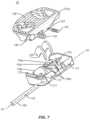
- FIG. 6is an exploded perspective view of one embodiment of an expandable spinal implant in an expanded configuration in accordance with the principles of the present disclosure
- FIG. 7is an exploded perspective view of one embodiment of an expandable spinal implant in an expanded configuration in accordance with the principles of the present disclosure
- FIG. 8is an exploded side view of one embodiment of an expandable spinal implant in an expanded configuration in accordance with the principles of the present disclosure
- FIG. 9is an exploded end view of one embodiment of an expandable spinal implant in an expanded configuration in accordance with the principles of the present disclosure.
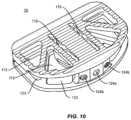
- FIG. 10is a perspective view of one embodiment of an expandable spinal implant in a closed configuration in accordance with the principles of the present disclosure
- FIG. 11is a perspective view of the inner surface of one embodiment of an endplate in accordance with the principles of the present disclosure.
- FIG. 12is a perspective view of the outer surface of one embodiment of an endplate in accordance with the principles of the present disclosure.
- FIG. 13is a top cutaway view of one embodiment of an expandable spinal implant and inserter in accordance with the principles of the present disclosure
- FIG. 14is a perspective view of one embodiment of an expandable spinal implant in a closed configuration in accordance with the principles of the present disclosure
- FIG. 15is a perspective view of one embodiment of an expandable spinal implant in an expanded configuration in accordance with the principles of the present disclosure
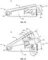
- FIG. 16is a side view of one embodiment of an expandable spinal implant in a closed configuration in accordance with the principles of the present disclosure
- FIG. 17is a side view of one embodiment of an expandable spinal implant in an expanded configuration in accordance with the principles of the present disclosure
- FIG. 18is a perspective view of one embodiment of an expandable spinal implant in an expanded configuration in accordance with the principles of the present disclosure
- FIG. 19is a perspective view of one embodiment of an expandable spinal implant in an expanded configuration in accordance with the principles of the present disclosure
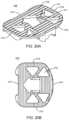
- FIG. 20 Ais a perspective view and FIG. 20 B is a plane view of the outer surface of one embodiment of an endplate in accordance with the principles of the present disclosure
- FIG. 21 Ais a perspective view and FIG. 21 B is a plane view of the outer surface of one embodiment of an endplate in accordance with the principles of the present disclosure
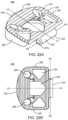
- FIG. 22 Ais a perspective view and FIG. 22 B is a plane view of the outer surface of one embodiment of an endplate in accordance with the principles of the present disclosure
- FIG. 23 Ais a perspective view and FIG. 23 B is a plane view of the outer surface of one embodiment of an endplate in accordance with the principles of the present disclosure
- FIG. 24 Adepicts one embodiment of an expandable spinal implant and inserter in a first position in accordance with the principles of the present disclosure
- FIG. 24 Bdepicts one embodiment of an expandable spinal implant and inserter in a second position in accordance with the principles of the present disclosure
- FIG. 24 Cdepicts one embodiment of an expandable spinal implant and inserter in a third position in accordance with the principles of the present disclosure
- FIG. 25is a top view of one embodiment of an expandable spinal implant as used in a spinal procedure in accordance with the principles of the present disclosure
- FIG. 26is a top view of one embodiment of an expandable spinal implant as used in a spinal procedure in accordance with the principles of the present disclosure
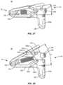
- FIG. 27is a side view of one embodiment of an expandable spinal implant in a closed configuration in accordance with the principles of the present disclosure
- FIG. 28is a side view of one embodiment of an expandable spinal implant in an expanded configuration in accordance with the principles of the present disclosure
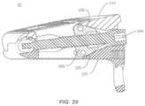
- FIG. 29is a cutaway side view of one embodiment of an expandable spinal implant in a closed configuration in accordance with the principles of the present disclosure
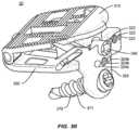
- FIG. 30is a perspective view of one embodiment of an expandable spinal implant in a partially expanded configuration in accordance with the principles of the present disclosure
- FIG. 31 Ais a perspective view and FIG. 31 B is a plane view of the outer surface of one embodiment of an endplate in accordance with the principles of the present disclosure
- FIG. 32 Ais a perspective view and FIG. 32 B is a plane view of the outer surface of one embodiment of an endplate in accordance with the principles of the present disclosure
- FIG. 33 Ais a perspective view and FIG. 33 B is a plane view of the outer surface of one embodiment of an endplate in accordance with the principles of the present disclosure
- FIG. 34 Ais a perspective view and FIG. 34 B is a plane view of the outer surface of one embodiment of an endplate in accordance with the principles of the present disclosure
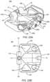
- FIG. 35is an end view of one embodiment of an expansion mechanism wedge in accordance with the principles of the present disclosure.
- FIG. 36is a top view of one embodiment of an endplate in accordance with the principles of the present disclosure.
- FIG. 37is a side view of one embodiment of an expandable spinal implant as used in a spinal procedure in accordance with the principles of the present disclosure
- FIG. 38is a side view of one embodiment of an expandable spinal implant as used in a spinal procedure in accordance with the principles of the present disclosure
- FIG. 39is a side view of one embodiment of an expandable spinal implant as used in a spinal procedure in accordance with the principles of the present disclosure.
- FIGS. 1 - 39Common numbering schemes in FIGS. 1 - 39 (e.g., 1xx, 2xx and 3xx), indicate similar components of implants 10 , 20 , and 30 .
- an expandable surgical implant systemmay include an expandable spinal implant, an insertion instrument, specialized instruments such as, for example, an expandable retractor and a spinal surgical table that rotates and bends the patient in various directions, and/or a method or methods for treating a spine.
- the present systemincludes an expandable spinal implant suitable for insertion from an oblique, postero-lateral procedures and/or transforaminal lumbar interbody fusions (sometimes referred to as TLIF procedures), direct posterior (sometimes referred to as PLIF procedures), direct lateral (sometimes referred to as DLIF procedures), anterior lumbar interbody fusions (sometimes refered to as ALIF procedures), or variations of these procedures, in which the present implant is inserted into an interverterbral space and then expanded in order to impart and/or augment a lordotic and/or kyphotic curve of the spine.
- TLIF procedurestransforaminal lumbar interbody fusions
- PLIF proceduresdirect posterior
- DLIF proceduresdirect lateral
- ALIF proceduresanterior lumbar interbody fusions
- the spinal implant systemmay also be employed to restore and/or impart sagittal balance to a patient by increasing and/or restoring an appropriate lordotic and/or kyphotic angle between vertebral bodies at a selected level where the spinal implant is implanted and expanded.
- the spinal implant systemmay be useful in a variety of complex spinal procedures for treating spinal conditions beyond one-level fusions.
- the spinal implant system described in the enclosed embodimentsmay also be used as a fusion device with an expandable height for tailoring the implant to a particular interbody disc space to restore the spacing between adjacent vertebral bodies and facilitate spinal fusion between the adjacent vertebral bodies.
- the present disclosuremay be employed to treat spinal disorders such as, for example, degenerative disc disease, disc herniation, osteoporosis, spondylolisthesis, stenosis, scoliosis and other curvature abnormalities, kyphosis, tumor and fractures.
- spinal disorderssuch as, for example, degenerative disc disease, disc herniation, osteoporosis, spondylolisthesis, stenosis, scoliosis and other curvature abnormalities, kyphosis, tumor and fractures.
- the present disclosuremay be employed with other osteal and bone related applications, including those associated with diagnostics and therapeutics.
- the disclosed spinal implant systemmay be alternatively employed in a surgical treatment with a patient in a prone or supine position, and/or employ various surgical approaches to the spine, including anterior, posterior, posterior mid-line, direct lateral, postero-lateral oblique, and/or antero lateral oblique approaches, and in other body regions.
- the present disclosuremay also be alternatively employed with procedures for treating the lumbar, cervical, thoracic, sacral and pelvic regions of a spinal column.
- the spinal implant system of the present disclosuremay also be used on animals, bone models and other non-living substrates, such as, for example, in training, testing and demonstration.
- Rangesmay be expressed herein as from “about” or “approximately” one particular value and/or to “about” or “approximately” another particular value. When such a range is expressed, another embodiment includes from the one particular value and/or to the other particular value. Similarly, when values are expressed as approximations, by use of the antecedent “about,” it will be understood that the particular value forms another embodiment. It is also understood that all spatial references, such as, for example, horizontal, vertical, top, upper, lower, bottom, left and right, are for illustrative purposes only and can be varied within the scope of the disclosure.
- references “upper” and “lower”are relative and used only in the context to the other, and are not necessarily “superior” and “inferior”.
- similar spatial references of different aspects or componentse.g., a “first end” of an end plate and a “first end” of a wedge, indicate similar spatial orientation and/or positioning, i.e., that each “first end” is situated on or directed towards the same end of the device.
- the use of various spatial terminology hereinshould not be interpreted to limit the various insertion techniques or orientations of the implant relative to the positions in the spine.
- treating or “treatment” of a disease or conditionrefers to performing a procedure that may include administering one or more drugs, biologics, bone grafts (including allograft, autograft, xenograft, for example) or bone-growth promoting materials to a patient (human, normal or otherwise or other mammal), employing implantable devices, and/or employing instruments that treat the disease, such as, for example, micro-discectomy instruments used to remove portions bulging or herniated discs and/or bone spurs, in an effort to alleviate signs or symptoms of the disease or condition. Alleviation can occur prior to signs or symptoms of the disease or condition appearing, as well as after their appearance.
- treating or treatmentincludes preventing or prevention of disease or undesirable condition (e.g., preventing the disease from occurring in a patient, who may be predisposed to the disease but has not yet been diagnosed as having it).
- treating or treatmentdoes not require complete alleviation of signs or symptoms, does not require a cure, and specifically includes procedures that have only a marginal effect on the patient.
- Treatmentcan include inhibiting the disease, e.g., arresting its development, or relieving the disease, e.g., causing regression of the disease.
- treatmentcan include reducing acute or chronic inflammation; alleviating pain and mitigating and inducing re-growth of new ligament, bone and other tissues; as an adjunct in surgery; and/or any repair procedure.
- tissueincludes soft tissue, ligaments, tendons, cartilage and/or bone unless specifically referred to otherwise.
- bone growth promoting materialas used herein may include, but is not limited to: bone graft (autograft, allograft, xenograft) in a variety of forms and compositions (including but not limited to morselized bone graft); osteoinductive material such as bone morphogenetic proteins (BMP) (including but not limited to INFUSE® available from Medtronic) and alternative small molecule osteoinductive substances; osteoconductive materials such as demineralized bone matrix (DBM) in a variety of forms and compositions (putty, chips, bagged (including but not limited to the GRAFTON® family of products available from Medtronic)); collagen sponge; bone putty; ceramic-based void fillers; ceramic powders; and/or other substances suitable for inducing, conducting or facilitating bone growth and/or bony fusion of existing bony
- BMPbone morphogenetic proteins
- DBMdemineralized bone matrix
- FIGS. 1 - 36there are illustrated components of a surgical system, such as, for example, an expandable spinal implant 10 , 20 , and 30 .
- the components of the expandable spinal implant systems described hereincan be fabricated from biologically acceptable materials suitable for medical applications, including metals, synthetic polymers, ceramics and bone material and/or their composites.
- the components of expandable spinal implant systemindividually or collectively, can be fabricated from materials such as stainless steel alloys, commercially pure titanium, titanium alloys, Grade 5 titanium, super-elastic titanium alloys, cobalt-chrome alloys, stainless steel alloys, superelastic metallic alloys (e.g., Nitinol, super elasto-plastic metals, such as GUM METAL®), ceramics and composites thereof such as calcium phosphate (e.g., SKELITETM), thermoplastics such as polyaryletherketone (PAEK) including polyetheretherketone (PEEK), polyetherketoneketone (PEKK) and polyetherketone (PEK), carbon-PEEK composites, PEEK-BaSO4 polymeric rubbers, polyethylene terephthalate (PET), fabric, silicone, silicone
- Various components of spinal implant systemmay be formed or constructed of material composites, including but not limited to the above-described materials, to achieve various desired characteristics such as strength, rigidity, elasticity, compliance, biomechanical performance, durability and radiolucency or imaging preference.
- the components of expandable spinal implant systemindividually or collectively, may also be fabricated from a heterogeneous material such as a combination of two or more of the above-described materials.
- the components of the expandable spinal implant systemsmay be monolithically formed, integrally connected or include fastening elements and/or instruments, as described herein.
- the expandable spinal implant systemsmay comprise expandable spinal implants 10 , 20 , 30 comprising PEEK and/or titanium structures with radiolucent markers (such as tantalum pins and/or spikes) selectively placed in the implant to provide a medical practitioner with placement and/or sizing information when the expandable spinal implant 10 , 20 , 30 is placed in the spine.
- the components of the expandable spinal implant systemmay be formed using a variety of subtractive and additive manufacturing techniques, including, but not limited to machining, milling, extruding, molding, 3D-printing, sintering, coating, vapor deposition, and laser/beam melting.
- various components of the expandable spinal implant systemmay be coated or treated with a variety of additives or coatings to improve biocompatibility, bone growth promotion or other features.
- the endplates 110 , 120 , 210 , 220 , 310 , 320may be selectively coated with bone growth promoting or bone ongrowth promoting surface treatments that may include, but are not limited to: titanium coatings (solid, porous or textured), hydroxyapatite coatings, or titanium plates (solid, porous or textured).
- the expandable spinal implant systemmay be employed, for example, with a minimally invasive procedure, including percutaneous techniques, mini-open and open surgical techniques to deliver and introduce instrumentation and/or one or more spinal implants at a surgical site within a body of a patient, for example, a section of a spine.
- the expandable spinal implant systemmay be employed with surgical procedures, as described herein, and/or, for example, corpectomy, discectomy, fusion and/or fixation treatments that employ spinal implants to restore the mechanical support function of vertebrae.
- the expandable spinal implant systemmay be employed with surgical approaches, including but not limited to: anterior lumbar interbody fusions (ALIF), posterior lumbar interbody fusion (PLIF), oblique lumbar interbody fusion, transforaminal lumbar interbody fusion (TLIF), various types of anterior fusion procedures, and any fusion procedure in any portion of the spinal column (sacral, lumbar, thoracic, and cervical, for example).
- ALIFanterior lumbar interbody fusions
- PLIFposterior lumbar interbody fusion
- TLIFtransforaminal lumbar interbody fusion
- various types of anterior fusion proceduresand any fusion procedure in any portion of the spinal column (sacral, lumbar, thoracic, and cervical, for example).
- Expandable spinal implants 10 , 20 , and 30may comprise first and second endplates operably engaged via a hinge mechanism that lordotically or angularly expands the endplates relative to one another via a wedge mechanism driven perpendicularly to the axis of the hinge joint.
- the wedge drive directionmay be oriented at an oblique angle between 0 and 90 degrees to the hinge axis.
- the first and second endplatesmay lordotically expand when the wedge mechanism is driven towards the hinge. In other embodiments, the first and second endplates may lordotically expand when the wedge mechanism is driven away from the hinge.
- an expandable spinal implant 10is configured to be inserted in an intervertebral disc space between adjacent vertebral bodies.
- the implant 10includes a first end 12 and a second end 14 defining a mid-longitudinal axis L1-L1 therebetween.
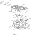
- the expandable spinal implant 10comprises a first endplate 110 and second endplate 120 .
- First endplate 110includes a first end 112 , a second end 114 , two opposing side surfaces 115 extending from the first end 112 of the first endplate to a portion of the second end 114 of the first endplate, and with the first endplate being therebetween, an inner surface 116 , and an outer surface 118 .
- Second endplate 120includes a first end 122 , a second end 124 , two opposing side surfaces 125 extending from the first end 122 of the second endplate to a portion of the second end 124 of the second endplate, and with the second endplate being therebetween, an inner surface 126 , and an outer surface 128 .
- endplates 110 , 120include projections 111 , 121 configured to engage a surface of an endplate of an adjacent vertebral body (not shown).
- Projections 111 , 121may comprise various anti-migration, anti-expulsion, and/or osseointegration features including, but not limited to: ridges, teeth, pores, and coatings (including but not limited to porous titanium coatings such as those provided on Capstone PTCTM implants available from Medtronic).
- the endplates 110 , 120may further comprise at least one opening 113 , 123 defined therein, configured to allow bone growth materials to be packed, placed, or loaded into implant 10 .
- endplates 110 , 120may be operably engaged via a hinge mechanism located near or on first ends 112 and 122 .
- first end 112 of first endplate 110may comprise first and second hinge protrusions 117 extending along at least a portion of the length of first end 112 perpendicular to mid-longitudinal axis L1-L1.
- first and second hinge protrusionsare cylindrical and extend from lateral side surfaces 115 towards the mid-longitudinal axis L1-L1, and further comprise lumen 117 b extending therethrough.
- First end 122 of second endplate 120may also comprise a hinge protrusion 127 .
- hinge protrusion 127is cylindrical and extends laterally along first end 122 , and further comprises a lumen 127 b extending therethrough.
- the lumen of first and second hinge protrusions 117 and lumen of hinge protrusion 127may be co-axially aligned along a hinge axis H1-H1.
- a pin 130may be disposed within the lumen of hinge protrusions 117 , 127 to pivotably engage first endplate 110 to second endplate 120 . In this way, first endplate 110 may hinge and/or rotate away from second endplate 120 such that the distance between second ends 114 and 124 is increased along radial arc R.
- endplates 110 , 120may be operably engaged in a number of different ways including but not limited to: integral connections, separable connections, mechanically fixed connections using fastener or adhesives, releasable connections (including, but not limited to keyways and partially open hinges), and other connection types.
- endplates 110 , 120may be integrally formed using additive manufacturing techniques such as 3D printing, sintering laser/beam melting, casting, extruding, or machined in an integral form using subtractive manufacturing techniques from one or more stock materials.
- the implant 10may include an expansion mechanism for expanding endplates 110 , 120 to increase the lordotic angle R of implant 10 .
- the expansion mechanism of implant 10includes a rod assembly 140 having a longitudinal axis E3-E3 comprising a rod 142 , a securing pin 143 and wedge 150 mounted within the implant between first endplate 110 and second endplate 120 .
- Wedge 150may comprise a first end 152 , a second end 154 , an upper surface 158 , a lower surface 156 , and opposing lateral surfaces 155 extending between the first and second ends.
- Wedge 150may further comprise an aperture 151 between the first and second ends.
- Rod assembly 140may comprise rod 142 disposed within aperture 151 .
- rod 142comprises a threaded outer surface 141 configured to be engaged with a complimentary inner threaded surface of aperture 151 of wedge 150 such that the wedge 150 travels forward and backwards along rod 142 between first and second ends of implant 10 when rod 142 is rotated relative to wedge 150 .
- rod 142 and securing pin 143may be integrally formed, and in such embodiments, it will be understood that integral rod assembly 140 may be interchanged with rod 142 in the discussions below.
- the expansion mechanism of implant 10may be operably engaged with first or second endplates 110 , 120 .
- the expansion mechanism of implant 10is secured to second endplate 120 .
- Hinge protrusion 127 of second endplate 120may comprise a first end aperture 127 a through the walls of hinge protrusion 127 and generally perpendicular to lumen 127 b therethrough.
- Second end 124 of second endplate 120may further comprise an aperture 124 a therethrough.
- apertures 127 a and 124 aare generally co-axial.
- rod assembly 140may be secured within one or both of aperture 124 a of second end 124 and first aperture 127 a of hinge protrusion 127 along first end 122 to operably engage the expansion mechanism of implant 10 with second endplate 120 .
- second end of rod 142is secured within aperture 124 a
- a cylindrical securing pin 143 disposed through aperture 127 acoaxially engages an end of rod 142 to further secure the expansion mechanism within implant 10 .
- Pin 130 disposed within the lumen of hinge protrusions 117 , 127may include a cut out portion 131 to allow rod 142 and/or cylindrical securing pin 143 to be disposed through aperture 127 a .
- rod assembly 140is disposed such that longitudinal axis E1-E1 is substantially parallel to mid-longitudinal axis L1-L1 of implant 10 (i.e., perpendicular to hinge axis H1-H1).
- apertures 124 a and 127 amay be aligned such that rod assembly 140 is disposed such that longitudinal axis E1-E1 is at an oblique angle to the mid-longitudinal axis L1-L1 of implant 10 (e.g., between zero and 90 degrees).
- Rod 142may be rotatable within apertures 124 a , 127 a relative to implant 10 .
- Inner surface 116 of first endplate 110may comprise guidewalls 116 a extending away from the inner surface 116 of first endplate 110 .
- guidewalls 116 aextend perpendicularly away from inner surface 116 of first endplate 110 .
- guidewalls 116 aare oriented substantially parallel to the longitudinal axis L of rod 142 and are disposed a width W apart from one another. In some embodiments, the width W is substantially similar to the width of wedge 150 , with wedge 150 being disposed between guidewalls 116 a .
- Wedge 150may include an upper surface 158 configured to engage with inner surface 116 of first endplate 110 and lordotically expand first endplate 110 away from second endplate 120 when wedge 150 is moved towards first end 12 of implant 10 .
- upper surface 158may be ramped or wedge-shaped and suitable for urging a complementary ramped or contoured surface on the inside of first endplate 110 so as to gradually move first endplate 140 away from second endplate 150 as wedge 150 is advanced towards first end 12 along rod 142 .
- inner surface 116 of first endplate 110may further comprise ramps 116 b to engage upper surface 158 of wedge 150 .
- the expansion mechanismmay be configured such that lower surface 156 of wedge 150 engages inner surface 126 of second endplate 120 alternatively to, or in addition to, upper surface 158 engaging inner surface 116 of first endplate 110 .
- the expansion mechanismmay be configured to lordotically expand implant 10 when wedge 150 is moved towards the second end 14 of implant 10 .
- the ramp mechanism 158 / 116 bmay cooperate with one or more paired lateral posts 155 a and channel 116 c system in order to optimize the opening and/or expansion of implant 10 .
- Guidewalls 116 amay comprise lateral channels 116 c .
- Channels 116 cmay be angled or partially angled to provide a mechanism for assisting in the expansion of implant 10 as wedge 150 is advanced along rod 142 towards the hinge at first end 12 of implant 10 .
- Wedge 150may comprise one or more lateral posts 155 a that engage with channels 116 c to provide an expansion mechanism configured to urge first endplate 110 away from second endplate 120 when wedge 150 is moved towards first end 12 of implant 10 .
- Post 155 a and channel 116 c mechanismmay also aid in making expansion of the implant 10 substantially reversible such that when wedge 150 is moved away from the hinge, lateral posts 155 a are moved in a second direction in the lateral channels 116 c to contract first endplate 110 towards second endplate 120 (which may result in implant 10 returning to the closed or unexpanded configuration shown generally in FIG. 1 ).
- This reversible featurecombined with the threaded interaction between rod 142 and wedge 150 , renders implant 10 capable of being incrementally expanded or contracted through a substantially infinite adjustable range of motion (bounded only by the length of the channels 116 c ).
- the length and orientation of channels 116 cmay be adjusted to determine the amount of lordotic expansion.
- the design of the expansion mechanismis configured to allow up to 30 degrees, 35 degrees, 40 degrees, 45 degrees, 50 degrees, or 60 degrees or anywhere in between these amounts from 0 to 60 degrees or more of lordotic expansion as wedge 150 is moved towards the hinge assembly.
- various designsmay be used to optimize the interaction of wedge 150 with first endplate 110 .
- Such configurationsmay include, but are not limited to: sequential ramps or tapered surfaces with varying angles; shallow angle sequential ramps or tapered surfaces leading into higher angle sequential ramps or tapered surfaces, as well as other opening mechanisms (such as the lateral post 155 a and channel 116 c system described above that may combine to assist the ramps in expanding implant 10 ).
- the expansion mechanism 140 , 150 of implant 10is secured to second endplate 120 such that first endplate 110 is urged away from expansion mechanism 140 , 150 and second endplate 120 when wedge 150 is moved towards first end 12 of implant 10 .
- first end 145 of rod assembly 140may be secured to first and/or second endplates 110 , 120 such that the a second end 146 of rod assembly 140 may move relative to endplates 110 , 120 as implant 10 is expanded or contracted.
- lower surface 156 of wedge 150may be ramped or wedge-shaped and suitable for urging a complementary ramped or contoured surface on the inside of second endplate 120 so as to gradually move the endplates 110 , 120 away from each other as the wedge 150 is advanced along the rod 142 .
- Inner surface 126 of second endplate 120comprise ramps to engage lower surface 156 of wedge 150 , and/or may comprise guidewalls with channels disposed therein to engage lateral posts extending from wedge 150 , similar to those described above for the interaction of upper surface 158 of wedge 150 with inner surface 116 of first endplate 110 .
- various designsmay be used to optimize the interaction of wedge 150 with endplates 110 , 120 .
- Such configurationsmay include, but are not limited to: sequential ramps or tapered surfaces with varying angles; shallow angle sequential ramps or tapered surfaces leading into higher angle sequential ramps or tapered surfaces, as well as other opening mechanisms (such as the lateral post 155 a and channel 116 c system described above that may combine to assist the ramps in expanding the implant 10 ).
- implant 10may be specifically paired or used with other surgical instruments that manipulate the spine.
- These surgical instrumentsinclude, for example, surgical tables, patient positioning frames, and the like, that manipulate the patient and may for example further facilitate and/or adjust access to one or more disc spaces by bending the spine of a patient in various directions and adjusting the orientation of the patient to ease or facilitate access to the spinal surgical location(s).
- Exemplary surgical tables, patient positioning frames, and the like, and related methods of using theminclude those described in, e.g., U.S. patent application Ser. Nos. 15/239,239, 15/239,256, 15/337,157, 15/638,802, 15/639,080, 15/672,005, and 15/674,456, all incorporated herein by reference in their entirety.
- second end 146 of rod 142may comprise an interface 144 configured to be operably engaged by a drive shaft (not shown) to rotate rod 142 .
- Rod interface 144may comprise a drive receptacle configured to cooperate with an implant-engaging end of the drive shaft.
- the drive connection between the driver shaft and rod interface 144may comprise a variety of drive interfaces including but not limited to: multi-lobular drives; hexalobular drives; cross or Phillips head drives; straight or “flat head” drives; square or other polygonal drives; and/or combinations thereof.
- first end 145 of rod assembly 140(via rod 142 or securing pin 143 ) may further comprise an interface configured to be operably engaged by a drive shaft to rotate rod assembly 140 . In this way, implants of the present disclosure may be expanded from both an anterior/oblique and posterior approach.
- implant 10may further comprise vertebral endplate engagement components 170 which are configured to engage the vertebral endplate as the implant 10 is expanding.
- vertebral endplate engagement components 170may be claw- or hook-shaped. It is contemplated that vertebral endplate engagement components 170 may comprise various configurations suitable to engage the vertebral endplate to decrease or prevent potential migration or expulsion of the device from the intervertebral space. As shown in FIGS. 1 and 3 , when implant 10 is in a collapsed, closed, or unexpanded state, vertebral endplate engagement components 170 may be retracted within the device to allow for easy insertion into the disc space. As shown in FIGS.
- vertebral endplate engagement components 170protrude from implant 10 and engage the vertebral endplate to decrease potential migration of the device.
- the vertebral endplate engagement components 170are mounted between guidewalls 116 a and disposed adjacent upper surface 158 of wedge 150 .
- Guidewalls 116 amay each comprise an aperture 171 through which a pin 172 is disposed to mount vertebral endplate engagement components 170 to first endplate 110 .
- vertebral endplate engagement components 170are at least partially rotatable about pin 172 .
- Vertebral endplate engagement components 170may be shaped to engage upper surface 158 of wedge 150 as wedge 150 is moved towards first end 12 of implant 10 , causing the teeth 170 to partially rotate about pin 172 and protrude through apertures 119 of first endplate 110 and engage the vertebral endplate. As wedge 150 is moved away from first end 12 , a separate portion of vertebral endplate engagement components 170 may engage upper surface 158 of wedge 150 to retract vertebral endplate engagement components 170 back into the interior of implant 10 . In an alternative embodiment (not shown), vertebral endplate engagement components 170 could be incorporated into a piston. Wedge 150 would engage the piston as implant 10 is expanded.
- vertebral endplate engagement components 170could be mounted onto a rotating gear.
- a mating gear on wedge 150would engage the rotating gear and rotate vertebral endplate engagement components 170 into engagement with the vertebral endplate as the wedge 150 expands implant 10 .
- rod assembly 140may engage vertebral endplate engagement components 170 directly, via, e.g., threaded outer surface 141 .
- FIGS. 1 - 12depict vertebral endplate engagement components 170 protruding only from first endplate 110
- other embodimentsmay include vertebral endplate engagement components protruding from second endplate 120 , or from both endplates 110 , 120 .
- implant 10may be secured through intrinsic screws placed through apertures between inner and outer surfaces of endplates 110 or 120 (as depicted for implant 20 in FIGS. 18 , 19 and discussed below). These screws may be further held in place by external locking mechanisms such as washers, springs, plates or covers that cover or push against at least a portion of the screw top or head.
- the screwsmay be held in place by interference fit in the screw hole and/or by features in the screw hole adding friction fit and/or holding force to the screw top or head.
- implant 10may be secured through integrated tabs on endplates 110 or 120 (as depicted for implant 30 in FIG. 30 and as discussed below) or separable plates that may cover a portion of the intervertebral implant.
- FIG. 13shows an implant 10 in use with an insertion instrument 40 to form an expandable spinal implant system according to one embodiment.
- the systemmay comprise an insertion instrument 40 comprising an attachment cannula 410 and a driver cannula 420 .
- Insertion instrument 40may further comprise an attachment shaft 411 removably and rotatably disposed within attachment cannula 410 and a drive shaft 421 removably and rotatably disposed within driver cannula 420 .
- the implant engaging end of attachment shaft 411may comprise a threaded outer surface.
- Insertion instrument 40may further comprise a drive engagement component 422 connected to the end of drive shaft 421 via, for example, a u-joint 423 .
- the systemmay also further comprise an expandable spinal implant 10 configured to be operably engaged with the insertion instrument 40 using a variety of mechanisms.
- second end 14 of implant 10may be configured to receive the tool end of insertion instrument 40 to manipulate expandable implant 10 .
- second end 124 of second endplate 120 of implant 10comprises attachment apertures 124 b disposed laterally adjacent to aperture 124 a . These apertures 124 b may be spaced and angled relative to mid-longitudinal axis L1-L1 of implant 10 as desired for particular surgical techniques. In some embodiments, apertures 124 b may be parallel to mid-longitudinal axis L1-L1 of implant 10 .
- the axis of apertures 124 bis angled at approximately 15 degrees relative to mid-longitudinal axis L1-L1.
- Apertures 124 bmay comprise an inner threaded surface for engaging the threaded outer surface on the implant engaging end of attachment shaft 411 .
- the implant engaging end of attachment shaft 411may interact with tabs or slots defined by one or both of endplates 110 , 120 .
- the attachment shaft 411may be coaxially placed within the attachment cannula 410 and rotatable therein using the manual end of the attachment cannula (not shown).
- the manual end of the attachment shaft 411may comprise a keyed or faceted surface configured for engagement with a quick-release handle (not shown) or a powered driver (not shown) for rotating attachment shaft 411 .
- interface 144 of rod 142may be configured to be operably engaged by an implant engaging end of drive shaft 421 to translate (by threaded rotation, for example) wedge 150 along rod 142 .
- Drive shaft 421may be coaxially placed within drive cannula 420 and rotatable therein using the manual end of drive shaft 421 (not shown).
- the manual end of drive shaft 421may comprise a keyed or faceted surface configured for engagement with a quick-release handle (not shown) or a powered driver (not shown) for rotating the drive shaft 421 .
- rod interface 144may comprise a drive receptacle configured to cooperate with an implant engaging end of drive shaft 421 .
- drive connection between drive shaft 421 and rod interface 144may comprise a variety of drive interfaces including but not limited to: multi-lobular drives; hexalobular drives; cross or Phillips head drives; straight or “flat head” drives; square or other polygonal drives; and/or combinations thereof.
- drive shaft 421engages rod interface 144 via a drive engagement component 422 connected to the end of drive shaft 421 via, for example, a u-joint 423 .
- U-joint 423allows for angulation between the drive shaft 421 and rod assembly 140 .
- FIGS. 14 - 26show various configurations of an implant 20 embodiment according to the present disclosure.
- Implant 20is generally similar in construction to implant 10 described above and implant 30 described below, and comprises a first endplate 210 and second endplate 220 operably engaged to one another via a hinge mechanism along an implant first end 22 , and an expansion mechanism comprising a rod assembly 240 and a wedge 250 disposed therebetween.
- First endplate 210includes a first end 212 , a second end 214 , opposing side surfaces 215 extending from the first end 212 of the first endplate to a portion of the second end 214 of the first endplate, and with the first endplate being therebetween, an inner surface 216 , and an outer surface 218 .
- Second endplate 220includes a first end 222 , a second end 224 , two opposing side surfaces 225 extending from the first end 222 of the second endplate to a portion of the second end 224 of the second endplate, and with the second endplate being therebetween, an inner surface 226 , and an outer surface 228 .
- the endplates 210 , 220includes projections 211 , 221 configured to engage a surface of the endplate of the adjacent vertebral body (not shown).
- Projections 211 , 221may comprise various anti-migration, anti-expulsion, and/or osseointegration features including, but not limited to: ridges, teeth, pores, and coatings (including but not limited to porous titanium coatings such as those provided on Capstone PTCTM implants available from Medtronic). Endplates 210 , 220 may further comprise at least one opening 213 , 223 defined therein, configured to allow bone growth materials to be packed, placed, or loaded into implant 20 .
- first end 212 of first endplate 210may comprise first and second hinge protrusions 217 extending along at least a portion of the length of first end 212 perpendicular to mid-longitudinal axis L2-L2.
- first and second hinge protrusionsare cylindrical and extend from lateral side surfaces 215 towards the mid-longitudinal axis L2-L2, and further comprise lumen 217 b extending therethrough.
- First end 222 of second endplate 220may also comprise a hinge protrusion 227 .
- hinge protrusion 227is cylindrical and extends laterally along first end 122 , and further comprises a lumen 227 b extending therethrough. Lumens 217 b , 227 b of hinge protrusions 217 , 227 may be co-axially aligned along a hinge axis H2-H2. A pin 230 may be disposed within lumens 217 b , 227 b of hinge protrusions 217 , 227 to pivotably engage first endplate 210 to second endplate 220 .
- the expansion mechanism 240 , 250is designed to expand first endplate 210 and second endplate 220 away from each other as wedge 250 is translated towards second end 24 of implant 20 along rod assembly 240 .
- Rod assembly 240may be integrally formed, or may be formed of multiple components for, e.g., ease of manufacturing and/or assembly, like rod assembly 140 above.
- Rod assembly 240may be secured to first and/or second endplates 210 , 220 at a rod first end 245 such that a second rod end 246 may move relative to endplates 210 , 220 as implant 20 is expanded or contracted (i.e., moved into an opened or closed configuration).
- longitudinal axis E2-E2 of expansion mechanism 240 , 250may be aligned along mid-longitudinal axis L2-L2 of implant 20 . In other embodiments, longitudinal axis E2-E2 of expansion mechanism 240 , 250 may be offset from mid-longitudinal axis L2-L2 of implant 20 , as depicted in FIG. 25 , and/or may be angled obliquely to mid-longitudinal axis L2-L2, as depicted in FIG. 26 . As described above for implant 10 , second end 246 of rod assembly 240 may comprise an interface 244 configured to be operably engaged by a drive shaft (not shown) to rotate rod assembly 240 .
- Rod interface 244may comprise a drive receptacle configured to cooperate with an implant engaging end of the drive shaft.
- the drive connection between the drive shaft and rod interface 244may comprise a variety of drive interfaces including but not limited to: multi-lobular drives; hexalobular drives; cross or Phillips head drives; straight or “flat head” drives; square or other polygonal drives; and/or combinations thereof.
- first end 245 of rod assembly 240may further comprise an interface configured to be operably engaged by a drive shaft to rotate rod assembly 240 . In this way, implants of the present disclosure may be expanded from both an anterior/oblique and posterior approach, as depicted in FIGS. 25 and 26 .
- upper surface 258 and lower surface 256 of wedge 250may be ramped or wedge-shaped and suitable for urging a complementary ramped or contoured surface on the inside of endplates 210 , 220 so as to gradually move endplates 210 , 220 away from each other as wedge 250 is advanced along the rod assembly 240 towards second end 24 of implant 20 .
- various designsmay be used to optimize the interaction of wedge 250 with endplates 210 , 220 .
- Such configurationsmay include, but are not limited to: sequential ramps or tapered surfaces with varying angles; shallow angle sequential ramps or tapered surfaces leading into higher angle sequential ramps or tapered surfaces, as well as other opening mechanisms (such as a lateral post and channel system). As shown in FIGS.
- inner surfaces 216 , 226 of endplates 210 , 220may comprise guidewalls 216 a , 226 a with lateral channels 216 c , 226 c disposed therein to engage lateral posts 255 a extending from wedge 250 .
- the mechanism provided by posts 255 a and channels 216 c , 226 cmay also aid in making the implant 20 expansion substantially reversible. For example, in the depicted embodiment, when wedge 250 is moved towards second end 24 of implant 20 , posts 255 a are moved in a first direction in channels 216 c , 226 c to expand first endplate 210 and second endplate 220 away from each other (which may result in implant 20 opening to the expanded configuration shown generally in FIG.
- implant 20provides 12 degrees of lordotic correction when in a collapsed/closed state and is capable of up to 32 degrees, 60 degrees, or more of lordotic or hyperlordotic expansion as wedge 250 is moved towards second end 24 of implant 20 .
- second endplate 220may comprise apertures 229 through which one or more screws 270 may be disposed to secure endplate 220 within an intervertebral space.
- Screws 270may comprise a threaded outer surface 271 that engages with the inner surface of aperture 229 , which may also be threaded.
- the engagement between threaded outer surface 271 and inner surface of aperture 229may be via pitch lock, major/minor lock, or any other thread/pitch interface.
- second end 224 of second endplate 220 of implant 20comprises inserter apertures 224 b to engage with an insertion instrument 50 to form an expandable spinal implant system.
- the number and arrangement of inserter apertures 224 ballows the insertion instrument 50 to be attached to implant 20 in multiple orientations. This provides user flexibility to place implant 20 within intervertebral space with first endplate 210 superior to second endplate 220 or with first endplate 210 inferior to second endplate 220 such that screws 270 may be placed in either the cephalad or caudad vertebral bodies.
- the inserter aperturesare offset from mid-longitudinal axis which allows the inserter to be attached at a 15 degree angle allowing the device to be placed from an oblique approach.
- FIGS. 27 - 36show various configurations of an implant 30 embodiment according to the present disclosure.
- Implant 30is generally similar in construction to implants 10 , 20 described above and comprises a first endplate 310 and second endplate 320 operably engaged to one another via a hinge mechanism along the first end 32 , and an expansion mechanism comprising a rod assembly 340 and a wedge 350 disposed between first and second endplates 310 , 320 .
- First endplate 310includes a first end 312 , a second end 314 , opposing side surfaces 315 extending from the first end 312 of the first endplate to a portion of the second end 314 of the first endplate, and with the first endplate being therebetween, an inner surface 316 , and an outer surface 318 .
- Second endplate 320includes a first end 322 , a second end 324 , opposing side surfaces 325 extending from the first end 322 of the second endplate to a portion of the second end 324 of the second endplate, and with the second endplate being therebetween, an inner surface 326 , and an outer surface 328 .
- the endplates 310 , 320includes projections 311 , 321 configured to engage a surface of the endplate of the adjacent vertebral body (not shown).
- Projections 311 , 321may comprise various anti-migration, anti-expulsion and/or osseointegration features including, but not limited to: ridges, teeth, pores, and coatings (including but not limited to porous titanium coatings such as those provided on Capstone PTCTM implants available from Medtronic).
- Endplates 310 , 320may further comprise at least one opening 313 , 323 defined therein, configured to allow bone growth materials to be packed, placed, or loaded into implant 30 .
- first end 312 of first endplate 310may comprise first and second hinge protrusions 317 extending along at least a portion of the length of first end 312 perpendicular to mid-longitudinal axis L3-L3.
- first and second hinge protrusionsare cylindrical and extend from lateral side surfaces 315 towards the mid-longitudinal axis L3-L3, and further comprise lumen 317 b extending therethrough.
- First end 322 of second endplate 320may also comprise a hinge protrusion 327 .
- hinge protrusion 327is cylindrical and extends laterally along first end 322 , and further comprises a lumen 327 b extending therethrough. Lumens 317 b , 327 b of hinge protrusions 317 , 327 may be co-axially aligned along a hinge axis H3-H3. A pin 330 may be disposed within lumens 217 b , 327 b of hinge protrusions 317 , 327 to pivotably engage first endplate 310 to second endplate 320 .
- the expansion mechanism 340 , 350is designed to expand first endplate 310 and second endplate 320 away from each other as wedge 350 is translated along rod assembly 340 towards second end 34 of implant 30 .
- Rod assembly 340may be integrally formed, or may be formed of multiple components for, e.g., ease of manufacturing and/or assembly, like rod assembly 140 above.
- Rod assembly 340may be secured to first and/or second endplates 310 , 320 at a first end 345 such that the second end 346 may move relative to endplates 310 , 320 as implant 30 is expanded or contracted.
- the longitudinal axis E3-E3 of expansion mechanism 340 , 350may be angled obliquely to mid-longitudinal axis L3-L3 at an angle ⁇ , as depicted in FIG. 36 .
- the shown deviceis angled at 15 degrees to optimize access for an oblique approach.
- first endplate 310 , second endplate 320 , and wedge 350are designed with compound surface angles to ensure proper contact between wedge 350 and endplates 310 , 320 throughout the range of translation
- the second end 346 of rod assembly 340may comprise an interface 344 configured to be operably engaged by a drive shaft (not shown) to rotate the rod assembly 340 .
- Rod interface 344may comprise a drive receptacle configured to cooperate with an implant engaging end of the drive shaft.
- the drive connection between the drive shaft and rod interface 344may comprise a variety of drive interfaces including but not limited to: multi-lobular drives; hexalobular drives; cross or Phillips head drives; straight or “flat head” drives; square or other polygonal drives; and/or combinations thereof.
- first end 345 of rod assembly 340may further comprise an interface configured to be operably engaged by a drive shaft to rotate rod assembly 340 . In this way, implants of the present disclosure may be expanded from both an anterior/oblique and posterior approach, as depicted in FIG. 36 .
- upper surface 358 and lower surface 356 of wedge 350may be ramped or wedge-shaped and suitable for urging a complementary ramped or contoured surface on the inner surfaces 316 , 326 of endplates 310 , 320 so as to gradually move the endplates 310 , 320 away from each other as wedge 350 is advanced along rod assembly 340 .
- various designsmay be used to optimize the interaction of the wedge 350 with the endplates 210 , 220 . For example, as depicted in FIG. 35 , one lateral side 355 of wedge 350 may be taller than opposing lateral side 355 of wedge 350 such that upper surface 358 and lower surface 356 may be angled.
- Inner surfaces 316 , 326 of endplates 310 , 320are angled in a complementary manner in order to ensure proper contact between wedge 350 and endplates 310 , 320 as wedge 350 is translated along rod assembly 340 at an angle oblique to mid-longitudinal axis L3-L3 of implant 30 .
- Other configurationsmay include, but are not limited to: sequential ramps or tapered surfaces with varying angles; shallow angle sequential ramps or tapered surfaces leading into higher angle sequential ramps or tapered surfaces, as well as other opening mechanisms (such as a lateral post and channel system).
- inner surfaces 316 , 326 of endplates 310 , 320may comprise guidewalls 316 a , 326 a with lateral channels 316 c , 326 c disposed therein to engage lateral posts 355 a extending from wedge 350 .
- the mechanism provided by posts 355 a and channels 316 c , 326 cmay also aid in making the implant 30 expansion substantially reversible. For example, in the depicted embodiment, when wedge 350 is moved towards second end 34 of implant 30 , posts 355 a are moved in a first direction in channels 316 c , 326 c to expand first endplate 310 and second endplate 320 away from each other (which may result in implant 30 opening to the expanded configuration shown generally in FIG.
- implant 30provides 12 degrees of lordotic correction when in a collapsed/closed state and is capable of up to 30 degrees, 60 degrees, or more of lordotic or hyperlordotic expansion as the wedge 350 is moved towards second end 34 of implant 30 .
- endplate 320may comprise one or more tabs 329 comprising an aperture 329 a through which one or more screws 370 may be disposed to secure endplate 320 within an intervertebral space.
- Screws 370may comprise a threaded outer surface 371 that engages with the inner surface of aperture 329 a , which may also be threaded. The engagement between threaded outer surface 371 and the inner surface of aperture 329 a may be via pitch lock, major/minor lock, or any other thread/pitch interface.
- second end 324 of second endplate 320 of implant 30comprises inserter apertures 324 b to engage with an insertion instrument (not shown) to form an expandable spinal implant system.
- the number and arrangement of inserter apertures 324 ballows the insertion instrument to be attached to implant 30 in multiple orientations. This provides user flexibility to place implant 30 within intervertebral space with first endplate 310 superior to second endplate 320 or with first endplate 310 inferior to second endplate 320 such that the tab 329 may be used to secure second endplate 320 in either the cephalad or caudad vertebral bodies.
- Spinal implant systems of the present disclosurecan be employed with a surgical arthrodesis procedure, such as, for example, an interbody fusion for treatment of an applicable condition or injury of an affected section of a spinal column and adjacent areas within a body, such as, for example, intervertebral disc space between adjacent vertebrae, and with additional surgical procedures and methods.
- spinal implant systemscan include an intervertebral implant that can be inserted with intervertebral disc space to space apart articular joint surfaces, provide support and maximize stabilization of vertebrae.
- spinal implant systemsmay be employed with one or a plurality of vertebra.
- a medical practitionerobtains access to a surgical site including vertebrae such as through incision and retraction of tissues.
- Spinal implant systems of the present disclosurecan be used in any existing surgical method or technique including open surgery, mini-open surgery, minimally invasive surgery and percutaneous surgical implantation, whereby vertebrae are accessed through a mini-incision, retractor, tube or sleeve that provides a protected passageway to the area, including, for example, an expandable retractor wherein the sleeve is formed from multiple portions that may be moved apart or together and may be inserted with the portions closed or together and then expanded to allow for insertion of implants of larger size than the closed cross section of the unexpanded retractor portions.
- the components of the spinal implant systemare delivered through a surgical pathway to the surgical site along a surgical approach into intervertebral disc space between vertebrae.
- Various surgical approaches and pathwaysmay be used.
- FIGS. 37 - 39depict various views of a typical anterior lumbar interbody fusion (ALIF) approach using a spinal implant of the present disclosure.
- Unilateral approachessuch as a transforaminal lumbar interbody fusion (TLIF) approach may also be used to place the implant in a substantially oblique position relative to the vertebrae.
- Multilateral approachessuch as those disclosed in U.S. Pat. No. 9,730,684, incorporated herein by reference in its entirety, may also be used with spinal implant systems of the present disclosure.
- a preparation instrumentmay be employed to remove disc tissue, fluids, adjacent tissues and/or bone, and scrape and/or remove tissue from endplate surfaces of a first vertebra and/or endplate surface of a second vertebra in preparation for or as part of the procedures utilizing a system of the present disclosure.
- the size of implant 10 , 20 , 30is selected after trialing using trialing instruments (not shown) that may approximate the size and configuration of the implants 10 , 20 , 30 .
- trialing instrumentsmay approximate the size and configuration of the implants 10 , 20 , 30 .
- such trialsmay be fixed in size and/or be fitted with expansion mechanisms similar to the various implant 10 , 20 , 30 embodiments described herein.
- implant 10may be visualized by fluoroscopy and oriented before introduction into intervertebral disc space. Furthermore, the insertion instruments 40 , 50 and implants 10 , 20 , 30 may be fitted with fiducial markers to enable image guided surgical navigation to be used prior to and/or during a procedure.
- Components of a spinal implant system of the present disclosure including implant 10 , 20 , 30can be delivered or implanted as a pre-assembled device or can be assembled in situ.
- Components of spinal implant system including implant 10 , 20 , 30may be expanded, contracted, completely or partially revised, removed or replaced in situ.
- one or all of the components of spinal implant system 10 , 20 , 30can be delivered to the surgical site via mechanical manipulation and/or a free hand technique.
- the spinal implant systemincludes an agent, including but not limited to the bone growth promoting materials described herein, which may be disposed, packed, coated or layered within, on or about the components and/or surfaces of the spinal implant system.
- the bone growth promoting materialsmay be pre-packed in the interior of the implant, and/or may be packed during or after implantation of the implant via a tube, cannula, syringe or a combination of these or other access instruments and may be further tamped into the implant before, during or after implantation.
- the agentmay include bone growth promoting material to enhance fixation of implants 10 , 20 , 30 with bony structures.
- the agentmay include one or a plurality of therapeutic agents and/or pharmacological agents for release, including sustained release, to treat, for example, pain, inflammation and degeneration.
- implants 10 , 20 , 30may include fastening elements, which may include locking structure, configured for fixation with vertebrae to secure joint surfaces and provide complementary stabilization and immobilization to a vertebral region.
- locking structuremay include fastening elements, such as, for example, rods, plates, clips, hooks, adhesives and/or flanges.
- the components of spinal implant system 20 , 30can be used with screws to enhance fixation.
- the components of the spinal implant systemcan be made of radiolucent materials such as polymers. Radiopaque markers may be included for identification under x-ray, fluoroscopy, CT or other imaging techniques.
- the insertion instruments 40 , 50may be radiolucent and may optionally include markers added at the tip and/or along the length of one or both of insertion instruments 40 , 50 and the tube to permit them to be seen on fluoroscopy/x-ray while advancing into the patient. If the implants 10 , 20 , 30 includes radiolucent markers placed near the end this may permit visualization of the proximity of the tip of the tube moving toward the second ends 14 , 24 , 34 of implants 10 , 20 , 30 .
- the use of microsurgical, minimally-invasive and image guided technologiesmay be employed to access, view and repair spinal deterioration or damage, with the aid of spinal implant system.
- the non-implanted components, surgical instruments and assemblies of spinal implant systemmay be removed and the incision is closed.
- the various instruments disclosedmay be provided with fiducial markers or other elements suitable for use with surgical navigation systems (including, but not limited to the STEALTHSTATION® Navigation system available from Medtronic), such that a surgeon may view a projected trajectory or insertion pathway of the implants 10 , 20 , 30 relative to a patient's anatomy in real time and/or in near-real time.
Landscapes
- Health & Medical Sciences (AREA)
- Engineering & Computer Science (AREA)
- Biomedical Technology (AREA)
- Orthopedic Medicine & Surgery (AREA)
- Transplantation (AREA)
- Vascular Medicine (AREA)
- Oral & Maxillofacial Surgery (AREA)
- Heart & Thoracic Surgery (AREA)
- Cardiology (AREA)
- Life Sciences & Earth Sciences (AREA)
- Animal Behavior & Ethology (AREA)
- General Health & Medical Sciences (AREA)
- Public Health (AREA)
- Veterinary Medicine (AREA)
- Neurology (AREA)
- Physical Education & Sports Medicine (AREA)
- Prostheses (AREA)
Abstract
Description
This Application is a continuation of U.S. application Ser. No. 16/282,654 (now U.S. Pat. No. 11,020,239), entitled “EXPANDABLE SPINAL IMPLANT SYSTEM AND METHOD OF USING SAME”, filed Feb. 22, 2019, which claims benefit to U.S. Provisional Patent Application Ser. No. U.S. 62/633,952, entitled “EXPANDABLE SPINAL IMPLANT SYSTEM AND METHOD OF USING SAME”, filed Feb. 22, 2018. The entire disclosure of each is incorporated herein by reference in its entirety.
The present disclosure generally relates to medical devices for the treatment of musculoskeletal disorders, and more particularly to a surgical system that includes an expandable spinal implant, systems for implanting an expandable spinal implant, and a method for treating a spine.
Spinal disorders such as degenerative disc disease, disc herniation, osteoporosis, spondylolisthesis, stenosis, scoliosis and other curvature abnormalities, kyphosis, tumor, and fracture may result from factors including trauma, disease and degenerative conditions caused by injury and aging. Spinal disorders typically result in symptoms including pain, nerve damage, and partial or complete loss of mobility.
Non-surgical treatments, such as medication, rehabilitation and exercise can be effective, however, may fail to relieve the symptoms associated with these disorders. Surgical treatment of these spinal disorders includes fusion, fixation, correction, discectomy, laminectomy and implantable prosthetics. As part of these surgical treatments, spinal constructs, such as, for example, bone fasteners, spinal rods and interbody devices can be used to provide stability to a treated region. For example, during surgical treatment, interbody devices may be introduced to a space between adjacent vertebral bodies (the interbody space) to properly space the vertebral bodies and provide a receptacle for bone growth promoting materials.
More recently, interbody devices have been introduced that provide additional capability beyond static spacing of the vertebral bodies. For example, some devices have expansion capability such that the implant may be introduced to the interbody space in a collapsed state and then expanded to produce additional spacing and, in some cases, introduce or restore curvature to the spine by expanding selectively on only one end or portion of the implant. However, many existing expandable interbody designs have limited ranges of expansion.
An additional problem exists related to subsidence of spinal surfaces due to existing interbody devices having inadequately-sized load-bearing surfaces. In the case of expandable devices, the loads on the load-bearing surfaces, including loads generated during expansion of the implant, are often significant. An expandable implant with relatively large surface areas is needed to bear the loads, including the loads generated during implant expansion, in an attempt to avoid a need for follow-on surgery due to subsidence of spinal surfaces.
A further problem is instability of existing expandable interbody devices as they are expanded. Often, the load-bearing surfaces move relative to one another, as well as relative to an inserter, as the interbody device is expanded such that there is a risk of undesired shifts in the positioning of the interbody device within the interverterbral space.
The present invention seeks to address these and other shortcomings in the existing art.
In one aspect, the present disclosure provides an expandable spinal implant deployable between a contracted position and an expanded position in a disc space between two vertebral bodies, the expandable spinal implant comprising a first endplate, the first endplate including an outer surface and an inner surface, a first endplate first end, a first endplate second end, a first endplate first lateral surface extending between the first endplate first end and the first endplate second end, an opposing first endplate second lateral surface extending between the first endplate first end and the first endplate second end; a second endplate, the second endplate including an outer surface and an inner surface, a second endplate first end, a second endplate second end, a second endplate first lateral surface extending between the second endplate first end and the second endplate second end, and an opposing second endplate second lateral surface extending between the second endplate first end and the second endplate second end, wherein the second endplate first end is pivotably engaged with the first endplate first end; an expansion mechanism disposed between the first endplate and the second endplate, the expansion mechanism including a wedge disposed between the first endplate and second endplate, the wedge including an upper surface, a lower surface, a wedge first end, a wedge second end, a wedge first lateral surface extending between the wedge first end and the wedge second end, and an opposing wedge second lateral surface extending between the wedge first end and the wedge second end, wherein the wedge comprises a wedge aperture between the wedge second end and wedge first end; a rod assembly, the rod assembly having a first end and a second end definining a longitudinal axis, wherein at least a portion of the rod assembly is disposed within the wedge aperture and operably engaged with the wedge to translate the wedge along the longitudinal axis of the rod; and wherein the wedge is operably engaged with at least one of the first endplate or second endplate and configured to expand the implant when the wedge is translated along the rod assembly in a first direction, and contract the implant when the wedge is translated along the rod assembly in a second direction.
In some embodiments, the rod assembly comprises a threaded outer surface, and the wedge aperture comprises a threaded inner surface operably engaged with the threaded outer surface of the rod.
In some embodiments, the translation of the wedge along the longitudinal axis of the rod in a first direction is towards the first and second endplate first ends. In some embodiments, translation of the wedge along the longitudinal axis of the rod in the first direction is towards the first and second endplate second ends.
In some embodiments, at least one of the first endplate or the second endplate further comprises at least one protrusion from its inner surface configured to engage a surface of the wedge. In some embodiments, at least one of the wedge first lateral surface and the wedge second lateral surface comprises a lateral post extending therefrom.
In some embodiments, at least one of the first endplate or second endplate further comprises at least one protrusion from its inner surface, wherein the at least one protrusion defines at least one lateral channel configured to receive the lateral post such that when the wedge is translated in the first direction, the lateral post of the wedge is moved in the first direction in the lateral channel to expand the implant and that when the wedge is translated in the second direction, the lateral post of the wedge is moved in the second direction in the lateral channel to contract the implant.
In some embodiments, the expandable spinal implant further comprises at least one vertebral endplate engagement component operably engaged to at least one of the first endplate or the second endplate and configured to engage with the wedge such that it protrudes from the outer surface of the first or second endplate when the wedge is translated in the first direction. In some embodiments, the vertebral endplate engagement component is configured to engage with the wedge such that it retracts from the outer surface of the first or second endplate when the wedge is translated in the second direction.
In some embodiments, the expandable spinal implant is capable of expanding up to 30 degrees, 35 degrees, 40 degrees, 45 degrees, 50 degrees, or 60 degrees or anywhere in between these amounts from 0 to 60 degrees.
In some embodiments, the expansion mechanism is secured to the second endplate. In some embodiments, the first end of the second endplate comprises a first aperture and the second end of the second endplate comprises a second aperture, and wherein the first end of the rod assembly is disposed within the first aperture and the second end of the rod assembly is disposed within the second aperture. In some embodiments, the rod assembly comprises a rod having a first and second end and a securing pin comprising a first and second end, the first end of the rod engaged with the second end of the securing pin, wherein the securing pin is disposed through the first aperture and the second end of the rod is diposed within the second aperture.
In some embodiments, the first endplate first end further comprises at least one protrusion comprising a lumen therethrough extending laterally along the first endplate first end; the second endplate first end further comprises at least one protusion comprising a lumen therethrough extending laterally along the second endplate first end; and the lumen through the at least one protrusion on the first endplate first end is co-axially aligned with the lumen through the at least one protrusion on the second endplate first end, and a rod is disposed through the lumens to pivotably engage first endplate first end with the second endplate first end.
In some embodiments, at least one of the first or second endplate comprises an aperture disposed therethrough from the outer surface to the inner surface, the aperture configured to receive an external screw for securing the first or second endplate to a vertebral body. In some embodiments, at least one of the first or second endplate comprises a tab extending from the first or second end, wherein the tab comprises an aperture therethrough configured to receive an external screw for securing first or second endplate to a vertebral body.
In some embodiments, at least one of the outer surfaces of the first or second endplates comprise anti-migration and/or anti-expulsion features. In some embodiments, at least one of the first or second endplates comprise apertures between the inner and outer surfaces thereof to allow bone growth material to be loaded into the implant. In some embodiments, at least one of the first or second endplates is porous.
In another aspect, the present disclosure provides an expandable spinal implant system comprising an insertion instrument comprising a drive cannula and a drive shaft removably and rotatably disposed within the drive cannula, and further comprising an attachment cannula and an attachment shaft removably and rotatably disposed within the attachment cannula; and an expandable spinal implant deployable between a contracted position and an expanded position in a disc space between two vertebral bodies, the expandable spinal implant comprising a first endplate, the first endplate including an outer surface and an inner surface, a first endplate first end, a first endplate second end, a first endplate first lateral surface extending between the first endplate first end and the first endplate second end, an opposing first endplate second lateral surface extending between the first endplate first end and the first endplate second end; a second endplate, the second endplate including an outer surface and an inner surface, a second endplate first end, a second endplate second end, a second endplate first lateral surface extending between the second endplate first end and the second endplate second end, and an opposing second endplate second lateral surface extending between the second endplate first end and the second endplate second end, wherein the second endplate first end is pivotably engaged with the first endplate first end; an expansion mechanism disposed between the first endplate and the second endplate, the expansion mechanism including a wedge disposed between the first endplate and second endplate, the wedge including an upper surface, a lower surface, a wedge first end, a wedge second end, a wedge first lateral surface extending between the wedge first end and the wedge second end, and an opposing wedge second lateral surface extending between the wedge first end and the wedge second end, wherein the wedge comprises a wedge aperture between the wedge second end and wedge first end; a rod assembly, the rod assembly having a first end and a second end defining a longitudinal axis, wherein at least a portion of the rod assembly is disposed within the wedge aperture and operably engaged with the wedge to translate the wedge along the longitudinal axis of the rod; and wherein the wedge is operably engaged with at least one of the first endplate or second endplate and configured to expand the implant when the wedge is translated along the rod assembly in a first direction, and contract the implant when the wedge is translated along the rod assembly in a second direction.
In another aspect, the present disclosure provides a method of deploying an expandable spinal implant in a disc space between two vertebral bodies, the method comprising utilizing an expandable spinal implant deployable between a contracted position and an expanded position in a disc space between upper and lower vertebral bodies, the expandable spinal implant comprising a first endplate, the first endplate including an outer surface and an inner surface, a first endplate first end, a first endplate second end, a first endplate first lateral surface extending between the first endplate first end and the first endplate second end, an opposing first endplate second lateral surface extending between the first endplate first end and the first endplate second end; a second endplate, the second endplate including an outer surface and an inner surface, a second endplate first end, a second endplate second end, a second endplate first lateral surface extending between the second endplate first end and the second endplate second end, and an opposing second endplate second lateral surface extending between the second endplate first end and the second endplate second end, wherein the second endplate first end is pivotably engaged with the first endplate first end; an expansion mechanism disposed between the first endplate and the second endplate, the expansion mechanism including a wedge disposed between the first endplate and second endplate, the wedge including an upper surface, a lower surface, a wedge first end, a wedge second end, a wedge first lateral surface extending between the wedge first end and the wedge second end, and an opposing wedge second lateral surface extending between the wedge first end and the wedge second end, wherein the wedge comprises a wedge aperture between the wedge second end and wedge first end; a rod assembly, the rod assembly having a first end and a second end defining a longitudinal axis, wherein at least a portion of the rod assembly is disposed within the wedge aperture and operably engaged with the wedge to translate the wedge along the longitudinal axis of the rod; and wherein the wedge is operably engaged with at least one of the first endplate or second endplate and configured to expand the implant when the wedge is translated along the rod assembly in a first direction, and contract the implant when the wedge is translated along the rod assembly in a second direction; inserting the implant in the collapsed position into the disc space between the upper and lower vertebral bodies; and expanding the first and second endplates.
In other aspects of the present disclosure, various other implants, systems and methods are disclosed.
The present disclosure is further informed by the specific description accompanied by the following drawings, in which:
Common numbering schemes inFIGS.1-39 (e.g., 1xx, 2xx and 3xx), indicate similar components ofimplants
The exemplary embodiments of the surgical system and related methods of use disclosed are discussed in terms of medical devices for the treatment of musculoskeletal disorders and more particularly, in terms of an expandable surgical implant system that may include an expandable spinal implant, an insertion instrument, specialized instruments such as, for example, an expandable retractor and a spinal surgical table that rotates and bends the patient in various directions, and/or a method or methods for treating a spine.
In some embodiments, the present system includes an expandable spinal implant suitable for insertion from an oblique, postero-lateral procedures and/or transforaminal lumbar interbody fusions (sometimes referred to as TLIF procedures), direct posterior (sometimes referred to as PLIF procedures), direct lateral (sometimes referred to as DLIF procedures), anterior lumbar interbody fusions (sometimes refered to as ALIF procedures), or variations of these procedures, in which the present implant is inserted into an interverterbral space and then expanded in order to impart and/or augment a lordotic and/or kyphotic curve of the spine.
In some embodiments, the spinal implant system may also be employed to restore and/or impart sagittal balance to a patient by increasing and/or restoring an appropriate lordotic and/or kyphotic angle between vertebral bodies at a selected level where the spinal implant is implanted and expanded. In the various embodiments described, the spinal implant system may be useful in a variety of complex spinal procedures for treating spinal conditions beyond one-level fusions. Furthermore, the spinal implant system described in the enclosed embodiments may also be used as a fusion device with an expandable height for tailoring the implant to a particular interbody disc space to restore the spacing between adjacent vertebral bodies and facilitate spinal fusion between the adjacent vertebral bodies.
In some embodiments, and as mentioned above, the present disclosure may be employed to treat spinal disorders such as, for example, degenerative disc disease, disc herniation, osteoporosis, spondylolisthesis, stenosis, scoliosis and other curvature abnormalities, kyphosis, tumor and fractures. In some embodiments, the present disclosure may be employed with other osteal and bone related applications, including those associated with diagnostics and therapeutics. In some embodiments, the disclosed spinal implant system may be alternatively employed in a surgical treatment with a patient in a prone or supine position, and/or employ various surgical approaches to the spine, including anterior, posterior, posterior mid-line, direct lateral, postero-lateral oblique, and/or antero lateral oblique approaches, and in other body regions. The present disclosure may also be alternatively employed with procedures for treating the lumbar, cervical, thoracic, sacral and pelvic regions of a spinal column. The spinal implant system of the present disclosure may also be used on animals, bone models and other non-living substrates, such as, for example, in training, testing and demonstration.
The present disclosure may be understood more readily by reference to the following detailed description of the embodiments taken in connection with the accompanying drawing figures, which form a part of this disclosure. It is to be understood that this application is not limited to the specific devices, methods, conditions or parameters described and/or shown herein, and that the terminology used herein is for the purpose of describing particular embodiments by way of example only and is not intended to be limiting. In some embodiments, as used in the specification and including the appended claims, the singular forms “a,” “an,” and “the” include the plural, and reference to a particular numerical value includes at least that particular value, unless the context clearly dictates otherwise. Ranges may be expressed herein as from “about” or “approximately” one particular value and/or to “about” or “approximately” another particular value. When such a range is expressed, another embodiment includes from the one particular value and/or to the other particular value. Similarly, when values are expressed as approximations, by use of the antecedent “about,” it will be understood that the particular value forms another embodiment. It is also understood that all spatial references, such as, for example, horizontal, vertical, top, upper, lower, bottom, left and right, are for illustrative purposes only and can be varied within the scope of the disclosure. For example, the references “upper” and “lower” are relative and used only in the context to the other, and are not necessarily “superior” and “inferior”. Generally, similar spatial references of different aspects or components, e.g., a “first end” of an end plate and a “first end” of a wedge, indicate similar spatial orientation and/or positioning, i.e., that each “first end” is situated on or directed towards the same end of the device. Further, the use of various spatial terminology herein should not be interpreted to limit the various insertion techniques or orientations of the implant relative to the positions in the spine.
As used in the specification and including the appended claims, “treating” or “treatment” of a disease or condition refers to performing a procedure that may include administering one or more drugs, biologics, bone grafts (including allograft, autograft, xenograft, for example) or bone-growth promoting materials to a patient (human, normal or otherwise or other mammal), employing implantable devices, and/or employing instruments that treat the disease, such as, for example, micro-discectomy instruments used to remove portions bulging or herniated discs and/or bone spurs, in an effort to alleviate signs or symptoms of the disease or condition. Alleviation can occur prior to signs or symptoms of the disease or condition appearing, as well as after their appearance. Thus, treating or treatment includes preventing or prevention of disease or undesirable condition (e.g., preventing the disease from occurring in a patient, who may be predisposed to the disease but has not yet been diagnosed as having it). In addition, treating or treatment does not require complete alleviation of signs or symptoms, does not require a cure, and specifically includes procedures that have only a marginal effect on the patient. Treatment can include inhibiting the disease, e.g., arresting its development, or relieving the disease, e.g., causing regression of the disease. For example, treatment can include reducing acute or chronic inflammation; alleviating pain and mitigating and inducing re-growth of new ligament, bone and other tissues; as an adjunct in surgery; and/or any repair procedure. Also, as used in the specification and including the appended claims, the term “tissue” includes soft tissue, ligaments, tendons, cartilage and/or bone unless specifically referred to otherwise. The term “bone growth promoting material” as used herein may include, but is not limited to: bone graft (autograft, allograft, xenograft) in a variety of forms and compositions (including but not limited to morselized bone graft); osteoinductive material such as bone morphogenetic proteins (BMP) (including but not limited to INFUSE® available from Medtronic) and alternative small molecule osteoinductive substances; osteoconductive materials such as demineralized bone matrix (DBM) in a variety of forms and compositions (putty, chips, bagged (including but not limited to the GRAFTON® family of products available from Medtronic)); collagen sponge; bone putty; ceramic-based void fillers; ceramic powders; and/or other substances suitable for inducing, conducting or facilitating bone growth and/or bony fusion of existing bony structures. Such bone growth promoting materials may be provided in a variety of solids, putties, liquids, colloids, solutions, or other preparations suitable for being packed or placed into or around thevarious implant
The following discussion includes a description of a surgical system including one or more spinal implants, related components and methods of employing the surgical system in accordance with the principles of the present disclosure. Various alternate embodiments are disclosed and individual components of each embodiment may be used with other embodiments. Reference is made in detail to the exemplary embodiments of the present disclosure, which are illustrated in the accompanying figures. Turning toFIGS.1-36 , there are illustrated components of a surgical system, such as, for example, an expandablespinal implant
The components of the expandable spinal implant systems described herein can be fabricated from biologically acceptable materials suitable for medical applications, including metals, synthetic polymers, ceramics and bone material and/or their composites. For example, the components of expandable spinal implant system, individually or collectively, can be fabricated from materials such as stainless steel alloys, commercially pure titanium, titanium alloys, Grade 5 titanium, super-elastic titanium alloys, cobalt-chrome alloys, stainless steel alloys, superelastic metallic alloys (e.g., Nitinol, super elasto-plastic metals, such as GUM METAL®), ceramics and composites thereof such as calcium phosphate (e.g., SKELITE™), thermoplastics such as polyaryletherketone (PAEK) including polyetheretherketone (PEEK), polyetherketoneketone (PEKK) and polyetherketone (PEK), carbon-PEEK composites, PEEK-BaSO4 polymeric rubbers, polyethylene terephthalate (PET), fabric, silicone, polyurethane, silicone-polyurethane copolymers, polymeric rubbers, polyolefin rubbers, hydrogels, semi-rigid and rigid materials, elastomers, rubbers, thermoplastic elastomers, thermoset elastomers, elastomeric composites, rigid polymers including polyphenylene, polyamide, polyimide, polyetherimide, polyethylene, epoxy, bone material including autograft, allograft, xenograft or transgenic cortical and/or corticocancellous bone, and tissue growth or differentiation factors, partially resorbable materials, such as, for example, composites of metals and calcium-based ceramics, composites of PEEK and calcium based ceramics, composites of PEEK with resorbable polymers, totally resorbable materials, such as, for example, calcium based ceramics such as calcium phosphate, tri-calcium phosphate (TCP), hydroxyapatite (HA)-TCP, calcium sulfate, or other resorbable polymers such as polyaetide, polyglycolide, polytyrosine carbonate, polycaprolactone and their combinations.
Various components of spinal implant system may be formed or constructed of material composites, including but not limited to the above-described materials, to achieve various desired characteristics such as strength, rigidity, elasticity, compliance, biomechanical performance, durability and radiolucency or imaging preference. The components of expandable spinal implant system, individually or collectively, may also be fabricated from a heterogeneous material such as a combination of two or more of the above-described materials. The components of the expandable spinal implant systems may be monolithically formed, integrally connected or include fastening elements and/or instruments, as described herein. For example, in some embodiments the expandable spinal implant systems may comprise expandablespinal implants spinal implant endplates
The expandable spinal implant system may be employed, for example, with a minimally invasive procedure, including percutaneous techniques, mini-open and open surgical techniques to deliver and introduce instrumentation and/or one or more spinal implants at a surgical site within a body of a patient, for example, a section of a spine. In some embodiments, the expandable spinal implant system may be employed with surgical procedures, as described herein, and/or, for example, corpectomy, discectomy, fusion and/or fixation treatments that employ spinal implants to restore the mechanical support function of vertebrae. In some embodiments, the expandable spinal implant system may be employed with surgical approaches, including but not limited to: anterior lumbar interbody fusions (ALIF), posterior lumbar interbody fusion (PLIF), oblique lumbar interbody fusion, transforaminal lumbar interbody fusion (TLIF), various types of anterior fusion procedures, and any fusion procedure in any portion of the spinal column (sacral, lumbar, thoracic, and cervical, for example).
Generally inFIGS.1-36 , three exemplary embodiments of an expandablespinal implant implant 10 is highlighted in exemplaryFIGS.1-13 ,implant 20 is highlighted in exemplaryFIGS.14-26 , andimplant 30 is highlighted in exemplaryFIGS.27-36 ). Expandablespinal implants
As shown inFIGS.1-13 , an expandablespinal implant 10 is configured to be inserted in an intervertebral disc space between adjacent vertebral bodies. Theimplant 10 includes afirst end 12 and asecond end 14 defining a mid-longitudinal axis L1-L1 therebetween. In some embodiments, the expandablespinal implant 10 comprises afirst endplate 110 andsecond endplate 120.First endplate 110 includes afirst end 112, asecond end 114, two opposing side surfaces115 extending from thefirst end 112 of the first endplate to a portion of thesecond end 114 of the first endplate, and with the first endplate being therebetween, aninner surface 116, and anouter surface 118.Second endplate 120 includes afirst end 122, asecond end 124, two opposing side surfaces125 extending from thefirst end 122 of the second endplate to a portion of thesecond end 124 of the second endplate, and with the second endplate being therebetween, aninner surface 126, and anouter surface 128. In one embodiment,endplates projections Projections endplates opening implant 10.
Referring generally toFIGS.1-12 ,endplates first ends FIG.7 ,first end 112 offirst endplate 110 may comprise first andsecond hinge protrusions 117 extending along at least a portion of the length offirst end 112 perpendicular to mid-longitudinal axis L1-L1. In some embodiments, first and second hinge protrusions are cylindrical and extend from lateral side surfaces115 towards the mid-longitudinal axis L1-L1, and further comprise lumen117bextending therethrough.First end 122 ofsecond endplate 120 may also comprise ahinge protrusion 127. In some embodiments, hingeprotrusion 127 is cylindrical and extends laterally alongfirst end 122, and further comprises alumen 127bextending therethrough. The lumen of first andsecond hinge protrusions 117 and lumen ofhinge protrusion 127 may be co-axially aligned along a hinge axis H1-H1. Apin 130 may be disposed within the lumen ofhinge protrusions first endplate 110 tosecond endplate 120. In this way,first endplate 110 may hinge and/or rotate away fromsecond endplate 120 such that the distance between second ends114 and124 is increased along radial arc R. While a simple pin and lumen hinge is shown in some of the pictured embodiments, it should be understood that other types of hinge and/or connection mechanisms may also be used to operably engage theendplates endplates endplates Endplates endplates
As described herein, theimplant 10 may include an expansion mechanism for expandingendplates implant 10. In some embodiments, the expansion mechanism ofimplant 10 includes arod assembly 140 having a longitudinal axis E3-E3 comprising arod 142, a securingpin 143 andwedge 150 mounted within the implant betweenfirst endplate 110 andsecond endplate 120.Wedge 150 may comprise afirst end 152, asecond end 154, anupper surface 158, alower surface 156, and opposinglateral surfaces 155 extending between the first and second ends.Wedge 150 may further comprise anaperture 151 between the first and second ends.Rod assembly 140 may compriserod 142 disposed withinaperture 151. In some embodiments,rod 142 comprises a threaded outer surface141 configured to be engaged with a complimentary inner threaded surface ofaperture 151 ofwedge 150 such that thewedge 150 travels forward and backwards alongrod 142 between first and second ends ofimplant 10 whenrod 142 is rotated relative to wedge150. In some embodiments,rod 142 and securingpin 143 may be integrally formed, and in such embodiments, it will be understood thatintegral rod assembly 140 may be interchanged withrod 142 in the discussions below.
The expansion mechanism ofimplant 10 may be operably engaged with first orsecond endplates implant 10 is secured tosecond endplate 120.Hinge protrusion 127 ofsecond endplate 120 may comprise afirst end aperture 127athrough the walls ofhinge protrusion 127 and generally perpendicular to lumen127btherethrough.Second end 124 ofsecond endplate 120 may further comprise anaperture 124atherethrough. In some embodiments,apertures rod assembly 140 may be secured within one or both ofaperture 124aofsecond end 124 andfirst aperture 127aofhinge protrusion 127 alongfirst end 122 to operably engage the expansion mechanism ofimplant 10 withsecond endplate 120. In the embodiment shown, second end ofrod 142 is secured withinaperture 124a, and acylindrical securing pin 143 disposed throughaperture 127acoaxially engages an end ofrod 142 to further secure the expansion mechanism withinimplant 10.Pin 130 disposed within the lumen ofhinge protrusions portion 131 to allowrod 142 and/orcylindrical securing pin 143 to be disposed throughaperture 127a. In some embodiments,rod assembly 140 is disposed such that longitudinal axis E1-E1 is substantially parallel to mid-longitudinal axis L1-L1 of implant10 (i.e., perpendicular to hinge axis H1-H1). In some embodiments,apertures rod assembly 140 is disposed such that longitudinal axis E1-E1 is at an oblique angle to the mid-longitudinal axis L1-L1 of implant10 (e.g., between zero and 90 degrees).
In some embodiments, theramp mechanism 158/116bmay cooperate with one or more pairedlateral posts 155aandchannel 116csystem in order to optimize the opening and/or expansion ofimplant 10.Guidewalls 116amay compriselateral channels 116c.Channels 116cmay be angled or partially angled to provide a mechanism for assisting in the expansion ofimplant 10 aswedge 150 is advanced alongrod 142 towards the hinge atfirst end 12 ofimplant 10.Wedge 150 may comprise one or morelateral posts 155athat engage withchannels 116cto provide an expansion mechanism configured to urgefirst endplate 110 away fromsecond endplate 120 whenwedge 150 is moved towardsfirst end 12 ofimplant 10.Post 155aandchannel 116cmechanism may also aid in making expansion of theimplant 10 substantially reversible such that whenwedge 150 is moved away from the hinge,lateral posts 155aare moved in a second direction in thelateral channels 116cto contractfirst endplate 110 towards second endplate120 (which may result inimplant 10 returning to the closed or unexpanded configuration shown generally inFIG.1 ). This reversible feature, combined with the threaded interaction betweenrod 142 andwedge 150, rendersimplant 10 capable of being incrementally expanded or contracted through a substantially infinite adjustable range of motion (bounded only by the length of thechannels 116c). The length and orientation ofchannels 116cmay be adjusted to determine the amount of lordotic expansion. In some embodiments, the design of the expansion mechanism, including the length and orientation ofchannels 116c, is configured to allow up to 30 degrees, 35 degrees, 40 degrees, 45 degrees, 50 degrees, or 60 degrees or anywhere in between these amounts from 0 to 60 degrees or more of lordotic expansion aswedge 150 is moved towards the hinge assembly.
In some embodiments, various designs may be used to optimize the interaction ofwedge 150 withfirst endplate 110. Such configurations may include, but are not limited to: sequential ramps or tapered surfaces with varying angles; shallow angle sequential ramps or tapered surfaces leading into higher angle sequential ramps or tapered surfaces, as well as other opening mechanisms (such as thelateral post 155aandchannel 116csystem described above that may combine to assist the ramps in expanding implant10).
As described above, theexpansion mechanism implant 10 is secured tosecond endplate 120 such thatfirst endplate 110 is urged away fromexpansion mechanism second endplate 120 whenwedge 150 is moved towardsfirst end 12 ofimplant 10. In some embodiments, only afirst end 145 ofrod assembly 140 may be secured to first and/orsecond endplates second end 146 ofrod assembly 140 may move relative toendplates implant 10 is expanded or contracted. In such embodiments,lower surface 156 ofwedge 150 may be ramped or wedge-shaped and suitable for urging a complementary ramped or contoured surface on the inside ofsecond endplate 120 so as to gradually move theendplates wedge 150 is advanced along therod 142.Inner surface 126 ofsecond endplate 120 comprise ramps to engagelower surface 156 ofwedge 150, and/or may comprise guidewalls with channels disposed therein to engage lateral posts extending fromwedge 150, similar to those described above for the interaction ofupper surface 158 ofwedge 150 withinner surface 116 offirst endplate 110. In some embodiments, various designs may be used to optimize the interaction ofwedge 150 withendplates lateral post 155aandchannel 116csystem described above that may combine to assist the ramps in expanding the implant10).
Aswedge 150 moves towards the hinge, the mechanism loses mechanical advantage because the lever arm between the wedge and hinge joint decreases during expansion. This provides increased force feedback to a medicalpractitioner using implant 10, giving the medical practitioner a better feel of anatomical constraints. To supplement the expansion force,implant 10 may be specifically paired or used with other surgical instruments that manipulate the spine. These surgical instruments include, for example, surgical tables, patient positioning frames, and the like, that manipulate the patient and may for example further facilitate and/or adjust access to one or more disc spaces by bending the spine of a patient in various directions and adjusting the orientation of the patient to ease or facilitate access to the spinal surgical location(s). Exemplary surgical tables, patient positioning frames, and the like, and related methods of using them include those described in, e.g., U.S. patent application Ser. Nos. 15/239,239, 15/239,256, 15/337,157, 15/638,802, 15/639,080, 15/672,005, and 15/674,456, all incorporated herein by reference in their entirety.
In some embodiments,second end 146 ofrod 142 may comprise aninterface 144 configured to be operably engaged by a drive shaft (not shown) to rotaterod 142.Rod interface 144 may comprise a drive receptacle configured to cooperate with an implant-engaging end of the drive shaft. The drive connection between the driver shaft androd interface 144 may comprise a variety of drive interfaces including but not limited to: multi-lobular drives; hexalobular drives; cross or Phillips head drives; straight or “flat head” drives; square or other polygonal drives; and/or combinations thereof. In other embodiments,first end 145 of rod assembly140 (viarod 142 or securing pin143) may further comprise an interface configured to be operably engaged by a drive shaft to rotaterod assembly 140. In this way, implants of the present disclosure may be expanded from both an anterior/oblique and posterior approach.
In some embodiments,implant 10 may further comprise vertebralendplate engagement components 170 which are configured to engage the vertebral endplate as theimplant 10 is expanding. In some embodiments, vertebralendplate engagement components 170 may be claw- or hook-shaped. It is contemplated that vertebralendplate engagement components 170 may comprise various configurations suitable to engage the vertebral endplate to decrease or prevent potential migration or expulsion of the device from the intervertebral space. As shown inFIGS.1 and3 , whenimplant 10 is in a collapsed, closed, or unexpanded state, vertebralendplate engagement components 170 may be retracted within the device to allow for easy insertion into the disc space. As shown inFIGS.2 and4 , asimplant 10 is expanded, and vertebralendplate engagement components 170 protrude fromimplant 10 and engage the vertebral endplate to decrease potential migration of the device. In the embodiment depicted inFIGS.1-12 , the vertebralendplate engagement components 170 are mounted between guidewalls116aand disposed adjacentupper surface 158 ofwedge 150.Guidewalls 116amay each comprise anaperture 171 through which apin 172 is disposed to mount vertebralendplate engagement components 170 tofirst endplate 110. In some embodiments, vertebralendplate engagement components 170 are at least partially rotatable aboutpin 172. Vertebralendplate engagement components 170 may be shaped to engageupper surface 158 ofwedge 150 aswedge 150 is moved towardsfirst end 12 ofimplant 10, causing theteeth 170 to partially rotate aboutpin 172 and protrude throughapertures 119 offirst endplate 110 and engage the vertebral endplate. Aswedge 150 is moved away fromfirst end 12, a separate portion of vertebralendplate engagement components 170 may engageupper surface 158 ofwedge 150 to retract vertebralendplate engagement components 170 back into the interior ofimplant 10. In an alternative embodiment (not shown), vertebralendplate engagement components 170 could be incorporated into a piston.Wedge 150 would engage the piston asimplant 10 is expanded. In another embodiment (not shown), vertebralendplate engagement components 170 could be mounted onto a rotating gear. A mating gear onwedge 150 would engage the rotating gear and rotate vertebralendplate engagement components 170 into engagement with the vertebral endplate as thewedge 150 expandsimplant 10. In another embodiment (not shown),rod assembly 140 may engage vertebralendplate engagement components 170 directly, via, e.g., threaded outer surface141.
AlthoughFIGS.1-12 depict vertebralendplate engagement components 170 protruding only fromfirst endplate 110, other embodiments may include vertebral endplate engagement components protruding fromsecond endplate 120, or from bothendplates implant 10 may be secured through intrinsic screws placed through apertures between inner and outer surfaces ofendplates 110 or120 (as depicted forimplant 20 inFIGS.18,19 and discussed below). These screws may be further held in place by external locking mechanisms such as washers, springs, plates or covers that cover or push against at least a portion of the screw top or head. In other embodiments the screws may be held in place by interference fit in the screw hole and/or by features in the screw hole adding friction fit and/or holding force to the screw top or head. In other embodiments,implant 10 may be secured through integrated tabs onendplates 110 or120 (as depicted forimplant 30 inFIG.30 and as discussed below) or separable plates that may cover a portion of the intervertebral implant.
The system may also further comprise an expandablespinal implant 10 configured to be operably engaged with theinsertion instrument 40 using a variety of mechanisms. As described herein,second end 14 ofimplant 10 may be configured to receive the tool end ofinsertion instrument 40 to manipulateexpandable implant 10. In one embodiment,second end 124 ofsecond endplate 120 ofimplant 10 comprisesattachment apertures 124bdisposed laterally adjacent toaperture 124a. Theseapertures 124bmay be spaced and angled relative to mid-longitudinal axis L1-L1 ofimplant 10 as desired for particular surgical techniques. In some embodiments,apertures 124bmay be parallel to mid-longitudinal axis L1-L1 ofimplant 10. In the depicted embodiment, the axis ofapertures 124bis angled at approximately 15 degrees relative to mid-longitudinal axis L1-L1.Apertures 124bmay comprise an inner threaded surface for engaging the threaded outer surface on the implant engaging end of attachment shaft411. In other embodiments, the implant engaging end of attachment shaft411 may interact with tabs or slots defined by one or both ofendplates attachment cannula 410 and rotatable therein using the manual end of the attachment cannula (not shown). The manual end of the attachment shaft411 may comprise a keyed or faceted surface configured for engagement with a quick-release handle (not shown) or a powered driver (not shown) for rotating attachment shaft411.
In some embodiments, as shown inFIG.13 ,interface 144 ofrod 142 may be configured to be operably engaged by an implant engaging end ofdrive shaft 421 to translate (by threaded rotation, for example)wedge 150 alongrod 142. Driveshaft 421 may be coaxially placed withindrive cannula 420 and rotatable therein using the manual end of drive shaft421 (not shown). The manual end ofdrive shaft 421 may comprise a keyed or faceted surface configured for engagement with a quick-release handle (not shown) or a powered driver (not shown) for rotating thedrive shaft 421. Furthermore,rod interface 144 may comprise a drive receptacle configured to cooperate with an implant engaging end ofdrive shaft 421. The drive connection betweendrive shaft 421 androd interface 144 may comprise a variety of drive interfaces including but not limited to: multi-lobular drives; hexalobular drives; cross or Phillips head drives; straight or “flat head” drives; square or other polygonal drives; and/or combinations thereof. In some embodiments,drive shaft 421 engagesrod interface 144 via adrive engagement component 422 connected to the end ofdrive shaft 421 via, for example, a u-joint423.U-joint 423 allows for angulation between thedrive shaft 421 androd assembly 140.
Theendplates first end 212 offirst endplate 210 may comprise first andsecond hinge protrusions 217 extending along at least a portion of the length offirst end 212 perpendicular to mid-longitudinal axis L2-L2. In some embodiments, first and second hinge protrusions are cylindrical and extend from lateral side surfaces215 towards the mid-longitudinal axis L2-L2, and further comprise lumen217bextending therethrough.First end 222 ofsecond endplate 220 may also comprise ahinge protrusion 227. In some embodiments, hingeprotrusion 227 is cylindrical and extends laterally alongfirst end 122, and further comprises alumen 227bextending therethrough.Lumens hinge protrusions pin 230 may be disposed withinlumens hinge protrusions first endplate 210 tosecond endplate 220.
Theexpansion mechanism first endplate 210 andsecond endplate 220 away from each other aswedge 250 is translated towardssecond end 24 ofimplant 20 alongrod assembly 240.Rod assembly 240 may be integrally formed, or may be formed of multiple components for, e.g., ease of manufacturing and/or assembly, likerod assembly 140 above.Rod assembly 240 may be secured to first and/orsecond endplates first end 245 such that asecond rod end 246 may move relative toendplates implant 20 is expanded or contracted (i.e., moved into an opened or closed configuration). In some embodiments, longitudinal axis E2-E2 ofexpansion mechanism implant 20. In other embodiments, longitudinal axis E2-E2 ofexpansion mechanism implant 20, as depicted inFIG.25 , and/or may be angled obliquely to mid-longitudinal axis L2-L2, as depicted inFIG.26 . As described above forimplant 10,second end 246 ofrod assembly 240 may comprise aninterface 244 configured to be operably engaged by a drive shaft (not shown) to rotaterod assembly 240.Rod interface 244 may comprise a drive receptacle configured to cooperate with an implant engaging end of the drive shaft. The drive connection between the drive shaft androd interface 244 may comprise a variety of drive interfaces including but not limited to: multi-lobular drives; hexalobular drives; cross or Phillips head drives; straight or “flat head” drives; square or other polygonal drives; and/or combinations thereof. In other embodiments,first end 245 ofrod assembly 240 may further comprise an interface configured to be operably engaged by a drive shaft to rotaterod assembly 240. In this way, implants of the present disclosure may be expanded from both an anterior/oblique and posterior approach, as depicted inFIGS.25 and26 .
In some embodiments,upper surface 258 andlower surface 256 ofwedge 250 may be ramped or wedge-shaped and suitable for urging a complementary ramped or contoured surface on the inside ofendplates endplates wedge 250 is advanced along therod assembly 240 towardssecond end 24 ofimplant 20. In some embodiments, various designs may be used to optimize the interaction ofwedge 250 withendplates FIGS.21 and23 ,inner surfaces endplates lateral channels lateral posts 255aextending fromwedge 250. The mechanism provided byposts 255aandchannels implant 20 expansion substantially reversible. For example, in the depicted embodiment, whenwedge 250 is moved towardssecond end 24 ofimplant 20,posts 255aare moved in a first direction inchannels first endplate 210 andsecond endplate 220 away from each other (which may result inimplant 20 opening to the expanded configuration shown generally inFIG.15 ), and whenwedge 250 is moved towardsfirst end 22 ofimplant 20,posts 255aare moved in a second direction inchannels first endplate 210 andsecond endplate 220 towards each other (which may result inimplant 20 returning to the closed or unexpanded configuration shown generally inFIG.14 ). This reversible feature, combined with the threaded interaction betweenrod assembly 240 andwedge 250 rendersimplant 20 capable of being incrementally expanded or contracted through a substantially infinite adjustable range of motion (bounded only by the length ofchannels channels implant 20 provides 12 degrees of lordotic correction when in a collapsed/closed state and is capable of up to 32 degrees, 60 degrees, or more of lordotic or hyperlordotic expansion aswedge 250 is moved towardssecond end 24 ofimplant 20.
In the depicted embodiment,second endplate 220 may compriseapertures 229 through which one ormore screws 270 may be disposed to secureendplate 220 within an intervertebral space.Screws 270 may comprise a threadedouter surface 271 that engages with the inner surface ofaperture 229, which may also be threaded. The engagement between threadedouter surface 271 and inner surface ofaperture 229 may be via pitch lock, major/minor lock, or any other thread/pitch interface.
In some embodiments,second end 224 ofsecond endplate 220 ofimplant 20 comprisesinserter apertures 224bto engage with aninsertion instrument 50 to form an expandable spinal implant system. As shown inFIGS.24A-C , the number and arrangement ofinserter apertures 224ballows theinsertion instrument 50 to be attached to implant20 in multiple orientations. This provides user flexibility to placeimplant 20 within intervertebral space withfirst endplate 210 superior tosecond endplate 220 or withfirst endplate 210 inferior tosecond endplate 220 such that screws270 may be placed in either the cephalad or caudad vertebral bodies. In one embodiment, the inserter apertures are offset from mid-longitudinal axis which allows the inserter to be attached at a 15 degree angle allowing the device to be placed from an oblique approach.
Theendplates first end 312 offirst endplate 310 may comprise first andsecond hinge protrusions 317 extending along at least a portion of the length offirst end 312 perpendicular to mid-longitudinal axis L3-L3. In some embodiments, first and second hinge protrusions are cylindrical and extend from lateral side surfaces315 towards the mid-longitudinal axis L3-L3, and further comprise lumen317bextending therethrough.First end 322 ofsecond endplate 320 may also comprise ahinge protrusion 327. In some embodiments, hingeprotrusion 327 is cylindrical and extends laterally alongfirst end 322, and further comprises a lumen327bextending therethrough.Lumens 317b,327bofhinge protrusions pin 330 may be disposed withinlumens 217b,327bofhinge protrusions first endplate 310 tosecond endplate 320.
Theexpansion mechanism first endplate 310 andsecond endplate 320 away from each other aswedge 350 is translated alongrod assembly 340 towardssecond end 34 ofimplant 30.Rod assembly 340 may be integrally formed, or may be formed of multiple components for, e.g., ease of manufacturing and/or assembly, likerod assembly 140 above.Rod assembly 340 may be secured to first and/orsecond endplates first end 345 such that thesecond end 346 may move relative toendplates implant 30 is expanded or contracted. In some embodiments, the longitudinal axis E3-E3 ofexpansion mechanism FIG.36 . The shown device is angled at 15 degrees to optimize access for an oblique approach. As depicted inFIGS.32,34 and35 ,first endplate 310,second endplate 320, and wedge350 are designed with compound surface angles to ensure proper contact betweenwedge 350 andendplates
As described above forimplants second end 346 ofrod assembly 340 may comprise aninterface 344 configured to be operably engaged by a drive shaft (not shown) to rotate therod assembly 340.Rod interface 344 may comprise a drive receptacle configured to cooperate with an implant engaging end of the drive shaft. The drive connection between the drive shaft androd interface 344 may comprise a variety of drive interfaces including but not limited to: multi-lobular drives; hexalobular drives; cross or Phillips head drives; straight or “flat head” drives; square or other polygonal drives; and/or combinations thereof. In other embodiments,first end 345 ofrod assembly 340 may further comprise an interface configured to be operably engaged by a drive shaft to rotaterod assembly 340. In this way, implants of the present disclosure may be expanded from both an anterior/oblique and posterior approach, as depicted inFIG.36 .
In some embodiments,upper surface 358 andlower surface 356 ofwedge 350 may be ramped or wedge-shaped and suitable for urging a complementary ramped or contoured surface on theinner surfaces endplates endplates wedge 350 is advanced alongrod assembly 340. In some embodiments, various designs may be used to optimize the interaction of thewedge 350 with theendplates FIG.35 , onelateral side 355 ofwedge 350 may be taller than opposinglateral side 355 ofwedge 350 such thatupper surface 358 andlower surface 356 may be angled.Inner surfaces endplates wedge 350 andendplates wedge 350 is translated alongrod assembly 340 at an angle oblique to mid-longitudinal axis L3-L3 ofimplant 30. Other configurations may include, but are not limited to: sequential ramps or tapered surfaces with varying angles; shallow angle sequential ramps or tapered surfaces leading into higher angle sequential ramps or tapered surfaces, as well as other opening mechanisms (such as a lateral post and channel system). In some embodiments,inner surfaces endplates lateral channels lateral posts 355aextending fromwedge 350. The mechanism provided byposts 355aandchannels implant 30 expansion substantially reversible. For example, in the depicted embodiment, whenwedge 350 is moved towardssecond end 34 ofimplant 30,posts 355aare moved in a first direction inchannels first endplate 310 andsecond endplate 320 away from each other (which may result inimplant 30 opening to the expanded configuration shown generally inFIG.28 ), and whenwedge 350 is moved towardssecond end 32 ofimplant 30,posts 355aare moved in a second direction inchannels first endplate 310 andsecond endplate 320 towards each other (which may result in theimplant 30 returning to the closed or unexpanded configuration shown generally inFIG.27 ). This reversible feature, combined with the threaded interaction betweenrod assembly 340 andwedge 350 rendersimplant 30 capable of being incrementally expanded or contracted through a substantially infinite adjustable range of motion (bounded only by the length of thechannels channels implant 30 provides 12 degrees of lordotic correction when in a collapsed/closed state and is capable of up to 30 degrees, 60 degrees, or more of lordotic or hyperlordotic expansion as thewedge 350 is moved towardssecond end 34 ofimplant 30.
In some embodiments,endplate 320 may comprise one ormore tabs 329 comprising anaperture 329athrough which one ormore screws 370 may be disposed to secureendplate 320 within an intervertebral space.Screws 370 may comprise a threadedouter surface 371 that engages with the inner surface ofaperture 329a, which may also be threaded. The engagement between threadedouter surface 371 and the inner surface ofaperture 329amay be via pitch lock, major/minor lock, or any other thread/pitch interface.
In some embodiments,second end 324 ofsecond endplate 320 ofimplant 30 comprisesinserter apertures 324bto engage with an insertion instrument (not shown) to form an expandable spinal implant system. The number and arrangement ofinserter apertures 324ballows the insertion instrument to be attached to implant30 in multiple orientations. This provides user flexibility to placeimplant 30 within intervertebral space withfirst endplate 310 superior tosecond endplate 320 or withfirst endplate 310 inferior tosecond endplate 320 such that thetab 329 may be used to securesecond endplate 320 in either the cephalad or caudad vertebral bodies.
Spinal implant systems of the present disclosure can be employed with a surgical arthrodesis procedure, such as, for example, an interbody fusion for treatment of an applicable condition or injury of an affected section of a spinal column and adjacent areas within a body, such as, for example, intervertebral disc space between adjacent vertebrae, and with additional surgical procedures and methods. In some embodiments, spinal implant systems can include an intervertebral implant that can be inserted with intervertebral disc space to space apart articular joint surfaces, provide support and maximize stabilization of vertebrae. In some embodiments, spinal implant systems may be employed with one or a plurality of vertebra.
A medical practitioner obtains access to a surgical site including vertebrae such as through incision and retraction of tissues. Spinal implant systems of the present disclosure can be used in any existing surgical method or technique including open surgery, mini-open surgery, minimally invasive surgery and percutaneous surgical implantation, whereby vertebrae are accessed through a mini-incision, retractor, tube or sleeve that provides a protected passageway to the area, including, for example, an expandable retractor wherein the sleeve is formed from multiple portions that may be moved apart or together and may be inserted with the portions closed or together and then expanded to allow for insertion of implants of larger size than the closed cross section of the unexpanded retractor portions. In one embodiment, the components of the spinal implant system are delivered through a surgical pathway to the surgical site along a surgical approach into intervertebral disc space between vertebrae. Various surgical approaches and pathways may be used. For example,FIGS.37-39 depict various views of a typical anterior lumbar interbody fusion (ALIF) approach using a spinal implant of the present disclosure. Unilateral approaches such as a transforaminal lumbar interbody fusion (TLIF) approach may also be used to place the implant in a substantially oblique position relative to the vertebrae. Multilateral approaches such as those disclosed in U.S. Pat. No. 9,730,684, incorporated herein by reference in its entirety, may also be used with spinal implant systems of the present disclosure.
As will be appreciated by one of skill in the art, a preparation instrument (not shown) may be employed to remove disc tissue, fluids, adjacent tissues and/or bone, and scrape and/or remove tissue from endplate surfaces of a first vertebra and/or endplate surface of a second vertebra in preparation for or as part of the procedures utilizing a system of the present disclosure. In some embodiments, the size ofimplant implants various implant implant 10 may be visualized by fluoroscopy and oriented before introduction into intervertebral disc space. Furthermore, theinsertion instruments implants
Components of a spinal implant system of the presentdisclosure including implant system including implant spinal implant system
In some embodiments, the spinal implant system includes an agent, including but not limited to the bone growth promoting materials described herein, which may be disposed, packed, coated or layered within, on or about the components and/or surfaces of the spinal implant system. In some embodiments the bone growth promoting materials may be pre-packed in the interior of the implant, and/or may be packed during or after implantation of the implant via a tube, cannula, syringe or a combination of these or other access instruments and may be further tamped into the implant before, during or after implantation. In some embodiments, the agent may include bone growth promoting material to enhance fixation ofimplants
In one embodiment,implants spinal implant system insertion instruments insertion instruments implants implants
In some embodiments, the use of microsurgical, minimally-invasive and image guided technologies may be employed to access, view and repair spinal deterioration or damage, with the aid of spinal implant system. Upon completion of the procedure, the non-implanted components, surgical instruments and assemblies of spinal implant system may be removed and the incision is closed. In some embodiments, the various instruments disclosed may be provided with fiducial markers or other elements suitable for use with surgical navigation systems (including, but not limited to the STEALTHSTATION® Navigation system available from Medtronic), such that a surgeon may view a projected trajectory or insertion pathway of theimplants
It will be understood that the various independent components of the expandablespinal implants insertion instruments
It will be understood that various modifications may be made to the embodiments disclosed herein. Other embodiments of the invention will be apparent to those skilled in the art from consideration of the specification and practice of the invention disclosed herein. It is intended that the specification and examples be considered as exemplary only, with the true scope and spirit of the invention being indicated by the following claims.
Claims (18)
1. An expandable spinal implant deployable between a contracted position and an expanded position, comprising:
a first endplate, the first endplate including an outer surface configured to engage a first vertebra and an inner surface, a first endplate first end, a first endplate second end, a first endplate first lateral surface extending between the first endplate first end and the first endplate second end, an opposing first endplate second lateral surface extending between the first endplate first end and the first endplate second end;
a second endplate, the second endplate including an outer surface configured to engage a second vertebra and an inner surface, a second endplate first end, a second endplate second end, a second endplate first lateral surface extending between the second endplate first end and the second endplate second end, and an opposing second endplate second lateral surface extending between the second endplate first end and the second endplate second end;
an expansion mechanism disposed between the first endplate and the second endplate, the expansion mechanism being configured to angularly expand the first endplate relative to the second endplate such that the first endplate second end pivots away from the second endplate second end, the expansion mechanism including:
a wedge disposed between the first endplate and the second endplate, the wedge including an upper surface, a lower surface, a wedge first end, a wedge second end, a wedge first lateral surface extending between the wedge first end and the wedge second end, and an opposing wedge second lateral surface extending between the wedge first end and the wedge second end, wherein the wedge comprises a threaded wedge aperture between the wedge second end and the wedge first end; and
a rod assembly, the rod assembly comprising a threaded rod extending in a longitudinal direction from a first end of the rod assembly adjacent the first endplate second end and the second endplate second end to a second end of the rod assembly adjacent the first endplate first end and the second endplate first end, the second end of the rod assembly being pivotally coupled to the first endplate first end and the second endplate first end, the threaded rod being disposed within the threaded wedge aperture such that rotation of the threaded rod linearly translates the wedge along the longitudinal direction of the threaded rod,
wherein, in a first mode of operation, translation of the wedge along the threaded rod in a first direction expands the first endplate second end away from the second endplate second end thereby increasing an angle of inclination between the first endplate outer surface and the second endplate outer surface,
wherein, in a second mode of operation, translation of the wedge along the threaded rod in a second direction, opposite the first direction, contracts the first endplate second end towards the second endplate second end thereby decreasing the angle of inclination between the first endplate outer surface and the second endplate outer surface, and
wherein, in a plan view, the longitudinal direction of the threaded rod is oriented at an oblique angle with respect to a mid-longitudinal axis of the expandable spinal implant extending along a centerline of the expandable spinal implant.
2. The expandable spinal implant ofclaim 1 , wherein the first direction is towards the first and second endplate second ends.
3. The expandable spinal implant ofclaim 1 , wherein the upper surface of the wedge is inclined with respect to the longitudinal direction.
4. The expandable spinal implant ofclaim 3 , wherein the lower surface of the wedge is inclined with respect to the longitudinal direction.
5. The expandable spinal implant ofclaim 4 , wherein the inner surface of the first endplate comprises at least one ramp that directly contacts the upper surface of the wedge in the first mode of operation and the inner surface of the second endplate comprises at least one ramp that directly contacts the lower surface of the wedge in the first mode of operation.
6. The expandable spinal implant ofclaim 3 , wherein the inner surface of the first endplate comprises at least one ramp that directly contacts the upper surface of the wedge in the first mode of operation.
7. The expandable spinal implant ofclaim 1 , wherein the inner surface of the first endplate comprises a first guidewall and a second guidewall disposed on opposite sides of the longitudinal direction.
8. The expandable spinal implant ofclaim 7 , wherein:
the first guidewall comprises a first channel and the second guidewall comprises a second channel,
the wedge first lateral surface comprises a first lateral post and the wedge second lateral surface comprises a second lateral post, and
the first lateral post is disposed within the first channel and the second lateral post is disposed within the second channel.
9. The expandable spinal implant ofclaim 8 , wherein the inner surface of the second endplate comprises a third guidewall and a fourth guidewall disposed on the opposite sides of the longitudinal direction.
10. The expandable spinal implant ofclaim 9 , wherein:
the third guidewall comprises a third channel and the fourth guidewall comprises a fourth channel,
the wedge first lateral surface comprises a third lateral post and the wedge second lateral surface comprises a fourth lateral post, and
the third lateral post is disposed within the third channel and the fourth lateral post is disposed within the fourth channel.
11. The expandable spinal implant ofclaim 1 , wherein the angle of inclination between the first endplate outer surface and the second endplate outer surface is continuously adjustable between about 0 degrees and about 60 degrees.
12. The expandable spinal implant ofclaim 1 , wherein the second end of the rod assembly is coupled to a hinge pin disposed between the first endplate and the second endplate.
13. The expandable spinal implant ofclaim 1 , wherein
the first endplate first end further comprises at least one protrusion comprising a lumen therethrough extending laterally along the first endplate first end;
the second endplate first end further comprises at least one protrusion comprising a lumen therethrough extending laterally along the second endplate first end; and
wherein the lumen through the at least one protrusion on the first endplate first end is co-axially aligned with the lumen through the at least one protrusion on the second endplate first end, and wherein a rod is disposed through the lumens to pivotably engage the first endplate first end with the second endplate first end.
14. The expandable spinal implant ofclaim 1 , further comprising a tab extending in a direction that is substantially perpendicular to the outer surface of the second endplate.
15. The expandable spinal implant ofclaim 14 , wherein:
the tab comprises at least one aperture configured to receive a bone screw configured to secure the tab to a side surface of the second vertebra, and
the tab is configured to abut the side surface of the second vertebra.
16. The expandable spinal implant ofclaim 1 , wherein, in the plan view, the oblique angle of the longitudinal direction of the threaded rod with respect to the mid-longitudinal axis of the expandable spinal implant is fifteen degrees.
17. An expandable spinal implant deployable between a contracted position and an expanded position, comprising:
a first endplate, the first endplate including a first outer surface configured to engage a first vertebra and a first inner surface opposite the first outer surface, a first lateral surface and a second lateral surface opposite the first lateral surface, wherein the first endplate extends in a proximal-to-distal direction from a first proximal end to a first distal end opposite the first proximal end;
a second endplate, the second endplate including a second outer surface configured to engage a second vertebra and a second inner surface opposite the second outer surface, a third lateral surface and a fourth lateral surface opposite the third lateral surface, wherein the second endplate extends in a second proximal-to-distal direction from a second proximal end to a second distal end opposite the second proximal end;
an expansion mechanism disposed between the first endplate and the second endplate, the expansion mechanism being configured to angularly expand the first endplate relative to the second endplate such that the first proximal end away from the second proximal end, the expansion mechanism including:
a wedge disposed between the first endplate and the second endplate, the wedge including an upper surface, a lower surface, a wedge first end, a wedge second end, a wedge first lateral surface extending between the wedge first end and the wedge second end, and an opposing wedge second lateral surface extending between the wedge first end and the wedge second end, wherein the wedge comprises a threaded wedge aperture between the wedge second end and the wedge first end; and
a rod assembly, the rod assembly comprising a threaded rod extending in a longitudinal direction from a first end of the rod assembly to a second end of the rod assembly, the first end of the rod assembly being pivotally coupled to the first distal end and the second distal end, and the second end of the rod assembly comprising a rod interface, the threaded rod being disposed within the threaded wedge aperture such that rotation of the threaded rod linearly translates the wedge in the longitudinal direction,
wherein, in a first mode of operation, translation of the wedge along the threaded rod in a first direction expands the first proximal end away from the second proximal end thereby increasing an angle of inclination between the first outer surface and the second outer surface,
wherein, in a second mode of operation, translation of the wedge along the threaded rod in a second direction, opposite the first direction, contracts the first proximal end towards the second proximal end thereby decreasing the angle of inclination between the first outer surface and the second outer surface, and
wherein, in a plan view, the longitudinal direction of the threaded rod is oriented at an oblique angle with respect to a mid-longitudinal axis of the expandable spinal implant extending along a centerline of the expandable spinal implant.
18. The expandable spinal implant ofclaim 17 , wherein, in the plan view, the oblique angle of the longitudinal direction of the threaded rod with respect to the mid-longitudinal axis of the expandable spinal implant is fifteen degrees.
Priority Applications (2)
| Application Number | Priority Date | Filing Date | Title |
|---|---|---|---|
| US17/246,959US11806250B2 (en) | 2018-02-22 | 2021-05-03 | Expandable spinal implant system and method of using same |
| US18/366,101US12036132B2 (en) | 2018-02-22 | 2023-08-07 | Expandable spinal implant system and method of using same |
Applications Claiming Priority (3)
| Application Number | Priority Date | Filing Date | Title |
|---|---|---|---|
| US201862633952P | 2018-02-22 | 2018-02-22 | |
| US16/282,654US11020239B2 (en) | 2018-02-22 | 2019-02-22 | Expandable spinal implant system and method of using same |
| US17/246,959US11806250B2 (en) | 2018-02-22 | 2021-05-03 | Expandable spinal implant system and method of using same |
Related Parent Applications (1)
| Application Number | Title | Priority Date | Filing Date |
|---|---|---|---|
| US16/282,654Continuation-In-PartUS11020239B2 (en) | 2018-02-22 | 2019-02-22 | Expandable spinal implant system and method of using same |
Related Child Applications (1)
| Application Number | Title | Priority Date | Filing Date |
|---|---|---|---|
| US18/366,101ContinuationUS12036132B2 (en) | 2018-02-22 | 2023-08-07 | Expandable spinal implant system and method of using same |
Publications (2)
| Publication Number | Publication Date |
|---|---|
| US20210322179A1 US20210322179A1 (en) | 2021-10-21 |
| US11806250B2true US11806250B2 (en) | 2023-11-07 |
Family
ID=78080988
Family Applications (2)
| Application Number | Title | Priority Date | Filing Date |
|---|---|---|---|
| US17/246,959ActiveUS11806250B2 (en) | 2018-02-22 | 2021-05-03 | Expandable spinal implant system and method of using same |
| US18/366,101ActiveUS12036132B2 (en) | 2018-02-22 | 2023-08-07 | Expandable spinal implant system and method of using same |
Family Applications After (1)
| Application Number | Title | Priority Date | Filing Date |
|---|---|---|---|
| US18/366,101ActiveUS12036132B2 (en) | 2018-02-22 | 2023-08-07 | Expandable spinal implant system and method of using same |
Country Status (1)
| Country | Link |
|---|---|
| US (2) | US11806250B2 (en) |
Families Citing this family (17)
| Publication number | Priority date | Publication date | Assignee | Title |
|---|---|---|---|---|
| US11806250B2 (en) | 2018-02-22 | 2023-11-07 | Warsaw Orthopedic, Inc. | Expandable spinal implant system and method of using same |
| US11376134B1 (en) | 2020-11-05 | 2022-07-05 | Warsaw Orthopedic, Inc. | Dual expanding spinal implant, system, and method of use |
| US11833059B2 (en) | 2020-11-05 | 2023-12-05 | Warsaw Orthopedic, Inc. | Expandable inter-body device, expandable plate system, and associated methods |
| US11517363B2 (en) | 2020-11-05 | 2022-12-06 | Warsaw Orthopedic, Inc. | Screw driver and complimentary screws |
| US11638653B2 (en) | 2020-11-05 | 2023-05-02 | Warsaw Orthopedic, Inc. | Surgery instruments with a movable handle |
| US11517443B2 (en) | 2020-11-05 | 2022-12-06 | Warsaw Orthopedic, Inc. | Dual wedge expandable implant, system and method of use |
| US12318308B2 (en) | 2020-11-05 | 2025-06-03 | Warsaw Orthopedic, Inc. | Dual expandable inter-body device |
| US11963881B2 (en) | 2020-11-05 | 2024-04-23 | Warsaw Orthopedic, Inc. | Expandable inter-body device, system, and method |
| US12171439B2 (en) | 2020-11-05 | 2024-12-24 | Warsaw Orthopedic, Inc. | Protected drill |
| US12121453B2 (en) | 2020-11-05 | 2024-10-22 | Warsaw Orthopedic, Inc. | Dual wedge expandable implant with eyelets, system, and method of use |
| US11395743B1 (en) | 2021-05-04 | 2022-07-26 | Warsaw Orthopedic, Inc. | Externally driven expandable interbody and related methods |
| US12239544B2 (en) | 2020-11-05 | 2025-03-04 | Warsaw Orthopedic, Inc. | Rhomboid shaped implants |
| US11612499B2 (en) | 2021-06-24 | 2023-03-28 | Warsaw Orthopedic, Inc. | Expandable interbody implant |
| US12268614B2 (en)* | 2021-06-24 | 2025-04-08 | Warsaw Orthopedic, Inc. | Interbody implant with adjusting shims |
| WO2022271280A1 (en) | 2021-06-24 | 2022-12-29 | Warsaw Orthopedic, Inc. | Expandable interbody implant and corresponding surgical tool |
| US12295865B2 (en) | 2021-06-24 | 2025-05-13 | Warsaw Orthopedic, Inc. | Expandable interbody implant and corresponding inserter |
| US11730606B2 (en)* | 2021-12-22 | 2023-08-22 | Ctl Biotec, Corporation | Expandable bi-dimensional interbody and method of manufacturing the same |
Citations (565)
| Publication number | Priority date | Publication date | Assignee | Title |
|---|---|---|---|---|
| US1677337A (en) | 1924-09-27 | 1928-07-17 | Thomas E Grove | Antrum drill |
| US3847154A (en) | 1972-09-22 | 1974-11-12 | Weck & Co Edward | Surgical drill with detachable hand-piece |
| US4401112A (en) | 1980-09-15 | 1983-08-30 | Rezaian Seyed M | Spinal fixator |
| US4553273A (en) | 1983-11-23 | 1985-11-19 | Henry Ford Hospital | Vertebral body prosthesis and spine stabilizing method |
| US4636217A (en) | 1985-04-23 | 1987-01-13 | Regents Of The University Of Minnesota | Anterior spinal implant |
| US4716894A (en) | 1986-08-27 | 1988-01-05 | Zimmer, Inc. | Acetabular cup inserting instrument |
| US4759769A (en) | 1987-02-12 | 1988-07-26 | Health & Research Services Inc. | Artificial spinal disc |
| US5059193A (en) | 1989-11-20 | 1991-10-22 | Spine-Tech, Inc. | Expandable spinal implant and surgical method |
| US5171278A (en) | 1991-02-22 | 1992-12-15 | Madhavan Pisharodi | Middle expandable intervertebral disk implants |
| US5228811A (en) | 1992-02-19 | 1993-07-20 | General Dynamics Corporation, Convair Division | Tool to assist in the removal of rivets |
| US5284483A (en) | 1992-09-16 | 1994-02-08 | Zimmer, Inc. | Acetabular cup inserting instrument |
| US5336223A (en) | 1993-02-04 | 1994-08-09 | Rogers Charles L | Telescoping spinal fixator |
| US5390683A (en) | 1991-02-22 | 1995-02-21 | Pisharodi; Madhavan | Spinal implantation methods utilizing a middle expandable implant |
| US5522899A (en) | 1988-06-28 | 1996-06-04 | Sofamor Danek Properties, Inc. | Artificial spinal fusion implants |
| US5554191A (en) | 1994-01-26 | 1996-09-10 | Biomat | Intersomatic vertebral cage |
| US5575790A (en) | 1995-03-28 | 1996-11-19 | Rensselaer Polytechnic Institute | Shape memory alloy internal linear actuator for use in orthopedic correction |
| US5609635A (en) | 1988-06-28 | 1997-03-11 | Michelson; Gary K. | Lordotic interbody spinal fusion implants |
| US5653762A (en) | 1994-03-18 | 1997-08-05 | Pisharodi; Madhavan | Method of stabilizing adjacent vertebrae with rotating, lockable, middle-expanded intervertebral disk stabilizer |
| US5653763A (en)* | 1996-03-29 | 1997-08-05 | Fastenetix, L.L.C. | Intervertebral space shape conforming cage device |
| US5658336A (en) | 1994-03-18 | 1997-08-19 | Pisharodi; Madhavan | Rotating, locking, middle-expanded intervertebral disk stabilizer |
| US5665122A (en) | 1995-01-31 | 1997-09-09 | Kambin; Parviz | Expandable intervertebral cage and surgical method |
| US5693100A (en) | 1991-02-22 | 1997-12-02 | Pisharodi; Madhavan | Middle expandable intervertebral disk implant |
| US5697977A (en) | 1994-03-18 | 1997-12-16 | Pisharodi; Madhavan | Method and apparatus for spondylolisthesis reduction |
| US5702453A (en) | 1994-12-09 | 1997-12-30 | Sofamor Danek Group | Adjustable vertebral body replacement |
| US5702455A (en) | 1996-07-03 | 1997-12-30 | Saggar; Rahul | Expandable prosthesis for spinal fusion |
| US5702391A (en) | 1995-05-16 | 1997-12-30 | Lin; Chih-I | Intervertebral fusion device |
| US5797918A (en) | 1991-12-13 | 1998-08-25 | David A. McGuire | Flexible surgical screwdriver and methods of arthroscopic ligament reconstruction |
| US5800550A (en) | 1996-03-13 | 1998-09-01 | Sertich; Mario M. | Interbody fusion cage |
| US5865848A (en) | 1997-09-12 | 1999-02-02 | Artifex, Ltd. | Dynamic intervertebral spacer and method of use |
| US5893890A (en) | 1994-03-18 | 1999-04-13 | Perumala Corporation | Rotating, locking intervertebral disk stabilizer and applicator |
| US5931777A (en) | 1998-03-11 | 1999-08-03 | Sava; Gerard A. | Tissue retractor and method for use |
| US5941885A (en) | 1996-10-08 | 1999-08-24 | Jackson; Roger P. | Tools for use in installing osteosynthesis apparatus utilizing set screw with break-off head |
| US5971987A (en) | 1998-09-18 | 1999-10-26 | Ethicon, Inc. | Biocompatible absorbable polymer fastener and driver for use in surgical procedures |
| US5980522A (en) | 1994-07-22 | 1999-11-09 | Koros; Tibor | Expandable spinal implants |
| FR2781998A1 (en) | 1998-08-07 | 2000-02-11 | Hassan Razian | Implantable prosthesis for bone, has frangible connection between handling and implant sections of implant rod |
| US6045579A (en) | 1997-05-01 | 2000-04-04 | Spinal Concepts, Inc. | Adjustable height fusion device |
| US6074343A (en) | 1999-04-16 | 2000-06-13 | Nathanson; Michael | Surgical tissue retractor |
| US6099531A (en) | 1998-08-20 | 2000-08-08 | Bonutti; Peter M. | Changing relationship between bones |
| US6102949A (en) | 1997-12-03 | 2000-08-15 | Biedermann Motech Gmbh | Intervertebrae implant |
| US6102950A (en) | 1999-01-19 | 2000-08-15 | Vaccaro; Alex | Intervertebral body fusion device |
| US6106557A (en) | 1998-07-23 | 2000-08-22 | Howmedica Gmbh | Reconstruction system for vertebra |
| US6113638A (en) | 1999-02-26 | 2000-09-05 | Williams; Lytton A. | Method and apparatus for intervertebral implant anchorage |
| US6117174A (en) | 1998-09-16 | 2000-09-12 | Nolan; Wesley A. | Spinal implant device |
| US6132465A (en) | 1998-06-04 | 2000-10-17 | Raymedica, Inc. | Tapered prosthetic spinal disc nucleus |
| US6159244A (en) | 1999-07-30 | 2000-12-12 | Suddaby; Loubert | Expandable variable angle intervertebral fusion implant |
| US6159211A (en) | 1998-10-22 | 2000-12-12 | Depuy Acromed, Inc. | Stackable cage system for corpectomy/vertebrectomy |
| US6176882B1 (en) | 1998-02-20 | 2001-01-23 | Biedermann Motech Gmbh | Intervertebral implant |
| US6179873B1 (en) | 1995-08-11 | 2001-01-30 | Bernhard Zientek | Intervertebral implant, process for widening and instruments for implanting an intervertebral implant |
| US6190414B1 (en) | 1996-10-31 | 2001-02-20 | Surgical Dynamics Inc. | Apparatus for fusion of adjacent bone structures |
| US6193757B1 (en) | 1998-10-29 | 2001-02-27 | Sdgi Holdings, Inc. | Expandable intervertebral spacers |
| US6245108B1 (en) | 1999-02-25 | 2001-06-12 | Spineco | Spinal fusion implant |
| US6309421B1 (en) | 1994-03-18 | 2001-10-30 | Madhavan Pisharodi | Rotating, locking intervertebral disk stabilizer and applicator |
| US6342074B1 (en) | 1999-04-30 | 2002-01-29 | Nathan S. Simpson | Anterior lumbar interbody fusion implant and method for fusing adjacent vertebrae |
| US6371989B1 (en) | 1996-09-13 | 2002-04-16 | Jean-Luc Chauvin | Method of providing proper vertebral spacing |
| US20020045943A1 (en) | 2000-10-17 | 2002-04-18 | Uk Chang Jong | Prosthetic device for correcting deformity of spine |
| US20020045945A1 (en) | 1998-08-28 | 2002-04-18 | Mingyan Liu | Expandable interbody fusion cage |
| US20020055741A1 (en) | 1999-05-14 | 2002-05-09 | Schlapfer Fridolin J. | Bone fixation device with a rotation joint |
| US6432106B1 (en) | 1999-11-24 | 2002-08-13 | Depuy Acromed, Inc. | Anterior lumbar interbody fusion cage with locking plate |
| US6443989B1 (en) | 2000-12-04 | 2002-09-03 | Roger P. Jackson | Posterior expandable fusion cage |
| US6443990B1 (en) | 1997-08-06 | 2002-09-03 | Synthes (U.S.A.) | Adjustable intervertebral implant |
| US20020128713A1 (en) | 1999-08-13 | 2002-09-12 | Bret Ferree | Spinal fusion cage with lordosis correction |
| US6454806B1 (en) | 1999-07-26 | 2002-09-24 | Advanced Prosthetic Technologies, Inc. | Spinal surgical prosthesis |
| US6454807B1 (en) | 2000-11-30 | 2002-09-24 | Roger P. Jackson | Articulated expandable spinal fusion cage system |
| US6461359B1 (en) | 1999-11-10 | 2002-10-08 | Clifford Tribus | Spine stabilization device |
| US20020183762A1 (en) | 2001-06-01 | 2002-12-05 | Ams Research Corporation | Bone anchor inserters and methods |
| US6520993B2 (en) | 2000-12-29 | 2003-02-18 | Depuy Acromed, Inc. | Spinal implant |
| US6520991B2 (en) | 1999-05-11 | 2003-02-18 | Donald R. Huene | Expandable implant for inter-vertebral stabilization, and a method of stabilizing vertebrae |
| US6524238B2 (en) | 2000-12-20 | 2003-02-25 | Synthes Usa | Universal handle and method for use |
| US6527803B1 (en) | 1998-06-23 | 2003-03-04 | Dimso (Distribution Medicale Du Sud-Ouest) | Intersomatic spine implant having anchoring elements |
| US20030050701A1 (en) | 2000-02-04 | 2003-03-13 | Michelson Gary Karlin | Expandable push-in arcuate interbody spinal fusion implant with cylindrical configuration during insertion |
| US6562074B2 (en) | 2001-10-17 | 2003-05-13 | Medicinelodge, Inc. | Adjustable bone fusion implant and method |
| US20030163132A1 (en) | 2002-02-27 | 2003-08-28 | Chin Kingsley Richard | Apparatus and method for spine fixation |
| US6623525B2 (en) | 2001-07-16 | 2003-09-23 | Spinecore, Inc. | Porous intervertebral distraction spacers |
| US6629998B1 (en) | 2000-08-23 | 2003-10-07 | Chih-I Lin | Intervertebral retrieval device |
| US6635086B2 (en) | 2000-05-30 | 2003-10-21 | Blacksheep Technologies Incorporated | Implant for placement between cervical vertebrae |
| US6685742B1 (en) | 2002-11-12 | 2004-02-03 | Roger P. Jackson | Articulated anterior expandable spinal fusion cage system |
| US6723126B1 (en) | 2002-11-01 | 2004-04-20 | Sdgi Holdings, Inc. | Laterally expandable cage |
| US20040102778A1 (en) | 2002-11-19 | 2004-05-27 | Huebner Randall J. | Adjustable bone plates |
| US6770096B2 (en) | 1999-07-01 | 2004-08-03 | Spinevision S.A. | Interbody spinal stabilization cage and spinal stabilization method |
| US6773460B2 (en) | 2000-12-05 | 2004-08-10 | Roger P. Jackson | Anterior variable expandable fusion cage |
| US20040186570A1 (en) | 2001-04-04 | 2004-09-23 | Rapp Lawrence G | Interbody spinal fusion device |
| US20040193158A1 (en) | 2002-06-25 | 2004-09-30 | Roy Lim | Minimally invasive expanding spacer and method |
| US20040204713A1 (en) | 2003-01-10 | 2004-10-14 | Abdou M. Samy | Plating system for bone fixation and subsidence and method of implantation |
| US6821298B1 (en) | 2000-04-18 | 2004-11-23 | Roger P. Jackson | Anterior expandable spinal fusion cage system |
| US20040249461A1 (en)* | 1999-08-13 | 2004-12-09 | Ferree Bret A. | Coupled artificial disc replacements methods and apparatus |
| US20040254644A1 (en) | 2002-10-21 | 2004-12-16 | Taylor Brett Allison | Intervertebral disk prosthesis |
| US20050015149A1 (en) | 2001-02-04 | 2005-01-20 | Michelson Gary K. | Instrumentation with inwardly moveable extensions for inserting an expandable interbody spinal fusion implant |
| US6849093B2 (en) | 2001-03-09 | 2005-02-01 | Gary K. Michelson | Expansion constraining member adapted for use with an expandable interbody spinal fusion implant and method for use thereof |
| US20050033429A1 (en) | 2003-08-05 | 2005-02-10 | Kuo Robert W. H. | Spinal expansion apparatus |
| US20050033439A1 (en) | 2003-08-05 | 2005-02-10 | Charles Gordon | Artificial functional spinal unit assemblies |
| US6923814B1 (en) | 2001-10-30 | 2005-08-02 | Nuvasive, Inc. | System and methods for cervical spinal fusion |
| US6926737B2 (en) | 1998-10-21 | 2005-08-09 | Roger P. Jackson | Spinal fusion apparatus and method |
| US20050228398A1 (en) | 2004-04-12 | 2005-10-13 | Rathbun David S | Free hand drill guide |
| US6964687B1 (en) | 1999-07-09 | 2005-11-15 | Scient'x | Anatomical interbody implant and gripper for same |
| US6974480B2 (en) | 2001-05-03 | 2005-12-13 | Synthes (Usa) | Intervertebral implant for transforaminal posterior lumbar interbody fusion procedure |
| US6984234B2 (en) | 2003-04-21 | 2006-01-10 | Rsb Spine Llc | Bone plate stabilization system and method for its use |
| US20060122701A1 (en) | 2004-11-23 | 2006-06-08 | Kiester P D | Posterior lumbar interbody fusion expandable cage with lordosis and method of deploying the same |
| US20060129244A1 (en) | 2004-10-25 | 2006-06-15 | Alphaspine, Inc. | Expandable intervertebral spacer method and apparatus |
| US7112222B2 (en) | 2003-03-31 | 2006-09-26 | Depuy Spine, Inc. | Anterior lumbar interbody fusion cage with locking plate |
| WO2006116850A1 (en) | 2005-05-02 | 2006-11-09 | Kinetic Spine Technologies Inc. | Artificial vertebral body |
| US7135043B2 (en) | 2002-08-20 | 2006-11-14 | Showa Ika Kohgyo Co., Ltd. | Intervertebral cage |
| US7137997B2 (en) | 2003-12-29 | 2006-11-21 | Globus Medical, Inc. | Spinal fusion implant |
| US20060260446A1 (en) | 2004-04-21 | 2006-11-23 | Chang Sheng M | Tool connecting device |
| US7172627B2 (en) | 2001-04-03 | 2007-02-06 | Scient'x | Stabilized interbody fusion system for vertebrae |
| US7188626B2 (en) | 1999-10-20 | 2007-03-13 | Warsaw Orthopedic, Inc. | Instruments and methods for stabilization of bony structures |
| US7232464B2 (en) | 2002-02-19 | 2007-06-19 | Synthes (Usa) | Intervertebral implant |
| US7238203B2 (en) | 2001-12-12 | 2007-07-03 | Vita Special Purpose Corporation | Bioactive spinal implants and method of manufacture thereof |
| US20070173840A1 (en) | 2006-01-11 | 2007-07-26 | Huebner Randall J | Bone plate with cover |
| US7255700B2 (en) | 2003-06-18 | 2007-08-14 | Biomet Sports Medicine, Inc. | Device and method of fastening a graft to a bone |
| US20070218750A1 (en) | 2006-03-17 | 2007-09-20 | Nexa Orthopedics, Inc. | Snap-off screw with recessed breakoff area |
| US20070233150A1 (en) | 2006-03-30 | 2007-10-04 | Jason Blain | Drill guide with rotating handle |
| US20070270859A1 (en) | 2006-04-28 | 2007-11-22 | Sdgi Holdings, Inc. | Orthopedic screw with break away drive |
| US7316714B2 (en) | 2003-08-05 | 2008-01-08 | Flexuspine, Inc. | Artificial functional spinal unit assemblies |
| US7316532B2 (en) | 2003-02-12 | 2008-01-08 | Synthes (U.S.A.) | Screw with integrated screwdriver |
| US20080058804A1 (en) | 2003-04-28 | 2008-03-06 | Andre Lechot | Precision Assembleable Surgical Tool Handle with Limited-Play Interconnect Mechanism |
| US20080132959A1 (en) | 2006-05-24 | 2008-06-05 | Bioretec Oy | System to be used with an implanting tool |
| US20080140207A1 (en) | 2006-12-07 | 2008-06-12 | Interventional Spine, Inc. | Intervertebral implant |
| US7407483B2 (en) | 2006-03-16 | 2008-08-05 | Perez-Cruet Mick J | Minimally invasive surgical access device |
| US20090024158A1 (en) | 2007-07-16 | 2009-01-22 | Zimmer Spine, Inc. | Access Port Expander And Method |
| US7481766B2 (en) | 2003-08-14 | 2009-01-27 | Synthes (U.S.A.) | Multiple-blade retractor |
| US7491168B2 (en) | 2003-12-18 | 2009-02-17 | Depuy Spine, Inc. | Surgical retractor systems and illuminated cannulae |
| US7537565B2 (en) | 2005-09-27 | 2009-05-26 | Daniel Bass | Surgical retractor with rotating blades |
| US20090292361A1 (en) | 2008-05-26 | 2009-11-26 | Rudolf Morgenstern Lopez | Intervertebral implant and installation tool |
| US7625394B2 (en) | 2005-08-05 | 2009-12-01 | Warsaw Orthopedic, Inc. | Coupling assemblies for spinal implants |
| US7635366B2 (en) | 2003-12-29 | 2009-12-22 | Abdou M Samy | Plating system for bone fixation and method of implantation |
| US7637909B2 (en) | 2002-04-30 | 2009-12-29 | Greatbatch Medical S.A. | Reamer spindle for minimally invasive joint surgery |
| US7655046B2 (en) | 2005-01-20 | 2010-02-02 | Warsaw Orthopedic, Inc. | Expandable spinal fusion cage and associated instrumentation |
| US7678148B2 (en) | 2004-07-23 | 2010-03-16 | Warsaw Orthopedic, Inc. | Expandable spinal implant having interlocking geometry for structural support |
| US20100076440A1 (en) | 2008-05-08 | 2010-03-25 | Chris Pamichev | Method and apparatus for performing arthroscopic microfracture surgery |
| US20100082109A1 (en) | 2008-09-22 | 2010-04-01 | Stout Medical Group, L.P. | Expandable intervertebral implant |
| US7703727B2 (en) | 2004-07-21 | 2010-04-27 | Selness Jerry N | Universal adjustable spacer assembly |
| US7708778B2 (en) | 2003-08-05 | 2010-05-04 | Flexuspine, Inc. | Expandable articulating intervertebral implant with cam |
| US7708779B2 (en) | 2006-05-01 | 2010-05-04 | Warsaw Orthopedic, Inc. | Expandable intervertebral spacers and methods of use |
| US7727280B2 (en) | 2004-11-03 | 2010-06-01 | Mcluen Design, Inc. | Bone fusion device |
| US20100152853A1 (en) | 2008-12-17 | 2010-06-17 | X-Spine Systems, Inc. | Prosthetic implant with biplanar angulation and compound angles |
| US20100191336A1 (en) | 2008-11-12 | 2010-07-29 | Stout Medical Group. L.P. | Fixation device and method |
| US20100211176A1 (en) | 2008-11-12 | 2010-08-19 | Stout Medical Group, L.P. | Fixation device and method |
| US7780594B2 (en) | 2005-10-07 | 2010-08-24 | Alphatec Spine, Inc. | Retractor and methods of use |
| US7806932B2 (en) | 2003-08-01 | 2010-10-05 | Zimmer Spine, Inc. | Spinal implant |
| US7815682B1 (en) | 2005-09-24 | 2010-10-19 | Nuvasive, Inc. | Spinal fusion implant and related methods |
| US7819801B2 (en) | 2003-02-27 | 2010-10-26 | Nuvasive, Inc. | Surgical access system and related methods |
| US7828849B2 (en) | 2003-02-03 | 2010-11-09 | Warsaw Orthopedic, Inc. | Expanding interbody implant and articulating inserter and method |
| US20100286777A1 (en) | 2009-05-08 | 2010-11-11 | Stryker Spine | Stand alone anterior cage |
| US7846207B2 (en) | 2003-02-06 | 2010-12-07 | Synthes Usa, Llc | Intervertebral implant |
| US7846167B2 (en) | 2005-11-07 | 2010-12-07 | Biomet Microfixation, Llc | Driver assembly and fastener apparatus |
| US7850733B2 (en) | 2004-02-10 | 2010-12-14 | Atlas Spine, Inc. | PLIF opposing wedge ramp |
| US7850731B2 (en) | 2006-10-04 | 2010-12-14 | Seaspine, Inc. | Articulating spinal implant |
| US7909869B2 (en) | 2003-08-05 | 2011-03-22 | Flexuspine, Inc. | Artificial spinal unit assemblies |
| US7914559B2 (en) | 2006-05-30 | 2011-03-29 | Warsaw Orthopedic, Inc. | Locking device and method employing a posted member to control positioning of a stabilization member of a bone stabilization system |
| US20110153020A1 (en) | 2009-12-17 | 2011-06-23 | Custom Spine, Inc. | Anterior Lumbar Interbody |
| US7967821B2 (en) | 2006-11-20 | 2011-06-28 | Depuy Spine, Inc. | Break-off screw extension removal tools |
| US7981031B2 (en) | 2006-01-04 | 2011-07-19 | Depuy Spine, Inc. | Surgical access devices and methods of minimally invasive surgery |
| US20110218572A1 (en) | 2010-03-04 | 2011-09-08 | Beat Lechmann | Expandable lamina spinal fusion implant |
| US8016836B2 (en) | 2007-06-19 | 2011-09-13 | Tornier, Inc. | Bone screw driver |
| US8062375B2 (en) | 2009-10-15 | 2011-11-22 | Globus Medical, Inc. | Expandable fusion device and method of installation thereof |
| US20120004732A1 (en) | 2009-03-13 | 2012-01-05 | University Of Toledo | Minimally Invasive Collapsible Cage |
| US20120095515A1 (en) | 2010-09-23 | 2012-04-19 | Hamilton J Adam | Cannulated Screw and Core Assembly |
| US20120109142A1 (en) | 2010-10-27 | 2012-05-03 | Alan Dayan | Surgical Screwdriver |
| US20120123546A1 (en) | 2010-11-15 | 2012-05-17 | MEDevice IP Holdings, LLC. | Implant apparatus for spinal fusion |
| US8182539B2 (en) | 2008-10-23 | 2012-05-22 | Aesculap Implant Systems, Llc | Dynamic interbody with motion control mechanisms |
| US20120143195A1 (en) | 2010-12-01 | 2012-06-07 | Howmedica Osteonics Corp. | Drive tool having an angled connector |
| US20120150237A1 (en) | 2009-06-08 | 2012-06-14 | Z-Medical Gmbh & Co.Kg | Bone screw |
| US20120197401A1 (en) | 2011-01-27 | 2012-08-02 | Warsaw Orthopedic, Inc. | Interbody spinal implants with modular add-on devices |
| US20120209385A1 (en) | 2011-02-15 | 2012-08-16 | Joshua Michael Aferzon | Anterior intervertebral fusion with fixation system, device and method |
| US20120215316A1 (en) | 2011-02-14 | 2012-08-23 | Medicinelodge, Inc. Dba Imds Co-Innovation | Expandable intervertebral spacer |
| US20120215313A1 (en) | 2011-02-23 | 2012-08-23 | Sean Saidha | Expandable interbody fusion implant |
| US8262570B2 (en) | 2008-05-30 | 2012-09-11 | Pioneer Surgical Technology, Inc. | Retraction apparatus and method of use |
| US8262710B2 (en) | 2006-10-24 | 2012-09-11 | Aesculap Implant Systems, Llc | Dynamic stabilization device for anterior lower lumbar vertebral fusion |
| WO2012139022A2 (en) | 2011-04-07 | 2012-10-11 | Kube Richard A | Interbody cage for spinal fusion and method of implanting interbody cages into spines |
| US8287597B1 (en) | 2009-04-16 | 2012-10-16 | Nuvasive, Inc. | Method and apparatus for performing spine surgery |
| US8303663B2 (en) | 2009-07-22 | 2012-11-06 | Spinex Tec, Llc | Methods and apparatuses for vertebral body distraction and fusion employing a coaxial screw gear sleeve mechanism |
| US8317866B2 (en) | 2010-06-02 | 2012-11-27 | Warsaw Orthopedic, Inc. | System and methods for a laterally expanding implant |
| US8328872B2 (en) | 2008-09-02 | 2012-12-11 | Globus Medical, Inc. | Intervertebral fusion implant |
| US8343048B2 (en) | 2006-10-31 | 2013-01-01 | Lanx, Inc. | Retractor system |
| US8355780B2 (en) | 2003-09-25 | 2013-01-15 | Nuvasive, Inc. | Surgical access system and related methods |
| US8353826B2 (en) | 2010-03-11 | 2013-01-15 | Globus Medical, Inc. | Tissue retractor and method of use |
| US8382842B2 (en) | 2009-05-14 | 2013-02-26 | Stout Medical Group, L.P. | Expandable support device and method of use |
| US8398713B2 (en) | 2010-09-03 | 2013-03-19 | Globus Medical, Inc. | Expandable fusion device and method of installation thereof |
| US8419797B2 (en) | 2010-02-26 | 2013-04-16 | Biedermann Technologies Gmbh & Co. Kg | Implant for stabilizing bones or vertebrae |
| US8425528B2 (en) | 2008-12-19 | 2013-04-23 | Amicus Design Group, Llc | Insertion tool for inter-body vertebral prosthetic device with self-deploying screws |
| US8435298B2 (en) | 2010-09-03 | 2013-05-07 | Globus Medical, Inc. | Expandable fusion device and method of installation thereof |
| US20130158664A1 (en) | 2011-12-19 | 2013-06-20 | Warsaw Orthopedic, Inc. | Expandable interbody implant and methods of use |
| US8480576B2 (en) | 2005-12-07 | 2013-07-09 | Faheem A. Sandhu | Access system for minimally invasive spinal surgery |
| US20130184823A1 (en) | 2008-07-23 | 2013-07-18 | Marc I. Malberg | Modular Nucleus Pulposus Prosthesis |
| US20130190876A1 (en) | 2012-01-19 | 2013-07-25 | Warsaw Orthopedic, Inc. | Expandable interbody implant and methods of use |
| US8496706B2 (en) | 2010-08-02 | 2013-07-30 | Ashraf A. Ragab | Bone cage with components for controlled expansion |
| US20130211526A1 (en) | 2011-08-16 | 2013-08-15 | Stryker Spine | Expandable implant |
| US8517935B2 (en) | 2006-01-04 | 2013-08-27 | DePuy Synthes Products, LLC | Surgical retractors and methods of minimally invasive surgery |
| US8518120B2 (en) | 2009-10-15 | 2013-08-27 | Globus Medical, Inc. | Expandable fusion device and method of installation thereof |
| US20130226191A1 (en) | 2010-06-02 | 2013-08-29 | Wright Medical Technology, Inc. | Orthopedic implant kit |
| US8535380B2 (en)* | 2010-05-13 | 2013-09-17 | Stout Medical Group, L.P. | Fixation device and method |
| US8556979B2 (en) | 2009-10-15 | 2013-10-15 | Globus Medical, Inc. | Expandable fusion device and method of installation thereof |
| US8579809B2 (en) | 2004-12-23 | 2013-11-12 | Symmetry Medical Manufacturing, Inc. | Radially expanding surgical retractor |
| US8579898B2 (en) | 2010-03-08 | 2013-11-12 | Memometal Technologies | Adjustable-angle radius plate |
| US20130304136A1 (en) | 2011-01-18 | 2013-11-14 | Zda Zirconia Developpement & Applications | Frangible fixing screw |
| US20130317312A1 (en) | 2012-05-25 | 2013-11-28 | Invuity, Inc. | Actuatable retractor |
| US8608785B2 (en) | 2010-06-02 | 2013-12-17 | Wright Medical Technology, Inc. | Hammer toe implant with expansion portion for retrograde approach |
| US8628578B2 (en) | 2011-12-19 | 2014-01-14 | Warsaw Orthopedic, Inc. | Expandable interbody implant and methods of use |
| US8628576B2 (en) | 2011-02-14 | 2014-01-14 | Imds Corporation | Expandable intervertebral implants and instruments |
| US20140018816A1 (en) | 2012-07-12 | 2014-01-16 | Synthes Usa, Llc | Torque transmitting ball joint driver having a rigid fixation mechanism |
| US8632595B2 (en) | 2010-09-03 | 2014-01-21 | Globus Medical, Inc. | Expandable fusion device and method of installation thereof |
| US8663329B2 (en) | 2012-01-28 | 2014-03-04 | Mark J Ernst | Expandable implant for mammalian bony segment stabilization |
| US8668419B2 (en) | 2006-12-12 | 2014-03-11 | Nexans | Shearable fastening device with force transmission element |
| US8668715B2 (en) | 2011-11-14 | 2014-03-11 | Custom Spine, Inc. | Cervical spine retractor |
| US8685098B2 (en) | 2010-06-25 | 2014-04-01 | Globus Medical, Inc. | Expandable fusion device and method of installation thereof |
| US8685095B2 (en) | 2011-04-19 | 2014-04-01 | Warsaw Orthopedic, Inc. | Expandable implant system and methods of use |
| US20140107790A1 (en) | 2011-04-15 | 2014-04-17 | Z-Medical Gmbh & Co. Kg | Intervertebral implant and insertion device |
| US20140114420A1 (en) | 2012-10-24 | 2014-04-24 | James C. Robinson | Expandable inter-body fusion devices and methods |
| US20140114321A1 (en) | 2012-10-23 | 2014-04-24 | Biomet Manufacturing Corporation | Method And Apparatus For Implanting A Prosthesis |
| US8709086B2 (en) | 2009-10-15 | 2014-04-29 | Globus Medical, Inc. | Expandable fusion device and method of installation thereof |
| US8709083B2 (en) | 2009-06-04 | 2014-04-29 | William E. Duffield | Intervertebral fusion implant |
| US8715285B2 (en) | 2005-05-13 | 2014-05-06 | Biomet Microfixation, Llc | Pectus bar stabilizer |
| US20140148904A1 (en) | 2012-08-08 | 2014-05-29 | James C. Robinson | Expandable intervertebral cage assemblies and methods |
| US8740983B1 (en) | 2009-11-11 | 2014-06-03 | Nuvasive, Inc. | Spinal fusion implants and related methods |
| US20140163682A1 (en) | 2012-12-11 | 2014-06-12 | Expandable Vertebral Implant | Expandable Vertebral Implant |
| US8753396B1 (en) | 2010-09-13 | 2014-06-17 | Theken Spine, Llc | Intervertebral implant having back-out prevention feature |
| US20140180419A1 (en) | 2012-12-14 | 2014-06-26 | Facet-Link Inc. | Continuously height-adjustable intervertebral fusion implant |
| US20140194992A1 (en) | 2013-01-04 | 2014-07-10 | Medevice Ip Holdings, Llc | Expandable interbody (lateral, posterior, anterior) multi-access cage for spinal surgery |
| US8778027B2 (en) | 2012-01-23 | 2014-07-15 | Medevice Ip Holdings, Llc | Implant apparatus and method including tee and screw mechanism for spinal fusion |
| US8778025B2 (en) | 2010-08-02 | 2014-07-15 | Ashraf A. Ragab | Rotatable cam lift for an expandable bone cage |
| US8795366B2 (en) | 2010-01-11 | 2014-08-05 | Innova Spinal Technologies, Llc | Expandable intervertebral implant and associated surgical method |
| US8808305B2 (en) | 2008-02-06 | 2014-08-19 | Jeffrey B. Kleiner | Spinal fusion cage system with inserter |
| US20140249631A1 (en)* | 2013-03-01 | 2014-09-04 | Mark Weiman | Articulating Expandable Intervertebral Implant |
| US8828085B1 (en) | 2013-03-15 | 2014-09-09 | Wade K. Jensen | Hinged spinal insert device |
| US8827902B2 (en) | 2010-08-16 | 2014-09-09 | Donald David DIETZE, Jr. | Surgical instrument system and method for providing retraction and vertebral distraction |
| US20140277487A1 (en) | 2013-03-15 | 2014-09-18 | Dan Davenport | Expandable Intervertebral Implant |
| US20140277500A1 (en) | 2013-03-15 | 2014-09-18 | Neuropro Technologies, INC | Bodiless bone fusion device, apparatus and method |
| US20140277471A1 (en) | 2013-03-15 | 2014-09-18 | Jason Gray | Expandable Intervertebral Implant |
| US8840668B1 (en) | 2009-11-11 | 2014-09-23 | Nuvasive, Inc. | Spinal implants, instruments and related methods |
| US8845734B2 (en) | 2010-09-03 | 2014-09-30 | Globus Medical, Inc. | Expandable fusion device and method of installation thereof |
| US8845731B2 (en) | 2010-09-03 | 2014-09-30 | Globus Medical, Inc. | Expandable fusion device and method of installation thereof |
| US8845732B2 (en) | 2010-09-03 | 2014-09-30 | Globus Medical, Inc. | Expandable fusion device and method of installation thereof |
| US8852282B2 (en) | 2010-08-27 | 2014-10-07 | Daniel K. Farley | Methods and systems for interbody implant and bone graft delivery |
| US8852252B2 (en) | 2008-12-23 | 2014-10-07 | Orthofix S.R.L. | Endosseous screws and orthopaedic device to assist the rigid osteosynthesis of fractures |
| US20140303674A1 (en) | 2011-11-18 | 2014-10-09 | Orthopaedic International, Inc. | Parallel rod connector |
| US8864833B2 (en) | 2011-09-30 | 2014-10-21 | Globus Medical, Inc. | Expandable fusion device and method of installation thereof |
| US8882813B2 (en) | 2007-10-19 | 2014-11-11 | Spinesmith Partners, L.P. | Locking mechanisms and associated methods |
| US8894712B2 (en) | 2010-01-11 | 2014-11-25 | Innova Spinal Technologies, Llc | Expandable intervertebral implant and associated surgical method |
| US8894708B2 (en) | 2009-11-09 | 2014-11-25 | Centinal Spine, Inc. | Spinal implant configured for lateral insertion |
| US8894711B2 (en) | 2010-01-11 | 2014-11-25 | Innova Spinal Technologies, Llc | Expandable intervertebral implant and associated surgical method |
| US8906095B2 (en) | 2011-03-11 | 2014-12-09 | FBC Device ApS | Spinal implant, instrument for preparation and method of use |
| US20140364855A1 (en) | 2013-06-07 | 2014-12-11 | Lanx, Inc. | Angled instrument assembly |
| US8936641B2 (en) | 2008-04-05 | 2015-01-20 | DePuy Synthes Products, LLC | Expandable intervertebral implant |
| US8940049B1 (en) | 2014-04-01 | 2015-01-27 | Ex Technology, Llc | Expandable intervertebral cage |
| US8968363B2 (en) | 2010-03-11 | 2015-03-03 | Globus Medical, Inc. | Tissue retractor and methods of use |
| US8992425B2 (en) | 2006-06-06 | 2015-03-31 | Globus Medical, Inc. | Surgical retractor system |
| US8992544B2 (en) | 2010-06-14 | 2015-03-31 | Orthopaedic International, Inc. | Tool and set screw for use in spinal implant systems |
| US9005295B2 (en) | 2007-11-16 | 2015-04-14 | DePuy Synthes Products, LLC | Low profile intervertebral implant |
| US9005292B2 (en) | 2011-05-10 | 2015-04-14 | Hooman M. MELAMED | Vertebral spacer |
| US9005293B2 (en) | 2005-04-12 | 2015-04-14 | Ahmnon D. Moskowitz | Bi-directional fixating transvertebral body screws and posterior cervical and lumbar interarticulating joint calibrated stapling devices for spinal fusion |
| US9017412B2 (en) | 2011-04-29 | 2015-04-28 | Life Spine, Inc. | Spinal interbody implant with bone screw retention |
| WO2015063721A1 (en) | 2013-10-31 | 2015-05-07 | Nlt Spine Ltd. | Adjustable implant |
| US9034045B2 (en) | 2013-03-15 | 2015-05-19 | Globus Medical, Inc | Expandable intervertebral implant |
| US9050146B2 (en) | 2009-11-10 | 2015-06-09 | Nuvasive, Inc. | Method and apparatus for performing spinal surgery |
| US9050194B2 (en) | 2009-05-06 | 2015-06-09 | Stryker Spine | Expandable spinal implant apparatus and method of use |
| US9060877B2 (en) | 2009-09-18 | 2015-06-23 | Spinal Surgical Strategies, Llc | Fusion cage with combined biological delivery system |
| US9072563B2 (en) | 2007-03-02 | 2015-07-07 | Biomet Microfixation, Llc | Fastener insertion method |
| US9072548B2 (en) | 2007-06-07 | 2015-07-07 | Anthem Orthopaedics Llc | Spine repair assembly |
| US9084591B2 (en) | 2012-10-23 | 2015-07-21 | Neurostructures, Inc. | Retractor |
| US20150223945A1 (en) | 2014-02-07 | 2015-08-13 | Globus Medical, Inc | Variable Lordosis Spacer and Related Methods of Use |
| US9113854B2 (en) | 2012-10-22 | 2015-08-25 | Alan G Ellman | Tissue retractor |
| US9125757B2 (en) | 2010-09-03 | 2015-09-08 | Globus Medical, Inc. | Expandable fusion device and method of installation thereof |
| US9132021B2 (en) | 2011-10-07 | 2015-09-15 | Pioneer Surgical Technology, Inc. | Intervertebral implant |
| US9138217B2 (en) | 2009-11-11 | 2015-09-22 | Nu Vasive, Inc. | Surgical access system and related methods |
| US9138330B2 (en) | 2008-10-13 | 2015-09-22 | Globus Medical, Inc. | Intervertebral spacer |
| US9155631B2 (en) | 2010-04-08 | 2015-10-13 | Globus Medical Inc. | Intervertbral implant |
| US9155628B2 (en) | 2009-10-15 | 2015-10-13 | Globus Medical, Inc. | Expandable fusion device and method of installation thereof |
| US9161841B2 (en) | 2011-07-12 | 2015-10-20 | Spinesmith Partners, L.P. | Interbody fusion device and associated methods |
| US9179903B2 (en) | 2010-03-11 | 2015-11-10 | Globus Medical, Inc. | Tissue retractor and method of use |
| US9186193B2 (en) | 2009-09-18 | 2015-11-17 | Spinal Surgical Strategies, Llc | Fusion cage with combined biological delivery system |
| US9186258B2 (en) | 2013-03-15 | 2015-11-17 | Globus Medical, Inc. | Expandable intervertebral implant |
| US9192483B1 (en) | 2014-06-27 | 2015-11-24 | Amendia, Inc. | Spinal fusion system |
| US9198772B2 (en) | 2013-03-01 | 2015-12-01 | Globus Medical, Inc. | Articulating expandable intervertebral implant |
| US9204972B2 (en) | 2013-03-01 | 2015-12-08 | Globus Medical, Inc. | Articulating expandable intervertebral implant |
| US20150354635A1 (en) | 2014-06-10 | 2015-12-10 | Howmedica Osteonics Corp. | Temporarily fixable angled drill |
| EP2954860A2 (en) | 2014-05-22 | 2015-12-16 | Symmetry Medical, Inc. | Offset orthopaedic reamer handle |
| US9216095B2 (en) | 2009-10-15 | 2015-12-22 | Globus Medical, Inc. | Expandable fusion device and method of installation thereof |
| WO2015198335A1 (en) | 2014-06-25 | 2015-12-30 | Nlt Spine Ltd. | Expanding implant with hinged arms |
| US9233007B2 (en) | 2012-02-13 | 2016-01-12 | Blue Tip Biologics, Llc | Expandable self-anchoring interbody cage for orthopedic applications |
| US20160008924A1 (en) | 2006-04-19 | 2016-01-14 | Arcelormittal France | Precoated steel plate, welded blank, part and methods |
| US20160022434A1 (en) | 2012-08-08 | 2016-01-28 | James C. Robinson | Expandable intervertebral cage assemblies |
| US9259327B2 (en) | 2008-10-13 | 2016-02-16 | Globus Medical, Inc. | Articulating spacer |
| US20160058571A1 (en) | 2013-03-15 | 2016-03-03 | Globus Medical, Inc. | Expandable intervertebral implant |
| US20160081681A1 (en) | 2013-10-07 | 2016-03-24 | Warsaw Orthopedic, Inc. | Spinal implant system and method for lumbar and lumbosacral fusion |
| US20160089247A1 (en) | 2013-05-13 | 2016-03-31 | Biomet Spine, Llc | Adjustable interbody fusion devices |
| US20160095710A1 (en) | 2013-05-07 | 2016-04-07 | Ceramtec Gmbh | Implants comprising anchoring elements |
| US20160095718A1 (en)* | 2013-03-01 | 2016-04-07 | Globus Medical, Inc. | Articulating expandable intervertebral implant |
| US9308099B2 (en) | 2011-02-14 | 2016-04-12 | Imds Llc | Expandable intervertebral implants and instruments |
| WO2016057940A1 (en) | 2014-10-09 | 2016-04-14 | K2M, Inc. | Expandable spinal interbody spacer and method of use |
| US9351848B2 (en) | 2010-09-03 | 2016-05-31 | Globus Medical, Inc. | Expandable fusion device and method of installation thereof |
| US9351845B1 (en) | 2009-04-16 | 2016-05-31 | Nuvasive, Inc. | Method and apparatus for performing spine surgery |
| US9364341B2 (en)* | 2014-01-09 | 2016-06-14 | Warsaw Orthopedic, Inc. | Spinal implant system and method |
| EP3031424A1 (en) | 2014-12-11 | 2016-06-15 | K2M, Inc. | Expandable spinal implants |
| US9370435B2 (en) | 2011-11-17 | 2016-06-21 | Zimmer Biomet Spine, Inc. | Modular anchor bone fusion cage |
| US9381008B2 (en) | 2014-03-06 | 2016-07-05 | Amendia, Inc. | Retractor device |
| US9386916B2 (en) | 2011-12-20 | 2016-07-12 | Life Spine, Inc. | Three-blade spinal retractor |
| US20160199073A1 (en) | 2015-01-13 | 2016-07-14 | Eca Medical Instruments | Trocar device with detachable handle and associated methods |
| US9402673B2 (en) | 2012-09-28 | 2016-08-02 | DePuy Synthes Products, Inc. | Devices and methods for breaking and retaining surgical reduction tabs |
| US9408596B2 (en) | 2013-03-11 | 2016-08-09 | Spinal Elements, Inc. | Method of using a surgical tissue retractor |
| US9408708B2 (en) | 2008-11-12 | 2016-08-09 | Stout Medical Group, L.P. | Fixation device and method |
| US9414828B2 (en) | 2014-05-01 | 2016-08-16 | Blackstone Medical, Inc. | Integrated retractor-distractor system for use with modular bone screws |
| US9414937B2 (en) | 2012-07-27 | 2016-08-16 | Zimmer Spine, Inc. | Bone stabilization member with bone screw retention mechanism |
| US9421110B2 (en) | 2013-05-10 | 2016-08-23 | Sidewinder Medical Products Llc | Expandable spinal fusion cage |
| US9427331B2 (en) | 2014-07-15 | 2016-08-30 | Apifix Ltd. | Spinal cage |
| US20160256291A1 (en) | 2015-03-06 | 2016-09-08 | DePuy Synthes Products, Inc. | Expandable intervertebral implant, system, kit and method |
| EP3069694A1 (en) | 2015-03-18 | 2016-09-21 | BAUI Biotech Co., Ltd. | Spinal spacer |
| US20160278830A1 (en) | 2015-03-25 | 2016-09-29 | William ARRINGTON | Reinforced cannulated implant system and method |
| US9456906B2 (en) | 2013-03-15 | 2016-10-04 | Globus Medical, Inc. | Expandable intervertebral implant |
| US9474625B2 (en) | 2010-09-03 | 2016-10-25 | Globus Medical, Inc | Expandable fusion device and method of installation thereof |
| US9480576B2 (en) | 2010-08-27 | 2016-11-01 | Thompson Mis | Methods and systems for interbody implant and bone graft delivery |
| US9480573B2 (en) | 2012-05-30 | 2016-11-01 | Globus Medical, Inc. | Expandable interbody spacer |
| US9486328B2 (en) | 2014-04-01 | 2016-11-08 | Ex Technology, Llc | Expandable intervertebral cage |
| US9486327B2 (en) | 2014-05-15 | 2016-11-08 | Globus Medical, Inc. | Standalone interbody implants |
| US9486133B2 (en) | 2010-08-23 | 2016-11-08 | Nuvasive, Inc. | Surgical access system and related methods |
| US9492288B2 (en)* | 2013-02-20 | 2016-11-15 | Flexuspine, Inc. | Expandable fusion device for positioning between adjacent vertebral bodies |
| US9498349B2 (en) | 2012-10-09 | 2016-11-22 | Titan Spine, Llc | Expandable spinal implant with expansion wedge and anchor |
| US20160345952A1 (en) | 2014-01-29 | 2016-12-01 | Spinal Usa, Inc. | Minimally invasive devices, systems and methods for treating the spine |
| US9517098B2 (en) | 2013-07-03 | 2016-12-13 | Biomet Manufacturing, Llc | Bone fusion device |
| US9522070B2 (en) | 2013-03-07 | 2016-12-20 | Interventional Spine, Inc. | Intervertebral implant |
| US20160367377A1 (en) | 2015-06-17 | 2016-12-22 | Globus Medical, Inc. | Variable lordotic interbody spacer |
| US9526620B2 (en) | 2009-03-30 | 2016-12-27 | DePuy Synthes Products, Inc. | Zero profile spinal fusion cage |
| US9532821B2 (en) | 2005-04-12 | 2017-01-03 | Nathan C. Moskowitz | Bi-directional fixating/locking transvertebral body screw/intervertebral cage stand-alone constructs with vertical hemi-bracket screw locking mechanism |
| US9539103B2 (en) | 2013-03-15 | 2017-01-10 | Globus Medical, Inc. | Expandable intervertebral implant |
| US20170010025A1 (en) | 2014-01-21 | 2017-01-12 | BSH Hausgeräte GmbH | Compressor For A Refrigeration Circuit Of A Domestic Refrigerator, Domestic Refrigerator With A Compressor And Method For Operating A Compressor Of A Domestic Refrigerator |
| US9545320B2 (en) | 2014-05-15 | 2017-01-17 | Globus Medical, Inc. | Standalone interbody implants |
| US9549723B2 (en) | 2014-03-19 | 2017-01-24 | Warsaw Othropedic, Inc. | Surgical instrumentation and method |
| US9549824B2 (en) | 2011-06-17 | 2017-01-24 | Globus Medical, Inc. | Expandable spinal implant and flexible driver |
| US20170029635A1 (en) | 2014-04-11 | 2017-02-02 | Sun Chemical Corporation | Pigments for filtering the solar spectrum |
| US9566166B2 (en) | 2013-03-15 | 2017-02-14 | Centinel Spine, Inc. | Spinal implant configured for midline insertion and related instruments |
| US9566163B2 (en) | 2013-08-21 | 2017-02-14 | K2M, Inc. | Expandable spinal implant |
| US9566168B2 (en) | 2010-09-03 | 2017-02-14 | Globus Medical, Inc. | Expandable fusion device and method of installation thereof |
| US9572560B2 (en) | 2011-08-31 | 2017-02-21 | Zimmer Biomet Spine, Inc. | Lateral retractor system and methods of use |
| US9572677B2 (en) | 2013-03-15 | 2017-02-21 | Globus Medical, Inc. | Expandable intervertebral implant |
| US20170049653A1 (en) | 2015-08-17 | 2017-02-23 | Warsaw Orthopedic, Inc | Surgical frame and method for use thereof facilitating articulatable support for a patient during surgery |
| US20170049651A1 (en) | 2015-08-17 | 2017-02-23 | Warsaw Orthopedic, Inc | Surgical frame facilitating articulatable support for a patient during surgery |
| US9579213B2 (en) | 2012-12-06 | 2017-02-28 | Kamil Bal | Intervertebral expandable cage system and its instrument |
| US9585649B2 (en) | 2006-09-25 | 2017-03-07 | Spinal Elements, Inc. | Retractor |
| US9603717B2 (en) | 2013-07-03 | 2017-03-28 | Spinefrontier, Inc | System and method for an expandable intervertebral implant |
| US9603713B2 (en) | 2005-04-12 | 2017-03-28 | Nathan C. Moskowitz | Bi-directional fixating/locking transvertebral body screw/intervertebral cage stand-alone constructs and posterior cervical and lumbar interarticulating joint stapling guns and devices for spinal fusion |
| US9615818B2 (en) | 2010-09-20 | 2017-04-11 | DePuy Synthes Products, Inc. | Spinal access retractor |
| US20170100255A1 (en) | 2015-04-16 | 2017-04-13 | Expanding Orthopedics Inc. | Intervertebral cage for lateral approach |
| US9622876B1 (en) | 2012-04-25 | 2017-04-18 | Theken Spine, Llc | Expandable support device and method of use |
| US9622732B2 (en) | 2004-10-08 | 2017-04-18 | Nuvasive, Inc. | Surgical access system and related methods |
| US20170105844A1 (en) | 2015-10-16 | 2017-04-20 | Warsaw Orthopedic, Inc. | Expandable spinal implant system and method |
| US9629729B2 (en) | 2009-09-18 | 2017-04-25 | Spinal Surgical Strategies, Llc | Biological delivery system with adaptable fusion cage interface |
| US20170112630A1 (en) | 2015-10-26 | 2017-04-27 | Warsaw Orthopedic, Inc. | Spinal implant system and method |
| US9636097B2 (en) | 2014-07-31 | 2017-05-02 | Tedan Surgical Innovations, LLC. | Surgical retractor with a locking retractor blade |
| US9642720B2 (en) | 2013-12-19 | 2017-05-09 | Amendia, Inc. | Expandable spinal implant |
| US9655746B2 (en) | 2011-11-09 | 2017-05-23 | Globus Medical, Inc. | Intervertebral spinal implant |
| US9662224B2 (en) | 2014-02-07 | 2017-05-30 | Globus Medical, Inc. | Variable lordosis spacer and related methods of use |
| US20170151065A1 (en) | 2015-10-13 | 2017-06-01 | Interventional Spine, Inc. | Intervertebral implant and bone graft inserter |
| US9668784B2 (en) | 2011-10-21 | 2017-06-06 | Amendia, Inc. | Facet screw system and method |
| US9668876B2 (en) | 2013-12-05 | 2017-06-06 | Spinal Elements, Inc. | Expandable interbody device |
| US20170156884A1 (en) | 2015-12-07 | 2017-06-08 | Ctl Medical Corporation | Plate cage system with standalone effects and related methods |
| US20170156882A1 (en) | 2015-12-07 | 2017-06-08 | Ctl Medical Corporation | Plate and cage system with standalone effects and related methods |
| US9675465B2 (en) | 2014-05-15 | 2017-06-13 | Globus Medical, Inc. | Standalone interbody implants |
| US9693871B2 (en) | 2012-05-25 | 2017-07-04 | Spirits | Vertebral implant provided with a self-locking and unlocking means |
| US20170189204A1 (en) | 2015-12-30 | 2017-07-06 | Nuvasive, Inc. | Interfixated vertebral body replacement and insertion methods |
| US9713536B2 (en) | 2015-08-12 | 2017-07-25 | Warsaw Orthopedic, Inc. | Expandable spinal implant and method of implanting same |
| US9717601B2 (en) | 2013-02-28 | 2017-08-01 | DePuy Synthes Products, Inc. | Expandable intervertebral implant, system, kit and method |
| US20170224504A1 (en) | 2013-03-13 | 2017-08-10 | Life Spine, Inc. | Expandable spinal interbody assembly |
| US9730806B2 (en) | 2014-10-27 | 2017-08-15 | Warsaw Orthopedic, Inc. | Spinal implant system and method |
| US9730684B2 (en) | 2014-07-07 | 2017-08-15 | Warsaw Orthopedic, Inc. | Multiple spinal surgical pathways systems and methods |
| US9737288B2 (en) | 2010-03-11 | 2017-08-22 | Globus Medical, Inc | Tissue retractor and methods of use |
| US20170246006A1 (en) | 2016-02-26 | 2017-08-31 | K2M, Inc. | Insertion instrument for expandable spinal implants |
| US9750618B1 (en) | 2016-11-29 | 2017-09-05 | Amendia, Inc. | Intervertebral implant device with independent distal-proximal expansion |
| CN107137166A (en) | 2017-05-09 | 2017-09-08 | 王文军 | Personalized 3D printing column reconstruction device and preparation method thereof |
| US9763722B2 (en) | 2013-03-14 | 2017-09-19 | K2M, Inc. | Surgical system, device, and method for implanting a surgical device without the use of a guide wire |
| US9782265B2 (en) | 2013-02-15 | 2017-10-10 | Globus Medical, Inc | Articulating and expandable vertebral implant |
| US9788971B1 (en) | 2013-05-22 | 2017-10-17 | Nuvasive, Inc. | Expandable fusion implant and related methods |
| US20170296352A1 (en) | 2014-09-30 | 2017-10-19 | Yellowsteps | Interbody fusion cage with adjustable cover, and related manufacture method |
| US9795370B2 (en) | 2014-08-13 | 2017-10-24 | Nuvasive, Inc. | Minimally disruptive retractor and associated methods for spinal surgery |
| US9795371B2 (en) | 2003-01-16 | 2017-10-24 | Nuvasive, Inc. | Surgical access system and related methods |
| US9801733B2 (en) | 2005-03-31 | 2017-10-31 | Life Spine, Inc. | Expandable spinal interbody and intravertebral body devices |
| US9801734B1 (en)* | 2013-08-09 | 2017-10-31 | Nuvasive, Inc. | Lordotic expandable interbody implant |
| US9827107B1 (en) | 2016-05-19 | 2017-11-28 | Apifix Ltd. | Adjustable spinal cage |
| US9839528B2 (en) | 2014-02-07 | 2017-12-12 | Globus Medical, Inc. | Variable lordosis spacer and related methods of use |
| US9848993B2 (en) | 2005-04-12 | 2017-12-26 | Nathan C. Moskowitz | Zero-profile expandable intervertebral spacer devices for distraction and spinal fusion and a universal tool for their placement and expansion |
| US20170367845A1 (en) | 2016-06-28 | 2017-12-28 | Eit Emerging Implant Technologies Gmbh | Expandable and angularly adjustable articulating intervertebral cages |
| US20170367842A1 (en)* | 2013-03-13 | 2017-12-28 | Life Spine, Inc. | Expandable implant assembly |
| US20170367843A1 (en) | 2016-06-28 | 2017-12-28 | Eit Emerging Implant Technologies Gmbh | Expandable, angularly adjustable intervertebral cages |
| US9855151B2 (en) | 2010-09-03 | 2018-01-02 | Globus Medical, Inc | Expandable fusion device and method of installation thereof |
| US20180000606A1 (en) | 2016-06-29 | 2018-01-04 | Globus Medical, Inc. | Expandable fusion device and method of installation thereof |
| US20180031810A1 (en) | 2013-03-05 | 2018-02-01 | Largan Precision Co., Ltd. | Photographing lens assembly |
| US20180030362A1 (en) | 2016-07-28 | 2018-02-01 | AECOM Technical Services, Inc. | System and method for dewatering coal combustion residuals |
| US20180036138A1 (en)* | 2014-10-28 | 2018-02-08 | Spectrum Spine Ip Holdings, Llc | Expandable, adjustable inter-body fusion devices and methods |
| US9889019B2 (en) | 2013-08-29 | 2018-02-13 | Spineex, Inc. | Expandable and adjustable lordosis interbody fusion system |
| US9907671B2 (en) | 2012-11-16 | 2018-03-06 | In Queue Innovations, Llc | Oblique expanding fusion cage device and method |
| US9907673B2 (en) | 2010-09-03 | 2018-03-06 | Globus Medical, Inc. | Expandable fusion device and method of installation thereof |
| US9924940B2 (en) | 2005-04-12 | 2018-03-27 | Nathan C. Moskowitz | Bi-directional fixating transvertebral body screws, zero-profile horizontal intervertebral miniplates, expansile intervertebral body fusion devices, and posterior motion-calibrating interarticulating joint stapling device for spinal fusion |
| US9937053B2 (en) | 2014-11-04 | 2018-04-10 | Warsaw Orthopedic, Inc. | Expandable interbody implant |
| US9943342B2 (en) | 2015-05-11 | 2018-04-17 | Providence Medical Technology, Inc. | Methods for implanting a bone screw |
| US20180104066A1 (en) | 2016-10-19 | 2018-04-19 | Imds Llc | Intervertebral cage |
| US9956087B2 (en) | 2015-07-17 | 2018-05-01 | Globus Medical, Inc | Intervertebral spacer and plate |
| US20180116891A1 (en) | 2016-10-28 | 2018-05-03 | Warsaw Orthopedic, Inc | Surgical table and method for use thereof |
| US9962272B1 (en)* | 2017-06-28 | 2018-05-08 | Amendia, Inc. | Intervertebral implant device with lordotic expansion |
| US9968461B2 (en) | 2014-05-15 | 2018-05-15 | Globus Medical, Inc. | Standalone interbody implants |
| US9974662B2 (en) | 2016-06-29 | 2018-05-22 | Globus Medical, Inc. | Expandable fusion device and method of installation thereof |
| US9974664B2 (en) | 2013-01-24 | 2018-05-22 | Biospine, Llc | Adjustable interbody fusion device and method of use |
| US9987143B2 (en) | 2013-03-15 | 2018-06-05 | Spectrum Spine Ip Holdings, Llc | Expandable inter-body fusion devices and methods |
| US9987146B1 (en) | 2018-01-31 | 2018-06-05 | Hammill Medical LLC | Spinal implant with lateral expanding coaxial drive system |
| US9987144B2 (en) | 2015-07-17 | 2018-06-05 | Globus Medical, Inc. | Intervertebral spacer and plate |
| US10016282B2 (en) | 2015-07-17 | 2018-07-10 | Globus Medical, Inc. | Intervertebral spacer and plate |
| US20180193164A1 (en) | 2017-01-10 | 2018-07-12 | Anza Innovations Inc. | Expandable intervertebral fusion device |
| US20180193160A1 (en) | 2017-01-06 | 2018-07-12 | Ke Ling Biotech Limited | Expandable spinal interbody cage |
| US10022239B1 (en) | 2017-08-16 | 2018-07-17 | Hammill Medical LLC | Spinal implant with opposing taper coaxial drive system |
| US20180206999A1 (en) | 2017-01-26 | 2018-07-26 | Loubert S. Suddaby | Stand-alone expandable interbody spinal fusion device with integrated fixation mechanism |
| US10034771B2 (en) | 2016-05-11 | 2018-07-31 | Warsaw Orthopedic, Inc. | Spinal implant system and method |
| US10034769B2 (en) | 2014-08-26 | 2018-07-31 | Atlas Spine, Inc. | Spinal implant device |
| US10039650B2 (en) | 2013-03-15 | 2018-08-07 | In Queue Innovations, Llc | Expandable fusion cage system |
| US10039539B2 (en) | 2014-02-18 | 2018-08-07 | Globus Medical, Inc. | Retracting tissue |
| US10058431B2 (en) | 2012-10-19 | 2018-08-28 | Tyber Medical, LLC | Small joint fixation |
| US10060469B2 (en) | 2008-12-31 | 2018-08-28 | Ex Technology, Llc | Flexible joint arrangement incorporating flexure members |
| US10076423B2 (en) | 2016-01-04 | 2018-09-18 | Warsaw Orthopedic, Inc. | Pivoting wedge expanding spinal implant and method of implanting same |
| US20180263784A1 (en) | 2010-09-03 | 2018-09-20 | Globus Medical, Inc. | Expandable interspinous process fixation device |
| US10085849B2 (en) | 2010-09-03 | 2018-10-02 | Globus Medical, Inc. | Expandable fusion device and method of installation thereof |
| US10085846B2 (en) | 2014-11-12 | 2018-10-02 | Iorthopedics, Inc. | Universally expanding cage |
| US20180280142A1 (en) | 2017-03-29 | 2018-10-04 | Stryker European Holdings I, Llc | Spinal implant system |
| US10098758B2 (en) | 2009-10-15 | 2018-10-16 | Globus Medical, Inc. | Expandable fusion device and method of installation thereof |
| US20180303473A1 (en) | 2017-04-19 | 2018-10-25 | Pantheon Spinal, Llc | Spine Surgery Retractor System and Related Methods |
| US20180303621A1 (en) | 2015-05-12 | 2018-10-25 | Nuvasive, Inc. | Expandable Lordosis Intervertebral Implants |
| US10111755B2 (en) | 2017-02-24 | 2018-10-30 | Warsaw, Orthopedic, Inc. | Expanding interbody implant and articulating inserter and methods of use |
| US10117754B2 (en) | 2013-02-25 | 2018-11-06 | Globus Medical, Inc. | Expandable intervertebral implant |
| US10117755B2 (en) | 2012-04-16 | 2018-11-06 | Biospine, Llc | Multiple spindle adjustable interbody fusion devices and methods of use |
| US20180318101A1 (en) | 2017-05-08 | 2018-11-08 | Medos International Sarl | Expandable cage |
| US20180325574A1 (en) | 2017-03-31 | 2018-11-15 | Spineology Inc. | Swivel drive system for screw insertion |
| US10137009B2 (en) | 2015-09-02 | 2018-11-27 | Globus Medical, Inc. | Expandable intervertebral fusion devices and methods of installation thereof |
| US10137006B2 (en) | 2016-01-28 | 2018-11-27 | Warsaw Orthopedic, Inc. | Geared cam expandable interbody implant and method of implanting same |
| US10137007B2 (en) | 2016-05-05 | 2018-11-27 | Warsaw Orthopedic, Inc. | Geared cam expandable interbody implant and method of implanting same |
| US20180338838A1 (en) | 2016-02-03 | 2018-11-29 | Globus Medical, Inc. | Intervertebral Spinal Implants, Associated Instruments, And Methods Thereof |
| US20180338841A1 (en) | 2017-05-25 | 2018-11-29 | Stryker European Holdings I, Llc | Fusion Cage With Integrated Fixation And Insertion Features |
| US10149671B2 (en) | 2011-12-20 | 2018-12-11 | Life Spine, Inc. | Retractor with modular handles |
| US10154781B2 (en) | 2010-03-11 | 2018-12-18 | Globus Medical, Inc | Tissue retractor and method of use |
| US10154914B2 (en) | 2012-08-08 | 2018-12-18 | Spectrum Spine Ip Holdings, Llc | Expandable intervertebral cage assemblies |
| US20180360616A1 (en) | 2017-06-14 | 2018-12-20 | DePuy Synthes Products, Inc. | Expandable Intervertebral Implant and Related Methods |
| US20190000702A1 (en) | 2017-06-30 | 2019-01-03 | Warsaw Orthopedic, Inc | Surgical frame and method for use thereof facilitating patient transfer |
| US20190000707A1 (en) | 2017-06-30 | 2019-01-03 | Warsaw Orthopedic, Inc | Surgical frame having translating lower beam and method for use thereof |
| US10178987B2 (en) | 2011-12-20 | 2019-01-15 | Life Spine, Inc. | Retractor |
| US20190020121A1 (en) | 2017-07-14 | 2019-01-17 | Apple Inc. | Multi-Band Millimeter Wave Antenna Arrays |
| US10182922B2 (en) | 2011-12-14 | 2019-01-22 | Biospine, Llc | Unilateral moveable interbody fusion device and method of use |
| US20190021873A1 (en) | 2015-12-15 | 2019-01-24 | LinkSPINE, Inc. | Continuously adjustable intervertebral implant |
| US20190046383A1 (en) | 2017-08-08 | 2019-02-14 | Warsaw Orthopedic, Inc. | Surgical frame including main beam for facilitating patient access |
| US20190046381A1 (en) | 2017-08-10 | 2019-02-14 | Warsaw Orthopedic, Inc | Surgical frame including torso-sling and method for use thereof |
| US10213192B2 (en) | 2015-07-15 | 2019-02-26 | Warsaw Orthopedic, Inc. | Surgical instrument and method of use |
| US10219914B2 (en) | 2015-11-10 | 2019-03-05 | Globus Medical, Inc. | Stabilized expandable intervertebral spacer |
| US10219798B2 (en) | 2015-07-15 | 2019-03-05 | Warsaw Orthopedic, Inc. | Surgical instrument and method of use |
| US20190083081A1 (en) | 2016-03-09 | 2019-03-21 | Spinal Elements, Inc. | Retractor |
| US10238375B2 (en) | 2017-07-19 | 2019-03-26 | Nuvasive, Inc. | Surgical retractor |
| US10238503B2 (en) | 2016-11-01 | 2019-03-26 | Warsaw Orthopedic, Inc. | Expandable spinal implant system with a biased tip and method of using same |
| US10245015B2 (en) | 2011-12-20 | 2019-04-02 | Life Spine, Inc. | Retractor with modular tap assemblies |
| US10278831B2 (en) | 2014-06-02 | 2019-05-07 | Zimmer Biomet Spine, Inc. | Expandable intervertebral fusion device |
| US10278830B1 (en) | 2018-02-07 | 2019-05-07 | Zavation, Llc | Expandable orthopedic implant |
| US10278786B2 (en) | 2014-02-18 | 2019-05-07 | Globus Medical, Inc. | Retracting tissue |
| US20190133779A1 (en) | 2017-11-09 | 2019-05-09 | Globus Medical, Inc. | Expandable intervertebral implant |
| US20190133784A1 (en) | 2017-09-29 | 2019-05-09 | Mirus Llc | Expandable Interbody Devices |
| US10285680B2 (en) | 2014-02-18 | 2019-05-14 | Globus Medical, Inc. | Retracting tissue |
| US10285824B2 (en) | 2014-10-28 | 2019-05-14 | Spectrum Spine Ip Holdings, Llc | Expandable, adjustable inter-body fusion devices and methods |
| US10299934B2 (en) | 2012-12-11 | 2019-05-28 | Globus Medical, Inc | Expandable vertebral implant |
| US10322009B2 (en) | 2014-08-01 | 2019-06-18 | H. Lee Moffitt Cancer Center And Research Institute, Inc. | Expandable intervertebral cage |
| US20190183656A1 (en) | 2015-12-30 | 2019-06-20 | Nuvasive, Inc. | Lordotic Expandable Fusion Implant |
| US10327912B1 (en) | 2018-01-16 | 2019-06-25 | Loubert S. Suddaby | Expandable interbody spinal fusion device capable of being deployed endoscopically |
| US10327917B2 (en) | 2009-10-15 | 2019-06-25 | Globus Medical, Inc. | Expandable fusion device and method of installation thereof |
| US10327909B2 (en) | 2017-05-31 | 2019-06-25 | Atlas Spine, Inc. | Cervical cage |
| US20190201210A1 (en) | 2017-12-18 | 2019-07-04 | Nuvasive, Inc. | Expandable implant device |
| US10342675B2 (en) | 2013-03-11 | 2019-07-09 | Stryker European Holdings I, Llc | Expandable implant |
| US20190216453A1 (en) | 2011-12-20 | 2019-07-18 | Life Spine, Inc. | Retractor with modular tap assemblies |
| US10363144B2 (en) | 2014-09-29 | 2019-07-30 | 41Medical Ag | Expandable spinal implant |
| US10369004B2 (en) | 2015-12-16 | 2019-08-06 | Globus Medical, Inc. | Expandable intervertebralspacer |
| US10376377B2 (en) | 2015-07-17 | 2019-08-13 | Globus Medical, Inc. | Intervertebral spacer and plate |
| US20190254838A1 (en) | 2018-02-22 | 2019-08-22 | Warsaw Orthopedic, Inc. | Expandable spinal implant system and method of using same |
| US20190262139A1 (en) | 2018-02-27 | 2019-08-29 | Life Spine, Inc. | Height Adjustable Spine Implant |
| US20190262009A1 (en) | 2018-02-28 | 2019-08-29 | Gyrus Acmi, Inc. D/B/A Olympus Surgical Technologies America | High speed drill configured with multiple cutting burr attachments |
| US20190269521A1 (en) | 2018-03-01 | 2019-09-05 | Integrity Implants Inc. | Expandable fusion device with independent expansion systems |
| US20190274836A1 (en) | 2018-03-06 | 2019-09-12 | Eit Emerging Implant Technologies Gmbh | Angularly Adjustable Intervertebral Cages With Integrated Ratchet Assembly |
| US20190274671A1 (en) | 2018-03-12 | 2019-09-12 | Life Spine, Inc. | Orthopedic Retractor for Lateral Spine Surgery |
| US10413423B2 (en) | 2016-03-21 | 2019-09-17 | 41Medical Ag | Expandable spinal implant |
| US10426634B1 (en) | 2019-02-05 | 2019-10-01 | King Saud University | Expandable intervertebral cage |
| US10426450B2 (en) | 2014-09-10 | 2019-10-01 | Spinal Elements, Inc. | Retractor |
| US20190298524A1 (en) | 2018-03-31 | 2019-10-03 | Life Spine, Inc. | Expandable Wedge Implant for Osteotomies of the Extremities |
| US20190298416A1 (en) | 2015-03-11 | 2019-10-03 | Warsaw Orthopedic, Inc. | Surgical instrument and method |
| US10441430B2 (en) | 2017-07-24 | 2019-10-15 | K2M, Inc. | Expandable spinal implants |
| US20190321022A1 (en) | 2010-03-11 | 2019-10-24 | Globus Medical, Inc. | Tissue retractor and methods of use |
| US10456122B2 (en) | 2012-03-13 | 2019-10-29 | Medtronic Xomed, Inc. | Surgical system including powered rotary-type handpiece |
| US20190328539A1 (en) | 2016-07-26 | 2019-10-31 | Ctl Medical Corporation | Acif cage, cage system and method |
| US20190328540A1 (en) | 2015-07-17 | 2019-10-31 | Globus Medical, Inc. | Intervertebral spacer and plate |
| US20190329388A1 (en) | 2018-04-27 | 2019-10-31 | Imds Llc | Fastener retention mechanisms |
| US20190336304A1 (en) | 2014-05-15 | 2019-11-07 | Globus Medical, Inc. | Laterally insertable intervertebral spinal implant |
| US10470894B2 (en) | 2017-04-06 | 2019-11-12 | Warsaw Orthopedic, Inc. | Expanding interbody implant and articulating inserter and methods of use |
| US10492912B2 (en) | 2017-08-18 | 2019-12-03 | Innovasis, Inc. | Interbody spinal fusion implant having locking elements with lateral displacement |
| US10512550B2 (en) | 2010-09-03 | 2019-12-24 | Globus Medical, Inc. | Expandable interspinous process fixation device |
| US20190388232A1 (en) | 2018-06-20 | 2019-12-26 | Astura Medical Inc. | Expandable cage |
| US10517645B2 (en) | 2015-06-09 | 2019-12-31 | Signus Medizintechnik Gmbh | Pedicle screw with tulip |
| US10531903B2 (en) | 2016-12-06 | 2020-01-14 | DePuy Synthes Products, Inc. | Orthopedic break-off screws, tools for inserting such screws, and related systems and methods |
| US10537436B2 (en) | 2016-11-01 | 2020-01-21 | DePuy Synthes Products, Inc. | Curved expandable cage |
| US10555729B1 (en) | 2019-07-26 | 2020-02-11 | Little Engine, LLC | Flush anchor snap-off method |
| US10561411B1 (en) | 2019-07-26 | 2020-02-18 | Little Engine, LLC | Flush anchor snap-off apparatus |
| US20200054461A1 (en) | 2018-05-25 | 2020-02-20 | Mirus Llc | Multiple expansion stage interbody devices |
| US20200069316A1 (en) | 2017-05-15 | 2020-03-05 | Zethon Limited | Coupling mechanism for a surgical device |
| US10582959B2 (en) | 2014-08-05 | 2020-03-10 | Medartis Holding Ag | Screw with insertion post |
| US20200078190A1 (en) | 2013-08-29 | 2020-03-12 | Spineex, Inc. | Expandable and adjustable lordosis interbody fusion system |
| US10603078B2 (en) | 2016-10-26 | 2020-03-31 | Warsaw Orthopedic, Inc. | Surgical instrument and method |
| US10624757B2 (en) | 2015-04-09 | 2020-04-21 | Centinel Spine, Llc | Spinal implants configured for tissue sparing angle of insertion and related methods |
| US20200129307A1 (en) | 2018-10-25 | 2020-04-30 | Medos International Sarl | Expandable intervertebral implant, inserter instrument, and related methods |
| US20200146840A1 (en) | 2018-11-13 | 2020-05-14 | Degen Medical, Inc. | Expandable Spacers |
| US10675157B2 (en) | 2017-04-05 | 2020-06-09 | Life Spine, Inc. | Lumbar stand-alone spine implant |
| US20200179120A1 (en) | 2017-08-28 | 2020-06-11 | botiss biomaterials GmbH | Dental screw |
| US20200214754A1 (en) | 2017-08-10 | 2020-07-09 | Pro-Dex, Inc. | Articulating tool for endoscopic placement of fasteners |
| US10709569B2 (en) | 2017-11-09 | 2020-07-14 | Globus Medical, Inc. | Expandable intervertebral implant |
| US20200229944A1 (en) | 2019-01-22 | 2020-07-23 | Ctl Medical Corporation | Footprint expanding cage |
| US20200246162A1 (en) | 2019-01-31 | 2020-08-06 | K2M, Inc. | Tritanium AL Implants and Instrumentation |
| US10758367B2 (en) | 2010-09-03 | 2020-09-01 | Globus Medical Inc. | Expandable fusion device and method of installation thereof |
| US20200281741A1 (en) | 2019-03-09 | 2020-09-10 | Iorthopedics, Inc. | Universally expanding cages |
| US10779957B2 (en) | 2010-09-03 | 2020-09-22 | Globus Medical, Inc. | Expandable fusion device and method of installation thereof |
| US10799368B2 (en) | 2010-06-25 | 2020-10-13 | Globus Medical, Inc. | Expandable fusion device and method of installation thereof |
| US20200352738A1 (en) | 2019-05-10 | 2020-11-12 | Bret Michael Berry | Dual expandable spinal implant |
| US20200352731A1 (en) | 2019-05-10 | 2020-11-12 | Bret Michael Berry | Dual expandable spinal implant |
| US10835387B2 (en) | 2010-09-03 | 2020-11-17 | Globus Medical Inc. | Expandable fusion device and method of installation thereof |
| US10842644B2 (en) | 2010-09-03 | 2020-11-24 | Globus Medical, Inc. | Expandable fusion device and method of installation thereof |
| US10856997B2 (en) | 2018-02-22 | 2020-12-08 | Warsaw Orthopedic, Inc. | Expandable spinal implant system and method of using same |
| US20200383797A1 (en) | 2019-06-10 | 2020-12-10 | Life Spine, Inc. | Expandable implant assembly with compression features |
| KR102192022B1 (en) | 2020-05-22 | 2020-12-16 | 힐로 이노베이션 | Lumbar Intervertebral expandable cage and the method of the Lumbar Intervertebral expandable cage insertion |
| US10869769B2 (en) | 2018-03-06 | 2020-12-22 | Eit Emerging Implant Technologies Gmbh | Intervertebral cages with integrated expansion and angular adjustment mechanism |
| US10874447B2 (en) | 2015-05-11 | 2020-12-29 | Providence Medical Technology, Inc. | Bone screw and implant delivery device |
| US10874524B2 (en) | 2015-12-28 | 2020-12-29 | Spineology Inc. | Expandable interbody device |
| US20200405499A1 (en) | 2019-06-28 | 2020-12-31 | Innovasis, Inc. | Expandable intervertebral implant |
| US20210015626A1 (en) | 2017-01-26 | 2021-01-21 | Loubert S. Suddaby | Stand-alone expandable interbody spinal fusion device with integrated fixation mechanism |
| US10898346B1 (en) | 2019-07-19 | 2021-01-26 | Loubert S. Suddaby | Expandable intervertebral fusion implant |
| US20210030561A1 (en) | 2019-08-01 | 2021-02-04 | Spineology Inc. | Variable lordotic angular expanding implant with centralized graft deployment channel |
| US20210045892A1 (en) | 2019-08-15 | 2021-02-18 | Spineex, Inc. | Dual-axis adjustable spinal systems and interbody fusion devices with fixation |
| US20210045891A1 (en) | 2019-08-15 | 2021-02-18 | Spineex, Inc. | Translating dual axis adjustable interbody fusion spinal system |
| US10925656B2 (en) | 2019-07-26 | 2021-02-23 | Little Engine, LLC | Anchor apparatus |
| US20210052395A1 (en) | 2009-10-15 | 2021-02-25 | Globus Medical, Inc. | Expandable fusion device and method of installation thereof |
| US20210068959A1 (en) | 2019-09-11 | 2021-03-11 | Gary R. McLuen | Bone fusion device, system and method |
| US20210077271A1 (en) | 2016-07-21 | 2021-03-18 | Seaspine, Inc. | Expandable Implant |
| WO2021055323A1 (en) | 2019-09-16 | 2021-03-25 | Mayo Foundation For Medical Education And Research | Spinal fixation system and kit |
| US20210093462A1 (en) | 2019-09-27 | 2021-04-01 | Degen Medical, Inc. | Expandable Intervertebral Spacers |
| US20210121299A1 (en) | 2019-10-25 | 2021-04-29 | Ctl Medical Corporation | Spinal implant device |
| US20210121300A1 (en) | 2010-09-03 | 2021-04-29 | Globus Medical, Inc. | Expandable fusion device and method of installation thereof |
| US20210137699A1 (en) | 2019-11-08 | 2021-05-13 | Industrial Technology Research Institute | Spinal intervertebral body fusion device |
| US20210154811A1 (en) | 2019-11-22 | 2021-05-27 | DePuy Synthes Products, Inc. | Self-retaining screwdriver with engaging tip feature |
| US20210186709A1 (en) | 2019-12-20 | 2021-06-24 | Globus Medical, Inc. | Stabilizing vertebrae with articulating implants |
| US20210186706A1 (en) | 2019-12-19 | 2021-06-24 | FloSpine, LLC | Expandable intervertebral implant |
| US11058469B2 (en) | 2013-12-13 | 2021-07-13 | The University Of Akron | Minimal shock set screw |
| US11065127B1 (en) | 2020-04-01 | 2021-07-20 | Hammill Medical LLC | Dual-lead thread drive screw for a lateral expanding coaxial spinal implant |
| US20210220147A1 (en) | 2019-05-10 | 2021-07-22 | Bret Michael Berry | Expandable interbody implant |
| US20210236298A1 (en) | 2020-02-03 | 2021-08-05 | Globus Medical, Inc. | Expandable fusions devices, instruments, and methods thereof |
| US20210259848A1 (en) | 2019-09-11 | 2021-08-26 | L&K Biomed Co., Ltd. | Expandable spinal fusion cage |
| US11103366B2 (en) | 2009-10-15 | 2021-08-31 | Globus Medical, Inc. | Expandable fusion device and method of installation thereof |
| US20210275318A1 (en) | 2020-03-05 | 2021-09-09 | Alphatec Spine, Inc. | Expandable Lordotic Interbodies and Related Methods |
| US20210275317A1 (en) | 2020-03-06 | 2021-09-09 | Eit Emerging Implant Technologies Gmbh | Expandable intervertebral implant |
| US20210315705A1 (en) | 2020-04-11 | 2021-10-14 | Neurostructures, Inc. | Expandable interbody spacer |
| US20210322179A1 (en) | 2018-02-22 | 2021-10-21 | Warsaw Orthopedic, Inc. | Expandable spinal implant system and method of using same |
| US20210322181A1 (en) | 2020-04-16 | 2021-10-21 | Life Spine, Inc. | Expandable implant assembly |
| US11154404B2 (en) | 2016-09-08 | 2021-10-26 | Mayo Foundation For Medical Education And Research | Spinal fixation system |
| US11166826B2 (en) | 2019-11-13 | 2021-11-09 | Ossaware Biotech Co., Ltd. | Multi-section expandable device |
| US20210346174A1 (en) | 2020-05-07 | 2021-11-11 | Globus Medical, Inc. | Dual-shaft implant expansion driver with reversible driver key mechanism and expandable intervertebral implant system |
| US11173044B1 (en) | 2021-04-20 | 2021-11-16 | Zavation Medical Products, Llc | Expanding orthopedic implant |
| US11179234B2 (en) | 2017-09-15 | 2021-11-23 | Paragon 28, Inc. | Ligament fixation system, implants, devices, and methods of use |
| US20220047312A1 (en) | 2020-08-14 | 2022-02-17 | Acumed Llc | Targeted torque relief for torque-based instruments |
| US11285014B1 (en) | 2020-11-05 | 2022-03-29 | Warsaw Orthopedic, Inc. | Expandable inter-body device, system, and method |
| US20220133498A1 (en) | 2020-11-05 | 2022-05-05 | Warsaw Orthopedic, Inc. | Expandable inter-body device, system, and method |
| US20220133336A1 (en) | 2020-11-04 | 2022-05-05 | Metal Industries Research & Development Centre | Tool for bone implant |
| US20220133499A1 (en) | 2020-11-05 | 2022-05-05 | Warsaw Orthopedic, Inc. | Expandable inter-body device, expandable plate system, and associated methods |
| US11376134B1 (en) | 2020-11-05 | 2022-07-05 | Warsaw Orthopedic, Inc. | Dual expanding spinal implant, system, and method of use |
| US20220387184A1 (en) | 2020-11-05 | 2022-12-08 | Warsaw Orthopedic, Inc. | Dual expandable inter-body device |
Family Cites Families (26)
| Publication number | Priority date | Publication date | Assignee | Title |
|---|---|---|---|---|
| US6923810B1 (en) | 1988-06-13 | 2005-08-02 | Gary Karlin Michelson | Frusto-conical interbody spinal fusion implants |
| FR2719763B1 (en) | 1994-05-11 | 1996-09-27 | Jean Taylor | Vertebral implant. |
| DE9407806U1 (en) | 1994-05-11 | 1994-07-14 | Aesculap AG & Co. KG, 78532 Tuttlingen | Intervertebral implant |
| AU6144496A (en) | 1995-06-19 | 1997-01-15 | Sven Olerud | An adjustable spacing device and a method of adjusting the distance between two vertebrae with the aid of said spacing device in spinal surgical operations |
| US6143031A (en) | 1995-10-20 | 2000-11-07 | Synthes (U.S.A.) | Intervertebral implant with compressible shaped hollow element |
| FR2763836B1 (en) | 1997-05-30 | 1999-07-23 | Biomat | CERVICAL INTERVERTEBRAL CAGE |
| FR2771282B1 (en) | 1997-11-25 | 2000-01-28 | Jean Taylor | VERTEBRAL IMPLANT SUITABLE FOR INTRODUCTION BY A POSTERIOR ROUTE IN AN INTERVERTEBRAL SPACE |
| JP3629557B2 (en) | 2001-04-28 | 2005-03-16 | 李 春澤 | Spinal fusion transfer |
| EP2039298B1 (en) | 2002-05-31 | 2017-10-25 | Vidacare LLC | Apparatus to access bone marrow |
| WO2003105673A2 (en) | 2002-06-17 | 2003-12-24 | Trimedyne, Inc. | Devices and methods for minimally invasive treatment of degenerated spinal discs |
| DE602004023039D1 (en) | 2003-07-23 | 2009-10-22 | Ebi Llc | Expandable intervertebral implant |
| WO2005041816A2 (en) | 2003-10-20 | 2005-05-12 | Blackstone Medical, Inc. | Vertebral body replacement apparatus and method |
| US7210881B2 (en) | 2003-12-30 | 2007-05-01 | Greenberg Alex M | Sleeved stop for a drill bit |
| US7883542B2 (en) | 2005-06-03 | 2011-02-08 | Zipnick Richard I | Minimally invasive apparatus to manipulate and revitalize spinal column disc |
| US20060276901A1 (en) | 2005-06-03 | 2006-12-07 | Zipnick Richard I | Minimally invasive apparatus to manipulate and revitalize spinal column disc |
| US20090105834A1 (en) | 2007-10-22 | 2009-04-23 | Spinalmotion, Inc. | Dynamic Spacer Device and Method for Spanning a Space Formed upon Removal of an Intervertebral Disc |
| DE102010020927A1 (en) | 2010-05-10 | 2011-11-10 | Karl Storz Gmbh & Co. Kg | Medical instrument with removable handle |
| US10357239B2 (en) | 2011-03-08 | 2019-07-23 | Pioneer Surgical Technology, Inc. | Apparatus and method for enlarging an incision |
| US9700430B2 (en) | 2013-03-15 | 2017-07-11 | Pioneer Surgical Technology, Inc. | Systems and methods for inserting an expandable intervertebral device |
| US9907669B2 (en) | 2014-08-22 | 2018-03-06 | Globus Medical, Inc. | Vertebral implants and related methods of use |
| RU2715750C1 (en) | 2016-03-30 | 2020-03-03 | Апификс Лтд. | Adjustable cage for vertebral column |
| FR3082115B1 (en) | 2018-06-06 | 2022-07-15 | Medicrea Int | VERTEBRAL OSTEOSYNTHESIS EQUIPMENT |
| US11457957B2 (en) | 2020-04-11 | 2022-10-04 | Life Spine, Inc. | Spine implant with an expandable cage and expandable vertebral attachment plate providing uniform rate movement |
| US12349889B2 (en) | 2020-07-10 | 2025-07-08 | Warsaw Orthopedic, Inc. | Tissue retractor, retraction modules, and associated methods |
| US12121453B2 (en) | 2020-11-05 | 2024-10-22 | Warsaw Orthopedic, Inc. | Dual wedge expandable implant with eyelets, system, and method of use |
| US11517363B2 (en) | 2020-11-05 | 2022-12-06 | Warsaw Orthopedic, Inc. | Screw driver and complimentary screws |
- 2021
- 2021-05-03USUS17/246,959patent/US11806250B2/enactiveActive
- 2023
- 2023-08-07USUS18/366,101patent/US12036132B2/enactiveActive
Patent Citations (979)
| Publication number | Priority date | Publication date | Assignee | Title |
|---|---|---|---|---|
| US1677337A (en) | 1924-09-27 | 1928-07-17 | Thomas E Grove | Antrum drill |
| US3847154A (en) | 1972-09-22 | 1974-11-12 | Weck & Co Edward | Surgical drill with detachable hand-piece |
| US4401112A (en) | 1980-09-15 | 1983-08-30 | Rezaian Seyed M | Spinal fixator |
| US4553273A (en) | 1983-11-23 | 1985-11-19 | Henry Ford Hospital | Vertebral body prosthesis and spine stabilizing method |
| US4636217A (en) | 1985-04-23 | 1987-01-13 | Regents Of The University Of Minnesota | Anterior spinal implant |
| US4716894A (en) | 1986-08-27 | 1988-01-05 | Zimmer, Inc. | Acetabular cup inserting instrument |
| US4759769A (en) | 1987-02-12 | 1988-07-26 | Health & Research Services Inc. | Artificial spinal disc |
| US5522899A (en) | 1988-06-28 | 1996-06-04 | Sofamor Danek Properties, Inc. | Artificial spinal fusion implants |
| US5609635A (en) | 1988-06-28 | 1997-03-11 | Michelson; Gary K. | Lordotic interbody spinal fusion implants |
| US5059193A (en) | 1989-11-20 | 1991-10-22 | Spine-Tech, Inc. | Expandable spinal implant and surgical method |
| US5693100A (en) | 1991-02-22 | 1997-12-02 | Pisharodi; Madhavan | Middle expandable intervertebral disk implant |
| US5171278A (en) | 1991-02-22 | 1992-12-15 | Madhavan Pisharodi | Middle expandable intervertebral disk implants |
| US5390683A (en) | 1991-02-22 | 1995-02-21 | Pisharodi; Madhavan | Spinal implantation methods utilizing a middle expandable implant |
| US5797918A (en) | 1991-12-13 | 1998-08-25 | David A. McGuire | Flexible surgical screwdriver and methods of arthroscopic ligament reconstruction |
| US5228811A (en) | 1992-02-19 | 1993-07-20 | General Dynamics Corporation, Convair Division | Tool to assist in the removal of rivets |
| US5284483A (en) | 1992-09-16 | 1994-02-08 | Zimmer, Inc. | Acetabular cup inserting instrument |
| US5336223A (en) | 1993-02-04 | 1994-08-09 | Rogers Charles L | Telescoping spinal fixator |
| US5554191A (en) | 1994-01-26 | 1996-09-10 | Biomat | Intersomatic vertebral cage |
| US5653762A (en) | 1994-03-18 | 1997-08-05 | Pisharodi; Madhavan | Method of stabilizing adjacent vertebrae with rotating, lockable, middle-expanded intervertebral disk stabilizer |
| US5658336A (en) | 1994-03-18 | 1997-08-19 | Pisharodi; Madhavan | Rotating, locking, middle-expanded intervertebral disk stabilizer |
| US5893890A (en) | 1994-03-18 | 1999-04-13 | Perumala Corporation | Rotating, locking intervertebral disk stabilizer and applicator |
| US5697977A (en) | 1994-03-18 | 1997-12-16 | Pisharodi; Madhavan | Method and apparatus for spondylolisthesis reduction |
| US6309421B1 (en) | 1994-03-18 | 2001-10-30 | Madhavan Pisharodi | Rotating, locking intervertebral disk stabilizer and applicator |
| US5980522A (en) | 1994-07-22 | 1999-11-09 | Koros; Tibor | Expandable spinal implants |
| US6217579B1 (en) | 1994-07-22 | 2001-04-17 | Tibor Koros | Expandable spinal implants |
| US5702453A (en) | 1994-12-09 | 1997-12-30 | Sofamor Danek Group | Adjustable vertebral body replacement |
| US5665122A (en) | 1995-01-31 | 1997-09-09 | Kambin; Parviz | Expandable intervertebral cage and surgical method |
| US5575790A (en) | 1995-03-28 | 1996-11-19 | Rensselaer Polytechnic Institute | Shape memory alloy internal linear actuator for use in orthopedic correction |
| US5702391A (en) | 1995-05-16 | 1997-12-30 | Lin; Chih-I | Intervertebral fusion device |
| US6179873B1 (en) | 1995-08-11 | 2001-01-30 | Bernhard Zientek | Intervertebral implant, process for widening and instruments for implanting an intervertebral implant |
| US5800550A (en) | 1996-03-13 | 1998-09-01 | Sertich; Mario M. | Interbody fusion cage |
| US5653763A (en)* | 1996-03-29 | 1997-08-05 | Fastenetix, L.L.C. | Intervertebral space shape conforming cage device |
| US5702455A (en) | 1996-07-03 | 1997-12-30 | Saggar; Rahul | Expandable prosthesis for spinal fusion |
| US20020116066A1 (en) | 1996-09-13 | 2002-08-22 | Jean-Luc Chauvin | Expandable osteosynthesis cage |
| US6371989B1 (en) | 1996-09-13 | 2002-04-16 | Jean-Luc Chauvin | Method of providing proper vertebral spacing |
| US5941885A (en) | 1996-10-08 | 1999-08-24 | Jackson; Roger P. | Tools for use in installing osteosynthesis apparatus utilizing set screw with break-off head |
| US6190414B1 (en) | 1996-10-31 | 2001-02-20 | Surgical Dynamics Inc. | Apparatus for fusion of adjacent bone structures |
| US6045579A (en) | 1997-05-01 | 2000-04-04 | Spinal Concepts, Inc. | Adjustable height fusion device |
| US6080193A (en) | 1997-05-01 | 2000-06-27 | Spinal Concepts, Inc. | Adjustable height fusion device |
| US6576016B1 (en) | 1997-05-01 | 2003-06-10 | Spinal Concepts, Inc. | Adjustable height fusion device |
| US6443990B1 (en) | 1997-08-06 | 2002-09-03 | Synthes (U.S.A.) | Adjustable intervertebral implant |
| US5865848A (en) | 1997-09-12 | 1999-02-02 | Artifex, Ltd. | Dynamic intervertebral spacer and method of use |
| US6102949A (en) | 1997-12-03 | 2000-08-15 | Biedermann Motech Gmbh | Intervertebrae implant |
| US6176882B1 (en) | 1998-02-20 | 2001-01-23 | Biedermann Motech Gmbh | Intervertebral implant |
| US5931777A (en) | 1998-03-11 | 1999-08-03 | Sava; Gerard A. | Tissue retractor and method for use |
| US6132465A (en) | 1998-06-04 | 2000-10-17 | Raymedica, Inc. | Tapered prosthetic spinal disc nucleus |
| US6527803B1 (en) | 1998-06-23 | 2003-03-04 | Dimso (Distribution Medicale Du Sud-Ouest) | Intersomatic spine implant having anchoring elements |
| US6106557A (en) | 1998-07-23 | 2000-08-22 | Howmedica Gmbh | Reconstruction system for vertebra |
| FR2781998A1 (en) | 1998-08-07 | 2000-02-11 | Hassan Razian | Implantable prosthesis for bone, has frangible connection between handling and implant sections of implant rod |
| US6099531A (en) | 1998-08-20 | 2000-08-08 | Bonutti; Peter M. | Changing relationship between bones |
| US6423063B1 (en) | 1998-08-20 | 2002-07-23 | Peter M. Bonutti | Changing relationship between bones |
| US6436140B1 (en) | 1998-08-28 | 2002-08-20 | Sofamor S.N.C. | Expandable interbody fusion cage and method for insertion |
| US20020045945A1 (en) | 1998-08-28 | 2002-04-18 | Mingyan Liu | Expandable interbody fusion cage |
| US6117174A (en) | 1998-09-16 | 2000-09-12 | Nolan; Wesley A. | Spinal implant device |
| US5971987A (en) | 1998-09-18 | 1999-10-26 | Ethicon, Inc. | Biocompatible absorbable polymer fastener and driver for use in surgical procedures |
| US6926737B2 (en) | 1998-10-21 | 2005-08-09 | Roger P. Jackson | Spinal fusion apparatus and method |
| US6159211A (en) | 1998-10-22 | 2000-12-12 | Depuy Acromed, Inc. | Stackable cage system for corpectomy/vertebrectomy |
| US6193757B1 (en) | 1998-10-29 | 2001-02-27 | Sdgi Holdings, Inc. | Expandable intervertebral spacers |
| US6395031B1 (en) | 1998-10-29 | 2002-05-28 | Sdgi Holdings, Inc. | Expandable intervertebral spacers |
| US20020151976A1 (en) | 1998-10-29 | 2002-10-17 | Kevin Foley | Expandable intervertebral spacers |
| US6102950A (en) | 1999-01-19 | 2000-08-15 | Vaccaro; Alex | Intervertebral body fusion device |
| US6676703B2 (en) | 1999-02-25 | 2004-01-13 | Depuy Acromed, Inc. | Spinal fusion implant |
| US6245108B1 (en) | 1999-02-25 | 2001-06-12 | Spineco | Spinal fusion implant |
| US6113638A (en) | 1999-02-26 | 2000-09-05 | Williams; Lytton A. | Method and apparatus for intervertebral implant anchorage |
| US6074343A (en) | 1999-04-16 | 2000-06-13 | Nathanson; Michael | Surgical tissue retractor |
| US6342074B1 (en) | 1999-04-30 | 2002-01-29 | Nathan S. Simpson | Anterior lumbar interbody fusion implant and method for fusing adjacent vertebrae |
| US6520991B2 (en) | 1999-05-11 | 2003-02-18 | Donald R. Huene | Expandable implant for inter-vertebral stabilization, and a method of stabilizing vertebrae |
| US20020055741A1 (en) | 1999-05-14 | 2002-05-09 | Schlapfer Fridolin J. | Bone fixation device with a rotation joint |
| US6770096B2 (en) | 1999-07-01 | 2004-08-03 | Spinevision S.A. | Interbody spinal stabilization cage and spinal stabilization method |
| US6964687B1 (en) | 1999-07-09 | 2005-11-15 | Scient'x | Anatomical interbody implant and gripper for same |
| US6454806B1 (en) | 1999-07-26 | 2002-09-24 | Advanced Prosthetic Technologies, Inc. | Spinal surgical prosthesis |
| US6159244A (en) | 1999-07-30 | 2000-12-12 | Suddaby; Loubert | Expandable variable angle intervertebral fusion implant |
| US20020128713A1 (en) | 1999-08-13 | 2002-09-12 | Bret Ferree | Spinal fusion cage with lordosis correction |
| US6491724B1 (en) | 1999-08-13 | 2002-12-10 | Bret Ferree | Spinal fusion cage with lordosis correction |
| US20040249461A1 (en)* | 1999-08-13 | 2004-12-09 | Ferree Bret A. | Coupled artificial disc replacements methods and apparatus |
| US7188626B2 (en) | 1999-10-20 | 2007-03-13 | Warsaw Orthopedic, Inc. | Instruments and methods for stabilization of bony structures |
| US6461359B1 (en) | 1999-11-10 | 2002-10-08 | Clifford Tribus | Spine stabilization device |
| US6432106B1 (en) | 1999-11-24 | 2002-08-13 | Depuy Acromed, Inc. | Anterior lumbar interbody fusion cage with locking plate |
| US20030050701A1 (en) | 2000-02-04 | 2003-03-13 | Michelson Gary Karlin | Expandable push-in arcuate interbody spinal fusion implant with cylindrical configuration during insertion |
| US6835206B2 (en) | 2000-04-18 | 2004-12-28 | Roger P. Jackson | Anterior expandable spinal fusion cage system |
| US6821298B1 (en) | 2000-04-18 | 2004-11-23 | Roger P. Jackson | Anterior expandable spinal fusion cage system |
| US6635086B2 (en) | 2000-05-30 | 2003-10-21 | Blacksheep Technologies Incorporated | Implant for placement between cervical vertebrae |
| US6629998B1 (en) | 2000-08-23 | 2003-10-07 | Chih-I Lin | Intervertebral retrieval device |
| US20020045943A1 (en) | 2000-10-17 | 2002-04-18 | Uk Chang Jong | Prosthetic device for correcting deformity of spine |
| US6454807B1 (en) | 2000-11-30 | 2002-09-24 | Roger P. Jackson | Articulated expandable spinal fusion cage system |
| US6443989B1 (en) | 2000-12-04 | 2002-09-03 | Roger P. Jackson | Posterior expandable fusion cage |
| US6773460B2 (en) | 2000-12-05 | 2004-08-10 | Roger P. Jackson | Anterior variable expandable fusion cage |
| US6524238B2 (en) | 2000-12-20 | 2003-02-25 | Synthes Usa | Universal handle and method for use |
| US6520993B2 (en) | 2000-12-29 | 2003-02-18 | Depuy Acromed, Inc. | Spinal implant |
| US20050015149A1 (en) | 2001-02-04 | 2005-01-20 | Michelson Gary K. | Instrumentation with inwardly moveable extensions for inserting an expandable interbody spinal fusion implant |
| US6849093B2 (en) | 2001-03-09 | 2005-02-01 | Gary K. Michelson | Expansion constraining member adapted for use with an expandable interbody spinal fusion implant and method for use thereof |
| US7172627B2 (en) | 2001-04-03 | 2007-02-06 | Scient'x | Stabilized interbody fusion system for vertebrae |
| US20040186570A1 (en) | 2001-04-04 | 2004-09-23 | Rapp Lawrence G | Interbody spinal fusion device |
| US6974480B2 (en) | 2001-05-03 | 2005-12-13 | Synthes (Usa) | Intervertebral implant for transforaminal posterior lumbar interbody fusion procedure |
| US20020183762A1 (en) | 2001-06-01 | 2002-12-05 | Ams Research Corporation | Bone anchor inserters and methods |
| US6623525B2 (en) | 2001-07-16 | 2003-09-23 | Spinecore, Inc. | Porous intervertebral distraction spacers |
| US20030130739A1 (en) | 2001-10-17 | 2003-07-10 | Medicinelodge, Inc. | Adjustable bone fusion implant and method |
| US6562074B2 (en) | 2001-10-17 | 2003-05-13 | Medicinelodge, Inc. | Adjustable bone fusion implant and method |
| US6863673B2 (en) | 2001-10-17 | 2005-03-08 | Movdice Holding, Inc. | Methods for adjustable bone fusion implants |
| US6852129B2 (en) | 2001-10-17 | 2005-02-08 | Movdice Holding, Inc. | Adjustable bone fusion implant and method |
| US6648917B2 (en) | 2001-10-17 | 2003-11-18 | Medicinelodge, Inc. | Adjustable bone fusion implant and method |
| US6923814B1 (en) | 2001-10-30 | 2005-08-02 | Nuvasive, Inc. | System and methods for cervical spinal fusion |
| US8715353B2 (en) | 2001-12-12 | 2014-05-06 | Orthovita, Inc. | Bioactive spinal implants and method of manufacture thereof |
| US7238203B2 (en) | 2001-12-12 | 2007-07-03 | Vita Special Purpose Corporation | Bioactive spinal implants and method of manufacture thereof |
| US9211194B2 (en) | 2001-12-12 | 2015-12-15 | Orthovita, Inc. | Bioactive spinal implants and method of manufacture thereof |
| US20120109313A1 (en) | 2002-02-19 | 2012-05-03 | Claude Mathieu | Intervertebral Implant |
| US20120109309A1 (en) | 2002-02-19 | 2012-05-03 | Claude Mathieu | Intervertebral implant |
| US7875076B2 (en) | 2002-02-19 | 2011-01-25 | Synthes Usa, Llc | Intervertebral implant |
| US20110118843A1 (en) | 2002-02-19 | 2011-05-19 | Claude Mathieu | Intervertebral implant |
| US20120101581A1 (en) | 2002-02-19 | 2012-04-26 | Claude Mathieu | Intervertebral implant |
| US20120109312A1 (en) | 2002-02-19 | 2012-05-03 | Claude Mathieu | Intervertebral implant |
| US20200060844A1 (en) | 2002-02-19 | 2020-02-27 | DePuy Synthes Products, Inc. | Intervertebral implant |
| US20120109310A1 (en) | 2002-02-19 | 2012-05-03 | Claude Mathieu | Intervertebral Implant |
| US10492922B2 (en) | 2002-02-19 | 2019-12-03 | DePuy Synthes Products, Inc. | Intervertebral implant |
| US7232464B2 (en) | 2002-02-19 | 2007-06-19 | Synthes (Usa) | Intervertebral implant |
| US9572681B2 (en) | 2002-02-19 | 2017-02-21 | DePuy Synthes Products, Inc. | Intervertebral implant |
| US7618456B2 (en) | 2002-02-19 | 2009-11-17 | Synthes Usa, Llc | Intervertebral implant |
| US20030163132A1 (en) | 2002-02-27 | 2003-08-28 | Chin Kingsley Richard | Apparatus and method for spine fixation |
| US7637909B2 (en) | 2002-04-30 | 2009-12-29 | Greatbatch Medical S.A. | Reamer spindle for minimally invasive joint surgery |
| US20040193158A1 (en) | 2002-06-25 | 2004-09-30 | Roy Lim | Minimally invasive expanding spacer and method |
| US7135043B2 (en) | 2002-08-20 | 2006-11-14 | Showa Ika Kohgyo Co., Ltd. | Intervertebral cage |
| US20040254644A1 (en) | 2002-10-21 | 2004-12-16 | Taylor Brett Allison | Intervertebral disk prosthesis |
| US20040172134A1 (en) | 2002-11-01 | 2004-09-02 | Bret Berry | Laterally expandable cage |
| US6953477B2 (en) | 2002-11-01 | 2005-10-11 | Sdgi Holdings, Inc. | Laterally expandable cage |
| US6723126B1 (en) | 2002-11-01 | 2004-04-20 | Sdgi Holdings, Inc. | Laterally expandable cage |
| US20040254643A1 (en) | 2002-11-12 | 2004-12-16 | Jackson Roger P. | Articulated anterior expandable spinal fusion cage system |
| US6685742B1 (en) | 2002-11-12 | 2004-02-03 | Roger P. Jackson | Articulated anterior expandable spinal fusion cage system |
| US20040102778A1 (en) | 2002-11-19 | 2004-05-27 | Huebner Randall J. | Adjustable bone plates |
| US20040204713A1 (en) | 2003-01-10 | 2004-10-14 | Abdou M. Samy | Plating system for bone fixation and subsidence and method of implantation |
| US9795371B2 (en) | 2003-01-16 | 2017-10-24 | Nuvasive, Inc. | Surgical access system and related methods |
| US10265191B2 (en) | 2003-02-03 | 2019-04-23 | Warsaw Orthopedic, Inc. | Expanding interbody implant and articulating inserter and method |
| US7828849B2 (en) | 2003-02-03 | 2010-11-09 | Warsaw Orthopedic, Inc. | Expanding interbody implant and articulating inserter and method |
| US9750617B2 (en) | 2003-02-03 | 2017-09-05 | Warsaw Orthopedic, Inc. | Expanding interbody implant and articulating inserter and method |
| US8579981B2 (en) | 2003-02-03 | 2013-11-12 | Warsaw Orthopedic, Inc. | Expanding interbody implant and articulating inserter and method |
| US9271846B2 (en) | 2003-02-03 | 2016-03-01 | Warsaw Orthopedic, Inc. | Expanding interbody implant and articulating inserter and method |
| US7846207B2 (en) | 2003-02-06 | 2010-12-07 | Synthes Usa, Llc | Intervertebral implant |
| US7862616B2 (en) | 2003-02-06 | 2011-01-04 | Synthes Usa, Llc | Intervertebral implant |
| US8709085B2 (en) | 2003-02-06 | 2014-04-29 | DePuy Synthes Products, LLC | Intervertebral implant |
| US7316532B2 (en) | 2003-02-12 | 2008-01-08 | Synthes (U.S.A.) | Screw with integrated screwdriver |
| US9468405B2 (en) | 2003-02-27 | 2016-10-18 | Nuvasive, Inc. | Surgical access system and related methods |
| US8303498B2 (en) | 2003-02-27 | 2012-11-06 | Nuvasive, Inc. | Surgical access system and related methods |
| US8696559B2 (en) | 2003-02-27 | 2014-04-15 | Nuvasive, Inc. | Surgical access system and related methods |
| US7892173B2 (en) | 2003-02-27 | 2011-02-22 | Nuvasive, Inc. | Surgical access system and related methods |
| US8550994B2 (en) | 2003-02-27 | 2013-10-08 | Nuvasive, Inc. | Surgical access system and related methods |
| US7819801B2 (en) | 2003-02-27 | 2010-10-26 | Nuvasive, Inc. | Surgical access system and related methods |
| US7112222B2 (en) | 2003-03-31 | 2006-09-26 | Depuy Spine, Inc. | Anterior lumbar interbody fusion cage with locking plate |
| US6984234B2 (en) | 2003-04-21 | 2006-01-10 | Rsb Spine Llc | Bone plate stabilization system and method for its use |
| US20080058804A1 (en) | 2003-04-28 | 2008-03-06 | Andre Lechot | Precision Assembleable Surgical Tool Handle with Limited-Play Interconnect Mechanism |
| US7255700B2 (en) | 2003-06-18 | 2007-08-14 | Biomet Sports Medicine, Inc. | Device and method of fastening a graft to a bone |
| US7806932B2 (en) | 2003-08-01 | 2010-10-05 | Zimmer Spine, Inc. | Spinal implant |
| US7909869B2 (en) | 2003-08-05 | 2011-03-22 | Flexuspine, Inc. | Artificial spinal unit assemblies |
| US8147550B2 (en) | 2003-08-05 | 2012-04-03 | Flexuspine, Inc. | Expandable articulating intervertebral implant with limited articulation |
| US8123810B2 (en) | 2003-08-05 | 2012-02-28 | Gordon Charles R | Expandable intervertebral implant with wedged expansion member |
| US8118871B2 (en) | 2003-08-05 | 2012-02-21 | Flexuspine, Inc. | Expandable articulating intervertebral implant |
| US8118870B2 (en) | 2003-08-05 | 2012-02-21 | Flexuspine, Inc. | Expandable articulating intervertebral implant with spacer |
| US7753958B2 (en) | 2003-08-05 | 2010-07-13 | Gordon Charles R | Expandable intervertebral implant |
| US20190133645A1 (en) | 2003-08-05 | 2019-05-09 | Flexuspine, Inc. | Expandable articulating intervertebral implant with limited articulation |
| US20050033429A1 (en) | 2003-08-05 | 2005-02-10 | Kuo Robert W. H. | Spinal expansion apparatus |
| US9579124B2 (en) | 2003-08-05 | 2017-02-28 | Flexuspine, Inc. | Expandable articulating intervertebral implant with limited articulation |
| US7708778B2 (en) | 2003-08-05 | 2010-05-04 | Flexuspine, Inc. | Expandable articulating intervertebral implant with cam |
| US8172903B2 (en) | 2003-08-05 | 2012-05-08 | Gordon Charles R | Expandable intervertebral implant with spacer |
| US7316714B2 (en) | 2003-08-05 | 2008-01-08 | Flexuspine, Inc. | Artificial functional spinal unit assemblies |
| US7204853B2 (en) | 2003-08-05 | 2007-04-17 | Flexuspine, Inc. | Artificial functional spinal unit assemblies |
| US20050033439A1 (en) | 2003-08-05 | 2005-02-10 | Charles Gordon | Artificial functional spinal unit assemblies |
| US20160296340A1 (en) | 2003-08-05 | 2016-10-13 | Flexuspine, Inc. | Expandable articulating intervertebral implant with limited articulation |
| US8647386B2 (en) | 2003-08-05 | 2014-02-11 | Charles R. Gordon | Expandable intervertebral implant system and method |
| US7481766B2 (en) | 2003-08-14 | 2009-01-27 | Synthes (U.S.A.) | Multiple-blade retractor |
| US8388527B2 (en) | 2003-09-25 | 2013-03-05 | Nuvasive, Inc. | Surgical access system and related method |
| US8556808B2 (en) | 2003-09-25 | 2013-10-15 | Nuvasive, Inc. | Surgical access system and related methods |
| US10357233B2 (en) | 2003-09-25 | 2019-07-23 | Nuvasive, Inc. | Surgical access system and related methods |
| US9974531B2 (en) | 2003-09-25 | 2018-05-22 | Nuvasive, Inc. | Surgical access system and related methods |
| US8355780B2 (en) | 2003-09-25 | 2013-01-15 | Nuvasive, Inc. | Surgical access system and related methods |
| US8500634B2 (en) | 2003-09-25 | 2013-08-06 | Nuvasive, Inc. | Surgical access system and related methods |
| US8753271B1 (en) | 2003-09-25 | 2014-06-17 | Nuvasive, Inc. | Surgical access system and related methods |
| US8764649B2 (en) | 2003-09-25 | 2014-07-01 | Nuvasive, Inc. | Surgical access system and related methods |
| US7491168B2 (en) | 2003-12-18 | 2009-02-17 | Depuy Spine, Inc. | Surgical retractor systems and illuminated cannulae |
| US8602984B2 (en) | 2003-12-18 | 2013-12-10 | DePuy Synthes Products, LLC | Surgical retractor systems and illuminated cannulae |
| US7137997B2 (en) | 2003-12-29 | 2006-11-21 | Globus Medical, Inc. | Spinal fusion implant |
| US7635366B2 (en) | 2003-12-29 | 2009-12-22 | Abdou M Samy | Plating system for bone fixation and method of implantation |
| US7850733B2 (en) | 2004-02-10 | 2010-12-14 | Atlas Spine, Inc. | PLIF opposing wedge ramp |
| US20050228398A1 (en) | 2004-04-12 | 2005-10-13 | Rathbun David S | Free hand drill guide |
| US20060260446A1 (en) | 2004-04-21 | 2006-11-23 | Chang Sheng M | Tool connecting device |
| US7703727B2 (en) | 2004-07-21 | 2010-04-27 | Selness Jerry N | Universal adjustable spacer assembly |
| US8303658B2 (en) | 2004-07-23 | 2012-11-06 | Warsaw Orthopedic, Inc. | Expandable spinal implant having interlocking geometry for structural support |
| US7678148B2 (en) | 2004-07-23 | 2010-03-16 | Warsaw Orthopedic, Inc. | Expandable spinal implant having interlocking geometry for structural support |
| US20170215856A1 (en) | 2004-10-08 | 2017-08-03 | Nuvasive, Inc. | Surgical Access System and Related Methods |
| US9622732B2 (en) | 2004-10-08 | 2017-04-18 | Nuvasive, Inc. | Surgical access system and related methods |
| US20190254650A1 (en) | 2004-10-08 | 2019-08-22 | Nuvasive, Inc. | Surgical Access System and Related Methods |
| US20060129244A1 (en) | 2004-10-25 | 2006-06-15 | Alphaspine, Inc. | Expandable intervertebral spacer method and apparatus |
| US7727280B2 (en) | 2004-11-03 | 2010-06-01 | Mcluen Design, Inc. | Bone fusion device |
| US20060122701A1 (en) | 2004-11-23 | 2006-06-08 | Kiester P D | Posterior lumbar interbody fusion expandable cage with lordosis and method of deploying the same |
| US8579809B2 (en) | 2004-12-23 | 2013-11-12 | Symmetry Medical Manufacturing, Inc. | Radially expanding surgical retractor |
| US8403990B2 (en) | 2005-01-20 | 2013-03-26 | Warsaw Orthopedic, Inc. | Expandable spinal fusion cage and associated instrumentation |
| US7655046B2 (en) | 2005-01-20 | 2010-02-02 | Warsaw Orthopedic, Inc. | Expandable spinal fusion cage and associated instrumentation |
| US9801733B2 (en) | 2005-03-31 | 2017-10-31 | Life Spine, Inc. | Expandable spinal interbody and intravertebral body devices |
| US10478319B2 (en) | 2005-04-12 | 2019-11-19 | Moskowitz Family Llc | System with tool assembly and expandable spinal implant |
| US10426633B2 (en) | 2005-04-12 | 2019-10-01 | Moskowitz Family Llc | Zero-profile expandable intervertebral spacer devices for distraction and spinal fusion and a universal tool for their placement and expansion |
| US10016284B2 (en) | 2005-04-12 | 2018-07-10 | Moskowitz Family Llc | Zero-profile expandable intervertebral spacer devices for distraction and spinal fusion and a universal tool for their placement and expansion |
| US20200138591A1 (en) | 2005-04-12 | 2020-05-07 | Moskowitz Family Llc | Zero-profile expandable intervertebral spacer devices for distraction and spinal fusion and a universal tool for their placement and expansion |
| US9532821B2 (en) | 2005-04-12 | 2017-01-03 | Nathan C. Moskowitz | Bi-directional fixating/locking transvertebral body screw/intervertebral cage stand-alone constructs with vertical hemi-bracket screw locking mechanism |
| US9848993B2 (en) | 2005-04-12 | 2017-12-26 | Nathan C. Moskowitz | Zero-profile expandable intervertebral spacer devices for distraction and spinal fusion and a universal tool for their placement and expansion |
| US10238383B2 (en) | 2005-04-12 | 2019-03-26 | Moskowitz Family Llc | Bi-directional fixating transvertebral body screws, zero-profile horizontal intervertebral miniplates, expansile intervertebral body fusion devices, and posterior motion-calibrating interarticulating joint stapling device for spinal fusion |
| US9924940B2 (en) | 2005-04-12 | 2018-03-27 | Nathan C. Moskowitz | Bi-directional fixating transvertebral body screws, zero-profile horizontal intervertebral miniplates, expansile intervertebral body fusion devices, and posterior motion-calibrating interarticulating joint stapling device for spinal fusion |
| US10307268B2 (en) | 2005-04-12 | 2019-06-04 | Moskowitz Family Llc | Intervertebral expandable implant |
| US9005293B2 (en) | 2005-04-12 | 2015-04-14 | Ahmnon D. Moskowitz | Bi-directional fixating transvertebral body screws and posterior cervical and lumbar interarticulating joint calibrated stapling devices for spinal fusion |
| US9622875B2 (en) | 2005-04-12 | 2017-04-18 | Nathan C. Moskowitz | Bi-directional fixating/locking transvertebral body screw/intervertebral cage stand-alone constructs having a central screw locking lever, and pliers and devices for spinal fusion |
| US11096797B2 (en) | 2005-04-12 | 2021-08-24 | Moskowitz Family Llc | Zero-profile expandable intervertebral spacer devices for distraction and spinal fusion and a universal tool for their placement and expansion |
| US10251643B2 (en) | 2005-04-12 | 2019-04-09 | Moskowitz Family Llc | Bi-directional fixating transvertebral body screws, zero-profile horizontal intervertebral miniplates, expansile intervertebral body fusion devices, and posterior motion-calibrating interarticulating joint stapling device for spinal fusion |
| US9603713B2 (en) | 2005-04-12 | 2017-03-28 | Nathan C. Moskowitz | Bi-directional fixating/locking transvertebral body screw/intervertebral cage stand-alone constructs and posterior cervical and lumbar interarticulating joint stapling guns and devices for spinal fusion |
| WO2006116850A1 (en) | 2005-05-02 | 2006-11-09 | Kinetic Spine Technologies Inc. | Artificial vertebral body |
| US8715285B2 (en) | 2005-05-13 | 2014-05-06 | Biomet Microfixation, Llc | Pectus bar stabilizer |
| US7625394B2 (en) | 2005-08-05 | 2009-12-01 | Warsaw Orthopedic, Inc. | Coupling assemblies for spinal implants |
| US7815682B1 (en) | 2005-09-24 | 2010-10-19 | Nuvasive, Inc. | Spinal fusion implant and related methods |
| US7537565B2 (en) | 2005-09-27 | 2009-05-26 | Daniel Bass | Surgical retractor with rotating blades |
| US7780594B2 (en) | 2005-10-07 | 2010-08-24 | Alphatec Spine, Inc. | Retractor and methods of use |
| US7846167B2 (en) | 2005-11-07 | 2010-12-07 | Biomet Microfixation, Llc | Driver assembly and fastener apparatus |
| US9918709B2 (en) | 2005-12-07 | 2018-03-20 | Spinal Usa, Inc. | Stand-alone access system for minimally invasive spinal surgery |
| US8986344B2 (en) | 2005-12-07 | 2015-03-24 | Spinal Usa, Inc. | Stand-alone access system for minimally invasive spinal surgery |
| US8480576B2 (en) | 2005-12-07 | 2013-07-09 | Faheem A. Sandhu | Access system for minimally invasive spinal surgery |
| US7981031B2 (en) | 2006-01-04 | 2011-07-19 | Depuy Spine, Inc. | Surgical access devices and methods of minimally invasive surgery |
| US8517935B2 (en) | 2006-01-04 | 2013-08-27 | DePuy Synthes Products, LLC | Surgical retractors and methods of minimally invasive surgery |
| US20070173840A1 (en) | 2006-01-11 | 2007-07-26 | Huebner Randall J | Bone plate with cover |
| US8323185B2 (en) | 2006-03-16 | 2012-12-04 | Thompson Mis, Llc | Surgical access device assembly |
| US9357909B2 (en) | 2006-03-16 | 2016-06-07 | Thompson Mis, Llc | Minimally invasive surgical access device |
| US7407483B2 (en) | 2006-03-16 | 2008-08-05 | Perez-Cruet Mick J | Minimally invasive surgical access device |
| US20070218750A1 (en) | 2006-03-17 | 2007-09-20 | Nexa Orthopedics, Inc. | Snap-off screw with recessed breakoff area |
| US20070233150A1 (en) | 2006-03-30 | 2007-10-04 | Jason Blain | Drill guide with rotating handle |
| US20160008924A1 (en) | 2006-04-19 | 2016-01-14 | Arcelormittal France | Precoated steel plate, welded blank, part and methods |
| US20070270859A1 (en) | 2006-04-28 | 2007-11-22 | Sdgi Holdings, Inc. | Orthopedic screw with break away drive |
| US7708779B2 (en) | 2006-05-01 | 2010-05-04 | Warsaw Orthopedic, Inc. | Expandable intervertebral spacers and methods of use |
| US8579979B2 (en) | 2006-05-01 | 2013-11-12 | Warsaw Orthopedic, Inc. | Expandable intervertebral spacers and methods of use |
| US8257442B2 (en) | 2006-05-01 | 2012-09-04 | Warsaw Orthopedic, Inc. | Expandable intervertebral spacers and methods of use |
| US20080132959A1 (en) | 2006-05-24 | 2008-06-05 | Bioretec Oy | System to be used with an implanting tool |
| US7824428B2 (en) | 2006-05-24 | 2010-11-02 | Bioretec Oy | System to be used with an implanting tool |
| US7914559B2 (en) | 2006-05-30 | 2011-03-29 | Warsaw Orthopedic, Inc. | Locking device and method employing a posted member to control positioning of a stabilization member of a bone stabilization system |
| US8992425B2 (en) | 2006-06-06 | 2015-03-31 | Globus Medical, Inc. | Surgical retractor system |
| US9993239B2 (en) | 2006-06-06 | 2018-06-12 | Globus Medical, Inc. | Surgical retractor system |
| US9585649B2 (en) | 2006-09-25 | 2017-03-07 | Spinal Elements, Inc. | Retractor |
| US7850731B2 (en) | 2006-10-04 | 2010-12-14 | Seaspine, Inc. | Articulating spinal implant |
| US8262710B2 (en) | 2006-10-24 | 2012-09-11 | Aesculap Implant Systems, Llc | Dynamic stabilization device for anterior lower lumbar vertebral fusion |
| US8343048B2 (en) | 2006-10-31 | 2013-01-01 | Lanx, Inc. | Retractor system |
| US7967821B2 (en) | 2006-11-20 | 2011-06-28 | Depuy Spine, Inc. | Break-off screw extension removal tools |
| US8262662B2 (en) | 2006-11-20 | 2012-09-11 | Depuy Spine, Inc. | Break-off screw extensions |
| US8105382B2 (en) | 2006-12-07 | 2012-01-31 | Interventional Spine, Inc. | Intervertebral implant |
| US10398566B2 (en) | 2006-12-07 | 2019-09-03 | DePuy Synthes Products, Inc. | Intervertebral implant |
| US20130231747A1 (en) | 2006-12-07 | 2013-09-05 | Interventional Spine, Inc. | Intervertebral implant |
| US10583015B2 (en) | 2006-12-07 | 2020-03-10 | DePuy Synthes Products, Inc. | Intervertebral implant |
| US20080140207A1 (en) | 2006-12-07 | 2008-06-12 | Interventional Spine, Inc. | Intervertebral implant |
| US20170290677A1 (en) | 2006-12-07 | 2017-10-12 | DePuy Synthes Products, Inc. | Intervertebral implant |
| US20200405497A1 (en) | 2006-12-07 | 2020-12-31 | DePuy Synthes Products, Inc. | Intervertebral implant |
| US8668419B2 (en) | 2006-12-12 | 2014-03-11 | Nexans | Shearable fastening device with force transmission element |
| US9072563B2 (en) | 2007-03-02 | 2015-07-07 | Biomet Microfixation, Llc | Fastener insertion method |
| US9072548B2 (en) | 2007-06-07 | 2015-07-07 | Anthem Orthopaedics Llc | Spine repair assembly |
| US8016836B2 (en) | 2007-06-19 | 2011-09-13 | Tornier, Inc. | Bone screw driver |
| US20090024158A1 (en) | 2007-07-16 | 2009-01-22 | Zimmer Spine, Inc. | Access Port Expander And Method |
| US8882813B2 (en) | 2007-10-19 | 2014-11-11 | Spinesmith Partners, L.P. | Locking mechanisms and associated methods |
| US9005295B2 (en) | 2007-11-16 | 2015-04-14 | DePuy Synthes Products, LLC | Low profile intervertebral implant |
| US8808305B2 (en) | 2008-02-06 | 2014-08-19 | Jeffrey B. Kleiner | Spinal fusion cage system with inserter |
| US9526625B2 (en) | 2008-04-05 | 2016-12-27 | DePuy Synthes Products, Inc. | Expandable intervertebral implant |
| US20200375755A1 (en) | 2008-04-05 | 2020-12-03 | DePuy Synthes Products, Inc. | Expandable intervertebral implant |
| US20200030114A1 (en) | 2008-04-05 | 2020-01-30 | DePuy Synthes Products, Inc. | Expandable intervertebral implant |
| US20200405500A1 (en) | 2008-04-05 | 2020-12-31 | DePuy Synthes Products, Inc. | Expandable intervertebral implant |
| US8936641B2 (en) | 2008-04-05 | 2015-01-20 | DePuy Synthes Products, LLC | Expandable intervertebral implant |
| US9993350B2 (en) | 2008-04-05 | 2018-06-12 | DePuy Synthes Products, Inc. | Expandable intervertebral implant |
| US20180256360A1 (en) | 2008-04-05 | 2018-09-13 | DePuy Synthes Products, Inc. | Expandable intervertebral implant |
| US9597195B2 (en) | 2008-04-05 | 2017-03-21 | DePuy Synthes Products, Inc. | Expandable intervertebral implant |
| US9414934B2 (en) | 2008-04-05 | 2016-08-16 | DePuy Synthes Products, Inc. | Expandable intervertebral implant |
| US10449056B2 (en) | 2008-04-05 | 2019-10-22 | DePuy Synthes Products, Inc. | Expandable intervertebral implant |
| US9931223B2 (en) | 2008-04-05 | 2018-04-03 | DePuy Synthes Products, Inc. | Expandable intervertebral implant |
| US20200383799A1 (en) | 2008-04-05 | 2020-12-10 | DePuy Synthes Products, Inc. | Expandable intervertebral implant |
| US20100076440A1 (en) | 2008-05-08 | 2010-03-25 | Chris Pamichev | Method and apparatus for performing arthroscopic microfracture surgery |
| US20110130838A1 (en) | 2008-05-26 | 2011-06-02 | Interventional Spine, Inc. | Intervertebral implant and installation tool |
| US20090292361A1 (en) | 2008-05-26 | 2009-11-26 | Rudolf Morgenstern Lopez | Intervertebral implant and installation tool |
| US8262570B2 (en) | 2008-05-30 | 2012-09-11 | Pioneer Surgical Technology, Inc. | Retraction apparatus and method of use |
| US20130184823A1 (en) | 2008-07-23 | 2013-07-18 | Marc I. Malberg | Modular Nucleus Pulposus Prosthesis |
| US8641768B2 (en) | 2008-09-02 | 2014-02-04 | Globus Medical, Inc. | Intervertebral fusion implant |
| US9358127B2 (en) | 2008-09-02 | 2016-06-07 | Globus Medical, Inc. | Intervertebral fusion implant |
| US20170202678A1 (en) | 2008-09-02 | 2017-07-20 | Globus Medical, Inc. | Intervertebral fusion implant |
| US9833333B2 (en) | 2008-09-02 | 2017-12-05 | Globus Medical, Inc. | Intervertebral fusion implant |
| US9675467B2 (en) | 2008-09-02 | 2017-06-13 | Globus Medical, Inc. | Intervertebral fusion implant |
| US20160242930A1 (en) | 2008-09-02 | 2016-08-25 | Globus Medical, Inc. | Intervertebral fusion implant |
| US8328872B2 (en) | 2008-09-02 | 2012-12-11 | Globus Medical, Inc. | Intervertebral fusion implant |
| US9364343B2 (en) | 2008-09-02 | 2016-06-14 | Globus Medical, Inc. | Intervertebral fusion implant |
| US10575960B2 (en) | 2008-09-02 | 2020-03-03 | Globus Medical, Inc. | Intervertebral fusion implant |
| US20180036136A1 (en) | 2008-09-02 | 2018-02-08 | Globus Medical, Inc. | Intervertebral fusion implant |
| US20100082109A1 (en) | 2008-09-22 | 2010-04-01 | Stout Medical Group, L.P. | Expandable intervertebral implant |
| US9259327B2 (en) | 2008-10-13 | 2016-02-16 | Globus Medical, Inc. | Articulating spacer |
| US9138330B2 (en) | 2008-10-13 | 2015-09-22 | Globus Medical, Inc. | Intervertebral spacer |
| US9700428B2 (en) | 2008-10-13 | 2017-07-11 | Globus Medical, Inc. | Articulating spacer |
| US8182539B2 (en) | 2008-10-23 | 2012-05-22 | Aesculap Implant Systems, Llc | Dynamic interbody with motion control mechanisms |
| US10292828B2 (en) | 2008-11-12 | 2019-05-21 | Stout Medical Group, L.P. | Fixation device and method |
| US20180256359A1 (en) | 2008-11-12 | 2018-09-13 | Stout Medical Group, L.P. | Fixation device and method |
| US20100211176A1 (en) | 2008-11-12 | 2010-08-19 | Stout Medical Group, L.P. | Fixation device and method |
| US20150230931A1 (en) | 2008-11-12 | 2015-08-20 | Stout Medical Group, L.P. | Fixation device and method |
| US10285819B2 (en) | 2008-11-12 | 2019-05-14 | Stout Medical Group, L.P. | Fixation device and method |
| US20190240043A1 (en) | 2008-11-12 | 2019-08-08 | Stout Medical Group, L.P. | Fixation device and method |
| US9408708B2 (en) | 2008-11-12 | 2016-08-09 | Stout Medical Group, L.P. | Fixation device and method |
| US20160310291A1 (en) | 2008-11-12 | 2016-10-27 | Stout Medical Group, L.P. | Fixation device and method |
| US20100191336A1 (en) | 2008-11-12 | 2010-07-29 | Stout Medical Group. L.P. | Fixation device and method |
| US10940014B2 (en) | 2008-11-12 | 2021-03-09 | Stout Medical Group, L.P. | Fixation device and method |
| US20100152853A1 (en) | 2008-12-17 | 2010-06-17 | X-Spine Systems, Inc. | Prosthetic implant with biplanar angulation and compound angles |
| US8425528B2 (en) | 2008-12-19 | 2013-04-23 | Amicus Design Group, Llc | Insertion tool for inter-body vertebral prosthetic device with self-deploying screws |
| US8852252B2 (en) | 2008-12-23 | 2014-10-07 | Orthofix S.R.L. | Endosseous screws and orthopaedic device to assist the rigid osteosynthesis of fractures |
| US10060469B2 (en) | 2008-12-31 | 2018-08-28 | Ex Technology, Llc | Flexible joint arrangement incorporating flexure members |
| US20120004732A1 (en) | 2009-03-13 | 2012-01-05 | University Of Toledo | Minimally Invasive Collapsible Cage |
| US20180256362A1 (en) | 2009-03-30 | 2018-09-13 | DePuy Synthes Products, Inc. | Zero profile spinal fusion cage |
| US9526620B2 (en) | 2009-03-30 | 2016-12-27 | DePuy Synthes Products, Inc. | Zero profile spinal fusion cage |
| US9592129B2 (en) | 2009-03-30 | 2017-03-14 | DePuy Synthes Products, Inc. | Zero profile spinal fusion cage |
| US10624758B2 (en) | 2009-03-30 | 2020-04-21 | DePuy Synthes Products, Inc. | Zero profile spinal fusion cage |
| US9192482B1 (en) | 2009-04-16 | 2015-11-24 | Nuvasive, Inc. | Methods and apparatus for performing spine surgery |
| US8920500B1 (en) | 2009-04-16 | 2014-12-30 | Nuvasive, Inc. | Methods and apparatus for performing spine surgery |
| US9351845B1 (en) | 2009-04-16 | 2016-05-31 | Nuvasive, Inc. | Method and apparatus for performing spine surgery |
| US8287597B1 (en) | 2009-04-16 | 2012-10-16 | Nuvasive, Inc. | Method and apparatus for performing spine surgery |
| US9050194B2 (en) | 2009-05-06 | 2015-06-09 | Stryker Spine | Expandable spinal implant apparatus and method of use |
| US10413419B2 (en) | 2009-05-06 | 2019-09-17 | Stryker European Holdings I, Llc | Expandable spinal implant apparatus and method of use |
| US20100286777A1 (en) | 2009-05-08 | 2010-11-11 | Stryker Spine | Stand alone anterior cage |
| US8382842B2 (en) | 2009-05-14 | 2013-02-26 | Stout Medical Group, L.P. | Expandable support device and method of use |
| US9925064B2 (en) | 2009-06-04 | 2018-03-27 | Globus Medical, Inc. | Intervertebral fusion implant |
| US9987141B2 (en) | 2009-06-04 | 2018-06-05 | Globus Medical, Inc. | Intervertebral fusion implant |
| US9615936B2 (en) | 2009-06-04 | 2017-04-11 | Globus Medical, Inc. | Intervertebral fusion implant |
| US8709083B2 (en) | 2009-06-04 | 2014-04-29 | William E. Duffield | Intervertebral fusion implant |
| US20170231675A1 (en) | 2009-06-08 | 2017-08-17 | Z-Medical Gmbh & Co. Kg | Bone screw |
| US20120150237A1 (en) | 2009-06-08 | 2012-06-14 | Z-Medical Gmbh & Co.Kg | Bone screw |
| US11026804B2 (en) | 2009-07-22 | 2021-06-08 | Spinex Tec, Llc | Coaxial screw gear sleeve mechanism |
| US20200030116A1 (en) | 2009-07-22 | 2020-01-30 | Spinex Tec Llc | Medical Device Employing a Coaxial Screw Gear Sleeve Mechanism |
| US8303663B2 (en) | 2009-07-22 | 2012-11-06 | Spinex Tec, Llc | Methods and apparatuses for vertebral body distraction and fusion employing a coaxial screw gear sleeve mechanism |
| US8771360B2 (en) | 2009-07-22 | 2014-07-08 | Spinex Tec, Llc | Methods and apparatuses for vertebral body distraction and fusion employing a coaxial screw gear sleeve mechanism |
| US10369008B2 (en) | 2009-07-22 | 2019-08-06 | Spinex Tec Llc | Medical device employing a coaxial screw gear sleeve mechanism |
| US9060877B2 (en) | 2009-09-18 | 2015-06-23 | Spinal Surgical Strategies, Llc | Fusion cage with combined biological delivery system |
| US9629729B2 (en) | 2009-09-18 | 2017-04-25 | Spinal Surgical Strategies, Llc | Biological delivery system with adaptable fusion cage interface |
| US9186193B2 (en) | 2009-09-18 | 2015-11-17 | Spinal Surgical Strategies, Llc | Fusion cage with combined biological delivery system |
| US8518120B2 (en) | 2009-10-15 | 2013-08-27 | Globus Medical, Inc. | Expandable fusion device and method of installation thereof |
| US9492287B2 (en) | 2009-10-15 | 2016-11-15 | Globus Medical, Inc. | Expandable fusion device and method of installation thereof |
| US20200330245A1 (en) | 2009-10-15 | 2020-10-22 | Globus Medical, Inc. | Expandable fusion device and method of installation thereof |
| US9119730B2 (en) | 2009-10-15 | 2015-09-01 | Globus Medical, Inc. | Expandable fusion device and method of installation thereof |
| US10327917B2 (en) | 2009-10-15 | 2019-06-25 | Globus Medical, Inc. | Expandable fusion device and method of installation thereof |
| US8709086B2 (en) | 2009-10-15 | 2014-04-29 | Globus Medical, Inc. | Expandable fusion device and method of installation thereof |
| US9155628B2 (en) | 2009-10-15 | 2015-10-13 | Globus Medical, Inc. | Expandable fusion device and method of installation thereof |
| US20200297507A1 (en) | 2009-10-15 | 2020-09-24 | Globus Medical, Inc. | Expandable vertebral implant |
| US9452063B2 (en) | 2009-10-15 | 2016-09-27 | Globus Medical, Inc. | Expandable fusion device and method of installation thereof |
| US10098758B2 (en) | 2009-10-15 | 2018-10-16 | Globus Medical, Inc. | Expandable fusion device and method of installation thereof |
| US8556979B2 (en) | 2009-10-15 | 2013-10-15 | Globus Medical, Inc. | Expandable fusion device and method of installation thereof |
| US9962271B2 (en) | 2009-10-15 | 2018-05-08 | Globus Medical, Inc. | Expandable fusion device and method of installation thereof |
| US10744002B2 (en) | 2009-10-15 | 2020-08-18 | Globus Medical, Inc. | Expandable fusion device and method of installation thereof |
| US9949841B2 (en) | 2009-10-15 | 2018-04-24 | Globus Medical, Inc. | Expandable fusion device and method of installation thereof |
| US10729561B2 (en) | 2009-10-15 | 2020-08-04 | Globus Medical, Inc. | Expandable fusion device and method of installation thereof |
| US9204974B2 (en) | 2009-10-15 | 2015-12-08 | Globus Medical, Inc. | Expandable fusion device and method of installation thereof |
| US20190133780A1 (en) | 2009-10-15 | 2019-05-09 | Globus Medical, Inc. | Expandable fusion device and method of installation thereof |
| US8926704B2 (en) | 2009-10-15 | 2015-01-06 | Globus Medical, Inc. | Expandable fusion device and method of installation thereof |
| US8062375B2 (en) | 2009-10-15 | 2011-11-22 | Globus Medical, Inc. | Expandable fusion device and method of installation thereof |
| US9211196B2 (en) | 2009-10-15 | 2015-12-15 | Globus Medical, Inc. | Expandable fusion device and method of installation thereof |
| US9358128B2 (en) | 2009-10-15 | 2016-06-07 | Globus Medical, Inc. | Expandable fusion device and method of installation thereof |
| US9216095B2 (en) | 2009-10-15 | 2015-12-22 | Globus Medical, Inc. | Expandable fusion device and method of installation thereof |
| US9655747B2 (en) | 2009-10-15 | 2017-05-23 | Globus Medical, Inc. | Expandable fusion device and method of installation thereof |
| US9226836B2 (en) | 2009-10-15 | 2016-01-05 | Globus Medical, Inc. | Expandable fusion device and method of installation thereof |
| US9358126B2 (en) | 2009-10-15 | 2016-06-07 | Globus Medical, Inc. | Expandable fusion device and method of installation thereof |
| US20210052395A1 (en) | 2009-10-15 | 2021-02-25 | Globus Medical, Inc. | Expandable fusion device and method of installation thereof |
| US10154912B2 (en) | 2009-10-15 | 2018-12-18 | Globus Medical, Inc. | Expandable fusion device and method of installation thereof |
| US10709571B2 (en) | 2009-10-15 | 2020-07-14 | Globus Medical, Inc. | Expandable vertebral implant |
| US8888853B2 (en) | 2009-10-15 | 2014-11-18 | Globus Medical Inc. | Expandable fusion device and method of installation thereof |
| US9510954B2 (en) | 2009-10-15 | 2016-12-06 | Globus Medical, Inc. | Expandable fusion device and method of installation thereof |
| US11103366B2 (en) | 2009-10-15 | 2021-08-31 | Globus Medical, Inc. | Expandable fusion device and method of installation thereof |
| US10219913B2 (en) | 2009-10-15 | 2019-03-05 | Globus Medical, Inc. | Expandable fusion device and method of installation thereof |
| US10226359B2 (en) | 2009-10-15 | 2019-03-12 | Globus Medical, Inc. | Expandable fusion device and method of installation thereof |
| US9233010B2 (en) | 2009-11-09 | 2016-01-12 | Centinel Spine, Inc. | Spinal implant configured for lateral insertion |
| US8894708B2 (en) | 2009-11-09 | 2014-11-25 | Centinal Spine, Inc. | Spinal implant configured for lateral insertion |
| US9050146B2 (en) | 2009-11-10 | 2015-06-09 | Nuvasive, Inc. | Method and apparatus for performing spinal surgery |
| US20190142480A1 (en) | 2009-11-10 | 2019-05-16 | Nuvasive, Inc. | Method and Apparatus for Performing Spinal Surgery |
| US10172652B2 (en) | 2009-11-10 | 2019-01-08 | Nuvasive, Inc. | Method and apparatus for performing spinal surgery |
| US8740983B1 (en) | 2009-11-11 | 2014-06-03 | Nuvasive, Inc. | Spinal fusion implants and related methods |
| US8840668B1 (en) | 2009-11-11 | 2014-09-23 | Nuvasive, Inc. | Spinal implants, instruments and related methods |
| US9138217B2 (en) | 2009-11-11 | 2015-09-22 | Nu Vasive, Inc. | Surgical access system and related methods |
| US20110153020A1 (en) | 2009-12-17 | 2011-06-23 | Custom Spine, Inc. | Anterior Lumbar Interbody |
| US8894712B2 (en) | 2010-01-11 | 2014-11-25 | Innova Spinal Technologies, Llc | Expandable intervertebral implant and associated surgical method |
| US8894711B2 (en) | 2010-01-11 | 2014-11-25 | Innova Spinal Technologies, Llc | Expandable intervertebral implant and associated surgical method |
| US8795366B2 (en) | 2010-01-11 | 2014-08-05 | Innova Spinal Technologies, Llc | Expandable intervertebral implant and associated surgical method |
| US8419797B2 (en) | 2010-02-26 | 2013-04-16 | Biedermann Technologies Gmbh & Co. Kg | Implant for stabilizing bones or vertebrae |
| US9179952B2 (en) | 2010-02-26 | 2015-11-10 | Biedermann Technologies Gmbh & Co. Kg | Implant for stabilizing bones or vertebrae |
| US20110218572A1 (en) | 2010-03-04 | 2011-09-08 | Beat Lechmann | Expandable lamina spinal fusion implant |
| US8579898B2 (en) | 2010-03-08 | 2013-11-12 | Memometal Technologies | Adjustable-angle radius plate |
| US8353826B2 (en) | 2010-03-11 | 2013-01-15 | Globus Medical, Inc. | Tissue retractor and method of use |
| US8968363B2 (en) | 2010-03-11 | 2015-03-03 | Globus Medical, Inc. | Tissue retractor and methods of use |
| US9179903B2 (en) | 2010-03-11 | 2015-11-10 | Globus Medical, Inc. | Tissue retractor and method of use |
| US10154781B2 (en) | 2010-03-11 | 2018-12-18 | Globus Medical, Inc | Tissue retractor and method of use |
| US9737288B2 (en) | 2010-03-11 | 2017-08-22 | Globus Medical, Inc | Tissue retractor and methods of use |
| US20190321022A1 (en) | 2010-03-11 | 2019-10-24 | Globus Medical, Inc. | Tissue retractor and methods of use |
| US10213193B2 (en) | 2010-03-11 | 2019-02-26 | Globus Medical, Inc. | Tissue retractor and methods of use |
| US20190082949A1 (en) | 2010-03-11 | 2019-03-21 | Globus Medical, Inc. | Tissue retractor and method of use |
| US9155631B2 (en) | 2010-04-08 | 2015-10-13 | Globus Medical Inc. | Intervertbral implant |
| US8535380B2 (en)* | 2010-05-13 | 2013-09-17 | Stout Medical Group, L.P. | Fixation device and method |
| US9949775B2 (en) | 2010-06-02 | 2018-04-24 | Wright Medical Technology, Inc. | Hammer toe implant with expansion portion for retrograde approach |
| US8506635B2 (en) | 2010-06-02 | 2013-08-13 | Warsaw Orthopedic, Inc. | System and methods for a laterally expanding implant |
| US8317866B2 (en) | 2010-06-02 | 2012-11-27 | Warsaw Orthopedic, Inc. | System and methods for a laterally expanding implant |
| US20130226191A1 (en) | 2010-06-02 | 2013-08-29 | Wright Medical Technology, Inc. | Orthopedic implant kit |
| US8608785B2 (en) | 2010-06-02 | 2013-12-17 | Wright Medical Technology, Inc. | Hammer toe implant with expansion portion for retrograde approach |
| US9603643B2 (en) | 2010-06-02 | 2017-03-28 | Wright Medical Technology, Inc. | Hammer toe implant with expansion portion for retrograde approach |
| US20150238236A1 (en) | 2010-06-14 | 2015-08-27 | Orthopaedic International, Inc. | Tool and set screw for use in spinal implant systems |
| US8992544B2 (en) | 2010-06-14 | 2015-03-31 | Orthopaedic International, Inc. | Tool and set screw for use in spinal implant systems |
| US9456903B2 (en) | 2010-06-25 | 2016-10-04 | Globus Medical Inc. | Expandable fusion device and method of installation thereof |
| US10799368B2 (en) | 2010-06-25 | 2020-10-13 | Globus Medical, Inc. | Expandable fusion device and method of installation thereof |
| US8685098B2 (en) | 2010-06-25 | 2014-04-01 | Globus Medical, Inc. | Expandable fusion device and method of installation thereof |
| US20210007860A1 (en) | 2010-06-25 | 2021-01-14 | Globus Medical, Inc. | Expandable fusion device and method of installation thereof |
| US10350085B2 (en) | 2010-06-25 | 2019-07-16 | Globus Medical, Inc | Expandable fusion device and method of installation thereof |
| US8679183B2 (en) | 2010-06-25 | 2014-03-25 | Globus Medical | Expandable fusion device and method of installation thereof |
| US8778025B2 (en) | 2010-08-02 | 2014-07-15 | Ashraf A. Ragab | Rotatable cam lift for an expandable bone cage |
| US8496706B2 (en) | 2010-08-02 | 2013-07-30 | Ashraf A. Ragab | Bone cage with components for controlled expansion |
| US8827902B2 (en) | 2010-08-16 | 2014-09-09 | Donald David DIETZE, Jr. | Surgical instrument system and method for providing retraction and vertebral distraction |
| US10172515B2 (en) | 2010-08-23 | 2019-01-08 | Nuvasive, Inc. | Surgical access system and related methods |
| US20190133434A1 (en) | 2010-08-23 | 2019-05-09 | Nuvasive, Inc. | Surgical Access System and Related Methods |
| US9924859B2 (en) | 2010-08-23 | 2018-03-27 | Nuvasive, Inc. | Surgical access system and related methods |
| US9486133B2 (en) | 2010-08-23 | 2016-11-08 | Nuvasive, Inc. | Surgical access system and related methods |
| US9480576B2 (en) | 2010-08-27 | 2016-11-01 | Thompson Mis | Methods and systems for interbody implant and bone graft delivery |
| US8852282B2 (en) | 2010-08-27 | 2014-10-07 | Daniel K. Farley | Methods and systems for interbody implant and bone graft delivery |
| US8845731B2 (en) | 2010-09-03 | 2014-09-30 | Globus Medical, Inc. | Expandable fusion device and method of installation thereof |
| US9907673B2 (en) | 2010-09-03 | 2018-03-06 | Globus Medical, Inc. | Expandable fusion device and method of installation thereof |
| US9358129B2 (en) | 2010-09-03 | 2016-06-07 | Globus Medical, Inc. | Expandable fusion device and method of installation thereof |
| US9351848B2 (en) | 2010-09-03 | 2016-05-31 | Globus Medical, Inc. | Expandable fusion device and method of installation thereof |
| US10842644B2 (en) | 2010-09-03 | 2020-11-24 | Globus Medical, Inc. | Expandable fusion device and method of installation thereof |
| US20210205094A1 (en) | 2010-09-03 | 2021-07-08 | Globus Medical, Inc. | Expandable fusion device and method of installation thereof |
| US10682241B2 (en) | 2010-09-03 | 2020-06-16 | Globus Medical, Inc. | Expandable fusion device and method of installation thereof |
| US8845732B2 (en) | 2010-09-03 | 2014-09-30 | Globus Medical, Inc. | Expandable fusion device and method of installation thereof |
| US10722377B2 (en) | 2010-09-03 | 2020-07-28 | Globus Medical, Inc. | Expandable fusion device and method of installation thereof |
| US10779957B2 (en) | 2010-09-03 | 2020-09-22 | Globus Medical, Inc. | Expandable fusion device and method of installation thereof |
| US20180263784A1 (en) | 2010-09-03 | 2018-09-20 | Globus Medical, Inc. | Expandable interspinous process fixation device |
| US9125757B2 (en) | 2010-09-03 | 2015-09-08 | Globus Medical, Inc. | Expandable fusion device and method of installation thereof |
| US10390962B2 (en) | 2010-09-03 | 2019-08-27 | Globus Medical, Inc. | Expandable fusion device and method of installation thereof |
| US10098759B2 (en) | 2010-09-03 | 2018-10-16 | Globus Medical, Inc. | Expandable fusion device and method of installation thereof |
| US20210137697A1 (en) | 2010-09-03 | 2021-05-13 | Globus Medical, Inc. | Expandable fusion device and method of installation thereof |
| US8632595B2 (en) | 2010-09-03 | 2014-01-21 | Globus Medical, Inc. | Expandable fusion device and method of installation thereof |
| US8398713B2 (en) | 2010-09-03 | 2013-03-19 | Globus Medical, Inc. | Expandable fusion device and method of installation thereof |
| US10085849B2 (en) | 2010-09-03 | 2018-10-02 | Globus Medical, Inc. | Expandable fusion device and method of installation thereof |
| US10925752B2 (en) | 2010-09-03 | 2021-02-23 | Globus Medical, Inc. | Expandable fusion device and method of installation thereof |
| US8845734B2 (en) | 2010-09-03 | 2014-09-30 | Globus Medical, Inc. | Expandable fusion device and method of installation thereof |
| US9370434B2 (en) | 2010-09-03 | 2016-06-21 | Globus Medical, Inc. | Expandable fusion device and method of installation thereof |
| US9561116B2 (en) | 2010-09-03 | 2017-02-07 | Globus Medical, Inc. | Expandable fusion device and method of installation thereof |
| US9925062B2 (en) | 2010-09-03 | 2018-03-27 | Globus Medical, Inc. | Expandable fusion device and method of installation thereof |
| US10512550B2 (en) | 2010-09-03 | 2019-12-24 | Globus Medical, Inc. | Expandable interspinous process fixation device |
| US20170100257A1 (en) | 2010-09-03 | 2017-04-13 | Globus Medical, Inc. | Expandable fusion device and method of installation thereof |
| US9566168B2 (en) | 2010-09-03 | 2017-02-14 | Globus Medical, Inc. | Expandable fusion device and method of installation thereof |
| US20210121300A1 (en) | 2010-09-03 | 2021-04-29 | Globus Medical, Inc. | Expandable fusion device and method of installation thereof |
| US9474625B2 (en) | 2010-09-03 | 2016-10-25 | Globus Medical, Inc | Expandable fusion device and method of installation thereof |
| US20210085479A1 (en) | 2010-09-03 | 2021-03-25 | Globus Medical, Inc. | Expandable fusion device and method of installation thereof |
| US20190000640A1 (en) | 2010-09-03 | 2019-01-03 | Globus Medical, Inc. | Expandable fusion device and method of installation thereof |
| US20200268524A1 (en) | 2010-09-03 | 2020-08-27 | Globus Medical, Inc. | Expandable fusion device and method of installation thereof |
| US10945858B2 (en) | 2010-09-03 | 2021-03-16 | Globus Medical, Inc. | Expandable interspinous process fixation device |
| US8435298B2 (en) | 2010-09-03 | 2013-05-07 | Globus Medical, Inc. | Expandable fusion device and method of installation thereof |
| US9855151B2 (en) | 2010-09-03 | 2018-01-02 | Globus Medical, Inc | Expandable fusion device and method of installation thereof |
| US10835387B2 (en) | 2010-09-03 | 2020-11-17 | Globus Medical Inc. | Expandable fusion device and method of installation thereof |
| US10758367B2 (en) | 2010-09-03 | 2020-09-01 | Globus Medical Inc. | Expandable fusion device and method of installation thereof |
| US10973649B2 (en) | 2010-09-03 | 2021-04-13 | Globus Medical, Inc. | Expandable fusion device and method of installation thereof |
| US8753396B1 (en) | 2010-09-13 | 2014-06-17 | Theken Spine, Llc | Intervertebral implant having back-out prevention feature |
| US9615818B2 (en) | 2010-09-20 | 2017-04-11 | DePuy Synthes Products, Inc. | Spinal access retractor |
| US10278686B2 (en) | 2010-09-20 | 2019-05-07 | DePuy Synthes Products, Inc. | Spinal access retractor |
| US20120095515A1 (en) | 2010-09-23 | 2012-04-19 | Hamilton J Adam | Cannulated Screw and Core Assembly |
| US20120109142A1 (en) | 2010-10-27 | 2012-05-03 | Alan Dayan | Surgical Screwdriver |
| US20120123546A1 (en) | 2010-11-15 | 2012-05-17 | MEDevice IP Holdings, LLC. | Implant apparatus for spinal fusion |
| US20120143195A1 (en) | 2010-12-01 | 2012-06-07 | Howmedica Osteonics Corp. | Drive tool having an angled connector |
| US20130304136A1 (en) | 2011-01-18 | 2013-11-14 | Zda Zirconia Developpement & Applications | Frangible fixing screw |
| US20120197401A1 (en) | 2011-01-27 | 2012-08-02 | Warsaw Orthopedic, Inc. | Interbody spinal implants with modular add-on devices |
| US10201431B2 (en) | 2011-02-14 | 2019-02-12 | Imds Llc | Expandable intervertebral implants and instruments |
| US20120215316A1 (en) | 2011-02-14 | 2012-08-23 | Medicinelodge, Inc. Dba Imds Co-Innovation | Expandable intervertebral spacer |
| US9308099B2 (en) | 2011-02-14 | 2016-04-12 | Imds Llc | Expandable intervertebral implants and instruments |
| US8628576B2 (en) | 2011-02-14 | 2014-01-14 | Imds Corporation | Expandable intervertebral implants and instruments |
| US9138331B2 (en) | 2011-02-15 | 2015-09-22 | Joshua Michael Aferzon | Anterior intervertebral fusion with fixation system, device, and method |
| US20120209385A1 (en) | 2011-02-15 | 2012-08-16 | Joshua Michael Aferzon | Anterior intervertebral fusion with fixation system, device and method |
| US20120215313A1 (en) | 2011-02-23 | 2012-08-23 | Sean Saidha | Expandable interbody fusion implant |
| US8906095B2 (en) | 2011-03-11 | 2014-12-09 | FBC Device ApS | Spinal implant, instrument for preparation and method of use |
| WO2012139022A2 (en) | 2011-04-07 | 2012-10-11 | Kube Richard A | Interbody cage for spinal fusion and method of implanting interbody cages into spines |
| US20140107790A1 (en) | 2011-04-15 | 2014-04-17 | Z-Medical Gmbh & Co. Kg | Intervertebral implant and insertion device |
| US8685095B2 (en) | 2011-04-19 | 2014-04-01 | Warsaw Orthopedic, Inc. | Expandable implant system and methods of use |
| US20170224502A1 (en) | 2011-04-29 | 2017-08-10 | Life Spine, Inc. | Spinal interbody implant with bone screw retention |
| US9649198B2 (en) | 2011-04-29 | 2017-05-16 | Life Spine, Inc. | Spinal interbody implant with bone screw retention |
| US9017412B2 (en) | 2011-04-29 | 2015-04-28 | Life Spine, Inc. | Spinal interbody implant with bone screw retention |
| US9005292B2 (en) | 2011-05-10 | 2015-04-14 | Hooman M. MELAMED | Vertebral spacer |
| US9549824B2 (en) | 2011-06-17 | 2017-01-24 | Globus Medical, Inc. | Expandable spinal implant and flexible driver |
| US10299937B2 (en) | 2011-06-17 | 2019-05-28 | Globus Medical, Inc. | Expandable spinal implant and flexible driver |
| US11039935B2 (en) | 2011-06-17 | 2021-06-22 | Global Medical Inc | Expandable spinal implant and flexible driver |
| US9161841B2 (en) | 2011-07-12 | 2015-10-20 | Spinesmith Partners, L.P. | Interbody fusion device and associated methods |
| US10898344B2 (en) | 2011-08-16 | 2021-01-26 | Stryker European Operations Holdings Llc | Expandable implant |
| US20130211526A1 (en) | 2011-08-16 | 2013-08-15 | Stryker Spine | Expandable implant |
| US9962270B2 (en) | 2011-08-16 | 2018-05-08 | Stryker European Holdings I, Llc | Expandable implant |
| US20180303625A1 (en) | 2011-08-16 | 2018-10-25 | Stryker European Holdings I, Llc | Expandable implant |
| US20210106434A1 (en) | 2011-08-16 | 2021-04-15 | Stryker European Operations Holdings Llc | Expandable Implant |
| US9320610B2 (en) | 2011-08-16 | 2016-04-26 | Stryker European Holdings I, Llc | Expandable implant |
| US20190209155A1 (en) | 2011-08-31 | 2019-07-11 | Zimmer Biomet Spine, Inc. | Lateral retractor system and methods of use |
| US9572560B2 (en) | 2011-08-31 | 2017-02-21 | Zimmer Biomet Spine, Inc. | Lateral retractor system and methods of use |
| US10070852B2 (en) | 2011-08-31 | 2018-09-11 | Zimmer Biomet Spine, Inc. | Lateral retractor system and methods of use |
| US10299777B2 (en) | 2011-08-31 | 2019-05-28 | Zimmer Biomet Spine, Inc. | Lateral retractor system and methods of use |
| US9826966B2 (en) | 2011-08-31 | 2017-11-28 | Zimmer Biomet Spine, Inc. | Lateral retractor system and methods of use |
| US10076320B2 (en) | 2011-08-31 | 2018-09-18 | Zimmer Biomet Spine, Inc. | Lateral retractor system and methods of use |
| US10034772B2 (en) | 2011-09-30 | 2018-07-31 | Globus Medical, Inc | Expandable fusion device and method of installation thereof |
| US8864833B2 (en) | 2011-09-30 | 2014-10-21 | Globus Medical, Inc. | Expandable fusion device and method of installation thereof |
| US20180311048A1 (en) | 2011-09-30 | 2018-11-01 | Globus Medical, Inc. | Expandable fusion device and method of installation thereof |
| US20210205092A1 (en) | 2011-09-30 | 2021-07-08 | Globus Medical, Inc. | Expandable fusion device and method of installation thereof |
| US10980642B2 (en) | 2011-09-30 | 2021-04-20 | Globus Medical, Inc. | Expandable fusion device and method of installation thereof |
| US9539108B2 (en) | 2011-09-30 | 2017-01-10 | Globus Medical, Inc. | Expandable fusion device and method of installation thereof |
| US9387092B2 (en) | 2011-10-07 | 2016-07-12 | Pioneer Surgical Technology, Inc. | Intervertebral implant |
| US9132021B2 (en) | 2011-10-07 | 2015-09-15 | Pioneer Surgical Technology, Inc. | Intervertebral implant |
| US10314622B2 (en) | 2011-10-21 | 2019-06-11 | Amendia, Inc. | Facet screw system and method |
| US9668784B2 (en) | 2011-10-21 | 2017-06-06 | Amendia, Inc. | Facet screw system and method |
| US20190247098A1 (en) | 2011-10-21 | 2019-08-15 | Amendia, Inc. | Facet screw system and method |
| US9655746B2 (en) | 2011-11-09 | 2017-05-23 | Globus Medical, Inc. | Intervertebral spinal implant |
| US8668715B2 (en) | 2011-11-14 | 2014-03-11 | Custom Spine, Inc. | Cervical spine retractor |
| US9370435B2 (en) | 2011-11-17 | 2016-06-21 | Zimmer Biomet Spine, Inc. | Modular anchor bone fusion cage |
| US20140303674A1 (en) | 2011-11-18 | 2014-10-09 | Orthopaedic International, Inc. | Parallel rod connector |
| US10182922B2 (en) | 2011-12-14 | 2019-01-22 | Biospine, Llc | Unilateral moveable interbody fusion device and method of use |
| US20190151115A1 (en) | 2011-12-14 | 2019-05-23 | Biospine,Llc | Unilateral moveable interbody fusion device and method of use |
| US20210282938A1 (en) | 2011-12-14 | 2021-09-16 | Biospine, Llc | Unilateral moveable interbody fusion device and method of use |
| US11020238B2 (en) | 2011-12-14 | 2021-06-01 | Biospine, Llc | Unilateral moveable interbody fusion device and method of use |
| US20130158664A1 (en) | 2011-12-19 | 2013-06-20 | Warsaw Orthopedic, Inc. | Expandable interbody implant and methods of use |
| US9872779B2 (en) | 2011-12-19 | 2018-01-23 | Warsaw Orthopedic, Inc. | Expandable interbody implant and methods of use |
| US9445919B2 (en) | 2011-12-19 | 2016-09-20 | Warsaw Orthopedic, Inc. | Expandable interbody implant and methods of use |
| US8628578B2 (en) | 2011-12-19 | 2014-01-14 | Warsaw Orthopedic, Inc. | Expandable interbody implant and methods of use |
| US10195050B2 (en) | 2011-12-19 | 2019-02-05 | Warsaw Othopedic, Inc. | Expandable interbody implant and methods of use |
| US10245015B2 (en) | 2011-12-20 | 2019-04-02 | Life Spine, Inc. | Retractor with modular tap assemblies |
| US10149671B2 (en) | 2011-12-20 | 2018-12-11 | Life Spine, Inc. | Retractor with modular handles |
| US9386916B2 (en) | 2011-12-20 | 2016-07-12 | Life Spine, Inc. | Three-blade spinal retractor |
| US20190216453A1 (en) | 2011-12-20 | 2019-07-18 | Life Spine, Inc. | Retractor with modular tap assemblies |
| US10178987B2 (en) | 2011-12-20 | 2019-01-15 | Life Spine, Inc. | Retractor |
| US20130190876A1 (en) | 2012-01-19 | 2013-07-25 | Warsaw Orthopedic, Inc. | Expandable interbody implant and methods of use |
| US8778027B2 (en) | 2012-01-23 | 2014-07-15 | Medevice Ip Holdings, Llc | Implant apparatus and method including tee and screw mechanism for spinal fusion |
| US8663329B2 (en) | 2012-01-28 | 2014-03-04 | Mark J Ernst | Expandable implant for mammalian bony segment stabilization |
| US9233007B2 (en) | 2012-02-13 | 2016-01-12 | Blue Tip Biologics, Llc | Expandable self-anchoring interbody cage for orthopedic applications |
| US10456122B2 (en) | 2012-03-13 | 2019-10-29 | Medtronic Xomed, Inc. | Surgical system including powered rotary-type handpiece |
| US10117755B2 (en) | 2012-04-16 | 2018-11-06 | Biospine, Llc | Multiple spindle adjustable interbody fusion devices and methods of use |
| US11090167B2 (en) | 2012-04-16 | 2021-08-17 | Biospine, Llc | Multiple spindle adjustable interbody fusion devices and methods of use |
| US9622876B1 (en) | 2012-04-25 | 2017-04-18 | Theken Spine, Llc | Expandable support device and method of use |
| US9693871B2 (en) | 2012-05-25 | 2017-07-04 | Spirits | Vertebral implant provided with a self-locking and unlocking means |
| US20130317312A1 (en) | 2012-05-25 | 2013-11-28 | Invuity, Inc. | Actuatable retractor |
| US9480573B2 (en) | 2012-05-30 | 2016-11-01 | Globus Medical, Inc. | Expandable interbody spacer |
| US20140018816A1 (en) | 2012-07-12 | 2014-01-16 | Synthes Usa, Llc | Torque transmitting ball joint driver having a rigid fixation mechanism |
| US9414937B2 (en) | 2012-07-27 | 2016-08-16 | Zimmer Spine, Inc. | Bone stabilization member with bone screw retention mechanism |
| US20160022434A1 (en) | 2012-08-08 | 2016-01-28 | James C. Robinson | Expandable intervertebral cage assemblies |
| US9585766B2 (en) | 2012-08-08 | 2017-03-07 | Spectrum Spine Ip Holdings, Llc | Expandable intervertebral cage assemblies and methods |
| US10154914B2 (en) | 2012-08-08 | 2018-12-18 | Spectrum Spine Ip Holdings, Llc | Expandable intervertebral cage assemblies |
| US20140148904A1 (en) | 2012-08-08 | 2014-05-29 | James C. Robinson | Expandable intervertebral cage assemblies and methods |
| US10709575B2 (en) | 2012-08-08 | 2020-07-14 | Spectrum Spine Ip Holdings, Llc | Expandable intervertebral cage assemblies |
| US10111758B2 (en) | 2012-08-08 | 2018-10-30 | Spectrum Spine Ip Holdings, Llc | Expandable intervertebral cage assemblies |
| US9585767B2 (en) | 2012-08-08 | 2017-03-07 | Spectrum Spine Ip Holdings, Llc | Expandable intervertebral cage assemblies and methods |
| US9827024B2 (en) | 2012-09-28 | 2017-11-28 | DePuy Synthes Products, Inc. | Devices and methods for breaking and retaining surgical reduction tabs |
| US9402673B2 (en) | 2012-09-28 | 2016-08-02 | DePuy Synthes Products, Inc. | Devices and methods for breaking and retaining surgical reduction tabs |
| US9579139B2 (en) | 2012-09-28 | 2017-02-28 | DePuy Synthes Products, Inc. | Devices and methods for breaking and retaining surgical reduction tabs |
| US9498349B2 (en) | 2012-10-09 | 2016-11-22 | Titan Spine, Llc | Expandable spinal implant with expansion wedge and anchor |
| US10058431B2 (en) | 2012-10-19 | 2018-08-28 | Tyber Medical, LLC | Small joint fixation |
| US11147680B2 (en) | 2012-10-19 | 2021-10-19 | Tyber Medical Llc | Small joint fixation |
| US20190380840A1 (en) | 2012-10-19 | 2019-12-19 | Tyber Medical Llc | Small Joint Fixation |
| US10639163B2 (en) | 2012-10-19 | 2020-05-05 | Tyber Medical, LLC | Small joint fixation |
| US9113854B2 (en) | 2012-10-22 | 2015-08-25 | Alan G Ellman | Tissue retractor |
| US9084591B2 (en) | 2012-10-23 | 2015-07-21 | Neurostructures, Inc. | Retractor |
| US20140114321A1 (en) | 2012-10-23 | 2014-04-24 | Biomet Manufacturing Corporation | Method And Apparatus For Implanting A Prosthesis |
| US20140114420A1 (en) | 2012-10-24 | 2014-04-24 | James C. Robinson | Expandable inter-body fusion devices and methods |
| US9839527B2 (en) | 2012-10-24 | 2017-12-12 | Spectrum Spine Ip Holdings, Llc | Expandable inter-body fusion devices and methods |
| US20190358050A1 (en) | 2012-11-16 | 2019-11-28 | In Queue Innovations, Llc | Oblique expanding fusion cage device and method |
| US10369012B2 (en) | 2012-11-16 | 2019-08-06 | In Queue Innovations, Llc | Oblique expanding fusion cage device and method |
| US9907671B2 (en) | 2012-11-16 | 2018-03-06 | In Queue Innovations, Llc | Oblique expanding fusion cage device and method |
| US9579213B2 (en) | 2012-12-06 | 2017-02-28 | Kamil Bal | Intervertebral expandable cage system and its instrument |
| US10299934B2 (en) | 2012-12-11 | 2019-05-28 | Globus Medical, Inc | Expandable vertebral implant |
| US20140163682A1 (en) | 2012-12-11 | 2014-06-12 | Expandable Vertebral Implant | Expandable Vertebral Implant |
| US20140180419A1 (en) | 2012-12-14 | 2014-06-26 | Facet-Link Inc. | Continuously height-adjustable intervertebral fusion implant |
| US20140194992A1 (en) | 2013-01-04 | 2014-07-10 | Medevice Ip Holdings, Llc | Expandable interbody (lateral, posterior, anterior) multi-access cage for spinal surgery |
| US20200289287A1 (en) | 2013-01-24 | 2020-09-17 | Biospine, Llc | Adjustable interbody fusion device and method of use |
| US9974664B2 (en) | 2013-01-24 | 2018-05-22 | Biospine, Llc | Adjustable interbody fusion device and method of use |
| US10667925B2 (en) | 2013-01-24 | 2020-06-02 | Biospine, Llc | Adjustable interbody fusion device and method of use |
| US10842640B2 (en) | 2013-02-15 | 2020-11-24 | Globus Medical Inc. | Articulating and expandable vertebral implant |
| US20210030555A1 (en) | 2013-02-15 | 2021-02-04 | Globus Medical, Inc. | Articulating and expandable vertebral implant |
| US9782265B2 (en) | 2013-02-15 | 2017-10-10 | Globus Medical, Inc | Articulating and expandable vertebral implant |
| US20190321190A1 (en) | 2013-02-20 | 2019-10-24 | Flexuspine, Inc. | Expandable fusion device for positioning between adjacent vertebral bodies |
| US9492288B2 (en)* | 2013-02-20 | 2016-11-15 | Flexuspine, Inc. | Expandable fusion device for positioning between adjacent vertebral bodies |
| US20200397593A1 (en) | 2013-02-25 | 2020-12-24 | Globus Medical, Inc. | Expandable intervertebral implant |
| US10786364B2 (en) | 2013-02-25 | 2020-09-29 | Globus Medical, Inc. | Expandable intervertebral implant |
| US10117754B2 (en) | 2013-02-25 | 2018-11-06 | Globus Medical, Inc. | Expandable intervertebral implant |
| US9717601B2 (en) | 2013-02-28 | 2017-08-01 | DePuy Synthes Products, Inc. | Expandable intervertebral implant, system, kit and method |
| US20210113349A1 (en) | 2013-03-01 | 2021-04-22 | Globus Medical, Inc. | Articulating expandable intervertebral implant |
| US9968462B2 (en) | 2013-03-01 | 2018-05-15 | Globus Medical, Inc. | Articulating expandable intervertebral implant |
| US20200360153A1 (en) | 2013-03-01 | 2020-11-19 | Globus Medical, Inc. | Articulating expandable intervertebral implant |
| US9770343B2 (en) | 2013-03-01 | 2017-09-26 | Globus Medical Inc. | Articulating expandable intervertebral implant |
| US20140249631A1 (en)* | 2013-03-01 | 2014-09-04 | Mark Weiman | Articulating Expandable Intervertebral Implant |
| US10765528B2 (en) | 2013-03-01 | 2020-09-08 | Globus Medical Inc. | Articulating expandable intervertebral implant |
| US10004607B2 (en) | 2013-03-01 | 2018-06-26 | Globus Medical, Inc. | Articulating expandable intervertebral implant |
| US10874523B2 (en) | 2013-03-01 | 2020-12-29 | Globus Medical, Inc. | Articulating expandable intervertebral implant |
| US10874522B2 (en) | 2013-03-01 | 2020-12-29 | Globus Medical, Inc. | Articulating expandable intervertebral implant |
| US20160095718A1 (en)* | 2013-03-01 | 2016-04-07 | Globus Medical, Inc. | Articulating expandable intervertebral implant |
| US9198772B2 (en) | 2013-03-01 | 2015-12-01 | Globus Medical, Inc. | Articulating expandable intervertebral implant |
| US9204972B2 (en) | 2013-03-01 | 2015-12-08 | Globus Medical, Inc. | Articulating expandable intervertebral implant |
| US20180031810A1 (en) | 2013-03-05 | 2018-02-01 | Largan Precision Co., Ltd. | Photographing lens assembly |
| US20190358051A1 (en) | 2013-03-07 | 2019-11-28 | DePuy Synthes Products, Inc. | Intervertebral implant |
| US10413422B2 (en) | 2013-03-07 | 2019-09-17 | DePuy Synthes Products, Inc. | Intervertebral implant |
| US9522070B2 (en) | 2013-03-07 | 2016-12-20 | Interventional Spine, Inc. | Intervertebral implant |
| US20190125328A1 (en) | 2013-03-11 | 2019-05-02 | Spinal Elements, Inc. | Method of using a surgical tissue retractor |
| US9408596B2 (en) | 2013-03-11 | 2016-08-09 | Spinal Elements, Inc. | Method of using a surgical tissue retractor |
| US10342675B2 (en) | 2013-03-11 | 2019-07-09 | Stryker European Holdings I, Llc | Expandable implant |
| US20190282373A1 (en) | 2013-03-11 | 2019-09-19 | Stryker European Holdings I, Llc | Expandable Implant |
| US20170367842A1 (en)* | 2013-03-13 | 2017-12-28 | Life Spine, Inc. | Expandable implant assembly |
| US20170224504A1 (en) | 2013-03-13 | 2017-08-10 | Life Spine, Inc. | Expandable spinal interbody assembly |
| US10575889B2 (en) | 2013-03-14 | 2020-03-03 | K2M, Inc. | Surgical system, device, and method for implanting a surgical device without the use of a guide wire |
| US9763722B2 (en) | 2013-03-14 | 2017-09-19 | K2M, Inc. | Surgical system, device, and method for implanting a surgical device without the use of a guide wire |
| US10667927B2 (en) | 2013-03-15 | 2020-06-02 | In Queue Innovations, Llc | Expandable fusion cage system |
| US9492289B2 (en) | 2013-03-15 | 2016-11-15 | Globus Medical, Inc. | Expandable intervertebral implant |
| US9707092B2 (en) | 2013-03-15 | 2017-07-18 | Globus Medical, Inc. | Expandable intervertebral implant |
| US10624761B2 (en) | 2013-03-15 | 2020-04-21 | Globus Medical, Inc. | Expandable intervertebral implant |
| US10080669B2 (en) | 2013-03-15 | 2018-09-25 | Globus Medical, Inc. | Expandable intervertebral implant |
| US9539103B2 (en) | 2013-03-15 | 2017-01-10 | Globus Medical, Inc. | Expandable intervertebral implant |
| US9675468B1 (en) | 2013-03-15 | 2017-06-13 | Wade K. Jensen | Hinged spinal insert device |
| US20140277471A1 (en) | 2013-03-15 | 2014-09-18 | Jason Gray | Expandable Intervertebral Implant |
| US11051951B2 (en) | 2013-03-15 | 2021-07-06 | Spectrum Spine Ip Holdings, Llc | Expandable inter-body fusion devices and methods |
| US10524924B2 (en) | 2013-03-15 | 2020-01-07 | Globus Medical, Inc. | Expandable intervertebral implant |
| US9987143B2 (en) | 2013-03-15 | 2018-06-05 | Spectrum Spine Ip Holdings, Llc | Expandable inter-body fusion devices and methods |
| US9034045B2 (en) | 2013-03-15 | 2015-05-19 | Globus Medical, Inc | Expandable intervertebral implant |
| US20200205993A1 (en) | 2013-03-15 | 2020-07-02 | Globus Medical, Inc. | Expandable intervertebral implant |
| US9566166B2 (en) | 2013-03-15 | 2017-02-14 | Centinel Spine, Inc. | Spinal implant configured for midline insertion and related instruments |
| US9149367B2 (en) | 2013-03-15 | 2015-10-06 | Globus Medical Inc | Expandable intervertebral implant |
| US9186258B2 (en) | 2013-03-15 | 2015-11-17 | Globus Medical, Inc. | Expandable intervertebral implant |
| US20180256356A1 (en) | 2013-03-15 | 2018-09-13 | Spectrum Spine Ip Holdings, Llc | Expandable inter-body fusion devices and methods |
| US10702393B2 (en) | 2013-03-15 | 2020-07-07 | Globus Medical Inc. | Expandable intervertebral implant |
| US20140277500A1 (en) | 2013-03-15 | 2014-09-18 | Neuropro Technologies, INC | Bodiless bone fusion device, apparatus and method |
| US20210259849A1 (en) | 2013-03-15 | 2021-08-26 | Spectrum Spine Ip Holdings, Llc | Expandable inter-body fusion devices and methods |
| US10369010B2 (en) | 2013-03-15 | 2019-08-06 | Spectrum Spine Ip Holdings, Llc | Expandable inter-body fusion devices and methods |
| US20200093607A1 (en) | 2013-03-15 | 2020-03-26 | Globus Medical, Inc. | Expandable intervertebral implant |
| US9233009B2 (en) | 2013-03-15 | 2016-01-12 | Globus Medical, Inc. | Expandable intervertebral implant |
| US9486325B2 (en) | 2013-03-15 | 2016-11-08 | Globus Medical, Inc. | Expandable intervertebral implant |
| US9480579B2 (en) | 2013-03-15 | 2016-11-01 | Globus Medical, Inc. | Expandable intervertebral implant |
| US9943418B2 (en) | 2013-03-15 | 2018-04-17 | Globus Medical, Inc. | Expandable intervertebral implant |
| US20160058571A1 (en) | 2013-03-15 | 2016-03-03 | Globus Medical, Inc. | Expandable intervertebral implant |
| US9474622B2 (en) | 2013-03-15 | 2016-10-25 | Globus Medical, Inc | Expandable intervertebral implant |
| US9833336B2 (en) | 2013-03-15 | 2017-12-05 | Globus Medical, Inc. | Expandable intervertebral implant |
| US9456906B2 (en) | 2013-03-15 | 2016-10-04 | Globus Medical, Inc. | Expandable intervertebral implant |
| US10028842B2 (en) | 2013-03-15 | 2018-07-24 | Globus Medical, Inc. | Expandable intervertebral implant |
| US20200405498A1 (en) | 2013-03-15 | 2020-12-31 | Globus Medical, Inc. | Expandable intervertebral implant |
| US9572677B2 (en) | 2013-03-15 | 2017-02-21 | Globus Medical, Inc. | Expandable intervertebral implant |
| US10039650B2 (en) | 2013-03-15 | 2018-08-07 | In Queue Innovations, Llc | Expandable fusion cage system |
| US10034773B2 (en) | 2013-03-15 | 2018-07-31 | Globus Medical, Inc. | Expandable intervertebral implant |
| US20140277487A1 (en) | 2013-03-15 | 2014-09-18 | Dan Davenport | Expandable Intervertebral Implant |
| US9867715B2 (en) | 2013-03-15 | 2018-01-16 | Globus Medical, Inc. | Expandable intervertebral implant |
| US8828085B1 (en) | 2013-03-15 | 2014-09-09 | Wade K. Jensen | Hinged spinal insert device |
| US10772737B2 (en) | 2013-03-15 | 2020-09-15 | Globus Medical, Inc. | Expandable intervertebral implant |
| US20200330239A1 (en) | 2013-03-15 | 2020-10-22 | Globus Medical, Inc. | Expandable intervertebral implant |
| US20170095345A1 (en) | 2013-03-15 | 2017-04-06 | Globus Medical, Inc. | Expandable intervertebral implant |
| US20160095710A1 (en) | 2013-05-07 | 2016-04-07 | Ceramtec Gmbh | Implants comprising anchoring elements |
| US11007067B2 (en) | 2013-05-10 | 2021-05-18 | Sidewinder Medical Products Llc | Expandable spinal fusion cage |
| US20190290446A1 (en) | 2013-05-10 | 2019-09-26 | Sidewinder Medical Products Llc | Expandable spinal fusion cage |
| US10322007B2 (en) | 2013-05-10 | 2019-06-18 | Sidewinder Medical Products Llc | Expandable spinal fusion cage |
| US9421110B2 (en) | 2013-05-10 | 2016-08-23 | Sidewinder Medical Products Llc | Expandable spinal fusion cage |
| US11045327B2 (en) | 2013-05-13 | 2021-06-29 | Biospine, Llc | Adjustable interbody fusion devices and methods of use |
| US9980825B2 (en) | 2013-05-13 | 2018-05-29 | Biospine, Llc | Adjustable interbody fusion devices |
| US20190254839A1 (en) | 2013-05-13 | 2019-08-22 | Biospine, Llc | Adjustable interbody fusion devices and methods of use |
| US20160089247A1 (en) | 2013-05-13 | 2016-03-31 | Biomet Spine, Llc | Adjustable interbody fusion devices |
| US10278832B2 (en) | 2013-05-13 | 2019-05-07 | Biospine, Llc | Adjustable interbody fusion devices and methods of use |
| US20190290447A1 (en) | 2013-05-22 | 2019-09-26 | Nuvasive, Inc. | Expandable Fusion Implant and Related Methods |
| US9788971B1 (en) | 2013-05-22 | 2017-10-17 | Nuvasive, Inc. | Expandable fusion implant and related methods |
| US10219915B1 (en) | 2013-05-22 | 2019-03-05 | Nuvasive, Inc. | Expandable fusion implant and related methods |
| US20210220145A1 (en) | 2013-05-22 | 2021-07-22 | Nuvasive, Inc. | Expandable Fusion Implant and Related Methods |
| US20140364855A1 (en) | 2013-06-07 | 2014-12-11 | Lanx, Inc. | Angled instrument assembly |
| US9962202B2 (en) | 2013-07-03 | 2018-05-08 | Biomet Manufacturing, Llc | Bone fusion device |
| US9603717B2 (en) | 2013-07-03 | 2017-03-28 | Spinefrontier, Inc | System and method for an expandable intervertebral implant |
| US9517098B2 (en) | 2013-07-03 | 2016-12-13 | Biomet Manufacturing, Llc | Bone fusion device |
| US10492924B2 (en) | 2013-08-09 | 2019-12-03 | Nuvasive, Inc. | Lordotic expandable interbody implant |
| US9801734B1 (en)* | 2013-08-09 | 2017-10-31 | Nuvasive, Inc. | Lordotic expandable interbody implant |
| US20200100904A1 (en) | 2013-08-09 | 2020-04-02 | Nuvasive Specialized Orthopedics, Inc. | Lordotic Expandable Interbody Implant |
| US9566163B2 (en) | 2013-08-21 | 2017-02-14 | K2M, Inc. | Expandable spinal implant |
| US10080666B2 (en) | 2013-08-21 | 2018-09-25 | K2M, Inc. | Expandable spinal implant |
| US11160669B2 (en) | 2013-08-29 | 2021-11-02 | Adcura, Inc. | Expandable and adjustable lordosis interbody fusion system |
| US10188527B2 (en) | 2013-08-29 | 2019-01-29 | Spineex, Inc. | Expandable and adjustable lordosis interbody fusion system |
| US9889019B2 (en) | 2013-08-29 | 2018-02-13 | Spineex, Inc. | Expandable and adjustable lordosis interbody fusion system |
| US10758369B2 (en) | 2013-08-29 | 2020-09-01 | Spineex, Inc. | Expandable and adjustable lordosis interbody fusion system |
| US20200078190A1 (en) | 2013-08-29 | 2020-03-12 | Spineex, Inc. | Expandable and adjustable lordosis interbody fusion system |
| US20160081681A1 (en) | 2013-10-07 | 2016-03-24 | Warsaw Orthopedic, Inc. | Spinal implant system and method for lumbar and lumbosacral fusion |
| US20190021716A1 (en) | 2013-10-07 | 2019-01-24 | Warsaw Orthopedic, Inc. | Spinal implant system and method for lumbar and lumbosacral fusion |
| WO2015063721A1 (en) | 2013-10-31 | 2015-05-07 | Nlt Spine Ltd. | Adjustable implant |
| US10034765B2 (en) | 2013-12-05 | 2018-07-31 | Spinal Elements, Inc. | Expandable interbody device |
| US20200276028A1 (en) | 2013-12-05 | 2020-09-03 | Spinal Elements, Inc. | Expandable interbody device |
| US9668876B2 (en) | 2013-12-05 | 2017-06-06 | Spinal Elements, Inc. | Expandable interbody device |
| US11058469B2 (en) | 2013-12-13 | 2021-07-13 | The University Of Akron | Minimal shock set screw |
| US9642720B2 (en) | 2013-12-19 | 2017-05-09 | Amendia, Inc. | Expandable spinal implant |
| US9757249B2 (en) | 2013-12-19 | 2017-09-12 | Amendia, Inc. | Expandable spinal implant |
| US9364341B2 (en)* | 2014-01-09 | 2016-06-14 | Warsaw Orthopedic, Inc. | Spinal implant system and method |
| US20170010025A1 (en) | 2014-01-21 | 2017-01-12 | BSH Hausgeräte GmbH | Compressor For A Refrigeration Circuit Of A Domestic Refrigerator, Domestic Refrigerator With A Compressor And Method For Operating A Compressor Of A Domestic Refrigerator |
| US20160345952A1 (en) | 2014-01-29 | 2016-12-01 | Spinal Usa, Inc. | Minimally invasive devices, systems and methods for treating the spine |
| US10639166B2 (en) | 2014-02-07 | 2020-05-05 | Globus Medical In. | Variable lordosis spacer and related methods of use |
| US9839528B2 (en) | 2014-02-07 | 2017-12-12 | Globus Medical, Inc. | Variable lordosis spacer and related methods of use |
| US9662224B2 (en) | 2014-02-07 | 2017-05-30 | Globus Medical, Inc. | Variable lordosis spacer and related methods of use |
| US20190060083A1 (en) | 2014-02-07 | 2019-02-28 | Globus Medical, Inc. | Variable lordosis spacer and related methods of use |
| US10092417B2 (en) | 2014-02-07 | 2018-10-09 | Globus Medical, Inc. | Variable lordosis spacer and related methods of use |
| US20150223945A1 (en) | 2014-02-07 | 2015-08-13 | Globus Medical, Inc | Variable Lordosis Spacer and Related Methods of Use |
| US9402739B2 (en) | 2014-02-07 | 2016-08-02 | Globus Medical, Inc. | Variable lordosis spacer and related methods of use |
| US10039539B2 (en) | 2014-02-18 | 2018-08-07 | Globus Medical, Inc. | Retracting tissue |
| US10285680B2 (en) | 2014-02-18 | 2019-05-14 | Globus Medical, Inc. | Retracting tissue |
| US10278786B2 (en) | 2014-02-18 | 2019-05-07 | Globus Medical, Inc. | Retracting tissue |
| US9381008B2 (en) | 2014-03-06 | 2016-07-05 | Amendia, Inc. | Retractor device |
| US9549723B2 (en) | 2014-03-19 | 2017-01-24 | Warsaw Othropedic, Inc. | Surgical instrumentation and method |
| US20180344307A1 (en) | 2014-03-19 | 2018-12-06 | Warsaw Orthopedic, Inc. | Surgical instrumentation and method |
| US9486328B2 (en) | 2014-04-01 | 2016-11-08 | Ex Technology, Llc | Expandable intervertebral cage |
| US10052214B2 (en) | 2014-04-01 | 2018-08-21 | Ex Technology, Llc | Expandable intervertebral cage |
| US20200390565A1 (en) | 2014-04-01 | 2020-12-17 | Ex Technology, Llc | Expandable intervertebral cage |
| US9668879B2 (en) | 2014-04-01 | 2017-06-06 | Ex Technology, Llc | Expandable intervertebral cage |
| US10687963B2 (en) | 2014-04-01 | 2020-06-23 | Ex Technology, Llc | Expandable intervertebral cage |
| US8940049B1 (en) | 2014-04-01 | 2015-01-27 | Ex Technology, Llc | Expandable intervertebral cage |
| US20170029635A1 (en) | 2014-04-11 | 2017-02-02 | Sun Chemical Corporation | Pigments for filtering the solar spectrum |
| US9414828B2 (en) | 2014-05-01 | 2016-08-16 | Blackstone Medical, Inc. | Integrated retractor-distractor system for use with modular bone screws |
| US20170035406A1 (en) | 2014-05-01 | 2017-02-09 | Blackstone Medical, Inc. | Integrated retractor-distractor system for use with modular bone screws |
| US20190105175A1 (en) | 2014-05-15 | 2019-04-11 | Globus Medical, Inc. | Standalone interbody implants |
| US9486327B2 (en) | 2014-05-15 | 2016-11-08 | Globus Medical, Inc. | Standalone interbody implants |
| US11096795B2 (en) | 2014-05-15 | 2021-08-24 | Globus Medical, Inc. | Standalone interbody implants |
| US9675465B2 (en) | 2014-05-15 | 2017-06-13 | Globus Medical, Inc. | Standalone interbody implants |
| US11160666B2 (en) | 2014-05-15 | 2021-11-02 | Globus Medical, Inc. | Laterally insertable intervertebral spinal implant |
| US10137002B2 (en) | 2014-05-15 | 2018-11-27 | Globus Medical, Inc. | Standalone interbody implants |
| US9545320B2 (en) | 2014-05-15 | 2017-01-17 | Globus Medical, Inc. | Standalone interbody implants |
| US20190046329A1 (en) | 2014-05-15 | 2019-02-14 | Globus Medical, Inc. | Standalone interbody implants |
| US9968461B2 (en) | 2014-05-15 | 2018-05-15 | Globus Medical, Inc. | Standalone interbody implants |
| US10537438B2 (en) | 2014-05-15 | 2020-01-21 | Globus Medical, Inc. | Standalone interbody implants |
| US10179053B2 (en) | 2014-05-15 | 2019-01-15 | Globus Medical, Inc. | Standalone interbody implants |
| US20190336304A1 (en) | 2014-05-15 | 2019-11-07 | Globus Medical, Inc. | Laterally insertable intervertebral spinal implant |
| US20200138593A1 (en) | 2014-05-15 | 2020-05-07 | Globus Medical, Inc. | Standalone interbody implants |
| US9980826B2 (en) | 2014-05-15 | 2018-05-29 | Globus Medical, Inc. | Standalone interbody implants |
| US10925750B2 (en) | 2014-05-15 | 2021-02-23 | Globus Medical Inc. | Standalone interbody implants |
| EP2954860A2 (en) | 2014-05-22 | 2015-12-16 | Symmetry Medical, Inc. | Offset orthopaedic reamer handle |
| US11065129B2 (en) | 2014-06-02 | 2021-07-20 | Zimmer Biomet Spine, Inc. | Expandable intervertebral fusion device |
| US10278831B2 (en) | 2014-06-02 | 2019-05-07 | Zimmer Biomet Spine, Inc. | Expandable intervertebral fusion device |
| US20190231552A1 (en) | 2014-06-02 | 2019-08-01 | Zimmer Biomet Spine, Inc. | Expandable intervertebral fusion device |
| US20150354635A1 (en) | 2014-06-10 | 2015-12-10 | Howmedica Osteonics Corp. | Temporarily fixable angled drill |
| WO2015198335A1 (en) | 2014-06-25 | 2015-12-30 | Nlt Spine Ltd. | Expanding implant with hinged arms |
| US9192483B1 (en) | 2014-06-27 | 2015-11-24 | Amendia, Inc. | Spinal fusion system |
| US9730684B2 (en) | 2014-07-07 | 2017-08-15 | Warsaw Orthopedic, Inc. | Multiple spinal surgical pathways systems and methods |
| US9427331B2 (en) | 2014-07-15 | 2016-08-30 | Apifix Ltd. | Spinal cage |
| US9636097B2 (en) | 2014-07-31 | 2017-05-02 | Tedan Surgical Innovations, LLC. | Surgical retractor with a locking retractor blade |
| US10322009B2 (en) | 2014-08-01 | 2019-06-18 | H. Lee Moffitt Cancer Center And Research Institute, Inc. | Expandable intervertebral cage |
| US20190298540A1 (en) | 2014-08-01 | 2019-10-03 | H. Lee Moffitt Cancer Center And Research Institute, Inc. | Expandable intervertebral cage |
| US10582959B2 (en) | 2014-08-05 | 2020-03-10 | Medartis Holding Ag | Screw with insertion post |
| US9795370B2 (en) | 2014-08-13 | 2017-10-24 | Nuvasive, Inc. | Minimally disruptive retractor and associated methods for spinal surgery |
| US10034769B2 (en) | 2014-08-26 | 2018-07-31 | Atlas Spine, Inc. | Spinal implant device |
| US10426450B2 (en) | 2014-09-10 | 2019-10-01 | Spinal Elements, Inc. | Retractor |
| US20190350573A1 (en) | 2014-09-10 | 2019-11-21 | Spinal Elements, Inc. | Retractor |
| US10363144B2 (en) | 2014-09-29 | 2019-07-30 | 41Medical Ag | Expandable spinal implant |
| US20170296352A1 (en) | 2014-09-30 | 2017-10-19 | Yellowsteps | Interbody fusion cage with adjustable cover, and related manufacture method |
| USRE48719E1 (en) | 2014-10-09 | 2021-09-07 | K2M, Inc. | Expandable spinal interbody spacer and method of use |
| US9585762B2 (en) | 2014-10-09 | 2017-03-07 | K2M, Inc. | Expandable spinal interbody spacer and method of use |
| US9808352B2 (en) | 2014-10-09 | 2017-11-07 | K2M, Inc. | Expandable spinal interbody spacer and method of use |
| WO2016057940A1 (en) | 2014-10-09 | 2016-04-14 | K2M, Inc. | Expandable spinal interbody spacer and method of use |
| US9730806B2 (en) | 2014-10-27 | 2017-08-15 | Warsaw Orthopedic, Inc. | Spinal implant system and method |
| US10888431B1 (en) | 2014-10-28 | 2021-01-12 | Spectrum Spine Ip Holdings, Llc | Expandable, adjustable inter-body fusion devices and methods |
| US10500064B2 (en) | 2014-10-28 | 2019-12-10 | Spectrum Spine Ip Holdings, Llc | Expandable, adjustable inter-body fusion devices and methods |
| US10285824B2 (en) | 2014-10-28 | 2019-05-14 | Spectrum Spine Ip Holdings, Llc | Expandable, adjustable inter-body fusion devices and methods |
| US11083595B2 (en) | 2014-10-28 | 2021-08-10 | Spectrum Spine Ip Holdings, Llc | Expandable, adjustable inter-body fusion devices and methods |
| US20180036138A1 (en)* | 2014-10-28 | 2018-02-08 | Spectrum Spine Ip Holdings, Llc | Expandable, adjustable inter-body fusion devices and methods |
| US9937053B2 (en) | 2014-11-04 | 2018-04-10 | Warsaw Orthopedic, Inc. | Expandable interbody implant |
| US11033402B2 (en) | 2014-11-04 | 2021-06-15 | Warsaw Orthopedic, Inc. | Expandable interbody implant |
| US20210298916A1 (en) | 2014-11-04 | 2021-09-30 | Warsaw Orthopedic, Inc. | Expandable interbody implant |
| US10085846B2 (en) | 2014-11-12 | 2018-10-02 | Iorthopedics, Inc. | Universally expanding cage |
| US10226356B2 (en) | 2014-11-12 | 2019-03-12 | Iorthopedics, Inc. | Universally expanding cage |
| EP3031424A1 (en) | 2014-12-11 | 2016-06-15 | K2M, Inc. | Expandable spinal implants |
| US20200008951A1 (en) | 2014-12-11 | 2020-01-09 | K2M, Inc. | Expandable Spinal Implants |
| US10363142B2 (en) | 2014-12-11 | 2019-07-30 | K2M, Inc. | Expandable spinal implants |
| US20160199073A1 (en) | 2015-01-13 | 2016-07-14 | Eca Medical Instruments | Trocar device with detachable handle and associated methods |
| US20160256291A1 (en) | 2015-03-06 | 2016-09-08 | DePuy Synthes Products, Inc. | Expandable intervertebral implant, system, kit and method |
| US20190298416A1 (en) | 2015-03-11 | 2019-10-03 | Warsaw Orthopedic, Inc. | Surgical instrument and method |
| EP3069694A1 (en) | 2015-03-18 | 2016-09-21 | BAUI Biotech Co., Ltd. | Spinal spacer |
| US20160278830A1 (en) | 2015-03-25 | 2016-09-29 | William ARRINGTON | Reinforced cannulated implant system and method |
| US10624757B2 (en) | 2015-04-09 | 2020-04-21 | Centinel Spine, Llc | Spinal implants configured for tissue sparing angle of insertion and related methods |
| US20200261242A1 (en) | 2015-04-09 | 2020-08-20 | Centinel Spine, Llc | Spinal implants configured for tissue sparing angle of insertion and related methods |
| US20170100255A1 (en) | 2015-04-16 | 2017-04-13 | Expanding Orthopedics Inc. | Intervertebral cage for lateral approach |
| US10874447B2 (en) | 2015-05-11 | 2020-12-29 | Providence Medical Technology, Inc. | Bone screw and implant delivery device |
| US9943342B2 (en) | 2015-05-11 | 2018-04-17 | Providence Medical Technology, Inc. | Methods for implanting a bone screw |
| US10653458B2 (en) | 2015-05-11 | 2020-05-19 | Providence Medical Technology, Inc. | Methods for implanting a bone screw |
| US10149710B2 (en) | 2015-05-11 | 2018-12-11 | Providence Medical Technology, Inc. | Bone screw and implant delivery device |
| US20180303621A1 (en) | 2015-05-12 | 2018-10-25 | Nuvasive, Inc. | Expandable Lordosis Intervertebral Implants |
| US10517645B2 (en) | 2015-06-09 | 2019-12-31 | Signus Medizintechnik Gmbh | Pedicle screw with tulip |
| US9848996B2 (en) | 2015-06-17 | 2017-12-26 | Globus Medical, Inc. | Variable lordotic interbody spacer |
| US10390964B2 (en) | 2015-06-17 | 2019-08-27 | Globus Medical, Inc. | Variable lordotic interbody spacer |
| US11123200B2 (en) | 2015-06-17 | 2021-09-21 | Globus Medical, Inc. | Variable lordotic interbody spacer |
| US20160367377A1 (en) | 2015-06-17 | 2016-12-22 | Globus Medical, Inc. | Variable lordotic interbody spacer |
| US20190358049A1 (en) | 2015-06-17 | 2019-11-28 | Globus Medical, Inc. | Variable lordotic interbody spacer |
| US10219798B2 (en) | 2015-07-15 | 2019-03-05 | Warsaw Orthopedic, Inc. | Surgical instrument and method of use |
| US10213192B2 (en) | 2015-07-15 | 2019-02-26 | Warsaw Orthopedic, Inc. | Surgical instrument and method of use |
| US20190328540A1 (en) | 2015-07-17 | 2019-10-31 | Globus Medical, Inc. | Intervertebral spacer and plate |
| US20210275321A1 (en) | 2015-07-17 | 2021-09-09 | Globus Medical, Inc. | Intervertebral spacer and plate |
| US11045326B2 (en) | 2015-07-17 | 2021-06-29 | Global Medical Inc | Intervertebral spacer and plate |
| US9956087B2 (en) | 2015-07-17 | 2018-05-01 | Globus Medical, Inc | Intervertebral spacer and plate |
| US10016282B2 (en) | 2015-07-17 | 2018-07-10 | Globus Medical, Inc. | Intervertebral spacer and plate |
| US11109980B2 (en) | 2015-07-17 | 2021-09-07 | Globus Medical Inc. | Intervertebral spacer and plate |
| US20180318102A1 (en) | 2015-07-17 | 2018-11-08 | Globus Medical, Inc. | Intervertebral spacer and plate |
| US10959856B2 (en) | 2015-07-17 | 2021-03-30 | Globus Medical, Inc. | Intervertebral spacer and plate |
| US10376377B2 (en) | 2015-07-17 | 2019-08-13 | Globus Medical, Inc. | Intervertebral spacer and plate |
| US9987144B2 (en) | 2015-07-17 | 2018-06-05 | Globus Medical, Inc. | Intervertebral spacer and plate |
| US9713536B2 (en) | 2015-08-12 | 2017-07-25 | Warsaw Orthopedic, Inc. | Expandable spinal implant and method of implanting same |
| US20170049651A1 (en) | 2015-08-17 | 2017-02-23 | Warsaw Orthopedic, Inc | Surgical frame facilitating articulatable support for a patient during surgery |
| US20170049653A1 (en) | 2015-08-17 | 2017-02-23 | Warsaw Orthopedic, Inc | Surgical frame and method for use thereof facilitating articulatable support for a patient during surgery |
| US11013617B2 (en) | 2015-09-02 | 2021-05-25 | Globus Medical, Inc. | Expandable intervertebral fusion devices and methods of installation thereof |
| US20190133788A1 (en) | 2015-09-02 | 2019-05-09 | Globus Medical, Inc. | Expandable intervertebral fusion devices and methods of installation thereof |
| US10137009B2 (en) | 2015-09-02 | 2018-11-27 | Globus Medical, Inc. | Expandable intervertebral fusion devices and methods of installation thereof |
| US10952866B2 (en) | 2015-10-13 | 2021-03-23 | DePuy Synthes Products, Inc. | Intervertebral implant and bone graft inserter |
| US20170151065A1 (en) | 2015-10-13 | 2017-06-01 | Interventional Spine, Inc. | Intervertebral implant and bone graft inserter |
| US20170105844A1 (en) | 2015-10-16 | 2017-04-20 | Warsaw Orthopedic, Inc. | Expandable spinal implant system and method |
| US10610376B2 (en) | 2015-10-16 | 2020-04-07 | Warsaw Orthopedic, Inc. | Expandable spinal implant system and method |
| US20200222202A1 (en) | 2015-10-16 | 2020-07-16 | Warsaw Orthopedic, Inc. | Expandable spinal implant system and method |
| US10779955B2 (en) | 2015-10-26 | 2020-09-22 | Warsaw Orthopedic, Inc. | Spinal implant system and method |
| US20170112630A1 (en) | 2015-10-26 | 2017-04-27 | Warsaw Orthopedic, Inc. | Spinal implant system and method |
| US20210298915A1 (en) | 2015-11-10 | 2021-09-30 | Globus Medical, Inc. | Stabilized expandable intervertebral spacer |
| US11033404B2 (en) | 2015-11-10 | 2021-06-15 | Globus Medical, Inc. | Stabilized expandable intervertebral spacer |
| US10219914B2 (en) | 2015-11-10 | 2019-03-05 | Globus Medical, Inc. | Stabilized expandable intervertebral spacer |
| US20170156882A1 (en) | 2015-12-07 | 2017-06-08 | Ctl Medical Corporation | Plate and cage system with standalone effects and related methods |
| US20200246159A1 (en) | 2015-12-07 | 2020-08-06 | Ctl Medical Corporation | Plate and cage system with standalone effects and related methods |
| US20170156884A1 (en) | 2015-12-07 | 2017-06-08 | Ctl Medical Corporation | Plate cage system with standalone effects and related methods |
| US20190021873A1 (en) | 2015-12-15 | 2019-01-24 | LinkSPINE, Inc. | Continuously adjustable intervertebral implant |
| US10369004B2 (en) | 2015-12-16 | 2019-08-06 | Globus Medical, Inc. | Expandable intervertebralspacer |
| US20210322182A1 (en) | 2015-12-16 | 2021-10-21 | Globus Medical, Inc. | Expandable intervertebral spacer |
| US11076966B2 (en) | 2015-12-16 | 2021-08-03 | Globus Medical Inc. | Expandable intervertebral spacer |
| US10874524B2 (en) | 2015-12-28 | 2020-12-29 | Spineology Inc. | Expandable interbody device |
| US20170189204A1 (en) | 2015-12-30 | 2017-07-06 | Nuvasive, Inc. | Interfixated vertebral body replacement and insertion methods |
| US20190183656A1 (en) | 2015-12-30 | 2019-06-20 | Nuvasive, Inc. | Lordotic Expandable Fusion Implant |
| US20210267767A1 (en) | 2015-12-30 | 2021-09-02 | Nuvasive, Inc. | Lordotic Expandable Fusion Implant |
| US10973650B2 (en) | 2015-12-30 | 2021-04-13 | Nuvasive, Inc. | Lordotic expandable fusion implant |
| US11129731B2 (en) | 2016-01-04 | 2021-09-28 | Warsaw Orthopedic, Inc. | Pivoting wedge expanding spinal implant and method of implanting same |
| US10076423B2 (en) | 2016-01-04 | 2018-09-18 | Warsaw Orthopedic, Inc. | Pivoting wedge expanding spinal implant and method of implanting same |
| US20200129306A1 (en) | 2016-01-04 | 2020-04-30 | Warsaw Orthopedic, Inc. | Pivoting wedge expanding spinal implant and method of implanting same |
| US10932920B2 (en) | 2016-01-28 | 2021-03-02 | Warsaw Orthopedic, Inc. | Geared cam expandable interbody implant and method of implanting same |
| US10137006B2 (en) | 2016-01-28 | 2018-11-27 | Warsaw Orthopedic, Inc. | Geared cam expandable interbody implant and method of implanting same |
| US20190091033A1 (en) | 2016-01-28 | 2019-03-28 | Warsaw Orthopedic, Inc. | Geared cam expandable interbody implant and method of implanting same |
| US20210161678A1 (en) | 2016-01-28 | 2021-06-03 | Warsaw Orthopedic, Inc. | Geared cam expandable interbody implant and method of implanting same |
| US20180338838A1 (en) | 2016-02-03 | 2018-11-29 | Globus Medical, Inc. | Intervertebral Spinal Implants, Associated Instruments, And Methods Thereof |
| US10159584B2 (en) | 2016-02-26 | 2018-12-25 | K2M, Inc. | Insertion instrument for expandable spinal implants |
| US20210068982A1 (en) | 2016-02-26 | 2021-03-11 | K2M, Inc. | Insertion Instrument For Expandable Spinal Implants |
| EP3213720A1 (en) | 2016-02-26 | 2017-09-06 | K2M, Inc. | Insertion instrument for expandable spinal implants |
| US10786369B2 (en) | 2016-02-26 | 2020-09-29 | K2M, Inc. | Insertion instrument for expandable spinal implants |
| US20170246006A1 (en) | 2016-02-26 | 2017-08-31 | K2M, Inc. | Insertion instrument for expandable spinal implants |
| US20190083081A1 (en) | 2016-03-09 | 2019-03-21 | Spinal Elements, Inc. | Retractor |
| US10413423B2 (en) | 2016-03-21 | 2019-09-17 | 41Medical Ag | Expandable spinal implant |
| US10137007B2 (en) | 2016-05-05 | 2018-11-27 | Warsaw Orthopedic, Inc. | Geared cam expandable interbody implant and method of implanting same |
| US11135071B2 (en) | 2016-05-05 | 2021-10-05 | Warsaw Orthopedic, Inc | Geared cam expandable interbody implant and method of implanting same |
| US10034771B2 (en) | 2016-05-11 | 2018-07-31 | Warsaw Orthopedic, Inc. | Spinal implant system and method |
| US9827107B1 (en) | 2016-05-19 | 2017-11-28 | Apifix Ltd. | Adjustable spinal cage |
| US20170367843A1 (en) | 2016-06-28 | 2017-12-28 | Eit Emerging Implant Technologies Gmbh | Expandable, angularly adjustable intervertebral cages |
| US20210259850A1 (en) | 2016-06-28 | 2021-08-26 | Eit Emerging Implant Technologies Gmbh | Expandable, Angularly Adjustable Intervertebral Cages |
| US20170367845A1 (en) | 2016-06-28 | 2017-12-28 | Eit Emerging Implant Technologies Gmbh | Expandable and angularly adjustable articulating intervertebral cages |
| US20170367844A1 (en) | 2016-06-28 | 2017-12-28 | Eit Emerging Implant Technologies Gmbh | Expandable and angularly adjustable intervertebral cages with articulating joint |
| US20180000606A1 (en) | 2016-06-29 | 2018-01-04 | Globus Medical, Inc. | Expandable fusion device and method of installation thereof |
| US10314719B2 (en) | 2016-06-29 | 2019-06-11 | Globus Medical Inc. | Expandable fusion device and method of installation thereof |
| US9974662B2 (en) | 2016-06-29 | 2018-05-22 | Globus Medical, Inc. | Expandable fusion device and method of installation thereof |
| US20210077271A1 (en) | 2016-07-21 | 2021-03-18 | Seaspine, Inc. | Expandable Implant |
| US20190328539A1 (en) | 2016-07-26 | 2019-10-31 | Ctl Medical Corporation | Acif cage, cage system and method |
| US20180030362A1 (en) | 2016-07-28 | 2018-02-01 | AECOM Technical Services, Inc. | System and method for dewatering coal combustion residuals |
| US11154404B2 (en) | 2016-09-08 | 2021-10-26 | Mayo Foundation For Medical Education And Research | Spinal fixation system |
| US20220015924A1 (en) | 2016-09-08 | 2022-01-20 | Mayo Foundation For Medical Education And Research | Spinal Fixation System |
| US20180104066A1 (en) | 2016-10-19 | 2018-04-19 | Imds Llc | Intervertebral cage |
| US10603078B2 (en) | 2016-10-26 | 2020-03-31 | Warsaw Orthopedic, Inc. | Surgical instrument and method |
| US20180116891A1 (en) | 2016-10-28 | 2018-05-03 | Warsaw Orthopedic, Inc | Surgical table and method for use thereof |
| US11065130B2 (en) | 2016-11-01 | 2021-07-20 | Warsaw Orthopedic, Inc. | Expandable spinal implant system and method of using same |
| US10537436B2 (en) | 2016-11-01 | 2020-01-21 | DePuy Synthes Products, Inc. | Curved expandable cage |
| US10238503B2 (en) | 2016-11-01 | 2019-03-26 | Warsaw Orthopedic, Inc. | Expandable spinal implant system with a biased tip and method of using same |
| US20210177618A1 (en) | 2016-11-01 | 2021-06-17 | Warsaw Orthopedic, Inc. | Expandable spinal implant system with a biased tip and method of using same |
| US20190201209A1 (en) | 2016-11-01 | 2019-07-04 | Warsaw Orthopedic, Inc. | Expandable spinal implant system with a biased tip and method of using same |
| US9750618B1 (en) | 2016-11-29 | 2017-09-05 | Amendia, Inc. | Intervertebral implant device with independent distal-proximal expansion |
| US10758366B2 (en) | 2016-11-29 | 2020-09-01 | Amendia, Inc. | Intervertebral implant device with independent distal-proximal expansion |
| US20200345511A1 (en) | 2016-11-29 | 2020-11-05 | Spinal Elements, Inc. | Intervertebral implant device with independent distal-proximal expansion |
| US10709572B2 (en) | 2016-11-29 | 2020-07-14 | Amendia, Inc. | Intervertebral implant device with independent distal-proximal expansion |
| US20200093526A1 (en) | 2016-12-06 | 2020-03-26 | DePuy Synthes Products, Inc. | Orthopedic Break-Off Screws, Tools For Inserting Such Screws, And Related Systems And Methods |
| US10531903B2 (en) | 2016-12-06 | 2020-01-14 | DePuy Synthes Products, Inc. | Orthopedic break-off screws, tools for inserting such screws, and related systems and methods |
| US20180193160A1 (en) | 2017-01-06 | 2018-07-12 | Ke Ling Biotech Limited | Expandable spinal interbody cage |
| US20210330472A1 (en) | 2017-01-10 | 2021-10-28 | Integrity Implants Inc. | Spinal fusion device with staged expansion |
| US20180193164A1 (en) | 2017-01-10 | 2018-07-12 | Anza Innovations Inc. | Expandable intervertebral fusion device |
| US11033401B2 (en) | 2017-01-10 | 2021-06-15 | Integrity Implants Inc. | Expandable intervertebral fusion device |
| US20200093609A1 (en) | 2017-01-10 | 2020-03-26 | Integrity Implants Inc. | Spinal fusion device with staged expansion |
| US20180206999A1 (en) | 2017-01-26 | 2018-07-26 | Loubert S. Suddaby | Stand-alone expandable interbody spinal fusion device with integrated fixation mechanism |
| US20210015626A1 (en) | 2017-01-26 | 2021-01-21 | Loubert S. Suddaby | Stand-alone expandable interbody spinal fusion device with integrated fixation mechanism |
| US10111755B2 (en) | 2017-02-24 | 2018-10-30 | Warsaw, Orthopedic, Inc. | Expanding interbody implant and articulating inserter and methods of use |
| US20180280142A1 (en) | 2017-03-29 | 2018-10-04 | Stryker European Holdings I, Llc | Spinal implant system |
| US20180325574A1 (en) | 2017-03-31 | 2018-11-15 | Spineology Inc. | Swivel drive system for screw insertion |
| US10675157B2 (en) | 2017-04-05 | 2020-06-09 | Life Spine, Inc. | Lumbar stand-alone spine implant |
| US20200038200A1 (en) | 2017-04-06 | 2020-02-06 | Warsaw Orthopeic, Inc. | Expanding interbody implant and articulating inserter and methods of use |
| US10470894B2 (en) | 2017-04-06 | 2019-11-12 | Warsaw Orthopedic, Inc. | Expanding interbody implant and articulating inserter and methods of use |
| US20180303473A1 (en) | 2017-04-19 | 2018-10-25 | Pantheon Spinal, Llc | Spine Surgery Retractor System and Related Methods |
| US20190336301A1 (en) | 2017-05-08 | 2019-11-07 | Medos International Sarl | Expandable Cage |
| US20180318101A1 (en) | 2017-05-08 | 2018-11-08 | Medos International Sarl | Expandable cage |
| US10398563B2 (en) | 2017-05-08 | 2019-09-03 | Medos International Sarl | Expandable cage |
| CN107137166A (en) | 2017-05-09 | 2017-09-08 | 王文军 | Personalized 3D printing column reconstruction device and preparation method thereof |
| US20200069316A1 (en) | 2017-05-15 | 2020-03-05 | Zethon Limited | Coupling mechanism for a surgical device |
| US10959855B2 (en) | 2017-05-25 | 2021-03-30 | Stryker European Holdings I, Llc | Fusion cage with integrated fixation and insertion features |
| US20210137701A1 (en) | 2017-05-25 | 2021-05-13 | Stryker European Operations Holdings Llc | Fusion Cage With Integrated Fixation And Insertion Features |
| US20180338841A1 (en) | 2017-05-25 | 2018-11-29 | Stryker European Holdings I, Llc | Fusion Cage With Integrated Fixation And Insertion Features |
| US10327909B2 (en) | 2017-05-31 | 2019-06-25 | Atlas Spine, Inc. | Cervical cage |
| US20180360616A1 (en) | 2017-06-14 | 2018-12-20 | DePuy Synthes Products, Inc. | Expandable Intervertebral Implant and Related Methods |
| US20210251776A1 (en) | 2017-06-28 | 2021-08-19 | Spinal Elements, Inc. | Intervertebral implant device with lordotic expansion |
| US10166117B1 (en) | 2017-06-28 | 2019-01-01 | Amendia, Inc. | Intervertebral implant device with lordotic expansion |
| US11026812B2 (en) | 2017-06-28 | 2021-06-08 | Spinal Elements, Inc. | Intervertebral implant device with lordotic expansion |
| US9962272B1 (en)* | 2017-06-28 | 2018-05-08 | Amendia, Inc. | Intervertebral implant device with lordotic expansion |
| US20190000707A1 (en) | 2017-06-30 | 2019-01-03 | Warsaw Orthopedic, Inc | Surgical frame having translating lower beam and method for use thereof |
| US20190000702A1 (en) | 2017-06-30 | 2019-01-03 | Warsaw Orthopedic, Inc | Surgical frame and method for use thereof facilitating patient transfer |
| US20190020121A1 (en) | 2017-07-14 | 2019-01-17 | Apple Inc. | Multi-Band Millimeter Wave Antenna Arrays |
| US10238375B2 (en) | 2017-07-19 | 2019-03-26 | Nuvasive, Inc. | Surgical retractor |
| US20190274670A1 (en) | 2017-07-19 | 2019-09-12 | Nuvasive, Inc. | Surgical Retractor |
| US10441430B2 (en) | 2017-07-24 | 2019-10-15 | K2M, Inc. | Expandable spinal implants |
| US20190046383A1 (en) | 2017-08-08 | 2019-02-14 | Warsaw Orthopedic, Inc. | Surgical frame including main beam for facilitating patient access |
| US20190046381A1 (en) | 2017-08-10 | 2019-02-14 | Warsaw Orthopedic, Inc | Surgical frame including torso-sling and method for use thereof |
| US20200214754A1 (en) | 2017-08-10 | 2020-07-09 | Pro-Dex, Inc. | Articulating tool for endoscopic placement of fasteners |
| US10022239B1 (en) | 2017-08-16 | 2018-07-17 | Hammill Medical LLC | Spinal implant with opposing taper coaxial drive system |
| US10492912B2 (en) | 2017-08-18 | 2019-12-03 | Innovasis, Inc. | Interbody spinal fusion implant having locking elements with lateral displacement |
| US20200179120A1 (en) | 2017-08-28 | 2020-06-11 | botiss biomaterials GmbH | Dental screw |
| US11179234B2 (en) | 2017-09-15 | 2021-11-23 | Paragon 28, Inc. | Ligament fixation system, implants, devices, and methods of use |
| US20190133784A1 (en) | 2017-09-29 | 2019-05-09 | Mirus Llc | Expandable Interbody Devices |
| US20200375753A1 (en) | 2017-11-09 | 2020-12-03 | Globus Medical, Inc. | Expandable intervertebral implant |
| US10722379B2 (en) | 2017-11-09 | 2020-07-28 | Globus Medical, Inc. | Expandable intervertebral implant |
| US20190133779A1 (en) | 2017-11-09 | 2019-05-09 | Globus Medical, Inc. | Expandable intervertebral implant |
| US10709569B2 (en) | 2017-11-09 | 2020-07-14 | Globus Medical, Inc. | Expandable intervertebral implant |
| US20190201210A1 (en) | 2017-12-18 | 2019-07-04 | Nuvasive, Inc. | Expandable implant device |
| US10327912B1 (en) | 2018-01-16 | 2019-06-25 | Loubert S. Suddaby | Expandable interbody spinal fusion device capable of being deployed endoscopically |
| US9987146B1 (en) | 2018-01-31 | 2018-06-05 | Hammill Medical LLC | Spinal implant with lateral expanding coaxial drive system |
| US10278830B1 (en) | 2018-02-07 | 2019-05-07 | Zavation, Llc | Expandable orthopedic implant |
| US20210307920A1 (en) | 2018-02-07 | 2021-10-07 | Zavation, Llc | Expandable orthopedic implant |
| US20190240039A1 (en) | 2018-02-07 | 2019-08-08 | Zavation, Llc | Expandable orthopedic implant |
| US11051949B2 (en) | 2018-02-07 | 2021-07-06 | Zavation, Llc | Expandable orthopedic implant |
| US20210068974A1 (en) | 2018-02-22 | 2021-03-11 | Warsaw Orthopedic, Inc. | Expandable spinal implant system and method of using same |
| US10856997B2 (en) | 2018-02-22 | 2020-12-08 | Warsaw Orthopedic, Inc. | Expandable spinal implant system and method of using same |
| US11020239B2 (en) | 2018-02-22 | 2021-06-01 | Warsaw Orthopedic, Inc. | Expandable spinal implant system and method of using same |
| US20190254838A1 (en) | 2018-02-22 | 2019-08-22 | Warsaw Orthopedic, Inc. | Expandable spinal implant system and method of using same |
| US20210322179A1 (en) | 2018-02-22 | 2021-10-21 | Warsaw Orthopedic, Inc. | Expandable spinal implant system and method of using same |
| US20190262139A1 (en) | 2018-02-27 | 2019-08-29 | Life Spine, Inc. | Height Adjustable Spine Implant |
| US10993814B2 (en) | 2018-02-27 | 2021-05-04 | Life Spine, Inc. | Height adjustable spine implant |
| US20190262009A1 (en) | 2018-02-28 | 2019-08-29 | Gyrus Acmi, Inc. D/B/A Olympus Surgical Technologies America | High speed drill configured with multiple cutting burr attachments |
| US20210196470A1 (en) | 2018-03-01 | 2021-07-01 | Integrity Implants Inc. | Expandable fusion device with interdigitating fingers |
| US20190269521A1 (en) | 2018-03-01 | 2019-09-05 | Integrity Implants Inc. | Expandable fusion device with independent expansion systems |
| US20190274836A1 (en) | 2018-03-06 | 2019-09-12 | Eit Emerging Implant Technologies Gmbh | Angularly Adjustable Intervertebral Cages With Integrated Ratchet Assembly |
| US10881524B2 (en) | 2018-03-06 | 2021-01-05 | Eit Emerging Implant Technologies Gmbh | Angularly adjustable intervertebral cages with integrated ratchet assembly |
| US20210077272A1 (en) | 2018-03-06 | 2021-03-18 | Eit Emerging Implant Technologies Gmbh | Intervertebral cages with integrated expansion and angular adjustment mechanism |
| US10869769B2 (en) | 2018-03-06 | 2020-12-22 | Eit Emerging Implant Technologies Gmbh | Intervertebral cages with integrated expansion and angular adjustment mechanism |
| US20190274671A1 (en) | 2018-03-12 | 2019-09-12 | Life Spine, Inc. | Orthopedic Retractor for Lateral Spine Surgery |
| US20190298524A1 (en) | 2018-03-31 | 2019-10-03 | Life Spine, Inc. | Expandable Wedge Implant for Osteotomies of the Extremities |
| US11083584B2 (en) | 2018-03-31 | 2021-08-10 | Life Spine, Inc. | Expandable wedge implant for osteotomies of the extremities |
| US20190329388A1 (en) | 2018-04-27 | 2019-10-31 | Imds Llc | Fastener retention mechanisms |
| US11116644B2 (en) | 2018-05-25 | 2021-09-14 | Mirus Llc | Multiple expansion stage interbody devices |
| US20200054461A1 (en) | 2018-05-25 | 2020-02-20 | Mirus Llc | Multiple expansion stage interbody devices |
| US10980644B2 (en) | 2018-06-20 | 2021-04-20 | Astura Medical Inc | Expandable cage |
| US20210251770A1 (en) | 2018-06-20 | 2021-08-19 | Astura Medical Inc. | Expandable cage |
| US20190388232A1 (en) | 2018-06-20 | 2019-12-26 | Astura Medical Inc. | Expandable cage |
| US20200129307A1 (en) | 2018-10-25 | 2020-04-30 | Medos International Sarl | Expandable intervertebral implant, inserter instrument, and related methods |
| US20200146840A1 (en) | 2018-11-13 | 2020-05-14 | Degen Medical, Inc. | Expandable Spacers |
| US11123198B2 (en) | 2018-11-13 | 2021-09-21 | Degen Medical, Inc. | Expandable spacers |
| US20200229944A1 (en) | 2019-01-22 | 2020-07-23 | Ctl Medical Corporation | Footprint expanding cage |
| US20200246162A1 (en) | 2019-01-31 | 2020-08-06 | K2M, Inc. | Tritanium AL Implants and Instrumentation |
| US10426634B1 (en) | 2019-02-05 | 2019-10-01 | King Saud University | Expandable intervertebral cage |
| US20200281741A1 (en) | 2019-03-09 | 2020-09-10 | Iorthopedics, Inc. | Universally expanding cages |
| US20200352731A1 (en) | 2019-05-10 | 2020-11-12 | Bret Michael Berry | Dual expandable spinal implant |
| US20200352738A1 (en) | 2019-05-10 | 2020-11-12 | Bret Michael Berry | Dual expandable spinal implant |
| US10881531B2 (en) | 2019-05-10 | 2021-01-05 | Bret Michael Berry | Dual expandable spinal implant |
| US20210220147A1 (en) | 2019-05-10 | 2021-07-22 | Bret Michael Berry | Expandable interbody implant |
| US20200383797A1 (en) | 2019-06-10 | 2020-12-10 | Life Spine, Inc. | Expandable implant assembly with compression features |
| US20200405499A1 (en) | 2019-06-28 | 2020-12-31 | Innovasis, Inc. | Expandable intervertebral implant |
| US10898346B1 (en) | 2019-07-19 | 2021-01-26 | Loubert S. Suddaby | Expandable intervertebral fusion implant |
| US10555729B1 (en) | 2019-07-26 | 2020-02-11 | Little Engine, LLC | Flush anchor snap-off method |
| US10561411B1 (en) | 2019-07-26 | 2020-02-18 | Little Engine, LLC | Flush anchor snap-off apparatus |
| US10743858B1 (en) | 2019-07-26 | 2020-08-18 | Little Engine, LLC | Flush anchor snap-off apparatus |
| US10925656B2 (en) | 2019-07-26 | 2021-02-23 | Little Engine, LLC | Anchor apparatus |
| US20210030561A1 (en) | 2019-08-01 | 2021-02-04 | Spineology Inc. | Variable lordotic angular expanding implant with centralized graft deployment channel |
| US20210045892A1 (en) | 2019-08-15 | 2021-02-18 | Spineex, Inc. | Dual-axis adjustable spinal systems and interbody fusion devices with fixation |
| US20210045891A1 (en) | 2019-08-15 | 2021-02-18 | Spineex, Inc. | Translating dual axis adjustable interbody fusion spinal system |
| US20210068959A1 (en) | 2019-09-11 | 2021-03-11 | Gary R. McLuen | Bone fusion device, system and method |
| US20210259848A1 (en) | 2019-09-11 | 2021-08-26 | L&K Biomed Co., Ltd. | Expandable spinal fusion cage |
| WO2021055323A1 (en) | 2019-09-16 | 2021-03-25 | Mayo Foundation For Medical Education And Research | Spinal fixation system and kit |
| US20210093462A1 (en) | 2019-09-27 | 2021-04-01 | Degen Medical, Inc. | Expandable Intervertebral Spacers |
| US20210121299A1 (en) | 2019-10-25 | 2021-04-29 | Ctl Medical Corporation | Spinal implant device |
| US20210137699A1 (en) | 2019-11-08 | 2021-05-13 | Industrial Technology Research Institute | Spinal intervertebral body fusion device |
| US11166826B2 (en) | 2019-11-13 | 2021-11-09 | Ossaware Biotech Co., Ltd. | Multi-section expandable device |
| US20210154811A1 (en) | 2019-11-22 | 2021-05-27 | DePuy Synthes Products, Inc. | Self-retaining screwdriver with engaging tip feature |
| US20210186706A1 (en) | 2019-12-19 | 2021-06-24 | FloSpine, LLC | Expandable intervertebral implant |
| US20210186709A1 (en) | 2019-12-20 | 2021-06-24 | Globus Medical, Inc. | Stabilizing vertebrae with articulating implants |
| US20210236298A1 (en) | 2020-02-03 | 2021-08-05 | Globus Medical, Inc. | Expandable fusions devices, instruments, and methods thereof |
| US20210275318A1 (en) | 2020-03-05 | 2021-09-09 | Alphatec Spine, Inc. | Expandable Lordotic Interbodies and Related Methods |
| US20210275319A1 (en) | 2020-03-05 | 2021-09-09 | Alphatec Spine, Inc. | Expandable Interbodies and Related Methods |
| US20210275317A1 (en) | 2020-03-06 | 2021-09-09 | Eit Emerging Implant Technologies Gmbh | Expandable intervertebral implant |
| US11065127B1 (en) | 2020-04-01 | 2021-07-20 | Hammill Medical LLC | Dual-lead thread drive screw for a lateral expanding coaxial spinal implant |
| US20210315705A1 (en) | 2020-04-11 | 2021-10-14 | Neurostructures, Inc. | Expandable interbody spacer |
| US20210322181A1 (en) | 2020-04-16 | 2021-10-21 | Life Spine, Inc. | Expandable implant assembly |
| US20210346174A1 (en) | 2020-05-07 | 2021-11-11 | Globus Medical, Inc. | Dual-shaft implant expansion driver with reversible driver key mechanism and expandable intervertebral implant system |
| KR102192022B1 (en) | 2020-05-22 | 2020-12-16 | 힐로 이노베이션 | Lumbar Intervertebral expandable cage and the method of the Lumbar Intervertebral expandable cage insertion |
| US20220047312A1 (en) | 2020-08-14 | 2022-02-17 | Acumed Llc | Targeted torque relief for torque-based instruments |
| US20220133336A1 (en) | 2020-11-04 | 2022-05-05 | Metal Industries Research & Development Centre | Tool for bone implant |
| US11285014B1 (en) | 2020-11-05 | 2022-03-29 | Warsaw Orthopedic, Inc. | Expandable inter-body device, system, and method |
| US20220133498A1 (en) | 2020-11-05 | 2022-05-05 | Warsaw Orthopedic, Inc. | Expandable inter-body device, system, and method |
| US20220133499A1 (en) | 2020-11-05 | 2022-05-05 | Warsaw Orthopedic, Inc. | Expandable inter-body device, expandable plate system, and associated methods |
| US11376134B1 (en) | 2020-11-05 | 2022-07-05 | Warsaw Orthopedic, Inc. | Dual expanding spinal implant, system, and method of use |
| US20220387184A1 (en) | 2020-11-05 | 2022-12-08 | Warsaw Orthopedic, Inc. | Dual expandable inter-body device |
| US11173044B1 (en) | 2021-04-20 | 2021-11-16 | Zavation Medical Products, Llc | Expanding orthopedic implant |
Non-Patent Citations (11)
| Title |
|---|
| Chinese Office Action in Application No. 201980010758.4 dated Jun. 16, 2023. |
| European Search Report, EP19756905, dated Oct. 18, 2021. |
| International Search Report and Written Opinion for Application No. PCT/US2019/019060, dated Jun. 5, 2019. |
| International Search Report and Written Opinion in Application No. PCT/US2022/016809 dated Jul. 27, 2022. |
| International Search Report and Written Opinion in Application No. PCT/US2022/016831 dated Sep. 29, 2022. |
| International Search Report and Written Opinion in Application No. PCT/US2022/027200 dated Aug. 19, 2022. |
| International Search Report and Written Opinion in Application No. PCT/US2022/027695 dated Jul. 27, 2022. |
| International Search Report and Written Opinion, PCT/IB2020/000932, dated Jul. 29, 2021. |
| International Search Report and Written Opinion, PCT/IB2020/000942, dated Aug. 10, 2021. |
| International Search Report and Written Opinion, PCT/US2022/030094, dated Sep. 16, 2022. |
| International Search Report, and Written Opinion for Application. No. PCT/US2019/019067, dated Jun. 3, 2019. |
Also Published As
| Publication number | Publication date |
|---|---|
| US20230372120A1 (en) | 2023-11-23 |
| US12036132B2 (en) | 2024-07-16 |
| US20210322179A1 (en) | 2021-10-21 |
Similar Documents
| Publication | Publication Date | Title |
|---|---|---|
| US11020239B2 (en) | Expandable spinal implant system and method of using same | |
| US12036132B2 (en) | Expandable spinal implant system and method of using same | |
| US11752005B2 (en) | Expandable spinal implant system and method of using same | |
| US12433765B2 (en) | Expandable spinal implant system and method | |
| US12403018B2 (en) | Expandable spinal implant system and method of using same | |
| US12364529B2 (en) | Expandable inter-body device, system, and method | |
| US11963881B2 (en) | Expandable inter-body device, system, and method |
Legal Events
| Date | Code | Title | Description |
|---|---|---|---|
| FEPP | Fee payment procedure | Free format text:ENTITY STATUS SET TO UNDISCOUNTED (ORIGINAL EVENT CODE: BIG.); ENTITY STATUS OF PATENT OWNER: LARGE ENTITY | |
| AS | Assignment | Owner name:WARSAW ORTHOPEDIC, INC., INDIANA Free format text:ASSIGNMENT OF ASSIGNORS INTEREST;ASSIGNORS:CAPOTE, CRISTIAN A.;NOORDIN, ZAIN;MILLER, KEITH E.;SIGNING DATES FROM 20190225 TO 20190227;REEL/FRAME:056664/0827 | |
| STPP | Information on status: patent application and granting procedure in general | Free format text:DOCKETED NEW CASE - READY FOR EXAMINATION | |
| STPP | Information on status: patent application and granting procedure in general | Free format text:NON FINAL ACTION MAILED | |
| STPP | Information on status: patent application and granting procedure in general | Free format text:NOTICE OF ALLOWANCE MAILED -- APPLICATION RECEIVED IN OFFICE OF PUBLICATIONS | |
| STPP | Information on status: patent application and granting procedure in general | Free format text:PUBLICATIONS -- ISSUE FEE PAYMENT VERIFIED | |
| STCF | Information on status: patent grant | Free format text:PATENTED CASE |