US11805624B2 - Coolant shroud - Google Patents
Coolant shroudDownload PDFInfo
- Publication number
- US11805624B2 US11805624B2US17/478,176US202117478176AUS11805624B2US 11805624 B2US11805624 B2US 11805624B2US 202117478176 AUS202117478176 AUS 202117478176AUS 11805624 B2US11805624 B2US 11805624B2
- Authority
- US
- United States
- Prior art keywords
- fluid
- coolant
- side walls
- dielectric
- heatsink
- Prior art date
- Legal status (The legal status is an assumption and is not a legal conclusion. Google has not performed a legal analysis and makes no representation as to the accuracy of the status listed.)
- Active, expires
Links
Images


Classifications
- H—ELECTRICITY
- H05—ELECTRIC TECHNIQUES NOT OTHERWISE PROVIDED FOR
- H05K—PRINTED CIRCUITS; CASINGS OR CONSTRUCTIONAL DETAILS OF ELECTRIC APPARATUS; MANUFACTURE OF ASSEMBLAGES OF ELECTRICAL COMPONENTS
- H05K7/00—Constructional details common to different types of electric apparatus
- H05K7/20—Modifications to facilitate cooling, ventilating, or heating
- H05K7/20218—Modifications to facilitate cooling, ventilating, or heating using a liquid coolant without phase change in electronic enclosures
- H05K7/20236—Modifications to facilitate cooling, ventilating, or heating using a liquid coolant without phase change in electronic enclosures by immersion
- H—ELECTRICITY
- H05—ELECTRIC TECHNIQUES NOT OTHERWISE PROVIDED FOR
- H05K—PRINTED CIRCUITS; CASINGS OR CONSTRUCTIONAL DETAILS OF ELECTRIC APPARATUS; MANUFACTURE OF ASSEMBLAGES OF ELECTRICAL COMPONENTS
- H05K7/00—Constructional details common to different types of electric apparatus
- H05K7/20—Modifications to facilitate cooling, ventilating, or heating
- H05K7/20218—Modifications to facilitate cooling, ventilating, or heating using a liquid coolant without phase change in electronic enclosures
- H05K7/20272—Accessories for moving fluid, for expanding fluid, for connecting fluid conduits, for distributing fluid, for removing gas or for preventing leakage, e.g. pumps, tanks or manifolds
- H—ELECTRICITY
- H05—ELECTRIC TECHNIQUES NOT OTHERWISE PROVIDED FOR
- H05K—PRINTED CIRCUITS; CASINGS OR CONSTRUCTIONAL DETAILS OF ELECTRIC APPARATUS; MANUFACTURE OF ASSEMBLAGES OF ELECTRICAL COMPONENTS
- H05K7/00—Constructional details common to different types of electric apparatus
- H05K7/20—Modifications to facilitate cooling, ventilating, or heating
- H05K7/2039—Modifications to facilitate cooling, ventilating, or heating characterised by the heat transfer by conduction from the heat generating element to a dissipating body
- H—ELECTRICITY
- H05—ELECTRIC TECHNIQUES NOT OTHERWISE PROVIDED FOR
- H05K—PRINTED CIRCUITS; CASINGS OR CONSTRUCTIONAL DETAILS OF ELECTRIC APPARATUS; MANUFACTURE OF ASSEMBLAGES OF ELECTRICAL COMPONENTS
- H05K7/00—Constructional details common to different types of electric apparatus
- H05K7/20—Modifications to facilitate cooling, ventilating, or heating
- H05K7/20709—Modifications to facilitate cooling, ventilating, or heating for server racks or cabinets; for data centers, e.g. 19-inch computer racks
- H05K7/20763—Liquid cooling without phase change
- H05K7/20772—Liquid cooling without phase change within server blades for removing heat from heat source
Definitions
- Immersion cooling racksprovide a bath of dielectric fluid in a tank.
- Computer servers or other electronic equipmentmay be mounted on immersion cooling racks within the tank.
- the dielectric fluidmay be circulated around computer servers or other electronic equipment such that heat can be rejected from one or more computer servers or other electronic equipment mounted within the tank.
- the flow of the dielectric fluid in and around the heat-generating electronic equipment immersed in the tankhelps remove heat from the electronic equipment generally, providing adequate localized cooling to some of the most intensive heat-generating elements of the electronic equipment, such as CPUs and GPUs, remains challenging.
- the surfaces of those intensive heat-generating elementstend to have dense (i.e., small pitch) fin patterns that make achieving heat transfer velocity targets difficult. Additionally, pressure losses of side stream flow channels may be lower than pressure losses of specific heat transfer surfaces, thereby allowing adverse amounts of bypass flow of dielectric cooling fluids.
- the devices and systemsmay include a coolant shroud comprising side walls and a covering wall.
- the side wallsmay be configured to be mounted on a mounting surface within the immersion coolant tank and on which the heatsink is secured, wherein the side walls are configured to extend away from the mounting surface.
- At least one of the side wallsmay include a fluid port.
- the covering wallextends from and between the side walls, wherein the side walls and the covering wall together form a cooling chamber configured to receive the heatsink therein.
- the covering wallincludes a fluid aperture separate from the fluid port, wherein dielectric fluid inside the cooling chamber is in fluid communication with dielectric fluid outside the cooling chamber via the fluid aperture.
- the fluid portmay be in fluid communication with a dielectric fluid pump disposed outside the cooling chamber such that fluid pressure generated by the dielectric fluid pump is configured to move dielectric fluid through and between each of the fluid aperture and the fluid port.
- the fluid aperturemay be formed as an elongate slot disposed at an opposite end of the covering wall from a side wall of the side walls that includes the fluid port.
- the fluid aperture and the fluid portmay be configured to enable the dielectric fluid pump to draw dielectric fluid from the immersion coolant tank into the cooling chamber through the fluid aperture for cooling the heatsink and return to the immersion coolant tank via the fluid port.
- the fluid aperture and the fluid portmay be disposed on opposite side walls.
- the heatsinkmay be disposed between the covering wall and the mounting surface. Inside the immersion coolant tank, the covering wall may be configured to be mounted in a vertical orientation and the fluid port is disposed in a downward facing orientation.
- Some embodimentsmay include tubing coupling the fluid port to the dielectric fluid pump.
- the dielectric fluid pumpmay be contained within the dielectric fluid tank and remote from the side walls and covering wall and contained within the dielectric fluid tank.
- the dielectric fluid pumpmay be a venture ejector pump configured to receive and combine a motivating fluid flow with a flow of dielectric fluid drawn from the fluid port of the coolant shroud.
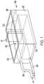
- FIG. 1a perspective view of an immersion cooling system in accordance with various embodiment.
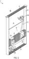
- FIG. 2is a perspective view of an electronic equipment coolant system with an electronic equipment case submerged in dielectric fluid in an immersion coolant tank in accordance with various embodiments.
- FIG. 3is a close-up isolation view of a coolant shroud and dielectric coolant pump coupled through tubing, from FIG. 2 , in accordance with various embodiments.
- FIG. 4is a close-up relief view of elements in FIG. 3 , but with the coolant shroud removed to reveal a heatsink of the electronic equipment in accordance with various embodiments.
- FIG. 5is a perspective view of a coolant shroud in accordance with various embodiments.
- FIG. 6is a side elevation view of an electronic equipment coolant system with a venturi ejector pump.
- Localized enhanced flow rate(s) in a servermay individually or in aggregate be less than, equal to, or greater than bulk flow rate through the server.
- localized enhanced flow ratesmay improve performance at greater volumetric rates than the bulk flow through the server; i.e., where the specific heat capacity of server bulk flow is sufficient to address appropriate net temperature changes, but other properties of the fluid (e.g., higher viscosity) may need the flow to be enhanced to improve local heat transfer coefficients.
- various embodimentsinclude a dedicated dielectric fluid pump and coolant shroud to promote additional flow over the CPU and heatsink.
- the coolant shroudmay be a shaped plastic containment system that separates fluid flow near the CPU and heatsink from the bulk fluid.
- Various embodiments disclosed hereininclude a coolant shroud for a heatsink of electronic equipment immersed in an immersion coolant tank.
- the coolant shroudincludes side walls and a covering wall.
- the side wallsmay be configured to be mounted on a mounting surface within the immersion coolant tank and on which the heatsink is secured.
- the side wallsmay be configured to extend away from the mounting surface, wherein at least one of the side walls includes a fluid port.
- the covering wallmay extend from and between the side walls such that the side walls and the covering wall together form a cooling chamber configured to receive the heatsink therein.
- the covering wallmay include a fluid aperture separate from the fluid port.
- Dielectric fluid inside the cooling chambermay be in fluid communication with dielectric fluid outside the cooling chamber via the fluid aperture.
- the fluid portmay be in fluid communication with a dielectric fluid pump disposed outside the cooling chamber and configured to move dielectric fluid through each of and between the fluid aperture and the fluid port.
- FIG. 1illustrates various aspects of an immersion coolant system 300 for immersing a rack of electronic equipment, such as independently operable servers, in a dielectric fluid 322 is depicted.
- the immersion coolant system 300may include an immersion coolant tank 310 and mounting members for mounting computer servers or other electronic equipment, as will be described in more detail hereinafter.
- the immersion coolant tank 310may be fabricated of steel, a sufficiently strong plastic that is compatible with the dielectric liquid coolant used as a cooling medium, or other suitable material.
- the immersion coolant tank 310may face upward with an open top 330 to form an open interior volume and may be shaped to have a length L, width W, and height H with the minimum footprint to insert multiple pieces of electronic equipment 20 (e.g., servers).
- Suitable mounting membersmay be used to mount the electronic equipment 20 in the immersion coolant tank 310 to form the server rack 370 therein.
- the immersion coolant tank 310may be shaped, dimensioned, and sized such that multiple standard-sized pieces of electronic equipment 20 (e.g., servers) can be supported without significant modification.
- the immersion coolant tank 310may be fabricated to have an inlet pipe or line 340 from a piping system connected to a heat exchanger for the flow of lower temperature or cooled liquid coolant into the immersion coolant tank 310 and an outlet pipe or line 350 connected to collection piping for the flowing or pumping of heated coolant out of the immersion coolant tank 310 to an external heat exchanger associated with one or more heat-rejection or cooling systems.
- the server rack 370may have a number of different implementations.
- the mounting membersare configured to receive the multiple pieces of electronic equipment 20 (e.g., servers) in a vertical orientation, thereby minimizing the footprint of the multiple pieces of electronic equipment 20 (e.g., servers) relative to the ground, and with the “front” panel facing upward for easy installation and removal of a server without the need to remove or disturb any other server within the immersion coolant tank 310 .
- the mounting membersmay be also configured to mount each of the multiple pieces of electronic equipment 20 (e.g., servers) such that the top level 360 of the dielectric coolant completely submerges the top level 372 of the server rack 370 formed by the multiple pieces of electronic equipment 20 (e.g., servers).
- a volume of liquid coolantcollects in a common area above the server rack 370 to improve the circulation of the liquid coolant through the multiple pieces of electronic equipment 20 (e.g., servers), thereby enhancing the cooling of each respective piece of electronic equipment 20 .
- the mounting membersmay also be configured to mount the multiple pieces of electronic equipment 20 (e.g., servers) in the server rack 370 above the bottom of the immersion coolant tank 310 to create a volume of liquid coolant between each respective server and the bottom of the immersion coolant tank 310 such that the flow of the dielectric liquid coolant through the servers is improved.
- the multiple pieces of electronic equipment 20e.g., servers
- the mounting membersmay also be configured to mount the multiple pieces of electronic equipment 20 (e.g., servers) in the server rack 370 above the bottom of the immersion coolant tank 310 to create a volume of liquid coolant between each respective server and the bottom of the immersion coolant tank 310 such that the flow of the dielectric liquid coolant through the servers is improved.
- FIG. 2illustrates various aspects of an electronic equipment coolant system 5 with a coolant shroud 100 used to cool the heatsink elements of electronic equipment 20 submerged in dielectric fluid 322 in an immersion coolant tank 310 , in accordance with various embodiments.
- the various embodimentsare described herein with regard to a system for enhancing flow rates of dielectric fluid to specific elements of electronic equipment, such as heatsinks, in an immersion coolant tank 310 .
- Each element of electronic equipment 20may include one or more dual in-line memory modules (DIMMs) 40 , some of which may be contained within a coolant shroud 100 .
- DIMMsdual in-line memory modules
- the coolant shroud 100may be coupled with tubing 75 to a dielectric fluid pump 50 for redirecting dielectric fluid specifically onto and over heatsinks (e.g., 80 in FIG. 4 ) or particular fins 81 of the heatsink housed within the coolant shroud 100 .
- the electronic equipment 20is illustrated as having one side removed, as well as several components thereof, to more clearly explain aspects of the various embodiments.
- the electronic equipment 20may include upper and lower screens 27 configured to allow the flow of dielectric fluid 322 from the immersion coolant tank 310 to flow in and out thereof.
- An inner volume 30 of the electronic equipment 20houses the DIMMs 40 and heatsinks (e.g., 80 in FIG. 4 ), which may be mounted on a mounting surface 25 , such as a printed circuit board supporting additional elements, within the electronic equipment 20 .
- the screens 27may be included on all or part of the lateral sides of the electronic equipment 20 , such as a lower portion of the lateral sides to take advantage of cooler dielectric fluid flowing near the bottom of the immersion coolant tank 310 .
- the DIMMs 40 illustrated in FIG. 2include two cooling shroud 100 that each enclose a heatsink (e.g., 80 in FIG. 4 ), however fewer or greater heatsinks and corresponding cooling shrouds 100 may be provided.
- Each cooling shroud 100may be configured to direct at least a portion of the flow of dielectric coolant 322 in the inner volume 30 specifically over other heat producing electronics (e.g., a DIMM, Power Supply, etc.) contained therein.
- a dielectric fluid pump 50 aalso disposed in the electronic equipment 20 , may provide a suction force, via tubing 75 , to create an in-flow F In into the cooling shroud 100 and redirect dielectric coolant with an out-flow F Out to another part of the inner volume 30 .
- the coolant shroud 100may include a coolant aperture 140 , which is where the dielectric coolant is suctioned in and over the heatsink, and a fluid port to the tubing 75 for expelling the dielectric coolant after it has absorbed heat generated by the heatsink.
- one dielectric fluid pump 50 amay provide the suction pressure to more than one coolant shroud 100 .
- each coolant shroud 100may have more than one dielectric fluid pump 50 providing the suction pressure thereto.
- the dielectric fluid pump 50 bmay provide a pushing force, via tubing 75 , to create an in-flow and an out-flow opposite to that illustrated.
- one dielectric fluid pump 50 amay provide a suction force
- another dielectric fluid pump 50 bmay provide a pushing force.
- FIG. 2is illustrated with a pulling pump 50 a and a pushing pump 50 b
- embodiments within the contemplated scope of disclosuremay include one pump, two pumps or more pumps.
- the pumps ( 50 a , 50 b )may be the same type or different types (i.e., push or pull).
- the piece of electronic equipment 20may be oriented with its lengthwise extent in a vertical direction, such that multiple cases may hang next to one another on a cooling rack of an immersion coolant tank. Additional cases may hang to the left and/or right of the piece of electronic equipment 20 as illustrated. Due to the vertical orientation, gravity may aid in pulling the dielectric fluid through the coolant aperture 140 located near a bottom of the coolant shroud 100 , since the heated dielectric fluid will have a lower density and tend to rise (i.e., move vertically upward) within the inner volume 30 . In this way, the position of the coolant shroud and the relative orientation of the coolant aperture 140 may leverage convection currents of the dielectric fluid within the inner volume 30 to improve coolant flow.
- FIG. 3is a close-up isolated view of the coolant shroud 100 and dielectric coolant pump 50 a coupled through tubing 75 .
- the coolant shroud 100includes side walls 121 , 122 , 123 , 124 and a covering wall 130 .
- the side walls 121 , 122 , 123 , 124may be configured to be mounted on the mounting surface 25 within the immersion coolant tank and on which the heatsink may be secured.
- the mounting surface 25may be located in the inner volume 30 of the case (e.g., for corresponding electronic equipment.
- the side walls 121 , 122 , 123 , 124may be configured to extend away from the mounting surface 25 .
- the side wallsmay include a fluid port 150 to which the tubing 75 may be coupled.
- the covering wall 130extends from and between the side walls 121 , 122 , 123 , 124 so together the side walls 121 , 122 , 123 , 124 and the covering wall 130 form a cooling chamber underneath.
- the cooling chambermay be configured to receive the heatsink therein.
- the heatsinkmay be disposed between the covering wall 130 and the mounting surface 25 .
- a central processing unitCPU
- CPUcentral processing unit
- the covering wall 130may include the fluid aperture 140 separate from the fluid port 150 .
- the fluid aperture 140may provide dielectric fluid inside the cooling chamber with a means of fluid communication with dielectric fluid outside the cooling chamber (i.e., via the fluid aperture 140 ).
- the fluid port 150may be in fluid communication with the dielectric fluid pump 50 disposed outside the coolant shroud 100 , and thus outside the cooling chamber. Fluid pressure generated by the dielectric fluid pump 50 a may be configured to move dielectric fluid 322 through and between each of the fluid aperture 140 and the fluid port 150 .
- the fluid aperture 140may be formed as an elongate slot disposed at an opposite end of the covering wall 130 from the side wall 123 that includes the fluid port 175 .
- the fluid aperture 140 and the fluid port 150may be configured to enable the dielectric fluid pump 50 a to generate a suction pressure that draws dielectric fluid from the immersion coolant tank (i.e., the inner volume 30 ) into the cooling chamber through the fluid aperture 140 for cooling the heatsink and return to the immersion coolant tank via the fluid port.
- the in-flow F In of dielectric fluidenters the fluid aperture 140 and dielectric fluid exits the fluid port 150 , directed toward an intake of the dielectric fluid pump 50 a , and eventually exits the dielectric fluid pump 50 a as an out-flow F Out .
- the tubing 75which couples the fluid port 150 to the dielectric fluid pump 50 , may enable dielectric fluid to be directed to a remote section of the inner chamber 30 so cooler dielectric fluid remains near the coolant shroud 100 .
- the dielectric fluid pump 50 a and the coolant shroud 100may be remote from one another. In this way, the dielectric fluid pump 50 a may be remote from the side walls 121 , 122 , 123 , 124 and covering wall 130 . While FIG.
- FIG 3illustrates the dielectric fluid pump 50 a and shroud operating in a pull type manner (i.e., the dielectric fluid is drawn into the coolant shroud 100 through the fluid aperture 140 ), the same components may be operated in a push type manner in which cool dielectric fluid 322 may enter into the dielectric fluid pump (i.e., 50 b ) and be pushed through tube 75 and directed over the specific heatsink and out through the fluid aperture 140 . In this manner, the pump may be placed in a position within the immersion coolant tank 310 to supply cooler dielectric fluid 322 directly over the specific heatsink.
- a pull type manneri.e., the dielectric fluid is drawn into the coolant shroud 100 through the fluid aperture 140
- the same componentsmay be operated in a push type manner in which cool dielectric fluid 322 may enter into the dielectric fluid pump (i.e., 50 b ) and be pushed through tube 75 and directed over the specific heatsink and out through the fluid aperture 140 .
- the pumpmay be placed
- FIG. 4shows a close-up relief view of elements in FIG. 3 , but with the coolant shroud (i.e., 100 ) removed to reveal a heatsink 80 of the electronic equipment in accordance with various embodiments.
- the heatsink 80may include a plurality of fins 81 formed to provide greater surface area for expelling heat. Once inside the cooling chamber of the coolant shroud, dielectric fluid may be made to flow over and between the fins 81 , absorbing heat there from.
- the heatsink 80typically are mounted on or over heat generating components such as processor units. Such heat generating components may be mounted directly on the mounting surface 25 .
- FIG. 5shows an alternative coolant shroud 101 , which includes a fluid aperture 141 disposed on one of the side walls thereof.
- the fluid aperture 141 and the fluid port 150may be disposed on opposite side walls 121 , 123 .
- the fluid aperture 141may be disposed on side wall 124 and/or 122 .
- the size, shape, and position of the fluid apertures 140 , 141may have a pronounced effect on the distribution of dielectric fluid flow throughout the cooling chamber of the coolant shroud 100 .
- the coolant shrouds 100 , 101 shown in FIGS. 1 , 2 , and 4show the fluid apertures 140 , 141 close to but not coincident with an edge of the coolant shrouds 140 , 141 , thus forming a narrow band of shroud between the apertures 140 , 141 and the respective edge.
- that narrow bandmay be eliminated or reduced substantially.
- the fluid apertures 140 , 141are shown as having a rectangular shape, which may promote an even well-distributed flow pattern over the heatsinks.
- the aperturesmay have a different shape, such as oval, round, square, triangular, or other less traditional geometric shapes.
- the apertures 140 , 141could be altered to achieve such flows. For example, one portion of the apertures 140 , 141 may be taller or wider than another.
- FIG. 6illustrates various aspects of an electronic equipment coolant system 6 with venturi ejector pumps 200 used in combination with the coolant shrouds 100 to cool the heatsink elements, in accordance with various embodiments.
- the venturi ejector pumps 200use a motivating flow F M at relatively high velocity and a relatively low volumetric flow within the body of the venturi ejector pump 200 to create a low-pressure space therein.
- Such a low-pressure spacemay be in fluid communication with the fluid port 150 on the shroud via tube 75 .
- This low pressureprovides the suction necessary to draw the dielectric fluid into the shroud through aperture 140 , across the heatsink, out the fluid port 150 , and supply a drawn flow FD of heated dielectric fluid into the venture ejector pump 200 .
- the motivating fluid in the motivating flow F M and the suction fluid from the drawn flow FDwill thus be combined to create and out flow F Out , which may be cooler than the suction fluid from the shroud thereby making it more suitable for discharge into the server body 20 for further cooling of other electronic components.
- the motivating fluid, with its associated motivating flow F Mmay be furnished by the pumping system that is also circulating dielectric fluid through the tank.
- supply tubing 76which supplies the motivating fluid may draw dielectric fluid from the inlet line (e.g., 340 in FIG. 1 ) of the immersion coolant tank (e.g., 310 in FIG. 1 ).
- the inlet linemay feed into a manifold, which may supply multiple supply tubes 76 to each piece of electronic equipment 20 and/or multiple pieces of electronic equipment 20 , in addition to the rest of the immersion coolant tank.
- the venturi ejector pumps 200 in the electronic equipment coolant system 6may be used to enhance circulation of the dielectric fluid within the inner volume 30 .
- An orientation of the venture ejector pumps 200which dictates a direction of the out flow F Out , may be used to cause a recirculating flow, a directional flow out of the casing of the electronic equipment 20 , and/or a combination thereof. Such a recirculating flow may help eliminate or reduce stagnation points in the dielectric fluid flow within the inner volume 30 .
Landscapes
- Engineering & Computer Science (AREA)
- Microelectronics & Electronic Packaging (AREA)
- Physics & Mathematics (AREA)
- Thermal Sciences (AREA)
- Computer Hardware Design (AREA)
- General Engineering & Computer Science (AREA)
- Cooling Or The Like Of Electrical Apparatus (AREA)
Abstract
Description
Claims (15)
Priority Applications (6)
| Application Number | Priority Date | Filing Date | Title |
|---|---|---|---|
| US17/478,176US11805624B2 (en) | 2021-09-17 | 2021-09-17 | Coolant shroud |
| EP22870752.7AEP4403005A4 (en) | 2021-09-17 | 2022-09-16 | COOLANT SHEATHING |
| KR1020247012161AKR20240058924A (en) | 2021-09-17 | 2022-09-16 | coolant shroud |
| PCT/US2022/043817WO2023044015A1 (en) | 2021-09-17 | 2022-09-16 | Coolant shroud |
| JP2024516645AJP2024535036A (en) | 2021-09-17 | 2022-09-16 | Coolant Shroud |
| US18/244,844US12309975B2 (en) | 2021-09-17 | 2023-09-11 | Coolant shroud |
Applications Claiming Priority (1)
| Application Number | Priority Date | Filing Date | Title |
|---|---|---|---|
| US17/478,176US11805624B2 (en) | 2021-09-17 | 2021-09-17 | Coolant shroud |
Related Child Applications (1)
| Application Number | Title | Priority Date | Filing Date |
|---|---|---|---|
| US18/244,844ContinuationUS12309975B2 (en) | 2021-09-17 | 2023-09-11 | Coolant shroud |
Publications (2)
| Publication Number | Publication Date |
|---|---|
| US20230091814A1 US20230091814A1 (en) | 2023-03-23 |
| US11805624B2true US11805624B2 (en) | 2023-10-31 |
Family
ID=85571702
Family Applications (2)
| Application Number | Title | Priority Date | Filing Date |
|---|---|---|---|
| US17/478,176Active2042-03-23US11805624B2 (en) | 2021-09-17 | 2021-09-17 | Coolant shroud |
| US18/244,844ActiveUS12309975B2 (en) | 2021-09-17 | 2023-09-11 | Coolant shroud |
Family Applications After (1)
| Application Number | Title | Priority Date | Filing Date |
|---|---|---|---|
| US18/244,844ActiveUS12309975B2 (en) | 2021-09-17 | 2023-09-11 | Coolant shroud |
Country Status (5)
| Country | Link |
|---|---|
| US (2) | US11805624B2 (en) |
| EP (1) | EP4403005A4 (en) |
| JP (1) | JP2024535036A (en) |
| KR (1) | KR20240058924A (en) |
| WO (1) | WO2023044015A1 (en) |
Cited By (1)
| Publication number | Priority date | Publication date | Assignee | Title |
|---|---|---|---|---|
| US20230389230A1 (en)* | 2022-05-27 | 2023-11-30 | Baidu Usa Llc | Server and cooling system for enhanced immersion cooling |
Families Citing this family (8)
| Publication number | Priority date | Publication date | Assignee | Title |
|---|---|---|---|---|
| US12389566B2 (en) | 2020-11-12 | 2025-08-12 | Green Revolution Cooling, Inc. | Multi-rack immersion cooling distribution system |
| US11805624B2 (en) | 2021-09-17 | 2023-10-31 | Green Revolution Cooling, Inc. | Coolant shroud |
| US12250791B2 (en)* | 2021-11-24 | 2025-03-11 | Microsoft Technology Licensing, Llc | Systems and methods for recovering fluid in immersion-cooled datacenters |
| TWI800371B (en)* | 2022-05-06 | 2023-04-21 | 緯創資通股份有限公司 | Fluid distribution assembly and cooling system including the same |
| CN219042341U (en)* | 2022-11-02 | 2023-05-16 | 富联精密电子(天津)有限公司 | Flow guiding device and liquid cooling machine case |
| TWI846195B (en)* | 2022-12-09 | 2024-06-21 | 緯創資通股份有限公司 | Immersion cooling device, active heat dissipation module and active flow-guiding module |
| US12414273B2 (en) | 2023-01-25 | 2025-09-09 | Green Revolution Cooling, Inc. | Immersion cooling reservoir level control |
| WO2025006803A1 (en)* | 2023-06-29 | 2025-01-02 | Green Revolution Cooling, Inc. | Coolant flow enhancement |
Citations (199)
| Publication number | Priority date | Publication date | Assignee | Title |
|---|---|---|---|---|
| US2643282A (en) | 1949-04-13 | 1953-06-23 | Albert D Greene | Electronic equipment cooling means |
| US3094133A (en) | 1959-07-22 | 1963-06-18 | Earl E Treanor | Chemical feed and blowdown system |
| US3320762A (en) | 1965-12-08 | 1967-05-23 | John P Murdoch | Air conditioning system with heating means |
| US3406244A (en) | 1966-06-07 | 1968-10-15 | Ibm | Multi-liquid heat transfer |
| US3450265A (en) | 1967-05-11 | 1969-06-17 | Culligan Inc | Recirculating water treatment and control system |
| US3489207A (en) | 1968-02-19 | 1970-01-13 | Gen Electric | Vapor-cooled electronics enclosures |
| US3600636A (en) | 1968-11-14 | 1971-08-17 | Danfoss As | Electrical apparatus comprising a power section and a control section with fluid cooling |
| US3754741A (en) | 1971-09-28 | 1973-08-28 | Parker Eng Chem Inc | Water treatment system |
| US3858090A (en) | 1972-11-14 | 1974-12-31 | Danfoss As | Oil-cooled electrical apparatus withdrawable from an outer casing for inspection and repairs |
| US4034335A (en) | 1974-08-30 | 1977-07-05 | Kabushiki Kaisha Komatsu Seisakusho | Automatic safety and alarming apparatus for construction equipments |
| US4245668A (en) | 1978-02-28 | 1981-01-20 | Chemetics International Ltd. | Pressure regulator |
| US4302793A (en) | 1979-11-30 | 1981-11-24 | Submergible Oil Systems, Inc. | Electronic cooling |
| US4313310A (en) | 1979-09-07 | 1982-02-02 | Fujitsu Limited | Cooling system |
| US4399501A (en) | 1980-04-21 | 1983-08-16 | Alsthom-Atlantique | Set of power semiconductors equipped with firing transformers and with protection circuits |
| US4460008A (en) | 1982-12-23 | 1984-07-17 | Leary Richard P O | Indexing controller apparatus for cooling water tower systems |
| US4464315A (en) | 1982-12-20 | 1984-08-07 | Betz Entec, Inc. | Indexing controller system and method of automatic control of cooling water tower systems |
| US4493010A (en) | 1982-11-05 | 1985-01-08 | Lockheed Corporation | Electronic packaging module utilizing phase-change conductive cooling |
| US4590538A (en) | 1982-11-18 | 1986-05-20 | Cray Research, Inc. | Immersion cooled high density electronic assembly |
| US4600230A (en) | 1984-01-27 | 1986-07-15 | Myotoku Ltd. | Fluid feeding valve and a vacuum chuck apparatus using same |
| US4648043A (en) | 1984-05-07 | 1987-03-03 | Betz Laboratories, Inc. | Computerized system for feeding chemicals into water treatment system |
| US4659459A (en) | 1985-07-18 | 1987-04-21 | Betz Laboratories, Inc. | Automated systems for introducing chemicals into water or other liquid treatment systems |
| US4704658A (en) | 1985-04-30 | 1987-11-03 | Fujitsu Limited | Evaporation cooling module for semiconductor devices |
| US4741385A (en) | 1986-02-18 | 1988-05-03 | Iowa State University Research Foundation, Inc. | Gas jet impingement means and method |
| US4834257A (en) | 1987-12-11 | 1989-05-30 | Westinghouse Electric Corp. | Reinforced wall structure for a transformer tank |
| US5102503A (en) | 1989-08-04 | 1992-04-07 | Environmental Technology Group Corporation | Mobile self-contained system for on-site recovery of solvents |
| US5145585A (en) | 1990-02-09 | 1992-09-08 | Coke Alden L | Method and apparatus for treating water in a cooling system |
| US5260850A (en) | 1991-03-08 | 1993-11-09 | Cray Computer Corporation | Logic module assembly for confining and directing the flow of cooling fluid |
| US5294916A (en) | 1992-01-23 | 1994-03-15 | Autotrol Corp. | Water treatment controller for an evaporative condenser |
| US5297621A (en) | 1989-07-13 | 1994-03-29 | American Electronic Analysis | Method and apparatus for maintaining electrically operating device temperatures |
| US5329418A (en) | 1991-11-18 | 1994-07-12 | Kabushiki Kaisha Toshiba | 3-D communication and interconnect technique for increased number of computational modules in large-scale electronic equipment |
| US5332494A (en) | 1992-02-03 | 1994-07-26 | H.E.R.C. Incorporated | Water control system using oxidation reduction potential sensing |
| US5414591A (en) | 1991-04-15 | 1995-05-09 | Hitachi, Ltd. | Magnetic disk storage system |
| US5574627A (en) | 1995-07-24 | 1996-11-12 | At&T Global Information Solutions Company | Apparatus for preventing the formation of condensation on sub-cooled integrated circuit devices |
| US5851143A (en) | 1996-05-10 | 1998-12-22 | Thermal Industries | Disk drive test chamber |
| US5907473A (en) | 1997-04-04 | 1999-05-25 | Raytheon Company | Environmentally isolated enclosure for electronic components |
| US6019167A (en) | 1997-12-19 | 2000-02-01 | Nortel Networks Corporation | Liquid immersion cooling apparatus for electronic systems operating in thermally uncontrolled environments |
| US20020014460A1 (en) | 1999-03-05 | 2002-02-07 | Mckay Scott | Method and apparatus for treating water |
| US6374627B1 (en) | 2001-01-09 | 2002-04-23 | Donald J. Schumacher | Data center cooling system |
| US20020151799A1 (en) | 2000-04-13 | 2002-10-17 | Boston Scientific Corporation | Catheter drive shaft clutch |
| US20020185262A1 (en) | 2001-06-12 | 2002-12-12 | Baer Daniel B. | Single or dual buss thermal transfer system |
| US20020189173A1 (en) | 1998-04-24 | 2002-12-19 | Staschik Udo Ingmar | Utilities container |
| US20030053293A1 (en) | 2001-09-14 | 2003-03-20 | Beitelmal Abdlmonem H. | Method and apparatus for individually cooling components of electronic systems |
| US20030127240A1 (en) | 2000-03-14 | 2003-07-10 | Kai Beckbissinger | Housing for an electrical device |
| USD477617S1 (en) | 2001-12-14 | 2003-07-22 | Austria Haustechnik Aktiengesellschaft | Cooling chest |
| US6600656B1 (en) | 2002-04-10 | 2003-07-29 | Sun Microsystems, Inc. | System structure for fast service access in a rack/cabinet |
| US6616851B1 (en) | 1999-08-14 | 2003-09-09 | Cognis Deutschland Gmbh & Co. Kg | System and method for treating water circulating in open-circuit cooling systems |
| US6621707B2 (en) | 1998-08-11 | 2003-09-16 | Fujitsu Limited | Liquid-cooled electronic apparatus |
| USD483045S1 (en) | 2002-06-14 | 2003-12-02 | Austria Haustechnik Aktiengesellschaft | Cooling chest |
| US20040008490A1 (en) | 2002-07-13 | 2004-01-15 | Kioan Cheon | Water cooling type soft cooling jacket for electronic device and buffer jacket using the same |
| US20040013563A1 (en) | 2000-05-19 | 2004-01-22 | Romer Edward Adolph | Cooling tower maintenance |
| US20040050491A1 (en) | 2002-09-13 | 2004-03-18 | Dainippon Screen Mfg. Co., Ltd. | Substrate processing apparatus |
| US20040223300A1 (en) | 2003-03-19 | 2004-11-11 | Fink James R. | Data center cooling |
| JP2004319628A (en) | 2003-04-14 | 2004-11-11 | Hitachi Ltd | System module |
| US20040246683A1 (en) | 2001-09-27 | 2004-12-09 | Martin Honsberg-Riedl | Electrical circuit arrangement comprised of a number of electrically interconnected circuit components |
| US20040254682A1 (en) | 2001-12-27 | 2004-12-16 | Tim Kast | Apparatus, system and method for non-chemical treatment and management of cooling water |
| JP2004363308A (en) | 2003-06-04 | 2004-12-24 | Hitachi Ltd | Rack mount server system |
| US20050011839A1 (en) | 2003-07-16 | 2005-01-20 | James Dart | Water treatment apparatus and method |
| US20050024826A1 (en) | 2003-07-29 | 2005-02-03 | Bash Cullen Edwin | Environmental condition measurement system |
| US20050052847A1 (en) | 2003-09-10 | 2005-03-10 | Hamman Brian A. | Liquid cooling system |
| US20050083657A1 (en) | 2003-10-18 | 2005-04-21 | Qnx Cooling Systems, Inc. | Liquid cooling system |
| US20050111184A1 (en) | 2003-10-31 | 2005-05-26 | Hewlett-Packard Development Company, L.P. | Cooling of a computer environment |
| US20050114876A1 (en) | 2003-11-21 | 2005-05-26 | Hitachi, Ltd. | Disc array apparatus |
| US6909606B2 (en) | 2003-08-08 | 2005-06-21 | Hewlett-Packard Development Company, L.P. | Electronic device cooling system and method of use |
| US20050152112A1 (en) | 2004-01-08 | 2005-07-14 | Apple Computer Inc. | Apparatus for air cooling of an electronic device |
| US20050259402A1 (en) | 2004-05-18 | 2005-11-24 | Denso Corporation | Power stack |
| US20060026610A1 (en) | 2004-08-02 | 2006-02-02 | Hitachi, Ltd. | Optical disk apparatus |
| US20060064709A1 (en) | 2004-08-20 | 2006-03-23 | Digital Site Management, Llc | Storage medium protection system |
| US20060123436A1 (en) | 2004-12-06 | 2006-06-08 | Hitachi, Ltd. | Disk array device and disk array device housing |
| US20060135042A1 (en) | 2004-12-17 | 2006-06-22 | Frost David T | Multi-station disk finishing apparatus and method |
| US7086247B2 (en) | 2004-08-31 | 2006-08-08 | International Business Machines Corporation | Cooling system and method employing auxiliary thermal capacitor unit for facilitating continuous operation of an electronics rack |
| USD530346S1 (en) | 2004-08-27 | 2006-10-17 | Aht Cooling Gmbh | Cooling machine |
| US20060250755A1 (en) | 2005-01-18 | 2006-11-09 | Tilton Charles L | Globally cooled computer system |
| US20060274501A1 (en) | 2001-12-27 | 2006-12-07 | Formfactor, Inc. | Electronic package with direct cooling of active electronic components |
| US20070006599A1 (en) | 2003-03-11 | 2007-01-11 | Mayekawa Mfg. Co., Ltd. | Apparatus and method for cooling super conductive body |
| US20070025081A1 (en) | 2005-07-28 | 2007-02-01 | Berlin Carl W | Electronic package and method of cooling electronics |
| US20070034360A1 (en) | 2005-06-08 | 2007-02-15 | Hall Jack P | High performance cooling assembly for electronics |
| US7184269B2 (en) | 2004-12-09 | 2007-02-27 | International Business Machines Company | Cooling apparatus and method for an electronics module employing an integrated heat exchange assembly |
| WO2007023130A2 (en) | 2005-08-23 | 2007-03-01 | International Business Machines Corporation | Systems and methods for cooling electronics components employing vapor compression refrigeration |
| US7210304B2 (en) | 2005-02-09 | 2007-05-01 | General Motors Corporation | Cooling arrangements for integrated electric motor-inverters |
| WO2007098078A2 (en) | 2006-02-16 | 2007-08-30 | Cooligy, Inc. | Liquid cooling loops for server applications |
| US20070199340A1 (en) | 2003-08-25 | 2007-08-30 | Isothermal Systems Research, Inc. | Multi-chamber spray cooling system |
| US20070213000A1 (en) | 2002-03-28 | 2007-09-13 | American Power Conversion | Data Center Cooling |
| US20070227710A1 (en) | 2006-04-03 | 2007-10-04 | Belady Christian L | Cooling system for electrical devices |
| US7278273B1 (en) | 2003-12-30 | 2007-10-09 | Google Inc. | Modular data center |
| US20070267741A1 (en) | 2006-05-16 | 2007-11-22 | Hardcore Computer, Inc. | Liquid submersion cooling system |
| US20080002364A1 (en) | 2006-06-29 | 2008-01-03 | International Business Machines Corporation | Coolant control unit, and cooled electronics system and method employing the same |
| US7318322B2 (en) | 2003-02-14 | 2008-01-15 | Hitachi, Ltd. | Liquid cooling system for a rack-mount server system |
| US20080017355A1 (en) | 2006-05-16 | 2008-01-24 | Hardcore Computer, Inc. | Case for a liquid submersion cooled electronic device |
| US20080026509A1 (en) | 2005-10-25 | 2008-01-31 | International Business Machines Corporation | Cooling apparatuses and methods employing discrete cold plates compliantly coupled between a common manifold and electronics components of an assembly to be cooled |
| US20080030945A1 (en) | 2002-03-21 | 2008-02-07 | Tempest Microsystems | High Density Storage System |
| US20080029250A1 (en) | 2006-06-01 | 2008-02-07 | Andrew Carlson | Warm Water Cooling |
| US20080055845A1 (en) | 2006-08-31 | 2008-03-06 | Vance Murakami | System for hot swapping heat exchangers |
| WO2008027931A2 (en) | 2006-08-29 | 2008-03-06 | Isothermal Systems Research, Inc. | Manifold for a two-phase cooling system |
| US20080158818A1 (en) | 2006-12-29 | 2008-07-03 | Google Inc. | Motherboards with Integrated Cooling |
| US20080174954A1 (en) | 2007-01-24 | 2008-07-24 | Vangilder James W | System and method for evaluating equipment rack cooling performance |
| WO2008089322A2 (en) | 2007-01-19 | 2008-07-24 | Al-Khorayef Group Company Ltd. | Temperature control systems and methods |
| US20080180908A1 (en) | 2007-01-23 | 2008-07-31 | Peter Wexler | In-row air containment and cooling system and method |
| US7413394B2 (en) | 2001-07-02 | 2008-08-19 | Transol Corporation | Low headroom telescoping bridge crane system |
| US20080209931A1 (en) | 2007-03-01 | 2008-09-04 | Jason Stevens | Data centers |
| US20080270572A1 (en) | 2007-04-25 | 2008-10-30 | Belady Christian L | Scalable computing apparatus |
| US20080266726A1 (en) | 2007-04-27 | 2008-10-30 | Vance Murakami | Cooling system for electrical devices |
| US20080273306A1 (en) | 2007-05-04 | 2008-11-06 | International Business Machines Corporation | System and method of facilitating cooling of electronics racks of a data center employing multiple cooling stations |
| US7511960B2 (en) | 2006-09-13 | 2009-03-31 | Sun Microsystems, Inc. | Balanced chilled fluid cooling system for a data center in a shipping container |
| US7551971B2 (en) | 2006-09-13 | 2009-06-23 | Sun Microsystems, Inc. | Operation ready transportable data center in a shipping container |
| US20090168345A1 (en) | 2006-06-15 | 2009-07-02 | Martini Valan R | Energy saving system and method for cooling computer data center and telecom equipment |
| US20090229194A1 (en) | 2008-03-11 | 2009-09-17 | Advanced Shielding Technologies Europe S.I. | Portable modular data center |
| US20090251860A1 (en) | 2008-04-02 | 2009-10-08 | Microsoft Corporation | Power-efficent data center |
| US20090262455A1 (en) | 2008-04-17 | 2009-10-22 | Teradyne, Inc. | Temperature Control Within Disk Drive Testing Systems |
| US20090260777A1 (en) | 2008-04-21 | 2009-10-22 | Hardcore Computer, Inc. | case and rack system for liquid submersion cooling of electronic devices connected in an array |
| US7609518B2 (en) | 2005-11-17 | 2009-10-27 | Iceotope Limited | Cooling computer components |
| US20090295167A1 (en) | 2007-02-26 | 2009-12-03 | Jimmy Clidaras | Water-based data center |
| US20100027212A1 (en) | 2008-07-17 | 2010-02-04 | Advanced Shielding Technologies Europe S.L. | Environmental disaster data protection system |
| US20100030267A1 (en) | 2007-06-05 | 2010-02-04 | Spartek Medical, Inc. | Surgical tool and method for implantation of a dynamic bone anchor |
| WO2010019517A1 (en) | 2008-08-11 | 2010-02-18 | Green Revolution Cooling, Inc. | Liquid submerged, horizontal computer server rack and systems and methods of cooling such a server rack |
| US20100061057A1 (en) | 2008-09-10 | 2010-03-11 | American Power Conversion Corporation | Hot aisle containment panel system and method |
| US7686175B2 (en) | 2004-09-03 | 2010-03-30 | Mhe Technologies, Inc. | Container crane |
| US20100103618A1 (en) | 2008-10-23 | 2010-04-29 | International Business Machines Corporation | Apparatus and method for facilitating pumped immersion-cooling of an electronic subsystem |
| US7724513B2 (en) | 2006-09-25 | 2010-05-25 | Silicon Graphics International Corp. | Container-based data center |
| US20100139887A1 (en) | 2008-12-04 | 2010-06-10 | George Slessman | System and Method of Providing Computer Resources |
| US20100165565A1 (en) | 2008-12-31 | 2010-07-01 | Hellriegal Stephen V R | Data center |
| US7757506B2 (en) | 2007-11-19 | 2010-07-20 | International Business Machines Corporation | System and method for facilitating cooling of a liquid-cooled electronics rack |
| US20100226094A1 (en) | 2009-03-09 | 2010-09-09 | Hardcore Computer, Inc. | Gravity assisted directed liquid cooling |
| US20100263885A1 (en) | 2009-04-21 | 2010-10-21 | 3M Innovative Properties Company | Protection systems and methods for electronic devices |
| US20100275441A1 (en) | 2001-03-20 | 2010-11-04 | American Power Conversion Corporation | Adjustable scalable rack power system and method |
| US20100290190A1 (en) | 2009-05-12 | 2010-11-18 | Iceotope Limited | Cooled electronic system |
| US7843298B2 (en) | 2004-12-27 | 2010-11-30 | Hitachi Industrial Equipment Systems Co., Ltd | Power distribution transformer and tank therefor |
| US7854652B2 (en) | 2006-09-13 | 2010-12-21 | Oracle America, Inc. | Server rack service utilities for a data center in a shipping container |
| US7856838B2 (en) | 2006-09-13 | 2010-12-28 | Oracle America, Inc. | Cooling air flow loop for a data center in a shipping container |
| US7934386B2 (en) | 2008-02-25 | 2011-05-03 | Raytheon Company | System and method for cooling a heat generating structure |
| US20110103019A1 (en) | 2008-10-23 | 2011-05-05 | International Business Machines Corporation | Open flow cold plate for immersion-cooled electronic packages |
| US20110120885A1 (en) | 2009-11-16 | 2011-05-26 | Earthwise Environmental Inc. | Cooling tower water management system |
| US20110151765A1 (en) | 2009-12-17 | 2011-06-23 | Delta Electronics, Inc. | Operating condition adjusting system and method of portable data center |
| US20110157829A1 (en) | 2009-12-28 | 2011-06-30 | Wormsbecher Paul A | Container-based data center having greater rack density |
| US7971632B2 (en) | 2003-11-07 | 2011-07-05 | Asetek A/S | Cooling system for a computer system |
| US20110240281A1 (en) | 2010-03-31 | 2011-10-06 | Industrial Idea Partners, Inc. | Liquid-Based Cooling System For Data Centers Having Proportional Flow Control Device |
| US8047904B2 (en) | 2006-09-13 | 2011-11-01 | Oracle America, Inc. | Cooling method for a data center in a shipping container |
| US20110267775A1 (en) | 2010-04-29 | 2011-11-03 | Brocade Communications Systems, Inc. | Side-exhaust cooling system with extensible duct for rack mounted equipment |
| US20120026691A1 (en) | 2010-07-28 | 2012-02-02 | International Business Machines Corporation | Apparatus and method for facilitating dissipation of heat from a liquid-cooled electronics rack |
| US20120035773A1 (en) | 2010-08-04 | 2012-02-09 | Powerquest, LLC. | Efficient computer cooling methods and apparatus |
| US20120123595A1 (en) | 2010-11-15 | 2012-05-17 | International Business Machines Corporation | Controlling fluid coolant flow in cooling systems of computing devices |
| US20120155027A1 (en) | 2010-12-16 | 2012-06-21 | Broome John P | Portable computer server enclosure |
| US8213261B2 (en) | 2008-05-22 | 2012-07-03 | Exxonmobil Upstream Research Company | Method for geophysical and geological interpretation of seismic volumes in the domains of depth, time, and age |
| US20120171943A1 (en) | 2010-12-30 | 2012-07-05 | Munters Corporation | Systems for removing heat from enclosed spaces with high internal heat generation |
| US20120236487A1 (en) | 2011-03-16 | 2012-09-20 | Lenovo (Singapore) Pte. Ltd. | Handle assembly configured for airflow |
| US8295047B1 (en) | 2007-09-28 | 2012-10-23 | Exaflop Llc | Changing data center cooling modes |
| US8310829B2 (en) | 2008-05-05 | 2012-11-13 | Carrier Corporation | Integrated computer equipment container and cooling unit |
| US20120294737A1 (en) | 2011-04-18 | 2012-11-22 | Singh Krishna P | Autonomous self-powered system for removing thermal energy from pools of liquid heated by radioactive materials, and method of the same |
| US20120300391A1 (en) | 2011-03-02 | 2012-11-29 | Earl Keisling | Modular it rack cooling assemblies and methods for assembling same |
| US20130025888A1 (en) | 2011-07-26 | 2013-01-31 | Firetrace Usa, Llc | Methods and apparatus for hot aisle/cold aisle data center fire suppression |
| US20130032217A1 (en) | 2011-08-05 | 2013-02-07 | Thomas Pesek | Methods and apparatus for level loop control |
| WO2013022805A1 (en) | 2011-08-05 | 2013-02-14 | Green Revolution Cooling, Inc. | Hard drive cooling for fluid submersion cooling systems |
| US20130075066A1 (en) | 2011-09-23 | 2013-03-28 | Mikhail Pavlovich Reytblat | Advanced Multi-Purpose, Multi-stage Evaporative Cold Water/Cold Air Generating and Supply System |
| US20130105139A1 (en) | 2011-10-31 | 2013-05-02 | International Business Machines Corporation | Multi-rack assembly with shared cooling unit |
| US20140060773A1 (en) | 2012-08-31 | 2014-03-06 | Fujitsu Limited | Power control apparatus, information processing apparatus, and power control method |
| US20140060799A1 (en) | 2012-08-31 | 2014-03-06 | International Business Machines Corporation | Configuring A Liquid Cooling System Associated With Electrical Computing Racks |
| US20140085821A1 (en) | 2012-09-25 | 2014-03-27 | Liquidcool Solutions, Inc. | Method and apparatus to manage coolant pressure and flow for an array of liquid submerged electronic devices |
| US20140085817A1 (en) | 2012-09-26 | 2014-03-27 | International Business Machines Corporation | Immersion-cooling of selected electronic component(s) mounted to printed circuit board |
| US20140109610A1 (en) | 2012-10-18 | 2014-04-24 | Port-A-Cool, Llc | Free-standing evaporative air cooling apparatus |
| US20140216686A1 (en) | 2013-02-01 | 2014-08-07 | Dell Products L.P. | Partitioned, Rotating Condenser Units to Enable Servicing of Submerged IT Equipment Positioned Beneath a Vapor Condenser Without Interrupting a Vaporization-Condensation Cycling of the Remaining Immersion Cooling System |
| US20140218858A1 (en) | 2013-02-01 | 2014-08-07 | Dell Products L.P. | Stand Alone Immersion Tank Data Center with Contained Cooling |
| US8817465B2 (en) | 2011-10-31 | 2014-08-26 | International Business Machines Corporation | Multi-rack assembly with shared cooling apparatus |
| US20140301037A1 (en) | 2013-04-04 | 2014-10-09 | Green Revolution Cooling, Inc. | Liquid coolant-submersible node |
| US20140307384A1 (en) | 2013-04-11 | 2014-10-16 | Green Revolution Cooling, Inc. | Integrated computing module with power and liquid cooling components |
| US20140362527A1 (en) | 2013-05-06 | 2014-12-11 | Green Revolution Cooling, Inc. | System and method of packaging computing resources for space and fire-resistance |
| US20150048950A1 (en) | 2013-08-16 | 2015-02-19 | Cisco Technology, Inc. | Liquid cooling of rack-mounted electronic equipment |
| US20150138723A1 (en) | 2011-06-27 | 2015-05-21 | Ebullient Llc | Method of cooling series-connected heat sink modules |
| US9049800B2 (en) | 2013-02-01 | 2015-06-02 | Dell Products L.P. | Immersion server, immersion server drawer, and rack-mountable immersion server drawer-based cabinet |
| US20150181762A1 (en) | 2012-12-14 | 2015-06-25 | Midas Green Technology, Llc | Appliance Immersion Cooling System |
| US20150276292A1 (en) | 2014-03-25 | 2015-10-01 | Samsung Electronics Co., Ltd. | Cooling apparatus and system including the same |
| US20150305209A1 (en) | 2012-12-03 | 2015-10-22 | Nec Corporation | Cooling system for electronic device storing apparatus and cooling system for electronic device storing building |
| US20150334880A1 (en) | 2014-05-13 | 2015-11-19 | Green Revolution Cooling, Inc. | System and method for air-cooling hard drives in liquid-cooled server rack |
| USD744996S1 (en) | 2013-03-15 | 2015-12-08 | Inertech Ip Llc | Enclosure system for cooling server racks |
| US9386727B2 (en) | 2009-09-09 | 2016-07-05 | International Business Machines Corporation | Apparatus for adjusting coolant flow resistance through liquid-cooled electronics racks |
| US20170142868A1 (en) | 2015-11-13 | 2017-05-18 | Hon Hai Precision Industry Co., Ltd. | Heat-dissipation system |
| US9664180B2 (en) | 2014-02-28 | 2017-05-30 | John A. Saavedra | Power generating system utilizing expanding liquid |
| USD796654S1 (en) | 2016-05-19 | 2017-09-05 | Modine Manufacturing Company | Heating and cooling unit |
| US20170265328A1 (en) | 2016-03-11 | 2017-09-14 | Fujitsu Limited | Electronic equipment |
| US20170303443A1 (en) | 2016-04-13 | 2017-10-19 | Fujitsu Limited | Data center and control method of data center |
| US20170332514A1 (en) | 2014-11-14 | 2017-11-16 | Exascaler Inc. | Cooling system and cooling method for electronic equipment |
| US20180020572A1 (en) | 2016-07-15 | 2018-01-18 | Fujitsu Limited | Liquid immersion tank of electronic equipment |
| JP2018019038A (en) | 2016-07-29 | 2018-02-01 | 株式会社ディーシーエス | Cooling equipment |
| USD821326S1 (en) | 2017-03-20 | 2018-06-26 | Primus Power Corporation | Battery enclosure |
| US20180288906A1 (en) | 2015-10-01 | 2018-10-04 | Iceotope Limited | An immersion cooling system |
| US20180368281A1 (en) | 2017-01-20 | 2018-12-20 | Guangdong HI-1 New Materials Technology Research I nstitute Co. Ltd Guangzhou | Data Centre Cabinet and Gravity Spray System Thereof |
| US20190090383A1 (en) | 2017-09-20 | 2019-03-21 | Liquidcool Solutions, Inc. | Liquid submersion cooled electronic systems and devices |
| WO2019061721A1 (en)* | 2017-09-30 | 2019-04-04 | 深圳绿色云图科技有限公司 | Data center cooling system and data center |
| CN109874275A (en)* | 2019-01-18 | 2019-06-11 | 广东合一新材料研究院有限公司 | A dry and wet separation chassis and network equipment using the same |
| US10342164B2 (en) | 2016-11-04 | 2019-07-02 | Fujitsu Limited | Rack mount-type information processing apparatus and rack mount-type information processing system |
| JP2019161201A (en) | 2018-03-09 | 2019-09-19 | 富士通株式会社 | Electronic apparatus |
| US20190387641A1 (en) | 2018-06-13 | 2019-12-19 | Fujitsu Limited | Electronic device |
| USD875206S1 (en) | 2018-06-13 | 2020-02-11 | Western Global Holdings Limited | Storage container |
| US10743438B2 (en) | 2016-07-25 | 2020-08-11 | Fujitsu Limited | Liquid cooling device, liquid cooling system, and control method of liquid cooling device |
| US20200323108A1 (en) | 2017-12-26 | 2020-10-08 | "Scientific and Technical Center InnTech" Limited | A direct liquid cooling system for cooling of electronic components |
| WO2020234600A1 (en) | 2019-05-21 | 2020-11-26 | Iceotope Group Limited | Cooling system for electronic modules |
| JP2021519978A (en) | 2018-03-27 | 2021-08-12 | ザ セクレタリー オブ ステイト フォー フォーリン アンド コモンウェルス アフェアーズ ジーシーエイチキュー | Power distribution assembly |
| US20210368656A1 (en) | 2020-05-20 | 2021-11-25 | Nvidia Corporation | Intelligent control and distribution of a liquid in a data center |
| US20210382533A1 (en) | 2020-06-03 | 2021-12-09 | Nvidia Corporation | Intelligent liquid-cooled computing pods for a mobile datacenter |
| US11359865B2 (en) | 2018-07-23 | 2022-06-14 | Green Revolution Cooling, Inc. | Dual Cooling Tower Time Share Water Treatment System |
| US20220220976A1 (en) | 2021-01-12 | 2022-07-14 | Emerson Climate Technologies, Inc. | Cooling system for centrifugal compressor and refrigeration system including same |
Family Cites Families (53)
| Publication number | Priority date | Publication date | Assignee | Title |
|---|---|---|---|---|
| US1606025A (en) | 1926-11-09 | Extensible leg | ||
| US1093951A (en) | 1913-01-13 | 1914-04-21 | Louis Steinberger | Case and cap for telephone-receivers. |
| US2525457A (en) | 1944-02-15 | 1950-10-10 | Gen Electric | Liquid cooling means for electrical apparatus |
| US2440930A (en) | 1945-04-02 | 1948-05-04 | Gen Electric | Cooling system |
| US4372632A (en) | 1981-02-02 | 1983-02-08 | Sperry Corporation | Slide interlock and cabinet stabilizer |
| US4722577A (en) | 1986-11-06 | 1988-02-02 | D. William Mewborne, T.T.E.E. | Cabinet for housing dispensing machines |
| US5655459A (en) | 1995-06-07 | 1997-08-12 | O'connor; Patrick H. | Wall-mounted fold-down seat assembly |
| US20020080575A1 (en) | 2000-11-27 | 2002-06-27 | Kwanghee Nam | Network switch-integrated high-density multi-server system |
| JP3898162B2 (en) | 2003-06-26 | 2007-03-28 | クリーン・テクノロジー株式会社 | A storage device in which a plurality of drawers can be pulled out horizontally. |
| US7604027B2 (en) | 2005-08-04 | 2009-10-20 | Thatcher John T | Retractable workbench |
| US7808783B2 (en) | 2008-02-25 | 2010-10-05 | International Business Machines Corporation | Multiple chip module cooling system and method of operation thereof |
| US20100033070A1 (en) | 2008-08-08 | 2010-02-11 | Hiwin Mikrosystem Corp. | Electronic box-drawer with auxiliary supporter |
| US8014150B2 (en)* | 2009-06-25 | 2011-09-06 | International Business Machines Corporation | Cooled electronic module with pump-enhanced, dielectric fluid immersion-cooling |
| US8445049B2 (en) | 2010-01-28 | 2013-05-21 | David J. Skender | Roasting apparatus and packaging system for providing a cooked food product having a long shelf life |
| US8959941B2 (en) | 2011-07-21 | 2015-02-24 | International Business Machines Corporation | Data center cooling with an air-side economizer and liquid-cooled electronics rack(s) |
| EP2581020A1 (en) | 2011-10-12 | 2013-04-17 | Black & Decker Inc. | Cyclonic separation apparatus |
| US8619425B2 (en) | 2011-10-26 | 2013-12-31 | International Business Machines Corporation | Multi-fluid, two-phase immersion-cooling of electronic component(s) |
| US8934244B2 (en) | 2011-10-28 | 2015-01-13 | Dell Products L.P. | System and method for cooling information handling resources |
| US8964374B1 (en) | 2012-02-28 | 2015-02-24 | Google Inc. | Vertical tray structure for rack in data center |
| JP5529209B2 (en) | 2012-06-14 | 2014-06-25 | 株式会社コスモライフ | Water server |
| WO2014040182A1 (en) | 2012-09-14 | 2014-03-20 | Marc-Antoine Pelletier | Apparatus and methods for cooling a cpu using a liquid bath |
| US8964390B2 (en) | 2012-11-08 | 2015-02-24 | International Business Machines Corporation | Sectioned manifolds facilitating pumped immersion-cooling of electronic components |
| US9042098B2 (en) | 2012-11-12 | 2015-05-26 | International Business Machines Corporation | Air-cooling and vapor-condensing door assembly |
| US10018425B2 (en) | 2013-02-01 | 2018-07-10 | Dell Products, L.P. | Heat exchanger and technique for cooling a target space and/or device via stepped sequencing of multiple working fluids of dissimilar saturation temperatures to provide condensation-by-vaporization cycles |
| US9269544B2 (en) | 2013-02-11 | 2016-02-23 | Colorado State University Research Foundation | System and method for treatment of biofilms |
| CN203353016U (en) | 2013-02-21 | 2013-12-18 | 深圳市腾讯计算机系统有限公司 | Server cabinet cooling device, server cabinet device and Internet data center |
| WO2016117098A1 (en) | 2015-01-22 | 2016-07-28 | 株式会社ExaScaler | Electronic instrument and cooling apparatus for electronic instrument |
| USPP28455P2 (en) | 2016-03-14 | 2017-09-26 | Ball Horticultural Company | Verbena plant named ‘Balendpibi’ |
| US10020242B2 (en)* | 2016-04-14 | 2018-07-10 | Hamilton Sundstrand Corporation | Immersion cooling arrangements for electronic devices |
| US10219400B2 (en) | 2016-06-14 | 2019-02-26 | Ovh | Transportable and stackable server racks |
| KR101694922B1 (en) | 2016-08-29 | 2017-01-10 | 박희준 | Safety Drawer |
| JP6217885B1 (en) | 2016-09-16 | 2017-10-25 | 富士通株式会社 | Immersion tank and apparatus having an immersion tank |
| US9801465B1 (en) | 2016-09-28 | 2017-10-31 | John L. Finch, Jr. | Storage systems |
| US20190329973A1 (en) | 2018-04-27 | 2019-10-31 | Jan Chabot | Self loading container |
| US11000943B2 (en) | 2018-05-10 | 2021-05-11 | Greg Reynolds | Work bench |
| US10667427B2 (en) | 2018-07-05 | 2020-05-26 | Baidu Usa Llc | Immersion cooling system for data centers |
| US10653043B2 (en) | 2018-09-19 | 2020-05-12 | TMGCore, LLC | Vapor management system for a liquid immersion cooling system |
| TWM575904U (en) | 2018-12-07 | 2019-03-21 | 勤誠興業股份有限公司 | Server chassis |
| CN109769381B (en) | 2019-03-01 | 2024-05-07 | 深圳市建恒测控股份有限公司 | Heat dissipation system, control method thereof and electronic equipment |
| US12004321B2 (en) | 2019-06-18 | 2024-06-04 | 3M Innovative Properties Company | Rack-mountable immersion cooling system |
| US11297738B2 (en) | 2019-10-02 | 2022-04-05 | Equinix, Inc. | Data center cooling system |
| GB201916768D0 (en)* | 2019-11-18 | 2020-01-01 | Iceotope Group Ltd | Cold plate and system for cooling electronic devices |
| US10939581B1 (en) | 2020-01-15 | 2021-03-02 | Quanta Computer Inc. | Immersion liquid cooling rack |
| CN111240448B (en) | 2020-01-19 | 2021-06-29 | 苏州浪潮智能科技有限公司 | A liquid immersion liquid cooling device for jetting liquid in the middle of the server |
| CN114071945A (en) | 2020-08-06 | 2022-02-18 | 台达电子工业股份有限公司 | Liquid cooling conduit |
| US11457735B1 (en) | 2021-08-04 | 2022-10-04 | Lucio D'Isep | Storage system |
| CN113795118A (en) | 2021-08-09 | 2021-12-14 | 深圳比特微电子科技有限公司 | Liquid cooling data processing system and control method thereof |
| US11818864B2 (en) | 2021-08-16 | 2023-11-14 | Quanta Computer Inc. | Tiered immersion cooling system |
| US11805624B2 (en) | 2021-09-17 | 2023-10-31 | Green Revolution Cooling, Inc. | Coolant shroud |
| CN114138084A (en) | 2021-10-29 | 2022-03-04 | 苏州浪潮智能科技有限公司 | An immersed negative pressure liquid cooling system applied to servers |
| US12336143B2 (en) | 2021-11-24 | 2025-06-17 | Microsoft Technology Licensing, Llc | Systems and methods for three-dimensional vapor chambers in immersion-cooled datacenters |
| US20230269900A1 (en) | 2022-02-18 | 2023-08-24 | Panduit Corp. | Cabinet Air Dam Enclosure |
| CN115407848B (en) | 2022-10-31 | 2023-03-24 | 苏州浪潮智能科技有限公司 | Liquid cooling heat dissipation system, control method, device and equipment of server |
- 2021
- 2021-09-17USUS17/478,176patent/US11805624B2/enactiveActive
- 2022
- 2022-09-16WOPCT/US2022/043817patent/WO2023044015A1/ennot_activeCeased
- 2022-09-16JPJP2024516645Apatent/JP2024535036A/enactivePending
- 2022-09-16KRKR1020247012161Apatent/KR20240058924A/enactivePending
- 2022-09-16EPEP22870752.7Apatent/EP4403005A4/enactivePending
- 2023
- 2023-09-11USUS18/244,844patent/US12309975B2/enactiveActive
Patent Citations (232)
| Publication number | Priority date | Publication date | Assignee | Title |
|---|---|---|---|---|
| US2643282A (en) | 1949-04-13 | 1953-06-23 | Albert D Greene | Electronic equipment cooling means |
| US3094133A (en) | 1959-07-22 | 1963-06-18 | Earl E Treanor | Chemical feed and blowdown system |
| US3320762A (en) | 1965-12-08 | 1967-05-23 | John P Murdoch | Air conditioning system with heating means |
| US3406244A (en) | 1966-06-07 | 1968-10-15 | Ibm | Multi-liquid heat transfer |
| US3450265A (en) | 1967-05-11 | 1969-06-17 | Culligan Inc | Recirculating water treatment and control system |
| US3489207A (en) | 1968-02-19 | 1970-01-13 | Gen Electric | Vapor-cooled electronics enclosures |
| US3600636A (en) | 1968-11-14 | 1971-08-17 | Danfoss As | Electrical apparatus comprising a power section and a control section with fluid cooling |
| US3754741A (en) | 1971-09-28 | 1973-08-28 | Parker Eng Chem Inc | Water treatment system |
| US3858090A (en) | 1972-11-14 | 1974-12-31 | Danfoss As | Oil-cooled electrical apparatus withdrawable from an outer casing for inspection and repairs |
| US4034335A (en) | 1974-08-30 | 1977-07-05 | Kabushiki Kaisha Komatsu Seisakusho | Automatic safety and alarming apparatus for construction equipments |
| US4245668A (en) | 1978-02-28 | 1981-01-20 | Chemetics International Ltd. | Pressure regulator |
| US4313310A (en) | 1979-09-07 | 1982-02-02 | Fujitsu Limited | Cooling system |
| US4302793A (en) | 1979-11-30 | 1981-11-24 | Submergible Oil Systems, Inc. | Electronic cooling |
| US4399501A (en) | 1980-04-21 | 1983-08-16 | Alsthom-Atlantique | Set of power semiconductors equipped with firing transformers and with protection circuits |
| US4493010A (en) | 1982-11-05 | 1985-01-08 | Lockheed Corporation | Electronic packaging module utilizing phase-change conductive cooling |
| US4590538A (en) | 1982-11-18 | 1986-05-20 | Cray Research, Inc. | Immersion cooled high density electronic assembly |
| US4464315A (en) | 1982-12-20 | 1984-08-07 | Betz Entec, Inc. | Indexing controller system and method of automatic control of cooling water tower systems |
| US4460008A (en) | 1982-12-23 | 1984-07-17 | Leary Richard P O | Indexing controller apparatus for cooling water tower systems |
| US4600230A (en) | 1984-01-27 | 1986-07-15 | Myotoku Ltd. | Fluid feeding valve and a vacuum chuck apparatus using same |
| US4648043A (en) | 1984-05-07 | 1987-03-03 | Betz Laboratories, Inc. | Computerized system for feeding chemicals into water treatment system |
| US4704658A (en) | 1985-04-30 | 1987-11-03 | Fujitsu Limited | Evaporation cooling module for semiconductor devices |
| US4659459A (en) | 1985-07-18 | 1987-04-21 | Betz Laboratories, Inc. | Automated systems for introducing chemicals into water or other liquid treatment systems |
| US4741385A (en) | 1986-02-18 | 1988-05-03 | Iowa State University Research Foundation, Inc. | Gas jet impingement means and method |
| US4834257A (en) | 1987-12-11 | 1989-05-30 | Westinghouse Electric Corp. | Reinforced wall structure for a transformer tank |
| US5297621A (en) | 1989-07-13 | 1994-03-29 | American Electronic Analysis | Method and apparatus for maintaining electrically operating device temperatures |
| US5102503A (en) | 1989-08-04 | 1992-04-07 | Environmental Technology Group Corporation | Mobile self-contained system for on-site recovery of solvents |
| US5145585A (en) | 1990-02-09 | 1992-09-08 | Coke Alden L | Method and apparatus for treating water in a cooling system |
| US5260850A (en) | 1991-03-08 | 1993-11-09 | Cray Computer Corporation | Logic module assembly for confining and directing the flow of cooling fluid |
| US5414591A (en) | 1991-04-15 | 1995-05-09 | Hitachi, Ltd. | Magnetic disk storage system |
| US5329418A (en) | 1991-11-18 | 1994-07-12 | Kabushiki Kaisha Toshiba | 3-D communication and interconnect technique for increased number of computational modules in large-scale electronic equipment |
| US5294916A (en) | 1992-01-23 | 1994-03-15 | Autotrol Corp. | Water treatment controller for an evaporative condenser |
| US5332494A (en) | 1992-02-03 | 1994-07-26 | H.E.R.C. Incorporated | Water control system using oxidation reduction potential sensing |
| US5574627A (en) | 1995-07-24 | 1996-11-12 | At&T Global Information Solutions Company | Apparatus for preventing the formation of condensation on sub-cooled integrated circuit devices |
| US5851143A (en) | 1996-05-10 | 1998-12-22 | Thermal Industries | Disk drive test chamber |
| US5907473A (en) | 1997-04-04 | 1999-05-25 | Raytheon Company | Environmentally isolated enclosure for electronic components |
| US6019167A (en) | 1997-12-19 | 2000-02-01 | Nortel Networks Corporation | Liquid immersion cooling apparatus for electronic systems operating in thermally uncontrolled environments |
| US20020189173A1 (en) | 1998-04-24 | 2002-12-19 | Staschik Udo Ingmar | Utilities container |
| US6621707B2 (en) | 1998-08-11 | 2003-09-16 | Fujitsu Limited | Liquid-cooled electronic apparatus |
| US20020014460A1 (en) | 1999-03-05 | 2002-02-07 | Mckay Scott | Method and apparatus for treating water |
| US6616851B1 (en) | 1999-08-14 | 2003-09-09 | Cognis Deutschland Gmbh & Co. Kg | System and method for treating water circulating in open-circuit cooling systems |
| US20030127240A1 (en) | 2000-03-14 | 2003-07-10 | Kai Beckbissinger | Housing for an electrical device |
| US20020151799A1 (en) | 2000-04-13 | 2002-10-17 | Boston Scientific Corporation | Catheter drive shaft clutch |
| US20040013563A1 (en) | 2000-05-19 | 2004-01-22 | Romer Edward Adolph | Cooling tower maintenance |
| US6374627B1 (en) | 2001-01-09 | 2002-04-23 | Donald J. Schumacher | Data center cooling system |
| US20100275441A1 (en) | 2001-03-20 | 2010-11-04 | American Power Conversion Corporation | Adjustable scalable rack power system and method |
| US20020185262A1 (en) | 2001-06-12 | 2002-12-12 | Baer Daniel B. | Single or dual buss thermal transfer system |
| US7413394B2 (en) | 2001-07-02 | 2008-08-19 | Transol Corporation | Low headroom telescoping bridge crane system |
| US20030053293A1 (en) | 2001-09-14 | 2003-03-20 | Beitelmal Abdlmonem H. | Method and apparatus for individually cooling components of electronic systems |
| US20040246683A1 (en) | 2001-09-27 | 2004-12-09 | Martin Honsberg-Riedl | Electrical circuit arrangement comprised of a number of electrically interconnected circuit components |
| USD477617S1 (en) | 2001-12-14 | 2003-07-22 | Austria Haustechnik Aktiengesellschaft | Cooling chest |
| US20060274501A1 (en) | 2001-12-27 | 2006-12-07 | Formfactor, Inc. | Electronic package with direct cooling of active electronic components |
| US20040254682A1 (en) | 2001-12-27 | 2004-12-16 | Tim Kast | Apparatus, system and method for non-chemical treatment and management of cooling water |
| US20080030945A1 (en) | 2002-03-21 | 2008-02-07 | Tempest Microsystems | High Density Storage System |
| US20070213000A1 (en) | 2002-03-28 | 2007-09-13 | American Power Conversion | Data Center Cooling |
| US6600656B1 (en) | 2002-04-10 | 2003-07-29 | Sun Microsystems, Inc. | System structure for fast service access in a rack/cabinet |
| USD483045S1 (en) | 2002-06-14 | 2003-12-02 | Austria Haustechnik Aktiengesellschaft | Cooling chest |
| US20040008490A1 (en) | 2002-07-13 | 2004-01-15 | Kioan Cheon | Water cooling type soft cooling jacket for electronic device and buffer jacket using the same |
| US20040050491A1 (en) | 2002-09-13 | 2004-03-18 | Dainippon Screen Mfg. Co., Ltd. | Substrate processing apparatus |
| US7318322B2 (en) | 2003-02-14 | 2008-01-15 | Hitachi, Ltd. | Liquid cooling system for a rack-mount server system |
| US20070006599A1 (en) | 2003-03-11 | 2007-01-11 | Mayekawa Mfg. Co., Ltd. | Apparatus and method for cooling super conductive body |
| US20040223300A1 (en) | 2003-03-19 | 2004-11-11 | Fink James R. | Data center cooling |
| JP2004319628A (en) | 2003-04-14 | 2004-11-11 | Hitachi Ltd | System module |
| JP2004363308A (en) | 2003-06-04 | 2004-12-24 | Hitachi Ltd | Rack mount server system |
| US20050011839A1 (en) | 2003-07-16 | 2005-01-20 | James Dart | Water treatment apparatus and method |
| US20050024826A1 (en) | 2003-07-29 | 2005-02-03 | Bash Cullen Edwin | Environmental condition measurement system |
| US6909606B2 (en) | 2003-08-08 | 2005-06-21 | Hewlett-Packard Development Company, L.P. | Electronic device cooling system and method of use |
| US20070199340A1 (en) | 2003-08-25 | 2007-08-30 | Isothermal Systems Research, Inc. | Multi-chamber spray cooling system |
| US20050052847A1 (en) | 2003-09-10 | 2005-03-10 | Hamman Brian A. | Liquid cooling system |
| US20050083657A1 (en) | 2003-10-18 | 2005-04-21 | Qnx Cooling Systems, Inc. | Liquid cooling system |
| US20050111184A1 (en) | 2003-10-31 | 2005-05-26 | Hewlett-Packard Development Company, L.P. | Cooling of a computer environment |
| US7971632B2 (en) | 2003-11-07 | 2011-07-05 | Asetek A/S | Cooling system for a computer system |
| US20050114876A1 (en) | 2003-11-21 | 2005-05-26 | Hitachi, Ltd. | Disc array apparatus |
| US7278273B1 (en) | 2003-12-30 | 2007-10-09 | Google Inc. | Modular data center |
| US20050152112A1 (en) | 2004-01-08 | 2005-07-14 | Apple Computer Inc. | Apparatus for air cooling of an electronic device |
| US20050259402A1 (en) | 2004-05-18 | 2005-11-24 | Denso Corporation | Power stack |
| US20060026610A1 (en) | 2004-08-02 | 2006-02-02 | Hitachi, Ltd. | Optical disk apparatus |
| US20060064709A1 (en) | 2004-08-20 | 2006-03-23 | Digital Site Management, Llc | Storage medium protection system |
| USD530346S1 (en) | 2004-08-27 | 2006-10-17 | Aht Cooling Gmbh | Cooling machine |
| US7086247B2 (en) | 2004-08-31 | 2006-08-08 | International Business Machines Corporation | Cooling system and method employing auxiliary thermal capacitor unit for facilitating continuous operation of an electronics rack |
| US7686175B2 (en) | 2004-09-03 | 2010-03-30 | Mhe Technologies, Inc. | Container crane |
| US20060123436A1 (en) | 2004-12-06 | 2006-06-08 | Hitachi, Ltd. | Disk array device and disk array device housing |
| US7184269B2 (en) | 2004-12-09 | 2007-02-27 | International Business Machines Company | Cooling apparatus and method for an electronics module employing an integrated heat exchange assembly |
| US20060135042A1 (en) | 2004-12-17 | 2006-06-22 | Frost David T | Multi-station disk finishing apparatus and method |
| US7843298B2 (en) | 2004-12-27 | 2010-11-30 | Hitachi Industrial Equipment Systems Co., Ltd | Power distribution transformer and tank therefor |
| US20060250755A1 (en) | 2005-01-18 | 2006-11-09 | Tilton Charles L | Globally cooled computer system |
| US7210304B2 (en) | 2005-02-09 | 2007-05-01 | General Motors Corporation | Cooling arrangements for integrated electric motor-inverters |
| US20070034360A1 (en) | 2005-06-08 | 2007-02-15 | Hall Jack P | High performance cooling assembly for electronics |
| US20070025081A1 (en) | 2005-07-28 | 2007-02-01 | Berlin Carl W | Electronic package and method of cooling electronics |
| US7307841B2 (en) | 2005-07-28 | 2007-12-11 | Delphi Technologies, Inc. | Electronic package and method of cooling electronics |
| WO2007023130A2 (en) | 2005-08-23 | 2007-03-01 | International Business Machines Corporation | Systems and methods for cooling electronics components employing vapor compression refrigeration |
| US20080026509A1 (en) | 2005-10-25 | 2008-01-31 | International Business Machines Corporation | Cooling apparatuses and methods employing discrete cold plates compliantly coupled between a common manifold and electronics components of an assembly to be cooled |
| US7609518B2 (en) | 2005-11-17 | 2009-10-27 | Iceotope Limited | Cooling computer components |
| WO2007098078A2 (en) | 2006-02-16 | 2007-08-30 | Cooligy, Inc. | Liquid cooling loops for server applications |
| US20070227710A1 (en) | 2006-04-03 | 2007-10-04 | Belady Christian L | Cooling system for electrical devices |
| US8009419B2 (en) | 2006-05-16 | 2011-08-30 | Hardcore Computer, Inc. | Liquid submersion cooling system |
| US7911782B2 (en) | 2006-05-16 | 2011-03-22 | Hardcore Computer, Inc. | Liquid submersion cooling system |
| US7724517B2 (en) | 2006-05-16 | 2010-05-25 | Hardcore Computer, Inc. | Case for a liquid submersion cooled electronic device |
| US20070267741A1 (en) | 2006-05-16 | 2007-11-22 | Hardcore Computer, Inc. | Liquid submersion cooling system |
| US20080017355A1 (en) | 2006-05-16 | 2008-01-24 | Hardcore Computer, Inc. | Case for a liquid submersion cooled electronic device |
| CN101443724A (en) | 2006-05-16 | 2009-05-27 | 固核电脑公司 | Liquid submersion cooling system |
| US20080196870A1 (en) | 2006-05-16 | 2008-08-21 | Hardcore Computer, Inc. | Liquid submersion cooling system |
| US20080196868A1 (en) | 2006-05-16 | 2008-08-21 | Hardcore Computer, Inc. | Case for a liquid submersion cooled electronic device |
| US7403392B2 (en) | 2006-05-16 | 2008-07-22 | Hardcore Computer, Inc. | Liquid submersion cooling system |
| US20110075353A1 (en) | 2006-05-16 | 2011-03-31 | Hardcore Computer, Inc. | Liquid submersion cooling system |
| US20080029250A1 (en) | 2006-06-01 | 2008-02-07 | Andrew Carlson | Warm Water Cooling |
| US20090168345A1 (en) | 2006-06-15 | 2009-07-02 | Martini Valan R | Energy saving system and method for cooling computer data center and telecom equipment |
| US20080002364A1 (en) | 2006-06-29 | 2008-01-03 | International Business Machines Corporation | Coolant control unit, and cooled electronics system and method employing the same |
| WO2008027931A2 (en) | 2006-08-29 | 2008-03-06 | Isothermal Systems Research, Inc. | Manifold for a two-phase cooling system |
| US20080055845A1 (en) | 2006-08-31 | 2008-03-06 | Vance Murakami | System for hot swapping heat exchangers |
| US7551971B2 (en) | 2006-09-13 | 2009-06-23 | Sun Microsystems, Inc. | Operation ready transportable data center in a shipping container |
| US7511960B2 (en) | 2006-09-13 | 2009-03-31 | Sun Microsystems, Inc. | Balanced chilled fluid cooling system for a data center in a shipping container |
| US7856838B2 (en) | 2006-09-13 | 2010-12-28 | Oracle America, Inc. | Cooling air flow loop for a data center in a shipping container |
| US7854652B2 (en) | 2006-09-13 | 2010-12-21 | Oracle America, Inc. | Server rack service utilities for a data center in a shipping container |
| US8047904B2 (en) | 2006-09-13 | 2011-11-01 | Oracle America, Inc. | Cooling method for a data center in a shipping container |
| US7724513B2 (en) | 2006-09-25 | 2010-05-25 | Silicon Graphics International Corp. | Container-based data center |
| US20080158818A1 (en) | 2006-12-29 | 2008-07-03 | Google Inc. | Motherboards with Integrated Cooling |
| WO2008089322A2 (en) | 2007-01-19 | 2008-07-24 | Al-Khorayef Group Company Ltd. | Temperature control systems and methods |
| US20080180908A1 (en) | 2007-01-23 | 2008-07-31 | Peter Wexler | In-row air containment and cooling system and method |
| US20080174954A1 (en) | 2007-01-24 | 2008-07-24 | Vangilder James W | System and method for evaluating equipment rack cooling performance |
| US20090295167A1 (en) | 2007-02-26 | 2009-12-03 | Jimmy Clidaras | Water-based data center |
| US20080209931A1 (en) | 2007-03-01 | 2008-09-04 | Jason Stevens | Data centers |
| US20080270572A1 (en) | 2007-04-25 | 2008-10-30 | Belady Christian L | Scalable computing apparatus |
| US7511959B2 (en) | 2007-04-25 | 2009-03-31 | Hewlett-Packard Development Company, L.P. | Scalable computing apparatus |
| US20080266726A1 (en) | 2007-04-27 | 2008-10-30 | Vance Murakami | Cooling system for electrical devices |
| US20080273306A1 (en) | 2007-05-04 | 2008-11-06 | International Business Machines Corporation | System and method of facilitating cooling of electronics racks of a data center employing multiple cooling stations |
| US20100030267A1 (en) | 2007-06-05 | 2010-02-04 | Spartek Medical, Inc. | Surgical tool and method for implantation of a dynamic bone anchor |
| US8295047B1 (en) | 2007-09-28 | 2012-10-23 | Exaflop Llc | Changing data center cooling modes |
| US7757506B2 (en) | 2007-11-19 | 2010-07-20 | International Business Machines Corporation | System and method for facilitating cooling of a liquid-cooled electronics rack |
| US7934386B2 (en) | 2008-02-25 | 2011-05-03 | Raytheon Company | System and method for cooling a heat generating structure |
| US20090229194A1 (en) | 2008-03-11 | 2009-09-17 | Advanced Shielding Technologies Europe S.I. | Portable modular data center |
| US7961463B2 (en) | 2008-04-02 | 2011-06-14 | Microsoft Corporation | Power efficient data center |
| US20090251860A1 (en) | 2008-04-02 | 2009-10-08 | Microsoft Corporation | Power-efficent data center |
| US20100302678A1 (en) | 2008-04-17 | 2010-12-02 | Teradyne, Inc. | Temperature Control Within Disk Drive Testing Systems |
| US20090262455A1 (en) | 2008-04-17 | 2009-10-22 | Teradyne, Inc. | Temperature Control Within Disk Drive Testing Systems |
| US20110134604A1 (en) | 2008-04-21 | 2011-06-09 | Hardcore Computer, Inc. | Case and rack system for liquid submersion cooling of electronic devices connected in an array |
| US20100246118A1 (en) | 2008-04-21 | 2010-09-30 | Hardcore Computer, Inc. | Case and rack system for liquid submersion cooling of electronic devices connected in an array |
| US20090260777A1 (en) | 2008-04-21 | 2009-10-22 | Hardcore Computer, Inc. | case and rack system for liquid submersion cooling of electronic devices connected in an array |
| US7905106B2 (en) | 2008-04-21 | 2011-03-15 | Hardcore Computer, Inc. | Case and rack system for liquid submersion cooling of electronic devices connected in an array |
| US7911793B2 (en) | 2008-04-21 | 2011-03-22 | Hardcore Computer, Inc. | Case and rack system for liquid submersion cooling of electronic devices connected in an array |
| JP2011518395A (en) | 2008-04-21 | 2011-06-23 | ハードコア コンピューター、インク. | Case and rack system for liquid immersion cooling of arrayed electronic devices |
| US8654529B2 (en) | 2008-04-21 | 2014-02-18 | Liquidcool Solutions, Inc. | Liquid submersion cooled network electronics |
| US8310829B2 (en) | 2008-05-05 | 2012-11-13 | Carrier Corporation | Integrated computer equipment container and cooling unit |
| US8213261B2 (en) | 2008-05-22 | 2012-07-03 | Exxonmobil Upstream Research Company | Method for geophysical and geological interpretation of seismic volumes in the domains of depth, time, and age |
| US20100027212A1 (en) | 2008-07-17 | 2010-02-04 | Advanced Shielding Technologies Europe S.L. | Environmental disaster data protection system |
| US9992914B2 (en) | 2008-08-11 | 2018-06-05 | Green Revolution Cooling, Inc. | Commmonly submersed servers with velocity augmentation and partial recirculation in tank |
| US10123463B2 (en) | 2008-08-11 | 2018-11-06 | Green Revolution Cooling, Inc. | Liquid submerged, horizontal computer server rack and systems and method of cooling such a server rack |
| US20110132579A1 (en) | 2008-08-11 | 2011-06-09 | Green Revolution Cooling, Inc. | Liquid Submerged, Horizontal Computer Server Rack and Systems and Method of Cooling such a Server Rack |
| WO2010019517A1 (en) | 2008-08-11 | 2010-02-18 | Green Revolution Cooling, Inc. | Liquid submerged, horizontal computer server rack and systems and methods of cooling such a server rack |
| AU2009282170B2 (en) | 2008-08-11 | 2014-11-27 | Green Revolution Cooling, Inc. | Liquid submerged, horizontal computer server rack and systems and methods of cooling such a server rack |
| US20100061057A1 (en) | 2008-09-10 | 2010-03-11 | American Power Conversion Corporation | Hot aisle containment panel system and method |
| US7983040B2 (en) | 2008-10-23 | 2011-07-19 | International Business Machines Corporation | Apparatus and method for facilitating pumped immersion-cooling of an electronic subsystem |
| US20110103019A1 (en) | 2008-10-23 | 2011-05-05 | International Business Machines Corporation | Open flow cold plate for immersion-cooled electronic packages |
| US20100103618A1 (en) | 2008-10-23 | 2010-04-29 | International Business Machines Corporation | Apparatus and method for facilitating pumped immersion-cooling of an electronic subsystem |
| US20100139887A1 (en) | 2008-12-04 | 2010-06-10 | George Slessman | System and Method of Providing Computer Resources |
| US20100165565A1 (en) | 2008-12-31 | 2010-07-01 | Hellriegal Stephen V R | Data center |
| US20100226094A1 (en) | 2009-03-09 | 2010-09-09 | Hardcore Computer, Inc. | Gravity assisted directed liquid cooling |
| US20100263885A1 (en) | 2009-04-21 | 2010-10-21 | 3M Innovative Properties Company | Protection systems and methods for electronic devices |
| US10306804B2 (en) | 2009-05-12 | 2019-05-28 | Iceotope Limited | Cooled electronic system |
| US20130146273A1 (en) | 2009-05-12 | 2013-06-13 | Daniel Chester | Cooled electronic system |
| US20100290190A1 (en) | 2009-05-12 | 2010-11-18 | Iceotope Limited | Cooled electronic system |
| US9386727B2 (en) | 2009-09-09 | 2016-07-05 | International Business Machines Corporation | Apparatus for adjusting coolant flow resistance through liquid-cooled electronics racks |
| US20110120885A1 (en) | 2009-11-16 | 2011-05-26 | Earthwise Environmental Inc. | Cooling tower water management system |
| US20110151765A1 (en) | 2009-12-17 | 2011-06-23 | Delta Electronics, Inc. | Operating condition adjusting system and method of portable data center |
| US20110157829A1 (en) | 2009-12-28 | 2011-06-30 | Wormsbecher Paul A | Container-based data center having greater rack density |
| US20110240281A1 (en) | 2010-03-31 | 2011-10-06 | Industrial Idea Partners, Inc. | Liquid-Based Cooling System For Data Centers Having Proportional Flow Control Device |
| US20110267775A1 (en) | 2010-04-29 | 2011-11-03 | Brocade Communications Systems, Inc. | Side-exhaust cooling system with extensible duct for rack mounted equipment |
| US20120026691A1 (en) | 2010-07-28 | 2012-02-02 | International Business Machines Corporation | Apparatus and method for facilitating dissipation of heat from a liquid-cooled electronics rack |
| US20120035773A1 (en) | 2010-08-04 | 2012-02-09 | Powerquest, LLC. | Efficient computer cooling methods and apparatus |
| US20120123595A1 (en) | 2010-11-15 | 2012-05-17 | International Business Machines Corporation | Controlling fluid coolant flow in cooling systems of computing devices |
| US20120155027A1 (en) | 2010-12-16 | 2012-06-21 | Broome John P | Portable computer server enclosure |
| US20120171943A1 (en) | 2010-12-30 | 2012-07-05 | Munters Corporation | Systems for removing heat from enclosed spaces with high internal heat generation |
| US20120300391A1 (en) | 2011-03-02 | 2012-11-29 | Earl Keisling | Modular it rack cooling assemblies and methods for assembling same |
| US20120236487A1 (en) | 2011-03-16 | 2012-09-20 | Lenovo (Singapore) Pte. Ltd. | Handle assembly configured for airflow |
| US20120294737A1 (en) | 2011-04-18 | 2012-11-22 | Singh Krishna P | Autonomous self-powered system for removing thermal energy from pools of liquid heated by radioactive materials, and method of the same |
| US20150138723A1 (en) | 2011-06-27 | 2015-05-21 | Ebullient Llc | Method of cooling series-connected heat sink modules |
| US20130025888A1 (en) | 2011-07-26 | 2013-01-31 | Firetrace Usa, Llc | Methods and apparatus for hot aisle/cold aisle data center fire suppression |
| US20140211412A1 (en) | 2011-08-05 | 2014-07-31 | Green Revolution Cooling, Inc. | Hard drive cooling for fluid submersion cooling systems |
| WO2013022805A1 (en) | 2011-08-05 | 2013-02-14 | Green Revolution Cooling, Inc. | Hard drive cooling for fluid submersion cooling systems |
| US20130032217A1 (en) | 2011-08-05 | 2013-02-07 | Thomas Pesek | Methods and apparatus for level loop control |
| US20130075066A1 (en) | 2011-09-23 | 2013-03-28 | Mikhail Pavlovich Reytblat | Advanced Multi-Purpose, Multi-stage Evaporative Cold Water/Cold Air Generating and Supply System |
| US20130105139A1 (en) | 2011-10-31 | 2013-05-02 | International Business Machines Corporation | Multi-rack assembly with shared cooling unit |
| US8817465B2 (en) | 2011-10-31 | 2014-08-26 | International Business Machines Corporation | Multi-rack assembly with shared cooling apparatus |
| US20140060799A1 (en) | 2012-08-31 | 2014-03-06 | International Business Machines Corporation | Configuring A Liquid Cooling System Associated With Electrical Computing Racks |
| US20140060773A1 (en) | 2012-08-31 | 2014-03-06 | Fujitsu Limited | Power control apparatus, information processing apparatus, and power control method |
| US20140085821A1 (en) | 2012-09-25 | 2014-03-27 | Liquidcool Solutions, Inc. | Method and apparatus to manage coolant pressure and flow for an array of liquid submerged electronic devices |
| US20140085817A1 (en) | 2012-09-26 | 2014-03-27 | International Business Machines Corporation | Immersion-cooling of selected electronic component(s) mounted to printed circuit board |
| US20140109610A1 (en) | 2012-10-18 | 2014-04-24 | Port-A-Cool, Llc | Free-standing evaporative air cooling apparatus |
| US20150305209A1 (en) | 2012-12-03 | 2015-10-22 | Nec Corporation | Cooling system for electronic device storing apparatus and cooling system for electronic device storing building |
| US10820446B2 (en) | 2012-12-14 | 2020-10-27 | Midas Green Technologies, Llc | Appliance immersion cooling system |
| US10405457B2 (en) | 2012-12-14 | 2019-09-03 | Midas Green Technologies, Llc | Appliance immersion cooling system |
| US20150181762A1 (en) | 2012-12-14 | 2015-06-25 | Midas Green Technology, Llc | Appliance Immersion Cooling System |
| US20160234970A1 (en) | 2013-02-01 | 2016-08-11 | Dell Products, L.P. | Partitioned, Rotating Condenser Units to Enable Servicing of Submerged IT Equipment Positioned Beneath a Vapor Condenser Without Interrupting a Vaporization-Condensation Cycling of the Remaining Immersion Cooling System |
| US20140216686A1 (en) | 2013-02-01 | 2014-08-07 | Dell Products L.P. | Partitioned, Rotating Condenser Units to Enable Servicing of Submerged IT Equipment Positioned Beneath a Vapor Condenser Without Interrupting a Vaporization-Condensation Cycling of the Remaining Immersion Cooling System |
| US9049800B2 (en) | 2013-02-01 | 2015-06-02 | Dell Products L.P. | Immersion server, immersion server drawer, and rack-mountable immersion server drawer-based cabinet |
| US20140218858A1 (en) | 2013-02-01 | 2014-08-07 | Dell Products L.P. | Stand Alone Immersion Tank Data Center with Contained Cooling |
| USD744996S1 (en) | 2013-03-15 | 2015-12-08 | Inertech Ip Llc | Enclosure system for cooling server racks |
| US20140301037A1 (en) | 2013-04-04 | 2014-10-09 | Green Revolution Cooling, Inc. | Liquid coolant-submersible node |
| US20140307384A1 (en) | 2013-04-11 | 2014-10-16 | Green Revolution Cooling, Inc. | Integrated computing module with power and liquid cooling components |
| US9504190B2 (en) | 2013-05-06 | 2016-11-22 | Green Revolution Cooling, Inc. | System and method of packaging computing resources for space and fire-resistance |
| US20140362527A1 (en) | 2013-05-06 | 2014-12-11 | Green Revolution Cooling, Inc. | System and method of packaging computing resources for space and fire-resistance |
| US20150048950A1 (en) | 2013-08-16 | 2015-02-19 | Cisco Technology, Inc. | Liquid cooling of rack-mounted electronic equipment |
| US9664180B2 (en) | 2014-02-28 | 2017-05-30 | John A. Saavedra | Power generating system utilizing expanding liquid |
| US20150276292A1 (en) | 2014-03-25 | 2015-10-01 | Samsung Electronics Co., Ltd. | Cooling apparatus and system including the same |
| US9756766B2 (en) | 2014-05-13 | 2017-09-05 | Green Revolution Cooling, Inc. | System and method for air-cooling hard drives in liquid-cooled server rack |
| US20150334880A1 (en) | 2014-05-13 | 2015-11-19 | Green Revolution Cooling, Inc. | System and method for air-cooling hard drives in liquid-cooled server rack |
| US20170332514A1 (en) | 2014-11-14 | 2017-11-16 | Exascaler Inc. | Cooling system and cooling method for electronic equipment |
| US20180288906A1 (en) | 2015-10-01 | 2018-10-04 | Iceotope Limited | An immersion cooling system |
| US20170142868A1 (en) | 2015-11-13 | 2017-05-18 | Hon Hai Precision Industry Co., Ltd. | Heat-dissipation system |
| US20170265328A1 (en) | 2016-03-11 | 2017-09-14 | Fujitsu Limited | Electronic equipment |
| US20170303443A1 (en) | 2016-04-13 | 2017-10-19 | Fujitsu Limited | Data center and control method of data center |
| USD796654S1 (en) | 2016-05-19 | 2017-09-05 | Modine Manufacturing Company | Heating and cooling unit |
| USD852936S1 (en) | 2016-05-19 | 2019-07-02 | Modine Manufacturing Company | Heating and cooling unit |
| US20180020572A1 (en) | 2016-07-15 | 2018-01-18 | Fujitsu Limited | Liquid immersion tank of electronic equipment |
| US10743438B2 (en) | 2016-07-25 | 2020-08-11 | Fujitsu Limited | Liquid cooling device, liquid cooling system, and control method of liquid cooling device |
| JP2018019038A (en) | 2016-07-29 | 2018-02-01 | 株式会社ディーシーエス | Cooling equipment |
| US10342164B2 (en) | 2016-11-04 | 2019-07-02 | Fujitsu Limited | Rack mount-type information processing apparatus and rack mount-type information processing system |
| US20180368281A1 (en) | 2017-01-20 | 2018-12-20 | Guangdong HI-1 New Materials Technology Research I nstitute Co. Ltd Guangzhou | Data Centre Cabinet and Gravity Spray System Thereof |
| USD821326S1 (en) | 2017-03-20 | 2018-06-26 | Primus Power Corporation | Battery enclosure |
| US20190090383A1 (en) | 2017-09-20 | 2019-03-21 | Liquidcool Solutions, Inc. | Liquid submersion cooled electronic systems and devices |
| WO2019061721A1 (en)* | 2017-09-30 | 2019-04-04 | 深圳绿色云图科技有限公司 | Data center cooling system and data center |
| US20200323108A1 (en) | 2017-12-26 | 2020-10-08 | "Scientific and Technical Center InnTech" Limited | A direct liquid cooling system for cooling of electronic components |
| US11516943B2 (en) | 2017-12-26 | 2022-11-29 | Inpro Technologies Limited Liability Company | Direct liquid cooling system for cooling of electronic components |
| JP2019161201A (en) | 2018-03-09 | 2019-09-19 | 富士通株式会社 | Electronic apparatus |
| JP2021519978A (en) | 2018-03-27 | 2021-08-12 | ザ セクレタリー オブ ステイト フォー フォーリン アンド コモンウェルス アフェアーズ ジーシーエイチキュー | Power distribution assembly |
| US20190387641A1 (en) | 2018-06-13 | 2019-12-19 | Fujitsu Limited | Electronic device |
| USD875206S1 (en) | 2018-06-13 | 2020-02-11 | Western Global Holdings Limited | Storage container |
| US11359865B2 (en) | 2018-07-23 | 2022-06-14 | Green Revolution Cooling, Inc. | Dual Cooling Tower Time Share Water Treatment System |
| CN109874275A (en)* | 2019-01-18 | 2019-06-11 | 广东合一新材料研究院有限公司 | A dry and wet separation chassis and network equipment using the same |
| WO2020234600A1 (en) | 2019-05-21 | 2020-11-26 | Iceotope Group Limited | Cooling system for electronic modules |
| US20210368656A1 (en) | 2020-05-20 | 2021-11-25 | Nvidia Corporation | Intelligent control and distribution of a liquid in a data center |
| US20210382533A1 (en) | 2020-06-03 | 2021-12-09 | Nvidia Corporation | Intelligent liquid-cooled computing pods for a mobile datacenter |
| US20220220976A1 (en) | 2021-01-12 | 2022-07-14 | Emerson Climate Technologies, Inc. | Cooling system for centrifugal compressor and refrigeration system including same |
Non-Patent Citations (76)
| Title |
|---|
| "Disruptive Technologies," SC10Disruptive Technologies, Retrieved from http://sc10supercomputing.org/index-pg=disrupttech.html, Nov. 13-19, 2010, 8 pages. |
| "Disruptive Technologies", Super Computing, Nov. 14-20, 2009, Oregon Convention Center, Portland, Oregon (2 pages). |
| "Green Revolution Cooling Named a Disruptive Technology of the Year at SC'10," Press Release, Nov. 1, 2010, New Orleans, LA (1 page). |
| "Green Revolution Cooling Named Disruptive at SC'09," Press Release, Aug. 3, 2009, Austin, TX (1 page). |
| "Intel Xeon Processor E7-4800/8800 v3 Product Families", May 2015, p. 46 (1 page). |
| "The Green 500 List—Nov. 2013," The Green 500, Nov. 20, 2013, (3 pages) [http://www.green500.org] (3 pages). |
| Andre Bakker, "Modeling Flow Fields in Stirred Tanks," 2006, (40 pages). |
| Canadian Intellectual Property Office, Office Action dated Nov. 8, 2016, for Canadian Patent Application No. 2,731,994 related to National Phase of Application No. PCT/US2009/053305 filed Aug. 10, 2009 (4 pages). |
| Canadian Intellectual Property Office, Office Action, Canadian Application No. 2,731,994, dated Dec. 3, 2015 (6 pages). |
| China National Intellectual Property Administration, Office Action from Chinese Application No. 200980131707.3, dated Dec. 20, 2012, including English-language translation, (17 pages). |
| China National Intellectual Property Administration, Office Action, Chinese Application No. 201280049039.1, dated Oct. 27, 2015 (33 pages). |
| Danish Patent and Trademark Office Singapore, Written Opinion and Search Report for Application No. 201100595-6, dated Apr. 16, 2012, Singapore. (20 pages). |
| Danish Patent and Trademark Office, Singapore Written Opinion and Search Report dated May 2, 2012, Application No. 201100595-6, (21 pages). |
| European Patent Office, Examination Report, Communication pursuant to Article 94(3) EPC, dated Nov. 26, 2018, for European Patent Application No. 09807136.8 from the European Patent Office, (13 pages). |
| European Patent Office, Supplemental Search Report, European Application No. 12821634.8, dated Jul. 15, 2015 (6 pages). |
| Extended European Search Report for European Application No. 09807136.8, dated Jun. 6, 2017, 12 Pages. |
| GRC ICE Immersion Cooling Solutions Brochure, published Jun. 2018 [online] [site visited Jul. 25, 2022] internet URL:https://www.grcooling.com/wp-content/uploads/2018/06/GRC_ICE_Product_Brochure.pdf (2018). |
| GRC ICEraQ® Series 10 Launch Event Presentation, published Dec. 27, 2021 [online] [site visited Jul. 25, 2022] Internet URL:https://digitalinfranetwork.com/videos/655447036-2 (2021). |
| GRC® Releases the Next Generation of Data Center Liquid Immersion Cooling, Providing Increased Sustainability Capable of Delivering a PUE Yield of <1.03 and a Significant Reduction in Operating Costs, published May 18, 2021 [online] [site visited Jul. 25, 2022 (2021) Internet URL: https://www.businesswire.com/news/home/20210518005857/en/GRCE%C2%AE-Releases-the-Next-Generation-of-Delivering-a-PUE-Yield-of-1.03-and-a-Signifcant-Reduction-in-Operating-Costs (2021). |
| Hernandez, "Are Liquid-Cooled Servers Coming to a Data Center Near you?", Clean Tech, Dec. 4, 2009 (2 pages). |
| Hernandez, "Will IT Managers Warm to Liquid-Cooled Servers?" Dec. 8, 2009 (3 pages). |
| ICEraQ 10 Quad Duo-SPecification Sheet, published 2021 [online] [site visited Jul. 25, 2022] Internet URL:https://www.grcooling.com/wp-content/uploads/2018/06/GRC_Data_Sheet_ICEraQ_Quad-Duo-One.pdf (2021). |
| Intel Core 2 Duo Processor on 65 nm Process for Empedded Applications, Aug. 2007, Intel, pp. 1, 14 and 21 (3 Pages). |
| Intel, "Intel® Pentium® 4 Processor on 90 nm Process," Datasheet, Feb. 2005, pp. 64-65. |
| International Preliminary Report on Patentability for International Application No. PCT/US2009/053305, dated Feb. 24, 2011, 19 pages. |
| International Preliminary Report on Patentability for International Application No. PCT/US2015/030618, dated Nov. 24, 2016, 10 pages. |
| International Preliminary Report on Patentability, Application No. PCT/US2014/037005, dated Nov. 19, 2015, 12 pages. |
| International Search Report & Written Opinion, Application No. PCT/US2015/30618, dated Aug. 27, 2015, (12 pages). |
| International Search Report and Written Opinion for International Application No. PCT/US2014/033081, dated Aug. 27, 2014, 9 pages. |
| International Search Report and Written Opinion for International Application No. PCT/US2023/016342, dated Jul. 13, 2023, 8 pages. |
| International Search Report and Written Opinion of the International Searching Authority received from the Korean Intellectual Property Office in related International Application No. PCT/US2022/043817 dated Jan. 10, 2023. |
| IP Australia, Examination Report from Australian Application No. 2009282170, dated Nov. 15, 2013, (3 pages). |
| IP Australia, Notice of Acceptance, Australian Application No. 2009282170, dated Nov. 14, 2014 (2 pages). |
| IP Australia, Patent Examination Report No. 2 from Australian Application No. 200928170 dated Jun. 18, 2014 (4 pages). |
| Korean Intellectual Property Office, International Search Report and Written Opinion in International Application No. PCT/US2021/058991 dated Mar. 3, 2022 (10 pages). |
| Lee, Si Young, et al, "Hydraulics and Mixing Evaluations for NT-21/41 Tanks," Oct. 2014 (32 pages). |
| Miarkoff, "Data Centers' Power Use Less Than was Expected," The New York Times, Jul. 31, 2011, (3 pages). |
| Miller, Rich, "Data Center Used to Heat Swimming Pool," Apr. 2, 2008, retrieved from the Internet: URL:https://www.datacenterknowledge.com/archives/2008/04/02/data-center-used-to-heat-swimming-pool [retrieved on Nov. 13, 2018](2 pages). |
| Office Action for Chinese Application No. 200980131707.3, dated Jul. 31, 2013, 8 pages. |
| Park J, "New Cooling Strategies for Greater Data Center Energy Efficiency," Facebook, Nov. 4, 2010, 4 pages. |
| People's Republic of China, Office Action issued in corresponding Application No. 200980131707.3 dated Apr. 18, 2014, incl. English Translation (7 pages). |
| People's Republic of China, Office Action issued in corresponding Chinese Application No. 200980131707.3 dated Apr. 3, 2014, English Translation (pp. 13). |
| People's Republic of China, Office Action issued in corresponding Chinese Application No. 200980131707.3 dated Dec. 20, 2013, incl. English Translation (8 pages). |
| People's Republic of China, Office Action issued in corresponding Chinese Application No. 200980131707.3 dated Jul. 31, 2013, including English-language Translation (3 pages). |
| Substantive Examination Adverse Report, Malaysian Application No. PI2011000494, dated May 15, 2015 (3 pages). |
| Supplementary Examination Report for Singapore Application No. 11202000306X, dated Nov. 18, 2022, 4 pages. |
| The State Intellectual Property of the Preople's Republic of China, Office Action from Chinese Application No. 200980131707.3, dated Dec. 31, 2014, English and Chinese versions, (10 pages). |
| U.S. Appl. No. 13/057,881, filed Feb. 7, 2011, Christiaan Scott Best, 72 pages. |
| U.S. Appl. No. 14/338,013, filed Jul. 22, 2014, Christian Scott Best (60 pages). |
| U.S. Appl. No. 14/338,020, filed Jul. 22, 2014, Christian Scott Best (60 pages). |
| U.S. Appl. No. 14/338,026, filed Jul. 22, 2014, Christian Scott Best (60 pages). |
| U.S. Appl. No. 14/338,035, filed Jul. 22, 2014, Christian Scott Best (60 pages). |
| U.S. Appl. No. 14/667,091, filed Mar. 24, 2015, Christiaan Scott Best, 65 pages. |
| USPTO, Applicant-Initiated Interview Summary from U.S. Appl. No. 13/057,881, dated Feb. 25, 2014 (4 pages). |
| USPTO, Applicant-Initiated Interview Summary from U.S. Appl. No. 13/057,881, dated Jul. 1, 2014 (3 pages). |
| USPTO, Applicant-Initiated Interview Summary from U.S. Appl. No. 13/057,881, dated Oct. 9, 2014 (3 pages). |
| USPTO, Final Office Action from U.S. Appl. No. 13/057,881, dated Nov. 22, 2013 (13 pages). |
| USPTO, Final Office Action from U.S. Appl. No. 13/057,881, dated Nov. 3, 2014 (23 pages). |
| USPTO, Final Office Action in U.S. Appl. No. 13/057,881, dated Jun. 16, 2015, (30 Pages). |
| USPTO, International Preliminary Report on Patentability, Application No. PCT/US2014/033081, dated Aug. 27, 2014 (9 pages). |
| USPTO, International Search Report & Written Opinion, Application No. PCT/US2014/037005, dated Sep. 24, 2014 (18 pages). |
| USPTO, International Search Report & Written Opinion, Application No. PCT/US2014/17835, dated Jun. 13, 2014 (9 pages). |
| USPTO, International Search Report & Written Opinion, Application No. PCT/US2014/33834, dated Sep. 15, 2014 (16 pages). |
| USPTO, International Search Report & Written Opinion, Application No. PCT/US2015/30618, dated Aug. 5, 2015, (12 pages). |
| USPTO, International Search Report & Written Opinion, Application No. PCT/US2015/43468, dated Oct. 30, 2015 (11 pages). |
| USPTO, International Search Report and Written Opinion dated Oct. 14, 2009, Application No. PCT/US2009/053305 (17 pages). |
| USPTO, International Search Report and Written Opinion from PCT/US2012/49668 dated Oct. 19, 2012. (10 pages). |
| USPTO, Non-final Office Action in corresponding U.S. Appl. No. 14/667,091 dated May 22, 2015, (30 pages). |
| USPTO, Non-Final Office Action, U.S. Appl. No. 14/237,100, dated Sep. 30, 2015, (21 pages). |
| USPTO, Non-final Office Action, U.S. Appl. No. 14/245,978, dated Jan. 13, 2016 (33 pages). |
| USPTO, Non-final Office Action, U.S. Appl. No. 14/251,014, dated Dec. 4, 2015 (13 pages). |
| USPTO, Non-Final Office Action, U.S. Appl. No. 14/271,386, dated Dec. 17, 2015, (17 pages). |
| USPTO, Office Action from U.S. Appl. No. 13/057,881, dated Apr. 11, 2014 (16 pages). |
| USPTO, Office Action from U.S. Appl. No. 13/057,881, dated Jan. 9, 2015 (3 pages). |
| USPTO, Office Action from U.S. Appl. No. 13/057,881, dated Jun. 4, 2013, (13 pages). |
| USPTO, Office Action from U.S. Appl. No. 13/057,881, dated Mar. 3, 2015 (20 pages). |
Cited By (2)
| Publication number | Priority date | Publication date | Assignee | Title |
|---|---|---|---|---|
| US20230389230A1 (en)* | 2022-05-27 | 2023-11-30 | Baidu Usa Llc | Server and cooling system for enhanced immersion cooling |
| US12089366B2 (en)* | 2022-05-27 | 2024-09-10 | Baidu Usa Llc | Server and cooling system for enhanced immersion cooling |
Also Published As
| Publication number | Publication date |
|---|---|
| WO2023044015A1 (en) | 2023-03-23 |
| JP2024535036A (en) | 2024-09-26 |
| US20230422445A1 (en) | 2023-12-28 |
| US12309975B2 (en) | 2025-05-20 |
| KR20240058924A (en) | 2024-05-03 |
| EP4403005A4 (en) | 2025-02-26 |
| WO2023044015A9 (en) | 2023-07-06 |
| US20230091814A1 (en) | 2023-03-23 |
| EP4403005A1 (en) | 2024-07-24 |
Similar Documents
| Publication | Publication Date | Title |
|---|---|---|
| US11805624B2 (en) | Coolant shroud | |
| JP7681019B2 (en) | Cold plate and system for cooling electronic devices - Patents.com | |
| US20230240042A1 (en) | Heat sink, heat sink arrangement and module for liquid immersion cooling | |
| CN111434197B (en) | Liquid immersion cooled electronic system and apparatus | |
| US12144145B2 (en) | Data center rack system with integrated liquid and dielectric immersion cooling | |
| US9313920B2 (en) | Direct coolant contact vapor condensing | |
| US8345423B2 (en) | Interleaved, immersion-cooling apparatuses and methods for cooling electronic subsystems | |
| US8490679B2 (en) | Condenser fin structures facilitating vapor condensation cooling of coolant | |
| EP2359670B1 (en) | Electronic module with pump-enhanced, dielectric fluid immersion-cooling | |
| US9261308B2 (en) | Pump-enhanced, sub-cooling of immersion-cooling fluid | |
| US20220248564A1 (en) | Rack-Mountable Immersion Cooling System | |
| CN115209685A (en) | rack system | |
| US20110069453A1 (en) | Apparatus and method with forced coolant vapor movement for facilitating two-phase cooling of an electronic device | |
| US20190387641A1 (en) | Electronic device | |
| TW201018381A (en) | Apparatus and method for facilitating pumped immersion-cooling of an electronic subsystem | |
| KR20100045366A (en) | Liquid cooling apparatus and method for cooling blades of an electronic system chassis | |
| US20240098944A1 (en) | Dielectric coolant distribution manifold | |
| EP4068932A1 (en) | Rack system with both immersion and forced liquid convection cooling | |
| CN220235305U (en) | Fluid immersion cooling system | |
| WO2022027145A1 (en) | System and method for single-phase immersion cooling | |
| TWI885327B (en) | Liquid immersion cooling device | |
| CN116744658A (en) | Fluid Immersion Cooling System |
Legal Events
| Date | Code | Title | Description |
|---|---|---|---|
| FEPP | Fee payment procedure | Free format text:ENTITY STATUS SET TO UNDISCOUNTED (ORIGINAL EVENT CODE: BIG.); ENTITY STATUS OF PATENT OWNER: LARGE ENTITY | |
| STPP | Information on status: patent application and granting procedure in general | Free format text:DOCKETED NEW CASE - READY FOR EXAMINATION | |
| AS | Assignment | Owner name:GREEN REVOLUTION COOLING, INC., TEXAS Free format text:ASSIGNMENT OF ASSIGNORS INTEREST;ASSIGNORS:GORDON, DEREK;MAYFIELD, JERRY;BAKER, CLAY;AND OTHERS;SIGNING DATES FROM 20210919 TO 20220330;REEL/FRAME:059472/0384 | |
| STPP | Information on status: patent application and granting procedure in general | Free format text:NOTICE OF ALLOWANCE MAILED -- APPLICATION RECEIVED IN OFFICE OF PUBLICATIONS | |
| STPP | Information on status: patent application and granting procedure in general | Free format text:NOTICE OF ALLOWANCE MAILED -- APPLICATION RECEIVED IN OFFICE OF PUBLICATIONS | |
| STPP | Information on status: patent application and granting procedure in general | Free format text:PUBLICATIONS -- ISSUE FEE PAYMENT VERIFIED | |
| STCF | Information on status: patent grant | Free format text:PATENTED CASE | |
| AS | Assignment | Owner name:CFIP2 GRC LLC, NEW YORK Free format text:SECURITY INTEREST;ASSIGNOR:GREEN REVOLUTION COOLING, INC.;REEL/FRAME:066491/0188 Effective date:20240216 |