US11802554B2 - MEMS-based airflow system having a vibrating fan element arrangement - Google Patents
MEMS-based airflow system having a vibrating fan element arrangementDownload PDFInfo
- Publication number
- US11802554B2 US11802554B2US17/081,890US202017081890AUS11802554B2US 11802554 B2US11802554 B2US 11802554B2US 202017081890 AUS202017081890 AUS 202017081890AUS 11802554 B2US11802554 B2US 11802554B2
- Authority
- US
- United States
- Prior art keywords
- fluid
- fan element
- fan
- orifice
- orifice plate
- Prior art date
- Legal status (The legal status is an assumption and is not a legal conclusion. Google has not performed a legal analysis and makes no representation as to the accuracy of the status listed.)
- Active
Links
Images


Classifications
- G—PHYSICS
- G05—CONTROLLING; REGULATING
- G05D—SYSTEMS FOR CONTROLLING OR REGULATING NON-ELECTRIC VARIABLES
- G05D19/00—Control of mechanical oscillations, e.g. of amplitude, of frequency, of phase
- G05D19/02—Control of mechanical oscillations, e.g. of amplitude, of frequency, of phase characterised by the use of electric means
- F—MECHANICAL ENGINEERING; LIGHTING; HEATING; WEAPONS; BLASTING
- F04—POSITIVE - DISPLACEMENT MACHINES FOR LIQUIDS; PUMPS FOR LIQUIDS OR ELASTIC FLUIDS
- F04B—POSITIVE-DISPLACEMENT MACHINES FOR LIQUIDS; PUMPS
- F04B43/00—Machines, pumps, or pumping installations having flexible working members
- F04B43/02—Machines, pumps, or pumping installations having flexible working members having plate-like flexible members, e.g. diaphragms
- F04B43/04—Pumps having electric drive
- F04B43/043—Micropumps
- F04B43/046—Micropumps with piezoelectric drive
- F—MECHANICAL ENGINEERING; LIGHTING; HEATING; WEAPONS; BLASTING
- F04—POSITIVE - DISPLACEMENT MACHINES FOR LIQUIDS; PUMPS FOR LIQUIDS OR ELASTIC FLUIDS
- F04B—POSITIVE-DISPLACEMENT MACHINES FOR LIQUIDS; PUMPS
- F04B39/00—Component parts, details, or accessories, of pumps or pumping systems specially adapted for elastic fluids, not otherwise provided for in, or of interest apart from, groups F04B25/00 - F04B37/00
- F04B39/12—Casings; Cylinders; Cylinder heads; Fluid connections
- F04B39/121—Casings
- F—MECHANICAL ENGINEERING; LIGHTING; HEATING; WEAPONS; BLASTING
- F04—POSITIVE - DISPLACEMENT MACHINES FOR LIQUIDS; PUMPS FOR LIQUIDS OR ELASTIC FLUIDS
- F04B—POSITIVE-DISPLACEMENT MACHINES FOR LIQUIDS; PUMPS
- F04B45/00—Pumps or pumping installations having flexible working members and specially adapted for elastic fluids
- F04B45/04—Pumps or pumping installations having flexible working members and specially adapted for elastic fluids having plate-like flexible members, e.g. diaphragms
- F04B45/047—Pumps having electric drive
- F—MECHANICAL ENGINEERING; LIGHTING; HEATING; WEAPONS; BLASTING
- F04—POSITIVE - DISPLACEMENT MACHINES FOR LIQUIDS; PUMPS FOR LIQUIDS OR ELASTIC FLUIDS
- F04B—POSITIVE-DISPLACEMENT MACHINES FOR LIQUIDS; PUMPS
- F04B49/00—Control, e.g. of pump delivery, or pump pressure of, or safety measures for, machines, pumps, or pumping installations, not otherwise provided for, or of interest apart from, groups F04B1/00 - F04B47/00
- F04B49/06—Control using electricity
- G—PHYSICS
- G05—CONTROLLING; REGULATING
- G05D—SYSTEMS FOR CONTROLLING OR REGULATING NON-ELECTRIC VARIABLES
- G05D7/00—Control of flow
- G05D7/06—Control of flow characterised by the use of electric means
- G05D7/0617—Control of flow characterised by the use of electric means specially adapted for fluid materials
- G05D7/0629—Control of flow characterised by the use of electric means specially adapted for fluid materials characterised by the type of regulator means
- G05D7/0635—Control of flow characterised by the use of electric means specially adapted for fluid materials characterised by the type of regulator means by action on throttling means
Definitions
- FIGS. 1 A- 1 Fdepict an embodiment of an active system including fan elements usable in a device.
- FIGS. 2 A- 2 Cdepict an embodiment an active system including fan elements usable in a device.
- FIGS. 3 A- 3 Care diagrams depicting an embodiment of active system including fan elements usable with in a device.
- FIGS. 4 A- 4 Edepict an embodiment of an active system using fan elements formed in a tile.
- FIG. 5is a diagram depicting an embodiment of an active system including fan elements usable in a device.
- FIG. 6is a diagram depicting an embodiment of a system usable as a fan.
- FIGS. 7 A- 7 Bare diagrams depicting an embodiment of a system usable as a fan including multiple cells.
- FIG. 8is a diagram depicting an embodiment of a system usable as a fan.
- FIG. 9is a diagram depicting an embodiment of a system usable as a fan.
- FIG. 10is a diagram depicting an embodiment of a system usable as a fan.
- FIG. 11is a diagram depicting an embodiment of a system usable as a fan.
- FIG. 12is a diagram depicting an embodiment of a system usable as a fan.
- FIG. 13is a diagram depicting an embodiment of a system usable as a fan.
- FIG. 14is a diagram depicting an embodiment of a system usable as a fan.
- FIG. 15is a diagram depicting an embodiment of a system usable as a fan.
- FIG. 16is a diagram depicting an embodiment of a system usable as a fan.
- FIG. 17is a diagram depicting an embodiment of a system usable as a fan.
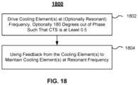
- FIG. 18is a flow-chart depicting an embodiment of a method for driving fluid flow.
- the inventioncan be implemented in numerous ways, including as a process; an apparatus; a system; a composition of matter; a computer program product embodied on a computer readable storage medium; and/or a processor, such as a processor configured to execute instructions stored on and/or provided by a memory coupled to the processor.
- these implementations, or any other form that the invention may take,may be referred to as techniques.
- the order of the steps of disclosed processesmay be altered within the scope of the invention.
- a componentsuch as a processor or a memory described as being configured to perform a task may be implemented as a general component that is temporarily configured to perform the task at a given time or a specific component that is manufactured to perform the task.
- the term ‘processor’refers to one or more devices, circuits, and/or processing cores configured to process data, such as computer program instructions.
- computing devicessuch as mobile devices (e.g. smartphones, tablet computers, notebook computers, and virtual reality devices) and networking devices (e.g. servers) produce a significant amount of heat.
- computing devicessuch as mobile devices (e.g. smartphones, tablet computers, notebook computers, and virtual reality devices) and networking devices (e.g. servers) produce a significant amount of heat.
- fluidsuch as air
- larger devicessuch as laptop or desktop computers
- fans having rotating bladescan be used to drive air through the larger devices.
- fansare typically too large for some devices such as smartphones or tablet computers.
- Fansalso may have limited efficacy because of the boundary layer of air existing at the surface of the components, provide a limited airspeed for air flow across the hot surface desired to be cooled and may generate an excessive amount of noise. Consequently, additional solutions for driving fluids are desired in computing and other applications.
- a system that drives a fluidincludes an orifice plate, a fan element and at least one channel.
- the orifice platehas at least one orifice therein.
- the fan elementis configured to undergo vibrational motion to drive a fluid through the orifice(s).
- the fluidis drawn through the channel(s) in response to the fluid being driven through the at least one orifice.
- the vibrational motion driving the fluid through the orificesprovides a low pressure region proximate to the orifice plate.
- the fluidis drawn through the channel(s) in response to the low pressure region being formed.
- the systemincludes a support structure.
- the fan elementhas multiple edges, at least one of which is anchored to the support structure such that an edge of the plurality of edges is free to vibrate.
- a border of the channelis defined by the fan element.
- the orifice plateis proximate to the edge of the fan element. The fluid flows substantially parallel to a surface of the fan element.
- the fan elementincludes anchored edges such that a central portion of the fan element undergoes the vibrational motion.
- a jet channelmay also be included in the device. The fluid flows through the channel being in a direction substantially perpendicular to the jet channel. An edge of the jet channel is formed by a jet channel wall. The jet channel wall has an aperture therein. Thus, the channel and the jet channel are configured such that the fluid is driven through the aperture.
- the devicemay include an additional fan element.
- the additional fan elementhas an additional plurality of anchored sides such that an additional central portion of the additional fan element undergoes an additional vibrational motion.
- the additional vibrational motion of the additional fan elementmay be out-of-phase with the vibrational motion of the fan element.
- a system including a plurality of cellsincludes an orifice plate (which may be shared between cells), a fan element, and at least one channel.
- the orifice platehas orifice(s) therein.
- the fan elementis configured to undergo vibrational motion to drive a fluid through the orifice(s).
- the fluidis drawn through the channel(s) in response to the fluid being driven through the at least one orifice.
- the vibrational motion driving the fluid through the orificesprovides a low pressure region proximate to the orifice plate.
- the fluidis drawn through the channel(s) in response to the low pressure region being formed.
- the deviceincludes a support structure and the fan element includes edges.
- At least one of the edgesis anchored to the support structure such that an edge of the plurality of edges is free to vibrate.
- a border of the channelis defined by the fan element and the orifice plate is proximate to the edge.
- the fluidflows substantially parallel to a surface of the fan element.
- the fan elementincludes anchored edges such that a central portion of the fan element undergoes the vibrational motion.
- the deviceincludes a jet channel. The fluid flowing through the channel being is in a direction substantially perpendicular to the jet channel.
- a method for moving fluidincludes driving a fan element and using feedback.
- the fan elementis driven to undergo vibrational motion to drive a fluid through orifice(s) of an orifice plate.
- the fluidis drawn through channel(s) in response to the fluid being driven through the orifice(s).
- Feedbackis used to control a frequency of the vibrational motion.
- driving the fluid through the orificesprovides a low pressure region proximate to the orifice plate.
- the fluidbeing drawn through the at least one channel in response to the low pressure region being formed.
- FIGS. 1 A- 1 Fare diagrams depicting exemplary embodiments of active systems 100 and 100 ′ usable with structure 102 . For clarity, only certain components are shown. FIGS. 1 A- 1 F are not to scale. Although shown as symmetric, system(s) 100 and/or 100 ′ need not be. FIGS. 1 A- 1 E depict various modes of one embodiment of a system. FIG. 1 F depicts another embodiment of a system 100 ′.
- System 100includes fan element 120 and support structure 170 .
- support structure 170includes top plate 110 having vent 112 therein, orifice plate 130 having orifices 132 therein, anchor 160 , pedestal 172 and sidewalls 174 .
- Fan element 120divides the interior of support structure 170 into top chamber 140 and bottom chamber 150 .
- Chambers 140 and 150(collectively chamber 140 / 150 ) are formed within orifice, or bottom, plate 130 , top plate 110 and sidewalls 174 .
- Support structureis thermally coupled to structure 102 via pedestal 172 .
- Pedestal 172also provides a space, or jet channel 180 for fluid to flow between orifice plate 130 and structure 102 .
- pedestal 172may be replaced or augmented by pedestal(s) (not shown) at the edges of a cell 100 . Further, structure 102 may be removed or placed a greater distance from orifice plate 130 .
- Fan element 120is supported at its central region by anchor 160 . Regions of fan element 120 closer to and including portions of the fan element's perimeter (e.g. tip 123 ) vibrate when actuated. In some embodiments, tip 123 of fan element 120 includes a portion of the perimeter furthest from anchor 160 and undergoes the largest deflection during actuation of fan element 120 . For clarity, only one tip 123 of fan element 120 is labeled in FIG. 1 A .
- FIG. 1 Adepicts system 100 in a neutral position.
- fan element 120is shown as substantially flat.
- fan element 120is driven to vibrate between positions shown in FIGS. 1 B and 1 C .
- This vibrational motiondraws fluid (e.g. air) into vent 112 , through chambers 140 and 150 and out orifices 132 at high speed and/or flow rates.
- the speed at which the fluid impinges on structure 102may be at least thirty meters per second.
- the fluidis driven by fan element 120 toward structure 102 at a speed of at least forty-five meters per second.
- the fluidis driven toward structure 102 by fan element 120 at speeds of at least sixty meters per second. Other speeds may be possible in some embodiments.
- System 100is also configured so that little or no fluid is drawn back into chamber 140 / 150 through orifices 132 by the vibrational motion of fan element 120 .
- system 100may also have limited space in which to place a system.
- system 100may be used in computing devices.
- Such computing devicesmay include but are not limited to smartphones, tablet computers, laptop computers, tablets, two-in-one laptops, hand held gaming systems, digital cameras, virtual reality headsets, augmented reality headsets, mixed reality headsets and other devices that are thin.
- the computing device in which system 100 is usedneed not be thin.
- servers, desktop computers and/or other larger computing systemsmay also be cooled using system 100 .
- System 100may be a micro-electro-mechanical system (MEMS) system capable of residing within mobile computing devices and/or other devices having limited space in at least one dimension.
- MEMSmicro-electro-mechanical system
- the total height of system 100may be less than 2 millimeters. In some embodiments, the total height of system 100 is not more than 1.5 millimeters. In some embodiments, the total height does not exceed two hundred and fifty micrometers. In some embodiments, this total height is not more than 1.1 millimeters. In some embodiments, the total height does not exceed one millimeter.
- system 100is usable in computing devices and/or other devices having limited space in at least one dimension. However, nothing prevents the use of system 100 in devices having fewer limitations on space and/or for purposes other than cooling or driving airflow.
- one system 100is shown (e.g. one cell), multiple cells 100 might be used. For example, a one or two-dimensional array of cells might be utilized.
- the distance between the bottom of orifice plate 130 and the top of structure 102 , ymay be small.
- yis at least two hundred micrometers and not more than one millimeter.
- yis at least two hundred micrometers and not more than three hundred micrometers.
- structure 102may be desired to be cooled.
- ymay be larger.
- structure 102may be significantly further from orifice plate 130 , as described below. More specifically, when used to entrain fluid, structure 102 may be further from orifice plate 130 or be omitted.
- System 100is in communication with a fluid.
- the fluidmay be a gas or a liquid.
- the fluidmay be air.
- the fluidincludes fluid from outside of the device in which system 100 resides (e.g. provided through external vents in the device).
- the fluidcirculates within the device in which system resides (e.g. in an enclosed device).
- Fan element 120can be considered to divide the interior of active system 100 into top chamber 140 and bottom chamber 150 .
- Top chamber 140is formed by fan element 120 , the sides, and top plate 110 .
- Bottom chamber 150is formed by orifice plate 130 , the sides, fan element 120 and anchor 160 .
- Top chamber 140 and bottom chamber 150are connected at the periphery of fan element 120 and together form chamber 140 / 150 (e.g. an interior chamber of system 100 ).
- top chamber 140may be a function of the cell (system 100 ) dimensions, fan element 120 motion, and the frequency of operation.
- Top chamber 140has a height, h 1 .
- the height of top chamber 140may be selected to provide sufficient pressure to drive the fluid to bottom chamber 150 and through orifices 132 at the desired flow rate and/or speed.
- Top chamber 140is also sufficiently tall that fan element 120 does not contact top plate 110 when actuated.
- the height of top chamber 140is at least fifty micrometers and not more than five hundred micrometers.
- top chamber 140has a height of at least two hundred and not more than three hundred micrometers.
- Bottom chamber 150has a height, h 2 .
- the height of bottom chamber 150is sufficient to accommodate the motion of fan element 120 . Thus, no portion of fan element 120 contacts orifice plate 130 during normal operation.
- Bottom chamber 150is generally smaller than top chamber 140 and may aid in reducing the backflow of fluid into orifices 132 .
- the height of bottom chamber 150is the maximum deflection of fan element 120 plus at least five micrometers and not more than ten micrometers.
- the deflection of fan element 120e.g. the deflection of tip 123
- zhas an amplitude of at least ten micrometers and not more than one hundred micrometers.
- the amplitude of deflection of fan element 120is at least ten micrometers and not more than sixty micrometers. However, the amplitude of deflection of fan element 120 depends on factors such as the desired flow rate through system 100 and the configuration of system 100 . Thus, the height of bottom chamber 150 generally depends on the flow rate through and other components of system 100 .
- Top plate 110includes vent 112 through which fluid may be drawn into system 100 .
- Top vent 112may have a size chosen based on the desired acoustic pressure in chamber 140 .
- the width, w, of vent 112is at least five hundred micrometers and not more than one thousand micrometers.
- the width of vent 112is at least two hundred fifty micrometers and not more than two thousand micrometers.
- vent 112is a centrally located aperture in top plate 110 .
- vent 112may be located elsewhere.
- vent 112may be closer to one of the edges of top plate 110 .
- Vent 112may have a circular, rectangular or other shaped footprint.
- vent 112may be omitted.
- Fan element 120includes an anchored region 122 and cantilevered arms 121 .
- anchored region 122 and cantilevered arms 121are only labeled in FIGS. 1 A and 1 F .
- Anchored region 122is supported (e.g. held in place) in system 100 by anchor 160 .
- Cantilevered arms 121undergo vibrational motion in response to fan element 120 being actuated.
- anchored region 122is centrally located.
- anchored region 122may be at one edge of the actuator and an outer region including vibrating tip 123 at the opposing edge.
- fan element 120is edge anchored. Although depicted as having a uniform thickness, in some embodiments, fan element 120 may have a varying thickness.
- Anchor 160supports fan element 120 at the central portion of fan element 120 .
- anchor 160extends along a central axis of fan element 120 (e.g. perpendicular to the page in FIGS. 1 A- 1 F ).
- portions of fan element 120 that vibratee.g. cantilevered arms 121 including tip 123
- cantilevered arms 121 of fan element 120may move in a manner analogous to the wings of a butterfly (i.e. in-phase) and/or analogous to a seesaw (i.e. out-of-phase).
- anchor 160does not extend along an axis of fan element 120 . In such embodiments, all portions of the perimeter of fan element 120 are free to vibrate (e.g. analogous to a jellyfish).
- anchor 160supports fan element 120 from the bottom of fan element 120 .
- anchor 160may support fan element 120 in another manner. For example, anchor 160 may support fan element 120 from the top (e.g. fan element 120 hangs from anchor 160 ).
- the width, a, of anchor 160is at least 0.5 millimeters and not more than four millimeters. In some embodiments, the width of anchor 160 is at least two millimeters and not more than 2.5 millimeters. Anchor 160 may occupy at least ten percent and not more than fifty percent of fan element 120 . In some embodiments, anchor 160 may be omitted. In such embodiments (described below), fan element 120 is supported at one or more of its edges. In such embodiments, fan element 120 operates as a cantilevered arm or may be pinned at multiple edges such that the central portion of fan element 120 vibrates.
- Fan element 120has a first side and a second side. In some embodiments, the first side is distal from structure 102 and the second side is proximate to structure 102 . In the embodiment shown in FIGS. 1 A- 1 F , the first side of fan element 120 is the top of fan element 120 (closer to top plate 110 ) and the second side is the bottom of fan element 120 (closer to orifice plate 130 ). Fan element 120 is actuated to undergo vibrational motion as shown in FIGS. 1 A- 1 F . The vibrational motion of fan element 120 drives fluid from the first side of fan element 120 (e.g. distal from structure 102 /from top chamber 140 ) to a second side of fan element 120 (e.g.
- fan element 120draws fluid through vent 112 and into top chamber 140 ; forces fluid from top chamber 140 to bottom chamber 150 ; and drives fluid from bottom chamber 150 through orifices 132 of orifice plate 130 .
- Fan element 120has a length, L, that depends upon the frequency at which fan element 120 is desired to vibrate.
- the length of fan element 120is at least four millimeters and not more than ten millimeters.
- fan element 120has a length of at least six millimeters and not more than eight millimeters.
- the depth of fan element 120(e.g. perpendicular to the plane shown in FIGS. 1 A- 1 F ) may vary from one fourth of L through twice L.
- fan element 120may have the same depth as length.
- the thickness, t, of fan element 120may vary based upon the configuration of fan element 120 and/or the frequency at which fan element 120 is desired to be actuated.
- the fan element thicknessis at least two hundred micrometers and not more than three hundred and fifty micrometers for fan element 120 having a length of eight millimeters and driven at a frequency of at least twenty kilohertz and not more than twenty-five kilohertz.
- the length, C of chamber 140 / 150is close to the length, L, of fan element 120 .
- the distance, d, between the edge of fan element 120 and the wall of chamber 140 / 50is at least one hundred micrometers and not more than five hundred micrometers. In some embodiments, d is at least two hundred micrometers and not more than three hundred micrometers.
- Fan element 120may have a substantially rectangular footprint in the embodiment shown. Other footprints are possible.
- fan element 120may have a substantially circular footprint.
- Fan element 120may be driven at a frequency that is at or near both the resonant frequency for an acoustic resonance of a pressure wave of the fluid in top chamber 140 and the resonant frequency for a structural resonance of fan element 120 .
- the portion of fan element 120 undergoing vibrational motionis driven at or near resonance (the “structural resonance”) of fan element 120 .
- This portion of fan element 120 undergoing vibrationmay be cantilevered arm(s) 121 in some embodiments.
- the frequency of vibration for structural resonanceis termed the structural resonant frequency. Use of the structural resonant frequency in driving fan element 120 reduces the power consumption of system 100 .
- Fan element 120 and top chamber 140may also be configured such that this structural resonant frequency corresponds to a resonance in a pressure wave in the fluid being driven through top chamber 140 (the acoustic resonance of top chamber 140 ).
- the frequency of such a pressure waveis termed the acoustic resonant frequency.
- a node in pressureoccurs near vent 112 and an antinode in pressure occurs near the periphery of system 100 (e.g. near tip 123 of fan element 120 and near the connection between top chamber 140 and bottom chamber 150 ).
- the distance between these two regionsis at or near C/2.
- C/2n ⁇ /4, where ⁇ is the acoustic wavelength for the fluid and n is odd (e.g.
- n1, 3, 5, etc.).
- C⁇ /2.
- ⁇is at or near the structural resonant frequency for fan element 120 .
- the frequency ⁇is also at or near the acoustic resonant frequency for at least top chamber 140 .
- the acoustic resonant frequency of top chamber 140generally varies less dramatically with parameters such as temperature and size than the structural resonant frequency of fan element 120 . Consequently, in some embodiments, fan element 120 may be driven at (or closer to) a structural resonant frequency than to the acoustic resonant frequency.
- Orifice plate 130has orifices 132 therein. Although a particular number and distribution of orifices 132 are shown, another number, other location(s) and/or another distribution may be used.
- a single orifice plate 130is used for a single system 100 . In other embodiments, multiple systems 100 may share an orifice plate. For example, multiple cells 100 may be provided together in a desired configuration. In such embodiments, the cells 100 may be the same size and configuration or different size(s) and/or configuration(s).
- Orifices 132are shown as having an axis oriented normal to a surface of structure 102 . In other embodiments, the axis of one or more orifices 132 may be at another angle.
- the angle of the axismay be selected from substantially zero degrees and a nonzero acute angle.
- Orifices 132also have sidewalls that are substantially parallel to the normal to the surface of orifice plate 130 .
- orificesmay have sidewalls at a nonzero angle to the normal to the surface of orifice plate 130 .
- orifices 132may be cone-shaped.
- trenches and/or other structuresmay be provided in orifice plate 130 to modify the configuration of bottom chamber 150 and/or the region between orifice plate 130 and structure 102 .
- the size, distribution and locations of orifices 132are chosen to control the flow rate of fluid driven to the surface of structure 102 .
- the locations and configurations of orifices 132may be configured to increase/maximize the fluid flow from bottom chamber 150 through orifices 132 to jet channel 180 .
- the locations and configurations of orifices 132may also be selected to reduce/minimize the suction flow (e.g. back flow) from jet channel 180 through orifices 132 .
- the locations of orificesare desired to be sufficiently far from tip 123 that suction in the upstroke of fan element 120 (tip 123 moves away from orifice plate 13 ) that would pull fluid into bottom chamber 150 through orifices 132 is reduced.
- the locations of orificesare also desired to be sufficiently close to tip 123 that suction in the upstroke of fan element 120 also allows a higher pressure from top chamber 140 to push fluid from top chamber 140 into bottom chamber 150 .
- the ratio of the flow rate from top chamber 140 into bottom chamber 150 to the flow rate from jet channel 180 through orifices 132 in the upstrokeis greater than 2:1.
- the net flow ratiois at least 85:15. In some embodiments, the net flow ratio is at least 90:10.
- orifices 132are desired to be at least a distance, r 1 , from tip 123 and not more than a distance, r 2 , from tip 123 of fan element 120 .
- r 1is at least one hundred micrometers (e.g. r 1 ⁇ 100 ⁇ m) and r 2 is not more than one millimeter (e.g. r 2 ⁇ 1000 ⁇ m).
- orifices 132are at least two hundred micrometers from tip 123 of fan element 120 (e.g. r 1 ⁇ 200 ⁇ m).
- orifices 132are at least three hundred micrometers from tip 123 of fan element 120 (e.g. r 1 ⁇ 300 ⁇ m). In some embodiments, orifices 132 have a width of at least one hundred micrometers and not more than five hundred micrometers. In some embodiments, orifices 132 have a width of at least two hundred micrometers and not more than three hundred micrometers. In some embodiments, the orifice separation, s, is at least one hundred micrometers and not more than one millimeter. In some such embodiments, the orifice separation is at least four hundred micrometers and not more than six hundred micrometers.
- orifices 132are also desired to occupy a particular fraction of the area of orifice plate 130 .
- orifices 132may cover at least five percent and not more than fifteen percent of the footprint of orifice plate 130 in order to achieve a desired flow rate of fluid through orifices 132 .
- orifices 132cover at least eight percent and not more than twelve percent of the footprint of orifice plate 130 .
- fan element 120is actuated using a piezoelectric.
- fan element 120may be a piezoelectric fan element.
- Fan element 120may be driven by a piezoelectric that is mounted on or integrated into fan element 120 .
- fan element 120is driven in another manner including but not limited to providing a piezoelectric on another structure in system 100 .
- Fan element 120 and analogous fan elementsare referred to hereinafter as piezoelectric fan element though it is possible that a mechanism other than a piezoelectric might be used to drive the fan element.
- fan element 120includes a piezoelectric layer on substrate.
- the substratemay be a stainless steel, Ni alloy and/or Hastelloy substrate.
- piezoelectric layerincludes multiple sublayers formed as thin films on the substrate.
- the piezoelectric layermay be a bulk layer affixed to the substrate.
- Such a piezoelectric fan element 120also includes electrodes used to activate the piezoelectric.
- the substratefunctions as an electrode in some embodiments.
- a bottom electrodemay be provided between the substrate and the piezoelectric layer.
- Other layersincluding but not limited to seed, capping, passivation or other layers might be included in piezoelectric fan element.
- fan element 120may be actuated using a piezoelectric.
- FIGS. 1 B- 1 Cdepict in-phase operation of system 100 .
- fan element 120has been actuated so that cantilevered arms 121 and tip 123 move away from top plate 110 .
- FIG. 1 Bcan thus be considered to depict the end of a down stroke of fan element 120 .
- gap 152 for bottom chamber 150has decreased in size and is shown as gap 152 B.
- gap 142 for top chamber 140has increased in size and is shown as gap 142 B.
- a lower (e.g. minimum) pressureis developed at the periphery when fan element 120 is at the neutral position.
- bottom chamber 150decreases in size and top chamber 140 increases in size as shown in FIG. 1 C .
- fluidis driven out of orifices 132 in a direction that is at or near perpendicular to the surface of orifice plate 130 and/or the top surface of structure 102 .
- the fluidis driven from orifices 132 (and toward structure 102 in the embodiment shown) at a high speed, for example in excess of thirty meters per second.
- the fluidthen travels along the surface of structure 102 and toward the periphery of structure 102 , where the pressure is lower than near orifices 132 . Also in the down stroke, top chamber 140 increases in size and a lower pressure is present in top chamber 140 . As a result, fluid is drawn into top chamber 140 through vent 112 . The motion of the fluid into vent 112 , through orifices 132 , and along the surface of structure 102 is shown by unlabeled arrows in FIG. 1 C .
- Fan element 120is also actuated so that cantilevered arms 121 and thus tip 123 moves away from structure 102 and toward top plate 110 .
- FIG. 1 Ccan thus be considered to depict the end of an up stroke of fan element 120 .
- gap 142has decreased in size and is shown as gap 142 C.
- Gap 152has increased in size and is shown as gap 152 C.
- a higher (e.g. maximum) pressureis developed at the periphery when fan element 120 is at the neutral position.
- bottom chamber 150increases in size and top chamber 140 decreases in size as shown in FIG. 1 C .
- the fluidis driven from top chamber 140 (e.g.
- top chamber 140serves as a nozzle for the entering fluid to speed up and be driven towards bottom chamber 150 .
- the motion of the fluid into bottom chamber 150is shown by unlabeled arrows in FIG. 1 C .
- the location and configuration of fan element 120 and orifices 132are selected to reduce suction and, therefore, back flow of fluid from jet channel 180 into orifices 132 during the upstroke.
- system 100is able to drive fluid from top chamber 140 to bottom chamber 150 without an undue amount of backflow of fluid from jet channel 180 entering bottom chamber 10 .
- fan element 120undergoes vibrational motion indicated in FIGS. 1 A- 1 C , drawing fluid through vent 112 from the distal side of top plate 110 into top chamber 140 ; transferring fluid from top chamber 140 to bottom chamber 150 ; and pushing the fluid through orifices 132 and toward structure 102 .
- fan element 120is driven to vibrate at or near the structural resonant frequency of fan element 120 . In some embodiments, this corresponds to the structural resonance of cantilevered arms 121 . Further, the structural resonant frequency of fan element 120 is configured to align with the acoustic resonance of the chamber 140 / 150 .
- the structural and acoustic resonant frequenciesare generally chosen to be in the ultrasonic range.
- the vibrational motion of fan element 120may be at frequencies from 15 kHz through 30 kHz.
- fan element 120vibrates at a frequency/frequencies of at least 20 kHz and not more than 30 kHz.
- the structural resonant frequency of fan element 120is within ten percent of the acoustic resonant frequency of system 100 .
- the structural resonant frequency of fan element 120is within five percent of the acoustic resonant frequency of system 100 .
- the structural resonant frequency of fan element 120is within three percent of the acoustic resonant frequency of system 100 . Consequently, efficiency and flow rate may be enhanced. However, other frequencies may be used.
- Fluid driven through orifices 132 in orifice plate 130may move substantially normal (perpendicular) to the bottom surface of orifice plate 130 (e.g. substantially perpendicular to the top surface of structure 102 ).
- the fluid motionmay have a nonzero acute angle with respect to the normal to the bottom surface of orifice plate 130 (e.g. to top surface of structure 102 ).
- FIGS. 1 D- 1 Edepict an embodiment of active system 100 including centrally anchored fan element 120 in which the fan element is driven out-of-phase. More specifically, cantilevered arms 121 of fan element 120 on opposite sides of anchor 160 (and thus on opposite sides of the central, anchored region 122 of fan element 120 that is supported by anchor 160 ) are driven to vibrate out-of-phase. In some embodiments, cantilevered arms 121 of fan element 120 on opposite sides of anchor 160 are driven at or near one hundred and eighty degrees out-of-phase. Thus, one cantilevered arm 121 of fan element 120 vibrates toward top plate 110 , while the other cantilevered arm 121 of fan element 120 vibrates toward orifice plate 130 /structure 102 .
- fan element 120undergoes vibrational motion indicated in FIGS. 1 A, 1 D, and 1 E , alternately drawing fluid through vent 112 from the distal side of top plate 110 into top chamber 140 for each side of fan element 120 ; transferring fluid from each side of top chamber 140 to the corresponding side of bottom chamber 150 ; and pushing the fluid through orifices 132 on each side of anchor 160 and toward structure 102 .
- fan element 120is driven to vibrate at or near the structural resonant frequency of fan element 120 .
- the structural resonant frequency of fan element 120is configured to align with the acoustic resonance of the chamber 140 / 150 .
- the structural and acoustic resonant frequenciesare generally chosen to be in the ultrasonic range.
- the vibrational motion of fan element 120may be at the frequencies described for in-phase vibration.
- the structural resonant frequency of fan element 120is within ten percent of the acoustic resonant frequency of system 100 .
- the structural resonant frequency of fan element 120is within five percent of the acoustic resonant frequency of system 100 .
- the structural resonant frequency of fan element 120is within three percent of the acoustic resonant frequency of system 100 . Consequently, efficiency and flow rate may be enhanced.
- other frequenciesmay be used. Fluid driven toward structure 102 for out-of-phase vibration may move substantially normal (perpendicular) to the bottom surface of orifice plate, in a manner analogous to that described above for in-phase operation.
- fan element 120may be vibrated at frequencies of 15 kHz or more, users may not hear any noise associated with actuation of fan elements. If driven at or near structural and/or acoustic resonant frequencies, the power used in operating systems may be significantly reduced. Fan element 120 does not physically contact top plate 110 or orifice plate 130 during vibration. Thus, resonance of fan element 120 may be more readily maintained. More specifically, physical contact between fan element 120 and other structures disturbs the resonance conditions for fan element 120 . Disturbing these conditions may drive fan element 120 out of resonance.
- out-of-phase vibration of fan element 120allows the position of the center of mass of fan element 100 to remain more stable. Although a torque is exerted on fan element 120 , the force due to the motion of the center of mass is reduced or eliminated. As a result, vibrations due to the motion of fan element 120 may be reduced. Moreover, efficiency of system 100 may be improved through the use of out-of-phase vibrational motion for the two sides of fan element 120 .
- system 100For out-of-phase vibration of cantilevered arms 121 , vibrations through system 100 may also be reduced. Consequently, performance of devices incorporating the system 100 may be improved. Further, system 100 may be usable in other applications (e.g. with or without structure 102 ) in which high fluid flows and/or velocities are desired.
- FIG. 1 Fdepicts and embodiment of active system 100 ′ including a top centrally anchored fan element.
- System 100 ′is analogous to system 100 . Consequently, analogous components have similar labels.
- system 100 ′may be used in conjunction with structure 102 that is analogous to structure 102 .
- System 100 ′includes support structure 170 ′, top plate 110 ′ having vents 112 ′, fan element 120 , orifice plate 130 including orifices 132 , top chamber 140 ′ having a gap, bottom chamber 150 having a gap, anchor 160 and jet channel 180 that are analogous to support structure 170 , top plate 110 having vent 112 , fan element 120 , orifice plate 130 including orifices 132 , top chamber 140 having gap 142 , bottom chamber 150 having gap 152 , anchor 160 and jet channel 180 , respectively, of FIGS. 1 A- 1 E .
- fan element 120is centrally supported by anchor 160 such that at least a portion of the perimeter of fan element 120 is free to vibrate.
- anchor 160extends along the axis of fan element 120 (e.g. in a manner analogous to anchor 360 A and/or 360 B). In other embodiments, anchor 160 is only near the center portion of fan element 120 (e.g. analogous to anchor 360 C and/or 360 D).
- Fan element 120includes an anchored region 122 and cantilevered arms 121 analogous to anchored region 122 and cantilevered arms 121 , respectively of fan element 120 depicted in FIGS. 1 A- 1 E . Cantilevered arms 121 of fan element 120 may be driven in-phase and/or driven out-of-phase.
- Anchor 160supports fan element 120 from above. Thus, fan element 120 is suspended from anchor 160 .
- Anchor 160is suspended from top plate 110 ′.
- Top plate 110 ′includes vent 113 . Vents 112 ′ on the sides of anchor 160 provide a path for fluid to flow into sides of chamber 140 ′.
- fan element 120may be driven to vibrate at or near the structural resonant frequency of fan element 120 .
- the structural resonant frequency of fan element 120may be configured to align with the acoustic resonance of the chamber 140 ′/ 150 .
- the structural and acoustic resonant frequenciesare generally chosen to be in the ultrasonic range.
- the vibrational motion of fan element 120may be at the frequencies described with respect to system 100 . Consequently, efficiency and flow rate may be enhanced. However, other frequencies may be used.
- System 100 ′operates in an analogous manner to system 100 .
- System 100 ′thus shares the benefits of system 100 .
- the use of fan element 120 configured in a manner analogous to fan element 120may improve efficiency and reliability.
- suspending fan element 120 from anchor 160may further enhance performance.
- vibrations in system 100 ′ that may affect other cells (not shown)may be reduced. For example, less vibration may be induced in top plate 110 ′ due to the motion of fan element 120 . Consequently, cross talk between system 100 ′ and other systems (e.g. other cells) or other portions of the device incorporating system 100 ′ may be reduced. Thus, performance may be enhanced.
- Systems 100 and 100 ′drive fluid such that fluid exiting orifices 132 has a high speed of at least thirty meters per second. In some embodiments, the fluid exiting orifices 132 has a speed of at least forty-five meters per second. In some embodiments, the fluid exits orifices 132 at speeds of at least sixty meters per second. Other speeds may be possible in some embodiments. Fluid exiting orifices 132 has a high speed in part because the fluid traveling through chambers 140 / 150 has a high flow rate. In some embodiments, for example, the flow rate through chambers 140 / 150 may be at least 0.05 cubic feet per minute (cfm). In some embodiments, the flow rate through chambers 140 / 150 is at least 0.1 cfm. Other (i.e. higher or lower) flow rates are possible. The relatively high flow rates that may be driven through system(s) 100 and/or 100 ′ efficiently remove heat from fan elements 120 and support structure(s) 170 and/or 170 ′.
- FIGS. 2 A- 2 Cdepict system 200 that is analogous to system 100 .
- FIG. 2 Adepicts system 200 in a neutral position.
- FIG. 2 Bdepicts system 200 in a suction arrangement.
- FIG. 2 Cdepicts system 200 in an expulsion arrangement. Consequently, analogous components have similar labels.
- system 200may be used in conjunction with structure 202 that is analogous to structure 102 .
- System 200includes support structure 270 having pedestal 272 and sidewalls 274 , fan element 220 , orifice plate 230 including orifices 232 , chamber 250 and jet channel 280 that are analogous to support structure 170 having pedestal 172 and sidewalls 174 , top plate 110 , fan element 120 , orifice plate 130 including orifices 132 , bottom chamber 150 , and jet channel 180 , respectively, of FIGS. 1 A- 1 F .
- support structure 270does not include a top plate.
- fan element 220is anchored at its edges to sidewalls 274 .
- chamber 250is formed between orifice plate 230 and fan element 220 .
- System 200operations in an analogous manner to systems 100 and/or 100 ′.
- fan element 220vibrates away from orifice plate 230 . This motion enlarges chamber 20 . Fan element 220 then vibrates in the opposite direction, in the expulsion mode and shown in FIG. 2 C .
- fluidis driven out of orifices 232 .
- fluidis driven out of orifices 232 at a speed of at least thirty meters per second.
- the fluid driven out of orifices 232has a speed of at least forty-five meters per second.
- the fluidhas a speed of at least fifty-five meters per second. Further, in some embodiments, fluid speeds of at least sixty meters per section and/or seventy-five meters per second may be achieved. However, higher speeds may be possible in some embodiments.
- FIGS. 3 A- 3 Care diagrams depicting an exemplary embodiment of active system 300 usable with a structure 302 . For clarity, only certain components are shown and FIGS. 3 A- 3 C are not to scale.
- System 300is used in connection with a structure 302 . Although shown as symmetric, system 300 need not be symmetric.
- System 300is analogous to systems 100 and 200 . Consequently, similar components have analogous labels.
- System 300includes fan elements 310 and 320 analogous to fan elements 120 and 220 . Fan element 310 may be considered to replace top plate 110 .
- System 300also includes orifice plate 330 having orifices 332 therein, top chamber 340 , bottom chamber 350 , support structure 370 and jet channel 380 that may be analogous to orifice plates 130 and/or 230 having orifices 132 and/or 232 therein, top chamber 140 , bottom chamber 150 and/or 250 , support structure 170 and/or 270 and jet channel 180 and/or 280 .
- jet channel 380is not labeled in FIG. 3 C .
- Support structure 370includes pedestals 372 and sidewalls 374 that are analogous to pedestals 172 and/or 272 and sidewalls 174 and/or 274 . Also shown are optional channels 390 used to entrain fluid, as described below.
- Fan element 310has a first side distal from structure 302 and a second side proximate to structure 302 .
- the first side of fan element 310is the top of fan element 310 and the second side is the bottom of fan element 310 .
- Fan element 310also has a passive vent 312 therein.
- passive vent 312is a centrally located aperture in fan element 310 .
- passive vent 312may be located elsewhere.
- passive vent 312may be closer to one of the edges of fan element 310 .
- Passive vent 312may have a circular, rectangular or other shaped footprint. Although one passive vent 312 is shown, multiple passive vents might be used.
- Fan element 320is between fan element 310 and structure 302 . In the embodiment shown, fan element 320 is also between fan element 310 and orifice plate 330 . Fan elements 310 and 320 are separated by gap 342 and form a top chamber 340 . A bottom chamber 350 is formed between fan element 320 and orifice plate 330 . Fan element 320 also has active vents 322 therein. In the embodiment shown, active vents 322 are apertures located away from the central region of fan element 320 . In other embodiments, active vents 322 may be located elsewhere. For example, an active vent may be centrally located in fan element 320 . Although two active vents 322 are shown, another number (e.g. one, three, etc.) might be present.
- active vents 322are positioned such that the active vents 322 are not aligned with passive vent 312 .
- Active vents 322may have circular, rectangular or other shaped footprints.
- a single fan element 310 or 320 which does not include a ventmay be used in lieu of two fan elements.
- FIG. 3 Adepicts system 300 in a neutral position.
- fan elements 310 and 320are shown as substantially flat.
- Fan elements 310 and 320are actuated to vibrate between positions shown in FIGS. 3 B and 3 C .
- Fan elements 310 and 320may, therefore, be piezoelectric actuators. Operation of system 300 is described in the context of FIGS. 3 B and 3 C .
- piezoelectric fan element 310has been actuated to move away from (deform to be convex) structure 302
- piezoelectric fan element 320has been actuated to move toward (deform to be concave) structure 302 . This configuration is referred to as the suction arrangement.
- gap 342has increased in size and is shown as gap 342 A.
- gap 342has a height of at least ten and not more than twenty micrometers in the neutral position ( FIG. 3 A ).
- Gap 342 Amay have a height of at least twenty and not more than thirty micrometers in the suction arrangement ( FIG. 3 B ).
- top chamber 340has increased in volume
- bottom chamber 350has decreased in volume.
- the flow resistance of passive vent 312passive suction flow resistance
- the pressure at passive vent 312is low.
- the flow resistance of active vent 322active suction flow resistance
- the pressure at active vent 322is high. Because of the low passive suction flow resistance, fluid is drawn into top chamber 340 through passive vent 312 . This is shown by arrows in FIG. 3 B . However, fluid does not flow out of (or flows out to a limited extent) active vent 322 because of the high passive suction flow resistance. However, active vent 322 is not physically closed in this configuration. For example, active vent 322 is not in contact with orifice plate 330 in the suction arrangement.
- FIG. 3 Cdepicts an expulsion arrangement.
- Piezoelectric fan element 310has been actuated to move toward (deform to be concave) structure 302
- piezoelectric fan element 320has been actuated to move away from (deform to be convex) structure 302 .
- gap 342has decreased in size and is shown as gap 342 B.
- gap 342has a height of at least ten and not more than twenty micrometers in the neutral position ( FIG. 3 A ).
- Gap 342 Bhas a height of at least five and not more than ten micrometers in the expulsion arrangement ( FIG. 3 C ).
- top chamber 340has decreased in volume
- bottom chamber 350has increased in volume.
- the flow resistance of passive vent 312(passive expulsion flow resistance) is high. Consequently, the pressure at passive vent 312 is high.
- the flow resistance of active vent 322(active expulsion flow resistance) is low. Consequently, the pressure at active vent 322 is low. Because of the low active expulsion flow resistance, fluid is expelled from top chamber 340 through active vent 322 , into bottom chamber 350 and through orifices 332 . This is shown by arrows in FIG. 3 C . However, fluid does not flow out of (or flows out to a limited extent) passive vent 312 because of the high passive expulsion flow resistance.
- passive vent 312is considered closed and active vent 322 is considered open in the expulsion arrangement.
- passive vent 312is not physically closed in this configuration.
- passive vent 312is not in contact with fan element 320 in the expulsion arrangement.
- Gap 342 Bdoes not have a zero length.
- the fluidis drawn in to top chamber 340 and through orifices 332 .
- the motion of the fluidis shown by arrows through orifices 332 .
- the fluidmay spread as it travels away from orifice plate 320 , as shown by dashed lines and arrows for some orifices 332 in FIG. 3 C .
- the fluidmay deflect off of structure 302 (if present) and travels along the channel between structure 302 and orifice plate 330 .
- the resonant frequencies of piezoelectric fan element(s) 310 and 320are desired to be within one hundred Hertz. In some embodiments, feedback is used to maintain piezoelectric fan element(s) 310 and/or 320 at or near resonance. The resonant frequencies of fan elements 310 and/or 320 may be closely matched to the acoustic resonant frequencies of chamber(s) 340 and/or 350 . In some embodiments, the speed at which the fluid impinges on structure 302 is in the ranges described herein for system(s) 100 and/or 200 .
- system 300fluid may be drawn in through passive vent 312 (in the suction arrangement) and driven through active vent 322 and orifices 332 (in the expulsion arrangement). Thus, airflow may be driven by system 300 . Further, the fluid may efficiently dissipate heat from structure 302 in a manner analogous to the fluid driven by system 100 . Thus, performance of a device utilizing system 300 may be improved. Further, system 300 may be a MEMS device. Thus, system 300 may small-having a total height analogous to that described above and may be used in similar devices.
- FIGS. 4 A- 4 Edepict an embodiment of active system 400 including multiple cells configured as a tile, or array.
- FIG. 4 Adepicts a top view
- FIGS. 4 B- 4 Edepict side views.
- FIGS. 4 A- 4 Eare not to scale.
- System 400includes four cells 401 A, 401 B, 401 C and 401 D (collectively or generically 401 ), which are analogous to one or more of systems described herein. More specifically, cells 401 are analogous to system 100 .
- cell(s) 401may be analogous to system 300 and/or another system. Although four cells 401 in a 2 ⁇ 2 configuration are shown, in some embodiments another number and/or another configuration of cells 401 might be employed.
- fan element 420 in one cellis driven out-of-phase with fan element(s) 420 in adjacent cell(s).
- fan elements 420 in a roware driven out-of-phase.
- fan element 420 in cell 401 Ais out-of-phase with fan element 420 in cell 401 B.
- fan element 420 in cell 401 Cis out-of-phase with fan element 420 in cell 401 D.
- fan elements 420 in a columnare driven out-of-phase.
- fan element 420 in cell 401 Ais out-of-phase with fan element 420 in cell 401 C.
- fan element 420 in cell 401 Bis out-of-phase with fan element 420 in cell 401 D.
- Cells 401 of system 400function in an analogous manner to system(s) 100 , 300 , and/or an analogous system. Consequently, the benefits described herein may be shared by system 400 . Because fan elements in nearby cells are driven out-of-phase, vibrations in system 400 may be reduced. Because multiple cells 401 are used, system 400 may enjoy enhanced cooling capabilities. Further, multiples of individual cells 401 and/or system 400 may be combined in various fashions to obtain the desired footprint of cells.
- FIG. 5is a diagram depicting an exemplary embodiment of a system 500 usable with a heat generating structure. For clarity, only certain components are shown and FIG. 5 is not to scale.
- Piezoelectric cooling system 500is used in connection with a structure 502 .
- Structure 502is analogous to structure(s) 102 , 202 and/or 302 .
- the frequency of vibrationis nominally 300 Hz. Other frequencies are possible.
- ⁇is nominally thirty degrees and h is nominally two hundred fifty microns.
- the top of each fan element 520is a distance, d, above the surface of structure 502 .
- dis at least three hundred microns and not more than five hundred micrometers. However, other spacings are possible
- fan elements 520vibrate, drawing fluid from the distal side of one piezoelectric element to the proximal side of another piezoelectric element. This motion of the fluid can be seen by the curved arrows in FIG. 5 .
- the fluidis driven along the surface of structure 502 .
- cellssuch as cells 100 , 200 , 300 and/or 401 (rotated ninety degrees) might be used.
- piezoelectric cooling structure 500can be combined with one or more of piezoelectric cooling structures 100 , 200 , 300 , and/or 400 . In such an embodiment, fan elements 520 can aid in drawing air along the corresponding heat generating structure.
- Systems 100 , 200 , 300 , 400 and/or 500may be used to drive fluid, such as air (or other gas) and/or a liquid.
- systems 100 , 200 , 300 , 400 and/or 500may be used as a MEMs-based fan.
- a MEMs-based fanis in contrast to fans having rotating blades, which require significantly more space, lower back pressures, and provide a flow at a significantly lower speed.
- the MEMs-based fanmay provide flow not directly from fluid directly driven by fan elements 120 , 220 , 320 , 420 and/or 520 . More specifically, fan elements such as elements 120 , 220 , 420 and/or 520 may drive fluid through orifices at high velocity.
- the speed at which the fluid leaves the orificesis at least thirty meters per second.
- the fluidis driven by piezoelectric cooling elements at a speed of at least forty meters per second.
- the fluidhas a speed of at least forty-five meters per second.
- the fluidhas a speed of at least fifty-five meters per second.
- fluid speeds of at least sixty meters per section and/or seventy-five meters per secondmay be achieved. Higher speeds may be possible in some embodiments. Because the fluid exits orifices at a high velocity, a low pressure is generated outside of orifice plate. This low pressure draws fluid through structures in the region of the orifice plate via entrainment.
- a significantly higher volume of fluid flowis entrained than is expelled through the orifices. For example, at least five times through ten times the volume of fluid pushed through the orifices may be entrained. Thus, a macroscopic flow of fluid may be achieved.
- any surfaces, such as for structures 102 , 202 , 302 and/or 502are at least five through ten millimeters from the bottom of the orifice plate in order to obtain the desired high entrainment.
- MEMS based fansare described herein may more efficiently move fluid through entrainment.
- FIG. 6is a diagram depicting an embodiment of system 600 that may operate as a fan. For clarity, only certain components are shown and FIG. 6 is not to scale. Portions of fan 600 are analogous to systems 100 , 200 , 300 , and/or 500 .
- fan 600includes fan element 620 , orifice plate 630 having orifices 632 therein, chamber 650 , anchor 660 , support structure 670 , channel 690 and orifice 692 that are analogous to fan element 120 , orifice plate 130 having orifices 132 therein, chamber 150 , anchor 160 , support structure 170 and channel 190 . Although only a single orifice 632 is shown, multiple orifices may be present. Although a single fan element 620 is shown, multiple fan elements might be used. Although no vents are shown, fan element 620 may include vents/apertures.
- Orifice plate 630is located near an edge (or tip) of fan element 620 instead of below fan element 620 .
- orifice plate 630is substantially perpendicular to the surface of fan element 620 if fan element 620 is in a neutral position (e.g. undriven). In other embodiments, orifice plate 630 may be oriented at another angle.
- fan element 620undergoes vibrational motion.
- fan element 620is driven at or near resonance.
- the frequency at which fan element 620 is drivenmay be in the ranges described herein (e.g. at least 15 kHz in some embodiments, and at least 20 kHz in some cases).
- fan element 620is attached to anchor 660 at one side, fan element 620 may be considered to vibrate in a manner similar to a cantilevered beam, or half of fan element 120 .
- the end of fan element 620 near orifice 632vibrates. This may be seen by the dual headed arrow in FIG. 6 .
- fluidmay be driven through orifice 632 at high speed, for example in the ranges described above.
- fluidmay be driven through orifice 632 at speeds of at least thirty meters per second, at least forty-five meters per second, or higher.
- a low pressureis generated on the side of orifice 632 opposite to fan element 620 . This low pressure causes fluid to be drawn in, or entrained, through channel 690 . This is shown by the unlabeled arrows in channel 690 .
- Fluidexits through aperture 692 .
- the region near aperture 690may be considered to be a jet channel because some fluid enters this region through orifice 632 .
- a significantly higher volume of fluidflows through channel 690 than through orifice 632 .
- at least five times through ten times the volume of fluid driven through orifice 632may be entrained through channel 690 , flow out of channel 690 and through aperture 692 .
- Other relationships between fluid flowsmay occur in other embodiments.
- a macroscopic flow of fluid through channel 690 and aperture 692may be achieved.
- the direction that this macroscopic fluid flowsis substantially parallel to the surface of fan element 620 when in a neutral position.
- fluidmay flow out of aperture 692 in substantially the same direction (e.g. horizontal as shown in FIG. 6 ) as fluid flows through channel 690 .
- high volumes of fluidmay be entrained.
- the flow rate of fluid entrained through channel 690may be at least three to five multiplied by the flow rate of the fluid driven through orifice(s) 632 .
- higher flow ratesmay be achieved.
- high flow rates through channel 690 and aperture 692may be achieved.
- system 600may be thin.
- the height of system 600 in a direction perpendicular to the direction of fluid flow in channel 690may be not larger than ten millimeters in some embodiments.
- the height of system 600may be not more than five millimeters.
- system 600may have a height of not more than three millimeters.
- system 600may provide significant fluid flows with a low profile.
- system 600may move large volumes of fluid in systems, such as mobile devices, with limited space. Thus, performance of such devices may be improved.
- FIGS. 7 A- 7 Bare diagrams depicting an embodiment of a fan 700 having multiple cells 600 .
- FIG. 7 Ais a perspective view indicating the inlet to a system 700
- FIG. 7 Bdepicts the outlet from system 700 .
- System 700includes multiple cells 600 , of which only some are labeled in FIG. 7 A .
- fan elements 620 , channels 690 and apertures 692are labeled.
- two layers of cells 600are shown, in other embodiments, another number of layers (e.g. 1, 3, or more) and/or another number of cells 600 per layer may be used.
- system 700functions in a manner analogous to system 600 .
- fluidis entrained through channels 690 .
- the direction of fluid flowis shown by unlabeled arrows in FIG. 7 A .
- the desired volume of fluid flowing substantially parallel to channel 690 (and the surface of fan elements 620 )may be achieved.
- performance of a device employing system 700may be improved.
- FIG. 8is a diagram depicting an embodiment of system 800 that may be used as a fan. For clarity, only certain components are shown and FIG. 8 is not to scale.
- System 800is shown as including a single cell. However, multiple systems 800 may be arranged in a one-dimensional array (e.g. a line or line segment(s)) or two-dimensional array. Thus, system 800 may also be viewed as a single cell in a larger cooling system that may include multiple systems 800 .
- System 800may be used in mobile computing devices, non-mobile devices and/or with other devices.
- System 800includes a top fan element 810 and a bottom fan element 820 .
- Fan elements 810 and 820may be analogous to fan elements described herein, such as fan elements 120 , 220 , 310 , 320 , and/or 420 .
- Fan 800may have dimensions analogous to those described above.
- fan elements 810 and 820may each includes a substrate, a piezoelectric layer and an electrode (not separately shown in FIG. 8 ). For simplicity, leads to the fan elements and other electronics are not shown.
- Orifice plate 830 having orifices 832 thereinis analogous to orifice plate(s) 130 , 230 , 330 , and/or 430 having orifices 132 , 232 , 332 and/or 432 , respectively. Although a particular number, size and distribution of orifices 832 are shown, another number (including a single orifice), other size(s) and another distribution of orifice(s) may be used. In the embodiment shown, fan elements 810 and 820 do not include apertures and/or valves. Thus, the system 800 is analogous to system 300 depicted in FIG. 3 . Chambers 840 and 850 analogous to chambers 340 and 350 are shown.
- fan elements 810 and 820do not include vents therein.
- system 800is also analogous to system 200 depicted in FIG. 2 .
- one or both of fan elements 810 and 820may include an aperture(s), vent(s), and/or valve(s).
- channels 890 in support structure 870used to entrain fluid (e.g. air) in the direction shown by arrows in FIG. 8 .
- fluide.g. air
- a surface or jet channel for directing entrained air from channels 890is not shown, such a surface or jet channel might be included.
- Other elementsare not shown or are not labeled.
- top and bottom fan elements 810 and 820vibrate. In some embodiments, top and bottom fan elements vibrate one hundred and eighty degrees out of phase. Thus, as top fan element 810 moves/bends away from orifice plate 830 , bottom fan element 820 moves/bends closer to the orifice plate 830 . As a result, bottom chamber 850 is reduced in size, forcing the flow of fluid through the orifices 832 . This may be termed a compression stroke. In a suction stroke, bottom fan element 820 moves/bends away from orifice plate 830 and top fan element 810 bends toward orifice plate 830 . Thus, fluid is sucked into the bottom chamber through orifices 832 .
- two fan elements 810 and 820may improve performance of system 800 800 . More specifically, two fan elements 810 and 820 vibrating out of phase may allow for sympathetic motion between fan elements 810 and 820 .
- the sympathetic motion of two fan elements 810 and 880may increase the amplitude of vibration for fan elements 810 and 880 . For example, the amplitude of vibration may be increased up to fifty percent in some embodiments.
- the speed at which the fluid leaves the orifices for the bottom chamberis at least thirty meters per second.
- the fluidis driven by fan elements 810 and 820 at a speed of at least forty meters per second.
- the fluidhas a speed of at least forty-five meters per second.
- the fluidhas a speed of at least fifty-five meters per second.
- fluid speeds of at least sixty meters per section and/or seventy-five meters per secondmay be achieved. However, higher speeds may be possible in some embodiments.
- any surfacesare at least five through ten millimeters from the bottom of the orifice plate in order to obtain the desired high entrainment.
- the flow rate of fluid through channels 890is at least three through five multiplied by the flow rate through orifices 832 . In some embodiments, higher flow rates may be achieved. In some embodiments, a doubling of the area of the channels results in a volume per unit time flow of fluid that is at least six multiplied by the fluid flow rate with smaller channels (e.g. 2 ⁇ channel area results in ⁇ 6 ⁇ fluid flow rate). Thus, system 800 may more efficiently move fluid through entrainment.
- System 800may share the benefits of the systems described herein.
- System 800may drive entrained fluid.
- the direction that entrained fluid is driven in the embodiment shownmay be substantially perpendicular to the surface of fan elements 810 and 820 . Because two fan elements 810 and 820 are used and driven out of phase, sympathetic motion may be achieved. Consequently, the amplitude of vibration of fan elements 810 and 820 may be increased and fluid flow enhanced. Thus, performance of a device employing system 800 may be improved.
- FIG. 9is a diagram depicting an embodiment of system 900 that may be used as a fan. For clarity, only certain components are shown and FIG. 9 is not to scale.
- System 900is shown as including a single cell. However, multiple systems 800 may be arranged in a one-dimensional array (e.g. a line or line segment(s)) or two-dimensional array. Thus, system 900 may also be viewed as a single cell in a larger cooling system that may include multiple systems 900 .
- System 900may be used in mobile computing devices, non-mobile devices and/or with other devices.
- Fan element 920may be analogous to fan elements described herein, such as fan elements 120 , 220 , 310 , 320 , 420 , and/or 920 .
- Fan 900may have dimensions analogous to those described above.
- fan element 920may each includes a substrate, a piezoelectric layer and an electrode (not separately shown in FIG. 8 ).
- Orifice plate 930 having orifices 932 thereinis analogous to orifice plate(s) 130 , 230 , 330 , 430 and/or 930 having orifices 132 , 232 , 332 , 432 and/or 832 , respectively.
- fan elements 810 and 820do not include apertures and/or valves.
- the system 900is analogous to system 200 depicted in FIG. 2 .
- channels 990 in support structure 970used to entrain fluid (e.g. air) in the direction shown by arrows in FIG. 9 .
- a surface or jet channel for directing entrained air from channels 990is not shown, such a surface or jet channel might be included.
- Other elementsare not shown or are not labeled.
- System 900operates in an analogous manner to system 800 .
- fan element 920vibrates, causing fluid to be driven from chamber 950 through orifices 932 .
- Fluid driven through orifices 932may travel at the speeds described herein (e.g. at least thirty meters per second or above).
- a low pressure regionis formed outside of orifice plate 930 (e.g. opposite to chamber 950 ).
- the low pressure regionentrains large volumes of fluid through channels 990 , in a manner analogous to that described above.
- flow rates analogous to those described abovee.g. at least three through five multiplied by the flow rate through orifices 932 , or higher
- flow ratesanalogous to those described above (e.g. at least three through five multiplied by the flow rate through orifices 932 , or higher) may be achieved.
- system 900shares some of the benefits of system 800 . However, only one fan element 920 is used. System 900 may still entrain fluid (e.g. air) through channels 990 as shown by arrows. Thus, system 900 may be used to move fluid at the desired flow rates. Performance of a device employing system 900 may thus be improved.
- fluide.g. air
- FIG. 10is a diagram depicting an embodiment of system 1000 usable as a fan. For clarity, only certain components are shown and FIG. 10 is not to scale.
- System 1000is shown as including a single cell. However, multiple systems 1000 may be arranged in one or two dimensions. Because system 1000 is analogous to systems 100 , 200 , 300 , 500 , 800 and 900 , analogous components have similar labels.
- top fan element 1010 and bottom fan element 1020there are two fan elements (top fan element 1010 and bottom fan element 1020 ), orifice plate 1030 with orifices 1032 therein, top chamber 1040 , bottom chamber 1050 , support structure 1070 , and vent 1012 that are analogous to top fan element 310 and bottom fan element 320 , orifice plate 330 with orifices 332 therein, top chamber 340 , bottom chamber 350 , support structure 370 , and vent 312 , respectively.
- system 1000is analogous to system 300 .
- optional ducting 1094which may be used to direct fluid to channels 1090 .
- fan elements 1010 and 1020vibrate. In some embodiments, fan elements 1010 and 1020 vibrate one hundred and eighty degrees out of phase. Thus, as top fan element 1010 moves/bends away from orifice plate 1032 , bottom fan element moves/bends closer to orifice plate 1030 . As a result, bottom chamber 1050 is reduced in size, preventing or reducing the flow of fluid through orifices 1032 . In addition, gap 1042 widens and a fluid (e.g. air) is drawn into top chamber 1040 . This may be termed a suction stroke. In a compression stroke, bottom fan element 1020 moves/bends away from orifice plate 1030 and top fan element 1010 bends toward orifice plate 1030 . Thus, system 1000 operates in a manner analogous to system 300 .
- a fluide.g. air
- Fluidis driven out of orifices 1032 at a high velocity. Fluid flow out of the orifices is shown by arrows.
- the speed at which the fluid leaves the orifices for the bottom chamberis at least thirty meters per second.
- the fluid is driven by fan elements 1010 and 1020 through orifices 1032is at a speed of at least forty meters per second. In some such embodiments, the fluid has a speed of at least forty-five meters per second. In some embodiments, the fluid has a speed of at least fifty-five meters per second. Further, in some embodiments, fluid speeds of at least sixty meters per section and/or seventy-five meters per second may be achieved. However, higher speeds may be possible in some embodiments. Fluid speeds in the range of thirty meters per second or more may be achievable in part due to judicious selection of the diameters of the orifices in the orifice plate.
- System 1000operates in a manner analogous to the systems described above. Because the fluid exits the orifices at a high velocity, a low pressure is generated outside of orifice plate 1030 . Consequently, fluid is drawn in through channels 1090 . In some embodiments, a significantly higher volume of fluid flow from channels 1090 than from the chambers 1040 and 1050 is achieved. For example, at least three through five multiplied by the flow rate of fluid pushed through orifices 1032 is entrained through channels 1090 . In some embodiments, high flow rates may be possible. Thus, a macroscopic flow of fluid may be achieved. In some embodiments, surfaces are at least five through ten millimeters from the bottom of the orifice plate in order to obtain the desired high entrainment.
- channels 1090there is a relatively high volume of fluid flow through channels 1090 .
- a doubling of the area of channels 1090results in a volume per unit time flow of fluid that is at least six multiplied by the fluid flow rate with smaller channels (e.g. 2 ⁇ channel area results in ⁇ 6 ⁇ fluid flow rate).
- system 1000may more efficiently move fluid.
- system 1000shares some of the benefits of system(s) 800 and/or 900 .
- system 1000may be used to move fluid at the desired flow rates. Performance of a device employing system 1000 may thus be improved.
- FIG. 11is a diagram depicting an embodiment of a system 1100 .
- the system 1100is shown as including a single cell. However, multiple systems 1100 may be arranged in one or two dimensions. Because system 1100 is analogous to systems 100 , 200 , 300 , 500 , 800 , 900 and 1000 , analogous components have similar labels.
- top fan element 1110 and bottom fan element 1120there are two fan elements (top fan element 1110 and bottom fan element 1120 ), orifice plate 1130 with orifices 1132 therein, top chamber 1140 , bottom chamber 1150 , support structure 1170 , and channels 1190 that are analogous to top fan element 810 and bottom fan element 820 , orifice plate 830 with orifices 832 therein, top chamber 840 , bottom chamber 850 , support structure 870 , and channels 890 .
- system 1100is analogous to system 800 .
- one or both of fan elements 1110 and/or 1120may include vents/apertures.
- System 1100operates in a manner analogous to the systems described above.
- fan element(s) 1110 and/or 1120vibrate.
- top and bottom fan elementsvibrate one hundred and eighty degrees out of phase.
- Fluidis driven out of the orifices 1132 at a high velocity. Fluid flow out of the orifices 1122 is shown by arrows.
- the speed at which the fluid leaves the orifices for the bottom chamberis at least thirty meters per second. The fluid speeds achieved may be analogous to those described above.
- Jet channel 1180may be utilized to direct the entrained flow out through aperture(s), such as aperture 1182 in jet channel 1180 .
- aperture(s)such as aperture 1182 in jet channel 1180 .
- a single, centrally located aperture 1182is used. However, another number and/or other location(s) of apertures may be selected. Jet channel 1180 may be used to direct the entrained fluid. Fluid exiting jet channel 1130 is shown by arrows.
- the surface forming jet channel 1130is at least five through ten millimeters from the bottom of the orifice plate 1130 in order to obtain the desired high entrainment.
- a significantly higher volume of fluid flow from the channels 1190 and through jet channel 1180 than from chamber 1150is achieved. For example, flow rates on the order of those described above may be obtained. Thus, a macroscopic flow of fluid may be achieved. Thus, MEMS based fan 1100 may more efficiently move fluid.
- system 1100shares some of the benefits of system(s) 800 , 900 and/or 1000 .
- system 1100may be used to move fluid at the desired flow rates. Performance of a device employing system 1100 may thus be improved.
- FIG. 12is a diagram depicting an embodiment of a system 1200 .
- the system 1200is shown as including a single cell. However, multiple systems 1200 may be arranged in one or two dimensions. Because system 1200 is analogous to systems 100 , 200 , 300 , 500 , 800 , 900 , 1000 and 1100 , analogous components have similar labels.
- top fan element 1210 and bottom fan element 1220there are two fan elements (top fan element 1210 and bottom fan element 1220 ), orifice plate 1230 with orifices 1232 therein, top chamber 1240 , bottom chamber 1250 , support structure 1270 , channels 1290 and jet channel 1280 having aperture 1282 that are analogous to top fan element 1110 and bottom fan element 1120 , orifice plate 1130 with orifices 1132 therein, top chamber 1140 , bottom chamber 1150 , support structure 1170 , channels 1190 and jet channel 1180 .
- system 1200is analogous to system 1100 .
- one or both of fan elements 1210 and/or 1220may include vents/apertures.
- System 1200is analogous to system 1100 .
- jet channel 1280is analogous to jet channel 1180 and may be used to direct the entrained fluid. Fluid exiting jet channel 1280 is shown by arrows. However, in the embodiment shown, jet channel 1280 is tapered.
- System 1200operates in a manner analogous to the systems described above. Consequently, entrained fluid is drawn in from the channels 1290 and through jet channel 1280 .
- the angle of the taper of jet channel 1280may be adjusted to control the flow from orifices 1232 and/or provide the desired entrained flow through jet channel 1280 .
- a macroscopic flow of fluide.g. on the order of the flow rates described above
- system 1200may more efficiently provide the desired fluid flow.
- system 1200shares some of the benefits of system(s) 800 , 900 , 1000 , and/or 1100 .
- system 1200may be used to move fluid at the desired flow rates. Performance of a device employing system 1200 may thus be improved.
- FIG. 13is a diagram depicting an embodiment of a system 1300 . For clarity, only certain components are shown and FIG. 13 is not to scale.
- the system 1300is shown as including a single cell. However, multiple systems 1300 may be arranged in one or two dimensions. Because system 1300 is analogous to systems 100 , 200 , 300 , 500 , 800 , 900 , 1000 , 1100 and 1200 , analogous components have similar labels.
- top fan element 1310 and bottom fan element 1320there are two fan elements (top fan element 1310 and bottom fan element 1320 ), orifice plate 1330 with orifices 1332 therein, top chamber 1340 , bottom chamber 1350 , support structure 1370 , channels 1390 and jet channel 1380 having aperture 1382 that are analogous to top fan element 1110 and bottom fan element 1120 , orifice plate 1130 with orifices 1132 therein, top chamber 1140 , bottom chamber 1150 , support structure 1170 , channels 1190 and jet channel 1180 having aperture 1182 .
- system 1300is analogous to system 1100 .
- one or both of fan elements 1310 and/or 1320may include vents/apertures.
- separator 1384may be used to divide flow in jet channels 1380 into two flows.
- the first flowis between separator 1384 and orifice plate 1330 .
- This flowmay enter bottom chamber 1350 and be pushed out of orifices 1332 to generate the entrained flow.
- the second flowis the entrained flow that travels through the bottom portion of j et channel 1380 , between separator 1384 and the walls of jet channel 1380 . This flow which may exit system 1300 as shown by arrows.
- the system 1300operates in a manner analogous to the systems described above.
- Fan element(s) 1310 and/or 1320are driven to vibrate (optionally out-of-phase). Fluid is driven out of the orifices 1332 at a high velocity.
- the speeds at which the fluid leaves the orificesmay be analogous to those described above.
- a low pressureis generated outside of the orifice plate 1330 . Consequently, fluid is drawn in from the channels 1390 and through divided jet channel 1380 .
- a significantly higher volume of fluid flow from the channels 1390 than from chamber 1350is achieved. For example, flow rates on the order of those described above may be obtained.
- a macroscopic flow of fluidmay be achieved.
- the fluid in jet channel 1380is split by separator 1384 .
- a portion of the fluid between separator 1384 and fan element 1320is used to drive entrainment, while the remainder flows out of jet channel 1380 as shown by the arrows.
- MEMS based fan 1300may more efficiently move fluid.
- system 1300shares some of the benefits of system(s) 800 , 900 , 1000 , 1100 , and/or 1200 .
- system 1300may be used to move fluid at the desired flow rates. Performance of a device employing system 1300 may thus be improved.
- FIG. 14is a diagram depicting an embodiment of a system 1400 .
- the system 1400is shown as including a single cell. However, multiple systems 1400 may be arranged in one or two dimensions. Because system 1400 is analogous to systems 100 , 200 , 300 , 500 , 800 , 900 , 1000 , 1100 , 1200 and 1300 , analogous components have similar labels.
- system 1400includes top fan element 1410 , bottom fan element 1420 , orifice plate 1430 having orifices 1432 therein, top chamber 1440 , bottom chamber 1450 , support structure 1470 , channels 1490 and jet channel 1480 having aperture 1482 that are analogous to top fan element 1110 and bottom fan element 1120 , orifice plate 1130 with orifices 1132 therein, top chamber 1140 , bottom chamber 1150 , support structure 1170 , channels 1190 and jet channel 1180 having aperture 1182 .
- system 1400is analogous to system 1100 . Although no vents are shown, one or both of fan elements 1410 and/or 1420 may include vents/apertures.
- system 1400operates in a manner analogous to the systems described above, particularly system 1300 .
- Jet channel 1480 and channel 1490are further divided than in system 1300 .
- Entrained fluid in channel 1490may be drawn into chamber 1450 and driven out of orifices 1432 by actuator(s) 1410 and 1420 .
- Fluidis driven out of the orifices 1432 at a high velocity.
- the fluid speeds achievedmay be analogous to those described above.
- fluidis entrained in channel 1490 and jet channel 14800 .
- the remaining entrained flowis through jet channel 1480 .
- Jet channel 1480may be used to direct the entrained fluid and may be positioned in a manner analogous to that described herein. Fluid exiting jet channel 1480 is shown by arrows.
- a macroscopic flow of fluide.g. on the order of the flow rates described above
- system 1400may more efficiently move fluid.
- system 1400shares some of the benefits of system(s) 800 , 900 , 1000 , 1100 , 1200 and/or 1300 .
- system 1400may be used to move fluid at the desired flow rates. Performance of a device employing system 1400 may thus be improved.
- FIG. 15is a diagram depicting an embodiment of a system 1500 .
- the system 1500is shown as including a single cell. However, multiple systems 1500 may be arranged in one or two dimensions. Because system 1500 is analogous to systems 100 , 200 , 300 , 500 , 800 , 900 , 1000 , 1100 , 1200 , 1300 and 1400 , analogous components have similar labels.
- system 1500includes top fan element 1510 , bottom fan element 1520 , orifice plate 1530 having orifices 1532 therein, top chamber 1540 , bottom chamber 1550 , support structure 1570 , channels 1590 and jet channel 1580 having aperture 1582 that are analogous to top fan element 1110 and bottom fan element 1120 , orifice plate 1130 with orifices 1132 therein, top chamber 1140 , bottom chamber 1150 , support structure 1170 , channels 1190 and jet channel 1180 having aperture 1182 .
- system 1500is analogous to system 1100 . Although no vents are shown, one or both of fan elements 1510 and/or 1520 may include vents/apertures.
- System 1500is analogous to system 1400 and operates in a similar manner.
- system 1500includes separator 15840 .
- jet channel 1580includes plugs 1586 , only one of which is labeled. Plugs 1586 may be used to moderate flow through jet channel 1580 .
- hood 1594may be used to control the direction of fluid flow to channels 1590 . For example, fluid may be directed across the top of fan element 1510 . Thus, a macroscopic flow of fluid (e.g. on the order of the flow rates described above) may be achieved. Thus, system 1500 may more efficiently move fluid in the desired direction.
- system 1500shares some of the benefits of system(s) 800 , 900 , 1000 , 1100 , 1200 , 1300 and/or 1400 .
- system 1500may be used to move fluid at the desired flow rates. Performance of a device employing system 1500 may thus be improved.
- FIG. 16is a diagram depicting an embodiment of a system 1600 .
- the system 1600is shown as including a single cell. However, multiple systems 1600 may be arranged in one or two dimensions. Because system 1600 is analogous to systems 100 , 200 , 300 , 500 , 800 , 900 , 1000 , 1100 , 1200 , 1300 , 1400 and 1600 , analogous components have similar labels.
- system 1600includes top fan element 1610 , bottom fan element 1620 , orifice plate 1630 having orifices 1632 therein, top chamber 1640 , bottom chamber 1650 , support structure 1670 , channels 1690 and jet channel 1680 having aperture 1682 and separator 1684 that are analogous to top fan element 1310 and bottom fan element 1320 , orifice plate 1330 with orifices 1332 therein, top chamber 1340 , bottom chamber 1350 , support structure 1370 , channels 1390 and jet channel 1380 having aperture 1382 and aperture 1384 .
- system 1600is analogous to system 1300 . Although no vents are shown, one or both of fan elements 1510 and/or 1520 may include vents/apertures.
- System 1600also includes cascaded cells.
- system 1600includes fan elements 1610 A and 1620 A, channels 1690 A, top chamber 1640 A, bottom chamber 1650 A, and separator 1684 A that are analogous to fan elements 1610 and 1620 , channels 1690 , top chamber 1640 , bottom chamber 1650 , and separator 1684 .
- Fan elements 1610 A, 1610 B, 1680 A and/or 1680 Bvibrate.
- pairs of fan elements1610 A and 1620 A, 1610 and 1620 ) vibrate one hundred and eighty degrees out of phase.
- top actuator 1610 / 1610 Amoves/bends away from orifice plate 1630
- bottom actuator 1620 / 1620 Amoves/bends closer to orifice plate 1630 . Consequently, fluid is entrained in channels 1690 and 1690 A.
- Jet channel 1680may be used to direct the entrained fluid. Fluid exiting jet channel 1680 through aperture 1682 is shown by arrows.
- System 1600is a cascaded architecture. Each level in the cascade includes a system analogous to system 1300 . However, other configurations may be used. In the embodiment shown, the fan elements are aligned in the cascade. In some embodiments, the fan elements in a cascade may be offset.
- the system 1600operates in a manner analogous to the systems described above. However, the use of cascaded actuators may allow the entrained fluid flow and/or pressure to be tailored. Thus, a macroscopic flow of fluid (e.g. on the order of the flow rates described above) may be achieved. Thus, system fan 1600 may more efficiently move fluid.
- system 1600shares some of the benefits of system(s) 800 , 900 , 1000 , 1100 , 1200 , 1300 , 1400 and/or 1500 .
- system 1600may be used to move fluid at the desired flow rates. Performance of a device employing system 1600 may thus be improved.
- FIG. 17is a diagram depicting an embodiment of system 1700 that may be used as a fan. For clarity, only certain components are shown and FIG. 17 is not to scale.
- System 1700is shown as including a single cell. However, multiple systems 1700 may be arranged in a one-dimensional array (e.g. a line or line segment(s)) or two dimensional array. Thus, system 1700 may also be viewed as a single cell in a larger cooling system that may include multiple systems 1700 .
- System 1700may be used in mobile computing devices, non-mobile devices and/or with other devices.
- Fan element 1720may be analogous to fan elements described herein, such as fan elements 120 , 220 , 310 , 320 , 420 , 820 , 920 , 1020 , 1120 , 1220 , 1320 , 1420 , 1520 and 1620 .
- Fan 1700may have dimensions analogous to those described above.
- fan element 1720may include a substrate, a piezoelectric layer and an electrode (not separately shown in FIG. 17 ). For simplicity, leads to the fan elements and other electronics are not shown.
- Orifice plate 1730 having orifices 932 thereinis analogous to orifice plate(s) 130 , 230 , 330 , 430 , 630 , 830 , 930 , 1030 , 1130 , 1230 , 1330 , 1430 , 1530 and/or 1630 having orifices 132 , 232 , 332 , 432 , 632 , 832 , 932 , 1032 , 1132 , 1232 , 1332 , 1432 , 1532 and/or 1632 , respectively.
- System 1700is analogous to system 100 depicted in FIG. 1 as well as to system 600 depicted in FIG. 6 .
- Orifice plates 1730are located near the tip of fan element 1720 .
- channels 1790 in support structure 1770as well as apertures 1792 in sidewalls 1774 used to entrain fluid (e.g. air) in the direction shown by arrows in FIG. 17 .
- System 1700operates in an analogous manner to systems 100 and 600 .
- fan element 1720vibrates as shown by the unlabeled, dual-headed arrows in FIG. 17 .
- This vibrational motioncauses fluid to be driven from chamber 1750 through orifices 1732 and into jet channel 1780 .
- Fluid driven through orifices 1732may travel at the speeds described herein (e.g. at least thirty meters per second or above).
- a low pressure regionis formed outside of orifice plate 1730 (e.g. opposite to chamber 1750 ) in jet channel 1780 .
- the low pressure regionentrains large volumes of fluid through channels 1790 , in a manner analogous to that described above.
- flow rates analogous to those described abovee.g. at least three through five multiplied by the flow rate through orifices 1732 , or higher
- This fluidalso travels through jet channel 1780 and exits via apertures 1792 .
- system 1700shares some of the benefits of system(s) 800 , 900 , 1000 , 1100 , 1200 , 1300 , 1400 , 1500 and/or 1600 .
- system 1700may be used to move fluid at the desired flow rates. Performance of a device employing system 1700 may thus be improved.
- FIG. 18is a flow chart depicting an embodiment of method 1800 for driving an active fan element in a mobile device.
- Method 1800may include steps that are not depicted for simplicity.
- Method 1800is described in the context of system 700 . However, method 1800 may be used with other systems including but not limited to systems and cells described herein.
- One or more of the fan element(s) in a systemis actuated to vibrate, at 1802 .
- an electrical signal having the desired frequencyis used to drive the fan element(s).
- the fan elementsare driven at or near structural and/or acoustic resonant frequencies at 1802 .
- the driving frequencymay be 15 kHz or higher (e.g. at least 20 kHz), for example for system 700 .
- the fan elementsmay be driven out-of-phase.
- the fan elementsare driven substantially at one hundred and eighty degrees out-of-phase. For example, a fan element may vibrate in the opposite direction as an adjacent fan element.
- individual fan elementsare driven out-of-phase. For example, different portions of a fan element may be driven to vibrate in opposite directions. Also at 1802 , the fan elements are driven such that the fluid exiting orifices has a high velocity, for example in the ranges described herein. Thus, a low pressure may be developed at the orifice plate and fluid drawn through the channels.
- Feedback from the piezoelectric fan element(s)is used to adjust the driving current, at 1804 .
- the adjustmentis used to maintain the frequency at or near the acoustic and/or structural resonant frequency/frequencies of the fan element(s) and/or system.
- Resonant frequency of a particular fan elementmay drift, for example due to changes in temperature. Adjustments made at 1804 allow the drift in resonant frequency to be accounted for.
- fan element(s) in system 700may be driven at its structural resonant frequency/frequencies, at 1802 .
- This resonant frequencymay also be at or near the acoustic resonant frequency for chamber 650 .
- feedbackis used to maintain the fan element(s) of system 700 at resonance and, in some embodiments in which multiple fan elements are driven, one hundred and eighty degrees out of phase.
- 1804includes sampling the current through the fan element(s) and adjusting the current to maintain resonance and low input power. As a result, high velocities through orifices 632 may be achieved and high volumes of fluid drawn through channels 690 .
- systemssuch as system(s) 600 , 700 , 800 , 900 , 1000 , 1100 , 1200 , 1300 , 1400 , 1500 , 1600 and/or 1700 , may be operated to drive fluid flow at the desired flow rates. Performance of a device employing method 1800 may thus be improved.
Landscapes
- Engineering & Computer Science (AREA)
- Mechanical Engineering (AREA)
- General Engineering & Computer Science (AREA)
- Physics & Mathematics (AREA)
- General Physics & Mathematics (AREA)
- Automation & Control Theory (AREA)
- Structures Of Non-Positive Displacement Pumps (AREA)
- Reciprocating Pumps (AREA)
Abstract
Description
Claims (16)
Priority Applications (1)
| Application Number | Priority Date | Filing Date | Title |
|---|---|---|---|
| US17/081,890US11802554B2 (en) | 2019-10-30 | 2020-10-27 | MEMS-based airflow system having a vibrating fan element arrangement |
Applications Claiming Priority (2)
| Application Number | Priority Date | Filing Date | Title |
|---|---|---|---|
| US201962928209P | 2019-10-30 | 2019-10-30 | |
| US17/081,890US11802554B2 (en) | 2019-10-30 | 2020-10-27 | MEMS-based airflow system having a vibrating fan element arrangement |
Publications (2)
| Publication Number | Publication Date |
|---|---|
| US20210131415A1 US20210131415A1 (en) | 2021-05-06 |
| US11802554B2true US11802554B2 (en) | 2023-10-31 |
Family
ID=75688851
Family Applications (1)
| Application Number | Title | Priority Date | Filing Date |
|---|---|---|---|
| US17/081,890ActiveUS11802554B2 (en) | 2019-10-30 | 2020-10-27 | MEMS-based airflow system having a vibrating fan element arrangement |
Country Status (4)
| Country | Link |
|---|---|
| US (1) | US11802554B2 (en) |
| KR (1) | KR102677216B1 (en) |
| CN (1) | CN114586479B (en) |
| WO (1) | WO2021086873A1 (en) |
Cited By (1)
| Publication number | Priority date | Publication date | Assignee | Title |
|---|---|---|---|---|
| US20250227874A1 (en)* | 2024-01-08 | 2025-07-10 | xMEMS Labs, Inc. | Electronic device and airflow generating package |
Families Citing this family (11)
| Publication number | Priority date | Publication date | Assignee | Title |
|---|---|---|---|---|
| US11043444B2 (en) | 2018-08-10 | 2021-06-22 | Frore Systems Inc. | Two-dimensional addessable array of piezoelectric MEMS-based active cooling devices |
| US11464140B2 (en) | 2019-12-06 | 2022-10-04 | Frore Systems Inc. | Centrally anchored MEMS-based active cooling systems |
| US12089374B2 (en) | 2018-08-10 | 2024-09-10 | Frore Systems Inc. | MEMS-based active cooling systems |
| KR102677216B1 (en) | 2019-10-30 | 2024-06-24 | 프로리 시스템스 인코포레이티드 | MEMS-based airflow system |
| US11510341B2 (en) | 2019-12-06 | 2022-11-22 | Frore Systems Inc. | Engineered actuators usable in MEMs active cooling devices |
| US11796262B2 (en) | 2019-12-06 | 2023-10-24 | Frore Systems Inc. | Top chamber cavities for center-pinned actuators |
| US12193192B2 (en) | 2019-12-06 | 2025-01-07 | Frore Systems Inc. | Cavities for center-pinned actuator cooling systems |
| JP7333417B2 (en) | 2019-12-17 | 2023-08-24 | フロー・システムズ・インコーポレーテッド | MEMS-based cooling system for closed and open devices |
| US12033917B2 (en) | 2019-12-17 | 2024-07-09 | Frore Systems Inc. | Airflow control in active cooling systems |
| US11765863B2 (en)* | 2020-10-02 | 2023-09-19 | Frore Systems Inc. | Active heat sink |
| WO2023244838A1 (en)* | 2022-06-17 | 2023-12-21 | Frore Systems Inc. | Cover for mems-based cooling systems |
Citations (200)
| Publication number | Priority date | Publication date | Assignee | Title |
|---|---|---|---|---|
| US4251031A (en) | 1978-07-11 | 1981-02-17 | Plessey Handel Und Investments Ag | Vibratory atomizer |
| US4450505A (en) | 1982-06-09 | 1984-05-22 | Sperry Corporation | Apparatus for cooling integrated circuit chips |
| JPS59152793A (en) | 1983-02-18 | 1984-08-31 | Matsushita Electric Ind Co Ltd | Microphone |
| US4595338A (en) | 1983-11-17 | 1986-06-17 | Piezo Electric Products, Inc. | Non-vibrational oscillating blade piezoelectric blower |
| US4667877A (en) | 1985-08-15 | 1987-05-26 | Carnegie-Mellon University | Multi-orifice impulsed spray generator |
| US4751713A (en) | 1987-07-31 | 1988-06-14 | Hughes Aircraft Company | Gas laser having a piezoelectric fan |
| US4780062A (en)* | 1985-10-09 | 1988-10-25 | Murata Manufacturing Co., Ltd. | Piezoelectric fan |
| US4834619A (en) | 1987-11-10 | 1989-05-30 | The Boeing Company | Ducted oscillatory blade fan |
| US4923000A (en) | 1989-03-03 | 1990-05-08 | Microelectronics And Computer Technology Corporation | Heat exchanger having piezoelectric fan means |
| US5008582A (en) | 1988-01-29 | 1991-04-16 | Kabushiki Kaisha Toshiba | Electronic device having a cooling element |
| JPH09246766A (en) | 1996-03-13 | 1997-09-19 | Fanuc Ltd | Enclosed electronic equipment case |
| US5673171A (en) | 1995-12-05 | 1997-09-30 | Compaq Computer Corporation | Hard disc drive support tray apparatus with built-in handling shock reduction, EMI shielding and mounting alignment structures |
| US5758823A (en) | 1995-06-12 | 1998-06-02 | Georgia Tech Research Corporation | Synthetic jet actuator and applications thereof |
| US5796152A (en) | 1997-01-24 | 1998-08-18 | Roxburgh Ltd. | Cantilevered microstructure |
| US5821962A (en) | 1995-06-02 | 1998-10-13 | Canon Kabushiki Kaisha | Liquid ejection apparatus and method |
| US5861703A (en) | 1997-05-30 | 1999-01-19 | Motorola Inc. | Low-profile axial-flow single-blade piezoelectric fan |
| JP2000323882A (en) | 1999-05-12 | 2000-11-24 | Sony Corp | Fan device and driving method therefor |
| US6211598B1 (en) | 1999-09-13 | 2001-04-03 | Jds Uniphase Inc. | In-plane MEMS thermal actuator and associated fabrication methods |
| JP2001119181A (en) | 1999-10-21 | 2001-04-27 | Fujitsu Ltd | Electronic component cooling device and electronic equipment |
| US6232680B1 (en) | 1999-01-13 | 2001-05-15 | Samsung Electronics Co., Ltd. | Cooling apparatus for electronic device |
| JP2002130198A (en) | 2000-10-19 | 2002-05-09 | Sony Corp | Piezoelectric fan |
| US6450773B1 (en) | 2001-03-13 | 2002-09-17 | Terabeam Corporation | Piezoelectric vacuum pump and method |
| US20020163782A1 (en) | 2001-05-01 | 2002-11-07 | Mainstream Engineering Corporation | Method and two-phase spray cooling apparatus |
| US6483419B1 (en) | 2000-09-12 | 2002-11-19 | 3M Innovative Properties Company | Combination horizontal and vertical thermal actuator |
| US20020184907A1 (en) | 2000-07-24 | 2002-12-12 | Venkateshwaran Vaiyapuri | MEMS heat pumps for integrated circuit heat dissipation |
| US6531947B1 (en) | 2000-09-12 | 2003-03-11 | 3M Innovative Properties Company | Direct acting vertical thermal actuator with controlled bending |
| US6570750B1 (en) | 2000-04-19 | 2003-05-27 | The United States Of America As Represented By The Secretary Of The Air Force | Shunted multiple throw MEMS RF switch |
| US6588497B1 (en) | 2002-04-19 | 2003-07-08 | Georgia Tech Research Corporation | System and method for thermal management by synthetic jet ejector channel cooling techniques |
| US6598960B1 (en) | 2002-05-23 | 2003-07-29 | Eastman Kodak Company | Multi-layer thermal actuator with optimized heater length and method of operating same |
| US6612816B1 (en)* | 1998-10-20 | 2003-09-02 | Pierre Vanden Brande | Molecular pump |
| US6650542B1 (en) | 2003-01-06 | 2003-11-18 | Intel Corporation | Piezoelectric actuated jet impingement cooling |
| US20040023614A1 (en) | 1998-12-30 | 2004-02-05 | Koplin Edward C. | Computer cabinet |
| US6713942B2 (en) | 2001-05-23 | 2004-03-30 | Purdue Research Foundation | Piezoelectric device with feedback sensor |
| US6771158B2 (en) | 2002-08-09 | 2004-08-03 | Industrial Technology Research Institute | Micro electromechanical differential actuator |
| US20040190251A1 (en) | 2003-03-31 | 2004-09-30 | Ravi Prasher | Two-phase cooling utilizing microchannel heat exchangers and channeled heat sink |
| US20040196999A1 (en) | 2003-04-01 | 2004-10-07 | Samsung Electronics Co., Ltd. | Speaker apparatus |
| US20040218362A1 (en) | 2003-02-19 | 2004-11-04 | Amaro Allen J. | System and apparatus for heat removal |
| US20040244405A1 (en) | 2002-10-23 | 2004-12-09 | Kim Jong-Won | Active micro cooler |
| US20040253130A1 (en) | 2003-01-06 | 2004-12-16 | Ioan Sauciuc | Electronic thermal management |
| US6853068B1 (en) | 2002-05-22 | 2005-02-08 | Volterra Semiconductor Corporation | Heatsinking and packaging of integrated circuit chips |
| KR20050026992A (en) | 2003-09-12 | 2005-03-17 | 삼성전자주식회사 | A diaphragm air-pump |
| US6876047B2 (en) | 2001-11-09 | 2005-04-05 | Turnstone Systems, Inc. | MEMS device having a trilayered beam and related methods |
| US20050074662A1 (en)* | 2003-10-07 | 2005-04-07 | Samsung Electronics Co., Ltd. | Valveless micro air delivery device |
| US20050089415A1 (en)* | 2003-09-12 | 2005-04-28 | Samsung Electronics Co., Ltd. | Diaphragm air pump |
| US20050110841A1 (en) | 1997-07-15 | 2005-05-26 | Kia Silverbrook | Printhead chip incorporating double action shutter mechanisms |
| US20050178529A1 (en) | 2004-02-16 | 2005-08-18 | Osamu Suzuki | Cooling system or electronic apparatus, and electronic apparatus using the same |
| US20050211418A1 (en) | 2002-11-01 | 2005-09-29 | Cooligy, Inc. | Method and apparatus for efficient vertical fluid delivery for cooling a heat producing device |
| US20050225213A1 (en) | 2000-10-25 | 2005-10-13 | Washington State University Research Foundation | Piezoelectric micro-transducers, methods of use and manufacturing methods for same |
| US20050266286A1 (en) | 2002-05-23 | 2005-12-01 | Honda Giken Kogyo Kabushiki Kaisha | Fuel cell stack |
| US20050280994A1 (en) | 2003-12-15 | 2005-12-22 | Kazuaki Yazawa | Apparatus, method, and control program for cooling electronic devices |
| US6996441B1 (en) | 2002-03-11 | 2006-02-07 | Advanced Micro Devices, Inc. | Forward-looking fan control using system operation information |
| US7023697B2 (en) | 2003-05-09 | 2006-04-04 | Intel Corporation | Actuation membrane for application to a card slot of a system |
| US20060147324A1 (en) | 2004-12-30 | 2006-07-06 | Par Technologies | Method and apparatus for scavenging energy during pump operation |
| US7081699B2 (en) | 2003-03-31 | 2006-07-25 | The Penn State Research Foundation | Thermoacoustic piezoelectric generator |
| US20060164805A1 (en) | 2003-02-20 | 2006-07-27 | Koninklijke Philips Electronics N.V. | Cooling assembly comprising micro-jets |
| US20060181848A1 (en) | 2005-02-14 | 2006-08-17 | Kiley Richard F | Heat sink and heat sink assembly |
| US20060208613A1 (en) | 2002-02-15 | 2006-09-21 | Siemens Technology-To-Business Center Llc | Small piezoelectric air pumps with unobstructed airflow |
| TW200635493A (en) | 2005-03-31 | 2006-10-01 | Ind Tech Res Inst | Spray cooling module for electronic device |
| US20060232167A1 (en) | 2005-04-13 | 2006-10-19 | Par Technologies Llc | Piezoelectric diaphragm with aperture(s) |
| US20060250774A1 (en) | 2005-05-06 | 2006-11-09 | International Business Machines Corporation | Cooling apparatus, cooled electronic module and methods of fabrication thereof employing an integrated coolant inlet and outlet manifold |
| US20060250773A1 (en) | 2005-05-06 | 2006-11-09 | International Business Machines Corporation | Cooling apparatus, cooled electronic module and methods of fabrication thereof employing an integrated manifold and a plurality of thermally conductive fins |
| US20060260784A1 (en) | 2005-05-19 | 2006-11-23 | International Business Machines Corporation | Microjet module assembly |
| US20060268534A1 (en) | 2005-05-31 | 2006-11-30 | Intel Corporation | Wireless device enclosure using piezoelectric cooling structures |
| US20070020124A1 (en) | 2003-12-10 | 2007-01-25 | Purdue Research Foundation | Micropump for electronics cooling |
| US20070037506A1 (en) | 2005-08-09 | 2007-02-15 | Seri Lee | Rake shaped fan |
| US20070048154A1 (en) | 2005-08-26 | 2007-03-01 | Itzhak Sapir | MEMS cooling device |
| US20070076375A1 (en) | 2005-09-30 | 2007-04-05 | Mongia Rajiv K | Synthetic jet-based heat dissipation device |
| KR20070063029A (en) | 2004-10-07 | 2007-06-18 | 엠케이에스 인스트루먼츠 인코포레이티드 | How to form a seal between the housing and diaphragm of the capacitive sensor |
| US7258464B2 (en) | 2002-12-18 | 2007-08-21 | General Electric Company | Integral ballast lamp thermal management method and apparatus |
| CN101032718A (en) | 2006-03-10 | 2007-09-12 | 财团法人工业技术研究院 | Multi-mode transducer and cooling device with multi-mode transducer |
| US20070235180A1 (en) | 2006-04-06 | 2007-10-11 | Sun Microsystems, Inc. | Multichannel cooling system with magnetohydrodynamic pump |
| US20070274045A1 (en) | 2006-05-25 | 2007-11-29 | International Business Machines Corporation | Cooling Apparatus, Cooled Electronic Module and Methods of Fabrication Thereof Employing A Thermally Conductive Return Manifold Structure Sealed To The Periphery Of A Surface To Be Cooled |
| US7324323B2 (en) | 2005-01-13 | 2008-01-29 | Lucent Technologies Inc. | Photo-sensitive MEMS structure |
| US20080041574A1 (en) | 2006-08-15 | 2008-02-21 | Mehmet Arik | Cooling Systems Employing Fluidic Jets, Methods for Their Use and Methods for Cooling |
| US20080101965A1 (en) | 2004-11-17 | 2008-05-01 | Sharp Kabushiki Kaisha | Piezoelectric Pump and Stirling Refrigerator/Freezer |
| US20080111866A1 (en) | 1997-07-15 | 2008-05-15 | Silverbrook Research Pty Ltd | Nozzle arrangement with a top wall portion having etchant holes therein |
| JP2008159688A (en) | 2006-12-21 | 2008-07-10 | Denso Corp | Cooling structure for electronic apparatus |
| JP2008525709A (en) | 2004-12-23 | 2008-07-17 | サブマシン コーポレイション | Reaction drive energy transmission device |
| US7420807B2 (en) | 2002-08-16 | 2008-09-02 | Nec Corporation | Cooling device for electronic apparatus |
| US20080218972A1 (en) | 2007-03-06 | 2008-09-11 | Ioan Sauciuc | Cooling device, system containing same, and cooling method |
| JP2008263830A (en) | 2007-04-18 | 2008-11-06 | Sansyu Sangyo Co Ltd | Wet-type dust collector of leaf tobacco workbench |
| US20090021908A1 (en) | 2007-07-18 | 2009-01-22 | Chandrakant Patel | System and method for cooling an electronic device |
| US20090034197A1 (en) | 2007-06-30 | 2009-02-05 | Javier Leija | Heatsink, method of manufacturing same, and microelectronic package containing same |
| US7492076B2 (en) | 2006-12-29 | 2009-02-17 | Artificial Muscle, Inc. | Electroactive polymer transducers biased for increased output |
| US20090050294A1 (en) | 2007-08-20 | 2009-02-26 | Fedorov Andrei G | Evaporation-enhanced thermal management devices, systems, and methods of heat management |
| US20090120621A1 (en) | 2005-07-15 | 2009-05-14 | Pulsacool Ltd. | Method and apparatus for cooling electronic or other devices |
| US20090148320A1 (en) | 2006-03-07 | 2009-06-11 | Influent Corporation | Fluidic Energy Transfer Devices |
| US20090167109A1 (en) | 2007-12-27 | 2009-07-02 | Sony Corporation | Piezoelectric pump, cooling device, and electronic apparatus |
| US20090174999A1 (en) | 2007-09-27 | 2009-07-09 | Ioan Sauciuc | Piezoelectric air jet augmented cooling for electronic devices |
| US20090232684A1 (en) | 2007-10-16 | 2009-09-17 | Murata Manufacturing Co., Ltd. | Piezoelectric micro-blower |
| US20090232685A1 (en) | 2007-03-12 | 2009-09-17 | Murata Manufacturing Co., Ltd. | Fluid conveyance device |
| US20090232683A1 (en) | 2006-12-09 | 2009-09-17 | Murata Manufacturing Co., Ltd. | Piezoelectric micro-blower |
| JP2010029759A (en) | 2008-07-28 | 2010-02-12 | Fujikura Ltd | Piezoelectric fan device |
| US20100067191A1 (en) | 2006-12-08 | 2010-03-18 | Mehmet Arik | Thermal management system for embedded environment and method for making same |
| US20100074775A1 (en) | 2007-01-23 | 2010-03-25 | Mitsuru Yamamoto | Diaphragm pump |
| US7714433B2 (en) | 2007-03-09 | 2010-05-11 | Intel Corporation | Piezoelectric cooling of a semiconductor package |
| CN101718235A (en) | 2009-11-19 | 2010-06-02 | 西北工业大学 | Synthetic jet actuator with double films, single chamber and single spout |
| US7742299B2 (en) | 2008-05-09 | 2010-06-22 | Intel Corporation | Piezo fans for cooling an electronic device |
| CN101785103A (en) | 2007-07-05 | 2010-07-21 | Aac微技术有限公司 | Low resistance through-wafer via |
| US20110063800A1 (en) | 2009-09-14 | 2011-03-17 | Kwan Woo Park | Heat dissipating device |
| US20110068799A1 (en) | 2007-10-23 | 2011-03-24 | Sony Ericsson Mobile Communications Ab | Activating batteries based on environmental conditions |
| US20110122582A1 (en) | 2009-11-20 | 2011-05-26 | Kwan Woo Park | Heat dissipating device |
| JP2011144743A (en) | 2010-01-14 | 2011-07-28 | Murata Mfg Co Ltd | Cooling device |
| US20110211020A1 (en) | 1997-07-15 | 2011-09-01 | Silverbrook Research Pty Ltd | Printhead micro-electromechanical nozzle arrangement with motion-transmitting structure |
| US20110259557A1 (en) | 2010-04-26 | 2011-10-27 | Foxconn Technology Co., Ltd. | Heat dissipation apparatus incorporating airflow generator |
| US20110277491A1 (en) | 2010-02-12 | 2011-11-17 | MicroBase Technology Group | Heat dissipation system with a spray cooling device |
| US20110304240A1 (en) | 2008-12-21 | 2011-12-15 | Sirius Implantable Systems Ltd. | High efficiency piezoelectric micro-generator and energy storage system |
| US20120063091A1 (en) | 2010-09-13 | 2012-03-15 | Toyota Motor Engineering & Manufacturing North America, Inc. | Cooling Apparatuses and Power Electronics Modules |
| US20120171062A1 (en)* | 2010-05-21 | 2012-07-05 | Murata Manufacturing Co., Ltd. | Fluid pump |
| US8289701B2 (en) | 2006-07-25 | 2012-10-16 | Fujistu Limited | Liquid cooling unit and heat receiver therefor |
| US8297947B2 (en) | 2009-06-03 | 2012-10-30 | The Technology Partnership Plc | Fluid disc pump |
| US20120301333A1 (en) | 2011-05-26 | 2012-11-29 | Samsung Electro-Mechanics Co., Ltd. | Piezoelectric type cooling device |
| US20130058818A1 (en) | 2011-09-06 | 2013-03-07 | Murata Manufacturing Co., Ltd. | Fluid control device |
| US20130071269A1 (en) | 2009-10-01 | 2013-03-21 | Murata Manufacturing Co., Ltd. | Piezoelectric micro-blower |
| US20130157729A1 (en) | 2011-12-16 | 2013-06-20 | Joseph Akwo Tabe | Energy harvesting computer device in association with a communication device configured with apparatus for boosting signal reception |
| US20130225065A1 (en) | 2012-02-29 | 2013-08-29 | Pantech Co., Ltd. | Mobile communication device and method for exhausting heat therefrom |
| US20130233523A1 (en) | 2012-03-08 | 2013-09-12 | International Business Machines Corporation | Cold plate with combined inclined impingement and ribbed channels |
| JP2013223818A (en) | 2012-04-20 | 2013-10-31 | Murata Mfg Co Ltd | Piezoelectric actuator and electronic apparatus |
| WO2014024608A1 (en) | 2012-08-10 | 2014-02-13 | 株式会社村田製作所 | Blower |
| US20140052429A1 (en) | 2012-08-20 | 2014-02-20 | International Business Machines Corporation | Proactive data center cooling |
| US8684707B2 (en) | 2008-06-05 | 2014-04-01 | Murata Manufacturing Co., Ltd. | Piezoelectric microblower |
| US8736139B2 (en) | 2010-06-04 | 2014-05-27 | Samsung Electro-Mechanics Co., Ltd. | Optical image stabilizer and method of manufacturing the same |
| CN103828050A (en) | 2011-09-02 | 2014-05-28 | 卡文迪什动力有限公司 | Merged pins and semi-flexible anchors for MEMS devices |
| US20140192485A1 (en) | 2013-01-04 | 2014-07-10 | Purdue Research Foundation | Vehicles, power electronics modules and cooling apparatuses with single-phase and two-phase surface enhancement features |
| US20140216696A1 (en)* | 2013-02-01 | 2014-08-07 | Alcatel Lucent | Cooling device and a cooling assembly comprising the cooling device |
| US8899944B2 (en) | 2009-12-04 | 2014-12-02 | Murata Manufacturing Co., Ltd. | Piezoelectric micro-blower |
| US20150007965A1 (en) | 2013-07-05 | 2015-01-08 | Toyota Motor Engineerig & Manufacturing North America, Inc. | Cooling Assemblies Having Porous Three Dimensional Surfaces |
| US20150009631A1 (en) | 2013-07-05 | 2015-01-08 | Toyota Motor Engineering & Manufacturing North America, Inc. | Cooling Assemblies and Power Electronics Modules Having Multiple-Porosity Structures |
| US8934240B2 (en)* | 2012-03-30 | 2015-01-13 | Delta Electronics, Inc. | Heat-dissipating module |
| US20150043164A1 (en) | 2013-08-08 | 2015-02-12 | Toyota Motor Engineering & Manufacturing North America, Inc. | Jet impingement cooling apparatuses having enhanced heat transfer assemblies |
| US20150173237A1 (en) | 2013-12-17 | 2015-06-18 | Htc Corporation | Electronic module and heat dissipation module |
| CN204436756U (en) | 2014-12-18 | 2015-07-01 | 浙江师范大学 | A kind of mode of resonance piezoelectric pump based on inertial drive |
| CN104832407A (en) | 2015-03-20 | 2015-08-12 | 长春隆美科技发展有限公司 | Double-vibrator piezoelectric driving micro fan |
| US20150308377A1 (en) | 2014-04-24 | 2015-10-29 | The Boeing Company | Thrust-reverser assemblies that utilize active flow-control and systems and methods including the same |
| US9179575B1 (en) | 2012-03-13 | 2015-11-03 | Rockwell Collins, Inc. | MEMS based device for phase-change autonomous transport of heat (PATH) |
| US9215520B2 (en) | 2012-08-15 | 2015-12-15 | General Electric Company | Multi-function synthetic jet and method of manufacturing same |
| US20160025429A1 (en) | 2013-03-15 | 2016-01-28 | Parker-Hannifin Corporation | Electroactive polymer actuated air flow thermal management module |
| US9252069B2 (en) | 2010-08-31 | 2016-02-02 | Teledyne Scientific & Imaging, Llc | High power module cooling system |
| US20160076530A1 (en) | 2014-09-15 | 2016-03-17 | Microjet Technology Co., Ltd. | Micro-gas pressure driving device |
| US9466452B1 (en) | 2015-03-31 | 2016-10-11 | Stmicroelectronics, Inc. | Integrated cantilever switch |
| TW201638469A (en) | 2015-04-28 | 2016-11-01 | yu-jie Luo | Miniature piezoelectric fan heat dissipation module |
| US20160343637A1 (en) | 2015-05-19 | 2016-11-24 | Ekaterina Axelrod | Device integration of active cooling systems |
| US20160353186A1 (en) | 2015-05-27 | 2016-12-01 | Apple Inc. | Electronic Device With Speaker Enclosure Sensor |
| CN106206490A (en) | 2016-07-01 | 2016-12-07 | 浙江大学 | Passive type MEMS Flow vibration strengthening and heat transferring device and heat-transferring method thereof |
| US20160358841A1 (en) | 2015-06-02 | 2016-12-08 | Intel Corporation | Package integrated synthetic jet device |
| US9523367B2 (en) | 2010-08-25 | 2016-12-20 | Aavid Thermalloy, Llc | Cantilever fan |
| US20160377072A1 (en) | 2015-06-25 | 2016-12-29 | Koge Micro Tech Co., Ltd. | Piezoelectric pump and operating method thereof |
| US20160377073A1 (en) | 2014-03-07 | 2016-12-29 | Murata Manufacturing Co., Ltd. | Blower |
| TWM542326U (en) | 2017-01-05 | 2017-05-21 | 研能科技股份有限公司 | Three-dimensional chip integrated circuit cooling system |
| US20170146039A1 (en) | 2015-11-20 | 2017-05-25 | Inventec (Pudong) Technology Corporation | Synthetic jet |
| CN106849747A (en) | 2017-02-28 | 2017-06-13 | 厦门大学 | A kind of MEMS piezoelectric ultrasonic pumps |
| US20170222123A1 (en) | 2016-01-29 | 2017-08-03 | Microjet Technology Co., Ltd. | Piezoelectric actuator |
| US20170276149A1 (en)* | 2014-08-25 | 2017-09-28 | Ge Aviation Systems Llc | Airflow generator and array of airflow generators |
| US20170292537A1 (en) | 2016-04-06 | 2017-10-12 | Menashe Barak | Mems-based active cooling system |
| US9846461B2 (en) | 2013-02-08 | 2017-12-19 | Delta Electronics, Inc. | Heat dissipating apparatus and electronic device |
| US20170363076A1 (en) | 2016-06-20 | 2017-12-21 | The Regents Of The University Of Michigan | Modular Stacked Variable-Compression Micropump and Method of Making Same |
| CN107642483A (en) | 2016-07-20 | 2018-01-30 | 杨杰 | A kind of piezoelectric ceramics blower fan |
| JP2018022868A (en) | 2016-07-26 | 2018-02-08 | 三菱電機株式会社 | Electronic apparatus cooler |
| US20180061737A1 (en) | 2015-12-09 | 2018-03-01 | Ozyegin Universitesi | Heat sink cooling with preferred synthetic jet cooling devices |
| EP3290211A1 (en) | 2016-09-05 | 2018-03-07 | Microjet Technology Co., Ltd | Fluid control device |
| TW201814772A (en) | 2016-10-03 | 2018-04-16 | 美商應用材料股份有限公司 | Multi-channel flow ratio controller and processing chamber |
| CN207287973U (en) | 2016-12-28 | 2018-05-01 | 意法半导体股份有限公司 | Piezoelectric micromachined ultrasonic transducer and electronic system |
| US9976547B2 (en) | 2014-02-21 | 2018-05-22 | Murata Manufacturing Co., Ltd. | Piezoelectric blower |
| US20180145010A1 (en) | 2016-11-18 | 2018-05-24 | Toyota Motor Engineering & Manufacturing North America, Inc. | Electronic Assemblies Having A Cooling Chip Layer With Impingement Channels And Through Substrate Vias |
| US20180146573A1 (en) | 2016-11-24 | 2018-05-24 | Microjet Technology Co., Ltd. | Air-cooling heat dissipation device and system |
| US20180146574A1 (en) | 2016-11-24 | 2018-05-24 | Microjet Technology Co., Ltd. | Air-cooling heat dissipation device |
| EP3327295A1 (en) | 2016-11-24 | 2018-05-30 | Microjet Technology Co., Ltd | Air-cooling heat dissipation device |
| JP2018085510A (en) | 2016-11-24 | 2018-05-31 | 研能科技股▲ふん▼有限公司 | Air cooling heat dissipation device |
| US20180187672A1 (en) | 2015-08-31 | 2018-07-05 | Murata Manufacturing Co., Ltd. | Blower |
| US10045461B1 (en) | 2014-09-30 | 2018-08-07 | Apple Inc. | Electronic device with diaphragm cooling |
| US20180240734A1 (en) | 2017-02-20 | 2018-08-23 | Microjet Technology Co., Ltd. | Air-cooling heat dissipation device |
| US20190067550A1 (en) | 2017-08-22 | 2019-02-28 | Microjet Technology Co., Ltd. | Actuator |
| US20190062150A1 (en) | 2016-03-14 | 2019-02-28 | At&S Austria Technologie & Systemtechnik Aktiengesellschaft | Component Carrier With Integrated Wall Structure For Subsequent Assembly of an Electronic Component |
| US20190085836A1 (en) | 2017-09-15 | 2019-03-21 | Microjet Technology Co., Ltd. | Gas transportation device |
| US20190101938A1 (en) | 2017-09-29 | 2019-04-04 | Microjet Technology Co., Ltd. | Fluid system |
| CN109641738A (en) | 2016-06-14 | 2019-04-16 | 麦斯卓微有限公司 | Electrical connection flexure |
| US10288192B2 (en) | 2016-09-05 | 2019-05-14 | Microjet Technology Co., Ltd. | Miniature fluid control device and piezoelectric actuator thereof |
| US20190309744A1 (en) | 2018-04-09 | 2019-10-10 | Chung-Yuan Christian University | Miniature cooling system |
| US10480502B2 (en) | 2014-02-21 | 2019-11-19 | Murata Manufacturing Co., Ltd. | Fluid control device and pump |
| US20200049386A1 (en) | 2018-08-10 | 2020-02-13 | Frore Systems Inc. | Two-dimensional addessable array of piezoelectric mems-based active cooling devices |
| US20200088185A1 (en) | 2018-09-17 | 2020-03-19 | Microjet Technology Co., Ltd. | Micro-electromechanical system pump |
| US20200229320A1 (en) | 2019-01-11 | 2020-07-16 | Microjet Technology Co., Ltd. | Actuating breathable material structure |
| US20210131415A1 (en) | 2019-10-30 | 2021-05-06 | Frore Systems Inc. | Mems-based airflow system |
| US20210144884A1 (en) | 2019-11-08 | 2021-05-13 | Microjet Technology Co., Ltd. | Heat-dissipating component for mobile device |
| US20210176894A1 (en) | 2019-12-06 | 2021-06-10 | Frore Systems Inc. | Centrally anchored mems-based active cooling systems |
| US20210176895A1 (en) | 2019-12-06 | 2021-06-10 | Frore Systems Inc. | Engineered actuators usable in mems active cooling devices |
| US20210185856A1 (en) | 2019-12-17 | 2021-06-17 | Frore Systems Inc. | Mems-based cooling systems for closed and open devices |
| US20210180723A1 (en) | 2019-12-16 | 2021-06-17 | Frore Systems Inc. | Virtual valve in a mems-based cooling system |
| US20210183739A1 (en) | 2019-12-17 | 2021-06-17 | Frore Systems Inc. | Airflow control in active cooling systems |
| US20210185853A1 (en) | 2019-12-16 | 2021-06-17 | Frore Systems Inc. | Mobile device case including an active cooling system |
| CN113898563A (en) | 2021-10-09 | 2022-01-07 | 中国电子科技集团公司第二十六研究所 | Piezoelectric micro-pump array, micro-system and thermal management method of micro-system |
| US11242241B2 (en) | 2015-07-13 | 2022-02-08 | Intrepid Visions Inc. | Systems and methods for micro-cantilever actuation by base excitation |
| US20220081284A1 (en) | 2020-09-16 | 2022-03-17 | Frore Systems Inc. | Tiles having multiple cooling cells for mems-based cooling |
| US20220087064A1 (en) | 2020-09-16 | 2022-03-17 | Frore Systems Inc. | Method and system for fabricating mems-based cooling systems |
| US20220087058A1 (en) | 2020-09-17 | 2022-03-17 | Frore Systems Inc. | System level control of mems-based cooling systems |
| US20220150335A1 (en) | 2020-11-11 | 2022-05-12 | Frore Systems Inc. | Mobile device having a high coefficient of thermal spreading |
| US20220187033A1 (en) | 2020-12-16 | 2022-06-16 | Frore Systems Inc. | Frequency lock in active mems cooling systems |
| US20220189852A1 (en) | 2018-08-10 | 2022-06-16 | Frore Systems Inc. | Mems-based active cooling systems |
| US20220282932A1 (en) | 2021-03-02 | 2022-09-08 | Frore Systems Inc. | Mounting and use of piezoelectric cooling systems in devices |
| US11466674B2 (en) | 2017-12-07 | 2022-10-11 | Wistron Corporation | Air flow generating device |
Family Cites Families (2)
| Publication number | Priority date | Publication date | Assignee | Title |
|---|---|---|---|---|
| JP4492349B2 (en)* | 2002-11-12 | 2010-06-30 | セイコーエプソン株式会社 | Piezoelectric vibrator |
| CN101415945A (en)* | 2006-03-29 | 2009-04-22 | 株式会社村田制作所 | Micropump |
- 2020
- 2020-10-27KRKR1020227016376Apatent/KR102677216B1/enactiveActive
- 2020-10-27CNCN202080075265.1Apatent/CN114586479B/enactiveActive
- 2020-10-27USUS17/081,890patent/US11802554B2/enactiveActive
- 2020-10-27WOPCT/US2020/057568patent/WO2021086873A1/ennot_activeCeased
Patent Citations (224)
| Publication number | Priority date | Publication date | Assignee | Title |
|---|---|---|---|---|
| US4251031A (en) | 1978-07-11 | 1981-02-17 | Plessey Handel Und Investments Ag | Vibratory atomizer |
| US4450505A (en) | 1982-06-09 | 1984-05-22 | Sperry Corporation | Apparatus for cooling integrated circuit chips |
| JPS59152793A (en) | 1983-02-18 | 1984-08-31 | Matsushita Electric Ind Co Ltd | Microphone |
| US4595338A (en) | 1983-11-17 | 1986-06-17 | Piezo Electric Products, Inc. | Non-vibrational oscillating blade piezoelectric blower |
| US4667877A (en) | 1985-08-15 | 1987-05-26 | Carnegie-Mellon University | Multi-orifice impulsed spray generator |
| US4780062A (en)* | 1985-10-09 | 1988-10-25 | Murata Manufacturing Co., Ltd. | Piezoelectric fan |
| US4751713A (en) | 1987-07-31 | 1988-06-14 | Hughes Aircraft Company | Gas laser having a piezoelectric fan |
| US4834619A (en) | 1987-11-10 | 1989-05-30 | The Boeing Company | Ducted oscillatory blade fan |
| US5008582A (en) | 1988-01-29 | 1991-04-16 | Kabushiki Kaisha Toshiba | Electronic device having a cooling element |
| US4923000A (en) | 1989-03-03 | 1990-05-08 | Microelectronics And Computer Technology Corporation | Heat exchanger having piezoelectric fan means |
| US5821962A (en) | 1995-06-02 | 1998-10-13 | Canon Kabushiki Kaisha | Liquid ejection apparatus and method |
| US5758823A (en) | 1995-06-12 | 1998-06-02 | Georgia Tech Research Corporation | Synthetic jet actuator and applications thereof |
| US5673171A (en) | 1995-12-05 | 1997-09-30 | Compaq Computer Corporation | Hard disc drive support tray apparatus with built-in handling shock reduction, EMI shielding and mounting alignment structures |
| JPH09246766A (en) | 1996-03-13 | 1997-09-19 | Fanuc Ltd | Enclosed electronic equipment case |
| US5796152A (en) | 1997-01-24 | 1998-08-18 | Roxburgh Ltd. | Cantilevered microstructure |
| US5861703A (en) | 1997-05-30 | 1999-01-19 | Motorola Inc. | Low-profile axial-flow single-blade piezoelectric fan |
| US20080111866A1 (en) | 1997-07-15 | 2008-05-15 | Silverbrook Research Pty Ltd | Nozzle arrangement with a top wall portion having etchant holes therein |
| US20110211020A1 (en) | 1997-07-15 | 2011-09-01 | Silverbrook Research Pty Ltd | Printhead micro-electromechanical nozzle arrangement with motion-transmitting structure |
| US20100073431A1 (en) | 1997-07-15 | 2010-03-25 | Silverbrook Research Pty Ltd | Nozzle Structure With Reciprocating Cantilevered Thermal Actuator |
| US20050110841A1 (en) | 1997-07-15 | 2005-05-26 | Kia Silverbrook | Printhead chip incorporating double action shutter mechanisms |
| US20110096125A1 (en) | 1997-07-15 | 2011-04-28 | Silverbrook Research Pty Ltd | Inkjet printhead with nozzle layer defining etchant holes |
| US6612816B1 (en)* | 1998-10-20 | 2003-09-02 | Pierre Vanden Brande | Molecular pump |
| US20040023614A1 (en) | 1998-12-30 | 2004-02-05 | Koplin Edward C. | Computer cabinet |
| US6232680B1 (en) | 1999-01-13 | 2001-05-15 | Samsung Electronics Co., Ltd. | Cooling apparatus for electronic device |
| JP2000323882A (en) | 1999-05-12 | 2000-11-24 | Sony Corp | Fan device and driving method therefor |
| US6211598B1 (en) | 1999-09-13 | 2001-04-03 | Jds Uniphase Inc. | In-plane MEMS thermal actuator and associated fabrication methods |
| JP2001119181A (en) | 1999-10-21 | 2001-04-27 | Fujitsu Ltd | Electronic component cooling device and electronic equipment |
| US6570750B1 (en) | 2000-04-19 | 2003-05-27 | The United States Of America As Represented By The Secretary Of The Air Force | Shunted multiple throw MEMS RF switch |
| US20020184907A1 (en) | 2000-07-24 | 2002-12-12 | Venkateshwaran Vaiyapuri | MEMS heat pumps for integrated circuit heat dissipation |
| US20060236710A1 (en) | 2000-07-24 | 2006-10-26 | Venkateshwaran Vaiyapuri | MEMS heat pumps for integrated circuit heat dissipation |
| US6531947B1 (en) | 2000-09-12 | 2003-03-11 | 3M Innovative Properties Company | Direct acting vertical thermal actuator with controlled bending |
| US6483419B1 (en) | 2000-09-12 | 2002-11-19 | 3M Innovative Properties Company | Combination horizontal and vertical thermal actuator |
| JP2002130198A (en) | 2000-10-19 | 2002-05-09 | Sony Corp | Piezoelectric fan |
| US20050225213A1 (en) | 2000-10-25 | 2005-10-13 | Washington State University Research Foundation | Piezoelectric micro-transducers, methods of use and manufacturing methods for same |
| US6450773B1 (en) | 2001-03-13 | 2002-09-17 | Terabeam Corporation | Piezoelectric vacuum pump and method |
| US6498725B2 (en) | 2001-05-01 | 2002-12-24 | Mainstream Engineering Corporation | Method and two-phase spray cooling apparatus |
| US20020163782A1 (en) | 2001-05-01 | 2002-11-07 | Mainstream Engineering Corporation | Method and two-phase spray cooling apparatus |
| US6713942B2 (en) | 2001-05-23 | 2004-03-30 | Purdue Research Foundation | Piezoelectric device with feedback sensor |
| US6876047B2 (en) | 2001-11-09 | 2005-04-05 | Turnstone Systems, Inc. | MEMS device having a trilayered beam and related methods |
| US20060208613A1 (en) | 2002-02-15 | 2006-09-21 | Siemens Technology-To-Business Center Llc | Small piezoelectric air pumps with unobstructed airflow |
| US7282837B2 (en) | 2002-02-15 | 2007-10-16 | Siemens Technology-To-Business Center Llc | Small piezoelectric air pumps with unobstructed airflow |
| US6996441B1 (en) | 2002-03-11 | 2006-02-07 | Advanced Micro Devices, Inc. | Forward-looking fan control using system operation information |
| US6588497B1 (en) | 2002-04-19 | 2003-07-08 | Georgia Tech Research Corporation | System and method for thermal management by synthetic jet ejector channel cooling techniques |
| US6853068B1 (en) | 2002-05-22 | 2005-02-08 | Volterra Semiconductor Corporation | Heatsinking and packaging of integrated circuit chips |
| US6598960B1 (en) | 2002-05-23 | 2003-07-29 | Eastman Kodak Company | Multi-layer thermal actuator with optimized heater length and method of operating same |
| US20050266286A1 (en) | 2002-05-23 | 2005-12-01 | Honda Giken Kogyo Kabushiki Kaisha | Fuel cell stack |
| US6771158B2 (en) | 2002-08-09 | 2004-08-03 | Industrial Technology Research Institute | Micro electromechanical differential actuator |
| US7420807B2 (en) | 2002-08-16 | 2008-09-02 | Nec Corporation | Cooling device for electronic apparatus |
| US20040244405A1 (en) | 2002-10-23 | 2004-12-09 | Kim Jong-Won | Active micro cooler |
| US20050211418A1 (en) | 2002-11-01 | 2005-09-29 | Cooligy, Inc. | Method and apparatus for efficient vertical fluid delivery for cooling a heat producing device |
| US7258464B2 (en) | 2002-12-18 | 2007-08-21 | General Electric Company | Integral ballast lamp thermal management method and apparatus |
| US6650542B1 (en) | 2003-01-06 | 2003-11-18 | Intel Corporation | Piezoelectric actuated jet impingement cooling |
| US20040253130A1 (en) | 2003-01-06 | 2004-12-16 | Ioan Sauciuc | Electronic thermal management |
| US7031155B2 (en) | 2003-01-06 | 2006-04-18 | Intel Corporation | Electronic thermal management |
| US20040218362A1 (en) | 2003-02-19 | 2004-11-04 | Amaro Allen J. | System and apparatus for heat removal |
| US20060164805A1 (en) | 2003-02-20 | 2006-07-27 | Koninklijke Philips Electronics N.V. | Cooling assembly comprising micro-jets |
| US20040190251A1 (en) | 2003-03-31 | 2004-09-30 | Ravi Prasher | Two-phase cooling utilizing microchannel heat exchangers and channeled heat sink |
| US7081699B2 (en) | 2003-03-31 | 2006-07-25 | The Penn State Research Foundation | Thermoacoustic piezoelectric generator |
| US20040196999A1 (en) | 2003-04-01 | 2004-10-07 | Samsung Electronics Co., Ltd. | Speaker apparatus |
| US7023697B2 (en) | 2003-05-09 | 2006-04-04 | Intel Corporation | Actuation membrane for application to a card slot of a system |
| KR20050026992A (en) | 2003-09-12 | 2005-03-17 | 삼성전자주식회사 | A diaphragm air-pump |
| US20050089415A1 (en)* | 2003-09-12 | 2005-04-28 | Samsung Electronics Co., Ltd. | Diaphragm air pump |
| US7553135B2 (en) | 2003-09-12 | 2009-06-30 | Samsung Electronics Co., Ltd. | Diaphragm air pump |
| US20050074662A1 (en)* | 2003-10-07 | 2005-04-07 | Samsung Electronics Co., Ltd. | Valveless micro air delivery device |
| US20070020124A1 (en) | 2003-12-10 | 2007-01-25 | Purdue Research Foundation | Micropump for electronics cooling |
| US20050280994A1 (en) | 2003-12-15 | 2005-12-22 | Kazuaki Yazawa | Apparatus, method, and control program for cooling electronic devices |
| US20050178529A1 (en) | 2004-02-16 | 2005-08-18 | Osamu Suzuki | Cooling system or electronic apparatus, and electronic apparatus using the same |
| KR20070063029A (en) | 2004-10-07 | 2007-06-18 | 엠케이에스 인스트루먼츠 인코포레이티드 | How to form a seal between the housing and diaphragm of the capacitive sensor |
| US20080101965A1 (en) | 2004-11-17 | 2008-05-01 | Sharp Kabushiki Kaisha | Piezoelectric Pump and Stirling Refrigerator/Freezer |
| US20080304979A1 (en) | 2004-12-23 | 2008-12-11 | Submachine Corp. | Reaction Drive Energy Transfer Device |
| JP2008525709A (en) | 2004-12-23 | 2008-07-17 | サブマシン コーポレイション | Reaction drive energy transmission device |
| US20060147324A1 (en) | 2004-12-30 | 2006-07-06 | Par Technologies | Method and apparatus for scavenging energy during pump operation |
| US7324323B2 (en) | 2005-01-13 | 2008-01-29 | Lucent Technologies Inc. | Photo-sensitive MEMS structure |
| US20060181848A1 (en) | 2005-02-14 | 2006-08-17 | Kiley Richard F | Heat sink and heat sink assembly |
| TW200635493A (en) | 2005-03-31 | 2006-10-01 | Ind Tech Res Inst | Spray cooling module for electronic device |
| US20060232167A1 (en) | 2005-04-13 | 2006-10-19 | Par Technologies Llc | Piezoelectric diaphragm with aperture(s) |
| US20060250773A1 (en) | 2005-05-06 | 2006-11-09 | International Business Machines Corporation | Cooling apparatus, cooled electronic module and methods of fabrication thereof employing an integrated manifold and a plurality of thermally conductive fins |
| US20060250774A1 (en) | 2005-05-06 | 2006-11-09 | International Business Machines Corporation | Cooling apparatus, cooled electronic module and methods of fabrication thereof employing an integrated coolant inlet and outlet manifold |
| US20060260784A1 (en) | 2005-05-19 | 2006-11-23 | International Business Machines Corporation | Microjet module assembly |
| US7516776B2 (en) | 2005-05-19 | 2009-04-14 | International Business Machines Corporation | Microjet module assembly |
| US20060268534A1 (en) | 2005-05-31 | 2006-11-30 | Intel Corporation | Wireless device enclosure using piezoelectric cooling structures |
| US20090120621A1 (en) | 2005-07-15 | 2009-05-14 | Pulsacool Ltd. | Method and apparatus for cooling electronic or other devices |
| US20070037506A1 (en) | 2005-08-09 | 2007-02-15 | Seri Lee | Rake shaped fan |
| US7321184B2 (en) | 2005-08-09 | 2008-01-22 | Intel Corporation | Rake shaped fan |
| US20070048154A1 (en) | 2005-08-26 | 2007-03-01 | Itzhak Sapir | MEMS cooling device |
| US20070076375A1 (en) | 2005-09-30 | 2007-04-05 | Mongia Rajiv K | Synthetic jet-based heat dissipation device |
| US20090148320A1 (en) | 2006-03-07 | 2009-06-11 | Influent Corporation | Fluidic Energy Transfer Devices |
| CN101032718A (en) | 2006-03-10 | 2007-09-12 | 财团法人工业技术研究院 | Multi-mode transducer and cooling device with multi-mode transducer |
| US20070235180A1 (en) | 2006-04-06 | 2007-10-11 | Sun Microsystems, Inc. | Multichannel cooling system with magnetohydrodynamic pump |
| US20070274045A1 (en) | 2006-05-25 | 2007-11-29 | International Business Machines Corporation | Cooling Apparatus, Cooled Electronic Module and Methods of Fabrication Thereof Employing A Thermally Conductive Return Manifold Structure Sealed To The Periphery Of A Surface To Be Cooled |
| US8289701B2 (en) | 2006-07-25 | 2012-10-16 | Fujistu Limited | Liquid cooling unit and heat receiver therefor |
| US8051905B2 (en) | 2006-08-15 | 2011-11-08 | General Electric Company | Cooling systems employing fluidic jets, methods for their use and methods for cooling |
| US20080041574A1 (en) | 2006-08-15 | 2008-02-21 | Mehmet Arik | Cooling Systems Employing Fluidic Jets, Methods for Their Use and Methods for Cooling |
| US20100067191A1 (en) | 2006-12-08 | 2010-03-18 | Mehmet Arik | Thermal management system for embedded environment and method for making same |
| US20090232683A1 (en) | 2006-12-09 | 2009-09-17 | Murata Manufacturing Co., Ltd. | Piezoelectric micro-blower |
| US8678787B2 (en) | 2006-12-09 | 2014-03-25 | Murata Manufacturing Co., Ltd. | Piezoelectric micro-blower |
| JP2008159688A (en) | 2006-12-21 | 2008-07-10 | Denso Corp | Cooling structure for electronic apparatus |
| US7492076B2 (en) | 2006-12-29 | 2009-02-17 | Artificial Muscle, Inc. | Electroactive polymer transducers biased for increased output |
| US8308453B2 (en) | 2007-01-23 | 2012-11-13 | Nec Corporation | Diaphragm pump |
| US20100074775A1 (en) | 2007-01-23 | 2010-03-25 | Mitsuru Yamamoto | Diaphragm pump |
| US20080218972A1 (en) | 2007-03-06 | 2008-09-11 | Ioan Sauciuc | Cooling device, system containing same, and cooling method |
| US7714433B2 (en) | 2007-03-09 | 2010-05-11 | Intel Corporation | Piezoelectric cooling of a semiconductor package |
| US20090232685A1 (en) | 2007-03-12 | 2009-09-17 | Murata Manufacturing Co., Ltd. | Fluid conveyance device |
| US8308454B2 (en) | 2007-03-12 | 2012-11-13 | Murata Manufacturing Co., Ltd. | Fluid conveyance device |
| JP2008263830A (en) | 2007-04-18 | 2008-11-06 | Sansyu Sangyo Co Ltd | Wet-type dust collector of leaf tobacco workbench |
| US20090034197A1 (en) | 2007-06-30 | 2009-02-05 | Javier Leija | Heatsink, method of manufacturing same, and microelectronic package containing same |
| CN101785103A (en) | 2007-07-05 | 2010-07-21 | Aac微技术有限公司 | Low resistance through-wafer via |
| US20090021908A1 (en) | 2007-07-18 | 2009-01-22 | Chandrakant Patel | System and method for cooling an electronic device |
| US20090050294A1 (en) | 2007-08-20 | 2009-02-26 | Fedorov Andrei G | Evaporation-enhanced thermal management devices, systems, and methods of heat management |
| US20090174999A1 (en) | 2007-09-27 | 2009-07-09 | Ioan Sauciuc | Piezoelectric air jet augmented cooling for electronic devices |
| US20090232684A1 (en) | 2007-10-16 | 2009-09-17 | Murata Manufacturing Co., Ltd. | Piezoelectric micro-blower |
| US7972124B2 (en)* | 2007-10-16 | 2011-07-05 | Murata Manufacturing Co., Ltd. | Piezoelectric micro-blower |
| US20110068799A1 (en) | 2007-10-23 | 2011-03-24 | Sony Ericsson Mobile Communications Ab | Activating batteries based on environmental conditions |
| US20090167109A1 (en) | 2007-12-27 | 2009-07-02 | Sony Corporation | Piezoelectric pump, cooling device, and electronic apparatus |
| US7742299B2 (en) | 2008-05-09 | 2010-06-22 | Intel Corporation | Piezo fans for cooling an electronic device |
| US8684707B2 (en) | 2008-06-05 | 2014-04-01 | Murata Manufacturing Co., Ltd. | Piezoelectric microblower |
| JP2010029759A (en) | 2008-07-28 | 2010-02-12 | Fujikura Ltd | Piezoelectric fan device |
| US20110304240A1 (en) | 2008-12-21 | 2011-12-15 | Sirius Implantable Systems Ltd. | High efficiency piezoelectric micro-generator and energy storage system |
| US8297947B2 (en) | 2009-06-03 | 2012-10-30 | The Technology Partnership Plc | Fluid disc pump |
| US20110063800A1 (en) | 2009-09-14 | 2011-03-17 | Kwan Woo Park | Heat dissipating device |
| US8520383B2 (en) | 2009-09-14 | 2013-08-27 | Lg Electronics Inc. | Heat dissipating device |
| US20130071269A1 (en) | 2009-10-01 | 2013-03-21 | Murata Manufacturing Co., Ltd. | Piezoelectric micro-blower |
| CN101718235A (en) | 2009-11-19 | 2010-06-02 | 西北工业大学 | Synthetic jet actuator with double films, single chamber and single spout |
| US20110122582A1 (en) | 2009-11-20 | 2011-05-26 | Kwan Woo Park | Heat dissipating device |
| US8520384B2 (en) | 2009-11-20 | 2013-08-27 | Lg Electronics Inc. | Heat dissipating device |
| US8899944B2 (en) | 2009-12-04 | 2014-12-02 | Murata Manufacturing Co., Ltd. | Piezoelectric micro-blower |
| JP2011144743A (en) | 2010-01-14 | 2011-07-28 | Murata Mfg Co Ltd | Cooling device |
| US20110277491A1 (en) | 2010-02-12 | 2011-11-17 | MicroBase Technology Group | Heat dissipation system with a spray cooling device |
| US20110259557A1 (en) | 2010-04-26 | 2011-10-27 | Foxconn Technology Co., Ltd. | Heat dissipation apparatus incorporating airflow generator |
| US20120171062A1 (en)* | 2010-05-21 | 2012-07-05 | Murata Manufacturing Co., Ltd. | Fluid pump |
| US8736139B2 (en) | 2010-06-04 | 2014-05-27 | Samsung Electro-Mechanics Co., Ltd. | Optical image stabilizer and method of manufacturing the same |
| US9523367B2 (en) | 2010-08-25 | 2016-12-20 | Aavid Thermalloy, Llc | Cantilever fan |
| US9252069B2 (en) | 2010-08-31 | 2016-02-02 | Teledyne Scientific & Imaging, Llc | High power module cooling system |
| US20120063091A1 (en) | 2010-09-13 | 2012-03-15 | Toyota Motor Engineering & Manufacturing North America, Inc. | Cooling Apparatuses and Power Electronics Modules |
| US8659896B2 (en) | 2010-09-13 | 2014-02-25 | Toyota Motor Engineering & Manufacturing North America, Inc. | Cooling apparatuses and power electronics modules |
| US20120301333A1 (en) | 2011-05-26 | 2012-11-29 | Samsung Electro-Mechanics Co., Ltd. | Piezoelectric type cooling device |
| CN103828050A (en) | 2011-09-02 | 2014-05-28 | 卡文迪什动力有限公司 | Merged pins and semi-flexible anchors for MEMS devices |
| US20130058818A1 (en) | 2011-09-06 | 2013-03-07 | Murata Manufacturing Co., Ltd. | Fluid control device |
| US20130157729A1 (en) | 2011-12-16 | 2013-06-20 | Joseph Akwo Tabe | Energy harvesting computer device in association with a communication device configured with apparatus for boosting signal reception |
| US20130225065A1 (en) | 2012-02-29 | 2013-08-29 | Pantech Co., Ltd. | Mobile communication device and method for exhausting heat therefrom |
| US20130233523A1 (en) | 2012-03-08 | 2013-09-12 | International Business Machines Corporation | Cold plate with combined inclined impingement and ribbed channels |
| US9179575B1 (en) | 2012-03-13 | 2015-11-03 | Rockwell Collins, Inc. | MEMS based device for phase-change autonomous transport of heat (PATH) |
| US8934240B2 (en)* | 2012-03-30 | 2015-01-13 | Delta Electronics, Inc. | Heat-dissipating module |
| JP2013223818A (en) | 2012-04-20 | 2013-10-31 | Murata Mfg Co Ltd | Piezoelectric actuator and electronic apparatus |
| WO2014024608A1 (en) | 2012-08-10 | 2014-02-13 | 株式会社村田製作所 | Blower |
| US9215520B2 (en) | 2012-08-15 | 2015-12-15 | General Electric Company | Multi-function synthetic jet and method of manufacturing same |
| US20140052429A1 (en) | 2012-08-20 | 2014-02-20 | International Business Machines Corporation | Proactive data center cooling |
| US20140192485A1 (en) | 2013-01-04 | 2014-07-10 | Purdue Research Foundation | Vehicles, power electronics modules and cooling apparatuses with single-phase and two-phase surface enhancement features |
| US20140216696A1 (en)* | 2013-02-01 | 2014-08-07 | Alcatel Lucent | Cooling device and a cooling assembly comprising the cooling device |
| US9846461B2 (en) | 2013-02-08 | 2017-12-19 | Delta Electronics, Inc. | Heat dissipating apparatus and electronic device |
| US20160025429A1 (en) | 2013-03-15 | 2016-01-28 | Parker-Hannifin Corporation | Electroactive polymer actuated air flow thermal management module |
| US20150007965A1 (en) | 2013-07-05 | 2015-01-08 | Toyota Motor Engineerig & Manufacturing North America, Inc. | Cooling Assemblies Having Porous Three Dimensional Surfaces |
| US20150009631A1 (en) | 2013-07-05 | 2015-01-08 | Toyota Motor Engineering & Manufacturing North America, Inc. | Cooling Assemblies and Power Electronics Modules Having Multiple-Porosity Structures |
| US20150043164A1 (en) | 2013-08-08 | 2015-02-12 | Toyota Motor Engineering & Manufacturing North America, Inc. | Jet impingement cooling apparatuses having enhanced heat transfer assemblies |
| US20150173237A1 (en) | 2013-12-17 | 2015-06-18 | Htc Corporation | Electronic module and heat dissipation module |
| US9976547B2 (en) | 2014-02-21 | 2018-05-22 | Murata Manufacturing Co., Ltd. | Piezoelectric blower |
| US10480502B2 (en) | 2014-02-21 | 2019-11-19 | Murata Manufacturing Co., Ltd. | Fluid control device and pump |
| US20160377073A1 (en) | 2014-03-07 | 2016-12-29 | Murata Manufacturing Co., Ltd. | Blower |
| US20150308377A1 (en) | 2014-04-24 | 2015-10-29 | The Boeing Company | Thrust-reverser assemblies that utilize active flow-control and systems and methods including the same |
| US20170276149A1 (en)* | 2014-08-25 | 2017-09-28 | Ge Aviation Systems Llc | Airflow generator and array of airflow generators |
| US20160076530A1 (en) | 2014-09-15 | 2016-03-17 | Microjet Technology Co., Ltd. | Micro-gas pressure driving device |
| US10045461B1 (en) | 2014-09-30 | 2018-08-07 | Apple Inc. | Electronic device with diaphragm cooling |
| CN204436756U (en) | 2014-12-18 | 2015-07-01 | 浙江师范大学 | A kind of mode of resonance piezoelectric pump based on inertial drive |
| CN104832407A (en) | 2015-03-20 | 2015-08-12 | 长春隆美科技发展有限公司 | Double-vibrator piezoelectric driving micro fan |
| US9466452B1 (en) | 2015-03-31 | 2016-10-11 | Stmicroelectronics, Inc. | Integrated cantilever switch |
| TW201638469A (en) | 2015-04-28 | 2016-11-01 | yu-jie Luo | Miniature piezoelectric fan heat dissipation module |
| US20160343637A1 (en) | 2015-05-19 | 2016-11-24 | Ekaterina Axelrod | Device integration of active cooling systems |
| US20160353186A1 (en) | 2015-05-27 | 2016-12-01 | Apple Inc. | Electronic Device With Speaker Enclosure Sensor |
| US20160358841A1 (en) | 2015-06-02 | 2016-12-08 | Intel Corporation | Package integrated synthetic jet device |
| US20160377072A1 (en) | 2015-06-25 | 2016-12-29 | Koge Micro Tech Co., Ltd. | Piezoelectric pump and operating method thereof |
| US11242241B2 (en) | 2015-07-13 | 2022-02-08 | Intrepid Visions Inc. | Systems and methods for micro-cantilever actuation by base excitation |
| US20180187672A1 (en) | 2015-08-31 | 2018-07-05 | Murata Manufacturing Co., Ltd. | Blower |
| US20170146039A1 (en) | 2015-11-20 | 2017-05-25 | Inventec (Pudong) Technology Corporation | Synthetic jet |
| US20180061737A1 (en) | 2015-12-09 | 2018-03-01 | Ozyegin Universitesi | Heat sink cooling with preferred synthetic jet cooling devices |
| US20170222123A1 (en) | 2016-01-29 | 2017-08-03 | Microjet Technology Co., Ltd. | Piezoelectric actuator |
| US20190062150A1 (en) | 2016-03-14 | 2019-02-28 | At&S Austria Technologie & Systemtechnik Aktiengesellschaft | Component Carrier With Integrated Wall Structure For Subsequent Assembly of an Electronic Component |
| US20170292537A1 (en) | 2016-04-06 | 2017-10-12 | Menashe Barak | Mems-based active cooling system |
| CN109641738A (en) | 2016-06-14 | 2019-04-16 | 麦斯卓微有限公司 | Electrical connection flexure |
| US20170363076A1 (en) | 2016-06-20 | 2017-12-21 | The Regents Of The University Of Michigan | Modular Stacked Variable-Compression Micropump and Method of Making Same |
| CN106206490A (en) | 2016-07-01 | 2016-12-07 | 浙江大学 | Passive type MEMS Flow vibration strengthening and heat transferring device and heat-transferring method thereof |
| CN107642483A (en) | 2016-07-20 | 2018-01-30 | 杨杰 | A kind of piezoelectric ceramics blower fan |
| JP2018022868A (en) | 2016-07-26 | 2018-02-08 | 三菱電機株式会社 | Electronic apparatus cooler |
| US10364910B2 (en) | 2016-09-05 | 2019-07-30 | Microjet Technology Co., Ltd. | Fluid control device |
| EP3290211A1 (en) | 2016-09-05 | 2018-03-07 | Microjet Technology Co., Ltd | Fluid control device |
| US10288192B2 (en) | 2016-09-05 | 2019-05-14 | Microjet Technology Co., Ltd. | Miniature fluid control device and piezoelectric actuator thereof |
| TW201814772A (en) | 2016-10-03 | 2018-04-16 | 美商應用材料股份有限公司 | Multi-channel flow ratio controller and processing chamber |
| US20180145010A1 (en) | 2016-11-18 | 2018-05-24 | Toyota Motor Engineering & Manufacturing North America, Inc. | Electronic Assemblies Having A Cooling Chip Layer With Impingement Channels And Through Substrate Vias |
| US20180146573A1 (en) | 2016-11-24 | 2018-05-24 | Microjet Technology Co., Ltd. | Air-cooling heat dissipation device and system |
| US20180146574A1 (en) | 2016-11-24 | 2018-05-24 | Microjet Technology Co., Ltd. | Air-cooling heat dissipation device |
| EP3327295A1 (en) | 2016-11-24 | 2018-05-30 | Microjet Technology Co., Ltd | Air-cooling heat dissipation device |
| JP2018085511A (en) | 2016-11-24 | 2018-05-31 | 研能科技股▲ふん▼有限公司 | Air cooling heat dissipation device |
| JP2018085510A (en) | 2016-11-24 | 2018-05-31 | 研能科技股▲ふん▼有限公司 | Air cooling heat dissipation device |
| CN207287973U (en) | 2016-12-28 | 2018-05-01 | 意法半导体股份有限公司 | Piezoelectric micromachined ultrasonic transducer and electronic system |
| TWM542326U (en) | 2017-01-05 | 2017-05-21 | 研能科技股份有限公司 | Three-dimensional chip integrated circuit cooling system |
| US20180240734A1 (en) | 2017-02-20 | 2018-08-23 | Microjet Technology Co., Ltd. | Air-cooling heat dissipation device |
| CN106849747A (en) | 2017-02-28 | 2017-06-13 | 厦门大学 | A kind of MEMS piezoelectric ultrasonic pumps |
| US20190067550A1 (en) | 2017-08-22 | 2019-02-28 | Microjet Technology Co., Ltd. | Actuator |
| US20190085836A1 (en) | 2017-09-15 | 2019-03-21 | Microjet Technology Co., Ltd. | Gas transportation device |
| US20190101938A1 (en) | 2017-09-29 | 2019-04-04 | Microjet Technology Co., Ltd. | Fluid system |
| US11466674B2 (en) | 2017-12-07 | 2022-10-11 | Wistron Corporation | Air flow generating device |
| US20190309744A1 (en) | 2018-04-09 | 2019-10-10 | Chung-Yuan Christian University | Miniature cooling system |
| US20200049386A1 (en) | 2018-08-10 | 2020-02-13 | Frore Systems Inc. | Two-dimensional addessable array of piezoelectric mems-based active cooling devices |
| US20200053905A1 (en) | 2018-08-10 | 2020-02-13 | Frore Systems Inc. | Mobile phone and other compute device cooling architecture |
| US10943850B2 (en) | 2018-08-10 | 2021-03-09 | Frore Systems Inc. | Piezoelectric MEMS-based active cooling for heat dissipation in compute devices |
| US20220189852A1 (en) | 2018-08-10 | 2022-06-16 | Frore Systems Inc. | Mems-based active cooling systems |
| US11043444B2 (en) | 2018-08-10 | 2021-06-22 | Frore Systems Inc. | Two-dimensional addessable array of piezoelectric MEMS-based active cooling devices |
| US20200088185A1 (en) | 2018-09-17 | 2020-03-19 | Microjet Technology Co., Ltd. | Micro-electromechanical system pump |
| US20200229320A1 (en) | 2019-01-11 | 2020-07-16 | Microjet Technology Co., Ltd. | Actuating breathable material structure |
| US20210131415A1 (en) | 2019-10-30 | 2021-05-06 | Frore Systems Inc. | Mems-based airflow system |
| US20210144884A1 (en) | 2019-11-08 | 2021-05-13 | Microjet Technology Co., Ltd. | Heat-dissipating component for mobile device |
| US20210176894A1 (en) | 2019-12-06 | 2021-06-10 | Frore Systems Inc. | Centrally anchored mems-based active cooling systems |
| US11503742B2 (en)* | 2019-12-06 | 2022-11-15 | Frore Systems Inc. | Engineered actuators usable in MEMS active cooling devices |
| US20210176895A1 (en) | 2019-12-06 | 2021-06-10 | Frore Systems Inc. | Engineered actuators usable in mems active cooling devices |
| US20210180723A1 (en) | 2019-12-16 | 2021-06-17 | Frore Systems Inc. | Virtual valve in a mems-based cooling system |
| US20210185853A1 (en) | 2019-12-16 | 2021-06-17 | Frore Systems Inc. | Mobile device case including an active cooling system |
| US20210185856A1 (en) | 2019-12-17 | 2021-06-17 | Frore Systems Inc. | Mems-based cooling systems for closed and open devices |
| US20210183739A1 (en) | 2019-12-17 | 2021-06-17 | Frore Systems Inc. | Airflow control in active cooling systems |
| US20220081284A1 (en) | 2020-09-16 | 2022-03-17 | Frore Systems Inc. | Tiles having multiple cooling cells for mems-based cooling |
| US20220087064A1 (en) | 2020-09-16 | 2022-03-17 | Frore Systems Inc. | Method and system for fabricating mems-based cooling systems |
| US20220087058A1 (en) | 2020-09-17 | 2022-03-17 | Frore Systems Inc. | System level control of mems-based cooling systems |
| US20220150335A1 (en) | 2020-11-11 | 2022-05-12 | Frore Systems Inc. | Mobile device having a high coefficient of thermal spreading |
| US20220187033A1 (en) | 2020-12-16 | 2022-06-16 | Frore Systems Inc. | Frequency lock in active mems cooling systems |
| US20220282932A1 (en) | 2021-03-02 | 2022-09-08 | Frore Systems Inc. | Mounting and use of piezoelectric cooling systems in devices |
| CN113898563A (en) | 2021-10-09 | 2022-01-07 | 中国电子科技集团公司第二十六研究所 | Piezoelectric micro-pump array, micro-system and thermal management method of micro-system |
Non-Patent Citations (3)
| Title |
|---|
| H.Q. Li, "A High Frequency High Flow Rate Piezoelectrically Driven Mems Micropump", Solid-State Sensors, Actuators, and Microsystems Workshop, Jun. 4-8, 2000, pp. 69-72. |
| Liu et al., Application Prospects of Microfluidics Technology in Electronic Chip Cooling Research, Cryo & Supercond, vol. 37, No. 9, Sep. 16, 2009. |
| Murata Manufacturing Co., Ltd., Microblower MZB1001T02, Microblower (Air Pump), Micro Mechatronics, Apr. 2014, downloaded from: https://www.murata.com/en-us/products/mechatronics/fluid/microblower_mzb1001t02. |
Cited By (1)
| Publication number | Priority date | Publication date | Assignee | Title |
|---|---|---|---|---|
| US20250227874A1 (en)* | 2024-01-08 | 2025-07-10 | xMEMS Labs, Inc. | Electronic device and airflow generating package |
Also Published As
| Publication number | Publication date |
|---|---|
| KR102677216B1 (en) | 2024-06-24 |
| CN114586479A (en) | 2022-06-03 |
| KR20220082053A (en) | 2022-06-16 |
| CN114586479B (en) | 2025-08-19 |
| US20210131415A1 (en) | 2021-05-06 |
| WO2021086873A1 (en) | 2021-05-06 |
Similar Documents
| Publication | Publication Date | Title |
|---|---|---|
| US11802554B2 (en) | MEMS-based airflow system having a vibrating fan element arrangement | |
| US11432433B2 (en) | Centrally anchored MEMS-based active cooling systems | |
| US11503742B2 (en) | Engineered actuators usable in MEMS active cooling devices | |
| US20250075825A1 (en) | Virtual valve in a mems-based cooling system | |
| US12033917B2 (en) | Airflow control in active cooling systems | |
| US12320595B2 (en) | Top chamber cavities for center-pinned actuators | |
| US20230011084A1 (en) | Cooling element architecture for mems-based cooling system architecture | |
| US20250268106A1 (en) | Actuator designs for mems-based active cooling | |
| US11696421B1 (en) | Method and system for driving and balancing actuators usable in MEMS-based cooling systems | |
| US20220287201A1 (en) | Exhaust blending for piezoelectric cooling systems | |
| US20230016991A1 (en) | Exit channel configuration for mems-based actuator systems | |
| KR102625364B1 (en) | Top chamber cavities for center-pinned actuators | |
| US11956921B1 (en) | Support structure designs for MEMS-based active cooling | |
| US20230200000A1 (en) | Method and system for tailoring fluidic resonant frequency in a mems-based cooling system | |
| US12193192B2 (en) | Cavities for center-pinned actuator cooling systems | |
| US20230413471A1 (en) | Mems based cooling systems having an integrated spout | |
| US20250142784A1 (en) | Mems cooling systems in data centers |
Legal Events
| Date | Code | Title | Description |
|---|---|---|---|
| FEPP | Fee payment procedure | Free format text:ENTITY STATUS SET TO UNDISCOUNTED (ORIGINAL EVENT CODE: BIG.); ENTITY STATUS OF PATENT OWNER: LARGE ENTITY | |
| AS | Assignment | Owner name:FRORE SYSTEMS INC., CALIFORNIA Free format text:ASSIGNMENT OF ASSIGNORS INTEREST;ASSIGNORS:YALAMARTHY, ANANTH SARAN;MUKUNDAN, VIKRAM;GANTI, SURYAPRAKASH;AND OTHERS;SIGNING DATES FROM 20201215 TO 20201216;REEL/FRAME:054925/0886 | |
| STPP | Information on status: patent application and granting procedure in general | Free format text:APPLICATION DISPATCHED FROM PREEXAM, NOT YET DOCKETED | |
| STPP | Information on status: patent application and granting procedure in general | Free format text:DOCKETED NEW CASE - READY FOR EXAMINATION | |
| STPP | Information on status: patent application and granting procedure in general | Free format text:NON FINAL ACTION MAILED | |
| STPP | Information on status: patent application and granting procedure in general | Free format text:NON FINAL ACTION MAILED | |
| STPP | Information on status: patent application and granting procedure in general | Free format text:RESPONSE TO NON-FINAL OFFICE ACTION ENTERED AND FORWARDED TO EXAMINER | |
| STPP | Information on status: patent application and granting procedure in general | Free format text:FINAL REJECTION MAILED | |
| STPP | Information on status: patent application and granting procedure in general | Free format text:NOTICE OF ALLOWANCE MAILED -- APPLICATION RECEIVED IN OFFICE OF PUBLICATIONS | |
| STPP | Information on status: patent application and granting procedure in general | Free format text:PUBLICATIONS -- ISSUE FEE PAYMENT RECEIVED | |
| STPP | Information on status: patent application and granting procedure in general | Free format text:PUBLICATIONS -- ISSUE FEE PAYMENT VERIFIED | |
| STPP | Information on status: patent application and granting procedure in general | Free format text:AWAITING TC RESP, ISSUE FEE PAYMENT VERIFIED | |
| STPP | Information on status: patent application and granting procedure in general | Free format text:PUBLICATIONS -- ISSUE FEE PAYMENT VERIFIED | |
| STCF | Information on status: patent grant | Free format text:PATENTED CASE |