US11800303B2 - Sliding bias and peak limiting for optical hearing devices - Google Patents
Sliding bias and peak limiting for optical hearing devicesDownload PDFInfo
- Publication number
- US11800303B2 US11800303B2US17/534,189US202117534189AUS11800303B2US 11800303 B2US11800303 B2US 11800303B2US 202117534189 AUS202117534189 AUS 202117534189AUS 11800303 B2US11800303 B2US 11800303B2
- Authority
- US
- United States
- Prior art keywords
- signal
- bias
- audio signal
- response
- comprises instructions
- Prior art date
- Legal status (The legal status is an assumption and is not a legal conclusion. Google has not performed a legal analysis and makes no representation as to the accuracy of the status listed.)
- Active
Links
Images


Classifications
- H—ELECTRICITY
- H04—ELECTRIC COMMUNICATION TECHNIQUE
- H04R—LOUDSPEAKERS, MICROPHONES, GRAMOPHONE PICK-UPS OR LIKE ACOUSTIC ELECTROMECHANICAL TRANSDUCERS; DEAF-AID SETS; PUBLIC ADDRESS SYSTEMS
- H04R25/00—Deaf-aid sets, i.e. electro-acoustic or electro-mechanical hearing aids; Electric tinnitus maskers providing an auditory perception
- H04R25/55—Deaf-aid sets, i.e. electro-acoustic or electro-mechanical hearing aids; Electric tinnitus maskers providing an auditory perception using an external connection, either wireless or wired
- H04R25/554—Deaf-aid sets, i.e. electro-acoustic or electro-mechanical hearing aids; Electric tinnitus maskers providing an auditory perception using an external connection, either wireless or wired using a wireless connection, e.g. between microphone and amplifier or using Tcoils
- H—ELECTRICITY
- H04—ELECTRIC COMMUNICATION TECHNIQUE
- H04B—TRANSMISSION
- H04B10/00—Transmission systems employing electromagnetic waves other than radio-waves, e.g. infrared, visible or ultraviolet light, or employing corpuscular radiation, e.g. quantum communication
- H04B10/11—Arrangements specific to free-space transmission, i.e. transmission through air or vacuum
- H04B10/114—Indoor or close-range type systems
- H—ELECTRICITY
- H04—ELECTRIC COMMUNICATION TECHNIQUE
- H04B—TRANSMISSION
- H04B10/00—Transmission systems employing electromagnetic waves other than radio-waves, e.g. infrared, visible or ultraviolet light, or employing corpuscular radiation, e.g. quantum communication
- H04B10/50—Transmitters
- H04B10/501—Structural aspects
- H04B10/503—Laser transmitters
- H04B10/505—Laser transmitters using external modulation
- H04B10/5059—Laser transmitters using external modulation using a feed-forward signal generated by analysing the optical or electrical input
- H04B10/50595—Laser transmitters using external modulation using a feed-forward signal generated by analysing the optical or electrical input to control the modulator DC bias
- H—ELECTRICITY
- H04—ELECTRIC COMMUNICATION TECHNIQUE
- H04R—LOUDSPEAKERS, MICROPHONES, GRAMOPHONE PICK-UPS OR LIKE ACOUSTIC ELECTROMECHANICAL TRANSDUCERS; DEAF-AID SETS; PUBLIC ADDRESS SYSTEMS
- H04R2225/00—Details of deaf aids covered by H04R25/00, not provided for in any of its subgroups
- H04R2225/33—Aspects relating to adaptation of the battery voltage, e.g. its regulation, increase or decrease
- H—ELECTRICITY
- H04—ELECTRIC COMMUNICATION TECHNIQUE
- H04R—LOUDSPEAKERS, MICROPHONES, GRAMOPHONE PICK-UPS OR LIKE ACOUSTIC ELECTROMECHANICAL TRANSDUCERS; DEAF-AID SETS; PUBLIC ADDRESS SYSTEMS
- H04R2225/00—Details of deaf aids covered by H04R25/00, not provided for in any of its subgroups
- H04R2225/49—Reducing the effects of electromagnetic noise on the functioning of hearing aids, by, e.g. shielding, signal processing adaptation, selective (de)activation of electronic parts in hearing aid
- H—ELECTRICITY
- H04—ELECTRIC COMMUNICATION TECHNIQUE
- H04R—LOUDSPEAKERS, MICROPHONES, GRAMOPHONE PICK-UPS OR LIKE ACOUSTIC ELECTROMECHANICAL TRANSDUCERS; DEAF-AID SETS; PUBLIC ADDRESS SYSTEMS
- H04R2460/00—Details of hearing devices, i.e. of ear- or headphones covered by H04R1/10 or H04R5/033 but not provided for in any of their subgroups, or of hearing aids covered by H04R25/00 but not provided for in any of its subgroups
- H04R2460/03—Aspects of the reduction of energy consumption in hearing devices
- H—ELECTRICITY
- H04—ELECTRIC COMMUNICATION TECHNIQUE
- H04R—LOUDSPEAKERS, MICROPHONES, GRAMOPHONE PICK-UPS OR LIKE ACOUSTIC ELECTROMECHANICAL TRANSDUCERS; DEAF-AID SETS; PUBLIC ADDRESS SYSTEMS
- H04R25/00—Deaf-aid sets, i.e. electro-acoustic or electro-mechanical hearing aids; Electric tinnitus maskers providing an auditory perception
- H04R25/60—Mounting or interconnection of hearing aid parts, e.g. inside tips, housings or to ossicles
- H04R25/604—Mounting or interconnection of hearing aid parts, e.g. inside tips, housings or to ossicles of acoustic or vibrational transducers
- H04R25/606—Mounting or interconnection of hearing aid parts, e.g. inside tips, housings or to ossicles of acoustic or vibrational transducers acting directly on the eardrum, the ossicles or the skull, e.g. mastoid, tooth, maxillary or mandibular bone, or mechanically stimulating the cochlea, e.g. at the oval window
Definitions
- the field of the present inventionis related to optical hearing devices.
- the prior methods and apparatus for providing sound to userscan be less than ideal in at least some respects. People like to communicate, and hearing is an important aspect of communication for both communication devices and prosthetic devices such as hearing aids.
- Contact hearing devices that contact tissue or bonehave the advantage of providing sound with decreased feedback along the ear canal to the input microphone.
- the earis composed of several small and delicate structures such as the tympanic membrane, ossicles and cochlea.
- Providing compact hearing devices that fit comfortably within the ear and contact moveable structures of the ear to provide high quality soundcan be challenging. Transmitting power and signals to such small devices has also proven challenging.
- Light based hearing deviceshave the advantage of potentially being small and providing high fidelity sound.
- realization of these potential advantageshas proven challenging for several reasons.
- Soundis transmitted with positive and negative changes in air pressure.
- the light energy transmitted from a light sourceonly results in the generation of positive light energy, with no corresponding negative light energy being available.
- lightdoes oscillate with electrical and magnetic fields in the Terahertz frequency range, such frequencies are too fast for most detectors to capture the oscillating positive and negative field components of light. Consequently prior methods and apparatus used to drive electrical signals associated with positive and negative sound pressure may not be well suited for use with light based systems.
- optical componentscan introduce distortions to optical signals, such as non-linear behavior of the light source and detector, which can present additional challenges.
- prior electronic circuitry solutionsare less than ideally suited for the transmission of light based optical signals.
- the use of prior delta-sigma modulation with optical signalscan result in more power consumption than would be ideal.
- prior analog approaches to transmitting electrical signalscan result in increased power consumption when used with optical systems. As hearing devices can be worn for extended amounts of time, excessive power consumption may result in less than ideal performance of the hearing device in at least some instances.
- optical deviceswould provide decreased power consumption, low amounts of distortion, be compact, and transmit the optical signal and energy to power the transducer with decreased amounts of distortion.
- Embodiments of the present inventionprovide improved transmission of optical signals with decreased amounts of light energy and distortion.
- circuitryis configured to bias an input signal in order to generate an optical signal with decreased power consumption and distortion.
- the biased input signalreduces the amount of light energy transmitted for low energy input sound, and increases the amount of light energy transmitted for higher amounts of input sound energy.
- the biascan be adjusted slowly in order to inhibit audible sounds from being perceived by the user when the bias is adjusted.
- the slowly changing biascan be combined with rapidly decreased gain in response to peaks of the signal in order to inhibit peak clipping, and the gain can be rapidly increased to restore the gain.
- the gainboth decreases and increases quickly while the bias remains substantially fixed to inhibit clipping.
- the biasshifts the input signal in a direction corresponding to negative sound pressure in response to low amounts of negative sound pressure.
- a processorcan be configured with a look ahead delay in order to adjust the gain in response to the signal traversing a threshold detected with the look ahead delay, such that the gain can be dynamically increased and decreased in real time in response to the detected peak in order to decrease distortion.
- the biased input signalcan be used with many types of circuitry, and the circuitry configured to generate the optical signal in response to the biased input signal may comprise delta sigma modulation circuitry or analog amplifier circuitry, and combinations thereof.
- a processoris configured with instructions to adjust the bias of the input sound signal in order to decrease a duty cycle of the output optical signal.
- the biascan be increased, decreased, or maintained in response to one or more measured values of the signal.
- a gain of the signalis adjusted with the bias in order to inhibit distortion.
- the biascan be adjusted slowly in order to inhibit audible noise such as thumping, and the gain can be adjusted faster than the bias in order to inhibit clipping of the signal and distortion. Thumping is a user perceivable sound like a “thump” that may occur if the bias were to be adjusted too quickly.
- one or more of the bias or the gainis adjusted in response to a value of the signal below a threshold.
- peak limiting with a variable change in gainis used to inhibit clipping of the biased audio signal.
- the processorcan be configured with a look ahead delay to detect an incident peak and to adjust the gain in response to the peak detected with the look ahead delay to inhibit clipping.
- embodimentsprovide a hearing apparatus to transmit an audio signal to an ear of a user with light.
- the apparatuscomprises an input to receive the audio signal, a light source to generate an optical signal, and an output transducer to receive the optical signal from the light source.
- a processoris coupled to the input and configured with instructions to receive the audio signal, determine a bias of the audio signal and a biased audio signal in response to the audio signal, and output the biased audio signal to circuitry to drive the light source with the biased signal in order to decrease light energy of the optical signal transmitted from the light source.
- the processorcomprises instructions to adjust the bias to decrease light energy in response to decreased energy of the audio signal and to adjust the bias to increase light energy in response to increased energy of the audio signal in order to inhibit distortion.
- the processormay comprise instructions to adjust the bias in a direction corresponding to negative sound pressure in response to decreased amounts of negative sound pressure of the audio signal.
- the processormay comprise instructions to adjust the bias to decrease amounts of light energy at a first rate and to increase amounts of light energy at a second rate to inhibit distortion. The first rate may be slower than the second rate.
- the processormay comprise instructions to adjust the bias over a time duration of more than about 50 ms or more than about 20 ms in order to inhibit an audible thump.
- the processorcomprises instructions for a look ahead delay to decrease the gain to inhibit clipping in response to a negative signal below a threshold amount detected with the look ahead delay.
- the processormay comprise instructions to adjust the biased signal to more positive values in response to the negative signal below the threshold amount and to increase the gain when the biased signal is adjusted to the more positive values.
- the negative signalmay correspond to negative sound pressure.
- the threshold amountmay comprise a lower end of the input range.
- the processormay comprise instructions to decrease the gain faster than a change in bias.
- the biasmay remain substantially fixed when the gain is decreased in response to the signal below the threshold.
- the processormay comprise instructions to decrease the gain over a duration of no more than a length of the look ahead delay.
- the biasmay remain substantially fixed to within about five percent (5%) over the length of the look ahead delay.
- the processormay comprise instructions to limit the bias in response to a noise floor associated with one or more of delta sigma modulation circuitry, the circuitry to drive the light source, the light source, or the output transducer to receive the output signal.
- the audio signalmay comprise a fixed bias.
- the processormay comprise instructions to determine the biased audio signal in response to the fixed bias of the audio signal.
- the circuitry to drive the light sourcemay comprise delta sigma modulation circuitry.
- the delta modulation circuitrymay comprise one or more of pulse width modulation circuitry, pulse density modulation circuitry, or a digital to analog converter of the processor comprising the pulse density modulation circuitry.
- the circuitry to drive the light sourcemay comprise an analog amplifier.
- embodimentsprovide a method of transmitting an audio signal to an ear of a user with light.
- the audio signalmay be received from an input.
- a bias of the audio signal and a biased audio signalmay be determined with a processor in response to the audio signal.
- the biased audio signalmay be output to circuitry to drive a light source with the biased signal in order to generate an optical signal with decreased light energy transmitted from the light source.
- the optical signalmay be received with an output transducer to vibrate the ear in response to the output optical signal.
- the processorcomprises instructions to adjust the bias to decrease light energy in response to decreased energy of the audio signal and to adjust the bias to increase light energy in response to increased energy of the audio signal in order to inhibit distortion.
- the processormay comprise instructions to adjust the bias in a direction corresponding to negative sound pressure in response to decreased amounts of negative sound pressure of the audio signal.
- the processormay comprise instructions to adjust the bias to decrease amounts of light energy at a first rate and to increase amounts of light energy at a second rate to inhibit distortion. The first rate may be slower than the second rate.
- the processormay comprise instructions to adjust the bias over a time duration of more than about 50 ms or more than about 20 ms in order to inhibit an audible thump.
- the processorcomprises instructions for a look ahead delay to decrease the gain to inhibit clipping in response to a negative signal below a threshold amount detected with the look ahead delay.
- the processormay comprise instructions to adjust the biased signal to more positive values in response to the negative signal below the threshold amount and to increase the gain when the biased signal is adjusted to the more positive values.
- the negative signalmay correspond to negative sound pressure.
- the threshold amountmay comprise a lower end of the input range.
- the processormay comprise instructions to decrease the gain faster than a change in bias.
- the biasmay remain substantially fixed when the gain is decreased in response to the signal below the threshold.
- the processormay comprise instructions to decrease the gain over a duration of no more than a length of the look ahead delay.
- the biasmay remain substantially fixed to within about five percent (5%) over the length of the look ahead delay.
- the processormay comprise instructions to limit the bias in response to a noise floor associated with one or more of delta sigma modulation circuitry, the circuitry to drive the light source, the light source or the output transducer to receive the output signal.
- the input audio signalmay comprise a fixed bias.
- the processormay comprise instructions to determine the biased audio signal in response to the fixed bias of the audio signal.
- the circuitry to drive the light sourcemay comprise delta sigma modulation circuitry.
- the delta modulation circuitrymay comprise one or more of pulse width modulation circuitry, pulse density modulation circuitry, or a digital to analog converter of the processor comprising the pulse density modulation circuitry.
- the circuitry to drive the light sourcemay comprise an analog amplifier.
- embodimentsprovide a method of transmitting an audio signal with light.
- the audio signalmay be received from an input.
- a bias of the audio signal and a biased audio signalmay be determined with a processor in response to the audio signal.
- the biased audio signalmay be output to circuitry to drive a light source with the biased signal in order to generate an optical signal with decreased light energy transmitted from the light source.
- inventionsprovide a hearing apparatus to transmit an audio signal to an ear of a user with light.
- the hearing apparatusmay comprise a processor coupled to an input to receive the audio signal.
- the processormay be configured with instructions to receive the audio signal from the input, determine a bias of the audio signal and a biased audio signal in response to the audio signal, and output the biased audio signal to circuitry to drive a light source with the biased signal in order to decrease light energy transmitted from the light source.
- inventionsprovide a hearing apparatus.
- the apparatusmay comprise an input to receive an audio signal, a light source, an output transducer to receive an optical signal from the light source, and a processor coupled to the input.
- the processormay comprise instructions configured to receive the audio signal, determine a bias of the audio signal to in response to the audio signal in order to decrease power consumption of the light source, decrease a gain in response to a negative peak of the audio signal below a threshold amount, and output an optical signal to the light source in response to the determined bias and the decreased gain in response to the negative peak of the audio signal below the threshold amount.
- inventionsprovide a hearing apparatus.
- the hearing apparatusmay comprise an input to receive an audio signal, an output transducer to receive an optical signal, and a processor coupled to the input.
- the processormay comprise instructions to receive the audio signal and determine a bias of the audio signal in response to the audio signal and output an optical signal in response to the bias.
- the optical signalmay comprise a pulse modulated optical signal.
- the processormay comprise instructions to output the pulse modulated optical signal.
- the optical signalmay comprise an analog optical signal, and the processor may comprise instructions to output the analog optical signal.
- the apparatusmay further comprise a light source.
- the light sourcemay comprise a laser diode.
- the laser diodemay comprise a linear light output in response to a biased audio signal input to the laser diode.
- the instructions of the processormay comprise instruction to adjust the bias in response to a value of the signal, to adjust the bias in response to a value of the signal traversing a threshold amount, or to adjust the bias and a gain of the signal in response to a value of the signal traversing a threshold amount, and combinations thereof.
- the biasmay be combined with the input audio signal to provide a biased audio signal.
- the pulse modulated signalmay be determined in response to the biased audio signal.
- the biasmay comprise a negative bias added to the input audio signal to decrease amounts of light transmitted with the pulse modulated signal.
- the biasmay comprise a sliding bias to offset the input audio signal by a variable amount and to provide the biased audio signal with a variable bias.
- the biasmay comprise an adjustable bias, and the instructions of the processor may be configured to adjust the bias with substantially inaudible frequencies.
- the audio signalmay comprise a peak.
- the biasmay be adjusted in response to the peak of the signal.
- the peakmay comprise a negative peak.
- the biasmay be determined in response to the negative peak of the signal.
- the audio signalmay comprise a positive peak and a negative peak.
- the biasmay be adjusted in response to the negative peak of the signal. Alternatively or in combination, the bias may be adjusted in response to the positive peak of the signal.
- the processormay comprise instructions to adjust or decrease a gain of the signal in response to the value of the audio signal.
- the apparatusmay further comprise one or more light sources to couple to the output transducer, and drive circuitry coupled to the processor and the one or more light sources.
- the processormay comprise instructions to drive the one or more light sources with drive circuitry and the pulse modulated signal.
- the one or more light sources and the drive circuitrymay be arranged to transmit power and signal to the output transducer with the pulse modulated optical signal in order to drive the output transducer assembly in response to the power and signal transmitted with the pulse modulated optical signal.
- the output transducermay comprise one or more of a support, a photodiode, an electromechanical transducer, or a photostrictive material.
- the supportmay comprise one or more of a support shaped to engage a tympanic membrane of the user, a support shaped to engage an ossicle of the user, a support shaped to engage a round window of the user, a support shaped to engage an oval window of the user, or a support shaped to engage bone of the user.
- the electromechanical transducermay comprise one or more of a balanced armature transducer, a coil and magnetic material, or a piezoelectric material.
- embodimentsprovide a method comprising providing the apparatus as in any one of embodiments described above and herein.
- embodimentsprovide a method of transmitting sound to a user.
- the methodcomprising receiving an audio signal, determining a bias of the signal in response to the signal, and providing a pulse modulated optical signal in response to the bias and the signal.
- FIG. 1shows a hearing aid system configured to transmit electromagnetic energy to an output transducer assembly, in accordance with embodiments
- FIGS. 2 A and 2 Bshow isometric and top views, respectively, of the output transducer assembly in accordance with embodiments
- FIG. 3shows circuitry of the hearing aid system 10 , in accordance with embodiments
- FIG. 4 Ashows an input signal and the input signal with bias, in accordance with embodiments
- FIG. 4 Bshows modulated light pulses in accordance with the adjustable bias as described herein;
- FIG. 4 Cshows an increased amplitude input signal with the bias of FIG. 4 A and peak limiting, in accordance with embodiments;
- FIGS. 5 A and 5 Bshow light power curves with a fixed bias, and a sliding bias to improve sound quality and substantially decrease power consumption, in accordance with embodiments;
- FIG. 5 Cshows an encoding of the fixed bias curve of FIG. 5 A , using pulse width modulation, in accordance with embodiments;
- FIG. 5 Dshows an encoding of the fixed bias curve of FIG. 5 A , using pulse density modulation, in accordance with embodiments;
- FIG. 5 Eshows an encoding of the sliding bias curve of FIG. 5 A , using pulse width modulation, in accordance with embodiments
- FIG. 5 Fshows an encoding of the sliding bias curve of FIG. 5 A , using pulse density modulation, in accordance with embodiments
- FIG. 6 Ashows amplitude of a digital input signal, adjusted with sliding bias and peak limiting to inhibit clipping, in accordance with embodiments
- FIG. 6 Bshows a look-ahead delay used to determine a change in gain, in accordance with embodiments
- FIG. 6 Cshows the adjustment of a sliding bias and gain over time, in accordance with embodiments.
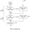
- FIG. 7shows a method of adjusting a bias and peak limiting, in accordance with embodiments.
- a hearing aidAlthough specific reference is made to a hearing aid, the embodiments disclosed herein will have application with many fields, such as acoustics and listening devices, for example electronic communication devices such as cell phones.
- optical methods and apparatus disclosed herein that provide low distortion optical signals with decreased power consumptionare well suited for combination with many types of commercially available electrical circuits and sound processors used to transmit electrical signals such as delta sigma modulation circuitry and class-A amplifiers for example.
- inventions disclosed hereincan be combined with implantable and non-implantable hearing devices.
- lightencompasses one or more of visible light, ultraviolet light, or infrared light, and combinations thereof.
- electromagnetic energyencompasses light energy.
- a troughencompasses a negative peak.
- an audio signalis transmitted using light to provide both power and signal to a transducer.
- lightcomprises electrical fields oscillating at terahertz frequencies
- commercially available detectorsdo not capture the negative component of the electric field oscillation. Because the light energy applied to a transducer results in a unidirectional signal, no opposing signal is available. Therefore, a light-encoded signal can be biased in order to decrease power consumption. Power consumption increases with increasing bias, and reducing bias can extend battery life substantially. However, the bias also determines the maximum signal amplitude that can be encoded, so reducing bias constrains signal level.
- the embodiments disclosed hereinare particularly well suited for providing a decreased bias in combination with inhibited clipping in order to provide improved sound to the user.
- the adjustable biascomprises a sliding bias (hereinafter “SB”).
- SBsliding bias
- the SB algorithmmonitors the signal level and may continually adjust the bias.
- the biasis set to the minimum value that can accommodate the signal level. Power consumption can be reduced when the signal level is low, such that the tradeoff between battery life and signal range can be balanced, for example optimized.
- the SB algorithmsets the bias level in response to the peak levels of the signal, such as negative peaks of the signal.
- the peak levelcan be proportional to the root mean square (rms) level of signal.
- a factor comprising the ratio of the peak value to rms valueis known as the crest factor.
- the crest factorcan vary with the type of input signal and may not be well suited for use with at least some input audio signals. High crest factor signals may require high bias levels and thus increase power consumption. Therefore it may be desirable to reduce the crest factor in conjunction with applying sliding bias.
- There are several methods that can be used to reduce the crest factor of a signalOne method is to use a variable level peak limiting strategy, for example. Another method is to use a peak cancellation strategy. Yet another method provides a soft limiting strategy. These methods are suitable for combination in accordance with embodiments disclosed herein.
- the peak limitingis adjustable and is not fixed, and the crest-factor limiting is dependent on the bias level.
- the sliding-bias algorithm and the combined peak limiting and sliding-bias algorithms as described hereincan be used alternatively or in combination as the front end to pulse-width or pulse density modulation circuitry. Alternatively, they can be used as the front end of a class-A analog system. In these embodiments, a significant savings in output power can be realized, particularly when the signal is low level.
- FIG. 1shows a hearing aid system 10 configured to transmit electromagnetic energy comprising light energy EM to an output transducer assembly 100 positioned in the ear canal EC of the user.
- the earcomprises an external ear, a middle ear ME and an inner ear.
- the external earcomprises a Pinna P and an ear canal EC and is bounded medially by an eardrum TM.
- Ear canal ECextends medially from pinna P to eardrum TM.
- Ear canal ECis at least partially defined by a skin SK disposed along the surface of the ear canal.
- the eardrum TMcomprises an annulus TMA that extends circumferentially around a majority of the eardrum to hold the eardrum in place.
- the middle ear MEis disposed between eardrum TM of the ear and a cochlea CO of the ear.
- the middle ear MEcomprises the ossicles OS to couple the eardrum TM to cochlea CO.
- the ossicles OScomprise an incus IN, a malleus ML and a stapes ST.
- the malleus MLis connected to the eardrum TM and the stapes ST is connected to an oval window OW, with the incus IN disposed between the malleus ML and stapes ST.
- Stapes STis coupled to the oval window OW so as to conduct sound from the middle ear to the cochlea.
- the hearing system 10includes an input transducer assembly 20 and an output transducer assembly 100 to transmit sound to the user.
- Hearing system 10may comprise a behind the ear unit BTE.
- Behind the ear unit BTEmay comprise many components of system 10 such as a speech processor, battery, wireless transmission circuitry and input transducer assembly 10 .
- Behind the ear unit BTEmay comprise many component as described in U.S. Pat. Pub. Nos. 2007/0100197, entitled “Output transducers for hearing systems”; and 2006/0251278, entitled “Hearing system having improved high frequency response”, the full disclosures of which are incorporated herein by reference and may be suitable for combination in accordance with some embodiments of the present invention.
- the input transducer assembly 20can be located at least partially behind the pinna P, although the input transducer assembly may be located at many sites.
- the input transducer assemblymay be located substantially within the ear canal, as described in U.S. Pub. No. 2006/0251278.
- the input transducer assemblymay comprise a Bluetooth® connection to couple to a cell phone and may comprise, for example, components of the commercially available Sound ID 300 , available from Sound ID of Palo Alto, Calif.
- the output transducer assembly 100may comprise components to receive the light energy and vibrate the eardrum in response to light energy.
- An example of an output transducer assembly having components suitable for combination in accordance with embodiments as described hereinis described in U.S. Pat. App. Nos.
- the input transducer assembly 20can receive a sound input, for example an audio sound. With hearing aids for hearing impaired individuals, the input can be ambient sound.
- the input transducer assemblycomprises at least one input transducer, for example a microphone 22 .
- Microphone 22can be positioned in many locations such as behind the ear, as appropriate. Microphone 22 is shown positioned to detect spatial localization cues from the ambient sound, such that the user can determine where a speaker is located based on the transmitted sound.
- the pinna P of the earcan diffract sound waves toward the ear canal opening such that sound localization cues can be detected with frequencies above at least about 4 kHz.
- the sound localization cuescan be detected when the microphone is positioned within ear canal EC and also when the microphone is positioned outside the ear canal EC and within about 5 mm of the ear canal opening.
- the at least one input transducermay comprise a second microphone located away from the ear canal and the ear canal opening, for example positioned on the behind the ear unit BTE.
- the input transducer assemblycan include a suitable amplifier or other electronic interface.
- the inputmay comprise an electronic sound signal from a sound producing or receiving device, such as a telephone, a cellular telephone, a Bluetooth connection, a radio, a digital audio unit, and the like.
- At least a first microphonecan be positioned in an ear canal or near an opening of the ear canal to measure high frequency sound above at least about one 4 kHz comprising spatial localization cues.
- a second microphonecan be positioned away from the ear canal and the ear canal opening to measure at least low frequency sound below about 4 kHz.
- Input transducer assembly 20includes a signal output source 12 which may comprise a light source such as an LED or a laser diode, an electromagnet, an RF source, or the like.
- the signal output sourcecan produce an output based on the sound input.
- Output transducer assembly 100can receive the output from input transducer assembly 20 and can produce mechanical vibrations in response.
- Output transducer assembly 100comprises a sound transducer and may comprise at least one of a coil, a magnet, a magnetostrictive element, a photostrictive element, or a piezoelectric element, for example.
- the output transducer assembly 100can be coupled input transducer assembly 20 comprising an elongate flexible support having a coil supported thereon for insertion into the ear canal as described in U.S. Pat. Pub. No. 2009/0092271, entitled “Energy Delivery and Microphone Placement Methods for Improved Comfort in an Open Canal Hearing Aid”, the full disclosure of which is incorporated herein by reference and may be suitable for combination in accordance with some embodiments of the present invention.
- the input transducer assembly 20may comprise a light source coupled to a fiber optic, for example as described in U.S. Pat. Pub. No.
- the light source of the input transducer assembly 20may also be positioned in the ear canal, and the output transducer assembly and the BTE circuitry components may be located within the ear canal so as to fit within the ear canal.
- the mechanical vibrations caused by output transducer assembly 100can induce neural impulses in the subject which can be interpreted by the subject as the original sound input.
- FIGS. 2 A and 2 Bshow isometric and top views, respectively, of the output transducer assembly 100 .
- Output transducer assembly 100comprises a retention structure 110 , a support 120 , a transducer 130 , at least one spring 140 and a photodetector 150 .
- Retention structure 110is sized to couple to the eardrum annulus TMA and at least a portion of the anterior sulcus AS of the ear canal EC.
- Retention structure 110comprises an aperture 110 A.
- Aperture 110 Ais sized to receive transducer 130 .
- the retention structure 110can be sized to the user and may comprise one or more of an o-ring, a c-ring, a molded structure, or a structure having a shape profile so as to correspond to a mold of the ear of the user.
- retention structure 110may comprise a polymer layer 115 coated on a positive mold of a user, such as an elastomer or other polymer.
- retention structure 110may comprise a layer 115 of material formed with vapor deposition on a positive mold of the user, as described herein.
- Retention structure 110may comprise a resilient retention structure such that the retention structure can be compressed radially inward as indicated by arrows 102 from an expanded wide profile configuration to a narrow profile configuration when passing through the ear canal and subsequently expand to the wide profile configuration when placed on one or more of the eardrum, the eardrum annulus, or the skin of the ear canal.
- the retention structure 110may comprise a shape profile corresponding to anatomical structures that define the ear canal.
- the retention structure 110may comprise a first end 112 corresponding to a shape profile of the anterior sulcus AS of the ear canal and the anterior portion of the eardrum annulus TMA.
- the first end 112may comprise an end portion having a convex shape profile, for example a nose, so as to fit the anterior sulcus and so as to facilitate advancement of the first end 112 into the anterior sulcus.
- the retention structure 110may comprise a second end 114 having a shape profile corresponding to the posterior portion of eardrum annulus TMA.
- the support 120may comprise a frame, or chassis, so as to support the components connected to support 120 .
- Support 120may comprise a rigid material and can be coupled to the retention structure 110 , the transducer 130 , the at least one spring 140 and the photodetector 150 .
- the support 120may comprise a biocompatible metal such as stainless steel so as to support the retention structure 110 , the transducer 130 , the at least one spring 140 and the photodetector 150 .
- support 120may comprise cut sheet metal material.
- support 120may comprise injection molded biocompatible plastic.
- the support 120may comprise an elastomeric bumper structure 122 extending between the support and the retention structure, so as to couple the support to the retention structure with the elastomeric bumper.
- the elastomeric bumper structure 122can also extend between the support 120 and the eardrum, such that the elastomeric bumper structure 122 contacts the eardrum TM and protects the eardrum TM from the rigid support 120 .
- the support 120may define an aperture 120 A formed thereon.
- the aperture 120 Acan be sized so as to receive the balanced armature transducer 130 , for example such that the housing of the balanced armature transducer 130 can extend at least partially through the aperture 120 A when the balanced armature transducer is coupled to the eardrum TM.
- the support 120may comprise an elongate dimension such that support 120 can be passed through the ear canal EC without substantial deformation when advanced along an axis corresponding to the elongate dimension, such that support 120 may comprise a substantially rigid material and thickness.
- the transducer 130comprises structures to couple to the eardrum when the retention structure 120 contacts one or more of the eardrum, the eardrum annulus, or the skin of the ear canal.
- the transducer 130may comprise a balanced armature transducer having a housing and a vibratory reed 132 extending through the housing of the transducer.
- the vibratory reed 132is affixed to an extension 134 , for example a post, and an inner soft coupling structure 136 .
- the soft coupling structure 136has a convex surface that contacts the eardrum TM and vibrates the eardrum TM.
- the soft coupling structure 136may comprise an elastomer such as silicone elastomer.
- the soft coupling structure 136can be anatomically customized to the anatomy of the ear of the user.
- the soft coupling structure 136can be customized based a shape profile of the ear of the user, such as from a mold of the ear of the user as described herein.
- At least one spring 140can be connected to the support 120 and the transducer 130 , so as to support the transducer 130 .
- the at least one spring 140may comprise a first spring 122 and a second spring 124 , in which each spring is connected to opposing sides of a first end of transducer 130 .
- the springsmay comprise coil springs having a first end attached to support 120 and a second end attached to a housing of transducer 130 or a mount affixed to the housing of the transducer 130 , such that the coil springs pivot the transducer about axes 140 A of the coils of the coil springs and resiliently urge the transducer toward the eardrum when the retention structure contacts one or more of the eardrum, the eardrum annulus, or the skin of the ear canal.
- the support 120may comprise a tube sized to receiving an end of the at least one spring 140 , so as to couple the at least one spring to support 120 .
- a photodetector 150can be coupled to the support 120 .
- a bracket mount 152can extend substantially around photodetector 150 .
- An arm 154extend between support 120 and bracket 152 so as to support photodetector 150 with an orientation relative to support 120 when placed in the ear canal EC.
- the arm 154may comprise a ball portion so as to couple to support 120 with a ball-joint.
- the photodetector 150can be coupled to transducer 130 so as to driven transducer 130 with electrical energy in response to the light energy signal from the output transducer assembly.
- Resilient retention structure 110can be resiliently deformed when inserted into the ear canal EC.
- the retention structure 110can be compressed radially inward along the pivot axes 140 A of the coil springs such that the retention structure 110 is compressed as indicated by arrows 102 from a wide profile configuration having a first width 110 W 1 to an elongate narrow profile configuration having a second width 110 W 2 when advanced along the ear canal EC as indicated by arrow 104 and when removed from the ear canal as indicated by arrow 106 .
- the elongate narrow profile configurationmay comprise an elongate dimension extending along an elongate axis corresponding to an elongate dimension of support 120 and aperture 120 A.
- the elongate narrow profile configurationmay comprise a shorter dimension corresponding to a width 120 W of the support 120 and aperture 120 A along a shorter dimension.
- the retention structure 110 and support 120can be passed through the ear canal EC for placement.
- the reed 132 of the balanced armature transducer 130can be aligned substantially with the ear canal EC when the assembly 100 is advanced along the ear canal EC in the elongate narrow profile configuration having second width 110 W 2 .
- the support 120may comprise a rigidity greater than the resilient retention structure 110 , such that the width 120 W remains substantially fixed when the resilient retention structure is compressed from the first configuration having width 110 W 1 to the second configuration having width 110 W 2 .
- the rigidity of support 120 greater than the resilient retention structure 110can provide an intended amount of force to the eardrum TM when the inner soft coupling structure 136 couples to the eardrum, as the support 120 can maintain a substantially fixed shape with coupling of the at least one spring 140 .
- the outer edges of the resilient retention structure 110can be rolled upwards toward the side of the photodetector 150 so as to compress the resilient retention structure from the first configuration having width 110 W 1 to the second configuration having width 110 W 2 , such that the assembly can be easily advanced along the ear canal EC.
- FIG. 3shows circuitry of the hearing aid system 10 .
- the circuitry of hearing system 10may comprise one or more components of input transducer assembly 20 and output transducer assembly 100 , for example.
- the circuitry of the input transducer assembly 20comprises one or more sources of an input audio signal 164 , such as one or more of wireless communication circuitry 160 or microphone circuitry 162 , for example.
- Wireless communication circuitry 160may comprise one or more of many known wireless communication circuitry components such as circuitry compatible with Bluetooth® communication standards, for example.
- the microphone circuitry 162may comprise microphone 22 and amplifiers, for example.
- the input audio signal 164is received with an input of sound processor 170 .
- Sound processor 170can be coupled to pulse modulation circuitry 180 to generate modulated pulses, for example. Alternatively or in combination, the sound processor 170 may comprise the pulse modulation circuitry.
- the output of the pulse modulation circuitry 180can be coupled to drive circuitry 190 .
- the drive circuitry 190can be coupled to an output light source 12 , for example.
- the output light source 12can provide output light energy pulses modulated in accordance with pulse modulation circuitry 190 , for example.
- the light output source 12can be configured in one or more of many ways.
- the light output source 12can be placed in the ear canal, or outside the ear canal such as in a BTE unit as described herein, for example.
- the light output source 12may comprise one or more of many light sources such as a light emitting diode, a laser, or a laser diode, for example.
- the output light source 12comprises a laser diode having a linear light energy output in response to an input signal, for example.
- the laser diode having the substantially linear output in response to the input signalcan provide a low distortion output light signal, which can be combined with an analog output or modulated output signal from the processor and drive circuitry as described herein, for example.
- the circuitry of the output transducer assembly 100can be configured in one or more of many ways to receive the pulse modulated light signal and induce vibrations of the subject's auditory pathway.
- a photodetector 150receives the modulated light pulses.
- the photodetector 150may comprise one or more of many light sensitive materials such as a photodiode, a silicone photodiode material or a photostrictive material, for example.
- photodetector 150is coupled to an output transducer 130 .
- the output transducer 130may comprise one or more of many electromechanical actuators such as a coil, a magnetic material, a magnet, a balanced armature transducer, or a piezo electric material, for example.
- the pulse modulation circuitry 180may comprise one or more of pulse width modulation circuitry or pulse density modulation circuitry, for example.
- the pulse modulation circuitrycan be replaced or combined with one or more of many forms of circuitry.
- the pulse modulation circuitrycan be replaced with circuitry configured to output an analog optical signal, such as a class A amplifier.
- the pulse modulation circuitrycan be replaced with one more of many forms of modulation circuitry such amplitude modulation, frequency modulation, or phase modulation, for example, in order to decrease the optical energy of the output signal from the light source.
- the processor 170may comprise on or more components of the input transducer assembly.
- the sound processor 170may comprise one or more of: analog circuitry to amplify an analog signal from the microphone; analog to digital conversion circuitry to convert an analog input signal to a digital circuitry; digital input circuitry to receive a digital sound signal; a digital signal processor; a tangible medium embodying instructions to process a sound signal; output circuitry to output a digital signal; digital filters to adjust a sound signal in response to user preference; and combinations thereof.
- the sound processoris configured with instructions to adjust the bias of the input signal and limit peaks as described herein.
- the sound processormay comprise one or more components of a commercially available sound processor known to those of ordinary skill in the art of hearing aid design.
- the sound processormay comprise a tangible medium such as one or more of a computer readable memory, random access memory, read only memory, writable erasable read only memory, and a solid state hard drive.
- the sound processormay comprise a processor capable of executing instructions stored on the tangible medium, and may comprise gate array logic, programmable gate array logic, and combinations thereof.
- the processormay comprise a plurality of processors and a plurality of tangible media, for example. A person of ordinary skill in the art will recognize many configurations of processor 170 in accordance with the embodiments disclosed herein.
- FIG. 4 Ashows an input signal 210 relative to an input reference 205 and the input signal 210 with an adjustable bias 220 .
- the input signal 210may comprise an audio signal as described herein.
- the reference level 205may correspond to, for example, 0 volts, and the amplitude of the input signal may vary over a range of positive and negative voltages of +1 and ⁇ 1, for example.
- the voltage scalecan be arbitrary.
- the input audio signal 210varies above and below the reference 205 which in many embodiments may correspond to, for example 0 Volts.
- the input signal 210comprises a peak 217 and a trough 218 .
- trough 218comprises a negative peak.
- the peak 217 and trough 218may comprise a local peak and a local trough, respectively, for example.
- an input signalmay have a voltage range from +1 to ⁇ 1 without causing clipping of the output.
- a small amplitude signale.g. a signal ranging in amplitude from approximately +0.1 to ⁇ 0.1 volts
- the pulse modulation circuitry 180e.g. a pulse wave modulator or pulse density modulator
- This duty cycle of about 50%results in greater power consumption than would be ideal for the amount of variation of the input audio signal 210 .
- a biasis applied to the input signal to ensure that the output of the pulse modulation circuitry accounts for both the positive and negative going amplitude peaks.
- this biase.g. reference level 205
- this biasmay be a fixed bias and may be illustrated in, for Example FIG. 4 A as having a reference value of 0.0.
- this reference levelis generally chosen to ensure that the largest input signal (e.g. a signal having positive and negative peak values of +1 and ⁇ 1 volts) will not encounter clipping, it is generally chosen to be larger than required to prevent clipping of smaller input signals.
- a small amplitude input signalsuch as signal 210 in FIG.
- a smaller bias 220can be combined with the input signal 210 to provide the biased input signal 212 .
- the biased input signal 212decreases the duty cycle of the pulses output from the pulse modulation circuitry 180 .
- the biased input signal 212can be offset by an amount sufficient to substantially decrease the duty cycle of light pulses in, for example, a laser driven by the output of drive circuitry 190 .
- a reference bias 205may be reduced by, for example, 0.7 units, as illustrated in FIG. 4 A , for a period of time during which the amplitude of an input signal 210 varies between a peak of approximately 0.1 units and ⁇ 0.1 units.
- FIG. 4 Bshows pulse width modulated light pulses in a system where sliding bias has not been applied.
- the instantaneous input signal valueis shown from an arbitrary scale of ⁇ 1 to +1.
- the duty cycle of the pulse modulated signalis 50%.
- the duty cycle valuesare 0%, 25%, 75% and 100%, respectively.
- Each duty cyclecomprises a period T, an on time Ton of the light source and an off time Toff of the light source.
- the duty cycle in percentcan be defined as (Ton/T)*100.
- a small signalsuch as signal 210 from FIG.
- thismay be done by, for example, modifying the duty cycle which is representative of the zero crossing of the incoming signal, such as, for example, reducing the duty cycle representative of a zero crossing from 50% as illustrated in FIG. 4 B to approximately 10% for input signal 205 from FIG. 4 A .
- the pulse modulated signalmay comprise a pulse density modulated signal, or a pulse frequency modulated signal, for example.
- the pulse modulated signal as described hereincomprises a substantially fixed amplitude in order to inhibit effects of non-linearities of the optical sound transmission system components such one or more of the light source, the photodetector or the output transducer, for example.
- FIG. 4 Cshows an increased amplitude of input signal 210 with the adjustable 220 bias of FIG. 4 A and peak limiting.
- Signal 210is shown in relation to input reference 205 .
- clipping of signal 210occurs when signal 201 exceeds an amplitude of +1.0 or ⁇ 1.0, therefore, any applied bias must account for those clipping limits. It would, however, be advantageous to lower the applied bias represented by reference 205 , in order to save energy.
- bias 220which is lower than reference bias 205 by approximately ⁇ 0.7 units, is applied to signal 210 in order to provide biased signal 212 .
- the clipping illustrated in the lower graph of FIG. 4 Cmay, therefore, be addressed by adjusting the gain of the system to ensure that the signal is not clipped.
- the bias 220comprises a fixed portion 222 having a substantially fixed value and a variable portion 224 comprising a gradually changing value.
- the gradually changing valueis varied sufficiently slowly so as to inhibit user perceptible noise. However, slowly varying the bias may result in clipping of the signal until the sliding bias reaches a level at which clipping no longer occurs.
- the amplitude of signal 210can be adjusted in order to inhibit clipping of the biased input signal 212 .
- the adjustment to the amplitude of signal 210is provided much more rapidly than the adjustment to the bias.
- reduction of the system gainwill result in reducing or eliminating clipping of signal 210 until the bias can be adjusted to avoid such clipping, which may take several cycles of signal 210 . Once the bias is adjusted sufficiently to avoid clipping, the system gain may be restored to its original value
- the adjustment to the gaincan be determined with a look ahead delay as described herein below with reference to FIG. 6 A .
- FIG. 4 Cshows the change to the gain over a portion of the signal for the convenience of illustration, the change to the gain can occur over several positive and negative oscillations of the sliding bias signal as described herein.
- the bias adjustmentcomprises a steady mode in which the bias remains substantially fixed and maintained at an appropriate value to, for example, minimize energy consumption.
- the sliding biaswhen the system detects a signal wherein the negative going peak will exceed the system limit, the sliding bias enters an attack mode, in which the bias is increased (in some embodiments an increase in sliding bias makes it less negative).
- the sliding biaswhere the system detects that the bias may be reduced without causing clipping, the sliding bias enters a release mode in which the bias is decreased, which, in some embodiments will result in a reduction of duty cycle in the output signal.
- the gain and corresponding amplitude of the signalcan be adjusted in a manner similar to the bias as described herein, and can be adjusted more quickly without substantial user perceptible artifacts, for example.
- the adjustment to the system gaininhibits user perceptible clipping of the signal which may otherwise occur when the biased signal exceeds the lower range limit.
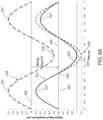
- FIGS. 5 A and 5 Bshow light power curves biased to substantially decrease power consumption.
- the system of FIGS. 5 A and 5 Bare designed to accommodate an output signal having a maximum peak to peak amplitude of +2.0 units without clipping.
- the bias applied to a large amplitude signalis, therefore, approximately +1.0 units.
- FIG. 5 Ashows the power curve 250 of an input signal of medium amplitude with a bias of +1.0 units but without sliding bias applied.
- the fixed bias of power curve 250provides improved signal quality and can accommodate negative voltage of an input signal such as a microphone.
- a sliding bias of ⁇ 0.5is shown applied to the fixed bias signal, reducing the bias applied to 0.5 units and producing a sliding biased signal 255 .
- the sliding biasmay be adjusted so that the trough (or negative peak) 256 of the signal to which the sliding bias has been applied is at or near zero power.
- This configurationallows the bias (and output power) to be substantially decreased when the signal to be transmitted is smaller than the maximum signal the system can transmit with clipping.
- the sliding biasis used to decrease the applied bias to a value which reduces output power consumed while preventing clipping of the output signal.
- FIG. 5 Bshows another example, in which a larger sliding bias adjustment is used to shift the bias applied to a small-amplitude signal. In this case, the power curve of signal 260 starts with a bias of +1.0.
- ⁇ 0.75may be chosen, corresponding to the difference between the amplitude and the offset of the input signal. This results in a sliding-biased signal 256 with a bias of 0.25, so that its trough 256 is substantially decreased at or near zero power and is not clipped.
- the input signalmay comprise an unbiased input audio signal or a biased input audio signal.
- the fixed bias as described hereincan be introduced to the input signal in many ways.
- an input analog audio signal from a microphonemay have an input range from ⁇ 1 to +1 (arbitrary), and the analog to digital converter can be configured to digitize the input analog signal such that the digitized values are positive, for example from 0 to 2 (arbitrary).
- the analog to digital convertermay convert the analog values to a digital range from ⁇ 1 to +1, and a fixed bias of 1.0 introduced to the digitized values with addition, for example, such that the digitized values range from 0 to 2, for example.
- the fixed biasmay comprise a fixed bias of an input digital audio signal from an external source such as music from a digital library or a cellular phone, for example.
- the processorcan be configured with instructions to provide a fixed bias to the input digital audio signal, for example.
- the curves shown in FIGS. 5 A and 5 Bcan be generated with the fixed bias and sliding bias output as described herein provided to an analog amplifier such as a class B amplifier.
- the sliding biascan be provided in order to provide decreased power consumption as a result of a decrease in the bias during periods where a maximum bias is not required.
- FIG. 5 Cshows an encoding of the fixed bias curve 250 of FIG. 5 A , using pulse width modulation (PWM).
- Black barsillustrate time periods in which light is on, and white bars illustrate time periods in which light is off.
- a clock rate of 12.5 kHzis used, with minimum pulse width of 10 microseconds, allowing a pulse width variable from 0 to 80 microseconds in 10 microsecond increments.
- Higher clock rates and smaller minimum pulse widths than illustratedmay be chosen to allow higher-resolution signal transmission.
- FIG. 5 Dshows an encoding of the fixed bias curve 250 of FIG. 5 A , using pulse density modulation (PDM).
- Black barsillustrate time periods in which light is on, and white bars illustrate time periods in which light is off.
- a clock rate of 100 kHzis used, corresponding to a minimum pulse width of 10 microseconds. Higher clock rates and smaller minimum pulse widths than illustrated may be chosen to allow higher-resolution signal transmission.
- FIG. 5 Eshows an encoding of the sliding biased curve 255 of FIG. 5 A , using PWM.
- Black barsillustrate time periods in which light is on, and white bars illustrate time periods in which light is off.
- a clock rate of 12.5 kHzis used, with minimum pulse width of 10 microseconds, allowing a pulse width variable from 0 to 80 microseconds in 10 microsecond increments. Higher clock rates and smaller minimum pulse widths than illustrated may be chosen to allow higher-resolution signal transmission.
- the encoding of FIG. 5 Ehas a lower duty cycle, as shown by the smaller amount of black signal, illustrating that less light power is needed to transmit the signal of sliding bias curve 255 than of fixed biased curve 250 .
- the lower duty cycleprovides substantially decreased power consumption.
- FIG. 5 Fshows an encoding of the sliding biased curve 255 of FIG. 5 A , using PDM.
- Black barsillustrate time periods in which light is on, and white bars illustrate time periods in which light is off.
- a clock rate of 100 kHzis used, corresponding to a minimum pulse width of 10 microseconds. Higher clock rates and smaller minimum pulse widths than illustrated may be chosen to allow higher-resolution signal transmission.
- the encoding of FIG. 5 Fhas a lower duty cycle, as shown by the smaller amount of black signal, illustrating that less light power is needed to transmit the signal of sliding bias curve 255 than of fixed biased curve 250 .
- the decreased duty cycle and pulse densityprovides decreased power consumption.
- the light sourcesuch as a laser may comprise the most significant source of power consumption with an optical hearing system, and the power drawn by the laser is often proportional to the signal offset. Therefore, applying a large sliding bias so that the signal comes close to clipping is helpful for reducing power consumption and extending battery life.
- FIG. 6 Ashows amplitude of an input signal, such as a digital input signal, with sliding bias and peak limiting to inhibit clipping.
- An input signal 210is shown in relation to input reference 205 corresponding to a peak-to-peak signal amplitude of 1.0 (arbitrary).
- the input reference 205corresponds to a middle of the input signal range, and may correspond to an average value of a fixed bias input signal as described herein.
- the reference level 205may correspond to 0 volts of an input such as a microphone as described herein, for example.
- the signal 210comprises positive peaks 217 and a negative peak comprising trough 218 at signal amplitudes of about 0.5 and ⁇ 0.5, respectively.
- a sliding bias of ⁇ 0.6 unitsis applied to input signal 210 , generating a sliding-biased signal 212 with peaks 217 at a signal levels of about ⁇ 0.1 units.
- signal 212is small enough that the sliding bias of ⁇ 0.6 does not result in any clipping and the system gain may be maintained at a constant level.
- an increase in signal 212may result in the negative peak being clipped absent a modification of the bias level and/or system gain.
- the system gainmay be dynamically adjusted, so that the trough 215 of the biased signal 212 is higher than the unadjusted trough 218 .
- This gain adjustmentensures that clipping of the negative peaks does not occur and results in a signal 214 with a peak negative magnitude of no greater than ⁇ 1.0.
- the positive peak value 217 of the sliding biased curveis reduced as well, such that the sliding-biased curve has a lower peak to peak amplitude of about 0.8 units. Dynamically adjusting the biased signal in this manner inhibits negative clipping, thus decreasing distortion of the signal.
- the system gainmay be restored to its optimum value.
- the adjustment to the bias during time period 224may be applied gradually, including over a period of multiple wavelengths, so that the bias remains substantially fixed when the system gain is reduced in order to inhibit user perceptible noise related to the change in bias.
- the processormay comprise instructions to decrease the gain over a duration no more than a length of a look ahead delay, such that bias remains substantially fixed to within about five percent (5%) over the length of the look ahead delay, for example.
- FIG. 6 Bshows how a look-ahead delay may be employed to determine when a change in gain is needed.
- a sliding-bias of approximately ⁇ 0.6 unitsis applied to an input signal 210 to generate a sliding-biased signal 212 .
- the systemhas applied a look ahead delay 270 such that the output signal is delayed by a fixed period in order to modify that output in the event that the input signal changes in a manner which requires the output signal to be modified to maintain, for example, sound quality.
- the look-ahead delay as illustratedis about 0.5 ms, or about one quarter of a wavelength, but different look-ahead delays, including longer look-ahead delays of about 1 ms, about 2 ms, or longer than 2 ms may be chosen to provide more time to react to amplitude changes.
- the look-ahead delay 270allows the generation of a prediction 216 of the value that the sliding-biased signal 212 is expected to take after the look-ahead delay. When the prediction 216 is measured to fall below a threshold value, resulting in a predicted clipping 271 , a shift in signal gain is triggered.
- the shift in signal gainmay not immediately cause a significant change in the amplitude of the sliding-biased signal 212 , but it may change the slope 272 .
- the change in the sliding-biased signalmay be gradual, the change in gain may cause a rapid change 273 in the predicted value 216 , because the predicted value 216 reflects the accumulation of the effect of the shifted gain over the time period of the look-ahead delay 272 .
- the sliding-biased signal 212may be adjusted to inhibit clipping.
- the amount of gain adjustmentcan be determined in order to prevent the predicted curve 216 from clipping.
- the gain adjustmentmay be applied at different rates depending on the amount of look-ahead delay used.
- the gainmay be adjusted gradually in response to a predicted clipping, for example in response to a growing area of predicted clipping 271 .
- the change 273may be much more gradual than illustrated in FIG. 6 B , and in some cases the change may be spread over much or all of the look-ahead delay 270 , which may in some cases constitute one or more milliseconds, for example. This slower shift may have the benefit of inhibiting acoustic artifacts and distortions.
- FIG. 6 Cshows the adjustment of a sliding bias over time.
- An input signal (not shown) with amplitude of about 0.5is initially biased with a sliding bias 220 of about 0.6 in a negative direction to produce a sliding-biased curve 212 .
- the gain applied to sliding-biased curve 212is reduced, resulting in an amplitude of about 0.4.
- the sliding bias 220is gradually adjusted from 0.6 to 0.5.
- the gainis smoothly adjusted back up, increasing the amplitude of the signal along with the shift in bias.
- This smooth adjustmentmay keep the troughs of the sliding-biased curve 212 at or near a lower threshold value, allowing the signal amplitude to be increased without clipping.
- the adjustment stops and the gain and biasmay remain constant until another change is appropriate as described herein. While FIG. 6 C shows a linear change in bias over about 30 ms, in some cases the bias may be shifted nonlinearly and/or over shorter or longer timescales, for example to inhibit audio artifacts such as thumping.
- the sliding bias as described hereinapplies a time-varying bias that adjusts to changes in the signal amplitude.
- the magnitude of the biasis increased to save power.
- the bias as described hereinmay comprise a negative number added to the signal, and the value of the bias can be decreased to save power with low energy input signals.
- the magnitude of the biasis adjusted to inhibit clipping, for example by increasing the value of the bias to a less negative number.
- the methods and apparatus disclosed hereinprovide a signal processing algorithm for sliding bias that can be implemented in the digital signal processor (DSP) of an optical sound system.
- the processorembodies instructions of an algorithm that adjusts the bias by adding a time-varying offset to the digital signal before it is sent to the digital-to-analog converter (DAC).
- the digital to analog convertermay comprise a digital to analog converter that converts a digital value to an output voltage.
- the digitally biased signalcan be output from the DAC to an amplifier such as class B amplifier to drive the light sourced with an analog signal.
- the DACmay comprise delta sigma modulation circuitry.
- the output of the delta sigma modulation circuitrycan be used to drive the light source with a digital signal, such as PWM or PDM, for example.
- the output of the sliding bias algorithm as disclosed hereinmay comprise the last element in the signal processing chain so that it provides output signal to the DAC to generate the light signal with appropriate amplification.
- Signalscan be represented in the DSP as fractional digital values in the range from ⁇ 1 to +1, for example.
- the DACcomprising delta sigma modulation circuitry maps ⁇ 1 to a pulse density of 0%, 0 to a pulse density of 50%, and +1 to a pulse density of 100%, for example.
- the offset added by the sliding bias algorithmis in the range ⁇ 1 to 0, in order to decrease power consumption.
- the sliding bias algorithm as described hereinis not limited to the modulation scheme that is used to represent the signal with light.
- the algorithm and circuitry as described hereinare effective for analog, delta sigma modulation, PDM, pulse width modulation, and many other approaches, for example.
- the sliding bias algorithm as described hereinhas the advantage of significantly decreasing power consumption in order to prolong battery life. However, this advantage is preferably achieved without introducing audio artifacts. There are at least three types of artifacts which can be inhibited with the methods and apparatus as disclosed herein:
- the circuitry as disclosed hereincan be configured to inhibit clipping without producing audible thumping. Peak limiting as disclosed herein can be used to inhibit clipping with adjustments to the gain.
- Clippingmay occur if a high-amplitude signal arrives when the bias is low.
- a look ahead delaycan be provided in order to shift the bias up in advance of the arrival of the high-amplitude signal.
- the look ahead delaymay not provide sufficient time to adjust the bias for a rapidly decreasing signal, and peak limiting can be provided to inhibit clipping of rapidly decreasing signals.
- the length of the look ahead delaymay not be sufficient to allow the bias to change slowly in order to inhibit a user perceptible thump.
- Work in relation to embodimentssuggests that a full-range bias shift applied over a duration of less than about 20-50 ms may produce an audible thump. Therefore, peak limiting can be employed to inhibit clipping while allowing the bias to be changed sufficiently slowly to inhibit thumping.
- Limitations of the look ahead delaycan be overcome by providing peak limiting with the sliding bias algorithm.
- An approach to peak limitingis to apply a rapid gain reduction just before the peak and to restore the gain just after the peak, for example as shown above with reference FIGS. 4 C and 6 .
- the advantages of combining peak limiting and sliding biasare that a rapid gain change is less likely to create a user perceivable artifact, and peak limiting allows a shorter look ahead delay to be used with the sliding bias.
- the sliding bias and peak limiting algorithmscan be combined in many ways.
- a short look ahead delay of a few millisecondscan used to identify a peak that would otherwise be clipped by the low bias and initiate the rapid gain reduction that is helpful to limit the peak sufficiently to inhibit clipping.
- a slow bias increasecan be initiated to accommodate higher positive and negative peaks of the input signal.
- the gainmay then be slowly increased as the bias increases, until full gain is restored. Alternatively or in combination, the gain may be rapidly restored in response to a negative signal rising above a threshold as described herein, depending on the amplitude of the input signal and how rapidly the input signal changes.
- peak limitingmay be considered a form of artifact
- peak limiting combined with the slidingis likely to less likely to be apparent to the user than clipping.
- the digital peak limiting on the lower peakhas the advantage of being less perceivable and can produce less artifact than rapidly increasing the bias, for example.
- the sliding bias algorithmoperates by tracking the negative-going peak of the signal and applying a bias that is as negative as possible without causing the negative-going signal peak to drop below the clipping level of ⁇ 1. If the negative-going signal peak is M, the most negative bias that can be applied is ⁇ 1 ⁇ M.
- the algorithmuses a linear trajectory to shift the bias, although non-linear trajectories can be used.
- attackrefers to shifting the bias up to prevent clipping when the signal amplitude rises
- releaserefers to shifting the bias down to save power when the signal amplitude falls.
- the slopes of the linear trajectoriescan be determined by algorithm parameters SBS A (sliding bias attack slope) and SBS R (sliding bias release slope), both specified in units of samples ⁇ 1 .
- the algorithmhas three bias-related state variables:
- the algorithmcan be initialized as follows:
- B T⁇ 1 ⁇ M, where M is the most negative observed signal value.
- B Tis constrained to the range from B min to 0.
- Steady modeis exited if either of the following conditions occur:
- B CWhile in Attack mode, B C is incremented by SBS A until it reaches B T , at which point Steady mode is entered. During this process, B T is updated if a signal value is observed that requires B T to be set to a higher value.
- B Cis decremented by SBS R until it reaches B T , at which point Steady mode is entered. During this process, if a signal value is observed that requires B T >B C , Attack mode is entered.
- the peak limiting algorithmmay begin by calculating a peak limiting threshold, which is the largest negative-going peak signal magnitude in dB in relation to full-scale that can be accommodated by the current bias value B C without clipping.
- the integration between the sliding bias and peak limiting algorithmsis configured such that the peak limiting threshold depends on the current bias value.
- the algorithmapplies a time-varying gain as required to compensate for exceedance and prevent clipping.
- exceedanceoccurs (i.e., E>0)
- the gainis gradually reduced to ⁇ E dB before the peak and gradually restored.
- a look ahead delayis employed to detect exceedance in advance so that the gain change can be initiated in time to prevent clipping.
- the look ahead delayis an algorithm parameter ⁇ (also referred to herein as “look ahead time delay”), in samples.
- the gain change trajectorymay be linear in dB.
- attackrefers to reducing the gain
- releaserefers to increasing the gain.
- the slopes of the gain trajectoriescan be determined by algorithm parameters PLS A (peak limiting attack slope) and PLS R (peak limiting release slope), both specified in units of dB/sample.
- the algorithmhas three peak-limiting-related state variables:
- G CWhile in Attack mode, G C is decremented by PLS A until it reaches G T , at which point Steady mode is entered. During this process, G T is updated if an exceedance is observed that requires G T to be set to a lower value.
- G CWhile in Release mode, G C is incremented by PLS R until it reaches G T , at which point Steady mode is entered. During this process, if an exceedance is observed that requires G T ⁇ G C , Attack mode is entered.
- Rrepresents the system sampling rate, in Hz.
- ⁇should be set to 0 to substantially decrease power consumption.
- setting the bias so low that negative-going peaks are at the digital railcan produce distortion, possibly related to the noise floor and associated circuitry as disclosed herein.
- the value for ⁇should be set to the minimum value that prevents such distortion.
- Work in relation to embodimentssuggests that E with in a range from about 0.05 to about 0.2, for example equal to 0.1 can provide acceptable results.
- a distortion analysiscan be performed by a person of ordinary skill in the art in order to choose an appropriate value.
- B mincan be set as negative as possible, to substantially decrease power consumption, but high enough to substantially avoid bias values that unacceptably elevate noise.
- a system noise analysiscan be performed by a person of ordinary skill in the art in order to choose an appropriate value.
- the parameter Dcan be chosen to provide an acceptable tradeoff between power consumption and artifacts. Smaller values of D reduce power consumption by allowing the bias to shift down more quickly in response to a drop in signal amplitude. Larger values of D reduce the rate of occurrence of clipping and/or peak-limiting artifacts, because the bias will be shifted down after the signal amplitude has been low for a longer duration, which reduces the likelihood of incorrectly concluding that the signal amplitude has actually decreased. Suitable values are in the range from 1 to 10 seconds, which corresponds to a range from R to 10R samples.
- SBS Rshould be set fast enough to substantially decrease power consumption and slow enough to substantially inhibit user perceptible thumping.
- a suitable valueis 1/(0.5R) samples ⁇ 1 , which implements a full-range bias shift over the course of 500 ms, for example.
- SBS Acan result a tradeoff between different types of artifacts. Faster values of SBS A allow a faster response to signal amplitude increase, which substantially decreases clipping and peak-limiting artifacts, but slower values of SBS A decrease thumping.
- a suitable valueis 1/(0.05R) samples ⁇ 1 , which implements a full-range bias shift over the course of 50 ms, for example.
- the peak-limiting slopes PLS A and PLS Rcan be chosen with a tradeoff between different types of artifacts. Fast slopes substantially decrease envelope distortion by making the gain change more time-limited, but excessively fast slopes may introduce spectral distortion. In addition, there is an interaction among PLS A , B min , and ⁇ . To inhibit clipping, the following relationship can be considered: PLS A ⁇ 20 log 10 ( B min +1)/ ⁇
- the release slopeis not critical for preventing clipping, so the release slope can be slower to inhibit spectral distortion.
- the algorithmcan be block-oriented for efficiency and for compatibility with the block-based architecture of commercially available DSP systems.
- Lis the block length, in samples.
- the look ahead delayis constrained to be an integral number of blocks.
- the algorithmreceives a block of input samples, x[i:i+L ⁇ 1], and produces a block of output samples, y[i:i+L ⁇ 1], where i is the starting sample number of the current block.
- the algorithmproceeds in three sections:
- FIG. 7shows a method 900 of implementing an adjustable bias and peak limiting, in accordance with embodiments.
- the method 900may comprise one or more of a plurality of methods, such as one or more of a method 300 , a method 400 , a method 500 , a method 600 , a method 700 or a method 800 , for example.
- the method 900may comprise one or more of the following parameters:
- Method 300comprises analyzing input signals of a system to determine whether a signal bias can be shifted and clipping inhibited, in accordance with embodiments.
- a block of incoming signalis provided.
- the signal blockmay comprise signal from one or more auditory inputs as described herein.
- the minimum value, M, of the incoming signal of the blockis determined.
- the most negative bias, Bthat can be applied to the block without clipping any troughs of the input is determined.
- a step 308the values of B and a target bias, B T , are compared.
- the value of B Tis compared to the value of B C .
- SBModea signal bias mode
- Steps 308 , 310 , 311 , and 312disclose a method of setting the SBMode to “attack” when the bias should be increased in order to account for deeper troughs in the signal, so as to inhibit clipping.
- the value of SBModeis compared to “steady.”
- a counter with a defined interval or cycleis decremented.
- the value of the counteris compared to zero.
- the SBModeis set to “release.”
- Steps 314 , 316 , 317 , and 318disclose a method of setting SBMode to “release” when, after a defined period as determined by the counter, no peaks were clipped.
- a method 400comprises analyzing input signals of a system to determine whether or not the gain should be adjusted to limit peaks in order to inhibit clipping, in accordance with embodiments.
- a threshold T for the peak limiting algorithm disclosed hereinis determined, comprising a formula that includes the value of B C from method 300 .
- the value of M, the minimum value of the incoming signal of the block of step 302is compared to 0.
- an exceedance Eis determined, representing the number of decibels a signal trough goes below the threshold, if at all.
- the value of ⁇ 1 multiplied by Eis compared to a target peak limiting gain, G T .
- G Tis set to equal ⁇ 1 multiplied by E.
- the value of G Tis compared to the value of the current gain of the system, G C .
- the peak limiting mode(hereinafter “PLMode”), is set to “attack.”
- Steps 407 , 408 , 409 , and 410disclose a method of setting the peak limiting mode to “attack” in order to adjust for troughs that may be clipped.
- the value of PLModeis compared to “steady.”
- a counter with a defined interval or cycleis decremented.
- the value of the counteris compared to 0.
- PLModeis set to “release.”
- the PLMode and the SBMode of method 300is passed on to a subsequent block loop method.
- Steps 412 , 414 , 415 , and 416disclose a method of setting the peak limiting mode to “release” when, after a given period as determined by the counter, no peaks have been clipped.
- Method 500comprises changing the signal bias and inhibiting clipping, in accordance with embodiments.
- Method 500comprises a block loop method that may accept outputs from method 300 .
- a loopis initiated.
- the state of SBmodeis determined.
- the state variable SBModecomprises an input from the outputs of method 300 , for example.
- the SBModemay comprise states “attack” and “release”, for example.
- B Cwill be set to the smaller value of either B C plus a sliding bias attack mode slope, or B T .
- the state of SBModeis determined.
- B Cwill be set to the larger value of either B C minus a sliding bias release mode slope, or B T .
- the loopexecutes until any loop conditions are satisfied.
- loop conditionsmay comprise exhaustion of a counter.
- Method 600comprises changing the gain of a system in order to inhibit clipping, in accordance with embodiments.
- Methodcomprises a block loop method that may accept outputs from method 400 .
- a loopis initiated.
- the state of PLModeis determined.
- the state variable PLModecomprises an input from the outputs of embodiments such as those of method 400 .
- PLModemay comprise states “attack” and “release.”
- G Cwill be set to the larger value of either G C minus a peak limiting attack mode slope, or G T .
- the state of PLModeis determined.
- G Cwill be set to the smaller value of either G C minus a peak limiting release mode slope, or G T .
- an output samplecomprising an equation comprising variables such as G C , a look ahead time delay, and a current bias—is determined.
- the loopexecutes until any loop conditions are satisfied.
- loop conditionsmay comprise exhaustion of a counter.
- a method 700comprises updating the sliding bias mode as appropriate, in accordance with embodiments.
- Method 700comprises accepting outputs from methods such as method 500 .
- the value of B Cis compared to the value of B T , and the value of SBMode is determined.
- SBModewill be set to “steady” for a defined amount of time.
- State variablessuch as B T , are also initialized.
- the methodterminates.
- a method 800comprises updating the peak limiting mode as appropriate, in accordance with embodiments.
- Method 800comprises accepting outputs from methods such as method 600 .
- the value of G Cis compared to the value of G T , and the value of PLMode is determined.
- G Cis equal to G T , and PLMode is not set to “steady, then PLMode will be set to “steady” for a given amount of time.
- State variables, such as G Tare also initialized.
- the algorithmterminates.
- the method 900discloses a method of adjusting a bias and limiting peaks, in accordance with embodiments.
- a person of ordinary skill in the artwill recognize many variations and modifications based on the disclosure provided herein. For example, some steps may be added or removed. The steps can be combined, or the order changed. Some of the methods may comprise sub-methods. Some of the steps may comprise sub-steps, and many of the steps can be repeated.
- the values of method 900can be determined with one or more of calculations, look up tables, fuzzy logic, or neural networks, for example.
- the method 900can be embodied with instructions stored on a tangible medium of processor 170 .
- the processorcan be coupled to components of the system in order to perform one or more steps of method 900 .
- ranges of parameters suitable for use with method 900may comprise one or more of the following, where R is the sampling rate of the system:
Landscapes
- Engineering & Computer Science (AREA)
- Computer Networks & Wireless Communication (AREA)
- Physics & Mathematics (AREA)
- Signal Processing (AREA)
- Electromagnetism (AREA)
- Health & Medical Sciences (AREA)
- General Health & Medical Sciences (AREA)
- Neurosurgery (AREA)
- Otolaryngology (AREA)
- Acoustics & Sound (AREA)
- Optics & Photonics (AREA)
- Circuit For Audible Band Transducer (AREA)
- Electrostatic, Electromagnetic, Magneto- Strictive, And Variable-Resistance Transducers (AREA)
Abstract
Description
The present patent application is a continuation of U.S. patent application Ser. No. 16/688,774, filed Nov. 19, 2019, now U.S. Patent Application No. 11,259,129; which is a continuation of U.S. Patent Application No. 15,890,185, filed Feb. 6, 2018, now U.S. Pat. No. 10,531,206; which is a continuation of U.S. patent application Ser. No. 14/813,301, filed Jul. 30, 2015, now U.S. Pat. No. 9,930,458; which is a continuation of PCT Application No. PCT/US15/40397, filed Jul. 14, 2015; which claims priority to U.S. Provisional Patent Application No. 62/024,275, filed Jul. 14, 2014; the entire disclosures of which are incorporated herein by reference.
The field of the present invention is related to optical hearing devices.
The prior methods and apparatus for providing sound to users can be less than ideal in at least some respects. People like to communicate, and hearing is an important aspect of communication for both communication devices and prosthetic devices such as hearing aids.
Contact hearing devices that contact tissue or bone have the advantage of providing sound with decreased feedback along the ear canal to the input microphone. However, the ear is composed of several small and delicate structures such as the tympanic membrane, ossicles and cochlea. Providing compact hearing devices that fit comfortably within the ear and contact moveable structures of the ear to provide high quality sound can be challenging. Transmitting power and signals to such small devices has also proven challenging.
Recently, it has been proposed to use light based hearing devices. Light based hearing devices have the advantage of potentially being small and providing high fidelity sound. However, realization of these potential advantages has proven challenging for several reasons. Sound is transmitted with positive and negative changes in air pressure. However, the light energy transmitted from a light source only results in the generation of positive light energy, with no corresponding negative light energy being available. Although light does oscillate with electrical and magnetic fields in the Terahertz frequency range, such frequencies are too fast for most detectors to capture the oscillating positive and negative field components of light. Consequently prior methods and apparatus used to drive electrical signals associated with positive and negative sound pressure may not be well suited for use with light based systems. Also, optical components can introduce distortions to optical signals, such as non-linear behavior of the light source and detector, which can present additional challenges.
At least some of the prior electronic circuitry solutions are less than ideally suited for the transmission of light based optical signals. For example, the use of prior delta-sigma modulation with optical signals can result in more power consumption than would be ideal. Similarly, prior analog approaches to transmitting electrical signals can result in increased power consumption when used with optical systems. As hearing devices can be worn for extended amounts of time, excessive power consumption may result in less than ideal performance of the hearing device in at least some instances.
In light of the above, it would be helpful to provide improved methods and apparatus for optical hearing. Ideally such optical devices would provide decreased power consumption, low amounts of distortion, be compact, and transmit the optical signal and energy to power the transducer with decreased amounts of distortion.
Embodiments of the present invention provide improved transmission of optical signals with decreased amounts of light energy and distortion. In many embodiments, circuitry is configured to bias an input signal in order to generate an optical signal with decreased power consumption and distortion. The biased input signal reduces the amount of light energy transmitted for low energy input sound, and increases the amount of light energy transmitted for higher amounts of input sound energy. The bias can be adjusted slowly in order to inhibit audible sounds from being perceived by the user when the bias is adjusted. The slowly changing bias can be combined with rapidly decreased gain in response to peaks of the signal in order to inhibit peak clipping, and the gain can be rapidly increased to restore the gain. In many embodiments, the gain both decreases and increases quickly while the bias remains substantially fixed to inhibit clipping. In many embodiments, the bias shifts the input signal in a direction corresponding to negative sound pressure in response to low amounts of negative sound pressure. A processor can be configured with a look ahead delay in order to adjust the gain in response to the signal traversing a threshold detected with the look ahead delay, such that the gain can be dynamically increased and decreased in real time in response to the detected peak in order to decrease distortion.
The biased input signal can be used with many types of circuitry, and the circuitry configured to generate the optical signal in response to the biased input signal may comprise delta sigma modulation circuitry or analog amplifier circuitry, and combinations thereof. In many embodiments, a processor is configured with instructions to adjust the bias of the input sound signal in order to decrease a duty cycle of the output optical signal.
The bias can be increased, decreased, or maintained in response to one or more measured values of the signal. In many embodiments, a gain of the signal is adjusted with the bias in order to inhibit distortion. The bias can be adjusted slowly in order to inhibit audible noise such as thumping, and the gain can be adjusted faster than the bias in order to inhibit clipping of the signal and distortion. Thumping is a user perceivable sound like a “thump” that may occur if the bias were to be adjusted too quickly. In many embodiments, one or more of the bias or the gain is adjusted in response to a value of the signal below a threshold.
In many embodiments, peak limiting with a variable change in gain is used to inhibit clipping of the biased audio signal. The processor can be configured with a look ahead delay to detect an incident peak and to adjust the gain in response to the peak detected with the look ahead delay to inhibit clipping.
In a first aspect, embodiments provide a hearing apparatus to transmit an audio signal to an ear of a user with light. The apparatus comprises an input to receive the audio signal, a light source to generate an optical signal, and an output transducer to receive the optical signal from the light source. A processor is coupled to the input and configured with instructions to receive the audio signal, determine a bias of the audio signal and a biased audio signal in response to the audio signal, and output the biased audio signal to circuitry to drive the light source with the biased signal in order to decrease light energy of the optical signal transmitted from the light source.
In many embodiments, the processor comprises instructions to adjust the bias to decrease light energy in response to decreased energy of the audio signal and to adjust the bias to increase light energy in response to increased energy of the audio signal in order to inhibit distortion. The processor may comprise instructions to adjust the bias in a direction corresponding to negative sound pressure in response to decreased amounts of negative sound pressure of the audio signal. The processor may comprise instructions to adjust the bias to decrease amounts of light energy at a first rate and to increase amounts of light energy at a second rate to inhibit distortion. The first rate may be slower than the second rate. The processor may comprise instructions to adjust the bias over a time duration of more than about 50 ms or more than about 20 ms in order to inhibit an audible thump.
In many embodiments, the processor comprises instructions for a look ahead delay to decrease the gain to inhibit clipping in response to a negative signal below a threshold amount detected with the look ahead delay. The processor may comprise instructions to adjust the biased signal to more positive values in response to the negative signal below the threshold amount and to increase the gain when the biased signal is adjusted to the more positive values. The negative signal may correspond to negative sound pressure. The threshold amount may comprise a lower end of the input range. The processor may comprise instructions to decrease the gain faster than a change in bias. The bias may remain substantially fixed when the gain is decreased in response to the signal below the threshold. The processor may comprise instructions to decrease the gain over a duration of no more than a length of the look ahead delay. The bias may remain substantially fixed to within about five percent (5%) over the length of the look ahead delay.
The processor may comprise instructions to limit the bias in response to a noise floor associated with one or more of delta sigma modulation circuitry, the circuitry to drive the light source, the light source, or the output transducer to receive the output signal.
The audio signal may comprise a fixed bias. The processor may comprise instructions to determine the biased audio signal in response to the fixed bias of the audio signal.
The circuitry to drive the light source may comprise delta sigma modulation circuitry. The delta modulation circuitry may comprise one or more of pulse width modulation circuitry, pulse density modulation circuitry, or a digital to analog converter of the processor comprising the pulse density modulation circuitry. Alternatively or in combination, the circuitry to drive the light source may comprise an analog amplifier.
In another aspect, embodiments provide a method of transmitting an audio signal to an ear of a user with light. The audio signal may be received from an input. A bias of the audio signal and a biased audio signal may be determined with a processor in response to the audio signal. The biased audio signal may be output to circuitry to drive a light source with the biased signal in order to generate an optical signal with decreased light energy transmitted from the light source. The optical signal may be received with an output transducer to vibrate the ear in response to the output optical signal.
In many embodiments, the processor comprises instructions to adjust the bias to decrease light energy in response to decreased energy of the audio signal and to adjust the bias to increase light energy in response to increased energy of the audio signal in order to inhibit distortion. The processor may comprise instructions to adjust the bias in a direction corresponding to negative sound pressure in response to decreased amounts of negative sound pressure of the audio signal. The processor may comprise instructions to adjust the bias to decrease amounts of light energy at a first rate and to increase amounts of light energy at a second rate to inhibit distortion. The first rate may be slower than the second rate. The processor may comprise instructions to adjust the bias over a time duration of more than about 50 ms or more than about 20 ms in order to inhibit an audible thump.
In many embodiments, the processor comprises instructions for a look ahead delay to decrease the gain to inhibit clipping in response to a negative signal below a threshold amount detected with the look ahead delay. The processor may comprise instructions to adjust the biased signal to more positive values in response to the negative signal below the threshold amount and to increase the gain when the biased signal is adjusted to the more positive values. The negative signal may correspond to negative sound pressure. The threshold amount may comprise a lower end of the input range. The processor may comprise instructions to decrease the gain faster than a change in bias. The bias may remain substantially fixed when the gain is decreased in response to the signal below the threshold. The processor may comprise instructions to decrease the gain over a duration of no more than a length of the look ahead delay. The bias may remain substantially fixed to within about five percent (5%) over the length of the look ahead delay.
The processor may comprise instructions to limit the bias in response to a noise floor associated with one or more of delta sigma modulation circuitry, the circuitry to drive the light source, the light source or the output transducer to receive the output signal.
The input audio signal may comprise a fixed bias. The processor may comprise instructions to determine the biased audio signal in response to the fixed bias of the audio signal.
The circuitry to drive the light source may comprise delta sigma modulation circuitry. The delta modulation circuitry may comprise one or more of pulse width modulation circuitry, pulse density modulation circuitry, or a digital to analog converter of the processor comprising the pulse density modulation circuitry. Alternatively or in combination, the circuitry to drive the light source may comprise an analog amplifier.
In another aspect, embodiments provide a method of transmitting an audio signal with light. The audio signal may be received from an input. A bias of the audio signal and a biased audio signal may be determined with a processor in response to the audio signal. The biased audio signal may be output to circuitry to drive a light source with the biased signal in order to generate an optical signal with decreased light energy transmitted from the light source.
In another aspect, embodiments provide a hearing apparatus to transmit an audio signal to an ear of a user with light. The hearing apparatus may comprise a processor coupled to an input to receive the audio signal. The processor may be configured with instructions to receive the audio signal from the input, determine a bias of the audio signal and a biased audio signal in response to the audio signal, and output the biased audio signal to circuitry to drive a light source with the biased signal in order to decrease light energy transmitted from the light source.
In another aspect, embodiments provide a hearing apparatus. The apparatus may comprise an input to receive an audio signal, a light source, an output transducer to receive an optical signal from the light source, and a processor coupled to the input. The processor may comprise instructions configured to receive the audio signal, determine a bias of the audio signal to in response to the audio signal in order to decrease power consumption of the light source, decrease a gain in response to a negative peak of the audio signal below a threshold amount, and output an optical signal to the light source in response to the determined bias and the decreased gain in response to the negative peak of the audio signal below the threshold amount.
In another aspect, embodiments provide a hearing apparatus. The hearing apparatus may comprise an input to receive an audio signal, an output transducer to receive an optical signal, and a processor coupled to the input. The processor may comprise instructions to receive the audio signal and determine a bias of the audio signal in response to the audio signal and output an optical signal in response to the bias.
The optical signal may comprise a pulse modulated optical signal. The processor may comprise instructions to output the pulse modulated optical signal. Alternatively, the optical signal may comprise an analog optical signal, and the processor may comprise instructions to output the analog optical signal.
The apparatus may further comprise a light source. The light source may comprise a laser diode. The laser diode may comprise a linear light output in response to a biased audio signal input to the laser diode.
The instructions of the processor may comprise instruction to adjust the bias in response to a value of the signal, to adjust the bias in response to a value of the signal traversing a threshold amount, or to adjust the bias and a gain of the signal in response to a value of the signal traversing a threshold amount, and combinations thereof.
The bias may be combined with the input audio signal to provide a biased audio signal. The pulse modulated signal may be determined in response to the biased audio signal. The bias may comprise a negative bias added to the input audio signal to decrease amounts of light transmitted with the pulse modulated signal. The bias may comprise a sliding bias to offset the input audio signal by a variable amount and to provide the biased audio signal with a variable bias. The bias may comprise an adjustable bias, and the instructions of the processor may be configured to adjust the bias with substantially inaudible frequencies.
The audio signal may comprise a peak. The bias may be adjusted in response to the peak of the signal. The peak may comprise a negative peak. The bias may be determined in response to the negative peak of the signal.
The audio signal may comprise a positive peak and a negative peak. The bias may be adjusted in response to the negative peak of the signal. Alternatively or in combination, the bias may be adjusted in response to the positive peak of the signal.
The processor may comprise instructions to adjust or decrease a gain of the signal in response to the value of the audio signal.
The apparatus may further comprise one or more light sources to couple to the output transducer, and drive circuitry coupled to the processor and the one or more light sources. The processor may comprise instructions to drive the one or more light sources with drive circuitry and the pulse modulated signal. The one or more light sources and the drive circuitry may be arranged to transmit power and signal to the output transducer with the pulse modulated optical signal in order to drive the output transducer assembly in response to the power and signal transmitted with the pulse modulated optical signal.
The output transducer may comprise one or more of a support, a photodiode, an electromechanical transducer, or a photostrictive material. The support may comprise one or more of a support shaped to engage a tympanic membrane of the user, a support shaped to engage an ossicle of the user, a support shaped to engage a round window of the user, a support shaped to engage an oval window of the user, or a support shaped to engage bone of the user.
The electromechanical transducer may comprise one or more of a balanced armature transducer, a coil and magnetic material, or a piezoelectric material.
In another aspect, embodiments provide a method comprising providing the apparatus as in any one of embodiments described above and herein.
In another aspect, embodiments provide a method of transmitting sound to a user. The method comprising receiving an audio signal, determining a bias of the signal in response to the signal, and providing a pulse modulated optical signal in response to the bias and the signal.
A better understanding of the features and advantages of the present disclosure will be obtained by reference to the following detailed description that sets forth illustrative embodiments, in which the principles of the disclosure are utilized, and the accompanying drawings of which:
A better understanding of the features and advantages of the present disclosure will be obtained by reference to the following detailed description that sets forth illustrative embodiments, in which the principles of embodiments of the present disclosure are utilized, and the accompanying drawings.
Although the detailed description contains many specifics, these should not be construed as limiting the scope of the disclosure but merely as illustrating different examples and aspects of the present disclosure. It should be appreciated that the scope of the disclosure includes other embodiments not discussed in detail above. Various other modifications, changes and variations which will be apparent to those skilled in the art may be made in the arrangement, operation and details of the method and apparatus of the present disclosure provided herein without departing from the spirit and scope of the invention as described herein.
Although specific reference is made to a hearing aid, the embodiments disclosed herein will have application with many fields, such as acoustics and listening devices, for example electronic communication devices such as cell phones.
The optical methods and apparatus disclosed herein that provide low distortion optical signals with decreased power consumption are well suited for combination with many types of commercially available electrical circuits and sound processors used to transmit electrical signals such as delta sigma modulation circuitry and class-A amplifiers for example.
The embodiments disclosed herein can be combined with implantable and non-implantable hearing devices.
The embodiments disclosed herein can be combined in one or more of many ways to provide improved sound quality with optically driven transducers.
As used herein like characters identify like elements.
As used herein light encompasses one or more of visible light, ultraviolet light, or infrared light, and combinations thereof.
As used herein electromagnetic energy encompasses light energy.
As used herein a trough encompasses a negative peak.
Examples of optical transducers that couple the transducer to structure of the ear so as to decrease occlusion are described in U.S. Pat. Nos. 7,668,325; 7,867,160; 8,396,239; 8,401,212; 8,715,153; 8,715,154; and U.S. patent application Ser. Nos. 12/820,776; 13/069,282; 61/217,801, filed Jun. 3, 2009, entitled “Balanced Armature Device and Methods for Hearing”; and PCT/US2009/057719, filed 21 Sep. 2009, entitled “Balanced Armature Device and Methods for Hearing”, published as WO 2010/033933; the full disclosures of which are incorporated herein by reference and suitable for combination in accordance with embodiments as described herein.
In many embodiments, an audio signal is transmitted using light to provide both power and signal to a transducer. Although light comprises electrical fields oscillating at terahertz frequencies, commercially available detectors do not capture the negative component of the electric field oscillation. Because the light energy applied to a transducer results in a unidirectional signal, no opposing signal is available. Therefore, a light-encoded signal can be biased in order to decrease power consumption. Power consumption increases with increasing bias, and reducing bias can extend battery life substantially. However, the bias also determines the maximum signal amplitude that can be encoded, so reducing bias constrains signal level. The embodiments disclosed herein are particularly well suited for providing a decreased bias in combination with inhibited clipping in order to provide improved sound to the user.
In many embodiments, the adjustable bias comprises a sliding bias (hereinafter “SB”). The SB algorithm monitors the signal level and may continually adjust the bias. In many embodiments, the bias is set to the minimum value that can accommodate the signal level. Power consumption can be reduced when the signal level is low, such that the tradeoff between battery life and signal range can be balanced, for example optimized.
In many embodiments, the SB algorithm sets the bias level in response to the peak levels of the signal, such as negative peaks of the signal. The peak level can be proportional to the root mean square (rms) level of signal. A factor comprising the ratio of the peak value to rms value is known as the crest factor. However, the crest factor can vary with the type of input signal and may not be well suited for use with at least some input audio signals. High crest factor signals may require high bias levels and thus increase power consumption. Therefore it may be desirable to reduce the crest factor in conjunction with applying sliding bias. There are several methods that can be used to reduce the crest factor of a signal. One method is to use a variable level peak limiting strategy, for example. Another method is to use a peak cancellation strategy. Yet another method provides a soft limiting strategy. These methods are suitable for combination in accordance with embodiments disclosed herein. In many embodiments, the peak limiting is adjustable and is not fixed, and the crest-factor limiting is dependent on the bias level.
The sliding-bias algorithm and the combined peak limiting and sliding-bias algorithms as described herein can be used alternatively or in combination as the front end to pulse-width or pulse density modulation circuitry. Alternatively, they can be used as the front end of a class-A analog system. In these embodiments, a significant savings in output power can be realized, particularly when the signal is low level.
Thehearing system 10 includes aninput transducer assembly 20 and anoutput transducer assembly 100 to transmit sound to the user.Hearing system 10 may comprise a behind the ear unit BTE. Behind the ear unit BTE may comprise many components ofsystem 10 such as a speech processor, battery, wireless transmission circuitry andinput transducer assembly 10. Behind the ear unit BTE may comprise many component as described in U.S. Pat. Pub. Nos. 2007/0100197, entitled “Output transducers for hearing systems”; and 2006/0251278, entitled “Hearing system having improved high frequency response”, the full disclosures of which are incorporated herein by reference and may be suitable for combination in accordance with some embodiments of the present invention. Theinput transducer assembly 20 can be located at least partially behind the pinna P, although the input transducer assembly may be located at many sites. For example, the input transducer assembly may be located substantially within the ear canal, as described in U.S. Pub. No. 2006/0251278. The input transducer assembly may comprise a Bluetooth® connection to couple to a cell phone and may comprise, for example, components of the commerciallyavailable Sound ID 300, available from Sound ID of Palo Alto, Calif. Theoutput transducer assembly 100 may comprise components to receive the light energy and vibrate the eardrum in response to light energy. An example of an output transducer assembly having components suitable for combination in accordance with embodiments as described herein is described in U.S. Pat. App. Nos. 61,217,801, filed Jun. 3, 2009, entitled “Balanced Armature Device and Methods for Hearing” and PCT/US2009/057719, filed 21 Sep. 2009, Balanced Armature Device and Methods for Hearing”, the full disclosure of which is incorporated herein by reference.
Theinput transducer assembly 20 can receive a sound input, for example an audio sound. With hearing aids for hearing impaired individuals, the input can be ambient sound. The input transducer assembly comprises at least one input transducer, for example amicrophone 22.Microphone 22 can be positioned in many locations such as behind the ear, as appropriate.Microphone 22 is shown positioned to detect spatial localization cues from the ambient sound, such that the user can determine where a speaker is located based on the transmitted sound. The pinna P of the ear can diffract sound waves toward the ear canal opening such that sound localization cues can be detected with frequencies above at least about 4 kHz. The sound localization cues can be detected when the microphone is positioned within ear canal EC and also when the microphone is positioned outside the ear canal EC and within about 5 mm of the ear canal opening. The at least one input transducer may comprise a second microphone located away from the ear canal and the ear canal opening, for example positioned on the behind the ear unit BTE. The input transducer assembly can include a suitable amplifier or other electronic interface. In some embodiments, the input may comprise an electronic sound signal from a sound producing or receiving device, such as a telephone, a cellular telephone, a Bluetooth connection, a radio, a digital audio unit, and the like.
In many embodiments, at least a first microphone can be positioned in an ear canal or near an opening of the ear canal to measure high frequency sound above at least about one 4 kHz comprising spatial localization cues. A second microphone can be positioned away from the ear canal and the ear canal opening to measure at least low frequency sound below about 4 kHz. This configuration may decrease feedback to the user, as described in U.S. Pat. Pub. No. US 2009/0097681, the full disclosure of which is incorporated herein by reference and may be suitable for combination in accordance with embodiments of the present invention.
Theretention structure 110 can be sized to the user and may comprise one or more of an o-ring, a c-ring, a molded structure, or a structure having a shape profile so as to correspond to a mold of the ear of the user. Forexample retention structure 110 may comprise apolymer layer 115 coated on a positive mold of a user, such as an elastomer or other polymer. Alternatively or in combination,retention structure 110 may comprise alayer 115 of material formed with vapor deposition on a positive mold of the user, as described herein.Retention structure 110 may comprise a resilient retention structure such that the retention structure can be compressed radially inward as indicated byarrows 102 from an expanded wide profile configuration to a narrow profile configuration when passing through the ear canal and subsequently expand to the wide profile configuration when placed on one or more of the eardrum, the eardrum annulus, or the skin of the ear canal.
Theretention structure 110 may comprise a shape profile corresponding to anatomical structures that define the ear canal. For example, theretention structure 110 may comprise afirst end 112 corresponding to a shape profile of the anterior sulcus AS of the ear canal and the anterior portion of the eardrum annulus TMA. Thefirst end 112 may comprise an end portion having a convex shape profile, for example a nose, so as to fit the anterior sulcus and so as to facilitate advancement of thefirst end 112 into the anterior sulcus. Theretention structure 110 may comprise asecond end 114 having a shape profile corresponding to the posterior portion of eardrum annulus TMA.
Thesupport 120 may comprise a frame, or chassis, so as to support the components connected to support120.Support 120 may comprise a rigid material and can be coupled to theretention structure 110, thetransducer 130, the at least onespring 140 and thephotodetector 150. Thesupport 120 may comprise a biocompatible metal such as stainless steel so as to support theretention structure 110, thetransducer 130, the at least onespring 140 and thephotodetector 150. For example,support 120 may comprise cut sheet metal material. Alternatively,support 120 may comprise injection molded biocompatible plastic. Thesupport 120 may comprise anelastomeric bumper structure 122 extending between the support and the retention structure, so as to couple the support to the retention structure with the elastomeric bumper. Theelastomeric bumper structure 122 can also extend between thesupport 120 and the eardrum, such that theelastomeric bumper structure 122 contacts the eardrum TM and protects the eardrum TM from therigid support 120. Thesupport 120 may define anaperture 120A formed thereon. Theaperture 120A can be sized so as to receive thebalanced armature transducer 130, for example such that the housing of thebalanced armature transducer 130 can extend at least partially through theaperture 120A when the balanced armature transducer is coupled to the eardrum TM. Thesupport 120 may comprise an elongate dimension such thatsupport 120 can be passed through the ear canal EC without substantial deformation when advanced along an axis corresponding to the elongate dimension, such thatsupport 120 may comprise a substantially rigid material and thickness.
Thetransducer 130 comprises structures to couple to the eardrum when theretention structure 120 contacts one or more of the eardrum, the eardrum annulus, or the skin of the ear canal. Thetransducer 130 may comprise a balanced armature transducer having a housing and avibratory reed 132 extending through the housing of the transducer. Thevibratory reed 132 is affixed to anextension 134, for example a post, and an innersoft coupling structure 136. Thesoft coupling structure 136 has a convex surface that contacts the eardrum TM and vibrates the eardrum TM. Thesoft coupling structure 136 may comprise an elastomer such as silicone elastomer. Thesoft coupling structure 136 can be anatomically customized to the anatomy of the ear of the user. For example, thesoft coupling structure 136 can be customized based a shape profile of the ear of the user, such as from a mold of the ear of the user as described herein.
At least onespring 140 can be connected to thesupport 120 and thetransducer 130, so as to support thetransducer 130. The at least onespring 140 may comprise afirst spring 122 and a second spring124, in which each spring is connected to opposing sides of a first end oftransducer 130. The springs may comprise coil springs having a first end attached to support120 and a second end attached to a housing oftransducer 130 or a mount affixed to the housing of thetransducer 130, such that the coil springs pivot the transducer aboutaxes 140A of the coils of the coil springs and resiliently urge the transducer toward the eardrum when the retention structure contacts one or more of the eardrum, the eardrum annulus, or the skin of the ear canal. Thesupport 120 may comprise a tube sized to receiving an end of the at least onespring 140, so as to couple the at least one spring to support120.
Aphotodetector 150 can be coupled to thesupport 120. Abracket mount 152 can extend substantially aroundphotodetector 150. Anarm 154 extend betweensupport 120 andbracket 152 so as to supportphotodetector 150 with an orientation relative to support120 when placed in the ear canal EC. Thearm 154 may comprise a ball portion so as to couple to support120 with a ball-joint. Thephotodetector 150 can be coupled totransducer 130 so as to driventransducer 130 with electrical energy in response to the light energy signal from the output transducer assembly.
Thesupport 120 may comprise a rigidity greater than theresilient retention structure 110, such that thewidth 120W remains substantially fixed when the resilient retention structure is compressed from the first configuration having width110W1 to the second configuration having width110W2. The rigidity ofsupport 120 greater than theresilient retention structure 110 can provide an intended amount of force to the eardrum TM when the innersoft coupling structure 136 couples to the eardrum, as thesupport 120 can maintain a substantially fixed shape with coupling of the at least onespring 140. In many embodiments, the outer edges of theresilient retention structure 110 can be rolled upwards toward the side of thephotodetector 150 so as to compress the resilient retention structure from the first configuration having width110W1 to the second configuration having width110W2, such that the assembly can be easily advanced along the ear canal EC.
The circuitry of theinput transducer assembly 20 comprises one or more sources of aninput audio signal 164, such as one or more ofwireless communication circuitry 160 ormicrophone circuitry 162, for example.Wireless communication circuitry 160 may comprise one or more of many known wireless communication circuitry components such as circuitry compatible with Bluetooth® communication standards, for example. Themicrophone circuitry 162 may comprisemicrophone 22 and amplifiers, for example. Theinput audio signal 164 is received with an input ofsound processor 170.Sound processor 170 can be coupled topulse modulation circuitry 180 to generate modulated pulses, for example. Alternatively or in combination, thesound processor 170 may comprise the pulse modulation circuitry. The output of thepulse modulation circuitry 180 can be coupled to drivecircuitry 190. Thedrive circuitry 190 can be coupled to anoutput light source 12, for example. Theoutput light source 12 can provide output light energy pulses modulated in accordance withpulse modulation circuitry 190, for example.
Thelight output source 12 can be configured in one or more of many ways. Thelight output source 12 can be placed in the ear canal, or outside the ear canal such as in a BTE unit as described herein, for example. Thelight output source 12 may comprise one or more of many light sources such as a light emitting diode, a laser, or a laser diode, for example. In many embodiments, theoutput light source 12 comprises a laser diode having a linear light energy output in response to an input signal, for example. The laser diode having the substantially linear output in response to the input signal can provide a low distortion output light signal, which can be combined with an analog output or modulated output signal from the processor and drive circuitry as described herein, for example.
The circuitry of theoutput transducer assembly 100 can be configured in one or more of many ways to receive the pulse modulated light signal and induce vibrations of the subject's auditory pathway. In many embodiments, aphotodetector 150 receives the modulated light pulses. Thephotodetector 150 may comprise one or more of many light sensitive materials such as a photodiode, a silicone photodiode material or a photostrictive material, for example. In many embodiments,photodetector 150 is coupled to anoutput transducer 130. Theoutput transducer 130 may comprise one or more of many electromechanical actuators such as a coil, a magnetic material, a magnet, a balanced armature transducer, or a piezo electric material, for example.
Thepulse modulation circuitry 180 may comprise one or more of pulse width modulation circuitry or pulse density modulation circuitry, for example. In many embodiments, the pulse modulation circuitry can be replaced or combined with one or more of many forms of circuitry. For example, the pulse modulation circuitry can be replaced with circuitry configured to output an analog optical signal, such as a class A amplifier. Alternatively, the pulse modulation circuitry can be replaced with one more of many forms of modulation circuitry such amplitude modulation, frequency modulation, or phase modulation, for example, in order to decrease the optical energy of the output signal from the light source.
Theprocessor 170 may comprise on or more components of the input transducer assembly. Thesound processor 170 may comprise one or more of: analog circuitry to amplify an analog signal from the microphone; analog to digital conversion circuitry to convert an analog input signal to a digital circuitry; digital input circuitry to receive a digital sound signal; a digital signal processor; a tangible medium embodying instructions to process a sound signal; output circuitry to output a digital signal; digital filters to adjust a sound signal in response to user preference; and combinations thereof. In many embodiments, the sound processor is configured with instructions to adjust the bias of the input signal and limit peaks as described herein.
The sound processor may comprise one or more components of a commercially available sound processor known to those of ordinary skill in the art of hearing aid design. The sound processor may comprise a tangible medium such as one or more of a computer readable memory, random access memory, read only memory, writable erasable read only memory, and a solid state hard drive. The sound processor may comprise a processor capable of executing instructions stored on the tangible medium, and may comprise gate array logic, programmable gate array logic, and combinations thereof. The processor may comprise a plurality of processors and a plurality of tangible media, for example. A person of ordinary skill in the art will recognize many configurations ofprocessor 170 in accordance with the embodiments disclosed herein.
In some embodiments of the invention, an input signal may have a voltage range from +1 to ˜1 without causing clipping of the output. In embodiments of the invention where the input signal is to a range of +1 to ˜1 volts, a small amplitude signal (e.g. a signal ranging in amplitude from approximately +0.1 to −0.1 volts) applied to the input of the pulse modulation circuitry180 (e.g. a pulse wave modulator or pulse density modulator) will result in a duty cycle, without the adjustable bias, of about 50%. This duty cycle of about 50% results in greater power consumption than would be ideal for the amount of variation of theinput audio signal 210.
In embodiments of the invention, a bias is applied to the input signal to ensure that the output of the pulse modulation circuitry accounts for both the positive and negative going amplitude peaks. In embodiments of the invention, this bias (e.g. reference level205) may be a fixed bias and may be illustrated in, for ExampleFIG.4A as having a reference value of 0.0. As this reference level is generally chosen to ensure that the largest input signal (e.g. a signal having positive and negative peak values of +1 and −1 volts) will not encounter clipping, it is generally chosen to be larger than required to prevent clipping of smaller input signals. For a small amplitude input signal, such assignal 210 inFIG.4A , asmaller bias 220 can be combined with theinput signal 210 to provide the biasedinput signal 212. Thebiased input signal 212 decreases the duty cycle of the pulses output from thepulse modulation circuitry 180. Thebiased input signal 212 can be offset by an amount sufficient to substantially decrease the duty cycle of light pulses in, for example, a laser driven by the output ofdrive circuitry 190. In some embodiments of the invention, areference bias 205 may be reduced by, for example, 0.7 units, as illustrated inFIG.4A , for a period of time during which the amplitude of aninput signal 210 varies between a peak of approximately 0.1 units and −0.1 units.
Although pulse width modulated signals are shown, the pulse modulated signal may comprise a pulse density modulated signal, or a pulse frequency modulated signal, for example. In many embodiments, the pulse modulated signal as described herein comprises a substantially fixed amplitude in order to inhibit effects of non-linearities of the optical sound transmission system components such one or more of the light source, the photodetector or the output transducer, for example.
Thebias 220 comprises a fixedportion 222 having a substantially fixed value and avariable portion 224 comprising a gradually changing value. The gradually changing value is varied sufficiently slowly so as to inhibit user perceptible noise. However, slowly varying the bias may result in clipping of the signal until the sliding bias reaches a level at which clipping no longer occurs.
Alternatively or in combination with the adjustment to bias220 withvariable portion 224, the amplitude ofsignal 210 can be adjusted in order to inhibit clipping of the biasedinput signal 212. In many embodiments, the adjustment to the amplitude ofsignal 210 is provided much more rapidly than the adjustment to the bias. In embodiments of the Invention, reduction of the system gain will result in reducing or eliminating clipping ofsignal 210 until the bias can be adjusted to avoid such clipping, which may take several cycles ofsignal 210. Once the bias is adjusted sufficiently to avoid clipping, the system gain may be restored to its original value
The adjustment to the gain can be determined with a look ahead delay as described herein below with reference toFIG.6A . AlthoughFIG.4C shows the change to the gain over a portion of the signal for the convenience of illustration, the change to the gain can occur over several positive and negative oscillations of the sliding bias signal as described herein.
In many embodiments, the bias adjustment comprises a steady mode in which the bias remains substantially fixed and maintained at an appropriate value to, for example, minimize energy consumption. In some embodiments of the present invention, when the system detects a signal wherein the negative going peak will exceed the system limit, the sliding bias enters an attack mode, in which the bias is increased (in some embodiments an increase in sliding bias makes it less negative). In some embodiments of the invention, where the system detects that the bias may be reduced without causing clipping, the sliding bias enters a release mode in which the bias is decreased, which, in some embodiments will result in a reduction of duty cycle in the output signal.
The gain and corresponding amplitude of the signal can be adjusted in a manner similar to the bias as described herein, and can be adjusted more quickly without substantial user perceptible artifacts, for example. In many embodiments, the adjustment to the system gain inhibits user perceptible clipping of the signal which may otherwise occur when the biased signal exceeds the lower range limit. By inhibiting the biased signal from reaching a value more negative than the negative limit of the circuitry, while reducing the sliding bias to a minimum value, improved sound quality with decreased distortion and power consumption can be provided.
The input signal may comprise an unbiased input audio signal or a biased input audio signal. The fixed bias as described herein can be introduced to the input signal in many ways. For example an input analog audio signal from a microphone may have an input range from −1 to +1 (arbitrary), and the analog to digital converter can be configured to digitize the input analog signal such that the digitized values are positive, for example from 0 to 2 (arbitrary). Alternatively, the analog to digital converter may convert the analog values to a digital range from −1 to +1, and a fixed bias of 1.0 introduced to the digitized values with addition, for example, such that the digitized values range from 0 to 2, for example. The fixed bias may comprise a fixed bias of an input digital audio signal from an external source such as music from a digital library or a cellular phone, for example. Alternatively or in combination, the processor can be configured with instructions to provide a fixed bias to the input digital audio signal, for example.
The curves shown inFIGS.5A and5B can be generated with the fixed bias and sliding bias output as described herein provided to an analog amplifier such as a class B amplifier. The sliding bias can be provided in order to provide decreased power consumption as a result of a decrease in the bias during periods where a maximum bias is not required.
The light source such as a laser may comprise the most significant source of power consumption with an optical hearing system, and the power drawn by the laser is often proportional to the signal offset. Therefore, applying a large sliding bias so that the signal comes close to clipping is helpful for reducing power consumption and extending battery life.
In some cases, when biasing a signal to reduce power consumption, it may be desirable, as discussed earlier, to adjust the signal gain dynamically, for example by peak limiting. Peak limiting may be useful to inhibit clipping.FIG.6A shows amplitude of an input signal, such as a digital input signal, with sliding bias and peak limiting to inhibit clipping. Aninput signal 210 is shown in relation toinput reference 205 corresponding to a peak-to-peak signal amplitude of 1.0 (arbitrary). Theinput reference 205 corresponds to a middle of the input signal range, and may correspond to an average value of a fixed bias input signal as described herein. Thereference level 205 may correspond to 0 volts of an input such as a microphone as described herein, for example. Thesignal 210 comprisespositive peaks 217 and a negativepeak comprising trough 218 at signal amplitudes of about 0.5 and −0.5, respectively. Although reference is made to sine waves by wave of example, the embodiments disclosed herein are well suited with many types of input sound, including asymmetric sound having different positive and negative maximum intensities in relation toinput reference 205.
As shown inFIG.6A , a sliding bias of −0.6 units is applied to input signal210, generating a sliding-biasedsignal 212 withpeaks 217 at a signal levels of about −0.1 units. For a substantial of the portion oftime 222, signal212 is small enough that the sliding bias of −0.6 does not result in any clipping and the system gain may be maintained at a constant level. However, an increase insignal 212 may result in the negative peak being clipped absent a modification of the bias level and/or system gain. In the event that the increase in signal level happens faster than the bias can be increased without causing negative audio artifacts, the system gain may be dynamically adjusted, so that thetrough 215 of thebiased signal 212 is higher than theunadjusted trough 218. This gain adjustment ensures that clipping of the negative peaks does not occur and results in asignal 214 with a peak negative magnitude of no greater than −1.0. After reducing the system gain, thepositive peak value 217 of the sliding biased curve is reduced as well, such that the sliding-biased curve has a lower peak to peak amplitude of about 0.8 units. Dynamically adjusting the biased signal in this manner inhibits negative clipping, thus decreasing distortion of the signal. Once the sliding bias is adjusted to a point where clipping no longer occurs, the system gain may be restored to its optimum value. The adjustment to the bias duringtime period 224 may be applied gradually, including over a period of multiple wavelengths, so that the bias remains substantially fixed when the system gain is reduced in order to inhibit user perceptible noise related to the change in bias. The processor may comprise instructions to decrease the gain over a duration no more than a length of a look ahead delay, such that bias remains substantially fixed to within about five percent (5%) over the length of the look ahead delay, for example.
After a shift in gain, the amplitude of the sliding-biased signal will be reduced. To allow the amplitude to be restored without clipping, the sliding bias may be gradually adjusted.FIG.6C shows the adjustment of a sliding bias over time. An input signal (not shown) with amplitude of about 0.5 is initially biased with a slidingbias 220 of about 0.6 in a negative direction to produce a sliding-biasedcurve 212. To inhibit clipping, the gain applied to sliding-biasedcurve 212 is reduced, resulting in an amplitude of about 0.4. In order to return to the correct value of amplitude, the slidingbias 220 is gradually adjusted from 0.6 to 0.5. During the same time, the gain is smoothly adjusted back up, increasing the amplitude of the signal along with the shift in bias. This smooth adjustment may keep the troughs of the sliding-biasedcurve 212 at or near a lower threshold value, allowing the signal amplitude to be increased without clipping. After the slidingbias 220 reaches about 0.5, and the gain has returned to normal, giving an amplitude 0.5, the adjustment stops and the gain and bias may remain constant until another change is appropriate as described herein. WhileFIG.6C shows a linear change in bias over about 30 ms, in some cases the bias may be shifted nonlinearly and/or over shorter or longer timescales, for example to inhibit audio artifacts such as thumping.
Sliding Bias
The sliding bias as described herein applies a time-varying bias that adjusts to changes in the signal amplitude. When amplitude is low, the magnitude of the bias is increased to save power. The bias as described herein may comprise a negative number added to the signal, and the value of the bias can be decreased to save power with low energy input signals. When input sound amplitude is high, the magnitude of the bias is adjusted to inhibit clipping, for example by increasing the value of the bias to a less negative number. By dynamically varying the bias, power consumption can be significantly reduced and a high fidelity signal transmitted.
The methods and apparatus disclosed herein provide a signal processing algorithm for sliding bias that can be implemented in the digital signal processor (DSP) of an optical sound system. The processor embodies instructions of an algorithm that adjusts the bias by adding a time-varying offset to the digital signal before it is sent to the digital-to-analog converter (DAC). The digital to analog converter may comprise a digital to analog converter that converts a digital value to an output voltage. The digitally biased signal can be output from the DAC to an amplifier such as class B amplifier to drive the light sourced with an analog signal. Alternatively, the DAC may comprise delta sigma modulation circuitry. The output of the delta sigma modulation circuitry can be used to drive the light source with a digital signal, such as PWM or PDM, for example. The output of the sliding bias algorithm as disclosed herein may comprise the last element in the signal processing chain so that it provides output signal to the DAC to generate the light signal with appropriate amplification.
Signals can be represented in the DSP as fractional digital values in the range from −1 to +1, for example. The DAC comprising delta sigma modulation circuitry maps −1 to a pulse density of 0%, 0 to a pulse density of 50%, and +1 to a pulse density of 100%, for example. In many cases, the offset added by the sliding bias algorithm is in the range −1 to 0, in order to decrease power consumption.
The sliding bias algorithm as described herein is not limited to the modulation scheme that is used to represent the signal with light. The algorithm and circuitry as described herein are effective for analog, delta sigma modulation, PDM, pulse width modulation, and many other approaches, for example.
Inhibiting Sliding Bias Artifacts
The sliding bias algorithm as described herein has the advantage of significantly decreasing power consumption in order to prolong battery life. However, this advantage is preferably achieved without introducing audio artifacts. There are at least three types of artifacts which can be inhibited with the methods and apparatus as disclosed herein:
- 1. Clipping. If the bias is inadequate to accommodate the signal range at any moment, the signal may clip, producing potentially audible distortion which can be inhibited with adjustments to the signal gain.
- 2. Thumping. The time varying bias as described herein is a signal that is added to the input signal, and this signal is introduced in a manner that is substantially inaudible. If the bias is shifted too rapidly, it approaches a step function and may become audible. This rapid change in bias can be referred to as “thumping”. Because a step function comprises a predominantly low-frequency signal, the user can perceive a rapid change in bias as a thump. Work in relation to embodiments suggests that the low-frequency rolloff of the output transducer assembly that receives transmitted optical power and signal, such as the tympanic membrane transducer assembly, may help to reduce the audibility of the bias shift. A person of ordinary skill in the art can conduct experiments to determine times over which the bias can be adjusted in order to inhibit user perceptible thumping in accordance with embodiments disclosed herein.
- 3. Noise. Due to nonlinearities of one or more of the DAC, laser driver circuitry, laser, or other components, user perceptible noise could potentially be introduced. The sliding bias as disclosed herein can be configured to inhibit noise that might otherwise be present with a low amplitude signal. For example, the noise may rise slightly as sliding bias approaches the lower end of the input range, for example below about −0.9. The algorithm can optionally limit the sliding bias values to a predetermined minimum amount, for example no lower than about −0.9. Work in relation to embodiments suggests that suitable delta sigma modulation circuitry can be provided that does not introduce distortion with low amplitude signals, and limiting of the sliding bias as described herein may not be helpful in at least some embodiments.
Peak Limiting
The circuitry as disclosed herein can be configured to inhibit clipping without producing audible thumping. Peak limiting as disclosed herein can be used to inhibit clipping with adjustments to the gain.
Clipping may occur if a high-amplitude signal arrives when the bias is low. In order to inhibit clipping, a look ahead delay can be provided in order to shift the bias up in advance of the arrival of the high-amplitude signal. However, the look ahead delay may not provide sufficient time to adjust the bias for a rapidly decreasing signal, and peak limiting can be provided to inhibit clipping of rapidly decreasing signals.
With a rapidly changing signal, the length of the look ahead delay may not be sufficient to allow the bias to change slowly in order to inhibit a user perceptible thump. Work in relation to embodiments suggests that a full-range bias shift applied over a duration of less than about 20-50 ms may produce an audible thump. Therefore, peak limiting can be employed to inhibit clipping while allowing the bias to be changed sufficiently slowly to inhibit thumping.
Limitations of the look ahead delay can be overcome by providing peak limiting with the sliding bias algorithm. An approach to peak limiting is to apply a rapid gain reduction just before the peak and to restore the gain just after the peak, for example as shown above with referenceFIGS.4C and6 . The advantages of combining peak limiting and sliding bias are that a rapid gain change is less likely to create a user perceivable artifact, and peak limiting allows a shorter look ahead delay to be used with the sliding bias.
The sliding bias and peak limiting algorithms can be combined in many ways. A short look ahead delay of a few milliseconds can used to identify a peak that would otherwise be clipped by the low bias and initiate the rapid gain reduction that is helpful to limit the peak sufficiently to inhibit clipping. At about the same time, a slow bias increase can be initiated to accommodate higher positive and negative peaks of the input signal. The gain may then be slowly increased as the bias increases, until full gain is restored. Alternatively or in combination, the gain may be rapidly restored in response to a negative signal rising above a threshold as described herein, depending on the amplitude of the input signal and how rapidly the input signal changes.
Although peak limiting may be considered a form of artifact, peak limiting combined with the sliding is likely to less likely to be apparent to the user than clipping. The digital peak limiting on the lower peak, has the advantage of being less perceivable and can produce less artifact than rapidly increasing the bias, for example.
Implementation of the Algorithm
Bias Calculation and Updating
In many implementations, the sliding bias algorithm operates by tracking the negative-going peak of the signal and applying a bias that is as negative as possible without causing the negative-going signal peak to drop below the clipping level of −1. If the negative-going signal peak is M, the most negative bias that can be applied is −1−M.
Several additional constraints may be imposed on the bias value:
- An extra margin against clipping may be imposed. This is an algorithm parameter ε, referred to as the “bias margin”. With the margin imposed, the most negative bias is ε−1−M rather than −1−M. Work in relation to embodiments suggests that a bias margin within a range from about 0.05 to about 0.15, for example 0.1, can be useful for decreasing distortion. A bias margin can be similarly employed with analog systems and delta sigma modulation systems, for example.
- A lower boundary may be imposed on the range of the bias value. This lower bound is an algorithm parameter Bmin, referred to as the “most negative allowed bias”. The most negative allowed bias can be used to avoid bias values that unacceptably elevate the noise floor.
- An upper bound at the middle of the input signal range, such as 0, can be imposed on the range of the bias value, in order to prevent the bias margin from pushing the bias into positive territory.
In many implementations, the algorithm uses a linear trajectory to shift the bias, although non-linear trajectories can be used. The term “attack” refers to shifting the bias up to prevent clipping when the signal amplitude rises, and the term “release” refers to shifting the bias down to save power when the signal amplitude falls. The slopes of the linear trajectories can be determined by algorithm parameters SBSA(sliding bias attack slope) and SBSR(sliding bias release slope), both specified in units of samples−1.
In many implementations, the algorithm has three bias-related state variables:
- The “current bias” (BC) is the bias value that is being applied at any instant.
- The “target bias” (BT) is the endpoint of the bias-shifting trajectory.
- The “sliding bias mode” (SBMode) is the mode of operation, which may be Attack, Release, or Steady. In Attack mode, the bias is shifting up. In Release mode, the bias is shifting down. In Steady mode, the bias is held steady for a period of time while the negative-going peak of the signal is monitored. The duration of Steady mode is an algorithm parameter D, referred to as the “steady duration”, in samples.
The algorithm can be initialized as follows:
- BC=0
- BT=−1
- SBMode=Steady
While in Steady mode, the algorithm monitors the signal and sets BT=ε−1−M, where M is the most negative observed signal value. BTis constrained to the range from Bminto 0.
Steady mode is exited if either of the following conditions occur:
- If the steady duration D is exhausted, Release mode is entered.
- If BT>BC, Attack mode is entered.
While in Attack mode, BCis incremented by SBSAuntil it reaches BT, at which point Steady mode is entered. During this process, BTis updated if a signal value is observed that requires BTto be set to a higher value.
While in Release mode, BCis decremented by SBSRuntil it reaches BT, at which point Steady mode is entered. During this process, if a signal value is observed that requires BT>BC, Attack mode is entered.
Peak Limiting
The peak limiting algorithm may begin by calculating a peak limiting threshold, which is the largest negative-going peak signal magnitude in dB in relation to full-scale that can be accommodated by the current bias value BCwithout clipping. The peak limiting threshold is defined as T=20 log10(BC+1). The integration between the sliding bias and peak limiting algorithms is configured such that the peak limiting threshold depends on the current bias value.
Next, the algorithm calculates the amount in dB by which the negative-going peak signal magnitude exceeds the peak limiting threshold. If M is the negative-going signal peak, then the exceedance may be calculated as E=20 log10(−M)−T. E is set to 0 if M≥0, and E is constrained to be ≥0 to prevent negative exceedance.
Finally, the algorithm applies a time-varying gain as required to compensate for exceedance and prevent clipping. When exceedance occurs (i.e., E>0), the gain is gradually reduced to −E dB before the peak and gradually restored. A look ahead delay is employed to detect exceedance in advance so that the gain change can be initiated in time to prevent clipping. The look ahead delay is an algorithm parameter Δ (also referred to herein as “look ahead time delay”), in samples.
The gain change trajectory may be linear in dB. Within the peak limiting algorithm, the term “attack” refers to reducing the gain and “release” refers to increasing the gain. The slopes of the gain trajectories can be determined by algorithm parameters PLSA(peak limiting attack slope) and PLSR(peak limiting release slope), both specified in units of dB/sample.
The algorithm has three peak-limiting-related state variables:
- The “current gain” (GC) is the gain value that is being applied at any instant.
- The “target gain” (GT) is the endpoint of the gain-shifting trajectory.
- The “peak limiting mode” (PLMode) is the mode of operation, which may be Attack, Release, or Steady. In Attack mode, the gain is falling. In Release mode, the gain is rising. In Steady mode, the gain is held steady for a period of time while the exceedance is monitored. The duration of Steady mode is the look ahead delay Δ.
The algorithm is initialized as follows:
- GC=0
- GT=0
- PLMode=Steady
While in Steady mode, the algorithm monitors the exceedance E and sets GT=−E. Steady mode is exited if either of the following conditions occurs:
- If the time spent in Steady mode exceeds the look ahead delay Δ, Release mode is entered.
- If GT<GC, Attack mode is entered.
While in Attack mode, GCis decremented by PLSAuntil it reaches GT, at which point Steady mode is entered. During this process, GTis updated if an exceedance is observed that requires GTto be set to a lower value.
While in Release mode, GCis incremented by PLSRuntil it reaches GT, at which point Steady mode is entered. During this process, if an exceedance is observed that requires GT<GC, Attack mode is entered.
Parameter Selection
While the parameters can be selected in many ways and may comprise many values, this section provides non-limiting examples of considerations for selecting values of the algorithm parameters.
In the following, R represents the system sampling rate, in Hz.
The algorithm parameters are summarized in the following table.
| Parameter | Symbol | Units |
| Bias margin | ε | unitless |
| Most negative allowed bias | Bmin | unitless |
| Sliding bias steady mode duration | D | samples |
| Sliding bias attack slope | SBSA | samples−1 |
| Sliding bias release slope | SBSR | samples−1 |
| Peak limiting attack slope | PLSA | dB/sample |
| Peak limiting release slope | PLSR | dB/sample |
| Look ahead delay | Δ | samples |
Ideally, ε should be set to 0 to substantially decrease power consumption. However, setting the bias so low that negative-going peaks are at the digital rail can produce distortion, possibly related to the noise floor and associated circuitry as disclosed herein. The value for ε should be set to the minimum value that prevents such distortion. Work in relation to embodiments suggests that E with in a range from about 0.05 to about 0.2, for example equal to 0.1 can provide acceptable results. A distortion analysis can be performed by a person of ordinary skill in the art in order to choose an appropriate value.
Bmincan be set as negative as possible, to substantially decrease power consumption, but high enough to substantially avoid bias values that unacceptably elevate noise. A system noise analysis can be performed by a person of ordinary skill in the art in order to choose an appropriate value.
The parameter D can be chosen to provide an acceptable tradeoff between power consumption and artifacts. Smaller values of D reduce power consumption by allowing the bias to shift down more quickly in response to a drop in signal amplitude. Larger values of D reduce the rate of occurrence of clipping and/or peak-limiting artifacts, because the bias will be shifted down after the signal amplitude has been low for a longer duration, which reduces the likelihood of incorrectly concluding that the signal amplitude has actually decreased. Suitable values are in the range from 1 to 10 seconds, which corresponds to a range from R to 10R samples.
SBSRshould be set fast enough to substantially decrease power consumption and slow enough to substantially inhibit user perceptible thumping. A suitable value is 1/(0.5R) samples−1, which implements a full-range bias shift over the course of 500 ms, for example.
Choosing SBSAcan result a tradeoff between different types of artifacts. Faster values of SBSAallow a faster response to signal amplitude increase, which substantially decreases clipping and peak-limiting artifacts, but slower values of SBSAdecrease thumping. A suitable value is 1/(0.05R) samples−1, which implements a full-range bias shift over the course of 50 ms, for example.
The peak-limiting slopes PLSAand PLSRcan be chosen with a tradeoff between different types of artifacts. Fast slopes substantially decrease envelope distortion by making the gain change more time-limited, but excessively fast slopes may introduce spectral distortion. In addition, there is an interaction among PLSA, Bmin, and Δ. To inhibit clipping, the following relationship can be considered:
PLSA≥−20 log10(Bmin+1)/Δ
PLSA≥−20 log10(Bmin+1)/Δ
This constraint can allow the attack slope to increase fast enough to respond to the worst-case exceedance condition within the look ahead delay. If the system noise analysis yields a choice of Bmin=−0.5, and a look ahead delay of 2 ms is acceptable, an attack slope of at least 3 dB/ms=3000/R dB/sample can be provided to inhibit clipping. The release slope is not critical for preventing clipping, so the release slope can be slower to inhibit spectral distortion. A suitable value might be 1 dB/ms=1000/R dB/sample, for example.
Additional Description of the Algorithm
The algorithm can be block-oriented for efficiency and for compatibility with the block-based architecture of commercially available DSP systems. L is the block length, in samples. The look ahead delay is constrained to be an integral number of blocks. The symbol K can be used to represent the look ahead delay in blocks; hence Δ=KL.
The algorithm receives a block of input samples, x[i:i+L−1], and produces a block of output samples, y[i:i+L−1], where i is the starting sample number of the current block. The algorithm proceeds in three sections:
- 1. The pre block loop section analyzes the input block, sets the sliding bias mode and target bias, and sets the peak limiting mode and target gain. The pre-block-loop section is described in further detail below with reference to
method 300 andmethod 400 ofFIG.7 . - 2. The block loop applies the time-varying bias and gain to the input block to produce the output block. The block loop is described in further detail below with reference to
method 500 and method600 ofFIG.7 . - 3. The post block loop section checks for termination of the bias and gain trajectories and resets state variables accordingly. The post block loop section is described in further detail below with reference to
method FIG.7
- 1. The pre block loop section analyzes the input block, sets the sliding bias mode and target bias, and sets the peak limiting mode and target gain. The pre-block-loop section is described in further detail below with reference to
The following table shows the state variables used in the algorithm and their initial values.
| Parameter | Symbol | Units | Initial Value |
| Sliding bias mode | SBMode | Steady, Attack, or Release | Steady |
| Peak limiting mode | PLMode | Steady, Attack, or Release | Steady |
| Sliding bias steady counter | SBCtr | samples | D |
| Peak limiting steady counter | PLCtr | samples | KL |
| Target bias | BT | unitless | −1 |
| Current bias | BC | unitless | 0 |
| Target peak limiting gain | GT | dB | 0 |
| Current peak limiting gain | GC | dB | 0 |
Themethod 900 may comprise one or more of the following parameters:
- Signals:
- x[i]=input at sample i, range [−1, +1]
- y[i]=output at sample i, range [−1, +1]
- Parameters:
- L=input/output block length, samples
- K=look ahead delay, blocks
- D=sliding bias steady mode duration, samples
- SBSA=sliding bias attack slope, samples−1
- SBSR=sliding bias release slope, samples−1
- PLSA=peak limiting attack slope, dB/sample
- PLSR=peak limiting release slope, dB/sample
- ε=bias margin (unitless)
- Bmin=most negative allowed bias (unitless)
- State Variables:
- SBMode=sliding bias mode (Steady, Attack, or Release)
- PLMode=peak limiting mode (Steady, Attack, or Release)
- SBCtr=sliding bias steady counter, samples
- PLCtr=peak limiting steady counter, samples
- BT=target bias (unitless)
- BC=current bias (unitless)
- GT=target peak limiting gain, dB
- GC=current peak limiting gain, dB
- i=starting sample number of current block
- Initialization of State Variables:
- SBMode=Steady
- PLMode=Steady
- SBCtr=D
- PLCtr=K×L
- BT=−1
- BC=0
- GT=0
- GC=0
- i=0
- Signals:
At astep 302, a block of incoming signal is provided. The signal block may comprise signal from one or more auditory inputs as described herein.
At astep 304, the minimum value, M, of the incoming signal of the block is determined.
At astep 306, the most negative bias, B, that can be applied to the block without clipping any troughs of the input is determined.
At astep 308, the values of B and a target bias, BT, are compared.
At astep 310, if the value of BTis less than the value of B, then the value of BTis set to equal the value of B.
At astep 311, the value of BTis compared to the value of BC.
At astep 312, if the value of BTis greater than BC, then a signal bias mode (hereinafter “SBMode”), is set to “Attack.”
At astep 314, the value of SBMode is compared to “steady.”
At astep 316, if the value of SBMode is equal to “steady,” a counter with a defined interval or cycle is decremented.
At astep 317, the value of the counter is compared to zero.
At astep 318, if the counter is less than or equal to zero, then the SBMode is set to “release.”
Amethod 400 comprises analyzing input signals of a system to determine whether or not the gain should be adjusted to limit peaks in order to inhibit clipping, in accordance with embodiments.
At astep 402, a threshold T for the peak limiting algorithm disclosed herein is determined, comprising a formula that includes the value of BCfrommethod 300.
At astep 403, the value of M, the minimum value of the incoming signal of the block ofstep 302, is compared to 0.
At astep 404, if M is less than 0, then an exceedance E is determined, representing the number of decibels a signal trough goes below the threshold, if at all.
At astep 406, if M is not less than 0, then E is set to equal 0.
At astep 407, the value of −1 multiplied by E is compared to a target peak limiting gain, GT.
At astep 408, if −1 multiplied by E is less than GT, then GTis set to equal −1 multiplied by E.
At astep 409, the value of GTis compared to the value of the current gain of the system, GC.
At astep 410, if GTis less than GC, the peak limiting mode (hereinafter “PLMode”), is set to “attack.”
At astep 412, the value of PLMode is compared to “steady.”
At astep 414, if the value of PLMode is equal to “steady,” a counter with a defined interval or cycle is decremented.
At astep 415, the value of the counter is compared to 0.
At astep 416, once the counter has been exhausted, PLMode is set to “release.”
At astep 418, the PLMode and the SBMode ofmethod 300 is passed on to a subsequent block loop method.
At astep 502, a loop is initiated.
At astep 503, the state of SBmode is determined. Atstep 503, the state variable SBMode comprises an input from the outputs ofmethod 300, for example. The SBMode may comprise states “attack” and “release”, for example.
At astep 504, if SBMode is set to “attack,” then BCwill be set to the smaller value of either BCplus a sliding bias attack mode slope, or BT.
At astep 505, the state of SBMode is determined.
At astep 506, if SBMode is set to “release,” then BCwill be set to the larger value of either BCminus a sliding bias release mode slope, or BT.
At astep 508, the loop executes until any loop conditions are satisfied. For example, such loop conditions may comprise exhaustion of a counter.
Method600 comprises changing the gain of a system in order to inhibit clipping, in accordance with embodiments. Method comprises a block loop method that may accept outputs frommethod 400.
At astep 602, a loop is initiated.
Atstep 603, the state of PLMode is determined. Atstep 603, the state variable PLMode comprises an input from the outputs of embodiments such as those ofmethod 400. For example, PLMode may comprise states “attack” and “release.”
At astep 604, if PLMode is set to “attack,” then GCwill be set to the larger value of either GCminus a peak limiting attack mode slope, or GT.
At astep 605, the state of PLMode is determined.
At astep 606, if PLMode is set to “release,” then GCwill be set to the smaller value of either GCminus a peak limiting release mode slope, or GT.
At astep 608, an output sample—comprising an equation comprising variables such as GC, a look ahead time delay, and a current bias—is determined.
At astep 610, the loop executes until any loop conditions are satisfied. For example, such loop conditions may comprise exhaustion of a counter.
Amethod 700 comprises updating the sliding bias mode as appropriate, in accordance with embodiments.Method 700 comprises accepting outputs from methods such asmethod 500.
At astep 701, the value of BCis compared to the value of BT, and the value of SBMode is determined.
At astep 702, if BCis equal to BTand SBMode is not set to “steady, then SBMode will be set to “steady” for a defined amount of time. State variables, such as BT, are also initialized.
At astep 704, the method terminates.
Amethod 800 comprises updating the peak limiting mode as appropriate, in accordance with embodiments.Method 800 comprises accepting outputs from methods such as method600.
At astep 801, the value of GCis compared to the value of GT, and the value of PLMode is determined.
At astep 802, if GCis equal to GT, and PLMode is not set to “steady, then PLMode will be set to “steady” for a given amount of time. State variables, such as GT, are also initialized.
At astep 804, the algorithm terminates.
Themethod 900 discloses a method of adjusting a bias and limiting peaks, in accordance with embodiments. A person of ordinary skill in the art will recognize many variations and modifications based on the disclosure provided herein. For example, some steps may be added or removed. The steps can be combined, or the order changed. Some of the methods may comprise sub-methods. Some of the steps may comprise sub-steps, and many of the steps can be repeated.
The values ofmethod 900 can be determined with one or more of calculations, look up tables, fuzzy logic, or neural networks, for example.
Themethod 900 can be embodied with instructions stored on a tangible medium ofprocessor 170. The processor can be coupled to components of the system in order to perform one or more steps ofmethod 900.
Examples of ranges of parameters suitable for use withmethod 900 may comprise one or more of the following, where R is the sampling rate of the system:
- K (look ahead delay), within a range from about 0.0001R/L to about 0.01R/L
- D (sliding bias steady mode duration), within a range from about 0.5R to about 2R
- SBSA(sliding bias attack slope), within a range from about 1/(0.01R) to about 1/(0.9R)
- SBSR(sliding bias release slope), within a range from about 1/(0.1R) to about 1/(0.9R)
- PLSA(peak limiting attack slope), within a range from about 1000/R to about 9000/R
- PLSR(peak limiting release slope), within a range from about 100/R to about 10000/R
- ε (bias margin), within a range from about 0.05 to about 0.3
- Bmin(most negative allowed bias), within a range from about −0.5 to about −1.0
While preferred embodiments of the present disclosure have been shown and described herein, it will be obvious to those skilled in the art that such embodiments are provided by way of example only. Numerous variations, changes, and substitutions will be apparent to those skilled in the art without departing from the scope of the present disclosure. It should be understood that various alternatives to the embodiments of the present disclosure described herein may be employed without departing from the scope of the present invention. Therefore, the scope of the present invention shall be defined solely by the scope of the appended claims and the equivalents thereof.
Claims (56)
1. A method of transmitting an audio signal to an ear of a user, the method comprising:
receiving the audio signal from an input;
determining a bias of the audio signal and a biased audio signal with a processor in response to the audio signal;
outputting the biased audio signal to circuitry to drive an electromagnetic energy source with the biased signal in order to generate an electromagnetic signal with decreased electromagnetic energy transmitted from the light source; and
receiving the electromagnetic signal with an output transducer to vibrate the ear in response to the electromagnetic signal,
wherein the processor comprises instructions for a look ahead delay to decrease the gain to inhibit clipping in response to a negative signal below a threshold amount detected with the look ahead delay.
2. A method as inclaim 1 , wherein the processor comprises instructions to adjust the bias to decrease the energy of the electromagnetic signaling in response to decreased energy of the audio signal and to adjust the bias to increase the energy of the electromagnetic signal in response to increased energy of the audio signal in order to inhibit distortion.
3. A method as inclaim 2 , wherein the processor comprises instructions to adjust the bias in a direction corresponding to negative sound pressure in response to decreased amounts of negative sound pressure of the audio signal.
4. A method as inclaim 2 , wherein the processor comprises instructions to adjust the bias to decrease amounts of the energy of the electromagnetic signal at a first rate and to increase amounts of the energy of the electromagnetic signal at a second rate to inhibit distortion, the first rate slower than the second rate.
5. A method as inclaim 2 , wherein the processor comprises instructions to adjust the bias over a time duration of more than about 50 ms in order to inhibit an audible thump.
6. A method as inclaim 2 , wherein the processor comprises instructions to adjust the bias over a time duration of more than about 20 ms in order to inhibit an audible thump.
7. A method as inclaim 1 , wherein the processor comprises instructions to adjust the biased signal to more positive values in response to the negative signal below the threshold amount and to increase the gain when the biased signal is adjusted to the more positive values.
8. A method as inclaim 1 , wherein the negative signal corresponds to negative sound pressure and the threshold amount comprises a lower end of the input range.
9. A method as inclaim 8 , wherein the processor comprises instructions to decrease the gain faster than a change in bias and wherein the bias remains substantially fixed when the gain is decreased in response to the signal below the threshold.
10. A method as inclaim 9 , wherein the processor comprises instructions to decrease the gain over a duration no more than a length of the look ahead delay and the bias remains substantially fixed to within about five percent (5%) over the length of the look ahead delay.
11. A method as inclaim 1 , wherein the processor comprises instructions to limit the bias in response to a noise floor associated with one or more of delta sigma modulation circuitry, the circuitry to drive the electromagnetic energy source, electromagnetic energy source or the output transducer to receive the output signal.
12. A method as inclaim 1 , wherein the audio signal comprises a fixed bias and the processor comprises instructions to determine the biased audio signal in response to the fixed bias of the audio signal.
13. A method as inclaim 1 , wherein the circuitry to drive the electromagnetic energy source comprises delta sigma modulation circuitry.
14. A method as inclaim 13 , wherein the delta sigma modulation circuitry comprises one or more of pulse width modulation circuitry, pulse density modulation circuitry, or a digital to analog converter of the processor comprising the pulse density modulation circuitry.
15. A method as inclaim 14 , wherein the circuitry to drive the electromagnetic energy source comprises an analog amplifier.
16. A method of transmitting an audio signal to an ear of a user, the method comprising:
receiving the audio signal from an input;
determining a bias of the audio signal and a biased audio signal with a processor in response to the audio signal;
outputting the biased audio signal to circuitry to drive an electromagnetic energy source with the biased signal in order to generate an electromagnetic signal with decreased electromagnetic energy transmitted from the light source; and
receiving the electromagnetic signal with an output transducer to vibrate the ear in response to the electromagnetic signal,
wherein the processor comprises instructions to limit the bias in response to a noise floor associated with one or more of delta sigma modulation circuitry, the circuitry to drive the electromagnetic energy source, the electromagnetic energy source or the output transducer to receive the output signal.
17. A method as inclaim 16 , wherein the processor comprises instructions to adjust the bias to decrease the energy of the electromagnetic signaling in response to decreased energy of the audio signal and to adjust the bias to increase the energy of the electromagnetic signal in response to increased energy of the audio signal in order to inhibit distortion.
18. A method as inclaim 17 , wherein the processor comprises instructions to adjust the bias in a direction corresponding to negative sound pressure in response to decreased amounts of negative sound pressure of the audio signal.
19. A method as inclaim 17 , wherein the processor comprises instructions to adjust the bias to decrease amounts of the energy of the electromagnetic signal at a first rate and to increase amounts of the energy of the electromagnetic signal at a second rate to inhibit distortion, the first rate slower than the second rate.
20. A method as inclaim 17 , wherein the processor comprises instructions to adjust the bias over a time duration of more than about 50 ms in order to inhibit an audible thump.
21. A method as inclaim 17 , wherein the processor comprises instructions to adjust the bias over a time duration of more than about 20 ms in order to inhibit an audible thump.
22. A method as inclaim 16 , wherein the processor comprises instructions for a look ahead delay to decrease the gain to inhibit clipping in response to a negative signal below a threshold amount detected with the look ahead delay.
23. A method as inclaim 22 , wherein the processor comprises instructions to adjust the biased signal to more positive values in response to the negative signal below the threshold amount and to increase the gain when the biased signal is adjusted to the more positive values.
24. A method as inclaim 22 , wherein the negative signal corresponds to negative sound pressure and the threshold amount comprises a lower end of the input range.
25. A method as inclaim 24 , wherein the processor comprises instructions to decrease the gain faster than a change in bias and wherein the bias remains substantially fixed when the gain is decreased in response to the signal below the threshold.
26. A method as inclaim 25 , wherein the processor comprises instructions to decrease the gain over a duration no more than a length of the look ahead delay and the bias remains substantially fixed to within about five percent (5%) over the length of the look ahead delay.
27. A method as inclaim 16 , wherein the audio signal comprises a fixed bias and the processor comprises instructions to determine the biased audio signal in response to the fixed bias of the audio signal.
28. A method as inclaim 16 , wherein the circuitry to drive the electromagnetic energy source comprises delta sigma modulation circuitry.
29. A method as inclaim 28 , wherein the delta sigma modulation circuitry comprises one or more of pulse width modulation circuitry, pulse density modulation circuitry, or a digital to analog converter of the processor comprising the pulse density modulation circuitry.
30. A method as inclaim 29 , wherein the circuitry to drive the electromagnetic energy source comprises an analog amplifier.
31. A method of transmitting an audio signal to an ear of a user, the method comprising:
receiving the audio signal from an input;
determining a bias of the audio signal and a biased audio signal with a processor in response to the audio signal;
outputting the biased audio signal to circuitry to drive an electromagnetic energy source with the biased signal in order to generate an electromagnetic signal with decreased electromagnetic energy transmitted from the light source; and
receiving the electromagnetic signal with an output transducer to vibrate the ear in response to the electromagnetic signal,
wherein the audio signal comprises a fixed bias and the processor comprises instructions to determine the biased audio signal in response to the fixed bias of the audio signal,
wherein the processor comprises instructions for a look ahead delay to decrease the gain to inhibit clipping in response to a negative signal below a threshold amount detected with the look ahead delay.
32. A method as inclaim 31 , wherein the processor comprises instructions to adjust the bias to decrease the energy of the electromagnetic signaling in response to decreased energy of the audio signal and to adjust the bias to increase the energy of the electromagnetic signal in response to increased energy of the audio signal in order to inhibit distortion.
33. A method as inclaim 32 , wherein the processor comprises instructions to adjust the bias in a direction corresponding to negative sound pressure in response to decreased amounts of negative sound pressure of the audio signal.
34. A method as inclaim 32 , wherein the processor comprises instructions to adjust the bias to decrease amounts of the energy of the electromagnetic signal at a first rate and to increase amounts of the energy of the electromagnetic signal at a second rate to inhibit distortion, the first rate slower than the second rate.
35. A method as inclaim 32 , wherein the processor comprises instructions to adjust the bias over a time duration of more than about 50 ms in order to inhibit an audible thump.
36. A method as inclaim 32 , wherein the processor comprises instructions to adjust the bias over a time duration of more than about 20 ms in order to inhibit an audible thump.
37. A method as inclaim 31 , wherein the processor comprises instructions to adjust the biased signal to more positive values in response to the negative signal below the threshold amount and to increase the gain when the biased signal is adjusted to the more positive values.
38. A method as inclaim 31 , wherein the negative signal corresponds to negative sound pressure and the threshold amount comprises a lower end of the input range.
39. A method as inclaim 38 , wherein the processor comprises instructions to decrease the gain faster than a change in bias and wherein the bias remains substantially fixed when the gain is decreased in response to the signal below the threshold.
40. A method as inclaim 39 , wherein the processor comprises instructions to decrease the gain over a duration no more than a length of the look ahead delay and the bias remains substantially fixed to within about five percent (5%) over the length of the look ahead delay.
41. A method as inclaim 31 , wherein the circuitry to drive the electromagnetic energy source comprises delta sigma modulation circuitry.
42. A method as inclaim 41 , wherein the delta sigma modulation circuitry comprises one or more of pulse width modulation circuitry, pulse density modulation circuitry, or a digital to analog converter of the processor comprising the pulse density modulation circuitry.
43. A method as inclaim 42 , wherein the circuitry to drive the electromagnetic energy source comprises an analog amplifier.
44. A method of transmitting an audio signal to an ear of a user, the method comprising:
receiving the audio signal from an input;
determining a bias of the audio signal and a biased audio signal with a processor in response to the audio signal;
outputting the biased audio signal to circuitry to drive an electromagnetic energy source with the biased signal in order to generate an electromagnetic signal with decreased electromagnetic energy transmitted from the light source; and
receiving the electromagnetic signal with an output transducer to vibrate the ear in response to the electromagnetic signal,
wherein the audio signal comprises a fixed bias and the processor comprises instructions to determine the biased audio signal in response to the fixed bias of the audio signal, and
wherein the circuitry to drive the electromagnetic energy source comprises delta sigma modulation circuitry.
45. A method as inclaim 44 , wherein the processor comprises instructions to adjust the bias to decrease the energy of the electromagnetic signaling in response to decreased energy of the audio signal and to adjust the bias to increase the energy of the electromagnetic signal in response to increased energy of the audio signal in order to inhibit distortion.
46. A method as inclaim 45 , wherein the processor comprises instructions to adjust the bias in a direction corresponding to negative sound pressure in response to decreased amounts of negative sound pressure of the audio signal.
47. A method as inclaim 45 , wherein the processor comprises instructions to adjust the bias to decrease amounts of the energy of the electromagnetic signal at a first rate and to increase amounts of the energy of the electromagnetic signal at a second rate to inhibit distortion, the first rate slower than the second rate.
48. A method as inclaim 45 , wherein the processor comprises instructions to adjust the bias over a time duration of more than about 50 ms in order to inhibit an audible thump.
49. A method as inclaim 45 , wherein the processor comprises instructions to adjust the bias over a time duration of more than about 20 ms in order to inhibit an audible thump.
50. A method as inclaim 44 , wherein the processor comprises instructions for a look ahead delay to decrease the gain to inhibit clipping in response to a negative signal below a threshold amount detected with the look ahead delay.
51. A method as inclaim 50 , wherein the processor comprises instructions to adjust the biased signal to more positive values in response to the negative signal below the threshold amount and to increase the gain when the biased signal is adjusted to the more positive values.
52. A method as inclaim 50 , wherein the negative signal corresponds to negative sound pressure and the threshold amount comprises a lower end of the input range.
53. A method as inclaim 52 , wherein the processor comprises instructions to decrease the gain faster than a change in bias and wherein the bias remains substantially fixed when the gain is decreased in response to the signal below the threshold.
54. A method as inclaim 53 , wherein the processor comprises instructions to decrease the gain over a duration no more than a length of the look ahead delay and the bias remains substantially fixed to within about five percent (5%) over the length of the look ahead delay.
55. A method as inclaim 44 , wherein the delta sigma modulation circuitry comprises one or more of pulse width modulation circuitry, pulse density modulation circuitry, or a digital to analog converter of the processor comprising the pulse density modulation circuitry.
56. A method as inclaim 55 , wherein the circuitry to drive the electromagnetic energy source comprises an analog amplifier.
Priority Applications (1)
| Application Number | Priority Date | Filing Date | Title |
|---|---|---|---|
| US17/534,189US11800303B2 (en) | 2014-07-14 | 2021-11-23 | Sliding bias and peak limiting for optical hearing devices |
Applications Claiming Priority (6)
| Application Number | Priority Date | Filing Date | Title |
|---|---|---|---|
| US201462024275P | 2014-07-14 | 2014-07-14 | |
| PCT/US2015/040397WO2016011044A1 (en) | 2014-07-14 | 2015-07-14 | Sliding bias and peak limiting for optical hearing devices |
| US14/813,301US9930458B2 (en) | 2014-07-14 | 2015-07-30 | Sliding bias and peak limiting for optical hearing devices |
| US15/890,185US10531206B2 (en) | 2014-07-14 | 2018-02-06 | Sliding bias and peak limiting for optical hearing devices |
| US16/688,774US11259129B2 (en) | 2014-07-14 | 2019-11-19 | Sliding bias and peak limiting for optical hearing devices |
| US17/534,189US11800303B2 (en) | 2014-07-14 | 2021-11-23 | Sliding bias and peak limiting for optical hearing devices |
Related Parent Applications (1)
| Application Number | Title | Priority Date | Filing Date |
|---|---|---|---|
| US16/688,774ContinuationUS11259129B2 (en) | 2014-07-14 | 2019-11-19 | Sliding bias and peak limiting for optical hearing devices |
Publications (2)
| Publication Number | Publication Date |
|---|---|
| US20220329954A1 US20220329954A1 (en) | 2022-10-13 |
| US11800303B2true US11800303B2 (en) | 2023-10-24 |
Family
ID=55078991
Family Applications (4)
| Application Number | Title | Priority Date | Filing Date |
|---|---|---|---|
| US14/813,301ActiveUS9930458B2 (en) | 2014-07-14 | 2015-07-30 | Sliding bias and peak limiting for optical hearing devices |
| US15/890,185ActiveUS10531206B2 (en) | 2014-07-14 | 2018-02-06 | Sliding bias and peak limiting for optical hearing devices |
| US16/688,774ActiveUS11259129B2 (en) | 2014-07-14 | 2019-11-19 | Sliding bias and peak limiting for optical hearing devices |
| US17/534,189ActiveUS11800303B2 (en) | 2014-07-14 | 2021-11-23 | Sliding bias and peak limiting for optical hearing devices |
Family Applications Before (3)
| Application Number | Title | Priority Date | Filing Date |
|---|---|---|---|
| US14/813,301ActiveUS9930458B2 (en) | 2014-07-14 | 2015-07-30 | Sliding bias and peak limiting for optical hearing devices |
| US15/890,185ActiveUS10531206B2 (en) | 2014-07-14 | 2018-02-06 | Sliding bias and peak limiting for optical hearing devices |
| US16/688,774ActiveUS11259129B2 (en) | 2014-07-14 | 2019-11-19 | Sliding bias and peak limiting for optical hearing devices |
Country Status (4)
| Country | Link |
|---|---|
| US (4) | US9930458B2 (en) |
| EP (1) | EP3169396B1 (en) |
| DK (1) | DK3169396T3 (en) |
| WO (1) | WO2016011044A1 (en) |
Families Citing this family (22)
| Publication number | Priority date | Publication date | Assignee | Title |
|---|---|---|---|---|
| US8401212B2 (en) | 2007-10-12 | 2013-03-19 | Earlens Corporation | Multifunction system and method for integrated hearing and communication with noise cancellation and feedback management |
| US7668325B2 (en) | 2005-05-03 | 2010-02-23 | Earlens Corporation | Hearing system having an open chamber for housing components and reducing the occlusion effect |
| WO2009155358A1 (en) | 2008-06-17 | 2009-12-23 | Earlens Corporation | Optical electro-mechanical hearing devices with separate power and signal components |
| BRPI0919266A2 (en) | 2008-09-22 | 2017-05-30 | SoundBeam LLC | device and method for transmitting an audio signal to a user, methods for manufacturing a device for transmitting an audio signal to the user, and for providing an audio device for a user, and device and method for transmitting a sound for a user. user having a tympanic membrane |
| EP2656639B1 (en) | 2010-12-20 | 2020-05-13 | Earlens Corporation | Anatomically customized ear canal hearing apparatus |
| US10034103B2 (en) | 2014-03-18 | 2018-07-24 | Earlens Corporation | High fidelity and reduced feedback contact hearing apparatus and methods |
| DK3169396T3 (en) | 2014-07-14 | 2021-06-28 | Earlens Corp | Sliding bias and peak limitation for optical hearing aids |
| US9924276B2 (en) | 2014-11-26 | 2018-03-20 | Earlens Corporation | Adjustable venting for hearing instruments |
| DK3888564T3 (en) | 2015-10-02 | 2025-07-14 | Earlens Corp | DEVICE FOR CUSTOMIZED DELIVERY OF MEDICINE IN THE EAR CANAL |
| US11350226B2 (en) | 2015-12-30 | 2022-05-31 | Earlens Corporation | Charging protocol for rechargeable hearing systems |
| US10178483B2 (en) | 2015-12-30 | 2019-01-08 | Earlens Corporation | Light based hearing systems, apparatus, and methods |
| US10492010B2 (en) | 2015-12-30 | 2019-11-26 | Earlens Corporations | Damping in contact hearing systems |
| EP3510796A4 (en) | 2016-09-09 | 2020-04-29 | Earlens Corporation | Contact hearing systems, apparatus and methods |
| WO2018093733A1 (en) | 2016-11-15 | 2018-05-24 | Earlens Corporation | Improved impression procedure |
| NL2018617B1 (en)* | 2017-03-30 | 2018-10-10 | Axign B V | Intra ear canal hearing aid |
| US11202159B2 (en)* | 2017-09-13 | 2021-12-14 | Gn Hearing A/S | Methods of self-calibrating of a hearing device and related hearing devices |
| CN111357250B (en)* | 2017-11-17 | 2022-05-10 | 瑞典爱立信有限公司 | Apparatus and method for authorizing secondary access to signal processing in a radio system |
| US10331400B1 (en)* | 2018-02-22 | 2019-06-25 | Cirrus Logic, Inc. | Methods and apparatus for soft clipping |
| WO2019173470A1 (en) | 2018-03-07 | 2019-09-12 | Earlens Corporation | Contact hearing device and retention structure materials |
| WO2019199683A1 (en)* | 2018-04-09 | 2019-10-17 | Earlens Corporation | Integrated sliding bias and output limiter |
| WO2019199680A1 (en) | 2018-04-09 | 2019-10-17 | Earlens Corporation | Dynamic filter |
| WO2020028086A1 (en) | 2018-07-31 | 2020-02-06 | Earlens Corporation | Inductive coupling coil structure in a contact hearing system |
Citations (610)
| Publication number | Priority date | Publication date | Assignee | Title |
|---|---|---|---|---|
| US2763334A (en) | 1952-08-07 | 1956-09-18 | Charles H Starkey | Ear mold for hearing aids |
| US3209082A (en) | 1957-05-27 | 1965-09-28 | Beltone Electronics Corp | Hearing aid |
| US3229049A (en) | 1960-08-04 | 1966-01-11 | Goldberg Hyman | Hearing aid |
| US3440314A (en) | 1966-09-30 | 1969-04-22 | Dow Corning | Method of making custom-fitted earplugs for hearing aids |
| US3449768A (en) | 1966-12-27 | 1969-06-17 | James H Doyle | Artificial sense organ |
| US3526949A (en) | 1967-10-09 | 1970-09-08 | Ibm | Fly's eye molding technique |
| US3549818A (en) | 1967-08-15 | 1970-12-22 | Message Systems Inc | Transmitting antenna for audio induction communication system |
| US3585416A (en) | 1969-10-07 | 1971-06-15 | Howard G Mellen | Photopiezoelectric transducer |
| US3594514A (en) | 1970-01-02 | 1971-07-20 | Medtronic Inc | Hearing aid with piezoelectric ceramic element |
| DE2044870A1 (en) | 1970-09-10 | 1972-03-16 | Matutinovic T | Device and method for transmitting acoustic signals |
| US3710399A (en) | 1970-06-23 | 1973-01-16 | H Hurst | Ossicle replacement prosthesis |
| US3712962A (en) | 1971-04-05 | 1973-01-23 | J Epley | Implantable piezoelectric hearing aid |
| US3764748A (en) | 1972-05-19 | 1973-10-09 | J Branch | Implanted hearing aids |
| US3808179A (en) | 1972-06-16 | 1974-04-30 | Polycon Laboratories | Oxygen-permeable contact lens composition,methods and article of manufacture |
| US3870832A (en) | 1972-07-18 | 1975-03-11 | John M Fredrickson | Implantable electromagnetic hearing aid |
| US3882285A (en) | 1973-10-09 | 1975-05-06 | Vicon Instr Company | Implantable hearing aid and method of improving hearing |
| US3965430A (en) | 1973-12-26 | 1976-06-22 | Burroughs Corporation | Electronic peak sensing digitizer for optical tachometers |
| US3985977A (en) | 1975-04-21 | 1976-10-12 | Motorola, Inc. | Receiver system for receiving audio electrical signals |
| US4002897A (en) | 1975-09-12 | 1977-01-11 | Bell Telephone Laboratories, Incorporated | Opto-acoustic telephone receiver |
| US4031318A (en) | 1975-11-21 | 1977-06-21 | Innovative Electronics, Inc. | High fidelity loudspeaker system |
| US4061972A (en) | 1973-12-03 | 1977-12-06 | Victor Robert Burgess | Short range induction field communication system |
| US4075042A (en) | 1973-11-16 | 1978-02-21 | Raytheon Company | Samarium-cobalt magnet with grain growth inhibited SmCo5 crystals |
| US4098277A (en) | 1977-01-28 | 1978-07-04 | Sherwin Mendell | Fitted, integrally molded device for stimulating auricular acupuncture points and method of making the device |
| US4109116A (en) | 1977-07-19 | 1978-08-22 | Victoreen John A | Hearing aid receiver with plural transducers |
| US4120570A (en) | 1976-06-22 | 1978-10-17 | Syntex (U.S.A.) Inc. | Method for correcting visual defects, compositions and articles of manufacture useful therein |
| US4207441A (en) | 1977-03-16 | 1980-06-10 | Bertin & Cie | Auditory prosthesis equipment |
| FR2455820A1 (en) | 1979-05-04 | 1980-11-28 | Gen Engineering Co | WIRELESS TRANSMITTING AND RECEIVING DEVICE USING AN EAR MICROPHONE |
| US4248899A (en) | 1979-02-26 | 1981-02-03 | The United States Of America As Represented By The Secretary Of Agriculture | Protected feeds for ruminants |
| US4252440A (en) | 1978-12-15 | 1981-02-24 | Nasa | Photomechanical transducer |
| US4281419A (en) | 1979-12-10 | 1981-08-04 | Richards Manufacturing Company, Inc. | Middle ear ossicular replacement prosthesis having a movable joint |
| US4303772A (en) | 1979-09-04 | 1981-12-01 | George F. Tsuetaki | Oxygen permeable hard and semi-hard contact lens compositions methods and articles of manufacture |
| US4319359A (en) | 1980-04-10 | 1982-03-09 | Rca Corporation | Radio transmitter energy recovery system |
| GB2085694A (en) | 1980-10-02 | 1982-04-28 | Standard Telephones Cables Ltd | Balanced armature transducers |
| US4334321A (en) | 1981-01-19 | 1982-06-08 | Seymour Edelman | Opto-acoustic transducer and telephone receiver |
| US4338929A (en) | 1976-03-18 | 1982-07-13 | Gullfiber Ab | Ear-plug |
| US4339954A (en) | 1978-03-09 | 1982-07-20 | National Research Development Corporation | Measurement of small movements |
| US4357497A (en) | 1979-09-24 | 1982-11-02 | Hochmair Ingeborg | System for enhancing auditory stimulation and the like |
| US4375016A (en) | 1980-04-28 | 1983-02-22 | Qualitone Hearing Aids Inc. | Vented ear tip for hearing aid and adapter coupler therefore |
| US4380689A (en) | 1979-08-01 | 1983-04-19 | Vittorio Giannetti | Electroacoustic transducer for hearing aids |
| EP0092822A2 (en) | 1982-04-27 | 1983-11-02 | Masao Konomi | Ear microphone |
| US4428377A (en) | 1980-03-06 | 1984-01-31 | Siemens Aktiengesellschaft | Method for the electrical stimulation of the auditory nerve and multichannel hearing prosthesis for carrying out the method |
| DE3243850A1 (en) | 1982-11-26 | 1984-05-30 | Manfred 6231 Sulzbach Koch | Induction coil for hearing aids for those with impaired hearing, for the reception of low-frequency electrical signals |
| US4524294A (en) | 1984-05-07 | 1985-06-18 | The United States Of America As Represented By The Secretary Of The Army | Ferroelectric photomechanical actuators |
| JPS60154800A (en) | 1984-01-24 | 1985-08-14 | Eastern Electric Kk | Hearing aid |
| US4540761A (en) | 1982-07-27 | 1985-09-10 | Hoya Lens Corporation | Oxygen-permeable hard contact lens |
| US4556122A (en) | 1981-08-31 | 1985-12-03 | Innovative Hearing Corporation | Ear acoustical hearing aid |
| US4592087A (en) | 1983-12-08 | 1986-05-27 | Industrial Research Products, Inc. | Class D hearing aid amplifier |
| US4606329A (en) | 1985-05-22 | 1986-08-19 | Xomed, Inc. | Implantable electromagnetic middle-ear bone-conduction hearing aid device |
| US4611598A (en) | 1984-05-30 | 1986-09-16 | Hortmann Gmbh | Multi-frequency transmission system for implanted hearing aids |
| DE3508830A1 (en) | 1985-03-13 | 1986-09-18 | Robert Bosch Gmbh, 7000 Stuttgart | Hearing aid |
| US4628907A (en) | 1984-03-22 | 1986-12-16 | Epley John M | Direct contact hearing aid apparatus |
| US4641377A (en) | 1984-04-06 | 1987-02-03 | Institute Of Gas Technology | Photoacoustic speaker and method |
| US4652414A (en) | 1985-02-12 | 1987-03-24 | Innovative Hearing Corporation | Process for manufacturing an ear fitted acoustical hearing aid |
| US4654554A (en) | 1984-09-05 | 1987-03-31 | Sawafuji Dynameca Co., Ltd. | Piezoelectric vibrating elements and piezoelectric electroacoustic transducers |
| US4689819A (en) | 1983-12-08 | 1987-08-25 | Industrial Research Products, Inc. | Class D hearing aid amplifier |
| US4696287A (en) | 1985-02-26 | 1987-09-29 | Hortmann Gmbh | Transmission system for implanted hearing aids |
| EP0242038A2 (en) | 1986-03-07 | 1987-10-21 | SMITH & NEPHEW RICHARDS, INC. | Magnetic induction hearing aid |
| US4729366A (en) | 1984-12-04 | 1988-03-08 | Medical Devices Group, Inc. | Implantable hearing aid and method of improving hearing |
| US4741339A (en) | 1984-10-22 | 1988-05-03 | Cochlear Pty. Limited | Power transfer for implanted prostheses |
| US4742499A (en) | 1986-06-13 | 1988-05-03 | Image Acoustics, Inc. | Flextensional transducer |
| US4756312A (en) | 1984-03-22 | 1988-07-12 | Advanced Hearing Technology, Inc. | Magnetic attachment device for insertion and removal of hearing aid |
| US4759070A (en) | 1986-05-27 | 1988-07-19 | Voroba Technologies Associates | Patient controlled master hearing aid |
| US4766607A (en) | 1987-03-30 | 1988-08-23 | Feldman Nathan W | Method of improving the sensitivity of the earphone of an optical telephone and earphone so improved |
| US4774933A (en) | 1987-05-18 | 1988-10-04 | Xomed, Inc. | Method and apparatus for implanting hearing device |
| US4776322A (en) | 1985-05-22 | 1988-10-11 | Xomed, Inc. | Implantable electromagnetic middle-ear bone-conduction hearing aid device |
| US4782818A (en) | 1986-01-23 | 1988-11-08 | Kei Mori | Endoscope for guiding radiation light rays for use in medical treatment |
| EP0291325A2 (en) | 1987-05-15 | 1988-11-17 | SMITH & NEPHEW RICHARDS, INC. | Magnetic ossicular replacement prosthesis |
| EP0296092A2 (en) | 1987-06-19 | 1988-12-21 | George Geladakis | Arrangement for wireless earphones without batteries and electronic circuits, applicable in audio-systems or audio-visual systems of all kinds |
| US4800982A (en) | 1987-10-14 | 1989-01-31 | Industrial Research Products, Inc. | Cleanable in-the-ear electroacoustic transducer |
| JPS6443252A (en) | 1987-08-06 | 1989-02-15 | Fuoreretsuku Nv | Stimulation system, housing, embedding, data processing circuit, ear pad ear model, electrode and coil |
| US4840178A (en) | 1986-03-07 | 1989-06-20 | Richards Metal Company | Magnet for installation in the middle ear |
| US4845755A (en) | 1984-08-28 | 1989-07-04 | Siemens Aktiengesellschaft | Remote control hearing aid |
| US4865035A (en) | 1987-04-07 | 1989-09-12 | Kei Mori | Light ray radiation device for use in the medical treatment of the ear |
| US4870688A (en) | 1986-05-27 | 1989-09-26 | Barry Voroba | Mass production auditory canal hearing aid |
| EP0352954A2 (en) | 1988-07-20 | 1990-01-31 | SMITH & NEPHEW RICHARDS, INC. | Shielded magnetic assembly for use with a hearing aid |
| US4918745A (en) | 1987-10-09 | 1990-04-17 | Storz Instrument Company | Multi-channel cochlear implant system |
| US4932405A (en) | 1986-08-08 | 1990-06-12 | Antwerp Bionic Systems N.V. | System of stimulating at least one nerve and/or muscle fibre |
| US4944301A (en) | 1988-06-16 | 1990-07-31 | Cochlear Corporation | Method for determining absolute current density through an implanted electrode |
| US4948855A (en) | 1986-02-06 | 1990-08-14 | Progressive Chemical Research, Ltd. | Comfortable, oxygen permeable contact lenses and the manufacture thereof |
| US4957478A (en) | 1988-10-17 | 1990-09-18 | Maniglia Anthony J | Partially implantable hearing aid device |
| US4963963A (en) | 1985-02-26 | 1990-10-16 | The United States Of America As Represented By The Secretary Of The Air Force | Infrared scanner using dynamic range conserving video processing |
| US4982434A (en) | 1989-05-30 | 1991-01-01 | Center For Innovative Technology | Supersonic bone conduction hearing aid and method |
| US4999819A (en) | 1990-04-18 | 1991-03-12 | The Pennsylvania Research Corporation | Transformed stress direction acoustic transducer |
| US5003608A (en) | 1989-09-22 | 1991-03-26 | Resound Corporation | Apparatus and method for manipulating devices in orifices |
| US5012520A (en) | 1988-05-06 | 1991-04-30 | Siemens Aktiengesellschaft | Hearing aid with wireless remote control |
| US5015225A (en) | 1985-05-22 | 1991-05-14 | Xomed, Inc. | Implantable electromagnetic middle-ear bone-conduction hearing aid device |
| US5015224A (en) | 1988-10-17 | 1991-05-14 | Maniglia Anthony J | Partially implantable hearing aid device |
| US5031219A (en) | 1988-09-15 | 1991-07-09 | Epic Corporation | Apparatus and method for conveying amplified sound to the ear |
| US5061282A (en) | 1989-10-10 | 1991-10-29 | Jacobs Jared J | Cochlear implant auditory prosthesis |
| US5066091A (en) | 1988-12-22 | 1991-11-19 | Kingston Technologies, Inc. | Amorphous memory polymer alignment device with access means |
| US5068902A (en) | 1986-11-13 | 1991-11-26 | Epic Corporation | Method and apparatus for reducing acoustical distortion |
| US5094108A (en) | 1990-09-28 | 1992-03-10 | Korea Standards Research Institute | Ultrasonic contact transducer for point-focussing surface waves |
| US5117461A (en) | 1989-08-10 | 1992-05-26 | Mnc, Inc. | Electroacoustic device for hearing needs including noise cancellation |
| WO1992009181A1 (en) | 1990-11-07 | 1992-05-29 | Resound Corporation | Contact transducer assembly for hearing devices |
| US5142186A (en) | 1991-08-05 | 1992-08-25 | United States Of America As Represented By The Secretary Of The Air Force | Single crystal domain driven bender actuator |
| US5163957A (en) | 1991-09-10 | 1992-11-17 | Smith & Nephew Richards, Inc. | Ossicular prosthesis for mounting magnet |
| US5167235A (en) | 1991-03-04 | 1992-12-01 | Pat O. Daily Revocable Trust | Fiber optic ear thermometer |
| US5201007A (en) | 1988-09-15 | 1993-04-06 | Epic Corporation | Apparatus and method for conveying amplified sound to ear |
| US5220612A (en) | 1991-12-20 | 1993-06-15 | Tibbetts Industries, Inc. | Non-occludable transducers for in-the-ear applications |
| US5259032A (en) | 1990-11-07 | 1993-11-02 | Resound Corporation | contact transducer assembly for hearing devices |
| US5272757A (en) | 1990-09-12 | 1993-12-21 | Sonics Associates, Inc. | Multi-dimensional reproduction system |
| US5276910A (en) | 1991-09-13 | 1994-01-04 | Resound Corporation | Energy recovering hearing system |
| US5277694A (en) | 1991-02-13 | 1994-01-11 | Implex Gmbh | Electromechanical transducer for implantable hearing aids |
| US5282858A (en) | 1991-06-17 | 1994-02-01 | American Cyanamid Company | Hermetically sealed implantable transducer |
| US5296797A (en) | 1992-06-02 | 1994-03-22 | Byrd Electronics Corp. | Pulse modulated battery charging system |
| US5298692A (en) | 1990-11-09 | 1994-03-29 | Kabushiki Kaisha Pilot | Earpiece for insertion in an ear canal, and an earphone, microphone, and earphone/microphone combination comprising the same |
| US5338287A (en) | 1991-12-23 | 1994-08-16 | Miller Gale W | Electromagnetic induction hearing aid device |
| US5360388A (en) | 1992-10-09 | 1994-11-01 | The University Of Virginia Patents Foundation | Round window electromagnetic implantable hearing aid |
| US5378933A (en) | 1992-03-31 | 1995-01-03 | Siemens Audiologische Technik Gmbh | Circuit arrangement having a switching amplifier |
| WO1995001678A1 (en) | 1993-07-02 | 1995-01-12 | Phonic Ear, Incorporated | Short range inductively coupled communication system employing time variant modulation |
| US5402496A (en) | 1992-07-13 | 1995-03-28 | Minnesota Mining And Manufacturing Company | Auditory prosthesis, noise suppression apparatus and feedback suppression apparatus having focused adaptive filtering |
| US5411467A (en) | 1989-06-02 | 1995-05-02 | Implex Gmbh Spezialhorgerate | Implantable hearing aid |
| US5425104A (en) | 1991-04-01 | 1995-06-13 | Resound Corporation | Inconspicuous communication method utilizing remote electromagnetic drive |
| US5424698A (en) | 1993-12-06 | 1995-06-13 | Motorola, Inc. | Ferrite-semiconductor resonator and filter |
| US5440237A (en) | 1993-06-01 | 1995-08-08 | Incontrol Solutions, Inc. | Electronic force sensing with sensor normalization |
| US5440082A (en) | 1991-09-19 | 1995-08-08 | U.S. Philips Corporation | Method of manufacturing an in-the-ear hearing aid, auxiliary tool for use in the method, and ear mould and hearing aid manufactured in accordance with the method |
| US5456654A (en) | 1993-07-01 | 1995-10-10 | Ball; Geoffrey R. | Implantable magnetic hearing aid transducer |
| US5455994A (en) | 1992-11-17 | 1995-10-10 | U.S. Philips Corporation | Method of manufacturing an in-the-ear hearing aid |
| US5531787A (en) | 1993-01-25 | 1996-07-02 | Lesinski; S. George | Implantable auditory system with micromachined microsensor and microactuator |
| US5531954A (en) | 1994-08-05 | 1996-07-02 | Resound Corporation | Method for fabricating a hearing aid housing |
| US5535282A (en) | 1994-05-27 | 1996-07-09 | Ermes S.R.L. | In-the-ear hearing aid |
| WO1996021334A1 (en) | 1994-12-29 | 1996-07-11 | Decibel Instruments, Inc. | Articulated hearing device |
| US5554096A (en) | 1993-07-01 | 1996-09-10 | Symphonix | Implantable electromagnetic hearing transducer |
| US5558618A (en) | 1995-01-23 | 1996-09-24 | Maniglia; Anthony J. | Semi-implantable middle ear hearing device |
| US5571148A (en) | 1994-08-10 | 1996-11-05 | Loeb; Gerald E. | Implantable multichannel stimulator |
| US5572594A (en) | 1994-09-27 | 1996-11-05 | Devoe; Lambert | Ear canal device holder |
| US5606621A (en) | 1995-06-14 | 1997-02-25 | Siemens Hearing Instruments, Inc. | Hybrid behind-the-ear and completely-in-canal hearing aid |
| US5624376A (en) | 1993-07-01 | 1997-04-29 | Symphonix Devices, Inc. | Implantable and external hearing systems having a floating mass transducer |
| US5654530A (en) | 1995-02-10 | 1997-08-05 | Siemens Audiologische Technik Gmbh | Auditory canal insert for hearing aids |
| WO1997036457A1 (en) | 1996-03-25 | 1997-10-02 | Lesinski S George | Attaching an implantable hearing aid microactuator |
| US5692059A (en) | 1995-02-24 | 1997-11-25 | Kruger; Frederick M. | Two active element in-the-ear microphone system |
| WO1997045074A1 (en) | 1996-05-31 | 1997-12-04 | Resound Corporation | Hearing improvement device |
| JPH09327098A (en) | 1996-06-03 | 1997-12-16 | Yoshihiro Koseki | Hearing aid |
| US5699809A (en) | 1985-11-17 | 1997-12-23 | Mdi Instruments, Inc. | Device and process for generating and measuring the shape of an acoustic reflectance curve of an ear |
| US5707338A (en) | 1996-08-07 | 1998-01-13 | St. Croix Medical, Inc. | Stapes vibrator |
| US5715321A (en) | 1992-10-29 | 1998-02-03 | Andrea Electronics Coporation | Noise cancellation headset for use with stand or worn on ear |
| WO1998006236A1 (en) | 1996-08-07 | 1998-02-12 | St. Croix Medical, Inc. | Middle ear transducer |
| US5721783A (en) | 1995-06-07 | 1998-02-24 | Anderson; James C. | Hearing aid with wireless remote processor |
| US5722411A (en) | 1993-03-12 | 1998-03-03 | Kabushiki Kaisha Toshiba | Ultrasound medical treatment apparatus with reduction of noise due to treatment ultrasound irradiation at ultrasound imaging device |
| US5729077A (en) | 1995-12-15 | 1998-03-17 | The Penn State Research Foundation | Metal-electroactive ceramic composite transducer |
| US5740258A (en) | 1995-06-05 | 1998-04-14 | Mcnc | Active noise supressors and methods for use in the ear canal |
| US5742692A (en) | 1994-04-08 | 1998-04-21 | U.S. Philips Corporation | In-the-ear hearing aid with flexible seal |
| US5749912A (en) | 1994-10-24 | 1998-05-12 | House Ear Institute | Low-cost, four-channel cochlear implant |
| US5762583A (en) | 1996-08-07 | 1998-06-09 | St. Croix Medical, Inc. | Piezoelectric film transducer |
| US5774259A (en) | 1995-09-28 | 1998-06-30 | Kabushiki Kaisha Topcon | Photorestrictive device controller and control method therefor |
| US5772575A (en) | 1995-09-22 | 1998-06-30 | S. George Lesinski | Implantable hearing aid |
| US5782744A (en) | 1995-11-13 | 1998-07-21 | Money; David | Implantable microphone for cochlear implants and the like |
| US5788711A (en) | 1996-05-10 | 1998-08-04 | Implex Gmgh Spezialhorgerate | Implantable positioning and fixing system for actuator and sensor implants |
| US5795287A (en) | 1996-01-03 | 1998-08-18 | Symphonix Devices, Inc. | Tinnitus masker for direct drive hearing devices |
| US5800336A (en) | 1993-07-01 | 1998-09-01 | Symphonix Devices, Inc. | Advanced designs of floating mass transducers |
| US5804907A (en) | 1997-01-28 | 1998-09-08 | The Penn State Research Foundation | High strain actuator using ferroelectric single crystal |
| US5804109A (en) | 1996-11-08 | 1998-09-08 | Resound Corporation | Method of producing an ear canal impression |
| US5814095A (en) | 1996-09-18 | 1998-09-29 | Implex Gmbh Spezialhorgerate | Implantable microphone and implantable hearing aids utilizing same |
| US5825122A (en) | 1994-07-26 | 1998-10-20 | Givargizov; Evgeny Invievich | Field emission cathode and a device based thereon |
| US5824022A (en) | 1996-03-07 | 1998-10-20 | Advanced Bionics Corporation | Cochlear stimulation system employing behind-the-ear speech processor with remote control |
| US5836863A (en) | 1996-08-07 | 1998-11-17 | St. Croix Medical, Inc. | Hearing aid transducer support |
| US5842967A (en) | 1996-08-07 | 1998-12-01 | St. Croix Medical, Inc. | Contactless transducer stimulation and sensing of ossicular chain |
| US5851199A (en) | 1997-10-14 | 1998-12-22 | Peerless; Sidney A. | Otological drain tube |
| US5859916A (en) | 1996-07-12 | 1999-01-12 | Symphonix Devices, Inc. | Two stage implantable microphone |
| WO1999003146A1 (en) | 1997-07-09 | 1999-01-21 | Symphonix Devices, Inc. | Vibrational transducer and method for its manufacture |
| US5868682A (en) | 1995-01-26 | 1999-02-09 | Mdi Instruments, Inc. | Device and process for generating and measuring the shape of an acoustic reflectance curve of an ear |
| US5879283A (en) | 1996-08-07 | 1999-03-09 | St. Croix Medical, Inc. | Implantable hearing system having multiple transducers |
| US5888187A (en) | 1997-03-27 | 1999-03-30 | Symphonix Devices, Inc. | Implantable microphone |
| WO1999015111A1 (en) | 1997-09-25 | 1999-04-01 | Symphonix Devices, Inc. | Biasing device for implantable hearing device |
| US5897486A (en) | 1993-07-01 | 1999-04-27 | Symphonix Devices, Inc. | Dual coil floating mass transducers |
| US5899847A (en) | 1996-08-07 | 1999-05-04 | St. Croix Medical, Inc. | Implantable middle-ear hearing assist system using piezoelectric transducer film |
| US5900274A (en) | 1998-05-01 | 1999-05-04 | Eastman Kodak Company | Controlled composition and crystallographic changes in forming functionally gradient piezoelectric transducers |
| US5906635A (en) | 1995-01-23 | 1999-05-25 | Maniglia; Anthony J. | Electromagnetic implantable hearing device for improvement of partial and total sensoryneural hearing loss |
| US5913815A (en) | 1993-07-01 | 1999-06-22 | Symphonix Devices, Inc. | Bone conducting floating mass transducers |
| US5922077A (en) | 1996-11-14 | 1999-07-13 | Data General Corporation | Fail-over switching system |
| US5922017A (en) | 1996-03-13 | 1999-07-13 | Med-El Elektromedizinische Gerate Gmbh | Device and method for implants in ossified cochleas |
| US5935170A (en) | 1994-12-02 | 1999-08-10 | P & B Research Ab | Disconnection device for implant coupling at hearing aids |
| US5940519A (en) | 1996-12-17 | 1999-08-17 | Texas Instruments Incorporated | Active noise control system and method for on-line feedback path modeling and on-line secondary path modeling |
| US5949895A (en) | 1995-09-07 | 1999-09-07 | Symphonix Devices, Inc. | Disposable audio processor for use with implanted hearing devices |
| US5987146A (en) | 1997-04-03 | 1999-11-16 | Resound Corporation | Ear canal microphone |
| US6001129A (en) | 1996-08-07 | 1999-12-14 | St. Croix Medical, Inc. | Hearing aid transducer support |
| US6011984A (en) | 1995-11-22 | 2000-01-04 | Minimed Inc. | Detection of biological molecules using chemical amplification and optical sensors |
| US6024717A (en) | 1996-10-24 | 2000-02-15 | Vibrx, Inc. | Apparatus and method for sonically enhanced drug delivery |
| US6038480A (en) | 1996-04-04 | 2000-03-14 | Medtronic, Inc. | Living tissue stimulation and recording techniques with local control of active sites |
| US6045528A (en) | 1997-06-13 | 2000-04-04 | Intraear, Inc. | Inner ear fluid transfer and diagnostic system |
| JP2000504913A (en) | 1996-02-15 | 2000-04-18 | アーマンド ピー ニューカーマンス | Improved biocompatible transducer |
| WO2000022875A2 (en) | 1998-10-15 | 2000-04-20 | St. Croix Medical, Inc. | Method and apparatus for fixation type feedback reduction in implantable hearing assistance systems |
| US6067474A (en) | 1997-08-01 | 2000-05-23 | Advanced Bionics Corporation | Implantable device with improved battery recharging and powering configuration |
| US6068590A (en) | 1997-10-24 | 2000-05-30 | Hearing Innovations, Inc. | Device for diagnosing and treating hearing disorders |
| US6072884A (en) | 1997-11-18 | 2000-06-06 | Audiologic Hearing Systems Lp | Feedback cancellation apparatus and methods |
| US6084975A (en) | 1998-05-19 | 2000-07-04 | Resound Corporation | Promontory transmitting coil and tympanic membrane magnet for hearing devices |
| US6093144A (en) | 1997-12-16 | 2000-07-25 | Symphonix Devices, Inc. | Implantable microphone having improved sensitivity and frequency response |
| EP1035753A1 (en) | 1999-03-05 | 2000-09-13 | Nino Rosica | Implantable acoustic device |
| US6137889A (en) | 1998-05-27 | 2000-10-24 | Insonus Medical, Inc. | Direct tympanic membrane excitation via vibrationally conductive assembly |
| US6135612A (en) | 1999-03-29 | 2000-10-24 | Clore; William B. | Display unit |
| US6153966A (en) | 1996-07-19 | 2000-11-28 | Neukermans; Armand P. | Biocompatible, implantable hearing aid microactuator |
| US6168948B1 (en) | 1995-06-29 | 2001-01-02 | Affymetrix, Inc. | Miniaturized genetic analysis systems and methods |
| US6175637B1 (en) | 1997-04-01 | 2001-01-16 | Sony Corporation | Acoustic transducer |
| US6181801B1 (en) | 1997-04-03 | 2001-01-30 | Resound Corporation | Wired open ear canal earpiece |
| US6190306B1 (en) | 1997-08-07 | 2001-02-20 | St. Croix Medical, Inc. | Capacitive input transducer for middle ear sensing |
| US6208445B1 (en) | 1996-12-20 | 2001-03-27 | Nokia Gmbh | Apparatus for wireless optical transmission of video and/or audio information |
| US6216040B1 (en) | 1998-08-31 | 2001-04-10 | Advanced Bionics Corporation | Implantable microphone system for use with cochlear implantable hearing aids |
| US6217508B1 (en) | 1998-08-14 | 2001-04-17 | Symphonix Devices, Inc. | Ultrasonic hearing system |
| US6219427B1 (en) | 1997-11-18 | 2001-04-17 | Gn Resound As | Feedback cancellation improvements |
| US6222302B1 (en) | 1997-09-30 | 2001-04-24 | Matsushita Electric Industrial Co., Ltd. | Piezoelectric actuator, infrared sensor and piezoelectric light deflector |
| US6222927B1 (en) | 1996-06-19 | 2001-04-24 | The University Of Illinois | Binaural signal processing system and method |
| US6240192B1 (en) | 1997-04-16 | 2001-05-29 | Dspfactory Ltd. | Apparatus for and method of filtering in an digital hearing aid, including an application specific integrated circuit and a programmable digital signal processor |
| US6241767B1 (en) | 1997-01-13 | 2001-06-05 | Eberhard Stennert | Middle ear prosthesis |
| US20010007050A1 (en) | 1991-01-17 | 2001-07-05 | Adelman Roger A. | Hearing apparatus |
| US6259951B1 (en) | 1999-05-14 | 2001-07-10 | Advanced Bionics Corporation | Implantable cochlear stimulator system incorporating combination electrode/transducer |
| WO2001050815A1 (en) | 1999-12-30 | 2001-07-12 | Insonus Medical, Inc. | Direct tympanic drive via a floating filament assembly |
| US6264603B1 (en) | 1997-08-07 | 2001-07-24 | St. Croix Medical, Inc. | Middle ear vibration sensor using multiple transducers |
| WO2001058206A2 (en) | 2000-02-04 | 2001-08-09 | Moses Ron L | Implantable hearing aid |
| US6277148B1 (en) | 1999-02-11 | 2001-08-21 | Soundtec, Inc. | Middle ear magnet implant, attachment device and method, and test instrument and method |
| US20010024507A1 (en) | 1999-05-10 | 2001-09-27 | Boesen Peter V. | Cellular telephone, personal digital assistant with voice communication unit |
| WO2001076059A2 (en) | 2000-04-04 | 2001-10-11 | Voice & Wireless Corporation | Low power portable communication system with wireless receiver and methods regarding same |
| US6312959B1 (en) | 1999-03-30 | 2001-11-06 | U.T. Battelle, Llc | Method using photo-induced and thermal bending of MEMS sensors |
| US20010053871A1 (en) | 2000-06-17 | 2001-12-20 | Yitzhak Zilberman | Hearing aid system including speaker implanted in middle ear |
| US6339648B1 (en) | 1999-03-26 | 2002-01-15 | Sonomax (Sft) Inc | In-ear system |
| US6342035B1 (en) | 1999-02-05 | 2002-01-29 | St. Croix Medical, Inc. | Hearing assistance device sensing otovibratory or otoacoustic emissions evoked by middle ear vibrations |
| US20020025055A1 (en) | 2000-06-29 | 2002-02-28 | Stonikas Paul R. | Compressible hearing aid |
| US6354990B1 (en) | 1997-12-18 | 2002-03-12 | Softear Technology, L.L.C. | Soft hearing aid |
| US6359993B2 (en) | 1999-01-15 | 2002-03-19 | Sonic Innovations | Conformal tip for a hearing aid with integrated vent and retrieval cord |
| US20020035309A1 (en) | 2000-09-21 | 2002-03-21 | Hans Leysieffer | At least partially implantable hearing system with direct mechanical stimulation of a lymphatic space of the inner ear |
| US6366863B1 (en) | 1998-01-09 | 2002-04-02 | Micro Ear Technology Inc. | Portable hearing-related analysis system |
| US6374143B1 (en) | 1999-08-18 | 2002-04-16 | Epic Biosonics, Inc. | Modiolar hugging electrode array |
| US20020048374A1 (en) | 2000-06-01 | 2002-04-25 | Sigfrid Soli | Method and apparatus for measuring the performance of an implantable middle ear hearing aid, and the respones of a patient wearing such a hearing aid |
| US6385363B1 (en) | 1999-03-26 | 2002-05-07 | U.T. Battelle Llc | Photo-induced micro-mechanical optical switch |
| US6390971B1 (en) | 1999-02-05 | 2002-05-21 | St. Croix Medical, Inc. | Method and apparatus for a programmable implantable hearing aid |
| US6393130B1 (en) | 1998-10-26 | 2002-05-21 | Beltone Electronics Corporation | Deformable, multi-material hearing aid housing |
| WO2002039874A2 (en) | 2000-11-16 | 2002-05-23 | A.B.Y. Shachar Initial Diagnosis Ltd. | A diagnostic system for the ear |
| US20020085728A1 (en) | 1999-06-08 | 2002-07-04 | Insonus Medical, Inc. | Disposable extended wear canal hearing device |
| US20020086715A1 (en) | 2001-01-03 | 2002-07-04 | Sahagen Peter D. | Wireless earphone providing reduced radio frequency radiation exposure |
| US6434247B1 (en) | 1999-07-30 | 2002-08-13 | Gn Resound A/S | Feedback cancellation apparatus and methods utilizing adaptive reference filter mechanisms |
| US6432248B1 (en) | 2000-05-16 | 2002-08-13 | Kimberly-Clark Worldwide, Inc. | Process for making a garment with refastenable sides and butt seams |
| US6434246B1 (en) | 1995-10-10 | 2002-08-13 | Gn Resound As | Apparatus and methods for combining audio compression and feedback cancellation in a hearing aid |
| US6436028B1 (en) | 1999-12-28 | 2002-08-20 | Soundtec, Inc. | Direct drive movement of body constituent |
| US6438244B1 (en) | 1997-12-18 | 2002-08-20 | Softear Technologies | Hearing aid construction with electronic components encapsulated in soft polymeric body |
| US6445799B1 (en) | 1997-04-03 | 2002-09-03 | Gn Resound North America Corporation | Noise cancellation earpiece |
| US6473512B1 (en) | 1997-12-18 | 2002-10-29 | Softear Technologies, L.L.C. | Apparatus and method for a custom soft-solid hearing aid |
| US20020172350A1 (en) | 2001-05-15 | 2002-11-21 | Edwards Brent W. | Method for generating a final signal from a near-end signal and a far-end signal |
| US6493453B1 (en) | 1996-07-08 | 2002-12-10 | Douglas H. Glendon | Hearing aid apparatus |
| US6493454B1 (en) | 1997-11-24 | 2002-12-10 | Nhas National Hearing Aids Systems | Hearing aid |
| US6491644B1 (en) | 1998-10-23 | 2002-12-10 | Aleksandar Vujanic | Implantable sound receptor for hearing aids |
| US6491622B1 (en) | 2000-05-30 | 2002-12-10 | Otologics Llc | Apparatus and method for positioning implantable hearing aid device |
| US6491722B1 (en) | 1996-11-25 | 2002-12-10 | St. Croix Medical, Inc. | Dual path implantable hearing assistance device |
| US6498858B2 (en) | 1997-11-18 | 2002-12-24 | Gn Resound A/S | Feedback cancellation improvements |
| US6507758B1 (en) | 1999-03-24 | 2003-01-14 | Second Sight, Llc | Logarithmic light intensifier for use with photoreceptor-based implanted retinal prosthetics and those prosthetics |
| US20030021903A1 (en) | 1987-07-17 | 2003-01-30 | Shlenker Robin Reneethill | Method of forming a membrane, especially a latex or polymer membrane, including multiple discrete layers |
| US6519376B2 (en) | 2000-08-02 | 2003-02-11 | Actis S.R.L. | Opto-acoustic generator of ultrasound waves from laser energy supplied via optical fiber |
| US6523985B2 (en) | 2000-01-14 | 2003-02-25 | Nippon Sheet Glass Co. Ltd. | Illuminating device |
| US6536530B2 (en) | 2000-05-04 | 2003-03-25 | Halliburton Energy Services, Inc. | Hydraulic control system for downhole tools |
| US6537200B2 (en) | 2000-03-28 | 2003-03-25 | Cochlear Limited | Partially or fully implantable hearing system |
| US20030064746A1 (en) | 2001-09-20 | 2003-04-03 | Rader R. Scott | Sound enhancement for mobile phones and other products producing personalized audio for users |
| US6549633B1 (en) | 1998-02-18 | 2003-04-15 | Widex A/S | Binaural digital hearing aid system |
| US6549635B1 (en) | 1999-09-07 | 2003-04-15 | Siemens Audiologische Technik Gmbh | Hearing aid with a ventilation channel that is adjustable in cross-section |
| US6547715B1 (en) | 1999-07-08 | 2003-04-15 | Phonak Ag | Arrangement for mechanical coupling of a driver to a coupling site of the ossicular chain |
| WO2003030772A2 (en) | 2001-10-05 | 2003-04-17 | Advanced Bionics Corporation | A microphone module for use with a hearing aid or cochlear implant system |
| US6554761B1 (en) | 1999-10-29 | 2003-04-29 | Soundport Corporation | Flextensional microphones for implantable hearing devices |
| US20030081803A1 (en) | 2001-10-31 | 2003-05-01 | Petilli Eugene M. | Low power, low noise, 3-level, H-bridge output coding for hearing aid applications |
| US20030097178A1 (en) | 2001-10-04 | 2003-05-22 | Joseph Roberson | Length-adjustable ossicular prosthesis |
| US6575894B2 (en) | 2000-04-13 | 2003-06-10 | Cochlear Limited | At least partially implantable system for rehabilitation of a hearing disorder |
| US20030125602A1 (en) | 2002-01-02 | 2003-07-03 | Sokolich W. Gary | Wideband low-noise implantable microphone assembly |
| US6592513B1 (en) | 2001-09-06 | 2003-07-15 | St. Croix Medical, Inc. | Method for creating a coupling between a device and an ear structure in an implantable hearing assistance device |
| US20030142841A1 (en) | 2002-01-30 | 2003-07-31 | Sensimetrics Corporation | Optical signal transmission between a hearing protector muff and an ear-plug receiver |
| WO2003063542A2 (en) | 2002-01-24 | 2003-07-31 | The University Court Of The University Of Dundee | Hearing aid |
| US6603860B1 (en) | 1995-11-20 | 2003-08-05 | Gn Resound North America Corporation | Apparatus and method for monitoring magnetic audio systems |
| US6620110B2 (en) | 2000-12-29 | 2003-09-16 | Phonak Ag | Hearing aid implant mounted in the ear and hearing aid implant |
| US6631196B1 (en) | 2000-04-07 | 2003-10-07 | Gn Resound North America Corporation | Method and device for using an ultrasonic carrier to provide wide audio bandwidth transduction |
| US6629922B1 (en) | 1999-10-29 | 2003-10-07 | Soundport Corporation | Flextensional output actuators for surgically implantable hearing aids |
| US6643378B2 (en) | 2001-03-02 | 2003-11-04 | Daniel R. Schumaier | Bone conduction hearing aid |
| US20030208099A1 (en) | 2001-01-19 | 2003-11-06 | Geoffrey Ball | Soundbridge test system |
| US20030208888A1 (en) | 2002-05-13 | 2003-11-13 | Fearing Ronald S. | Adhesive microstructure and method of forming same |
| US6663575B2 (en) | 2000-08-25 | 2003-12-16 | Phonak Ag | Device for electromechanical stimulation and testing of hearing |
| US6668062B1 (en) | 2000-05-09 | 2003-12-23 | Gn Resound As | FFT-based technique for adaptive directionality of dual microphones |
| US6676592B2 (en) | 1993-07-01 | 2004-01-13 | Symphonix Devices, Inc. | Dual coil floating mass transducers |
| US6681022B1 (en) | 1998-07-22 | 2004-01-20 | Gn Resound North Amerca Corporation | Two-way communication earpiece |
| WO2004010733A1 (en) | 2002-07-24 | 2004-01-29 | Tohoku University | Hearing aid system and hearing aid method |
| US6695943B2 (en) | 1997-12-18 | 2004-02-24 | Softear Technologies, L.L.C. | Method of manufacturing a soft hearing aid |
| US6697674B2 (en) | 2000-04-13 | 2004-02-24 | Cochlear Limited | At least partially implantable system for rehabilitation of a hearing disorder |
| US6724902B1 (en) | 1999-04-29 | 2004-04-20 | Insound Medical, Inc. | Canal hearing device with tubular insert |
| US6728024B2 (en) | 2000-07-11 | 2004-04-27 | Technion Research & Development Foundation Ltd. | Voltage and light induced strains in porous crystalline materials and uses thereof |
| US6726618B2 (en) | 2001-04-12 | 2004-04-27 | Otologics, Llc | Hearing aid with internal acoustic middle ear transducer |
| US6727789B2 (en) | 2001-06-12 | 2004-04-27 | Tibbetts Industries, Inc. | Magnetic transducers of improved resistance to arbitrary mechanical shock |
| US6726718B1 (en) | 1999-12-13 | 2004-04-27 | St. Jude Medical, Inc. | Medical articles prepared for cell adhesion |
| US6735318B2 (en) | 1998-12-30 | 2004-05-11 | Kyungpook National University Industrial Collaboration Foundation | Middle ear hearing aid transducer |
| US20040093040A1 (en) | 2001-01-23 | 2004-05-13 | Boylston Byron Lee | Transcanal cochlear implant system |
| US6754537B1 (en) | 1999-05-14 | 2004-06-22 | Advanced Bionics Corporation | Hybrid implantable cochlear stimulator hearing aid system |
| US6754359B1 (en) | 2000-09-01 | 2004-06-22 | Nacre As | Ear terminal with microphone for voice pickup |
| US6754358B1 (en) | 1999-05-10 | 2004-06-22 | Peter V. Boesen | Method and apparatus for bone sensing |
| US20040121291A1 (en) | 2002-12-23 | 2004-06-24 | Nano-Write Corporation | Vapor deposited titanium and titanium-nitride layers for dental devices |
| EP1435757A1 (en) | 2002-12-30 | 2004-07-07 | Andrzej Zarowski | Device implantable in a bony wall of the inner ear |
| JP2004193908A (en) | 2002-12-10 | 2004-07-08 | Victor Co Of Japan Ltd | Visible light communication device |
| JP2004187953A (en) | 2002-12-12 | 2004-07-08 | Rion Co Ltd | Contact-type sound guide and hearing aid using the same |
| US20040158157A1 (en) | 2001-05-17 | 2004-08-12 | Jensen Preben Damgard | Method and apparatus for locating foreign objects in the ear canal |
| US20040167377A1 (en) | 2002-11-22 | 2004-08-26 | Schafer David Earl | Apparatus for creating acoustic energy in a balanced receiver assembly and manufacturing method thereof |
| US20040166495A1 (en) | 2003-02-24 | 2004-08-26 | Greinwald John H. | Microarray-based diagnosis of pediatric hearing impairment-construction of a deafness gene chip |
| US6785394B1 (en) | 2000-06-20 | 2004-08-31 | Gn Resound A/S | Time controlled hearing aid |
| US6792114B1 (en) | 1998-10-06 | 2004-09-14 | Gn Resound A/S | Integrated hearing aid performance measurement and initialization system |
| US20040190734A1 (en) | 2002-01-28 | 2004-09-30 | Gn Resound A/S | Binaural compression system |
| US6801629B2 (en) | 2000-12-22 | 2004-10-05 | Sonic Innovations, Inc. | Protective hearing devices with multi-band automatic amplitude control and active noise attenuation |
| US20040202339A1 (en) | 2003-04-09 | 2004-10-14 | O'brien, William D. | Intrabody communication with ultrasound |
| US20040202340A1 (en) | 2003-04-10 | 2004-10-14 | Armstrong Stephen W. | System and method for transmitting audio via a serial data port in a hearing instrument |
| US20040208333A1 (en) | 2003-04-15 | 2004-10-21 | Cheung Kwok Wai | Directional hearing enhancement systems |
| US20040236416A1 (en) | 2003-05-20 | 2004-11-25 | Robert Falotico | Increased biocompatibility of implantable medical devices |
| US20040234089A1 (en) | 2003-05-20 | 2004-11-25 | Neat Ideas N.V. | Hearing aid |
| US20040240691A1 (en) | 2003-05-09 | 2004-12-02 | Esfandiar Grafenberg | Securing a hearing aid or an otoplastic in the ear |
| US6829363B2 (en) | 2002-05-16 | 2004-12-07 | Starkey Laboratories, Inc. | Hearing aid with time-varying performance |
| US6831986B2 (en) | 2000-12-21 | 2004-12-14 | Gn Resound A/S | Feedback cancellation in a hearing aid with reduced sensitivity to low-frequency tonal inputs |
| US6837857B2 (en) | 2002-07-29 | 2005-01-04 | Phonak Ag | Method for the recording of acoustic parameters for the customization of hearing aids |
| US6842647B1 (en) | 2000-10-20 | 2005-01-11 | Advanced Bionics Corporation | Implantable neural stimulator system including remote control unit for use therewith |
| US20050018859A1 (en) | 2002-03-27 | 2005-01-27 | Buchholz Jeffrey C. | Optically driven audio system |
| US20050020873A1 (en) | 2003-07-23 | 2005-01-27 | Epic Biosonics Inc. | Totally implantable hearing prosthesis |
| US20050036639A1 (en) | 2001-08-17 | 2005-02-17 | Herbert Bachler | Implanted hearing aids |
| AU2004301961A1 (en) | 2003-08-11 | 2005-02-17 | Vast Audio Pty Ltd | Sound enhancement for hearing-impaired listeners |
| US20050038498A1 (en) | 2003-04-17 | 2005-02-17 | Nanosys, Inc. | Medical device applications of nanostructured surfaces |
| WO2005015952A1 (en) | 2003-08-11 | 2005-02-17 | Vast Audio Pty Ltd | Sound enhancement for hearing-impaired listeners |
| US20050088435A1 (en) | 2003-10-23 | 2005-04-28 | Z. Jason Geng | Novel 3D ear camera for making custom-fit hearing devices for hearing aids instruments and cell phones |
| US6888949B1 (en) | 1999-12-22 | 2005-05-03 | Gn Resound A/S | Hearing aid with adaptive noise canceller |
| US20050101830A1 (en) | 2003-11-07 | 2005-05-12 | Easter James R. | Implantable hearing aid transducer interface |
| US20050111683A1 (en) | 1994-07-08 | 2005-05-26 | Brigham Young University, An Educational Institution Corporation Of Utah | Hearing compensation system incorporating signal processing techniques |
| US20050117765A1 (en) | 2003-12-01 | 2005-06-02 | Meyer John A. | Hearing aid assembly |
| US6912289B2 (en) | 2003-10-09 | 2005-06-28 | Unitron Hearing Ltd. | Hearing aid and processes for adaptively processing signals therein |
| US6920340B2 (en) | 2002-10-29 | 2005-07-19 | Raphael Laderman | System and method for reducing exposure to electromagnetic radiation |
| US6931231B1 (en) | 2002-07-12 | 2005-08-16 | Griffin Technology, Inc. | Infrared generator from audio signal source |
| US20050190939A1 (en) | 1997-07-18 | 2005-09-01 | Gn Resound North America Corporation | Method of manufacturing hearing aid ear tube |
| US6940988B1 (en) | 1998-11-25 | 2005-09-06 | Insound Medical, Inc. | Semi-permanent canal hearing device |
| US6942989B2 (en) | 1999-05-03 | 2005-09-13 | Icf Technologies, Inc. | Methods, compositions and kits for biological indicator of sterilization |
| US20050222823A1 (en) | 2004-04-05 | 2005-10-06 | Hearing Aid Express, Inc. | Decentralized method for manufacturing hearing aid devices |
| US20050226446A1 (en) | 2004-04-08 | 2005-10-13 | Unitron Hearing Ltd. | Intelligent hearing aid |
| WO2005107320A1 (en) | 2004-04-22 | 2005-11-10 | Petroff Michael L | Hearing aid with electro-acoustic cancellation process |
| US20050267549A1 (en) | 2004-05-28 | 2005-12-01 | Della Santina Charles C | Hybrid cochlear/vestibular implant |
| US20050271870A1 (en) | 2004-06-07 | 2005-12-08 | Jackson Warren B | Hierarchically-dimensioned-microfiber-based dry adhesive materials |
| US6975402B2 (en) | 2002-11-19 | 2005-12-13 | Sandia National Laboratories | Tunable light source for use in photoacoustic spectrometers |
| USD512979S1 (en) | 2003-07-07 | 2005-12-20 | Symphonix Limited | Public address system |
| US6978159B2 (en) | 1996-06-19 | 2005-12-20 | Board Of Trustees Of The University Of Illinois | Binaural signal processing using multiple acoustic sensors and digital filtering |
| US20050288739A1 (en) | 2004-06-24 | 2005-12-29 | Ethicon, Inc. | Medical implant having closed loop transcutaneous energy transfer (TET) power transfer regulation circuitry |
| WO2006014915A2 (en) | 2004-07-28 | 2006-02-09 | Earlens Corporation | Improved transmitter and transducer for electromagnetic hearing devices |
| JP2006060833A (en) | 2004-08-23 | 2006-03-02 | Samsung Electronics Co Ltd | Optical communication system capable of analog telephone service |
| US20060058573A1 (en) | 2004-09-16 | 2006-03-16 | Neisz Johann J | Method and apparatus for vibrational damping of implantable hearing aid components |
| US20060062420A1 (en) | 2004-09-16 | 2006-03-23 | Sony Corporation | Microelectromechanical speaker |
| US7020297B2 (en) | 1999-09-21 | 2006-03-28 | Sonic Innovations, Inc. | Subband acoustic feedback cancellation in hearing aids |
| US7024010B2 (en) | 2003-05-19 | 2006-04-04 | Adaptive Technologies, Inc. | Electronic earplug for monitoring and reducing wideband noise at the tympanic membrane |
| US20060075175A1 (en) | 2004-10-04 | 2006-04-06 | Cisco Technology, Inc. (A California Corporation) | Method and system for configuring high-speed serial links between components of a network device |
| US20060074159A1 (en) | 2002-10-04 | 2006-04-06 | Zheng Lu | Room temperature curable water-based mold release agent for composite materials |
| WO2006039146A2 (en) | 2004-09-29 | 2006-04-13 | Finisar Corporation | Optical cables for consumer electronics |
| WO2006037156A1 (en) | 2004-10-01 | 2006-04-13 | Hear Works Pty Ltd | Acoustically transparent occlusion reduction system and method |
| WO2006042298A2 (en) | 2004-10-12 | 2006-04-20 | Earlens Corporation | Systems and methods for photo-mechanical hearing transduction |
| US7043037B2 (en) | 2004-01-16 | 2006-05-09 | George Jay Lichtblau | Hearing aid having acoustical feedback protection |
| US7050876B1 (en) | 2000-10-06 | 2006-05-23 | Phonak Ltd. | Manufacturing methods and systems for rapid production of hearing-aid shells |
| US7050675B2 (en) | 2000-11-27 | 2006-05-23 | Advanced Interfaces, Llc | Integrated optical multiplexer and demultiplexer for wavelength division transmission of information |
| US7058188B1 (en) | 1999-10-19 | 2006-06-06 | Texas Instruments Incorporated | Configurable digital loudness compensation system and method |
| US7058182B2 (en) | 1999-10-06 | 2006-06-06 | Gn Resound A/S | Apparatus and methods for hearing aid performance measurement, fitting, and initialization |
| US7057256B2 (en) | 2001-05-25 | 2006-06-06 | President & Fellows Of Harvard College | Silicon-based visible and near-infrared optoelectric devices |
| US7072475B1 (en) | 2001-06-27 | 2006-07-04 | Sprint Spectrum L.P. | Optically coupled headset and microphone |
| WO2006071210A1 (en) | 2003-12-24 | 2006-07-06 | Cochlear Americas | Transformable speech processor module for a hearing prosthesis |
| US7076076B2 (en) | 2002-09-10 | 2006-07-11 | Vivatone Hearing Systems, Llc | Hearing aid system |
| WO2006075175A1 (en) | 2005-01-13 | 2006-07-20 | Sentient Medical Limited | Photodetector assembly |
| WO2006075169A1 (en) | 2005-01-13 | 2006-07-20 | Sentient Medical Limited | Hearing implant |
| US20060161227A1 (en) | 2004-11-12 | 2006-07-20 | Northwestern University | Apparatus and methods for optical stimulation of the auditory nerve |
| US20060177082A1 (en) | 2005-02-04 | 2006-08-10 | Solomito Joe A Jr | Custom-fit hearing device kit and method of use |
| US20060177079A1 (en) | 2003-09-19 | 2006-08-10 | Widex A/S | Method for controlling the directionality of the sound receiving characteristic of a hearing aid and a signal processing apparatus |
| US20060183965A1 (en) | 2005-02-16 | 2006-08-17 | Kasic James F Ii | Integrated implantable hearing device, microphone and power unit |
| KR100624445B1 (en) | 2005-04-06 | 2006-09-20 | 이송자 | Earphones for Optical Music Therapy |
| US20060233398A1 (en) | 2005-03-24 | 2006-10-19 | Kunibert Husung | Hearing aid |
| US20060237126A1 (en) | 2005-04-07 | 2006-10-26 | Erik Guffrey | Methods for forming nanofiber adhesive structures |
| US20060247735A1 (en) | 2005-04-29 | 2006-11-02 | Cochlear Americas | Focused stimulation in a medical stimulation device |
| WO2006118819A2 (en) | 2005-05-03 | 2006-11-09 | Earlens Corporation | Hearing system having improved high frequency response |
| US20060256989A1 (en) | 2003-03-17 | 2006-11-16 | Olsen Henrik B | Hearing prosthesis comprising rechargeable battery information |
| US20060278245A1 (en) | 2005-05-26 | 2006-12-14 | Gan Rong Z | Three-dimensional finite element modeling of human ear for sound transmission |
| US7167572B1 (en) | 2001-08-10 | 2007-01-23 | Advanced Bionics Corporation | In the ear auxiliary microphone system for behind the ear hearing prosthetic |
| US7174026B2 (en) | 2002-01-14 | 2007-02-06 | Siemens Audiologische Technik Gmbh | Selection of communication connections in hearing aids |
| US20070030990A1 (en) | 2005-07-25 | 2007-02-08 | Eghart Fischer | Hearing device and method for reducing feedback therein |
| US20070036377A1 (en) | 2005-08-03 | 2007-02-15 | Alfred Stirnemann | Method of obtaining a characteristic, and hearing instrument |
| US7181034B2 (en) | 2001-04-18 | 2007-02-20 | Gennum Corporation | Inter-channel communication in a multi-channel digital hearing instrument |
| US7179238B2 (en) | 2002-05-21 | 2007-02-20 | Medtronic Xomed, Inc. | Apparatus and methods for directly displacing the partition between the middle ear and inner ear at an infrasonic frequency |
| WO2007023164A1 (en) | 2005-08-22 | 2007-03-01 | 3Win N.V. | A combined set comprising a vibrator actuator and an implantable device |
| US20070076913A1 (en) | 2005-10-03 | 2007-04-05 | Shanz Ii, Llc | Hearing aid apparatus and method |
| US7203331B2 (en) | 1999-05-10 | 2007-04-10 | Sp Technologies Llc | Voice communication device |
| US20070083078A1 (en) | 2005-10-06 | 2007-04-12 | Easter James R | Implantable transducer with transverse force application |
| US20070127766A1 (en) | 2005-12-01 | 2007-06-07 | Christopher Combest | Multi-channel speaker utilizing dual-voice coils |
| US20070135870A1 (en) | 2004-02-04 | 2007-06-14 | Hearingmed Laser Technologies, Llc | Method for treating hearing loss |
| US7239069B2 (en) | 2004-10-27 | 2007-07-03 | Kyungpook National University Industry-Academic Cooperation Foundation | Piezoelectric type vibrator, implantable hearing aid with the same, and method of implanting the same |
| US20070161848A1 (en) | 2006-01-09 | 2007-07-12 | Cochlear Limited | Implantable interferometer microphone |
| US7245732B2 (en) | 2001-10-17 | 2007-07-17 | Oticon A/S | Hearing aid |
| US7255457B2 (en) | 1999-11-18 | 2007-08-14 | Color Kinetics Incorporated | Methods and apparatus for generating and modulating illumination conditions |
| US20070191673A1 (en) | 2006-02-14 | 2007-08-16 | Vibrant Med-El Hearing Technology Gmbh | Bone conductive devices for improving hearing |
| US20070201713A1 (en) | 2005-09-13 | 2007-08-30 | Siemens Corporate Research Inc | Method and Apparatus for Aperture Detection of 3D Hearing Aid Shells |
| US7266208B2 (en) | 2002-06-21 | 2007-09-04 | Mxm | Auditory aid device for the rehabilitation of patients suffering from partial neurosensory hearing loss |
| US20070206825A1 (en) | 2006-01-20 | 2007-09-06 | Zounds, Inc. | Noise reduction circuit for hearing aid |
| US20070225776A1 (en) | 2006-03-22 | 2007-09-27 | Fritsch Michael H | Intracochlear Nanotechnology and Perfusion Hearing Aid Device |
| US20070223755A1 (en) | 2006-03-13 | 2007-09-27 | Starkey Laboratories, Inc. | Output phase modulation entrainment containment for digital filters |
| US20070236704A1 (en) | 2006-04-07 | 2007-10-11 | Symphony Acoustics, Inc. | Optical Displacement Sensor Comprising a Wavelength-tunable Optical Source |
| US20070250119A1 (en) | 2005-01-11 | 2007-10-25 | Wicab, Inc. | Systems and methods for altering brain and body functions and for treating conditions and diseases of the same |
| US20070251082A1 (en) | 2001-05-07 | 2007-11-01 | Dusan Milojevic | Process for manufacturing electronically conductive components |
| US20070258507A1 (en) | 2006-04-26 | 2007-11-08 | Qualcomm Incorporated | Inter-pulse duty cycling |
| US20070286429A1 (en) | 2006-06-08 | 2007-12-13 | Siemens Audiologische Technik Gbmh | Compact test apparatus for hearing device |
| US7313245B1 (en) | 2000-11-22 | 2007-12-25 | Insound Medical, Inc. | Intracanal cap for canal hearing devices |
| US7315211B1 (en) | 2006-03-28 | 2008-01-01 | Rf Micro Devices, Inc. | Sliding bias controller for use with radio frequency power amplifiers |
| US20080021518A1 (en) | 2006-07-24 | 2008-01-24 | Ingeborg Hochmair | Moving Coil Actuator For Middle Ear Implants |
| US20080051623A1 (en) | 2003-01-27 | 2008-02-28 | Schneider Robert E | Simplified implantable hearing aid transducer apparatus |
| US20080054509A1 (en) | 2006-08-31 | 2008-03-06 | Brunswick Corporation | Visually inspectable mold release agent |
| US20080063231A1 (en) | 1998-05-26 | 2008-03-13 | Softear Technologies, L.L.C. | Method of manufacturing a soft hearing aid |
| US7349741B2 (en) | 2002-10-11 | 2008-03-25 | Advanced Bionics, Llc | Cochlear implant sound processor with permanently integrated replenishable power source |
| US20080077198A1 (en) | 2006-09-21 | 2008-03-27 | Aculight Corporation | Miniature apparatus and method for optical stimulation of nerves and other animal tissue |
| US7354792B2 (en) | 2001-05-25 | 2008-04-08 | President And Fellows Of Harvard College | Manufacture of silicon-based devices having disordered sulfur-doped surface layers |
| US20080089292A1 (en) | 2006-03-21 | 2008-04-17 | Masato Kitazoe | Handover procedures in a wireless communications system |
| US20080107292A1 (en) | 2006-10-02 | 2008-05-08 | Siemens Audiologische Technik Gmbh | Behind-the-ear hearing device having an external, optical microphone |
| US7376563B2 (en) | 2000-06-30 | 2008-05-20 | Cochlear Limited | System for rehabilitation of a hearing disorder |
| US20080123866A1 (en) | 2006-11-29 | 2008-05-29 | Rule Elizabeth L | Hearing instrument with acoustic blocker, in-the-ear microphone and speaker |
| US20080130927A1 (en) | 2006-10-23 | 2008-06-05 | Starkey Laboratories, Inc. | Entrainment avoidance with an auto regressive filter |
| US7390689B2 (en) | 2001-05-25 | 2008-06-24 | President And Fellows Of Harvard College | Systems and methods for light absorption and field emission using microstructured silicon |
| US7394909B1 (en) | 2000-09-25 | 2008-07-01 | Phonak Ag | Hearing device with embedded channnel |
| US20080188707A1 (en) | 2004-11-30 | 2008-08-07 | Hans Bernard | Implantable Actuator For Hearing Aid Applications |
| EP1955407A1 (en) | 2005-11-15 | 2008-08-13 | Sony Ericsson Mobile Communications AB | Multi-frequency band antenna device for radio communication terminal having wide high-band bandwidth |
| US7424122B2 (en) | 2003-04-03 | 2008-09-09 | Sound Design Technologies, Ltd. | Hearing instrument vent |
| US7444877B2 (en) | 2002-08-20 | 2008-11-04 | The Regents Of The University Of California | Optical waveguide vibration sensor for use in hearing aid |
| US20080298600A1 (en) | 2007-04-19 | 2008-12-04 | Michael Poe | Automated real speech hearing instrument adjustment system |
| US20090016553A1 (en) | 2007-07-09 | 2009-01-15 | Wai Kit David Ho | Hearing aid with component mounted in the housing by a damping clip |
| US20090023976A1 (en) | 2007-07-20 | 2009-01-22 | Kyungpook National University Industry-Academic Corporation Foundation | Implantable middle ear hearing device having tubular vibration transducer to drive round window |
| US20090076581A1 (en) | 2000-11-14 | 2009-03-19 | Cochlear Limited | Implantatable component having an accessible lumen and a drug release capsule for introduction into same |
| WO2009046329A1 (en) | 2007-10-04 | 2009-04-09 | Earlens Corporation | Energy delivery and microphone placement in a hearing aid |
| WO2009047370A2 (en) | 2009-01-21 | 2009-04-16 | Phonak Ag | Partially implantable hearing aid |
| WO2009049320A1 (en) | 2007-10-12 | 2009-04-16 | Earlens Corporation | Multifunction system and method for integrated hearing and communiction with noise cancellation and feedback management |
| WO2009056167A1 (en) | 2007-10-30 | 2009-05-07 | 3Win N.V. | Body-worn wireless transducer module |
| WO2009062142A1 (en) | 2007-11-09 | 2009-05-14 | Med-El Elektromedizinische Geraete Gmbh | Pulsatile cochlear implant stimulation strategy |
| US20090131742A1 (en) | 2007-11-20 | 2009-05-21 | Kyung National University Industry-Academic Cooperation Foundation | Round window driving transducer for easy implantation and implantable hearing device having the same |
| US20090149697A1 (en) | 2007-08-31 | 2009-06-11 | Uwe Steinhardt | Length-variable auditory ossicle prosthesis |
| US7547275B2 (en) | 2003-10-25 | 2009-06-16 | Kyungpook National University Industrial Collaboration Foundation | Middle ear implant transducer |
| CN101459868A (en) | 2007-11-28 | 2009-06-17 | 奥迪康有限公司 | Method for fitting a bone anchored hearing aid to a user and bone anchored bone conduction hearing aid system |
| US20090157143A1 (en) | 2005-09-19 | 2009-06-18 | Fraunhofer-Gesellschaft Zur Foerderung Der Angewandten Forschung E.V. | Cochlear implant, device for generating a control signal for a cochlear implant, device for generating a combination signal and combination signal and corresponding methods |
| US20090175474A1 (en) | 2006-03-13 | 2009-07-09 | Starkey Laboratories, Inc. | Output phase modulation entrainment containment for digital filters |
| CN101489171A (en) | 2007-12-27 | 2009-07-22 | 奥迪康有限公司 | Hearing device and method for wireless receiving and/or transmitting data |
| CA2242545C (en) | 1997-07-11 | 2009-09-15 | Sony Corporation | Information provision system, information regeneration terminal and server |
| US20090246627A1 (en) | 2008-03-31 | 2009-10-01 | Samsung Sdi Co., Ltd. | Battery pack |
| US20090253951A1 (en) | 1993-07-01 | 2009-10-08 | Vibrant Med-El Hearing Technology Gmbh | Bone conducting floating mass transducers |
| WO2009125903A1 (en) | 2008-04-11 | 2009-10-15 | Nurobiosys | A cochlea implant system in ite (in the ear) type using infrared data communication |
| US20090262966A1 (en) | 2007-01-03 | 2009-10-22 | Widex A/S | Component for a hearing aid and a method of making a component for a hearing aid |
| US20090281367A1 (en) | 2008-01-09 | 2009-11-12 | Kyungpook National University Industry-Academic Cooperation Foundation | Trans-tympanic membrane transducer and implantable hearing aid system using the same |
| WO2009146151A2 (en) | 2008-04-04 | 2009-12-03 | Forsight Labs, Llc | Corneal onlay devices and methods |
| WO2009145842A2 (en) | 2008-04-04 | 2009-12-03 | Forsight Labs, Llc | Therapeutic device for pain management and vision |
| US20090310805A1 (en) | 2008-06-14 | 2009-12-17 | Michael Petroff | Hearing aid with anti-occlusion effect techniques and ultra-low frequency response |
| WO2009155358A1 (en) | 2008-06-17 | 2009-12-23 | Earlens Corporation | Optical electro-mechanical hearing devices with separate power and signal components |
| WO2009155385A1 (en) | 2008-06-20 | 2009-12-23 | Motorola, Inc. | Preventing random access based on outdated system information in a wireless communication system |
| WO2009155361A1 (en) | 2008-06-17 | 2009-12-23 | Earlens Corporation | Optical electro-mechanical hearing devices with combined power and signal architectures |
| US20090316922A1 (en) | 2008-06-20 | 2009-12-24 | Starkey Laboratories, Inc. | System for measuring maximum stable gain in hearing assistance devices |
| US7645877B2 (en) | 2004-09-29 | 2010-01-12 | Zylum Beteiligungsgesellschaft Mbh & Co. | Heptazine derivatives containing phosphorus, method for the production thereof and use thereof as flame retardants |
| WO2010033932A1 (en) | 2008-09-22 | 2010-03-25 | Earlens Corporation | Transducer devices and methods for hearing |
| US20100085176A1 (en) | 2006-12-06 | 2010-04-08 | Bernd Flick | Method and device for warning the driver |
| US20100103404A1 (en) | 2007-11-06 | 2010-04-29 | Starkey Laboratories, Inc. | Method and apparatus for a single point scanner |
| US20100114190A1 (en) | 2008-10-03 | 2010-05-06 | Lockheed Martin Corporation | Nerve stimulator and method using simultaneous electrical and optical signals |
| US20100145135A1 (en) | 2008-12-10 | 2010-06-10 | Vibrant Med-El Hearing Technology Gmbh | Skull Vibrational Unit |
| US7747295B2 (en) | 2004-12-28 | 2010-06-29 | Samsung Electronics Co., Ltd. | Earphone jack for eliminating power noise in mobile communication terminal, and operating method thereof |
| US20100172507A1 (en) | 2006-03-04 | 2010-07-08 | Starkey Laboratories, Inc. | Method and apparatus for measurement of gain margin of a hearing assistance device |
| WO2010077781A2 (en) | 2008-12-16 | 2010-07-08 | Earlens Corporation | Hearing-aid transducer having an engineered surface |
| US20100171369A1 (en) | 2009-01-06 | 2010-07-08 | Access Business Group International Llc | Communication across an inductive link with a dynamic load |
| US20100177918A1 (en) | 2008-10-15 | 2010-07-15 | Personics Holdings Inc. | Device and Method to reduce Ear Wax Clogging of Acoustic Ports, Hearing Aid Sealing System, and Feedback Reduction System |
| US7778434B2 (en) | 2004-05-28 | 2010-08-17 | General Hearing Instrument, Inc. | Self forming in-the-ear hearing aid with conical stent |
| US20100222639A1 (en) | 2006-07-27 | 2010-09-02 | Cochlear Limited | Hearing device having a non-occluding in the canal vibrating component |
| US7809150B2 (en) | 2003-05-27 | 2010-10-05 | Starkey Laboratories, Inc. | Method and apparatus to reduce entrainment-related artifacts for hearing assistance systems |
| US20100260364A1 (en) | 2009-04-01 | 2010-10-14 | Starkey Laboratories, Inc. | Hearing assistance system with own voice detection |
| US7822215B2 (en) | 2005-07-07 | 2010-10-26 | Face International Corp | Bone-conduction hearing-aid transducer having improved frequency response |
| US7826632B2 (en) | 2006-08-03 | 2010-11-02 | Phonak Ag | Method of adjusting a hearing instrument |
| US20100290653A1 (en) | 2009-04-14 | 2010-11-18 | Dan Wiggins | Calibrated hearing aid tuning appliance |
| US7853033B2 (en) | 2001-10-03 | 2010-12-14 | Advanced Bionics, Llc | Hearing aid design |
| US20100322452A1 (en) | 2004-02-05 | 2010-12-23 | Insound Medical, Inc. | Contamination resistant ports for hearing devices |
| WO2010148345A2 (en) | 2009-06-18 | 2010-12-23 | SoundBeam LLC | Eardrum implantable devices for hearing systems and methods |
| WO2010147935A1 (en) | 2009-06-15 | 2010-12-23 | SoundBeam LLC | Optically coupled active ossicular replacement prosthesis |
| EP2272520A1 (en) | 2008-04-11 | 2011-01-12 | Sinphar Tian-li Pharmaceutical Co., Ltd. (Hangzhou) | Pharmaceutical composition and poria extract useful for enhancing absorption of nutrients |
| WO2011005500A2 (en) | 2009-06-22 | 2011-01-13 | SoundBeam LLC | Round window coupled hearing systems and methods |
| US7885359B2 (en) | 2007-08-15 | 2011-02-08 | Seiko Epson Corporation | Sampling demodulator for amplitude shift keying (ASK) radio receiver |
| US7883535B2 (en) | 2004-11-09 | 2011-02-08 | Institut National D'optique | Device and method for transmitting multiple optically-encoded stimulation signals to multiple cell locations |
| US20110062793A1 (en) | 2008-03-17 | 2011-03-17 | Powermat Ltd. | Transmission-guard system and method for an inductive power supply |
| US20110069852A1 (en) | 2009-09-23 | 2011-03-24 | Georg-Erwin Arndt | Hearing Aid |
| US20110084654A1 (en) | 2009-10-08 | 2011-04-14 | Etymotic Research Inc. | Magnetically Coupled Battery Charging System |
| US20110112462A1 (en) | 2008-03-31 | 2011-05-12 | John Parker | Pharmaceutical agent delivery in a stimulating medical device |
| US20110116666A1 (en) | 2009-11-19 | 2011-05-19 | Gn Resound A/S | Hearing aid with beamforming capability |
| US20110125222A1 (en) | 2009-06-24 | 2011-05-26 | SoundBeam LLC | Transdermal Photonic Energy Transmission Devices and Methods |
| US20110130622A1 (en) | 2009-12-01 | 2011-06-02 | Med-El Elektromedizinische Geraete Gmbh | Inductive Signal and Energy Transfer through the External Auditory Canal |
| US7955249B2 (en) | 2005-10-31 | 2011-06-07 | Earlens Corporation | Output transducers for hearing systems |
| US20110144414A1 (en) | 2009-10-01 | 2011-06-16 | Ototronix, Llc | Middle ear implant and method |
| US7983435B2 (en) | 2006-01-04 | 2011-07-19 | Moses Ron L | Implantable hearing aid |
| US20110196460A1 (en) | 2010-02-11 | 2011-08-11 | Ingo Weiss | Implantable element and electronic implant |
| US20110221391A1 (en) | 2010-03-12 | 2011-09-15 | Samsung Electronics Co., Ltd. | Method for wireless charging using communication network |
| US20110249845A1 (en) | 2010-04-08 | 2011-10-13 | Gn Resound A/S | Stability improvements in hearing aids |
| US20110249847A1 (en) | 2010-04-13 | 2011-10-13 | Starkey Laboratories, Inc. | Methods and apparatus for early audio feedback cancellation for hearing assistance devices |
| US20110257290A1 (en) | 2007-12-20 | 2011-10-20 | Sebastian Zeller | Dental impression material containing rheological modifiers and process of production |
| US20110258839A1 (en) | 2008-12-19 | 2011-10-27 | Phonak Ag | Method of manufacturing hearing devices |
| US20110271965A1 (en) | 2010-05-10 | 2011-11-10 | Red Tail Hawk Corporation | Multi-Material Hearing Protection Custom Earplug |
| US8090134B2 (en) | 2008-09-11 | 2012-01-03 | Yamaha Corporation | Earphone device, sound tube forming a part of earphone device and sound generating apparatus |
| US20120008807A1 (en) | 2009-12-29 | 2012-01-12 | Gran Karl-Fredrik Johan | Beamforming in hearing aids |
| US8099169B1 (en) | 2002-07-31 | 2012-01-17 | Advanced Bionics, Llc | Methods and systems for providing a power signal to an implantable device |
| US8116494B2 (en) | 2006-05-24 | 2012-02-14 | Siemens Audiologische Technik Gmbh | Method for generating an acoustic signal or for transmitting energy in an auditory canal and corresponding hearing apparatus |
| US20120038881A1 (en) | 2007-11-07 | 2012-02-16 | University Of Washington | Free-standing two-sided device fabrication |
| US8128551B2 (en) | 2006-07-17 | 2012-03-06 | Med-El Elektromedizinische Geraete Gmbh | Remote sensing and actuation of fluid of inner ear |
| US8157730B2 (en) | 2006-12-19 | 2012-04-17 | Valencell, Inc. | Physiological and environmental monitoring systems and methods |
| US20120092461A1 (en) | 2009-06-17 | 2012-04-19 | Rune Fisker | Focus scanning apparatus |
| US20120114157A1 (en) | 2010-11-04 | 2012-05-10 | Siemens Medical Instruments Pte. Ltd. | Method and hearing aid for determining moisture and computer program product implementing the method |
| US20120140967A1 (en) | 2009-06-30 | 2012-06-07 | Phonak Ag | Hearing device with a vent extension and method for manufacturing such a hearing device |
| US8197461B1 (en) | 1998-12-04 | 2012-06-12 | Durect Corporation | Controlled release system for delivering therapeutic agents into the inner ear |
| WO2012088187A2 (en) | 2010-12-20 | 2012-06-28 | SoundBeam LLC | Anatomically customized ear canal hearing apparatus |
| US8233651B1 (en) | 2008-09-02 | 2012-07-31 | Advanced Bionics, Llc | Dual microphone EAS system that prevents feedback |
| US8251903B2 (en) | 2007-10-25 | 2012-08-28 | Valencell, Inc. | Noninvasive physiological analysis using excitation-sensor modules and related devices and methods |
| US20120217087A1 (en) | 2008-07-23 | 2012-08-30 | Asius Technologies, Llc | Audio Device, System and Method |
| US20120236524A1 (en) | 2011-03-18 | 2012-09-20 | Pugh Randall B | Stacked integrated component devices with energization |
| US8284970B2 (en) | 2002-09-16 | 2012-10-09 | Starkey Laboratories Inc. | Switching structures for hearing aid |
| US20120263339A1 (en) | 2005-09-27 | 2012-10-18 | Matsushita Electric Industrial Co., Ltd. | Speaker |
| US8295505B2 (en) | 2006-01-30 | 2012-10-23 | Sony Ericsson Mobile Communications Ab | Earphone with controllable leakage of surrounding sound and device therefor |
| WO2012149970A1 (en) | 2011-05-04 | 2012-11-08 | Phonak Ag | Adjustable vent of an open fitted ear mould of a hearing aid |
| US8320982B2 (en) | 2006-12-27 | 2012-11-27 | Valencell, Inc. | Multi-wavelength optical devices and methods of using same |
| US8320601B2 (en) | 2008-05-19 | 2012-11-27 | Yamaha Corporation | Earphone device and sound generating apparatus equipped with the same |
| US8340335B1 (en) | 2009-08-18 | 2012-12-25 | iHear Medical, Inc. | Hearing device with semipermanent canal receiver module |
| US8340310B2 (en) | 2007-07-23 | 2012-12-25 | Asius Technologies, Llc | Diaphonic acoustic transduction coupler and ear bud |
| US20130004004A1 (en) | 2010-01-25 | 2013-01-03 | David Yong Zhao | Ear mould and hearing aid with open in-ear receiving device |
| WO2013016336A2 (en) | 2011-07-28 | 2013-01-31 | Bose Corporation | Earpiece passive noise attenuating |
| US20130034258A1 (en) | 2011-08-02 | 2013-02-07 | Lifun Lin | Surface Treatment for Ear Tips |
| US8391527B2 (en) | 2009-07-27 | 2013-03-05 | Siemens Medical Instruments Pte. Ltd. | In the ear hearing device with a valve formed with an electroactive material having a changeable volume and method of operating the hearing device |
| US8396235B2 (en) | 2009-02-03 | 2013-03-12 | Siemens Medical Instruments Pte. Ltd. | Hearing aid with interference compensation and method for configurating the hearing aid |
| US8396239B2 (en) | 2008-06-17 | 2013-03-12 | Earlens Corporation | Optical electro-mechanical hearing devices with combined power and signal architectures |
| US20130083938A1 (en) | 2011-10-03 | 2013-04-04 | Bose Corporation | Instability detection and avoidance in a feedback system |
| US20130089227A1 (en) | 2011-10-08 | 2013-04-11 | Gn Resound A/S | Stability and Speech Audibility Improvements in Hearing Devices |
| US20130195300A1 (en) | 2011-01-07 | 2013-08-01 | Widex A/S | Hearing aid system and a hearing aid |
| US8526651B2 (en) | 2010-01-25 | 2013-09-03 | Sonion Nederland Bv | Receiver module for inflating a membrane in an ear device |
| US8526652B2 (en) | 2008-07-23 | 2013-09-03 | Sonion Nederland Bv | Receiver assembly for an inflatable ear device |
| US8526971B2 (en) | 1996-08-15 | 2013-09-03 | Snaptrack, Inc. | Method and apparatus for providing position-related information to mobile recipients |
| US8545383B2 (en) | 2009-01-30 | 2013-10-01 | Medizinische Hochschule Hannover | Light activated hearing aid device |
| US20130303835A1 (en) | 2012-05-10 | 2013-11-14 | Otokinetics Inc. | Microactuator |
| US20130308807A1 (en) | 2012-05-17 | 2013-11-21 | Starkey Laboratories, Inc. | Method and apparatus for harvesting energy in a hearing assistance device |
| US20130343585A1 (en) | 2012-06-20 | 2013-12-26 | Broadcom Corporation | Multisensor hearing assist device for health |
| US20130343587A1 (en) | 2012-06-21 | 2013-12-26 | Oticon A/S | Hearing aid comprising a feedback alram |
| US8647270B2 (en) | 2009-02-25 | 2014-02-11 | Valencell, Inc. | Form-fitted monitoring apparatus for health and environmental monitoring |
| US8652040B2 (en) | 2006-12-19 | 2014-02-18 | Valencell, Inc. | Telemetric apparatus for health and environmental monitoring |
| US20140084698A1 (en) | 2011-12-14 | 2014-03-27 | Panasonic Corporation | Noncontact connector apparatus and system using inductive coupling between coils |
| US8684922B2 (en) | 2006-05-12 | 2014-04-01 | Bao Tran | Health monitoring system |
| US8696054B2 (en) | 2011-05-24 | 2014-04-15 | L & P Property Management Company | Enhanced compatibility for a linkage mechanism |
| US20140107423A1 (en) | 2011-03-11 | 2014-04-17 | Yoseph Yaacobi | System and Methods for Treating Ear Disorders |
| US8715153B2 (en) | 2009-06-22 | 2014-05-06 | Earlens Corporation | Optically coupled bone conduction systems and methods |
| US8715154B2 (en) | 2009-06-24 | 2014-05-06 | Earlens Corporation | Optically coupled cochlear actuator systems and methods |
| US20140153761A1 (en) | 2012-11-30 | 2014-06-05 | iHear Medical, Inc. | Dynamic pressure vent for canal hearing devices |
| US20140169603A1 (en) | 2012-12-19 | 2014-06-19 | Starkey Laboratories, Inc. | Hearing assistance device vent valve |
| US8761423B2 (en) | 2011-11-23 | 2014-06-24 | Insound Medical, Inc. | Canal hearing devices and batteries for use with same |
| US20140177863A1 (en) | 2006-08-31 | 2014-06-26 | Red Tail Hawk Corporation | Magnetic Field Antenna |
| EP2752030A1 (en) | 2011-08-30 | 2014-07-09 | Qualcomm Mems Technologies, Inc. | Piezoelectric microphone fabricated on glass |
| US20140194891A1 (en) | 2007-04-19 | 2014-07-10 | Acclarent, Inc. | System and method for the simultaneous automated bilateral delivery of pressure equalization tubes |
| US8788002B2 (en) | 2009-02-25 | 2014-07-22 | Valencell, Inc. | Light-guiding devices and monitoring devices incorporating same |
| US8817998B2 (en) | 2009-07-31 | 2014-08-26 | Honda Motor Co., Ltd. | Active vibratory noise control apparatus |
| US20140254856A1 (en) | 2013-03-05 | 2014-09-11 | Wisconsin Alumni Research Foundation | Eardrum Supported Nanomembrane Transducer |
| US8837758B2 (en) | 2011-02-28 | 2014-09-16 | Widex A/S | Hearing aid and method of driving an output stage |
| US20140288356A1 (en) | 2013-03-15 | 2014-09-25 | Jurgen Van Vlem | Assessing auditory prosthesis actuator performance |
| US8845705B2 (en) | 2009-06-24 | 2014-09-30 | Earlens Corporation | Optical cochlear stimulation devices and methods |
| US8855323B2 (en) | 2007-07-10 | 2014-10-07 | Widex A/S | Method for identifying a receiver in a hearing aid |
| US20140321657A1 (en) | 2011-11-22 | 2014-10-30 | Phonak Ag | Method of processing a signal in a hearing instrument, and hearing instrument |
| US8885860B2 (en) | 2011-06-02 | 2014-11-11 | The Regents Of The University Of California | Direct drive micro hearing device |
| US8888701B2 (en) | 2011-01-27 | 2014-11-18 | Valencell, Inc. | Apparatus and methods for monitoring physiological data during environmental interference |
| US20140379874A1 (en) | 2012-12-03 | 2014-12-25 | Mylan, Inc. | Medication delivery system and method |
| US20150021568A1 (en) | 2013-07-22 | 2015-01-22 | Samsung Display Co., Ltd. | Organic light emitting display apparatus and method of manufacturing the same |
| US20150049889A1 (en) | 2013-08-14 | 2015-02-19 | Oticon Medical A/S | Holding unit for a vibration transmitter and a vibration transmission system using it |
| US20150117689A1 (en) | 2013-10-29 | 2015-04-30 | Tommy BERGS | Electromagnetic transducer with specific interface geometries |
| US20150124985A1 (en) | 2013-11-06 | 2015-05-07 | Samsung Electronics Co., Ltd. | Device and method for detecting change in characteristics of hearing aid |
| US9055379B2 (en) | 2009-06-05 | 2015-06-09 | Earlens Corporation | Optically coupled acoustic middle ear implant systems and methods |
| DE102013114771A1 (en) | 2013-12-23 | 2015-06-25 | Eberhard Karls Universität Tübingen Medizinische Fakultät | In the auditory canal einbringbare hearing aid and hearing aid system |
| US20150201269A1 (en) | 2008-02-27 | 2015-07-16 | Linda D. Dahl | Sound System with Ear Device with Improved Fit and Sound |
| US20150222978A1 (en) | 2014-02-06 | 2015-08-06 | Sony Corporation | Earpiece and electro-acoustic transducer |
| US20150358743A1 (en)* | 2014-06-05 | 2015-12-10 | Etymotic Research, Inc. | Sliding bias method and system for reducing idling current while maintaining maximum undistorted output capability in a single-ended pulse modulated driver |
| US9211069B2 (en) | 2012-02-17 | 2015-12-15 | Honeywell International Inc. | Personal protective equipment with integrated physiological monitoring |
| US20160008176A1 (en) | 2012-09-04 | 2016-01-14 | Personics Holdings, LLC. | Occlusion device capable of occluding an ear canal |
| WO2016011044A1 (en) | 2014-07-14 | 2016-01-21 | Earlens Corporation | Sliding bias and peak limiting for optical hearing devices |
| US20160064814A1 (en) | 2013-03-05 | 2016-03-03 | Amosense Co., Ltd. | Composite sheet for shielding magnetic field and electromagnetic wave, and antenna module comprising same |
| US20160087687A1 (en) | 2008-09-27 | 2016-03-24 | Witricity Corporation | Communication in a wireless power transmission system |
| US20160094043A1 (en) | 2014-09-26 | 2016-03-31 | Integrated Device Technology, Inc. | Apparatuses and related methods for detecting coil alignment with a wireless power receiver |
| WO2016045709A1 (en) | 2014-09-23 | 2016-03-31 | Sonova Ag | An impression-taking pad, a method of impression-taking, an impression, a method of manufacturing a custom ear canal shell, a custom ear canal shell and a hearing device |
| CN105491496A (en) | 2014-10-07 | 2016-04-13 | 奥迪康医疗有限公司 | Hearing system |
| US9427191B2 (en) | 2011-07-25 | 2016-08-30 | Valencell, Inc. | Apparatus and methods for estimating time-state physiological parameters |
| WO2016146487A1 (en) | 2015-03-13 | 2016-09-22 | Sivantos Pte. Ltd. | Binaural hearing aid system |
| US20160309266A1 (en) | 2015-04-20 | 2016-10-20 | Oticon A/S | Hearing aid device and hearing aid device system |
| US20160330555A1 (en) | 2012-03-16 | 2016-11-10 | Sonova Ag | Antenna for hearing device, ear tip and hearing device provided with such an antenna |
| US9497556B2 (en) | 2010-02-26 | 2016-11-15 | Fraunhofer-Gesellschaft zur Förderung der angewandten Forschung e.V. | Sound transducer for insertion in an ear |
| EP3101519A1 (en) | 2007-08-16 | 2016-12-07 | SnapTrack, Inc. | Systems and methods for providing a user interface |
| US9524092B2 (en) | 2014-05-30 | 2016-12-20 | Snaptrack, Inc. | Display mode selection according to a user profile or a hierarchy of criteria |
| US9538921B2 (en) | 2014-07-30 | 2017-01-10 | Valencell, Inc. | Physiological monitoring devices with adjustable signal analysis and interrogation power and monitoring methods using same |
| US9544675B2 (en) | 2014-02-21 | 2017-01-10 | Earlens Corporation | Contact hearing system with wearable communication apparatus |
| EP2425502B1 (en) | 2009-04-29 | 2017-01-11 | SnapTrack, Inc. | Connector arrangement |
| US9564862B2 (en) | 2012-04-30 | 2017-02-07 | Merus Audio Aps | Class D audio amplifier with adjustable loop filter characteristics |
| US20170040012A1 (en) | 2015-05-29 | 2017-02-09 | Steven Wayne Goldstein | Methods and devices for attenuating sound in a conduit or chamber |
| WO2017045700A1 (en) | 2015-09-15 | 2017-03-23 | Advanced Bionics Ag | Implantable vibration diaphragm |
| US20170095202A1 (en) | 2015-10-02 | 2017-04-06 | Earlens Corporation | Drug delivery customized ear canal apparatus |
| EP2907294B1 (en) | 2012-10-09 | 2017-05-03 | SnapTrack, Inc. | Ear position and gesture detection with mobile device |
| US20170180888A1 (en) | 2015-12-16 | 2017-06-22 | Marcus ANDERSSON | Bone conduction device having magnets integrated with housing |
| EP3183814A1 (en) | 2014-08-20 | 2017-06-28 | SnapTrack, Inc. | Tunable hf filter having parallel resonators |
| WO2017116791A1 (en) | 2015-12-30 | 2017-07-06 | Earlens Corporation | Light based hearing systems, apparatus and methods |
| US9750462B2 (en) | 2009-02-25 | 2017-09-05 | Valencell, Inc. | Monitoring apparatus and methods for measuring physiological and/or environmental conditions |
| EP3094067B1 (en) | 2005-11-28 | 2017-10-04 | SnapTrack, Inc. | Method and device for communication channel selection |
| US9794688B2 (en) | 2015-10-30 | 2017-10-17 | Guoguang Electric Company Limited | Addition of virtual bass in the frequency domain |
| US9788794B2 (en) | 2014-02-28 | 2017-10-17 | Valencell, Inc. | Method and apparatus for generating assessments using physical activity and biometric parameters |
| US9794653B2 (en) | 2014-09-27 | 2017-10-17 | Valencell, Inc. | Methods and apparatus for improving signal quality in wearable biometric monitoring devices |
| US9801552B2 (en) | 2011-08-02 | 2017-10-31 | Valencell, Inc. | Systems and methods for variable filter adjustment by heart rate metric feedback |
| US20180077503A1 (en) | 2016-09-09 | 2018-03-15 | Earlens Corporation | Contact hearing systems, apparatus and methods |
| US9924276B2 (en) | 2014-11-26 | 2018-03-20 | Earlens Corporation | Adjustable venting for hearing instruments |
| US9949045B2 (en) | 2014-08-14 | 2018-04-17 | Bernafon Ag | Method and system for modeling a custom fit earmold |
| WO2018081121A1 (en) | 2016-10-28 | 2018-05-03 | Earlens Corporation | Interactive hearing aid error detection |
| US9964672B2 (en) | 2012-09-27 | 2018-05-08 | Polight As | Method for optimizing a piezoelectric actuator structure for a deformable lens |
| WO2018093733A1 (en) | 2016-11-15 | 2018-05-24 | Earlens Corporation | Improved impression procedure |
| US10003888B2 (en) | 2011-11-29 | 2018-06-19 | Snaptrack, Inc | Transducer with piezoelectric, conductive and dielectric membrane |
| US10034103B2 (en) | 2014-03-18 | 2018-07-24 | Earlens Corporation | High fidelity and reduced feedback contact hearing apparatus and methods |
| WO2019055308A1 (en) | 2017-09-13 | 2019-03-21 | Earlens Corporation | Contact hearing protection device |
| US10286215B2 (en) | 2009-06-18 | 2019-05-14 | Earlens Corporation | Optically coupled cochlear implant systems and methods |
| US20190166438A1 (en) | 2017-11-30 | 2019-05-30 | Earlens Corporation | Ear tip designs |
| WO2019173470A1 (en) | 2018-03-07 | 2019-09-12 | Earlens Corporation | Contact hearing device and retention structure materials |
| WO2019199680A1 (en) | 2018-04-09 | 2019-10-17 | Earlens Corporation | Dynamic filter |
| WO2019199683A1 (en) | 2018-04-09 | 2019-10-17 | Earlens Corporation | Integrated sliding bias and output limiter |
| US10492010B2 (en) | 2015-12-30 | 2019-11-26 | Earlens Corporations | Damping in contact hearing systems |
| WO2020176086A1 (en) | 2019-02-27 | 2020-09-03 | Earlens Corporation | Improved tympanic lens for hearing device with reduced fluid ingress |
| US20200336843A1 (en) | 2017-11-21 | 2020-10-22 | Samsung Electronics Co., Ltd. | Atmospheric pressure adjustment apparatus and atmospheric pressure adjustment method of atmospheric pressure adjustment apparatus |
| WO2021003087A1 (en) | 2019-07-03 | 2021-01-07 | Earlens Corporation | Piezoelectric transducer for tympanic membrane |
| US11350226B2 (en) | 2015-12-30 | 2022-05-31 | Earlens Corporation | Charging protocol for rechargeable hearing systems |
- 2015
- 2015-07-14DKDK15821719.0Tpatent/DK3169396T3/enactive
- 2015-07-14WOPCT/US2015/040397patent/WO2016011044A1/enactiveApplication Filing
- 2015-07-14EPEP15821719.0Apatent/EP3169396B1/enactiveActive
- 2015-07-30USUS14/813,301patent/US9930458B2/enactiveActive
- 2018
- 2018-02-06USUS15/890,185patent/US10531206B2/enactiveActive
- 2019
- 2019-11-19USUS16/688,774patent/US11259129B2/enactiveActive
- 2021
- 2021-11-23USUS17/534,189patent/US11800303B2/enactiveActive
Patent Citations (798)
| Publication number | Priority date | Publication date | Assignee | Title |
|---|---|---|---|---|
| US2763334A (en) | 1952-08-07 | 1956-09-18 | Charles H Starkey | Ear mold for hearing aids |
| US3209082A (en) | 1957-05-27 | 1965-09-28 | Beltone Electronics Corp | Hearing aid |
| US3229049A (en) | 1960-08-04 | 1966-01-11 | Goldberg Hyman | Hearing aid |
| US3440314A (en) | 1966-09-30 | 1969-04-22 | Dow Corning | Method of making custom-fitted earplugs for hearing aids |
| US3449768A (en) | 1966-12-27 | 1969-06-17 | James H Doyle | Artificial sense organ |
| US3549818A (en) | 1967-08-15 | 1970-12-22 | Message Systems Inc | Transmitting antenna for audio induction communication system |
| US3526949A (en) | 1967-10-09 | 1970-09-08 | Ibm | Fly's eye molding technique |
| US3585416A (en) | 1969-10-07 | 1971-06-15 | Howard G Mellen | Photopiezoelectric transducer |
| US3594514A (en) | 1970-01-02 | 1971-07-20 | Medtronic Inc | Hearing aid with piezoelectric ceramic element |
| US3710399A (en) | 1970-06-23 | 1973-01-16 | H Hurst | Ossicle replacement prosthesis |
| DE2044870A1 (en) | 1970-09-10 | 1972-03-16 | Matutinovic T | Device and method for transmitting acoustic signals |
| US3712962A (en) | 1971-04-05 | 1973-01-23 | J Epley | Implantable piezoelectric hearing aid |
| US3764748A (en) | 1972-05-19 | 1973-10-09 | J Branch | Implanted hearing aids |
| US3808179A (en) | 1972-06-16 | 1974-04-30 | Polycon Laboratories | Oxygen-permeable contact lens composition,methods and article of manufacture |
| US3870832A (en) | 1972-07-18 | 1975-03-11 | John M Fredrickson | Implantable electromagnetic hearing aid |
| US3882285A (en) | 1973-10-09 | 1975-05-06 | Vicon Instr Company | Implantable hearing aid and method of improving hearing |
| US4075042A (en) | 1973-11-16 | 1978-02-21 | Raytheon Company | Samarium-cobalt magnet with grain growth inhibited SmCo5 crystals |
| US4061972A (en) | 1973-12-03 | 1977-12-06 | Victor Robert Burgess | Short range induction field communication system |
| US3965430A (en) | 1973-12-26 | 1976-06-22 | Burroughs Corporation | Electronic peak sensing digitizer for optical tachometers |
| US3985977A (en) | 1975-04-21 | 1976-10-12 | Motorola, Inc. | Receiver system for receiving audio electrical signals |
| US4002897A (en) | 1975-09-12 | 1977-01-11 | Bell Telephone Laboratories, Incorporated | Opto-acoustic telephone receiver |
| US4031318A (en) | 1975-11-21 | 1977-06-21 | Innovative Electronics, Inc. | High fidelity loudspeaker system |
| US4338929A (en) | 1976-03-18 | 1982-07-13 | Gullfiber Ab | Ear-plug |
| US4120570A (en) | 1976-06-22 | 1978-10-17 | Syntex (U.S.A.) Inc. | Method for correcting visual defects, compositions and articles of manufacture useful therein |
| US4098277A (en) | 1977-01-28 | 1978-07-04 | Sherwin Mendell | Fitted, integrally molded device for stimulating auricular acupuncture points and method of making the device |
| JPS621726B2 (en) | 1977-03-16 | 1987-01-14 | Berutan E Co | |
| US4207441A (en) | 1977-03-16 | 1980-06-10 | Bertin & Cie | Auditory prosthesis equipment |
| US4109116A (en) | 1977-07-19 | 1978-08-22 | Victoreen John A | Hearing aid receiver with plural transducers |
| US4339954A (en) | 1978-03-09 | 1982-07-20 | National Research Development Corporation | Measurement of small movements |
| US4252440A (en) | 1978-12-15 | 1981-02-24 | Nasa | Photomechanical transducer |
| US4248899A (en) | 1979-02-26 | 1981-02-03 | The United States Of America As Represented By The Secretary Of Agriculture | Protected feeds for ruminants |
| US4334315A (en) | 1979-05-04 | 1982-06-08 | Gen Engineering, Ltd. | Wireless transmitting and receiving systems including ear microphones |
| FR2455820A1 (en) | 1979-05-04 | 1980-11-28 | Gen Engineering Co | WIRELESS TRANSMITTING AND RECEIVING DEVICE USING AN EAR MICROPHONE |
| US4380689A (en) | 1979-08-01 | 1983-04-19 | Vittorio Giannetti | Electroacoustic transducer for hearing aids |
| US4303772A (en) | 1979-09-04 | 1981-12-01 | George F. Tsuetaki | Oxygen permeable hard and semi-hard contact lens compositions methods and articles of manufacture |
| US4357497A (en) | 1979-09-24 | 1982-11-02 | Hochmair Ingeborg | System for enhancing auditory stimulation and the like |
| US4281419A (en) | 1979-12-10 | 1981-08-04 | Richards Manufacturing Company, Inc. | Middle ear ossicular replacement prosthesis having a movable joint |
| US4428377A (en) | 1980-03-06 | 1984-01-31 | Siemens Aktiengesellschaft | Method for the electrical stimulation of the auditory nerve and multichannel hearing prosthesis for carrying out the method |
| US4319359A (en) | 1980-04-10 | 1982-03-09 | Rca Corporation | Radio transmitter energy recovery system |
| US4375016A (en) | 1980-04-28 | 1983-02-22 | Qualitone Hearing Aids Inc. | Vented ear tip for hearing aid and adapter coupler therefore |
| GB2085694A (en) | 1980-10-02 | 1982-04-28 | Standard Telephones Cables Ltd | Balanced armature transducers |
| US4334321A (en) | 1981-01-19 | 1982-06-08 | Seymour Edelman | Opto-acoustic transducer and telephone receiver |
| US4556122B1 (en) | 1981-08-31 | 1987-08-18 | ||
| US4556122A (en) | 1981-08-31 | 1985-12-03 | Innovative Hearing Corporation | Ear acoustical hearing aid |
| EP0092822A2 (en) | 1982-04-27 | 1983-11-02 | Masao Konomi | Ear microphone |
| US4540761A (en) | 1982-07-27 | 1985-09-10 | Hoya Lens Corporation | Oxygen-permeable hard contact lens |
| DE3243850A1 (en) | 1982-11-26 | 1984-05-30 | Manfred 6231 Sulzbach Koch | Induction coil for hearing aids for those with impaired hearing, for the reception of low-frequency electrical signals |
| US4689819A (en) | 1983-12-08 | 1987-08-25 | Industrial Research Products, Inc. | Class D hearing aid amplifier |
| US4689819B1 (en) | 1983-12-08 | 1996-08-13 | Knowles Electronics Inc | Class D hearing aid amplifier |
| US4592087A (en) | 1983-12-08 | 1986-05-27 | Industrial Research Products, Inc. | Class D hearing aid amplifier |
| US4592087B1 (en) | 1983-12-08 | 1996-08-13 | Knowles Electronics Inc | Class D hearing aid amplifier |
| JPS60154800A (en) | 1984-01-24 | 1985-08-14 | Eastern Electric Kk | Hearing aid |
| US4756312A (en) | 1984-03-22 | 1988-07-12 | Advanced Hearing Technology, Inc. | Magnetic attachment device for insertion and removal of hearing aid |
| US4628907A (en) | 1984-03-22 | 1986-12-16 | Epley John M | Direct contact hearing aid apparatus |
| US4641377A (en) | 1984-04-06 | 1987-02-03 | Institute Of Gas Technology | Photoacoustic speaker and method |
| US4524294A (en) | 1984-05-07 | 1985-06-18 | The United States Of America As Represented By The Secretary Of The Army | Ferroelectric photomechanical actuators |
| US4611598A (en) | 1984-05-30 | 1986-09-16 | Hortmann Gmbh | Multi-frequency transmission system for implanted hearing aids |
| US4845755A (en) | 1984-08-28 | 1989-07-04 | Siemens Aktiengesellschaft | Remote control hearing aid |
| US4654554A (en) | 1984-09-05 | 1987-03-31 | Sawafuji Dynameca Co., Ltd. | Piezoelectric vibrating elements and piezoelectric electroacoustic transducers |
| US4741339A (en) | 1984-10-22 | 1988-05-03 | Cochlear Pty. Limited | Power transfer for implanted prostheses |
| US4729366A (en) | 1984-12-04 | 1988-03-08 | Medical Devices Group, Inc. | Implantable hearing aid and method of improving hearing |
| US4652414A (en) | 1985-02-12 | 1987-03-24 | Innovative Hearing Corporation | Process for manufacturing an ear fitted acoustical hearing aid |
| US4696287A (en) | 1985-02-26 | 1987-09-29 | Hortmann Gmbh | Transmission system for implanted hearing aids |
| US4963963A (en) | 1985-02-26 | 1990-10-16 | The United States Of America As Represented By The Secretary Of The Air Force | Infrared scanner using dynamic range conserving video processing |
| DE3508830A1 (en) | 1985-03-13 | 1986-09-18 | Robert Bosch Gmbh, 7000 Stuttgart | Hearing aid |
| US4776322A (en) | 1985-05-22 | 1988-10-11 | Xomed, Inc. | Implantable electromagnetic middle-ear bone-conduction hearing aid device |
| US4606329A (en) | 1985-05-22 | 1986-08-19 | Xomed, Inc. | Implantable electromagnetic middle-ear bone-conduction hearing aid device |
| US5015225A (en) | 1985-05-22 | 1991-05-14 | Xomed, Inc. | Implantable electromagnetic middle-ear bone-conduction hearing aid device |
| US5699809A (en) | 1985-11-17 | 1997-12-23 | Mdi Instruments, Inc. | Device and process for generating and measuring the shape of an acoustic reflectance curve of an ear |
| US4782818A (en) | 1986-01-23 | 1988-11-08 | Kei Mori | Endoscope for guiding radiation light rays for use in medical treatment |
| US4948855A (en) | 1986-02-06 | 1990-08-14 | Progressive Chemical Research, Ltd. | Comfortable, oxygen permeable contact lenses and the manufacture thereof |
| US4800884A (en) | 1986-03-07 | 1989-01-31 | Richards Medical Company | Magnetic induction hearing aid |
| US4817607A (en) | 1986-03-07 | 1989-04-04 | Richards Medical Company | Magnetic ossicular replacement prosthesis |
| EP0242038A3 (en) | 1986-03-07 | 1989-05-31 | Richards Medical Company | Magnetic induction hearing aid |
| US4840178A (en) | 1986-03-07 | 1989-06-20 | Richards Metal Company | Magnet for installation in the middle ear |
| EP0242038A2 (en) | 1986-03-07 | 1987-10-21 | SMITH & NEPHEW RICHARDS, INC. | Magnetic induction hearing aid |
| US4759070A (en) | 1986-05-27 | 1988-07-19 | Voroba Technologies Associates | Patient controlled master hearing aid |
| US4870688A (en) | 1986-05-27 | 1989-09-26 | Barry Voroba | Mass production auditory canal hearing aid |
| US4742499A (en) | 1986-06-13 | 1988-05-03 | Image Acoustics, Inc. | Flextensional transducer |
| US4932405A (en) | 1986-08-08 | 1990-06-12 | Antwerp Bionic Systems N.V. | System of stimulating at least one nerve and/or muscle fibre |
| US5068902A (en) | 1986-11-13 | 1991-11-26 | Epic Corporation | Method and apparatus for reducing acoustical distortion |
| US4766607A (en) | 1987-03-30 | 1988-08-23 | Feldman Nathan W | Method of improving the sensitivity of the earphone of an optical telephone and earphone so improved |
| US4865035A (en) | 1987-04-07 | 1989-09-12 | Kei Mori | Light ray radiation device for use in the medical treatment of the ear |
| EP0291325A3 (en) | 1987-05-15 | 1990-06-13 | Richards Medical Company | Magnetic ossicular replacement prosthesis |
| EP0291325A2 (en) | 1987-05-15 | 1988-11-17 | SMITH & NEPHEW RICHARDS, INC. | Magnetic ossicular replacement prosthesis |
| US4774933A (en) | 1987-05-18 | 1988-10-04 | Xomed, Inc. | Method and apparatus for implanting hearing device |
| EP0296092A3 (en) | 1987-06-19 | 1989-08-16 | George Geladakis | Arrangement for wireless earphones without batteries and electronic circuits, applicable in audio-systems or audio-visual systems of all kinds |
| EP0296092A2 (en) | 1987-06-19 | 1988-12-21 | George Geladakis | Arrangement for wireless earphones without batteries and electronic circuits, applicable in audio-systems or audio-visual systems of all kinds |
| US20030021903A1 (en) | 1987-07-17 | 2003-01-30 | Shlenker Robin Reneethill | Method of forming a membrane, especially a latex or polymer membrane, including multiple discrete layers |
| JPS6443252A (en) | 1987-08-06 | 1989-02-15 | Fuoreretsuku Nv | Stimulation system, housing, embedding, data processing circuit, ear pad ear model, electrode and coil |
| US4918745A (en) | 1987-10-09 | 1990-04-17 | Storz Instrument Company | Multi-channel cochlear implant system |
| US4800982A (en) | 1987-10-14 | 1989-01-31 | Industrial Research Products, Inc. | Cleanable in-the-ear electroacoustic transducer |
| US5012520A (en) | 1988-05-06 | 1991-04-30 | Siemens Aktiengesellschaft | Hearing aid with wireless remote control |
| US4944301A (en) | 1988-06-16 | 1990-07-31 | Cochlear Corporation | Method for determining absolute current density through an implanted electrode |
| EP0352954A2 (en) | 1988-07-20 | 1990-01-31 | SMITH & NEPHEW RICHARDS, INC. | Shielded magnetic assembly for use with a hearing aid |
| EP0352954A3 (en) | 1988-07-20 | 1991-08-28 | SMITH & NEPHEW RICHARDS, INC. | Shielded magnetic assembly for use with a hearing aid |
| US4936305A (en) | 1988-07-20 | 1990-06-26 | Richards Medical Company | Shielded magnetic assembly for use with a hearing aid |
| US5031219A (en) | 1988-09-15 | 1991-07-09 | Epic Corporation | Apparatus and method for conveying amplified sound to the ear |
| US5201007A (en) | 1988-09-15 | 1993-04-06 | Epic Corporation | Apparatus and method for conveying amplified sound to ear |
| US5015224A (en) | 1988-10-17 | 1991-05-14 | Maniglia Anthony J | Partially implantable hearing aid device |
| US4957478A (en) | 1988-10-17 | 1990-09-18 | Maniglia Anthony J | Partially implantable hearing aid device |
| US5066091A (en) | 1988-12-22 | 1991-11-19 | Kingston Technologies, Inc. | Amorphous memory polymer alignment device with access means |
| US4982434A (en) | 1989-05-30 | 1991-01-01 | Center For Innovative Technology | Supersonic bone conduction hearing aid and method |
| US5411467A (en) | 1989-06-02 | 1995-05-02 | Implex Gmbh Spezialhorgerate | Implantable hearing aid |
| US5117461A (en) | 1989-08-10 | 1992-05-26 | Mnc, Inc. | Electroacoustic device for hearing needs including noise cancellation |
| US5003608A (en) | 1989-09-22 | 1991-03-26 | Resound Corporation | Apparatus and method for manipulating devices in orifices |
| US5061282A (en) | 1989-10-10 | 1991-10-29 | Jacobs Jared J | Cochlear implant auditory prosthesis |
| US4999819A (en) | 1990-04-18 | 1991-03-12 | The Pennsylvania Research Corporation | Transformed stress direction acoustic transducer |
| US5272757A (en) | 1990-09-12 | 1993-12-21 | Sonics Associates, Inc. | Multi-dimensional reproduction system |
| US5094108A (en) | 1990-09-28 | 1992-03-10 | Korea Standards Research Institute | Ultrasonic contact transducer for point-focussing surface waves |
| US5259032A (en) | 1990-11-07 | 1993-11-02 | Resound Corporation | contact transducer assembly for hearing devices |
| WO1992009181A1 (en) | 1990-11-07 | 1992-05-29 | Resound Corporation | Contact transducer assembly for hearing devices |
| US5298692A (en) | 1990-11-09 | 1994-03-29 | Kabushiki Kaisha Pilot | Earpiece for insertion in an ear canal, and an earphone, microphone, and earphone/microphone combination comprising the same |
| US20010007050A1 (en) | 1991-01-17 | 2001-07-05 | Adelman Roger A. | Hearing apparatus |
| US5277694A (en) | 1991-02-13 | 1994-01-11 | Implex Gmbh | Electromechanical transducer for implantable hearing aids |
| US5167235A (en) | 1991-03-04 | 1992-12-01 | Pat O. Daily Revocable Trust | Fiber optic ear thermometer |
| US5425104A (en) | 1991-04-01 | 1995-06-13 | Resound Corporation | Inconspicuous communication method utilizing remote electromagnetic drive |
| US5282858A (en) | 1991-06-17 | 1994-02-01 | American Cyanamid Company | Hermetically sealed implantable transducer |
| US5142186A (en) | 1991-08-05 | 1992-08-25 | United States Of America As Represented By The Secretary Of The Air Force | Single crystal domain driven bender actuator |
| US5163957A (en) | 1991-09-10 | 1992-11-17 | Smith & Nephew Richards, Inc. | Ossicular prosthesis for mounting magnet |
| US5276910A (en) | 1991-09-13 | 1994-01-04 | Resound Corporation | Energy recovering hearing system |
| US5440082A (en) | 1991-09-19 | 1995-08-08 | U.S. Philips Corporation | Method of manufacturing an in-the-ear hearing aid, auxiliary tool for use in the method, and ear mould and hearing aid manufactured in accordance with the method |
| US5220612A (en) | 1991-12-20 | 1993-06-15 | Tibbetts Industries, Inc. | Non-occludable transducers for in-the-ear applications |
| US5338287A (en) | 1991-12-23 | 1994-08-16 | Miller Gale W | Electromagnetic induction hearing aid device |
| US5378933A (en) | 1992-03-31 | 1995-01-03 | Siemens Audiologische Technik Gmbh | Circuit arrangement having a switching amplifier |
| US5296797A (en) | 1992-06-02 | 1994-03-22 | Byrd Electronics Corp. | Pulse modulated battery charging system |
| US5402496A (en) | 1992-07-13 | 1995-03-28 | Minnesota Mining And Manufacturing Company | Auditory prosthesis, noise suppression apparatus and feedback suppression apparatus having focused adaptive filtering |
| US5360388A (en) | 1992-10-09 | 1994-11-01 | The University Of Virginia Patents Foundation | Round window electromagnetic implantable hearing aid |
| US5715321A (en) | 1992-10-29 | 1998-02-03 | Andrea Electronics Coporation | Noise cancellation headset for use with stand or worn on ear |
| US5455994A (en) | 1992-11-17 | 1995-10-10 | U.S. Philips Corporation | Method of manufacturing an in-the-ear hearing aid |
| US5531787A (en) | 1993-01-25 | 1996-07-02 | Lesinski; S. George | Implantable auditory system with micromachined microsensor and microactuator |
| US5984859A (en) | 1993-01-25 | 1999-11-16 | Lesinski; S. George | Implantable auditory system components and system |
| US5722411A (en) | 1993-03-12 | 1998-03-03 | Kabushiki Kaisha Toshiba | Ultrasound medical treatment apparatus with reduction of noise due to treatment ultrasound irradiation at ultrasound imaging device |
| US5440237A (en) | 1993-06-01 | 1995-08-08 | Incontrol Solutions, Inc. | Electronic force sensing with sensor normalization |
| US6190305B1 (en) | 1993-07-01 | 2001-02-20 | Symphonix Devices, Inc. | Implantable and external hearing systems having a floating mass transducer |
| US5913815A (en) | 1993-07-01 | 1999-06-22 | Symphonix Devices, Inc. | Bone conducting floating mass transducers |
| US6676592B2 (en) | 1993-07-01 | 2004-01-13 | Symphonix Devices, Inc. | Dual coil floating mass transducers |
| US5897486A (en) | 1993-07-01 | 1999-04-27 | Symphonix Devices, Inc. | Dual coil floating mass transducers |
| US5800336A (en) | 1993-07-01 | 1998-09-01 | Symphonix Devices, Inc. | Advanced designs of floating mass transducers |
| US5624376A (en) | 1993-07-01 | 1997-04-29 | Symphonix Devices, Inc. | Implantable and external hearing systems having a floating mass transducer |
| US5554096A (en) | 1993-07-01 | 1996-09-10 | Symphonix | Implantable electromagnetic hearing transducer |
| US20010003788A1 (en) | 1993-07-01 | 2001-06-14 | Ball Geoffrey R. | Implantable and external hearing system having a floating mass transducer |
| US20090253951A1 (en) | 1993-07-01 | 2009-10-08 | Vibrant Med-El Hearing Technology Gmbh | Bone conducting floating mass transducers |
| US6475134B1 (en) | 1993-07-01 | 2002-11-05 | Symphonix Devices, Inc. | Dual coil floating mass transducers |
| US5857958A (en) | 1993-07-01 | 1999-01-12 | Symphonix Devices, Inc. | Implantable and external hearing systems having a floating mass transducer |
| US5456654A (en) | 1993-07-01 | 1995-10-10 | Ball; Geoffrey R. | Implantable magnetic hearing aid transducer |
| WO1995001678A1 (en) | 1993-07-02 | 1995-01-12 | Phonic Ear, Incorporated | Short range inductively coupled communication system employing time variant modulation |
| US5424698A (en) | 1993-12-06 | 1995-06-13 | Motorola, Inc. | Ferrite-semiconductor resonator and filter |
| US5742692A (en) | 1994-04-08 | 1998-04-21 | U.S. Philips Corporation | In-the-ear hearing aid with flexible seal |
| US5535282A (en) | 1994-05-27 | 1996-07-09 | Ermes S.R.L. | In-the-ear hearing aid |
| US20050111683A1 (en) | 1994-07-08 | 2005-05-26 | Brigham Young University, An Educational Institution Corporation Of Utah | Hearing compensation system incorporating signal processing techniques |
| US5825122A (en) | 1994-07-26 | 1998-10-20 | Givargizov; Evgeny Invievich | Field emission cathode and a device based thereon |
| US5531954A (en) | 1994-08-05 | 1996-07-02 | Resound Corporation | Method for fabricating a hearing aid housing |
| US5571148A (en) | 1994-08-10 | 1996-11-05 | Loeb; Gerald E. | Implantable multichannel stimulator |
| US5572594A (en) | 1994-09-27 | 1996-11-05 | Devoe; Lambert | Ear canal device holder |
| US5749912A (en) | 1994-10-24 | 1998-05-12 | House Ear Institute | Low-cost, four-channel cochlear implant |
| US5935170A (en) | 1994-12-02 | 1999-08-10 | P & B Research Ab | Disconnection device for implant coupling at hearing aids |
| CN1176731A (en) | 1994-12-29 | 1998-03-18 | 戴西伯仪器有限公司 | Articulated hearing device |
| US5701348A (en) | 1994-12-29 | 1997-12-23 | Decibel Instruments, Inc. | Articulated hearing device |
| WO1996021334A1 (en) | 1994-12-29 | 1996-07-11 | Decibel Instruments, Inc. | Articulated hearing device |
| US5906635A (en) | 1995-01-23 | 1999-05-25 | Maniglia; Anthony J. | Electromagnetic implantable hearing device for improvement of partial and total sensoryneural hearing loss |
| US5558618A (en) | 1995-01-23 | 1996-09-24 | Maniglia; Anthony J. | Semi-implantable middle ear hearing device |
| US5868682A (en) | 1995-01-26 | 1999-02-09 | Mdi Instruments, Inc. | Device and process for generating and measuring the shape of an acoustic reflectance curve of an ear |
| US5654530A (en) | 1995-02-10 | 1997-08-05 | Siemens Audiologische Technik Gmbh | Auditory canal insert for hearing aids |
| US5692059A (en) | 1995-02-24 | 1997-11-25 | Kruger; Frederick M. | Two active element in-the-ear microphone system |
| US5740258A (en) | 1995-06-05 | 1998-04-14 | Mcnc | Active noise supressors and methods for use in the ear canal |
| US5721783A (en) | 1995-06-07 | 1998-02-24 | Anderson; James C. | Hearing aid with wireless remote processor |
| US5606621A (en) | 1995-06-14 | 1997-02-25 | Siemens Hearing Instruments, Inc. | Hybrid behind-the-ear and completely-in-canal hearing aid |
| US6168948B1 (en) | 1995-06-29 | 2001-01-02 | Affymetrix, Inc. | Miniaturized genetic analysis systems and methods |
| US5949895A (en) | 1995-09-07 | 1999-09-07 | Symphonix Devices, Inc. | Disposable audio processor for use with implanted hearing devices |
| US5772575A (en) | 1995-09-22 | 1998-06-30 | S. George Lesinski | Implantable hearing aid |
| US5774259A (en) | 1995-09-28 | 1998-06-30 | Kabushiki Kaisha Topcon | Photorestrictive device controller and control method therefor |
| US6434246B1 (en) | 1995-10-10 | 2002-08-13 | Gn Resound As | Apparatus and methods for combining audio compression and feedback cancellation in a hearing aid |
| US5782744A (en) | 1995-11-13 | 1998-07-21 | Money; David | Implantable microphone for cochlear implants and the like |
| US6603860B1 (en) | 1995-11-20 | 2003-08-05 | Gn Resound North America Corporation | Apparatus and method for monitoring magnetic audio systems |
| US6011984A (en) | 1995-11-22 | 2000-01-04 | Minimed Inc. | Detection of biological molecules using chemical amplification and optical sensors |
| US5729077A (en) | 1995-12-15 | 1998-03-17 | The Penn State Research Foundation | Metal-electroactive ceramic composite transducer |
| US5795287A (en) | 1996-01-03 | 1998-08-18 | Symphonix Devices, Inc. | Tinnitus masker for direct drive hearing devices |
| US6068589A (en) | 1996-02-15 | 2000-05-30 | Neukermans; Armand P. | Biocompatible fully implantable hearing aid transducers |
| JP2000504913A (en) | 1996-02-15 | 2000-04-18 | アーマンド ピー ニューカーマンス | Improved biocompatible transducer |
| US20030055311A1 (en) | 1996-02-15 | 2003-03-20 | Neukermans Armand P. | Biocompatible transducers |
| US5824022A (en) | 1996-03-07 | 1998-10-20 | Advanced Bionics Corporation | Cochlear stimulation system employing behind-the-ear speech processor with remote control |
| US5922017A (en) | 1996-03-13 | 1999-07-13 | Med-El Elektromedizinische Gerate Gmbh | Device and method for implants in ossified cochleas |
| US5951601A (en) | 1996-03-25 | 1999-09-14 | Lesinski; S. George | Attaching an implantable hearing aid microactuator |
| WO1997036457A1 (en) | 1996-03-25 | 1997-10-02 | Lesinski S George | Attaching an implantable hearing aid microactuator |
| US6038480A (en) | 1996-04-04 | 2000-03-14 | Medtronic, Inc. | Living tissue stimulation and recording techniques with local control of active sites |
| US5788711A (en) | 1996-05-10 | 1998-08-04 | Implex Gmgh Spezialhorgerate | Implantable positioning and fixing system for actuator and sensor implants |
| US5797834A (en) | 1996-05-31 | 1998-08-25 | Resound Corporation | Hearing improvement device |
| WO1997045074A1 (en) | 1996-05-31 | 1997-12-04 | Resound Corporation | Hearing improvement device |
| JPH09327098A (en) | 1996-06-03 | 1997-12-16 | Yoshihiro Koseki | Hearing aid |
| US6978159B2 (en) | 1996-06-19 | 2005-12-20 | Board Of Trustees Of The University Of Illinois | Binaural signal processing using multiple acoustic sensors and digital filtering |
| US6222927B1 (en) | 1996-06-19 | 2001-04-24 | The University Of Illinois | Binaural signal processing system and method |
| US6493453B1 (en) | 1996-07-08 | 2002-12-10 | Douglas H. Glendon | Hearing aid apparatus |
| US5859916A (en) | 1996-07-12 | 1999-01-12 | Symphonix Devices, Inc. | Two stage implantable microphone |
| US6153966A (en) | 1996-07-19 | 2000-11-28 | Neukermans; Armand P. | Biocompatible, implantable hearing aid microactuator |
| US5762583A (en) | 1996-08-07 | 1998-06-09 | St. Croix Medical, Inc. | Piezoelectric film transducer |
| US6005955A (en) | 1996-08-07 | 1999-12-21 | St. Croix Medical, Inc. | Middle ear transducer |
| US5899847A (en) | 1996-08-07 | 1999-05-04 | St. Croix Medical, Inc. | Implantable middle-ear hearing assist system using piezoelectric transducer film |
| US5836863A (en) | 1996-08-07 | 1998-11-17 | St. Croix Medical, Inc. | Hearing aid transducer support |
| US6050933A (en) | 1996-08-07 | 2000-04-18 | St. Croix Medical, Inc. | Hearing aid transducer support |
| US6001129A (en) | 1996-08-07 | 1999-12-14 | St. Croix Medical, Inc. | Hearing aid transducer support |
| US5879283A (en) | 1996-08-07 | 1999-03-09 | St. Croix Medical, Inc. | Implantable hearing system having multiple transducers |
| WO1998006236A1 (en) | 1996-08-07 | 1998-02-12 | St. Croix Medical, Inc. | Middle ear transducer |
| US5707338A (en) | 1996-08-07 | 1998-01-13 | St. Croix Medical, Inc. | Stapes vibrator |
| US5842967A (en) | 1996-08-07 | 1998-12-01 | St. Croix Medical, Inc. | Contactless transducer stimulation and sensing of ossicular chain |
| US6261224B1 (en) | 1996-08-07 | 2001-07-17 | St. Croix Medical, Inc. | Piezoelectric film transducer for cochlear prosthetic |
| US8526971B2 (en) | 1996-08-15 | 2013-09-03 | Snaptrack, Inc. | Method and apparatus for providing position-related information to mobile recipients |
| US5814095A (en) | 1996-09-18 | 1998-09-29 | Implex Gmbh Spezialhorgerate | Implantable microphone and implantable hearing aids utilizing same |
| US6024717A (en) | 1996-10-24 | 2000-02-15 | Vibrx, Inc. | Apparatus and method for sonically enhanced drug delivery |
| US5804109A (en) | 1996-11-08 | 1998-09-08 | Resound Corporation | Method of producing an ear canal impression |
| US5922077A (en) | 1996-11-14 | 1999-07-13 | Data General Corporation | Fail-over switching system |
| US6491722B1 (en) | 1996-11-25 | 2002-12-10 | St. Croix Medical, Inc. | Dual path implantable hearing assistance device |
| US5940519A (en) | 1996-12-17 | 1999-08-17 | Texas Instruments Incorporated | Active noise control system and method for on-line feedback path modeling and on-line secondary path modeling |
| US6208445B1 (en) | 1996-12-20 | 2001-03-27 | Nokia Gmbh | Apparatus for wireless optical transmission of video and/or audio information |
| US6241767B1 (en) | 1997-01-13 | 2001-06-05 | Eberhard Stennert | Middle ear prosthesis |
| US5804907A (en) | 1997-01-28 | 1998-09-08 | The Penn State Research Foundation | High strain actuator using ferroelectric single crystal |
| US6174278B1 (en) | 1997-03-27 | 2001-01-16 | Symphonix Devices, Inc. | Implantable Microphone |
| US5888187A (en) | 1997-03-27 | 1999-03-30 | Symphonix Devices, Inc. | Implantable microphone |
| US6175637B1 (en) | 1997-04-01 | 2001-01-16 | Sony Corporation | Acoustic transducer |
| US6181801B1 (en) | 1997-04-03 | 2001-01-30 | Resound Corporation | Wired open ear canal earpiece |
| US5987146A (en) | 1997-04-03 | 1999-11-16 | Resound Corporation | Ear canal microphone |
| US6445799B1 (en) | 1997-04-03 | 2002-09-03 | Gn Resound North America Corporation | Noise cancellation earpiece |
| US6240192B1 (en) | 1997-04-16 | 2001-05-29 | Dspfactory Ltd. | Apparatus for and method of filtering in an digital hearing aid, including an application specific integrated circuit and a programmable digital signal processor |
| US6045528A (en) | 1997-06-13 | 2000-04-04 | Intraear, Inc. | Inner ear fluid transfer and diagnostic system |
| WO1999003146A1 (en) | 1997-07-09 | 1999-01-21 | Symphonix Devices, Inc. | Vibrational transducer and method for its manufacture |
| CA2242545C (en) | 1997-07-11 | 2009-09-15 | Sony Corporation | Information provision system, information regeneration terminal and server |
| US20050190939A1 (en) | 1997-07-18 | 2005-09-01 | Gn Resound North America Corporation | Method of manufacturing hearing aid ear tube |
| US6067474A (en) | 1997-08-01 | 2000-05-23 | Advanced Bionics Corporation | Implantable device with improved battery recharging and powering configuration |
| US20010029313A1 (en) | 1997-08-07 | 2001-10-11 | Kennedy Joel A. | Middle ear vibration sensor using multiple transducers |
| US6264603B1 (en) | 1997-08-07 | 2001-07-24 | St. Croix Medical, Inc. | Middle ear vibration sensor using multiple transducers |
| US6190306B1 (en) | 1997-08-07 | 2001-02-20 | St. Croix Medical, Inc. | Capacitive input transducer for middle ear sensing |
| US6139488A (en) | 1997-09-25 | 2000-10-31 | Symphonix Devices, Inc. | Biasing device for implantable hearing devices |
| WO1999015111A1 (en) | 1997-09-25 | 1999-04-01 | Symphonix Devices, Inc. | Biasing device for implantable hearing device |
| US6222302B1 (en) | 1997-09-30 | 2001-04-24 | Matsushita Electric Industrial Co., Ltd. | Piezoelectric actuator, infrared sensor and piezoelectric light deflector |
| US5851199A (en) | 1997-10-14 | 1998-12-22 | Peerless; Sidney A. | Otological drain tube |
| US6068590A (en) | 1997-10-24 | 2000-05-30 | Hearing Innovations, Inc. | Device for diagnosing and treating hearing disorders |
| US6498858B2 (en) | 1997-11-18 | 2002-12-24 | Gn Resound A/S | Feedback cancellation improvements |
| US6072884A (en) | 1997-11-18 | 2000-06-06 | Audiologic Hearing Systems Lp | Feedback cancellation apparatus and methods |
| US6219427B1 (en) | 1997-11-18 | 2001-04-17 | Gn Resound As | Feedback cancellation improvements |
| US6493454B1 (en) | 1997-11-24 | 2002-12-10 | Nhas National Hearing Aids Systems | Hearing aid |
| US6422991B1 (en) | 1997-12-16 | 2002-07-23 | Symphonix Devices, Inc. | Implantable microphone having improved sensitivity and frequency response |
| US7322930B2 (en) | 1997-12-16 | 2008-01-29 | Vibrant Med-El Hearing Technology, Gmbh | Implantable microphone having sensitivity and frequency response |
| US6093144A (en) | 1997-12-16 | 2000-07-25 | Symphonix Devices, Inc. | Implantable microphone having improved sensitivity and frequency response |
| US6626822B1 (en) | 1997-12-16 | 2003-09-30 | Symphonix Devices, Inc. | Implantable microphone having improved sensitivity and frequency response |
| US6695943B2 (en) | 1997-12-18 | 2004-02-24 | Softear Technologies, L.L.C. | Method of manufacturing a soft hearing aid |
| US6354990B1 (en) | 1997-12-18 | 2002-03-12 | Softear Technology, L.L.C. | Soft hearing aid |
| US6473512B1 (en) | 1997-12-18 | 2002-10-29 | Softear Technologies, L.L.C. | Apparatus and method for a custom soft-solid hearing aid |
| US6438244B1 (en) | 1997-12-18 | 2002-08-20 | Softear Technologies | Hearing aid construction with electronic components encapsulated in soft polymeric body |
| US6366863B1 (en) | 1998-01-09 | 2002-04-02 | Micro Ear Technology Inc. | Portable hearing-related analysis system |
| US6549633B1 (en) | 1998-02-18 | 2003-04-15 | Widex A/S | Binaural digital hearing aid system |
| US5900274A (en) | 1998-05-01 | 1999-05-04 | Eastman Kodak Company | Controlled composition and crystallographic changes in forming functionally gradient piezoelectric transducers |
| US6084975A (en) | 1998-05-19 | 2000-07-04 | Resound Corporation | Promontory transmitting coil and tympanic membrane magnet for hearing devices |
| US20080063231A1 (en) | 1998-05-26 | 2008-03-13 | Softear Technologies, L.L.C. | Method of manufacturing a soft hearing aid |
| US6137889A (en) | 1998-05-27 | 2000-10-24 | Insonus Medical, Inc. | Direct tympanic membrane excitation via vibrationally conductive assembly |
| US6681022B1 (en) | 1998-07-22 | 2004-01-20 | Gn Resound North Amerca Corporation | Two-way communication earpiece |
| US6217508B1 (en) | 1998-08-14 | 2001-04-17 | Symphonix Devices, Inc. | Ultrasonic hearing system |
| US6216040B1 (en) | 1998-08-31 | 2001-04-10 | Advanced Bionics Corporation | Implantable microphone system for use with cochlear implantable hearing aids |
| US6792114B1 (en) | 1998-10-06 | 2004-09-14 | Gn Resound A/S | Integrated hearing aid performance measurement and initialization system |
| WO2000022875A3 (en) | 1998-10-15 | 2000-07-06 | St Croix Medical Inc | Method and apparatus for fixation type feedback reduction in implantable hearing assistance systems |
| WO2000022875A2 (en) | 1998-10-15 | 2000-04-20 | St. Croix Medical, Inc. | Method and apparatus for fixation type feedback reduction in implantable hearing assistance systems |
| US6491644B1 (en) | 1998-10-23 | 2002-12-10 | Aleksandar Vujanic | Implantable sound receptor for hearing aids |
| US6393130B1 (en) | 1998-10-26 | 2002-05-21 | Beltone Electronics Corporation | Deformable, multi-material hearing aid housing |
| US20050196005A1 (en) | 1998-11-25 | 2005-09-08 | Insound Medical, Inc. | Semi-permanent canal hearing device |
| US6940988B1 (en) | 1998-11-25 | 2005-09-06 | Insound Medical, Inc. | Semi-permanent canal hearing device |
| US8197461B1 (en) | 1998-12-04 | 2012-06-12 | Durect Corporation | Controlled release system for delivering therapeutic agents into the inner ear |
| US6735318B2 (en) | 1998-12-30 | 2004-05-11 | Kyungpook National University Industrial Collaboration Foundation | Middle ear hearing aid transducer |
| US6359993B2 (en) | 1999-01-15 | 2002-03-19 | Sonic Innovations | Conformal tip for a hearing aid with integrated vent and retrieval cord |
| US6342035B1 (en) | 1999-02-05 | 2002-01-29 | St. Croix Medical, Inc. | Hearing assistance device sensing otovibratory or otoacoustic emissions evoked by middle ear vibrations |
| US6390971B1 (en) | 1999-02-05 | 2002-05-21 | St. Croix Medical, Inc. | Method and apparatus for a programmable implantable hearing aid |
| US20010027342A1 (en) | 1999-02-11 | 2001-10-04 | Dormer Kenneth J. | Middle ear magnet implant, attachment device and method, and test instrument and method |
| US6277148B1 (en) | 1999-02-11 | 2001-08-21 | Soundtec, Inc. | Middle ear magnet implant, attachment device and method, and test instrument and method |
| EP1035753A1 (en) | 1999-03-05 | 2000-09-13 | Nino Rosica | Implantable acoustic device |
| US6507758B1 (en) | 1999-03-24 | 2003-01-14 | Second Sight, Llc | Logarithmic light intensifier for use with photoreceptor-based implanted retinal prosthetics and those prosthetics |
| US6385363B1 (en) | 1999-03-26 | 2002-05-07 | U.T. Battelle Llc | Photo-induced micro-mechanical optical switch |
| US6339648B1 (en) | 1999-03-26 | 2002-01-15 | Sonomax (Sft) Inc | In-ear system |
| US6135612A (en) | 1999-03-29 | 2000-10-24 | Clore; William B. | Display unit |
| US6312959B1 (en) | 1999-03-30 | 2001-11-06 | U.T. Battelle, Llc | Method using photo-induced and thermal bending of MEMS sensors |
| US20040165742A1 (en) | 1999-04-29 | 2004-08-26 | Insound Medical, Inc. | Canal hearing device with tubular insert |
| US6724902B1 (en) | 1999-04-29 | 2004-04-20 | Insound Medical, Inc. | Canal hearing device with tubular insert |
| US6942989B2 (en) | 1999-05-03 | 2005-09-13 | Icf Technologies, Inc. | Methods, compositions and kits for biological indicator of sterilization |
| US6754358B1 (en) | 1999-05-10 | 2004-06-22 | Peter V. Boesen | Method and apparatus for bone sensing |
| US7203331B2 (en) | 1999-05-10 | 2007-04-10 | Sp Technologies Llc | Voice communication device |
| US20010024507A1 (en) | 1999-05-10 | 2001-09-27 | Boesen Peter V. | Cellular telephone, personal digital assistant with voice communication unit |
| US6259951B1 (en) | 1999-05-14 | 2001-07-10 | Advanced Bionics Corporation | Implantable cochlear stimulator system incorporating combination electrode/transducer |
| US6754537B1 (en) | 1999-05-14 | 2004-06-22 | Advanced Bionics Corporation | Hybrid implantable cochlear stimulator hearing aid system |
| US20020085728A1 (en) | 1999-06-08 | 2002-07-04 | Insonus Medical, Inc. | Disposable extended wear canal hearing device |
| US6547715B1 (en) | 1999-07-08 | 2003-04-15 | Phonak Ag | Arrangement for mechanical coupling of a driver to a coupling site of the ossicular chain |
| US6434247B1 (en) | 1999-07-30 | 2002-08-13 | Gn Resound A/S | Feedback cancellation apparatus and methods utilizing adaptive reference filter mechanisms |
| US6374143B1 (en) | 1999-08-18 | 2002-04-16 | Epic Biosonics, Inc. | Modiolar hugging electrode array |
| US6549635B1 (en) | 1999-09-07 | 2003-04-15 | Siemens Audiologische Technik Gmbh | Hearing aid with a ventilation channel that is adjustable in cross-section |
| US7020297B2 (en) | 1999-09-21 | 2006-03-28 | Sonic Innovations, Inc. | Subband acoustic feedback cancellation in hearing aids |
| US7058182B2 (en) | 1999-10-06 | 2006-06-06 | Gn Resound A/S | Apparatus and methods for hearing aid performance measurement, fitting, and initialization |
| US7058188B1 (en) | 1999-10-19 | 2006-06-06 | Texas Instruments Incorporated | Configurable digital loudness compensation system and method |
| US6554761B1 (en) | 1999-10-29 | 2003-04-29 | Soundport Corporation | Flextensional microphones for implantable hearing devices |
| US6629922B1 (en) | 1999-10-29 | 2003-10-07 | Soundport Corporation | Flextensional output actuators for surgically implantable hearing aids |
| US7255457B2 (en) | 1999-11-18 | 2007-08-14 | Color Kinetics Incorporated | Methods and apparatus for generating and modulating illumination conditions |
| US6726718B1 (en) | 1999-12-13 | 2004-04-27 | St. Jude Medical, Inc. | Medical articles prepared for cell adhesion |
| US6888949B1 (en) | 1999-12-22 | 2005-05-03 | Gn Resound A/S | Hearing aid with adaptive noise canceller |
| US20020183587A1 (en) | 1999-12-28 | 2002-12-05 | Dormer Kenneth J. | Direct drive movement of body constituent |
| US6436028B1 (en) | 1999-12-28 | 2002-08-20 | Soundtec, Inc. | Direct drive movement of body constituent |
| US6940989B1 (en) | 1999-12-30 | 2005-09-06 | Insound Medical, Inc. | Direct tympanic drive via a floating filament assembly |
| WO2001050815A1 (en) | 1999-12-30 | 2001-07-12 | Insonus Medical, Inc. | Direct tympanic drive via a floating filament assembly |
| US6523985B2 (en) | 2000-01-14 | 2003-02-25 | Nippon Sheet Glass Co. Ltd. | Illuminating device |
| WO2001058206A3 (en) | 2000-02-04 | 2002-02-21 | Ron L Moses | Implantable hearing aid |
| WO2001058206A2 (en) | 2000-02-04 | 2001-08-09 | Moses Ron L | Implantable hearing aid |
| US6387039B1 (en) | 2000-02-04 | 2002-05-14 | Ron L. Moses | Implantable hearing aid |
| US6537200B2 (en) | 2000-03-28 | 2003-03-25 | Cochlear Limited | Partially or fully implantable hearing system |
| WO2001076059A2 (en) | 2000-04-04 | 2001-10-11 | Voice & Wireless Corporation | Low power portable communication system with wireless receiver and methods regarding same |
| US7630646B2 (en) | 2000-04-04 | 2009-12-08 | Great American Technologies, Inc. | Low power portable communication system with wireless receiver and methods regarding same |
| US7095981B1 (en) | 2000-04-04 | 2006-08-22 | Great American Technologies | Low power infrared portable communication system with wireless receiver and methods regarding same |
| US6631196B1 (en) | 2000-04-07 | 2003-10-07 | Gn Resound North America Corporation | Method and device for using an ultrasonic carrier to provide wide audio bandwidth transduction |
| US6575894B2 (en) | 2000-04-13 | 2003-06-10 | Cochlear Limited | At least partially implantable system for rehabilitation of a hearing disorder |
| US6697674B2 (en) | 2000-04-13 | 2004-02-24 | Cochlear Limited | At least partially implantable system for rehabilitation of a hearing disorder |
| US6536530B2 (en) | 2000-05-04 | 2003-03-25 | Halliburton Energy Services, Inc. | Hydraulic control system for downhole tools |
| US6668062B1 (en) | 2000-05-09 | 2003-12-23 | Gn Resound As | FFT-based technique for adaptive directionality of dual microphones |
| US6432248B1 (en) | 2000-05-16 | 2002-08-13 | Kimberly-Clark Worldwide, Inc. | Process for making a garment with refastenable sides and butt seams |
| US6491622B1 (en) | 2000-05-30 | 2002-12-10 | Otologics Llc | Apparatus and method for positioning implantable hearing aid device |
| US20020048374A1 (en) | 2000-06-01 | 2002-04-25 | Sigfrid Soli | Method and apparatus for measuring the performance of an implantable middle ear hearing aid, and the respones of a patient wearing such a hearing aid |
| US20010053871A1 (en) | 2000-06-17 | 2001-12-20 | Yitzhak Zilberman | Hearing aid system including speaker implanted in middle ear |
| US6785394B1 (en) | 2000-06-20 | 2004-08-31 | Gn Resound A/S | Time controlled hearing aid |
| US20020025055A1 (en) | 2000-06-29 | 2002-02-28 | Stonikas Paul R. | Compressible hearing aid |
| US7376563B2 (en) | 2000-06-30 | 2008-05-20 | Cochlear Limited | System for rehabilitation of a hearing disorder |
| US6900926B2 (en) | 2000-07-11 | 2005-05-31 | Technion Research & Development Foundation Ltd. | Light induced strains in porous crystalline materials and uses thereof |
| US6728024B2 (en) | 2000-07-11 | 2004-04-27 | Technion Research & Development Foundation Ltd. | Voltage and light induced strains in porous crystalline materials and uses thereof |
| US6519376B2 (en) | 2000-08-02 | 2003-02-11 | Actis S.R.L. | Opto-acoustic generator of ultrasound waves from laser energy supplied via optical fiber |
| US6663575B2 (en) | 2000-08-25 | 2003-12-16 | Phonak Ag | Device for electromechanical stimulation and testing of hearing |
| US6754359B1 (en) | 2000-09-01 | 2004-06-22 | Nacre As | Ear terminal with microphone for voice pickup |
| US20020035309A1 (en) | 2000-09-21 | 2002-03-21 | Hans Leysieffer | At least partially implantable hearing system with direct mechanical stimulation of a lymphatic space of the inner ear |
| US7394909B1 (en) | 2000-09-25 | 2008-07-01 | Phonak Ag | Hearing device with embedded channnel |
| US20080300703A1 (en) | 2000-09-25 | 2008-12-04 | Phonak Ag | Hearing device with embedded channel |
| US7050876B1 (en) | 2000-10-06 | 2006-05-23 | Phonak Ltd. | Manufacturing methods and systems for rapid production of hearing-aid shells |
| US6842647B1 (en) | 2000-10-20 | 2005-01-11 | Advanced Bionics Corporation | Implantable neural stimulator system including remote control unit for use therewith |
| US20090076581A1 (en) | 2000-11-14 | 2009-03-19 | Cochlear Limited | Implantatable component having an accessible lumen and a drug release capsule for introduction into same |
| WO2002039874A2 (en) | 2000-11-16 | 2002-05-23 | A.B.Y. Shachar Initial Diagnosis Ltd. | A diagnostic system for the ear |
| WO2002039874A3 (en) | 2000-11-16 | 2003-02-13 | Y Shachar Initial Diagnosis Lt | A diagnostic system for the ear |
| US7313245B1 (en) | 2000-11-22 | 2007-12-25 | Insound Medical, Inc. | Intracanal cap for canal hearing devices |
| US7050675B2 (en) | 2000-11-27 | 2006-05-23 | Advanced Interfaces, Llc | Integrated optical multiplexer and demultiplexer for wavelength division transmission of information |
| US6831986B2 (en) | 2000-12-21 | 2004-12-14 | Gn Resound A/S | Feedback cancellation in a hearing aid with reduced sensitivity to low-frequency tonal inputs |
| US6801629B2 (en) | 2000-12-22 | 2004-10-05 | Sonic Innovations, Inc. | Protective hearing devices with multi-band automatic amplitude control and active noise attenuation |
| US6620110B2 (en) | 2000-12-29 | 2003-09-16 | Phonak Ag | Hearing aid implant mounted in the ear and hearing aid implant |
| US20020086715A1 (en) | 2001-01-03 | 2002-07-04 | Sahagen Peter D. | Wireless earphone providing reduced radio frequency radiation exposure |
| US20030208099A1 (en) | 2001-01-19 | 2003-11-06 | Geoffrey Ball | Soundbridge test system |
| US20040093040A1 (en) | 2001-01-23 | 2004-05-13 | Boylston Byron Lee | Transcanal cochlear implant system |
| US6643378B2 (en) | 2001-03-02 | 2003-11-04 | Daniel R. Schumaier | Bone conduction hearing aid |
| US6726618B2 (en) | 2001-04-12 | 2004-04-27 | Otologics, Llc | Hearing aid with internal acoustic middle ear transducer |
| US20070127752A1 (en) | 2001-04-18 | 2007-06-07 | Armstrong Stephen W | Inter-channel communication in a multi-channel digital hearing instrument |
| US7181034B2 (en) | 2001-04-18 | 2007-02-20 | Gennum Corporation | Inter-channel communication in a multi-channel digital hearing instrument |
| US20070251082A1 (en) | 2001-05-07 | 2007-11-01 | Dusan Milojevic | Process for manufacturing electronically conductive components |
| US20020172350A1 (en) | 2001-05-15 | 2002-11-21 | Edwards Brent W. | Method for generating a final signal from a near-end signal and a far-end signal |
| US20040158157A1 (en) | 2001-05-17 | 2004-08-12 | Jensen Preben Damgard | Method and apparatus for locating foreign objects in the ear canal |
| US7354792B2 (en) | 2001-05-25 | 2008-04-08 | President And Fellows Of Harvard College | Manufacture of silicon-based devices having disordered sulfur-doped surface layers |
| US7057256B2 (en) | 2001-05-25 | 2006-06-06 | President & Fellows Of Harvard College | Silicon-based visible and near-infrared optoelectric devices |
| US20060231914A1 (en) | 2001-05-25 | 2006-10-19 | President & Fellows Of Harvard College | Silicon-based visible and near-infrared optoelectric devices |
| US7390689B2 (en) | 2001-05-25 | 2008-06-24 | President And Fellows Of Harvard College | Systems and methods for light absorption and field emission using microstructured silicon |
| US6727789B2 (en) | 2001-06-12 | 2004-04-27 | Tibbetts Industries, Inc. | Magnetic transducers of improved resistance to arbitrary mechanical shock |
| US7072475B1 (en) | 2001-06-27 | 2006-07-04 | Sprint Spectrum L.P. | Optically coupled headset and microphone |
| US7167572B1 (en) | 2001-08-10 | 2007-01-23 | Advanced Bionics Corporation | In the ear auxiliary microphone system for behind the ear hearing prosthetic |
| US20050036639A1 (en) | 2001-08-17 | 2005-02-17 | Herbert Bachler | Implanted hearing aids |
| US6592513B1 (en) | 2001-09-06 | 2003-07-15 | St. Croix Medical, Inc. | Method for creating a coupling between a device and an ear structure in an implantable hearing assistance device |
| US20030064746A1 (en) | 2001-09-20 | 2003-04-03 | Rader R. Scott | Sound enhancement for mobile phones and other products producing personalized audio for users |
| US7853033B2 (en) | 2001-10-03 | 2010-12-14 | Advanced Bionics, Llc | Hearing aid design |
| US20030097178A1 (en) | 2001-10-04 | 2003-05-22 | Joseph Roberson | Length-adjustable ossicular prosthesis |
| WO2003030772A2 (en) | 2001-10-05 | 2003-04-17 | Advanced Bionics Corporation | A microphone module for use with a hearing aid or cochlear implant system |
| US7245732B2 (en) | 2001-10-17 | 2007-07-17 | Oticon A/S | Hearing aid |
| US20030081803A1 (en) | 2001-10-31 | 2003-05-01 | Petilli Eugene M. | Low power, low noise, 3-level, H-bridge output coding for hearing aid applications |
| US20030125602A1 (en) | 2002-01-02 | 2003-07-03 | Sokolich W. Gary | Wideband low-noise implantable microphone assembly |
| US7174026B2 (en) | 2002-01-14 | 2007-02-06 | Siemens Audiologische Technik Gmbh | Selection of communication connections in hearing aids |
| US7289639B2 (en) | 2002-01-24 | 2007-10-30 | Sentient Medical Ltd | Hearing implant |
| WO2003063542A2 (en) | 2002-01-24 | 2003-07-31 | The University Court Of The University Of Dundee | Hearing aid |
| JP2005516505A (en) | 2002-01-24 | 2005-06-02 | ザ・ユニバーシティ・コート・オブ・ザ・ユニバーシティ・オブ・ダンディ | hearing aid |
| WO2003063542A3 (en) | 2002-01-24 | 2004-01-08 | Univ Dundee | Hearing aid |
| US20040190734A1 (en) | 2002-01-28 | 2004-09-30 | Gn Resound A/S | Binaural compression system |
| US20030142841A1 (en) | 2002-01-30 | 2003-07-31 | Sensimetrics Corporation | Optical signal transmission between a hearing protector muff and an ear-plug receiver |
| US20050018859A1 (en) | 2002-03-27 | 2005-01-27 | Buchholz Jeffrey C. | Optically driven audio system |
| US20030208888A1 (en) | 2002-05-13 | 2003-11-13 | Fearing Ronald S. | Adhesive microstructure and method of forming same |
| US6829363B2 (en) | 2002-05-16 | 2004-12-07 | Starkey Laboratories, Inc. | Hearing aid with time-varying performance |
| US7179238B2 (en) | 2002-05-21 | 2007-02-20 | Medtronic Xomed, Inc. | Apparatus and methods for directly displacing the partition between the middle ear and inner ear at an infrasonic frequency |
| US7266208B2 (en) | 2002-06-21 | 2007-09-04 | Mxm | Auditory aid device for the rehabilitation of patients suffering from partial neurosensory hearing loss |
| US6931231B1 (en) | 2002-07-12 | 2005-08-16 | Griffin Technology, Inc. | Infrared generator from audio signal source |
| US20040234092A1 (en) | 2002-07-24 | 2004-11-25 | Hiroshi Wada | Hearing aid system and hearing aid method |
| WO2004010733A1 (en) | 2002-07-24 | 2004-01-29 | Tohoku University | Hearing aid system and hearing aid method |
| US6837857B2 (en) | 2002-07-29 | 2005-01-04 | Phonak Ag | Method for the recording of acoustic parameters for the customization of hearing aids |
| US8099169B1 (en) | 2002-07-31 | 2012-01-17 | Advanced Bionics, Llc | Methods and systems for providing a power signal to an implantable device |
| US7444877B2 (en) | 2002-08-20 | 2008-11-04 | The Regents Of The University Of California | Optical waveguide vibration sensor for use in hearing aid |
| US7076076B2 (en) | 2002-09-10 | 2006-07-11 | Vivatone Hearing Systems, Llc | Hearing aid system |
| US8284970B2 (en) | 2002-09-16 | 2012-10-09 | Starkey Laboratories Inc. | Switching structures for hearing aid |
| US20060074159A1 (en) | 2002-10-04 | 2006-04-06 | Zheng Lu | Room temperature curable water-based mold release agent for composite materials |
| US7349741B2 (en) | 2002-10-11 | 2008-03-25 | Advanced Bionics, Llc | Cochlear implant sound processor with permanently integrated replenishable power source |
| US6920340B2 (en) | 2002-10-29 | 2005-07-19 | Raphael Laderman | System and method for reducing exposure to electromagnetic radiation |
| US6975402B2 (en) | 2002-11-19 | 2005-12-13 | Sandia National Laboratories | Tunable light source for use in photoacoustic spectrometers |
| US20040167377A1 (en) | 2002-11-22 | 2004-08-26 | Schafer David Earl | Apparatus for creating acoustic energy in a balanced receiver assembly and manufacturing method thereof |
| JP2004193908A (en) | 2002-12-10 | 2004-07-08 | Victor Co Of Japan Ltd | Visible light communication device |
| JP2004187953A (en) | 2002-12-12 | 2004-07-08 | Rion Co Ltd | Contact-type sound guide and hearing aid using the same |
| US20040121291A1 (en) | 2002-12-23 | 2004-06-24 | Nano-Write Corporation | Vapor deposited titanium and titanium-nitride layers for dental devices |
| US20060161255A1 (en) | 2002-12-30 | 2006-07-20 | Andrej Zarowski | Implantable hearing system |
| EP1435757A1 (en) | 2002-12-30 | 2004-07-07 | Andrzej Zarowski | Device implantable in a bony wall of the inner ear |
| US20080051623A1 (en) | 2003-01-27 | 2008-02-28 | Schneider Robert E | Simplified implantable hearing aid transducer apparatus |
| US20040166495A1 (en) | 2003-02-24 | 2004-08-26 | Greinwald John H. | Microarray-based diagnosis of pediatric hearing impairment-construction of a deafness gene chip |
| US20060256989A1 (en) | 2003-03-17 | 2006-11-16 | Olsen Henrik B | Hearing prosthesis comprising rechargeable battery information |
| US7424122B2 (en) | 2003-04-03 | 2008-09-09 | Sound Design Technologies, Ltd. | Hearing instrument vent |
| US20040202339A1 (en) | 2003-04-09 | 2004-10-14 | O'brien, William D. | Intrabody communication with ultrasound |
| US20040202340A1 (en) | 2003-04-10 | 2004-10-14 | Armstrong Stephen W. | System and method for transmitting audio via a serial data port in a hearing instrument |
| US20040208333A1 (en) | 2003-04-15 | 2004-10-21 | Cheung Kwok Wai | Directional hearing enhancement systems |
| US20050038498A1 (en) | 2003-04-17 | 2005-02-17 | Nanosys, Inc. | Medical device applications of nanostructured surfaces |
| US20040240691A1 (en) | 2003-05-09 | 2004-12-02 | Esfandiar Grafenberg | Securing a hearing aid or an otoplastic in the ear |
| US7024010B2 (en) | 2003-05-19 | 2006-04-04 | Adaptive Technologies, Inc. | Electronic earplug for monitoring and reducing wideband noise at the tympanic membrane |
| US20040234089A1 (en) | 2003-05-20 | 2004-11-25 | Neat Ideas N.V. | Hearing aid |
| US20040236416A1 (en) | 2003-05-20 | 2004-11-25 | Robert Falotico | Increased biocompatibility of implantable medical devices |
| US7809150B2 (en) | 2003-05-27 | 2010-10-05 | Starkey Laboratories, Inc. | Method and apparatus to reduce entrainment-related artifacts for hearing assistance systems |
| USD512979S1 (en) | 2003-07-07 | 2005-12-20 | Symphonix Limited | Public address system |
| US20050020873A1 (en) | 2003-07-23 | 2005-01-27 | Epic Biosonics Inc. | Totally implantable hearing prosthesis |
| WO2005015952A1 (en) | 2003-08-11 | 2005-02-17 | Vast Audio Pty Ltd | Sound enhancement for hearing-impaired listeners |
| AU2004301961A1 (en) | 2003-08-11 | 2005-02-17 | Vast Audio Pty Ltd | Sound enhancement for hearing-impaired listeners |
| US20070127748A1 (en) | 2003-08-11 | 2007-06-07 | Simon Carlile | Sound enhancement for hearing-impaired listeners |
| US20110164771A1 (en) | 2003-09-19 | 2011-07-07 | Widex A/S | Method for controlling the directionality of the sound receiving characteristic of a hearing aid and a signal processing apparatus |
| US20060177079A1 (en) | 2003-09-19 | 2006-08-10 | Widex A/S | Method for controlling the directionality of the sound receiving characteristic of a hearing aid and a signal processing apparatus |
| US6912289B2 (en) | 2003-10-09 | 2005-06-28 | Unitron Hearing Ltd. | Hearing aid and processes for adaptively processing signals therein |
| US20050088435A1 (en) | 2003-10-23 | 2005-04-28 | Z. Jason Geng | Novel 3D ear camera for making custom-fit hearing devices for hearing aids instruments and cell phones |
| US7547275B2 (en) | 2003-10-25 | 2009-06-16 | Kyungpook National University Industrial Collaboration Foundation | Middle ear implant transducer |
| US20050101830A1 (en) | 2003-11-07 | 2005-05-12 | Easter James R. | Implantable hearing aid transducer interface |
| US20050117765A1 (en) | 2003-12-01 | 2005-06-02 | Meyer John A. | Hearing aid assembly |
| WO2006071210A1 (en) | 2003-12-24 | 2006-07-06 | Cochlear Americas | Transformable speech processor module for a hearing prosthesis |
| US7043037B2 (en) | 2004-01-16 | 2006-05-09 | George Jay Lichtblau | Hearing aid having acoustical feedback protection |
| US20070135870A1 (en) | 2004-02-04 | 2007-06-14 | Hearingmed Laser Technologies, Llc | Method for treating hearing loss |
| US20100322452A1 (en) | 2004-02-05 | 2010-12-23 | Insound Medical, Inc. | Contamination resistant ports for hearing devices |
| US20050222823A1 (en) | 2004-04-05 | 2005-10-06 | Hearing Aid Express, Inc. | Decentralized method for manufacturing hearing aid devices |
| US20050226446A1 (en) | 2004-04-08 | 2005-10-13 | Unitron Hearing Ltd. | Intelligent hearing aid |
| WO2005107320A1 (en) | 2004-04-22 | 2005-11-10 | Petroff Michael L | Hearing aid with electro-acoustic cancellation process |
| US20050267549A1 (en) | 2004-05-28 | 2005-12-01 | Della Santina Charles C | Hybrid cochlear/vestibular implant |
| US7778434B2 (en) | 2004-05-28 | 2010-08-17 | General Hearing Instrument, Inc. | Self forming in-the-ear hearing aid with conical stent |
| US20050271870A1 (en) | 2004-06-07 | 2005-12-08 | Jackson Warren B | Hierarchically-dimensioned-microfiber-based dry adhesive materials |
| US20050288739A1 (en) | 2004-06-24 | 2005-12-29 | Ethicon, Inc. | Medical implant having closed loop transcutaneous energy transfer (TET) power transfer regulation circuitry |
| US7421087B2 (en) | 2004-07-28 | 2008-09-02 | Earlens Corporation | Transducer for electromagnetic hearing devices |
| WO2006014915A2 (en) | 2004-07-28 | 2006-02-09 | Earlens Corporation | Improved transmitter and transducer for electromagnetic hearing devices |
| US9226083B2 (en) | 2004-07-28 | 2015-12-29 | Earlens Corporation | Multifunction system and method for integrated hearing and communication with noise cancellation and feedback management |
| US20160277854A1 (en) | 2004-07-28 | 2016-09-22 | Earlens Corporation | Multifunction System and Method for Integrated Hearing and Communication with Noise Cancellation and Feedback Management |
| JP2006060833A (en) | 2004-08-23 | 2006-03-02 | Samsung Electronics Co Ltd | Optical communication system capable of analog telephone service |
| US20060062420A1 (en) | 2004-09-16 | 2006-03-23 | Sony Corporation | Microelectromechanical speaker |
| US20060058573A1 (en) | 2004-09-16 | 2006-03-16 | Neisz Johann J | Method and apparatus for vibrational damping of implantable hearing aid components |
| US7645877B2 (en) | 2004-09-29 | 2010-01-12 | Zylum Beteiligungsgesellschaft Mbh & Co. | Heptazine derivatives containing phosphorus, method for the production thereof and use thereof as flame retardants |
| WO2006039146A2 (en) | 2004-09-29 | 2006-04-13 | Finisar Corporation | Optical cables for consumer electronics |
| WO2006037156A1 (en) | 2004-10-01 | 2006-04-13 | Hear Works Pty Ltd | Acoustically transparent occlusion reduction system and method |
| US20080063228A1 (en) | 2004-10-01 | 2008-03-13 | Mejia Jorge P | Accoustically Transparent Occlusion Reduction System and Method |
| US20060075175A1 (en) | 2004-10-04 | 2006-04-06 | Cisco Technology, Inc. (A California Corporation) | Method and system for configuring high-speed serial links between components of a network device |
| WO2006042298A2 (en) | 2004-10-12 | 2006-04-20 | Earlens Corporation | Systems and methods for photo-mechanical hearing transduction |
| US20220007114A1 (en) | 2004-10-12 | 2022-01-06 | Earlens Corporation | Systems and methods for photo-mechanical hearing transduction |
| US20160309265A1 (en) | 2004-10-12 | 2016-10-20 | Earlens Corporation | Systems and methods for photo-mechanical hearing transduction |
| US20140286514A1 (en) | 2004-10-12 | 2014-09-25 | Earlens Corporation | Systems and Methods for Photo-Mechanical Hearing Transduction |
| US8696541B2 (en) | 2004-10-12 | 2014-04-15 | Earlens Corporation | Systems and methods for photo-mechanical hearing transduction |
| WO2006042298A3 (en) | 2004-10-12 | 2006-12-28 | Vincent Pluvinage | Systems and methods for photo-mechanical hearing transduction |
| US7867160B2 (en) | 2004-10-12 | 2011-01-11 | Earlens Corporation | Systems and methods for photo-mechanical hearing transduction |
| US7239069B2 (en) | 2004-10-27 | 2007-07-03 | Kyungpook National University Industry-Academic Cooperation Foundation | Piezoelectric type vibrator, implantable hearing aid with the same, and method of implanting the same |
| US7883535B2 (en) | 2004-11-09 | 2011-02-08 | Institut National D'optique | Device and method for transmitting multiple optically-encoded stimulation signals to multiple cell locations |
| US20060161227A1 (en) | 2004-11-12 | 2006-07-20 | Northwestern University | Apparatus and methods for optical stimulation of the auditory nerve |
| US20080188707A1 (en) | 2004-11-30 | 2008-08-07 | Hans Bernard | Implantable Actuator For Hearing Aid Applications |
| US7747295B2 (en) | 2004-12-28 | 2010-06-29 | Samsung Electronics Co., Ltd. | Earphone jack for eliminating power noise in mobile communication terminal, and operating method thereof |
| US20070250119A1 (en) | 2005-01-11 | 2007-10-25 | Wicab, Inc. | Systems and methods for altering brain and body functions and for treating conditions and diseases of the same |
| EP1845919B1 (en) | 2005-01-13 | 2010-09-15 | Sentient Medical Limited | Hearing implant |
| WO2006075169A1 (en) | 2005-01-13 | 2006-07-20 | Sentient Medical Limited | Hearing implant |
| WO2006075175A1 (en) | 2005-01-13 | 2006-07-20 | Sentient Medical Limited | Photodetector assembly |
| US20090043149A1 (en) | 2005-01-13 | 2009-02-12 | Sentient Medical Limited | Hearing implant |
| EP1845919A1 (en) | 2005-01-13 | 2007-10-24 | Sentient Medical Limited | Hearing implant |
| US20060177082A1 (en) | 2005-02-04 | 2006-08-10 | Solomito Joe A Jr | Custom-fit hearing device kit and method of use |
| US20060183965A1 (en) | 2005-02-16 | 2006-08-17 | Kasic James F Ii | Integrated implantable hearing device, microphone and power unit |
| US20060233398A1 (en) | 2005-03-24 | 2006-10-19 | Kunibert Husung | Hearing aid |
| KR100624445B1 (en) | 2005-04-06 | 2006-09-20 | 이송자 | Earphones for Optical Music Therapy |
| US20060237126A1 (en) | 2005-04-07 | 2006-10-26 | Erik Guffrey | Methods for forming nanofiber adhesive structures |
| US20060247735A1 (en) | 2005-04-29 | 2006-11-02 | Cochlear Americas | Focused stimulation in a medical stimulation device |
| US9154891B2 (en) | 2005-05-03 | 2015-10-06 | Earlens Corporation | Hearing system having improved high frequency response |
| US9949039B2 (en) | 2005-05-03 | 2018-04-17 | Earlens Corporation | Hearing system having improved high frequency response |
| US20220007115A1 (en) | 2005-05-03 | 2022-01-06 | Earlens Corporation | Hearing system having improved high frequency response |
| WO2006118819A2 (en) | 2005-05-03 | 2006-11-09 | Earlens Corporation | Hearing system having improved high frequency response |
| US7668325B2 (en) | 2005-05-03 | 2010-02-23 | Earlens Corporation | Hearing system having an open chamber for housing components and reducing the occlusion effect |
| US20180262846A1 (en) | 2005-05-03 | 2018-09-13 | Earlens Corporation | Hearing system having improved high frequency response |
| US20200037082A1 (en) | 2005-05-03 | 2020-01-30 | Earlens Corporation | Hearing system having improved high frequency response |
| US20060278245A1 (en) | 2005-05-26 | 2006-12-14 | Gan Rong Z | Three-dimensional finite element modeling of human ear for sound transmission |
| US7822215B2 (en) | 2005-07-07 | 2010-10-26 | Face International Corp | Bone-conduction hearing-aid transducer having improved frequency response |
| US20070030990A1 (en) | 2005-07-25 | 2007-02-08 | Eghart Fischer | Hearing device and method for reducing feedback therein |
| US20070036377A1 (en) | 2005-08-03 | 2007-02-15 | Alfred Stirnemann | Method of obtaining a characteristic, and hearing instrument |
| US20090141919A1 (en) | 2005-08-22 | 2009-06-04 | 3Win N.V. | Combined set comprising a vibrator actuator and an implantable device |
| WO2007023164A1 (en) | 2005-08-22 | 2007-03-01 | 3Win N.V. | A combined set comprising a vibrator actuator and an implantable device |
| US20070201713A1 (en) | 2005-09-13 | 2007-08-30 | Siemens Corporate Research Inc | Method and Apparatus for Aperture Detection of 3D Hearing Aid Shells |
| US20090157143A1 (en) | 2005-09-19 | 2009-06-18 | Fraunhofer-Gesellschaft Zur Foerderung Der Angewandten Forschung E.V. | Cochlear implant, device for generating a control signal for a cochlear implant, device for generating a combination signal and combination signal and corresponding methods |
| US20120263339A1 (en) | 2005-09-27 | 2012-10-18 | Matsushita Electric Industrial Co., Ltd. | Speaker |
| US20070076913A1 (en) | 2005-10-03 | 2007-04-05 | Shanz Ii, Llc | Hearing aid apparatus and method |
| US20070083078A1 (en) | 2005-10-06 | 2007-04-12 | Easter James R | Implantable transducer with transverse force application |
| US7955249B2 (en) | 2005-10-31 | 2011-06-07 | Earlens Corporation | Output transducers for hearing systems |
| EP1955407A1 (en) | 2005-11-15 | 2008-08-13 | Sony Ericsson Mobile Communications AB | Multi-frequency band antenna device for radio communication terminal having wide high-band bandwidth |
| EP3094067B1 (en) | 2005-11-28 | 2017-10-04 | SnapTrack, Inc. | Method and device for communication channel selection |
| US20070127766A1 (en) | 2005-12-01 | 2007-06-07 | Christopher Combest | Multi-channel speaker utilizing dual-voice coils |
| US7983435B2 (en) | 2006-01-04 | 2011-07-19 | Moses Ron L | Implantable hearing aid |
| US20070161848A1 (en) | 2006-01-09 | 2007-07-12 | Cochlear Limited | Implantable interferometer microphone |
| US20070206825A1 (en) | 2006-01-20 | 2007-09-06 | Zounds, Inc. | Noise reduction circuit for hearing aid |
| US8295505B2 (en) | 2006-01-30 | 2012-10-23 | Sony Ericsson Mobile Communications Ab | Earphone with controllable leakage of surrounding sound and device therefor |
| US20070191673A1 (en) | 2006-02-14 | 2007-08-16 | Vibrant Med-El Hearing Technology Gmbh | Bone conductive devices for improving hearing |
| US20100172507A1 (en) | 2006-03-04 | 2010-07-08 | Starkey Laboratories, Inc. | Method and apparatus for measurement of gain margin of a hearing assistance device |
| US20070223755A1 (en) | 2006-03-13 | 2007-09-27 | Starkey Laboratories, Inc. | Output phase modulation entrainment containment for digital filters |
| US20090175474A1 (en) | 2006-03-13 | 2009-07-09 | Starkey Laboratories, Inc. | Output phase modulation entrainment containment for digital filters |
| US20080089292A1 (en) | 2006-03-21 | 2008-04-17 | Masato Kitazoe | Handover procedures in a wireless communications system |
| US20070225776A1 (en) | 2006-03-22 | 2007-09-27 | Fritsch Michael H | Intracochlear Nanotechnology and Perfusion Hearing Aid Device |
| US7315211B1 (en) | 2006-03-28 | 2008-01-01 | Rf Micro Devices, Inc. | Sliding bias controller for use with radio frequency power amplifiers |
| US20070236704A1 (en) | 2006-04-07 | 2007-10-11 | Symphony Acoustics, Inc. | Optical Displacement Sensor Comprising a Wavelength-tunable Optical Source |
| US20070258507A1 (en) | 2006-04-26 | 2007-11-08 | Qualcomm Incorporated | Inter-pulse duty cycling |
| US8684922B2 (en) | 2006-05-12 | 2014-04-01 | Bao Tran | Health monitoring system |
| US8116494B2 (en) | 2006-05-24 | 2012-02-14 | Siemens Audiologische Technik Gmbh | Method for generating an acoustic signal or for transmitting energy in an auditory canal and corresponding hearing apparatus |
| US20070286429A1 (en) | 2006-06-08 | 2007-12-13 | Siemens Audiologische Technik Gbmh | Compact test apparatus for hearing device |
| US8128551B2 (en) | 2006-07-17 | 2012-03-06 | Med-El Elektromedizinische Geraete Gmbh | Remote sensing and actuation of fluid of inner ear |
| US20080021518A1 (en) | 2006-07-24 | 2008-01-24 | Ingeborg Hochmair | Moving Coil Actuator For Middle Ear Implants |
| US20100222639A1 (en) | 2006-07-27 | 2010-09-02 | Cochlear Limited | Hearing device having a non-occluding in the canal vibrating component |
| US7826632B2 (en) | 2006-08-03 | 2010-11-02 | Phonak Ag | Method of adjusting a hearing instrument |
| US20080054509A1 (en) | 2006-08-31 | 2008-03-06 | Brunswick Corporation | Visually inspectable mold release agent |
| US20140177863A1 (en) | 2006-08-31 | 2014-06-26 | Red Tail Hawk Corporation | Magnetic Field Antenna |
| US20080077198A1 (en) | 2006-09-21 | 2008-03-27 | Aculight Corporation | Miniature apparatus and method for optical stimulation of nerves and other animal tissue |
| US20080107292A1 (en) | 2006-10-02 | 2008-05-08 | Siemens Audiologische Technik Gmbh | Behind-the-ear hearing device having an external, optical microphone |
| US20080130927A1 (en) | 2006-10-23 | 2008-06-05 | Starkey Laboratories, Inc. | Entrainment avoidance with an auto regressive filter |
| US20080123866A1 (en) | 2006-11-29 | 2008-05-29 | Rule Elizabeth L | Hearing instrument with acoustic blocker, in-the-ear microphone and speaker |
| US20100085176A1 (en) | 2006-12-06 | 2010-04-08 | Bernd Flick | Method and device for warning the driver |
| US8652040B2 (en) | 2006-12-19 | 2014-02-18 | Valencell, Inc. | Telemetric apparatus for health and environmental monitoring |
| US8702607B2 (en) | 2006-12-19 | 2014-04-22 | Valencell, Inc. | Targeted advertising systems and methods |
| US8204786B2 (en) | 2006-12-19 | 2012-06-19 | Valencell, Inc. | Physiological and environmental monitoring systems and methods |
| US8157730B2 (en) | 2006-12-19 | 2012-04-17 | Valencell, Inc. | Physiological and environmental monitoring systems and methods |
| US8320982B2 (en) | 2006-12-27 | 2012-11-27 | Valencell, Inc. | Multi-wavelength optical devices and methods of using same |
| US20090262966A1 (en) | 2007-01-03 | 2009-10-22 | Widex A/S | Component for a hearing aid and a method of making a component for a hearing aid |
| US20080298600A1 (en) | 2007-04-19 | 2008-12-04 | Michael Poe | Automated real speech hearing instrument adjustment system |
| US20140194891A1 (en) | 2007-04-19 | 2014-07-10 | Acclarent, Inc. | System and method for the simultaneous automated bilateral delivery of pressure equalization tubes |
| US20090016553A1 (en) | 2007-07-09 | 2009-01-15 | Wai Kit David Ho | Hearing aid with component mounted in the housing by a damping clip |
| US8855323B2 (en) | 2007-07-10 | 2014-10-07 | Widex A/S | Method for identifying a receiver in a hearing aid |
| US20090023976A1 (en) | 2007-07-20 | 2009-01-22 | Kyungpook National University Industry-Academic Corporation Foundation | Implantable middle ear hearing device having tubular vibration transducer to drive round window |
| US8340310B2 (en) | 2007-07-23 | 2012-12-25 | Asius Technologies, Llc | Diaphonic acoustic transduction coupler and ear bud |
| US7885359B2 (en) | 2007-08-15 | 2011-02-08 | Seiko Epson Corporation | Sampling demodulator for amplitude shift keying (ASK) radio receiver |
| EP3101519A1 (en) | 2007-08-16 | 2016-12-07 | SnapTrack, Inc. | Systems and methods for providing a user interface |
| US20090149697A1 (en) | 2007-08-31 | 2009-06-11 | Uwe Steinhardt | Length-variable auditory ossicle prosthesis |
| WO2009046329A1 (en) | 2007-10-04 | 2009-04-09 | Earlens Corporation | Energy delivery and microphone placement in a hearing aid |
| US8295523B2 (en) | 2007-10-04 | 2012-10-23 | SoundBeam LLC | Energy delivery and microphone placement methods for improved comfort in an open canal hearing aid |
| US10154352B2 (en) | 2007-10-12 | 2018-12-11 | Earlens Corporation | Multifunction system and method for integrated hearing and communication with noise cancellation and feedback management |
| WO2009049320A1 (en) | 2007-10-12 | 2009-04-16 | Earlens Corporation | Multifunction system and method for integrated hearing and communiction with noise cancellation and feedback management |
| US10516950B2 (en) | 2007-10-12 | 2019-12-24 | Earlens Corporation | Multifunction system and method for integrated hearing and communication with noise cancellation and feedback management |
| US10863286B2 (en) | 2007-10-12 | 2020-12-08 | Earlens Corporation | Multifunction system and method for integrated hearing and communication with noise cancellation and feedback management |
| US11483665B2 (en) | 2007-10-12 | 2022-10-25 | Earlens Corporation | Multifunction system and method for integrated hearing and communication with noise cancellation and feedback management |
| US8401212B2 (en) | 2007-10-12 | 2013-03-19 | Earlens Corporation | Multifunction system and method for integrated hearing and communication with noise cancellation and feedback management |
| US9808204B2 (en) | 2007-10-25 | 2017-11-07 | Valencell, Inc. | Noninvasive physiological analysis using excitation-sensor modules and related devices and methods |
| US8251903B2 (en) | 2007-10-25 | 2012-08-28 | Valencell, Inc. | Noninvasive physiological analysis using excitation-sensor modules and related devices and methods |
| US8512242B2 (en) | 2007-10-25 | 2013-08-20 | Valencell, Inc. | Noninvasive physiological analysis using excitation-sensor modules and related devices and methods |
| US9044180B2 (en) | 2007-10-25 | 2015-06-02 | Valencell, Inc. | Noninvasive physiological analysis using excitation-sensor modules and related devices and methods |
| WO2009056167A1 (en) | 2007-10-30 | 2009-05-07 | 3Win N.V. | Body-worn wireless transducer module |
| US20100272299A1 (en) | 2007-10-30 | 2010-10-28 | Koenraad Van Schuylenbergh | Body-worn wireless transducer module |
| US20100103404A1 (en) | 2007-11-06 | 2010-04-29 | Starkey Laboratories, Inc. | Method and apparatus for a single point scanner |
| US20120038881A1 (en) | 2007-11-07 | 2012-02-16 | University Of Washington | Free-standing two-sided device fabrication |
| WO2009062142A1 (en) | 2007-11-09 | 2009-05-14 | Med-El Elektromedizinische Geraete Gmbh | Pulsatile cochlear implant stimulation strategy |
| US20090131742A1 (en) | 2007-11-20 | 2009-05-21 | Kyung National University Industry-Academic Cooperation Foundation | Round window driving transducer for easy implantation and implantable hearing device having the same |
| CN101459868A (en) | 2007-11-28 | 2009-06-17 | 奥迪康有限公司 | Method for fitting a bone anchored hearing aid to a user and bone anchored bone conduction hearing aid system |
| US20110257290A1 (en) | 2007-12-20 | 2011-10-20 | Sebastian Zeller | Dental impression material containing rheological modifiers and process of production |
| CN101489171A (en) | 2007-12-27 | 2009-07-22 | 奥迪康有限公司 | Hearing device and method for wireless receiving and/or transmitting data |
| US20090281367A1 (en) | 2008-01-09 | 2009-11-12 | Kyungpook National University Industry-Academic Cooperation Foundation | Trans-tympanic membrane transducer and implantable hearing aid system using the same |
| US20150201269A1 (en) | 2008-02-27 | 2015-07-16 | Linda D. Dahl | Sound System with Ear Device with Improved Fit and Sound |
| US20110062793A1 (en) | 2008-03-17 | 2011-03-17 | Powermat Ltd. | Transmission-guard system and method for an inductive power supply |
| US20170257710A1 (en) | 2008-03-31 | 2017-09-07 | Cochlear Limited | Bone conduction device |
| US20180376255A1 (en) | 2008-03-31 | 2018-12-27 | John Parker | Bone conduction device fitting |
| US20090246627A1 (en) | 2008-03-31 | 2009-10-01 | Samsung Sdi Co., Ltd. | Battery pack |
| US20110112462A1 (en) | 2008-03-31 | 2011-05-12 | John Parker | Pharmaceutical agent delivery in a stimulating medical device |
| US20100036488A1 (en) | 2008-04-04 | 2010-02-11 | Forsight Labs, Llc | Therapeutic device for pain management and vision |
| WO2009145842A2 (en) | 2008-04-04 | 2009-12-03 | Forsight Labs, Llc | Therapeutic device for pain management and vision |
| WO2009146151A2 (en) | 2008-04-04 | 2009-12-03 | Forsight Labs, Llc | Corneal onlay devices and methods |
| EP2272520A1 (en) | 2008-04-11 | 2011-01-12 | Sinphar Tian-li Pharmaceutical Co., Ltd. (Hangzhou) | Pharmaceutical composition and poria extract useful for enhancing absorption of nutrients |
| WO2009125903A1 (en) | 2008-04-11 | 2009-10-15 | Nurobiosys | A cochlea implant system in ite (in the ear) type using infrared data communication |
| US8320601B2 (en) | 2008-05-19 | 2012-11-27 | Yamaha Corporation | Earphone device and sound generating apparatus equipped with the same |
| US20090310805A1 (en) | 2008-06-14 | 2009-12-17 | Michael Petroff | Hearing aid with anti-occlusion effect techniques and ultra-low frequency response |
| US8396239B2 (en) | 2008-06-17 | 2013-03-12 | Earlens Corporation | Optical electro-mechanical hearing devices with combined power and signal architectures |
| US8824715B2 (en) | 2008-06-17 | 2014-09-02 | Earlens Corporation | Optical electro-mechanical hearing devices with combined power and signal architectures |
| US8715152B2 (en) | 2008-06-17 | 2014-05-06 | Earlens Corporation | Optical electro-mechanical hearing devices with separate power and signal components |
| US9049528B2 (en) | 2008-06-17 | 2015-06-02 | Earlens Corporation | Optical electro-mechanical hearing devices with combined power and signal architectures |
| US20100048982A1 (en)* | 2008-06-17 | 2010-02-25 | Earlens Corporation | Optical Electro-Mechanical Hearing Devices With Separate Power and Signal Components |
| US20140296620A1 (en) | 2008-06-17 | 2014-10-02 | Earlens Corporation | Optical Electro-Mechanical Hearing Devices with Separate Power and Signal Components |
| WO2009155361A1 (en) | 2008-06-17 | 2009-12-23 | Earlens Corporation | Optical electro-mechanical hearing devices with combined power and signal architectures |
| US9591409B2 (en) | 2008-06-17 | 2017-03-07 | Earlens Corporation | Optical electro-mechanical hearing devices with separate power and signal components |
| US9961454B2 (en) | 2008-06-17 | 2018-05-01 | Earlens Corporation | Optical electro-mechanical hearing devices with separate power and signal components |
| EP2301262A1 (en) | 2008-06-17 | 2011-03-30 | Earlens Corporation | Optical electro-mechanical hearing devices with combined power and signal architectures |
| US11310605B2 (en) | 2008-06-17 | 2022-04-19 | Earlens Corporation | Optical electro-mechanical hearing devices with separate power and signal components |
| US10516949B2 (en) | 2008-06-17 | 2019-12-24 | Earlens Corporation | Optical electro-mechanical hearing devices with separate power and signal components |
| WO2009155358A1 (en) | 2008-06-17 | 2009-12-23 | Earlens Corporation | Optical electro-mechanical hearing devices with separate power and signal components |
| WO2009155385A1 (en) | 2008-06-20 | 2009-12-23 | Motorola, Inc. | Preventing random access based on outdated system information in a wireless communication system |
| US20090316922A1 (en) | 2008-06-20 | 2009-12-24 | Starkey Laboratories, Inc. | System for measuring maximum stable gain in hearing assistance devices |
| US8526652B2 (en) | 2008-07-23 | 2013-09-03 | Sonion Nederland Bv | Receiver assembly for an inflatable ear device |
| US20120217087A1 (en) | 2008-07-23 | 2012-08-30 | Asius Technologies, Llc | Audio Device, System and Method |
| US8233651B1 (en) | 2008-09-02 | 2012-07-31 | Advanced Bionics, Llc | Dual microphone EAS system that prevents feedback |
| US8090134B2 (en) | 2008-09-11 | 2012-01-03 | Yamaha Corporation | Earphone device, sound tube forming a part of earphone device and sound generating apparatus |
| US10511913B2 (en) | 2008-09-22 | 2019-12-17 | Earlens Corporation | Devices and methods for hearing |
| US20120039493A1 (en) | 2008-09-22 | 2012-02-16 | SoudBeam LLC | Transducer devices and methods for hearing |
| WO2010033932A1 (en) | 2008-09-22 | 2010-03-25 | Earlens Corporation | Transducer devices and methods for hearing |
| WO2010033933A1 (en) | 2008-09-22 | 2010-03-25 | Earlens Corporation | Balanced armature devices and methods for hearing |
| US20210306777A1 (en) | 2008-09-22 | 2021-09-30 | Earlens Corporation | Transducer devices and methods for hearing |
| US10237663B2 (en) | 2008-09-22 | 2019-03-19 | Earlens Corporation | Devices and methods for hearing |
| US20210266686A1 (en) | 2008-09-22 | 2021-08-26 | Earlens Corporation | Devices and methods for hearing |
| CN102301747A (en) | 2008-09-22 | 2011-12-28 | 声束有限公司 | Balanced Armature Devices And Methods For Hearing |
| US10516946B2 (en) | 2008-09-22 | 2019-12-24 | Earlens Corporation | Devices and methods for hearing |
| US11057714B2 (en) | 2008-09-22 | 2021-07-06 | Earlens Corporation | Devices and methods for hearing |
| US9749758B2 (en) | 2008-09-22 | 2017-08-29 | Earlens Corporation | Devices and methods for hearing |
| US9949035B2 (en) | 2008-09-22 | 2018-04-17 | Earlens Corporation | Transducer devices and methods for hearing |
| US8858419B2 (en) | 2008-09-22 | 2014-10-14 | Earlens Corporation | Balanced armature devices and methods for hearing |
| US10743110B2 (en) | 2008-09-22 | 2020-08-11 | Earlens Corporation | Devices and methods for hearing |
| US20180213331A1 (en) | 2008-09-22 | 2018-07-26 | Earlens Corporation | Transducer devices and methods for hearing |
| US20160087687A1 (en) | 2008-09-27 | 2016-03-24 | Witricity Corporation | Communication in a wireless power transmission system |
| US20100114190A1 (en) | 2008-10-03 | 2010-05-06 | Lockheed Martin Corporation | Nerve stimulator and method using simultaneous electrical and optical signals |
| US20100177918A1 (en) | 2008-10-15 | 2010-07-15 | Personics Holdings Inc. | Device and Method to reduce Ear Wax Clogging of Acoustic Ports, Hearing Aid Sealing System, and Feedback Reduction System |
| US20100145135A1 (en) | 2008-12-10 | 2010-06-10 | Vibrant Med-El Hearing Technology Gmbh | Skull Vibrational Unit |
| WO2010077781A2 (en) | 2008-12-16 | 2010-07-08 | Earlens Corporation | Hearing-aid transducer having an engineered surface |
| US8506473B2 (en) | 2008-12-16 | 2013-08-13 | SoundBeam LLC | Hearing-aid transducer having an engineered surface |
| US20110258839A1 (en) | 2008-12-19 | 2011-10-27 | Phonak Ag | Method of manufacturing hearing devices |
| US20100171369A1 (en) | 2009-01-06 | 2010-07-08 | Access Business Group International Llc | Communication across an inductive link with a dynamic load |
| WO2009047370A3 (en) | 2009-01-21 | 2009-07-09 | Phonak Ag | Partially implantable hearing aid |
| WO2009047370A2 (en) | 2009-01-21 | 2009-04-16 | Phonak Ag | Partially implantable hearing aid |
| US8545383B2 (en) | 2009-01-30 | 2013-10-01 | Medizinische Hochschule Hannover | Light activated hearing aid device |
| US8600089B2 (en) | 2009-01-30 | 2013-12-03 | Medizinische Hochschule Hannover | Light activated hearing device |
| US8396235B2 (en) | 2009-02-03 | 2013-03-12 | Siemens Medical Instruments Pte. Ltd. | Hearing aid with interference compensation and method for configurating the hearing aid |
| US9301696B2 (en) | 2009-02-25 | 2016-04-05 | Valencell, Inc. | Earbud covers |
| US8934952B2 (en) | 2009-02-25 | 2015-01-13 | Valencell, Inc. | Wearable monitoring devices having sensors and light guides |
| US9131312B2 (en) | 2009-02-25 | 2015-09-08 | Valencell, Inc. | Physiological monitoring methods |
| US8989830B2 (en) | 2009-02-25 | 2015-03-24 | Valencell, Inc. | Wearable light-guiding devices for physiological monitoring |
| US8961415B2 (en) | 2009-02-25 | 2015-02-24 | Valencell, Inc. | Methods and apparatus for assessing physiological conditions |
| US8942776B2 (en) | 2009-02-25 | 2015-01-27 | Valencell, Inc. | Physiological monitoring methods |
| US9289175B2 (en) | 2009-02-25 | 2016-03-22 | Valencell, Inc. | Light-guiding devices and monitoring devices incorporating same |
| US8929966B2 (en) | 2009-02-25 | 2015-01-06 | Valencell, Inc. | Physiological monitoring methods |
| US8929965B2 (en) | 2009-02-25 | 2015-01-06 | Valencell, Inc. | Light-guiding devices and monitoring devices incorporating same |
| US9750462B2 (en) | 2009-02-25 | 2017-09-05 | Valencell, Inc. | Monitoring apparatus and methods for measuring physiological and/or environmental conditions |
| US8923941B2 (en) | 2009-02-25 | 2014-12-30 | Valencell, Inc. | Methods and apparatus for generating data output containing physiological and motion-related information |
| US8788002B2 (en) | 2009-02-25 | 2014-07-22 | Valencell, Inc. | Light-guiding devices and monitoring devices incorporating same |
| US9289135B2 (en) | 2009-02-25 | 2016-03-22 | Valencell, Inc. | Physiological monitoring methods and apparatus |
| US8886269B2 (en) | 2009-02-25 | 2014-11-11 | Valencell, Inc. | Wearable light-guiding bands for physiological monitoring |
| US8700111B2 (en) | 2009-02-25 | 2014-04-15 | Valencell, Inc. | Light-guiding devices and monitoring devices incorporating same |
| US8647270B2 (en) | 2009-02-25 | 2014-02-11 | Valencell, Inc. | Form-fitted monitoring apparatus for health and environmental monitoring |
| US9314167B2 (en) | 2009-02-25 | 2016-04-19 | Valencell, Inc. | Methods for generating data output containing physiological and motion-related information |
| US20100260364A1 (en) | 2009-04-01 | 2010-10-14 | Starkey Laboratories, Inc. | Hearing assistance system with own voice detection |
| US20100290653A1 (en) | 2009-04-14 | 2010-11-18 | Dan Wiggins | Calibrated hearing aid tuning appliance |
| EP2425502B1 (en) | 2009-04-29 | 2017-01-11 | SnapTrack, Inc. | Connector arrangement |
| US9055379B2 (en) | 2009-06-05 | 2015-06-09 | Earlens Corporation | Optically coupled acoustic middle ear implant systems and methods |
| US9544700B2 (en) | 2009-06-15 | 2017-01-10 | Earlens Corporation | Optically coupled active ossicular replacement prosthesis |
| WO2010147935A1 (en) | 2009-06-15 | 2010-12-23 | SoundBeam LLC | Optically coupled active ossicular replacement prosthesis |
| US20120092461A1 (en) | 2009-06-17 | 2012-04-19 | Rune Fisker | Focus scanning apparatus |
| WO2010148345A2 (en) | 2009-06-18 | 2010-12-23 | SoundBeam LLC | Eardrum implantable devices for hearing systems and methods |
| US10286215B2 (en) | 2009-06-18 | 2019-05-14 | Earlens Corporation | Optically coupled cochlear implant systems and methods |
| US8401214B2 (en) | 2009-06-18 | 2013-03-19 | Earlens Corporation | Eardrum implantable devices for hearing systems and methods |
| US9277335B2 (en) | 2009-06-18 | 2016-03-01 | Earlens Corporation | Eardrum implantable devices for hearing systems and methods |
| US8787609B2 (en) | 2009-06-18 | 2014-07-22 | Earlens Corporation | Eardrum implantable devices for hearing systems and methods |
| US20140288358A1 (en) | 2009-06-22 | 2014-09-25 | Earlens Corporation | Optically Coupled Bone Conduction Systems and Methods |
| WO2011005500A2 (en) | 2009-06-22 | 2011-01-13 | SoundBeam LLC | Round window coupled hearing systems and methods |
| US8715153B2 (en) | 2009-06-22 | 2014-05-06 | Earlens Corporation | Optically coupled bone conduction systems and methods |
| US10555100B2 (en) | 2009-06-22 | 2020-02-04 | Earlens Corporation | Round window coupled hearing systems and methods |
| US20110125222A1 (en) | 2009-06-24 | 2011-05-26 | SoundBeam LLC | Transdermal Photonic Energy Transmission Devices and Methods |
| US8845705B2 (en) | 2009-06-24 | 2014-09-30 | Earlens Corporation | Optical cochlear stimulation devices and methods |
| US8986187B2 (en) | 2009-06-24 | 2015-03-24 | Earlens Corporation | Optically coupled cochlear actuator systems and methods |
| US8715154B2 (en) | 2009-06-24 | 2014-05-06 | Earlens Corporation | Optically coupled cochlear actuator systems and methods |
| US20120140967A1 (en) | 2009-06-30 | 2012-06-07 | Phonak Ag | Hearing device with a vent extension and method for manufacturing such a hearing device |
| US8391527B2 (en) | 2009-07-27 | 2013-03-05 | Siemens Medical Instruments Pte. Ltd. | In the ear hearing device with a valve formed with an electroactive material having a changeable volume and method of operating the hearing device |
| US8817998B2 (en) | 2009-07-31 | 2014-08-26 | Honda Motor Co., Ltd. | Active vibratory noise control apparatus |
| US8340335B1 (en) | 2009-08-18 | 2012-12-25 | iHear Medical, Inc. | Hearing device with semipermanent canal receiver module |
| US20110069852A1 (en) | 2009-09-23 | 2011-03-24 | Georg-Erwin Arndt | Hearing Aid |
| US20110144414A1 (en) | 2009-10-01 | 2011-06-16 | Ototronix, Llc | Middle ear implant and method |
| US20110084654A1 (en) | 2009-10-08 | 2011-04-14 | Etymotic Research Inc. | Magnetically Coupled Battery Charging System |
| US20110116666A1 (en) | 2009-11-19 | 2011-05-19 | Gn Resound A/S | Hearing aid with beamforming capability |
| US20130308782A1 (en) | 2009-11-19 | 2013-11-21 | Gn Resound A/S | Hearing aid with beamforming capability |
| US20110130622A1 (en) | 2009-12-01 | 2011-06-02 | Med-El Elektromedizinische Geraete Gmbh | Inductive Signal and Energy Transfer through the External Auditory Canal |
| US20120008807A1 (en) | 2009-12-29 | 2012-01-12 | Gran Karl-Fredrik Johan | Beamforming in hearing aids |
| US8526651B2 (en) | 2010-01-25 | 2013-09-03 | Sonion Nederland Bv | Receiver module for inflating a membrane in an ear device |
| US20130004004A1 (en) | 2010-01-25 | 2013-01-03 | David Yong Zhao | Ear mould and hearing aid with open in-ear receiving device |
| US20110196460A1 (en) | 2010-02-11 | 2011-08-11 | Ingo Weiss | Implantable element and electronic implant |
| US10206045B2 (en) | 2010-02-26 | 2019-02-12 | Vibrosonic Gmbh | Sound transducer for insertion in an ear |
| US9497556B2 (en) | 2010-02-26 | 2016-11-15 | Fraunhofer-Gesellschaft zur Förderung der angewandten Forschung e.V. | Sound transducer for insertion in an ear |
| US20110221391A1 (en) | 2010-03-12 | 2011-09-15 | Samsung Electronics Co., Ltd. | Method for wireless charging using communication network |
| US20110249845A1 (en) | 2010-04-08 | 2011-10-13 | Gn Resound A/S | Stability improvements in hearing aids |
| US20110249847A1 (en) | 2010-04-13 | 2011-10-13 | Starkey Laboratories, Inc. | Methods and apparatus for early audio feedback cancellation for hearing assistance devices |
| US20110271965A1 (en) | 2010-05-10 | 2011-11-10 | Red Tail Hawk Corporation | Multi-Material Hearing Protection Custom Earplug |
| US20120114157A1 (en) | 2010-11-04 | 2012-05-10 | Siemens Medical Instruments Pte. Ltd. | Method and hearing aid for determining moisture and computer program product implementing the method |
| US9392377B2 (en) | 2010-12-20 | 2016-07-12 | Earlens Corporation | Anatomically customized ear canal hearing apparatus |
| US20220007120A1 (en) | 2010-12-20 | 2022-01-06 | Earlens Corporation | Anatomically customized ear canal hearing apparatus |
| US10609492B2 (en) | 2010-12-20 | 2020-03-31 | Earlens Corporation | Anatomically customized ear canal hearing apparatus |
| WO2012088187A2 (en) | 2010-12-20 | 2012-06-28 | SoundBeam LLC | Anatomically customized ear canal hearing apparatus |
| US11153697B2 (en) | 2010-12-20 | 2021-10-19 | Earlens Corporation | Anatomically customized ear canal hearing apparatus |
| US10284964B2 (en) | 2010-12-20 | 2019-05-07 | Earlens Corporation | Anatomically customized ear canal hearing apparatus |
| US20130195300A1 (en) | 2011-01-07 | 2013-08-01 | Widex A/S | Hearing aid system and a hearing aid |
| US8888701B2 (en) | 2011-01-27 | 2014-11-18 | Valencell, Inc. | Apparatus and methods for monitoring physiological data during environmental interference |
| US8837758B2 (en) | 2011-02-28 | 2014-09-16 | Widex A/S | Hearing aid and method of driving an output stage |
| US20140107423A1 (en) | 2011-03-11 | 2014-04-17 | Yoseph Yaacobi | System and Methods for Treating Ear Disorders |
| US20120236524A1 (en) | 2011-03-18 | 2012-09-20 | Pugh Randall B | Stacked integrated component devices with energization |
| WO2012149970A1 (en) | 2011-05-04 | 2012-11-08 | Phonak Ag | Adjustable vent of an open fitted ear mould of a hearing aid |
| US8696054B2 (en) | 2011-05-24 | 2014-04-15 | L & P Property Management Company | Enhanced compatibility for a linkage mechanism |
| US8885860B2 (en) | 2011-06-02 | 2014-11-11 | The Regents Of The University Of California | Direct drive micro hearing device |
| US9788785B2 (en) | 2011-07-25 | 2017-10-17 | Valencell, Inc. | Apparatus and methods for estimating time-state physiological parameters |
| US9521962B2 (en) | 2011-07-25 | 2016-12-20 | Valencell, Inc. | Apparatus and methods for estimating time-state physiological parameters |
| US9427191B2 (en) | 2011-07-25 | 2016-08-30 | Valencell, Inc. | Apparatus and methods for estimating time-state physiological parameters |
| US20130230204A1 (en) | 2011-07-28 | 2013-09-05 | Bose Corporation | Earpiece passive noise attenuating |
| WO2013016336A2 (en) | 2011-07-28 | 2013-01-31 | Bose Corporation | Earpiece passive noise attenuating |
| US9801552B2 (en) | 2011-08-02 | 2017-10-31 | Valencell, Inc. | Systems and methods for variable filter adjustment by heart rate metric feedback |
| US20130034258A1 (en) | 2011-08-02 | 2013-02-07 | Lifun Lin | Surface Treatment for Ear Tips |
| EP2752030A1 (en) | 2011-08-30 | 2014-07-09 | Qualcomm Mems Technologies, Inc. | Piezoelectric microphone fabricated on glass |
| US20130083938A1 (en) | 2011-10-03 | 2013-04-04 | Bose Corporation | Instability detection and avoidance in a feedback system |
| US20130089227A1 (en) | 2011-10-08 | 2013-04-11 | Gn Resound A/S | Stability and Speech Audibility Improvements in Hearing Devices |
| US20140321657A1 (en) | 2011-11-22 | 2014-10-30 | Phonak Ag | Method of processing a signal in a hearing instrument, and hearing instrument |
| US8761423B2 (en) | 2011-11-23 | 2014-06-24 | Insound Medical, Inc. | Canal hearing devices and batteries for use with same |
| US10003888B2 (en) | 2011-11-29 | 2018-06-19 | Snaptrack, Inc | Transducer with piezoelectric, conductive and dielectric membrane |
| US20140084698A1 (en) | 2011-12-14 | 2014-03-27 | Panasonic Corporation | Noncontact connector apparatus and system using inductive coupling between coils |
| US9211069B2 (en) | 2012-02-17 | 2015-12-15 | Honeywell International Inc. | Personal protective equipment with integrated physiological monitoring |
| US20160330555A1 (en) | 2012-03-16 | 2016-11-10 | Sonova Ag | Antenna for hearing device, ear tip and hearing device provided with such an antenna |
| US9564862B2 (en) | 2012-04-30 | 2017-02-07 | Merus Audio Aps | Class D audio amplifier with adjustable loop filter characteristics |
| US20130303835A1 (en) | 2012-05-10 | 2013-11-14 | Otokinetics Inc. | Microactuator |
| US20130308807A1 (en) | 2012-05-17 | 2013-11-21 | Starkey Laboratories, Inc. | Method and apparatus for harvesting energy in a hearing assistance device |
| US20130343584A1 (en) | 2012-06-20 | 2013-12-26 | Broadcom Corporation | Hearing assist device with external operational support |
| US20130343585A1 (en) | 2012-06-20 | 2013-12-26 | Broadcom Corporation | Multisensor hearing assist device for health |
| US20130343587A1 (en) | 2012-06-21 | 2013-12-26 | Oticon A/S | Hearing aid comprising a feedback alram |
| US20160008176A1 (en) | 2012-09-04 | 2016-01-14 | Personics Holdings, LLC. | Occlusion device capable of occluding an ear canal |
| US10143592B2 (en) | 2012-09-04 | 2018-12-04 | Staton Techiya, Llc | Occlusion device capable of occluding an ear canal |
| US9964672B2 (en) | 2012-09-27 | 2018-05-08 | Polight As | Method for optimizing a piezoelectric actuator structure for a deformable lens |
| EP2907294B1 (en) | 2012-10-09 | 2017-05-03 | SnapTrack, Inc. | Ear position and gesture detection with mobile device |
| US20140153761A1 (en) | 2012-11-30 | 2014-06-05 | iHear Medical, Inc. | Dynamic pressure vent for canal hearing devices |
| US20140379874A1 (en) | 2012-12-03 | 2014-12-25 | Mylan, Inc. | Medication delivery system and method |
| US20140169603A1 (en) | 2012-12-19 | 2014-06-19 | Starkey Laboratories, Inc. | Hearing assistance device vent valve |
| US20160064814A1 (en) | 2013-03-05 | 2016-03-03 | Amosense Co., Ltd. | Composite sheet for shielding magnetic field and electromagnetic wave, and antenna module comprising same |
| US20140254856A1 (en) | 2013-03-05 | 2014-09-11 | Wisconsin Alumni Research Foundation | Eardrum Supported Nanomembrane Transducer |
| US20140288356A1 (en) | 2013-03-15 | 2014-09-25 | Jurgen Van Vlem | Assessing auditory prosthesis actuator performance |
| US20150021568A1 (en) | 2013-07-22 | 2015-01-22 | Samsung Display Co., Ltd. | Organic light emitting display apparatus and method of manufacturing the same |
| US20150049889A1 (en) | 2013-08-14 | 2015-02-19 | Oticon Medical A/S | Holding unit for a vibration transmitter and a vibration transmission system using it |
| US20150117689A1 (en) | 2013-10-29 | 2015-04-30 | Tommy BERGS | Electromagnetic transducer with specific interface geometries |
| US20150124985A1 (en) | 2013-11-06 | 2015-05-07 | Samsung Electronics Co., Ltd. | Device and method for detecting change in characteristics of hearing aid |
| DE102013114771A1 (en) | 2013-12-23 | 2015-06-25 | Eberhard Karls Universität Tübingen Medizinische Fakultät | In the auditory canal einbringbare hearing aid and hearing aid system |
| US20150222978A1 (en) | 2014-02-06 | 2015-08-06 | Sony Corporation | Earpiece and electro-acoustic transducer |
| US9544675B2 (en) | 2014-02-21 | 2017-01-10 | Earlens Corporation | Contact hearing system with wearable communication apparatus |
| US9788794B2 (en) | 2014-02-28 | 2017-10-17 | Valencell, Inc. | Method and apparatus for generating assessments using physical activity and biometric parameters |
| US10034103B2 (en) | 2014-03-18 | 2018-07-24 | Earlens Corporation | High fidelity and reduced feedback contact hearing apparatus and methods |
| US11317224B2 (en) | 2014-03-18 | 2022-04-26 | Earlens Corporation | High fidelity and reduced feedback contact hearing apparatus and methods |
| US20180317026A1 (en) | 2014-03-18 | 2018-11-01 | Earlens Corporation | High fidelity and reduced feedback contact hearing apparatus and methods |
| US9524092B2 (en) | 2014-05-30 | 2016-12-20 | Snaptrack, Inc. | Display mode selection according to a user profile or a hierarchy of criteria |
| US20150358743A1 (en)* | 2014-06-05 | 2015-12-10 | Etymotic Research, Inc. | Sliding bias method and system for reducing idling current while maintaining maximum undistorted output capability in a single-ended pulse modulated driver |
| US9930458B2 (en) | 2014-07-14 | 2018-03-27 | Earlens Corporation | Sliding bias and peak limiting for optical hearing devices |
| US10531206B2 (en) | 2014-07-14 | 2020-01-07 | Earlens Corporation | Sliding bias and peak limiting for optical hearing devices |
| US11259129B2 (en) | 2014-07-14 | 2022-02-22 | Earlens Corporation | Sliding bias and peak limiting for optical hearing devices |
| WO2016011044A1 (en) | 2014-07-14 | 2016-01-21 | Earlens Corporation | Sliding bias and peak limiting for optical hearing devices |
| US9538921B2 (en) | 2014-07-30 | 2017-01-10 | Valencell, Inc. | Physiological monitoring devices with adjustable signal analysis and interrogation power and monitoring methods using same |
| US9949045B2 (en) | 2014-08-14 | 2018-04-17 | Bernafon Ag | Method and system for modeling a custom fit earmold |
| EP3183814A1 (en) | 2014-08-20 | 2017-06-28 | SnapTrack, Inc. | Tunable hf filter having parallel resonators |
| WO2016045709A1 (en) | 2014-09-23 | 2016-03-31 | Sonova Ag | An impression-taking pad, a method of impression-taking, an impression, a method of manufacturing a custom ear canal shell, a custom ear canal shell and a hearing device |
| US20160094043A1 (en) | 2014-09-26 | 2016-03-31 | Integrated Device Technology, Inc. | Apparatuses and related methods for detecting coil alignment with a wireless power receiver |
| US9794653B2 (en) | 2014-09-27 | 2017-10-17 | Valencell, Inc. | Methods and apparatus for improving signal quality in wearable biometric monitoring devices |
| CN105491496A (en) | 2014-10-07 | 2016-04-13 | 奥迪康医疗有限公司 | Hearing system |
| EP3006079B1 (en) | 2014-10-07 | 2019-03-13 | Oticon Medical A/S | Hearing system |
| US9924276B2 (en) | 2014-11-26 | 2018-03-20 | Earlens Corporation | Adjustable venting for hearing instruments |
| US10516951B2 (en) | 2014-11-26 | 2019-12-24 | Earlens Corporation | Adjustable venting for hearing instruments |
| US11252516B2 (en) | 2014-11-26 | 2022-02-15 | Earlens Corporation | Adjustable venting for hearing instruments |
| WO2016146487A1 (en) | 2015-03-13 | 2016-09-22 | Sivantos Pte. Ltd. | Binaural hearing aid system |
| US20160309266A1 (en) | 2015-04-20 | 2016-10-20 | Oticon A/S | Hearing aid device and hearing aid device system |
| US20170040012A1 (en) | 2015-05-29 | 2017-02-09 | Steven Wayne Goldstein | Methods and devices for attenuating sound in a conduit or chamber |
| WO2017045700A1 (en) | 2015-09-15 | 2017-03-23 | Advanced Bionics Ag | Implantable vibration diaphragm |
| WO2017059240A1 (en) | 2015-10-02 | 2017-04-06 | Earlens Corporation | Drug delivery customized ear canal apparatus |
| WO2017059218A1 (en) | 2015-10-02 | 2017-04-06 | Earlens Corporation | Wearable customized ear canal apparatus |
| US20210186343A1 (en) | 2015-10-02 | 2021-06-24 | Earlens Corporation | Drug delivery customized ear canal apparatus |
| US11058305B2 (en) | 2015-10-02 | 2021-07-13 | Earlens Corporation | Wearable customized ear canal apparatus |
| US10292601B2 (en) | 2015-10-02 | 2019-05-21 | Earlens Corporation | Wearable customized ear canal apparatus |
| US20170095202A1 (en) | 2015-10-02 | 2017-04-06 | Earlens Corporation | Drug delivery customized ear canal apparatus |
| US9794688B2 (en) | 2015-10-30 | 2017-10-17 | Guoguang Electric Company Limited | Addition of virtual bass in the frequency domain |
| US20170180888A1 (en) | 2015-12-16 | 2017-06-22 | Marcus ANDERSSON | Bone conduction device having magnets integrated with housing |
| US10178483B2 (en) | 2015-12-30 | 2019-01-08 | Earlens Corporation | Light based hearing systems, apparatus, and methods |
| US10492010B2 (en) | 2015-12-30 | 2019-11-26 | Earlens Corporations | Damping in contact hearing systems |
| US20220369052A1 (en) | 2015-12-30 | 2022-11-17 | Earlens Corporation | Charging protocol for rechargable hearing systems |
| US20170195806A1 (en) | 2015-12-30 | 2017-07-06 | Earlens Corporation | Battery coating for rechargable hearing systems |
| US11350226B2 (en) | 2015-12-30 | 2022-05-31 | Earlens Corporation | Charging protocol for rechargeable hearing systems |
| WO2017116865A1 (en) | 2015-12-30 | 2017-07-06 | Earlens Corporation | Damping in contact hearing systems |
| US10779094B2 (en) | 2015-12-30 | 2020-09-15 | Earlens Corporation | Damping in contact hearing systems |
| US20190253815A1 (en) | 2015-12-30 | 2019-08-15 | Earlens Corporation | Battery coating for rechargable hearing systems |
| US11337012B2 (en) | 2015-12-30 | 2022-05-17 | Earlens Corporation | Battery coating for rechargable hearing systems |
| US10306381B2 (en) | 2015-12-30 | 2019-05-28 | Earlens Corporation | Charging protocol for rechargable hearing systems |
| US11070927B2 (en) | 2015-12-30 | 2021-07-20 | Earlens Corporation | Damping in contact hearing systems |
| WO2017116791A1 (en) | 2015-12-30 | 2017-07-06 | Earlens Corporation | Light based hearing systems, apparatus and methods |
| US11516602B2 (en) | 2015-12-30 | 2022-11-29 | Earlens Corporation | Damping in contact hearing systems |
| US20200128338A1 (en) | 2016-09-09 | 2020-04-23 | Earlens Corporation | Contact hearing systems, apparatus and methods |
| US20180077504A1 (en) | 2016-09-09 | 2018-03-15 | Earlens Corporation | Contact hearing systems, apparatus and methods |
| US11102594B2 (en) | 2016-09-09 | 2021-08-24 | Earlens Corporation | Contact hearing systems, apparatus and methods |
| US20210314712A1 (en) | 2016-09-09 | 2021-10-07 | Earlens Corporation | Contact hearing systems, apparatus and methods |
| WO2018048794A1 (en) | 2016-09-09 | 2018-03-15 | Earlens Corporation | Contact hearing systems, apparatus and methods |
| US20180077503A1 (en) | 2016-09-09 | 2018-03-15 | Earlens Corporation | Contact hearing systems, apparatus and methods |
| WO2018081121A1 (en) | 2016-10-28 | 2018-05-03 | Earlens Corporation | Interactive hearing aid error detection |
| US20190253811A1 (en) | 2016-10-28 | 2019-08-15 | Earlens Corporation | Interactive hearing aid error detection |
| US11166114B2 (en) | 2016-11-15 | 2021-11-02 | Earlens Corporation | Impression procedure |
| US20210400405A1 (en) | 2016-11-15 | 2021-12-23 | Earlens Corporation | Improved impression procedure |
| WO2018093733A1 (en) | 2016-11-15 | 2018-05-24 | Earlens Corporation | Improved impression procedure |
| US20220086572A1 (en) | 2017-09-13 | 2022-03-17 | Earlens Corporation | Contact hearing protection device |
| US20200186942A1 (en) | 2017-09-13 | 2020-06-11 | Earlens Corporation | Contact hearing protection device |
| WO2019055308A1 (en) | 2017-09-13 | 2019-03-21 | Earlens Corporation | Contact hearing protection device |
| US20200336843A1 (en) | 2017-11-21 | 2020-10-22 | Samsung Electronics Co., Ltd. | Atmospheric pressure adjustment apparatus and atmospheric pressure adjustment method of atmospheric pressure adjustment apparatus |
| US20190166438A1 (en) | 2017-11-30 | 2019-05-30 | Earlens Corporation | Ear tip designs |
| WO2019173470A1 (en) | 2018-03-07 | 2019-09-12 | Earlens Corporation | Contact hearing device and retention structure materials |
| US11516603B2 (en) | 2018-03-07 | 2022-11-29 | Earlens Corporation | Contact hearing device and retention structure materials |
| WO2019199680A1 (en) | 2018-04-09 | 2019-10-17 | Earlens Corporation | Dynamic filter |
| US20220046366A1 (en) | 2018-04-09 | 2022-02-10 | Earlens Corporation | Dynamic filter |
| US20210029451A1 (en) | 2018-04-09 | 2021-01-28 | Earlens Corporation | Integrated sliding bias and output limiter |
| WO2019199683A1 (en) | 2018-04-09 | 2019-10-17 | Earlens Corporation | Integrated sliding bias and output limiter |
| US11212626B2 (en) | 2018-04-09 | 2021-12-28 | Earlens Corporation | Dynamic filter |
| US20210392449A1 (en) | 2019-02-27 | 2021-12-16 | Earlens Corporation | Tympanic lens for hearing device with reduced fluid ingress |
| WO2020176086A1 (en) | 2019-02-27 | 2020-09-03 | Earlens Corporation | Improved tympanic lens for hearing device with reduced fluid ingress |
| US20220150650A1 (en) | 2019-07-03 | 2022-05-12 | Earlens Corporation | Piezoelectric transducer for tympanic membrane |
| WO2021003087A1 (en) | 2019-07-03 | 2021-01-07 | Earlens Corporation | Piezoelectric transducer for tympanic membrane |
Non-Patent Citations (156)
| Title |
|---|
| "International search report and written opinion dated Oct. 15, 2015 for PCT/US2015/040397." |
| Asbeck, et al. Scaling Hard Vertical Surfaces with Compliant Microspine Arrays, The International Journal of Robotics Research 2006; 25; 1165-79. |
| ATASOY [Paper] Opto-acoustic Imaging. for BYM504E Biomedical Imaging Systems class at ITU, downloaded from the Internet www2.itu.edu.td-cilesiz/courses/BYM504-2005-OA504041413.pdf, 14 pages. |
| Athanassiou, et al. Laser controlled photomechanical actuation of photochromic polymers Microsystems. Rev. Adv. Mater. Sci. 2003; 5:245-251. |
| Autumn, et al. Dynamics of geckos running vertically, The Journal of Experimental Biology 209, 260-272, (2006). |
| Autumn, et al., Evidence for van der Waals adhesion in gecko setae, www.pnas.orgycgiydoiy10.1073ypnas.192252799 (2002). |
| Ayatollahi, et al. Design and Modeling of Micromachined Condenser MEMS Loudspeaker using Permanent Magnet Neodymium-Iron-Boron (Nd—Fe—B). IEEE International Conference on Semiconductor Electronics, 2006. ICSE '06, Oct. 29, 2006-Dec. 1, 2006; 160-166. |
| Baer, et al. Effects of Low Pass Filtering on the Intelligibility of Speech in Noise for People With and Without Dead Regions at High Frequencies. J. Acost. Soc. Am 112 (3), pt. 1, (Sep. 2002), pp. 1133-1144. |
| Best, et al. The influence of high frequencies on speech localization. Abstract 981 (Feb. 24, 2003) from www.aro.org/abstracts/abstracts.html. |
| Birch, et al. Microengineered systems for the hearing impaired. IEE Colloquium on Medical Applications of Microengineering, Jan. 31, 1996; pp. 2/1-2/5. |
| Boedts. Tympanic epithelial migration, Clinical Otolaryngology 1978, 3, 249-253. |
| Burkhard, et al. Anthropometric Manikin for Acoustic Research. J. Acoust. Soc. Am., vol. 58, No. 1, (Jul. 1975), pp. 214-222. |
| Camacho-Lopez, et al. Fast Liquid Crystal Elastomer Swims Into the Dark, Electronic Liquid Crystal Communications. Nov. 26, 2003; 9 pages total. |
| Carlile, et al. Frequency bandwidth and multi-talker environments. Audio Engineering Society Convention 120. Audio Engineering Society, May 20-23, 2006. Paris, France. 118: 8 pages. |
| Carlile, et al. Spatialisation of talkers and the segregation of concurrent speech. Abstract 1264 (Feb. 24, 2004) from www.aro.org/abstracts/abstracts.html. |
| Cheng, et al. A Silicon Microspeaker for Hearing Instruments. Journal of Micromechanics and Microengineering 2004; 14(7):859-866. |
| Co-pending U.S. Appl. No. 17/356,217, inventors Imatani; Kyle et al., filed on Jun. 23, 2021. |
| Datskos, et al. Photoinduced and thermal stress in silicon microcantilevers. Applied Physics Letters. Oct. 19, 1998; 73(16):2319-2321. |
| Decraemer, et al. A method for determining three-dimensional vibration in the ear. Hearing Res., 77:19-37 (1994). |
| Dictionary.corn's (via American Heritage Medical Dictionary) online dictionary definition of ‘percutaneous’. Accessed on Jun. 3, 2013. 2 pages. |
| Dundas et al. The Earlens Light-Driven Hearing Aid: Top 10 questions and answers. Hearing Review. 2018;25(2):36-39. |
| EAR. Downloaded from the Internet. Accessed Jun. 17, 2008. 4 pages. URL: http://wwwmgs.bionet.nsc.ru/mgs/gnw/trrd/thesaurus/Se/ear.html. |
| Edinger, J.R. High-Quality Audio Amplifier With Automatic Bias Control. Audio Engineering; Jun. 1947; pp. 7-9. |
| European search report and opinion dated May 4, 2018 for EP Application No. 15821719.0. |
| Fay, et al. Cat eardrum response mechanics. Mechanics and Computation Division. Department of Mechanical Engineering. Stanford University. 2002; 10 pages total. |
| Fay, et al. Preliminary evaluation of a light-based contact hearing device for the hearing impaired. Otol Neurotol. Jul. 2013;34(5):912-21. doi: 10.1097/MAO.0b013e31827de4b1. |
| Fay, et al. The discordant eardrum, PNAS, Dec. 26, 2006, vol. 103, No. 52, p. 19743-19748. |
| Fay. Cat eardrum mechanics. Ph.D. thesis. Dissertation submitted to Department of Aeronautics and Astronautics. Stanford University. May 2001; 210 pages total. |
| Fletcher. Effects of Distortion on the Individual Speech Sounds. Chapter 18, ASA Edition of Speech and Hearing in Communication, Acoust Soc.of Am. (republished in 1995) pp. 415-423. |
| Folkeard, et al. Detection, Speech Recognition, Loudness, and Preference Outcomes With a Direct Drive Hearing Aid: Effects of Bandwidth. Trends Hear. Jan.-Dec. 2021; 25: 1-17. doi: 10.1177/2331216521999139. |
| Freyman, et al. Spatial Release from Informational Masking in Speech Recognition. J. Acost. Soc. Am., vol. 109, No. 5, pt. 1, (May 2001); 2112-2122. |
| Freyman, et al. The Role of Perceived Spatial Separation in the Unmasking of Speech. J. Acoust. Soc. Am., vol. 106, No. 6, (Dec. 1999); 3578-3588. |
| Fritsch, et al. EarLens transducer behavior in high-field strength MRI scanners. Otolaryngol Head Neck Surg. Mar. 2009;140(3):426-8. doi: 10.1016/j.otohns.2008.10.016. |
| Galbraith et al. A wide-band efficient inductive transdermal power and data link with coupling insensitive gain IEEE Trans Biomed Eng. Apr. 1987;34(4):265-75. |
| Gantz, et al. Broad Spectrum Amplification with a Light Driven Hearing System. Combined Otolaryngology Spring Meetings, 2016 (Chicago). |
| Gantz, et al. Light Driven Hearing System: A Multi-Center Clinical Study. Association for Research in Otolaryngology Annual Meeting, 2016 (San Diego). |
| Gantz, et al. Light-Driven Contact Hearing Aid for Broad Spectrum Amplification: Safety and Effectiveness Pivotal Study. Otology & Neurotology Journal, 2016 (in review). |
| Gantz, et al. Light-Driven Contact Hearing Aid for Broad-Spectrum Amplification: Safety and Effectiveness Pivotal Study. Otology & Neurotology. Copyright 2016. 7 pages. |
| Ge, et al., Carbon nanotube-based synthetic gecko tapes, p. 10792-10795, PNAS, Jun. 26, 2007, vol. 104, No. 26. |
| Gennum. GA3280 Preliminary Data Sheet: Voyageur TD Open Platform DSP System for Ultra Low Power Audio Processing. Oct. 2006; 17 pages. Downloaded from the Internet: www.sounddesigntechnologies.com/products/pdf/37601DOC.pdf. |
| Gobin, et al. Comments on the physical basis of the active materials concept. Proc. SPIE 2003; 4512:84-92. |
| Gorb, et al. Structural Design and Biomechanics of Friction-Based Releasable Attachment Devices in Insects. Integr Comp Biol. Dec. 2002. 42(6):1127-1139. doi: 10.1093/icb/42.6.1127. |
| Hakansson, et al. Percutaneous vs. transcutaneous transducers for hearing by direct bone conduction (Abstract). Otolaryngol Head Neck Surg. Apr. 1990;102(4):339-44. |
| Hato, et al. Three-dimensional stapes footplate motion in human temporal bones. Audiol. Neurootol., 8:140-152 (Jan. 30, 2003). |
| Hofman, et al. Relearning Sound Localization With New Ears. Nature Neuroscience, vol. 1, No. 5, (Sep. 1998); 417-421. |
| Izzo, et al. Laser Stimulation of Auditory Neurons: Effect of Shorter Pulse Duration and Penetration Depth. Biophys J. Apr. 15, 2008;94(8):3159-3166. |
| Izzo, et al. Laser Stimulation of the Auditory Nerve. Lasers Surg Med. Sep. 2006;38(8):745-753. |
| Izzo, et al. Selectivity of Neural Stimulation in the Auditory System: A Comparison of Optic and Electric Stimuli. J Biomed Opt. Mar.-Apr. 2007;12(2):021008. |
| Jackson, et al. Multiphoton and Transmission Electron Microscopy of Collagen in Ex Vivo Tympanic Membranes. Ninth Annual Symposium on Biomedical Computation at Stanford (BCATS). BCATS 2008 Abstract Book. Poster 18:56. Oct. 2008. URL: www.stanford.edu/˜puria1/BCATS08.html. |
| Jian, et al. A 0.6 V, 1.66 mW energy harvester and audio driver for tympanic membrane transducer with wirelessly optical signal and power transfer. InCircuits and Systems (ISCAS), 2014 IEEE International Symposium on Jun. 1, 2014. 874-7. IEEE. |
| Jin, et al. Speech Localization. J. Audio Eng. Soc. convention paper, presented at the AES 112th Convention, Munich, Germany, May 10-13, 2002, 13 pages total. |
| Khaleghi, et al. Attenuating the ear canal feedback pressure of a laser-driven hearing aid. J Acoust Soc Am. Mar. 2017;141(3):1683. |
| Khaleghi, et al. Attenuating the feedback pressure of a light-activated hearing device to allows microphone placement at the ear canal entrance. IHCON 2016, International Hearing Aid Research Conference, Tahoe City, CA, Aug. 2016. |
| Khaleghi, et al. Characterization of Ear-Canal Feedback Pressure due to Umbo-Drive Forces: Finite-Element vs. Circuit Models. ARO Midwinter Meeting 2016, (San Diego). |
| Khaleghi, et al. Mechano-Electro-Magnetic Finite Element Model of a Balanced Armature Transducer for a Contact Hearing Aid. Proc. MoH 2017, Mechanics of Hearing workshop, Brock University, Jun. 2017. |
| Khaleghi, et al. Multiphysics Finite Element Model of a Balanced Armature Transducer used in a Contact Hearing Device. ARO 2017, 40th ARO MidWinter Meeting, Baltimore, MD, Feb. 2017. |
| Kiessling, et al. Occlusion Effect of Earmolds with Different Venting Systems. J Am Acad Audiol. Apr. 2005;16(4):237-49. |
| Killion, et al. The case of the missing dots: AI and SNR loss. The Hearing Journal, 1998. 51(5), 32-47. |
| Killion. Myths About Hearing in Noise and Directional Microphones. The Hearing Review. Feb. 2004; 11(2):14, 16, 18, 19, 72 & 73. |
| Killion. SNR loss: I can hear what people say but I can't understand them. The Hearing Review, 1997; 4(12):8-14. |
| Knight, D. Diode detectors for RF measurement. Paper. Jan. 1, 2016. [Retrieved from 1-16 online] (retrieved Feb. 11, 2020) abstract, p. 1; section 1, p. 6; section 1.3, p. 9; section 3 voltage-double rectifier, p. 21; section 5, p. 27. URL: g3ynh.info/circuits/Diode_det.pdf. |
| Lee, et al. A Novel Opto-Electromagnetic Actuator Coupled to the tympanic Membrane. J Biomech. Dec. 5, 2008;41(16):3515-8. Epub Nov. 7, 2008. |
| Lee, et al. The optimal magnetic force for a novel actuator coupled to the tympanic membrane: a finite element analysis. Biomedical engineering: applications, basis and communications. 2007; 19(3):171-177. |
| Levy et al. Light-driven contact hearing aid: a removable direct-drive hearing device option for mild to severe sensorineural hearing impairment. Conference on Implantable Auditory Prostheses, Tahoe City, CA, Jul. 2017. 4 pages. |
| Levy, et al. Characterization of the available feedback gain margin at two device microphone locations, in the fossa triangularis and Behind the Ear, for the light-based contact hearing device. Acoustical Society of America (ASA) meeting, 2013 (San Francisco). |
| Levy, et al. Extended High-Frequency Bandwidth Improves Speech Reception in the Presence of Spatially Separated Masking Speech. Ear Hear. Sep.-Oct. 2015;36(5):e214-24. doi: 10.1097/AUD.0000000000000161. |
| Lezal. Chalcogenide glasses—survey and progress. Journal of Optoelectronics and Advanced Materials. Mar. 2003; 5(1):23-34. |
| Mah. Fundamentals of photovoltaic materials. National Solar Power Research Institute. Dec. 21, 1998, 3-9. |
| Makino, et al. Epithelial migration in the healing process of tympanic membrane perforations. Eur Arch Otorhinolaryngol. 1990; 247: 352-355. |
| Makino, et al., Epithelial migration on the tympanic membrane and external canal, Arch Otorhinolaryngol (1986) 243:39-42. |
| Markoff. Intuition + Money: An Aha Moment. New York Times Oct. 11, 2008, page BU4, 3 pages total. |
| Martin, et al. Utility of Monaural Spectral Cues is Enhanced in the Presence of Cues to Sound-Source Lateral Angle. JARO. 2004; 5:80-89. |
| McElveen et al. Overcoming High-Frequency Limitations of Air Conduction Hearing Devices Using a LIGHT-DRIVEN Contact Hearing Aid. Poster presentation at The Triological Society, 120th Annual Meeting at COSM, Apr. 28, 2017; San Diego, CA. |
| Merriam-Webster's online dictionary definition of ‘percutaneous’. Accessed on Jun. 3, 2013. 3 pages. |
| Michaels, et al., Auditory epithelial migration on the human tympanic membrane: II. The existence of two discrete migratory pathways and their embryologic correlates. Am J Anat. Nov. 1990. 189(3):189-200. DOI: 10.1002/aja.1001890302. |
| Moore, et al. Perceived naturalness of spectrally distorted speech and music. J Acoust Soc Am. Jul. 2003;114(1):408-19. |
| Moore, et al. Spectro-temporal characteristics of speech at high frequencies, and the potential for restoration of audibility to people with mild-to-moderate hearing loss. Ear Hear. Dec. 2008;29(6):907-22. doi: 10.1097/AUD.0b013e31818246f6. |
| Moore. Loudness perception and intensity resolution. Cochlear Hearing Loss, Chapter 4, pp. 90-115, Whurr Publishers Ltd., London (1998). |
| Murphy, et al. Adhesion and anisotropic friction enhancements of angled heterogeneous micro-fiber arrays with spherical and spatula tips. Journal of Adhesion Science and Technology. vol. 21. No. 12-13. Aug. 2007. pp. 1281-1296. DOI: 10.1163/156856107782328380. |
| Murugasu, et al. Malleus-to-footplate versus malleus-to-stapes-head ossicular reconstruction prostheses: temporal bone pressure gain measurements and clinical audiological data. Otol Neurotol. Jul. 2005;26(4):572-82. DOI: 10.1097/01.mao.0000178151.44505.1b. |
| Musicant, et al. Direction-dependent spectral properties of cat external ear: new data and cross-species comparisons. J Acoust Soc Am. Feb. 1990. 87(2):757-781. DOI: 10.1121/1.399545. |
| National Semiconductor. LM4673 Boomer: Filterless, 2.65W, Mono, Class D Audio Power Amplifier. Nov. 1, 2007. 24 pages. [Data Sheet] downloaded from the Internet: URL: www.national.com/ds/LM/LM4673.pdf. |
| Nishihara, et al. Effect of changes in mass on middle ear function. Otolaryngol Head Neck Surg. Nov. 1993;109(5):889-910. |
| Notice of Allowance dated Aug. 29, 2019 for U.S. Appl. No. 15/890,185. |
| Notice of Allowance dated Dec. 10, 2021 for U.S. Appl. No. 16/688,774. |
| Notice of Allowance dated Jan. 14, 2022 for U.S. Appl. No. 16/688,774. |
| Notice of Allowance dated Jul. 19, 2019 for U.S. Appl. No. 15/890,185. |
| Notice of Allowance dated Jul. 29, 2021 for U.S. Appl. No. 16/688,774. |
| Notice of Allowance dated May 14, 2019 for U.S. Appl. No. 15/890,185. |
| Notice of Allowance dated Nov. 7, 2017 for U.S. Appl. No. 14/813,301. |
| Notice of Allowance dated Sep. 29, 2017 for U.S. Appl. No. 14/813,301. |
| Notice of Allowance dated Sep. 9, 2021 for U.S. Appl. No. 16/688,774. |
| O'Connor, et al. Middle ear Cavity and Ear Canal Pressure-Driven Stapes Velocity Responses in Human Cadaveric Temporal Bones. J Acoust Soc Am. Sep. 2006;120(3):1517-28. |
| Office Action dated Aug. 29, 2018 for U.S. Appl. No. 15/890,185. |
| Office action dated Jan. 22, 2021 for U.S. Appl. No. 16/688,774. |
| Office Action dated Sep. 29, 2016 for U.S. Appl. No. 14/813,301. |
| Park, et al. Design and analysis of a microelectromagnetic vibration transducer used as an implantable middle ear hearing aid. J. Micromech. Microeng. vol. 12 (2002), pp. 505-511. |
| Perkins, et al. Light-based Contact Hearing Device: Characterization of available Feedback Gain Margin at two device microphone locations. Presented at AAO-HNSF Annual Meeting, 2013 (Vancouver). |
| Perkins, et al. The EarLens Photonic Transducer: Extended bandwidth. Presented at AAO-HNSF Annual Meeting, 2011 (San Francisco). |
| Perkins, et al. The EarLens System: New Sound Transduction Methods. Hear Res. May 2010; 263(1-2): 104-113. Published online Jan. 29, 2010. doi: 10.1016/j.heares.2010.01.012. |
| Perkins, R. Earlens tympanic contact transducer: a new method of sound transduction to the human ear. Otolaryngol Head Neck Surg. Jun. 1996;114(6):720-8. |
| Poosanaas, et al. Influence of sample thickness on the performance of photostrictive ceramics, J. App. Phys. Aug. 1, 1998; 84(3):1508-1512. |
| Puria et al. A gear in the middle ear. ARO Denver CO, 2007b. |
| Puria, et al. Cues above 4 kilohertz can improve spatially separated speech recognition. The Journal of the Acoustical Society of America, 2011, 129, 2384. |
| Puria, et al. Extending bandwidth above 4 kHz improves speech understanding in the presence of masking speech. Association for Research in Otolaryngology Annual Meeting, 2012 (San Diego). |
| Puria, et al. Extending bandwidth provides the brain what it needs to improve hearing in noise. First international conference on cognitive hearing science for communication, 2011 (Linkoping, Sweden). |
| Puria, et al. Hearing Restoration: Improved Multi-talker Speech Understanding. 5th International Symposium on Middle Ear Mechanics in Research and Otology (MEMRO), Jun. 2009 (Stanford University). |
| Puria, et al. Imaging, Physiology and Biomechanics of the middle ear: Towards understating the functional consequences of anatomy. Stanford Mechanics and Computation Symposium, 2005, ed Fong J. |
| Puria, et al. Malleus-to-footplate ossicular reconstruction prosthesis positioning: cochleovestibular pressure optimization. Otol Nerotol. May 2005; 26(3):368-379. DOI: 10.1097/01 .mao.0000169788.07460.4a. |
| Puria, et al. Measurements and model of the cat middle ear: Evidence of tympanic membrane acoustic delay. J. Acoust. Soc. Am., 104(6):3463-3481 (Dec. 1998). |
| Puria, et al. Middle Ear Morphometry From Cadaveric Temporal Bone MicroCT Imaging. Proceedings of the 4th International Symposium, Zurich, Switzerland, Jul. 27-30, 2006, Middle Ear Mechanics In Research and Otology, pp. 260-269. |
| Puria, et al. Sound-Pressure Measurements in the Cochlear Vestibule of Human-Cadaver Ears. Journal of the Acoustical Society of America. 1997; 101 (5-1): 2754-2770. |
| Puria, et al. Temporal-Bone Measurements of the Maximum Equivalent Pressure Output and Maximum Stable Gain of a Light-Driven Hearing System That Mechanically Stimulates the Umbo. Otol Neurotol. Feb. 2016;37(2):160-6. doi: 10.1097/MAO.0000000000000941. |
| Puria, et al. The EarLens Photonic Hearing Aid. Association for Research in Otolaryngology Annual Meeting, 2012 (San Diego). |
| Puria, et al. The Effects of bandwidth and microphone location on understanding of masked speech by normal-hearing and hearing-impaired listeners. International Conference for Hearing Aid Research (IHCON) meeting, 2012 (Tahoe City). |
| Puria, et al. Tympanic-membrane and malleus-incus-complex co-adaptations for high-frequency hearing in mammals. Hear Res. May 2010;263(1-2):183-90. doi: 10.1016/j.heares.2009.10.013. Epub Oct. 28, 2009. |
| Puria, et al., Mechano-Acoustical Transformations in A. Basbaum et al., eds., The Senses: A Comprehensive Reference, v3, p. 165-201, Academic Press (2008). |
| Puria, S. Middle Ear Hearing Devices. Chapter 10. Part of the series Springer Handbook of Auditory Research pp. 273-308. Date: Feb. 9, 2013. |
| Puria. Measurements of human middle ear forward and reverse acoustics: implications for otoacoustic emissions. J Acoust Soc Am. May 2003;113(5):2773-89. |
| Qu, et al. Carbon nanotube arrays with strong shear binding-on and easy normal lifting-off. Science. Oct. 10, 2008. 322(5899):238-342. doi: 10.1126/science.1159503. |
| Robles, et al. Mechanics of the mammalian cochlea. Physiol Rev. Jul. 2001;81(3):1305-52. |
| Roush. SiOnyx Brings "Black Silicon" into the Light; Material Could Upend Solar, Imaging Industries. Xconomy, Oct. 12, 2008, retrieved from the Internet: www.xconomy.com/boston/2008/10/12/sionyx-brings-black-silicon-into-the-light-material-could-upend-solar-imaging-industries 4 pages total. |
| Rubinstein. How cochlear implants encode speech. Curr Opin Otolaryngol Head Neck Surg. Oct. 2004. 12(5):444-448. DOI: 10.1097/01.moo.0000134452.24819.c0. |
| School of Physics Sydney, Australia. Acoustic Compliance, Inertance and Impedance. 1-6. (2018). http://www.animations.physics.unsw.edu.au/jw/compliance-inertance-impedance.htm. |
| Sekaric, et al. Nanomechanical resonant structures as tunable passive modulators. Applied Physics Letters. May 2002. 80(19):3617-3619. DOI: 10.1063/1.1479209. |
| Shaw. Transformation of Sound Pressure Level From the Free Field to the Eardrum in the Horizontal Plane. J. Acoust. Soc. Am., vol. 56, No. 6, (Dec. 1974), 1848-1861. |
| Shih, et al. Shape and displacement control of beams with various boundary conditions via photostrictive optical actuators. Proc. IMECE. Nov. 2003; 1-10. |
| Smith. The Scientist and Engineers Guide to Digital Signal Processing. California Technical Publishing. 1997. Chapter 22. pp. 351-372. |
| Song, et al. The development of a non-surgical direct drive hearing device with a wireless actuator coupled to the tympanic membrane. Applied Acoustics. Dec. 31, 2013;74(12):1511-8. |
| Sound Design Technologies. Voyager TD Open Platform DSP System for Ultra Low Power Audio Processing—GA3280 Data Sheet. Oct. 2007. 15 pages. Retrieved from the Internet: www.sounddes.com/pdf/37601DOC.pdf. |
| Spolenak, et al. Effects of contact shape on the scaling of biological attachments. Proc. R. Soc. A. 2005; 461:305-319. |
| Stenfelt, et al. Bone-Conducted Sound: Physiological and Clinical Aspects. Otology & Neurotology, Nov. 2005; 26 (6):1245-1261. |
| Struck, et al. Comparison of Real-world Bandwidth in Hearing Aids vs Earlens Light-driven Hearing Aid System. The Hearing Review. TechTopic: EarLens. Hearingreview.com. Mar. 14, 2017. pp. 24-28. |
| Stuchlik, et al. Micro-Nano Actuators Driven by Polarized Light. IEEE Proc. Sci. Meas. Techn. Mar. 2004; 151(2):131-136. |
| Suski, et al. Optically activated ZnO/SiO2/Si cantilever beams. Sensors and Actuators A: Physical. Sep. 1990. 24(3): 221-225. https://doi.org/10.1016/0924-4247(90)80062-A. |
| Takagi, et al. Mechanochemical Synthesis of Piezoelectric PLZT Powder. KONA. 2003; 51(21):234-241. |
| Thakoor, et al. Optical microactuation in piezoceramics. Proc. SPIE. Jul. 1998; 3328:376-391. |
| Thompson. Tutorial on microphone technologies for directional hearing aids. Hearing Journal. Nov. 2003; 56(11):14-16,18, 20-21. |
| Tzou, et al. Smart Materials, Precision Sensors/Actuators, Smart Structures, and Structronic Systems. Mechanics of Advanced Materials and Structures. 2004; 11:367-393. |
| Uchino, et al. Photostricitve actuators. Ferroelectrics. 2001; 258:147-158. |
| Vickers, et al. Effects of Low-Pass Filtering on the Intelligibility of Speech in Quiet for People With and Without Dead Regions at High Frequencies. J. Acoust. Soc. Am. Aug. 2001; 110(2):1164-1175. |
| Vinge. Wireless Energy Transfer by Resonant Inductive Coupling. Master of Science Thesis. Chalmers University of Technology. 1-83 (2015). |
| Vinikman-Pinhasi, et al. Piezoelectric and Piezooptic Effects in Porous Silicon. Applied Physics Letters, Mar. 2006; 88(11): 111905-1-111905-2. DOI: 10.1063/1.2186395. |
| Wang, et al. Preliminary Assessment of Remote Photoelectric Excitation of an Actuator for a Hearing Implant. Proceeding of the 2005 IEEE, Engineering in Medicine and Biology 27th Annual Conference, Shanghai, China. Sep. 1-4, 2005; 6233-6234. |
| Web Books Publishing, "The Ear," accessed online Jan. 22, 2013, available online Nov. 2, 2007 at http://www.web-books.com/eLibrary/Medicine/Physiology/Ear/Ear.htm. |
| Wiener, et al. On the Sound Pressure Transformation by the Head and Auditory Meatus of the Cat. Acta Otolaryngol. Mar. 1966; 61(3):255-269. |
| Wightman, et al. Monaural Sound Localization Revisited. J Acoust Soc Am. Feb. 1997;101(2):1050-1063. |
| Wiki. Sliding Bias Variant 1, Dynamic Hearing (2015). |
| Wikipedia. Headphones. Downloaded from the Internet. Accessed Oct. 27, 2008. 7 pages. URL: http://en.wikipedia.org/wiki/Headphones. |
| Wikipedia. Inductive Coupling. 1-2 (Jan. 11, 2018). https://en.wikipedia.org/wiki/Inductive_coupling. |
| Wikipedia. Pulse-density Coupling. 1-4 (Apr. 6, 2017). https://en.wikipedia.org/wiki/Pulse-density_modulation. |
| Wikipedia. Resonant Inductive Coupling. 1-11 (Jan. 12, 2018). https://en.wikipedia.org/wiki/Resonant_inductive_coupling#cite_note-13. |
| Yao, et al. Adhesion and sliding response of a biologically inspired fibrillar surface: experimental observations, J. R. Soc. Interface (2008) 5, 723-733 doi:10.1098/rsif.2007.1225 Published online Oct. 30, 2007. |
| Yao, et al. Maximum strength for intermolecular adhesion of nanospheres at an optimal size. J R Soc Interface. Nov. 6, 2008;5(28):1363-70. doi: 10.1098/rsif.2008.0066. |
| Yi, et al. Piezoelectric Microspeaker with Compressive Nitride Diaphragm. The Fifteenth IEEE International Conference on Micro Electro Mechanical Systems, 2002; 260-263. |
| Yu, et al. Photomechanics: Directed bending of a polymer film by light. Nature. Sep. 11, 2003;425(6954):145. DOI: 10.1038/425145a. |
Also Published As
| Publication number | Publication date |
|---|---|
| US20160029132A1 (en) | 2016-01-28 |
| US20200092664A1 (en) | 2020-03-19 |
| EP3169396A1 (en) | 2017-05-24 |
| US11259129B2 (en) | 2022-02-22 |
| EP3169396A4 (en) | 2018-05-30 |
| US20220329954A1 (en) | 2022-10-13 |
| US10531206B2 (en) | 2020-01-07 |
| DK3169396T3 (en) | 2021-06-28 |
| US20180167750A1 (en) | 2018-06-14 |
| US9930458B2 (en) | 2018-03-27 |
| EP3169396B1 (en) | 2021-04-21 |
| WO2016011044A1 (en) | 2016-01-21 |
Similar Documents
| Publication | Publication Date | Title |
|---|---|---|
| US11800303B2 (en) | Sliding bias and peak limiting for optical hearing devices | |
| US11317224B2 (en) | High fidelity and reduced feedback contact hearing apparatus and methods | |
| DK1981310T3 (en) | Hearing aid with linearized output stage | |
| CN102740212B (en) | Hearing device capable of preventing automatic clipping and corresponding method | |
| US11234087B2 (en) | Hearing device comprising an active vent and method for its operation | |
| US7197152B2 (en) | Frequency response equalization system for hearing aid microphones | |
| US20090281367A1 (en) | Trans-tympanic membrane transducer and implantable hearing aid system using the same | |
| US20130272556A1 (en) | Hearing instrument and method of operating the same | |
| US10375484B2 (en) | Hearing aid having level and frequency-dependent gain | |
| US20170195803A1 (en) | Audio systems, devices, and methods | |
| WO2000001196A1 (en) | High quality open-canal sound transduction device and method | |
| US8170235B2 (en) | Hearing apparatus with unsymmetrical tone balance unit and corresponding control method | |
| US20130230198A1 (en) | Amplification of a speech signal in dependence on the input level | |
| US20100246868A1 (en) | Method for operating a hearing apparatus with amplified feedback compensation and hearing apparatus | |
| AU2005291830B2 (en) | Acoustically transparent occlusion reduction system and method | |
| JP2009268039A (en) | Adjustment-free hearing aid |
Legal Events
| Date | Code | Title | Description |
|---|---|---|---|
| AS | Assignment | Owner name:EARLENS CORPORATION, CALIFORNIA Free format text:ASSIGNMENT OF ASSIGNORS INTEREST;ASSIGNORS:FREED, DANIEL J.;PURIA, SUNIL;SIGNING DATES FROM 20150421 TO 20150511;REEL/FRAME:058199/0396 | |
| FEPP | Fee payment procedure | Free format text:ENTITY STATUS SET TO UNDISCOUNTED (ORIGINAL EVENT CODE: BIG.); ENTITY STATUS OF PATENT OWNER: SMALL ENTITY | |
| FEPP | Fee payment procedure | Free format text:ENTITY STATUS SET TO SMALL (ORIGINAL EVENT CODE: SMAL); ENTITY STATUS OF PATENT OWNER: SMALL ENTITY | |
| STPP | Information on status: patent application and granting procedure in general | Free format text:DOCKETED NEW CASE - READY FOR EXAMINATION | |
| STPP | Information on status: patent application and granting procedure in general | Free format text:NOTICE OF ALLOWANCE MAILED -- APPLICATION RECEIVED IN OFFICE OF PUBLICATIONS | |
| STPP | Information on status: patent application and granting procedure in general | Free format text:PUBLICATIONS -- ISSUE FEE PAYMENT VERIFIED | |
| STCF | Information on status: patent grant | Free format text:PATENTED CASE |