US11796885B2 - Controller for optically-switchable windows - Google Patents
Controller for optically-switchable windowsDownload PDFInfo
- Publication number
- US11796885B2 US11796885B2US16/948,341US202016948341AUS11796885B2US 11796885 B2US11796885 B2US 11796885B2US 202016948341 AUS202016948341 AUS 202016948341AUS 11796885 B2US11796885 B2US 11796885B2
- Authority
- US
- United States
- Prior art keywords
- electrochromic
- voltage
- tintable window
- drive parameter
- window
- Prior art date
- Legal status (The legal status is an assumption and is not a legal conclusion. Google has not performed a legal analysis and makes no representation as to the accuracy of the status listed.)
- Active, expires
Links
Images


Classifications
- G—PHYSICS
- G02—OPTICS
- G02F—OPTICAL DEVICES OR ARRANGEMENTS FOR THE CONTROL OF LIGHT BY MODIFICATION OF THE OPTICAL PROPERTIES OF THE MEDIA OF THE ELEMENTS INVOLVED THEREIN; NON-LINEAR OPTICS; FREQUENCY-CHANGING OF LIGHT; OPTICAL LOGIC ELEMENTS; OPTICAL ANALOGUE/DIGITAL CONVERTERS
- G02F1/00—Devices or arrangements for the control of the intensity, colour, phase, polarisation or direction of light arriving from an independent light source, e.g. switching, gating or modulating; Non-linear optics
- G02F1/01—Devices or arrangements for the control of the intensity, colour, phase, polarisation or direction of light arriving from an independent light source, e.g. switching, gating or modulating; Non-linear optics for the control of the intensity, phase, polarisation or colour
- G02F1/15—Devices or arrangements for the control of the intensity, colour, phase, polarisation or direction of light arriving from an independent light source, e.g. switching, gating or modulating; Non-linear optics for the control of the intensity, phase, polarisation or colour based on an electrochromic effect
- G02F1/163—Operation of electrochromic cells, e.g. electrodeposition cells; Circuit arrangements therefor
- E—FIXED CONSTRUCTIONS
- E06—DOORS, WINDOWS, SHUTTERS, OR ROLLER BLINDS IN GENERAL; LADDERS
- E06B—FIXED OR MOVABLE CLOSURES FOR OPENINGS IN BUILDINGS, VEHICLES, FENCES OR LIKE ENCLOSURES IN GENERAL, e.g. DOORS, WINDOWS, BLINDS, GATES
- E06B9/00—Screening or protective devices for wall or similar openings, with or without operating or securing mechanisms; Closures of similar construction
- E06B9/24—Screens or other constructions affording protection against light, especially against sunshine; Similar screens for privacy or appearance; Slat blinds
- G—PHYSICS
- G05—CONTROLLING; REGULATING
- G05B—CONTROL OR REGULATING SYSTEMS IN GENERAL; FUNCTIONAL ELEMENTS OF SUCH SYSTEMS; MONITORING OR TESTING ARRANGEMENTS FOR SUCH SYSTEMS OR ELEMENTS
- G05B13/00—Adaptive control systems, i.e. systems automatically adjusting themselves to have a performance which is optimum according to some preassigned criterion
- G05B13/02—Adaptive control systems, i.e. systems automatically adjusting themselves to have a performance which is optimum according to some preassigned criterion electric
- G05B13/0205—Adaptive control systems, i.e. systems automatically adjusting themselves to have a performance which is optimum according to some preassigned criterion electric not using a model or a simulator of the controlled system
- G05B13/024—Adaptive control systems, i.e. systems automatically adjusting themselves to have a performance which is optimum according to some preassigned criterion electric not using a model or a simulator of the controlled system in which a parameter or coefficient is automatically adjusted to optimise the performance
- E—FIXED CONSTRUCTIONS
- E06—DOORS, WINDOWS, SHUTTERS, OR ROLLER BLINDS IN GENERAL; LADDERS
- E06B—FIXED OR MOVABLE CLOSURES FOR OPENINGS IN BUILDINGS, VEHICLES, FENCES OR LIKE ENCLOSURES IN GENERAL, e.g. DOORS, WINDOWS, BLINDS, GATES
- E06B9/00—Screening or protective devices for wall or similar openings, with or without operating or securing mechanisms; Closures of similar construction
- E06B9/24—Screens or other constructions affording protection against light, especially against sunshine; Similar screens for privacy or appearance; Slat blinds
- E06B2009/2464—Screens or other constructions affording protection against light, especially against sunshine; Similar screens for privacy or appearance; Slat blinds featuring transparency control by applying voltage, e.g. LCD, electrochromic panels
Definitions
- This disclosurerelates generally to optically-switchable devices including electrochromic windows, and more particularly to controllers for controlling and driving optically-switchable devices.
- Optically-switchable devicescan be integrated with windows to enable control over, for example, the tinting, transmittance, or reflectance of window panes.
- Optically-switchable devicesinclude electrochromic devices. Electrochromism is a phenomenon in which a material exhibits a reversible electrochemically-mediated change in one or more optical properties when stimulated to a different electronic state. For example, the electrochromic material can be stimulated by an applied voltage. Optical properties that can be reversibly manipulated include, for example, color, transmittance, absorbance, and reflectance.
- One well known electrochromic materialis tungsten oxide (WO 3 ). Tungsten oxide is a cathodic electrochromic material that undergoes a coloration transition—transparent to blue—by electrochemical action via intercalation of positive ions into the tungsten oxide matrix with concurrent charge balance by electron insertion.
- Electrochromic materials and the devices made from themmay be incorporated into, for example, windows for home, commercial, or other uses.
- the color, transmittance, absorbance, or reflectance of such electrochromic windowscan be changed by inducing a change in the electrochromic material.
- electrochromic windowscan be darkened or lightened in response to electrical stimulation.
- a first voltage applied to an electrochromic device of the windowmay cause the window to darken while a second voltage may cause the window to lighten.
- This capabilitycan allow for control over the intensities of various wavelengths of light that may pass through the window, including both the light that passes from an outside environment through the window into an inside environment as well as potentially the light that passes from an inside environment through the window out to an outside environment.
- electrochromic windowspresent enormous opportunities for increasing energy efficiency, as well as for aesthetic purposes. With energy conservation being foremost in the minds of many modern energy policy-makers, it is expected that the growth of the electrochromic window industry will be robust.
- An important consideration in the engineering of electrochromic windowsis how best to integrate them into new as well as existing (e.g., retrofit) applications. Of particular importance is how best to organize, control, and deliver power to the electrochromic windows.
- a window controllerincludes a command-voltage generator configured to generate a command voltage signal.
- the window controlleralso includes a pulse-width-modulated-signal generator configured to generate a pulse-width-modulated signal based on the command voltage signal.
- the pulse-width-modulated signalis configured to drive an optically-switchable device on a substantially transparent substrate.
- the pulse-width-modulated signalcomprises a first power component having a first duty cycle and a second power component having a second duty cycle.
- the first power componentis configured to deliver a first pulse during each active portion of the first duty cycle
- the second power componentis configured to deliver a second pulse during each active portion of the second duty cycle.
- the first pulsesare applied to a first conductive electrode layer of the optically-switchable device and the second pulses are applied to a second conductive electrode layer of the optically-switchable device.
- the relative durations of the active portions of the first and second duty cycles and the relative durations of the first and second pulsesare adjusted to result in a change in an effective DC voltage applied across the optically-switchable device.
- the substantially transparent substrateis configured in an IGU.
- the window controlleris located at least partially within a seal of the IGU.
- the optically-switchable deviceis an electrochromic device formed on a surface of the substantially transparent substrate and adjacent an interior volume of the IGU.
- the first duty cyclehas a first time period and a first voltage magnitude
- the second duty cyclehas a second time period and a second voltage magnitude
- the first time periodequals the second time period
- the first voltage magnitudeequals the second voltage magnitude
- the window controlleralso includes first and second inductors that couple the first and second power components to the optically-switchable device, the voltage applied across the optically-switchable device resulting from the applied first and second power components is effectively a DC voltage.
- the active portion of the first duty cyclecomprises a first fraction of the first time period
- the active portion of the second duty cyclecomprises a second fraction of the second time period
- the magnitude of the voltage applied to a first conductive layer of the optically-switchable deviceis substantially proportional to the product of the first fraction and the first voltage magnitude
- the magnitude of the voltage applied to a second conductive layer of the optically-switchable deviceis substantially proportional to the product of the second fraction and the second voltage magnitude
- the effective DC voltage applied across the optically-switchable deviceis substantially equal to the difference between the magnitude of the voltage applied to the first conductive layer and the magnitude of the voltage applied to the second conductive layer.
- the command-voltage generatorincludes a microcontroller configured to generate the command voltage signal.
- the microcontrollergenerates the command voltage signal based at least in part on a voltage feedback signal that is itself based on an effective DC voltage applied across the optically-switchable device.
- the microcontrollergenerates the command voltage signal based at least in part on a current feedback signal that is itself based on a detected current transmitted through the optically-switchable device.
- the window controlleralso includes a memory device configured to store one or more drive parameters.
- the drive parametersinclude one or more of a current outside temperature, a current inside temperature, a current transmissivity value of the electrochromic device, a target transmissivity value of the electrochromic device, and a transition rate.
- the microcontrolleris further configured to modify the command voltage signal based on one or more other input, feedback, or control signals. The window controller of claim 15 , wherein the microcontroller modifies the command voltage signal based at least in part on a voltage feedback signal that is itself based on a detected actual level of the effective DC voltage applied across the optically-switchable device.
- a systemincludes: a plurality of windows, each window including an optically-switchable device on a substantially transparent substrate; a plurality of window controllers such as those just described; and a network controller configured to control the plurality of window controllers.
- each window controlleris configured to generate a command voltage signal based at least in part and at least at certain times on an input received from the network controller.
- the network controlleris configured to communicate with a building management system and the microcontroller of each window controller is configured to modify the command voltage signal based on input from the building management system. In some embodiments, the network controller is configured to communicate with one or more lighting systems, heating systems, cooling systems, ventilation systems, power systems, and/or security systems and the microcontroller of each window controller is configured to modify the command voltage signal based on input from the one or more lighting systems, heating systems, cooling systems, ventilation systems, power systems, and/or security systems.
- FIG. 1shows a depiction of a system for controlling and driving a plurality of electrochromic windows.
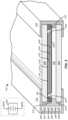
- FIG. 2shows a cross-sectional axonometric view of an example electrochromic window that includes two window panes.
- FIG. 3shows an example of a voltage profile for driving an optical state transition in an electrochromic device.
- FIG. 4shows a depiction of an example plug-in component including a window controller.
- FIG. 5 Ashows a depiction of an example transistor implementation of a pulse-width modulator circuit.
- FIG. 5 Bshows a depiction of an equivalent H-bridge configuration representation of the pulse-width modulator circuit of FIG. 5 A .
- FIG. 5 Cshows voltage profiles for the configurations of FIGS. 5 A and 5 B .
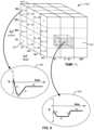
- FIG. 6shows an example 3-dimensional data structure including drive parameters for driving an electrochromic device.
- electrochromic windowsalso referred to as smart windows
- the concepts disclosed hereinmay apply to other types of switchable optical devices including, for example, liquid crystal devices and suspended particle devices, among others.
- a liquid crystal device or a suspended particle devicerather than an electrochromic device, could be incorporated into some or all of the disclosed embodiments.
- some embodimentsrelate to a system, 100 , for controlling and driving (e.g., selectively powering) a plurality of electrochromic windows, 102 .
- System 100adapted for use in a building, 104 , is used for controlling and driving a plurality of exterior facing electrochromic windows 102 .
- Some embodimentsfind particularly advantageous use in buildings such as commercial office buildings or residential buildings. Some embodiments can be particularly suited and adapted for use in the construction of new buildings.
- system 100are designed to work in conjunction with modern or novel heating, ventilation, and air conditioning (HVAC) systems, 106 , interior lighting systems, 107 , security systems, 108 , and power systems, 109 , as a single holistic efficient energy control system for the entire building 104 , or campus of buildings 104 .
- HVACheating, ventilation, and air conditioning
- Some embodimentsare particularly well-suited for integration with a building management system (BMS), 110 .
- BMSis a computer-based control system that can be installed in a building to monitor and control the building's mechanical and electrical equipment such as HVAC systems, lighting systems, power systems, elevators, fire systems, and security systems.
- a BMSconsists of hardware and associated firmware or software for maintaining conditions in the building according to preferences set by the occupants or a building manager or other administrator.
- the softwarecan be based on, for example, internet protocols or open standards.
- a BMSis typically used in large buildings, and typically functions at least to control the environment within the building.
- a BMSmay control lighting, temperature, carbon dioxide levels, and humidity within a building.
- mechanical or electrical devicesthat are controlled by a BMS such as, for example, heaters, air conditioners, blowers, and vents.
- a BMSmay turn on and off these various devices according to pre-defined rules or in response to pre-defined conditions.
- a core function of a typical modern BMSis to maintain a comfortable environment for the building's occupants while minimizing heating and cooling energy losses and costs.
- a modern BMScan be used not only to monitor and control, but also to optimize the synergy between various systems, for example, to conserve energy and lower building operation costs.
- Some embodimentsare alternatively or additionally designed to work responsively or reactively based on feedback sensed through, for example, thermal, optical, or other sensors or through input from, for example, an HVAC or interior lighting system, or an input from a user control.
- Some embodimentsalso can be utilized in existing structures, including both commercial and residential structures, having traditional or conventional HVAC or interior lighting systems. Some embodiments also can be retrofitted for use in older residential homes.
- system 100includes a network controller, 112 .
- network controller 112controls a plurality of window controllers, 114 .
- network controller 112can control tens, hundreds, or even thousands of window controllers 114 .
- Each window controller 114can control and drive one or more electrochromic windows 102 .
- the number and size of the electrochromic windows 102 that each window controller 114 can driveis generally limited by the voltage and current characteristics of the load on the window controller 114 controlling the respective electrochromic windows 102 .
- the maximum window size that each window controller 114 can driveis limited by the voltage, current, or power requirements to cause the desired optical transitions in the electrochromic window 102 within a desired time-frame.
- Such requirementsare, in turn, a function of the surface area of the window.
- this relationshipis nonlinear.
- the voltage, current, or power requirementscan increase nonlinearly with the surface area of the electrochromic window 102 .
- the relationshipis nonlinear at least in part because the sheet resistance of the first and second conductive layers 230 and 238 (see FIG. 2 ) increases nonlinearly with distance across the length and width of the first or second conductive layers.
- the relationship between the voltage, current, or power requirements required to drive multiple electrochromic windows 102 of equal size and shapeis, however, directly proportional to the number of the electrochromic windows 102 being driven.
- each electrochromic window 102will be referred to as an insulated glass unit (IGU) 102 .
- IGUinsulated glass unit
- This conventionis assumed, for example, because it is common and can be desirable to have IGUs serve as the fundamental construct for holding an electrochromic lite or pane. Additionally, IGUs, especially those having double or triple pane window configurations, offer superior thermal insulation over single pane configurations. However, this convention is for convenience only because, as described below, in many implementations the basic unit of an electrochromic window can be considered to include a pane or substrate of transparent material, upon which an electrochromic coating or device is deposited, and to which associated electrical connections are coupled to power the electrochromic coating or device.
- FIG. 2shows a cross-sectional axonometric view of an embodiment of an IGU 102 that includes two window panes, 216 .
- each IGU 102can include one, two, or more substantially transparent (e.g., at no applied voltage) window panes 216 as well as a frame, 218 , that supports the panes 216 .
- the IGU 102 shown in FIG. 2is configured as a double-pane window.
- One or more of the panes 216can itself be a laminate structure of two, three, or more layers or panes (e.g., shatter-resistant glass similar to automotive windshield glass).
- At least one of the panes 216includes an electrochromic device or stack, 220 , disposed on at least one of its inner surface, 222 , or outer surface, 224 : for example, the inner surface 222 of the outer pane 216 .
- each adjacent set of panes 216can have a volume, 226 , disposed between them.
- each of the panes 216 and the IGU 102 as a wholeare rectangular and form a rectangular solid.
- other shapese.g., circular, elliptical, triangular, curvilinear, convex, concave
- the volume 226 between the panes 116is evacuated of air.
- the IGU 102is hermetically-sealed.
- the volume 226can be filled (to an appropriate pressure) with one or more gases, such as argon (Ar), krypton (Kr), or xenon (Xn), for example. Filling the volume 226 with a gas such as Ar, Kr, or Xn can reduce conductive heat transfer through the IGU 102 because of the low thermal conductivity of these gases. The latter two gases also can impart improved acoustic insulation due to their increased weight.
- gasessuch as argon (Ar), krypton (Kr), or xenon (Xn)
- frame 218is constructed of one or more pieces.
- frame 218can be constructed of one or more materials such as vinyl, PVC, aluminum (Al), steel, or fiberglass.
- the frame 218may also include or hold one or more foam or other material pieces that work in conjunction with frame 218 to separate the window panes 216 and to hermetically seal the volume 226 between the panes 216 .
- a spacerlies between adjacent panes 216 and forms a hermetic seal with the panes in conjunction with an adhesive sealant that can be deposited between them. This is termed the primary seal, around which can be fabricated a secondary seal, typically of an additional adhesive sealant.
- frame 218can be a separate structure that supports the IGU construct.
- Each pane 216includes a substantially transparent or translucent substrate, 228 .
- substrate 228has a first (e.g., inner) surface 222 and a second (e.g., outer) surface 224 opposite the first surface 222 .
- substrate 228can be a glass substrate.
- substrate 228can be a conventional silicon oxide (SO x )-based glass substrate such as soda-lime glass or float glass, composed of, for example, approximately 75% silica (SiO 2 ) plus Na 2 O, CaO, and several minor additives.
- SO xsilicon oxide
- SiO 2silica
- Na 2 O, CaOCaO
- any material having suitable optical, electrical, thermal, and mechanical propertiesmay be used as substrate 228 .
- Such substratesalso can include, for example, other glass materials, plastics and thermoplastics (e.g., poly(methyl methacrylate), polystyrene, polycarbonate, allyl diglycol carbonate, SAN (styrene acrylonitrile copolymer), poly(4-methyl-1-pentene), polyester, polyamide), or mirror materials.
- substrate 228can be strengthened, e.g., by tempering, heating, or chemically strengthening. In other implementations, the substrate 228 is not further strengthened, e.g., the substrate is untempered.
- substrate 228is a glass pane sized for residential or commercial window applications. The size of such a glass pane can vary widely depending on the specific needs of the residence or commercial enterprise.
- substrate 228can be formed of architectural glass.
- Architectural glassis typically used in commercial buildings, but also can be used in residential buildings, and typically, though not necessarily, separates an indoor environment from an outdoor environment.
- a suitable architectural glass substratecan be at least approximately 20 inches by approximately 20 inches, and can be much larger, for example, approximately 80 inches by approximately 120 inches, or larger.
- Architectural glassis typically at least about 2 millimeters (mm) thick and may be as thick as 6 mm or more.
- electrochromic devices 220can be scalable to substrates 228 smaller or larger than architectural glass, including in any or all of the respective length, width, or thickness dimensions.
- substrate 228has a thickness in the range of approximately 1 mm to approximately 10 mm.
- Electrochromic device 220is disposed over, for example, the inner surface 222 of substrate 228 of the outer pane 216 (the pane adjacent the outside environment). In some other embodiments, such as in cooler climates or applications in which the IGUs 102 receive greater amounts of direct sunlight (e.g., perpendicular to the surface of electrochromic device 220 ), it may be advantageous for electrochromic device 220 to be disposed over, for example, the inner surface (the surface bordering the volume 226 ) of the inner pane adjacent the interior environment.
- electrochromic device 220includes a first conductive layer (CL) 230 , an electrochromic layer (EC) 232 , an ion conducting layer (IC) 234 , a counter electrode layer (CE) 236 , and a second conductive layer (CL) 238 .
- layers 230 , 232 , 234 , 236 , and 238are also collectively referred to as electrochromic stack 220 .
- a power source 240 operable to apply an electric potential across a thickness of electrochromic stack 220effects the transition of the electrochromic device 220 from, for example, a bleached or lighter state (e.g., a transparent, semitransparent, or translucent state) to a colored or darker state (e.g., a tinted, less transparent or less translucent state).
- a bleached or lighter statee.g., a transparent, semitransparent, or translucent state
- a colored or darker statee.g., a tinted, less transparent or less translucent state.
- the order of layers 230 , 232 , 234 , 236 , and 238can be reversed or otherwise reordered or rearranged with respect to substrate 238 .
- first conductive layer 230 and second conductive layer 238is formed from an inorganic and solid material.
- first conductive layer 230can be made from a number of different materials, including conductive oxides, thin metallic coatings, conductive metal nitrides, and composite conductors, among other suitable materials.
- conductive layers 230 and 238are substantially transparent at least in the range of wavelengths where electrochromism is exhibited by the electrochromic layer 232 .
- Transparent conductive oxidesinclude metal oxides and metal oxides doped with one or more metals.
- metal oxides and doped metal oxides suitable for use as first or second conductive layers 230 and 238can include indium oxide, indium tin oxide (ITO), doped indium oxide, tin oxide, doped tin oxide, zinc oxide, aluminum zinc oxide, doped zinc oxide, ruthenium oxide, doped ruthenium oxide, among others.
- First and second conductive layers 230 and 238also can be referred to as “transparent conductive oxide” (TCO) layers.
- TEC GlassTMis, for example, a glass coated with a fluorinated tin oxide conductive layer.
- first or second conductive layers 230 and 238can each be deposited by physical vapor deposition processes including, for example, sputtering. In some embodiments, first and second conductive layers 230 and 238 can each have a thickness in the range of approximately 0.01 ⁇ m to approximately 1 ⁇ m. In some embodiments, it may be generally desirable for the thicknesses of the first and second conductive layers 230 and 238 as well as the thicknesses of any or all of the other layers described below to be individually uniform with respect to the given layer; that is, that the thickness of a given layer is uniform and the surfaces of the layer are smooth and substantially free of defects or other ion traps.
- a primary function of the first and second conductive layers 230 and 238is to spread an electric potential provided by a power source 240 , such as a voltage or current source, over surfaces of the electrochromic stack 220 from outer surface regions of the stack to inner surface regions of the stack, with relatively little Ohmic potential drop from the outer regions to the inner regions (e.g., as a result of a sheet resistance of the first and second conductive layers 230 and 238 ).
- a power source 240such as a voltage or current source
- bus bars 242 and 244one (e.g., bus bar 242 ) in contact with conductive layer 230 and one (e.g., bus bar 244 ) in contact with conductive layer 238 provide electric connection between the voltage or current source 240 and the conductive layers 230 and 238 .
- bus bar 242can be electrically coupled with a first (e.g., positive) terminal 246 of power source 240 while bus bar 244 can be electrically coupled with a second (e.g., negative) terminal 248 of power source 240 .
- IGU 102includes a plug-in component 250 .
- plug-in component 250includes a first electrical input 252 (e.g., a pin, socket, or other electrical connector or conductor) that is electrically coupled with power source terminal 246 via, for example, one or more wires or other electrical connections, components, or devices.
- plug-in component 250can include a second electrical input 254 that is electrically coupled with power source terminal 248 via, for example, one or more wires or other electrical connections, components, or devices.
- first electrical input 252can be electrically coupled with bus bar 242 , and from there with first conductive layer 230
- second electrical input 254can be coupled with bus bar 244 , and from there with second conductive layer 238
- the conductive layers 230 and 238also can be connected to power source 240 with other conventional means as well as according to other means described below with respect to window controller 114 .
- first electrical input 252can be connected to a first power line while second electrical input 254 can be connected to a second power line.
- third electrical input 256can be coupled to a device, system, or building ground.
- fourth and fifth electrical inputs/outputs 258 and 260respectively, can be used for communication between, for example, window controller 114 , or microcontroller 274 , and network controller 112 , as described below.
- electrochromic layer 232is deposited or otherwise formed over first conductive layer 230 .
- electrochromic layer 232is formed of an inorganic and solid material.
- electrochromic layer 232can include or be formed of one or more of a number of electrochromic materials, including electrochemically cathodic or electrochemically anodic materials.
- metal oxides suitable for use as electrochromic layer 232can include tungsten oxide (WO 3 ), molybdenum oxide (MoO 3 ), niobium oxide (Nb 2 O 5 ), titanium oxide (TiO 2 ), copper oxide (CuO), iridium oxide (Ir 2 O 3 ), chromium oxide (Cr 2 O 3 ), manganese oxide (Mn 2 O 3 ), vanadium oxide (V 2 O 5 ), nickel oxide (Ni 2 O 3 ), and cobalt oxide (Co 2 O 3 ), among other materials.
- electrochromic layer 232can have a thickness in the range of approximately 0.05 ⁇ m to approximately 1 ⁇ m.
- electrochromic layer 232transfers or exchanges ions to or from counter electrode layer 236 resulting in the desired optical transitions in electrochromic layer 232 , and in some embodiments, also resulting in an optical transition in counter electrode layer 236 .
- the choice of appropriate electrochromic and counter electrode materialsgoverns the relevant optical transitions.
- counter electrode layer 236is formed of an inorganic and solid material.
- Counter electrode layer 236can generally include one or more of a number of materials or material layers that can serve as a reservoir of ions when the electrochromic device 220 is in, for example, the transparent state.
- suitable materials for the counter electrode layer 236include nickel oxide (NiO), nickel tungsten oxide (NiWO), nickel vanadium oxide, nickel chromium oxide, nickel aluminum oxide, nickel manganese oxide, nickel magnesium oxide, chromium oxide (Cr 2 O 3 ), manganese oxide (MnO 2 ), and Prussian blue.
- counter electrode layer 236can have a thickness in the range of approximately 0.05 ⁇ m to approximately 1 ⁇ m.
- counter electrode layer 236is a second electrochromic layer of opposite polarity as electrochromic layer 232 .
- electrochromic layer 232is formed from an electrochemically cathodic material
- counter electrode layer 236can be formed of an electrochemically anodic material.
- counter electrode layer 236transfers all or a portion of the ions it holds to electrochromic layer 232 , causing the optical transition in the electrochromic layer 232 .
- the counter electrode layer 236also optically transitions with the loss of ions it has transferred to the electrochromic layer 232 .
- a counter electrode layer 236 made of NiWOe.g., ions are transported from the counter electrode layer 236 to the electrochromic layer 232
- the counter electrode layer 236will transition in the opposite direction (e.g., from a transparent state to a darkened state).
- ion conducting layer 234serves as a medium through which ions are transported (e.g., in the manner of an electrolyte) when the electrochromic device 220 transitions between optical states.
- ion conducting layer 234is highly conductive to the relevant ions for the electrochromic and the counter electrode layers 232 and 236 , but also has sufficiently low electron conductivity such that negligible electron transfer occurs during normal operation.
- a thin ion conducting layer 234 with high ionic conductivitypermits fast ion conduction and hence fast switching for high performance electrochromic devices 220 .
- ion conducting layer 234can have a thickness in the range of approximately 0.01 ⁇ m to approximately 1 ⁇ m.
- ion conducting layer 234also is inorganic and solid.
- ion conducting layer 234can be formed from one or more silicates, silicon oxides, tungsten oxides, tantalum oxides, niobium oxides, and borates.
- the silicon oxidesinclude silicon-aluminum-oxide. These materials also can be doped with different dopants, including lithium. Lithium-doped silicon oxides include lithium silicon-aluminum-oxide.
- the electrochromic and the counter electrode layers 232 and 236are formed immediately adjacent one another, sometimes in direct contact, without separately depositing an ion conducting layer.
- electrochromic deviceshaving an interfacial region between first and second conductive electrode layers rather than a distinct ion conducting layer 234 can be utilized. Such devices, and methods of fabricating them, are described in U.S. patent application Ser. Nos. 12/772,055 and 12/772,075, each filed 30 Apr. 2010, and in U.S. patent application Ser. Nos. 12/814,277 and 12/814,279, each filed 11 Jun. 2010, all four of which are titled ELECTROCHROMIC DEVICES and name Zhongchun Wang et al. as inventors. Each of these four applications is incorporated by reference herein in its entirety.
- electrochromic device 220also can include one or more additional layers (not shown), such as one or more passive layers.
- passive layers used to improve certain optical propertiescan be included in or on electrochromic device 220 .
- Passive layers for providing moisture or scratch resistancealso can be included in electrochromic device 220 .
- the conductive layers 230 and 238can be treated with anti-reflective or protective oxide or nitride layers.
- Other passive layerscan serve to hermetically seal the electrochromic device 220 .
- one or more of the layers in electrochromic stack 220can contain some amount of organic material. Additionally or alternatively, in some embodiments, one or more of the layers in electrochromic stack 220 can contain some amount of liquids in one or more layers. Additionally or alternatively, in some embodiments, solid state material can be deposited or otherwise formed by processes employing liquid components such as certain processes employing sol-gels or chemical vapor deposition.
- transitions between a bleached or transparent state and a colored or opaque stateare but one example, among many, of an optical or electrochromic transition that can be implemented.
- the corresponding device or process describedencompasses other optical state transitions such as, for example, intermediate state transitions such as percent transmission (% T) to % T transitions, non-reflective to reflective transitions (or to and from intermediate states in between), bleached to colored transitions (or to and from intermediate states in between), and color to color transitions (or to and from intermediate states in between).
- the term “bleached”may refer to an optically neutral state, for example, uncolored, transparent or translucent.
- the “color” of an electrochromic transitionis not limited to any particular wavelength or range of wavelengths.
- the colorization or other optical transition of the electrochromic material in electrochromic layer 232is caused by reversible ion insertion into the material (for example, intercalation) and a corresponding injection of charge-balancing electrons.
- some fraction of the ions responsible for the optical transitionis irreversibly bound up in the electrochromic material.
- Some or all of the irreversibly bound ionscan be used to compensate “blind charge” in the material.
- suitable ionsinclude lithium ions (Li+) and hydrogen ions (H+) (i.e., protons). In some other embodiments, however, other ions can be suitable.
- Intercalation of lithium ions, for example, into tungsten oxidecauses the tungsten oxide to change from a transparent (e.g., bleached) state to a blue (e.g., colored) state.
- the electrochromic device 220reversibly cycles between a transparent state and an opaque or tinted state.
- a potentialis applied to the electrochromic stack 220 such that available ions in the stack reside primarily in the counter electrode layer 236 .
- ionsare transported back across the ion conducting layer 234 to the electrochromic layer 232 causing the electrochromic material to transition to an opaque, tinted, or darker state.
- layers 232 and 236are complementary coloring layers; that is, for example, when ions are transferred into the counter electrode layer it is not colored.
- a potentialis applied to the electrochromic stack 220 such that available ions in the stack reside primarily in the counter electrode layer 236 .
- ionsare transported back across the ion conducting layer 234 to the electrochromic layer 232 causing the electrochromic material to transition to a transparent or lighter state.
- These layersmay also be complementary coloring.
- FIG. 3shows an example of a voltage profile for driving an optical state transition in an electrochromic device (e.g., electrochromic device 220 ).
- the magnitude of the DC voltages (e.g., supplied by power source 240 ) applied to an electrochromic device 220may depend in part on the thickness of the electrochromic stack and the size (e.g., surface area) of the electrochromic device 220 .
- a voltage profile 300can include the following sequence of applied voltage or current parameters for driving electrochromic device 220 from a first state to a colored state, and from a colored state to a bleached state: a negative ramp 301 , a negative hold 303 , a positive ramp 305 , a negative hold 307 , a positive ramp 309 , a positive hold 311 , a negative ramp 313 , and a positive hold 315 .
- the voltageremains constant during the length of time that the device remains in its defined optical state, e.g., in negative hold 307 or positive hold 315 .
- Negative ramp 301drives the device to the colored or opaque state (or an intermediate partially transparent state) and negative hold 307 maintains the device in the transitioned-to state for a desired period of time.
- negative hold 303may be applied for a specified duration of time or until another condition is met, such as a desired amount of ionic charge being passed sufficient to cause the desired change in coloration, for example.
- Positive ramp 305increases the voltage from the maximum magnitude negative voltage (e.g., negative hold 303 ) to the smaller magnitude negative voltage (e.g., negative hold 307 ) used to hold the desired optical state.
- first negative ramp 301and a first negative hold voltage 303 at this peak negative voltage
- first negative hold voltage 303at this peak negative voltage
- the second negative hold voltage 307effectively serves to counteract the voltage drop that would otherwise result from the leakage current. As the leakage current is reduced for any given electrochromic device 220 , the hold voltage required to hold the desired optical transition can approach zero.
- positive ramp 309drives the transition of the electrochromic device from the colored or opaque state (or an intermediate less transparent state) to the bleached or transparent state (or an intermediate more transparent state).
- Positive hold 315maintains the device in the transitioned-to state for a desired period of time.
- positive hold 311may be applied for a specified duration of time or until another condition is met, such as a desired amount of ionic charge being passed sufficient to cause the desired change in coloration, for example.
- Negative ramp 313decreases the voltage from the maximum magnitude positive voltage (e.g., positive hold 311 ) to the smaller magnitude positive voltage (e.g., positive hold 315 ) used to hold the desired optical state.
- first positive ramp 309and a first positive hold voltage 311 at this peak positive voltage
- the second positive hold voltage 315effectively serves to counteract the voltage drop that would otherwise result from the leakage current. As the leakage current is reduced for any given electrochromic device 220 , the hold voltage required to hold the desired optical transition can approach zero.
- the rate of the optical transitioncan be a function of not only the applied voltage, but also the temperature and the voltage ramping rate. For example, since both voltage and temperature affect lithium ion diffusion, the amount of charge passed (and hence the intensity of the ionic current peak) increases with voltage and temperature. Additionally, because voltage and temperature are interdependent, this implies that a lower voltage can be used at higher temperatures to attain the same transition rate as a higher voltage at lower temperatures. This temperature response can be exploited in a voltage-based switching algorithm as described below. The temperature is used to determine which voltage to apply in order to effect rapid transitioning without damaging the device.
- electrical input 252 and electrical input 254receive, carry, or transmit complementary power signals.
- electrical input 252 and its complement electrical input 254can be directly connected to the bus bars 242 and 244 , respectively, and on the other side, to an external power source that provides a variable DC voltage (e.g., sign and magnitude).
- the external power sourcecan be window controller 114 itself, or power from building 104 transmitted to window controller 114 or otherwise coupled to electrical inputs 252 and 254 .
- the electrical signals transmitted through electrical inputs/outputs 258 and 260can be directly connected to memory device 292 , described below, to allow communication between window controller 114 and memory device 292 .
- the electrical signal input to electrical input 256can be internally connected or coupled (within IGU 102 ) to either electrical input 252 or 254 or to the bus bars 242 or 244 in such a way as to enable the electrical potential of one or more of those elements to be remotely measured (sensed). This can allow window controller 114 to compensate for a voltage drop on the connecting wires from the window controller 114 to the electrochromic device 220 .
- the window controller 114can be immediately attached (e.g., external to the IGU 102 but inseparable by the user) or integrated within the IGU 102 .
- the window controller 114can be immediately attached (e.g., external to the IGU 102 but inseparable by the user) or integrated within the IGU 102 .
- U.S. patent application Ser. No. 13/049,750 naming Brown et al. as inventors, titled ONBOARD CONTROLLER FOR MULTISTATE WINDOWS and filed 16 Mar. 2011, incorporated by reference hereindescribes in detail various embodiments of an “onboard” controller.
- electrical input 252can be connected to the positive output of an external DC power source.
- electrical input 254can be connected to the negative output of the DC power source.
- electrical inputs 252 and 254can, alternately, be connected to the outputs of an external low voltage AC power source (e.g., a typical 24 V AC transformer common to the HVAC industry).
- electrical inputs/outputs 258 and 260can be connected to the communication bus between window controller 114 and the network controller 112 as described below.
- electrical input/output 256can be eventually (e.g., at the power source) connected with the earth ground (e.g., Protective Earth, or PE in Europe) terminal of the system.
- the voltages plotted in FIG. 3are expressed as DC voltages, in some embodiments, the voltages actually supplied by the external power source are AC voltage signals. In some other embodiments, the supplied voltage signals are converted to pulse-width modulated voltage signals. However, as described below with reference to FIG. 4 , the voltages actually “seen” or applied to the bus bars 242 and 244 are effectively DC voltages.
- the frequency of the oscillations of the applied voltage signalcan depend on various factors including the leakage current of the electrochromic device 220 , the sheet resistance of the conductive layers 230 and 238 , the desired end or target state (e.g., % T), or a critical length of a part (e.g., the distance between bus bars 242 and 244 ).
- the voltage oscillations applied at terminals 246 and 248are in the range of approximately 1 Hz to 1 MHz, and in particular embodiments, approximately 100 kHz.
- the amplitude of the oscillationsalso can depend on numerous factors including the desired level of the desired intermediate target state. However, in some example applications, the amplitude of the applied voltage oscillations can be in the range of approximately 0 volts (V) to 24 V while, as described below, the amplitude of the DC voltage actually applied to bus bars 242 and 244 can be in the range of approximately 0.01 V and 10 V, and in some applications, in the range of approximately 0.5 V and 3 V.
- the oscillationshave asymmetric residence times for the darkening (e.g., tinting) and lightening (e.g., bleaching) portions of a period.
- darkeninge.g., tinting
- lighteninge.g., bleaching
- transitioning from a first less transparent state to a second more transparent staterequires more time than the reverse; that is, transitioning from the more transparent second state to the less transparent first state.
- a controllercan be designed or configured to apply a driving voltage meeting these requirements.
- the oscillatory applied voltage controlallows the electrochromic device 220 to operate in, and transition to and from, one or more intermediate states without any necessary modification to the electrochromic device stack 220 or to the transitioning time.
- window controller 114can be configured or designed to provide an oscillating drive voltage of appropriate wave profile, taking into account such factors as frequency, duty cycle, mean voltage, amplitude, among other possible suitable or appropriate factors.
- a level of controlpermits the transitioning to any intermediate state over the full range of optical states between the two end states.
- an appropriately configured controllercan provide a continuous range of transmissivity (% T) which can be tuned to any value between end states (e.g., opaque and bleached end states).
- a controllercould simply apply the appropriate intermediate voltage.
- high driving voltagescan be applied to reach the end states but are traditionally not applied to reach an intermediate state.
- One technique for increasing the rate at which the electrochromic device 220 reaches a desired intermediate stateis to first apply a high voltage pulse suitable for full transition (to an end state) and then back off to the voltage of the oscillating intermediate state (just described). Stated another way, an initial low frequency single pulse (low in comparison to the frequency employed to maintain the intermediate state) of magnitude and duration chosen for the intended final state can be employed to speed the transition. After this initial pulse, a higher frequency voltage oscillation can be employed to sustain the intermediate state for as long as desired.
- each IGU 102includes a plug-in component 250 that in some embodiments is “pluggable” or readily-removable from IGU 102 (e.g., for ease of maintenance, manufacture, or replacement).
- each plug-in component 250itself includes a window controller 114 . That is, in some such embodiments, each electrochromic device 220 is controlled by its own respective local window controller 114 located within plug-in component 250 .
- window controller 114is integrated with another portion of frame 218 , between the glass panes in the secondary seal area, or within volume 226 . In some other embodiments, window controller 114 can be located external to IGU 102 .
- each window controller 114can communicate with the IGUs 102 it controls and drives, as well as communicate to other window controllers 114 , network controller 112 , BMS 110 , or other servers, systems, or devices (e.g., sensors), via one or more wired (e.g., Ethernet) networks or wireless (e.g., WiFi) networks, for example, via wired (e.g., Ethernet) interface 263 or wireless (WiFi) interface 265 .
- wired (e.g., Ethernet) interface 263 or wireless (WiFi) interface 265e.g., Ethernet interface 263 or wireless (WiFi) interface 265 .
- Ethernet or Wifi capabilitiesare also well-suited for use in residential homes and other smaller-scale non-commercial applications.
- the communicationcan be direct or indirect, e.g., via an intermediate node between a master controller such as network controller 112 and the IGU 102 .
- FIG. 4shows a depiction of an example plug-in component 250 including a window controller 114 .
- window controller 114communicates with network controller 112 over a communication bus 262 .
- communication bus 262can be designed according to the Controller Area Network (CAN) vehicle bus standard.
- first electrical input 252can be connected to a first power line 264 while second electrical input 254 can be connected to a second power line 266 .
- the power signals sent over power lines 264 and 266are complementary; that is, collectively they represent a differential signal (e.g., a differential voltage signal).
- line 268is coupled to a system or building ground (e.g., an Earth Ground).
- communication over CAN bus 262may proceed along first and second communication lines 270 and 272 transmitted through electrical inputs/outputs 258 and 260 , respectively, according to the CANopen communication protocol or other suitable open, proprietary, or overlying communication protocol.
- the communication signals sent over communication lines 270 and 272are complementary; that is, collectively they represent a differential signal (e.g., a differential voltage signal).
- plug-in component 250couples CAN communication bus 262 into window controller 114 , and in particular embodiments, into microcontroller 274 .
- microcontroller 274is also configured to implement the CANopen communication protocol.
- Microcontroller 274is also designed or configured (e.g., programmed) to implement one or more drive control algorithms in conjunction with pulse-width modulated amplifier or pulse-width modulator (PWM) 276 , smart logic 278 , and signal conditioner 280 .
- PWMpulse-width modulated amplifier or pulse-width modulator
- microcontroller 274is configured to generate a command signal V COMMAND , e.g., in the form of a voltage signal, that is then transmitted to PWM 276 .
- PWM 276in turn, generates a pulse-width modulated power signal, including first (e.g., positive) component V PW1 and second (e.g., negative) component V PW2 , based on V COMMAND .
- Power signals V PW1 and V PW2are then transmitted over, for example, interface 288 , to IGU 102 , or more particularly, to bus bars 242 and 244 in order to cause the desired optical transitions in electrochromic device 220 .
- PWM 276is configured to modify the duty cycle of the pulse-width modulated signals such that the durations of the pulses in signals V PW1 and V PW2 are not equal: for example, PWM 276 pulses V PW1 with a first 60% duty cycle and pulses V PW2 for a second 40% duty cycle. The duration of the first duty cycle and the duration of the second duty cycle collectively represent the duration, t PWM of each power cycle. In some embodiments, PWM 276 can additionally or alternatively modify the magnitudes of the signal pulses V PW1 and V PW2 .
- microcontroller 274is configured to generate V COMMAND based on one or more factors or signals such as, for example, any of the signals received over CAN bus 262 as well as voltage or current feedback signals, V FB and I FB respectively, generated by PWM 276 .
- microcontroller 274determines current or voltage levels in the electrochromic device 220 based on feedback signals I FB or V FB , respectively, and adjusts V COMMAND according to one or more rules or algorithms to effect a change in the relative pulse durations (e.g., the relative durations of the first and second duty cycles) or amplitudes of power signals V PW1 and V PW2 to produce the voltage profiles described above with respect to FIG. 3 .
- microcontroller 274can also adjust V COMMAND in response to signals received from smart logic 278 or signal conditioner 280 .
- a conditioning signal V CONcan be generated by signal conditioner 280 in response to feedback from one or more networked or non-networked devices or sensors, such as, for example, an exterior photosensor or photodetector 282 , an interior photosensor or photodetector 284 , a thermal or temperature sensor 286 , or a tint command signal V TC .
- additional embodiments of signal conditioner 280 and V CONare also described in U.S.
- V TCcan be an analog voltage signal between 0 V and 10 V that can be used or adjusted by users (such as residents or workers) to dynamically adjust the tint of an IGU 102 (for example, a user can use a control in a room or zone of building 104 similarly to a thermostat to finely adjust or modify a tint of the IGUs 102 in the room or zone) thereby introducing a dynamic user input into the logic within microcontroller 274 that determines V COMMAND .
- userssuch as residents or workers
- V TCwhen set in the 0 to 2.5 V range, V TC can be used to cause a transition to a 5% T state, while when set in the 2.51 to 5 V range, V TC can be used to cause a transition to a 20% T state, and similarly for other ranges such as 5.1 to 7.5 V and 7.51 to 10 V, among other range and voltage examples.
- signal conditioner 280receives the aforementioned signals or other signals over a communication bus or interface 290 .
- PWM 276also generates V COMMAND based on a signal V SMART received from smart logic 278 , as described below.
- smart logic 278transmits V SMART over a communication bus such as, for example, an Inter-Integrated Circuit (I 2 C) multi-master serial single-ended computer bus.
- smart logic 278communicates with memory device 292 over a 1-WIRE device communications bus system protocol (by Dallas Semiconductor Corp., of Dallas, Tex.).
- microcontroller 274includes a processor, chip, card, or board, or a combination of these, which includes logic for performing one or more control functions. Power and communication functions of microcontroller 274 may be combined in a single chip, for example, a programmable logic device (PLD) chip or field programmable gate array (FPGA), or similar logic. Such integrated circuits can combine logic, control and power functions in a single programmable chip.
- PLDprogrammable logic device
- FPGAfield programmable gate array
- Such integrated circuitscan combine logic, control and power functions in a single programmable chip.
- the logiccan be configured to control each of the two electrochromic devices 220 independently from the other.
- each of the two electrochromic devices 220is controlled in a synergistic fashion, for example, such that each device is controlled in order to complement the other.
- the desired level of light transmission, thermal insulative effect, or other propertycan be controlled via a combination of states for each of the individual electrochromic devices 220 .
- one electrochromic devicemay be placed in a colored state while the other is used for resistive heating, for example, via a transparent electrode of the device.
- the optical states of the two electrochromic devicesare controlled so that the combined transmissivity is a desired outcome.
- microcontroller 274or window controller 114 generally, also can have wireless capabilities, such as wireless control and powering capabilities.
- wireless control signalssuch as radio-frequency (RF) signals or infra-red (IR) signals can be used, as well as wireless communication protocols such as WiFi (mentioned above), Bluetooth, Zigbee, EnOcean, among others, to send instructions to the microcontroller 274 and for microcontroller 274 to send data out to, for example, other window controllers 114 , network controller 112 , or directly to BMS 110 .
- RFradio-frequency
- IRinfra-red
- wireless communicationcan be used for at least one of programming or operating the electrochromic device 220 , collecting data or receiving input from the electrochromic device 220 or the IGU 102 generally, collecting data or receiving input from sensors, as well as using the window controller 114 as a relay point for other wireless communications.
- Data collected from IGU 102also can include count data, such as a number of times an electrochromic device 220 has been activated (cycled), an efficiency of the electrochromic device 220 over time, among other useful data or performance metrics.
- Window controller 114also can have wireless power capability.
- window controller 114can have one or more wireless power receivers that receive transmissions from one or more wireless power transmitters as well as one or more wireless power transmitters that transmit power transmissions enabling window controller 114 to receive power wirelessly and to distribute power wirelessly to electrochromic device 220 .
- Wireless power transmissionincludes, for example, induction, resonance induction, RF power transfer, microwave power transfer, and laser power transfer.
- U.S. patent application Ser. No. 12/971,576 naming Rozbicki as inventor, titled WIRELESS POWERED ELECTROCHROMIC WINDOWS and filed 17 Dec. 2010, incorporated by reference hereindescribes in detail various embodiments of wireless power capabilities.
- the pulse-width modulated power signalis generated such that the positive component V PW1 is supplied to, for example, bus bar 244 during the first portion of the power cycle, while the negative component V PW2 is supplied to, for example, bus bar 242 during the second portion of the power cycle.
- the signals V PW1 and V PW2are effectively DC signals as seen by electrochromic device 220 as a result of, for example, the inductance of series inductors 312 and 314 (see FIGS. 5 A and 5 B ) within PWM 276 , or of various other components of window controller 114 or electrochromic device 220 in relation to the frequency of the pulse-width modulated power signals V PW1 and V PW2 .
- the inductanceis such that the inductors 312 and 314 effectively filter out the highest frequency components in the voltages V TEC and VITO, the voltages applied to the first and second conductive layers 230 and 238 , respectively, and thus the effective voltage V EFF applied across the bus bars 242 and 244 is effectively constant when the first and second duty cycles are constant.
- bus bar 244floating at substantially the fraction of the magnitude of V PW1 that is given by the ratio of the duration of the first duty cycle to the total duration t PWM of the power cycle.
- bus bar 242floating at substantially the fraction of the magnitude of V PW2 that is given by the ratio of the duration of the second duty cycle to the total duration t PWM of the power cycle.
- the difference between the magnitudes of the pulse-width modulated signal components V PW1 and V PW2is twice the effective DC voltage across terminals 246 and 248 , and consequently, across electrochromic device 220 .
- the difference between the fraction (determined by the relative duration of the first duty cycle) of V PW1 applied to bus bar 244 and the fraction (determined by the relative duration of the second duty cycle) of V PW2 applied to bus bar 242is the effective DC voltage V EFF applied to electrochromic device 220 .
- the current IEFF through the load—electromagnetic device 220is roughly equal to the effective voltage V EFF divided by the effective resistance (represented by resistor 316 ) or impedance of the load.
- PWM 276 , and IGU 102in order to generate the two opposing polarity signals V PW1 and V PW2 , PWM 276 , and IGU 102 generally, is designed according to an H-bridge configuration 294 .
- PWM 276is constructed using four transistors 296 , 298 , 300 , and 302 powered by a supply voltage V SUPPLY as shown in FIG. 5 A .
- Transistors 296 , 298 , 300 , and 302can be, for example, metal-oxide-semiconductor field-effect transistors (MOSFETs).
- MOSFETsmetal-oxide-semiconductor field-effect transistors
- transistors 296 and 300are n-type MOSFET transistors while transistors 298 and 302 are p-type MOSFET transistors.
- the gate of transistor 296receives signal A
- the gate of transistor 302receives its complement ⁇ such that when signal A is high ⁇ is low, and thus, transistors 296 and 302 are conducting while transistors 298 and 300 are not.
- FIG. 5 Bshows a depiction of an equivalent H-bridge configuration representation 294 in which switches 304 , 306 , 308 , and 310 represent transistors 296 , 298 , 300 , and 302 .
- H-Bridge 294synchronously transitions from a first state (represented by solid arrows), to generate the first duty cycle (V PW1 pulse), to a second state (represented by dotted arrows), to generate the second duty cycle (V PW2 pulse).
- the switches 304 and 310can be closed (e.g., transistors 296 and 302 are conducting) and switches 306 and 308 can be open (e.g., transistors 298 and 300 are not conducting).
- switches 306 and 308can be closed (e.g., transistors 298 and 300 are conducting) and switches 304 and 310 can be open (e.g., transistors 296 and 302 are not conducting).
- the first and second duty cycles of the pulse-width modulated signals V PW1 and V PW2are not symmetric; that is, neither the first nor the second duty cycle is a 50% duty cycle.
- V PW1could be pulsed for more than half the time constant t PWM (e.g., more than 5 micro-seconds ( ⁇ s)) followed by V PW2 being pulsed for less than half the time constant t PWM (e.g., less than 5 ⁇ s), and so on resulting in a first duty cycle of greater than 50% and a second duty cycle of less than 50%.
- t PWMtime constant
- t PWMtime constant
- the effective voltage at the loade.g., electrochromic device 220
- the duty cyclesare symmetric (e.g., (V PW1 ⁇ V PW2 )/2).
- a voltage rampe.g., ramps 301 , 305 , 309 , or 313
- the duty cyclesalso can be varied such that a static DC voltage is developed to compensate, for example, for ions trapped in defects.
- This method—pulse-width modulation—of applying the DC voltage across electrochromic device 220provides increased protection from damage as compared to, for example, devices that simply use a battery or other DC voltage source.
- DC voltages sourcessuch as batteries can result in initial current spikes that can permanently damage the electrochromic device 220 in the form of, for example, defects that trap ions.
- the command signal V COMMANDcan be used to change the applied DC voltage at the electrochromic device 220 (e.g., to produce ramps 301 , 305 , 309 , and 313 ) continuously without changing the magnitude of the supply voltage V SUPPLY .
- the transistors 296 , 298 , 300 , and 302can be configured at certain times to all be insulating (or open) enabling certain embodiments of electrochromic device 220 to hold at a desired optical state without an applied voltage.
- this configurationcan be used to save energy by not drawing power from V SUPPLY , which is typically the main electrical power for the building 104 . In such a configuration, the electrochromic device 220 could be left floating.
- the electrochromic device 220could receive power from another source to hold the desired optical state, such as from, for example, a photovoltaic cell on or within the IGU 102 .
- the transistors 296 , 298 , 300 , and 302can be configured at certain times to all be conducting (or closed) and shorted to ground enabling a discharge of electrochromic device 220 .
- appropriately sized resistorscan be arranged within the H-bridge configuration 294 between each transistor or switch and ground to ease or to make more graceful the discharge of the electrochromic device 220 .
- microcontroller 274is programmed to darken or lighten (e.g., change the % T of) the windows on various sides, surfaces, or zones of a building 104 at certain times of day as well as according to certain times of year, according to certain conditions or in response to other feedback, or based on manual input.
- microcontroller 274can be programmed to darken east-facing IGUs 102 at 9:00 am for 1 hour during winter months while at the same time lightening west-facing IGUs.
- microcontroller 274can be programmed to darken an IGU 102 based on light intensity detected outside by a photodetector.
- microcontroller 274can be programmed to continue to darken the IGU 102 as long as light detected inside by a second photodetector remains above a threshold amount of interior light intensity, or until a lighting system 107 or network controller 112 transmits an input command to window controller 114 commanding the window controller 114 to stop tinting such that the lighting system can remain off or at a lower energy operational level while enabling workers to have enough ambient light or other light to continue working.
- microcontroller 274can be programmed to darken an IGU 102 based on a manual input from a user, for example, in his or her own office relative to a baseline % T commanded by network controller 112 .
- the drive or device parameters for a given IGU 102are stored within the IGU 102 , in the frame 218 , or in an internal or external electrical connection assembly wired to the frame or IGU.
- the drive and device parameters for the IGU 102are stored within the plug-in component 250 .
- the drive and device parametersare stored within non-volatile memory device 292 , which may be included within or be external to window controller 114 or plug-in component 250 , but which, in particular embodiments, is located within IGU 102 .
- memory device 292transfers or loads the drive or device parameters to a fast dynamic memory (e.g., a random access memory (RAM), DRAM, NVRAM, or other flash memory) location within microcontroller 274 for quick access by microcontroller 274 .
- a fast dynamic memorye.g., a random access memory (RAM), DRAM, NVRAM, or other flash memory
- window controller 114can periodically poll for memory device 292 , and when window controller 114 detects memory device 292 , it can transfer the drive parameters to the RAM or other faster memory location within microcontroller 274 .
- memory device 292can be a chip (e.g., computer chip having processing or logic capabilities in addition to storing capabilities) designed according to the 1-WIRE device communications bus system protocol.
- memory device 292can include solid state serial memory (e.g. EEPROM (E 2 PROM), I 2 C, or SPI), which can also be programmable memory.
- the drive parameterscan be used by microcontroller 274 in conjunction with one or more voltage profiles, current algorithms, or voltage and current operating instructions for transitioning electrochromic device 220 from a first optical state to a second optical state.
- microcontroller 274uses the drive parameters to calculate or select a voltage profile (e.g., a portion of voltage profile 300 ) and, using the voltage profile, to generate the associated command voltages V COMMAND to achieve the calculated or selected voltage profile.
- a voltage profilecan be selected from a number of pre-determined profiles (e.g., stored or loaded within microcontroller 274 or other suitable accessible memory location) based on one or more of a multitude of drive parameters including, for example, a current temperature outside, a current temperature inside, a % T of the first or current optical state, a % T of the second or desired optical state, or a desired transition or ramp (e.g., ramp 301 or 309 ) rate, as well as various initial driving voltages, holding voltages, among other parameters.
- a current temperature outsidee.g., stored or loaded within microcontroller 274 or other suitable accessible memory location
- drive parametersincluding, for example, a current temperature outside, a current temperature inside, a % T of the first or current optical state, a % T of the second or desired optical state, or a desired transition or ramp (e.g., ramp 301 or 309 ) rate, as well as various initial driving voltages, holding voltages, among other parameters.
- Some drive parameterscan be generated prior to manufacture of the device, for example, based theoretically or empirically on a number of device parameters including, for example, the size, shape, thickness, age, or number of cycles experienced by electrochromic pane 216 .
- each voltage profilecan, in turn, be determined theoretically or empirically prior to manufacture of the device based on the drive and device parameters.
- microcontroller 274calculates V COMMAND values during operation of IGU 102 based on the selected voltage profile and drive parameters. In some other embodiments, microcontroller 274 selects discrete V COMMAND values previously calculated and stored based on the selected voltage profile and drive parameters. However, as described above, in some cases V COMMAND can additionally be modified according to one or more other input or feedback signals, such as signals V CON , V FB , or I FB , for example, based on input from temperature sensors or photodetectors, voltage feedback from electrochromic device 220 or PWM 276 , or current feedback from electrochromic device 220 or PWM 276 .
- the microcontroller 274can be programmed to darken the electrochromic device 220 , but as the electrochromic device 220 darkens the temperature of the device can rise significantly as a result of the increased photon absorption and, because the tinting of the electrochromic device 220 is dependent on the temperature of the device, the tinting could change if not compensated for by, for example, modifying V COMMAND in response to a signal, such as V CON , V FB , or I FB .
- the voltage profiles themselves stored in the microcontroller 274 or memory device 292can be modified temporarily (e.g., in RAM) or permanently/perpetually (e.g., in memory device 292 ) based on signals received from, for example, network controller 112 .
- the drive and device parameters stored within a given IGU 102can be transmitted, for example via CAN communication bus 262 , to network controller 112 periodically, in response to certain conditions, or at other appropriate times.
- drive parameters, voltage profiles, current algorithms, location or zone membership parameterse.g. at what location or in what zone of the building 104 is this IGU 102 and controller 114 ), digital output states, and generally various digital controls (tint, bleach, auto, reboot, etc.) can be transmitted from network controller 112 to window controller 114 and microcontroller 274 as well as to memory device 292 for storage and subsequent use.
- Network controller 112also can be configured to transmit to microcontroller 274 or memory device 292 information relating to a location of the IGU 102 or building 104 (e.g., a latitude, longitude, or region parameter), a time of day, or a time of year. Additionally, the drive or device parameters can contain information specifying a maximum voltage or current level that can safely be applied to electrochromic device 220 by a window controller 114 .
- network controller 112can be programmed or configured to compare the actual current being output to a particular IGU 102 and electrochromic device 220 to the current expected to be output to the IGU 102 based on the device or drive characteristics (e.g., transmitted from the memory device 292 to the microcontroller 274 and to the network controller 112 ), or otherwise determine that they are different or different beyond a threshold range of acceptability, and thereafter signal an alarm, shut off power to the IGU 102 , or take some other action to, for example, prevent damage to the electrochromic device 220 .
- memory device 292also can include cycling or other performance data for electrochromic device 220 .
- the drive parametersare organized into an n-dimensional data array, structure, or matrix.
- FIG. 6shows an example 3-dimensional data structure 600 of drive parameters for driving an electrochromic device 220 .
- Data structure 600is a 3-by-4-by-4 matrix of elements 624 .
- a voltage profileis associated with each element 624 .
- matrix element (0, 3, 3)is associated with voltage profile 626 while matrix element (1, 0, 1) is associated with voltage profile 628 .
- each matrix element 624is specified for three drive parameters that define the element 624 and thus the corresponding voltage profile.
- each matrix element 624is specified for a given temperature range value (e.g., ⁇ 0 degrees Celsius, 0-50 degrees Celsius, or >50 degrees Celsius), a current % T value (e.g., 5%, 20%, 40%, or 70%), and a target % T value (e.g., 5%, 20%, 40%, or 70%).
- a given temperature range valuee.g., ⁇ 0 degrees Celsius, 0-50 degrees Celsius, or >50 degrees Celsius
- a current % T valuee.g., 5%, 20%, 40%, or 70%
- a target % T valuee.g., 5%, 20%, 40%, or 70%
- each voltage profileincludes one or more specific parameters (e.g., ramp rate, target voltage, and applied voltage duration) or a combination of one or more specific parameters.
- each voltage profilecan include one or more specific parameters for each of one or more profile portions or zones (e.g., S 1 , S 2 , S 3 , S 4 ) for making the desired optical transition from the current % T, at a current temperature, to a target % T at the same or a different temperature.
- voltage profile 626contains parameters to transition a electrochromic window from 70% T to 5% T, at a temperature less than zero degrees Celsius.
- voltage profile 626provides an initial ramp S 1 (e.g., a rate in mV/s for a specified time duration or to a specified target voltage value), a first hold S 2 (e.g., specified in V for a specified time duration), a second ramp S 3 (e.g., a rate in mV/s for a specified time duration or to a specified target voltage value), and a fourth hold S 4 (e.g., a specified holding voltage to maintain the target % T).
- initial ramp S 1e.g., a rate in mV/s for a specified time duration or to a specified target voltage value
- first hold S 2e.g., specified in V for a specified time duration
- a second ramp S 3e.g., a rate in mV/s for a specified time duration or to a specified target voltage value
- a fourth hold S 4e.g., a specified holding voltage to maintain the target % T.
- voltage profile 628can provide a different initial ramp S 1 (e.g., a flatter voltage ramp), a different hold S 2 (e.g., a longer hold at this holding voltage), a different second ramp S 3 (e.g., a shorter but steeper ramp), and a different fourth hold S 4 (e.g., the holding voltage to maintain the target % T) based on the different drive parameters associated with that element (in this example, transitioning from 20% T to 70% T at a temperature of between zero and fifty degrees Celsius).
- initial ramp S 1e.g., a flatter voltage ramp
- a different hold S 2e.g., a longer hold at this holding voltage
- a different second ramp S 3e.g., a shorter but steeper ramp
- a different fourth hold S 4e.g., the holding voltage to maintain the target % T
- Each voltage profile in the n-dimensional data matrixmay, in some implementations, be unique. For example, because even at the same temperature, transitioning from 70% T to 5% T often cannot be achieved by a simple reversal of the voltage profile used to transition from 5% T to 70% T, a different voltage profile may be required or at least desirable. Put another way, by virtue of the device architecture and materials, bleaching is not simply the reverse of coloring; devices often behave differently for each transition due to differences in driving forces for ion intercalation and deintercalation to and from the electrochromic materials.
- the data structurecan have another number of dimensions n, that is, be more or less granular than matrix 600 .
- more drive parameterscan be included.
- 288 drive parametersare used including three temperature range values, four current % T values, and four target % T values resulting in a 3-dimensional matrix having 36 matrix elements and 72 corresponding voltage profiles, each of which has one or more specific parameters (e.g., ramp rate, target voltage, and applied voltage duration, or a combination of one or more specific parameters) for each of one or more profile portions or zones (e.g., S 1 , S 2 , S 3 , . . . ).
- specific parameterse.g., ramp rate, target voltage, and applied voltage duration, or a combination of one or more specific parameters
- the number of temperature bins or ranges of valuescan be increased or decreased (e.g., 5 or more temperature range values), the number of possible current % T values can be increased or decreased (e.g., there could be eight possible optical states such as 5% T, 15% T, 25% T, 35% T, 45% T, 55% T, 65% T, and 75% T), the number of possible target % T values can be increased or decreased (e.g., to match the possible current % T states), among other suitable modifications.
- the voltage profiles associated with each element of the matrixmay have more than four profile portions or zones (e.g. S 1 -S 8 ) with associated parameters.
- 8 zonesare permitted to be specified for each voltage profile, 12 voltage profiles are permitted to be specified for the current ambient temperature range, and 3 sets of 12 profiles are permitted to be specified for the 3 temperature ranges specified. That combines to 288 parameters for the voltage profile alone. Additional information also can be stored within memory device 292 .
- each IGU 102can still include its own memory device 292 .
- each memory device 292transmits its drive parameters to the single window controller 114 and window controller 114 , and particularly microcontroller 274 , uses the drive parameters for the IGU having the smallest size (and hence the lowest power requirements) to calculate V COMMAND as an added safety to prevent damage.
- window controller 114can include logic to identify the IGU size (e.g., length, width, thickness, surface area, etc.) or the IGU 102 can store size information within memory that can then be read by controller 114 , e.g., by microcontroller 274 .
- the microcontrollercan compare the drive parameters for two coupled IGUs 102 , determine that incompatible IGUs have been connected based on the compared drive parameters, and send an alarm to the BMS 110 or network controller 112 .
- the microcontroller 274can use the drive parameters of the parallel-connected IGUs 102 to determine a safe maximum current drive for the aggregate group to further prevent damage to the IGUs.
- each window controller 114also can be configured to compensate for transmission losses such as, for example, voltage drops across bus bars 242 or 244 or down other transmission lines in between PWM 276 and bus bars 242 and 244 .
- PWM 276or some other component of window controller 114 or IGU 102
- microcontroller 274or some other logic component of window controller 114
- resistor R T in FIG. 4models the transmission line resistance while resistor R S in FIG. 4 models a series resistance.
- R T and R Sare inherent to the transmission line or other system components.
- R TAs current is supplied from the window controller 114 it passes through R T , through IGU 102 , and through R S , before returning to the window controller 114 closing the loop. Because the current through R T , IGU 102 , and R S is known—by using I FB to set a fixed current output of the PWM 276 (e.g. 1 Ampere)—and because the differential amplifier 422 can be used to effectively measure the voltage drop across R S , the values of R S and R T can be calculated. For all intents and purposes, R T can be approximated by R S .
- one or more of the functions describedmay be implemented in hardware, digital electronic circuitry, analog electronic circuitry, computer software, firmware, including the structures disclosed in this specification and their structural equivalents thereof, or in any combination thereof.
- Certain embodiments of the subject matter described in this specificationalso can be implemented as one or more computer programs, i.e., one or more modules of computer program instructions, encoded on a computer storage media for execution by, or to control the operation of, data processing apparatus.
Landscapes
- Physics & Mathematics (AREA)
- Engineering & Computer Science (AREA)
- Structural Engineering (AREA)
- Nonlinear Science (AREA)
- General Physics & Mathematics (AREA)
- Architecture (AREA)
- Civil Engineering (AREA)
- Optics & Photonics (AREA)
- Health & Medical Sciences (AREA)
- Artificial Intelligence (AREA)
- Computer Vision & Pattern Recognition (AREA)
- Evolutionary Computation (AREA)
- Medical Informatics (AREA)
- Software Systems (AREA)
- Automation & Control Theory (AREA)
- Electrochromic Elements, Electrophoresis, Or Variable Reflection Or Absorption Elements (AREA)
Abstract
Description
Claims (18)
Priority Applications (4)
| Application Number | Priority Date | Filing Date | Title |
|---|---|---|---|
| US16/948,341US11796885B2 (en) | 2012-04-17 | 2020-09-14 | Controller for optically-switchable windows |
| US16/949,855US11796886B2 (en) | 2012-04-17 | 2020-11-17 | Controller for optically-switchable windows |
| US17/814,427US20230011016A1 (en) | 2012-04-17 | 2022-07-22 | Controllers for optically switchable devices |
| US18/367,607US20240077780A1 (en) | 2012-04-17 | 2023-09-13 | Controller for optically-switchable windows |
Applications Claiming Priority (3)
| Application Number | Priority Date | Filing Date | Title |
|---|---|---|---|
| US13/449,248US20130271813A1 (en) | 2012-04-17 | 2012-04-17 | Controller for optically-switchable windows |
| US15/882,719US10809589B2 (en) | 2012-04-17 | 2018-01-29 | Controller for optically-switchable windows |
| US16/948,341US11796885B2 (en) | 2012-04-17 | 2020-09-14 | Controller for optically-switchable windows |
Related Parent Applications (1)
| Application Number | Title | Priority Date | Filing Date |
|---|---|---|---|
| US15/882,719ContinuationUS10809589B2 (en) | 2012-04-17 | 2018-01-29 | Controller for optically-switchable windows |
Related Child Applications (2)
| Application Number | Title | Priority Date | Filing Date |
|---|---|---|---|
| US16/949,855ContinuationUS11796886B2 (en) | 2012-04-17 | 2020-11-17 | Controller for optically-switchable windows |
| US18/367,607ContinuationUS20240077780A1 (en) | 2012-04-17 | 2023-09-13 | Controller for optically-switchable windows |
Publications (2)
| Publication Number | Publication Date |
|---|---|
| US20210055619A1 US20210055619A1 (en) | 2021-02-25 |
| US11796885B2true US11796885B2 (en) | 2023-10-24 |
Family
ID=49324820
Family Applications (5)
| Application Number | Title | Priority Date | Filing Date |
|---|---|---|---|
| US13/449,248AbandonedUS20130271813A1 (en) | 2009-12-22 | 2012-04-17 | Controller for optically-switchable windows |
| US15/882,719Active2032-11-01US10809589B2 (en) | 2012-04-17 | 2018-01-29 | Controller for optically-switchable windows |
| US16/948,341Active2032-10-28US11796885B2 (en) | 2012-04-17 | 2020-09-14 | Controller for optically-switchable windows |
| US16/949,855Active2032-10-18US11796886B2 (en) | 2012-04-17 | 2020-11-17 | Controller for optically-switchable windows |
| US18/367,607PendingUS20240077780A1 (en) | 2012-04-17 | 2023-09-13 | Controller for optically-switchable windows |
Family Applications Before (2)
| Application Number | Title | Priority Date | Filing Date |
|---|---|---|---|
| US13/449,248AbandonedUS20130271813A1 (en) | 2009-12-22 | 2012-04-17 | Controller for optically-switchable windows |
| US15/882,719Active2032-11-01US10809589B2 (en) | 2012-04-17 | 2018-01-29 | Controller for optically-switchable windows |
Family Applications After (2)
| Application Number | Title | Priority Date | Filing Date |
|---|---|---|---|
| US16/949,855Active2032-10-18US11796886B2 (en) | 2012-04-17 | 2020-11-17 | Controller for optically-switchable windows |
| US18/367,607PendingUS20240077780A1 (en) | 2012-04-17 | 2023-09-13 | Controller for optically-switchable windows |
Country Status (1)
| Country | Link |
|---|---|
| US (5) | US20130271813A1 (en) |
Cited By (2)
| Publication number | Priority date | Publication date | Assignee | Title |
|---|---|---|---|---|
| US20220278740A1 (en)* | 2019-08-12 | 2022-09-01 | Metawave Corporation | Meta-structure wireless infrastructure for beamforming systems |
| US12105395B2 (en) | 2015-10-06 | 2024-10-01 | View, Inc. | Controllers for optically-switchable devices |
Families Citing this family (103)
| Publication number | Priority date | Publication date | Assignee | Title |
|---|---|---|---|---|
| US8514476B2 (en) | 2008-06-25 | 2013-08-20 | View, Inc. | Multi-pane dynamic window and method for making same |
| US8213074B1 (en) | 2011-03-16 | 2012-07-03 | Soladigm, Inc. | Onboard controller for multistate windows |
| US11314139B2 (en) | 2009-12-22 | 2022-04-26 | View, Inc. | Self-contained EC IGU |
| US20210063836A1 (en) | 2017-04-26 | 2021-03-04 | View, Inc. | Building network |
| US10747082B2 (en) | 2009-12-22 | 2020-08-18 | View, Inc. | Onboard controller for multistate windows |
| US20130271813A1 (en) | 2012-04-17 | 2013-10-17 | View, Inc. | Controller for optically-switchable windows |
| US10690540B2 (en) | 2015-10-06 | 2020-06-23 | View, Inc. | Multi-sensor having a light diffusing element around a periphery of a ring of photosensors |
| US10303035B2 (en) | 2009-12-22 | 2019-05-28 | View, Inc. | Self-contained EC IGU |
| US11592723B2 (en) | 2009-12-22 | 2023-02-28 | View, Inc. | Automated commissioning of controllers in a window network |
| US10533892B2 (en) | 2015-10-06 | 2020-01-14 | View, Inc. | Multi-sensor device and system with a light diffusing element around a periphery of a ring of photosensors and an infrared sensor |
| US8643933B2 (en) | 2011-12-14 | 2014-02-04 | View, Inc. | Connectors for smart windows |
| US10989977B2 (en) | 2011-03-16 | 2021-04-27 | View, Inc. | Onboard controller for multistate windows |
| US11703814B2 (en) | 2011-03-16 | 2023-07-18 | View, Inc. | Security event detection with smart windows |
| WO2015134789A1 (en) | 2014-03-05 | 2015-09-11 | View, Inc. | Monitoring sites containing switchable optical devices and controllers |
| US9778532B2 (en) | 2011-03-16 | 2017-10-03 | View, Inc. | Controlling transitions in optically switchable devices |
| US11054792B2 (en)* | 2012-04-13 | 2021-07-06 | View, Inc. | Monitoring sites containing switchable optical devices and controllers |
| US9030725B2 (en) | 2012-04-17 | 2015-05-12 | View, Inc. | Driving thin film switchable optical devices |
| US8254013B2 (en) | 2011-03-16 | 2012-08-28 | Soladigm, Inc. | Controlling transitions in optically switchable devices |
| WO2013155467A1 (en) | 2012-04-13 | 2013-10-17 | View, Inc. | Applications for controlling optically switchable devices |
| US10935865B2 (en) | 2011-03-16 | 2021-03-02 | View, Inc. | Driving thin film switchable optical devices |
| US9645465B2 (en) | 2011-03-16 | 2017-05-09 | View, Inc. | Controlling transitions in optically switchable devices |
| US8705162B2 (en) | 2012-04-17 | 2014-04-22 | View, Inc. | Controlling transitions in optically switchable devices |
| US9454055B2 (en) | 2011-03-16 | 2016-09-27 | View, Inc. | Multipurpose controller for multistate windows |
| US12105394B2 (en) | 2011-03-16 | 2024-10-01 | View, Inc. | Commissioning window networks |
| US11630367B2 (en) | 2011-03-16 | 2023-04-18 | View, Inc. | Driving thin film switchable optical devices |
| US9412290B2 (en) | 2013-06-28 | 2016-08-09 | View, Inc. | Controlling transitions in optically switchable devices |
| US11415949B2 (en) | 2011-03-16 | 2022-08-16 | View, Inc. | Security event detection with smart windows |
| US11822202B2 (en) | 2011-03-16 | 2023-11-21 | View, Inc. | Controlling transitions in optically switchable devices |
| CN106930675B (en) | 2011-10-21 | 2019-05-28 | 唯景公司 | Mitigate the thermal shock in pigmentable window |
| US11635666B2 (en) | 2012-03-13 | 2023-04-25 | View, Inc | Methods of controlling multi-zone tintable windows |
| US12153320B2 (en) | 2012-03-13 | 2024-11-26 | View, Inc. | Multi-zone EC windows |
| US12429742B2 (en) | 2012-03-13 | 2025-09-30 | View Operating Corporation | Methods of controlling multi-zone tintable windows |
| US9341912B2 (en) | 2012-03-13 | 2016-05-17 | View, Inc. | Multi-zone EC windows |
| US11950340B2 (en) | 2012-03-13 | 2024-04-02 | View, Inc. | Adjusting interior lighting based on dynamic glass tinting |
| US11674843B2 (en) | 2015-10-06 | 2023-06-13 | View, Inc. | Infrared cloud detector systems and methods |
| US12400651B2 (en) | 2012-04-13 | 2025-08-26 | View Operating Corporation | Controlling optically-switchable devices |
| US12345568B2 (en) | 2012-04-13 | 2025-07-01 | View Operating Corporation | Predictive modeling for tintable windows |
| WO2018200702A1 (en) | 2017-04-26 | 2018-11-01 | View, Inc. | Tintable window system computing platform |
| US12124147B2 (en) | 2012-04-13 | 2024-10-22 | View, Inc. | Control methods and systems using external 3D modeling and neural networks |
| US10503039B2 (en) | 2013-06-28 | 2019-12-10 | View, Inc. | Controlling transitions in optically switchable devices |
| US10048561B2 (en) | 2013-02-21 | 2018-08-14 | View, Inc. | Control method for tintable windows |
| WO2017189618A1 (en)* | 2016-04-26 | 2017-11-02 | View, Inc. | Controlling optically-switchable devices |
| US9638978B2 (en) | 2013-02-21 | 2017-05-02 | View, Inc. | Control method for tintable windows |
| US10964320B2 (en) | 2012-04-13 | 2021-03-30 | View, Inc. | Controlling optically-switchable devices |
| US11255120B2 (en) | 2012-05-25 | 2022-02-22 | View, Inc. | Tester and electrical connectors for insulated glass units |
| US20220136319A1 (en)* | 2012-05-25 | 2022-05-05 | View, Inc. | Tester and electrical connectors for insulated glass units |
| EP2888427B1 (en) | 2012-08-23 | 2021-02-17 | View, Inc. | Photonic-powered electrochromic (ec) devices |
| US11719990B2 (en) | 2013-02-21 | 2023-08-08 | View, Inc. | Control method for tintable windows |
| US11966142B2 (en) | 2013-02-21 | 2024-04-23 | View, Inc. | Control methods and systems using outside temperature as a driver for changing window tint states |
| US12422725B2 (en) | 2013-02-21 | 2025-09-23 | View Operating Corporation | Control methods and systems using outside temperature as a driver for changing window tint states |
| US12372846B2 (en) | 2013-02-21 | 2025-07-29 | View Operating Corporation | Control methods and systems using external 3D modeling and schedule-based computing |
| US11960190B2 (en) | 2013-02-21 | 2024-04-16 | View, Inc. | Control methods and systems using external 3D modeling and schedule-based computing |
| US12353111B2 (en) | 2013-06-28 | 2025-07-08 | View Operating Corporation | Controlling transitions in optically switchable devices |
| US12061404B2 (en) | 2013-06-28 | 2024-08-13 | View, Inc. | Controlling transitions in optically switchable devices |
| US9885935B2 (en) | 2013-06-28 | 2018-02-06 | View, Inc. | Controlling transitions in optically switchable devices |
| US10221612B2 (en) | 2014-02-04 | 2019-03-05 | View, Inc. | Infill electrochromic windows |
| US11868103B2 (en) | 2014-03-05 | 2024-01-09 | View, Inc. | Site monitoring system |
| US11150616B2 (en) | 2014-03-05 | 2021-10-19 | View, Inc. | Site monitoring system |
| US11743071B2 (en) | 2018-05-02 | 2023-08-29 | View, Inc. | Sensing and communications unit for optically switchable window systems |
| US10481459B2 (en) | 2014-06-30 | 2019-11-19 | View, Inc. | Control methods and systems for networks of optically switchable windows during reduced power availability |
| US11003041B2 (en) | 2014-06-30 | 2021-05-11 | View, Inc. | Power management for electrochromic window networks |
| US10234596B2 (en) | 2014-09-29 | 2019-03-19 | View, Inc. | Sunlight intensity or cloud detection with variable distance sensing |
| US11781903B2 (en) | 2014-09-29 | 2023-10-10 | View, Inc. | Methods and systems for controlling tintable windows with cloud detection |
| US11566938B2 (en) | 2014-09-29 | 2023-01-31 | View, Inc. | Methods and systems for controlling tintable windows with cloud detection |
| TW202130977A (en) | 2014-09-29 | 2021-08-16 | 美商唯景公司 | Combi-sensor systems |
| RU2711515C2 (en) | 2014-12-08 | 2020-01-17 | Вью, Инк. | Plurality of interacting systems on object |
| US11740948B2 (en) | 2014-12-08 | 2023-08-29 | View, Inc. | Multiple interacting systems at a site |
| TWI746446B (en) | 2015-07-07 | 2021-11-21 | 美商唯景公司 | Viewcontrol methods for tintable windows |
| US12366111B2 (en) | 2015-09-18 | 2025-07-22 | View Operating Corporation | Trunk line window controllers |
| US11384596B2 (en) | 2015-09-18 | 2022-07-12 | View, Inc. | Trunk line window controllers |
| US11255722B2 (en) | 2015-10-06 | 2022-02-22 | View, Inc. | Infrared cloud detector systems and methods |
| KR102862536B1 (en) | 2015-10-29 | 2025-09-29 | 뷰, 인크. | Controller for optically switchable devices |
| CN109073950A (en)* | 2016-02-22 | 2018-12-21 | 金泰克斯公司 | The electronic dimming window of performance improvement |
| EP3426874B1 (en) | 2016-03-09 | 2022-07-13 | View, Inc. | Method of commissioning electrochromic windows |
| EP4130865A1 (en) | 2016-04-29 | 2023-02-08 | View, Inc. | Calibration of eletrical parameters in optically switchable windows |
| WO2018152249A1 (en) | 2017-02-16 | 2018-08-23 | View, Inc. | Solar power dynamic glass for heating and cooling buildings |
| US11513412B2 (en) | 2017-04-26 | 2022-11-29 | View, Inc. | Displays for tintable windows |
| US12339557B2 (en) | 2017-04-26 | 2025-06-24 | View, Inc. | Configuration associated with media display of a facility |
| US12147142B2 (en) | 2017-04-26 | 2024-11-19 | View, Inc. | Remote management of a facility |
| US11747696B2 (en) | 2017-04-26 | 2023-09-05 | View, Inc. | Tandem vision window and media display |
| US11747698B2 (en) | 2017-04-26 | 2023-09-05 | View, Inc. | Tandem vision window and media display |
| US11892738B2 (en) | 2017-04-26 | 2024-02-06 | View, Inc. | Tandem vision window and media display |
| CN111108720B (en) | 2017-09-22 | 2022-09-13 | Sage电致变色显示有限公司 | System including router, controller and non-emissive variable transmission device and method of use thereof |
| US11386865B2 (en) | 2018-03-06 | 2022-07-12 | Furcifer Inc. | Method for changing states of electrochromic film |
| US10539851B2 (en)* | 2018-03-06 | 2020-01-21 | Furcifer Inc. | Method for changing states of electrochromic film |
| US12271868B2 (en) | 2018-08-15 | 2025-04-08 | View Operating Corporation | Failure prediction of at least one tintable window |
| WO2020046914A1 (en)* | 2018-08-31 | 2020-03-05 | Gentex Corporation | Pulse-width modulation for clearing electro-optic device |
| MX2021013259A (en)* | 2019-04-29 | 2022-01-06 | Cardinal Ig Co | SYSTEMS AND METHODS FOR OPERATING ONE OR MORE GLAZING STRUCTURES WITH ELECTRICALLY CONTROLLABLE PRIVACY. |
| KR102809744B1 (en) | 2019-04-29 | 2025-05-16 | 카디날 아이지 컴퍼니 | Leakage current detection and control for one or more electrically controllable privacy glass structures |
| US11175523B2 (en)* | 2019-04-29 | 2021-11-16 | Cardinal Ig Company | Staggered driving electrical control of a plurality of electrically controllable privacy glazing structures |
| EP3966963A2 (en) | 2019-05-09 | 2022-03-16 | View, Inc. | Antenna systems for controlled coverage in buildings |
| US11631493B2 (en) | 2020-05-27 | 2023-04-18 | View Operating Corporation | Systems and methods for managing building wellness |
| US12176596B2 (en) | 2019-05-31 | 2024-12-24 | View, Inc. | Building antenna |
| CN111929932B (en)* | 2019-11-27 | 2024-10-29 | 法国圣戈班玻璃公司 | Adjusting device, adjusting method and functional glass for adjusting electric control functional layer |
| CN111261097A (en)* | 2020-03-11 | 2020-06-09 | 深圳市德普微电子有限公司 | Gray scale display driving method |
| TW202206925A (en) | 2020-03-26 | 2022-02-16 | 美商視野公司 | Access and messaging in a multi client network |
| AT524200B1 (en) | 2020-10-27 | 2022-03-15 | Hella Sonnen Und Wetterschutztechnik Gmbh | Shading and lighting system |
| US20220404676A1 (en)* | 2021-06-17 | 2022-12-22 | Sage Electrochromics, Inc. | Stack Voltage Based Closed-Loop Feedback Control of Electrochromic Glass |
| DE102021126557B3 (en)* | 2021-10-13 | 2023-03-23 | Webasto SE | Glass panel device and method for driving a glass panel device |
| US20230229051A1 (en)* | 2022-01-18 | 2023-07-20 | Furcifer Inc. | Method and device for controlling states of dynamic glass |
| US20240103331A1 (en)* | 2022-09-23 | 2024-03-28 | Sage Electrochromics, Inc. | Flexible controls for smart glass |
| CN117891106A (en)* | 2022-10-08 | 2024-04-16 | 中国科学院自动化研究所 | Control method, device, electronic device and storage medium of electrochromic device |
| WO2024163260A1 (en)* | 2023-01-30 | 2024-08-08 | View, Inc. | Controllers for optically switchable devices |
Citations (406)
| Publication number | Priority date | Publication date | Assignee | Title |
|---|---|---|---|---|
| US4148015A (en) | 1975-10-24 | 1979-04-03 | Citizen Watch Co., Ltd. | Electronic timepiece with an electrochromic display |
| US4491727A (en) | 1981-07-01 | 1985-01-01 | Ramot University Authority For Applied Research | Solar radiation sensor and system including same for measuring solar radiation distribution |
| JPS63208830A (en) | 1987-02-25 | 1988-08-30 | Nikon Corp | How to drive an electrochromic device |
| JPS63271320A (en) | 1987-04-30 | 1988-11-09 | Central Glass Co Ltd | Light adjusting glass |
| US4864314A (en) | 1985-01-17 | 1989-09-05 | Cossor Electronics Limited | Dual band antennas with microstrip array mounted atop a slot array |
| US4874903A (en) | 1987-06-09 | 1989-10-17 | Pilkington Plc | Shielding panel |
| US4923289A (en)* | 1988-10-05 | 1990-05-08 | Ford Motor Company | Electrochromic devices having a gradient of color intensities |
| JPH02132420A (en) | 1988-11-14 | 1990-05-21 | Nikon Corp | Electrochromic device control circuit |
| US4932755A (en) | 1988-10-12 | 1990-06-12 | Swedlow, Inc. | Optical transparency having an electromagnetic pulse shield |
| EP0413580A1 (en) | 1989-08-18 | 1991-02-20 | Pilkington Plc | Electromagnetic shielding panel |
| EP0445314A1 (en) | 1990-03-03 | 1991-09-11 | Youhichiro Aoyagi | Color changing transparent plate device |
| US5124833A (en) | 1989-07-11 | 1992-06-23 | Saint-Gobain Vitrage | Electrochromic system with less than 30 seconds switching time |
| US5139850A (en) | 1987-02-03 | 1992-08-18 | Pilkington Plc | Electromagnetic shielding panel |
| US5170108A (en) | 1991-01-31 | 1992-12-08 | Daylighting, Inc. | Motion control method and apparatus for motorized window blinds and and the like |
| US5204778A (en) | 1992-04-06 | 1993-04-20 | Gentex Corporation | Control system for automatic rearview mirrors |
| US5217296A (en) | 1991-04-11 | 1993-06-08 | Siemens Solar Industries, L.P. | Solar powered light |
| US5220317A (en) | 1990-12-11 | 1993-06-15 | Donnelly Corporation | Electrochromic device capable of prolonged coloration |
| JPH05178645A (en) | 1990-09-14 | 1993-07-20 | Saint Gobain Vitrage Internatl | Electrochromic windowpane |
| US5290986A (en) | 1991-10-22 | 1994-03-01 | International Business Machines Corporation | Thermally assisted shorts removal process for glass ceramic product using an RF field |
| EP0588514A1 (en) | 1992-09-15 | 1994-03-23 | Ford Motor Company | Hybrid monopole/log-periodic antenna |
| US5353148A (en) | 1991-09-16 | 1994-10-04 | Corning Incorporated | Electrochromic device |
| US5365365A (en) | 1992-04-30 | 1994-11-15 | Saint Gobain Vitrage International | Electrochromic system with measurement of charge to be transferred |
| US5379146A (en) | 1992-04-28 | 1995-01-03 | Saint-Gobain Vitrage International | Electrochromic pane |
| US5390045A (en) | 1993-07-09 | 1995-02-14 | Bernard, Jr.; Leroy A. | Adjustable window tinting system |
| US5402144A (en) | 1992-08-12 | 1995-03-28 | Saint-Gobain Vitrage International | Electrical supply for an electrochromic cell |
| US5451822A (en) | 1991-03-15 | 1995-09-19 | Gentex Corporation | Electronic control system |
| US5598000A (en) | 1996-02-22 | 1997-01-28 | Popat; Pradeep P. | Dual-mode automatic window covering system responsive to AC-induced flicker in ambient illumination |
| US5606393A (en) | 1994-09-16 | 1997-02-25 | Kamerawerke Noble Gmbh | Illumination measuring device for panoramic photography |
| US5621526A (en) | 1994-05-30 | 1997-04-15 | Nec Corporation | Interferometer to eliminate the influence of clouds |
| US5673028A (en) | 1993-01-07 | 1997-09-30 | Levy; Henry A. | Electronic component failure indicator |
| US5694144A (en) | 1994-05-16 | 1997-12-02 | Saint-Gobain Vitrage | Electrochromic system and its supply process |
| JPH1063216A (en) | 1996-08-23 | 1998-03-06 | Nikon Corp | Driving device for electrochromic device |
| WO1998016870A1 (en) | 1996-10-16 | 1998-04-23 | Sustainable Technologies Australia Limited | Control of electrochromic devices |
| US5764402A (en) | 1994-04-29 | 1998-06-09 | Glaverbel | Optical cell control system |
| JPH10233612A (en) | 1997-02-19 | 1998-09-02 | Sony Corp | Antenna system |
| EP0869032A2 (en) | 1997-04-02 | 1998-10-07 | Donnelly Corporation | Digital electrochromic mirror system |
| US5822107A (en) | 1994-12-23 | 1998-10-13 | Saint-Gobain Vitrage | Electrically drivable glazing |
| WO1999013359A1 (en) | 1997-09-10 | 1999-03-18 | John Graham Wood | Solar radiation sensor |
| US5900720A (en) | 1993-09-10 | 1999-05-04 | Kallman; William R. | Micro-electronic power supply for electrochromic eyewear |
| EP0920210A1 (en) | 1997-11-21 | 1999-06-02 | Kazuya Deguchi | Remote monitoring and security system and method |
| US5956012A (en) | 1997-04-02 | 1999-09-21 | Gentex Corporation | Series drive circuit |
| US5959586A (en) | 1995-02-06 | 1999-09-28 | Megawave Corporation | Sheet antenna with tapered resistivity |
| US5973818A (en) | 1998-09-21 | 1999-10-26 | Ppg Industries Ohio, Inc. | Method and apparatus for controlling an electrochromic device |
| US5973819A (en) | 1998-09-21 | 1999-10-26 | Ppg Industries Ohio, Inc. | Method and apparatus for controlling an electrochromic device |
| US5978126A (en) | 1998-09-21 | 1999-11-02 | Ppg Industries Ohio, Inc. | Apparatus for controlling an electrochromic device |
| US6039850A (en) | 1995-12-05 | 2000-03-21 | Minnesota Mining And Manufacturing Company | Sputtering of lithium |
| US6055089A (en) | 1999-02-25 | 2000-04-25 | Minnesota Mining And Manufacturing Company | Photovoltaic powering and control system for electrochromic windows |
| US6084700A (en) | 1998-04-29 | 2000-07-04 | Gentex Corporation | Reflectance control of an electrochromic element using a variable duty cycle drive |
| US6104513A (en) | 1998-03-05 | 2000-08-15 | Air Fiber, Inc. | High bandwidth communication system for large buildings |
| CN1267416A (en) | 1997-06-19 | 2000-09-20 | 温斯达通信公司 | Metropolitan wide area network |
| US6128471A (en) | 1995-08-21 | 2000-10-03 | Nortel Networks Corporation | Telecommunication method and system for communicating with multiple terminals in a building through multiple antennas |
| US6130772A (en) | 1997-06-06 | 2000-10-10 | Cava; Frank James | Electrochromic device and method |
| US6130448A (en) | 1998-08-21 | 2000-10-10 | Gentex Corporation | Optical sensor package and method of making same |
| US6222177B1 (en) | 1999-01-19 | 2001-04-24 | Gentex Corporation | Electrochromic element driver with negative output resistance |
| US6262831B1 (en) | 1999-10-22 | 2001-07-17 | Gentex Corporation | Power supply for electrochromic mirrors in high voltage automotive power systems |
| JP2001196826A (en) | 2000-01-14 | 2001-07-19 | Nippon Sheet Glass Co Ltd | Film antenna for dwelling windowpane |
| WO2001082410A1 (en) | 2000-04-19 | 2001-11-01 | Advanced Automotive Antennas, S.L. | Multilevel advanced antenna for motor vehicles |
| WO2002013052A2 (en) | 2000-08-03 | 2002-02-14 | Newerhome Technologies Canada, Inc. | Method of interactively profiling a structure |
| US20020021481A1 (en) | 2000-12-15 | 2002-02-21 | Lin Chia Cheng | Electrochromic transparency incorporating security system |
| US6362806B1 (en) | 1997-02-20 | 2002-03-26 | Pilkington Deutschland Ag | Process for driving an electrochromic element |
| US6386713B1 (en) | 1997-09-16 | 2002-05-14 | Gentex Corporation | Individual mirror control system |
| WO2002041740A1 (en) | 2000-11-24 | 2002-05-30 | Hunter Douglas Industries B.V. | Solar powered motorized covering for an architectural opening |
| US6407468B1 (en) | 2000-05-25 | 2002-06-18 | Gentex Corporation | Rearview mirror with buttons incorporating display |
| US6407847B1 (en) | 2000-07-25 | 2002-06-18 | Gentex Corporation | Electrochromic medium having a color stability |
| US20020075472A1 (en) | 2000-09-22 | 2002-06-20 | Holton Carvel E. | Optical fiber ceilometer for meteorological cloud altitude sensing |
| US20020109634A1 (en) | 2001-02-15 | 2002-08-15 | Integral Technologies, Inc. | Low cost antennas using conductive plastics or conductive composites |
| US6449082B1 (en) | 1998-07-02 | 2002-09-10 | Donnelly Corporation | Busbars for electrically powered cells |
| US6456239B1 (en) | 1999-08-25 | 2002-09-24 | Rf Technologies, Inc. | Method and apparatus for locating mobile tags |
| US20020140611A1 (en) | 2001-03-30 | 2002-10-03 | Telefonaktiebolaget L M Ericsson (Publ) | Antenna arrangement |
| US20020152298A1 (en) | 2001-01-12 | 2002-10-17 | Christopher Kikta | Small building automation control system |
| US6471360B2 (en) | 2000-08-03 | 2002-10-29 | Ppg Industries Ohio, Inc. | Switchable electrochromic devices with uniform switching and preferential area shading |
| DE10124673A1 (en) | 2001-05-18 | 2002-11-21 | Flabeg Gmbh & Co Kg | Varying at least one control variable influencing at least one optical property of switchable element involves limiting temperature gradient produced by absorption of electromagnetic radiation |
| US20030034926A1 (en) | 2001-08-14 | 2003-02-20 | Veerasamy Vijayen S. | Vehicle windshield with fractal antenna(s) |
| US20030052854A1 (en) | 2001-04-26 | 2003-03-20 | Dar-Chang Juang | Source drive amplifier of a liquid crystal display |
| WO2003037056A1 (en) | 2001-10-26 | 2003-05-01 | Central Glass Company, Limited | Substrate with electromagnetic shield film |
| US6567708B1 (en) | 2000-07-25 | 2003-05-20 | Gentex Corporation | System to interconnect, link, and control variable transmission windows and variable transmission window constructions |
| US20030098791A1 (en) | 2001-11-27 | 2003-05-29 | Julian Carlson | Wireless security sensor systems for windows and doors |
| US6614577B1 (en) | 2000-08-23 | 2003-09-02 | Ppg Industries Ohio, Inc. | Method and apparatus for controlling an electrochromic device |
| US20030210449A1 (en) | 2002-05-10 | 2003-11-13 | Ingalls James F. | Inferential temperature measurement of an electrochromic device |
| CN2590732Y (en) | 2002-12-31 | 2003-12-10 | 湖北省荆门市龙华实业有限公司 | Sandwich light modulating colour change glass |
| US20030227663A1 (en) | 2000-05-04 | 2003-12-11 | Anoop Agrawal | Chromogenic glazing |
| US20030227664A1 (en) | 2000-05-24 | 2003-12-11 | Anoop Agrawal | Electrochromic devices |
| US20030232181A1 (en) | 2002-05-28 | 2003-12-18 | Deron Simpson | System and methods for filtering electromagnetic visual, and minimizing acoustic transmissions |
| US20040001056A1 (en) | 2002-06-28 | 2004-01-01 | Honeywell International Inc. | Electrochromic window driver |
| US6703981B2 (en) | 2002-06-05 | 2004-03-09 | Motorola, Inc. | Antenna(s) and electrochromic surface(s) apparatus and method |
| US6707590B1 (en) | 1999-04-29 | 2004-03-16 | Flabeg Gmbh | Control method for electrochromic glazing |
| US20040135989A1 (en) | 2003-01-09 | 2004-07-15 | Klebe Dimitri I | Cloud sensor |
| US20040148057A1 (en) | 2000-05-08 | 2004-07-29 | Breed David S. | Vehicular exterior identification and monitoring system-agricultural product distribution |
| US20040160657A1 (en) | 1997-04-02 | 2004-08-19 | Tonar William L. | Electrochromic rearview mirror assembly incorporating a display/signal light |
| US20040160322A1 (en) | 2003-02-03 | 2004-08-19 | Stilp Louis A. | RFID reader for a security system |
| US20040160324A1 (en) | 2003-02-03 | 2004-08-19 | Stilp Louis A. | Controller for a security system |
| EP0835475B1 (en) | 1995-06-26 | 2004-09-01 | Minnesota Mining And Manufacturing Company | Optical panel capable of switching between reflective and transmissive states |
| JP2004245985A (en) | 2003-02-13 | 2004-09-02 | Olympus Corp | Method for driving dimmer element, driving program, dimmer device, and camera using the dimmer device |
| US20040196179A1 (en) | 2003-04-03 | 2004-10-07 | Turnbull Robert R. | Vehicle rearview assembly incorporating a tri-band antenna module |
| EP1510854A1 (en) | 2002-05-31 | 2005-03-02 | Sony Corporation | Display device drive method |
| US20050082639A1 (en) | 2003-10-17 | 2005-04-21 | Nec Electronics Corporation | Semiconductor device having MIM structure resistor |
| US6897936B1 (en) | 1999-04-06 | 2005-05-24 | Inventqjaya Sdn. Bhd | Electro-optical glazing structures having scattering and transparent modes of operation |
| US20050157675A1 (en) | 2004-01-16 | 2005-07-21 | Feder Peretz M. | Method and apparatus for cellular communication over data networks |
| US6940627B2 (en) | 2002-10-30 | 2005-09-06 | Finisar Corporation | Control system for electrochromic devices |
| US20050200934A1 (en) | 2004-03-12 | 2005-09-15 | The Boeing Company | Dimming control system for an array of electrochromic devices |
| TW200532346A (en) | 2004-03-31 | 2005-10-01 | Exon Science Inc | A controlling system and method for controlling an electrochromic element |
| WO2005098811A1 (en) | 2004-03-17 | 2005-10-20 | Siemens Aktiengesellschaft | Control of electrochromic displays |
| JP2005303348A (en) | 2004-04-06 | 2005-10-27 | Seiko Epson Corp | Antenna and communication device |
| WO2005103807A2 (en) | 2004-04-09 | 2005-11-03 | Saint-Gobain Glass France | Method of powering an electrically-controlled device with variable optical and/or energy properties |
| TWI243239B (en) | 2004-03-31 | 2005-11-11 | Benq Corp | Digital still camera for detecting chromaticity coordinate and related color temperature and method thereof |
| US20050254442A1 (en) | 2004-05-13 | 2005-11-17 | Widefi, Inc. | Non-frequency translating repeater with detection and media access control |
| US20050260983A1 (en) | 2004-05-20 | 2005-11-24 | Dipiazza Gerald C | Millimeter wave communication system |
| US20050270620A1 (en) | 2004-06-08 | 2005-12-08 | Bauer Frederick T | Rearview mirror element having a circuit mounted to the rear surface of the element |
| US20050268629A1 (en)* | 2004-03-25 | 2005-12-08 | Osman Ahmed | Method and apparatus for controlling building component characteristics |
| US20050278047A1 (en) | 2004-03-25 | 2005-12-15 | Siemens Building Technologies, Inc | Method and apparatus for generating a building system model |
| EP1619546A2 (en) | 2004-07-23 | 2006-01-25 | Sage Electrochromics, Inc. | Control system for electrochromic devices |
| US20060033663A1 (en) | 2004-08-10 | 2006-02-16 | Saint Clair Jonathan M | Combined optical and electromagnetic communication system and method |
| KR200412640Y1 (en) | 2006-01-16 | 2006-03-30 | 박기건 | Glass window with shading control |
| US20060107616A1 (en) | 2004-10-08 | 2006-05-25 | Carlo Ratti | Programmable window: a device for controlling the opacity of small-scale areas within a large scale transparent membrane |
| US20060170376A1 (en) | 2005-01-24 | 2006-08-03 | Color Kinetics Incorporated | Methods and apparatus for providing workspace lighting and facilitating workspace customization |
| US20060187608A1 (en) | 2002-03-22 | 2006-08-24 | Stark David H | Insulated glazing units |
| JP2006252886A (en) | 2005-03-09 | 2006-09-21 | Bridgestone Corp | Low reflectance conductive film, electromagnetic wave shielding film and electromagnetic wave shielding light transmission window material |
| US20060207730A1 (en) | 2004-05-06 | 2006-09-21 | Joel Berman | Automated shade control method and system |
| US20060209007A1 (en) | 2005-03-16 | 2006-09-21 | Uksun Pyo | Method and apparatus for controlling electrochromic device |
| US20070002007A1 (en) | 2005-07-04 | 2007-01-04 | Seiko Epson Corporation | Electro-optical arrangement |
| US20070012349A1 (en) | 2000-04-27 | 2007-01-18 | Konarka Technolgies, Inc. | Photovoltaic sensor facilities in a home environment |
| WO2007016546A2 (en) | 2005-07-29 | 2007-02-08 | Kestrel Wireless Inc. | Stable electro-chromic device |
| US20070042819A1 (en) | 2005-07-13 | 2007-02-22 | ASTIC Signals Defenses L.L.C | Wireless network shielding system and method |
| US20070097480A1 (en) | 2005-10-31 | 2007-05-03 | National Research Council Of Canada | Electrochromic material |
| US7215318B2 (en) | 2002-06-24 | 2007-05-08 | Gentex Corporation | Electrochromic element drive control circuit |
| US20070126637A1 (en) | 2005-12-05 | 2007-06-07 | Laurent Habib | Fractal monopole antenna |
| US20070162233A1 (en) | 2006-01-06 | 2007-07-12 | Robert Schwenke | Printable sensors for plastic glazing |
| KR100752041B1 (en) | 2004-03-16 | 2007-08-23 | 주식회사 엘지화학 | Drive circuit of electrochromic device |
| CN101032052A (en) | 2005-04-04 | 2007-09-05 | 松下电器产业株式会社 | On-vehicle antenna device and electronic device possessing same |
| US20070221338A1 (en) | 2004-08-30 | 2007-09-27 | Hunter Doughlas Inc. | Apparatus, Software and Method for Controlling the Operation of a Window Covering |
| US7304787B2 (en) | 2004-07-27 | 2007-12-04 | E Ink Corporation | Electro-optic displays |
| US20070285759A1 (en) | 2006-06-09 | 2007-12-13 | Ash Kevin L | Variable Transmission Window System |
| US20070292606A1 (en) | 2006-06-20 | 2007-12-20 | Eclipse Energy Systems | Electrochromic Device with Self-forming Ion transfer Layer and Lithium Fluoro-Nitride Electrolyte |
| WO2007146862A2 (en) | 2006-06-09 | 2007-12-21 | Gentex Corporation | Variable transmission window system |
| KR20080022319A (en) | 2006-09-06 | 2008-03-11 | 주식회사 엘지화학 | Electrochromic device driving device and control method thereof |
| US20080128586A1 (en) | 2006-10-13 | 2008-06-05 | Johnson Richard L | Sun sensor assembly and related method of using |
| WO2008073372A2 (en) | 2006-12-11 | 2008-06-19 | Qualcomm Incorporated | Multiple-antenna device having an isolation element |
| US20080177919A1 (en) | 2006-09-07 | 2008-07-24 | Denso Corporation | Communication system and method for assigning addresses |
| US20080230653A1 (en) | 2007-03-23 | 2008-09-25 | The Boeing Company | Self-Powered Dimmable Windows with Integrated Controls |
| US20080234893A1 (en) | 2007-03-23 | 2008-09-25 | The Boeing Company | Window control system |
| US20080239451A1 (en) | 2007-03-30 | 2008-10-02 | The Boeing Company | Control System for Dimmable Windows |
| JP2008542578A (en) | 2005-05-06 | 2008-11-27 | スターク、デイヴィッド・エイチ | Insulating glass unit and method |
| WO2008147322A1 (en) | 2007-06-01 | 2008-12-04 | Chromogenics Sweden Ab | Control of electrochromic device |
| US20090013317A1 (en) | 2007-02-08 | 2009-01-08 | Airnet Communications Corporation | Software Management for Software Defined Radio in a Distributed Network |
| US20090027759A1 (en) | 2007-07-23 | 2009-01-29 | University Of Kuwait | Electronic Window Shading System for Houses, Transport Vehicles and the Like |
| US20090047900A1 (en) | 2007-04-26 | 2009-02-19 | Eduardo Motta Cruz | Repeater system with transparent antenna integrated into a glass pane |
| US20090054054A1 (en) | 2007-08-20 | 2009-02-26 | Samsung Electronics Co., Ltd. | System and method for maintaining reliable beacon transmission and reception in a wireless communication network |
| US20090066157A1 (en) | 2006-08-05 | 2009-03-12 | Min Ming Tarng | Green Technology: Green circuit and device designs of green chip |
| CN101401312A (en) | 2006-03-22 | 2009-04-01 | 鲍尔卡斯特公司 | Method and apparatus for implementation of a wireless power supply |
| US20090143141A1 (en) | 2002-08-06 | 2009-06-04 | Igt | Intelligent Multiplayer Gaming System With Multi-Touch Display |
| US20090139052A1 (en) | 2006-03-20 | 2009-06-04 | Schuco International Kg | Handle element |
| US7548833B2 (en) | 2004-03-25 | 2009-06-16 | Siemens Building Technologies, Inc. | Method and apparatus for graphical display of a condition in a building system with a mobile display unit |
| KR100904847B1 (en) | 2008-12-23 | 2009-06-25 | 박기건 | Shading Glass |
| US20090179923A1 (en) | 2001-11-20 | 2009-07-16 | E Ink Corporation | Methods for driving electro-optic displays |
| US20090224980A1 (en) | 2008-01-30 | 2009-09-10 | Eduardo Motta Cruz | Printed antenna having a dual-beam diagram |
| US20090243802A1 (en) | 2006-05-30 | 2009-10-01 | Andreas Wolf | Insulating Glass Unit With An Electronic Device and Process For Its Production |
| US20090243732A1 (en) | 2006-08-05 | 2009-10-01 | Min Ming Tarng | SDOC with FPHA & FPXC: System Design On Chip with Field Programmable Hybrid Array of FPAA, FPGA, FPLA, FPMA, FPRA, FPTA and Frequency Programmable Xtaless ClockChip with Trimless/Trimfree Self-Adaptive Bandgap Reference Xtaless ClockChip |
| US20090254222A1 (en) | 2004-05-06 | 2009-10-08 | Mechoshade Systems, Inc. | Automated shade control relectance module |
| WO2009124647A1 (en) | 2008-04-10 | 2009-10-15 | Saint-Gobain Glass France | Control device for at least one electrochromic window, control system for one or more electrochromic windows, means of transport with at least one electrochromic window and with at least one control device, and method of |
| US20090284220A1 (en) | 2008-05-13 | 2009-11-19 | Qualcomm Incorporated | Method and apparatus for adaptive tuning of wireless power transfer |
| WO2010014648A1 (en) | 2008-07-31 | 2010-02-04 | Ppg Industries Ohio, Inc. | Conductive multilayer stack |
| US20100027694A1 (en) | 2008-07-31 | 2010-02-04 | Designart Networks Ltd | Wireless telecommunicatons network |
| US20100039410A1 (en) | 2006-10-12 | 2010-02-18 | Ntera, Inc. | Distributed display apparatus |
| US20100052718A1 (en) | 2008-08-27 | 2010-03-04 | Baker Tracy M | Method For Verifying A Completeness Of An Antenna |
| EP2161615A1 (en) | 2008-09-04 | 2010-03-10 | EControl-Glas GmbH & Co. KG | Process and apparatus for switching large-area electrochromic devices |
| US20100066484A1 (en) | 2008-09-15 | 2010-03-18 | Commtiva Technology Corporation | Remote monitor/control for billboard lighting or standby power system |
| US20100076615A1 (en) | 2008-09-13 | 2010-03-25 | Moixa Energy Holdings Limited | Systems, devices and methods for electricity provision, usage monitoring, analysis, and enabling improvements in efficiency |
| KR20100034361A (en) | 2008-09-23 | 2010-04-01 | 이종오 | A automatic sunshine filter control unit for a glass door and method thereof |
| US20100082081A1 (en) | 2006-12-19 | 2010-04-01 | Koninklijke Philips Electronics N.V. | Electrochromic device and photodynamic treatment device comprising such an electrochromic device |
| US7722966B1 (en) | 2005-05-11 | 2010-05-25 | Alliance For Sustainable Energy, Llc | Nano-composite materials |
| US7722948B2 (en) | 2005-10-06 | 2010-05-25 | Pilkington Group Limited | Laminated Glazing |
| US20100165436A1 (en) | 2007-07-03 | 2010-07-01 | Pilkington Group Limited | Rf interference reduction for functional glazings |
| US20100172009A1 (en) | 2009-01-02 | 2010-07-08 | Econtrol-Glas Gmbh & Co. Kg | Process and apparatus for switching large-area electrochromic devices |
| US20100171667A1 (en) | 2009-01-08 | 2010-07-08 | Ove Knudsen | Miniature patch antenna |
| WO2010079388A1 (en) | 2009-01-07 | 2010-07-15 | Koninklijke Philips Electronics N.V. | Intelligent controllable lighting networks and schemata therefore |
| US20100188057A1 (en) | 2006-08-05 | 2010-07-29 | Min Ming Tarng | Zilinx : the 11Less Green Technology for FPIC of Smart Window |
| US20100210233A1 (en) | 2008-09-08 | 2010-08-19 | Qualcomm Incorporated | Receive antenna arrangement for wireless power |
| US20100235206A1 (en) | 2008-11-14 | 2010-09-16 | Project Frog, Inc. | Methods and Systems for Modular Buildings |
| WO2010106648A1 (en) | 2009-03-18 | 2010-09-23 | トヨタ自動車株式会社 | Contactless power receiving device, contactless power transmitting device, contactless power supply system, and vehicle |
| US20100245972A1 (en) | 2009-03-30 | 2010-09-30 | Aaron Wright | Variable attenuated transmittance device control system |
| US20100243427A1 (en) | 2009-03-31 | 2010-09-30 | Soladigm, Inc. | Fabrication of low defectivity electrochromic devices |
| US7817326B1 (en) | 2009-04-08 | 2010-10-19 | Stmicroelectronics Design And Application Gmbh | Electrochrome element driver |
| CN101868346A (en) | 2007-11-16 | 2010-10-20 | Ppg工业俄亥俄公司 | Electromagnetic radiation shielding device |
| WO2010120771A1 (en) | 2009-04-15 | 2010-10-21 | DiMi, Inc. | Remote building monitoring and controlling system and method |
| US20100302624A1 (en)* | 2005-09-08 | 2010-12-02 | Spd Control Systems Corporation | Suspended particle device electronic control processes |
| US20100315693A1 (en) | 2009-06-11 | 2010-12-16 | Switch Materials, Inc. | Variable transmittance optical filter and uses thereof |
| KR20110003698A (en) | 2009-07-06 | 2011-01-13 | 한국전자통신연구원 | Transparent Information Delivery Window |
| JP2011008271A (en) | 2003-03-31 | 2011-01-13 | E Ink Corp | Method for driving bistable electro-optic display |
| US7873490B2 (en) | 2005-12-28 | 2011-01-18 | Solmetric Corporation | Solar access measurement device |
| CN101969207A (en) | 2010-09-16 | 2011-02-09 | 国网电力科学研究院 | Photovoltaic ultra-short term power predicting method based on satellite remote sensing and meteorology telemetry technology |
| WO2011020478A1 (en) | 2009-08-17 | 2011-02-24 | Vkr Holding A/S | Method and apparatus for control of household devices |
| US20110074342A1 (en) | 2009-09-30 | 2011-03-31 | Nellcor Puritan Bennett Llc | Wireless electricity for electronic devices |
| US20110080630A1 (en) | 2006-07-21 | 2011-04-07 | Saint-Gobain Glass France | Glass type electrochemical/electrically controllable device with variable optical and/or energetic characteristic |
| US7941245B1 (en) | 2007-05-22 | 2011-05-10 | Pradeep Pranjivan Popat | State-based system for automated shading |
| US20110124313A1 (en) | 2006-09-26 | 2011-05-26 | Bridgewater Systems Corp. | Systems and Methods for Subscriber Profile Management |
| JP4694816B2 (en) | 2004-09-17 | 2011-06-08 | 政安 宮崎 | Multi-layer high airtight insulation member |
| US20110148218A1 (en) | 2009-12-22 | 2011-06-23 | Soladigm, Inc. | Wireless powered electrochromic windows |
| US20110159821A1 (en) | 2009-12-24 | 2011-06-30 | Minyoung Park | Method and system for improving wireless link robustness using spatial diversity |
| US7972021B2 (en) | 2005-08-23 | 2011-07-05 | Airbus Deutschland Gmbh | Transmission-controlled window glazing |
| WO2011082208A2 (en) | 2010-01-04 | 2011-07-07 | Titan Pet Products, Inc. | Animal containment and monitoring systems |
| US20110164304A1 (en) | 2009-07-07 | 2011-07-07 | Brown G Z | Weather-responsive shade control system |
| US7977904B2 (en) | 2004-05-06 | 2011-07-12 | Mechoshade Systems, Inc. | Automated shade control method and system |
| US20110170170A1 (en) | 2008-09-22 | 2011-07-14 | Pilkington Group Limited | Switchable glazings |
| US20110167617A1 (en) | 2008-07-04 | 2011-07-14 | Saint-Gobain Glass France | Method for electrically securing an electrical power supply of an electrically controlled lighting system or system with variable optical properties and use of the electrically secured system |
| WO2011087687A1 (en) | 2010-01-13 | 2011-07-21 | Masco Corporation | Low voltage control systems and associated methods |
| WO2011087684A1 (en) | 2010-01-13 | 2011-07-21 | Masco Corporation | Low voltage control systems and associated methods |
| EP2357544A2 (en) | 2009-11-03 | 2011-08-17 | VKR Holding A/S | Shading means control |
| KR20110094672A (en) | 2010-02-17 | 2011-08-24 | 박기건 | High thermal efficiency window system |
| CN102203370A (en) | 2008-06-25 | 2011-09-28 | 索拉迪格姆公司 | Multi-pane dynamic window and method of making same |
| WO2011124720A2 (en) | 2010-04-09 | 2011-10-13 | Siemens Concentrated Solar Power Ltd. | Clouds managing system for a solar field, method for operating the clouds management system and solar field with the clouds managing system |
| WO2011127015A1 (en) | 2010-04-05 | 2011-10-13 | Alphamicron Incorporated | Electronically switchable optical device with a multi-functional optical control apparatus and methods for operating the same |
| US20110249313A1 (en) | 2008-12-20 | 2011-10-13 | Philippe Letocart | Optically active glazing with overvoltage protection |
| US20110248901A1 (en) | 2010-04-11 | 2011-10-13 | Broadcom Corporation | Multiple frequency projected artificial magnetic mirror and antenna application thereof |
| JP4799113B2 (en) | 2005-10-05 | 2011-10-26 | 株式会社村上開明堂 | Electrochromic device and driving method thereof |
| US20110260856A1 (en) | 2008-04-18 | 2011-10-27 | Rittal BmbH & Co. KG | Position-Monitoring Device for Persons |
| US20110266419A1 (en) | 2010-05-03 | 2011-11-03 | Gm Global Technology Operations, Inc. | Methods and systems for controlling a reflectance of mirror in a vehicle |
| KR20110128213A (en) | 2002-06-27 | 2011-11-28 | 오픈픽 인크. | Methods, systems, and computer usable media for managing controlled residential or non-residential environments |
| US20110292488A1 (en) | 2010-06-01 | 2011-12-01 | RavenBrick LLC. | Multifunctional building component |
| US20110304898A1 (en) | 2008-12-10 | 2011-12-15 | Philippe Letocart | Assembly and method for adapting the polarity of a power source to an electrochromic device |
| US20110308318A1 (en) | 2010-06-22 | 2011-12-22 | Sma Solar Technology Ag | Insolation sensor for solar light intensity |
| TWM419698U (en) | 2011-04-15 | 2012-01-01 | jia-rong Zhang | Filter device for color-changing film |
| US20120007507A1 (en) | 2010-07-08 | 2012-01-12 | Hella Kgaa Hueck & Co. | Method and sensor arrangement for detecting the visibility outside of a motor vehicle |
| US20120026573A1 (en) | 2010-11-08 | 2012-02-02 | Soladigm, Inc. | Electrochromic window fabrication methods |
| US20120033287A1 (en) | 2010-08-05 | 2012-02-09 | Soladigm, Inc. | Multi-pane electrochromic windows |
| US8125172B2 (en) | 2004-05-06 | 2012-02-28 | Mechoshade Systems, Inc. | Automated shade control method and system |
| US20120062975A1 (en) | 2011-03-16 | 2012-03-15 | Soladigm, Inc. | Controlling transitions in optically switchable devices |
| TW201217999A (en) | 2010-06-30 | 2012-05-01 | Koninkl Philips Electronics Nv | Methods and apparatus for capturing ambience |
| US20120133315A1 (en) | 2004-05-06 | 2012-05-31 | Mechoshade Systems, Inc. | Automated shade control in connection with electrochromic glass |
| US20120133213A1 (en) | 2010-11-24 | 2012-05-31 | Georgia-Pacific Consumer Products Lp | Apparatus and method for wirelessly powered dispensing |
| US20120147449A1 (en) | 2010-12-08 | 2012-06-14 | Soladigm, Inc. | Spacers for insulated glass units |
| WO2012079159A1 (en) | 2010-12-15 | 2012-06-21 | Switch Materials Inc. | Variable transmittance optical devices |
| WO2012080618A1 (en) | 2010-12-16 | 2012-06-21 | Saint-Gobain Glass France | System for controlling active glass panels in a building using glare, temperature, and luminosity |
| WO2012080656A1 (en) | 2010-12-16 | 2012-06-21 | Saint-Gobain Glass France | System for controlling active glazing units for managing the colour of light in a building |
| WO2012080657A1 (en) | 2010-12-16 | 2012-06-21 | Saint-Gobain Glass France | System for controlling active glass panels including a glare sensor |
| US20120154241A1 (en) | 2010-01-22 | 2012-06-21 | Topcon Positioning Systems, Inc. | Flat Semi-Transparent Ground Plane for Reducing Multipath |
| US8213074B1 (en) | 2011-03-16 | 2012-07-03 | Soladigm, Inc. | Onboard controller for multistate windows |
| US20120190386A1 (en) | 2008-02-05 | 2012-07-26 | Victor Thomas Anderson | Wireless location establishing device |
| US20120188627A1 (en) | 2011-01-21 | 2012-07-26 | E Ink Holdings Inc. | Smart window and smart window system using the same |
| US20120194895A1 (en) | 2011-01-24 | 2012-08-02 | Sage Electrochromics, Inc. | Control system for electrochromic device |
| US20120200908A1 (en) | 2011-02-09 | 2012-08-09 | Bergh Howard S | Electrochromic multi-layer devices with spatially coordinated switching |
| US20120217346A1 (en) | 2009-03-12 | 2012-08-30 | Ppg Industries Ohio, Inc. | Foam window mount having an electric conductive layer over a light blocking layer |
| US20120239209A1 (en) | 2011-03-16 | 2012-09-20 | Soladigm, Inc. | Multipurpose controller for multistate windows |
| US8296287B1 (en) | 2009-10-19 | 2012-10-23 | Microstrategy Incorporated | Dynamic sourcing |
| US20120268803A1 (en) | 2011-04-20 | 2012-10-25 | Sage Electrochromics, Inc. | Electrochromic systems and controls comprising unique identifiers |
| US20120275008A1 (en) | 2010-04-30 | 2012-11-01 | Soladigm, Inc. | Electrochromic devices |
| US20120287017A1 (en) | 2011-05-10 | 2012-11-15 | Harris Corporation, Corporation Of The State Of Delaware | Electronic device including electrically conductive mesh layer patch antenna and related methods |
| US20120300516A1 (en) | 2011-05-24 | 2012-11-29 | Compal Electronics, Inc. | Power supply module |
| US20120323382A1 (en) | 2011-06-15 | 2012-12-20 | Expanergy, Llc | Systems and methods to assess and optimize energy usage for a facility |
| US20120328849A1 (en) | 2011-06-23 | 2012-12-27 | Eastman Chemical Company | Lamination process optimization utilizing neopentyl glycol-modified polyesters |
| US20130054033A1 (en) | 2011-08-25 | 2013-02-28 | Siemens Industry, Inc. | Synergistic interface system for a building network |
| TWI387734B (en) | 2008-12-25 | 2013-03-01 | Ind Tech Res Inst | Apparatus and method for providing light source with standard tone characteristics |
| US20130057937A1 (en) | 2004-05-06 | 2013-03-07 | Mechoshade Systems, Inc. | Automated shade control in connection with electrochromic glass |
| US20130063065A1 (en) | 2004-05-06 | 2013-03-14 | Mechoshade Systems, Inc. | Automated shade control system utilizing brightness modeling |
| JP2013057975A (en) | 2008-04-14 | 2013-03-28 | E Ink Corp | Method for driving electro-optic display |
| WO2013059674A1 (en) | 2011-10-21 | 2013-04-25 | View, Inc. | Mitigating thermal shock in tintable windows |
| US20130158790A1 (en)* | 2011-12-16 | 2013-06-20 | Continental Automotive Systems, Inc. | Photo-electrochromic window tinter |
| WO2013109881A2 (en) | 2012-01-20 | 2013-07-25 | Sage Electrochromics, Inc. | Electrical connectivity within architectural glazing frame systems |
| US20130194141A1 (en) | 2010-12-22 | 2013-08-01 | Sharp Kabushiki Kaisha | Eyeglasses-type wireless communications apparatus |
| WO2013121103A1 (en) | 2012-02-13 | 2013-08-22 | Lammin Ikkuna Oy | Selective glass |
| US20130226353A1 (en) | 2012-02-23 | 2013-08-29 | Electronics And Telecommunications Research Institute | Apparatus and method for automatically configuring sensor to configure building energy management system |
| US20130242370A1 (en) | 2011-05-25 | 2013-09-19 | Qi Wang | Nano smart glass system |
| US20130243120A1 (en) | 2012-03-16 | 2013-09-19 | Favepc Inc. | Ask modulator and transmitter having the same |
| US20130263510A1 (en) | 2010-12-16 | 2013-10-10 | Romain Gassion | Method for the individualized and automated control of the means for closing off at least one window, control assembly for implementing said method, and parameter-setting tool for said assembly |
| US20130271812A1 (en) | 2012-04-17 | 2013-10-17 | View, Inc. | Controlling transitions in optically switchable devices |
| WO2013155467A1 (en) | 2012-04-13 | 2013-10-17 | View, Inc. | Applications for controlling optically switchable devices |
| US20130271815A1 (en) | 2012-04-17 | 2013-10-17 | View, Inc. | Driving thin film switchable optical devices |
| US20130271813A1 (en) | 2012-04-17 | 2013-10-17 | View, Inc. | Controller for optically-switchable windows |
| US20130271814A1 (en) | 2012-04-17 | 2013-10-17 | View, Inc. | Controller for optically-switchable windows |
| WO2013155612A1 (en) | 2012-04-18 | 2013-10-24 | Switch Materials Inc. | System and method for controlling an optical filter assembly |
| US20130278988A1 (en) | 2012-04-20 | 2013-10-24 | View, Inc. | Angled bus bar |
| WO2013158365A1 (en) | 2012-04-17 | 2013-10-24 | View, Inc. | Controller for optically-switchable windows |
| TW201344874A (en) | 2012-04-26 | 2013-11-01 | Sandisk Semiconductor Shanghai Co Ltd | Semiconductor device including electromagnetic absorption and shielding |
| US8614848B2 (en) | 2010-11-04 | 2013-12-24 | Canon Kabushiki Kaisha | Electrochromic element and method of forming same |
| KR101346862B1 (en) | 2013-05-28 | 2014-01-02 | 이재화 | Smart window using electrochromic |
| US20140008992A1 (en) | 2012-07-06 | 2014-01-09 | DvineWave Inc. | Receivers for wireless power transmission |
| TW201403034A (en) | 2012-07-11 | 2014-01-16 | Eminent Electronic Technology Corp Ltd | Sensor apparatus based on light sensing technology |
| US20140043669A1 (en) | 2012-08-08 | 2014-02-13 | Kinestral Technologies, Inc. | Electrochromic multi-layer devices with composite current modulating structure |
| US20140067733A1 (en) | 2012-08-31 | 2014-03-06 | George Loisos | Expert system for prediction of changes to local environment |
| TWI430251B (en) | 2011-01-05 | 2014-03-11 | Chunghwa Picture Tubes Ltd | Color correction system of a color sequential display and the method thereof |
| EP2733998A1 (en) | 2012-11-16 | 2014-05-21 | Thomson Licensing | A method for wireless energy optimization |
| US20140149416A1 (en) | 2006-10-05 | 2014-05-29 | Trimble Navigation Limited | System and method for asset management |
| US20140163742A1 (en) | 2011-08-05 | 2014-06-12 | Richard Geriant Element | Apparatus and system for controlling window coverings to adjust admitted daylight |
| TW201423773A (en) | 2012-12-07 | 2014-06-16 | 3M Innovative Properties Co | Conductive article |
| US20140177027A1 (en) | 2010-04-30 | 2014-06-26 | View, Inc. | Electrochromic devices |
| US20140177028A1 (en) | 2012-03-13 | 2014-06-26 | View, Inc. | Multi-zone ec windows |
| US8780432B1 (en) | 2011-03-22 | 2014-07-15 | Paul Phong Nguyen | Electrochromic devices and methods for forming such devices |
| EP2764998A1 (en) | 2013-02-06 | 2014-08-13 | ISOCLIMA S.p.A. | Window construction |
| WO2014121863A1 (en) | 2013-02-05 | 2014-08-14 | Siemens Aktiengesellschaft | Method and device for controlling an energy-generating system which can be operated with a renewable energy source |
| US20140236323A1 (en) | 2013-02-21 | 2014-08-21 | View, Inc. | Control method for tintable windows |
| US20140240474A1 (en) | 2011-10-14 | 2014-08-28 | Sharp Kabushiki Kaisha | Wireless communication device |
| WO2014134451A2 (en) | 2013-03-01 | 2014-09-04 | New Energy Technologies, Inc. | Building intergrated photovoltaic devices as smart sensors for intelligent building energy management systems |
| US20140259931A1 (en) | 2013-03-15 | 2014-09-18 | Andersen Corporation | Glazing units with cartridge-based control units |
| CN104102060A (en) | 2014-03-28 | 2014-10-15 | 能源X控股有限公司 | Preparation method for intelligent color changing window |
| JP2014204550A (en) | 2013-04-04 | 2014-10-27 | パナソニック株式会社 | Device and system for wireless power transmission |
| US20140319116A1 (en) | 2012-01-10 | 2014-10-30 | Saint-Gobain Glass France | Transparent pane with electrically conductive coating |
| US20140333485A1 (en) | 2013-05-13 | 2014-11-13 | Smartsky Networks, Llc | Plasma aviation antenna |
| US8902486B1 (en) | 2013-11-20 | 2014-12-02 | Ashwin-Ushas Corporation, Inc. | Method and apparatus for control of electrochromic devices |
| US20140368899A1 (en) | 2013-06-18 | 2014-12-18 | Sage Electrochromics, Inc. | Control system trunk line architecture |
| US20140368048A1 (en) | 2013-05-10 | 2014-12-18 | DvineWave Inc. | Wireless charging with reflectors |
| US20140371931A1 (en) | 2013-06-16 | 2014-12-18 | Mei-Jech Lin | W5RS: Anlinx & Milinx & Zilinx - the 23Less Green Technology for FSOC of Scalable iPindow of iPhome & Scalable Smart Window of Smart Home with Wire/Wireless/Solar/Battery Communication, Power Supplies & Conversions |
| US8924076B2 (en) | 2007-03-16 | 2014-12-30 | Pilkington Group Limited | Interactive vehicle glazing |
| WO2014209812A1 (en) | 2013-06-28 | 2014-12-31 | View, Inc. | Controlling transitions in optically switchable devices |
| US8927069B1 (en) | 2013-10-02 | 2015-01-06 | Eritek, Inc. | Method and apparatus for improving radio frequency signal transmission through low-emissivity coated glass |
| WO2015013578A1 (en) | 2013-07-26 | 2015-01-29 | Gentex Corporation | Electro-optic window assembly emi shield |
| US8976440B2 (en) | 2012-02-03 | 2015-03-10 | Itn Energy Systems, Inc. | Autonomous electrochromic assembly |
| US20150070745A1 (en) | 2011-03-16 | 2015-03-12 | View, Inc. | Controlling transitions in optically switchable devices |
| JP2015045129A (en) | 2013-08-27 | 2015-03-12 | 東洋熱工業株式会社 | Blind control system |
| EP2851993A1 (en) | 2013-09-24 | 2015-03-25 | Alcatel Lucent | Integrated window antenna |
| US20150092260A1 (en) | 2010-11-08 | 2015-04-02 | View, Inc. | Electrochromic window fabrication methods |
| US20150110991A1 (en) | 2011-05-13 | 2015-04-23 | Yoshiharu Miwa | Laminate, method for cutting laminate, method for processing laminate, and device and method for cutting brittle plate-like object |
| CN104603686A (en) | 2012-08-06 | 2015-05-06 | 唯景公司 | Driving thin film switchable optical devices |
| US20150122474A1 (en) | 2012-04-27 | 2015-05-07 | Sl Holding, Kolding Aps | Temperature-controlled window and mehtod of controlling thereof |
| WO2015075007A1 (en) | 2013-11-19 | 2015-05-28 | Koninklijke Philips N.V. | Controllable light-transmissive element |
| WO2015077829A1 (en) | 2013-11-29 | 2015-06-04 | Ranasinghe Damith Chinthana | System for monitoring subject movement |
| US20150155737A1 (en) | 2013-12-02 | 2015-06-04 | Qualcomm Incorporated | Wireless power orthogonal polarization antenna array |
| JP2015128349A (en) | 2013-12-27 | 2015-07-09 | キヤノン株式会社 | Power transmission device, radio power supply system, control method and program |
| CN104781493A (en) | 2012-11-13 | 2015-07-15 | 唯景公司 | Multi-zone electrochromic windows |
| US20150198640A1 (en) | 2014-01-16 | 2015-07-16 | Mediatek Inc. | Method for performing wireless charging control with aid of admittance detection, and associated apparatus |
| US20150219975A1 (en) | 2012-08-23 | 2015-08-06 | Roger W. Phillips | Photonic-powered ec devices |
| US20150222126A1 (en) | 2013-05-10 | 2015-08-06 | Energous | External or internal receiver for smart mobile devices |
| CN104884248A (en) | 2013-12-31 | 2015-09-02 | 法国圣戈班玻璃厂 | Luminous glass unit with optical isolator and method of manufacturing the same |
| WO2015134789A1 (en) | 2014-03-05 | 2015-09-11 | View, Inc. | Monitoring sites containing switchable optical devices and controllers |
| US20150323287A1 (en) | 2014-05-09 | 2015-11-12 | Rosemount Aerospace Inc. | Multimode short wavelength infrared and radio-frequency seeker |
| US20150355520A1 (en) | 2014-06-10 | 2015-12-10 | Tintable Smart Material Co., Ltd. | Control circuit and method for maintaining light transmittance of electrochromic device |
| US20150362728A1 (en) | 2013-01-17 | 2015-12-17 | Daicel Corporation | Semitransparent diffusion-polarization laminate and usage therefor |
| US20160020647A1 (en) | 2014-07-21 | 2016-01-21 | Energous Corporation | Integrated Antenna Structure Arrays for Wireless Power Transmission |
| US20160028162A1 (en) | 2014-07-28 | 2016-01-28 | Qualcomm Incorporated | Cavity-backed patch antenna |
| WO2016026306A1 (en) | 2014-08-22 | 2016-02-25 | 中兴通讯股份有限公司 | Data backup method, system, node and computer storage media |
| US20160079960A1 (en) | 2014-09-17 | 2016-03-17 | Vecima Networks Inc. | Fast FIR Filtering Technique for Multirate Filters |
| US20160090098A1 (en) | 2014-09-25 | 2016-03-31 | Lg Electronics Inc. | Controlling a vehicle |
| TWM519749U (en) | 2015-11-27 | 2016-04-01 | Nano Bit Tech Co Ltd | Wireless Control Polymer Dispersed Liquid Crystal (PDLC) Wisdom Window |
| JP2016512677A (en) | 2013-02-04 | 2016-04-28 | オシア,インク. | System and method for optimal delivery of pulsed radio power |
| WO2016072620A1 (en) | 2014-11-07 | 2016-05-12 | Samsung Electronics Co., Ltd. | Antenna device |
| US20160149635A1 (en) | 2014-09-08 | 2016-05-26 | Mimosa Networks, Inc. | Wi-Fi Hotspot Repeater |
| US20160154290A1 (en) | 2009-12-22 | 2016-06-02 | View, Inc. | Self-contained ec igu |
| WO2016085964A1 (en) | 2014-11-25 | 2016-06-02 | View, Inc. | Window antennas |
| US20160181873A1 (en) | 2013-08-09 | 2016-06-23 | Drayson Wireless Limited | RF Energy Harvester |
| US20160183056A1 (en) | 2013-07-11 | 2016-06-23 | Energous Corporation | Proximity Transmitters For Wireless Power Charging Systems |
| US20160203403A1 (en) | 2015-01-12 | 2016-07-14 | Kinestral Technologies, Inc. | Install mode and cloud learning for smart windows |
| US20160248270A1 (en) | 2015-02-19 | 2016-08-25 | Ossia Inc. | Embedded or deposited surface antennas for integrated wireless power facilities |
| WO2016174228A1 (en) | 2015-04-29 | 2016-11-03 | Agc Glass Europe | Glazing panel having an electrically conductive connector |
| US20160363799A1 (en) | 2015-06-12 | 2016-12-15 | Kent State University | Frequency-controlled electro-optical device |
| US20170006694A1 (en) | 2014-03-13 | 2017-01-05 | Kortek Industries Pty Ltd | Wireless and Power Line Light Pairing, Dimming and Control |
| WO2017007841A1 (en) | 2015-07-08 | 2017-01-12 | View, Inc. | Power management for electrochromic window networks |
| US20170052753A1 (en) | 2015-08-19 | 2017-02-23 | E Ink Corporation | Displays intended for use in architectural applications |
| US20170075183A1 (en) | 2013-02-21 | 2017-03-16 | View, Inc. | Control method for tintable windows |
| US20170097259A1 (en) | 2015-10-06 | 2017-04-06 | View, Inc. | Multi-sensor |
| US20170104374A1 (en) | 2015-10-09 | 2017-04-13 | Ossia Inc. | Antenna configurations for wireless power and communication, and supplemental visual signals |
| US20170117754A1 (en) | 2015-10-23 | 2017-04-27 | Apple Inc. | Wireless Charging and Communications Systems With Dual-Frequency Patch Antennas |
| US20170131610A1 (en) | 2015-10-06 | 2017-05-11 | View, Inc. | Controllers for optically-switchable devices |
| US20170212400A1 (en) | 2014-06-30 | 2017-07-27 | View, Inc. | Control methods and systems for networks of optically switchable windows during reduced power availability |
| WO2017129855A1 (en) | 2016-01-27 | 2017-08-03 | Stealthcase Oy | Device and method for receiving and re-radiating electromagnetic signals |
| US20170272317A1 (en) | 2016-03-18 | 2017-09-21 | Plume Design, Inc. | Cloud-based control of a wi-fi network |
| US20170272145A1 (en) | 2014-08-21 | 2017-09-21 | Stealthcase Oy | Device and method for guiding electromagnetic waves |
| US20170285432A1 (en) | 2014-12-08 | 2017-10-05 | View, Inc. | Multiple interacting systems at a site |
| WO2017192881A1 (en) | 2016-05-06 | 2017-11-09 | View. Inc. | Window antennas |
| US20170328121A1 (en) | 2014-02-04 | 2017-11-16 | View, Inc. | Infill electrochromic windows |
| US9898912B1 (en) | 2014-10-07 | 2018-02-20 | State Farm Mutual Automobile Insurance Company | Systems and methods for automatically generating an escape route |
| WO2018039080A1 (en) | 2016-08-22 | 2018-03-01 | View, Inc. | Electromagnetic-shielding electrochromic windows |
| US20180088432A1 (en) | 2011-03-16 | 2018-03-29 | View, Inc. | Commissioning window networks |
| US20180090992A1 (en) | 2009-12-22 | 2018-03-29 | View, Inc. | Window antennas for emitting radio frequency signals |
| US20180095337A1 (en) | 2015-03-20 | 2018-04-05 | View, Inc. | Faster switching low-defect electrochromic windows |
| WO2018063919A1 (en) | 2016-09-30 | 2018-04-05 | View, Inc. | Wirelessly powered and powering electrochromic windows |
| US9939703B1 (en) | 2015-09-29 | 2018-04-10 | Apple Inc. | Electrochromic devices having reduced switching times and their methods of manufacture |
| CN104730795B (en) | 2015-03-23 | 2018-05-04 | 福建省诺希科技园发展有限公司 | A kind of electrochomeric glass for having wireless charging function and preparation method thereof |
| US20180129172A1 (en) | 2012-04-13 | 2018-05-10 | View, Inc. | Monitoring sites containing switchable optical devices and controllers |
| US20180138576A1 (en) | 2016-11-16 | 2018-05-17 | Fractal Antenna Systems, Inc. | Millimetric fractal plasmonic arrays |
| WO2018094203A1 (en) | 2016-11-18 | 2018-05-24 | Intel IP Corporation | 5g mmwave wireless remote radio head system |
| WO2018112241A1 (en) | 2016-12-14 | 2018-06-21 | View, Inc. | Tester and electrical connectors for insulated glass units |
| CN207652442U (en) | 2017-12-29 | 2018-07-24 | 珠海中腾科技有限公司 | A kind of optical transmitter and receiver of dust-proof radiating |
| US20180301783A1 (en) | 2014-05-07 | 2018-10-18 | Alcatel Lucent | Electrically controllable radio-frequency circuit element having an electrochromic material |
| WO2018200702A1 (en) | 2017-04-26 | 2018-11-01 | View, Inc. | Tintable window system computing platform |
| US10153845B2 (en) | 2014-04-04 | 2018-12-11 | Nxgen Partners Ip, Llc | Re-generation and re-transmission of millimeter waves for building penetration |
| KR20180135741A (en) | 2017-06-13 | 2018-12-21 | 인우시스템 주식회사 | Discoloration Glass control system and Control method thereof |
| US20190036209A1 (en) | 2017-07-31 | 2019-01-31 | T-Mobile Usa, Inc. | Low profile antenna |
| WO2019022129A1 (en) | 2017-07-27 | 2019-01-31 | 横浜ゴム株式会社 | Pneumatic tire |
| US20190067826A1 (en) | 2017-08-29 | 2019-02-28 | Metawave Corporation | Smart infrastructure sensing and communication system |
| US20190097827A1 (en) | 2013-01-18 | 2019-03-28 | Irobot Corporation | Mobile robot providing environmental mapping for household environmental control |
| US10299101B1 (en) | 2017-12-27 | 2019-05-21 | Motorola Solutions, Inc. | Device, system and method for controlling quality of service of communication devices based on a predicted hazard path |
| US10372007B1 (en) | 2016-11-23 | 2019-08-06 | Kinestral Technologies, Inc. | Electrochromic device driver with a failsafe module and method of use |
| US20190267840A1 (en) | 2009-12-22 | 2019-08-29 | View, Inc. | Wirelessly powered and powering electrochromic windows |
| US20190294018A1 (en) | 2009-12-22 | 2019-09-26 | View, Inc. | Automated commissioning of controllers in a window network |
| US20190324341A1 (en) | 2018-04-19 | 2019-10-24 | Gentex Corporation | Plastic coatings for improved solvent resistance |
| US20190354071A1 (en) | 2018-05-18 | 2019-11-21 | Johnson Controls Technology Company | Hvac control system with model driven deep learning |
| US20200004096A1 (en) | 2015-10-06 | 2020-01-02 | View, Inc. | Controllers for optically-switchable devices |
| WO2020037055A1 (en) | 2018-08-15 | 2020-02-20 | View, Inc. | Control methods and systems using external 3d modeling and neural networks |
| US20200132276A1 (en) | 2018-10-26 | 2020-04-30 | Eaton Intelligent Power Limited | Luminaire With Electrochromic Film Reflector |
| US20200193155A1 (en) | 2018-12-12 | 2020-06-18 | International Business Machines Corporation | Interpreting sensor transmission patterns to analyze anomalies in a smart environment |
| US20200209057A1 (en) | 2015-10-06 | 2020-07-02 | View, Inc. | Multi-sensor device and system with a light diffusing element around a periphery of a ring of photosensors and an infrared sensor |
| US20200241379A1 (en) | 2019-01-29 | 2020-07-30 | Kinestral Technologies, Inc. | Overcharge-aware driver for electrochromic devices |
| US20200259237A1 (en) | 2014-11-25 | 2020-08-13 | View, Inc. | Window antennas |
| WO2020227702A2 (en) | 2019-05-09 | 2020-11-12 | View, Inc. | Antenna systems for controlled coverage in buildings |
| WO2020243690A1 (en) | 2019-05-31 | 2020-12-03 | View, Inc. | Building antenna |
| US10867266B1 (en) | 2017-05-23 | 2020-12-15 | Signify Holding B.V. | Active configurator |
| US20210040789A1 (en) | 2009-12-22 | 2021-02-11 | View, Inc. | Wirelessly powered and powering electrochromic windows |
| KR20210032133A (en) | 2019-09-16 | 2021-03-24 | 주식회사 케이티 | Method for iot terminal to autonomically accessing wireless lan network and system there of |
| WO2021067505A1 (en) | 2019-10-05 | 2021-04-08 | View, Inc. | Tandem vision window and media display |
| KR20210039721A (en) | 2019-10-02 | 2021-04-12 | 삼성전자주식회사 | Method for efficiently providing profile for communication service and apparatus thereof |
| US20210384764A1 (en) | 2009-12-22 | 2021-12-09 | View, Inc. | Window antennas for emitting radio frequency signals |
| US20220019117A1 (en) | 2014-11-25 | 2022-01-20 | View, Inc. | Electromagnetic-shielding electrochromic windows |
| US20220187667A1 (en) | 2020-12-16 | 2022-06-16 | Kinestral Technologies, Inc. | Integrated driver and tint selector |
| US20220255351A1 (en) | 2009-12-22 | 2022-08-11 | View, Inc. | Wirelessly powered and powering electrochromic windows |
| US20220252952A1 (en) | 2014-11-25 | 2022-08-11 | View, Inc. | Faster switching electrochromic devices |
| US11422580B2 (en) | 2019-10-15 | 2022-08-23 | Sage Electrochromics, Inc. | Class 2 controller for non-light-emitting variable transmission devices and a method of using the same |
| US20230011016A1 (en) | 2012-04-17 | 2023-01-12 | View, Inc. | Controllers for optically switchable devices |
| US20230074720A1 (en) | 2014-06-30 | 2023-03-09 | View, Inc. | Data and power network of a facility |
Family Cites Families (1)
| Publication number | Priority date | Publication date | Assignee | Title |
|---|---|---|---|---|
| US10921675B2 (en)* | 2019-02-13 | 2021-02-16 | Kinestral Technologies, Inc. | Cloud-based system for controlling electrochromic devices |
- 2012
- 2012-04-17USUS13/449,248patent/US20130271813A1/ennot_activeAbandoned
- 2018
- 2018-01-29USUS15/882,719patent/US10809589B2/enactiveActive
- 2020
- 2020-09-14USUS16/948,341patent/US11796885B2/enactiveActive
- 2020-11-17USUS16/949,855patent/US11796886B2/enactiveActive
- 2023
- 2023-09-13USUS18/367,607patent/US20240077780A1/enactivePending
Patent Citations (538)
| Publication number | Priority date | Publication date | Assignee | Title |
|---|---|---|---|---|
| US4148015A (en) | 1975-10-24 | 1979-04-03 | Citizen Watch Co., Ltd. | Electronic timepiece with an electrochromic display |
| US4491727A (en) | 1981-07-01 | 1985-01-01 | Ramot University Authority For Applied Research | Solar radiation sensor and system including same for measuring solar radiation distribution |
| US4864314A (en) | 1985-01-17 | 1989-09-05 | Cossor Electronics Limited | Dual band antennas with microstrip array mounted atop a slot array |
| US5139850A (en) | 1987-02-03 | 1992-08-18 | Pilkington Plc | Electromagnetic shielding panel |
| JPS63208830A (en) | 1987-02-25 | 1988-08-30 | Nikon Corp | How to drive an electrochromic device |
| JPS63271320A (en) | 1987-04-30 | 1988-11-09 | Central Glass Co Ltd | Light adjusting glass |
| US4874903A (en) | 1987-06-09 | 1989-10-17 | Pilkington Plc | Shielding panel |
| US4923289A (en)* | 1988-10-05 | 1990-05-08 | Ford Motor Company | Electrochromic devices having a gradient of color intensities |
| US4932755A (en) | 1988-10-12 | 1990-06-12 | Swedlow, Inc. | Optical transparency having an electromagnetic pulse shield |
| JPH02132420A (en) | 1988-11-14 | 1990-05-21 | Nikon Corp | Electrochromic device control circuit |
| US5124833A (en) | 1989-07-11 | 1992-06-23 | Saint-Gobain Vitrage | Electrochromic system with less than 30 seconds switching time |
| EP0413580A1 (en) | 1989-08-18 | 1991-02-20 | Pilkington Plc | Electromagnetic shielding panel |
| US5147694A (en) | 1989-08-18 | 1992-09-15 | Pilkington Plc | Electromagnetic shielding panel |
| EP0445314A1 (en) | 1990-03-03 | 1991-09-11 | Youhichiro Aoyagi | Color changing transparent plate device |
| JPH05178645A (en) | 1990-09-14 | 1993-07-20 | Saint Gobain Vitrage Internatl | Electrochromic windowpane |
| US5384578A (en) | 1990-12-11 | 1995-01-24 | Donnelly Corporation | Electrochromic device capable of prolonged coloration |
| US5220317A (en) | 1990-12-11 | 1993-06-15 | Donnelly Corporation | Electrochromic device capable of prolonged coloration |
| US5170108A (en) | 1991-01-31 | 1992-12-08 | Daylighting, Inc. | Motion control method and apparatus for motorized window blinds and and the like |
| US5451822A (en) | 1991-03-15 | 1995-09-19 | Gentex Corporation | Electronic control system |
| US5217296A (en) | 1991-04-11 | 1993-06-08 | Siemens Solar Industries, L.P. | Solar powered light |
| US5353148A (en) | 1991-09-16 | 1994-10-04 | Corning Incorporated | Electrochromic device |
| US5290986A (en) | 1991-10-22 | 1994-03-01 | International Business Machines Corporation | Thermally assisted shorts removal process for glass ceramic product using an RF field |
| US5204778A (en) | 1992-04-06 | 1993-04-20 | Gentex Corporation | Control system for automatic rearview mirrors |
| US5379146A (en) | 1992-04-28 | 1995-01-03 | Saint-Gobain Vitrage International | Electrochromic pane |
| US5365365A (en) | 1992-04-30 | 1994-11-15 | Saint Gobain Vitrage International | Electrochromic system with measurement of charge to be transferred |
| US5402144A (en) | 1992-08-12 | 1995-03-28 | Saint-Gobain Vitrage International | Electrical supply for an electrochromic cell |
| EP0588514A1 (en) | 1992-09-15 | 1994-03-23 | Ford Motor Company | Hybrid monopole/log-periodic antenna |
| US5673028A (en) | 1993-01-07 | 1997-09-30 | Levy; Henry A. | Electronic component failure indicator |
| US5390045A (en) | 1993-07-09 | 1995-02-14 | Bernard, Jr.; Leroy A. | Adjustable window tinting system |
| US5900720A (en) | 1993-09-10 | 1999-05-04 | Kallman; William R. | Micro-electronic power supply for electrochromic eyewear |
| US5764402A (en) | 1994-04-29 | 1998-06-09 | Glaverbel | Optical cell control system |
| US5694144A (en) | 1994-05-16 | 1997-12-02 | Saint-Gobain Vitrage | Electrochromic system and its supply process |
| US5621526A (en) | 1994-05-30 | 1997-04-15 | Nec Corporation | Interferometer to eliminate the influence of clouds |
| US5606393A (en) | 1994-09-16 | 1997-02-25 | Kamerawerke Noble Gmbh | Illumination measuring device for panoramic photography |
| US5822107A (en) | 1994-12-23 | 1998-10-13 | Saint-Gobain Vitrage | Electrically drivable glazing |
| US5959586A (en) | 1995-02-06 | 1999-09-28 | Megawave Corporation | Sheet antenna with tapered resistivity |
| EP0835475B1 (en) | 1995-06-26 | 2004-09-01 | Minnesota Mining And Manufacturing Company | Optical panel capable of switching between reflective and transmissive states |
| US6128471A (en) | 1995-08-21 | 2000-10-03 | Nortel Networks Corporation | Telecommunication method and system for communicating with multiple terminals in a building through multiple antennas |
| US6039850A (en) | 1995-12-05 | 2000-03-21 | Minnesota Mining And Manufacturing Company | Sputtering of lithium |
| US5598000A (en) | 1996-02-22 | 1997-01-28 | Popat; Pradeep P. | Dual-mode automatic window covering system responsive to AC-induced flicker in ambient illumination |
| JPH1063216A (en) | 1996-08-23 | 1998-03-06 | Nikon Corp | Driving device for electrochromic device |
| WO1998016870A1 (en) | 1996-10-16 | 1998-04-23 | Sustainable Technologies Australia Limited | Control of electrochromic devices |
| JPH10233612A (en) | 1997-02-19 | 1998-09-02 | Sony Corp | Antenna system |
| US6362806B1 (en) | 1997-02-20 | 2002-03-26 | Pilkington Deutschland Ag | Process for driving an electrochromic element |
| US5956012A (en) | 1997-04-02 | 1999-09-21 | Gentex Corporation | Series drive circuit |
| US20040160657A1 (en) | 1997-04-02 | 2004-08-19 | Tonar William L. | Electrochromic rearview mirror assembly incorporating a display/signal light |
| EP0869032A2 (en) | 1997-04-02 | 1998-10-07 | Donnelly Corporation | Digital electrochromic mirror system |
| US6130772A (en) | 1997-06-06 | 2000-10-10 | Cava; Frank James | Electrochromic device and method |
| CN1267416A (en) | 1997-06-19 | 2000-09-20 | 温斯达通信公司 | Metropolitan wide area network |
| EP1012633B1 (en) | 1997-09-10 | 2002-03-06 | John Graham Wood | Solar radiation sensor |
| WO1999013359A1 (en) | 1997-09-10 | 1999-03-18 | John Graham Wood | Solar radiation sensor |
| US6417500B1 (en) | 1997-09-10 | 2002-07-09 | John Graham Wood | Solar radiation sensor |
| US6386713B1 (en) | 1997-09-16 | 2002-05-14 | Gentex Corporation | Individual mirror control system |
| EP0920210A1 (en) | 1997-11-21 | 1999-06-02 | Kazuya Deguchi | Remote monitoring and security system and method |
| US6104513A (en) | 1998-03-05 | 2000-08-15 | Air Fiber, Inc. | High bandwidth communication system for large buildings |
| US6084700A (en) | 1998-04-29 | 2000-07-04 | Gentex Corporation | Reflectance control of an electrochromic element using a variable duty cycle drive |
| US6449082B1 (en) | 1998-07-02 | 2002-09-10 | Donnelly Corporation | Busbars for electrically powered cells |
| US6130448A (en) | 1998-08-21 | 2000-10-10 | Gentex Corporation | Optical sensor package and method of making same |
| US5973818A (en) | 1998-09-21 | 1999-10-26 | Ppg Industries Ohio, Inc. | Method and apparatus for controlling an electrochromic device |
| US5978126A (en) | 1998-09-21 | 1999-11-02 | Ppg Industries Ohio, Inc. | Apparatus for controlling an electrochromic device |
| US5973819A (en) | 1998-09-21 | 1999-10-26 | Ppg Industries Ohio, Inc. | Method and apparatus for controlling an electrochromic device |
| US6222177B1 (en) | 1999-01-19 | 2001-04-24 | Gentex Corporation | Electrochromic element driver with negative output resistance |
| US6055089A (en) | 1999-02-25 | 2000-04-25 | Minnesota Mining And Manufacturing Company | Photovoltaic powering and control system for electrochromic windows |
| TWI286622B (en) | 1999-04-06 | 2007-09-11 | Reveo Inc | Electro-optical glazing structures having scattering and transparent modes of operation and methods and apparatus for making the same |
| US6897936B1 (en) | 1999-04-06 | 2005-05-24 | Inventqjaya Sdn. Bhd | Electro-optical glazing structures having scattering and transparent modes of operation |
| US6707590B1 (en) | 1999-04-29 | 2004-03-16 | Flabeg Gmbh | Control method for electrochromic glazing |
| US6456239B1 (en) | 1999-08-25 | 2002-09-24 | Rf Technologies, Inc. | Method and apparatus for locating mobile tags |
| US6262831B1 (en) | 1999-10-22 | 2001-07-17 | Gentex Corporation | Power supply for electrochromic mirrors in high voltage automotive power systems |
| JP2001196826A (en) | 2000-01-14 | 2001-07-19 | Nippon Sheet Glass Co Ltd | Film antenna for dwelling windowpane |
| US6809692B2 (en) | 2000-04-19 | 2004-10-26 | Advanced Automotive Antennas, S.L. | Advanced multilevel antenna for motor vehicles |
| WO2001082410A1 (en) | 2000-04-19 | 2001-11-01 | Advanced Automotive Antennas, S.L. | Multilevel advanced antenna for motor vehicles |
| US20070012349A1 (en) | 2000-04-27 | 2007-01-18 | Konarka Technolgies, Inc. | Photovoltaic sensor facilities in a home environment |
| US6795226B2 (en) | 2000-05-04 | 2004-09-21 | Schott Corporation | Chromogenic glazing |
| EP1297380B1 (en) | 2000-05-04 | 2008-11-26 | Schott Donnelly LLC | Method of making an electrochromic panel |
| US20030227663A1 (en) | 2000-05-04 | 2003-12-11 | Anoop Agrawal | Chromogenic glazing |
| US20040148057A1 (en) | 2000-05-08 | 2004-07-29 | Breed David S. | Vehicular exterior identification and monitoring system-agricultural product distribution |
| US20030227664A1 (en) | 2000-05-24 | 2003-12-11 | Anoop Agrawal | Electrochromic devices |
| US6407468B1 (en) | 2000-05-25 | 2002-06-18 | Gentex Corporation | Rearview mirror with buttons incorporating display |
| US20050117193A1 (en) | 2000-07-25 | 2005-06-02 | Poll David L. | Electrochromic windows and method of making the same |
| US20110046810A1 (en) | 2000-07-25 | 2011-02-24 | Bechtel Jon H | Variable Transmission Window Constructions |
| US6567708B1 (en) | 2000-07-25 | 2003-05-20 | Gentex Corporation | System to interconnect, link, and control variable transmission windows and variable transmission window constructions |
| US6829511B2 (en) | 2000-07-25 | 2004-12-07 | Gentex Corporation | System to control variable transmission windows having a security system interface |
| US6407847B1 (en) | 2000-07-25 | 2002-06-18 | Gentex Corporation | Electrochromic medium having a color stability |
| US20070067048A1 (en) | 2000-07-25 | 2007-03-22 | Bechtel Jon H | Variable Transmission Window Constructions |
| US7085609B2 (en) | 2000-07-25 | 2006-08-01 | Gentex Corporation | Variable transmission window constructions |
| US7542809B2 (en) | 2000-07-25 | 2009-06-02 | Gentex Corporation | Variable transmission window constructions |
| US7822490B2 (en) | 2000-07-25 | 2010-10-26 | Gentex Corporation | Variable transmission window constructions |
| WO2002013052A2 (en) | 2000-08-03 | 2002-02-14 | Newerhome Technologies Canada, Inc. | Method of interactively profiling a structure |
| US6471360B2 (en) | 2000-08-03 | 2002-10-29 | Ppg Industries Ohio, Inc. | Switchable electrochromic devices with uniform switching and preferential area shading |
| US20030210450A1 (en) | 2000-08-23 | 2003-11-13 | Yu Phillip C. | Method and apparatus for controlling an electrochromic device |
| US6614577B1 (en) | 2000-08-23 | 2003-09-02 | Ppg Industries Ohio, Inc. | Method and apparatus for controlling an electrochromic device |
| US20020075472A1 (en) | 2000-09-22 | 2002-06-20 | Holton Carvel E. | Optical fiber ceilometer for meteorological cloud altitude sensing |
| WO2002041740A1 (en) | 2000-11-24 | 2002-05-30 | Hunter Douglas Industries B.V. | Solar powered motorized covering for an architectural opening |
| US6535126B2 (en) | 2000-12-15 | 2003-03-18 | Ppg Industries Ohio, Inc. | Electrochromic transparency incorporating security system |
| US20020021481A1 (en) | 2000-12-15 | 2002-02-21 | Lin Chia Cheng | Electrochromic transparency incorporating security system |
| US20020152298A1 (en) | 2001-01-12 | 2002-10-17 | Christopher Kikta | Small building automation control system |
| US20020109634A1 (en) | 2001-02-15 | 2002-08-15 | Integral Technologies, Inc. | Low cost antennas using conductive plastics or conductive composites |
| US20020140611A1 (en) | 2001-03-30 | 2002-10-03 | Telefonaktiebolaget L M Ericsson (Publ) | Antenna arrangement |
| US20030052854A1 (en) | 2001-04-26 | 2003-03-20 | Dar-Chang Juang | Source drive amplifier of a liquid crystal display |
| DE10124673A1 (en) | 2001-05-18 | 2002-11-21 | Flabeg Gmbh & Co Kg | Varying at least one control variable influencing at least one optical property of switchable element involves limiting temperature gradient produced by absorption of electromagnetic radiation |
| EP1417535A2 (en) | 2001-07-31 | 2004-05-12 | PPG Industries Ohio, Inc. | Switchable electrochromic devices |
| US20030034926A1 (en) | 2001-08-14 | 2003-02-20 | Veerasamy Vijayen S. | Vehicle windshield with fractal antenna(s) |
| WO2003037056A1 (en) | 2001-10-26 | 2003-05-01 | Central Glass Company, Limited | Substrate with electromagnetic shield film |
| US20090179923A1 (en) | 2001-11-20 | 2009-07-16 | E Ink Corporation | Methods for driving electro-optic displays |
| US20030098791A1 (en) | 2001-11-27 | 2003-05-29 | Julian Carlson | Wireless security sensor systems for windows and doors |
| US20060187608A1 (en) | 2002-03-22 | 2006-08-24 | Stark David H | Insulated glazing units |
| JP4351914B2 (en) | 2002-04-03 | 2009-10-28 | ジェンテックス コーポレイション | Electrochromic rearview mirror assembly using display / signal lights |
| US6856444B2 (en) | 2002-05-10 | 2005-02-15 | Sage Electrochromics, Inc. | Inferential temperature measurement of an electrochromic device |
| US20030210449A1 (en) | 2002-05-10 | 2003-11-13 | Ingalls James F. | Inferential temperature measurement of an electrochromic device |
| US20030232181A1 (en) | 2002-05-28 | 2003-12-18 | Deron Simpson | System and methods for filtering electromagnetic visual, and minimizing acoustic transmissions |
| EP1510854A1 (en) | 2002-05-31 | 2005-03-02 | Sony Corporation | Display device drive method |
| US6703981B2 (en) | 2002-06-05 | 2004-03-09 | Motorola, Inc. | Antenna(s) and electrochromic surface(s) apparatus and method |
| US7215318B2 (en) | 2002-06-24 | 2007-05-08 | Gentex Corporation | Electrochromic element drive control circuit |
| KR20110128213A (en) | 2002-06-27 | 2011-11-28 | 오픈픽 인크. | Methods, systems, and computer usable media for managing controlled residential or non-residential environments |
| US20040001056A1 (en) | 2002-06-28 | 2004-01-01 | Honeywell International Inc. | Electrochromic window driver |
| WO2004003649A1 (en) | 2002-06-28 | 2004-01-08 | Sage Electrochromics, Inc. | Driving circuit for an electrochromic window |
| US20090143141A1 (en) | 2002-08-06 | 2009-06-04 | Igt | Intelligent Multiplayer Gaming System With Multi-Touch Display |
| US6940627B2 (en) | 2002-10-30 | 2005-09-06 | Finisar Corporation | Control system for electrochromic devices |
| CN2590732Y (en) | 2002-12-31 | 2003-12-10 | 湖北省荆门市龙华实业有限公司 | Sandwich light modulating colour change glass |
| US20040135989A1 (en) | 2003-01-09 | 2004-07-15 | Klebe Dimitri I | Cloud sensor |
| US20040160324A1 (en) | 2003-02-03 | 2004-08-19 | Stilp Louis A. | Controller for a security system |
| US20040160322A1 (en) | 2003-02-03 | 2004-08-19 | Stilp Louis A. | RFID reader for a security system |
| JP2004245985A (en) | 2003-02-13 | 2004-09-02 | Olympus Corp | Method for driving dimmer element, driving program, dimmer device, and camera using the dimmer device |
| JP2011008271A (en) | 2003-03-31 | 2011-01-13 | E Ink Corp | Method for driving bistable electro-optic display |
| US20040196179A1 (en) | 2003-04-03 | 2004-10-07 | Turnbull Robert R. | Vehicle rearview assembly incorporating a tri-band antenna module |
| US20050082639A1 (en) | 2003-10-17 | 2005-04-21 | Nec Electronics Corporation | Semiconductor device having MIM structure resistor |
| US20050157675A1 (en) | 2004-01-16 | 2005-07-21 | Feder Peretz M. | Method and apparatus for cellular communication over data networks |
| US20050200934A1 (en) | 2004-03-12 | 2005-09-15 | The Boeing Company | Dimming control system for an array of electrochromic devices |
| KR100752041B1 (en) | 2004-03-16 | 2007-08-23 | 주식회사 엘지화학 | Drive circuit of electrochromic device |
| WO2005098811A1 (en) | 2004-03-17 | 2005-10-20 | Siemens Aktiengesellschaft | Control of electrochromic displays |
| US7548833B2 (en) | 2004-03-25 | 2009-06-16 | Siemens Building Technologies, Inc. | Method and apparatus for graphical display of a condition in a building system with a mobile display unit |
| US20050278047A1 (en) | 2004-03-25 | 2005-12-15 | Siemens Building Technologies, Inc | Method and apparatus for generating a building system model |
| US20050268629A1 (en)* | 2004-03-25 | 2005-12-08 | Osman Ahmed | Method and apparatus for controlling building component characteristics |
| US7610910B2 (en) | 2004-03-25 | 2009-11-03 | Siemens Building Technologies, Inc. | Method and apparatus for controlling building component characteristics |
| US6954299B1 (en) | 2004-03-31 | 2005-10-11 | Exon Science Incorporation | Controlling system with fixed frequency driver for controlling an electrochromic element and method for the same |
| TW200532346A (en) | 2004-03-31 | 2005-10-01 | Exon Science Inc | A controlling system and method for controlling an electrochromic element |
| TWI243239B (en) | 2004-03-31 | 2005-11-11 | Benq Corp | Digital still camera for detecting chromaticity coordinate and related color temperature and method thereof |
| US20050225830A1 (en) | 2004-03-31 | 2005-10-13 | Exon Science Inc. | Controlling system with fixed frequency driver for controlling an electrochromic element and method for the same |
| JP2005303348A (en) | 2004-04-06 | 2005-10-27 | Seiko Epson Corp | Antenna and communication device |
| US20080018979A1 (en) | 2004-04-09 | 2008-01-24 | Saint-Gobain Glass France | Method of Powering an Electrically-Controlled Device with Variable Optical and/or Energy Properties |
| WO2005103807A2 (en) | 2004-04-09 | 2005-11-03 | Saint-Gobain Glass France | Method of powering an electrically-controlled device with variable optical and/or energy properties |
| US20120133315A1 (en) | 2004-05-06 | 2012-05-31 | Mechoshade Systems, Inc. | Automated shade control in connection with electrochromic glass |
| US20060207730A1 (en) | 2004-05-06 | 2006-09-21 | Joel Berman | Automated shade control method and system |
| US20090254222A1 (en) | 2004-05-06 | 2009-10-08 | Mechoshade Systems, Inc. | Automated shade control relectance module |
| US7977904B2 (en) | 2004-05-06 | 2011-07-12 | Mechoshade Systems, Inc. | Automated shade control method and system |
| US8120292B2 (en) | 2004-05-06 | 2012-02-21 | Mechoshade Systems, Inc. | Automated shade control reflectance module |
| US8125172B2 (en) | 2004-05-06 | 2012-02-28 | Mechoshade Systems, Inc. | Automated shade control method and system |
| US7417397B2 (en) | 2004-05-06 | 2008-08-26 | Mechoshade Systems, Inc. | Automated shade control method and system |
| US9938765B2 (en) | 2004-05-06 | 2018-04-10 | Mechoshade Systems, Llc | Automated shade control system interaction with building management system |
| US20150225999A1 (en) | 2004-05-06 | 2015-08-13 | Mechoshade Systems, Inc. | Automated shade control system utilizing brightness modeling |
| US8836263B2 (en) | 2004-05-06 | 2014-09-16 | Mechoshade Systems, Inc. | Automated shade control in connection with electrochromic glass |
| US8248014B2 (en) | 2004-05-06 | 2012-08-21 | Mechoshade Systems, Inc. | Automated shade control system |
| US8723467B2 (en) | 2004-05-06 | 2014-05-13 | Mechoshade Systems, Inc. | Automated shade control in connection with electrochromic glass |
| US20130057937A1 (en) | 2004-05-06 | 2013-03-07 | Mechoshade Systems, Inc. | Automated shade control in connection with electrochromic glass |
| US20130063065A1 (en) | 2004-05-06 | 2013-03-14 | Mechoshade Systems, Inc. | Automated shade control system utilizing brightness modeling |
| US20120285630A1 (en) | 2004-05-06 | 2012-11-15 | Mechoshade Systems, Inc. | Automated shade control system |
| US20050254442A1 (en) | 2004-05-13 | 2005-11-17 | Widefi, Inc. | Non-frequency translating repeater with detection and media access control |
| US20050260983A1 (en) | 2004-05-20 | 2005-11-24 | Dipiazza Gerald C | Millimeter wave communication system |
| US20050270620A1 (en) | 2004-06-08 | 2005-12-08 | Bauer Frederick T | Rearview mirror element having a circuit mounted to the rear surface of the element |
| US20060245024A1 (en) | 2004-07-23 | 2006-11-02 | Sage Electrochromics, Inc. | Control system for electrochromic devices |
| US7133181B2 (en) | 2004-07-23 | 2006-11-07 | Sage Electrochromics, Inc. | Control system for electrochromic devices |
| EP1619546A2 (en) | 2004-07-23 | 2006-01-25 | Sage Electrochromics, Inc. | Control system for electrochromic devices |
| US20060018000A1 (en) | 2004-07-23 | 2006-01-26 | Greer Bryan D | Control system for electrochromic devices |
| US7277215B2 (en) | 2004-07-23 | 2007-10-02 | Sage Electrochromics, Inc. | Control system for electrochromic devices |
| US7304787B2 (en) | 2004-07-27 | 2007-12-04 | E Ink Corporation | Electro-optic displays |
| US20060033663A1 (en) | 2004-08-10 | 2006-02-16 | Saint Clair Jonathan M | Combined optical and electromagnetic communication system and method |
| US20070221338A1 (en) | 2004-08-30 | 2007-09-27 | Hunter Doughlas Inc. | Apparatus, Software and Method for Controlling the Operation of a Window Covering |
| JP4694816B2 (en) | 2004-09-17 | 2011-06-08 | 政安 宮崎 | Multi-layer high airtight insulation member |
| US20060107616A1 (en) | 2004-10-08 | 2006-05-25 | Carlo Ratti | Programmable window: a device for controlling the opacity of small-scale areas within a large scale transparent membrane |
| US20060170376A1 (en) | 2005-01-24 | 2006-08-03 | Color Kinetics Incorporated | Methods and apparatus for providing workspace lighting and facilitating workspace customization |
| JP2006252886A (en) | 2005-03-09 | 2006-09-21 | Bridgestone Corp | Low reflectance conductive film, electromagnetic wave shielding film and electromagnetic wave shielding light transmission window material |
| US20060209007A1 (en) | 2005-03-16 | 2006-09-21 | Uksun Pyo | Method and apparatus for controlling electrochromic device |
| CN101032052A (en) | 2005-04-04 | 2007-09-05 | 松下电器产业株式会社 | On-vehicle antenna device and electronic device possessing same |
| JP2008542578A (en) | 2005-05-06 | 2008-11-27 | スターク、デイヴィッド・エイチ | Insulating glass unit and method |
| US7722966B1 (en) | 2005-05-11 | 2010-05-25 | Alliance For Sustainable Energy, Llc | Nano-composite materials |
| US20070002007A1 (en) | 2005-07-04 | 2007-01-04 | Seiko Epson Corporation | Electro-optical arrangement |
| US20070042819A1 (en) | 2005-07-13 | 2007-02-22 | ASTIC Signals Defenses L.L.C | Wireless network shielding system and method |
| WO2007016546A2 (en) | 2005-07-29 | 2007-02-08 | Kestrel Wireless Inc. | Stable electro-chromic device |
| US7972021B2 (en) | 2005-08-23 | 2011-07-05 | Airbus Deutschland Gmbh | Transmission-controlled window glazing |
| US20100302624A1 (en)* | 2005-09-08 | 2010-12-02 | Spd Control Systems Corporation | Suspended particle device electronic control processes |
| JP4799113B2 (en) | 2005-10-05 | 2011-10-26 | 株式会社村上開明堂 | Electrochromic device and driving method thereof |
| US7722948B2 (en) | 2005-10-06 | 2010-05-25 | Pilkington Group Limited | Laminated Glazing |
| US20070097480A1 (en) | 2005-10-31 | 2007-05-03 | National Research Council Of Canada | Electrochromic material |
| US20070126637A1 (en) | 2005-12-05 | 2007-06-07 | Laurent Habib | Fractal monopole antenna |
| US7873490B2 (en) | 2005-12-28 | 2011-01-18 | Solmetric Corporation | Solar access measurement device |
| US7567183B2 (en) | 2006-01-06 | 2009-07-28 | Exatec Llc | Printable sensors for plastic glazing |
| US20070162233A1 (en) | 2006-01-06 | 2007-07-12 | Robert Schwenke | Printable sensors for plastic glazing |
| KR200412640Y1 (en) | 2006-01-16 | 2006-03-30 | 박기건 | Glass window with shading control |
| US20090139052A1 (en) | 2006-03-20 | 2009-06-04 | Schuco International Kg | Handle element |
| US20110031821A1 (en) | 2006-03-22 | 2011-02-10 | Powercast Corporation | Method and Apparatus for Implementation of a Wireless Power Supply |
| CN101401312A (en) | 2006-03-22 | 2009-04-01 | 鲍尔卡斯特公司 | Method and apparatus for implementation of a wireless power supply |
| US20090243802A1 (en) | 2006-05-30 | 2009-10-01 | Andreas Wolf | Insulating Glass Unit With An Electronic Device and Process For Its Production |
| WO2007146862A2 (en) | 2006-06-09 | 2007-12-21 | Gentex Corporation | Variable transmission window system |
| US7990603B2 (en) | 2006-06-09 | 2011-08-02 | Gentex Corporation | Variable transmission window system |
| KR20090026181A (en) | 2006-06-09 | 2009-03-11 | 젠텍스 코포레이션 | Transmittance Window System for Vehicles |
| CN101501757A (en) | 2006-06-09 | 2009-08-05 | 金泰克斯公司 | Variable transmission window system |
| US20110255142A1 (en) | 2006-06-09 | 2011-10-20 | Ash Kevin L | Variable transmission window system |
| US20070285759A1 (en) | 2006-06-09 | 2007-12-13 | Ash Kevin L | Variable Transmission Window System |
| US8547624B2 (en) | 2006-06-09 | 2013-10-01 | Gentex Corporation | Variable transmission window system |
| US20070292606A1 (en) | 2006-06-20 | 2007-12-20 | Eclipse Energy Systems | Electrochromic Device with Self-forming Ion transfer Layer and Lithium Fluoro-Nitride Electrolyte |
| US20110080630A1 (en) | 2006-07-21 | 2011-04-07 | Saint-Gobain Glass France | Glass type electrochemical/electrically controllable device with variable optical and/or energetic characteristic |
| US20100188057A1 (en) | 2006-08-05 | 2010-07-29 | Min Ming Tarng | Zilinx : the 11Less Green Technology for FPIC of Smart Window |
| US20090066157A1 (en) | 2006-08-05 | 2009-03-12 | Min Ming Tarng | Green Technology: Green circuit and device designs of green chip |
| US20090243732A1 (en) | 2006-08-05 | 2009-10-01 | Min Ming Tarng | SDOC with FPHA & FPXC: System Design On Chip with Field Programmable Hybrid Array of FPAA, FPGA, FPLA, FPMA, FPRA, FPTA and Frequency Programmable Xtaless ClockChip with Trimless/Trimfree Self-Adaptive Bandgap Reference Xtaless ClockChip |
| WO2008030018A1 (en) | 2006-09-06 | 2008-03-13 | Lg Chem, Ltd. | Apparatus for driving electrochromic device and method thereof |
| KR100931183B1 (en) | 2006-09-06 | 2009-12-10 | 주식회사 엘지화학 | Electrochromic device driving device and control method thereof |
| KR20080022319A (en) | 2006-09-06 | 2008-03-11 | 주식회사 엘지화학 | Electrochromic device driving device and control method thereof |
| US20080177919A1 (en) | 2006-09-07 | 2008-07-24 | Denso Corporation | Communication system and method for assigning addresses |
| US20110124313A1 (en) | 2006-09-26 | 2011-05-26 | Bridgewater Systems Corp. | Systems and Methods for Subscriber Profile Management |
| US20140149416A1 (en) | 2006-10-05 | 2014-05-29 | Trimble Navigation Limited | System and method for asset management |
| US20100039410A1 (en) | 2006-10-12 | 2010-02-18 | Ntera, Inc. | Distributed display apparatus |
| US20080128586A1 (en) | 2006-10-13 | 2008-06-05 | Johnson Richard L | Sun sensor assembly and related method of using |
| WO2008073372A2 (en) | 2006-12-11 | 2008-06-19 | Qualcomm Incorporated | Multiple-antenna device having an isolation element |
| US20100082081A1 (en) | 2006-12-19 | 2010-04-01 | Koninklijke Philips Electronics N.V. | Electrochromic device and photodynamic treatment device comprising such an electrochromic device |
| US20090013317A1 (en) | 2007-02-08 | 2009-01-08 | Airnet Communications Corporation | Software Management for Software Defined Radio in a Distributed Network |
| US8924076B2 (en) | 2007-03-16 | 2014-12-30 | Pilkington Group Limited | Interactive vehicle glazing |
| US20080230653A1 (en) | 2007-03-23 | 2008-09-25 | The Boeing Company | Self-Powered Dimmable Windows with Integrated Controls |
| US20080234893A1 (en) | 2007-03-23 | 2008-09-25 | The Boeing Company | Window control system |
| US9016630B2 (en) | 2007-03-30 | 2015-04-28 | The Boeing Company | Control system for dimmable windows |
| US20130043347A1 (en) | 2007-03-30 | 2013-02-21 | The Boeing Company | Control System for Dimmable Windows |
| US8292228B2 (en) | 2007-03-30 | 2012-10-23 | The Boeing Company | Control system for dimmable windows |
| US20080239451A1 (en) | 2007-03-30 | 2008-10-02 | The Boeing Company | Control System for Dimmable Windows |
| US8634764B2 (en) | 2007-04-26 | 2014-01-21 | Bouygues Telecom | Repeater system with transparent antenna integrated into a glass pane |
| US20090047900A1 (en) | 2007-04-26 | 2009-02-19 | Eduardo Motta Cruz | Repeater system with transparent antenna integrated into a glass pane |
| US7941245B1 (en) | 2007-05-22 | 2011-05-10 | Pradeep Pranjivan Popat | State-based system for automated shading |
| WO2008147322A1 (en) | 2007-06-01 | 2008-12-04 | Chromogenics Sweden Ab | Control of electrochromic device |
| KR20100017542A (en) | 2007-06-01 | 2010-02-16 | 크로모제닉스 에이비 | Control of Electrochromic Devices |
| CN101707892A (en) | 2007-06-01 | 2010-05-12 | 显色公司 | Control of electrochromic device |
| US20100172010A1 (en)* | 2007-06-01 | 2010-07-08 | Chromogenics Sweden Ab | Control of electrochromic device |
| US8018644B2 (en) | 2007-06-01 | 2011-09-13 | Chromogenics Ab | Control of electrochromic device |
| US20100165436A1 (en) | 2007-07-03 | 2010-07-01 | Pilkington Group Limited | Rf interference reduction for functional glazings |
| US8102586B2 (en) | 2007-07-23 | 2012-01-24 | Kuwait University | Electronic window shading system for houses, transport vehicles and the like |
| US20090027759A1 (en) | 2007-07-23 | 2009-01-29 | University Of Kuwait | Electronic Window Shading System for Houses, Transport Vehicles and the Like |
| US20090054054A1 (en) | 2007-08-20 | 2009-02-26 | Samsung Electronics Co., Ltd. | System and method for maintaining reliable beacon transmission and reception in a wireless communication network |
| CN101868346A (en) | 2007-11-16 | 2010-10-20 | Ppg工业俄亥俄公司 | Electromagnetic radiation shielding device |
| US20090224980A1 (en) | 2008-01-30 | 2009-09-10 | Eduardo Motta Cruz | Printed antenna having a dual-beam diagram |
| US20120190386A1 (en) | 2008-02-05 | 2012-07-26 | Victor Thomas Anderson | Wireless location establishing device |
| WO2009124647A1 (en) | 2008-04-10 | 2009-10-15 | Saint-Gobain Glass France | Control device for at least one electrochromic window, control system for one or more electrochromic windows, means of transport with at least one electrochromic window and with at least one control device, and method of |
| US20110235152A1 (en) | 2008-04-10 | 2011-09-29 | Philippe Letocart | Control device for at least one electrochromic window and method for activating the same |
| US20110063708A1 (en) | 2008-04-10 | 2011-03-17 | Philippe Letocart | Control device for at least one electrochromic window, control system for one or more electrochromic windows, means of transport with at least one electrochromic window and with at least one control device, and method of |
| US8004739B2 (en) | 2008-04-10 | 2011-08-23 | Saint-Gobain Glass France | Control device for at least one electrochromic window and method for activating the same |
| JP2013057975A (en) | 2008-04-14 | 2013-03-28 | E Ink Corp | Method for driving electro-optic display |
| US20110260856A1 (en) | 2008-04-18 | 2011-10-27 | Rittal BmbH & Co. KG | Position-Monitoring Device for Persons |
| US20090284220A1 (en) | 2008-05-13 | 2009-11-19 | Qualcomm Incorporated | Method and apparatus for adaptive tuning of wireless power transfer |
| CN102203370A (en) | 2008-06-25 | 2011-09-28 | 索拉迪格姆公司 | Multi-pane dynamic window and method of making same |
| US20110167617A1 (en) | 2008-07-04 | 2011-07-14 | Saint-Gobain Glass France | Method for electrically securing an electrical power supply of an electrically controlled lighting system or system with variable optical properties and use of the electrically secured system |
| WO2010014648A1 (en) | 2008-07-31 | 2010-02-04 | Ppg Industries Ohio, Inc. | Conductive multilayer stack |
| US20100027694A1 (en) | 2008-07-31 | 2010-02-04 | Designart Networks Ltd | Wireless telecommunicatons network |
| US20100052718A1 (en) | 2008-08-27 | 2010-03-04 | Baker Tracy M | Method For Verifying A Completeness Of An Antenna |
| EP2161615A1 (en) | 2008-09-04 | 2010-03-10 | EControl-Glas GmbH & Co. KG | Process and apparatus for switching large-area electrochromic devices |
| US20100210233A1 (en) | 2008-09-08 | 2010-08-19 | Qualcomm Incorporated | Receive antenna arrangement for wireless power |
| US20100076615A1 (en) | 2008-09-13 | 2010-03-25 | Moixa Energy Holdings Limited | Systems, devices and methods for electricity provision, usage monitoring, analysis, and enabling improvements in efficiency |
| US20100066484A1 (en) | 2008-09-15 | 2010-03-18 | Commtiva Technology Corporation | Remote monitor/control for billboard lighting or standby power system |
| US20110170170A1 (en) | 2008-09-22 | 2011-07-14 | Pilkington Group Limited | Switchable glazings |
| KR20100034361A (en) | 2008-09-23 | 2010-04-01 | 이종오 | A automatic sunshine filter control unit for a glass door and method thereof |
| US20100235206A1 (en) | 2008-11-14 | 2010-09-16 | Project Frog, Inc. | Methods and Systems for Modular Buildings |
| US20110304898A1 (en) | 2008-12-10 | 2011-12-15 | Philippe Letocart | Assembly and method for adapting the polarity of a power source to an electrochromic device |
| US20110249313A1 (en) | 2008-12-20 | 2011-10-13 | Philippe Letocart | Optically active glazing with overvoltage protection |
| KR100904847B1 (en) | 2008-12-23 | 2009-06-25 | 박기건 | Shading Glass |
| TWI387734B (en) | 2008-12-25 | 2013-03-01 | Ind Tech Res Inst | Apparatus and method for providing light source with standard tone characteristics |
| US20100172009A1 (en) | 2009-01-02 | 2010-07-08 | Econtrol-Glas Gmbh & Co. Kg | Process and apparatus for switching large-area electrochromic devices |
| WO2010079388A1 (en) | 2009-01-07 | 2010-07-15 | Koninklijke Philips Electronics N.V. | Intelligent controllable lighting networks and schemata therefore |
| US20100171667A1 (en) | 2009-01-08 | 2010-07-08 | Ove Knudsen | Miniature patch antenna |
| US20120217346A1 (en) | 2009-03-12 | 2012-08-30 | Ppg Industries Ohio, Inc. | Foam window mount having an electric conductive layer over a light blocking layer |
| WO2010106648A1 (en) | 2009-03-18 | 2010-09-23 | トヨタ自動車株式会社 | Contactless power receiving device, contactless power transmitting device, contactless power supply system, and vehicle |
| US20100245972A1 (en) | 2009-03-30 | 2010-09-30 | Aaron Wright | Variable attenuated transmittance device control system |
| US20100243427A1 (en) | 2009-03-31 | 2010-09-30 | Soladigm, Inc. | Fabrication of low defectivity electrochromic devices |
| US7817326B1 (en) | 2009-04-08 | 2010-10-19 | Stmicroelectronics Design And Application Gmbh | Electrochrome element driver |
| WO2010120771A1 (en) | 2009-04-15 | 2010-10-21 | DiMi, Inc. | Remote building monitoring and controlling system and method |
| US20100315693A1 (en) | 2009-06-11 | 2010-12-16 | Switch Materials, Inc. | Variable transmittance optical filter and uses thereof |
| KR20110003698A (en) | 2009-07-06 | 2011-01-13 | 한국전자통신연구원 | Transparent Information Delivery Window |
| US20110164304A1 (en) | 2009-07-07 | 2011-07-07 | Brown G Z | Weather-responsive shade control system |
| US8456729B2 (en) | 2009-07-07 | 2013-06-04 | The State Of Oregon Acting By And Through The State Board Of Higher Education On Behalf Of The University Of Oregon | Weather-responsive shade control system |
| WO2011020478A1 (en) | 2009-08-17 | 2011-02-24 | Vkr Holding A/S | Method and apparatus for control of household devices |
| US20110074342A1 (en) | 2009-09-30 | 2011-03-31 | Nellcor Puritan Bennett Llc | Wireless electricity for electronic devices |
| US8296287B1 (en) | 2009-10-19 | 2012-10-23 | Microstrategy Incorporated | Dynamic sourcing |
| EP2357544A2 (en) | 2009-11-03 | 2011-08-17 | VKR Holding A/S | Shading means control |
| US11342791B2 (en) | 2009-12-22 | 2022-05-24 | View, Inc. | Wirelessly powered and powering electrochromic windows |
| US20190294018A1 (en) | 2009-12-22 | 2019-09-26 | View, Inc. | Automated commissioning of controllers in a window network |
| US20180090992A1 (en) | 2009-12-22 | 2018-03-29 | View, Inc. | Window antennas for emitting radio frequency signals |
| US9664976B2 (en) | 2009-12-22 | 2017-05-30 | View, Inc. | Wireless powered electrochromic windows |
| US20160154290A1 (en) | 2009-12-22 | 2016-06-02 | View, Inc. | Self-contained ec igu |
| US11205926B2 (en) | 2009-12-22 | 2021-12-21 | View, Inc. | Window antennas for emitting radio frequency signals |
| US20210040789A1 (en) | 2009-12-22 | 2021-02-11 | View, Inc. | Wirelessly powered and powering electrochromic windows |
| US20120293855A1 (en) | 2009-12-22 | 2012-11-22 | Soladigm, Inc. | Onboard controller for multistate windows |
| US20150049378A1 (en) | 2009-12-22 | 2015-02-19 | View, Inc. | Onboard controller for multistate windows |
| US20220255351A1 (en) | 2009-12-22 | 2022-08-11 | View, Inc. | Wirelessly powered and powering electrochromic windows |
| US20210384764A1 (en) | 2009-12-22 | 2021-12-09 | View, Inc. | Window antennas for emitting radio frequency signals |
| US20110148218A1 (en) | 2009-12-22 | 2011-06-23 | Soladigm, Inc. | Wireless powered electrochromic windows |
| JP2013515457A (en) | 2009-12-22 | 2013-05-02 | ビュー, インコーポレイテッド | Electrochromic window powered wirelessly |
| US20190267840A1 (en) | 2009-12-22 | 2019-08-29 | View, Inc. | Wirelessly powered and powering electrochromic windows |
| US20110159821A1 (en) | 2009-12-24 | 2011-06-30 | Minyoung Park | Method and system for improving wireless link robustness using spatial diversity |
| WO2011082208A2 (en) | 2010-01-04 | 2011-07-07 | Titan Pet Products, Inc. | Animal containment and monitoring systems |
| WO2011087684A1 (en) | 2010-01-13 | 2011-07-21 | Masco Corporation | Low voltage control systems and associated methods |
| WO2011087687A1 (en) | 2010-01-13 | 2011-07-21 | Masco Corporation | Low voltage control systems and associated methods |
| US20130038218A1 (en) | 2010-01-13 | 2013-02-14 | Enocean Gmbh | Low voltage control systems and associated methods |
| US20120154241A1 (en) | 2010-01-22 | 2012-06-21 | Topcon Positioning Systems, Inc. | Flat Semi-Transparent Ground Plane for Reducing Multipath |
| KR20110094672A (en) | 2010-02-17 | 2011-08-24 | 박기건 | High thermal efficiency window system |
| WO2011127015A1 (en) | 2010-04-05 | 2011-10-13 | Alphamicron Incorporated | Electronically switchable optical device with a multi-functional optical control apparatus and methods for operating the same |
| WO2011124720A2 (en) | 2010-04-09 | 2011-10-13 | Siemens Concentrated Solar Power Ltd. | Clouds managing system for a solar field, method for operating the clouds management system and solar field with the clouds managing system |
| US20110248901A1 (en) | 2010-04-11 | 2011-10-13 | Broadcom Corporation | Multiple frequency projected artificial magnetic mirror and antenna application thereof |
| CN102255119A (en) | 2010-04-11 | 2011-11-23 | 美国博通公司 | Projected artificial magnetic mirror |
| US20120275008A1 (en) | 2010-04-30 | 2012-11-01 | Soladigm, Inc. | Electrochromic devices |
| US20140177027A1 (en) | 2010-04-30 | 2014-06-26 | View, Inc. | Electrochromic devices |
| US20110266419A1 (en) | 2010-05-03 | 2011-11-03 | Gm Global Technology Operations, Inc. | Methods and systems for controlling a reflectance of mirror in a vehicle |
| US20110292488A1 (en) | 2010-06-01 | 2011-12-01 | RavenBrick LLC. | Multifunctional building component |
| US20110308318A1 (en) | 2010-06-22 | 2011-12-22 | Sma Solar Technology Ag | Insolation sensor for solar light intensity |
| TW201217999A (en) | 2010-06-30 | 2012-05-01 | Koninkl Philips Electronics Nv | Methods and apparatus for capturing ambience |
| US20120007507A1 (en) | 2010-07-08 | 2012-01-12 | Hella Kgaa Hueck & Co. | Method and sensor arrangement for detecting the visibility outside of a motor vehicle |
| US20120033287A1 (en) | 2010-08-05 | 2012-02-09 | Soladigm, Inc. | Multi-pane electrochromic windows |
| TW201215981A (en) | 2010-08-05 | 2012-04-16 | Soladigm Inc | Multi-pane electrochromic windows |
| CN101969207A (en) | 2010-09-16 | 2011-02-09 | 国网电力科学研究院 | Photovoltaic ultra-short term power predicting method based on satellite remote sensing and meteorology telemetry technology |
| US8614848B2 (en) | 2010-11-04 | 2013-12-24 | Canon Kabushiki Kaisha | Electrochromic element and method of forming same |
| US20120182593A1 (en) | 2010-11-08 | 2012-07-19 | Soladigm, Inc. | Electrochromic window fabrication methods |
| US20120026573A1 (en) | 2010-11-08 | 2012-02-02 | Soladigm, Inc. | Electrochromic window fabrication methods |
| US20150092260A1 (en) | 2010-11-08 | 2015-04-02 | View, Inc. | Electrochromic window fabrication methods |
| US20120133213A1 (en) | 2010-11-24 | 2012-05-31 | Georgia-Pacific Consumer Products Lp | Apparatus and method for wirelessly powered dispensing |
| US20120147449A1 (en) | 2010-12-08 | 2012-06-14 | Soladigm, Inc. | Spacers for insulated glass units |
| WO2012079159A1 (en) | 2010-12-15 | 2012-06-21 | Switch Materials Inc. | Variable transmittance optical devices |
| WO2012080656A1 (en) | 2010-12-16 | 2012-06-21 | Saint-Gobain Glass France | System for controlling active glazing units for managing the colour of light in a building |
| WO2012080618A1 (en) | 2010-12-16 | 2012-06-21 | Saint-Gobain Glass France | System for controlling active glass panels in a building using glare, temperature, and luminosity |
| US20130263510A1 (en) | 2010-12-16 | 2013-10-10 | Romain Gassion | Method for the individualized and automated control of the means for closing off at least one window, control assembly for implementing said method, and parameter-setting tool for said assembly |
| WO2012080657A1 (en) | 2010-12-16 | 2012-06-21 | Saint-Gobain Glass France | System for controlling active glass panels including a glare sensor |
| US20130194141A1 (en) | 2010-12-22 | 2013-08-01 | Sharp Kabushiki Kaisha | Eyeglasses-type wireless communications apparatus |
| TWI430251B (en) | 2011-01-05 | 2014-03-11 | Chunghwa Picture Tubes Ltd | Color correction system of a color sequential display and the method thereof |
| US20120188627A1 (en) | 2011-01-21 | 2012-07-26 | E Ink Holdings Inc. | Smart window and smart window system using the same |
| US20120194895A1 (en) | 2011-01-24 | 2012-08-02 | Sage Electrochromics, Inc. | Control system for electrochromic device |
| US20120200908A1 (en) | 2011-02-09 | 2012-08-09 | Bergh Howard S | Electrochromic multi-layer devices with spatially coordinated switching |
| US8254013B2 (en) | 2011-03-16 | 2012-08-28 | Soladigm, Inc. | Controlling transitions in optically switchable devices |
| US20140160550A1 (en) | 2011-03-16 | 2014-06-12 | View, Inc. | Multipurpose controller for multistate windows |
| US20120062975A1 (en) | 2011-03-16 | 2012-03-15 | Soladigm, Inc. | Controlling transitions in optically switchable devices |
| CN103649826A (en) | 2011-03-16 | 2014-03-19 | 唯景公司 | On-board controller for multiple status windows |
| US20120236386A1 (en) | 2011-03-16 | 2012-09-20 | Soladigm, Inc. | Controlling transitions in optically switchable devices |
| US8213074B1 (en) | 2011-03-16 | 2012-07-03 | Soladigm, Inc. | Onboard controller for multistate windows |
| US8864321B2 (en) | 2011-03-16 | 2014-10-21 | View, Inc. | Controlling transitions in optically switchable devices |
| US9454055B2 (en) | 2011-03-16 | 2016-09-27 | View, Inc. | Multipurpose controller for multistate windows |
| US20180088432A1 (en) | 2011-03-16 | 2018-03-29 | View, Inc. | Commissioning window networks |
| US20150070745A1 (en) | 2011-03-16 | 2015-03-12 | View, Inc. | Controlling transitions in optically switchable devices |
| CN103547965A (en) | 2011-03-16 | 2014-01-29 | 唯景公司 | Multipurpose controller for multiple state windows |
| US20120239209A1 (en) | 2011-03-16 | 2012-09-20 | Soladigm, Inc. | Multipurpose controller for multistate windows |
| US8780432B1 (en) | 2011-03-22 | 2014-07-15 | Paul Phong Nguyen | Electrochromic devices and methods for forming such devices |
| TWM419698U (en) | 2011-04-15 | 2012-01-01 | jia-rong Zhang | Filter device for color-changing film |
| US20120268803A1 (en) | 2011-04-20 | 2012-10-25 | Sage Electrochromics, Inc. | Electrochromic systems and controls comprising unique identifiers |
| WO2012145155A1 (en) | 2011-04-20 | 2012-10-26 | Sage Electrochromics, Inc. | System for controlling electrochromic glazings based on identifiers |
| US20120287017A1 (en) | 2011-05-10 | 2012-11-15 | Harris Corporation, Corporation Of The State Of Delaware | Electronic device including electrically conductive mesh layer patch antenna and related methods |
| US20150110991A1 (en) | 2011-05-13 | 2015-04-23 | Yoshiharu Miwa | Laminate, method for cutting laminate, method for processing laminate, and device and method for cutting brittle plate-like object |
| US20120300516A1 (en) | 2011-05-24 | 2012-11-29 | Compal Electronics, Inc. | Power supply module |
| US20130242370A1 (en) | 2011-05-25 | 2013-09-19 | Qi Wang | Nano smart glass system |
| US20120323382A1 (en) | 2011-06-15 | 2012-12-20 | Expanergy, Llc | Systems and methods to assess and optimize energy usage for a facility |
| US20120328849A1 (en) | 2011-06-23 | 2012-12-27 | Eastman Chemical Company | Lamination process optimization utilizing neopentyl glycol-modified polyesters |
| US20140163742A1 (en) | 2011-08-05 | 2014-06-12 | Richard Geriant Element | Apparatus and system for controlling window coverings to adjust admitted daylight |
| US20130054033A1 (en) | 2011-08-25 | 2013-02-28 | Siemens Industry, Inc. | Synergistic interface system for a building network |
| US20140240474A1 (en) | 2011-10-14 | 2014-08-28 | Sharp Kabushiki Kaisha | Wireless communication device |
| US20140300945A1 (en) | 2011-10-21 | 2014-10-09 | View, Inc. | Mitigating thermal shock in tintable windows |
| WO2013059674A1 (en) | 2011-10-21 | 2013-04-25 | View, Inc. | Mitigating thermal shock in tintable windows |
| US10254618B2 (en) | 2011-10-21 | 2019-04-09 | View, Inc. | Mitigating thermal shock in tintable windows |
| US20130158790A1 (en)* | 2011-12-16 | 2013-06-20 | Continental Automotive Systems, Inc. | Photo-electrochromic window tinter |
| US20140319116A1 (en) | 2012-01-10 | 2014-10-30 | Saint-Gobain Glass France | Transparent pane with electrically conductive coating |
| WO2013109881A2 (en) | 2012-01-20 | 2013-07-25 | Sage Electrochromics, Inc. | Electrical connectivity within architectural glazing frame systems |
| US8975789B2 (en) | 2012-01-20 | 2015-03-10 | Sage Electrochromics, Inc. | Electrical connectivity within architectural glazing frame systems |
| US8976440B2 (en) | 2012-02-03 | 2015-03-10 | Itn Energy Systems, Inc. | Autonomous electrochromic assembly |
| WO2013121103A1 (en) | 2012-02-13 | 2013-08-22 | Lammin Ikkuna Oy | Selective glass |
| US20130226353A1 (en) | 2012-02-23 | 2013-08-29 | Electronics And Telecommunications Research Institute | Apparatus and method for automatically configuring sensor to configure building energy management system |
| US20140177028A1 (en) | 2012-03-13 | 2014-06-26 | View, Inc. | Multi-zone ec windows |
| US20130243120A1 (en) | 2012-03-16 | 2013-09-19 | Favepc Inc. | Ask modulator and transmitter having the same |
| US20150116811A1 (en) | 2012-04-13 | 2015-04-30 | View, Inc. | Applications for controlling optically switchable devices |
| US20180129172A1 (en) | 2012-04-13 | 2018-05-10 | View, Inc. | Monitoring sites containing switchable optical devices and controllers |
| WO2013155467A1 (en) | 2012-04-13 | 2013-10-17 | View, Inc. | Applications for controlling optically switchable devices |
| US20150060648A1 (en) | 2012-04-17 | 2015-03-05 | View, Inc. | Controlling transitions in optically switchable devices |
| CN104321497A (en) | 2012-04-17 | 2015-01-28 | 唯景公司 | Controlling the Switching of Optically Switchable Devices |
| US20150185581A1 (en) | 2012-04-17 | 2015-07-02 | View, Inc. | Driving thin film switchable optical devices |
| US20210072611A1 (en) | 2012-04-17 | 2021-03-11 | View, Inc. | Controller for optically-switchable windows |
| WO2013158464A1 (en) | 2012-04-17 | 2013-10-24 | View, Inc. | Controlling transitions in optically switchable devices |
| US8705162B2 (en) | 2012-04-17 | 2014-04-22 | View, Inc. | Controlling transitions in optically switchable devices |
| US9030725B2 (en) | 2012-04-17 | 2015-05-12 | View, Inc. | Driving thin film switchable optical devices |
| US20130271814A1 (en) | 2012-04-17 | 2013-10-17 | View, Inc. | Controller for optically-switchable windows |
| US20130271813A1 (en) | 2012-04-17 | 2013-10-17 | View, Inc. | Controller for optically-switchable windows |
| US10809589B2 (en) | 2012-04-17 | 2020-10-20 | View, Inc. | Controller for optically-switchable windows |
| US20130271815A1 (en) | 2012-04-17 | 2013-10-17 | View, Inc. | Driving thin film switchable optical devices |
| WO2013158365A1 (en) | 2012-04-17 | 2013-10-24 | View, Inc. | Controller for optically-switchable windows |
| US9081247B1 (en) | 2012-04-17 | 2015-07-14 | View, Inc. | Driving thin film switchable optical devices |
| US20130271812A1 (en) | 2012-04-17 | 2013-10-17 | View, Inc. | Controlling transitions in optically switchable devices |
| US20150293422A1 (en) | 2012-04-17 | 2015-10-15 | View, Inc. | Driving thin film switchable optical devices |
| US20190049812A1 (en) | 2012-04-17 | 2019-02-14 | View, Inc. | Controller for optically-switchable windows |
| US20160124283A1 (en) | 2012-04-17 | 2016-05-05 | View, Inc. | Controlling transitions in optically switchable devices |
| US20230011016A1 (en) | 2012-04-17 | 2023-01-12 | View, Inc. | Controllers for optically switchable devices |
| US20140268287A1 (en) | 2012-04-17 | 2014-09-18 | View, Inc. | Controlling transitions in optically switchable devices |
| US20150116808A1 (en) | 2012-04-18 | 2015-04-30 | Switch Materials, Inc. | System and method for controlling an optical filter assembly |
| WO2013155612A1 (en) | 2012-04-18 | 2013-10-24 | Switch Materials Inc. | System and method for controlling an optical filter assembly |
| US20130278988A1 (en) | 2012-04-20 | 2013-10-24 | View, Inc. | Angled bus bar |
| TW201344874A (en) | 2012-04-26 | 2013-11-01 | Sandisk Semiconductor Shanghai Co Ltd | Semiconductor device including electromagnetic absorption and shielding |
| US20150122474A1 (en) | 2012-04-27 | 2015-05-07 | Sl Holding, Kolding Aps | Temperature-controlled window and mehtod of controlling thereof |
| US20140008992A1 (en) | 2012-07-06 | 2014-01-09 | DvineWave Inc. | Receivers for wireless power transmission |
| TW201403034A (en) | 2012-07-11 | 2014-01-16 | Eminent Electronic Technology Corp Ltd | Sensor apparatus based on light sensing technology |
| CN104603686A (en) | 2012-08-06 | 2015-05-06 | 唯景公司 | Driving thin film switchable optical devices |
| US20140043669A1 (en) | 2012-08-08 | 2014-02-13 | Kinestral Technologies, Inc. | Electrochromic multi-layer devices with composite current modulating structure |
| US20150219975A1 (en) | 2012-08-23 | 2015-08-06 | Roger W. Phillips | Photonic-powered ec devices |
| US20140067733A1 (en) | 2012-08-31 | 2014-03-06 | George Loisos | Expert system for prediction of changes to local environment |
| CN104781493A (en) | 2012-11-13 | 2015-07-15 | 唯景公司 | Multi-zone electrochromic windows |
| EP2733998A1 (en) | 2012-11-16 | 2014-05-21 | Thomson Licensing | A method for wireless energy optimization |
| TW201423773A (en) | 2012-12-07 | 2014-06-16 | 3M Innovative Properties Co | Conductive article |
| US20150362728A1 (en) | 2013-01-17 | 2015-12-17 | Daicel Corporation | Semitransparent diffusion-polarization laminate and usage therefor |
| US20190097827A1 (en) | 2013-01-18 | 2019-03-28 | Irobot Corporation | Mobile robot providing environmental mapping for household environmental control |
| JP2016512677A (en) | 2013-02-04 | 2016-04-28 | オシア,インク. | System and method for optimal delivery of pulsed radio power |
| WO2014121863A1 (en) | 2013-02-05 | 2014-08-14 | Siemens Aktiengesellschaft | Method and device for controlling an energy-generating system which can be operated with a renewable energy source |
| EP2764998A1 (en) | 2013-02-06 | 2014-08-13 | ISOCLIMA S.p.A. | Window construction |
| US20170075183A1 (en) | 2013-02-21 | 2017-03-16 | View, Inc. | Control method for tintable windows |
| US20140236323A1 (en) | 2013-02-21 | 2014-08-21 | View, Inc. | Control method for tintable windows |
| WO2014130471A1 (en) | 2013-02-21 | 2014-08-28 | View, Inc. | Control method for tintable windows |
| WO2014134451A2 (en) | 2013-03-01 | 2014-09-04 | New Energy Technologies, Inc. | Building intergrated photovoltaic devices as smart sensors for intelligent building energy management systems |
| US20140330538A1 (en) | 2013-03-01 | 2014-11-06 | New Energy Technologies, Inc. | Building integrated photovoltaic devices as smart sensors for intelligent building energy management systems |
| US20140259931A1 (en) | 2013-03-15 | 2014-09-18 | Andersen Corporation | Glazing units with cartridge-based control units |
| JP2014204550A (en) | 2013-04-04 | 2014-10-27 | パナソニック株式会社 | Device and system for wireless power transmission |
| US20150222126A1 (en) | 2013-05-10 | 2015-08-06 | Energous | External or internal receiver for smart mobile devices |
| US20140368048A1 (en) | 2013-05-10 | 2014-12-18 | DvineWave Inc. | Wireless charging with reflectors |
| US20140333485A1 (en) | 2013-05-13 | 2014-11-13 | Smartsky Networks, Llc | Plasma aviation antenna |
| KR101346862B1 (en) | 2013-05-28 | 2014-01-02 | 이재화 | Smart window using electrochromic |
| US20140371931A1 (en) | 2013-06-16 | 2014-12-18 | Mei-Jech Lin | W5RS: Anlinx & Milinx & Zilinx - the 23Less Green Technology for FSOC of Scalable iPindow of iPhome & Scalable Smart Window of Smart Home with Wire/Wireless/Solar/Battery Communication, Power Supplies & Conversions |
| US20140368899A1 (en) | 2013-06-18 | 2014-12-18 | Sage Electrochromics, Inc. | Control system trunk line architecture |
| US20150002919A1 (en) | 2013-06-28 | 2015-01-01 | View, Inc. | Controlling transitions in optically switchable devices |
| WO2014209812A1 (en) | 2013-06-28 | 2014-12-31 | View, Inc. | Controlling transitions in optically switchable devices |
| US20160183056A1 (en) | 2013-07-11 | 2016-06-23 | Energous Corporation | Proximity Transmitters For Wireless Power Charging Systems |
| WO2015013578A1 (en) | 2013-07-26 | 2015-01-29 | Gentex Corporation | Electro-optic window assembly emi shield |
| US20160181873A1 (en) | 2013-08-09 | 2016-06-23 | Drayson Wireless Limited | RF Energy Harvester |
| JP2015045129A (en) | 2013-08-27 | 2015-03-12 | 東洋熱工業株式会社 | Blind control system |
| EP2851993A1 (en) | 2013-09-24 | 2015-03-25 | Alcatel Lucent | Integrated window antenna |
| US8927069B1 (en) | 2013-10-02 | 2015-01-06 | Eritek, Inc. | Method and apparatus for improving radio frequency signal transmission through low-emissivity coated glass |
| WO2015075007A1 (en) | 2013-11-19 | 2015-05-28 | Koninklijke Philips N.V. | Controllable light-transmissive element |
| US8902486B1 (en) | 2013-11-20 | 2014-12-02 | Ashwin-Ushas Corporation, Inc. | Method and apparatus for control of electrochromic devices |
| WO2015077097A1 (en) | 2013-11-20 | 2015-05-28 | Ashwin-Ushas Corporation, Inc. | Method and apparatus for control of electrochromic devices |
| WO2015077829A1 (en) | 2013-11-29 | 2015-06-04 | Ranasinghe Damith Chinthana | System for monitoring subject movement |
| US20150155737A1 (en) | 2013-12-02 | 2015-06-04 | Qualcomm Incorporated | Wireless power orthogonal polarization antenna array |
| JP2015128349A (en) | 2013-12-27 | 2015-07-09 | キヤノン株式会社 | Power transmission device, radio power supply system, control method and program |
| CN104884248A (en) | 2013-12-31 | 2015-09-02 | 法国圣戈班玻璃厂 | Luminous glass unit with optical isolator and method of manufacturing the same |
| US20150198640A1 (en) | 2014-01-16 | 2015-07-16 | Mediatek Inc. | Method for performing wireless charging control with aid of admittance detection, and associated apparatus |
| US20170328121A1 (en) | 2014-02-04 | 2017-11-16 | View, Inc. | Infill electrochromic windows |
| US20170075323A1 (en) | 2014-03-05 | 2017-03-16 | View, Inc. | Monitoring sites containing switchable optical devices and controllers |
| WO2015134789A1 (en) | 2014-03-05 | 2015-09-11 | View, Inc. | Monitoring sites containing switchable optical devices and controllers |
| US20170006694A1 (en) | 2014-03-13 | 2017-01-05 | Kortek Industries Pty Ltd | Wireless and Power Line Light Pairing, Dimming and Control |
| CN104102060A (en) | 2014-03-28 | 2014-10-15 | 能源X控股有限公司 | Preparation method for intelligent color changing window |
| US10153845B2 (en) | 2014-04-04 | 2018-12-11 | Nxgen Partners Ip, Llc | Re-generation and re-transmission of millimeter waves for building penetration |
| US20180301783A1 (en) | 2014-05-07 | 2018-10-18 | Alcatel Lucent | Electrically controllable radio-frequency circuit element having an electrochromic material |
| US20150323287A1 (en) | 2014-05-09 | 2015-11-12 | Rosemount Aerospace Inc. | Multimode short wavelength infrared and radio-frequency seeker |
| US20150355520A1 (en) | 2014-06-10 | 2015-12-10 | Tintable Smart Material Co., Ltd. | Control circuit and method for maintaining light transmittance of electrochromic device |
| US20230074720A1 (en) | 2014-06-30 | 2023-03-09 | View, Inc. | Data and power network of a facility |
| US20170212400A1 (en) | 2014-06-30 | 2017-07-27 | View, Inc. | Control methods and systems for networks of optically switchable windows during reduced power availability |
| US20160020647A1 (en) | 2014-07-21 | 2016-01-21 | Energous Corporation | Integrated Antenna Structure Arrays for Wireless Power Transmission |
| US20160028162A1 (en) | 2014-07-28 | 2016-01-28 | Qualcomm Incorporated | Cavity-backed patch antenna |
| US20170272145A1 (en) | 2014-08-21 | 2017-09-21 | Stealthcase Oy | Device and method for guiding electromagnetic waves |
| WO2016026306A1 (en) | 2014-08-22 | 2016-02-25 | 中兴通讯股份有限公司 | Data backup method, system, node and computer storage media |
| US20160149635A1 (en) | 2014-09-08 | 2016-05-26 | Mimosa Networks, Inc. | Wi-Fi Hotspot Repeater |
| US20160079960A1 (en) | 2014-09-17 | 2016-03-17 | Vecima Networks Inc. | Fast FIR Filtering Technique for Multirate Filters |
| US20160090098A1 (en) | 2014-09-25 | 2016-03-31 | Lg Electronics Inc. | Controlling a vehicle |
| US9898912B1 (en) | 2014-10-07 | 2018-02-20 | State Farm Mutual Automobile Insurance Company | Systems and methods for automatically generating an escape route |
| WO2016072620A1 (en) | 2014-11-07 | 2016-05-12 | Samsung Electronics Co., Ltd. | Antenna device |
| WO2016085964A1 (en) | 2014-11-25 | 2016-06-02 | View, Inc. | Window antennas |
| US11114742B2 (en) | 2014-11-25 | 2021-09-07 | View, Inc. | Window antennas |
| US20190319335A1 (en) | 2014-11-25 | 2019-10-17 | View, Inc. | Window antennas |
| US11462814B2 (en) | 2014-11-25 | 2022-10-04 | View, Inc. | Window antennas |
| US10673121B2 (en) | 2014-11-25 | 2020-06-02 | View, Inc. | Window antennas |
| US20220252952A1 (en) | 2014-11-25 | 2022-08-11 | View, Inc. | Faster switching electrochromic devices |
| US20200259237A1 (en) | 2014-11-25 | 2020-08-13 | View, Inc. | Window antennas |
| US20170365908A1 (en) | 2014-11-25 | 2017-12-21 | View, Inc. | Window antennas |
| US20220019117A1 (en) | 2014-11-25 | 2022-01-20 | View, Inc. | Electromagnetic-shielding electrochromic windows |
| US20220021099A1 (en) | 2014-11-25 | 2022-01-20 | View, Inc. | Window antennas |
| US20190219881A1 (en) | 2014-11-25 | 2019-07-18 | View, Inc. | Electromagnetic-shielding electrochromic windows |
| US10797373B2 (en) | 2014-11-25 | 2020-10-06 | View, Inc. | Window antennas |
| US20210376445A1 (en) | 2014-11-25 | 2021-12-02 | View, Inc. | Window antennas |
| US20200321682A1 (en) | 2014-11-25 | 2020-10-08 | View, Inc. | Window antennas |
| US11054711B2 (en) | 2014-11-25 | 2021-07-06 | View, Inc. | Electromagnetic-shielding electrochromic windows |
| US20210119318A1 (en) | 2014-11-25 | 2021-04-22 | View, Inc. | Window antennas |
| US20170285432A1 (en) | 2014-12-08 | 2017-10-05 | View, Inc. | Multiple interacting systems at a site |
| US20160203403A1 (en) | 2015-01-12 | 2016-07-14 | Kinestral Technologies, Inc. | Install mode and cloud learning for smart windows |
| US20160248270A1 (en) | 2015-02-19 | 2016-08-25 | Ossia Inc. | Embedded or deposited surface antennas for integrated wireless power facilities |
| US20180095337A1 (en) | 2015-03-20 | 2018-04-05 | View, Inc. | Faster switching low-defect electrochromic windows |
| CN104730795B (en) | 2015-03-23 | 2018-05-04 | 福建省诺希科技园发展有限公司 | A kind of electrochomeric glass for having wireless charging function and preparation method thereof |
| WO2016174228A1 (en) | 2015-04-29 | 2016-11-03 | Agc Glass Europe | Glazing panel having an electrically conductive connector |
| US20160363799A1 (en) | 2015-06-12 | 2016-12-15 | Kent State University | Frequency-controlled electro-optical device |
| WO2017007841A1 (en) | 2015-07-08 | 2017-01-12 | View, Inc. | Power management for electrochromic window networks |
| US20170052753A1 (en) | 2015-08-19 | 2017-02-23 | E Ink Corporation | Displays intended for use in architectural applications |
| US9939703B1 (en) | 2015-09-29 | 2018-04-10 | Apple Inc. | Electrochromic devices having reduced switching times and their methods of manufacture |
| US20190025661A9 (en) | 2015-10-06 | 2019-01-24 | View, Inc. | Controllers for optically-switchable devices |
| US10809587B2 (en) | 2015-10-06 | 2020-10-20 | View, Inc. | Controllers for optically-switchable devices |
| US20230041779A1 (en) | 2015-10-06 | 2023-02-09 | View, Inc. | Controllers for optically-switchable devices |
| US20170097259A1 (en) | 2015-10-06 | 2017-04-06 | View, Inc. | Multi-sensor |
| US20220244608A1 (en) | 2015-10-06 | 2022-08-04 | View, Inc. | Controllers for optically-switchable devices |
| US20170131611A1 (en) | 2015-10-06 | 2017-05-11 | View, Inc. | Controllers for optically-switchable devices |
| US11300848B2 (en) | 2015-10-06 | 2022-04-12 | View, Inc. | Controllers for optically-switchable devices |
| US10495939B2 (en) | 2015-10-06 | 2019-12-03 | View, Inc. | Controllers for optically-switchable devices |
| US20200004096A1 (en) | 2015-10-06 | 2020-01-02 | View, Inc. | Controllers for optically-switchable devices |
| US20220091469A1 (en) | 2015-10-06 | 2022-03-24 | View, Inc. | Controllers for optically-switchable devices |
| US11237449B2 (en) | 2015-10-06 | 2022-02-01 | View, Inc. | Controllers for optically-switchable devices |
| US20220026267A1 (en) | 2015-10-06 | 2022-01-27 | View, Inc. | Multi-sensor having a light diffusing element around a periphery of a ring of photosensors |
| US20170131610A1 (en) | 2015-10-06 | 2017-05-11 | View, Inc. | Controllers for optically-switchable devices |
| US20200209057A1 (en) | 2015-10-06 | 2020-07-02 | View, Inc. | Multi-sensor device and system with a light diffusing element around a periphery of a ring of photosensors and an infrared sensor |
| US11175178B2 (en) | 2015-10-06 | 2021-11-16 | View, Inc. | Adjusting window tint based at least in part on sensed sun radiation |
| US20190011798A9 (en) | 2015-10-06 | 2019-01-10 | View, Inc. | Controllers for optically-switchable devices |
| US20200278245A1 (en) | 2015-10-06 | 2020-09-03 | View, Inc. | Multi-sensor having a light diffusing element around a periphery of a ring of photosensors |
| US20210063834A1 (en) | 2015-10-06 | 2021-03-04 | View, Inc. | Controllers for optically-switchable devices |
| WO2017062915A1 (en) | 2015-10-09 | 2017-04-13 | Ossia Inc. | Antenna configurations for wireless power and communication, and supplemental visual signals |
| US20170104374A1 (en) | 2015-10-09 | 2017-04-13 | Ossia Inc. | Antenna configurations for wireless power and communication, and supplemental visual signals |
| US20170117754A1 (en) | 2015-10-23 | 2017-04-27 | Apple Inc. | Wireless Charging and Communications Systems With Dual-Frequency Patch Antennas |
| TWM519749U (en) | 2015-11-27 | 2016-04-01 | Nano Bit Tech Co Ltd | Wireless Control Polymer Dispersed Liquid Crystal (PDLC) Wisdom Window |
| US20190044606A1 (en) | 2016-01-27 | 2019-02-07 | Stealthcase Oy | Device and method for receiving and reradiating electromagnetic signals |
| WO2017129855A1 (en) | 2016-01-27 | 2017-08-03 | Stealthcase Oy | Device and method for receiving and re-radiating electromagnetic signals |
| US20170272317A1 (en) | 2016-03-18 | 2017-09-21 | Plume Design, Inc. | Cloud-based control of a wi-fi network |
| WO2017192881A1 (en) | 2016-05-06 | 2017-11-09 | View. Inc. | Window antennas |
| WO2018039080A1 (en) | 2016-08-22 | 2018-03-01 | View, Inc. | Electromagnetic-shielding electrochromic windows |
| WO2018063919A1 (en) | 2016-09-30 | 2018-04-05 | View, Inc. | Wirelessly powered and powering electrochromic windows |
| US20180138576A1 (en) | 2016-11-16 | 2018-05-17 | Fractal Antenna Systems, Inc. | Millimetric fractal plasmonic arrays |
| WO2018094203A1 (en) | 2016-11-18 | 2018-05-24 | Intel IP Corporation | 5g mmwave wireless remote radio head system |
| US10768503B1 (en) | 2016-11-23 | 2020-09-08 | Kinestral Technologies, Inc | Two rail design and safety circuit for electrochromic windows |
| US10372007B1 (en) | 2016-11-23 | 2019-08-06 | Kinestral Technologies, Inc. | Electrochromic device driver with a failsafe module and method of use |
| WO2018112241A1 (en) | 2016-12-14 | 2018-06-21 | View, Inc. | Tester and electrical connectors for insulated glass units |
| WO2018200702A1 (en) | 2017-04-26 | 2018-11-01 | View, Inc. | Tintable window system computing platform |
| US10867266B1 (en) | 2017-05-23 | 2020-12-15 | Signify Holding B.V. | Active configurator |
| KR20180135741A (en) | 2017-06-13 | 2018-12-21 | 인우시스템 주식회사 | Discoloration Glass control system and Control method thereof |
| WO2019022129A1 (en) | 2017-07-27 | 2019-01-31 | 横浜ゴム株式会社 | Pneumatic tire |
| US20190036209A1 (en) | 2017-07-31 | 2019-01-31 | T-Mobile Usa, Inc. | Low profile antenna |
| US20190067826A1 (en) | 2017-08-29 | 2019-02-28 | Metawave Corporation | Smart infrastructure sensing and communication system |
| US10299101B1 (en) | 2017-12-27 | 2019-05-21 | Motorola Solutions, Inc. | Device, system and method for controlling quality of service of communication devices based on a predicted hazard path |
| CN207652442U (en) | 2017-12-29 | 2018-07-24 | 珠海中腾科技有限公司 | A kind of optical transmitter and receiver of dust-proof radiating |
| US20190324341A1 (en) | 2018-04-19 | 2019-10-24 | Gentex Corporation | Plastic coatings for improved solvent resistance |
| US20190354071A1 (en) | 2018-05-18 | 2019-11-21 | Johnson Controls Technology Company | Hvac control system with model driven deep learning |
| WO2020037055A1 (en) | 2018-08-15 | 2020-02-20 | View, Inc. | Control methods and systems using external 3d modeling and neural networks |
| US20200132276A1 (en) | 2018-10-26 | 2020-04-30 | Eaton Intelligent Power Limited | Luminaire With Electrochromic Film Reflector |
| US20200193155A1 (en) | 2018-12-12 | 2020-06-18 | International Business Machines Corporation | Interpreting sensor transmission patterns to analyze anomalies in a smart environment |
| US20200241379A1 (en) | 2019-01-29 | 2020-07-30 | Kinestral Technologies, Inc. | Overcharge-aware driver for electrochromic devices |
| US20220231399A1 (en) | 2019-05-09 | 2022-07-21 | View, Inc. | Antenna systems for controlled coverage in buildings |
| WO2020227702A3 (en) | 2019-05-09 | 2021-01-07 | View, Inc. | Antenna systems for controlled coverage in buildings |
| WO2020227702A2 (en) | 2019-05-09 | 2020-11-12 | View, Inc. | Antenna systems for controlled coverage in buildings |
| US20220231396A1 (en) | 2019-05-31 | 2022-07-21 | View, Inc. | Building antenna |
| WO2020243690A1 (en) | 2019-05-31 | 2020-12-03 | View, Inc. | Building antenna |
| KR20210032133A (en) | 2019-09-16 | 2021-03-24 | 주식회사 케이티 | Method for iot terminal to autonomically accessing wireless lan network and system there of |
| KR20210039721A (en) | 2019-10-02 | 2021-04-12 | 삼성전자주식회사 | Method for efficiently providing profile for communication service and apparatus thereof |
| WO2021067505A1 (en) | 2019-10-05 | 2021-04-08 | View, Inc. | Tandem vision window and media display |
| US11422580B2 (en) | 2019-10-15 | 2022-08-23 | Sage Electrochromics, Inc. | Class 2 controller for non-light-emitting variable transmission devices and a method of using the same |
| US20220187667A1 (en) | 2020-12-16 | 2022-06-16 | Kinestral Technologies, Inc. | Integrated driver and tint selector |
Non-Patent Citations (305)
| Title |
|---|
| "Halio Rooftop Sensor Kit (Model SR500)," Product Data Sheet, Kinestral Technologies, 2020, 4 pp. |
| "How Cleantech wants to make a 2012 comeback" http://mountainview.patch.com/articles/how-cleantech-wants-to-make-a-2012-comeback, Jan. 23, 2012. |
| "New from Pella: Windows with Smartphone-run blinds", Pella Corp., http://www.desmoinesregister.com/article/20120114/BUSINESS/301140031/0/biggame/?odyssey=nav%7Chead, Jan. 13, 2012. |
| "Remote Sensing: Clouds," Department of Atmospheric and Ocean Science, University of Maryland, (undated) [http://www.atmos.umd.edu/˜pinker/remote_sensing_clouds.htm]. |
| "SageGlass helps Solar Decathlon- and AIA award-winning home achieve net-zero energy efficiency" in MarketWatch.com, http://www.marketwatch.com/story/sageglass-helps-solar-decathlon-and-aia-award-winning-home-achieve-net-zero-energy-efficiency-2012-06-07, Jun. 7, 2012. |
| "SPN1 Sunshine Pyranometer," Product Overview, Specification, Accessories and Product Resources, Delta-T Devices, May 5, 2016, 9 pp. <<https://www.deha-t.co.uk/product/spn1/>> (downloaded Apr. 28, 2020). |
| "That's right, 5G could depend on Corning glass in your antenna," by Robert Triggs, Android Authority, Mar. 2, 2018, 5 pp.. [https://www.androidauthority.com/corning-glass-5g-antenna-842341/] downloaded Nov. 13, 2018. |
| Agc, Inc., "AGC completes development of 5G-compatible ‘Glass Antenna that adds cellular base station capabilities to windows,’" Press Release, Jun. 3, 2020, 2 pp. |
| APC by Schneider Electric, Smart-UPS 120V Product Brochure, 2013, 8 pp. |
| AU Examination report dated Feb. 22, 2022, in Application No. AU2016346328. |
| AU examination report dated Oct. 1, 2021, in application No. AU2020220165. |
| AU Examination report dated Oct. 7, 2021, in AU Application No. 2016346328. |
| AU Office Action dated Aug. 30, 2022, in Application No. AU20210250838. |
| AU Office Action dated Jan. 24, 2022, in Application No. AU2020273368. |
| AU Office Action dated Jul. 14, 2022, in Application No. AU2020273368. |
| Australian Examination Report dated Apr. 4, 2016 in AU Application No. 2013249706. |
| Australian Examination Report dated Jul. 10, 2019 in AU Application No. 2018203436. |
| Australian Examination Report dated Nov. 21, 2019 in AU Application No. 2018260906. |
| Australian Examination Report No. 1 dated Nov. 9, 2017 in AU Application No. 2017200334. |
| Australian Examination Report No. 2 dated Apr. 5, 2018 in AU Application No. 2017200334. |
| Australian Examination Report No. 3 dated Nov. 6, 2018 in AU Application No. 2017200334. |
| Australian Office Action dated Apr. 8, 2020 in AU Application No. 2015353606. |
| Australian Office Action dated Aug. 20, 2019 in AU Application No. 2015353606. |
| Australian Office Action dated Feb. 19, 2021 in AU Application No. 2017260101. |
| Australian Office Action dated Jun. 3, 2021 in AU Application No. AU 2020220165. |
| Australian Office Action dated Mar. 4, 2020 in AU Application No. 2015353606. |
| Australian Office Action dated May 10, 2019 in AU Application No. 2015353606. |
| Australian Office Action dated May 21, 2021 in AU Application No. 2016346328. |
| Azini, A.S. et al., "Transparent Antenna Design for Wireless Access Point Application," PIERS Proceedings, Taipei, Mar. 25-28, 2013, pp. 910-913. |
| Balzano Q., et al., "RF Energy In Cars From Window-mounted Antennas", 36th IEEE Vehicular Technology Conference, 2006, pp. 32-39. |
| CA Office Action dated Dec. 22, 2021, in Application No. 2968665. |
| CA Office Action dated Jan. 13, 2023, in Application No. CA3003639. |
| CA Office action dated Nov. 10, 2021, in CA Application No. CA2870673. |
| Canadian Examination Report dated Feb. 13, 2020 in CA Application No. 2,870,673. |
| Canadian Examination Report dated Jan. 18, 2019 in CA Application No. 2,870,673. |
| Chinese Notice of Grant & Search Report dated May 8, 17 in CN Application No. 201380030251.8. |
| Chinese Office Action dated Dec. 23, 2020 in CN Application No. 201710564603.8. |
| Chinese Office Action dated Feb. 3, 2020 in CN Application No. 201710564603.8. |
| Chinese Office Action dated Jul. 2, 2021 in CN Application No. 201810573469.2. |
| Chinese Office Action dated Jul. 21, 2020 in CN Application No. 201710564603.8. |
| Chinese Office Action dated Mar. 26, 2015 in CN Application No. 201280060910.8. |
| Chinese Office Action dated Mar. 3, 2021 in CN Application No. 201810573469.2. |
| Chinese Office Action dated Mar. 5, 2019 in CN Application No. 201680068239.X. |
| Chinese Office Action dated May 7, 2020 in CN Application No. 201810573469.2. |
| Chinese Office Action dated Sep. 6, 2019 in CN Application No. 201680068239.X. |
| Chinese Office Action dated Sep. 7, 2016 in CN Application No. 201380030251.8. |
| CN Office Action dated Apr. 15, 2022 in CN Application No. 201780063202.2. |
| CN Office Action dated Apr. 27, 2022, in Application No. CN201780057293.9 with English translation. |
| CN Office Action dated Apr. 29, 2020 in CN Application No. 201780038353.2. |
| CN Office Action dated Apr. 6, 2021 in CN Application No. 201780038353.2. |
| CN Office Action dated Apr. 6, 2021 in CN Application No. 201911227990.1. |
| CN Office Action dated Aug. 2, 2021, in CN Application No. 201780038353.2. |
| CN Office Action dated Aug. 3, 2021 in CN Application No. 201780063202.2. |
| CN Office Action dated Aug. 6, 2019 in CN Application No. 201580070207.9. |
| CN Office Action dated Dec. 23, 2022 in Application No. CN201710564603.8 with English translation. |
| CN Office Action dated Jul. 28, 2021, in CN Application No. 201780057293.9. |
| CN Office Action dated Mar. 24, 2023, in Application No. CN201710564603.8 with English translation. |
| CN Office Action dated Mar. 5, 2019 in CN Application No. 201580070207.9. |
| CN Office Action dated May 6, 2022 in Application No. CN202010475742 With English Translation. |
| CN Office Action dated Nov. 3, 2022, in Application No. CN202010475742.5 with English translation. |
| CN Office Action dated Nov. 3, 2022, in Application No. CN202010475742.5. |
| CN Office Action dated Nov. 6, 2020 in CN Application No. 201780038353.2. |
| CN Office Action dated Oct. 22, 2020 in CN Application No. 201911227990.1. |
| CN Office Action dated Sep. 15, 2021, in application No. CN201911227990.1. |
| CN Office Action dated Sep. 28, 2022 in CN Application No. 201710564603.8 with English translation. |
| CN Office Action dated Sep. 3, 2021, in CN Application No. CN202010475742.5 with English translation. |
| Communication re Third-Party Observation dated Dec. 4, 2014 and Third-Party Observation dated Dec. 3, 2014 in PCT/US2014/016974. |
| Duchon, Claude E. et al., "Estimating Cloud Type from Pyranometer Observations," Journal of Applied Meteorology, vol. 38, Jan. 1999, pp. 132-141. |
| EP Extended Search Report dated Dec. 4, 2019 in EP Application No. 17793364.5. |
| EP Extended Search Report dated Feb. 25, 2020 in EP Application No. 17844188.7. |
| EP Extended Search Report dated Mar. 31, 2020 in EP Application No. 17857230.1. |
| EP Extended Search Report dated Sep. 6, 2018 in EP Application No. 15863433.7. |
| EP Office Action dated Dec. 16, 2021, in Application No. EP17793364.5. |
| EP Office Action dated Jun. 3, 2022, in Application No. EP19713970.2. |
| EP Office Action dated Oct. 1, 2021, in application No. EP17857230.1. |
| EP Office Action dated Sep. 30, 2021, in application No. EP19185576.6. |
| EP Partial Supplementary Search Report dated May 23, 2018 in EP Application No. 15863433.7. |
| European Decision to Refuse dated Jun. 6, 2019 in EP Application No. 13777692.8. |
| European Extended Search Report dated Dec. 13, 2019 in EP Application No. 19185576.6. |
| European Extended Search Report dated Jan. 25, 2016 in EP Application No. 13777692.8. |
| European Extended Search Report dated May 31, 2019 in EP Application No. 16860691.1. |
| European Office Action dated Apr. 8, 2020 in EP Application No. 18186062.8. |
| European Office Action dated Jul. 8, 2020 in EP Application No. 15863433.7. |
| European Office Action dated Mar. 11, 2021 in EP Application No. 16860691.1. |
| European Office Action dated Mar. 31, 2017 in EP Application No. 13777692.8. |
| European Office Action dated May 7, 2021 in EP Application No. 15863433.7. |
| European Office Action dated Oct. 17, 2019 in EP Application No. 15863433.7. |
| European Office Action dated Sep. 26, 2022 in Application No. EP18186062.8. |
| European Partial Search Report dated Oct. 6, 2015 in EP Application No. 13777692.8. |
| European Search Report dated Aug. 11, 2014 in EP Application No. 12757877.1. |
| European Search Report dated Jul. 23, 2014 in EP Application No. 12756917.6. |
| European Search Report dated Jul. 29, 2014 in EP Application No. 12758250.0. |
| European Search Report dated Mar. 5, 2015 in EP Application No. 12841714.4. |
| European Summons to Oral Proceedings dated Jun. 27, 2018 in EP Application No. 13777692.8. |
| Examiner's Answer dated Jan. 27, 2017 in U.S. Appl. No. 13/449,248. |
| Examiner's Answer dated Nov. 28, 2016 in U.S. Appl. No. 13/449,251. |
| Extended European Search Report dated Nov. 29, 2021, in the application EP21185911.1. |
| Extended European Search Report dated Nov. 30, 2018 in EP Application No. 18186062.8. |
| Graham, Steve, "Clouds & Radiation," Mar. 1, 1999. [http://earthobservatory.nasa.gov/Features/Clouds/]. |
| Haby, Jeff, "Cloud Detection (IR v. VIS)," (undated) [http://theweatherprediction.com/habyhints2/512/]. |
| Hoosier Energy, "How do they do that? Measuring Real-Time Cloud Activity" Hoosier Energy Current Connections, undated. (http://members.questline.com/Article.aspx?articleID=18550&accountID=196000&n1=11774). |
| IN Office Action dated Dec. 24, 2021, in Application No. IN202138004005. |
| IN Office Action dated Jul. 25, 2022, in Application No. IN202038028121. |
| IN Office Action dated Mar. 25, 2022, in Application No. IN202038028121. |
| IN Office Action dated May 10, 2022, in Application No. IN202037043494. |
| Indian Office Action dated Feb. 10, 2021 in IN Application No. 201837015533. |
| Indian Office Action dated Mar. 24, 2021 in IN Application No. 201817042545. |
| Indian Office Action dated Oct. 4, 2019 in IN Application No. 2514/KOLNP/2014. |
| Indian Office Action dated Sep. 25, 2020 in IN Application No. 201737018864. |
| International Preliminary Report on Patentability dated Apr. 11, 2019 in PCT/US2017/052798. |
| International Preliminary Report on Patentability dated Dec. 9, 2021, in PCT Application No. PCT/US2020/035485. |
| International Preliminary Report on Patentability dated Feb. 10, 2022 issued in Application No. PCT/US2020/044337. |
| International Preliminary Report on Patentability dated Feb. 19, 2015 issued in PCT/US2013/053625. |
| International Preliminary Report on Patentability dated Jun. 8, 2017 in PCT Application No. PCT/US2015/062387. |
| International Preliminary Report on Patentability dated Mar. 7, 2019 in PCT/US2017/047664. |
| International Preliminary Report on Patentability dated May 1, 2014 in PCT/US2012/061137. |
| International Preliminary Report on Patentability dated May 11, 2018 in PCT/US2016/058872. |
| International Preliminary Report on Patentability dated Nov. 15, 2018 in PCT Application No. PCT/US2017/031106. |
| International Preliminary Report on Patentability dated Nov. 18, 2021, issued in PCT/US2020/032269. |
| International Preliminary Report on Patentability dated Oct. 23, 2014 issued in PCT/US2013/036456. |
| International Preliminary Report on Patentability dated Oct. 30, 2014 issued in PCT/US2013/034998. |
| International Preliminary Report on Patentability dated Oct. 30, 2014 issued in PCT/US2013/036235. |
| International Preliminary Report on Patentability dated Sep. 24, 2020 in PCT/US2019/022129. |
| International Preliminary Report on Patentability dated Sep. 26, 2013, issued in PCT/US2012/027742. |
| International Preliminary Report on Patentability dated Sep. 26, 2013, issued in PCT/US2012/027828. |
| International Preliminary Report on Patentability dated Sep. 26, 2013, issued in PCT/US2012/027909. |
| International Search Report and Written Opinion (ISA/EP) dated Dec. 7, 2020 in PCT Application No. PCT/US2020/032269. |
| International Search Report and Written Opinion (ISA/EP) dated May 9, 2019 in PCT/US2019/022129. |
| International Search Report and Written Opinion (ISA/EP) dated Sep. 30, 2020 in PCT Application No. PCT/US2020/035485. |
| International Search Report and Written Opinion (ISA/KR) dated Aug. 22, 2017 in PCT Application No. PCT/US2017/031106. |
| International Search Report and Written Opinion (ISA/KR) dated Dec. 13, 2017 in PCT/US2017/047664. |
| International Search Report and Written Opinion (ISA/KR) dated Feb. 3, 2017 in PCT/US2014/016974. |
| International Search Report and Written Opinion (ISA/KR) dated Feb. 6, 2018 in PCT/US2017/052798. |
| International Search Report and Written Opinion (ISA/KR) dated Mar. 8, 2016 in PCT Application No. PCT/US2015/062387. |
| International Search Report and Written Opinion dated Aug. 5, 2021 in PCT Application No. PCT/US2021/027418. |
| International Search Report and Written Opinion dated Aug. 8, 2022, in Application No. PCT/US2022/023605. |
| International Search Report and Written Opinion dated Dec. 26, 2013, issued in PCT/US2013/053625. |
| International Search Report and Written Opinion dated Jul. 11, 2013, issued in PCT/US2013/034998. |
| International Search Report and Written Opinion dated Jul. 23, 2013, issued in PCT/US2013/036235. |
| International Search Report and Written Opinion dated Jul. 26, 2013, issued in PCT/US2013/036456. |
| International Search Report and Written Opinion dated Mar. 28, 2013 in PCT/US2012/061137. |
| International Search Report and Written Opinion dated May 26, 2014, issued in PCT/US2014/016974. |
| International Search Report and Written Opinion dated Nov. 18, 2022 in PCT Application No. PCT/US2022/074066. |
| International Search Report and Written Opinion dated Oct. 16, 2014, issued in PCT/US2014/043514. |
| International Search Report and Written Opinion dated Sep. 1, 2022 in Application No. PCT/US2022/028850. |
| International Search Report and Written Opinion dated Sep. 24, 2012, issued in PCT/US2012/027742. |
| International Search Report and Written Opinion dated Sep. 24, 2012, issued in PCT/US2012/027909. |
| International Search Report and Written Opinion dated Sep. 26, 2012, issued in PCT/US2012/027828. |
| Japanese Office Action dated Nov. 10, 2020 in JP Application No. 2018-521413. |
| JP Decision of Rejection dated Sep. 21, 2021, in application No. JP2018-521413. |
| JP Office Action dated Jul. 5, 2022, in Application No. JP2021-119155. |
| JP Office Action dated Mar. 2, 2021 in JP Application No. 2018-557808. |
| Kipp & Zonen, "Solar Radiation" (undated) [http://www.kippzonen.com/Knowledge-Center/Theoretical-info/Solar-Radiation]. |
| Kleissl, Jan et al., "Recent Advances in Solar Variability Modeling and Solar Forecasting at UC San Diego," Proceedings, American Solar Energy Society, 2013 Solar Conference, Apr. 16-20, 2013, Baltimore, MD. |
| Korean Office Action dated Apr. 18, 2019 in KR Application No. 10-2014-7032108. |
| Korean Office Action dated Apr. 27, 2021 in KR Application No. 10-2021-7003065. |
| Korean Office Action dated May 25, 2020 in KR Application No. 10-2020-7005628. |
| KR Office Action dated Apr. 16, 2021 in KR Application No. 10-2018-7035235. |
| KR Office Action dated Feb. 22, 2022, in Application No. KR1020177017285. |
| KR Office Action dated May 28, 2022, in Application No. KR10-2022-7004024. |
| Letter dated Dec. 1, 2014 re Prior Art re U.S. Appl. No. 13/772,969 from Ryan D. Ricks representing MechoShade Systems, Inc. |
| Lim, Sunnie H.N. et al., "Modeling of optical and energy performance of tungstenoxide-based electrochromic windows including their intermediate states," Solar Energy Materials & Solar Cells, vol. 108, Oct. 16, 2012, pp. 129-135. |
| National Aeronautics & Space Administration, "Cloud Radar System (CRS)," (undated) [http://har.gsfc.nasa.gov/index.php?section=12]. |
| National Aeronautics & Space Administration, "Cloud Remote Sensing and Modeling," (undated) [http://atmospheres.gsfc.nasa.gov/climate/index.php?section=134]. |
| Notice of Allowance dated Nov. 16, 2021 in U.S. Appl. No. 16/948,340. |
| Notice of Allowance dated Oct. 14, 2021 in U.S. Appl. No. 16/871,976. |
| Notice of Allowanced dated Jun. 17, 2014 in U.S. Appl. No. 13/309,990. |
| Pasternack Enterprises, Inc. Technical Data Sheet for MCX Jack Connector Solder Attachment Surface Mount PCB (PE4889), 2013, 2 pp. |
| Preliminary Amendment filed Jun. 12, 2019 for U.S. Appl. No. 15/882,719. |
| Restriction requirement dated Oct. 18, 2021, for U.S. Appl. No. 16/849,540. |
| Rolith Inc., "NanoWeb: sub-micron transparent metal mesh conductors," [http://www.rolith.com/applications/transparent-conductive-electrodes] retrieved Jan. 29, 2016, 3 pp. |
| Russian Office Action dated Dec. 11, 14 in RU Application No. 2014145565. |
| Russian Office Action dated Jun. 27, 2017 in RU Application No. 2014145822. |
| Russian Office Action dated Nov. 15, 2017 in RU Application No. 2014145822. |
| Saad, A. "Printed millimeter-wave MIMO-based slot antenna arrays for 5G networks," AEU—International Journal of Electronics and Communications, vol. 99, Feb. 2019, pp. 59-69. |
| Saberin, J. R., "Optically Transparent Antennas for Small Satellites," University of Utah, Dept. of Electrical and Computer Engineering, Masters Thesis, Aug. 2010, 55 pp. |
| Science and Technology Facilities Council. "Cloud Radar: Predicting The Weather More Accurately." ScienceDaily, Oct. 1, 2008. [www.sciencedaily.com/releases/2008/09/080924085200.htm]. |
| Singapore Notice of Eligibility for Grant & Search/Examination Report dated Sep. 15, 2015 in SG Application No. 11201406722V. |
| Stephen J. Martel, Scientific Programming Lab Notes Lecture Notes, Sep. 2004, Department of Geology and Geophysics School of Ocean and Earth Science and Technology University of Hawaii at Manoa (Year: 2004).* |
| SunPartner Technologies web page, "Li-Fi", [http://sunpartnertechnologies.com/li-fi/]; 3 pages; retrieved Jan. 24, 2018. |
| SunPartner Technologies web page, "Smart Building-Cameleon", [http://sunpartnertechnologies.com/vitrage-intelligent/]; 3 pages; retrieved Jan. 24, 2018. |
| SunPartner Technologies web page, "Smart Building-Design Glass", [http://sunpartnertechnologies.com/vitrage-intelligent/]; 3 pages; retrieved Jan. 24, 2018. |
| SunPartner Technologies web page, "Smart Building-Vision Glass", [http://sunpartnertechnologies.com/vitrage-intelligent/]; 3 pages; retrieved Jan. 24, 2018. |
| SunPartner Technologies White Paper, "Wysips Connect, the first solution for the indoor/outdoor VLC lighting saturation problematics," Feb. 26, 2015, 6 pages, [http://sunpartnertechnologies.com/wp-content/uploads/2012/08/White_Paper_LiFi_26_02_2015.pdf]. |
| Taiwan Office Action dated Dec. 31, 2020 issued in TW Application No. 106133563. |
| Taiwan Office Action dated Jan. 25, 2021 issued in TW Application No. 106128249. |
| Taiwanese First Office Action dated May 21, 2021 in TW 109134283. |
| Taiwanese Office Action dated Aug. 25, 2020 in TW Application No. 105134929. |
| Taiwanese Office Action dated Dec. 30, 2020 in TW Application No. 108114019. |
| Taiwanese Office Action dated Jul. 2, 2020 in TW Application No. 107119905. |
| Taiwanese Office Action dated Jul. 30, 2018 in TW Application No. 106137770. |
| Taiwanese Office Action dated Jun. 29, 2021 in TW Application No. 110115755. |
| Taiwanese Office Action dated Mar. 16, 2020 in TW Application No. 104139297. |
| Taiwanese Office Action dated Mar. 30, 2017 in TW Application No. 102113541. |
| Taiwanese Office Action dated Oct. 1, 2019 in TW Application No. 104139297. |
| Third-Party Submission dated Feb. 2, 2015 and Feb. 18, 2015 PTO Notice re Third-Party Submission for U.S. Appl. No. 13/772,969. |
| TW Office Action dated Apr. 26, 2022 in Application No. TW110144841 with English translation. |
| TW Office Action dated Dec. 30, 2022 in Application No. TW110112565 with English translation. |
| TW Office Action dated Jan. 31, 2023 in Application No. TW110141329 with English translation. |
| TW Office Action dated Mar. 13, 2022, in Application No. TW106114947 with English translation. |
| TW Office Action dated May 31, 2021 in TW Application No. TW 106114947. |
| TW Office Action dated Nov. 29, 2021, in Application No. TW109134283 with English translation. |
| U.S Corrected Notice of Allowance dated Apr. 26, 2022 in U.S. Appl. No. 16/334,716. |
| U.S Supplementary Notice of Allowability dated Dec. 30, 2021, in U.S. Appl. No. 16/948,340. |
| U.S. Appl. No. 16/696,887, inventors Brown et al., filed Nov. 26, 2019 |
| U.S. Appl. No. 17/814,427, inventors Martinson et al., filed Jul. 22, 2022. |
| U.S. Appl. No. 17/904,156, inventors Brown et al., filed Aug. 12, 2022. |
| U.S. Appl. No. 17/964,210, inventors Brown et al., filed Oct. 12, 2022. |
| U.S. Appl. No. 62/102,515, inventors Nagar et al., filed Jan. 12, 2015. |
| U.S. Appl. No. 62/102,516, inventors Nagar et al., filed Jan. 12, 2015. |
| U.S. Appl. No. 63/080,899, inventor Makker et al., filed Sep. 21, 2020. |
| U.S. Appl. No. 63/146,365, inventors Brown et al., filed Feb. 5, 2021. |
| U.S. Appl. No. 63/171,871, inventors Gomez-Martinez et al., filed Apr. 7, 2021. |
| U.S. Appl. No. 63/187,632, inventors Hur et al., filed May 12, 2021. |
| U.S. Appl. No. 63/226,127, inventors Lee et al., filed Jul. 21, 2021. |
| U.S. Corrected Notice of Allowability dated Jan. 10, 2022, in U.S. Appl. No. 16/334,716. |
| U.S. Corrected Notice of Allowability dated Nov. 1, 2019 in U.S. Appl. No. 15/334,835. |
| U.S. Corrected Notice of Allowability for U.S. Appl. No. 16/327,789 dated Mar. 1, 2021. |
| U.S. Corrected Notice of Allowance dated Aug. 19, 2021 in U.S. Appl. No. 16/871,976. |
| U.S. Corrected Notice of Allowance dated Jun. 3, 2022 In U.S. Appl. No. 16/849,540. |
| U.S. Corrected Notice of Allowance dated Sep. 6, 2022 in U.S. Appl. No. 16/849,540. |
| U.S. Final Office Action dated Apr. 30, 2012 in U.S. Appl. No. 13/049,750. |
| U.S. Final Office Action dated Apr. 5, 2023 in U.S. Appl. No. 17/964,210. |
| U.S. Final Office Action dated Aug. 19, 2013 in U.S. Appl. No. 13/049,756. |
| U.S. Final Office Action dated Feb. 26, 2015 in U.S. Appl. No. 13/479,137. |
| U.S. Final Office Action dated Feb. 6, 2020 in U.S. Appl. No. 16/451,784. |
| U.S. Final Office Action dated Jan. 11, 2019 in U.S. Appl. No. 15/334,835. |
| U.S. Final Office Action dated Jan. 27, 2014 in U.S. Appl. No. 13/479,137. |
| U.S. Final Office Action dated Jul. 1, 2019 in U.S. Appl. No. 15/334,832. |
| U.S. Final Office Action dated Jul. 2, 2015 in U.S. Appl. No. 13/049,756. |
| U.S. Final Office Action dated Jun. 5, 2015 U.S. Appl. No. 13/968,258. |
| U.S. Final Office Action dated May 11, 2021 in U.S. Appl. No. 16/334,716. |
| U.S. Final Office Action dated May 15, 2014 in U.S. Appl. No. 13/449,251. |
| U.S. Final Office Action dated May 16, 2014 in U.S. Appl. No. 13/449,248. |
| U.S. Non Final Office Action dated Jan. 31, 2022 in U.S. Appl. No. 16/849,540. |
| U.S. Non-Final Office Action dated Apr. 12, 2023 in U.S. Appl. No. 17/450,091. |
| U.S. Non-Final Office Action dated Aug. 16, 2021 in U.S. Appl. No. 16/568,639. |
| U.S. Non-Final Office Action dated Dec. 21, 2022 in U.S. Appl. No. 17/964,210. |
| U.S. Non-Final office Action dated Dec. 22, 2022 in U.S. Appl. No. 17/538,660. |
| U.S. Non-Final Office Action dated Nov. 16, 2022, in U.S. Appl. No. 16/949,855. |
| U.S. Non-Final office Action dated Sep. 29, 2022 in U.S. Appl. No. 16/949,978. |
| U.S. Non-Final office Action dated Sep. 8, 2022 in U.S. Appl. No. 17/406,301. |
| U.S. Notice of Allowance (supplemental) dated Jun. 12, 2015 in U.S. Appl. No. 13/479,137. |
| U.S. Notice of Allowance dated Apr. 13, 2015 in U.S. Appl. No. 14/657,380. |
| U.S. Notice of Allowance dated Apr. 17, 2023 in U.S. Appl. No. 17/538,660. |
| U.S. Notice of Allowance dated Apr. 19, 2021 in U.S. Appl. No. 16/099,424. |
| U.S. Notice of Allowance dated Apr. 26, 2023 in U.S. Appl. No. 17/538,660. |
| U.S. Notice of Allowance dated Apr. 7, 2023 in U.S. Appl. No. 17/654,458. |
| U.S. Notice of Allowance dated Dec. 22, 2021 in U.S. Appl. No. 16/334,716. |
| U.S. Notice of Allowance dated Dec. 27, 2021, in U.S. Appl. No. 16/568,639. |
| U.S. Notice of Allowance dated Jan. 10, 2014 in U.S. Appl. No. 13/449,235. |
| U.S. Notice of Allowance dated Jan. 22, 2015 in U.S. Appl. No. 13/682,618. |
| U.S. Notice of Allowance dated Jul. 1, 2020 in U.S. Appl. No. 15/334,832. |
| U.S. Notice of Allowance dated Jul. 15, 2020 in U.S. Appl. No. 15/882,719. |
| U.S. Notice of Allowance dated Jul. 15, 2021 in U.S. Appl. No. 16/871,976. |
| U.S. Notice of Allowance dated Jul. 20, 2012 in U.S. Appl. No. 13/049,623. |
| U.S. Notice of Allowance dated Jun. 26, 2019 in U.S. Appl. No. 15/334,835. |
| U.S. Notice of Allowance dated Mar. 2, 2023 in U.S. Appl. No. 17/654,458. |
| U.S. Notice of Allowance dated May 14, 2015 in U.S. Appl. No. 13/479,137. |
| U.S. Notice of Allowance dated May 25, 2021 in U.S. Appl. No. 15/709,339. |
| U.S. Notice of Allowance dated May 26, 2020 in U.S. Appl. No. 16/451,784. |
| U.S. Notice of Allowance dated May 26, 2022, in U.S. Appl. No. 16/849,540. |
| U.S. Notice of Allowance dated May 8, 2012 in U.S. Appl. No. 13/049,750. |
| U.S. Notice of Allowance dated Sep. 10, 2021, in the U.S. Appl. No. 15/709,339. |
| U.S. Notice of Allowance dated Sep. 16, 2021 in U.S. Appl. No. 16/948,340. |
| U.S. Notice of Allowance dated Sep. 7, 2021 in U.S. Appl. No. 16/948,340. |
| U.S. Notice of Allowance for U.S. Appl. No. 16/327,789 dated Feb. 4, 2021. |
| U.S. Office Action dated Dec. 10, 2020 in U.S. Appl. No. 16/871,976. |
| U.S. Office Action dated Dec. 24, 2013 in U.S. Appl. No. 13/309,990. |
| U.S. Office Action dated Dec. 31, 2018 in U.S. Appl. No. 15/334,832. |
| U.S. Office Action dated Feb. 21, 2020 in U.S. Appl. No. 15/334,832. |
| U.S. Office Action dated Feb. 23, 2016 in U.S. Appl. No. 13/449,248. |
| U.S. Office Action dated Feb. 24, 2015 in U.S. Appl. No. 14/163,026. |
| U.S. Office Action dated Feb. 3, 2012 in U.S. Appl. No. 13/049,750. |
| U.S. Office Action dated Jan. 16, 2015 in U.S. Appl. No. 14/468,778. |
| U.S. Office Action dated Jan. 16, 2020 in U.S. Appl. No. 15/529,677. |
| U.S. Office Action dated Jan. 18, 2013 in U.S. Appl. No. 13/049,756. |
| U.S. Office Action dated Jan. 21, 2021 in U.S. Appl. No. 15/709,339. |
| U.S. Office Action dated Jul. 25, 2019 in U.S. Appl. No. 15/529,677. |
| U.S. Office Action dated Jul. 3, 2014 in U.S. Appl. No. 13/479,137. |
| U.S. Office Action dated Jun. 3, 2015 in U.S. Appl. No. 13/449,251. |
| U.S. Office Action dated Mar. 12, 2020 in U.S. Appl. No. 15/882,719. |
| U.S. Office Action dated Mar. 15, 2019 in U.S. Appl. No. 15/334,835. |
| U.S. Office Action dated Mar. 27, 2012 in U.S. Appl. No. 13/049,623. |
| U.S. Office Action dated Mar. 27, 2018 in U.S. Appl. No. 15/334,835. |
| U.S. Office Action dated Nov. 12, 2019 in U.S. Appl. No. 15/882,719. |
| U.S. Office Action dated Nov. 12, 2020 in U.S. Appl. No. 16/334,716. |
| U.S. Office Action dated Nov. 29, 2013 in U.S. Appl. No. 13/449,248. |
| U.S. Office Action dated Nov. 29, 2013 in U.S. Appl. No. 13/449,251. |
| U.S. Office Action dated Oct. 11, 2013 in U.S. Appl. No. 13/449,235. |
| U.S. Office Action dated Oct. 28, 2014 in U.S. Appl. No. 13/449,251. |
| U.S. Office Action dated Oct. 6, 2014 in U.S. Appl. No. 13/049,756. |
| U.S. Office Action dated Oct. 6, 2014 in U.S. Appl. No. 13/968,258. |
| U.S. Office Action dated Sep. 15, 2014 in U.S. Appl. No. 13/682,618. |
| U.S. Office Action dated Sep. 23, 2013 in U.S. Appl. No. 13/479,137. |
| U.S. Office Action dated Sep. 23, 2019 in U.S. Appl. No. 16/451,784. |
| U.S. Office Action dated Sep. 29, 2014 in U.S. Appl. No. 13/449,248. |
| U.S. Office Action for U.S. Appl. No. 16/327,789 dated Sep. 28, 2020. |
| U.S. Pat. Appl. No. PCT/US2021/027418, inventors Makker et al., filed on Apr. 15, 2021. |
| U.S. Supplemental Notice of Allowability dated Aug. 6, 2020 in U.S. Appl. No. 15/334,832. |
| US PTAB Decision on Appeal dated Feb. 25, 2019 in U.S. Appl. No. 13/449,248. |
| US PTAB Decision on Appeal dated Feb. 25, 2019 in U.S. Appl. No. 13/449,251. |
| WeBoost Connect 3G Cell Phone Booster 472205 [https://store.weboost.com/products/connect-3g-directional] retrieved Apr. 1, 2016, 12 pp. |
| Yasin, T. et al., "A study on the efficiency of transparent patch antennas designed from conductive oxide films," IEEE International Symposium on Antennas and Propagation (APSURSI), Spokane, WA, Jul. 3-8, 2011, pp. 3085-3087. |
| Yasin, T., "Transparent antennas for solar cell integration," Utah State University, Dept. of Electrical Engineering, Doctoral Thesis, 2013, 98 pp. |
Cited By (4)
| Publication number | Priority date | Publication date | Assignee | Title |
|---|---|---|---|---|
| US12105395B2 (en) | 2015-10-06 | 2024-10-01 | View, Inc. | Controllers for optically-switchable devices |
| US12429743B2 (en) | 2015-10-06 | 2025-09-30 | View Operating Corporation | Controllers for optically-switchable devices |
| US20220278740A1 (en)* | 2019-08-12 | 2022-09-01 | Metawave Corporation | Meta-structure wireless infrastructure for beamforming systems |
| US12294439B2 (en)* | 2019-08-12 | 2025-05-06 | Bdcm A2 Llp | Meta-structure wireless infrastructure for beamforming systems |
Also Published As
| Publication number | Publication date |
|---|---|
| US20190049812A1 (en) | 2019-02-14 |
| US20210072611A1 (en) | 2021-03-11 |
| US10809589B2 (en) | 2020-10-20 |
| US11796886B2 (en) | 2023-10-24 |
| US20210055619A1 (en) | 2021-02-25 |
| US20240077780A1 (en) | 2024-03-07 |
| US20130271813A1 (en) | 2013-10-17 |
Similar Documents
| Publication | Publication Date | Title |
|---|---|---|
| US11796885B2 (en) | Controller for optically-switchable windows | |
| AU2020273368B2 (en) | Controller for optically-switchable windows | |
| US20130271814A1 (en) | Controller for optically-switchable windows | |
| US11927867B2 (en) | Driving thin film switchable optical devices | |
| AU2013249706A1 (en) | Controller for optically-switchable windows |
Legal Events
| Date | Code | Title | Description |
|---|---|---|---|
| FEPP | Fee payment procedure | Free format text:ENTITY STATUS SET TO UNDISCOUNTED (ORIGINAL EVENT CODE: BIG.); ENTITY STATUS OF PATENT OWNER: LARGE ENTITY | |
| AS | Assignment | Owner name:SOLADIGM, INC., CALIFORNIA Free format text:ASSIGNMENT OF ASSIGNORS INTEREST;ASSIGNOR:BROWN, STEPHEN C.;REEL/FRAME:053805/0946 Effective date:20120628 Owner name:VIEW, INC., CALIFORNIA Free format text:CHANGE OF NAME;ASSIGNOR:SOLADIGM, INC.;REEL/FRAME:053806/0972 Effective date:20121108 | |
| STPP | Information on status: patent application and granting procedure in general | Free format text:APPLICATION DISPATCHED FROM PREEXAM, NOT YET DOCKETED | |
| STPP | Information on status: patent application and granting procedure in general | Free format text:DOCKETED NEW CASE - READY FOR EXAMINATION | |
| STPP | Information on status: patent application and granting procedure in general | Free format text:NON FINAL ACTION MAILED | |
| STPP | Information on status: patent application and granting procedure in general | Free format text:RESPONSE TO NON-FINAL OFFICE ACTION ENTERED AND FORWARDED TO EXAMINER | |
| STPP | Information on status: patent application and granting procedure in general | Free format text:FINAL REJECTION MAILED | |
| STPP | Information on status: patent application and granting procedure in general | Free format text:NOTICE OF ALLOWANCE MAILED -- APPLICATION RECEIVED IN OFFICE OF PUBLICATIONS | |
| STPP | Information on status: patent application and granting procedure in general | Free format text:PUBLICATIONS -- ISSUE FEE PAYMENT VERIFIED | |
| STCF | Information on status: patent grant | Free format text:PATENTED CASE | |
| AS | Assignment | Owner name:CANTOR FITZGERALD SECURITIES, NEW YORK Free format text:SECURITY INTEREST;ASSIGNOR:VIEW, INC.;REEL/FRAME:065266/0810 Effective date:20231016 | |
| FEPP | Fee payment procedure | Free format text:ENTITY STATUS SET TO SMALL (ORIGINAL EVENT CODE: SMAL); ENTITY STATUS OF PATENT OWNER: SMALL ENTITY | |
| FEPP | Fee payment procedure | Free format text:ENTITY STATUS SET TO UNDISCOUNTED (ORIGINAL EVENT CODE: BIG.); ENTITY STATUS OF PATENT OWNER: LARGE ENTITY | |
| AS | Assignment | Owner name:VIEW OPERATING CORPORATION, CALIFORNIA Free format text:MERGER AND CHANGE OF NAME;ASSIGNORS:VIEW, INC.;PVMS MERGER SUB, INC.;VIEW OPERATING CORPORATION;REEL/FRAME:069743/0586 Effective date:20210308 |