US11796198B2 - System and method for monitoring air quality while cooling an outdoor electronic display assembly - Google Patents
System and method for monitoring air quality while cooling an outdoor electronic display assemblyDownload PDFInfo
- Publication number
- US11796198B2 US11796198B2US16/521,337US201916521337AUS11796198B2US 11796198 B2US11796198 B2US 11796198B2US 201916521337 AUS201916521337 AUS 201916521337AUS 11796198 B2US11796198 B2US 11796198B2
- Authority
- US
- United States
- Prior art keywords
- air quality
- pathway
- quality monitoring
- housing
- monitoring device
- Prior art date
- Legal status (The legal status is an assumption and is not a legal conclusion. Google has not performed a legal analysis and makes no representation as to the accuracy of the status listed.)
- Active, expires
Links
- 238000012544monitoring processMethods0.000titleclaimsabstractdescription22
- 238000000034methodMethods0.000titleabstractdescription5
- 238000001816coolingMethods0.000titledescription2
- 239000003570airSubstances0.000claimsabstractdescription108
- 238000012806monitoring deviceMethods0.000claimsabstractdescription52
- 239000012080ambient airSubstances0.000claimsabstractdescription48
- 230000037361pathwayEffects0.000claimsabstractdescription47
- 230000037406food intakeEffects0.000claimsabstractdescription10
- 239000007789gasSubstances0.000claimsabstractdescription8
- 238000004891communicationMethods0.000claimsdescription15
- 150000001875compoundsChemical class0.000claimsdescription13
- 238000005259measurementMethods0.000claimsdescription12
- 230000000712assemblyEffects0.000claimsdescription11
- 238000000429assemblyMethods0.000claimsdescription11
- RAHZWNYVWXNFOC-UHFFFAOYSA-NSulphur dioxideChemical compoundO=S=ORAHZWNYVWXNFOC-UHFFFAOYSA-N0.000claimsdescription8
- -1trioxygenChemical compound0.000claimsdescription5
- MGWGWNFMUOTEHG-UHFFFAOYSA-N4-(3,5-dimethylphenyl)-1,3-thiazol-2-amineChemical compoundCC1=CC(C)=CC(C=2N=C(N)SC=2)=C1MGWGWNFMUOTEHG-UHFFFAOYSA-N0.000claimsdescription4
- UGFAIRIUMAVXCW-UHFFFAOYSA-NCarbon monoxideChemical compound[O+]#[C-]UGFAIRIUMAVXCW-UHFFFAOYSA-N0.000claimsdescription4
- RWSOTUBLDIXVET-UHFFFAOYSA-NDihydrogen sulfideChemical compoundSRWSOTUBLDIXVET-UHFFFAOYSA-N0.000claimsdescription4
- 229910002091carbon monoxideInorganic materials0.000claimsdescription4
- 229910000037hydrogen sulfideInorganic materials0.000claimsdescription4
- JCXJVPUVTGWSNB-UHFFFAOYSA-Nnitrogen dioxideInorganic materialsO=[N]=OJCXJVPUVTGWSNB-UHFFFAOYSA-N0.000claimsdescription4
- 238000001514detection methodMethods0.000claims3
- 238000009434installationMethods0.000claims2
- 230000005540biological transmissionEffects0.000claims1
- 230000003993interactionEffects0.000claims1
- 230000006855networkingEffects0.000claims1
- 239000003344environmental pollutantSubstances0.000description5
- 230000008901benefitEffects0.000description4
- 238000007726management methodMethods0.000description4
- 238000004519manufacturing processMethods0.000description4
- 238000012986modificationMethods0.000description4
- 230000004048modificationEffects0.000description4
- 231100000719pollutantToxicity0.000description3
- 230000001681protective effectEffects0.000description3
- 239000000126substanceSubstances0.000description3
- CURLTUGMZLYLDI-UHFFFAOYSA-NCarbon dioxideChemical compoundO=C=OCURLTUGMZLYLDI-UHFFFAOYSA-N0.000description2
- 238000010586diagramMethods0.000description2
- 230000007613environmental effectEffects0.000description2
- 230000000007visual effectEffects0.000description2
- CBENFWSGALASAD-UHFFFAOYSA-NOzoneChemical compound[O-][O+]=OCBENFWSGALASAD-UHFFFAOYSA-N0.000description1
- 229910002092carbon dioxideInorganic materials0.000description1
- 239000001569carbon dioxideSubstances0.000description1
- 230000001413cellular effectEffects0.000description1
- 238000010276constructionMethods0.000description1
- 239000000356contaminantSubstances0.000description1
- 239000000428dustSubstances0.000description1
- 239000002360explosiveSubstances0.000description1
- 239000012530fluidSubstances0.000description1
- 230000010354integrationEffects0.000description1
- 239000004973liquid crystal related substanceSubstances0.000description1
- 239000000463materialSubstances0.000description1
- 239000012857radioactive materialSubstances0.000description1
- 238000005070samplingMethods0.000description1
- 229910001220stainless steelInorganic materials0.000description1
- 239000010935stainless steelSubstances0.000description1
- XLYOFNOQVPJJNP-UHFFFAOYSA-NwaterSubstancesOXLYOFNOQVPJJNP-UHFFFAOYSA-N0.000description1
Images


Classifications
- F—MECHANICAL ENGINEERING; LIGHTING; HEATING; WEAPONS; BLASTING
- F24—HEATING; RANGES; VENTILATING
- F24F—AIR-CONDITIONING; AIR-HUMIDIFICATION; VENTILATION; USE OF AIR CURRENTS FOR SCREENING
- F24F11/00—Control or safety arrangements
- F24F11/30—Control or safety arrangements for purposes related to the operation of the system, e.g. for safety or monitoring
- F—MECHANICAL ENGINEERING; LIGHTING; HEATING; WEAPONS; BLASTING
- F24—HEATING; RANGES; VENTILATING
- F24F—AIR-CONDITIONING; AIR-HUMIDIFICATION; VENTILATION; USE OF AIR CURRENTS FOR SCREENING
- F24F11/00—Control or safety arrangements
- F24F11/50—Control or safety arrangements characterised by user interfaces or communication
- F24F11/52—Indication arrangements, e.g. displays
- F—MECHANICAL ENGINEERING; LIGHTING; HEATING; WEAPONS; BLASTING
- F24—HEATING; RANGES; VENTILATING
- F24F—AIR-CONDITIONING; AIR-HUMIDIFICATION; VENTILATION; USE OF AIR CURRENTS FOR SCREENING
- F24F11/00—Control or safety arrangements
- F24F11/70—Control systems characterised by their outputs; Constructional details thereof
- F24F11/72—Control systems characterised by their outputs; Constructional details thereof for controlling the supply of treated air, e.g. its pressure
- F24F11/74—Control systems characterised by their outputs; Constructional details thereof for controlling the supply of treated air, e.g. its pressure for controlling air flow rate or air velocity
- G—PHYSICS
- G01—MEASURING; TESTING
- G01N—INVESTIGATING OR ANALYSING MATERIALS BY DETERMINING THEIR CHEMICAL OR PHYSICAL PROPERTIES
- G01N33/00—Investigating or analysing materials by specific methods not covered by groups G01N1/00 - G01N31/00
- G01N33/0004—Gaseous mixtures, e.g. polluted air
- G01N33/0009—General constructional details of gas analysers, e.g. portable test equipment
- G01N33/0027—General constructional details of gas analysers, e.g. portable test equipment concerning the detector
- G01N33/0031—General constructional details of gas analysers, e.g. portable test equipment concerning the detector comprising two or more sensors, e.g. a sensor array
- G—PHYSICS
- G01—MEASURING; TESTING
- G01N—INVESTIGATING OR ANALYSING MATERIALS BY DETERMINING THEIR CHEMICAL OR PHYSICAL PROPERTIES
- G01N33/00—Investigating or analysing materials by specific methods not covered by groups G01N1/00 - G01N31/00
- G01N33/0004—Gaseous mixtures, e.g. polluted air
- G01N33/0009—General constructional details of gas analysers, e.g. portable test equipment
- G01N33/0062—General constructional details of gas analysers, e.g. portable test equipment concerning the measuring method or the display, e.g. intermittent measurement or digital display
- G01N33/0063—General constructional details of gas analysers, e.g. portable test equipment concerning the measuring method or the display, e.g. intermittent measurement or digital display using a threshold to release an alarm or displaying means
- F—MECHANICAL ENGINEERING; LIGHTING; HEATING; WEAPONS; BLASTING
- F24—HEATING; RANGES; VENTILATING
- F24F—AIR-CONDITIONING; AIR-HUMIDIFICATION; VENTILATION; USE OF AIR CURRENTS FOR SCREENING
- F24F11/00—Control or safety arrangements
- F24F11/0001—Control or safety arrangements for ventilation
- F24F2011/0006—Control or safety arrangements for ventilation using low temperature external supply air to assist cooling
- G—PHYSICS
- G01—MEASURING; TESTING
- G01N—INVESTIGATING OR ANALYSING MATERIALS BY DETERMINING THEIR CHEMICAL OR PHYSICAL PROPERTIES
- G01N33/00—Investigating or analysing materials by specific methods not covered by groups G01N1/00 - G01N31/00
- G01N33/0004—Gaseous mixtures, e.g. polluted air
- G01N33/0009—General constructional details of gas analysers, e.g. portable test equipment
- G01N33/0027—General constructional details of gas analysers, e.g. portable test equipment concerning the detector
- G01N33/0036—General constructional details of gas analysers, e.g. portable test equipment concerning the detector specially adapted to detect a particular component
- G01N33/0037—NOx
- G—PHYSICS
- G01—MEASURING; TESTING
- G01N—INVESTIGATING OR ANALYSING MATERIALS BY DETERMINING THEIR CHEMICAL OR PHYSICAL PROPERTIES
- G01N33/00—Investigating or analysing materials by specific methods not covered by groups G01N1/00 - G01N31/00
- G01N33/0004—Gaseous mixtures, e.g. polluted air
- G01N33/0009—General constructional details of gas analysers, e.g. portable test equipment
- G01N33/0027—General constructional details of gas analysers, e.g. portable test equipment concerning the detector
- G01N33/0036—General constructional details of gas analysers, e.g. portable test equipment concerning the detector specially adapted to detect a particular component
- G01N33/0039—O3
- G—PHYSICS
- G01—MEASURING; TESTING
- G01N—INVESTIGATING OR ANALYSING MATERIALS BY DETERMINING THEIR CHEMICAL OR PHYSICAL PROPERTIES
- G01N33/00—Investigating or analysing materials by specific methods not covered by groups G01N1/00 - G01N31/00
- G01N33/0004—Gaseous mixtures, e.g. polluted air
- G01N33/0009—General constructional details of gas analysers, e.g. portable test equipment
- G01N33/0027—General constructional details of gas analysers, e.g. portable test equipment concerning the detector
- G01N33/0036—General constructional details of gas analysers, e.g. portable test equipment concerning the detector specially adapted to detect a particular component
- G01N33/004—CO or CO2
- G—PHYSICS
- G01—MEASURING; TESTING
- G01N—INVESTIGATING OR ANALYSING MATERIALS BY DETERMINING THEIR CHEMICAL OR PHYSICAL PROPERTIES
- G01N33/00—Investigating or analysing materials by specific methods not covered by groups G01N1/00 - G01N31/00
- G01N33/0004—Gaseous mixtures, e.g. polluted air
- G01N33/0009—General constructional details of gas analysers, e.g. portable test equipment
- G01N33/0027—General constructional details of gas analysers, e.g. portable test equipment concerning the detector
- G01N33/0036—General constructional details of gas analysers, e.g. portable test equipment concerning the detector specially adapted to detect a particular component
- G01N33/0042—SO2 or SO3
- G—PHYSICS
- G01—MEASURING; TESTING
- G01N—INVESTIGATING OR ANALYSING MATERIALS BY DETERMINING THEIR CHEMICAL OR PHYSICAL PROPERTIES
- G01N33/00—Investigating or analysing materials by specific methods not covered by groups G01N1/00 - G01N31/00
- G01N33/0004—Gaseous mixtures, e.g. polluted air
- G01N33/0009—General constructional details of gas analysers, e.g. portable test equipment
- G01N33/0027—General constructional details of gas analysers, e.g. portable test equipment concerning the detector
- G01N33/0036—General constructional details of gas analysers, e.g. portable test equipment concerning the detector specially adapted to detect a particular component
- G01N33/0044—Sulphides, e.g. H2S
- Y—GENERAL TAGGING OF NEW TECHNOLOGICAL DEVELOPMENTS; GENERAL TAGGING OF CROSS-SECTIONAL TECHNOLOGIES SPANNING OVER SEVERAL SECTIONS OF THE IPC; TECHNICAL SUBJECTS COVERED BY FORMER USPC CROSS-REFERENCE ART COLLECTIONS [XRACs] AND DIGESTS
- Y02—TECHNOLOGIES OR APPLICATIONS FOR MITIGATION OR ADAPTATION AGAINST CLIMATE CHANGE
- Y02A—TECHNOLOGIES FOR ADAPTATION TO CLIMATE CHANGE
- Y02A50/00—TECHNOLOGIES FOR ADAPTATION TO CLIMATE CHANGE in human health protection, e.g. against extreme weather
- Y02A50/20—Air quality improvement or preservation, e.g. vehicle emission control or emission reduction by using catalytic converters
Definitions
- Exemplary embodimentsrelate generally to a system and method for monitoring air quality, particularly while cooling an outdoor electronic display assembly.
- Air quality monitorsexist which can be used to monitor air quality by measuring the concentration of various pollutants and other compounds in a sample of air as well as various characteristics of the sample of air.
- existing air quality monitorsare expensive and cumbersome to use.
- to get useful air quality readings and an accurate depiction of overall air qualitysuch monitors must be deployed in many locations across a city or other geographic area.
- Each of these air quality monitorsmust be powered and protected.
- the use of just one or two, or even a dozen, individual air quality monitorsoften does not provide enough data for one to draw reliable conclusions from.
- the expensive nature of such air quality monitorsmakes them a desirable target for thieves, vandals, and other criminals.
- the present disclosuresprovide a powered and protected air quality monitor that can be placed in a multi-purpose structure.
- electronic displaysare increasingly being used throughout cities for advertisement, messaging, wayfinding, and the like.
- Such electronic displaysare often placed in ruggedized assemblies to protect the various components of the display from the elements, vandalism, and the like.
- the environmental conditions, and sometimes the sealed or semi-sealed nature of the ruggedized assembliesrequires that the assemblies be thermally managed.
- thermal managementis often accomplished, at least in part, by ingesting ambient air.
- the ingested ambient airmay be circulated through the assembly and placed in direct or indirect contact with various components of the assembly before being exhausted back into the ambient environment.
- an air quality monitoris placed within the path of ingested ambient air.
- the air quality monitormay comprise one or more sensors placed on a board.
- the boardmay be placed within a housing. Seals may be placed between the board and the housing to substantially seal the housing.
- the sensorsmay be exposed to the ambient air ingested by the assembly.
- the sensorsare placed above riser ducts located along intake ductwork such that a portion of the ingested ambient air is sufficiently slowed before contacting the sensors and then traveling on through the remainder of the assembly.
- the intake ductworkmay form a substantially “L” shape and a drain may be located along the horizontal portion of the intake ductwork to drain any ingested moisture.
- the sensorsmay be placed within a protective housing.
- the protective housingmay comprise one or more features such as deflectors, walls, baffles, holes, fans, some combination thereof, or the like, which slow the air down sufficiently to permit readings at an air quality sensor.
- the protective housingmay also provide for water protection.
- the air quality monitormay be powered by existing power supplies provided by the assembly.
- the air quality monitormay be otherwise protected by the housing for the air quality monitor as well as the housing for the assembly. This arrangement has the further advantage of not disrupting the aesthetic appearance of the assembly or the surrounding cityscape or geography.
- FIG. 1is a perspective view of an exemplary display assembly also indicating Detail A;
- FIG. 2is a detailed sectional view of Detail A of FIG. 1 ;
- FIG. 3is a plan view of an exemplary air quality monitoring device
- FIG. 4is a simplified block diagram of an exemplary system
- FIG. 5 Ais a perspective view of another exemplary embodiment of the air quality monitoring device
- FIG. 5 Bis a perspective sectional view of the air quality monitoring device of FIG. 5 A ;
- FIG. 6is a perspective view of another exemplary embodiment of the air quality monitoring device.
- Embodiments of the inventionare described herein with reference to illustrations of idealized embodiments (and intermediate structures) of the invention. As such, variations from the shapes of the illustrations as a result, for example, of manufacturing techniques and/or tolerances, are to be expected. Thus, embodiments of the invention should not be construed as limited to the particular shapes of regions illustrated herein but are to include deviations in shapes that result, for example, from manufacturing.
- FIG. 1is a perspective view of an exemplary display assembly 10 .
- the display assembly 10may comprise a housing 14 .
- the housing 14may be of any size or shape.
- the housing 14is configured to be mounted or otherwise secured to a sidewalk.
- the housing 14is configured to be mounted or otherwise secured to the ground, a building, a storefront, a wall, the roof of a vehicle, the side of a bus shelter, or the like.
- the housing 14is configured to be placed in a suspended arrangement from a ceiling or other overhead member, such as but not limited to, for placement in a window.
- the display assembly 10may comprise one or more electronic displays 12 located within said housing 14 .
- the electronic displays 12may be any type of electronic display 12 such as, but not limited to, liquid crystal display, organic light emitting diode, light emitting diode, plasma, cathode ray tube, or the like.
- the electronic display 12may comprise a backlight assembly. Backlighting may be provided directly or by edge light.
- the display assembly 10may be configured to hold one or more illuminated posters.
- two electronic display 12may be positioned in a back to back arrangement on the housing 14 , though any number and arrangement of electronic displays 12 is contemplated.
- the electronic display 12may be oriented in landscape, portrait, or the like.
- the display assembly 10may comprise a thermal management system.
- the display assembly 10may comprise one or more intake areas 16 and one or more exhaust areas 17 .
- the intake area(s) 16may be located on the bottom half of the assembly 10 and the exhaust area(s) 17 may be located on the upper half of the assembly, though any location of the intake and exhaust areas 16 and 17 are contemplated.
- Ambient air 15may be ingested through the intake area(s) 16 .
- the ambient air 15may travel through one or more ducts 18 located within the display assembly 10 and contact various heat generating components such as, but not limited to, the electronic display 12 (including the backlight assembly), power modules, video players, processors, electronic storage devices, network connectivity devices, and other electronic equipment for the electronic display 12 and other components of the assembly 10 .
- Such contactmay be direct, or may be indirect, such as but not limited to, by way of convection, conduction, heat exchangers, thermoelectric devices, some combination thereof, or the like.
- any number of fansmay be located along, adjacent to, or otherwise in gaseous communication with the ducts 18 , the intake areas 16 , the exhaust areas 17 , some combination thereof, or the like to facilitate the ingestion, movement, and/or exhaustion of the ambient air.
- the thermal management systemmay comprise one or more open loop pathways, which may extend through some or all of the housing 10 .
- the open loop pathwaysmay be configured to receive ambient air.
- the thermal management systemmay further comprise one or more closed loop pathways, which may extend through some or all of the housing 10 .
- the closed loop pathwaysmay be configured to receive circulating gas. Any number of fans may be located along, adjacent to, or otherwise in gaseous communication with the closed loop pathway to facilitate the ingestion, movement, and/or exhaustion of the ambient air.
- the closed loop pathway(s)may be configured to thermally interact with the open loop pathway(s).
- the closed loop pathway(s)may be substantially sealed so as to prevent contaminates potentially present in the ambient air from entering the circulating gas.
- the closed loop pathway(s)may substantially surround the electronic displays 12 .
- the closed loopmay, for example without limitation, pass in front of the electronic display 12 and into an area behind the electronic display, though any location is contemplated.
- the open loopmay, for example without limitation, pass along a rear surface of the backlight assembly for the electronic display, though any location is contemplated.
- the ambient air 15may eventually be exhausted from the display assembly 10 by way of the exhaust area(s) 17 . In this way the pathway of the ambient air 15 may form an open loop.
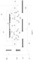
- FIG. 2is a detailed sectional view of Detail A of FIG. 1 .
- An air quality monitoring device 20may be placed along, adjacent to, or in proximity with the path of at least a portion of the ingested ambient air 15 A.
- the air quality monitoring device 20is placed along the ducts 18 such that the air quality monitoring device 20 is in fluid communication with at least a portion of the ingested ambient air 15 A.
- a first portion of the duct 18 Atravels substantially horizontally inward from the intake 16 and a second portion of the duct 18 B travels substantially vertically upward from the first portion of the duct 18 A.
- any shape, size, and arrangement of the ductwork 18is contemplated such that the ductwork 18 may comprise any number of portions traveling any number of directions.
- a drain 22may be located at one or more locations along the ductwork 18 .
- the drain 22may be configured to remove moisture or other debris that are contained within the ingested ambient air 15 A or are ingested with the ambient air 15 A. For example, without limitation, rain, snow, dust, and the like may be ingested with the ambient air 15 A and removed by way of the drain 22 .
- the drain 22is located along a lower edge of the first portion of the duct 18 A, preferably where the first portion of the duct 18 A meets the second portion of the duct 18 B. Some or all of the ductwork 18 may be angled towards the drains 22 .
- the air quality monitoring device 20may comprise a housing having an upper portion 26 and a lower portion 28 , though any number of portions of any size and/or shape are contemplated.
- the upper portion 26may be selectively joined with a lower portion 28 in a substantially sealed arrangement.
- the upper and lower portions 26 and 28 of the housingmay at least partially surround an air quality sensor board 30 .
- the upper portion 26 and the lower portion 28 of the housingare configured to be joined to one another.
- the upper and lower portions 26 and 28may join one another in a substantially airtight or watertight fashion.
- the air quality sensor board 30in exemplary embodiments, is a printed circuit board.
- One or more sensors 32may be mounted to the air quality sensor board 30 .
- One or more seals 34may be placed between the sensors 32 and the air quality sensor board 30 and/or the lower housing 28 .
- the sensors 32may be in electronic communication with the air quality sensor board 30 .
- the sensors 32may be configured to take various air quality measurements.
- the upper and lower housing 26 and 28may entirely or partially expose some or all of the sensors 32 such that at least a portion of the sensors 32 may remain exposed to at least a portion 15 B of the ingested ambient air 15 A.
- the sensors 32may be placed in gaseous communication with at least a representative portion 15 B of the ingested ambient air 15 A.
- gaseous communicationis made by way of the risers 24 , though such is not required.
- the risers 24may slow the portion of the ingested ambient air 15 contacting the sensors 32 in order to provide a more accurate reading. Additionally, the risers 24 may ensure that little to no moisture ingested with the ambient air 15 contacts the sensors 32 .
- FIG. 3is a plan view of an exemplary air quality monitoring device 20 for use with the display assembly 10 .
- the sensors 32may be configured to measure the concentrations of various gas pollutants.
- the gas pollutantsmay be those defined by the Environmental Protection Agency (EPA), though such is not required.
- the sensors 32may be configured to measure one or more of: particulate, pollution, pollen, ambient temperature, humidity, air pressure, or the like.
- the sensors 32may be configured to measure the concentration of one or more of compounds such as, but not limited to: carbon dioxide, nitrogen dioxide, ozone, trioxygen, sulfur dioxide, hydrogen sulfide, carbon monoxide, some combination thereof, or the like.
- the sensors 32may be further configured to measure one or more characteristics of the ingested ambient air 15 such as, but not limited to: temperature, humidity, pressure, air speed, some combination thereof, or the like.
- One or more sensors 32may be provided to measure one or more of the compounds and/or characteristics.
- each of the sensors 32may comprise one or more cells each configured to measure one or more particular compounds and/or characteristics. It is contemplated that the sensors 32 may be configured to measure any type or number of compounds and/or characteristics of the ambient air 15 .
- temperature and/or other measurementsmay be taken over a geographic area and/or period of time in order to determine the existence, size, shape, and the like of various phenomena such as, but not limited to, urban heat islands and canyons.
- the sensors 32may be configured to detect the presences and/or concentration of particular chemicals and/or compounds, such as but not limited to, those found in explosives, chemical weapons, biological weapons, nuclear weapons, some combination thereof or the like. Alternatively, or additionally, the sensors 32 may be configured to detect the presence of radioactive materials in the air, such as but not limited, to the presences and/or concentration of certain isotopes.
- the air quality sensor board 30may comprise one or more components such as, but not limited to: power module(s) 36 , electronic storage device(s) 38 , processor(s) 40 , network connectivity device(s) 42 , some combination thereof, or the like. In other exemplary embodiments, the air quality monitoring device 20 may not comprise such components.
- the air quality monitoring device 20may be in electrical connection with one or more components such as, but not limited to: a power module(s) 36 , electronic storage device(s) 38 , processor(s) 40 , network connectivity device(s) 42 , some combination thereof, or the like.
- the air quality monitoring device 20may be in communication with any number of components provided in the assembly 10 to support the electronic display 12 , related components, and other components of the assembly 10 . This arrangement may reduce the cost and complexity of manufacturing and installing such air quality monitors 20 .
- FIG. 4is a simplified block diagram of an exemplary system for use with the display assembly 10 .
- the integration of such air quality monitors 20 with the display assemblies 10may provide a convenient system and method for monitoring air quality in a city or geographic area.
- the air quality monitors 20may be powered and networked for electronic communication with one or more monitoring stations 46 by way of air quality sensor board 30 and/or the existing electronic components in the assemblies 10 .
- the air quality monitoring device 20may be otherwise protected by the existing housing 12 for the assembly 10 . This may also reduce the cost and complexity of manufacturing and installing such air quality monitors 20 . This has the further advantage of not disrupting the aesthetic appearance of the assembly 10 or the surrounding cityscape or geography.
- ambient air otherwise provided from the open loopmay provide more accurate sampling of the surrounding environment, particularly as compared to natural convection.
- Natural convectionmay be more affected by localized conditions and may result in re-ingestion. Forced airflow may take sample from further away and may be less affected by localized conditions resulting in more accurate measurements.
- the monitoring stations 46may be configured to generate a visual representation of the city or other geographic area overlaid with the measurements from the various display assemblies 10 .
- the monitoring stations 46may be further configured to display the alerts.
- the monitoring stations 46may be configured to display other visual representations of the measurements such as, but not limited to, listings, charts, graphs, tables, some combination thereof, and the like.
- one of more of the electronic storage device(s) 38 , processor(s) 40 , network connectivity device(s) 42may be in electrical connection with the power module(s) 36 .
- One or more of the electronic storage device(s) 38 , the processor(s) 40 , and the network connectivity device(s) 42may alternatively be in electronic communication with one another.
- the network connectivity device(s) 42may be in communication with one or more monitoring stations 46 by way of a network 44 .
- the network 44may be the internet, intranet, cellular network, the world wide web, or the like.
- the monitoring stations 46may be a physical center and/or one or more electronic devices computers, tablets, smartphones, a database, a server, a monitoring center, a command center, some combination thereof, or the like.
- the processor 40may continuously and/or periodically direct the sensor 32 to take one or more measurements from the sensor 32 .
- the processor 40may so direct the sensor 32 to take such measurements at any frequency or interval.
- the measurements taken by the sensors 32may be interpreted by the processor(s) 40 .
- the measurements taken by the sensors 32may be stored as air quality data on electronic storage device(s) 38 .
- the frequency, interval, types, and the like of measurements takenmay be altered.
- thresholds, types, and the like of alertsmay be altered.
- Instructionsmay be stored on the electronic storage device 38 and executed by the processor 40 .
- the processors 40may be configured to automatically generate an alert when chemicals, compounds, or other components of the ingested ambient air 15 B are detected and/or found to be within a certain range, outside a certain rage, above a certain threshold, below a certain threshold, some combination thereof, or the like.
- FIG. 5 Ais a perspective view of another exemplary embodiment of the air quality monitoring device 20 .
- the air quality monitoring device 20may comprise a first housing portion 52 , a second housing portion 54 , and a third housing portion 56 , though any number, size, shape, configuration, and type of housing portions are contemplated.
- One or more apertures 58may be provided for access to the sensors 32 stored within.
- the apertures 58may provide access for servicing, power connectivity, network connectivity, or the like.
- FIG. 5 Bis a perspective sectional view of the air quality monitoring device 20 .
- the second housing portion 54may be configured to support the sensors 32 and/or the air quality sensor board 30 .
- other portions of the housing 52 and 56may be used to support the sensors 32 and/or the air quality sensor board 30 .
- An entrance aperture 62may be provided within the third housing portion 56 .
- An exit aperture 64may be provided within the third housing portion 56 .
- the entrance aperture 62 and/or the exit aperture 64may be provided in other portions of the housing 52 and 56 .
- the exit aperture 64may be used for the ingestion of ambient air 15 B into the air quality monitoring device 20 and that the entrance aperture 62 may be used for the exhaustion of ambient air 15 B from the air quality monitoring device.
- An air pathway 66may extend between the entrance aperture 62 and the exit aperture 64 .
- the air pathway 66may extend through some or all of the air quality monitoring device 20 .
- the airflow pathway 66may be configured to slow the speed of the flow of ambient air 15 B passing through the air quality monitoring device 20 .
- one or more structural features and/or modificationssuch as but not limited to, risers, baffles, walls, ramped surfaces, holes, channels, sloped surfaces, textured surfaces, some combination thereof, or the like, may be provided along some or all of the airflow pathway 66 .
- the airflow pathway 66may be configured to provide a desirable flow rate, pressure, speed, amount, some combination thereof, or the like, of the portion of the ambient air 15 B which travels through the air quality monitoring device 20 .
- the sensors 32may be mounted above the air pathway 66 .
- the sensors 32may be oriented in a downward facing position towards the ground such that the sensor's 32 exposure to any moisture and/or contaminants in the ambient air 15 B may be minimized.
- one or more fansmay be mounted within, along, or in proximity to the air quality monitoring device 20 so as to force a portion 15 B of the ingested ambient air 15 A into the air quality monitoring device 20 .
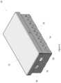
- FIG. 6is a perspective view of another exemplary embodiment of the air quality monitoring device 20 .
- the air quality monitoring device 20may comprise a housing.
- a lower portion 74 of the housingmay be generally shaped as a cuboid with an open upper surface.
- An upper portion 72 of the housingmay be sized to cover at least the open upper surface defined by the lower portion 74 .
- the upper portion 72may serve as a lid.
- a number of apertures 76may be located on one or more surfaces of the lower portion 74 . Alternatively, or additionally, the apertures 76 may be located on one or more surfaces of the upper portion 72 .
- the size, shape, location, and/or number of apertures 76may be selected to control the amount, flow rate, pressure, speed, some combination thereof, or the like, of the ambient air 15 A is gathered to form the portion 15 B which travels through the air quality monitoring device 20 .
- One or more apertures 58may be provided for access to the sensors 32 stored within.
- the air quality monitoring device 20may be comprised of stainless steel, though any material is contemplated.
- any embodiment of the present inventionmay include any of the optional or preferred features of the other embodiments of the present invention.
- the exemplary embodiments herein disclosedare not intended to be exhaustive or to unnecessarily limit the scope of the invention.
- the exemplary embodimentswere chosen and described in order to explain the principles of the present invention so that others skilled in the art may practice the invention. Having shown and described exemplary embodiments of the present invention, those skilled in the art will realize that many variations and modifications may be made to the described invention. Many of those variations and modifications will provide the same result and fall within the spirit of the claimed invention. It is the intention, therefore, to limit the invention only as indicated by the scope of the claims.
- Each electronic devicemay comprise one or more processors, electronic storage devices, executable software instructions, and the like configured to perform the operations described herein.
- the electronic devicesmay be general purpose computers or specialized computing device.
- the electronic devicesmay be personal computers, smartphone, tablets, databases, servers, or the like.
- the electronic connections described hereinmay be accomplished by wired or wireless means.
Landscapes
- Engineering & Computer Science (AREA)
- Chemical & Material Sciences (AREA)
- Combustion & Propulsion (AREA)
- Health & Medical Sciences (AREA)
- Life Sciences & Earth Sciences (AREA)
- Physics & Mathematics (AREA)
- Mechanical Engineering (AREA)
- General Engineering & Computer Science (AREA)
- Food Science & Technology (AREA)
- Medicinal Chemistry (AREA)
- Analytical Chemistry (AREA)
- Biochemistry (AREA)
- General Health & Medical Sciences (AREA)
- General Physics & Mathematics (AREA)
- Immunology (AREA)
- Pathology (AREA)
- Human Computer Interaction (AREA)
- Fluid Mechanics (AREA)
- Air Conditioning Control Device (AREA)
- Emergency Alarm Devices (AREA)
- Cooling Or The Like Of Electrical Apparatus (AREA)
Abstract
Description
Claims (18)
Priority Applications (4)
| Application Number | Priority Date | Filing Date | Title |
|---|---|---|---|
| US16/521,337US11796198B2 (en) | 2018-07-24 | 2019-07-24 | System and method for monitoring air quality while cooling an outdoor electronic display assembly |
| US18/368,397US11971181B2 (en) | 2018-07-24 | 2023-09-14 | System and method for monitoring air quality while cooling an outdoor electronic display assembly |
| US18/620,635US12158278B2 (en) | 2018-07-24 | 2024-03-28 | System and method for monitoring air quality while cooling an outdoor electronic display assembly |
| US18/925,476US12372259B2 (en) | 2018-07-24 | 2024-10-24 | System and method for monitoring air quality while cooling an outdoor electronic display assembly |
Applications Claiming Priority (2)
| Application Number | Priority Date | Filing Date | Title |
|---|---|---|---|
| US201862702382P | 2018-07-24 | 2018-07-24 | |
| US16/521,337US11796198B2 (en) | 2018-07-24 | 2019-07-24 | System and method for monitoring air quality while cooling an outdoor electronic display assembly |
Related Child Applications (1)
| Application Number | Title | Priority Date | Filing Date |
|---|---|---|---|
| US18/368,397ContinuationUS11971181B2 (en) | 2018-07-24 | 2023-09-14 | System and method for monitoring air quality while cooling an outdoor electronic display assembly |
Publications (2)
| Publication Number | Publication Date |
|---|---|
| US20200033017A1 US20200033017A1 (en) | 2020-01-30 |
| US11796198B2true US11796198B2 (en) | 2023-10-24 |
Family
ID=69179529
Family Applications (4)
| Application Number | Title | Priority Date | Filing Date |
|---|---|---|---|
| US16/521,337Active2042-03-01US11796198B2 (en) | 2018-07-24 | 2019-07-24 | System and method for monitoring air quality while cooling an outdoor electronic display assembly |
| US18/368,397ActiveUS11971181B2 (en) | 2018-07-24 | 2023-09-14 | System and method for monitoring air quality while cooling an outdoor electronic display assembly |
| US18/620,635ActiveUS12158278B2 (en) | 2018-07-24 | 2024-03-28 | System and method for monitoring air quality while cooling an outdoor electronic display assembly |
| US18/925,476ActiveUS12372259B2 (en) | 2018-07-24 | 2024-10-24 | System and method for monitoring air quality while cooling an outdoor electronic display assembly |
Family Applications After (3)
| Application Number | Title | Priority Date | Filing Date |
|---|---|---|---|
| US18/368,397ActiveUS11971181B2 (en) | 2018-07-24 | 2023-09-14 | System and method for monitoring air quality while cooling an outdoor electronic display assembly |
| US18/620,635ActiveUS12158278B2 (en) | 2018-07-24 | 2024-03-28 | System and method for monitoring air quality while cooling an outdoor electronic display assembly |
| US18/925,476ActiveUS12372259B2 (en) | 2018-07-24 | 2024-10-24 | System and method for monitoring air quality while cooling an outdoor electronic display assembly |
Country Status (3)
| Country | Link |
|---|---|
| US (4) | US11796198B2 (en) |
| EP (1) | EP3827234A4 (en) |
| WO (1) | WO2020023667A1 (en) |
Families Citing this family (9)
| Publication number | Priority date | Publication date | Assignee | Title |
|---|---|---|---|---|
| US12185512B2 (en) | 2007-11-16 | 2024-12-31 | Manufacturing Resources International, Inc. | Electronic display assembly with thermal management |
| WO2021011589A1 (en)* | 2019-07-18 | 2021-01-21 | Clean Air Group, Inc. | Indoor air quality purification system for a heating ventilation and cooling system of building |
| US11526044B2 (en) | 2020-03-27 | 2022-12-13 | Manufacturing Resources International, Inc. | Display unit with orientation based operation |
| US11851205B2 (en)* | 2020-07-06 | 2023-12-26 | Honeywell International Inc. | Air quality monitoring |
| US11477923B2 (en)* | 2020-10-02 | 2022-10-18 | Manufacturing Resources International, Inc. | Field customizable airflow system for a communications box |
| US12105370B2 (en) | 2021-03-15 | 2024-10-01 | Manufacturing Resources International, Inc. | Fan control for electronic display assemblies |
| US11966263B2 (en) | 2021-07-28 | 2024-04-23 | Manufacturing Resources International, Inc. | Display assemblies for providing compressive forces at electronic display layers |
| US12130032B2 (en)* | 2021-09-24 | 2024-10-29 | Apollo America, Inc. | Compact duct detectors for HVAC systems |
| US12027132B1 (en) | 2023-06-27 | 2024-07-02 | Manufacturing Resources International, Inc. | Display units with automated power governing |
Citations (29)
| Publication number | Priority date | Publication date | Assignee | Title |
|---|---|---|---|---|
| US3415178A (en) | 1967-05-04 | 1968-12-10 | Ilg Ind Inc | Ventilating system and device |
| US20030163369A1 (en) | 2002-02-26 | 2003-08-28 | Dane Arr | Electronic advertising display and public internet access system |
| US20070181000A1 (en) | 2006-02-03 | 2007-08-09 | General Electric Company | Air quality device |
| US7389158B2 (en) | 2001-02-07 | 2008-06-17 | Aircuity, Inc. | Method of making comparisons of indoor air quality scores |
| US20120026432A1 (en)* | 2008-03-26 | 2012-02-02 | Manufacturing Resources International, Inc. | System and method for maintaining a consistent temperature gradient across an electronic display |
| US8373841B2 (en) | 2007-11-16 | 2013-02-12 | Manufacturing Resources International, Inc. | Shared isolated gas cooling system for oppositely facing electronic displays |
| US20130038470A1 (en) | 2009-12-29 | 2013-02-14 | The Regents Of The University Of California | Multimodal climate sensor network |
| US8472174B2 (en) | 2008-05-07 | 2013-06-25 | Vertigo Digital Displays Inc. | Video display system |
| US8591455B2 (en) | 2008-02-21 | 2013-11-26 | Dexcom, Inc. | Systems and methods for customizing delivery of sensor data |
| US8654302B2 (en) | 2008-03-03 | 2014-02-18 | Manufacturing Resources International, Inc. | Heat exchanger for an electronic display |
| US8767165B2 (en) | 2007-11-16 | 2014-07-01 | Manufacturing Resources International, Inc. | Isolated gas cooling system for an electronic display |
| US8790005B2 (en) | 2009-01-28 | 2014-07-29 | Visteon Global Technologies, Inc. | Sensor for determining the temperature in the cabin of a motor vehicle, climate control member for an air conditioning system of a motor vehicle, and device for determining the temperature in the cabin of a motor vehicle |
| US8854595B2 (en) | 2008-03-03 | 2014-10-07 | Manufacturing Resources International, Inc. | Constricted convection cooling system for an electronic display |
| US9026310B2 (en) | 2010-12-15 | 2015-05-05 | Jaguar Land Rover Limited | Wading depth estimation for a vehicle |
| US20150224437A1 (en) | 2014-02-07 | 2015-08-13 | Blueair Ab | Air treatment device with a detachable sensor module |
| CN104879155A (en) | 2015-04-30 | 2015-09-02 | 中国有色集团抚顺红透山矿业有限公司 | Method and system for mine air flow quality monitoring and alarming on basis of controllable circulating air |
| US20150330817A1 (en) | 2006-03-10 | 2015-11-19 | Sui Chun Law | Method and Device for Environmental and Health Monitoring |
| CN105115049A (en) | 2015-07-31 | 2015-12-02 | 深圳市鼎信科技有限公司 | Air purifier and control method thereof |
| US20160011158A1 (en) | 2014-07-11 | 2016-01-14 | Boe Technology Group Co., Ltd. | Gas detection sensor, display panel, and display device |
| US9370127B2 (en) | 2008-03-03 | 2016-06-14 | Manufacturing Resources International, Inc. | System for using constricted convection with closed loop cooling system as the convection plate |
| US20170023457A1 (en)* | 2015-04-22 | 2017-01-26 | TZOA/Clad Innovations Ltd. | Portable device for detecting and measuring particles entrained in the air |
| US20170074453A1 (en) | 2015-09-11 | 2017-03-16 | Civiq Smartscapes, Llc | Techniques and apparatus for securing a structure to a support |
| US20170083043A1 (en)* | 2015-09-17 | 2017-03-23 | Civiq Smartscapes, Llc | Techniques and apparatus for mounting a housing on a personal communication structure (pcs) |
| US20170106218A1 (en) | 2015-10-14 | 2017-04-20 | National Cheng Kung University | Portable electronic device with a smart air purifier |
| CN106765790A (en)* | 2017-02-06 | 2017-05-31 | 深圳安道云科股份有限公司 | Purification of air advertisement machine |
| US20170193788A1 (en) | 2014-07-08 | 2017-07-06 | Young Wung KIM | Air quality notifying device connecting air quality measurement device and wireless terminal, and air quality notifying method therefor |
| US20170284906A1 (en) | 2016-03-29 | 2017-10-05 | Beijing Xiaomi Mobile Software Co., Ltd. | Plug-in air quality detector, control method and control device |
| US20170351221A1 (en) | 2016-06-01 | 2017-12-07 | Withings | Wearable device with air quality sensor |
| US20180299161A1 (en) | 2017-04-14 | 2018-10-18 | Johnson Controls Technology Company | Multi-function thermostat with air quality display |
Family Cites Families (5)
| Publication number | Priority date | Publication date | Assignee | Title |
|---|---|---|---|---|
| EP2096427A3 (en)* | 1998-11-16 | 2009-11-18 | California Institute of Technology | Simultaneous determination of equilibrium and kinetic properties |
| US8032123B2 (en)* | 2006-08-21 | 2011-10-04 | Samsung Electronics Co., Ltd. | Mobile handset with air pollution meter and system |
| US7791882B2 (en)* | 2008-04-23 | 2010-09-07 | International Business Machines Corporation | Energy efficient apparatus and method for cooling an electronics rack |
| GB201112477D0 (en)* | 2011-07-20 | 2011-08-31 | Corentium As | Gas sensor |
| KR102082586B1 (en)* | 2015-09-24 | 2020-02-27 | 로케이터 아이피, 엘피 | Highly-localized weather / environment data |
- 2019
- 2019-07-24USUS16/521,337patent/US11796198B2/enactiveActive
- 2019-07-24EPEP19840267.9Apatent/EP3827234A4/enactivePending
- 2019-07-24WOPCT/US2019/043289patent/WO2020023667A1/ennot_activeCeased
- 2023
- 2023-09-14USUS18/368,397patent/US11971181B2/enactiveActive
- 2024
- 2024-03-28USUS18/620,635patent/US12158278B2/enactiveActive
- 2024-10-24USUS18/925,476patent/US12372259B2/enactiveActive
Patent Citations (29)
| Publication number | Priority date | Publication date | Assignee | Title |
|---|---|---|---|---|
| US3415178A (en) | 1967-05-04 | 1968-12-10 | Ilg Ind Inc | Ventilating system and device |
| US7389158B2 (en) | 2001-02-07 | 2008-06-17 | Aircuity, Inc. | Method of making comparisons of indoor air quality scores |
| US20030163369A1 (en) | 2002-02-26 | 2003-08-28 | Dane Arr | Electronic advertising display and public internet access system |
| US20070181000A1 (en) | 2006-02-03 | 2007-08-09 | General Electric Company | Air quality device |
| US20150330817A1 (en) | 2006-03-10 | 2015-11-19 | Sui Chun Law | Method and Device for Environmental and Health Monitoring |
| US8373841B2 (en) | 2007-11-16 | 2013-02-12 | Manufacturing Resources International, Inc. | Shared isolated gas cooling system for oppositely facing electronic displays |
| US8767165B2 (en) | 2007-11-16 | 2014-07-01 | Manufacturing Resources International, Inc. | Isolated gas cooling system for an electronic display |
| US8591455B2 (en) | 2008-02-21 | 2013-11-26 | Dexcom, Inc. | Systems and methods for customizing delivery of sensor data |
| US8854595B2 (en) | 2008-03-03 | 2014-10-07 | Manufacturing Resources International, Inc. | Constricted convection cooling system for an electronic display |
| US8654302B2 (en) | 2008-03-03 | 2014-02-18 | Manufacturing Resources International, Inc. | Heat exchanger for an electronic display |
| US9370127B2 (en) | 2008-03-03 | 2016-06-14 | Manufacturing Resources International, Inc. | System for using constricted convection with closed loop cooling system as the convection plate |
| US20120026432A1 (en)* | 2008-03-26 | 2012-02-02 | Manufacturing Resources International, Inc. | System and method for maintaining a consistent temperature gradient across an electronic display |
| US8472174B2 (en) | 2008-05-07 | 2013-06-25 | Vertigo Digital Displays Inc. | Video display system |
| US8790005B2 (en) | 2009-01-28 | 2014-07-29 | Visteon Global Technologies, Inc. | Sensor for determining the temperature in the cabin of a motor vehicle, climate control member for an air conditioning system of a motor vehicle, and device for determining the temperature in the cabin of a motor vehicle |
| US20130038470A1 (en) | 2009-12-29 | 2013-02-14 | The Regents Of The University Of California | Multimodal climate sensor network |
| US9026310B2 (en) | 2010-12-15 | 2015-05-05 | Jaguar Land Rover Limited | Wading depth estimation for a vehicle |
| US20150224437A1 (en) | 2014-02-07 | 2015-08-13 | Blueair Ab | Air treatment device with a detachable sensor module |
| US20170193788A1 (en) | 2014-07-08 | 2017-07-06 | Young Wung KIM | Air quality notifying device connecting air quality measurement device and wireless terminal, and air quality notifying method therefor |
| US20160011158A1 (en) | 2014-07-11 | 2016-01-14 | Boe Technology Group Co., Ltd. | Gas detection sensor, display panel, and display device |
| US20170023457A1 (en)* | 2015-04-22 | 2017-01-26 | TZOA/Clad Innovations Ltd. | Portable device for detecting and measuring particles entrained in the air |
| CN104879155A (en) | 2015-04-30 | 2015-09-02 | 中国有色集团抚顺红透山矿业有限公司 | Method and system for mine air flow quality monitoring and alarming on basis of controllable circulating air |
| CN105115049A (en) | 2015-07-31 | 2015-12-02 | 深圳市鼎信科技有限公司 | Air purifier and control method thereof |
| US20170074453A1 (en) | 2015-09-11 | 2017-03-16 | Civiq Smartscapes, Llc | Techniques and apparatus for securing a structure to a support |
| US20170083043A1 (en)* | 2015-09-17 | 2017-03-23 | Civiq Smartscapes, Llc | Techniques and apparatus for mounting a housing on a personal communication structure (pcs) |
| US20170106218A1 (en) | 2015-10-14 | 2017-04-20 | National Cheng Kung University | Portable electronic device with a smart air purifier |
| US20170284906A1 (en) | 2016-03-29 | 2017-10-05 | Beijing Xiaomi Mobile Software Co., Ltd. | Plug-in air quality detector, control method and control device |
| US20170351221A1 (en) | 2016-06-01 | 2017-12-07 | Withings | Wearable device with air quality sensor |
| CN106765790A (en)* | 2017-02-06 | 2017-05-31 | 深圳安道云科股份有限公司 | Purification of air advertisement machine |
| US20180299161A1 (en) | 2017-04-14 | 2018-10-18 | Johnson Controls Technology Company | Multi-function thermostat with air quality display |
Non-Patent Citations (7)
| Title |
|---|
| Array of Things, Welcome homepage, webpage, Jul. 15, 2019, 10 pages. |
| Bradford Zone, Bradford trials air quality monitoring unites from InLink, webpage, Jul. 16, 2019, 2 pages. |
| Sensors, The Role of Advanced Sensing in Smart Cities, journal article, Dec. 27, 2012, 33 pages. |
| Smartcities World News, UK cities use digital street units to measure air quality, webpage article, Jul. 16, 2019, 2 pages. |
| Thomas, How Gas Detectors Work, webpage, Jul. 11, 2019, 4 pages. |
| United States Environmental Protection Agency, Air Sensor Guidebook, Jun. 2014, 73 pages. |
| United States Environmental Protection Agency, Visualize Trends, webpage, Jul. 16, 2019, 2 pages. |
Also Published As
| Publication number | Publication date |
|---|---|
| US20240263818A1 (en) | 2024-08-08 |
| EP3827234A1 (en) | 2021-06-02 |
| US12372259B2 (en) | 2025-07-29 |
| US12158278B2 (en) | 2024-12-03 |
| US20240003565A1 (en) | 2024-01-04 |
| US20250043979A1 (en) | 2025-02-06 |
| EP3827234A4 (en) | 2022-10-05 |
| US20200033017A1 (en) | 2020-01-30 |
| US11971181B2 (en) | 2024-04-30 |
| WO2020023667A1 (en) | 2020-01-30 |
Similar Documents
| Publication | Publication Date | Title |
|---|---|---|
| US11796198B2 (en) | System and method for monitoring air quality while cooling an outdoor electronic display assembly | |
| US12173913B2 (en) | Smart system for manhole event suppression system | |
| US20220326203A1 (en) | Apparatus and methods for reducing fugitive gas emissions at oil facilities | |
| US11293908B2 (en) | System and method for detecting gas recirculation or airway occlusion | |
| KR102181109B1 (en) | Monitoring and total control system of indoor or outdoor atmospheric environment monitoring of public transportation | |
| WO2016129715A1 (en) | Air quality prediction and management system for early detection of environmental disasters | |
| US12108546B1 (en) | Electronic display assembly with fabric panel communications box | |
| Zeiger et al. | Demonstration abstract: participatory sensing enabled environmental monitoring in smart cities | |
| KR102351615B1 (en) | Air quality sensor apparatus | |
| Krupp et al. | Towards Fine-Grained Air Quality Sensing in Urban Environments | |
| WO2022116621A1 (en) | Warning lamp for environmental monitoring in security engineering | |
| US11692913B2 (en) | Air constituent measurement system, method and apparatus | |
| JP2007293120A (en) | Information display device | |
| Chen | Installation of a flow control device in an inclined air-curtain fume hood to control wake-induced exposure | |
| CN109723458B (en) | Municipal tunnel | |
| KR102800451B1 (en) | Automatic alarm information system for disaster prevention having self-diagnosis | |
| JP2019039240A (en) | Digital signage and fitting mechanism of digital signage | |
| Sohn et al. | Estimates of pollutant temporal and spatial variability in commercial buildings from the joint urban 2003 field experiments | |
| CN216695104U (en) | Remote computer room environment monitoring device based on VPN technology | |
| US20240348918A1 (en) | Robust optical monitoring device and operating method thereof | |
| WO2021039145A1 (en) | Air quality information processing system and air quality information processing method | |
| CN208721159U (en) | A kind of distribution type LED display screen environmental monitoring installation | |
| RU115543U1 (en) | MULTIFUNCTIONAL TERMINAL COMPLEX MTK-P OUTDOOR | |
| CN115326028A (en) | An automatic monitoring device with early warning function for rail transit engineering |
Legal Events
| Date | Code | Title | Description |
|---|---|---|---|
| FEPP | Fee payment procedure | Free format text:ENTITY STATUS SET TO UNDISCOUNTED (ORIGINAL EVENT CODE: BIG.); ENTITY STATUS OF PATENT OWNER: LARGE ENTITY | |
| AS | Assignment | Owner name:PRECISION SYSTEMS INTEGRATION, LLC, GEORGIA Free format text:ASSIGNMENT OF ASSIGNORS INTEREST;ASSIGNOR:OMEGA SI, LLC;REEL/FRAME:051206/0107 Effective date:20191202 Owner name:OMEGA SI, LLC, GEORGIA Free format text:ASSIGNMENT OF ASSIGNORS INTEREST;ASSIGNORS:BROWN, MIKE;DUNN, WILLIAM;BENNETT, DOUG;SIGNING DATES FROM 20180806 TO 20180814;REEL/FRAME:051205/0989 | |
| STPP | Information on status: patent application and granting procedure in general | Free format text:DOCKETED NEW CASE - READY FOR EXAMINATION | |
| STPP | Information on status: patent application and granting procedure in general | Free format text:NON FINAL ACTION MAILED | |
| STPP | Information on status: patent application and granting procedure in general | Free format text:RESPONSE TO NON-FINAL OFFICE ACTION ENTERED AND FORWARDED TO EXAMINER | |
| STPP | Information on status: patent application and granting procedure in general | Free format text:FINAL REJECTION MAILED | |
| STPP | Information on status: patent application and granting procedure in general | Free format text:NOTICE OF ALLOWANCE MAILED -- APPLICATION RECEIVED IN OFFICE OF PUBLICATIONS | |
| STPP | Information on status: patent application and granting procedure in general | Free format text:PUBLICATIONS -- ISSUE FEE PAYMENT VERIFIED | |
| STCF | Information on status: patent grant | Free format text:PATENTED CASE | |
| CC | Certificate of correction |