US11794005B2 - Controlling functions of wearable cardiac defibrillation system - Google Patents
Controlling functions of wearable cardiac defibrillation systemDownload PDFInfo
- Publication number
- US11794005B2 US11794005B2US17/847,680US202217847680AUS11794005B2US 11794005 B2US11794005 B2US 11794005B2US 202217847680 AUS202217847680 AUS 202217847680AUS 11794005 B2US11794005 B2US 11794005B2
- Authority
- US
- United States
- Prior art keywords
- patient
- performance
- function
- wcd system
- function includes
- Prior art date
- Legal status (The legal status is an assumption and is not a legal conclusion. Google has not performed a legal analysis and makes no representation as to the accuracy of the status listed.)
- Active
Links
Images


Classifications
- A—HUMAN NECESSITIES
- A61—MEDICAL OR VETERINARY SCIENCE; HYGIENE
- A61N—ELECTROTHERAPY; MAGNETOTHERAPY; RADIATION THERAPY; ULTRASOUND THERAPY
- A61N1/00—Electrotherapy; Circuits therefor
- A61N1/02—Details
- A61N1/08—Arrangements or circuits for monitoring, protecting, controlling or indicating
- A—HUMAN NECESSITIES
- A61—MEDICAL OR VETERINARY SCIENCE; HYGIENE
- A61B—DIAGNOSIS; SURGERY; IDENTIFICATION
- A61B5/00—Measuring for diagnostic purposes; Identification of persons
- A61B5/24—Detecting, measuring or recording bioelectric or biomagnetic signals of the body or parts thereof
- A61B5/316—Modalities, i.e. specific diagnostic methods
- A61B5/318—Heart-related electrical modalities, e.g. electrocardiography [ECG]
- A61B5/332—Portable devices specially adapted therefor
- A—HUMAN NECESSITIES
- A61—MEDICAL OR VETERINARY SCIENCE; HYGIENE
- A61B—DIAGNOSIS; SURGERY; IDENTIFICATION
- A61B5/00—Measuring for diagnostic purposes; Identification of persons
- A61B5/68—Arrangements of detecting, measuring or recording means, e.g. sensors, in relation to patient
- A61B5/6801—Arrangements of detecting, measuring or recording means, e.g. sensors, in relation to patient specially adapted to be attached to or worn on the body surface
- A61B5/6813—Specially adapted to be attached to a specific body part
- A61B5/6823—Trunk, e.g., chest, back, abdomen, hip
- A—HUMAN NECESSITIES
- A61—MEDICAL OR VETERINARY SCIENCE; HYGIENE
- A61N—ELECTROTHERAPY; MAGNETOTHERAPY; RADIATION THERAPY; ULTRASOUND THERAPY
- A61N1/00—Electrotherapy; Circuits therefor
- A61N1/18—Applying electric currents by contact electrodes
- A61N1/32—Applying electric currents by contact electrodes alternating or intermittent currents
- A61N1/38—Applying electric currents by contact electrodes alternating or intermittent currents for producing shock effects
- A61N1/39—Heart defibrillators
- A61N1/3993—User interfaces for automatic external defibrillators
- A—HUMAN NECESSITIES
- A61—MEDICAL OR VETERINARY SCIENCE; HYGIENE
- A61B—DIAGNOSIS; SURGERY; IDENTIFICATION
- A61B5/00—Measuring for diagnostic purposes; Identification of persons
- A61B5/0002—Remote monitoring of patients using telemetry, e.g. transmission of vital signals via a communication network
- A61B5/0015—Remote monitoring of patients using telemetry, e.g. transmission of vital signals via a communication network characterised by features of the telemetry system
- A61B5/0024—Remote monitoring of patients using telemetry, e.g. transmission of vital signals via a communication network characterised by features of the telemetry system for multiple sensor units attached to the patient, e.g. using a body or personal area network
- A—HUMAN NECESSITIES
- A61—MEDICAL OR VETERINARY SCIENCE; HYGIENE
- A61B—DIAGNOSIS; SURGERY; IDENTIFICATION
- A61B5/00—Measuring for diagnostic purposes; Identification of persons
- A61B5/02—Detecting, measuring or recording for evaluating the cardiovascular system, e.g. pulse, heart rate, blood pressure or blood flow
- A61B5/0205—Simultaneously evaluating both cardiovascular conditions and different types of body conditions, e.g. heart and respiratory condition
- A—HUMAN NECESSITIES
- A61—MEDICAL OR VETERINARY SCIENCE; HYGIENE
- A61B—DIAGNOSIS; SURGERY; IDENTIFICATION
- A61B5/00—Measuring for diagnostic purposes; Identification of persons
- A61B5/24—Detecting, measuring or recording bioelectric or biomagnetic signals of the body or parts thereof
- A61B5/316—Modalities, i.e. specific diagnostic methods
- A61B5/318—Heart-related electrical modalities, e.g. electrocardiography [ECG]
- A61B5/346—Analysis of electrocardiograms
- A61B5/349—Detecting specific parameters of the electrocardiograph cycle
- A61B5/361—Detecting fibrillation
- A—HUMAN NECESSITIES
- A61—MEDICAL OR VETERINARY SCIENCE; HYGIENE
- A61B—DIAGNOSIS; SURGERY; IDENTIFICATION
- A61B5/00—Measuring for diagnostic purposes; Identification of persons
- A61B5/68—Arrangements of detecting, measuring or recording means, e.g. sensors, in relation to patient
- A61B5/6801—Arrangements of detecting, measuring or recording means, e.g. sensors, in relation to patient specially adapted to be attached to or worn on the body surface
- A61B5/683—Means for maintaining contact with the body
- A61B5/6831—Straps, bands or harnesses
- A—HUMAN NECESSITIES
- A61—MEDICAL OR VETERINARY SCIENCE; HYGIENE
- A61B—DIAGNOSIS; SURGERY; IDENTIFICATION
- A61B5/00—Measuring for diagnostic purposes; Identification of persons
- A61B5/68—Arrangements of detecting, measuring or recording means, e.g. sensors, in relation to patient
- A61B5/6801—Arrangements of detecting, measuring or recording means, e.g. sensors, in relation to patient specially adapted to be attached to or worn on the body surface
- A61B5/6843—Monitoring or controlling sensor contact pressure
- A—HUMAN NECESSITIES
- A61—MEDICAL OR VETERINARY SCIENCE; HYGIENE
- A61N—ELECTROTHERAPY; MAGNETOTHERAPY; RADIATION THERAPY; ULTRASOUND THERAPY
- A61N1/00—Electrotherapy; Circuits therefor
- A61N1/18—Applying electric currents by contact electrodes
- A61N1/32—Applying electric currents by contact electrodes alternating or intermittent currents
- A61N1/38—Applying electric currents by contact electrodes alternating or intermittent currents for producing shock effects
- A61N1/39—Heart defibrillators
- A61N1/3925—Monitoring; Protecting
Definitions
- SCASudden Cardiac Arrest
- ICDImplantable Cardioverter Defibrillator
- a WCD systemtypically includes a harness, vest, or other garment that the patient is to wear.
- the WCD systemincludes a defibrillator and electrodes, coupled to the harness, vest, or other garment.
- the external electrodesmay then make good electrical contact with the patient's skin, and therefore can help determine the patient's ECG. If a shockable heart arrhythmia is detected, then the defibrillator delivers the appropriate electric shock through the patient's body, and thus through the heart.
- WCDWearable Cardiac Defibrillator
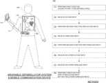
- a Wearable Cardiac Defibrillator (WCD) systemis configured to be worn by a patient who carries a mobile communication device.
- the mobile communication devicehas a user interface that is configured to enable the patient to enter wireless inputs.
- the WCD systemincludes a communication module that is configured to establish a local comlink with the mobile communication device.
- the WCD systemalso includes a tethered action unit that has a user interface configured to enable the patient to enter action inputs.
- the WCD systemcan perform some of its functions in response to the action inputs or to the wireless inputs. Since the wireless inputs can be provided from the mobile communication device instead of the action unit, the patient is less likely to attract attention when entering the action inputs, and thus exhibit better compliance.
- a Wearable Cardiac Defibrillator (WCD) systemincludes a support structure that is configured to be worn by the patient.
- a first electronics moduleis configured to be coupled to the support structure such that, when the support structure is worn by the patient, the first electronics module is substantially located at the lumbar region of the patient. This way, the support structure is less discernible to others, and the patient is less demotivated from wearing it.
- FIG. 1is a diagram of components of a sample wearable cardiac defibrillator (WCD) system, made according to embodiments.
- WCDwearable cardiac defibrillator
- FIG. 2is a diagram showing sample components of an external defibrillator, such as the one belonging in the system of FIG. 1 , and which is made according to embodiments.
- FIG. 3is a diagram showing a sample allocation of access of functions according to embodiments.
- FIG. 4is a diagram of a sample action unit with a user interface requesting an action input according to embodiments.
- FIG. 5is a diagram of a sample mobile communication device with a user interface requesting a wireless input according to embodiments.
- FIG. 6is a diagram showing a sample allocation of access of functions according to embodiments.
- FIG. 7is a flowchart for illustrating methods according to embodiments.
- FIG. 8is a diagram showing a sample allocation of access of functions according to embodiments.
- FIG. 9is a flowchart for illustrating methods according to embodiments.
- FIG. 10is a diagram for showing separable embodiments of WCD systems.
- FIG. 11 Ashows sample components of a WCD system according to embodiments.
- FIG. 11 Bshows how the components of FIG. 11 A may be worn by a patient.
- WCDWearable Cardiac Defibrillator
- a Wearable Cardiac Defibrillator (WCD) systemmade according to embodiments has a number of components. These components can be provided separately as modules that can be interconnected, or can be combined with other components, etc.
- a component of a WCD systemcan be a support structure, which is configured to be worn by the patient.
- the support structurecan be any structure suitable for wearing, such as a harness, a vest, a half-vest—for example over the left side of the torso that positions electrodes on opposite sides of the heart, one or more belts that are configured to be worn horizontally or possibly vertically over a shoulder, another garment, and so on.
- the support structurecan be implemented in a single component, or multiple components.
- a support structuremay have a top component resting on the shoulders, for ensuring that the defibrillation electrodes will be in the right place for defibrillating, and a bottom component resting on the hips, for carrying the bulk of the weight of the defibrillator.
- a single component embodimentcould be with a belt around at least the torso.
- Other embodimentscould use an adhesive structure or another way for attaching to the patient, without encircling any part of the body. There can be other examples.
- FIG. 1depicts components of a WCD system made according to embodiments, as it might be worn by a person 182 .
- a person such as person 182may also be referred to as patient 182 , wearer 182 since he or she wears the WCD system.
- the components of the WCD system of FIG. 1include a generic support structure 170 shown relative to the body of patient 182 , and thus also relative to his or her heart 185 .
- Structure 170could be a harness, a vest, a half-vest, one or more belts, or a garment, etc., as per the above.
- Structure 170could be implemented in a single component, or multiple components, and so on.
- Structure 170is wearable by patient 182 , but the manner of wearing it is not depicted, as structure 170 is depicted only generically in FIG. 1 .
- Structure 170can be designed to be worn under the clothes of patient 182 , and can be shaped and sized to effectively remain hidden. This can be accomplished by thin materials, design principles that avoid often-exposed areas of a patient's anatomy (such as the neck, upper chest or lower arms), and/or providing an extensive range of sizes and/or adjustability.
- a wearable cardiac defibrillator (WCD) systemis configured to defibrillate a patient who is wearing it, by delivering electrical charge to the patient's body in the form of an electric shock delivered in one or more pulses.
- the components of the WCD system of FIG. 1include a sample external defibrillator 100 made according to embodiments, and sample defibrillation electrodes 104 , 108 , which are coupled to external defibrillator 100 via electrode leads 105 .
- Defibrillator 100 and defibrillation electrodes 104 , 108are coupled to support structure 170 . As such, many of the individual components of defibrillator 100 can be therefore coupled to support structure 170 .
- defibrillator 100can administer, via electrodes 104 , 108 , a brief, strong electric pulse 111 through the body.
- Pulse 111also known as a defibrillation shock or therapy shock, is intended to go through and restart heart 185 , in an effort to save the life of patient 182 .
- Pulse 111can further include one or more pacing pulses, and so on.
- a prior art defibrillatortypically decides whether to defibrillate or not based on an electrocardiogram (“ECG”) signal of the patient.
- ECGelectrocardiogram
- defibrillator 100can defibrillate, or not defibrillate, also based on other inputs.
- defibrillator 100includes additional individual components, as will be described in more detail later in this document.
- these additional componentsinclude a power source that is configured to store an electrical charge, a discharge circuit, and one or more processors.
- the componentsalso include a communication module that is integrated with the defibrillation unit in a single electronics module, although the communication module can be provided in an electronics module of the WCD system separately from that of the shown defibrillator 100 .
- defibrillator 100is shown in the front of the patient.
- one or more components of a WCD systemare preferably ergonomically designed to fit the lumbar region of the body.
- the lumbar regionis sometimes referred to as the lower spine, or as an area of the back in its proximity.
- a componentsuch as an electronics module may be discreetly worn on the body under a patient's clothes when placed in a lumbar pack/carrying case, or carried in a common accessory such as a purse or backpack—effectively hiding it in plain sight.
- Such an electronics modulemay include one or more components of the WCD system.
- Action unit 160can be a device for patient 182 to exchange information with the WCD system.
- action unit 160may have a user interface that is configured to enable patient 182 to read system messages and enter action inputs.
- Action unit 160can be configured to be coupled to support structure 170 .
- action unit 160is integrated with the one or more processors in a single electronics module, for example the same electronics module that includes defibrillator 100 .
- action unit 160is electrically coupled with the module of defibrillator 100 via a cable, which can be a permanent cable or a USB or Firewire connection.
- patient 182may reach into their clothes to access action unit 160 .
- patient 182may bring action unit 160 to a comfortable position for reading the system messages and entering the action inputs. Accordingly, patient 182 can access and control various functions of the WCD system via action unit 160 .
- some of the WCD system functions that can be controlled by access unit 160can instead be controlled by a mobile communication device 110 , redundantly or not.
- patient 182carries mobile communication device 110 on their person for typically much of the day.
- Patient 182may carry device 110 in a pocket, in a special holder, or even wear it on their wrist.
- Patient 182may use device 110 to communicate with the WCD system, which is why patient 182 may also be referred to as user 182 .
- Mobile communication device 110has a user interface that is configured to enable patient 182 to enter inputs that in this document are often called wireless inputs.
- Wireless communication linksmay be established and used in embodiments, for exchanging data, voice, etc.
- a wireless communication linkis also sometimes referred to as “comlink”.
- a mobile communication device such as device 110can be a custom-made device that is part of the WCD system. If made to look substantially like a common, commercially available mobile communication device, it might help preserve the privacy of patient 182 as to the fact that he or she is wearing a medical device, and thus also help preserve their dignity. In making such a custom-made device 110 appear like a commercially available mobile communication device, care should be taken to not use others' intellectual property rights without their permission.
- a mobile communication devicesuch as device 110 can be a wireless telephone, a smartphone, a Personal Digital Assistant (PDA), a personal electronic device, a pager, a laptop computer, a tablet, an e-reader, and so on. It can have an app made according to embodiments, so as to perform various functions as described.
- mobile communication device 110can communicate with a wireless service provider network (not shown) via a remote comlink (not shown).
- a “remote comlink”means a wireless communication link established between devices that are at least 500 feet (150 m) away from each other, and typically farther, such as a cellular communication link.
- the remote comlinkcan be used for a number of other functions, such as dialing an emergency number (e.g. 911 in the US), which may also be accessible via the mobile communication device directly.
- the location of the patientmay be determined by GPS. If the WCD system and the mobile communication device have been paired and one of them knows that it is physically close to the other, GPS information may thus become known and communicated to EMS services.
- the mobile communication devicemay provide a redundant communication path for the data of the WCD system. This redundant communication path might be used as a secondary communication path for remote monitoring data if a primary, in-house internet path is not available for the WCD system to report.
- the remote comlinkcan also be used by a remote caregiver to provide patient 182 with troubleshooting assistance, motivational feedback, etc.
- Mobile communication device 110can thus be configured to establish a local comlink 171 with the communication module of the WCD system, which may be inside the same module as defibrillator 100 . If mobile communication device 110 is indeed a wireless telephone or other independent standalone communication device, a local comlink may be established first pursuant to some authentication. Local comlink 171 may be established by the initiative of mobile communication device 110 , the communication module, or both. For purposes of this document, a “local comlink” means a wireless communication link established between devices that are at most 50 feet (15 m) away from each other, and typically closer, such as when patient 182 is holding device 110 . Local comlink 171 can be a wireless link.
- local comlink 171uses radio transmission technology that can be broadband and/or shortwave.
- Local comlink 171may use Bluetooth technology, Wi-Fi technology, Zigbee or other suitable short-range wireless technology.
- FIG. 2is a diagram showing individual components of an external defibrillator 200 , which is made according to embodiments. These individual components can be, for example, those included in the module that includes defibrillator 100 of FIG. 1 .
- the components shown in FIG. 2can be provided in a housing 201 , which is also known as casing 201 .
- Defibrillator 200is intended for a patient who would be wearing the WCD system, such as patient 182 of FIG. 1 .
- Defibrillator 200may further include a user interface 270 , which can be the same as action unit 160 .
- User interface 270can thus be used by patient 182 , or a bystander at a scene where the patient may experience SCA.
- the bystandermay be a person familiar with patient 182 , a stranger, a trained person, etc. In some scenarios the bystander may be a rescuer, etc.
- User interface 270can be made in a number of ways.
- User interface 270may include output devices, which can be visual, audible or tactile, for communicating to a user.
- an output devicecan be a light, or a screen to display what is detected and measured, and provide visual feedback to a rescuer for their resuscitation attempts, and so on.
- Another output devicecan be a speaker, which can be configured to issue voice prompts, etc. Sounds, images, vibrations, and anything that can be perceived by a user can also be called human perceptible indications.
- User interface 270may also include input devices for receiving inputs from users. Such input devices may additionally include various controls, such as pushbuttons, keyboards, touchscreens, a microphone, and so on.
- An input devicecan be a cancel switch, which is sometimes called a “live-man” switch, an “I am OK” switch, a “divert therapy” switch, etc.
- actuating the cancel switchcan prevent the impending delivery of a shock.
- the WCD systemmay optionally include a monitoring device 280 .
- Device 280can be configured to monitor at least one local parameter.
- a local parametercan be a physiological parameter of patient 182 , or a parameter of the WCD system, or a parameter of the environment, as will be described later in this document.
- Patient physiological parametersinclude, for example, those physiological parameters that can be of any help in detecting by the wearable defibrillation system whether the patient is in need of a shock, plus optionally their medical history and/or event history. Examples of such parameters include the patient's ECG, blood oxygen level, blood flow, blood pressure, blood perfusion, pulsatile change in light transmission or reflection properties of perfused tissue, heart sounds, heart wall motion, breathing sounds and pulse.
- the monitoring devicecould include a perfusion sensor, a pulse oximeter, a Doppler device for detecting blood flow, a cuff for detecting blood pressure, an optical sensor, illumination detectors and perhaps sources for detecting color change in tissue, a motion sensor, a device that can detect heart wall movement, a sound sensor, a device with a microphone, an SpO2 sensor, and so on.
- Pulse detectionis taught at least in Physio-Control's U.S. Pat. No. 8,135,462, which is hereby incorporated by reference in its entirety.
- a person skilled in the artmay implement other ways of performing pulse detection.
- Patient state parametersinclude recorded aspects of patient 182 , such as motion, posture, whether they have spoken recently plus maybe also what they said, and so on, plus optionally the history of these parameters.
- one of these monitoring devicescould include a location sensor such as a Global Positioning System (GPS) location sensor. Such a sensor can detect the location, plus a speed can be detected as a rate of change of location over time.
- GPSGlobal Positioning System
- Many motion detectorsoutput a motion signal that is indicative of the motion of the detector, and thus of the patient's body.
- Patient state parameterscan be very helpful in narrowing down the determination of whether SCA is indeed taking place.
- Defibrillator 200typically includes a defibrillation port 210 , such as a socket in housing 201 .
- Defibrillation port 210includes electrical nodes 214 , 218 .
- Leads of defibrillation electrodes 204 , 208such as leads 105 of FIG. 1 , can be plugged in defibrillation port 210 , so as to make electrical contact with nodes 214 , 218 , respectively.
- Electrodes 204 , 208can be electrodes 104 , 108 . Either way, defibrillation port 210 can be used for guiding, via electrodes, to the wearer the electrical charge that has been stored in energy storage module 250 . The electric charge will be the shock for defibrillation, pacing, and so on.
- Defibrillator 200may optionally also have an ECG port 219 in housing 201 , for plugging in sensing electrodes 209 , which are also known as ECG electrodes and ECG leads. It is also possible that sensing electrodes 209 can be connected continuously to ECG port 219 , instead. Sensing electrodes 209 can help sense an ECG signal, e.g. a 12-lead signal, or a signal from a different number of leads, especially if they make good electrical contact with the body of the patient. Sensing electrodes 209 can be attached to the inside of support structure 170 for making good electrical contact with the patient, similarly as defibrillation electrodes 204 , 208 .
- ECG signale.g. a 12-lead signal
- Sensing electrodes 209can be attached to the inside of support structure 170 for making good electrical contact with the patient, similarly as defibrillation electrodes 204 , 208 .
- Defibrillator 200also includes a measurement circuit 220 .
- Measurement circuit 220receives physiological signals of the patient from ECG port 219 , if provided. Even if defibrillator 200 lacks ECG port 219 , measurement circuit 220 can obtain physiological signals through nodes 214 , 218 instead, when defibrillation electrodes 204 , 208 are attached to the patient. In these cases, the patient's ECG signal can be sensed as a voltage difference between electrodes 204 , 208 . Plus, impedance between electrodes 204 , 208 and/or the connections of ECG port 219 can be sensed.
- Sensing the impedancecan be useful for detecting, among other things, whether these electrodes 204 , 208 and/or sensing electrodes 209 are not making good electrical contact with the patient's body. These patient physiological signals can be sensed, when available. Measurement circuit 220 can then render or generate information about them as physiological inputs, data, other signals, etc. More strictly speaking, the information rendered by measurement circuit 220 is output from it, but this information can be called an input because it is received by a subsequent device or functionality as an input.
- a WCD systemalso includes one or more processors, of which defibrillator 200 shows only one processor 230 .
- the one or more processorsmay be implemented in any number of ways. Such ways include, by way of example and not of limitation, digital and/or analog processors such as microprocessors and Digital Signal Processors (DSPs); controllers such as microcontrollers; software running in a machine; programmable circuits such as Field Programmable Gate Arrays (FPGAs), Field-Programmable Analog Arrays (FPAAs), Programmable Logic Devices (PLDs), Application Specific Integrated Circuits (ASICs), any combination of one or more of these, and so on.
- DSPsDigital Signal Processors
- controllerssuch as microcontrollers
- software running in a machineprogrammable circuits such as Field Programmable Gate Arrays (FPGAs), Field-Programmable Analog Arrays (FPAAs), Programmable Logic Devices (PLDs), Application Specific Integrated Circuits (ASICs), any combination
- the one or more processorsmay be configured to receive the action inputs that have been entered via the user interface of action unit 160 , and the wireless inputs that have been entered via the user interface of mobile communication device 110 .
- the one or more processorsmay be configured to perform various functions, for example by causing various components to operate in certain ways. In some embodiments, the performance of these functions can have aspects that are controlled by any received action inputs and wireless inputs.
- a first functioncan be to cause the patient to be defibrillated. This first function can be performed by controlling discharge circuit 255 to discharge the electrical charge stored in power source 240 through patient 182 , while patient 182 is wearing support structure 170 .
- this first function processor 230can be considered to have a number of modules.
- One such modulecan be a detection module 232 .
- Detection module 232can include a ventricular fibrillation (“VF”) detector.
- the patient's sensed ECG from measurement circuit 220which can be available as physiological inputs, data, or other signals, may be used by the VF detector to determine whether the patient is experiencing VF. Detecting VF is useful, because VF results in SCA.
- Detection module 232can also include a ventricular tachycardia (“VT”) detector, and so on.
- VTventricular tachycardia
- Another such module in processor 230can be an advice module 234 , which generates advice for what to do.
- the advicecan be based on outputs of detection module 232 .
- the adviceis a shock/no shock determination that processor 230 can make, for example via advice module 234 .
- the shock/no shock determinationcan be made by executing a stored Shock Advisory Algorithm.
- a Shock Advisory Algorithmcan make a shock/no shock determination from one or more of ECG signals that are captured according to embodiments, and determining whether a shock criterion is met. The determination can be made from a rhythm analysis of the captured ECG signal or otherwise.
- an electrical chargeis delivered to the patient. Delivering the electrical charge is also known as discharging. Shocking can be for defibrillation, pacing, and so on.
- Processor 230can include additional modules, such as other module 236 , for other functions.
- internal monitoring device 280may be operated in part by processor 230 , etc.
- Defibrillator 200optionally further includes a memory 238 , which can work together with processor 230 .
- Memory 238may be implemented in any number of ways. Such ways include, by way of example and not of limitation, volatile memories, nonvolatile memories (NVM), read-only memories (ROM), random access memories (RAM), magnetic disk storage media, optical storage media, smart cards, flash memory devices, any combination of these, and so on. Memory 238 is thus a non-transitory storage medium.
- Memory 238if provided, can include programs for processor 230 , which processor 230 may be able to read and execute. More particularly, the programs can include sets of instructions in the form of code, which processor 230 may be able to execute upon reading.
- Executingis performed by physical manipulations of physical quantities, and may result in the functions, processes, actions and/or methods to be performed, and/or the processor to cause other devices or components or blocks to perform such functions, processes, actions and/or methods.
- the programscan be operational for the inherent needs of processor 230 , and can also include protocols and ways that decisions can be made by advice module 234 .
- memory 238can store prompts for the user of user interface 270 , if this user is a local rescuer.
- memory 238can store data.
- the datacan include patient data, system data and environmental data, for example as learned by internal monitoring device 280 and outside monitoring device 180 .
- the datacan be stored in memory 238 before it is transmitted out of defibrillator 200 , or stored there after it is received by defibrillator 200 .
- defibrillator 200also includes a power source 240 .
- power source 240typically includes a battery. Such a battery is typically implemented as a battery pack, which can be rechargeable or not. Sometimes a combination is used of rechargeable and non-rechargeable battery packs.
- Other embodiments of power source 240can include an AC power override, for where AC power will be available, an energy storage capacitor, and so on.
- power source 240is controlled by processor 230 .
- Defibrillator 200additionally includes an energy storage module 250 , which can thus be coupled to the support structure of the WCD system.
- Module 250is where some electrical energy is stored in the form of an electrical charge, when preparing it for sudden discharge to administer a shock.
- Module 250can be charged from power source 240 to the right amount of energy, as controlled by processor 230 .
- module 250includes a capacitor 252 , which can be a single capacitor or a system of capacitors, and so on. As described above, capacitor 252 can store the energy in the form of electrical charge, for delivering to the patient.
- defibrillator 200moreover includes a discharge circuit 255 .
- processor 230can be configured to control discharge circuit 255 to discharge through the patient the electrical charge stored in energy storage module 250 .
- circuit 255can permit the energy stored in module 250 to be discharged to nodes 214 , 218 , and from there also to defibrillation electrodes 204 , 208 .
- Circuit 255can include one or more switches 257 . Switches 257 can be made in a number of ways, such as by an H-bridge, and so on. Circuit 255 can also be controlled via user interface 270 .
- defibrillator 200includes a communication module 290 , for establishing one or more wired or wireless communication links with other devices of other entities, such as a remote assistance center, Emergency Medical Services (EMS), device 110 , and so on.
- the communication moduleneed not be in the same housing 201 as defibrillator 200 .
- Module 290may also include an antenna, portions of a processor, and other sub-components as may be deemed necessary by a person skilled in the art. This way, data and commands can be communicated via comlinks, such as patient data, event information, therapy attempted, CPR performance, system data, environmental data, and so on.
- Defibrillator 200can optionally include other components.
- one or more of the components of the shown WCD systemhave been customized for patient 182 .
- This customizationmay include a number of aspects.
- support structure 170can be fitted to the body of patient 182 .
- baseline physiological parameters of patient 182can be measured, such as the heart rate of patient 182 while resting, while walking, motion detector outputs while walking, etc.
- Such baseline physiological parameterscan be used to customize the WCD system, in order to make its diagnoses more accurate, since bodies behave differently.
- such parameterscan be stored in a memory of the WCD system, and so on.
- a programming interfacecan be made according to embodiments, which receives such measured baseline physiological parameters. Such a programming interface may input automatically in the WCD system the baseline physiological parameters, along with other data.
- embodimentsgive patient 182 the option to control the performance of a number of functions of the WCD system via mobile communication device 110 , as opposed to action unit 160 .
- Using device 110will attract less attention in public places where others may be watching, than using action unit 160 .
- using device 110will be less distracting to people familiar with patient 182 , and the fact that this patient needs to be attending to their WCD system. As such, patient 182 will have one less deterrent from exhibiting good compliance in actually wearing their WCD system daily.
- Embodimentsmake various allocations as to which of action unit 160 and mobile communication device 110 can affect which functions of the processor(s) of the WCD system.
- there is redundancyin that one or more functions can be accessed from either action unit 160 or mobile communication device 110 , meaning aspects of the performance of these functions can be controlled either by received action inputs or by received wireless inputs.
- there is exclusivityin that one or more functions can be accessed from either action unit 160 or mobile communication device 110 , but not both.
- the allocationscan be made by taking into account the context that functions may be performed in, in terms of criticality and afforded privacy. For example, there can be a preference that some initialization functions that are operated when patient 182 is initially fitted with the WCD system at the doctor's office be exclusively accessible and controllable by action unit 160 , and not accessible by mobile communication device 110 . For another example, there can be a preference that functions which patient 182 is expected to perform periodically be accessible from mobile communication device 110 . For some of these choices it can be further considered that, in case of an emergency, action unit 160 may be more reliable if it does not need to be separately powered, or for a wireless network to be operating.
- FIG. 3is a diagram showing a sample allocation of access of functions according to embodiments.
- a WCD systemwhich is not indicated separately, has one or more processors 388 .
- Processor(s) 388are configured to perform a defibrillation function 311 , which is the function of causing the patient to be defibrillated as described above.
- Processor(s) 388are further configured to perform at least one second function that is distinct from defibrillation function 311 .
- there is a set 320 of such possible additional second functionsnamely functions 321 , 322 , although more are possible. Sample functions are described later in this document.
- the WCD systemalso has an action unit 360 , which can be as described for action unit 160 .
- Action unit 360has a user interface 367 , which may receive action inputs 368 entered by the patient.
- the patientmay prefer to be in a more private context, which is indicated conceptually by showing customized action unit 360 in a gray domain 391 .
- Action inputs 368may affect the functions of set 320 . More particularly, an aspect of the performance of one of the second functions in set 320 can be controlled by received action input 368 .
- the WCD systemfurther cooperates with a mobile communication device 310 , which can be as described for mobile communication device 110 .
- Mobile communication device 310has a user interface 317 , which may receive wireless inputs 318 entered by the patient.
- the patientmay not mind being in a public space, which is indicated conceptually by showing mobile communication device 110 in a clear domain 392 .
- Wireless inputs 318may affect the functions of set 320 . More particularly, an aspect of the performance of one of the second functions in set 320 can be controlled by received wireless input 318 .
- processor(s) 388may receive an action input 368 and perform second function 321 , in which an aspect of the performance of second function 321 can be controlled by received action input 368 .
- processor(s) 388may receive wireless input 318 and subsequently perform again second function 321 , in which the same aspect of the subsequent performance of second function 321 can be controlled by received wireless input 318 .
- each of these functionsmay be designated for exclusive access by either action unit 360 or mobile communication device 310 , or may be designed for redundant access by both.
- one or more suitable interfacescan change these designations according to embodiments for an individual system, for example customized based on a particular patient.
- a protocol and one or more suitable interfacescan be used to determine for any time or condition which of action unit 360 and mobile communication device 310 is accessing the second function in question.
- the second functionincludes causing a physiological parameter of the patient to be measured.
- This parametercan be the ECG, heart sounds, CO2, etc.
- the patient's cooperationis needed for this parameter to be measured.
- the patientmay need to become substantially motionless, or apply a measuring implement on his or her body, etc.
- FIG. 4is a diagram of an action unit 460 , which can be as action unit 360 .
- Action unit 460has a user interface that includes a touchscreen 467 .
- a message on touchscreen 467requests an action input, namely for the patient to touch a specific place on touchscreen 467 after he or she has stopped moving.
- the controlled aspect of the performance of the second functionmay include a time when the patient signifies that a condition for the measuring is optimized.
- the timeis defined by the moment the patient touches touchscreen 467 as requested. That time is when the patient thus signifies that a condition for the measuring is optimized, for example they have stopped moving as much as possible.
- the second functionincludes causing to be measured a physiological parameter of the patient that is not the ECG, the patient could instead be signifying that he or she has applied the appropriate measuring implement on his or her body, etc.
- the controlled aspect of the performance of the second functionmay include a time when the physiological parameter is measured.
- a time when the physiological parameter is measuredis again what was described with reference to FIG. 4 .
- Another examplecan be to touch the screen while no therapy is indicated by a component of the WCD system, so as to “snapshot” a symptomatic episode, record more aspects of it, report it, and so on.
- Such a symptomatic episodecould be further analyzed in addition with extra reporting by the patient to investigate for any further problems, or to add to their baseline of normal occurrences, and so on.
- the messaging and exchange shown in FIG. 4could have also occurred via an interface of a mobile communication device.
- the WCD systemmay suspect activity, or a symptomatic episode may occur while the patient is in a context of domain 392 , not 391, and reporting via the mobile communication device may be preferred.
- the second functionincludes settings of the WCD system, such as airplane mode selection, audio preferences such as non-safety-related audio preferences, etc.
- the second functionmay include causing an auditory notification to be provided to the patient, and the controlled aspect of the performance of the second function may include a sound volume of the auditory notification.
- the sound volumemay be set as an explicit setting, or be part of another setting that is of larger scope. An example is now described.
- FIG. 5is a diagram of a sample mobile communication device 510 , which can be as mobile communication device 110 .
- Mobile communication device 510has a user interface that includes a touchscreen 517 .
- a message on touchscreen 517requests a wireless input, namely for the patient to touch a specific place on touchscreen 517 for affecting settings of the WCD system.
- the settingscould include a “return to default” setting, which may include a default sound volume setting.
- the messaging and exchange shown in FIG. 5could have also occurred via an interface of an action unit.
- the second functionincludes causing quality-of-life data to be received from the patient, which can be entered by the patient as one or more responses to a survey.
- the controlled aspect of the performance of the second functioncan include a time that the quality-of-life data is received, which is controlled by when the patient enters the quality-of-life data.
- the second functionincludes causing condition data to be transmitted to a remote party that is designated as friendly to the patient. Indeed, as part of a support network to enhance patient compliance, such condition data can be shared with loved ones. If done via a mobile communication device that is also commercially available, the condition data can be transmitted via a secure application (“app”).
- the condition datacan be physiological, and also mental or emotional, current or previous, and so on.
- the controlled aspect of the performance of the second functionmay include a time that the condition data is transmitted.
- a “snooze” functionalityis implemented, which can be activated prior to temporarily removing the WCD system.
- the second functionmay include causing a certain operation to be performed, and the controlled aspect of the performance of the second function may include pausing the performance of the certain operation at a particular time. The particular time can be when the patient activates the snooze functionality.
- the certain operationmay include transmitting data wirelessly, receiving data wirelessly, performing a diagnostic self-test, etc. As described above, the transmitted data can be WCD system data, environment data, patient data, etc.
- functions 321 , 322 in set 320are accessible redundantly.
- some additional functionsmay be accessible by only one of the action unit and the mobile communication device.
- the one or more processorscan be configured to further receive another one of the action inputs, and another one of the wireless inputs.
- the one or more processorscan be configured to perform a third function that is distinct from the first function of defibrillation and the second functions. An aspect of the performance of the third function can be controlled by the received other action input, but not by the received other wireless input. Examples are now described.
- FIG. 6is a diagram showing a sample allocation of access of functions according to embodiments.
- FIG. 6intentionally has many similarities with FIG. 3 , and much of the description of elements of FIG. 3 applies to corresponding elements of FIG. 6 .
- Functions of the WCD systemcan be allocated differently, for instance as second or third functions described below. Plus, they might be renumbered because words like “second” and “third” are mere differentiating labels.
- a WCD systemwhich is not indicated separately, has one or more processors 688 .
- Processor(s) 688are configured to perform a first defibrillation function 611 , and at least one second function that is distinct from defibrillation function 611 .
- a set 620 of such possible additional second functionsis shown, namely functions 621 , 622 , although more are possible.
- Processor(s) 688are further configured to perform at least one third function, which is distinct from defibrillation function 611 and from the second functions of set 620 .
- there is a set 630 of such possible additional third functionsnamely functions 631 , 632 , although more are possible.
- the WCD system of FIG. 6also has an action unit 660 that has a user interface 667 .
- the patientmay enter action inputs 668 in user interface 667 .
- Action unit 660is shown in gray domain 391 .
- Action inputs 668may affect the functions of set 620 , or set 630 . More particularly, an aspect of the performance of one of the second functions or one of the third functions can be controlled by received action input 668 .
- processor(s) 688may receive an action input 668 and perform second function 621 , in which an aspect of the performance of second function 621 can be controlled by received action input 668 . Moreover, processor(s) 688 may receive wireless input 618 and subsequently perform again second function 621 , in which the same aspect of the subsequent performance of second function 621 can be controlled by received wireless input 618 .
- the WCD system of FIG. 6further cooperates with a mobile communication device 610 that has a user interface 617 .
- the patientmay enter wireless inputs 618 in user interface 617 .
- Mobile communication device 610is shown in clear domain 392 .
- Wireless inputs 618may affect the functions of set 620 , but not those of set 630 . More particularly, an aspect of the performance of one of the third functions can be controlled by received action input 668 , but not by received wireless input 618 .
- the functions of set 620can be controlled redundantly, either by action inputs 668 , or by wireless inputs 618 of mobile communication device 610 .
- the functions of set 630can be controlled exclusively, by action inputs 668 but not by wireless inputs 618 .
- the use of the word “exclusively”means the lack of control by one of action unit 660 and mobile communication device 610 .
- third functions 631 , 632might be further controllable by other means, and so on.
- the devices and/or systems mentioned in this documentperform functions, processes and/or methods. These functions, processes and/or methods may be implemented by one or more devices that include logic circuitry. Such a device can be alternately called a computer, and so on. It may be a standalone device or computer, such as a general purpose computer, or part of a device that has one or more additional functions.
- the logic circuitrymay include a processor and non-transitory computer-readable storage media, such as memories, of the type described elsewhere in this document. Often, for the sake of convenience only, it is preferred to implement and describe a program as various interconnected distinct software modules or features. These, along with data are individually and also collectively known as software. In some instances, software is combined with hardware, in a mix called firmware.
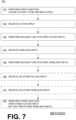
- FIG. 7shows a flowchart 700 for describing methods according to embodiments.
- Some functions of a WCD systemmay be controlled redundantly.
- a first functionis performed.
- the first functionmay be to cause a patient to be defibrillated, for example by controlling a discharge circuit to discharge a stored electrical charge through the patient, while the patient is wearing a support structure of a WCD system.
- an action inputmay be received.
- a second function that is distinct from the first functionmay be performed. An aspect of the performance of the second function may be controlled by the action input received at operation 720 .
- a wireless inputmay be received.
- the second function of operation 730may be subsequently performed again.
- the aspect of the subsequent performance of the second function that was controlled by the action input of operation 720may be controlled by the wireless input of operation 740 .
- other functions of the WCD systemmay optionally be controlled exclusively, meaning not by one of the two functionalities.
- An example of thiswas functions of set 630 .
- another action inputmay be received.
- another wireless inputmay be received.
- a third functionmay be performed. The third function can be distinct from the first and the second functions. An aspect of the performance of the third function can be controlled by the other action input received at operation 760 , but not by the other wireless input received at operation 770 .
- functions 631 , 632 in set 630are accessible by action unit 660 exclusively. In addition to this, some additional functions may be accessible by the mobile communication device exclusively. Examples are now described.
- FIG. 8is a diagram showing a sample allocation of access of functions according to embodiments.
- FIG. 8intentionally has many similarities with FIGS. 3 and 6 , and much of the description of elements of FIGS. 3 and 6 applies to corresponding elements of FIG. 8 .
- Functions of the WCD systemsuch as those described above, can be allocated differently, for instance as second or third or fourth functions described below, and can be in different combinations.
- a WCD systemwhich is not indicated separately, has one or more processors 888 .
- Processor(s) 888are configured to perform a first defibrillation function 811 , and at least one second function that is distinct from defibrillation function 811 .
- a set 820 of such possible additional second functionsis shown, namely functions 821 , 822 , although more are possible.
- Processor(s) 888are further configured to perform at least one third function, which is distinct from defibrillation function 811 and from the second functions of set 820 .
- there is a set 830 of such possible additional third functionsnamely functions 831 , 832 , although more are possible.
- Function 841is optional, and described later.
- the WCD system of FIG. 8further cooperates with a mobile communication device 810 that has a user interface 817 .
- the patientmay enter wireless inputs 818 in user interface 817 .
- Mobile communication device 810is shown in clear domain 392 .
- Wireless inputs 818may affect the functions of set 820 , but not necessarily those of set 830 . More particularly, an aspect of the performance of one of the second functions can be controlled by received wireless input 818 , but not necessarily an aspect of the performance of one of the third functions.
- the WCD system of FIG. 8also has an action unit 860 that has a user interface 867 .
- the patientmay enter action inputs 868 in user interface 867 .
- Action unit 860is shown in gray domain 391 .
- Action inputs 868may affect the functions of set 830 , but not necessarily those of set 820 . More particularly, an aspect of the performance of one of the third functions can be controlled by received action input 868 , but not necessarily an aspect of the performance of one of the second functions.
- FIG. 8shows examples of where processor(s) 888 can be configured to receive one of the action inputs 868 , receive one of the wireless inputs 818 , and perform a second function 821 , in which an aspect of the performance of second function 821 is controlled by the received wireless input but not by the received action input.
- Processor(s) 888can further be configured to perform a third function 831 , in which an aspect of the performance of the third function is controlled by the received action input but not by the received wireless input.
- processor(s) 888may receive an action input 868 and perform fourth function 841 , in which an aspect of the performance of fourth function 841 can be controlled by received action input 868 .
- processor(s) 888may receive wireless input 818 and subsequently perform again fourth function 841 , in which the same aspect of the subsequent performance of fourth function 841 can be controlled by received wireless input 818 .
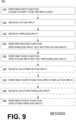
- FIG. 9shows a flowchart 900 for describing methods according to embodiments. Some functions of a WCD system may be controlled partly mutually exclusively.
- a first functionis performed similarly as was described for operation 710 .
- an action inputmay be received, and according to another operation 930 , a wireless input may be received.
- a second function that is distinct from the first functionmay be performed.
- An aspect of the performance of the second functionmay be controlled by the wireless input received at operation 930 , but not by the action input received at operation 920 .
- a third function distinct from the first and the second functionsmay be performed.
- An aspect of the performance of the third functionmay be controlled by the action input received at operation 920 , but not by the wireless input received at operation 930 .
- other functions of the WCD systemmay optionally be controlled redundantly, meaning by either one of the two functionalities.
- another action inputmay be received.
- a fourth function distinct from the first, the second and the third functionsmay be performed.
- An aspect of the performance of the fourth functionmay be controlled by the other action input received at operation 960 .
- another wireless inputmay be received.
- the fourth function of operation 970may be subsequently performed again.
- the aspect of the subsequent performance of the fourth function that was controlled by the action input of operation 960may be controlled by the other wireless input of operation 980 .
- a portion of a WCD systemis separable, and carried by the patient instead of being worn. Examples are now described.
- a patient 1082is shown, along with components of a WCD system.
- the componentsinclude a support structure 1070 that can be as described for support structure 170 . Coupled to support structure 1070 are a component 1006 , and electrodes 1004 , 1008 that are also electrically coupled to component 1006 with leads 1005 .
- component 1007cooperates with component 1006 , and is carried in container 1091 that can be a suitcase, a handbag, a backpack, and so on. Component 1007 can thus be carried out of sight. Component 1007 maybe coupled by a wire with component 1006 , for example both can be electronics modules. In some embodiments, component 1006 is a defibrillator. In some embodiments, component 1007 is an action unit.
- FIG. 11 Ashows sample components of a WCD system according to embodiments
- FIG. 11 Bshows how they can be worn by a patient 1182 .
- the components of FIG. 11 Ainclude a support structure that has an upper harness 1170 A and a lower harness 1170 B.
- the support structureis configured to be worn by patient 1182 , in that both upper harness 1170 A and lower harness 1170 B are configured to be worn—it would be the same if the support structure were made from a single harness, belt, etc.
- a first electronics module 1141is configured to be coupled to the support structure and, more particularly, to lower harness 1170 B. The coupling is such that, when the support structure is worn by patient 1182 , first electronics module 1141 is substantially at a lumbar region of patient 1182 .
- first electronics module 1141includes a power source that is configured to store an electrical charge, as per the above.
- the WCD systemfurther includes a second electronics module 1142 .
- Second electronics module 1142is electrically coupled to first electronics module 1141 via a cable 1176 .
- Second electronics module 1142may include a discharge circuit, as per the above.
- Upper harness 1170 Ahas a main body 1172 with a pocket 1173 .
- Second electronics module 1142can be provided in pocket 1173 .
- each operationcan be performed as an affirmative step of doing, or causing to happen, what is written that can take place. Such doing or causing to happen can be by the whole system or device, or just one or more components of it.
- the methods and the operationsmay be implemented in a number of ways, including using systems, devices and implementations described above.
- the order of operationsis not constrained to what is shown, and different orders may be possible according to different embodiments. Examples of such alternate orderings may include overlapping, interleaved, interrupted, reordered, incremental, preparatory, supplemental, simultaneous, reverse, or other variant orderings, unless context dictates otherwise.
- new operationsmay be added, or individual operations may be modified or deleted. The added operations can be, for example, from what is mentioned while primarily describing a different system, apparatus, device or method.
- the phrases “constructed to” and/or “configured to”denote one or more actual states of construction and/or configuration that is fundamentally tied to physical characteristics of the element or feature preceding these phrases and, as such, reach well beyond merely describing an intended use. Any such elements or features can be implemented in a number of ways, as will be apparent to a person skilled in the art after reviewing the present disclosure, beyond any examples shown in this document.
Landscapes
- Health & Medical Sciences (AREA)
- Life Sciences & Earth Sciences (AREA)
- Engineering & Computer Science (AREA)
- Animal Behavior & Ethology (AREA)
- Biomedical Technology (AREA)
- Heart & Thoracic Surgery (AREA)
- General Health & Medical Sciences (AREA)
- Public Health (AREA)
- Veterinary Medicine (AREA)
- Cardiology (AREA)
- Surgery (AREA)
- Molecular Biology (AREA)
- Physics & Mathematics (AREA)
- Biophysics (AREA)
- Pathology (AREA)
- Medical Informatics (AREA)
- Radiology & Medical Imaging (AREA)
- Nuclear Medicine, Radiotherapy & Molecular Imaging (AREA)
- Human Computer Interaction (AREA)
- Neurology (AREA)
- Electrotherapy Devices (AREA)
- Measurement And Recording Of Electrical Phenomena And Electrical Characteristics Of The Living Body (AREA)
- Computer Networks & Wireless Communication (AREA)
- Signal Processing (AREA)
- Physiology (AREA)
Abstract
Description
Claims (19)
Priority Applications (2)
| Application Number | Priority Date | Filing Date | Title |
|---|---|---|---|
| US17/847,680US11794005B2 (en) | 2012-08-10 | 2022-06-23 | Controlling functions of wearable cardiac defibrillation system |
| US18/492,421US20240050739A1 (en) | 2012-08-10 | 2023-10-23 | Controlling functions of wearable cardiac defibrillation system |
Applications Claiming Priority (10)
| Application Number | Priority Date | Filing Date | Title |
|---|---|---|---|
| US201261682143P | 2012-08-10 | 2012-08-10 | |
| US201261706697P | 2012-09-27 | 2012-09-27 | |
| US201361768897P | 2013-02-25 | 2013-02-25 | |
| US13/959,876US8838235B2 (en) | 2012-08-10 | 2013-08-06 | Wearable defibrillator system communicating via mobile communication device |
| US201462000404P | 2014-05-19 | 2014-05-19 | |
| US14/454,517US9079045B2 (en) | 2012-08-10 | 2014-08-07 | Wearable defibrillator system communicating via mobile communication device |
| US14/684,274US10155110B2 (en) | 2012-08-10 | 2015-04-10 | Controlling functions of wearable cardiac defibrillation system |
| US16/171,042US10471252B2 (en) | 2012-08-10 | 2018-10-25 | Performing and pausing functions of wearable cardiac defibrillation system |
| US16/678,727US11376425B2 (en) | 2012-08-10 | 2019-11-08 | Controlling functions of wearable cardiac defibrillation system |
| US17/847,680US11794005B2 (en) | 2012-08-10 | 2022-06-23 | Controlling functions of wearable cardiac defibrillation system |
Related Parent Applications (1)
| Application Number | Title | Priority Date | Filing Date |
|---|---|---|---|
| US16/678,727ContinuationUS11376425B2 (en) | 2012-08-10 | 2019-11-08 | Controlling functions of wearable cardiac defibrillation system |
Related Child Applications (1)
| Application Number | Title | Priority Date | Filing Date |
|---|---|---|---|
| US18/492,421DivisionUS20240050739A1 (en) | 2012-08-10 | 2023-10-23 | Controlling functions of wearable cardiac defibrillation system |
Publications (2)
| Publication Number | Publication Date |
|---|---|
| US20220313989A1 US20220313989A1 (en) | 2022-10-06 |
| US11794005B2true US11794005B2 (en) | 2023-10-24 |
Family
ID=57111161
Family Applications (4)
| Application Number | Title | Priority Date | Filing Date |
|---|---|---|---|
| US14/684,274Active2034-12-09US10155110B2 (en) | 2012-08-10 | 2015-04-10 | Controlling functions of wearable cardiac defibrillation system |
| US16/171,042ActiveUS10471252B2 (en) | 2012-08-10 | 2018-10-25 | Performing and pausing functions of wearable cardiac defibrillation system |
| US17/847,680ActiveUS11794005B2 (en) | 2012-08-10 | 2022-06-23 | Controlling functions of wearable cardiac defibrillation system |
| US18/492,421PendingUS20240050739A1 (en) | 2012-08-10 | 2023-10-23 | Controlling functions of wearable cardiac defibrillation system |
Family Applications Before (2)
| Application Number | Title | Priority Date | Filing Date |
|---|---|---|---|
| US14/684,274Active2034-12-09US10155110B2 (en) | 2012-08-10 | 2015-04-10 | Controlling functions of wearable cardiac defibrillation system |
| US16/171,042ActiveUS10471252B2 (en) | 2012-08-10 | 2018-10-25 | Performing and pausing functions of wearable cardiac defibrillation system |
Family Applications After (1)
| Application Number | Title | Priority Date | Filing Date |
|---|---|---|---|
| US18/492,421PendingUS20240050739A1 (en) | 2012-08-10 | 2023-10-23 | Controlling functions of wearable cardiac defibrillation system |
Country Status (1)
| Country | Link |
|---|---|
| US (4) | US10155110B2 (en) |
Families Citing this family (13)
| Publication number | Priority date | Publication date | Assignee | Title |
|---|---|---|---|---|
| US10852069B2 (en) | 2010-05-04 | 2020-12-01 | Fractal Heatsink Technologies, LLC | System and method for maintaining efficiency of a fractal heat sink |
| US10155110B2 (en) | 2012-08-10 | 2018-12-18 | West Affum Holdings Corp. | Controlling functions of wearable cardiac defibrillation system |
| US11040214B2 (en) | 2018-03-01 | 2021-06-22 | West Affum Holdings Corp. | Wearable cardioverter defibrillator (WCD) system having main UI that conveys message and peripheral device that amplifies the message |
| US11260238B2 (en)* | 2018-04-26 | 2022-03-01 | West Affum Holdings Corp. | Wearable medical device (WMD) implementing adaptive techniques to save power |
| US11324960B2 (en) | 2018-04-26 | 2022-05-10 | West Affum Holdings Corp. | Permission-based control of interfacing components with a medical device |
| US11382364B2 (en)* | 2018-06-08 | 2022-07-12 | Hemodynamiq Wearables Private Limited | Wearable health monitoring fabric |
| US11596799B2 (en)* | 2018-08-16 | 2023-03-07 | Commhealth Systems Pty Limited | Portable monitored AED system and street furniture for an AED |
| JP2020137727A (en)* | 2019-02-28 | 2020-09-03 | ウェスト・アファム・ホールディングス・コーポレーションWest Affum Holdings Corp. | A wearable defibrillator (WCD) system with a main UI that communicates messages in concert with peripherals that amplify the messages. |
| EP4013297A4 (en) | 2019-08-16 | 2023-12-13 | Poltorak Technologies, LLC | DEVICE AND METHOD FOR MEDICAL DIAGNOSTICS |
| US12138469B2 (en)* | 2019-11-01 | 2024-11-12 | Zoll Medical Corporation | Wearable medical device controller with capacitor framing |
| US11173315B1 (en) | 2020-07-24 | 2021-11-16 | Defibrio AS | Mobile defibrillator |
| US20230381527A1 (en)* | 2022-05-31 | 2023-11-30 | West Affum Holdings Dublin DAC | Wearable medical system with device parameters and patient information programmable via browser interface |
| US20240090854A1 (en)* | 2022-09-16 | 2024-03-21 | West Affum Holdings Corp. | Wearable medical device system with caregiver notifications |
Citations (81)
| Publication number | Priority date | Publication date | Assignee | Title |
|---|---|---|---|---|
| US3724455A (en) | 1970-06-02 | 1973-04-03 | P Unger | Cardiac warning device |
| US4583524A (en) | 1984-11-21 | 1986-04-22 | Hutchins Donald C | Cardiopulmonary resuscitation prompting |
| US4619265A (en) | 1984-03-08 | 1986-10-28 | Physio-Control Corporation | Interactive portable defibrillator including ECG detection circuit |
| US4928690A (en) | 1988-04-25 | 1990-05-29 | Lifecor, Inc. | Portable device for sensing cardiac function and automatically delivering electrical therapy |
| US4955381A (en) | 1988-08-26 | 1990-09-11 | Cardiotronics, Inc. | Multi-pad, multi-function electrode |
| US5078134A (en) | 1988-04-25 | 1992-01-07 | Lifecor, Inc. | Portable device for sensing cardiac function and automatically delivering electrical therapy |
| US5228449A (en) | 1991-01-22 | 1993-07-20 | Athanasios G. Christ | System and method for detecting out-of-hospital cardiac emergencies and summoning emergency assistance |
| US5348008A (en) | 1991-11-25 | 1994-09-20 | Somnus Corporation | Cardiorespiratory alert system |
| US5394892A (en) | 1990-04-02 | 1995-03-07 | K J Mellet Nominees Pty Ltd | CPR prompting apparatus |
| US5405362A (en) | 1991-04-29 | 1995-04-11 | The Board Of Regents For The University Of Texas System | Interactive external defibrillation and drug injection system |
| US5474574A (en) | 1992-06-24 | 1995-12-12 | Cardiac Science, Inc. | Automatic external cardioverter/defibrillator |
| US5662690A (en) | 1994-12-08 | 1997-09-02 | Heartstream, Inc. | Defibrillator with training features and pause actuator |
| US5782878A (en) | 1994-12-07 | 1998-07-21 | Heartstream, Inc. | External defibrillator with communications network link |
| US5792204A (en) | 1996-05-08 | 1998-08-11 | Pacesetter, Inc. | Methods and apparatus for controlling an implantable device programmer using voice commands |
| WO1998039061A2 (en) | 1997-03-07 | 1998-09-11 | Cadent Medical Corporation | Wearable defibrillation system |
| US5902249A (en) | 1995-03-03 | 1999-05-11 | Heartstream, Inc. | Method and apparatus for detecting artifacts using common-mode signals in differential signal detectors |
| US5913685A (en) | 1996-06-24 | 1999-06-22 | Hutchins; Donald C. | CPR computer aiding |
| US5944669A (en) | 1997-11-20 | 1999-08-31 | Lifecor, Inc. | Apparatus and method for sensing cardiac function |
| US6047203A (en) | 1997-03-17 | 2000-04-04 | Nims, Inc. | Physiologic signs feedback system |
| US6065154A (en) | 1998-04-07 | 2000-05-23 | Lifecor, Inc. | Support garments for patient-worn energy delivery apparatus |
| US6108197A (en) | 1992-05-15 | 2000-08-22 | Via, Inc. | Flexible wearable computer |
| US6201992B1 (en) | 1999-04-01 | 2001-03-13 | Agilent Technologies, Inc. | Defibrillator interface capable of generating video images |
| US6263238B1 (en) | 1998-04-16 | 2001-07-17 | Survivalink Corporation | Automatic external defibrillator having a ventricular fibrillation detector |
| US6287328B1 (en) | 1999-04-08 | 2001-09-11 | Agilent Technologies, Inc. | Multivariable artifact assessment |
| US6292687B1 (en) | 2000-05-25 | 2001-09-18 | Lowell Dewitt James | Medical emergency response and locating system |
| US6319011B1 (en) | 1995-04-06 | 2001-11-20 | Michael J. Motti | Automatic training defibrillator simulator and method |
| US6334070B1 (en) | 1998-11-20 | 2001-12-25 | Medtronic Physio-Control Manufacturing Corp. | Visual and aural user interface for an automated external defibrillator |
| US6356785B1 (en) | 1997-11-06 | 2002-03-12 | Cecily Anne Snyder | External defibrillator with CPR prompts and ACLS prompts and methods of use |
| US6529875B1 (en) | 1996-07-11 | 2003-03-04 | Sega Enterprises Ltd. | Voice recognizer, voice recognizing method and game machine using them |
| US20030158593A1 (en) | 2002-02-19 | 2003-08-21 | Heilman Marlin S. | Cardiac garment |
| US6681003B2 (en) | 1999-10-05 | 2004-01-20 | Lifecor, Inc. | Data collection and system management for patient-worn medical devices |
| US6762917B1 (en) | 2001-06-12 | 2004-07-13 | Novx Corporation | Method of monitoring ESC levels and protective devices utilizing the method |
| US20050107834A1 (en) | 2003-11-13 | 2005-05-19 | Freeman Gary A. | Multi-path transthoracic defibrillation and cardioversion |
| US7065401B2 (en) | 2002-05-08 | 2006-06-20 | Michael Worden | Method of applying electrical signals to a patient and automatic wearable external defibrillator |
| US20070162090A1 (en) | 2006-01-10 | 2007-07-12 | Abraham Penner | Body attachable unit in wireless communication with implantable devices |
| US7277752B2 (en) | 2002-06-11 | 2007-10-02 | Matos Jeffrey A | System for cardiac resuscitation |
| US20080312709A1 (en) | 2007-06-13 | 2008-12-18 | Volpe Shane S | Wearable medical treatment device with motion/position detection |
| US20090005827A1 (en) | 2007-06-26 | 2009-01-01 | David Weintraub | Wearable defibrillator |
| US7559902B2 (en) | 2003-08-22 | 2009-07-14 | Foster-Miller, Inc. | Physiological monitoring garment |
| US20100007413A1 (en) | 2006-11-10 | 2010-01-14 | Koninklijke Philips Electronics N.V. | Ecg electrode contact quality measurement system |
| US20100241181A1 (en) | 2009-03-17 | 2010-09-23 | Walter T. Savage | External defibrillator |
| US20100298899A1 (en) | 2007-06-13 | 2010-11-25 | Donnelly Edward J | Wearable medical treatment device |
| US7865238B2 (en) | 2004-09-29 | 2011-01-04 | Koninklijke Philips Electronics N.V. | High-voltage module for an external defibrillator |
| US7870761B2 (en) | 2002-05-14 | 2011-01-18 | Koninklijke Philips Electronics N.V. | Garment and method for producing the same |
| US20110288605A1 (en) | 2010-05-18 | 2011-11-24 | Zoll Medical Corporation | Wearable ambulatory medical device with multiple sensing electrodes |
| US20110288604A1 (en) | 2010-05-18 | 2011-11-24 | Kaib Thomas E | Wearable therapeutic device |
| US8135462B2 (en) | 2002-08-26 | 2012-03-13 | Physio-Control, Inc. | Pulse detection using patient physiological signals |
| US20120112903A1 (en) | 2010-11-08 | 2012-05-10 | Zoll Medical Corporation | Remote medical device alarm |
| US20120150008A1 (en) | 2010-12-09 | 2012-06-14 | Kaib Thomas E | Electrode with redundant impedance reduction |
| US20120144551A1 (en) | 2010-12-09 | 2012-06-14 | Eric Guldalian | Conductive Garment |
| US20120158075A1 (en) | 2010-12-16 | 2012-06-21 | Kaib Thomas E | Water resistant wearable medical device |
| US20120265265A1 (en) | 2011-04-13 | 2012-10-18 | Mehdi Razavi | Automated External Defibrillator Pad System |
| US20120283794A1 (en) | 2011-05-02 | 2012-11-08 | Kaib Thomas E | Patient-worn energy delivery apparatus and techniques for sizing same |
| US20120293323A1 (en) | 2011-03-25 | 2012-11-22 | Zoll Medical Corporation | System and method for adapting alarms in a wearable medical device |
| US20120302860A1 (en) | 2011-03-25 | 2012-11-29 | Zoll Medical Corporation | Selection of optimal channel for rate determination |
| US20120310315A1 (en) | 2009-03-17 | 2012-12-06 | Savage Walter T | Device and method for reducing patient transthoracic impedance for the purpose of delivering a therapeutic current |
| US8369944B2 (en) | 2007-06-06 | 2013-02-05 | Zoll Medical Corporation | Wearable defibrillator with audio input/output |
| US20130085538A1 (en) | 2011-09-01 | 2013-04-04 | Zoll Medical Corporation | Wearable monitoring and treatment device |
| US20130231711A1 (en) | 2012-03-02 | 2013-09-05 | Thomas E. Kaib | Systems and methods for configuring a wearable medical monitoring and/or treatment device |
| US20130245388A1 (en) | 2011-09-01 | 2013-09-19 | Mc10, Inc. | Electronics for detection of a condition of tissue |
| US8548557B2 (en) | 2010-08-12 | 2013-10-01 | Covidien Lp | Medical electrodes |
| US20130274565A1 (en) | 2012-04-13 | 2013-10-17 | Alois Antonin Langer | Outpatient health emergency warning system |
| US20130317852A1 (en) | 2012-05-22 | 2013-11-28 | Geneva Healthcare, LLC | Medical device information portal |
| US20130325078A1 (en) | 2012-05-31 | 2013-12-05 | Zoll Medical Corporation | Medical monitoring and treatment device with external pacing |
| US20130337976A1 (en) | 2012-06-19 | 2013-12-19 | EZ as a Drink Productions, Inc. | Personal wellness device |
| US20140025131A1 (en) | 2012-07-20 | 2014-01-23 | Physio-Control, Inc. | Wearable defibrillator with voice prompts and voice recognition |
| US20140043149A1 (en) | 2012-08-10 | 2014-02-13 | Physio-Control, Inc | Mobile communication device & app for wearable defibrillator system |
| US20140070957A1 (en) | 2012-09-11 | 2014-03-13 | Gianluigi LONGINOTTI-BUITONI | Wearable communication platform |
| US20140163663A1 (en) | 2012-12-11 | 2014-06-12 | Piyush Poddar | Method and system for switching shock vectors and decreasing transthoracic impedance for cardioversion and defibrillation |
| US8904214B2 (en) | 2010-07-09 | 2014-12-02 | Zoll Medical Corporation | System and method for conserving power in a medical device |
| US20140378812A1 (en) | 2011-12-20 | 2014-12-25 | Sensible Medical Innovatons | Thoracic garment of positioning electromagnetic (em) transducers and methods of using such thoracic garment |
| US20150039053A1 (en) | 2013-06-28 | 2015-02-05 | Zoll Medical Corporation | Systems and methods of delivering therapy using an ambulatory medical device |
| US9089685B2 (en) | 2013-02-25 | 2015-07-28 | West Affum Holdings Corp. | Wearable defibrillator with a multivector shock waveform |
| US9132267B2 (en) | 2013-03-04 | 2015-09-15 | Zoll Medical Corporation | Flexible therapy electrode system |
| US20150328472A1 (en) | 2014-05-13 | 2015-11-19 | Physio-Control, Inc. | Wearable cardioverter defibrillator components discarding ecg signals prior to making shock/no shock determination |
| US20160004831A1 (en) | 2014-07-07 | 2016-01-07 | Zoll Medical Corporation | Medical device with natural language processor |
| US20160082277A1 (en) | 2013-02-25 | 2016-03-24 | West Affum Holdings Corp. | Wearable cardioverter defibrillator (wcd) system informing patient that it is validating just-detected cardiac arrhythmia |
| WO2016154425A1 (en) | 2015-03-26 | 2016-09-29 | Zoll Medical Corporation | Amplitude spectrum area considerations for an external medical monitoring and treatment device |
| US9592403B2 (en) | 2013-02-25 | 2017-03-14 | West Affum Holdings Corp. | Wearable cardioverter defibrillator (WCD) system making shock/no shock determinations from multiple patient parameters |
| US10155110B2 (en) | 2012-08-10 | 2018-12-18 | West Affum Holdings Corp. | Controlling functions of wearable cardiac defibrillation system |
| US11363958B2 (en) | 2017-03-23 | 2022-06-21 | Helpwear Inc. | Systems, articles and methods for cardiology sensory technology |
Family Cites Families (6)
| Publication number | Priority date | Publication date | Assignee | Title |
|---|---|---|---|---|
| DE2029044C3 (en) | 1970-06-12 | 1974-02-21 | Agfa-Gevaert Ag, 5090 Leverkusen | Photographic developing device |
| US20040027245A1 (en)* | 2002-08-10 | 2004-02-12 | Dan Schlager | Portable, self-locating smart defibrillator system |
| US6437083B1 (en) | 2001-12-06 | 2002-08-20 | General Electric Company | Process for preparing branched aromatic polycarbonates |
| US20060092029A1 (en)* | 2004-10-29 | 2006-05-04 | Browne David W | Powering down a portable medical device after a data transmission |
| US8024037B2 (en)* | 2006-08-01 | 2011-09-20 | Kumar Uday N | External defibrillator |
| KR101604077B1 (en)* | 2009-05-26 | 2016-03-16 | 삼성전자주식회사 | Method and apparatus for transmitting biological information of user |
- 2015
- 2015-04-10USUS14/684,274patent/US10155110B2/enactiveActive
- 2018
- 2018-10-25USUS16/171,042patent/US10471252B2/enactiveActive
- 2022
- 2022-06-23USUS17/847,680patent/US11794005B2/enactiveActive
- 2023
- 2023-10-23USUS18/492,421patent/US20240050739A1/enactivePending
Patent Citations (103)
| Publication number | Priority date | Publication date | Assignee | Title |
|---|---|---|---|---|
| US3724455A (en) | 1970-06-02 | 1973-04-03 | P Unger | Cardiac warning device |
| US4619265A (en) | 1984-03-08 | 1986-10-28 | Physio-Control Corporation | Interactive portable defibrillator including ECG detection circuit |
| US4583524A (en) | 1984-11-21 | 1986-04-22 | Hutchins Donald C | Cardiopulmonary resuscitation prompting |
| USRE34800E (en) | 1984-11-21 | 1994-11-29 | Hutchins; Donald C. | Cardiopulmonary resuscitation prompting |
| US4928690A (en) | 1988-04-25 | 1990-05-29 | Lifecor, Inc. | Portable device for sensing cardiac function and automatically delivering electrical therapy |
| US5078134A (en) | 1988-04-25 | 1992-01-07 | Lifecor, Inc. | Portable device for sensing cardiac function and automatically delivering electrical therapy |
| US4955381A (en) | 1988-08-26 | 1990-09-11 | Cardiotronics, Inc. | Multi-pad, multi-function electrode |
| US5394892A (en) | 1990-04-02 | 1995-03-07 | K J Mellet Nominees Pty Ltd | CPR prompting apparatus |
| US5228449A (en) | 1991-01-22 | 1993-07-20 | Athanasios G. Christ | System and method for detecting out-of-hospital cardiac emergencies and summoning emergency assistance |
| US5405362A (en) | 1991-04-29 | 1995-04-11 | The Board Of Regents For The University Of Texas System | Interactive external defibrillation and drug injection system |
| US5348008A (en) | 1991-11-25 | 1994-09-20 | Somnus Corporation | Cardiorespiratory alert system |
| US5353793A (en) | 1991-11-25 | 1994-10-11 | Oishi-Kogyo Company | Sensor apparatus |
| US6108197A (en) | 1992-05-15 | 2000-08-22 | Via, Inc. | Flexible wearable computer |
| US5474574A (en) | 1992-06-24 | 1995-12-12 | Cardiac Science, Inc. | Automatic external cardioverter/defibrillator |
| US5782878A (en) | 1994-12-07 | 1998-07-21 | Heartstream, Inc. | External defibrillator with communications network link |
| US5662690A (en) | 1994-12-08 | 1997-09-02 | Heartstream, Inc. | Defibrillator with training features and pause actuator |
| US5902249A (en) | 1995-03-03 | 1999-05-11 | Heartstream, Inc. | Method and apparatus for detecting artifacts using common-mode signals in differential signal detectors |
| US6319011B1 (en) | 1995-04-06 | 2001-11-20 | Michael J. Motti | Automatic training defibrillator simulator and method |
| US5792204A (en) | 1996-05-08 | 1998-08-11 | Pacesetter, Inc. | Methods and apparatus for controlling an implantable device programmer using voice commands |
| US5913685A (en) | 1996-06-24 | 1999-06-22 | Hutchins; Donald C. | CPR computer aiding |
| US6529875B1 (en) | 1996-07-11 | 2003-03-04 | Sega Enterprises Ltd. | Voice recognizer, voice recognizing method and game machine using them |
| US6546285B1 (en) | 1997-03-07 | 2003-04-08 | Cardiac Science, Inc. | Long term wear electrode for defibrillation system |
| WO1998039061A2 (en) | 1997-03-07 | 1998-09-11 | Cadent Medical Corporation | Wearable defibrillation system |
| US6148233A (en) | 1997-03-07 | 2000-11-14 | Cardiac Science, Inc. | Defibrillation system having segmented electrodes |
| US20110022105A9 (en) | 1997-03-07 | 2011-01-27 | Owen James M | Defibrillation system |
| US6671545B2 (en) | 1997-03-07 | 2003-12-30 | Cardiac Science, Inc. | Defibrillator with controller operating in a low power mode |
| US6304780B1 (en) | 1997-03-07 | 2001-10-16 | Cardiac Science Inc. | External defibrillator system with diagnostic module |
| US6427083B1 (en) | 1997-03-07 | 2002-07-30 | Cardiac Science, Inc. | Defibrillation system |
| US6047203A (en) | 1997-03-17 | 2000-04-04 | Nims, Inc. | Physiologic signs feedback system |
| US6356785B1 (en) | 1997-11-06 | 2002-03-12 | Cecily Anne Snyder | External defibrillator with CPR prompts and ACLS prompts and methods of use |
| US5944669A (en) | 1997-11-20 | 1999-08-31 | Lifecor, Inc. | Apparatus and method for sensing cardiac function |
| US6065154A (en) | 1998-04-07 | 2000-05-23 | Lifecor, Inc. | Support garments for patient-worn energy delivery apparatus |
| US6263238B1 (en) | 1998-04-16 | 2001-07-17 | Survivalink Corporation | Automatic external defibrillator having a ventricular fibrillation detector |
| US6334070B1 (en) | 1998-11-20 | 2001-12-25 | Medtronic Physio-Control Manufacturing Corp. | Visual and aural user interface for an automated external defibrillator |
| US6201992B1 (en) | 1999-04-01 | 2001-03-13 | Agilent Technologies, Inc. | Defibrillator interface capable of generating video images |
| US6287328B1 (en) | 1999-04-08 | 2001-09-11 | Agilent Technologies, Inc. | Multivariable artifact assessment |
| US6681003B2 (en) | 1999-10-05 | 2004-01-20 | Lifecor, Inc. | Data collection and system management for patient-worn medical devices |
| US6292687B1 (en) | 2000-05-25 | 2001-09-18 | Lowell Dewitt James | Medical emergency response and locating system |
| US6762917B1 (en) | 2001-06-12 | 2004-07-13 | Novx Corporation | Method of monitoring ESC levels and protective devices utilizing the method |
| US20030158593A1 (en) | 2002-02-19 | 2003-08-21 | Heilman Marlin S. | Cardiac garment |
| US7065401B2 (en) | 2002-05-08 | 2006-06-20 | Michael Worden | Method of applying electrical signals to a patient and automatic wearable external defibrillator |
| US7870761B2 (en) | 2002-05-14 | 2011-01-18 | Koninklijke Philips Electronics N.V. | Garment and method for producing the same |
| US7277752B2 (en) | 2002-06-11 | 2007-10-02 | Matos Jeffrey A | System for cardiac resuscitation |
| US8135462B2 (en) | 2002-08-26 | 2012-03-13 | Physio-Control, Inc. | Pulse detection using patient physiological signals |
| US7559902B2 (en) | 2003-08-22 | 2009-07-14 | Foster-Miller, Inc. | Physiological monitoring garment |
| US20050107833A1 (en) | 2003-11-13 | 2005-05-19 | Freeman Gary A. | Multi-path transthoracic defibrillation and cardioversion |
| US20050107834A1 (en) | 2003-11-13 | 2005-05-19 | Freeman Gary A. | Multi-path transthoracic defibrillation and cardioversion |
| US7865238B2 (en) | 2004-09-29 | 2011-01-04 | Koninklijke Philips Electronics N.V. | High-voltage module for an external defibrillator |
| US20070162090A1 (en) | 2006-01-10 | 2007-07-12 | Abraham Penner | Body attachable unit in wireless communication with implantable devices |
| US20100007413A1 (en) | 2006-11-10 | 2010-01-14 | Koninklijke Philips Electronics N.V. | Ecg electrode contact quality measurement system |
| US8965500B2 (en) | 2007-06-06 | 2015-02-24 | Zoll Medical Corporation | Wearable defibrillator with audio input/output |
| US8369944B2 (en) | 2007-06-06 | 2013-02-05 | Zoll Medical Corporation | Wearable defibrillator with audio input/output |
| US20140324112A1 (en) | 2007-06-06 | 2014-10-30 | Zoll Medical Corporation | Wearable defibrillator with audio input/output |
| US8140154B2 (en) | 2007-06-13 | 2012-03-20 | Zoll Medical Corporation | Wearable medical treatment device |
| US20100298899A1 (en) | 2007-06-13 | 2010-11-25 | Donnelly Edward J | Wearable medical treatment device |
| US20080312709A1 (en) | 2007-06-13 | 2008-12-18 | Volpe Shane S | Wearable medical treatment device with motion/position detection |
| US7974689B2 (en) | 2007-06-13 | 2011-07-05 | Zoll Medical Corporation | Wearable medical treatment device with motion/position detection |
| US20090005827A1 (en) | 2007-06-26 | 2009-01-01 | David Weintraub | Wearable defibrillator |
| US8615295B2 (en) | 2009-03-17 | 2013-12-24 | Cardiothrive, Inc. | External defibrillator |
| US20120310315A1 (en) | 2009-03-17 | 2012-12-06 | Savage Walter T | Device and method for reducing patient transthoracic impedance for the purpose of delivering a therapeutic current |
| US20100241181A1 (en) | 2009-03-17 | 2010-09-23 | Walter T. Savage | External defibrillator |
| US9008801B2 (en) | 2010-05-18 | 2015-04-14 | Zoll Medical Corporation | Wearable therapeutic device |
| US20110288604A1 (en) | 2010-05-18 | 2011-11-24 | Kaib Thomas E | Wearable therapeutic device |
| US20110288605A1 (en) | 2010-05-18 | 2011-11-24 | Zoll Medical Corporation | Wearable ambulatory medical device with multiple sensing electrodes |
| US9454219B2 (en) | 2010-07-09 | 2016-09-27 | Zoll Medical Corporation | System and method for conserving power in a medical device |
| US8904214B2 (en) | 2010-07-09 | 2014-12-02 | Zoll Medical Corporation | System and method for conserving power in a medical device |
| US8548557B2 (en) | 2010-08-12 | 2013-10-01 | Covidien Lp | Medical electrodes |
| US20120112903A1 (en) | 2010-11-08 | 2012-05-10 | Zoll Medical Corporation | Remote medical device alarm |
| US20120144551A1 (en) | 2010-12-09 | 2012-06-14 | Eric Guldalian | Conductive Garment |
| US20120150008A1 (en) | 2010-12-09 | 2012-06-14 | Kaib Thomas E | Electrode with redundant impedance reduction |
| US20120158075A1 (en) | 2010-12-16 | 2012-06-21 | Kaib Thomas E | Water resistant wearable medical device |
| US9408548B2 (en) | 2011-03-25 | 2016-08-09 | Zoll Medical Corporation | Selection of optimal channel for rate determination |
| US20120293323A1 (en) | 2011-03-25 | 2012-11-22 | Zoll Medical Corporation | System and method for adapting alarms in a wearable medical device |
| US20120302860A1 (en) | 2011-03-25 | 2012-11-29 | Zoll Medical Corporation | Selection of optimal channel for rate determination |
| US8897860B2 (en) | 2011-03-25 | 2014-11-25 | Zoll Medical Corporation | Selection of optimal channel for rate determination |
| US20120265265A1 (en) | 2011-04-13 | 2012-10-18 | Mehdi Razavi | Automated External Defibrillator Pad System |
| US20120283794A1 (en) | 2011-05-02 | 2012-11-08 | Kaib Thomas E | Patient-worn energy delivery apparatus and techniques for sizing same |
| US8644925B2 (en) | 2011-09-01 | 2014-02-04 | Zoll Medical Corporation | Wearable monitoring and treatment device |
| US20130245388A1 (en) | 2011-09-01 | 2013-09-19 | Mc10, Inc. | Electronics for detection of a condition of tissue |
| US20130085538A1 (en) | 2011-09-01 | 2013-04-04 | Zoll Medical Corporation | Wearable monitoring and treatment device |
| US9131901B2 (en) | 2011-09-01 | 2015-09-15 | Zoll Medical Corporation | Wearable monitoring and treatment device |
| US20140378812A1 (en) | 2011-12-20 | 2014-12-25 | Sensible Medical Innovatons | Thoracic garment of positioning electromagnetic (em) transducers and methods of using such thoracic garment |
| US20130231711A1 (en) | 2012-03-02 | 2013-09-05 | Thomas E. Kaib | Systems and methods for configuring a wearable medical monitoring and/or treatment device |
| US20130274565A1 (en) | 2012-04-13 | 2013-10-17 | Alois Antonin Langer | Outpatient health emergency warning system |
| US20130317852A1 (en) | 2012-05-22 | 2013-11-28 | Geneva Healthcare, LLC | Medical device information portal |
| US20130325078A1 (en) | 2012-05-31 | 2013-12-05 | Zoll Medical Corporation | Medical monitoring and treatment device with external pacing |
| US20130337976A1 (en) | 2012-06-19 | 2013-12-19 | EZ as a Drink Productions, Inc. | Personal wellness device |
| US20140025131A1 (en) | 2012-07-20 | 2014-01-23 | Physio-Control, Inc. | Wearable defibrillator with voice prompts and voice recognition |
| US10155110B2 (en) | 2012-08-10 | 2018-12-18 | West Affum Holdings Corp. | Controlling functions of wearable cardiac defibrillation system |
| US11376425B2 (en) | 2012-08-10 | 2022-07-05 | West Affum Holdings Corp. | Controlling functions of wearable cardiac defibrillation system |
| US10471252B2 (en) | 2012-08-10 | 2019-11-12 | West Affum Holdings Corp. | Performing and pausing functions of wearable cardiac defibrillation system |
| US20140043149A1 (en) | 2012-08-10 | 2014-02-13 | Physio-Control, Inc | Mobile communication device & app for wearable defibrillator system |
| US20140070957A1 (en) | 2012-09-11 | 2014-03-13 | Gianluigi LONGINOTTI-BUITONI | Wearable communication platform |
| US20140163663A1 (en) | 2012-12-11 | 2014-06-12 | Piyush Poddar | Method and system for switching shock vectors and decreasing transthoracic impedance for cardioversion and defibrillation |
| US9592403B2 (en) | 2013-02-25 | 2017-03-14 | West Affum Holdings Corp. | Wearable cardioverter defibrillator (WCD) system making shock/no shock determinations from multiple patient parameters |
| US9089685B2 (en) | 2013-02-25 | 2015-07-28 | West Affum Holdings Corp. | Wearable defibrillator with a multivector shock waveform |
| US20160082277A1 (en) | 2013-02-25 | 2016-03-24 | West Affum Holdings Corp. | Wearable cardioverter defibrillator (wcd) system informing patient that it is validating just-detected cardiac arrhythmia |
| US9132267B2 (en) | 2013-03-04 | 2015-09-15 | Zoll Medical Corporation | Flexible therapy electrode system |
| US20150039053A1 (en) | 2013-06-28 | 2015-02-05 | Zoll Medical Corporation | Systems and methods of delivering therapy using an ambulatory medical device |
| US20150328472A1 (en) | 2014-05-13 | 2015-11-19 | Physio-Control, Inc. | Wearable cardioverter defibrillator components discarding ecg signals prior to making shock/no shock determination |
| US20160004831A1 (en) | 2014-07-07 | 2016-01-07 | Zoll Medical Corporation | Medical device with natural language processor |
| WO2016154425A1 (en) | 2015-03-26 | 2016-09-29 | Zoll Medical Corporation | Amplitude spectrum area considerations for an external medical monitoring and treatment device |
| US11363958B2 (en) | 2017-03-23 | 2022-06-21 | Helpwear Inc. | Systems, articles and methods for cardiology sensory technology |
Non-Patent Citations (7)
| Title |
|---|
| Heartstart MRx and XL AED Algorithm—Application Note, Jul. 2001, Edition 2 Philips Healthcare, USA. |
| Klein, H. U., Goldenberg I., & Moss, A. J., Risk Stratification for Implantable Cardioverter Defibrillator Therapy: The Role of the Wearable Cardioverter-Defibrillator, Clinical update, European Heart Journal, May 31, 2013, pp. 1-14, doi:10.1093/eurheartj/eht167, European Society of Cardiology. |
| LIFECOR LifeVest System Model WCD 3100 Operator's Manual, 2006, PN 20B0040 Rev FI, Zoll Lifecor Corporation, Pittsburgh, PA. |
| LifeVest Model 4000 Patient Manual, Zoll, 2009, PN 20B0047 Rev B. |
| Non-Final Office action dated Oct. 22, 2021, to U.S. Appl. No. 16/678,727. |
| Pagan-Carlo, et al., "Encircling Overlapping Multipulse Shock Waveforms for Transthoracic Defibrillation," JACC Journals, Dec. 1998, vol. 32 Issue 7, p. 2065-2071. |
| The LifeVest Network/Patient Data Management System, Zoll, 2015, 2000503 Rev A. |
Also Published As
| Publication number | Publication date |
|---|---|
| US20240050739A1 (en) | 2024-02-15 |
| US20190060644A1 (en) | 2019-02-28 |
| US20180001083A9 (en) | 2018-01-04 |
| US10471252B2 (en) | 2019-11-12 |
| US20160296114A1 (en) | 2016-10-13 |
| US10155110B2 (en) | 2018-12-18 |
| US20220313989A1 (en) | 2022-10-06 |
Similar Documents
| Publication | Publication Date | Title |
|---|---|---|
| US11376425B2 (en) | Controlling functions of wearable cardiac defibrillation system | |
| US11794005B2 (en) | Controlling functions of wearable cardiac defibrillation system | |
| US11207538B2 (en) | Wearable cardioverter defibrillator (WCD) system warning ambulatory patient by weak alerting shock | |
| US20240245906A1 (en) | Wearable cardioverter defibrillator (wcd) system measuring patient's respiration | |
| US12226625B2 (en) | Wearable cardiac defibrillator systems and methods and software for contacting non-witnessing responders | |
| US12226646B2 (en) | Wearable cardioverter defibrillator (WCD) system having main UI that conveys message and peripheral device that amplifies the message | |
| US11944835B2 (en) | Wearable cardioverter defibrillator (WCD) system having WCD mode and also AED mode | |
| US12115379B2 (en) | Wearable cardioverter defibrillation (WCD) system with proximate programming device which stores ECG data that the WCD system normally discards | |
| US20160331986A1 (en) | Wearable cardiac defibrillator system with communicating battery charger | |
| US20240021286A1 (en) | Remote management of wearable cardiac defibrillation system | |
| JP2020137727A (en) | A wearable defibrillator (WCD) system with a main UI that communicates messages in concert with peripherals that amplify the messages. | |
| US11950174B2 (en) | Detailed alarm messages and support | |
| US20230277860A1 (en) | Wearable medical system (wms) implementing wearable cardioverter defibrillator (wcd) capturing, recording and reporting ambient sounds | |
| US11058885B2 (en) | Wearable cardioverter defibrillator (WCD) system detecting ventricular tachycardia and/or ventricular fibrillation using variable heart rate decision threshold |
Legal Events
| Date | Code | Title | Description |
|---|---|---|---|
| FEPP | Fee payment procedure | Free format text:ENTITY STATUS SET TO UNDISCOUNTED (ORIGINAL EVENT CODE: BIG.); ENTITY STATUS OF PATENT OWNER: LARGE ENTITY | |
| STPP | Information on status: patent application and granting procedure in general | Free format text:DOCKETED NEW CASE - READY FOR EXAMINATION | |
| AS | Assignment | Owner name:WEST AFFUM HOLDINGS CORP., CAYMAN ISLANDS Free format text:ASSIGNMENT OF ASSIGNORS INTEREST;ASSIGNOR:PHYSIO-CONTROL, INC.;REEL/FRAME:063734/0160 Effective date:20150706 Owner name:PHYSIO-CONTROL, INC., WASHINGTON Free format text:ASSIGNMENT OF ASSIGNORS INTEREST;ASSIGNORS:FINCH, DAVID P.;FOSHEE, PHILLIP D., JR.;ROANE, ERICK M.;AND OTHERS;SIGNING DATES FROM 20150512 TO 20150609;REEL/FRAME:063733/0930 Owner name:WEST AFFUM HOLDINGS CORP., CAYMAN ISLANDS Free format text:ASSIGNMENT OF ASSIGNORS INTEREST;ASSIGNOR:KAVOUNAS, GREGORY T.;REEL/FRAME:063734/0069 Effective date:20150512 Owner name:WEST AFFUM HOLDINGS DESIGNATED ACTIVITY COMPANY, IRELAND Free format text:ASSIGNMENT OF ASSIGNORS INTEREST;ASSIGNOR:WEST AFFUM HOLDINGS CORP.;REEL/FRAME:063734/0400 Effective date:20220427 | |
| STPP | Information on status: patent application and granting procedure in general | Free format text:RESPONSE TO NON-FINAL OFFICE ACTION ENTERED AND FORWARDED TO EXAMINER | |
| STPP | Information on status: patent application and granting procedure in general | Free format text:NOTICE OF ALLOWANCE MAILED -- APPLICATION RECEIVED IN OFFICE OF PUBLICATIONS | |
| STPP | Information on status: patent application and granting procedure in general | Free format text:PUBLICATIONS -- ISSUE FEE PAYMENT VERIFIED | |
| AS | Assignment | Owner name:PERCEPTIVE CREDIT HOLDINGS IV, LP, NEW YORK Free format text:SECURITY AGREEMENT;ASSIGNOR:WEST AFFUM HOLDINGS DESIGNATED ACTIVITY COMPANY;REEL/FRAME:065116/0049 Effective date:20230929 | |
| STCF | Information on status: patent grant | Free format text:PATENTED CASE |